Table of Contents
APC Galaxy VS User Manual
Displayed below is the user manual for Galaxy VS by APC which is a product in the UPS Accessories category. This manual has pages.
Related Manuals
Galaxy VS
IP52 Kit for UPS
Installation
GVSOPT033
9/2020
www.se.com

Legal Information
The Schneider Electric brand and any trademarks of Schneider Electric SE and its
subsidiaries referred to in this guide are the property of Schneider Electric SE or its
subsidiaries. All other brands may be trademarks of their respective owners.
This guide and its content are protected under applicable copyright laws and
furnished for informational use only. No part of this guide may be reproduced or
transmitted in any form or by any means (electronic, mechanical, photocopying,
recording, or otherwise), for any purpose, without the prior written permission of
Schneider Electric.
Schneider Electric does not grant any right or license for commercial use of the guide
or its content, except for a non-exclusive and personal license to consult it on an "as
is" basis. Schneider Electric products and equipment should be installed, operated,
serviced, and maintained only by qualified personnel.
As standards, specifications, and designs change from time to time, information
contained in this guide may be subject to change without notice.
To the extent permitted by applicable law, no responsibility or liability is assumed by
Schneider Electric and its subsidiaries for any errors or omissions in the informational
content of this material or consequences arising out of or resulting from the use of the
information contained herein.
Go to
IEC: https://www.productinfo.schneider-electric.com/galaxyvs_iec/ or
UL: https://www.productinfo.schneider-electric.com/galaxyvs_ul/
or scan the QR code above for digital experience and translated manuals.

IP52 Kit for UPS
Table of Contents
Important Safety Instructions — SAVE THESE
INSTRUCTIONS.........................................................................................5
Safety Precautions .....................................................................................6
Electrical Safety .........................................................................................8
Battery Safety ............................................................................................8
Load Derating for UPS with IP52 Kit Installed ......................................10
Install the IP52 Kit on the UPS................................................................12
990-6363-001 3

Important Safety Instructions — SAVE THESE
INSTRUCTIONS IP52 Kit for UPS
Important Safety Instructions — SAVE THESE
INSTRUCTIONS
Read these instructions carefully and look at the equipment to become familiar
with it before trying to install, operate, service or maintain it. The following safety
messages may appear throughout this manual or on the equipment to warn of
potential hazards or to call attention to information that clarifies or simplifies a
procedure.
The addition of this symbol to a “Danger” or “Warning” safety
message indicates that an electrical hazard exists which will result in
personal injury if the instructions are not followed.
This is the safety alert symbol. It is used to alert you to potential
personal injury hazards. Obey all safety messages with this symbol
to avoid possible injury or death.
DANGER
DANGER indicates a hazardous situation which, if not avoided, will result in
death or serious injury.
Failure to follow these instructions will result in death or serious injury.
WARNING
WARNING indicates a hazardous situation which, if not avoided, could result
in death or serious injury.
Failure to follow these instructions can result in death, serious injury, or
equipment damage.
CAUTION
CAUTION indicates a hazardous situation which, if not avoided, could result in
minor or moderate injury.
Failure to follow these instructions can result in injury or equipment
damage.
NOTICE
NOTICE is used to address practices not related to physical injury. The safety
alert symbol shall not be used with this type of safety message.
Failure to follow these instructions can result in equipment damage.
Please Note
Electrical equipment should only be installed, operated, serviced, and maintained
by qualified personnel. No responsibility is assumed by Schneider Electric for any
consequences arising out of the use of this material.
A qualified person is one who has skills and knowledge related to the construction,
installation, and operation of electrical equipment and has received safety training
to recognize and avoid the hazards involved.
990-6363-001 5

IP52 Kit for UPS
Important Safety Instructions — SAVE THESE
INSTRUCTIONS
Safety Precautions
DANGER
HAZARD OF ELECTRIC SHOCK, EXPLOSION, OR ARC FLASH
All safety instructions in this document must be read, understood and followed.
Failure to follow these instructions will result in death or serious injury.
DANGER
HAZARD OF ELECTRIC SHOCK, EXPLOSION, OR ARC FLASH
Read all instructions in the installation manual before installing or working on
this UPS system.
Failure to follow these instructions will result in death or serious injury.
DANGER
HAZARD OF ELECTRIC SHOCK, EXPLOSION, OR ARC FLASH
Do not install the UPS system until all construction work has been completed
and the installation room has been cleaned. If additional construction work is
needed in the installation room after the UPS has been installed, turn off the
UPS and cover the UPS with the protective packaging bag the UPS was
delivered in.
Failure to follow these instructions will result in death or serious injury.
DANGER
HAZARD OF ELECTRIC SHOCK, EXPLOSION, OR ARC FLASH
• The product must be installed according to the specifications and
requirements as defined by Schneider Electric. It concerns in particular the
external and internal protections (upstream breakers, battery breakers,
cabling, etc.) and environmental requirements. No responsibility is assumed
by Schneider Electric if these requirements are not respected.
• After the UPS system has been electrically wired, do not start up the system.
Start-up must only be performed by Schneider Electric.
Failure to follow these instructions will result in death or serious injury.
DANGER
HAZARD OF ELECTRIC SHOCK, EXPLOSION, OR ARC FLASH
The UPS system must be installed according to local and national regulations.
Install the UPS according to:
• IEC 60364 (including 60364-4-41– protection against electric shock, 60364-
4-42 – protection against thermal effect, and 60364-4-43 – protection against
overcurrent), or
• NEC NFPA 70, or
• Canadian Electrical Code (C22.1, Part 1)
depending on which one of the standards apply in your local area.
Failure to follow these instructions will result in death or serious injury.
6 990-6363-001
Important Safety Instructions — SAVE THESE
INSTRUCTIONS IP52 Kit for UPS
DANGER
HAZARD OF ELECTRIC SHOCK, EXPLOSION, OR ARC FLASH
• Install the UPS system in a temperature controlled indoor environment free
of conductive contaminants and humidity.
• Install the UPS system on a non-flammable, level and solid surface (e.g.
concrete) that can support the weight of the system.
Failure to follow these instructions will result in death or serious injury.
DANGER
HAZARD OF ELECTRIC SHOCK, EXPLOSION, OR ARC FLASH
The UPS is not designed for and must therefore not be installed in the following
unusual operating environments:
• Damaging fumes
• Explosive mixtures of dust or gases, corrosive gases, or conductive or
radiant heat from other sources
• Moisture, abrasive dust, steam or in an excessively damp environment
• Fungus, insects, vermin
• Salt-laden air or contaminated cooling refrigerant
• Pollution degree higher than 2 according to IEC 60664-1
• Exposure to abnormal vibrations, shocks, and tilting
• Exposure to direct sunlight, heat sources, or strong electromagnetic fields
Failure to follow these instructions will result in death or serious injury.
DANGER
HAZARD OF ELECTRIC SHOCK, EXPLOSION, OR ARC FLASH
Do not drill or cut holes for cables or conduits with the gland plates installed and
do not drill or cut holes in close proximity to the UPS.
Failure to follow these instructions will result in death or serious injury.
WARNING
HAZARD OF ARC FLASH
Do not make mechanical changes to the product (including removal of cabinet
parts or drilling/cutting of holes) that are not described in the installation manual.
Failure to follow these instructions can result in death, serious injury, or
equipment damage.
NOTICE
RISK OF OVERHEATING
Respect the space requirements around the UPS system and do not cover the
UPS ventilation openings when the UPS system is in operation.
Failure to follow these instructions can result in equipment damage.
990-6363-001 7
IP52 Kit for UPS
Important Safety Instructions — SAVE THESE
INSTRUCTIONS
NOTICE
RISK OF EQUIPMENT DAMAGE
Do not connect the UPS output to regenerative load systems including
photovoltaic systems and speed drives.
Failure to follow these instructions can result in equipment damage.
Electrical Safety
DANGER
HAZARD OF ELECTRIC SHOCK, EXPLOSION OR ARC FLASH
• Electrical equipment must be installed, operated, serviced, and maintained
only by qualified personnel.
• Apply appropriate personal protective equipment (PPE) and follow safe
electrical work practices.
• Turn off all power supplying the UPS system before working on or inside the
equipment.
• Before working on the UPS system, check for hazardous voltage between all
terminals including the protective earth.
• The UPS contains an internal energy source. Hazardous voltage can be
present even when disconnected from the utility/mains supply. Before
installing or servicing the UPS system, ensure that the units are OFF and
that utility/mains and batteries are disconnected. Wait five minutes before
opening the UPS to allow the capacitors to discharge.
• A disconnection device (e.g. disconnection circuit breaker or switch) must be
installed to enable isolation of the system from upstream power sources in
accordance with local regulations. This disconnection device must be easily
accessible and visible.
• The UPS must be properly earthed/grounded and due to a high leakage
current, the earthing/grounding conductor must be connected first.
Failure to follow these instructions will result in death or serious injury.
Battery Safety
DANGER
HAZARD OF ELECTRIC SHOCK, EXPLOSION, OR ARC FLASH
• Battery circuit breakers must be installed according to the specifications and
requirements as defined by Schneider Electric.
• Servicing of batteries must only be performed or supervised by qualified
personnel knowledgeable of batteries and the required precautions. Keep
unqualified personnel away from batteries.
• Disconnect charging source prior to connecting or disconnecting battery
terminals.
• Do not dispose of batteries in a fire as they can explode.
• Do not open, alter, or mutilate batteries. Released electrolyte is harmful to
the skin and eyes. It may be toxic.
Failure to follow these instructions will result in death or serious injury.
8 990-6363-001

Important Safety Instructions — SAVE THESE
INSTRUCTIONS IP52 Kit for UPS
DANGER
HAZARD OF ELECTRIC SHOCK, EXPLOSION, OR ARC FLASH
Batteries can present a risk of electric shock and high short-circuit current. The
following precautions must be observed when working on batteries
• Remove watches, rings, or other metal objects.
• Use tools with insulated handles.
• Wear protective glasses, gloves and boots.
• Do not lay tools or metal parts on top of batteries.
• Disconnect the charging source prior to connecting or disconnecting battery
terminals.
• Determine if the battery is inadvertently grounded. If inadvertently grounded,
remove source from ground. Contact with any part of a grounded battery can
result in electric shock. The likelihood of such shock can be reduced if such
grounds are removed during installation and maintenance (applicable to
equipment and remote battery supplies not having a grounded supply
circuit).
Failure to follow these instructions will result in death or serious injury.
DANGER
HAZARD OF ELECTRIC SHOCK, EXPLOSION, OR ARC FLASH
When replacing batteries, always replace with the same type and number of
batteries or battery packs.
Failure to follow these instructions will result in death or serious injury.
NOTICE
RISK OF EQUIPMENT DAMAGE
• Wait until the system is ready to be powered up before installing batteries in
the system. The time duration from battery installation until the UPS system
is powered up must not exceed 72 hours or 3 days.
• Batteries must not be stored more than six months due to the requirement of
recharging. If the UPS system remains de-energized for a long period,
Schneider Electric recommends that you energize the UPS system for a
period of 24 hours at least once every month. This charges the batteries,
thus avoiding irreversible damage.
Failure to follow these instructions can result in equipment damage.
990-6363-001 9

IP52 Kit for UPS Load Derating for UPS with IP52 Kit Installed
Load Derating for UPS with IP52 Kit Installed
NOTICE
RISK OF OVERHEATING
• Galaxy VS IP52 UPS may have load deratings/temperature deratings.
• Read all instructions in the installation manual before installing or working on
this UPS.
Failure to follow these instructions can result in equipment damage.
380/400/415/480 V UPS
UPS rating Maximum
continuous load at
30 °C (86 °F)
Maximum
continuous load at
35 °C (95 °F)
Maximum
continuous load at
40 °C (104 °F)
Operating temperature and load
derating
20 kW 20 kW 20 kW 20 kW 0 °C to 40 °C (32 °F to 104 °F): No
derating.
30 kW 30 kW 30 kW 30 kW 0 °C to 40 °C (32 °F to 104 °F): No
derating.
40 kW 40 kW 34 kW 30 kW 0 °C to 30 °C (32 °F to 86 °F): No
derating;
30 °C to 40 °C (32 °F to 104 °F): Reduce
load with 3% for every °C.
40 kW (N+1 power
module)
40 kW 40 kW 40 kW 0 °C to 40 °C (32 °F to 104 °F): No
derating.
50 kW 40 kW 34 kW 30 kW 40 kW maximum load on UPS. Output
overload alarm settings need to be
adjusted by Schneider Electric Service.
50 kW (N+1 power
module)
50 kW 50 kW 50 kW 0 °C to 40 °C (32 °F to 104 °F): No
derating.
60 kW 60 kW 60 kW 50 kW 0 °C to 35 °C (32 °F to 95 °F): No
derating;
35 °C to 40 °C (95 °F to 104 °F): Reduce
load with 3% for every °C.
60 kW (N+1 power
module)
60 kW 60 kW 60 kW 0 °C to 40 °C (32 °F to 104 °F): No
derating.
80 kW 80 kW 68 kW 50 kW 0 °C to 30 °C (32 °F to 86 °F): No
derating;
30 °C to 40 °C (86 °F to 104 °F): Reduce
load with 3% for every °C.
80 kW (N+1 power
module)
80 kW 80 kW 80 kW 0 °C to 40 °C (32 °F to 104 °F): No
derating.
100 kW 80 kW 68 kW 50 kW 80 kW maximum load on UPS. Output
overload alarm settings need to be
adjusted by Schneider Electric Service.
100 kW (N+1 power
module)
100 kW 100 kW 84 kW 0 °C to 35 °C (32 °F to 95 °F): No
derating;
35 °C to 40 °C (95 °F to 104 °F): Reduce
load with 3% for every °C.
120 kW 120 kW 102 kW 84 kW 0 °C to 30 °C (32 °F to 86 °F): No
derating;
30 °C to 40 °C (86 °F to 104 °F): Reduce
load with 3% for every °C.
150 kW 120 kW 102 kW 84 kW 120 kW maximum load on UPS. Output
overload alarm settings need to be
adjusted by Schneider Electric Service.
10 990-6363-001

Load Derating for UPS with IP52 Kit Installed IP52 Kit for UPS
200/208/220 V UPS
UPS rating Maximum
continuous load at
30 °C (86 °F)
Maximum
continuous load at
35 °C (95 °F)
Maximum
continuous load at
40 °C (104 °F)
Operating temperature and load
derating
10 kW 10 kW 10 kW 10 kW 0 °C to 40 °C (32 °F to 104 °F): No
derating.
15 kW 15 kW 15 kW 15 kW 0 °C to 40 °C (32 °F to 104 °F): No
derating.
20 kW 20 kW 17 kW 15 kW 0 °C to 30 °C (32 °F to 86 °F): No
derating;
30 °C to 40 °C (86 °F to 104 °F): Reduce
load with 3% for every °C.
20 (N+1 power
module)
20 kW 20 kW 20 kW 0 °C to 40 °C (32 °F to 104 °F): No
derating.
25 kW 20 kW 17 kW 15 kW 20 kW maximum load on UPS. Output
overload alarm settings need to be
adjusted by Schneider Electric Service.
25 (N+1 power
module)
25 kW 25 kW 25 kW 0 °C to 40 °C (32 °F to 104 °F): No
derating.
30 kW 30 kW 30 kW 25 kW 0 °C to 35 °C (32 °F to 95 °F): No
derating;
35 °C to 40 °C (95 °F to 104 °F): Reduce
load with 3% for every °C.
40 kW 40 kW 34 kW 25 kW 0 °C to 30 °C (32 °F to 86 °F): No
derating;
30 °C to 40 °C (86 °F to 104 °F): Reduce
load with 3% for every °C.
40 (N+1 power
module)
40 kW 40 kW 40 kW 0 °C to 40 °C (32 °F to 104 °F): No
derating.
50 kW 40 kW 34 kW 25 kW 40 kW maximum load on UPS. Output
overload alarm settings need to be
adjusted by Schneider Electric Service.
50 (N+1 power
module)
50 kW 50 kW 50 kW 0 °C to 35 °C (32 °F to 95 °F): No
derating;
35 °C to 40 °C (95 °F to 104 °F): Reduce
load with 3% for every °C.
60 kW 60 kW 51 kW 42 kW 0 °C to 30 °C (32 °F to 86 °F): No
derating;
30 °C to 40 °C (86 °F to 104 °F): Reduce
load with 3% for every °C.
75 kW 60 kW 51 kW 42 kW 60 kW maximum load on UPS. Output
overload alarm settings need to be
adjusted by Schneider Electric Service.
990-6363-001 11
IP52 Kit for UPS Install the IP52 Kit on the UPS
Install the IP52 Kit on the UPS
NOTE: The IP52 kit can only be installed on a UPS with bottom cable entry.
NOTE: This procedure describes installing the IP52 kit after power cabling
and signal cabling is completed. Rear access is required to install the IP52 kit
on the UPS.
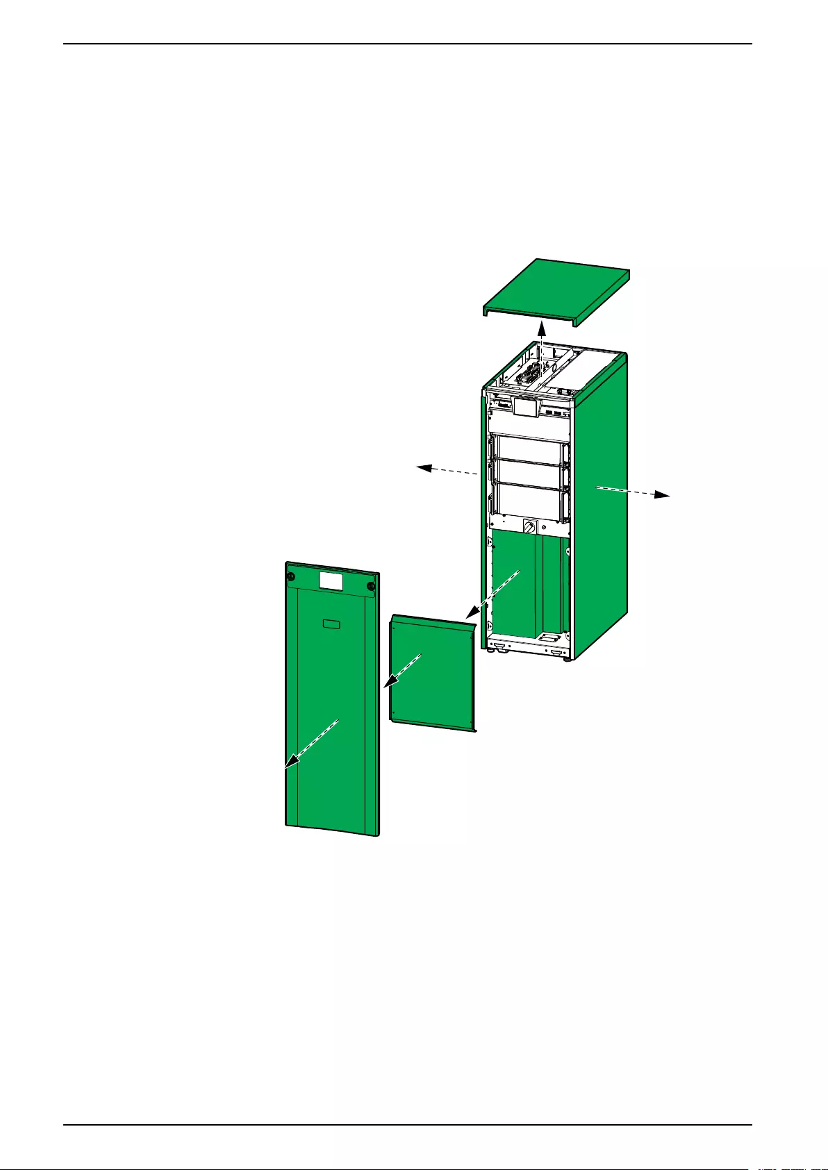
1. Follow the UPS installation manual to install the UPS.
2. Remove the front panel, the lower front plate, the transparent cover, the top
cover, the left side panel (if present), and the right side panel.
12 990-6363-001
Install the IP52 Kit on the UPS IP52 Kit for UPS
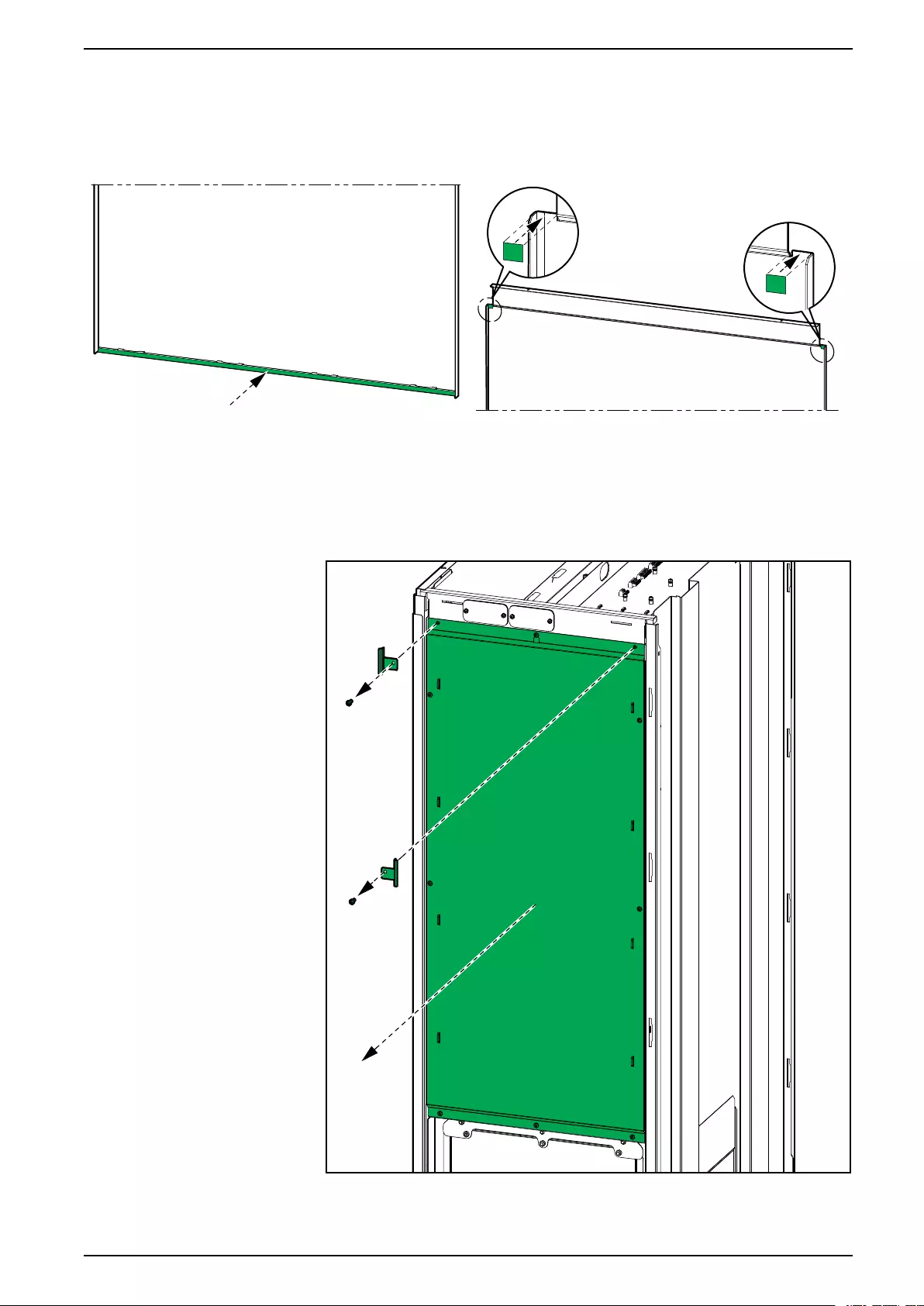
3. Mount the provided flat gaskets on the side panel(s) as close to the bottom
and top inside edges as possible for optimal sealing.
Inside View of the Bottom Part of the Side Panel Inside View of the Top Part of the Side Panel
4. Reinstall the side panel(s) on the UPS.
5. Remove the two brackets and the rear cover. Save the two brackets and the
flat head screws and discard the rear cover.
Rear View
990-6363-001 13
IP52 Kit for UPS Install the IP52 Kit on the UPS
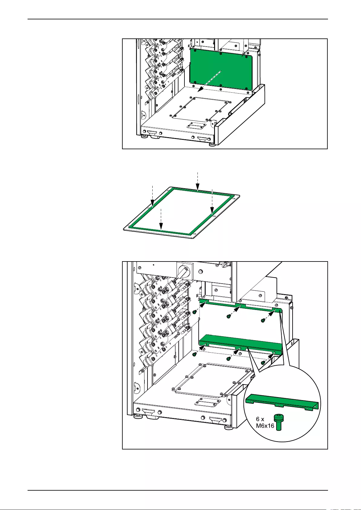
6. From inside the UPS, remove the rear gland plate.
7. Mount the flat gasket 12.7 mm from the edges on the rear gland plate for
optimal sealing and save the rear gland plate for later installation.
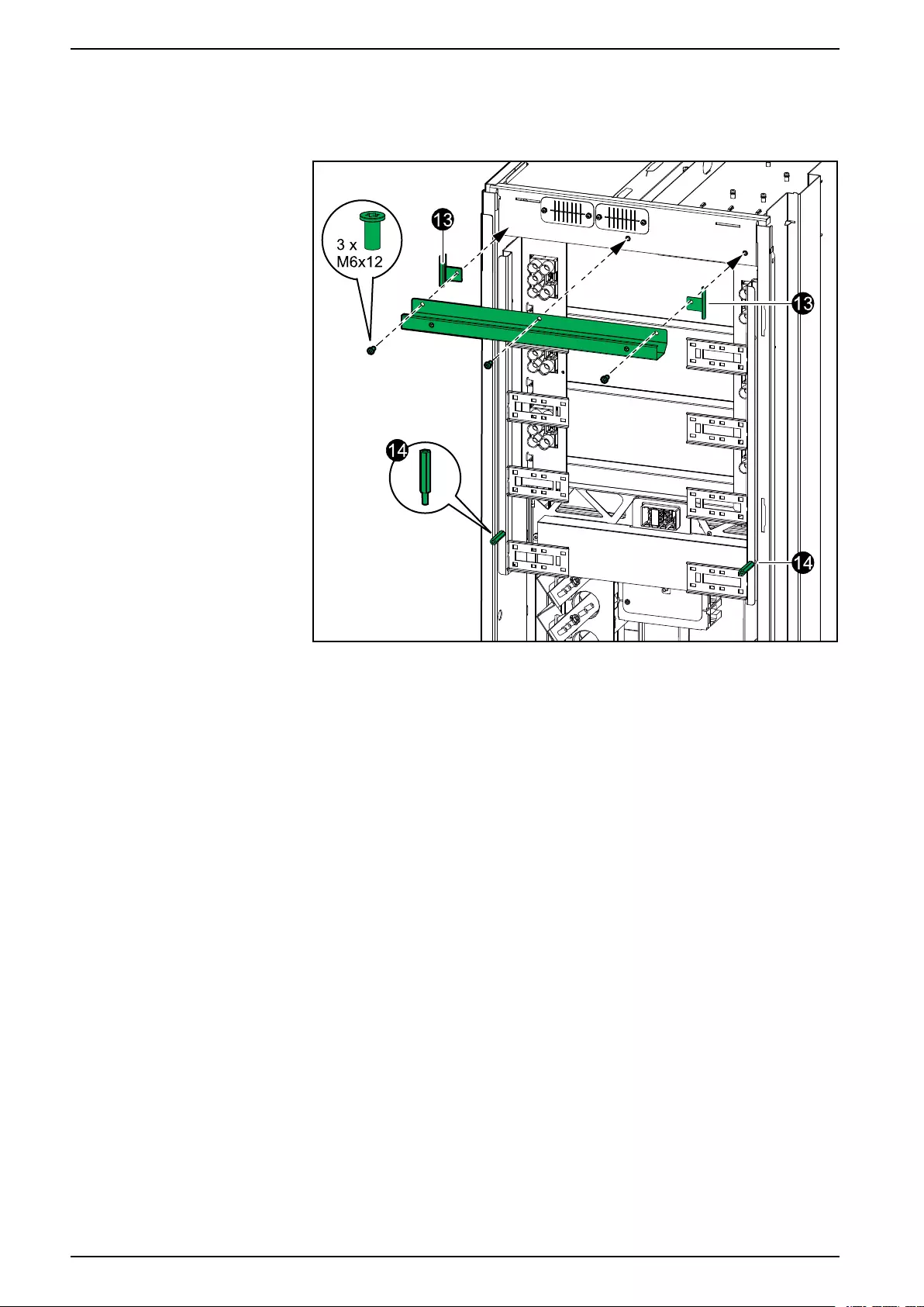
8. From inside the UPS, install the two shown parts with the six provided M6
screws.
14 990-6363-001
Install the IP52 Kit on the UPS IP52 Kit for UPS
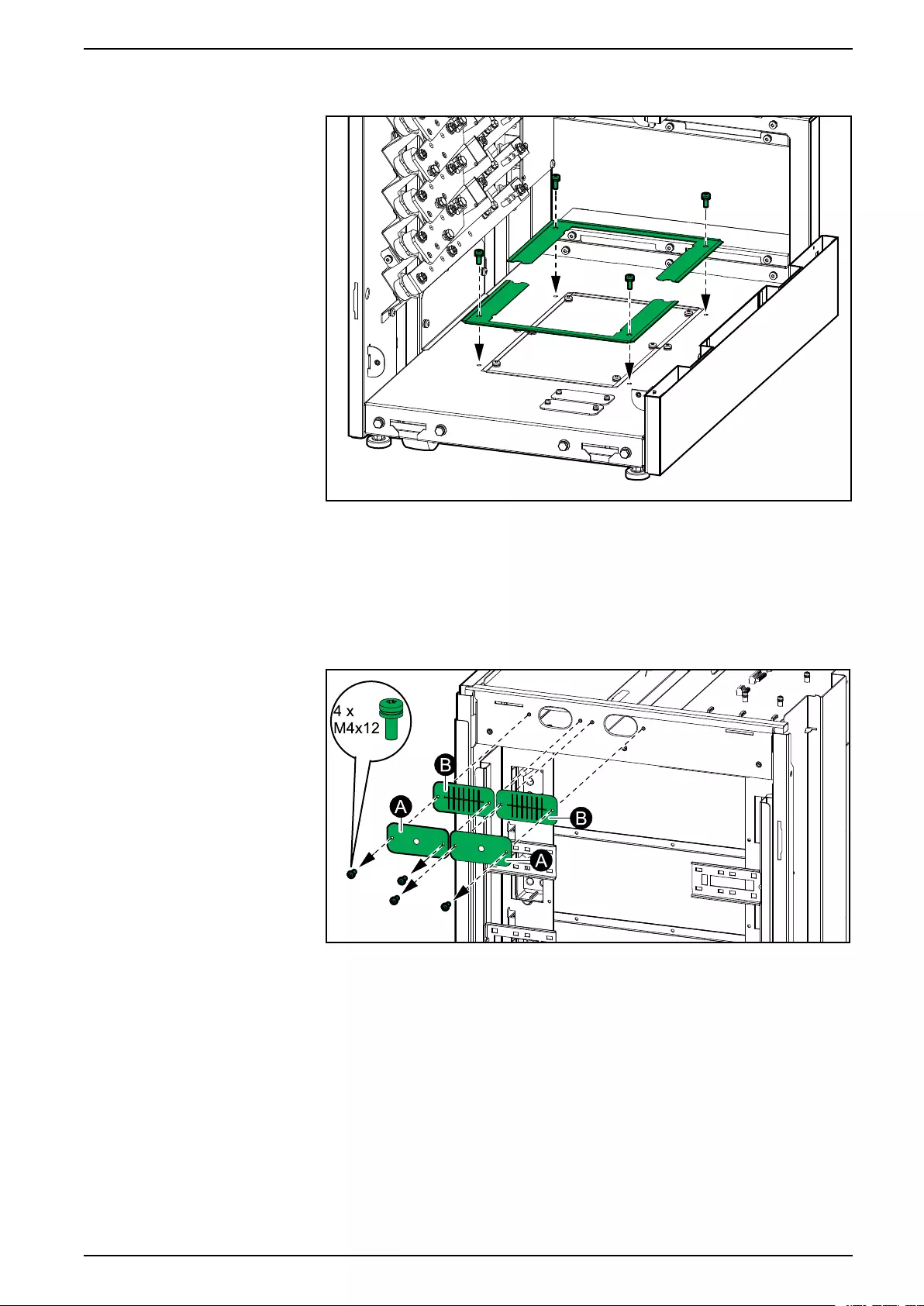
9. From inside the UPS, install the two shown parts on the bottom gland plate
with the existing screws.
10. Disconnect the signal cables from the top of the UPS and pull the signal
cables out through the rear gland plates on the UPS. Note the signal cable
connections.
11. Remove the gland plates (A) and the brush plates (B) from the rear of the
UPS.
Rear View
12. Reinstall the two brush plates reusing the four screws. Save the gland plates
for later installation.
990-6363-001 15
Install the IP52 Kit on the UPS IP52 Kit for UPS
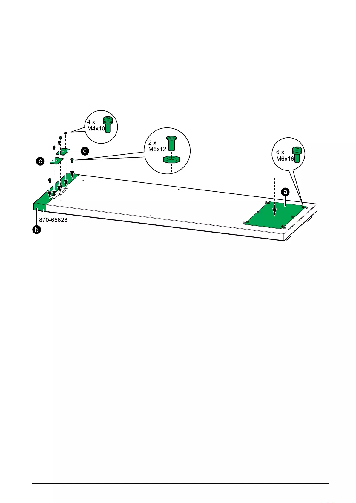
15. Assemble the rear assembly:
a. Install the rear gland plate from step 6 on the shown part reusing the M6
screws.
b. Install the shown part with the two provided M6 flat head screws and
nylon washers.
c. Install the gland plates from step 11 as shown with the four provided M4
screws.
Rear Assembly
990-6363-001 17
IP52 Kit for UPS Install the IP52 Kit on the UPS
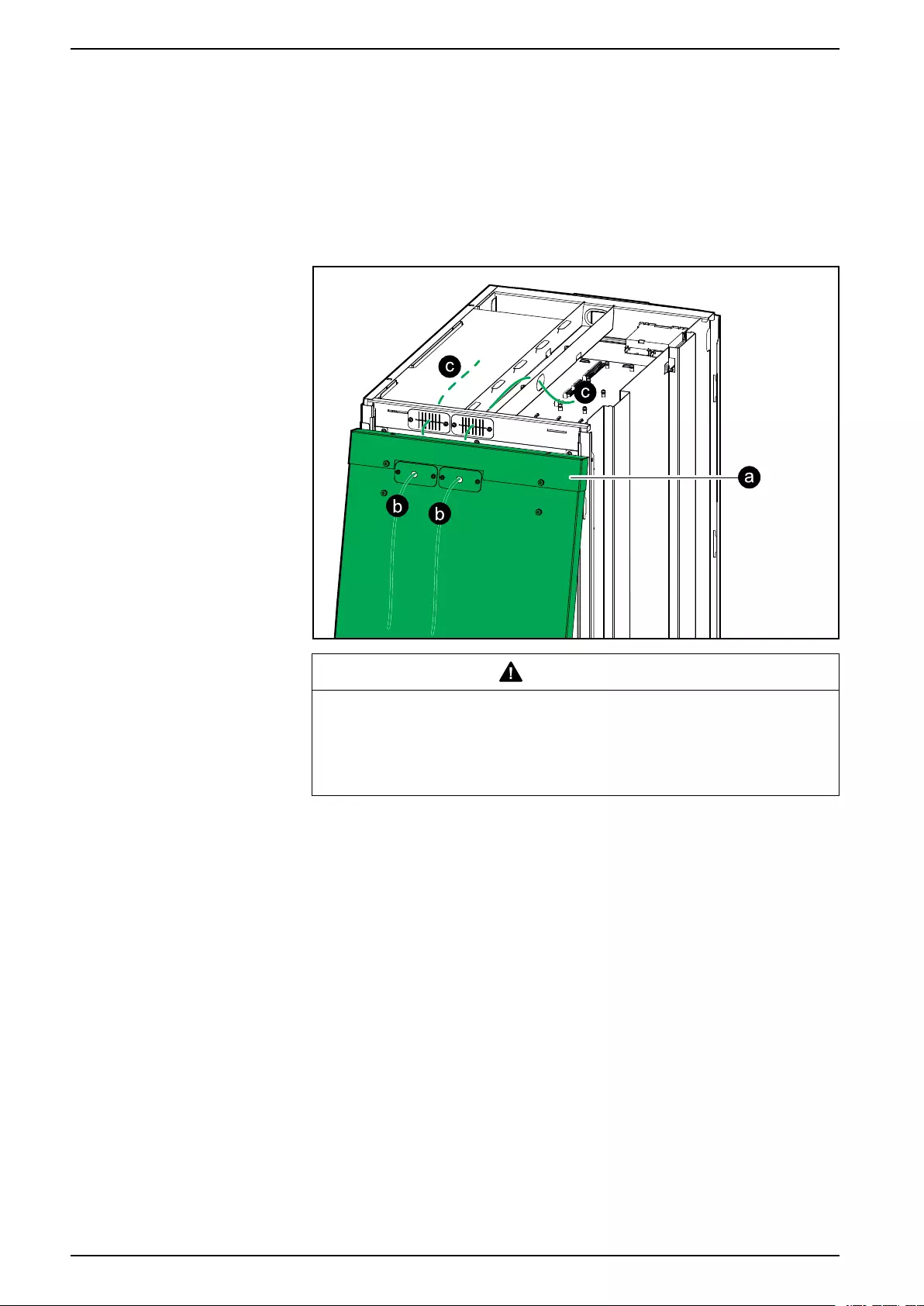
16. Reconnect all the signal cables in the UPS:
a. Place the rear assembly up against the UPS.
b. Route the signal cables through the signal gland plates. See routing
instructions in the UPS installation manual.
c. Reconnect the signal cables in the UPS. See connection instructions in
the UPS installation manual.
Rear View
CAUTION
EQUIPMENT DAMAGE
Ensure that the signal cables are not damaged during this procedure.
Failure to follow these instructions can result in injury or equipment
damage.
18 990-6363-001
Install the IP52 Kit on the UPS IP52 Kit for UPS
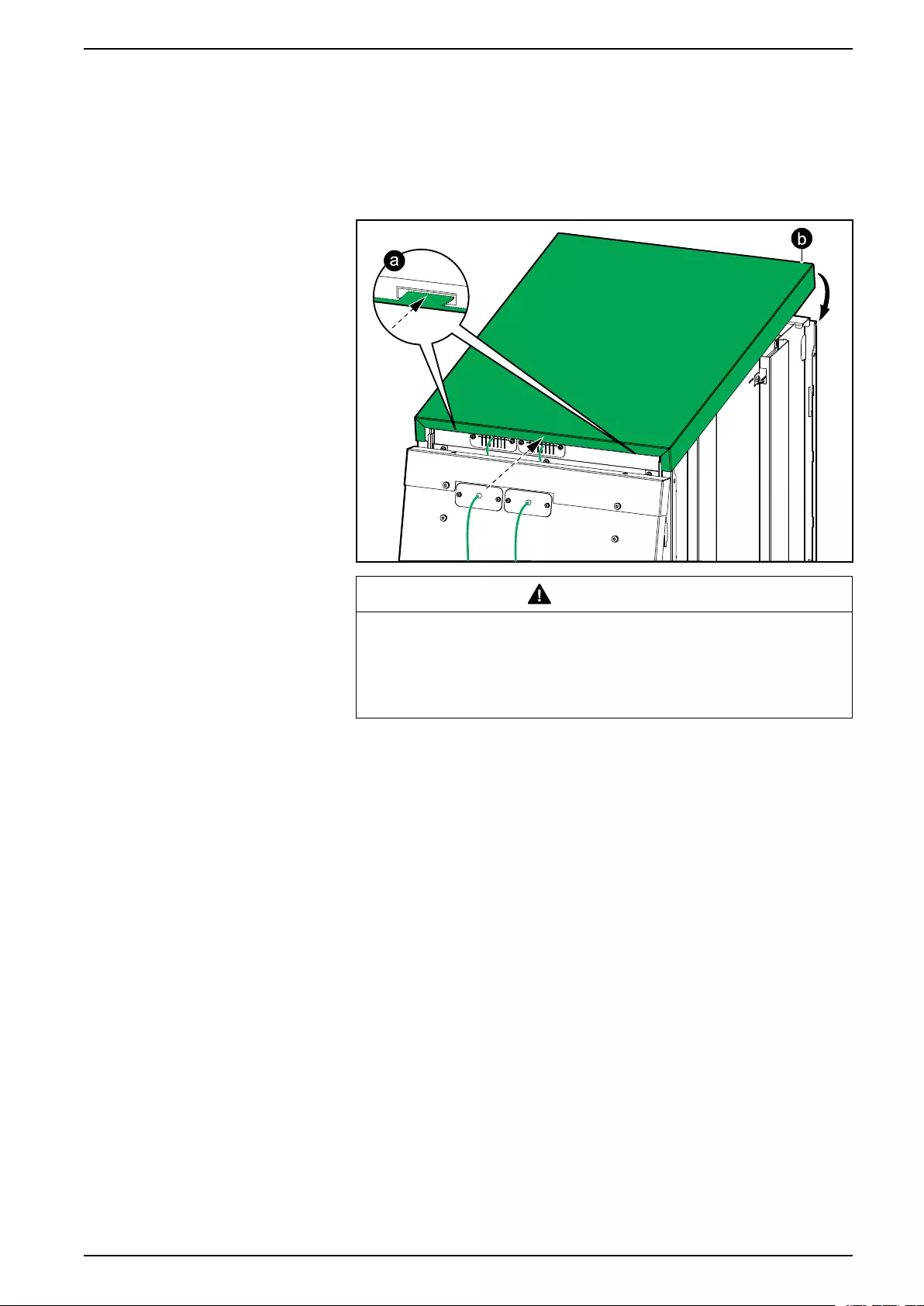
17. Reinstall the top cover:
a. Tilt the top cover and slide it onto the UPS from the rear. Tabs in the rear
of the top cover must connect to the slots in the rear of the UPS.
b. Push the top cover down in the front.
Rear View
CAUTION
EQUIPMENT DAMAGE
Ensure that the signal cables are not damaged during this procedure.
Failure to follow these instructions can result in injury or
equipment damage.
990-6363-001 19
IP52 Kit for UPS Install the IP52 Kit on the UPS
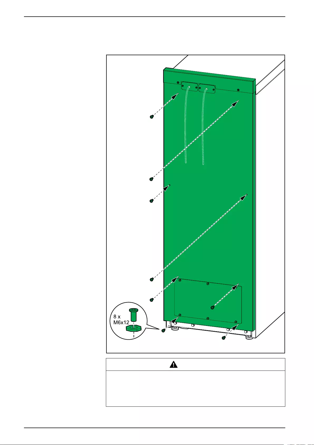
18. Install the rear assembly with the eight provided M6 flat head screws and
nylon washers.
Rear View
CAUTION
EQUIPMENT DAMAGE
Ensure that the signal cables are not damaged during this procedure.
Failure to follow these instructions can result in injury or equipment
damage.
20 990-6363-001
Install the IP52 Kit on the UPS IP52 Kit for UPS
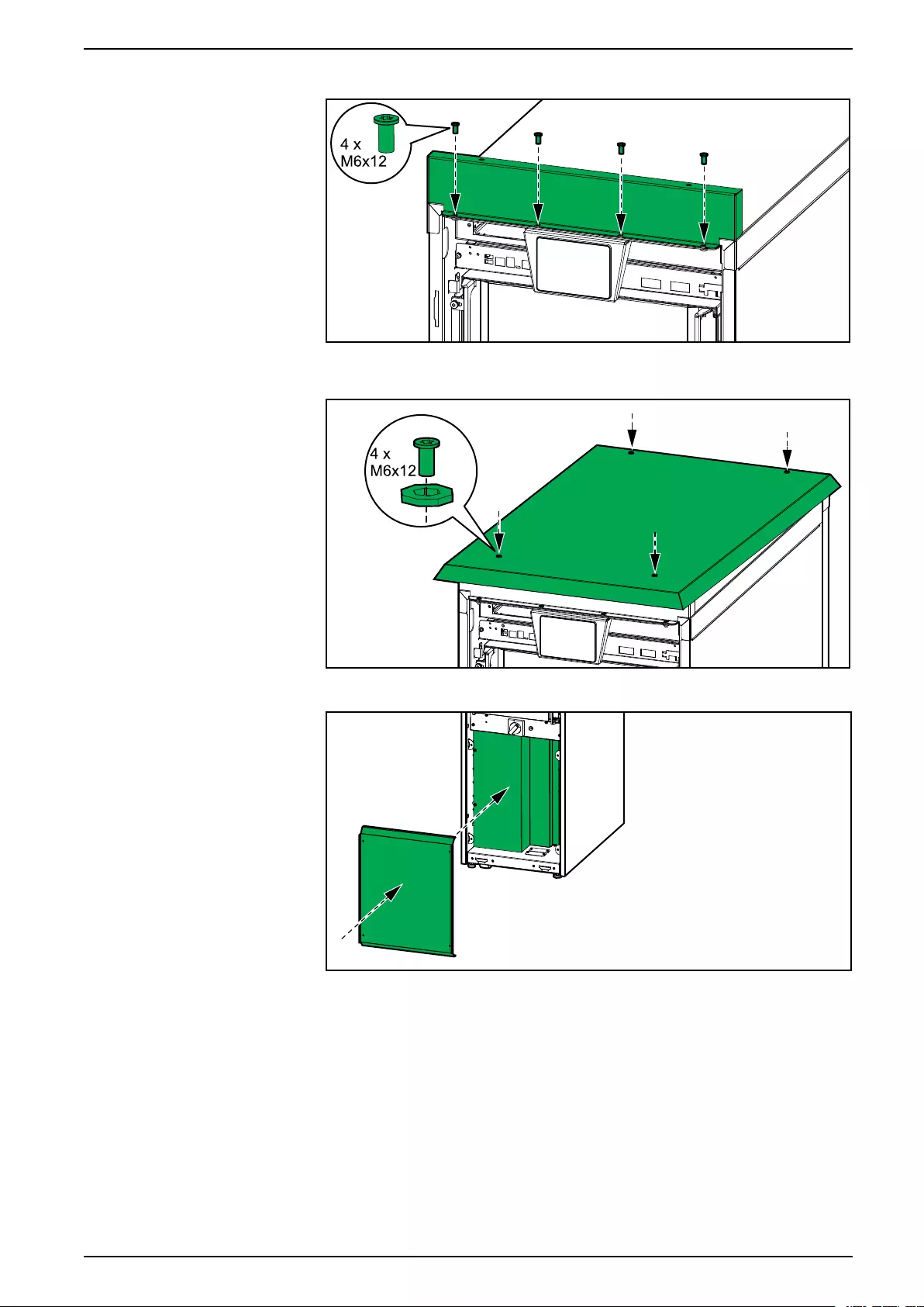
19. Install the shown part reusing the M6 flat head screws from the top cover.
20. Install the shown part with the four provided M6 flat head screws and nylon
washers.
21. Reinstall the transparent cover and the lower front plate.
22. Remove the air filter from the front panel. Discard the air filter.
990-6363-001 21
IP52 Kit for UPS Install the IP52 Kit on the UPS
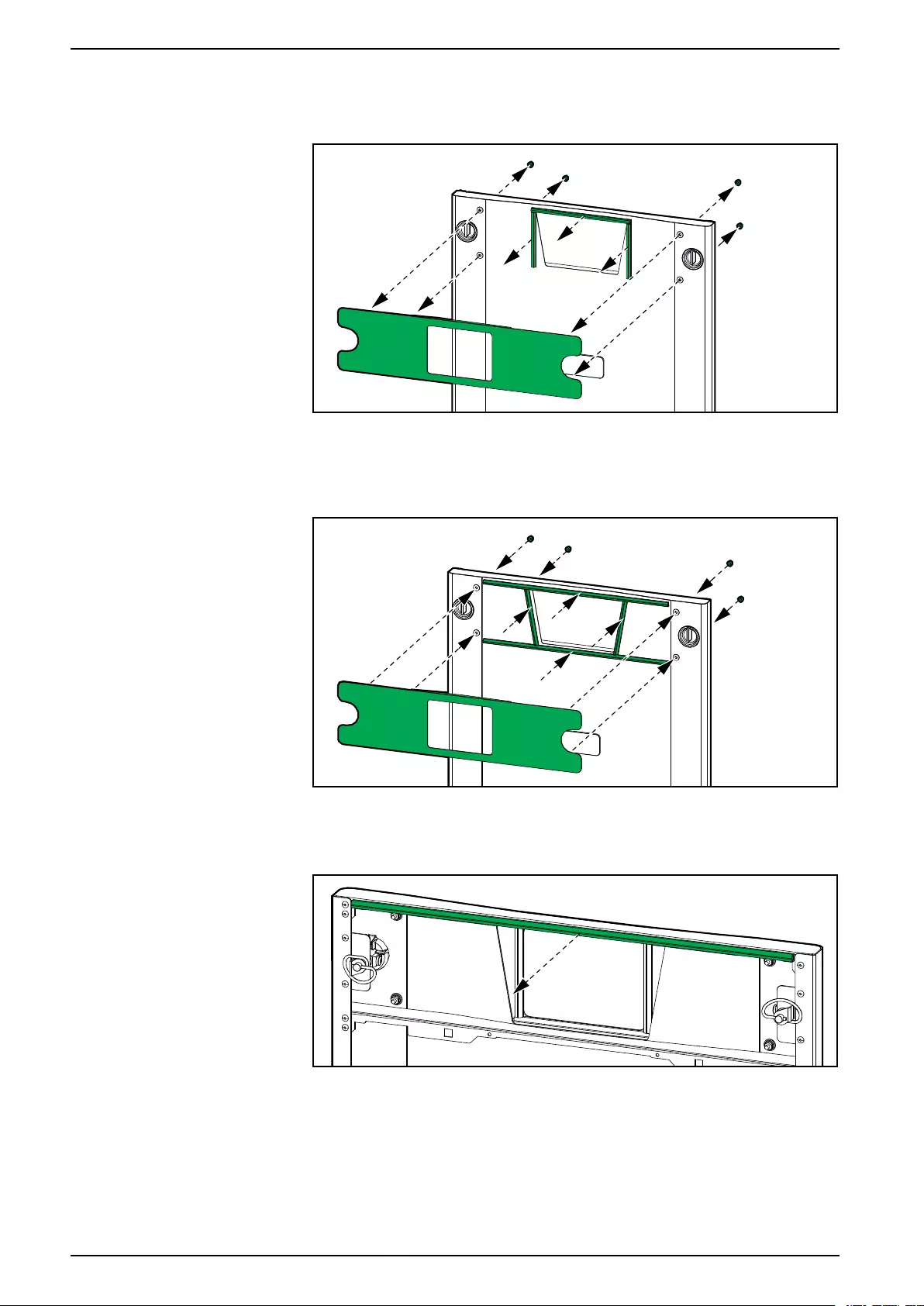
23. Remove the display plate and the three gaskets from the front panel.
Outside View of the Front Panel
24. Mount the provided profile gaskets as shown and reinstall the display plate on
the front cover.
Outside View of the Front Panel
25. Remove the top gasket from the front panel.
Inside View of the Front Panel
22 990-6363-001
Install the IP52 Kit on the UPS IP52 Kit for UPS
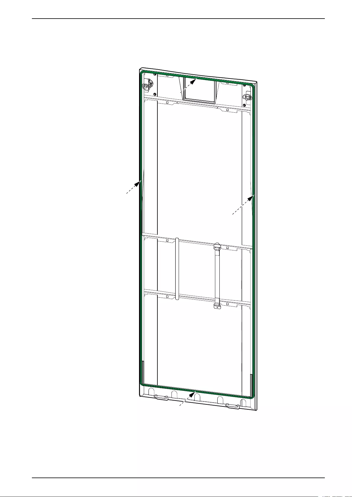
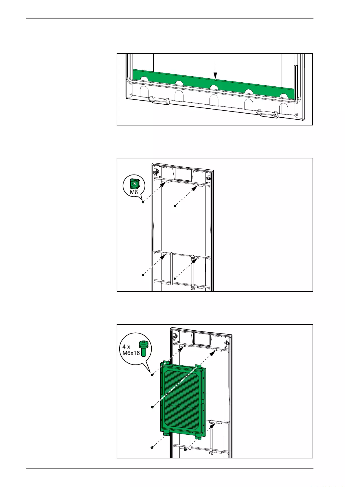
26. Mount the provided profile gasket as shown on the front panel as close to the
edges of the front panel frame as possible. Start from the bottom centre and
mount the profile gasket in one piece for optimal sealing.
Inside View of the Front Panel
990-6363-001 23
IP52 Kit for UPS Install the IP52 Kit on the UPS
27. Install the transparent plastic part in the bottom of the front panel.
Inside View of the Front Panel
28. Install the four provided cage nuts.
Inside View of the Front Panel
29. Install the shown part with the four provided M6 screws.
Inside View of the Front Panel
24 990-6363-001
Install the IP52 Kit on the UPS IP52 Kit for UPS
30. Attach the supplied label 885-92048 from the kit on the UPS lower front plate
to alert to the risk of overheating.
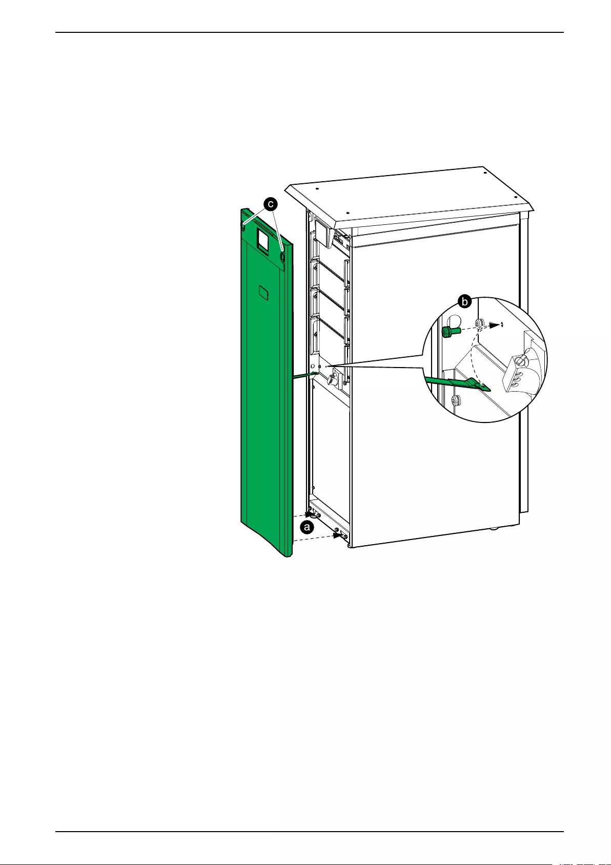
31. Reinstall the front panel on the UPS:
a. Insert the two tabs in the bottom of the front panel in the UPS at a tilted
angle.
b. Reconnect the front panel strap to the UPS.
c. Close the front panel and lock with the two locking knobs.
990-6363-001 25


Schneider Electric
35 rue Joseph Monier
92500 Rueil Malmaison
France
+ 33 (0) 1 41 29 70 00
*990-6363-001*
As standards, specifications, and design change from time to time,
please ask for confirmation of the information given in this publication.
© 2020 – 2020 Schneider Electric. All rights reserved.
990-6363-001