Table of Contents
- Safety
- General Information
- Inventory
- Component Identification
- Dimensions and Weights
- Installation
APC InRow User Manual
Displayed below is the user manual for InRow by APC which is a product in the UPS Accessories category. This manual has pages.
Related Manuals
InRow®Direct Expansion Air Conditioners
ACRD300 and ACCU30000 Series
Installation Manual
990–91193A–001
Release date: 11/2018
www.schneider-electric.com

Legal Information
The Schneider Electric brand and any registered trademarks of Schneider Electric
Industries SAS referred to in this guide are the sole property of Schneider Electric SA
and its subsidiaries. They may not be used for any purpose without the owner's
permission, given in writing. This guide and its content are protected, within the
meaning of the French intellectual property code (Code de la propriété intellectuelle
français, referred to hereafter as "the Code"), under the laws of copyright covering
texts, drawings and models, as well as by trademark law. You agree not to reproduce,
other than for your own personal, noncommercial use as defined in the Code, all or
part of this guide on any medium whatsoever without Schneider Electric's permission,
given in writing. You also agree not to establish any hypertext links to this guide or its
content. Schneider Electric does not grant any right or license for the personal and
noncommercial use of the guide or its content, except for a non-exclusive license to
consult it on an "as is" basis, at your own risk. All other rights are reserved.
Electrical equipment should be installed, operated, serviced, and maintained only by
qualified personnel. No responsibility is assumed by Schneider Electric for any
consequences arising out of the use of this material.
As standards, specifications, and designs change from time to time, please ask for
confirmation of the information given in this publication.

ACRD300 and ACCU30000 Series
Table of Contents
Safety...........................................................................................................5
Important Safety Instructions — SAVE THESE INSTRUCTIONS...................5
Safety During Installation ...........................................................................6
General Information...................................................................................7
Document Overview ..................................................................................7
Original Instructions .............................................................................7
Save These Instructions .......................................................................7
Manual Updates ..................................................................................7
Cross-Reference Symbol Used in This Manual.......................................7
Abbreviations ......................................................................................7
Receiving and Inspecting the Equipment .....................................................8
Filing a Claim.......................................................................................8
Radio Frequency Interference ....................................................................8
California Proposition 65—Warning Statement for California
Residents..................................................................................................8
Storing the Cooling Unit Before Installation ..................................................8
Moving the Unit .........................................................................................9
Unit Overview.......................................................................................... 11
Model Identification ............................................................................ 11
Equipment Guidelines ........................................................................13
Unit Compatibility...............................................................................14
Inventory....................................................................................................15
Package Contents—Indoor Unit................................................................15
Package Contents—Outdoor Unit .............................................................16
Component Identification........................................................................18
External Components ..............................................................................18
Indoor Unit—All ACRD30X Units.........................................................18
Outdoor Unit—All ACCU30XXX Units..................................................19
Internal Components ...............................................................................20
Indoor Unit ........................................................................................20
Outdoor Unit......................................................................................21
Electrical Panels......................................................................................23
Indoor Unit ........................................................................................23
Outdoor Unit......................................................................................24
Refrigeration Piping Diagram....................................................................30
Display Interface......................................................................................31
Alarm LED.........................................................................................31
Status LED........................................................................................32
Link-RX/TX (10/100) LED ...................................................................32
Dimensions and Weights ........................................................................33
Indoor Unit ..............................................................................................33
Outdoor Unit............................................................................................34
Service Access........................................................................................35
Airflow Clearance ....................................................................................36
Piping and Electrical Access Locations......................................................37
Indoor Unit ........................................................................................37
Outdoor Unit......................................................................................41
990–91193A–001 3

ACRD300 and ACCU30000 Series
Installation.................................................................................................42
Location and Power Considerations ..........................................................42
Room Preparation..............................................................................42
Incoming Power Supply Requirements ................................................42
Indoor Unit Location ...........................................................................43
Outdoor Unit Location ........................................................................43
Removing Doors and Panels ....................................................................44
Indoor Unit ........................................................................................44
Outdoor Unit......................................................................................46
Stabilizing the Cooling Unit.......................................................................48
Joining the Equipment to Enclosures ................................................... 48
Leveling ............................................................................................49
Stabilizing the Outdoor Unit ......................................................................50
Mounting Hole Dimensions .................................................................50
Vibration Damping Pads.....................................................................51
Connections Overview .............................................................................52
Power Connections............................................................................52
Sensor and Communication Connections ............................................53
Mechanical Connections ..........................................................................54
Installing the Main Switch ...................................................................54
Condensate Drain Pan Additions.........................................................56
Condensate Drain Connections...........................................................57
Refrigerant Piping ..............................................................................60
Suction and Liquid Line Piping Connections.........................................62
Electrical Connections .............................................................................70
Power Connections............................................................................71
Communication Connections....................................................................88
Interface Connection ..........................................................................88
A-Link Connections............................................................................89
Modbus Switch Configuration .............................................................90
Output Relays and Standby Input ........................................................ 91
Leak Detector—Optional ....................................................................92
Rack Air Temperature Sensors............................................................93
Network Connection...........................................................................94
Outdoor Unit Connection ....................................................................95
Charging the Refrigeration System ...........................................................96
Calculating R410A Refrigerant Charge ................................................96
Refrigerant Charging Process .............................................................96
Compressor Oil Charge............................................................................97
Oil Charging Procedure ......................................................................97
4 990–91193A–001
Safety ACRD300 and ACCU30000 Series
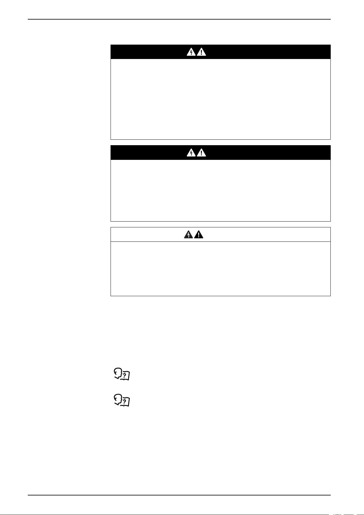
Safety
Important Safety Instructions — SAVE THESE INSTRUCTIONS
Read these instructions carefully and look at the equipment to become familiar
with it before trying to install, operate, service or maintain it. The following safety
messages may appear throughout this manual or on the equipment to warn of
potential hazards or to call attention to information that clarifies or simplifies a
procedure.
The addition of this symbol to a “Danger” or “Warning” safety
message indicates that an electrical hazard exists which will
result in personal injury if the instructions are not followed.
This is the safety alert symbol. It is used to alert you to potential
personal injury hazards. Obey all safety messages with this
symbol to avoid possible injury or death.
DANGER
DANGER indicates a hazardous situation which, if not avoided, will result in
death or serious injury.
Failure to follow these instructions will result in death or serious injury.
WARNING
WARNING indicates a hazardous situation which, if not avoided, could result
in death or serious injury.
Failure to follow these instructions can result in death, serious injury, or
equipment damage.
CAUTION
CAUTION indicates a hazardous situation which, if not avoided, could result in
minor or moderate injury.
Failure to follow these instructions can result in injury or equipment
damage.
NOTICE
NOTICE is used to address practices not related to physical injury. The safety
alert symbol shall not be used with this type of safety message.
Failure to follow these instructions can result in equipment damage.
Please Note
Electrical equipment should only be installed, operated, serviced, and maintained
by qualified personnel. No responsibility is assumed by Schneider Electric for any
consequences arising out of the use of this material.
A qualified person is one who has skills and knowledge related to the construction,
installation, and operation of electrical equipment and has received safety training
to recognize and avoid the hazards involved.
990–91193A–001 5

ACRD300 and ACCU30000 Series Safety
Safety During Installation
DANGER
HAZARD OF ELECTRIC SHOCK, EXPLOSION, OR ARC FLASH
• Apply appropriate personal protective equipment (PPE) and follow safe
electrical work practices.
• This equipment must be installed and serviced by qualified personnel only.
• Turn off all power supplying this equipment before working on or inside the
equipment.
• Replace all devices, doors, and covers before turning on power to this
equipment.
Failure to follow these instructions will result in death or serious injury.
WARNING
HAZARD TO EQUIPMENT OR PERSONNEL
This equipment is not to be operated or installed by persons with reduced
physical, sensory, or mental capabilities, or persons lacking experience or
knowledge. Children are not to operate or play on or around this equipment.
Failure to follow these instructions can result in death, serious injury, or
equipment damage.
WARNING
HAZARD OF EQUIPMENT FALLING OVER
• Use two or more persons at all times to move or turn this equipment.
• Always push, pull, or turn while facing the front and rear of this equipment.
Never push, pull, or turn while facing the sides of this equipment.
• Slowly move this equipment across uneven surfaces or door thresholds.
• Lower leveling feet to floor when this equipment is at rest.
• Lower leveling feet and attach joining brackets to adjacent racks when this
equipment is in final position.
Failure to follow these instructions can result in death, serious injury, or
equipment damage.
WARNING
HAZARD FROM MOVING PARTS
Keep hands, clothing, and jewelry away from moving parts. Check the
equipment for foreign objects before closing the doors and starting the
equipment.
Failure to follow these instructions can result in death, serious injury, or
equipment damage.
WARNING
HAZARD TO EQUIPMENT OR PERSONNEL
All work must be performed by Schneider Electric qualified personnel.
Failure to follow these instructions can result in death, serious injury, or
equipment damage.
6 990–91193A–001

General Information ACRD300 and ACCU30000 Series
General Information
Document Overview
Original Instructions
These are the original instructions provided by the manufacturer.
Save These Instructions
This manual contains important instructions that must be followed during the
installation of this equipment.
Manual Updates
Schneider Electric™ policy is one of continuous technological innovation and the
company reserves the right to amend any data herein without prior notice. The
images shown in this manual are for descriptive purposes only and they may differ
from specific models that are selected.
NOTE: Unit images and component identification information are examples
only. The final configuration of the unit may change according to the different
options.
Check for updates to this manual on the Schneider Electric Web site, www.
schneider-electric.com/support. Select the Download Documents and Software
link under the Support tab and enter the manual part number or SKU for your
equipment in the search field. See the back cover of this manual for the part
number.
Cross-Reference Symbol Used in This Manual
See another section of this document or another document for more
information on this subject.
Abbreviations
The following are abbreviations and terms used in this manual:
• EEV: Electronic expansion valve
• VFD/VSD: Variable-frequency drive/variable-speed drive
• DX: Direct expansion
• BMS: Building management system
• ATS: Automatic transfer switch
• HACS: Hot aisle containment system
• CACS: Cold aisle containment system
• RACS: Rack aisle containment system
990–91193A–001 7
ACRD300 and ACCU30000 Series General Information
Receiving and Inspecting the Equipment
Your InRow air conditioner has been tested and inspected for quality assurance
before shipment from Schneider Electric. Carefully inspect both the exterior and
interior of the equipment immediately upon receipt to ensure that the equipment
has not been damaged during transit.
Verify that all parts ordered were received as specified and that the equipment is
the correct type, size, and voltage.
Filing a Claim
If damage is identified on receipt of the equipment, note the damage on the bill of
lading and file a damage claim with the shipping company. Contact Schneider
Electric Worldwide Customer Support at one of the numbers listed on the Web
page on the back page of this manual for information on how to file a claim with
the shipping company. The shipping claim must be filed at the receiving end of the
delivery.
NOTE: In case of shipping damage, do not operate the equipment. Keep all
packaging for inspection by the shipping company and contact Schneider
Electric.
Radio Frequency Interference
The SKUs ACRD301, ACRD301G, ACCU30001, ACCU30002, ACCU30101, and
ACCU30102 comply with part 15 of the FCC Rules. Operation is subject to the
following two conditions:
1. These devices may not cause harmful interference.
2. These devices must accept any interference received, including interference
that may cause undesired operation.
Any changes or modifications not expressly approved by the party responsible for
compliance could void the user’s authority to operate the equipment.
California Proposition 65—Warning Statement for California
Residents
WARNING: This product can expose you to chemicals including lead and lead
compounds, that are known to the State of California to cause cancer and birth
defects or other reproductive harm. For more information go to
www.P65Warnings.ca.gov.
Storing the Cooling Unit Before Installation
NOTICE
DAMAGE FROM EXPOSURE
Leaving the equipment uncovered and exposed to possible damage from the
environment will void the factory warranty.
Failure to follow these instructions can result in equipment damage.
If the cooling unit will not be installed immediately, store it in a safe place,
protected from the weather.
8 990–91193A–001
General Information ACRD300 and ACCU30000 Series
Moving the Unit
WARNING
DAMAGE TO EQUIPMENT OR PERSONNEL
• The equipment is heavy. For safety purposes, adequate personnel must be
present when moving this item.
• The load must always be solidly anchored to the bearing element of the
lifting equipment and means of transport.
• No one should be near the suspended load, nor in the working area of the
crane, forklift, truck, or any other lifting equipment or means of transport.
Failure to follow these instructions can result in death, serious injury, or
equipment damage.
Lifting and transporting the units must be carried out by qualified personnel as
described in this manual.
Use all relevant safety standards to prevent any possible damage to people or
objects.
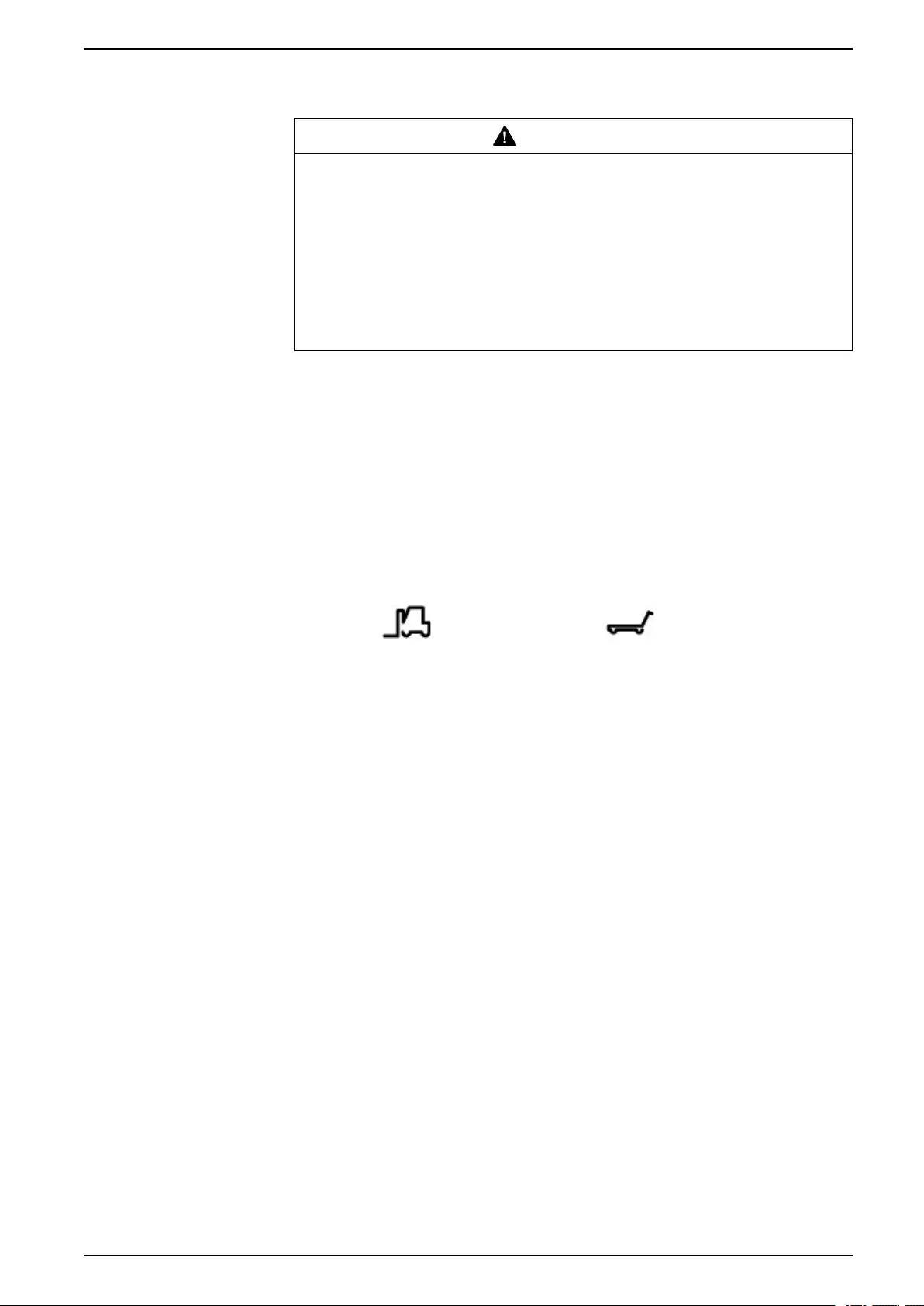
Indoor Unit
The cooling unit is packaged in a wooden crate or anchored to a pallet and
covered with transparent film. The recommended tools for moving and installing
the equipment include the following:
Forklift Pallet Jack
990–91193A–001 9
ACRD300 and ACCU30000 Series General Information
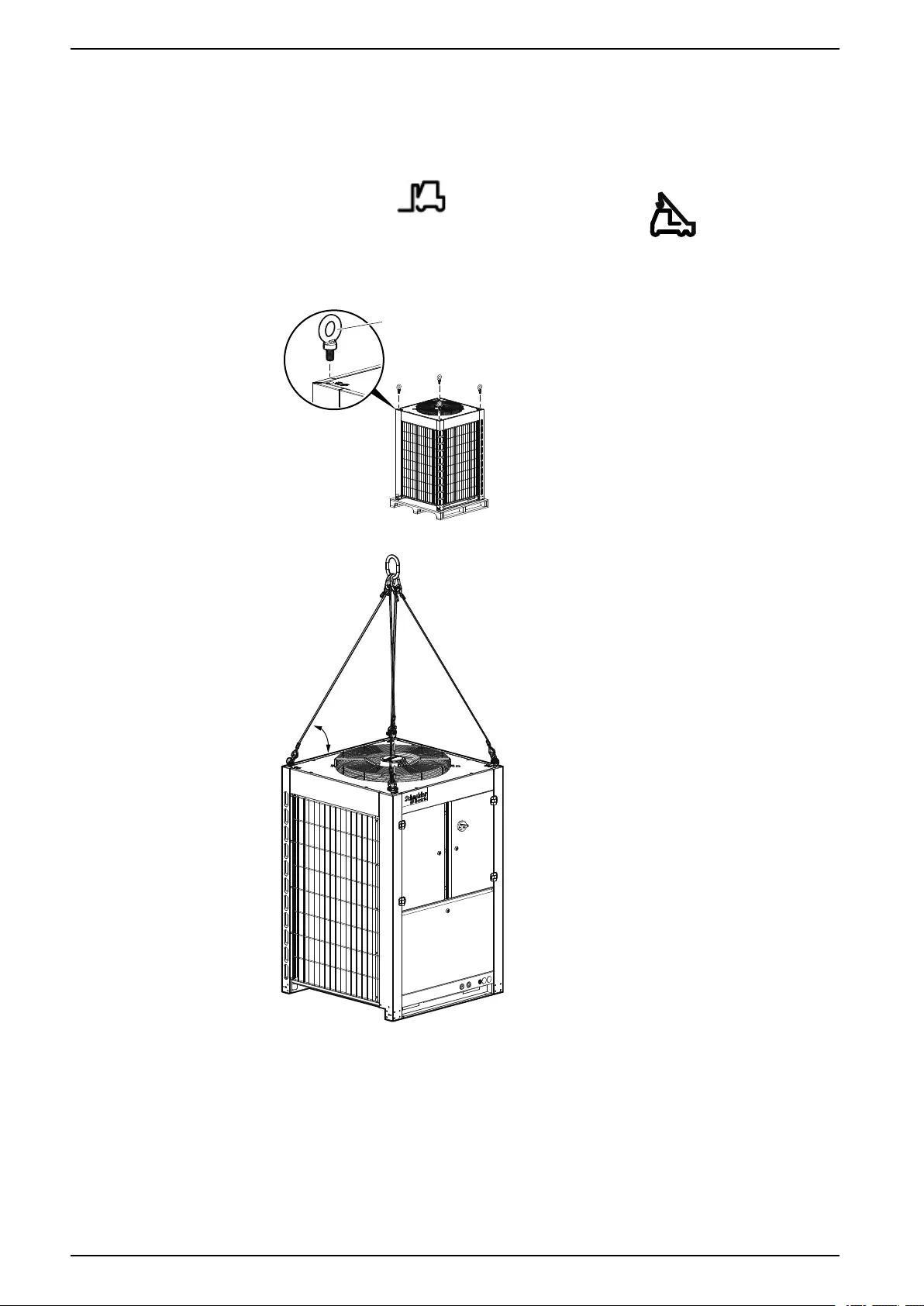
Outdoor Unit
The condensing unit is packaged in a wooden crate. The recommended tools for
moving and installing the equipment include the following:
Forklift Crane
Use field-supplied eyebolts rated for angular lifting with a shoulder similar to the
one shown below. The minimum weight rating for a 90° lift is 726 kg (1600 lb).
M10 EYEBOLT
44.1 N•m
(32.5 ft•lb)
na7012a
The lifting angle for the lifting straps must be greater than or equal to 73°.
≥73°
na7013a
10 990–91193A–001
General Information ACRD300 and ACCU30000 Series
Unit Overview
Model Identification
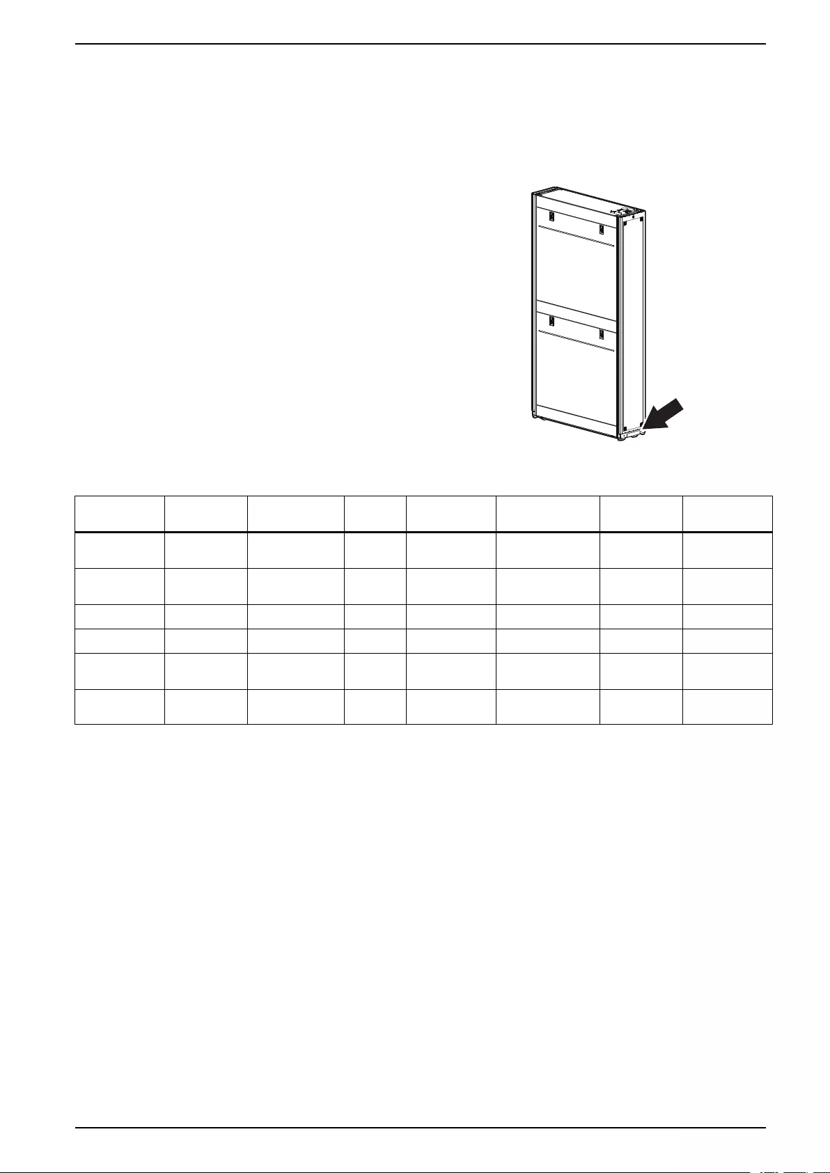
Indoor Unit
The model number can be found on
the outside of the shipping crate and
on the name plate located on the unit
as shown. Use the table below to
verify that the equipment is the right
type and voltage.
REAR
NAME PLATE
na4402b
NOTE: The unit is not to be accessed by the general public.
SKU Voltage Frequency 65 kAIC Power Feed Number of Fan
Power Supplies
Drainage
System
Airflow
Pattern
ACRD300 220 V~ 50 Hz No Dual feed 1 Condensate
pump
Rear to front
ACRD300D 220 V~ 50 Hz No Dual feed 2 Condensate
pump
Rear to front
ACRD300G 220 V~ 50 Hz No Dual feed 1 Gravity drain Rear to front
ACRD300GD 220 V~ 50 Hz No Dual feed 2 Gravity drain Rear to front
ACRD301 100–120 V~*
/ 200–240 V~
50/60 Hz Yes Dual feed 1 Condensate
pump
Rear to front
ACRD301G 100–120 V~*
/ 200–240 V~
50/60 Hz Yes Dual feed 1 Gravity drain Rear to front
*Configure proper voltage before applying power to the cooling unit.
990–91193A–001 11
ACRD300 and ACCU30000 Series General Information
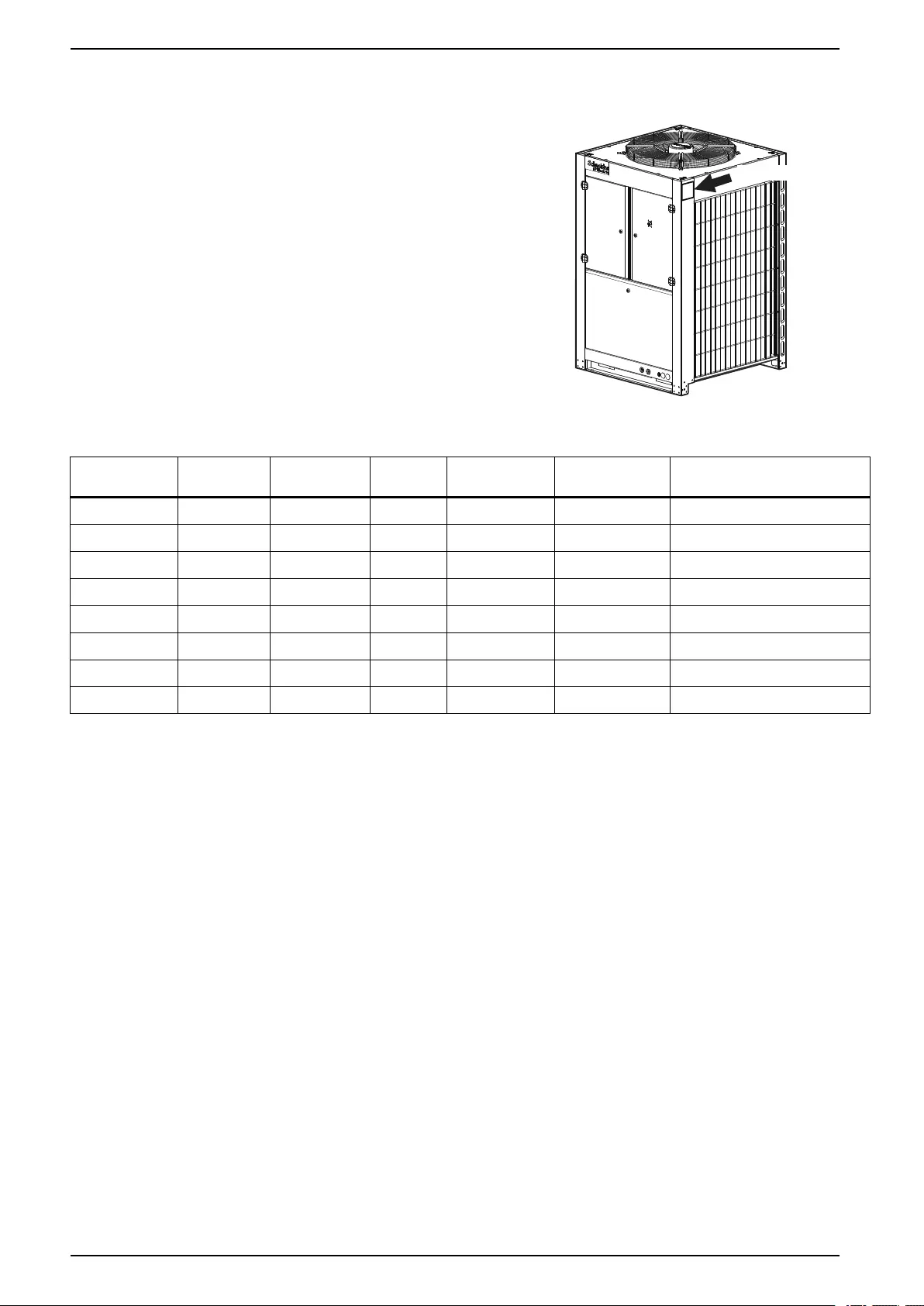
Outdoor Unit
The model number can be found on
the outside of the shipping crate and
on the name plate located on the unit
as shown. Use the table below to
verify that the equipment is the right
type and voltage.
na6990a
NAME PLATE
NOTE: The unit is not to be accessed by the general public.
SKU Voltage Frequency 65 kAIC Power Feed Accumulator Outdoor Temperature Minimum
Operation Temperature
ACCU30301 380 V 3~ 50 Hz No Single feed Yes –20°C (–4°F)
ACCU30302 380 V 3~ 50 Hz No Dual feed Yes –20°C (–4°F)
ACCU30001 200–240 V 3~ 50/60 Hz Yes Single feed Yes (UL) –20°C (–4°F)
ACCU30002 200–240 V 3~ 50/60 Hz Yes Dual feed Yes (UL) –20°C (–4°F)
ACCU30201 380–415 V 3~ 50/60 Hz Yes Single feed Yes (PED) –20°C (–4°F)
ACCU30202 380–415 V 3~ 50/60 Hz Yes Dual feed Yes (PED) –20°C (–4°F)
ACCU30101 460–480 V 3~ 50/60 Hz Yes Single feed Yes (UL) –20°C (–4°F)
ACCU30102 460–480 V 3~ 50/60 Hz Yes Dual feed Yes (UL) –20°C (–4°F)
12 990–91193A–001
General Information ACRD300 and ACCU30000 Series
Equipment Guidelines
Working Conditions and Environmental Limits
InRow DX units have a minimum heat load to ensure proper operation. Failure to
operate the unit with at least the minimum load will result in one or more of the
following conditions:
• Decreased operating efficiency
• Equipment on/off cycling
• Inadequate dehumidification
• Increased wear and tear caused by frequent on/off cycles
• Decreased group control effectiveness
• Potential increase in cost of ownership
Limit Working Conditions—Indoor Unit
Refrigerant type R410A
Voltage input tolerance ±10%
Minimum recommended load 9.5 kW (32,400 BTU/hr)
Ambient temperature +15°C to +45°C (+59°F to +113°F)
Ambient %RH 5 to 80%RH
Altitude 3000 m (9843 ft)
Storage Conditions
Temperature –25°C to +65°C (–13°F to +149°F)
Humidity 5 to 95%RH
Limit Working Conditions—Outdoor Unit
Refrigerant type R410A
Compressor oil type PVE (Daphne Hermetic Oil FVC32D)
Operating Ambient temperature –20°C to +48°C (-4°F to +118°F)
Altitude 3000 m (9843 ft)
Storage Conditions
Temperature –25°C to +65°C (–13°F to +149°F)
Humidity 5 to 95%RH
NOTE: ACRD301, ACRD301G, ACCU30201, ACCU30202 are in accordance with the Electromagnetic
Compatibility Standard (EMC): EN 55032, EN55024, EN61000-3-2, EN61000-3-3, EN61000-6-3,
EN61000-6-1, EN61000-3-11, EN 61000-3-12.
ACRD301, ACRD301G, ACCU30001, ACCU30002, ACCU30101, ACCU30102 are in accordance with
FCC: ANSI C63.4.
NOTE: The SKUs comply with EN61000-3-12 provided that the short-circuit
power SSC is greater than or equal to 350 at the interface point between the
user supply and the public system. It is the responsibility of the installer or user
of the equipment to ensure, by consultation with the distribution network
operator if necessary, that the equipment is connected only to a supply with a
short-circuit power SSC greater than or equal to 350.
990–91193A–001 13

ACRD300 and ACCU30000 Series General Information
Unit Compatibility
SKU ACRD300 ACRD300D ACRD300G ACRD300GD ACRD301 ACRD301G
ACCU30301 Yes Yes Yes Yes No No
ACCU30302 Yes Yes Yes Yes No No
ACCU30001 No No No No Yes Yes
ACCU30002 No No No No Yes Yes
ACCU30201 No No No No Yes Yes
ACCU30202 No No No No Yes Yes
ACCU30101 No No No No Yes Yes
ACCU30102 No No No No Yes Yes
14 990–91193A–001
Inventory ACRD300 and ACCU30000 Series
Inventory
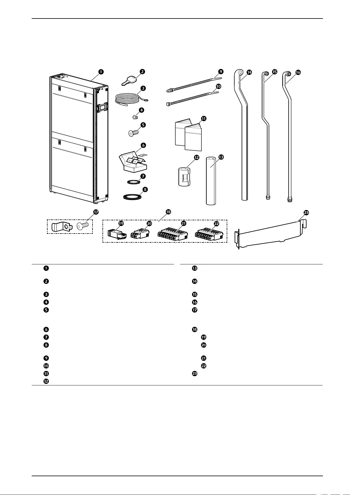
Package Contents—Indoor Unit
na6952a
Item Description Quantity Item Description Quantity
ACRD3xx 1Suction line pipe
insulation
1
Panel keys 2 Suction line pipe
insulation
1
Temperature sensor 1 Liquid line pipe* 1
Wire clip 3 Suction line pipe* 1
Philips screw—M5 x 12** 4Bracket and screw for
ACCS1009
installation****
1
Bolt-down kit*** 1Connector kit —
Gasket (inlet pipe)—1 in. 2RJ-45 terminator 1
Gasket (outlet pipe)—
1 1/4 in.
23–position connector†2
Wire tie 16 9–position connector‡1
Wire tie 3 8–position connector‡1
Documentation —Drain pan supplement 1
Clamp insulation 1
*Shipped inside the unit attached to side braces.
**Use to join the equipment to adjacent enclosures.
***Shipped with ACRD301 and ACRD301G models only.
****Do not throw away. Keep these parts for use with the ACCS1009 extension kit.
†Use for the controller connection (RS485 (1)) for the condensing unit communication cable. (See Outdoor Unit
Connection, page 95.)
‡Use for the output relay and standby input connections. (See Output Relays and Standby Input, page 91.)
990–91193A–001 15
ACRD300 and ACCU30000 Series Inventory
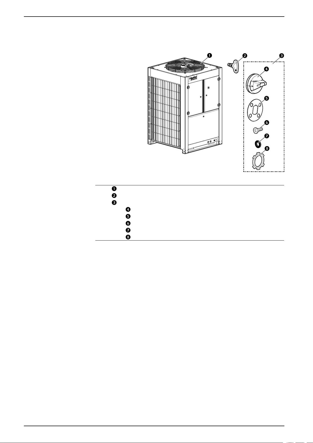
Package Contents—Outdoor Unit
ACCU30301, ACCU30302
na6979a
Item Description Quantity
ACCU30XXX unit 1
Key* 1
Main switch handle installation kit** 1
Main switch handle 1
Main switch gasket 1
Tap screws 4
Grommet 4
Nut*** 1
*Attached to the fan grille with a wire tie.
**Shipped inside the electrical panel.
***Not used. This item can be recycled.
16 990–91193A–001
Inventory ACRD300 and ACCU30000 Series
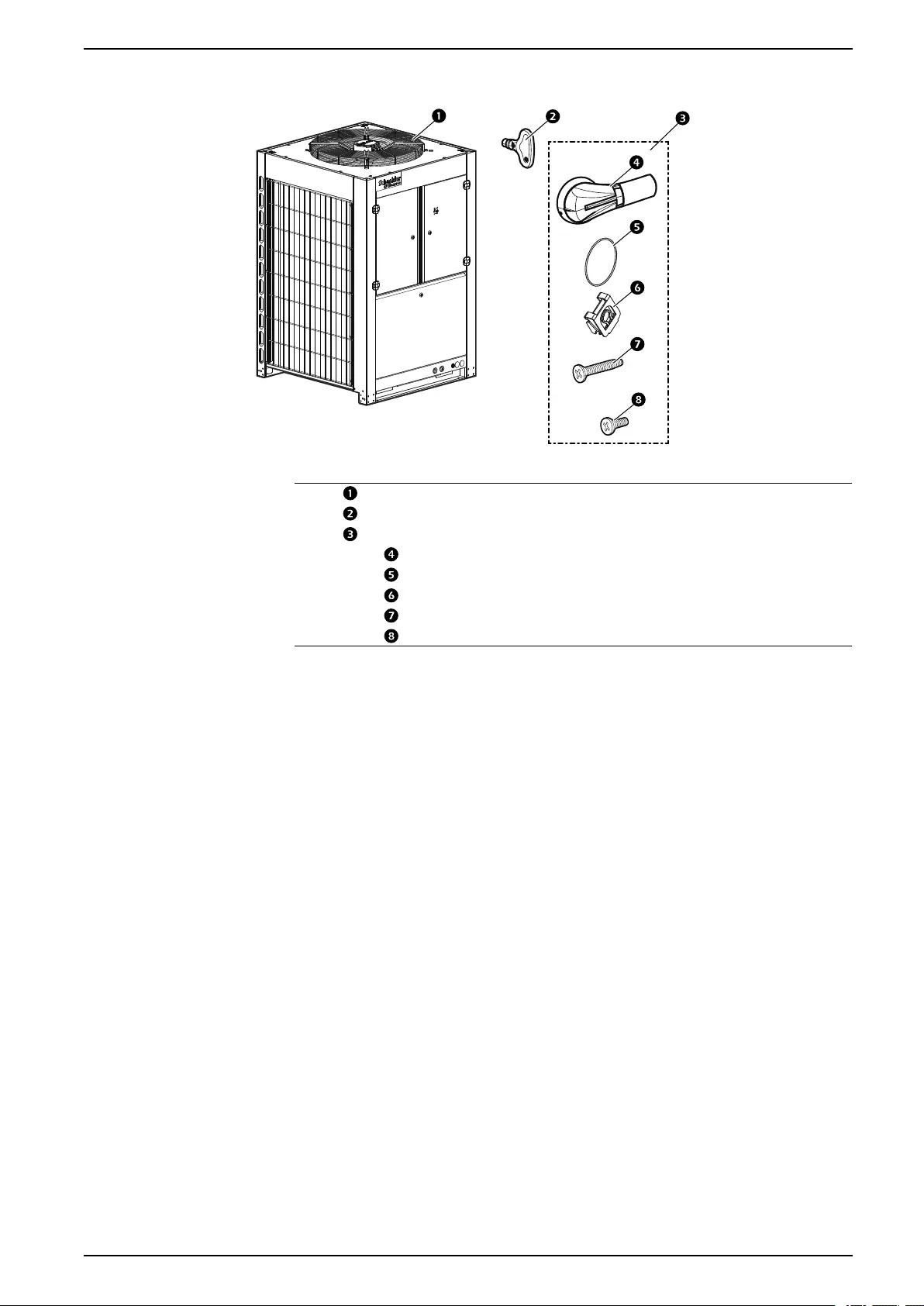
ACCU30001, ACCU30002, ACCU30201, ACCU30202, ACCU30101, ACCU30102
na6979b
Item Description Quantity
ACCU30XXX unit 1
Key* 1
Main switch handle installation kit**
Main switch handle*** 1
Main switch gasket*** 1
Nuts*** 4
Machine screws*** 4
Tap screws**** 4
*Attached to the fan grille with a wire tie.
**Shipped inside the electrical panel.
***Quantity will be doubled for models ACCU30002, ACCU30102, and
ACCU30202.
****Not used. This item can be recycled.
990–91193A–001 17
ACRD300 and ACCU30000 Series Component Identification
Component Identification
External Components
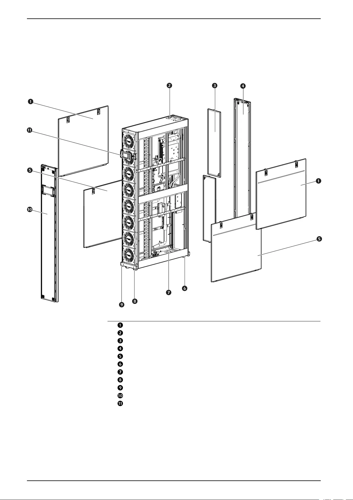
Indoor Unit—All ACRD30X Units
na6950a
Item Description
Upper side panel
Upper piping connection openings
Filters
Rear panel
Lower side panel
Rear casters (non-swiveling)
Lower piping connection openings
Front casters (swiveling)
Leveling feet
Front panel
Display interface
18 990–91193A–001
Component Identification ACRD300 and ACCU30000 Series
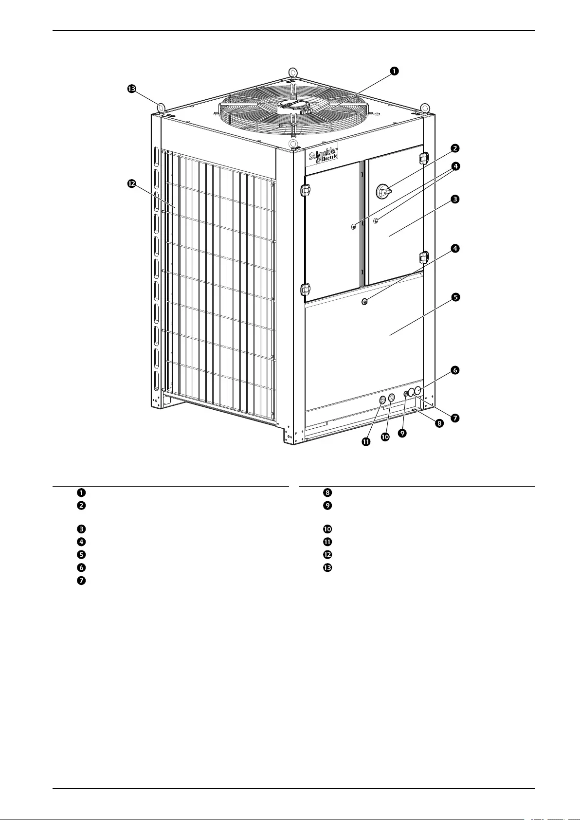
Outdoor Unit—All ACCU30XXX Units
na6953a
NOTE: Model ACCU30301 is shown.
Item Description Item Description
Fan Mounting holes
Main disconnect switch handle (field
installed)
Signal cable inlet
Electrical panel access doors Liquid line inlet
Quarter-turn latches Suction line inlet
Service panel Coil grilles
Power feed A inlet Lifting eyebolts (field supplied)
Power feed B inlet
990–91193A–001 19
ACRD300 and ACCU30000 Series Component Identification
Internal Components
Indoor Unit
na6951a
Item Description Item Description
Power supply connections Lower return air temperature sensor
Fans Service port
Upper supply air temperature sensor Automatic transfer switch (ATS)
Solenoid valve Condensate drain pump
(ACRD300, ACRD300D, and
ACRD301 only)
Service port Temperature and humidity sensor
(optional)
Cooling coil Inlet connection
Lower supply air temperature Outlet connection
Refrigerant temperature sensor Electronic expansion valve (EEV)
Leveling feet Sight glass
Condensate drain pan Filter drier
Drain pan float switch Electrical box
Temperature sensor (suction) Upper return air temperature sensor
Joining bracket
20 990–91193A–001
Component Identification ACRD300 and ACCU30000 Series
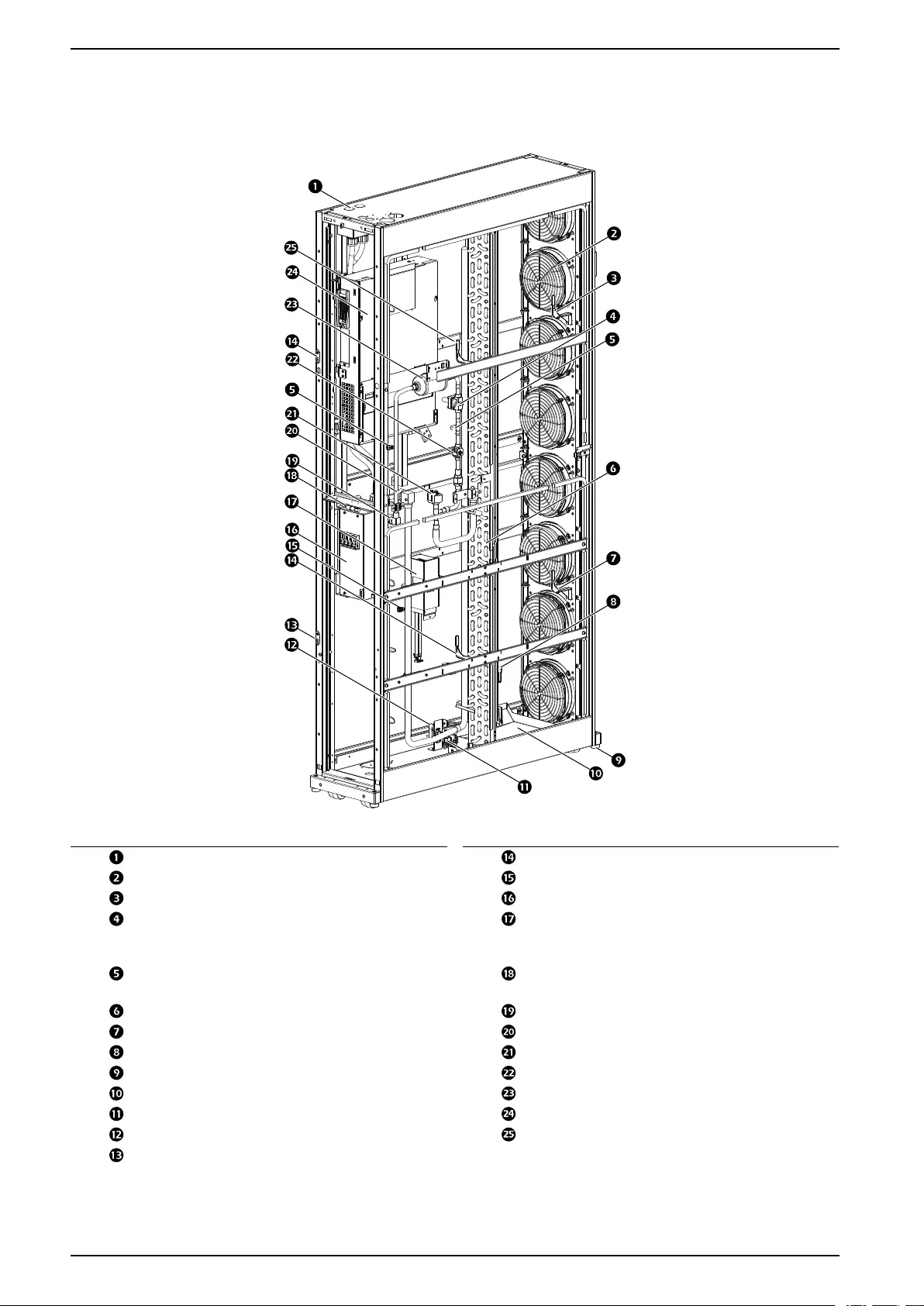
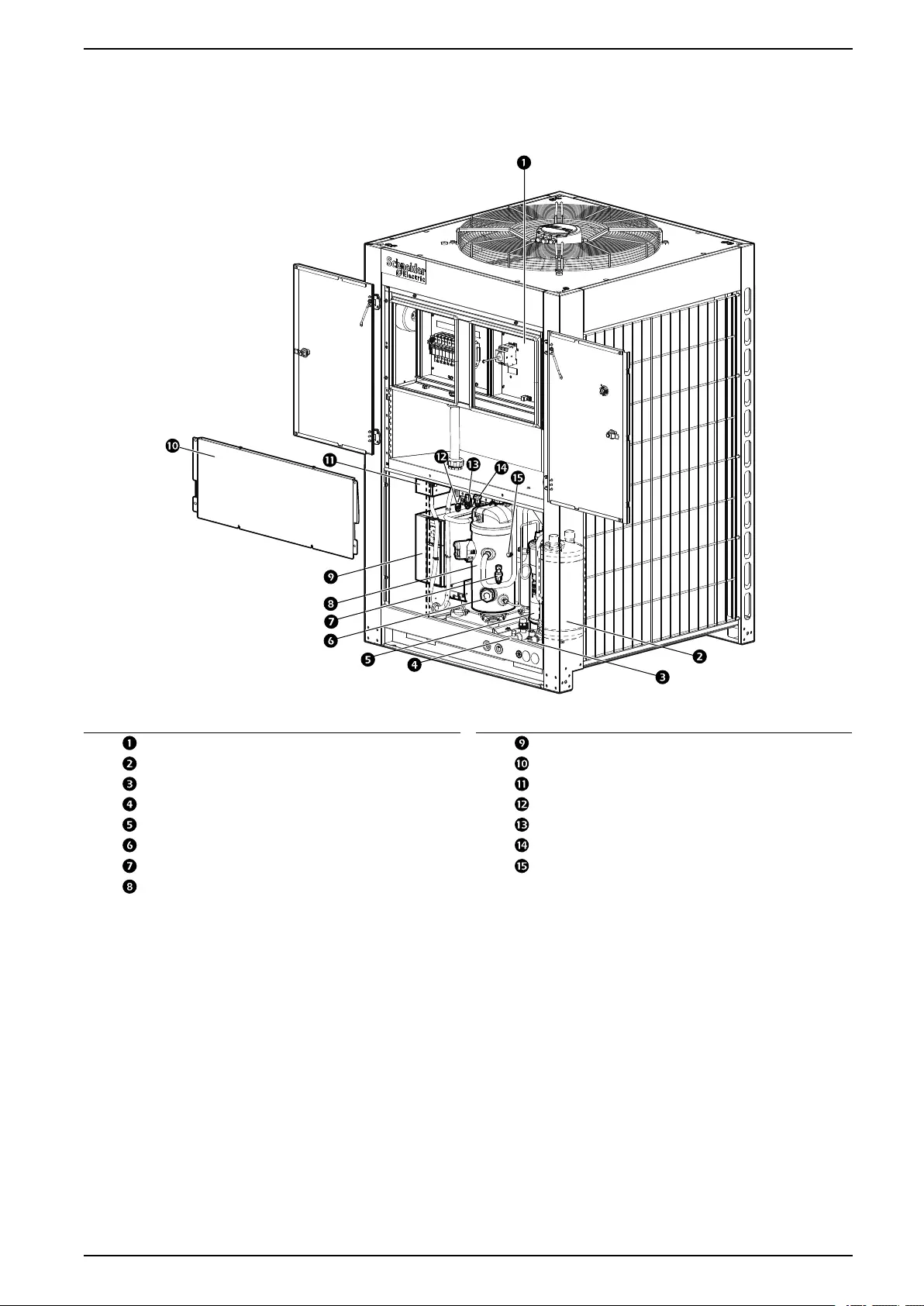
Outdoor Unit
ACCU30301, ACCU30302, ACCU30001, ACCU30002, ACCU30101,
ACCU30102
na6954a
Item Description Item Description
Electrical panel Variable frequency drive (VFD)
Accumulator Interior protection panel
Liquid line connection EMI filter
Suction line connection Service port
Oil separator High pressure switch
Compressor sight glass High (discharge) pressure sensor
Low (suction) pressure sensor Service port
Variable-speed compressor
990–91193A–001 21
ACRD300 and ACCU30000 Series Component Identification
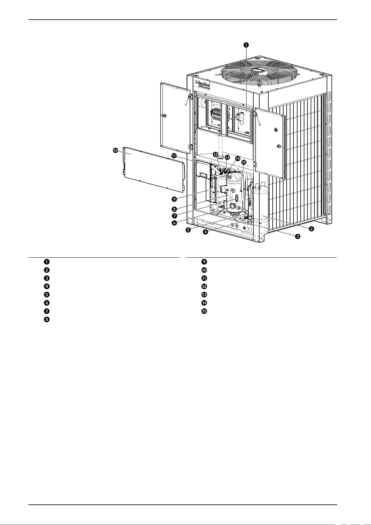
ACCU30201, ACCU30202
na6954b
Item Description Item Description
Electrical panel Variable frequency drive (VFD)
Accumulator Interior protection panel
Liquid line connection Line reactor and EMI filter
Suction line connection Service port
Oil separator High pressure switch
Compressor sight glass High (discharge) pressure sensor
Low (suction) pressure sensor Service port
Variable-speed compressor
22 990–91193A–001
ACRD300 and ACCU30000 Series Component Identification
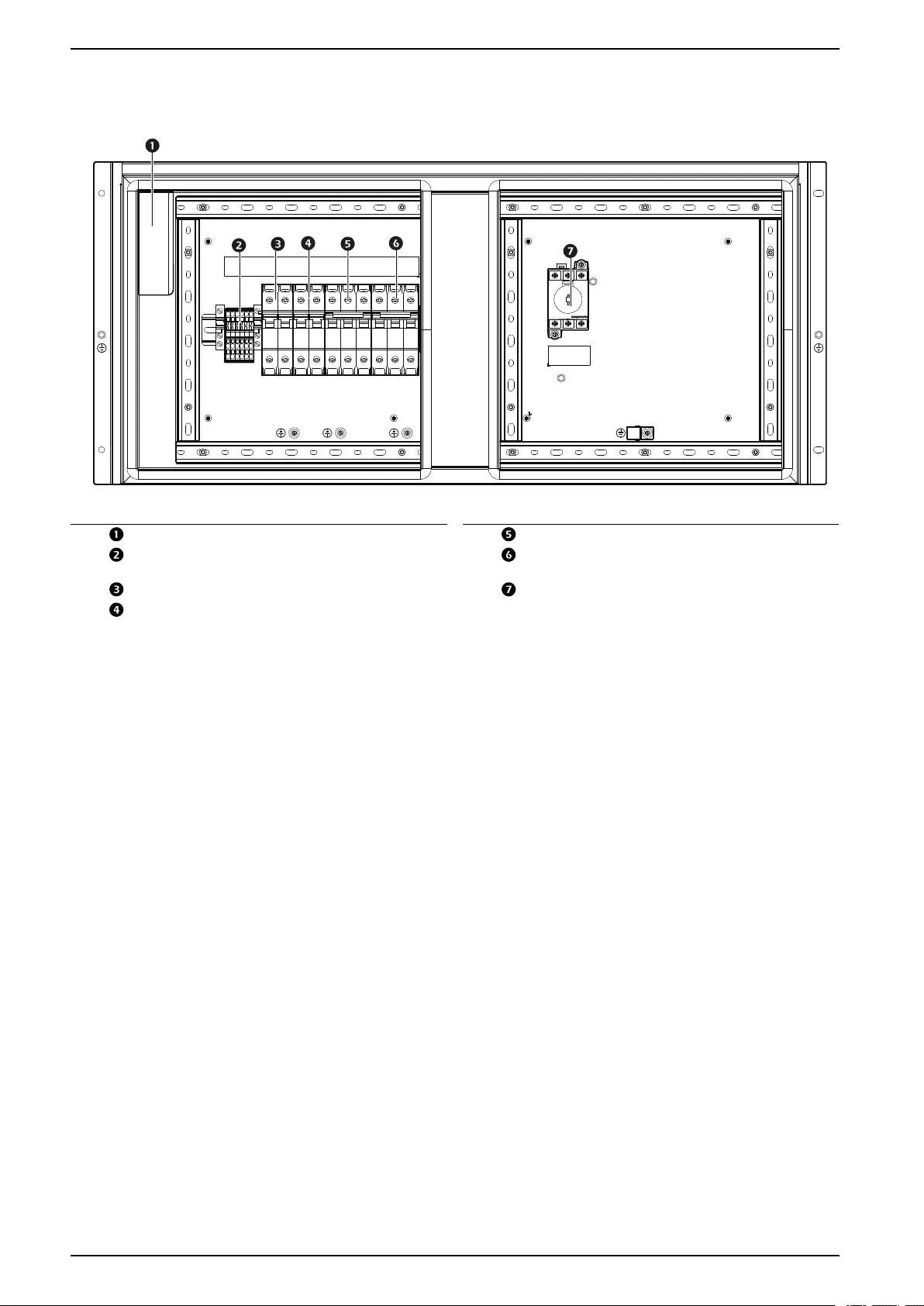
Outdoor Unit
ACCU30301
na6981a
Item Description Item Description
Crank case heater power transformer Fan motor switch
Terminal block Compressor variable-speed drive
switch
Crank case heater switch Main switch
Crank case heater power transformer
switch
24 990–91193A–001
Component Identification ACRD300 and ACCU30000 Series
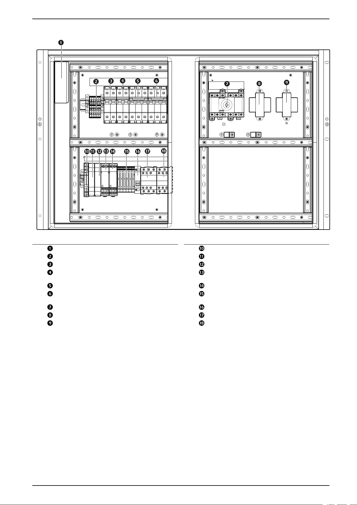
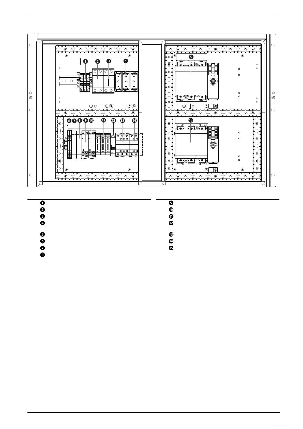
ACCU30302
na6980a
Item Description Item Description
Crank case heater power transformer Supply line selector relay
Terminal block Supply A line monitor
Crank case heater switch Supply B line monitor
Crank case heater power transformer
switch
Supply A contactor timer
Fan motor switch Supply B contactor timer
Compressor variable-speed drive
switch
ATS circuit fuse
Main switch Supply line selector A/B
ATS supply A power transformer Supply A contactor
ATS supply B power transformer Supply B contactor
990–91193A–001 25
Component Identification ACRD300 and ACCU30000 Series
ACCU30002
na7035a
Item Description Item Description
Terminal block Supply A contactor timer
Crank case heater switch Supply B contactor timer
Fan motor switch ATS circuit fuse
Compressor variable-speed drive
switch
Suppl line selector A/B
Power supply A main switch Supply A contactor
Supply line selector relay Supply B contactor
Supply A line monitor Power supply B main switch
Supply B line monitor
990–91193A–001 27
ACRD300 and ACCU30000 Series Component Identification
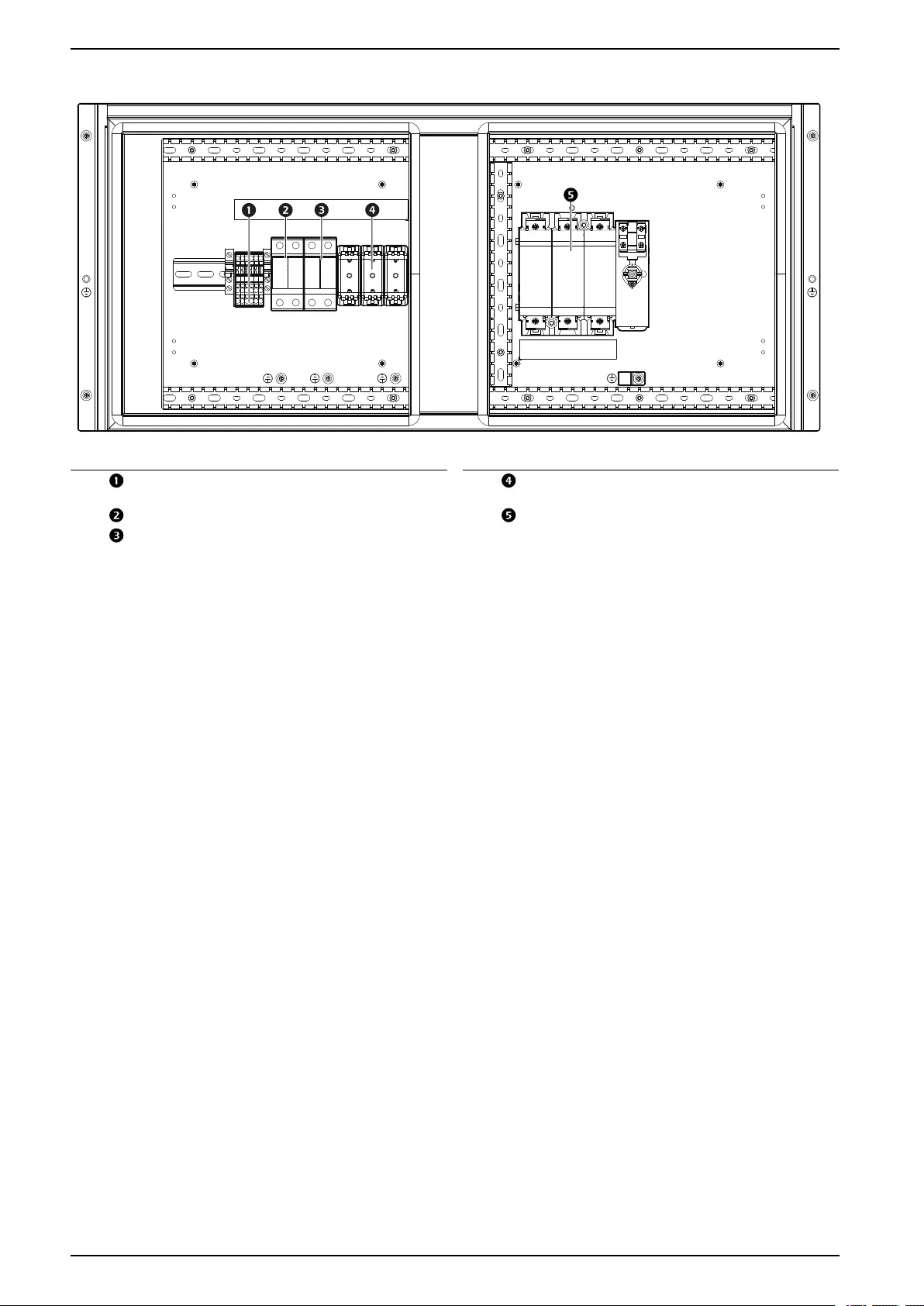
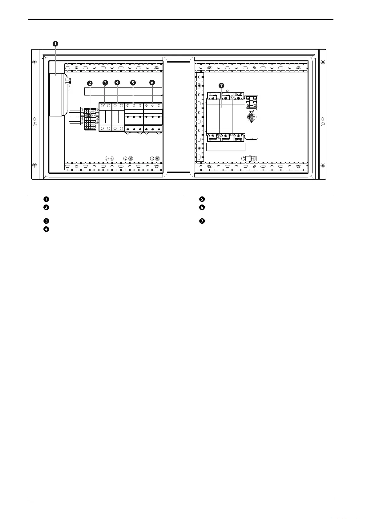
ACCU30101 and ACCU30201
na7032a
Item Description Item Description
Crank case heater power transformer Fan motor switch
Terminal block Compressor variable-speed drive
switch
Crank case heater switch Main switch
Crank case heater power transformer
switch
28 990–91193A–001
Component Identification ACRD300 and ACCU30000 Series
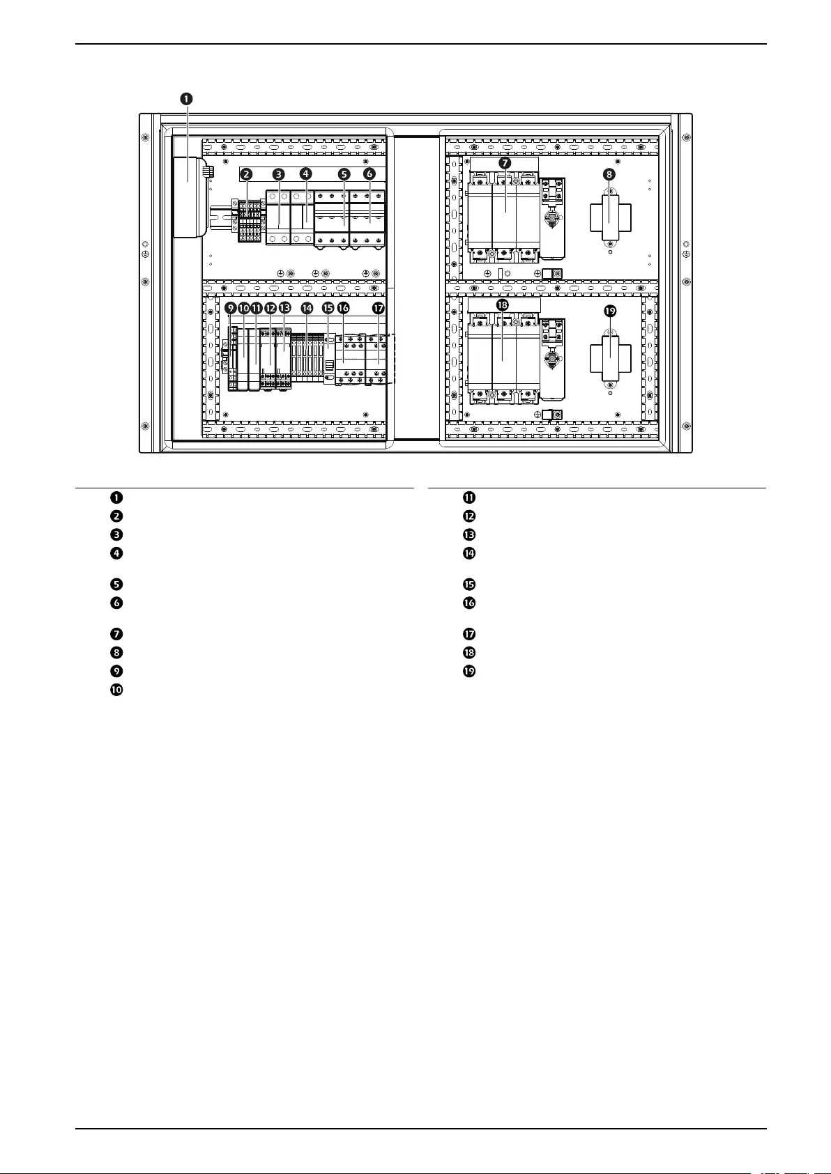
ACCU30102 and ACCU30202
na7033a
Item Description Item Description
Crank case heater power transformer Supply B line monitor
Terminal block Supply A contactor timer
Crank case heater switch Supply B contactor timer
Crank case heater power transformer
switch
ATS circuit fuse
Fan motor switch Supply line selector A/B
Compressor variable-speed drive
switch
Supply A contactor
Power supply A main switch Supply B contactor
ATS supply A power transformer Power supply Bmain switch
Supply line selector relay ATS supply B power transformer
Supply A line monitor
990–91193A–001 29
Component Identification ACRD300 and ACCU30000 Series
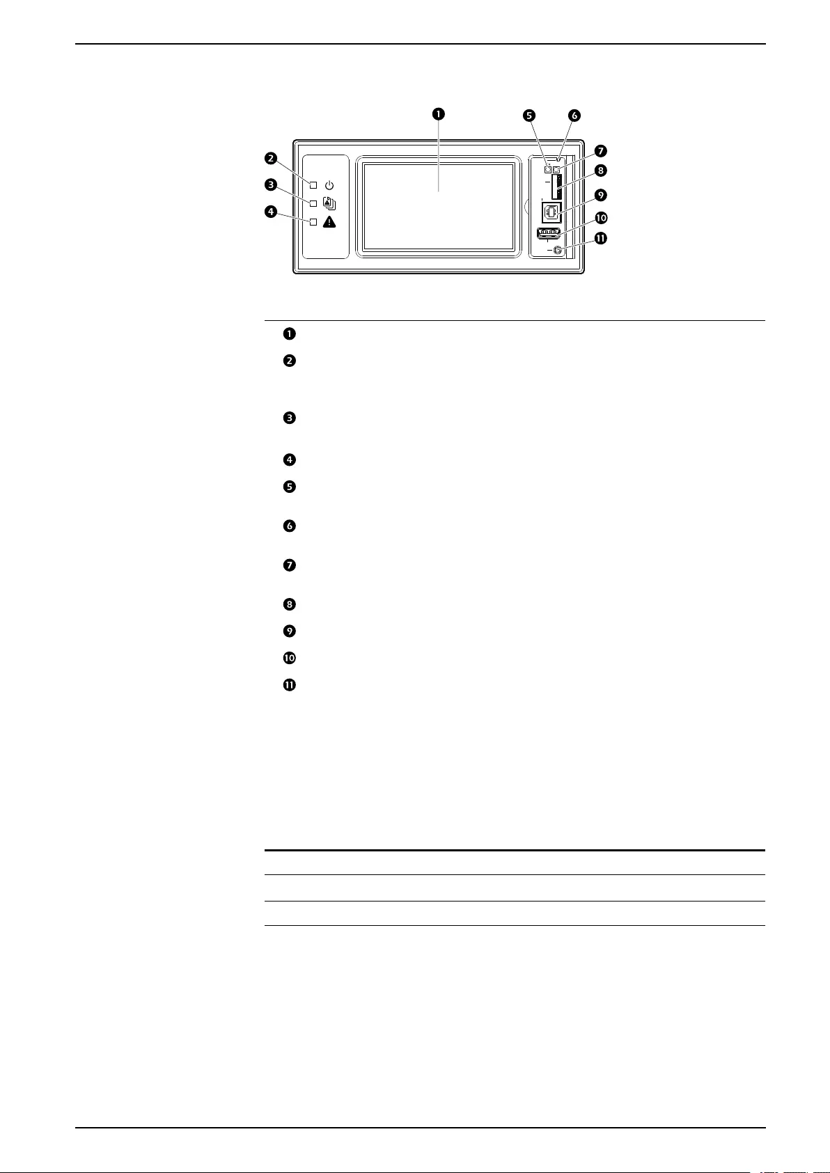
Display Interface
Display
Reset
Micro
SD
Service
Port
USB
Console
10/100
na4820a
Item Description Function
LCD Display 4.3-inch touch-screen color display
Power LED The cooling unit is powered when the LED is
illuminated. Unit firmware is updating when
LED is blinking.
Check Log LED When this LED is illuminated, a new entry has
been made to the event log.
Alarm LED Displays current alarm condition of unit.
Status LED Displays current network management card
status.
Display Reset button Resets the display microprocessor. This has
no effect on the air conditioner controller.
Link-RX/TX (10/100)
LED
Displays current network link status.
Micro SD card slot Memory card expansion slot.
Service port USB-B port used only by service personnel.
USB-A port Supports firmware upgrades.
Serial Configuration
port
Connects the display to a local computer to
configure initial network settings or access the
command line interface (CLI).
Alarm LED
This LED indicates active alarms on the display.
Condition Description
Off No alarm
Solid yellow Warning alarm
Solid red Critical alarm
990–91193A–001 31

ACRD300 and ACCU30000 Series Component Identification
Status LED
This LED indicates the status of the display.
Condition Description
Off One of the following situations exist:
• The display is not receiving input
power.
• The display is not operating
properly. It may need to be
repaired or replaced. Contact
Schneider Electric Customer
Support.
Solid green The display has valid TCP/IP settings.
Solid orange A hardware malfunction has been
detected in the display. Contact
Schneider Electric Customer Support.
Flashing green The display does not have valid TCP/
IP settings.
Flashing orange The display is making BOOTP
requests.
Alternately flashing green and orange If the LED is flashing slowly, the
display is making DHCP requests. If
the LED is flashing rapidy, the display
is starting up.
Link-RX/TX (10/100) LED
This LED indicates the network status of the display.
Condition Description
Off One or more of the following situations exist:
• The display is not receiving input power.
• The cable or device that connects the cooling unit
to the network is disconnected or not functioning
properly.
• The display itself is not operating properly. It may
need to be repaired or replaced. Contact
Schneider Electric Customer Support.
Solid green The display is connected to a network operating at 10
megabits per second (Mbps).
Solid orange The display is connected to a network operating at 100
Mbps.
Flashing green The display is receiving or transmitting at 10 Mbps.
Flashing orange The display is receiving data packets at 100 Mbps.
32 990–91193A–001
Dimensions and Weights ACRD300 and ACCU30000 Series
Dimensions and Weights
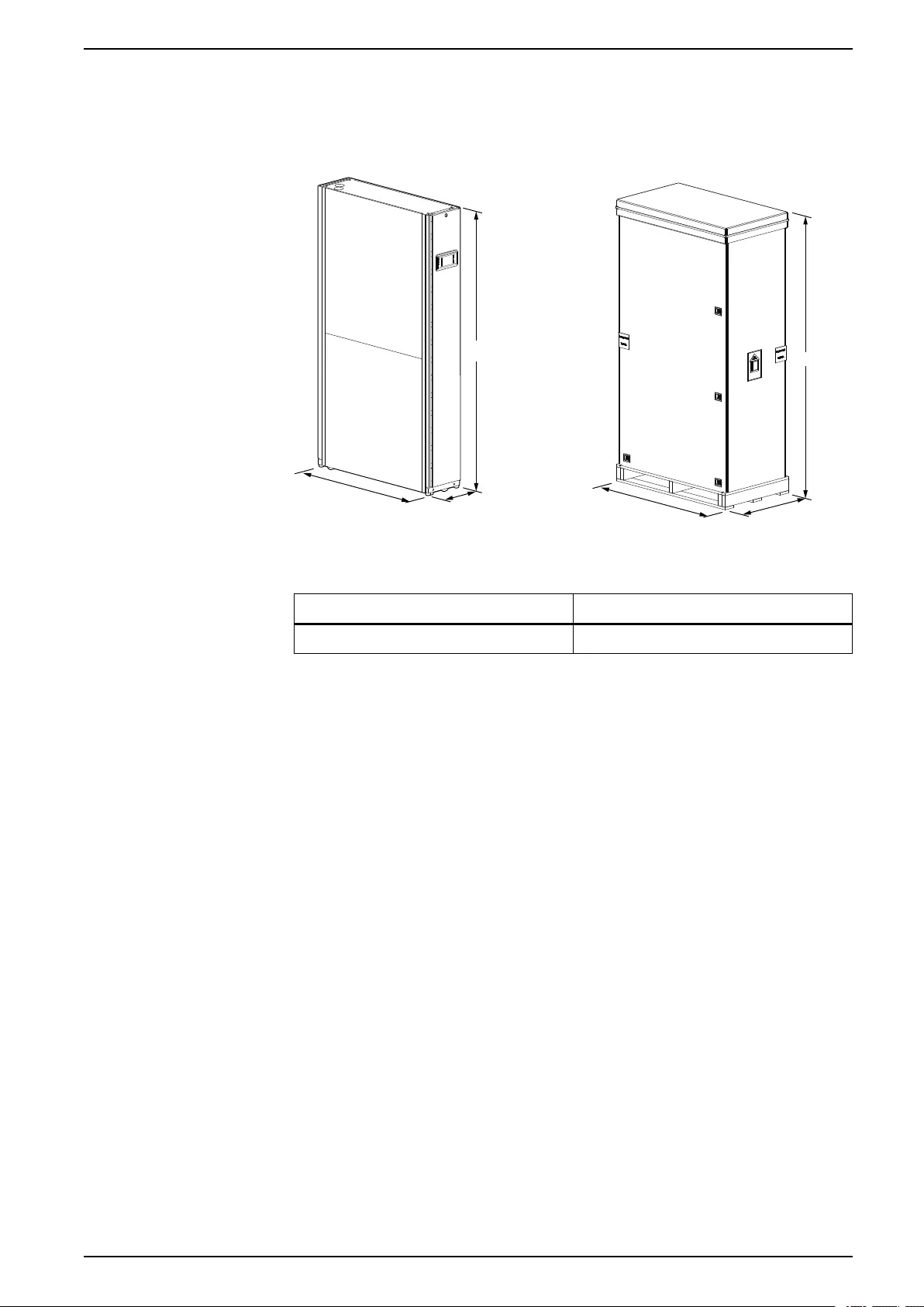
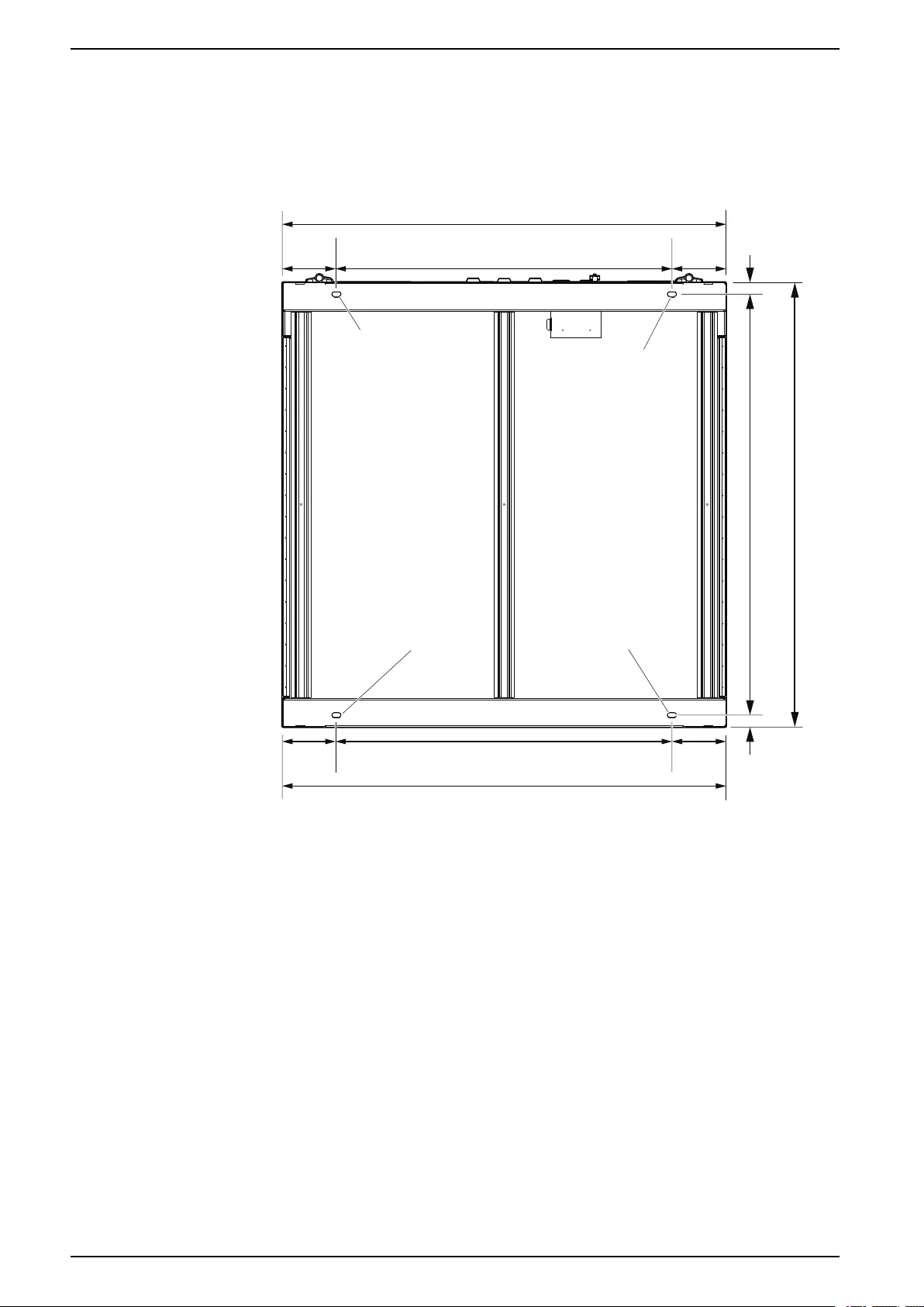
Indoor Unit
na6955b
1095 (43.11)
300 (11.80)
1991 (78.39)
1137 (44.76)
661 (26.02)
2152 (84.72)
NOTE: Image is an example only to show dimensions of unit: your unit may
differ.
Net Weight – kg (lb) Shipping Weight – kg (lb)
160 (352.7) 200 (440.9)
990–91193A–001 33
ACRD300 and ACCU30000 Series Dimensions and Weights
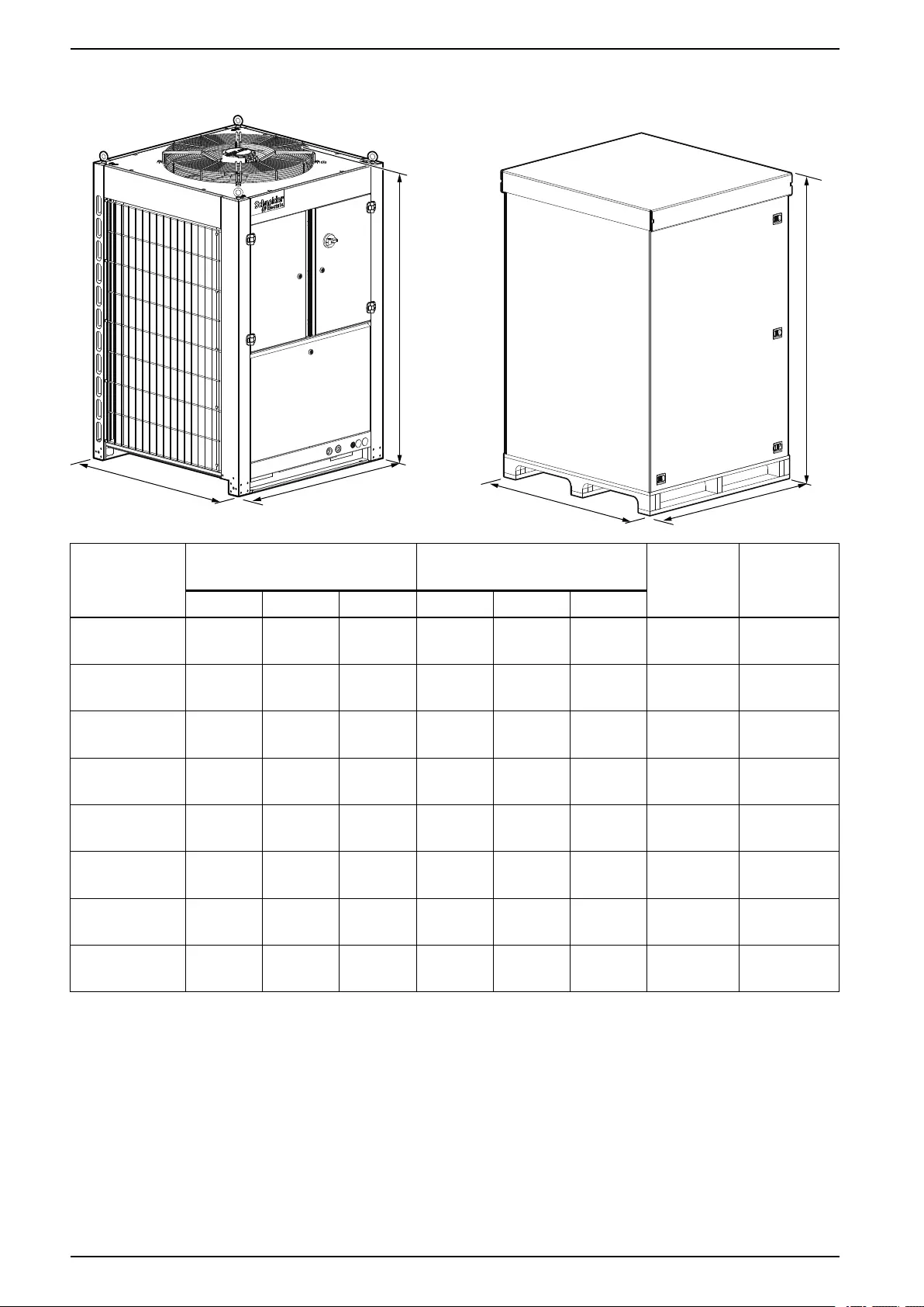
Outdoor Unit
A
B
C
A
B
C
na6956a
SKU Unit Dimensions – mm (in.) Shipping Dimensions – mm
(in.)
Net
Weight –
kg (lb)
Shipping
Weight –
kg (lb)
A B CA B C
ACCU30301 1000
(39.4)
1000
(39.4)
1555
(61.2)
1136
(44.7)
1085
(42.7)
1745
(68.7)
267
(588.6)
297 (654.8)
ACCU30302 1000
(39.4)
1000
(39.4)
1555
(61.2)
1136
(44.7)
1085
(42.7)
1745
(68.7)
272
(600.0)
305 (672.4)
ACCU30001 1000
(39.4)
1000
(39.4)
1600
(63.0)
1136
(44.7)
1085
(42.7)
1745
(68.7)
267
(588.6)
297 (654.8)
ACCU30002 1000
(39.4)
1000
(39.4)
1600
(63.0)
1136
(44.7)
1085
(42.7)
1745
(68.7)
272
(600.0)
305 (672.4)
ACCU30201 1000
(39.4)
1000
(39.4)
1555
(61.2)
1136
(44.7)
1085
(42.7)
1745
(68.7)
273
(601.9)
303 (668.0)
ACCU30202 1000
(39.4)
1000
(39.4)
1555
(61.2)
1136
(44.7)
1085
(42.7)
1745
(68.7)
278
(612.9)
308 (679.0)
ACCU30101 1000
(39.4)
1000
(39.4)
1555
(61.2)
1136
(44.7)
1085
(42.7)
1745
(68.7)
267
(588.6)
297 (654.8)
ACCU30102 1000
(39.4)
1000
(39.4)
1555
(61.2)
1136
(44.7)
1085
(42.7)
1745
(68.7)
272
(600.0)
305 (672.4)
34 990–91193A–001
Dimensions and Weights ACRD300 and ACCU30000 Series
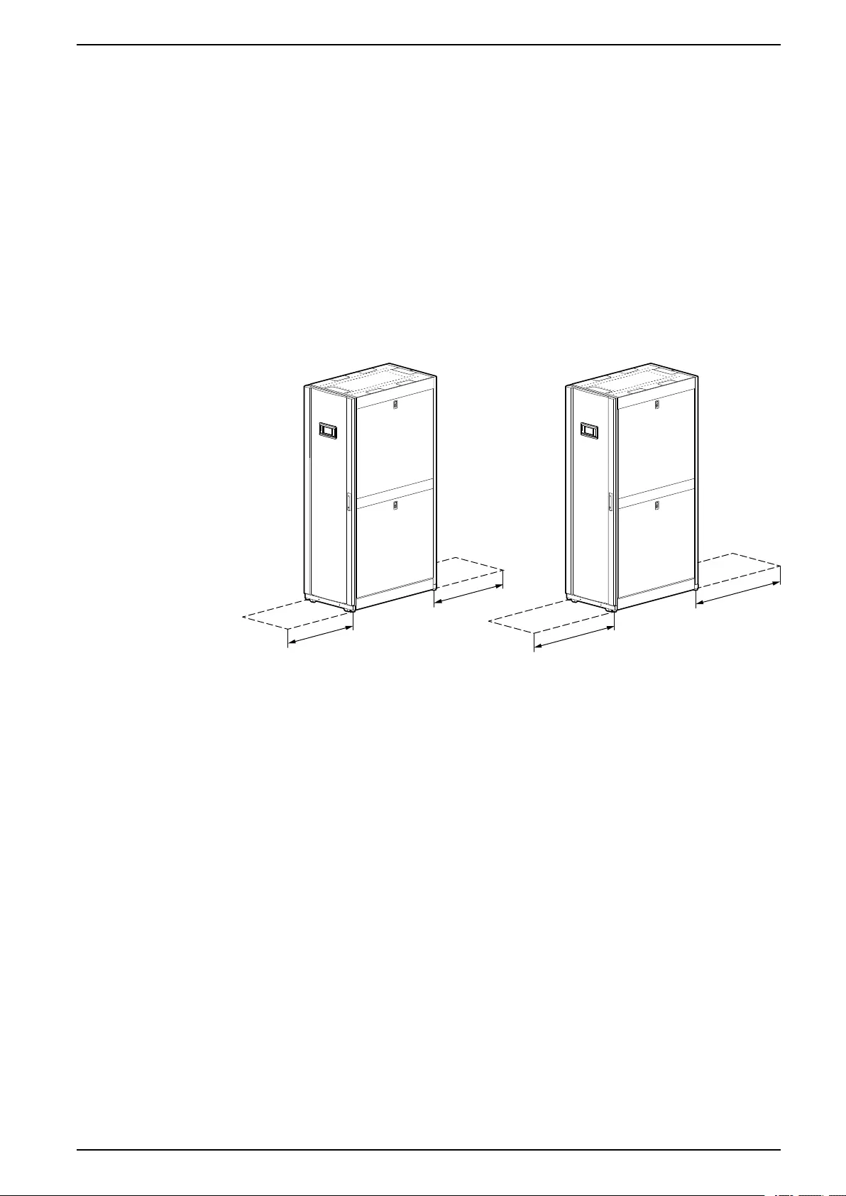
Service Access
Indoor Unit
A minimum of 900 mm (36 in.) of clear floor space in front of and behind the
equipment is recommended for service access. All required normal maintenance
is performed from the front and rear of the equipment.
Most of the cooling components in the equipment can be replaced while the unit is
installed in row and without the use of heavy lift equipment or a welding torch.
However, if it is necessary to remove the unit for repair, use the casters on the
equipment to remove it from the row. An area of minimum 1200 mm (48 in.) of
clear floor space in front of or behind the equipment is recommended to roll out
the equipment.
NOTE: Check local and national codes and regulations for further service
access requirements.
NOTE: Image is an example only: your unit may differ.
na5810a
900 (36.00) 900 (36.00)
1200 (48.00) 1200 (48.00)
SERVICE ACCESS REQUIRED
WHEN EQUIPMENT IS
INSIDE THE ROW
FREE SPACE NEEDED TO
MOVE EQUIPMENT
OUTSIDE THE ROW
NOTE: Dimensions are shown in mm (in.).
990–91193A–001 35

ACRD300 and ACCU30000 Series Dimensions and Weights
Outdoor Unit
A minimum of 1 m (39 in.) of clear space on all sides of the equipment is
recommended for service access.
1m (39 in.)
1m (39 in.) 1m (39 in.)
1m (39 in.)
1m (39 in.)
na6963a
Airflow Clearance
The following clearances are required for proper airflow around the outdoor unit.
na7029a
> 1 m
(3.3 ft)
> 1 m (3.3 ft)
> 3 m (9.8 ft)
36 990–91193A–001
Dimensions and Weights ACRD300 and ACCU30000 Series
Piping and Electrical Access Locations
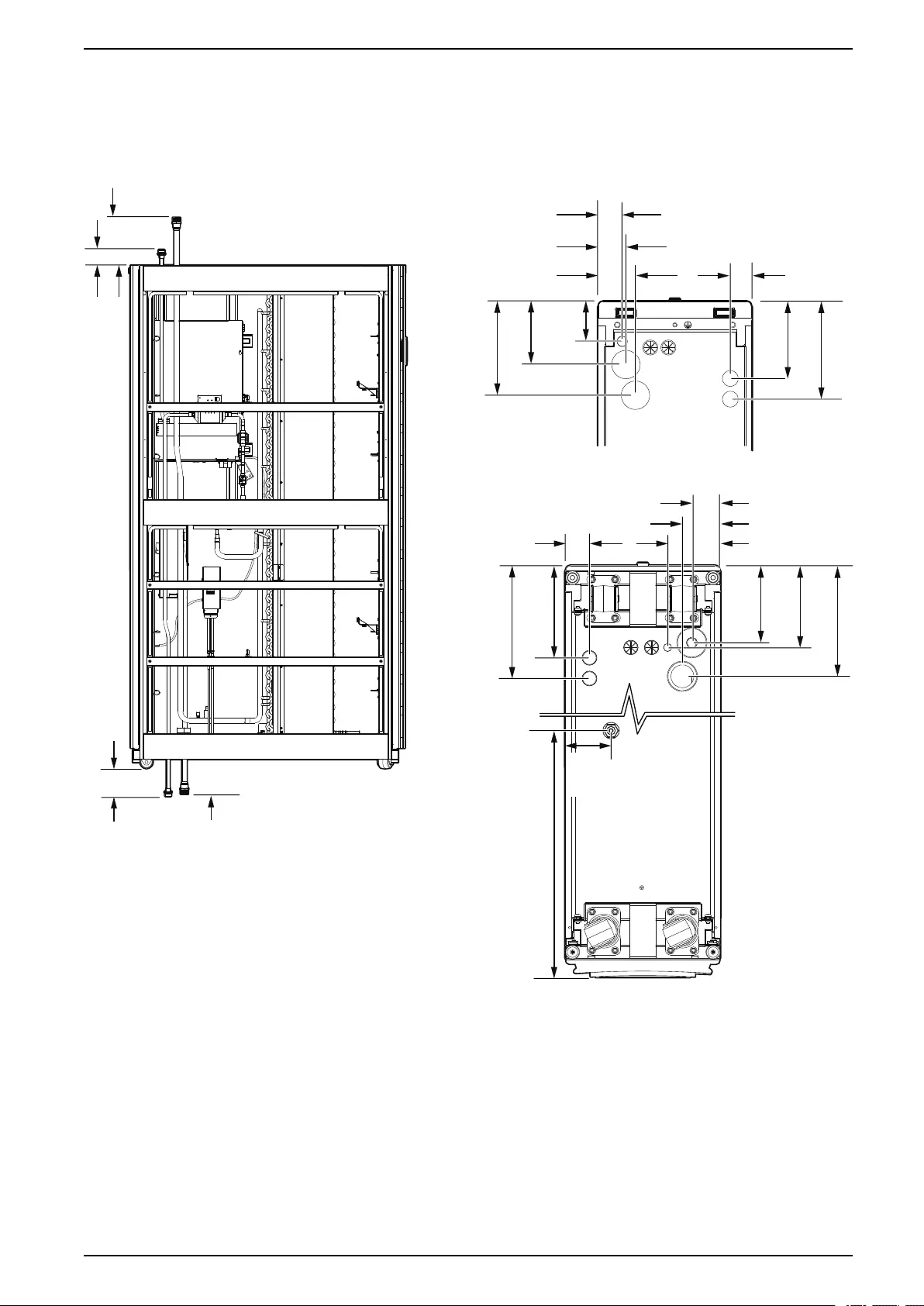
Indoor Unit
ACRD300, ACRD300G, ACRD300D, ACRD300GD
TOP VIEW
BOTTOM VIEW
(LOOKING UP)
na6957a
47.0 (1.9)
47.8 (1.9)
55.1 (2.2)
73.5 (2.9) 42.8 (1.7)
78.4
(3.1)
123.4 (4.9)
182.8 (7.2)
150.4 (5.9)
190.4 (7.5)
177.9 (7.0)
217.9 (8.6)
148.8 (5.6)
157.9 (6.2)
213.6 (8.4)
102.0 (4.0)
73.5 (2.9)
55.1 (2.2)
62.8 (2.5)
188.8 (7.4)
111 (4.37)
101.7 (4.0)
437.1 (17.2)
92.66
(3.6)
NOTE: Dimensions are shown in mm (in.).
990–91193A–001 37
ACRD300 and ACCU30000 Series Dimensions and Weights
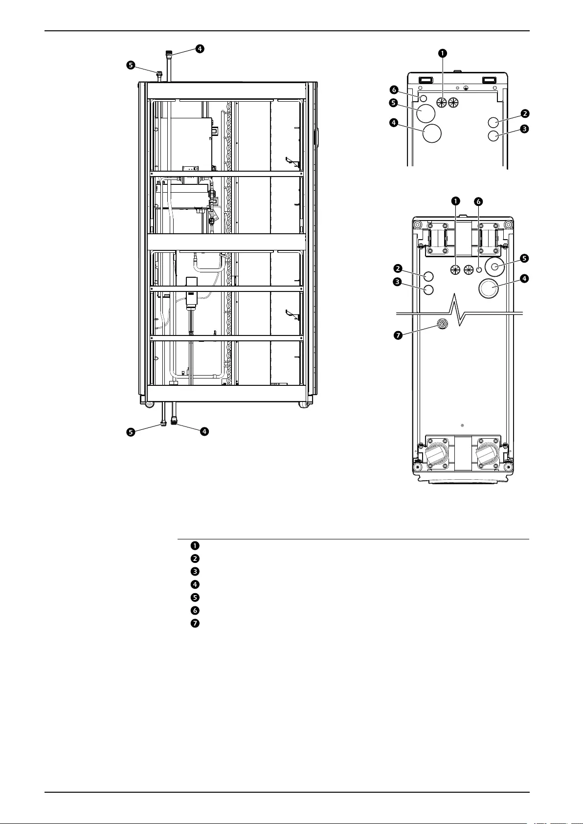
TOP VIEW
BOTTOM VIEW
(LOOKING UP)
na6958a
Item Description
Low voltage input wiring inlets
Power supply 1 inlet
Power supply 2 inlet
Suction line connection—1 1/4 in. (12 UNF)
Liquid line connection—1 in. (14 UNS)
Condensate drain line outlet
Gravity drain connection
38 990–91193A–001
Dimensions and Weights ACRD300 and ACCU30000 Series
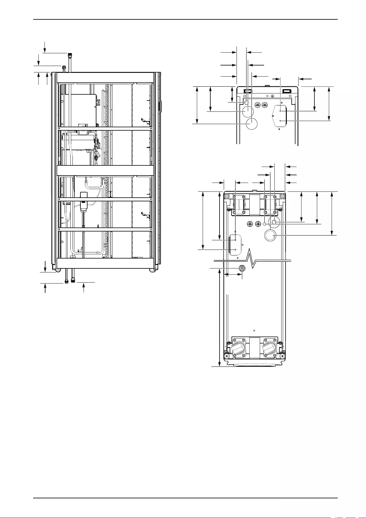
ACRD301, ACRD301G
TOP VIEW
BOTTOM VIEW
(LOOKING UP)
na6957a
56.5 (2.2)
47.8 (1.9)
55.1 (2.2)
73.5 (2.9) 87.3 (3.4)
78.4
(3.1)
123.4 (4.9)
182.8 (7.2)
150.4
(5.9)
190.4 (7.5)
227.0 (8.9)
274.0 (10.8)
148.8 (5.6)
157.9 (6.2)
213.6 (8.4)
102.0 (4.0)
73.5 (2.9)
55.1 (2.2)
62.8 (2.5)
188.8 (7.4)
111 (4.37)
101.7 (4.0)
437.1 (17.2)
92.66
(3.6)
990–91193A–001 39
ACRD300 and ACCU30000 Series Dimensions and Weights
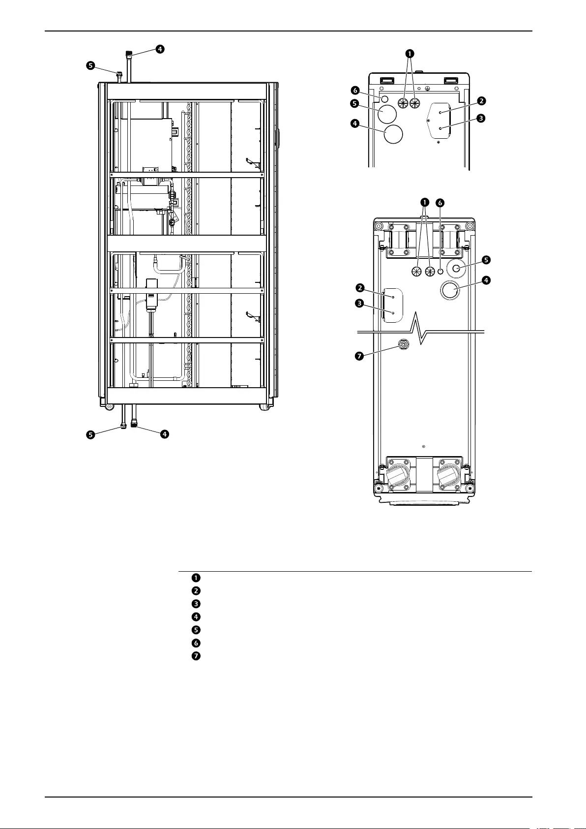
TOP VIEW
BOTTOM VIEW
(LOOKING UP)
na6958b
Item Description
Low voltage input wiring inlets
Power supply 1 inlet
Power supply 2 inlet
Suction line connection—1 1/4 in. (12 UNF)
Liquid line connection—1 in. (14 UNS)
Condensate drain line outlet
Gravity drain connection
40 990–91193A–001
Dimensions and Weights ACRD300 and ACCU30000 Series
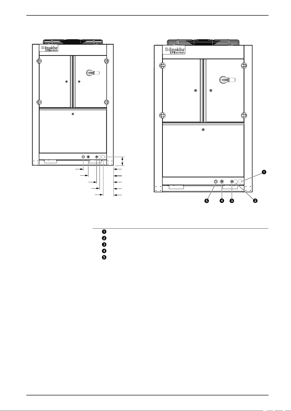
Outdoor Unit
na6961a
309.3 (12.2)
371.0 (14.6)
105.6 (4.2)
121.8 (4.8)
169.0 (6.7)
206.5 (8.1)
na6962a
NOTE: Dimensions are shown in mm (in.).
Item Description
Power supply 1 inlet
Power supply 2 inlet
Communication cable inlet
Liquid line connection inlet
Suction line connection inlet
990–91193A–001 41
ACRD300 and ACCU30000 Series Installation
Installation
Location and Power Considerations
Room Preparation
During the design of the data center, consider ease of entry for the equipment,
floor loading factors, and accessibility to piping and wiring. In addition, the room
temperature and humidity combination should conform to the environmental
operating envelope as defined in the following graphics.
Seal the room with a vapor barrier to minimize moisture infiltration. Polyethylene
film is recommended for ceiling and wall applications. Apply rubber- or plastic-
based paints to concrete walls and floors.
Insulate the room to minimize the influence of exterior heat loads. Reduce fresh
air to the minimum required by local and national codes and regulations. Fresh air
imposes extreme load variation on the cooling equipment from summer to winter
and causes increased system operating costs.
Incoming Power Supply Requirements
WARNING
ELECTRICAL HAZARD
• Electrical service must conform to local and national electrical codes and
regulations.
• The equipment must be grounded.
Failure to follow these instructions can result in death, serious injury, or
equipment damage.
See the name plate on the unit to determine the maximum possible current draw
of the cooling unit. Provide either a single outlet circuit or a Power Distribution Unit
(PDU) with sufficient capacity to handle all loads. Do not plug two InRow units into
the same branch circuit or PDU.
42 990–91193A–001

Installation ACRD300 and ACCU30000 Series
Indoor Unit Location
Refer to the floor layout drawing for the exact placement of the cooling unit in the
row of IT equipment. This layout drawing can be found in the Configure-to-Order
(CTO) report or the engineering specification drawings provided by the Consulting
Engineer.
Due to potentially high noise levels during peak loads, the InRow cooling unit is
not intended to be used in an occupied office environment. It is recommended that
ear protection be worn if prolonged exposure to the high noise level is expected.
Outdoor Unit Location
The installation area must follow these requirements:
• Installed on a flat, level surface
• Can only be installed at the same level or higher than the indoor unit
• Not exposed to air containing inflammable or greasy substances
• Service clearance of 1 m (39 in.) must be available on all sides
• Clearance of 3 m (10.8 ft) above the unit to allow for proper airflow
• Installing the unit in areas with increased airborne debris may result in more
frequent service intervals
Secure the unit to its foundation using the mounting holes located on the bottom of
the frame.
See Stabilizing the Outdoor Unit, page 50.
990–91193A–001 43
ACRD300 and ACCU30000 Series Installation
Removing Doors and Panels
WARNING
MOVING PARTS HAZARD
Do not remove rear panels if the equipment is operating.
Failure to follow these instructions can result in death, serious injury, or
equipment damage.
NOTICE
EQUIPMENT DAMAGE
Do not lean the doors against a wall with the side panel latches facing the wall.
This can deform the latches and prevent them from working properly.
Failure to follow these instructions can result in equipment damage.
Indoor Unit
Front and Rear Panels
The front and rear panels must first be unlocked before they can be removed. Two
keys are provided with the unit.
NOTE: Image is an example only: your unit may differ.
na4336c
44 990–91193A–001
ACRD300 and ACCU30000 Series Installation
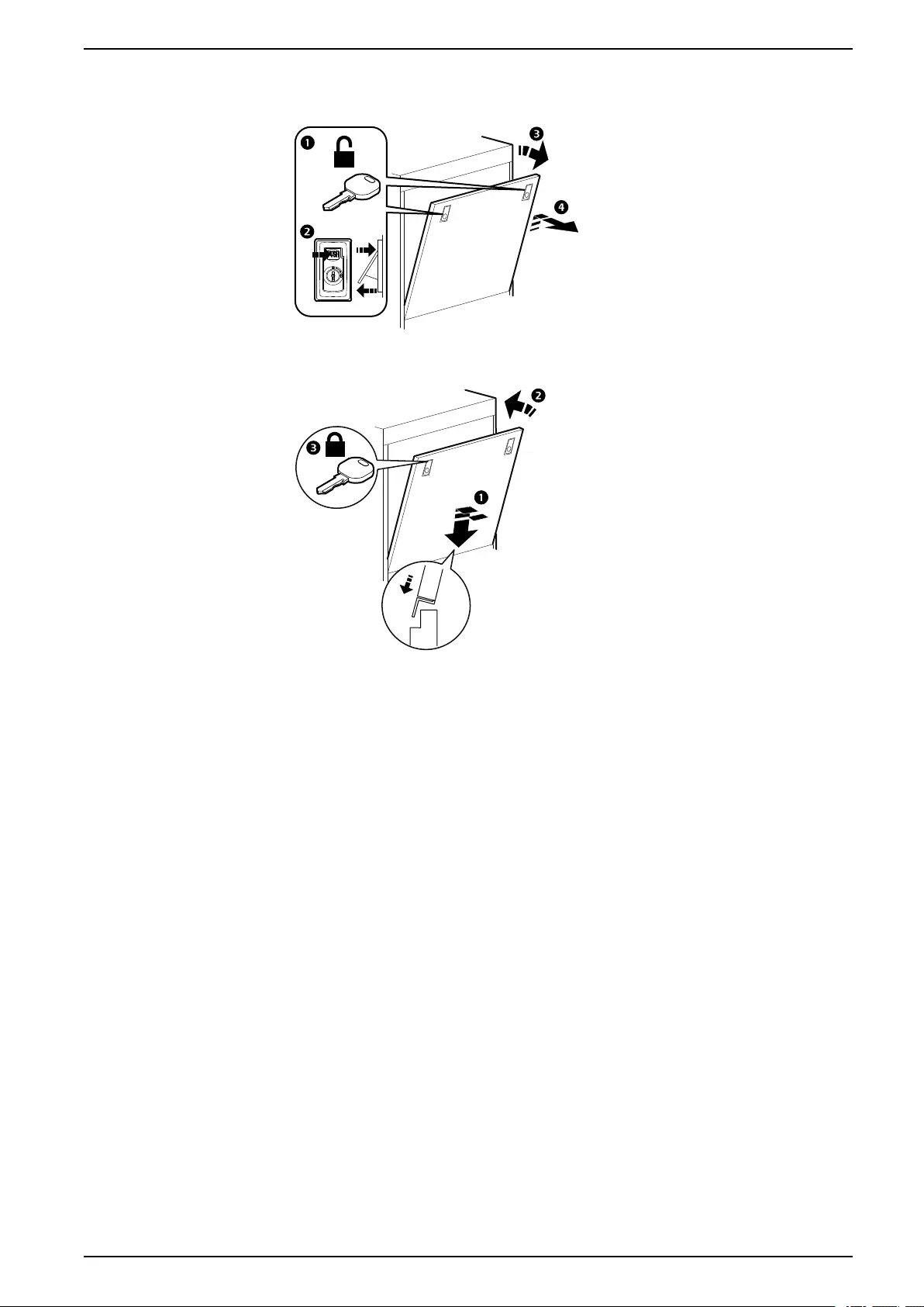
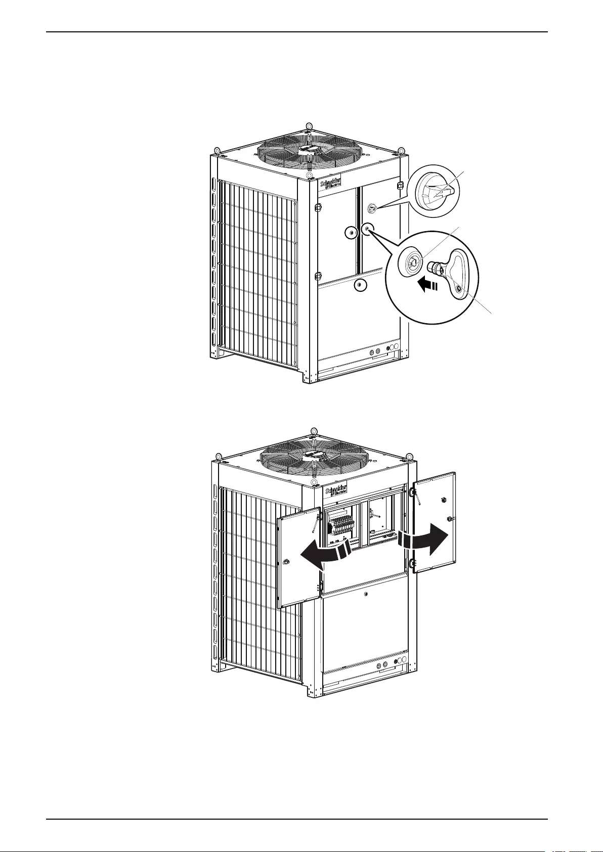
Outdoor Unit
Electrical Panel Access
1. Turn the main switch to the “Off” position and the rotate the quarter-turn
latches to the right.
na6975a
MAIN DISCONNECT
SWITCH
QUARTER-TURN
LATCH
KEY
NOTE: Model ACCU30301 is shown.
2. Open the electrical panel access doors.
na6974a
46 990–91193A–001
ACRD300 and ACCU30000 Series Installation
Stabilizing the Cooling Unit
DANGER
HAZARD OF ELECTRIC SHOCK, EXPLOSION, OR ARC FLASH
Turn off all power supplying this equipment before working on the equipment.
All electrical work must be performed by qualified personnel. Practice Lockout/
Tagout procedures. Do not wear jewelry when working with electrical
equipment.
Failure to follow these instructions will result in death or serious injury.
WARNING
HAZARD OF EQUIPMENT FALLING OVER
• Use two or more persons at all times to move or turn this equipment.
• Always push, pull, or turn while facing the front and rear of this equipment.
Never push, pull, or turn while facing the sides of this equipment.
• Slowly move this equipment across uneven surfaces or door thresholds.
• Lower leveling feet to floor when this equipment is at rest.
• Lower leveling feet and attach joining brackets to adjacent racks when this
equipment is in final position.
Failure to follow these instructions can result in death, serious injury, or
equipment damage.
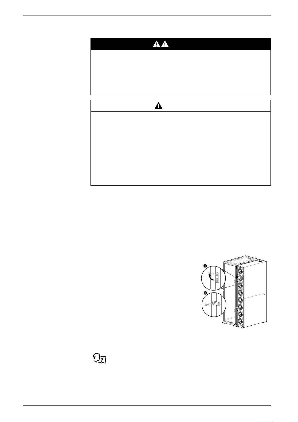
Joining the Equipment to Enclosures
Joining to NetShelter™SX Enclosures
Joining brackets are installed on the unit, two in the front and two on the rear.
Each bracket is designed to accommodate both 24-in. or 600- mm enclosure
spacing.
NOTE: Image is an example only: your unit may differ.
1. Loosen the attachment screw.
2. Rotate the brackets 90°.
3. Install a provided Phillips M5 screw
through the bracket and into the adjoining
enclosure.
4. Re-tighten the attachment screw.
na4354a
90°
Joining to NetShelter VX and VS Enclosures
For information on joining the equipment to NetShelter VX and VS
enclosures, see the installation sheet NetShelter SX to VX or VS
External Joining Kit—AR7601, AR7602.
48 990–91193A–001
Installation ACRD300 and ACCU30000 Series
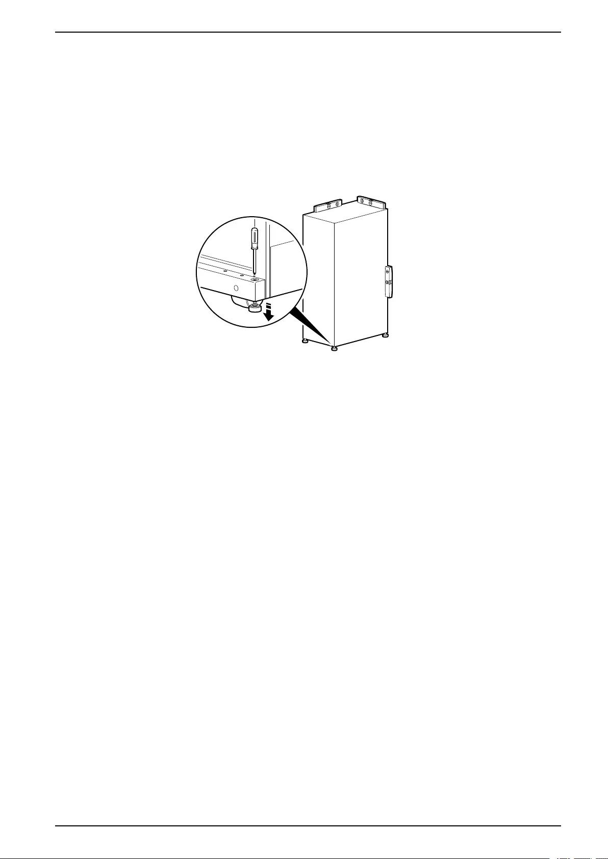
Leveling
The leveling feet provide a stable base if the floor is uneven but cannot
compensate for a badly sloped surface.
Once the cooling unit is in its intended location, use a screwdriver to turn each
leveling foot until it makes contact with the floor. Adjust each foot until the cooling
unit is level and plumb. The casters and leveling feet can be removed to allow the
cooling unit to rest directly on the floor.
NOTE: Front and rear panels will need to be removed to access the leveling
screw.
NOTE: Image is an example only: your unit may differ.
na1572b
NOTE: Use a 13-mm open-ended wrench to level the equipment without
removing the doors.
990–91193A–001 49
ACRD300 and ACCU30000 Series Installation
Stabilizing the Outdoor Unit
Mounting Hole Dimensions
The following image shows the dimensions for the mounting holes located on the
frame of the outdoor unit.
FRONT OF UNIT
REAR OF UNIT
MOUNTING HOLE
MOUNTING HOLE
MOUNTING HOLE
MOUNTING HOLE
na7028a
+ +
27 (1.1)
27 (1.1)
946
(37.2)
1000.0 (39.4)
122
(4.8)
122
(4.8)
756 (29.8)
1000.0 (39.4)
122
(4.8)
122
(4.8)
756 (29.8)
1000.0
(39.4)
NOTE: Dimensions are shown in mm (in.).
NOTE: View is bottom view looking up.
50 990–91193A–001
Installation ACRD300 and ACCU30000 Series
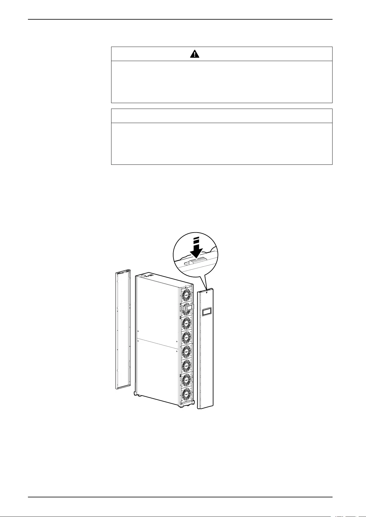
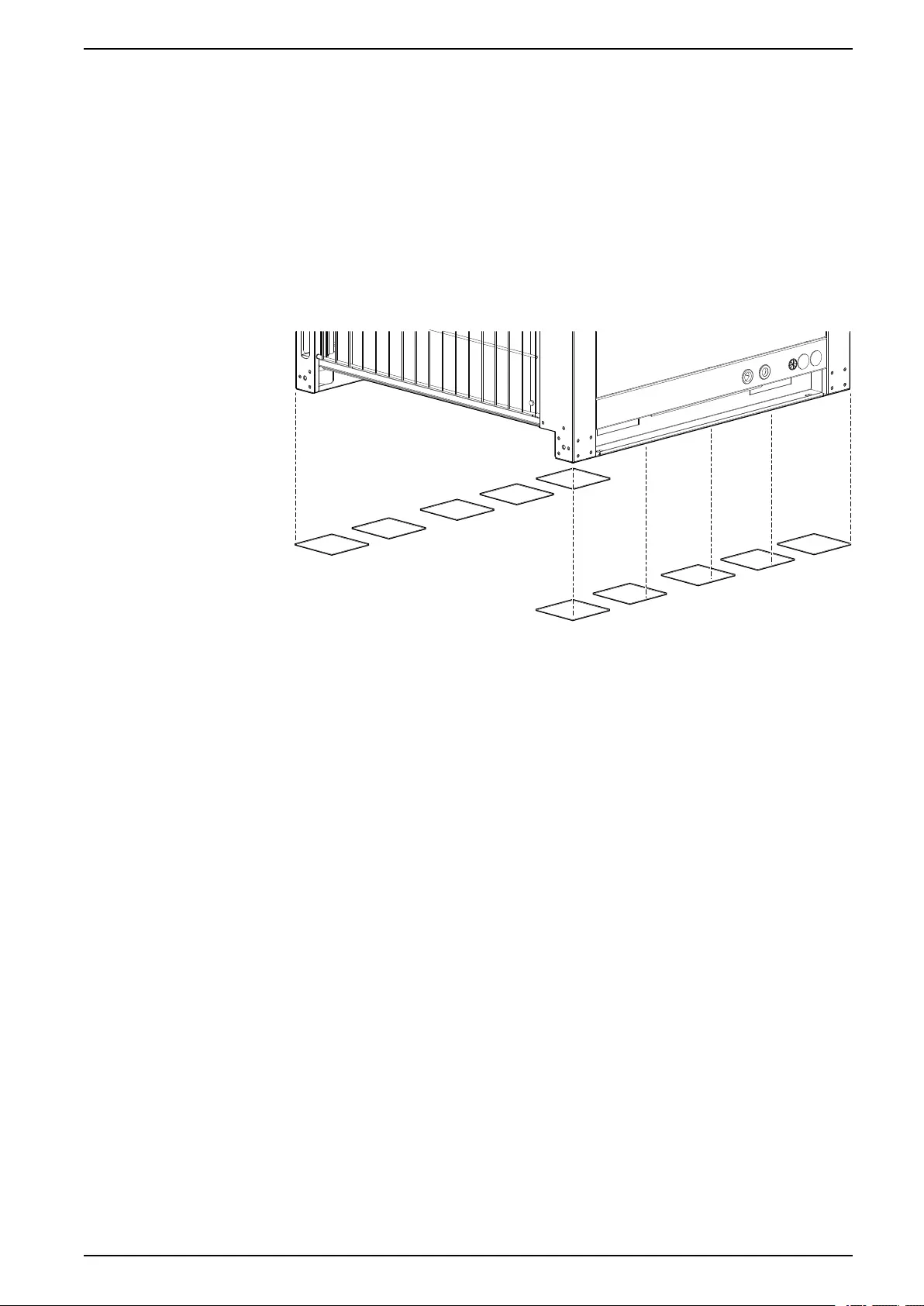
Vibration Damping Pads
It is recommended to place field-supplied vibration damping pads under the
outdoor unit to minimize vibration and noise. The following specs are
recommended for the vibration pads:
• Hardness: Durometer 90A
• Material: Green neoprene rubber
• Dimensions: 152 mm x 152 mm (6 in. x 6 in.)
• Thickness: 9.5 mm (3/8 in.)
Place the vibration damping pads flush with the edges of the unit so they are not
visible. The following is the recommended placement of the vibration damping
pads:
na7044a
NOTE: Do not block the mounting holes with vibration damping pads.
Vibration damping pads may need to be cut to size.
990–91193A–001 51
ACRD300 and ACCU30000 Series Installation
Connections Overview
All connections to and from the indoor unit can be made through either the top or
the bottom of the unit. Once the corresponding connectors are sweated or
soldered into place, the equipment can be disconnected without soldering,
welding, or gluing. See the following tables for information about the sizes and
types of connectors.
Power Connections
Model Type Minimum Maximum Torque
ACRD300 Screw connector AWG 14 (2.5 mm2) —1.0 Nm (0.74 ft-lb)
ACRD300D Screw connector AWG 14 (2.5 mm2) —1.0 Nm (0.74 ft-lb)
ACRD300G Screw connector AWG 14 (2.5 mm2) —1.0 Nm (0.74 ft-lb)
ACRD300GD Screw connector AWG 14 (2.5 mm2) —1.0 Nm (0.74 ft-lb)
ACRD301 Screw connector AWG 14 (2.5 mm2) —1.0 Nm (0.74 ft-lb)
ACRD302 Screw connector AWG 14 (2.5 mm2) —1.0 Nm (0.74 ft-lb)
ACCU30301 Screw connector AWG 14 (2.5 mm2) —1.5 Nm (1.1 ft-lb)
ACCU30302 Screw connector AWG 14 (2.5 mm2) —1.5 Nm (1.1 ft-lb)
ACCU30001 Screw connector AWG 10 (6 mm2) —1.5 Nm (1.1 ft-lb)
ACCU30002 Screw connector AWG 10 (6 mm2) —1.5 Nm (1.1 ft-lb)
ACCU30201 Screw connector AWG 14 (2.5 mm2) —1.5 Nm (1.1 ft-lb)
ACCU30202 Screw connector AWG 14 (2.5 mm2) —1.5 Nm (1.1 ft-lb)
52 990–91193A–001

Installation ACRD300 and ACCU30000 Series
Sensor and Communication Connections
Wire Size
Connection Type Minimum Maximum
Rack temperature RJ-45 — —
Leak Rope RJ-45 — —
A-Link IN RJ-45 — —
A-Link OUT RJ-45 — —
Network port RJ-45 — —
Console port USB (Type B) — —
Customer output,
Normally Closed (NC)
Push-in spring
connection
AWG 24 (0.2 mm2) AWG 18 (0.75 mm2)
Customer output,
Common (COM)
Push-in spring
connection
AWG 24 (0.2 mm2) AWG 18 (0.75 mm2)
Customer output,
Normally Open (NO)
Push-in spring
connection
AWG 24 (0.2 mm2) AWG 18 (0.75 mm2)
Supply GND Push-in spring
connection
AWG 24 (0.2 mm2) AWG 18 (0.75 mm2)
Supply 12 Vdc Push-in spring
connection
AWG 24 (0.2 mm2) AWG 18 (0.75 mm2)
Supply 24 Vdc Push-in spring
connection
AWG 24 (0.2 mm2) AWG 18 (0.75 mm2)
Customer input + Push-in spring
connection
AWG 24 (0.2 mm2) AWG 18 (0.75 mm2)
Customer input - Push-in spring
connection
AWG 24 (0.2 mm2) AWG 18 (0.75 mm2)
Modbus D1 Push-in spring
connection/ Spring-cage
connection
AWG 24 (0.2 mm2) AWG 18 (0.75 mm2)
Modbus D0 Push-in spring
connection/ Spring-cage
connection
AWG 24 (0.2 mm2) AWG 18 (0.75 mm2)
Modbus GND Push-in spring
connection/ Spring-cage
connection
AWG 24 (0.2 mm2) AWG 18 (0.75 mm2)
Temperature sensor 2P Molex Mini-Fit Jr.™— —
Humidity sensor 6P Molex Mini-Fit Jr.™— —
Display interface HDMI — —
990–91193A–001 53
ACRD300 and ACCU30000 Series Installation
Mechanical Connections
Installing the Main Switch
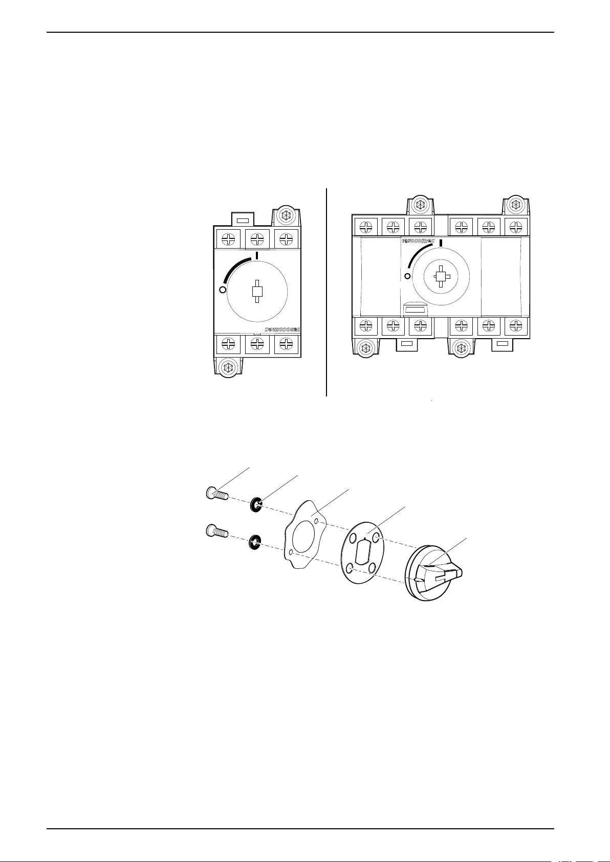
ACCU30301 and ACCU30302
The main switch handle of the condensing unit is shipped inside the electrical
panel of the unit and must be installed in the field.
1. Open the electrical panel access door.
2. Make sure the power supply is in the “OFF” position.
SINGLE FEED DUAL FEED
PRIMARY
(FEED A)
SECONDARY
(FEED B)
OFF
ON
OFF
ON
na7010a
3. Install the main switch handle on the outside of the door using the gasket, 2
tap screws, and 2 grommets.
NOTE: Make sure the main switch handle is in the “OFF” position.
na7011a
MAIN SWITCH
HANDLE
TAP SCREW
GASKET
GROMMET
DOOR
4. Close the door and make sure the shaft of the switch and main switch handle
align properly.
54 990–91193A–001
Installation ACRD300 and ACCU30000 Series
ACCU30001, ACCU30002, ACCU30201, ACCU30202, ACCU30101, and
ACCU30102
The main switch handle of the condensing unit is shipped inside the electrical
panel of the unit and must be installed in the field.
1. Open the electrical panel access door.
2. Make sure the power supply is in the “OFF” position.
NOTE: Make sure both power supplies are in the “OFF” position if two are
present.
OFF
ON
na7030a
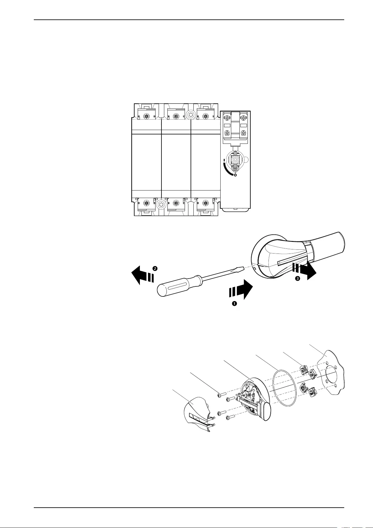
3. Remove the cover from the main switch handle.
na7031a
4. Install the main switch handle on the outside of the door using the gasket, 4
machine screws, and 4 nuts.
NOTE: Place the flat side of the nuts against the main switch handle.
MAIN SWITCH
HANDLE
MACHINE
SCREWS
GASKET NUTS
DOOR
MAIN SWITCH
HANDLE COVER
na7027a
990–91193A–001 55
ACRD300 and ACCU30000 Series Installation
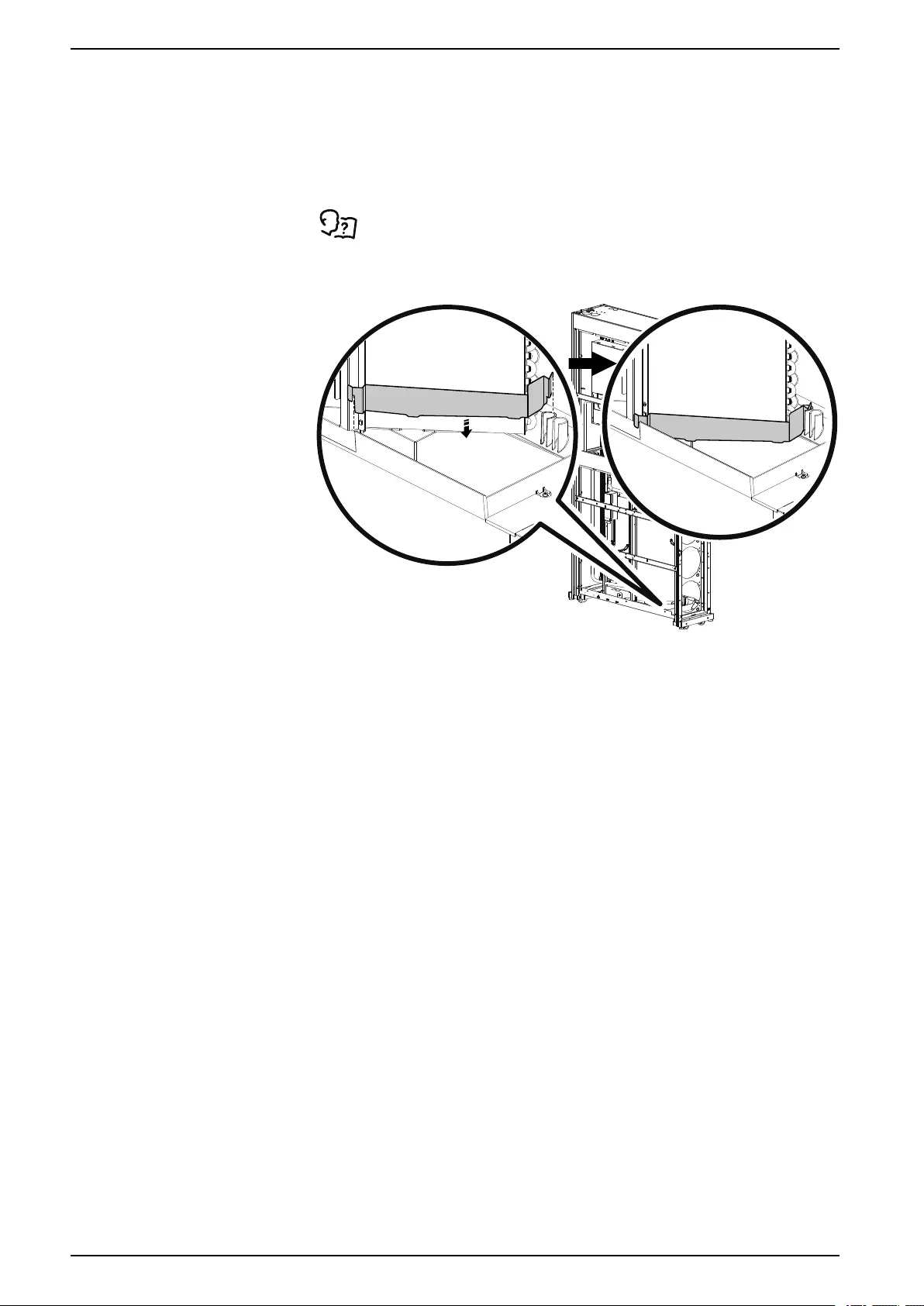
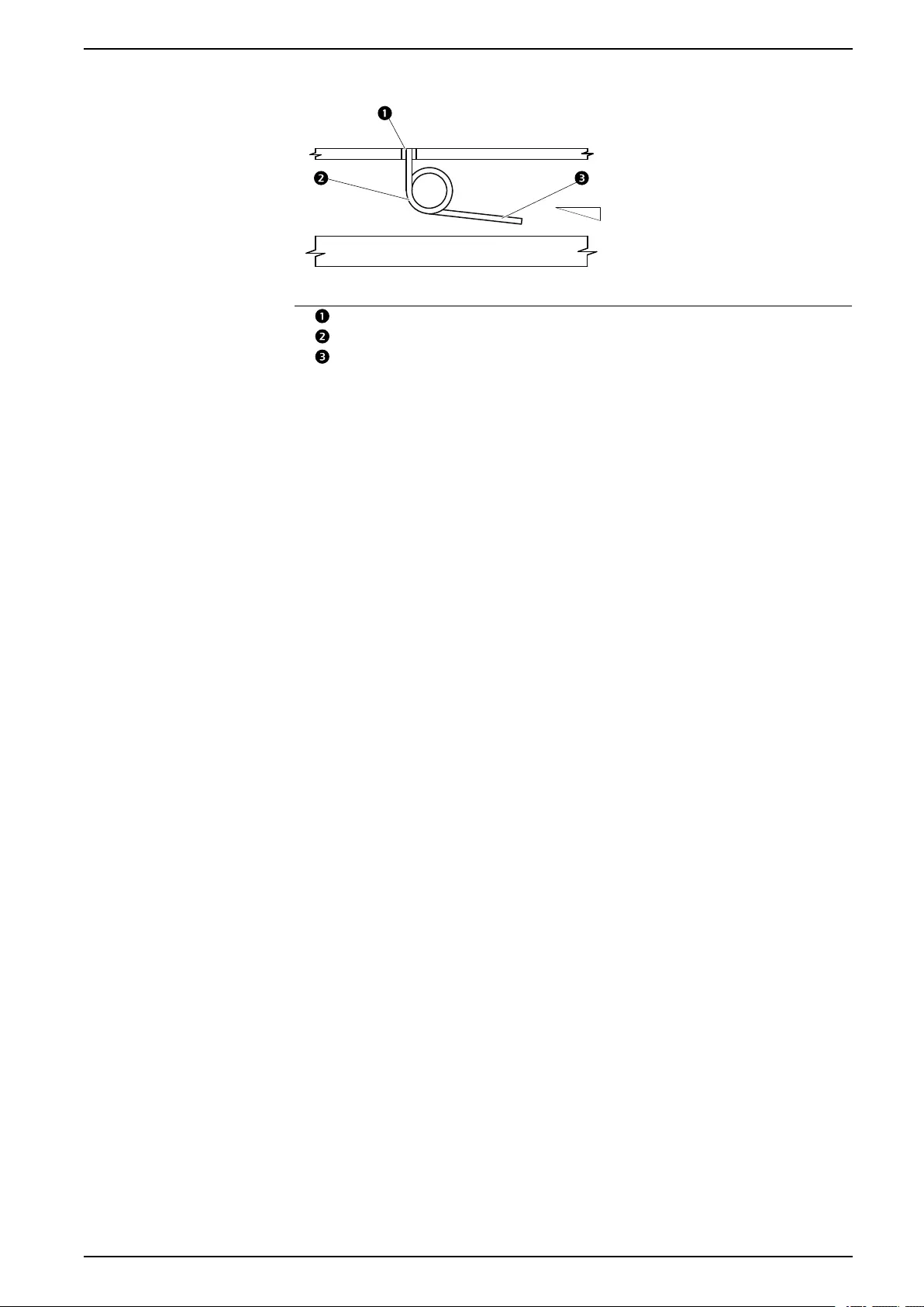
Condensate Drain Pan Additions
The condensate drain pan requires a strip of insulation and a supplemental
bracket around the cooling coil to prevent water from overflowing when the fans
are operating at high speed.
1. Remove the lower side panels.
See Side Panels, page 45 for panel removal instructions.
2. Place the supplemental bracket in front of the cooling coil (fan side).
na7193a
56 990–91193A–001
Installation ACRD300 and ACCU30000 Series
Condensate Drain Connections
NOTICE
COMPLIANCE REQUIREMENT
The installation must comply with local plumbing codes.
Failure to follow these instructions can result in equipment damage.
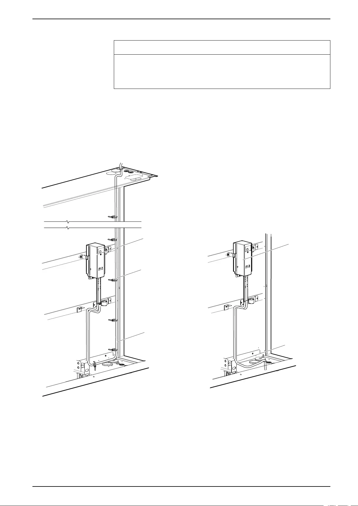
With Condensate Pump
The pump is factory-wired and piped internally to the condensate drain pan. The
pump uses an on-board, condensate-high-level float switch wired into the
equipment for alarm capabilities.
The condensate drain line can be connected through either the top or the bottom
of the equipment using factory-installed male quick connectors and tubing.
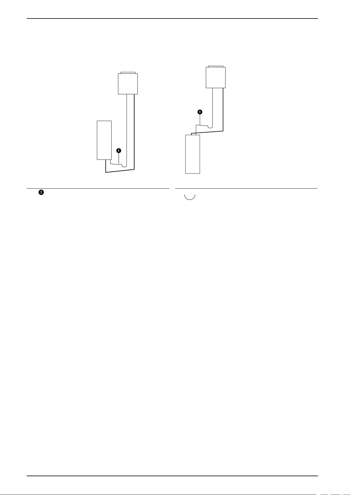
The following image shows routing options for the condensate drain line:
na6964a
CONDENSATE
PUMP CONDENSATE
PUMP
WIRE TIE
(SQUARE-HEAD)
TUBING
TUBING
BOTTOM ROUTING
TOP ROUTING
990–91193A–001 57
ACRD300 and ACCU30000 Series Installation
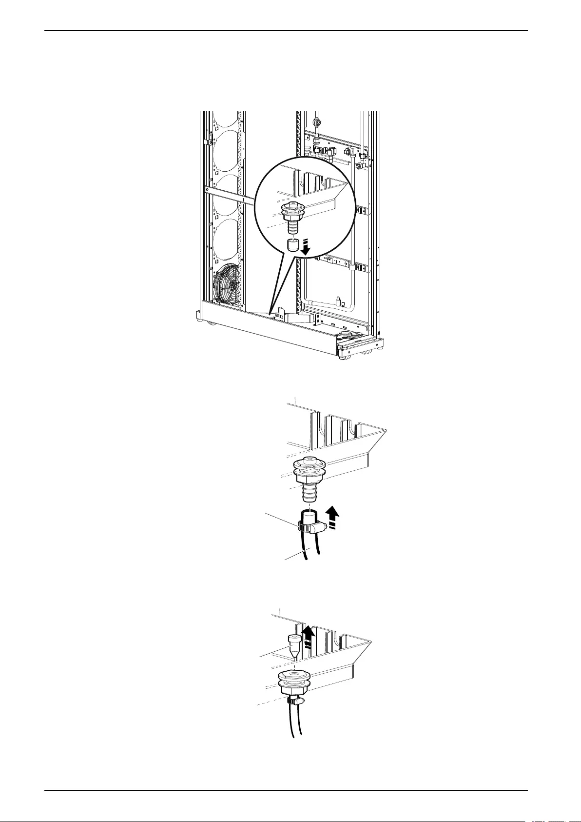
With Gravity Drain
NOTE: A hole at least 102 mm (4 in.) in diameter is required in the raised floor
to access the gravity drain connection.
1. Remove the rubber seal cap from the drain connection.
na7002a
2. Attach tubing with a 136-mm (0.5-in.) internal diameter (field supplied) to the
barbed connection with a tube clamp (field supplied).
CLAMP
(FIELD SUPPLIED)
TUBING
(FIELD SUPPLIED)
na7003a
3. Remove the silicon plug.
NOTE: Water will not drain if the plug is not removed.
SILICON PLUG
na7004a
4. Route the tubing through the hole in the raised floor.
58 990–91193A–001
Installation ACRD300 and ACCU30000 Series
Connection to Building Drain
na4737a
2.5 cm PER 2.1 m
(1 in PER 10 ft)
Item Description
Drain
Trap
Minimum slope
1. Connect the unit drainage tube to the building drains using a rubber or plastic
tube with a 25-mm (1-in.) internal diameter.
2. Use a trap on the external drainage tube in order to avoid unpleasant odors
and to allow the condensate pan to drain properly. Consult local building
codes for drain requirements.
3. Once the connections have been made, pour water into the condensate drain
until the trap inside the unit is full.
990–91193A–001 59
ACRD300 and ACCU30000 Series Installation
Refrigerant Piping
The indoor unit connects to an external condensing unit. Install all refrigerant lines
in accordance with applicable industry guidelines as well as local and national
codes and regulations. Calculate an equivalent length based on the actual linear
length of the run, including valves and fittings.
NOTE: All fittings should be long-radius to minimize pressure drop.
See Refrigeration Piping Diagram, page 30.
Make all refrigerant lines as short and direct as possible. Horizontal suction lines
must be pitched downward at a minimum of 4 mm per m (1/2 in. per 10 ft) in the
direction of flow to aid in oil return. Install a trap in the suction line at the bottom of
the riser and additional traps approximately every 6 m (20 ft) of rise to ensure
proper oil return. Isolate piping from structural surfaces using vibration clamps.
NOTE: Field-installed gas lines must be insulated.
NOTE: Install all piping in accordance with applicable industry guidelines as
well as local and national codes and regulations.
The following table provides ASHRAE standards for equivalent piping lengths of
fittings and valves.
Type of Fitting or Valve—Equivalent Length of Pipe in m (ft)
Nominal
Pipe Size
ACR
Tubing Size
Gate Valve Angle Valve Globe
Valve
Standard
Elbow 90°
Contraction
1/2
Tee Branch Tee
Straight
3/4 in. 7/8 in. 0.27 (0.9) 2.74 (9.0) 6.71 (22.0) 0.61 (2.0) 0.30 (1.0) 1.22 (4.0) 0.43 (1.4)
1 in. 1 1.8 in. 0.30 (1.0) 3.66 (12.0) 8.84 (29.0) 0.79 (2.6) 0.37 (1.2) 1.52 (5.0) 0.52 (1.7)
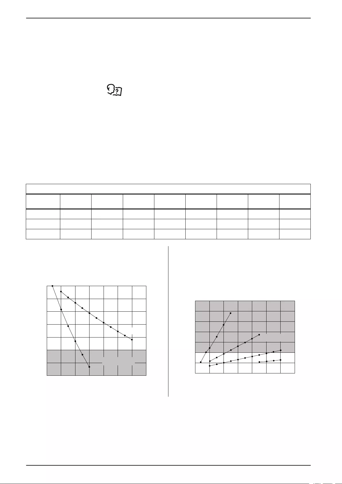
1 1/4 in. 1 3.8 in. 0.46 (1.5) 4.57 (15.0) 11.58 (38.0) 1.01 (3.3) 0.55 (1.8) 2.13 (7.0) 0.70 (2.3)
Size the suction line piping based on the equivalent
length to provide a capacity greater than 90% of the
rated capacity.
Size the liquid line piping based on the equivalent
length to provide a sub-cooling loss of less than 2°C
(3.6°F).
0
(0)
86%
88%
90%
92%
94%
96%
98%
100%
SUCTION LINE EQUIVALENT PIPING LINE LENGTH – m (ft)
PERCENT OF RATED CAPACITY
RECOMMENDED PIPE SIZES
20.0
(65.6)
40.0
(131.2)
60.0
(196.9)
80.0
(262.5)
100.0
(328.1)
120.0
(393.7)
140.0
(459.3)
1 1/8 in.
7/8 in.
UNACCEPTABLE
RANGE
na7005a
1 (1.8)
2 (3.6)
3 (5.4)
4 (7.2)
0 (0) 0
(0)
20.0
(65.6)
40.0
(131.2)
60.0
(196.9)
80.0
(262.5)
100.0
(328.1)
120.0
(393.7)
140.0
(459.3)
5 (9.0)
6 (10.8)
7 (12.6)
1/2 in. 5/8 in. 3/4 in.
7/8 in.
SUB-COOLING LOSS – °C (°F)
LIQUID LINE EQUIVALENT LINE LENGTH – m (ft)
UNACCEPTABLE
RANGE
na7006a
NOTE: The maximum vertical height of the condensing unit above the indoor unit is 30 m (98 ft).
60 990–91193A–001

Installation ACRD300 and ACCU30000 Series
Unit Connections
Be sure to use only clean, air conditioning/refrigeration (ACR) pipe and follow
standard procedures for pipe size selection for air-cooled equipment. All
refrigerant piping must be Type L ACR hard-drawn copper pipes (soft/annealed
copper is unacceptable) and must be 700 psig UL rated or equivalent. The
maximum allowable equivalent length between the evaporator and condenser is
120 equivalent m (394 equivalent ft). Vertical runs require a trap every 6 m (20 ft)
of rise.
IMPORTANT: The outdoor condensing unit can only be installed at the same
level or higher than the indoor unit. The maximum vertical height above the
indoor unit is 30 m (98 ft).
NOTE: When brazing field-installed copper refrigeration lines, use a nitrogen
purge to minimize contamination of the refrigeration system during the brazing
process.
The air-cooled equipment has been dehydrated at the factory and is shipped with
a holding charge of nitrogen. Test refrigerant connections for leaks before
replacing the holding charge.
NOTE: Remove the nitrogen holding charge tag from the lines after nitrogen
removal and product startup.
990–91193A–001 61
ACRD300 and ACCU30000 Series Installation
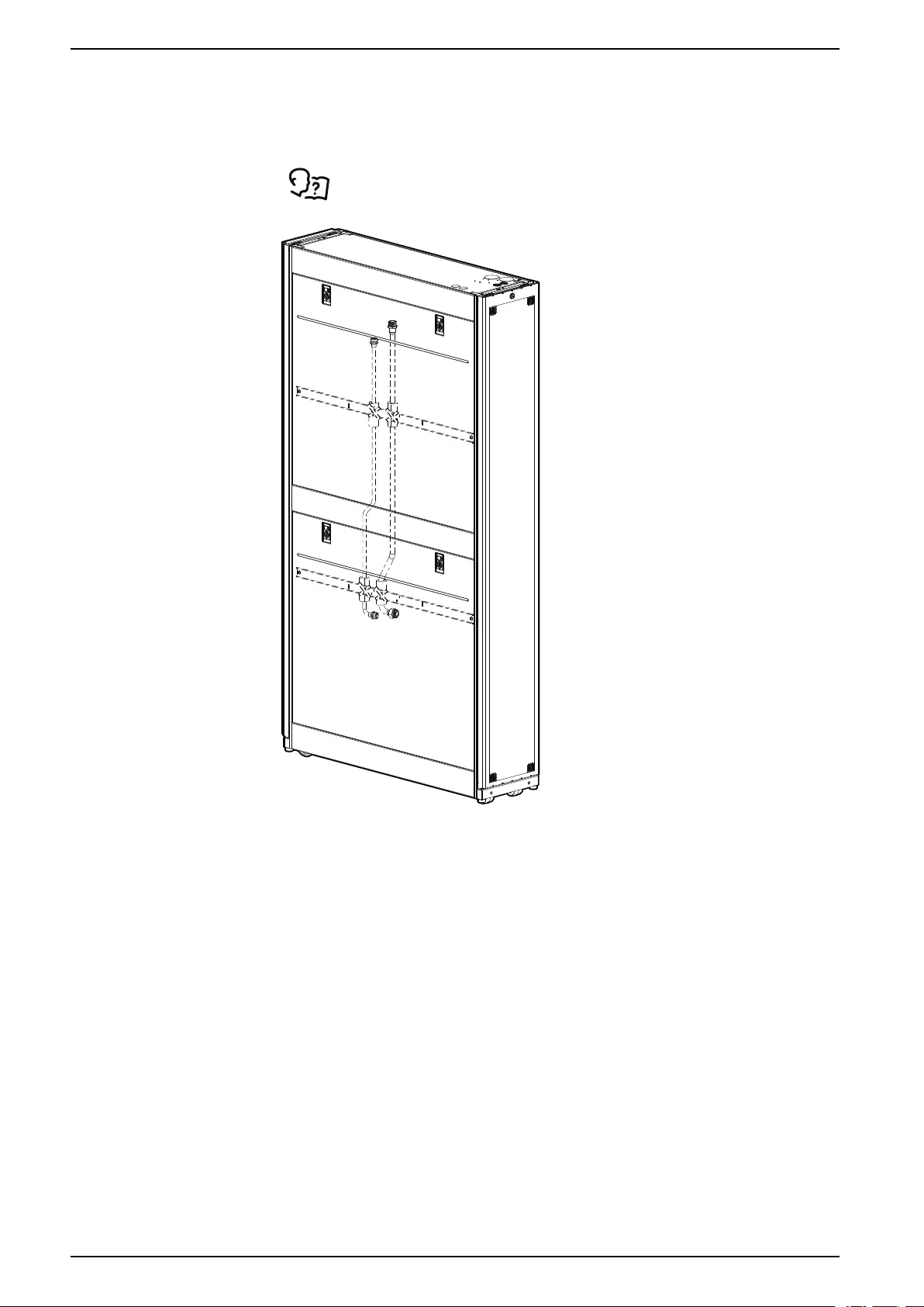
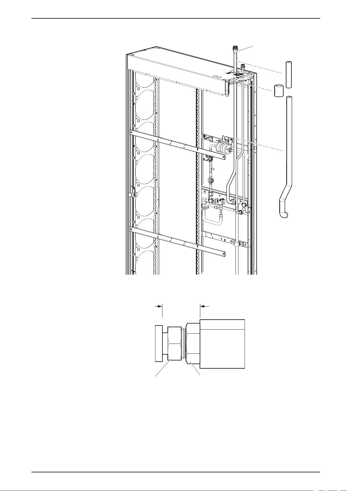
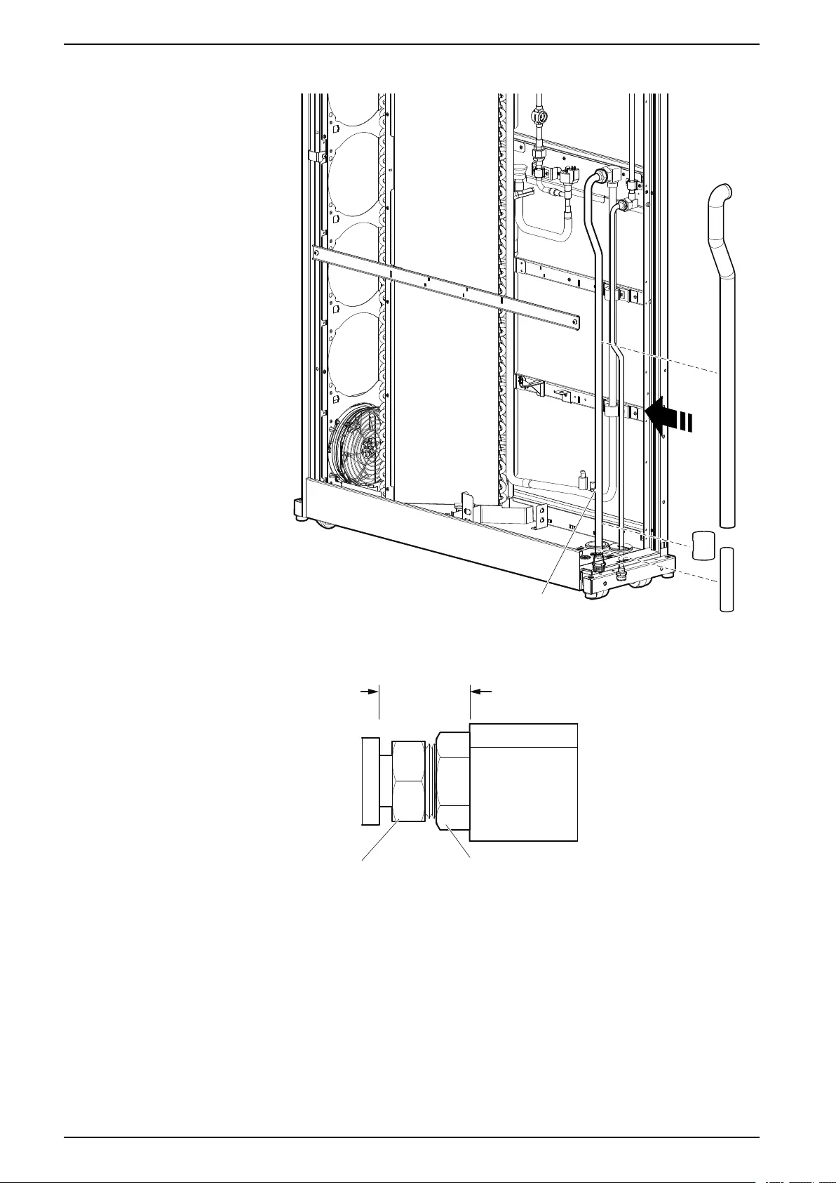
Suction and Liquid Line Piping Connections
The suction and liquid line pipes are shipped inside the unit attached to the side
braces. Remove the piping from inside the unit.
See Removing Doors and Panels, page 44.
na6983b
NOTE: Some components not shown for clarity.
62 990–91193A–001
Installation ACRD300 and ACCU30000 Series
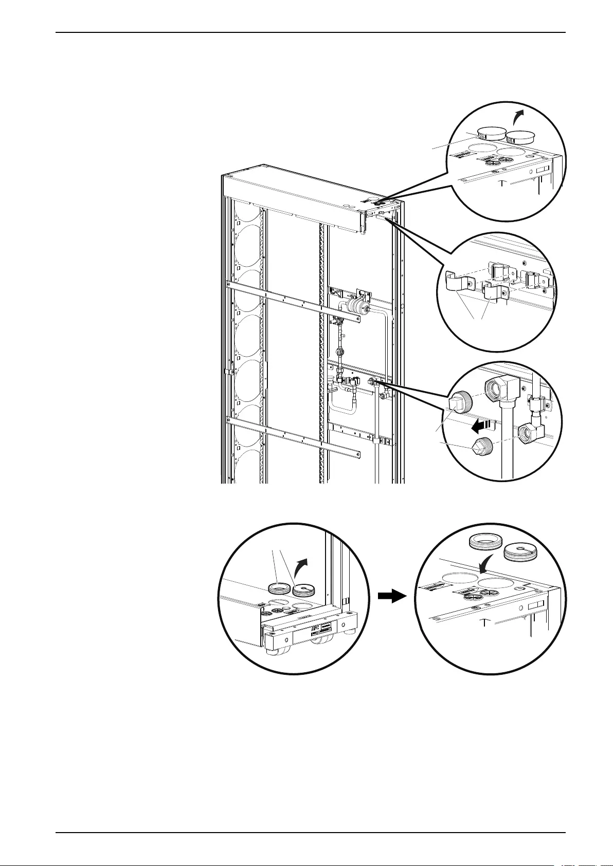
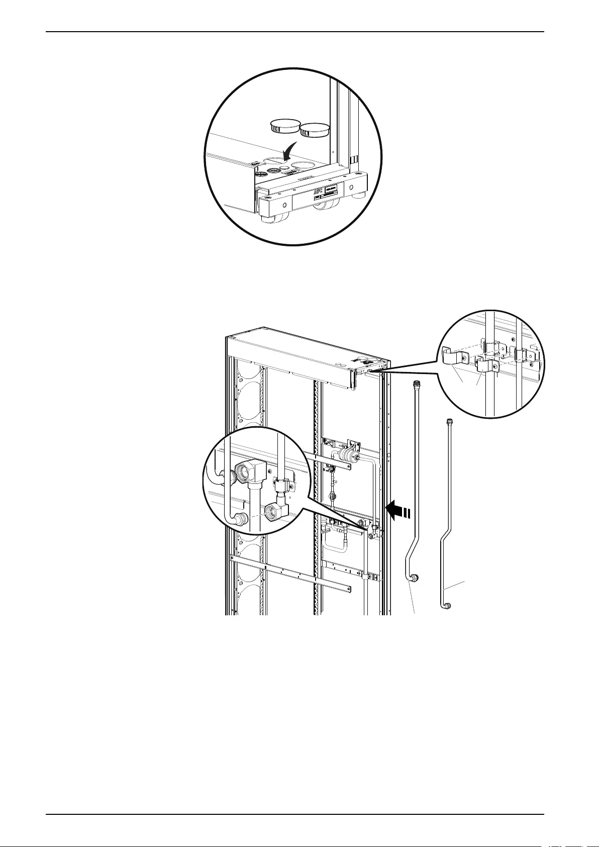
Top Routing
1. Remove the pipe connection caps from the unit piping, the caps from the
inlets, and the pipe clamps from the side of the unit.
PLUGS
PIPE
CLAMPS
CAPS
na6982a
2. Remove the grommets from the bottom piping inlets and move them to the
top piping inlets.
GROMMETS
na7007a
990–91193A–001 63
ACRD300 and ACCU30000 Series Installation
3. Place the plugs from the top piping inlets in the bottom piping inlets.
na7008a
4. Hold the pipes in position by replacing the pipe clamps. Tighten connections
to 50 Nm (37 lb-ft).
NOTE: Use caution when routing the pipes through the top of the unit to
avoid damaging sensors.
PIPE
CLAMPS
LIQUID LINE
PIPE
SUCTION LINE
PIPE
na6984a
64 990–91193A–001
Installation ACRD300 and ACCU30000 Series
5. Place insulation on the suction line unit piping.
SUCTION LINE PIPE
na6986a
NOTE: There is a gap between the provided insulation around the union.
Insulation needs to be field supplied for the suction line union.
na7051a
GAP
SUCTION LINE
PIPE
UNION
990–91193A–001 65
ACRD300 and ACCU30000 Series Installation
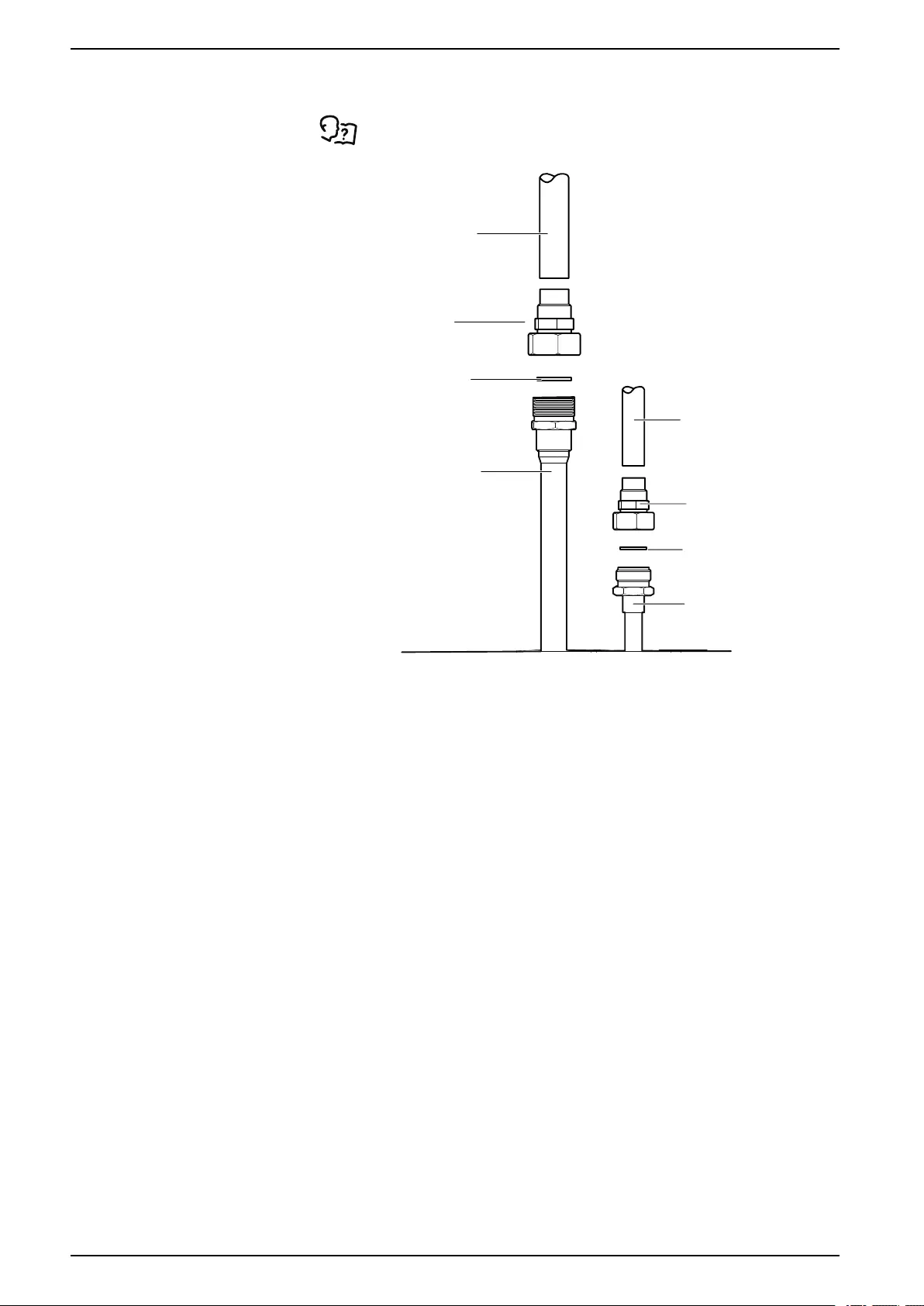
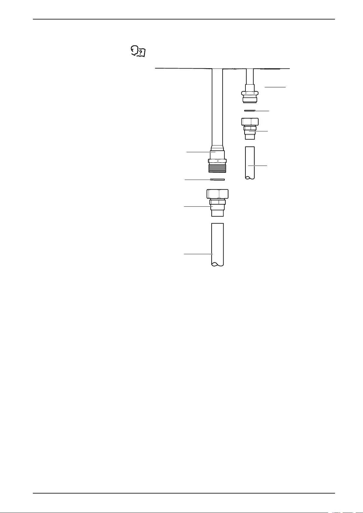
6. Make customer piping connections.
If the ball valve and union kit (ACAC10037) will be installed, see the
sheet included with the kit for installation instructions.
SUCTION LINE
LIQUID LINE
1 IN. GASKET
CUSTOMER PIPING
(FIELD SUPPLIED)
CUSTOMER PIPING
(FIELD SUPPLIED)
CUSTOMER PIPING
(FIELD SUPPLIED)
1 1/4 IN. GASKET
BALL VALVE AND UNION
(ACAC10037
OR FIELD SUPPLIED)
na7009a
BALL VALVE AND UNION
(ACAC10037
OR FIELD SUPPLIED)
66 990–91193A–001
Installation ACRD300 and ACCU30000 Series
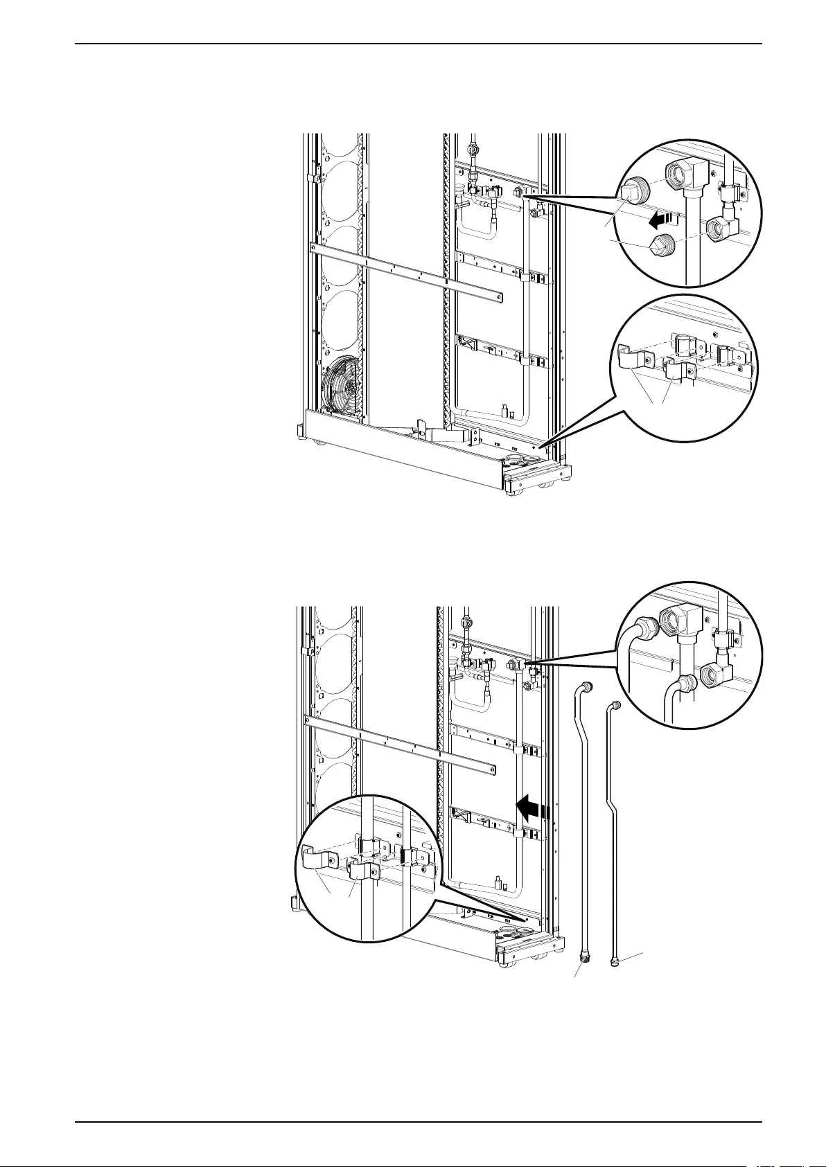
Bottom Routing
1. Remove the pipe connection caps from the unit piping and the pipe clamps
from the side of the unit.
PIPE
CLAMPS
CAPS
na6987a
2. Hold the pipes in position by replacing the pipe clamps. Tighten connections
to 50 Nm (37 lb-ft).
NOTE: Use caution when routing the pipes through the bottom of the unit
to avoid damaging sensors.
PIPE
CLAMPS
LIQUID LINE
PIPE
SUCTION LINE PIPE
na6988a
990–91193A–001 67
ACRD300 and ACCU30000 Series Installation
3. Place insulation on the suction line unit piping.
SUCTION LINE PIPE
na6989a
NOTE: There is a gap between the provided insulation around the union.
Insulation needs to be field supplied for the suction line union.
na7051a
GAP
SUCTION LINE
PIPE
UNION
68 990–91193A–001
Installation ACRD300 and ACCU30000 Series
4. Make customer piping connections.
If the ball valve and union kit (ACAC10037) will be installed, see the
sheet included with the kit for installation instructions.
SUCTION LINE
LIQUID LINE
1 IN. GASKET
1 1/4 IN. GASKET
BALL VALVE AND UNION
(ACAC10037
OR FIELD SUPPLIED)
BALL VALVE AND UNION
(ACAC10037
OR FIELD SUPPLIED)
na7009b
CUSTOMER PIPING
(FIELD SUPPLIED)
CUSTOMER PIPING
(FIELD SUPPLIED)
CUSTOMER PIPING
(FIELD SUPPLIED)
990–91193A–001 69
ACRD300 and ACCU30000 Series Installation
Electrical Connections
DANGER
HAZARD OF ELECTRIC SHOCK, EXPLOSION, OR ARC FLASH
• Apply appropriate personal protective equipment (PPE) and follow safe
electrical work practices.
• This equipment must be installed and serviced by qualified personnel only.
• Turn off all power supplying this equipment before working on or inside the
equipment.
• Replace all devices, doors, and covers before turning on power to this
equipment.
Failure to follow these instructions will result in death or serious injury.
DANGER
HAZARD OF ELECTRIC SHOCK, EXPLOSION, OR ARC FLASH
Potentially dangerous and lethal voltages exist within this unit. More than one
disconnect switch may be required to energize or de-energize this equipment.
Observe all cautions and warnings. Failure to do so could result in serious injury
or death. Only qualified service and maintenance personnel may work on this
equipment.
Failure to follow these instructions will result in death or serious injury.
WARNING
ELECTRICAL HAZARD
• Electrical service must conform to local and national electrical codes and
regulations.
• The equipment must be grounded.
Failure to follow these instructions can result in death, serious injury, or
equipment damage.
The following electrical connections are required in the field:
• Power to the indoor unit (single-phase plus ground)
• Power to the outdoor unit (three-phase plus ground)
• Communication (A-Link, Building Management System, Modbus)
• Outdoor unit RS-485 connection
• Sensors
See the electrical schematic (located on the electrical box) for all
electrical connections.
See the equipment name plate for voltage and current requirements.
All low-voltage connections, including data and control connections, must be
made with properly insulated wires. Low-voltage wiring must be insulated based
on the wiring with which it is routed. The low-voltage connections must have 300-
V minimum insulation.
NOTE: A power disconnect is required to isolate each unit for maintenance
and servicing.
70 990–91193A–001
Installation ACRD300 and ACCU30000 Series
Power Connections
WARNING
ELECTRICAL HAZARD
• Electrical service must conform to local and national electrical codes and
regulations.
• The equipment must be grounded.
Failure to follow these instructions can result in death, serious injury, or
equipment damage.
WARNING
HAZARD TO EQUIPMENT OR PERSONNEL
All work must be performed by Schneider Electric qualified personnel.
Failure to follow these instructions can result in death, serious injury, or
equipment damage.
Primary and Secondary Power Feeds
All indoor unit models and some of the outdoor units (ACCU30302, ACCU3002,
ACCU30202, and ACCU30102) are capable of receiving power through one of
two separate feeds: primary feed or secondary feed. Use the display interface to
configure the unit to receive power through the primary feed, the secondary feed,
or both). The equipment receives power through the primary feed regardless of
whether the secondary feed is receiving power. If power is removed from the
primary feed, the secondary feed takes over and supplies power to the equipment
(if a secondary feed is connected).
Connect the primary feed and secondary feed input cables to individual, breaker-
controlled branch circuits or to PDUs backed by separate Uninterruptible Power
Supplies (UPS).
NOTE: The primary and secondary feeds must not use the same branch
circuit, PDU, or UPS.
990–91193A–001 71
ACRD300 and ACCU30000 Series Installation
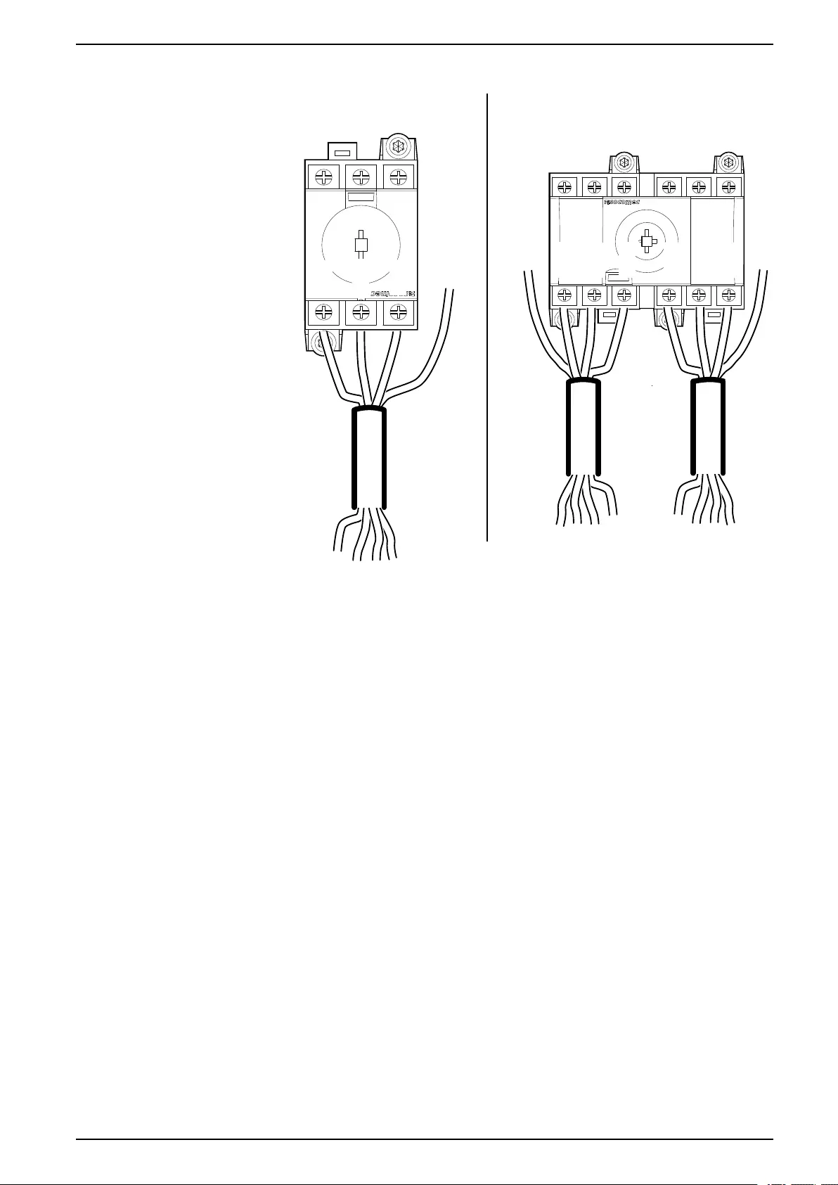
Indoor Unit—ACRD300, ACRD300D, ACRD300G, ACRD300GD
Power connections can be routed through the top or bottom of the unit.
NOTE: Some components not shown for easier viewing.
1. Remove the plugs from the power supply inlets that will be used on top of the
unit or bottom of the unit.
na6969a
TOP CONNECTION BOTTOM CONNECTION
2. Remove the rear door and filters.
See Removing Doors and Panels, page 44.
3. Remove the cover from the ATS.
NOTE: The ATS in ACRD300 units is different from other units and
includes an EMI filter; power connections are made the same.
na6970a
na7203a
ACRD300 ONLY
72 990–91193A–001
Installation ACRD300 and ACCU30000 Series
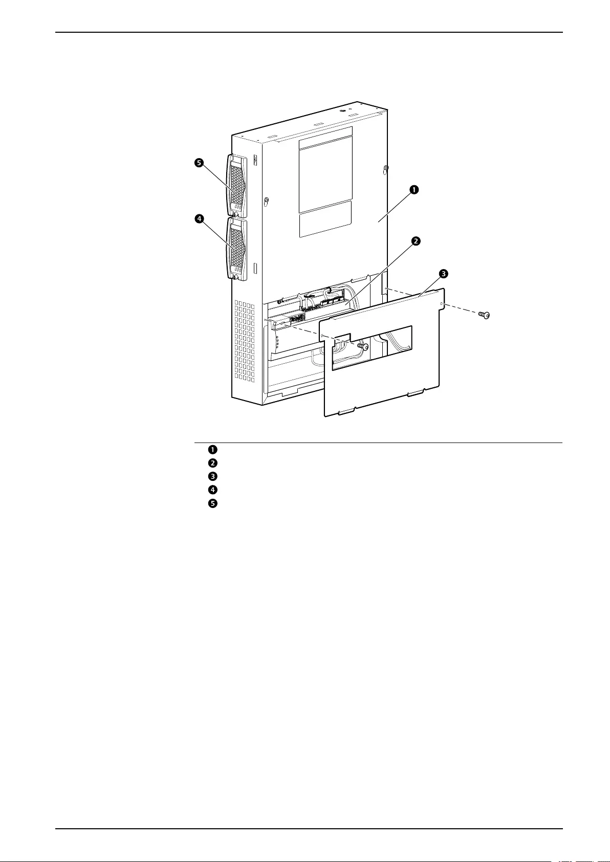
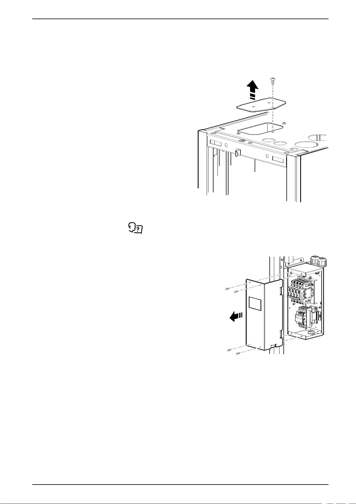
Indoor Unit (Top Routing)—ACRD301, ACRD301G
Power connections can be routed through the top or bottom of the unit: this
section covers a top routing.
NOTE: Some components not shown for easier viewing.
1. Remove the cover plate from the top of the unit.
na7036a
2. Remove the rear door and filters.
See Removing Doors and Panels, page 44.
3. Remove the cover from the ATS.
na6970b
990–91193A–001 75
ACRD300 and ACCU30000 Series Installation
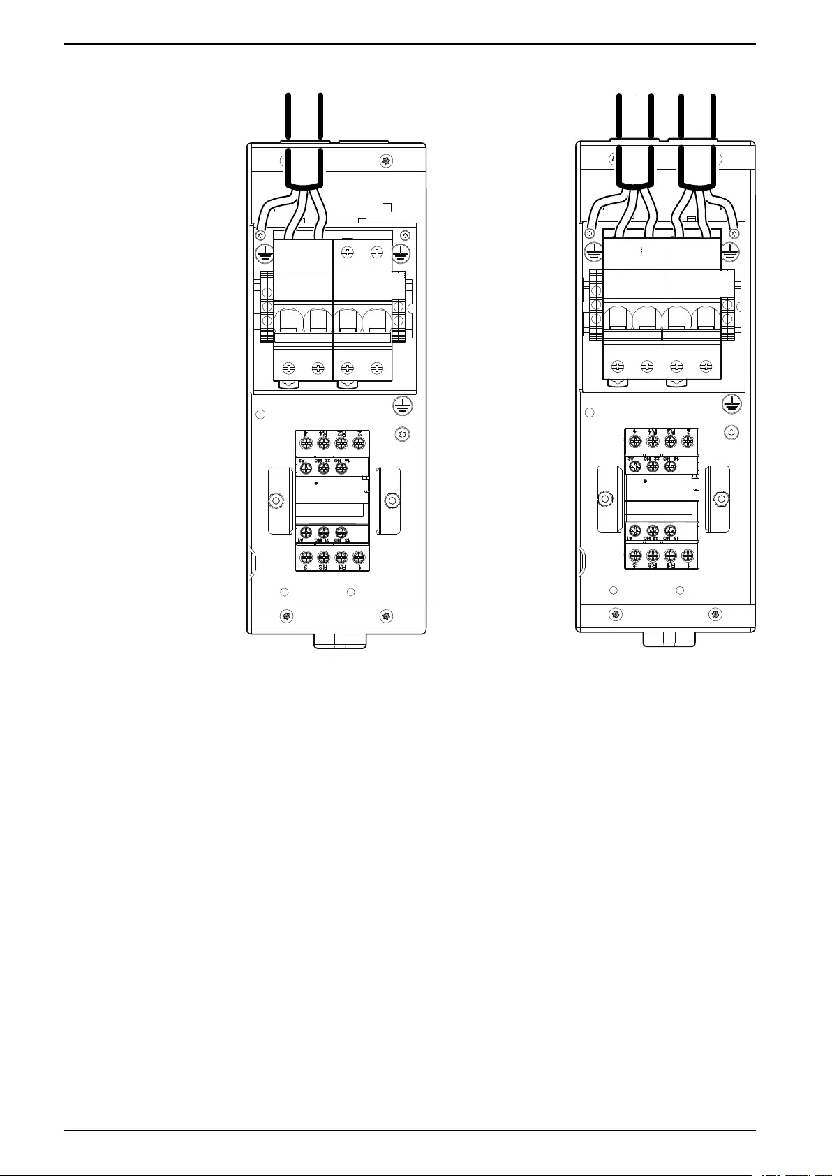
8. Configure the voltage.
• 200–240 V: Connect the wire labeled F2-1 to the 240–V fuse.
• 100–120 V: Connect the wire labeled F2-1 to the 120–V fuse.
na7050a
F1
F2
F3
F4
120 V
240 V
24 AC
24 DC
See the ladder diagram included with the unit for more information.
9. Replace the ATS cover, filters, and rear door.
78 990–91193A–001
Installation ACRD300 and ACCU30000 Series
Indoor Unit (Bottom Routing)—ACRD301, ACRD301G
Power connections can be routed through the top or bottom of the unit: this
section covers a bottom routing.
NOTE: Some components not shown for easier viewing.
1. Remove the rear door and filters.
See Removing Doors and Panels, page 44.
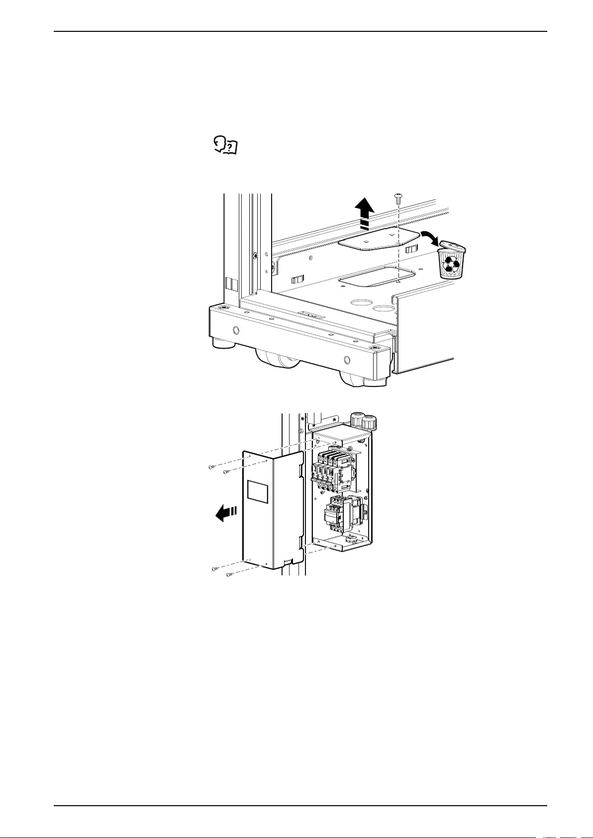
2. Remove the cover plate from the bottom of the unit and recycle the plate.
na7039a
3. Remove the cover from the ATS.
na6970b
990–91193A–001 79
Installation ACRD300 and ACCU30000 Series
9. Configure the voltage.
• 200–240 V: Connect the wire labeled F2-1 to the 240–V fuse.
• 100–120 V: Connect the wire labeled F2-1 to the 120–V fuse.
na7050a
F1
F2
F3
F4
120 V
240 V
24 AC
24 DC
See the ladder diagram included with the unit for more information.
10. Replace the ATS cover, filters, and rear door.
990–91193A–001 83
ACRD300 and ACCU30000 Series Installation
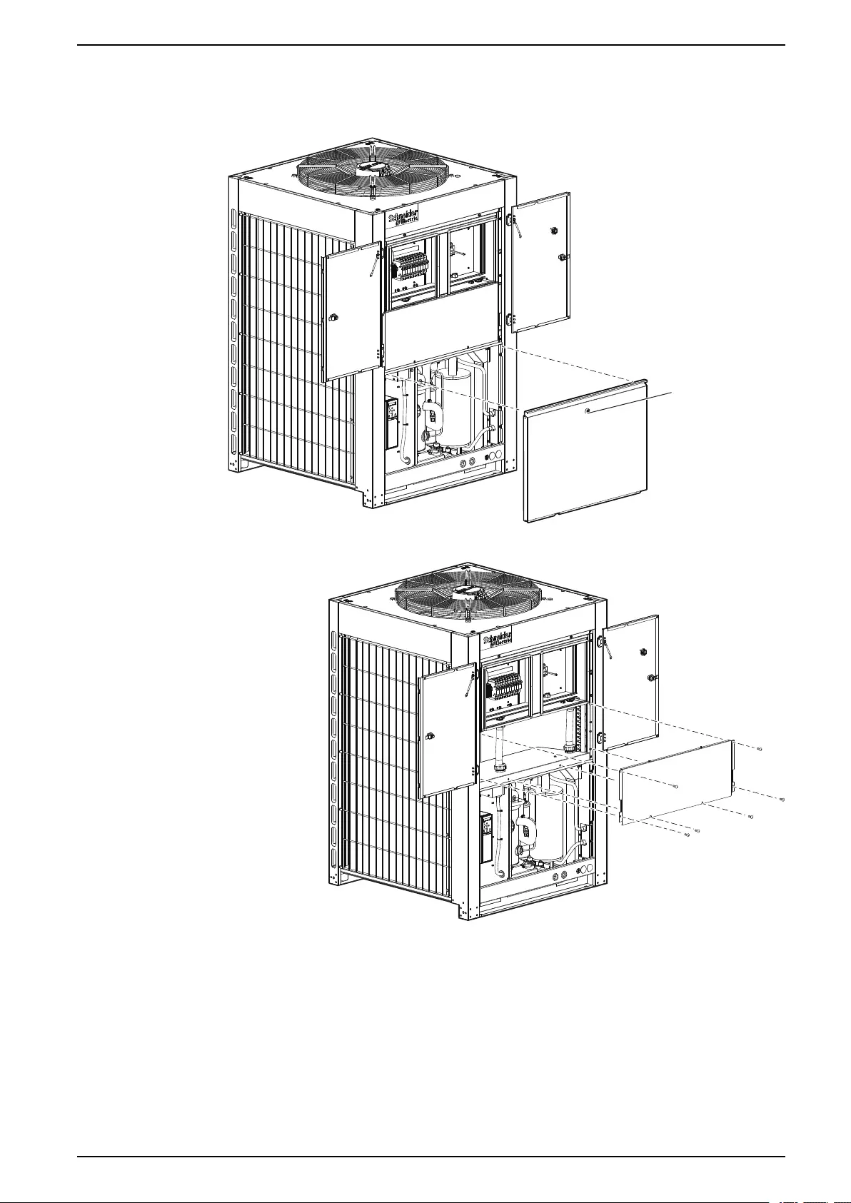
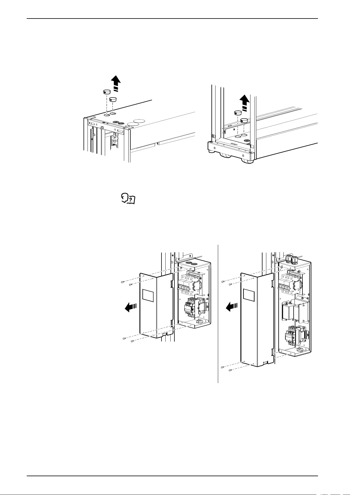
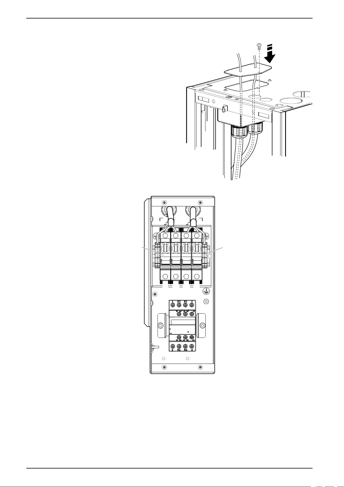
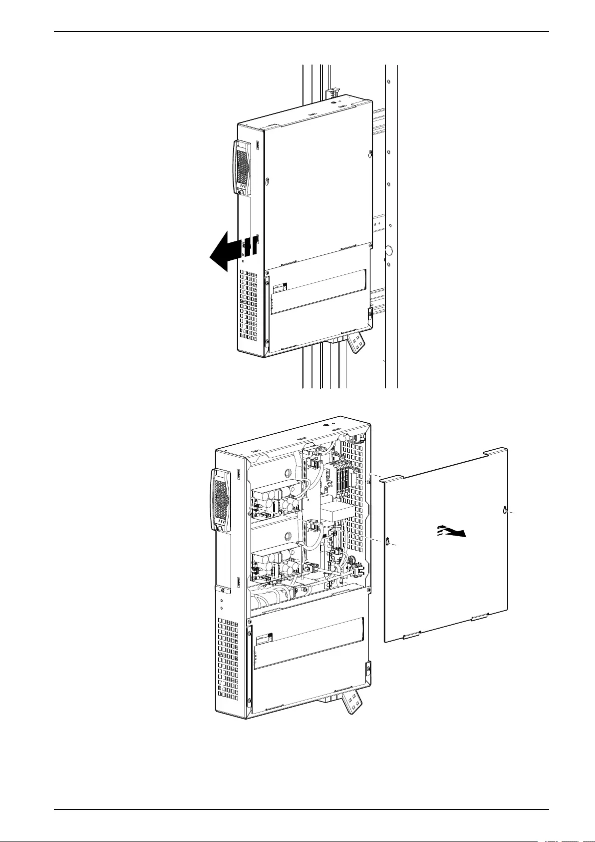
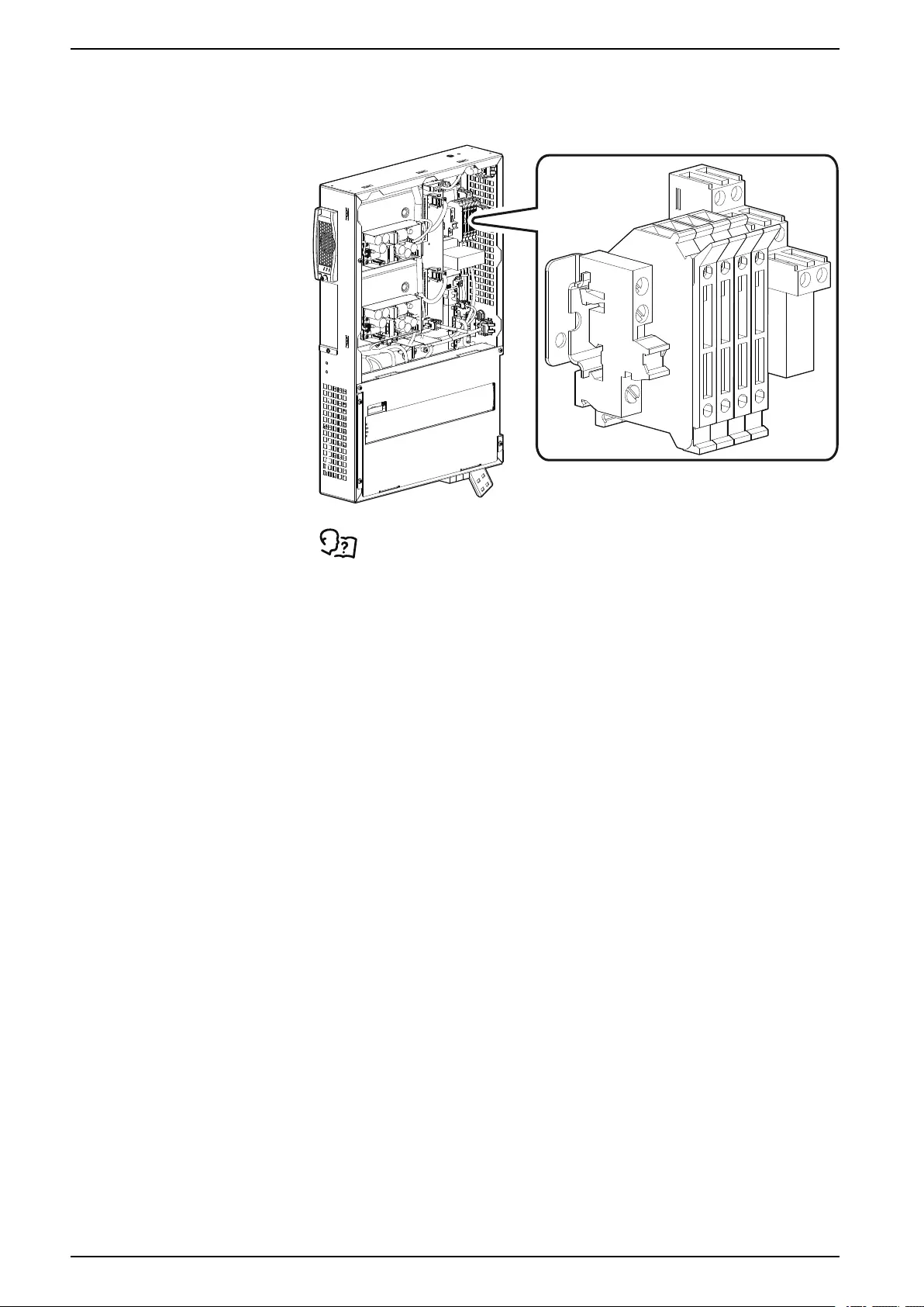
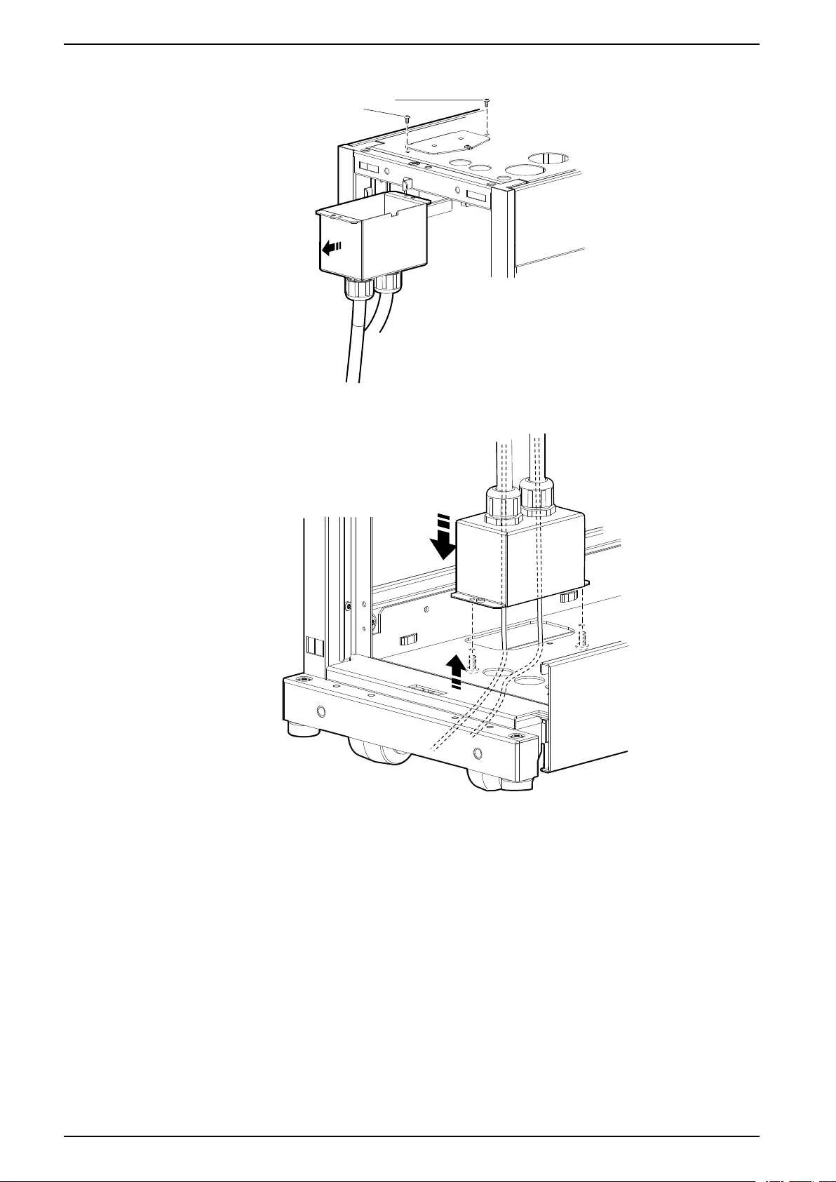
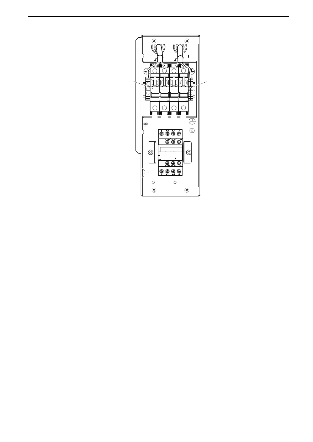
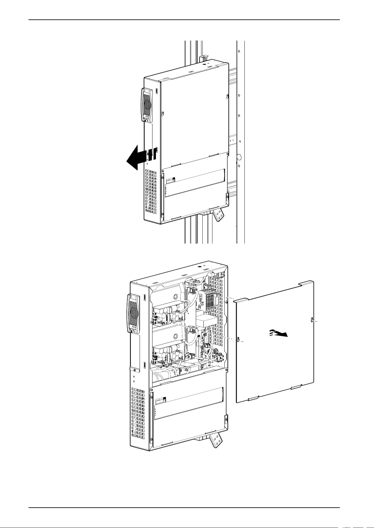
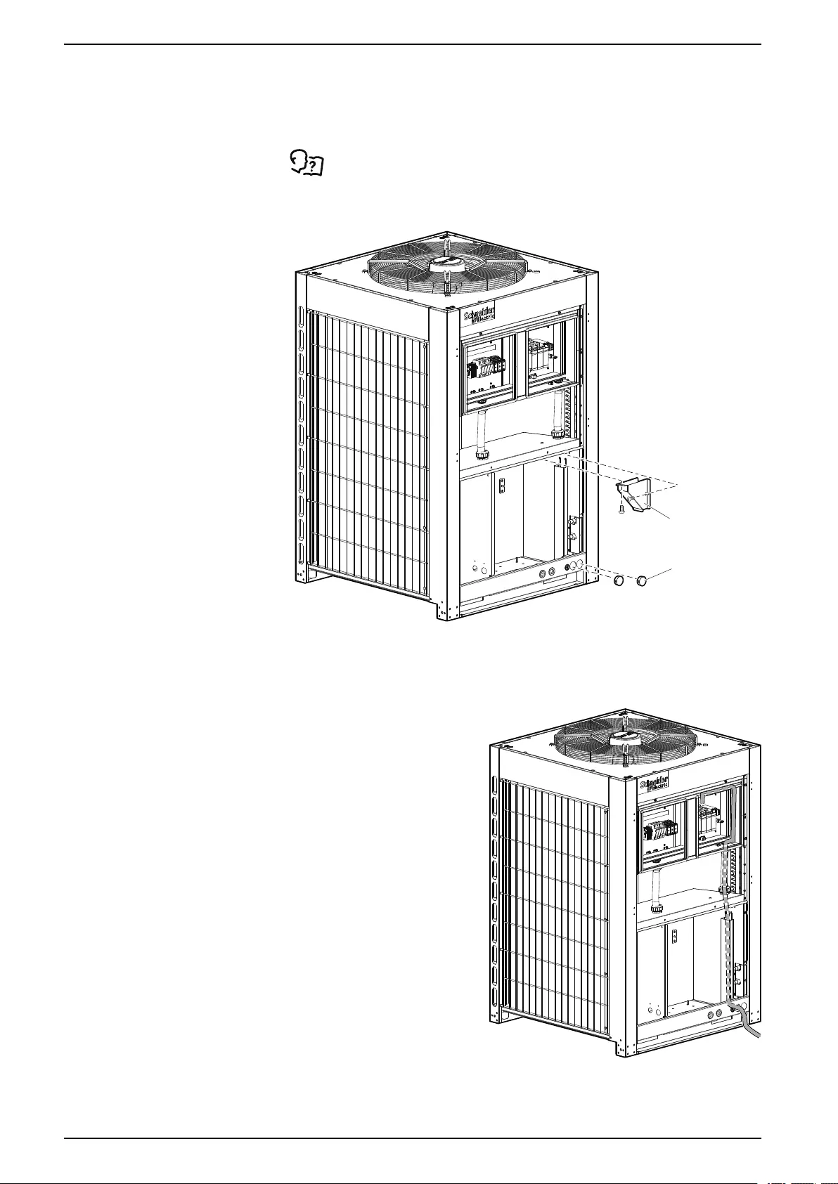
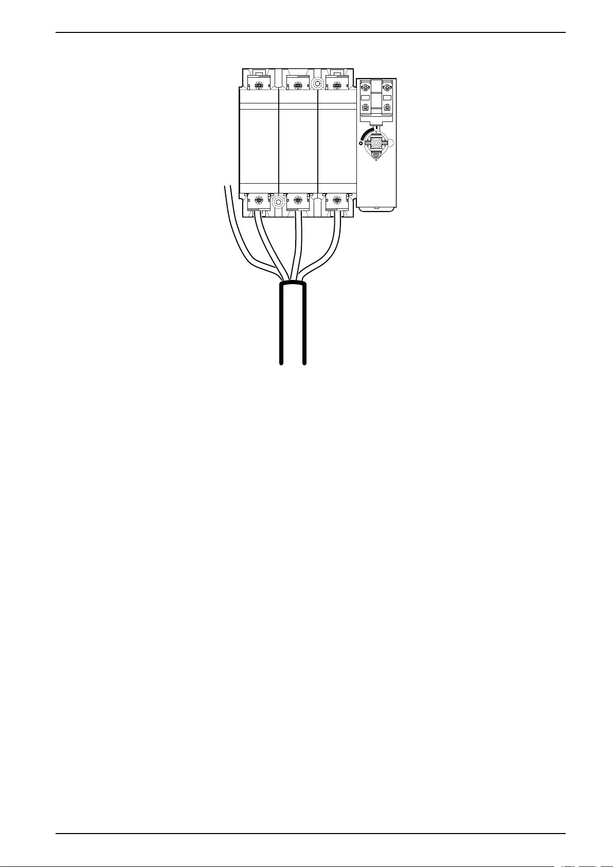
Outdoor Unit—ACCU30301, ACCU30302
1. Remove the service and internal protection panels, and open the electrical
panel.
See Removing Doors and Panels, page 44.
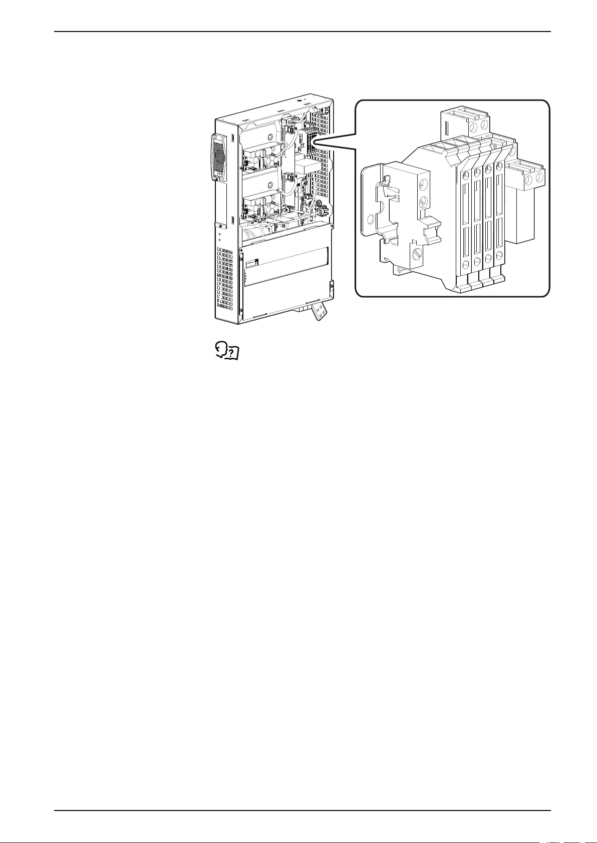
2. Remove the cover plate and plugs from the power supply inlets.
na6968c
COVER PLATE
PLUGS
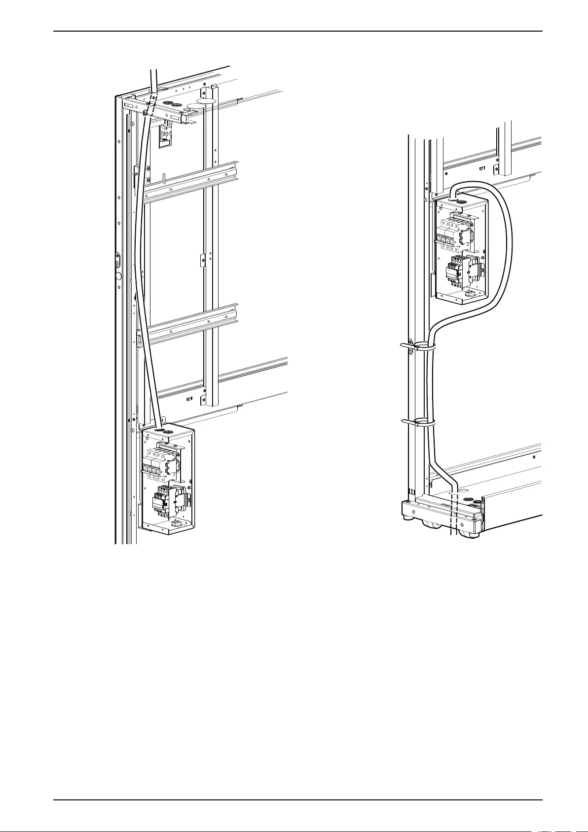
3. Route the cable or cables through the unit to the electrical panel.
NOTE: Use a conduit at least 25 mm (1 in.) ID to protect the exposed
portion of the power cable between the unit and the building. The conduit
must conform to any applicable local and national codes.
na6968b
84 990–91193A–001
ACRD300 and ACCU30000 Series Installation
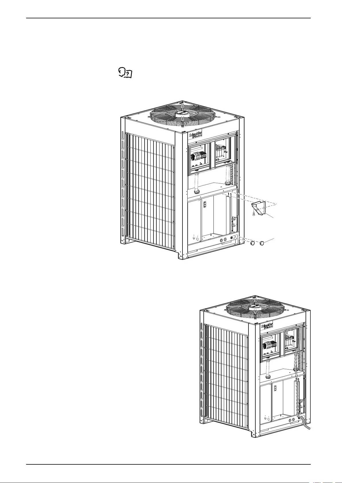
Outdoor Unit—ACCU30001, ACCU30002, ACCU30201, ACCU30202,
ACCU30101, ACCU30102
1. Remove the service and internal protection panels, and open the electrical
panel.
See Removing Doors and Panels, page 44.
2. Remove the cover plate and plugs from the power supply inlets.
na6968c
COVER PLATE
PLUGS
3. Route the cable or cables through the unit to the electrical panel.
NOTE: Use a conduit at least 25 mm (1 in.) ID to protect the exposed
portion of the power cable between the unit and the building. The conduit
must conform to any applicable local and national codes.
na6968b
86 990–91193A–001
ACRD300 and ACCU30000 Series Installation
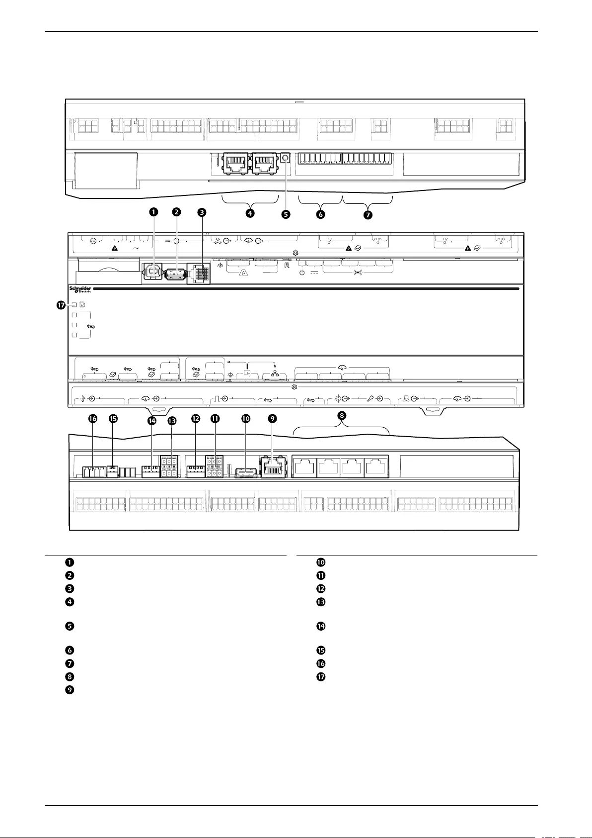
Communication Connections
Interface Connection
J15
J9
24V
J10 J11 J12
100-240V
J13
24V
J14 J16 J17 J18 J19
123
NC COM NONC COM NONC COM NO
4
24V 12V 0V
– +
21 – Link
21
3 4
(1)
(2)
(3)
RS485
RS485 (1)
FIELDBUS
CAN
CANH CANL 0V D0- D1+ 0V
RS485 (2)
2W/4W D0- D1+ 0V
D0- D1+ 0V
TX
RX
RS485 (3)
2W/4W D0- D1+ 0V
D0- D1+ 0V
TX
RX
MODBUS NETWORK
12 3 4
J8J7
M
J6
J5J4 CAN
RS485
J3J2J1
na6256a
Item Description Item Description
USB device port Touch screen display connection
USB host port (Not available) Modbus connection
Serial port (Not available) Modbus configuration switches
A-Link ports Fieldbus Modbus connection (Not
available)
Reset button Fieldbus Modbus configuration switches
(Not available)
Output relay 4/standby input Fieldbus CANbus configuration switches
Output relay 1–3 (Not available) Fieldbus CANbus connection
Universal sensor ports Processor status LED
Network connection
88 990–91193A–001
Installation ACRD300 and ACCU30000 Series
A-Link Connections
NOTE: All input and output connections should be wired as Class 2 circuits.
The A-Link bus connection allows a maximum group of twenty (20) InRow
ACRD30X units to communicate with each other.
To enable the units to function as a group, link them together using a standard pin-
out CAT-5 cable with RJ-45 connectors. The A-Link bus must be terminated at the
first and last unit installed in the group. The A-Link bus must be terminated at the
first and last unit installed in the group. An A-Link terminator is supplied with each
unit.
NOTE: The maximum wire length for the entire group must not exceed 305 m
(1,000 ft).
Active Flow Controllers (AFC)
AFC units are installed in the cooling group in a HACS or CACS environment, they
are connected to the A-Link bus as shown. If the cooling group is in an under floor
environment, the AFC unit is connected through the J5 port on the controller.
NOTICE
CAT 5 PINOUT
Devices connected on the A-Link ports should use a standard pin-out (1-1, 2-2,
3-3, 4-4, 5-5, 6-6, 7-7, 8-8) CAT5 cable only.
Failure to follow these instructions can result in equipment damage.
See the AFC Installation Manual for more information.
990–91193A–001 89
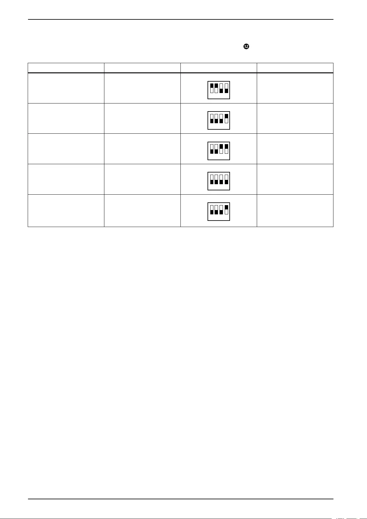
ACRD300 and ACCU30000 Series Installation
Modbus Switch Configuration
The DIP switches in DIP switch bank RS485 (3) ( in Interface Connection, page
88) may need to be configured during installation.
Position Status DIP Switches Mode
1 and 2 Open (up)
1 2 3 4
4-wire Modbus (needs TXD0-,
TXD1+, RXD0-, RXD0+, and
COM connected to Modbus
master)
1 and 2 Closed (down)
1 2 3 4
2-wire Modbus (needs TXD0-,
TXD1+, and COM, or RXD0,
RXD0+, and COM)
3 and 4 Open (up)
1 2 3 4
2-wire or 4-wire Modbus (no
termination)
3 and 4 Closed (down)
1 2 3 4
4-wire Modbus (termination
enabled)
3 Closed (down)
1 2 3 4
2-wire Modbus (termination
enabled, position 4 must remain
in the Open (up) position in 2-
wire mode, or double
termination will occur)
90 990–91193A–001
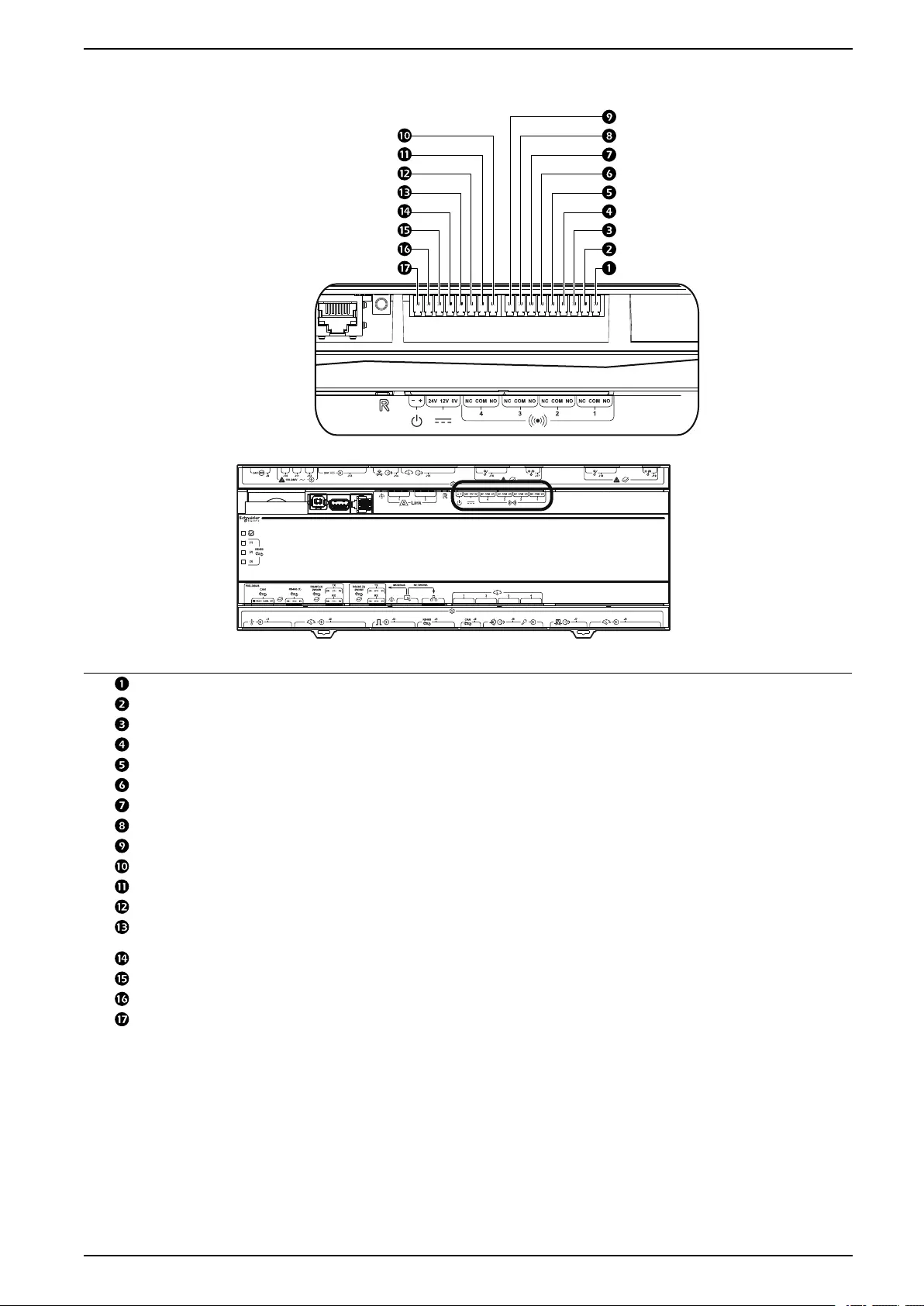
Installation ACRD300 and ACCU30000 Series
Output Relays and Standby Input
na6274a
Item Name Description
Output relay 1 N.O. (Not available) Normally Open contact
Output relay 1 COM (Not available) Common contact
Output relay 1 N.C. (Not available) Normally Closed contact
Output relay 2 N.O. (Not available) Normally Open contact
Output relay 2 COM (Not available) Common contact
Output relay 2 N.C. (Not available) Normally Closed contact
Output relay 3 N.O. (Not available) Normally Open contact
Output relay 3 COM (Not available) Common contact
Output relay 3 N.C. (Not available) Normally Closed contact
Output relay 4 N.O. Normally Open contact
Output relay 4 COM Common contact
Output relay 4 N.C. Normally Closed contact
Ground Ground reference, typically connected to the negative connection of Standby
Input, when using the 12-VDC or 24-VDC power supply.
12VDC Standby input 12-VDC supply current limited to 20 mA
24VDC Standby input 24-VDC supply current limited to 20 mA
Standby Input + Positive connection used for Standby Input
Standby Input – Negative connection used for Standby Input. Typically connected to ground.
990–91193A–001 91
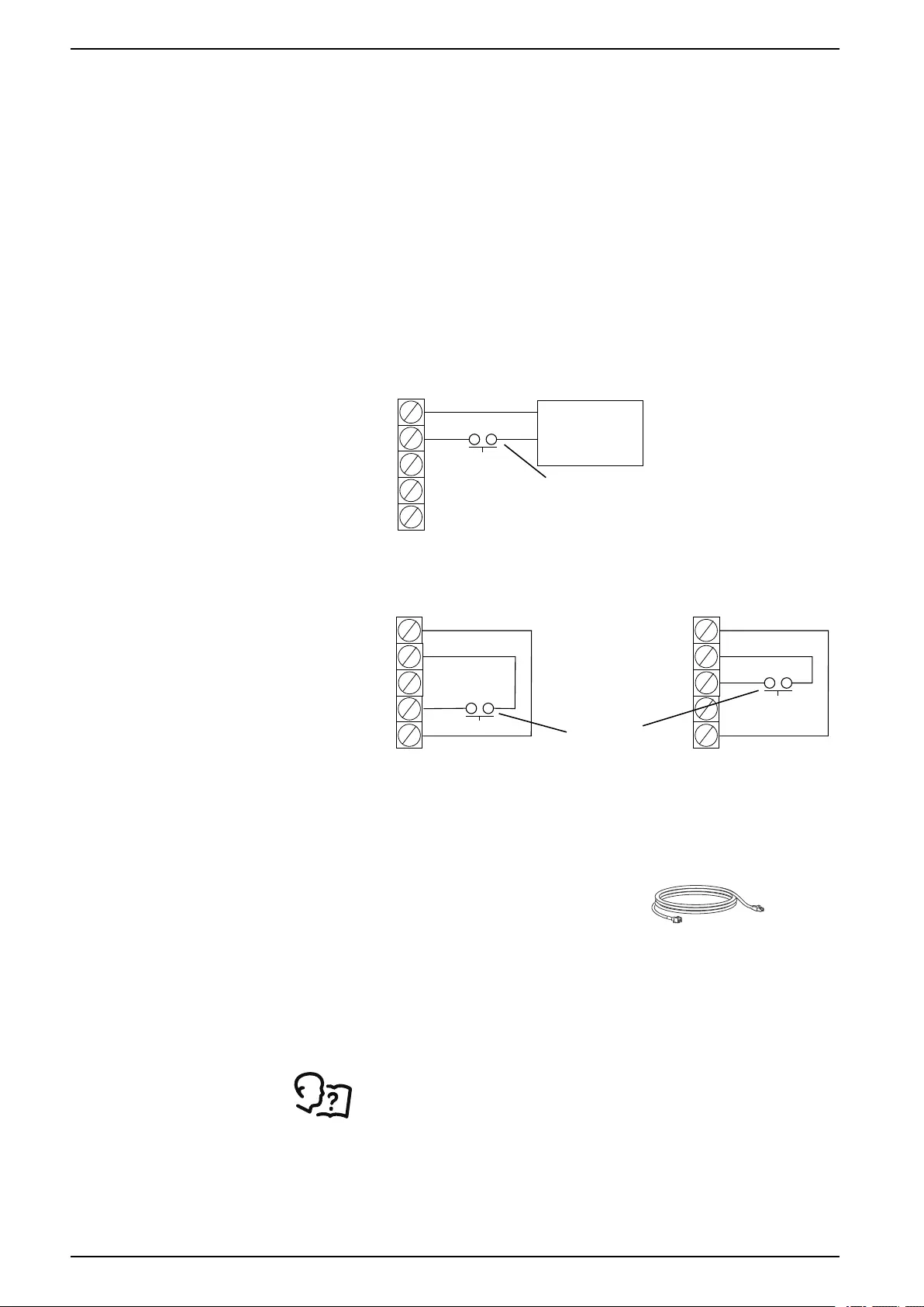
ACRD300 and ACCU30000 Series Installation
Output Relays
Four output relays connections are available. These relays can be configured,
through the user interface, to various alarms detecting normal or abnormal
conditions.
Output relays are Form C type, having a Normally Open (N.O.), Normally Closed
(N.C.), and Common (COM) contacts.
NOTE: Output relays are rated at 24 VDC, 6 A maximum.
Standby Input
Standby input allows the cooling unit to be remotely placed in backup mode.
Backup mode is configured through the user interface and can be set as a
normally “active” or “not active” input.
NOTE: Standby Input is rated at 12-/24-V AC or DC. If using field supplied
voltage, the Standby Input consumes 10 mA maximum at 24 VDC :
na4478a
EXTERNAL POWER SUPPLY
STANDBY
12-30 V AC/DC
SD–
SD+
24V_SD
12V_SD
GND
NOT USED
NOT USED
NOT USED
12–30V AC/DC
POWER SUPPLY
N.O. OR N.C.
CONTACTS
12V POWER SUPPLY 24V POWER SUPPLY
STANDBY
12-30 V AC/DC
STANDBY
12-30 V AC/DC
N.O. OR N.C.
CONTACTS
SD–
SD+
24V_SD
12V_SD
GND
SD–
SD+
24V_SD
12V_SD
GND
NOT USED
NOT USED
*Normally open contacts shown.
Leak Detector—Optional
The leak rope detector (NBES0308)
connects to a universal sensor port
connection using the supplied cable in
the leak detector kit. Route the leak
detector cable through one of the low
voltage wiring openings.
NOTE: The total length of the rope
leak sensor can be extended up to
24.4 m (80 ft) using a Rope Leak
Sensor Extension kit (NBES0309).
See the documentation supplied with the kit for installation
information.
92 990–91193A–001
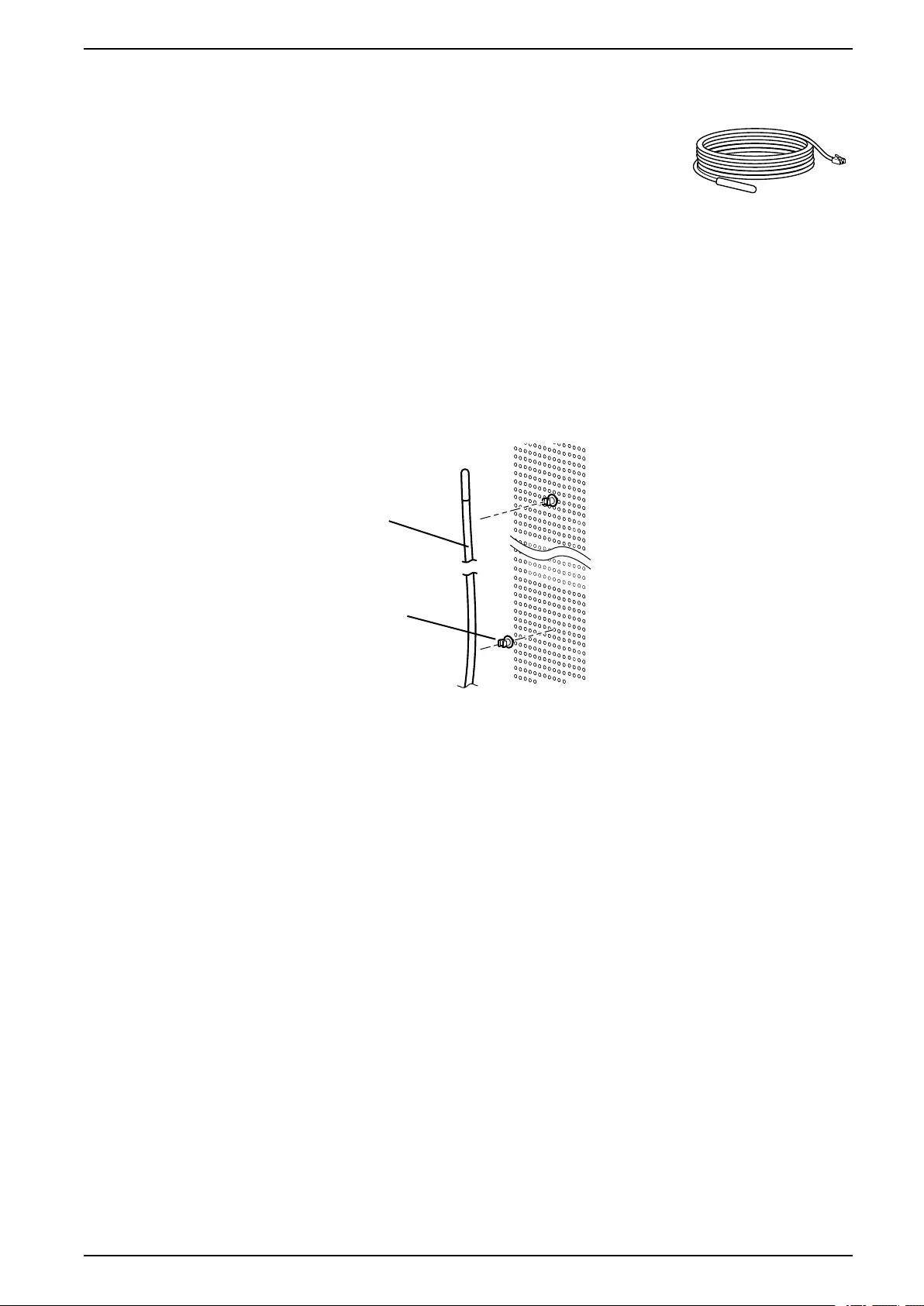
Installation ACRD300 and ACCU30000 Series
Rack Air Temperature Sensors
The rack air temperature sensors control unit airflow
and ensure an adequate supply of cooling air to the
server racks in the data center. The unit is supplied
with . These sensors are attached on the unit front
door.
Installation
NOTE: Rack temperature sensor installation is not required if the equipment
operates in Rack Air Containment System (RACS) or Hot Aisle Containment
System (HACS) mode. The InRow configuration requires temperature sensor
installation.
1. Route the sensor through either the top or the bottom of the adjacent server
rack.
2. Secure the temperature sensor cable to the front door of the adjacent server
rack at multiple locations using the provided wire clips as shown.
TEMPERATURE
SENSOR
WIRE CLIPS
NOTE: Remote rack sensors must be installed for proper operation.
The sensors should be located on racks that are adjacent to the cooling
unit. The optimum position of the rack temperature sensors will vary from
installation to installation but should be located in close proximity to fan-
cooled IT equipment to ensure accurate readings. Servers most likely to
have insufficient or inadequately cooled cooling air due to the
recirculation of hot air from the hot aisle include:
• Servers positioned at the top of a rack
• Servers positioned at any height in the last rack at an open end of a
row
• Servers positioned behind flow-impairing obstacles such as building
elements
• Servers positioned in a bank of high-density racks
• Servers positioned next to racks with Air Removal Units (ARU)
• Servers positioned very far from the equipment
• Servers positioned very close to the equipment
990–91193A–001 93
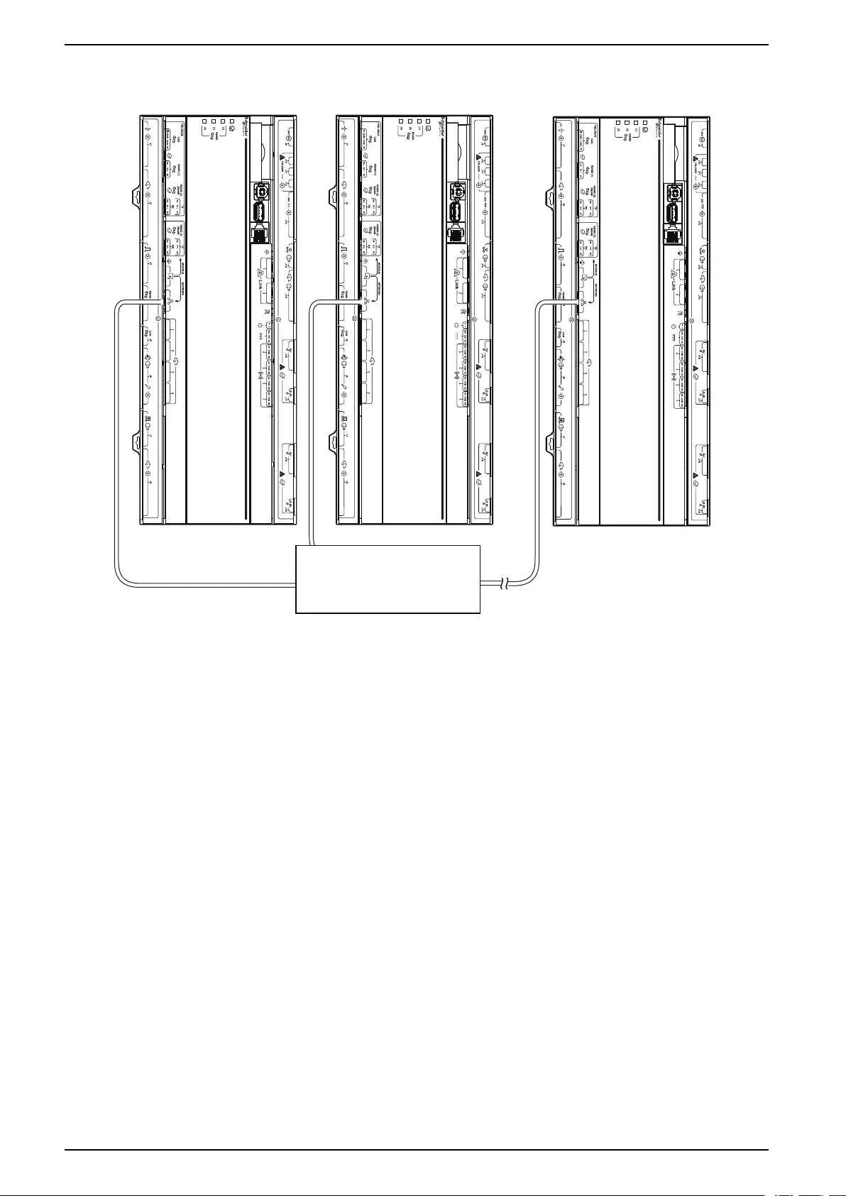
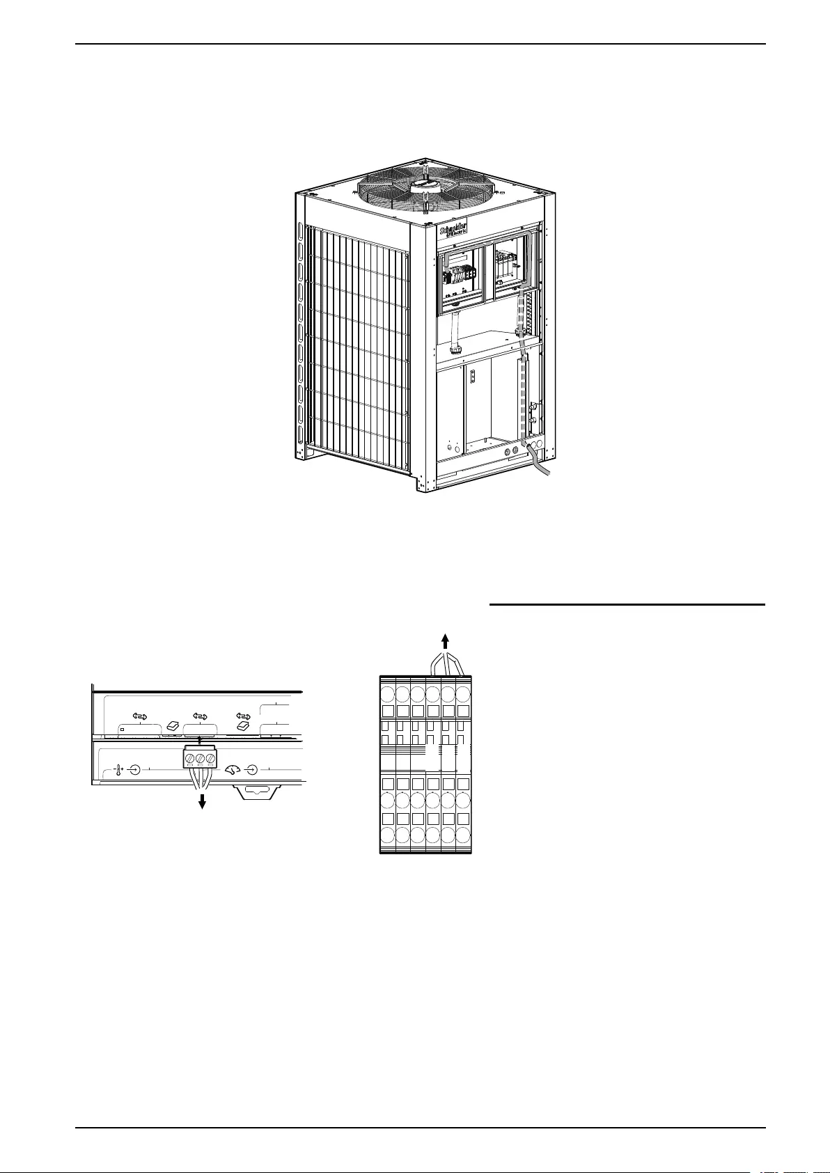
Installation ACRD300 and ACCU30000 Series
Outdoor Unit Connection
Remove the cover plate and route the signal cable through the unit as shown
below:
NOTE: Some components not shown for easier viewing.
na6968a
NOTE: Routing of the signal cable in the indoor unit is left to the discretion of
the installer. The signal cable located outside the building requires a conduit to
protect the cable. The cable protection must conform to local regulations.
Indoor Unit J5
Controller
Outdoor Unit
Terminal Blocks
TERMINAL BLOCKS
(OUTDOOR UNIT)
na6967a
J5 CONTROLLER
(INDOOR UNIT)
RS485 (1)
FIELDBUS
CAN
CANH CANL 0V D0- D1+ 0V
RS485 (2)
2W/4W D0- D1+ 0V
D0- D1+ 0V
TX
RX
J2J1
TO OUTDOOR
UNIT TERMINAL
BLOCKS
TO J5 CONTROLLER
RS485 (1) PORT
GND
RSA
RSB
0 V to GND
D1+ to RSB
D0– to RSA
990–91193A–001 95
ACRD300 and ACCU30000 Series Installation
Charging the Refrigeration System
Calculating R410A Refrigerant Charge
The nominal equipment charge is 15 kg (33.1 lb) with a standard piping
connection of 7.5 m (24.6 ft). If the piping length is longer than 7.5 m (24.6 ft), the
refrigerant charge must be calculated and added to the overall system charge.
The following table provides a reference for added charge if the piping length is
longer than 7.5 m (24.6 ft):
U.S. Nominal Pipe
Size – in. Type Outside Diameter –
in.
Wall Thickness –
mm
Cross-Section –
mm2
Refrigerant Charge
– kg/m (lb/ft)
3/8 L 1/2 0.89 94 0.094 (0.063)
1/2 L 5/8 1.02 150 0.151 (0.101)
5/8 L 3/4 1.07 224 0.226 (0.151)
3/4 L 7/8 1.14 312 0.314 (0.211)
Refrigerant Charging Process
R410A is a mixed refrigerant. When charging this equipment with mixed
refrigerant, only liquid refrigerant must be used.
NOTE: The equipment must be charged only with R410A refrigerant. The
installing contractor is responsible for providing sufficient refrigerant for a
complete system charge during start-up.
See Component Identification, page 18 for the location of service ports.
1. Pressurize the system to 17.2 bar (250 PSI) with nitrogen (use the service
and discharge ports). Leave the system pressurized for 24 hours then check
the gauges for a drop in pressure.
2. Use a vacuum pump and pull the first vacuum down to 750 microns (use the
vacuum ports on the connection piping). The initial pull-down can take up to
24 hours.
3. Once the vacuum level has reached 750 microns, close the manifold gauge
valves and turn off the vacuum pump. Wait for one hour (the vacuum should
not rise above 1500 microns) and then break the vacuum with nitrogen gas (
use the service and discharge ports) until the system pressure equals
atmospheric pressure.
4. Pull a final vacuum down to 300 microns for a minimum of two hours.
5. Charge with liquid R410A refrigerant through the service port and needle
valve on the condenser until the pressure equalizes with the refrigerant
canister.
6. Open the ball valves and start the system. Charge the refrigerant slowly
through the suction.
96 990–91193A–001
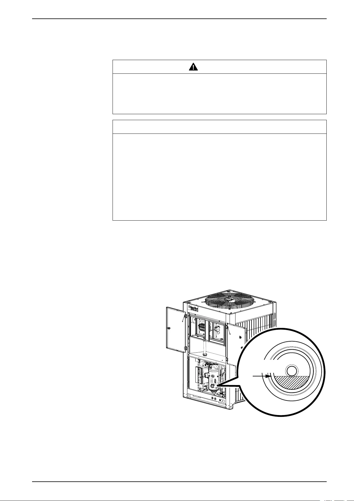
Installation ACRD300 and ACCU30000 Series
Compressor Oil Charge
Oil Charging Procedure
WARNING
HAZARD TO EQUIPMENT OR PERSONNEL
All work must be performed by Schneider Electric qualified personnel.
Failure to follow these instructions can result in death, serious injury, or
equipment damage.
NOTICE
DAMAGE TO EQUIPMENT
Do not charge the compressor with too much oil: compressor damage could
result. The only way to drain oil from the compressor is to remove the
compressor from the equipment. The following system damage could also
occur:
• Failure of valves and pistons due to oil slugging.
• Excessive oil carryover.
• Loss of evaporator performance due to oil level build-up in the low-pressure
side of the system.
Failure to follow these instructions can result in equipment damage.
The system must be field-charged with 600 ml (20 oz) of PVE oil to make sure the
system functions normally.
In installations with good oil return and line runs up to 15 m (49 ft), no additional oil
above the initial 600 ml (20 oz) of oil is required. If the installation lines exceed 15
m (49 ft), additional oil may be needed. 1% or 2% of the total system refrigerant
charge can be used to calculate the required oil. Regardless, the oil charge has to
be adjusted based on the oil level in the compressor sight glass: the oil level must
be no lower than 1/3 in the sight glass when the compressor is running.
MINIMUM OIL
LEVEL
na7022b
1. Prepare to add oil:
a. Use a new sealed oil can and a manual oil pump. The pump hose must
be sized for 1/4 in. flare fittings and must include a valve depressor at its
end, which will open the valve on the suction port of the compressor.
b. Use Daphne Hermetic PVE Oil FVC32D. Any other oil must be approved
by Schneider Electric before using.
2. Purge the pump and hose
990–91193A–001 97

ACRD300 and ACCU30000 Series Installation
a. Ensure that the oil pump is clean. Insert the pump in the oil container and
make sure that the container is open to the atmosphere for as short a
period of time as possible. When available, use a plug adapter kit to
further reduce the exposure of the oil to the atmosphere.
b. Bleed all air from the pump and hose with a few strokes of the pump.
Purging the pump removes the moisture-saturated oil left inside the hose
from previous usage.
c. Connect the hose to the suction port of the compressor immediately after
purging to avoid moisture contamination.
3. While the equipment is running, charge 600 ml (60 oz) PVE oil through the
suction port. Pump the oil very slowly. (This is to ensure the oil separator is
functioning properly.)
4. Other than the amount required for the oil separator, no additional oil should
be required. Let the compressor run at full capacity for at least one hour and
check the oil level in the oil sight glass. The level should be between 1/3 and
2/3 full, or within the limit shown on the oil level sticker. If the oil is not within
the acceptable limit, check the oil return line for restrictions. When oil is
flowing properly, the oil return line should feel warm to the touch.
NOTE: Dispose of the oil waste appropriately.
98 990–91193A–001


Schneider Electric
35 rue Joseph Monier
92500 Rueil Malmaison
France
+ 33 (0) 1 41 29 70 00
www.schneider-electric.com
As standards, specifications, and design change from time to time,
please ask for confirmation of the information given in this publication.
© 2018 – 2018 Schneider Electric. All rights reserved.
990–91193A–001