Table of Contents
APC Parallel Maintenance Bypass User Manual
Displayed below is the user manual for Parallel Maintenance Bypass by APC which is a product in the Uninterruptible Power Supplies (UPSs) category. This manual has pages.
Related Manuals
MGE™Galaxy™3500
3:115-40kVA400V
Wall-MountedParallel
MaintenanceBypass
PanelInstallation
IMPORTANTSAFETY
INSTRUCTIONS
–SAVETHESEINSTRUCTIONS
WARNING:AllsafetyinstructionsintheSafetySheet
shippedwiththeproductmustberead,understood
andfollowedpriortoinstallingthesystem.Failure
todosocouldresultinequipmentdamage,serious
injury,ordeath.
WARNING:Allelectricalpowerandpowercontrol
wiringmustbeinstalledbyacertifiedelectrician,and
mustcomplywithlocalandnationalregulationsfor
maximumpowerrating.
Caution:Useaforkliftorotherliftingdevicetoliftthe
MBPtotheinstallationheight.
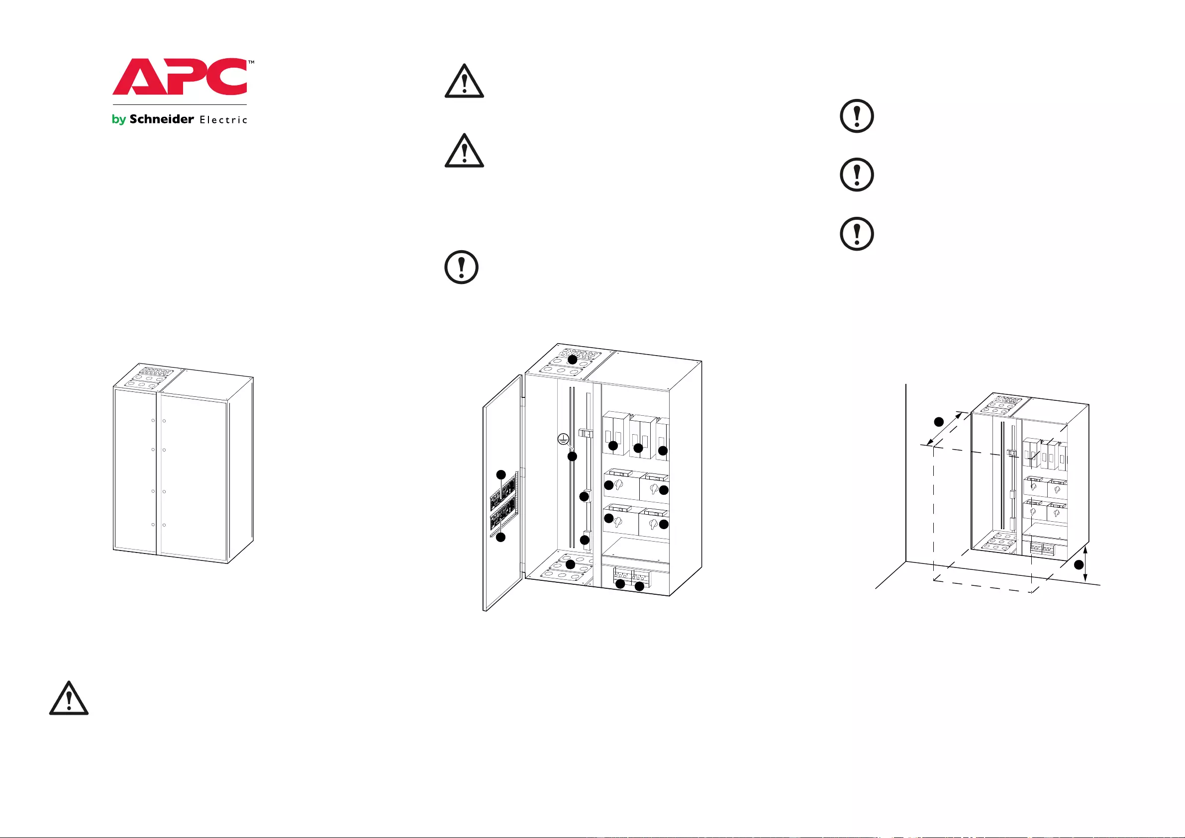
ProductOverview
Note:ThisMaintenanceBypassPanelsupportstwoUPS
unitsconnectedinparallelforredundancy(1+1)only.
FrontView(Interior)
Q21
Terminals
Terminals
NN
ID 1
ID 2
AA
B
B
C
D
EE
H
H
I
A
F
G
G
E
A.Mainsinput(Q1a,Q1b)
B.UPSoutput(Q2a,Q2b)
C.SystemoutputF7
D.Maintenancebypass(Q3)
E.Bypassinput(Q5a,Q5b)
F.Systemisolationbreaker(Q4)
G.Communicationboards
H.Cableentry
I.PE/Ground
SitePlanning
Note:WhenselectingalocationfortheMBP,consider
theneedforeasyaccesstoallswitchesandinternal
components.
Note:Ensurethattheselectedwallisstructurallysound
andabletosupportthesizeandweightoftheunit.
Note:ProtecttheMBPatalltimesfromexcessive
moisture,constructiondirt,corrosiveelements,orother
contaminants.
SpaceRequirements
Refertothebelowfiguretodeterminethespacerequirementsforthe
MBP.Consultlocalcodesforanyadditionalrequirements.Ideally,
installtheMBPinalocationclosetotheUPS.
Q21
Terminals
Terminals
A
B
N
N
A.Minimumfrontclearance700mm.
B.Minimumfloorclearance600mm.
990-5055-0011
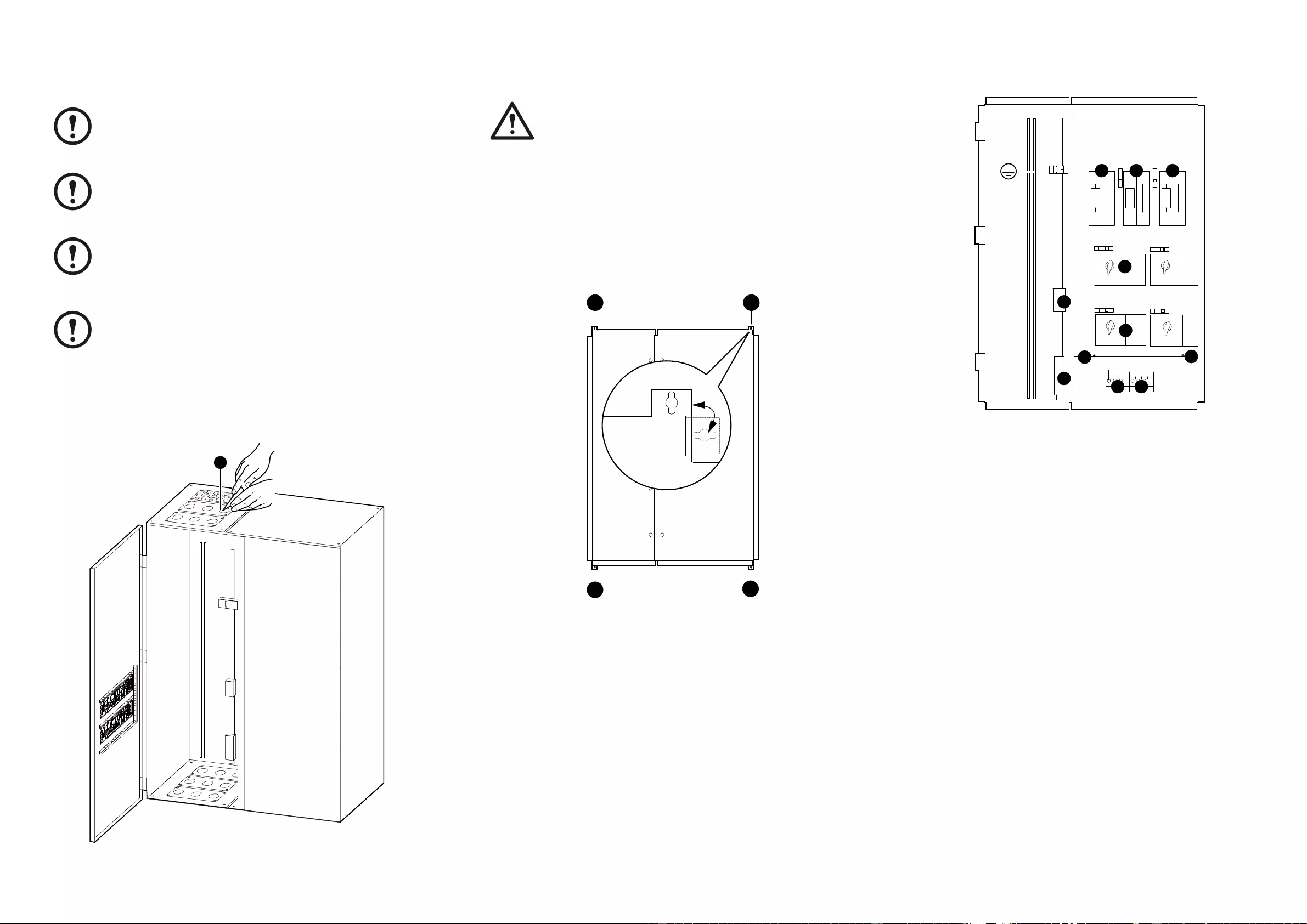
PrepareforCables
Note:Allpowercablesmustbeconnectedon-site.
Externalpowercablesarenotsuppliedwiththe
equipment.
Note:Twocommunicationcables(30m)aresupplied
withtheequipment.
Note:Youcancutholesforcableaccesseitherbefore
orafteryouhavemountedtheMBPtothewall.APC
bySchneiderElectricrecommendsthatyoucreateall
necessaryholesbeforemountingtheMBP.
Note:Theglandplatewithsmallholescanbereplaced
withtheplateinthebottomifnecessary.Tomaintain
ingresslevelaglandplatemustbeinstalledineach
opening.
1.Opentheleftfrontdoor.
2.Useaknifetocutanxineitherthetoporbottomglandplate
oftheMBP.
Q21
Terminals
Terminals
NN
ID 1
ID 2
2
MounttheMBPtotheWall
Caution:Anchoringboltsarenotsupplied.Use
anchors/boltsthataresuitabletosupporttheweightof
thepanel.
1.Measureandmarkthefourmountingholelocationsonthe
wall.
2.Drillholesineachofthefourmarkedlocationsandmount
anchorbolts.
3.LifttheMBP,positionitagainstthebackingandlineitup
withthefourholes/anchorbolts.SecuretheMBPwiththe
fourboltsandflatwashers.
1
1
1
1
ConnectthePowerCables
X10
X5
X1
X4
X6 X11
Terminals
Terminals
NH1
NH1
N
N
Q2a Q3
Q2b Q4
Q5a Q5b F7
H2b H4
H3
H2a
Q1A Q1B
H5bH5a
NH1
Q21
3
X2 X3
PE/G
L1
L2
L3
NL1 L2 L3 NL1 L2 L3 N
N
L1
NL1 NL1
N
L1
N
L1
NL1
X9
2
5
4 4
6 6
7
7
8
3
1.RoutethecablesthroughthetoporbottomoftheMBP.
2.Connectthemainsinputcables(L1,L2,L3,N)totheterminal
block“X1”andthePEcabletothePE/Gbar.
3.RemovethecoverplateaboveQ1aandQ1bbylooseningthe
twoscrews.
4.Connecttheinputcables(L1,L2,L3,N)fromthetwoUPS
unitstothetopofQ1a(X2)andQ1b(X3)andthePEcables
tothePE/Gbar.ReinstallthecoverplateaboveQ1aandQ1b.
5.Connectthebypassinputcables(L1,N)totheterminalblock
X4.
6.Connectthebypassinputcables(L1,N)fromthetwoUPS
unitstoQ5a(X5)andQ5b(X6).
7.Connecttheoutputcables(L1,N)fromthetwoUPSunits
toQ2a(X9)andQ2b(X10).
8.Connectthesystemoutputcablestotheload(L,N)toF7
(X11).
990-5055-0012
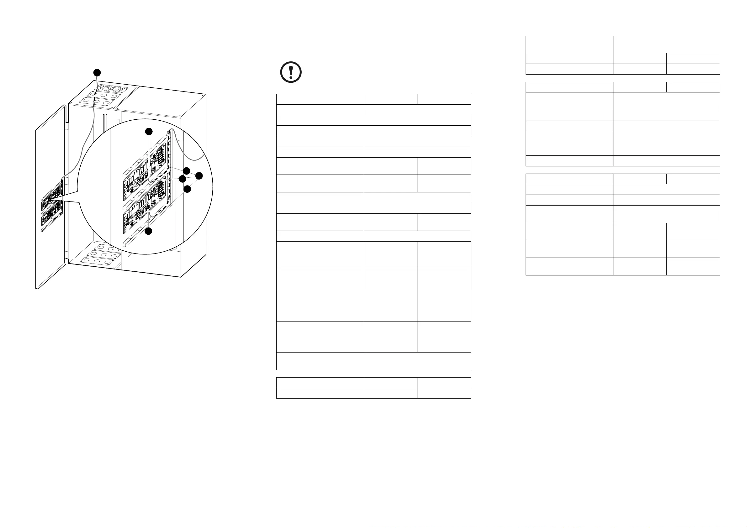
ConnecttheCommunication
Cables
Q21
Terminals
Terminals
NN
ID 1
ID 2
ID 1
ID 2
4
4
3
5
5
5
2
1.ConnecttheABuscables(suppliedwiththeMBP)tothe
ABusterminalsintheparallelcommunicationboxineach
UPS.SeeInstallationManualforinformationonhowtoroute
thecablestotheparallelcommunicationbox.
2.RoutetheABuscablesfromtheABusterminalsineach
parallelcommunicationboxthroughthetoporbottomofthe
UPSandtotheMBPCanI/Oboard.
3.Removethecoverplatesfromthecablechannelandroutethe
cablesinthechannel.
4.ConnectthetwoABuscablestotheX134Aconnectorson
theMBPCanI/Oboard.
5.Reinstallthecoverplatesonthecablechannel.
Specifications
Note:Themaximumcablesareforoneconductor/wire
perterminal.Theterminalscannotacceptparallel
conductors.
Electrical15–20kVA30–40kVA
Nominalinputvoltage3×400/230V(L1,L2,L3,N,PE)
Nominalbypassinputvoltage230V(L1,N,PE)
Nominaloutputvoltage230V(L1,N,PE)
Frequency(Hz)50
EarthingTN-S
Maximumratedinputcurrent
(A)3563
Maximumratedoutputcurrent
(A)100200
Ratedshort-circuitcurrent30kA,0.1sec
Switchratings:Q1a,Q1b(A)63
Switchratings:Q2a,Q2b,Q3,
Q4,Q5a,Q5b,F7(A)100250
Wiring(useonlycopperconductorswithaminimumratingfor70oC)
Recommendedcablecross
sectionformainsinput
(L1,L2,L3,N,PE)1
10mm225mm2
Maximumcablecrosssection
allowedbytheterminalsfor
mainsinput(L1,L2,L3,N,PE)
16mm225mm2
Recommendedcablecross
sectionforbypassinput
respectivelysystemoutput
(L1,N,PE)1
35mm295mm2
Maximumcablecrosssection
allowedbytheterminalsfor
bypassinputrespectivelysystem
output(L1,N,PE)
70mm2150mm2
1RecommendedcablesizesareforinstallationmethodB1,B2,Cin
EN60364–5–52table52–E3
Physical15–20kVA30–40kVA
DimensionsH×W×D(mm)1200×1010×4151390×1010×415
Shippingdimensions
H×W×D(mm)1600×1200×800
Weight(kg)113123
Shippingweight(kg)128138
Environmental15–20kVA30–40kVA
OperatingenvironmentIndooruseonly,protectfromwaterand
conductivecontaminates
Operatingtemperature0◦to40◦C
Humidity0to95%,non-condensing
Pollutiondegree
(accordingtoEN60439-1
6.1.2.3)
1
ProtectionclassIP31
Torque15–20kVA30–40kVA
Terminalblock“X1”Min.6.0Nm-max.12.0Nm
Terminalblock“X4”Min.25.0Nm-max.30.0Nm
Q1atop(X2),
Q1btop(X3)3.0Nm
Q5atop(X5),
Q5btop(X6)Twobolts,each
4.0NmTwobolts,each
6.0Nm
Q2aleft(X9),
Q2bleft(X10)12Nm26Nm
F7(X11)Twobolts,each
4.0NmTwobolts,each
6.0Nm
ContactInformation
Forlocal,country-specificcenters:goto
www.apc.com/support/contact.
990-5055-0013

Appendix
MBPOne-lineDiagram
System
Output
To UPS "a"
Input
To UPS "b"
Input
To UPS "b"
Bypass Input
To UPS "a"
Bypass Input
Q5a
Q5b
Q3
X11
F7
Q4
Q2a
Q2b
X4
X9
X10
Maintenance
Bypass
From UPS "a"
Output
From UPS "b"
Output
Bypass Input
Mains Input
X1
Q1a
Q1b
X2
X3
X6
X5
990-5055-0014