Table of Contents
Gigabyte GA-990X-Gaming SLI (rev. 1.0) User Manual
Displayed below is the user manual for GA-990X-Gaming SLI (rev. 1.0) by Gigabyte which is a product in the Motherboards category. This manual has pages.
Related Manuals

To reduce the impacts on global warming, the packaging materials of this product
are recyclable and reusable. GIGABYTE works with you to protect the environment.
For more product details, please visit GIGABYTE's website.
GA-990X-Gaming SLI
User's Manual
Rev. 1002
12ME-990XGMS-1002R
Copyright
© 2016 GIGA-BYTE TECHNOLOGY CO., LTD. All rights reserved.
The trademarks mentioned in this manual are legally registered to their respective owners.
Disclaimer
Information in this manual is protected by copyright laws and is the property of GIGABYTE.
Changes to the specications and features in this manual may be made by GIGABYTE without prior notice.
No part of this manual may be reproduced, copied, translated, transmitted, or published in any form or
by any means without GIGABYTE's prior written permission.
For quick set-up of the product, read the Quick Installation Guide included with the product.
In order to assist in the use of this product, carefully read the User's Manual.
For product-related information, check on our website at: http://www.gigabyte.com
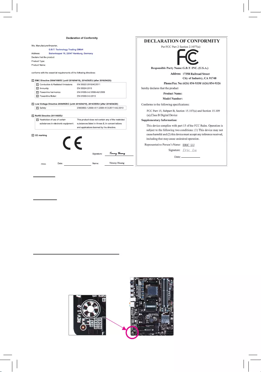
Identifying Your Motherboard Revision
The revision number on your motherboard looks like this: "REV: X.X." For example, "REV: 1.0" means
the revision of the motherboard is 1.0. Check your motherboard revision before updating motherboard
BIOS, drivers, or when looking for technical information.
Example:
Motherboard
GA-990X-Gaming SLI
Feb. 15, 2016
Feb. 15, 2016
Motherboard
GA-990X-Gaming SLI

- 3 -
Table of Contents
GA-990X-Gaming SLI Motherboard Layout ....................................................................4
Chapter 1 Hardware Installation .....................................................................................5
1-1 Installation Precautions .................................................................................... 5
1-2 ProductSpecications ...................................................................................... 6
1-3 Installing the CPU ............................................................................................ 9
1-4 Installing the Memory ....................................................................................... 9
1-5 Installing an Expansion Card ......................................................................... 10
1-6 Back Panel Connectors .................................................................................. 10
1-7 Internal Connectors ........................................................................................ 12
Chapter 2 BIOS Setup ..................................................................................................19
2-1 Startup Screen ............................................................................................... 20
2-2 M.I.T. .............................................................................................................. 20
2-3 System Information ........................................................................................ 24
2-4 BIOS Features ............................................................................................... 25
2-5 Peripherals ..................................................................................................... 27
2-6 Power Management ....................................................................................... 30
2-7 Save & Exit ..................................................................................................... 31
Chapter 3 Appendix ......................................................................................................32
3-1 ConguringaRAIDSet .................................................................................. 32
3-2 DriversInstallation .......................................................................................... 35
RegulatoryStatements .............................................................................................. 36
Contact Us ................................................................................................................ 40
- 4 -
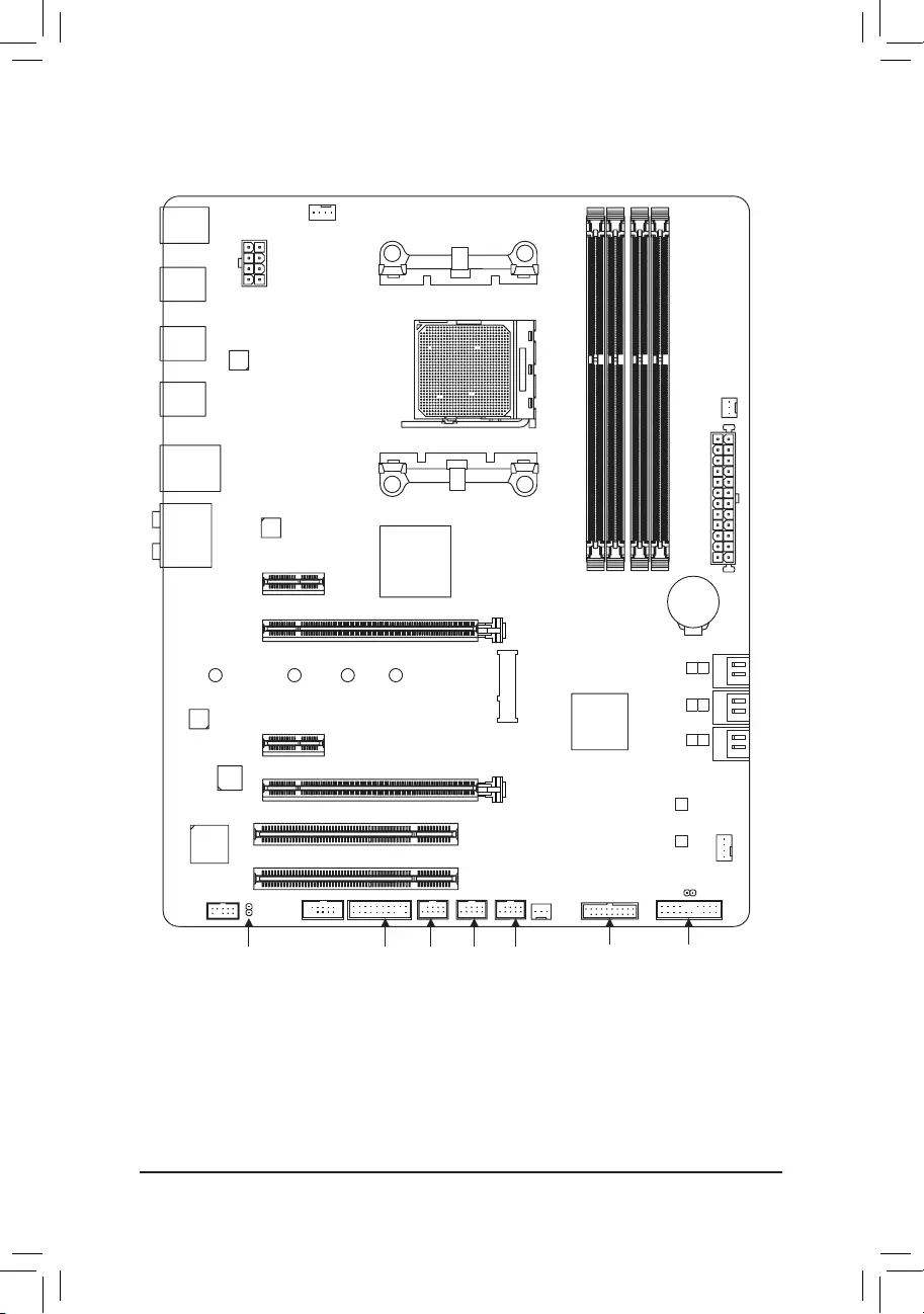
GA-990X-Gaming SLI Motherboard Layout
* The box contents above are for reference only and the actual items shall depend on the product package you obtain.
The box contents are subject to change without notice.
Box Contents
5GA-990X-Gaming SLI motherboard 5Four SATA cables
5Motherboard driver disk 5I/O Shield
5User's Manual 5One G Connector
5Quick Installation Guide 5One 2-Way SLI bridge connector
(Note) Duetoahardwarelimitation,thePCIEX1_1slotcanonlyaccommodateashorterPCIExpressx1
expansion card. For a longer expansion card, use other expansion slots.
KB_MS_USB
CPU_FAN
ATX
GA-990X-Gaming SLI
AUDIO
SYS_FAN1
PCIEX1_1(Note)
DDR3_4
DDR3_2
ATX_12V
AMD990X
AMDSB950
PCIEX1_2
CODEC
BAT
PCI1
F_USB2
B_BIOS
F_PANEL
M_BIOS
F_USB1
PCIEX16
R_USB31
CLR_CMOS
SPDIF_O
Socket AM3+
Intel®
GbE LAN
iTE®
Super I/O
R_USB
R_USB30
USB_LAN
DDR3_3
DDR3_1
PWR_FAN
F_USB30
SYS_FAN2
F_USB3TPM
F_AUDIO
COMA
PCIEX8
PCI2
4
5
2
3
0
1
SATA3
VIA®VL805
ASMedia®
USB 3.1 Controller
M2F_20G
42F60F80F110F

Chapter 1 Hardware Installation
1-1 Installation Precautions
The motherboard contains numerous delicate electronic circuits and components which can become
damagedasaresultofelectrostaticdischarge(ESD).Priortoinstallation,carefullyreadtheuser's
manual and follow these procedures:
•Prior to installation, make sure the chassis is suitable for the motherboard.
•Prior to installation, do not remove or break motherboard S/N (Serial Number) sticker or
warranty sticker provided by your dealer. These stickers are required for warranty validation.
•Always remove the AC power by unplugging the power cord from the power outlet before
installing or removing the motherboard or other hardware components.
•When connecting hardware components to the internal connectors on the motherboard, make
sure they are connected tightly and securely.
•When handling the motherboard, avoid touching any metal leads or connectors.
•It is best to wear an electrostatic discharge (ESD) wrist strap when handling electronic
componentssuchasamotherboard,CPUormemory.IfyoudonothaveanESDwriststrap,
keepyourhandsdryandrsttouchametalobjecttoeliminatestaticelectricity.
•Prior to installing the motherboard, please have it on top of an antistatic pad or within an
electrostatic shielding container.
•Before connecting or unplugging the power supply cable from the motherboard, make sure
the power supply has been turned off.
•Before turning on the power, make sure the power supply voltage has been set according to
the local voltage standard.
•Before using the product, please verify that all cables and power connectors of your hardware
components are connected.
•To prevent damage to the motherboard, do not allow screws to come in contact with the
motherboard circuit or its components.
•Make sure there are no leftover screws or metal components placed on the motherboard or
within the computer casing.
•Donotplacethecomputersystemonanunevensurface.
•Donotplacethecomputersysteminahigh-temperatureorwetenvironment.
•Turning on the computer power during the installation process can lead to damage to system
components as well as physical harm to the user.
•If you are uncertain about any installation steps or have a problem related to the use of the
product,pleaseconsultacertiedcomputertechnician.
•If you use an adapter, extension power cable, or power strip, ensure to consult with its installation
and/or grounding instructions.
- 5 -

1-2 ProductSpecications
CPU AM3+ Socket:
- AMDAM3+FXprocessor
- AMDAM3Phenom™IIprocessor/AMDAthlon™ II processor
(Go to GIGABYTE's website for the latest CPU support list.)
HyperTransport
Bus
HyperTransport™ 3.0
5200 MT/s
Chipset NorthBridge:AMD990X
SouthBridge:AMDSB950
Memory 4xDDR3DIMMsocketssupportingupto64GBofsystemmemory
* DuetoaWindows32-bitoperatingsystemlimitation,whenmorethan4GBofphysical
memory is installed, the actual memory size displayed will be less than the size of
the physical memory installed.
Dualchannelmemoryarchitecture
SupportforDDR32000(O.C.)/1866/1600/1333/1066MHzmemorymodules
* TosupportaDDR31866MHz(andabove)memory,youmustinstallanAM3+CPU
rst.
SupportforExtremeMemoryProle(XMP)memorymodules
(Go to GIGABYTE's website for the latest supported memory speeds and memory
modules.)
Audio Realtek® ALC1150 codec
HighDenitionAudio
2/4/5.1/7.1-channel
SupportforS/PDIFOut
LAN Intel® GbE LAN chip (10/100/1000 Mbit)
Expansion Slots 1 x PCI Express x16 slot, running at x16 (PCIEX16)
* For optimum performance, if only one PCI Express graphics card is to be installed,
be sure to install it in the PCIEX16 slot.
1 x PCI Express x16 slot, running at x8 (PCIEX8)
* The PCIEX8 slot shares bandwidth with the PCIEX16 slot. When the PCIEX8 slot is
populated, the PCIEX16 slot will operate at up to x8 mode.
2 x PCI Express x1 slots
(All of the PCI Express slots conform to PCI Express 2.0 standard.)
2 x PCI slots
Multi-Graphics
Technology
SupportforNVIDIA® Quad-GPU SLI™and2-WayNVIDIA® SLI™ technologies
SupportforAMDQuad-GPUCrossFireX™and2-WayAMDCrossFire™ technologies
Storage Interface South Bridge:
- 1 x M.2 connector (Socket 3, M key, type 2242/2260/2280/22110 SATA
andPCIex4/x2/x1SSDsupport)
- 6 x SATA 6Gb/s connectors
- SupportforRAID0,RAID1,RAID5,RAID10,andJBOD
* Referto"1-7InternalConnectors,"forthesupportedcongurationswiththeM.2and
SATA connectors.
- 6 -
USB South Bridge:
- 12 x USB 2.0/1.1 ports (6 ports on the back panel, 6 ports available through
the internal USB headers)
VIA®VL805chip:
- 4 x USB 3.0/2.0 ports (2 ports on the back panel, 2 ports available through
the internal USB header)
ASMedia® USB 3.1 Controller:
- 2 x USB 3.1 Type-A ports (red) on the back panel
Internal
Connectors
1 x 24-pin ATX main power connector
1x8-pinATX12Vpowerconnector
1 x M.2 Socket 3 connector
6 x SATA 6Gb/s connectors
1 x CPU fan header
2 x system fan headers
1 x power fan header
1 x front panel header
1 x front panel audio header
1xS/PDIFOutheader
1 x USB 3.0/2.0 header
3 x USB 2.0/1.1 headers
1 x serial port header
1 x Clear CMOS jumper
1 x Trusted Platform Module (TPM) header
Back Panel
Connectors
1 x PS/2 keyboard/mouse port
2 x USB 3.1 Type-A ports (red)
2 x USB 3.0/2.0 ports
6 x USB 2.0/1.1 ports
1xRJ-45port
1xopticalS/PDIFOutconnector
5xaudio jacks (Center/Subwoofer Speaker Out, RearSpeaker Out, Line In,
Line Out, Mic In)
I/O Controller iTE® I/O Controller Chip
Hardware
Monitor
System voltage detection
CPU/System temperature detection
CPU/System/Power fan speed detection
CPU overheating warning
CPU/System/Power fan fail warning
CPU/System fan speed control
* Whether the fan speed control function is supported will depend on the cooler you
install.
- 7 -
BIOS 2x32Mbitash
Use of licensed AMI UEFI BIOS
SupportforDualBIOS™
PnP1.0a,DMI2.7,WfM2.0,SMBIOS2.7,ACPI5.0
Unique Features Support for APP Center
* Available applications in APP Center may vary by motherboard model. Supported
functionsofeachapplicationmayalsovarydependingonmotherboardspecications.
- @BIOS
- AmbientLED
- Cloud Station
- EasyTune
- Game Controller
- Smart TimeLock
- SmartRecovery2
- SystemInformationViewer
- USB Blocker
Support for Q-Flash
Support for ON/OFF Charge
Support for Smart Switch
Support for Xpress Install
Bundled
Software
Norton® Internet Security (OEM version)
cFosSpeed
Operating
System Support for Windows 10/8.1/7 32-bit/64-bit
Form Factor ATX Form Factor; 30.5cm x 24.4cm
*GIGABYTEreservestherighttomakeanychangestotheproductspecicationsandproduct-relatedinformationwithout
prior notice.
Please visit GIGABYTE's website
for support lists of CPU, memory
modules,SSDs,andM.2devices.
Please visit the Support\Utility List
page on GIGABYTE's website to
download the latest version of apps.
- 8 -
Please visit GIGABYTE's website for details on hardware installation.
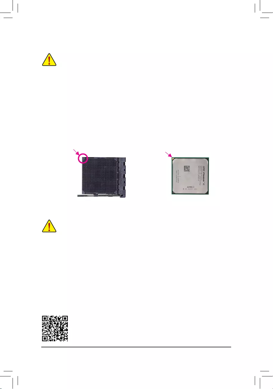
1-3 Installing the CPU
ReadthefollowingguidelinesbeforeyoubegintoinstalltheCPU:
•Make sure that the motherboard supports the CPU.
(Go to GIGABYTE's website for the latest CPU support list.)
•Always turn off the computer and unplug the power cord from the power outlet before installing the
CPU to prevent hardware damage.
•Locate the pin one of the CPU. The CPU cannot be inserted if oriented incorrectly.
•Apply an even and thin layer of thermal grease on the surface of the CPU.
•DonotturnonthecomputeriftheCPUcoolerisnotinstalled,otherwiseoverheatinganddamage
of the CPU may occur.
•SettheCPUhostfrequencyinaccordancewiththeCPUspecications.Itisnotrecommended
thatthesystembusfrequencybesetbeyondhardwarespecicationssinceitdoesnotmeetthe
standard requirements for the peripherals. If you wish to set the frequency beyond the standard
specications,pleasedosoaccordingtoyourhardwarespecicationsincludingtheCPU,graphics
card, memory, hard drive, etc.
Installing the CPU
Locate the pin one (denoted by a small triangle) of the CPU socket and the CPU.
1-4 Installing the Memory
DualChannelMemoryConguration
Thismotherboardprovidesfour DDR3 memory sockets and supports Dual Channel Technology.After the
memoryisinstalled,theBIOSwillautomaticallydetectthespecicationsandcapacityofthememory.Enabling
DualChannelmemorymodewilldoubletheoriginalmemorybandwidth.
ThefourDDR3memorysocketsaredividedintotwochannelsandeachchannelhastwomemorysocketsas
following:
ChannelA:DDR3_2,DDR3_4
ChannelB:DDR3_1,DDR3_3
Readthefollowingguidelinesbeforeyoubegintoinstallthememory:
•Make sure that the motherboard supports the memory. It is recommended that memory of the
same capacity, brand, speed, and chips be used.
(Go to GIGABYTE's website for the latest supported memory speeds and memory modules.)
•Always turn off the computer and unplug the power cord from the power outlet before installing the
memory to prevent hardware damage.
•Memory modules have a foolproof design. A memory module can be installed in only one direction.
If you are unable to insert the memory, switch the direction.
AM3+ Socket
A Small Triangle
MarkingDenotesPin
One of the Socket AM3+/AM3 CPU
A Small Triangle
MarkingDenotesCPU
Pin One
- 9 -
DuetoCPUlimitations,readthefollowingguidelinesbeforeinstallingthememoryinDualChannelmode.
1. DualChannelmodecannotbeenabledifonlyonememorymoduleisinstalled.
2. WhenenablingDualChannelmodewithtwoorfourmemorymodules,itisrecommendedthatmemory
of the same capacity, brand, speed, and chips be used and installed in the same colored sockets. For
optimumperformance,whenenablingDualChannelmodewithtwomemorymodules,werecommend
thatyouinstallthemintheDDR3_1andDDR3_2sockets.
1-5 Installing an Expansion Card
Readthefollowingguidelinesbeforeyoubegintoinstallanexpansioncard:
•Make sure the motherboard supports the expansion card. Carefully read the manual that came
with your expansion card.
•Always turn off the computer and unplug the power cord from the power outlet before installing an
expansion card to prevent hardware damage.
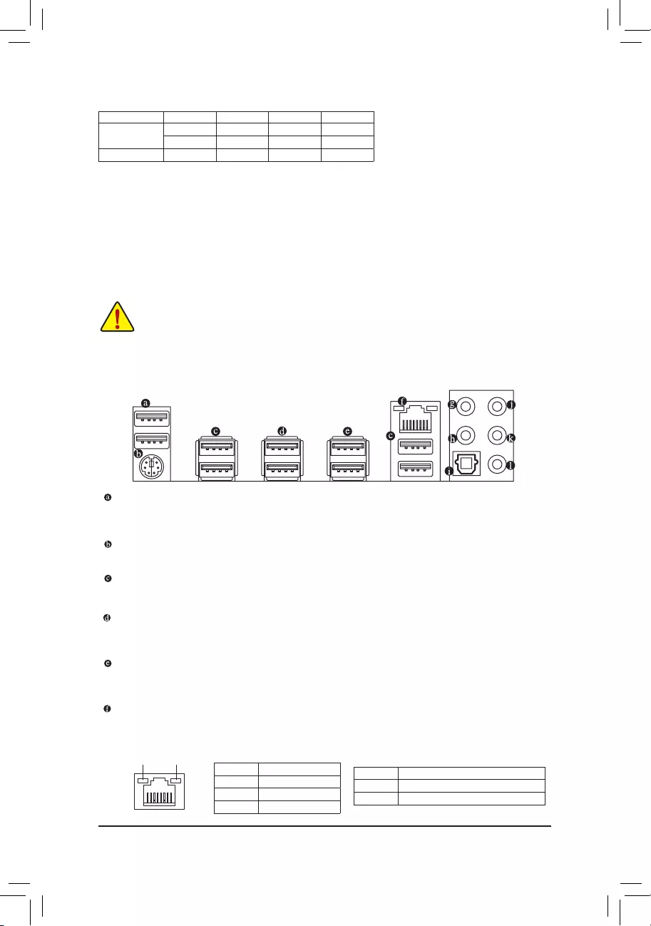
1-6 Back Panel Connectors
USB 2.0/1.1 Port
TheUSBportsupportstheUSB2.0/1.1specication.YoucanconnectaUSBDACtothisportoruse
this port for USB devices.
PS/2 Keyboard/Mouse Port
Use this port to connect a PS/2 mouse or keyboard.
USB 2.0/1.1 Port
TheUSBportsupportstheUSB2.0/1.1specication.UsethisportforUSBdevices.
USB 3.1 Type-A Port (Red)
TheUSB3.1portsupportstheUSB3.1specicationandiscompatibletotheUSB3.0/2.0/1.1specication.
Use this port for USB devices.
USB 3.0/2.0 Port
TheUSB3.0portsupportstheUSB3.0specicationandiscompatibletotheUSB2.0/1.1specication.
Use this port for USB devices.
RJ-45 LAN Port
The Gigabit Ethernet LAN port provides Internet connection at up to 1 Gbps data rate. The following
describesthestatesoftheLANportLEDs.
DualChannelMemoryCongurationsTable
DDR3_4 DDR3_2 DDR3_3 DDR3_1
2 Modules - - DS/SS - - DS/SS
DS/SS - - DS/SS - -
4 Modules DS/SS DS/SS DS/SS DS/SS
(SS=Single-Sided,DS=Double-Sided,"--"=NoMemory)
ActivityLED
Connection/
SpeedLED
LAN Port
ActivityLED:
Connection/SpeedLED:
State Description
Orange 1 Gbps data rate
Green 100 Mbps data rate
Off 10 Mbps data rate
State Description
Blinking Datatransmissionorreceivingisoccurring
On No data transmission or receiving is occurring
- 10 -
Center/Subwoofer Speaker Out
Usethisaudiojacktoconnectcenter/subwooferspeakersina5.1/7.1-channelaudioconguration.
Rear Speaker Out
Thisjackcanbeusedtoconnectrearspeakersina4/5.1/7.1-channelaudioconguration.
Optical S/PDIF Out Connector
This connector provides digital audio out to an external audio system that supports digital optical audio.
Before using this feature, ensure that your audio system provides an optical digital audio in connector.
Line In
The line in jack. Use this audio jack for line in devices such as an optical drive, walkman, etc.
Line Out
The line out jack. This jack supports audio amplifying function. For better sound quality, it is recommended
that you connect your headphone/speaker to this jack (actual effects may vary by the device being used).
Use this audio jack for a headphone or 2-channel speaker. This jack can be used to connect front speakers
ina4/5.1/7.1-channelaudioconguration.
Mic In
The Mic in jack.
If you want to install a Side Speaker, you need to retask either the Line in or Mic in jack to be Side
Speaker out through the audio driver. Please visit GIGABYTE's website for more software information.
•Whenremovingthecableconnectedtoabackpanelconnector,rstremovethecablefromyour
device and then remove it from the motherboard.
•Whenremovingthecable,pullitstraightoutfromtheconnector.Donotrockitsidetosideto
prevent an electrical short inside the cable connector.
- 11 -
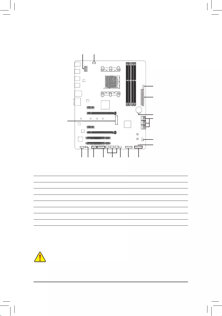
1-7 Internal Connectors
Readthefollowingguidelinesbeforeconnectingexternaldevices:
•First make sure your devices are compliant with the connectors you wish to connect.
•Before installing the devices, be sure to turn off the devices and your computer. Unplug the power
cord from the power outlet to prevent damage to the devices.
•After installing the device and before turning on the computer, make sure the device cable has
been securely attached to the connector on the motherboard.
1) ATX_12V
2) ATX
3) CPU_FAN
4) SYS_FAN1/2
5) PWR_FAN
6) SATA3 0/1/2/3/4/5
7) M2F_ 20G
8) F_PANEL
9) F_AUDIO
10) SPDIF_O
11) F_USB30
12) F_USB1/F_USB2/F_USB3
13) COMA
14) TPM
15) BAT
16) CLR_CMOS
1
5
2
15
3
6
4
814109 11
7
16
12 413
- 12 -
DEBUG
PORT
G.QBOFM
131
2412
ATX
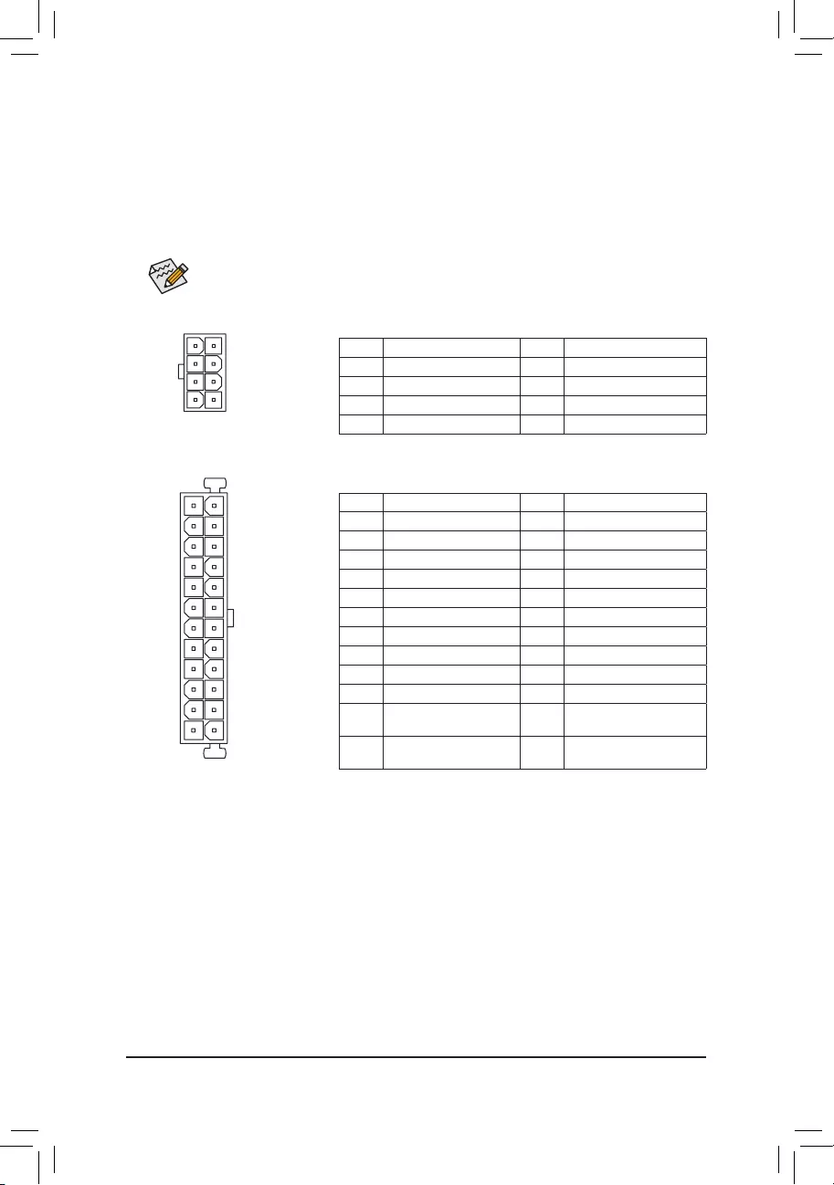
1/2) ATX_12V/ATX (2x4 12V Power Connector and 2x12 Main Power Connector)
With the use of the power connector, the power supply can supply enough stable power to all the components
onthemotherboard.Beforeconnectingthepowerconnector,rstmakesurethepowersupplyisturned
off and all devices are properly installed. The power connector possesses a foolproof design. Connect the
power supply cable to the power connector in the correct orientation.
The12VpowerconnectormainlysuppliespowertotheCPU.Ifthe12Vpowerconnectorisnotconnected,
the computer will not start.
To meet expansion requirements, it is recommended that a power supply that can withstand high
power consumption be used (500W or greater). If a power supply is used that does not provide the
required power, the result can lead to an unstable or unbootable system.
ATX:
Pin No. Denition Pin No. Denition
13.3V 13 3.3V
23.3V 14 -12V
3GND 15 GND
4+5V 16 PS_ON(softOn/Off)
5GND 17 GND
6+5V 18 GND
7GND 19 GND
8 Power Good 20 NC
95VSB(standby+5V) 21 +5V
10 +12V 22 +5V
11 +12V(Onlyfor 2x12-pin
ATX)
23 +5V(Onlyfor2x12-pinATX)
12 3.3V(Onlyfor 2x12-pin
ATX)
24 GND(Onlyfor2x12-pinATX)
ATX_12V:
Pin No. Denition Pin No. Denition
1GND(Onlyfor2x4-pin12V) 5+12V(Onlyfor2x4-pin12V)
2GND(Onlyfor2x4-pin12V) 6+12V(Onlyfor2x4-pin12V)
3GND 7+12V
4GND 8+12V
DEBUG
PORT
G.QBOFM
ATX_12V
5
8
1
4
- 13 -
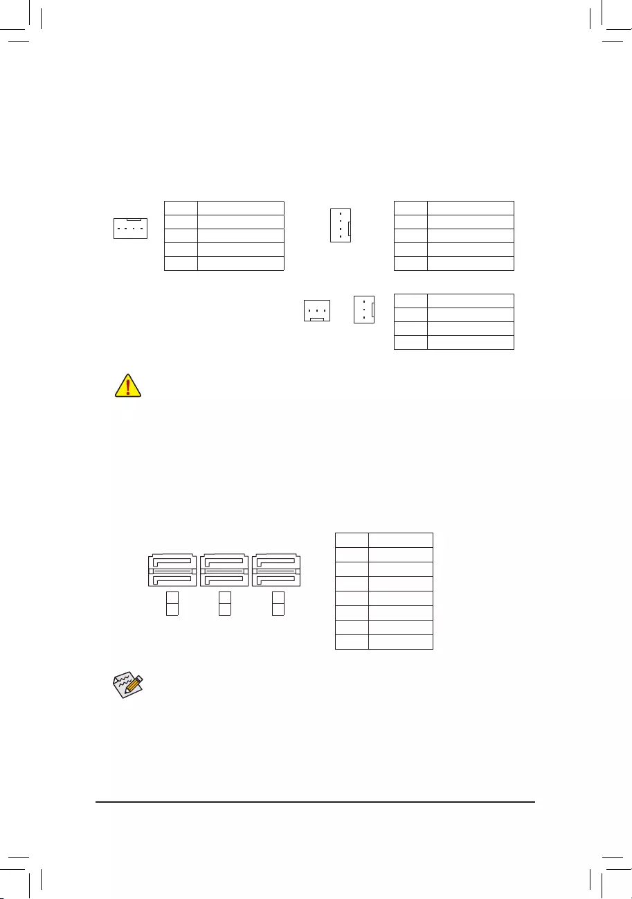
6) SATA3 0/1/2/3/4/5 (SATA 6Gb/s Connectors)
The SATA connectors conform to SATA 6Gb/s standard and are compatible with SATA 3Gb/s and SATA
1.5Gb/sstandard.EachSATAconnectorsupportsasingleSATAdevice.TheAMDSouthBridgesupports
RAID0,RAID1,RAID5,RAID10,andJBOD.RefertoChapter3,"ConguringaRAIDSet,"forinstructions
onconguringaRAIDarray.
Pin No. Denition
1GND
2 TXP
3 TXN
4GND
5RXN
6RXP
7GND
Toenablehot-pluggingfortheSATAports,refertoChapter2,"BIOSSetup,""Peripherals\SBSATA
Conguration,"formoreinformation.
SYS_FAN2/PWR_FAN:
Pin No. Denition
1GND
2+12V
3 Sense
•Be sure to connect fan cables to the fan headers to prevent your CPU and system from
overheating. Overheating may result in damage to the CPU or the system may hang.
•Thesefanheadersarenotcongurationjumperblocks.Donotplaceajumpercapontheheaders.
3/4/5) CPU_FAN/SYS_FAN1/SYS_FAN2/PWR_FAN (Fan Headers)
Themotherboardhasa4-pinCPUfanheader(CPU_FAN),a4-pin(SYS_FAN1)anda3-pin(SYS_FAN2)
systemfanheaders,anda3-pinpowerfanheader(PWR_FAN).Mostfanheaderspossessafoolproof
insertion design. When connecting a fan cable, be sure to connect it in the correct orientation (the black
connector wire is the ground wire). The speed control function requires the use of a fan with fan speed
control design. For optimum heat dissipation, it is recommended that a system fan be installed inside the
chassis.
CPU_FAN
DEBUG
PORT
G.QBOFM
1
CPU_FAN:
Pin No. Denition
1GND
2+12V
3 Sense
4 Speed Control
SYS_FAN1:
Pin No. Denition
1GND
2 Speed Control
3 Sense
4VCC
1
PWR_FAN
DEBUG
PORT
G.QBOFM
1
SYS_FAN1
SYS_FAN2
1
1
1
DEBUG
PORT
G.QBOFM
DEBUG
PORT
G.QBOFM
DEBUG
PORT
G.QBOFM
7
7
0
1
2
3
4
5
SATA3
- 14 -
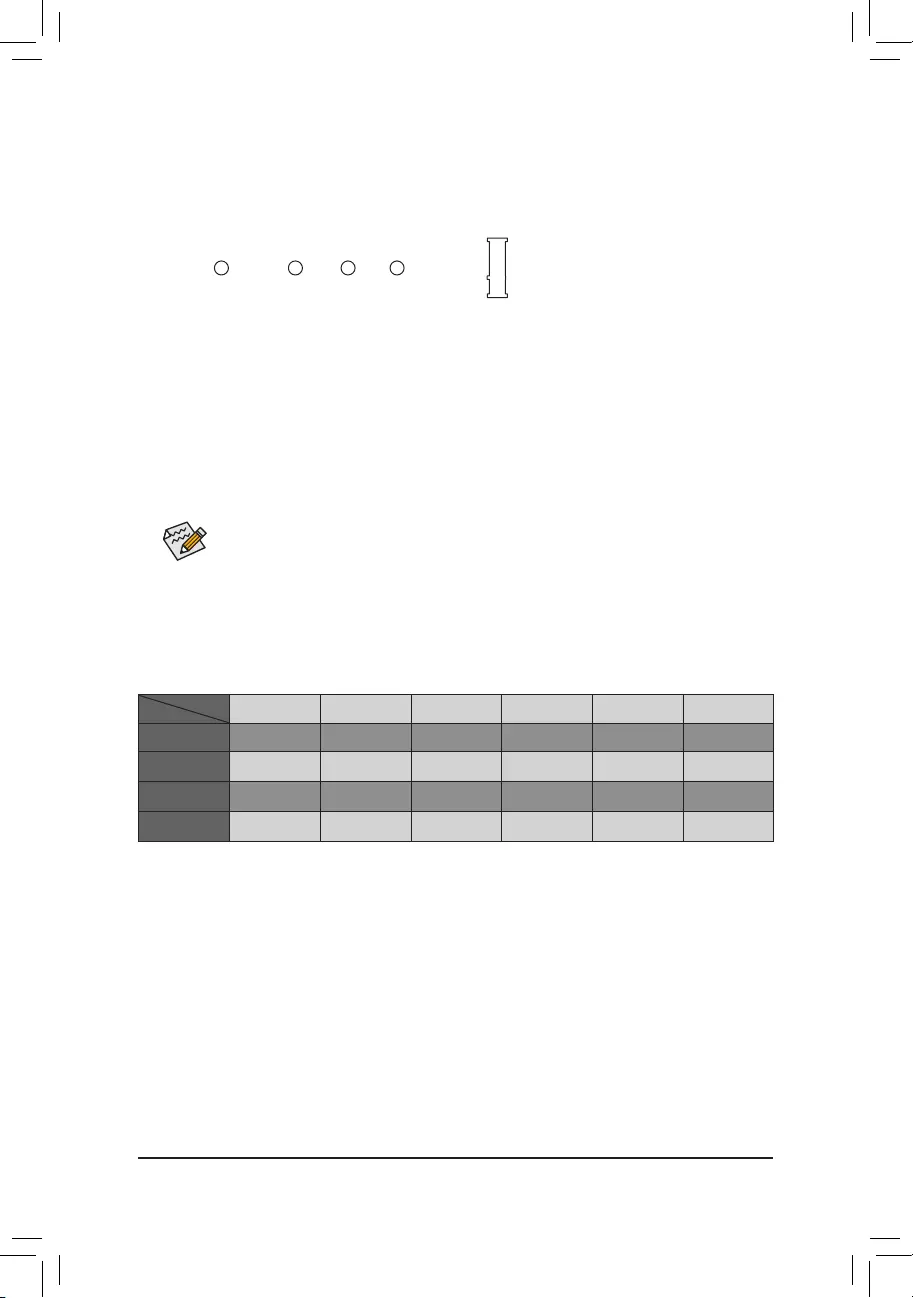
WheninstallingdifferenttypesofM.2SSDs(includingSATASSDs,PCIex4SSDs,andPCIex2SSDs),be
suretorefertothesupportedcongurationsinthetablesbelow.
•AHCI/RAID mode:
SATA3_0 SATA3_1 SATA3_2 SATA3_3 SATA3_4 SATA3_5
M.2SATASSD aaaaar
M.2 PCIe x4
SSD (Note) a a a a a a
M.2 PCIe x2
SSD (Note) a a a a a a
NoM.2SSDs
Installed a a a a a a
a: Supported, r: Not supported.
Connector
TypeofSSD
SelecttheproperholefortheM.2SSDtobeinstalledandrefastenthescrewandnut.
7) M2F_20G (M.2 Socket 3 Connector)
TheM.2connectorsupportsM.2SATASSDsandM.2PCIeSSDs.ItcansupportSATARAIDconguration
throughtheAMDSouthBridge.PleasenotethatanM.2PCIeSSDcannotbeusedtocreateaRAIDset
withSATAdrive(s).RefertoChapter3,"ConguringaRAIDSet,"forinstructionsonconguringaRAID
array.
FollowthestepsbelowtocorrectlyinstallanM.2SSDintheM.2connector.
Step 1:
Use a screw driver to unfasten the screw and nut from the motherboard. Locate the proper mounting hole
fortheM.2SSDtobeinstalledandthenscrewthenutrst.
Step 2:
SlidetheM.2SSDintotheconnectoratanangle.
Step 3:
PresstheM.2SSDdownandthensecureitwiththescrew.
(Note) PleasenotethatanM.2PCIeSSDcannotbeusedtocreateaRAIDsetwithSATAdrive(s).
F_USB30 F_U
B_
F_ F_
_
B
BS_
B
SB_
B
_S
S_
_
B
_U
_
B
S
123
123
123
123
1
1
1
1
BSS
S
_S
SSU
1 2 3 4 5
S3 BSSS U
__ 3
F_USB3F
S _
S _
S _
SF
B_
F
_0
S
S
_0F
_F
_
_
__B
80F 60F 42F
110F
- 15 -
The front panel design may differ by chassis. A front panel module mainly consists of power switch,
resetswitch,powerLED,harddriveactivityLED,speakerandetc.Whenconnectingyourchassis
front panel module to this header, make sure the wire assignments and the pin assignments are
matched correctly.
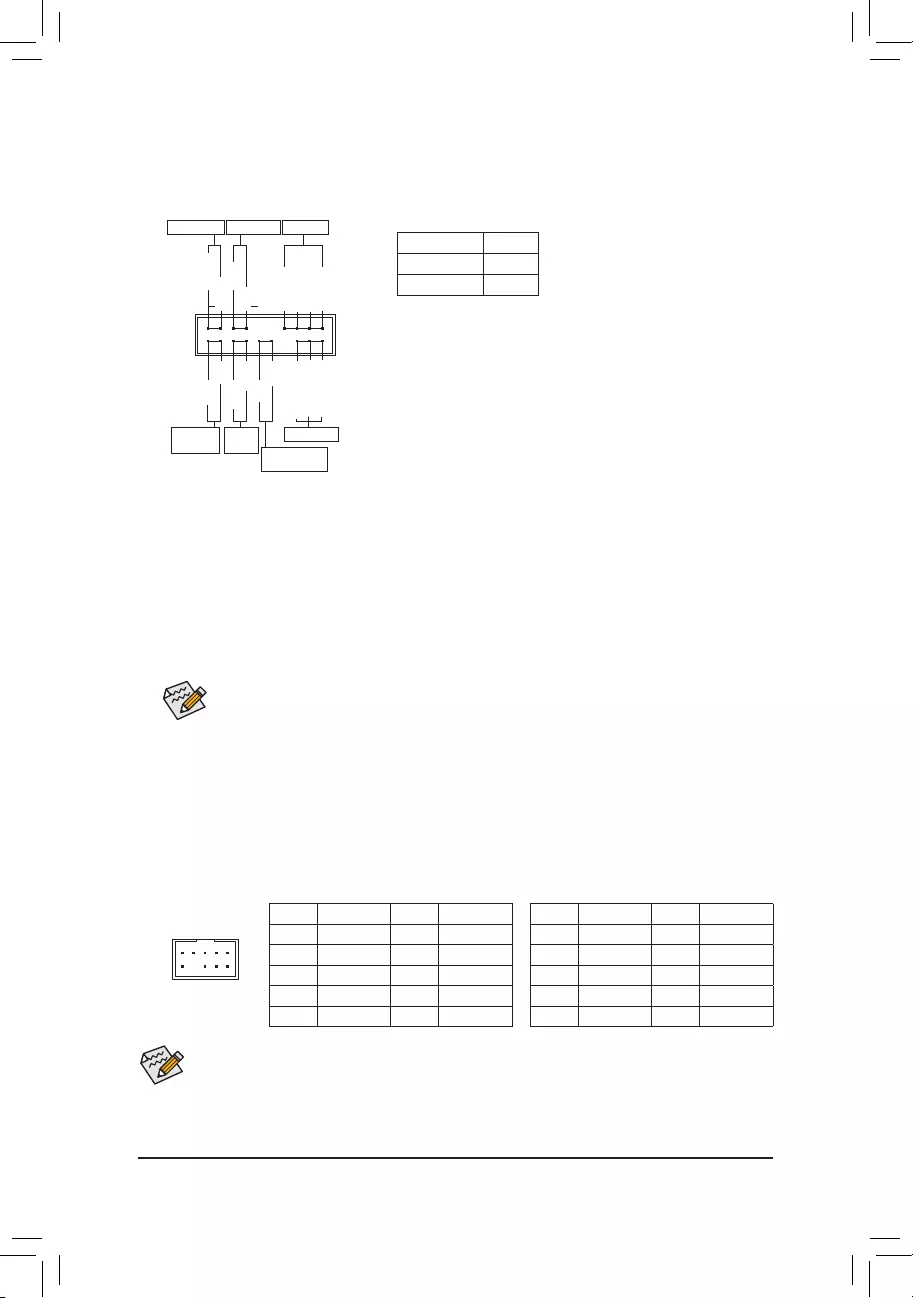
8) F_PANEL (Front Panel Header)
Connect the power switch, reset switch, speaker, chassis intrusion switch/sensor and system status indicator
on the chassis to this header according to the pin assignments below. Note the positive and negative pins
before connecting the cables.
System Status LED
S0 On
S3/S4/S5 Off
•PW(PowerSwitch,Red):
Connects to the power switch on the chassis front panel. You may
congurethewaytoturnoffyoursystemusingthepowerswitch
(refertoChapter2,"BIOSSetup,""PowerManagement,"formore
information).
•SPEAK (Speaker, Orange):
Connects to the speaker on the chassis front panel. The system
reports system startup status by issuing a beep code. One single
short beep will be heard if no problem is detected at system startup.
•PLED/PWR_LED (PowerLED,Yellow/Purple):
Connects to the power status indicator
onthechassisfrontpanel.TheLEDison
whenthesystemisoperating.TheLED
is off when the system is in S3/S4 sleep
state or powered off (S5).
•HD (HardDriveActivityLED,Blue):
ConnectstotheharddriveactivityLEDonthechassisfrontpanel.TheLEDisonwhentheharddriveis
reading or writing data.
•RES (ResetSwitch,Green):
Connects to the reset switch on the chassis front panel. Press the reset switch to restart the computer if the
computer freezes and fails to perform a normal restart.
•CI (Chassis Intrusion Header, Gray):
Connects to the chassis intrusion switch/sensor on the chassis that can detect if the chassis cover has been
removed. This function requires a chassis with a chassis intrusion switch/sensor.
•NC (Orange): No Connection.
•ThefrontpanelaudioheadersupportsHDaudiobydefault.
•Audio signals will be present on both of the front and back panel audio connections simultaneously.
•Some chassis provide a front panel audio module that has separated connectors on each wire instead
of a single plug. For information about connecting the front panel audio module that has different
wire assignments, please contact the chassis manufacturer.
9) F_AUDIO (Front Panel Audio Header)
ThefrontpanelaudioheadersupportsIntelHighDenitionaudio(HD)andAC'97audio.Youmayconnect
your chassis front panel audio module to this header. Make sure the wire assignments of the module
connector match the pin assignments of the motherboard header. Incorrect connection between the module
connector and the motherboard header will make the device unable to work or even damage it.
F_USB30 F_U
B_
F_ F_
_
B
BS_
B
SB_
B
_S
S_
_
B
_U
_
B
S
123
123
123
123
1
1
1
1
BSS
S
_S
SSU
1 2 3 4 5
S3 BSSS U
__ 3
F_USB3F
S _
S _
S _
SF
B_
F
_0
S
S
_0F
_F
_
_
__B
9 1
10 2
ForHDFrontPanelAudio:
Pin No. Denition Pin No. Denition
1MIC2_L 6 Sense
2GND 7FAUDIO_JD
3MIC2_R 8 No Pin
4-ACZ_DET 9LINE2_L
5LINE2_R 10 Sense
For AC'97 Front Panel Audio:
Pin No. Denition Pin No. Denition
1 MIC 6 NC
2GND 7 NC
3 MIC Power 8 No Pin
4 NC 9 Line Out (L)
5LineOut(R) 10 NC
PowerLED
DEBUG
PORT
G.QBOFM
1
2
19
20
CI-
CI+
PWR_LED-
PWR_LED+
PLED-
PW-
SPEAK+
SPEAK-
PLED+
PW+
PowerLED
HD-
RES+
HD+
RES-
HardDrive
ActivityLED
Reset
Switch Chassis Intrusion
Header
Power Switch Speaker
PWR_LED-
NC
NC
- 16 -
10) SPDIF_O (S/PDIF Out Header)
ThisheadersupportsdigitalS/PDIFOutandconnectsaS/PDIFdigitalaudiocable(providedbyexpansion
cards) for digital audio output from your motherboard to certain expansion cards like graphics cards and
soundcards.Forexample,somegraphicscardsmayrequireyoutouseaS/PDIFdigitalaudiocablefor
digitalaudiooutputfromyourmotherboardtoyourgraphicscardifyouwishtoconnectanHDMIdisplay
tothegraphicscardandhavedigitalaudiooutputfromtheHDMIdisplayatthesametime.Forinformation
aboutconnectingtheS/PDIFdigitalaudiocable,carefullyreadthemanualforyourexpansioncard.
Pin No. Denition
1SPDIFO
2GND
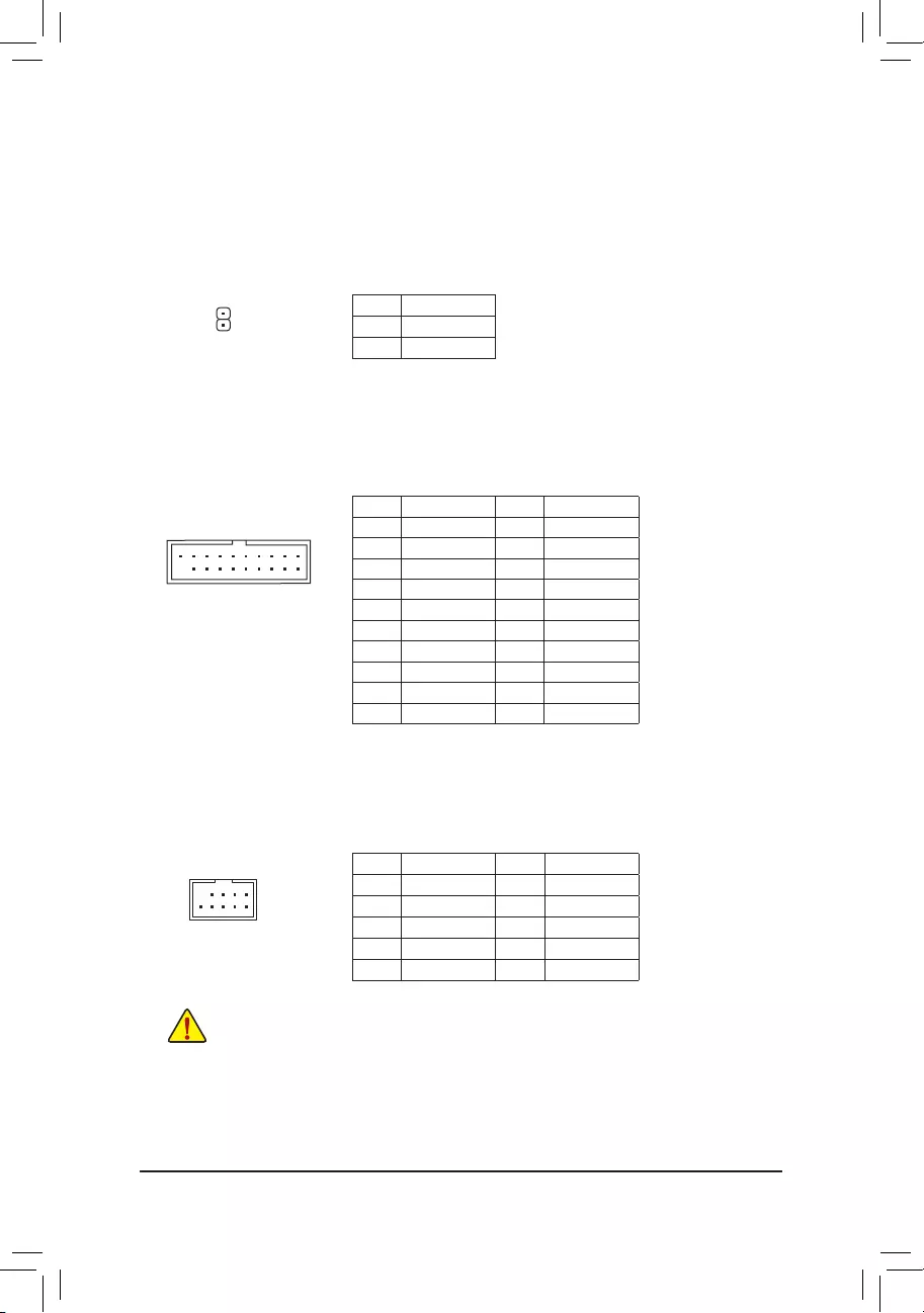
Pin No. Denition Pin No. Denition
1VBUS 11 D2+
2SSRX1- 12 D2-
3SSRX1+ 13 GND
4GND 14 SSTX2+
5 SSTX1- 15 SSTX2-
6 SSTX1+ 16 GND
7GND 17 SSRX2+
8D1- 18 SSRX2-
9D1+ 19 VBUS
10 NC 20 No Pin
11) F_USB30 (USB 3.0/2.0 Header)
Theheader conforms to USB 3.0/2.0 specication andeach header can provide two USB ports.For
purchasingtheoptional3.5"frontpanelthatprovidestwoUSB3.0/2.0ports,pleasecontactthelocaldealer.
1
F_USB30 F_U
B_
F_ F_
_
B
BS_
B
SB_
B
_S
S_
_
B
_U
_
B
S
123
123
123
123
1
1
1
1
BSS
S
_S
SSU
1 2 3 4 5
S3 BSSS U
__ 3
F_USB3F
S _
S _
S _
SF
B_
F
_0
S
S
_0F
_F
_
_
__B
10
20
1
11
12) F_USB1/F_USB2/F_USB3 (USB 2.0/1.1 Headers)
TheheadersconformtoUSB2.0/1.1specication.EachUSBheadercanprovidetwoUSBportsviaan
optional USB bracket. For purchasing the optional USB bracket, please contact the local dealer.
Pin No. Denition Pin No. Denition
1Power(5V) 6USBDY+
2Power(5V) 7GND
3USBDX- 8GND
4USBDY- 9 No Pin
5USBDX+ 10 NC
•DonotplugtheIEEE1394bracket(2x5-pin)cableintotheUSB2.0/1.1header.
•Prior to installing the USB bracket, be sure to turn off your computer and unplug the power cord
from the power outlet to prevent damage to the USB bracket.
DEBUG
PORT
G.QBOFM
10
9
2
1
- 17 -
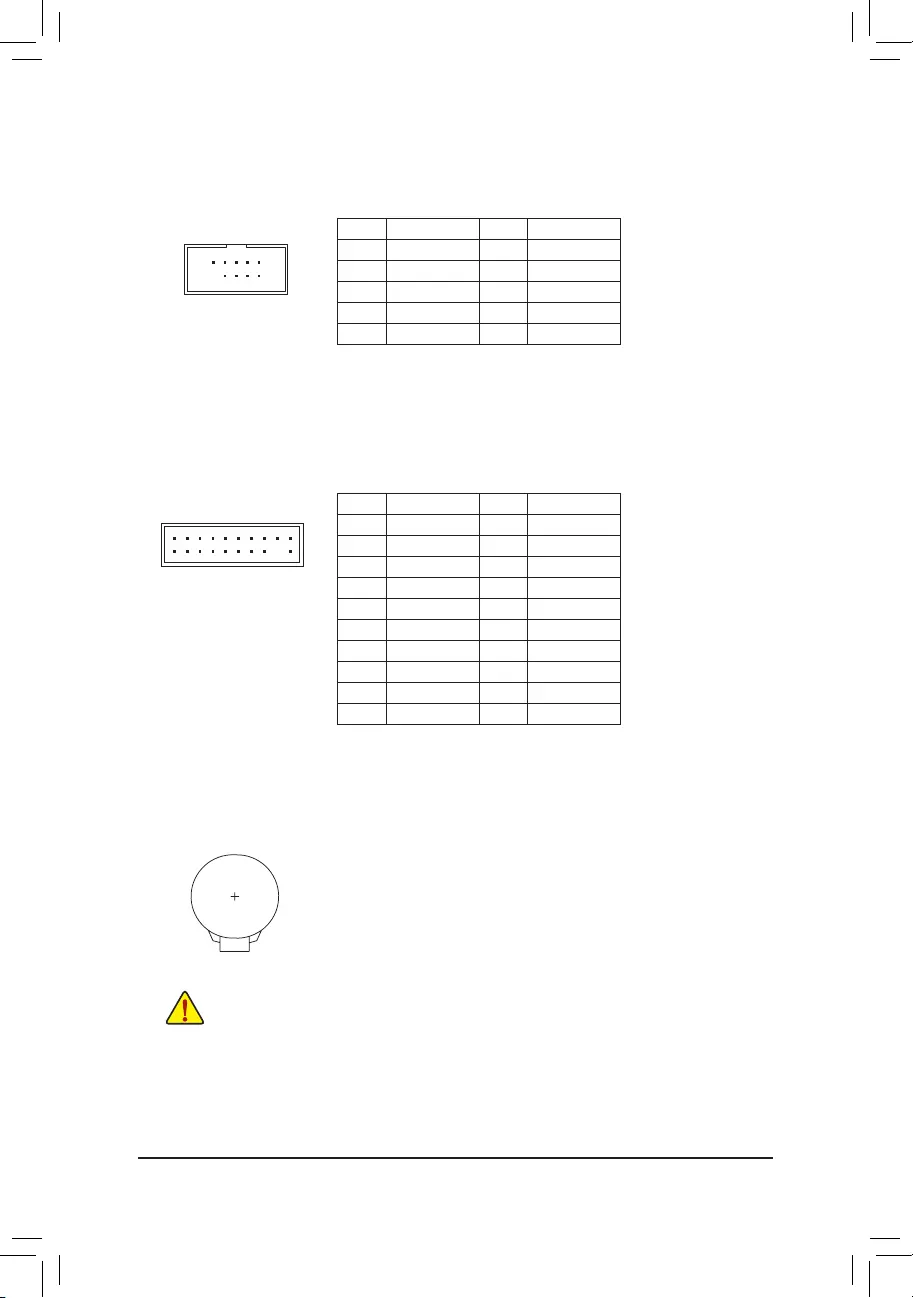
13) COMA (Serial Port Header)
The COM header can provide one serial port via an optional COM port cable. For purchasing the optional
COM port cable, please contact the local dealer.
Pin No. Denition Pin No. Denition
1NDCD- 6NDSR-
2NSIN 7NRTS-
3NSOUT 8NCTS-
4NDTR- 9NRI-
5GND 10 No Pin
10
9
2
1
15) BAT (Battery)
Thebatteryprovidespowertokeepthevalues(suchasBIOScongurations,date,andtimeinformation)
intheCMOSwhenthecomputeristurnedoff.Replacethebatterywhenthebatteryvoltagedropstoalow
level, or the CMOS values may not be accurate or may be lost.
You may clear the CMOS values by removing the battery:
1. Turn off your computer and unplug the power cord.
2. Gently remove the battery from the battery holder and wait for one minute. (Or use
a metal object like a screwdriver to touch the positive and negative terminals of the
battery holder, making them short for 5 seconds.)
3. Replacethebattery.
4. Plug in the power cord and restart your computer.
•Always turn off your computer and unplug the power cord before replacing the battery.
•Replacethebatterywithanequivalentone.Dangerofexplosionifthebatteryisreplacedwith
an incorrect model.
•Contact the place of purchase or local dealer if you are not able to replace the battery by yourself
or uncertain about the battery model.
•When installing the battery, note the orientation of the positive side (+) and the negative side (-)
of the battery (the positive side should face up).
•Used batteries must be handled in accordance with local environmental regulations.
20
19
2
1
F_USB30 F_U
B_
F_ F_
_
B
BS_
B
SB_
B
_S
S_
_
B
_U
_
B
S
123
123
123
123
1
1
1
1
BSS
S
_S
SSU
1 2 3 4 5
S3 BSSS U
__ 3
F_USB3F
S _
S _
S _
SF
B_
F
_0
S
S
_0F
_F
_
_
__B
14) TPM (Trusted Platform Module Header)
You may connect a TPM (Trusted Platform Module) to this header.
Pin No. Denition Pin No. Denition
1 LCLK 11 LAD0
2GND 12 GND
3LFRAME 13 NC
4 No Pin 14 NC
5LRESET 15 SB3V
6 NC 16 SERIRQ
7LAD3 17 GND
8LAD2 18 NC
9VCC3 19 NC
10 LAD1 20 SUSCLK
- 18 -
16) CLR_CMOS (Clear CMOS Jumper)
UsethisjumpertocleartheBIOScongurationandresettheCMOSvaluestofactorydefaults.Toclear
the CMOS values, use a metal object like a screwdriver to touch the two pins for a few seconds.
•Always turn off your computer and unplug the power cord from the power outlet before clearing
the CMOS values.
•Aftersystemrestart,gotoBIOSSetuptoloadfactorydefaults(selectLoadOptimizedDefaults)or
manuallyconguretheBIOSsettings(refertoChapter2,"BIOSSetup,"forBIOScongurations).
Open: Normal
Short:ClearCMOSValues
Chapter 2 BIOS Setup
BIOS (Basic Input and Output System) records hardware parameters of the system in the CMOS on the
motherboard. Its major functions include conducting the Power-On Self-Test (POST) during system startup,
saving system parameters and loading operating system, etc. BIOS includes a BIOS Setup program that allows
theusertomodifybasicsystemcongurationsettingsortoactivatecertainsystemfeatures.
When the power is turned off, the battery on the motherboard supplies the necessary power to the CMOS to
keepthecongurationvaluesintheCMOS.
ToaccesstheBIOSSetupprogram,pressthe<Delete>keyduringthePOSTwhenthepoweristurnedon.
To upgrade the BIOS, use either the GIGABYTE Q-Flash or @BIOS utility.
•Q-Flash allows the user to quickly and easily upgrade or back up BIOS without entering the operating system.
•@BIOS is a Windows-based utility that searches and downloads the latest version of BIOS from the Internet
and updates the BIOS.
•BecauseBIOSashingispotentiallyrisky,ifyoudonotencounterproblemsusingthecurrentversionofBIOS,
itisrecommendedthatyounotashtheBIOS.ToashtheBIOS,doitwithcaution.InadequateBIOSashing
may result in system malfunction.
•It is recommended that you not alter the default settings (unless you need to) to prevent system instability or other
unexpected results. Inadequately altering the settings may result in system's failure to boot. If this occurs, try to
cleartheCMOSvaluesandresettheboardtodefaultvalues.(Refertothe"LoadOptimizedDefaults"sectionin
this chapter or introductions of the battery/clear CMOS jumper in Chapter 1 for how to clear the CMOS values.)
- 19 -
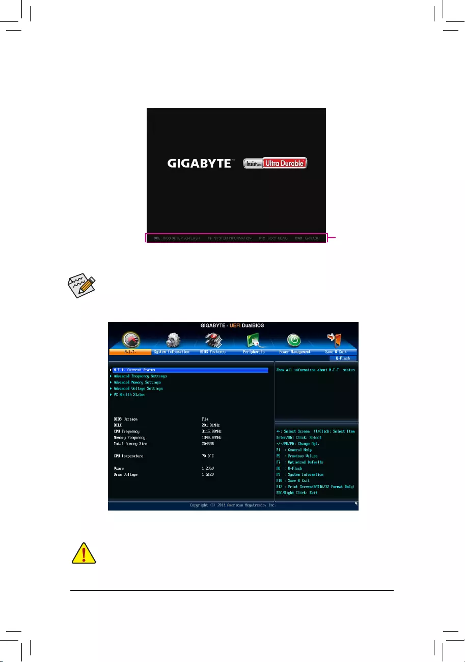
2-1 Startup Screen
The following startup Logo screen will appear when the computer boots.
(SampleBIOSVersion:F1a)
Function Keys
•When the system is not stable as usual, select the Load Optimized Defaults item to set your system to its defaults.
•The BIOS Setup menus described in this chapter are for reference only and may differ by BIOS version.
OnthemainmenuoftheBIOSSetupprogram,pressarrowkeystomoveamongtheitemsandpress<Enter>
to accept or enter a sub-menu. Or you can use your mouse to select the item you want.
2-2 M.I.T.
This section provides information on the BIOS version, CPU base clock, CPU frequency, memory frequency,
totalmemorysize,CPUtemperature,Vcore,andmemoryvoltage,etc.
Whether the system will work stably with the overclock/overvoltage settings you made is dependent on your overall
systemcongurations.Incorrectlydoingoverclock/overvoltagemayresultindamagetoCPU,chipset,ormemory
and reduce the useful life of these components. This page is for advanced users only and we recommend you not to
alter the default settings to prevent system instability or other unexpected results. (Inadequately altering the settings
may result in system's failure to boot. If this occurs, clear the CMOS values and reset the board to default values.)
- 20 -

`M.I.T. Current Status
This screen provides information on CPU/memory frequencies/parameters.
`Advanced Frequency Settings
&BCLK Clock Control
AllowsyoutomanuallysettheCPUbaseclockin1MHzincrements.(Default:Auto)
Important: It is highly recommended that the CPU frequency be set in accordance with the CPU
specications.
&CPU NorthBridge Frequency
Allows you to alter the North Bridge controller frequency for the installed CPU. The adjustable range is
dependent on the CPU being installed.
&HT Link Frequency
Allows you to manually set the frequency for the HT Link between the CPU and chipset. The adjustable
rangeisdependentontheCPUbeinginstalled.(Default:Auto)
&CPU Clock Ratio
Allows you to alter the clock ratio for the installed CPU. The adjustable range is dependent on the CPU
being installed.
&CPU Frequency
DisplaysthecurrentoperatingCPUfrequency.
`Advanced CPU Core Features
&CPU Clock Ratio, CPU Frequency
The settings above are synchronous to those under the same items on the Advanced Frequency Settings
menu.
&Core Performance Boost (Note)
Allows you to determine whether to enable the Core Performance Boost (CPB) technology, a CPU
performance-boosttechnology.(Default:Auto)
&CPB Ratio (Note)
Allows you alter the ratio for the CPB. The adjustable range is dependent on the CPU being installed.
(Default:Auto)
&CPU Unlock (Note)
AllowsyoutodeterminewhetherunlockhiddenCPUcores.(Default:Disabled)
&Cool & Quiet
Enabled LetstheAMDCool'n'QuietdriverdynamicallyadjusttheCPUclockandVIDtoreduce
heatoutputfromyourcomputeranditspowerconsumption.(Default)
Disabled Disablesthisfunction.
&C1E Support
Allows you to determine whether to let the CPU enter C1 mode in system halt state. When enabled, the
CPU core frequency and voltage will be reduced during system halt state to decrease power consumption.
(Default:Enabled)
&SVM
VirtualizationenhancedbyVirtualizationTechnologywillallowaplatformtorunmultipleoperatingsystems
and applications in independent partitions. With virtualization, one computer system can function as multiple
virtualsystems.(Default:Enabled)
&CPU core Control (Note)
Allows you to determine whether to manually enable/disable CPU cores. Automatic mode allows the BIOS
toenableallCPUcores(numberofcoresavailabledependsontheCPUbeingused).(Default:Automatic
mode)
(Note) This item is present only when you install a CPU that supports this feature.
- 21 -

&Core C6 State (Note 1)
Allows you to determine whether to let the CPU enter C6 mode in system halt state. When enabled, the
CPU core frequency will be reduced during system halt state to decrease power consumption. The C6
stateisamoreenhancedpower-savingstatethanC1.(Default:Enabled)
&HPC Mode (Note 1)
Allows you to determine whether to enable High Performance Computing (HPC) mode for the CPU. Enabled
preventstheCPUfrequencyfrombeingloweredduringsystemhaltstate.(Default:Disabled)
&APM (AMD Application Power Management) (Note 1)
Enabled Dynamically monitors the power consumption of the CPU cores and automatically
optimizestheCPUtoitsbestperformancelevel.(Default)
Disabled Disablesthisfunction.
&ExtremeMemoryProle(X.M.P.)(Note 2)
AllowstheBIOStoreadtheSPDdataonXMPmemorymodule(s)toenhancememoryperformancewhen
enabled.
Disabled Disablesthisfunction.(Default)
Prole1 UsesProle1settings.
Prole2(Note 2) UsesProle2settings.
&System Memory Multiplier
Allows you to set the system memory multiplier. AutosetsmemorymultiplieraccordingtomemorySPD
data.(Default:Auto)
&Memory Frequency (MHz)
This value is automatically adjusted according to the BCLK Clock Control and System Memory Multiplier
settings.
`Advanced Memory Settings
&ExtremeMemoryProle(X.M.P.)(Note 2), System Memory Multiplier, Memory Frequency(MHz)
The settings above are synchronous to those under the same items on the Advanced Frequency Settings
menu.
&DRAM Timing Selectable
Quick and Expertallowsthememorytimingsettingsbelowtobecongurable.Optionsare:Auto(default),
Quick, Expert.
&ProleDDRVoltage
When using a non-XMP memory module or ExtremeMemoryProle(X.M.P.) is set to Disabled, the value
isdisplayedaccordingtoyourmemoryspecication.WhenExtremeMemoryProle(X.M.P.) is set to
Prole1 or Prole2,thevalueisdisplayedaccordingtotheSPDdataontheXMPmemory.
&ProleVTTVoltage
The value displayed here is dependent on the CPU being used.
&Channel Interleaving
Enables or disables memory channel interleaving. Enabled allows the system to simultaneously access
different channels of the memory to increase memory performance and stability. Auto lets the BIOS
automaticallycongurethissetting.(Default:Auto)
&Rank Interleaving
Enables or disables memory rank interleaving. Enabled allows the system to simultaneously access different
ranks of the memory to increase memory performance and stability. Auto lets the BIOS automatically
congurethissetting.(Default:Auto)
(Note 1) This item is present only when you install a CPU that supports this feature.
(Note 2) This item is present only when you install a memory module that supports this feature.
- 22 -

`Channel A/B Timing Settings
This sub-menu provides memory timing settings for each channel of memory. The respective timing setting
screensarecongurableonlywhenDRAM Timing Selectable is set to Quick or Expert. Note: Your system
may become unstable or fail to boot after you make changes on the memory timings. If this occurs, please reset
the board to default values by loading optimized defaults or clearing the CMOS values.
`Advanced Voltage Settings
This sub-menu allows you to set CPU, chipset and memory voltages.
`PC Health Status
&Reset Case Open Status
Disabled Keepsorclearstherecordofpreviouschassisintrusionstatus.(Default)
Enabled Clears the record of previous chassis intrusion status and the Case Openeldwill
show"No"atnextboot.
&Case Open
DisplaysthedetectionstatusofthechassisintrusiondetectiondeviceattachedtothemotherboardCI
header.Ifthesystemchassiscoverisremoved,thiseldwillshow"Yes",otherwiseitwillshow"No".To
clear the chassis intrusion status record, set Reset Case Open Status to Enabled, save the settings to
the CMOS, and then restart your system.
&CPU Vcore/Dram Voltage/+3.3V/+5V/+12V
Displaysthecurrentsystemvoltages.
&CPU/System Temperature
DisplayscurrentCPU/systemtemperature.
&CPU/System/Power Fan Speed
DisplayscurrentCPU/system/powerfanspeed.
&CPU Warning Temperature
Sets the warning threshold for CPU temperature. When temperature exceeds the threshold, BIOS will emit
warningsound.Optionsare:Disabled(default),60oC/140oF, 70oC/158oF, 80oC/176oF, 90oC/194oF.
&CPU/System/Power Fan Fail Warning
Allows the system to emit warning sound if the fan is not connected or fails. Check the fan condition or fan
connectionwhenthisoccurs.(Default:Disabled)
&CPU Fan Control Mode
Auto Lets the BIOS automatically detect the type of CPU fan installed and sets the optimal
CPUfancontrolmode.(Default)
Voltage SetsVoltagemodefora3-pinCPUfan.
PWM Sets PWM mode for a 4-pin CPU fan.
&CPU Fan Speed Control
Allows you to determine whether to enable the fan speed control function and adjust the fan speed.
Normal Allows the fan to run at different speeds according to the CPU temperature. You
canadjustthe fan speed with System Information Viewerbasedon your system
requirements.(Default)
Silent Allows the fan to run at slow speeds.
Manual Allows you to control the fan speed under the Slope PWM item.
Disabled Allowsthefantorunatfullspeeds.
&Slope PWM
AllowsyoutocontroltheCPUfanspeed.ThisitemiscongurableonlywhenCPU Fan Speed Control is
set to Manual. Options are: 0.75 PWM value /oC ~ 2.50 PWM value /oC.
&1st System Fan Speed Control (SYS_FAN1 Connector)
Allows you to determine whether to enable the fan speed control function and adjust the fan speed.
Normal Allows the fan to run at different speeds according to the system temperature. You
canadjustthe fan speed with System Information Viewerbasedon your system
requirements.(Default)
- 23 -
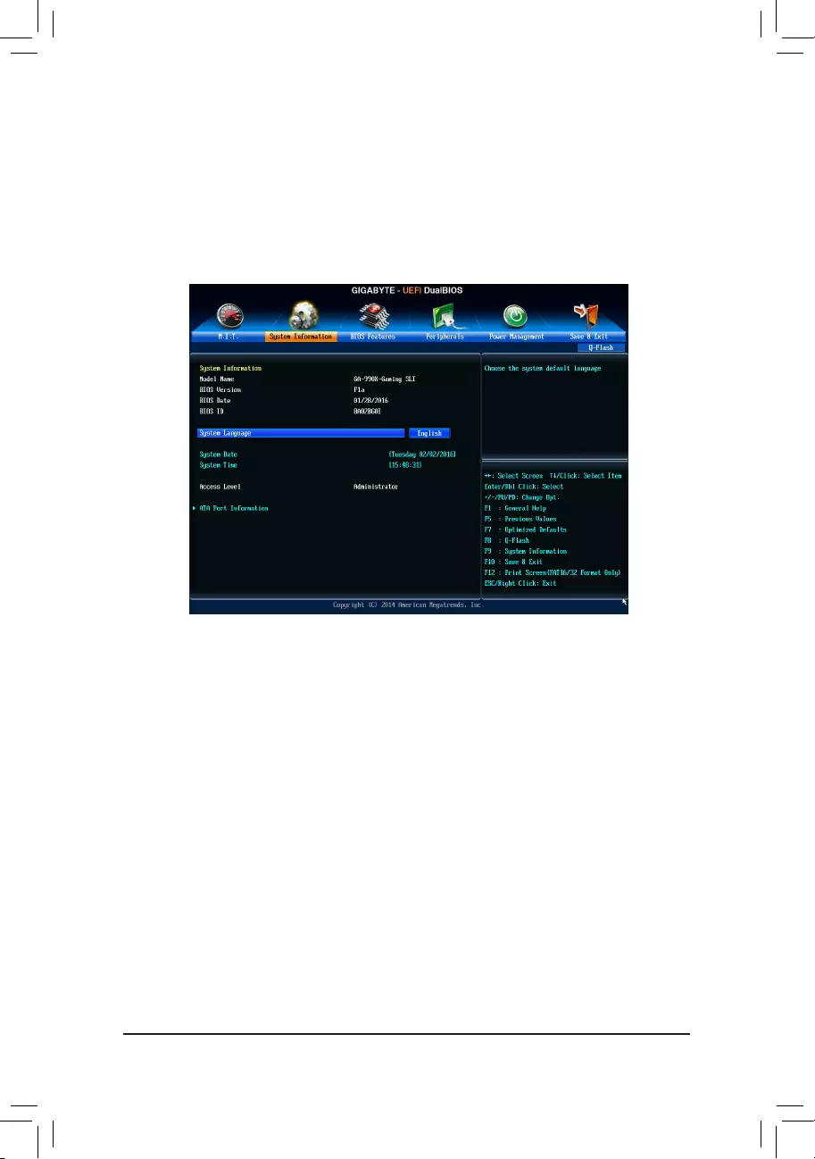
2-3 System Information
This section provides information on your motherboard model and BIOS version. You can also select the default
language used by the BIOS and manually set the system time.
&System Language
Selects the default language used by the BIOS.
&System Date
Setsthesystemdate.Thedateformatisweek(read-only),month,date,andyear.Use<Enter>toswitch
betweentheMonth,Date,andYeareldsandusethe<PageUp>or<PageDown>keytosetthedesired
value.
&System Time
Sets the system time. The time format is hour, minute, and second. For example, 1 p.m. is 13:00:00. Use
<Enter>toswitchbetweentheHour,Minute,andSecondeldsandusethe<PageUp>or<PageDown>
key to set the desired value.
&Access Level
Displaysthecurrentaccessleveldependingonthetypeofpasswordprotectionused.(Ifnopasswordis
set, the default will display as Administrator.) The Administrator level allows you to make changes to all
BIOS settings; the User level only allows you to make changes to certain BIOS settings but not all.
`ATA Port Information
ThissectionprovidesinformationonthedeviceconnectedtoeachSATAportcontrolledbyAMDChipset.
Silent Allows the fan to run at slow speeds.
Manual Allows you to control the fan speed under the Slope PWM item.
Disabled Allowsthefantorunatfullspeeds.
&Slope PWM
Allowsyoutocontrolthesystemfanspeed.Thisitemiscongurableonlywhen1st System Fan Speed
Control is set to Manual. Options are: 0.75 PWM value /oC ~ 2.50 PWM value /oC.
- 24 -
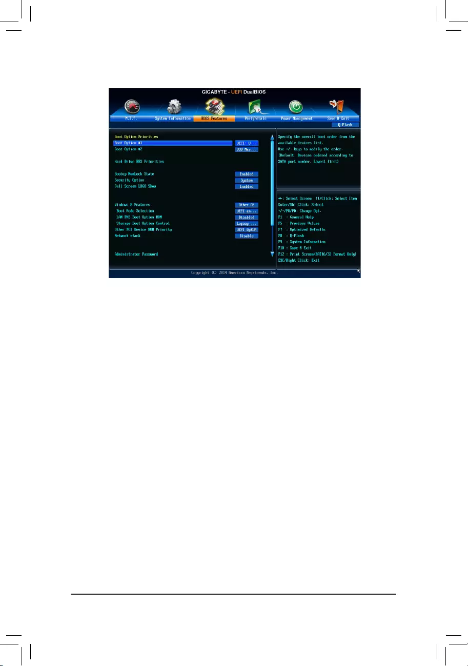
&Boot Option Priorities
Speciestheoverallbootorderfromtheavailabledevices.RemovablestoragedevicesthatsupportGPT
formatwillbeprexedwith"UEFI:"stringonthebootdevicelist.Tobootfromanoperatingsystemthat
supportsGPTpartitioning,selectthedeviceprexedwith"UEFI:"string.
Or if you want to install an operating system that supports GPT partitioning such as Windows 7 64-bit, select
theopticaldrivethatcontainstheWindows764-bitinstallationdiskandisprexedwith"UEFI:"string.
&Hard Drive/CD/DVD ROM Drive/Floppy Drive/Network Device BBS Priorities
Speciesthebootorderforaspecicdevicetype,suchasharddrives,opticaldrives,oppydiskdrives,
anddevicesthatsupportBootfromLANfunction,etc.Press<Enter>onthisitemtoenterthesubmenuthat
presents the devices of the same type that are connected. This item is present only if at least one device
for this type is installed.
&Bootup NumLock State
EnablesordisablesNumlockfeatureonthenumerickeypadofthekeyboardafterthePOST.(Default:
Enabled)
&Security Option
Specieswhetherapasswordisrequiredeverytimethesystemboots,oronlywhenyouenterBIOSSetup.
Afterconguringthisitem,setthepassword(s)undertheAdministrator Password/User Password item.
Setup A password is only required for entering the BIOS Setup program.
System A password is required for booting the system and for entering the BIOS Setup program.
(Default)
&Full Screen LOGO Show
Allows you to determine whether to display the GIGABYTE Logo at system startup. Disabled skips the
GIGABYTELogowhenthesystemstartsup.(Default:Enabled)
&Windows 8 Features
Allowsyoutoselecttheoperatingsystemtobeinstalled.(Default:OtherOS)
2-4 BIOS Features
- 25 -

&CSM Support
Enables or disables UEFI CSM (Compatibility Support Module) to support a legacy PC boot process.
Always EnablesUEFICSM.(Default)
Never DisablesUEFICSMandsupportsUEFIBIOSbootprocessonly.
ThisitemiscongurableonlywhenWindows 8 Features is set to Windows 8 or Windows 8 WHQL.
&Boot Mode Selection
Allows you to select which type of operating system to boot.
UEFIandLegacy AllowsbootingfromoperatingsystemsthatsupportlegacyoptionROMorUEFI
optionROM.(Default)
LegacyOnly AllowsbootingfromoperatingsystemsthatonlysupportlegacyOptionROM.
UEFIOnly AllowsbootingfromoperatingsystemsthatonlysupportUEFIOptionROM.
ThisitemiscongurableonlywhenCSM Support is set to Always.
&LAN PXE Boot Option ROM
AllowsyoutoselectwhethertoenablethelegacyoptionROMfortheLANcontroller.(Default:Disabled)
ThisitemiscongurableonlywhenCSM Support is set to Always.
&Storage Boot Option Control
AllowsyoutoselectwhethertoenabletheUEFIorlegacyoptionROMforthestoragedevicecontroller.
Disabled DisablesoptionROM.
LegacyOnly EnableslegacyoptionROMonly.(Default)
UEFIOnly EnablesUEFIoptionROMonly.
LegacyFirst EnableslegacyoptionROMrst.
UEFIFirst EnablesUEFIoptionROMrst.
ThisitemiscongurableonlywhenCSM Support is set to Always.
&Other PCI Device ROM Priority
AllowsyoutoselectwhethertoenabletheUEFIorLegacyoptionROMforthePCIdevicecontrollerother
than the LAN, storage device, and graphics controllers.
LegacyOpROM EnableslegacyoptionROMonly.
UEFIOpROM EnablesUEFIoptionROMonly.(Default)
ThisitemiscongurableonlywhenCSM Support is set to Always.
&Network Stack
DisablesorenablesbootingfromthenetworktoinstallaGPTformatOS,suchasinstallingtheOSfrom
theWindowsDeploymentServicesserver.(Default:Disable)
&Ipv4 PXE Support
EnablesordisablesIPv4PXESupport.ThisitemiscongurableonlywhenNetwork Stack is enabled.
&Ipv6 PXE Support
EnablesordisablesIPv6PXESupport.ThisitemiscongurableonlywhenNetwork Stack is enabled.
&Administrator Password
Allowsyoutocongureanadministratorpassword.Press<Enter>onthisitem,typethepassword,and
thenpress<Enter>.Youwillberequestedtoconrmthepassword.Typethepasswordagainandpress
<Enter>.Youmustentertheadministratorpassword(oruserpassword)atsystemstartupandwhenentering
BIOSSetup.Differingfromtheuserpassword,theadministratorpasswordallowsyoutomakechangesto
all BIOS settings.
&User Password
Allowsyoutocongureauserpassword.Press<Enter>onthisitem,typethepassword,andthenpress
<Enter>.Youwillberequestedtoconrmthepassword.Typethepasswordagainandpress<Enter>.
You must enter the administrator password (or user password) at system startup and when entering BIOS
Setup. However, the user password only allows you to make changes to certain BIOS settings but not all.
- 26 -
Tocancelthepassword,press<Enter>onthepassworditemandwhenrequestedforthepassword,enter
thecorrectonerst.Whenpromptedforanewpassword,press<Enter>withoutenteringanypassword.
Press<Enter>againwhenpromptedtoconrm.
NOTE:BeforesettingtheUserPassword,besuretosettheAdministratorPasswordrst.
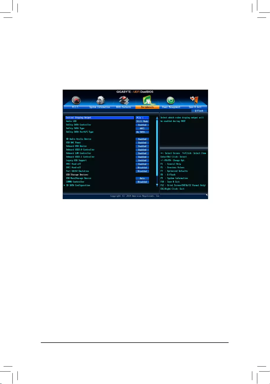
2-5 Peripherals
&Initial Display Output
SpeciestherstinitiationofthemonitordisplayfromtheinstalledPCIorPCIExpressgraphicscard.
PCIe1Slot SetsthePCIExpressgraphicscardonthePCIEX16slotastherstdisplay.(Default)
PCIe2Slot SetsthePCIExpressgraphicscardonthePCIEX8slotastherstdisplay.
PCI1Slot SetsthePCIgraphicscardonthePCI1slotastherstdisplay.
PCI2Slot SetsthePCIgraphicscardonthePCI2slotastherstdisplay.
&Audio LED
EnablesordisablestheonboardaudioLEDfunction.
Off Disablesthisfunction.
StillMode TheLEDsstayconstantlyon.(Default)
BeatMode ThebrightnessoftheLEDchangesaccordingtothemusicrhythm.
PulseMode ThebrightnessoftheLEDchangesslowlyandsmoothlylikebreath.
&OnChip SATA Controller
EnablesordisablestheintegratedSATAcontrollers.(Default:Enabled)
&OnChip SATA Type
EnablesordisablesRAIDfortheSATAcontrollersintegratedintheChipsetorcongurestheSATAcontrollers
to AHCI mode.
NativeIDE CongurestheSATAcontrollertoIDEmode.
RAID EnablesRAIDfortheSATAcontroller.
AHCI CongurestheSATAcontrollerstoAHCImode.AdvancedHostControllerInterface
(AHCI)isaninterfacespecicationthatallowsthestoragedrivertoenableadvanced
SerialATAfeaturessuchasNativeCommandQueuingandhotplug.(Default)
- 27 -

&OnChip SATA Port4/5 Type (SATA3 4/SATA3 5 connectors)
ThisoptioniscongurableonlywhenOnChip SATA Type is set to RAID or AHCI.Congurestheoperating
mode of the integrated SATA3 4~SATA3 5 connectors.
As SATA Type The mode depends on the OnChip SATA Type settings.
IDE CongurestheSATA34~SATA35connectorstoPATAmode.(Default)
&HD Audio Azalia Device
Enablesordisablestheonboardaudiofunction.(Default:Enabled)
If you wish to install a 3rd party add-in audio card instead of using the onboard audio, set this item to
Disabled.
&USB DAC Power
EnablesordisablesthepowerfortheUSBDACconnectoronthebackpanel.ForaUSBDACthathas
independent power, set this item to Disabled.(Default:Enabled)
&Onboard USB Device
EnablesordisablestheintegratedUSBcontroller.(Default:Enabled)
&Onboard USB3.0 Controller (VIA® VL805 USB Controller)
EnablesordisablestheVIA®VL805USBcontroller.(Default:Enabled)
&Onboard LAN Controller
EnablesordisablestheonboardLANfunction.(Default:Enabled)
If you wish to install a 3rd party add-in network card instead of using the onboard LAN, set this item to
Disabled.
&Onboard USB3.1 Controller (ASMedia® USB 3.1 Controller)
Enables or disables the ASMedia®USB3.1controller.(Default:Enabled)
&Legacy USB Support
AllowsUSBkeyboard/mousetobeusedinMS-DOS.(Default:Enabled)
&XHCI Hand-off
Determineswhether to enable XHCI Hand-off feature for an operating system without XHCIHand-off
support.(Default:Enabled)
&EHCI Hand-off
Determineswhether to enable EHCI Hand-off feature for an operating system without EHCIHand-off
support.(Default:Disabled)
&Port 60/64 Emulation
Enables or disables emulation of I/O ports 64h and 60h. This should be enabled for full legacy support
forUSBkeyboards/miceinMS-DOSorinoperatingsystemthatdoesnotnativelysupportUSBdevices.
(Default:Disabled)
&USB Storage Devices
DisplaysalistofconnectedUSBmassstoragedevices.ThisitemappearsonlywhenaUSBstoragedevice
is installed.
&IOMMU Controller
EnablesordisablesAMDIOMMUsupport.(Default:Disabled)
`SBSATAConguration
&SATA Hot Plug on PORT0~SATA Hot Plug on PORT5
EnablesordisablethehotplugcapabilityforeachSATAport.(Default:Disabled)
&SATA Power on PORT0~SATA Power on PORT5
EnablesordisableseachSATAport.(Default:Enabled)
- 28 -

`Trusted Computing
&Security Device Support
Enables or disables Trusted Platform Module (TPM). Set this item to Enable when a TPM device is installed.
(Default:Disable)
`SuperIOConguration
&Serial Port A
Enablesordisablestheonboardserialport.(Default:Enabled)
`NVMeConguration
DisplaysinformationonyourM.2NVMEPCIeSSDifinstalled.
- 29 -
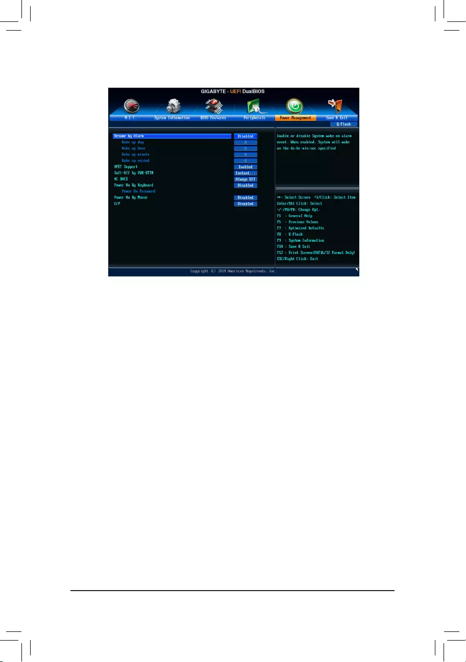
&Resume by Alarm
Determineswhethertopoweronthesystematadesiredtime.(Default:Disabled)
If enabled, set the date and time as following:
Wakeupday:Turnonthesystemataspecictimeoneachdayoronaspecicdayinamonth.
Wake up hour/minute/second: Set the time at which the system will be powered on automatically.
Note: When using this function, avoid inadequate shutdown from the operating system or removal of the
AC power, or the settings may not be effective.
&HPET Support
EnablesordisablesHighPrecisionEventTimer(HPET)forWindows10/8.1/7operatingsystem.(Default:
Enabled)
&Soft-Off by PWR-BTTN
ConguresthewaytoturnoffthecomputerinMS-DOSmodeusingthepowerbutton.
Instant-Off Pressthepowerbuttonandthenthesystemwillbeturnedoffinstantly.(Default)
Delay4Sec. Pressandholdthepowerbuttonfor4secondstoturnoffthesystem.Ifthepower
button is pressed for less than 4 seconds, the system will enter suspend mode.
&AC BACK
DeterminesthestateofthesystemafterthereturnofpowerfromanACpowerloss.
Memory The system returns to its last known awake state upon the return of the AC power.
Always On The system is turned on upon the return of the AC power.
AlwaysOff ThesystemstaysoffuponthereturnoftheACpower.(Default)
&Power On By Keyboard
Allows the system to be turned on by a PS/2 keyboard wake-up event.
Note:Tousethisfunction,youneedanATXpowersupplyprovidingatleast1Aonthe+5VSBlead.
Disabled Disablesthisfunction.(Default)
Password Set a password with 1~5 characters to turn on the system.
Keyboard98 PressPOWERbuttonontheWindows98keyboardtoturnonthesystem.
Any key Press any key to turn on the system.
2-6 Power Management
- 30 -
&Power On Password
Set the password when Power On By Keyboard is set to Password.
Press<Enter>onthisitemandsetapasswordwithupto5charactersandthenpress<Enter>toaccept.
Toturnonthesystem,enterthepasswordandpress<Enter>.
Note:Tocancelthepassword,press<Enter>onthisitem.Whenpromptedforthepassword,press<Enter>
again without entering the password to clear the password settings.
&Power On By Mouse
Allows the system to be turned on by a PS/2 mouse wake-up event.
Note:Tousethisfunction,youneedanATXpowersupplyprovidingatleast1Aonthe+5VSBlead.
Disabled Disablesthisfunction.(Default)
Move Move the mouse to turn on the system.
DoubleClick Doubleclickonleftbuttononthemousetoturnonthesystem.
&ErP
DetermineswhethertoletthesystemconsumeleastpowerinS5(shutdown)state.(Default:Disabled)
Note: When this item is set to Enabled,thefollowingfunctionswillbecomeunavailable:ResumebyAlarm,
PME event wake up, power on by mouse, power on by keyboard, and wake on LAN.
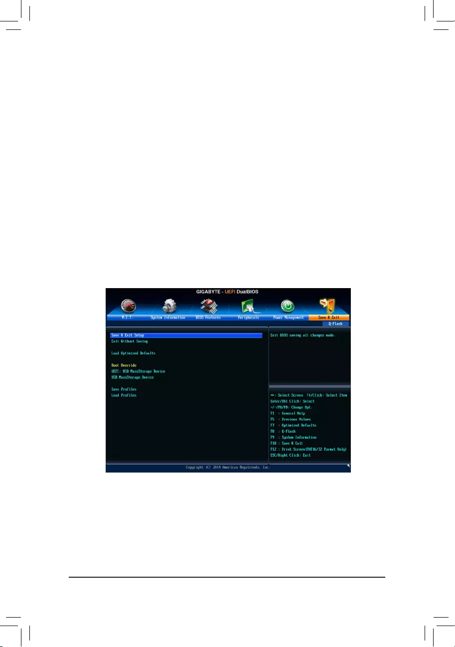
2-7 Save & Exit
&Save & Exit Setup
Press<Enter>onthisitemandselectYes. This saves the changes to the CMOS and exits the BIOS Setup
program. Select Noorpress<Esc>toreturntotheBIOSSetupMainMenu.
&Exit Without Saving
Press<Enter>onthisitemandselectYes. This exits the BIOS Setup without saving the changes made
in BIOS Setup to the CMOS. Select Noorpress<Esc>toreturntotheBIOSSetupMainMenu.
- 31 -
&Load Optimized Defaults
Press<Enter>onthisitemandselectYes to load the optimal BIOS default settings. The BIOS defaults
settings help the system to operate in optimum state. Always load the Optimized defaults after updating
the BIOS or after clearing the CMOS values.
&Boot Override
Allowsyoutoselectadevicetobootimmediately.Press<Enter>onthedeviceyouselectandselectYes
toconrm.Yoursystemwillrestartautomaticallyandbootfromthatdevice.
&SaveProles
ThisfunctionallowsyoutosavethecurrentBIOSsettingstoaprole.Youcancreateupto8prolesand
saveasSetupProle1~SetupProle8.Press<Enter>tocomplete.OryoucanselectSelect File in
HDD/FDD/USBtosavetheproletoyourstoragedevice.
&LoadProles
If your system becomes unstable and you have loaded the BIOS default settings, you can use this function
toloadtheBIOS settingsfromaprolecreatedbefore,withoutthehasslesofreconguring theBIOS
settings.Firstselecttheproleyouwishtoloadandthenpress<Enter>tocomplete.YoucanselectSelect
File in HDD/FDD/USBtoinputtheprolepreviouslycreatedfromyourstoragedeviceorloadtheprole
automatically created by the BIOS, such as reverting the BIOS settings to the last settings that worked
properly (last known good record).
Chapter 3 Appendix
Before you begin, please prepare the following items:
•AtleasttwoSATAharddrivesorM.2SSD(Note 1) (To ensure optimal performance, it is recommended that you
use two hard drives with identical model and capacity). (Note 2)
•Windows setup disk.
•Motherboard driver disk.
•A USB thumb drive.
ConguringtheOnboardSATAController
A. Installing SATA hard drive(s) in your computer
Connect the SATA signal cables to SATA hard drives and the SATA ports on the motherboard. Then connect
thepowerconnectorsfromyourpowersupplytotheharddrives.OrinstallyourM.2SSDintheM.2connector
on the motherboard.
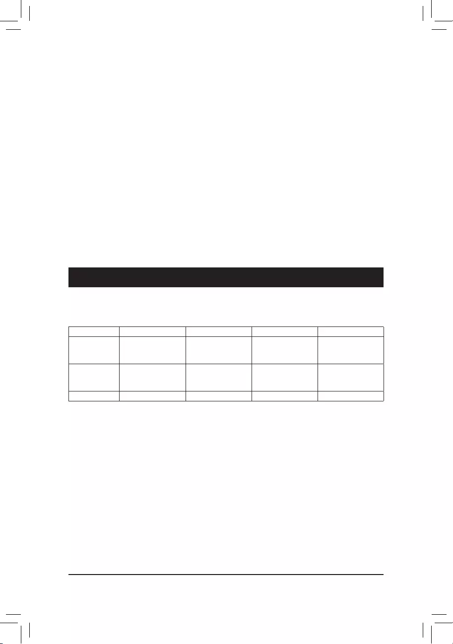
3-1 ConguringaRAIDSet
RAID Levels
(Note1) PleasenotethatanM.2PCIeSSDcannotbeusedtocreateaRAIDsetwithSATAdrive(s).
(Note2) RefertoChapter1,"InternalConnectors,""M.2Socket3Connector,"forthecongurationtablesof
SATAharddrivesandM.2SSDs.
RAID 0 RAID 1 RAID 5 RAID 10
Minimum
Number of Hard
Drives
≥2 2≥3 ≥4
Array Capacity Number of hard
drives * Size of the
smallest drive
Size of the smallest
drive
(Number of hard
drives -1) * Size of
the smallest drive
(Number of hard
drives/2) * Size of the
smallest drive
Fault Tolerance No Yes Yes Yes
- 32 -

C-1.UEFIRAIDConguration
OnlyWindows10/8.164-bitsupportsUEFIRAIDconguration.
Step 1:
In BIOS Setup, go to BIOS Features and set Windows 8 Features to Windows 8 and CSM Support to Never.
Save the changes and exit BIOS Setup.
Step 2:
Restartyour computerandpress<F12>to enterthebootdevicecongurationmenu.Usethe upordown
arrow key to select UEFI: Built-in EFI Shell.Press<Enter>toaccess.Followthestepsbelowandenterthe
commandstoaccesstheRAIDsetuputility.
1. Enter drvcfg at Shellandpress<Enter>:
Shell> drvcfg
2. When Drv [XX] Ctrl [XX] Lang [eng] appears, enter the following commands at Shell again:
Shell> drvcfg -s XX XX
XXs are the values shown in the brackets after Drv and Ctrl above, which may vary by hard drives.
Thenpress<Enter>toentertheRAIDsetuputility.
Step 3:
The Main MenuistherstscreenwhenyouentertheBIOSRAIDSetuputility.Usetheupordownarrowkey
to select Logical Drive Main Menuandpress<Enter>.
Step 4:
Tocreateanarray,press<Enter>onLogical Drive Create Menu.
Step 5:
Usable hard drives are listed on the Logical Drive Create Menu. Use the up or down arrow key to select the
harddrivetobeincludedinthearrayandpressthe<Space>key.Theselectedharddriveswillbemarkedwith
[X]. Then move to Basic Settingandpress<Enter>.
Step 6:
Usetheupordownarrowkeytomovetoandcongureeachrequirediteminsequence.
Aftercompleting,press<Enter>onStart To Create.Whenthemessage"AreYouSureToCreateLogicalDrive?"
appears,press<Enter>tobegincreatingtheRAIDarrayor<Esc>tocancel.
Whencompleted,amessagewhichsays"SuccessfulToCreateLogicalDrive"willappear.Press<Enter>to
complete.Press<F10>toexittheRAIDsetuputility.
B.ConguringSATAcontrollermodeinBIOSSetup
MakesuretoconguretheSATAcontrollermodecorrectlyinsystemBIOSSetup.FortheBIOSSetupmenus,
refertoChapter2,"BIOSSetup,""Peripherals."
Steps:
1. Turnonyourcomputerandpress<Delete>toenterBIOSSetupduringthePOST(Power-OnSelf-Test).Ensure
OnChip SATA Controller is enabled under Peripherals.ToenableRAIDfortheSATA30/1/2/3connectors,
set OnChip SATA Type to RAID.ToenableRAIDfortheSATA34/SATA35connectors,setOnChip SATA
Type to RAID and set OnChip SATA Port4/5 Type to As SATA Type.
2. IfyouwanttocongureUEFIRAID,followthestepsin"C-1."ToenterthelegacyRAIDROM,savethe
settingsandexitBIOSSetup.Referto"C-2"formoreinformation.
The BIOS Setup menus described in this section may differ from the exact settings for your motherboard.
The actual BIOS Setup menu options you will see shall depend on the motherboard you have and
the BIOS version.
- 33 -

PleasevisitGIGABYTE'swebsitefordetailsonconguringaRAIDarray.
Installing the SATA RAID/AHCI Driver and Operating System
With the correct BIOS settings, you are ready to install the operating system.
Installing the Operating System
(The following instructions use Windows 8.1 as the example operating system.)
Step 1:
YouneedtoinstalltheSATARAID/AHCIdriverduringtheOSinstallation.Useanalternativesystemtocopy
theSATARAID/AHCIdriverfromthemotherboarddriverdisktoaUSBashdrive.CopytheHw8 folder under
BootDrv in the driver disk.
Step 2:
Boot from the Windows 8.1 setup disk and perform standard OS installation steps. When the screen requesting
you to load the driver appears, select Browse.
Step 3:
ThenbrowsetotheUSBashdriveandselectthelocationofthedriver.Thelocationsofthedriversareasfollows:
RAIDdriverforWindows8.132-bit:Hw8\RAID\x86
RAIDdriverforWindows8.164-bit:Hw8\RAID\x64
AHCIdriverforWindows8.132-bit:Hw8\AHCI\W8
AHCIdriverforWindows8.164-bit:Hw8\AHCI\W864A
For Windows 7, browse to the Hw7 folder.
Step 4:
When a screen appears, select AMD-RAID Controller and click Next to load the driver and continue the OS
installation.
C-2.ConguringLegacyRAIDROM
EntertheRAIDBIOSsetuputilitytocongureaRAIDarray.SkipthisstepifyoudonotwanttocreateRAID
array on the SATA controller.
Steps:
After the POST memory test begins and before the operating system boot begins, look for a message which
says"Press<Ctrl-F>toenterRAIDOptionROMUtility".Press<Ctrl>+<F>toentertheRAIDBIOSsetuputility.
Tocreateanewarray,press<2>toentertheLD View Menuwindow.Tocreateanarray,press<Ctrl+C>to
access the LDDeneMenu.
In the LDDeneMenu,usetheupordownarrowkeytomovetoanitemforfurtherconguration.
- 34 -
• Beforeinstalling the drivers, rst install the operatingsystem. (The following instructions use
Windows 8.1 as the example operating system.)
• After installing the operating system, insert the motherboard driver disk into your optical drive. Click
onthemessage"Taptochoosewhathappenswiththisdisc"onthetop-rightcornerofthescreen
andselect"RunRun.exe."(OrgotoMyComputer,double-clicktheopticaldriveandexecutethe
Run.exeprogram.)
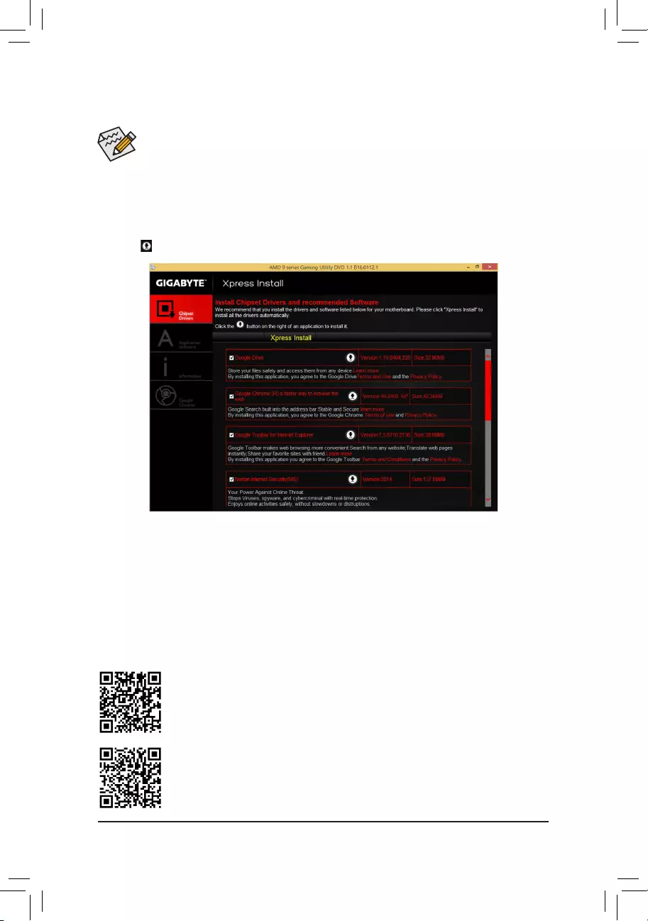
3-2 Drivers Installation
Please visit GIGABYTE's website for more software information.
PleasevisitGIGABYTE'swebsitefordetailsonconguringtheaudiosoftware.
"XpressInstall"willautomaticallyscanyoursystemandthenlistallofthedriversthatarerecommendedto
install. You can click the Xpress Install buttonand"XpressInstall"willinstallalloftheselecteddrivers.Orclick
the arrow icon to individually install the drivers you need.
- 35 -

Regulatory Statements
Regulatory Notices
This document must not be copied without our written permission, and the contents there of must not be imparted
to a third party nor be used for any unauthorized purpose.
Contravention will be prosecuted. We believe that the information contained herein was accurate in all respects
at the time of printing. GIGABYTE cannot, however, assume any responsibility for errors or omissions in this text.
Also note that the information in this document is subject to change without notice and should not be construed
as a commitment by GIGABYTE.
Our Commitment to Preserving the Environment
Inadditionto high-efciency performance, all GIGABYTE motherboards fulll European Union regulations
forRoHS(RestrictionofCertainHazardousSubstancesinElectricalandElectronicEquipment)andWEEE
(Waste Electrical and Electronic Equipment) environmental directives, as well as most major worldwide safety
requirements. To prevent releases of harmful substances into the environment and to maximize the use of our
natural resources, GIGABYTE provides the following information on how you can responsibly recycle or reuse
mostofthematerialsinyour"endoflife"product.
Restriction of Hazardous Substances (RoHS) Directive Statement
GIGABYTEproductshavenotintendedtoaddandsafefromhazardoussubstances(Cd,Pb,Hg,Cr+6,PBDE
andPBB).ThepartsandcomponentshavebeencarefullyselectedtomeetRoHSrequirement.Moreover,weat
GIGABYTE are continuing our efforts to develop products that do not use internationally banned toxic chemicals.
Waste Electrical & Electronic Equipment (WEEE) Directive Statement
GIGABYTEwillfulllthenationallawsasinterpretedfromthe2002/96/ECWEEE(WasteElectricalandElectronic
Equipment)directive.TheWEEEDirectivespeciesthetreatment,collection,recyclinganddisposalofelectric
andelectronicdevicesandtheircomponents.UndertheDirective,usedequipmentmustbemarked,collected
separately, and disposed of properly.
WEEE Symbol Statement
The symbol shown below is on the product or on its packaging, which indicates that this product
must not be disposed of with other waste. Instead, the device should be taken to the waste collection
centers for activation of the treatment, collection, recycling and disposal procedure. The separate
collection and recycling of your waste equipment at the time of disposal will help to conserve natural
resources and ensure that it is recycled in a manner that protects human health and the environment.
For more information about where you can drop off your waste equipment for recycling, please contact your
localgovernmentofce,yourhouseholdwastedisposalserviceorwhereyoupurchasedtheproductfordetails
of environmentally safe recycling.
Whenyourelectricalorelectronicequipmentisnolongerusefultoyou,"takeitback"toyourlocalorregional
waste collection administration for recycling.
Ifyouneedfurtherassistanceinrecycling,reusinginyour"endoflife"product,youmaycontactusatthe
Customer Care number listed in your product's user's manual and we will be glad to help you with your effort.
Finally, we suggest that you practice other environmentally friendly actions by understanding and using the
energy-saving features of this product (where applicable), recycling the inner and outer packaging (including
shipping containers) this product was delivered in, and by disposing of or recycling used batteries properly.
With your help, we can reduce the amount of natural resources needed to produce electrical and electronic
equipment,minimizetheuseoflandllsforthedisposalof"endoflife"products,andgenerallyimproveour
quality of life by ensuring that potentially hazardous substances are not released into the environment and are
disposed of properly.
- 36 -

FCC Notice (U.S.A. Only)
This equipment has been tested and found to comply with the limits for a Class B digital device, pursuant to Part
15oftheFCCRules.Theselimitsaredesignedtoprovidereasonableprotectionagainstharmfulinterference
in a residential installation. This equipment generates, uses, and can radiate radio frequency energy and, if not
installed and used in accordance with the instructions, may cause harmful interference to radio communications.
However, there is no guarantee that interference will not occur in a particular installation. If this equipment does
cause harmful interference to radio or television reception, which can be determined by turning the equipment
off and on, the user is encouraged to try to correct the interference by one or more of the following measures:
Reorientorrelocatethereceivingantenna.
Increase the separation between the equipment and receiver.
Connect the equipment into an outlet on a circuit different from that to which the receiver is connected.
ConsultadealerorexperiencedTV/radiotechnicianforhelp.
Canada, Industry Canada (IC) Notices / Canada, avis d'Industry Canada (IC)
ThisClassBdigitalapparatuscomplieswithCanadianICES-003andRSS-210.
Operation is subject to the following two conditions: (1) this device may not cause interference, and (2) this
device must accept any interference, including interference that may cause undesired operation of the device.
CetappareilnumériquedeclasseBestconformeauxnormescanadiennesICES-003etRSS-210.
Son fonctionnement est soumis aux deux conditions suivantes : (1) cet appareil ne doit pas causer
d'interférence et (2) cet appareil doit accepter toute interférence, notamment les interférences qui peuvent
affecter son fonctionnement.
- 37 -

- 38 -

- 39 -
Contact Us
GIGA-BYTE TECHNOLOGY CO., LTD.
Address:No.6,BaoqiangRd.,XindianDist.,NewTaipeiCity231,Taiwan
TEL: +886-2-8912-4000, FAX: +886-2-8912-4005
Tech. and Non-Tech. Support (Sales/Marketing) : http://esupport.gigabyte.com
WEB address (English): http://www.gigabyte.com
WEB address (Chinese): http://www.gigabyte.tw
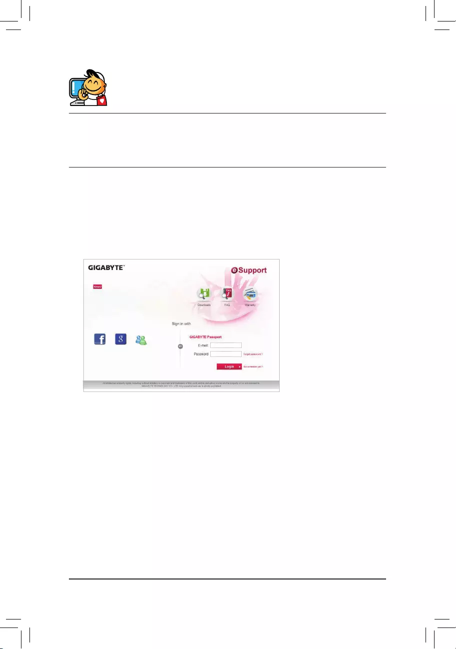
•GIGABYTE eSupport
To submit a technical or non-technical (Sales/Marketing) question, please link to:
http://esupport.gigabyte.com
- 40 -