Table of Contents
Gigabyte Z390 M User Manual
Displayed below is the user manual for Z390 M by Gigabyte which is a product in the Motherboards category. This manual has pages.
Related Manuals

To reduce the impacts on global warming, the packaging materials of this product
are recyclable and reusable. GIGABYTE works with you to protect the environment.
For more product details, please visit GIGABYTE's website.
Z390 M
User's Manual
Rev. 1001
12ME-Z390M-1001R
Copyright
© 2018 GIGA-BYTE TECHNOLOGY CO., LTD. All rights reserved.
The trademarks mentioned in this manual are legally registered to their respective owners.
Disclaimer
Information in this manual is protected by copyright laws and is the property of GIGABYTE.
Changes to the specications and features in this manual may be made by GIGABYTE without prior notice.
No part of this manual may be reproduced, copied, translated, transmitted, or published in any form or
by any means without GIGABYTE's prior written permission.
In order to assist in the use of this product, carefully read the User's Manual.
For product-related information, check on our website at: https://www.gigabyte.com
Identifying Your Motherboard Revision
The revision number on your motherboard looks like this: "REV: X.X." For example, "REV: 1.0" means
the revision of the motherboard is 1.0. Check your motherboard revision before updating motherboard
BIOS, drivers, or when looking for technical information.
Example:
Motherboard
Z390 M
Nov. 16, 2018
Nov. 16, 2018
Motherboard
Z390 M

- 3 -
Table of Contents
Z390 M Motherboard Layout ...........................................................................................4
Chapter 1 Hardware Installation .....................................................................................5
1-1 Installation Precautions .................................................................................... 5
1-2 ProductSpecications ...................................................................................... 6
1-3 Installing the CPU ............................................................................................ 9
1-4 Installing the Memory ....................................................................................... 9
1-5 Installing an Expansion Card ......................................................................... 10
1-6 Back Panel Connectors .................................................................................. 10
1-7 Internal Connectors ........................................................................................ 13
Chapter 2 BIOS Setup ..................................................................................................21
2-1 Startup Screen ............................................................................................... 21
2-2 The Main Menu .............................................................................................. 22
2-3 M.I.T. .............................................................................................................. 23
2-4 System ........................................................................................................... 29
2-5 BIOS ............................................................................................................... 30
2-6 Peripherals ..................................................................................................... 33
2-7 Chipset ........................................................................................................... 36
2-8 Power ............................................................................................................. 37
2-9 Save & Exit ..................................................................................................... 39
Chapter 3 Appendix ......................................................................................................40
3-1 ConguringaRAIDSet .................................................................................. 40
3-2 Installing an Intel® Optane™ Memory .............................................................. 42
3-3 DriversInstallation .......................................................................................... 44
RegulatoryStatements .............................................................................................. 45
Contact Us ................................................................................................................ 48
- 4 -
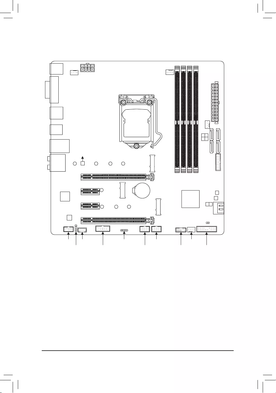
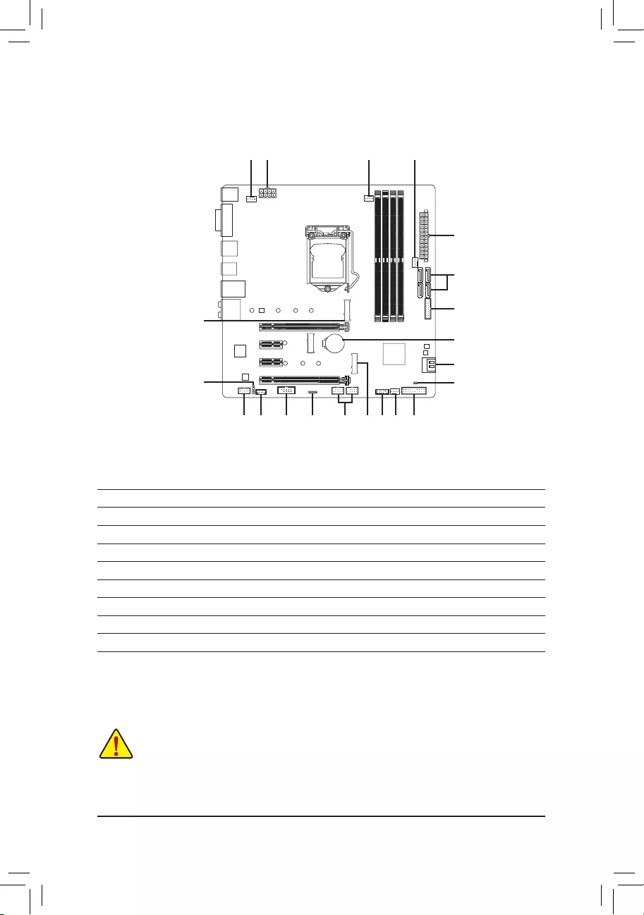
Z390 M Motherboard Layout
* The box contents above are for reference only and the actual items shall depend on the product package you obtain.
The box contents are subject to change without notice.
Box Contents
5Z390 M motherboard 5Two SATA cables
5Motherboard driver disk 5I/O Shield
5User's Manual
KB_MS_USB
DVI
DP
HDMI
USB31
TYPEC
USB30_LAN
LGA1151
ATX
AUDIO
DDR4_B1
DDR4_B2
DDR4_A1
DDR4_A2
ATX_12V_2X4
Intel® Z390
CLR_CMOS
M_BIOS
B_BIOS
PCIEX1_2
PCIEX1_1
PCIEX4
PCIEX16
F_USB30
CODEC
Z390 M
F_USB1LED_C
THB_C
F_AUDIO SYS_FAN3
F_USB2COM TPM F_PANELSPDIF_O
SYS_FAN1
SYS_FAN2
CPU_FAN
iTE®
Super I/O
CNVI
30
M2P
426080
M2Q
426080110
SATA3
SATA3
1 3
0 2
5
4
BAT
Intel® GbE LAN

Chapter 1 Hardware Installation
1-1 Installation Precautions
The motherboard contains numerous delicate electronic circuits and components which can become
damagedasaresultofelectrostaticdischarge(ESD).Priortoinstallation,carefullyreadtheuser's
manual and follow these procedures:
•Prior to installation, make sure the chassis is suitable for the motherboard.
•Priortoinstallation,donotremoveorbreakmotherboardS/N(SerialNumber)stickeror
warranty sticker provided by your dealer. These stickers are required for warranty validation.
•Always remove the AC power by unplugging the power cord from the power outlet before
installing or removing the motherboard or other hardware components.
•When connecting hardware components to the internal connectors on the motherboard, make
sure they are connected tightly and securely.
•When handling the motherboard, avoid touching any metal leads or connectors.
•It is best to wear an electrostatic discharge (ESD) wrist strap when handling electronic
componentssuchasamotherboard,CPUormemory.IfyoudonothaveanESDwriststrap,
keepyourhandsdryandrsttouchametalobjecttoeliminatestaticelectricity.
•Prior to installing the motherboard, please have it on top of an antistatic pad or within an
electrostatic shielding container.
•Before connecting or unplugging the power supply cable from the motherboard, make sure
the power supply has been turned off.
•Before turning on the power, make sure the power supply voltage has been set according to
the local voltage standard.
•Before using the product, please verify that all cables and power connectors of your hardware
components are connected.
•To prevent damage to the motherboard, do not allow screws to come in contact with the
motherboard circuit or its components.
•Make sure there are no leftover screws or metal components placed on the motherboard or
within the computer casing.
•Donotplacethecomputersystemonanunevensurface.
•Donotplacethecomputersysteminahigh-temperatureorwetenvironment.
•Turning on the computer power during the installation process can lead to damage to system
components as well as physical harm to the user.
•If you are uncertain about any installation steps or have a problem related to the use of the
product,pleaseconsultacertiedcomputertechnician.
•If you use an adapter, extension power cable, or power strip, ensure to consult with its installation
and/or grounding instructions.
- 5 -
1-2 ProductSpecications
CPU Support for 9th and 8th Generation Intel® Core™ i9 processors/Intel® Core™ i7
processors/Intel® Core™ i5 processors/Intel® Core™ i3 processors/Intel® Pentium®
processors/Intel® Celeron® processors in the LGA1151 package
(Go to GIGABYTE's website for the latest CPU support list.)
L3 cache varies with CPU
Chipset Intel® Z390 Express Chipset
Memory 4 x DDR4 DIMM sockets supporting up to 128 GB (32 GB single DIMM capacity)
of system memory
Dual channel memory architecture
Support for DDR4 2666/2400/2133 MHz memory modules
Support for ECC Un-buffered DIMM 1Rx8/2Rx8 memory modules (operate in
non-ECC mode)
Support for non-ECC Un-buffered DIMM 1Rx8/2Rx8/1Rx16 memory modules
Support for Extreme Memory Prole (XMP) memory modules
(Go to GIGABYTE's website for the latest supported memory speeds and memory
modules.)
Onboard
Graphics
Integrated Graphics Processor-Intel® HD Graphics support:
- 1 x DVI-D port, supporting a maximum resolution of 1920x1200@60 Hz
* The DVI-D port does not support D-Sub connection by adapter.
- 1 x DisplayPort, supporting a maximum resolution of 4096x2304@60 Hz
* Support for DisplayPort 1.2 version, HDCP 2.2, and HDR.
- 1 x HDMI port, supporting a maximum resolution of 4096x2160@30 Hz
* Support for HDMI 1.4 version and HDCP 2.2.
Maximum shared memory of 1 GB
Audio Realtek® ALC892 codec
High Denition Audio
2/4/5.1/7.1-channel
Support for S/PDIF Out
LAN Intel® GbE LAN chip (10/100/1000 Mbit)
Expansion Slots 1 x PCI Express x16 slot, running at x16 (PCIEX16)
* For optimum performance, if only one PCI Express graphics card is to be installed,
be sure to install it in the PCIEX16 slot.
1 x PCI Express x16 slot, running at x4 (PCIEX4)
2 x PCI Express x1 slots
(All of the PCI Express slots conform to PCI Express 3.0 standard.)
1 x M.2 Socket 1 connector for an Intel® CNVi wireless module only (CNVI)
Multi-Graphics
Technology Support for AMD Quad-GPU CrossFire™ and 2-Way AMD CrossFire™ technologies
Storage Interface Chipset:
- 1 x M.2 connector (Socket 3, M key, type 2242/2260/2280/22110 PCIe x4/
x2 SSD support) (M2Q)
- 1 x M.2 connector (Socket 3, M key, type 2242/2260/2280 SATA and PCIe
x4/x2 SSD support) (M2P)
- 6 x SATA 6Gb/s connectors
- Support for RAID 0, RAID 1, RAID 5, and RAID 10
* Refer to "1-7 Internal Connectors," for the installation notices for the M.2 and SATA
connectors.
Intel® Optane™ Memory Ready
- 6 -

USB Chipset:
- 1 x USB Type-C™ port on the back panel, with USB 3.1 Gen 1 support
- 1xUSB3.1Gen2Type-Aport(red)onthebackpanel
- 4 x USB 3.1 Gen 1 ports (2 ports on the back panel, 2 ports available through
theinternalUSBheader)
- 6 x USB 2.0/1.1 ports (2 ports on the back panel, 4 ports available through
theinternalUSBheaders)
Internal
Connectors
1 x 24-pin ATX main power connector
1x8-pinATX12Vpowerconnector
1 x CPU fan header
3 x system fan headers
1xRGBLEDstripheader
6 x SATA 6Gb/s connectors
2 x M.2 Socket 3 connectors
1 x front panel header
1 x front panel audio header
1xS/PDIFOutheader
1 x USB 3.1 Gen 1 header
2 x USB 2.0/1.1 headers
1 x Thunderbolt™ add-in card connector
1 xTrusted Platform Module (TPM)header (2x6 pin,for the GC-TPM2.0_S
moduleonly)
1 x serial port header
1 x Clear CMOS jumper
Back Panel
Connectors
1 x PS/2 keyboard/mouse port
1xDVI-Dport
1xDisplayPort
1xHDMIport
1 x USB Type-C™ port, with USB 3.1 Gen 1 support
1xUSB3.1Gen2Type-Aport(red)
2 x USB 3.1 Gen 1 ports
2 x USB 2.0/1.1 ports
1xRJ-45port
6 x audio jacks
I/O Controller iTE® I/O Controller Chip
Hardware
Monitor
Voltagedetection
Temperature detection
Fan speed detection
Overheating warning
Fan fail warning
Fan speed control
* Whether the fan speed control function is supported will depend on the cooler you
install.
- 7 -
BIOS 2x128Mbitash
Use of licensed AMI UEFI BIOS
SupportforDualBIOS™
PnP1.0a,DMI2.7,WfM2.0,SMBIOS2.7,ACPI5.0
Unique Features Support for APP Center
* Available applications in APP Center may vary by motherboard model. Supported
functionsofeachapplicationmayalsovarydependingonmotherboardspecications.
- 3DOSD
- @BIOS
- AmbientLED
- AutoGreen
- Cloud Station
- EasyTune
- EasyRAID
- Fast Boot
- Game Boost
- ON/OFF Charge
- Platform Power Management
- Smart Backup
- Smart Keyboard
- Smart TimeLock
- SmartHUD
- Smart Survey
- SystemInformationViewer
- USB Blocker
Support for Q-Flash
Support for Xpress Install
Bundled
Software
Norton®InternetSecurity(OEMversion)
cFosSpeed
Operating
System Support for Windows 10 64-bit
Form Factor Micro ATX Form Factor; 24.4cm x 24.4cm
* GIGABYTEreservestherighttomakeanychangestotheproductspecicationsandproduct-relatedinformationwithout
prior notice.
Please visit GIGABYTE's website
for support lists of CPU, memory
modules,SSDs,andM.2devices.
Please visit the Support\Utility List
page on GIGABYTE's website to
download the latest version of apps.
- 8 -
DualChannelMemoryConguration
ThismotherboardprovidesfourmemorysocketsandsupportsDualChannelTechnology.Afterthememory
isinstalled,theBIOSwillautomaticallydetectthespecicationsandcapacityofthememory.EnablingDual
Channel memory mode will double the original memory bandwidth.
Please visit GIGABYTE's website for details on hardware installation.
1-3 InstallingtheCPU
ReadthefollowingguidelinesbeforeyoubegintoinstalltheCPU:
•Make sure that the motherboard supports the CPU.
(GotoGIGABYTE'swebsiteforthelatestCPUsupportlist.)
•Always turn off the computer and unplug the power cord from the power outlet before installing the
CPU to prevent hardware damage.
•Locate the pin one of the CPU. The CPU cannot be inserted if oriented incorrectly. (Or you may
locatethenotchesonbothsidesoftheCPUandalignmentkeysontheCPUsocket.)
•Apply an even and thin layer of thermal grease on the surface of the CPU.
•DonotturnonthecomputeriftheCPUcoolerisnotinstalled,otherwiseoverheatinganddamage
of the CPU may occur.
•SettheCPUhostfrequencyinaccordancewiththeCPUspecications.Itisnotrecommended
thatthesystembusfrequencybesetbeyondhardwarespecicationssinceitdoesnotmeetthe
standard requirements for the peripherals. If you wish to set the frequency beyond the standard
specications,pleasedosoaccordingtoyourhardwarespecicationsincludingtheCPU,graphics
card, memory, hard drive, etc.
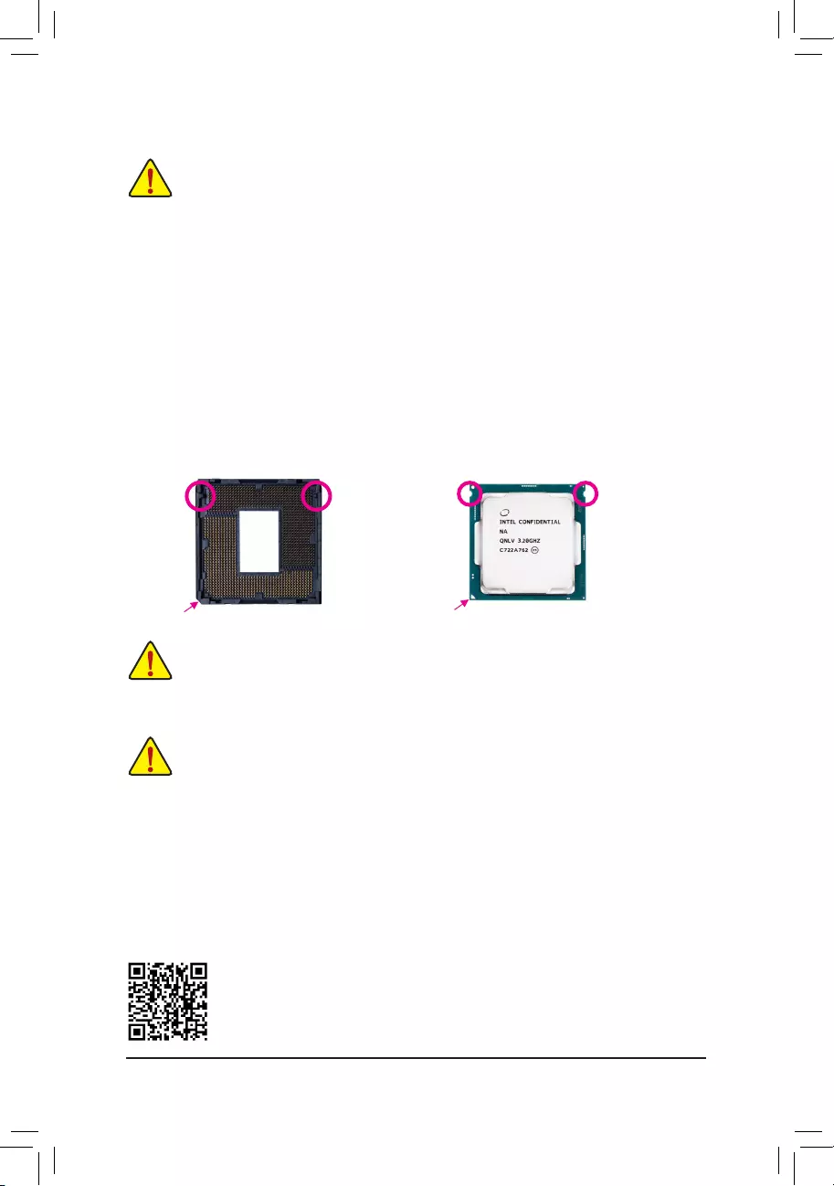
InstallingtheCPU
Locate the alignment keys on the motherboard CPU socket and the notches on the CPU.
DonotremovetheCPUsocketcoverbeforeinsertingtheCPU.Itmaypopofffromtheload
plateautomaticallyduringtheprocessofre-engagingtheleverafteryouinserttheCPU.
Triangle Pin One Marking on the CPU
NotchNotch
LGA1151 CPU
Alignment KeyAlignment Key
LGA1151 CPU Socket
Pin One Corner of the CPU Socket
1-4 InstallingtheMemory
Readthefollowingguidelinesbeforeyoubegintoinstallthememory:
•Make sure that the motherboard supports the memory. It is recommended that memory of the same
capacity, brand, speed, and chips be used.
(GotoGIGABYTE'swebsiteforthelatestsupportedmemoryspeedsandmemorymodules.)
•Always turn off the computer and unplug the power cord from the power outlet before installing the
memory to prevent hardware damage.
•Memory modules have a foolproof design. A memory module can be installed in only one direction.
If you are unable to insert the memory, switch the direction.
- 9 -
The four memory sockets are divided into two channels and each channel has two memory sockets as following:
ChannelA:DDR4_A1,DDR4_A2
ChannelB:DDR4_B1,DDR4_B2
DualChannelMemoryCongurationsTable
DDR4_B1 DDR4_B2 DDR4_A1 DDR4_A2
2 Modules - - DS/SS - - DS/SS
DS/SS - - DS/SS - -
4 Modules DS/SS DS/SS DS/SS DS/SS
(SS=Single-Sided,DS=Double-Sided,"--"=NoMemory)
DuetoCPUlimitations,readthefollowingguidelinesbeforeinstallingthememoryinDualChannelmode.
1. DualChannelmodecannotbeenabledifonlyonememorymoduleisinstalled.
2. WhenenablingDualChannelmodewithtwoorfourmemorymodules,itisrecommendedthatmemory
of the same capacity, brand, speed, and chips be used.
1-5 InstallinganExpansionCard
Readthefollowingguidelinesbeforeyoubegintoinstallanexpansioncard:
•Make sure the motherboard supports the expansion card. Carefully read the manual that came
with your expansion card.
•Always turn off the computer and unplug the power cord from the power outlet before installing an
expansion card to prevent hardware damage.
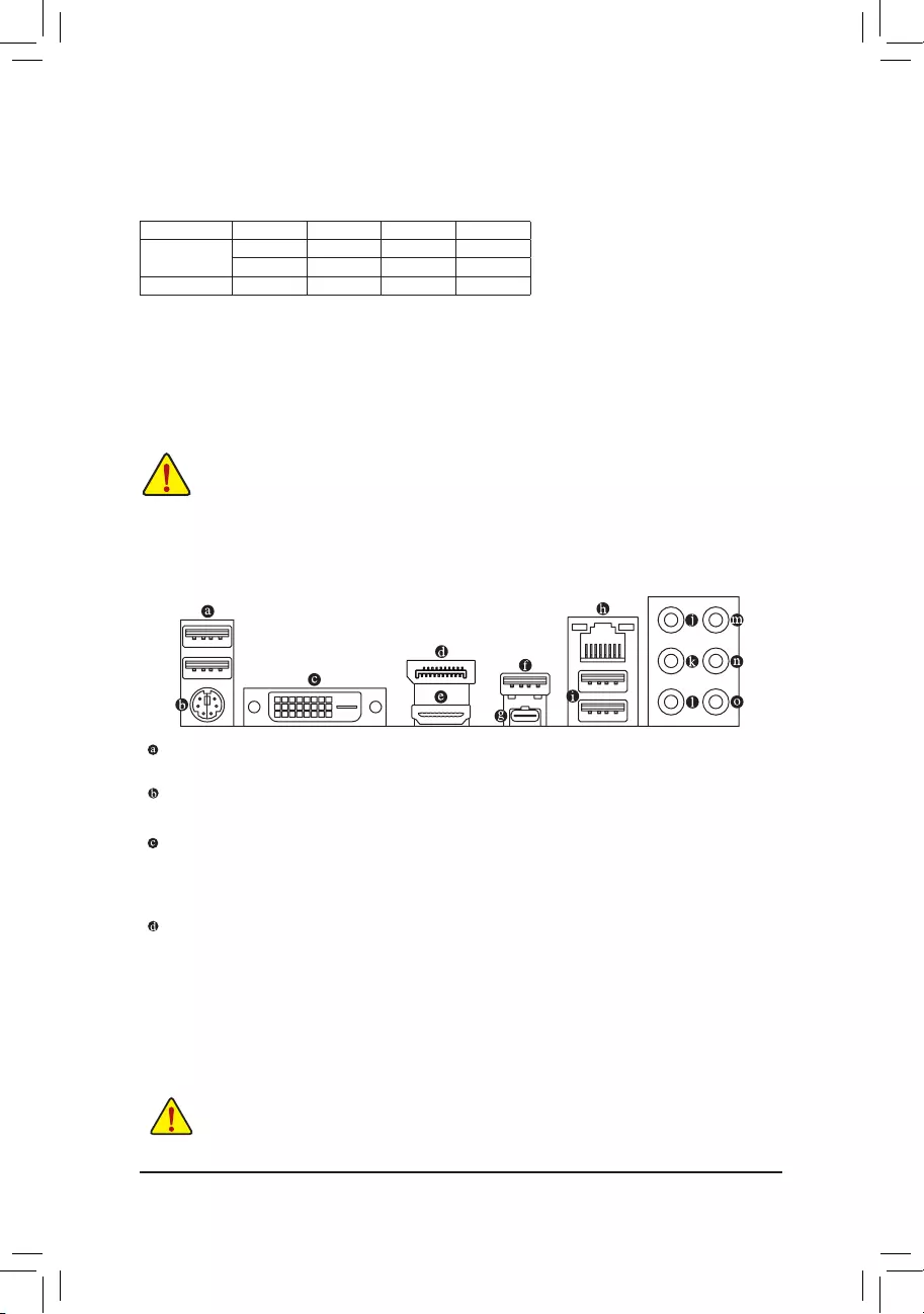
1-6 Back Panel Connectors
USB2.0/1.1Port
TheUSBportsupportstheUSB2.0/1.1specication.UsethisportforUSBdevices.
PS/2Keyboard/MousePort
Use this port to connect a PS/2 mouse or keyboard.
DVI-D Port (Note)
TheDVI-DportconformstotheDVI-Dspecicationandsupportsamaximumresolutionof1920x1200@60Hz
(theactualresolutionssupporteddependonthemonitorbeingused).Connectamonitorthatsupports
DVI-Dconnectiontothisport.
DisplayPort
DisplayPortdelivershighqualitydigitalimagingandaudio,supportingbi-directionalaudiotransmission.
DisplayPortcansupportbothDPCPandHDCP2.2contentprotectionmechanisms.Itprovidesimproved
visualssupportingRec. 2020 (WideColorGamut) andHighDynamic Range (HDR)forBlu-ray UHD
playback.YoucanusethisporttoconnectyourDisplayPort-supportedmonitor.Note:TheDisplayPort
Technologycansupportamaximumresolutionof4096x2304@60Hzbuttheactualresolutionssupported
depend on the monitor being used.
(Note) TheDVI-DportdoesnotsupportD-Subconnectionbyadapter.
•Whenremovingthecableconnectedtoabackpanelconnector,rstremovethecablefromyour
device and then remove it from the motherboard.
•Whenremovingthecable,pullitstraightoutfromtheconnector.Donotrockitsidetosideto
prevent an electrical short inside the cable connector.
- 10 -
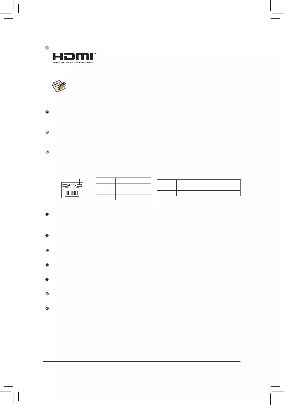
HDMI Port
TheHDMIportsupportsHDCP2.2andDolbyTrueHDandDTSHDMasterAudio
formats.Italsosupportsupto192KHz/16bit8-channelLPCMaudiooutput.You
canusethisport to connectyourHDMI-supported monitor.The maximumsupportedresolution is
4096x2160@30Hz,buttheactualresolutionssupportedaredependentonthemonitorbeingused.
USB3.1Gen2Type-APort(Red)
TheUSB3.1Gen2Type-AportsupportstheUSB3.1Gen2specicationandiscompatibletotheUSB
3.1Gen1andUSB2.0specication.UsethisportforUSBdevices.
USB Type-C™ Port
Thereversible USBportsupportstheUSB3.1Gen 1specicationandiscompatibletothe USB2.0
specication.UsethisportforUSBdevices.
RJ-45LANPort
The Gigabit Ethernet LAN port provides Internet connection at up to 1 Gbps data rate. The following
describesthestatesoftheLANportLEDs.
•Tosetupatriple-displayconguration,youmustinstallmotherboarddriversintheoperating
systemrst.
•Afterinstallingthe DisplayPort/HDMI device,makesure to setthedefault sound playback
devicetoDisplayPort/HDMI.(Theitemnamemaydifferdependingonyouroperatingsystem.)
USB3.1Gen1Port
TheUSB3.1Gen1portsupportstheUSB3.1Gen1specicationandiscompatibletotheUSB2.0
specication.UsethisportforUSBdevices.
Center/SubwooferSpeakerOut(Orange)
Use this audio jack to connect center/subwoofer speakers.
RearSpeakerOut(Black)
Use this audio jack to connect rear speakers.
SideSpeakerOut(Gray)
Use this audio jack to connect side speakers.
Line In (Blue)
The line in jack. Use this audio jack for line in devices such as an optical drive, walkman, etc.
LineOut/FrontSpeakerOut(Green)
The line out jack.
Mic In (Pink)
The Mic in jack.
ActivityLED
Connection/
SpeedLED
LAN Port
ActivityLED:
Connection/SpeedLED:
State Description
Orange 1 Gbps data rate
Green 100 Mbps data rate
Off 10 Mbps data rate
State Description
Blinking Datatransmissionorreceivingisoccurring
On No data transmission or receiving is occurring
- 11 -
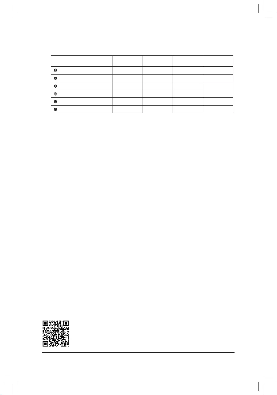
AudioJackCongurations:
Jack Headphone/
2-channel 4-channel 5.1-channel 7.1-channel
Center/Subwoofer Speaker Out a a
RearSpeakerOut a a a
Side Speaker Out a
Line In
Line Out/Front Speaker Out a a a a
Mic In
PleasevisitGIGABYTE'swebsitefordetailsonconguringtheaudiosoftware.
- 12 -
1-7 Internal Connectors
Readthefollowingguidelinesbeforeconnectingexternaldevices:
•First make sure your devices are compliant with the connectors you wish to connect.
•Before installing the devices, be sure to turn off the devices and your computer. Unplug the power
cord from the power outlet to prevent damage to the devices.
•After installing the device and before turning on the computer, make sure the device cable has
been securely attached to the connector on the motherboard.
4 87
11
17
6
16
2
6
59 15
1
4
13
10
7
12 14
3 4
1) ATX_12V_2X4
2) ATX
3) CPU_FAN
4) SYS_FAN1/2/3
5) LED_C
6) SATA30/1/2/3/4/5
7) M2Q/M2P
8) F_PANEL
9) F_AUDIO
10) SPDIF_O
11) F_USB30
12) F_USB1/F_USB2
13) COM
14) TPM
15) THB_C
16) CLR_CMOS
17) BAT
- 13 -
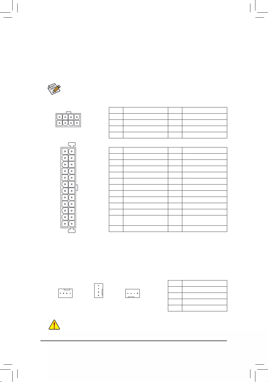
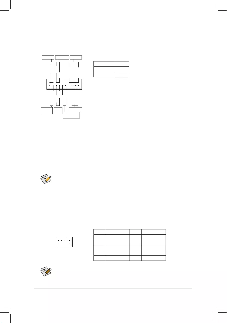
3/4)CPU_FAN/SYS_FAN1/2/3(FanHeaders)
All fan headers on this motherboard are 4-pin. Most fan headers possess a foolproof insertion design.
When connecting a fan cable, be sure to connect it in the correct orientation (the black connector wire is
thegroundwire).Thespeedcontrolfunctionrequirestheuseofafanwithfanspeedcontroldesign.For
optimum heat dissipation, it is recommended that a system fan be installed inside the chassis.
•Be sure to connect fan cables to the fan headers to prevent your CPU and system from
overheating. Overheating may result in damage to the CPU or the system may hang.
•Thesefanheadersarenotcongurationjumperblocks.Donotplaceajumpercapontheheaders.
CPU_FAN/SYS_FAN1
DEBUG
PORT
G.QBOFM
DEBUG
PORT
G.QBOFM
1 1
SYS_FAN2 SYS_FAN3
DEBUG
PORT
G.QBOFM
1
Pin No. Denition
1GND
2VoltageSpeedControl
3 Sense
4 PWM Speed Control
DEBUG
PORT
G.QBOFM
131
24
12
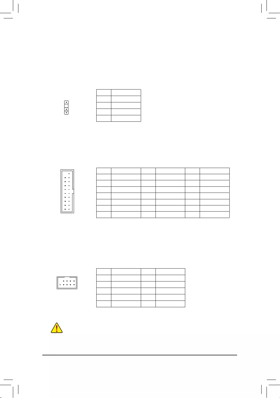
ATX
ATX:
Pin No. Denition Pin No. Denition
13.3V 13 3.3V
23.3V 14 -12V
3GND 15 GND
4+5V 16 PS_ON(softOn/Off)
5GND 17 GND
6+5V 18 GND
7GND 19 GND
8 Power Good 20 NC
95VSB(standby+5V) 21 +5V
10 +12V 22 +5V
11 +12V(Onlyfor2x12-pin
ATX)
23 +5V(Onlyfor2x12-pinATX)
12 3.3V(Onlyfor2x12-pinATX) 24 GND(Onlyfor2x12-pinATX)
ATX_12V_2X4:
Pin No. Denition Pin No. Denition
1GND(Onlyfor2x4-pin12V) 5+12V(Onlyfor2x4-pin12V)
2GND(Onlyfor2x4-pin12V) 6+12V(Onlyfor2x4-pin12V)
3GND 7+12V
4GND 8+12V
DEBUG
PORT
G.QBOFM
ATX_12V_2X4
41
85
1/2)ATX_12V_2X4/ATX(2x412VPowerConnectorand2x12MainPowerConnector)
With the use of the power connector, the power supply can supply enough stable power to all the components
onthemotherboard.Beforeconnectingthepowerconnector,rstmakesurethepowersupplyisturned
off and all devices are properly installed. The power connector possesses a foolproof design. Connect the
power supply cable to the power connector in the correct orientation.
The12VpowerconnectormainlysuppliespowertotheCPU.Ifthe12Vpowerconnectorisnotconnected,
the computer will not start.
To meet expansion requirements, it is recommended that a power supply that can withstand high
powerconsumptionbeused(500Worgreater).Ifapowersupplyisusedthatdoesnotprovidethe
required power, the result can lead to an unstable or unbootable system.
- 14 -
DEBUG
PORT
G.QBOFM
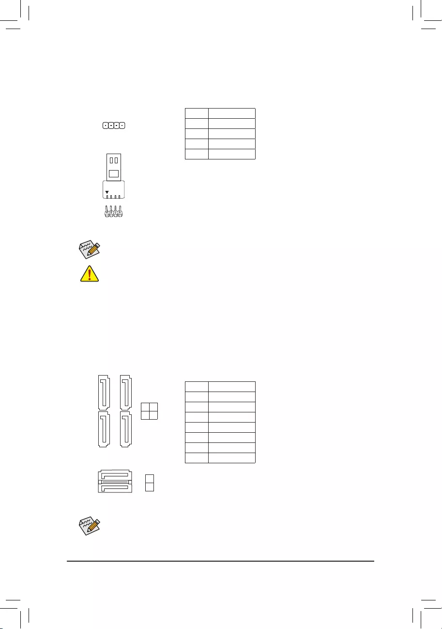
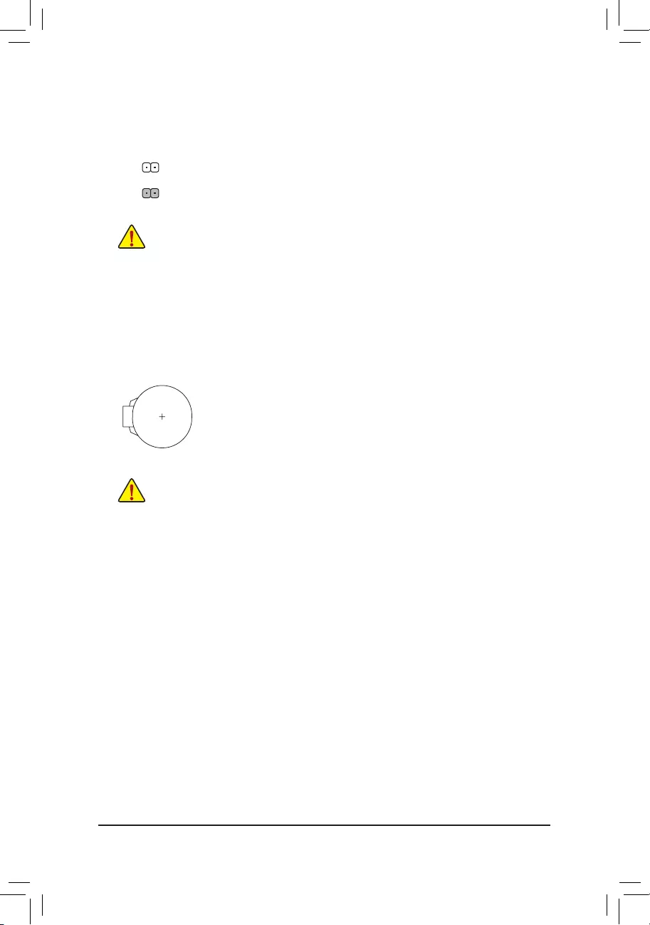
5) LED_C(RGBLEDStripHeader)
Theheadercanbeusedtoconnectastandard5050RGBLEDstrip(12V/G/R/B),withmaximumpower
ratingof2A(12V)andmaximumlengthof2m.
Pin No. Denition
112V
2 G
3R
4 B
Before installing the devices, be sure to turn off the devices and your computer. Unplug the power
cord from the power outlet to prevent damage to the devices.
ConnectyourRGBLEDstriptotheheader.Thepowerpin(marked
withatriangleontheplug)oftheLEDstripmustbeconnectedtoPin
1(12V)ofthisheader.Incorrectconnectionmayleadtothedamage
oftheLEDstrip.
RGBLEDStrip
1
12V
1
DEBUG
PORT
G.QBOFM
6) SATA30/1/2/3/4/5(SATA6Gb/sConnectors)
The SATA connectors conform to SATA 6Gb/s standard and are compatible with SATA 3Gb/s and SATA
1.5Gb/s standard. Each SATA connector supports a single SATA device. The Intel®ChipsetsupportsRAID0,
RAID1,RAID5,andRAID10.RefertoChapter3,"ConguringaRAIDSet,"forinstructionsonconguring
aRAIDarray.
Pin No. Denition
1GND
2 TXP
3 TXN
4GND
5RXN
6RXP
7GND
Toenablehot-pluggingfortheSATAports,refertoChapter2,"BIOSSetup,""Peripherals\SATA
AndRSTConguration,"formoreinformation.
Forhowtoturnon/offthelightsoftheLEDstrippleasevisitthe"UniqueFeatures"webpageof
GIGABYTE's website.
SATA3
SATA3
3 2
1 0
5
4
DEBUG
PORT
G.QBOFM
DEBUG
PORT
G.QBOFM
DEBUG
PORT
G.QBOFM
DEBUG
PORT
G.QBOFM
7
1
7
1
17
17
- 15 -
7) M2Q/M2P(M.2Socket3Connectors)
TheM.2connectorssupportM.2SATASSDsorM.2PCIeSSDsandsupportRAIDconguration.Please
notethatanM.2PCIeSSDcannotbeusedtocreateaRAIDseteitherwithanM.2SATASSDoraSATA
harddrive.TocreateaRAIDarraywithanM.2PCIeSSD,youmustsetupthecongurationinUEFIBIOS
mode.RefertoChapter3,"ConguringaRAIDSet,"forinstructionsonconguringaRAIDarray.
F_USB30 F_U
B_
F_ F_
_
B
BS_
B
SB_
B
_S
S_
_
B
_U
_
B
S
123
123
123
123
1
1
1
1
BSS
S
_S
SSU
1 2 3 4 5
S3 BSSS
U
__ 3
F_USB3F
S _
S _
S _
SF
B_
B_
F
_0
S
S
_0F
_F
_
_
__B
U
S _S
_ SF_
USB0_B
B_ F_USB3
F_USB303
_
_3U
S_
80110 60 42
F_USB30 F_U
B_
F_ F_
_
B
BS_
B
SB_
B
_S
S_
_
B
_U
_
B
S
123
123
123
123
1
1
1
1
BSS
S
_S
SSU
1 2 3 4 5
S3 BSSS
U
__ 3
F_USB3F
S _
S _
S _
SF
B_
B_
F
_0
S
S
_0F
_F
_
_
__B
U
S _S
_ SF_
USB0_B
B_ F_USB3
F_USB303
_
_3U
S_
80 60 42
FollowthestepsbelowtocorrectlyinstallanM.2SSDintheM.2connector.
Step 1:
Use a screw driver to unfasten the screw and standoff from the motherboard. Locate the proper mounting
holefortheM.2SSDtobeinstalledandthenscrewthestandoffrst.
Step 2:
SlidetheM.2SSDintotheconnectoratanangle.
Step 3:
PresstheM.2SSDdownandthensecureitwiththescrew.
SelecttheproperholefortheM.2SSDtobeinstalledandrefastenthescrewandstandoff.
M2Q
M2P
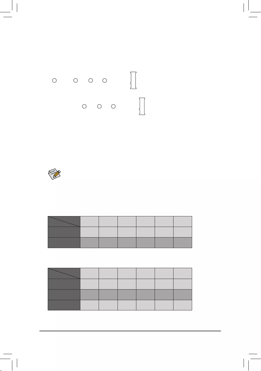
InstallationNoticesfortheM.2andSATAConnectors:
DuetothelimitednumberoflanesprovidedbytheChipset,theavailabilityoftheSATAconnectorsmay
be affected by the type of device installed in the M.2 connector. The M2P connector shares bandwidth with
theSATA31connector.Refertothefollowingtablefordetails.
•M2Q:
SATA3 0 SATA3 1 SATA3 2 SATA3 3 SATA3 4 SATA3 5
M.2PCIeSSD*
a a a a a a
NoM.2SSDInstalled a a a a a a
a: Available, r: Not available
* TheM2QconnectorsupportsonlyPCIeSSDs.
Connector
Type of
M.2SSD
•M2P:
SATA3 0 SATA3 1 SATA3 2 SATA3 3 SATA3 4 SATA3 5
M.2SATASSD ara a a a
M.2PCIeSSD
a a a a a a
NoM.2SSDInstalled a a a a a a
a: Available, r: Not available
Connector
Type of
M.2SSD
- 16 -
9) F_AUDIO(FrontPanelAudioHeader)
ThefrontpanelaudioheadersupportsHighDenitionaudio(HD).Youmayconnectyourchassisfront
panel audio module to this header. Make sure the wire assignments of the module connector match the
pin assignments of the motherboard header. Incorrect connection between the module connector and the
motherboard header will make the device unable to work or even damage it.
F_USB30 F_U
B_
F_ F_
_
B
BS_
B
SB_
B
_S
S_
_
B
_U
_
B
S
123
123
123
123
1
1
1
1
BSS
S
_S
SSU
1 2 3 4 5
S3 BSSS
U
__ 3
F_USB3F
S _
S _
S _
SF
B_
B_
F
_0
S
S
_0F
_F
_
_
__B
U
S _S
_ SF_
USB0_B
B_ F_USB3
F_USB303
_
_3U
S_
9 1
10 2
Pin No. Denition Pin No. Denition
1 MIC2_L 6 Sense
2GND 7FAUDIO_JD
3MIC2_R 8 No Pin
4 NC 9 LINE2_L
5LINE2_R 10 Sense
The front panel design may differ by chassis. A front panel module mainly consists of power switch,
resetswitch,powerLED,harddriveactivityLED,speakerandetc.Whenconnectingyourchassis
front panel module to this header, make sure the wire assignments and the pin assignments are
matched correctly.
Some chassis provide a front panel audio module that has separated connectors on each wire
instead of a single plug. For information about connecting the front panel audio module that has
different wire assignments, please contact the chassis manufacturer.
8) F_PANEL(FrontPanelHeader)
Connect the power switch, reset switch, speaker, chassis intrusion switch/sensor and system status indicator
on the chassis to this header according to the pin assignments below. Note the positive and negative pins
before connecting the cables.
System Status LED
S0 On
S3/S4/S5 Off
•PW(PowerSwitch,Red):
Connects to the power switch on the chassis front panel. You may
congurethewaytoturnoffyoursystemusingthepowerswitch(refer
toChapter2,"BIOSSetup,""Power,"formoreinformation).
•SPEAK(Speaker,Orange):
Connects to the speaker on the chassis front panel. The system reports
system startup status by issuing a beep code. One single short beep
will be heard if no problem is detected at system startup.
•PLED/PWR_LED(PowerLED,Yellow/Purple):
Connects to the power status indicator
onthechassisfrontpanel.TheLEDison
whenthesystemisoperating.TheLEDis
off when the system is in S3/S4 sleep state
orpoweredoff(S5).
•HD (HardDriveActivityLED,Blue):
ConnectstotheharddriveactivityLEDonthechassisfrontpanel.TheLEDisonwhentheharddrive
is reading or writing data.
•RES(ResetSwitch,Green):
Connects to the reset switch on the chassis front panel. Press the reset switch to restart the computer
ifthecomputerfreezesandfailstoperformanormalrestart.
•CI (ChassisIntrusionHeader,Gray):
Connects to the chassis intrusion switch/sensor on the chassis that can detect if the chassis cover has
been removed. This function requires a chassis with a chassis intrusion switch/sensor.
•NC (Orange):NoConnection.
NC
NC
PowerLED
DEBUG
PORT
G.QBOFM
1
2
19
20
CI-
CI+
PWR_LED-
PWR_LED+
PLED-
PW-
SPEAK+
SPEAK-
PLED+
PW+
PowerLED
HD-
RES+
HD+
RES-
HardDrive
ActivityLED
Reset
Switch Chassis Intrusion
Header
Power Switch Speaker
PWR_LED-
- 17 -
10) SPDIF_O(S/PDIFOutHeader)
ThisheadersupportsdigitalS/PDIFOutandconnectsaS/PDIFdigitalaudiocable(providedbyexpansion
cards)fordigitalaudiooutputfromyourmotherboardtocertainexpansioncardslikegraphicscardsand
soundcards.Forexample,somegraphicscardsmayrequireyoutouseaS/PDIFdigitalaudiocablefor
digitalaudiooutputfromyourmotherboardtoyourgraphicscardifyouwishtoconnectanHDMIdisplay
tothegraphicscardandhavedigitalaudiooutputfromtheHDMIdisplayatthesametime.Forinformation
aboutconnectingtheS/PDIFdigitalaudiocable,carefullyreadthemanualforyourexpansioncard.
Pin No. Denition
15VDUAL
2 No Pin
3SPDIFO
4GND
1
F_USB30 F_U
B_
F_ F_
_
B
BS_
B
SB_
B
_S
S_
_
B
_U
_
B
S
123
123
123
123
1
1
1
1
BSS
S
_S
SSU
1 2 3 4 5
S3 BSSS
U
__ 3
F_USB3F
S _
S _
S _
SF
B_
B_
F
_0
S
S
_0F
_F
_
_
__B
U
S _S
_ SF_
USB0_B
B_ F_USB3
F_USB303
_
_3U
S_
Pin No. Denition Pin No. Denition Pin No. Denition
1VBUS 8D1- 15 SSTX2-
2SSRX1- 9D1+ 16 GND
3SSRX1+ 10 NC 17 SSRX2+
4GND 11 D2+ 18 SSRX2-
5 SSTX1- 12 D2- 19 VBUS
6 SSTX1+ 13 GND 20 No Pin
7GND 14 SSTX2+
11) F_USB30(USB3.1Gen1Header)
TheheaderconformstoUSB3.1Gen1andUSB2.0specicationandcanprovidetwoUSBports.For
purchasingtheoptional3.5"frontpanelthatprovidestwoUSB3.1Gen1ports,pleasecontactthelocal
dealer.
F_USB30 F_U
B_
F_ F_
_
B
BS_
B
SB_
B
_S
S_
_
B
_U
_
B
S
123
123
123
123
1
1
1
1
BSS
S
_S
SSU
1 2 3 4 5
S3 BSSS
U
__ 3
F_USB3F
S _
S _
S _
SF
B_
B_
F
_0
S
S
_0F
_F
_
_
__B
U
S _S
_ SF_
USB0_B
B_ F_USB3
F_USB303
_
_3U
S_
10
20 1
11
12) F_USB1/F_USB2(USB2.0/1.1Headers)
TheheadersconformtoUSB2.0/1.1specication.EachUSBheadercanprovidetwoUSBportsviaan
optional USB bracket. For purchasing the optional USB bracket, please contact the local dealer.
Pin No. Denition Pin No. Denition
1Power(5V) 6USBDY+
2Power(5V) 7GND
3USBDX- 8GND
4USBDY- 9 No Pin
5USBDX+ 10 NC
•DonotplugtheIEEE1394bracket(2x5-pin)cableintotheUSB2.0/1.1header.
•Prior to installing the USB bracket, be sure to turn off your computer and unplug the power cord
from the power outlet to prevent damage to the USB bracket.
DEBUG
PORT
G.QBOFM
10
9
2
1
- 18 -

10
9
2
1
13) COM(SerialPortHeader)
The COM header can provide one serial port via an optional COM port cable. For purchasing the optional
COM port cable, please contact the local dealer.
Pin No. Denition Pin No. Denition
1NDCD- 6NDSR-
2 NSIN 7 NRTS-
3 NSOUT 8 NCTS-
4NDTR- 9NRI-
5GND 10 No Pin
14) TPM (Trusted Platform Module Header)
YoumayconnectaTPM(TrustedPlatformModule)tothisheader.
Pin No. Denition Pin No. Denition
1LAD0 7LAD3
2VCC3 8GND
3LAD1 9LFRAME
4No Pin 10 NC
5LAD2 11 SERIRQ
6LCLK 12 LRESET
12
11
2
1
F_USB30 F_U
B_
F_ F_
_
B
BS_
B
SB_
B
_S
S_
_
B
_U
_
B
S
123
123
123
123
1
1
1
1
BSS
S
_S
SSU
1 2 3 4 5
S3 BSSS
U
__ 3
F_USB3F
S _
S _
S _
SF
B_
B_
F
_0
S
S
_0F
_F
_
_
__B
U
S _S
_ SF_
USB0_B
B_ F_USB3
F_USB303
_
_3U
S_
F_USB30 F_U
B_
F_ F_
_
B
BS_
B
SB_
B
_S
S_
_
B
_U
_
B
S
123
123
123
123
1
1
1
1
BSS
S
_S
SSU
1 2 3 4 5
S3 BSSS
U
__ 3
F_USB3F
S _
S _
S _
SF
B_
B_
F
_0
S
S
_0F
_F
_
_
__B
U
S _S
_ SF_
USB0_B
B_ F_USB3
F_USB303
_
_3U
S_
1
15) THB_C(Thunderbolt™Add-inCardConnector)
This connector is for a GIGABYTE Thunderbolt™ add-in card.
Supports a Thunderbolt™ add-in card.
- 19 -
16) CLR_CMOS(ClearCMOSJumper)
UsethisjumpertocleartheBIOScongurationandresettheCMOSvaluestofactorydefaults.Toclear
the CMOS values, use a metal object like a screwdriver to touch the two pins for a few seconds.
•Always turn off your computer and unplug the power cord from the power outlet before clearing
the CMOS values.
•Aftersystemrestart,gotoBIOSSetuptoloadfactorydefaults(selectLoadOptimizedDefaults)or
manuallyconguretheBIOSsettings(refertoChapter2,"BIOSSetup,"forBIOScongurations).
Open: Normal
Short:ClearCMOSValues
17) BAT(Battery)
Thebatteryprovidespowertokeepthevalues(suchasBIOScongurations,date,andtimeinformation)
intheCMOSwhenthecomputeristurnedoff.Replacethebatterywhenthebatteryvoltagedropstoalow
level, or the CMOS values may not be accurate or may be lost.
You may clear the CMOS values by removing the battery:
1. Turn off your computer and unplug the power cord.
2. Gently remove the battery from the battery holder and wait for one minute. (Or use a
metal object like a screwdriver to touch the positive and negative terminals of the battery
holder,makingthemshortfor5seconds.)
3. Replacethebattery.
4. Plug in the power cord and restart your computer.
•Always turn off your computer and unplug the power cord before replacing the battery.
•Replacethebatterywithanequivalentone.Damagetoyourdevicesmayoccurifthebattery
is replaced with an incorrect model.
•Contact the place of purchase or local dealer if you are not able to replace the battery by yourself
or uncertain about the battery model.
•Wheninstallingthebattery,notetheorientationofthepositiveside(+)andthenegativeside(-)
ofthebattery(thepositivesideshouldfaceup).
•Used batteries must be handled in accordance with local environmental regulations.
- 20 -
BIOS(Basic Input and Output System) records hardware parameters of the system in theCMOS on the
motherboard.ItsmajorfunctionsincludeconductingthePower-OnSelf-Test(POST)duringsystemstartup,
saving system parameters and loading operating system, etc. BIOS includes a BIOS Setup program that allows
theusertomodifybasicsystemcongurationsettingsortoactivatecertainsystemfeatures.
When the power is turned off, the battery on the motherboard supplies the necessary power to the CMOS to
keepthecongurationvaluesintheCMOS.
ToaccesstheBIOSSetupprogram,pressthe<Delete>keyduringthePOSTwhenthepoweristurnedon.
ToupgradetheBIOS,useeithertheGIGABYTEQ-Flashor@BIOSutility.
•Q-Flash allows the user to quickly and easily upgrade or back up BIOS without entering the operating system.
•@BIOSisaWindows-basedutilitythatsearchesanddownloadsthelatestversionofBIOSfromtheInternet
and updates the BIOS.
Chapter2 BIOSSetup
•BecauseBIOSashingispotentiallyrisky,ifyoudonotencounterproblemsusingthecurrentversionofBIOS,
itisrecommendedthatyounotashtheBIOS.ToashtheBIOS,doitwithcaution.InadequateBIOSashing
may result in system malfunction.
•Itisrecommendedthatyounotalterthedefaultsettings(unlessyouneedto)topreventsysteminstabilityorother
unexpected results. Inadequately altering the settings may result in system's failure to boot. If this occurs, try to
cleartheCMOSvaluesandresettheboardtodefaultvalues.(Refertothe"LoadOptimizedDefaults"sectionin
thischapterorintroductionsofthebattery/clearCMOSjumperinChapter1forhowtocleartheCMOSvalues.)
•When the system is not stable as usual, select the LoadOptimizedDefaults item to set your system to its defaults.
•The BIOS Setup menus described in this chapter are for reference only and may differ by BIOS version.
TherearetwodifferentBIOSmodesasfollowsandyoucanusethe<F2>keytoswitchbetweenthetwomodes.
The Classic Setup mode provides detailed BIOS settings. You can press the arrow keys on your keyboard to move
amongtheitemsandpress<Enter>toacceptorenterasub-menu.Oryoucanuseyourmousetoselectthe
item you want. Easy Mode allows users to quickly view their current system information or to make adjustments
foroptimumperformance.InEasyMode,youcanuseyourmousetomovethroughcongurationitems.
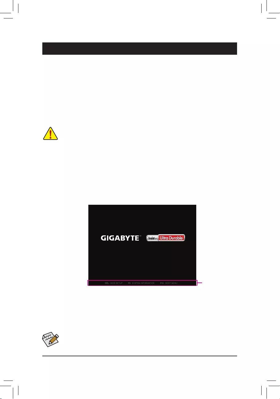
2-1 Startup Screen
The following startup Logo screen will appear when the computer boots.
(SampleBIOSVersion:T0d)
Function Keys
- 21 -
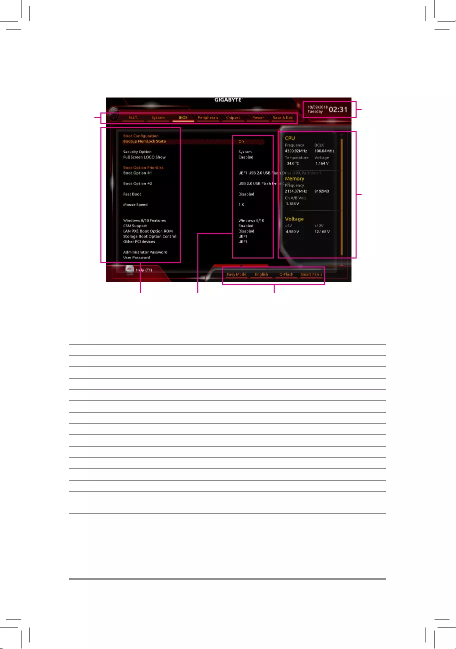
2-2 The Main Menu
ClassicSetupFunctionKeys
<f><g>Move the selection bar to select a setup menu
<h><i> Movetheselectionbartoselectancongurationitemonamenu
<Enter> Execute command or enter a menu
<+>/<PageUp> Increase the numeric value or make changes
<->/<PageDown> Decreasethenumericvalueormakechanges
<F1> Show descriptions of the function keys
<F2> Switch to Easy Mode
<F5> RestorethepreviousBIOSsettingsforthecurrentsubmenus
<F7> LoadtheOptimizedBIOSdefaultsettingsforthecurrentsubmenus
<F8> Access the Q-Flash utility
<F9> Displaysysteminformation
<F10> Save all the changes and exit the BIOS Setup program
<F12> Capture the current screen as an image and save it to your USB drive
<Esc> Main Menu: Exit the BIOS Setup program
Submenus: Exit current submenu
Hardware
Information
CongurationItems Current Settings
Setup
Menus
System Time
Quick Access Bar allows you to enter Easy Mode, select
BIOSdefaultlanguage,congurefansettings,orenter
Q-Flash.
- 22 -
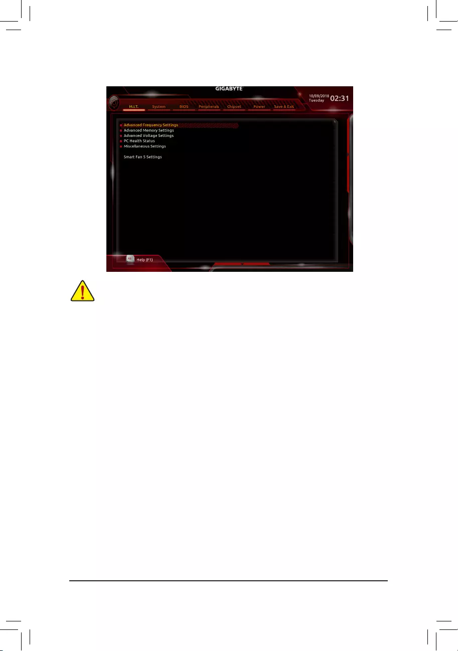
2-3 M.I.T.
`AdvancedFrequencySettings
&CPU Base Clock
AllowsyoutomanuallysettheCPUbaseclockin0.01MHzincrements.(Default:Auto)
Important:It is highly recommended that the CPU frequency be set in accordance with the CPU
specications.
&Host Clock Value
DisplaysthecurrentoperatingHostClockfrequency.
&GraphicsSliceRatio (Note)
AllowsyoutosettheGraphicsSliceRatio.
&GraphicsUnSliceRatio (Note)
AllowsyoutosettheGraphicsUnSliceRatio.
&CPUUpgrade (Note)
AllowsyoutosettheCPUfrequency.OptionsmayvarydependingontheCPUbeingused.(Default:Auto)
&EnhancedMulti-CorePerformance
DetermineswhethertoallowtheCPUtorunatTurbo1Cspeed.AutoletstheBIOSautomaticallycongure
thissetting.(Default:Auto)
&CPUClockRatio
Allows you to alter the clock ratio for the installed CPU. The adjustable range is dependent on the CPU
being installed.
(Note) ThisitemispresentonlywhenyouinstallaCPUthatsupportsthisfeature.Formoreinformationabout
Intel® CPUs' unique features, please visit Intel's website.
Whether the system will work stably with the overclock/overvoltage settings you made is dependent on your overall
systemcongurations.Incorrectlydoingoverclock/overvoltagemayresultindamagetoCPU,chipset,ormemory
and reduce the useful life of these components. This page is for advanced users only and we recommend you not to
alter the default settings to prevent system instability or other unexpected results. (Inadequately altering the settings
mayresultinsystem'sfailuretoboot.Ifthisoccurs,cleartheCMOSvaluesandresettheboardtodefaultvalues.)
- 23 -

&CPUFrequency
DisplaysthecurrentoperatingCPUfrequency.
&FCLKFrequencyforEarlyPowerOn
AllowsyoutosettheFCLKfrequency.Optionsare:Normal(800Mhz),1GHz,400MHz.(Default:1GHz)
`AdvancedCPUCoreSettings
&CPUClockRatio,CPUFrequency,FCLKFrequencyforEarlyPowerOn
The settings above are synchronous to those under the same items on the AdvancedFrequencySettings
menu.
&AVXOffset (Note)
AVXoffsetisthenegativeoffsetofAVXratio.
&TjMAXTemperature (Note)
Allowsyoutone-tunetheTJMaxoffsetvalue.(Default:Auto)
&UncoreRatio
Allows you to set the CPU Uncore ratio. The adjustable range is dependent on the CPU being used.
&UncoreFrequency
DisplaysthecurrentCPUUncorefrequency.
&CPUFlexRatioOverride
EnablesordisablestheCPUFlexRatio.ThemaximumCPUclockratiowillbebasedontheCPUFlex
RatioSettings value if CPUClockRatio is set to Auto.(Default:Disabled)
&CPUFlexRatioSettings
AllowsyoutosettheCPUFlexRatio.TheadjustablerangemayvarybyCPU.
&Intel(R)TurboBoostTechnology(Note)
Allows you to determine whether to enable the Intel® CPU Turbo Boost technology. Auto lets the BIOS
automaticallycongurethissetting.(Default:Auto)
&TurboRatio (Note)
Allows you to set the CPU Turbo ratios for different number of active cores. Auto sets the CPU Turbo ratios
accordingtotheCPUspecications.(Default:Auto)
&PowerLimitTDP(Watts)/PowerLimitTime
AllowsyoutosetthepowerlimitforCPUTurbomodeandhowlongittakestooperateatthespecied
powerlimit.Ifthespeciedvalueisexceeded,theCPUwillautomaticallyreducethecorefrequencyin
order to reduce the power. AutosetsthepowerlimitaccordingtotheCPUspecications.(Default:Auto)
&CoreCurrentLimit(Amps)
AllowsyoutosetacurrentlimitforCPUTurbomode.WhentheCPUcurrentexceedsthespeciedcurrent
limit, the CPU will automatically reduce the core frequency in order to reduce the current. Auto sets the
powerlimitaccordingtotheCPUspecications.(Default:Auto)
&Turbo Per Core Limit Control (Note)
AllowsyoutocontroleachCPUcorelimitseparately.(Default:Auto)
&No.ofCPUCoresEnabled (Note)
Allows you to select the number of CPU cores to enable in an Intel® multi-core CPU (the number of CPU
coresmayvarybyCPU).AutoletstheBIOSautomaticallycongurethissetting.(Default:Auto)
&Hyper-ThreadingTechnology (Note)
Allows you to determine whether to enable multi-threading technology when using an Intel® CPU that
supports this function. This feature only works for operating systems that support multi-processor mode.
AutoletstheBIOSautomaticallycongurethissetting.(Default:Auto)
(Note) ThisitemispresentonlywhenyouinstallaCPUthatsupportsthisfeature.Formoreinformationabout
Intel® CPUs' unique features, please visit Intel's website.
- 24 -

&Intel(R)SpeedShiftTechnology(Intel®SpeedShiftTechnology) (Note)
Enables or disables Intel® Speed Shift Technology. Enabling this feature allows the processor to ramp up
itsoperatingfrequencymorequicklyandthenimprovesthesystemresponsiveness.(Default:Auto)
&CPUEnhancedHalt(C1E) (Note)
Enables or disables Intel
®
CPUEnhancedHalt(C1E)function,aCPUpower-savingfunctioninsystemhalt
state.
When enabled, the CPU core frequency and voltage will be reduced during system halt state to
decrease power consumption. AutoletstheBIOSautomaticallycongurethissetting.(Default:Auto)
&C3 State Support (Note)
Allows you to determine whether to let the CPU enter C3 mode in system halt state. When enabled, the
CPU core frequency and voltage will be reduced during system halt state to decrease power consumption.
The C3 state is a more enhanced power-saving state than C1. AutoletstheBIOSautomaticallycongure
thissetting.(Default:Auto)
&C6/C7StateSupport (Note)
Allows you to determine whether to let the CPU enter C6/C7 mode in system halt state. When enabled, the
CPU core frequency and voltage will be reduced during system halt state to decrease power consumption.
The C6/C7 state is a more enhanced power-saving state than C3. AutoletstheBIOSautomaticallycongure
thissetting.(Default:Auto)
&C8 State Support (Note)
Allows you to determine whether to let the CPU enter C8 mode in system halt state. When enabled, the CPU
core frequency and voltage will be reduced during system halt state to decrease power consumption. The
C8 state is a more enhanced power-saving state than C6/C7. AutoletstheBIOSautomaticallycongure
thissetting.(Default:Auto)
&C10 State Support (Note)
Allows you to determine whether to let the CPU enter C10 mode in system halt state. When enabled, the
CPU core frequency and voltage will be reduced during system halt state to decrease power consumption.
The C10 state is a more enhanced power-saving state than C8. AutoletstheBIOSautomaticallycongure
thissetting.(Default:Auto)
&PackageCStateLimit (Note)
Allows you to specify the C-state limit for the processor. AutoletstheBIOSautomaticallycongurethis
setting.(Default:Auto)
&CPU Thermal Monitor (Note)
Enables or disables Intel® Thermal Monitor function, a CPU overheating protection function. When enabled,
the CPU core frequency and voltage will be reduced when the CPU is overheated. Auto lets the BIOS
automaticallycongurethissetting.(Default:Auto)
&RingtoCoreoffset(DownBin)
AllowsyoutodeterminewhethertodisabletheCPURingratioauto-downfunction.Auto lets the BIOS
automaticallycongurethissetting.(Default:Auto)
&CPUEISTFunction (Note)
Enables or disables Enhanced Intel®SpeedStepTechnology(EIST).DependingonCPUloading,Intel®
EIST technology can dynamically and effectively lower the CPU voltage and core frequency to decrease
average power consumption and heat production. AutoletstheBIOSautomaticallycongurethissetting.
(Default:Auto)
&RaceToHalt(RTH) (Note)/EnergyEfcientTurbo (Note)
Enables or disables the CPU power saving related settings.
&VoltageOptimization
Allowsyoutodeterminewhethertoenablevoltageoptimizationtoreducepowerconsumption.(Default:
Auto)
(Note) ThisitemispresentonlywhenyouinstallaCPUthatsupportsthisfeature.Formoreinformationabout
Intel® CPUs' unique features, please visit Intel's website.
- 25 -

&Hardware Prefetcher
Allows you to determine whether to enable hardware prefetcher to prefetch data and instructions from the
memoryintothecache.(Default:Auto)
&AdjacentCacheLinePrefetch
Allows you to determine whether to enable the adjacent cache line prefetch mechanism that lets the
processorretrievetherequestedcachelineaswellasthesubsequentcacheline.(Default:Auto)
&ExtremeMemoryProle(X.M.P.) (Note)
AllowstheBIOStoreadtheSPDdataonXMPmemorymodule(s)toenhancememoryperformancewhen
enabled.
Disabled Disablesthisfunction.(Default)
Prole1 UsesProle1settings.
Prole2(Note) UsesProle2settings.
&System Memory Multiplier
Allows you to set the system memory multiplier. AutosetsmemorymultiplieraccordingtomemorySPD
data.(Default:Auto)
&MemoryRefClock
Allowsyoutomanuallyadjustthememoryreferenceclock.(Default:Auto)
&MemoryOddRatio(100/133or200/266)
EnabledallowsQclktoruninoddfrequency.(Default:Auto)
&MemoryFrequency(MHz)
Therstmemoryfrequencyvalueisthenormaloperatingfrequencyofthememorybeingused;thesecond
is the memory frequency that is automatically adjusted according to the System Memory Multiplier settings.
`AdvancedMemorySettings
&ExtremeMemoryProle(X.M.P.) (Note),SystemMemoryMultiplier,MemoryRefClock,
MemoryOddRatio(100/133or200/266),MemoryFrequency(MHz)
The settings above are synchronous to those under the same items on the AdvancedFrequencySettings
menu.
&Memory Boot Mode (Note)
Provides memory detection and training methods.
Auto LetstheBIOSautomaticallycongurethissetting.(Default)
Normal The BIOS automatically performs memory training. Please note that if the system
becomes unstable or unbootable, try to clear the CMOS values and reset the board
todefaultvalues.(Refertotheintroductionsofthebattery/clearCMOSjumperin
Chapter1forhowtocleartheCMOSvalues.)
EnableFastBoot Skipmemorydetectionandtraininginsomespeciccriteriaforfastermemory
boot.
DisableFastBoot Detectandtrainmemoryateverysingleboot.
&RealtimeMemoryTiming
Allowsyoutone-tunememorytimingsaftertheBIOSstage.(Default:Auto)
&MemoryEnhancementSettings
Providesseveralmemory performance enhancement settings:Relax OC, Enhanced Stability,Normal,
EnhancedPerformance,HighFrequency,andHighDensity.(Default:Auto)
(Note) ThisitemispresentonlywhenyouinstallaCPUandamemorymodulethatsupportthisfeature.
- 26 -

&MemoryTimingMode
Manual and AdvancedManual allows the Memory Multiplier Tweaker, ChannelInterleaving, Rank
Interleaving,andmemorytimingsettingsbelowtobecongurable.Optionsare:Auto(default),Manual,
Advanced Manual.
&ProleDDRVoltage
When using a non-XMP memory module or ExtremeMemoryProle(X.M.P.) is set to Disabled, the value
isdisplayedaccordingtoyourmemoryspecication.WhenExtremeMemoryProle(X.M.P.) is set to
Prole1 or Prole2,thevalueisdisplayedaccordingtotheSPDdataontheXMPmemory.
&Memory Multiplier Tweaker
Providesdifferentlevelsofmemoryauto-tuning.(Default:Auto)
&ChannelInterleaving
Enables or disables memory channel interleaving. Enabled allows the system to simultaneously access
different channels of the memory to increase memory performance and stability. Auto lets the BIOS
automaticallycongurethissetting.(Default:Auto)
&RankInterleaving
Enables or disables memory rank interleaving. Enabled allows the system to simultaneously access different
ranks of the memory to increase memory performance and stability. Auto lets the BIOS automatically
congurethissetting.(Default:Auto)
`ChannelA/BMemorySubTimings
This sub-menu provides memory timing settings for each channel of memory. The respective timing setting
screensarecongurableonlywhenMemoryTimingMode is set to Manual or AdvancedManual. Note:
Your system may become unstable or fail to boot after you make changes on the memory timings. If this
occurs,pleaseresettheboardtodefaultvaluesbyloadingoptimizeddefaultsorclearingtheCMOSvalues.
`AdvancedVoltageSettings
`AdvancedPowerSettings
&CPU Vcore Loadline Calibration
AllowsyoutocongureLoad-LineCalibrationfortheCPUVcorevoltage.Selectingahigherlevelkeeps
theCPUVcorevoltagemoreconsistentwithwhatissetinBIOSunderheavyload.Auto lets the BIOS
automaticallycongurethissettingandsetsthevoltagefollowingIntel'sspecications.(Default:Auto)
`CPUCoreVoltageControl
This section provides CPU voltage control options.
`ChipsetVoltageControl
This section provides Chipset voltage control options.
`DRAMVoltageControl
This section provides memory voltage control options.
`InternalVRControl
ThissectionprovidesVRvoltagecontroloptions.
`PC Health Status
&ResetCaseOpenStatus
Disabled Keepsorclearstherecordofpreviouschassisintrusionstatus.(Default)
Enabled Clears the record of previous chassis intrusion status and the CaseOpeneldwill
show"No"atnextboot.
&CaseOpen
DisplaysthedetectionstatusofthechassisintrusiondetectiondeviceattachedtothemotherboardCI
header.Ifthesystemchassiscoverisremoved,thiseldwillshow"Yes",otherwiseitwillshow"No".To
clear the chassis intrusion status record, set ResetCaseOpenStatus to Enabled, save the settings to
the CMOS, and then restart your system.
- 27 -

&CPUVcore/CPUVCCSA/DRAMChannelA/BVoltage/+3.3V/+5V/+12V/CPUVAXG
Displaysthecurrentsystemvoltages.
`MiscellaneousSettings
&Max Link Speed
Allows you to set the operation mode of the PCI Express slots to Gen 1, Gen 2, or Gen 3. Actual operation
modeissubjecttothehardwarespecicationofeachslot.AutoletstheBIOSautomaticallycongurethis
setting.(Default:Auto)
&3DMark01Enhancement
Allowsyoutodeterminewhethertoenhancesomelegacybenchmarkperformance.(Default:Disabled)
`SmartFan5Settings
&Monitor
Allowsyoutoselectatargettomonitorandtomakefurtheradjustment.(Default:CPUFAN)
&FanSpeedControl
Allows you to determine whether to enable the fan speed control function and adjust the fan speed.
Normal Allows the fan to run at different speeds according to the temperature. You can adjust
thefanspeedwithSystemInformationViewerbasedonyoursystemrequirements.
(Default)
Silent Allows the fan to run at slow speeds.
Manual Allows you to control the fan speed in the curve graph.
Full Speed Allows the fan to run at full speeds.
&FanControlUseTemperatureInput
Allows you to select the reference temperature for fan speed control.
&Temperature Interval
Allows you to select the temperature interval for fan speed change.
&FanControlmode
Auto Lets the BIOS automatically detect the type of fan installed and sets the optimal control
mode.(Default)
Voltage Voltagemodeisrecommendedfora3-pinfan.
PWM PWM mode is recommended for a 4-pin fan.
&FanStop
Enables or disables the fan stop function. You can set the temperature limit using the temperature curve.
Thefanstopsoperationwhenthetemperatureislowerthanthelimit.(Default:Disabled)
&Temperature
Displaysthecurrenttemperatureoftheselectedtargetarea.
&FanSpeed
Displayscurrentfanspeeds.
&TemperatureWarningControl
Sets the warning threshold for temperature. When temperature exceeds the threshold, BIOS will emit
warningsound.Optionsare:Disabled(default),60oC/140oF, 70oC/158oF, 80oC/176oF, 90oC/194oF.
&FanFailWarning
Allows the system to emit warning sound if the fan is not connected or fails. Check the fan condition or fan
connectionwhenthisoccurs.(Default:Disabled)
- 28 -
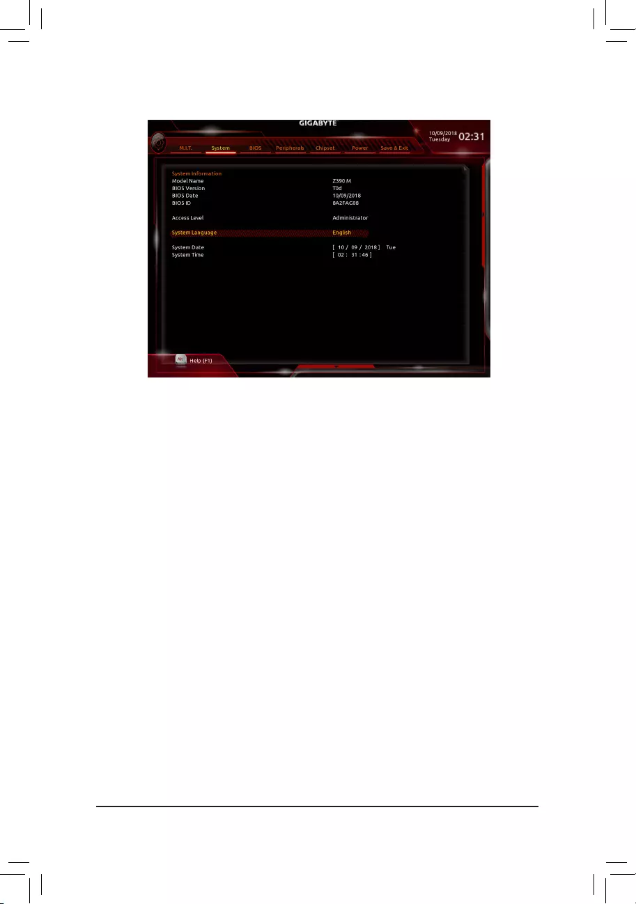
2-4 System
This section provides information on your motherboard model and BIOS version. You can also select the default
language used by the BIOS and manually set the system time.
&AccessLevel
Displaysthecurrentaccessleveldependingonthetypeofpasswordprotectionused.(Ifnopasswordis
set, the default will display as Administrator.)TheAdministratorlevelallowsyoutomakechangestoall
BIOS settings; the User level only allows you to make changes to certain BIOS settings but not all.
&SystemLanguage
Selects the default language used by the BIOS.
&System Date
Setsthesystemdate.Thedateformatisweek(read-only),month,date,andyear.Use<Enter>toswitch
betweentheMonth,Date,andYeareldsandusethe<PageUp>or<PageDown>keytosetthedesired
value.
&System Time
Sets the system time. The time format is hour, minute, and second. For example, 1 p.m. is 13:00:00. Use
<Enter>toswitchbetweentheHour,Minute,andSecondeldsandusethe<PageUp>or<PageDown>
key to set the desired value.
- 29 -
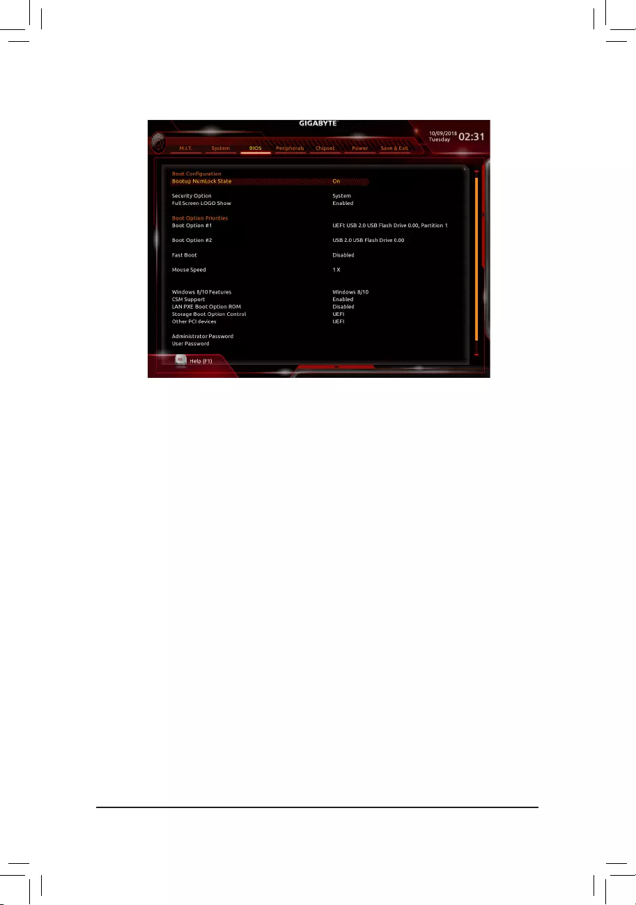
2-5 BIOS
&Bootup NumLock State
EnablesordisablesNumlockfeatureonthenumerickeypadofthekeyboardafterthePOST.(Default:On)
&SecurityOption
Specieswhetherapasswordisrequiredeverytimethesystemboots,oronlywhenyouenterBIOSSetup.
Afterconguringthisitem,setthepassword(s)undertheAdministratorPassword/UserPassword item.
Setup A password is only required for entering the BIOS Setup program.
System A password is required for booting the system and for entering the BIOS Setup program.
(Default)
&FullScreenLOGOShow
Allows you to determine whether to display the GIGABYTE Logo at system startup. Disabled skips the
GIGABYTELogowhenthesystemstartsup.(Default:Enabled)
&BootOptionPriorities
Speciestheoverallbootorderfromtheavailabledevices.RemovablestoragedevicesthatsupportGPT
formatwillbeprexedwith"UEFI:"stringonthebootdevicelist.Tobootfromanoperatingsystemthat
supportsGPTpartitioning,selectthedeviceprexedwith"UEFI:"string.
Or if you want to install an operating system that supports GPT partitioning such as Windows 10 64-bit,
selecttheopticaldrivethatcontainstheWindows1064-bitinstallationdiskandisprexedwith"UEFI:"
string.
&HardDrive/CD/DVDROMDrive/FloppyDrive/NetworkDeviceBBSPriorities
Speciesthebootorderforaspecicdevicetype,suchasharddrives,opticaldrives,oppydiskdrives,
anddevicesthatsupportBootfromLANfunction,etc.Press<Enter>onthisitemtoenterthesubmenuthat
presents the devices of the same type that are connected. This item is present only if at least one device
for this type is installed.
&FastBoot
Enables or disables Fast Boot to shorten the OS boot process. UltraFast provides the fastest bootup
speed.(Default:Disabled)
- 30 -

&SATASupport
LastBootHDDOnly Exceptforthepreviousbootdrive,allSATAdevicesaredisabledbeforetheOS
bootprocesscompletes.(Default)
AllSataDevices AllSATAdevicesarefunctionalintheoperatingsystemandduringthePOST.
ThisitemiscongurableonlywhenFastBoot is set to Enabled or UltraFast.
&VGASupport
Allows you to select which type of operating system to boot.
Auto EnableslegacyoptionROMonly.
EFIDriver EnablesEFIoptionROM.(Default)
ThisitemiscongurableonlywhenFastBoot is set to Enabled or UltraFast.
&USB Support
Disabled AllUSBdevicesaredisabledbeforetheOSbootprocesscompletes.
Full Initial All USB devices are functional in the operating system and during the POST.
(Default)
Partial Initial Part of the USB devices are disabled before the OS boot process completes.
ThisitemiscongurableonlywhenFastBoot is set to Enabled. This function is disabled when FastBoot
is set to UltraFast.
&PS2 Devices Support
Disabled AllPS/2devicesaredisabledbeforetheOSbootprocesscompletes.
Enabled All PS/2 devices are functional in the operating system and during the POST.
(Default)
ThisitemiscongurableonlywhenFastBoot is set to Enabled. This function is disabled when FastBoot
is set to UltraFast.
&NetWork Stack Driver Support
Disabled Disablesbootingfromthenetwork.(Default)
Enabled Enables booting from the network.
ThisitemiscongurableonlywhenFastBoot is set to Enabled or UltraFast.
&NextBootAfterACPowerLoss
NormalBoot EnablesnormalbootupuponthereturnoftheACpower.(Default)
Fast Boot Keeps the Fast Boot settings upon the return of the AC power.
ThisitemiscongurableonlywhenFastBoot is set to Enabled or UltraFast.
&Mouse Speed
Allowsyoutosetthemousecursormovementspeed.(Default:1X)
&Windows8/10Features
Allowsyoutoselecttheoperatingsystemtobeinstalled.(Default:Windows8/10)
&CSM Support
EnablesordisablesUEFICSM(CompatibilitySupportModule)tosupportalegacyPCbootprocess.
Disabled DisablesUEFICSMandsupportsUEFIBIOSbootprocessonly.
Enabled EnablesUEFICSM.(Default)
&LANPXEBootOptionROM
AllowsyoutoselectwhethertoenablethelegacyoptionROMfortheLANcontroller.(Default:Disabled)
ThisitemiscongurableonlywhenCSM Support is set to Enabled.
- 31 -

&StorageBootOptionControl
AllowsyoutoselectwhethertoenabletheUEFIorlegacyoptionROMforthestoragedevicecontroller.
Donotlaunch DisablesoptionROM.
UEFI EnablesUEFIoptionROMonly.(Default)
Legacy EnableslegacyoptionROMonly.
ThisitemiscongurableonlywhenCSM Support is set to Enabled.
&OtherPCIdevices
AllowsyoutoselectwhethertoenabletheUEFIorLegacyoptionROMforthePCIdevicecontrollerother
than the LAN, storage device, and graphics controllers.
Donotlaunch DisablesoptionROM.
UEFI EnablesUEFIoptionROMonly.(Default)
Legacy EnableslegacyoptionROMonly.
ThisitemiscongurableonlywhenCSM Support is set to Enabled.
&AdministratorPassword
Allowsyoutocongureanadministratorpassword.Press<Enter>onthisitem,typethepassword,and
thenpress<Enter>.Youwillberequestedtoconrmthepassword.Typethepasswordagainandpress
<Enter>.Youmustentertheadministratorpassword(oruserpassword)atsystemstartupandwhenentering
BIOSSetup.Differingfromtheuserpassword,theadministratorpasswordallowsyoutomakechangesto
all BIOS settings.
&User Password
Allowsyoutocongureauserpassword.Press<Enter>onthisitem,typethepassword,andthenpress
<Enter>.Youwillberequestedtoconrmthepassword.Typethepasswordagainandpress<Enter>.
Youmustentertheadministratorpassword(oruserpassword)atsystemstartupandwhenenteringBIOS
Setup. However, the user password only allows you to make changes to certain BIOS settings but not all.
Tocancelthepassword,press<Enter>onthepassworditemandwhenrequestedforthepassword,enter
thecorrectonerst.Whenpromptedforanewpassword,press<Enter>withoutenteringanypassword.
Press<Enter>againwhenpromptedtoconrm.
NOTE:BeforesettingtheUserPassword,besuretosettheAdministratorPasswordrst.
&Secure Boot
AllowsyoutoenableordisableSecureBootandcongurerelatedsettings.Thisitemiscongurableonly
when CSM Support is set to Disabled.
- 32 -
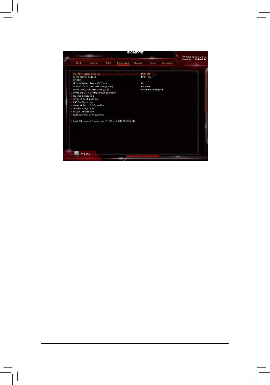
2-6 Peripherals
&PCIEBifurcationSupport
Allows you to determine how the bandwidth of the PCIEX16 slot is divided. Options: PCIE x16, PCIE x8/
x8,PCIEx8/x4/x4.(Default:PCIEx16)
&InitialDisplayOutput
SpeciestherstinitiationofthemonitordisplayfromtheinstalledPCIExpressgraphicscardortheonboard
graphics.
IGFX Setstheonboardgraphicsastherstdisplay.
PCIe1Slot SetsthegraphicscardonthePCIEX16slotastherstdisplay.(Default)
PCIe2Slot SetsthegraphicscardonthePCIEX4slotastherstdisplay.
&EZRAID
AllowsyoutoquicklysetupaRAIDarray.RefertoChapter3,"ConguringaRAIDSet,"forinstructions
onconguringaRAIDarray.
&LEDsinSystemPowerOnState
AllowsyoutoenableordisablemotherboardLEDlightingwhenthesystemison.
Off Disablestheselectedlightingmodewhenthesystemison.
On Enablestheselectedlightingmodewhenthesystemison.(Default)
&IntelPlatformTrustTechnology(PTT)
Enables or disables Intel®PTTTechnology.(Default:Disabled)
&SoftwareGuardExtensions(SGX)
Enables or disables the Intel® Software Guard Extensions technology. This feature allows legal software
to operate in a safe environment and protects the software against attacks from malicious software. The
Software Controlled option allows you to enable or disable this feature with an Intel-provided application.
(Default:SoftwareControlled)
`OffBoardSATAControllerConguration
DisplaysinformationonyourM.2PCIeSSDifinstalled.
`TrustedComputing
EnablesordisablesTrustedPlatformModule(TPM).
- 33 -

`SuperIOConguration
&Serial Port
Enablesordisablestheonboardserialport.(Default:Enabled)
`USBConguration
&LegacyUSBSupport
AllowsUSBkeyboard/mousetobeusedinMS-DOS.(Default:Enabled)
&XHCIHand-off
Determineswhether toenable XHCIHand-offfeature foran operatingsystem withoutXHCI Hand-off
support.(Default:Disabled)
&USBMassStorageDriverSupport
EnablesordisablessupportforUSBstoragedevices.(Default:Enabled)
&Port60/64Emulation
Enables or disables emulation of I/O ports 64h and 60h. This should be enabled for full legacy support
forUSBkeyboards/miceinMS-DOSorinoperatingsystemthatdoesnotnativelysupportUSBdevices.
(Default:Disabled)
&MassStorageDevices
DisplaysalistofconnectedUSBmassstoragedevices.ThisitemappearsonlywhenaUSBstoragedevice
is installed.
`NetworkStackConguration
&Network Stack
DisablesorenablesbootingfromthenetworktoinstallaGPTformatOS,suchasinstallingtheOSfrom
theWindowsDeploymentServicesserver.(Default:Disabled)
&Ipv4PXESupport
EnablesordisablesIPv4PXESupport.ThisitemiscongurableonlywhenNetwork Stack is enabled.
&Ipv4 HTTP Support
EnablesordisablesHTTPbootsupportforIPv4.ThisitemiscongurableonlywhenNetwork Stack is
enabled.
&Ipv6PXESupport
EnablesordisablesIPv6PXESupport.ThisitemiscongurableonlywhenNetwork Stack is enabled.
&Ipv6 HTTP Support
EnablesordisablesHTTPbootsupportforIPv6.ThisitemiscongurableonlywhenNetwork Stack is
enabled.
&IPSECCerticate
EnablesordisablestheInternetProtocolSecurity.ThisitemiscongurableonlywhenNetwork Stack is
enabled.
&PXEbootwaittime
Allowsyoutocongurehowlongtowaitbeforeyoucanpress<Esc>toabortthePXEboot.Thisitemis
congurableonlywhenNetwork Stackisenabled.(Default:0)
&Media detect count
Allowsyoutosetthenumberoftimestocheckthepresenceofmedia.Thisitemiscongurableonlywhen
Network Stackisenabled.(Default:1)
`NVMeConguration
DisplaysinformationonyourM.2NVMEPCIeSSDifinstalled.
- 34 -

`PluginDevicesInfo
DisplaystheinformationoftheconnectedPCIExpressandM.2device(s).
`SATAAndRSTConguration
&SATAController(s)
EnablesordisablestheintegratedSATAcontrollers.(Default:Enabled)
&SATAModeSelection
EnablesordisablesRAIDfortheSATAcontrollersintegratedintheChipsetorcongurestheSATAcontrollers
to AHCI mode.
IntelRSTPremiumWithIntelOptaneSystemAcceleration EnablesRAIDfortheSATAcontroller.
AHCI CongurestheSATAcontrollerstoAHCImode.AdvancedHostControllerInterface
(AHCI)isaninterfacespecicationthatallowsthestoragedrivertoenableadvanced
SerialATAfeaturessuchasNativeCommandQueuingandhotplug.(Default)
&AggressiveLPMSupport
Enablesordisablesthepowersavingfeature,ALPM(AggressiveLinkPowerManagement),fortheChipset
SATAcontrollers.(Default:Disabled)
&Port0/1/2/3/4/5
EnablesordisableseachSATAport.(Default:Enabled)
&Hotplug
EnablesordisablethehotplugcapabilityforeachSATAport.(Default:Disabled)
&ConguredaseSATA
Enables or disables support for external SATA devices.
`Intel(R)EthernetConnection
Thissub-menuprovidesinformationonLANcongurationandrelatedcongurationoptions.
- 35 -
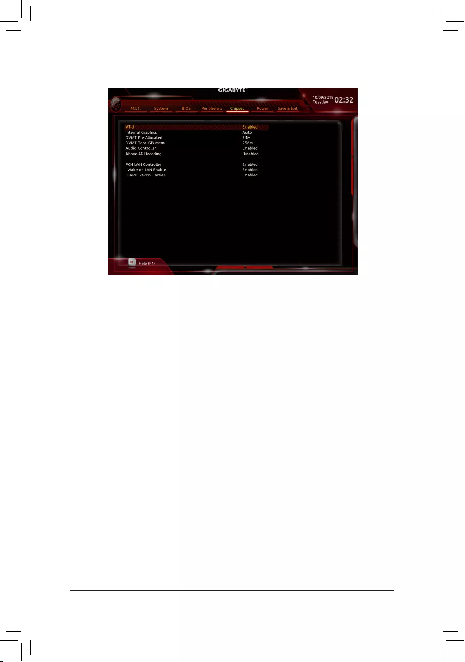
&VT-d (Note)
Enables or disables Intel®VirtualizationTechnologyforDirectedI/O.(Default:Enabled)
&InternalGraphics
Enablesordisablestheonboardgraphicsfunction.(Default:Auto)
&DVMTPre-Allocated
Allowsyoutosettheonboardgraphicsmemorysize.Optionsare:32M~1024M.(Default:64M)
&DVMTTotalGfxMem
AllowsyoutoallocatetheDVMTmemorysizeoftheonboardgraphics.Optionsare:128M,256M,MAX.
(Default:256M)
&AudioController
Enablesordisablestheonboardaudiofunction.(Default:Enabled)
If you wish to install a 3rd party add-in audio card instead of using the onboard audio, set this item to
Disabled.
&Above4GDecoding
Enables or disables 64-bit capable devices to be decoded in above 4 GB address space (only if your system
supports64-bitPCIdecoding).SettoEnabled if more than one advanced graphics card are installed and
their drivers are not able to be launched when entering the operating system (because of the limited 4 GB
memoryaddressspace).(Default:Disabled)
&PCHLANController
EnablesordisablestheonboardLANfunction.(Default:Enabled)
If you wish to install a 3rd party add-in network card instead of using the onboard LAN, set this item to
Disabled.
&WakeonLANEnable
EnablesordisablesthewakeonLANfunction.(Default:Enabled)
&IOAPIC24-119Entries
Enablesordisablesthisfunction.(Default:Enabled)
2-7 Chipset
(Note) ThisitemispresentonlywhenyouinstallaCPUthatsupportsthisfeature.Formoreinformationabout
Intel® CPUs' unique features, please visit Intel's website.
- 36 -
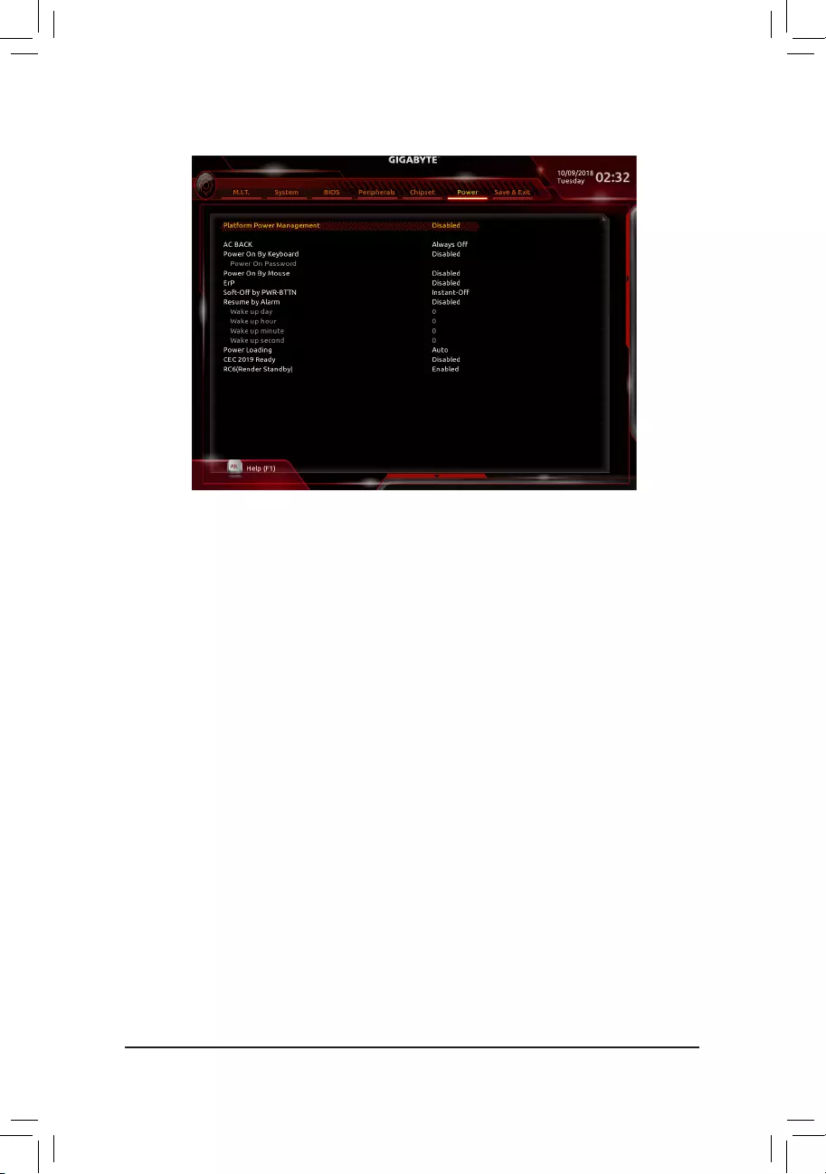
2-8 Power
&PlatformPowerManagement
EnablesordisablestheActiveStatePowerManagementfunction(ASPM).(Default:Disabled)
&PEGASPM
AllowsyoutoconguretheASPMmodeforthedevice connected to the CPUPEGbus.This itemis
congurableonlywhenPlatformPowerManagementis set to Enabled.(Default:Disabled)
&PCHASPM
AllowsyoutoconguretheASPMmodeforthedeviceconnectedtoChipset'sPCIExpressbus.Thisitem
iscongurableonlywhenPlatformPowerManagementis set to Enabled.(Default:Disabled)
&DMIASPM
AllowsyoutoconguretheASPMmodeforbothCPUsideandChipsetsideoftheDMIlink.Thisitemis
congurableonlywhenPlatformPowerManagementis set to Enabled.(Default:Disabled)
&ACBACK
DeterminesthestateofthesystemafterthereturnofpowerfromanACpowerloss.
Memory The system returns to its last known awake state upon the return of the AC power.
Always On The system is turned on upon the return of the AC power.
AlwaysOff ThesystemstaysoffuponthereturnoftheACpower.(Default)
&PowerOnByKeyboard
Allows the system to be turned on by a PS/2 keyboard wake-up event.
Note:Tousethisfunction,youneedanATXpowersupplyprovidingatleast1Aonthe+5VSBlead.
Disabled Disablesthisfunction.(Default)
Password Setapasswordwith1~5characterstoturnonthesystem.
Keyboard98 PressPOWERbuttonontheWindows98keyboardtoturnonthesystem.
Any Key Press any key to turn on the system.
- 37 -

&PowerOnPassword
Set the password when PowerOnByKeyboard is set to Password.
Press<Enter>onthisitemandsetapasswordwithupto5charactersandthenpress<Enter>toaccept.
Toturnonthesystem,enterthepasswordandpress<Enter>.
Note:Tocancelthepassword,press<Enter>onthisitem.Whenpromptedforthepassword,press<Enter>
again without entering the password to clear the password settings.
&PowerOnByMouse
Allows the system to be turned on by a PS/2 mouse wake-up event.
Note:Tousethisfunction,youneedanATXpowersupplyprovidingatleast1Aonthe+5VSBlead.
Disabled Disablesthisfunction.(Default)
Move Move the mouse to turn on the system.
DoubleClick Doubleclickonleftbuttononthemousetoturnonthesystem.
&ErP
DetermineswhethertoletthesystemconsumeleastpowerinS5(shutdown)state.(Default:Disabled)
Note: When this item is set to Enabled,thefollowingfunctionswillbecomeunavailable:ResumebyAlarm,
power on by mouse, and power on by keyboard.
&Soft-OffbyPWR-BTTN
ConguresthewaytoturnoffthecomputerinMS-DOSmodeusingthepowerbutton.
Instant-Off Pressthepowerbuttonandthenthesystemwillbeturnedoffinstantly.(Default)
Delay4Sec. Pressandholdthepowerbuttonfor4secondstoturnoffthesystem.Ifthepower
button is pressed for less than 4 seconds, the system will enter suspend mode.
&ResumebyAlarm
Determineswhethertopoweronthesystematadesiredtime.(Default:Disabled)
If enabled, set the date and time as following:
Wakeupday:Turnonthesystemataspecictimeoneachdayoronaspecicdayinamonth.
Wake up hour/minute/second: Set the time at which the system will be powered on automatically.
Note: When using this function, avoid inadequate shutdown from the operating system or removal of the
AC power, or the settings may not be effective.
&PowerLoading
Enables or disables dummy load. When the power supply is at low load, a self-protection will activate causing
it to shutdown or fail. If this occurs, please set to Enabled. AutoletstheBIOSautomaticallycongurethis
setting.(Default:Auto)
&CEC2019Ready
Allows you to select whether to allow the system to adjust power consumption when it is in shutdown, idle,
orstandbystateinordertocomplywiththeCEC(CaliforniaEnergyCommission)2019Standards.(Default:
Disabled)
&RC6(RenderStandby)
Allows you to determine whether to let the onboard graphics enter standby mode to decrease power
consumption.(Default:Enabled)
- 38 -

2-9 Save&Exit
&Save&ExitSetup
Press<Enter>onthisitemandselectYes. This saves the changes to the CMOS and exits the BIOS Setup
program. Select Noorpress<Esc>toreturntotheBIOSSetupMainMenu.
&ExitWithoutSaving
Press<Enter>onthisitemandselectYes. This exits the BIOS Setup without saving the changes made
in BIOS Setup to the CMOS. Select Noorpress<Esc>toreturntotheBIOSSetupMainMenu.
&LoadOptimizedDefaults
Press<Enter>onthisitemandselectYes to load the optimal BIOS default settings. The BIOS defaults
settingshelpthesystemtooperateinoptimumstate.AlwaysloadtheOptimizeddefaultsafterupdating
the BIOS or after clearing the CMOS values.
&BootOverride
Allowsyoutoselectadevicetobootimmediately.Press<Enter>onthedeviceyouselectandselectYes
toconrm.Yoursystemwillrestartautomaticallyandbootfromthatdevice.
&SaveProles
ThisfunctionallowsyoutosavethecurrentBIOSsettingstoaprole.Youcancreateupto8prolesand
saveasSetupProle1~SetupProle8.Press<Enter>tocomplete.OryoucanselectSelectFilein
HDD/FDD/USBtosavetheproletoyourstoragedevice.
&LoadProles
If your system becomes unstable and you have loaded the BIOS default settings, you can use this function
toloadtheBIOSsettingsfromaprolecreatedbefore,withoutthehasslesofreconguringtheBIOS
settings.Firstselecttheproleyouwishtoloadandthenpress<Enter>tocomplete.YoucanselectSelect
FileinHDD/FDD/USBtoinputtheprolepreviouslycreatedfromyourstoragedeviceorloadtheprole
automatically created by the BIOS, such as reverting the BIOS settings to the last settings that worked
properly(lastknowngoodrecord).
- 39 -
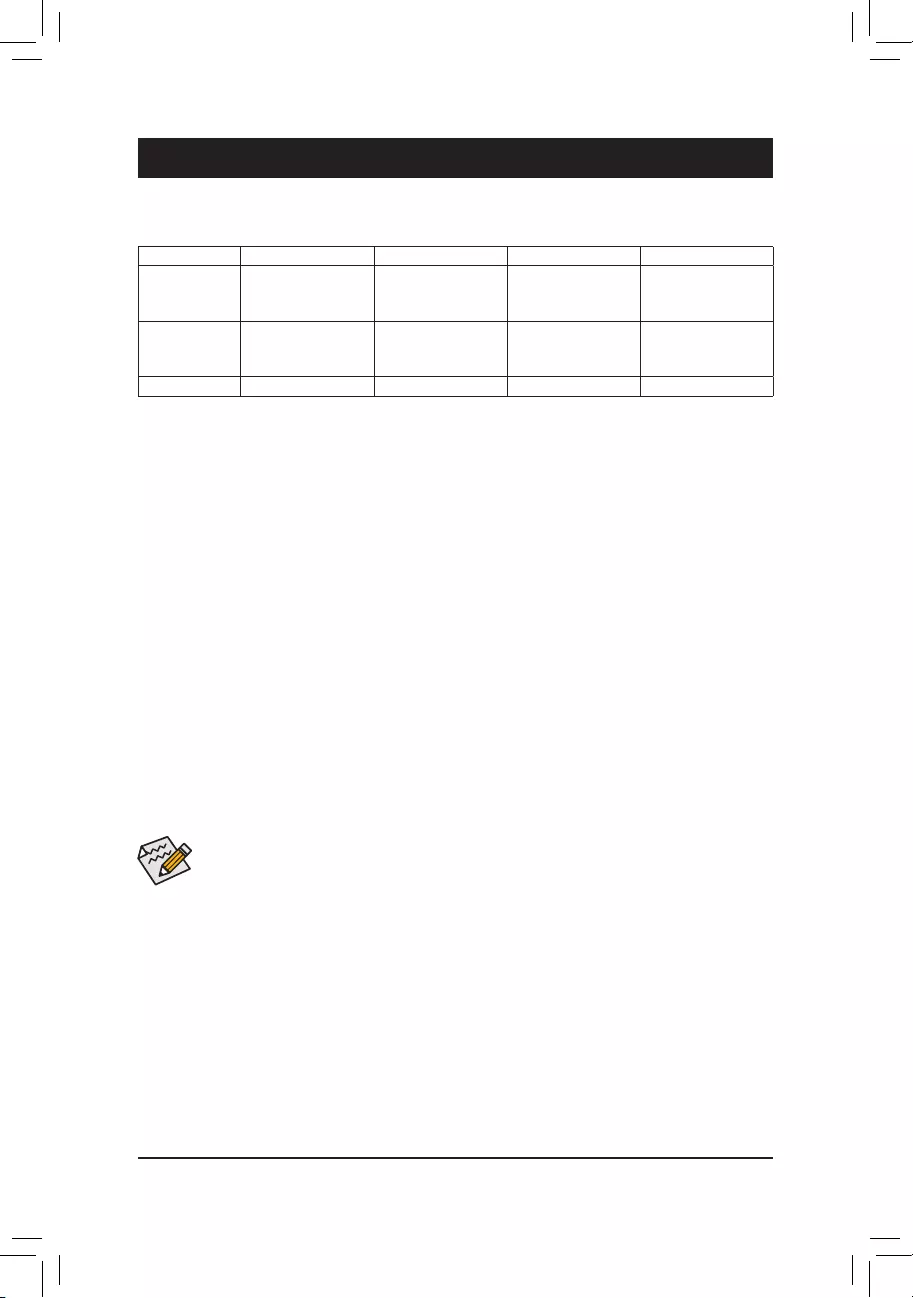
Chapter3 Appendix
3-1 ConguringaRAIDSet
RAIDLevels
Beforeyoubegin,pleasepreparethefollowingitems:
•AtleasttwoSATAharddrivesorSSDs.(Note1) (To ensure optimal performance, it is recommended that you
usetwoharddriveswithidenticalmodelandcapacity).(Note2)
•Windows setup disk.
•Motherboard driver disk.
•A USB thumb drive.
ConguringtheOnboardSATAController
A.InstallingSATAharddrive(s)inyourcomputer
Installtheharddrives/SSDsintheIntel® Chipset controlled connectors on the motherboard. Then connect the
power connectors from your power supply to the hard drives.
B.ConguringSATAcontrollermodeinBIOSSetup
MakesuretoconguretheSATAcontrollermodecorrectlyinsystemBIOSSetup.
Steps:
1. Go to Peripherals\SATAAndRSTConguration, make sure SATAController(s) is enabled. To create
RAID,setSATAModeSelection to IntelRSTPremiumWithIntelOptaneSystemAcceleration. Then
savethesettingsandrestartyourcomputer.Note:WhenusingaPCIeSSD,makesuretosettheUSERST
LegacyOROM item under Peripherals\SATAAndRSTConguration to Disabled. Then depending the
M.2 connector you use, set the corresponding PCIeStorageDevonPortXX item to RSTControlled.
2. TousetheEZRAIDfeature,followthestepsin"C-1."TocongureUEFIRAID,followthestepsin"C-2."To
enterthelegacyRAIDROM,referto"C-3"formoreinformation.Finally,savethesettingsandexitBIOSSetup.
The BIOS Setup menus described in this section may differ from the exact settings for your motherboard.
The actual BIOS Setup menu options you will see shall depend on the motherboard you have and
the BIOS version.
C-1.UsingEZRAID
GIGABYTEmotherboardsprovideyouwiththeEZRAIDfeature,allowingyoutoquicklycongure aRAID
arraywithsimpliedsteps.
Steps:
1. After restarting the computer, enter the BIOS Setup and go to Peripherals.Press<Enter>ontheEZRAID
item.SelectthetypeofharddrivesyouuseforRAIDintheTypetabandthenpress<Enter>.
2. Go to the ModetabtoselectaRAIDlevel.RAIDlevelssupportedincludeRAID0,RAID1,RAID10,andRAID
5(theselectionsavailabledependonthenumberoftheharddrivesbeinginstalled).Thenpress<Enter>to
move to the Create tab. Click Proceed to begin.
RAID0 RAID1 RAID5 RAID10
Minimum
Number of Hard
Drives
≥2 2≥3 4
Array Capacity Number of hard
drives*Sizeofthe
smallest drive
Sizeofthesmallest
drive
(Number of hard
drives-1)*Sizeof
the smallest drive
(Number of hard
drives/2)*Sizeofthe
smallest drive
Fault Tolerance No Yes Yes Yes
(Note1) AnM.2PCIeSSDcannotbeusedtosetupaRAIDseteitherwithanM.2SATASSDoraSATAharddrive.
(Note2) Referto"1-7InternalConnectors,"fortheinstallationnoticesfortheM.2andSATAconnectors.
- 40 -

C-2.UEFIRAIDConguration
Steps:
1. In BIOS Setup, go to BIOS and set CSM Support to Disabled. Save the changes and exit BIOS Setup.
2. After the system reboot, enter BIOS Setup again. Then enter the Peripherals\Intel(R) Rapid Storage
Technology sub-menu.
3. On the Intel(R)RapidStorageTechnologymenu,press<Enter>onCreateRAIDVolume to enter the
CreateRAIDVolumescreen.Enteravolumenamewith1~16letters(letterscannotbespecialcharacters)
under the Nameitemandpress<Enter>.Then,selectaRAIDlevel.RAIDlevelssupportedincludeRAID0,
RAID1,RAID10,andRAID5(theselectionsavailabledependonthenumberoftheharddrivesbeing
installed).Next,usethedownarrowkeytomovetoSelect Disks.
4. Under Select Disksitem,selecttheharddrivestobeincludedintheRAIDarray.Pressthe<Space>key
ontheharddrivestobeselected(selectedharddrivesaremarkedwith"X").Thensetthestripeblocksize.
Thestripeblocksizecanbesetfrom4KBto128KB.Onceyouhaveselectedthestripeblocksize,setthe
volume capacity.
5. After setting the capacity, move to Create Volumeandpress<Enter>tobegin.
6. After completing, you'll be brought back to the Intel(R)RapidStorageTechnology screen. Under RAID
VolumesyoucanseethenewRAIDvolume.Toseemoredetailedinformation,press<Enter>onthevolume
tocheckforinformationonRAIDlevel,stripeblocksize,arrayname,andarraycapacity,etc.
PleasevisitGIGABYTE'swebsitefordetailsonconguringaRAIDarray.
C-3.ConguringLegacyRAIDROM
Enter the Intel®legacyRAIDBIOSsetuputilitytocongureaRAIDarray.Skipthisstepandproceedwiththe
installationofWindowsoperatingsystemforanon-RAIDconguration.
Steps:
1. In BIOS Setup, go to BIOS and set CSM Support to Enabled and StorageBootOptionControl to Legacy.
Next, go to Peripherals\SATAAndRSTConguration and make sure UseRSTLegacyOROM is set
to Enabled. Save the changes and exit BIOS Setup. After the POST memory test begins and before the
operatingsystembootbegins,lookforamessagewhichsays"Press<Ctrl-I>toenterCongurationUtility".
Press<Ctrl>+<I>toentertheRAIDCongurationUtility.
2. Afteryoupress<Ctrl>+<I>,theMAINMENUscreenwillappear.IfyouwanttocreateaRAIDarray,select
CreateRAIDVolumeinMAINMENUandpress<Enter>.
3. After entering the CREATEVOLUMEMENUscreen,enteravolumenamewith1~16letters(letterscannot
bespecialcharacters)undertheNameitemandpress<Enter>.Then,selectaRAIDlevel.RAIDlevels
supportedincludeRAID0,RAID1,RAID10,andRAID5(theselectionsavailabledependonthenumberof
theharddrivesbeinginstalled).Press<Enter>toproceed.
4. Under Disksitem,selecttheharddrivestobeincludedintheRAIDarray.Ifonlytwoharddrivesareinstalled,
theywillbeautomaticallyassignedtothearray.Setthestripeblocksizeifnecessary.Thestripeblocksize
canbesetfrom4KBto128KB.Onceyouhaveselectedthestripeblocksize,press<Enter>.
5. Enterthearraycapacity andpress<Enter>.Finally press<Enter>onthe Create Volume item to begin
creatingtheRAIDarray.Whenpromptedtoconrmwhethertocreatethisvolume,press<Y>toconrmor
<N>tocancel.
6. Whencompleted,youcanseedetailedinformationabouttheRAIDarrayintheDISK/VOLUMEINFORMATION
section,includingtheRAIDlevel,stripeblocksize,arrayname,andarraycapacity,etc.ToexittheRAID
BIOSutility,press<Esc>orselect6.Exit in MAINMENU.
3. After completing, you'll be brought back to the Intel(R)RapidStorageTechnology screen. Under RAID
VolumesyoucanseethenewRAIDvolume.Toseemoredetailedinformation,press<Enter>onthevolume
tocheckforinformationonRAIDlevel,stripeblocksize,arrayname,andarraycapacity,etc.
- 41 -

(Note) IfthesystemalreadyhasIntel®RapidStorageTechnologyutilityinstalled,youhavetoremoveitrst
beforeinstallingtheIntel(R)Optane(TM)MemorySystemAccelerationapplication.
InstallingtheRAID/AHCIDriverandOperatingSystem
With the correct BIOS settings, you are ready to install the operating system.
InstallingtheOperatingSystem
AssomeoperatingsystemsalreadyincludeRAID/AHCIdriver,youdonotneedtoinstallseparateRAID/AHCI
driver during the Windows installation process. After the operating system is installed, we recommend that you
installallrequireddriversfromthemotherboarddriverdiskusing"XpressInstall"toensuresystemperformance
andcompatibility.IftheoperatingsystemtobeinstalledrequiresthatyouprovideadditionalRAID/AHCIdriver
during the OS installation process, please refer to the steps below:
1. Copy the IRST folder under \Boot in the driver disk to your USB thumb drive.
2. Boot from the Windows setup disk and perform standard OS installation steps. When the screen requesting
you to load the driver appears, select Browse.
3. ThenbrowsetotheUSBashdriveandselectthelocationofthedriver.Thelocationofthedriverisas
follows:\IRST\f6py-x64
4. When a screen as shown, select IntelChipsetSATARAIDController and click Next to load the driver and
continue the OS installation.
3-2 InstallinganIntel®Optane™ Memory
SystemRequirements
1. Intel® Optane™ memory
2. The Optane™ memory must have at least 16 GB capacity, and it must have equal or smaller capacity than
theharddrive/SSDtobeaccelerated.
3. The Optane™memorycannotbeusedtoaccelerateanexistingRAIDarray;theacceleratedharddrive/SSD
cannotbeincludedinaRAIDarray.
4. Theharddrive/SSDtobeacceleratedmustbeaSATAharddriveorM.2SATASSD.
5. Theharddrive/SSDtobeacceleratedcanbeasystemdriveordatadrive.ThesystemdrivemustbeGPT
formattedandhaveWindows1064-bit(orlaterversion)installedonit.ThedatadrivemustalsobeGPT
formatted.
6. The motherboard driver disk
InstallationGuidelines
A-1:InstallationinAHCImode
IftheSATAcontrollerhasbeenconguredinAHCImode,pleasefollowthestepsbelow:
1. After entering the operating system, insert the motherboard driver disk into your optical drive. On the Xpress
Install screen, select Intel(R)Optane(TM)MemorySystemAcceleration (Note) to install. Follow the on-screen
instructions to continue. When completed, restart the system.
2. After re-entering the operating system, follow the on-screen instructions to complete the settings, and then the
Intel®Optane™ Memory application will appear automatically. If you install more than one Optane™ memory,
please select which one you are going to use. Then select which drive to be accelerated. Click Enable. All
data on the Optane™ memory will be erased. Make sure you back up the data before continuing. Follow the
on-screen instructions to proceed. When completed, restart the system.
3. Launch the Intel®Optane™ Memory application from the Start menu and make sure the Intel® Optane™
Memoryhasbeenenabled.(TheSATAcontrollermodeischangedto"IntelRSTPremiumWithIntelOptane
SystemAcceleration"fromAHCImode.DONOTchangeyourSATAcontrollermodebacktoAHCI.Doing
so will cause the Optane™memoryunabletofunctionproperly.)
4. Ifyouwanttoacceleratethesystemdrive,youcanselectspecicfolders,les,orapplicationstoaccelerate
using the Intel®Optane™MemoryPinning function. (The Intel® Optane™ memory used must have at least
32GBcapacity.)
- 42 -

A-2:InstallationinIntelRSTPremiumWithIntelOptaneSystemAccelerationmode
IftheSATAcontrollerhasbeenconguredinIntelRSTPremiumWithIntelOptaneSystemAccelerationmode,
please follow the steps below:
1. After system restarts, go to the BIOS Setup, make sure CSM Support under the BIOS menu is disabled.
2. Go to Peripherals\SATAAndRSTConguration and make sure UseRSTLegacyOROM is disabled. If
you want to enable the Optane™ memory installed in the M2Q connector, set PCIeStorageDevOnPort21
to RSTControlled; to enable the Optane™ memory installed in the M2P connector, set PCIeStorageDev
OnPort9 to RSTControlled.
3. Enter the operating system, launch the Intel®RapidStorageTechnologyutilityfromtheStartmenu,andthen
enable Intel® Optane™ Memory on the Intel®Optane™ Memory screen.
4. If you install more than one Optane™ memory, please select which one you are going to use. Then select
which drive to be accelerated. Click Yes to continue. Follow the on-screen instructions to proceed. When
completed, restart the system.
5. Launch the Intel®RapidStorageTechnology utility from the Start menu and make sure the Intel® Optane™
Memoryhasbeenenabled.Ifyouwanttoacceleratethesystemdrive,youcanselectspecicfolders,les,or
applications to accelerate using the Intel®Optane™MemoryPinning function. (The Intel® Optane™ memory
usedmusthaveatleast32GBcapacity.)
•An Optane™memorycannotbeusedtoaccelerateanM.2PCIeSSD.
•If more than one Optane™ memory is installed, you can select only one of them to accelerate your
SATA-basedbootdrive.Theother(s)canonlybeusedasdatadrive(s).
•DonotabruptlyremovetheOptane™memory.Doingsowillcausetheoperatingsystemtostop
functioning correctly.
•If you want to change/remove the Optane™ memory, you must disable it using the Intel®Rapid
StorageTechnologyorIntel(R)Optane™Memoryapplicationrst.
•After enabling the Optane™ memory, the related BIOS settings will remain even after a BIOS update.
- 43 -
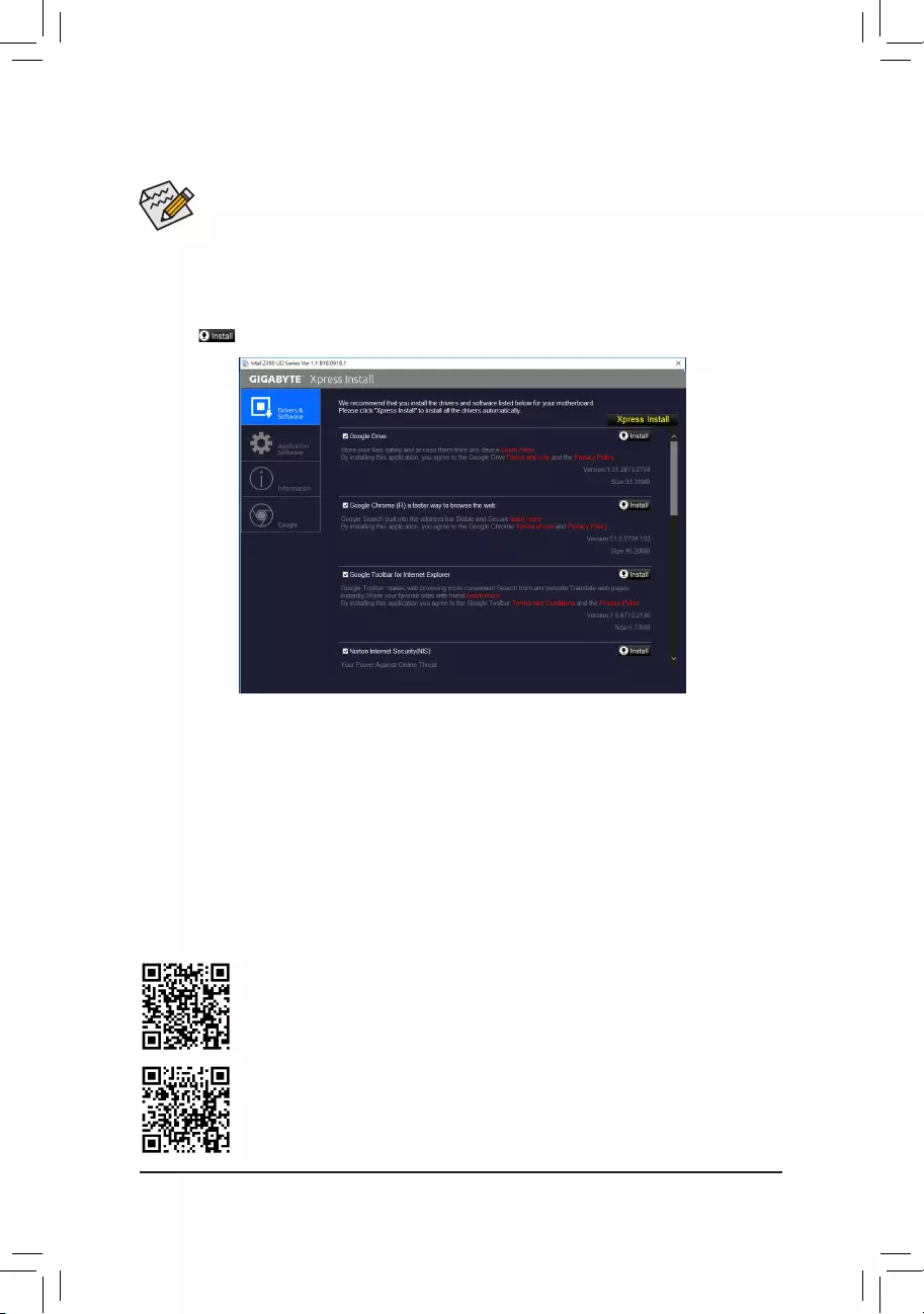
•Beforeinstallingthedrivers,rstinstalltheoperatingsystem.
•After installing the operating system, insert the motherboard driver disk into your optical drive. Click
onthemessage"Taptochoosewhathappenswiththisdisc"onthetop-rightcornerofthescreen
andselect"RunRun.exe."(OrgotoMyComputer,double-clicktheopticaldriveandexecutethe
Run.exeprogram.)
"XpressInstall"willautomaticallyscanyoursystemandthenlistallofthedriversthatarerecommendedto
install. You can click the XpressInstallbuttonand"XpressInstall"willinstallalloftheselecteddrivers.Orclick
the arrow icon to individually install the drivers you need.
3-3 Drivers Installation
Please visit GIGABYTE's website for more software information.
Please visit GIGABYTE's website for more troubleshooting information.
- 44 -

RegulatoryStatements
RegulatoryNotices
This document must not be copied without our written permission, and the contents there of must not be imparted to a
thirdpartynorbeusedforanyunauthorizedpurpose.
Contravention will be prosecuted. We believe that the information contained herein was accurate in all respects at the
time of printing. GIGABYTE cannot, however, assume any responsibility for errors or omissions in this text. Also note
that the information in this document is subject to change without notice and should not be construed as a commitment
by GIGABYTE.
OurCommitmenttoPreservingtheEnvironment
Inadditiontohigh-efciencyperformance,allGIGABYTEmotherboardsfulllEuropeanUnionregulationsforRoHS
(RestrictionofCertainHazardousSubstancesinElectricalandElectronicEquipment)andWEEE(WasteElectricaland
ElectronicEquipment)environmentaldirectives,aswellasmostmajorworldwidesafetyrequirements.Topreventreleases
ofharmfulsubstancesintotheenvironmentandtomaximizetheuseofournaturalresources,GIGABYTEprovidesthe
followinginformationonhowyoucanresponsiblyrecycleorreusemostofthematerialsinyour"endoflife"product.
RestrictionofHazardousSubstances(RoHS)DirectiveStatement
GIGABYTEproductshavenotintendedtoaddandsafefromhazardoussubstances(Cd,Pb,Hg,Cr+6,PBDEand
PBB).ThepartsandcomponentshavebeencarefullyselectedtomeetRoHSrequirement.Moreover,weatGIGABYTE
are continuing our efforts to develop products that do not use internationally banned toxic chemicals.
WasteElectrical&ElectronicEquipment(WEEE)DirectiveStatement
GIGABYTEwillfulllthenationallawsasinterpretedfromthe2012/19/EUWEEE(WasteElectricalandElectronic
Equipment)directive.TheWEEEDirectivespeciesthetreatment,collection,recyclinganddisposalofelectricand
electronicdevicesandtheircomponents.UndertheDirective,usedequipmentmustbemarked,collectedseparately,
and disposed of properly.
WEEESymbolStatement
The symbol shown below is on the product or on its packaging, which indicates that this product must
not be disposed of with other waste. Instead, the device should be taken to the waste collection centers
for activation of the treatment, collection, recycling and disposal procedure. The separate collection and
recycling of your waste equipment at the time of disposal will help to conserve natural resources and ensure
that it is recycled in a manner that protects human health and the environment. For more information about where you
candropoffyourwasteequipmentforrecycling,pleasecontactyourlocalgovernmentofce,yourhouseholdwaste
disposal service or where you purchased the product for details of environmentally safe recycling.
Whenyourelectricalorelectronicequipmentisnolongerusefultoyou,"takeitback"toyourlocalorregionalwaste
collection administration for recycling.
Ifyouneedfurtherassistanceinrecycling,reusinginyour"endoflife"product,youmaycontactusattheCustomer
Care number listed in your product's user's manual and we will be glad to help you with your effort.
Finally, we suggest that you practice other environmentally friendly actions by understanding and using the energy-saving
featuresofthisproduct(whereapplicable),recyclingtheinnerandouterpackaging(includingshippingcontainers)this
product was delivered in, and by disposing of or recycling used batteries properly. With your help, we can reduce the
amountofnaturalresourcesneededtoproduceelectricalandelectronicequipment,minimizetheuseoflandllsfor
thedisposalof"endoflife"products,andgenerallyimproveourqualityoflifebyensuringthatpotentiallyhazardous
substances are not released into the environment and are disposed of properly.
Battery Information
EuropeanUnion—Disposalandrecyclinginformation
GIGABYTERecyclingProgram(availableinsomeregions)
This symbol indicates that this product and/or battery should not be disposed of with household waste. You must use
the public collection system to return, recycle, or treat them in compliance with the local regulations.
- 45 -

FCCNotice(U.S.A.Only)
This equipment has been tested and found to comply with the limits for a Class B digital device, pursuant to Part
15oftheFCCRules.Theselimitsaredesignedtoprovidereasonableprotectionagainstharmfulinterference
in a residential installation. This equipment generates, uses, and can radiate radio frequency energy and, if not
installed and used in accordance with the instructions, may cause harmful interference to radio communications.
However, there is no guarantee that interference will not occur in a particular installation. If this equipment does
cause harmful interference to radio or television reception, which can be determined by turning the equipment
off and on, the user is encouraged to try to correct the interference by one or more of the following measures:
Reorientorrelocatethereceivingantenna.
Increase the separation between the equipment and receiver.
Connect the equipment into an outlet on a circuit different from that to which the receiver is connected.
ConsultadealerorexperiencedTV/radiotechnicianforhelp.
Canada,IndustryCanada(IC)Notices/Canada,avisd'IndustryCanada(IC)
ThisClassBdigitalapparatuscomplieswithCanadianICES-003andRSS-210.
Operationissubjecttothefollowingtwoconditions:(1)thisdevicemaynotcauseinterference,and(2)this
device must accept any interference, including interference that may cause undesired operation of the device.
CetappareilnumériquedeclasseBestconformeauxnormescanadiennesICES-003etRSS-210.
Sonfonctionnement est soumis aux deux conditionssuivantes :(1) cet appareil ne doit pas causer
d'interférenceet(2)cetappareildoitacceptertouteinterférence,notammentlesinterférencesquipeuvent
affecter son fonctionnement.
- 46 -

- 47 -

Contact Us
GIGA-BYTETECHNOLOGYCO.,LTD.
Address:No.6,BaoqiangRd.,XindianDist.,NewTaipeiCity231,Taiwan
TEL: +886-2-8912-4000, FAX: +886-2-8912-4005
Tech.andNon-Tech.Support(Sales/Marketing):https://esupport.gigabyte.com
WEBaddress(English):https://www.gigabyte.com
WEBaddress(Chinese):https://www.gigabyte.com/tw
•GIGABYTEeSupport
Tosubmitatechnicalornon-technical(Sales/Marketing)question,pleaselinkto:
https://esupport.gigabyte.com
- 48 -