Table of Contents
- Chapter 1. About this manual
- Chapter 2. Safety information
- Chapter 3. General information
- Chapter 4. General Checkout
- Chapter 5. Using the Setup Utility
- Chapter 6. Symptom-to-FRU Index
- Chapter 7. Locating connectors, controls and components
- Chapter 8. Replacing hardware
- General information
- Replacing the keyboard and mouse
- Replacing the adapter
- Removing the stand base
- Removing the rear cover
- Replacing the hard disk drive
- Replacing the memory module
- Replacing the solid state drive
- Removing the stand holder
- Removing the middle cover
- Replacing the front bezel
- Replacing the power switch board
- Removing the EMI cover
- Replacing the camera
- Removing the mount bracket
- Replacing the power supply unit
- Replacing the speaker system
- Replacing the Wi-Fi card
- Replacing the heat-sink
- Replacing the system fan
- Replacing the motherboard
- Replacing the LCD panel module
- Chapter 9. General information
Lenovo 720 User Manual
Displayed below is the user manual for 720 by Lenovo which is a product in the All-in-One PCs/Workstations category. This manual has pages.
Related Manuals

ideacentreAll-In-One720ComputerHardware
MaintenanceManual
MachineTypes:F0CM[AIO720-24IKB/EnergyStar]


ideacentreAll-In-One720Computer
HardwareMaintenanceManual
MachineTypes:F0CM[AIO720-24IKB/EnergyStar]

FirstEdition(July2016)14th
©CopyrightLenovo2016.
LIMITEDANDRESTRICTEDRIGHTSNOTICE:IfdataorsoftwarearedeliveredpursuantaGeneralServices
Administration“GSA”contract,use,reproduction,ordisclosureissubjecttorestrictionssetforthinContractNo.
GS-35F-05925

Contents
Chapter1.Aboutthismanual.....1
ImportantSafetyInformation.........1
Chapter2.Safetyinformation.....3
Generalsafety...............3
Electricalsafety..............3
Safetyinspectionguide...........5
Handlingelectrostaticdischarge-sensitive
devices.................5
Groundingrequirements...........6
Safetynotices...............6
Chapter3.Generalinformation....9
Specifications...............9
Chapter4.GeneralCheckout.....11
Chapter5.UsingtheSetupUtility...13
StartingtheLenovoBIOSSetupUtilityprogram.13
Viewingandchangingsettings........13
Usingpasswords..............13
Enablingordisablingadevice........15
Selectingastartupdevice..........16
ExitingtheLenovoBIOSSetupUtilityprogram..17
Chapter6.Symptom-to-FRUIndex..19
Harddiskdrivebooterror..........19
PowerSupplyProblems...........19
POSTerrorcodes.............20
Undeterminedproblems...........20
Chapter7.Locatingconnectors,
controlsandcomponents......21
Chapter8.Replacinghardware....27
Generalinformation.............27
Replacingthekeyboardandmouse......28
Replacingtheadapter............28
Removingthestandbase..........29
Removingtherearcover...........29
Replacingtheharddiskdrive.........30
Replacingthememorymodule........31
Replacingthesolidstatedrive........32
Removingthestandholder..........33
Removingthemiddlecover.........34
Replacingthefrontbezel...........36
Replacingthepowerswitchboard.......36
RemovingtheEMIcover...........37
Replacingthecamera............38
Removingthemountbracket.........40
Replacingthepowersupplyunit........41
Replacingthespeakersystem........42
ReplacingtheWi-Ficard...........43
Replacingtheheat-sink...........44
Replacingthesystemfan..........45
Replacingthemotherboard..........47
ReplacingtheLCDpanelmodule.......48
Chapter9.Generalinformation....51
AdditionalServiceInformation........51
©CopyrightLenovo2016iii

ivideacentreAll-In-One720ComputerHardwareMaintenanceManual
Chapter1.Aboutthismanual
ThismanualcontainsserviceandreferenceinformationforLenovoAll-In-One720seriescomputerslistedon
thecover.ItisintendedonlyfortrainedservicerswhoarefamiliarwithLenovocomputerproducts.
BeforeservicingaLenovoproduct,besuretoreadtheSafetyInformation.
ThedescriptionoftheTV-tunercardinthismanualappliesonlytocomputerswithaTV-tunercardinstalled.
ItdoesnotapplytocomputerswithoutaTV-tunercard.
ImportantSafetyInformation
BesuretoreadallCAUTIONandDANGERsectionsinthismanualbeforefollowinganyoftheinstructions.
VeuillezliretouteslesconsignesdetypeDANGERetATTENTIONduprésentdocumentavantd’exécuter
lesinstructions.
LesenSieunbedingtalleHinweisevomTyp“ACHTUNG”oder“VORSICHT”indieserDokumentation,bevor
SieirgendwelcheVorgängedurchführen
LeggereleistruzioniintrodottedaATTENZIONEePERICOLOpresentinelmanualeprimadieseguireuna
qualsiasidelleistruzioni
Certifique-sedelertodasasinstruçõesdecuidadoeperigonestemanualantesdeexecutarqualquer
umadasinstruções
Esimportantequeleatodaslasdeclaracionesdeprecauciónydepeligrodeestemanualantesdeseguir
lasinstrucciones.
©CopyrightLenovo20161

2ideacentreAll-In-One720ComputerHardwareMaintenanceManual

Chapter2.Safetyinformation
Thischaptercontainsthesafetyinformationthatyouneedtobefamiliarwithbeforeservicingacomputer.
Generalsafety
Followtheserulestoensuregeneralsafety:
•Keeptheareasaroundthecomputerclearandcleanduringandaftermaintenance.
•Whenliftinganyheavyobject:
1.Ensureyoucanstandsafelywithoutslipping.
2.Distributetheweightoftheobjectequallyacrossbothfeet.
3.Liftslowly.Nevermovesuddenlyortwistwhenyouattempttolift.
4.Liftbystandingorbypushingupwithyourlegmuscles;thisactionremovesthestrainfromthe
musclesinyourback.
Donotattempttoliftanyobjectsthatweighmorethan16kg(35lb)orobjectsthatyouthinkare
tooheavyforyou.
•Donotperformanyactionthatwouldcreateahazardforthecustomer,orwouldmakethecomputer
unsafe.
•Beforeyoustartthecomputer,ensurethatotherservicerepresentativesandcustomerpersonnelarenot
inapositionthatwouldcreateahazardforthem.
•Placeremovedcoversandotherpartsinasafeplace,awayfromallpersonnel,whileyouareservicingthe
computer.
•Keepyourtoolcaseawayfromareasthatpeoplemaywalkthroughtoensureno-onetripsoverit.
•Donotwearlooseclothingthatcanbetrappedinthemovingpartsofamachine.Ensurethatyoursleeves
arefastenedorrolledupaboveyourelbows.Ifyourhairislong,tieorfastenitback.
•Inserttheendsofyournecktieorscarfinsideclothingorfastenitwithanon-conductiveclip,
approximately8centimeters(3inches)fromtheend.
•Donotwearjewelry,chains,metal-frameeyeglasses,ormetalfastenersforyourclothing.
Remember:Metalobjectsaregoodelectricalconductors.
•Wearsafetyglasseswhenyouare:hammering,drillingsoldering,cuttingwire,attachingsprings,using
solvents,orworkinginanyotherconditionsthatmightbehazardoustoyoureyes.
•Afterservice,reinstallallsafetyshields,guards,labels,andgroundwires.Replaceanysafetydevice
thatiswornordefective.
•Reattachallcoverscorrectlybeforereturningthecomputertothecustomer.
Electricalsafety
CAUTION:
Electricalcurrentfrompower,telephone,andcommunicationcablescanbehazardous.T oavoid
personalinjuryorequipmentdamage,disconnectanyattachedpowercords,telecommunication
cables,networkcables,andmodemcablesbeforeyouopenthecomputercovers,unlessinstructed
otherwiseintheinstallationandconfigurationprocedures.
©CopyrightLenovo20163

Observethefollowingruleswhenworkingonelectricalequipment.
Important:Useonlyapprovedtoolsandtestequipment.Somehandtoolshavehandlescoveredwithasoft
materialthatdoesnotinsulateyouwhenworkingwithliveelectricalcurrents.Manycustomershaverubber
floormatsneartheirequipmentthatcontainsmallconductivefiberstodecreaseelectrostaticdischarge.
•Findtheroomemergencypower-off(EPO)switch,disconnectingswitch,orelectricaloutlet.Ifanelectrical
accidentoccurs,youcanthenoperatetheswitchorunplugthepowercordquickly.
•Donotworkaloneunderhazardousconditionsornearequipmentthathashazardousvoltages.
•Disconnectallpowerbefore:
–Performingamechanicalinspection
–Workingnearpowersupplies
–RemovingorinstallingFieldReplaceableUnits(FRUs)
•Beforeyoustarttoworkonthecomputer,unplugthepowercord.Ifyoucannotunplugit,askthe
customertopower-offtheelectricaloutletthatsuppliespowertothemachineandtolocktheelectrical
outletintheoffposition.
•Ifyouneedtoworkonacomputerthathasexposedelectricalcircuits,observethefollowingprecautions:
–Ensurethatanotherperson,familiarwiththepower-offcontrols,isnearyou.
Remember:Anotherpersonmustbetheretoswitchoffthepower,ifnecessary.
–Useonlyonehandwhenworkingwithpowered-onelectricalequipment;keeptheotherhandinyour
pocketorbehindyourback.
Remember:Theremustbeacompletecircuittocauseelectricalshock.Byobservingtheaboverule,
youmaypreventacurrentfrompassingthroughyourbody.
–Whenusingatester,setthecontrolscorrectlyandusetheapprovedprobeleadsandaccessoriesfor
thattester.
–Standonsuitablerubbermats(obtainedlocally,ifnecessary)toinsulateyoufromgroundssuchas
metalfloorstripsandmachineframes.
Observethespecialsafetyprecautionswhenyouworkwithveryhighvoltages;theseinstructionsarein
thesafetysectionsofthemaintenanceinformation.Useextremecarewhenmeasuringhighvoltages.
•Regularlyinspectandmaintainyourelectricalhandtoolstoensuretheyaresafetouse.
•Donotusewornorbrokentoolsandtesters.
•Neverassumethatpowerhasbeendisconnectedfromacircuit.First,checkthatithasbeenpoweredoff.
•Alwayslookcarefullyforpossiblehazardsinyourworkarea.Examplesofthesehazardsarewetfloors,
non-groundedpowerextensioncables,conditionsthatmaycauseorallowpowersurges,andmissing
safetygrounds.
•Donottouchliveelectricalcircuitswiththereflectivesurfaceofaplasticdentalmirror.Thissurfaceis
conductive,andtouchingalivecircuitcancausepersonalinjuryanddamagetothecomputer.
•Donotservicethefollowingpartswiththepoweronwhentheyareremovedfromtheirnormaloperating
positionsinacomputer:
–Powersupplyunits
–Pumps
–Blowersandfans
–Motorgenerators
andsimilarunits.(Thispracticeensurescorrectgroundingoftheunits.)
•Ifanelectricalaccidentoccurs:
–Usecaution;donotbecomeavictimyourself.
4ideacentreAll-In-One720ComputerHardwareMaintenanceManual

–Switchoffpower.
–Sendanotherpersontogetmedicalaid.
Safetyinspectionguide
Theintentofthisinspectionguideistoassistyouinidentifyingpotentialhazardsposedbytheseproducts.
Eachcomputer,asitwasdesignedandbuilt,hadrequiredsafetyitemsinstalledtoprotectusersand
servicepersonnelfrominjury.Thisguideaddressesonlythoseitems.However,goodjudgmentshouldbe
usedtoidentifypotentialsafetyhazardsduetoattachmentoffeaturesoroptionsnotcoveredbythis
inspectionguide.
Ifanyhazardsarepresent,youmustdeterminehowserioustheapparenthazardcouldbeandwhetheryou
cancontinuewithoutfirstresolvingtheproblem.
Considerthefollowingitemsandthesafetyhazardstheypresent:
•Electricalhazards,especiallyprimarypower(primaryvoltageontheframecancauseseriousorfatal
electricalshock).
•Explosivehazards,suchasadamagedCRTfaceorbulgingcapacitor
•Mechanicalhazards,suchaslooseormissinghardware
Theguideconsistsofaseriesofstepspresentedasachecklist.Beginthecheckswiththepoweroff,and
thepowercorddisconnected.
Checklist:
1.Checkexteriorcoversfordamage(loose,broken,orsharpedges).
2.Power-offthecomputer.Disconnectthepowercord.
3.Checkthepowercordfor:
a.Athird-wiregroundconnectoringoodcondition.Useametertomeasurethird-wireground
continuityfor0.1ohmorlessbetweentheexternalgroundpinandframeground.
b.Thepowercordshouldbetheappropriatetypeasspecifiedinthepartslistings.
c.Insulationmustnotbefrayedorworn.
4.Removethecover.
5.Checkforanyobviousalterations.Usegoodjudgmentastothesafetyofanyalterations.
6.Checkinsidetheunitforanyobvioushazards,suchasmetalfilings,contamination,waterorother
liquids,orsignsoffireorsmokedamage.
7.Checkforworn,frayed,orpinchedcables.
8.Checkthatthepower-supplycoverfasteners(screwsorrivets)havenotbeenremovedortamperedwith.
Handlingelectrostaticdischarge-sensitivedevices
Anycomputerpartcontainingtransistorsorintegratedcircuits(ICs)shouldbeconsideredsensitiveto
electrostaticdischarge(ESD).ESDdamagecanoccurwhenthereisadifferenceinchargebetweenobjects.
ProtectagainstESDdamagebyequalizingthechargesothatthecomputer,thepart,theworkmat,andthe
personhandlingthepartareallatthesamecharge.
Notes:
1.Useproduct-specificESDprocedureswhentheyexceedtherequirementsnotedhere.
2.MakesurethattheESDprotectivedevicesyouusehavebeencertified(ISO9000)asfullyeffective.
WhenhandlingESD-sensitiveparts:
Chapter2.Safetyinformation5

•Keepthepartsinprotectivepackagesuntiltheyareinsertedintotheproduct.
•Avoidcontactwithotherpeoplewhilehandlingthepart.
•Wearagroundedwriststrapagainstyourskintoeliminatestaticonyourbody.
•Preventthepartfromtouchingyourclothing.Mostclothingisinsulativeandretainsachargeeven
whenyouarewearingawriststrap.
•Usetheblacksideofagroundedworkmattoprovideastatic-freeworksurface.Thematisespecially
usefulwhenhandlingESD-sensitivedevices.
•Selectagroundingsystem,suchasthoselistedbelow,toprovideprotectionthatmeetsthespecific
servicerequirement.
Note:TheuseofagroundingsystemisdesirablebutnotrequiredtoprotectagainstESDdamage.
–AttachtheESDgroundcliptoanyframeground,groundbraid,orgreen-wireground.
–UseanESDcommongroundorreferencepointwhenworkingonadouble-insulatedor
battery-operatedsystem.Youcanusecoaxorconnector-outsideshellsonthesesystems.
–Usetheroundground-prongoftheACplugonAC-operatedcomputers.
Groundingrequirements
Electricalgroundingofthecomputerisrequiredforoperatorsafetyandcorrectsystemfunction.Proper
groundingoftheelectricaloutletcanbeverifiedbyacertifiedelectrician.
Safetynotices
TheCAUTIONandDANGERsafetynoticesinthissectionareprovidedinthelanguageofEnglish.
DANGER
Electricalcurrentfrompower,telephoneandcommunicationcablesishazardous.
Toavoidashockhazard:
•Donotconnectordisconnectanycablesorperforminstallation,maintenance,orreconfiguration
ofthisproductduringanelectricalstorm.
•Connectallpowercordstoaproperlywiredandgroundedelectricaloutlet.
•Connectanyequipmentthatwillbeattachedtothisproducttoaproperlywiredoutlet.
•Whenpossible,useonehandonlytoconnectordisconnectsignalcables.
•Neverturnonanyequipmentwhenthereisevidenceoffire,water,orstructuraldamage.
•Disconnecttheattachedpowercords,telecommunicationscables,networkcables,andmodem
cablesbeforeyouopenthedevicecovers,unlessinstructedotherwiseintheinstallationand
configurationprocedures.
•Connectanddisconnectcablesasdescribedinthefollowingtablewheninstalling,moving,or
openingcoversonthisproductorattacheddevices.
6ideacentreAll-In-One720ComputerHardwareMaintenanceManual
ToConnectToDisconnect
1.TurneverythingOFF.
2.First,attachallcablestodevices.
3.Attachsignalcablestoconnectors.
4.Attachpowercordstooutlet.
5.TurndeviceON.
1.TurneverythingOFF.
2.First,removepowercordsfromoutlets.
3.Removesignalcablesfromconnectors.
4.Removeallcablesfromdevices.
CAUTION:
Whenreplacingthelithiumbattery,useonlyPartNumber45C1566oranequivalenttypebattery
recommendedbythemanufacturer.Ifyoursystemhasamodulecontainingalithiumbattery,replace
itonlywiththesamemoduletypemadebythesamemanufacturer.Thebatterycontainslithiumand
canexplodeifnotproperlyused,handled,ordisposedof.
Donot:
•Throwintoorimmerseinwater
•Heattomorethan100°C(212°F)
•Repairordisassemble
Disposeofthebatteryasrequiredbylocalordinancesorregulations.
CAUTION:
Whenlaserproducts(suchasCD-ROMs,DVD-ROMdrives,fiberopticdevices,ortransmitters)are
installed,notethefollowing:
•Donotremovethecovers.Removingthecoversofthelaserproductcouldresultinexposureto
hazardouslaserradiation.Therearenoserviceablepartsinsidethedevice.
•Useofcontrolsoradjustmentsorperformanceofproceduresotherthanthosespecifiedherein
mightresultinhazardousradiationexposure.
DANGER
SomelaserproductscontainanembeddedClass3AorClass3Blaserdiode.Notethefollowing:
Thesediodesemitradiationwhenopen.Donotstareintothebeam,donotviewdirectlywith
opticalinstruments,andavoiddirectexposuretothebeam.
Chapter2.Safetyinformation7
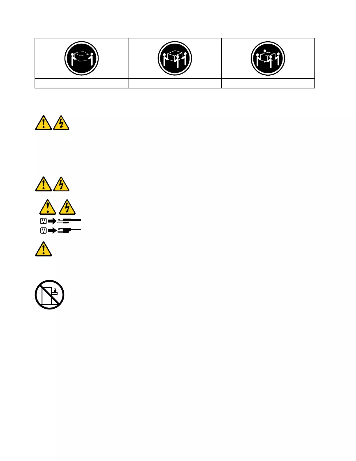
≥18kg(37lbs)≥32kg(70.5lbs)≥55kg(121.2lbs)
CAUTION:
Usesafepracticeswhenlifting.
CAUTION:
Thepowercontrolbuttononthedeviceandthepowerswitchonthepowersupplydonotturnoff
theelectricalcurrentsuppliedtothedevice.Thedevicealsomighthavemorethanonepower
cord.Toremoveallelectricalcurrentfromthedevice,ensurethatallpowercordsaredisconnected
fromthepowersource.
1
2
CAUTION:
Donotplaceanyobjectweighingmorethan82kg(180lbs.)ontopofrack-mounteddevices.
8ideacentreAll-In-One720ComputerHardwareMaintenanceManual

Chapter3.Generalinformation
Thischapterprovidesgeneralinformationthatappliestoallcomputermodelscoveredbythismanual.
Specifications
Thissectionliststhephysicalspecificationsforyourcomputer.
Thissectionliststhephysicalspecificationsforyourcomputer.
TypeLenovoAll-In-One720
Thissectionliststhephysicalspecifications.
Environment
Airtemperature:
Operating:10°to35°C
Transit:-20°to55°C
Humidity:
Operating:35%to80%
Transit:20%to90%(40°C)
Altitude:86KPato106KPa
Electricalinput:
Inputvoltage:90V-264V(AC)
Inputfrequency:47Hz-63Hz
©CopyrightLenovo20169

10ideacentreAll-In-One720ComputerHardwareMaintenanceManual

Chapter4.GeneralCheckout
Attention:Thedrivesinthecomputeryouareservicingmighthavebeenrearrangedorthedrivestartup
sequencemayhavebeenchanged.Beextremelycarefulduringwriteoperationssuchascopying,saving,or
formatting.Dataorprogramscanbeoverwrittenifyouselectanincorrectdrive.
Generalerrormessagesappearifaproblemorconflictisfoundbyanapplication,theoperatingsystem,or
both.Foranexplanationofthesemessages,refertotheinformationsuppliedwiththatsoftwarepackage.
Usethefollowingproceduretohelpdeterminethecauseoftheproblem:
1.Power-offthecomputerandallexternaldevices.
2.Checkallcablesandpowercords.
3.Setalldisplaycontrolstothemiddleposition.
4.Power-onallexternaldevices.
5.Power-onthecomputer.
•Lookfordisplayederrorcodes.
•Lookforreadableinstructionsoramainmenuonthedisplay.
Ifyoudidnotreceivethecorrectresponse,proceedtostep6.
Ifyoudidreceivethecorrectresponse,proceedtostep7.
6.Ifoneofthefollowinghappens,followtheinstructiongiven:
•IfthecomputerdisplaysaPOSTerror,goto“POSTerrorcodes” .
•Ifthecomputerhangsandnoerrorisdisplayed,continueatstep7.
7.Iftheteststopsandyoucannotcontinue,replacethelastdevicetested.
©CopyrightLenovo201611

12ideacentreAll-In-One720ComputerHardwareMaintenanceManual

Chapter5.UsingtheSetupUtility
TheSetupUtilityprogramisusedtoviewandchangetheconfigurationsettingsofyourcomputer,regardless
ofwhichoperatingsystemyouareusing.However,theoperatingsystemsettingsmightoverrideanysimilar
settingsintheSetupUtilityprogram.
StartingtheLenovoBIOSSetupUtilityprogram
TostarttheLenovoBIOSSetupUtilityprogram,dothefollowing:
1.Ifyourcomputerisalreadyonwhenyoustartthisprocedure,shutdowntheoperatingsystemand
turnoffthecomputer.
2.PressandholdtheF1keythenturnonthecomputer.WhentheLenovoBIOSSetupUtilityprogramis
displayed,releasetheF1key.
Note:IfaPower-OnPasswordoranAdministratorPasswordhasbeenset,theSetupUtilityprogrammenu
willnotbedisplayeduntilyoutypeyourpassword.Formoreinformation,see“Usingpasswords.”
Viewingandchangingsettings
SystemconfigurationoptionsarelistedintheLenovoBIOSSetupUtilityprogrammenu.Tovieworchange
settings,see“StartingtheSetupUtilityprogram.”
YoumustusethekeyboardwhenusingtheLenovoBIOSSetupUtilitymenu.Thekeysusedtoperform
varioustasksaredisplayedonthebottomofeachscreen.
Usingpasswords
YoucanusetheLenovoBIOSSetupUtilityprogramtosetpasswordstopreventunauthorizedpersons
fromgainingaccesstoyourcomputeranddata.See“StartingtheSetupUtilityprogram.”Thefollowing
typesofpasswordsareavailable:
•AdministratorPassword
•Power-OnPassword
Youdonothavetosetanypasswordstouseyourcomputer.However,ifyoudecidetosetpasswords,read
thefollowingsections.
Passwordconsiderations
Apasswordcanbeanycombinationoflettersandnumbersupto16characters(a-zand0-9).Forsecurity
reasons,itisagoodideatouseastrongpasswordthatcannotbeeasilycompromised.Wesuggestthat
passwordsshouldfollowtheserules:
•Forastrongpassword,use7-16charactersandamixoflettersandnumbers.
•Donotuseyournameoryourusername.
•Donotuseacommonwordoracommonname.
•Usesomethingsignificantlydifferentfromyourpreviouspassword.
Attention:AdministratorandPower-Onpasswordsarenotcasesensitive.
©CopyrightLenovo201613

AdministratorPassword
SettinganAdministratorPassworddetersunauthorizedpersonsfromchangingconfigurationsettings.Y ou
mightwanttosetanAdministratorPasswordifyouareresponsibleformaintainingthesettingsofseveral
computers.
AfteryousetanAdministratorPassword,apasswordpromptisdisplayedeverytimeyouaccesstheLenovo
BIOSSetupUtilityprogram.
IfboththeAdministratorandPower-OnPasswordareset,youcantypeeitherpassword.However,youmust
useyourAdministratorPasswordtochangeanyconfigurationsettings.
Setting,changing,ordeletinganAdministratorpassword
TosetanAdministratorPassword,dothefollowing:
Note:Apasswordcanbeanycombinationoflettersandnumbersupto16characters(a-zand0-9).For
moreinformation,see“Passwordconsiderations”onpage13.
1.StarttheLenovoBIOSSetupUtilityprogram(see“StartingtheLenovoBIOSSetupUtilityprogram”on
page13).
2.FromtheSecuritymenu,selectSetAdministratorPasswordandpresstheEnterkey.
3.Thepassworddialogboxwillbedisplayed.TypethepasswordthenpresstheEnterkey.
4.Re-typethepasswordtoconfirm,thenpresstheEnterkey.Ifyoutypedthepasswordcorrectly,
thepasswordwillbeinstalled.
TochangeanAdministratorPassword,dothefollowing:
1.StarttheLenovoBIOSSetupUtilityprogram(see“StartingtheLenovoBIOSSetupUtilityprogram”on
page13).
2.FromtheSecuritymenu,selectSetAdministratorPasswordandpresstheEnterkey.
3.Thepassworddialogboxwillbedisplayed.TypethecurrentpasswordthenpresstheEnterkey.
4.Typethenewpassword,thenpresstheEnterkey.Re-typethepasswordtoconfirmthenewpassword.
Ifyoutypedthenewpasswordcorrectly,thenewpasswordwillbeinstalled.ASetupNoticedconfirming
thatchangeshavebeensavedwillbedisplayed.
TodeleteapreviouslysetAdministratorPassword,dothefollowing:
1.FromtheSecuritymenu,selectSetAdministratorPasswordandpresstheEnterkey.
2.Thepassworddialogboxwillbedisplayed.T ypethecurrentpasswordandpresstheEnterkey.
3.TodeleteanAdministratorPassword,leaveeachnewpasswordlineitemblank,thenpresstheEnter
key.ASetupNoticeconfirmingthatchangeshavebeensavedwillbedisplayed.
4.ReturntotheLenovoBIOSSetupUtilityprogrammenuandselecttheExitoption.
5.SelectSavechangesandExitfromthemenu.
Power-OnPassword
WhenaPower-OnPasswordisset,youcannotstarttheLenovoBIOSSetupUtilityprogramuntilavalid
passwordistypedfromthekeyboard.
Setting,changing,ordeletingaPower-OnPassword
Note:Apasswordcanbeanycombinationoflettersandnumbersupto16characters(a-zand0-9).
14ideacentreAll-In-One720ComputerHardwareMaintenanceManual

TosetaPower-OnPassword,dothefollowing:
1.StarttheLenovoBIOSSetupUtilityprogram(See”StartingtheLenovoBIOSSetupUtilityprogram”on
page13.)
2.FromtheSecuritymenu,selectSetPower-OnPasswordandpresstheEnterkey.
3.Thepassworddialogboxwillbedisplayed.T ypethepassword,thenpresstheEnterkey.
4.Re-typethepasswordtoconfirm.Ifyoutypedthepasswordcorrectly,thepasswordwillbeinstalled.
TochangeaPower-OnPassword,dothefollowing:
1.StarttheLenovoBIOSSetupUtilityprogram(See”StartingtheLenovoBIOSSetupUtilityprogram”on
page13.)
2.FromtheSecuritymenu,selectSetPower-OnPasswordandpresstheEnterkey.
3.Thepassworddialogboxwillbedisplayed.TypethecurrentpasswordthenpresstheEnterkey.
4.Typethenewpassword,thenpresstheEnterkey.Re-typethepasswordtoconfirmthenewpassword.
Ifyoutypedthenewpasswordcorrectly,thenewpasswordwillbeinstalled.ASetupNoticedconfirming
thatchangeshavebeensavedwillbedisplayed.
TodeleteapreviouslysetPower-OnPassword,dothefollowing:
1.FromtheSecuritymenu,selectSetPower-OnPasswordandpresstheEnterkey.
2.Thepassworddialogboxwillbedisplayed.T ypethecurrentpasswordandpresstheEnterkey.
3.TodeletethePower-OnPassword,leaveeachnewpasswordlineitemblank,thenpressEnter.ASetup
Noticeconfirmingthatchangeshavebeensavedwillbedisplayed.
4.ReturntotheLenovoBIOSSetupUtilityprogrammenuandselecttheExitoption.
5.SelectSavechangesandExitfromthemenu.
Enablingordisablingadevice
TheDevicesoptionsisusedtoenableordisableuseraccesstothefollowingdevices:
USBFunctionsSelectwhethertoenableordisableUSB(UniversalSerial
Bus)functions.Ifthefunctionsaredisabled,noUSB
devicescanbeused.
SATAModeWhenthisfeatureissettoDisabled,alldevices
connectedtotheSATAconnectors(e.g.harddiskdrives
ortheopticaldiskdrive)aredisabledandcannotbe
accessed.
OnboardAudioControllerSelectwhethertoenableordisabletheOnboard
AudioController.WhenthisfeatureissettoDisabled
alldevicesconnectedtotheaudioconnectors(e.g.
headphonesoramicrophone)aredisabledandcannot
beused.
OnboardEthernetControllerorLANBootAgentSelectwhethertoenableordisabletheOnboardEthernet
Controller,orselectwhethertoenableordisableload
onboardPXE(PrebootExecutionEnvironment).
Toenableordisableadevice,dothefollowing:
1.StarttheSetupUtilityprogram(see“StartingtheSetupUtilityprogram”onpage13).
2.FromtheSetupUtilityprogrammenu,selectDevices.
3.Selectanoptionasfollows:
SelectUSBSetup,presstheEnterkey,thenselectUSBFunctions.
Chapter5.UsingtheSetupUtility15

SelectATADeviceSetup,presstheEnterkey,thenselectSATAMode.
SelectAudioSetup,presstheEnterkey,thenselectOnboardAudioController.
SelectNetworkSetup,presstheEnterkey,thenselectOnboardEthernetSupportorLANBoot
Agent.
4.SelectDisabledorEnabledandpresstheEnterkey.
5.ReturntotheLenovoBIOSSetupUtilityprogrammenuandselecttheExitoption.
6.SelectSavechangesandExitfromthemenu.
Notes:
a.Ifyoudonotwanttosavethesettings,selectDiscardchangesandExitfromthemenu.
b.SelectIDE/AHCIMode:DevicedriversupportisrequiredforACHI.Dependingonhowtheharddisk
imagewasinstalled,changingthissettingmaypreventthesystemfrombooting.
Selectingastartupdevice
IfyourcomputerdoesnotbootfromadevicesuchastheCD/DVD-ROMdrivediskorharddiskasexpected,
followoneoftheproceduresbelow.
Selectingatemporarystartupdevice
Usethisproceduretostartupfromanybootdevice.
Note:NotallCDs,DVDsorharddiskdrivesarebootable.
1.Turnoffyourcomputer.
2.PressandholdtheF12keythenturnonthecomputer.WhentheStartupDeviceMenuappears,
releasetheF12key.
Note:IftheStartupDeviceMenudoesnotdisplayusingthesesteps,repeatedlypressandreleasethe
F12keyratherthankeepingitpressedwhenturningonthecomputer.
3.Use↑and↓arrowstoselectthedesiredstartupdevicefromtheStartupDeviceMenuandpress
theEnterkeytobegin.
Note:SelectingastartupdevicefromtheStartupDeviceMenudoesnotpermanentlychangethe
startupsequence.
Selectingorchangingthestartupdevicesequence
Tovieworpermanentlychangetheconfiguredstartupdevicesequence,dothefollowing:
1.StarttheLenovoBIOSSetupUtilityprogram(see“StartingtheLenovoBIOSSetupUtilityprogram”on
page13).
2.FromtheLenovoBIOSSetupUtilityprogrammainmenu,selecttheStartupoption.
3.PresstheEnterkey,andselectthedevicesforthePrimaryBootSequence.Readtheinformation
displayedontherightsideofthescreen.
4.Use↑and↓arrowstoselectadevice.Usethe<+>or<->keystomoveadeviceupordown.Usethe
<×>keytoexcludethedevicefromorincludethedeviceinthebootsequence.
5.ReturntotheLenovoBIOSSetupUtilityprogrammenuandselecttheExitoption.
6.SelectSavechangesandExitfromthemenu.
Notes:
16ideacentreAll-In-One720ComputerHardwareMaintenanceManual

a.Ifyoudonotwanttosavethesettings,selectDiscardchangesandExitfromthemenu.
b.Ifyouhavechangedthesesettingsandwanttoreturntothedefaultsettings,selectLoadOptimal
Defaultsfromthemenu.
ExitingtheLenovoBIOSSetupUtilityprogram
Afteryoufinishviewingorchangingsettings,presstheEsckeytoreturntotheLenovoBIOSSetupUtility
programmainmenu.YoumighthavetopresstheEsckeyseveraltimes.Dooneofthefollowing:
•Ifyouwanttosavethenewsettings,selectSavechangesandExitfromthemenu.WhentheSave&
resetwindowshows,selecttheYesbutton,andthenpresstheEnterkeytoexittheLenovoBIOS
SetupUtilityprogram.
•Ifyoudonotwanttosavethesettings,selectDiscardchangesandExitfromthemenu.Whenthe
ResetWithoutSavingwindowshows,selecttheYesbutton,andthenpresstheEnterkeytoexitthe
LenovoBIOSSetupUtilityprogram.
Chapter5.UsingtheSetupUtility17

18ideacentreAll-In-One720ComputerHardwareMaintenanceManual
Chapter6.Symptom-to-FRUIndex
TheSymptom-to-FRUindexlistserrorsymptomsandpossiblecauses.Themostlikelycauseislistedfirst.
AlwaysbeginwithChapter4,“GeneralCheckout,”onpage11.Thisindexcanalsobeusedtohelpyou
decidewhichFRUstohaveavailablewhenservicingacomputer.Ifyouareunabletocorrecttheproblem
usingthisindex,goto“Undeterminedproblems”onpage20.
Notes:
•Ifyouhavebothanerrormessageandanincorrectaudioresponse,diagnosetheerrormessagefirst.
•Ifyoucannotrunthediagnostictestsoryougetadiagnosticerrorcodewhenrunningatestbutdid
receiveaPOSTerrormessage,diagnosethePOSTerrormessagefirst.
•Ifyoudidnotreceiveanyerrormessagelookforadescriptionofyourerrorsymptomsinthefirstpartof
thisindex.
Harddiskdrivebooterror
Aharddiskdrivebooterrorcanbecausedbythefollowing.
ErrorFRU/Action
Thestartupdriveisnotincludedinthebootsequence
configuration.
Checktheconfigurationandensurethestartupdriveis
inthebootsequence.
Nooperatingsystemisinstalledonthebootdrive.Installanoperatingsystemonthebootdrive.
Thebootsectoronthestartupdriveiscorrupted.Thedrivemustbeformatted.Dothefollowing:
1.Attempttobackupthedataonthefailingharddisk
drive.
2.Usetheoperatingsystemtoformattheharddisk
drive.
Thedriveisdefective.Replacetheharddiskdrive.
PowerSupplyProblems
Followtheseproceduresifyoususpectthereisapowersupplyproblem.
Check/VerifyFRU/Action
Checkthatthefollowingareproperlyinstalled:
•PowerCord
•On/OffSwitchconnector
•SystemBoardPowerSupplyconnectors
•Microprocessorconnections
Reseatconnectors
Checkthepowercord.PowerCord
Checkthepower-onswitch.Power-onSwitch
©CopyrightLenovo201619
POSTerrorcodes
Eachtimeyouturnthecomputeron,itperformsaseriesofteststocheckthatthesystemisoperating
correctlyandthatcertainoptionsareset.ThisseriesoftestsiscalledthePower-OnSelf-Test,orPOST.
POSTdoesthefollowing:
•Checkssomebasicmotherboardoperations
•Checksthatthememoryisworkingcorrectly
•Startsvideooperations
•Verifiesthatthebootdriveisworking
POSTErrorMessageDescription/Action
KeyboarderrorCannotinitializethekeyboard.Makesurethekeyboard
isproperlyconnectedtothecomputerandthatnokeys
areheldpressedduringPOST.Topurposelyconfigure
thecomputerwithoutakeyboard,selectKeyboardless
operationinStartupandsettheoptiontoEnabled.The
BIOSthenignoresthemissingkeyboardduringPOST.
RebootandSelectproperBootdeviceorInsertBoot
MediainselectedBootdevice
TheBIOSwasunabletofindasuitablebootdevice.Make
surethebootdriveisproperlyconnectedtothecomputer.
Makesureyouhavebootablemediainthebootdevice.
Undeterminedproblems
1.Power-offthecomputer.
2.Removeordisconnectthefollowingcomponents(ifconnectedorinstalled)oneatatime.
a.Externaldevices(modem,printer,ormouse)
b.Extendedvideomemory
c.ExternalCache
d.ExternalCacheRAM
e.Harddiskdrive
f.Diskdrive
3.Power-onthecomputertore-testthesystem.
4.Repeatsteps1through3untilyoufindthefailingdeviceorcomponent.
Ifalldevicesandcomponentshavebeenremovedandtheproblemcontinues,replacethesystemboard.
20ideacentreAll-In-One720ComputerHardwareMaintenanceManual
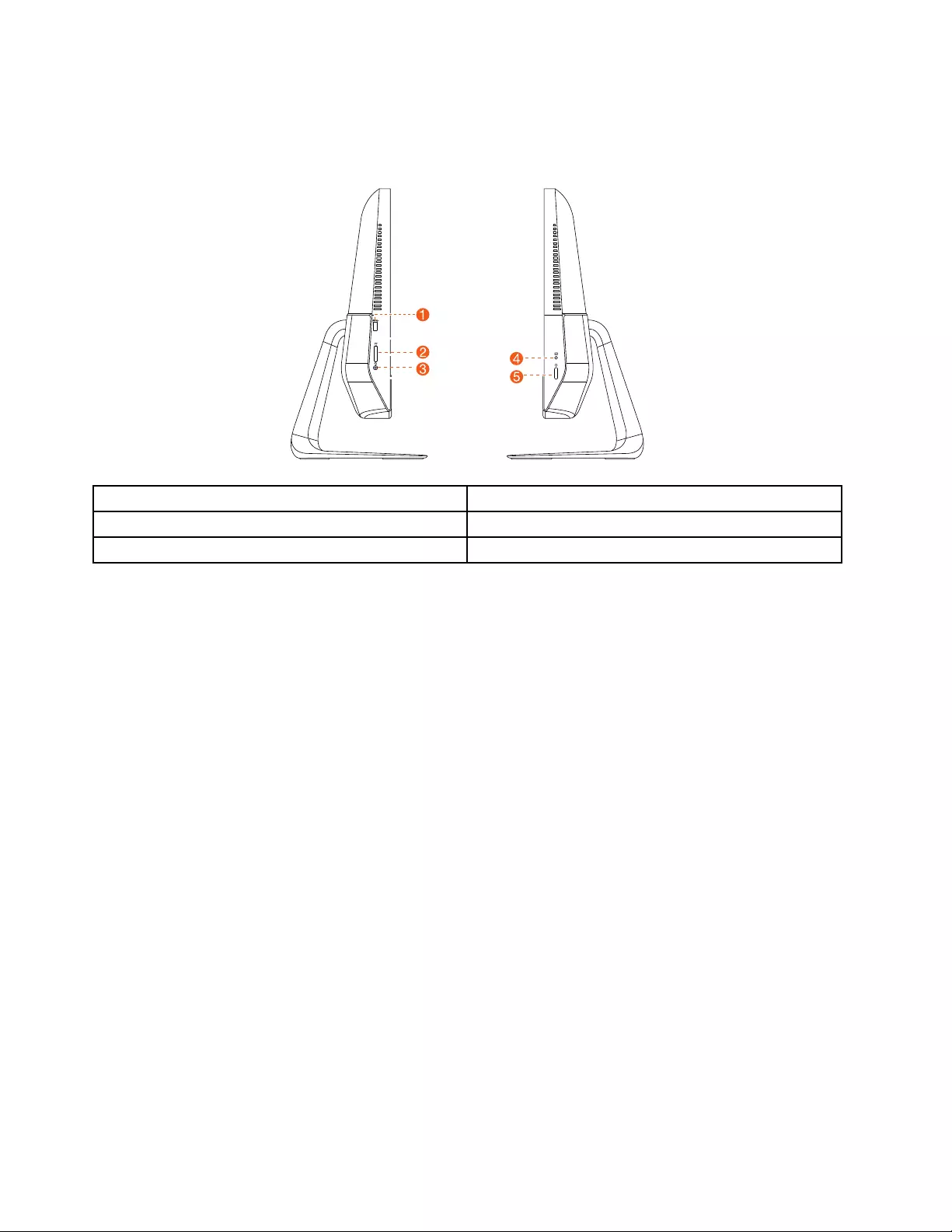
Chapter7.Locatingconnectors,controlsandcomponents
Thissectionprovidesillustrationstohelplocatethevariousconnectors,controlsandcomponentsofthe
computer.
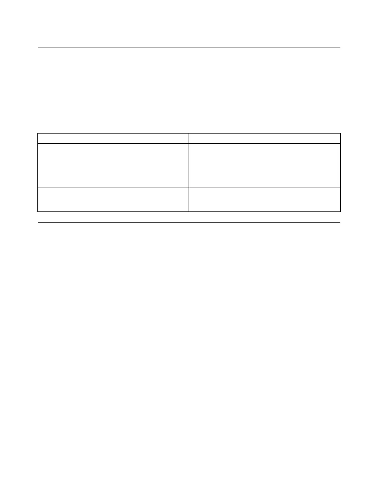
Fontview
Thefollowingillustrationshowsthelocationofcontrolsandcomponentsonthefrontofthecomputer.
Attention:Becarefulnottoblockanyairventsonthecomputer.Blockedairventscancauseoverheating.
1.CameraLEDindicator3.Built-inmicrophone
2.Built-incamera
©CopyrightLenovo201621
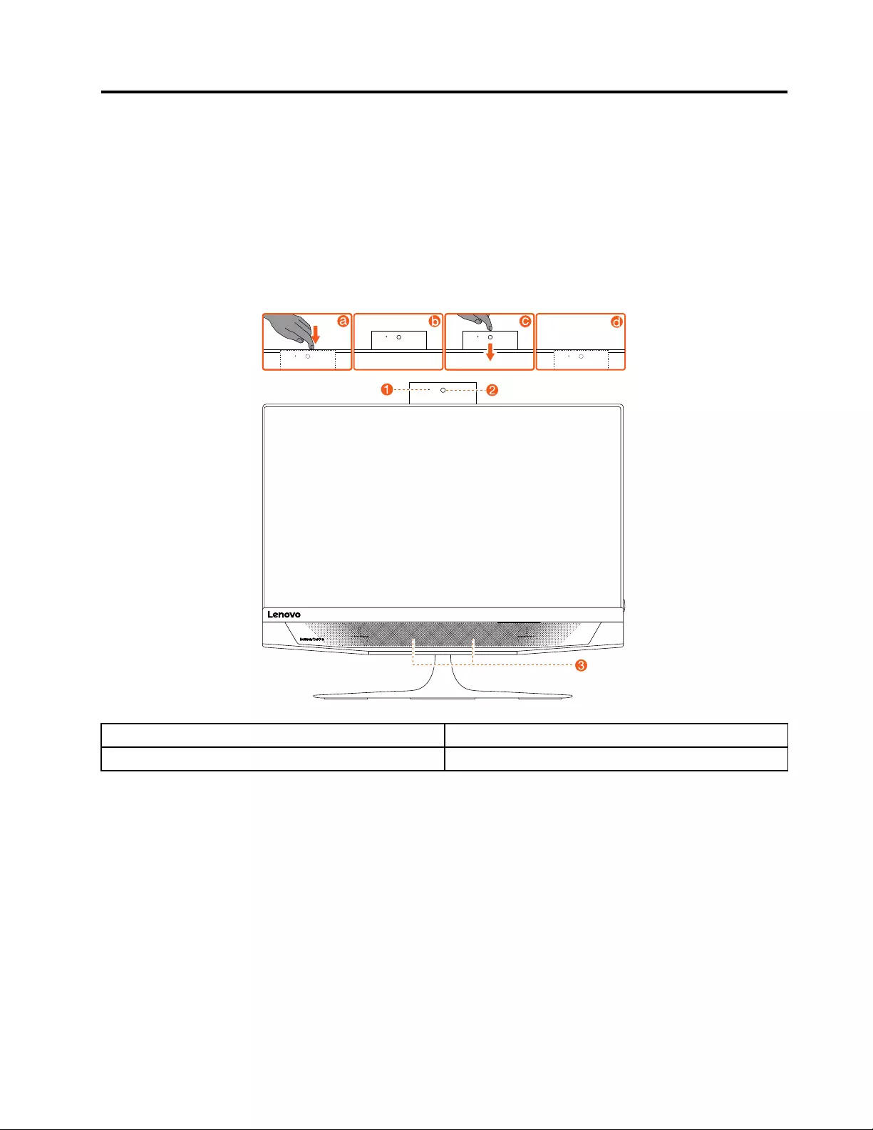
Leftandrightview
Thefollowingillustrationshowsthelocationofconnectors,controlsandcomponentsontheleftandright
sideofthecomputer.
1.USB3.0connectors4.HDMI-inswitch
2.Memorycardreader5.Powerbutton
3.Comboaudiojack
22ideacentreAll-In-One720ComputerHardwareMaintenanceManual
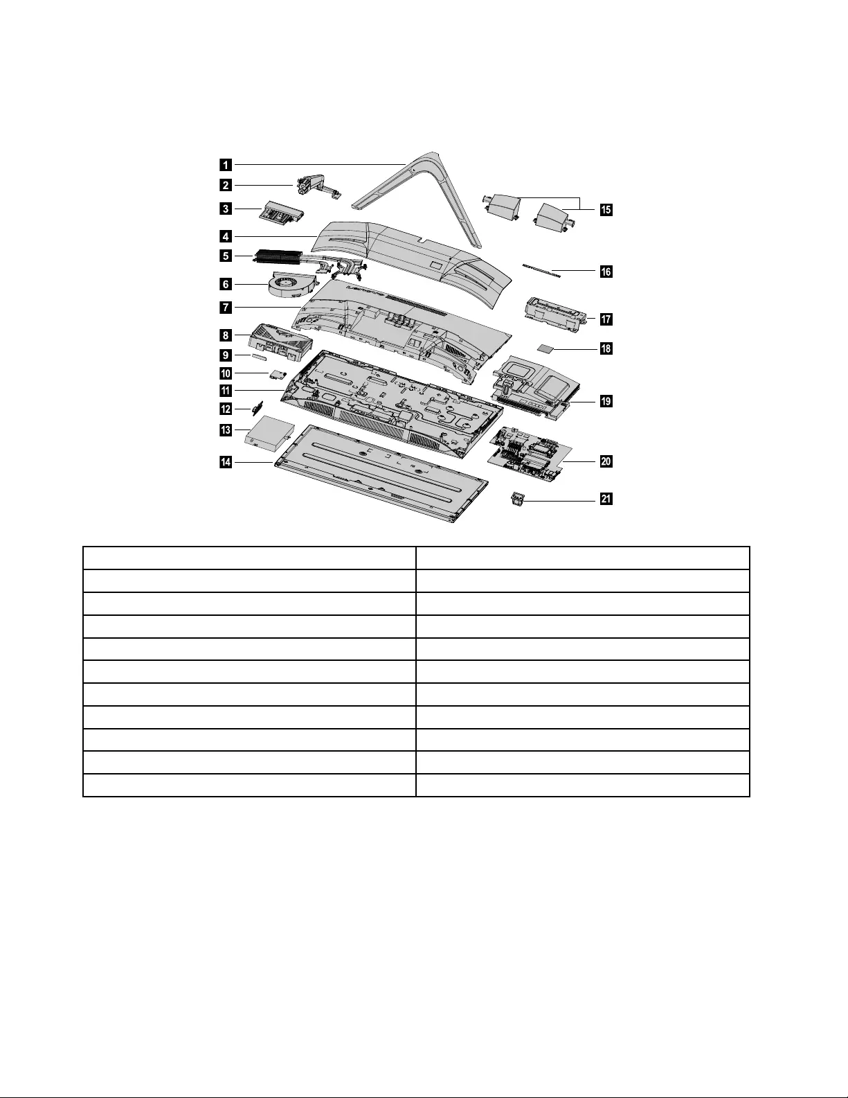
Hardwarecomponents
Thefollowingillustrationshowsthecomponentsthatmakeupyourcomputer.
1
2
3
4
8
7
6
9
13
16
17
18
19
20
11
10
14
12
5
15
21
1.Standbase12.Powerbutton
2.Standholder13.Powersupplyunit
3.Cameramodule14.LCDpanel
4.Rearcover15.Speakersystem
5.Heat-sink16.Micboard
6.Systemfan17.VESAmountbracket
7.Middlecover18.Wi-Ficard
8.Harddiskdrive19.EMIcover
9.Wi-Fiantenna20.Motherboard
10.Powerswitchboard21.Powersocket
11.Mainframe
24ideacentreAll-In-One720ComputerHardwareMaintenanceManual
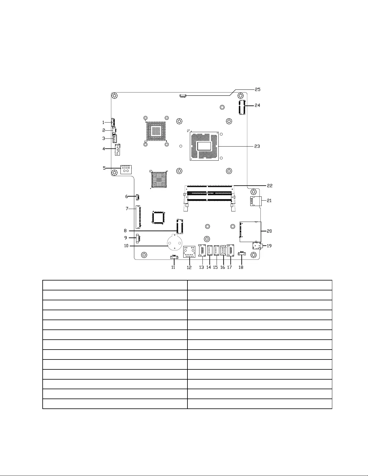
Identifyingpartsonthemotherboard
Themotherboard(sometimescalledtheplanarorsystemboard)isthemaincircuitboardinyourcomputer.
Itprovidesbasiccomputingfunctionsandsupportsavarietyofdevicesthatarefactory-installedorthat
youcaninstalllater.Thefollowingillustrationshowsthelocationofconnectorsandcomponentsonthe
frontofthemotherboard.
1
A
1
AP
34
7
8
451
A
30
128
96
64
32
9
260
2
259
25
24
23
22
21
20
19
181716151413
12
11
10
9
8
7
6
5
4
3
2
1
1.Backlightconnector14.USB2.0connector
2.Systemfanconnector15.USB2.0connector
3.SATApowercable16.USB3.0connector
4.SATAHDDconnector17.HDMI-inconnector
5.Powersupplyunitconnector18.Speakerconnector
6.Touchpanelconnector19.Comboaudiojack
7.LVDSconnector20.Cardreaderconnector
8.M.2solidstatedriveconnector21.USB3.0connector
9.Powerswitchboardconnector22.Memoryslots
10.Battery23.CPU
11.Micconnector24.Wi-Ficardconnector
12.Ethernetconnector25.Cameraconnector
13.HDMI-outconnector
Chapter7.Locatingconnectors,controlsandcomponents25

26ideacentreAll-In-One720ComputerHardwareMaintenanceManual

Chapter8.Replacinghardware
Attention:Donotremovethecomputercoverorattemptanyrepairbeforereadingthe“Importantsafetyinformation”
intheSafetyandWarrantyGuidethatwasincludedwithyourcomputer.T oobtaincopiesoftheSafetyandWarranty
Guide,gototheSupportWebsiteat:http://consumersupport.lenovo.com.
Note:UseonlypartsprovidedbyLenovo.
Generalinformation
Pre-disassemblyinstructions
Beforestartingthedisassemblyprocedure,makesurethatyoudothefollowing:
1.Turnoffthepowertothesystemandallperipherals.
2.Unplugallpowerandsignalcablesfromthecomputer.
3.Placethesystemonaflat,stablesurface.
©CopyrightLenovo201627
Replacingthekeyboardandmouse
Note:YourkeyboardwillbeconnectedtoaUSBconnectorateithersideorattherearofthecomputer.
Toreplacethekeyboardandmouse:
Step1.Removeanymediafromthedrives,shutdownthecomputer,andturnoffallattacheddevices.
Step2.Unplugallpowercordsfromelectricaloutlets.
Step3.Disconnectallcablesattachedtothecomputer.Thisincludespowercords,input/output(I/O)
cables,andanyothercablesthatareconnectedtothecomputer..
Step4.Locatetheconnectorforthekeyboard.RefertoLocatingconnectors,controlsandcomponentsto
locatethevariousconnectors.
Step5.Disconnectthedefectivekeyboardcablefromthecomputerandconnectthenewkeyboardcable
tothesameconnector.
Step6.Themousecanbereplacedusingthesamemethod.
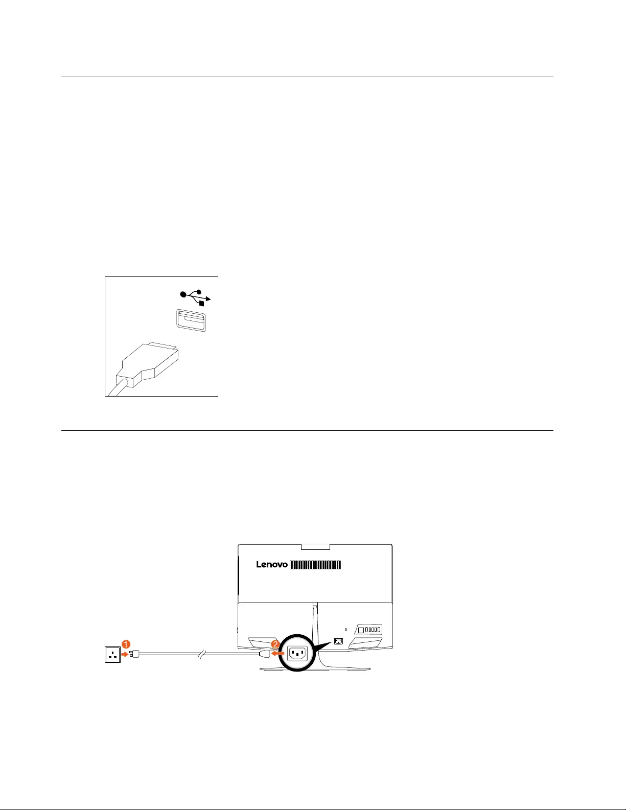
Replacingtheadapter
Attention:Turnoffthecomputerandwait3to5minutestoletitcooldownbeforeremovingthecover.
Step1.Removeanymediafromthedrives,shutdowntheoperatingsystem,andturnoffthecomputer
andallattacheddevices.
Step2.Disconnecttheadapterfromtheconnectoronthecomputer,thenunplugtheadapterfrom
electricaloutlet.
28ideacentreAll-In-One720ComputerHardwareMaintenanceManual
Step3.Connectthenewadapterasshown.
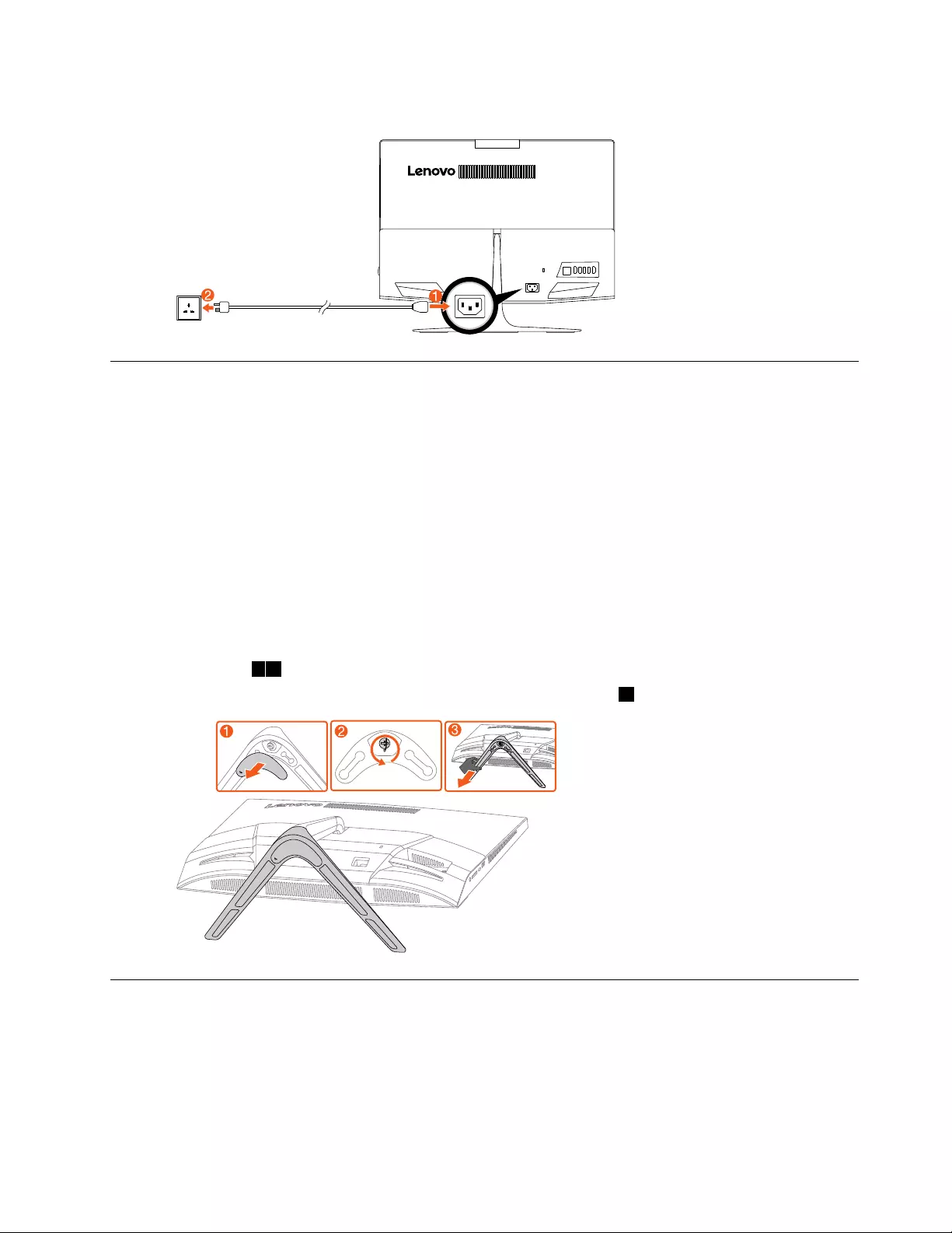
Removingthestandbase
Attention:Turnoffthecomputerandwait3to5minutestoletitcooldownbeforeremovingthecover.
Note:Itmaybehelpfultoplacethecomputerface-downonasoftflatsurfaceforthisprocedure.Lenovo
recommendsthatyouuseablanket,towel,orothersoftclothtoprotectthetouchscreenfromscratches
orotherdamage.
Step1.Removeanymediafromthedrives,shutdowntheoperatingsystem,andturnoffthecomputer
andallattacheddevices.
Step2.Unplugallpowercordsfromelectricaloutlets.
Step3.Disconnectallcablesattachedtothecomputer.Thisincludespowercords,input/output(I/O)
cables,andanyothercablesthatareconnectedtothecomputer.RefertoLocatingconnectors,
controlsandcomponentstolocatethevariousconnectors.
Step4.Removetherubber,andthentwistthehandscrewringcounter-clockwiseuntilthestandbaseis
loosened.12
Step5.Removethestandbasefromthestandholderandputitaside.3
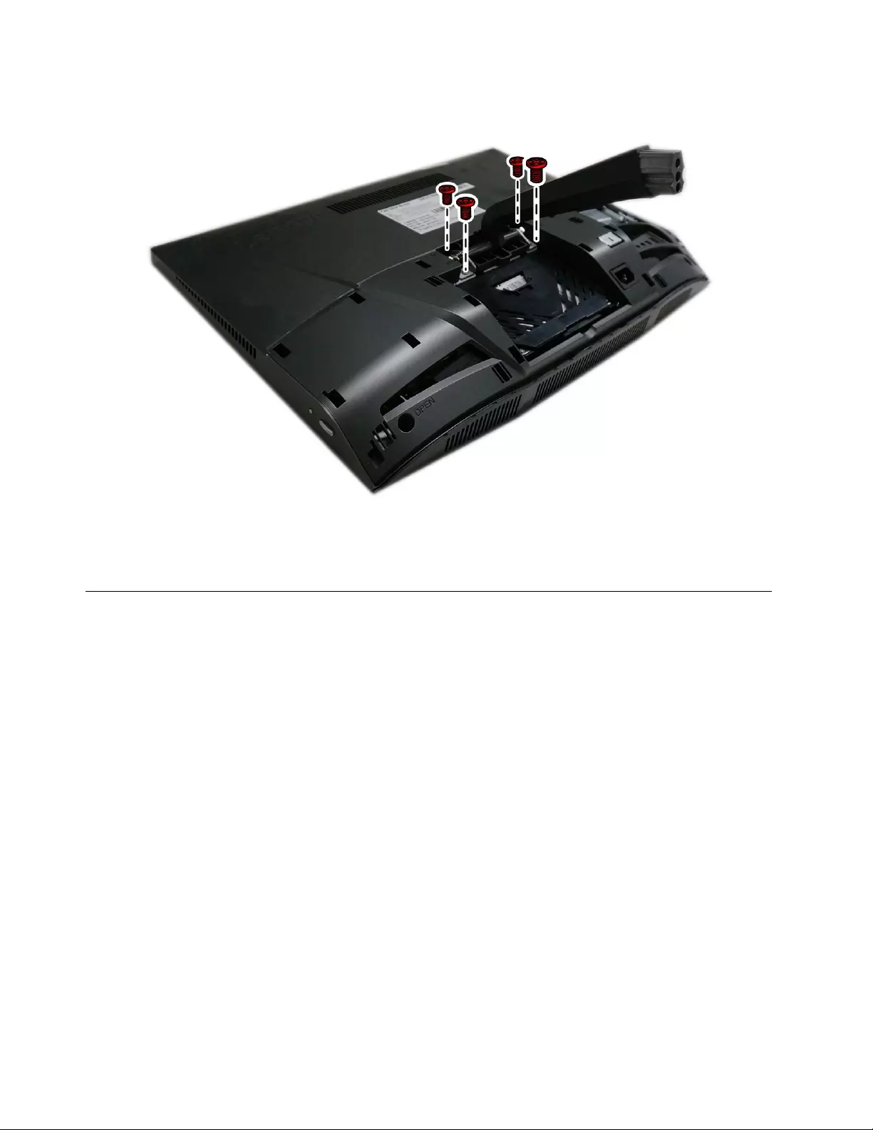
Removingtherearcover
Attention:Turnoffthecomputerandwait3to5minutestoletitcooldownbeforeremovingthecover.
Note:Itmaybehelpfultoplacethecomputerface-downonasoftflatsurfaceforthisprocedure.Lenovo
recommendsthatyouuseablanket,towel,orothersoftclothtoprotectthetouchscreenfromscratches
orotherdamage.
Chapter8.Replacinghardware29
Step1.Removeanymediafromthedrives,shutdowntheoperatingsystem,andturnoffthecomputer
andallattacheddevices.
Step2.Unplugallpowercordsfromelectricaloutlets.
Step3.Disconnectallcablesattachedtothecomputer.Thisincludespowercords,input/output(I/O)
cables,andanyothercablesthatareconnectedtothecomputer.RefertoLocatingconnectors,
controlsandcomponentstolocatethevariousconnectors.
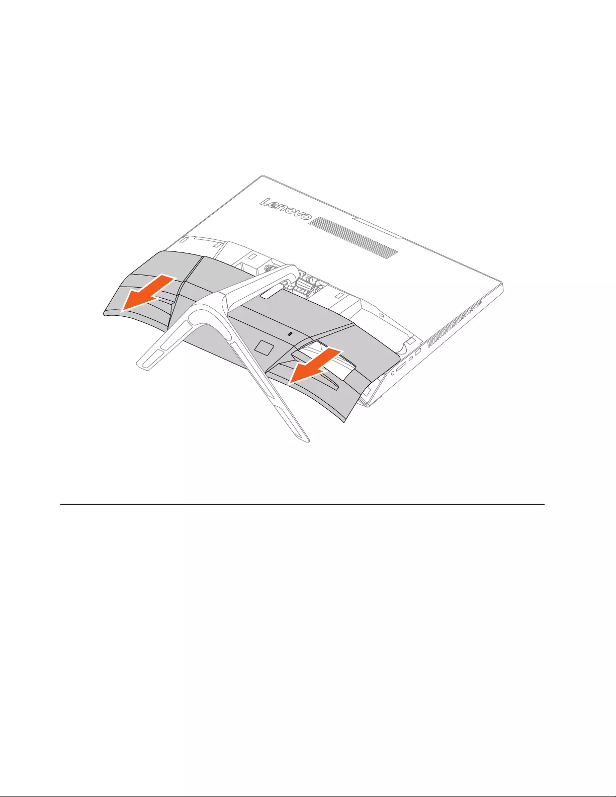
Step4.Slideouttherearcover.
Step5.Toreattachtherearcover:
a.Lineuptherearcoverwithmountingholesonthebackofthecomputer,thenslideitbackinto
position.
Replacingtheharddiskdrive
Attention:Turnoffthecomputerandwait3to5minutestoletitcooldownbeforeremovingthecover.
Note:Itmaybehelpfultoplacethecomputerface-downonasoftflatsurfaceforthisprocedure.Lenovo
recommendsthatyouuseablanket,towel,orothersoftclothtoprotectthetouchscreenfromscratches
orotherdamage.
Step1.Removeanymediafromthedrives,shutdowntheoperatingsystem,andturnoffthecomputer
andallattacheddevices.
Step2.Unplugallpowercordsfromelectricaloutlets.
Step3.Disconnectallcablesattachedtothecomputer.Thisincludespowercords,input/output(I/O)
cables,andanyothercablesthatareconnectedtothecomputer.RefertoLocatingconnectors,
controlsandcomponentstolocatethevariousconnectors.
Step4.Removetherearcover.RefertoRemovingtherearcover.
30ideacentreAll-In-One720ComputerHardwareMaintenanceManual
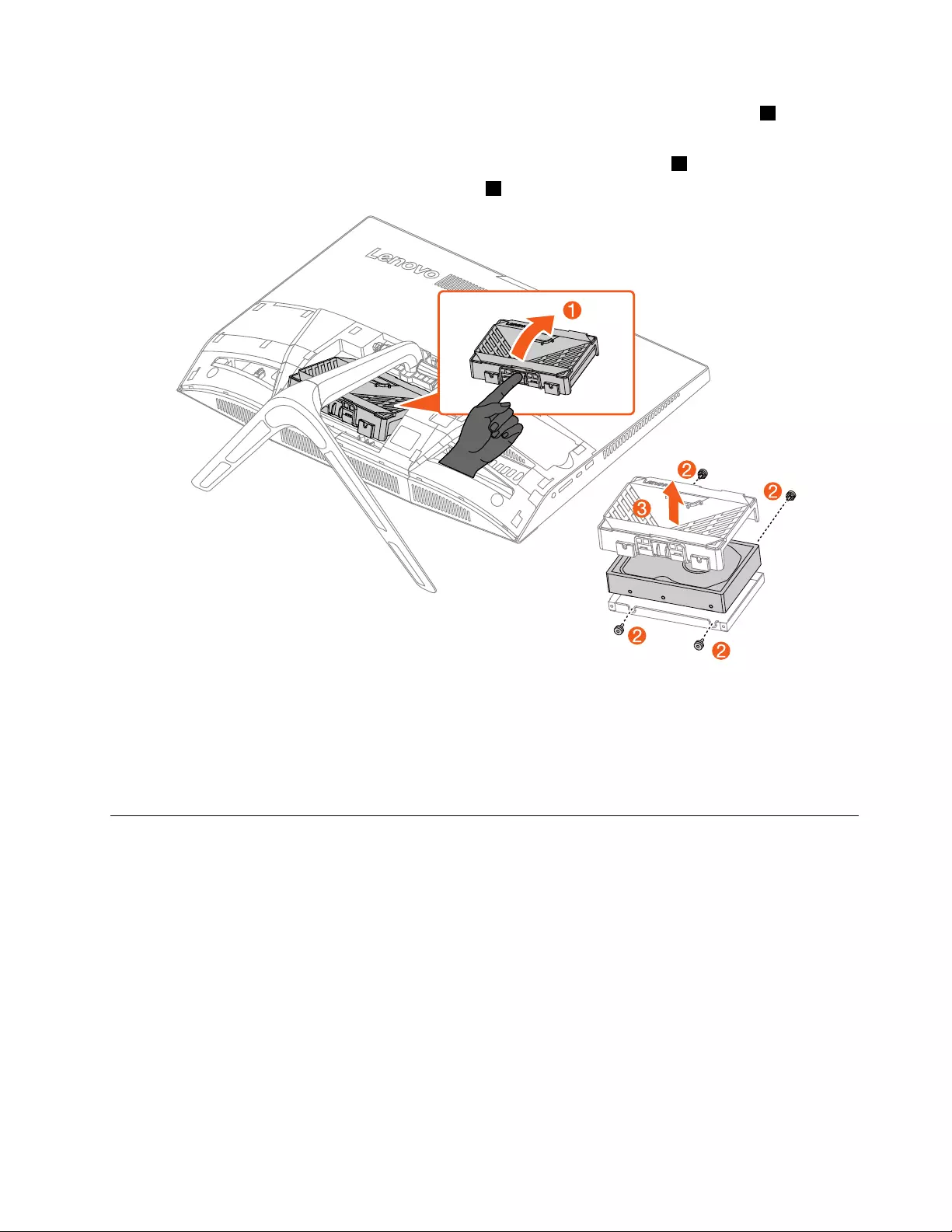
Step5.Pressthelockingpinandthenliftuptheharddiskdrivemodulefromthecomputer.1
Step6.Disconnectthesignalcablefromtheharddiskdrive.
Step7.Removethefourscrewsthatsecuretheharddiskdrivetothebracket.2
Step8.Liftupthebracketfromtheharddiskdrive.3
Step9.Toinstallthenewharddiskdrive:
a.Lineupthenewharddiskdrivewiththebracketandsecureitwithfourscrews.
b.Connectthedataandpowercablestothenewharddiskdrive.
c.Slidetheharddiskdrivemodulebackintoposition.
Step10.Reinstalltheremovedparts.
Replacingthememorymodule
Attention:Turnoffthecomputerandwait3to5minutestoletitcooldownbeforeremovingthecover.
Note:Itmaybehelpfultoplacethecomputerface-downonasoftflatsurfaceforthisprocedure.Lenovo
recommendsthatyouuseablanket,towel,orothersoftclothtoprotectthetouchscreenfromscratches
orotherdamage.
Step1.Removeanymediafromthedrives,shutdowntheoperatingsystem,andturnoffthecomputer
andallattacheddevices.
Step2.Unplugallpowercordsfromelectricaloutlets.
Step3.Disconnectallcablesattachedtothecomputer.Thisincludespowercords,input/output(I/O)
cables,andanyothercablesthatareconnectedtothecomputer.RefertoLocatingconnectors,
controlsandcomponentstolocatethevariousconnectors.
Step4.Removetherearcover.RefertoRemovingtherearcover.
Chapter8.Replacinghardware31
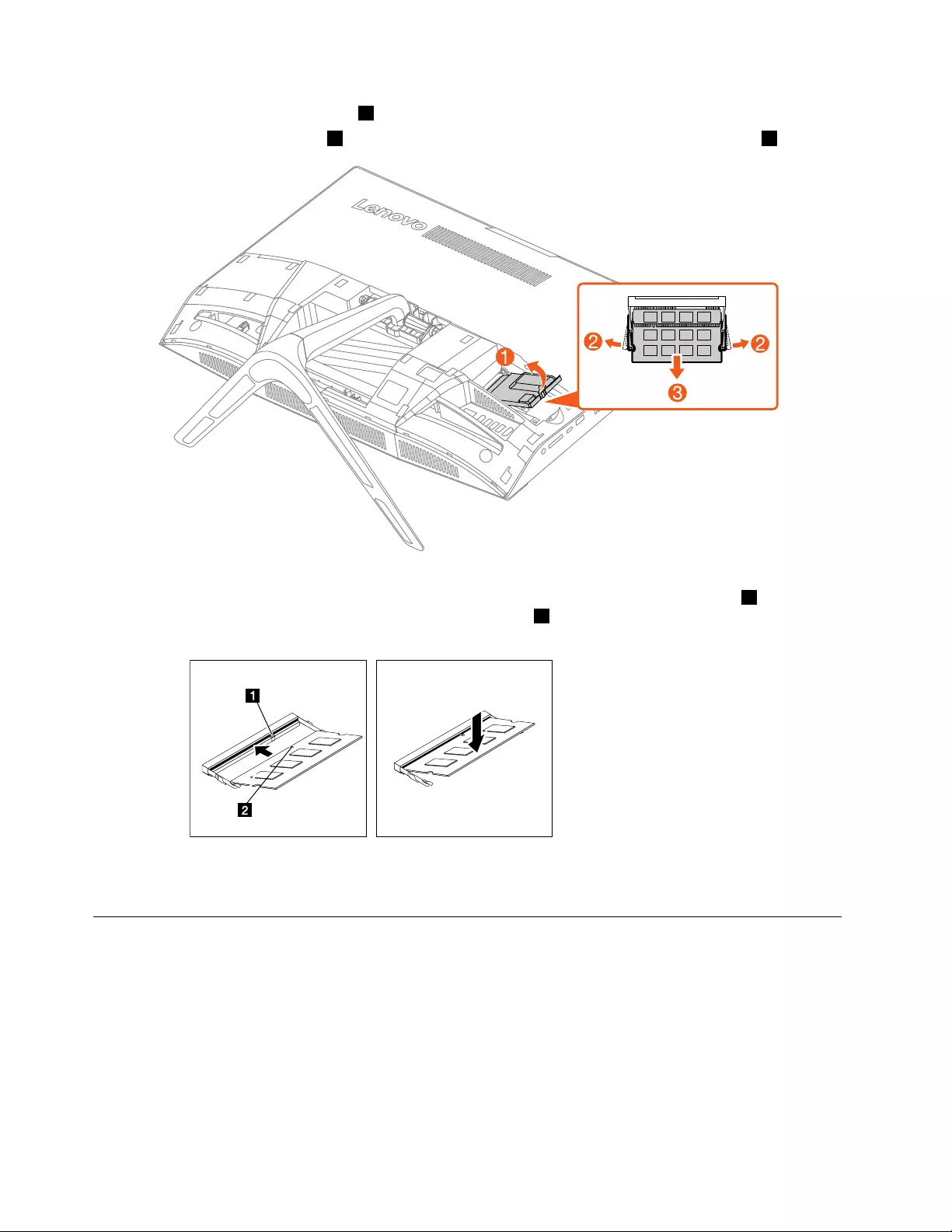
Step5.Removethememorycover.1
Step6.Opentheretainingclips2andgentlypullthememorymoduleoutofthememoryslot.3
Step7.Toinstallthenewmemorymodule:
a.Positionthenewmemorymoduleoverthememoryslot.Ensurethatthenotch2onthe
memorymodulealignscorrectlywiththeslotkey1inthememoryslot.Pressthememory
moduledownuntilsnapsintoposition.
b.Reinstallthememorycover.
Step8.Reinstalltheremovedparts.
Replacingthesolidstatedrive
Attention:Turnoffthecomputerandwait3to5minutestoletitcooldownbeforeremovingthecover.
Note:Itmaybehelpfultoplacethecomputerface-downonasoftflatsurfaceforthisprocedure.Lenovo
recommendsthatyouuseablanket,towel,orothersoftclothtoprotectthetouchscreenfromscratches
orotherdamage.
Step1.Removeanymediafromthedrives,shutdowntheoperatingsystem,andturnoffthecomputer
andallattacheddevices.
Step2.Unplugallpowercordsfromelectricaloutlets.
32ideacentreAll-In-One720ComputerHardwareMaintenanceManual
Step3.Disconnectallcablesattachedtothecomputer.Thisincludespowercords,input/output(I/O)
cables,andanyothercablesthatareconnectedtothecomputer.RefertoLocatingconnectors,
controlsandcomponentstolocatethevariousconnectors.
Step4.Removetherearcover.RefertoRemovingtherearcover.
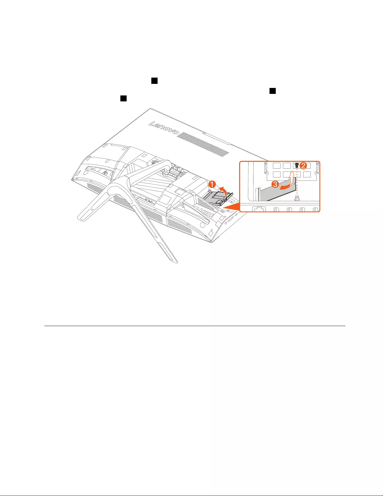
Step5.Removethememorycover.1
Step6.Removethescrewthatsecurethesolidstatedrivetothemotherboard2,andthenslideoutthe
solidstatedrive.3
Step7.Toinstallthenewsolidstatedrive:
a.Insertthesolidstatedriveintotheslot.
b.Securethenewsolidstatedrivetomotherboardwithonescrew.
c.Reinstallthememorycover.
Step8.Reinstalltheremovedparts.
Removingthestandholder
Attention:Turnoffthecomputerandwait3to5minutestoletitcooldownbeforeremovingthecover.
Note:Itmaybehelpfultoplacethecomputerface-downonasoftflatsurfaceforthisprocedure.Lenovo
recommendsthatyouuseablanket,towel,orothersoftclothtoprotectthetouchscreenfromscratches
orotherdamage.
Step1.Removeanymediafromthedrives,shutdowntheoperatingsystem,andturnoffthecomputer
andallattacheddevices.
Step2.Unplugallpowercordsfromelectricaloutlets.
Step3.Disconnectallcablesattachedtothecomputer.Thisincludespowercords,input/output(I/O)
cables,andanyothercablesthatareconnectedtothecomputer.RefertoLocatingconnectors,
controlsandcomponentstolocatethevariousconnectors.
Step4.Removethestandbase.RefertoRemovingthestandbase.
Step5.Removetherearcover.RefertoRemovingtherearcover.
Chapter8.Replacinghardware33
Step6.Removethefourscrewsthatsecurethestandholdertothechassis,andthenliftupthestand
holdertoremoveit.
Step7.Toreattachthestandholder:
a.Aligntheholesinthestandholderwiththecorrespondingholesinthechassis.
b.Securethestandholdertothechassiswithfourscrews.
Removingthemiddlecover
Note:Turnoffthecomputerandwait3to5minutestoletitcooldownbeforeremovingthecover.
Note:Itmaybehelpfultoplacethecomputerface-downonasoftflatsurfaceforthisprocedure.Lenovo
recommendsthatyouuseablanket,towel,orothersoftclothtoprotectthecomputerscreenfromscratches
orotherdamage.
Toremovethemiddlecover:
Step1.Removeanymediafromthedrives,shutdowntheoperatingsystem,andturnoffthecomputer
andallattacheddevices.
Step2.Unplugallpowercordsfromelectricaloutlets.
Step3.Disconnectallcablesattachedtothecomputer.Thisincludespowercords,input/output(I/O)
cables,andanyothercablesthatareconnectedtothecomputer.RefertoLocatingconnectors,
controlsandcomponentstolocatethevariousconnectors.
Step4.Removethestandbase.RefertoRemovingthestandbase.
Step5.Removetherearcover.RefertoRemovingtherearcover.
34ideacentreAll-In-One720ComputerHardwareMaintenanceManual
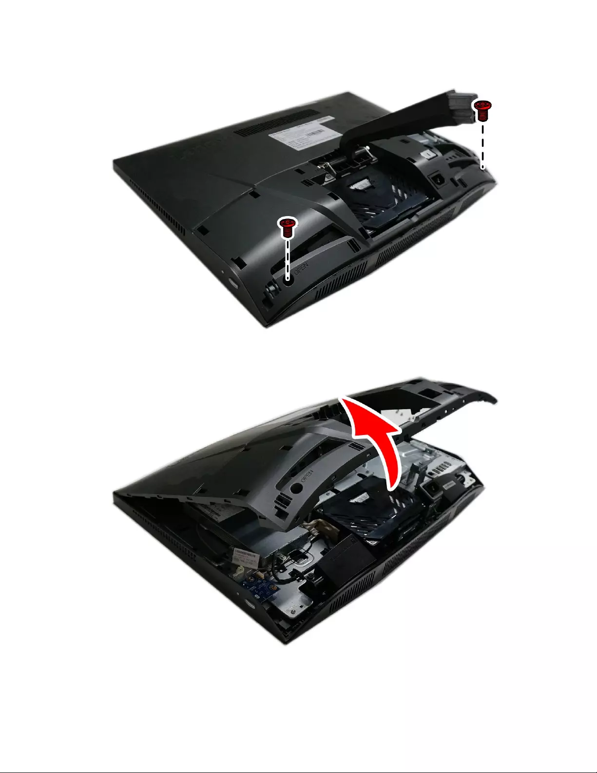
Step6.Loosethetwoscrewsthatsecurethemiddlecovertothemainframe.
Step7.Removethestandholder.RefertoRemovingthestandholder.
Step8.Liftupthemiddlecoverasshown.
Step9.Toreattachthemiddlecover:
a.Lineupthemiddlecoverwiththemainframe,andthenpressthemiddlecoveruntilitsnaps
intoposition.
b.Securethemiddlecovertothemainframewithtwoscrews.
Chapter8.Replacinghardware35
Replacingthefrontbezel
Note:Turnoffthecomputerandwait3to5minutestoletitcooldownbeforeremovingthecover.
Note:Itmaybehelpfultoplacethecomputerface-downonasoftflatsurfaceforthisprocedure.Lenovo
recommendsthatyouuseablanket,towel,orothersoftclothtoprotectthecomputerscreenfromscratches
orotherdamage.
Toreplacethefrontbezel
Step1.Removeanymediafromthedrives,shutdowntheoperatingsystem,andturnoffthecomputer
andallattacheddevices.
Step2.Unplugallpowercordsfromelectricaloutlets.
Step3.Disconnectallcablesattachedtothecomputer.Thisincludespowercords,input/output(I/O)
cables,andanyothercablesthatareconnectedtothecomputer.RefertoLocatingconnectors,
controlsandcomponentstolocatethevariousconnectors.
Step4.Removetherearcover.RefertoRemovingtherearcover.
Step5.Removetheharddiskdrive.RefertoReplacingtheharddiskdrive.
Step6.Removethestandbase.RefertoRemovingthestandbase.
Step7.Removethestandholder.RefertoRemovingthestandholder.
Step8.Removethemiddlecover.RefertoRemovingthemiddlecover.
Step9.Removethetwoscrewsthatsecurethefrontbezeltothemainframe.1
Step10.Removethefrontbezelasshown.2
Step11.Toinstallthenewfrontbezel:attachthenewfrontbezeltothemainframeandsecureitwith
twoscrews.
Step12.Reinstalltheremovedparts,andthenreconnectthedisconnectedcables.
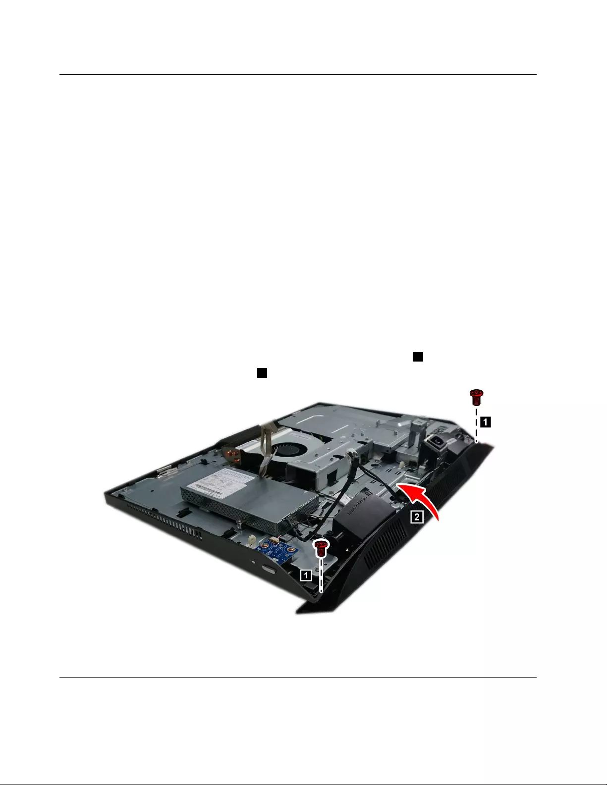
Replacingthepowerswitchboard
Note:Turnoffthecomputerandwait3to5minutestoletitcooldownbeforeremovingthecover.
36ideacentreAll-In-One720ComputerHardwareMaintenanceManual
Note:Itmaybehelpfultoplacethecomputerface-downonasoftflatsurfaceforthisprocedure.Lenovo
recommendsthatyouuseablanket,towel,orothersoftclothtoprotectthecomputerscreenfromscratches
orotherdamage.
Toreplacethepowerswitchboard
Step1.Removeanymediafromthedrives,shutdowntheoperatingsystem,andturnoffthecomputer
andallattacheddevices.
Step2.Unplugallpowercordsfromelectricaloutlets.
Step3.Disconnectallcablesattachedtothecomputer.Thisincludespowercords,input/output(I/O)
cables,andanyothercablesthatareconnectedtothecomputer.RefertoLocatingconnectors,
controlsandcomponentstolocatethevariousconnectors.
Step4.Removethestandbase.RefertoRemovingthestandbase.
Step5.Removetherearcover.RefertoRemovingtherearcover.
Step6.Removethestandholder.RefertoRemovingthestandholder.
Step7.Removethemiddlecover.RefertoRemovingthemiddlecover.
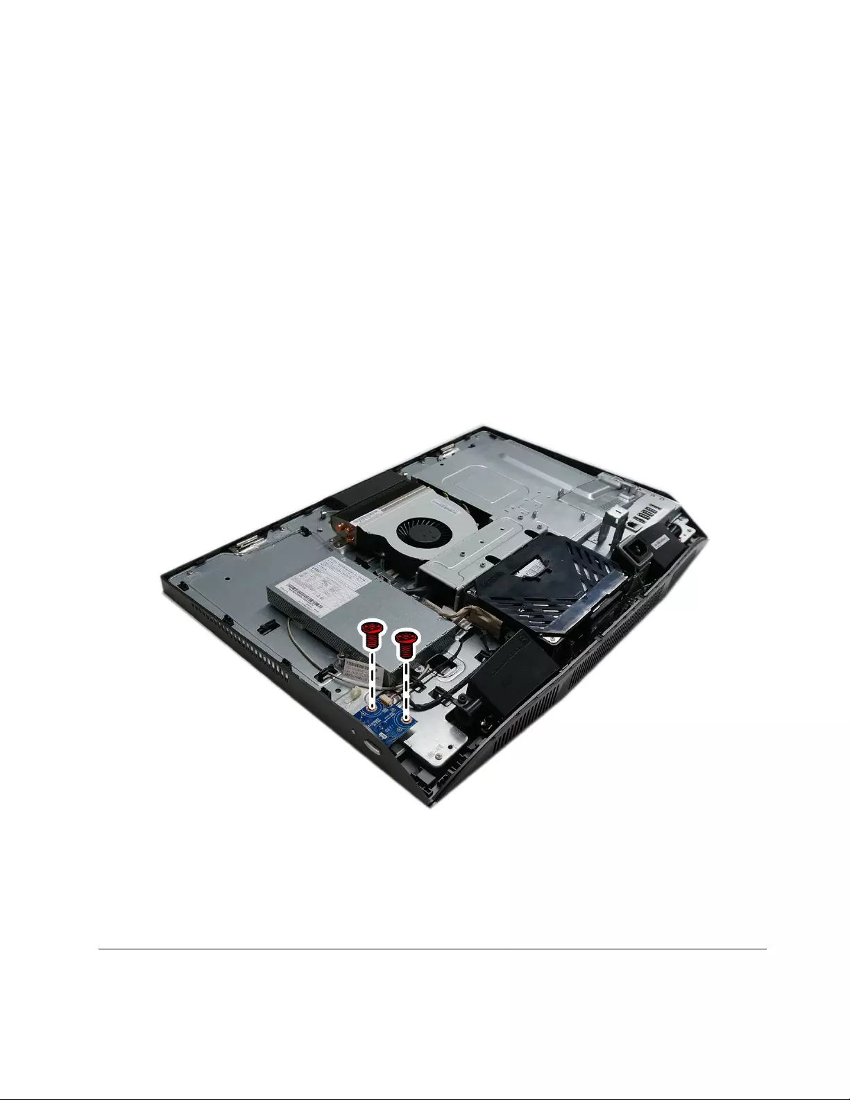
Step8.Removethetwoscrewsthatsecurethepowerswitchboardtothechassis.
Step9.Disconnectthesignalcablefromthepowerswitchboard.
Step10.Toinstallthenewpowerswitchboard:
a.Connectthesignalcabletothenewpowerswitchboard.
b.Alignthenewpowerswitchboardintopositionandsecureitwithtwoscrews.
Step11.Reinstallalltheremovedparts,andthenreconnectallthedisconnectedcables.
RemovingtheEMIcover
Note:Turnoffthecomputerandwait3to5minutestoletitcooldownbeforeremovingthecover.
Chapter8.Replacinghardware37
Note:Itmaybehelpfultoplacethecomputerface-downonasoftflatsurfaceforthisprocedure.Lenovo
recommendsthatyouuseablanket,towel,orothersoftclothtoprotectthecomputerscreenfromscratches
orotherdamage.
ToreplacetheEMIcover
Step1.Removeanymediafromthedrives,shutdowntheoperatingsystem,andturnoffthecomputer
andallattacheddevices.
Step2.Unplugallpowercordsfromelectricaloutlets.
Step3.Disconnectallcablesattachedtothecomputer.Thisincludespowercords,input/output(I/O)
cables,andanyothercablesthatareconnectedtothecomputer.RefertoLocatingconnectors,
controlsandcomponentstolocatethevariousconnectors.
Step4.Removethestandbase.RefertoRemovingthestandbase.
Step5.Removetherearcover.RefertoRemovingtherearcover.
Step6.Removethestandholder.RefertoRemovingthestandholder.
Step7.Removethemiddlecover.RefertoRemovingthemiddlecover.
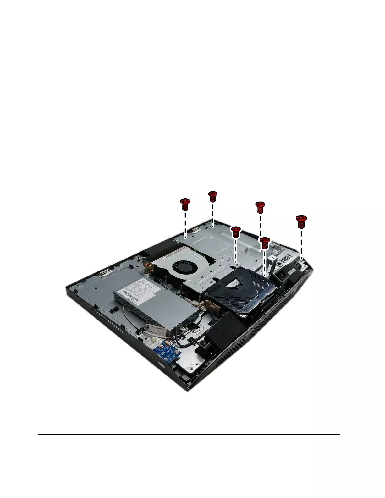
Step8.RemovethesixscrewsthatsecuretheEMIcovertothechassis,andthenliftitup.
Step9.ToinstallthenewEMIcover:
a.AligntheholesintheEMIcoverwiththemountingholesinthechassis.
b.SecuretheEMIcovertothechassiswithsixscrews.
Replacingthecamera
Note:Turnoffthecomputerandwait3to5minutestoletitcooldownbeforeremovingthecover.
38ideacentreAll-In-One720ComputerHardwareMaintenanceManual
Note:Itmaybehelpfultoplacethecomputerface-downonasoftflatsurfaceforthisprocedure.Lenovo
recommendsthatyouuseablanket,towel,orothersoftclothtoprotectthecomputerscreenfromscratches
orotherdamage.
Toreplacethecamera:
Step1.Removeanymediafromthedrives,shutdowntheoperatingsystem,andturnoffthecomputer
andallattacheddevices.
Step2.Unplugallpowercordsfromelectricaloutlets.
Step3.Disconnectallcablesattachedtothecomputer.Thisincludespowercords,input/output(I/O)
cables,andanyothercablesthatareconnectedtothecomputer.RefertoLocatingconnectors,
controlsandcomponentstolocatethevariousconnectors.
Step4.Removetherearcover.RefertoRemovingtherearcover.
Step5.Removethestandbase.RefertoRemovingthestandbase.
Step6.Removethestandholder.RefertoRemovingthestandholder.
Step7.Removethemiddlecover.RefertoRemovingthemiddlecover.
Step8.RemovetheEMIcover.RefertoRemovingtheEMIcover.
Step9.Disconnectthecameracableformthecorrespondingconnectoronthemotherboard.Referto
Locatingconnectors,controlsandcomponents.
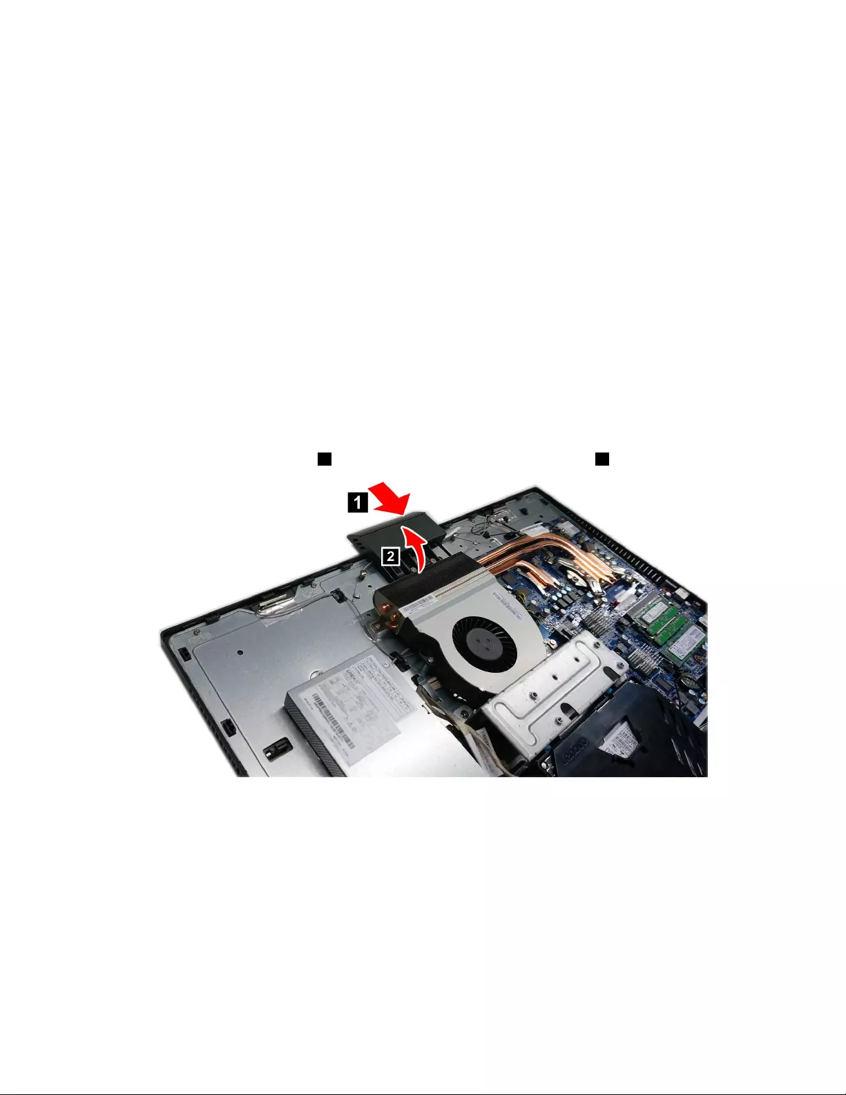
Step10.Pressthecameramodule1,andthenliftupthecameramodulecover2.
Chapter8.Replacinghardware39
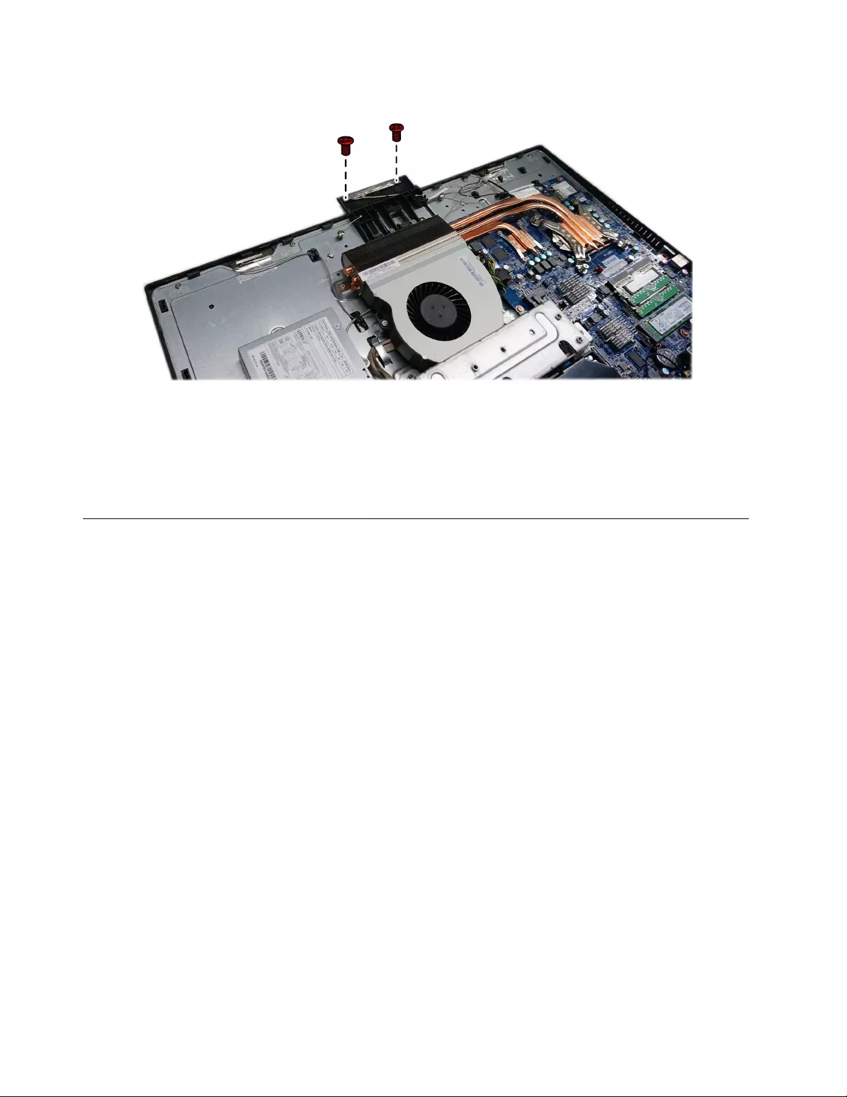
Step11.Removethetwoscrewsthatsecurethecameratothechassis,andthenremovethecamera.
Step12.Toinstallthenewcamera:
a.Alignthenewcameraintoposition,andthensecureittothechassiswithtwoscrews.
b.Connectthecameracabletothemotherboard.
c.Reinstallthecameracover.
Step13.Reinstallalltheremovedparts,andthenreconnectallthedisconnectedcables.
Removingthemountbracket
Note:Turnoffthecomputerandwait3to5minutestoletitcooldownbeforeremovingthecover.
Note:Itmaybehelpfultoplacethecomputerface-downonasoftflatsurfaceforthisprocedure.Lenovo
recommendsthatyouuseablanket,towel,orothersoftclothtoprotectthecomputerscreenfromscratches
orotherdamage.
Toreplacethemountbracket
Step1.Removeanymediafromthedrives,shutdowntheoperatingsystem,andturnoffthecomputer
andallattacheddevices.
Step2.Unplugallpowercordsfromelectricaloutlets.
Step3.Disconnectallcablesattachedtothecomputer.Thisincludespowercords,input/output(I/O)
cables,andanyothercablesthatareconnectedtothecomputer.RefertoLocatingconnectors,
controlsandcomponentstolocatethevariousconnectors.
Step4.Removethestandbase.RefertoRemovingthestandbase.
Step5.Removetherearcover.RefertoRemovingtherearcover.
Step6.Removethestandholder.RefertoRemovingthestandholder.
Step7.Removethemiddlecover.RefertoRemovingthemiddlecover.
Step8.RemovetheEMIcover.RefertoRemovingtheEMIcover.
40ideacentreAll-In-One720ComputerHardwareMaintenanceManual
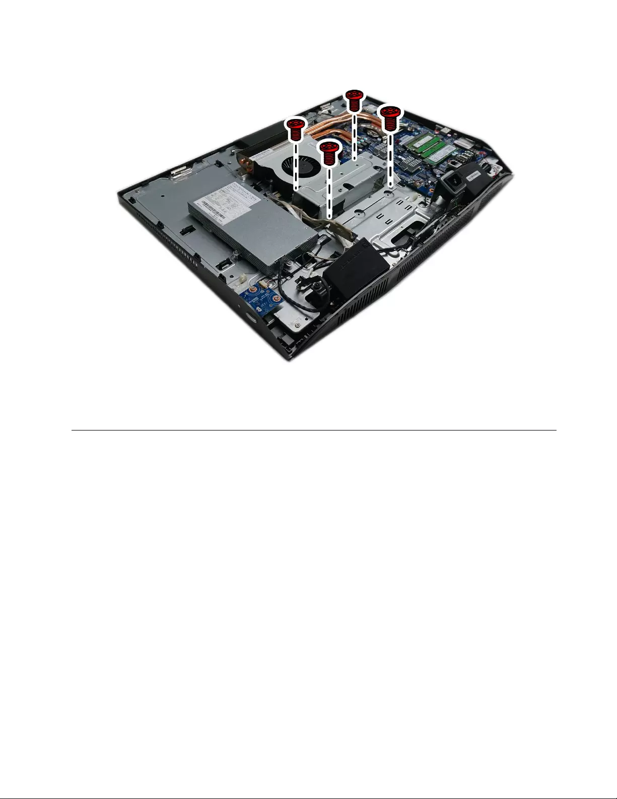
Step9.Removethefourscrewsthatsecurethemountbrackettothechassis,andthenliftitup.
Step10.Toinstallthenewmountbracket:
a.Aligntheholesinthenewmountbracketwiththemountingholesinthechassis.
b.Securethemountbrackettothechassiswithfourscrews.
Replacingthepowersupplyunit
Note:Turnoffthecomputerandwait3to5minutestoletitcooldownbeforeremovingthecover.
Note:Itmaybehelpfultoplacethecomputerface-downonasoftflatsurfaceforthisprocedure.Lenovo
recommendsthatyouuseablanket,towel,orothersoftclothtoprotectthecomputerscreenfromscratches
orotherdamage.
Toreplacethepowersupplyunit
Step1.Removeanymediafromthedrives,shutdowntheoperatingsystem,andturnoffthecomputer
andallattacheddevices.
Step2.Unplugallpowercordsfromelectricaloutlets.
Step3.Disconnectallcablesattachedtothecomputer.Thisincludespowercords,input/output(I/O)
cables,andanyothercablesthatareconnectedtothecomputer.RefertoLocatingconnectors,
controlsandcomponentstolocatethevariousconnectors.
Step4.Removethestandbase.RefertoRemovingthestandbase.
Step5.Removetherearcover.RefertoRemovingtherearcover.
Step6.Removetheharddiskdrive.RefertoReplacingtheharddiskdrive.
Step7.Removethestandholder.RefertoRemovingthestandholder.
Step8.Removethemiddlecover.RefertoRemovingthemiddlecover.
Step9.RemovetheEMIcover.RefertoRemovingtheEMIcover.
Chapter8.Replacinghardware41
Step10.Removethemountbracket.RefertoRemovingthemountbracket.
Step11.Removethefourscrewsthatsecurethepowersupplyunittothechassis.
Step12.Disconnectthecablefromthemotherboardandthepowersocket.
Step13.Toinstallthenewpowersupplyunit:
a.Connectthecableofthenewpowersupplyunittothecorrespondingconnectoronthe
motherboardandpowersocket.
b.Alignthenewpowersupplyunitintopositionandsecureitwithfourscrews.
Step14.Reinstallalltheremovedparts,andthenreconnectallthedisconnectedcables.
Replacingthespeakersystem
Note:Turnoffthecomputerandwait3to5minutestoletitcooldownbeforeremovingthecover.
Note:Itmaybehelpfultoplacethecomputerface-downonasoftflatsurfaceforthisprocedure.Lenovo
recommendsthatyouuseablanket,towel,orothersoftclothtoprotectthecomputerscreenfromscratches
orotherdamage.
Toreplacethespeakersystem:
Step1.Removeanymediafromthedrives,shutdowntheoperatingsystem,andturnoffthecomputer
andallattacheddevices.
Step2.Unplugallpowercordsfromelectricaloutlets.
Step3.Disconnectallcablesattachedtothecomputer.Thisincludespowercords,input/output(I/O)
cables,andanyothercablesthatareconnectedtothecomputer.RefertoLocatingconnectors,
controlsandcomponentstolocatethevariousconnectors.
Step4.Removethestandbase.RefertoRemovingthestandbase.
Step5.Removetherearcover.RefertoRemovingtherearcover.
Step6.Removethestandholder.RefertoRemovingthestandholder.
42ideacentreAll-In-One720ComputerHardwareMaintenanceManual
Step7.Removethemiddlecover.RefertoRemovingthemiddlecover.
Step8.RemovetheEMIcover.RefertoRemovingtheEMIcover.
Step9.Removethefourscrewsthatsecurethespeakersystemtothechassis,andthendisconnectthe
speakercablefromtheconnectoronthemotherboard.
Step10.Liftupthespeakersystemtoremoveit.
Step11.Toinstallthenewspeakersystem:
a.Alignthenewspeakersystemintoposition,andthensecureittothechassiswithfourscrews.
b.Connectthecabletothemotherboard.
Step12.Reinstallalltheremovedparts,andthenreconnectallthedisconnectedcables.
ReplacingtheWi-Ficard
Note:Turnoffthecomputerandwait3to5minutestoletitcooldownbeforeremovingthecover.
Note:Itmaybehelpfultoplacethecomputerface-downonasoftflatsurfaceforthisprocedure.Lenovo
recommendsthatyouuseablanket,towel,orothersoftclothtoprotectthecomputerscreenfromscratches
orotherdamage.
ToreplacetheWi-Ficard:
Step1.Removeanymediafromthedrives,shutdowntheoperatingsystem,andturnoffthecomputer
andallattacheddevices.
Step2.Unplugallpowercordsfromelectricaloutlets.
Step3.Disconnectallcablesattachedtothecomputer.Thisincludespowercords,input/output(I/O)
cables,andanyothercablesthatareconnectedtothecomputer.RefertoLocatingconnectors,
controlsandcomponentstolocatethevariousconnectors.
Step4.Removethestandbase.RefertoRemovingthestandbase.
Chapter8.Replacinghardware43
Step5.Removetherearcover.RefertoRemovingtherearcover.
Step6.Removethestandholder.RefertoRemovingthestandholder.
Step7.Removethemiddlecover.RefertoRemovingthemiddlecover.
Step8.RemovetheEMIcover.RefertoRemovingtheEMIcover.
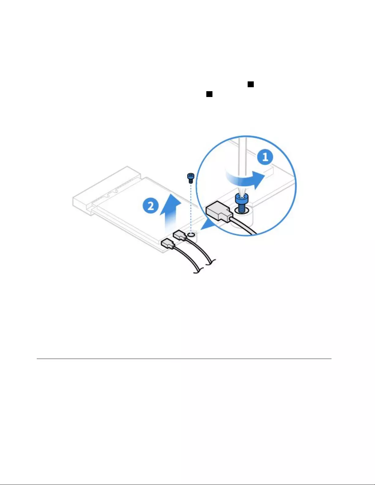
Step9.RemovethescrewthatsecurestheWi-Ficardtothemotherboard.1
Step10.DisconnecttheantennacablesfromtheWi-Ficard.2
Step11.PulltheWi-Ficardoutoftheslot.
Step12.ToinstallthenewWi-Ficard:
a.InsertthenewWi-FicardintotheWi-Ficardslot.
b.ConnecttheantennacablestothenewWi-Ficard.
c.SecurenewtheWi-Ficardtothemotherboardwiththescrew.
Step13.Reinstallalltheremovedparts,andthenreconnectallthedisconnectedcables.
Replacingtheheat-sink
Note:Turnoffthecomputerandwait3to5minutestoletitcooldownbeforeremovingthecover.
Note:Itmaybehelpfultoplacethecomputerface-downonasoftflatsurfaceforthisprocedure.Lenovo
recommendsthatyouuseablanket,towel,orothersoftclothtoprotectthecomputerscreenfromscratches
orotherdamage.
Toreplacetheheat-sink:
Step1.Removeanymediafromthedrives,shutdowntheoperatingsystem,andturnoffthecomputer
andallattacheddevices.
44ideacentreAll-In-One720ComputerHardwareMaintenanceManual
Step2.Unplugallpowercordsfromelectricaloutlets.
Step3.Disconnectallcablesattachedtothecomputer.Thisincludespowercords,input/output(I/O)
cables,andanyothercablesthatareconnectedtothecomputer.RefertoLocatingconnectors,
controlsandcomponentstolocatethevariousconnectors.
Step4.Removethestandbase.RefertoRemovingthestandbase.
Step5.Removetherearcover.RefertoRemovingtherearcover.
Step6.Removethestandholder.RefertoRemovingthestandholder.
Step7.Removethemiddlecover.RefertoRemovingthemiddlecover.
Step8.RemovetheEMIcover.RefertoRemovingtheEMIcover.
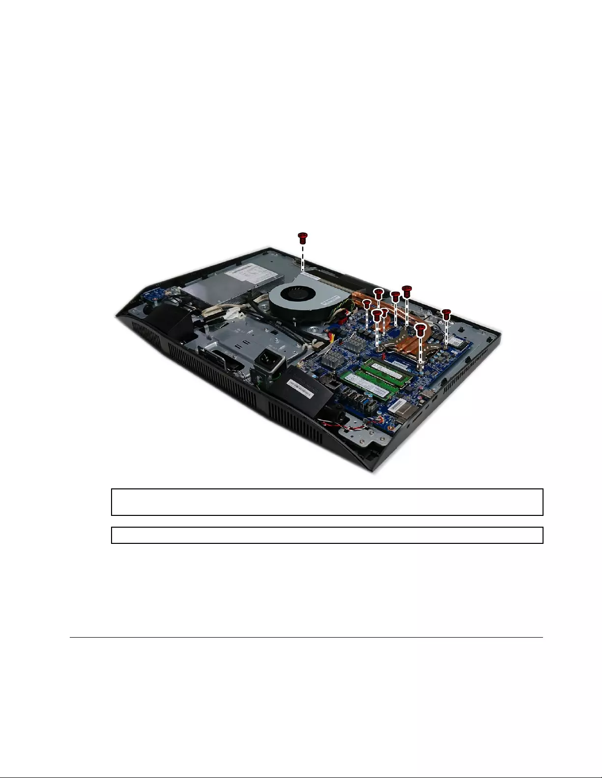
Step9.Loosentheninescrewsthatsecuretheheat-sinktothemotherboard,andthenliftuptheheat-sink
andremoveit.
Attention:Placetheheat-sinkupsidedownonaflatsurfacetopreventthermalgreasefromcontaminating
othercomponents.
Attention:UseanalcoholpadtowipethethermalgreaseofftheCPU.
Step10.Toinstallthenewheat-sink:
a.Positionthenewheat-sinkonthemotherboardsothattheninescrewsarealignedwiththe
holesinthemotherboard.
b.Tightenthescrewsinnumericordertosecurethenewheat-sinktothemotherboard.
Step11.Reinstallalltheremovedparts,andthenreconnectallthedisconnectedcables.
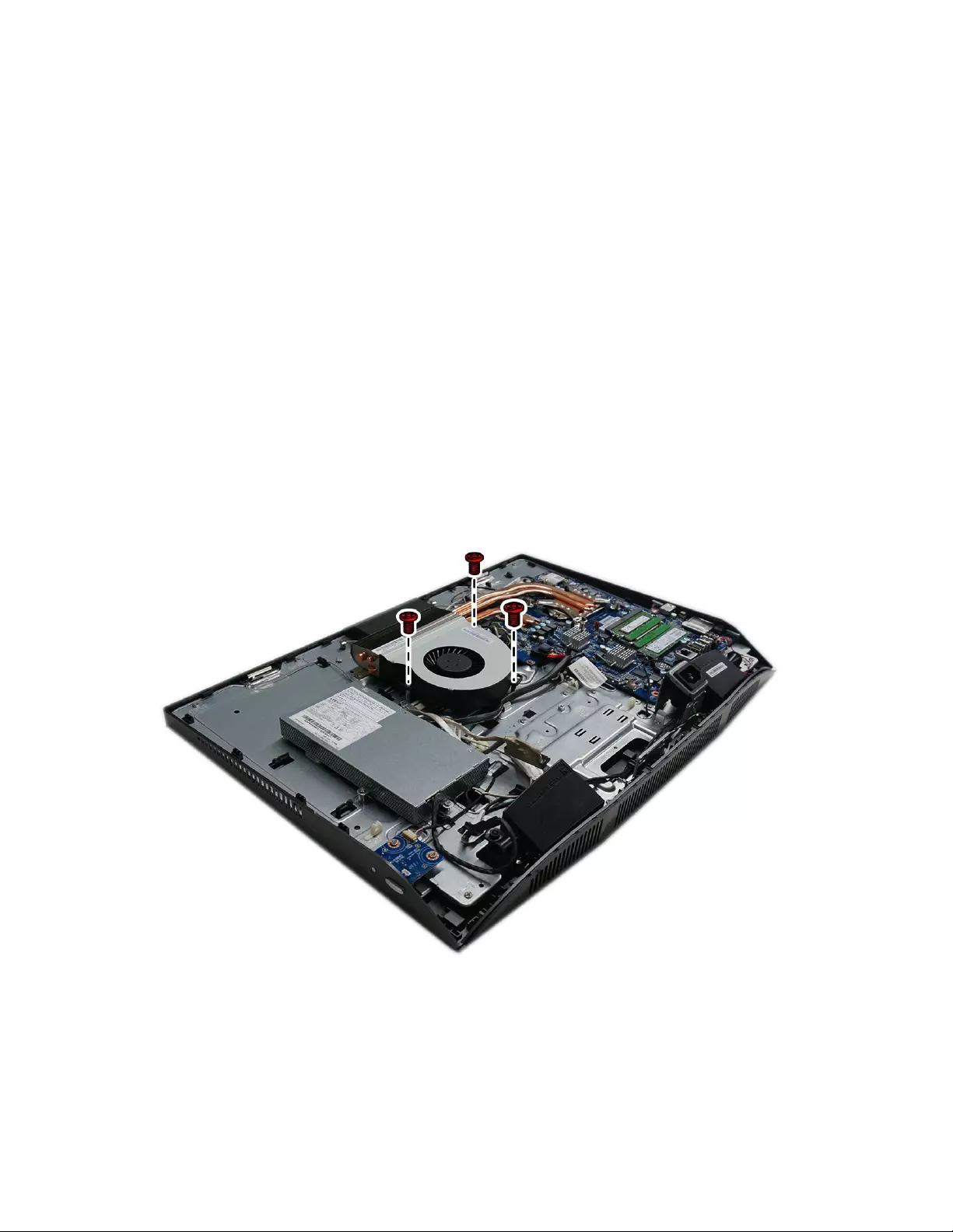
Replacingthesystemfan
Note:Turnoffthecomputerandwait3to5minutestoletitcooldownbeforeremovingthecover.
Chapter8.Replacinghardware45
Note:Itmaybehelpfultoplacethecomputerface-downonasoftflatsurfaceforthisprocedure.Lenovo
recommendsthatyouuseablanket,towel,orothersoftclothtoprotectthecomputerscreenfromscratches
orotherdamage.
Toreplacethesystemfan
Step1.Removeanymediafromthedrives,shutdowntheoperatingsystem,andturnoffthecomputer
andallattacheddevices.
Step2.Unplugallpowercordsfromelectricaloutlets.
Step3.Disconnectallcablesattachedtothecomputer.Thisincludespowercords,input/output(I/O)
cables,andanyothercablesthatareconnectedtothecomputer.RefertoLocatingconnectors,
controlsandcomponentstolocatethevariousconnectors.
Step4.Removethestandbase.RefertoRemovingthestandbase.
Step5.Removetherearcover.RefertoRemovingtherearcover.
Step6.Removetheharddiskdrive.RefertoReplacingtheharddiskdrive.
Step7.Removethestandholder.RefertoRemovingthestandholder.
Step8.Removethemiddlecover.RefertoRemovingthemiddlecover.
Step9.RemovetheEMIcover.RefertoRemovingtheEMIcover.
Step10.Removethemountbracket.RefertoRemovingthemountbracket.
Step11.Removethethreescrewsthatsecurethesystemfantothechassis.
Step12.Disconnectthesystemfanpowercablefromthemotherboard.
Step13.Liftthesystemfanuptoremoveit.
Step14.Toinstallthenewsystemfan:
a.Placethenewsystemfanintoposition,andthensecureittothechassiswiththreescrews.
b.Connectthesystemfanpowercabletotheconnectoronthemotherboard.
Step15.Reinstallalltheremovedparts,andthenreconnectallthedisconnectedcables.
46ideacentreAll-In-One720ComputerHardwareMaintenanceManual

Replacingthemotherboard
Note:Turnoffthecomputerandwait3to5minutestoletitcooldownbeforeremovingthecover.
Note:Itmaybehelpfultoplacethecomputerface-downonasoftflatsurfaceforthisprocedure.Lenovo
recommendsthatyouuseablanket,towel,orothersoftclothtoprotectthecomputerscreenfromscratches
orotherdamage.
Toreplacethemotherboard:
Step1.Removeanymediafromthedrives,shutdowntheoperatingsystem,andturnoffthecomputer
andallattacheddevices.
Step2.Unplugallpowercordsfromelectricaloutlets.
Step3.Disconnectallcablesattachedtothecomputer.Thisincludespowercords,input/output(I/O)
cables,andanyothercablesthatareconnectedtothecomputer.RefertoLocatingconnectors,
controlsandcomponentstolocatethevariousconnectors.
Step4.Removethestandbase.RefertoRemovingthestandbase.
Step5.Removetherearcover.RefertoRemovingtherearcover.
Step6.Removetheharddiskdrive.RefertoReplacingtheharddiskdrive.
Step7.Removethestandholder.RefertoRemovingthestandholder.
Step8.Removethemiddlecover.RefertoRemovingthemiddlecover.
Step9.RemovetheEMIcover.RefertoRemovingtheEMIcover.
Step10.Removethemountbracket.RefertoRemovingthemountbracket.
Step11.Removethesystemfan.RefertoReplacingthesystemfan.
Step12.Removethememorymodules.RefertoReplacingthememorymodule.
Step13.Removetheheat-sink.RefertoReplacingtheheat-sink.
Step14.RemovetheWi-Ficard.RefertoReplacingtheWi-Ficard.
Step15.Removeallthecablesfromthemotherboard.
Chapter8.Replacinghardware47
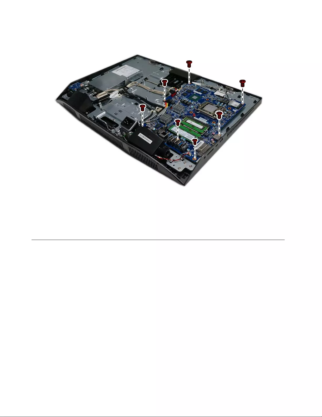
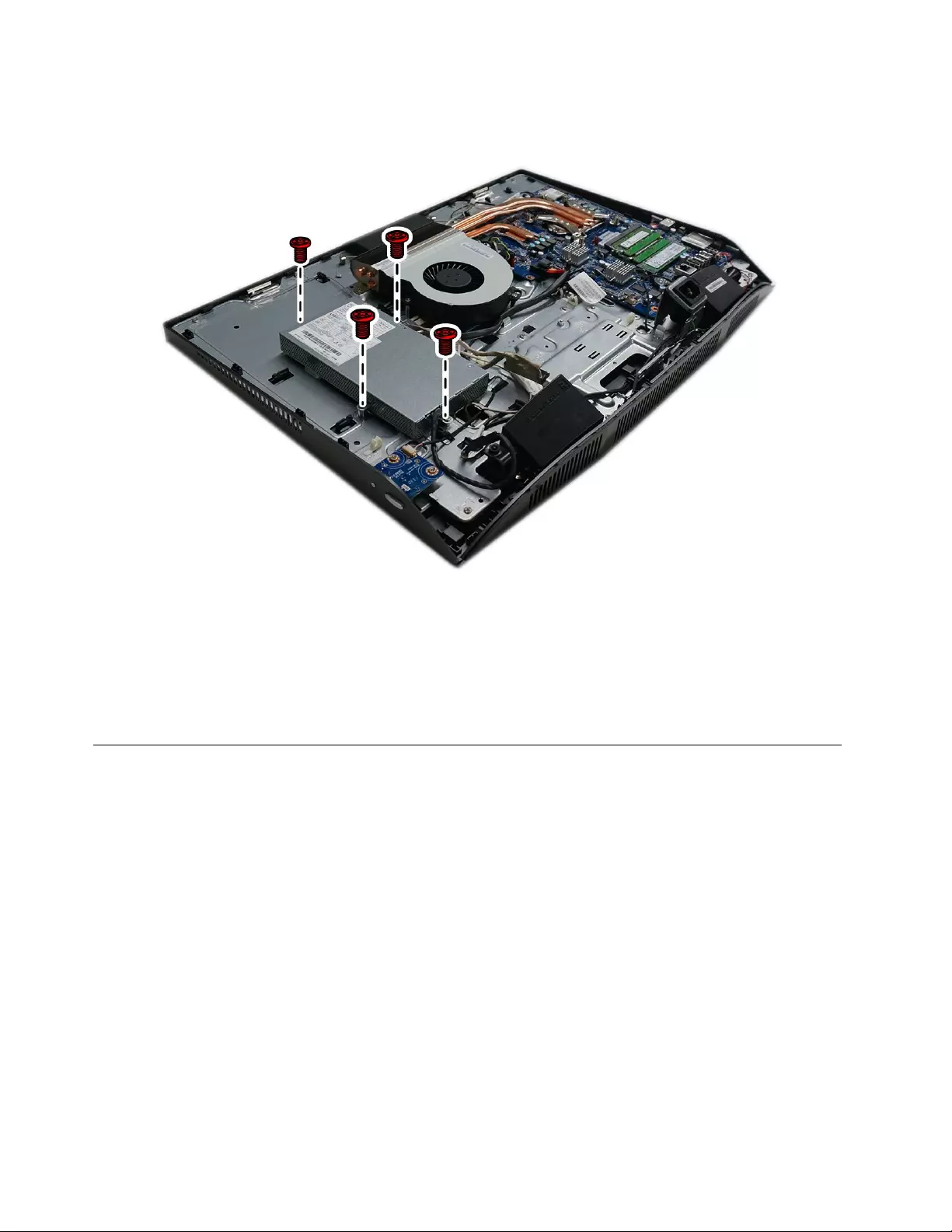
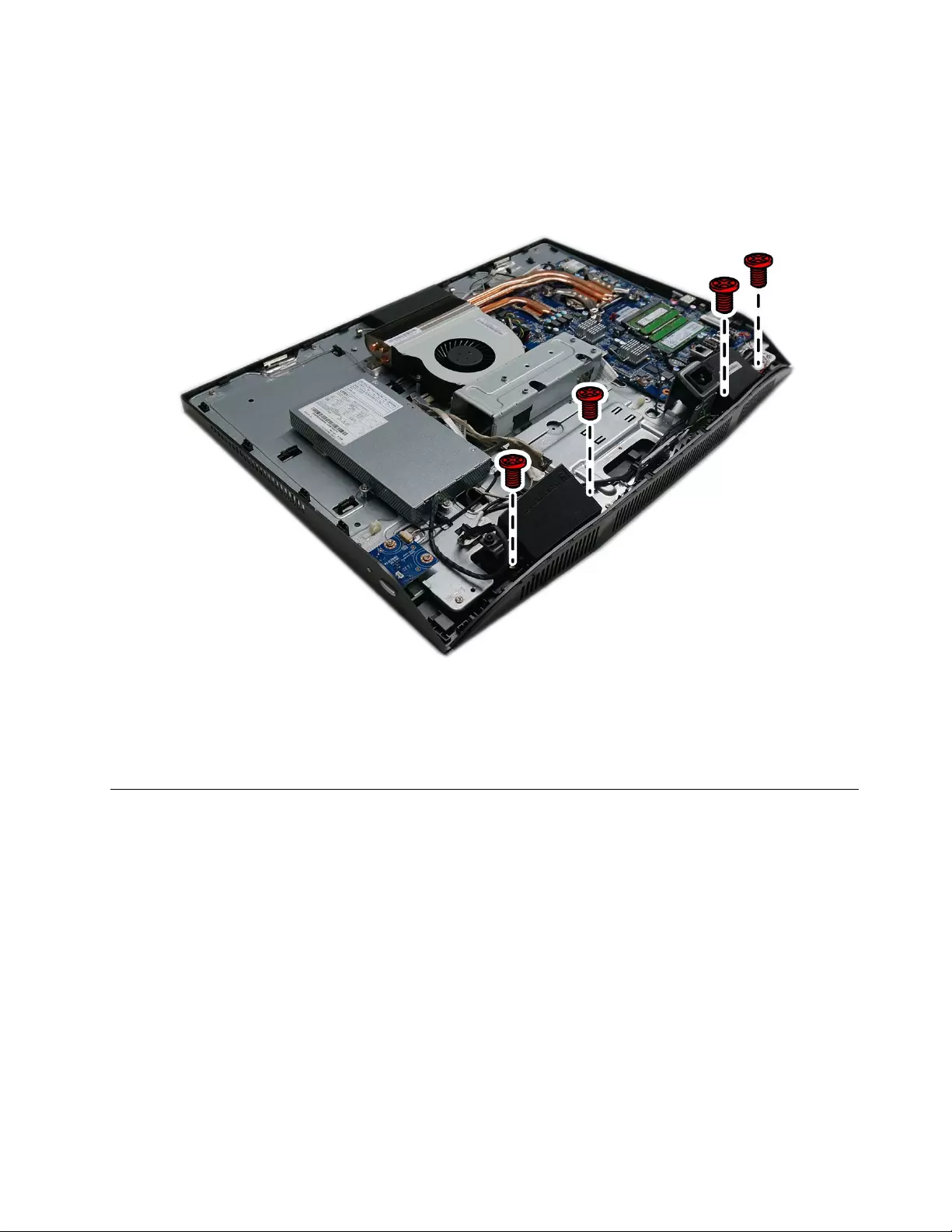
Step16.Removethesixscrewsthatsecurethemotherboardtothechassis,andthenliftthemotherboard
uptoremoveit.
Step17.Toinstallthenewmotherboard:
a.Alignthescrewholesinthenewmotherboardwiththecorrespondingholesinthechassis.
b.Securethenewmotherboardtothechassiswithsixscrews.
c.Connectallthecablestothenewmotherboard.
Step18.Reinstallalltheremovedparts,andthenreconnectallthedisconnectedcables.
ReplacingtheLCDpanelmodule
Note:Turnoffthecomputerandwait3to5minutestoletitcooldownbeforeremovingthecover.
Note:Itmaybehelpfultoplacethecomputerface-downonasoftflatsurfaceforthisprocedure.Lenovo
recommendsthatyouuseablanket,towel,orothersoftclothtoprotectthecomputerscreenfromscratches
orotherdamage.
ToreplacetheLCDpanelmodule:
Step1.Removeanymediafromthedrives,shutdowntheoperatingsystem,andturnoffthecomputer
andallattacheddevices.
Step2.Unplugallpowercordsfromelectricaloutlets.
Step3.Disconnectallcablesattachedtothecomputer.Thisincludespowercords,input/output(I/O)
cables,andanyothercablesthatareconnectedtothecomputer.RefertoLocatingconnectors,
controlsandcomponentstolocatethevariousconnectors.
Step4.Removethestandbase.RefertoRemovingthestandbase.
Step5.Removetherearcover.RefertoRemovingtherearcover.
Step6.Removetheharddiskdrive.RefertoReplacingtheharddiskdrive.
Step7.Removethestandholder.RefertoRemovingthestandholder.
48ideacentreAll-In-One720ComputerHardwareMaintenanceManual
Step8.Removethemiddlecover.RefertoRemovingthemiddlecover.
Step9.RemovetheEMIcover.RefertoRemovingtheEMIcover.
Step10.Removethepowerswitchboard.RefertoReplacingthepowerswitchboard.
Step11.Removethemountbracket.RefertoRemovingthemountbracket.
Step12.Removethesystemfan.RefertoReplacingthesystemfan.
Step13.Removethecameramodule.RefertoReplacingthecamera.
Step14.Removetheheat-sink.RefertoReplacingtheheat-sink.
Step15.Removethepowersupplyunit.RefertoReplacingthepowersupplyunit.
Step16.DisconnecttheLVDScablefromtheLCDpanel.
Step17.Ifyourdeviceisatouchcomputer,disconnectthetouchcablefromthetouchpanelconnector
onthemotherboard.Otherwise,skipthisstep.RefertoLocatingconnectors,controlsand
componentstolocatethetouchconnector.
Step18.Removethemotherboard.RefertoReplacingthemotherboard.
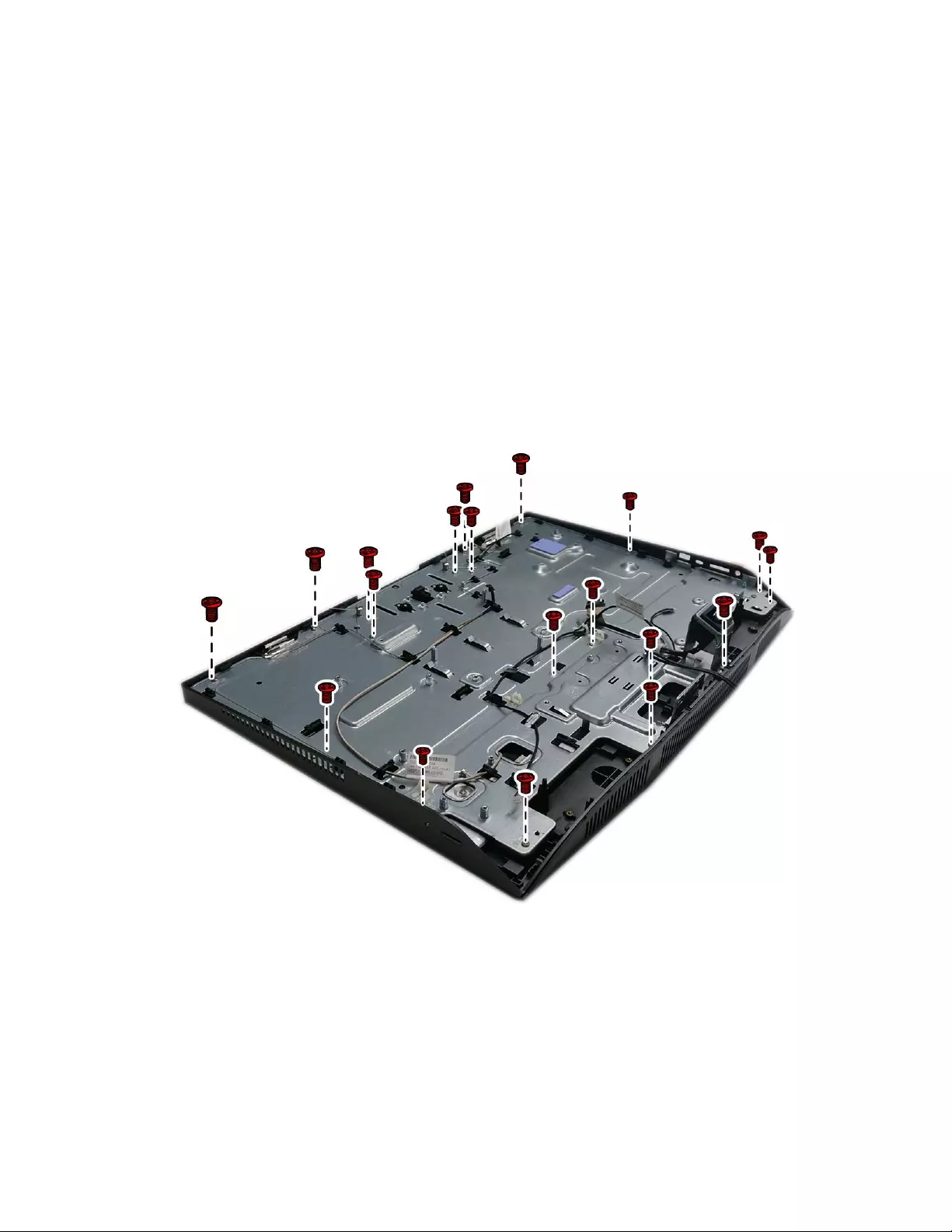
Step19.RemovethescrewsthatsecurethemainbracketandframeassemblytotheLCDpanel.
Chapter8.Replacinghardware49
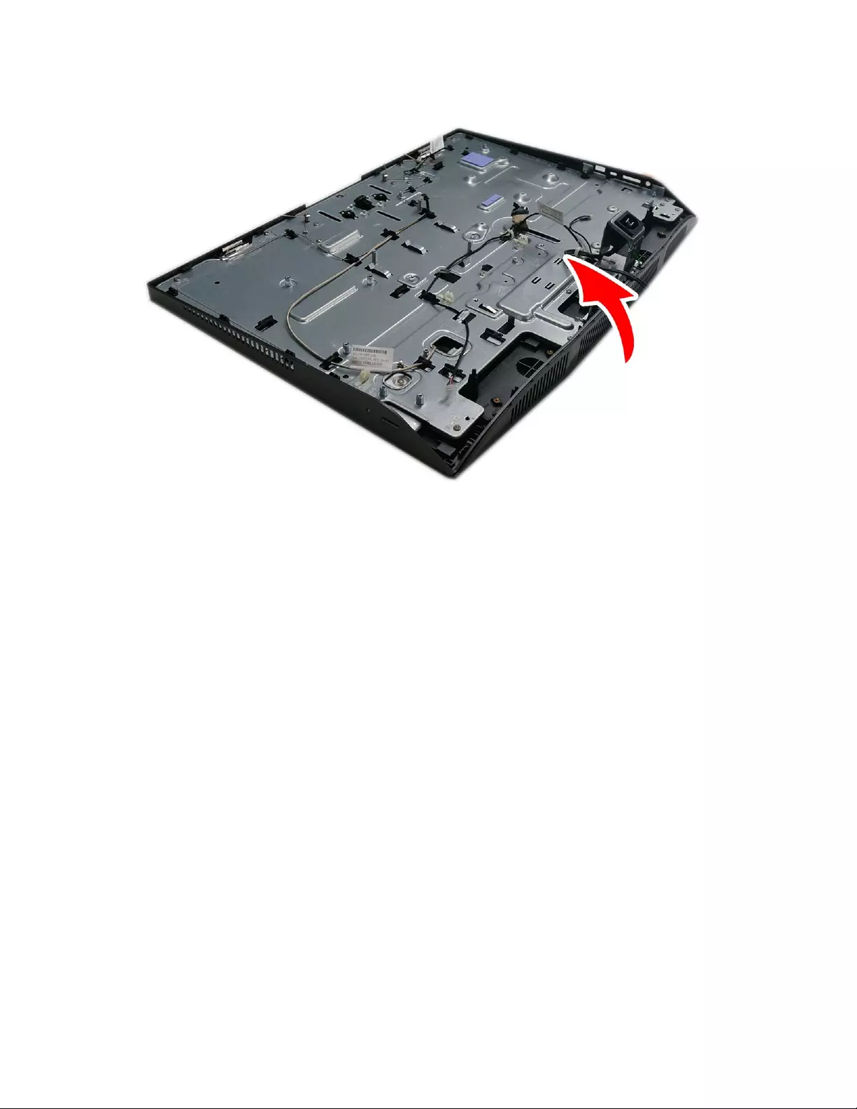
Step20.LiftupthemainbracketandframeassemblyasshowntoseparatethemfromtheLCDpanel.
Step21.ToinstallthenewtheLCDpanelmodule:
a.AlignthenewLCDpanelwiththemainbracketandframeassembly.
b.SecurethenewLCDpaneltothemainbracketandframeassemblywithscrews.
c.Connectthetouch(touchmodelonly)andLVDScablestotheconnectorsinthenewLCD
panel.
Step22.Reinstallalltheremovedparts,andthenreconnectallthedisconnectedcables.
50ideacentreAll-In-One720ComputerHardwareMaintenanceManual

Chapter9.Generalinformation
Thischapterprovidesgeneralinformationthatappliestoallcomputermodelscoveredbythismanual.
AdditionalServiceInformation
Thischapterprovidesadditionalinformationthattheservicerepresentativemightfindhelpful.
Powermanagement
Powermanagementreducesthepowerconsumptionofcertaincomponentsofthecomputersuchasthe
systempowersupply,processor,harddiskdrives,andsomemonitors.
Advancedconfigurationandpowerinterface(ACPI)BIOS
AsthiscomputerhasanACPIBIOSsystem,theoperatingsystemisallowedtocontrolthepower
managementfeaturesofthecomputerandthesettingsforAdvancedPowerManagement(APM)BIOSmode
isignored.NotalloperatingsystemssupportACPIBIOSmode.
AutomaticPower-Onfeatures
TheAutomaticPower-OnfeatureswithinthePowerManagementmenuallowyoutoenableanddisable
featuresthatturnonthecomputerautomatically.
•WakeUponAlarm:Youcanspecifyadateandtimeatwhichthecomputerwillbeturnedonautomatically.
Thiscanbeeitherasingleevent,adailyeventoraweeklyevent.
•WakeUponLAN:ThisfeatureallowsLANadaptercardtowaketheSystem.
©CopyrightLenovo201651