Table of Contents
- Product Description
- Package Contents
- Accessories
- Safety and General Information
- Product Overview
- Specifications
- Installation
- Operation
- Connect Equipment to the UPS
- Connect the Internal Battery and Install the Bezel
- Connect Power and Start the UPS
- Configuration
- UPS Settings
- Emergency Power Off (EPO)
- Terminal Mode To Configure UPS Parameters
- Troubleshooting
- Maintenance
- Battery Replacement
- Service and Transport
- Service
- Transport the unit
- Limited Factory Warranty
APC Smart-UPS RT User Manual
Displayed below is the user manual for Smart-UPS RT by APC which is a product in the Uninterruptible Power Supplies (UPSs) category. This manual has pages.
Related Manuals
Installation and Operation
Smart-UPS™
Un inte rr upt i ble P o w er Sup p ly
SURTA 1000XL/1000RMXL2U
120 Vac
Tower/Rack-Mount 2U
su0541a


Smart-UPS™
Uninterrupt ible Power Supply
SURTA1000XL
SURTA1000RMXL2U
120 Vac
Tower/Rack -Mount 2U
English

SURTA1000XL/1000RMXL2U 120 Vac Tower/Rack-Mount 2U2
Product Description
The APC™ by Schneider Electric Smart-UPS™ SURTA100 0XL/1000RMXL2U is a high performance
uninterruptible power supply (UPS ). Th e UPS prov ides protection for electronic equi pment from utility power
blackouts, brownouts, sags, surges, s mall utility power fluctuatio ns and la rge dist urbances. The UPS also provides
batte r y bac kup power for connec ted equipment until utility power returns to accept able levels or the ba tteries are
fully dischar ged.
This user manual is available on the enclosed Docum entation CD and on the APC by Schneider Electric web site,
www.apc.com.
Package Contents
Accessories
Install accessories prior to connecting power to the UPS.
Refer to the APC by Schnei der Electric web site , www.apc.com for available acce ssories .
Optional accessories
• External battery pack (XLBP)
• USB communication cables
• Network Management Card (NMC)
All models
• UPS • PowerChute™ utility CD
• Front bezel • USB communication cable
• Serial communica tion cab le
• Lit erature kit contain i ng:
–Produc t documentation
–Safety guide
–Warranty information

3SU RTA1000XL/1000RMXL2U 120 Vac Tow er/Rack-Mount 2U
Safety and General Information
Inspect the package contents upon receipt.
Notify the carrier and dealer if ther e is any damage.
• Adhere to all national and local ele ctrical codes.
• All wiring mus t be pe rformed by a qualified elec trician.
• Change s and modifi cati ons to thi s unit not ex pressly approved by AP C by Schnei der Ele ctric could void the
warranty.
• This UPS is intended for indoor use only.
• Do not operate this unit in direct sunlight, in contact with fluids, or where there is excessive dust or
humidity.
• Be sure the air ven ts on the UPS are not bloc ked. Allow adequate s pac e for prope r ventilat ion.
• For a UPS with a factory installed power cord, connect the UPS power cable directly to a wall outlet. Do not
use s u rge pr o t ec to r s or ex t en si on co r d s.
• The batte ry ty pical ly las ts for two to five yea rs. Environ menta l fact ors imp act batte ry li fe. Eleva ted ambie nt
temperatures, poor quality utility power, and frequent sh ort duration discharges will short en battery li fe.
• The equipment is heavy. Always pract ice safe lifting tec hniques adequa te for the wei ght of the equ ipm ent.
• The bat ter ies are he avy. Remov e the b atter ie s befor e ins talli ng the UPS and e xterna l ba ttery packs (XLBPs),
in a ra ck .
• Always ins tall XLBPs at the bottom in rack-mount confi gurations . T he UPS must be in stalled above the
XLBPs.
• Always ins tall periph eral equipment above the UPS in rack-mount configurations.
Dee nergizing safety
The UPS contains internal batteries and may present a shock hazard even when disconnected from the branch
circui t (m ains). Before instal ling or servi cing the equipment check that the:
• input circu it br eaker is in the OFF posit ion. The UPS is disconnected from mains or wall outlet.
• intern al UPS batteries are remov ed.
• XLBP battery modules are disconnected.
Electrical safety
• For models wit h a hardwi red input, the connec tion to the branch circuit (main s) mus t be pe rform ed by a
qualif ied el ectrician.
• 230 V models only: In orde r to maintain compliance with the EMC dire ctive for products sold in Europe,
output cords attached to the UPS must not exc eed 10 meters in length.
• The protec tive earth conductor for the UPS carri es the lea kage current fr om th e load devices (computer
equipment) . An insulated ground conduc tor is to be insta lled as part of the branc h circuit that supplie s the
UPS. The conductor must have the same size and insulati on material as the grounded and ungrounded
br anc h circuit supply cond uctors. The conductor wi ll typica lly be gree n and with or without a y ellow stripe.
• The UPS input ground conductor must be properly bonded to protective e arth at the service panel.
• If the UPS input power is supplied by a separately derived system, the ground conductor must be properly
bonded at the supply transformer or motor generator set.

SURTA1000XL/1000RMXL2U 120 Vac Tower/Rack-Mount 2U4
Battery safety
• Before inst alling or repl ac ing the batte ries, remove jewelry such as wristwatches and rings.
High sh ort circuit c urrent through con ductive materials could cause seve re burns.
• Do not dispo se of batterie s by burning them. Th e bat teries may explode.
• Do not open or mutilate bat teries. Released elec trolyt e is harm ful to the s kin and eyes, an d may be toxic.
Hardwire safety
• Verify that all branch circuit (mains) and low voltage (control) circuits are deenergi ze d, and locked out
before installing c ables or making connections, whether in the juncti on box or to the UPS.
• Wiring by a quali fied electrician is required.
• Check national and local codes before wiring.
• Strain rel ief is requi red for a ll ha rdwiring (not supplied).
• All openings tha t all ow ac ce ss to UP S hardwire terminals must be cove red. Failure to do so may result in
pers onal injury or equ ipm ent damage .
• Selec t wire size a nd connectors ac cording to national and loca l codes.
General information
• The UPS will recognize as many as 10 externa l battery packs conne cted to the UPS. However the r e is no
lim i t to th e n u m b er of X L B P s that can be used wi th th e U P S.
Note: For each XLBP added, increased recharge time will be required.
• The model and serial num bers are locate d on a smal l, rear panel label. For some models, an a dditional labe l
is located on the chassis under the front bezel.
• Always re cycle u sed batteries.
• Recycle the package materials or save them for reuse.
5SU RTA1000XL/1000RMXL2U 120 Vac Tow er/Rack-Mount 2U
Produc t Overview
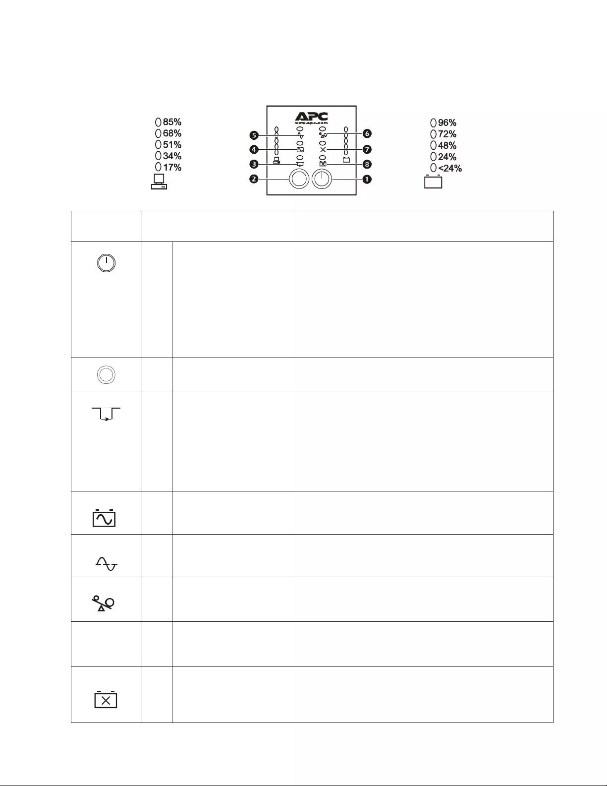
Front display panel
Butto n o r
Indicator Description
The ON button: has three functions .
Pre ss this button to turn on the UPS.
Press this button to initiate a Cold Star t. Co ld St art is not a norma l condit ion . When there is no
utility power and UPS is off, press and hold this button to restore power to UPS. UPS will
emit two beeps. During sec ond beep, release the but ton.
Press this button to initiate a Self-Test.
Automatic: The UPS performs a sel f-test autom aticall y when turned on, and every two
weeks there after by default. During self-test, UPS briefly operates on battery pow er.
Manual: Press and hold ON button for a few seconds to initiate self-test.
The OFF button: This bu tton is used to switch UPS off.
The Bypass LED illuminates indicating that the UPS is in bypass mode. Utility power is sent
directly to connected equipment during bypass mode operation. Bypass mode operation is the
res ult when UPS det ec ts an inter nal fault, an overload condition or a selection made through
NMC or PowerChute software.
Battery operation is not available while the UPS is in bypass mode.
Refer to “Troubleshooting” on page 14 in this manual.
The On B attery LED illuminat es indicating tha t the UPS is supplying bat tery power to
connected equipm ent
The On Li ne LED illu minates when the UPS is dra wing utility power and pe rform ing double
conversion to supply power to connected equipment.
The Overload LED il lum inates indicating that the UPS is experie n cing an ove rload condition.
Refer to “Troubleshooting” on page 14 in this manual.
The Fault LED illuminates indicati ng that the UPS has de tected an in ternal faul t.
Refer to “Troubleshooting” on page 14 in this manual.
The Battery Fault il luminates indicating that one or more batteries are dis connected or must
be replaced.
Refer to “Troubleshooting” on page 14 in this manual.
su0311b
Test
Battery Charge
Load
Test
Bypass
On Battery
On Line
Overload
Faul
t
X
Battery
Fault
SURTA1000XL/1000RMXL2U 120 Vac Tower/Rack-Mount 2U6
Front Display
Panel Feature Description
The UPS has a diagnostic f eature that indicate s utility voltage.
The UPS starts a self-test as part of this procedure. The sel f-test does not affect vol tage display.
Press and hold the ON button to view utility voltage bar graph indicator. As soo n as the On Line LED
sta rts flashing indicat ing a s elf-test is in progress, the five-LED Battery Charge indicator to the right
of the dis play panel will s how utility input volt age .
Refer to diagram for voltage reading.
Values are not listed on the UPS.
Indica tor s on the UPS sho w the voltage is between the displa yed valu e on lis t and the ne xt higher val ue.
Refer to “Troubleshoo ting ” on page 14 in this man ual.
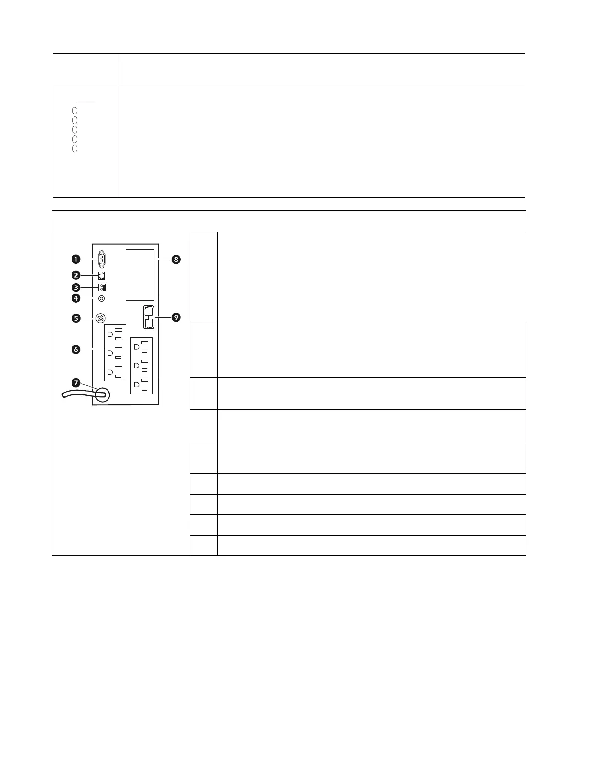
Rear Panel
SERIAL COM-serial communication port for:
Power management software
Inte rfac e kits
Use only interface kits supplied or approved by APC by Schneider
E lectric. Any other serial inter f a ce cable will be in compa tibl e with UPS
connector.
Serial and USB communication ports cannot be used simultaneously.
USB COM-USB comm unication port
120 Vac models: USB communication cable
Contact APC by Schnei der Electric at www.apc.com for purchase
information.
Emer ge ncy Power Off (EPO) term inal al lows th e user to co nnect t he UPS to a
central EPO system.
SITE WIRING FAULT i ndicator -t he LED illumin ates when t he UPS de tects a
building wir ing fault.
Ground screw -The UPS features a chassis ground located on the UPS rear
panel.
Outlets for connec ting ele ctronic eq uipment.
UPS power c able for connec ting to utility power.
SmartSlot for optional NMC or PowerChute a ccess ories .
Exte rnal batter y pac k connector. The UPS will support up to 10 XLBPs .
138.2
120V
128.8
119.5
110.1
100.8
suo0523a

7SU RTA1000XL/1000RMXL2U 120 Vac Tow er/Rack-Mount 2U
Specifications
Temperature Operating 0° to 40°C (32° to 104°F ) This unit is intended for indoor use only. Select a
location sturdy enough to handle the weight.
Do not operate UPS where there is excessive dust
or temp er at u r e or hu mid i ty a re o ut s i d e spe ci f ied
limits.
This u ni t has side air vent s. Allow ad equate
space for proper ventilation.
Environmental factors impact battery life. High
temperatures, poor utility power, and frequent,
short duration discharges will shorten battery life.
Storage -15° to 45°C (5° to 113°F)
charge UPS battery every six months
Maximum
Elevation Operating 3,000 m (10,000 ft)
Storage 15,00 0 m (50, 000 ft)
Humidity 0% to 95% relat ive humidity, non-condensing

SURTA1000XL/1000RMXL2U 120 Vac Tower/Rack-Mount 2U8
Installation
Units may vary in appearance from those depicted in this manual.
Always place UPS above XLBPs in rac k-mount configuration.
The unit is heavy. Remove the battery prior to in stallation.
Rack-Mo unt and stack configurations
Refer to the install ation guide supplied with the rail kit for rack-mount configuration instructions.
Towe r con figura tion
The UPS is shipped with stabilizer br ackets installed. D o not r emove the stabilizer br ackets when the
UPS is to be opera ted in towe r configurati on. Removal of the stabiliz er brackets for towe r
configuration m ay result in personal injury or equi pm ent damage .
External battery pack(s)
Refer to the user manual s upplied with the external ba ttery pack for installation instructions .
9SU RTA1000XL/1000RMXL2U 120 Vac Tow er/Rack-Mount 2U
Operation
Connect Equipment to the UPS
1. Connect equipm ent to UPS. Do not use extension cords, plug equipment directly into the UPS outlets.
2. If applicable, connect equipment to the serial or USB ports.
3. Add optional accessories to the SmartSlot.
4. For additional system security, install Powe rChute software. Refer to the PowerChute utility CD for
instructions.
5. External ba ttery packs provide extended runtime during power outages. Refer to the APC by Schnei der
Electri c Web site, www.apc .c om for exte rnal bat tery pack purchase information. Refer to the ext erna l
batte ry pack user manual for installation ins tructions.
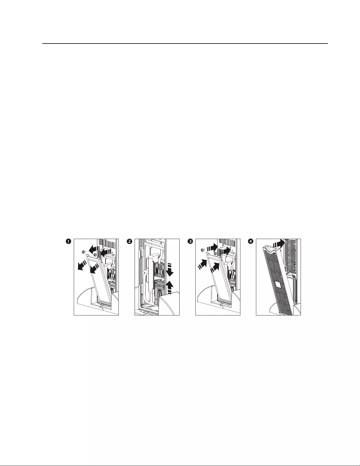
Connect the Internal Battery and Install the Bezel
The UPS is sh ipped with the internal battery disconnecte d.
1. Remove the battery compartme n t cover.
2. Remove the warning label and protective sticker from the battery connector. Place the sticker on the back
of the battery comp artment cover for re -us e.
3. Snap the battery connectors together.
4. Reinstall the battery cover.
5. Install th e f r ont bezel.
su0072b

SURTA1000XL/1000RMXL2U 120 Vac Tower/Rack-Mount 2U10
Connect Power and Start the UPS
The UPS will charge to 90% capac ity in the first four hours of normal operation. Do not expect full
battery run capability during this initial charge period.
1. Connect the UPS to the building utility power. Connect the UPS into a two-pole, three-wire, grounded
receptacle.
2. Press the On button on the front display panel of the UPS to a pply power to the unit and al l connected
equipment.
3. To us e UP S as a master on/off switch turn on all the equipment that is connecte d to the UPS.
4. Configure the Network Management card (NMC), if ins talled. Refer to NMC documentation for
instructions.

11SU RTA1000XL/1000RMXL2U 120 Vac Tow er/Rack-Mount 2U
Configuration
UPS Settings
Configure the settings using PowerChute softwa re, a netw ork management card or terminal mode.
Fun ction Factory Default Options Description
Automatic
Self-Test On startup and
every
14 days (336 hours )
there after
• On startup and every
7 days (168 hours) there afte r
• On startup and ev ery 14 days
(336 hours) there after
• On s t a r t up on ly
• N o self-test
Se t th e in terva l at wh i ch the U P S w ill
ex ecut e s e lf - te st s .
UPS ID UPS_IDEN Use a maximum of eight
alph a n umer i c ch ar a cter s to
define a nam e for the UPS.
Uniqu el y identi fy th e UPS, i. e. serve r na me
or locat ion for network manageme nt
purposes.
Date of Last
Battery
Replacement
Manufacture Date mm/dd/yy Reset this date when the battery module is
replaced.
Minimum Capacity
Before Return from
Shutdown
0 percent • 0%
• 15%
• 30%
• 60%
• 75%
• 90%
Specify the perce ntage to which batteries
will be charged following a low-battery
shutdown, before sending power to
connected equipment.
Alarm Cont rol Enabl e • Enable
•Mute • D is able Specify the behavior of the audible alarm.
Shutdown Delay 90 seconds • 0 sec
• 90 sec
• 180 sec
• 270 sec
• 360 sec
• 450 sec
• 540 sec
• 630 sec
Specify the del ay betwe en the UPS
shutdown command and the actual
shutdown.
Duration of
Low Battery
Warning
2 minutes • 2 min
•5 min
•8 min
•11 min
• 14 min
• 17 min
• 20 min
• 23 min
Specify the number of minutes before
system shutdown , af ter th e lo w b attery
warning.
Synchronized
Turn-on Delay 0 seconds • 0 sec
• 60 sec
• 120 sec
• 180 sec
• 240 sec
• 300 sec
• 360 sec
• 420 sec
Specify the delay betwe en the return of
utility power and the UPS turns on. Set the
interval to avoid a branch circuit overload
condition.
High Bypas s Points 120 Vac models
133 Va c
• 127 Va c
• 130 Va c
• 133 Va c
• 136 Va c
• 139 Va c
• 142 Va c
• 145 Va c
• 148 Va c
Maximum vol tage t hat the UPS will pa ss to
connected equipment during internal
bypas s operation.
Low Bypass Poi nts 120 Vac models
86 Va c
• 86 Vac
• 88 Vac
• 90 Vac
• 92 Vac
• 94 Va c
• 96 Va c
• 98 Va c
• 100 Va c
Minimum voltage that th e UP S will pass to
connected equipment during internal
bypas s operation.

SURTA1000XL/1000RMXL2U 120 Vac Tower/Rack-Mount 2U12
Emergency Power Off (EPO)
The E mergency Power Off (EPO) option is a safety feature tha t will im mediately remove power to all connected
equipment. When EPO button is pushed, all connected equipment will immediately turn off and will not switch to
batte ry power.
Adhere to all national and local electrical codes. Wiring must be performed by a qualified electrician.
The s witch should be connected in a norm ally open switch contact. External voltage is not required; the switch is
driven by 12 V inte rnal supply. In closed condition, 2 mA of current are drawn.
The E PO switch is internally powered by the UPS for use with non-powered switch circuit breakers.
Connect the EPO
The EPO interface is a Safety Extra Low Voltage (SELV) circuit. Connect it only to other SELV circuits. The
EP O in terf a ce monit o rs circu i t s th at ha ve no d et e rmined v olt a ge pot en tia l. S uch cl o su re ci rcu i t s ma y be
provided by a switch or relay pr op erly isolated from the utility. To avoid damage to the UPS, do not connect
the EPO interface to any circuit other than a closur e type circuit.
Use one of the following cable types to connect the UPS to the EPO swi tch.
• CL2: Class 2 cable for general use.
• CL2P: Plenum cable for use in ducts, plen ums, and othe r spaces used for environmental air.
• CL2R: Ri se r cable for use in a vertical r un in a floor - to-floor sha ft.
• CLEX: Limit ed us e cable for use in dwellings and for use in raceways.
• Use standard low-voltage cable in accordance with national and local re gulations , for ins tallation.
Output Fre quency Automatic selection
between:
• 50 ± 3 Hz
• 60 ± 3 Hz
Automatic
• 50 ± 0.1 Hz
• 50 ± 3Hz
• 60 ± 0.1 Hz
• 60 ± 3 Hz
Specify the UPS output frequency.
Whenever possible the output frequency
should track the input frequency.
Number of Battery
Packs 1 Num ber of connected battery
packs Defines the numb er of connected bat tery
packs for proper runtime prediction.
1=internal battery module
2=one external battery pack
3=two ext ernal batt ery packs
The EPO connector is located on the rear panel of the UPS.
1. St rip insulation from one end of each wire to be us ed for connecting EPO.
2. Insert a screwdriver into the sl ot abo ve the te rminal to be wired. Insert stripped wire into
terminal . Remove scre wdrive r to sec ure wir e in terminal. Repeat for each terminal .
Fun ction Factory Default Options Description

13SU RTA1000XL/1000RMXL2U 120 Vac Tow er/Rack-Mount 2U
Terminal Mode To Configure UPS Parameters
Terminal Mode is a menu driven interfac e that enables configuration of the UPS by users not wish ing to use
PowerChute™ software or an optional Network Management Card.
Co n n ect th e se ri al cab l e to th e se ri al co m co n ne ct o r on th e ba ck of th e UPS .
If PowerChute software is not installed do not perform ste ps 1, 2, 8 and 9.
1. For Windows user s: STOP the PowerChute Server using the following steps:
– From the Desktop, go to Start => Settings => Contr ol Pan el => Administrative Tools =>
Services.
– Select APC P ow erC h ute Serv er - right click the mouse and select Stop.
2. For Linux users: STOP the PowerChute Server using th e following steps:
– Change directory to /etc/init.d.
– Initiate the command ./P owerChute s top.
3. Open a termina l program. Example: HyperTe rmi nal
– From the Desktop, go to Star t => Progr ams => Accessories => Communication
=>HyperTerminal.
4. Double- click on the HyperTerminal icon.
– Follow the prompts to choose a name and select a n icon. Disr egard the message, ".. .m ust
install a modem," if it is displayed. Click OK.
– Select the COM port that is conne cted to your UPS. The port settings are:
• bits per second - 2400
• data - bits 8
• parity - n one
• stop bit - 1
• flow control - none
–Press
ENTER
5. Press 1 to modify the UPS parameters.
6. Follow the prompts.
7. E x it th e terminal p r ogr am .
8. For Windows users: START the Po werChute Server using the following steps:
– From the Desktop, go to Start => Settings => Contr ol Pan el => Administrative Tools =>
Services.
– Select APC P ow erC h ute Serv er - right click the mouse and select Start.
9. For Linux users: START the Power Chute Server using the following st eps :
– Change directory to /etc/init.d.
– Initiate the command ./PowerChute start .

SURTA1000XL/1000RMXL2U 120 Vac Tower/Rack-Mount 2U14
Troubleshooting
Problem and Possible Cause Solution
The UPS will not turn on or there is no output
The unit has not been turned on. P ress the ON button once to turn on the UPS.
The UPS is not connected to utility
power. Ensure that the power cable is securely conne cted to the utility power sup ply.
The input circuit breaker has tripped. Reduce the load to the UPS, disconnect nonessential equipment and reset the
circui t breaker.
The unit shows very low or no input
utility voltage. Check the utili ty power supply to the UPS by plugging in a table lamp. If the
ligh t is very dim, check the utility volta ge.
The battery connectors are not securely
connected. Ensure that all battery conn ections are secure.
The UPS will not turn off
The unit has not been turned off. Press the OFF button once to turn of f the UPS.
There is an internal UPS fault. Do not attempt to use the UPS. Disc onnect the UPS from utility and batt ery
power. Have the UPS serviced immediately.
UPS beeps occasionally
Th e U PS is in no r mal op er ation . No n e. Th e U P S is helpin g to pro t ect th e con n ected e q ui p m e n t.
P ress the ON b utt on to sil en ce th e au d ib l e al ar m .
The UPS is operating on batter y, while connected to inpu t utility power
The input circuit breaker has tripped. Reduce the load to the UPS, disconnect nonessential equipment and reset the
circui t breaker.
The r e is very high, very low, or disto r ted
input line voltage. Move the UPS to a different outlet on a different circuit. Test the input
voltage with the uti lity voltage display.
A connected generator is an
inappropriate size. Check the UPS and generator specifications for compatibility.
UPS does not provide expected backup time
The UPS battery is weak due to a recent
outage or is near the end of its service
life.
Charge the battery . Batteries require recharging after extended outages and
wear out faster when put into service often or when operated at elevated
temperatures. If the batt ery is near the end of it s service life, consider
replacing the batter y even if the Rep l ac e B att e ry LED indic ator is not yet
illuminated.
A UPS overlo ad condition has occu rred. Check the UPS Load indicator. Disconnect nonessential equipment.

15SU RTA1000XL/1000RMXL2U 120 Vac Tow er/Rack-Mount 2U
Site Wiri ng Fau lt ind ica to r is illum i nated
The UPS is connected to an im properly
wired utility outlet. W iring faults detected include missi ng ground, hot-ne utral polari ty reversal
and overloaded neutra l circuit.
Do not attempt to use the UPS. Disconnect the UPS from utility and battery
power. Contact a qualified electrician to correc t the building wiring.
All indicator s are off and the UPS is connected to utility service
The UPS has been shut down or the
batteries are discharged from extended
usage.
None. The UPS w ill restart au tomatic ally when utility pow er r eturns and
configuration criteria have been met.
All indicator s flash sequentially
Th e UP S has been shut down remo te l y
through software or an optional
accessory card.
None. The UPS will restart automatically wh en util ity power returns.
All indicator s are illuminated and the UPS emits a constant beeping sound
The UPS detects an internal fault. Do not attempt to use the UPS. Disconnect the UPS from utility and battery
power. Have the UPS serviced immediately.
Batt ery Fau l t indi cato r is ill umi n a ted
The Battery Fault LED f las h es an d a
short beep is em itted every two se conds
to indicate the battery is dis connect ed.
Check tha t the batter y connectors are f ully engaged .
Weak battery. Allow battery to recharge for 24 hours and perform a self-test. If the problem
persists after recharging, repla ce battery.
Failure of a battery self-test: Battery
Fault LED illuminates and the UPS
emits short beeps for one minu te. The
UPS re p eats the audible alarm every f ive
hours.
Allow battery to recharge for 24 hours. Perform the self-test procedure to
confirm the replace battery condition. The audible alarm s t o ps and the LED
cl ears i f t h e battery pass es the self - t est.
If battery fails again, it m ust be replaced. The connected equipment is
unaffected.
Bypass ind icator is illuminated
Bypass mode has been t urned on throu gh
an accessory. If bypass mode has be en selected, ign ore the LED.
Overload indicator is illuminated and the UPS emits a sustained audible alarm tone
A UPS overlo ad condition exists. Discon nect nonessential equipment from UPS to eliminate overload
condition.
Problem and Possible Cause Solution

SURTA1000XL/1000RMXL2U 120 Vac Tower/Rack-Mount 2U16
Bypass and Overload indicators are illuminated and the UPS emits a sustained audible alarm tone
A UPS overload condition has occu rred. Connected equipme nt exceeds spec ified “maximum lo ad” as defi ned in
Specifications on A PC by Schneider Electric Web site, www.apc.com.
The audible ala r m remains on until t he overload is rem oved. Disconnect
nonessential equipment from UPS to elim inate ove rload condition.
The UPS continues to supply power as long as it is on line and the circuit
breaker does not trip. The UPS will not provide power from batteries in the
event of a ut ility voltage inte rruption.
Fault indicator is illuminated
An internal UPS fault is detected. Do not attempt to use UPS. T urn UPS off and ha ve it serviced immediately.
Refer to APC by Schneider Electric Web site , www.apc.com.
Bypass and Fault indicators are illuminated and the UPS emits a sustaine d alarm tone
The UPS has autom atically switched to
Bypass mode. Bypass mode ope ration is
the result of an internal UPS fault or an
overload condition while operating on
utility power.
In the event an inter n al UPS fault occ u r s, Do Not attempt to use UPS. Turn
UPS off and ha ve it serviced immediately. Refer to APC by Schneider
Electric Web site, www.apc.com.
Fault and Over load indicators are illuminat ed and th e UPS emits a sustained audible alarm tone
The UPS is not sending power to
connected equipment. Connected equip ment exceeds sp ecified “max im um load” as defined in
Specifications on A PC by Schneider Electric Web site, www.apc.com.
The audible alarm remains on until the overload is remove d. Dis connect
nonessential equipment from UPS to elim inate ove rload condition.
The UPS will not provide power f r om batteries in the eve nt of a util ity
voltage interruption.
There is no utility power
There is no utility power and the UPS is
off. U se the Cold Start feature to supply power to connected equipment fr om
UPS battery(s).
Press and hold the ON butt on. Ther e will be a short beep follo wed by a lon ger
beep. Release the but ton during sec ond beep.
Diagnostic utility voltage feature
All five LEDs are illuminated. The line voltage is extremely high an d should be checke d by an electrician.
There is no LED illumi nation. The line voltage is extremely low and should be checked by an electric ian.
On Line indicator
The r e is no LED illumination. The UPS is running on battery, or it m ust be turned on.
The LED is blinking. The UPS is running an internal self-test.
Problem and Possible Cause Solution

17SU RTA1000XL/1000RMXL2U 120 Vac Tow er/Rack-Mount 2U
Maintenance
Battery Replacement
This UPS has a replac eable, swap pable battery module.
Once the battery modules have been disconnected the connected equipment is not pr otected from
power outages.
When the batteries are replaced be sure to enter a new battery replacement date.
Refer to the appropri ate replaceme nt battery user manual for inst allation instructions. See your dealer or contact
AP C b y Sch n e id er El ectr i c at www.apc.com for information on replacement batteries.
Be sure to deliver spent batteries to a recycling f acility or shi p to A PC by Schneider Electric in the
replacement battery packing material.

SURTA1000XL/1000RMXL2U 120 Vac Tower/Rack-Mount 2U18
Service and Transport
Service
If the unit requires service, do not return it to the dealer. Follow these steps :
1. Review the Troubleshooting se ction of the manual to eliminat e co mmon pr o b lems.
2. If the proble m pe rsi sts, conta ct APC by Schneider Electric Customer S upport through the APC by
Schneider Electric Web site, www.apc.com.
a. Note the model number and serial number and the date of purchase. The model and seri al
numbers ar e located on the rear panel of the unit and are availa ble through the LCD display
on select models.
b. Call APC by Schneide r Electric Custome r Support and a technician will a ttempt to solve
the problem over the phone. If this is not possible, the technic ian will issue a Returned
Material Authorization Number (RMA#).
c. If the unit is under warra nty, the repairs are free.
d. Service procedures and returns may vary internationally. Refer to the APC by Schneider
Electric Web site for countr y specific instructions.
3. Pack the uni t in the original packaging whenever poss ible to avoid dama ge in transit. Never use foam
beads for packag ing. Damage sustained in transit is not covered under warranty.
a. Always DISCONNECT THE UPS BATTERIES before shippin g. The United States
Department of Tr ansportation (DOT), and the Internation al Air Transport
Association (IATA) regulations require that UPS batteries be disconnected before
shipping. The internal batteries may remain in the UPS.
b. External Battery Pack produc ts are de-energized when disconnected from the associated
UPS product. I t is not necessary to disconnect the internal batt eries for shipping. Not all
units utilize an external batt ery pack.
4. W r ite the RMA# provi ded by Customer S upport on the outside of the pa ckage.
5. Return the unit by insured , pre-paid carrier to the addres s provided by Customer Supp ort.
Transport the unit
6. Shut down and dis connect all connected equipment.
7. Discon nec t the unit fr om uti lity power.
8. Disconn ect all in ternal and ex ternal batteries (if applic able).
9. Follow the shipping instructions outlined in the Service section of this manu al.

19SU RTA1000XL/1000RMXL2U 120 Vac Tow er/Rack-Mount 2U
Limited Factory Warranty
Schneider Electri c IT Corporation (SEIT) , warrants its products to be free from defects in materials and
workmanship for a period of two (2) years from the date of pur cha s e. The SEIT obligation unde r this warra nty is
limi ted to repairing or repl ac ing, at its so le discretion, any such defective products. Repa ir or replacement of a
defec tive product or parts thereof does not extend the original warranty period.
This warra nty applies only to the original purchaser who must have properly r egistered the product within 10 days
of purchase. Products may be reg is tered onlin e at warran ty.apc .c om.
SEIT shall not be li able under the warranty if its tes ting and exa mi nation dis close that the alleged defect in the
product does not exist or was cause d by end user or any third pers on m isuse, negl igence, imp r oper ins tallati on,
test ing, o perati on or use o f the product contra ry t o SEIT r ecommen dation s or s pecif icati ons. Furthe r , SE IT s hall no t
be liab le for defects res ulting from: 1) unauthorized at tempts to repair or mod ify the product, 2) incorrect or
inadequate electrical vol tage or connection, 3) inappropriat e on site operation cond itions, 4) Acts of God, 5)
expos ure to the elements, or 6) theft. In no eve nt s hall SEIT have any liability unde r this warranty for any product
where the serial number has been altered, defaced, or removed.
EXCEPT AS SET FORTH ABOVE, THERE ARE NO WARRANT IES, EXPRESS OR IMPLIED, BY
OPERATION OF LAW OR OTHER WISE, APPLICABLE TO PRODUCTS SOLD, SERVICED OR
FURNISHED UNDER THIS AGREEMENT OR IN CONNECTION HEREWITH.
SEIT DISCLAIMS ALL IMPLIED WARRANTIES OF MERCHANTAB IL ITY, SATISFACTION AND
FITNESS FOR A PARTICULAR PURPOSE.
SEIT EXPRESS WA RRANTIES WILL NOT BE ENLARG E D, DIMINISHED, OR AFF ECTED BY AND
NO OBLIGATION OR LIABILITY WILL ARISE OUT OF, SEIT RENDERING OF TECHNICAL OR
OTHER ADVICE OR SERVICE IN CO NNECTION WITH THE PRODUCTS.
THE FOREGOING WARRANTIES AND REMEDIES ARE EXCLUSIVE AND IN LIEU OF ALL
OTHER WARRANTIES AND REMEDIES. THE WARRANTIES SET FORTH ABOVE CONSTITUTE
SEIT SOLE LIABILITY AND PURCHASER EXCLUSIVE REMEDY FOR ANY BREACH OF SUCH
WARRANTIES. SEIT WARRANTIES EXTEND ONLY TO ORIGINAL PURCHASER AND ARE NOT
EXTENDE D TO ANY THIRD PARTIES.
IN NO EVEN T SHALL SEIT, ITS O FFICERS, DIRECTORS, AFFILIATES OR EMPLOYEES BE
LIABLE FO R A NY F ORM OF IND IRECT, SPECIAL, CONSEQU E N TIAL OR PUNITI V E DAMAGES,
ARISI N G OUT OF TH E U SE, SERVICE O R INSTALLATION OF THE PRODUCTS, WHETHER SUCH
DAMAGES ARISE IN CONTRACT OR TORT, IRRESPECTIVE OF FAULT, NEGLIGENCE OR
STRICT LIABILITY OR WHETHER SEIT HAS BEEN ADVISED IN ADVANCE OF THE POSSIBILITY
OF SUCH DAMA GES. SPECIFICALLY, SEIT IS NOT LIABLE FOR ANY CO STS, SUCH AS LO ST
PROFITS OR REVENUE, WHETHER DIRECT OR INDIRECT, LOSS OF EQUIPMENT, LOSS OF USE
OF EQUIPME NT, LOSS OF SO FTWARE, LOSS OF DATA, COST S OF SUBSTITUANTS, CLAIMS BY
THIRD P ARTIES, OR OTHERWISE.
NOTHING IN THIS LIMITED WARRANTY SHALL SEEK TO EXCLUDE OR LIMIT SEIT LIABILITY FOR
DEATH OR PERSONAL INJURY RESULTING FROM ITS NEGLIGENCE OR ITS FRAUDULENT
MISREPRESENTATION OF TO THE EXTENT THAT IT CANNOT BE EXCLUDED OR LIMITED BY
APPLI C AB LE LAW.
To obtain service under warranty you mu st obtain a Returned Material Authorization (RMA) number from
customer support. Customers with warranty claims iss ues may access the SEIT worldwide customer support
network through the APC by Schneider Electric web site: www.apc.com. Select your country from the country
selection drop down menu. Open the Support tab at the top of the web page to obtain information for customer
support in your region . Produc ts must be ret urned with tran sportati on char ges pre paid and must be accom panied by
a brief description of the problem encountered and proof of date and plac e of purc hase.

SURTA1000XL/1000RMXL2U 120 Vac Tower/Rack-Mount 2U20


4/2015990-5067B
APC by Schneider Electric IT
Worldwide Customer Support
Customer support for this or any othe r APC by Schneider Ele ctric IT product is available at no charge in any
of the following ways:
• Visit the APC Web site to acc ess documents in the APC by Schneider Ele ctric Knowledge Base and to
submit customer support reque sts.
–www.apc.com (Corporate Headquarte rs)
Connect to localized APC by Schneider Electric Web sites for specific countries, ea ch of which
provides customer support information.
–www.apc.com/support/
Global suppor t searching APC by Schneide r Electric Knowle dge Base and usi ng e-support.
• Contact the APC by Schneider Electric Customer Support Center by telephone or e-mail.
– Local, country-specific centers: go to www.apc.com/support/contact for contact information.
– For information on how to obtain loc al c ustomer support, contact the APC by Schneider Electric
representative or other distributors from whom you purchased your APC by Schneider Electric
product.
FCC Statement for Class A products
This equipment has been teste d and found to co mply with the limits f or a Class A digital device,
pursuant to p art 15 of the FCC R ules. These limit s a re intende d to p rov ide reaso nable protection against
harmful interference when the equipment is operated in a commercial environment. This equipment
generate s, uses, and can radi ate radio frequ ency ener gy and, if not insta lled and used in accord ance with
the instruction manual, may cause har mful interference to radio communications. Operation of this
equipment in a residential area is likely to cause harmful interference in which case the user will be
required to correct the interference at his own expense.
© 2015 APC by Schneider Electric. APC, the APC logo and S mart-UPS are owned by Schneider Electric
I ndus tries S.A.S . or the ir affiliated companie s. All other trad emarks are property of thei r respec tive owners.