APC Smart-UPS RT 3000VA User Manual
Displayed below is the user manual for Smart-UPS RT 3000VA by APC which is a product in the Uninterruptible Power Supplies (UPSs) category. This manual has pages.
Related Manuals
Installation and
Operation
Smart-UPSTM
Uninterruptible Power Supply
SURTD3000XLI
SURTD5000XLI
220/230/240 Vac
Tower/Rack-Mount 3U
su0835a

1
Smart-UPSTM RT
Uninterruptible Power Supply
SURTD 3000/5000 VA 200-240 Vac
Tower/Rack-M ount 3U
English
EN 990-2690C 07/2014

2
INTRODUCTION
The APCTM b y Schneider Electric Smart-UPSTM RT is a high performance, uninterruptible po wer
supply (UP S). The UPS provides protection for electronic equipme nt from utility power blackouts,
brownouts, sags, and surges and small utility fluctuations and large disturbances. T he UP S also
provides battery backup po wer for connected equipment until utility power returns to safe levels or
the batteries are fully dischar g ed.
This user manual is available on the enclosed Documentation CD and on the
APC by Schneider Electric web site, www.apc.com.
INSTALLATION
Read the Safety Guide before installing the UPS.
Unpacking
Inspect the UPS upon receipt. Notify the carrier and dealer if there is damage.
The packaging is recyclable; save it for reuse or dispose of it properly.
Check the package contents:
UPS ( with battery modules disco nnected)
Front bezel
Literature kit containing:
Product documentation
Smart-UPS RT User Manuals CD
Warranty Information
XLT/XLI/XLTW models:
PowerChuteTM software CD
Serial cable
3000 VA XLI models: two output power cords,
two input power cords
3000 VA models: conversion faceplate for
accommodating a Net work Management
Card
5000 VA XLI models: four output power cords,
Network Management Card documentation
Specifications
TEMPERATURE
OPERATING
STORAGE
32° to 104° F (0° to 40° C)
5° to 113° F (-15° to 45° C) charge the UPS
battery every six months
This unit is intended for indoor use only.
Select a location sturdy enough to
handle the weight.
Do not operate the UPS where t here is
excessive d ust or the t emperat ure and
humidity are outside the specified limits.
Ensure that the air vents on the front
and rear of t he UPS are not bloc ke d.
MAXIMUM
ELEVATION
OPERATING
STORAGE
10,000 ft (3,000 m)
50,000 ft (15,240 m)
HUMIDITY 0 to 95% relative humidity
WEIGHT UPS 120 lbs (55 kg)
UPS with packaging 140 lbs (64 kg)
3
Wiring and Connecting the UPS
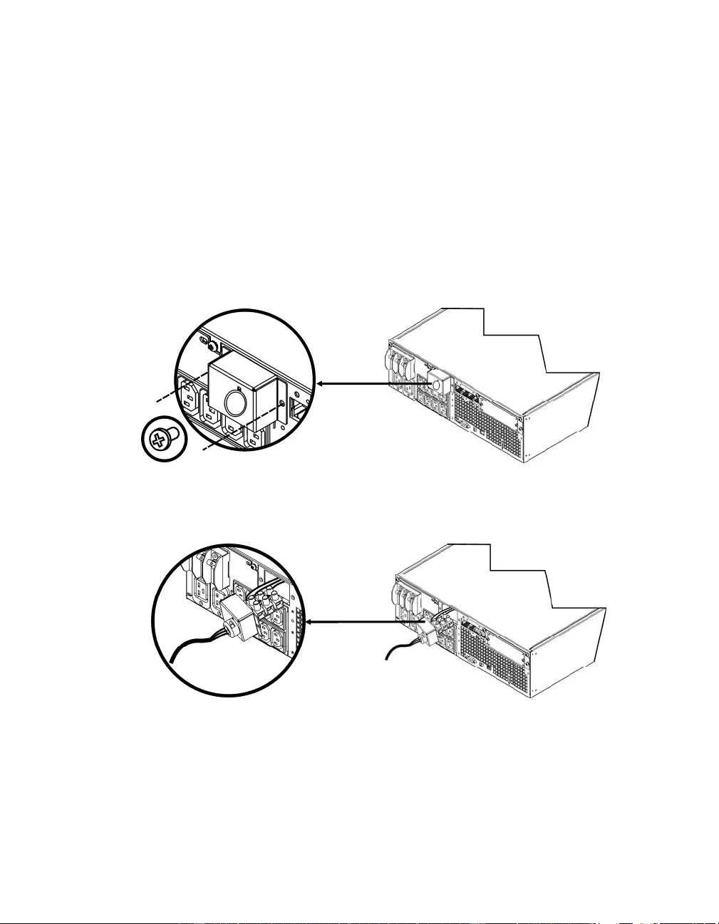
5000 VA XLI MO D ELS ONLY: HARDWIRING INSTRUCTIONS
• Wiring must be performed by a qualified electrician.
• Install a high magnetic 30/32 A utility circuit breaker.
• Adhere to all national and local electrical codes.
• Use #10 AWG gauge (5 mm2) wire.
1. Switch the utility circuit breaker OFF.
2. Remove the input access panel.
3. Remo ve circ ular knockout.
4. Run #10 AWG gauge (5 mm2) wire through the access panel, and connect t he wires to the
terminal block (Green: Ground, Brown: Hot, Blue: Ne utral). Use an appropriate strain relief (not
included).
5. Switch the utility circuit breaker ON.
6. Check line volta ges.
7. Replace the access panel.
4
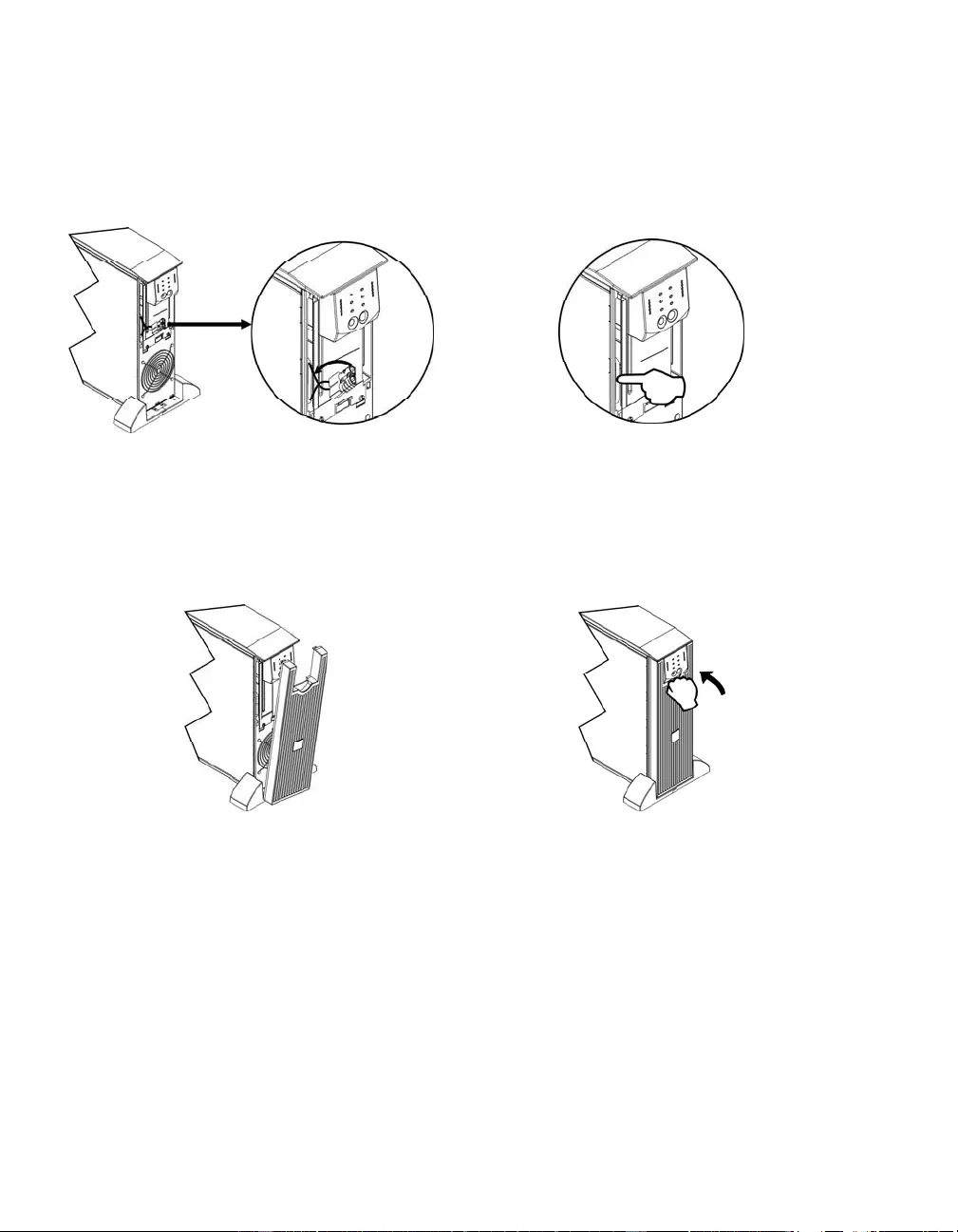
CONNECTING THE BATTERY MODULES AND ATTACHING THE FRONT BEZEL
∂ •
÷ ≠
5
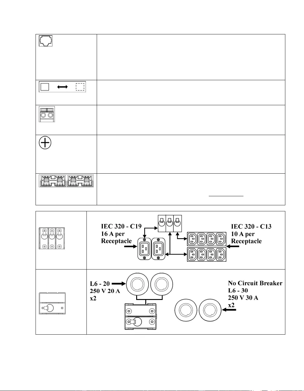
BASIC CONNECTORS
serial com
The serial connector is to be used for interfacing with AP C by Schneider
Electric PowerChute software and termi nal e mulation software.
Use only APC by Schneider Electric approved cables.
Any other interface cable will be incompatible with the UPS
connector.
normal bypass
Manual bypass enables the user to manually put connected eq uipment into
bypass mode.
EPO terminal
Emergency Power Off terminal allows the user to connect the UPS to the
central EPO system.
TVSS screw
The UPS features a transient voltage surge suppression (TVSS) screw for
connecting the ground lead on surge suppression devices such as telephone
and network line protectors.
When connecting grounding cable, disconnect the unit from the utility
power outlet.
external battery
pack connector
Optional external battery packs provide extended run ti me during power
outages. These units support up to ten external batter y packs.
See the APC by Schneider Electric web site, www.apc.com for the
information on the external battery pack, SURT192XLBP.
5000 VA
XLI models
output circuit
breakers
3000/5000VA
XLJ/XLT/XLTW
models
output circuit
breakers

6
CONNECTING EQUIPMENT AND POWER TO THE UPS
1. Connect equipment to the UPS (cables not included for XLJ/XLT/XLTW models).
2. Avoid using extension cords.
• 3000 VA XLJ/XLT/XLI/XLTW and 5000 VA XLJ/XLT/XLTW models: Using a power cord,
plug the UPS into a two-pole, three-wire, grounded receptacle only.
• 5000 VA XLJ models: To draw full 5000 VA from the UPS have a qualified electrician cut
off the input plug and hardwire the UPS to the appropriate power p anel.
3. Turn on all connected equipment. To use the UPS as a master ON/OFF switch, ensure all
connected equipment is switched ON. The equipment will not be powered until the UPS is
turned on.
4. To power up the UPS press the button on the front panel.
• The UPS battery charges when it is connected to utility power. The battery charges to 90%
capacity during t he first three hours of normal operation. Do not expect full battery run
capability during this initial charge period.
5. For additional computer system securit y, install PowerChute Server Smart-UP S monitoring
software.
OPTIONS
Refer to the APC by Schneider Electric web site, www.apc.com for available accessories.
External Battery Pack SURT192XLBP
Rail Kit SURTRK2
Isolation Transformer
Service Bypass Panel
7
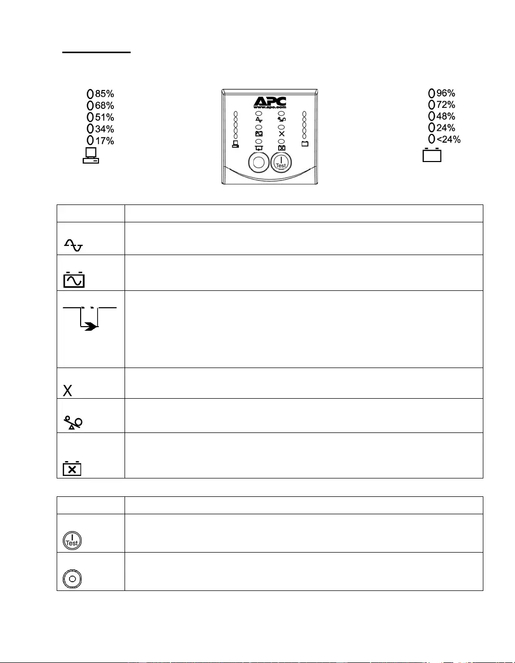
OPERATION
Load SMART-UPS RT FRONT DISPLAY Battery Charge
Indicator Description
Online
The Online LED illuminates when the UPS is drawing utility power and performing
double conversion to supply power to connected equip ment.
On Battery
The UPS is supplying battery power to the connected equipment.
Bypass
The Bypass LED ill uminates indicating that the UP S is in bypass mode. Utility
power is sent directly to connected equipment during bypass mode operation.
Bypass mode operation is the result of an internal UPS fault, an overload condition
or a user initiated command either through an accessory or the manual bypass
switch. Battery operation is not available while the UPS is in bypass mode. Refer to
Troubleshooting in this manual.
Fault
The UPS detects an internal fault.
Refer to Troubleshooting in this manual.
Overload
An overload condition exists. See Troubleshooting.
Replace
Battery
The battery is disconnected or must be replaced. See Troubleshooting.
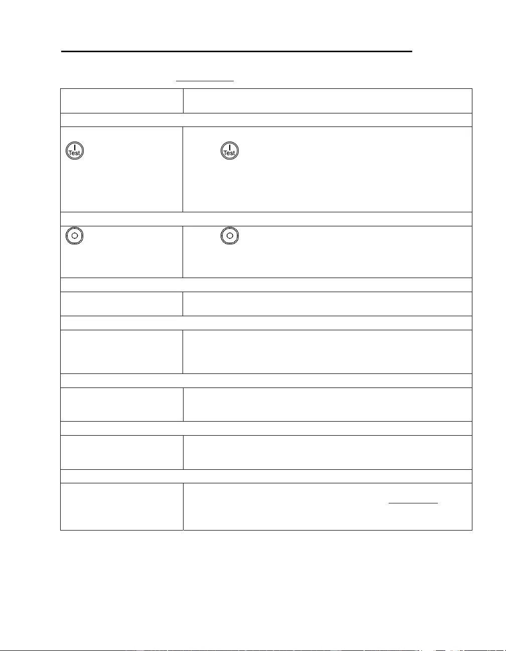
Feature Function
Power On
Press this button to turn on the UPS. (See be lo w for additio nal capabilities.)
Power Off
Press this butto n to turn off the UPS.
8
Feature Function
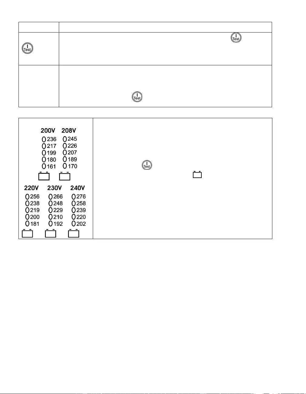
Cold Start
When there is no utility power and the UPS is off, press and hold the button to
power up the UPS and connected equip ment.
The UPS will emit two beeps. During t he second beep, release the button.
Self-Test Automatic: The UPS performs a self-test auto matically when turned on, and every
two weeks thereafter (by default). During the self-test, the UPS briefly operates the
connected equipment on battery.
Manual: Press and hold the button for a few seconds to initiate the self -test.
Diagnostic Utility Voltage The UPS has a diagnostic feat ure that displays the utility voltage. Plug
the UPS into the normal utilit y power.
The UPS starts a self-test as part of this procedure. The self-test
does not affect the voltage display.
Press and hold the button to view the utility voltage bar graph
display. The five-LED, Battery Charge display on the right of the
front panel shows the utility in put voltage.
Refer to the figure at left for the voltage reading (values are not listed
on the UPS).
The display indicates the voltage is between the displayed value on the
list a nd the next higher value.

9
USER CONFIGURABLE ITEMS
NOTE: SETTINGS ARE MADE THROUGH SUPPLIED POWERCHUTE SOFTWARE, OPTIONAL SMART SLOT
ACCESSORY CARDS, OR TERMINAL MODE.
FUNCTION FACTORY
DEFAULT USER SELECTABLE
CHOICES DESCRIPTION
Automatic Self-Test On start-up and
every 14 days,
thereafter
On start-up and every 7
days thereaft er
On start-up and every 14
days thereaft er
On start-up only
No self-test
Set the interval at which the
UPS will execute a self-test.
Date of Last Battery
Replacement Manufacture date Date of
battery replacement Reset this date when you repl ace
the battery modules.
Minimum Run time
Before Return from
Shutdown
0 seconds 0 to 3600 s of run time Specify the mini mum run time
following a low battery
shutdown, before powering
connected equipment .
Audible Alarm
Setting ON ON, OFF Enabl e or disable all alarms
permanently.
Simple Shutdown
Delay 90 seconds 0 to 1800 s Set the interval between the time
when the UPS receives a simpl e
shutdown command and the
actual shutdown.
Simple Low Run
Time War n i n g
150 seconds 0 to 1800 s Change the warning interval
default to a higher setting if the
operating system requires a
longer interval for shutdown.
The low battery warning beeps
are continuous when 150
seconds of run time remain.
High Bypass Point
255 VAC
Output Voltage Setting
200 VAC:
210 - 280 VAC
208 VAC:
220 - 280 VAC
220 VAC:
235 - 280 VAC
230 VAC:
245 - 280 VAC
240 VAC:
255 - 280 VAC
Maximum voltage that the UPS
will pass to connected
equipment during internal
bypass operation.

10
NOTE: SETTINGS ARE MADE THROUGH SUPPLIED POWERCHUTE SOFTWARE, OPTIONAL SMART SLOT
ACCESSORY CARDS, OR TERMINAL MODE.
FUNCTION FACTORY
DEFAULT USER SELECTABLE
CHOICES DESCRIPTION
Low Bypass Point
160 VAC
Output Voltage Setting
200 VAC:
160 - 185 VAC
208 VAC:
160 - 190 VAC
220 VAC:
160 - 195 VAC
230 VAC:
160 - 200 VAC
240 VAC:
160 - 205 VAC
Minimum voltage that the UPS
will pass to connected
equipment during internal
bypass operation.
Output Voltage XLJ models:
200 VAC
XLT models:
208 VAC
XLTW models:
220 VAC
XLI models:
230 VAC
200 , 208, 220,
230, 240 VAC Allows the user to select the on
on-line output voltage.
Output Frequency Automatic
50 ± 3 Hz or
60 ± 3 Hz
50 ± 3 Hz
50 ± 1 Hz
50 ± 0.1 Hz
60 ± 3 Hz
60 ± 1 Hz
60 ± 0.1 Hz
Sets the allowable UPS output
frequency. Whenever possible,
the output frequency tracks the
input frequency.
50 ± 3 Hz o r 60 ± 3 Hz
Number of External
Battery Packs 0 0 to 100 Defines the number of external
connected battery packs for
proper run time prediction.
Bypass Acceptable Not requi r ed Required/ Not requir ed Phase and frequency lock
required/not required before the
UPS will switch to bypass.

11
CONNECTING THE EPO (EMERGENCY POWER OFF) OPTION
The output power can be disabled in an emergency by closing a switch connec ted to the EPO.
Adhere to National and local electrical codes when wiring the EPO.
The EPO switch is internall y powered by the UPS for use with non-powered switc h circuit breakers.
The EPO circuit is considered a Class 2 circuit, (UL, CSA standards) and a SELV circuit (IEC
standard).
Both Class 2 and SELV circuits must be isolated from all primary circuitry. Do not connect any
circuit to the EPO terminal block unless it can be confirmed that the circuit is Class 2 o r SELV.
If circuit standard cannot be confirmed, use a contact closure switch.
Use one of the following cable types to connect the UPS to the EPO switch:
• CL2: Cl ass 2 cable for general use
• CL2P: Plenum cable for use in ducts, plenums, and other spaces used for environmental air.
• CL2R: Riser cable for use in a vertical run in a floor to floor shaft.
• CLEX: Limited use cable for use in d wellings and for use in raceways.
• For installation in Canada: Use o nl y CSA certified, type ELC (extra-low voltage control cable).
EPO
switch

12
TERMINAL MODE TO CONFIGU RE UPS PARAMETERS
3000 VA models:
Terminal Mode is a menu driven interface that enables configuration of the UPS by users not wishing
to use PowerChut e software or an optional Network Management Card.
Connect the serial cable to the serial com connec tor on the back of the UPS.
If PowerChute software is not installed do not perform steps 1 and 7.
1. For W i ndows users: STOP the P o werChute Server using the follo wing steps:
• From the Desktop, go to Start => Settings => Control Panel =>
Administrative Tools => Services.
• Select APC PowerChute Server – right click the mouse and select Stop.
1a. For Linux users: STOP the PowerChute Server using the fo ll owing ste ps:
• Change directory to /etc/init.d.
• Initiate the command ./PowerChute stop.
2. Open a terminal progra m. Example: HyperTerminal
• From the Desktop, go to Start => Programs => Accessories => Communication
=>HyperTerminal.
3. Double-click on the HyperTerminal icon.
• Follow the prompts to choose a name and select an icon. Disregard the message, “...must
install a modem,” if it is displayed. Click OK.
• Select the COM port that is connected to your UPS. The port settings are:
9 bits per second - 9600
9 data - bits 8
9 parity - none
9 stop bit - 1
9 flow control - no ne
• Pre ss ENTER
4. Press 1 to modify the UPS parameters.
5. Follow the prompts.
6. Exit the terminal program.
7. For W i ndows users: START the PowerChute Server usi ng the following steps:
• From the Desktop, go to Start => Settings => Control Panel =>
Administrative Tools => Services.
• Select APC PowerChute Server – right click the mouse and select Start.
7a. For Linux users: START the PowerChute Server usin g the f ol lo wing st ep s:
• Change directory to /etc/init.d.
• Initiate the command ./PowerChute start.

13
5000 VA models:
Terminal Mode is a menu driven interface that enables configuration of the UPS by users not using
PowerChute software or the installed Network Management Card interfaces.
Connect the serial cable to the serial port on the back of the UPS.
If PowerChute software is not installed do not perform steps 1 and 5.
1. For W i ndows users: STOP the P o werChute Server using the follo wing steps:
• From the Desktop, go to Start => Settings => Control Panel =>
Administrative Tools => Services.
• Select APC PowerChute Server – right click the mouse and select Stop.
1a. For Linux users: STOP the PowerChute Server using the fo ll owing ste ps:
• Change directory to /etc/init.d.
• Initiate the command ./PowerChute stop.
2. Open a terminal progra m. Example: HyperTerminal
• From the Desktop, go to Start => Programs => Accessories => Communication
=>HyperTerminal.
3. Double-click on the HyperTerminal icon.
• Follow the prompts to choose a name and select an icon. Disregard the message, “...must
install a modem,” if it is displayed. Click OK.
• Select the COM port that is connected to your UPS. The port settings are:
9 bits per second - 9600
9 data - bits 8
9 parity - none
9 stop bit - 1
9 flow control - no ne
• Pre ss ENTER
4. Example for setting the number of external battery packs (SURT192XLBP):
Once the blank terminal window is open, follow t hese steps to enter the number of battery packs:
• Press ENTER to initiate terminal mode. Pr ess ENTER multiple times, until the pro mpt User
Name: is displayed. Follow the prompts. Type slo wly, waiti ng u ntil each character appears
on the screen prior to typing the next character.
Network Management Card defaults:
• User Name: apc
• Password: apc
• Press 1 and ENTER to select Device Manager.
• Select the model by entering the corresponding number, then press ENTER.
• Press 3 and ENTER to select Configuration.
• Press 1 and ENTER to select Battery.

14
• Press 2 and ENTER to change the Battery Settings.
• Type in t he number of external battery packs (four battery modules per pack), and
press ENTER.
(Number of packs: 1 = 1 SURT192XLBP, 2 = 2 SURT192XLBP etc.)
• Press 3 and ENTER to accept the changes.
• Press ESC multiple ti mes (5) to return to the main menu.
• Press 4 and ENTER to log out.
5. For W i ndows users: START the PowerChute Server usi ng the following steps:
• From the Desktop, go to Start => Settings => Control Panel =>
Administrative Tools => Services.
• Select APC by Schneider Electric PowerChute Server – right clic k the mouse and select
Start.
5a. For Linux users: START the PowerChute Server usin g the f ol lo wing st ep s:
• Change directory to /etc/init.d.
• Initiate the command ./PowerChute start.
15
MAINTENANCE AND TRANSPORT
Replacing the Battery Module
This UPS has an easy to replace, hot-swappable battery module. Replacement is a safe procedure,
isolated from electrical hazards. You may leave the UPS and connected equipment on during the
procedure. See your dealer or go to the APC by Schneider Electric web site, www.apc.com for
information on replacement battery modules.
The battery replacement procedure must include replacing all battery modules in the UPS and
connected external battery pack(s).
Once the battery(s) are disconnected, the connected equi pment is not protected
from power outages.
Be careful during battery replacement, the battery modules are heavy.
Be sure to deliver spent batteries to a recycling facility or ship to the manufacturer
in the replacement battery packing material.
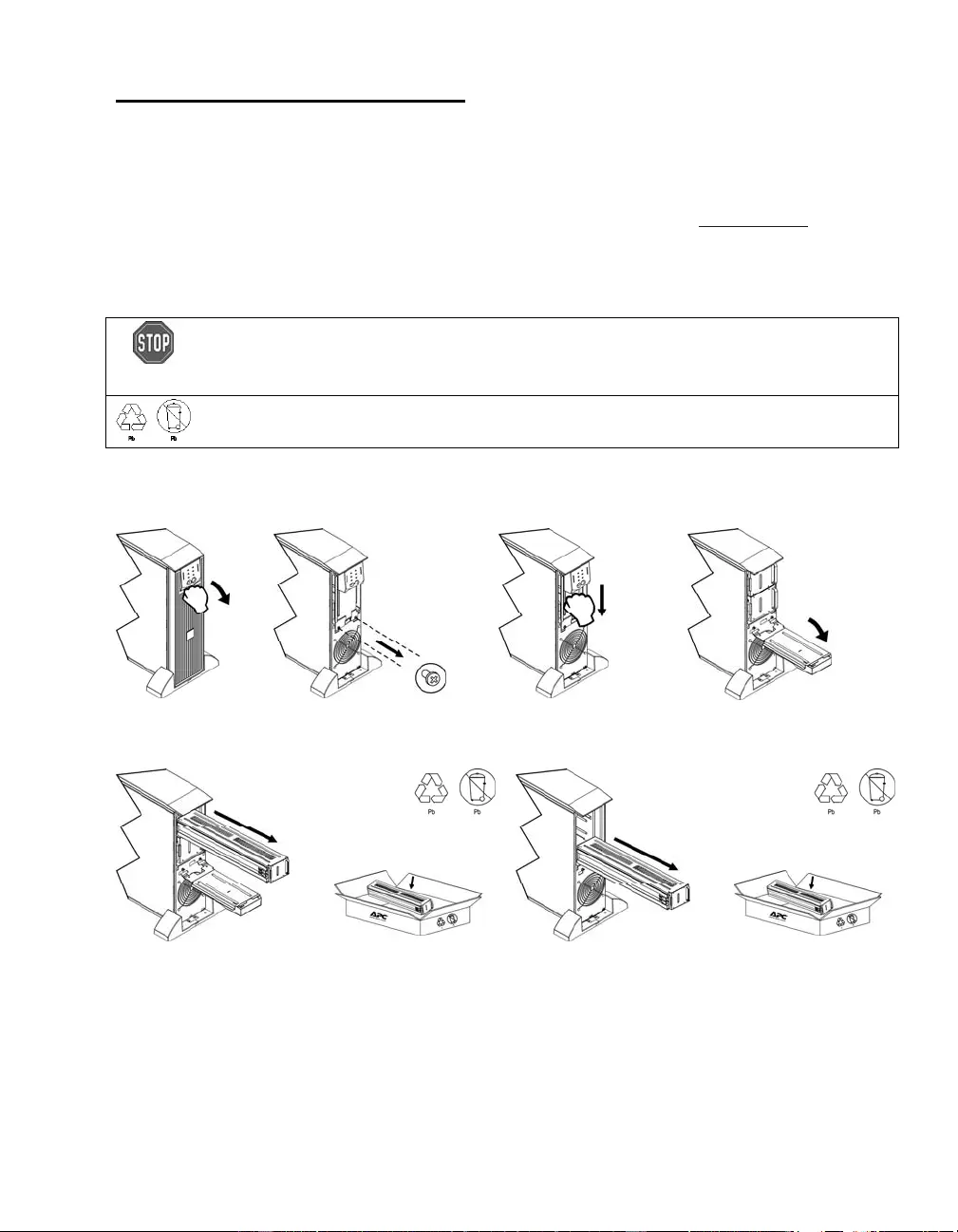
REMOVING BATTERY MODULES
X Y Z
[ \
16
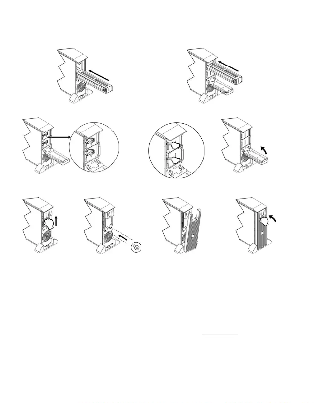
REPLACING BATTERY MODULES
X Y
Z [ \
] ^ _ ⎯
Disconnecting the Battery for Transport
Alway s DISCONNECT THE BATTERY(s) before shipping in compliance with U.S.
Departme nt of Transportation (DOT) and IATA regulations.
The battery(s) may remain in the UPS.
1. Shut down and disconnect any equipment attached to the UPS.
2. Shut down and disconnect the UP S from the power supply.
3. Unplug the battery connectors. Refer to Replacing Battery modules in this ma nual.
For shipping instructio ns go to the APC by Schneider Electric web site, www.apc.com.
17
TROUBLESHOOTING, SERVICE, AND WARRANTY INFORMATION
Use the table below to solve minor installation and op e ration problems. Refer to the APC by
Schneider Electric web site, www.apc.com for assistance with complex UPS problems.
PROBLEM AND POSSIBLE
CAUSE SOLUTION
UPS WILL NOT TURN ON
Battery not connected properly. Check that the batter y connectors are fully engaged.
button not pushed. Press the button onc e to power the UPS and the connected equipment.
UPS not connected to utility
power supply. Check that the power cable from the UPS to the utility power supply is securely
connected at both ends.
Very low or no utility voltage. Check the utility power supply to the UPS by plugging i n a tab le lamp. If the
light is very dim, have the utility voltage checked.
UPS WILL NOT TURN OFF
button not pushed. Press the button once to turn the UPS of f.
Internal UPS f ault. Do not attempt to use the UPS. Unplug the UP S and have it servic ed
immediately.
UPS BEEPS OCCASIONALLY
Normal UPS operation when
running on battery. None. The UPS is protect ing the connected equipment.
UPS DOES NOT PROVIDE EXPECTED BACKUP TIME
The UPS batter y(s) are weak
due to a recent outage or
battery(s) are near the end of
their service life.
Charge the battery(s ). Battery modules require recharging af ter extended outages.
They wea r faster when put into service often or when operated at elevated
temperatures. If the batt ery(s) are near the end of their service life, consider
replacing the battery(s) even if the Replace Battery LED is not illuminated.
FRONT PANEL LEDS FLASH SEQUENTIALLY
The UPS has been shut down
remotely through software or an
option al ac ce sso ry card.
None. The UPS will restart automatically when utility power returns.
ALL LEDS ARE OFF AND THE UPS IS PLUGGED INTO A WALL OUTLET
The UPS is shut down a nd the
battery is discharged from an
extended outage.
None. The UPS will return to normal operation when the power is restored and
the battery has a sufficient charge.
BYPASS AND OVERLOAD LEDS ILLUMINATE, UPS EMITS A SUSTAINED ALARM TONE
The UPS is overloaded The c onnected equipm ent exceeds the specified “maximum load” as defined i n
Specifications on the APC by Schneider Electric web site, www.apc.com.
The alarm remains on until the overload is removed. Disconnect nonessentia l
equipment from the UPS to eliminate the overload condition.

18
PROBLEM AND POSSIBLE
CAUSE SOLUTION
BYPASS LED ILLUMINATES
The bypass switch has been
turned on manually or through
an accessory.
If bypass is t he chosen mode of operation, i gnore the illuminated LED.
If bypass is not the chosen mode of operation move the bypass switch on the
back of the UPS, to the normal position.
FAULT AND OVERLOAD LEDS ILLUMINATE, UPS EMITS A SUSTAINED ALARM TONE
The UPS has ceased sending
power to connected equipment. The connected equipment exceeds the specified “maximum load” as defined in
Specifications on the APC by Schneider Electric web site, www.apc.com.
Disconnect nonessential equipment from the UPS to el iminate t he overload
condition.
Press the OFF but ton, then t he ON button to res tore power to connect ed
equipment.
FAULT LED ILLUMINATES
Internal UPS fault. Do not attempt to use the UPS. Turn the UPS off and have it serviced
immediately.
REPLACE BATTERY LED ILLUMINATES
Replace Battery LED flashes and
short beep is emitted every two
seconds to indicate the battery is
disconnected.
Check that the batter y connectors are fully engaged.
Weak battery. Allow the battery to recharge for 24 hours. Then, perform a self-test. If the
problem persists after recharging, replace the battery.
Failure of a battery self-test. The UPS emits short beeps for one minute and the Replace Battery LED
illuminates. The UPS repeats the alarm every five hours. Perform the self-test
procedure after the battery has charged for 24 hours t o confirm the Replace
Battery condition. The alarm stops and the LED clears if the battery passes the
self-test.
UPS OPERATES ON BATTERY ALTHOUGH NORMAL LINE VOLTAGE EXISTS
Very high, low, or di stort ed line
voltage. Inexpensive fuel
powered generators can dist ort
the voltage.
Move the UPS to a different outlet on a different circuit. Test the input voltage
with the utility voltage display.
DIAGNOSTIC UTILITY VOLTAGE
All five LEDs are illuminat ed The line volta ge is extremely high and should b e check ed by an electrici an.
There is no LED illumination If the UPS is plugged into a properly functioning utility power outlet, the line
voltage is extremely low.
ONLINE LED
There is no LED illumination The UPS is running on batt ery, or it is not turned on.
The LED is blinking The UPS is running an internal self-test .

19
Service
If the unit requires service, do not return it to the dealer. Follow these steps:
1 . Review the Troubleshooting section of the manual to eliminate common problems.
2 . If the problem persists, contact APC by Schneider Electric Customer Support through
the APC by Schneider Electric web site, www.apc.com.
a. Note the model number and serial number and the date of purchase. The
model and serial numbers are located on the rear panel of the unit and
are available through the LCD display on select models.
b. Call Customer Support and a technician will attempt to solve the
problem over the phone. If this is not possible, the technician will issue a
Returned Material Authorization Number (RMA#).
c. If the unit is under warranty, the repairs are free.
d. Service procedures and returns may vary internationally. Refer to the
APC by Schneider Electric web site, www.apc.co m for country specific
instructions.
3 . Pack the unit properly to avoid damage in transit. Never use foam beads for
pac kaging. Damage sustaine d in transi t is not cover ed under warranty.
a. Note: When shipping within the United States, or to the United
States always DISCONNECT ONE UPS BATTERY before shipping
in compliance with U.S. Department of Transportation (DOT) and
IATA regulations. The internal batteries may remain in the UPS.
b. Batteries may remain connected in the XBP during shipment. Not all
units utilize XLBPs.
4 . Write the RMA# provided by Customer Support on the outside of the package.
5 . Return the unit by insured, prepaid carrier to the address provided by Customer
Support.

20
Limited Factory Warranty
Schneider Electric IT Corporati on (SEIT) warrants it s products to be free from defects in materi als and workmanship for a
period of two (2) years from t he date of purchase. The SEIT obligation under this warranty is limited to repairing or replacing,
at its own sole option, any such defective products. Repair or replacement of a defective product or parts thereof does not
extend the original warranty period.
This warranty applies only to th e original purchas er wh o must have pr op erly registered the product within 10 days of
pu rchase. Products ma y be registered online at warranty.apc.com.
SEIT shall not be liab le under t he warranty if its testin g and examination disclose that the alleged defect in the product do es
not exist or was caused by end user or any third person misuse, negligence, improper installation, testing, operation or use of
the pr oduct contrary to SEIT recommendations or specification s. Further, SEIT shall not be liable for defects res ulti ng from:
1) unauthorized attempts to repair or modify the product, 2) incorrect or inadequate electrical voltage or connection, 3)
inappropriate on site operation conditions, 4) Acts of God, 5) exposure to the elements, or 6) theft. In no event shall SEIT have
any liability under this warranty for any product where the serial number has been altered, defaced, or removed.
EXCEPT AS SET FORTH ABOVE, THERE ARE NO WARRANTIES, EXPRESS OR IMPLIED, BY OPERATION
OF LAW OR OTHERWISE, APPLICABLE TO PRODUCTS SOLD, SERVICED OR FURNISHED UNDER THIS
AGREEMENT OR IN CONNECTION HERE WITH.
SEIT DISCLAIMS ALL IMPLIED WARRANTIES OF MERCHANTABIL ITY, SATISFACTION AND FITNESS
FOR A PARTICULAR PURPOSE.
SEIT EXPRESS WARRANTIES WILL NOT BE ENLARGED, DIMINISHED, OR AFFECTED BY AND NO
OBLIGATION OR LIABILITY WILL ARISE OUT OF, SEIT RENDERING OF TECHNICAL OR OTHER
ADVICE OR SERVICE IN CONNECTION WITH THE PRODUCTS.
THE FORE GOING WARRANTIES AND RE MEDIES ARE EXCLUSIVE AND IN LIEU OF ALL OTHER
WARRANTIES AND REMEDIES. THE WARRANTIES SET FORTH ABOVE CONSTITUTE SEIT SOLE
LIABILITY AND PURCHASER EXCLUSIVE REMEDY FOR ANY BREACH OF SUCH WARRANTIES. SEIT
WARRANTIES EXTEND ONL Y TO ORIGINAL P URCHASER AND ARE NOT EXTENDED TO ANY THIRD
PARTIES.
IN NO EVENT SHALL SEIT, ITS OFFICERS, DIRECTORS, AFFILIATES OR EMPLOYEES BE LIABLE FO R
ANY FORM OF INDIRECT, SPECIAL, CONSEQUENTIAL OR PUNITIVE DAMAGES, ARISING OUT OF THE
USE, SERVICE OR INSTALLATION OF THE PRODUCTS, WHETHER SUCH DAMAGES ARISE IN
CONTRACT OR TORT, IRRE SPECTIVE OF FAULT, NEGLIGENCE OR STRICT LIABILITY OR WHETHER
SEIT HAS BEEN ADVISED IN ADVANCE OF THE POSSIBIL ITY OF SUCH DAMAGES. SPECIFICALLY, SEIT
IS NOT LIABLE FOR ANY COSTS, SUCH AS LOST PROFITS OR REVENUE, WHETHER DIRECT OR
INDIRECT, LOSS OF EQUIPMENT, LOSS OF USE OF EQUIPMENT, LOSS OF SOFTWARE , LOSS OF DATA,
COSTS OF SUBSTITUANTS, CLAIMS BY THIRD PARTIES, OR OTHERWISE.
NOTHING IN THIS LIMITED WARRANTY SHALL SEEK TO EXCLUDE OR LIMIT SEIT LIABILITY FOR
DEATH OR PERSONAL INJURY RESULTING FROM ITS NEGLIGENCE OR ITS FRAUDULENT
MISREPRESENTATION OF TO THE EXTENT THAT IT CANNOT BE EXCLUDE D OR LIMITED BY
APPLICABLE LAW.
To obta in service under warranty you must obtain a Returned Materi al Authoriza tion (RMA) number from customer support.
Customers with warranty claims issues may access the SEIT worldwide customer support network through the APC by
Schneider Electric web site: www.apc.com. Select your country from the country selection drop down menu. Open the
Support tab at the top of the web page to obtain information for customer support in your region . Products must be retu rned
with transportation charges prepaid and must be accompanied by a brief description of the problem encountered and proof of
date and place of purchase.


07/2014
EN 990-2690C
APC by Schneider Electric
Worl dwide Customer Support
Customer support for this or any other APC by Schneider Electric product is
available at no charge in any of the following ways:
• Visit the APC by Schneider Electric web site, www.apc.com to access
documents in the APC Knowledge Base and to submit customer support
requests.
–www.apc.com (Corporate Headquarters)
Connect to localized APC by Schneider Electric web site for specific
countries, each of which provides customer support information.
–www.apc.com/support/
Global support searching APC Knowledge Base and using e-support.
• Contact the APC by Schneider Electric Customer Support Center by
telephone or e-mail.
– Local, c ountry spec if ic centers: go to www.apc.com/support/contact for
contact information.
– For information on how to obtain local customer support, contact the
APC by Schneider Electr ic repr esent ative or other distribut or fro m whom
you purchased your APC by Schneider Electric product.
© 2014 APC by Schneider Electric. Smart-UPS and PowerChute are owned by Schneider Electric
Industries S.A.S. or their affiliated companies. All other trademarks are property of their respective
owners.