Table of Contents
- Safety information
- Chapter 1: Product Introduction
- Chapter 2: Basic Installation
- 2.1 Building your PC system
- 2.1.1 Motherboard installation
- 2.1.2 CPU installation
- 2.1.3 CPU heatsink and fan assembly installation
- 2.1.4 DIMM installation
- 2.1.5 ATX power connection
- 2.1.6 SATA device connection
- 2.1.7 Front I/O connector
- 2.1.8 Expansion card installation
- 2.1.9 SupremeFX Hi-Fi installation
- 2.1.10 Wi-Fi antenna installation
- 2.2 BIOS update utility
- 2.3 Motherboard rear and audio connections
- 2.4 Starting up for the first time
- 2.5 Turning off the computer
- 2.1 Building your PC system
- Chapter 3: BIOS Setup
- 3.1 Knowing BIOS
- 3.2 BIOS setup program
- 3.3 My Favorites
- 3.4 Main menu
- 3.5 Extreme Tweaker menu
- 3.6 Advanced menu
- 3.6.1 CPU Configuration
- 3.6.2 PCH Configuration
- 3.6.3 PCH Storage Configuration
- 3.6.4 System Agent (SA) Configuration
- 3.6.5 USB Configuration
- 3.6.6 Platform Misc Configuration
- 3.6.7 Onboard Devices Configuration
- 3.6.8 APM Configuration
- 3.6.9 Network Stack Configuration
- 3.6.10 ROG Effects
- 3.6.11 HDD/SDD SMART Information
- 3.7 Monitor menu
- 3.8 Boot menu
- 3.9 Tool menu
- 3.10 Exit menu
- 3.11 Updating BIOS
- Chapter 4: RAID Support
- Appendix
ASUS ROG Rampage V Edition 10 User Manual
Displayed below is the user manual for ROG Rampage V Edition 10 by ASUS which is a product in the Motherboards category. This manual has 130 pages.
Related Manuals

Motherboard
RAMPAGE V
EDITION 10

ii
E11375
First Edition
April 2016
Copyright © 2016 ASUSTeK COMPUTER INC. All Rights Reserved.
No part of this manual, including the products and software described in it, may be reproduced,
transmitted, transcribed, stored in a retrieval system, or translated into any language in any form or by any
means, except documentation kept by the purchaser for backup purposes, without the express written
permission of ASUSTeK COMPUTER INC. (“ASUS”).
Product warranty or service will not be extended if: (1) the product is repaired, modied or altered, unless
such repair, modication of alteration is authorized in writing by ASUS; or (2) the serial number of the
product is defaced or missing.
ASUS PROVIDES THIS MANUAL “AS IS” WITHOUT WARRANTY OF ANY KIND, EITHER EXPRESS
OR IMPLIED, INCLUDING BUT NOT LIMITED TO THE IMPLIED WARRANTIES OR CONDITIONS OF
MERCHANTABILITY OR FITNESS FOR A PARTICULAR PURPOSE. IN NO EVENT SHALL ASUS, ITS
DIRECTORS, OFFICERS, EMPLOYEES OR AGENTS BE LIABLE FOR ANY INDIRECT, SPECIAL,
INCIDENTAL, OR CONSEQUENTIAL DAMAGES (INCLUDING DAMAGES FOR LOSS OF PROFITS,
LOSS OF BUSINESS, LOSS OF USE OR DATA, INTERRUPTION OF BUSINESS AND THE LIKE),
EVEN IF ASUS HAS BEEN ADVISED OF THE POSSIBILITY OF SUCH DAMAGES ARISING FROM ANY
DEFECT OR ERROR IN THIS MANUAL OR PRODUCT.
SPECIFICATIONS AND INFORMATION CONTAINED IN THIS MANUAL ARE FURNISHED FOR
INFORMATIONAL USE ONLY, AND ARE SUBJECT TO CHANGE AT ANY TIME WITHOUT NOTICE,
AND SHOULD NOT BE CONSTRUED AS A COMMITMENT BY ASUS. ASUS ASSUMES NO
RESPONSIBILITY OR LIABILITY FOR ANY ERRORS OR INACCURACIES THAT MAY APPEAR IN THIS
MANUAL, INCLUDING THE PRODUCTS AND SOFTWARE DESCRIBED IN IT.
Products and corporate names appearing in this manual may or may not be registered trademarks or
copyrights of their respective companies, and are used only for identication or explanation and to the
owners’ benet, without intent to infringe.
Offer to Provide Source Code of Certain Software
This product contains copyrighted software that is licensed under the General Public License (“GPL”),
under the Lesser General Public License Version (“LGPL”) and/or other Free Open Source Software
Licenses. Such software in this product is distributed without any warranty to the extent permitted by the
applicable law. Copies of these licenses are included in this product.
Where the applicable license entitles you to the source code of such software and/or other additional data,
you may obtain it for a period of three years after our last shipment of the product, either
(1) for free by downloading it from https://www.asus.com/support/
or
(2) for the cost of reproduction and shipment, which is dependent on the preferred carrier and the location
where you want to have it shipped to, by sending a request to:
ASUSTeK Computer Inc.
Legal Compliance Dept.
15 Li Te Rd.,
Beitou, Taipei 112
Taiwan
In your request please provide the name, model number and version, as stated in the About Box of the
product for which you wish to obtain the corresponding source code and your contact details so that we
can coordinate the terms and cost of shipment with you.
The source code will be distributed WITHOUT ANY WARRANTY and licensed under the same license as
the corresponding binary/object code.
This offer is valid to anyone in receipt of this information.
ASUSTeK is eager to duly provide complete source code as required under various Free Open Source
Software licenses. If however you encounter any problems in obtaining the full corresponding source
code we would be much obliged if you give us a notication to the email address gpl@asus.com, stating
the product and describing the problem (please DO NOT send large attachments such as source code
archives, etc. to this email address).

iii
Contents
Safety information ...................................................................................................... vi
About this guide ........................................................................................................ vii
RAMPAGE V EDITION 10 specifications summary ................................................. ix
SupremeFX Hi-Fi specifications summary ............................................................. xv
Package contents ..................................................................................................... xvi
Installation tools and components ........................................................................ xvii
Chapter 1: Product Introduction
1.1 Motherboard overview ...............................................................................1-1
1.1.1 Before you proceed ..................................................................... 1-1
1.1.2 Motherboard layout ..................................................................... 1-2
1.1.3 Central Processing Unit (CPU) ................................................... 1-4
1.1.4 System memory .......................................................................... 1-5
1.1.5 Expansion slots ........................................................................... 1-7
1.1.6 Onboard buttons and switches.................................................... 1-9
1.1.7 Onboard LEDs .......................................................................... 1-15
1.1.8 Jumper ...................................................................................... 1-24
1.1.9 Internal connectors....................................................................1-25
1.1.10 ProbeIt....................................................................................... 1-36
Chapter 2: Basic Installation
2.1 Building your PC system ...........................................................................2-1
2.1.1 Motherboard installation .............................................................. 2-1
2.1.2 CPU installation...........................................................................2-3
2.1.3 CPU heatsink and fan assembly installation ............................... 2-6
2.1.4 DIMM installation......................................................................... 2-8
2.1.5 ATX power connection ................................................................ 2-9
2.1.6 SATA device connection ........................................................... 2-10
2.1.7 Front I/O connector ................................................................... 2-11
2.1.8 Expansion card installation ....................................................... 2-12
2.1.9 SupremeFX Hi-Fi installation .................................................... 2-13
2.1.10 Wi-Fi antenna installation .......................................................... 2-14
2.2 BIOS update utility ................................................................................... 2-15
2.3 Motherboard rear and audio connections .............................................2-16
2.3.1 Rear I/O connection .................................................................. 2-16
2.3.2 Audio I/O connections ............................................................... 2-18
2.3.3 SupremeFX Hi-Fi Audio I/O connections .................................. 2-20
2.4 Starting up for the first time ....................................................................2-21
2.5 Turning off the computer ........................................................................2-21

iv
Chapter 3: BIOS Setup
3.1 Knowing BIOS ............................................................................................3-1
3.2 BIOS setup program ..................................................................................3-2
3.2.1 EZ Mode......................................................................................3-3
3.2.2 Advanced Mode .......................................................................... 3-4
3.2.3 QFan Control...............................................................................3-7
3.2.4 EZ Tuning Wizard ....................................................................... 3-9
3.3 My Favorites .............................................................................................3-12
3.4 Main menu ................................................................................................3-14
3.5 Extreme Tweaker menu ...........................................................................3-16
3.6 Advanced menu .......................................................................................3-18
3.6.1 CPU Conguration .................................................................... 3-19
3.6.2 PCH Conguration .................................................................... 3-20
3.6.3 PCH Storage Conguration....................................................... 3-20
3.6.4 System Agent (SA) Conguration ............................................. 3-21
3.6.5 USB Conguration .................................................................... 3-22
3.6.6 Platform Misc Conguration ...................................................... 3-22
3.6.7 Onboard Devices Conguration ................................................ 3-23
3.6.8 APM Conguration .................................................................... 3-24
3.6.9 Network Stack Conguration..................................................... 3-24
3.6.10 ROG Effects .............................................................................. 3-25
3.6.11 HDD/SDD SMART Information ................................................. 3-25
3.7 Monitor menu ...........................................................................................3-25
3.8 Boot menu ................................................................................................3-26
3.9 Tool menu ................................................................................................. 3-28
3.9.1 GPU Post .................................................................................. 3-28
3.9.2 ASUS EZ Flash 3 Utility ............................................................ 3-28
3.9.3 Secure Erase ............................................................................ 3-29
3.9.4 ASUS Overclocking Prole ....................................................... 3-30
3.9.5 ASUS SPD Information ............................................................. 3-31
3.10 Exit menu .................................................................................................. 3-31
3.11 Updating BIOS ..........................................................................................3-32
3.11.1 EZ Update ................................................................................. 3-32
3.11.2 ASUS EZ Flash 3 Utility ............................................................ 3-33
3.11.3 ASUS CrashFree BIOS 3 .......................................................... 3-35
Contents

v
Chapter 4: RAID Support
4.1 RAID configurations ..................................................................................4-1
4.1.1 RAID denitions .......................................................................... 4-1
4.1.2 Installing Serial ATA hard disks .................................................. 4-2
4.1.3 Intel® Rapid Storage Technology in UEFI BIOS .......................... 4-2
4.1.4 Intel® Rapid Storage Technology Option ROM utility .................. 4-6
4.2 Creating a RAID driver disk ....................................................................4-10
4.2.1 Creating a RAID driver disk in Windows® ................................. 4-10
Appendix
Notices .................................................................................................................... A-1
ASUS contact information ...................................................................................... A-6
Contents

vi
Safety information
Electrical safety
• To prevent electrical shock hazard, disconnect the power cable from the electrical outlet
before relocating the system.
• When adding or removing devices to or from the system, ensure that the power cables
for the devices are unplugged before the signal cables are connected. If possible,
disconnect all power cables from the existing system before you add a device.
• Before connecting or removing signal cables from the motherboard, ensure that all
power cables are unplugged.
• Seek professional assistance before using an adapter or extension cord. These devices
could interrupt the grounding circuit.
• Ensure that your power supply is set to the correct voltage in your area. If you are not
sure about the voltage of the electrical outlet you are using, contact your local power
company.
• If the power supply is broken, do not try to x it by yourself. Contact a qualied service
technician or your retailer.
Operation safety
• Before installing the motherboard and adding devices on it, carefully read all the manuals
that came with the package.
• Before using the product, ensure all cables are correctly connected and the power
cables are not damaged. If you detect any damage, contact your dealer immediately.
• To avoid short circuits, keep paper clips, screws, and staples away from connectors,
slots, sockets, and circuitry.
• Avoid dust, humidity, and temperature extremes. Do not place the product in any area
where it may become wet.
• Place the product on a stable surface.
• If you encounter technical problems with the product, contact a qualied service
technician or your retailer.

vii
About this guide
This user guide contains the information you need when installing and conguring the
motherboard.
How this guide is organized
This guide contains the following parts:
1. Chapter 1: Product Introduction
This chapter describes the features of the motherboard and the new technology it
supports. It includes description of the switches, jumpers, and connectors on the
motherboard.
2. Chapter 2: Basic Installation
This chapter lists the hardware setup procedures that you have to perform when
installing system components.
3. Chapter 3: BIOS Setup
This chapter explains how to change system settings through the BIOS Setup menus.
Detailed descriptions of the BIOS parameters are also provided.
4. Chapter 4: RAID Support
This chapter describes the RAID congurations.
Where to find more information
Refer to the following sources for additional information and for product and software
updates.
1. ASUS website
The ASUS website (www.asus.com) provides updated information on ASUS hardware
and software products.
2. Optional documentation
Your product package may include optional documentation, such as warranty yers,
that may have been added by your dealer. These documents are not part of the
standard package.

viii
Conventions used in this guide
To ensure that you perform certain tasks properly, take note of the following symbols used
throughout this manual.
DANGER/WARNING: Information to prevent injury to yourself when trying to
complete a task.
CAUTION: Information to prevent damage to the components when trying to
complete a task.
IMPORTANT: Instructions that you MUST follow to complete a task.
NOTE: Tips and additional information to help you complete a task.
Typography
Bold text Indicates a menu or an item to select.
Italics
Used to emphasize a word or a phrase.
<Key> Keys enclosed in the less-than and greater-than sign
means that you must press the enclosed key.
Example: <Enter> means that you must press the Enter or
Return key.
<Key1> + <Key2> + <Key3> If you must press two or more keys simultaneously, the key
names are linked with a plus sign (+).

ix
RAMPAGE V EDITION 10 specifications summary
CPU
New Intel® Core™ i7 X-Series Processors on LGA 2011-v3 Socket
Supports 14nm CPU
Supports Intel® Turbo Boost Max Technology 3.0*
* The support of these features depends on the CPU types.
Chipset Intel® X99 Chipset
Memory
8 x DIMM, max. 128GB, DDR4 3333(O.C)*/3300(O.C)*/3200(O.C)*/30
00(O.C.)*/2800(O.C)*/2666(O.C.)*/2400(O.C.)*/2133 MHz, non-ECC,
un-buffered memory
Quad channel memory architecture
Supports Intel® Extreme Memory Prole (XMP)
* Hyper DIMM support is subject to the physical characteristics of individual
CPUs.
Please refer to Memory QVL (Qualified Vendors List) for details.
Expansion Slots
4 x PCIe 3.0 x16 slots (supports x16, x16/x16, x16/x8/x8, x16/x8/x8/x8
or x8/x8/x8/x8 mode with 40-LANE CPU; x16, x16/x8 or x8/x8/x8 mode
with 28-LANE CPU)* [CPU]
1 x PCIe 2.0 x4 slot** [PCH]
1 x PCIe 2.0 x1 slot [PCH]
40-LANE CPU:
- In 4-Way conguration, if the PCIEX16/X8_1 is used in x16 mode,
both U.2 and M.2 ports will be disabled.
28-LANE CPU:
- In 2-Way and 3-Way conguration, U.2 port will be disabled.
* The PCIEX8_4 slot shares bandwidth with M.2 and U.2.
** The PCIEX4_1 slot shares bandwidth with front USB3_34 ports and back
USB3.1_EC1_EA2 ports.
If a X2 device is connected to the PCIEx4_1 slot, the front USB3_34 ports
will be disabled.
If a X4 or higher device is connected to the PCIEx4_1 slot, both front
USB3_34 and back USB3.1_EC1_EA2 ports will be disabled.
Multi-GPU Technology
Supports NVIDIA® 4-Way/3-Way/Quad-GPU SLI® Technology*
Supports AMD® 4-Way/3-Way/Quad-GPU CrossFireX™ Technology*
* 28-LANE CPUs can only support up to 3-Way SLI®/3-Way CrossFireX™.
Storage
New Intel® Core™ i7 Processors:
- 1 x M.2 PCIe 3.0 x4 Socket 3 with M Key, type 2260/2280/22110
(supports PCIe storage device only)*
- 1 x U.2 port (support PCIe 3.0 x4 NVM Express storage)*
Intel® X99 Chipset with RAID 0, 1, 5, 10 and Intel Rapid Storage
Technology 14 support**:
- 10 x SATA 6Gb/s ports
- Supports Intel® Smart Response Technology***
* These ports share bandwidth with PCIEX8_4 slot.
** Windows® 10 32-bit does not support RAID.
*** These functions will work depending on the CPU installed.
(continued on the next page)

x
(continued on the next page)
RAMPAGE V EDITION 10 specifications summary
LAN
Gigabit Intel® LAN connection - 802.3az Energy Efficient Ethernet
(EEE) appliance:
- Intel® I218-V Gigabit LAN- Dual interconnect between the integrated
Media Access Controller (MAC) and physical layer (PHY)
- Intel® I211-AT Gigabit LAN controller
Anti-surge LANGuard
ROG GameFirst Technology
Wireless / Bluetooth
Wi-Fi 802.11 a/b/g/n/ac support 3x3 dual frequency band 2.4/5 GHz
Up to 1300Mbps transfer speed
Bluetooth v4.0
Audio
SupremeFX 8-Channel High Definition Audio CODEC:
- SupremeFX Shielding Technology
- Dual Headpone Ampliers
- Jack-detection, Multi-streaming, and Front Panel Jack-retasking
- Optical S/PDIF out port at back panel
Audio Features:
- Sonic Radar II
- Sonic Studio II
- DTS connect
USB
Intel® X99 Chipset - supports ASUS USB 3.1 Boost:
- 4 x USB 3.0 ports (4 ports at mid-board)*
- 6 x USB 2.0 ports (2 ports at back panel [black], 4 ports at mid-
board)**
ASMedia® USB 3.1 Controller - support ASUS USB 3.1 Boost:
- 4 x USB 3.1 ports (2 x Type-A [red] and 2 x Type-C ports [black] at
back panel)*
ASMedia® USB 3.0 controller - supports ASUS USB 3.1 Boost:
- 4 x USB 3.0 ports (at back paned [blue])
* Front USB3_34 ports and back USB3.1_EC1_EA2 ports share bandwidth
with PCIEX4_1 slot.
If a X2 device is connected to the PCIEx4_1 slot, the front USB3_34 ports
will be disabled.
If a X4 or higher device is connected to the PCIEx4_1 slot, both front
USB3_34 and back USB3.1_EC1_EA2
** 2 x USB2.0 ports at mid-board share with ROG extension (ROG_EXT) port

xi
ROG Exclusive Features
Extreme Engine Digi+
- MicroFine Alloy Choke
- IR3555 PoweIRstage®
- 10K Black Metallic Capacitors
OC Zone
- ReTry button
- Safe Boot button
- LN2 Mode header
- Slow Mode switch
- Start button
- Reset button
- ProbeIt
- PCIe x16 lane switch
- DRAM channel switches
ROG RAMCache
ROG RAMDisk
AURA
KeyBot II
- One-click overclocking
- X.M.P.
- DirectKey
- CLr CMOS
- Power On
UEFI BIOS features:
- Extreme Tweaker
- Tweakers’ Paradise
- ROG SSD Secure Erase
- GPU.DIMM Post
- O.C. Prole
- Graphics Card Information Preview
(continued on the next page)
RAMPAGE V EDITION 10 specifications summary

xii
Special Features
ASUS Dual Intelligent Processors 5
- 5-Way Optimization tuning key perfectly consolidates TPU, EPU,
DIGI+ Power Control, Fan Xpert 3, and Turbo App
ASUS Wi-Fi GO! Module
- Wi-Fi 3x3 802.11 a/b/g/n/ac and Bluetooth v4.0
Media Streamer
- Pipe music or movies from your PC to a smart TV, your
entertainment goes wherever you go!
- Media Streamer app for portable smartphone/tablet, supporting iOS
7 & Android 4.0 systems
HyStream
- Stream Android/iOS/Windows devices’ screen on your PC screen.*
ASUS Exclusive Features:
- AI Suite 3
- USB 3.1 Boost
- AI Charger+
- Push Notice
ASUS EZ DIY
- USB BIOS Flashback
- ASUS CrashFree BIOS 3
- ASUS EZ Flash 3
- ASUS C.P.R.(CPU Parameter Recall)
- MemOK!
ASUS Q-Design
- ASUS Q-Code
- ASUS Q-Connector
- ASUS Q-LED (CPU, DRAM, VGA, and Boot Device LED)
- ASUS Q-Slot
- ASUS Q-DIMM
* Contact your device vendor for supporting information.
Back Panel I/O Ports
1 x Clear CMOS button
1 x BIOS Flashback button
4 x USB 3.0 ports [blue]
4 x USB 3.1 ports (2 x Type-C [black] and 2 x Type-A [red])
2 x Anti-surge LAN (RJ45) ports
1 x ASUS Wi-Fi GO! module (Wi-Fi 3x3 802.11 a/b/g/n/ac and
Bluetooth v4.0)
1 x PS/2 keyboard/mouse combo port
2 x USB 2.0 ports [black]
1 x Optical S/PDIF out
5 x Audio jacks
RAMPAGE V EDITION 10 specifications summary
(continued on the next page)

xiii
Internal I/O Connectors
2 x USB 3.0 connector support additional 4 USB 3.0 ports
2 x USB 2.0 connectors support additional 4 USB 2.0 ports
[one connector via ROG_EXT header]
10 x SATA 6Gb/s connectors
1 x U.2 port
1 x M.2 PCIe 3.0 x4 Socket 3 with M Key, type 2260/2280/22110
(supports PCIe storage device only)*
1 x ROG extension (ROG_EXT) header
1 x 4-Pin CPU fan connector
1 x 4-Pin CPU_OPT fan connector
1 x 4-Pin H_AMP fan connector
3 x 4-Pin Chassis fan connectors
1 x 4-pin Water pump connector
1 x 5-pin EXT_FAN (Extension Fan) connector
1 x Thermal sensor connector
1 x 24-pin EATX power connector
1 x 8-pin EATX 12V power connector
1 x 4-pin EATX 12V power connector
1 x EZ Plug connector
9 x ProbeIt Measurement Points
1 x Power-on button
1 x Reset button
1 x Safe Boot button
1 x ReTry button
1 x LN2 mode jumper
1 x Slow mode switch
1 x DRAM channel switch
1 x PCIe x16 lane switch
1 x MemOK! button
1 x SLI/CFX switch
1 x BIOS Switch button
1 x System panel connector
1 x Aura RGB Strip Header
1 x TPM connector
1 x Front panel audio connector (AAFP)
1 x Thunderbolt header
BIOS Features
128 Mb Flash ROM, UEFI AMI BIOS, PnP, WfM2.0, SM BIOS 3.0,
ACPI 5.0, Multi-language BIOS, ASUS EZ Flash 3, CrashFree BIOS 3,
F11 EZ Tuning Wizard, F6 Qfan Control, F3 My Favorites, Quick Note,
Last Modied log, F12 PrintScreen, and ASUS DRAM SPD (Serial
Presence Detect) memory information.
Manageability WfM 2.0, WOL by PME, PXE
RAMPAGE V EDITION 10 specifications summary
(continued on the next page)
xiv
RAMPAGE V EDITION 10 specifications summary
Software
Drivers
ROG GameFirst Technology
ROG RAMDisk
ROG RAMCache
ROG CPU-Z
ROG Mem TweakIt
AURA
Kaspersky® Anti-Virus
ASUS WebStorage
ASUS Utilities
Operating Systems
Support Windows® 10 / Windows® 8.1 / Windows® 7
Form Factor Extended ATX Form Factor, 12”x 10.7” (30.5cm x 27.2cm)
Specications are subject to change without notice.

xv
SupremeFX Hi-Fi specifications summary
Hardware
1 x ESS ES9018K2M SABRE DAC
2 x LM4562 Op amps
1 x TPA6120A2 Headphone amp
1 x Cirrus Logic CS5361
5 x RC4580 Op amps
Headphone Output
Performance
Supported formats: Up to 32-bit/384kHz and DSD 64/128*
Output (32Ohms): 4.8VRMS (720mW RMS per channel)
Output (600Ohms): 6.8VRMS (77mW RMS per channel)
THD+N @ 1K (-3dB): -104dB (<0.0007%)
Signal to Noise Ratio (A-weighted): -121.1dB
Crosstalk: -98dB
* Sample rates greater than 32-bit/96kHz are only supported when high
speed mode is enabled.
Rear I/O Ports POWER : 1 x 6-pin PCIe power connector
SIGNAL : 1 x USB 2.0 header
Front I/O Ports
1 x Volume control knob
1 x 6.3mm headphone jack*
1 x 3.5mm headphone jack*
1 x 3.5mm mic/line in jack
* Only one of these jacks will be active at a given time
Dimensions
5.25” ODD drive bay Form Factor (14.5 x 4.2x 14cm [W x H x D])*
* The face of this device is designed to be flush with a standard drive bay
with the knob extending 1cm

xvi
Package contents
Check your motherboard package for the following items.
Motherboard ROG RAMPAGE V EDITION 10
Cables
5 x 2-in-1 SATA 6.0 Gb/s signal cables
1 x 4-Way SLI® bridge
1 x 3-Way SLI® bridge
1 x SLI® bridge
1 x 3-in-1 thermistor cables
1 x Wafer cable
1 x Cable for SupremeFX Hi-Fi
1 x AURA cable
Accessories
1 x ASUS 3T3R dual band Wi-Fi moving antennas (Wi-Fi
802.11a/b/g/n/ac compliant)
1 x FAN Extension Card
1 x Q-Connector Kit
2 x ROG coaster
1 x ROG fan label
1 x ROG cable label set
1 x M.2 screws kit
1 x Bracket for FAN Extension Card
1 x CPU Installation Tool for Broadwell processors
1 x CPU Installation Tool for Haswell processors
1 x I/O frame
Application drive USB drive with utilities and drivers
Documentation User guide
If any of the above items is damaged or missing, contact your retailer.
xvii
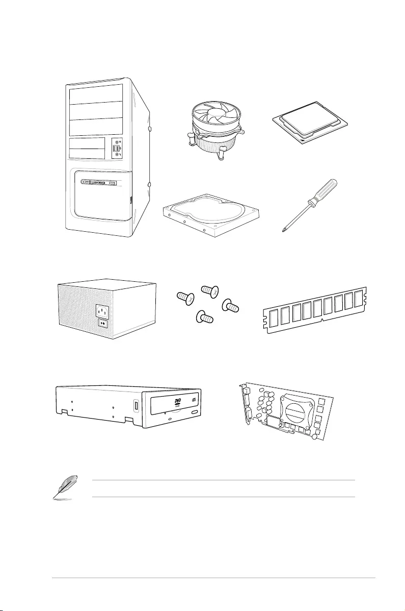
Installation tools and components
The tools and components listed above are not included in the motherboard package.
PC chassis
Power supply unit
Intel® LGA2011-v3 compatible CPU Fan
Intel® LGA2011-v3 CPU
DIMM
SATA hard disk drive
Graphics card
Phillips (cross) screwdriver
SATA optical disc drive (optional)
1 bag of screws

xviii

ASUS RAMPAGE V EDITION 10 1-1
Chapter 1
Product Introduction
1
Chapter 1: Product Introduction
1.1 Motherboard overview
1.1.1 Before you proceed
Take note of the following precautions before you install motherboard components or change
any motherboard settings.
• Unplugthepowercordfromthewallsocketbeforetouchinganycomponent.
• Beforehandlingcomponents,useagroundedwriststraportouchasafelygrounded
objectorametalobject,suchasthepowersupplycase,toavoiddamagingthemdue
to static electricity.
• HoldcomponentsbytheedgestoavoidtouchingtheICsonthem.
• Wheneveryouuninstallanycomponent,placeitonagroundedantistaticpadorinthe
bag that came with the component.
• Beforeyouinstallorremoveanycomponent,ensurethattheATXpowersupplyis
switched off or the power cord is detached from the power supply. Failure to do so
maycauseseveredamagetothemotherboard,peripherals,orcomponents.
1-2 Chapter 1: Product Introduction
Chapter 1
Refer to 1.1.9 Internal connectors and 2.3.1 Rear I/O Connection sections for more
information about the internal connectors and rear panel connectors.
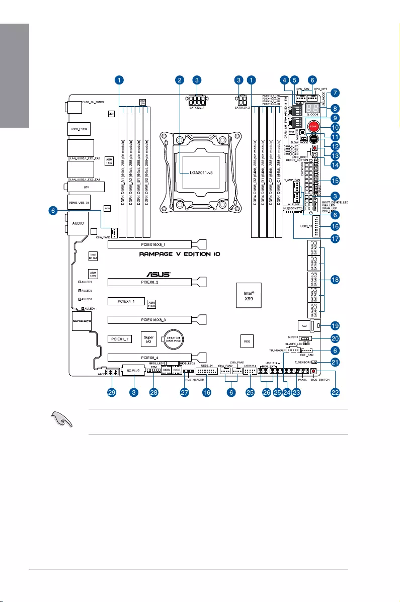
1.1.2 Motherboard layout

ASUS RAMPAGE V EDITION 10 1-3
Chapter 1
Layout contents
Connectors/Jumpers/Buttons and switches/Slots Page
1. DDR4DIMMslots 1-5
2. LGA2011-v3CPUsocket 1-4
3. ATXpowerconnectors(24-pinEATXPWR;8-pinEATX12V_1;4-pin
EATX12V_2;4-pinEZ_PLUG) 1-33
4. PCIex16Laneswitch(PCIEX16_SW) 1-13
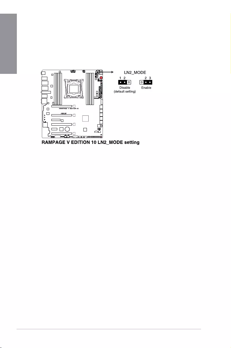
5. LN2Modejumper(3-pinLN2_MODE) 1-24
6. CPU,CPUoptional,highamp,waterpump,extensionandchassisfan
connectors(4-pinCPU_FAN;4-pinCPU_OPT;4-pinH_AMP_FAN;
4-pinW_PUMP;5-pinEXT_FAN;4-pinCHA_FAN1-3)
1-32
7. Q-CodeLED(Q_CODE1) 1-18
8. DRAMLaneswitch(DRAM_SM_SW) 1-13
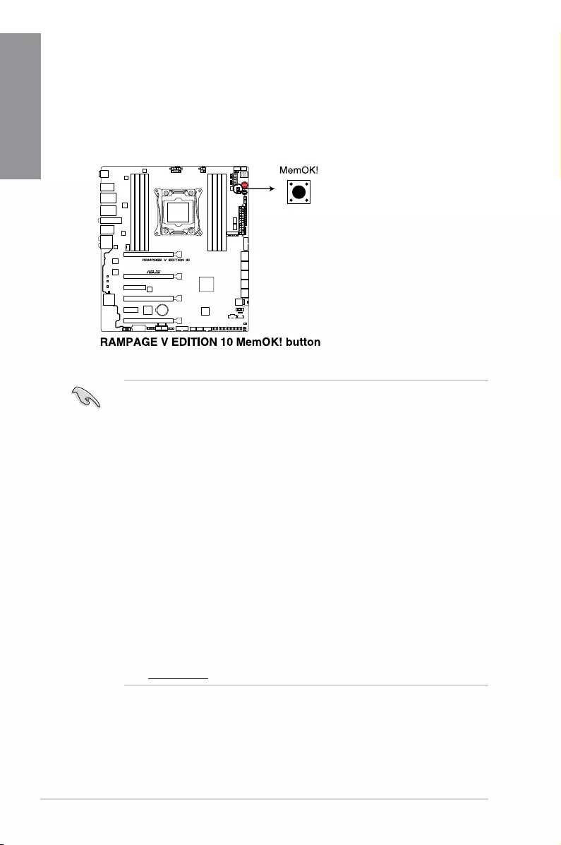
9. MemOK!button(MemOK!) 1-10
10. Power-on(START)button 1-9
11. SlowModeSwitch(SLOW_MODE) 1-14
12. RESETbutton 1-9
13. SafeBootbutton(SAFE_BOOT) 1-12
14. ReTrybutton(RETRY_BUTTON) 1-11
15. ProbeIt 1-36
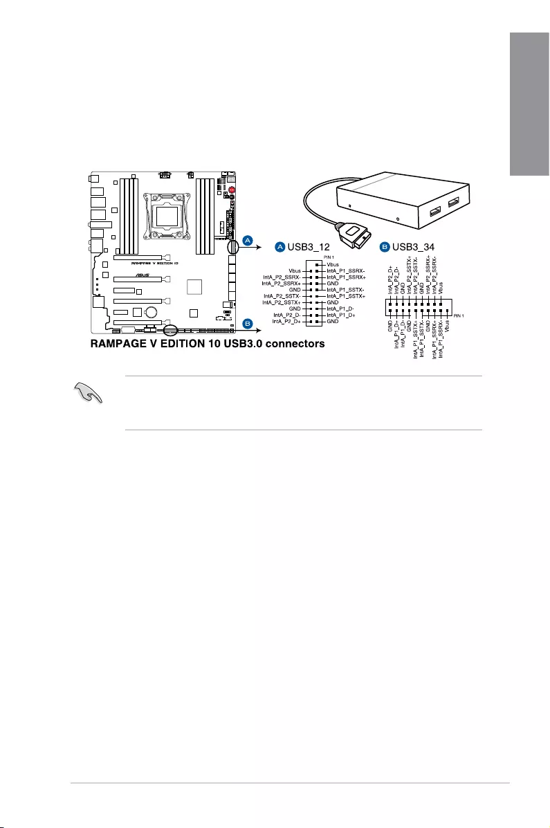
16. USB3.0connector(20-1pinUSB3_12;USB3_34) 1-27
17. M.2(SOCKET3) 1-30
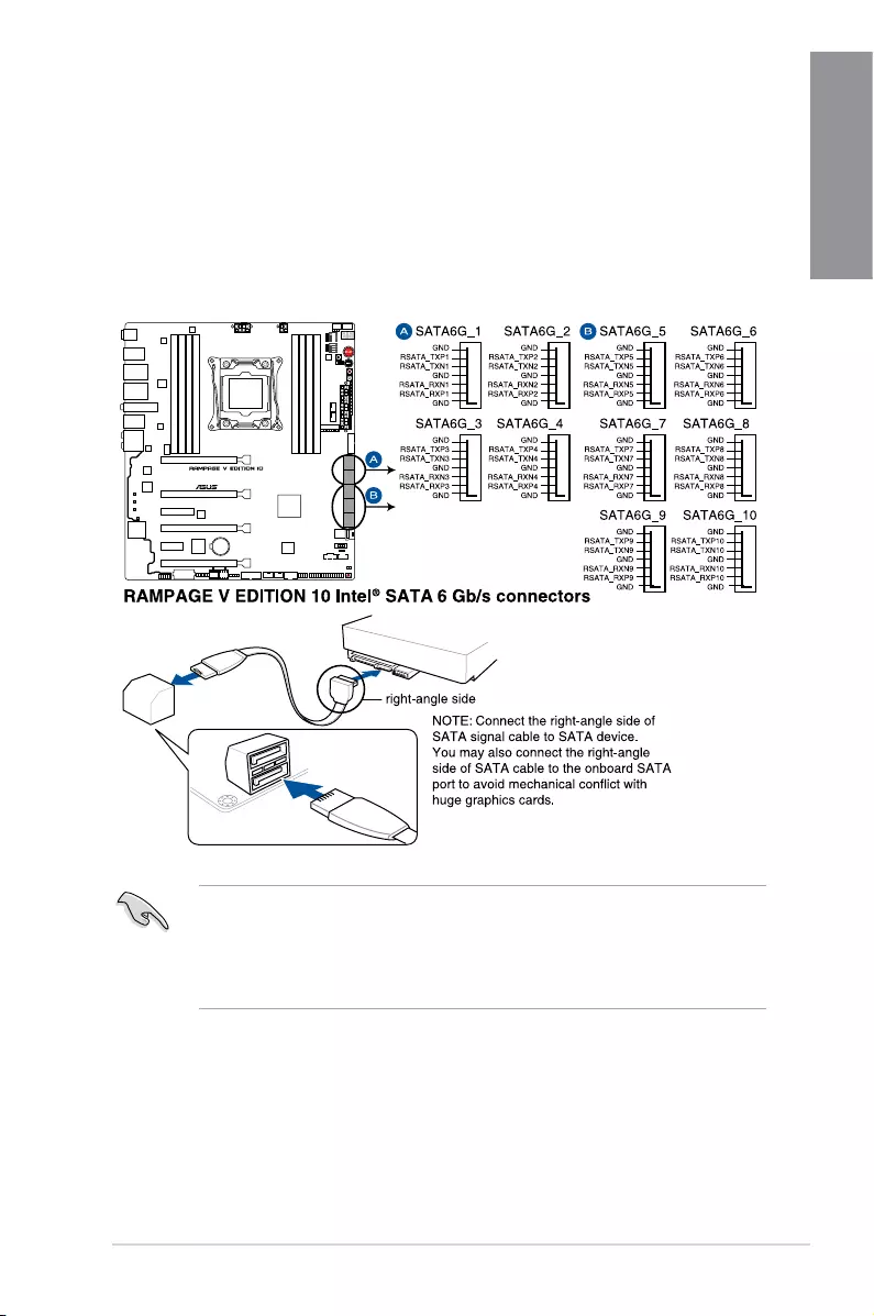
18. Intel®X99SerialATA6Gb/sconnectors(7-pinSATA6G_1-10) 1-25
19. U.2connector(U.2) 1-35
20. SLI/CFXswitch(SLI/CFX) 1-12
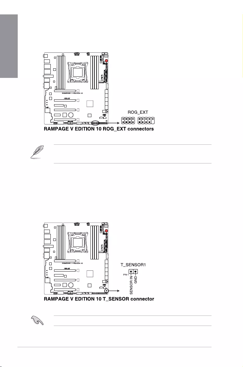
21. Thermalsensorcableconnector(2-pinT_SENSOR1) 1-26
22. BIOSSwitchbutton(BIOS_SWITCH) 1-11
23. Systempanelconnector(20-3pinPANEL) 1-34
24. Thunderboltheader(5-pinTB_HEADER) 1-29
25. USB2.0connector(10-1pinUSB1112,USB1314) 1-28
26. ROGExtensionconnector(18-1pinROG_EXT) 1-26
27. RGBheader(4-pinRGB_HEADER) 1-31
28. TPMconnector(14-1pinTPM) 1-29
29. Frontpanelaudioconnector(10-1pinAAFP) 1-30
1-4 Chapter 1: Product Introduction
Chapter 1
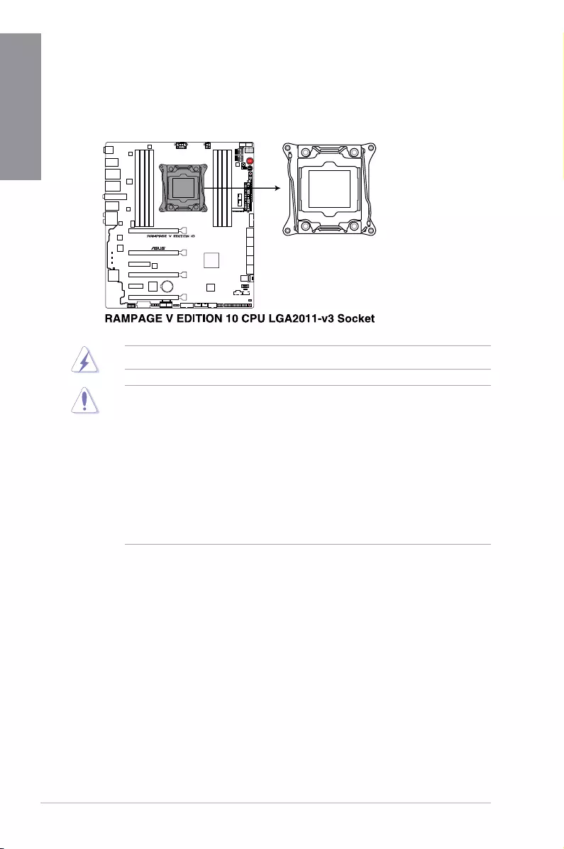
1.1.3 Central Processing Unit (CPU)
ThemotherboardcomeswithasurfacemountLGA2011-v3socketdesignedforNewIntel®
Core™i7X-SeriesProcessorsonLGA2011-v3socket.
• Uponpurchaseofthemotherboard,ensurethatthePnPcapisonthesocketand
thesocketcontactsarenotbent.ContactyourretailerimmediatelyifthePnPcap
ismissing,orifyouseeanydamagetothePnPcap/socketcontacts/motherboard
components.ASUSwillshoulderthecostofrepaironlyifthedamageisshipment/
transit-related.
• Keepthecapafterinstallingthemotherboard.ASUSwillprocessReturnMerchandise
Authorization(RMA)requestsonlyifthemotherboardcomeswiththecaponthe
LGA2011-v3socket.
• Theproductwarrantydoesnotcoverdamagetothesocketcontactsresultingfrom
incorrectCPUinstallation/removal,ormisplacement/loss/incorrectremovalofthePnP
cap.
EnsurethatallpowercablesareunpluggedbeforeinstallingtheCPU.
ASUS RAMPAGE V EDITION 10 1-5
Chapter 1
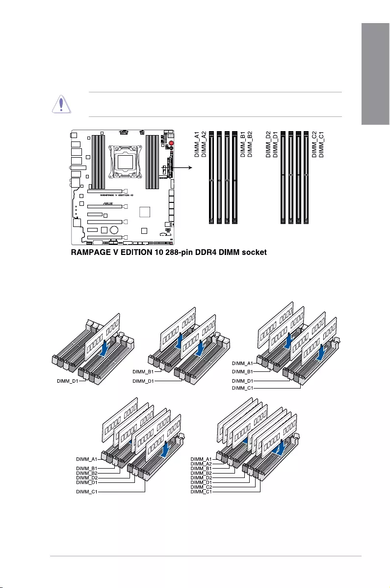
Recommended memory configurations
1.1.4 System memory
Themotherboardcomeswitheight(8)DoubleDataRate4(DDR4)DualInlineMemory
Module(DIMM)slots.
ADDR4moduleisnotcheddifferentlyfromaDDR3orDDR2module.DONOTinstalla
DDR3 or DDR2 memory module to the DDR4 slot.

1-6 Chapter 1: Product Introduction
Chapter 1
Memory configurations
Youmayinstall1GB,2GB,4GB,8GBand16GBunbufferedandnon-ECCDDR4DIMMs
intotheDIMMsockets.
• YoumayinstallvaryingmemorysizesinChannelAandChannelB.Thesystem
mapsthetotalsizeofthelower-sizedchannelforthedual-channelconguration.Any
excessmemoryfromthehigher-sizedchannelisthenmappedforsingle-channel
operation.
• AccordingtoIntel®CPUspec,DIMMvoltagebelow1.65Visrecommendedtoprotect
theCPU.
• Duetothememoryaddresslimitationon32-bitWindowsOS,whenyouinstall4GB
ormorememoryonthemotherboard,theactualusablememoryfortheOScanbe
about3GBorless.Foreffectiveuseofmemory,werecommendthatyoudoanyofthe
following:
a) Useamaximumof3GBsystemmemoryifyouareusinga32-bitWindowsOS.
b) Installa64-bitWindowsOSwhenyouwanttoinstall4GBormoreonthe
motherboard.
c) Formoredetails,refertotheMicrosoft®supportsiteathttp://support.microsoft.
com/kb/929605/en-us.
• ThedesignoftheDIMMfanmayvary.EnsurethattheDIMMfantstothe
motherboard.
• ThedefaultmemoryoperationfrequencyisdependentonitsSerialPresenceDetect
(SPD),whichisthestandardwayofaccessinginformationfromamemorymodule.
Underthedefaultstate,somememorymodulesforoverclockingmayoperateata
lowerfrequencythanthevendor-markedvalue.Tooperateatthevendor-markedorat
ahigherfrequency,refertosection3.5 Extreme Tweaker menu for manual memory
frequencyadjustment.
• Forsystemstability,useamoreefcientmemorycoolingsystemtosupportafull
memoryload(4DIMMs)oroverclockingcondition.
• Memorymoduleswithmemoryfrequencyhigherthan2133MHzandtheir
correspondingtimingortheloadedXMPproleisnottheJEDECmemorystandard.
ThestabilityandcompatibilityofthememorymodulesdependontheCPU’s
capabilitiesandotherinstalleddevices.
• AlwaysinstalltheDIMMSwiththesameCASlatency.Foranoptimumcompatibility,
werecommendthatyouinstallmemorymodulesofthesameversionordatacode
(D/C)fromthesamevendor.Checkwiththevendortogetthecorrectmemory
modules.
• ASUSexclusivelyprovideshyperDIMMsupportfunction.
• HyperDIMMsupportissubjecttothephysicalcharacteristicsofindividualCPUs.Load
theX.M.P.orD.O.C.P.settingsintheBIOSforthehyperDIMMsupport.
• VisittheASUSwebsiteforthelatestQVL.
ASUS RAMPAGE V EDITION 10 1-7
Chapter 1
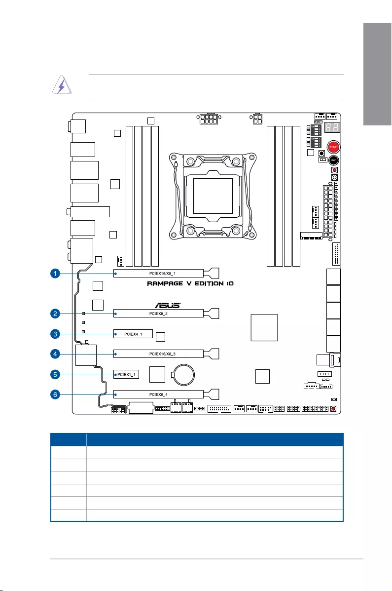
1.1.5 Expansion slots
Ensuretounplugthepowercordbeforeaddingorremovingexpansioncards.Failuretodo
so may cause you physical injury and damage motherboard components.
Slot No. Slot Description
1PCIe3.0x16/x8_1slot
2PCIe3.0x8_2slot
3PCIe2.0x4_1slot
4PCIe3.0x16/8_3slot
5PCIe2.0x1_1slot
6PCIe3.0x8_4slot
1-8 Chapter 1: Product Introduction
Chapter 1
PCIe 3.0 operating mode for 40 lanes CPU
PCIe 3.0 operating mode for 28 lanes CPU
• WerecommendthatyouprovidesufcientpowerwhenrunningCrossFireX™orSLI®
mode.
• WhilerunningatfourheavyloadedVGAcards,ensuretopluginthe4-pinextraPCIe
power supply for stability.
Refertothefollowingcongurationtableforinstallation.
Slot # Single VGA SLI/CFX 3-way
SLI/CFX
4-way
SLI/CFX
PCIEX16/X8_1 x16 x16 x16 x16 x8
PCIEX8_2 — — x8 x8 x8
PCIEX16/X8_3 —x16 x8 x8 x8
PCIEX8_4 ———x8 x8
Slot # Single VGA SLI/CFX 3-way SLI/
CFX
PCIEX16/X8_1 x16 x16 x8
PCIEX8_2 — — x8
PCIEX16/X8_3 —x8 x8
• ThePCIEX8_4slotsharesbandwidthwithM.2andU.2ports.
• 40-LANECPU:In4-Wayconguration,ifthePCIEX16/X8_1isusedinx16mode,
bothM.2andU.2portswillbedisabled.
• 28-LANECPU:In2-Wayand3-Wayconguration,U.2portwillbedisabled.
ASUS RAMPAGE V EDITION 10 1-9
Chapter 1
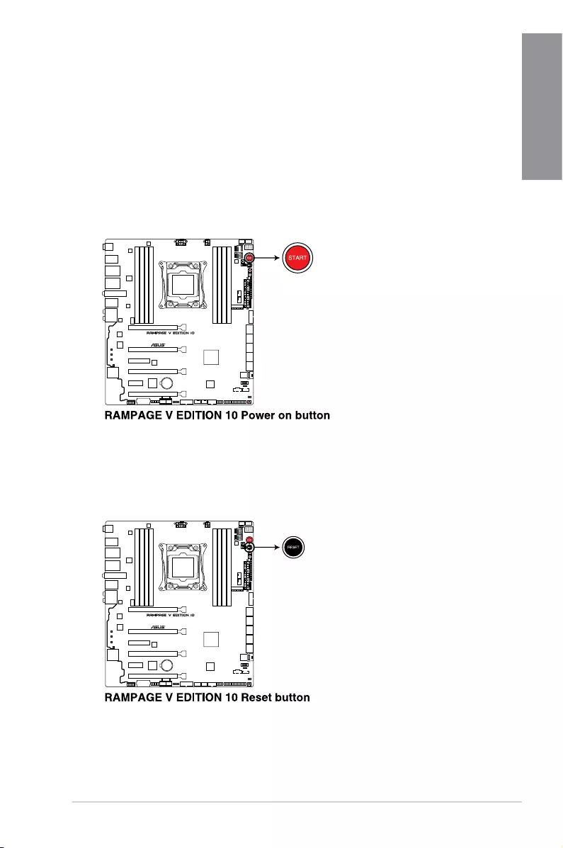
2. RESET button
PresstheResetbuttontorebootthesystem.
1.1.6 Onboard buttons and switches
Onboardbuttonsandswitchesallowyoutone-tuneperformancewhenworkingonabareor
open-casesystem.Thisisidealforoverclockersandgamerswhocontinuallychangesettings
to enhance system performance.
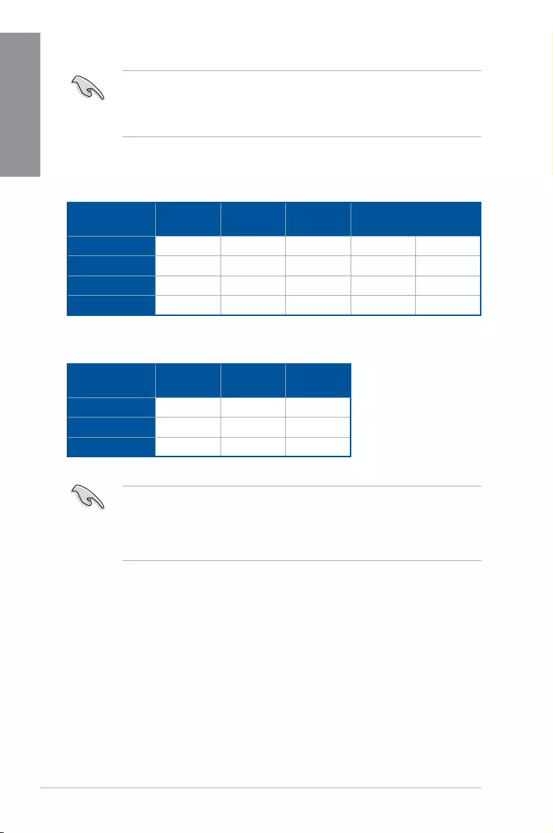
1. Power-on (START) button
The motherboard comes with a power-on button that allows you to power up or wake
up the system. The button also lights up when the system is plugged to a power source
indicating that you should shut down the system and unplug the power cable before
removingorinstallinganymotherboardcomponent.
1-10 Chapter 1: Product Introduction
Chapter 1
3. MemOK! button (MemOK!)
InstallingDIMMsthatarenotcompatiblewiththemotherboardmaycausesystemboot
failure.IfthesystemfailstobootduringPOSTstageandtheDRAM_LEDnearthe
MemOK!buttonlightscontinuously,presstheMemOK!buttonuntiltheDRAM_LED
startsblinking.Systemwillbeginautomaticmemorycompatibilitytuningandrebootfor
successful boot.
• Refertothe1.1.7 Onboard LEDssectionfortheexactlocationoftheDRAM_LED.
• TheDRAM_LEDalsolightsupwhentheDIMMisnotproperlyinstalled.Turnoffthe
systemandreinstalltheDIMMbeforeusingtheMemOK!function.
• TheMemOK!buttondoesnotfunctionunderWindows®OSenvironment.
• Duringthetuningprocess,thesystemloadsandtestsfailsafememorysettings.It
takesabout30secondsforthesystemtotestonesetoffailsafesettings.Ifthetest
fails,thesystemrebootsandtestthenextsetoffailsafesettings.Theblinkingspeed
oftheDRAM_LEDincreases,indicatingdifferenttestprocesses.
• Duetomemorytuningrequirement,thesystemautomaticallyrebootswheneach
timingsetistested.IftheinstalledDIMMsstillfailtobootafterthetuningprocess
iscompleted,theDRAM_LEDlightscontinuously.ReplacetheDIMMswithones
recommendedintheMemoryQVL(QualiedVendorsLists)atwww.asus.com.
• IfyouturnoffthecomputerandreplaceDIMMsduringthetuningprocess,thesystem
continuesmemorytuningafterturningonthecomputer.Tostopmemorytuning,turn
offthecomputerandunplugthepowercordforabout5–10seconds.
• IfyoursystemfailstobootupduetoBIOSoverclocking,presstheMemOK!button
tobootandloadtheBIOSdefaultsettings.AmessagewillappearduringPOSTto
remindyouthattheBIOShasbeenrestoredtoitsdefaultsettings.
• WerecommendthatyoudownloadandupdatetothelatestBIOSversionfrom
www.asus.comafterusingtheMemOK!function.
ASUS RAMPAGE V EDITION 10 1-11
Chapter 1
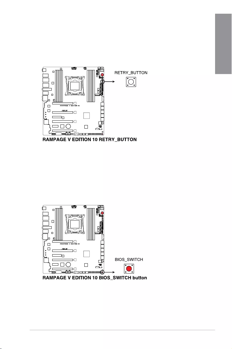
4. ReTry button (RETRY_BUTTON)
TheReTrybuttonisspeciallydesignedforoverclockersandismostusefulduringthe
bootingprocesswheretheResetbuttonisrendereduseless.Whenpressed,itforces
thesystemtorebootwhileretainingthesamesettingstoberetriedinquicksuccession
toachieveasuccessfulPOST.
5. BIOS Switch button (BIOS_SWITCH)
ThemotherboardcomeswithtwoBIOS.PresstheBIOSbuttontoswitchBIOSand
loaddifferentBIOSsettings.ThenearbyBIOSLEDsindicatethecurrentlyselected
BIOS.
1-12 Chapter 1: Product Introduction
Chapter 1
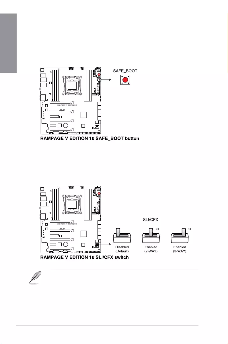
6. Safe Boot button (SAFE_BOOT)
TheSafeBootbuttoncanbepressedanytimetoforcethesystemtorebootintothe
BIOSsafemode.ThisbuttontemporarilyappliessafesettingstotheBIOSwhile
retaininganyoverclockedsettingsallowingyoutomodifythesettingscausingboot
failure.Usethisbuttonwhenoverclockingortweakingthesettingsofyoursystem.
7. SLI/CFX switch (SLI/CFX)
Thisswitchallowsyoutodeterminetheslotsfor2-WAYor3-WAYgraphicscard
installation.Whenenabled,thePCIELEDsneartheslotslightup,tellingyoutoinstall
thegraphicscardstothespecicslots.
• TheLEDsbelowtheSLI/CFXswitchandnearthePCIEslotslightupwhentheSLI/
CFXswitchisenabled.Refertosection1.1.7 Onboard LEDsfortheexactlocationof
theSLI/CFXandPCIELEDs.
• AfteradjustingPCIEbandwidthintheBIOS,shutdownthesystemforthePCIELEDs
to update the lighting effect.
ASUS RAMPAGE V EDITION 10 1-13
Chapter 1
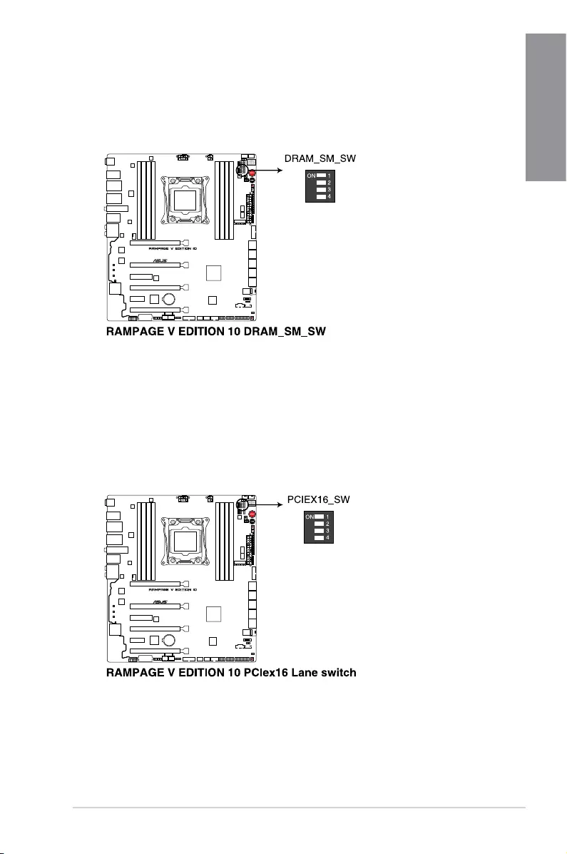
9. PCIe x16 Lane switch (PCIEX16_SW)
TheseslideswitchesallowsyoutoenableanddisablethecorrespondingPCIex16
slots.WhenoneoftheinstalledPCIex16cardsisoutoforder,youcanusetheslide
switchtondoutthefaultyonewithoutremovingthecards.
8. DRAM Lane switch (DRAM_SM_SW)
TheseslideswitchesallowsyoutoenableanddisablethecorrespondingDIMMslots.
WhenoneoftheinstalledDIMMsisoutoforder,youcanusetheslideswitchtond
outthefaultyonewithoutremovingtheDIMMS.
1-14 Chapter 1: Product Introduction
Chapter 1
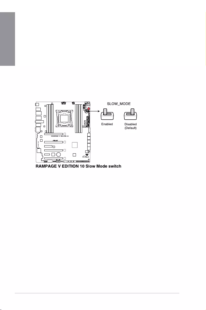
10. Slow Mode Switch (SLOW_MODE)
SlowModeSwitchisemployedduringLN2benching.Someprocessorshaveasmall
optimumtemperaturerangetorunattheirhighestfrequency.Temperaturesthatfall
outsidethisbandmayyieldinstability.Forexample,aprocessormayneedtooperate
at-80°Cunderloadandonly75°Cwhenidletomaintainstabilityat5.8GHz.
Atlowerfrequencies,theCPU’stemperaturetoleranceincreases.Itwillhowever
remainstableatlowerfrequenciesatmuchcolderorwarmertemperatures.Once
itcomesoutofaheavyloadwhiletransitioningovertoalightload,whenthe
temperaturedoesnotwarmfastenough,itmaycrash.Toovercomethis,simplyipthe
switchovertodecreasetheprocessorfrequency.SwitchingovertoSlow-Modeduring
criticalmomentswhenTemperature/MaxFrequencyalignmentisoff-synccanprevent
alotofcrashes,evenwhentryingtobootintotheOSatcoldtemperatures.
ASUS RAMPAGE V EDITION 10 1-15
Chapter 1
1.1.7 Onboard LEDs
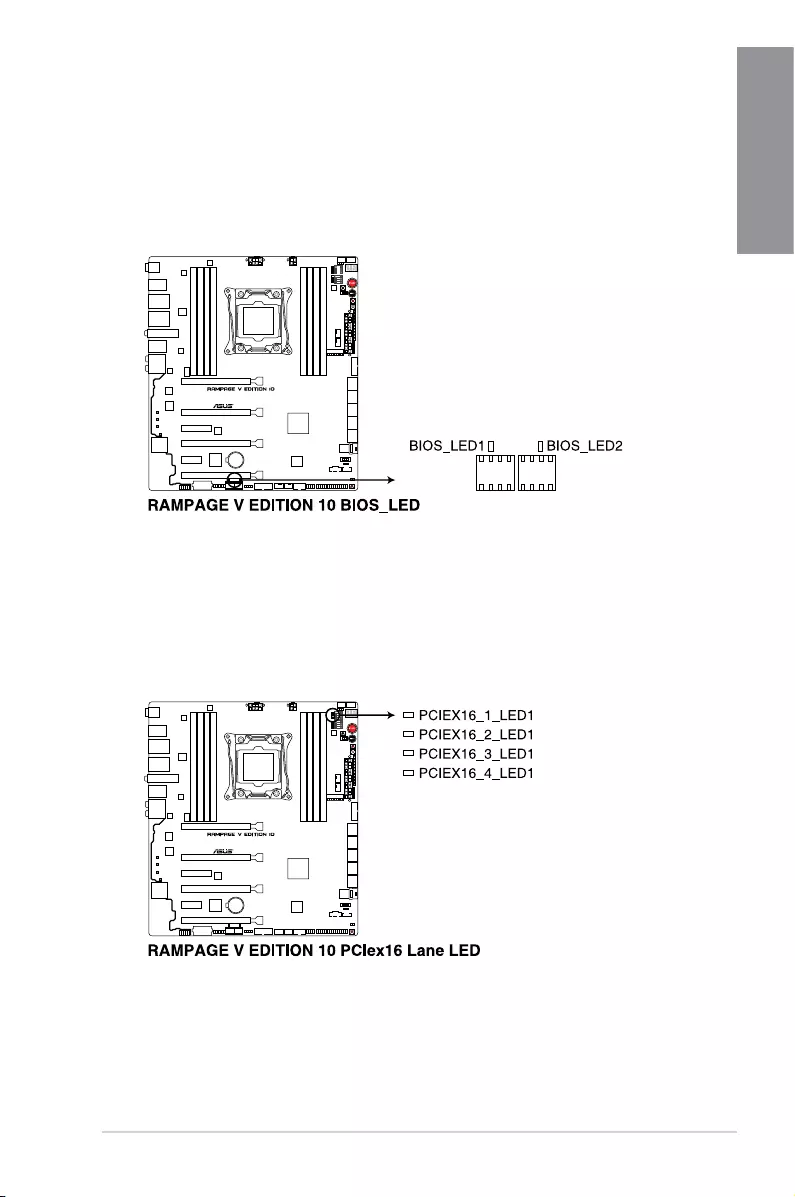
1. BIOS LEDs (BIOS_LED1-2)
TheBIOSLEDshelpindicatetheBIOSactivity.PresstheBIOSbuttontoswitch
betweenBIOS1andBIOS2andtheLEDlightsupwhenthecorrespondingBIOSisin
use.
2. PCIex16 lane LED indicator (PCIEX16_1_LED1; PCIEX16_2_LED1; PCIEX16_3_
LED1; PCIEX16_4_LED1)
IndicatesthePCIElaneused.
1-16 Chapter 1: Product Introduction
Chapter 1
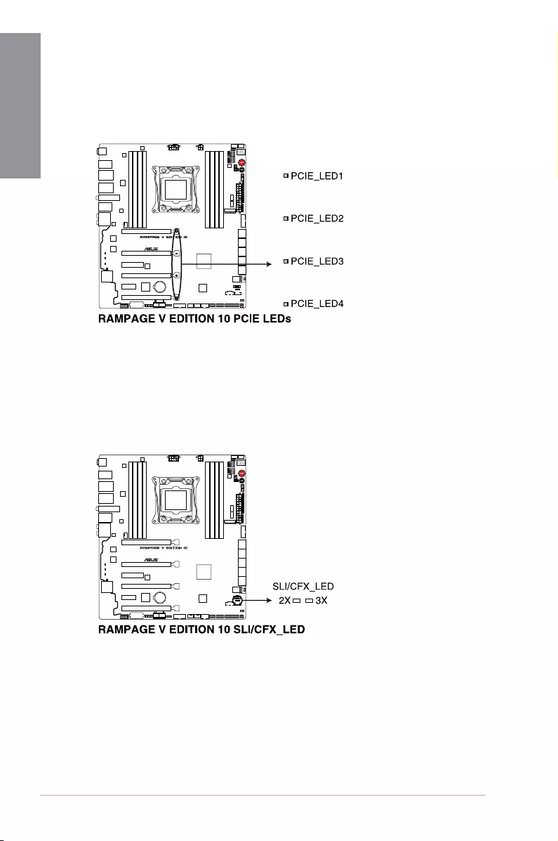
3. PCIE LEDs (PCIE_LED1-4)
ThePCIELEDslightuptoindicatewhichPCIEslotstousewhenSLI/CFXswitchis
enabled.
4. SLI/CFX LED (SLI/CFX_LED)
TheSLI/CFXLEDslightupwhenSLI/CFXswitchisenabled.
ASUS RAMPAGE V EDITION 10 1-17
Chapter 1
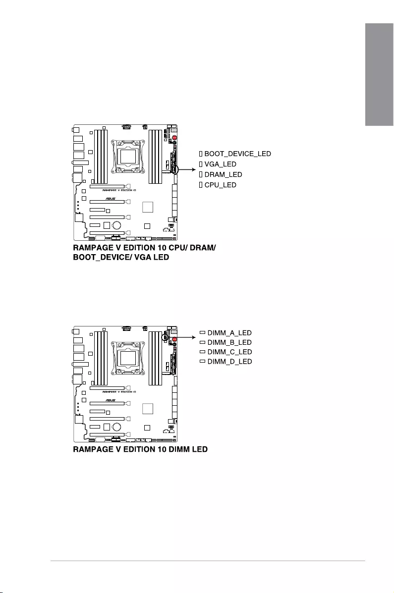
5. Q LEDs (BOOT_DEVICE_LED; VGA_LED; DRAM_LED; CPU_LED)
QLEDscheckkeycomponents(CPU,DRAM,VGAcard,andbootdevices)in
sequenceduringmotherboardbootingprocess.Ifanerrorisfound,thecorresponding
LEDwillcontinuelightinguntiltheproblemissolved.Thisuser-friendlydesignprovides
anintuitivewaytolocatetheroot-causeoftheproblemwithinseconds.
6. DIMM LED (DIMM_A_LED; DIMM_B_LED; DIMM_C_LED; DIMM_D_LED)
TheDIMMLEDindicateswhenthecorrespondingmemorychannelisenabled.
1-18 Chapter 1: Product Introduction
Chapter 1
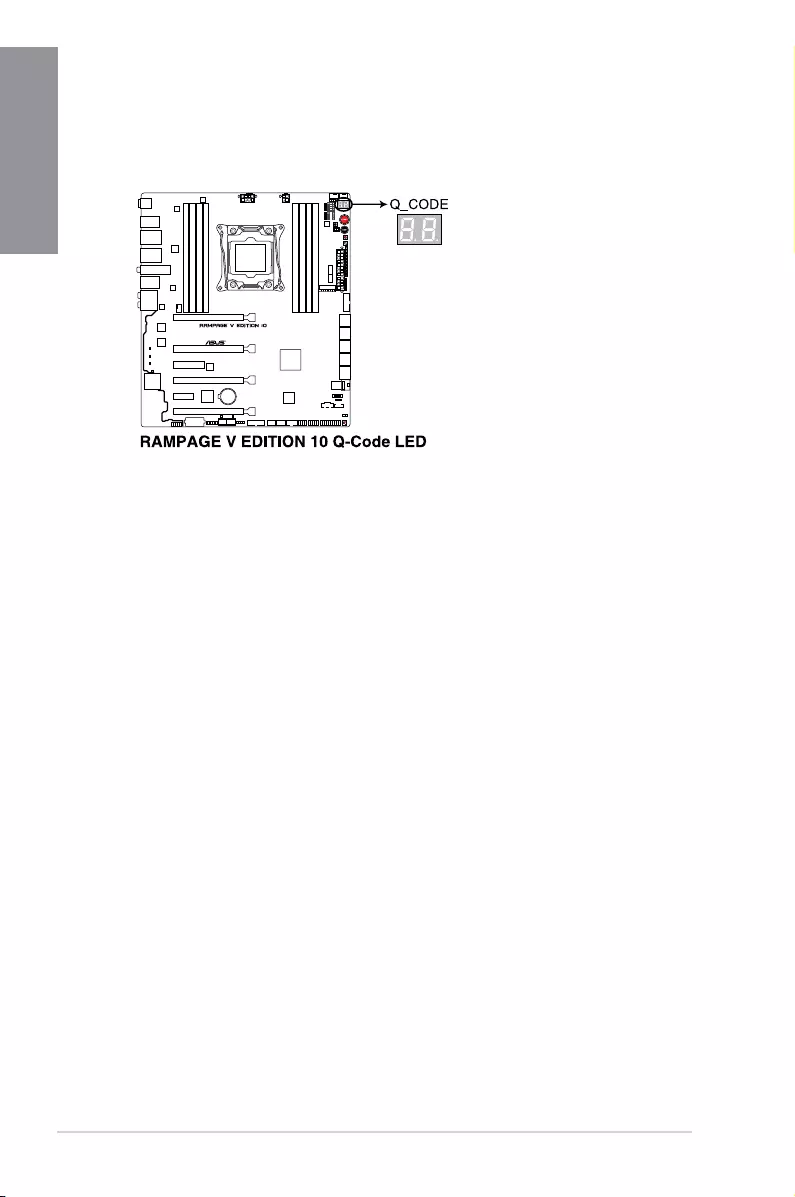
7. Q-Code LED (Q_CODE1)
TheQ-CodeLEDdesignprovidesyouwitha2-digiterrorcodethatdisplaysthesystem
status.RefertotheQ-Codetableonthenextpagefordetails.

ASUS RAMPAGE V EDITION 10 1-19
Chapter 1
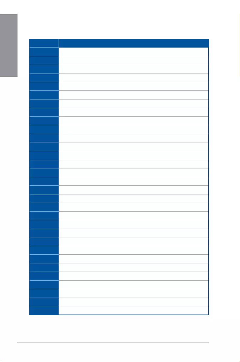
Q-Code table
(continuedonthenextpage)
Code Description
00 Not used
01 Poweron.Resettypedetection(soft/hard).
02 APinitializationbeforemicrocodeloading
03 SystemAgentinitializationbeforemicrocodeloading
04 PCHinitializationbeforemicrocodeloading
06 Microcodeloading
07 APinitializationaftermicrocodeloading
08 SystemAgentinitializationaftermicrocodeloading
09 PCHinitializationaftermicrocodeloading
0B Cacheinitialization
0C – 0D ReservedforfutureAMISECerrorcodes
0E Microcodenotfound
0F Microcodenotloaded
10 PEICoreisstarted
11 – 14 Pre-memoryCPUinitializationisstarted
15 – 18 Pre-memorySystemAgentinitializationisstarted
19 – 1C Pre-memoryPCHinitializationisstarted
2B – 2F Memoryinitialization
30 ReservedforASL(seeASLStatusCodessectionbelow)
31 MemoryInstalled
32 – 36 CPUpost-memoryinitialization
37 – 3A Post-MemorySystemAgentinitializationisstarted
3B – 3E Post-MemoryPCHinitializationisstarted
4F DXEIPLisstarted
50 – 53 Memoryinitializationerror.Invalidmemorytypeorincompatiblememory
speed
54 Unspeciedmemoryinitializationerror
55 Memorynotinstalled
56 InvalidCPUtypeorSpeed
57 CPUmismatch
58 CPUselftestfailedorpossibleCPUcacheerror
1-20 Chapter 1: Product Introduction
Chapter 1
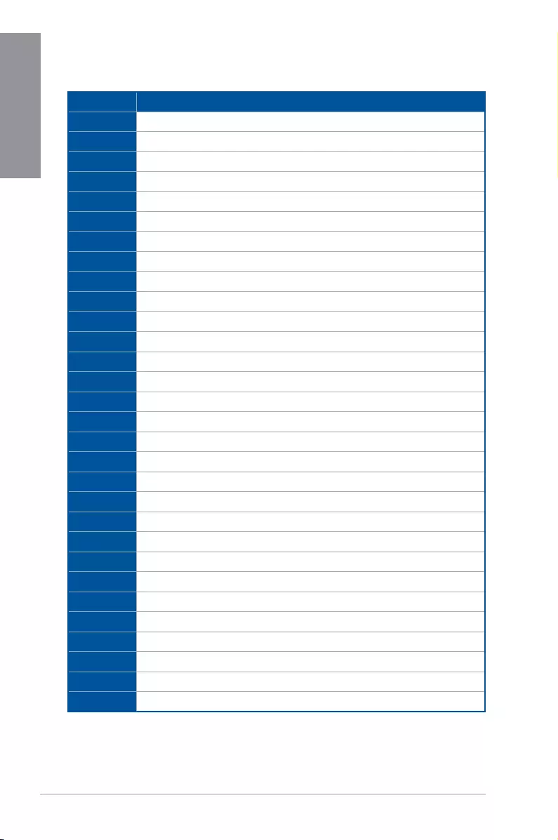
Q-Code table
(continuedonthenextpage)
Code Description
59 CPUmicro-codeisnotfoundormicro-codeupdateisfailed
5A InternalCPUerror
5B ResetPPIisnotavailable
5C – 5F ReservedforfutureAMIerrorcodes
E0 S3Resumeisstared(S3ResumePPIiscalledbytheDXEIPL)
E1 S3BootScriptexecution
E2 Videorepost
E3 OSS3wakevectorcall
E4 – E7 ReservedforfutureAMIprogresscodes
E8 S3ResumeFailed
E9 S3ResumePPInotFound
EA S3ResumeBootScriptError
EB S3OSWakeError
EC – EF ReservedforfutureAMIerrorcodes
F0 Recoveryconditiontriggeredbyrmware(Autorecovery)
F1 Recoveryconditiontriggeredbyuser(Forcedrecovery)
F2 Recoveryprocessstarted
F3 Recoveryrmwareimageisfound
F4 Recoveryrmwareimageisloaded
F5 – F7 ReservedforfutureAMIprogresscodes
F8 RecoveryPPIisnotavailable
F9 Recoverycapsuleisnotfound
FA Invalidrecoverycapsule
FB – FF ReservedforfutureAMIerrorcodes
60 DXECoreisstarted
61 NVRAMinitialization
62 InstallationofthePCHRuntimeServices
63 – 67 CPUDXEinitializationisstarted
68 PCIhostbridgeinitialization
69 SystemAgentDXEinitializationisstarted
6A SystemAgentDXESMMinitializationisstarted

ASUS RAMPAGE V EDITION 10 1-21
Chapter 1
Code Description
6B – 6F SystemAgentDXEinitialization(SystemAgentmodulespecic)
70 PCHDXEinitializationisstarted
71 PCHDXESMMinitializationisstarted
72 PCHdevicesinitialization
73 – 77 PCHDXEInitialization(PCHmodulespecic)
78 ACPImoduleinitialization
79 CSMinitialization
7A – 7F ReservedforfutureAMIDXEcodes
90 BootDeviceSelection(BDS)phaseisstarted
91 Driverconnectingisstarted
92 PCIBusinitializationisstarted
93 PCIBusHotPlugControllerInitialization
94 PCIBusEnumeration
95 PCIBusRequestResources
96 PCIBusAssignResources
97 ConsoleOutputdevicesconnect
98 Consoleinputdevicesconnect
99 SuperIOInitialization
9A USBinitializationisstarted
9B USBReset
9C USBDetect
9D USBEnable
9E – 9F ReservedforfutureAMIcodes
A0 IDEinitializationisstarted
A1 IDEReset
A2 IDEDetect
A3 IDEEnable
A4 SCSIinitializationisstarted
A5 SCSIReset
A6 SCSIDetect
A7 SCSIEnable
Q-Code table
(continuedonthenextpage)
1-22 Chapter 1: Product Introduction
Chapter 1
Q-Code table
Code Description
A8 SetupVerifyingPassword
A9 StartofSetup
AA ReservedforASL(seeASLStatusCodessectionbelow)
AB SetupInputWait
AC ReservedforASL(seeASLStatusCodessectionbelow)
AD ReadyToBootevent
AE LegacyBootevent
AF ExitBootServicesevent
B0 RuntimeSetVirtualAddressMAPBegin
B1 RuntimeSetVirtualAddressMAPEnd
B2 LegacyOptionROMInitialization
B3 SystemReset
B4 USBhotplug
B5 PCIbushotplug
B6 Clean-upofNVRAM
B7 CongurationReset(resetofNVRAMsettings)
B8– BF ReservedforfutureAMIcodes
D0 CPUinitializationerror
D1 SystemAgentinitializationerror
D2 PCHinitializationerror
D3 SomeoftheArchitecturalProtocolsarenotavailable
D4 PCIresourceallocationerror.OutofResources
D5 NoSpaceforLegacyOptionROM
D6 NoConsoleOutputDevicesarefound
D7 NoConsoleInputDevicesarefound
D8 Invalidpassword
D9 ErrorloadingBootOption(LoadImagereturnederror)
DA BootOptionisfailed(StartImagereturnederror)
DB Flash update is failed
DC Resetprotocolisnotavailable
ASUS RAMPAGE V EDITION 10 1-23
Chapter 1
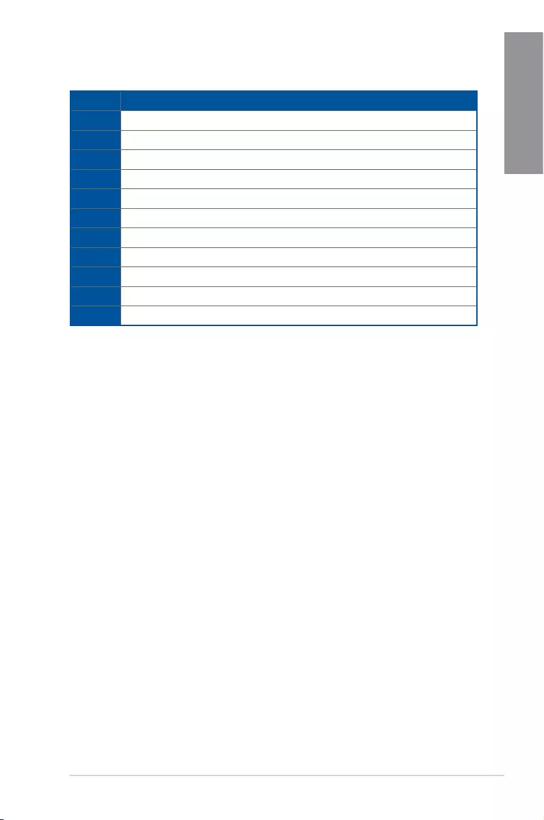
ACPI/ASL Checkpoints
Code Description
0x01 SystemisenteringS1sleepstate
0x02 SystemisenteringS2sleepstate
0x03 SystemisenteringS3sleepstate
0x04 SystemisenteringS4sleepstate
0x05 SystemisenteringS5sleepstate
0x10 SystemiswakingupfromtheS1sleepstate
0x20 SystemiswakingupfromtheS2sleepstate
0x30 SystemiswakingupfromtheS3sleepstate
0x40 SystemiswakingupfromtheS4sleepstate
0xAC SystemhastransitionedintoACPImode.InterruptcontrollerisinPICmode.
0xAA SystemhastransitionedintoACPImode.InterruptcontrollerisinAPICmode.
1-24 Chapter 1: Product Introduction
Chapter 1
1.1.8 Jumper
1. LN2 Mode jumper (3-pin LN2_MODE)
WithLN2modeactivated,theROGmotherboardisoptimizedtoremedythecold-boot
bugduringPOSTandhelpthesystembootsuccessfully.
ASUS RAMPAGE V EDITION 10 1-25
Chapter 1
1.1.9 Internal connectors
1. Intel® X99 Serial ATA 6 Gb/s connectors (7-pin SATA6G_1-10)
TheseconnectorsconnecttoSerialATA6Gb/sharddiskdrivesviaSerialATA6Gb/s
signal cables.
IfyouinstalledSerialATAharddiskdrives,youcancreateaRAID0,1,5,and10
congurationwiththeIntel®RapidStorageTechnologythroughtheonboardIntel®X99
chipset.
• Theseconnectorsaresetto[AHCI Mode]bydefault.IfyouintendtocreateaSerial
ATARAIDarrayusingtheseconnectors,settheSATAModeitemintheBIOSto
[RAID Mode]. Refer to the PCH Storage Configuration section for details.
• BeforecreatingaRAIDarray,referto4.1 RAID configurations section or the manual
bundledinthemotherboardsupportUSBdrive.
1-26 Chapter 1: Product Introduction
Chapter 1
2. ROG Extension connector (18-1 pin ROG_EXT)
ThisconnectorisfortheOCPanelI/II,FrontBase,andotherROGdevices.
• TheFrontBaseispurchasedseparately.
• Visitwww.asus.comformoreinformationabouttheOCPanelandFrontBase.
3. Thermal sensor cable connector (2-pin T_SENSOR1)
Thisconnectorisforthethermistorcablethatmonitorsthetemperatureofthedevices
andthecriticalcomponentsinsidethemotherboard.Connectthethermistorcable
andplacethesensoronthedeviceorthemotherboard’scomponenttodetectits
temperature.
TomonitorthetemperatureattheBIOS,gotoBIOS>Monitor>Temperature Monitor.
ASUS RAMPAGE V EDITION 10 1-27
Chapter 1
4. USB 3.0 connector (20-1 pin USB3_12, USB3_34)
ThisconnectorallowsyoutoconnectaUSB3.0moduleforadditionalUSB3.0front
orrearpanelports.WithaninstalledUSB3.0module,youcanenjoyallthebenetsof
USB3.0includingfasterdatatransferspeedsofupto5Gbps,fasterchargingtimefor
USB-chargeabledevices,optimizedpowerefciency,andbackwardcompatibilitywith
USB2.0.
• TheUSB3.0moduleispurchasedseparately.
• TheseconnectorsarebasedonxHCIspecication.Werecommendyoutoinstallthe
relateddrivertofullyusetheUSB3.0portsunderWindows® 7.
1-28 Chapter 1: Product Introduction
Chapter 1
YoucanconnectthefrontpanelUSBcabletotheASUSQ-Connector(USB)rst,andthen
installtheQ-Connector(USB)totheUSBconnectoronboardifyourchassissupportsfront
panelUSBports.
DONOTconnecta1394cabletotheUSBconnectors.Doingsowilldamagethe
motherboard!
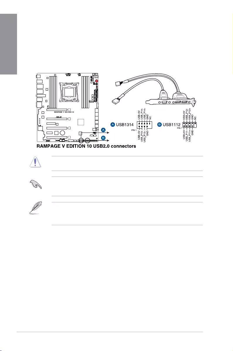
5. USB 2.0 connectors (10-1 pin USB1112; USB1314)
TheseconnectorsareforUSB2.0ports.ConnecttheUSBmodulecabletoanyof
theseconnectors,theninstallthemoduletoaslotopeningatthebackofthesystem
chassis.TheseUSBconnectorscomplywithUSB2.0specicationthatsupportupto
480Mb/sconnectionspeed.
• TheUSB2.0moduleispurchasedseparately.
• 1xUSB2.0port(USB1112)atmid-boardshareswithROGextension(ROG_EXT)
port.
ASUS RAMPAGE V EDITION 10 1-29
Chapter 1
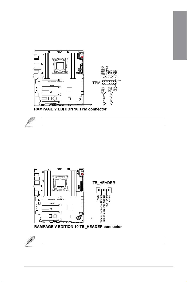
7. Thunderbolt header (5-pin TB_HEADER)
Thisconnectorisfortheadd-onThunderboltI/OcardthatsupportsIntel’sThunderbolt
Technology,allowingyoutoconnectuptosixThunderbolt-enableddevicesanda
DisplayPort-enableddisplayinadaisy-chainconguration.
Theadd-onThunderboltI/OcardandThunderboltcablesarepurchasedseparately.
6. TPM connector (14-1 pin TPM)
ThisconnectorsupportsaTrustedPlatformModule(TPM)system,whichsecurely
storeskeys,digitalcerticates,passwordsanddata.ATPMsystemalsohelps
enhancenetworksecurity,protectdigitalidentities,andensuresplatformintegrity.
TheTPMmoduleispurchasedseparately.
1-30 Chapter 1: Product Introduction
Chapter 1
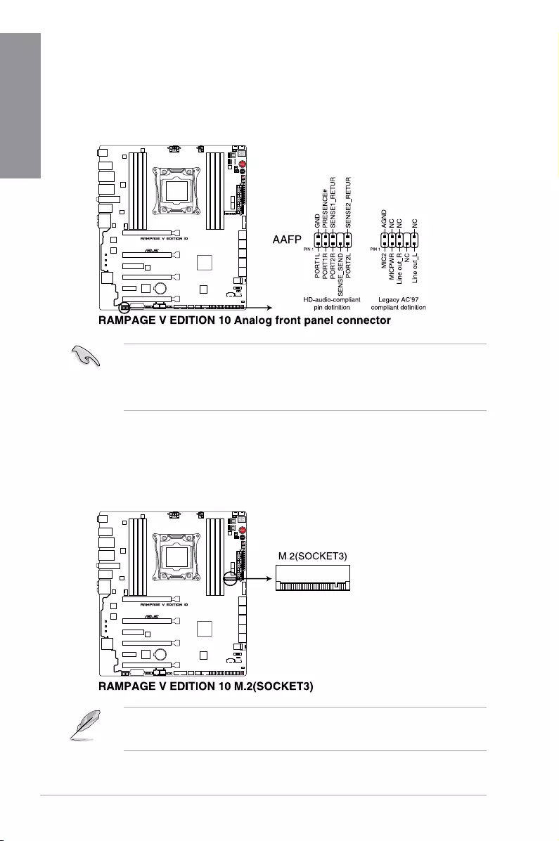
8. Front panel audio connector (10-1 pin AAFP)
Thisconnectorisforachassis-mountedfrontpanelaudioI/Omodulethatsupportseither
HDAudioorlegacyAC’97audiostandard.ConnectoneendofthefrontpanelaudioI/O
module cable to this connector.
• Werecommendthatyouconnectahigh-denitionfrontpanelaudiomoduletothis
connectortotakeadvantageofthemotherboard’shigh-denitionaudiocapability.
• Ifyouwanttoconnectahigh-denitionoranAC’97frontpanelaudiomoduletothis
connector,settheFrontPanelTypeitemintheBIOSsetupto[HD] or [AC97].
9. M.2 (SOCKET3)
TheM.2(Socket3)withMKeysupportstype2260(22mmx60mm),2280(22mmx
80mm),and22110(22mmx110mm)PCIeinterfacestoragedevices.
• ThePCIEX8_4slotsharesbandwidthwithM.2andU.2.
• TheM.2(NGFF)SSDmoduleispurchasedseparately.
ASUS RAMPAGE V EDITION 10 1-31
Chapter 1
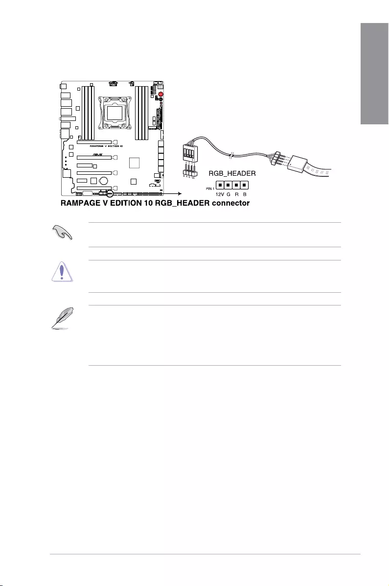
10. RGB header (4-pin RGB_HEADER)
ThisconnectorisforRGBLEDstrips.
TheRGBheadersupports5050RGBmulti-colorLEDstrips(12V/G/R/B),withamaximum
powerratingof2A(12V),andnolongerthan2m.
Beforeyouinstallorremoveanycomponent,ensurethattheATXpowersupplyisswitched
offorthepowercordisdetachedfromthepowersupply.Failuretodosomaycausesevere
damagetothemotherboard,peripherals,orcomponents.
• ActuallightingandcolorwillvarywithLEDstrip.
• IfyourLEDstripdoesnotlightup,checkiftheRGBLEDextensioncableandthe
RGBLEDstripisconnectedinthecorrectorientation,andthe12Vconnectoris
alignedwiththe12Vheaderonthemotherboard.
• TheLEDstripwillonlylightupundertheoperatingsystem.
1-32 Chapter 1: Product Introduction
Chapter 1
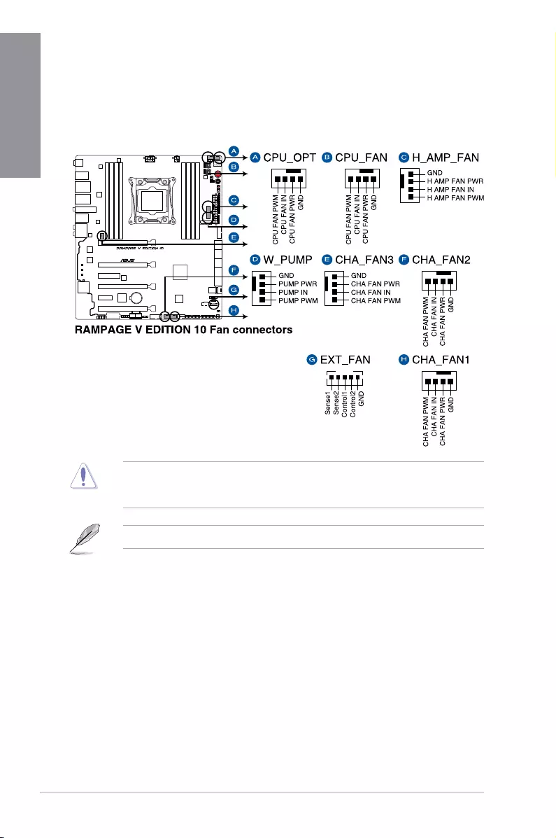
11. CPU, CPU optional, high amp, water pump, extension and chassis fan
connectors (4-pin CPU_FAN; 4-pin CPU_OPT; 4-pin H_AMP_FAN; 4-pin W_
PUMP; 5-pin EXT_FAN; 4-pin CHA_FAN1-3)
Connectthefancablestothefanconnectorsonthemotherboard,ensuringthatthe
black wire of each cable matches the ground pin of the connector.
TheCPU_FANconnectorsupportstheCPUfanofmaximum1A(12W)fanpower.
DONOTforgettoconnectthefancablestothefanconnectors.Insufcientairowinside
thesystemmaydamagethemotherboardcomponents.Thesearenotjumpers!Donot
placejumpercapsonthefanconnectors!
ASUS RAMPAGE V EDITION 10 1-33
Chapter 1
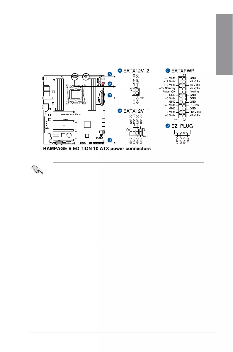
12. ATX power connectors (24-pin EATXPWR; 8-pin EATX12V_1; 4-pin EATX12V_2;
4-pin EZ_PLUG)
TheseconnectorsareforATXpowersupplyplugs.Thepowersupplyplugsare
designedtottheseconnectorsinonlyoneorientation.Findtheproperorientationand
pushdownrmlyuntiltheconnectorscompletelyt.
• Forafullyconguredsystem,werecommendthatyouuseapowersupplyunit
(PSU)thatcomplieswithATX12VSpecication2.0(orlaterversion)andprovidesa
minimumpowerof450W.
• Donotforgettoconnectthe4-pin/8-pinEATX12Vpowerplug;otherwise,thesystem
will not boot.
• Connectthe4-pinEZ_PLUGpowerplugstoensuresufcientpowerwhenyouinstall
multiple graphics cards.
• UseofaPSUwithhigherpoweroutputisrecommendedwhenconguringasystem
withmorepower-consumingdevices.Thesystemmaybecomeunstableormaynot
bootupifthepowerisinadequate.
• Ifyouwanttousetwoormorehigh-endPCIExpressx16cards,useaPSUwithat
least1000Wofoutputpowertoensuresystemstability.
1-34 Chapter 1: Product Introduction
Chapter 1
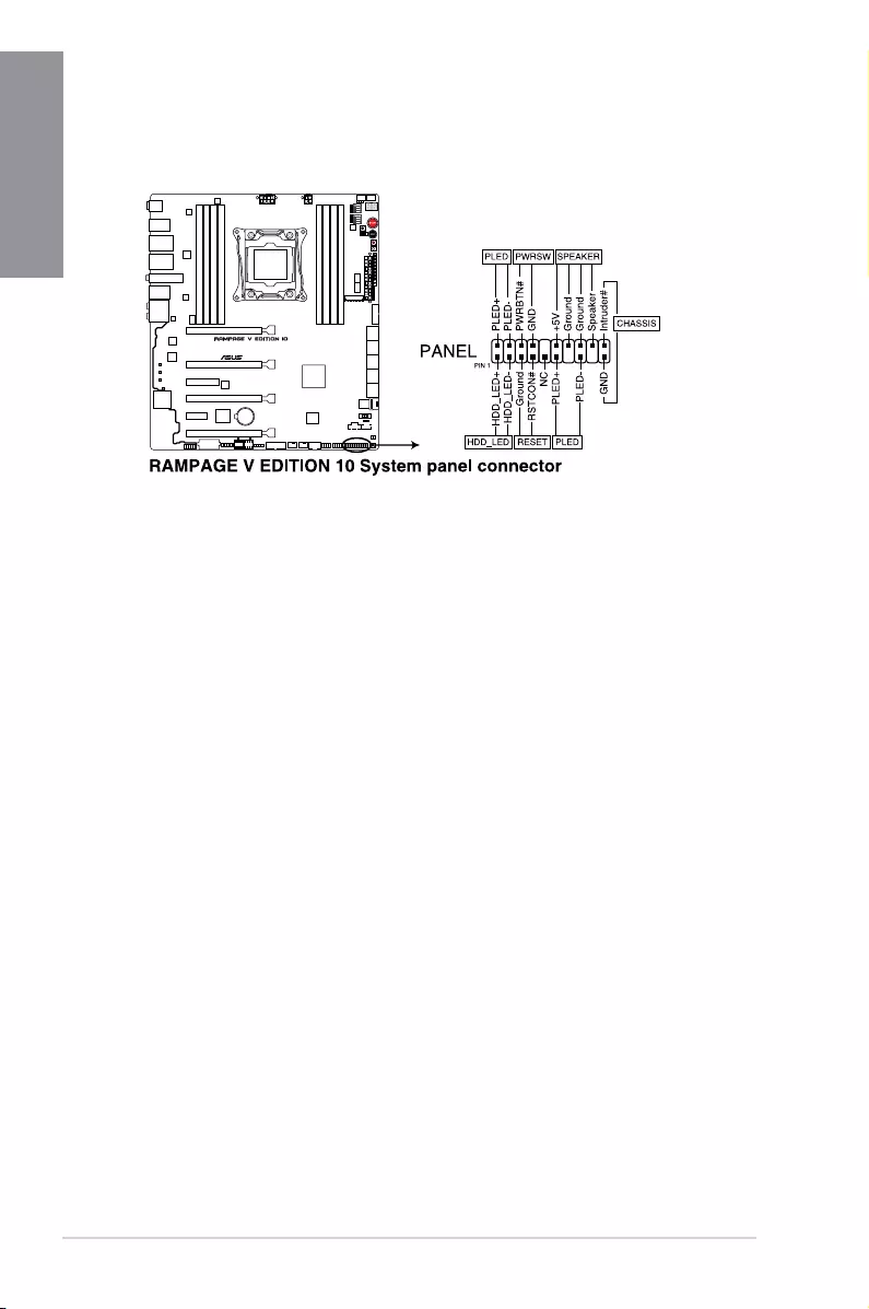
13. System panel connector (20-3 pin PANEL)
Thisconnectorsupportsseveralchassis-mountedfunctions.
• SystempowerLED(2-pinor3-1pinPLED)
The2-pinor3-1pinconnectorisforthesystempowerLED.Connectthechassis
powerLEDcabletothisconnector.ThesystempowerLEDlightsupwhenyouturnon
thesystempower,andblinkswhenthesystemisinsleepmode.
• HarddiskdriveactivityLED(2-pinHDD_LED)
This2-pinconnectorisfortheHDDActivityLED.ConnecttheHDDActivityLEDcable
tothisconnector.TheHDDLEDlightsuporasheswhendataisreadfromorwritten
totheHDD.
• Systemwarningspeaker(4-pinSPEAKER)
This 4-pin connector is for the chassis-mounted system warning speaker. The speaker
allows you to hear system beeps and warnings.
• ATXpowerbutton/soft-offbutton(2-pinPWRSW)
Thisconnectorisforthesystempowerbutton.Pressingthepowerbuttonturnsthe
system on or puts the system in sleep or soft-off mode depending on the operating
systemsettings.Pressingthepowerswitchformorethanfoursecondswhilethe
systemisONturnsthesystemOFF.
• Resetbutton(2-pinRESET)
This 2-pin connector is for the chassis-mounted reset button for system reboot without
turning off the system power.
• Chassisintrusionconnector(2-pinCHASSIS)
Thisconnectorisforachassis-mountedintrusiondetectionsensororswitch.Connect
one end of the chassis intrusion sensor or switch cable to this connector. The chassis
intrusionsensororswitchsendsahigh-levelsignaltothisconnectorwhenachassis
componentisremovedorreplaced.Thesignalisthengeneratedasachassisintrusion
event.
ASUS RAMPAGE V EDITION 10 1-35
Chapter 1
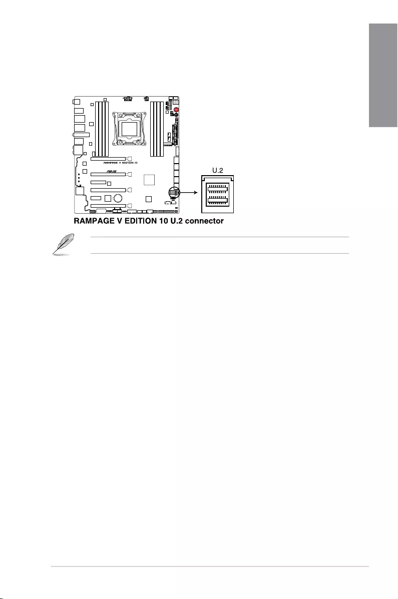
14. U.2 connector (U.2_1-2)
ThismotherboardcomeswithaU.2connectorwhichsupportsPCIe3.0x4NVM
Expressstorage.
ThePCIEX8_4slotsharesbandwidthwithM.2andU.2.
1-36 Chapter 1: Product Introduction
Chapter 1
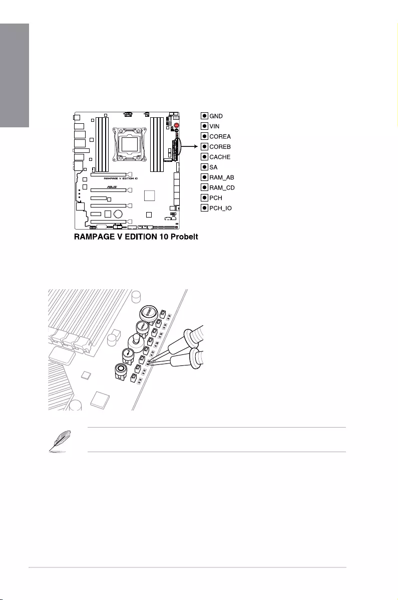
1.1.10 ProbeIt
TheROGProbeItallowsyoutodetectyoursystem’scurrentvoltageandOCsettings.Usea
multimetertomeasuretheProbeItpointsevenduringoverclocking.
SeetheillustrationbelowtolocatetherespectiveProbeItpoints.
Using ProbeIt
Youcanconnectthemultimetertothemotherboardasshownonthefollowinggure.
Theillustrationaboveareforreferenceonly,theactualmotherboardlayoutandmeasure
points location may differ by models.
ASUS RAMPAGE V EDITION 10 2-1
Chapter 2
2
Chapter 2: Basic Installation
Basic Installation
2.1 Building your PC system
2.1.1 Motherboard installation
The diagrams in this section are for reference only. The motherboard layout may vary with
models, but the installation steps are the same for all models.
1. Install the I/O frame to the chassis rear I/O panel.
2. Place the motherboard into the chassis ensuring that its rear I/O ports are aligned to
the chassis’ rear I/O panel.
2-2 Chapter 2: Basic Installation
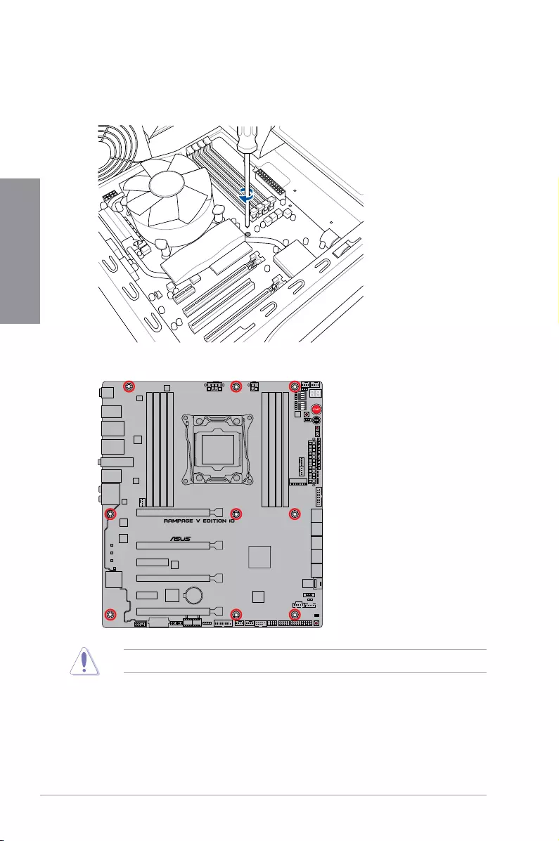
Chapter 2
3. Place nine (9) screws into the holes indicated by circles to secure the motherboard to
the chassis.
DO NOT overtighten the screws! Doing so can damage the motherboard.
ASUS RAMPAGE V EDITION 10 2-3
Chapter 2
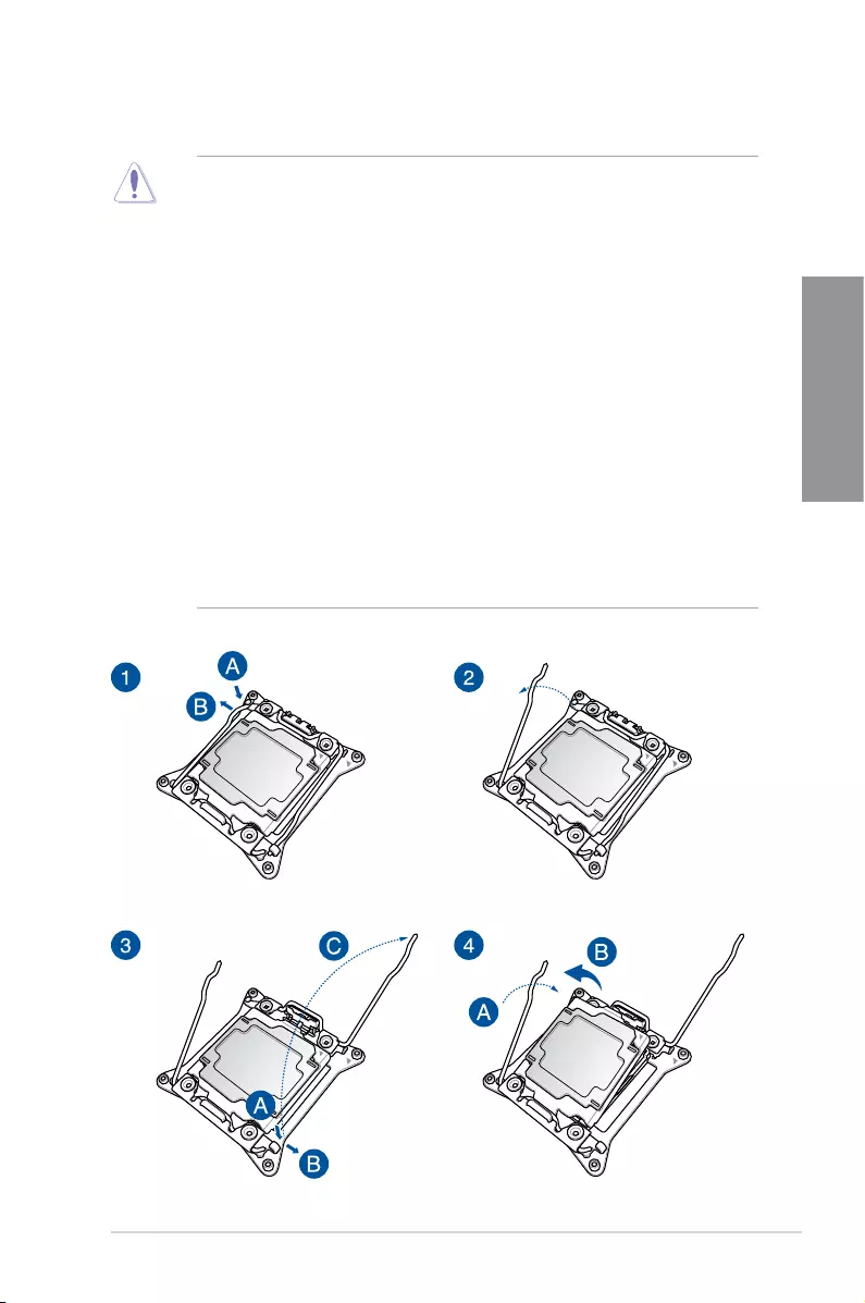
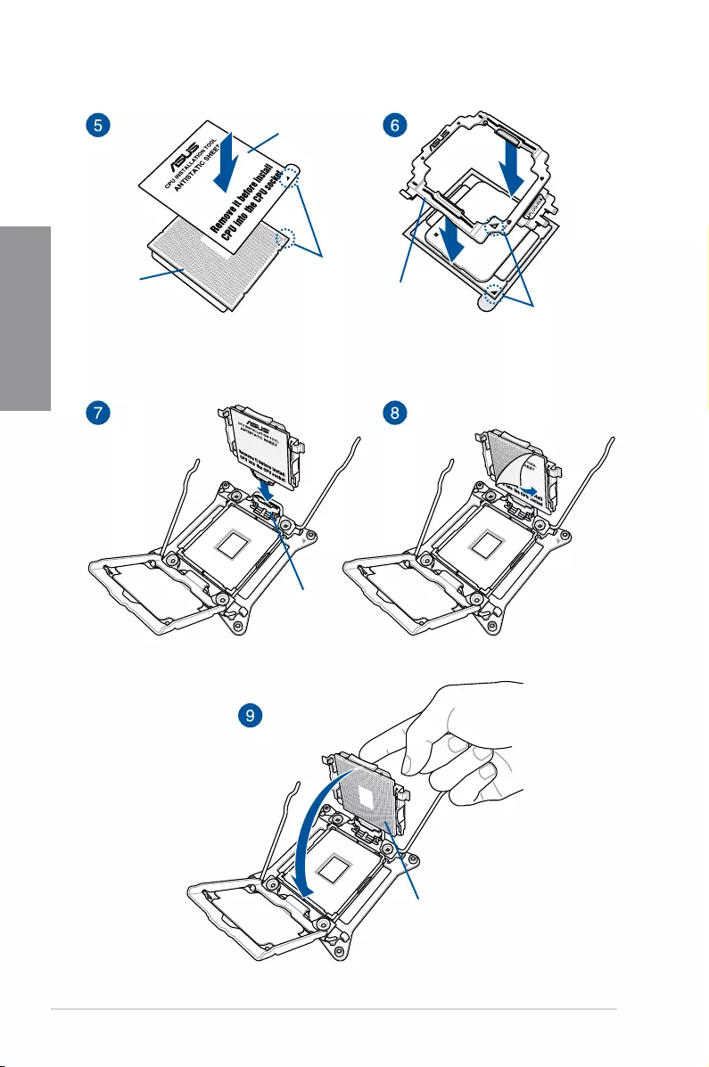
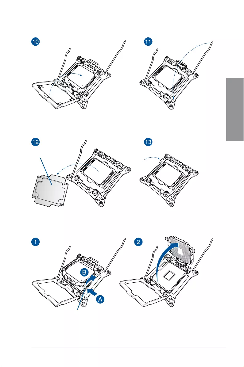
2.1.2 CPU installation
Installing CPU
• Pleasenotetheorderinopening/closingthedoublelatch.Followtheinstructions
printed on the metal sealing hatch or the illustrations shown below in this manual. The
plastic cap will pop up automatically once the CPU is in place and the hatch properly
sealed down.
• Theillustrationsareforreferenceonly.
• TheCPUInstallationToolisonlycompatibleonASUSmotherboardswithanIntel®
LGA2011-V3socket.
• EnsurethattheCPUisrmlyclickedintoplacebeforeinstallingitintotheCPUsocket
orsocketslot.
• UsetheCPUInstallationToolforinstallingtheCPUonly.DONOTdamageorbend
the CPU Installation Tool.
• AlwaysrmlyholdbothsidesoftheCPUInstallationToolwheninstalling,removing,or
pickinguptheCPUInstallationTool.
• EnsuretouseasoftstablesurfacewheninstallingtheCPUtotheCPUInstallation
Tool to prevent CPU damage.
• ASUSwillnotcoverdamagesresultingfromincorrectCPUinstallation/removal,
incorrect CPU orientation/placement, or other damages resulting from negligence by
the user.
2-4 Chapter 2: Basic Installation
Chapter 2
Bottom of CPU CPU Installation Tool
Socket slot
Bottom of CPU
Antistatic sheet
Align pin
Align pin
ASUS RAMPAGE V EDITION 10 2-5
Chapter 2
PnP cap
Handle
Removing CPU
2-6 Chapter 2: Basic Installation
Chapter 2
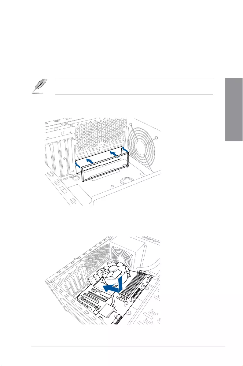
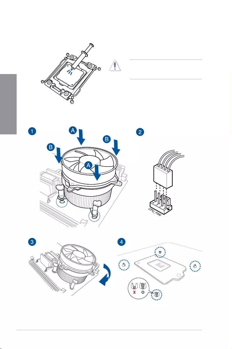
2.1.3 CPU heatsink and fan assembly installation
Applythethermalinterfacematerialtothe
CPUheatsinkandCPUbeforeyouinstall
theheatsinkandfan,ifnecessary.
Installing the CPU heatsink and fan assembly
ASUS RAMPAGE V EDITION 10 2-7
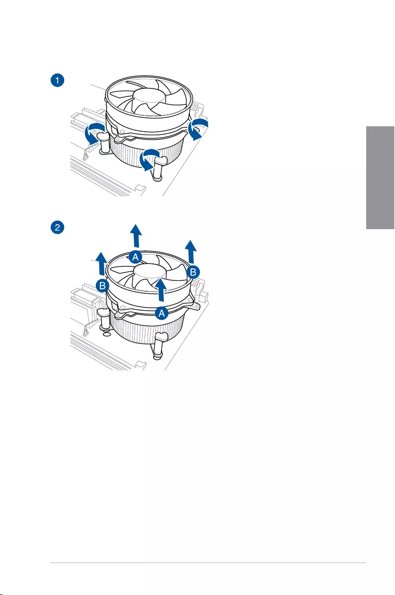
Chapter 2
Uninstalling the CPU heatsink and fan assembly
2-8 Chapter 2: Basic Installation
Chapter 2
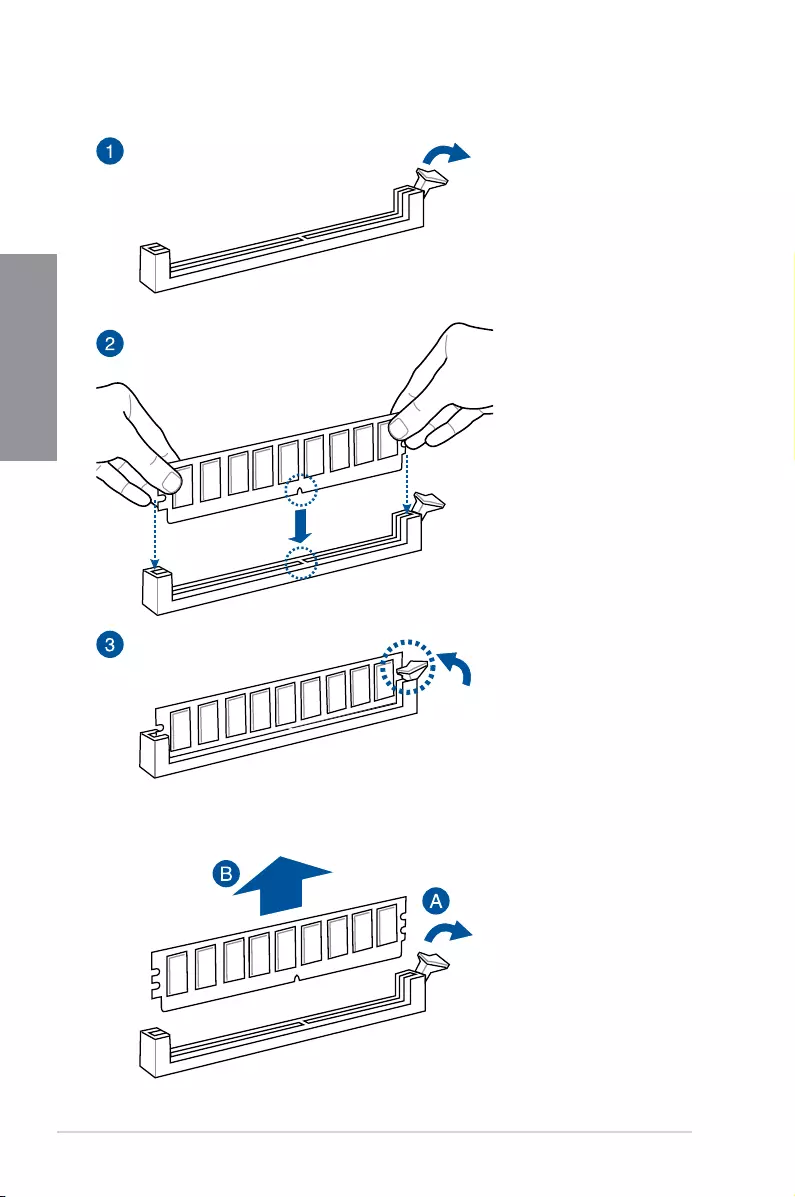
To remove a DIMM
2.1.4 DIMM installation
ASUS RAMPAGE V EDITION 10 2-9
Chapter 2
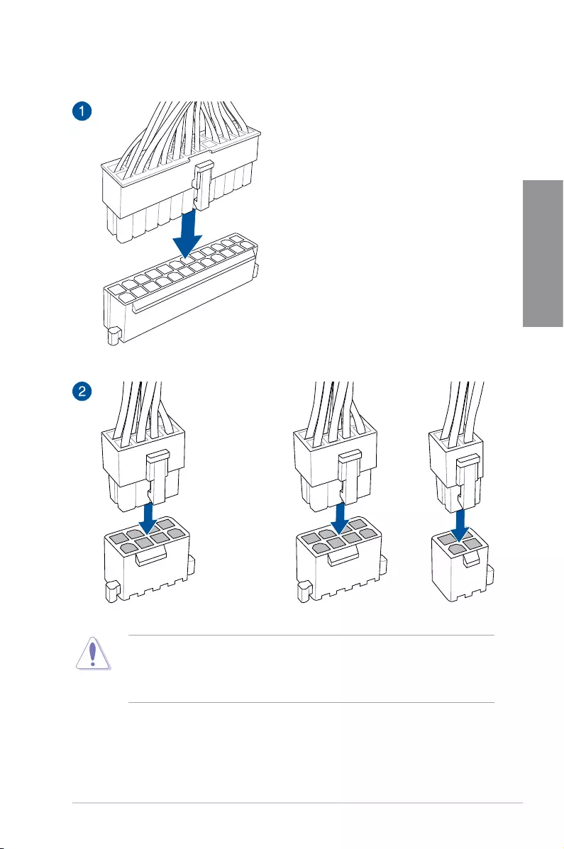
2.1.5 ATX power connection
OR AND
• DONOTconnectthe4-pinpowerplugonly,themotherboardmayoverheatunder
heavy usage.
• Ensuretoconnectthe8-pinpowerplug,orconnectboththe8-pinand4-pinpower
plugs.
2-10 Chapter 2: Basic Installation
Chapter 2
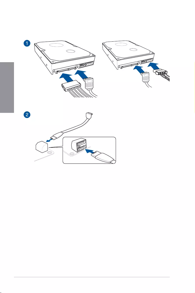
2.1.6 SATA device connection
OR
ASUS RAMPAGE V EDITION 10 2-11
Chapter 2
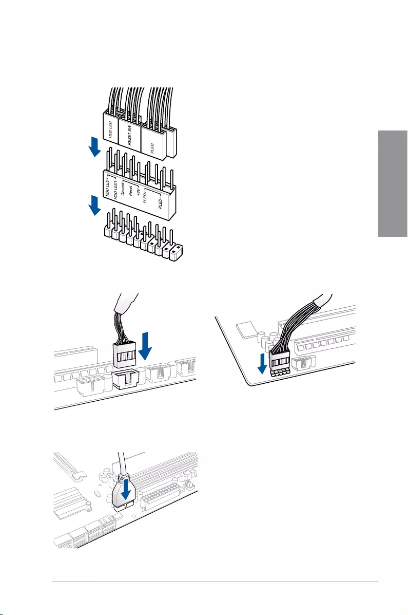
2.1.7 Front I/O connector
To install ASUS Q-Connector
USB 2.0
AAFP
To install USB 2.0 connector To install front panel audio connector
USB 3.0
To install USB 3.0 connector
2-12 Chapter 2: Basic Installation
Chapter 2
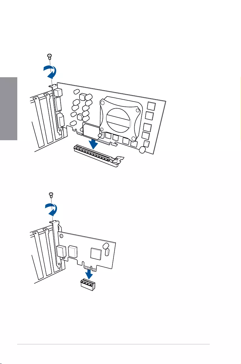
2.1.8 Expansion card installation
To install PCIe x16 cards
To install PCIe x1 cards
ASUS RAMPAGE V EDITION 10 2-13
Chapter 2
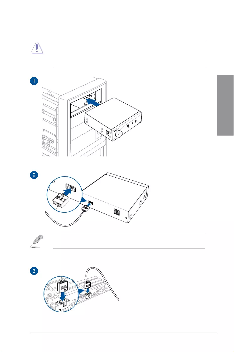
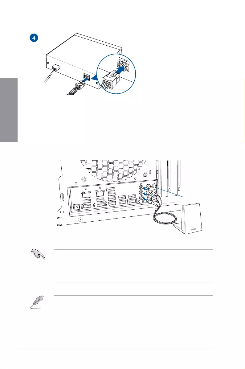
2.1.9 SupremeFX Hi-Fi installation
UsingthebundledUSB2.0connectorcabletoconnectyourSupremeFXHi-Fipanelisthe
bestwaytouseyourSupremeFXHi-Fipanel.
• Unplugthepowercordfromthewallsocketbeforetouchinganycomponent.
• Beforeyouinstallorremoveanycomponent,ensurethatthepowersupplyisswitched
offorthepowercordisdetachedfromthepowersupply.Failuretodosomaycause
severe damage to the motherboard, peripherals, or components.
USB 2.0
2-14 Chapter 2: Basic Installation
Chapter 2
2.1.10 Wi-Fi antenna installation
Installing the ASUS 3T3R dual band W-Fi antenna
ConnectthebundledASUS3T3RdualbandWi-FiantennaconnectortotheWi-Fiportsat
thebackofthechassis.
• EnsurethattheASUS3T3RdualbandWi-FiantennaissecurelyinstalledtotheWi-Fi
ports.
• EnsuretoinstalltheBluetoothdriverbeforeinstallingtheWi-FiGO!software.
• Ensurethattheantennaisatleast20cmawayfromallpersons.
The illustration above is for reference only. The I/O port layout may vary with models, but
theWi-Fiantennainstallationprocedureisthesameforallmodels.
USB BIOS
Flashback
USB BIOS
Flashback
USB 3.0/UASP
USB 3.0/UASP
USB 3.0/UASP
USB 3.0/UASP
SPDIF OUT REAR O/SUB
LINE IN
LINE OUT
MIC IN
USB 3.0/UASP
BIOS
IO Shield
ASUS RAMPAGE V EDITION 10 2-15
Chapter 2
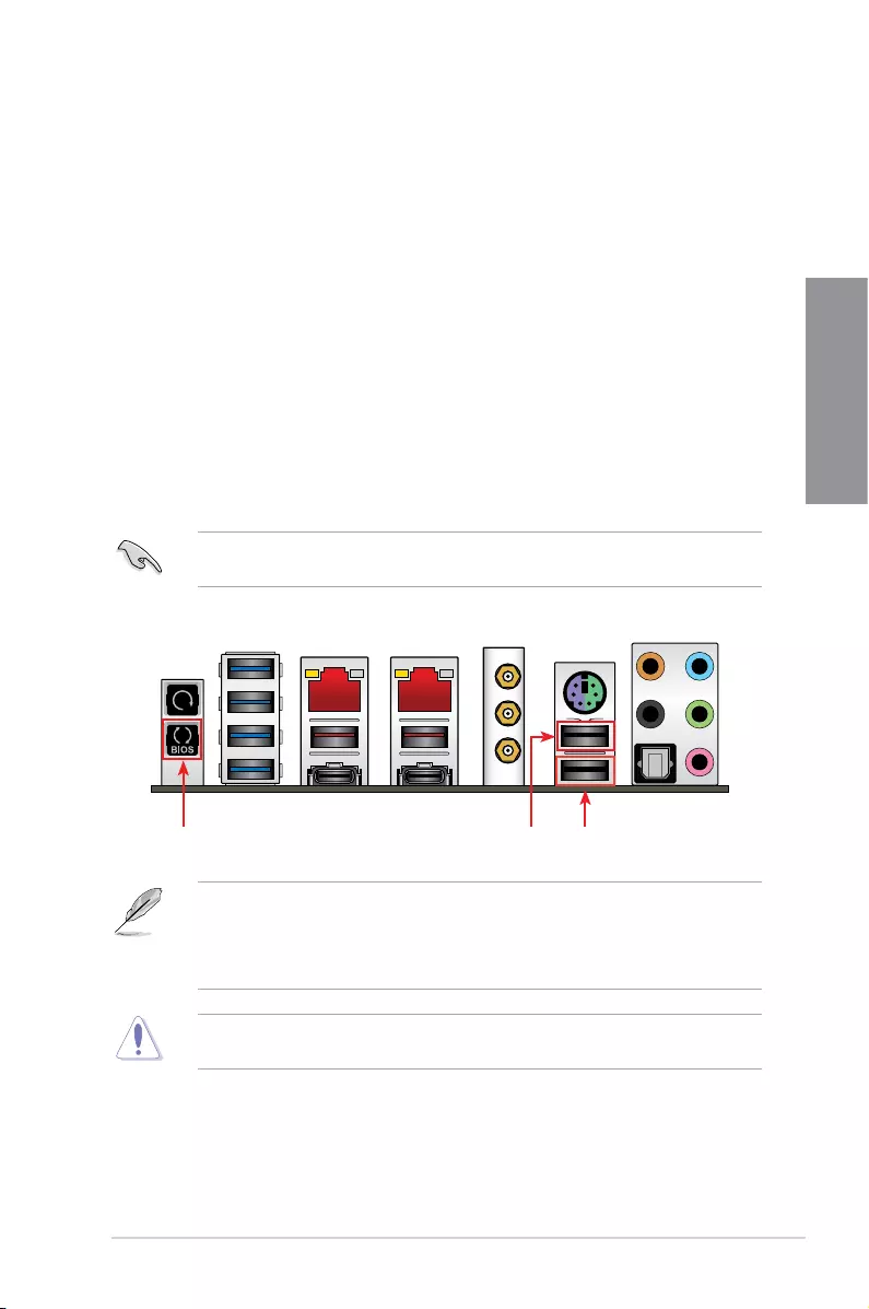
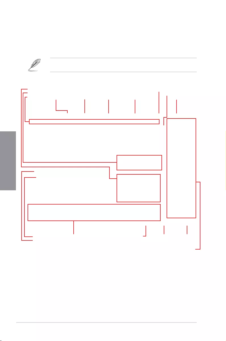
USB BIOS Flashback port
2.2 BIOS update utility
USB BIOS Flashback
USBBIOSFlashbackallowsyoutoeasilyupdatetheBIOSwithoutenteringtheexisting
BIOSoroperatingsystem.SimplyinsertaUSBstoragedevicetotheUSBport,pressthe
USBBIOSFlashbackbuttonforthreeseconds,andtheBIOSisupdatedautomatically.
To use USB BIOS Flashback:
1. DownloadthelatestBIOSlefromtheASUSwebsite.
2. ExtractandrenametheBIOSimageletoR5E10.CAP.
3. Copy R5E10.CAPtotherootdirectoryofyourUSBstoragedevice.
4. TurnoffthesystemandconnecttheUSBstoragedevicetotheUSBBIOSFlashback
port.
5. PresstheUSBBIOSFlashbackbuttonfor3secondsuntiltheBIOS_LED1orBIOS_
LED2ashes.
AashinglightindicatesthattheBIOSFlashbackfunctionisenabled.Thelightgoesout
whentheprocessofupdatingtheBIOSiscomplete.
USB BIOS Flashback button KeyBot II port
• FormoreBIOSupdateutilitiesinBIOSsetup,refertothesectionUpdatingBIOSin
Chapter 3.
• ConnectyourUSBkeyboardontheKeyBotIIportifyouwanttousetheKeyBot
feature.
UpdatingBIOSmayhaverisks.IftheBIOSprogramisdamagedduringtheprocessand
resultstothesystem’sfailuretobootup,pleasecontactyourlocalASUSServiceCenter.
2-16 Chapter 2: Basic Installation
Chapter 2
2.3 Motherboard rear and audio connections
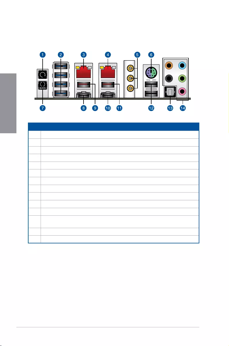
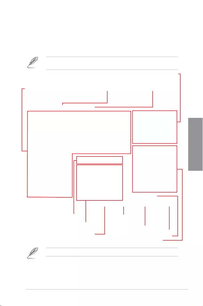
2.3.1 Rear I/O connection
Rear panel connectors
1. ClearCMOSbutton
2. ASMedia® USB3.0portsE1234.SupportsUSB3.0Boost.
3. Intel®LAN(RJ-45)port*
4. Intel®LAN(RJ-45)port*
5. Wi-Fi802.11a/b/g/n/ac,BluetoothV4.0
6. PS/2Keyboard/Mousecomboport
7. USBBIOSFlashbackbutton
8. ASMedia®USB3.1Type-CportEC1.SupportsUSB3.1Boost.
9. ASMedia®USB3.1Type-AportEA2.SupportsUSB3.1Boost.
10. ASMedia®USB3.1Type-CportEC3.SupportsUSB3.1Boost.
11. ASMedia®USB3.1Type-AportEA4.SupportsUSB3.1Boost.
12. Intel®USB2.0ports7and8.UpperportsupportstheKeyBotIIfeature,andlower
portsupportsUSBBIOSFlashbackfunction.
13. OpticalS/PDIFOUTport
14. AudioI/Oports**
* and ** : Refer to the tables on the next page for LAN port LEDs, and audio port definitions.
ASUS RAMPAGE V EDITION 10 2-17
Chapter 2
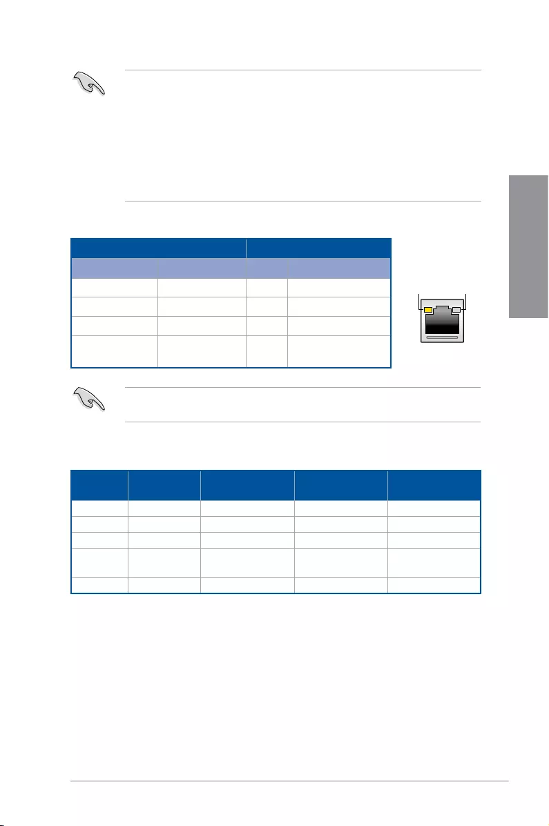
* LAN ports LED indications
ACT/LINK
LED SPEED
LED
LAN port
Activity Link LED Speed LED
Status Description Status Description
Off Nolink Off 10Mbpsconnection
Orange Linked Orange 100Mbpsconnection
Orange(Blinking) Data activity Green 1 Gbps connection
Orange(Blinking
then steady)
Readytowakeup
fromS5mode
YoucandisabletheLANcontrollersinBIOS.Duetohardwaredesign,theLAN1port’s
LEDsmaycontinuetoblinkevenwhendisabled.
• DuetoUSB3.0controllerlimitation,USB3.0devicescanonlybeusedunder
Windows®7andaftertheUSB3.0driverinstallation.
• USB3.0devicescanonlybeusedasdatastorageonly.
• WestronglyrecommendthatyouconnectUSB3.0devicestoUSB3.0portsforfaster
andbetterperformanceforyourUSB3.0devices.
• DuetothedesignoftheIntelchipset,allUSBdevicesconnectedtotheUSB2.0and
USB3.0portsarecontrolledbythexHCIcontroller.SomelegacyUSBdevicesmust
updatetheirrmwareforbettercompatibility.
** Audio 2.1, 4.1, 5.1 or 7.1-channel configuration
Port Headset
2.1-channel
4.1-channel 5.1-channel 7.1-channel
LightBlue Line In Line In Line In SideSpeakerOut
Lime Line Out FrontSpeakerOut FrontSpeakerOut FrontSpeakerOut
Pink Mic In Mic In Mic In Mic In
Orange – – Center/Sub
woofer
Center/Sub
woofer
Black –RearSpeakerOut RearSpeakerOut RearSpeakerOut
2-18 Chapter 2: Basic Installation
Chapter 2
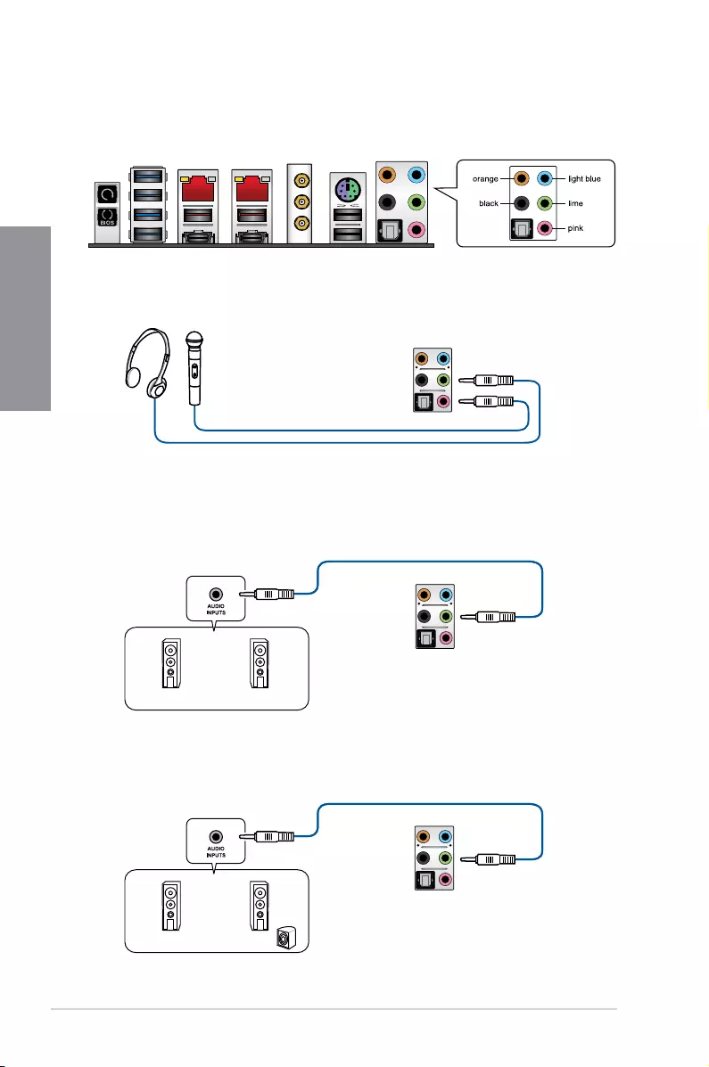
Connect to Headphone and Mic
Connect to Stereo Speakers
Connect to 2.1 channel Speakers
2.3.2 Audio I/O connections
Audio I/O ports
ASUS RAMPAGE V EDITION 10 2-19
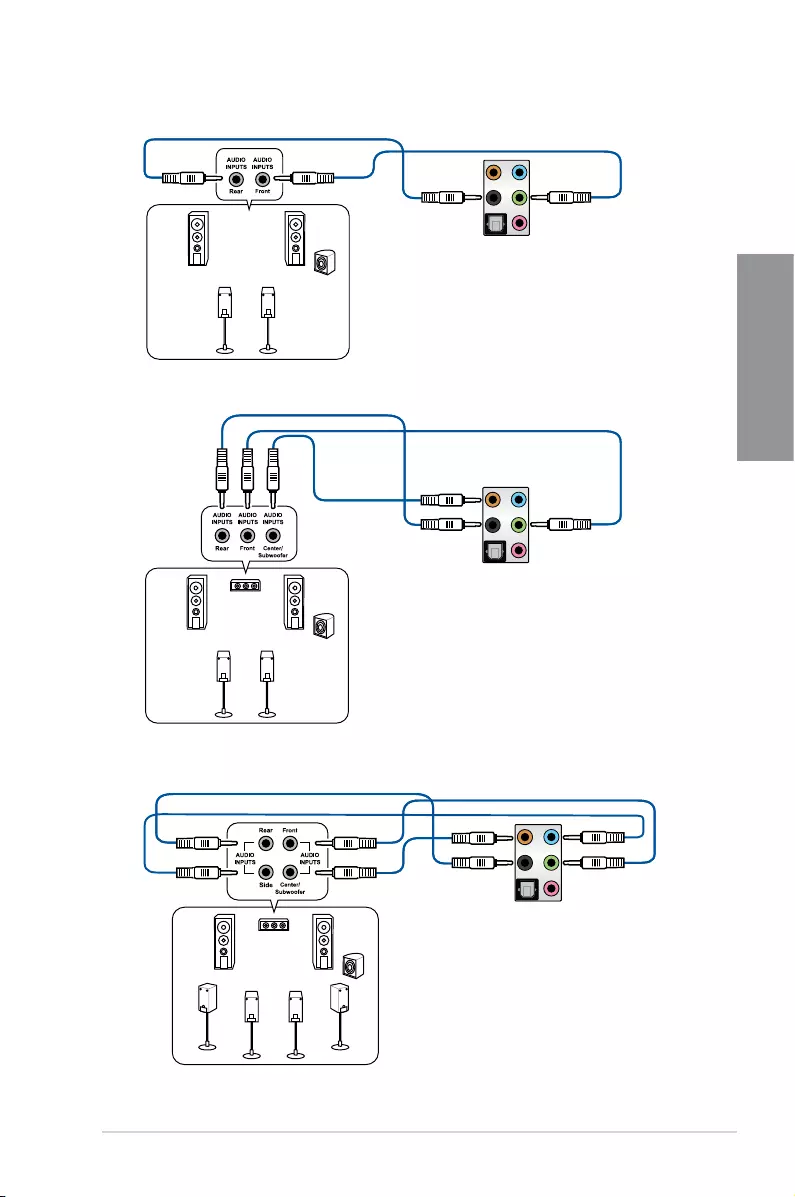
Chapter 2
Connect to 4.1 channel Speakers
Connect to 5.1 channel Speakers
Connect to 7.1 channel Speakers
2-20 Chapter 2: Basic Installation
Chapter 2
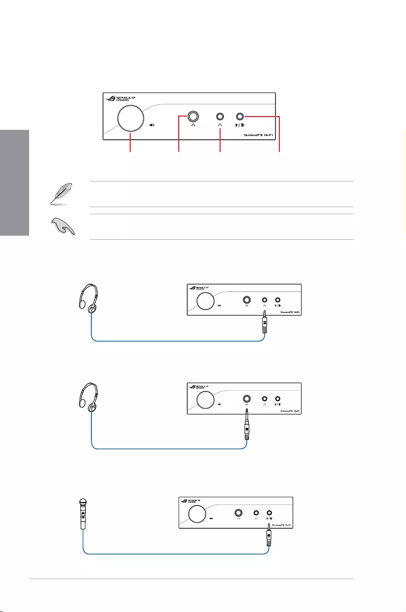
2.3.3 SupremeFX Hi-Fi Audio I/O connections
Audio I/O ports
Volume control knob 6.3mm
headphone
output jack
3.5mm
headphone
output jack
Microphone
/ Line input
jack
Thevolumewillbesetattheminimalleveluponrstinstallation.Pleaseslowlyadjustthe
volume to a comfortable level after plugging in a headphone.
Ensuretoalwaysruntheimpedancedetectfunctionbeforeplaybackeverytimeyouswitch
headphones to avoid damage to your headphones.
Connect to 3.5mm headphones
Connect to 6.3mm headphones
Connect to microphone
ASUS RAMPAGE V EDITION 10 2-21
Chapter 2
2.4 Starting up for the first time
1. Aftermakingalltheconnections,replacethesystemcasecover.
2. Ensurethatallswitchesareoff.
3. Connectthepowercordtothepowerconnectoratthebackofthesystemchassis.
4. Connect the power cord to a power outlet that is equipped with a surge protector.
5. Turn on the devices in the following order:
a. Monitor
b. ExternalSCSIdevices(startingwiththelastdeviceonthechain)
c. Systempower
6. Afterapplyingpower,thesystempowerLEDonthesystemfrontpanelcaselights
up.ForsystemswithATXpowersupplies,thesystemLEDlightsupwhenyoupress
theATXpowerbutton.Ifyourmonitorcomplieswiththegreenstandardsorifithasa
powerstandbyfeature,themonitorLEDmaylightuporchangefromorangetogreen
afterthesystemLEDturnson.
Thesystemthenrunsthepower-onselftests(POST).Whilethetestsarerunning,the
BIOSbeeps(refertotheBIOSbeepcodestable)oradditionalmessagesmayappear
onthescreen.Ifyoudonotseeanythingwithin30secondsfromthetimeyouturned
onthepower,thesystemmayhavefailedapower-ontest.Checkthejumpersettings
and connections or call your retailer for assistance.
BIOS Beep Description
One short beep
VGAdetected
Quickbootsettodisabled
Nokeyboarddetected
One continuous beep followed by two
short beeps then a pause (repeated) No memory detected
One continuous beep followed by three
short beeps NoVGAdetected
One continuous beep followed by four
short beeps Hardwarecomponentfailure
7. Holddownthe<Delete>keyduringpowerontoentertheBIOSSetup.Followthe
instructions in Chapter 3.
2.5 Turning off the computer
WhilethesystemisON,pressthepowerbuttonforlessthanfoursecondstoputthesystem
tosleepmodeorsoft-offmode,dependingontheBIOSsetting.Pressthepowerswitchfor
morethanfoursecondstoletthesystementerthesoft-offmoderegardlessoftheBIOS
setting.

2-22 Chapter 2: Basic Installation
Chapter 2

ASUS RAMPAGE V EDITION 10 3-1
Chapter 3
BIOS setup
3
3.1 Knowing BIOS
The new ASUS UEFI BIOS is a Unied Extensible Interface that complies with UEFI
architecture, offering a user-friendly interface that goes beyond the traditional keyboard-
only BIOS controls to enable a more exible and convenient mouse input. You can easily
navigate the new UEFI BIOS with the same smoothness as your operating system. The
term “BIOS” in this user manual refers to “UEFI BIOS” unless otherwise specied.
BIOS (Basic Input and Output System) stores system hardware settings such as storage
device conguration, overclocking settings, advanced power management, and boot
device conguration that are needed for system startup in the motherboard CMOS. In
normal circumstances, the default BIOS settings apply to most conditions to ensure
optimal performance. DO NOT change the default BIOS settings except in the following
circumstances:
• An error message appears on the screen during the system bootup and requests you to
run the BIOS Setup.
• You have installed a new system component that requires further BIOS settings or
update.
Inappropriate BIOS settings may result to instability or boot failure. We strongly
recommend that you change the BIOS settings only with the help of a trained service
personnel.
When downloading or updating the BIOS le, rename it as R5E10.CAP for this
motherboard.
Chapter 3: BIOS Setup

3-2 Chapter 3: BIOS Setup
Chapter 3
3.2 BIOS setup program
Use the BIOS Setup to update the BIOS or congure its parameters. The BIOS screen
includes navigation keys and a brief on-screen tip to help guide you in using the BIOS Setup
program.
Entering BIOS at startup
To enter BIOS Setup at startup, press <Delete> during the Power-On Self Test (POST). If
you do not press <Delete>, the computer continues to boot normally.
Entering BIOS Setup after POST
To enter BIOS Setup after POST:
• Press <Ctrl>+<Alt>+<Delete> simultaneously.
• Press the reset button on the system chassis.
• Press the power button to turn the system off then back on. Do this option only if you
failed to enter BIOS Setup using the previous options.
After doing either of the three options, press <Delete> key to enter BIOS.
BIOS menu screen
The BIOS Setup program can be used under two modes: EZ Mode and Advanced Mode.
You can change modes from Setup Mode in Boot menu or by pressing the <F7> hotkey.
• The BIOS setup screens shown in this section are for reference purposes only, and
may not exactly match what you see on your screen.
• Ensure that a USB mouse is connected to your motherboard if you want to use the
mouse to control the BIOS setup program.
• If the system becomes unstable after changing any BIOS setting, load the default
settings to ensure system compatibility and stability. Select the Load Optimized
Defaults item under the Exit menu or press hotkey <F5>. See section 3.10 Exit Menu
for details.
• If the system fails to boot after changing any BIOS setting, try to clear the CMOS and
reset the motherboard to the default value. See section 2.3.1 Rear I/O connection for
location of the Clear CMOS button to clear RTC RAM.
• The BIOS setup program does not support bluetooth devices.
Please visit ASUS website for the detailed BIOS content manual.
ASUS RAMPAGE V EDITION 10 3-3
Chapter 3
3.2.1 EZ Mode
The EZ Mode provides you an overview of the basic system information, and allows you to
select the display language, system performance, mode and boot device priority. To access
the Advanced Mode, select Advanced Mode or press the <F7> hotkey for the advanced
BIOS settings.
The default screen for entering the BIOS setup program can be changed. Refer to the
Setup Mode item in section Boot menu for details.
The boot device options vary depending on the devices you installed to the system.
Click to display boot devices
Selects the boot device priority
Selects the display language
of the BIOS setup program
Displays the CPU/motherboard temperature,
CPU voltage output, CPU/chassis/power fan
speed, and SATA information
Displays the system properties of the selected mode.
Click < or > to switch EZ System Tuning modes
Creates storage RAID and
configures system overclocking
Saves the changes
and resets the system
Loads optimized default settings
Click to go to Advanced mode
Search on the FAQ
Displays the CPU Fan’s speed. Click
the button to manually tune the fans
Enables or disables the Intel
Rapid Storage Technology
3-4 Chapter 3: BIOS Setup
Chapter 3
3.2.2 Advanced Mode
The Advanced Mode provides advanced options for experienced end-users to congure
the BIOS settings. The gure below shows an example of the Advanced Mode. Refer to the
following sections for the detailed congurations.
To switch from EZ Mode to Advanced Mode, click Advanced Mode(F7) or press the <F7>
hotkey.
Menu items
General helpSub-menu item
Menu bar
Last modified settings Go back to
EZ Mode
Displays the CPU temperature,
CPU, and memory voltage output
Language Hot Keys
Qfan Control(F6)
MyFavorite(F3)
Quick Note (F9)
EZ Tuning Wizard(F11)
Scroll bar
Pop-up Menu
Configuration fields
Search on
the FAQ
ASUS RAMPAGE V EDITION 10 3-5
Chapter 3
Menu bar
The menu bar on top of the screen has the following main items:
My Favorites For saving the frequently-used system settings and conguration.
Main For changing the basic system conguration
Extreme Tweaker For changing the overclocking settings
Advanced For changing the advanced system settings
Monitor For displaying the system temperature, power status, and changing
the fan settings.
Boot For changing the system boot conguration
Tool For conguring options for special functions
Exit For selecting the exit options and loading default settings
Menu items
The highlighted item on the menu bar displays the specic items for that menu. For example,
selecting Main shows the Main menu items.
The other items (My Favorites, Extreme Tweaker, Advanced, Monitor, Boot, Tool, and Exit)
on the menu bar have their respective menu items.
Submenu items
A greater than sign (>) before each item on any menu screen means that the item has a
submenu. To display the submenu, select the item and press <Enter>.
Language
This button above the menu bar contains the languages that you can select for your BIOS.
Click this button to select the language that you want to display in your BIOS screen.
MyFavorite(F3)
This button above the menu bar shows all BIOS items in a Tree Map setup. Select frequently-
used BIOS settings and save it to MyFavorite menu.
Refer to section 3.3 My Favorites for more information.
Qfan Control(F6)
This button above the menu bar displays the current settings of your fans. Use this button to
manually tweak the fans to your desired settings.
Refer to section 3.2.3 QFan Control for more information.
EZ Tuning Wizard(F11)
This button above the menu bar allows you to view and tweak the overclocking settings of
your system. It also allows you to change the motherboard’s SATA mode from AHCI to RAID
mode.
Refer to section 3.2.4 EZ Tuning Wizard for more information.

3-6 Chapter 3: BIOS Setup
Chapter 3
Search on FAQ
Move your mouse over this button to show a QR code, scan this QR code on your mobile
device to connect to the BIOS FAQ web page of the ASUS support website. You can also
scan the following QR code:
Quick Note (F9)
This button above the menu bar allows you to key in notes of the activities that you have
done in BIOS.
• The quick Note function does not support the following keyboard functions: delete, cut,
copy and paste.
• You can only use the alphanumeric characters to enter your notes.
Hot keys
This button above the menu bar contains the navigation keys for the BIOS setup program.
Use the navigation keys to select items in the menu and change the settings.
Scroll bar
A scroll bar appears on the right side of a menu screen when there are items that do not t
on the screen. Press the Up/Down arrow keys or <Page Up> / <Page Down> keys to display
the other items on the screen.
General help
At the bottom of the menu screen is a brief description of the selected item. Use the <F12>
key to capture the BIOS screen and save it to the removable storage device.
Configuration fields
These elds show the values for the menu items. If an item is user-congurable, you can
change the value of the eld opposite the item. You cannot select an item that is not user-
congurable.
A congurable eld is highlighted when selected. To change the value of a eld, select it and
press <Enter> to display a list of options.
Last Modified button
This button shows the items that you last modied and saved in BIOS Setup.
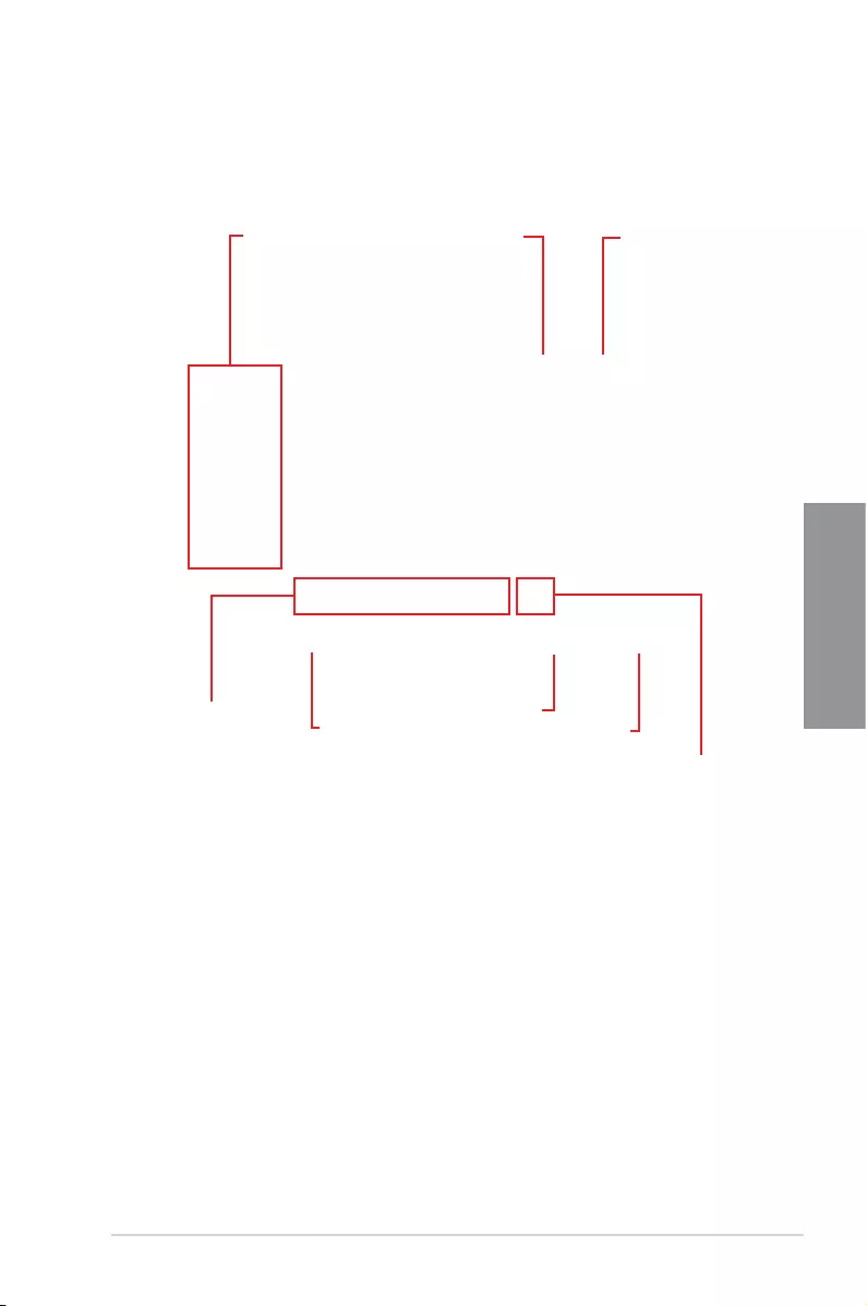
ASUS RAMPAGE V EDITION 10 3-7
Chapter 3
3.2.3 QFan Control
The QFan Control allows you to set a fan prole or manually congure the operating speed of
your CPU and chassis fans.
Click to select a fan to be
configured Click to activate
PWM Mode
Click to undo the
changes
Click to apply the fan setting
Click to go back to main menu
Select a profile to apply to
your fans
Click to activate DC Mode
Select to manually configure
your fans

3-8 Chapter 3: BIOS Setup
Chapter 3
Configuring fans manually
Select Manual from the list of proles to manually congure your fans’ operating speed.
To congure your fans:
1. Select the fan that you want to congure and to view its current status.
2. Click and drag the speed points to adjust the fans’ operating speed.
3. Click Apply to save the changes then click Exit (ESC).
Speed points Select to manually
configure your fans
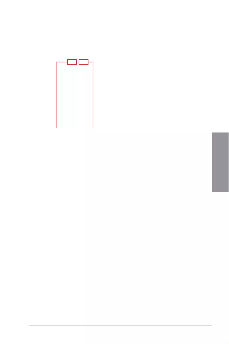
ASUS RAMPAGE V EDITION 10 3-9
Chapter 3
3.2.4 EZ Tuning Wizard
EZ Tuning Wizard allows you to easily overclock your CPU and DRAM, computer usage, and
CPU fan to their best settings. You can also set RAID in your system using this feature.
RAID setup
OC Tuning
To start OC Tuning:
1. Press <F11> on your keyboard or click from the BIOS screen to open
EZ Tuning Wizard screen.
2. Click OC
then click Next.
3. Select a PC scenario Daily Computing or Gaming/Media Editing, then click Next.
OC setup

3-10 Chapter 3: BIOS Setup
Chapter 3
Creating RAID
To create RAID:
1. Press <F11> on your keyboard or click from the BIOS screen to open
EZ Tuning Wizard screen.
2. Click RAID
then click Next.
• Ensure that your HDDs have no existing RAID volumes.
• Ensure to connect your HDDs to Intel® SATA connectors.
3. Check the available storage disk drives, then click Next.
4. Select a Main Cooling System BOX cooler, Tower cooler, Water cooler, or I’m not
sure, then click Next.
5. After selecting the Main Cooling System, click Next then click Yes to start the OC
Tuning.

ASUS RAMPAGE V EDITION 10 3-11
Chapter 3
5. After selecting the type of RAID, click Next then click Yes to continue the RAID setup.
6. After the RAID setup is done, click Yes to exit the setup then click OK to reset your
system.
You can only select Easy Backup (RAID 10) if you connect four (4) HDDs.
b. For Super Speed, click Next then select from Super Speed (RAID 0) or Super
Speed (RAID 5).
a. For Easy Backup, click Next then select from Easy Backup (RAID 1) or Easy
Backup (RAID 10).
4. Select the type of storage for your RAID, Easy Backup or Super Speed, then click
Next.

3-12 Chapter 3: BIOS Setup
Chapter 3
3.3 My Favorites
My Favorites is your personal space where you can easily save and access your favorite
BIOS items.
My Favorites comes with several performance, power saving, and fast boot related items by
default. You can personalize this screen by adding or removing items.
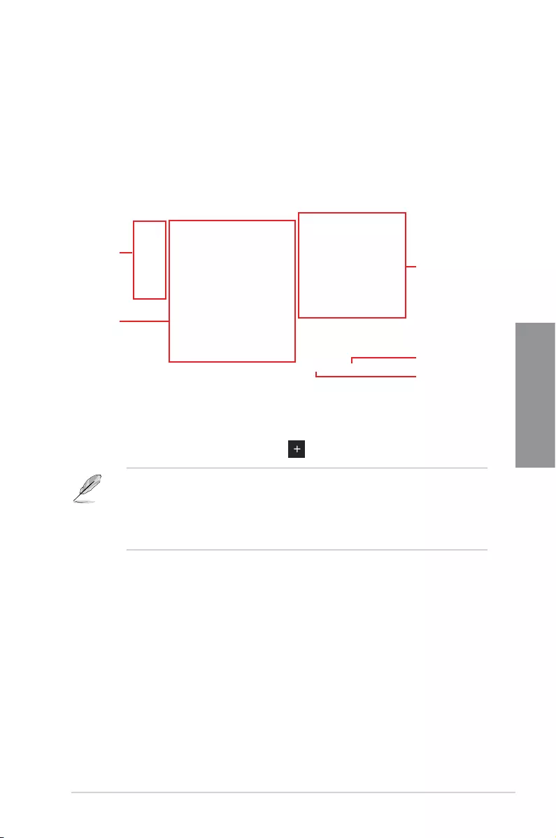
ASUS RAMPAGE V EDITION 10 3-13
Chapter 3
Adding items to My Favorites
To add frequently-used BIOS items to My Favorites:
1. Press <F3> on your keyboard or click to open Setup Tree Map screen.
2. On the Setup Tree Map screen, select the BIOS items that you want to save in My
Favorites screen.
3. Select an item from main menu panel, then click the submenu that you want to save as
favorite from the submenu panel and click or press <Enter> on your keyboard.
You cannot add the following items to My Favorite items:
• Items with submenu options.
• User-managed items such as language and boot order.
• Conguration items such as Memory SPD Information, system time and date.
4. Click Exit (ESC) or press <Esc> key to close Setup Tree Map screen.
5. Go to My Favorites menu to view the saved BIOS items.
Main menu panel
Submenu panel
Selected shortcut
items
Delete all favorite
items
Recover to default
favorite items

3-14 Chapter 3: BIOS Setup
Chapter 3
3.4 Main menu
The Main menu screen appears when you enter the Advanced Mode of the BIOS Setup
program. The Main menu provides you an overview of the basic system information, and
allows you to set the system date, time, language, and security settings.

ASUS RAMPAGE V EDITION 10 3-15
Chapter 3
Security
The Security menu items allow you to change the system security settings.
• If you have forgotten your BIOS password, erase the CMOS Real Time Clock (RTC)
RAM to clear the BIOS password. See section 2.3.1 Rear I/O connection for location
of the Clear CMOS button to clear RTC RAM.
• The Administrator or User Password items on top of the screen show the default [Not
Installed]. After you set a password, these items show [Installed].

3-16 Chapter 3: BIOS Setup
Chapter 3
3.5 Extreme Tweaker menu
The Extreme Tweaker menu items allow you to congure overclocking-related items.
Be cautious when changing the settings of the Extreme Tweaker menu items. Incorrect
eld values can cause the system to malfunction
The conguration options for this section vary depending on the CPU and DIMM model you
installed on the motherboard.
Scroll down to display other BIOS items.
Ai Overclock Tuner
Allows you to select the CPU overclocking options to achieve the desired CPU internal
frequency. Conguration options:
[Auto] Loads the optimal settings for the system.
[Manual] Allows you to individually set overclocking parameters.
[X.M.P.] If you install memory modules supporting the eXtreme Memory Prole
(X.M.P.) Technology, choose this item to set the proles supported by your
memory modules for optimizing the system performance.
The [X.M.P.] conguration option appears only when you install memory modules
supporting the eXtreme Memory Prole(X.M.P.) Technology.
When the Ai Overclock Tuner is set to [Manual] or [XMP], the following items appear.
ASUS RAMPAGE V EDITION 10 3-17
Chapter 3
BCLK Frequency
This item allows you to set the BCLK (base clock) frequency to enhance the system
performance. Use the <+> or <-> to adjust the value. The values range from 40.0 MHz
to 500.0 MHz.
We recommend you to set the value based on the CPU specication, as high BCLK
frequencies may damage the CPU permanently.
When Ai Overclock Tuner is set to [XMP], the XMP mode supported by the installed
memory module is displayed.
ASUS MultiCore Enhancement
[Auto] This item allows you to maximize the oveclocking performance optimized
by ASUS core ratio settings.
[Disabled] This item allows you to set to default core ratio settings.
CPU Core Ratio
This item allows you to set the CPU core ratio limit per core or synchronize automatically to
all cores.
Conguration options: [Auto] [Sync All Cores] [Per Core]
BCLK Frequency : DRAM Frequency Ratio
[Auto] The BCLK frequency to DRAM frequency ratio will be set to the optimized
setting.
[100:133] The BCLK frequency to DRAM frequency ratio will be set to 100:133.
[100:100] The BCLK frequency to DRAM frequency ratio will be set to 100:100.
DRAM Frequency
This item allows you to set the memory operating frequency. The congurable options vary
with the BCLK (base clock) frequency setting. Select the auto mode to apply the optimized
setting.
Conguration options: [Auto] [DDR4-800MHz] - [DDR4-4000MHz]
TPU
This item allows you to automatically overclock the CPU and DRAM frequencies and voltage
for an enhanced system performance.
[Keep Current Settings] Keep the current settings without changing anything.
[TPU I] Applies air cooling overclocking conditions.
[TPU II] Applies water cooling overclocking conditions.
Ensure to use water cooling device before selecting [TPU II].

3-18 Chapter 3: BIOS Setup
Chapter 3
EPU Power Saving Mode
The ASUS EPU (Energy Processing Unit) sets the CPU in its minimum power consumption
settings. Enable this item to set lower CPU core/cache voltage and achieve the best energy
saving condition.
Conguration options: [Disabled] [Enabled]
Internal CPU Power Management
The subitems in this menu allow you to set the CPU ratio and features.
Enhanced Intel SpeedStep Technology
Allows the operating system to dynamically adjust the processor voltage and cores
frequency to decrease the average power consumption and decrease average heat
production.
Conguration options: [Disabled] [Enabled]
Turbo Mode
Allows you to enable your processor cores to run faster than the base operating
frequency when it is below power, current and specication limit.
Conguration options: [Disabled] [Enabled]
3.6 Advanced menu
The Advanced menu items allow you to change the settings for the CPU and other system
devices.
Be cautious when changing the settings of the Advanced menu items. Incorrect eld values
can cause the system to malfunction.

ASUS RAMPAGE V EDITION 10 3-19
Chapter 3
3.6.1 CPU Configuration
The items in this menu show the CPU-related information that the BIOS automatically
detects.
The items in this menu may vary based on the CPU installed.
Hyper-threading[ALL]
This item allows a hyper-threading processor to appear as two logical processors, allowing
the operating system to schedule two threads or processors simultaneously.
Conguration options: [Disabled] [Enabled]
CPU Power Management Configuration
This item allows you to manage and congure the CPU’s power.
Enhanced Intel SpeedStep Technology
This item allows your system to adjust the CPU’s voltage and cores frequency,
resulting in decreased power consumption and heat production.
[Disabled] The CPU runs at its default speed.
[Enabled] The system controls the CPU speed.
Turbo Mode
This item allows you to automatically set the CPU cores to run faster than the base
operating frequency when it is below the operating power, current and temperature
specication limit.
Conguration options: [Disabled] [Enabled]
CPU C-States
This item allows you to set the power saving of the CPU states.
Conguration options: [Auto] [Disabled] [Enabled]
Scroll down to display other BIOS items.

3-20 Chapter 3: BIOS Setup
Chapter 3
3.6.2 PCH Configuration
PCI Express Configuration
This item allows you to congure the PCI Express slots.
PCIEX4_1 Speed
This item allows your system to automatically select the PCI Express port speed.
Conguration options: [Auto] [Gen1] [Gen2]
3.6.3 PCH Storage Configuration
While entering Setup, the BIOS automatically detects the presence of SATA devices. The
SATA Port items show [Not Installed] if no SATA device is installed to the corresponding
SATA port.
Scroll down to display the other BIOS items.
S.M.A.R.T. Status Check
SMART (Self-Monitoring, Analysis and Reporting Technology) is a monitoring system that
shows a warning message during POST (Power-On Self Test) when an error occurs in the
hard disks.
Conguration options: [On] [Off]

ASUS RAMPAGE V EDITION 10 3-21
Chapter 3
SATA Controller(s)
SATA Controller(s) Mode Selection
This item allows you to set the SATA conguration.
[Disabled] Disable the SATA function.
[IDE] Use SATA hard disk as Parallel ATA storage devices
[AHCI] Set to [AHCI] when you want the SATA hard disk drives to use the AHCI
(Advanced Host Controller Interface). The AHCI allows the onboard storage
driver to enable advanced Serial ATA features that increases storage
performance on random workloads by allowing the drive to internally
optimize the order of commands.
[RAID] Set to [RAID] when you want to create a RAID conguration from the SATA
hard disk drives.
SATA6G_1(Gray) - SATA6G_10(Gray)
SATA6G_7(Gray) - SATA6G_10(Gray)
This item allows you to enable or disable the selected SATA port.
Conguration options: [Disabled] [Enabled]
Hot Plug
These items appear only when the SATA Mode Selection is set to [AHCI] and allows
you to enable or disable SATA Hot Plug Support.
Conguration options: [Disabled] [Enabled]
3.6.4 System Agent (SA) Configuration

3-22 Chapter 3: BIOS Setup
Chapter 3
3.6.5 USB Configuration
The items in this menu allow you to change the USB-related features.
The Mass Storage Devices item will only appear when a USB device is detected.
USB Single Port Control
This item allows you to enable or disable the individual USB ports.
Refer to section 1.1.2 Motherboard layout for the location of the USB ports.
3.6.6 Platform Misc Configuration
The items in this menu allow you to congure the platform-related features.

ASUS RAMPAGE V EDITION 10 3-23
Chapter 3
3.6.7 Onboard Devices Configuration
Scroll down to view the other BIOS items.
HD Audio Controller
[Disabled] HDA will be unconditionally disabled
[Enabled] HDA will be unconditionally enabled
Asmedia USB 3.1 Controller
This item allows you to disable or enable the ASMedia USB 3.1 controller.
Conguration options: [Disabled] [Enabled]
Asmedia USB 3.1 Battery Charging Support
This item allows you to disable or enable the ASMedia USB 3.1 battery charging support.
Conguration options: [Disabled] [Enabled]
RGB LED(onboard)
[Disabled] LEDs will not light up.
[Enabled] LEDs will always light up at the S0(Working), S3(Sleep), and S5(Soft off)
RGB LED lighting effects
This item allows you to set the RGB LED lighting effects.
Conguration options: [Default] [Auto] [Static] [Breathing] [Strobing] [Color Cycle]
• When the power is completely removed from your motherboard (G3 state), the RGB
LED lighting effect will revert to the default setting the next time the motherboard is
powered on.
• The following item appears only when you set the RGB LED lighting effects to [Static],
[Breathing], or [Strobing].

3-24 Chapter 3: BIOS Setup
Chapter 3
3.6.8 APM Configuration
ErP Ready
Allows you to switch off some power at S4/S5 to get the system ready for ErP requirement.
When set to [Enabled], all other PME options will be switched off.
Conguration options: [Disabled] [Enabled(S4+S5)] [Enabled(S5)]
3.6.9 Network Stack Configuration
RGB LED lighting color
This item allows you to set the RGB LED lighting colors.
Bluetooth Controller
This item allows you to enable or disable the Bluetooth Controller.
Conguration options: [Disabled] [Enabled]
Wi-Fi Controller
This item allows you to enable or disable the Wi-Fi Controller.
Conguration options: [Disabled] [Enabled]
Intel LAN1 Controller
This item allows you to enable or disable the GbE Controller.
Conguration options: [Disabled] [Enabled]
Intel LAN2 Controller
This item allows you to enable or disable the Intel LAN2 Controller.
Conguration options: [Disabled] [Enabled]

ASUS RAMPAGE V EDITION 10 3-25
Chapter 3
3.6.10 ROG Effects
3.6.11 HDD/SDD SMART Information
This menu displays the SMART information of the connected devices.
3.7 Monitor menu
The Monitor menu displays the system temperature/power status, and allows you to change
the fan settings.
Scroll down to display other BIOS items.
Optimize All
This item will automatically detect the lowest speed and congure the minimum duty cycle for
each fan.

3-26 Chapter 3: BIOS Setup
Chapter 3
3.8 Boot menu
The Boot menu items allow you to change the system boot options.
Scroll down to display the other BIOS items.
Fast Boot
[Disabled] Allows your system to go back to its normal boot speed.
[Enabled] Allows your system to accelerate the boot speed.
The following items appear only when you set the Fast Boot to [Enabled].
Next Boot after AC Power Loss
[Normal Boot] Returns to normal boot on the next boot after an AC power loss.
[Fast Boot] Accelerates the boot speed on the next boot after an AC power loss.
Water Pump Control
[Disabled] Disable the Water Pump control feature.
[Auto] Detect the type of Water Pump installed and automatically switches the
mode control.
[DC mode] Enable the Water Pump control in DC mode for 3-pin Water Pump.
[PWM mode] Enable the Water Pump control in PWM mode for 4-pin Water Pump.
HAMP Fan Control
[Disabled] Disable the HAMP Fan control.
[Auto] Detect the type of HAMP fan installed and automatically switches the mode
control.
[DC mode] Enable the HAMP Fan control feature in DC mode for 3-pin chassis fan.
[PWM mode] Enable the HAMP Fan control feature in PWM mode for 4-pin chassis fan.

ASUS RAMPAGE V EDITION 10 3-27
Chapter 3
DirectKey (DRCT)
[Disabled] The system will only turn on or off when the reset button is pressed.
[Enabled] Allow the system to turn on and go to the BIOS Setup directly when the
reset button is pressed. Connect the 2-pin connector of the chassis reset
button cable to the onboard DRCT header to support this function.
Setup Mode
[Advanced Mode] This item allows you to go to Advanced Mode of the BIOS after POST.
[EZ Mode] This item allows you to go to EZ Mode of the BIOS after POST.
CSM (Compatibility Support Module)
This item allows you to congure the CSM (Compatibility Support Module) items to fully
support the various VGA, bootable devices and add-on devices for better compatibility.
Launch CSM
[Auto] The system automatically detects the bootable devices and the add-
on devices for CSM support.
[Enabled] For better compatibility, enable the CSM to fully support the non-UEFI
driver add-on devices or the Windows® UEFI mode.
[Disabled] Disable the CSM to fully support the Windows® secure update and
secure boot.
The following items appear only when you set the Launch CSM to [Enabled].
Boot Devices Control
This item allows you to select the devices boot-up mode by the devices
specication.
Conguration options: [UEFI and Legacy OPROM] [Legacy OPROM only]
[UEFI only]
Boot from Network Devices
This item allows you to select the type of the onboard LAN controllers and
installed LAN cards.
Conguration options: [Ignore] [Legacy only] [UEFI driver rst]
Boot from Storage Devices
This item allows you to select the type of storage devices that will run rst
during the system boot.
Conguration options: [Ignore] [Legacy only] [UEFI driver rst]
Boot from PCI-E/PCI Expansion Devices
This item allows you to select the type of PCI-E/PCI expansion devices that
will run rst during the system boot.
Conguration options: [Legacy only] [UEFI driver rst]
Secure Boot
This item allows you to congure the Windows® Secure Boot settings and manage its keys to
protect the system from unauthorized access and malwares during POST.

3-28 Chapter 3: BIOS Setup
Chapter 3
Boot Option Priorities
These items specify the boot device priority sequence from the available devices. The
number of device items that appears on the screen depends on the number of devices
installed in the system.
• To access Windows® OS in Safe Mode, press <F8> after POST (Windows® 8 not
supported).
• To select the boot device during system startup, press <F8> when the ASUS Logo
appears.
Boot Override
These items displays the available devices. The number of device items that appears on
the screen depends on the number of devices installed in the system. Click an item to start
booting from the selected device.
3.9 Tool menu
The Tools menu items allow you to congure options for special functions. Select an item
then press <Enter> to display the submenu.
3.9.1 GPU Post
This item shows the installed graphics cards in the motherboard. It also suggests the
conguration of graphic cards in the motherboard for the best performance.
3.9.2 ASUS EZ Flash 3 Utility
Allows you to run ASUS EZ Flash 3. When you press <Enter>, a conrmation message
appears. Use the Left/Right arrow key to select between [via Storage Devices(s)] or [via
Internet], then press <Enter> to conrm your choice.
For more details, refer to section 3.11.2 ASUS EZ Flash 3 utility.
Setup Animator
This item allows you to enable or disable Setup Animator.
Conguration options: [Enabled] [Disabled]
ASUS RAMPAGE V EDITION 10 3-29
Chapter 3
3.9.3 Secure Erase
SSD speeds may lower over time as with any storage medium due to data processing.
Secure Erase completely and safely cleans your SSD, restoring it to factory performance
levels.
Secure Erase is only available in AHCI mode. Ensure to set the SATA mode to AHCI. Click
Advanced > PCH Storage Configuration > AHCI.
To launch Secure Erase, click Tool > Secure Erase on the Advanced mode menu.
Check the ASUS support site for a full list of SSDs tested with Secure Erase. The drive may
become unstable if you run Secure Erase on an incompatible SSD.
Displays the
available SSDs
Status denition:
• Frozen. The frozen state is the result of a BIOS protective measure. The BIOS guards
drives that do not have password protection by freezing them prior to booting. If the
drive is frozen, a power off or hard reset of your PC must be performed to proceed
with the Secure Erase.
• Locked. SSDs might be locked if the Secure Erase process is either incomplete or
was stopped. This may be due to a third party software that uses a different password
dened by ASUS. You have to unlock the SSD in the software before proceeding with
Secure Erase.
• The time to erase the contents of your SSD may take a while depending on its size.
Do not turn off the system during the process.
• Secure Erase is only supported on Intel SATA port. For more information about Intel
SATA ports, refer to section 1.1.2 Motherboard layout of this manual.

3-30 Chapter 3: BIOS Setup
Chapter 3
3.9.4 ASUS Overclocking Profile
This item allows you to store or load multiple BIOS settings.
Load from Profile
This item allows you to load the previous BIOS settings saved in the BIOS Flash. Key in the
prole number that saved your BIOS settings, press <Enter>, and then select Yes.
• DO NOT shut down or reset the system while updating the BIOS to prevent the
system boot failure!
• We recommend that you update the BIOS le only coming from the same memory/
CPU conguration and BIOS version.
Profile Name
This item allows you to key in a prole name.
Save to Profile
This item allows you to save the current BIOS settings to the BIOS Flash, and create a
prole. Key in a prole number from one to eight, press <Enter>, and then select Yes.
Load/Save Profile from/to USB Drive
This item allows you to load or save prole from your USB drive, load and save prole to your
USB drive.

ASUS RAMPAGE V EDITION 10 3-31
Chapter 3
3.9.5 ASUS SPD Information
Allows you to view the DRAM SPD information.
3.10 Exit menu
The Exit menu items allow you to load the optimal default values for the BIOS items, and
save or discard your changes to the BIOS items.
Load Optimized Defaults
This option allows you to load the default values for each of the parameters on the Setup
menus. When you select this option or if you press <F5>, a conrmation window appears.
Select Yes to load the default values.
Save Changes & Reset
Once you are nished making your selections, choose this option from the Exit menu to
ensure the values you selected are saved. When you select this option or if you press <F10>,
a conrmation window appears. Select Yes to save changes and exit.
Discard Changes & Exit
This option allows you to exit the Setup program without saving your changes. When you
select this option or if you press <Esc>, a conrmation window appears. Select Yes to
discard changes and exit.

3-32 Chapter 3: BIOS Setup
Chapter 3
3.11 Updating BIOS
The ASUS website publishes the latest BIOS versions to provide enhancements on system
stability, compatibility,and performance. However, BIOS updating is potentially risky. If
there is no problem using the current version of BIOS, DO NOT manually update the BIOS.
Inappropriate BIOS updating may result to system’s failure to boot. Carefully follow the
instructions in this chapter to update your BIOS when necessary.
Visit http://www.asus.com to download the latest BIOS le for this motherboard.
The following utilities allow you to manage and update the motherboard BIOS setup program.
1. EZ Update: Updates the BIOS in Windows® environment.
2. ASUS EZ Flash 3: Updates the BIOS using a USB ash drive.
3. ASUS CrashFree BIOS 3: Restores the BIOS using the motherboard support USB
drive when the BIOS le fails or gets corrupted.
3.11.1 EZ Update
The EZ Update is a utility that allows you to update the motherboard BIOS in Windows®
environment.
• EZ Update requires an Internet connection either through a network or an ISP
(Internet Service Provider).
• This utility is available in the support USB drive that comes with the motherboard
package.
Launch EFI Shell from USB devices
This option allows you to attempt to launch the EFI Shell application (shellx64.e) from one of
the available USB devices.

ASUS RAMPAGE V EDITION 10 3-33
Chapter 3
3.11.2 ASUS EZ Flash 3 Utility
ASUS EZ Flash 3 Utility allows you to update the BIOS without having to use a bootable
oppy disk or an OS-based utility.
Updating through the Internet varies per region and Internet conditions. Check your local
Internet connection before updating through the Internet.
To update the BIOS by USB:
1. Insert the USB ash disk that contains the latest BIOS le to the USB port.
2. Enter the Advanced Mode of the BIOS setup program. Go to the Tool menu to select
ASUS EZ Flash 3 Utility and press <Enter>.
3. Select via Storage Device(s).
4. Press <Tab> to switch to the Drive eld.
5. Press the Up/Down arrow keys to nd the USB ash disk that contains the latest BIOS,
and then press <Enter>.
6. Press <Tab> to switch to the Folder Info eld.
7. Press the Up/Down arrow keys to nd the BIOS le, and then press <Enter> to perform
the BIOS update process. Reboot the system when the update process is done.

3-34 Chapter 3: BIOS Setup
Chapter 3
• This function can support devices such as a USB ash disk with FAT 32/16 format and
single partition only.
• DO NOT shut down or reset the system while updating the BIOS to prevent system
boot failure!
Ensure to load the BIOS default settings to ensure system compatibility and stability. Select
the Load Optimized Defaults item under the Exit menu. See section 3.10 Exit Menu for
details.
To update the BIOS by Internet:
1. Enter the Advanced Mode of the BIOS setup program. Go to the Tool menu to select
ASUS EZ Flash 3 Utility and press <Enter>.
2. Select via Internet.
3. Press the Left/Right arrow keys to select an Internet connection method, and then
press <Enter>
4. Follow the onscreen instructions to complete the update.
5. Reboot the system when the update process is done.
Ensure to load the BIOS default settings to ensure system compatibility and stability. Select
the Load Optimized Defaults item under the Exit menu. See section 3.10 Exit Menu for
details.

ASUS RAMPAGE V EDITION 10 3-35
Chapter 3
3.11.3 ASUS CrashFree BIOS 3
The ASUS CrashFree BIOS 3 utility is an auto recovery tool that allows you to restore the
BIOS le when it fails or gets corrupted during the updating process. You can restore a
corrupted BIOS le using the motherboard support USB drive that contains the BIOS le.
The BIOS le in the motherboard support USB drive may be older than the BIOS le
published on the ASUS ofcial website. If you want to use the newer BIOS le, download
the le at https://www.asus.com/support/ and save it to a USB ash drive.
Recovering the BIOS
To recover the BIOS:
1. Turn on the system.
2. Insert the motherboard support USB drive, or a USB ash drive containing the BIOS
le to the USB port.
3. The utility automatically checks the devices for the BIOS le. When found, the utility
reads the BIOS le and enters the ASUS EZ Flash 3 Utility automatically.
4. The system requires you to enter BIOS Setup to recover the BIOS setting. To ensure
system compatibility and stability, we recommend that you press <F5> to load default
BIOS values.
DO NOT shut down or reset the system while updating the BIOS! Doing so can cause
system boot failure!

3-36 Chapter 3: BIOS Setup
Chapter 3

ASUS RAMPAGE V EDITION 10 4-1
Chapter 5
RAID support
5
4.1 RAID configurations
The motherboard comes with the Intel® Rapid Storage Technology that supports RAID 0,
RAID 1, RAID 10, and RAID 5 conguration.
If you want to install a Windows® operating system to a hard disk drive included in a RAID
set, you have to create a RAID driver disk and load the RAID driver during OS installation.
Refer to section 4.2 Creating a RAID driver disk for details.
4.1.1 RAID definitions
RAID 0 (Data striping) optimizes two identical hard disk drives to read and write data in
parallel, interleaved stacks. Two hard disks perform the same work as a single drive but at a
sustained data transfer rate, double that of a single disk alone, thus improving data access
and storage. Use of two new identical hard disk drives is required for this setup.
RAID 1 (Data mirroring) copies and maintains an identical image of data from one drive to
a second drive. If one drive fails, the disk array management software directs all applications
to the surviving drive as it contains a complete copy of the data in the other drive. This RAID
conguration provides data protection and increases fault tolerance to the entire system. Use
two new drives or use an existing drive and a new drive for this setup. The new drive must be
of the same size or larger than the existing drive.
RAID 5 strips both data and parity information across three or more hard disk drives. Among
the advantages of RAID 5 conguration include better HDD performance, fault tolerance, and
higher storage capacity. The RAID 5 conguration is best suited for transaction processing,
relational database applications, enterprise resource planning, and other business systems.
Use a minimum of three identical hard disk drives for this setup.
RAID 10 is data striping and data mirroring combined without parity (redundancy data) having
to be calculated and written. With the RAID 10 conguration you get all the benets of both
RAID 0 and RAID 1 congurations. Use four new hard disk drives or use an existing drive
and three new drives for this setup.
Windows® 10 32-bit does not support RAID.

4-2 Chapter 5: RAID Support
Chapter 5
4.1.2 Installing Serial ATA hard disks
The motherboard supports Serial ATA hard disk drives. For optimal performance, install
identical drives of the same model and capacity when creating a disk array.
To install the SATA hard disks for a RAID configuration:
1. Install the SATA hard disks into the drive bays.
2. Connect the SATA signal cables.
3. Connect a SATA power cable to the power connector on each drive.
4.1.3 Intel® Rapid Storage Technology in UEFI BIOS
To enter the Intel® Rapid Storage Technology in UEFI BIOS:
1. Enter the BIOS Setup during POST.
2. Go to the Advanced menu > PCH Storage Configuration, then press <Enter>.
3. Set the SATA Controller Mode Selection item to [RAID Mode].
4. Go to the Boot menu > CSM (Compatibility Support Module) > Launch CSM, then
set the item to [Disabled].
5. Save your changes and exit the BIOS Setup, then enter the BIOS Setup again.
6. Go to the Advanced menu > Intel(R) Rapid Storage Technology, then press <Enter>
to display the Intel® Rapid Storage Technology menu.
Refer to Chapter 3 for details on entering and navigating through the BIOS Setup
Due to chipset limitation, when SATA ports are set to RAID mode, all SATA ports run at
RAID mode together.

ASUS RAMPAGE V EDITION 10 4-3
Chapter 5
Creating a RAID set
To create a RAID set:
1. From the Intel® Rapid Storage Technology menu, select Create RAID Volume and
press <Enter>. The following screen appears:
2. When the Name item is selected, enter a name for the RAID set and press <Enter>.
3. When the RAID Level item is selected, press <Enter> to select the RAID level to
create, and then press <Enter>.
4. Under Select Disks, press <Enter> and select X for the disks you want to include in the
RAID set.

4-4 Chapter 5: RAID Support
Chapter 5
5. When the Strip Size item is selected, press <Enter> to select strip size for the RAID
array (for RAID 0, 10 and 5 only), and then press <Enter>. The available strip size
values range from 4 KB to 128 KB. The following are typical values:
- RAID 0: 128 KB
- RAID 10: 64 KB
- RAID 5: 64 KB
We recommend a lower strip size for server systems, and a higher strip size for multimedia
computer systems used mainly for audio and video editing.
6. When the Capacity (MB) item is selected, enter the RAID volume capacity that you
want and press <Enter>. The default value indicates the maximum allowed capacity.
7. When the Create Volume item is selected, press <Enter> to create the RAID volume
and return to the Intel® Rapid Storage Technology menu.

ASUS RAMPAGE V EDITION 10 4-5
Chapter 5
Deleting a RAID set
Be cautious when deleting a RAID set. You will lose all data on the hard disk drives when
you delete a RAID set.
To delete a RAID set:
1. From the Intel® Rapid Storage Technology menu, select the RAID volume you want to
delete and press <Enter>. The following screen appears:
2. When the Delete item is selected, press <Enter>, then select Yes to delete the RAID
volume and return to the Intel® Rapid Storage Technology menu, or select No to
cancel.
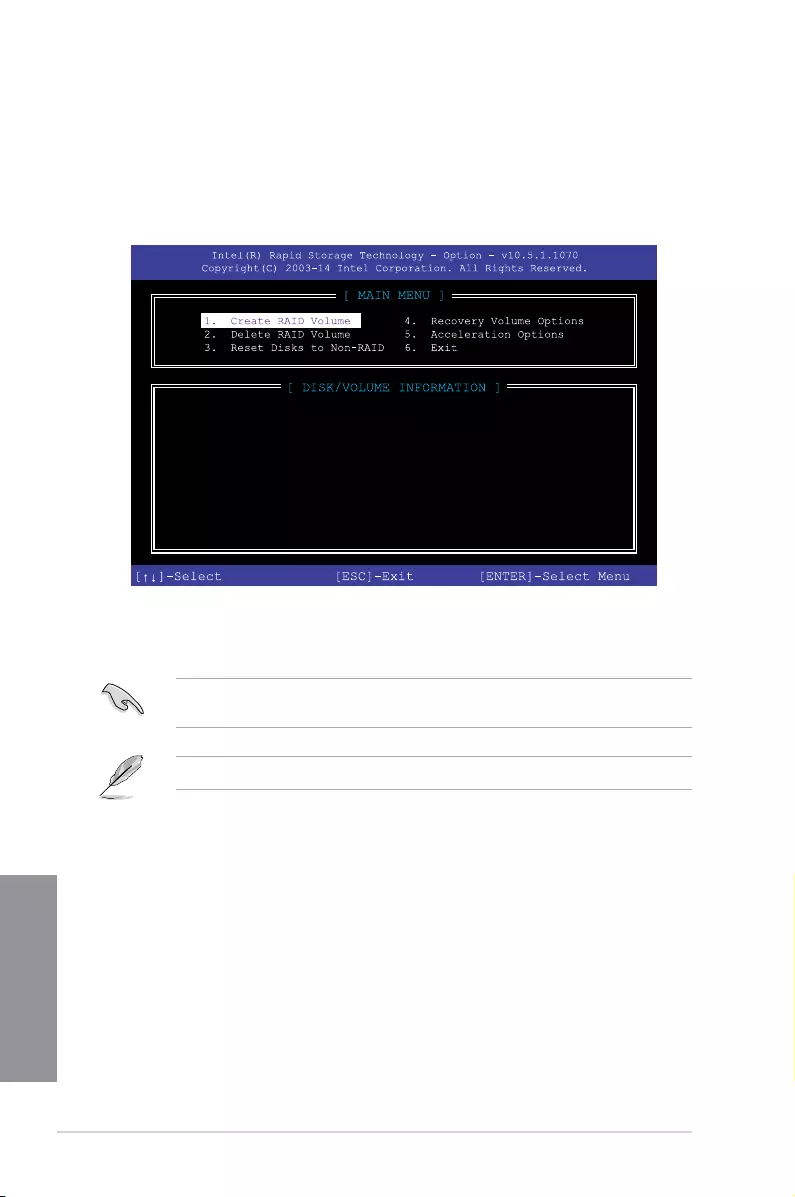
4-6 Chapter 5: RAID Support
Chapter 5
4.1.4 Intel® Rapid Storage Technology Option ROM utility
To enter the Intel® Rapid Storage Technology Option ROM utility:
1. Turn on the system.
2. During POST, press <Ctrl> + <I> to display the utility main menu.
The navigation keys at the bottom of the screen allow you to move through the menus
and select the menu options.
The RAID BIOS setup screens shown in this section are for reference only and may not
exactly match the items on your screen.
The utility supports maximum four hard disk drives for RAID conguration.
RAID Volumes:
None defined.
Physical Devices:
Port Device Model Serial # Size Type/Status(Vol ID)
0 ST3160812AS 9LS0HJA4 149.0GB Non-RAID Disk
1 ST3160812AS 9LS0F4HL 149.0GB Non-RAID Disk
2 ST3160812AS 3LS0JYL8 149.0GB Non-RAID Disk
3 ST3160812AS 9LS0BJ5H 149.0GB Non-RAID Disk
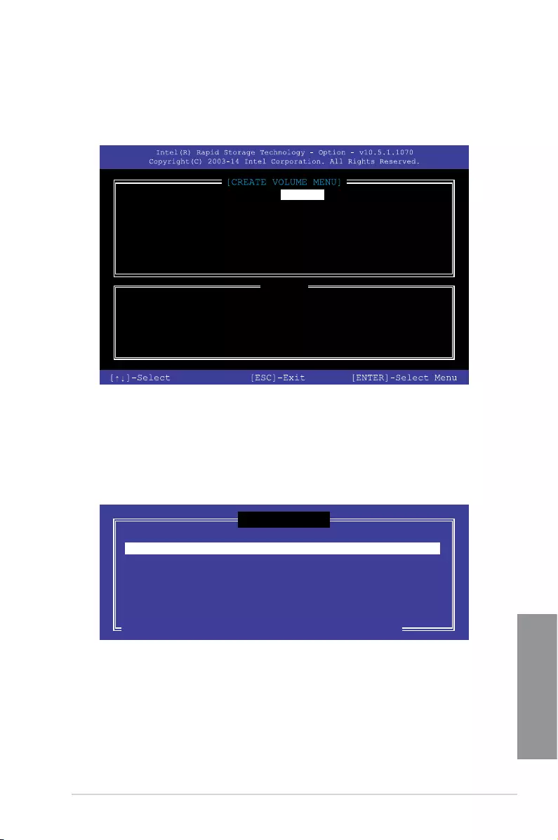
ASUS RAMPAGE V EDITION 10 4-7
Chapter 5
Creating a RAID set
To create a RAID set:
1. From the utility main menu, select 1. Create RAID Volume and press <Enter>. The
following screen appears:
2. Enter a name for the RAID set and press <Enter>.
3. When the RAID Level item is selected, press the up/down arrow key to select a RAID
level to create, and then press <Enter>.
4. When the Disks item is selected, press <Enter> to select the hard disk drives you want
to include in the RAID set. The SELECT DISKS screen appears:
Enter a unique volume name that has no special characters
and is 16 characters or less.
[HELP]
Name: Volume 0
RAID Level: aaaaaaaaaaaaaaa
Disks: dssdsdsds
Strip Size:aaaaaaaaaaaaaaaa
Capacity:aaaaaaaaaaaaaa
Sync:aaaaaaaaaa
Create volume
[SELECT DISKS]
Port Device Model Serial # Size Status
0 ST3160812AS 9LS0HJA4 149.0GB Non-RAID Disk
1 ST3160812AS 9LS0F4HL 149.0GB Non-RAID Disk
2 ST3160812AS 3LS0JYL8 149.0GB Non-RAID Disk
3 ST3160812AS 9LS0BJ5H 149.0GB Non-RAID Disk
Select 2 to 6 to use in creating the volume.
[↑↓]-Prev/Next [SPACE]-SelectDisk [ENTER]-Done

4-8 Chapter 5: RAID Support
Chapter 5
5. Use the up/down arrow key to select a drive, and then press <Space> to select. A
small triangle marks the selected drive. Press <Enter> after completing your selection.
6. Use the up/down arrow key to select the strip size for the RAID array (for RAID 0, 10
and 5 only),and then press <Enter>. The available strip size values range from 4KB to
128KB. The following are typical values:
• RAID 0: 128KB
• RAID 10: 64KB
• RAID 5: 64KB
We recommend a lower strip size for server systems, and a higher strip size for multimedia
computer systems used mainly for audio and video editing.
7. When the Capacity item is selected, enter the RAID volume capacity that you want
and press <Enter>. The default value indicates the maximum allowed capacity.
8. When the Create Volume item is selected, press <Enter>. The following warning
message appears:
9. Press <Y> to create the RAID volume and return to the main menu, or <N> to go back
to the CREATE VOLUME menu.
WARNING: ALL DATA ON SELECTED DISKS WILL BE LOST.
Are you sure you want to create this volume? (Y/N)
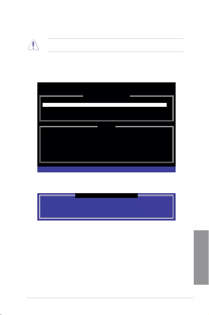
ASUS RAMPAGE V EDITION 10 4-9
Chapter 5
Deleting a RAID set
Be cautious when deleting a RAID set. You will lose all data on the hard disk drives when
you delete a RAID set.
To delete a RAID set:
1. From the utility main menu, select 2. Delete RAID Volume and press <Enter>. The
following screen appears:
2. Use the up/down arrow key to select the RAID set you want to delete, and then press
<Delete>. The following warning message appears:
3. Press <Y> to delete the RAID set and return to the utility main menu, or press <N> to
return to the DELETE VOLUME menu.
Deleting a volume will reset the disks to non-RAID.
WARNING: ALL DISK DATA WILL BE DELETED.
(This does not apply to Recovery volumes)
[HELP]
[DELETE VOLUME MENU]
Name Level Drives Capacity Status Bootable
Volume0 RAID0 (Stripe) 2 298.0GB Normal Yes
[↑↓]-Select [ESC]-Previous Menu [DEL]-Delete Volume
ALL DATA IN THE VOLUME WILL BE LOST!
(This does not apply to Recovery volumes)
Are you sure you want to delete “Volume0”? (Y/N):
[DELETE VOLUME VERIFICATION]
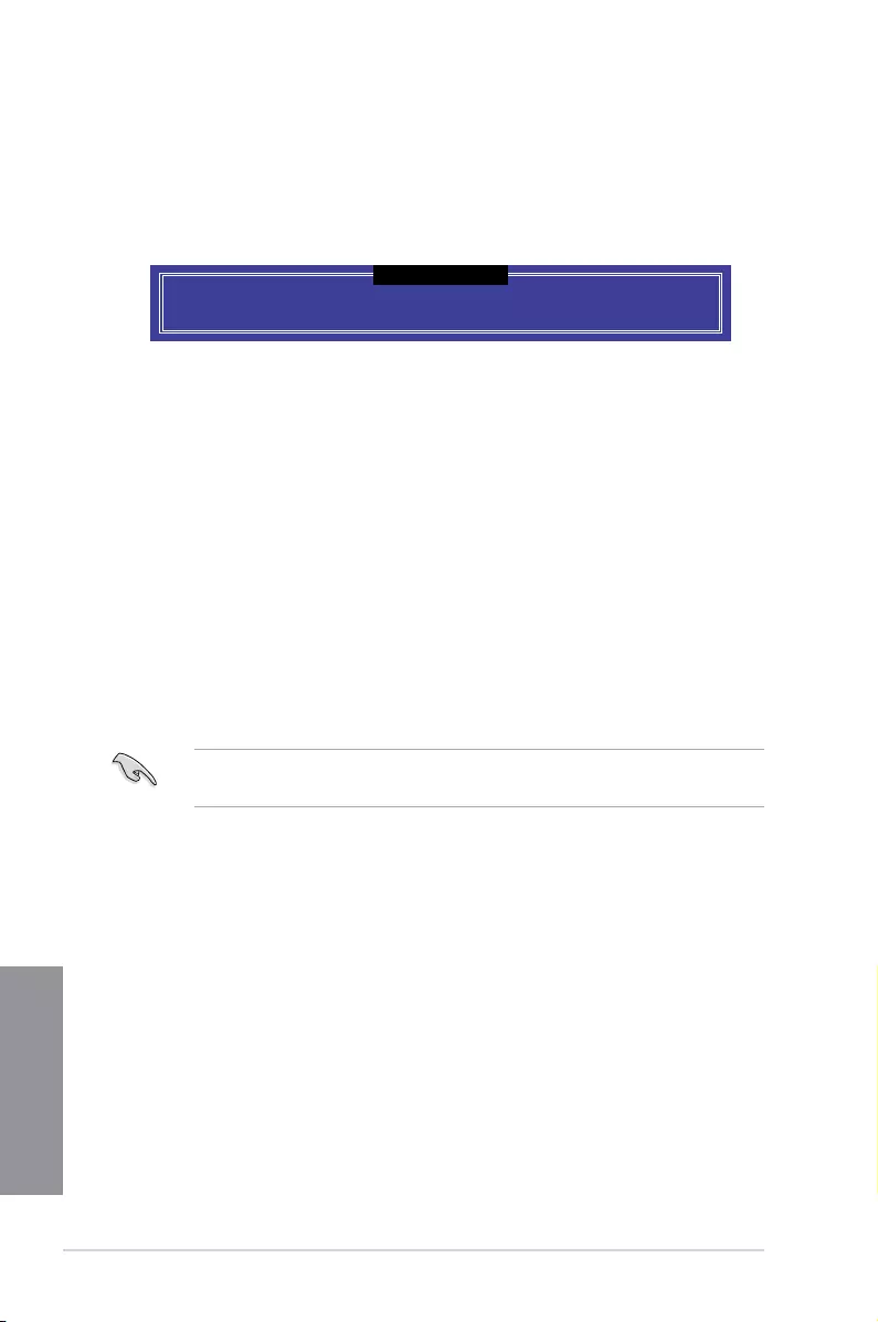
4-10 Chapter 5: RAID Support
Chapter 5
Exiting the Intel® Rapid Storage Technology Option ROM utility
To exit the utility:
1. From the utility main menu, select 5. Exit, and then press <Enter>. The following
warning message appears:
Are you sure you want to exit? (Y/N):
[CONFIRM EXIT]
2. Press <Y> to exit or press <N> to return to the utility main menu.
4.2 Creating a RAID driver disk
4.2.1 Creating a RAID driver disk in Windows®
To install the RAID driver for Windows® OS:
1. During the OS installation, click Load Driver to allow you to select the installation
media containing the RAID driver.
2. Insert the support USB drive with RAID driver into the USB port, and then click
Browse.
3. Click the name of the device you’ve inserted, go to Drivers > RAID, and then select
the RAID driver for the corresponding OS version. Click OK.
4. Follow the succeeding screen instructions to complete the installation.
To set up a Windows® UEFI operating system under RAID mode, ensure to load the UEFI
driver for your optical drive.

ASUS RAMPAGE V EDITION 10 A-1
Appendix
Appendix
Appendix
Notices
Federal Communications Commission Statement
This device complies with Part 15 of the FCC Rules. Operation is subject to the following two
conditions:
• This device may not cause harmful interference.
• This device must accept any interference received including interference that may cause
undesired operation.
This equipment has been tested and found to comply with the limits for a Class B digital
device, pursuant to Part 15 of the FCC Rules. These limits are designed to provide
reasonable protection against harmful interference in a residential installation. This
equipment generates, uses and can radiate radio frequency energy and, if not installed
and used in accordance with manufacturer’s instructions, may cause harmful interference
to radio communications. However, there is no guarantee that interference will not occur
in a particular installation. If this equipment does cause harmful interference to radio or
television reception, which can be determined by turning the equipment off and on, the user
is encouraged to try to correct the interference by one or more of the following measures:
• Reorient or relocate the receiving antenna.
• Increase the separation between the equipment and receiver.
• Connect the equipment to an outlet on a circuit different from that to which the receiver
is connected.
• Consult the dealer or an experienced radio/TV technician for help.
The use of shielded cables for connection of the monitor to the graphics card is required
toassurecompliancewithFCCregulations.Changesormodicationstothisunitnot
expressly approved by the party responsible for compliance could void the user’s authority
to operate this equipment.

A-2 Appendix
Appendix
IC: Canadian Compliance Statement
ComplieswiththeCanadianICES-003ClassBspecications.ThisdevicecomplieswithRSS
210 of Industry Canada. This Class B device meets all the requirements of the Canadian
interference-causing equipment regulations.
This device complies with Industry Canada license exempt RSS standard(s). Operation is
subject to the following two conditions: (1) this device may not cause interference, and (2)
this device must accept any interference, including interference that may cause undesired
operation of the device.
Cut appareil numérique de la Classe B est conforme à la norme NMB-003 du Canada.
Cet appareil numérique de la Classe B respecte toutes les exigences du Règlement sur le
matériel brouilleur du Canada.
Cet appareil est conforme aux normes CNR exemptes de licence d’Industrie Canada. Le
fonctionnement est soumis aux deux conditions suivantes :
(1) cet appareil ne doit pas provoquer d’interférences et
(2) cet appareil doit accepter toute interférence, y compris celles susceptibles de provoquer
un fonctionnement non souhaité de l’appareil.
Canadian Department of Communications Statement
This digital apparatus does not exceed the Class B limits for radio noise emissions from
digital apparatus set out in the Radio Interference Regulations of the Canadian Department
of Communications.
This class B digital apparatus complies with Canadian ICES-003.
VCCI: Japan Compliance Statement
KC: Korea Warning Statement
Class B ITE

ASUS RAMPAGE V EDITION 10 A-3
Appendix
REACH
Complying with the REACH (Registration, Evaluation, Authorisation, and Restriction of
Chemicals) regulatory framework, we published the chemical substances in our products at
ASUS REACH website at http://csr.asus.com/english/REACH.htm.
DO NOT throw the motherboard in municipal waste. This product has been designed to
enable proper reuse of parts and recycling. This symbol of the crossed out wheeled bin
indicates that the product (electrical and electronic equipment) should not be placed in
municipal waste. Check local regulations for disposal of electronic products.
DO NOT throw the mercury-containing button cell battery in municipal waste. This symbol
of the crossed out wheeled bin indicates that the battery should not be placed in municipal
waste.
ASUS Recycling/Takeback Services
ASUS recycling and takeback programs come from our commitment to the highest standards
for protecting our environment. We believe in providing solutions for you to be able to
responsibly recycle our products, batteries, other components as well as the packaging
materials. Please go to http://csr.asus.com/english/Takeback.htm for detailed recycling
information in different regions.
RF Equipment Notices
CE: European Community Compliance Statement
The equipment complies with the RF Exposure Requirement 1999/519/EC, Council
Recommendation of 12 July 1999 on the limitation of exposure of the general public to
electromagneticelds(0–300GHz).ThiswirelessdevicecomplieswiththeR&TTEDirective.
Wireless Radio Use
Thisdeviceisrestrictedtoindoorusewhenoperatinginthe5.15to5.25GHzfrequency
band.
Exposure to Radio Frequency Energy
The radiated output power of the Wi-Fi technology is below the FCC radio frequency
exposure limits. Nevertheless, it is advised to use the wireless equipment in such a manner
thatthepotentialforhumancontactduringnormaloperationisminimized.
FCC Bluetooth Wireless Compliance
The antenna used with this transmitter must not be co-located or operated in conjunction with
anyotherantennaortransmittersubjecttotheconditionsoftheFCCGrant.
Bluetooth Industry Canada Statement
This Class B device meets all requirements of the Canadian interference-causing equipment
regulations.
Cet appareil numérique de la Class B respecte toutes les exigences du Règlement sur le
matériel brouilleur du Canada.

A-4 Appendix
Appendix
Google™ License Terms
Copyright© 2016 Google Inc. All Rights Reserved.
LicensedundertheApacheLicense,Version2.0(the“License”);youmaynotusethisle
except in compliance with the License. You may obtain a copy of the License at:
http://www.apache.org/licenses/LICENSE-2.0
Unless required by applicable law or agreed to in writing, software distributed under the
License is distributed on an “AS IS” BASIS, WITHOUT WARRANTIES OR CONDITIONS OF
ANY KIND, either express or implied.
SeetheLicenseforthespeciclanguagegoverningpermissionsandlimitationsunderthe
License.
NCC: Taiwan Wireless Statement
Japan RF Equipment Statement
屋外での使用について
本製品は、5GHz帯域での通信に対応しています。電波法の定めにより5.2GHz、5.3GHz帯域の電
波は屋外で使用が禁じられています。
法律および規制遵守
本製品は電波法及びこれに基づく命令の定めるところに従い使用してください。日本国外では、
その国の法律または規制により、本製品の使用ができないことがあります。このような国では、本
製品を運用した結果、罰せられることがありますが、当社は一切責任を負いかねますのでご了承
ください。
Warranty
ASUS warrants the Product to be free from defects in workmanship and materials for the
Warranty Period. The Warranty does not cover bundled accessories, which were delivered
together with the Product such as: USB, cables, I/O shield, bag, mouse etc. If the Product
fails during normal and proper use within the Warranty Period, ASUS, at its discretion, within
maximum 45 days, will repair or replace the defective parts of the Product, or the Product
itself, with new or reconditioned parts or products that are functionally equivalent or superior
to those originally supplied.
ASUS RAMPAGE V EDITION 10 A-5
Appendix
Lietuvių ASUSTeK Computer Inc. ar šo paziņo, ka šī ierīce atbilst Direktīvas
1995/5/ EK būtiskajām prasībām un citiem citiem saistošajiem nosacījumiem.
Pilns ES atbilstības paziņojuma teksts pieejams šeit: www.asus.com/support
Šį įrenginį galima naudoti toliau išvardytose šalyse:
Norsk ASUSTeK Computer Inc. erklærer herved at denne enheten er i
samsvar med hovedsaklige krav og andre relevante forskrifter i direktivet
1995/5/EF. Fullstendig tekst for EU-samsvarserklæringen nnes på:
www.asus.com/support
Enheten kan brukes i landene under:
Polski Firma ASUSTeK Computer Inc. niniejszym oświadcza, że
urządzenie to jest zgodne z zasadniczymi wymogami i innymi właściwymi
postanowieniami dyrektywy 1995/5/WE. Pełny tekst deklaracji zgodności UE
jest dostępny pod adresem: www.asus.com/support
Urządzenie to może być używane w wymienionych poniżej krajach:
Português A ASUSTeK Computer Inc. declara que este dispositivo está em
conformidade com os requisitos essenciais e outras disposições relevantes da
Diretiva 1995/5/CE. Texto integral da declaração da UE disponível em:
www.asus.com/support
Este dispositivo pode ser utilizado nos países indicados abaixo:
Română ASUSTeK Computer Inc. declară că acest dispozitiv se conformează
cerinţelor esenţiale şi altor prevederi relevante ale Directivei 1995/5/CE.
Textul complet al declaraţiei de conformitate a Uniunii Europene se găseşte
la: www.asus.com/support
Puteţi utiliza acest dispozitiv în ţările următoare:
Srpski ASUSTeK Computer Inc. ovim izjavljuje da je ovaj uređaj u saglasnosti
sa osnovnim zahtevima i drugim relevantnim odredbama Direktive 1995/5/
EC. Pun tekst EU deklaracije o usaglašenosti je dostupan da adresi:
www.asus.com/support
Ovaj uređaj može da se koristi u državama navedenim ispod:
Slovensky Spoločnosť ASUSTeK Computer Inc. týmto vyhlasuje, že toto
zariadenie vyhovuje základným požiadavkám a ostatým príslušným
ustanoveniam smernice 1995/5/ES. Celý text vyhlásenia o zhode pre štáty EÚ
je dostupný na adrese: www.asus.com/support
Toto zariadenie môže byť prevádzkované v dolu uvedených krajinách:
Slovenščina ASUSTeK Computer Inc. izjavlja, da je ta naprava skladna z
bistvenimi zahtevami in drugimi ustreznimi določbami Direktive 1995/5/ES.
Celotno besedilo EU-izjave o skladnosti je na voljo na spletnem mestu:
www.asus.com/support
To napravo je mogoče uporabljati v spodaj navedenih državah:
Español Por la presente, ASUSTeK Computer Inc. declara que este dispositivo
cumple los requisitos básicos y otras disposiciones pertinentes de la directiva
1995/5/ EC. El texto completo de la declaración de la UE de conformidad está
disponible en: www.asus.com/support
Este dispositivo se puede utilizar en los países enumerados a continuación:
Svenska ASUSTeK Computer Inc. förklarar härmed att denna
enhet överensstämmer med de grundläggande kraven och andra
relevanta föreskrifter i direktiv 1995/5/EG. Fulltext av EU-försäkran om
överensstämmelse nns på: www.asus.com/support
Denna enhet kan användas i följande länder:
Українська ASUSTeK Computer Inc. заявляє, що цей пристрій відповідає
основним вимогам та іншим відповідним положенням Директиви 1995/5/
ЕС. Повний текст декларації відповідності стандартам ЄС доступний на:
www.asus.com/support
Цей пристрій можна експлуатувати у країнах зі списку нижче:
Türkçe AsusTek Computer Inc., bu aygıtın temel gereksinimlerle ve 1995/5/
EC Yönergesinin diğer ilgili koşullarıyla uyumlu olduğunu beyan eder. AB
uygunluk bildiriminin tam metni şu adreste bulunabilir:
www.asus.com/support
Bu aygıt aşağıda listelenen ülkelerde çalıştırılabilir:
Bosanski ASUSTeK Computer Inc. ovim izjavljuje da je ovaj uređaj usklađen
sa bitnim zahtjevima i ostalim odgovarajućim odredbama direktive 1995/5/
EC. Cijeli tekst EU izjave o usklađenosti dostupan je na:
www.asus.com/support
Ovaj uređaj može se koristiti u dolje navedenim zemljama:
AT BE BG CH CY CZ DE DK
EE ES FI FR GB GR HU IE
IT IS LI LT LU LV MT NL
NO PL PT RO SE SI SK TR
English ASUSTeK Computer Inc. hereby declares that this device is in
compliance with the essential requirements and other relevant provisions
of Directive 1995/5/EC. Full text of EU declaration of conformity available at:
www.asus.com/support
This device may be operated in the countries listed below:
Français AsusTek Computer Inc. déclare par la présente que cet appareil est
conforme aux critères essentiels et autres clauses pertinentes de la directive
1995/5/EC. La déclaration de conformité de l’UE peut être téléchargée à partir
du site Internet suivant: www.asus.com/support.
Cet appareil peut être utilisé dans les pays de la liste ci-dessous:
Deutsch ASUSTeK Computer Inc. erklärt hiermit, dass dieses Gerät mit
den wesentlichen Anforderungen und anderen relevanten Bestimmungen
der Richtlinie 1995/5/EC übereinstimmt. Der gesamte Text der EU-
Konformitätserklärung ist verfügbar unter: www.asus.com/support
Dieses Gerät darf in den unten aufgeführten Ländern betrieben werden:
Italiano ASUSTeK Computer Inc. con la presente dichiara che questo
dispositivo è conforme ai requisiti essenziali e alle altre disposizioni pertinenti
con la direttiva 1995/5/EC. Il testo completo della dichiarazione di conformità
UE è disponibile all’indirizzo: www.asus.com/support
Questo dispositivo può essere utilizzato nei paesi elencati qui di seguito:
Русский Компания ASUS заявляет, что это устройство соответствует
основным требованиям и другим соответствующим условиям европейской
директивы 1995/5/EC. Подробную информацию, пожалуйста, смотрите на
www.asus.com/support
Это устройство может работать в странах, которые приведены ниже:
Български С настоящото ASUSTeK Computer Inc. декларира, че това
устройство е в съответствие със съществените изисквания и другите
приложими постановления на Директива 1995/5/EC. Пълният текст на
декларацията за съответствие на ЕС е достъпна на адрес:
www.asus.com/support
Устройството може да се използва във всички страни, посочени по-долу:
Hrvatski ASUSTeK Computer Inc. ovim izjavljuje da je ovaj uređaj sukladan
s bitnim zahtjevima i ostalim odgovarajućim odredbama direktive 1995/5/
EZ. Cijeli tekst EU izjave o sukladnosti dostupan je na: www.asus.com/support
Ovaj uređaj može se koristiti u dolje navedenim zemljama:
Čeština Společnost ASUSTeK Computer Inc. tímto prohlašuje, že toto zařízení
splňuje základní požadavky a další příslušná ustanovení směrnice 1995/5/ EC.
Plné znění prohlášení o shodě EU je k dispozici na adrese:
www.asus.com/support
Toto zařízení lze používat v níže uvedených zemích:
Dansk ASUSTeK Computer Inc. erklærer hermed, at denne enhed er i
overensstemmelse med hovedkravene og andre relevante bestemmelser
i direktivet 1995/5/EC. Hele EU-overensstemmelseserklæringen kan ndes på:
www.asus.com/support
Denne enhed kan bruges i landene, der står på listen nedenfor:
Nederlands ASUSTeK Computer Inc. verklaart hierbij dat dit apparaat
voldoet aan de essentiële vereisten en andere relevante bepalingen van de
verwante richtlijnen1995/5/EC. De volledige tekst van de EU-verklaring van
conformiteit is beschikbaar op: www.asus.com/support
Dit apparaat kan worden gebruikt in de hieronder vermelde landen:
Eesti Käesolevaga kinnitab ASUSTeK Computer Inc, et see seade vastab
Direktiivi 1995/5/EÜ asjakohaste direktiivide oluliste nõuetele ja teistele
asjassepuutuvatele sätetele. EL vastavusdeklaratsiooni täielik tekst on
saadaval järgmisel aadressil: www.asus.com/support
Seda seadet võib kasutada alltoodud riikides:
Suomi ASUSTeK Computer Inc. ilmoittaa täten, että tämä laite on on
EY-direktiivin 1995/5/ olennaisten vaatimusten ja muiden tätä koskevien
säädösten mukainen. EU-yhdenmukaisuusilmoituksen koko teksti on
luettavissa osoitteessa: www.asus.com/support
Tätä laitetta voidaan käyttää alla luetelluissa maissa:
Ελληνικά Με το παρόν, η AsusTek Computer Inc. δηλώνει ότι αυτή
η συσκευή συμμορφώνεται με τις θεμελιώδεις απαιτήσεις και άλλες
σχετικές διατάξεις της Οδηγίας 1995/5/ΕΕ. Το πλήρες κείμενο της δήλωσης
συμβατότητας είναι διαθέσιμο στη διεύθυνση: www.asus.com/support
Αυτή η συσκευή μπορεί να λειτουργήσει στις χώρες που αναφέρονται στη
λίστα που ακολουθεί:
Magyar Az ASUSTeK Computer Inc. ezennel kijelenti, hogy ez az eszköz
megfelel az 1995/5/EK Irányelv lényeges követelményeinek és egyéb
vonatkozó rendelkezéseinek. Az EU megfelelőségi nyilatkozat teljes szövege
innen letölthető: www.asus.com/support
Az eszköz az alább felsorolt országokban működtethető:
Latviski „ASUSTeK Computer Inc.“ šiuo tvirtina, kad šis įrenginys atitinka
pagrindinius reikalavimus ir kitas svarbias Direktyvos 1995/5 EB nuostatas.
Visą ES atitikties deklaracijos tekstą galima rasti: www.asus.com/support
Šo ierīci var lietot tālāk norādītajās valstīs:

A-6 Appendix
Appendix
ASUS contact information
ASUSTeK COMPUTER INC.
Address 4F, No. 150, Li-Te Road, Peitou, Taipei 112, Taiwan
Telephone +886-2-2894-3447
Fax +886-2-2890-7798
Web site www.asus.com
Technical Support
Telephone +86-21-38429911
Fax +86-21-5866-8722, ext. 9101#
Online support http://qr.asus.com/techserv
ASUS COMPUTER INTERNATIONAL (America)
Address 800 Corporate Way, Fremont, CA 94539, USA
Telephone +1-510-739-3777
Fax +1-510-608-4555
Web site http://www.asus.com/us/
Technical Support
Support fax +1-812-284-0883
Telephone +1-812-282-2787
Online support http://qr.asus.com/techserv
ASUS COMPUTER GmbH (Germany and Austria)
Address HarkortStr.21-23,40880Ratingen,Germany
Fax +49-2102-959931
Web site http://www.asus.com/de
Online contact http://eu-rma.asus.com/sales
Technical Support
Telephone +49-2102-5789555
Support Fax +49-2102-959911
Online support http://qr.asus.com/techserv
ASUS RAMPAGE V EDITION 10 A-7
Appendix
DECLARATION OF CONFORMITY
Per FCC Part 2 Section 2. 1077(a)
Responsible Party Name:
Asus Computer International
Address: 800 Corporate Way, Fremont
, CA 94539.
Phone/Fax No: (510)739-3777/(510)608-4555
hereby declares that the product
Product Name : Motherboard
Model Number : RAMPAGE V EDITION 10
Conforms to the following specifications:
FCC Part 15, Subpart B, Unintentional Radiators
Supplementary Information:
This device complies with part 15 of the FCC Rules. Operation is subject to the
following two conditions: (1) This device may not cause harmful interference,
and (2) this device must accept any interference received, including interference
that may cause undesired operation.
Representative Person’s Name : Steve Chang / President
Signature :
Date : APR. 25, 2016
Ver. 140331

A-8 Appendix
Appendix