DELL GX520 User Manual
Displayed below is the user manual for GX520 by DELL which is a product in the PCs/Workstations category. This manual has pages.
Related Manuals
Back to Contents Page
Advanced Features
Dell™OptiPlex™GX520User'sGuide
LegacySelect Technology Control
Manageability
Security
Password Protection
System Setup
Booting to a USB Device
Clearing Forgotten Passwords
Clearing CMOS Settings
Hyper-Threading
Power Management
LegacySelect Technology Control
LegacySelect technology control offers legacy-full, legacy-reduced, or legacy-free solutions based on common platforms, hard-drive images, and help desk
procedures.Controlisprovidedtotheadministratorthroughsystemsetup,DellOpenManage™ITAssistant,orDellcustomfactoryintegration.
LegacySelect allows administrators to electronically activate or deactivate connectors and media devices that include serial and USB connectors, a parallel
connector, a floppy drive, PCI slots, and a PS/2 mouse. Connectors and media devices that are deactivated make resources available. You must restart the
computer to effect the changes.
Manageability
Alert Standard Format
ASF is a DMTF management standard that specifies "pre-operating system" or "operating system-absent" alerting techniques. The standard is designed to
generate an alert on potential security and fault conditions when the operating system is in a sleep mode or the system is turned off. ASF is designed to
supersede previous operating-system-absent alerting technologies.
Your computer supports the following ASF version 1.03 and 2.0 alerts and remote capabilities:
For more information about Dell's ASF implementation, see the ASF User's Guide and the ASF Administrator's Guide, which are available on the Dell Support
website at support.dell.com.
DellOpenManage™ITAssistant
IT Assistant configures, manages, and monitors computers and other devices on a corporate network. IT Assistant manages assets, configurations, events
(alerts), and security for computers equipped with industry-standard management software. It supports instrumentation that conforms to SNMP, DMI, and CIM
industry standards.
Dell OpenManage Client instrumentation, which is based on DMI and CIM, is available for your computer. For information on IT Assistant, see the Dell
OpenManage IT Assistant User's Guide available on the Dell Support website at support.dell.com.
Dell OpenManage Client Instrumentation
Dell OpenManage Client Instrumentation is software that enables remote management programs such as IT Assistant to do the following:
lAccess information about your computer, such as how many processors it has and what operating system it is running.
Alert
Description
Chassis: Chassis Intrusion – Physical Security Violation/Chassis
Intrusion – Physical Security Violation Event Cleared
The computer chassis with the chassis intrusion feature installed and enabled
has been opened or the chassis intrusion alert has been cleared.
CPU: Emergency Shutdown Event
The processor temperature is too hot and the power supply has shut down.
Cooling Device: Generic Critical Fan Failure/Generic Critical Fan
Failure Cleared
The fan speed (rpm) is out of limits or the fan speed (rpm) problem has been
resolved.
Temperature: Generic Critical Temperature Problem/Generic Critical
Temperature Problem Cleared
The computer temperature is out of limits or the computer temperature
problem has been resolved.
Battery Low
The system battery has reached a voltage of 2.2 V or lower.

lMonitor the status of your computer, such as listening for thermal alerts from temperature probes or hard-drive failure alerts from storage devices.
lChange the state of your computer, such as updating its BIOS or shutting it down remotely.
A managed system is one that has Dell OpenManage Client Instrumentation set up on a network that uses IT Assistant. For information about Dell
OpenManage Client Instrumentation, see the Dell OpenManage Client Instrumentation User's Guide available on the Dell Support website at support.dell.com.
Security
Chassis Intrusion Detection
This feature, if installed and enabled, detects that the chassis was opened and alerts the user. To change the Chassis Intrusion setting:
1. Enter system setup.
2. Press the down-arrow keys to move to the System Security option.
3. Press <Enter> to access the System Security option's pop-up menu.
4. Press the down-arrow key to move to the Chassis Intrusion setting.
5. Press <Enter> to select an option setting.
6. Press <Enter> again after you update the option setting.
7. Exit and save system setup.
Option Settings
lOn — If the computer cover is opened, the setting changes to Detected, and the following alert message displays during the boot routine at the next
computer start-up:
Alert! Cover was previously removed.
To reset the Detected setting, enter system setup. In the Chassis Intrusion option, press the left- or right-arrow key to select Reset, and then choose
On, On-Silent, or Off.
lOn-Silent (default setting) — If the computer cover is opened, the setting changes to Detected. No alert message appears during the boot sequence
at the next computer start-up.
lOff — No intrusion monitoring occurs and no messages appear.
Padlock Ring and Security Cable Slot
Use one of the following methods to secure your computer:
lUse a padlock alone or a padlock and looped security cable with the padlock ring.
A padlock alone prevents the computer from being opened.
A security cable looped around a stationary object is used in conjunction with a padlock to prevent unauthorized movement of the computer.
lAttach a commercially available antitheft device to the security cable slot on the back of the computer.
Antitheft devices usually include a segment of metal-stranded cable with an attached locking device and key. The documentation that comes with the
device contains instructions for installing it.
Password Protection
NOTE: When the administrator password is enabled, you must know the administrator password before you can reset the Chassis Intrusion setting.
NOTE: Before you purchase an antitheft device, make sure that it works with the security cable slot on your computer.
NOTICE: Although passwords provide security for the data on your computer, they are not foolproof. If your data requires more security, it is your
responsibility to obtain and use additional forms of protection, such as data encryption programs.

System Password
Option Settings
You cannot change or enter a new system password if either of the following two options is displayed:
lSet — A system password is assigned.
lDisabled — The system password is disabled by a jumper setting on the system board.
You can only assign a system password when the following option is displayed:
lNot Set — No system password is assigned and the password jumper on the system board is in the enabled position (the default setting).
Assigning a System Password
To escape from the field without assigning a system password, press <Tab> or the <Shift><Tab> key combination to move to another field, or press <Esc> at
any time before you complete step 5.
1. Enter system setup and verify that Password Status is set to Unlocked.
2. Highlight System Password, and then press the left- or right-arrow key.
The option heading changes to Enter Password, followed by an empty 32-character field in square brackets.
3. Type your new system password.
You can use up to 32 characters. To erase a character when entering your password, press <Backspace> or the left-arrow key. The password is not
case sensitive.
Certain key combinations are not valid. If you enter one of these combinations, the speaker emits a beep.
As you press each character key (or the spacebar for a blank space), a placeholder appears in the field.
4. Press <Enter>.
If the new system password is less than 32 characters, the whole field fills with placeholders. Then the option heading changes to Verify Password,
followed by another empty 32-character field in square brackets.
5. To confirm your password, type it a second time and press <Enter>.
The password setting changes to Set.
6. Exit system setup.
Password protection takes effect when you restart the computer.
Typing Your System Password
When you start or restart your computer, the following prompt appears on the screen.
If Password Status is set to Locked:
Type the password and press <Enter>.
If you have assigned an administrator password, the computer accepts your administrator password as an alternate system password.
If you type a wrong or incomplete system password, the following message appears on the screen:
** Incorrect password. **
If you again type an incorrect or incomplete system password, the same message appears on the screen. The third and subsequent times you type an
incorrect or incomplete system password, the computer displays the following message:
** Incorrect password. **
Number of unsuccessful password attempts: 3
System halted! Must power down.
Even after your computer is turned off and on, the previous message is displayed each time you type an incorrect or incomplete system password.
NOTICE: If you leave your computer running and unattended without having a system password assigned, or if you leave your computer unlocked so
that someone can disable the password by changing a jumper setting, anyone can access the data stored on your hard drive.

Deleting or Changing an Existing System Password
1. Enter system setup.
2. Highlight System Password and press <Enter>.
3. When prompted, type the system password.
4. Press <Enter> twice to clear the existing system password. The setting changes to Not Set.
If Not Set is displayed, the system password is deleted. If Not Set is not displayed, press <Alt><b> to restart the computer, and then repeat steps 3
and 4.
5. To assign a new password, follow the procedure in "Assigning a System Password."
6. Exit system setup.
Administrator Password
Option Settings
You cannot change or enter a new administrator password if either of the following two options is displayed:
lSet — An administrator password is assigned.
lDisabled — The administrator password is disabled by a jumper setting on the system board.
You can only assign an administrator password when the following option is displayed:
lNot Set — No administrator password is assigned and the password jumper on the system board is in the enabled position (the default setting).
Assigning an Administrator Password
The administrator password can be the same as the system password.
1. Enter system setup and verify that Admin Password is set to Not Set.
2. Highlight Admin Password and press the left- or right-arrow key.
The computer prompts you to type and verify the password. If a character is not permitted, the computer emits a beep.
3. Type and then verify the password.
After you verify the password, the Admin Password setting changes to Set. The next time you enter system setup, the computer prompts you for the
administrator password.
4. Exit system setup.
A change to Admin Password becomes effective immediately (no need to restart the computer).
Operating Your Computer With an Administrator Password Enabled
When you enter system setup, the Admin Password option is highlighted, prompting you to type the password.
If you do not type the correct password, the computer lets you view, but not modify, system setup options.
Deleting or Changing an Existing Administrator Password
NOTE: You can use Password Status in conjunction with System Password and Admin Password to further protect your computer from unauthorized
changes.
NOTE: If the two passwords are different, the administrator password can be used as an alternate system password. However, the system password
cannot be used in place of the administrator password.
NOTE: You can use Password Status in conjunction with Admin Password to protect the system password from unauthorized changes.

To change an existing administrator password, you must know the administrator password.
1. Enter system setup.
2. Type the administrator password at the prompt.
3. Highlight Admin Password and press the left- or right-arrow key to delete the existing administrator password.
The setting changes to Not Set.
To assign a new administrator password, perform the steps in "Assigning an Administrator Password."
4. Exit system setup.
Disabling a Forgotten Password and Setting a New Password
To reset system and/or administrator passwords, see "Clearing Forgotten Passwords."
System Setup
Overview
Use system setup as follows:
lTo change the system configuration information after you add, change, or remove any hardware in your computer
lTo set or change a user-selectable option such as the user password
lTo read the current amount of memory or set the type of hard drive installed
Before you use system setup, it is recommended that you write down the system setup screen information for future reference.
Entering System Setup
1. Turn on (or restart) your computer.
2. WhentheblueDELL™logoappears,press<F2>immediately.
If you wait too long and the operating system logo appears, continue to wait until you see the Microsoft®Windows®desktop. Then shut down your
computer and try again.
System Setup Screens
The system setup screen displays current or changeable configuration information for your computer. Information on the screen is divided into three areas: the
options list, active options field, and key functions.
Options List — This field appears on the left side of the system setup window. The field is a
scrollable list containing features that define the configuration of your computer, including
installed hardware, power conservation, and security features.
Scroll up and down the list by using the up and down arrow keys. As an option is highlighted,
the Option Field displays more information about that option and the option's current and
available settings.
Option Field — This field contains information about each
option. In this field you can view your current settings and
make changes to your settings.
Use the right- and left-arrow keys to highlight an option.
Press <Enter> to make that selection active.

System Setup Options
Key Functions — This field appears below the Option Field
and lists keys and their functions within the active system
setup field.
NOTE: Depending on your computer and installed devices, the items listed in this section may or may not appear.
System
System Info
Lists the computer name, BIOS version, and service tag.
CPU Info
Identifies whether the computer's processor supports Hyper-Threading and identifies the CPU speed, bus speed, clock speed, and L2 cache.
Memory Info
Indicates amount of installed memory, computer memory speed, amount of video memory, size of the display cache, and channel mode (dual
or single).
Date/Time
Displays current date and time settings.
Boot Sequence
The computer attempts to boot from the sequence of devices specified in this list.
Drives
Diskette
Drive
This option enables or disables the floppy drive. The options are Off, Internal, USB, and Read Only.
Drive 0
through Drive
n
Identifies and enables and disables the drives attached to the SATA or IDE connectors on the system board and lists the capacities for the
hard drives.
NOTE: These options appear as Drive 0 through Drive 3.
Module Bay
Enables or disables devices in the module bay. The options are On or Off. The default setting is On.
NOTE: The USB Controller and Diskette Drive setup option affect operation of the optional floppy drive in the module bay.
Drive
Controller
Configures the serial ATA controller's operating mode. Normal enables the serial ATA controller to operate in its serial ATA native mode only.
Compatible enables the serial ATA controller to operate in serial/parallel ATA combination mode.
Error
Reporting
This setting determines whether hard drive errors are reported or not during system setup.
SATA
Operation
Configures the operation mode of the integrated hard-drive controller.
Normal — The hard-drive controller is configured for native mode. This mode provides the highest drive performance and most flexibility.
Combination — The hard-drive controller is configured for combination mode. This mode enables compatibility with some older operating
systems that do not support SATA drives.
The factory default setting is Normal.
NOTE: Changing this setting affects the order in which drives are listed. However, system setup does not reflect these changes until after a
reboot.
SATA
Reporting
Controls whether hard drive errors for integrated drives are reported during system status. This technology is part of the SMART (Self-
Monitoring Analysis and Reporting Technology) specification.
The options are On or Off. The default setting is Off.
Onboard Devices
Integrated
NIC
You can set the NIC to On (default setting), Off, or On w/ PXE. When the On w/ PXE setting is active (available only for the future boot
process), the computer prompts the user to press <Ctrl><Alt><b>. Pressing this key combination causes a menu to display that allows you
to select a method for booting from a network server. If a boot routine is not available from the network server, the system attempts to
boot from the next device in the boot sequence list.
Integrated
Audio
Enables or disables the onboard audio controller
LPT Port Mode
This option sets the operating mode for the built-in parallel port. The settings are Off, AT, PS/2 (default setting), EPP, and ECP.
lAT — The port is configured for IBM®AT compatibility.
lPS/2 — The port is configured for IBM PS/2 compatibility.
lEPP — The port is set for enhanced parallel port protocol.
lECP — The port is set for extended capability port protocol.
LPT Port
Address
This option sets the address that the built-in parallel port uses. The settings are 378h (default setting), 278h, and 3BCh.
PCI Slots
Enables or disables the PCI slots.
Serial Port
#1
Auto, the default setting, automatically configures a connector to a particular designation (COM1 or COM3).
Serial Port
#2
Auto, the default setting, automatically configures a connector to a particular designation (COM1 or COM3). (This setting appears only if an
optional serial port adapter is installed.)
USB
USB devices are detected and supported in the operating system when this option is set to On.

USB Disable
Enables or disables the front-panel USB connectors. The default setting is On. To disable the front-panel connectors, select Off.
USB
Controller
Enables and disables the integrated USB controller
Off — The USB controller is disabled
On — The USB controller is enabled
No Boot — The USB controller is enabled; however, the BIOS will not recognize USB storage devices.
The factory default setting is On.
Front USB
Ports
Enables and disables the front-panel USB ports.
Off — Disabled
On — Enabled
The factory default setting is On.
LPT Port Mode
Selects the mode of operation for the integrated parallel port.
Off — Port is disabled
AT — Port is configured for IBM AT compatibility
PS/2 — Port is configured for IBM PS/2 compatibility
EPP — Enhanced parallel port protocol
ECP — Extended Capability port protocol
The factory default setting is PS/2.
LPT Port
Address
Selects the base IO address for the integrated parallel port. The factory default setting is 378h.
Video
Primary Video
This setting specifies which video controller is primary when two video controllers are present on the computer.
Video Memory
Size
This setting specifies the amount of memory available to video controllers.
Performance
Hyper-
Threading
If your computer's processor supports Hyper-Threading, this option appears in the Options List.
HDD Acoustic
Mode
lQuiet (default setting) — The hard drive operates at its most quiet setting.
lPerformance — The hard drive operates at its maximum speed.
lBypass — Your computer does not test or change the current acoustics mode setting.
lSuggested — The hard drive operates at the level suggested by the drive manufacturer.
NOTE: Switching to performance mode may cause the drive to be noisier, but its performance is not affected.
Changing the acoustics setting does not alter your hard-drive image.
Security
This section displays available system security options. See "Security" for more information.
Admin
Password
This option provides restricted access to the computer's System Setup program in the same way that access to the system can be restricted
with the System Password option. The settings are Set, Not Set, and Disabled.
If the option is to Set, an administrator password is assigned.
If the option is to Not Set, no administrator password is assigned and the password jumper on the system board is in the enabled position
(the default setting).
If the option is to Disabled, the administrator password is disabled by a jumper setting on the system board.
To disable the administrator password, enter the password at the prompt and hit <Ctrl><Enter>.
System
Password
Displays the current status of the system's password security feature and allows a new system password to be assigned and verified. The
settings are Set, Not Set, and Disabled.
If the option is Set, a system password is assigned.
If the option is Not Set, no system password is assigned and the password jumper on the system board is in the enabled position (the
default setting).
If the option is Disabled, the system password is disabled by a jumper setting on the system board.
To disable the system password, enter the password at the prompt and hit <Ctrl><Enter>.
Drive
Password
Set this password to prevent unauthorized users from accessing the hard drive.
NOTE: The option appears for each installed hard drive that supports hard-drive passwords. If no drives support a drive password, this
option will not display.
ModBay
Password
Set this password to prevent unauthorized users from accessing a hard drive installed in the module bay.

Boot Sequence
This feature allows you to change the boot sequence for devices.
Option Settings
lOnboard or USB Floppy Drive — The computer attempts to boot from the floppy drive. If the floppy disk in the drive is not bootable, or if no floppy disk
is in the drive, the computer generates an error message.
lOnboard SATA Hard Drive — The computer attempts to boot from the primary serial ATA hard drive. If no operating system is on the drive, the
computer generates an error message.
lOnboard IDE Hard Drive — The computer attempts to boot from the primary IDE hard drive, if applicable. If no operating system is on the drive, the
computer generates an error message.
lOnboard or USB CD-ROM Drive — The computer attempts to boot from the CD drive. If no CD is in the drive, or if the CD has no operating system, the
computer generates an error message.
NOTE: The option only appears for a hard drive installed in the module bay that supports hard-drive passwords. If no hard drive is installed
in the module bay, or if one is installed that does not support a hard-drive password, this option will not display.
Password
Changes
This option locks the system password field with the administrator password. When the field is locked, the option to disable password
security by pressing <Ctrl><Enter> when the computer starts is no longer available.
Intrusion
Alert
When installed and enabled, this option alerts the user, during the next system start-up, that the computer cover has been opened. The
settings are On, On-Silent (default setting), and Off.
Intrusion
Status
This option appears in system setup only if a chassis intrusion event occurred. The settings are Clear and Detected (default setting). Select
Clear to clear the chassis intrusion status.
TPM Security
Controls the TPM security device.
Off — TPM security device is Off.
On — TPM security device is On.
The factory default setting is Off.
Power Management
AC Recovery
Determines what happens when AC power is restored to the computer.
Auto Power On
Sets time and days of week to automatically turn on the computer. Choices are Everyday or Weekdays. The factory default setting is Off.
This feature does not work if you turn off your computer using a power strip or surge protector.
Auto Power
Time
Sets the specific time to automatically turn on the computer. Time is kept in a 24-hour format (hours:minutes). Change the start-up time by
pressing the right- or left-arrow key to increase or decrease the numbers, or type numbers in both the date and time fields.
Use this setting in conjunction with the Auto Power On setting.
Low Power
Mode
When Low Power Mode is selected, remote wakeup events no longer turn on from Hibernate or Off unless an additional NIC card is
installed.
NOTE: This setting affects only the integrated network controller.
Remote Wake-
Up
This option allows the system to turn on when a Network Interface Controller or Remote Wakeup-capable modem receives a wake up
signal.
On is the default setting. On w/Boot to NIC will allow the computer to attempt to boot from a network prior to using the boot sequence.
NOTE: Normally, the system can be powered up remotely from suspend mode, hibernate mode, or when powered off. When Low Power
Mode (in the Power Management menu) is enabled, the system can only be turned on remotely from Suspend.
Suspend Mode
The options are S1, a suspend mode where the computer is running in a low-power mode, and S3, a standby mode where the power is
reduced or turned off for most components; however, system memory remains active.
Maintenance
Load Defaults
This setting will restore the computer's factory-installed default settings. The options are Cancel and Continue/Reset CMOS.
Event Log
Displays the system event log.
BIOS Update
Select the location of the BIOS update file. The options are Floppy Disk or Hard Drive.
POST Behavior
Fast Boot
When set to On (default setting), your computer will start more quickly because it will skip certain configurations and tests.
Numlock Key
This option involves the rightmost bank of keys on your keyboard. When set to On (default setting), this option activates the numeric and
mathematical features shown at the top of each key. When set to Off, this option activates the cursor-control functions labeled on the
bottom of each key.
POST Hotkeys
This setting specifies whether keystroke sequences are displayed when the computer starts. The default setting is Setup & Boot Menu.
Keyboard
Errors
This option disables or enables keyboard error reporting when the computer starts.

Changing Boot Sequence for the Current Boot
You can use this feature, for example, to tell the computer to boot from the CD drive so that you can run the Dell Diagnostics on the Drivers and Utilities CD, but
you want the computer to boot from the hard drive when the diagnostic tests are complete. You can also use this feature to restart your computer to a USB
device such as a floppy drive, memory key, or CD drive.
1. If you are booting to a USB device, connect the USB device to a USB connector.
2. Turn on (or restart) your computer.
3. When F2 = Setup, F12 = Boot Menu appears in the upper-right corner of the screen, press <F12>.
If you wait too long and the operating system logo appears, continue to wait until you see the Microsoft Windows desktop. Then shut down your
computer and try again.
The Boot Device Menu appears, listing all available boot devices. Each device has a number next to it.
4. At the bottom of the menu, enter the number of the device that is to be used for the current boot only.
For example, if you are booting to a USB memory key, highlight USB Device and press <Enter>.
Changing Boot Sequence for Future Boots
1. Enter system setup.
2. Use the arrow keys to highlight the Boot Sequence menu option and press <Enter> to access the pop-up menu.
3. Press the up- and down-arrow keys to move through the list of devices.
4. Press the spacebar to enable or disable a device. (Enabled devices have a checkmark.)
5. Press <Shift><Up Arrow> or <Shift><Down Arrow> to move a selected device up or down the list.
Booting to a USB Device
Memory Key
1. Insert the memory key into a USB port and restart the computer.
2. When F12 = Boot Menu appears in the upper-right corner of the screen, press <F12>.
The BIOS detects the device and adds the USB device option to the boot menu.
3. From the boot menu, select the number that appears next to the USB device.
The computer boots to the USB device.
Floppy Drive
1. In system setup, set the Diskette Drive option to USB.
2. Save and exit system setup.
3. Connect the USB floppy drive, insert a bootable floppy, and re-boot the system.
NOTE: If you are booting to a USB floppy drive, you must first set the floppy drive to USB in system setup.
NOTE: To boot to a USB device, the device must be bootable. To make sure your device is bootable, check the device documentation.
NOTE: Write down your current boot sequence in case you want to restore it.
NOTE: To boot to a USB device, the device must be bootable. To ensure that your device is bootable, check the device documentation.
Clearing Forgotten Passwords
1. Follow the procedures in "Before You Begin."
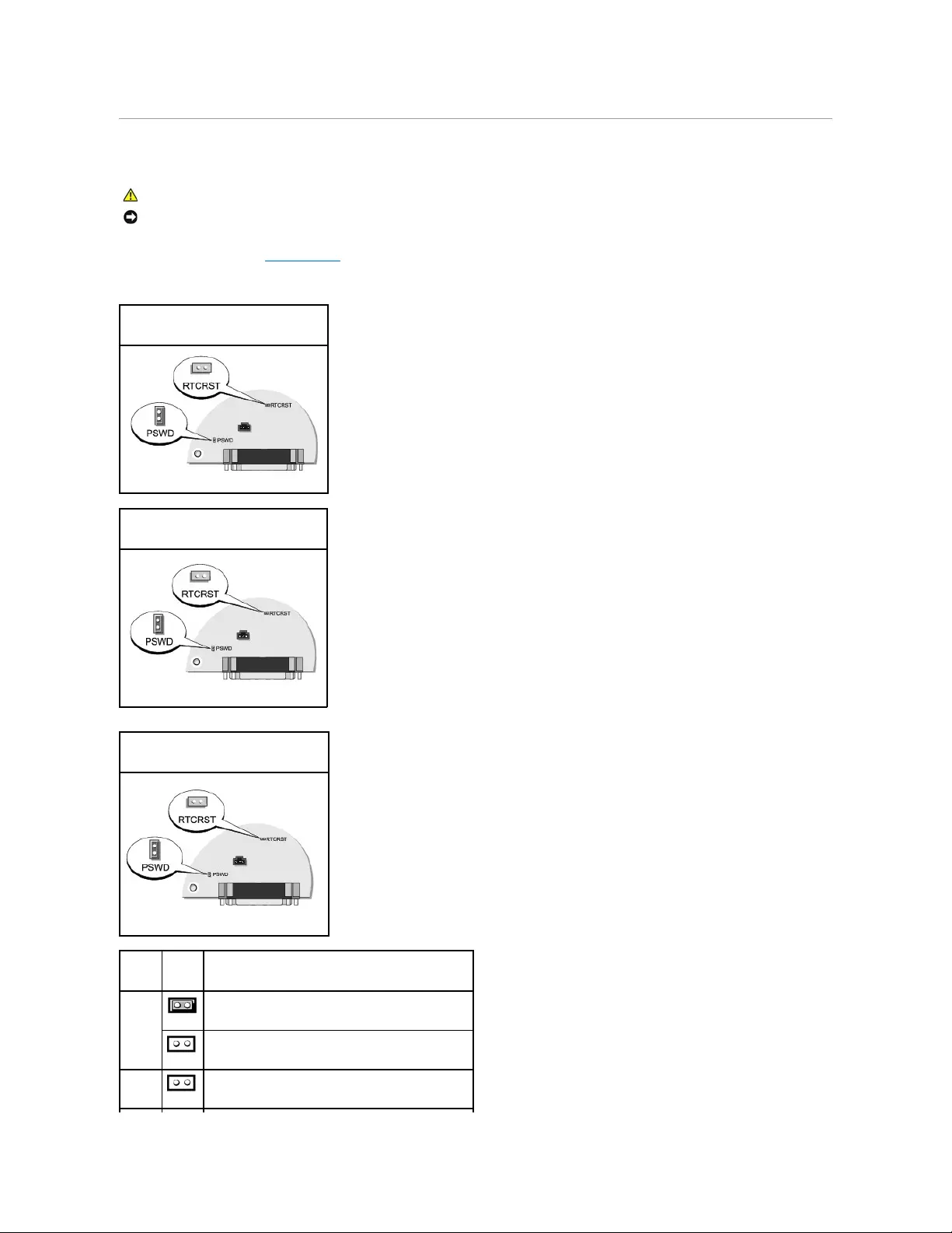
2. Locate the 2-pin password jumper (PSWD) on the system board, and remove the jumper to clear the password.
CAUTION: Before you begin any of the procedures in this section, follow the safety instructions located in the Product Information Guide.
NOTICE: This process erases both the system and administrator passwords.
Mini Tower Computer
Desktop Computer
Small Form Computer
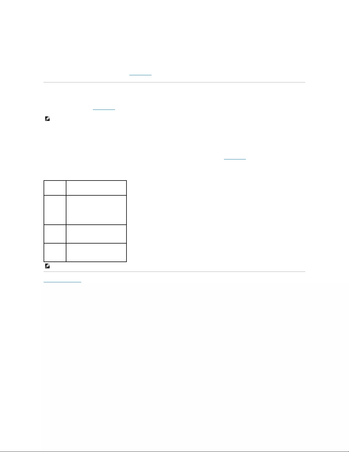
Jumper
Setting
Description
PSWD
Password features are enabled (default setting).
Password features are disabled.
RTCRST
The real-time clock has not been reset.

3. Replace the computer cover.
4. Connect your computer and monitor to electrical outlets, and turn them on.
5. After the Microsoft®Windows®desktop appears on your computer, shut down your computer.
6. Turn off the monitor and disconnect it from the electrical outlet.
7. Disconnect the computer power cable from the electrical outlet, and press the power button to ground the system board.
8. Open the computer cover.
9. Locate the 2-pin password jumper on the system board and attach the jumper to reenable the password feature.
10. Replace the computer cover.
11. Connect your computer and devices to electrical outlets, and turn them on.
12. Assign a new system and/or administrator password.
Clearing CMOS Settings
1. Follow the procedures in "Before You Begin."
2. Reset the current CMOS settings:
a. Locate the password (PSWD) and CMOS (RTC_RST) jumpers on the system board.
b. Remove the password jumper plug from its pins.
c. Place the password jumper plug on the RTC_RST pins and wait approximately 5 seconds.
d. Remove the jumper plug from the RTC_RST pins and place it back on the password pins.
3. Replace the computer cover.
4. Attach the computer stand, if used.
5. Connect your computer and devices to electrical outlets, and turn them on.
Hyper-Threading
Hyper-Threading is an Intel®technology that can enhance overall computer performance by allowing one physical processor to function as two logical
processors, capable of performing certain tasks simultaneously. It is recommended that you use the Microsoft®Windows®XP Service Pack 1 (SP1) or higher
operating system because Windows XP is optimized to take advantage of Hyper-Threading technology. While many programs can benefit from Hyper-
Threading, some programs have not been optimized for Hyper-Threading and may require an update from the software manufacturer. Contact the software
manufacturer for updates and information about using Hyper-Threading with your software.
To determine if your computer is using Hyper-Threading technology:
The real-time clock is being reset (jumpered temporarily).
jumpered unjumpered
NOTICE: To connect a network cable, first plug the cable into the network wall jack and then plug it into the computer.
NOTE: This procedure enables the password feature. When you enter system setup, both system and administrator password options appear as Not
Set—meaning that the password feature is enabled but no password is assigned.
CAUTION: Before you begin any of the procedures in this section, follow the safety instructions located in the Product Information Guide.
NOTICE: To connect a network cable, first plug the cable into the network wall jack and then plug it into the computer.
1. Click the Start button, right-click My Computer, and then click Properties.
2. Click Hardware and click Device Manager.
3. In the Device Manager window, click the plus (+) sign next to the processor type. If Hyper- Threading is enabled, the processor is listed twice.
You can enable or disable Hyper-Threading through system setup.
Power Management
Your computer can be set to use less power when you are not working. You control the power usage through the operating system installed on your computer
and certain option settings in system setup. These periods of reduced power are called "sleep modes."
lStandby. In this sleep mode, power is reduced or turned off for most components, including the cooling fans. However, system memory remains active.
lHibernate. This sleep mode reduces power consumption to a minimum by writing all data in system memory to a hard drive and then removing system
power. Waking up from this mode restarts the computer, and the memory contents are restored. Operation then resumes where the computer left off
when it entered the hibernation mode.
lShutdown. This sleep mode removes all power from the computer except a small auxiliary amount. As long as the computer remains connected to an
electrical outlet, it can be automatically or remotely started. For example, the Auto Power On option in system setup allows the computer to
automatically start at a specified time. Also, your network administrator can remotely start your computer using a power management event such as
Remote Wake Up.
The following table lists the sleep modes and the methods you can use to wake the computer from each mode.
Back to Contents Page
NOTE: All components installed in the computer must support the hibernate and/or standby mode feature(s) and have the appropriate drivers loaded to
enter either of these sleep modes. For more information, see the manufacturer's documentation for each component.
Sleep Mode
Wake-Up Methods (Windows XP)
Standby
lPress the power button
lAuto power on
lMove or click the mouse
lType on the keyboard
lUSB device activity
lPower management event
Hibernate
lPress the power button
lAuto power on
lPower management event
Shutdown
lPress the power button
lAuto power on
lPower management event
NOTE: For more information on power management, see your operating system documentation.

Back to Contents Page
Battery
Dell™OptiPlex™GX520User'sGuide
Replacing the Battery
Replacing the Battery
A coin-cell battery maintains computer configuration, date, and time information. The battery can last several years.
The battery may need replacing if an incorrect time or date is displayed during the boot routine along with a message such as:
Time-of-day not set - please run SETUP program
or
Invalid configuration information -
please run SETUP program
or
Strike the F1 key to continue,
F2 to run the setup utility
To determine whether you need to replace the battery, reenter the time and date in system setup and exit the program to save the information. Turn off your
computer and disconnect it from the electrical outlet for a few hours; then reconnect the computer, turn it on, and enter system setup. If the date and time are
not correct in system setup, replace the battery.
You can operate your computer without a battery; however, without a battery, the configuration information is erased if the computer is turned off or
unplugged from the electrical outlet. In this case, you must enter system setup and reset the configuration options.
To remove the battery:
1. If you have not already done so, make a copy of your configuration information, found in system setup.
2. Follow the procedures in "Before You Begin."
3. Locate the battery socket.
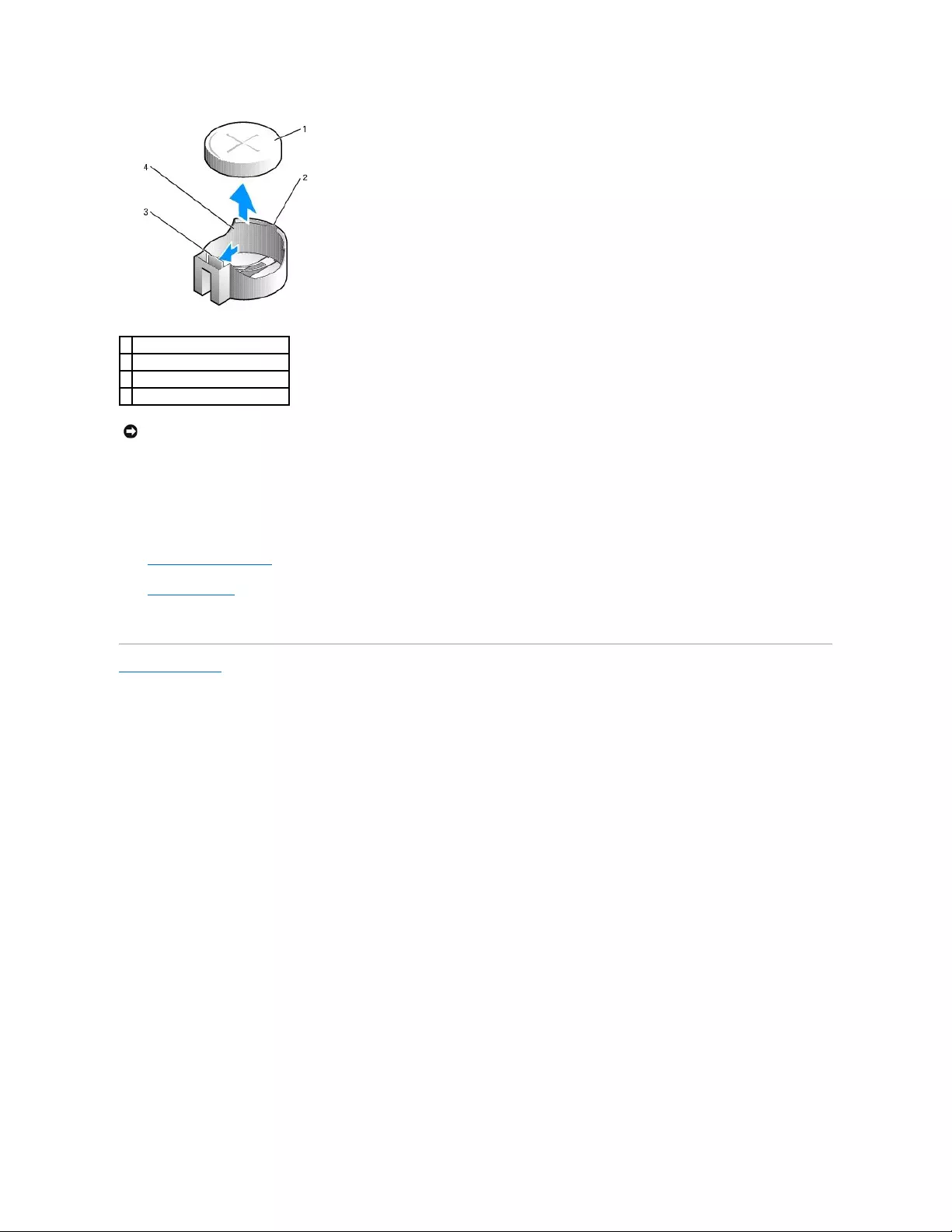
4. Remove the system battery.
a. Support the battery connector by pressing down firmly on the positive side of the connector.
b. While supporting the battery connector, press the battery tab away from the positive side of the connector and pry the battery it up out of the
securing tabs at the negative side of the connector.
CAUTION: Before you begin any of the procedures in this section, follow the safety instructions in the Product Information Guide.
NOTICE: To prevent static damage to components inside your computer, discharge static electricity from your body before you touch any of your
computer's electronic components. You can do so by touching an unpainted metal surface on the computer chassis.
CAUTION: A new battery can explode if it is incorrectly installed. Replace the battery only with the same or equivalent type recommended by the
manufacturer. Discard used batteries according to the manufacturer's instructions.
NOTICE: If you pry the battery out of its socket with a blunt object, be careful not to touch the system board with the object. Ensure that the object is
inserted between the battery and the socket before you attempt to pry out the battery. Otherwise, you may damage the system board by prying off
the socket or by breaking circuit traces on the system board.
NOTICE: To avoid damage to the battery connector, you must firmly support the connector while removing the battery.
1. Install the new system battery.
a. Support the battery connector by pressing down firmly on the positive side of the connector.
b. Hold the battery with the "+" facing up, and slide it under the securing tabs at the positive side of the connector.
c. Press the battery straight down into the connector until it snaps into place.
2. Replace the computer cover.
3. Enter system setup and restore the settings you recorded in step 1.
4. Properly dispose of the old battery as described in the Product Information Guide.
Back to Contents Page
1
system battery
2
positive side of battery connector
3
battery socket tab
4
battery socket
NOTICE: To avoid damage to the battery connector, you must firmly support the connector while replacing the battery.

Back to Contents Page
Before You Begin
Dell™OptiPlex™GX520User'sGuide
Recommended Tools
Turning Off Your Computer
Before Working Inside Your Computer
This chapter provides procedures for removing and installing the components in your computer. Unless otherwise noted, each procedure assumes that the
following conditions exist:
lYou have performed the steps in "Turning Off Your Computer" and "Before Working Inside Your Computer."
lYouhavereadthesafetyinformationinyourDell™Product Information Guide.
lA component can be replaced by performing the removal procedure in reverse order.
Recommended Tools
The procedures in this document may require the following tools:
lSmall flat-blade screwdriver
lPhillips screwdriver
lFlash BIOS update program floppy disk or CD
Turning Off Your Computer
1. Shut down the operating system:
a. Save and close any open files, exit any open programs, click the Start button, and then click Turn Off Computer.
b. In the Turn off computer window, click Turn off.
The computer turns off after the operating system shutdown process finishes.
2. Ensure that the computer and any attached devices are turned off. If your computer and attached devices did not automatically turn off when you shut
down your operating system, turn them off now.
Before Working Inside Your Computer
Use the following safety guidelines to help protect your computer from potential damage and to help ensure your own personal safety.
To avoid damaging the computer, perform the following steps before you begin working inside the computer.
1. Turn off your computer.
2. Disconnect any telephone or telecommunication lines from the computer.
3. Disconnect your computer and all attached devices from their electrical outlets, and then press the power button to ground the system board.
NOTICE: To avoid losing data, save and close any open files and exit any open programs before you turn off your computer.
CAUTION: Before you begin any of the procedures in this section, follow the safety instructions in the Product Information Guide.
CAUTION: Handle components and cards with care. Do not touch the components or contacts on a card. Hold a card by its edges or by its metal
mounting bracket. Hold a component such as a processor by its edges, not by its pins.
NOTICE: Only a certified service technician should perform repairs on your computer. Damage due to servicing that is not authorized by Dell is not
covered by your warranty.
NOTICE: When you disconnect a cable, pull on its connector or on its strain-relief loop, not on the cable itself. Some cables have a connector with
locking tabs; if you are disconnecting this type of cable, press in on the locking tabs before you disconnect the cable. As you pull connectors apart, keep
them evenly aligned to avoid bending any connector pins. Also, before you connect a cable, ensure that both connectors are correctly oriented and
aligned.
NOTICE: To disconnect a network cable, first unplug the cable from your computer and then unplug it from the network wall jack.

4. If applicable, remove the computer stand (for instructions, see the documentation that came with the stand) and the cable cover, if attached.
5. Remove the computer cover:
lRemove the mini tower computer cover.
lRemove the desktop computer cover.
lRemove the small form factor computer cover.
Back to Contents Page
CAUTION: To guard against electrical shock, always unplug your computer from the electrical outlet before removing the cover.
NOTICE: Before touching anything inside your computer, ground yourself by touching an unpainted metal surface, such as the metal at the back of the
computer. While you work, periodically touch an unpainted metal surface to dissipate any static electricity that could harm internal components.

Back to Contents Page
Before You Begin
Dell™OptiPlex™GX520User'sGuide
Recommended Tools
Turning Off Your Computer
Before Working Inside Your Computer
This chapter provides procedures for removing and installing the components in your computer. Unless otherwise noted, each procedure assumes that the
following conditions exist:
lYou have performed the steps in "Turning Off Your Computer" and "Before Working Inside Your Computer."
lYouhavereadthesafetyinformationinyourDell™Product Information Guide.
lA component can be replaced by performing the removal procedure in reverse order.
Recommended Tools
The procedures in this document may require the following tools:
lSmall flat-blade screwdriver
lPhillips screwdriver
lFlash BIOS update program floppy disk or CD
Turning Off Your Computer
1. Shut down the operating system:
a. Save and close any open files, exit any open programs, click the Start button, and then click Turn Off Computer.
b. In the Turn off computer window, click Turn off.
The computer turns off after the operating system shutdown process finishes.
2. Ensure that the computer and any attached devices are turned off. If your computer and attached devices did not automatically turn off when you shut
down your operating system, turn them off now.
Before Working Inside Your Computer
Use the following safety guidelines to help protect your computer from potential damage and to help ensure your own personal safety.
To avoid damaging the computer, perform the following steps before you begin working inside the computer.
1. Turn off your computer.
2. Disconnect any telephone or telecommunication lines from the computer.
NOTICE: To avoid losing data, save and close any open files and exit any open programs before you turn off your computer.
CAUTION: Before you begin any of the procedures in this section, follow the safety instructions in the Product Information Guide.
CAUTION: Handle components and cards with care. Do not touch the components or contacts on a card. Hold a card by its edges or by its metal
mounting bracket. Hold a component such as a processor by its edges, not by its pins.
CAUTION: Many repairs may only be done by a certified service technician. You should only perform troubleshooting and simple repairs as
authorized in your product documentation, or as directed by the online or telephone service and support team. Damage due to servicing that is not
authorized by Dell is not covered by your warranty. Read and follow the safety instructions that came with the product.
NOTICE: When you disconnect a cable, pull on its connector or on its strain-relief loop, not on the cable itself. Some cables have a connector with
locking tabs; if you are disconnecting this type of cable, press in on the locking tabs before you disconnect the cable. As you pull connectors apart,
keep them evenly aligned to avoid bending any connector pins. Also, before you connect a cable, ensure that both connectors are correctly
oriented and aligned.
NOTICE: To disconnect a network cable, first unplug the cable from your computer and then unplug it from the network wall jack.

3. Disconnect your computer and all attached devices from their electrical outlets, and then press the power button to ground the system board.
4. If applicable, remove the computer stand (for instructions, see the documentation that came with the stand) and the cable cover, if attached.
5. Remove the computer cover:
lRemove the mini tower computer cover.
lRemove the desktop computer cover.
lRemove the small form factor computer cover.
Back to Contents Page
CAUTION: To guard against electrical shock, always unplug your computer from the electrical outlet before removing the cover.
NOTICE: Before touching anything inside your computer, ground yourself by touching an unpainted metal surface, such as the metal at the back of
the computer. While you work, periodically touch an unpainted metal surface to dissipate any static electricity that could harm internal
components.
Back to Contents Page
Chassis Intrusion Switch
Dell™OptiPlex™GX520User'sGuide
Removing the Chassis Instrusion Switch
Replacing the Chassis Intrusion Switch
Resetting the Chassis Intrusion Detector
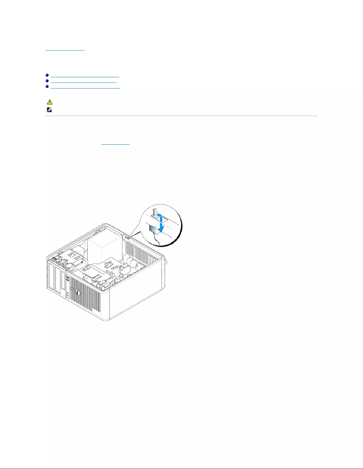
Removing the Chassis Instrusion Switch
1. Follow the procedures in "Before You Begin."
2. Disconnect the chassis intrusion switch cable from the system board.
Note the routing of the chassis intrusion cable as you remove it from the chassis. Chassis hooks may hold the cable in place inside the chassis.
3. Using a flat blade screwdriver, gently slide the chassis intrusion switch out of its slot, and remove the switch and its attached cable from the computer.
Mini Tower Computer
Desktop Computer
CAUTION: Before you begin any of the procedures in this section, follow the safety instructions located in the Product Information Guide.
NOTE: The chassis intrusion switch is optional and may not ship with your computer.
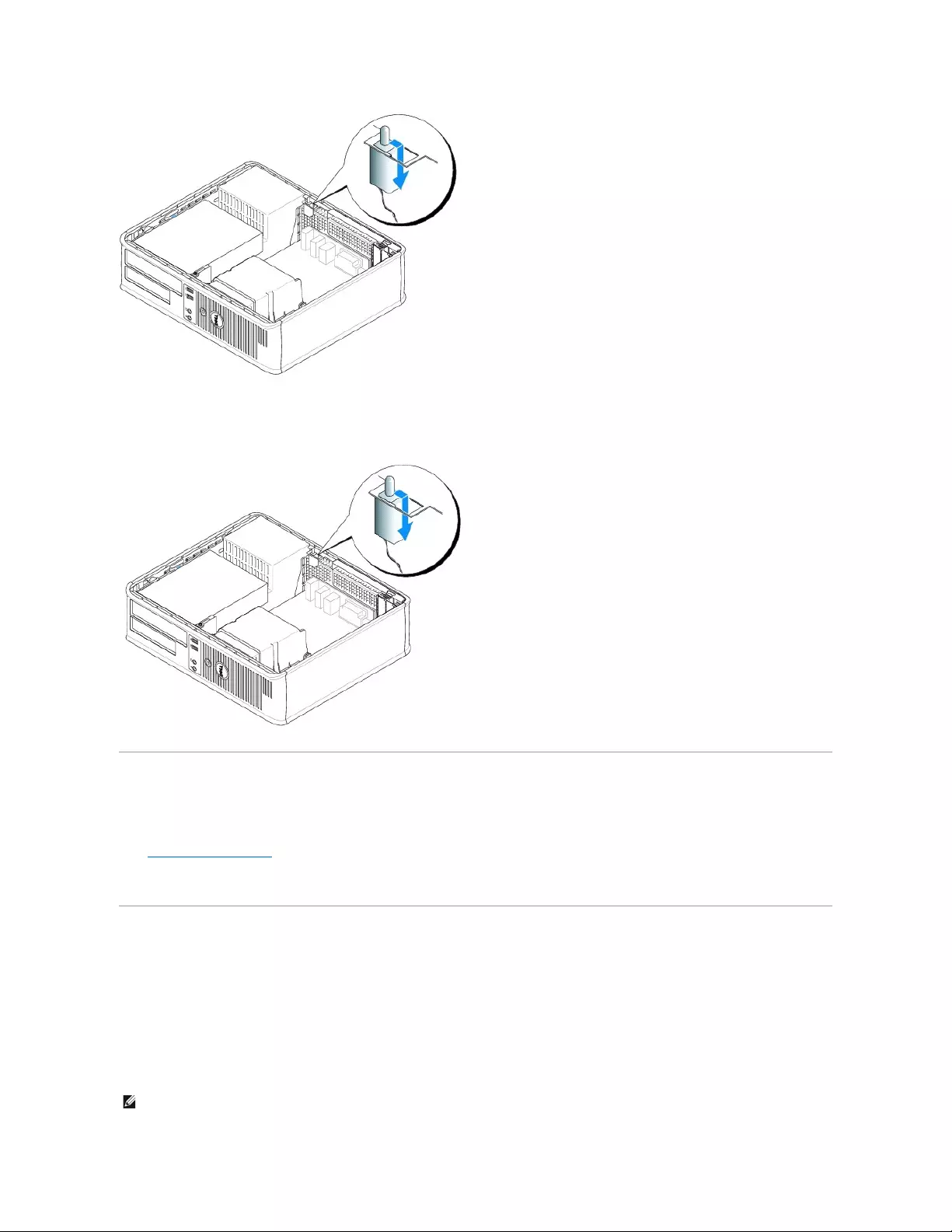
Small Form Factor Computer
Replacing the Chassis Intrusion Switch
1. Gently slide the chassis instrusion switch into its slot and reconnect the cable to the system board.
2. Replace the computer cover.
3. Attach the computer stand, if it is used.
Resetting the Chassis Intrusion Detector
1. Turn on (or restart) your computer.
2. WhentheblueDELL™logoappears,press<F2>immediately.
If you wait too long and the operating system logo appears, continue to wait until you see the Microsoft®Windows®desktop. Then shut down your
computer and try again.
3. Select the Chassis Intrusion option and then press the left- or right-arrow key to select Reset. Change the setting to On, On-Silent, or Disabled.
NOTE: The default setting is On-Silent.


Back to Contents Page
Cleaning Your Computer
Dell™OptiPlex™GX520User'sGuide
Computer, Keyboard, and Monitor
lUse a vacuum cleaner with a brush attachment to gently remove dust from the slots and holes on your computer and from between the keys on the
keyboard.
lTo clean your monitor screen, lightly dampen a soft, clean cloth with water. If possible, use a special screen-cleaning tissue or solution suitable for the
monitor's antistatic coating.
lWipe the keyboard, computer, and plastic part of the monitor with a soft cleaning cloth moistened with a solution of three parts water and one part
dish washing detergent.
Do not soak the cloth or let water drip inside your computer or keyboard.
Mouse
If your screen cursor skips or moves abnormally, clean the mouse. To clean a non-optical mouse:
1. Turn the retainer ring on the underside of your mouse counterclockwise, and then remove the ball.
2. Wipe the ball with a clean, lint-free cloth.
3. Blow carefully into the ball cage to dislodge dust and lint.
4. If the rollers inside the ball cage are dirty, clean the rollers with a cotton swab moistened lightly with isopropyl alcohol.
5. Re-center the rollers in their channels if they are misaligned. Ensure that lint from the swab is not left on the rollers.
6. Replace the ball and retainer ring, and turn the retainer ring clockwise until it clicks into place.
Floppy Drive
Clean your floppy drive using a commercially available cleaning kit. These kits contain pretreated floppy disks to remove contaminants that accumulate during
normal operation.
CDs and DVDs
If you notice problems, such as skipping, with the playback quality of your CDs or DVDs, try cleaning the discs.
1. Hold the disc by its outer edge. You can also touch the inside edge of the center hole.
2. With a soft, lint-free cloth, gently wipe the bottom of the disc (the unlabeled side) in a straight line from the center to the outer edge of the disc.
For stubborn dirt, try using water or a diluted solution of water and mild soap. You can also purchase commercial products that clean discs and provide
CAUTION: Before you begin any of the procedures in this section, follow the safety instructions located in the Product Information Guide.
CAUTION: Before you clean your computer, disconnect the computer from the electrical outlet. Clean your computer with a soft cloth dampened
with water. Do not use liquid or aerosol cleaners, which may contain flammable substances.
NOTICE: Do not wipe the display screen with any soap or alcohol solution. Doing so may damage the antiglare coating.
NOTICE: Do not attempt to clean drive heads with a swab. You might accidentally misalign the heads, which prevents the drive from operating.
NOTICE: Always use compressed air to clean the lens in the CD/DVD drive, and follow the instructions that come with the compressed air. Never touch
the lens in the drive.
NOTICE: To prevent damaging the surface, do not wipe in a circular motion around the disc.


Back to Contents Page
Replacing the Computer Cover
Dell™OptiPlex™GX520User'sGuide
1. Ensure that all cables are connected, and fold cables out of the way.
Gently pull the power cables toward you so that they do not get caught underneath the drives.
2. Ensure that no tools or extra parts are left inside the computer.
3. To replace the cover:
a. Align the bottom of the cover with the hinge tabs located along the bottom edge of the computer.
b. Using the hinge tabs as leverage, rotate the cover downward to close it.
c. Snap the cover into place by pulling back on the cover release latch and then releasing the latch when the cover is properly seated.
d. Ensure that the cover is seated correctly before moving the computer.
4. Attach the computer stand (if applicable). For instructions, see the documentation that came with the stand.
5. Connect your computer and devices to electrical outlets, and turn them on.
After you remove and replace the cover, the chassis intrusion detector, if installed and enabled, causes the following message to appear on the screen
at the next computer start-up:
ALERT! Cover was previously removed.
6. Reset the chassis intrusion detector in system setup by changing Chassis Intrusion to On or On-Silent.
Back to Contents Page
CAUTION: Before you begin any of the procedures in this section, follow the safety instructions in the Product Information Guide.
NOTICE: To connect a network cable, first plug the cable into the network wall jack and then plug it into the computer.
NOTE: If an administrator password has been assigned by someone else, contact your network administrator for information on resetting the chassis
intrusion detector.
Dell™OptiPlex™GX520User'sGuide
Notes, Notices, and Cautions
Abbreviations and Acronyms
For a complete list of abbreviations and acronyms, see the Glossary.
IfyoupurchasedaDell™nSeriescomputer,anyreferencesinthisdocumenttoMicrosoft® Windows® operating systems are not applicable.
Information in this document is subject to change without notice.
©2005–2006DellInc.Allrightsreserved.
Reproduction in any manner whatsoever without the written permission of Dell Inc. is strictly forbidden.
Trademarks used in this text: Dell, the DELL logo, OptiPlex, Inspiron, Dimension, Latitude, Dell Precision, DellNet, TravelLite, Dell OpenManage, PowerVault, Axim, PowerEdge, PowerConnect,
and PowerApp are trademarks of Dell Inc.; Intel, Pentium, and Celeron are registered trademarks of Intel Corporation; Microsoft, MS-DOS, and Windows are registered trademarks of
Microsoft Corporation; IBM is a registered trademark of International Business Machines Corporation; Bluetooth is a trademark owned by Bluetooth SIG, Inc. and is used by Dell
Inc. under license. ENERGY STAR is a registered trademark of the U.S. Environmental Protection Agency. As an ENERGY STAR partner, Dell Inc. has determined that this product
meets the ENERGY STAR guidelines for energy efficiency.
Other trademarks and trade names may be used in this document to refer to either the entities claiming the marks and names or their products. Dell Inc. disclaims any
proprietary interest in trademarks and trade names other than its own.
Model DCNE
October 2006 P/N W9246 Rev. A03
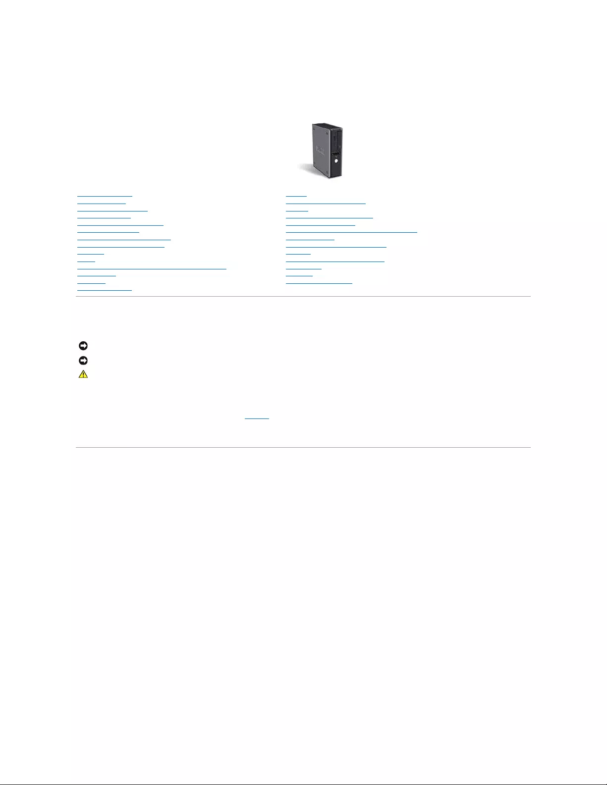
Desktop Computer
Finding Information
Before You Begin
Chassis Intrusion Switch
Desktop Computer
About Your Desktop Computer
Inside Your Computer
Desktop Computer Specifications
Removing the Computer Cover
I/O Panel
Drives
PCI and PCI Express Cards and Serial Port Adapters
Power Supply
Processor
Advanced Features
Battery
Replacing the System Board
Memory
Replacing the Computer Cover
Cleaning Your Computer
Reinstalling Drivers and the Operating System
Solving Problems
Microsoft®Windows®XP Features
Glossary
Troubleshooting Tools and Utilities
Getting Help
Warranty
FCC Notices (U.S. Only)
NOTE: A NOTE indicates important information that helps you make better use of your computer.
NOTICE: A NOTICE indicates either potential damage to hardware or loss of data and tells you how to avoid the problem.
CAUTION: A CAUTION indicates a potential for property damage, personal injury, or death.
Back to Contents Page
Finding Information
Dell™OptiPlex™GX520User'sGuide
NOTE: Some features may not be available for your computer or in certain countries.
NOTE: Additional information may ship with your computer.
What Are You Looking For?
Find It Here
lA diagnostic program for my computer
lDrivers for my computer
lMy computer documentation
lMy device documentation
lDesktop System Software (DSS)
Drivers and Utilities CD (also known as ResourceCD)
Documentation and drivers are already installed on your computer.
You can use the CD to run the Dell Diagnostics or access your
documentation.
Readme files may be included on your CD to provide last-minute
updates about technical changes to your computer or advanced
technical-reference material for technicians or experienced users.
NOTE: Drivers and documentation updates can be found at
support.dell.com.
NOTE: The Drivers and Utilities CD is optional and may not ship with
your computer.
lHow to set up my computer
lBasic troubleshooting information
lHow to run the Dell Diagnostics
lError codes and diagnostic lights
lTools and utilities
lHow to remove and install parts
Quick Reference Guide
NOTE: The Quick Reference Guide is optional and may not ship with
your computer.
NOTE: This document is available as a PDF at support.dell.com.
lWarranty information
lTerms and Conditions (U.S. only)
lSafety instructions
lRegulatory information
lErgonomics information
lEnd User License Agreement
Dell™ProductInformationGuide
lHow to remove and replace parts
lSpecifications
lHow to configure system settings
lHow to troubleshoot and solve problems
User's Guide
Microsoft® Windows® XP Help and Support Center
Back to Contents Page
1. Click the Start button and click Help and Support.
2. Click User's and system guides and click User's guides.
The User's Guide is also available on the optional Drivers and Utilities
CD.
lService Tag and Express Service Code
lMicrosoft Windows License Label
Service Tag and Microsoft Windows License
These labels are located on your computer.
lUse the Service Tag to identify your computer when you use
support.dell.com or contact technical support.
lEnter the Express Service Code to direct your call when
contacting technical support.
lSolutions — Troubleshooting hints and tips, articles from technicians, online
courses, frequently asked questions
lCommunity — Online discussion with other Dell customers
lUpgrades — Upgrade information for components, such as memory, the hard
drive, and the operating system
lCustomer Care — Contact information, service call and order status, warranty,
and repair information
lService and support — Service call status and support history, service contract,
online discussions with technical support
lReference — Computer documentation, details on my computer configuration,
product specifications, and white papers
lDownloads — Certified drivers, patches, and software updates
lDesktop System Software (DSS) — If you reinstall the operating system for
your computer, you should also reinstall the DSS utility. DSS provides critical
updatesforyouroperatingsystemandsupportforDell™3.5-inch USB floppy
drives, Intel® Pentium®M processors, optical drives, and USB devices. DSS is
necessary for correct operation of your Dell computer. The software
automatically detects your computer and operating system and installs the
updates appropriate for your configuration.
Dell Support Website — support.dell.com
NOTE: Select your region to view the appropriate support site.
NOTE: Corporate, government, and education customers can also
use the customized Dell Premier Support website at
premier.support.dell.com. The website may not be available in all
regions.
lHow to use Windows XP
lDocumentation for my computer
lDocumentation for devices (such as a modem)
Windows Help and Support Center
1. Click the Start button and click Help and Support.
2. Type a word or phrase that describes your problem and click
the arrow icon.
3. Click the topic that describes your problem.
4. Follow the instructions on the screen.
lHow to reinstall my operating system
Operating System CD
The operating system is already installed on your computer. To
reinstall your operating system, use the Operating System CD. See
"Reinstalling Microsoft Windows XP" for instructions.
After you reinstall your operating system, use the optional Drivers
and Utilities CD to reinstall drivers for the devices that came with
your computer.
Your operating system product key label is located on your
computer.
NOTE: The color of your CD varies based on the operating system
you ordered.
NOTE: The Operating System CD is optional and may not ship with
your computer.


Back to Contents Page
Getting Help
Dell™OptiPlex™GX520User'sGuide
Technical Assistance
Problems With Your Order
Product Information
Returning Items for Warranty Repair or Credit
Before You Call
Contacting Dell
Technical Assistance
If you need help with a technical problem, Dell is ready to assist you.
1. Complete the procedures in "Solving Problems."
2. Run the Dell Diagnostics.
3. Make a copy of the Diagnostics Checklist and fill it out.
4. Use Dell's extensive suite of online services available at Dell Support (support.dell.com) for help with installation and troubleshooting procedures.
5. If the preceding steps have not resolved the problem, contact Dell.
NOTE: Call technical support from a telephone near or at the computer so that technical support can assist you with any necessary procedures.
NOTE: Dell's Express Service Code system may not be available in all countries.
When prompted by Dell's automated telephone system, enter your Express Service Code to route the call directly to the proper support personnel. If you do
not have an Express Service Code, open the Dell Accessories folder, double-click the Express Service Code icon, and follow the directions.
For instructions on using the technical support service, see "Technical Support Service."
NOTE: Some of the following services are not always available in all locations outside the continental U.S. Call your local Dell representative for information on
availability.
Online Services
You can access Dell Support at support.dell.com. Select your region on the WELCOME TO DELL SUPPORT page, and fill in the requested details to access
help tools and information.
You can contact Dell electronically using the following addresses:
lWorld Wide Web
www.dell.com/
www.dell.com/ap/ (Asian/Pacific countries only)
www.dell.com/jp (Japan only)
www.euro.dell.com (Europe only)
www.dell.com/la/ (Latin American countries)
www.dell.ca (Canada only)
lAnonymous file transfer protocol (FTP)
ftp.dell.com/
Log in as user: anonymous, and use your e-mail address as your password.
lElectronic Support Service
mobile_support@us.dell.com
support@us.dell.com
CAUTION: If you need to remove the computer covers, first disconnect the computer power and modem cables from all electrical outlets.

apsupport@dell.com (Asian/Pacific countries only)
support.jp.dell.com (Japan only)
support.euro.dell.com (Europe only)
lElectronic Quote Service
sales@dell.com
apmarketing@dell.com (Asian/Pacific countries only)
sales_canada@dell.com (Canada only)
lElectronic Information Service
info@dell.com
AutoTech Service
Dell's automated technical support service—AutoTech—provides recorded answers to the questions most frequently asked by Dell customers about their
portable and desktop computers.
When you call AutoTech, use your touch-tone telephone to select the subjects that correspond to your questions.
TheAutoTechserviceisavailable24hoursaday,7daysaweek.Youcanalsoaccessthisservicethroughthetechnicalsupportservice.Forthetelephone
number to call, see the contact numbers for your region.
Automated Order-Status Service
TocheckonthestatusofanyDell™productsthatyouhaveordered,youcangotosupport.dell.com, or you can call the automated order-status service. A
recording prompts you for the information needed to locate and report on your order. For the telephone number to call, see the contact numbers for your
region.
Technical Support Service
Dell'stechnicalsupportserviceisavailable24hoursaday,7daysaweek,toansweryourquestionsaboutDellhardware.Ourtechnicalsupportstaffuses
computer-based diagnostics to provide fast, accurate answers.
To contact Dell's technical support service, see "Technical Assistance" and then call the number for your country as listed in "Contacting Dell."
Problems With Your Order
If you have a problem with your order, such as missing parts, wrong parts, or incorrect billing, contact Dell for customer assistance. Have your invoice or
packing slip handy when you call. For the telephone number to call, see the contact numbers for your region.
Product Information
If you need information about additional products available from Dell, or if you would like to place an order, visit the Dell website at www.dell.com. For the
telephone number to call to speak to a sales specialist, see the contact numbers for your region.
Returning Items for Warranty Repair or Credit
Prepare all items being returned, whether for repair or credit, as follows:
1. Call Dell to obtain a Return Material Authorization Number, and write it clearly and prominently on the outside of the box.
For the telephone number to call, see the contact numbers for your region.
2. Include a copy of the invoice and a letter describing the reason for the return.
3. Include a copy of the Diagnostics Checklist indicating the tests you have run and any error messages reported by the Dell Diagnostics.
4. Include any accessories that belong with the item(s) being returned (power cables, software floppy disks, guides, and so on) if the return is for credit.
5. Pack the equipment to be returned in the original (or equivalent) packing materials.
You are responsible for paying shipping expenses. You are also responsible for insuring any product returned, and you assume the risk of loss during shipment
to Dell. Collect On Delivery (C.O.D.) packages are not accepted.
Returns that are missing any of the preceding requirements will be refused at Dell's receiving dock and returned to you.
Before You Call
NOTE: Have your Express Service Code ready when you call. The code helps Dell's automated-support telephone system direct your call more efficiently.
Remember to fill out the Diagnostics Checklist. If possible, turn on your computer before you call Dell for technical assistance and call from a telephone at or
near the computer. You may be asked to type some commands at the keyboard, relay detailed information during operations, or try other troubleshooting
steps possible only at the computer itself. Ensure that the computer documentation is available.
Contacting Dell
To contact Dell electronically, you can access the following websites:
lwww.dell.com
lsupport.dell.com (technical support)
lpremiersupport.dell.com (technical support for educational, government, healthcare, and medium/large business customers, including Premier,
Platinum, and Gold customers)
For specific web addresses for your country, find the appropriate country section in the table below.
NOTE: In certain countries, technical support specific to Dell Inspiron™ XPS computers is available at a separate telephone number listed for participating
countries. If you do not see a telephone number listed that is specific for Inspiron XPS computers, you may contact Dell through the technical support number
listed and your call will be routed appropriately.
When you need to contact Dell, use the electronic addresses, telephone numbers, and codes provided in the following table. If you need assistance in
determining which codes to use, contact a local or an international operator.
CAUTION: Before working inside your computer, read the safety instructions in your Product Information Guide.
Diagnostics Checklist
Name:
Date:
Address:
Phone number:
Service Tag (bar code on the back of the computer):
Express Service Code:
Return Material Authorization Number (if provided by Dell support technician):
Operating system and version:
Devices:
Expansion cards:
Are you connected to a network? Yes No
Network, version, and network adapter:
Programs and versions:
See your operating system documentation to determine the contents of the system's start-up files. If the computer is connected to a printer, print each file.
Otherwise, record the contents of each file before calling Dell.
Error message, beep code, or diagnostic code:
Description of problem and troubleshooting procedures you performed:
NOTE: Toll-free numbers are for use within the country for which they are listed.
Country (City)
International Access Code
Country Code
City Code
Department Name or Service Area,
Website and E-Mail Address
Area Codes,
Local Numbers, and
Toll-Free Numbers
Anguilla
General Support
toll-free:800-335-0031
Antigua and Barbuda
General Support
1-800-805-5924
Website: www.dell.com.ar

Argentina (Buenos Aires)
International Access Code: 00
Country Code: 54
City Code: 11
E-mail: us_latin_services@dell.com
E-mail for desktop and portable computers:
la-techsupport@dell.com
E-mail for servers and EMC®storage products:
la_enterprise@dell.com
Customer Care
toll-free:0-800-444-0730
Tech Support
toll-free:0-800-444-0733
Tech Support Services
toll-free:0-800-444-0724
Sales
0-810-444-3355
Aruba
General Support
toll-free:800-1578
Australia (Sydney)
International Access Code:
0011
Country Code: 61
City Code: 2
E-mail (Australia): au_tech_support@dell.com
E-mail (New Zealand): nz_tech_support@dell.com
Home and Small Business
1-300-655-533
Government and Business
toll-free:1-800-633-559
Preferred Accounts Division (PAD)
toll-free:1-800-060-889
Customer Care
toll-free:1-800-819-339
Technical Support (portables and desktops)
toll-free:1-300-655-533
Technical Support (servers and workstations)
toll-free:1-800-733-314
Corporate Sales
toll-free:1-800-808-385
Transaction Sales
toll-free:1-800-808-312
Fax
toll-free:1-800-818-341
Austria (Vienna)
International Access Code: 900
Country Code: 43
City Code: 1
Website: support.euro.dell.com
E-mail: tech_support_central_europe@dell.com
Technical Support for Inspiron XPS computers only
082024053081
Home/Small Business Sales
082024053000
Home/Small Business Fax
082024053049
Home/Small Business Customer Care
082024053014
Preferred Accounts/Corporate Customer Care
082024053016
Home/Small Business Technical Support
082024053014
Preferred Accounts/Corporate Technical Support
06608779
Switchboard
082024053000
Bahamas
General Support
toll-free:1-866-278-6818
Barbados
General Support
1-800-534-3066
Belgium (Brussels)
International Access Code: 00
Country Code: 32
City Code: 2
Website: support.euro.dell.com
E-mail for French-speaking Customers:
support.euro.dell.com/be/fr/emaildell/
Technical Support for Inspiron XPS computers only
024819296
Technical Support for all other Dell computers
024819288
Technical Support Fax
024819295
Customer Care
0271315.65
Corporate Sales
024819100
Fax
024819299
Switchboard
024819100
Bermuda
General Support
1-800-342-0671
Bolivia
General Support
toll-free:800-10-0238
Brazil
International Access Code: 00
Country Code: 55
City Code: 51
Website: www.dell.com/br
Customer Support, Technical Support
0800903355
Technical Support Fax
514815470
Customer Care Fax
514815480
Sales
0800903390
British Virgin Islands
General Support
toll-free:1-866-278-6820
Brunei
Country Code: 673
Customer Technical Support (Penang, Malaysia)
6046334966
Customer Service (Penang, Malaysia)
6046334949
Transaction Sales (Penang, Malaysia)
6046334955
Canada (North York, Ontario)
Online Order Status: www.dell.ca/ostatus
AutoTech (automated technical support)
toll-free:1-800-247-9362
Customer Care (Home Sales/Small Business)
toll-free:1-800-847-4096
Customer Care (med./large business, government)
toll-free:1-800-326-9463
Technical Support (Home Sales/Small Business)
toll-free:1-800-847-4096
International Access Code: 011
Technical Support (med./large bus., government)
toll-free:1-800-387-5757
Technical Support (printers, projectors, televisions, handhelds, digital
jukebox, and wireless)
1-877-335-5767
Sales (Home Sales/Small Business)
toll-free:1-800-387-5752
Sales (med./large bus., government)
toll-free:1-800-387-5755
Spare Parts Sales & Extended Service Sales
18664403355
Cayman Islands
General Support
1-800-805-7541
Chile (Santiago)
Country Code: 56
City Code: 2
Sales, Customer Support, and Technical Support
toll-free:1230-020-4823
China (Xiamen)
Country Code: 86
City Code: 592
Technical Support website: support.dell.com.cn
Technical Support E-mail: cn_support@dell.com
Customer Care E-mail: customer_cn@dell.com
Technical Support Fax
5928181350
TechnicalSupport(Dell™Dimension™andInspiron)
toll-free:8008582969
TechnicalSupport(OptiPlex™,Latitude™,andDellPrecision™)
toll-free:8008580950
Technical Support (servers and storage)
toll-free:8008580960
Technical Support (projectors, PDAs, switches, routers, and so on)
toll-free:8008582920
Technical Support (printers)
toll-free:8008582311
Customer Care
toll-free:8008582060
Customer Care Fax
5928181308
Home and Small Business
toll-free:8008582222
Preferred Accounts Division
toll-free:8008582557
Large Corporate Accounts GCP
toll-free:8008582055
Large Corporate Accounts Key Accounts
toll-free:8008582628
Large Corporate Accounts North
toll-free:8008582999
Large Corporate Accounts North Government and Education
toll-free:8008582955
Large Corporate Accounts East
toll-free:8008582020
Large Corporate Accounts East Government and Education
toll-free:8008582669
Large Corporate Accounts Queue Team
toll-free:8008582572
Large Corporate Accounts South
toll-free:8008582355
Large Corporate Accounts West
toll-free:8008582811
Large Corporate Accounts Spare Parts
toll-free:8008582621
Colombia
General Support
980-9-15-3978
Costa Rica
General Support
0800-012-0435
Czech Republic (Prague)
International Access Code: 00
Country Code: 420
Website: support.euro.dell.com
E-mail: czech_dell@dell.com
Technical Support
225372727
Customer Care
225372707
Fax
225372714
Tech Fax
225372728
Switchboard
225372711
Denmark (Copenhagen)
International Access Code: 00
Country Code: 45
Website: support.euro.dell.com
E-mail: support.euro.dell.com/dk/da/emaildell/
Technical Support for Inspiron XPS computers only
7010 0074
Technical Support for all other Dell computers
70230182
Customer Care (Relational)
70230184
Home/Small Business Customer Care
32875505
Switchboard (Relational)
32871200
Switchboard Fax (Relational)
32871201
Switchboard (Home/Small Business)
32875000
Switchboard Fax (Home/Small Business)
32875001
Dominica
General Support
toll-free:1-866-278-6821
Dominican Republic
General Support
1-800-148-0530
Ecuador
General Support
toll-free:999-119
El Salvador
General Support
01-899-753-0777
Finland (Helsinki)
Website: support.euro.dell.com

International Access Code: 990
Country Code: 358
City Code: 9
E-mail: support.euro.dell.com/fi/fi/emaildell/
Technical Support
0925331360
Customer Care
0925331338
Fax
0925331399
Switchboard
0925331300
France (Paris) (Montpellier)
International Access Code: 00
Country Code: 33
City Codes: (1) (4)
Website: support.euro.dell.com
E-mail: support.euro.dell.com/fr/fr/emaildell/
Home and Small Business
Technical Support for Inspiron XPS computers only
0825 387 129
Technical Support for all other Dell computers
0825387270
Customer Care
0825823833
Switchboard
0825004700
Switchboard (calls from outside of France)
0499754000
Sales
0825004700
Fax
0825004701
Fax (calls from outside of France)
0499754001
Corporate
Technical Support
0825004719
Customer Care
0825338339
Switchboard
0155947100
Sales
0155947100
Fax
0155947101
Germany (Langen)
International Access Code: 00
Country Code: 49
City Code: 6103
Website: support.euro.dell.com
E-mail: tech_support_central_europe@dell.com
Technical Support for Inspiron XPS computers only
06103 766-7222
Technical Support for all other Dell computers
06103766-7200
Home/Small Business Customer Care
0180-5-224400
Global Segment Customer Care
06103766-9570
Preferred Accounts Customer Care
06103766-9420
Large Accounts Customer Care
06103766-9560
Public Accounts Customer Care
06103766-9555
Switchboard
06103766-7000
Greece
International Access Code: 00
Country Code: 30
Website: support.euro.dell.com
E-mail: support.euro.dell.com/gr/en/emaildell/
Technical Support
00800-44 14 95 18
Gold Service Technical Support
00800-44 14 00 83
Switchboard
2108129810
Gold Service Switchboard
2108129811
Sales
2108129800
Fax
2108129812
Grenada
General Support
toll-free:1-866-540-3355
Guatemala
General Support
1-800-999-0136
Guyana
General Support
toll-free:1-877-270-4609
Hong Kong
International Access Code: 001
Country Code: 852
Website: support.ap.dell.com
Technical Support E-mail: apsupport@dell.com
Technical Support (Dimension and Inspiron)
29693188
Technical Support (OptiPlex, Latitude, and Dell Precision)
29693191
TechnicalSupport(PowerApp™,PowerEdge™,PowerConnect™,and
PowerVault™)
29693196
Customer Care
34160910
Large Corporate Accounts
34160907
Global Customer Programs
34160908
Medium Business Division
34160912
Home and Small Business Division
29693105
India
Technical Support
1600338045
Sales (Large Corporate Accounts)
1600338044
Sales (Home and Small Business)
1600338046
Website: support.euro.dell.com
E-mail: dell_direct_support@dell.com

Ireland (Cherrywood)
International Access Code: 16
Country Code: 353
City Code: 1
Technical Support for Inspiron XPS computers only
1850 200 722
Technical Support for all other Dell computers
1850543543
U.K. Technical Support (dial within U.K. only)
08709080800
Home User Customer Care
012044014
Small Business Customer Care
012044014
U.K. Customer Care (dial within U.K. only)
08709060010
Corporate Customer Care
1850200982
Corporate Customer Care (dial within U.K. only)
08709074499
Ireland Sales
012044444
U.K. Sales (dial within U.K. only)
08709074000
Fax/Sales Fax
012040103
Switchboard
012044444
Italy (Milan)
International Access Code: 00
Country Code: 39
City Code: 02
Website: support.euro.dell.com
E-mail: support.euro.dell.com/it/it/emaildell/
Home and Small Business
Technical Support
0257782690
Customer Care
0269682114
Fax
0269682113
Switchboard
0269682112
Corporate
Technical Support
0257782690
Customer Care
0257782555
Fax
0257503530
Switchboard
02577821
Jamaica
General Support (dial from within Jamaica only)
1-800-682-3639
Japan (Kawasaki)
International Access Code: 001
Country Code: 81
City Code: 44
Website: support.jp.dell.com
Technical Support (servers)
toll-free: 0120-198-498
Technical Support outside of Japan (servers)
81-44-556-4162
Technical Support (Dimension and Inspiron)
toll-free: 0120-198-226
Technical Support outside of Japan (Dimension and Inspiron)
81-44-520-1435
Technical Support (Dell Precision, OptiPlex, and Latitude)
toll-free:0120-198-433
Technical Support outside of Japan (Dell Precision, OptiPlex, and Latitude)
81-44-556-3894
Technical Support (PDAs, projectors, printers, routers)
toll-free: 0120-981-690
Technical Support outside of Japan (PDAs, projectors, printers, routers)
81-44-556-3468
Faxbox Service
044-556-3490
24-Hour Automated Order Service
044-556-3801
Customer Care
044-556-4240
Business Sales Division (up to 400 employees)
044-556-1465
Preferred Accounts Division Sales (over 400 employees)
044-556-3433
Large Corporate Accounts Sales (over 3500 employees)
044-556-3430
Public Sales (government agencies, educational institutions, and medical
institutions)
044-556-1469
Global Segment Japan
044-556-3469
Individual User
044-556-1760
Switchboard
044-556-4300
Korea (Seoul)
International Access Code: 001
Country Code: 82
City Code: 2
Technical Support
toll-free:080-200-3800
Sales
toll-free:080-200-3600
Customer Service (Penang, Malaysia)
6046334949
Fax
2194-6202
Switchboard
2194-6000
Technical Support (Electronics and Accessories)
toll-free: 080-200-3801
Latin America
Customer Technical Support (Austin, Texas, U.S.A.)
512728-4093
Customer Service (Austin, Texas, U.S.A.)
512728-3619
Fax (Technical Support and Customer Service) (Austin, Texas, U.S.A.)
512728-3883
Sales (Austin, Texas, U.S.A.)
512728-4397
SalesFax (Austin, Texas, U.S.A.)
512728-4600
or512728-3772
Website: support.euro.dell.com
E-mail: tech_be@dell.com

Luxembourg
International Access Code: 00
Country Code: 352
Technical Support (Brussels, Belgium)
3420808075
Home/Small Business Sales (Brussels, Belgium)
toll-free:080016884
Corporate Sales (Brussels, Belgium)
024819100
Customer Care (Brussels, Belgium)
024819119
Fax (Brussels, Belgium)
024819299
Switchboard (Brussels, Belgium)
024819100
Macao
Country Code: 853
Technical Support
toll-free:0800105
Customer Service (Xiamen, China)
34 160 910
Transaction Sales (Xiamen, China)
29 693 115
Malaysia (Penang)
International Access Code: 00
Country Code: 60
City Code: 4
Website: support.ap.dell.com
Technical Support (Dell Precision, OptiPlex, and Latitude)
toll-free:1800880193
Technical Support (Dimension, Inspiron, and Electronics and Accessories)
toll-free:1800881306
Technical Support (PowerApp, PowerEdge, PowerConnect, and PowerVault)
toll-free:1800881386
Customer Service (Penang, Malaysia)
046334949
Transaction Sales
toll-free:1800888202
Corporate Sales
toll-free:1800888213
Mexico
International Access Code: 00
Country Code: 52
Customer Technical Support
001-877-384-8979
or 001-877-269-3383
Sales
50-81-8800
or 01-800-888-3355
Customer Service
001-877-384-8979
or 001-877-269-3383
Main
50-81-8800
or 01-800-888-3355
Montserrat
General Support
toll-free:1-866-278-6822
Netherlands Antilles
General Support
001-800-882-1519
Netherlands (Amsterdam)
International Access Code: 00
Country Code: 31
City Code: 20
Website: support.euro.dell.com
Technical Support for Inspiron XPS computers only
0206744594
Technical Support for all other Dell computers
0206744500
Technical Support Fax
0206744766
Home/Small Business Customer Care
0206744200
Relational Customer Care
0206744325
Home/Small Business Sales
0206745500
Relational Sales
0206745000
Home/Small Business Sales Fax
0206744775
Relational Sales Fax
0206744750
Switchboard
0206745000
Switchboard Fax
0206744750
New Zealand
International Access Code: 00
Country Code: 64
E-mail (New Zealand): nz_tech_support@dell.com
E-mail (Australia): au_tech_support@dell.com
Technical Support (for desktop and portable computers)
toll-free:0800446255
Technical Support (for servers and workstations)
toll-free:0800443563
Home and Small Business
0800446255
Government and Business
0800444617
Sales
0800441567
Fax
0800441566
Nicaragua
General Support
001-800-220-1006
Norway (Lysaker)
International Access Code: 00
Country Code: 47
Website: support.euro.dell.com
E-mail: support.euro.dell.com/no/no/emaildell/
Technical Support
67116882
Relational Customer Care
67117575
Home/Small Business Customer Care
23162298
Switchboard
67116800
Fax Switchboard
67116865
Panama
General Support
001-800-507-0962
Peru
General Support
0800-50-669
Website: support.euro.dell.com

Poland (Warsaw)
International Access Code: 011
Country Code: 48
City Code: 22
E-mail: pl_support_tech@dell.com
Customer Service Phone
5795700
Customer Care
5795999
Sales
5795999
Customer Service Fax
5795806
Reception Desk Fax
5795998
Switchboard
5795999
Portugal
International Access Code: 00
Country Code: 351
Website: support.euro.dell.com
E-mail: support.euro.dell.com/pt/en/emaildell/
Technical Support
707200149
Customer Care
800300413
Sales
800300410or800300411or
800300412or214220710
Fax
214240112
Puerto Rico
General Support
1-800-805-7545
St. Kitts and Nevis
General Support
toll-free:1-877-441-4731
St. Lucia
General Support
1-800-882-1521
St. Vincent and the
Grenadines
General Support
toll-free:1-877-270-4609
Singapore (Singapore)
International Access Code: 005
Country Code: 65
Website: support.ap.dell.com
Technical Support (Dimension, Inspiron, and Electronics and Accessories)
toll-free:18003947430
Technical Support (OptiPlex, Latitude, and Dell Precision)
toll-free:18003947488
Technical Support (PowerApp, PowerEdge, PowerConnect, and PowerVault)
toll-free:18003947478
Customer Service (Penang, Malaysia)
6046334949
Transaction Sales
toll-free:18003947412
Corporate Sales
toll-free:18003947419
Slovakia (Prague)
International Access Code: 00
Country Code: 421
Website: support.euro.dell.com
E-mail: czech_dell@dell.com
Technical Support
0254415727
Customer Care
420225372707
Fax
0254418328
Tech Fax
0254418328
Switchboard (Sales)
0254417585
South Africa (Johannesburg)
International Access Code:
09/091
Country Code: 27
City Code: 11
Website: support.euro.dell.com
E-mail: dell_za_support@dell.com
Gold Queue
0117097713
Technical Support
0117097710
Customer Care
0117097707
Sales
0117097700
Fax
0117060495
Switchboard
0117097700
Southeast Asian and Pacific
Countries
Customer Technical Support, Customer Service, and Sales (Penang,
Malaysia)
6046334810
Spain (Madrid)
International Access Code: 00
Country Code: 34
City Code: 91
Website: support.euro.dell.com
E-mail: support.euro.dell.com/es/es/emaildell/
Home and Small Business
Technical Support
902100130
Customer Care
902118540
Sales
902118541
Switchboard
902118541
Fax
902118539
Corporate
Technical Support
902100130
Customer Care
902115236
Switchboard
917229200
Fax
917229583
Sweden (Upplands Vasby)
International Access Code: 00
Website: support.euro.dell.com
E-mail: support.euro.dell.com/se/sv/emaildell/
Technical Support
0859005199
Relational Customer Care
0859005642
Country Code: 46
City Code: 8
Home/Small Business Customer Care
0858770527
Employee Purchase Program (EPP) Support
201401444
Technical Support Fax
0859005594
Sales
0859005185
Switzerland (Geneva)
International Access Code: 00
Country Code: 41
City Code: 22
Website: support.euro.dell.com
E-mail: Tech_support_central_Europe@dell.com
E-mail for French-speaking HSB and Corporate Customers:
support.euro.dell.com/ch/fr/emaildell/
Technical Support (Home and Small Business)
0844811411
Technical Support (Corporate)
0844822844
Customer Care (Home and Small Business)
0848802202
Customer Care (Corporate)
0848821721
Fax
0227990190
Switchboard
0227990101
Taiwan
International Access Code: 002
Country Code: 886
Website: support.ap.dell.com
E-mail: ap_support@dell.com
Technical Support (OptiPlex, Latitude, Inspiron, Dimension, and Electronics
and Accessories)
toll-free:00801861011
Technical Support (PowerApp, PowerEdge, PowerConnect, and PowerVault)
toll-free:00801601256
Transaction Sales
toll-free:00801651228
Corporate Sales
toll-free:00801651227
Thailand
International Access Code: 001
Country Code: 66
Website: support.ap.dell.com
Technical Support (OptiPlex, Latitude, and Dell Precision)
toll-free:1800006007
Technical Support (PowerApp, PowerEdge, PowerConnect, and PowerVault)
toll-free:1800060009
Customer Service (Penang, Malaysia)
6046334949
Corporate Sales
toll-free:1800006009
Transaction Sales
toll-free:1800006006
Trinidad/Tobago
General Support
1-800-805-8035
Turks and Caicos Islands
General Support
toll-free:1-866-540-3355
U.K. (Bracknell)
International Access Code: 00
Country Code: 44
City Code: 1344
Website: support.euro.dell.com
Customer Care website: support.euro.dell.com/uk/en/ECare/Form/Home.asp
E-mail: dell_direct_support@dell.com
Technical Support (Corporate/Preferred Accounts/PAD [1000+ employees])
08709080500
Technical Support (direct and general)
08709080800
Global Accounts Customer Care
01344373186
Home and Small Business Customer Care
08709060010
Corporate Customer Care
01344373185
Preferred Accounts (500–5000 employees) Customer Care
08709060010
Central Government Customer Care
01344373193
Local Government & Education Customer Care
01344373199
Health Customer Care
01344373194
Home and Small Business Sales
08709074000
Corporate/Public Sector Sales
01344860456
Home and Small Business Fax
08709074006
Uruguay
General Support
toll-free:000-413-598-2521
U.S.A. (Austin, Texas)
Automated Order-Status Service
toll-free:1-800-433-9014
AutoTech (portable and desktop computers)
toll-free:1-800-247-9362
Consumer (HomeandHomeOffice)
Technical Support
toll-free:1-800-624-9896
Customer Service
toll-free:1-800-624-9897
DellNet™ServiceandSupport
toll-free:1-877-Dellnet
(1-877-335-5638)
Employee Purchase Program (EPP) Customers
toll-free:1-800-695-8133
Financial Services website:
www.dellfinancialservices.com
Financial Services (lease/loans)
toll-free:1-877-577-3355
Financial Services (Dell Preferred Accounts [DPA])
toll-free:1-800-283-2210
Business
Customer Service and Technical Support
toll-free:1-800-822-8965

Back to Contents Page
International Access Code: 011
Country Code: 1
Employee Purchase Program (EPP) Customers
toll-free:1-800-695-8133
Printers and Projectors Technical Support
toll-free:1-877-459-7298
Public(government,education,andhealthcare)
Customer Service and Technical Support
toll-free:1-800-456-3355
Employee Purchase Program (EPP) Customers
toll-free:1-800-234-1490
Dell Sales
toll-free:1-800-289-3355
or toll-free:1-800-879-3355
Dell Outlet Store (Dell refurbished computers)
toll-free:1-888-798-7561
Software and Peripherals Sales
toll-free:1-800-671-3355
Spare Parts Sales
toll-free:1-800-357-3355
Extended Service and Warranty Sales
toll-free:1-800-247-4618
Fax
toll-free:1-800-727-8320
Dell Services for the Deaf, Hard-of-Hearing, or Speech-Impaired
toll-free:1-877-DELLTTY
(1-877-335-5889)
U.S. Virgin Islands
General Support
1-877-673-3355
Venezuela
General Support
8001-3605

Back to Contents Page
Glossary
Dell™OptiPlex™GX520User'sGuide
Terms in this Glossary are provided for informational purposes only and may or may not describe features included with your particular computer.
A
AC — alternating current — The form of electricity that powers your computer when you plug the AC adapter power cable in to an electrical outlet.
ACPI — advanced configuration and power interface — A power management specification that enables Microsoft®Windows®operating systems to put a
computer in standby or hibernate mode to conserve the amount of electrical power allocated to each device attached to the computer.
AGP — accelerated graphics port — A dedicated graphics port that allows system memory to be used for video-related tasks. AGP delivers a smooth, true-color
video image because of the faster interface between the video circuitry and the computer memory.
antivirus software — A program designed to identify, quarantine, and/or delete viruses from your computer.
APR — advanced port replicator — A docking device that allows you to conveniently use a monitor, keyboard, mouse, and other devices with your portable
computer.
ASF — alert standards format — A standard to define a mechanism for reporting hardware and software alerts to a management console. ASF is designed to
be platform- and operating system-independent.
B
backup — A copy of a program or data file on a floppy disk, CD, or hard drive. As a precaution, back up the data files from your hard drive regularly.
battery — An internal power source used to operate portable computers when not connected to an AC adapter and an electrical outlet.
battery life span — The length of time (years) during which a portable computer battery is able to be depleted and recharged.
battery operating time — The length of time (minutes or hours) that a portable computer battery holds a charge while powering the computer.
BIOS — basic input/output system — A program (or utility) that serves as an interface between the computer hardware and the operating system. Unless you
understand what effect the settings have on the computer, do not change the settings for this program. Also referred to as system setup.
bit — The smallest unit of data interpreted by your computer.
Bluetooth™— A wireless technology standard for short-range (9 m [29 feet]) networking devices that allows for enabled devices to automatically recognize
each other.
boot sequence — Specifies the order of the devices from which the computer attempts to boot.
bootable CD — A CD that you can use to start your computer. In case your hard drive is damaged or your computer has a virus, ensure that you always have
a bootable CD or floppy disk available. Your Drivers and Utilities or Resource CD is a bootable CD.

bootable disk — A disk that you can use to start your computer. In case your hard drive is damaged or your computer has a virus, ensure that you always
have a bootable CD or floppy disk available.
bps — bits per second — The standard unit for measuring data transmission speed.
BTU — British thermal unit — A measurement of heat output.
bus — A communication pathway between the components in your computer.
bus speed — The speed, given in MHz, that indicates how fast a bus can transfer information.
byte — The basic data unit used by your computer. A byte is usually equal to 8 bits.
C
C — Celsius — Atemperaturemeasurementsystemwhere0°isthefreezingpointand100°istheboilingpointofwater.
cache — A special high-speed storage mechanism which can be either a reserved section of main memory or an independent high-speed storage device. The
cache enhances the efficiency of many processor operations.
L1 cache — Primary cache stored inside the processor.
L2 cache — Secondary cache which can either be external to the processor or incorporated into the processor architecture.
carnet — An international customs document that facilitates temporary imports into foreign countries. Also known as a merchandise passport.
CD — compact disc — An optical form of storage media, typically used for audio and software programs.
CD drive — A drive that uses optical technology to read data from CDs.
CD player — The software used to play music CDs. The CD player displays a window with buttons that you use to play a CD.
CD-R — CD recordable — A recordable version of a CD. Data can be recorded only once onto a CD-R. Once recorded, the data cannot be erased or written
over.
CD-RW — CD rewritable — A rewritable version of a CD. Data can be written to a CD-RW disc, and then erased and written over (rewritten).
CD-RW drive — A drive that can read CDs and write to CD-RW (rewritable CDs) and CD-R (recordable CDs) discs. You can write to CD-RW discs multiple times,
but you can write to CD-R discs only once.
CD-RW/DVD drive — A drive, sometimes referred to as a combo drive, that can read CDs and DVDs and write to CD-RW (rewritable CDs) and CD-R
(recordable CDs) discs. You can write to CD-RW discs multiple times, but you can write to CD-R discs only once.
clock speed — The speed, given in MHz, that indicates how fast computer components that are connected to the system bus operate.
COA — Certificate of Authenticity — The Windows alpha-numeric code located on a sticker on your computer. You may need the COA to complete the operating
system setup or reinstallation. Also referred to as the Product Key or Product ID.

Control Panel — A Windows utility that allows you to modify operating system and hardware settings, such as display settings.
controller — A chip that controls the transfer of data between the processor and memory or between the processor and devices.
CRIMM — continuity rambus in-line memory module — A special module that has no memory chips and is used to fill unused RIMM slots.
cursor — The marker on a display or screen that shows where the next keyboard, touch pad, or mouse action will occur. It often is a blinking solid line, an
underline character, or a small arrow.
D
DDR SDRAM — double-data-rate SDRAM — A type of SDRAM that doubles the data burst cycle, improving system performance.
device — Hardware such as a disk drive, printer, or keyboard that is installed in or connected to your computer.
device driver — See driver.
DIN connector — A round, six-pin connector that conforms to DIN (Deutsche Industrie-Norm) standards; it is typically used to connect PS/2 keyboard or mouse
cable connectors.
disk striping — A technique for spreading data over multiple disk drives. Disk striping can speed up operations that retrieve data from disk storage.
Computers that use disk striping generally allow the user to select the data unit size or stripe width.
DMA — direct memory access — A channel that allows certain types of data transfer between RAM and a device to bypass the processor.
docking device — See APR.
DMTF — Distributed Management Task Force — A consortium of hardware and software companies who develop management standards for distributed
desktop, network, enterprise, and Internet environments.
domain — A group of computers, programs, and devices on a network that are administered as a unit with common rules and procedures for use by a specific
group of users. A user logs on to the domain to gain access to the resources.
DRAM — dynamic random-access memory — Memory that stores information in integrated circuits containing capacitors.
driver — Software that allows the operating system to control a device such as a printer. Many devices do not work properly if the correct driver is not
installed in the computer.
DSL — Digital Subscriber Line — A technology that provides a constant, high-speed Internet connection through an analog telephone line.
dual display mode — A display setting that allows you to use a second monitor as an extension of your display. Also referred to as extended display mode.
DVD — digital versatile disc — A disc usually used to store movies. DVDs are double-sided, whereas CDs are single-sided. DVD drives read most CD media as
well.

DVD drive — A drive that uses optical technology to read data from DVDs and CDs.
DVD player — The software used to watch DVD movies. The DVD player displays a window with buttons that you use to watch a movie.
DVD+RW — DVD rewritable — A rewritable version of a DVD. Data can be written to a DVD+RW disc, and then erased and written over (rewritten). (DVD+RW
technology is different from DVD-RW technology.)
DVD+RW drive — A drive that can read DVDs and most CD media and write to DVD+RW (rewritable DVDs) discs.
DVI — digital video interface — A standard for digital transmission between a computer and a digital video display; the DVI adapter works through the
computer's integrated graphics.
E
ECC — error checking and correction — A type of memory that includes special circuitry for testing the accuracy of data as it passes in and out of memory.
ECP — extended capabilities port — A parallel connector design that provides improved bidirectional data transmission. Similar to EPP, ECP uses direct memory
access to transfer data and often improves performance.
EIDE — enhanced integrated device electronics — An improved version of the IDE interface for hard drives and CD drives.
EMI — electromagnetic interference — Electrical interference caused by electromagnetic radiation.
ENERGY STAR®— Environmental Protection Agency requirements that decrease the overall consumption of electricity.
EPP — enhanced parallel port — A parallel connector design that provides bidirectional data transmission.
ESD — electrostatic discharge — A rapid discharge of static electricity. ESD can damage integrated circuits found in computer and communications equipment.
expansion card — A circuit board that installs in an expansion slot on the system board in some computers, expanding the capabilities of the computer.
Examples include video, modem, and sound cards.
expansion slot — A connector on the system board (in some computers) where you insert an expansion card, connecting it to the system bus.
Express Service Code — AnumericcodelocatedonastickeronyourDell™computer.UsetheExpressServiceCodewhencontactingDellforassistance.
Express Service Code service may not be available in some countries.
extended display mode — A display setting that allows you to use a second monitor as an extension of your display. Also referred to as dual display mode.
extended PC Card — A PC Card that extends beyond the edge of the PC Card slot when installed.
F
Fahrenheit — Atemperaturemeasurementsystemwhere32°isthefreezingpointand212°istheboilingpointofwater.

FCC — Federal Communications Commission — A U.S. agency responsible for enforcing communications-related regulations that state how much radiation
computers and other electronic equipment can emit.
floppy drive — A disk drive that can read and write to floppy disks.
folder — A term used to describe space on a disk or drive where files are organized and grouped. Files in a folder can be viewed and ordered in various ways,
such as alphabetically, by date, and by size.
format — The process that prepares a drive or disk for file storage. When a drive or disk is formatted, the existing information on it is lost.
FSB — front side bus — The data path and physical interface between the processor and RAM.
FTP — file transfer protocol — A standard Internet protocol used to exchange files between computers connected to the Internet.
G
G — gravity — A measurement of weight and force.
GB — gigabyte — A measurement of data storage that equals 1024 MB (1,073,741,824 bytes). When used to refer to hard drive storage, the term is often
rounded to 1,000,000,000 bytes.
GHz — gigahertz — A measurement of frequency that equals one thousand million Hz, or one thousand MHz. The speeds for computer processors, buses, and
interfaces are often measured in GHz.
graphics mode — A video mode that can be defined as x horizontal pixels by y vertical pixels by z colors. Graphics modes can display an unlimited variety of
shapes and fonts.
GUI — graphical user interface — Software that interacts with the user by means of menus, windows, and icons. Most programs that operate on the Windows
operating systems are GUIs.
H
hard drive — A drive that reads and writes data on a hard disk. The terms hard drive and hard disk are often used interchangeably.
heat sink — A metal plate on some processors that helps dissipate heat.
help file — A file that contains descriptive or instructional information about a product. Some help files are associated with a particular program, such as Help in
Microsoft Word. Other help files function as stand-alonereferencesources.Helpfilestypicallyhaveafilenameextensionof.hlpor.chm.
hibernate mode — A power management mode that saves everything in memory to a reserved space on the hard drive and then turns off the computer.
When you restart the computer, the memory information that was saved to the hard drive is automatically restored.
HTML — hypertext markup language — A set of codes inserted into an Internet web page intended for display on an Internet browser.
HTTP — hypertext transfer protocol — A protocol for exchanging files between computers connected to the Internet.

Hz — hertz — A unit of frequency measurement that equals 1 cycle per second. Computers and electronic devices are often measured in kilohertz (kHz),
megahertz (MHz), gigahertz (GHz), or terahertz (THz).
I
IC — Industry Canada — The Canadian regulatory body responsible for regulating emissions from electronic equipment, much as the FCC does in the United
States.
IC — integrated circuit — A semiconductor wafer, or chip, on which thousands or millions of tiny electronic components are fabricated for use in computer,
audio, and video equipment.
IDE — integrated device electronics — An interface for mass storage devices in which the controller is integrated into the hard drive or CD drive.
infrared sensor — A port that allows you to transfer data between the computer and infrared-compatible devices without using a cable connection.
integrated — Usually refers to components that are physically located on the computer's system board. Also referred to as built-in.
I/O — input/output — An operation or device that enters and extracts data from your computer. Keyboards and printers are I/O devices.
I/O address — An address in RAM that is associated with a specific device (such as a serial connector, parallel connector, or expansion slot) and allows the
processor to communicate with that device.
IrDA — Infrared Data Association — The organization that creates international standards for infrared communications.
IRQ — interrupt request — An electronic pathway assigned to a specific device so that the device can communicate with the processor. Each device connection
must be assigned an IRQ. Although two devices can share the same IRQ assignment, you cannot operate both devices simultaneously.
ISP — Internet service provider — A company that allows you to access its host server to connect directly to the Internet, send and receive e-mail, and access
websites. The ISP typically provides you with a software package, user name, and access phone numbers for a fee.
K
Kb — kilobit — (written as Kb) A unit of data that equals 1024 bits. A measurement of the capacity of memory integrated circuits.
KB — kilobyte — A unit of data that equals 1024 bytes but is often referred to as 1000 bytes.
key combination —
A command requiring you to press multiple keys at the same time.
kHz — kilohertz — (written as kHz) A measurement of frequency that equals 1000 Hz.
L
LAN — local area network — A computer network covering a small area. A LAN usually is confined to a building or a few nearby buildings. A LAN can be
connected to another LAN over any distance through telephone lines and radio waves to form a wide area network (WAN).

LCD — liquid crystal display — The technology used by portable computer and flat-panel displays.
LED — light-emitting diode — An electronic component that emits light to indicate the status of the computer.
local bus — A data bus that provides a fast throughput for devices to the processor.
LPT — line print terminal — The designation for a parallel connection to a printer or other parallel device.
M
Mb — megabit — (written as Mb) A measurement of memory chip capacity that equals 1024 Kb.
Mbps — megabits per second — (written as Mbps) One million bits per second. This measurement is typically used for transmission speeds for networks and
modems.
MB — megabyte — Ameasurementofdatastoragethatequals1,048,576bytes.1MBequals1024KB.Whenusedtorefertoharddrivestorage,thetermis
often rounded to 1,000,000 bytes.
MB/sec — megabytes per second — One million bytes per second. This measurement is typically used for data transfer ratings.
memory — A temporary data storage area inside your computer. Because the data in memory is not permanent, it is recommended that you frequently save
your files while you are working on them, and always save your files before you shut down the computer. Your computer can contain several different forms of
memory, such as RAM, ROM, and video memory. Frequently, the word memory is used as a synonym for RAM.
memory address — A specific location where data is temporarily stored in RAM.
memory mapping — The process by which the computer assigns memory addresses to physical locations at start-up. Devices and software can then identify
information that the processor can access.
memory module — A small circuit board containing memory chips, which connects to the system board.
MHz — megahertz — A measure of frequency that equals 1 million cycles per second. The speeds for computer processors, buses, and interfaces are often
measured in MHz.
modem — A device that allows your computer to communicate with other computers over analog telephone lines. Three types of modems include: external, PC
Card, and internal. You typically use your modem to connect to the Internet and exchange e-mail.
module bay — Abaythatsupportsdevicessuchasopticaldrives,asecondbattery,oraDellTravelLite™module.
monitor — The high-resolution TV-like device that displays computer output.
mouse — A pointing device that controls the movement of the cursor on your screen. Typically you roll the mouse over a hard, flat surface to move the pointer
or cursor on your screen.
ms — millisecond — A measure of time that equals one thousandth of a second. Access times of storage devices are often measured in ms.

N
network adapter — A chip that provides network capabilities. A computer may include a network adapter on its system board, or it may contain a PC Card with
an adapter on it. A network adapter is also referred to as a NIC (network interface controller).
NIC — See network adapter.
notification area — The section of the Windows taskbar that contains icons for providing quick access to programs and computer functions, such as the clock,
volume control, and print status. Also referred to as system tray.
ns — nanosecond — A measure of time that equals one billionth of a second.
NVRAM — nonvolatile random access memory — A type of memory that stores data when the computer is turned off or loses its external power source. NVRAM
is used for maintaining computer configuration information such as date, time, and other system setup options that you can set.
O
optical drive — A drive that uses optical technology to read or write data from CDs, DVDs, or DVD+RWs. Example of optical drives include CD drives, DVD
drives, CD-RW drives, and CD-RW/DVD combo drives.
P
parallel connector — An I/O port often used to connect a parallel printer to your computer. Also referred to as an LPT port.
partition — A physical storage area on a hard drive that is assigned to one or more logical storage areas known as logical drives. Each partition can contain
multiple logical drives.
PC Card — A removable I/O card adhering to the PCMCIA standard. Modems and network adapters are common types of PC Cards.
PCI — peripheral component interconnect — PCI is a local bus that supports 32-and 64-bit data paths, providing a high-speed data path between the
processor and devices such as video, drives, and networks.
PCMCIA — Personal Computer Memory Card International Association — The organization that establishes standards for PC Cards.
PIN — personal identification number — A sequence of numerals and/or letters used to restrict unauthorized access to computer networks and other secure
systems.
PIO — programmed input/output — A method of transferring data between two devices through the processor as part of the data path.
pixel — A single point on a display screen. Pixels are arranged in rows and columns to create an image. A video resolution, such as 800 x 600, is expressed as
the number of pixels across by the number of pixels up and down.
Plug-and-Play — The ability of the computer to automatically configure devices. Plug and Play provides automatic installation, configuration, and compatibility
with existing hardware if the BIOS, operating system, and all devices are Plug and Play compliant.
POST — power-on self-test — Diagnostics programs, loaded automatically by the BIOS, that perform basic tests on the major computer components, such as
memory, hard drives, and video. If no problems are detected during POST, the computer continues the start-up.

processor —
A computer chip that interprets and executes program instructions. Sometimes the processor is referred to as the CPU (central processing unit).
program — Any software that processes data for you, including spreadsheet, word processor, database, and game packages. Programs require an operating
system to run.
PS/2 — personal system/2 — A type of connector for attaching a PS/2-compatible keyboard, mouse, or keypad.
PXE — pre-boot execution environment — A WfM (Wired for Management) standard that allows networked computers that do not have an operating system to
be configured and started remotely.
R
RAID — redundant array of independent disks — Amethodofprovidingdataredundancy.SomecommonimplementationsofRAIDincludeRAID0,RAID1,
RAID5,RAID10,andRAID50.
RAM — random-access memory — The primary temporary storage area for program instructions and data. Any information stored in RAM is lost when you shut
down your computer.
readme file — A text file included with a software package or hardware product. Typically, readme files provide installation information and describe new
product enhancements or corrections that have not yet been documented.
read-Only — Data and/or files you can view but cannot edit or delete. A file can have read-only status if:
¡It resides on a physically write-protected floppy disk, CD, or DVD.
¡It is located on a network in a directory and the system administrator has assigned rights only to specific individuals.
refresh rate — The frequency, measured in Hz, at which your screen's horizontal lines are recharged (sometimes also referred to as its vertical frequency). The
higher the refresh rate, the less video flicker can be seen by the human eye.
resolution — The sharpness and clarity of an image produced by a printer or displayed on a monitor. The higher the resolution, the sharper the image.
RFI — radio frequency interference — Interference that is generated at typical radio frequencies, in the range of 10 kHz to 100,000 MHz. Radio frequencies are
at the lower end of the electromagnetic frequency spectrum and are more likely to have interference than the higher frequency radiations, such as infrared
and light.
ROM — read-only memory — Memory that stores data and programs that cannot be deleted or written to by the computer. ROM, unlike RAM, retains its
contents after you shut down your computer. Some programs essential to the operation of your computer reside in ROM.
RPM — revolutions per minute — The number of rotations that occur per minute. Hard drive speed is often measured in rpm.
RTC — real time clock — Battery-powered clock on the system board that keeps the date and time after you shut down the computer.
RTCRST — real-time clock reset — A jumper on the system board of some computers that can often be used for troubleshooting problems.
S
ScanDisk — A Microsoft utility that checks files, folders, and the hard disk's surface for errors. ScanDisk often runs when you restart the computer after it has

stopped responding.
SDRAM — synchronous dynamic random-access memory — A type of DRAM that is synchronized with the optimal clock speed of the processor.
serial connector — An I/O port often used to connect devices such as a handheld digital device or digital camera to your computer.
Service Tag — A bar code label on your computer that identifies your computer when you access Dell Support at support.dell.com or when you call Dell for
customer service or technical support.
setup program — A program that is used to install and configure hardware and software. The setup.exe or install.exe program comes with most Windows
software packages. Setup program differs from system setup.
shortcut — An icon that provides quick access to frequently used programs, files, folders, and drives. When you place a shortcut on your Windows desktop
and double-click the icon, you can open its corresponding folder or file without having to find it first. Shortcut icons do not change the location of files. If you
delete a shortcut, the original file is not affected. Also, you can rename a shortcut icon.
shutdown — The process of closing windows and exiting programs, exiting the operating system, and turning off your computer. You can lose data if you turn
off your computer before completing a shutdown.
smart card — A card that is embedded with a processor and a memory chip. Smart cards can be used to authenticate a user on computers equipped for smart
cards.
software — Anything that can be stored electronically, such as computer files or programs.
S/PDIF — Sony/Philips Digital Interface — An audio transfer file format that allows the transfer of audio from one file to another without converting it to and
from an analog format, which could degrade the quality of the file.
standby mode — A power management mode that shuts down all unnecessary computer operations to save energy.
surge protectors — Prevent voltage spikes, such as those that may occur during an electrical storm, from entering the computer through the electrical outlet.
Surge protectors do not protect against lightning strikes or against brownouts, which occur when the voltage drops more than 20 percent below the normal
AC-line voltage level.
Network connections cannot be protected by surge protectors. Always disconnect the network cable from the network connector during electrical storms.
SVGA — super-video graphics array — A video standard for video cards and controllers. Typical SVGA resolutions are 800 x 600 and 1024 x 768.
The number of colors and resolution that a program displays depends on the capabilities of the monitor, the video controller and its drivers, and the amount of
video memory installed in the computer.
S-video TV-out — A connector used to attach a TV or digital audio device to the computer.
SXGA — super-extended graphics array — A video standard for video cards and controllers that supports resolutions up to 1280 x 1024.
SXGA+ — super-extended graphics array plus — A video standard for video cards and controllers that supports resolutions up to 1400 x 1050.
system board — The main circuit board in your computer. Also known as the motherboard.
system setup — A utility that serves as an interface between the computer hardware and the operating system. System setup allows you to configure user-
selectable options in the BIOS, such as date and time or system password. Unless you understand what effect the settings have on the computer, do not
change the settings for this program.

system tray — See notification area.
T
TAPI — telephony application programming interface — Enables Windows programs to operate with a wide variety of telephony devices, including voice, data,
fax, and video.
text editor — A program used to create and edit files that contain only text; for example, Windows Notepad uses a text editor. Text editors do not usually
provide word wrap or formatting functionality (the option to underline, change fonts, and so on).
travel module — A plastic device designed to fit inside the module bay of a portable computer to reduce the weight of the computer.
U
UPS — uninterruptible power supply — A backup power source used when the electrical power fails or drops to an unacceptable voltage level. A UPS keeps a
computer running for a limited amount of time when there is no electrical power. UPS systems typically provide surge suppression and may also provide
voltage regulation. Small UPS systems provide battery power for a few minutes to enable you to shut down your computer.
USB — universal serial bus — A hardware interface for a low-speed device such as a USB-compatible keyboard, mouse, joystick, scanner, set of speakers,
printer, broadband devices (DSL and cable modems), imaging devices, or storage devices. Devices are plugged directly in to a 4-pin socket on your computer
or in to a multi-port hub that plugs in to your computer. USB devices can be connected and disconnected while the computer is turned on, and they can also be
daisy-chained together.
UTP — unshielded twisted pair — Describes a type of cable used in most telephone networks and some computer networks. Pairs of unshielded wires are
twisted to protect against electromagnetic interference, rather than relying on a metal sheath around each pair of wires to protect against interference.
UXGA — ultra extended graphics array — A video standard for video cards and controllers that supports resolutions up to 1600 x 1200.
V
video controller — The circuitry on a video card or on the system board (in computers with an integrated video controller) that provides the video
capabilities—in combination with the monitor—for your computer.
video memory — Memory that consists of memory chips dedicated to video functions. Video memory is usually faster than system memory. The amount of
video memory installed primarily influences the number of colors that a program can display.
video mode — A mode that describes how text and graphics are displayed on a monitor. Graphics-based software, such as Windows operating systems,
displays in video modes that can be defined as x horizontal pixels by y vertical pixels by z colors. Character-based software, such as text editors, displays in
video modes that can be defined as x columns by y rows of characters.
video resolution — See resolution.
virus — A program that is designed to inconvenience you or to destroy data stored on your computer. A virus program moves from one computer to another
through an infected disk, software downloaded from the Internet, or e-mail attachments. When an infected program starts, its embedded virus also starts.
A common type of virus is a boot virus, which is stored in the boot sectors of a floppy disk. If the floppy disk is left in the drive when the computer is shut down
and then turned on, the computer is infected when it reads the boot sectors of the floppy disk expecting to find the operating system. If the computer is
infected, the boot virus may replicate itself onto all the floppy disks that are read or written in that computer until the virus is eradicated.
V — volt — The measurement of electric potential or electromotive force. One V appears across a resistance of 1 ohm when a current of 1 ampere flows
through that resistance.

W
W — watt — The measurement of electrical power. One W is 1 ampere of current flowing at 1 volt.
WHr — watt-hour — A unit of measure commonly used to indicate the approximate capacity of a battery. For example, a 66-WHr battery can supply 66 W of
power for 1 hour or 33 W for 2 hours.
wallpaper — The background pattern or picture on the Windows desktop. Change your wallpaper through the Windows Control Panel. You can also scan in
your favorite picture and make it wallpaper.
write-protected — Files or media that cannot be changed. Use write-protection when you want to protect data from being changed or destroyed. To write-
protect a 3.5-inch floppy disk, slide its write-protect tab to the open position.
X
XGA — extended graphics array — A video standard for video cards and controllers that supports resolutions up to 1024 x 768.
Z
ZIF — zero insertion force — A type of socket or connector that allows a computer chip to be installed or removed with no stress applied to either the chip or
its socket.
Zip — A popular data compression format. Files that have been compressed with the Zip format are called Zip files and usually have a filename extension
of.zip. A special kind of zipped file is a self-extracting file, which has a filename extension of.exe. You can unzip a self-extracting file by double-clicking it.
Zip drive — A high-capacity floppy drive developed by Iomega Corporation that uses 3.5-inch removable disks called Zip disks. Zip disks are slightly larger than
regular floppy disks, about twice as thick, and hold up to 100 MB of data.
Back to Contents Page
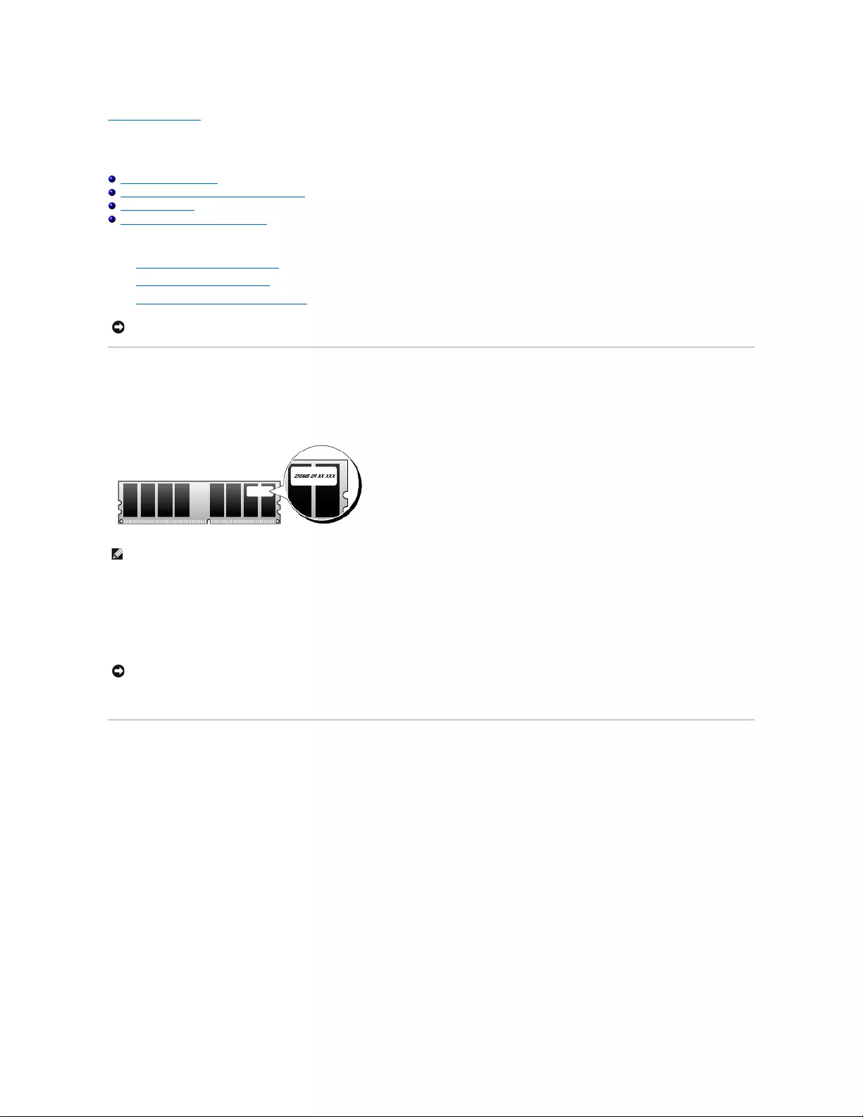
Back to Contents Page
Memory
Dell™OptiPlex™GX520User'sGuide
DDR2 Memory Overview
Addressing Memory With 4-GB Configurations
Removing Memory
Replacing/Adding Additional Memory
For information on the type of memory supported by your computer, see the "Memory" section of the specifications for your computer:
lMini Tower Computer Specifications
lDesktop Computer Specifications
lSmall Form Factor Computer Specifications
DDR2 Memory Overview
Dual-channel DDR2 memory modules should be installed in pairs of matched memory size. If the DDR2 memory modules are not installed with the same amount
of memory in each channel, the computer will continue to operate, but with a slight reduction in performance. See the label in the upper-right corner of the
module to determine the module's capacity.
The recommended memory configurations are:
lA pair of matched memory modules installed in connectors DIMM1 and DIMM2
or
lA memory module installed in connector DIMM1
Be sure to install a single memory module in DIMM1, the connector closer to the processor, before you install a module in the other connector.
Addressing Memory With 4-GB Configurations
This computer supports a maximum of 4 GB of memory when you use two 2-GB DIMMs. Current operating systems, such as Microsoft®Windows®XP, can only
use a maximum of 4 GB of address space; however, the amount of memory available to the operating system is less than 4 GB. Certain components within the
computer require address space in the 4-GB range. Any address space reserved for these components cannot be used by computer memory.
The following components require memory address space:
lSystem ROM
lAPIC(s)
lIntegrated PCI devices, such as network connectors and SCSI controllers
lPCI cards
lGraphics card
lPCI Express cards (if applicable)
At start-up, the BIOS identifies the components that require address space. The BIOS dynamically calculates the amount of reserved address space required.
The BIOS then subtracts the reserved address space from 4 GB to determine the amount of usable space.
lIf the total installed computer memory is less than the usable space, all installed computer memory is available for use only by the operating system.
lIf the total installed computer memory is equal to or greater than the usable address space, a small portion of installed memory is available for use by
the operating system.
NOTICE: Before you install new memory modules, download the most recent BIOS for your computer from the Dell Support website at
support.dell.com.
NOTE: Always install DDR2 memory modules in the order indicated on the system board.
NOTICE: Do not install ECC memory modules. Doing so may cause the system not to boot or affect performance.
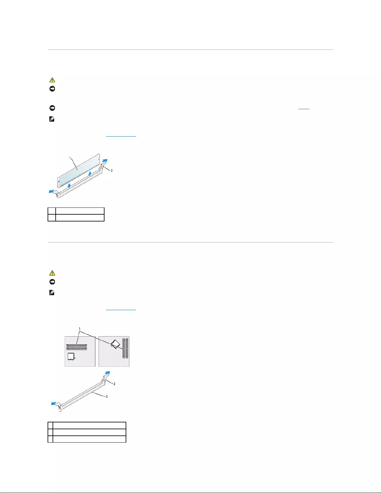
Removing Memory
1. Follow the procedures in "Before You Begin."
2. Carefully press out the securing clip at each end of the memory module connector.
3. Remove the memory module.
Replacing/Adding Additional Memory
1. Follow the procedures in "Before You Begin."
2. Press out the securing clip at each end of the memory module connector.
CAUTION: Before you begin any of the procedures in this section, follow the safety instructions in the Product Information Guide.
NOTICE: If you remove your original memory modules from the computer during a memory upgrade, keep them separate from any new modules that
you may have, even if you purchased the new modules from Dell. If possible, do not pair an original memory module with a new memory module.
Otherwise, your computer may not start properly. You should install your original memory modules in pairs either in connectors DIMM1 and DIMM2 or
connectors DIMM3 and DIMM4.
NOTICE: Removing memory modules from DIMM2 and DIMM4 on the desktop computer requires you to remove the optical drive (see "Drives"). Failure
to do so may cause damage to the memory module and the DIMM socket.
NOTE: Memory purchased from Dell is covered under your computer warranty.
1
memory module
2
securing clip (2)
CAUTION: Before you begin any of the procedures in this section, follow the safety instructions in the Product Information Guide.
NOTICE: To prevent static damage to components inside your computer, discharge static electricity from your body before you touch any of your
computer's electronic components. You can do so by touching an unpainted metal surface on the computer chassis.
NOTE: Memory purchased from Dell is covered under your computer warranty.
1
memory connector closest to processor
2
securing clips (2)
3
connector
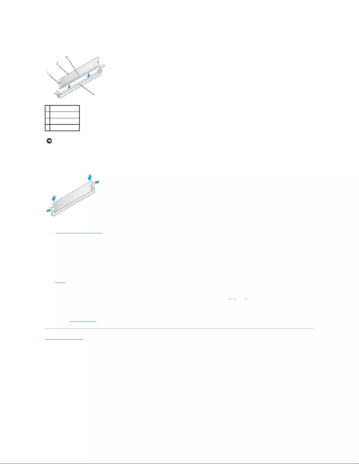
3. Align the notch on the bottom of the module with the crossbar in the connector.
4. Insert the module into the connector until the module snaps into position.
If you insert the module correctly, the securing clips snap into the cutouts at each end of the module.
5. Replace the computer cover.
6. The computer detects that the new memory does not match the existing configuration information and generates the following message:
The amount of system memory has changed.
Strike the F1 key to continue, F2 to run the setup utility
7. Press <F2> to enter system setup and check the value for System Memory.
The computer should have changed the value of System Memory to reflect the newly installed memory. Verify the new total. If it is correct, skip to
step9.
8. If the memory total is incorrect, turn off and disconnect your computer and devices from their electrical outlets. Open the computer cover and check the
installed memory modules to ensure that they are seated properly in their sockets. Then repeat steps 5, 6, and 7.
9. When the System Memory total is correct, press <Esc> to exit system setup.
10. Run the Dell Diagnostics to verify that the memory modules are operating properly.
Back to Contents Page
1
cutouts (2)
2
memory module
3
notch
4
crossbar
NOTICE: To avoid damage to the memory module, press the module straight down into the connector while you apply equal force to each end of the
module.
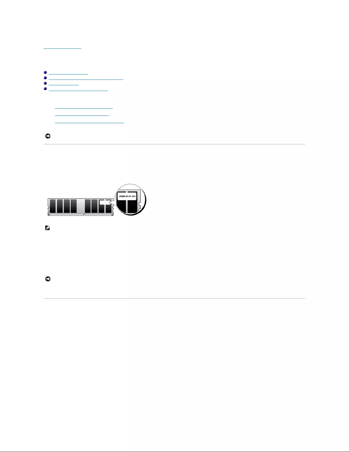
Back to Contents Page
Memory
Dell™OptiPlex™GX520User'sGuide
DDR2 Memory Overview
Addressing Memory With 4-GB Configurations
Removing Memory
Replacing/Adding Additional Memory
For information on the type of memory supported by your computer, see the "Memory" section of the specifications for your computer:
lMini Tower Computer Specifications
lDesktop Computer Specifications
lSmall Form Factor Computer Specifications
DDR2 Memory Overview
Dual-channel DDR2 memory modules should be installed in pairs of matched memory size. If the DDR2 memory modules are not installed with the same amount
of memory in each channel, the computer will continue to operate, but with a slight reduction in performance. See the label in the upper-right corner of the
module to determine the module's capacity.
The recommended memory configurations are:
lA pair of matched memory modules installed in connectors DIMM1 and DIMM2
or
lA memory module installed in connector DIMM1
Be sure to install a single memory module in DIMM1, the connector closer to the processor, before you install a module in the other connector.
Addressing Memory With 4-GB Configurations
This computer supports a maximum of 4 GB of memory when you use two 2-GB DIMMs. Current operating systems, such as Microsoft®Windows®XP, can only
use a maximum of 4 GB of address space; however, the amount of memory available to the operating system is less than 4 GB. Certain components within the
computer require address space in the 4-GB range. Any address space reserved for these components cannot be used by computer memory.
The following components require memory address space:
lSystem ROM
lAPIC(s)
lIntegrated PCI devices, such as network connectors and SCSI controllers
lPCI cards
lGraphics card
lPCI Express cards (if applicable)
At start-up, the BIOS identifies the components that require address space. The BIOS dynamically calculates the amount of reserved address space required.
The BIOS then subtracts the reserved address space from 4 GB to determine the amount of usable space.
lIf the total installed computer memory is less than the usable space, all installed computer memory is available for use only by the operating system.
NOTICE: Before you install new memory modules, download the most recent BIOS for your computer from the Dell Support website at
support.dell.com.
NOTE: Always install DDR2 memory modules in the order indicated on the system board.
NOTICE: Do not install ECC memory modules. Doing so may cause the system not to boot or affect performance.
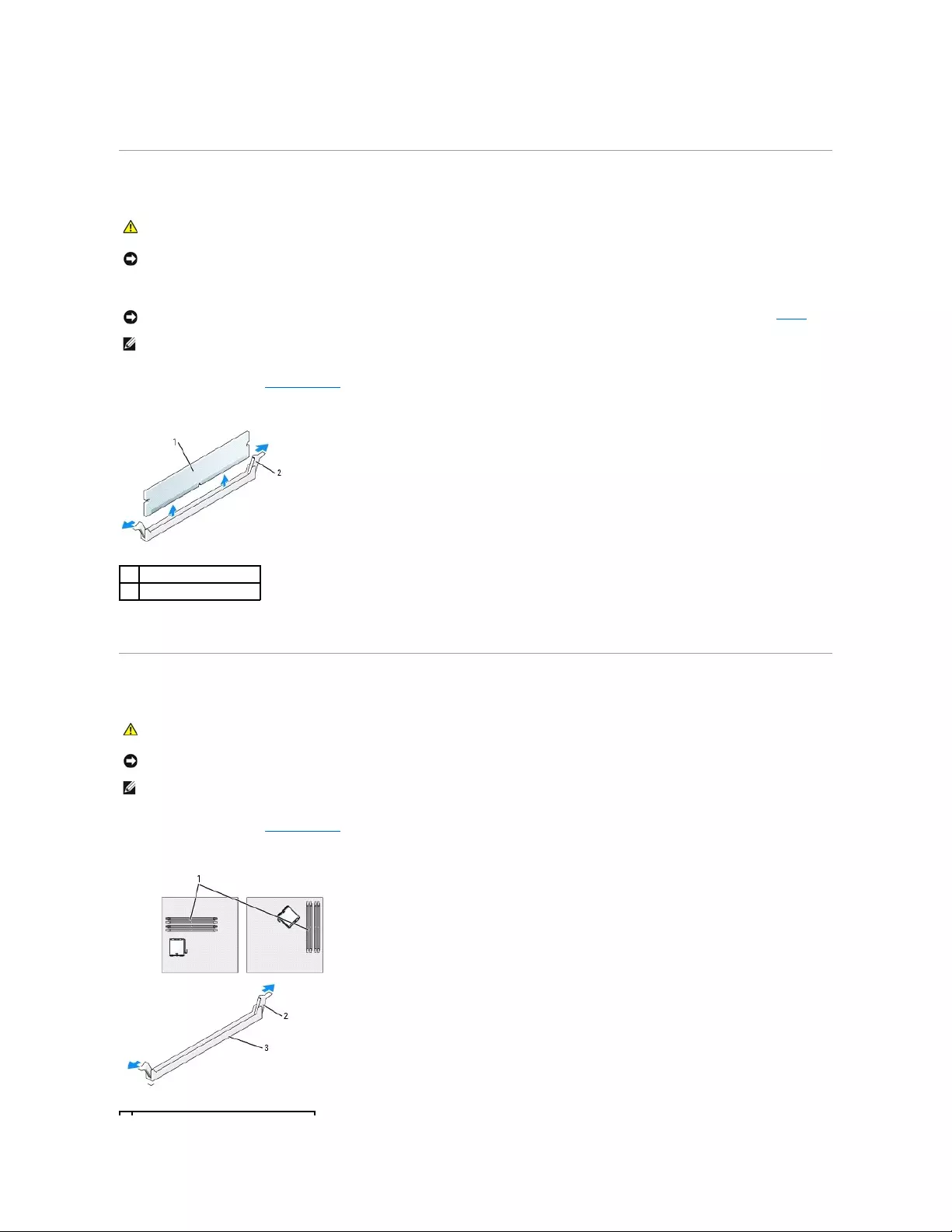
lIf the total installed computer memory is equal to or greater than the usable address space, a small portion of installed memory is available for use by
the operating system.
Removing Memory
1. Follow the procedures in "Before You Begin."
2. Carefully press out the securing clip at each end of the memory module connector.
3. Remove the memory module.
Replacing/Adding Additional Memory
1. Follow the procedures in "Before You Begin."
2. Press out the securing clip at each end of the memory module connector.
CAUTION: Before you begin any of the procedures in this section, follow the safety instructions in the Product Information Guide.
NOTICE: If you remove your original memory modules from the computer during a memory upgrade, keep them separate from any new modules
that you may have, even if you purchased the new modules from Dell. If possible, do not pair an original memory module with a new memory
module. Otherwise, your computer may not start properly. You should install your original memory modules in pairs either in connectors DIMM1
and DIMM2 or connectors DIMM3 and DIMM4.
NOTICE: Removing memory modules from DIMM2 and DIMM4 on the desktop computer requires you to remove the optical drive (see "Drives").
Failure to do so may cause damage to the memory module and the DIMM socket.
NOTE: Memory purchased from Dell is covered under your computer warranty.
1
memory module
2
securing clip (2)
CAUTION: Before you begin any of the procedures in this section, follow the safety instructions in the Product Information Guide.
NOTICE: To prevent static damage to components inside your computer, discharge static electricity from your body before you touch any of your
computer's electronic components. You can do so by touching an unpainted metal surface on the computer chassis.
NOTE: Memory purchased from Dell is covered under your computer warranty.
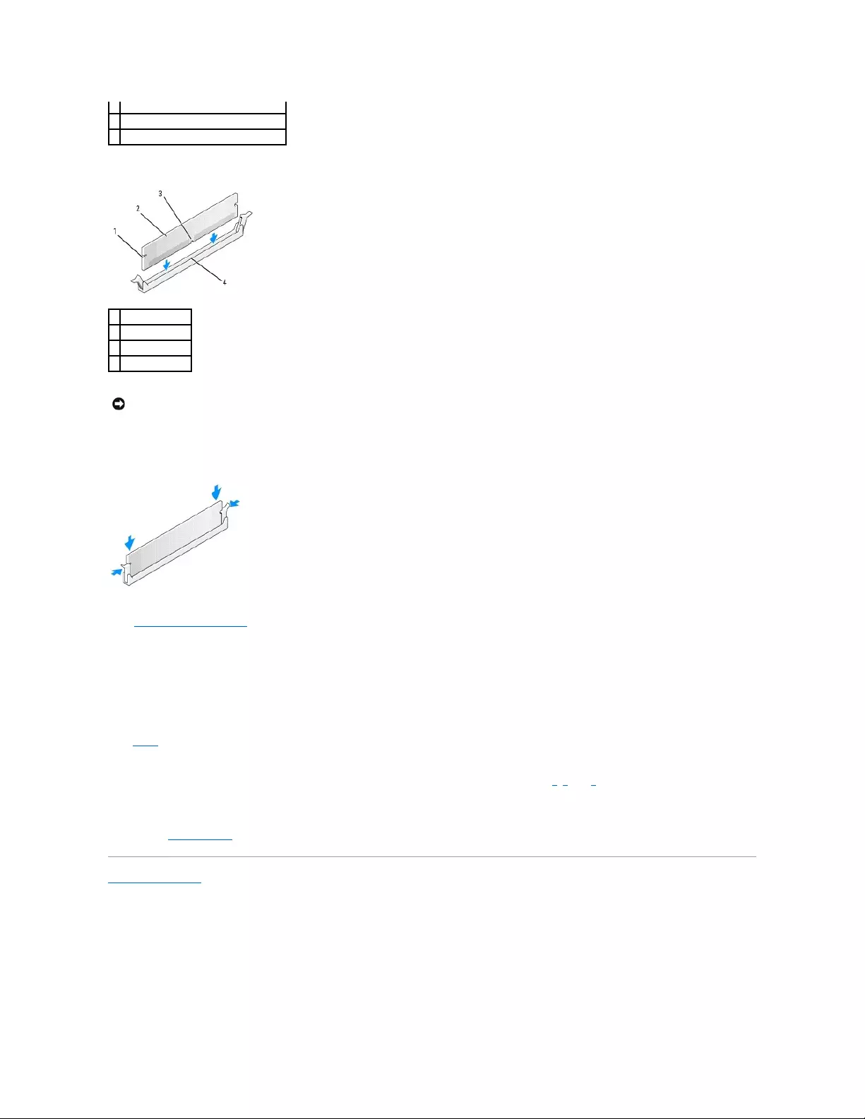
3. Align the notch on the bottom of the module with the crossbar in the connector.
4. Insert the module into the connector until the module snaps into position.
If you insert the module correctly, the securing clips snap into the cutouts at each end of the module.
5. Replace the computer cover.
6. The computer detects that the new memory does not match the existing configuration information and generates the following message:
The amount of system memory has changed.
Strike the F1 key to continue, F2 to run the setup utility
7. Press <F2> to enter system setup and check the value for System Memory.
The computer should have changed the value of System Memory to reflect the newly installed memory. Verify the new total. If it is correct, skip to
step9.
8. If the memory total is incorrect, turn off and disconnect your computer and devices from their electrical outlets. Open the computer cover and check the
installed memory modules to ensure that they are seated properly in their sockets. Then repeat steps 5, 6, and 7.
9. When the System Memory total is correct, press <Esc> to exit system setup.
10. Run the Dell Diagnostics to verify that the memory modules are operating properly.
Back to Contents Page
1
memory connector closest to processor
2
securing clips (2)
3
connector
1
cutouts (2)
2
memory module
3
notch
4
crossbar
NOTICE: To avoid damage to the memory module, press the module straight down into the connector while you apply equal force to each end of
the module.
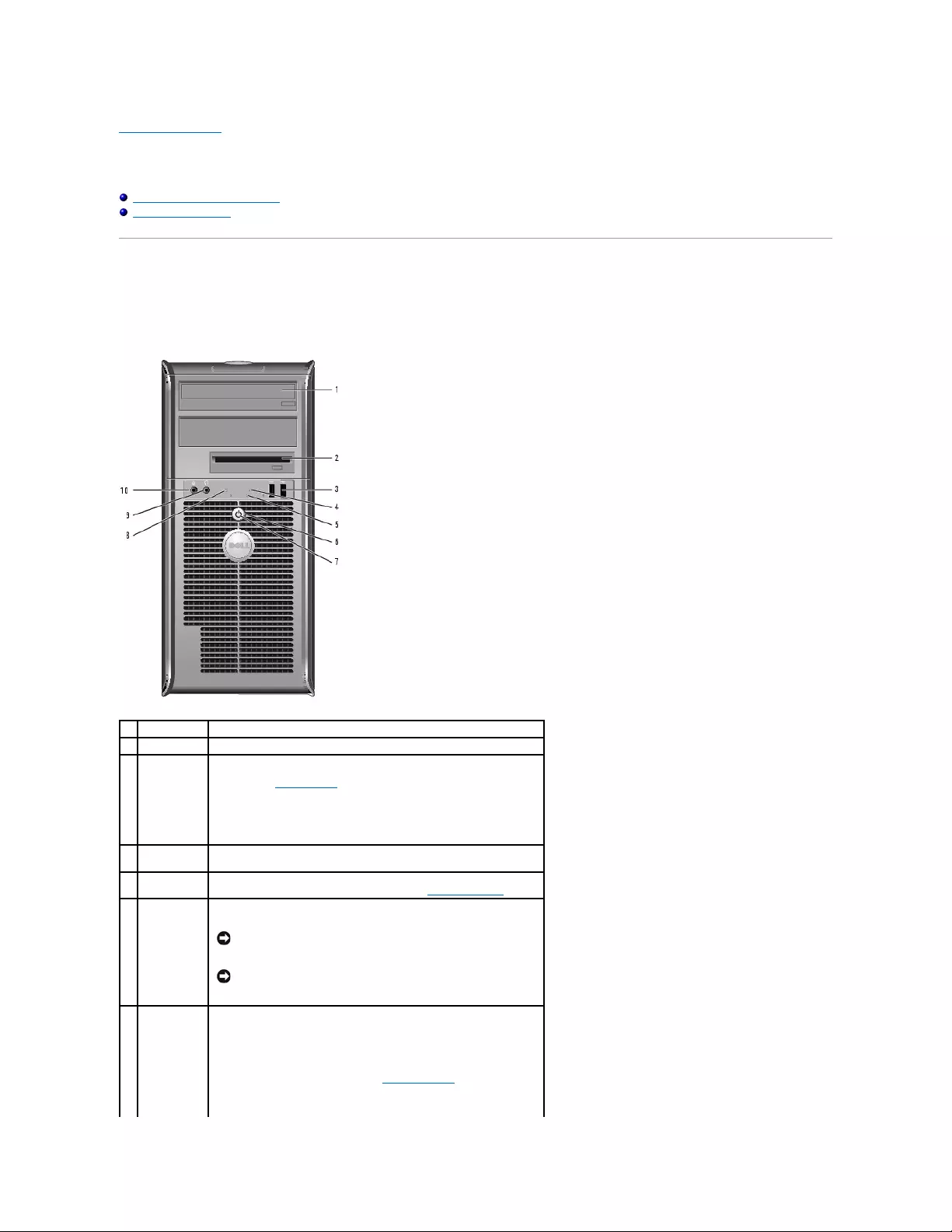
Back to Contents Page
Mini Tower Computer
Dell™OptiPlex™GX520User'sGuide
About Your Mini Tower Computer
Inside Your Computer
About Your Mini Tower Computer
Front View
1
CD/DVD drive
Insert a CD or DVD (if applicable) into this drive.
2
floppy drive
Insert a floppy disk into this drive.
3
USB 2.0
connectors
(2)
Use the USB connectors on the front of the computer for devices that you
connect occasionally, such as joysticks or cameras, or for bootable USB
devices (see "System Setup" for more information on booting to a USB
device).
It is recommended that you use the USB connectors on the back of the
computer for devices that typically remain connected, such as printers
and keyboards.
4
LAN indicator
light
This light indicates that a LAN (network) connection is established.
5
diagnostic
lights
Use the lights to help you troubleshoot a computer problem based on
the diagnostic code. For more information, see "Diagnostic Lights."
6
power button
Press this button to turn on the computer.
NOTICE: To avoid losing data, do not turn off the computer by
pressing the power button for 6 seconds or longer. Instead,
perform an operating system shutdown.
NOTICE: If your operating system has ACPI enabled, when you
press the power button the computer will perform an operating
system shutdown.
7
power light
The power light illuminates and blinks or remains solid to indicate
different operating states:
lNo light — The computer is turned off.
lSteady green — The computer is in a normal operating state.
lBlinking green — The computer is in a power-saving mode.
lBlinking or solid amber — See "Power Problems."
To exit from a power-saving mode, press the power button or use the
keyboard or the mouse if it is configured as a wake device in the
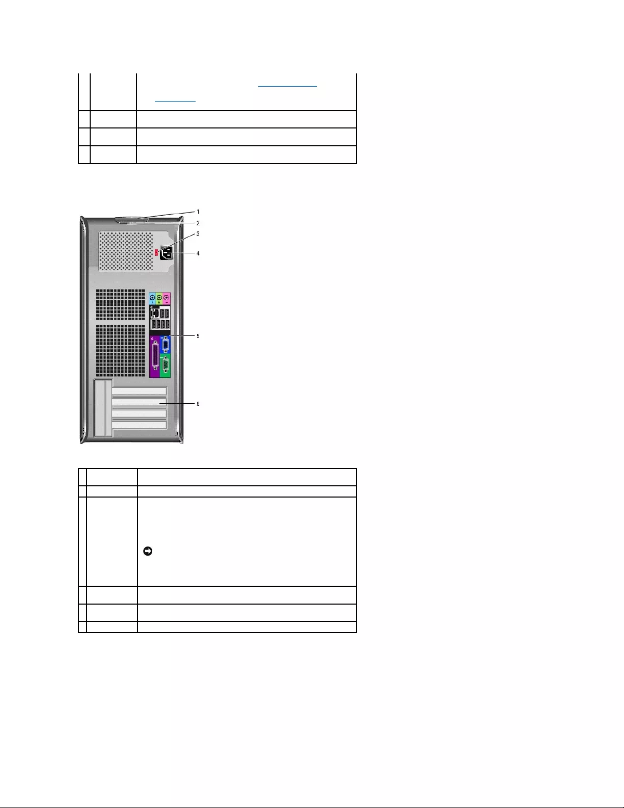
Back View
Back-Panel Connectors
Windows Device Manager. For more information about sleep modes and
exiting from a power-saving mode, see "Power Management."
See "System Lights" for a description of light codes that can help you
troubleshoot problems with your computer.
8
hard-drive
activity light
This light flickers when the hard drive is in use.
9
headphone
connector
Use the headphone connector to attach headphones and most kinds of
speakers.
10
microphone
connector
Use the microphone connector to attach a microphone.
1
cover release
latch
This latch allows you to open the computer cover.
2
padlock ring
Insert a padlock to lock the computer cover.
3
voltage
selection
switch
Your computer is equipped with a manual voltage-selection switch.
To help avoid damaging a computer with a manual voltage-selection
switch, set the switch for the voltage that most closely matches the AC
power available in your location.
Also, ensure that your monitor and attached devices are electrically
rated to operate with the AC power available in your location.
NOTICE: The voltage selection switch must be set to the 115-V
position even though the AC power available in Japan is 100 V.
4
power
connector
Insert the power cable into this connector.
5
back-panel
connectors
Plug serial, USB, and other devices into the appropriate connector.
6
card slots
Access connectors for any installed PCI and PCI Express cards.
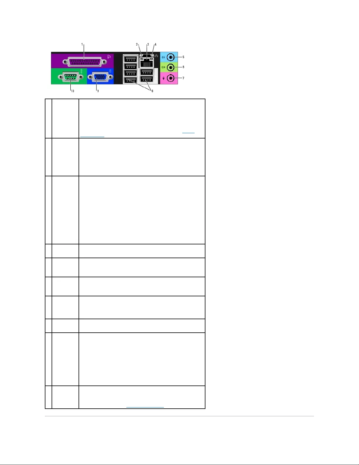
1
parallel
connector
Connect a parallel device, such as a printer, to the parallel connector. If
you have a USB printer, plug it into a USB connector.
NOTE: The integrated parallel connector is automatically disabled if the
computer detects an installed card containing a parallel connector
configured to the same address. For more information, see "System
Setup Options."
2
link integrity
light
lGreen — A good connection exists between a 10-Mbps network
and the computer.
lOrange — A good connection exists between a 100-Mbps network
and the computer.
lYellow — A good connection exists between a 1-Gbps (or 1000-
Mbps) network and the computer.
lOff — The computer is not detecting a physical connection to the
network.
3
network
adapter
connector
To attach your computer to a network or broadband device, connect one
end of a network cable to either a network jack or your network or
broadband device. Connect the other end of the network cable to the
network adapter connector on the back panel of your computer. A click
indicates that the network cable has been securely attached.
NOTE: Do not plug a telephone cable into the network connector.
On computers with a network adapter card, use the connector on the
card.
It is recommended that you use Category 5 wiring and connectors for
your network. If you must use Category 3 wiring, force the network
speed to 10 Mbps to ensure reliable operation.
4
network
activity light
This light flashes yellow when the computer is transmitting or receiving
network data. A high volume of network traffic may make this light
appear to be in a steady "on" state.
5
line-in
connector
Use the blue line-in connector to attach a record/playback device such as
a cassette player, CD player, or VCR.
On computers with a sound card, use the connector on the card.
6
line-out
connector
Use the green line-out connector to attach headphones and most
speakers with integrated amplifiers.
On computers with a sound card, use the connector on the card.
7
microphone
connector
Use the pink microphone connector to attach a personal computer
microphone for voice or musical input into a sound or telephony program.
On computers with a sound card, the microphone connector is on the
card.
8
USB 2.0
connectors
(6)
Use the back USB connectors for devices that typically remain connected,
such as printers and keyboards.
9
video
connector
Plug the cable from your VGA-compatible monitor into the blue connector.
NOTE: If you purchased an optional graphics card, this connector will be
covered by a cap. Connect your monitor to the connector on the graphics
card. Do not remove the cap.
NOTE: If you are using a graphics card that supports dual monitors, use
the y-cable that came with your computer.
10
serial
connector
Connect a serial device, such as a handheld device, to the serial port.
The default designations are COM1 for serial connector 1 and COM2 for
serial connector 2.
For more information, see "System Setup Options."
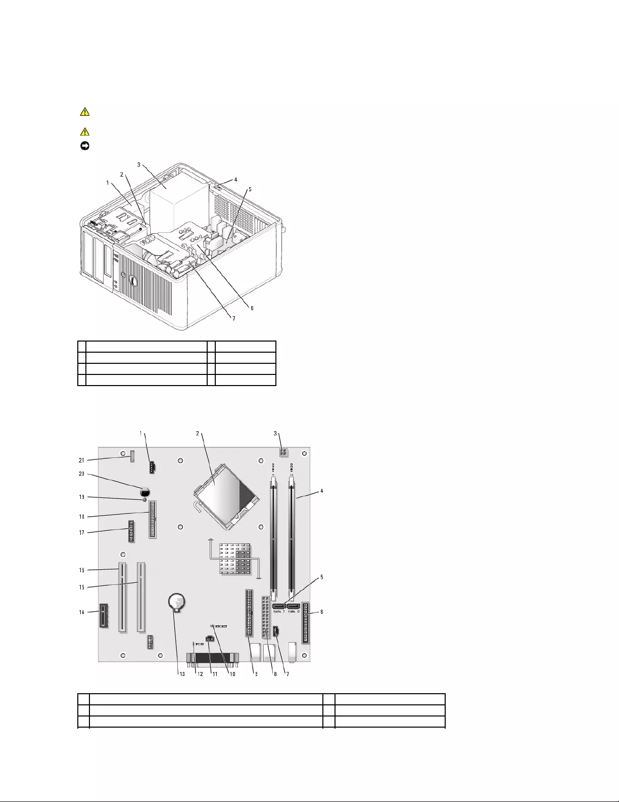
Inside Your Computer
System Board Components
CAUTION: Before you begin any of the procedures in this section, follow the safety instructions located in the Product Information Guide.
CAUTION: To avoid electrical shock, always unplug your computer from the electrical outlet before removing the computer cover.
NOTICE: Be careful when opening the computer cover to ensure that you do not accidentally disconnect cables from the system board.
1
CD/DVD drive
5
system board
2
floppy drive
6
heat sink assembly
3
power supply
7
hard drive
4
chassis manual voltage-selection switch
1
fan connector (FAN)
12
password jumper (PSWD)
2
processor connector (CPU)
13
battery socket (BATT)
3
power connector (12VPOWER)
14
PCI Express x1 connector (SLOT4)
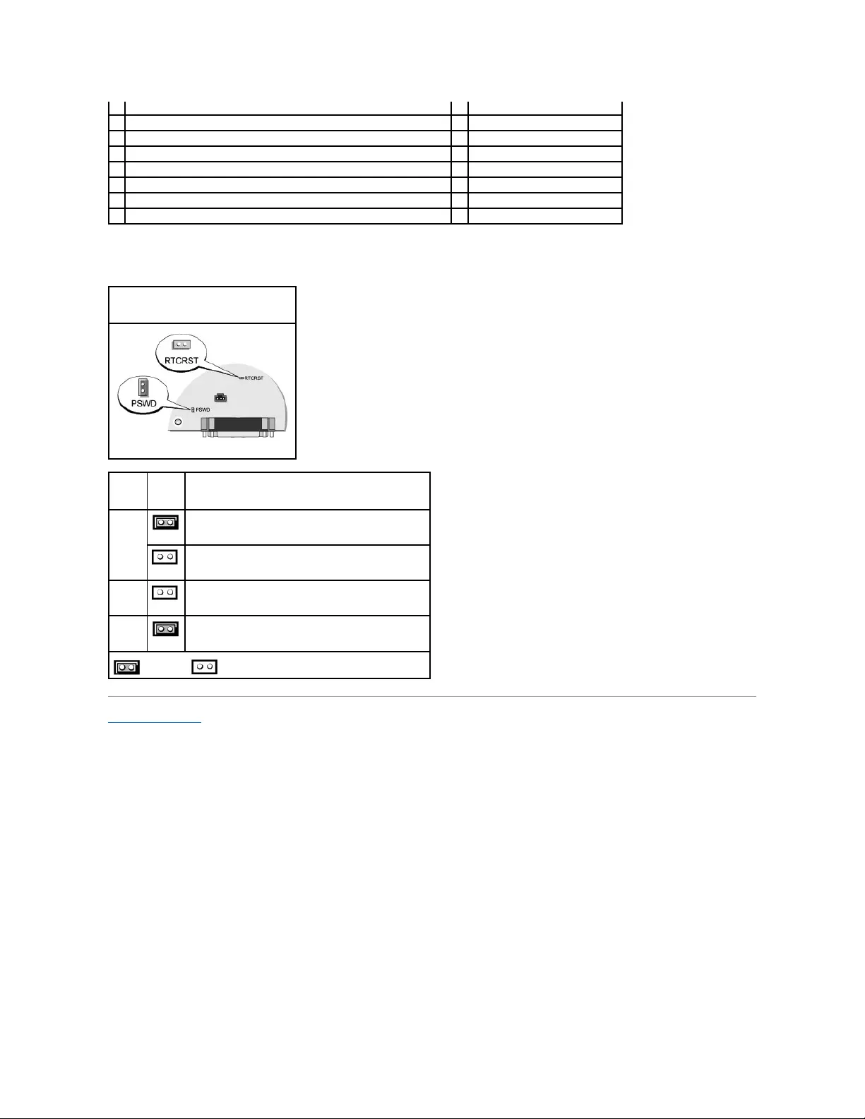
Jumper Settings
Back to Contents Page
4
memory module connectors (DIMM_1, DIMM_2)
15
PCI connector (SLOT2)
5
serial ATA drive connectors (SATA0, SATA2)
16
PCI connector (SLOT3)
6
front-panel connector (FNT_PANEL)
17
serial connector (SER2)
7
CD drive analog audio cable connector for optional analog audio cable (CD_IN)
18
floppy drive connector (DSKT)
8
power connector (POWER)
19
standby power indicator (AUX_PWR)
9
CD/DVD drive connector (IDE)
20
system board speaker (BEEP)
10
RTC reset jumper (RTCRST)
21
internal speaker (INT_SPKR)
11
chassis manual voltage-selection switch connector (INTRUDER)
Mini Tower Computer
Jumper
Setting
Description
PSWD
Password features are enabled (default).
Password features are disabled.
RTCRST
The real-time clock has not been reset.
The real-time clock is being reset (jumpered temporarily).
jumpered unjumpered
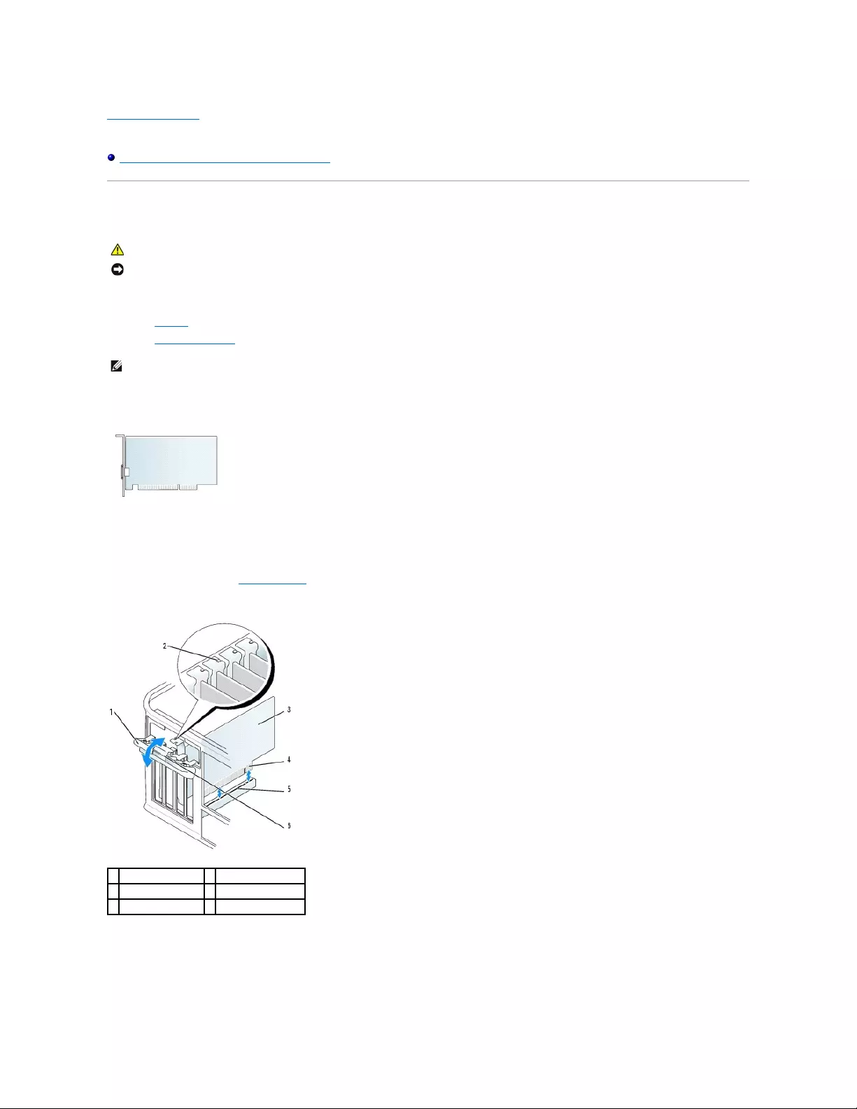
Back to Contents Page
Dell™OptiPlex™GX520User'sGuide
PCI and PCI Express Cards and Serial Port Adapters
PCI and PCI Express Cards and Serial Port Adapters
YourDell™computersupportsaserialportadapterandprovidesthefollowingconnectorsforPCIandPCIExpresscards.
lTwo PCI card slots
lOne PCI Express x1 card slot
PCI Cards
Installing a PCI Card
1. Follow the procedures in "Before You Begin."
2. Gently push the release tab on the card retention latch from the inside to pivot the latch open. The latch will remain in the open position.
3. Open the card retention mechanism that secures the card in place from the top:
a. Place your thumb on the top of the card retention mechanism and grip the bottom of the retention mechanism with your fingers.
b. With your free hand, gently squeeze the sides of the card retention mechanism to release it from the tab slots holding it in place.
c. Pivot the card retention mechanism upward to release it from the two tab slots.
CAUTION: Before you begin any of the procedures in this section, follow the safety instructions located in the Product Information Guide.
NOTICE: To prevent static damage to components inside your computer, discharge static electricity from your body before you touch any of your
computer's electronic components. You can do so by touching an unpainted metal surface on the computer chassis.
NOTE: Your Dell computer uses only PCI and PCI Express slots. ISA cards are not supported.
1
card retention latch
4
card-edge connector
2
alignment guide
5
card connector
3
card
6
release tab
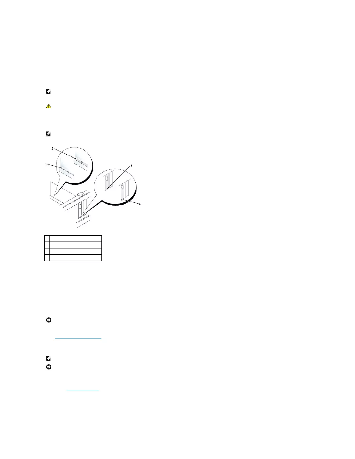
4. Set the card retention mechanism aside in your work area.
5. If you are installing a new card, remove the filler bracket to create a card-slot opening. Then continue with step 5.
6. If you are replacing a card that is already installed in the computer, remove the card. If necessary, disconnect any cables connected to the card.
7. Prepare the new card for installation.
8. Place the card in the connector and press down firmly. Ensure that the card is fully seated in the slot.
9. Before you replace and lower the card retention mechanism, ensure that:
lThe tops of all cards and filler brackets are flush with the alignment bar.
lThe notch in the top of the card or filler bracket fits around the alignment guide.
10. Gently press down on the card retention mechanism to secure the adapter bracket in place.
11. Secure the card(s) by closing the card retention latch and snapping it into place.
12. Replace the computer cover.
13. Connect any cables that should be attached to the card.
14. If you installed a sound card:
a. Enter system setup, select Audio Controller, and change the setting to Off.
b. Connect external audio devices to the sound card's connectors. Do not connect external audio devices to the microphone, speaker/headphone,
or line-in connectors on the back panel of the computer.
15. If you installed an network adapter card and want to turn off the integrated network adapter:
NOTE: See the documentation that came with the card for information on configuring the card, making internal connections, or customizing it for your
computer
CAUTION: Some network adapters automatically start the computer when they are connected to a network. To guard against electrical shock, be
sure to unplug your computer from its electrical outlet before installing any cards.
NOTE: If the card is full-length, insert the end of the card into the card-guide bracket as you lower the card toward its connector on the system board.
Insert the card firmly into the card connector on the system board.
1
card fully seated
2
card not fully seated
3
bracket within slot
4
bracket caught outside of slot
NOTICE: Do not route card cables over or behind the cards. Cables routed over the cards can prevent the computer cover from closing properly or
cause damage to the equipment.
NOTE: See the documentation for the card for information about the card's cable connections.
NOTICE: To connect a network cable, first plug the cable into the network wall jack and then plug it into the computer.
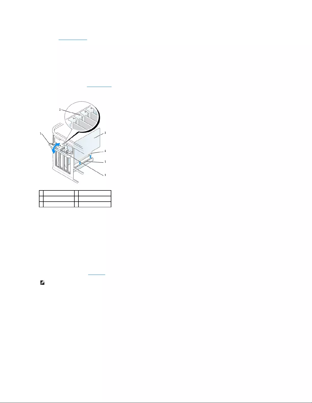
a. Enter system setup, select Network Controller, and change the setting to Off.
b. Connect the network cable to the network adapter card's connectors. Do not connect the network cable to the integrated network connector on
the back panel of the computer.
16. Install any drivers required for the card as described in the card documentation.
Removing a PCI Card
1. Follow the procedures in "Before You Begin."
2. Gently push the release tab on the card retention latch from the inside to pivot the latch open. The latch will remain in the open position.
3. Open the card retention mechanism that secures the card in place from the top:
a. Place your thumb on the top of the card retention mechanism and grip the bottom of the retention mechanism with your fingers.
b. With your free hand, gently squeeze the sides of the card retention mechanism to release it from the tab slots holding it in place.
c. Pivot the card retention mechanism upward to release it from the two tab slots.
4. If necessary, disconnect any cables connected to the card.
5. Grasp the card by its top corners, and ease it out of its connector.
6. If you are removing the card permanently, install a filler bracket in the empty card-slot opening.
If you need a filler bracket, contact Dell.
7. Before you replace and lower the card retention mechanism, ensure that:
lThe tops of all cards and filler brackets are flush with the alignment bar.
lThe notch in the top of the card or filler bracket fits around the alignment guide.
1
card retention latch
4
card-edge connector
2
alignment guide
5
card connector
3
card
6
release tab
NOTE: Installing filler brackets over empty card-slot openings is necessary to maintain FCC certification of the computer. The brackets also keep dust
and dirt out of your computer.
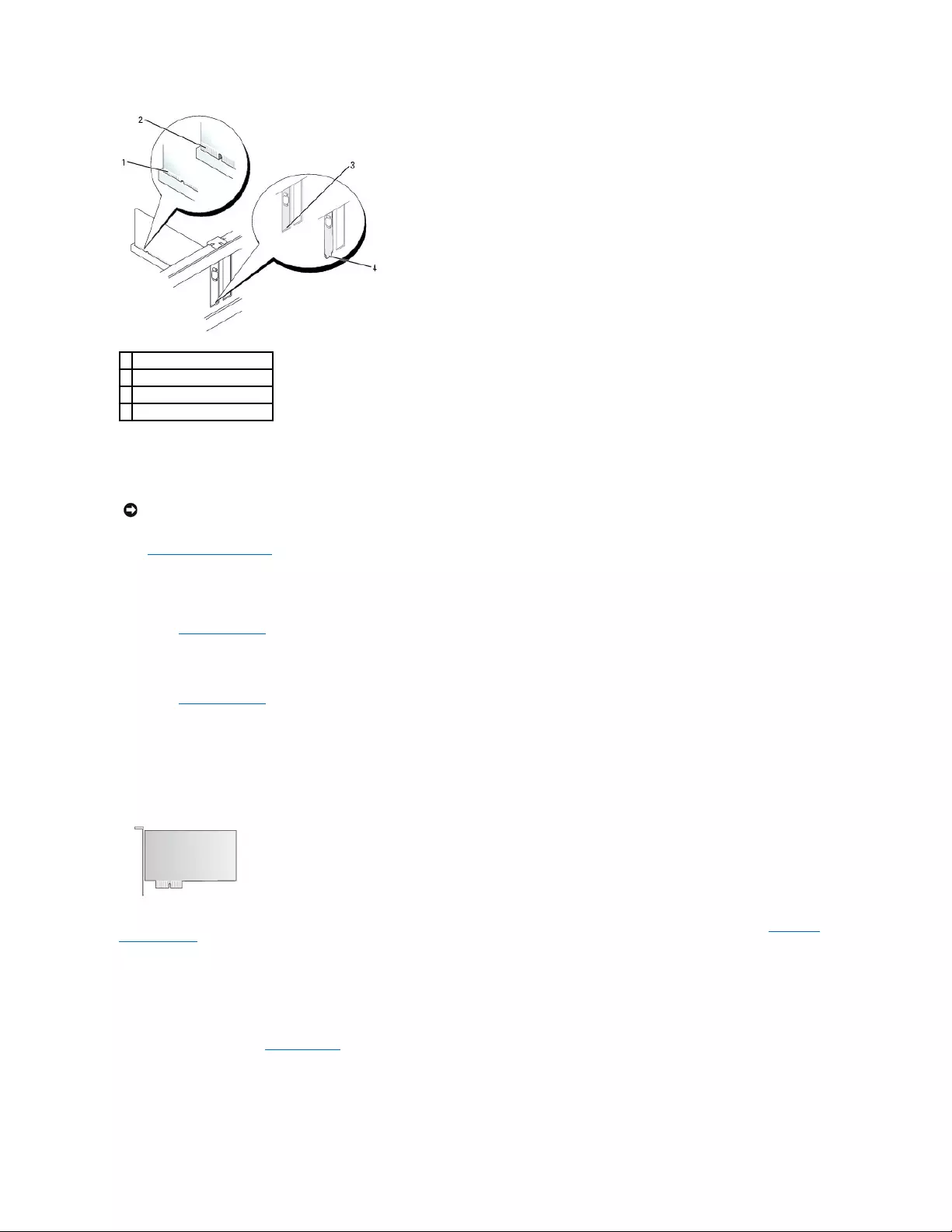
8. Gently press down on the card retention mechanism to secure the adapter bracket in place.
9. Close the card retention latch by snapping it into place.
10. Replace the computer cover.
11. Uninstall the card's driver. See the documentation that came with the card for instructions.
12. If you removed a sound card:
a. Enter system setup, select Audio Controller, and change the setting to On.
b. Connect external audio devices to the audio connectors on the back panel of the computer.
13. If you removed an network-adapter card connector:
a. Enter system setup, select Network Controller, and change the setting to On.
b. Connect the network cable to the integrated network connector on the back panel of the computer.
PCI Express Cards
Your computer supports one PCI Express x1 card.
If you are installing or replacing a PCI Express card, follow the procedures in the next section. If you are removing but not replacing a card, see "Removing a
PCI Express Card."
If you are replacing a card, uninstall the driver for the existing card. See the documentation that came with the card for instructions.
Installing a PCI Express Card
1. Follow the procedures in "Before You Begin."
1
card fully seated
2
card not fully seated
3
bracket within slot
4
bracket caught outside of slot
NOTICE: To connect a network cable, first plug the cable into the network wall jack and then plug it into the computer.
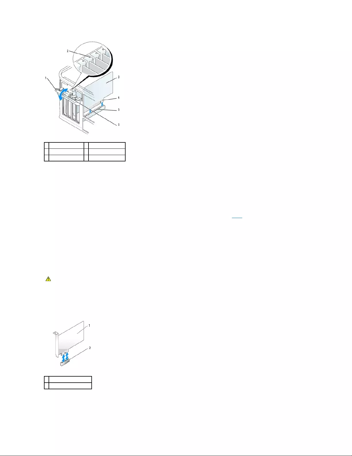
2. Gently push the release tab on the card retention latch from the inside to pivot the latch open. The latch will remain in the open position.
3. Open the card retention mechanism that secures the card in place from the top:
a. Place your thumb on the top of the card retention mechanism and grip the bottom of the retention mechanism with your fingers.
b. With your free hand, gently squeeze the sides of the card retention mechanism to release it from the tab slots holding it in place.
c. Pivot the card retention mechanism upward to release it from the two tab slots.
4. If you are installing a new card, remove the filler bracket to create a card-slot opening. Then continue with step6.
5. If you are replacing a card that is already installed in the computer, remove the card.
If necessary, disconnect any cables connected to the card. If your card includes a card retention bar, remove the bar. Gently pull the securing tab, grasp
the card by its top corners, and ease it out of its connector.
6. Prepare the new card for installation.
See the documentation that came with the card for information on configuring the card, making internal connections, or otherwise customizing it for your
computer.
7. If you are installing the card into the x16 card connector, position the card so that the securing slot is aligned with the securing tab, and gently pull the
securing tab.
8. Place the card in the connector and press down firmly. Ensure that the card is fully seated in the slot.
1
card retention latch
4
card-edge connector
2
alignment guide
5
card connector
3
card
6
release tab
CAUTION: Some network adapters automatically start the computer when they are connected to a network. To guard against electrical shock, be
sure to unplug your computer from its electrical outlet before installing any cards.
1
PCI Express x1 card
2
PCI Express x1 card slot
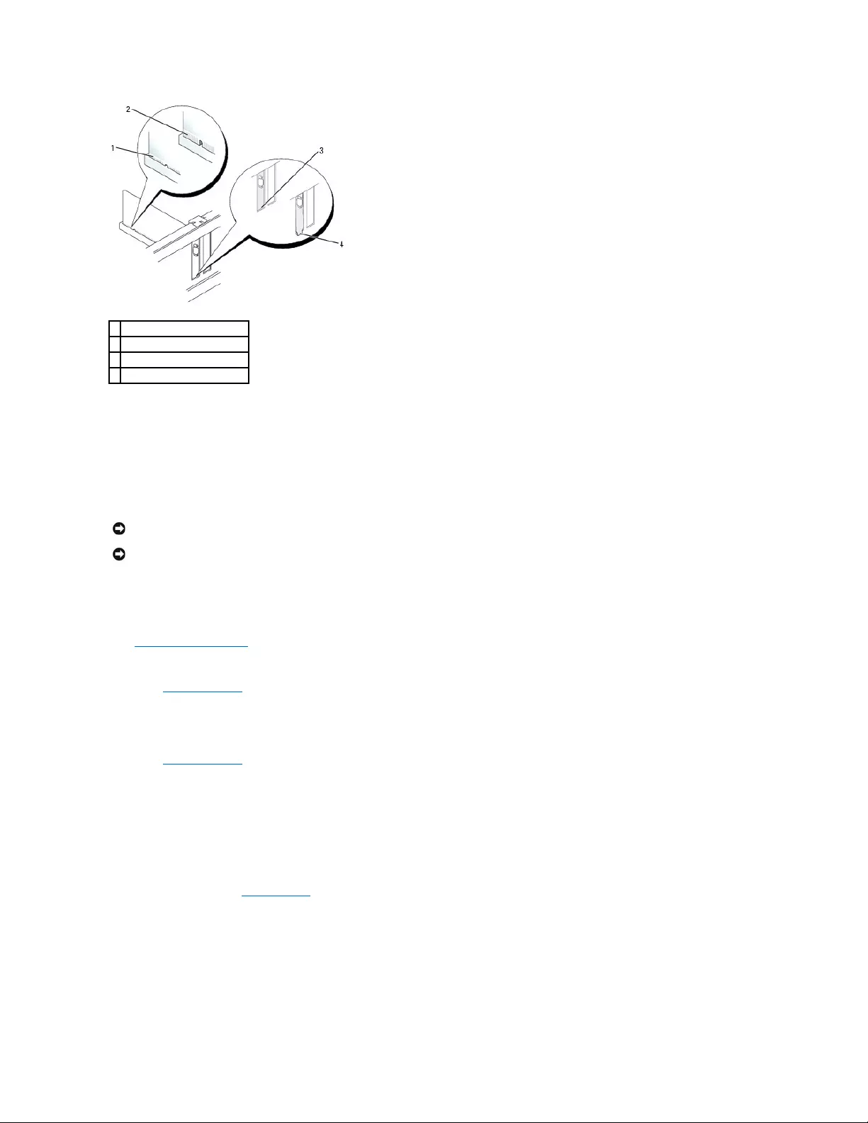
9. Before you replace and lower the card retention mechanism, ensure that:
lThe tops of all cards and filler brackets are flush with the alignment bar.
lThe notch in the top of the card or filler bracket fits around the alignment guide.
10. Gently press down on the card retention mechanism to secure the adapter bracket in place.
11. Close the card retention latch and gently press until it clicks into place.
12. Connect any cables that should be attached to the card.
See the documentation for the card for information about the card's cable connections.
13. Replace the computer cover.
14. If you installed a sound card:
a. Enter system setup, select Audio Controller, and change the setting to Off.
b. Connect external audio devices to the sound card's connectors. Do not connect external audio devices to the microphone, speaker/headphone,
or line-in connectors on the back panel of the computer.
15. If you installed an network adapter card and want to turn off the integrated network adapter:
a. Enter system setup, select Network Controller, and change the setting to Off.
b. Connect the network cable to the network adapter card's connectors. Do not connect the network cable to the integrated network connector on
the back panel of the computer.
16. Install any drivers required for the card as described in the card documentation.
Removing a PCI Express Card
1. Follow the procedures in "Before You Begin."
1
card fully seated
2
card not fully seated
3
bracket within slot
4
bracket caught outside of slot
NOTICE: Do not route card cables over or behind the cards. Cables routed over the cards can prevent the computer cover from closing properly or
cause damage to the equipment.
NOTICE: To connect a network cable, first plug the cable into the network wall jack and then plug it into the computer.
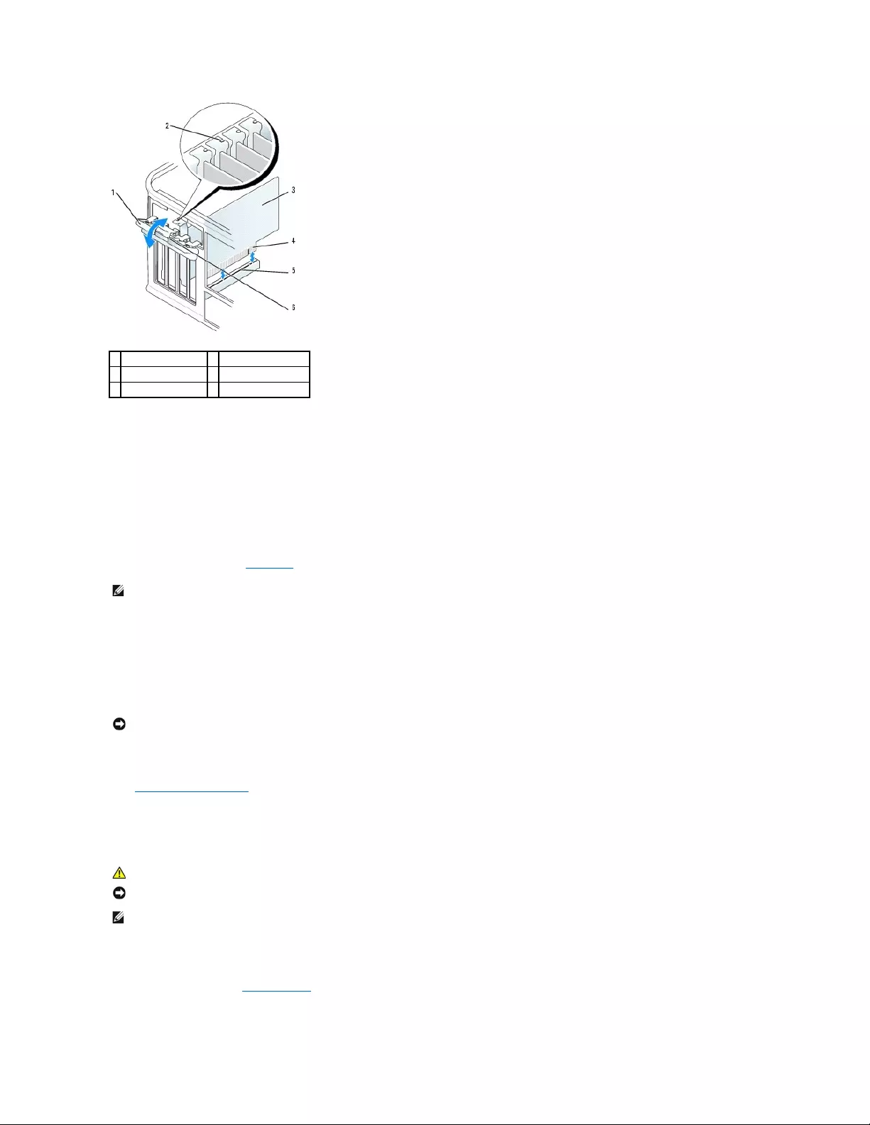
2. Gently push the release tab on the card retention latch from the inside to pivot the latch open. Because the latch is captive, it will remain in the open
position.
3. Open the card retention mechanism that secures the card in place from the top:
a. Place your thumb on the top of the card retention mechanism and grip the bottom of the retention mechanism with your fingers.
b. With your free hand, gently squeeze the sides of the card retention mechanism to release it from the tab slots holding it in place.
c. Pivot the card retention mechanism upward to release it from the two tab slots.
4. If you are removing the card permanently, install a filler bracket in the empty card-slot opening.
If you need a filler bracket, contact Dell.
5. Before you replace and lower the card retention mechanism, ensure that:
lThe tops of all cards and filler brackets are flush with the alignment bar.
lThe notch in the top of the card or filler bracket fits around the alignment guide.
6. Gently press down on the card retention mechanism to secure the adapter bracket in place.
7. Secure the card(s) by closing the card retention latch and snapping it into place.
8. Replace the computer cover.
Serial Port Adapters
Installing a Serial Port Adapter
1. Follow the procedures in "Before You Begin."
1
card retention latch
4
card-edge connector
2
alignment guide
5
card connector
3
card
6
release tab
NOTE: Installing filler brackets over empty card-slot openings is necessary to maintain FCC certification of the computer. The brackets also keep dust
and dirt out of your computer.
NOTICE: To connect a network cable, first plug the cable into the network wall jack and then plug it into the computer.
CAUTION: Before you begin any of the procedures in this section, follow the safety instructions located in the Product Information Guide.
NOTICE: To prevent static damage to components inside your computer, discharge static electricity from your body before you touch any of your
computer's electronic components. You can do so by touching an unpainted metal surface on the computer chassis.
NOTE: The serial port adapter for your mini tower computer also includes two PS/2 connectors.
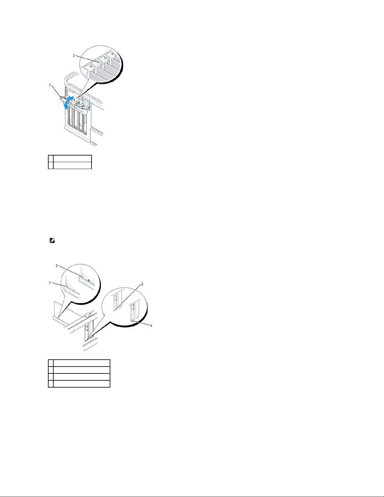
2. Gently push the release tab on the card retention latch from the inside to pivot the latch open. The latch will remain in the open position.
3. Open the card retention mechanism that secures the adapter bracket and cards in place from the top:
a. Place your thumb on the top of the card retention mechanism and grip the bottom of the retention mechanism with your fingers.
b. With your free hand, gently squeeze the sides of the card retention mechanism to release it from the tab slots holding it in place.
c. Pivot the card retention mechanism upward to release it from the two tab slots.
4. Remove the filler bracket (if applicable).
Place the serial-port adapter bracket in the connector and press down firmly. Ensure that the adapter is fully seated in the slot.
5. Before you replace and lower the card retention mechanism, ensure that:
lThe tops of all adapters and filler brackets are flush with the alignment bar.
lThe notch in the top of the adapter or filler bracket fits around the alignment guide.
6. Gently press down on the card retention mechanism to secure the adapter bracket in place.
7. Close the card retention latch and gently press until it clicks into place.
1
card retention latch
2
alignment guide
NOTE: See the documentation that came with the serial port adapter for information on configuring the adapter, making internal connections, or
customizing it for your computer.
1
card fully seated
2
card not fully seated
3
bracket within slot
4
bracket caught outside of slot

8. Connect the adapter cable to the serial-port adapter connector (SER2) on the system board.
9. Connect any cables that should be attached to the serial port adapter.
10. Replace the computer cover.
Removing a Serial Port Adapter
1. Follow the procedures in "Before You Begin."
2. Gently push the release tab on the retention lever.
3. If necessary, disconnect any cables connected to the adapter.
4. Grasp the serial-port adapter bracket by its top corners, and ease it out of its connector.
5. Replace the computer cover.
Back to Contents Page
NOTICE: Do not route cables over or behind any installed cards. Cables routed over the cards can prevent the computer cover from closing properly or
cause damage to the equipment.
NOTE: See the documentation for the serial port adapter for information about the cable connections.
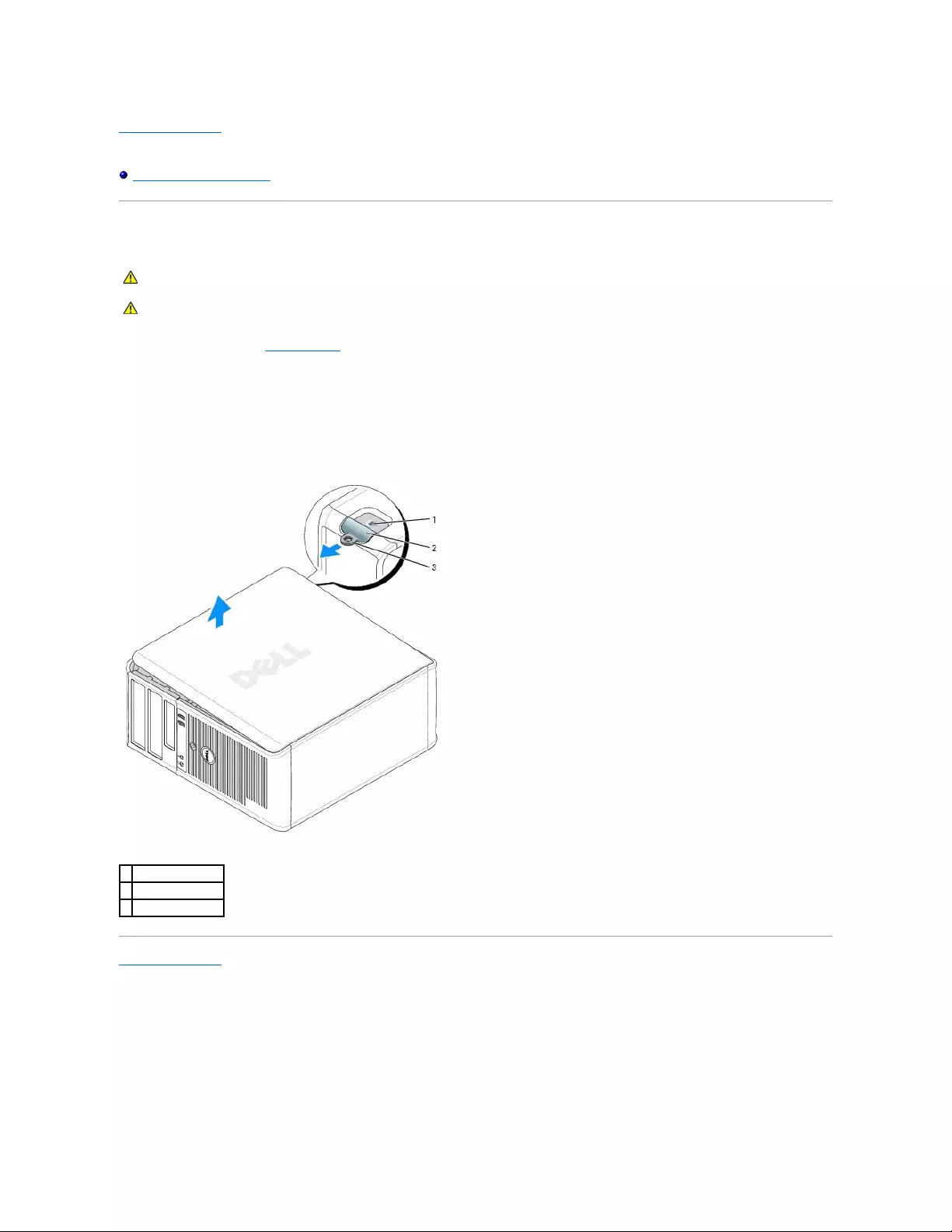
Back to Contents Page
Dell™OptiPlex™GX520User'sGuide
Removing the Computer Cover
Removing the Computer Cover
1. Follow the procedures in "Before You Begin."
2. Lay the computer on its side.
3. Slide the cover release latch back as you lift the cover.
4. Grip the sides of the computer cover and pivot the cover up using the hinge tabs as leverage points.
5. Remove the cover from the hinge tabs and set it aside on a soft nonabrasive surface.
Back to Contents Page
CAUTION: Before you begin any of the procedures in this section, follow the safety instructions located in the Product Information Guide.
CAUTION: To guard against electrical shock, always unplug your computer from the electrical outlet before removing the computer cover.
1
security cable slot
2
cover release latch
3
padlock ring
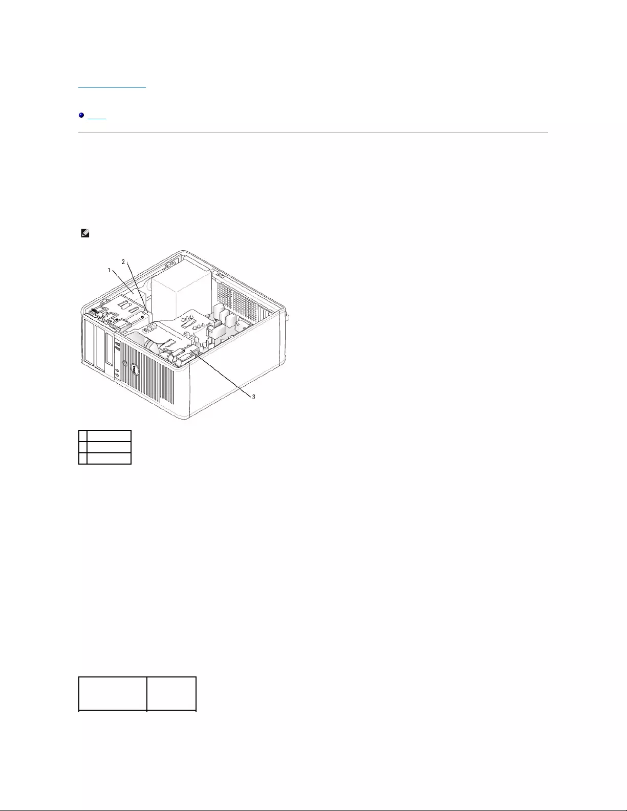
Back to Contents Page
Dell™OptiPlex™GX520User'sGuide
Drives
Drives
Your computer supports:
lTwo serial ATA hard drives
lTwo floppy or optional Zip drives
lTwo CD or DVD drives
General Installation Guidelines
Connect CD/DVD drives to the connector labeled "IDE" on the system board. Serial ATA hard drives should be connected to the connectors labeled "SATA0" or
"SATA2" on the system board.
IDE Drive Addressing
When you connect two IDE devices to a single IDE interface cable and configure them for the cable select setting, the device attached to the last connector on
the interface cable is the master or boot device (drive 0), and the device attached to the middle connector on the interface cable is the slave device (drive 1).
See the drive documentation in your upgrade kit for information on configuring devices for the cable select setting.
Connecting Drive Cables
When you install a drive, you connect two cables—a DC power cable and a data cable—to the back of the drive and to the system board.
Drive Interface Connectors
NOTE: Due to the limited number of drive bays and IDE controllers on this computer, you will not be able to connect all supported devices at once.
1
CD/DVD drive
2
floppy drive
3
hard drive
IDE Drive Connector
Serial ATA
Connector
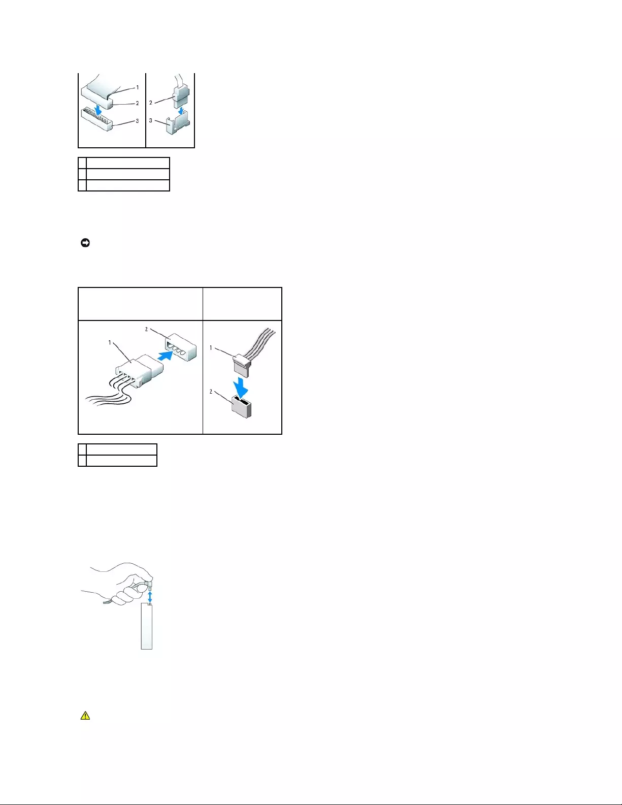
Most interface connectors are keyed for correct insertion; that is, a notch or a missing pin on one connector matches a tab or a filled-in hole on the other
connector. Keyed connectors ensure that the pin-1 wire in the cable (indicated by the colored stripe along one edge of the IDE cable—serial ATA cables do not
use a colored stripe) goes to the pin-1 end of the connector. The pin-1 end of a connector on a board or a card is usually indicated by a silk-screened "1"
printed directly on the board or card.
Power Cable Connectors
Connecting and Disconnecting Drive Cables
When removing an IDE drive data cable, grasp the colored pull-tab and pull until the connector detaches.
When connecting and disconnecting a serial ATA data cable, hold the cable by the black connector at each end.
Like IDE connectors, the serial ATA interface connectors are keyed for correct insertion; that is, a notch or a missing pin on one connector matches a tab or a
filled-in hole on the other connector.
Hard Drive
1
colored stripe on IDE cable
2
interface cable connector
3
interface connector
NOTICE: When you connect an IDE interface cable, do not place the colored stripe away from pin 1 of the connector. Reversing the cable prevents the
drive from operating and could damage the controller, the drive, or both.
IDE Drive Power Connector
Serial ATA Power
Connector
1
power cable
2
power input connector
CAUTION: Before you begin any of the procedures in this section, follow the safety instructions in the Product Information Guide.
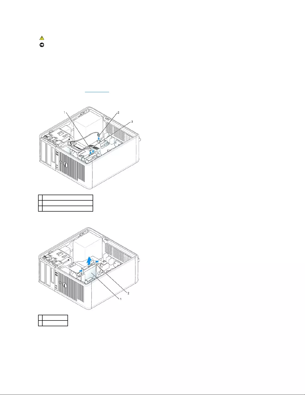
Removing a Hard Drive
1. If you are replacing a hard drive that contains data you want to keep, back up your files before you begin this procedure.
2. Check the documentation for the drive to verify that it is configured for your computer.
3. Follow the procedures in "Before You Begin."
4. Disconnect the power and hard-drive cables from the drive. Disconnect the hard-drive cable from the system board.
5. Press in on the blue release tabs on each side of the drive and slide the drive up and out of the computer.
Installing a Hard Drive
1. Unpack the replacement hard drive, and prepare it for installation.
CAUTION: To guard against electrical shock, always unplug your computer from the electrical outlet before removing the computer cover.
NOTICE: To avoid damage to the drive, do not set it on a hard surface. Instead, set the drive on a surface, such as a foam pad, that will sufficiently
cushion it.
1
hard-drive cable
2
hard-drive cable on system board
3
power cable
1
hard drive
2
release tabs (2)
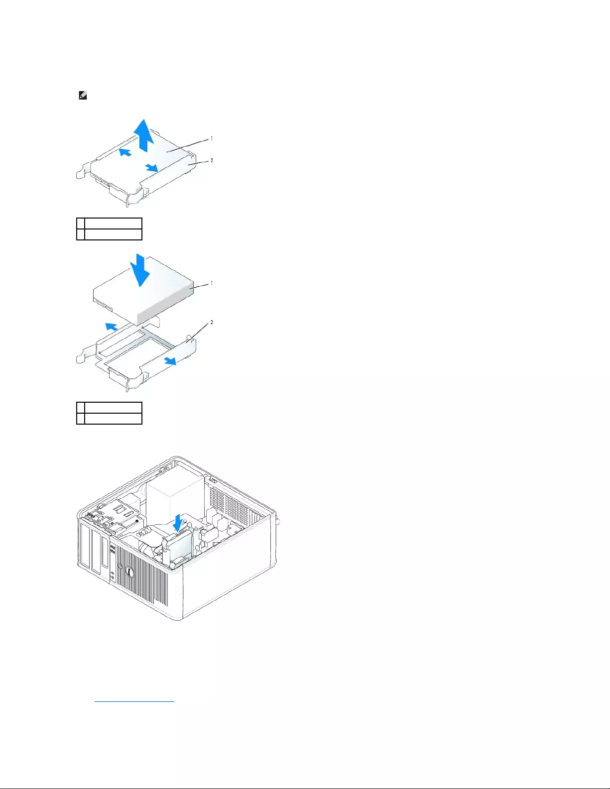
2. Check the documentation for the drive to verify that it is configured for your computer.
3. Gently slide the hard drive into the hard-drive bracket until it clicks into place.
4. Gently slide the hard drive into the drive bay until it clicks into place.
5. Connect the power and hard-drive cables to the drive. Connect the hard-drive cable to the connector on the system board.
6. Check all connectors to be certain that they are properly cabled and firmly seated.
7. Replace the computer cover.
NOTE: If your replacement hard drive does not have the plastic hard-drive bracket attached, remove the bracket from the existing drive by unsnapping
it from the drive. Snap the bracket onto the new drive.
1
hard drive
2
hard-drive bracket
1
hard drive
2
hard-drive bracket
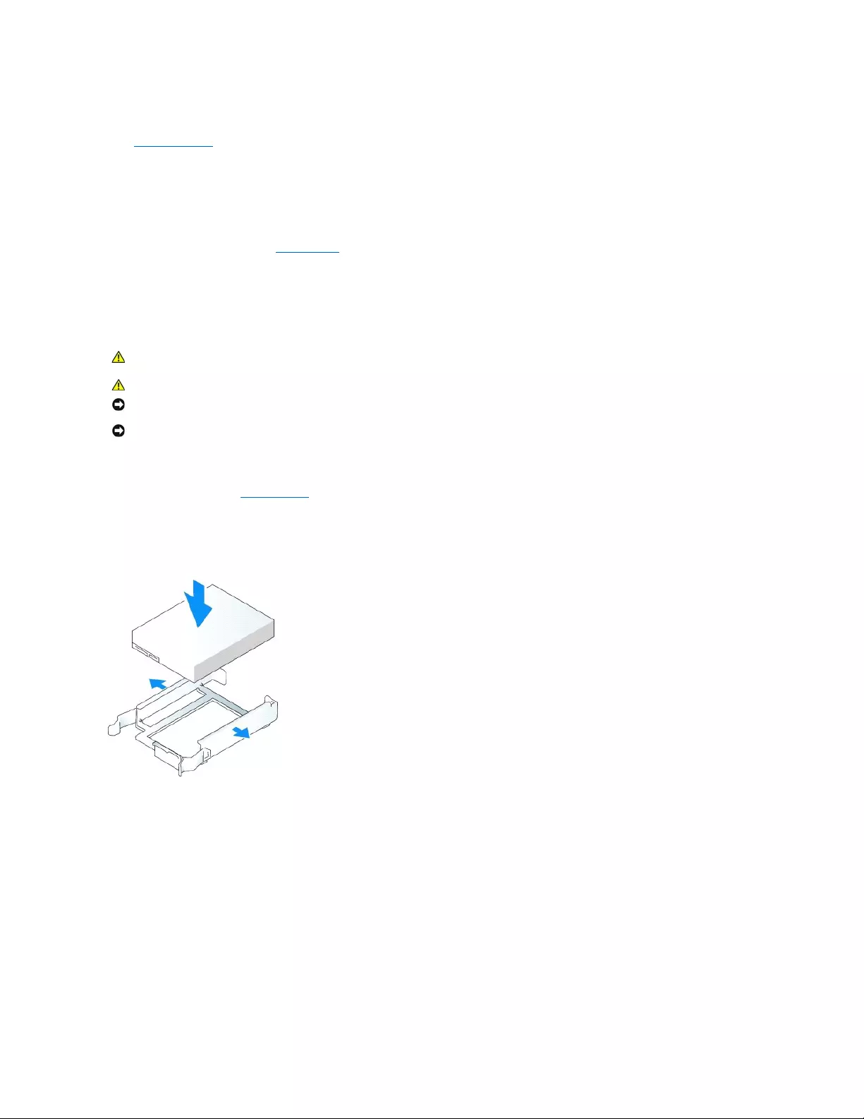
8. If the drive you just installed is the primary drive, insert a bootable medium into your boot drive. See the documentation that came with the drive for
instructions on installing any software required for drive operation.
9. Enter system setup and update the appropriate Primary Drive option (0 or 1).
10. Exit system setup, and reboot the computer.
11. Partition and logically format your drive before you proceed to the next step.
See the documentation for your operating system for instructions.
12. Test the hard drive by running the Dell Diagnostics.
13. If the drive you just installed is the primary drive, install your operating system on the hard drive.
Adding a Second Hard Drive
1. Check the documentation for the drive to verify that it is configured for your computer.
2. Follow the procedures in "Before You Begin."
3. Remove the plastic hard-drive bracket from the inside of the hard-drive bay by squeezing the release tabs and gently pulling the bracket up and out of
the bay.
4. Gently spread the sides of the drive bracket and slide the hard drive into the bracket until the drive clicks into place.
5. Move the first hard drive from the upper bay to the lower bay:
a. Disconnect the power and the hard-drive cables from the back of the first hard drive.
b. Press in on the blue release tabs on each side of the drive and slide the first hard drive up and out of the upper bay.
c. Gently slide the first hard drive into the lower bay until it clicks into place.
6. Gently slide the new hard drive into the upper bay until it clicks into place.
7. Connect the power cable to the drives.
CAUTION: Before you begin any of the procedures in this section, follow the safety instructions in the Product Information Guide.
CAUTION: To guard against electrical shock, always unplug your computer from the electrical outlet before removing the computer cover.
NOTICE: To avoid damage to the drive, do not set it on a hard surface. Instead, set the drive on a surface, such as a foam pad, that will sufficiently
cushion it.
NOTICE: If you are replacing a hard drive that contains data you want to keep, back up your files before you begin this procedure.
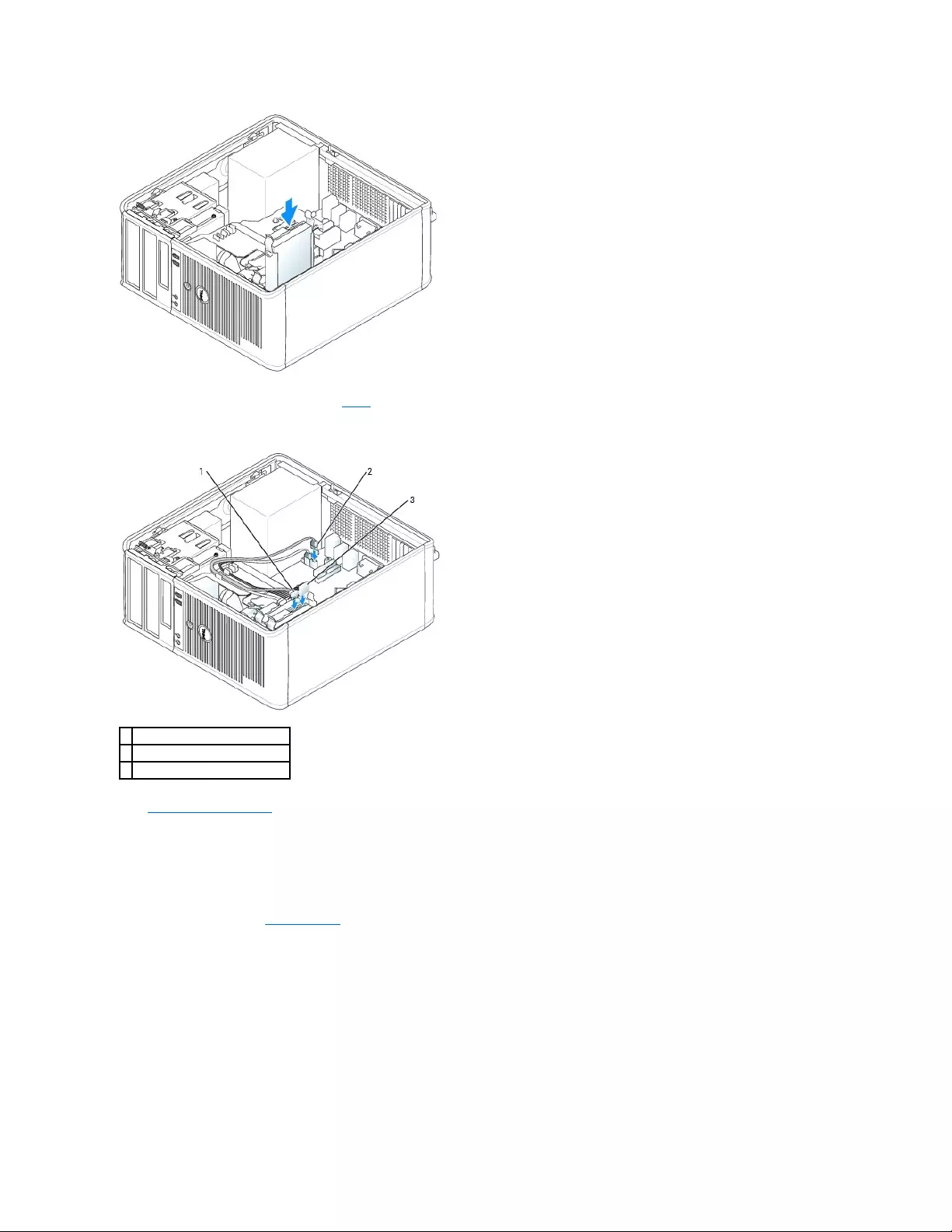
8. Attach the serial ATA connector removed in step5 to the first hard drive.
9. Locate an unused serial ATA connector on the system board and attach a drive cable to this connector and to the second hard drive.
10. Replace the computer cover.
Drive-Panel Inserts
If you are installing a new floppy or CD/DVD drive instead of replacing a drive, remove the drive-panel inserts.
1. Follow the procedures in "Before You Begin."
2. Remove the drive panel by sliding the drive release latch downward to open the panel. Then remove it from the hinges.
1
hard-drive cable
2
hard-drive cable on system board
3
power cable
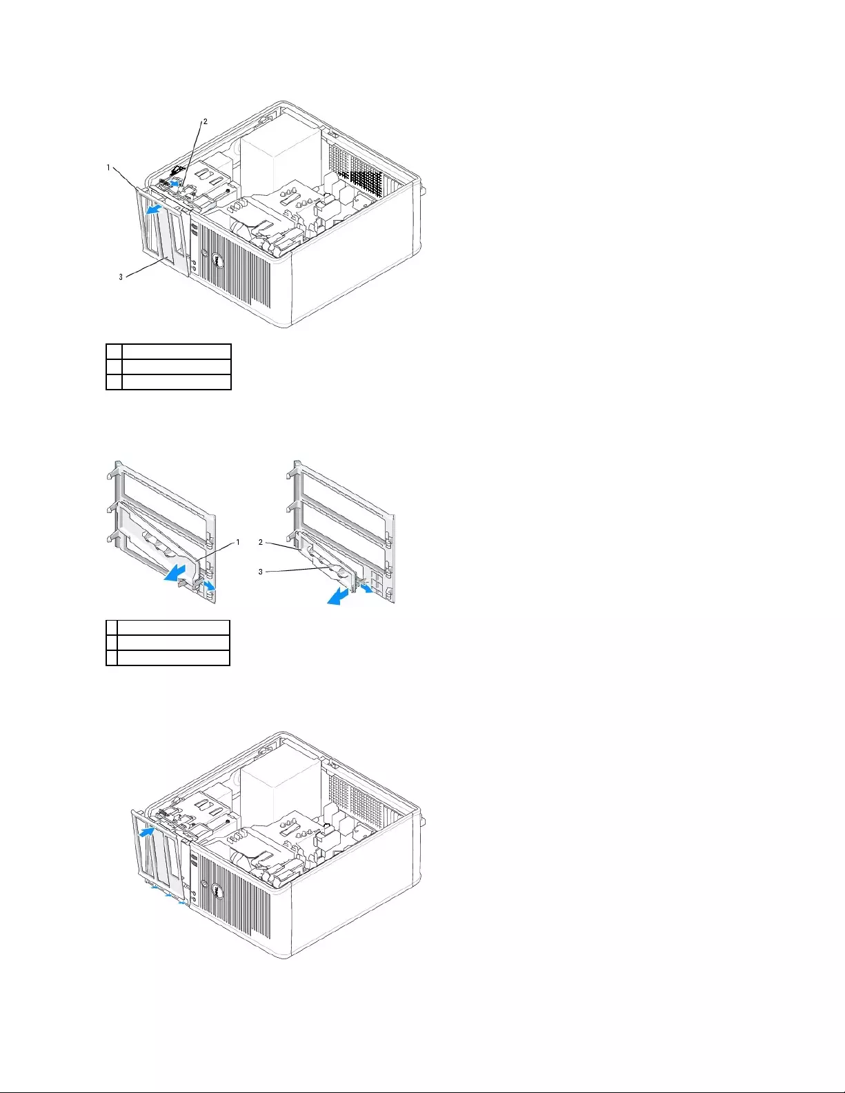
3. Select the drive-panel insert in front of the drive bay that you want to use.
4. Gently press the release tab of the insert to remove it from the drive panel.
5. Reattach the drive panel to the front of the computer.
The drive panel only fits one way.
1
drive panel
2
release tab
3
drive-panel insert
1
CD/DVD-drive panel insert
2
floppy-drive panel insert
3
holder for shoulder screws

Floppy Drive
Removing the Floppy Drive
1. Follow the procedures in "Before You Begin."
2. Remove the drive panel by sliding the drive release latch downward to open the panel, and then remove it from the hinges.
3. Disconnect the power and floppy-drive cables from the back of the floppy drive.
4. Remove the floppy drive by sliding and holding the drive release latch downward. Then slide the drive out of the computer.
Installing the Floppy Drive
1. If you are replacing a floppy drive, remove the shoulder screws from the existing drive and attach the screws to the replacement drive.
2. If you are installing a new floppy drive, remove the drive-panel insert for your new drive, remove the shoulder screws from the inside of the drive-panel
insert and attach the screws to the new drive.
3. Align the shoulder screws on the floppy drive with the shoulder screw slots, and gently slide the drive into the bay until it clicks into place.
CAUTION: Before you begin any of the procedures in this section, follow the safety instructions located in the Product Information Guide.
CAUTION: To guard against electrical shock, always unplug your computer from the electrical outlet before removing the computer cover.
1
floppy drive
2
drive release latch

4. Attach the power and floppy-drive cables to the floppy drive.
5. Replace the computer cover.
6. Enter system setup and use the Diskette Drive option to enable your new floppy drive.
7. Verify that your computer works correctly by running the Dell Diagnostics.
CD/DVD Drive
Removing a CD/DVD Drive
1. Follow the procedures in "Before You Begin."
1
floppy drive
2
shoulder screws (4)
3
shoulder screw slots (2)
1
power cable
2
floppy-drive cable
3
floppy-drive connector (DSKT)
CAUTION: Before you begin any of the procedures in this section, follow the safety instructions located in the Product Information Guide.
CAUTION: To guard against electrical shock, always unplug your computer from the electrical outlet before replacing the cover.
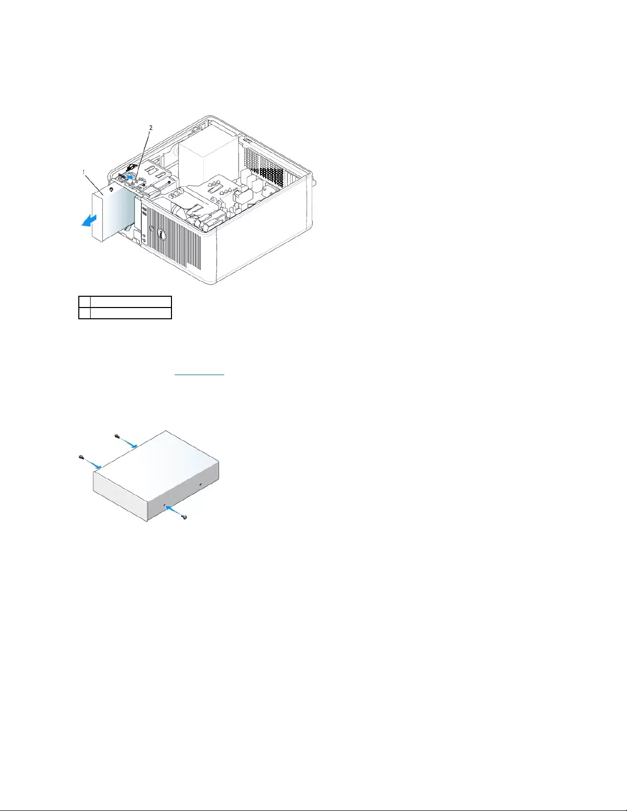
2. Disconnect the power and CD/DVD drive cables from the back of the drive.
3. Remove the CD/DVD drive by sliding and holding the drive release latch downward. Then slide the drive out of the computer.
Installing a CD/DVD Drive
1. Follow the procedures in "Before You Begin."
2. If you are replacing a CD/DVD drive, remove the shoulder screws from the existing drive and attach the screws to the replacement drive.
3. If you are installing a new CD/DVD drive, remove the drive-panel insert for your new drive, remove the shoulder screws from the inside of the drive-
panel insert, and attach the screws to the new drive.
4. Check the documentation that accompanied the drive to verify that the drive is configured for your computer. If you are installing an IDE drive, configure
the drive for the cable select setting by using the documentation that came with the drive.
5. Align the shoulder screws on the CD/DVD drive with the shoulder screw slots, and slide the drive into the bay until it clicks into place.
1
CD/DVD drive
2
drive release latch
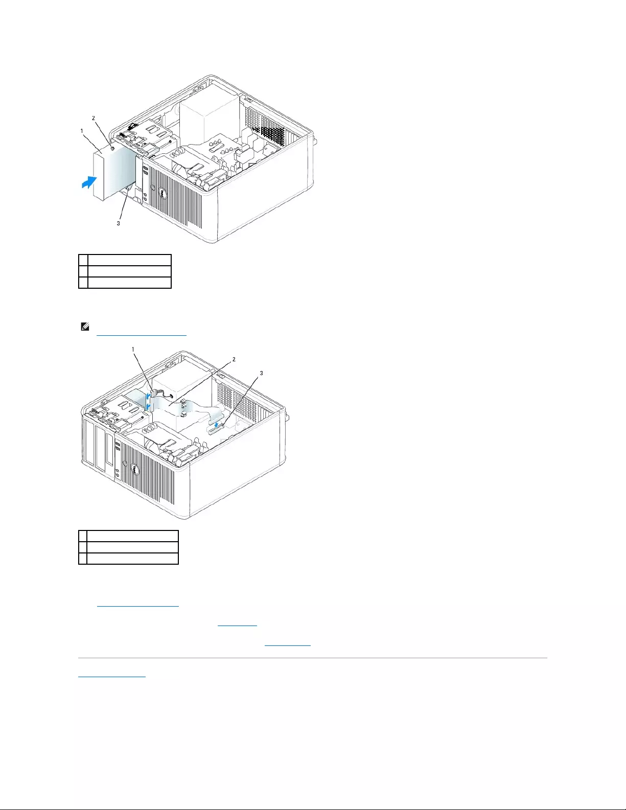
6. Connect the power and CD/DVD drive cables to the drive and to the system board.
7. Check all cable connections, and fold cables out of the way to provide airflow for the fan and cooling vents.
8. Replace the computer cover.
9. Update your configuration information in system setup by setting the appropriate Drive option (0 or 1) under Drives.
10. Verify that your computer works correctly by running the Dell Diagnostics.
Back to Contents Page
1
CD/DVD drive
2
shoulder screws (3)
3
shoulder screw slots (2)
NOTE: The CD/DVD drive cable may be a SATA cable and appear differently than the image below. For information on SATA cable connectors, see
"General Installation Guidelines."
1
power cable
2
CD/DVD drive cable
3
CD/DVD drive connector (IDE)

Back to Contents Page
Dell™OptiPlex™GX520User'sGuide
Drives
Drives
Your computer supports:
lTwo serial ATA hard drives
lTwo floppy or optional Zip drives
lTwo CD or DVD drives
General Installation Guidelines
Connect CD/DVD drives to the connector labeled "IDE" on the system board. Serial ATA hard drives should be connected to the connectors labeled "SATA0" or
"SATA2" on the system board.
IDE Drive Addressing
When you connect two IDE devices to a single IDE interface cable and configure them for the cable select setting, the device attached to the last connector on
the interface cable is the master or boot device (drive 0), and the device attached to the middle connector on the interface cable is the slave device (drive 1).
See the drive documentation in your upgrade kit for information on configuring devices for the cable select setting.
Connecting Drive Cables
When you install a drive, you connect two cables—a DC power cable and a data cable—to the back of the drive and to the system board.
Drive Interface Connectors
NOTE: Due to the limited number of drive bays and IDE controllers on this computer, you will not be able to connect all supported devices at once.
1
CD/DVD drive
2
floppy drive
3
hard drive
IDE Drive Connector
Serial ATA
Connector
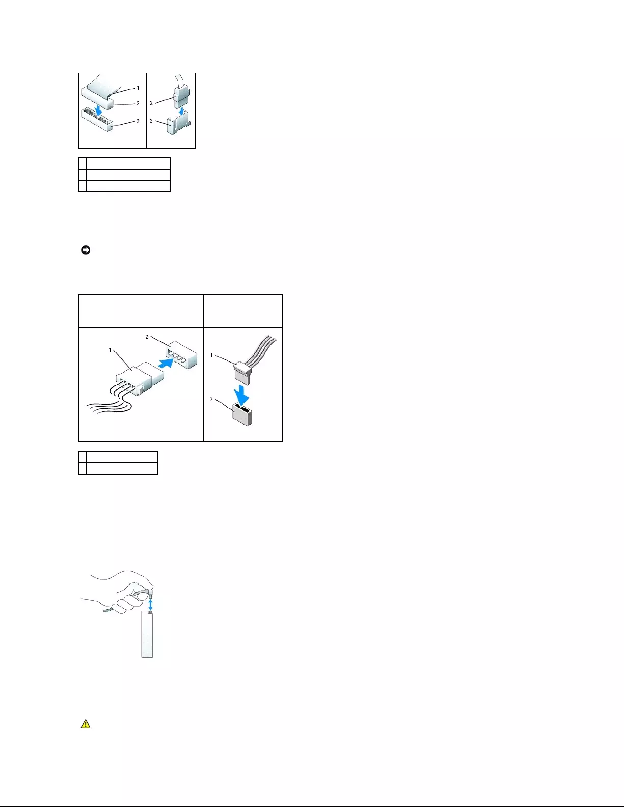
Most interface connectors are keyed for correct insertion; that is, a notch or a missing pin on one connector matches a tab or a filled-in hole on the other
connector. Keyed connectors ensure that the pin-1 wire in the cable (indicated by the colored stripe along one edge of the IDE cable—serial ATA cables do not
use a colored stripe) goes to the pin-1 end of the connector. The pin-1 end of a connector on a board or a card is usually indicated by a silk-screened "1"
printed directly on the board or card.
Power Cable Connectors
Connecting and Disconnecting Drive Cables
When removing an IDE drive data cable, grasp the colored pull-tab and pull until the connector detaches.
When connecting and disconnecting a serial ATA data cable, hold the cable by the black connector at each end.
Like IDE connectors, the serial ATA interface connectors are keyed for correct insertion; that is, a notch or a missing pin on one connector matches a tab or a
filled-in hole on the other connector.
Hard Drive
1
colored stripe on IDE cable
2
interface cable connector
3
interface connector
NOTICE: When you connect an IDE interface cable, do not place the colored stripe away from pin 1 of the connector. Reversing the cable
prevents the drive from operating and could damage the controller, the drive, or both.
IDE Drive Power Connector
Serial ATA Power
Connector
1
power cable
2
power input connector
CAUTION: Before you begin any of the procedures in this section, follow the safety instructions in the Product Information Guide.
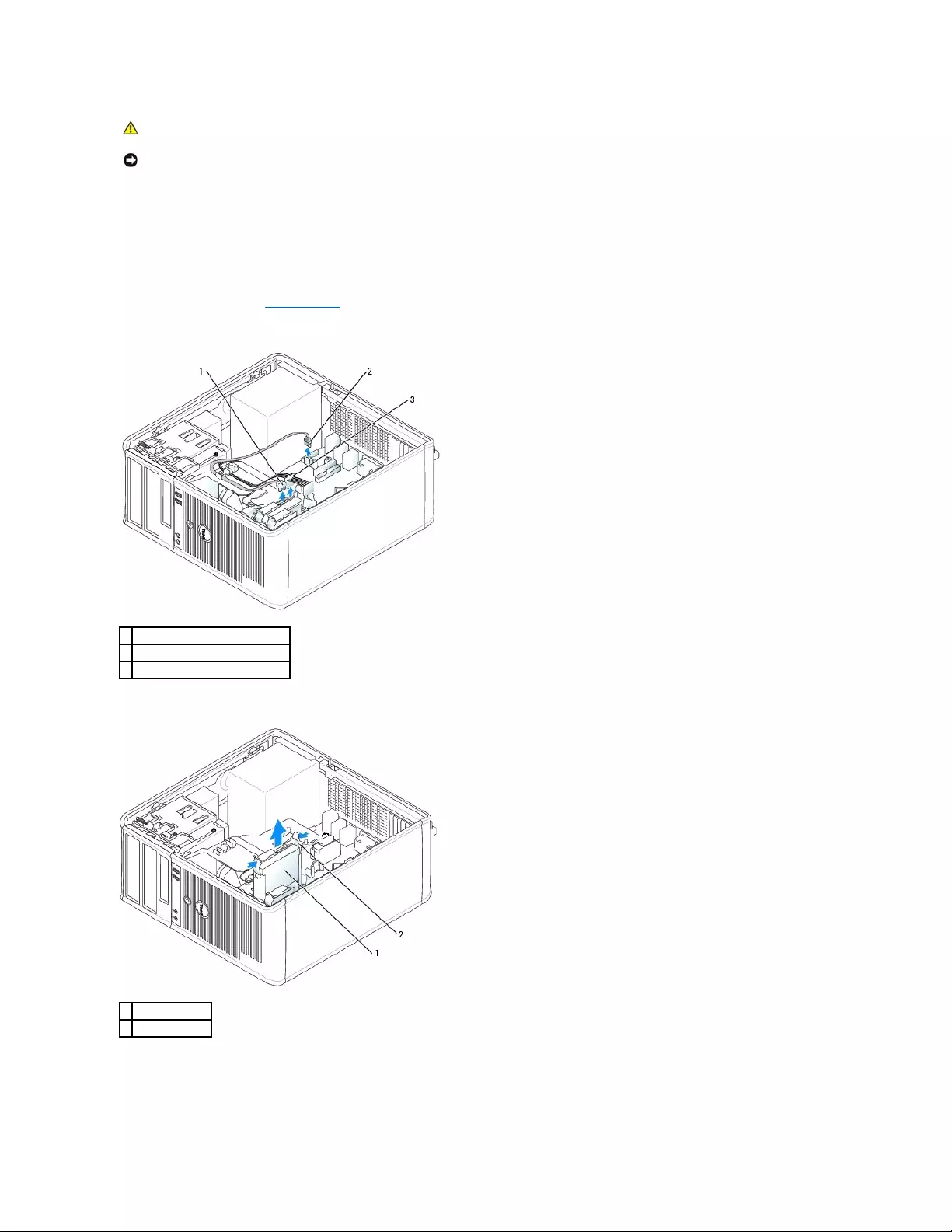
Removing a Hard Drive
1. If you are replacing a hard drive that contains data you want to keep, back up your files before you begin this procedure.
2. Check the documentation for the drive to verify that it is configured for your computer.
3. Follow the procedures in "Before You Begin."
4. Disconnect the power and hard-drive cables from the drive. Disconnect the hard-drive cable from the system board.
5. Press in on the blue release tabs on each side of the drive and slide the drive up and out of the computer.
Installing a Hard Drive
CAUTION: To guard against electrical shock, always unplug your computer from the electrical outlet before removing the computer cover.
NOTICE: To avoid damage to the drive, do not set it on a hard surface. Instead, set the drive on a surface, such as a foam pad, that will
sufficiently cushion it.
1
hard-drive cable
2
hard-drive cable on system board
3
power cable
1
hard drive
2
release tabs (2)
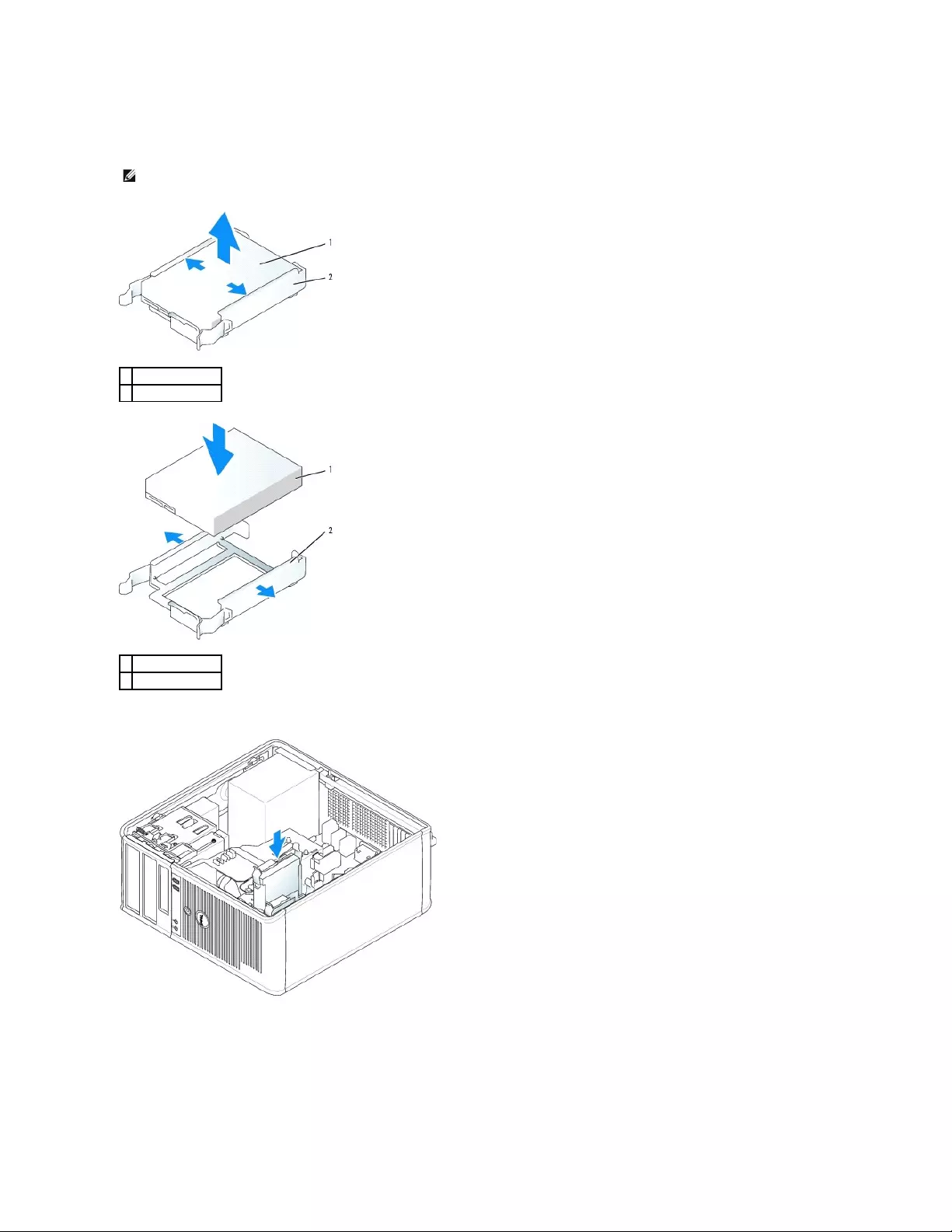
1. Unpack the replacement hard drive, and prepare it for installation.
2. Check the documentation for the drive to verify that it is configured for your computer.
3. Gently slide the hard drive into the hard-drive bracket until it clicks into place.
4. Gently slide the hard drive into the drive bay until it clicks into place.
5. Connect the power and hard-drive cables to the drive. Connect the hard-drive cable to the connector on the system board.
6. Check all connectors to be certain that they are properly cabled and firmly seated.
NOTE: If your replacement hard drive does not have the plastic hard-drive bracket attached, remove the bracket from the existing drive by unsnapping
it from the drive. Snap the bracket onto the new drive.
1
hard drive
2
hard-drive bracket
1
hard drive
2
hard-drive bracket
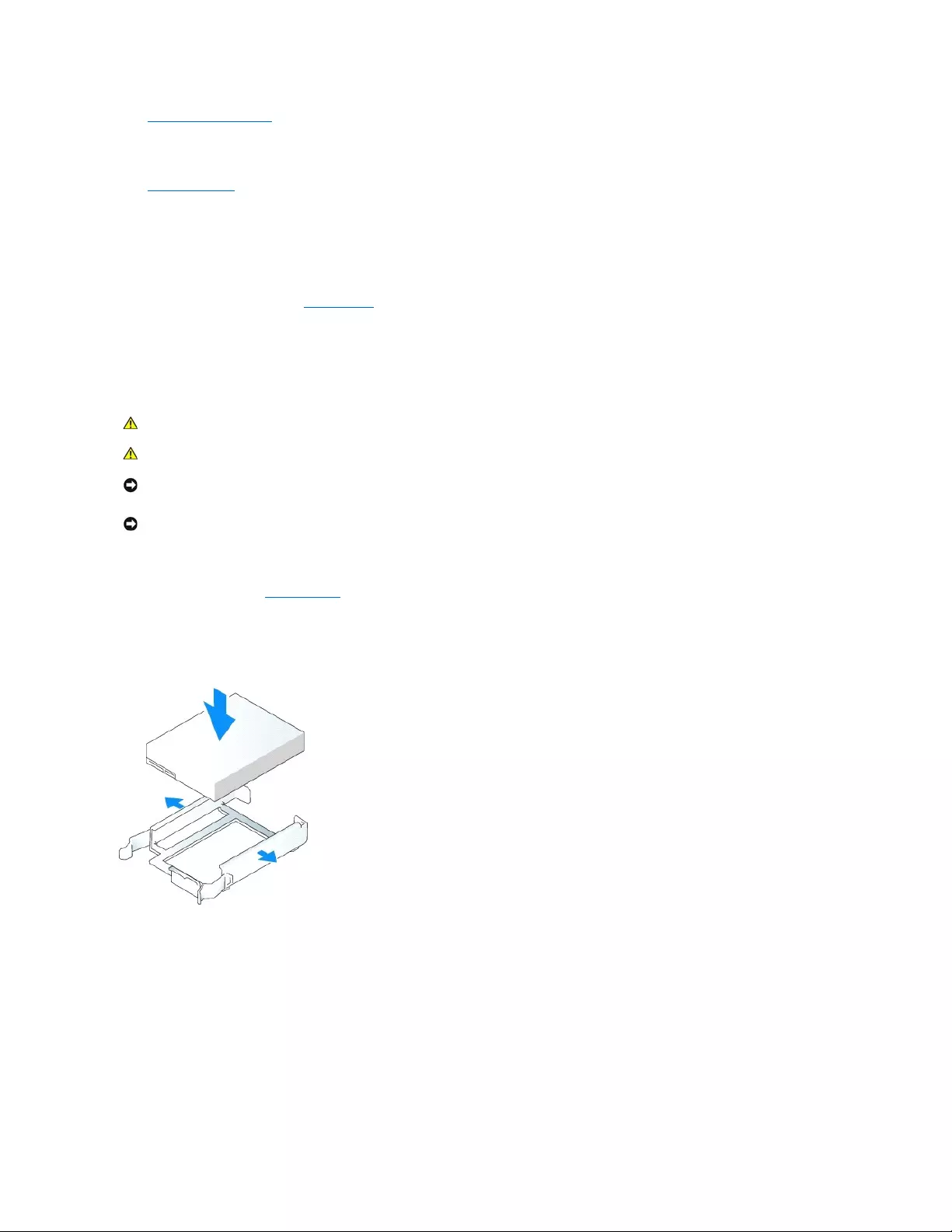
7. Replace the computer cover.
8. If the drive you just installed is the primary drive, insert a bootable medium into your boot drive. See the documentation that came with the drive for
instructions on installing any software required for drive operation.
9. Enter system setup and update the appropriate Primary Drive option (0 or 1).
10. Exit system setup, and reboot the computer.
11. Partition and logically format your drive before you proceed to the next step.
See the documentation for your operating system for instructions.
12. Test the hard drive by running the Dell Diagnostics.
13. If the drive you just installed is the primary drive, install your operating system on the hard drive.
Adding a Second Hard Drive
1. Check the documentation for the drive to verify that it is configured for your computer.
2. Follow the procedures in "Before You Begin."
3. Remove the plastic hard-drive bracket from the inside of the hard-drive bay by squeezing the release tabs and gently pulling the bracket up and out of
the bay.
4. Gently spread the sides of the drive bracket and slide the hard drive into the bracket until the drive clicks into place.
5. Move the first hard drive from the upper bay to the lower bay:
a. Disconnect the power and the hard-drive cables from the back of the first hard drive.
b. Press in on the blue release tabs on each side of the drive and slide the first hard drive up and out of the upper bay.
c. Gently slide the first hard drive into the lower bay until it clicks into place.
6. Gently slide the new hard drive into the upper bay until it clicks into place.
7. Connect the power cable to the drives.
CAUTION: Before you begin any of the procedures in this section, follow the safety instructions in the Product Information Guide.
CAUTION: To guard against electrical shock, always unplug your computer from the electrical outlet before removing the computer cover.
NOTICE: To avoid damage to the drive, do not set it on a hard surface. Instead, set the drive on a surface, such as a foam pad, that will
sufficiently cushion it.
NOTICE: If you are replacing a hard drive that contains data you want to keep, back up your files before you begin this procedure.

8. Attach the serial ATA connector removed in step5 to the first hard drive.
9. Locate an unused serial ATA connector on the system board and attach a drive cable to this connector and to the second hard drive.
10. Replace the computer cover.
Drive-Panel Inserts
If you are installing a new floppy or CD/DVD drive instead of replacing a drive, remove the drive-panel inserts.
1. Follow the procedures in "Before You Begin."
2. Remove the drive panel by sliding the drive release latch downward to open the panel. Then remove it from the hinges.
1
hard-drive cable
2
hard-drive cable on system board
3
power cable
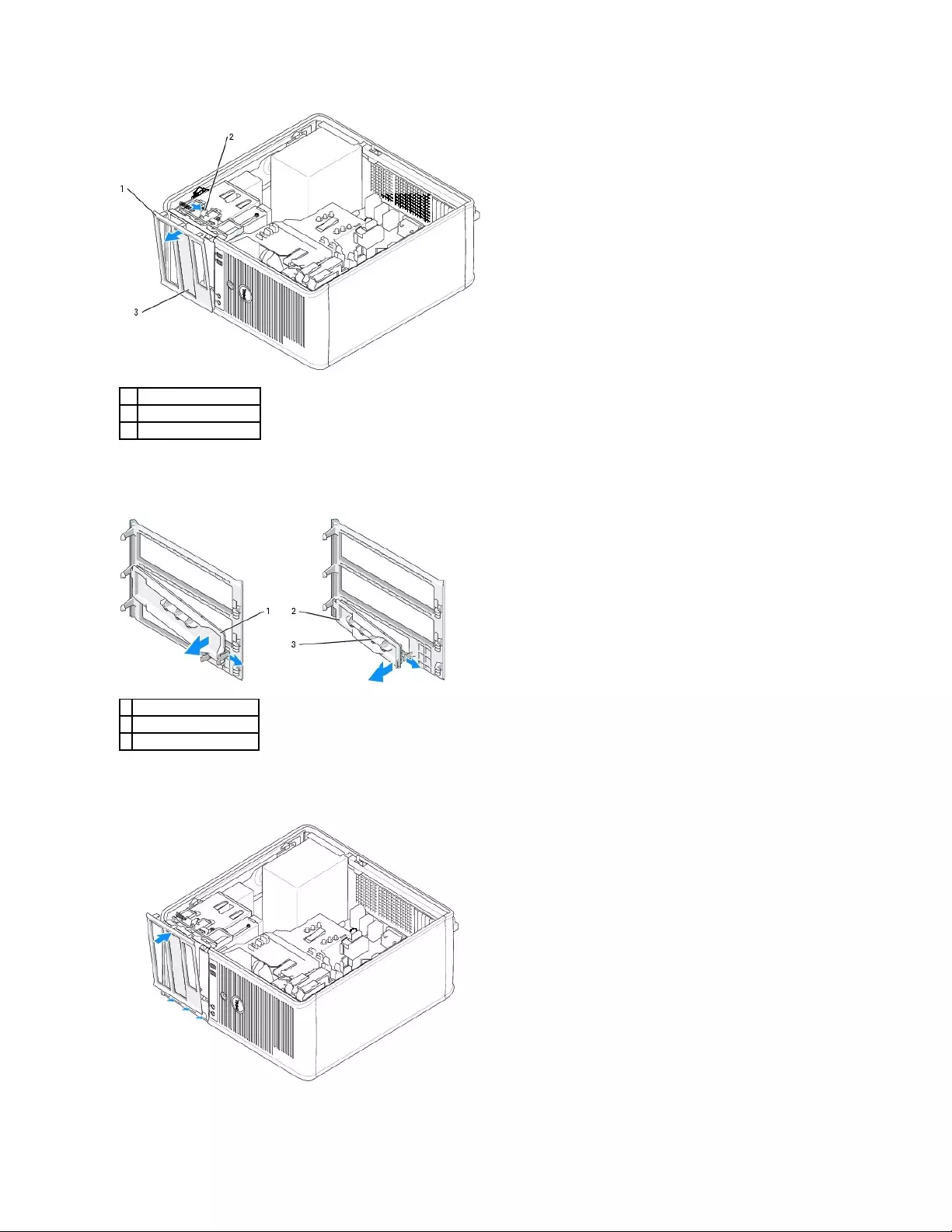
3. Select the drive-panel insert in front of the drive bay that you want to use.
4. Gently press the release tab of the insert to remove it from the drive panel.
5. Reattach the drive panel to the front of the computer.
The drive panel only fits one way.
1
drive panel
2
release tab
3
drive-panel insert
1
CD/DVD-drive panel insert
2
floppy-drive panel insert
3
holder for shoulder screws
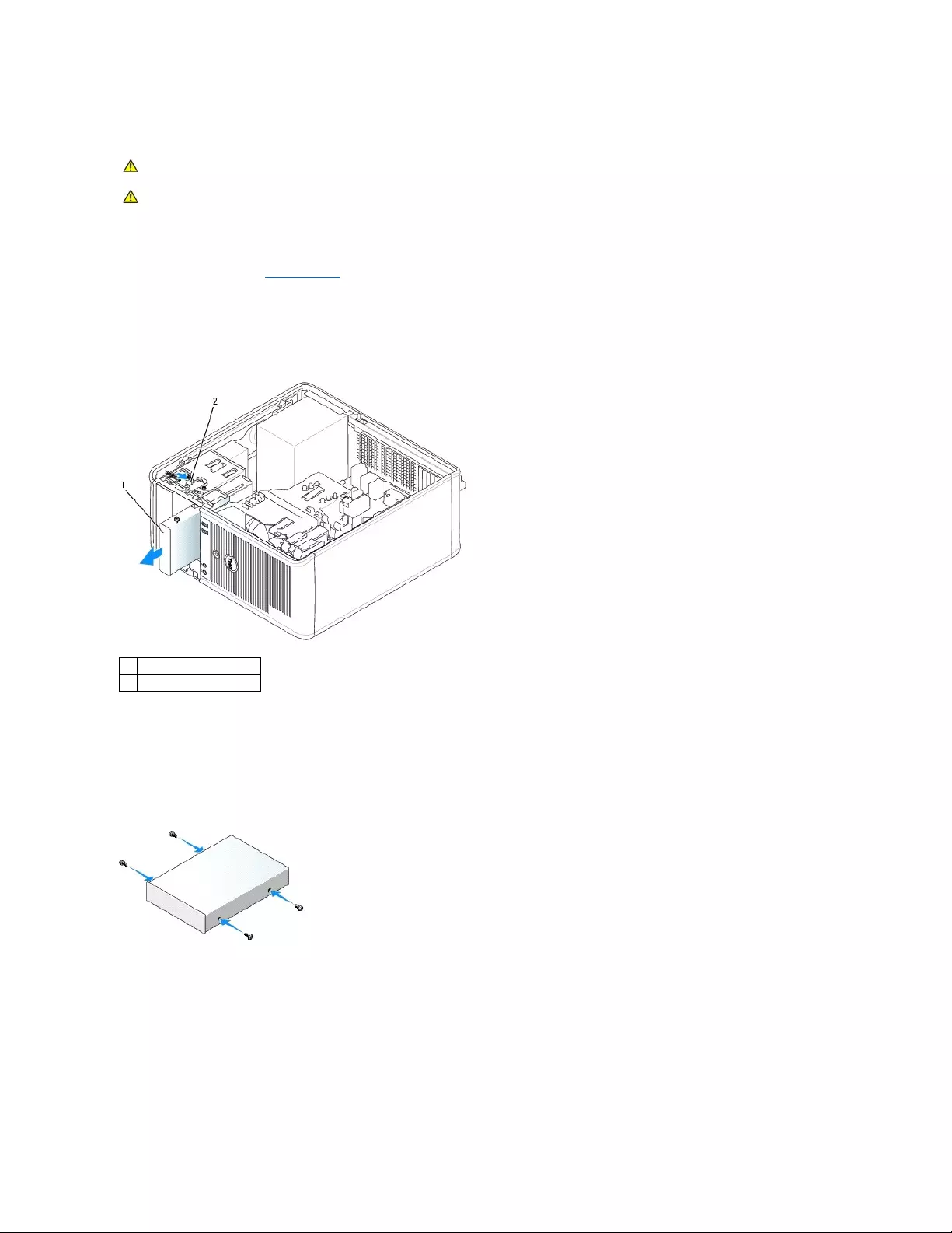
Floppy Drive
Removing the Floppy Drive
1. Follow the procedures in "Before You Begin."
2. Remove the drive panel by sliding the drive release latch downward to open the panel, and then remove it from the hinges.
3. Disconnect the power and floppy-drive cables from the back of the floppy drive.
4. Remove the floppy drive by sliding and holding the drive release latch downward. Then slide the drive out of the computer.
Installing the Floppy Drive
1. If you are replacing a floppy drive, remove the shoulder screws from the existing drive and attach the screws to the replacement drive.
2. If you are installing a new floppy drive, remove the drive-panel insert for your new drive, remove the shoulder screws from the inside of the drive-panel
insert and attach the screws to the new drive.
3. Align the shoulder screws on the floppy drive with the shoulder screw slots, and gently slide the drive into the bay until it clicks into place.
CAUTION: Before you begin any of the procedures in this section, follow the safety instructions located in the Product Information Guide.
CAUTION: To guard against electrical shock, always unplug your computer from the electrical outlet before removing the computer cover.
1
floppy drive
2
drive release latch
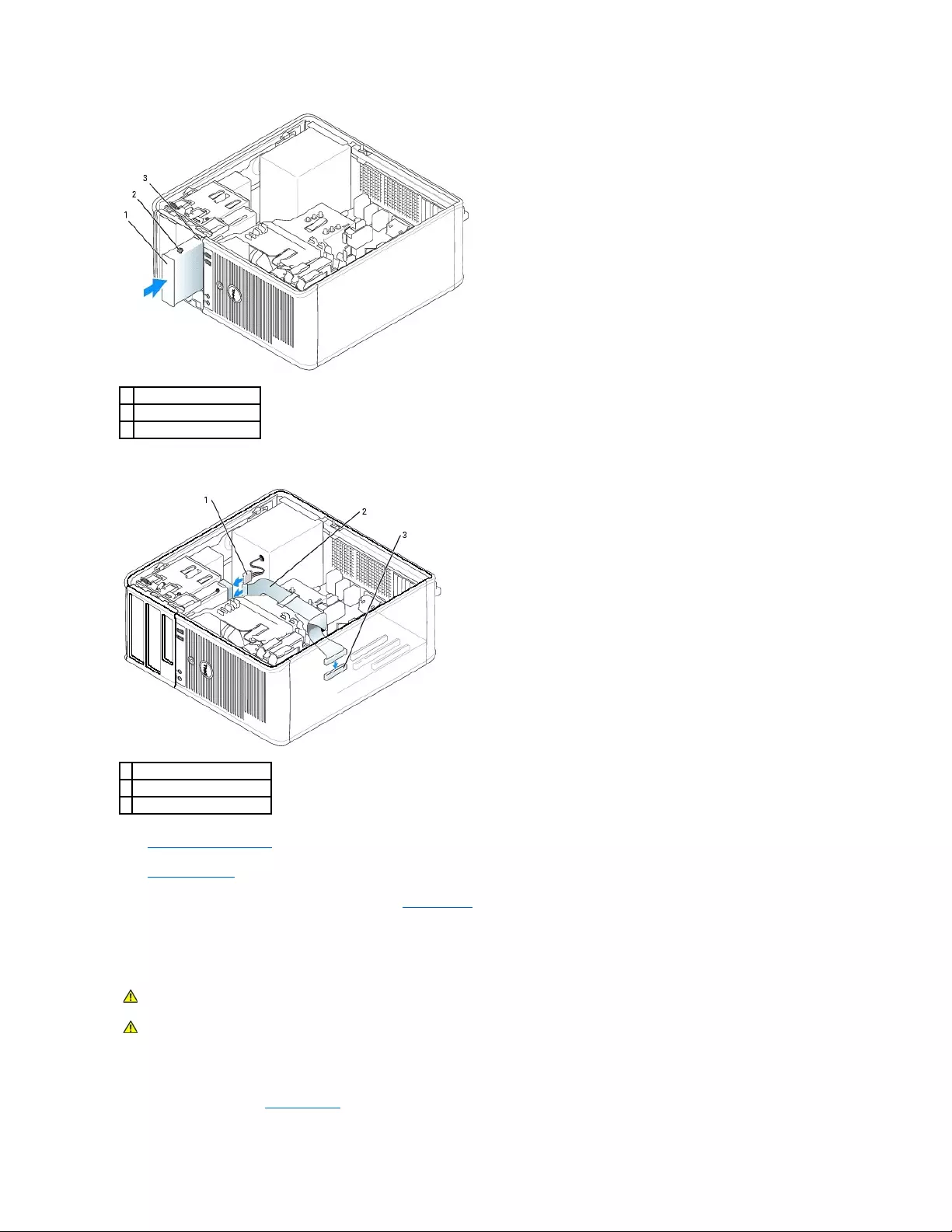
4. Attach the power and floppy-drive cables to the floppy drive.
5. Replace the computer cover.
6. Enter system setup and use the Diskette Drive option to enable your new floppy drive.
7. Verify that your computer works correctly by running the Dell Diagnostics.
CD/DVD Drive
Removing a CD/DVD Drive
1. Follow the procedures in "Before You Begin."
1
floppy drive
2
shoulder screws (4)
3
shoulder screw slots (2)
1
power cable
2
floppy-drive cable
3
floppy-drive connector (DSKT)
CAUTION: Before you begin any of the procedures in this section, follow the safety instructions located in the Product Information Guide.
CAUTION: To guard against electrical shock, always unplug your computer from the electrical outlet before replacing the cover.

2. Disconnect the power and CD/DVD drive cables from the back of the drive.
3. Remove the CD/DVD drive by sliding and holding the drive release latch downward. Then slide the drive out of the computer.
Installing a CD/DVD Drive
1. Follow the procedures in "Before You Begin."
2. If you are replacing a CD/DVD drive, remove the shoulder screws from the existing drive and attach the screws to the replacement drive.
3. If you are installing a new CD/DVD drive, remove the drive-panel insert for your new drive, remove the shoulder screws from the inside of the drive-
panel insert, and attach the screws to the new drive.
4. Check the documentation that accompanied the drive to verify that the drive is configured for your computer. If you are installing an IDE drive, configure
the drive for the cable select setting by using the documentation that came with the drive.
5. Align the shoulder screws on the CD/DVD drive with the shoulder screw slots, and slide the drive into the bay until it clicks into place.
1
CD/DVD drive
2
drive release latch

6. Connect the power and CD/DVD drive cables to the drive and to the system board.
7. Check all cable connections, and fold cables out of the way to provide airflow for the fan and cooling vents.
8. Replace the computer cover.
9. Update your configuration information in system setup by setting the appropriate Drive option (0 or 1) under Drives.
10. Verify that your computer works correctly by running the Dell Diagnostics.
Back to Contents Page
1
CD/DVD drive
2
shoulder screws (3)
3
shoulder screw slots (2)
NOTE: The CD/DVD drive cable may be a SATA cable and appear differently than the image below. For information on SATA cable connectors, see
"General Installation Guidelines."
1
power cable
2
CD/DVD drive cable
3
CD/DVD drive connector (IDE)
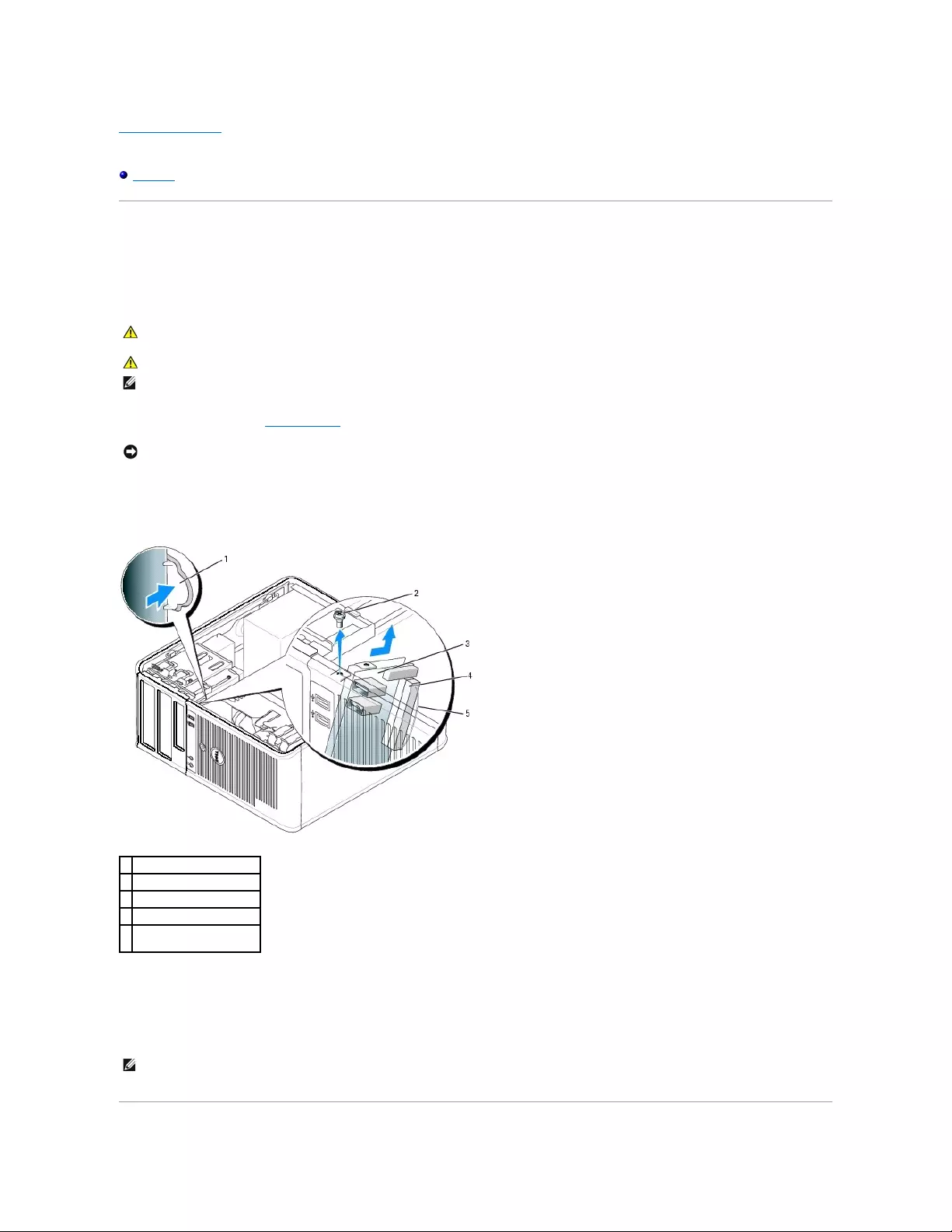
Back to Contents Page
Dell™OptiPlex™GX520User'sGuide
I/O Panel
I/O Panel
Removing the I/O Panel
1. Follow the procedures in "Before You Begin."
2. Remove the screw that secures the I/O panel. Press on the release button and pull on the loop to slide the card away from the computer.
3. Disconnect all of the cables from the I/O panel, and remove the panel from the computer.
Replacing the I/O Panel
1. To replace the I/O panel, follow the removal procedure in the reverse order.
CAUTION: Before you begin any of the procedures in this section, follow the safety instructions located in the Product Information Guide.
CAUTION: To guard against electrical shock, always unplug your computer from the electrical outlet before removing the cover.
NOTE: Note the routing of all cables as you remove them so that you can re-route them correctly when installing the new I/O panel.
NOTICE: When sliding the I/O panel out of the computer, be extremely careful. Carelessness my result in damage to the cable connectors and the cable
routing clips.
1
I/O panel release button
2
securing screw
3
I/O panel
4
I/O cable connector
5
I/O cable connector pull-
loop
NOTE: Use the guides on the I/O panel bracket to help position the I/O panel in place, and use the notch on the I/O panel bracket to help seat the
panel.

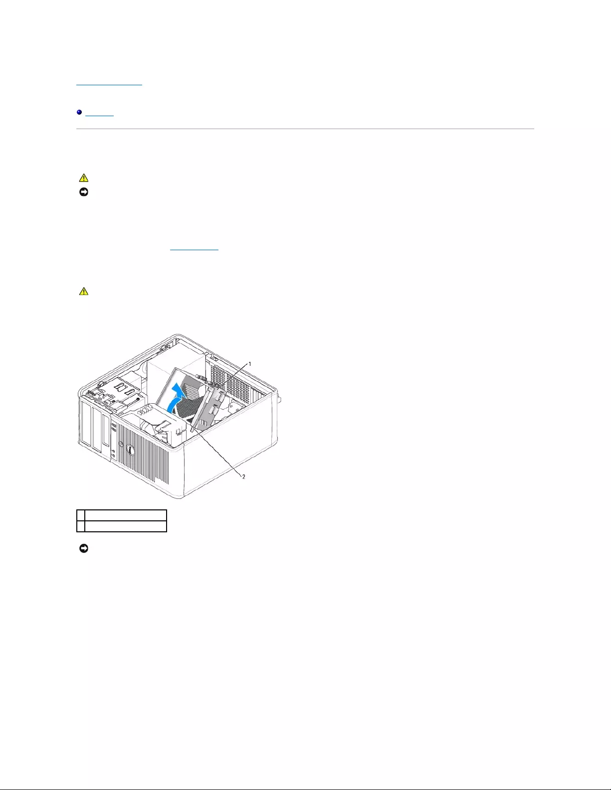
Back to Contents Page
Dell™OptiPlex™GX520User'sGuide
Processor
Processor
Removing the Processor
1. Follow the procedures in "Before You Begin."
2. Loosen the captive screw on each side of the heat sink assembly.
3. Rotate the heat sink assembly upward, and remove it from the computer.
4. Open the processor cover by sliding the release lever from under the center cover latch on the socket. Then, pull the lever back to release the
processor.
CAUTION: Before you begin any of the procedures in this section, follow the safety instructions located in the Product Information Guide.
NOTICE: To prevent static damage to components inside your computer, discharge static electricity from your body before you touch any of your
computer's electronic components. You can do so by touching an unpainted metal surface on the computer chassis.
CAUTION: Despite having a plastic shield, the heat sink assembly may be very hot during normal operation. Be sure that it has had sufficient time
to cool before you touch it.
1
heat sink assembly
2
captive screw housings (2)
NOTICE: If you are installing a processor upgrade kit from Dell, remove the heat sink assembly from the shroud and discard the original heat sink. If
you are not installing a processor upgrade kit from Dell, reuse the original heat sink when you install your new processor.
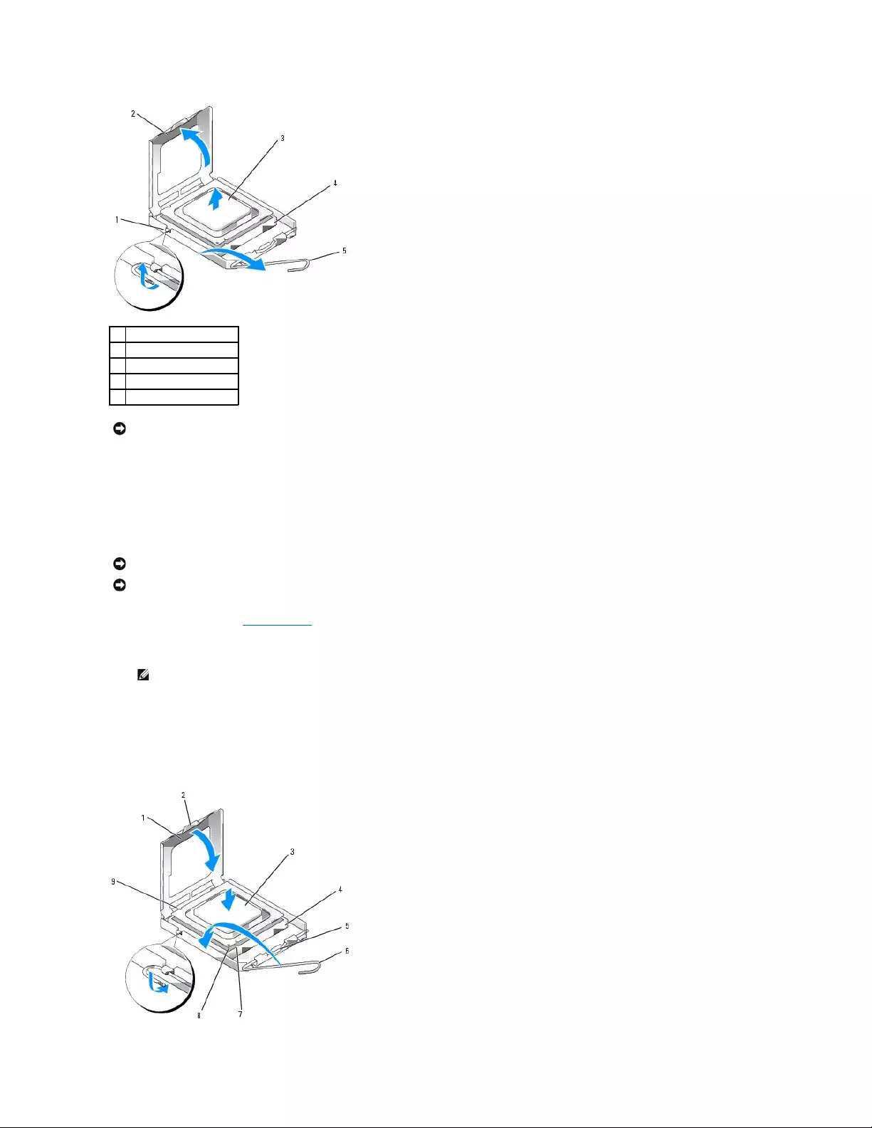
5. Gently remove the processor from the socket.
Leave the release lever extended in the release position so that the socket is ready for the new processor.
Installing the Processor
1. Follow the procedures in "Before You Begin."
2. Unpack the new processor, being careful not to touch the underside of the processor.
3. If the release lever on the socket is not fully extended, move it to that position.
4. Orient the front and rear alignment-notches on the processor with the front and rear alignment-notches on the socket.
5. Align the pin-1 corners of the processor and socket.
1
center cover latch
2
processor cover
3
processor
4
socket
5
release lever
NOTICE: When replacing the processor, do not touch any of the pins inside the socket or allow any objects to fall on the pins in the socket.
NOTICE: Ground yourself by touching an unpainted metal surface on the back of the computer.
NOTICE: When replacing the processor, do not touch any of the pins inside the socket or allow any objects to fall on the pins in the socket.
NOTE: You must position the processor correctly in the socket to avoid permanent damage to the processor and the computer when you turn on
the computer.
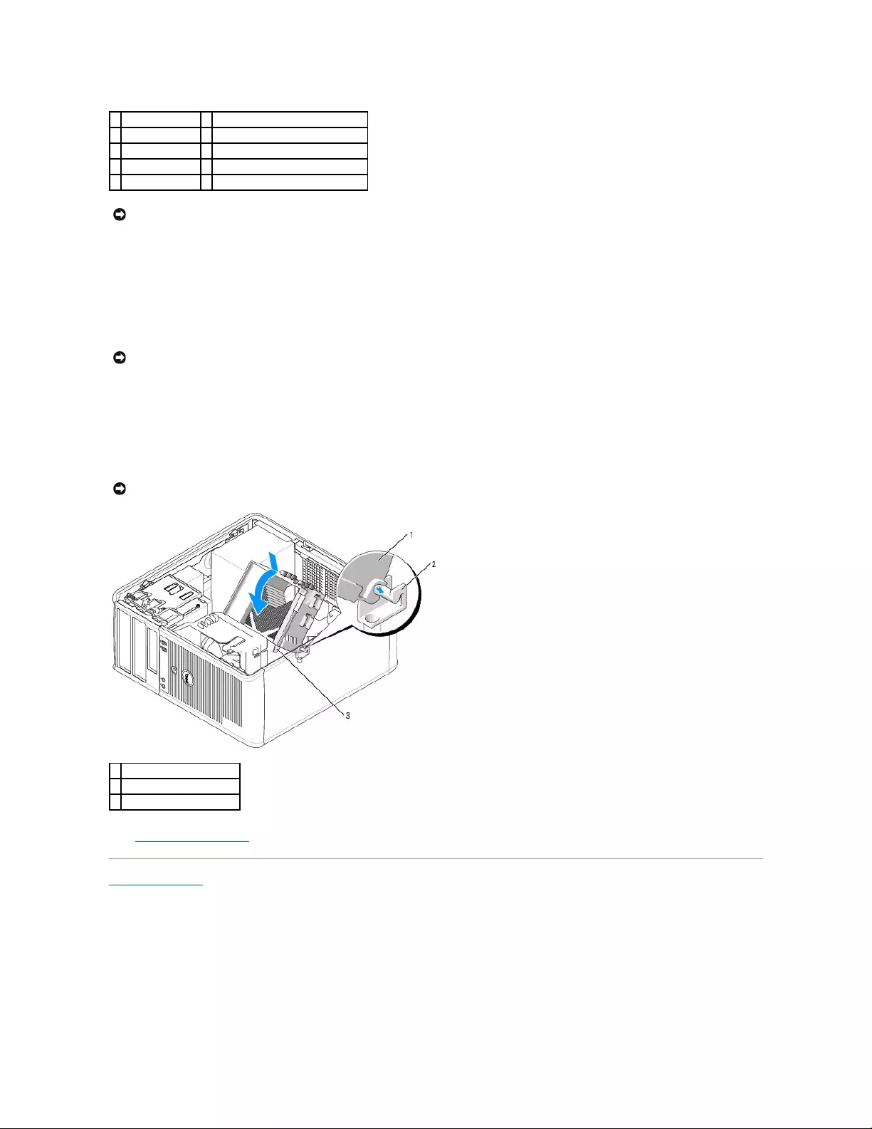
6. Set the processor lightly in the socket and ensure that the processor is positioned correctly.
7. When the processor is fully seated in the socket, close the processor cover.
Ensure that the tab on the processor cover is positioned underneath the center cover latch on the socket.
8. Pivot the socket release lever back toward the socket, and snap it into place to secure the processor.
If you installed a processor replacement kit from Dell, remove the original heat sink assembly from the shroud and return it with the processor to Dell in
the same package in which your replacement kit was sent.
9. Install the heat sink assembly:
a. Place the heat sink assembly back onto the heat-sink assembly bracket.
b. Rotate the heat sink assembly down towards the computer base and tighten the two captive screws.
10. Replace the computer cover.
Back to Contents Page
1
processor cover
6
release lever
2
tab
7
front alignment-notch
3
processor
8
socket and processor pin-1 indicator
4
processor socket
9
rear alignment-notch
5
center cover latch
NOTICE: To avoid damage, ensure that the processor aligns properly with the socket, and do not use excessive force when you install the processor.
NOTICE: If you are not installing a processor upgrade kit from Dell, reuse the original heat sink assembly when you replace the processor.
NOTICE: Ensure that the heat sink assembly is correctly seated and secure.
1
heat sink assembly
2
heat-sink assembly bracket
3
captive screw housing (2)
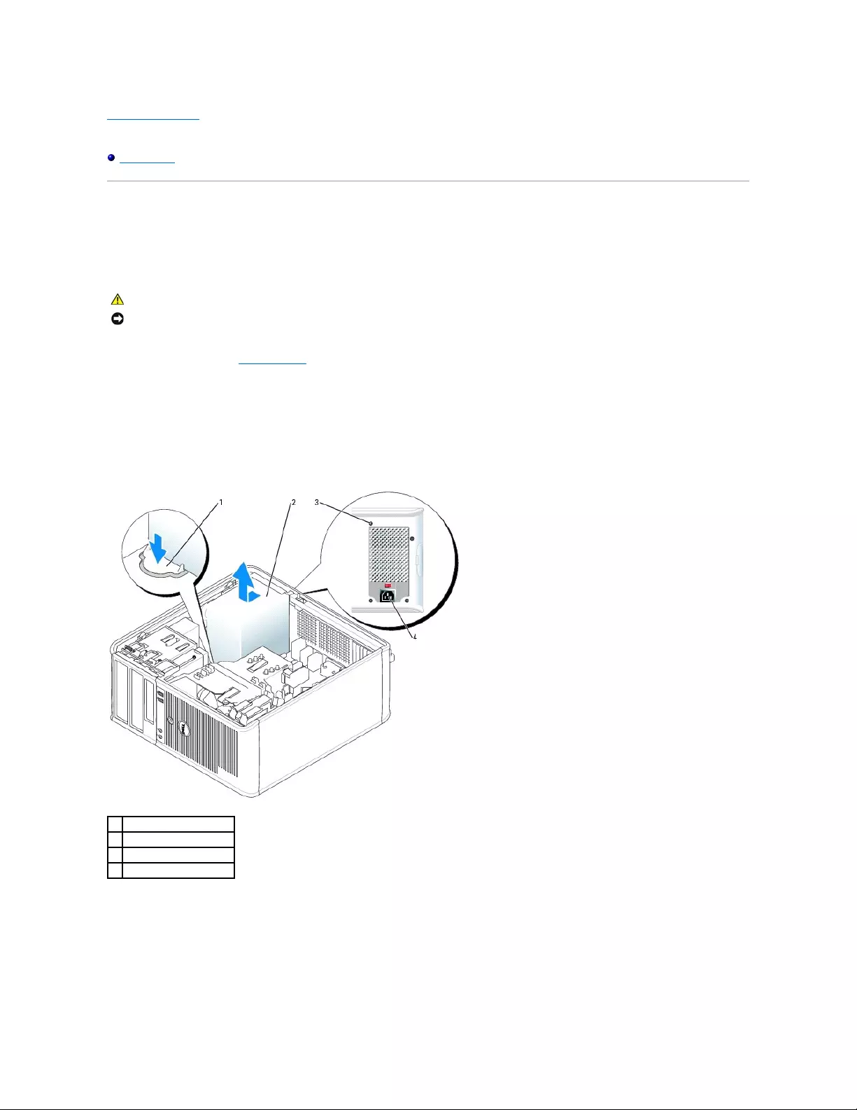
Back to Contents Page
Dell™OptiPlex™GX520User'sGuide
Power Supply
Power Supply
Replacing the Power Supply
1. Follow the procedures in "Before You Begin."
2. Disconnect the DC power cables from the system board and the drives.
Note the routing of the DC power cables underneath the tabs in the computer chassis as you remove them from the system board and drives. You must
route these cables properly when you replace them to prevent them from being pinched or crimped.
3. Remove the four screws that attach the power supply to the back of the computer chassis.
4. Press the release button located on the floor of the computer chassis.
5. Slide the power supply toward the front of the computer by approximately 1 inch.
6. Lift the power supply up and out of the computer.
7. Slide the replacement power supply into place.
8. Replace the screws that secure the power supply to the back of the computer chassis.
CAUTION: Before you begin any of the procedures in this section, follow the safety instructions located in the Product Information Guide.
NOTICE: To prevent static damage to components inside your computer, discharge static electricity from your body before you touch any of your
computer's electronic components. You can do so by touching an unpainted metal surface on the computer chassis.
1
release button
2
power supply
3
screws (4)
4
AC power connector
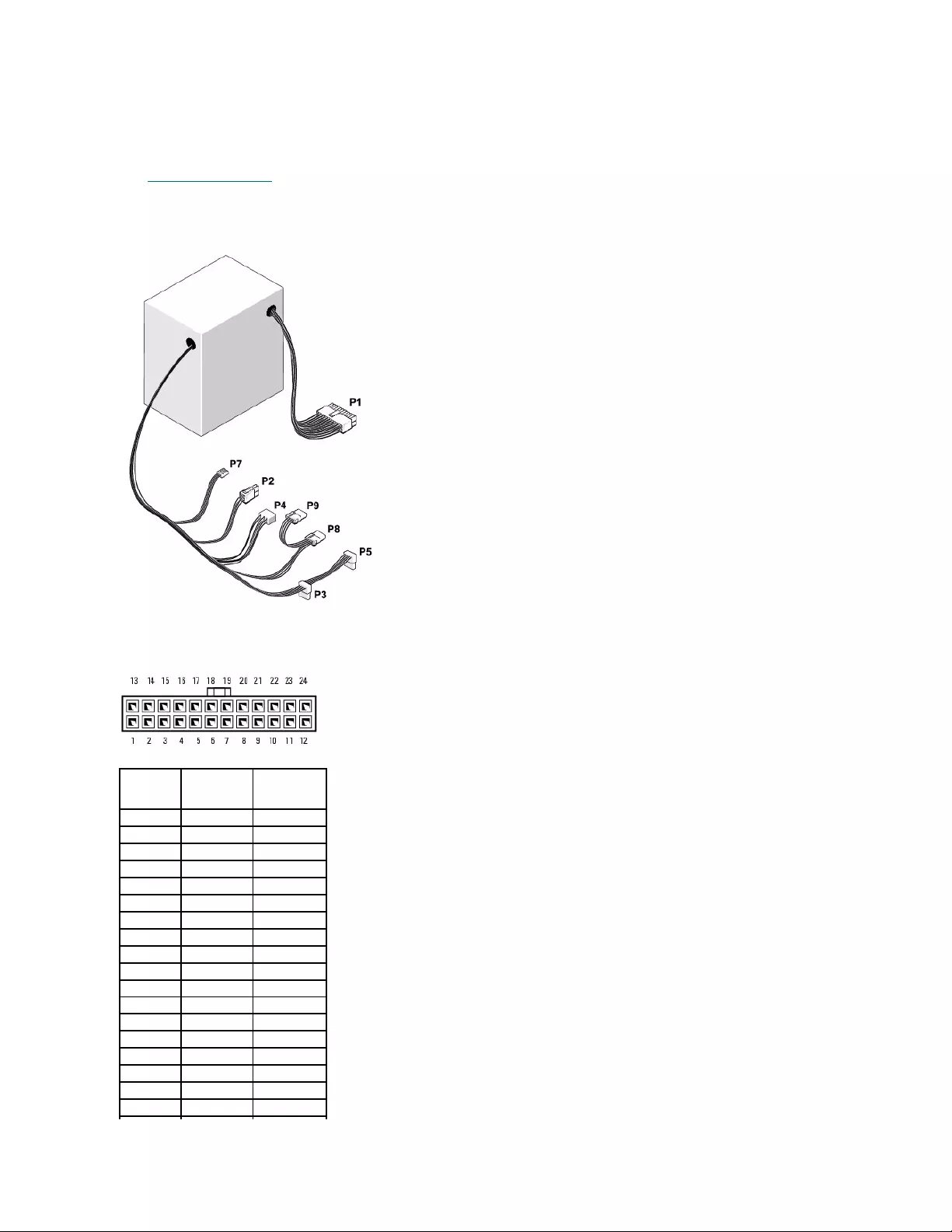
9. Reconnect the DC power cables to the power supply.
10. Connect the AC power cable to the AC power connector.
11. Replace the computer cover.
DC Power Connectors
DC Power Connector P1
Pin Number
Signal name
18-AWG Wire
1
+3.3 VDC
Orange
2
+3.3 VDC
Orange
3
GND
Black
4
VCC (+5 V)
Red
5
GND
Black
6
VCC (+5 V)
Red
7
GND
Black
8
PS_PWRGOOD
Gray
9
P5AUX
Purple
10
V_12P0_DIG
Yellow
11
V_12P0_DIG
Yellow
12
+3.3 V
Orange
13
+3.3 V
Orange
14
-12 V*
Blue
15
GND
Black
16
PWR_PS_ON
Green
17
GND
Black
18
GND
Black
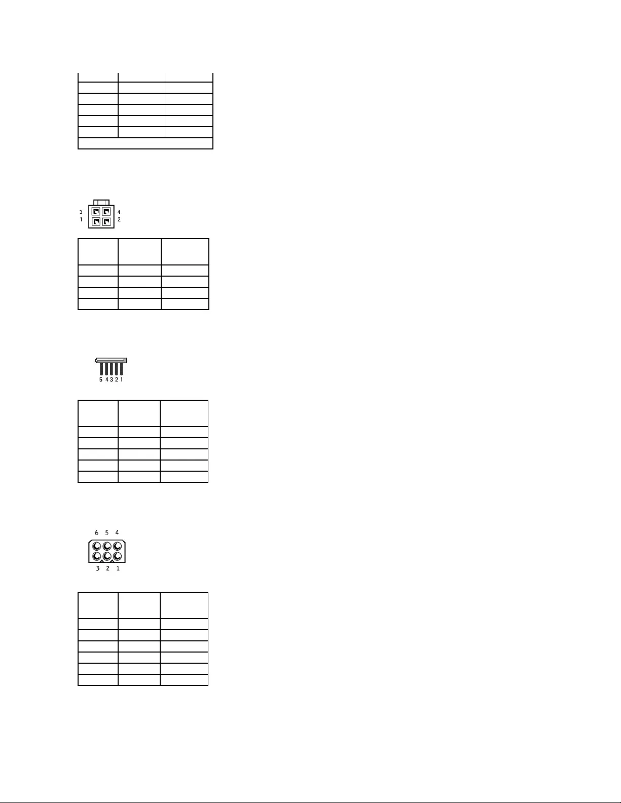
DC Power Connector P2
DC Power Connectors P3 and P5
DC Power Connector P4
DC Power Connector P7
19
GND
Black
20
NC
N/C
21
VCC (+5 V)
Red
22
VCC (+5 V)
Red
23
VCC (+5 V)
Red
24
GND
Black
*Use 22-AWG wire instead of 18-AWG wire.
Pin Number
Signal Name
18-AWG Wire
1
COM
Black
2
COM
Black
3
+12 VDC
Yellow
4
+12 VDC
Yellow
Pin Number
Signal name
18-AWG Wire
1
+3.3 VDC
Orange
2
COM
Black
3
+5 VDC
Red
4
COM
Black
5
+12 VDC
Yellow
Pin Number
Signal name
18-AWG Wire
1
N/C
2
COM
Black
3
COM
Black
4
+ 3.3 VDC
Orange
5
+5 VDC
Red
6
+12 VDC
Yellow
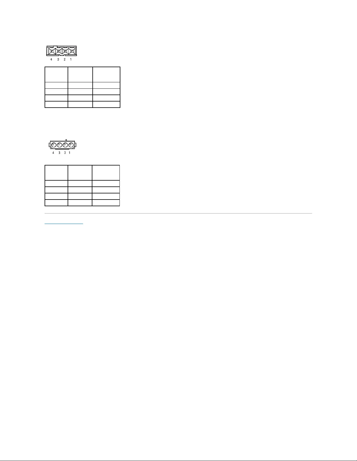
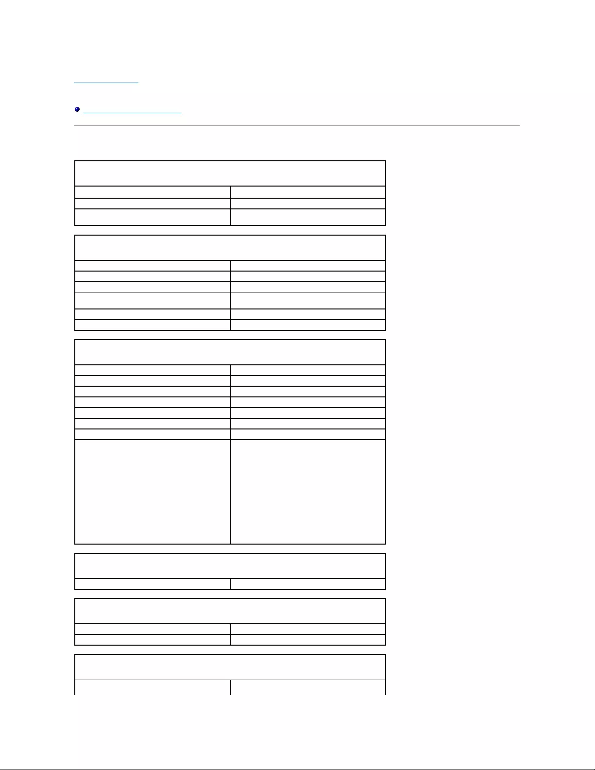
Back to Contents Page
Dell™OptiPlex™GX520User'sGuide
Mini Tower Computer Specifications
Mini Tower Computer Specifications
Microprocessor
Microprocessor type
Intel®Pentium®or Celeron® processor
Level 1 (L1) cache
32 KB
Level 2 (L2) cache
512-KB, 1-MB, or 2-MB pipelined-burst, eight-way set
associative, write-back SRAM
Memory
Type
400-MHz and 533-MHz DDR2 SDRAM
Memory connectors
2
Memory modules supported
256-MB, 512-MB, 1-GB, or 2-GB non-ECC
Minimum memory
dual-channel: 512 MB
single-channel: 256 MB
Maximum memory
4 GB
BIOS address
F0000h
Computer Information
Chipset
Intel®945 Express
Data bus width
64 bits
Address bus width
32 bits
DMA channels
eight
Interrupt levels
24
BIOS chip (NVRAM)
4 Mb
Memory speed
400MHzand533MHz
NIC
integrated network interface with ASF 1.03 and 2.0
support as defined by DMTF
Capable of 10/100/1000 communication:
lGreen — A good connection exists between a
10-Mbps network and the computer.
lOrange — A good connection exists between a
100-Mbps network and the computer.
lYellow — A good connection exists between a
1-Gb (or 1000-Mbps) network and the
computer.
lOff — The computer is not detecting a physical
connection to the network.
Video
Type
integrated Intel Graphic Media Accelerator 950
Audio
Type
AC97, Sound Blaster emulation
Stereo conversion
16-bit analog-to-digital; 20-bit digital-to-analog
Controllers
Drives
four serial ATA controllers supporting one device each
and one parallel Ultra ATA/100 IDE supporting two

devices per channel with one channel
Expansion Bus
Bus type
PCI 2.3
SATA 1.0a and 2.0
USB 2.0
PCI Express 1.0a
Bus speed
PCI: 33 MHz
SATA: 1.5 Gbps and 3.0 Gbps
USB: 480 Mbps
PCI Express x1: 5 Gbps
Cards:
full-height cards supported
PCI:
connectors
two
connector size
120 pins
connector data width
(maximum)
32 bits
PCI Express:
connectors
one x1
power
10 W maximum
connector size
36 pins
connector data width (maximum)
one PCI Express lane
Drives
Externally accessible
one 3.5-inch drive
two 5.25-inch drive bays
Internally accessible
two bays for 1-inch-high hard drives
Connectors
External connectors:
Serial
9-pin connector; 16550C-compatible
Parallel
25-hole connector (bidirectional)
Video
15-hole VGA connector
Network adapter
RJ45 connector
Optional PS/2 with secondary serial port
adapter
two 6-pin mini-DINs
USB
two front-panel and six back-panel USB 2.0–
compliant connectors
Audio
three connectors for line-in, line-out, and microphone;
two front-panel connectors for headphones and
microphone
System board connectors:
Primary IDE drive
40-pin connector
Serial ATA
four 7-pin connectors
Floppy drive
34-pin connector
Serial
12-pin connector for optional second serial port card
Fan
5-pin connector
PCI 2.2
120-pin connector
CD drive audio interface
4-pin connector
Front panel
40-pin connector
Key Combinations
<Ctrl><Alt><Del>
in Microsoft®Windows®XP, brings up the Windows
Security window.; in MS-DOS®mode, restarts
(reboots) the computer
<F2> or <Ctrl><Alt><Enter>
starts embedded system setup (during system start-
up only)
<Ctrl><Alt><b>
automatically starts the computer from the network
environment specified by the remote boot
environment (PXE) rather than from one of the
devices in the system setup Boot Sequence option
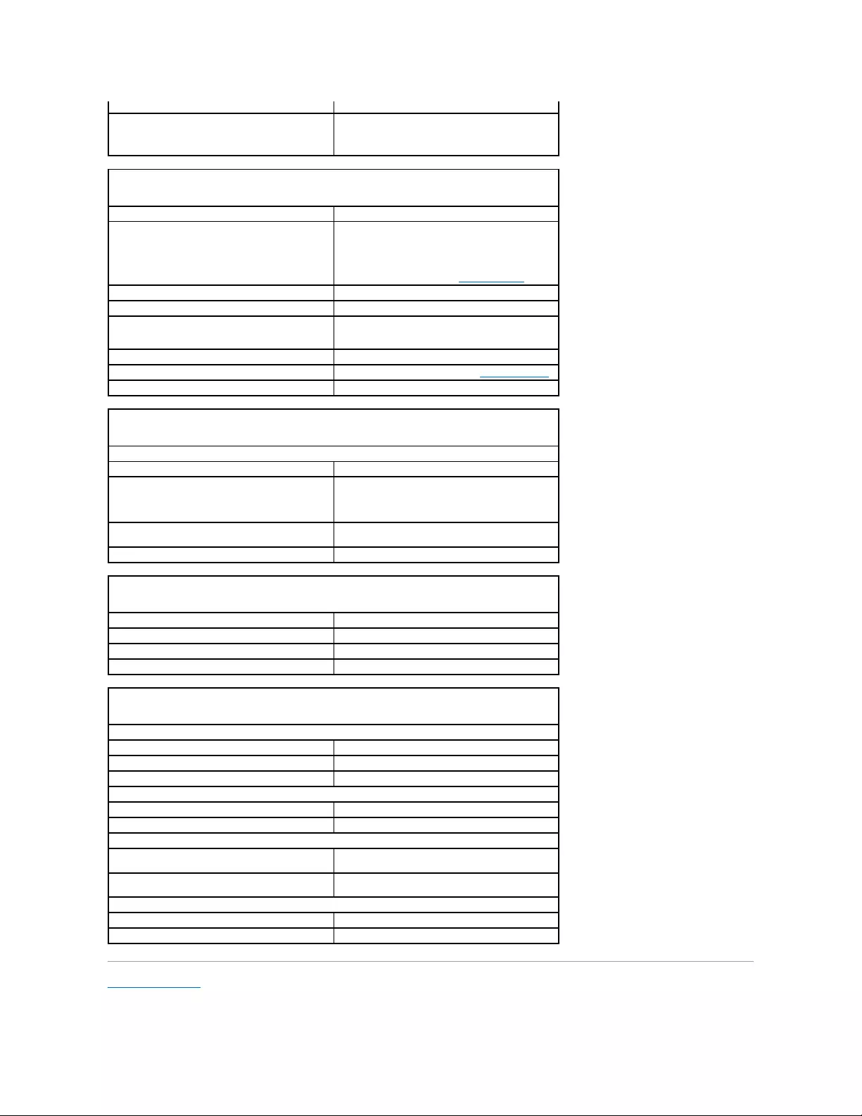
Back to Contents Page
(during system tart-up only)
<F12> or <Ctrl><Alt><F8>
displays a boot device menu that allows the user to
enter a device for a single boot (during system start-
up only) as well as options to run hard-drive and
system diagnostics
Controls and Lights
Power control
push button
Power light
green light — Blinking green indicates sleep mode;
solid green indicates power-on state.
amber light — Blinking amber indicates a problem
with an installed device; solid amber indicates an
internal power problem (see "Power Problems").
Hard-drive access light
green
Link light
solid green light indicates network connection
Link integrity light (on integrated network adapter)
green light for 10-Mb operation; orange light for 100-
Mb operation; yellow light for a 1000-Mb (1-Gb)
operation
Activity light (on integrated network adapter)
yellow blinking light
Diagnostic lights
four lights on the back panel (see "Diagnostic Lights")
Standby power light
AUX_PWR on the system board
Power
DC power supply:
Wattage
230 W
Heat dissipation
785 BTU/hr
NOTE: Heat dissipation is calculated based upon the
power supply wattage rating.
Voltage
manual selection power supplies — 90 to 135 V at
50/60Hz;180to265Vat50/60Hz
Backup battery
3-V CR2032 lithium coin cell
Physical
Height
41.4 cm (16.3 inches)
Width
18.5 cm (7.3 inches)
Depth
43.9 cm (17.3 inches)
Weight
12.34 kg (27.2 lb)
Environmental
Temperature:
Operating
10°to35°C(50°to95°F)
Storage
–40°to65°C(–40°to149°F)
Relative humidity
20% to 80% (noncondensing)
Maximum vibration:
Operating
0.25 G at 3 to 200 Hz at 0.5 octave/min
Storage
0.5 G at 3 to 200 Hz at 1 octave/min
Maximum shock:
Operating
bottom half-sine pulse with a change in velocity of
50.8 cm/sec (20 inches/sec)
Storage
27-G faired square wave with a velocity change of
508 cm/sec (200 inches/sec)
Altitude:
Operating
–15.2 to 3048 m (–50 to 10,000 ft)
Storage
–15.2 to 10,668 m (–50 to 35,000 ft)


Back to Contents Page
FCC Notices (U.S. Only)
Dell™OptiPlex™GX520User'sGuide
Electromagnetic Interference (EMI) is any signal or emission, radiated in free space or conducted along power or signal leads, that endangers the functioning
of a radio navigation or other safety service or seriously degrades, obstructs, or repeatedly interrupts a licensed radio communications service. Radio
communications services include but are not limited to AM/FM commercial broadcast, television, cellular services, radar, air-traffic control, pager, and Personal
Communication Services (PCS). These licensed services, along with unintentional radiators such as digital devices, including computer systems, contribute to
the electromagnetic environment.
Electromagnetic Compatibility (EMC) is the ability of items of electronic equipment to function properly together in the electronic environment. While this
computer system has been designed and determined to be compliant with regulatory agency limits for EMI, there is no guarantee that interference will not
occur in a particular installation. If this equipment does cause interference with radio communications services, which can be determined by turning the
equipment off and on, you are encouraged to try to correct the interference by one or more of the following measures:
lReorient the receiving antenna.
lRelocate the computer with respect to the receiver.
lMove the computer away from the receiver.
lPlug the computer into a different outlet so that the computer and the receiver are on different branch circuits.
If necessary, consult a Dell Technical Support representative or an experienced radio/television technician for additional suggestions.
For additional regulatory information, see the Product Information Guide that came with your computer.
Dell™computersystemsaredesigned,tested,andclassifiedfortheirintendedelectromagneticenvironment.Theseelectromagneticenvironment
classifications generally refer to the following harmonized definitions:
lClass A is typically for business or industrial environments.
lClass B is typically for residential environments.
Information Technology Equipment (ITE), including peripherals, expansion cards, printers, input/output (I/O) devices, monitors, and so on, that are integrated
into or connected to the system should match the electromagnetic environment classification of the computer system.
A Notice About Shielded Signal Cables: Use only shielded cables for connecting peripherals to any Dell device to reduce the possibility of interference
with radio communications services. Using shielded cables ensures that you maintain the appropriate EMC classification for the intended environment.
For parallel printers, a cable is available from Dell. If you prefer, you can order a cable from Dell on the World Wide Web at
accessories.us.dell.com/sna/category.asp?category_id=4117.
Most Dell computer systems are classified for Class B environments. However, the inclusion of certain options can change the rating of some configurations to
Class A. To determine the electromagnetic classification for your system or device, see the following sections specific for each regulatory agency. Each section
provides country-specific EMC/EMI or product safety information.
FCC Notices (U.S. Only)
Most Dell computer systems are classified by the Federal Communications Commission (FCC) as Class B digital devices. To determine which classification
applies to your computer system, examine all FCC registration labels located on the bottom, side, or back panel of your computer, on card-mounting brackets,
and on the cards themselves. If any one of the labels carries a Class A rating, your entire system is considered to be a Class A digital device. If all labels carry
an FCC Class B rating as distinguished by either an FCC ID number or the FCC logo, ( ), your system is considered to be a Class B digital device.
Once you have determined your system's FCC classification, read the appropriate FCC notice. Note that FCC regulations provide that changes or modifications
not expressly approved by Dell could void your authority to operate this equipment.
This device complies with Part 15 of the FCC Rules. Operation is subject to the following two conditions:
lThis device may not cause harmful interference.
lThis device must accept any interference received, including interference that may cause undesired operation.
Class A
This equipment has been tested and found to comply with the limits for a Class A digital device pursuant to Part 15 of the FCC Rules. These limits are designed
to provide reasonable protection against harmful interference when the equipment is operated in a commercial environment. This equipment generates, uses,
and can radiate radio frequency energy and, if not installed and used in accordance with the manufacturer's instruction manual, may cause harmful
interference with radio communications. Operation of this equipment in a residential area is likely to cause harmful interference, in which case you will be
required to correct the interference at your own expense.
Class B
This equipment has been tested and found to comply with the limits for a Class B digital device pursuant to Part 15 of the FCC Rules. These limits are designed
to provide reasonable protection against harmful interference in a residential installation. This equipment generates, uses, and can radiate radio frequency
energy and, if not installed and used in accordance with the manufacturer's instruction manual, may cause interference with radio communications. However,
there is no guarantee that interference will not occur in a particular installation. If this equipment does cause harmful interference to radio or television
reception, which can be determined by turning the equipment off and on, you are encouraged to try to correct the interference by one or more of the following
measures:
lReorient or relocate the receiving antenna.

lIncrease the separation between the equipment and the receiver.
lConnect the equipment into an outlet on a circuit different from that to which the receiver is connected.
lConsult the dealer or an experienced radio/television technician for help.
FCC Identification Information
The following information is provided on the device or devices covered in this document in compliance with FCC regulations:
lModel numbers: DCTR, DCNE, and DCSM
lCompany name:
Dell Inc.
One Dell Way
Round Rock, Texas 78682 USA
512-338-4400
Back to Contents Page

Back to Contents Page
FCC Notices (U.S. Only)
Dell™OptiPlex™GX520User'sGuide
Electromagnetic Interference (EMI) is any signal or emission, radiated in free space or conducted along power or signal leads, that endangers the functioning
of a radio navigation or other safety service or seriously degrades, obstructs, or repeatedly interrupts a licensed radio communications service. Radio
communications services include but are not limited to AM/FM commercial broadcast, television, cellular services, radar, air-traffic control, pager, and Personal
Communication Services (PCS). These licensed services, along with unintentional radiators such as digital devices, including computer systems, contribute to
the electromagnetic environment.
Electromagnetic Compatibility (EMC) is the ability of items of electronic equipment to function properly together in the electronic environment. While this
computer system has been designed and determined to be compliant with regulatory agency limits for EMI, there is no guarantee that interference will not
occur in a particular installation. If this equipment does cause interference with radio communications services, which can be determined by turning the
equipment off and on, you are encouraged to try to correct the interference by one or more of the following measures:
lReorient the receiving antenna.
lRelocate the computer with respect to the receiver.
lMove the computer away from the receiver.
lPlug the computer into a different outlet so that the computer and the receiver are on different branch circuits.
If necessary, consult a Dell Technical Support representative or an experienced radio/television technician for additional suggestions.
For additional regulatory information, see the Product Information Guide that came with your computer.
Dell™computersystemsaredesigned,tested,andclassifiedfortheirintendedelectromagneticenvironment.Theseelectromagneticenvironment
classifications generally refer to the following harmonized definitions:
lClass A is typically for business or industrial environments.
lClass B is typically for residential environments.
Information Technology Equipment (ITE), including peripherals, expansion cards, printers, input/output (I/O) devices, monitors, and so on, that are integrated
into or connected to the system should match the electromagnetic environment classification of the computer system.
A Notice About Shielded Signal Cables: Use only shielded cables for connecting peripherals to any Dell device to reduce the possibility of interference
with radio communications services. Using shielded cables ensures that you maintain the appropriate EMC classification for the intended environment.
For parallel printers, a cable is available from Dell. If you prefer, you can order a cable from Dell on the World Wide Web at
accessories.us.dell.com/sna/category.asp?category_id=4117.
Most Dell computer systems are classified for Class B environments. However, the inclusion of certain options can change the rating of some configurations to
Class A. To determine the electromagnetic classification for your system or device, see the following sections specific for each regulatory agency. Each section
provides country-specific EMC/EMI or product safety information.
FCC Notices (U.S. Only)
Most Dell computer systems are classified by the Federal Communications Commission (FCC) as Class B digital devices. To determine which classification
applies to your computer system, examine all FCC registration labels located on the bottom, side, or back panel of your computer, on card-mounting brackets,
and on the cards themselves. If any one of the labels carries a Class A rating, your entire system is considered to be a Class A digital device. If all labels carry
an FCC Class B rating as distinguished by either an FCC ID number or the FCC logo, ( ), your system is considered to be a Class B digital device.
Once you have determined your system's FCC classification, read the appropriate FCC notice. Note that FCC regulations provide that changes or modifications
not expressly approved by Dell could void your authority to operate this equipment.
This device complies with Part 15 of the FCC Rules. Operation is subject to the following two conditions:
lThis device may not cause harmful interference.
lThis device must accept any interference received, including interference that may cause undesired operation.
Class A
This equipment has been tested and found to comply with the limits for a Class A digital device pursuant to Part 15 of the FCC Rules. These limits are designed
to provide reasonable protection against harmful interference when the equipment is operated in a commercial environment. This equipment generates, uses,
and can radiate radio frequency energy and, if not installed and used in accordance with the manufacturer's instruction manual, may cause harmful
interference with radio communications. Operation of this equipment in a residential area is likely to cause harmful interference, in which case you will be
required to correct the interference at your own expense.
Class B
This equipment has been tested and found to comply with the limits for a Class B digital device pursuant to Part 15 of the FCC Rules. These limits are designed
to provide reasonable protection against harmful interference in a residential installation. This equipment generates, uses, and can radiate radio frequency
energy and, if not installed and used in accordance with the manufacturer's instruction manual, may cause interference with radio communications. However,
there is no guarantee that interference will not occur in a particular installation. If this equipment does cause harmful interference to radio or television
reception, which can be determined by turning the equipment off and on, you are encouraged to try to correct the interference by one or more of the following
measures:
lReorient or relocate the receiving antenna.

lIncrease the separation between the equipment and the receiver.
lConnect the equipment into an outlet on a circuit different from that to which the receiver is connected.
lConsult the dealer or an experienced radio/television technician for help.
FCC Identification Information
The following information is provided on the device or devices covered in this document in compliance with FCC regulations:
lModel numbers: DCTR, DCNE, and DCSM
lCompany name:
Dell Inc.
One Dell Way
Round Rock, Texas 78682 USA
512-338-4400
Back to Contents Page

Back to Contents Page
Reinstalling Drivers and the Operating System
Dell™OptiPlex™GX520User'sGuide
Drivers
Using Microsoft®Windows®XP System Restore
Reinstalling Microsoft Windows XP
Drivers
What Is a Driver?
A driver is a program that controls a device such as a printer, mouse, or keyboard. All devices require a driver program.
A driver acts like a translator between the device and any other programs that use the device. Each device has its own set of specialized commands that only
its driver recognizes.
Dell ships your computer to you with required drivers already installed—no further installation or configuration is needed.
Many drivers, such as the keyboard driver, come with your Microsoft Windows operating system. You may need to install drivers if you:
lUpgrade your operating system.
lReinstall your operating system.
lConnect or install a new device.
Identifying Drivers
If you experience a problem with any device, identify whether the driver is the source of your problem and, if necessary, update the driver.
1. Click the Start button and click Control Panel.
2. Under Pick a Category, click Performance and Maintenance.
3. Click System.
4. In the System Properties window, click the Hardware tab.
5. Click Device Manager.
6. Scroll down the list to see if any device has an exclamation point (a yellow circle with a [!]) on the device icon.
If an exclamation point is next to the device name, you may need to reinstall the driver or install a new driver.
Reinstalling Drivers and Utilities
Using Windows XP Device Driver Rollback
If a problem occurs on your computer after you install or update a driver, use Windows XP Device Driver Rollback to replace the driver with the previously
installed version.
CAUTION: Before you begin any of the procedures in this section, follow the safety instructions in the Product Information Guide.
NOTICE: You must use Microsoft®Windows®XP Service Pack 1 or later when you reinstall the Microsoft Windows XP operating system.
NOTE: If you installed a unique image on your computer or if you had to reinstall your operating system, run the DSS utility. DSS is available on your
optional Drivers and Utilities CD and at support.dell.com.
NOTICE: The optional Drivers and Utilities CD may contain drivers for operating systems that are not on your computer. Ensure that you are installing
software appropriate for your operating system.
NOTICE: The Dell Support website at support.dell.com and your Drivers and UtilitiesCDprovideapproveddriversforDell™computers.Ifyouinstall
drivers obtained from other sources, your computer might not work correctly.
NOTE: The Drivers and Utilities CD (ResourceCD) is optional, and as such, may not ship with certain computers.

1. Click the Start button and click Control Panel.
2. Under Pick a Category, click Performance and Maintenance.
3. Click System.
4. In the System Properties window, click the Hardware tab.
5. Click Device Manager.
6. Right-click the device for which the new driver was installed and click Properties.
7. Click the Drivers tab.
8. Click Roll Back Driver.
If Device Driver Rollback does not resolve the problem, then use System Restore (see "Enabling System Restore") to return your computer to the operating
state that existed before you installed the new driver.
Using the Optional Drivers and Utilities CD
If using Device Driver Rollback or System Restore does not resolve the problem, then reinstall the driver from the Drivers and Utilities CD (also known as the
ResourceCD).
1. Insert the Drivers and Utilities CD.
If this is your first time to use the Drivers and Utilities CD, the Installation window opens to inform you that the CD will begin the installation. Click OK
and respond to the installation program prompts to complete the installation.
2. Click Next at the Welcome Dell System Owner screen.
3. Choose the appropriate selections for System Model, Operating System, Device Type, and Topic.
4. Click My Drivers in the Topic drop-down menu.
The Drivers and Utilities CD scans your computer's hardware and operating system and then displays a list of device drivers for your system
configuration.
5. Click the appropriate driver and follow the instructions to download the driver for your computer.
To view a list of all available drivers for your computer, click Drivers in the Topic drop-down menu.
To access the help files on the Drivers and Utilities CD, click the question mark button or the Help link at the top of the screen.
Using Microsoft®Windows®XP System Restore
The Microsoft Windows XP operating system provides System Restore to allow you to return your computer to an earlier operating state (without affecting
data files) if changes to the hardware, software, or other system settings have left the computer in an undesirable operating state. See the Windows Help
and Support Center for information on using System Restore.
Creating a Restore Point
1. Click the Start button and click Help and Support.
2. Click System Restore.
3. Follow the instructions on the screen.
NOTE: The Drivers and Utilities CD (ResourceCD) is optional, and as such, may not ship with all computers.
NOTE: To access device drivers and user documentation, you must use the Drivers and Utilities CD while your computer is running Windows.
NOTICE: Make regular backups of your data files. System Restore does not monitor your data files or recover them.

Restoring the Computer to an Earlier Operating State
1. Click the Start button, point to All Programs® Accessories® System Tools, and then click System Restore.
2. Ensure that Restore my computer to an earlier time is selected and click Next.
3. Click a calendar date to which you want to restore your computer.
The Select a Restore Point screen provides a calendar that allows you to see and select restore points. All calendar dates with available restore points
appear in boldface type.
4. Select a restore point and click Next.
If a calendar date has only one restore point, then that restore point is automatically selected. If two or more restore points are available, click the
restore point that you prefer.
5. Click Next.
The Restoration Complete screen appears after System Restore finishes collecting data and then the computer restarts.
6. After the computer restarts, click OK.
To change the restore point, you can either repeat the steps using a different restore point, or you can undo the restoration.
Undoing the Last System Restore
1. Click the Start button, point to All Programs® Accessories® System Tools, and then click System Restore.
2. Click Undo my last restoration and click Next.
3. Click Next.
The System Restore screen appears and the computer restarts.
4. After the computer restarts, click OK.
Enabling System Restore
If you reinstall Windows XP with less than 200 MB of free hard-disk space available, System Restore is automatically disabled. To see if System Restore is
enabled:
1. Click the Start button and click Control Panel.
2. Click Performance and Maintenance.
3. Click System.
4. Click the System Restore tab.
5. Ensure that Turn off System Restore is unchecked.
Reinstalling Microsoft Windows XP
Before You Begin
NOTICE: Before you restore the computer to an earlier operating state, save and close any open files and exit any open programs. Do not alter, open,
or delete any files or programs until the system restoration is complete.
NOTICE: Before you undo the last system restore, save and close all open files and exit any open programs. Do not alter, open, or delete any files or
programs until the system restoration is complete.
NOTICE: You must use Windows XP Service Pack 1 or later when you reinstall your operating system.

If you are considering reinstalling the Windows XP operating system to correct a problem with a newly installed driver, first try using Windows XP Device Driver
Rollback. If Device Driver Rollback does not resolve the problem, then use System Restore to return your operating system to the operating state it was in
before you installed the new device driver.
To reinstall Windows XP, you need the following items:
lDell™Operating System CD
lDell Drivers and Utilities CD
Reinstalling Windows XP
To reinstall Windows XP, perform all the steps in the following sections in the order in which they are listed.
The reinstallation process can take 1 to 2 hours to complete. After you reinstall the operating system, you must also reinstall the device drivers, virus
protection program, and other software.
Booting From the Operating System CD
1. Save and close any open files and exit any open programs.
2. Insert the Operating System CD. Click Exit if Install Windows XP message appears.
3. Restart the computer.
4. Press<F12>immediatelyaftertheDELL™logoappears.
If the operating system logo appears, wait until you see the Windows desktop, and then shut down the computer and try again.
5. Press the arrow keys to select CD-ROM, and press <Enter>.
6. When the Press any key to boot from CD message appears, press any key.
Windows XP Setup
1. When the Windows XP Setup screen appears, press <Enter> to select To set up Windows now.
2. Read the information on the Microsoft Windows Licensing Agreement screen, and press <F8> to accept the license agreement.
3. If your computer already has Windows XP installed and you want to recover your current Windows XP data, type r to select the repair option, and
remove the CD.
4. If you want to install a new copy of Windows XP, press <Esc> to select that option.
5. Press <Enter> to select the highlighted partition (recommended), and follow the instructions on the screen.
The Windows XP Setup screen appears, and the operating system begins to copy files and install the devices. The computer automatically restarts
multiple times.
6. When the Regional and Language Options screen appears, select the settings for your location and click Next.
7. Enter your name and organization (optional) in the Personalize Your Software screen, and click Next.
8. At the Computer Name and Administrator Password window, enter a name for your computer (or accept the one provided) and a password, and click
Next.
NOTICE: Before performing the installation, back up all data files on your primary hard drive. For conventional hard drive configurations, the primary
hard drive is the first drive detected by the computer.
NOTE: The Drivers and Utilities CD contains drivers that were installed during assembly of the computer. Use the Drivers and Utilities CD to load any
required drivers.
NOTICE: The Operating System CD provides options for reinstalling Windows XP. The options can overwrite files and possibly affect programs installed
on your hard drive. Therefore, do not reinstall Windows XP unless a Dell technical support representative instructs you to do so.
NOTICE: To prevent conflicts with Windows XP, disable any virus protection software installed on your computer before you reinstall Windows XP. See
the documentation that came with the software for instructions.
NOTICE: Do not press any key when the following message appears: Press any key to boot from the CD.
NOTE: The time required to complete the setup depends on the size of the hard drive and the speed of your computer.

9. If the Modem Dialing Information screen appears, enter the requested information and click Next.
10. Enter the date, time, and time zone in the Date and Time Settings window, and click Next.
11. If the Networking Settings screen appears, click Typical and click Next.
12. If you are reinstalling Windows XP Professional and you are prompted to provide further information regarding your network configuration, enter your
selections. If you are unsure of your settings, accept the default selections.
Windows XP installs the operating system components and configures the computer. The computer automatically restarts.
13. When the Welcome to Microsoft screen appears, click Next.
14. When the How will this computer connect to the Internet? message appears, click Skip.
15. When the Ready to register with Microsoft? screen appears, select No, not at this time and click Next.
16. When the Who will use this computer? screen appears, you can enter up to five users.
17. Click Next.
18. Click Finish to complete the setup, and remove the CD.
19. Reinstall the appropriate drivers with the Drivers and Utilities CD.
20. Reinstall your virus protection software.
21. Reinstall your programs.
Back to Contents Page
NOTICE: Do not press any key when the following message appears: Press any key to boot from the CD.
NOTE: To reinstall and activate your Microsoft Office or Microsoft Works Suite programs, you need the Product Key number located on the back of the
Microsoft Office or Microsoft Works Suite CD sleeve.

Back to Contents Page
Replacing the System Board
Dell™OptiPlex™GX520User'sGuide
Removing the System Board
1. Shut down the computer through the Start menu.
2. Ensure that your computer and attached devices are turned off. If your computer and attached devices did not automatically turn off when you shut
down your computer, turn them off now.
3. Disconnect any telephone or telecommunication lines from the computer.
4. Disconnect your computer and all attached devices from their electrical outlets, and then press the power button to ground the system board.
5. Remove the computer cover:
lRemove the mini tower computer cover.
lRemove the desktop computer cover.
lRemove the small form factor computer cover.
6. Remove any components that restrict access to the system board (CD/DVD drive(s), floppy drive, hard drive, I/O panel (except for small form factor
computer).
7. Remove the processor and heat sink assembly:
lRemove the mini tower processor and heat sink assembly.
lRemove the desktop processor and heat sink assembly.
lRemove the small form factor processor and heat sink assembly.
8. Disconnect all cables from the system board.
9. Remove the screws from the system board. See the illustrations below for screw locations:
lSee "Mini Tower System Board Screws" for an illustration of the screw locations.
lSee "Desktop System Board Screws" for an illustration of the screw locations.
lSee "Small Form Factor System Board Screws" for an illustration of the screw locations.
10. Slide the system board assembly toward the front of the computer, and then lift the board up and away.
Mini Tower System Board Screws
NOTICE: To disconnect a network cable, first unplug the cable from your computer and then unplug it from the network wall jack.
CAUTION: To guard against the electrical shock, always unplug your computer from the electrical outlet before removing the cover.
NOTICE: Before touching anything inside your computer, ground yourself by touching an unpainted metal surface, such as the metal at the back of the
computer. While you work, periodically touch an unpainted metal surface to dissipate any static electricity that could harm internal components.
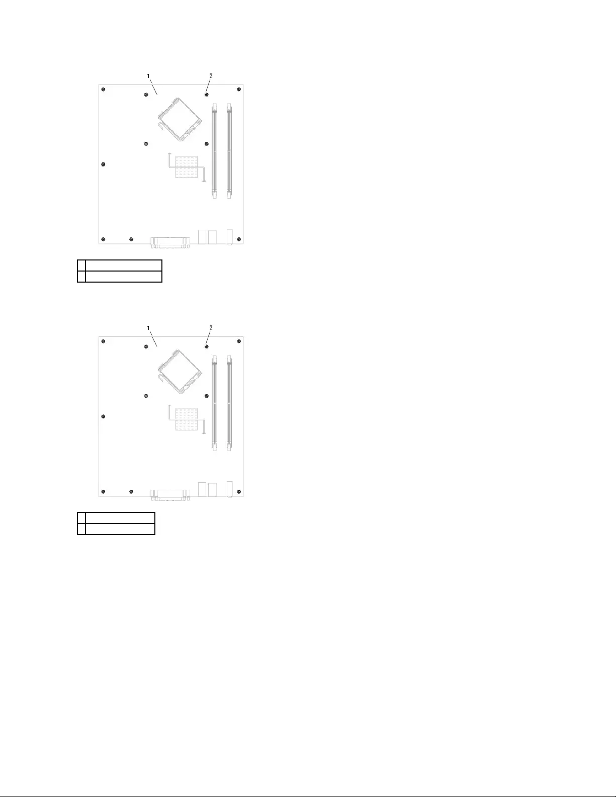
Desktop System Board Screws
Small Form Factor System Board Screws
1
mini tower system board
2
screws (10)
1
desktop system board
2
screws (10)

Place the system board assembly that you just removed next to the replacement system board to ensure it is identical.
Replacing the System Board
1. Gently align the board into the chassis and slide it toward the back of the computer.
2. Replace the screws on the system board.
3. Replace any components and cables that you removed from the system board.
4. Reconnect all cables to their connectors at the back of the computer.
5. Replace the computer cover.
Back to Contents Page
1
small form factor system board
2
screws (8)
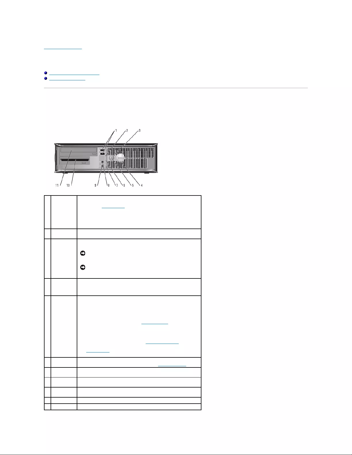
Back to Contents Page
Desktop Computer
Dell™OptiPlex™GX520User'sGuide
About Your Desktop Computer
Inside Your Computer
About Your Desktop Computer
Front View
1
USB 2.0
connectors
(2)
Use the USB connectors on the front of the computer for devices that you
connect occasionally, such as joysticks or cameras, or for bootable USB
devices (see "System Setup" for more information about booting to a
USB device).
It is recommended that you use the USB connectors on the back panel
for devices that typically remain connected, such as printers and
keyboards.
2
LAN indicator
light
This light indicates that a LAN (network) connection is established.
3
power button
Press this button to turn on the computer.
NOTICE: To avoid losing data, do not turn off the computer by
pressing the power button for 6 seconds or longer. Instead,
perform an operating system shutdown.
NOTICE: If your operating system has ACPI enabled, when you
press the power button the computer will perform an operating
system shutdown.
4
Dell badge
This badge can be rotated to match the orientation of your computer. To
rotate the badge, place your fingers around the outside of the badge,
press firmly, and turn the badge. You can also rotate the badge using
the slot provided near the bottom of the badge.
5
power light
The power light illuminates and blinks or remains solid to indicate
different operating states:
lNo light — The computer is turned off.
lSteady green — The computer is in a normal operating state.
lBlinking green — The computer is in a power-saving mode.
lBlinking or solid amber — See "Power Problems."
To exit from a power-saving mode, press the power button or use the
keyboard or the mouse if it is configured as a wake device in the
Windows Device Manager. For more information about sleep modes and
exiting from a power-saving mode, see "Power Management."
See"System Lights" for a description of light codes that can help you
troubleshoot problems with your computer.
6
diagnostic
lights
Use the lights to help you troubleshoot a computer problem based on
the diagnostic code. For more information, see "Diagnostic Lights."
7
hard-drive
activity light
This light flickers when the hard drive is being accessed.
8
headphone
connector
Use the headphone connector to attach headphones and most kinds of
speakers.
9
microphone
connector
Use the microphone connector to attach a microphone.
10
floppy drive
Insert a floppy disk into this drive.
11
CD/DVD drive
Insert a CD or DVD (if applicable) into this drive.
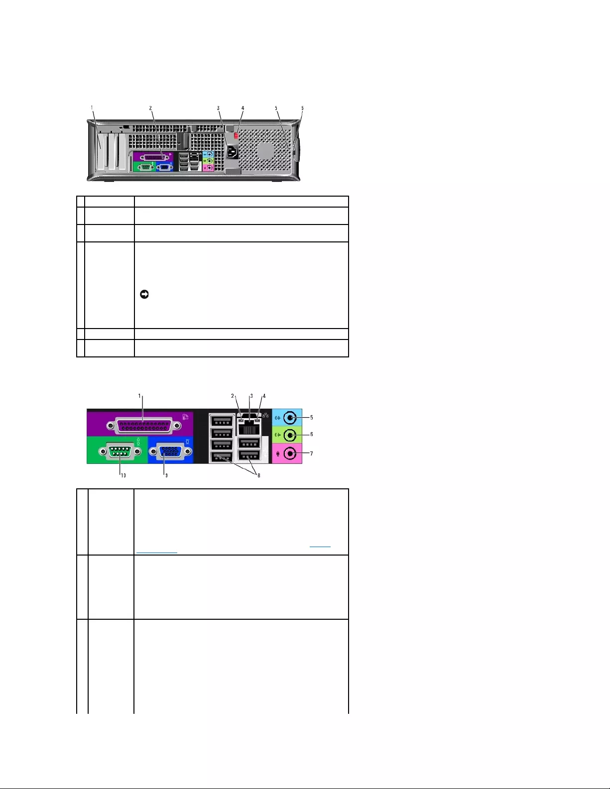
Back View
Back-Panel Connectors
1
card slots
Access connectors for any installed PC Cards.
2
back-panel
connectors
Plug serial, USB, and other devices into the appropriate connector.
3
power
connector
Insert the power cable into this connector.
4
voltage
selection
switch
Your computer is equipped with a manual voltage-selection switch.
To help avoid damaging a computer with a manual voltage-selection
switch, set the switch for the voltage that most closely matches the AC
power available in your location.
Also, ensure that your monitor and attached devices are electrically
rated to operate with the AC power available in your location.
NOTICE: The voltage selection switch must be set to the 115-V
position even though the AC power available in Japan is 100 V.
5
padlock ring
Insert a padlock to lock the computer cover.
6
cover release
latch
Use this latch to open the computer cover.
1
parallel
connector
Connect a parallel device, such as a printer, to the parallel connector. If
you have a USB printer, plug it into a USB connector.
NOTE: The integrated parallel connector is automatically disabled if the
computer detects an installed card containing a parallel connector
configured to the same address. For more information, see "System
Setup Options."
2
link integrity
light
lGreen — A good connection exists between a 10-Mbps network
and the computer.
lOrange — A good connection exists between a 100-Mbps network
and the computer.
lYellow — A good connection exists between a 1-Gbps (or 1000-
Mbps) network and the computer.
lOff — The computer is not detecting a physical connection to the
network.
3
network
adapter
connector
To attach your computer to a network or broadband device, connect one
end of a network cable to either a network jack or your network or
broadband device. Connect the other end of the network cable to the
network adapter connector on the back panel of your computer. A click
indicates that the network cable has been securely attached.
NOTE: Do not plug a telephone cable into the network connector.
On computers with a network connector card, use the connector on the
card.
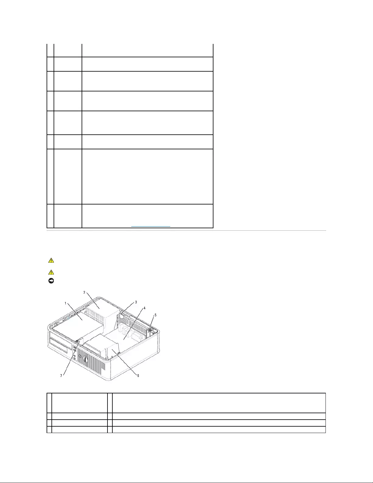
Inside Your Computer
It is recommended that you use Category 5 wiring and connectors for
your network. If you must use Category 3 wiring, force the network
speed to 10 Mbps to ensure reliable operation.
4
network
activity light
This light flashes yellow when the computer is transmitting or receiving
network data. A high volume of network traffic may make this light
appear to be in a steady "on" state.
5
line-in
connector
Use the blue line-in connector to attach a record/playback device such as
a cassette player, CD player, or VCR.
On computers with a sound card, use the connector on the card.
6
line-out
connector
Use the green line-out connector to attach headphones and most
speakers with integrated amplifiers.
On computers with a sound card, use the connector on the card.
7
microphone
connector
Use the pink microphone connector to attach a personal computer
microphone for voice or musical input into a sound or telephony program.
On computers with a sound card, the microphone connector is on the
card.
8
USB 2.0
connectors
(6)
Use the USB connectors on the back panel for devices that typically
remain connected, such as printers and keyboards.
9
video
connector
Plug the cable from your VGA-compatible monitor into the blue connector.
NOTE: If you purchased an optional graphics card, this connector will be
covered by a cap. Connect your monitor to the connector on the graphics
card. Do not remove the cap.
NOTE: If you are using a graphics card that supports dual monitors, use
the y-cable that came with your computer.
10
serial
connector
Connect a serial device, such as a handheld device, to the serial port.
The default designations are COM1 for serial connector 1 and COM2 for
serial connector 2.
For more information, see "System Setup Options."
CAUTION: Before you begin any of the procedures in this section, follow the safety instructions in the Product Information Guide.
CAUTION: To avoid electrical shock, always unplug your computer from the electrical outlet before removing the computer cover.
NOTICE: Be careful when opening the computer cover to ensure that you do not accidentally disconnect cables from the system board.
1
drives bay (CD/DVD, floppy,
and hard drive)
5
two low-profile PCI card slots
Optionally, you can install a PCI riser card that converts one low-profile PCI slot to two full-height slots. A total of three
card slots are available: one low-profile and two full-height card slots.
2
power supply
6
heat sink assembly
3
chassis intrusion switch
7
front I/O panel
4
system board
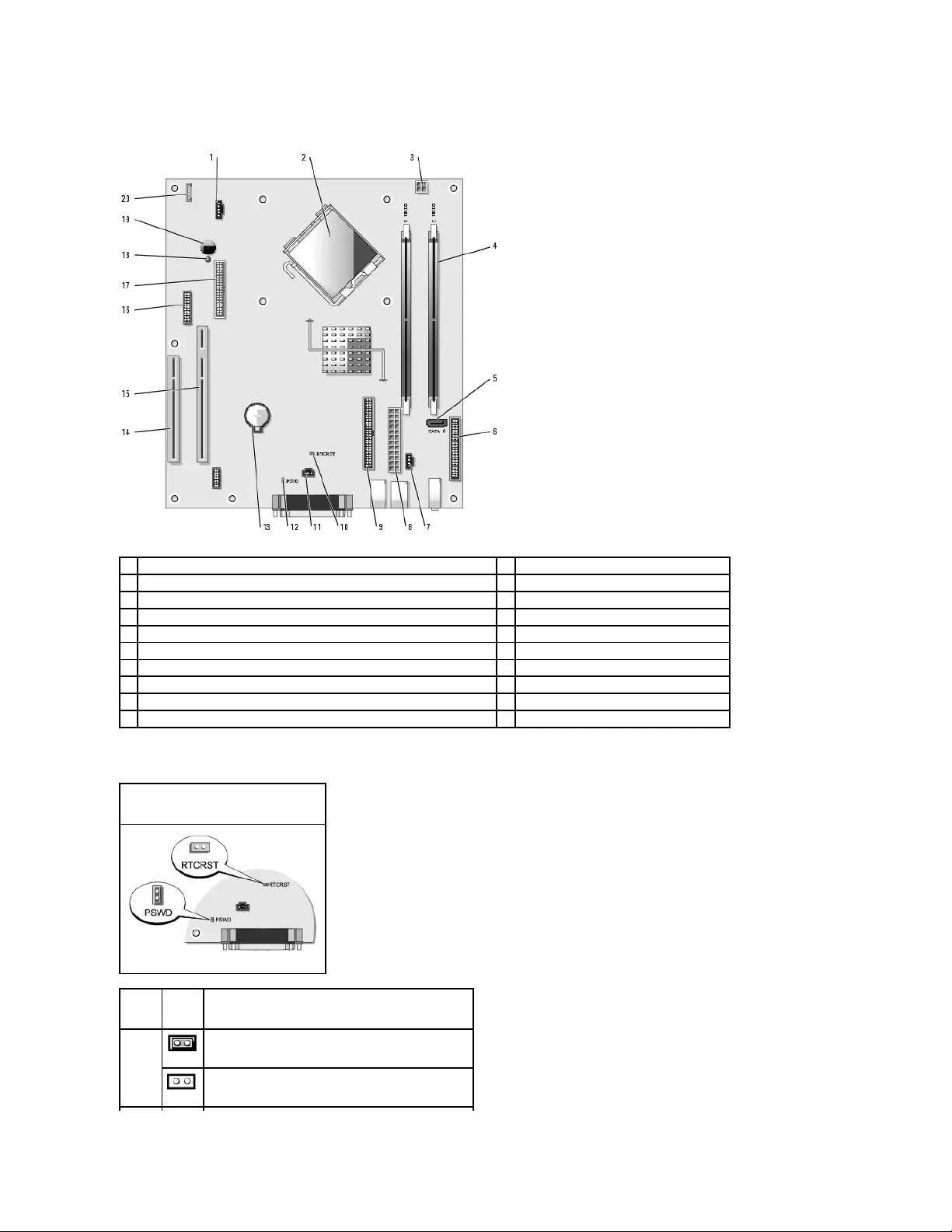
System Board Components
Jumper Settings
1
fan connector (FAN)
11
chassis intrusion switch connector (INTRUDER)
2
processor connector (CPU)
12
password jumper (PSWD)
3
power connector (12VPOWER)
13
battery socket (BATT)
4
memory module connectors (DIMM_1, DIMM_2)
14
PCI connector (SLOT3)
5
serial ATA drive connector (SATA0)
15
PCI riser connector (SLOT2)
6
front-panel connector (FNT_PANEL)
16
serial connector (SER2)
7
CD drive analog audio cable connector for optional analog audio cable (CD_IN)
17
floppy-drive connector (DSKT)
8
power connector (POWER)
18
standby power indicator (AUX_PWR)
9
CD/DVD drive connector (IDE)
19
system board speaker (BEEP)
10
RTC reset jumper (RTCRST)
20
internal speaker (INT_SPKR)
Desktop Computer
Jumper
Setting
Description
PSWD
Password features are enabled (default).
Password features are disabled.

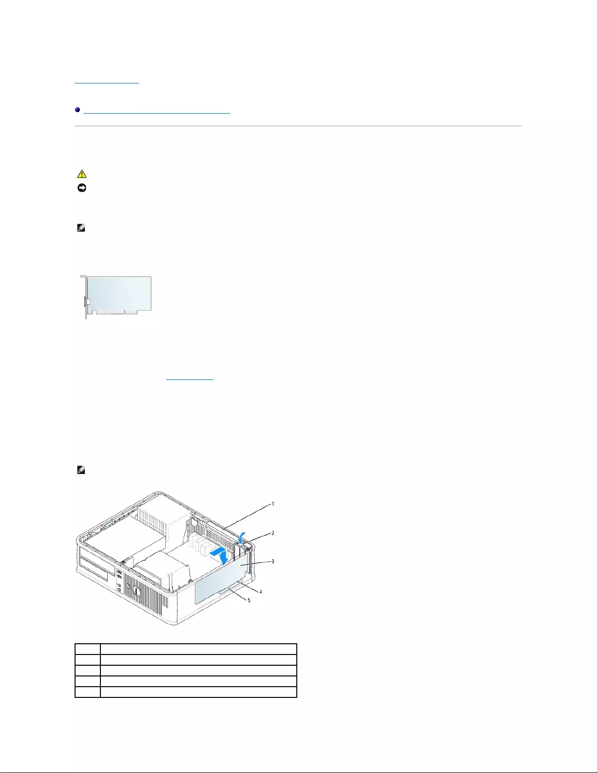
Back to Contents Page
Dell™OptiPlex™GX520User'sGuide
PCI and PCI Express Cards and Serial Port Adapters
PCI and PCI Express Cards and Serial Port Adapters
YourDell™computersupportsaserialportadapterandprovidestwolow-profile PCI card slots for PCI cards:
PCI Cards
Installing a PCI Card
1. Follow the procedures in "Before You Begin."
2. Gently push the release tab on the card retention latch.
3. If you are installing a new card, remove the filler bracket to create a card-slot opening. Then continue with step 5.
4. If you are replacing a card that is already installed in the computer, remove the card. If necessary, disconnect any cables connected to the card.
5. Prepare the card for installation.
CAUTION: Before you begin any of the procedures in this section, follow the safety instructions in the Product Information Guide.
NOTICE: To prevent static damage to components inside your computer, discharge static electricity from your body before you touch any of your
computer's electronic components. You can do so by touching an unpainted metal surface on the computer chassis.
NOTE: Your Dell computer uses only PCI slots. ISA cards are not supported.
NOTE: See the documentation that came with the card for information on configuring the card, making internal connections, or customizing it for your
computer.
1
card retention latch
2
release tab
3
card
4
card-edge connector
5
card connector
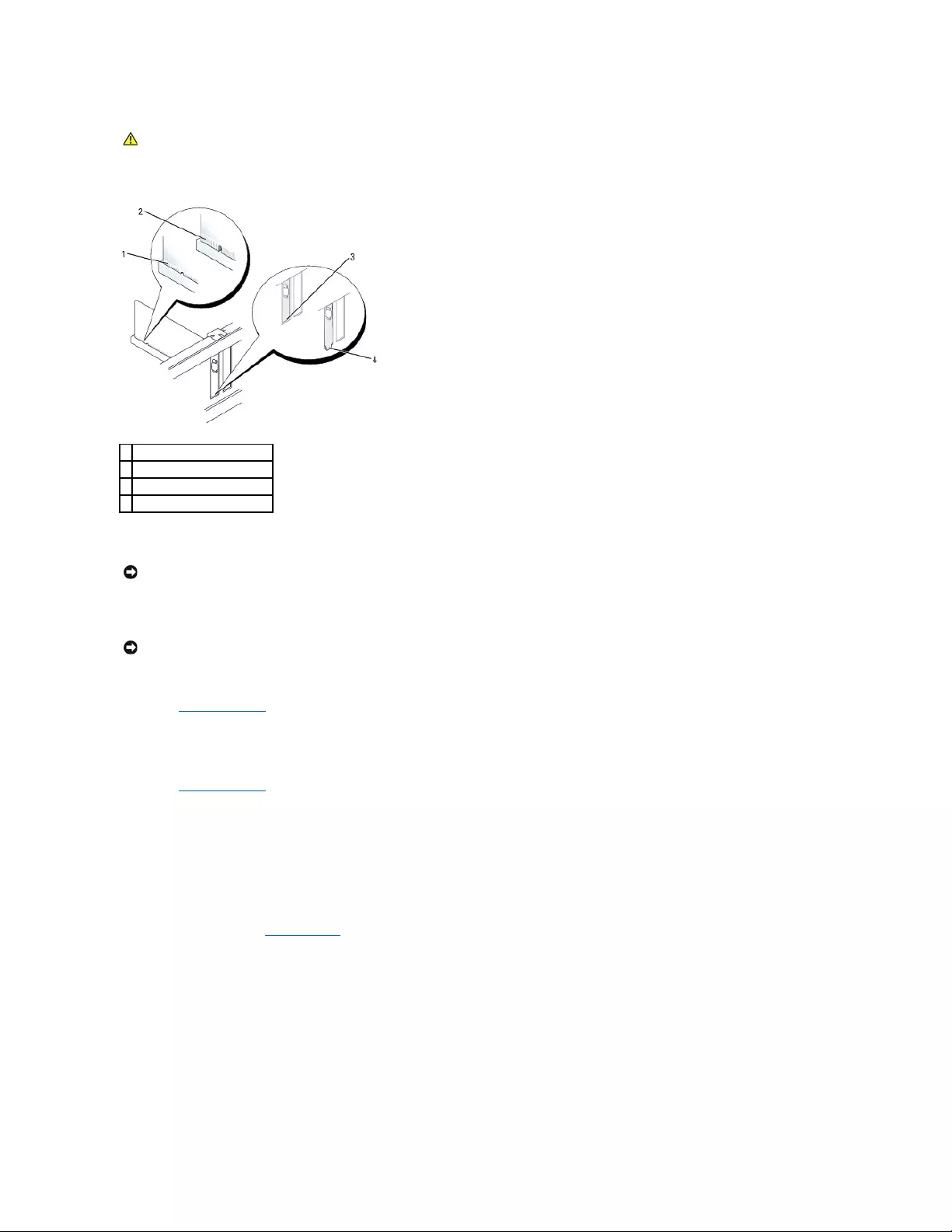
6. Place the card in the connector and press down firmly. Ensure that the card is fully seated in the slot.
7. Gently press down on the card retention latch to secure the card.
8. Connect any cables that should be attached to the card.
9. If you installed a sound card:
a. Enter system setup, select Audio Controller, and change the setting to Off.
b. Connect external audio devices to the sound card's connectors. Do not connect external audio devices to the microphone, speaker/headphone,
or line-in connectors on the back or front panel.
10. If you installed an network adapter card and want to turn off the integrated network adapter:
a. Enter system setup, select Network Controller, and change the setting to Off.
b. Connect the network cable to the network adapter card's connectors. Do not connect the network cable to the integrated network connector on
the back panel.
11. Install any drivers required for the card as described in the card documentation.
Removing a PCI Card
1. Follow the procedures in "Before You Begin."
2. Gently push the release tab on the card retention latch and swing it outward.
3. If necessary, disconnect any cables connected to the card.
4. Grasp the card by its top corners, and ease it out of its connector.
CAUTION: Some network adapters automatically start the computer when they are connected to a network. To guard against electrical shock, be
sure to unplug your computer from its electrical outlet before installing any cards.
1
card fully seated
2
card not fully seated
3
bracket within slot
4
bracket caught outside of slot
NOTICE: Do not route card cables over or behind the cards. Cables routed over the cards can prevent the computer cover from closing properly or
cause damage to the equipment.
NOTICE: To connect a network cable, first plug the cable into the network wall jack and then plug it into the computer.
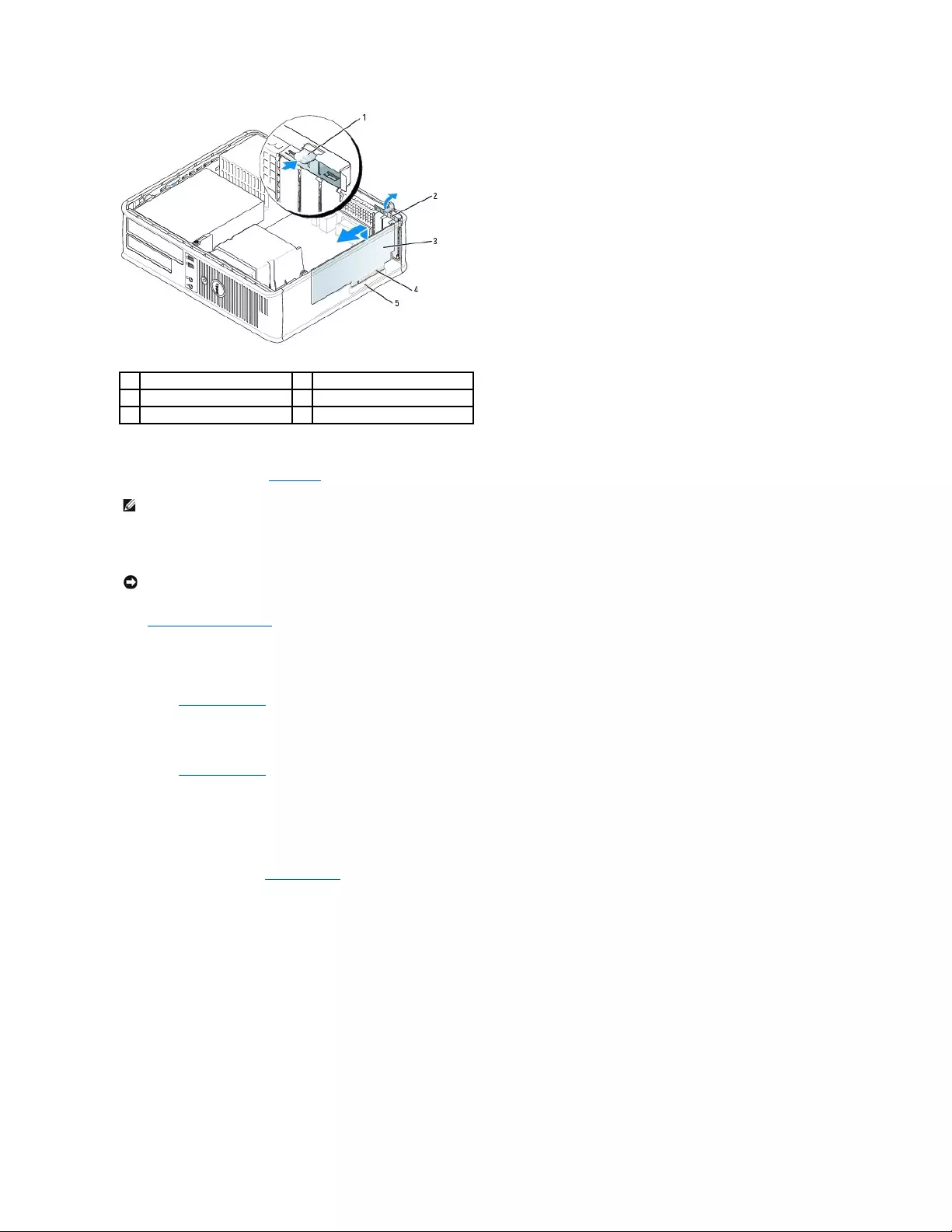
5. If you are removing the card permanently, install a filler bracket in the empty card-slot opening.
If you need a filler bracket, contact Dell.
6. Snap the card retention latch into place.
7. Replace the computer cover.
8. Uninstall the card's driver. See the documentation that came with the card for instructions.
9. If you removed a sound card:
a. Enter system setup, select Audio Controller, and change the setting to On.
b. Connect external audio devices to the audio connectors on the computer back panel.
10. If you removed a network adapter card:
a. Enter system setup, select Network Controller, and change the setting to On.
b. Connect the network cable to the integrated network connector on the back panel of the computer.
Installing a PCI Card in the Riser-Card Cage
1. Follow the procedures in "Before You Begin."
2. If applicable, remove the card installed in the PCI3 connector on the system board.
3. Remove the riser-card cage:
a. Check any cables connected to cards through the back-panel openings. Disconnect any cables that will not reach the riser-card cage once they
are removed from the computer.
b. Gently pull on the handle and lift the riser-card cage up and away from the computer.
1
release tab
4
card-edge connector
2
card retention latch
5
card connector
3
card
NOTE: Installing filler brackets over empty card-slot openings is necessary to maintain FCC certification of the computer. The brackets also keep dust
and dirt out of your computer.
NOTICE: To connect a network cable, first plug the cable into the network wall jack and then plug it into the computer.
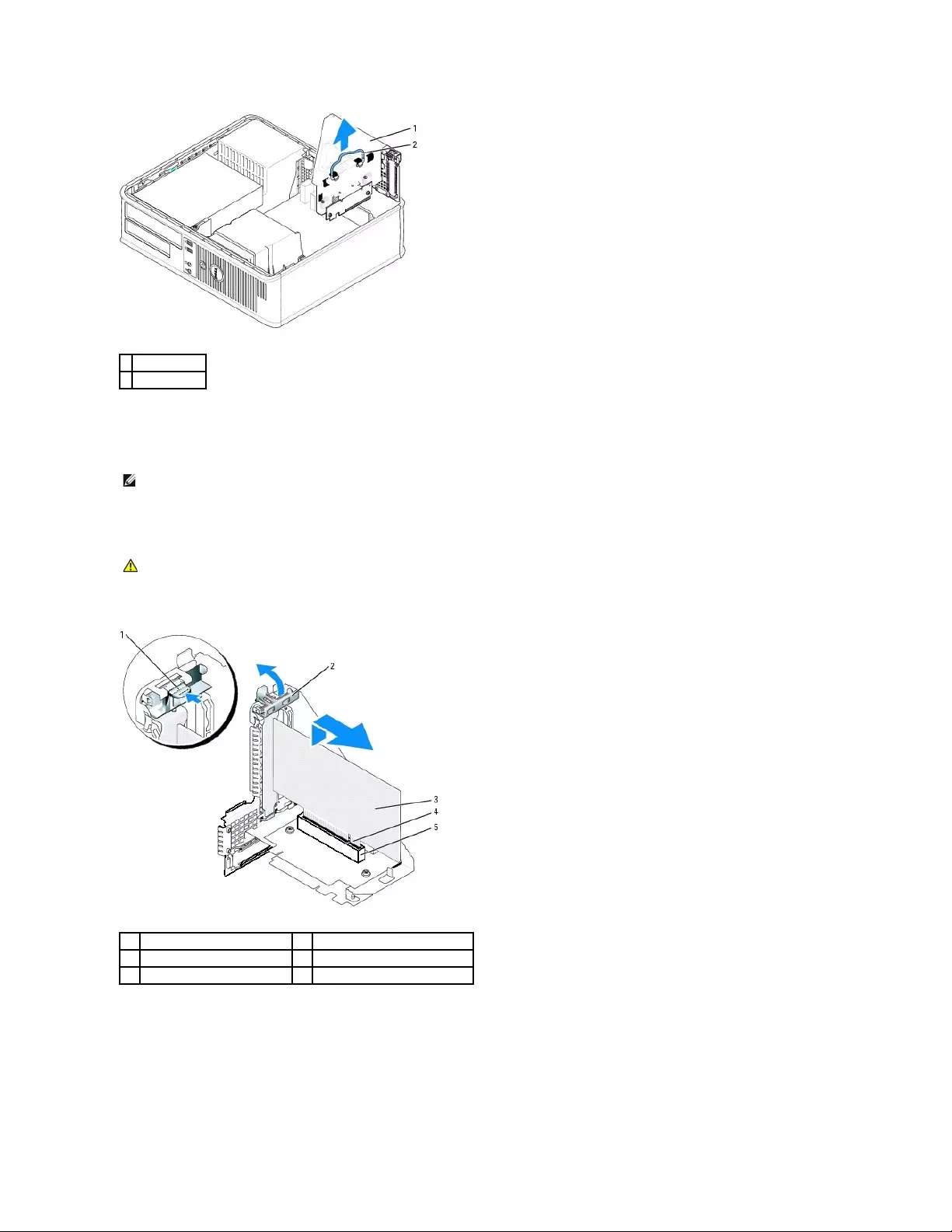
4. If you are installing a new card, remove the filler bracket to create an empty card-slot opening.
If you are replacing a card that is already installed in the computer, remove the card. If necessary, disconnect any cables connected to the card. Grasp
the card by its corners, and ease it out of its connector.
5. Prepare the new card for installation.
6. Press the release tab to raise the card retention latch.
7. Insert the card firmly into the card connector on the riser-card cage.
8. Lower the card retention latch and press it into place, securing the card(s) in the computer.
9. Replace the riser-card cage:
a. Align the tabs in the side of the riser-card cage with the slots on the side of the computer, and slide the riser-card cage down into place.
b. Ensure that the riser board is fully seated in the connector on the system board.
1
riser-card cage
2
handle
NOTE: See the documentation that came with the card for information on configuring the card, making internal connections, or customizing it for your
computer.
CAUTION: Some network adapters automatically start the computer when they are connected to a network. To guard against electrical shock, be
sure to unplug your computer from its electrical outlet before installing any cards.
1
release tab
4
card-edge connector
2
card retention latch
5
card connector
3
card
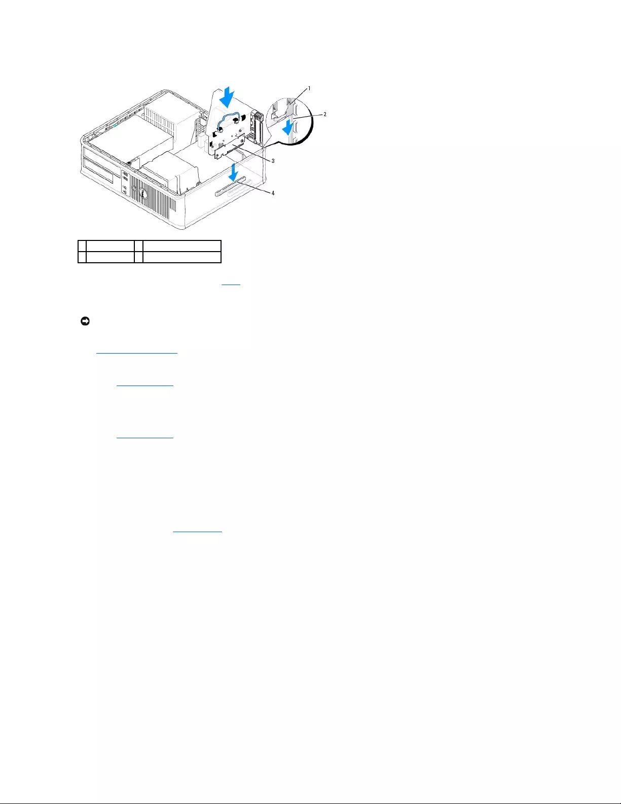
10. Reconnect any cables that you removed in step 3.
11. Connect any cables that should be attached to the card.
12. Replace the computer cover.
13. If you installed a sound card, perform the following steps:
a. Enter system setup, select Audio Controller, and change the setting to Off.
b. Connect external audio devices to the sound card's connectors. Do not connect external audio devices to the microphone, speaker/headphone,
or line-in connectors on the back panel.
14. If you installed an network adapter card and want to turn off the integrated network adapter:
a. Enter system setup, select Network Controller and change the setting to Off.
b. Connect the network cable to the network adapter card's connectors. Do not connect the network cable to the integrated network connector on
the back panel of the computer.
15. Install any drivers required for the card as described in the card documentation.
Removing a PCI Card From the Riser-Card Cage
1. Follow the procedures in "Before You Begin."
2. Remove the riser-card cage:
a. Check any cables connected to cards through the back-panel openings. Disconnect any cables that will not reach the riser-card cage once they
are removed from the computer.
b. Gently pull on the handle and lift the riser-card cage up and away from the computer.
1
riser-card cage
3
riser board
2
slots
4
system board connectors
NOTICE: Do not route card cables over or behind the cards. Cables routed over the cards can prevent the computer cover from closing properly or
cause damage to the equipment.
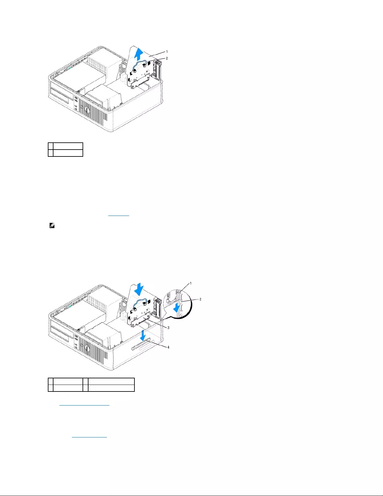
3. Press in on the tab to raise the card retention latch.
4. If necessary, disconnect any cables connected to the card.
5. Grasp the card by its top corners, and ease it out of its connector.
6. If you are removing the card permanently, install a filler bracket in the empty card-slot opening.
If you need a filler bracket, contact Dell.
7. Lower the card retention latch and press it into place.
8. Replace the riser-card cage:
a. Align the tabs in the side of the riser-card cage with the slots on the side of the computer, and slide the riser-card cage down into place.
b. Ensure that the riser board is fully seated in the connector on the system board.
9. Replace the computer cover.
10. Uninstall the card's driver. See the documentation that came with the card for instructions.
11. If you removed a sound card:
a. Enter system setup, select Audio Controller, and change the setting to On.
b. Connect external audio devices to the audio connectors on the computer back panel.
1
riser-card cage
2
handle
NOTE: Installing filler brackets over empty card-slot openings is necessary to maintain FCC certification of the computer. The brackets also keep dust
and dirt out of your computer.
1
riser-card cage
3
riser board
2
slots
4
system board connector
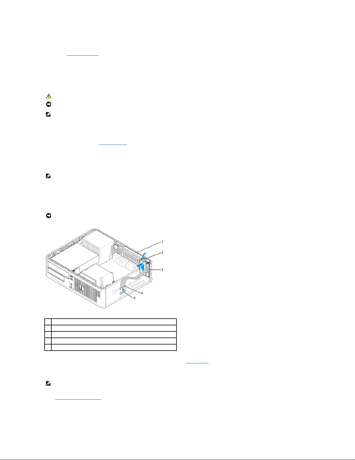
12. If you removed an network adapter card:
a. Enter system setup, select Network Controller, and change the setting to On.
b. Connect the network cable to the integrated network connector on the back panel of the computer.
Serial Port Adapters
Installing a Serial Port Adapter
1. Follow the procedures in "Before You Begin."
2. Gently push the release tab on the adapter retention latch.
3. Remove the filler bracket (if applicable).
4. Place the serial-port adapter bracket in the connector and press down firmly. Ensure that the adapter is fully seated in the slot.
5. Gently press the adapter retention latch to secure the adapter bracket.
6. Connect the adapter cable to the serial-port adapter connector (SER2) on the system board.
7. Connect any cables that should be attached to the serial port adapter.
8. Replace the computer cover.
CAUTION: Before you begin any of the procedures in this section, follow the safety instructions in the Product Information Guide.
NOTICE: To prevent static damage to components inside your computer, discharge static electricity from your body before you touch any of your
computer's electronic components. You can do so by touching an unpainted metal surface on the computer chassis.
NOTE: The serial port adapter for your computer also includes two PS/2 connectors.
NOTE: See the documentation that came with the adapter for information on configuring the adapter, making internal connections, or customizing it for
your computer.
NOTICE: Do not route card cables over or behind the cards. Cables routed over the cards can prevent the computer cover from closing properly or
cause damage to the equipment.
1
adapter retention latch
2
release tab
3
serial-port adapter bracket
4
serial-port adapter connector
5
serial-port adapter system board connector (SER2)
NOTE: See the documentation for the serial-port adapter for information about the cable connections.
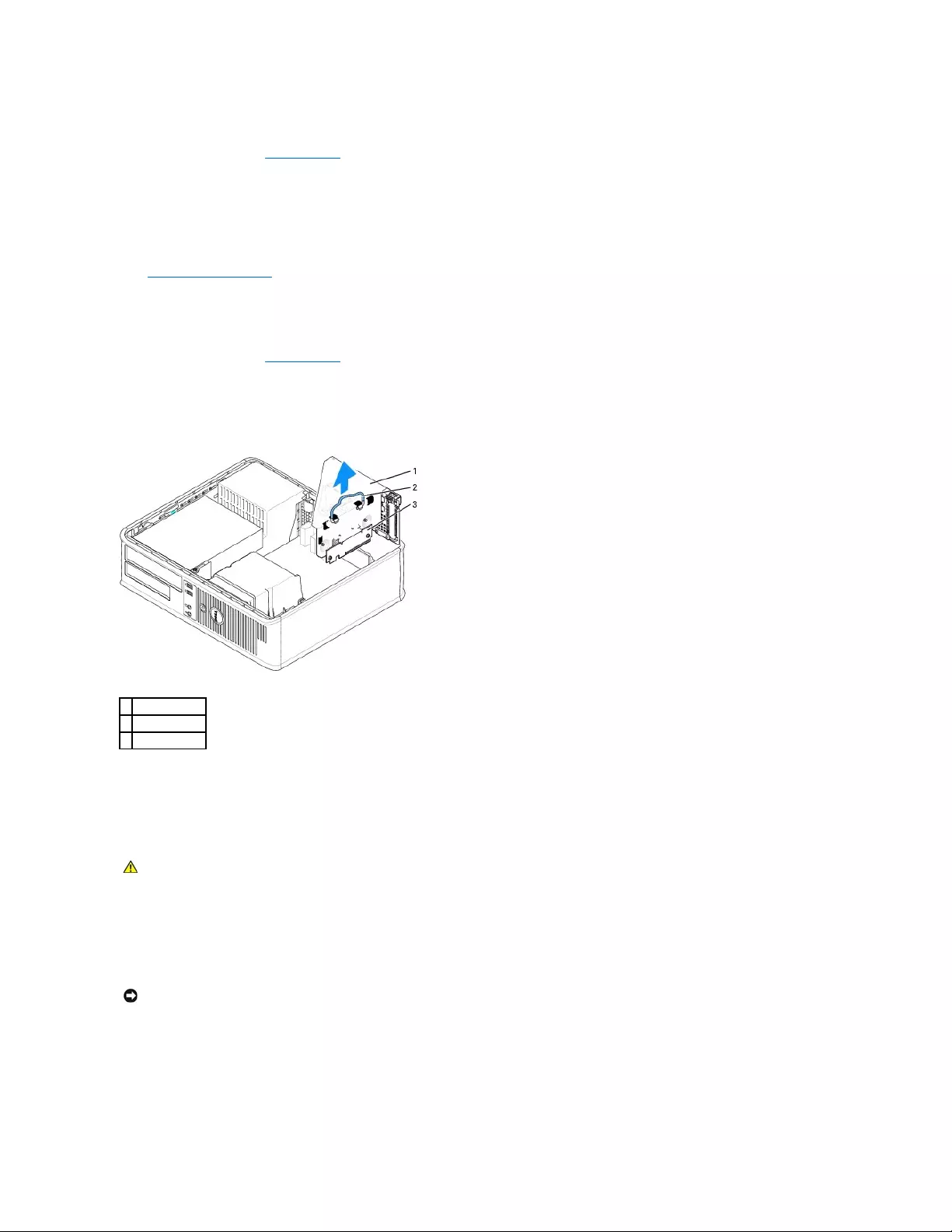
Removing a Serial Port Adapter
1. Follow the procedures in "Before You Begin."
2. Gently push the release tab on the adapter retention latch.
3. Disconnect the cable that connects the adapter to the system board.
4. Grasp the serial-port adapter bracket by its top corners, and ease it out of its connector.
5. Replace the computer cover.
Installing a Serial Port Adapter in the Riser-Card Cage
1. Follow the procedures in "Before You Begin."
2. Remove the riser-card cage:
a. Check any cables connected to cards through the back-panel openings. Disconnect any cables that will not reach the riser-card cage once they
are removed from the computer.
b. Gently pull on the handle and lift the riser-card cage up and away from the computer.
3. If you are installing a new serial port adapter, remove the filler bracket to create an empty card-slot opening. If you are replacing an adapter that is
already installed in the computer, remove the adapter. If necessary, disconnect any cables connected to the adapter. Grasp the serial port adapter by
its top corners, and ease it out of its connector.
4. Prepare the serial port adapter for installation.
5. Gently push the release tab on the adapter retention latch.
6. Place the serial-port adapter bracket in the connector and press down firmly. Ensure that the adapter is fully seated in the connector.
7. Gently press the adapter retention latch down to secure the adapter.
8. Connect the adapter cable to the serial port adapter connector (SER2) on the system board.
9. Replace the riser-card cage:
a. Align the tabs in the side of the riser-card cage with the slots on the side of the computer, and slide the riser-card cage down into place.
b. Ensure that the riser board is fully seated in the connector on the system board.
1
riser-card cage
2
handle
3
riser board
CAUTION: To guard against electrical shock, be sure to unplug your computer from its electrical outlet before installing any cards or adapters.
NOTICE: Do not route card cables over or behind the cards. Cables routed over the cards can prevent the computer cover from closing properly or
cause damage to the equipment.
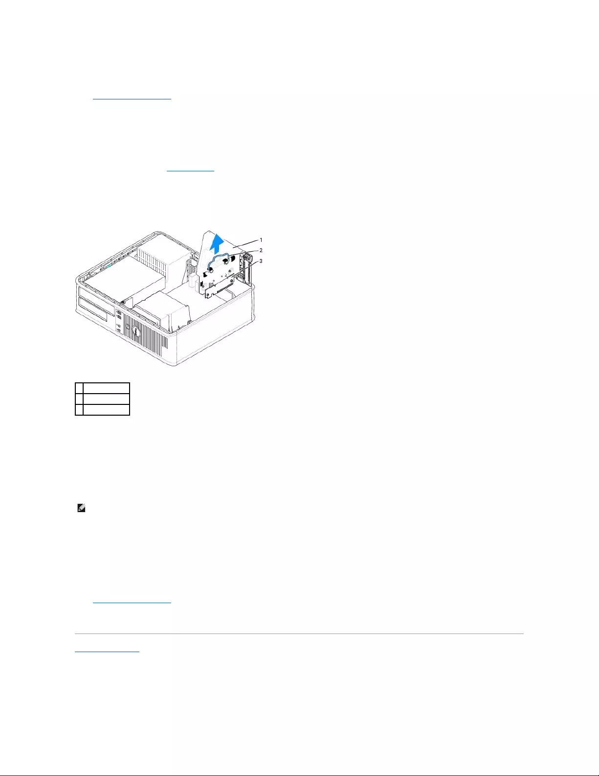
10. Connect any disconnected cables.
11. Replace the computer cover.
12. Install any drivers required for the serial port adapter.
Removing a Serial Port Adapter From the Riser-Card Cage
1. Follow the procedures in "Before You Begin."
2. Remove the riser-card cage:
a. Check any cables connected to cards through the back-panel openings. Disconnect any cables that will not reach the riser-card cage once they
are removed from the computer.
b. Gently pull on the handle and lift the riser-card cage up and away from the computer.
3. Press the tab to raise the riser-card retention latch.
4. Disconnect the cable that attaches the adapter to the system board connector (SER2).
5. Grasp the serial port adapter by its corners, and ease it out of its slot.
6. If you are removing the adapter permanently, install a filler bracket in the empty card-slot opening.
7. Lower the riser-card retention latch and press it into place.
8. Replace the riser-card cage:
a. Align the tabs in the side of the riser-card cage with the slots on the side of the computer, and slide the riser-card cage down into place.
b. Ensure that the riser board is fully seated in the connector on the system board.
9. Replace the computer cover.
10. Uninstall the adapter's driver. See the documentation that came with the adapter for instructions.
Back to Contents Page
1
riser-card cage
2
handle
3
riser board
NOTE: Installing filler brackets over empty card-slot openings is necessary to maintain FCC certification of the computer. The brackets also keep dust
and dirt out of your computer.
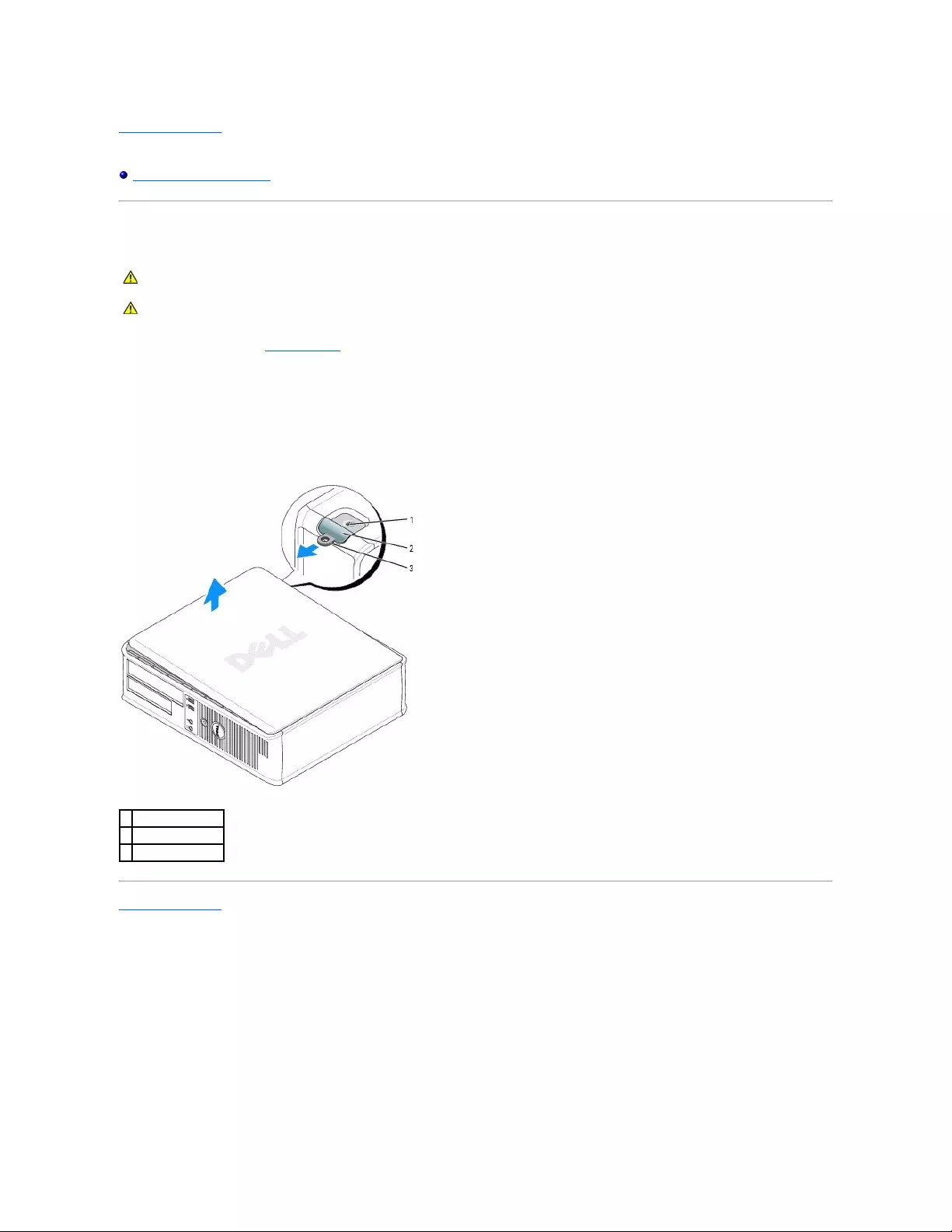
Back to Contents Page
Dell™OptiPlex™GX520User'sGuide
Removing the Computer Cover
Removing the Computer Cover
1. Follow the procedures in "Before You Begin."
2. If you have installed a padlock through the padlock ring on the back panel, remove the padlock.
3. Slide the cover release latch back as you lift the cover.
4. Pivot the cover up using the hinge tabs as leverage points.
5. Remove the cover from the hinge tabs and set it aside on a soft nonabrasive surface.
Back to Contents Page
CAUTION: Before you begin any of the procedures in this section, follow the safety instructions in the Product Information Guide.
CAUTION: To guard against electrical shock, always unplug your computer from the electrical outlet before removing the computer cover.
1
security cable slot
2
cover release latch
3
padlock ring
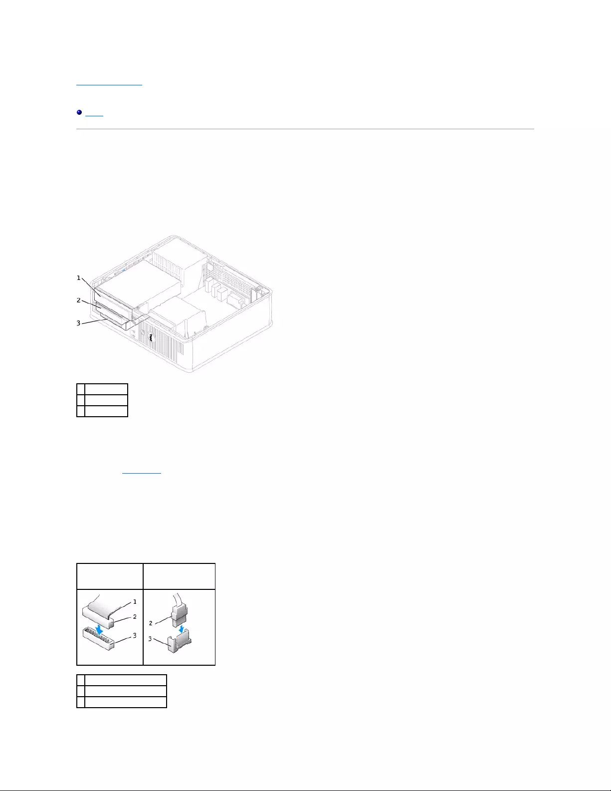
Back to Contents Page
Dell™OptiPlex™GX520User'sGuide
Drives
Drives
Your computer supports:
lOne serial ATA hard drive
lOne optional ATA hard drive
lOne optional floppy drive
lOne optional CD or DVD drive
General Installation Guidelines
Connect CD/DVD drives to the connector labeled "IDE" on the system board. Serial ATA hard drives should be connected to the connectors labeled "SATA0" or
"SATA2" on the system board.
Connecting Drive Cables
When you install a drive, you connect two cables—a DC power cable and a data cable—to the back of the drive and to the system board.
Drive Interface Connectors
1
CD/DVD drive
2
floppy drive
3
hard drive
IDE Drive Connector
Serial ATA Connector
1
colored stripe on IDE cable
2
interface cable connector
3
interface connector
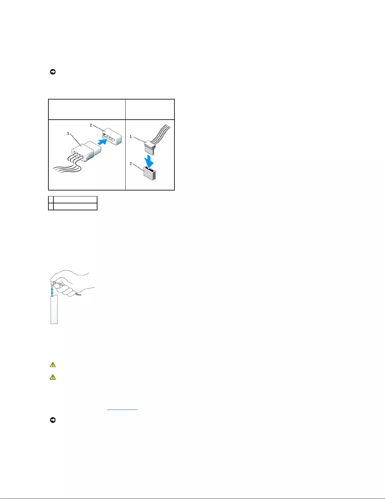
Most interface connectors are keyed for correct insertion; that is, a notch or a missing pin on one connector matches a tab or a filled-in hole on the other
connector. Keyed connectors ensure that the pin-1 wire in the cable (indicated by the colored stripe along one edge of the IDE cable—serial ATA cables do not
use a colored stripe) goes to the pin-1 end of the connector. The pin-1 end of a connector on a board or a card is usually indicated by a silk-screened "1"
printed directly on the board or card.
Power Cable Connectors
Connecting and Disconnecting Drive Cables
When removing an IDE drive data cable, grasp the colored pull-tab and pull until the connector detaches.
When connecting and disconnecting a serial ATA data cable, hold the cable by the black connector at each end.
Like IDE connectors, the serial ATA interface connectors are keyed for correct insertion; that is, a notch or a missing pin on one connector matches a tab or a
filled-in hole on the other connector.
CD/DVD Drive
Removing a CD/DVD Drive
1. Follow the procedures in "Before You Begin."
2. Pull up on the drive release latch and slide the drive towards the back of the computer. Then, lift up to remove the drive from the computer.
NOTICE: When you connect an IDE interface cable, do not place the colored stripe away from pin 1 of the connector. Reversing the cable prevents the
drive from operating and could damage the controller, the drive, or both.
IDE Drive Power Connector
Serial ATA Power
Connector
1
power cable
2
power input connector
CAUTION: Before you begin any of the procedures in this section, follow the safety instructions in the Product Information Guide.
CAUTION: To guard against electrical shock, always unplug your computer from the electrical outlet before removing the computer cover.
NOTICE: Do not pull the drive out of the computer by the drive cables. Doing so may cause damage to cables and the cable connectors.
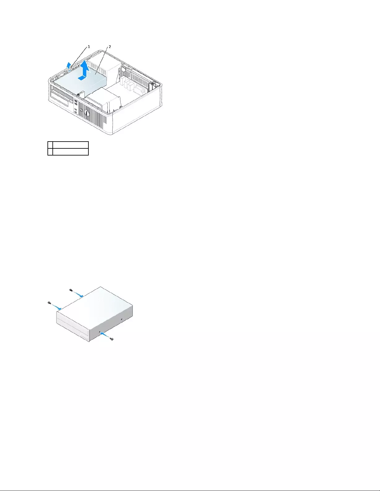
3. Disconnect the power and CD/DVD drive cables from the back of the drive.
Installing a CD/DVD Drive
1. Unpack the drive and prepare it for installation.
Check the documentation that accompanied the drive to verify that the drive is configured for your computer. If you are installing an IDE drive, configure
the drive for the cable select setting.
2. If you are installing a new drive:
a. Press the two snaps on the top of the drive-panel insert and rotate the insert toward the front of the computer.
b. Remove the three shoulder screws from the drive-panel insert.
3. If you are replacing an existing drive:
a. Press the two snaps on the top of the drive-panel insert and rotate the insert toward the front of the computer.
b. Remove the three shoulder screws from the existing drive.
c. Insert the three shoulder screws into the sides of the new drive and tighten them.
4. Connect the power and CD/DVD drive cables to the drive.
5. Align the shoulder screws with the screw guides, and slide the drive into the bay until it clicks into place.
1
drive release latch
2
CD/DVD drive
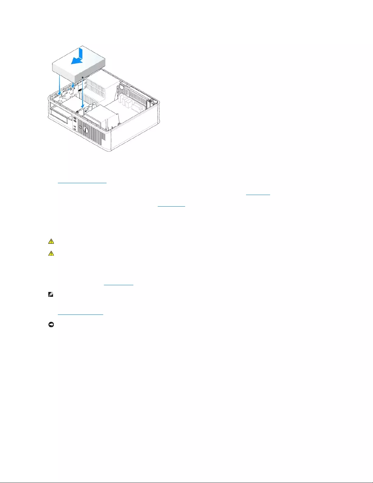
6. Check all cable connections, and fold cables out of the way to provide airflow for the fan and cooling vents.
7. Replace the computer cover.
8. Update your configuration information by setting the appropriate Drive option (0 or 1) under Drives. See "System Setup" for more information.
9. Verify that your computer works correctly by running the Dell Diagnostics.
Floppy Drive
Removing a Floppy Drive
1. Follow the procedures in "Before You Begin."
2. Remove the CD/DVD drive and carefully set it aside.
3. Pull up on the drive release latch and slide the floppy drive towards the back of the computer. Then, lift up to remove the drive from the computer.
CAUTION: Before you begin any of the procedures in this section, follow the safety instructions in the Product Information Guide.
CAUTION: To guard against electrical shock, always unplug your computer from the electrical outlet before removing the computer cover.
NOTE: Since the following steps do not require the complete removal of the CD/DVD drive, it is not necessary to disconnect the cables connecting the
CD/DVD drive.
NOTICE: Do not pull the drive out of the computer by the drive cables. Doing so may cause damage to cables and the cable connectors.
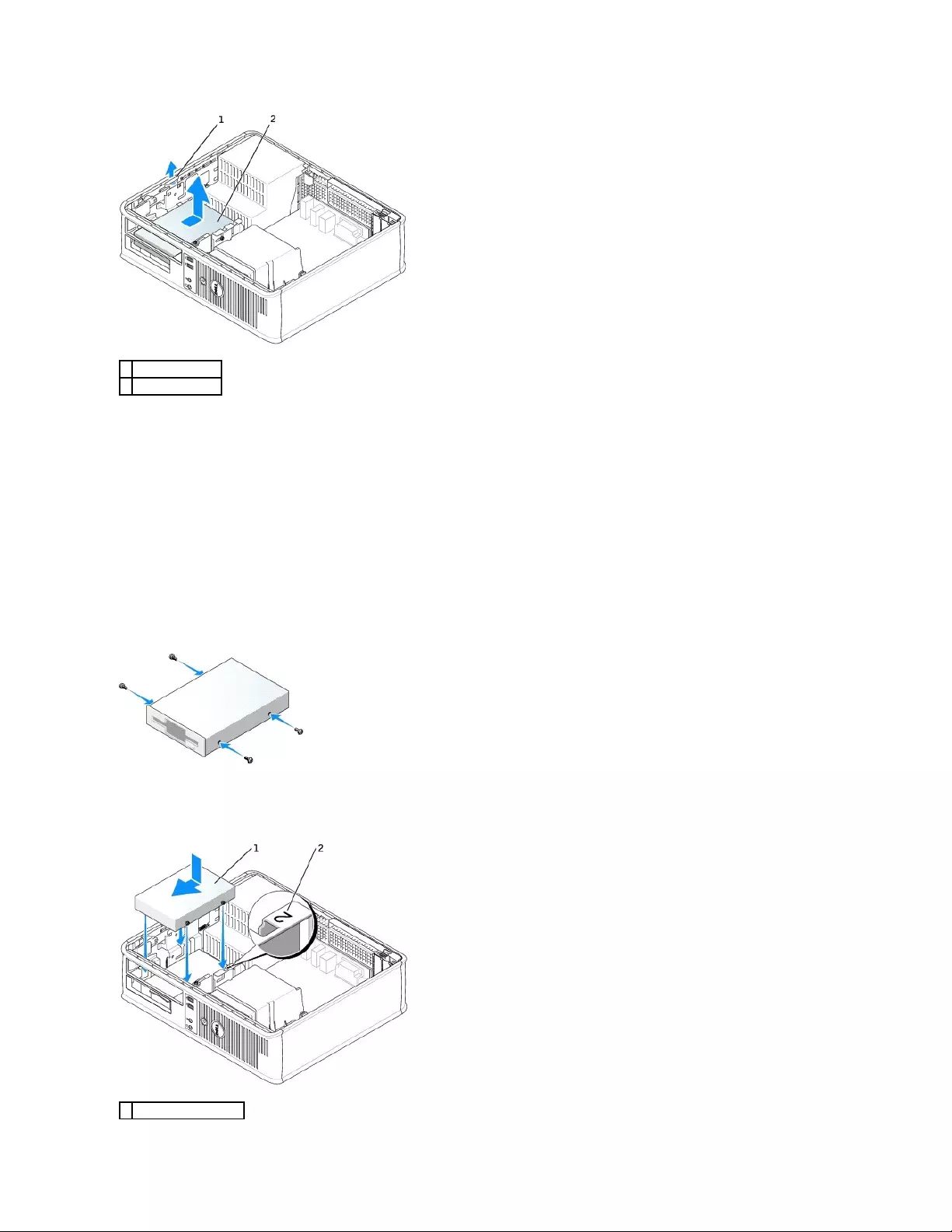
4. Disconnect the power and floppy-drive cables from the back of the floppy drive.
Installing a Floppy Drive
1. If you are installing a new drive:
a. Use a small flat-edge screw driver on the back side of the drive-panel insert to gently pop off the insert.
b. Remove the four shoulder screws from the drive-panel insert.
2. If you are replacing an existing drive:
Remove the four shoulder screws from the existing drive.
3. Insert the four shoulder screws into the sides of the new floppy drive and tighten them.
4. Attach the power and floppy-drive cables to the floppy drive.
5. Align the shoulder screws with the screw guides, and slide the drive into the bay until it clicks into place.
1
drive release latch
2
floppy drive
1
power cable
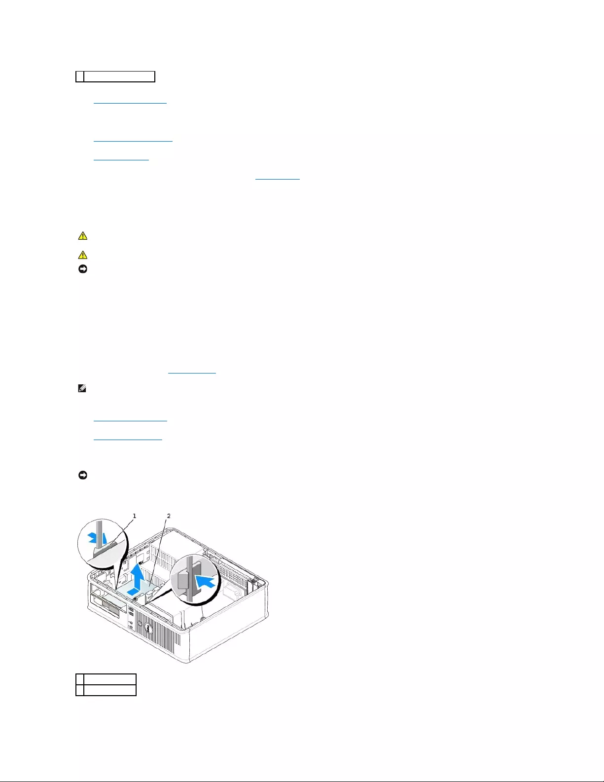
6. Replace the CD/DVD drive.
7. Check all cable connections, and fold cables out of the way to provide airflow for the fan and cooling vents.
8. Replace the computer cover.
9. Enter system setup and set the Diskette Drive option to enable your new floppy drive.
10. Verify that your computer works correctly by running the Dell Diagnostics.
Hard Drive
1. If you are replacing a hard drive that contains data you want to keep, back up your files before you begin this procedure.
2. Check the documentation for the drive to verify that it is configured for your computer.
Removing a Hard Drive
1. Follow the procedures in "Before You Begin."
2. Remove the CD/DVD drive from the bay and carefully set it aside.
3. Remove the floppy drive from the bay and carefully set it aside.
4. Press in on the two plastic securing clips on each side of the drive and slide the drive towards the back of the computer.
5. Lift the drive out of the computer and disconnect the power and hard-drive cables from the drive.
2
slot verification number
CAUTION: Before you begin any of the procedures in this section, follow the safety instructions in the Product Information Guide.
CAUTION: To guard against electrical shock, always unplug your computer from the electrical outlet before removing the computer cover.
NOTICE: To avoid damage to the drive, do not set it on a hard surface. Instead, set the drive on a surface, such as a foam pad, that will sufficiently
cushion it.
NOTE: Since the following steps do not require the complete removal of the CD/DVD drive and the floppy drive, it is not necessary to disconnect the
cables connecting the two drives.
NOTICE: Do not pull the drive out of the computer by the drive cables. Doing so may cause damage to cables and the cable connectors.
1
securing clips (2)
2
hard drive
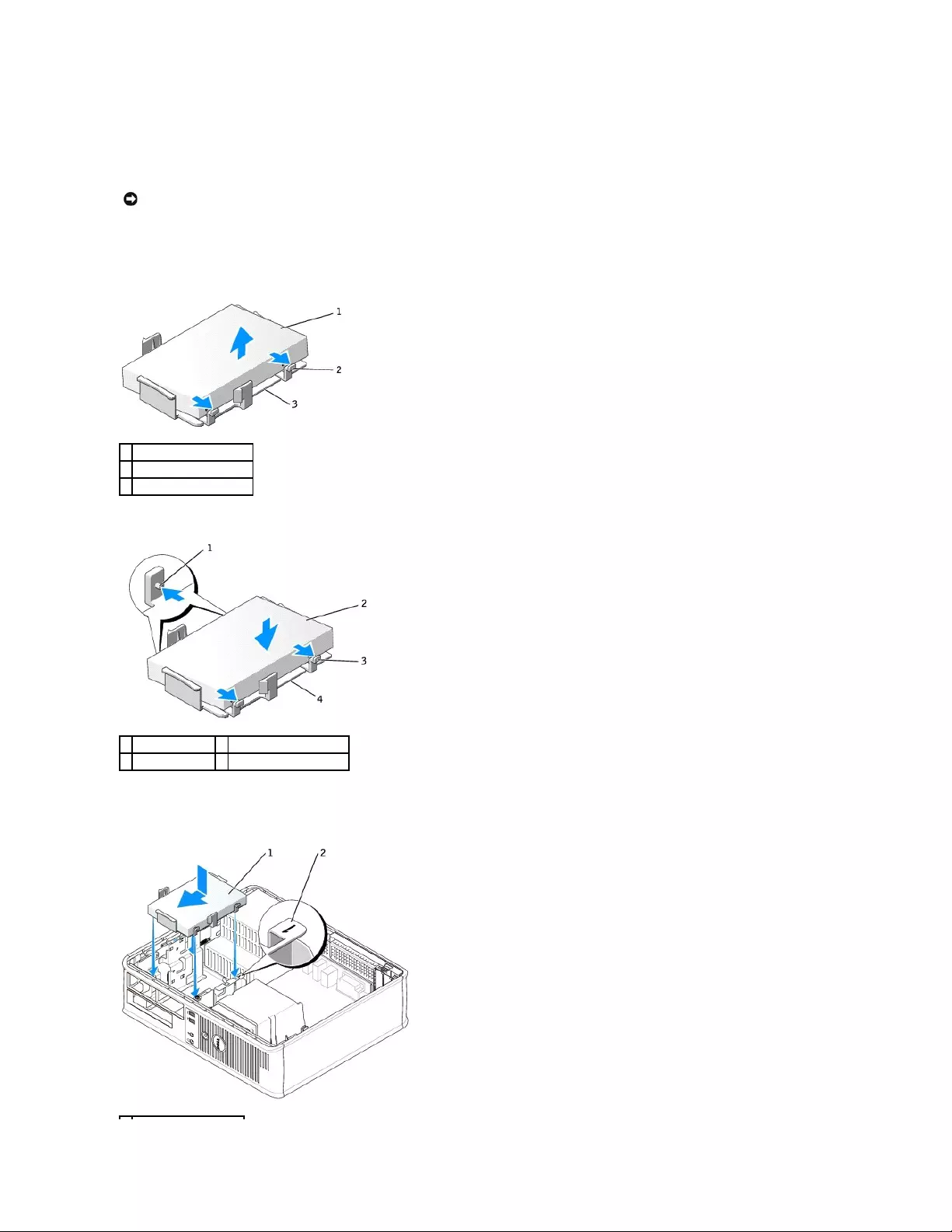
Installing a Hard Drive
1. Check the documentation for the drive to verify that it is configured for your computer.
2. Unpack the replacement hard drive, and prepare it for installation.
3. If your replacement hard drive does not have the plastic hard-drive bracket attached, remove the bracket from the existing drive by unsnapping it from
the drive.
4. Attach the bracket to the new drive by snapping it onto the drive.
5. Connect the power and hard-drive cables to the drive.
6. Locate the correct slot for the drive, and slide the drive into the bay until it clicks into place.
NOTICE: To avoid damage to the drive, do not set it on a hard surface. Instead, set the drive on a surface, such as a foam pad, that will sufficiently
cushion it.
1
hard drive
2
release tabs (2)
3
plastic hard-drive bracket
1
securing tabs (2)
3
release tabs (2)
2
drive
4
plastic hard-drive bracket

7. Replace the floppy drive and CD/DVD drive.
8. Check all connectors to be certain that they are properly cabled and firmly seated.
9. Replace the computer cover.
10. If the drive you just installed is the primary drive, insert a bootable medium into your boot drive.
11. Turn on the computer.
12. Enter system setup and update the appropriate Primary Drive option (0 or 2).
13. Exit system setup, and reboot the computer.
14. Partition and logically format your drive before you proceed to the next step.
For instructions, see the documentation that came with your operating system.
15. Test the hard drive by running the Dell Diagnostics.
16. Install your operating system on the hard drive.
For instructions, see the documentation that came with your operating system.
Back to Contents Page
1
hard drive
2
slot verification number
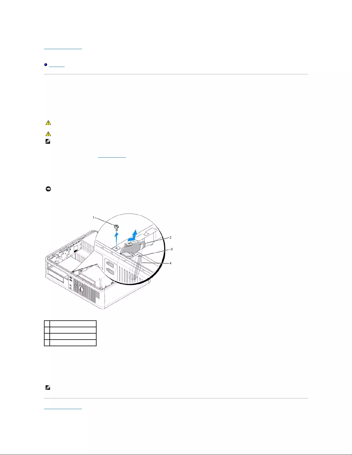
Back to Contents Page
Dell™OptiPlex™GX520User'sGuide
I/O Panel
I/O Panel
Removing the I/O Panel
1. Follow the procedures in "Before You Begin."
2. Remove the cable from the I/O panel by pulling on the pull-loop.
3. Remove the screw that secures the I/O panel to the desktop computer.
4. Gently rotate and slide the I/O panel away from the computer.
Replacing the I/O Panel
1. To replace the I/O panel, follow the removal procedures in the reverse order.
Back to Contents Page
CAUTION: Before you begin any of the procedures in this section, follow the safety instructions located in the Product Information Guide.
CAUTION: To guard against electrical shock, always unplug your computer from the electrical outlet before removing the cover.
NOTE: Note the routing of all cables before disconnecting them, so that you can re route them correctly when installing the new I/O panel.
NOTICE: When sliding the I/O panel out of the computer, be extremely careful. Carelessness may result in damage to the cable connectors and the
cable routing clips.
1
securing screw
2
I/O panel
3
I/O cable connector
4
I/O connector pull-loop
NOTE: Use the guides on the I/O panel bracket to help position the I/O panel in place and use the notch on the I/O panel bracket to help seat the card.

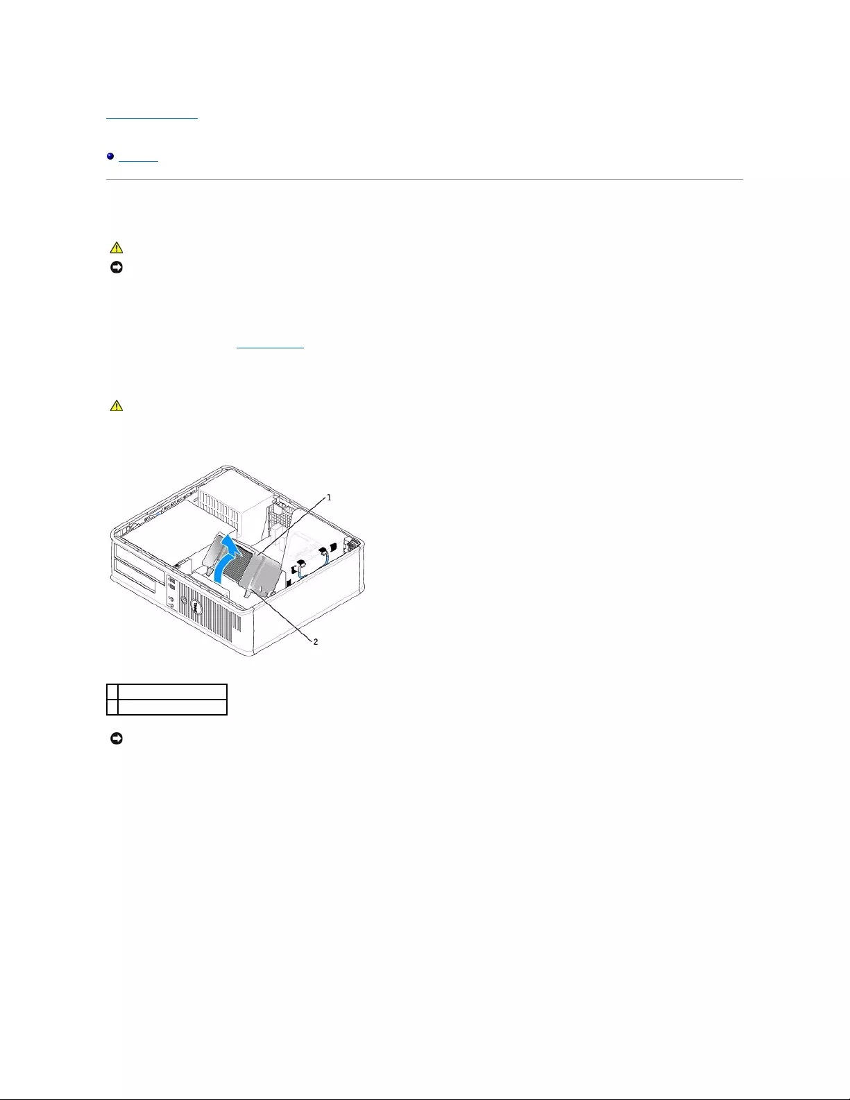
Back to Contents Page
Dell™OptiPlex™GX520User'sGuide
Processor
Processor
Removing the Processor
1. Follow the procedures in "Before You Begin."
2. Loosen the captive screw on each side of the heat sink assembly.
3. Rotate the heat sink assembly upward, and remove the assembly from the computer.
4. Open the processor cover by sliding the release lever from under the center cover latch on the socket. Then pull the lever back to release the processor.
CAUTION: Before you begin any of the procedures in this section, follow the safety instructions located in the Product Information Guide.
NOTICE: To prevent static damage to components inside your computer, discharge static electricity from your body before you touch any of your
computer's electronic components. You can do so by touching an unpainted metal surface on the computer chassis.
CAUTION: Despite having a plastic shield, the heat sink assembly may be very hot during normal operation. Be sure that it has had sufficient time
to cool before you touch it.
1
heat sink assembly
2
captive screw housing (2)
NOTICE: If you are installing a processor upgrade kit from Dell, discard the original heat sink. If you are not installing a processor upgrade kit from Dell,
reuse the original heat sink when you install your new processor.
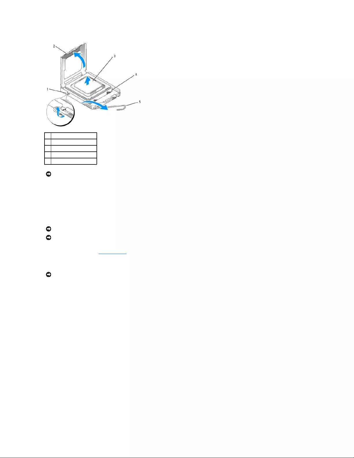
5. Gently remove the processor from the socket.
Leave the release lever extended in the release position so that the socket is ready for the new processor.
Installing the Processor
1. Follow the procedures in "Before You Begin."
2. Unpack the new processor, being careful not to touch the underside of the processor.
3. If the release lever on the socket is not fully extended, move it to that position.
4. Orient the front and rear alignment-notches on the processor with the front and rear alignment-notches on the socket.
5. Align the pin-1 corners of the processor and socket.
1
center cover latch
2
processor cover
3
processor
4
socket
5
release lever
NOTICE: When replacing the processor, do not touch any of the pins inside the socket or allow any objects to fall on the pins in the socket.
NOTICE: Ground yourself by touching an unpainted metal surface on the back of the computer.
NOTICE: When replacing the processor, do not touch any of the pins inside the socket or allow any objects to fall on the pins in the socket.
NOTICE: You must position the processor correctly in the socket to avoid permanent damage to the processor and the computer when you turn on the
computer.
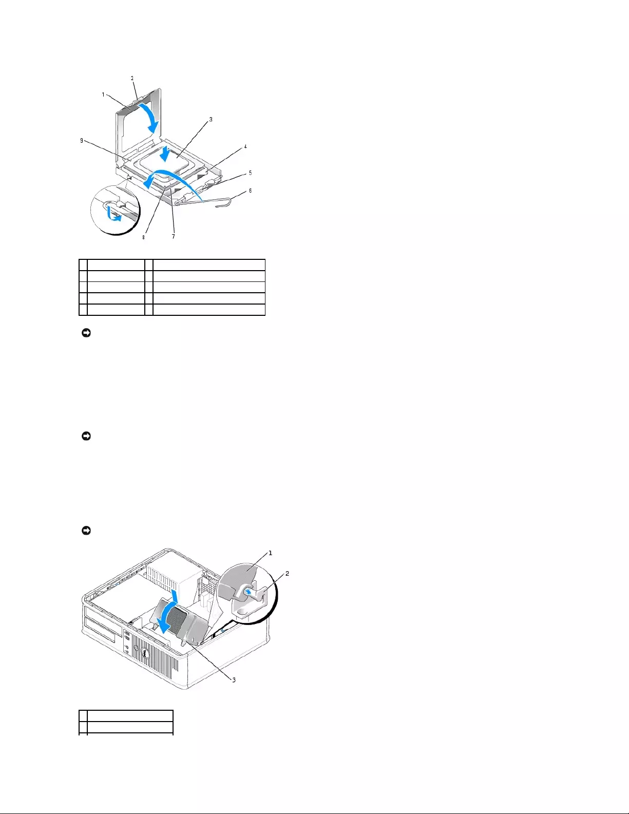
6. Set the processor lightly in the socket and ensure that the processor is positioned correctly.
7. When the processor is fully seated in the socket, close the processor cover.
Ensure that the tab on the processor cover is positioned underneath the center cover latch on the socket.
8. Pivot the socket release lever back toward the socket, and snap it into place to secure the processor.
If you installed a processor replacement kit from Dell, return the original heat sink assembly and processor to Dell in the same package in which your
replacement kit was sent.
9. Install the heat sink assembly:
a. Place the heat sink assembly back onto the heat-sink assembly bracket.
b. Rotate the heat sink assembly down towards the computer base and tighten the two captive screws.
1
processor cover
6
release lever
2
tab
7
front alignment-notch
3
processor
8
socket and processor pin-1 indicator
4
processor socket
9
rear alignment-notch
5
center cover latch
NOTICE: To avoid damage, ensure that the processor aligns properly with the socket, and do not use excessive force when you install the processor.
NOTICE: If you are not installing a processor upgrade kit from Dell, reuse the original heat sink assembly when you replace the processor.
NOTICE: Ensure that the heat sink assembly is correctly seated and secure.
1
heat sink assembly
2
heat-sink assembly bracket

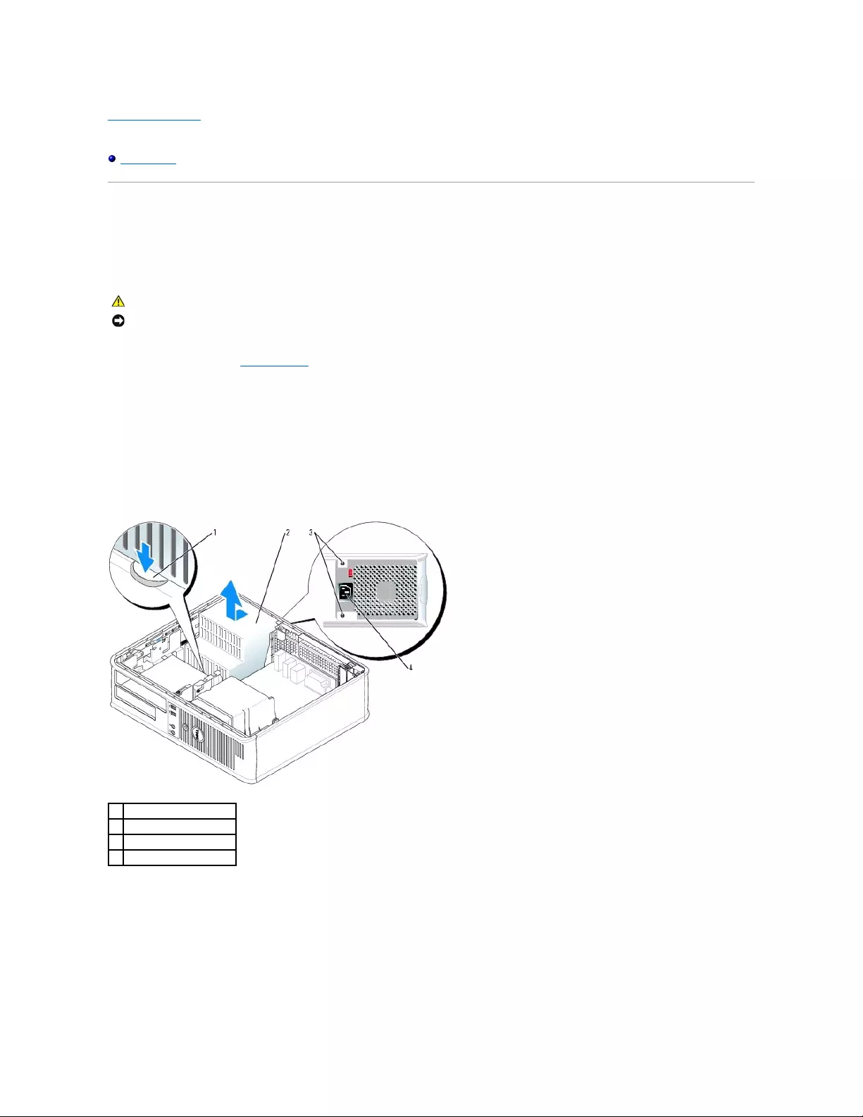
Back to Contents Page
Dell™OptiPlex™GX520User'sGuide
Power Supply
Power Supply
Replacing the Power Supply
1. Follow the procedures in "Before You Begin."
2. Disconnect the DC power cables from the system board and the drives.
Note the routing of the DC power cables underneath the tabs in the computer chassis as you remove them from the system board and drives. You must
route these cables properly when you replace them to prevent their being pinched or crimped.
3. Remove the two screws that attach the power supply to the back of the computer chassis.
4. Remove the CD/DVD drive and carefully set it aside.
5. Press the release button located on the floor of the computer chassis.
6. Slide the power supply toward the front of the computer by approximately 1 inch.
7. Lift the power supply up and out of the computer.
8. Slide the replacement power supply into place.
9. Replace the screws that secure the power supply to the back of the computer chassis.
10. Reconnect the DC power cables.
CAUTION: Before you begin any of the procedures in this section, follow the safety instructions located in the Product Information Guide.
NOTICE: To prevent static damage to components inside your computer, discharge static electricity from your body before you touch any of your
computer's electronic components. You can do so by touching an unpainted metal surface on the computer chassis.
1
release button
2
power supply
3
screws (2)
4
AC power connector
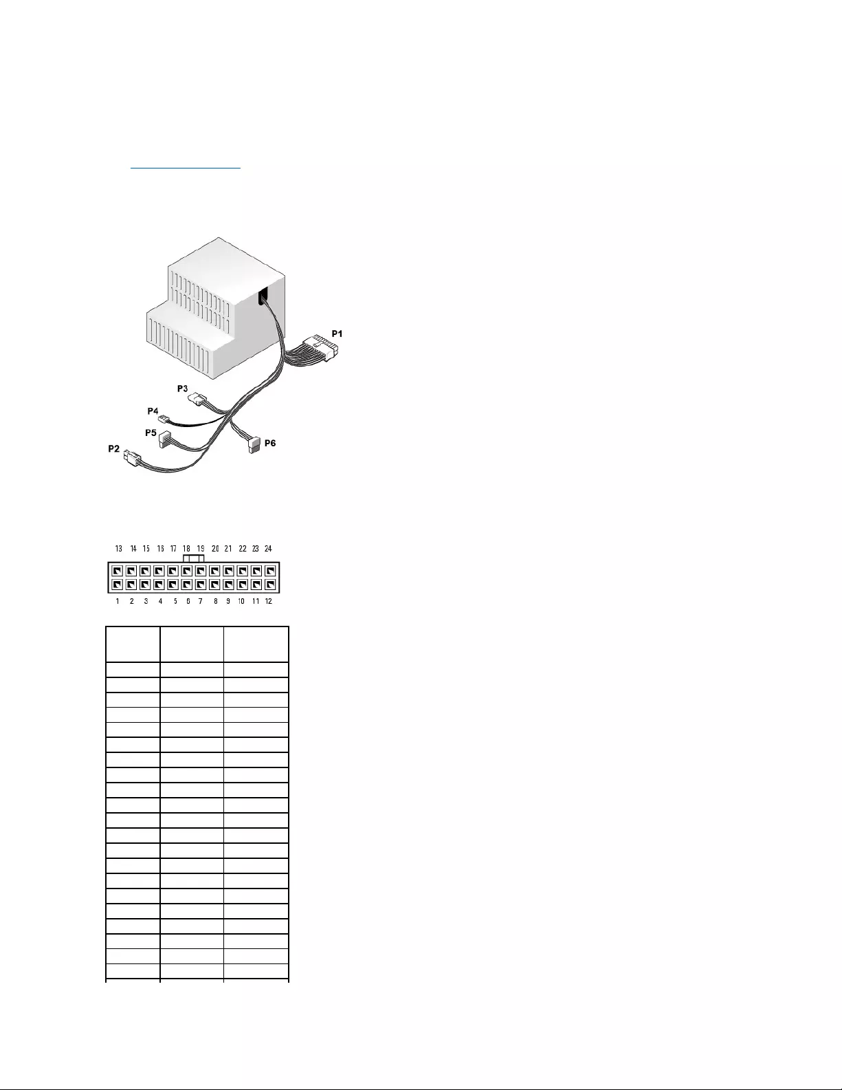
11. Replace the CD/DVD drive.
12. Connect the AC power cable to the connector.
13. Replace the computer cover.
DC Power Connectors
DC Power Connector P1
Pin Number
Signal name
18-AWG Wire
1
+3.3 VDC
Orange
2
+3.3 VDC
Orange
3
GND
Black
4
VCC (+5 V)
Red
5
GND
Black
6
VCC (+5 V)
Red
7
GND
Black
8
PS_PWRGOOD
Gray
9
P5AUX
Purple
10
V_12P0_DIG
Yellow
11
V_12P0_DIG
Yellow
12
+3.3 V
Orange
13
+3.3 V
Orange
14
-12 V*
Blue
15
GND
Black
16
PWR_PS_ON
Green
17
GND
Black
18
GND
Black
19
GND
Black
20
NC
N/C
21
VCC (+5V)
Red
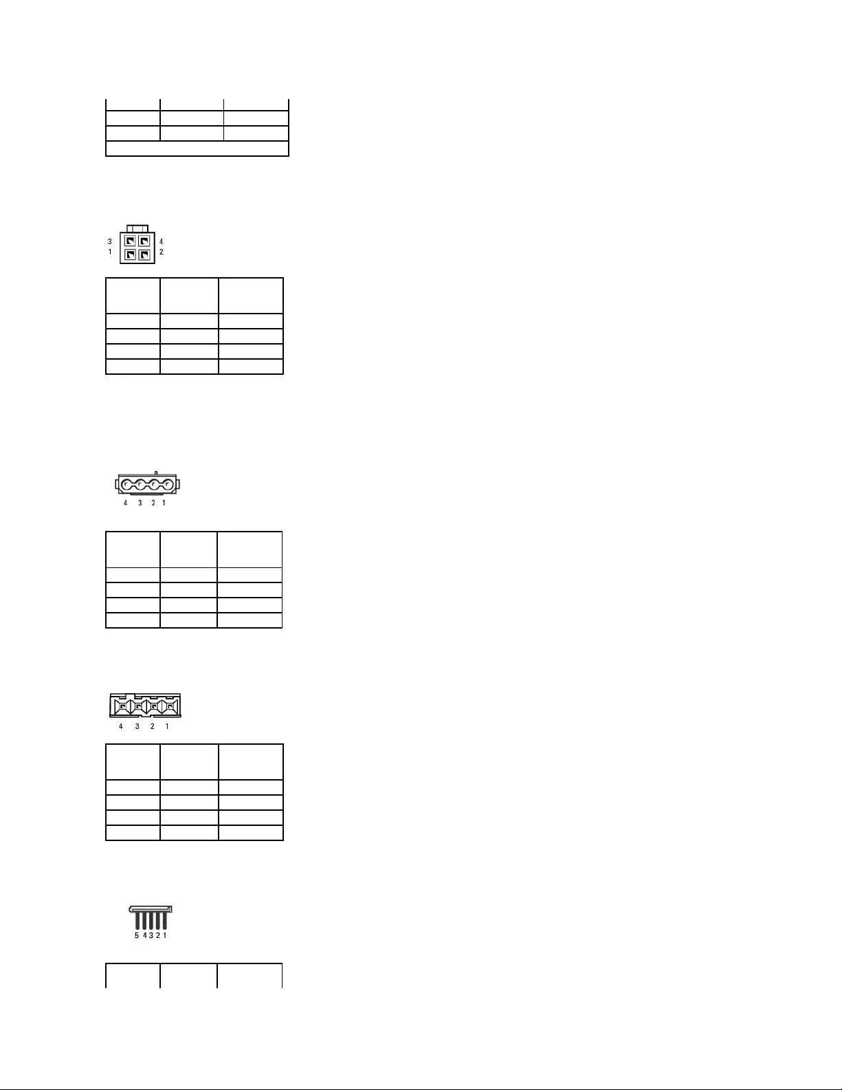
DC Power Connector P2
DC Power Connector P3
DC Power Connector P4
DC Power Connector P5 and P6
22
VCC (+5V)
Red
23
VCC (+5V)
Red
24
GND
Black
*Use 22-AWG wire instead of 18-AWG wire.
Pin Number
Signal Name
18-AWG Wire
1
COM
Black
2
COM
Black
3
+12 VDC
Yellow
4
+12 VDC
Yellow
Pin Number
Signal name
18-AWG Wire
1
+12 VDC
Yellow
2
COM
Black
3
COM
Black
4
+5 VDC
Red
Pin Number
Signal Name
22-AWG Wire
1
+5 VCD
Red
2
COM
Black
3
COM
Black
4
+12 VDC
Yellow


Back to Contents Page
Dell™OptiPlex™GX520User'sGuide
Desktop Computer Specifications
Desktop Computer Specifications
Microprocessor
Microprocessor type
Intel®Pentium®or Celeron® processor
Level 1 (L1) cache
32 KB
Level 2 (L2) cache
512-KB, 1-MB, or 2-MB pipelined-burst, eight-way set
associative, write-back SRAM
Memory
Type
400-MHz and 533-MHz DDR2 SDRAM
Memory connectors
2
Memory modules supported
256-MB, 512-MB, 1-GB, or 2-GB non-ECC
Minimum memory
dual-channel: 512 MB;
single-channel: 256 MB
Maximum memory
4 GB
BIOS address
F0000h
Computer Information
Chipset
Intel®945 Express
Data bus width
64 bits
Address bus width
32 bits
DMA channels
eight
Interrupt levels
24
BIOS chip (NVRAM)
4 Mb
Memory speed
400MHzand533MHz
NIC
integrated network interface with ASF 1.03 and 2.0
support as defined by DMTF
Capable of 10/100/1000 communication:
lGreen — A good connection exists between a
10-Mbps network and the computer.
lOrange — A good connection exists between a
100-Mbps network and the computer.
lYellow — A good connection exists between a
1-Gb (or 1000-Mbps) network and the
computer.
lOff — The computer is not detecting a physical
connection to the network.
Video
Type
integrated Intel Graphic Media Accelerator 950
Audio
Type
AC97, Sound Blaster emulation
Stereo conversion
16-bit analog-to-digital; 20-bit digital-to-analog
Controllers
Drives
two serial ATA controllers supporting one device each
and one parallel Ultra ATA/100 IDE supporting two

devices per channel with one channel
Expansion Bus
Bus type
PCI 2.3
SATA 1.0a and 2.0
USB 2.0
Bus speed
PCI: 33 MHz
SATA:1.5Gbpsand3.0Gbps
USB: 480 Mbps
Cards
half-length, full-height cards supported with optional
riser-card cage
Default: no riser-card cage:
low-profile cards supported
PCI:
connectors
two
card size
low profile
connector size
120 pins
connector data width
(maximum)
32 bits
Optional: full-height PCI riser-card cage:
low-profile and full-height cards supported
PCI:
connectors
three
card size
one low-profile card and two full-height cards
connector size
120 pins
connector data width
(maximum)
32 bits
Drives
Externally accessible
one 3.5-inch drive
one bay for CD/DVD or optional second hard drive
Internally accessible
one bay for a 1-inch-high hard drive
Connectors
External connectors:
Serial
9-pin connector; 16550C-compatible
Parallel
25-hole connector (bidirectional)
Video
15-hole VGA connector
Network adapter
RJ45 connector
Optional PS/2 with secondary serial port
adapter
two 6-pin mini-DINs
USB
two front-panel and six back-panel USB 2.0–
compliant connectors
Audio
three connectors for line-in, line-out, and microphone;
two front-panel connectors for headphones and
microphone
System board connectors:
Primary IDE drive
40-pin connector
Serial ATA
two 7-pin connectors
Floppy drive
34-pin connector
Serial
12-pin connector for optional second serial port card
Fan
5-pin connector
PCI 2.3
120-pin connector
CD drive audio interface
4-pin connector
Front panel
40-pin connector
Key Combinations
<Ctrl><Alt><Del>
in Microsoft®Windows®XP, brings up the Windows
Security window; in MS-DOS®mode, restarts
(reboots) the computer
<F2> or <Ctrl><Alt><Enter>
starts embedded system setup (during system start-
up only)
<Ctrl><Alt><b>
automatically starts the computer from the network
environment specified by the remote boot
environment (PXE) rather than from one of the
devices in the system setup Boot Sequence option
(during system start-up only)
<F12> or <Ctrl><Alt><F8>
displays a boot device menu that allows the user to
enter a device for a single boot (during system start-
up only) as well as options to run hard-drive and
system diagnostics
Controls and Lights
Power control
push button
Power light
green light — Blinking green indicates a sleep mode;
solid green indicates a power-on state.
amber light — Blinking amber indicates a problem
with an installed device; solid amber indicates an
internal power problem (see "Power Problems").
Hard-drive access light
green
Link light
solid green light indicates network connection
Link integrity light (on integrated network adapter)
green light for 10-Mb operation; orange light for 100-
Mb operation; yellow light for a 1000-Mb (1-Gb)
operation
Activity light (on integrated network adapter)
yellow blinking light
Diagnostic lights
four lights on the back panel (see "Diagnostic Lights")
Standby power light
AUX_PWR on the system board
Power
DC power supply:
Wattage
220 W
Heat dissipation
751 BTU/hr
NOTE: Heat dissipation is calculated based upon the
power supply wattage rating.
Voltage
manual selection power supplies — 90 to 135 V at
50/60Hz;180to265Vat50/60Hz
Backup battery
3-V CR2032 lithium coin cell
Physical
Height
11.4 cm (4.5 inches)
Width
39.9 cm (15.7 inches)
Depth
35.3 cm (13.9 inches)
Weight
10.4 kg (23 lb)
Environmental
Temperature:
Operating
10°to35°C(50°to95°F)
Storage
–40°to65°C(–40°to149°F)
Relative humidity
20% to 80% (noncondensing)
Maximum vibration:
Operating
0.25 G at 3 to 200 Hz at 0.5 octave/min
Storage
0.5 G at 3 to 200 Hz at 1 octave/min
Maximum shock:
Operating
bottom half-sine pulse with a change in velocity of
50.8 cm/sec (20 inches/sec)
Storage
27-G faired square wave with a velocity change of
508 cm/sec (200 inches/sec)
Altitude:
Operating
–15.2 to 3048 m (–50 to 10,000 ft)
Storage
–15.2 to 10,668 m (–50 to 35,000 ft)

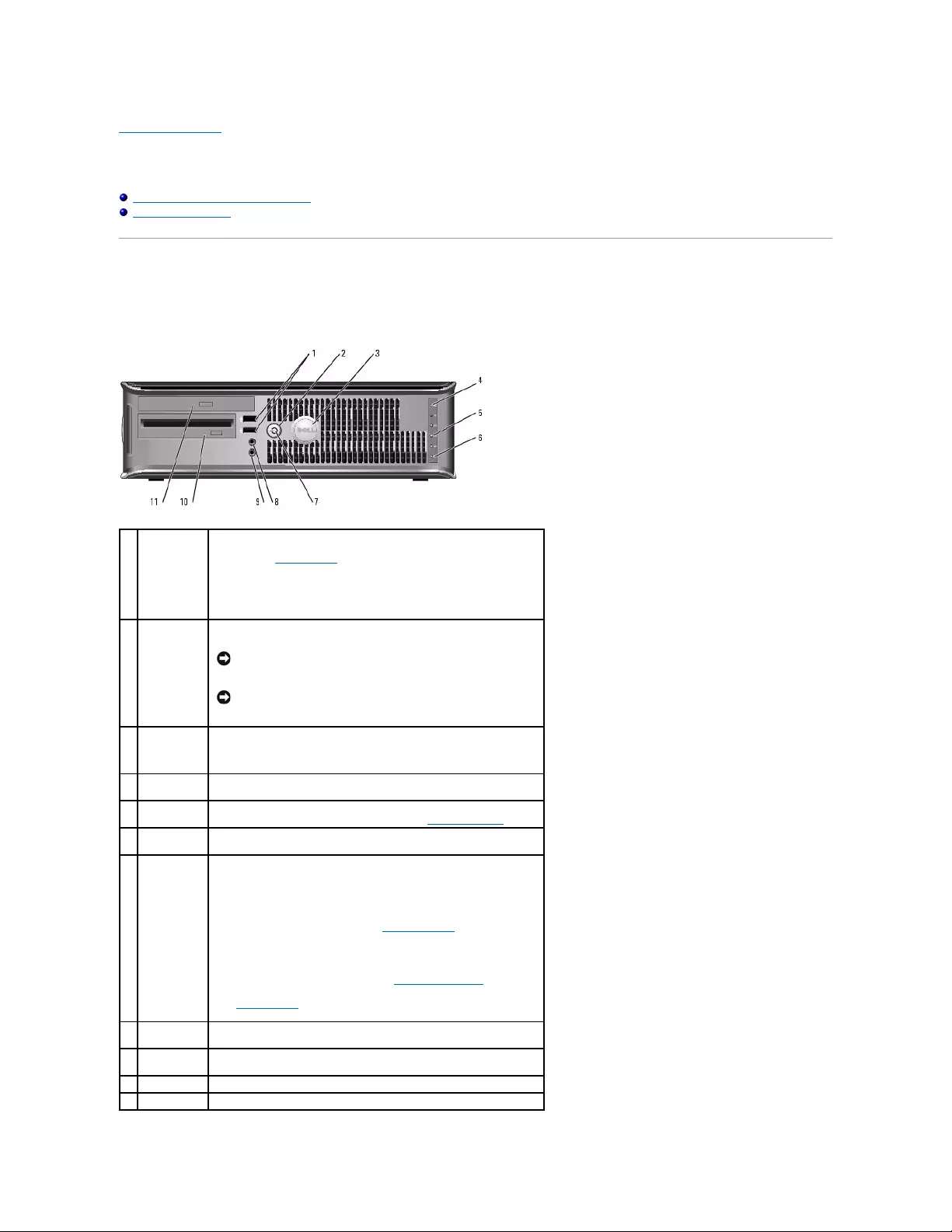
Back to Contents Page
Small Form Factor Computer
Dell™OptiPlex™GX520User'sGuide
About Your Small Form Factor Computer
Inside Your Computer
About Your Small Form Factor Computer
Front View
1
USB 2.0
connectors
(2)
Use the USB connectors on the front of the computer for devices that you
connect occasionally, such as joysticks or cameras, or for bootable USB
devices (see "System Setup" for more information about booting to a
USB device).
It is recommended that you use the USB connectors on the back panel
for devices that typically remain connected, such as printers and
keyboards.
2
power button
Press this button to turn on the computer.
NOTICE: To avoid losing data, do not turn off the computer by
pressing the power button for 6 seconds or longer. Instead,
perform an operating system shutdown.
NOTICE: If your operating system has ACPI enabled, when you
press the power button the computer will perform an operating
system shutdown.
3
Dell badge
The badge can be rotated to match the orientation of your computer. To
rotate the badge, place your fingers around the outside of the badge,
press firmly, and turn the badge. You can also rotate the badge using
the slot provided near the bottom of the badge.
4
LAN indicator
light
This light indicates that a LAN (network) connection is established.
5
diagnostic
lights
Use these lights to help you troubleshoot a computer problem based on
the diagnostic code. For more information, see "Diagnostic Lights."
6
hard drive
activity light
This light flickers when the hard drive is being accessed.
7
power light
The power light turns on and blinks or remains solid to indicate different
operating states:
lNo light — The computer is turned off.
lSteady green — The computer is in a normal operating state.
lBlinking green — The computer is in a power-saving mode.
lBlinking or solid amber — See "Power Problems."
To exit from a power-saving mode, press the power button or use the
keyboard or the mouse if it is configured as a wake device in the
Windows Device Manager. For more information about sleep modes and
exiting from a power-saving mode, see "Power Management."
See "System Lights" for a description of light codes that can help you
troubleshoot problems with your computer.
8
headphone
connector
Use the headphone connector to attach headphones and most kinds of
speakers.
9
microphone
connector
Use the microphone connector to attach a microphone.
10
floppy drive
Insert a floppy disk into this drive.
11
CD/DVD drive
Insert a CD or DVD (if applicable) into this drive.
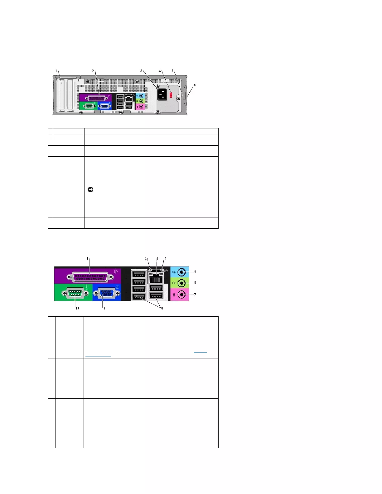
Back View
Back-Panel Connectors
1
card slots
Access connectors for any installed PCI cards.
2
back-panel
connectors
Plug serial, USB, and other devices into the appropriate connector.
3
power
connector
Insert the power cable into this connector.
4
voltage
selection
switch
Your computer is equipped with a manual voltage-selection switch.
To help avoid damaging a computer with a manual voltage-selection
switch, set the switch for the voltage that most closely matches the AC
power available in your location.
Also, ensure that your monitor and attached devices are electrically
rated to operate with the AC power available in your location.
NOTICE: The voltage selection switch must be set to the 115-V
position even though the AC power available in Japan is 100 V.
5
padlock ring
Insert a padlock to lock the computer cover.
6
cover release
latch
Allows you to open the computer cover.
1
parallel
connector
Connect a parallel device, such as a printer, to the parallel connector. If
you have a USB printer, plug it into a USB connector.
NOTE: The integrated parallel connector is automatically disabled if the
computer detects an installed card containing a parallel connector
configured to the same address. For more information, see "System
Setup Options."
2
link integrity
light
lGreen — A good connection exists between a 10-Mbps network
and the computer.
lOrange — A good connection exists between a 100-Mbps network
and the computer.
lYellow — A good connection exists between a 1-Gbps (or 1000-
Mbps) network and the computer.
lOff — The computer is not detecting a physical connection to the
network.
3
network
adapter
connector
To attach your computer to a network or broadband device, connect one
end of a network cable to either a network jack or your network or
broadband device. Connect the other end of the network cable to the
network adapter connector on the back panel of your computer. A click
indicates that the network cable has been securely attached.
NOTE: Do not plug a telephone cable into the network connector.
On computers with a network connector card, use the connector on the
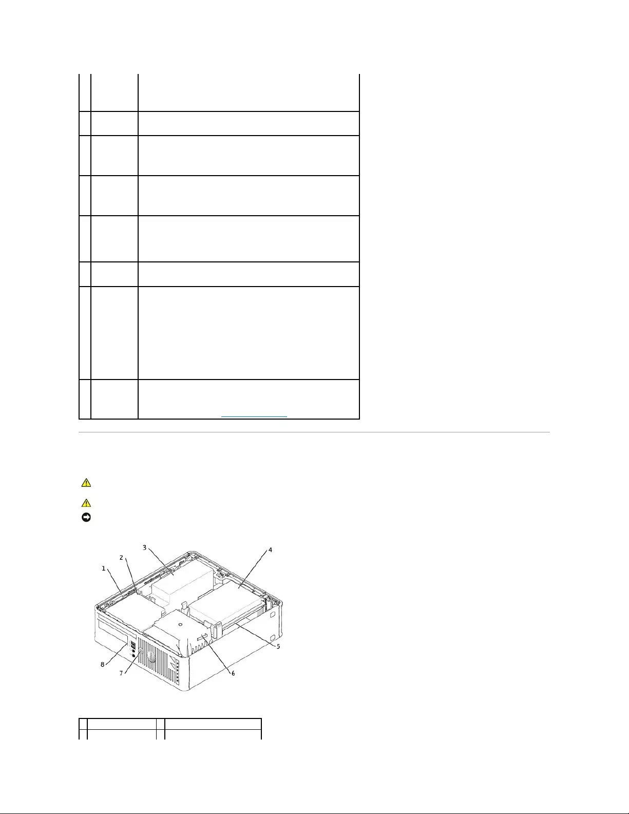
Inside Your Computer
card.
It is recommended that you use Category 5 wiring and connectors for
your network. If you must use Category 3 wiring, force the network
speed to 10 Mbps to ensure reliable operation.
4
network
activity light
Flashes a yellow light when the computer is transmitting or receiving
network data. A high volume of network traffic may make this light
appear to be in a steady "on" state.
5
line-in
connector
Use the blue line-in connector (available on computers with integrated
sound) to attach a record/playback device such as a cassette player, CD
player, or VCR.
On computers with a sound card, use the connector on the card.
6
line-out
connector
Use the green line-out connector (available on computers with
integrated sound) to attach headphones and most speakers with
integrated amplifiers.
On computers with a sound card, use the connector on the card.
7
microphone
connector
Use the pink microphone connector (available on computers with
integrated sound) to attach a personal computer microphone for voice or
musical input into a sound or telephony program.
On computers with a sound card, the microphone connector is on the
card.
8
USB 2.0
connectors
(6)
Use the back USB connectors for devices that typically remain connected,
such as printers and keyboards.
9
video
connector
Plug the cable from your VGA-compatible monitor into the blue connector.
NOTE: If you purchased an optional graphics card, this connector will be
covered by a cap. Connect your monitor to the connector on the graphics
card. Do not remove the cap.
NOTE: If you are using a graphics card that supports dual monitors, use
the y-cable that came with your computer.
10
serial
connector
Connect a serial device, such as a handheld device, to the serial port.
The default designations are COM1 for serial connector 1 and COM2 for
serial connector 2.
For more information, see "System Setup Options."
CAUTION: Before you begin any of the procedures in this section, follow the safety instructions in the Product Information Guide.
CAUTION: To avoid electrical shock, always unplug your computer from the electrical outlet before removing the computer cover.
NOTICE: Be careful when opening the computer cover to ensure that you do not accidentally disconnect cables from the system board.
1
drive release latch
5
system board
2
CD/DVD drive
6
heat sink and blower assembly
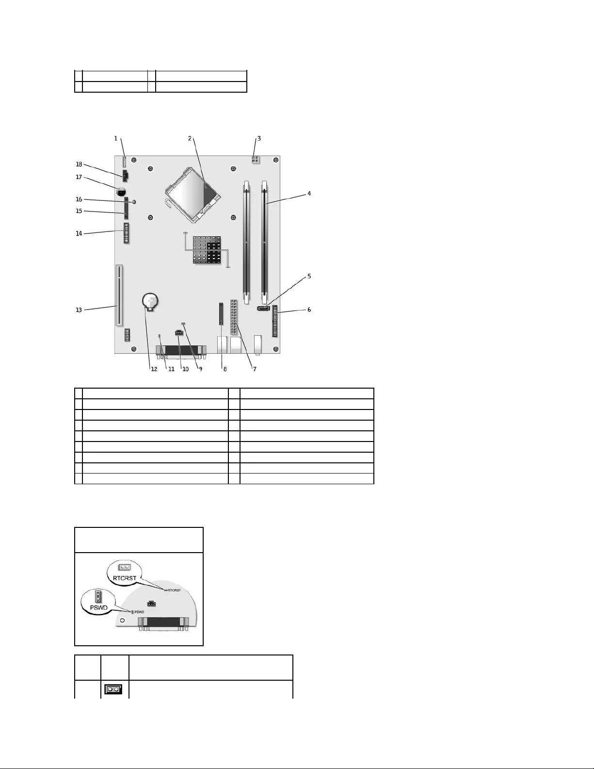
System Board Components
Jumper Settings
3
power supply and fan
7
power button
4
hard drive
8
front panel door
1
fan connector (FAN)
10
chassis intrusion switch connector (INTRUDER)
2
processor connector (CPU)
11
password jumper (PSWD)
3
power connector (12VPOWER)
12
battery socket (BATT)
4
memory module connectors (DIMM_1 and DIMM_2)
13
PCI connector (SLOT2)
5
serial ATA drive connector (SATA0)
14
serial connector (SER2)
6
front-panel connector (FNT_PANEL)
15
floppy-drive connector (DSKT)
7
power connector (POWER)
16
standby power indicator (AUX_PWR)
8
CD/DVD drive connector (IDE)
17
system board speaker (BEEP)
9
RTC reset jumper (RTCRST)
18
internal speaker (INT_SPKR)
Small Form Factor Computer
Jumper
Setting
Description
PSWD
Password features are enabled.
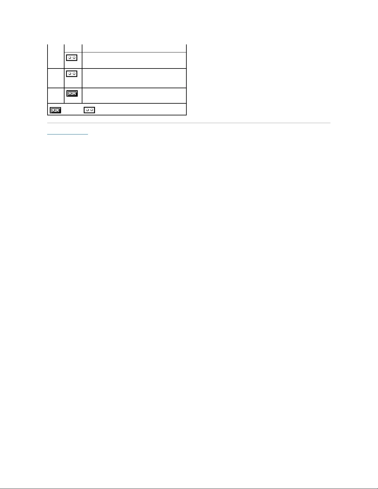

Back to Contents Page
Dell™OptiPlex™GX520User'sGuide
PCI Cards and Serial Port Adapters
PCI Cards
PCI Cards and Serial Port Adapters
YourDell™computersupportsaserialportadapterandprovidesonelow-profile PCI card slot for one PCI card.
PCI Cards
If you are replacing a card, uninstall the driver for the existing card. See the documentation that came with the card for instructions.
Installing a PCI Card
1. Follow the procedures in "Before You Begin."
2. Gently push the release tab on the card retention latch from the inside to pivot the latch open. The latch will remain in the open position.
3. Remove the card retention mechanism:
a. Place your thumb on the top of the card retention mechanism and grip the bottom of the retention mechanism with your fingers.
b. With your free hand, gently squeeze the sides of the card retention mechanism to release it from the tab slots holding it in place.
c. Pivot the card retention mechanism upward to release it from the two tab slots.
4. If you are installing a new card, remove the filler bracket to create a card-slot opening. Then continue with step6.
5. If you are replacing a card that is already installed in the computer, remove the card.
If necessary, disconnect any cables connected to the card. If your card includes a card retention bar, remove the bar. Gently pull the securing tab, grasp
the card by its top corners, and ease it out of its connector.
6. Prepare the new card for installation.
See the documentation that came with the card for information on configuring the card, making internal connections, or otherwise customizing it for your
computer.
7. Place the card in the connector and press down firmly. Ensure that the card is fully seated in the slot.
CAUTION: Before you begin any of the procedures in this section, follow the safety instructions located in the Product Information Guide.
NOTICE: To prevent static damage to components inside your computer, discharge static electricity from your body before you touch any of your
computer's electronic components. You can do so by touching an unpainted metal surface on the computer chassis.
NOTE: Your Dell computer uses only a PCI slot. ISA cards are not supported.
CAUTION: Some network adapters automatically start the computer when they are connected to a network. To guard against electrical shock, be
sure to unplug your computer from its electrical outlet before installing any cards.
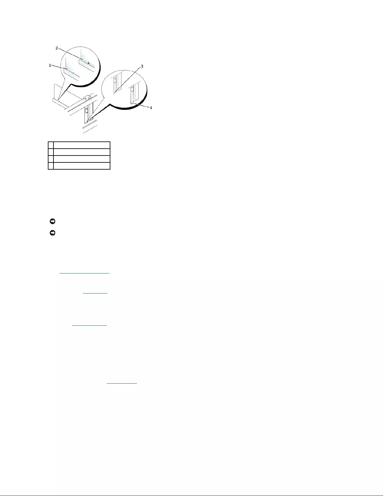
8. If applicable, before replacing the card retention mechanism, ensure that:
lThe tops of all cards and filler brackets are flush with the alignment bar.
lThe notch in the top of the card or filler bracket fits around the alignment guide.
9. Snap the card retention mechanism into place, securing the card(s) in the computer.
10. Connect any cables that should be attached to the card.
See the documentation for the card for information about the card's cable connections.
11. Replace the computer cover.
12. If you installed a sound card:
a. Enter System Setup, select Audio Controller, and change the setting to Off.
b. Connect external audio devices to the sound card's connectors. Do not connect external audio devices to the microphone, speaker/headphone,
or line-in connectors on the back panel.
13. If you installed an network adapter card and want to turn off the integrated network adapter:
a. Enter system setup, select Network Controller, and change the setting to Off.
b. Connect the network cable to the network adapter card's connectors. Do not connect the network cable to the integrated network connector on
the back panel of the computer.
14. Install any drivers required for the card as described in the card documentation.
Removing a PCI Card
1. Follow the procedures in "Before You Begin."
2. Gently push the release tab on the card retention latch from the inside to pivot the latch open. Because the latch is captive, it will remain in the open
position.
3. Use the card retention mechanism to secure the card in place from the top:
a. Place your thumb on the top of the card retention mechanism and grip the bottom of the retention mechanism with your fingers.
b. With your free hand, gently squeeze the sides of the card retention mechanism to release it from the tab slots holding it in place.
c. Pivot the card retention mechanism upward to release it from the two tab slots.
d. Set the card retention mechanism aside in your work area.
1
fully seated card
2
not fully seated card
3
bracket within slot
4
bracket caught outside of slot
NOTICE: Do not route card cables over or behind the cards. Cables routed over the cards can prevent the computer cover from closing properly or
cause damage to the equipment.
NOTICE: To connect a network cable, first plug the cable into the network wall jack and then plug it into the computer.

4. If you are removing the card permanently, install a filler bracket in the empty card-slot opening.
If you need a filler bracket, contact Dell.
5. Re-seat the card retention mechanism in the tabs and pivot downward to snap it into place.
6. Lower the retention arm and press it into place.
7. Secure the card(s) by closing the card retention latch and snapping it into place.
8. Replace the computer cover.
Serial Port Adapters
Installing a Serial Port Adapter
1. Follow the procedures in "Before You Begin."
2. Gently push the release tab on the retention lever.
3. Remove the filler bracket (if applicable).
4. Place the serial-port adapter bracket in the connector and press down firmly. Ensure that the adapter is fully seated in the slot.
5. Gently press down on the retention lever to secure the adapter bracket in place.
6. Connect the adapter cable to the serial port adapter connector (SER2) on the system board.
7. Connect any cables that should be attached to the serial port adapter.
8. Replace the computer cover.
Removing a Serial Port Adapter
1. Follow the procedures in "Before You Begin."
2. Gently push the release tab on the retention lever.
3. If necessary, disconnect any cables connected to the adapter.
4. Grasp the serial-port adapter bracket by its top corners, and ease it out of its connector.
5. Replace the computer cover.
NOTE: Installing filler brackets over empty card-slot openings is necessary to maintain FCC certification of the computer. The brackets also keep dust
and dirt out of your computer.
NOTICE: To connect a network cable, first plug the cable into the network wall jack and then plug it into the computer.
CAUTION: Before you begin any of the procedures in this section, follow the safety instructions located in the Product Information Guide.
NOTICE: To prevent static damage to components inside your computer, discharge static electricity from your body before you touch any of your
computer's electronic components. You can do so by touching an unpainted metal surface on the computer chassis.
NOTE: See the documentation that came with the serial port adapter for information on configuring the adapter, making internal connections, or
customizing it for your computer.
NOTICE: Do not route cables over or behind any installed cards. Cables routed over the cards can prevent the computer cover from closing properly or
cause damage to the equipment.
NOTE: See the documentation for the serial port adapter for information about the cable connections.

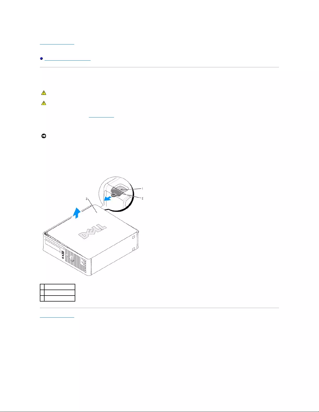
Back to Contents Page
Dell™OptiPlex™GX520User'sGuide
Removing the Computer Cover
Removing the Computer Cover
1. Follow the procedures in "Before You Begin."
2. If you have installed a padlock through the padlock ring on the back panel, remove the padlock.
3. Slide the release latch back as you lift the cover.
4. Pivot the cover up using the hinge tabs as leverage points.
5. Remove the cover from the hinge tabs and set it aside on a soft nonabrasive surface.
Back to Contents Page
CAUTION: Before you begin any of the procedures in this section, follow the safety instructions in the Product Information Guide.
CAUTION: To guard against electrical shock, always unplug your computer from the electrical outlet before removing the computer cover.
NOTICE: Ensure that there is sufficient space to support the open cover—at least 30 cm (1 ft) of desk top space.
1
security cable slot
2
cover release latch
3
computer cover
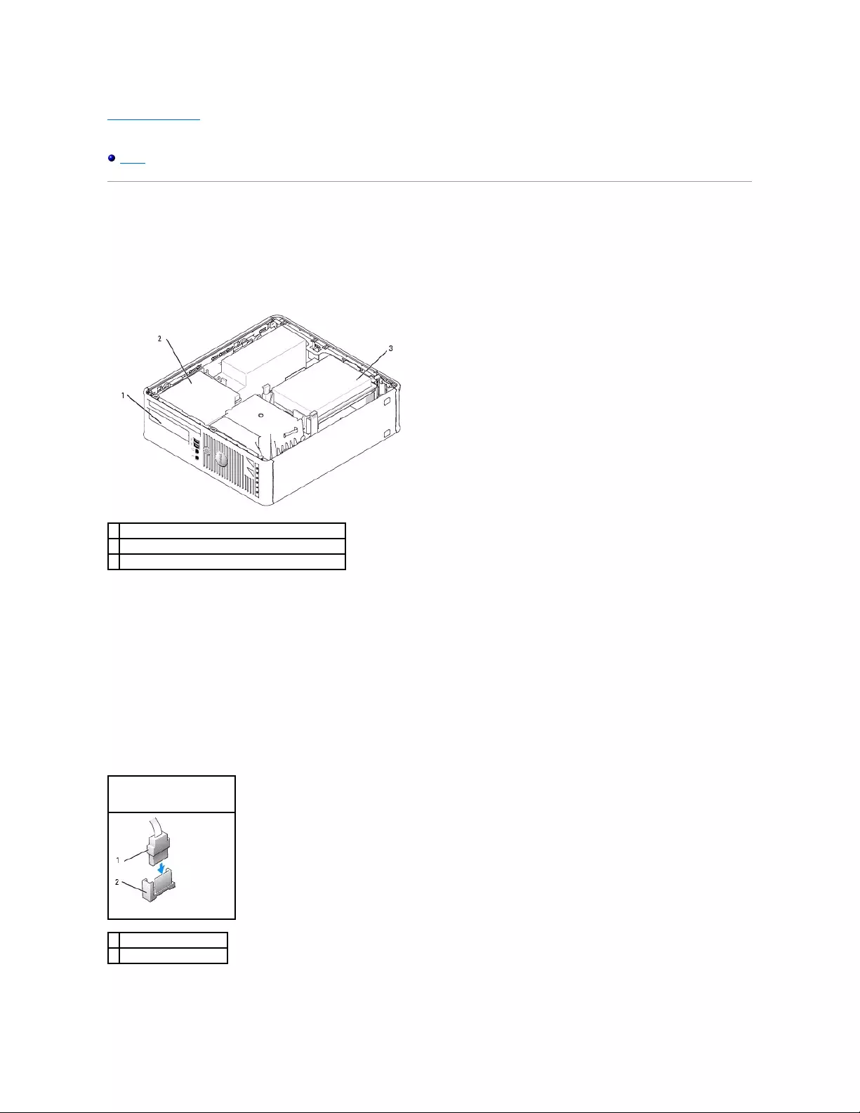
Back to Contents Page
Dell™OptiPlex™GX520User'sGuide
Drives
Drives
Your computer supports:
lOne serial ATA drive
lOne FlexBay drive (floppy drive or Media Card Reader)
lOne CD or DVD drive
General Installation Guidelines
Connect CD/DVD drives to the connector labeled "IDE" on the system board. Serial ATA hard drives should be connected to the connectors labeled "SATA0" or
"SATA2" on the system board.
Connecting Drive Cables
When you install a drive, you connect two cables—a DC power cable and a data cable—to the back of the drive and to the system board.
Drive Interface Connectors
Most interface connectors are keyed for correct insertion; that is, a notch or a missing pin on one connector matches a tab or a filled-in hole on the other
connector. Keyed connectors ensure that the pin-1 wire in the cable goes to the pin-1 end of the connector. The pin-1 end of a connector on a board or a card
is usually indicated by a silk-screened "1" printed directly on the board or card.
1
FlexBay for optional floppy drive or Media Card Reader
2
CD/DVD drive
3
hard drive
Serial ATA Connector
1
interface cable connector
2
interface connector
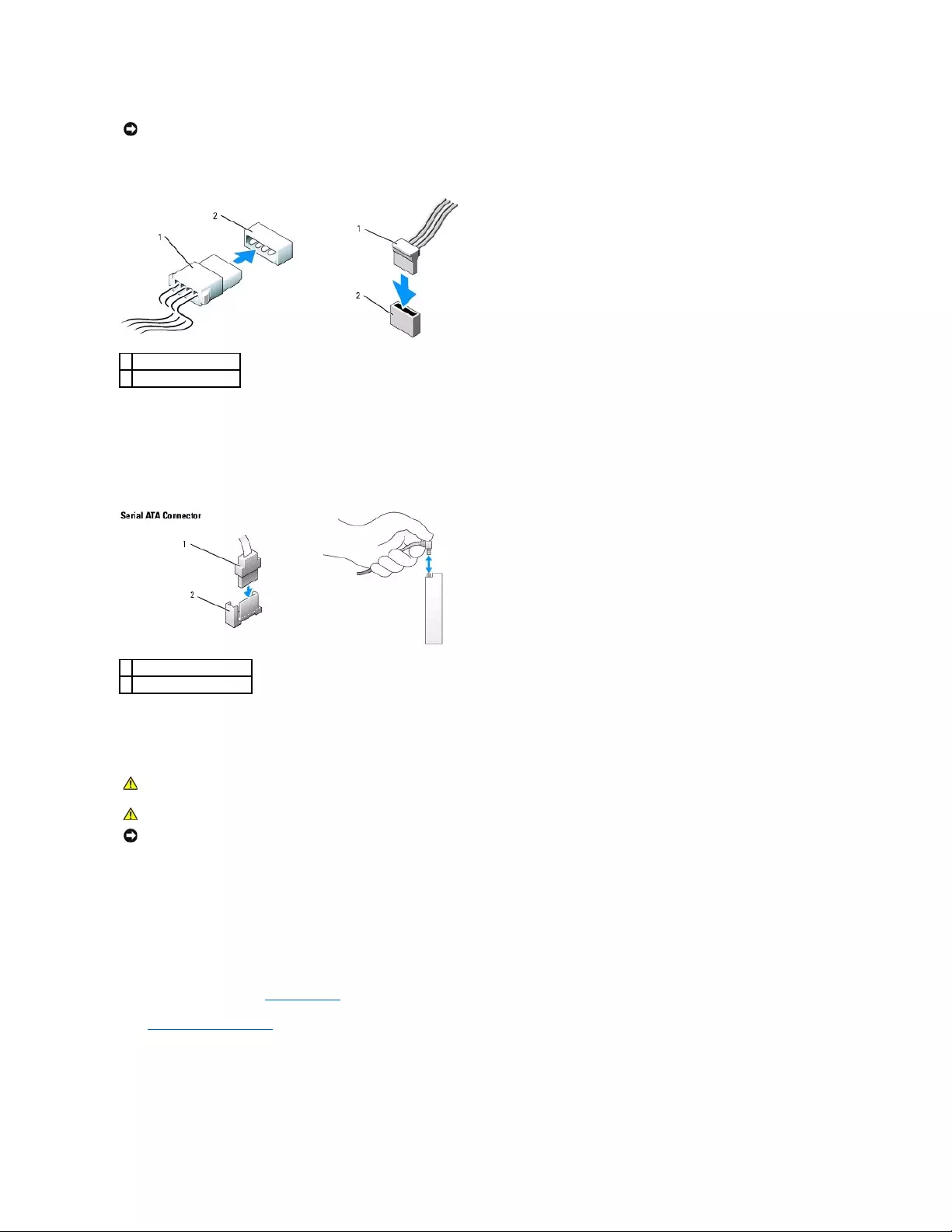
Power Cable Connectors
Connecting and Disconnecting Drive Cables
When connecting and disconnecting a serial ATA data cable, hold the cable by the black connector at each end.
Serial ATA interface connectors are keyed for correct insertion; that is, a notch or a missing pin on one connector matches a tab or a filled-in hole on the other
connector.
Hard Drive
1. If you are replacing a hard drive that contains data you want to keep, back up your files before you begin this procedure.
2. Check the documentation for the drive to verify that it is configured for your computer.
Removing a Hard Drive
1. Follow the procedures in "Before You Begin."
2. Remove the computer cover.
3. Lay the computer on its side so that the system board is on the bottom of the inside of the computer.
4. Press in on the two blue securing tabs on each side of the drive and slide the drive up and out of the computer.
NOTICE: When you connect an IDE interface cable, do not place the colored stripe away from pin 1 of the connector. Reversing the cable prevents the
drive from operating and could damage the controller, the drive, or both.
1
power cable
2
power input connector
1
interface cable connector
2
interface connector
CAUTION: Before you begin any of the procedures in this section, follow the safety instructions in the Product Information Guide.
CAUTION: To guard against electrical shock, always unplug your computer from the electrical outlet before removing the computer cover.
NOTICE: To avoid damage to the drive, do not set it on a hard surface. Instead, set the drive on a surface, such as a foam pad, that will sufficiently
cushion it.
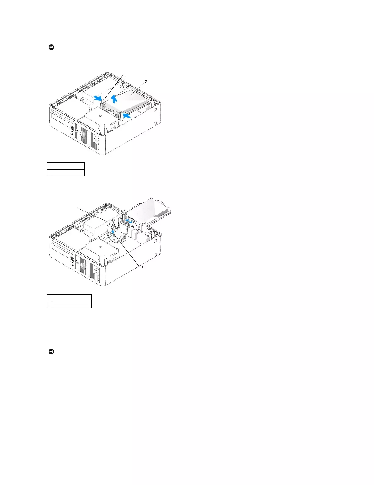
5. Lift the drive out of the computer and disconnect the power and hard-drive cables from the drive.
6. Disconnect the power and hard-drive cable from the drive.
Installing a Hard Drive
1. Check the documentation for the drive to verify that it is configured for your computer.
2. Unpack the replacement hard drive, and prepare it for installation.
3. If your replacement hard drive does not have the plastic drive bracket attached, remove the bracket from the existing drive by unsnapping it from the
drive.
NOTICE: Do not pull the drive out of the computer by the drive cables. Doing so may cause damage to cables and the cable connectors.
1
securing tabs (2)
2
hard drive
1
power cable
2
serial ATA data cable
NOTICE: To avoid damage to the drive, do not set it on a hard surface. Instead, set the drive on a surface, such as a foam pad, that will sufficiently
cushion it.
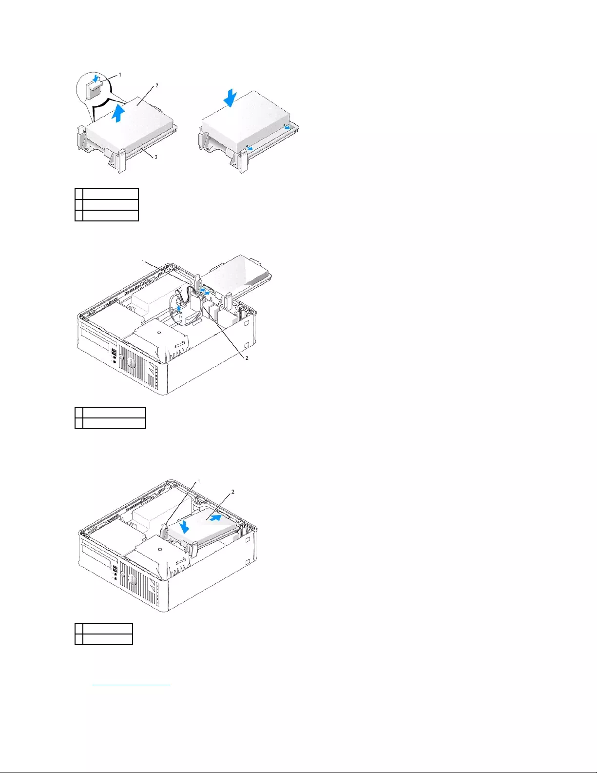
4. Connect the power and hard-drive cables to the drive.
5. Check all connectors to be certain that they are properly cabled and firmly seated.
6. Gently position the drive until it clicks into place.
7. Check all connectors to be certain that they are properly cabled and firmly seated.
8. Replace the computer cover.
1
drive
2
release tabs (2)
3
hard drive bracket
1
power cable
2
serial ATA data cable
1
release tabs (2)
2
hard drive
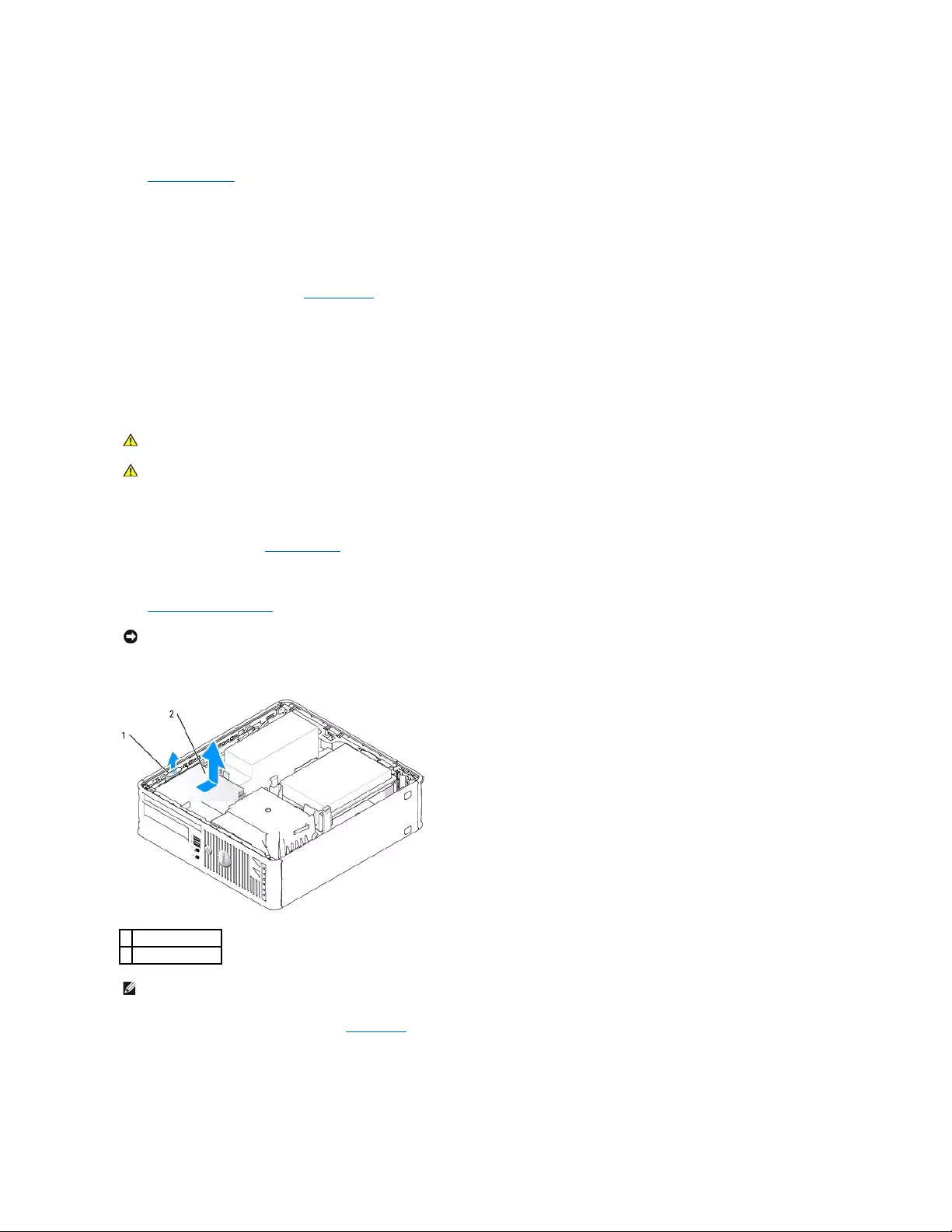
9. If the drive you just installed is the primary drive, insert a bootable medium into your boot drive.
10. Turn on the computer.
11. Enter system setup and update the appropriate Primary Drive option (0 or 2).
12. Exit system setup, and reboot the computer.
13. Partition and logically format your drive before you proceed to the next step.
For instructions, see the documentation that came with your operating system.
14. Test the hard drive by running the Dell Diagnostics.
15. Install your operating system on the hard drive.
For instructions, see the documentation that came with your operating system.
CD/DVD Drive
Removing a CD/DVD Drive
1. Follow the procedures in "Before You Begin."
2. Lay the computer on its side so that the system board is on the bottom of the inside of the computer.
3. Remove the computer cover.
4. Pull up on the drive release latch and slide the drive towards the back of the computer. Then lift up to remove the drive from the computer.
5. Disconnect the CD/DVD drive cable from the system board connector labeled (IDE).
CAUTION: Before you begin any of the procedures in this section, follow the safety instructions in the Product Information Guide.
CAUTION: To guard against electrical shock, always unplug your computer from the electrical outlet before removing the computer cover.
NOTICE: Do not pull the drive out of the computer by the drive cables. Doing so may cause damage to cables and the cable connectors.
1
drive release latch
2
CD/DVD drive
NOTE: You must remove the drive bracket from the CD/DVD drive before you can remove the CD/DVD drive cable from the drive.
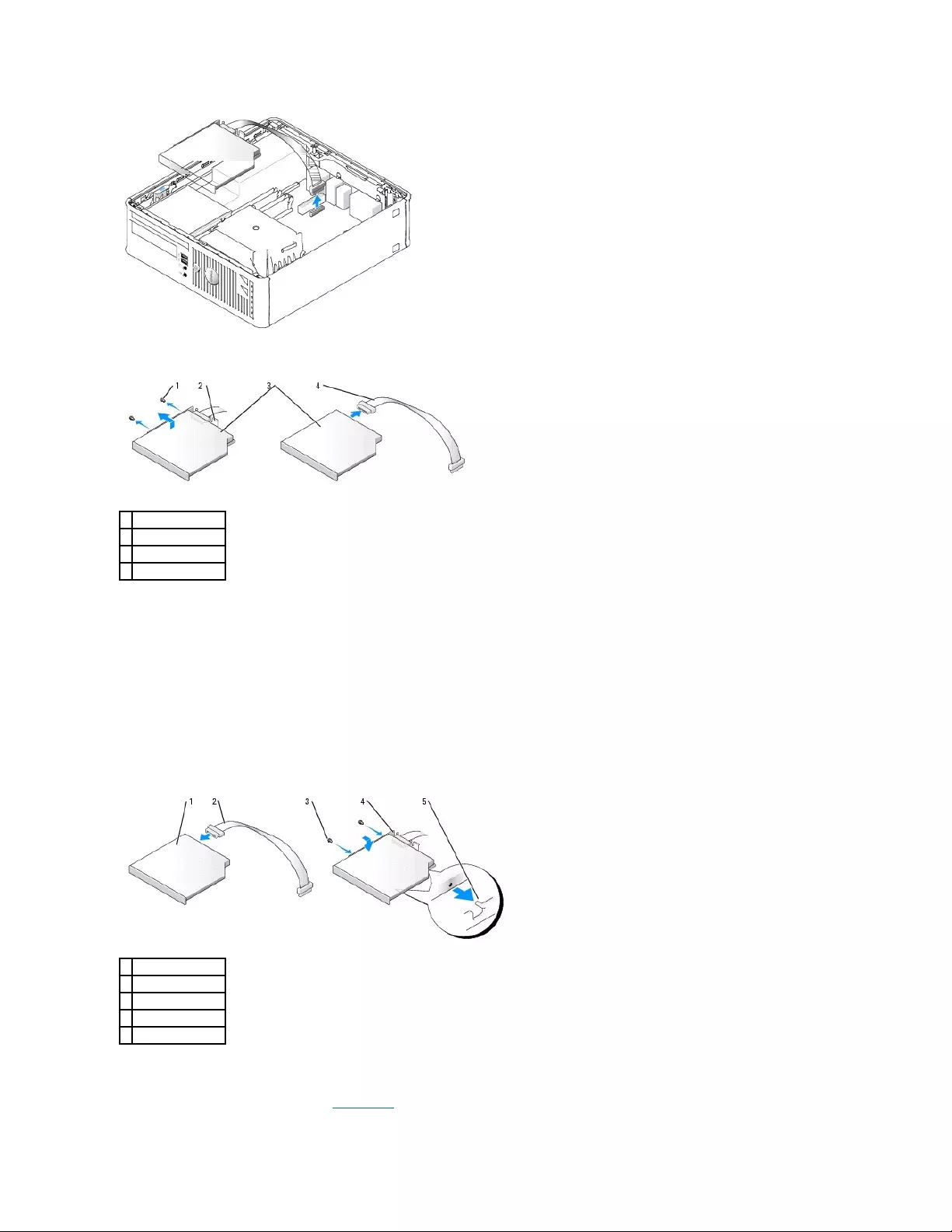
6. Remove the two screws from the side of drive and remove the drive bracket. Then disconnect the CD/DVD drive cable from the back of the drive.
Installing a CD/DVD Drive
1. Unpack the drive and prepare it for installation.
Check the documentation that accompanied the drive to verify that the drive is configured for your computer. Configure the drive for the cable select
setting.
2. Connect the CD/DVD drive cables to the drive.
3. Lower the drive into the drive bracket and align the two drive bracket tabs with the holes on the side of the drive. Then attach the two screws to the
side to secure it.
4. Gently position the drive until it clicks into place.
5. Reconnect the CD/DVD drive cable to the system board connector labeled (IDE).
1
screws (2)
2
drive bracket
3
CD/DVD drive
4
CD/DVD drive cable
1
CD/DVD drive
2
CD/DVD drive cable
3
screws (2)
4
drive bracket
5
alignment tabs (2)
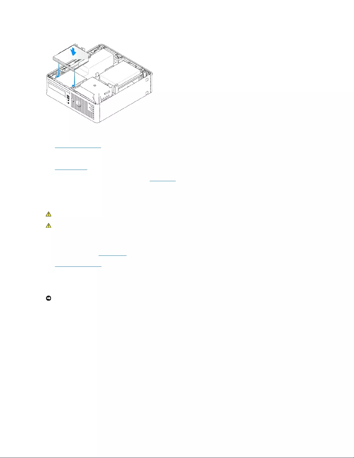
6. Check all cable connections, and fold cables out of the way to provide airflow for the fan and cooling vents.
7. Replace the computer cover.
8. See the documentation that came with the drive for instructions on installing any software required for drive operation.
9. Enter system setup and select the appropriate Drive option.
10. Verify that your computer works correctly by running the Dell Diagnostics.
Floppy Drive
Removing a Floppy Drive
1. Follow the procedures in "Before You Begin."
2. Remove the computer cover.
3. Lay the computer on its side so that the system board is on the bottom of the inside of the computer.
4. Remove the CD/DVD drive and carefully set it aside.
5. Pull up the cable release tab to unlock it and disconnect the floppy-drive cable from the back of the floppy drive.
6. Use the pull tab on the cable connector to disconnect the floppy-drive cable from the system board.
CAUTION: Before you begin any of the procedures in this section, follow the safety instructions in the Product Information Guide.
CAUTION: To guard against electrical shock, always unplug your computer from the electrical outlet before removing the computer cover.
NOTICE: Do not pull the drive out of the computer by the drive cables. Doing so may cause damage to cables and the cable connectors.
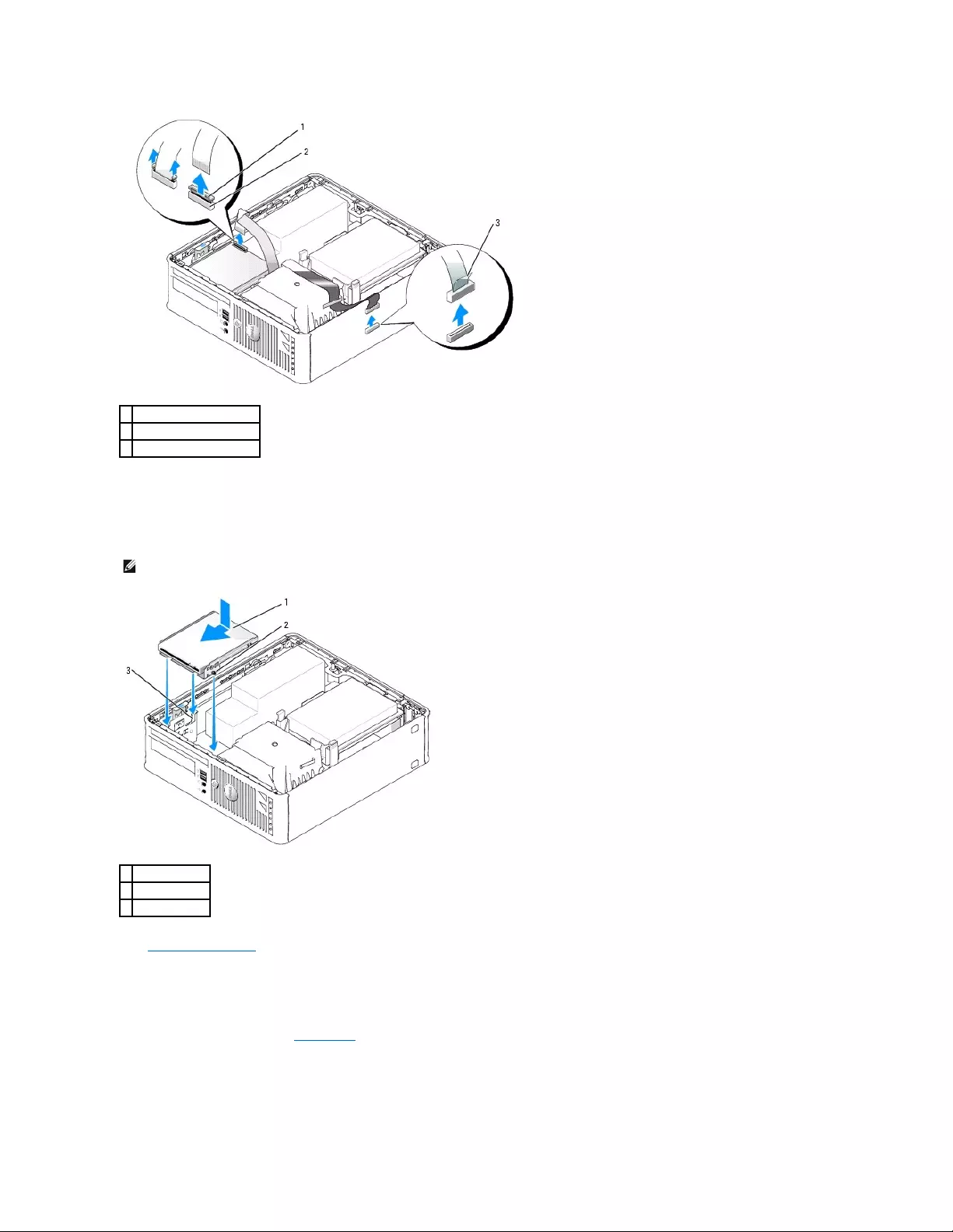
7. Pull up on the drive release latch and slide the floppy drive towards the back of the computer. Then lift up to remove the drive from the computer.
Installing a Floppy Drive
1. Remove the floppy drive.
2. Align the screws on the drive with the bracket rails in the computer, and gently position the drive until it clicks into place.
3. Insert the floppy-drive cable into the cable release tab on the floppy drive and press down on the tab until it clicks to lock it in place.
4. Reconnect the data cable to the system board connector labeled (DSKT).
1
cable release tab
2
data-cable edge connector
3
data-cable pull tab
NOTE: In the event the replacement or new floppy drive does not have the shoulder screws, use the screws located within the drive-panel insert.
1
drive
2
screws (3)
3
bracket rails (3)
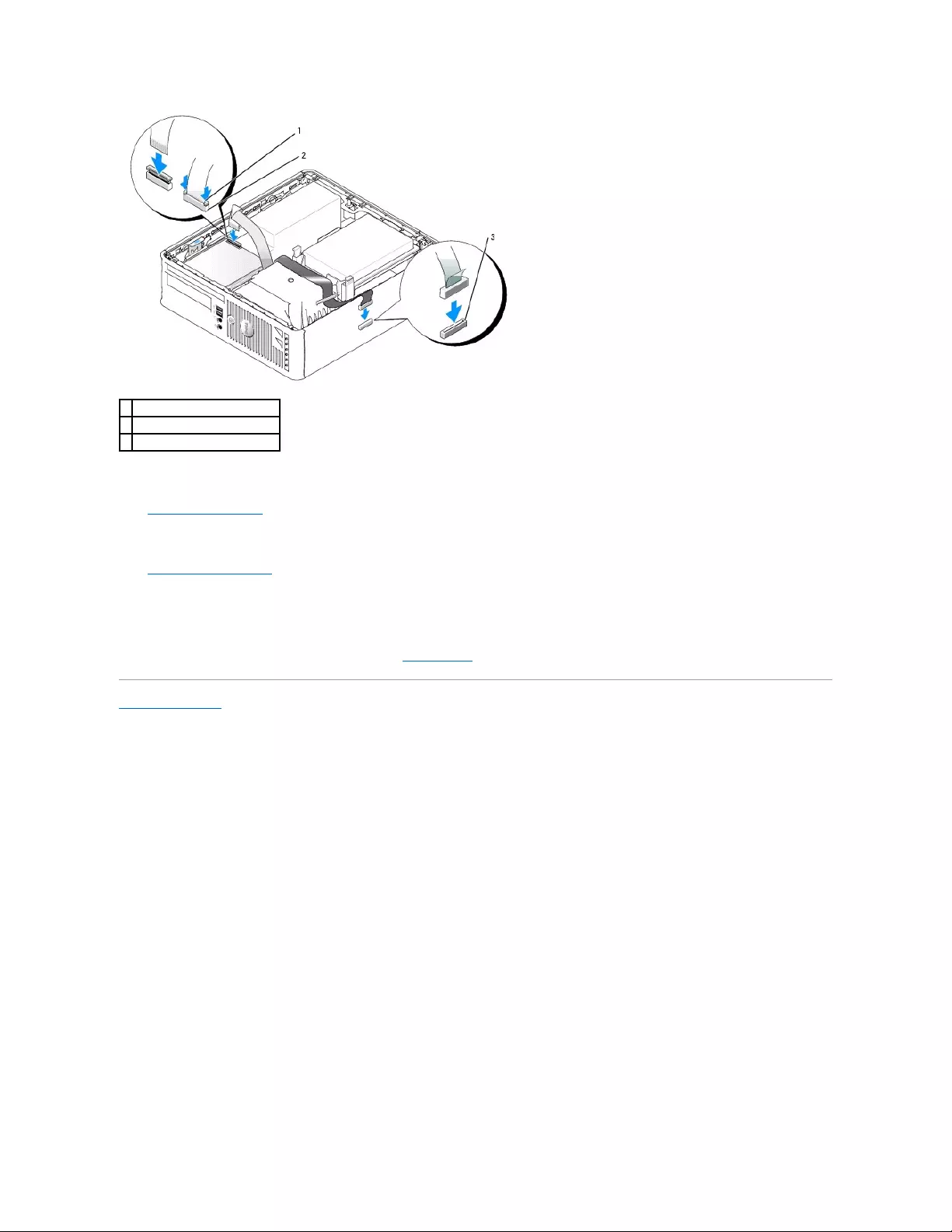
5. Check all cable connections, and fold cables out of the way to provide airflow for the fan and cooling vents.
6. Replace the CD/DVD drive.
7. Check all cable connections, and fold cables out of the way to provide airflow for the fan and cooling vents.
8. Replace the computer cover.
9. Enter and use the Diskette Drive option to enable your new floppy drive.
See the documentation that came with the drive for instructions on installing any software required for drive operation.
10. Verify that your computer works correctly by running the Dell Diagnostics.
Back to Contents Page
1
cable release tab
2
data cable edge connector
3
system board connector (DSKT)
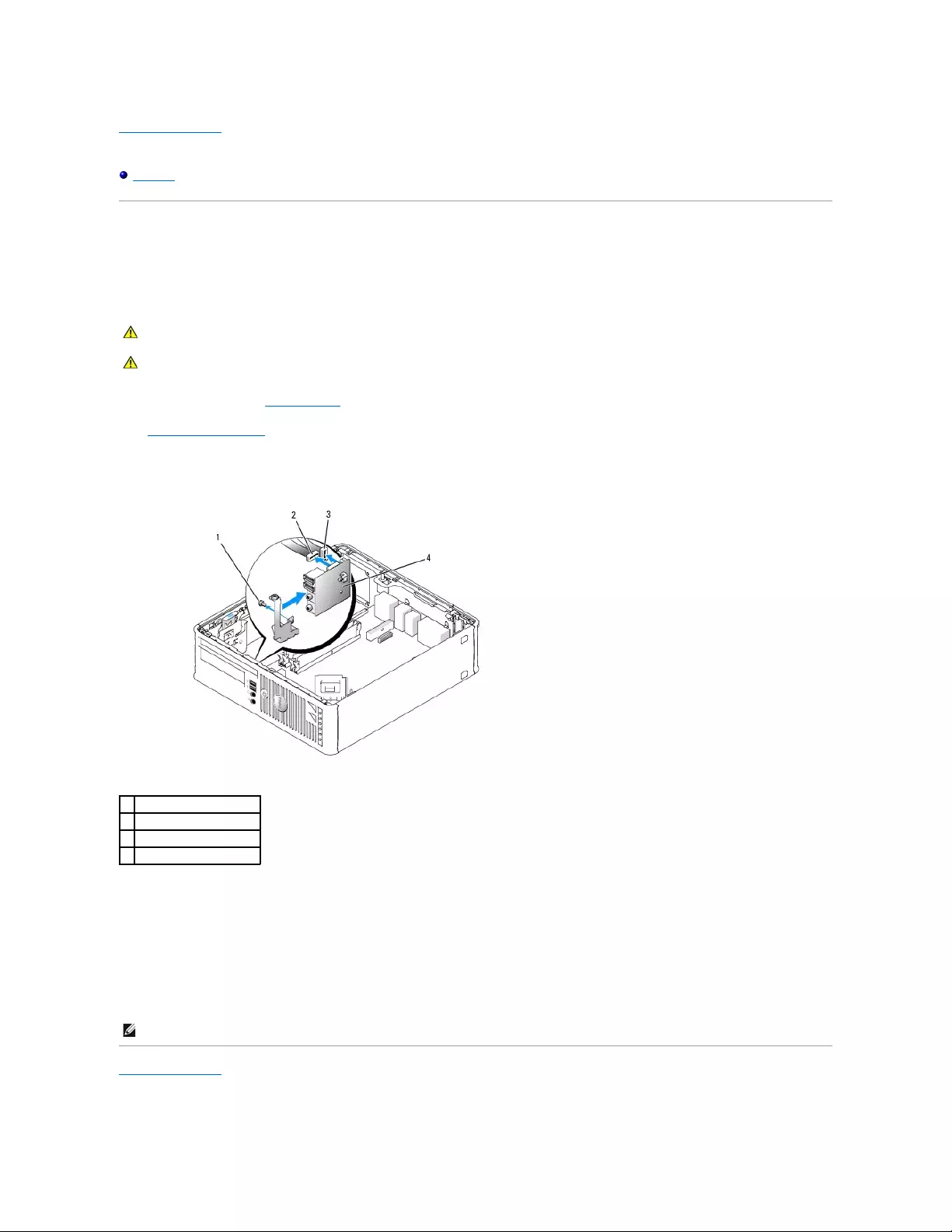
Back to Contents Page
Dell™OptiPlex™GX520User'sGuide
I/O Panel
I/O Panel
Removing the I/O Panel
1. Follow the procedures in "Before You Begin."
2. Remove the system board.
3. Disconnect all cables that are connected to the I/O panel.
Note the routing of the control panel cables as you remove them from the computer so that you can replace them correctly.
4. From inside the computer cover, remove the mounting screws that secure the I/O panel to the computer.
5. Remove the I/O panel from the computer.
Replacing the I/O Panel
To replace the I/O panel, follow the removal procedures in the reverse order.
Back to Contents Page
CAUTION: Before you begin any of the procedures in this section, follow the safety instructions located in the Product Information Guide.
CAUTION: To guard against electrical shock, always unplug your computer from the electrical outlet before removing the computer cover.
1
securing screw (2)
2
I/O panel
3
I/O cable connector
4
I/O connector pull loop
NOTE: Use the guides on the I/O panel bracket to help position the I/O panel in place and use the notch on the I/O panel bracket to help seat the card.
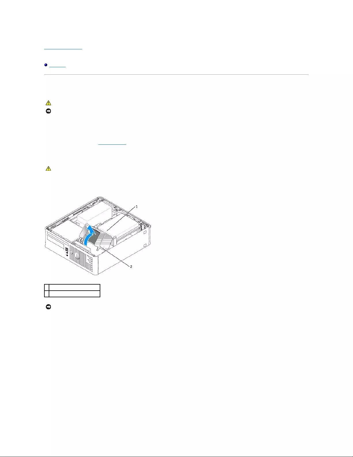
Back to Contents Page
Dell™OptiPlex™GX520User'sGuide
Processor
Processor
Removing the Processor
1. Follow the procedures in "Before You Begin."
2. Loosen the captive screw on each side of the heat sink assembly.
3. Rotate the heat sink assembly upward, and remove the assembly from the computer.
4. Open the processor cover by sliding the release lever from under the center cover latch on the socket. Then, pull the lever back to release the
processor.
CAUTION: Before you begin any of the procedures in this section, follow the safety instructions located in the Product Information Guide.
NOTICE: To prevent static damage to components inside your computer, discharge static electricity from your body before you touch any of your
computer's electronic components. You can do so by touching an unpainted metal surface on the computer chassis.
CAUTION: Despite having a plastic shield, the heat sink assembly may be very hot during normal operation. Be sure that it has had sufficient time
to cool before you touch it.
1
heat sink assembly
2
captive screws in housing (2)
NOTICE: If you are installing a processor upgrade kit from Dell, discard the original heat sink. If you are not installing a processor upgrade kit from Dell,
reuse the original heat sink when you install your new processor.

5. Gently remove the processor from the socket.
Leave the release lever extended in the release position so that the socket is ready for the new processor.
Installing the Processor
1. Follow the procedures in "Before You Begin."
2. Unpack the new processor, being careful not to touch the underside of the processor.
3. If the release lever on the socket is not fully extended, move it to that position.
4. Orient the front and rear alignment-notches on the processor with the front and rear alignment-notches on the socket.
5. Align the pin-1 corners of the processor and socket.
1
center cover latch
2
processor cover
3
processor
4
socket
5
release lever
NOTICE: When replacing the processor, do not touch any of the pins inside the socket or allow any objects to fall on the pins in the socket.
NOTICE: Ground yourself by touching an unpainted metal surface on the back of the computer.
NOTICE: When replacing the processor, do not touch any of the pins inside the socket or allow any objects to fall on the pins in the socket.
NOTICE: You must position the processor correctly in the socket to avoid permanent damage to the processor and the computer when you turn on the
computer.

6. Set the processor lightly in the socket and ensure that the processor is positioned correctly.
7. When the processor is fully seated in the socket, close the processor cover.
Ensure that the tab on the processor cover is positioned underneath the center cover latch on the socket.
8. Pivot the socket release lever back toward the socket and snap it into place to secure the processor.
If you installed a processor replacement kit from Dell, return the original heat sink assembly and processor to Dell in the same package in which your
replacement kit was sent.
9. Install the heat sink assembly:
a. Place the heat sink assembly back onto the heat-sink assembly bracket.
b. Rotate the heat sink assembly down towards the computer base and tighten the two captive screws.
1
processor cover
6
release lever
2
tab
7
front alignment-notch
3
processor
8
socket and processor pin-1 indicator
4
processor socket
9
rear alignment-notch
5
center cover latch
NOTICE: To avoid damage, ensure that the processor aligns properly with the socket, and do not use excessive force when you install the processor.
NOTICE: If you are not installing a processor upgrade kit from Dell, reuse the original heat sink assembly when you replace the processor.
NOTICE: Ensure that the heat sink is correctly seated and secure.
1
heat sink assembly
2
heat-sink assembly bracket

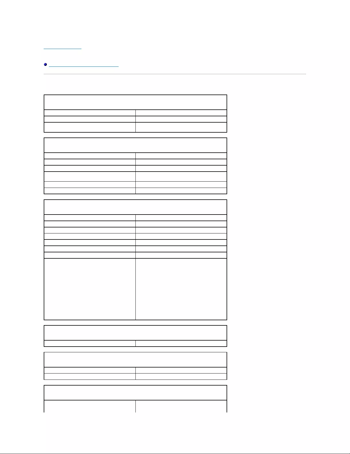
Back to Contents Page
Dell™OptiPlex™GX520User'sGuide
Small Form Factor Computer Specifications
Small Form Factor Computer Specifications
Microprocessor
Microprocessor type
Intel®Pentium®or Celeron®processor
Level 1 (L1) cache
32 KB
Level 2 (L2) cache
512-KB, 1-MB, or 2-MB pipelined-burst, eight-way set
associative, write-back SRAM
Memory
Type
400-MHz and 533-MHz DDR2 SDRAM
Memory connectors
2
Memory modules supported
256-MB, 512-MB, 1-GB, or 2-GB non-ECC
Minimum memory
dual-channel: 512 MB;
single-channel: 256 MB
Maximum memory
4 GB
BIOS address
F0000h
Computer Information
Chipset
Intel®945 Express
Data bus width
64 bits
Address bus width
32 bits
DMA channels
eight
Interrupt levels
24
BIOS chip (NVRAM)
4 Mb
Memory speed
400 MHz and 533 MHz
NIC
integrated network interface with ASF 1.03 and 2.0
support as defined by DMTF
Capable of 10/100/1000 communication:
lGreen — A good connection exists between a
10-Mbps network and the computer.
lOrange — A good connection exists between a
100-Mbps network and the computer.
lYellow — A good connection exists between a
1-Gb (or 1000-Mbps) network and the
computer.
lOff — The computer is not detecting a physical
connection to the network.
Video
Type
integrated Intel Graphic Media Accelerator 950
Audio
Type
AC97, Sound Blaster emulation
Stereo conversion
16-bit analog-to-digital; 20-bit digital-to-analog
Controllers
Drives
one serial ATA controller supporting one device and
one parallel Ultra ATA/100 IDE supporting two
devices per channel with one channel
Expansion Bus
Bus type
PCI 2.2
SATA 1.0a and 2.0
USB 2.0
Bus speed
PCI: 33 MHz
SATA: 1.5 and 3.0 Gbps
USB: 480 Mbps
Cards:
low-profile cards supported
PCI:
connector
one
connector size
120 pins
connector data width (maximum)
32 bits
Drives
Externally accessible
one bay for a slimline floppy drive;
one bay for a slimline CD/DVD drive
Internally accessible
one bay for a 1-inch-high hard drive
Connectors
External connectors:
Serial
9-pin connector; 16550C-compatible
Parallel
25-hole connector (bidirectional)
Video
15-hole VGA connector
Network adapter
RJ45 connector
USB
two front-panel and six back-panel USB 2.0–
compliant connectors
Audio
three connectors for line-in, line-out, and microphone;
one front-panel connector for headphones
System board connectors:
Primary IDE drive
40-pin connector
Serial ATA
7-pin connector
Floppy drive
34-pin connector
Serial
12-pin connector for optional second serial port card
Fan
5-pin connector
PCI 2.2
120-pin connector
CD drive audio interface
4-pin connector
Front panel
40-pin connector
Key Combinations
<Ctrl><Alt><Del>
in Microsoft®Windows®XP, brings up the Windows
Security window; in MS-DOS®mode, restarts
(reboots) the computer
<F2> or <Ctrl><Alt><Enter>
starts embedded system setup (during system start-
up only)
<Ctrl><Alt><b>
automatically starts the computer from the network
environment specified by the remote boot
environment (PXE) rather than from one of the
devices in the system setup Boot Sequence option
(during system start-up only)
<F12> or <Ctrl><Alt><F8>
displays a boot device menu that allows the user to
enter a device for a single boot (during system start-
up only) as well as options to run hard-drive and
system diagnostics
Controls and Lights
Power control
push button
Power light
green light — Blinking green indicates sleep mode;
solid green indicates power-on state.
Back to Contents Page
amber light — Blinking amber indicates a problem
with an installed device; solid amber indicates an
internal power problem (see "Power Problems").
Hard-drive access light
green
Link light
solid green light indicates network connection
Link integrity light (on integrated network adapter)
green light for 10-Mb operation; orange light for 100-
Mb operation; yellow light for a 1000-Mb (1-Gb)
operation
Activity light (on integrated network adapter)
yellow blinking light
Diagnostic lights
four lights on the back panel (see "Diagnostic Lights")
Standby power light
AUX_PWR on the system board
Power
DC power supply:
Wattage
220 W
Heat dissipation
751 BTU/hr
NOTE: Heat dissipation is calculated based upon the
power supply wattage rating.
Voltage
manual selection power supplies — 90 to 135 V at
50/60Hz;180to265Vat50/60Hz
Backup battery
3-V CR2032 lithium coin cell
Physical
Height
9.26 cm (3.65 inches)
Width
31.37 cm (12.35 inches)
Depth
34.03 cm (13.40 inches)
Weight
7.4 kg (16.4 lb)
Environmental
Temperature:
Operating
10°to35°C(50°to95°F)
Storage
–40°to65°C(–40°to149°F)
Relative humidity
20% to 80% (noncondensing)
Maximum vibration:
Operating
0.25 G at 3 to 200 Hz at 0.5 octave/min
Storage
0.5 G at 3 to 200 Hz at 1 octave/min
Maximum shock:
Operating
bottom half-sine pulse with a change in velocity of 20
inches/sec (50.8 cm/sec)
Storage
27-G faired square wave with a velocity change of
200 inches/sec (508 cm/sec)
Altitude:
Operating
–15.2 to 3048 m (–50 to 10,000 ft)
Storage
–15.2 to 10,668 m (–50 to 35,000 ft)
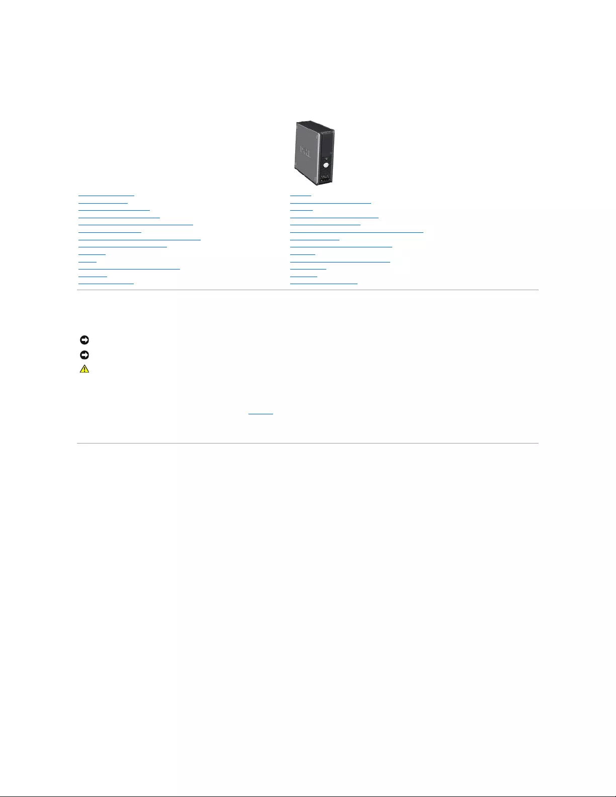
Dell™OptiPlex™GX520User'sGuide
Notes, Notices, and Cautions
Abbreviations and Acronyms
For a complete list of abbreviations and acronyms, see the Glossary.
IfyoupurchasedaDell™nSeriescomputer,anyreferencesinthisdocumenttoMicrosoft® Windows® operating systems are not applicable.
Information in this document is subject to change without notice.
©2005–2006DellInc.Allrightsreserved.
Reproduction in any manner whatsoever without the written permission of Dell Inc. is strictly forbidden.
Trademarks used in this text: Dell, the DELL logo, OptiPlex, Inspiron, Dimension, Latitude, Dell Precision, DellNet, TravelLite, Dell OpenManage, PowerVault, Axim, PowerEdge, PowerConnect,
and PowerApp are trademarks of Dell Inc.; Intel, Pentium, and Celeron are registered trademarks of Intel Corporation; Microsoft, MS-DOS, and Windows are registered trademarks of
Microsoft Corporation; IBM is a registered trademark of International Business Machines Corporation; Bluetooth is a trademark owned by Bluetooth SIG, Inc. and is used by Dell
Inc. under license. ENERGY STAR is a registered trademark of the U.S. Environmental Protection Agency. As an ENERGY STAR partner, Dell Inc. has determined that this product
meets the ENERGY STAR guidelines for energy efficiency.
Other trademarks and trade names may be used in this document to refer to either the entities claiming the marks and names or their products. Dell Inc. disclaims any
proprietary interest in trademarks and trade names other than its own.
Model DCSM
October 2006 P/N W9246 Rev. A03
Small Form Factor Computer
Finding Information
Before You Begin
Chassis Intrusion Switch
Small Form Factor Computer
About Your Small Form Factor Computer
Inside Your Computer
Small Form Factor Computer Specifications
Removing the Computer Cover
I/O Panel
Drives
PCI Cards and Serial Port Adapters
Processor
Advanced Features
Battery
Replacing the System Board
Memory
Replacing the Computer Cover
Cleaning Your Computer
Reinstalling Drivers and the Operating System
Solving Problems
Microsoft®Windows®XP Features
Glossary
Troubleshooting Tools and Utilities
Getting Help
Warranty
FCC Notices (U.S. Only)
NOTE: A NOTE indicates important information that helps you make better use of your computer.
NOTICE: A NOTICE indicates either potential damage to hardware or loss of data and tells you how to avoid the problem.
CAUTION: A CAUTION indicates a potential for property damage, personal injury, or death.
Back to Contents Page
Solving Problems
Dell™OptiPlex™GX520User'sGuide
Battery Problems
Drive Problems
Keyboard Problems
Lockups and Software Problems
Memory Problems
Mouse Problems
Network Problems
Power Problems
Printer Problems
Restoring Default Settings
Serial or Parallel Device Problems
Sound and Speaker Problems
Video and Monitor Problems
Battery Problems
Fill out the Diagnostics Checklist before you complete these checks.
Drive Problems
Fill out the Diagnostics Checklist as you complete these checks.
CD and DVD drive problems
CAUTION: There is a danger of a new battery exploding if it is incorrectly installed. Replace the battery only with the same or equivalent type
recommended by the manufacturer. Discard used batteries according to the manufacturer's instructions.
CAUTION: Before you begin any of the procedures in this section, follow the safety instructions located in the Product Information Guide.
Replacethebattery— If you have to repeatedly reset time and date information after turning on the computer, or if an incorrect time or
date displays during start-up, replace the battery. If the battery still does not work properly, contact Dell.
CAUTION: Before you begin any of the procedures in this section, follow the safety instructions located in the Product Information Guide.
Testthedrive—
lInsert another floppy disk, CD, or DVD to eliminate the possibility that the original one is defective.
lInsert a bootable floppy disk and restart the computer.
Cleanthedriveordisk— See "Cleaning Your Computer."
Check the cable connections
Check for software and hardware conflicts
Run the Dell Diagnostics
NOTE: Because of different regions worldwide and different disc formats, not all DVD titles work in all DVD drives.

Problems writing to a CD/DVD-RW drive
Hard drive problems
Keyboard Problems
AdjusttheWindowsvolumecontrol—
lClick the speaker icon in the lower-right corner of your screen.
lEnsure that the volume is turned up by clicking the slidebar and dragging it up.
lEnsure that the sound is not muted by clicking any boxes that are checked.
Checkthespeakersandsubwoofer— See "Sound and Speaker Problems."
Closeotherprograms— The CD/DVD-RW drive must receive a steady stream of data when writing. If the stream is interrupted, an error
occurs. Try closing all programs before you write to the CD/DVD-RW.
Turn off Standby mode in Windows before writing to a CD/DVD-RWdisc— See "Power Management."
RunningtheDellIDEHardDriveDiagnostics —
The Dell IDE Hard Drive Diagnostics is a utility that tests the hard drive to troubleshoot or confirm a hard drive failure.
1. Turn on your computer (if your computer is already on, restart it).
2. When F2 = Setup appears in the upper-right corner of the screen, press <Ctrl><Alt><d>.
3. Follow the instructions on the screen.
RunCheckDisk—
1. Click the Start button and click My Computer.
2. Right-click Local Disk C:.
3. Click Properties.
4. Click the Tools tab.
5. Under Error-checking, click Check Now.
6. Click Scan for and attempt recovery of bad sectors.
7. Click Start.
CAUTION: Before you begin any of the procedures in this section, follow the safety instructions located in the Product Information Guide.
Checkthekeyboardcable—
lEnsure that the keyboard cable is firmly connected to the computer.
lShut down the computer, reconnect the keyboard cable as shown in the Quick Reference Guide for your computer, and then restart the
computer.
lCheck the cable connector for bent or broken pins and for damaged or frayed cables. Straighten bent pins.
lRemove keyboard extension cables and connect the keyboard directly to the computer.
Testthekeyboard— Connect a properly working keyboard to the computer, and try using the keyboard. If the new keyboard works, the
original keyboard is faulty.
Run the Dell Diagnostics
Lockups and Software Problems
The computer does not start up
The computer stops responding
A program stops responding
A program crashes repeatedly
A solid blue screen appears
Check for software and hardware conflicts
CAUTION: Before you begin any of the procedures in this section, follow the safety instructions located in the Product Information Guide.
NOTE: If you installed a unique image on your computer or if you had to reinstall your operating system, run the DSS utility. DSS is available on your
Drivers and Utilities CD and at support.dell.com.
NOTE: You must use Microsoft® Windows® XP Service Pack 1 or later when you reinstall Windows XP.
Check the Diagnostic Lights
Ensure that the power cable is firmly connected to the computer and to the electrical outlet
NOTICE: You might lose data if you are unable to perform an operating system shutdown.
Turnthecomputeroff— If you are unable to get a response by pressing a key on your keyboard or moving your mouse, press and hold
the power button for at least 8 to 10 seconds until the computer turns off. Then restart your computer.
Endtheprogram—
1. Press <Ctrl><Shift><Esc> simultaneously.
2. Click Applications.
3. Click the program that is no longer responding.
4. Click End Task.
NOTE: Software usually includes installation instructions in its documentation or on a floppy disk or CD.
Checkthesoftwaredocumentation— If necessary, uninstall and then reinstall the program.
Ensure that the original installed version of Windows XP is installed on your computer
Turnthecomputeroff— If you are unable to get a response by pressing a key on your keyboard or moving your mouse, press and hold
the power button for at least 8 to 10 seconds until the computer turns off. Then restart your computer.
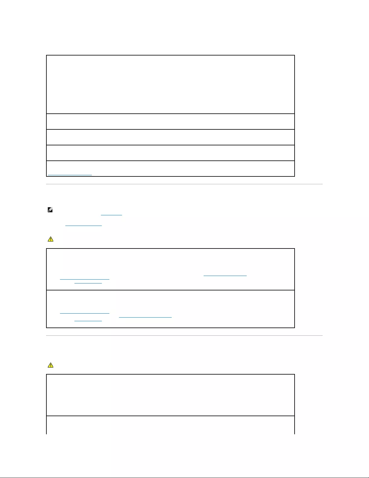
Other software problems
Memory Problems
Fill out the Diagnostics Checklist as you complete these checks.
Mouse Problems
Checkthesoftwaredocumentationorcontactthesoftwaremanufacturerfortroubleshootinginformation—
lEnsure that the program is compatible with the operating system installed on your computer.
lEnsure that your computer meets the minimum hardware requirements needed to run the software. See the software documentation
for information.
lEnsure that the program is installed and configured properly.
lVerify that the device drivers do not conflict with the program.
lIf necessary, uninstall and then reinstall the program.
Back up your files immediately
Use a virus-scanning program to check the hard drive, floppy disks, or CDs
Save and close any open files or programs and shut down your computer through the Start menu
Run the Dell Diagnostics— If all tests run successfully, the error condition is related to a software problem.
NOTE: Your computer might emit a series of beeps (beep code) during start-up if the monitor cannot display errors or problems. This series of beeps
identifies a problem. See "Beep Codes" for more information.
CAUTION: Before you begin any of the procedures in this section, follow the safety instructions located in the Product Information Guide.
Ifyoureceiveaninsufficientmemorymessage—
lSave and close any open files and exit any open programs you are not using to see if that resolves the problem.
lSee the software documentation for minimum memory requirements. If necessary, install additional memory.
lReseat the memory modules to ensure that your computer is successfully communicating with the memory.
lRun the Dell Diagnostics.
Ifyouexperienceothermemoryproblems—
lReseat the memory modules to ensure that your computer is successfully communicating with the memory.
lEnsure that you are following the memory installation guidelines.
lRun the Dell Diagnostics.
CAUTION: Before you begin any of the procedures in this section, follow the safety instructions located in the Product Information Guide.
Checkthemousecable—
1. Check the cable connector for bent or broken pins and for damaged or frayed cables. Straighten bent pins.
2. Remove mouse extension cables, if used, and connect the mouse directly to the computer.
3. Shut down the computer, reconnect the mouse cable as shown in the Quick Reference Guide for your computer, and then restart the
computer.
Restartthecomputer—

Network Problems
Fill out the Diagnostics Checklist as you complete these checks.
Power Problems
Fill out the Diagnostics Checklist as you complete these checks.
1. Simultaneously press <Ctrl><Esc> to display the Start menu.
2. Type u, press the keyboard arrow keys to highlight Shut down or Turn Off, and then press <Enter>.
3. After the computer turns off, reconnect the mouse cable as shown on the in the Quick Reference Guide for your computer.
4. Start the computer.
Testthemouse— Connect a properly working mouse to the computer, and try using the mouse. If the new mouse works, the original
mouse is faulty.
Checkthemousesettings—
1. Click the Start button, click Control Panel, and then click Printers and Other Hardware.
2. Click Mouse.
3. Try adjusting the settings.
If you are using a PS/2 mouse
1. Enter system setup and ensure that the Mouse Port option is set to On.
2. Exit system setup and restart the computer.
Reinstall the mouse driver
Run the Dell Diagnostics
Check for software and hardware conflicts
CAUTION: Before you begin any of the procedures in this section, follow the safety instructions located in the Product Information Guide.
Checkthenetworkcableconnector— Ensure that the network cable is firmly inserted into both the network connector on the back of the
computer and the network jack.
Checkthenetworklightsonthefrontorbackofthecomputerdependingonsystemchassistype.— No connection speed light indicates
that no network communication exists. Replace the network cable.
Restart the computer and log on to the network again
Checkyournetworksettings— Contact your network administrator or the person who set up your network to verify that your network
settings are correct and that the network is functioning.
Check for software and hardware conflicts
CAUTION: Before you begin any of the procedures in this section, follow the safety instructions located in the Product Information Guide.
Ifthepowerlightisgreenandthecomputerisnotresponding— See "Diagnostic Lights."
Ifthepowerlightisblinkinggreen— The computer is in standby mode. Press a key on the keyboard or move the mouse to resume
normal operation.
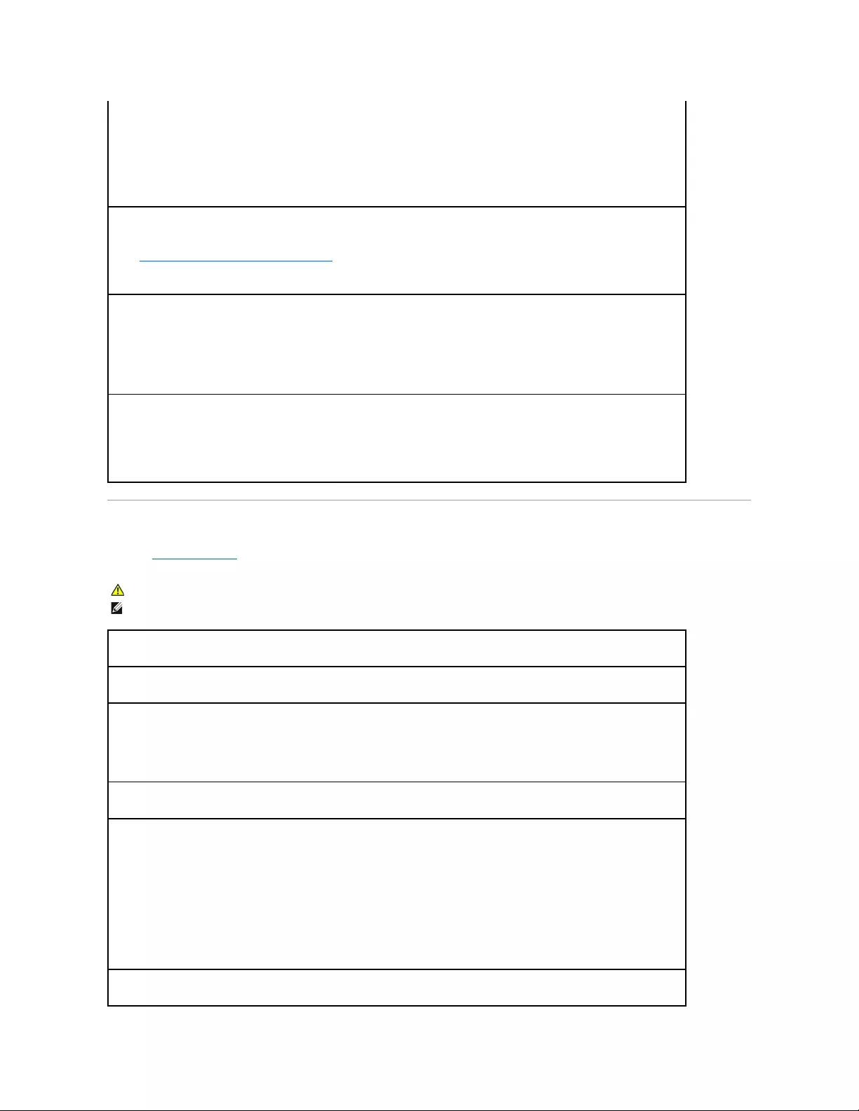
Printer Problems
Fill out the Diagnostics Checklist as you complete these checks.
Ifthepowerlightisoff— The computer is either turned off or is not receiving power.
lReseat the power cable into both the power connector on the back of the computer and the electrical outlet.
lIf the computer is plugged into a power strip, ensure that the power strip is plugged into an electrical outlet and that the power strip
is turned on. Also bypass power protection devices, power strips, and power extension cables to verify that the computer turns on
properly.
lEnsure that the electrical outlet is working by testing it with another device, such as a lamp.
lEnsure that the main power cable and front panel cable are securely connected to the system board.
Ifthepowerlightisamberandgreenorsteadyamber— A device might be malfunctioning or incorrectly installed.
lRemove and then reinstall the memory modules.
lRemove and then reinstall any cards.
lRemove and then reinstall the graphics card, if applicable.
Ifthepowerlightisblinkingamber—
The computer is receiving electrical power, but an internal power problem might exist.
lEnsure that the voltage selection switch is set to match the AC power at your location (if applicable).
lEnsure that the processor power cable is securely connected to the system board.
Eliminateinterference— Some possible causes of interference are:
lPower, keyboard, and mouse extension cables
lToo many devices on a power strip
lMultiple power strips connected to the same electrical outlet
CAUTION: Before you begin any of the procedures in this section, follow the safety instructions located in the Product Information Guide.
NOTE: If you need technical assistance for your printer, contact the printer's manufacturer.
Checktheprinterdocumentation— See the printer documentation for setup and troubleshooting information.
Ensure that the printer is turned on
Checktheprintercableconnections—
lSee the printer documentation for cable connection information.
lEnsure that the printer cables are securely connected to the printer and the computer.
Testtheelectricaloutlet— Ensure that the electrical outlet is working by testing it with another device, such as a lamp.
VerifythattheprinterisrecognizedbyWindows—
1. Click the Start button, click Control Panel, and then click Printers and Other Hardware.
2. Click View installed printers or fax printers.
If the printer is listed, right-click the printer icon.
3. Click Properties and click the Ports tab. For a parallel printer, ensure that the Print to the following port(s): setting is LPT1 (Printer
Port). For a USB printer, ensure that the Print to the following port(s): setting is USB.
Reinstalltheprinterdriver— See the printer documentation for instructions
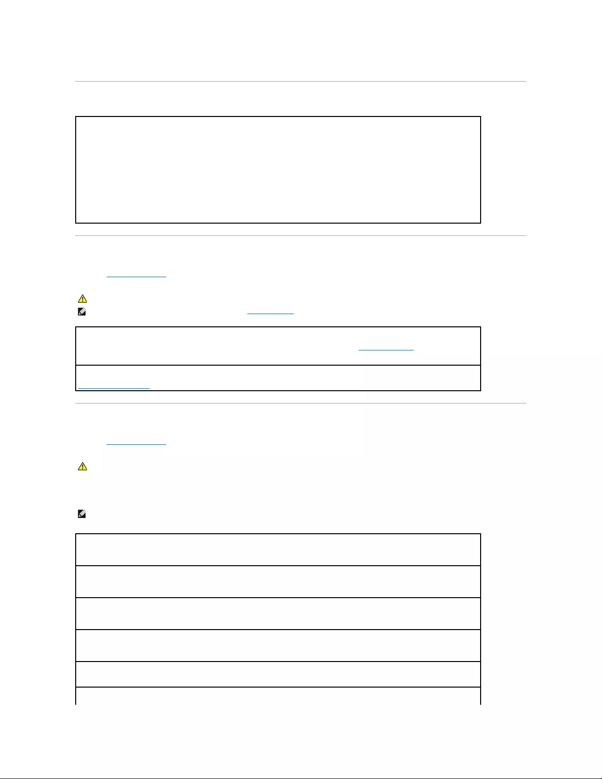
Restoring Default Settings
Serial or Parallel Device Problems
Fill out the Diagnostics Checklist as you complete these checks.
Sound and Speaker Problems
Fill out the Diagnostics Checklist as you complete these checks.
No sound from speakers
To restore the computer's system settings to their default values —
1. Turn on or restart your computer.
2. When Press <F2> to Enter Setup appears in the upper-right corner of the screen, press <F2> immediately.
If you wait too long and the Microsoft®Windows®logo appears, continue to wait until you see the Windows desktop. Then shut
down your computer through the Start menu and try again.
3. Under System Management, select the Maintenance option and follow the directions on the screen.
CAUTION: Before you begin any of the procedures in this section, follow the safety instructions located in the Product Information Guide.
NOTE: If you are having a problem with a printer, see "Printer Problems."
Checktheoptionsetting— See the device's documentation for the recommended settings. Then enter system setup and ensure that the
Serial Port #1 setting (or the Serial Port #2 settings if you have an optional serial port adapter installed) or the LPT Port Mode setting
matches the recommended settings.
Run the Dell Diagnostics
CAUTION: Before you begin any of the procedures in this section, follow the safety instructions located in the Product Information Guide.
NOTE: The volume control in some MP3 players overrides the Windows volume setting. If you have been listening to MP3 songs, ensure that you did not
turn the player volume down or off.
Checkthespeakercableconnections— Ensure that the speakers are connected as shown on the setup diagram supplied with the
speakers. If you purchased an audio card, ensure that the speakers are connected to the card.
Ensurethatthesubwooferandthespeakersareturnedon— See the setup diagram supplied with the speakers. If your speakers have
volume controls, adjust the volume, bass, or treble to eliminate distortion.
AdjusttheWindowsvolumecontrol— Click or double-click the speaker icon in the lower-right corner of your screen. Ensure that the
volume is turned up and that the sound is not muted.
Disconnectheadphonesfromtheheadphoneconnector— Sound from the speakers is automatically disabled when headphones are
connected to the computer's front-panel headphone connector.
Testtheelectricaloutlet— Ensure that the electrical outlet is working by testing it with another device, such as a lamp.

No sound from headphones
Video and Monitor Problems
Fill out the Diagnostics Checklist as you complete these checks.
If the screen is blank
Enabledigitalmode— Your speakers do not work if the CD drive is operating in analog mode.
1. Click the Start button, click Control Panel, and then click Sounds, Speech, and Audio Devices.
2. Click Sounds and Audio Devices.
3. Click the Hardware tab.
4. Double-click the name of your CD drive.
5. Click the Properties tab
6. Check the Enable digital CD audio for this CD-ROM device box.
Eliminatepossibleinterference— Turn off nearby fans, fluorescent lights, or halogen lamps to check for interference.
Run the speaker diagnostics
Reinstall the audio driver
Checkthedeviceoptionsetting— Enter system setup and ensure that the Audio Controller option is set to On. Exit system setup and
restart your computer.
Enter system setup
Run the Dell Diagnostics
Check for software and hardware conflicts
Checktheheadphonecableconnection— Ensure that the headphone cable is securely inserted into the headphone connector.
Disabledigitalmode— Your headphones do not work if the CD drive is operating in digital mode.
1. Click the Start button, click Control Panel, and then click Sounds, Speech, and Audio Devices.
2. Click Sounds and Audio Devices.
3. Click the Hardware tab.
4. Double-click the name of your CD drive.
5. Click the Properties tab.
6. Uncheck the Enable digital CD audio for this CD-ROM device box.
AdjusttheWindowsvolumecontrol— Click or double-click the speaker icon in the lower-right corner of your screen. Ensure that the
volume is turned up and that the sound is not muted.
CAUTION: Before you begin any of the procedures in this section, follow the safety instructions located in the Product Information Guide.
NOTE: See the monitor documentation for troubleshooting procedures.
Checkthemonitorcableconnection—
lIf you purchased a graphics card, ensure that the monitor is connected to the card.
lEnsure that your monitor is properly connected (see the Quick Reference Guide that came with your computer).
lIf you are using a video extension cable and removing the cable solves the problem, the cable is defective.
lSwap the computer and monitor power cables to determine if the power cable is defective.
lCheck the connector for bent or broken pins. (It is normal for monitor cable connectors to have missing pins.)

If the screen is difficult to read
Back to Contents Page
Checkthemonitorpowerlight— If the power light is off, firmly press the button to ensure that the monitor is turned on. If the power light
is lit or blinking, the monitor has power. If the power light is blinking, press a key on the keyboard or move the mouse.
Testtheelectricaloutlet— Ensure that the electrical outlet is working by testing it with another device, such as a lamp.
Testthemonitor— Connect a properly working monitor to the computer, and try using the monitor. If the new monitor works, the original
monitor is faulty.
Check the diagnostic lights
Checkthecardsetting— Enter system setup and ensure that Primary Video option is set correctly. Exit system setup and restart your
computer.
Run the monitor self-test — Check the monitor documentation for more information.
Checkthemonitorsettings— See the monitor documentation for instructions on adjusting the contrast and brightness, demagnetizing
(degaussing) the monitor, and running the monitor self-test.
Movethesubwooferawayfromthemonitor— Ifyourspeakersystemincludesasubwoofer,ensurethatthesubwooferisatleast60cm
(2ft)awayfromthemonitor.
Movethemonitorawayfromexternalpowersources— Fans, fluorescent lights, halogen lamps, and other electrical devices can cause
the screen image to appear "shaky." Turn off nearby devices to check for interference.
AdjusttheWindowsdisplaysettings—
1. Click the Start button, click Control Panel, and then click Appearance and Themes.
2. Click Display and click the Settings tab.
3. Try different settings for Screen resolution and Color quality.

Back to Contents Page
Solving Problems
Dell™OptiPlex™GX520User'sGuide
Battery Problems
Drive Problems
Keyboard Problems
Lockups and Software Problems
Memory Problems
Mouse Problems
Network Problems
Power Problems
Printer Problems
Restoring Default Settings
Serial or Parallel Device Problems
Sound and Speaker Problems
Video and Monitor Problems
Battery Problems
Fill out the Diagnostics Checklist before you complete these checks.
Drive Problems
Fill out the Diagnostics Checklist as you complete these checks.
CD and DVD drive problems
CAUTION: There is a danger of a new battery exploding if it is incorrectly installed. Replace the battery only with the same or equivalent type
recommended by the manufacturer. Discard used batteries according to the manufacturer's instructions.
CAUTION: Before you begin any of the procedures in this section, follow the safety instructions located in the Product Information Guide.
Replacethebattery— If you have to repeatedly reset time and date information after turning on the computer, or if an incorrect time or
date displays during start-up, replace the battery. If the battery still does not work properly, contact Dell.
CAUTION: Before you begin any of the procedures in this section, follow the safety instructions located in the Product Information Guide.
Testthedrive—
lInsert another floppy disk, CD, or DVD to eliminate the possibility that the original one is defective.
lInsert a bootable floppy disk and restart the computer.
Cleanthedriveordisk— See "Cleaning Your Computer."
Check the cable connections
Check for software and hardware conflicts
Run the Dell Diagnostics
NOTE: Because of different regions worldwide and different disc formats, not all DVD titles work in all DVD drives.

Problems writing to a CD/DVD-RW drive
Hard drive problems
Keyboard Problems
AdjusttheWindowsvolumecontrol—
lClick the speaker icon in the lower-right corner of your screen.
lEnsure that the volume is turned up by clicking the slidebar and dragging it up.
lEnsure that the sound is not muted by clicking any boxes that are checked.
Checkthespeakersandsubwoofer— See "Sound and Speaker Problems."
Closeotherprograms— The CD/DVD-RW drive must receive a steady stream of data when writing. If the stream is interrupted, an error
occurs. Try closing all programs before you write to the CD/DVD-RW.
Turn off Standby mode in Windows before writing to a CD/DVD-RWdisc— See "Power Management."
RunningtheDellIDEHardDriveDiagnostics —
The Dell IDE Hard Drive Diagnostics is a utility that tests the hard drive to troubleshoot or confirm a hard drive failure.
1. Turn on your computer (if your computer is already on, restart it).
2. When F2 = Setup appears in the upper-right corner of the screen, press <Ctrl><Alt><d>.
3. Follow the instructions on the screen.
RunCheckDisk—
1. Click the Start button and click My Computer.
2. Right-click Local Disk C:.
3. Click Properties.
4. Click the Tools tab.
5. Under Error-checking, click Check Now.
6. Click Scan for and attempt recovery of bad sectors.
7. Click Start.
CAUTION: Before you begin any of the procedures in this section, follow the safety instructions located in the Product Information Guide.
Checkthekeyboardcable—
lEnsure that the keyboard cable is firmly connected to the computer.
lShut down the computer, reconnect the keyboard cable as shown in the Quick Reference Guide for your computer, and then restart the
computer.
lCheck the cable connector for bent or broken pins and for damaged or frayed cables. Straighten bent pins.
lRemove keyboard extension cables and connect the keyboard directly to the computer.
Testthekeyboard— Connect a properly working keyboard to the computer, and try using the keyboard. If the new keyboard works, the
original keyboard is faulty.
Run the Dell Diagnostics
Lockups and Software Problems
The computer does not start up
The computer stops responding
A program stops responding
A program crashes repeatedly
A solid blue screen appears
Check for software and hardware conflicts
CAUTION: Before you begin any of the procedures in this section, follow the safety instructions located in the Product Information Guide.
NOTE: If you installed a unique image on your computer or if you had to reinstall your operating system, run the DSS utility. DSS is available on your
Drivers and Utilities CD and at support.dell.com.
NOTE: You must use Microsoft® Windows® XP Service Pack 1 or later when you reinstall Windows XP.
Check the Diagnostic Lights
Ensure that the power cable is firmly connected to the computer and to the electrical outlet
NOTICE: You might lose data if you are unable to perform an operating system shutdown.
Turnthecomputeroff— If you are unable to get a response by pressing a key on your keyboard or moving your mouse, press and hold
the power button for at least 8 to 10 seconds until the computer turns off. Then restart your computer.
Endtheprogram—
1. Press <Ctrl><Shift><Esc> simultaneously.
2. Click Applications.
3. Click the program that is no longer responding.
4. Click End Task.
NOTE: Software usually includes installation instructions in its documentation or on a floppy disk or CD.
Checkthesoftwaredocumentation— If necessary, uninstall and then reinstall the program.
Ensure that the original installed version of Windows XP is installed on your computer
Turnthecomputeroff— If you are unable to get a response by pressing a key on your keyboard or moving your mouse, press and hold
the power button for at least 8 to 10 seconds until the computer turns off. Then restart your computer.
Other software problems
Memory Problems
Fill out the Diagnostics Checklist as you complete these checks.
Mouse Problems
Checkthesoftwaredocumentationorcontactthesoftwaremanufacturerfortroubleshootinginformation—
lEnsure that the program is compatible with the operating system installed on your computer.
lEnsure that your computer meets the minimum hardware requirements needed to run the software. See the software documentation
for information.
lEnsure that the program is installed and configured properly.
lVerify that the device drivers do not conflict with the program.
lIf necessary, uninstall and then reinstall the program.
Back up your files immediately
Use a virus-scanning program to check the hard drive, floppy disks, or CDs
Save and close any open files or programs and shut down your computer through the Start menu
Run the Dell Diagnostics— If all tests run successfully, the error condition is related to a software problem.
NOTE: Your computer might emit a series of beeps (beep code) during start-up if the monitor cannot display errors or problems. This series of beeps
identifies a problem. See "Beep Codes" for more information.
CAUTION: Before you begin any of the procedures in this section, follow the safety instructions located in the Product Information Guide.
Ifyoureceiveaninsufficientmemorymessage—
lSave and close any open files and exit any open programs you are not using to see if that resolves the problem.
lSee the software documentation for minimum memory requirements. If necessary, install additional memory.
lReseat the memory modules to ensure that your computer is successfully communicating with the memory.
lRun the Dell Diagnostics.
Ifyouexperienceothermemoryproblems—
lReseat the memory modules to ensure that your computer is successfully communicating with the memory.
lEnsure that you are following the memory installation guidelines.
lRun the Dell Diagnostics.
CAUTION: Before you begin any of the procedures in this section, follow the safety instructions located in the Product Information Guide.
Checkthemousecable—
1. Check the cable connector for bent or broken pins and for damaged or frayed cables. Straighten bent pins.
2. Remove mouse extension cables, if used, and connect the mouse directly to the computer.
3. Shut down the computer, reconnect the mouse cable as shown in the Quick Reference Guide for your computer, and then restart the
computer.
Restartthecomputer—
Network Problems
Fill out the Diagnostics Checklist as you complete these checks.
Power Problems
Fill out the Diagnostics Checklist as you complete these checks.
1. Simultaneously press <Ctrl><Esc> to display the Start menu.
2. Type u, press the keyboard arrow keys to highlight Shut down or Turn Off, and then press <Enter>.
3. After the computer turns off, reconnect the mouse cable as shown on the in the Quick Reference Guide for your computer.
4. Start the computer.
Testthemouse— Connect a properly working mouse to the computer, and try using the mouse. If the new mouse works, the original
mouse is faulty.
Checkthemousesettings—
1. Click the Start button, click Control Panel, and then click Printers and Other Hardware.
2. Click Mouse.
3. Try adjusting the settings.
If you are using a PS/2 mouse
1. Enter system setup and ensure that the Mouse Port option is set to On.
2. Exit system setup and restart the computer.
Reinstall the mouse driver
Run the Dell Diagnostics
Check for software and hardware conflicts
CAUTION: Before you begin any of the procedures in this section, follow the safety instructions located in the Product Information Guide.
Checkthenetworkcableconnector— Ensure that the network cable is firmly inserted into both the network connector on the back of the
computer and the network jack.
Checkthenetworklightsonthefrontorbackofthecomputerdependingonsystemchassistype.— No connection speed light indicates
that no network communication exists. Replace the network cable.
Restart the computer and log on to the network again
Checkyournetworksettings— Contact your network administrator or the person who set up your network to verify that your network
settings are correct and that the network is functioning.
Check for software and hardware conflicts
CAUTION: Before you begin any of the procedures in this section, follow the safety instructions located in the Product Information Guide.
Ifthepowerlightisgreenandthecomputerisnotresponding— See "Diagnostic Lights."
Ifthepowerlightisblinkinggreen— The computer is in standby mode. Press a key on the keyboard or move the mouse to resume
normal operation.
Printer Problems
Fill out the Diagnostics Checklist as you complete these checks.
Ifthepowerlightisoff— The computer is either turned off or is not receiving power.
lReseat the power cable into both the power connector on the back of the computer and the electrical outlet.
lIf the computer is plugged into a power strip, ensure that the power strip is plugged into an electrical outlet and that the power strip
is turned on. Also bypass power protection devices, power strips, and power extension cables to verify that the computer turns on
properly.
lEnsure that the electrical outlet is working by testing it with another device, such as a lamp.
lEnsure that the main power cable and front panel cable are securely connected to the system board.
Ifthepowerlightisamberandgreenorsteadyamber— A device might be malfunctioning or incorrectly installed.
lRemove and then reinstall the memory modules.
lRemove and then reinstall any cards.
lRemove and then reinstall the graphics card, if applicable.
Ifthepowerlightisblinkingamber—
The computer is receiving electrical power, but an internal power problem might exist.
lEnsure that the voltage selection switch is set to match the AC power at your location (if applicable).
lEnsure that the processor power cable is securely connected to the system board.
Eliminateinterference— Some possible causes of interference are:
lPower, keyboard, and mouse extension cables
lToo many devices on a power strip
lMultiple power strips connected to the same electrical outlet
CAUTION: Before you begin any of the procedures in this section, follow the safety instructions located in the Product Information Guide.
NOTE: If you need technical assistance for your printer, contact the printer's manufacturer.
Checktheprinterdocumentation— See the printer documentation for setup and troubleshooting information.
Ensure that the printer is turned on
Checktheprintercableconnections—
lSee the printer documentation for cable connection information.
lEnsure that the printer cables are securely connected to the printer and the computer.
Testtheelectricaloutlet— Ensure that the electrical outlet is working by testing it with another device, such as a lamp.
VerifythattheprinterisrecognizedbyWindows—
1. Click the Start button, click Control Panel, and then click Printers and Other Hardware.
2. Click View installed printers or fax printers.
If the printer is listed, right-click the printer icon.
3. Click Properties and click the Ports tab. For a parallel printer, ensure that the Print to the following port(s): setting is LPT1 (Printer
Port). For a USB printer, ensure that the Print to the following port(s): setting is USB.
Reinstalltheprinterdriver— See the printer documentation for instructions
Restoring Default Settings
Serial or Parallel Device Problems
Fill out the Diagnostics Checklist as you complete these checks.
Sound and Speaker Problems
Fill out the Diagnostics Checklist as you complete these checks.
No sound from speakers
To restore the computer's system settings to their default values —
1. Turn on or restart your computer.
2. When Press <F2> to Enter Setup appears in the upper-right corner of the screen, press <F2> immediately.
If you wait too long and the Microsoft®Windows®logo appears, continue to wait until you see the Windows desktop. Then shut
down your computer through the Start menu and try again.
3. Under System Management, select the Maintenance option and follow the directions on the screen.
CAUTION: Before you begin any of the procedures in this section, follow the safety instructions located in the Product Information Guide.
NOTE: If you are having a problem with a printer, see "Printer Problems."
Checktheoptionsetting— See the device's documentation for the recommended settings. Then enter system setup and ensure that the
Serial Port #1 setting (or the Serial Port #2 settings if you have an optional serial port adapter installed) or the LPT Port Mode setting
matches the recommended settings.
Run the Dell Diagnostics
CAUTION: Before you begin any of the procedures in this section, follow the safety instructions located in the Product Information Guide.
NOTE: The volume control in some MP3 players overrides the Windows volume setting. If you have been listening to MP3 songs, ensure that you did not
turn the player volume down or off.
Checkthespeakercableconnections— Ensure that the speakers are connected as shown on the setup diagram supplied with the
speakers. If you purchased an audio card, ensure that the speakers are connected to the card.
Ensurethatthesubwooferandthespeakersareturnedon— See the setup diagram supplied with the speakers. If your speakers have
volume controls, adjust the volume, bass, or treble to eliminate distortion.
AdjusttheWindowsvolumecontrol— Click or double-click the speaker icon in the lower-right corner of your screen. Ensure that the
volume is turned up and that the sound is not muted.
Disconnectheadphonesfromtheheadphoneconnector— Sound from the speakers is automatically disabled when headphones are
connected to the computer's front-panel headphone connector.
Testtheelectricaloutlet— Ensure that the electrical outlet is working by testing it with another device, such as a lamp.
No sound from headphones
Video and Monitor Problems
Fill out the Diagnostics Checklist as you complete these checks.
If the screen is blank
Enabledigitalmode— Your speakers do not work if the CD drive is operating in analog mode.
1. Click the Start button, click Control Panel, and then click Sounds, Speech, and Audio Devices.
2. Click Sounds and Audio Devices.
3. Click the Hardware tab.
4. Double-click the name of your CD drive.
5. Click the Properties tab
6. Check the Enable digital CD audio for this CD-ROM device box.
Eliminatepossibleinterference— Turn off nearby fans, fluorescent lights, or halogen lamps to check for interference.
Run the speaker diagnostics
Reinstall the audio driver
Checkthedeviceoptionsetting— Enter system setup and ensure that the Audio Controller option is set to On. Exit system setup and
restart your computer.
Enter system setup
Run the Dell Diagnostics
Check for software and hardware conflicts
Checktheheadphonecableconnection— Ensure that the headphone cable is securely inserted into the headphone connector.
Disabledigitalmode— Your headphones do not work if the CD drive is operating in digital mode.
1. Click the Start button, click Control Panel, and then click Sounds, Speech, and Audio Devices.
2. Click Sounds and Audio Devices.
3. Click the Hardware tab.
4. Double-click the name of your CD drive.
5. Click the Properties tab.
6. Uncheck the Enable digital CD audio for this CD-ROM device box.
AdjusttheWindowsvolumecontrol— Click or double-click the speaker icon in the lower-right corner of your screen. Ensure that the
volume is turned up and that the sound is not muted.
CAUTION: Before you begin any of the procedures in this section, follow the safety instructions located in the Product Information Guide.
NOTE: See the monitor documentation for troubleshooting procedures.
Checkthemonitorcableconnection—
lIf you purchased a graphics card, ensure that the monitor is connected to the card.
lEnsure that your monitor is properly connected (see the Quick Reference Guide that came with your computer).
lIf you are using a video extension cable and removing the cable solves the problem, the cable is defective.
lSwap the computer and monitor power cables to determine if the power cable is defective.
lCheck the connector for bent or broken pins. (It is normal for monitor cable connectors to have missing pins.)

If the screen is difficult to read
Back to Contents Page
Checkthemonitorpowerlight— If the power light is off, firmly press the button to ensure that the monitor is turned on. If the power light
is lit or blinking, the monitor has power. If the power light is blinking, press a key on the keyboard or move the mouse.
Testtheelectricaloutlet— Ensure that the electrical outlet is working by testing it with another device, such as a lamp.
Testthemonitor— Connect a properly working monitor to the computer, and try using the monitor. If the new monitor works, the original
monitor is faulty.
Check the diagnostic lights
Checkthecardsetting— Enter system setup and ensure that Primary Video option is set correctly. Exit system setup and restart your
computer.
Run the monitor self-test — Check the monitor documentation for more information.
Checkthemonitorsettings— See the monitor documentation for instructions on adjusting the contrast and brightness, demagnetizing
(degaussing) the monitor, and running the monitor self-test.
Movethesubwooferawayfromthemonitor— Ifyourspeakersystemincludesasubwoofer,ensurethatthesubwooferisatleast60cm
(2ft)awayfromthemonitor.
Movethemonitorawayfromexternalpowersources— Fans, fluorescent lights, halogen lamps, and other electrical devices can cause
the screen image to appear "shaky." Turn off nearby devices to check for interference.
AdjusttheWindowsdisplaysettings—
1. Click the Start button, click Control Panel, and then click Appearance and Themes.
2. Click Display and click the Settings tab.
3. Try different settings for Screen resolution and Color quality.
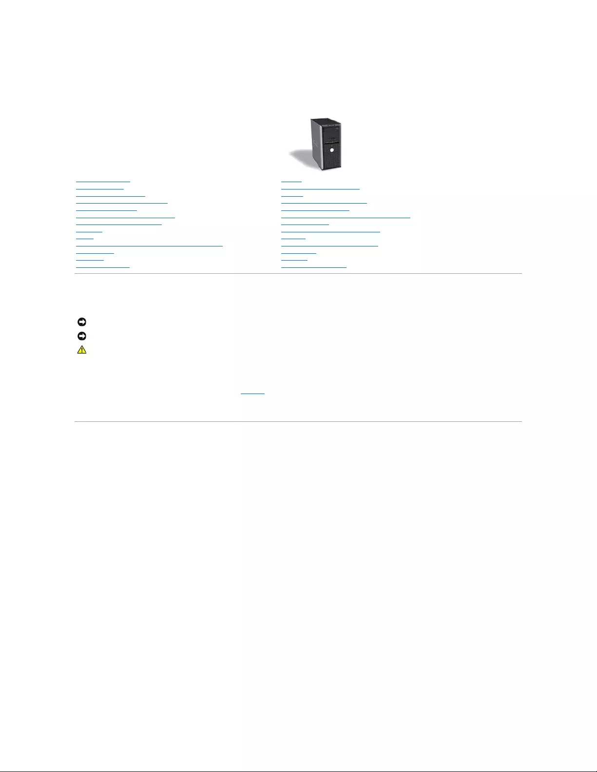
Dell™OptiPlex™GX520User'sGuide
Notes, Notices, and Cautions
Abbreviations and Acronyms
For a complete list of abbreviations and acronyms, see the Glossary.
IfyoupurchasedaDell™nSeriescomputer,anyreferencesinthisdocumenttoMicrosoft® Windows® operating systems are not applicable.
Information in this document is subject to change without notice.
©2005–2006DellInc.Allrightsreserved.
Reproduction in any manner whatsoever without the written permission of Dell Inc. is strictly forbidden.
Trademarks used in this text: Dell, the DELL logo, OptiPlex, Inspiron, Dimension, Latitude, Dell Precision, DellNet, TravelLite, Dell OpenManage, PowerVault, Axim, PowerEdge, PowerConnect,
and PowerApp are trademarks of Dell Inc.; Intel, Pentium, and Celeron are registered trademarks of Intel Corporation; Microsoft, MS-DOS, and Windows are registered trademarks of
Microsoft Corporation; IBM is a registered trademark of International Business Machines Corporation; Bluetooth is a trademark owned by Bluetooth SIG, Inc. and is used by Dell
Inc. under license. ENERGY STAR is a registered trademark of the U.S. Environmental Protection Agency. As an ENERGY STAR partner, Dell Inc. has determined that this product
meets the ENERGY STAR guidelines for energy efficiency.
Other trademarks and trade names may be used in this document to refer to either the entities claiming the marks and names or their products. Dell Inc. disclaims any
proprietary interest in trademarks and trade names other than its own.
Model DCTR
October 2006 P/N W9246 Rev. A03
Mini Tower Computer
Finding Information
Before You Begin
Chassis Intrusion Switch
About Your Mini Tower Computer
Inside Your Computer
Mini Tower Computer Specifications
Removing the Computer Cover
I/O Panel
Drives
PCI and PCI Express Cards and Serial Port Adapters
Power Supply
Processor
Advanced Features
Battery
Replacing the System Board
Memory
Replacing the Computer Cover
Cleaning Your Computer
Reinstalling Drivers and the Operating System
Solving Problems
Microsoft®Windows®XP Features
Glossary
Troubleshooting Tools and Utilities
Getting Help
Warranty
FCC Notices (U.S. Only)
NOTE: A NOTE indicates important information that helps you make better use of your computer.
NOTICE: A NOTICE indicates either potential damage to hardware or loss of data and tells you how to avoid the problem.
CAUTION: A CAUTION indicates a potential for property damage, personal injury, or death.

Back to Contents Page
Dell™OptiPlex™GX520User'sGuide
For a complete list of abbreviations and acronyms, see the Glossary.
IfyoupurchasedaDell™nSeriescomputer,anyreferencesinthisdocumenttoMicrosoft® Windows® operating systems are not applicable.
Information in this document is subject to change without notice.
©2005DellInc.Allrightsreserved.
Reproduction in any manner whatsoever without the written permission of Dell Inc. is strictly forbidden.
Trademarks used in this text: Dell, the DELL logo, OptiPlex, Inspiron, Dimension, Latitude, Dell Precision, DellNet, TravelLite, Dell OpenManage, PowerVault, Axim, PowerEdge, PowerConnect,
and PowerApp are trademarks of Dell Inc.; Intel, Pentium, and Celeron are registered trademarks of Intel Corporation; Microsoft, MS-DOS, and Windows are registered trademarks of
Microsoft Corporation; IBM is a registered trademark of International Business Machines Corporation; Bluetooth is a trademark owned by Bluetooth SIG, Inc. and is used by Dell
Inc. under license. ENERGY STAR is a registered trademark of the U.S. Environmental Protection Agency. As an ENERGY STAR partner, Dell Inc. has determined that this product
meets the ENERGY STAR guidelines for energy efficiency.
Other trademarks and trade names may be used in this document to refer to either the entities claiming the marks and names or their products. Dell Inc. disclaims any
proprietary interest in trademarks and trade names other than its own.
Models: DCTR, DCNE, and DCSM
March 2005 P/N W9246 Rev. A00
Back to Contents Page
NOTE: A NOTE indicates important information that helps you make better use of your computer.
NOTICE: A NOTICE indicates either potential damage to hardware or loss of data and tells you how to avoid the problem.
CAUTION: A CAUTION indicates a potential for property damage, personal injury, or death.

Back to Contents Page
Troubleshooting Tools and Utilities
Dell™OptiPlex™GX520User'sGuide
Dell Diagnostics
System Lights
Diagnostic Lights
Beep Codes
Error Messages
Resolving Software and Hardware Incompatibilities
Dell Diagnostics
When to Use the Dell Diagnostics
If you experience a problem with your computer, perform the checks in this section and run the Dell Diagnostics before you contact Dell for technical
assistance.
It is recommended that you print these procedures before you begin.
Enter system setup, review your computer's configuration information, and ensure that the device you want to test displays in system setup and is active.
Start the Dell Diagnostics from either your hard drive or from the Drivers and Utilities CD (an optional CD also known as the ResourceCD).
Starting the Dell Diagnostics From Your Hard Drive
1. Turn on (or restart) your computer.
2. WhentheDELL™logoappears,press<F12>immediately.
If you wait too long and the operating system logo appears, continue to wait until you see the Microsoft®Windows®desktop. Then shut down your
computer and try again.
3. When the boot device list appears, highlight Boot to Utility Partition and press <Enter>.
4. When the Dell Diagnostics Main Menu appears, select the test you want to run.
Starting the Dell Diagnostics From the Drivers and Utilities CD (Optional)
1. Insert the Drivers and Utilities CD (optional).
2. Shut down and restart the computer.
When the DELL logo appears, press <F12> immediately.
If you wait too long and the Windows logo appears, continue to wait until you see the Windows desktop. Then shut down your computer and try again.
3. When the boot device list appears, highlight IDE CD-ROM Device and press <Enter>.
4. Select the IDE CD-ROM Device option from the CD boot menu.
5. Select the Boot from CD-ROM option from the menu that appears.
CAUTION: Before you begin any of the procedures in this section, follow the safety instructions located in the Product Information Guide.
NOTICE: TheDellDiagnosticsworksonlyonDell™computers.
NOTE: If you see a message stating that no diagnostics utility partition has been found, run the Dell Diagnostics from your Drivers and Utilities CD
(optional).
NOTE: The next steps change the boot sequence for one time only. On the next start-up, the computer boots according to the devices specified in
system setup.
6. Type 1 to start the Drivers and Utilities CD menu.
7. Type 2 to start the Dell Diagnostics.
8. Select Run the 32 Bit Dell Diagnostics from the numbered list. If multiple versions are listed, select the version appropriate for your computer.
9. When the Dell Diagnostics Main Menu appears, select the test you want to run.
Dell Diagnostics Main Menu
1. After the Dell Diagnostics loads and the Main Menu screen appears, click the button for the option you want.
2. If a problem is encountered during a test, a message appears with an error code and a description of the problem. Write down the error code and
problem description and follow the instructions on the screen.
If you cannot resolve the error condition, contact Dell
3. If you run a test from the Custom Test or Symptom Tree option, click the applicable tab described in the following table for more information.
4. When the tests are completed, if you are running the Dell Diagnostics from the Drivers and Utilities CD, remove the CD.
5. Close the test screen to return to the Main Menu screen. To exit the Dell Diagnostics and restart the computer, close the Main Menu screen.
System Lights
Your power button light and hard-drive light may indicate a computer problem.
Option
Function
Express Test
Performs a quick test of devices. This test typically takes 10 to 20 minutes and requires no interaction on your part. Run Express Test first to
increase the possibility of tracing the problem quickly.
Extended
Test
Performs a thorough check of devices. This test typically takes an hour or more and requires you to answer questions periodically.
Custom Test
Tests a specific device. You can customize the tests you want to run.
Symptom
Tree
Lists the most common symptoms encountered and allows you to select a test based on the symptom of the problem you are having.
NOTE: The Service Tag for your computer is located at the top of each test screen. If you contact Dell, technical support will ask for your Service Tag.
Your computer's Service Tag is listed in the System Info option in system setup.
Tab
Function
Results
Displays the results of the test and any error conditions encountered.
Errors
Displays error conditions encountered, error codes, and the problem description.
Help
Describes the test and may indicate requirements for running the test.
Configuration
Displays your hardware configuration for the selected device.
The Dell Diagnostics obtains configuration information for all devices from system setup, memory, and various internal tests, and it displays
the information in the device list in the left pane of the screen. The device list may not display the names of all the components installed on
your computer or all devices attached to your computer.
Parameters
Allows you to customize the test by changing the test settings.
Power Light
Problem Description
Suggested Resolution
Solid green
Power is on, and the computer is operating normally. On
the desktop computer, a solid green light indicates a
network connection.
No corrective action is required.
Blinking green
The computer is in a power-saving mode (Microsoft®
Windows®XP).
Press the power button, move the mouse, or press a key
on the keyboard to wake the computer.
Blinks green several times and then
turns off
A configuration error exists.
Check the diagnostic lights to see if the specific problem is
identified.
Solid yellow
The Dell Diagnostics is running a test, or a device on the
system board may be faulty or incorrectly installed.
If the Dell Diagnostics is running, allow the testing to
complete.
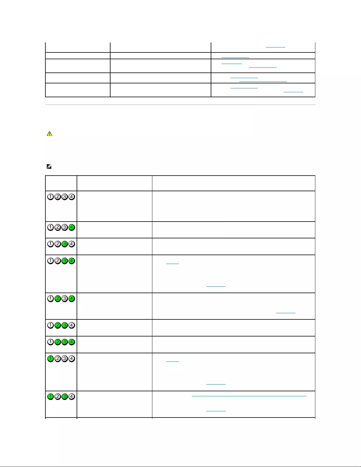
Diagnostic Lights
To help you troubleshoot a problem, your computer has four lights labeled "1," "2," "3," and "4"on the front or back panel. The lights can be off or green.
When the computer starts normally, the patterns or codes on the lights change as the boot process completes. When the computer starts normally, the
patterns or codes on the lights change as the boot process completes. If the POST portion of system boot completes successfully, all four lights display solid
green. If the computer malfunctions during the POST process, the pattern displayed on the LEDs may help identify where in the process the computer halted.
If the computer does not boot, contact Dell for technical
assistance.
Blinking yellow
A power supply or system board failure has occurred.
See "Power Problems."
Solid green and a beep code during
POST
A problem was detected while the BIOS was executing.
See "Beep Codes" for instructions on diagnosing the beep
code. Also, check the diagnostic lights to see if the specific
problem is identified.
Solid green power light and no beep
code and no video during POST
The monitor or the graphics card may be faulty or
incorrectly installed.
Check the diagnostic lights to see if the specific problem is
identified. See "Video and Monitor Problems."
Solid green power light and no beep
code but the computer locks up
during POST
An integrated system board device may be faulty.
Check the diagnostic lights to see if the specific problem is
identified. If the problem is not identified, contact Dell for
technical assistance.
CAUTION: Before you begin any of the procedures in this section, follow the safety instructions located in the Product Information Guide.
NOTE: The orientation of the diagnostic lights may vary depending on the system type. The diagnostic lights can appear either vertical or horizontal.
Light Pattern
Problem Description
Suggested Resolution
The computer is in a normal "off"
condition, or a possible pre-BIOS failure
has occurred.
The diagnostic lights are not lit after the
computer successfully boots to the
operating system.
Plug the computer into a working electrical outlet and press the power button.
A possible BIOS failure has occurred; the
computer is in the recovery mode.
Run the BIOS Recovery utility, wait for recovery completion, and then restart the computer.
A possible processor failure has occurred.
Reinstall the processor and restart the computer.
Memory modules are detected, but a
memory failure has occurred.
lIf you have one memory module installed, reinstall it and restart the computer. (see
"Memory" for instructions on how to remove and install memory modules.)
lIf you have two or more memory modules installed, remove the modules, reinstall one
module, and then restart the computer. If the computer starts normally, reinstall an
additional module. Continue until you have identified a faulty module or reinstalled all
modules without error.
lIf available, install properly working memory of the same type into your computer.
lIf the problem persists, contact Dell.
A possible graphics card failure has
occurred.
lIf the computer has a graphics card, remove the card, reinstall it, and then restart the
computer.
lIf the problem still exists, install a graphics card that you know works and restart the
computer.
lIf the problem persists or the computer has integrated graphics, contact Dell.
A possible floppy or hard drive failure has
occurred.
Reseat all power and data cables and restart the computer.
A possible USB failure has occurred.
Reinstall all USB devices, check cable connections, and then restart the computer.
No memory modules are detected.
lIf you have one memory module installed, reinstall it and restart the computer. (see
"Memory" for instructions on how to remove and install memory modules.)
lIf you have two or more memory modules installed, remove the modules, reinstall one
module, and then restart the computer. If the computer starts normally, reinstall an
additional module. Continue until you have identified a faulty module or reinstalled all
modules without error.
lIf available, install properly working memory of the same type into your computer.
lIf the problem persists, contact Dell.
Memory modules are detected, but a
memory configuration or compatibility error
exists.
lEnsure that no special memory module/memory connector placement requirements
exist.
lVerify that the memory modules that you are installing are compatible with your
computer.
lIf the problem persists, contact Dell.
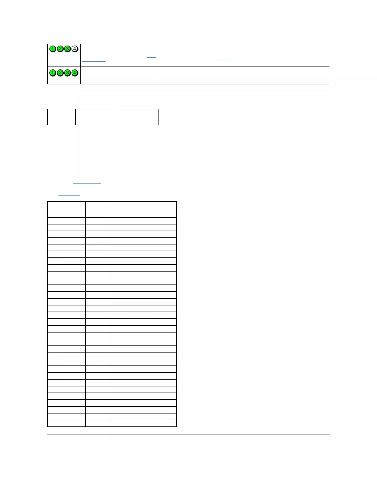
Beep Codes
Your computer might emit a series of beeps during start-up if the monitor cannot display errors or problems. This series of beeps, called a beep code, identifies
a problem. One possible beep code (code 1-3-1) consists of one beep, a burst of three beeps, and then one beep. This beep code tells you that the computer
encountered a memory problem.
If your computer beeps during start-up:
1. Write down the beep code on the Diagnostics Checklist.
2. Run the Dell Diagnostics to identify a more serious cause.
3. Contact Dell for technical assistance.
A failure has occurred.
This pattern also displays when you enter
system setup and may not indicate a
problem.
lEnsure that the cables are properly connected to the system board from the hard
drive, CD drive, and DVD drive.
lCheck the computer message that appears on your monitor screen.
lIf the problem persists, contact Dell.
After POST is complete, all four diagnostic
lights turn green briefly before turning off
to indicate normal operating condition.
None.
LightPattern
Problem Description
Suggested Resolution
Code
Cause
1-1-2
Microprocessor register failure
1-1-3
NVRAM read/write failure
1-1-4
ROM BIOS checksum failure
1-2-1
Programmable interval timer failure
1-2-2
DMA initialization failure
1-2-3
DMA page register read/write failure
1-3
Video Memory test failure
1-3-1 through 2-4-4
Memory not being properly identified or used
3-1-1
Slave DMA register failure
3-1-2
Master DMA register failure
3-1-3
Master interrupt mask register failure
3-1-4
Slave interrupt mask register failure
3-2-2
Interrupt vector loading failure
3-2-4
Keyboard Controller test failure
3-3-1
NVRAM power loss
3-3-2
Invalid NVRAM configuration
3-3-4
Video Memory test failure
3-4-1
Screen initialization failure
3-4-2
Screen retrace failure
3-4-3
Search for video ROM failure
4-2-1
No timer tick
4-2-2
Shutdown failure
4-2-3
Gate A20 failure
4-2-4
Unexpected interrupt in protected mode
4-3-1
Memory failure above address 0FFFFh
4-3-3
Timer-chip counter 2 failure
4-3-4
Time-of-day clock stopped
4-4-1
Serial or parallel port test failure
4-4-2
Failure to decompress code to shadowed memory
4-4-3
Math-coprocessor test failure
4-4-4
Cache test failure

Error Messages
Fill out the Diagnostics Checklist as you complete these checks.
If the message is not listed, see the documentation for the operating system or the program that was running when the message appeared.
CAUTION: Before you begin any of the procedures in this section, follow the safety instructions located in the Product Information Guide.
Afilenamecannotcontainanyofthefollowingcharacters:\/:*?"<>|— Do not use these characters in filenames.
Arequired.DLLfilewasnotfound— The program that you are trying to open is missing an essential file. To remove and then reinstall the program:
1. Click the Start button, click Control Panel, and then click Add or Remove Programs.
2. Select the program you want to remove.
3. Click the Change or Remove Program icon.
4. See the program documentation for installation instructions.
Alert! Previous attempts at booting this system have failed at checkpoint [nnnn]. For help in resolving this problem, please note this checkpoint and
contactDellTechnicalSupport— Contact Dell and report the checkpoint code (nnnn) to the support technician.
Attachmentfailedtorespond— See "Drive Problems."
Badcommandorfilename— Ensure that you spelled the command correctly, put spaces in the proper place, and used the correct pathname.
Bad error-correctioncode(ECC)ondiskread— See "Drive Problems."
Controllerhasfailed— See "Drive Problems."
Dataerror— See "Drive Problems."
Decreasingavailablememory—
See "Lockups and Software Problems."
Diskettedrive0seekfailure— See "Drive Problems."
Diskettereadfailure—
See "Drive Problems."
Diskettesubsystemresetfailed— Run the Dell Diagnostics.
Diskettewriteprotected— Slide the write-protect notch on the floppy disk to the open position.
Drivenotready— Put a floppy disk in the drive.
GateA20failure—
See "Lockups and Software Problems."
Hard-diskconfigurationerror—
Hard-diskcontrollerfailure—
Hard-diskdrivefailure—

Hard-diskdrivefailure—
See "Drive Problems."
Insertbootablemedia— Insert a bootable floppy disk or CD.
Invalid configuration information -pleaserunSETUPprogram— Enter system setup and correct the computer configuration information.
Keyboardfailure— See "Keyboard Problems."
Memory address line failure at address, read value expecting value — See "Lockups and Software Problems."
Memoryallocationerror—
1. Turn off the computer, wait 30 seconds, and then restart the computer.
2. Try to run the program again.
3. If the error message appears again, see the software documentation for additional troubleshooting suggestions.
Memory data line failure at address, read value expecting value —
Memory double word logic failure at address, read value expecting value —
Memory odd/even logic failure at address, read value expecting value—
Memory write/read failure at address, read value expecting value —
MemorysizeinCMOSinvalid—
See "Lockups and Software Problems."
Nobootdeviceavailable—
lIf the floppy drive is your boot device, ensure that a bootable floppy disk is in the drive.
lIf the hard drive is your boot device, ensure that the cables are connected and that the drive is installed properly and partitioned as a boot device.
lEnter system setup and ensure that the boot sequence information is correct.
No boot sector on hard-diskdrive— Enter system setup and ensure that the computer configuration information for the hard drive is correct.
Notimertickinterrupt— Run the Dell Diagnostics.
Non-systemdiskordiskerror— Replace the floppy disk with one that has a bootable operating system or remove the floppy disk from drive A and restart
the computer.
Notabootdiskette— Insert a bootable floppy disk and restart your computer.
Notenoughmemoryorresources.Closesomeprogramsandtryagain— Close all windows and open the program that you want to use. In some cases,
you might have to restart your computer to restore computer resources. If so, run the program that you want to use first.
Operatingsystemnotfound— Contact Dell.
PlugandPlayConfigurationError—
1. Turn your computer off, unplug it from the electrical outlet, and then remove all but one of the cards.
2. Plug in your computer and reboot it.
3. If the message reappears, the installed card might be malfunctioning. If the message does not reappear, turn off the computer and reinsert one of

Resolving Software and Hardware Incompatibilities
If a device is either not detected during the operating system setup or is detected but incorrectly configured, you can use Device Manager or the Hardware
Troubleshooter to resolve the incompatibility.
Microsoft® Windows® XP
To resolve incompatibilities using Device Manager:
1. Click the Start button and click Control Panel.
the other cards.
4. Repeat this process until you identify which card is malfunctioning.
Readfault—
Requestedsectornotfound—
Resetfailed—
See "Drive Problems."
Sectornotfound—
lRun the Windows error-checking utility to check the file structure on the floppy disk or hard drive. See Windows Help for instructions.
lIf a large number of sectors are defective, back up the data (if possible), and then reformat the floppy disk or hard drive.
Seekerror— See "Drive Problems."
Shutdownfailure— Run the Dell Diagnostics.
Time-of-dayclockstopped—
Time-of-day not set-pleaseruntheSystemSetupprogram—
Enter system setup and correct the date or time. If the problem persists, replace the battery.
Timerchipcounter2failed— Run the Dell Diagnostics.
Unexpectedinterruptinprotectedmode— Run the Dell Diagnostics.
WARNING: Dell's Disk Monitoring System has detected that drive [0/1] on the [primary/secondary] EIDE controller is operating outside of normal
specifications.ItisadvisabletoimmediatelybackupyourdataandreplaceyourharddrivebycallingyoursupportdeskorDell—
If no replacement drive is immediately available and the drive is not the only bootable drive, enter system setup and change the appropriate drive setting to
None. Then remove the drive from the computer.
Writefault—
Writefaultonselecteddrive—
See "Drive Problems."
<drive letter>:\isnotaccessible.Thedeviceisnotready— The selected drive cannot read its medium. Depending on its medium type, insert a floppy,
CD, or Zip disk into the drive and try again.

2. Click Performance and Maintenance and click System.
3. Click the Hardware tab and click Device Manager.
4. In the Device Manager list, check for devices that are incorrectly configured.
Incorrectly configured devices are indicated by a yellow exclamation point (!) or a red X if the device has been disabled.
5. Double-click any device marked with an exclamation point to display the Properties window.
The Device status area in the Properties window reports the devices that need to be re-configured.
6. Reconfigure the devices or remove the devices from the Device Manager. See the documentation that came with the device for information on
configuring the device.
To resolve incompatibilities using the Windows XP Hardware Troubleshooter:
1. Click the Start button and click Help and Support.
2. Type hardware troubleshooter in the Search field and click the arrow to start the search.
3. Click Hardware Troubleshooter in the Search Results list.
4. In the Hardware Troubleshooter list, click I need to resolve a hardware conflict on my computer, and click Next.
Back to Contents Page

Back to Contents Page
Troubleshooting Tools and Utilities
Dell™OptiPlex™GX520User'sGuide
Dell Diagnostics
System Lights
Diagnostic Lights
Beep Codes
Error Messages
Resolving Software and Hardware Incompatibilities
Dell Diagnostics
When to Use the Dell Diagnostics
If you experience a problem with your computer, perform the checks in this section and run the Dell Diagnostics before you contact Dell for technical
assistance.
It is recommended that you print these procedures before you begin.
Enter system setup, review your computer's configuration information, and ensure that the device you want to test displays in system setup and is active.
Start the Dell Diagnostics from either your hard drive or from the Drivers and Utilities CD (an optional CD also known as the ResourceCD).
Starting the Dell Diagnostics From Your Hard Drive
1. Turn on (or restart) your computer.
2. WhentheDELL™logoappears,press<F12>immediately.
If you wait too long and the operating system logo appears, continue to wait until you see the Microsoft®Windows®desktop. Then shut down your
computer and try again.
3. When the boot device list appears, highlight Boot to Utility Partition and press <Enter>.
4. When the Dell Diagnostics Main Menu appears, select the test you want to run.
Starting the Dell Diagnostics From the Drivers and Utilities CD (Optional)
1. Insert the Drivers and Utilities CD (optional).
2. Shut down and restart the computer.
When the DELL logo appears, press <F12> immediately.
If you wait too long and the Windows logo appears, continue to wait until you see the Windows desktop. Then shut down your computer and try again.
3. When the boot device list appears, highlight IDE CD-ROM Device and press <Enter>.
4. Select the IDE CD-ROM Device option from the CD boot menu.
CAUTION: Before you begin any of the procedures in this section, follow the safety instructions located in the Product Information Guide.
NOTICE: TheDellDiagnosticsworksonlyonDell™computers.
NOTE: If you see a message stating that no diagnostics utility partition has been found, run the Dell Diagnostics from your Drivers and Utilities CD
(optional).
NOTE: The next steps change the boot sequence for one time only. On the next start-up, the computer boots according to the devices specified in
system setup.
5. Select the Boot from CD-ROM option from the menu that appears.
6. Type 1 to start the Drivers and Utilities CD menu.
7. Type 2 to start the Dell Diagnostics.
8. Select Run the 32 Bit Dell Diagnostics from the numbered list. If multiple versions are listed, select the version appropriate for your computer.
9. When the Dell Diagnostics Main Menu appears, select the test you want to run.
Dell Diagnostics Main Menu
1. After the Dell Diagnostics loads and the Main Menu screen appears, click the button for the option you want.
2. If a problem is encountered during a test, a message appears with an error code and a description of the problem. Write down the error code and
problem description and follow the instructions on the screen.
If you cannot resolve the error condition, contact Dell
3. If you run a test from the Custom Test or Symptom Tree option, click the applicable tab described in the following table for more information.
4. When the tests are completed, if you are running the Dell Diagnostics from the Drivers and Utilities CD, remove the CD.
5. Close the test screen to return to the Main Menu screen. To exit the Dell Diagnostics and restart the computer, close the Main Menu screen.
System Lights
Your power button light and hard-drive light may indicate a computer problem.
Option
Function
Express Test
Performs a quick test of devices. This test typically takes 10 to 20 minutes and requires no interaction on your part. Run Express Test first to
increase the possibility of tracing the problem quickly.
Extended
Test
Performs a thorough check of devices. This test typically takes an hour or more and requires you to answer questions periodically.
Custom Test
Tests a specific device. You can customize the tests you want to run.
Symptom
Tree
Lists the most common symptoms encountered and allows you to select a test based on the symptom of the problem you are having.
NOTE: The Service Tag for your computer is located at the top of each test screen. If you contact Dell, technical support will ask for your Service Tag.
Your computer's Service Tag is listed in the System Info option in system setup.
Tab
Function
Results
Displays the results of the test and any error conditions encountered.
Errors
Displays error conditions encountered, error codes, and the problem description.
Help
Describes the test and may indicate requirements for running the test.
Configuration
Displays your hardware configuration for the selected device.
The Dell Diagnostics obtains configuration information for all devices from system setup, memory, and various internal tests, and it displays
the information in the device list in the left pane of the screen. The device list may not display the names of all the components installed on
your computer or all devices attached to your computer.
Parameters
Allows you to customize the test by changing the test settings.
Power Light
Problem Description
Suggested Resolution
Solid green
Power is on, and the computer is operating normally. On
the desktop computer, a solid green light indicates a
network connection.
No corrective action is required.
Blinking green
The computer is in a power-saving mode (Microsoft®
Windows®XP).
Press the power button, move the mouse, or press a key
on the keyboard to wake the computer.
Blinks green several times and then
turns off
A configuration error exists.
Check the diagnostic lights to see if the specific problem is
identified.
Solid yellow
The Dell Diagnostics is running a test, or a device on the
If the Dell Diagnostics is running, allow the testing to
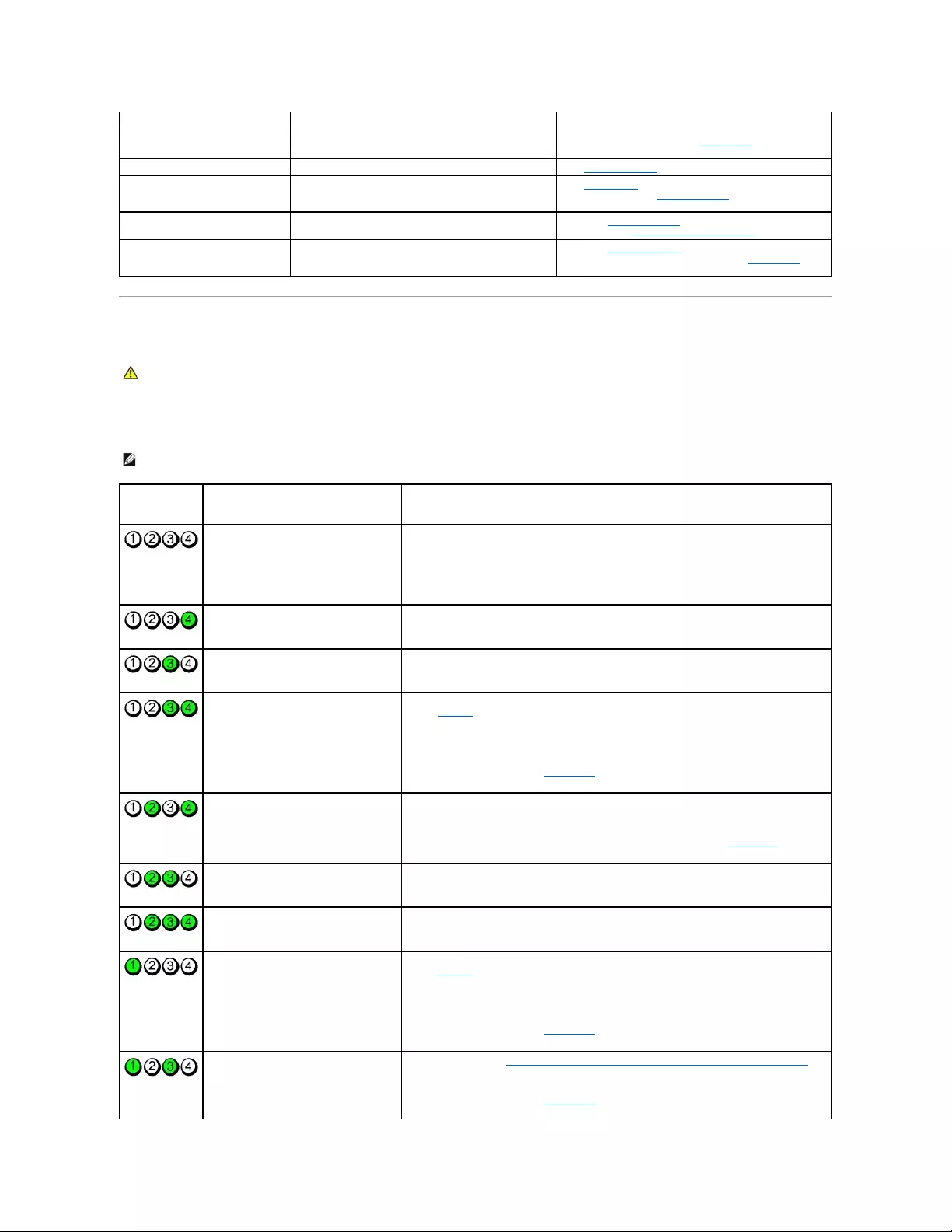
Diagnostic Lights
To help you troubleshoot a problem, your computer has four lights labeled "1," "2," "3," and "4"on the front or back panel. The lights can be off or green.
When the computer starts normally, the patterns or codes on the lights change as the boot process completes. When the computer starts normally, the
patterns or codes on the lights change as the boot process completes. If the POST portion of system boot completes successfully, all four lights display solid
green. If the computer malfunctions during the POST process, the pattern displayed on the LEDs may help identify where in the process the computer halted.
system board may be faulty or incorrectly installed.
complete.
If the computer does not boot, contact Dell for technical
assistance.
Blinking yellow
A power supply or system board failure has occurred.
See "Power Problems."
Solid green and a beep code during
POST
A problem was detected while the BIOS was executing.
See "Beep Codes" for instructions on diagnosing the beep
code. Also, check the diagnostic lights to see if the specific
problem is identified.
Solid green power light and no beep
code and no video during POST
The monitor or the graphics card may be faulty or
incorrectly installed.
Check the diagnostic lights to see if the specific problem is
identified. See "Video and Monitor Problems."
Solid green power light and no beep
code but the computer locks up
during POST
An integrated system board device may be faulty.
Check the diagnostic lights to see if the specific problem is
identified. If the problem is not identified, contact Dell for
technical assistance.
CAUTION: Before you begin any of the procedures in this section, follow the safety instructions located in the Product Information Guide.
NOTE: The orientation of the diagnostic lights may vary depending on the system type. The diagnostic lights can appear either vertical or horizontal.
Light Pattern
Problem Description
Suggested Resolution
The computer is in a normal "off"
condition, or a possible pre-BIOS failure
has occurred.
The diagnostic lights are not lit after the
computer successfully boots to the
operating system.
Plug the computer into a working electrical outlet and press the power button.
A possible BIOS failure has occurred; the
computer is in the recovery mode.
Run the BIOS Recovery utility, wait for recovery completion, and then restart the computer.
A possible processor failure has occurred.
Reinstall the processor and restart the computer.
Memory modules are detected, but a
memory failure has occurred.
lIf you have one memory module installed, reinstall it and restart the computer. (see
"Memory" for instructions on how to remove and install memory modules.)
lIf you have two or more memory modules installed, remove the modules, reinstall one
module, and then restart the computer. If the computer starts normally, reinstall an
additional module. Continue until you have identified a faulty module or reinstalled all
modules without error.
lIf available, install properly working memory of the same type into your computer.
lIf the problem persists, contact Dell.
A possible graphics card failure has
occurred.
lIf the computer has a graphics card, remove the card, reinstall it, and then restart the
computer.
lIf the problem still exists, install a graphics card that you know works and restart the
computer.
lIf the problem persists or the computer has integrated graphics, contact Dell.
A possible floppy or hard drive failure has
occurred.
Reseat all power and data cables and restart the computer.
A possible USB failure has occurred.
Reinstall all USB devices, check cable connections, and then restart the computer.
No memory modules are detected.
lIf you have one memory module installed, reinstall it and restart the computer. (see
"Memory" for instructions on how to remove and install memory modules.)
lIf you have two or more memory modules installed, remove the modules, reinstall one
module, and then restart the computer. If the computer starts normally, reinstall an
additional module. Continue until you have identified a faulty module or reinstalled all
modules without error.
lIf available, install properly working memory of the same type into your computer.
lIf the problem persists, contact Dell.
Memory modules are detected, but a
memory configuration or compatibility error
exists.
lEnsure that no special memory module/memory connector placement requirements
exist.
lVerify that the memory modules that you are installing are compatible with your
computer.
lIf the problem persists, contact Dell.
Beep Codes
Your computer might emit a series of beeps during start-up if the monitor cannot display errors or problems. This series of beeps, called a beep code, identifies
a problem. One possible beep code (code 1-3-1) consists of one beep, a burst of three beeps, and then one beep. This beep code tells you that the computer
encountered a memory problem.
If your computer beeps during start-up:
1. Write down the beep code on the Diagnostics Checklist.
2. Run the Dell Diagnostics to identify a more serious cause.
3. Contact Dell for technical assistance.
A failure has occurred.
This pattern also displays when you enter
system setup and may not indicate a
problem.
lEnsure that the cables are properly connected to the system board from the hard
drive, CD drive, and DVD drive.
lCheck the computer message that appears on your monitor screen.
lIf the problem persists, contact Dell.
After POST is complete, all four diagnostic
lights turn green briefly before turning off
to indicate normal operating condition.
None.
LightPattern
Problem Description
Suggested Resolution
Code
Cause
1-1-2
Microprocessor register failure
1-1-3
NVRAM read/write failure
1-1-4
ROM BIOS checksum failure
1-2-1
Programmable interval timer failure
1-2-2
DMA initialization failure
1-2-3
DMA page register read/write failure
1-3
Video Memory test failure
1-3-1 through 2-4-4
Memory not being properly identified or used
3-1-1
Slave DMA register failure
3-1-2
Master DMA register failure
3-1-3
Master interrupt mask register failure
3-1-4
Slave interrupt mask register failure
3-2-2
Interrupt vector loading failure
3-2-4
Keyboard Controller test failure
3-3-1
NVRAM power loss
3-3-2
Invalid NVRAM configuration
3-3-4
Video Memory test failure
3-4-1
Screen initialization failure
3-4-2
Screen retrace failure
3-4-3
Search for video ROM failure
4-2-1
No timer tick
4-2-2
Shutdown failure
4-2-3
Gate A20 failure
4-2-4
Unexpected interrupt in protected mode
4-3-1
Memory failure above address 0FFFFh
4-3-3
Timer-chip counter 2 failure
4-3-4
Time-of-day clock stopped
4-4-1
Serial or parallel port test failure
4-4-2
Failure to decompress code to shadowed memory
4-4-3
Math-coprocessor test failure
4-4-4
Cache test failure

Error Messages
Fill out the Diagnostics Checklist as you complete these checks.
If the message is not listed, see the documentation for the operating system or the program that was running when the message appeared.
CAUTION: Before you begin any of the procedures in this section, follow the safety instructions located in the Product Information Guide.
Afilenamecannotcontainanyofthefollowingcharacters:\/:*?"<>|— Do not use these characters in filenames.
Arequired.DLLfilewasnotfound— The program that you are trying to open is missing an essential file. To remove and then reinstall the program:
1. Click the Start button, click Control Panel, and then click Add or Remove Programs.
2. Select the program you want to remove.
3. Click the Change or Remove Program icon.
4. See the program documentation for installation instructions.
Alert! Previous attempts at booting this system have failed at checkpoint [nnnn]. For help in resolving this problem, please note this checkpoint and
contactDellTechnicalSupport— Contact Dell and report the checkpoint code (nnnn) to the support technician.
Attachmentfailedtorespond— See "Drive Problems."
Badcommandorfilename— Ensure that you spelled the command correctly, put spaces in the proper place, and used the correct pathname.
Bad error-correctioncode(ECC)ondiskread— See "Drive Problems."
Controllerhasfailed— See "Drive Problems."
Dataerror— See "Drive Problems."
Decreasingavailablememory—
See "Lockups and Software Problems."
Diskettedrive0seekfailure— See "Drive Problems."
Diskettereadfailure—
See "Drive Problems."
Diskettesubsystemresetfailed— Run the Dell Diagnostics.
Diskettewriteprotected— Slide the write-protect notch on the floppy disk to the open position.
Drivenotready— Put a floppy disk in the drive.
GateA20failure—
See "Lockups and Software Problems."
Hard-diskconfigurationerror—
Hard-diskcontrollerfailure—
Hard-diskdrivefailure—

Hard-diskdrivefailure—
See "Drive Problems."
Insertbootablemedia— Insert a bootable floppy disk or CD.
Invalid configuration information -pleaserunSETUPprogram— Enter system setup and correct the computer configuration information.
Keyboardfailure— See "Keyboard Problems."
Memory address line failure at address, read value expecting value — See "Lockups and Software Problems."
Memoryallocationerror—
1. Turn off the computer, wait 30 seconds, and then restart the computer.
2. Try to run the program again.
3. If the error message appears again, see the software documentation for additional troubleshooting suggestions.
Memory data line failure at address, read value expecting value —
Memory double word logic failure at address, read value expecting value —
Memory odd/even logic failure at address, read value expecting value—
Memory write/read failure at address, read value expecting value —
MemorysizeinCMOSinvalid—
See "Lockups and Software Problems."
Nobootdeviceavailable—
lIf the floppy drive is your boot device, ensure that a bootable floppy disk is in the drive.
lIf the hard drive is your boot device, ensure that the cables are connected and that the drive is installed properly and partitioned as a boot device.
lEnter system setup and ensure that the boot sequence information is correct.
No boot sector on hard-diskdrive— Enter system setup and ensure that the computer configuration information for the hard drive is correct.
Notimertickinterrupt— Run the Dell Diagnostics.
Non-systemdiskordiskerror— Replace the floppy disk with one that has a bootable operating system or remove the floppy disk from drive A and restart
the computer.
Notabootdiskette— Insert a bootable floppy disk and restart your computer.
Notenoughmemoryorresources.Closesomeprogramsandtryagain— Close all windows and open the program that you want to use. In some cases,
you might have to restart your computer to restore computer resources. If so, run the program that you want to use first.
Operatingsystemnotfound— Contact Dell.
PlugandPlayConfigurationError—
1. Turn your computer off, unplug it from the electrical outlet, and then remove all but one of the cards.
2. Plug in your computer and reboot it.

Resolving Software and Hardware Incompatibilities
If a device is either not detected during the operating system setup or is detected but incorrectly configured, you can use Device Manager or the Hardware
Troubleshooter to resolve the incompatibility.
Microsoft® Windows® XP
To resolve incompatibilities using Device Manager:
3. If the message reappears, the installed card might be malfunctioning. If the message does not reappear, turn off the computer and reinsert one of
the other cards.
4. Repeat this process until you identify which card is malfunctioning.
Readfault—
Requestedsectornotfound—
Resetfailed—
See "Drive Problems."
Sectornotfound—
lRun the Windows error-checking utility to check the file structure on the floppy disk or hard drive. See Windows Help for instructions.
lIf a large number of sectors are defective, back up the data (if possible), and then reformat the floppy disk or hard drive.
Seekerror— See "Drive Problems."
Shutdownfailure— Run the Dell Diagnostics.
Time-of-dayclockstopped—
Time-of-day not set-pleaseruntheSystemSetupprogram—
Enter system setup and correct the date or time. If the problem persists, replace the battery.
Timerchipcounter2failed— Run the Dell Diagnostics.
Unexpectedinterruptinprotectedmode— Run the Dell Diagnostics.
WARNING: Dell's Disk Monitoring System has detected that drive [0/1] on the [primary/secondary] EIDE controller is operating outside of normal
specifications.ItisadvisabletoimmediatelybackupyourdataandreplaceyourharddrivebycallingyoursupportdeskorDell—
If no replacement drive is immediately available and the drive is not the only bootable drive, enter system setup and change the appropriate drive setting to
None. Then remove the drive from the computer.
Writefault—
Writefaultonselecteddrive—
See "Drive Problems."
<drive letter>:\isnotaccessible.Thedeviceisnotready— The selected drive cannot read its medium. Depending on its medium type, insert a floppy,
CD, or Zip disk into the drive and try again.

1. Click the Start button and click Control Panel.
2. Click Performance and Maintenance and click System.
3. Click the Hardware tab and click Device Manager.
4. In the Device Manager list, check for devices that are incorrectly configured.
Incorrectly configured devices are indicated by a yellow exclamation point (!) or a red X if the device has been disabled.
5. Double-click any device marked with an exclamation point to display the Properties window.
The Device status area in the Properties window reports the devices that need to be re-configured.
6. Reconfigure the devices or remove the devices from the Device Manager. See the documentation that came with the device for information on
configuring the device.
To resolve incompatibilities using the Windows XP Hardware Troubleshooter:
1. Click the Start button and click Help and Support.
2. Type hardware troubleshooter in the Search field and click the arrow to start the search.
3. Click Hardware Troubleshooter in the Search Results list.
4. In the Hardware Troubleshooter list, click I need to resolve a hardware conflict on my computer, and click Next.
Back to Contents Page


Back to Contents Page
Warranty
Dell™OptiPlex™GX520User'sGuide
Dell Inc. ("Dell") manufactures its hardware products from parts and components that are new or equivalent to new in accordance with industry-standard
practices. For information about the Dell warranty for your computer, see the Product Information Guide or separate paper warranty document that shipped
with your computer.
Back to Contents Page

Back to Contents Page
Microsoft®Windows®XP Features
Dell™OptiPlex™GX520User'sGuide
Transferring Information to a New Computer
User Accounts and Fast User Switching
Setting Up a Home and Office Network
Transferring Information to a New Computer
The Microsoft Windows XP operating system provides a Files and Settings Transfer wizard to move data from the source computer to the new computer. You
can move data such as:
lE-mails
lToolbar settings
lWindow sizes
lInternet bookmarks
You can transfer the data to the new computer over a network or serial connection, or you can store it on a removable medium, such as a writable CD or
floppy disk.
To prepare the new computer for the file transfer:
1. Click the Start button, point to All Programs® Accessories® System Tools, and then click Files and Settings Transfer Wizard.
2. When the Files and Settings Transfer Wizard welcome screen appears, click Next.
3. On the Which computer is this? screen, click New Computer and click Next.
4. On the Do you have a Windows XP CD? screen, click I will use the wizard from the Windows XP CD and click Next.
5. When the Now go to your old computer screen appears, go to your old or source computer. Do not click Next at this time.
To copy data from the old computer:
1. On the old computer, insert the Windows XP Operating System CD.
2. On the Welcome to Microsoft Windows XP screen, click Perform additional tasks.
3. Under What do you want to do?, click Transfer files and settings.
4. On the Files and Settings Transfer Wizard welcome screen, click Next.
5. On the Which computer is this? screen, click Old Computer and click Next.
6. On the Select a transfer method screen, click the transfer method you prefer.
7. On the What do you want to transfer? screen, select the items you want to transfer and click Next.
After the information has been copied, the Completing the Collection Phase screen appears.
8. Click Finish.
To transfer data to the new computer:
1. On the Now go to your old computer screen on the new computer, click Next.
2. On the Where are the files and settings? screen, select the method you chose for transferring your settings and files and click Next.
The wizard reads the collected files and settings and applies them to your new computer.
When all of the settings and files have been applied, the Finished screen appears.
3. Click Finished and restart the new computer.

User Accounts and Fast User Switching
Adding User Accounts
After the Microsoft Windows XP operating system is installed, the administrator or a user with administrator rights can create additional user accounts.
1. Click the Start button and click Control Panel.
2. In the Control Panel window, click User Accounts.
3. Under Pick a task, click Create a new account.
4. Under Name the new account, type the name of the new user and click Next.
5. Under Pick an account type, click one of the following options:
lComputer administrator — You can change all computer settings.
lLimited — You can change only your own personal settings, such as your password. You cannot install programs or use the Internet.
6. Click Create Account.
Fast User Switching
Fast User Switching allows multiple users to access one computer without requiring the previous user to log off.
1. Click the Start button and click Log Off.
2. In the Log Off Windows window, click Switch User.
When you use Fast User Switching, programs that previous users were using remain running in the background, which might decrease your computer's
response time. Also, multimedia programs, such as games and DVD software, might not work with Fast User Switching. For more information, see the Windows
Help and Support Center.
Setting Up a Home and Office Network
Connecting to a Network Adapter
Before you connect your computer to a network, the computer must have a network adapter installed and a network cable connected to it.
To connect a network cable:
1. Connect the network cable to the network adapter connector on the back of your computer.
2. Connect the other end of the network cable to a network connection device, such as a network wall jack.
Network Setup Wizard
The Microsoft Windows XP operating system provides a Network Setup Wizard to guide you through the process of sharing files, printers, or an Internet
connection between computers in a home or small office.
NOTE: Additional options may be available, depending on whether you are using Windows XP Home Edition or Windows XP Professional. Also, options
available in Windows XP Professional vary depending on whether your computer is connected to a domain.
NOTE: Fast User Switching is unavailable if your computer is running Windows XP Professional and is a member of a computer domain, or if your
computer has less than 128 MB of memory.
NOTE: Insert the cable until it clicks into place, and then gently pull it to ensure that it is secure.
NOTE: Do not use a network cable with a telephone wall jack.

1. Click the Start button, point to All Programs® Accessories® Communications, and then click Network Setup Wizard.
2. On the welcome screen, click Next.
3. Click Checklist for creating a network.
4. Complete the checklist and required preparations.
5. Return to the Network Setup Wizard and follow the instructions on the screen.
Back to Contents Page
NOTE: Selecting the connection method This computer connects directly to the Internet enables the integrated firewall provided with Windows XP
SP1.

Back to Contents Page
Microsoft®Windows®XP Features
Dell™OptiPlex™GX520User'sGuide
Transferring Information to a New Computer
User Accounts and Fast User Switching
Setting Up a Home and Office Network
Transferring Information to a New Computer
The Microsoft Windows XP operating system provides a Files and Settings Transfer wizard to move data from the source computer to the new computer. You
can move data such as:
lE-mails
lToolbar settings
lWindow sizes
lInternet bookmarks
You can transfer the data to the new computer over a network or serial connection, or you can store it on a removable medium, such as a writable CD or
floppy disk.
To prepare the new computer for the file transfer:
1. Click the Start button, point to All Programs® Accessories® System Tools, and then click Files and Settings Transfer Wizard.
2. When the Files and Settings Transfer Wizard welcome screen appears, click Next.
3. On the Which computer is this? screen, click New Computer and click Next.
4. On the Do you have a Windows XP CD? screen, click I will use the wizard from the Windows XP CD and click Next.
5. When the Now go to your old computer screen appears, go to your old or source computer. Do not click Next at this time.
To copy data from the old computer:
1. On the old computer, insert the Windows XP Operating System CD.
2. On the Welcome to Microsoft Windows XP screen, click Perform additional tasks.
3. Under What do you want to do?, click Transfer files and settings.
4. On the Files and Settings Transfer Wizard welcome screen, click Next.
5. On the Which computer is this? screen, click Old Computer and click Next.
6. On the Select a transfer method screen, click the transfer method you prefer.
7. On the What do you want to transfer? screen, select the items you want to transfer and click Next.
After the information has been copied, the Completing the Collection Phase screen appears.
8. Click Finish.
To transfer data to the new computer:
1. On the Now go to your old computer screen on the new computer, click Next.
2. On the Where are the files and settings? screen, select the method you chose for transferring your settings and files and click Next.
The wizard reads the collected files and settings and applies them to your new computer.
When all of the settings and files have been applied, the Finished screen appears.
3. Click Finished and restart the new computer.

User Accounts and Fast User Switching
Adding User Accounts
After the Microsoft Windows XP operating system is installed, the administrator or a user with administrator rights can create additional user accounts.
1. Click the Start button and click Control Panel.
2. In the Control Panel window, click User Accounts.
3. Under Pick a task, click Create a new account.
4. Under Name the new account, type the name of the new user and click Next.
5. Under Pick an account type, click one of the following options:
lComputer administrator — You can change all computer settings.
lLimited — You can change only your own personal settings, such as your password. You cannot install programs or use the Internet.
6. Click Create Account.
Fast User Switching
Fast User Switching allows multiple users to access one computer without requiring the previous user to log off.
1. Click the Start button and click Log Off.
2. In the Log Off Windows window, click Switch User.
When you use Fast User Switching, programs that previous users were using remain running in the background, which might decrease your computer's
response time. Also, multimedia programs, such as games and DVD software, might not work with Fast User Switching. For more information, see the Windows
Help and Support Center.
Setting Up a Home and Office Network
Connecting to a Network Adapter
Before you connect your computer to a network, the computer must have a network adapter installed and a network cable connected to it.
To connect a network cable:
1. Connect the network cable to the network adapter connector on the back of your computer.
2. Connect the other end of the network cable to a network connection device, such as a network wall jack.
Network Setup Wizard
The Microsoft Windows XP operating system provides a Network Setup Wizard to guide you through the process of sharing files, printers, or an Internet
connection between computers in a home or small office.
NOTE: Additional options may be available, depending on whether you are using Windows XP Home Edition or Windows XP Professional. Also, options
available in Windows XP Professional vary depending on whether your computer is connected to a domain.
NOTE: Fast User Switching is unavailable if your computer is running Windows XP Professional and is a member of a computer domain, or if your
computer has less than 128 MB of memory.
NOTE: Insert the cable until it clicks into place, and then gently pull it to ensure that it is secure.
NOTE: Do not use a network cable with a telephone wall jack.

1. Click the Start button, point to All Programs® Accessories® Communications, and then click Network Setup Wizard.
2. On the welcome screen, click Next.
3. Click Checklist for creating a network.
4. Complete the checklist and required preparations.
5. Return to the Network Setup Wizard and follow the instructions on the screen.
Back to Contents Page
NOTE: Selecting the connection method This computer connects directly to the Internet enables the integrated firewall provided with Windows XP
SP1.