Table of Contents
- Notations Used in This Guide
- Contents
- Introduction
- Preparing the Projector
- Installing the Projector
- Removing and Attaching the Projector Lens Unit
- Installation Settings
- Screen Settings
- Displaying a Test Pattern
- Adjusting the Position of the Projected Image (Lens Shift)
- Adjusting the Image Size
- Correcting the Focus
- Registering and Loading Lens Adjustment Values
- Adjusting the Height of the Projected Image (for Normal Installment)
- Adjusting the Horizontal Tilt (for Normal Installment)
- ID Settings
- Setting the Time
- Other Settings
- Connecting Equipment
- Installing the Projector
- Basic Usage
- Turning On the Projector
- Turning Off the Projector
- Projecting Images
- Adjusting Projected Images
- Useful Functions
- Configuration Menu
- Troubleshooting
- Using the Help
- Reading the Indicators
- Reading the Status Information
- Problem Solving
- Problems Relating to Images
- No images appear
- Moving images are not displayed
- Projection stops automatically
- Not supported is displayed
- No Signal is displayed
- Images are fuzzy, out of focus, or distorted
- Interference or distortion appear in images
- The image is truncated (large) or small, the aspect is not suitable, or the image has been reversed
- Image colors are not right
- Images appear dark
- Problems when Projection Starts
- Other Problems
- No sound can be heard or the sound is faint
- The remote control does not work
- Nothing appears on the external monitor
- I want to change the language for messages and menus
- Email is not received even if a problem occurs in the projector
- The battery that saves your clock settings is running low. is displayed
- Problems Relating to Images
- About Event ID
- Maintenance
- Appendix
- Monitoring and Controlling
- Optional Accessories and Consumables
- Screen Size and Projection Distance
- Supported Monitor Displays
- Specifications
- Appearance
- Glossary
- General Notes
- List of Safety Symbols Compliant with IEC60950-1 A2
- Index
Epson EB-G7200W User Manual
Displayed below is the user manual for EB-G7200W by Epson which is a product in the Data Projectors category. This manual has pages.
Related Manuals
User's Guide
Notations Used in This Guide
•Safety indications
The documentation and the projector use graphical symbols to show how to use the projector safely.
Please understand and respect these caution symbols in order to avoid injury to persons or property.
Warning
This symbol indicates information that, if ignored, could possibly result in personal injury or even death due to incorrect handling.
Caution
This symbol indicates information that, if ignored, could possibly result in personal injury or physical damage due to incorrect handling.
•General information indications
Attention
Indicates procedures which may result in damage or injury if sufficient care is not taken.
a
Indicates additional information and points which may be useful to know regarding a topic.
sIndicates a page where detailed information regarding a topic can be found.
g
Indicates that an explanation of the underlined word or words in front of this symbol appears in the glossary of terms. See the "Glossary"
section of the "Appendix".
s "Glossary" p.247
[Name] Indicates the name of the buttons on the remote control or the control panel.
Example: [Esc] button
Menu Name Indicates Configuration menu items.
Example:
Select Brightness from Image.
Image - Brightness
Make sure you read the following before you use the projector.
s Safety Instructions
Warning and Cautions on Installation
An optional ceiling mount is required when suspending the projector from
a ceiling.
s "Optional Accessories" p.217
Warning
•Do not use or install the projector where it may be subject to water or rain,
or high humidity, such as outdoors, in a bathroom, or shower room, and so
on. Otherwise, it could cause a fire or electric shock.
•A special method of installation is required when suspending the projector
from a ceiling (ceiling mount). If installation work is not carried out
correctly, the projector could fall down. This may result in injury or
accidents. Contact your local dealer or the nearest address provided in the
Epson Projector Contact List.
s Epson Projector Contact List
•If you use adhesives on the ceiling mount fixing points to prevent the screws
from loosening, or if you use things such as lubricants or oils on the
projector, the projector case may crack causing it to fall from its ceiling
mount. This could cause an accident or injury to anyone under the ceiling
mount.
When installing or adjusting the ceiling mount, do not use adhesives to
prevent the screws from loosening and do not use oils or lubricants and so
on.
•Do not cover the projector's air intake vent or air exhaust vent. If either of
the vents are covered, the internal temperature could rise and cause a fire.
•Do not place flammable objects in front of the lens. If you set the schedule to
turn on the projector automatically, any flammable objects placed in front of
the lens could cause a fire.
•Do not tie the power cord and other connection cables together. Otherwise, it
could cause a fire.
•Only use the specified power-supply voltage. Otherwise, it could cause a fire
or electric shock.
Safety Warning and Cautions
3
Warning
•Be careful when handling the power cord. Otherwise, it could cause a fire or
electric shock. Note the following when handling the power cord.
- Do not plug multiple power cords in a single electric outlet.
- Do not plug in the power cord if there are any foreign substances, such
as dust, stuck to it.
- Make sure you insert the power cord all the way in.
- Do not plug in or unplug the power cord with wet hands.
- Do not pull the cord when unplugging the power cord. Make sure you
hold it by the plug.
•Do not use a damaged power cord. Otherwise, it could cause a fire or electric
shock. Note the following when handling the power cord.
- Do not alter the power cord.
- Do not place any heavy objects on the power cord.
- Do not bend, twist, or pull the power cord forcibly.
- Do not layout the power cord near a heating device.
Caution
Do not place the projector on an unstable surface, such as on an unstable table
or tilted surface. When projecting vertically, install the projector appropriately
to prevent the projector from falling.
Otherwise it may cause an injury.
Attention
•Do not install the projector in a location that is subject to vibration or
shock.
•Do not install the projector near a high-voltage line or object that generates
magnetism. Otherwise the projector may not work correctly.
•Do not use or store the projector in a location that is subject to extreme
temperatures. Also, avoid sudden temperature changes.
Make sure you use or store the projector in a place that is within the
following operating or storage temperature ranges.
- Operating temperature range
0 to +45˚C (Altitude of 0 to 1,500 m, no condensation)
0 to +40˚C (Altitude of 1,501 to 3,048 m, no condensation)
0 to +35˚C (Altitude of 3,049 to 5,000 m, no condensation)
- Storage temperature range: -10 to +60˚C (No condensation)
•When using at an altitude that exceeds 1,500 m, set High Altitude Mode to
On.
s Extended - Operation - High Altitude Mode p.142
Safety Warning and Cautions
4
Attention
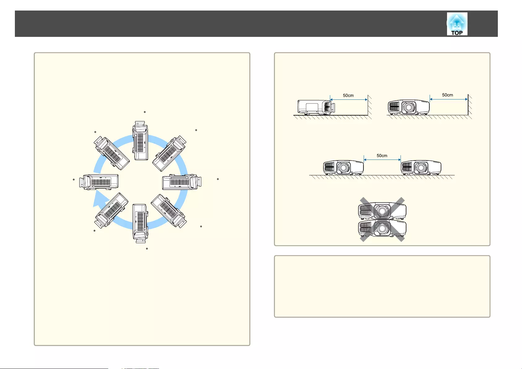
•When projecting with the projector tilted, do not tilt it at more than the
specified angle. This may cause malfunctions or accidents to occur.
Angle of tilt
Vertical: Can be installed at any angle in a complete 360 degrees.
90
45
0
135
180
-135
-90
-45
Horizontal: Can be tilted within the range (about ±1.3 degrees) of expansion
and contraction for the rear feet. The feet can be attached and removed. Note
that the feet will detach if they are extended more than 10 mm.
•Once installation is complete, make sure you set the Direction. If it is not
set, the projector does not cool down correctly, and the lamps may
deteriorate.
s "Setting the direction" p.28
•Using the projector at an improper angle or setting the Configuration menu
incorrectly causes malfunctions and shortens the operating life of optical
parts.
Attention
•Make sure there is a gap as shown in the following illustration between the
wall and the air exhaust vent and the air intake vent.
Air exhaust vent Air intake vent
•When setting up multiple projectors, make sure there is a gap of at least
50 cm between the projectors. Also, make sure that the heat from the air
exhaust vent does not go into the air intake vent.
•Do not place the projector directly on top of another projector.
a
•We recommend setting the focus, zoom, and lens shift at least
20 minutes after you start the projection, because images are not
stable right after turning on the projector.
•When adjusting the image height with the vertical lens shift, adjust
by moving the image from the bottom to the top. If it is adjusted
from the top to the bottom, the image position may move down
slightly after adjusting.
Safety Warning and Cautions
5
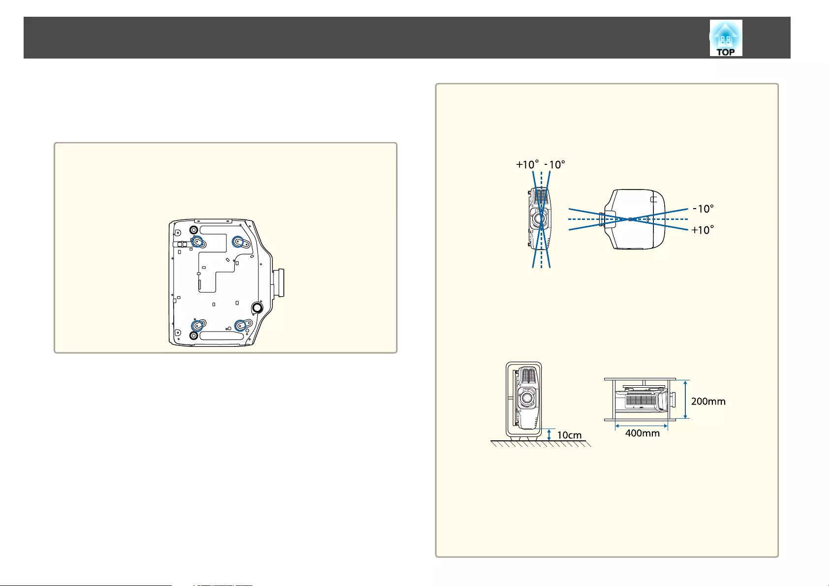
Notes on portrait installation
A dedicated mount is required for portrait installation. Contact a
professional and prepare the mount.
Attention
•Plan so that the mount does not fall.
•Use commercially available M6 screws (up to a depth of 12 mm) to fix the
ceiling mount fixing points of the projector and the mount at four points
(you do not need to remove the feet of the projector).
Attention
•Make sure you install the projector with the air intake vent facing down. If
the air intake vent is facing up, the projector does not cool down correctly,
and it may cause a malfunction.
Angle of tilt
Using the projector at angles not shown in the illustrations above may
damage it or cause an accident.
•Make sure that you install the projector with the air intake vent facing down
and that there is a gap at least as wide as shown in the following illustration
between the projector and the floor and so on. Make sure there is a gap of
400 x 200 mm for the base so that the air intake vent is not blocked.
•Once installation is complete, make sure you set the Direction. If it is not
set, the projector does not cool down correctly, and the lamps may
deteriorate.
s "Setting the direction" p.28
•Do not use lamps that have been used for about 2000 hours or more at
normal installment. This may cause the projector to malfunction or cause the
lamps to deteriorate.
Safety Warning and Cautions
6

Warning and Cautions on Usage
Warning
•Do not cover the projector's air intake vent or air exhaust vent. If either of
the vents is covered, the internal temperature could rise and cause a fire.
•Do not look into the lens while projecting.
•During projection, do not block the light from the projector with the lens
cover (removable) or a book and so on.
If the light from the projector is blocked, the area on which the light shines
becomes hot which could cause it to melt, burn, or start a fire. Also, the lens
may get hot due to the reflected light which could cause the projector to
malfunction. To stop projection, use the A/V Mute function, or turn off the
projector.
•A mercury lamp with high internal pressure is used as the projector's light
source. If the lamp is subjected to vibrations, shocks, or if it is used for an
overly extended length of time, the lamp may break or it may not turn on. If
the lamp explodes, gases may escape and small fragments of glass may be
scattered which could cause an injury. Be sure to observe the instructions
below.
- Do not disassemble or damage the lamp or subject it to any impacts.
- Do not bring your face close to the projector while it is in use.
- Particular care should be taken when the projector is installed to a
ceiling, as small pieces of glass may fall down when the lamp cover is
removed.
When cleaning the projector or replacing the lamp yourself, be very
careful not to allow such pieces of glass to get into the eyes or mouth.
If the lamp breaks, ventilate the area immediately, and contact a doctor if any
fragments of broken glass are inhaled or get into the eyes or mouth. In
addition, consult your local regulations regarding proper disposal and do not
place in the trash.
Caution
Do not place objects that may become warped or otherwise affected by heat
near the air exhaust vent and do not put your face or hands near the vent
while projection is in progress.
Attention
•Do not repeatedly turn off the power and immediately back on. Turning the
power on and off frequently may shorten the lamp's operating life.
•Only remove the lens unit when necessary. If dust or dirt enter the projector,
projection quality deteriorates and it could cause a malfunction.
•Try not to touch the lens section with your hand or fingers. If fingerprints or
oils are left on the surface of the lens, projection quality deteriorates.
•Store the projector with the lens unit installed.
If the projector is stored without the lens unit, dust and dirt may get inside
the projector and cause malfunctions or lower the quality of projection.
•When storing, make sure you remove the batteries from the remote control.
If the batteries are left in the remote control for an extended period of time,
they may leak.
Safety Warning and Cautions
7
Notes on Transporting
There are many glass parts and precision components inside the projector.
To prevent damage due to impacts when transporting, handle the projector
as follows.
Caution
Do not carry the projector by one person. Two people are needed to unpack or
carry the projector.
Attention
•Moving Nearby
- Turn off the power to the projector and disconnect all cables.
- Attach the cover to the lens.
•When Transporting
After checking the points in "Moving Nearby", prepare the following and then
pack up the projector.
- Remove the lens unit if an option lens is installed.
- If the projector does not have a lens, attach the cover that was on the
lens mount when you purchased the projector.
- Attach the lens if the projector has a built-in lens. Upon purchase,
attach the protective pad that is attached around the lens unit.
- Move the lens position to the home position.
s "Adjusting the Position of the Projected Image (Lens Shift)"
p.33
- Enclose the projector securely in packaging material to protect it from
shock, and place it into a strong cardboard container. Be sure to notify
the carrier company that it is precision equipment.
Safety Warning and Cautions
8

Notations Used in This Guide ........................ 2
Introduction
Part Names and Functions .................................. 14
Front/Top...................................................14
Rear.......................................................15
Interface...................................................16
Base......................................................17
Control Panel................................................17
Remote Control...............................................19
Replacing the remote control batteries ............................. 22
Remote control operating range.................................24
Connecting a Cable to the Remote Control..........................24
Preparing the Projector
Installing the Projector ..................................... 26
Removing and Attaching the Projector Lens Unit........................ 26
Attaching.................................................26
Lens Calibration............................................27
Removing.................................................28
Installation Settings............................................28
Setting the direction .........................................28
Changing the direction of the image (projection mode).................29
Projecting in a portrait installation ................................30
Screen Settings...............................................30
Adjusting the position of the image on the projected screen..............31
Displaying a Test Pattern........................................32
Adjusting the Position of the Projected Image (Lens Shift) ..................33
Adjusting the Image Size........................................ 36
Correcting the Focus ...........................................37
Correcting Distortion (Image Warping).............................38
Registering and Loading Lens Adjustment Values.......................39
Adjusting the Height of the Projected Image (for Normal Installment)..........40
Adjusting the Horizontal Tilt (for Normal Installment).....................41
ID Settings..................................................41
Set the projector ID..........................................41
Checking the projector ID......................................42
Setting the remote control ID...................................42
Setting the Time..............................................43
Other Settings................................................44
Settings related to basic operations ...............................44
Settings related to display......................................45
Connecting Equipment ..................................... 46
Connecting a Computer......................................... 46
Connecting Image Sources .......................................48
Connecting External Equipment...................................49
Connecting a LAN Cable.........................................50
Connecting an HDBaseT Transmitter................................51
Installing the Wireless LAN Unit....................................52
Using the Quick Wireless Connection USB Key..........................53
Attaching the Cable Cover....................................... 53
Attaching.................................................54
Basic Usage
Turning On the Projector ................................... 56
Home screen................................................57
Turning Off the Projector ................................... 58
Projecting Images ......................................... 59
Automatically Detecting Input Signals and Changing the Projected Image (Source
Search) ....................................................59
Switching to the Target Image by Remote Control.......................60
Adjusting the Volume..........................................61
Adjusting Projected Images ................................ 62
Correcting Distortion in the Projected Image...........................62
H/V-Keystone..............................................63
Quick Corner...............................................64
Contents
9

Curved Surface.............................................65
Corner Wall................................................ 76
Point Correction............................................ 86
Selecting the Projection Quality (Selecting Color Mode)...................87
Setting Auto Iris ..............................................88
Changing the Aspect Ratio of the Projected Image ......................89
Changing methods..........................................89
Adjusting the Image ...........................................92
Hue, Saturation, and Brightness adjustment.........................92
Gamma adjustment ..........................................93
Frame Interpolation .......................................... 96
Adjusting Image Resolution (Image Enhancement) .......................97
4K Enhancement (EB-G7905U/EB-G7900U/EB-G7500U/EB-G7400U only) ......97
Image Preset Mode ..........................................98
Noise Reduction............................................99
MPEG Noise Reduction ........................................ 99
Super-resolution ............................................99
Detail Enhancement .........................................100
Projecting 3D images.......................................... 100
Useful Functions
Multi-Projection Function ................................. 102
Preparation.................................................102
Edge Blending ...............................................102
Adjust the Edges of the Images (Edge Blending) ...................... 103
Correcting the Brightness (EB-G7905U/EB-G7900U/EB-G7500U/EB-G7200W/EB-
G7000W/EB-G7805/EB-G7800/EB-G7100 only) ....................... 105
Fine-tuning the color balance.................................. 106
Tiling..................................................... 111
Displaying a Scaled Image .......................................112
Projection Functions ...................................... 115
Projecting Two Images Simultaneously (Split Screen) .................... 115
Input Sources for Split Screen Projection ...........................115
Operating procedures....................................... 116
Restrictions during split screen projection..........................118
Hiding the Image and Sound Temporarily (A/V Mute).................... 118
Freezing the Image (Freeze)..................................... 119
Enlarging Part of the Image (E-Zoom)............................... 119
Saving a User's Logo ........................................... 120
Memory Function ......................................... 122
Saving/Loading/Erasing/Resetting the Memory........................ 122
Scheduling Function ...................................... 124
Saving a Schedule ............................................ 124
Setting a schedule.......................................... 124
Checking a schedule ........................................ 125
Editing a schedule .......................................... 125
Security Functions ........................................ 127
Managing Users (Password Protection).............................. 127
Kinds of Password Protection.................................. 127
Setting Password Protection................................... 127
Entering the password....................................... 128
Restricting Operation .......................................... 129
Control Panel Lock ..........................................129
Lens Lock ................................................ 130
Remote control button lock ....................................130
Anti-Theft Lock.............................................. 131
Installing the wire lock ....................................... 131
Configuration Menu
Using the Configuration Menu ............................. 134
List of Functions .......................................... 135
Configuration Menu Table...................................... 135
Network menu............................................ 136
Image Menu................................................ 137
Signal Menu................................................ 139
Settings Menu...............................................140
Extended Menu ..............................................142
Network Menu.............................................. 147
Contents
10

Notes on operating the Network menu ............................148
Soft keyboard operations ..................................... 148
Basic menu...............................................149
Wireless LAN menu......................................... 149
Wired LAN menu........................................... 152
Notification menu .......................................... 152
Others menu..............................................153
Reset menu...............................................154
Info Menu (Display Only)........................................154
Reset Menu.................................................155
Batch Setup .............................................. 156
Setup Using a USB Flash Drive.................................... 156
Saving settings to the USB flash drive ............................. 156
Reflecting saved settings to other projectors........................ 158
Setup by Connecting the Computer and Projector with a USB Cable.......... 160
Saving settings to a computer.................................. 160
Reflecting saved settings to other projectors........................ 161
When Setup Fails .............................................162
Troubleshooting
Using the Help ........................................... 164
Reading the Indicators . . . . . . .............................. 166
Reading the Status Information ............................ 172
Explanations of the Display Content................................173
Problem Solving .......................................... 179
Problems Relating to Images.....................................180
No images appear.......................................... 180
Moving images are not displayed................................180
Projection stops automatically ..................................181
Not supported is displayed.................................... 181
No Signal is displayed........................................181
Images are fuzzy, out of focus, or distorted......................... 182
Interference or distortion appear in images ......................... 182
The image is truncated (large) or small, the aspect is not suitable, or the image has
been reversed .............................................183
Image colors are not right.....................................184
Images appear dark......................................... 184
Problems when Projection Starts.................................. 185
The projector does not turn on................................. 185
Other Problems.............................................. 186
No sound can be heard or the sound is faint........................ 186
The remote control does not work............................... 186
Nothing appears on the external monitor.......................... 187
I want to change the language for messages and menus . . . . . . . . . . . . . . . . 188
Email is not received even if a problem occurs in the projector . . . . . . . . . . . . 188
The battery that saves your clock settings is running low. is displayed . . . . . . . 188
About Event ID ........................................... 189
Maintenance
Cleaning ................................................. 191
Cleaning the Projector's Surface ...................................191
Cleaning the Lens............................................ 191
Cleaning the Air Filter..........................................191
Cleaning the air filter........................................ 191
Replacing Consumables ................................... 194
Replacing the Lamp........................................... 194
Lamp replacement period .....................................194
How to replace the lamp......................................194
Resetting the lamp hours..................................... 197
Replacing the Air Filter......................................... 197
Air filter replacement period................................... 197
How to replace the air filter.................................... 197
Image Maintenance ....................................... 199
Panel Alignment ............................................. 199
Color Uniformity............................................. 200
Contents
11

Appendix
Monitoring and Controlling ............................... 204
About EasyMP Monitor......................................... 204
About Message Broadcasting.................................. 204
Changing Settings Using a Web Browser (Epson Web Control).............. 204
Displaying the Epson Web Control Screen..........................204
Basic Control Screen.........................................205
OSD Control Pad Screen...................................... 206
Lens Control Screen ......................................... 206
Status Information Screen ..................................... 208
Using the Mail Notification Function to Report Problems..................209
Reading error notification mail..................................209
Management Using SNMP...................................... 210
ESC/VP21 Commands..........................................210
Command list............................................. 210
Cable layouts............................................. 211
About PJLink................................................212
About Crestron RoomView
®
..................................... 212
Operating a projector from your computer......................... 213
Optional Accessories and Consumables .................... 217
Optional Accessories.......................................... 217
Consumables ............................................... 218
Screen Size and Projection Distance ........................ 219
Projection Distance (For EB-G7905U/EB-G7900U/EB-G7500U/EB-G7400U/EB-
G7200W/EB-G7000W)..........................................219
ELPLM08 ................................................ 219
ELPLX01................................................. 220
ELPLU03.................................................220
ELPLU04/ELPLU02.......................................... 221
ELPLW05................................................ 222
ELPLW06/ELPLW04......................................... 222
ELPLM09/ELPLS04 .......................................... 223
ELPLM10/ELPLM06......................................... 224
ELPLM11/ELPLM07......................................... 225
ELPLL08/ELPLL07 ...........................................226
ELPLR04 ................................................. 227
Projection Distance (For EB-G7805/EB-G7800/EB-G7100).................. 228
ELPLM08 ................................................ 228
ELPLX01 ................................................. 229
ELPLU03.................................................229
ELPLU04/ELPLU02.......................................... 230
ELPLW05................................................ 231
ELPLW06/ELPLW04......................................... 231
ELPLM09/ELPLS04.......................................... 232
ELPLM10/ELPLM06......................................... 233
ELPLM11/ELPLM07......................................... 234
ELPLL08/ELPLL07...........................................235
ELPLR04 ................................................. 236
Polarizer (ELPPL01) Installation Distance ............................. 237
EB-G7905U/EB-G7900U/EB-G7500U/EB-G7400U . . . . . . . . . . . . . . . . . . . . . . 237
EB-G7200W/EB-G7000W . . . . . . . . . . . . . . . . . ..................... 237
EB-G7805/EB-G7800/EB-G7100 . ................................ 237
Supported Monitor Displays ............................... 238
Supported Resolutions ......................................... 238
Computer signals (analog RGB) ................................. 238
Component Video.......................................... 238
Composite video........................................... 238
Input signal from the DVI-D port, HDMI port, and HDBaseT port
*1
..........238
Specifications ............................................ 240
Projector General Specifications ...................................240
Appearance .............................................. 245
Glossary ................................................. 247
General Notes ............................................ 249
About Notations............................................. 249
Trademarks and Copyrights ......................................250
List of Safety Symbols Compliant with IEC60950-1 A2 . . . . . . . 251
Index .................................................... 253
Contents
12

Introduction
This chapter explains the names for each part.
The illustrations in this guide are for EB-G7900U (with the zoom lens
ELPLM08 attached).
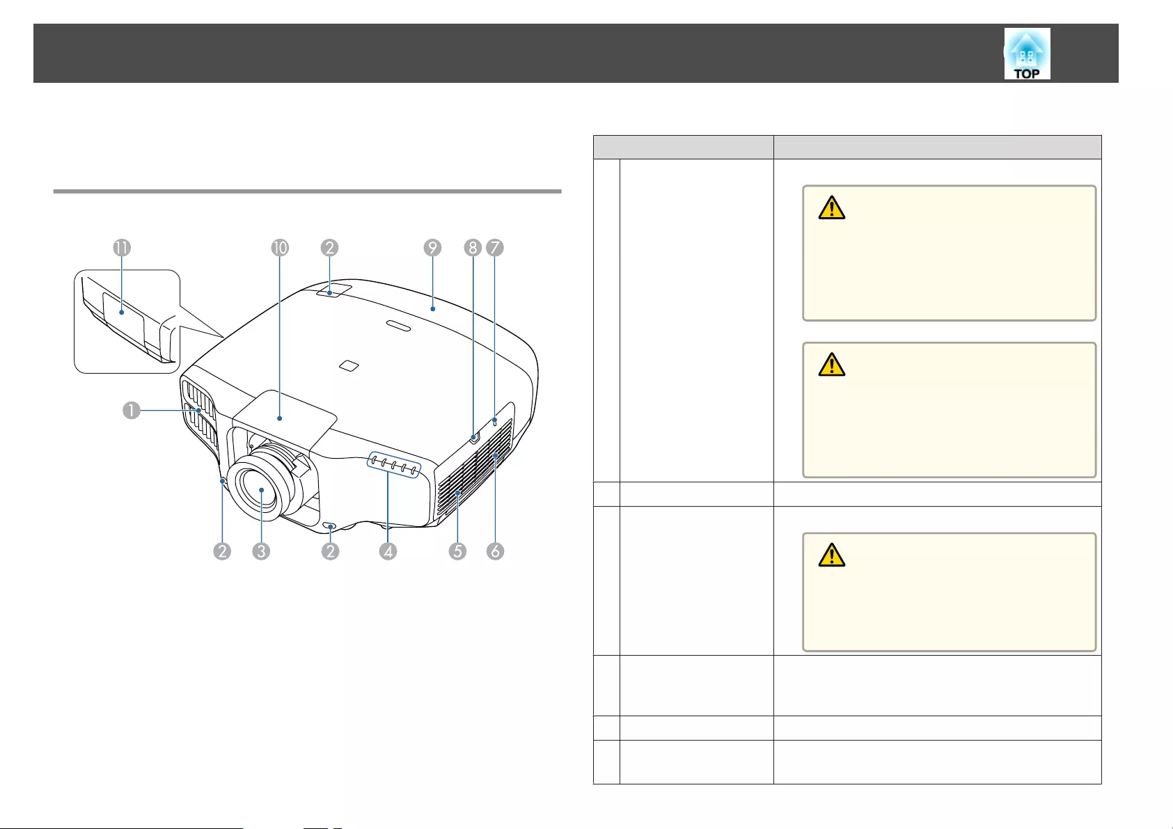
Front/Top
Name Function
AAir exhaust vent Exhaust vent for air used to cool the projector internally.
Warning
Do not look into the vents. If the lamp explodes,
gases may escape and small fragments of glass may
be scattered which could cause an injury. Contact
a doctor if any fragments of broken glass are in‐
haled or get into the eyes or mouth.
Caution
While projecting, do not put your face or hands
near the air exhaust vent, and do not place objects
that may become warped or damaged by heat near
the vent. Hot air from the air exhaust vent could
cause burns, warping, or accidents to occur.
BRemote receiver Receives signals from the remote control.
CProjection lens Images are projected through here.
Caution
When shifting the lens, do not put your hands near
the lens unit. Your fingers may get caught between
the lens unit and the projector, and cause an in‐
jury.
DStatus indicators The color of the indicators and whether they are flashing
or lit indicate the status of the projector.
s "Reading the Indicators" p.166
ESpeaker Outputs audio.
FAir intake vent
(air filter)
Takes in air to cool the projector internally.
s "Cleaning the Air Filter" p.191
Part Names and Functions
14
Name Function
GWireless LAN indicator Indicates the access status to the optional wireless LAN
unit.
s "Optional Accessories" p.217
HAir filter cover
operation knob
Use this knob to open the air filter cover.
s "Replacing the Air Filter" p.197
ICable cover Cover for the rear interface cable connection section.
s "Attaching the Cable Cover" p.53
JLens replacement
cover
Remove when attaching or removing the lens.
s "Removing and Attaching the Projector Lens Unit"
p.26
Caution
When moving the projector, do not hold the lens
replacement cover. The lens replacement cover
may be removed and the projector may fall, which
could cause an injury.
KLamp cover Open when replacing the projector's lamp.
s "Replacing the Lamp" p.194
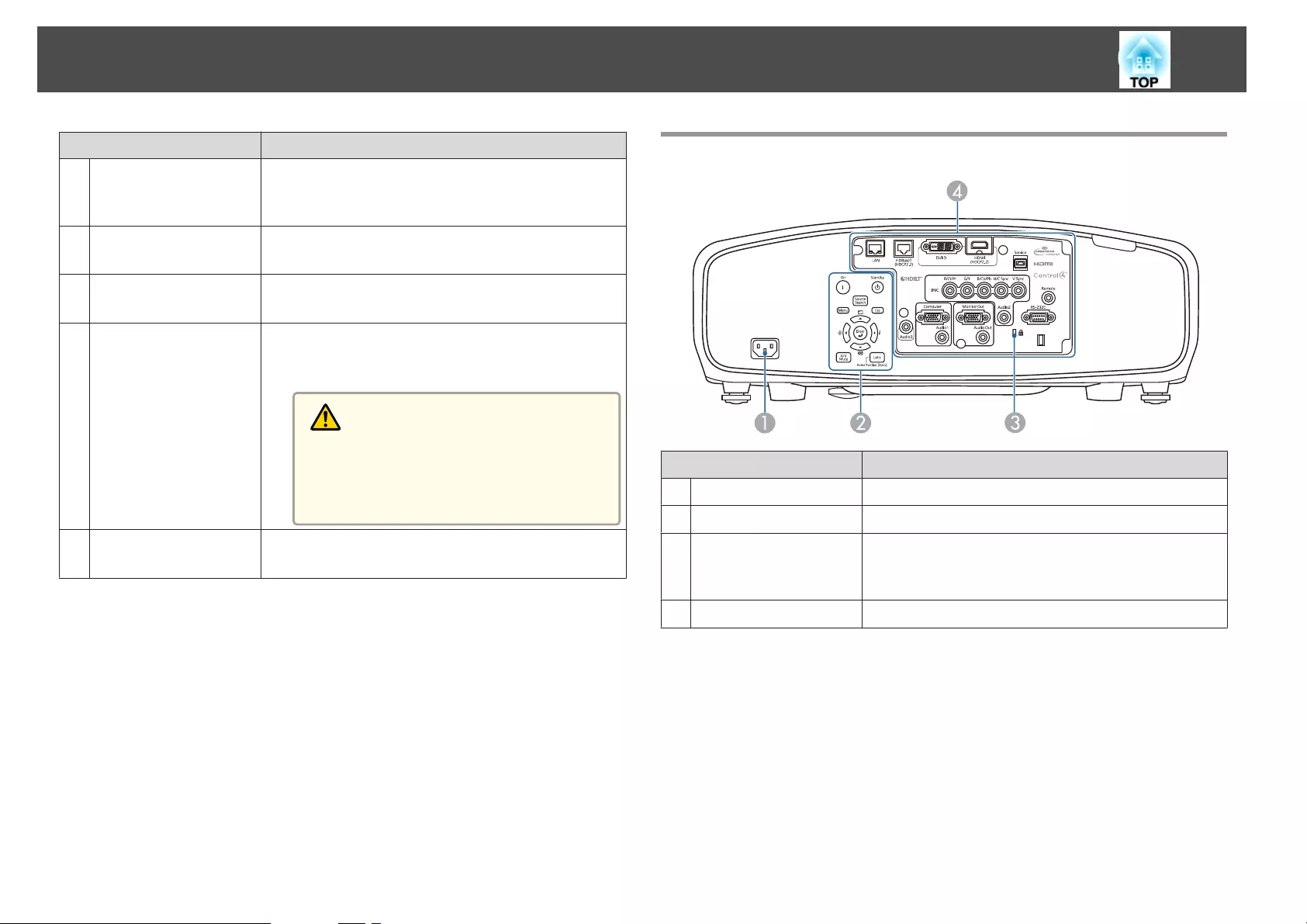
Rear
Name Function
APower inlet Connects the power cord to the projector.
BControl panel s "Control Panel" p.17
CSecurity slot The security slot is compatible with the Microsaver
Security System manufactured by Kensington.
s "Anti-Theft Lock" p.131
DInterface s "Interface" p.16
Part Names and Functions
15
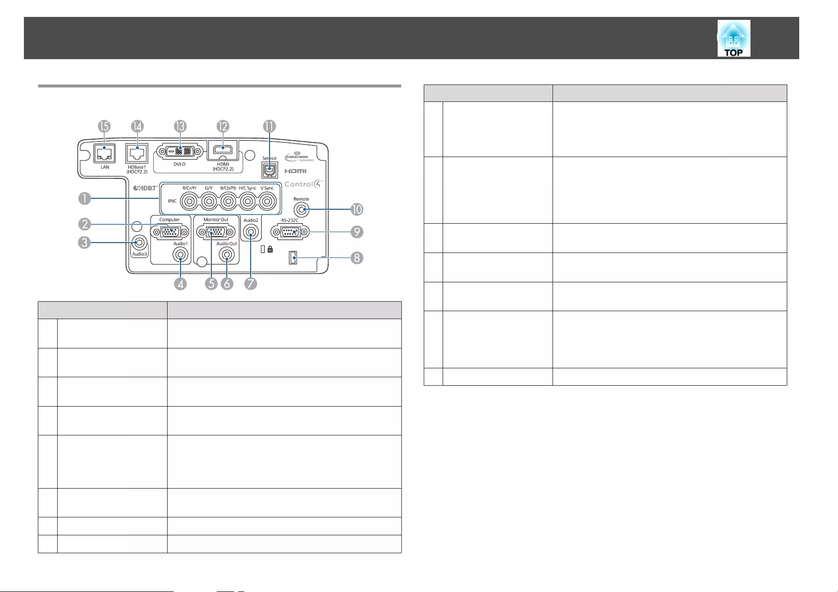
Interface
Name Function
ABNC port For analog RGB signals from a computer and component
video signals from other video sources.
BComputer port For analog RGB signals from a computer and component
video signals from other video sources.
CAudio3 port Inputs audio from equipment connected to the HDMI
port or the DVI-D port.
DAudio1 port Inputs audio from equipment connected to the Computer
port.
EMonitor Out port Outputs to an external monitor the analog signal from the
computer connected to the Computer port or the BNC
port. You cannot output signals input from other ports or
component video signals.
FAudio Out port Outputs audio from the currently projected image to an
external speaker.
GAudio2 port Inputs audio from equipment connected to the BNC port.
HCable holder Run a commercially available cable tie to secure cables.
Name Function
IRS-232C port When controlling the projector from a computer, connect
it to the computer with an RS-232C cable. This port is for
control use and should not normally be used.
s "ESC/VP21 Commands" p.210
JRemote port Connects the optional remote control cable set and inputs
signals from the remote control. When the remote control
cable is plugged into the Remote port, the remote receiver
on the projector is disabled.
s "Optional Accessories" p.217
KService port This port is used by maintenance personnel to control the
projector. This should not normally be used.
LHDMI port Inputs video signals from HDMI compatible video
equipment and computers.
MDVI-D port Inputs the computer DVI-D signals.
NHDBaseT port Connects a LAN cable to the optional HDBaseT
Transmitter.
s "Connecting an HDBaseT Transmitter" p.51
s "Optional Accessories" p.217
OLAN port Connects a LAN cable to connect to a network.
Part Names and Functions
16
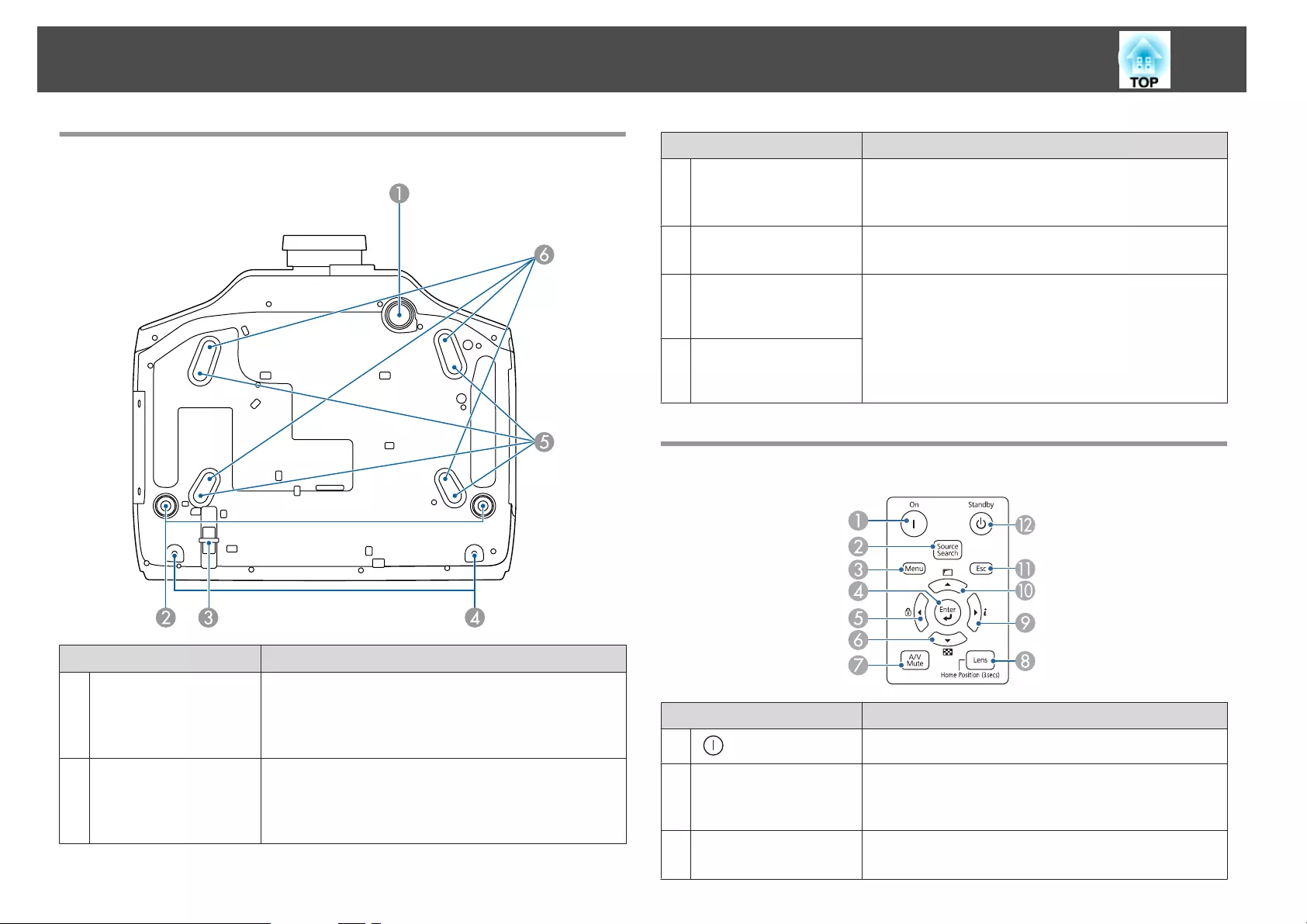
Base
Name Function
AFront adjustable foot When setup on a surface such as a desk, extend the foot to
adjust the position of the image.
s "Adjusting the Height of the Projected Image (for
Normal Installment)" p.40
BRear feet When setup on a surface such as a desk, turn to extend and
retract to adjust the horizontal tilt.
s "Adjusting the Horizontal Tilt (for Normal
Installment)" p.41
Name Function
CSecurity cable
installation point
Pass a commercially available wire lock through here and
lock it in place.
s "Installing the wire lock" p.131
DScrew holes to fix the
cable cover
Screw holes to fix the cable cover in place.
s "Attaching the Cable Cover" p.53
ECeiling mount fixing
points (for ELPMB47/
ELPMB48, four points)
Attach the optional Ceiling Mount here when suspending
the projector from a ceiling.
s "Installing the Projector" p.26
s "Optional Accessories" p.217
FCeiling mount fixing
points (for ELPMB22,
four points)
Control Panel
Name Function
A[] button Turns the projector on.
B[Source Search]
button
Changes to the next input source that is sending an image.
s "Automatically Detecting Input Signals and Changing
the Projected Image (Source Search)" p.59
C[Menu] button Displays and closes the Configuration menu.
s "Using the Configuration Menu" p.134
Part Names and Functions
17
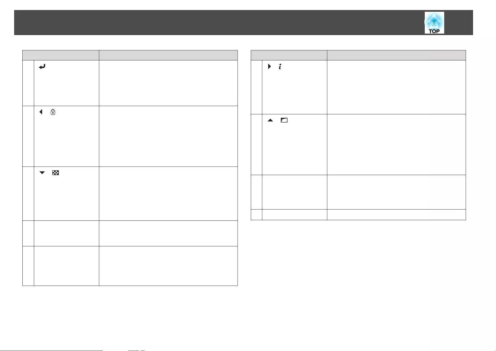
Name Function
D[] button •When the Configuration menu or the Help screen is
displayed, it accepts and enters the current selection and
moves to the next level.
•If pressed while projecting analog RGB signals from the
Computer port or the BNC port, you can automatically
optimize Tracking, Sync., and Position.
E[]/[ ] buttons •Displays the Control Panel Lock screen allowing you to
make settings to lock the control panel buttons.
s "Restricting Operation" p.129
•If pressed when the Configuration menu or the Help
screen is displayed, this button selects menu items and
setting values.
s "Using the Configuration Menu" p.134
s "Using the Help" p.164
F[]/[ ] buttons •Displays a test pattern.
s "Displaying a Test Pattern" p.32
•If pressed when the Configuration menu or the Help
screen is displayed, this button selects menu items and
setting values.
s "Using the Configuration Menu" p.134
s "Using the Help" p.164
G[A/V Mute] button Turns the video and audio on or off.
s "Hiding the Image and Sound Temporarily (A/V
Mute)" p.118
H[Lens] button Displays the adjustment screens for lens shift, zoom,
focus, and distortion in that order each time the button is
pressed.
If pressed for more than three seconds, the lens position
moves to the home position.
Name Function
I[]/[ ] buttons •Displays the Info menu from the Configuration menu.
s "Info Menu (Display Only)" p.154
•If pressed when the Configuration menu or the Help
screen is displayed, this button selects menu items and
setting values.
s "Using the Configuration Menu" p.134
s "Using the Help" p.164
J[]/[ ] buttons •Performs screen adjustments using the settings in
Geometric Correction from the Configuration menu.
s Settings - Geometric Correction p.140
•If pressed when the Configuration menu or the Help
screen is displayed, this button selects menu items and
setting values.
s "Using the Configuration Menu" p.134
s "Using the Help" p.164
K[Esc] button •Stops the current function.
•If pressed when the Configuration menu is displayed, it
moves to the previous menu level.
s "Using the Configuration Menu" p.134
L[t] button Turns the projector off.
Part Names and Functions
18
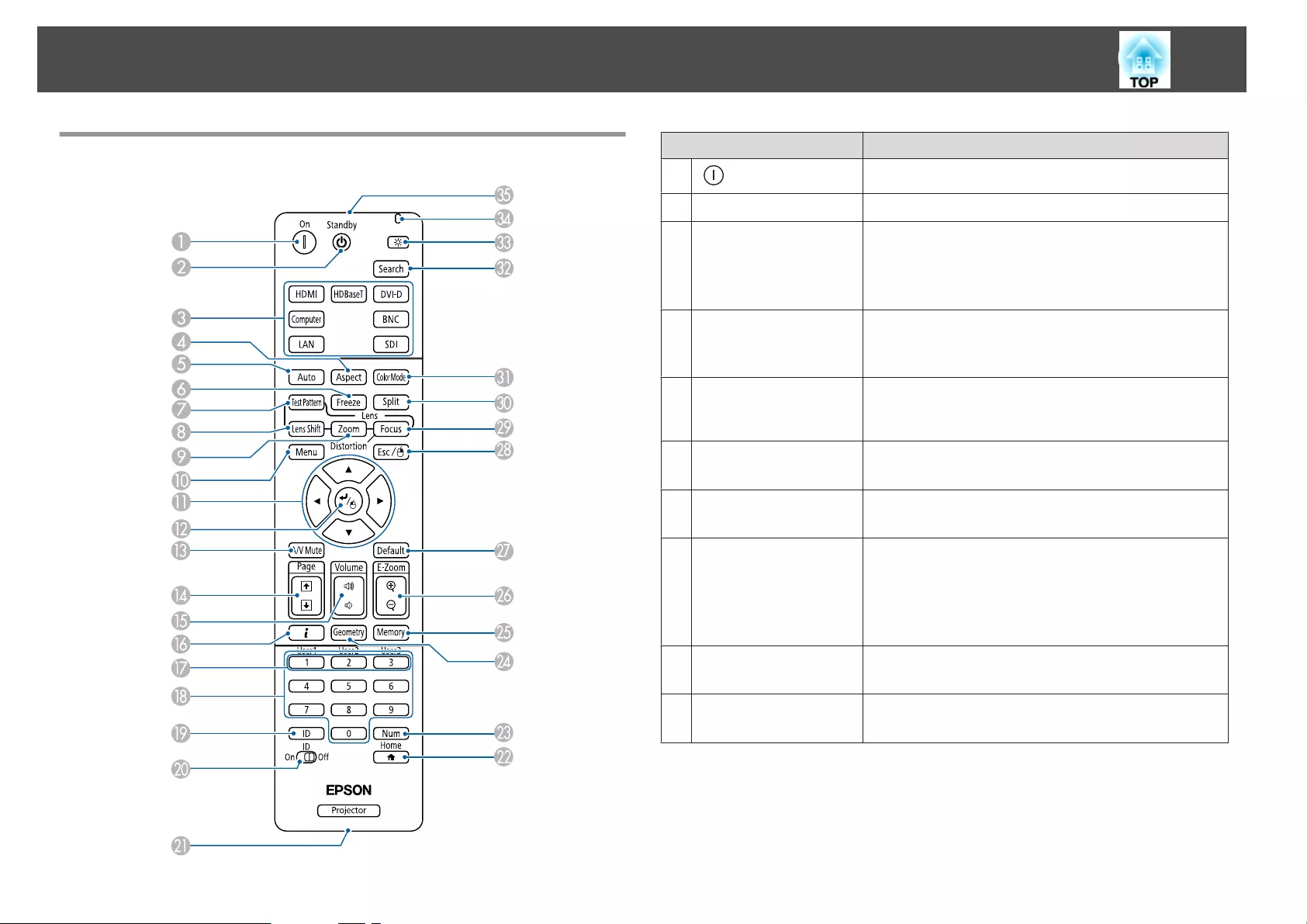
Remote Control Name Function
A[] button Turns the projector on.
B[t] button Turns the projector off.
CChange input buttons Changes to images from each input port.
s "Switching to the Target Image by Remote Control"
p.60
The [SDI] button is not available for this projector.
D[Aspect] button Each time the button is pressed, the aspect mode changes.
s "Changing the Aspect Ratio of the Projected Image "
p.89
E[Auto] button If pressed while projecting analog RGB signals from the
Computer port or the BNC port, you can automatically
optimize Tracking, Sync., and Position.
F[Freeze] button Images are paused or unpaused.
s "Freezing the Image (Freeze)" p.119
G[Test Pattern] button Displays a test pattern.
s "Displaying a Test Pattern" p.32
H[Lens Shift] button Press to adjust the lens shift.
s "Adjusting the Position of the Projected Image (Lens
Shift)" p.33
If pressed for more than three seconds, the lens position
moves to the home position.
I[Zoom] button Press to adjust the zoom.
s "Adjusting the Image Size" p.36
J[Menu] button Displays and closes the Configuration menu.
s "Using the Configuration Menu" p.134
Part Names and Functions
19
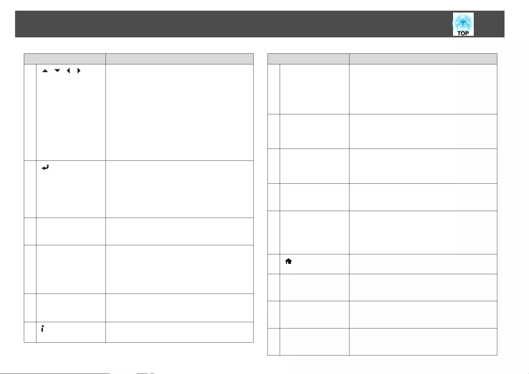
Name Function
K[][ ][ ][ ]
buttons
•Press to adjust focus, distortion, zoom, and lens shift.
s "Adjusting the Position of the Projected Image
(Lens Shift)" p.33
s "Adjusting the Image Size" p.36
s "Correcting the Focus" p.37
•When the Configuration menu or the Help screen is
displayed, pressing these buttons selects menu items
and setting values.
s "Using the Configuration Menu" p.134
•When using the optional wireless mouse receiver,
pressing these buttons moves the pointer.
s "Optional Accessories" p.217
L[] button •When the Configuration menu or the Help screen is
displayed, it accepts and enters the current selection and
moves to the next level.
s "Using the Configuration Menu" p.134
•Acts as a mouse's left button when using the optional
wireless mouse receiver.
s "Optional Accessories" p.217
M[A/V Mute] button Turns the video and audio on or off.
s "Hiding the Image and Sound Temporarily (A/V
Mute)" p.118
N[Page] buttons
[[][]]
•Moves to the previous or next image file when
projecting images from a computer connected via a
network.
•When using the optional wireless mouse receiver, you
can change the PowerPoint file page during projection
by pressing the page up/page down buttons.
O[Volume] buttons
[a][b]
[a] Decreases the volume.
[b] Increases the volume.
s "Adjusting the Volume" p.61
P[] button Displays the Info menu from the Configuration menu.
s "Info Menu (Display Only)" p.154
Name Function
Q[User1] button
[User2] button
[User3] button
Select any frequently used item from the Configuration
menu items, and assign it to any of these buttons. By
pressing the button, the assigned menu item selection/
adjustment screen is displayed, allowing you to make one-
touch settings/adjustments.
s "Settings Menu" p.140
RNumeric buttons •Enter the Password.
s "Setting Password Protection" p.127
•Use this button to enter numbers in Network settings
from the Configuration menu.
S[ID] button Hold down this button and press the numeric buttons to
select the ID for the projector you want to operate using
the remote control.
s "ID Settings" p.41
T[ID] switch Use this switch to enable (On)/disable (Off) ID settings for
the remote control.
s "ID Settings" p.41
URemote port Connects the optional remote control cable set and
outputs signals from the remote control.
s "Optional Accessories" p.217
When the remote control cable is plugged into this remote
port, the remote control light-emitting is disabled.
V[] button Displays and closes the Home screen.
s "Home screen" p.57
W[Num] button Hold down this button and press the numeric buttons to
enter passwords and numbers.
s "Setting Password Protection" p.127
X[Geometry] button Corrects distortion in the projected image.
s "Correcting Distortion in the Projected Image"
p.62
Y[Memory] button Performs operations and makes settings for the memory
function.
s "Memory Function" p.122
Part Names and Functions
20
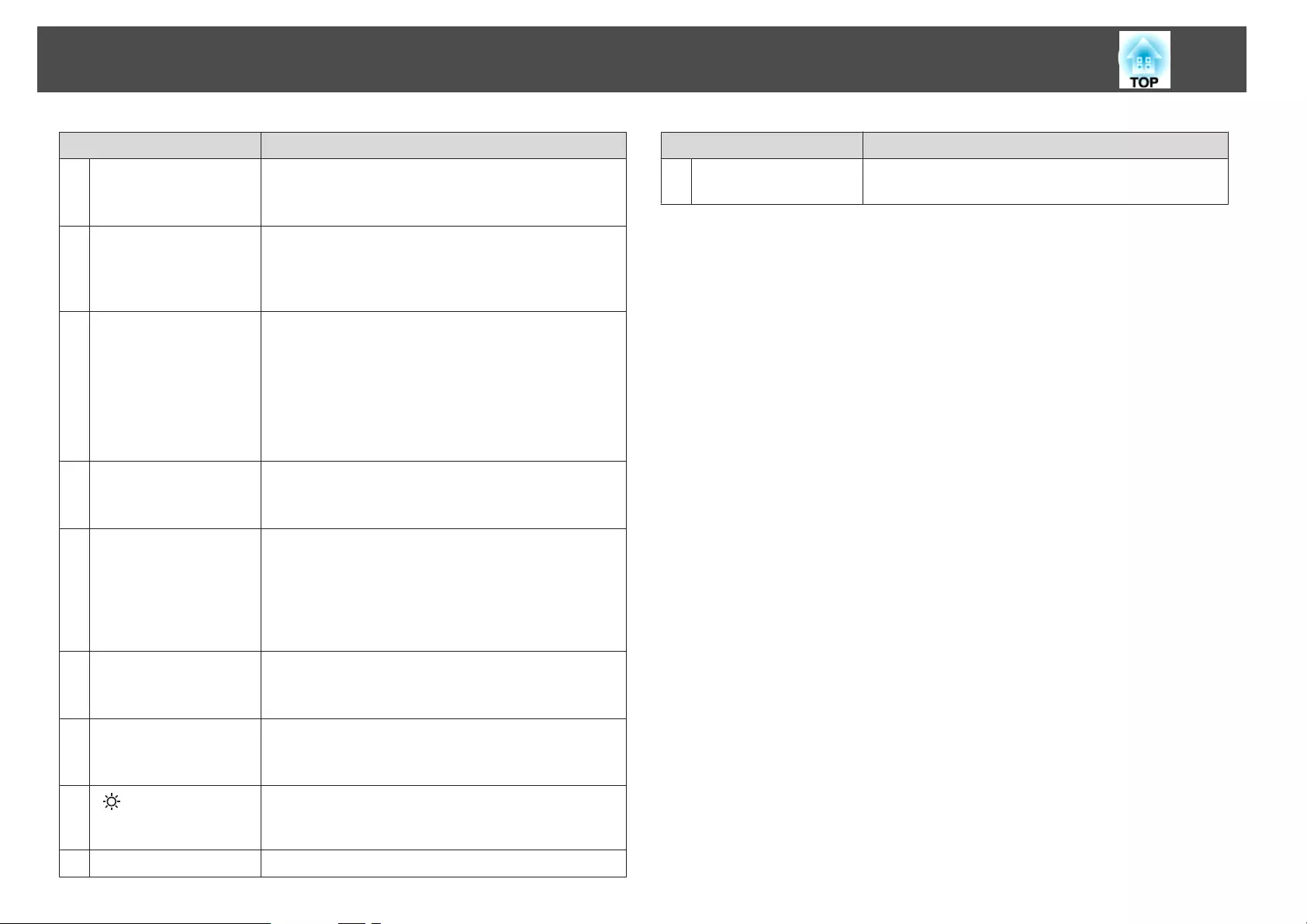
Name Function
Z[E-Zoom] buttons
[z][x]
Enlarges or reduces the image without changing the
projection size.
s "Enlarging Part of the Image (E-Zoom)" p.119
a[Default] button Enabled when [Default]: Reset is displayed on the
configuration menu guide. The settings being adjusted are
returned to their default values.
s "Using the Configuration Menu" p.134
b[Esc] button •Stops the current function.
•If pressed when the Configuration menu is displayed, it
moves to the previous level.
s "Using the Configuration Menu" p.134
•Acts as a mouse's right button when using the optional
wireless mouse receiver.
s "Optional Accessories" p.217
c[Focus] button Each time the button is pressed, the adjustment screens for
focus and distortion are displayed in that order.
s "Correcting the Focus" p.37
d[Split] button Each time the button is pressed, the image changes
between projecting two images simultaneously by
splitting the projected screen, or projecting one image as
normal.
s "Projecting Two Images Simultaneously (Split Screen)
" p.115
e[Color Mode] button Each time the button is pressed, the Color Mode changes.
s "Selecting the Projection Quality (Selecting Color
Mode)" p.87
f[Search] button Changes to the next input source that is sending an image.
s "Automatically Detecting Input Signals and Changing
the Projected Image (Source Search)" p.59
g[] button Illuminates the buttons on the remote control for
approximately 15 seconds. This is useful when using the
remote control in the dark.
hIndicator A light is emitted when outputting remote control signals.
Name Function
iRemote control light-
emitting area
Outputs remote control signals.
Part Names and Functions
21
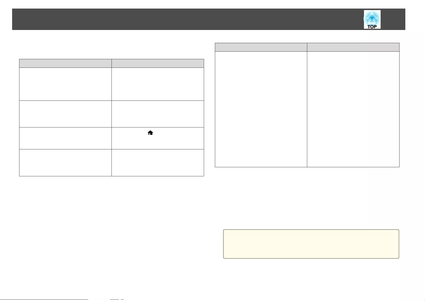
You can perform the following operations by simply pressing one of the
buttons on the remote control.
Operation Settings
Reverse the projected image vertically.
(Switch the Projection between Front and
Front/Ceiling)
s "Changing the direction of the image
(projection mode)" p.29
Hold down the [A/V Mute] button for more
than five seconds.
Selecting the password security settings.
s "Managing Users (Password
Protection)" p.127
Hold down the [Freeze] button for more
than five seconds. The Password Protection
screen is displayed, and you can select
various settings.
Locking or unlocking some of the operation
of the buttons on the remote control.
s "Remote control button lock" p.130
Hold down the [ ] button for more than
five seconds.
Initializing the settings for the Remote
Receiver in the Configuration menu.
(Enables all Remote receiver for this
projector.)
Hold down the [Menu] button for more than
15 seconds.
Operation Settings
Displaying frequently used Configuration
menu items.
Press the [User1], [User2], or [User3]
button. You can set the menu item you want
to assign to each button in User Button.
s Settings - User Button p.140
The following items can be assigned.
Power Consumption (supported models
only), Multi-Projection, Resolution,
Image Processing, On-Screen Display,
Display the QR Code, Image
Enhancement, Frame Interpolation
When you press the button for which On-
Screen Display is assigned, menu or
messages are not displayed on the screen.
When the same button is pressed, they are
displayed again. If On-Screen Display is
enabled, you cannot operate the
Configuration menu (except switching the
color mode and input source).
Replacing the remote control batteries
If delays in the responsiveness of the remote control occur or if it does not
operate after it has been used for some time, it probably means that the
batteries are becoming flat. When this happens, replace them with new
batteries. Have two AA size alkaline or manganese batteries ready. You
cannot use other batteries except for the AA size alkaline or manganese.
Attention
Make sure you read the following manual before handling the batteries.
s Safety Instructions
Part Names and Functions
22
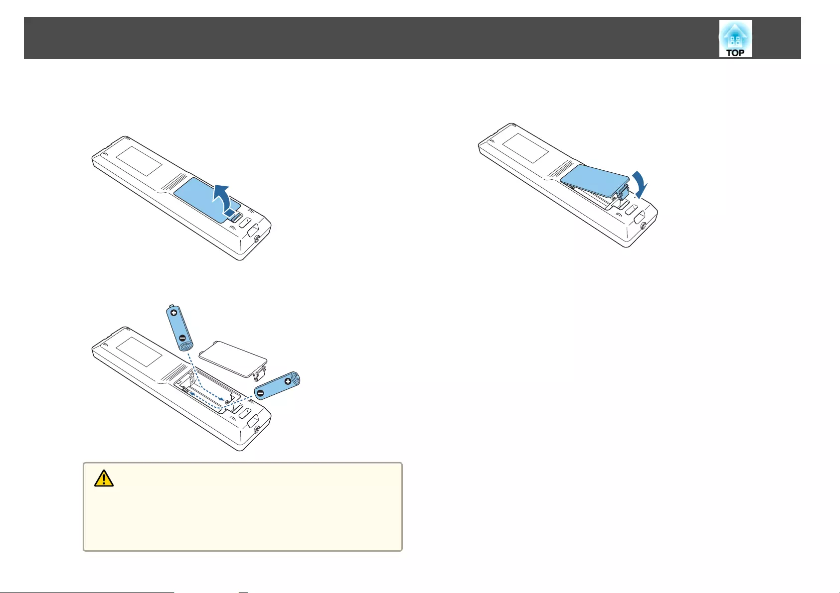
a
Remove the battery cover.
While pushing the battery compartment cover catch, lift the cover
up.
b
Replace the old batteries with new batteries.
Caution
Check the positions of the (+) and (-) marks inside the battery holder to
ensure the batteries are inserted the correct way.
If the batteries are not used correctly, they could explode or leak causing
a fire, injury, or damage to the product.
c
Replace the battery cover.
Press the battery compartment cover until it clicks into place.
Part Names and Functions
23
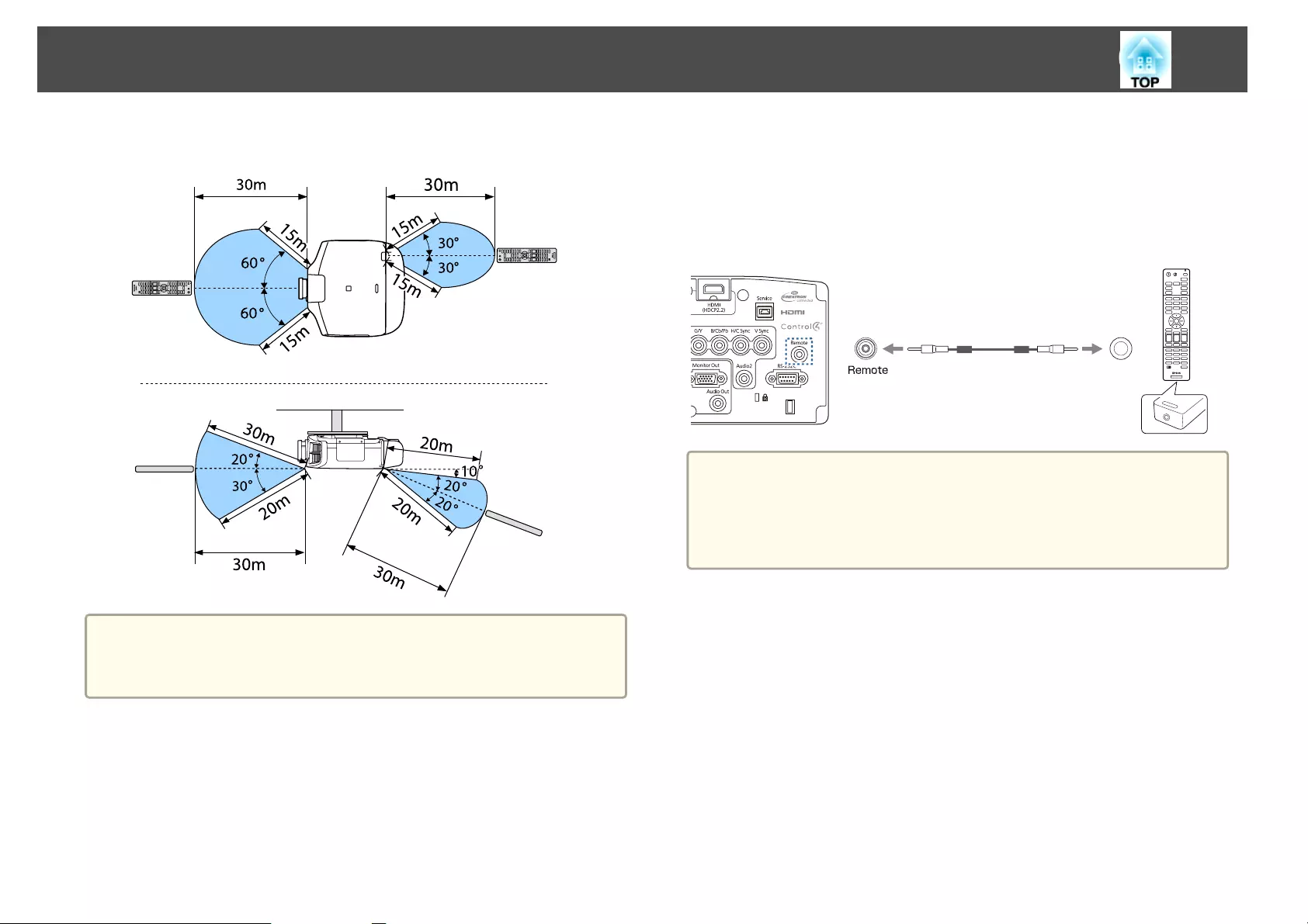
Remote control operating range
a
To restrict reception of the operation signals from the remote control,
set Remote Receiver.
s Settings - Remote Receiver p.140
Connecting a Cable to the Remote Control
You can make operations securely with the optional remote control cable
set when you use multiple units of this projector in the same place or when
there are obstacles around the remote receiver.
s "Optional Accessories" p.217
a
•When the remote control cable is plugged into the Remote port, the
remote receiver on the projector is disabled.
•You can also connect the optional HDBaseT transmitter and remote
control with the cable to control the projector.
s "Connecting an HDBaseT Transmitter" p.51
Part Names and Functions
24

Preparing the Projector
This chapter explains how to install the projector and connect projection sources.
Removing and Attaching the Projector Lens Unit
Attaching
Attention
•When attaching the lens unit, remove the power plug from the electrical
outlet first.
•Do not attach the lens unit when the projector's lens insertion section is
facing up. Dust or dirt could enter the projector.
•Try not to touch the lens section with your hand or fingers. If fingerprints or
oils are left on the surface of the lens, projection quality deteriorates.
a
•The projector supports lens with the following model numbers.
ELPLM08, ELPLX01, ELPLU03, ELPLU04, ELPLW05, ELPLW06,
ELPLM09, ELPLM10, ELPLM11, ELPLL08, ELPLS04, ELPLU02,
ELPLR04, ELPLW04, ELPLM06, ELPLM07, ELPLL07
When using the following lens, set the Lens Type in the
Configuration menu according to the lens you are using so that
distortion correction is performed correctly.
ELPLS04, ELPLU02, ELPLR04, ELPLW04, ELPLM06, ELPLM07,
ELPLL07
s Extended - Operation - Advanced - Lens Type p.142
•In a normal installation, the image may be tilted depending on your
lens. Adjust the tilt of the image using the rear feet.
s "Adjusting the Horizontal Tilt (for Normal Installment)"
p.41
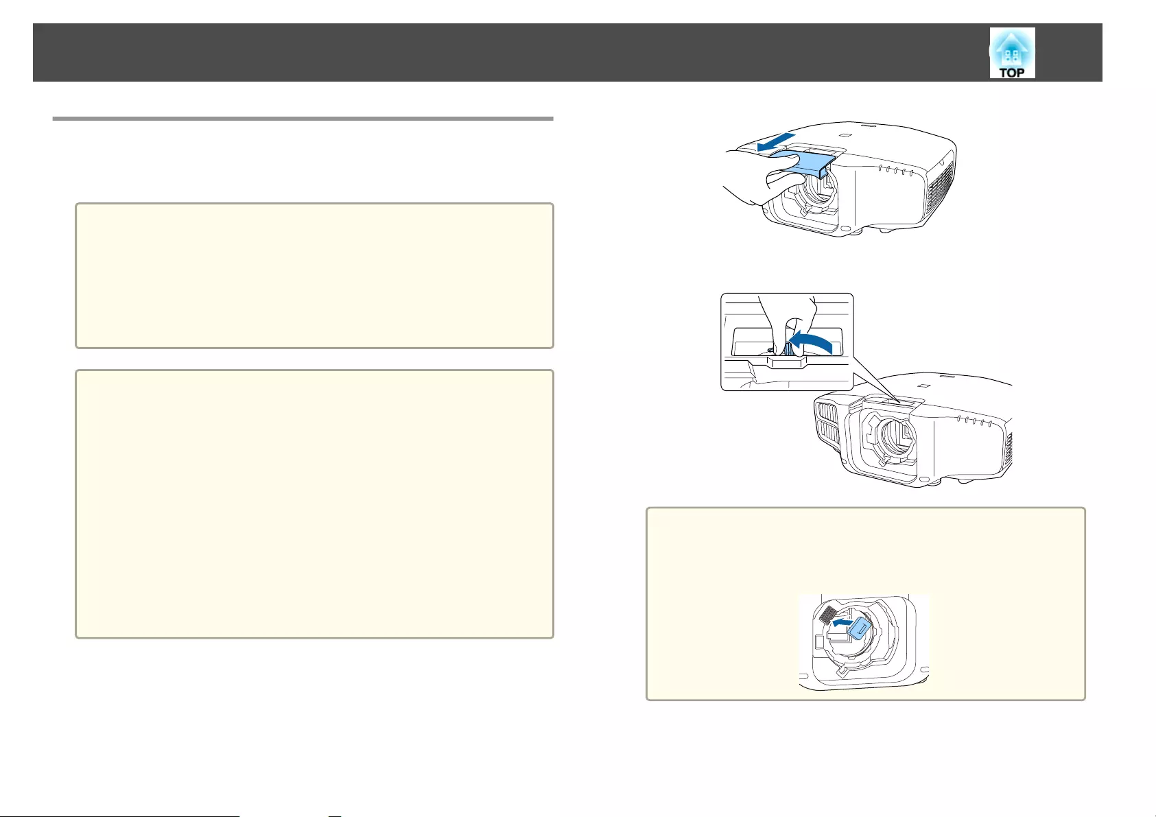
a
Pull the lens replacement cover straight out.
b
Hold the lock lever and turn it counterclockwise.
a
When using the following lens, attach the supplied lens
connector cap to protect the port.
ELPLS04, ELPLU02, ELPLR04, ELPLW04, ELPLM06, ELPLM07,
ELPLL07
c
Insert the lens unit straight into the lens insertion section with the
white circle on the lens on top.
Installing the Projector
26
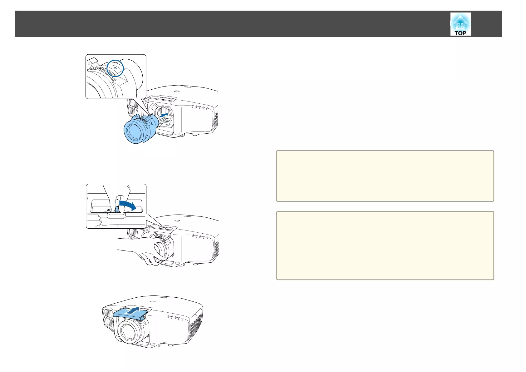
d
While holding the lens unit firmly, hold the lock lever and turn it
clockwise to lock the lens unit.
Check that the lens cannot be detached.
e
Attach the lens replacement cover.
Lens Calibration
After replacing the lens unit, calibrate the lens so that the projector can
correctly acquire the lens position and adjustment range.
After attaching a lens unit that differs from the previous one, a message is
displayed when the projector is turned on.
Select Yes to calibrate the lens.
Lens calibration takes up to about 100 seconds until it is complete. When it
is complete, the lens position returns to the position before the calibration
(ELPLX01 returns to the standard position).
Attention
If the message "Lens Calibration failed." is displayed, stop using the projector,
remove the power plug from the electrical outlet, and contact your local
dealer or the nearest address provided in the Epson Projector Contact List.
s Epson Projector Contact List
a
•You can also calibrate the lens from the Configuration menu.
s Extended - Operation - Lens Calibration p.142
•If you attach a lens unit that is the same as the previous one,
calibrate the lens from the Configuration menu.
•If you do not calibrate the lens, the following functions may not
operate correctly.
Lens Shift, Memory (Lens Position)
Installing the Projector
27
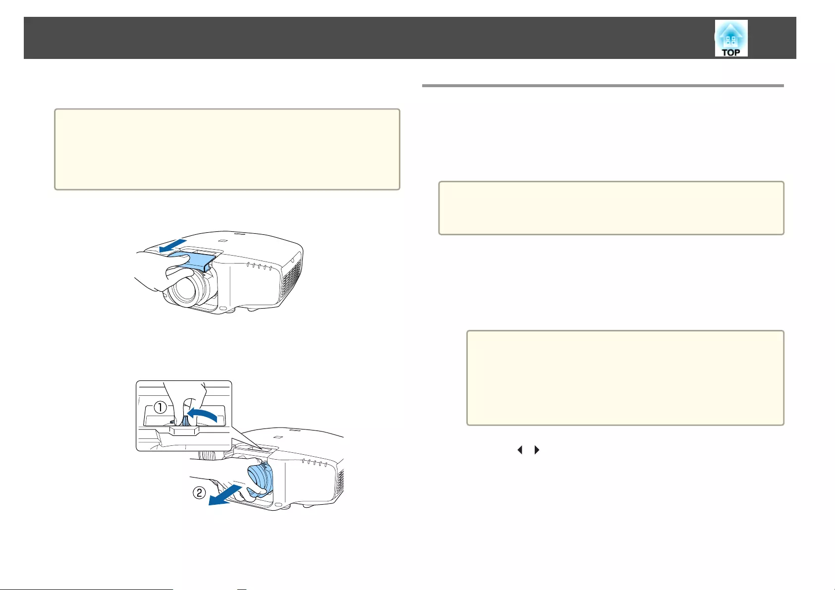
Removing
Attention
When replacing the lens unit, remove the power plug from the electrical
outlet first. If the lens shift has been done, move the lens position to the
home position before replacing the lens unit.
s "Adjusting the Position of the Projected Image (Lens Shift)" p.33
a
Pull the lens replacement cover straight out.
b
While holding the lens unit firmly, hold the lock lever and turn it
counterclockwise to unlock the lens unit.
Pull the lens unit straight out as it is released.
Installation Settings
Setting the direction
When installation is complete, set the Direction from the configuration
menu according to the vertical installation angle.
Attention
Make sure you set Direction correctly. If it is not set, the projector does not
cool down correctly, and the lamps may deteriorate.
a
Press the [Menu] button while projecting.
b
Select Direction from Extended.
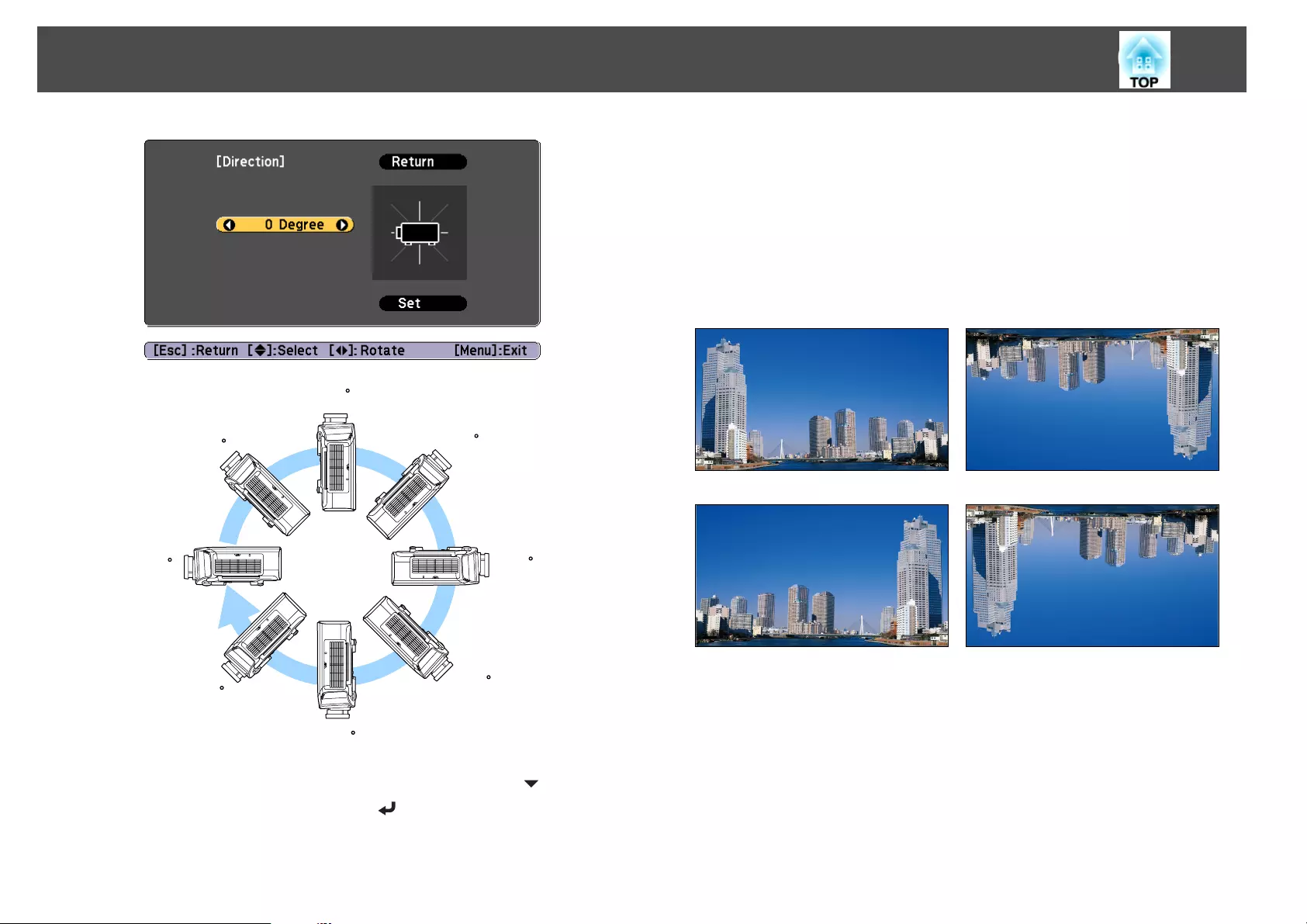
c
Select Direction.
a
•For portrait installation, set Portrait Mode to On.
s Extended - Direction - Portrait Mode p.142
•For normal installation, set Portrait Mode to Off. When
Portrait Mode is On, you cannot set Direction.
•If the Portrait Mode setting is changed, the Power
Consumption and Brightness Level settings may change.
d
Use the [ ][ ] buttons to set the projector's installation angle.
Each time you press one of the buttons, the angle of tilt changes by
15 degrees. Set as close to the actual setup angle as possible.
Installing the Projector
28
90
45
0
135
180
-135
-90
-45
e
When you have finished making settings, use the [ ] button to
select Set, and then press the [ ] button.
Changing the direction of the image (projection mode)
You can change the direction of the image using Projection mode from the
Configuration menu.
s Extended - Projection p.142
When Front is the standard, the image directions for each projection mode
are as follows.
Front (default) Front/Ceiling
Rear Rear/Ceiling
Installing the Projector
29
a
•You can change the setting as follows by pressing down the [A/V
Mute] button on the remote control for about five seconds.
FrontWFront/Ceiling
RearWRear/Ceiling
•Make sure you check the Direction setting when you change the
projector's installation position.
s Extended - Direction p.142
•When suspending the projector from a ceiling, set the Inv Direction
Button to On so that the [ ], [ ], [ ], and [ ] buttons on the
control panel operate in the correct direction.
s Extended - Operation - Inv Direction Button p.142
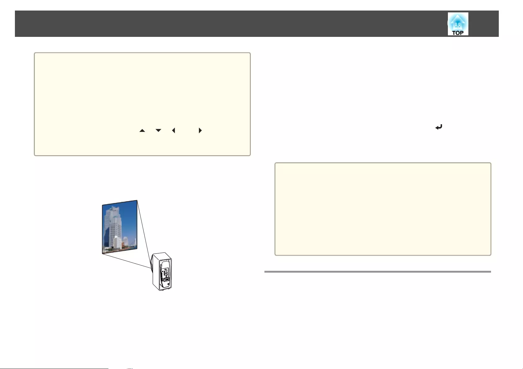
Projecting in a portrait installation
Install the projector vertically and project a vertically long screen.
See the following for notes when doing a portrait installation.
s "Notes on portrait installation" p.6
When projecting in a portrait installation, set Portrait Mode to On.
s "Setting the direction" p.28
To rotate the menu display, set OSD Rotation in the Configuration menu.
a
Press the [Menu] button while projecting.
b
Select Display from Extended.
c
Select OSD Rotation.
d
Select Right 90 Degree, and then press the [ ] button.
e
Press the [Menu] button to finish making settings.
a
•When projecting in a portrait installation, the brightness is about
80% (90% for EB-G7400U/EB-G7000W/EB-G7100) compared to
projecting in a normal installation.
•When continually using the projector in a portrait installation, the
lamp's operating life is short compared to a normal installation.
s "Projector General Specifications" p.240
•When the total projection time in a portrait installation exceeds
about 2000 hours, projection stops automatically.
•Power Consumption is disabled.
s Settings - Power Consumption p.140
Screen Settings
Set the Screen Type according to the aspect ratio of the screen being used.
The area where the image is displayed matches the shape of the screen.
Installing the Projector
30

a
The settings for the Screen Type at the time of purchase are as
follows:
•WUXGA/WXGA projector: 16:10
•XGA projector: 4:3
a
Press the [Menu] button while projecting.
s "Using the Configuration Menu" p.134
b
Select Display from Extended.
c
Select Screen Type from Screen.
d
Select the screen's aspect ratio.
The shape of the background test pattern changes depending on the
setting.
e
Press the [Menu] button to finish making settings.
a
•When you change the Screen Type, adjust the aspect ratio for the
projected image as well.
s "Changing the Aspect Ratio of the Projected Image " p.89
•This function does not support Message Broadcasting (an EasyMP
Monitor plugin).
Adjusting the position of the image on the projected screen
You can adjust the position of the image if there are margins between the
edge of the image and the projected screen frame due to the Screen Type
setting.
Example: When the Screen Type is set to 4:3 for the WUXGA/WXGA
projector
You can move the image to the left and right.
a
Press the [Menu] button while projecting.
s "Using the Configuration Menu" p.134
b
Select Display from Extended.
c
Select Screen Position from Screen.
d
Use the [ ], [ ], [ ], and [ ] buttons to adjust the position of
the image.
You can check the current display position by using the background
test pattern.
Installing the Projector
31
e
Press the [Menu] button to finish making settings.
a
The Screen Position cannot be adjusted in the following situations.
•If you are using a WUXGA/WXGA projector and the Screen Type
is set to 16:10
•If you are using an XGA projector and the Screen Type is set to
4:3
Displaying a Test Pattern
A test pattern can be displayed to adjust the projection status without
connecting video equipment.
The shape of a test pattern is according to the setting of Screen Type. Set
Screen Type first.
s "Screen Settings" p.30
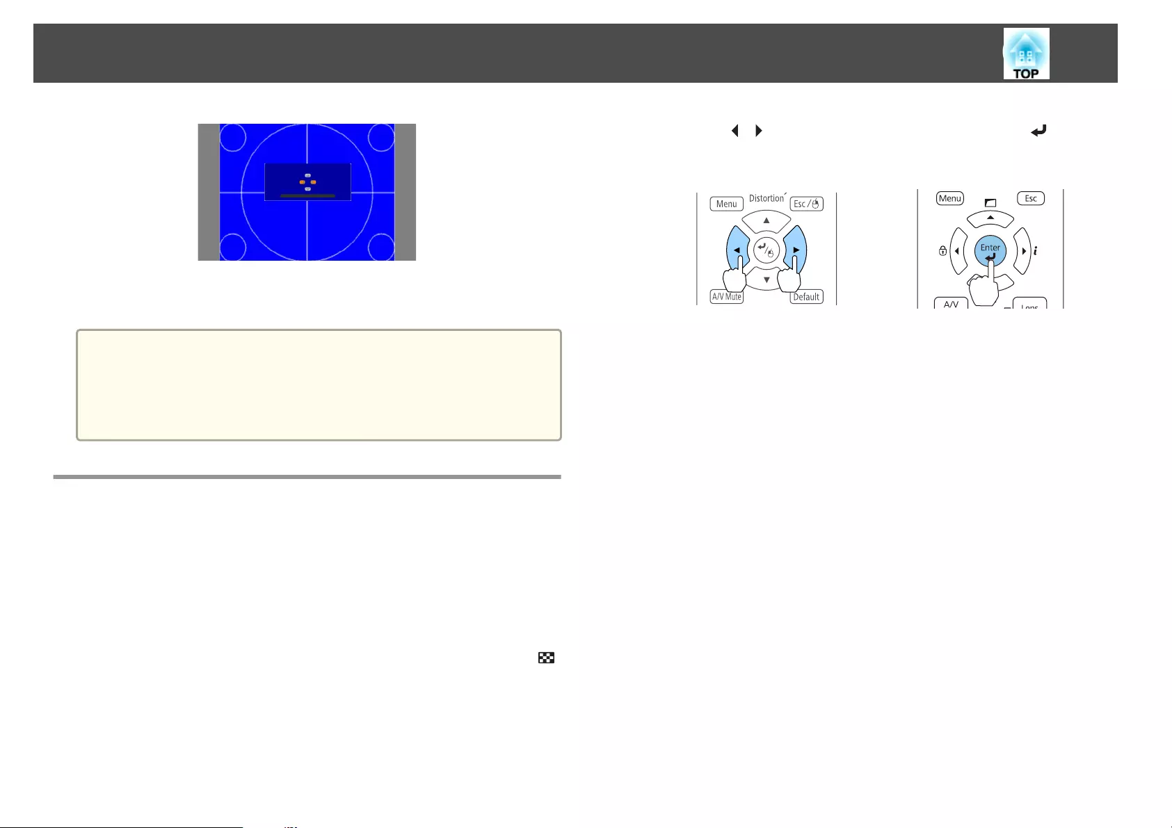
a
Press the [Test Pattern] button of the remote control or the [ ]
button on the control panel while projecting.
b
Press the [ ][ ] buttons on the remote control or the [ ] button
on the control panel to change the test pattern.
Using the remote control Using the control panel
Installing the Projector
32
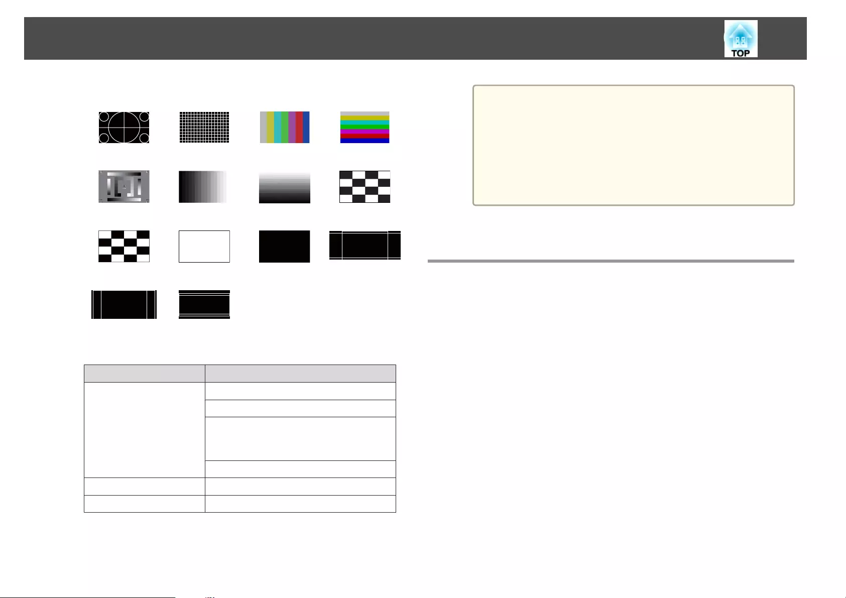
Standard Cross-hatching
W
Color Bars V Color Bars H
Grayscale Gray Bars V Gray Bars H Checkerboard
1
Checkerboard
2
White Black 16:10 Aspect
Frame
16:9 Aspect
Frame
4:3 Aspect
Frame
In addition to lens operations, the following image adjustments can
be made while the test pattern is being displayed.
Top Menu Name Sub Menu/Items
Image Color Mode s p.87
White Balance
Advanced
- Gamma
*1
s p.93
- RGBCMY s p.92
Reset
Settings Geometric Correction s p.62
Extended Multi-Projection
*2
s p.102
*1 Except for custom settings of gamma
*2 Except for Scale, Color Uniformity, and Black Level
a
•To set menu items that cannot be set while the test pattern is
being displayed or to fine-tune the projected image, project an
image from the connected device.
•During image adjustment, press the [[][]] [Page] buttons on
the remote control to change the test pattern.
•You can also select a test pattern from the Configuration
menu.
s Settings - Test Pattern p.140
c
Press the [Esc] button to close the test pattern.
Adjusting the Position of the Projected Image
(Lens Shift)
The lens can be shifted to adjust the position of the projected image, for
example, when the projector cannot be installed directly in front of the
screen.
Installing the Projector
33
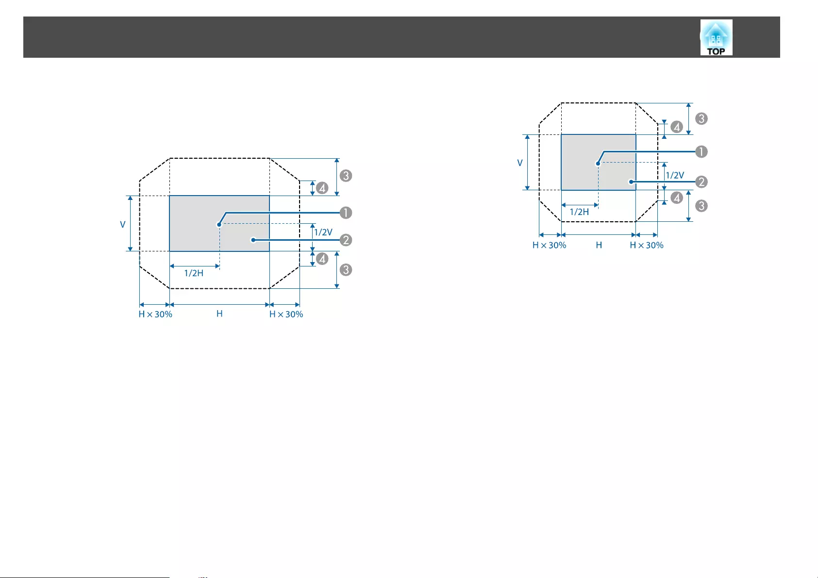
The ranges within which the image can be moved are shown below. The
position of the projected image cannot be moved to both the horizontal and
vertical maximum values.
EB-G7905U/EB-G7900U/EB-G7500U/EB-G7400U/EB-G7200W/EB-
G7000W
ACenter of lens
BProjected image when the lens position is moved to the home
position
CMaximum motion range: V x 67%
DWhen the horizontal direction is at the maximum value: V x 19%
EB-G7805/EB-G7800/EB-G7100
ACenter of lens
BProjected image when the lens position is moved to the home
position
CMaximum motion range: V x 57%
DWhen the horizontal direction is at the maximum value: V x 16%
Installing the Projector
34
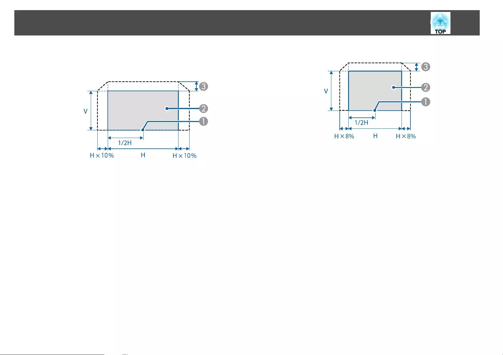
When using the ELPLX01 ultra short throw zoom lens
EB-G7905U/EB-G7900U/EB-G7500U/EB-G7400U/EB-G7200W/EB-
G7000W
ACenter of lens
BProjected image when the lens position is moved to the home
position
CMaximum motion range: V x 17%
*When the horizontal direction is at the maximum value: The image
cannot be moved upward.
EB-G7805/EB-G7800/EB-G7100
ACenter of lens
BProjected image when the lens position is moved to the home
position
CMaximum motion range: V x 7%
*When the horizontal direction is at the maximum value: The image
cannot be moved upward.
Installing the Projector
35
a
•When adjusting the image height with the vertical lens shift, adjust
by moving the image from the bottom to the top. If it is adjusted
from the top to the bottom, the image position may move down
slightly after adjusting.
•We recommend setting the focus, zoom, and lens shift at least
20 minutes after you start the projection, because images are not
stable right after turning on the projector.
•The image will be clearest when the lens position is moved to the
home position.
•If you hold down the [Lens Shift] button on the remote control or
the [Lens] button on the control panel for at least three seconds, the
lens position moves to the home position.
•If you set A/V Output to Always On, you can move the lens
position to the home position even if the projector is in standby
mode.
s Extended - A/V Settings - A/V Output p.142
•ELPLR04 does not support lens shift.
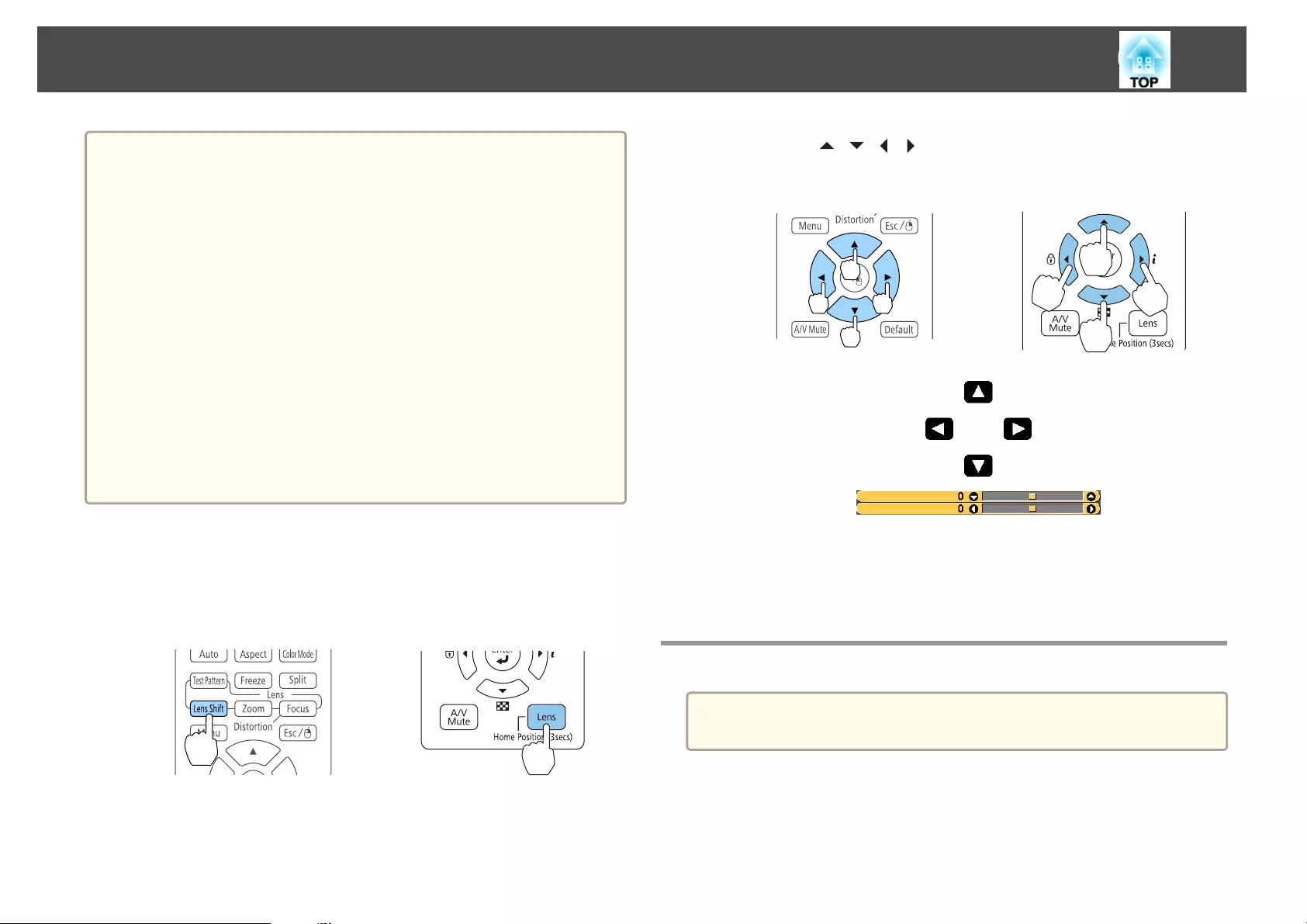
a
Press the [Lens Shift] button on the remote control or the [Lens]
button on the control panel.
Repeatedly press the [Lens] button on the control panel until the
lens shift adjustment screen is displayed.
Using the remote control Using the control panel
b
Press the [ ][ ][ ][ ] buttons to adjust the position of the
projected image.
Using the remote control Using the control panel
The displayed screen may differ depending on your lens.
c
Press the [Esc] button to finish the adjustment.
Adjusting the Image Size
a
This is not available for ELPLX01 and ELPLR04.
Installing the Projector
36
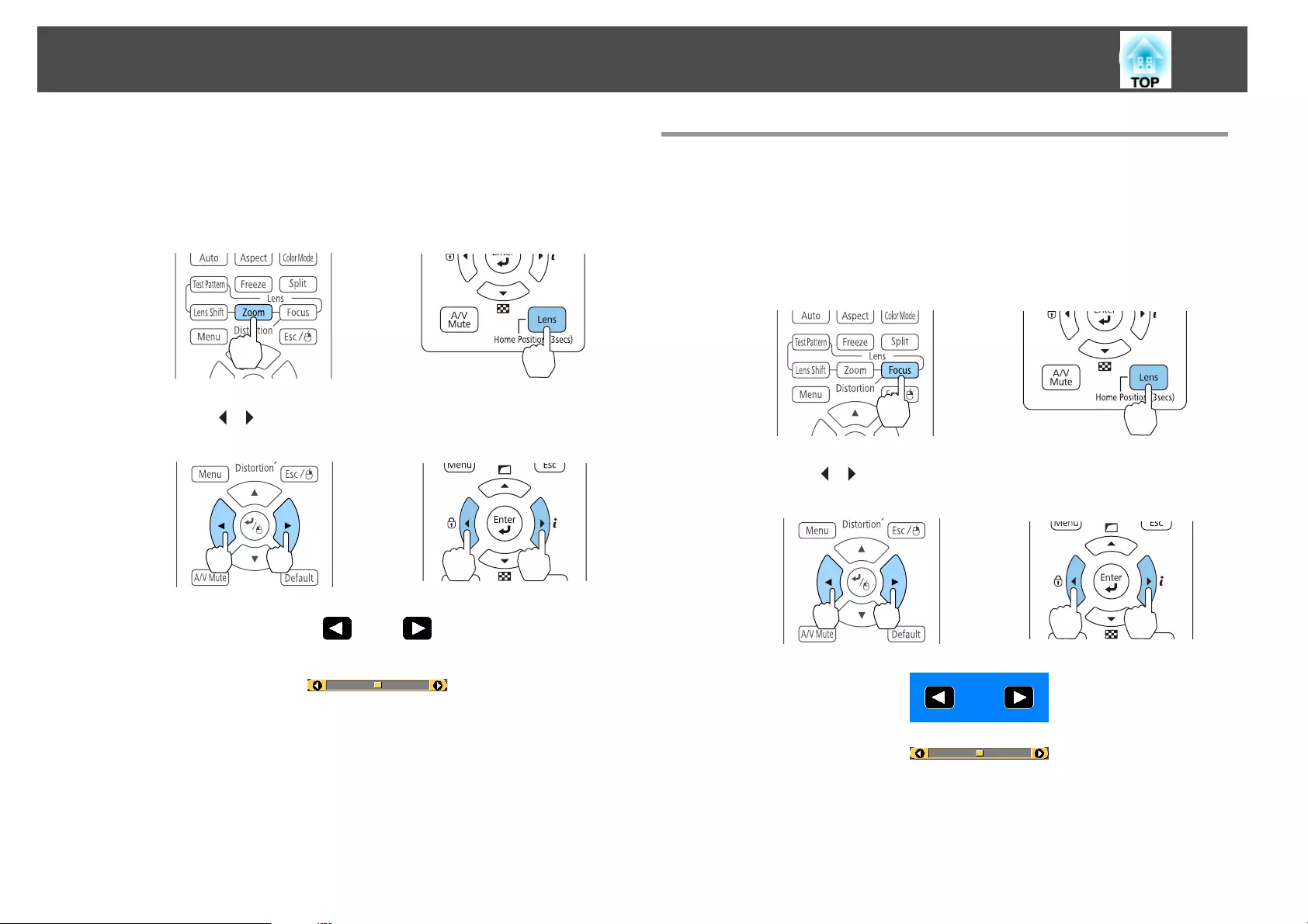
a
Press the [Zoom] button on the remote control or the [Lens]
button on the control panel.
Repeatedly press the [Lens] button on the control panel until the
zoom adjustment screen is displayed.
Using the remote control Using the control panel
b
Press the [ ][ ] buttons to adjust.
Using the remote control Using the control panel
The displayed screen may differ depending on your lens.
c
Press the [Esc] button to finish the adjustment.
Correcting the Focus
a
Press the [Focus] button or the [Lens] button on the control
panel.
Repeatedly press the [Lens] button on the control panel until the
focus adjustment screen is displayed.
Using the remote control Using the control panel
b
Press the [ ][ ] buttons to adjust.
Using the remote control Using the control panel
The displayed screen may differ depending on your lens.
Installing the Projector
37
a
When using the following lens, a message prompting you to
adjust the distortion (image warping) is displayed. After
adjusting the focus, adjust the distortion.
ELPLX01, ELPLU03, ELPLU04, ELPLW05, ELPLU02
s "Correcting Distortion (Image Warping)" p.38
c
Press the [Esc] button to finish the adjustment.
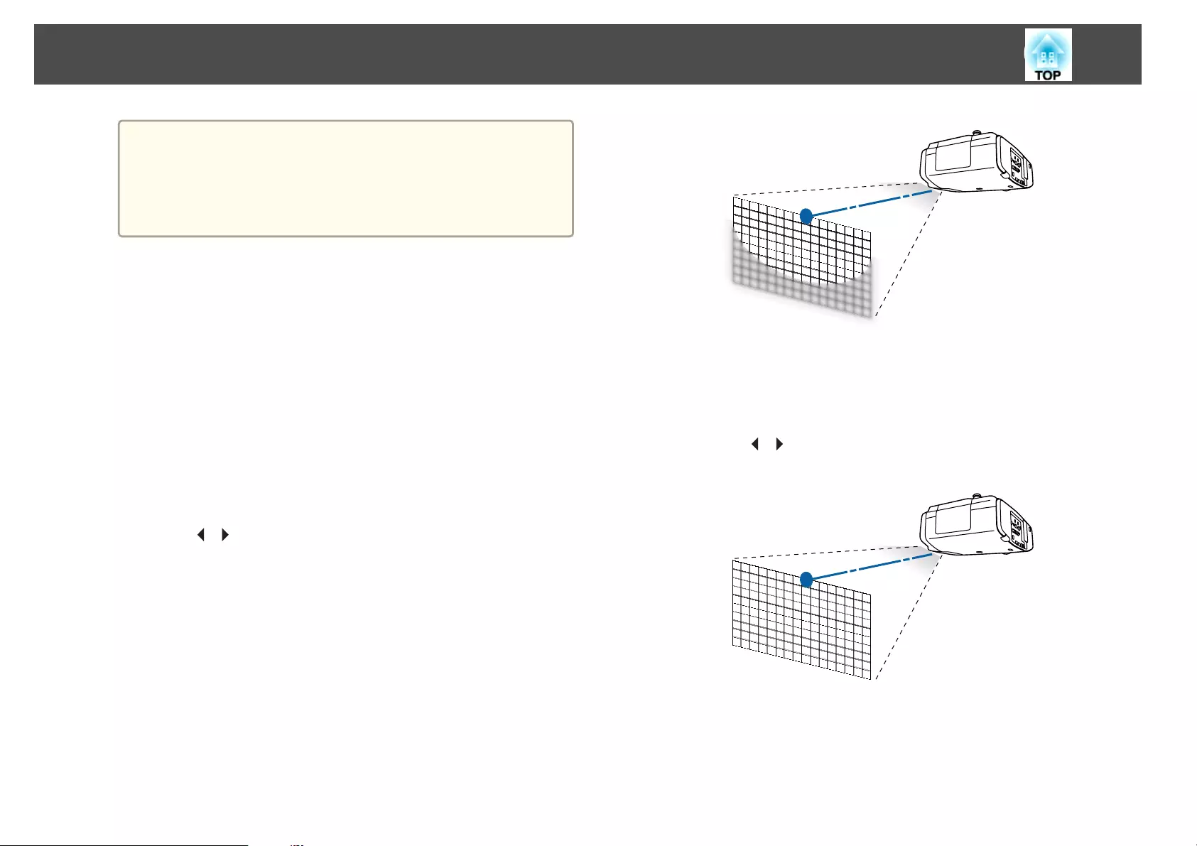
Correcting Distortion (Image Warping)
When using a short throw zoom lens and focusing at the center of the
screen, the surrounding image may warp and be out of focus. Follow the
steps below to correct the warping.
a
Press the [Focus] button on the remote control or the [Lens]
button on the control panel.
Repeatedly press the [Lens] button on the control panel until the
focus adjustment screen is displayed.
b
Press the [ ][ ] buttons to focus the image around the center of
the lens.
c
Press the [Focus] button on the remote control or the [Lens]
button on the control panel again.
d
Press the [ ][ ] button to adjust the focus of the surrounding
area.
Installing the Projector
38
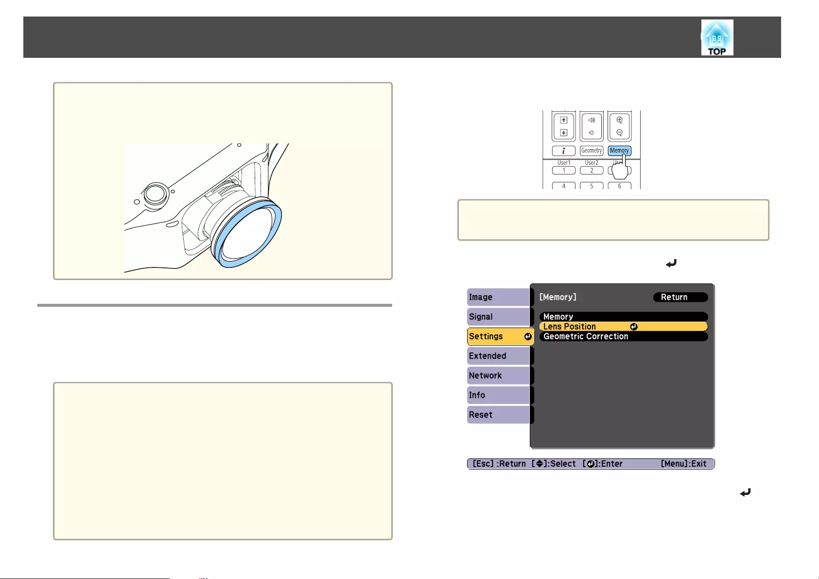
a
When using the ELPLU02, a message prompting you to manually
adjust the distortion is displayed. Turn the distortion ring
counterclockwise, and then adjust the focus. After adjusting the focus,
manually turn the distortion ring to correct the image warping.
Registering and Loading Lens Adjustment Values
You can register a lens position whose lens shift, zoom, focus, and
distortion was adjusted in memory, and load it when necessary. You can
register up to 10 values.
a
•This feature cannot be used if the following lenses are attached.
ELPLS04, ELPLU02, ELPLR04, ELPLW04, ELPLM06, ELPLM07,
ELPLL07
•If you did not calibrate your lens, a message is displayed when you
save a memory. Select Yes to calibrate the lens.
•The lens position when a memory is loaded may not completely
match the lens position when the memory was saved.
•If there is a large discrepancy between the lens position when a
memory is loaded and the lens position when the memory was
saved, calibrate the lens.
s Extended - Operation - Lens Calibration p.142
a
Press the [Memory] button while projecting.
a
You can also operate from the Configuration menu.
s Settings - Memory p.140
b
Select Lens Position, and then press the [ ] button.
c
Select the function you want to perform, then press the [ ]
button.
Installing the Projector
39
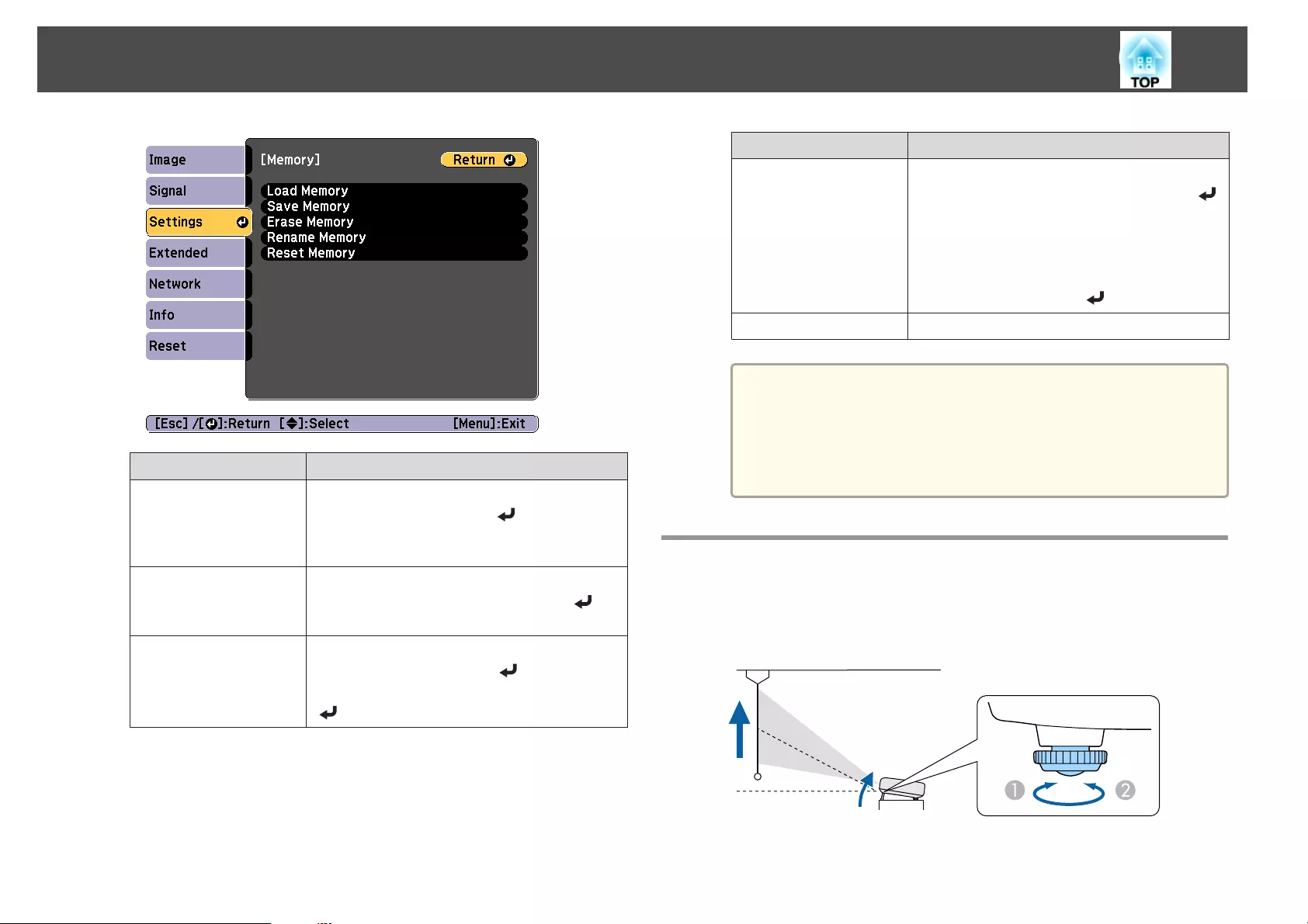
Function Explanation
Load Memory Loads the saved memory. When you select a
memory name and press the [ ] button, the lens
is automatically adjusted according to the settings
of the selected memory.
Save Memory Registers current settings in the memory. When
you select a memory name and press the [ ]
button, the settings are saved.
Erase Memory Erases the registered memory. When you select a
memory name and press the [ ] button, a
message is displayed. Select Yes, and then press the
[] button to erase the selected memory.
Function Explanation
Rename Memory Changes the memory name. Select the memory
name you want to change, and then press the [ ]
button. Enter the memory name using the soft
keyboard.
s "Soft keyboard operations" p.148
When you have finished, move the cursor over
Finish, and then press the [ ] button.
Reset Memory Resets the name and settings of a saved memory.
a
If the mark on the left of the memory name is turned blue, it
means the memory has already been registered. When you
select a registered memory, a message is displayed asking you to
confirm that you want to overwrite the memory. If you select
Yes, the previous settings are deleted and the current settings
are registered.
Adjusting the Height of the Projected Image (for
Normal Installment)
Extend or retract the front foot to make adjustments. You can adjust the
position of the image by tilting the projector up to 10 degrees.
AExtend the front foot.
Installing the Projector
40
BRetract the front foot.
a
The larger the angle of tilt, the harder it becomes to focus. Install the
projector so that it only needs to be tilted at a small angle.
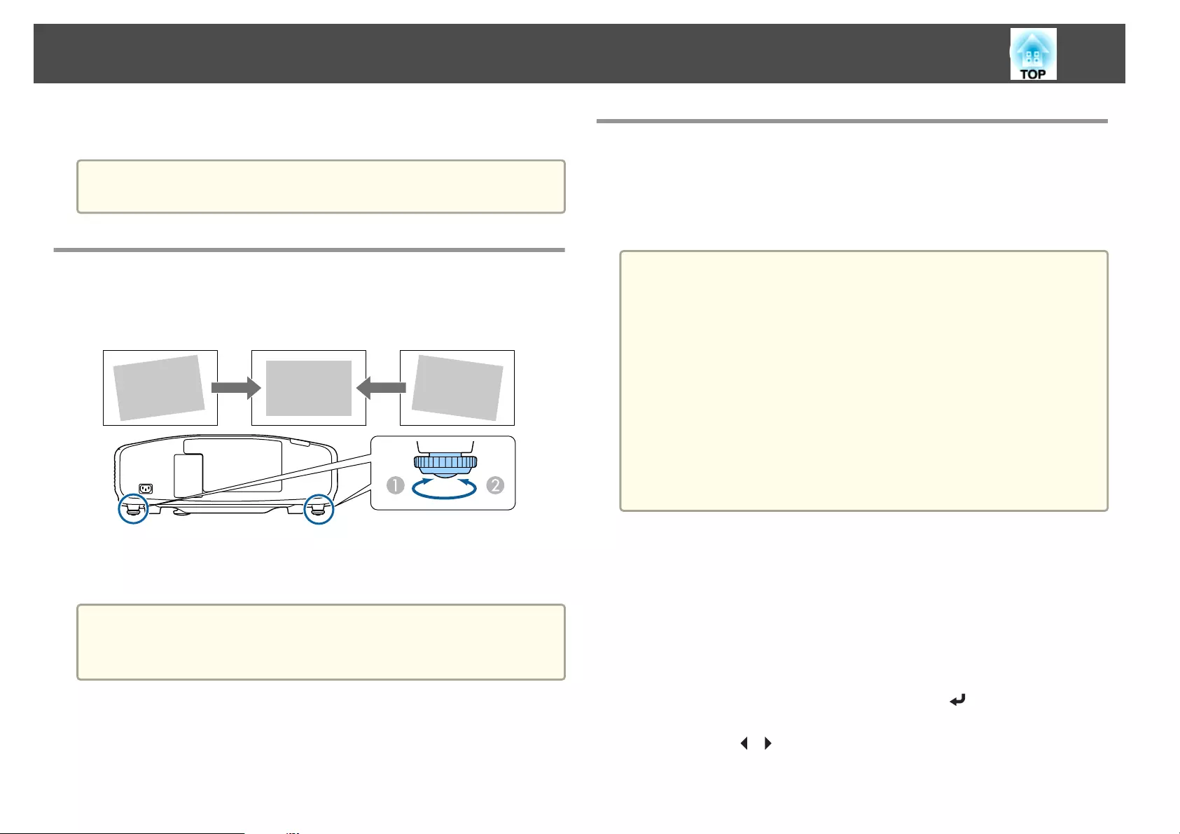
Adjusting the Horizontal Tilt (for Normal
Installment)
Extend and retract the rear feet to adjust the projector's horizontal tilt.
AExtend the rear foot.
BRetract the rear foot.
Attention
The rear feet can be attached and removed. Note that the feet will detach if
they are extended more than 10 mm.
ID Settings
When an ID is set for the projector and the remote control, you can use
the remote control to operate only the projector with a matching ID. This
is very useful when managing multiple projectors. You can set up to 30
IDs.
a
•Operation using the remote control is possible only for projectors
that are within the operating range of the remote control.
s "Remote control operating range" p.24
•When Remote Control Type is set to Simple in the configuration
menu, you cannot set the remote control ID.
s Extended - Operation - Advanced - Remote Control Type
p.142
•IDs are ignored when the projector ID is set to Off or the remote
control ID is set to 0.
•If you use Epson Web Control, you can operate a specific projector
from a mobile device.
s "Changing Settings Using a Web Browser (Epson Web Control)"
p.204
Set the projector ID
a
Press the [Menu] button while projecting.
s "Using the Configuration Menu" p.134
b
Select Multi-Projection from Extended.
c
Select Projector ID, and then press the [ ] button.
d
Press the [ ][ ] buttons to select an ID number.
Installing the Projector
41
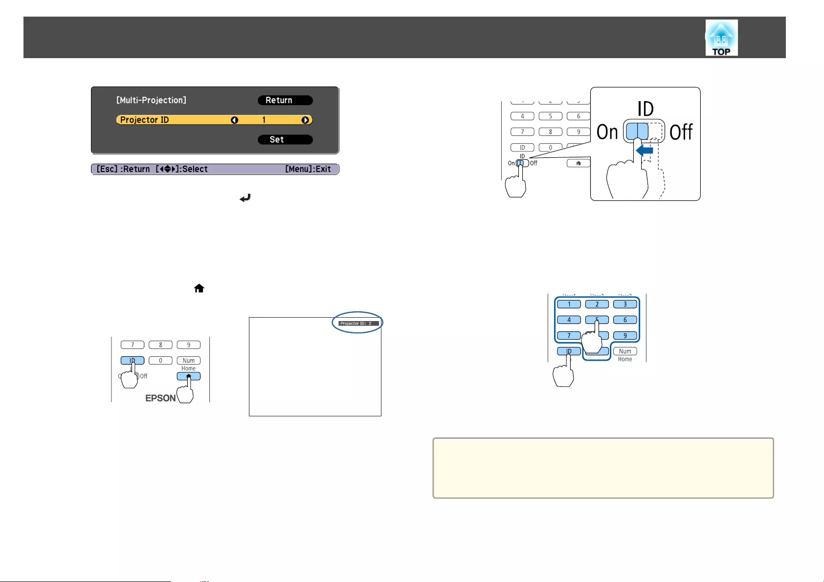
e
Select Set, and then press the [ ] button.
f
Press the [Menu] button to close the Configuration menu.
Checking the projector ID
During projection, press the [ ] button while holding down the [ID]
button.
Remote control
When you press the buttons, the current Projector ID is displayed on the
projection screen. It disappears in about three seconds.
Setting the remote control ID
a
Set the remote control [ID] switch to On.
b
While holding the [ID] button, press a number button to select a
number to match the ID of the projector you want to operate.
s "Checking the projector ID" p.42
Enter a two digit number (Example: 01 when the ID is 1).
Remote control
Once this setting has been made, the projector that can be operated by the
remote control is limited.
a
The remote control ID setting is saved in the remote control. Even if
the remote control batteries are removed to replace them and so on,
the stored ID setting is retained. However, if the batteries are left out
for a long time, it is reset to the default value (ID0).
Installing the Projector
42
Setting the Time
You can set the time for the projector. The set time is used for the schedule
function.
s "Scheduling Function" p.124
a
•When you turn on the projector for the first time, the message "Do
you want to set the time?" is displayed. When you select Yes, the
screen from step 4 is displayed.
•When Schedule Protection is set to On in Password Protection,
settings related to the date and time cannot be changed. You can
make changes after setting Schedule Protection to Off.
s "Managing Users (Password Protection)" p.127
a
Press the [Menu] button while projecting.
s "Using the Configuration Menu" p.134
b
Select Operation from Extended.
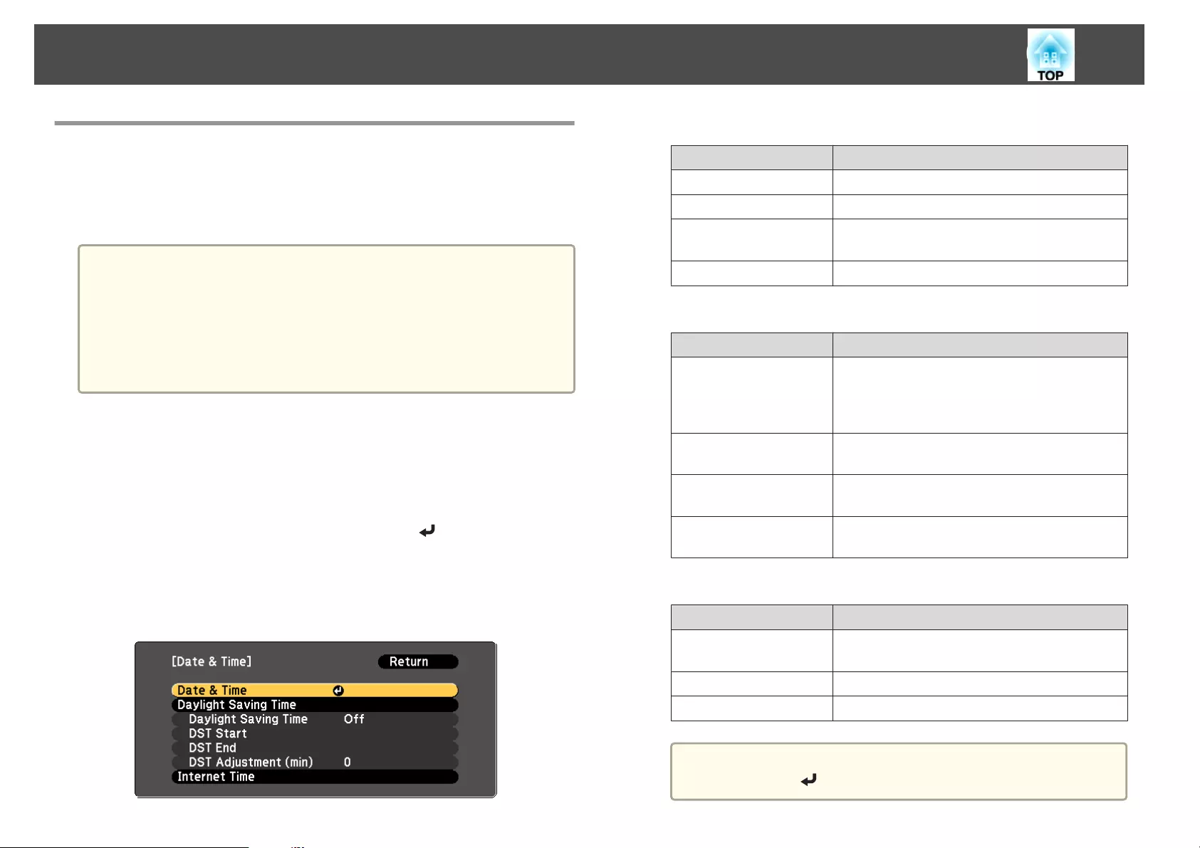
c
Select Date & Time, and then press the [ ] button.
d
Make settings for the date and time.
Use the soft keyboard to enter the date and time.
s "Soft keyboard operations" p.148
Date & Time
Submenu Function
Date Set today's date.
Time Set the current time.
Time Difference (UTC) Set the time difference from Coordinated
Universal Time.
Set The settings made in Date & Time are applied.
Daylight Saving Time
Submenu Function
Daylight Saving Time Set whether or not (On/Off) to activate the
daylight saving time. DST Adjustment (min)
adjusts the time difference between the standard
time and daylight saving time.
DST Start Set the date and time to start the daylight saving
time.
DST End Set the date and time to end the daylight saving
time.
Set The settings made in Daylight Saving Time are
applied.
Internet Time
Submenu Function
Internet Time Set to On to update the time automatically through
an Internet time server.
Internet Time Server Input the IP address for an Internet time server.
Set The settings made in Internet Time are applied.
a
When changing settings, make sure you select Set, and then
press the [ ] button.
Installing the Projector
43
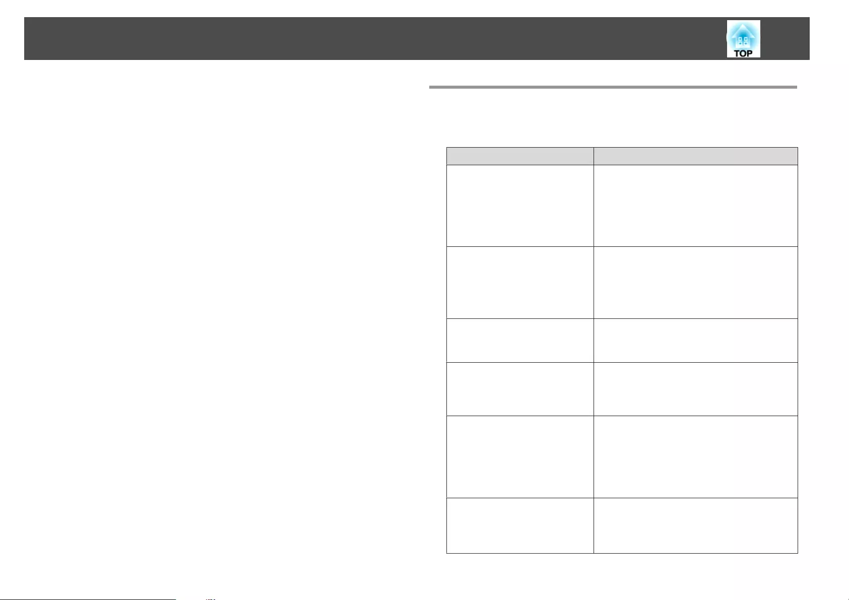
e
Press the [Menu] button to finish making settings. Other Settings
Settings related to basic operations
Purpose Setting Methods
To start/stop projection by turning
on/off the main power or plugging
in or unplugging the power plug of
the projector.
Set Direct Power On to On. (Default value: Off)
s Extended - Operation - Direct Power On
p.142
The projector can be powered off directly by the
breaker because it supports the direct shutdown
function.
To disable the automatic shutdown
function.
Set Sleep Mode to Off. (Default value: On)
s Extended - Operation - Sleep Mode p.142
Set A/V Mute Timer to Off.
s Extended - Operation - A/V Mute Settings -
A/V Mute Timer p.142
To disable buzzer beeps generated
when the projector is powered on/
off.
Set Beep to Off. (Default value: On)
s Extended - Operation - Advanced - Beep
p.142
To operate the projector by
communication command even
when the power of the projector is
off.
Set Standby Mode to Communication On.
(Default value: Communication Off)
s Extended - Standby Mode p.142
To operate the projector by
communication command while
executing A/V Mute.
Set A/V Mute Release to A/V Mute.
s Extended - Operation - A/V Mute Settings -
A/V Mute Release p.142
The default value is Any Button. If you operate
the projector while A/V Mute is on, A/V Mute is
released.
To turn off the power by pressing
the [t] button once.
Set Standby Confirmation to Off. (Default value:
On)
s Extended - Display - Standby Confirmation
p.142
Installing the Projector
44
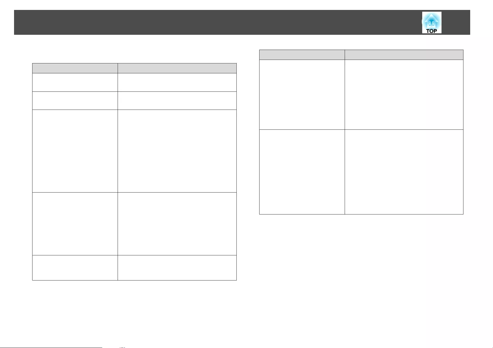
Settings related to display
Purpose Setting Methods
To change the menu position. Change the settings of Menu Position.
s Extended - Display - Menu Position p.142
To change the menu direction. Change the settings of OSD Rotation.
s Extended - Display - OSD Rotation p.142
To prevent the display of menus,
messages, or warnings on the
screen.
Use User Button to set On-Screen Display to
User Button 1, User Button 2, or User Button
3.
s Settings - User Button p.140
When you press the button for which On-Screen
Display is assigned, menus or messages are not
displayed on the screen. When the same button is
pressed, they are displayed again. If On-Screen
Display is enabled, you cannot operate the
Configuration menu (except switching the color
mode and input source).
To disable the display of the
message on the projection screen
when switching the source.
Set Messages to Off. (Default value: On)
s Extended - Display - Messages p.142
You can confirm warning by the display of the
indicator.
s "Reading the Indicators" p.166
Dialogs related to operations and behaviors, lamp
replacement notification, termination of Message
Broadcasting, and projector ID are displayed.
To reduce the display delay of the
image.
Set Image Processing to Fast 1 or Fast 2.
s Signal - Advanced - Image Processing
p.139
Purpose Setting Methods
To register and save the settings of
the projected image.
Set Memory.
s "Memory Function" p.122
You can save the following settings.
•Memory: Some settings in the Configuration
menu
•Lens Position: Adjustment values of the lens
shift, zoom, focus, and distortion
•Geometric Correction: Adjustment value of
the geometric correction
To change the screen displayed on
the background.
Change from Display. You can select from blue,
black, and logo. If no logo is registered, the
EPSON logo is displayed.
Display Background: Set the screen display with
no image signal input. (Default value: Blue)
s Extended - Display - Display Background
p.142
Startup Screen: Set whether or not (On/Off) to
display the user logo when the projector is turned
on. (Default value: On)
s Extended - Display - Startup Screen p.142
Installing the Projector
45

The port name, location, and connector orientation differ depending on the source being connected.
Connecting a Computer
To project images from a computer, connect the computer using one of the following methods.
AWhen using the supplied computer cable
Connect the computer's display output port to the projector's Computer port.
You can output audio from the projector's speaker by connecting the audio output port on the computer to the projector's Audio1 port using a commercially available audio cable.
BWhen using a commercially available 5BNC cable
Connect the computer's display output port to the projector's BNC port.
You can output audio from the projector's speaker by connecting the audio output port on the computer to the projector's Audio2 port using a commercially available audio cable.
CWhen using a commercially available HDMI cable
Connect the HDMI port on the computer to the projector's HDMI port.
You can send the computer's audio with the projected image.
DWhen using a commercially available DVI-D cable
Connect the DVI-D port on the computer to the projector's DVI-D port.
You can output audio from the projector's speaker by connecting the audio output port on the computer to the projector's Audio3 port using a commercially available audio cable.
Connecting Equipment
46
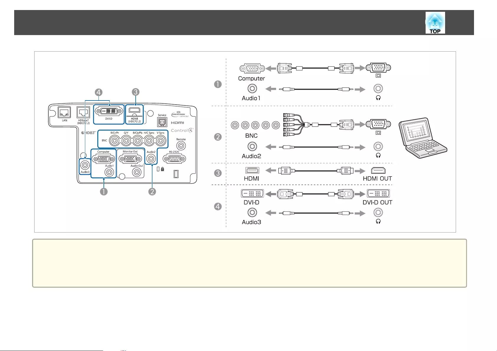
a
•Change the audio output from Audio Settings.
s Extended - A/V Settings - Audio Settings p.142
•If audio is not sent using an HDMI cable, connect a commercially available audio cable to the Audio3 port to send the audio. Set HDMI Audio Output to
Audio3.
s Extended - A/V Settings - Audio Settings - HDMI Audio Output p.142
Connecting Equipment
47
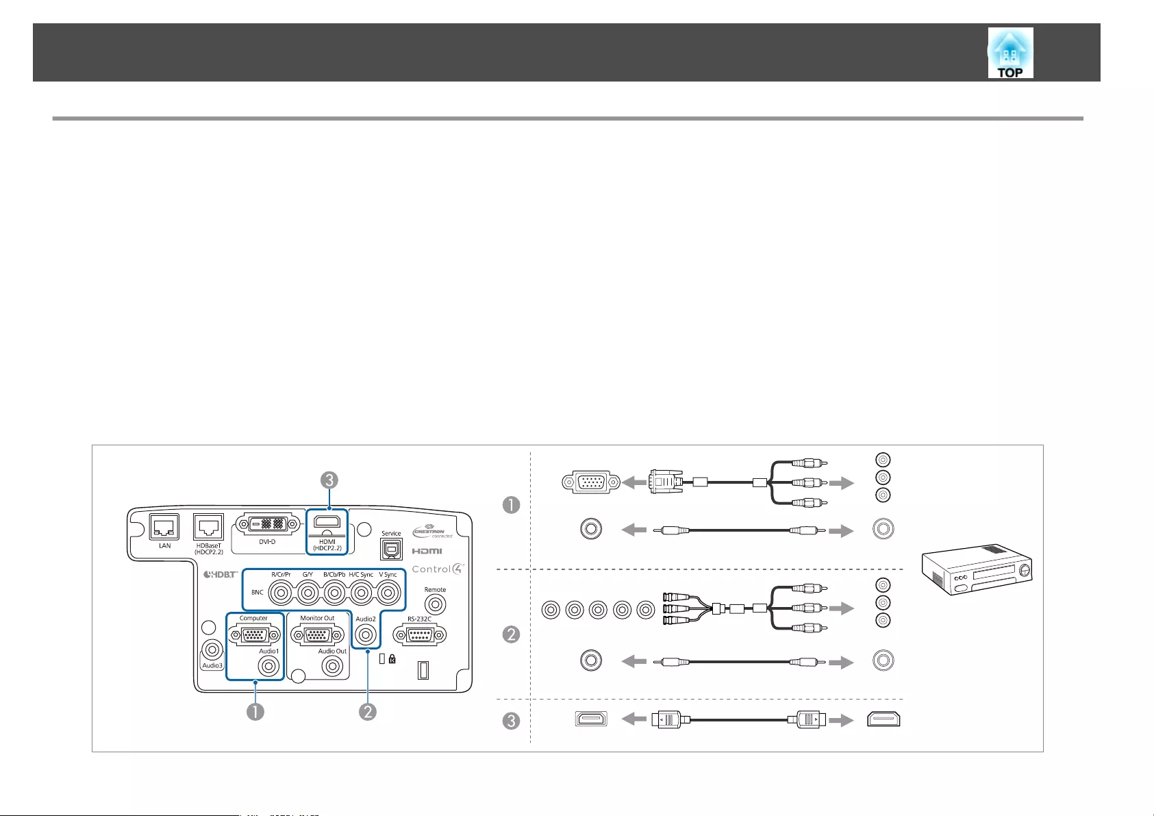
Connecting Image Sources
To project video images, connect to the projector using one of the following methods.
AWhen using an optional component video cable (D-sub/component converter)
s "Optional Accessories" p.217
Connect the component output port on the image source to the projector's Computer port.
You can output audio from the projector's speaker by connecting the audio output port on the video equipment to the projector's Audio1 port using a commercially available audio
cable.
BWhen using a commercially available component video cable (RCA) and a BNC/RCA adapter
Connect the component output port on the video equipment to the projector's BNC port (R/Cr/Pr, G/Y, B/Cb/Pb).
You can output audio from the projector's speaker by connecting the audio output port on the video equipment to the projector's Audio2 port using a commercially available audio
cable.
CWhen using a commercially available HDMI cable
Connect the HDMI port on the image source to the projector's HDMI port.
You can send the image source's audio with the projected image.
Computer
Audio1
AUDIOOUT
AUDIOOUT
Y
Cb/Pb
Cr/Pr
Y
Cb/Pb
Cr/Pr
Audio2
HDMI
HDMIOUT
BNC(R/Cr/Pr,G/Y,B/Cb/Pb)
Connecting Equipment
48
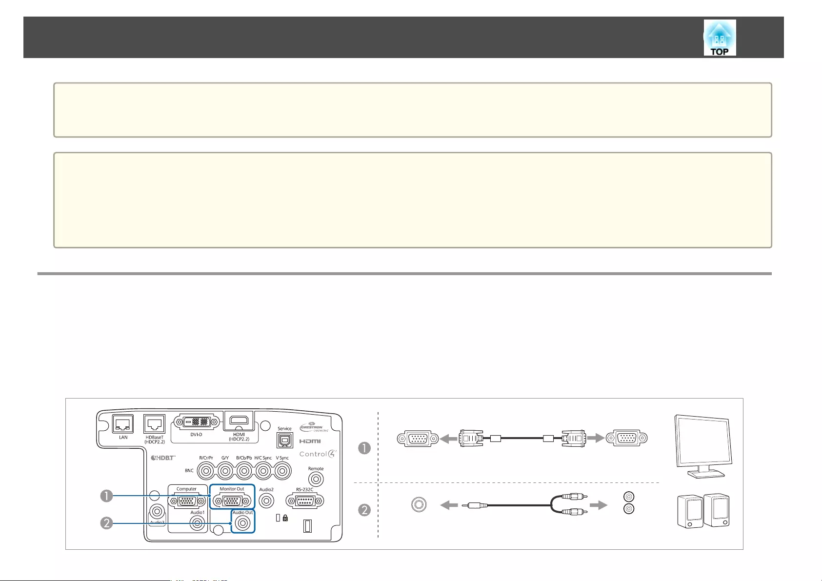
Attention
•If the input source is on when you connect it to the projector, it could cause a malfunction.
•If the orientation or shape of the plug differs, do not try to force it in. The device could be damaged or could malfunction.
a
•Change the audio output from Audio Settings.
s Extended - A/V Settings - Audio Settings p.142
•If audio is not sent using an HDMI cable, connect a commercially available audio cable to the Audio3 port to send the audio. Set HDMI Audio Output to
Audio3.
s Extended - A/V Settings - Audio Settings - HDMI Audio Output p.142
•If the source you want to connect to has an unusually shaped port, use the cable supplied with the device or an optional cable to connect to the projector.
Connecting External Equipment
You can output images and audio by connecting an external monitor or speaker.
AWhen outputting images to an external monitor
Connect the external monitor to the projector's Monitor Out port using the cable supplied with the external monitor.
BWhen outputting audio to an external speaker
Connect the external speaker to the projector's Audio Out port using a commercially available audio cable.
MonitorOut D-Sub
AudioOut AudioIN
Connecting Equipment
49
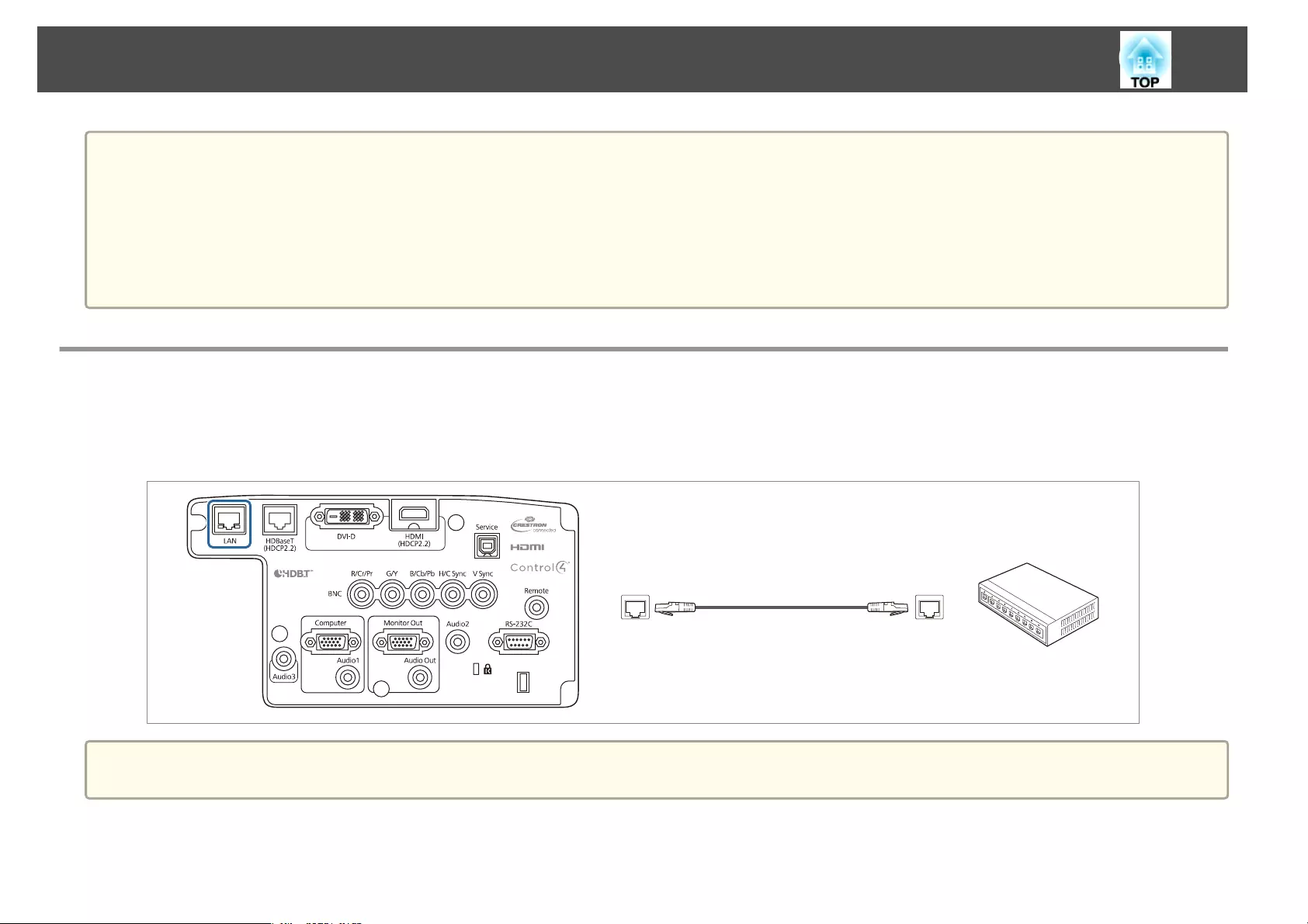
a
•Make the following settings to output image and audio even when the projector is in standby mode.
Set A/V Output to Always On.
s Extended - A/V Settings - A/V Output p.142
•Only analog RGB signals from the Computer port or BNC port can be output to an external monitor. You can set which signals to output in Monitor
Out.
s Extended - A/V Settings - Monitor Out p.142
•When the audio cable jack is inserted into the Audio Out port, audio stops being output from the projector's built-in speakers and switches to external
output.
Connecting a LAN Cable
Connect a LAN port on network hubs or other equipment to the projector's LAN port with a commercially available 100BASE-TX or 10BASE-T LAN
cable.
By connecting a computer to the projector over a network, you can project images and check the status of the projector.
LAN
a
To prevent malfunctions, use a category 5 or higher shielded LAN cable.
Connecting Equipment
50
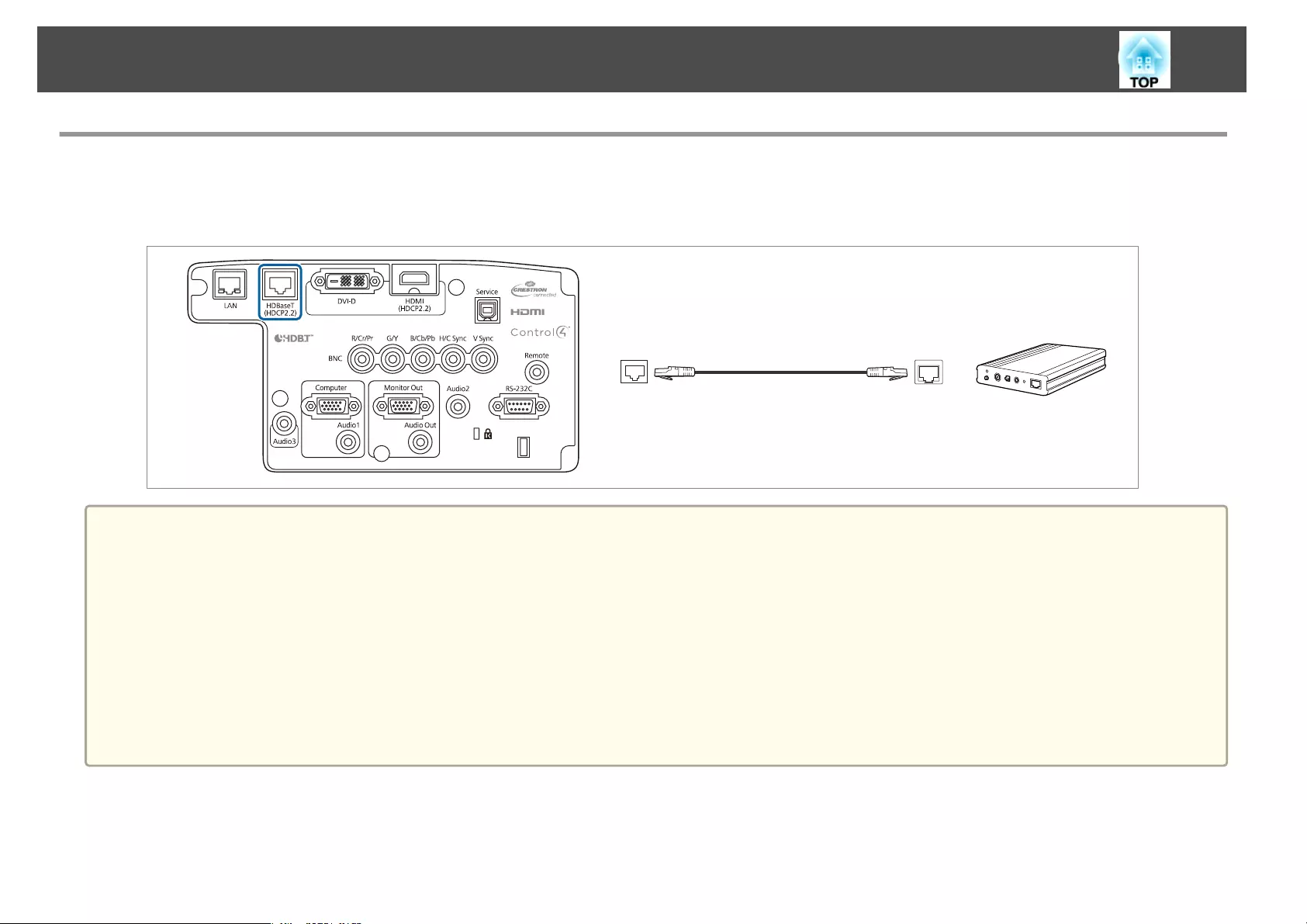
Connecting an HDBaseT Transmitter
Connect the optional HDBaseT Transmitter with a commercially available 100BASE-TX LAN cable.
s "Optional Accessories" p.217
HDBaseT
a
•Make sure you read the User's Guide supplied with the HDBaseT Transmitter carefully before use.
•For the LAN cable, use an HDBaseT Alliance-recommended STP cable (straight) of category 5e or higher. However, operation is not guaranteed for all
input/output devices and environments.
•When connecting or disconnecting the LAN cable, make sure you turn off the power for the projector and the HDBaseT Transmitter.
•When performing Ethernet communication or serial communication, or when using the wired remote control via HDBaseT port, set Control Communications
to On from the Configuration menu.
s Extended - HDBaseT - Control Communications p.142
Note that when Control Communications is set to On, the projector's LAN port, RS-232C port, and Remote port are disabled.
•When using the Extron XTP transmitter or switcher, connect to the projector's HDBaseT port. Set Extron XTP to On (Standby Mode and Control
Communications are automatically set to On).
s Extended - HDBaseT - Extron XTP p.142
Connecting Equipment
51
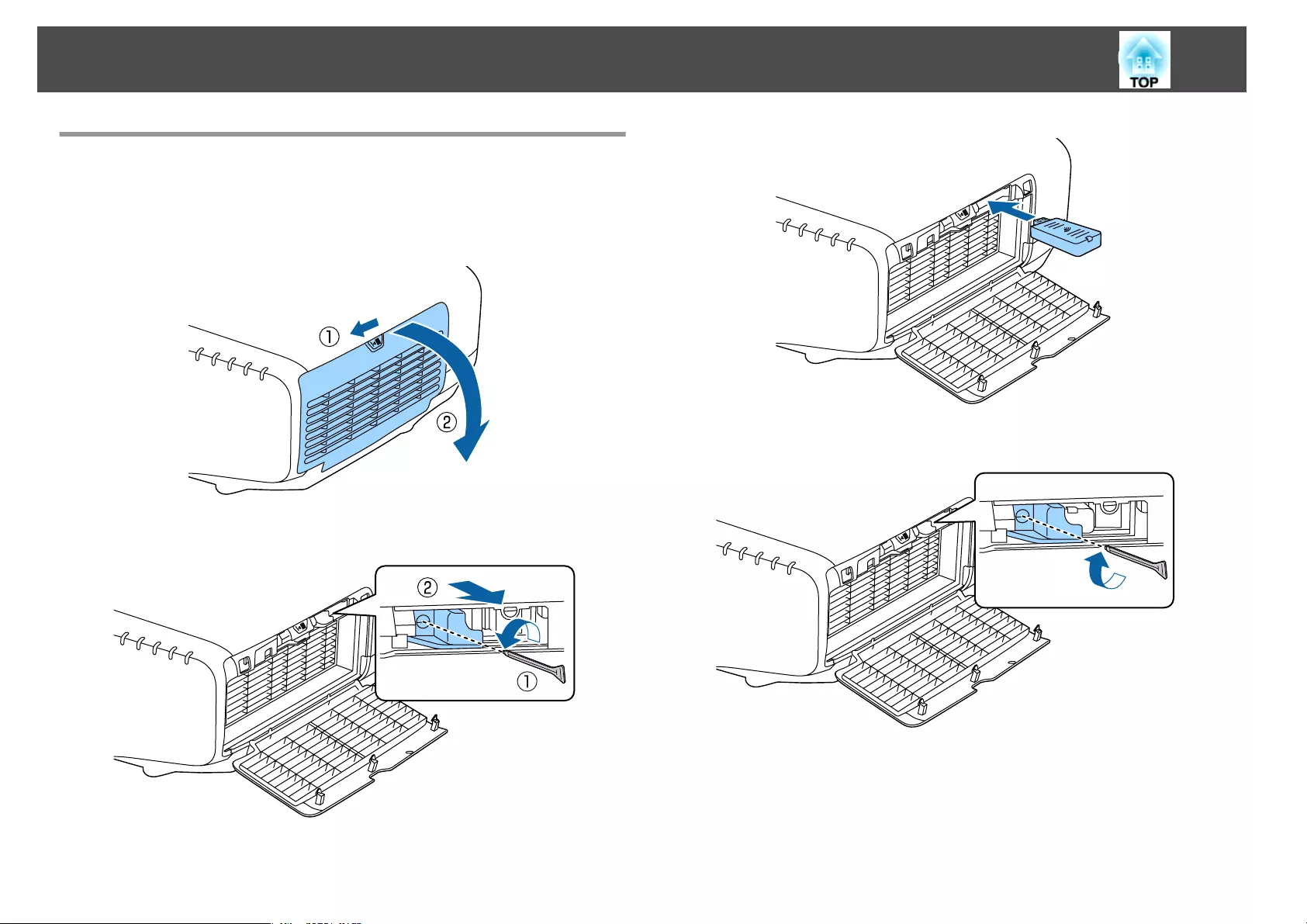
Installing the Wireless LAN Unit
a
Open the air filter cover.
Slide the air filter cover operation knob, and open the air filter
cover.
b
Remove the stopper for the Wireless LAN unit.
c
Install the Wireless LAN unit.
d
Secure the stopper with a screw.
e
Close the air filter cover.
Connecting Equipment
52
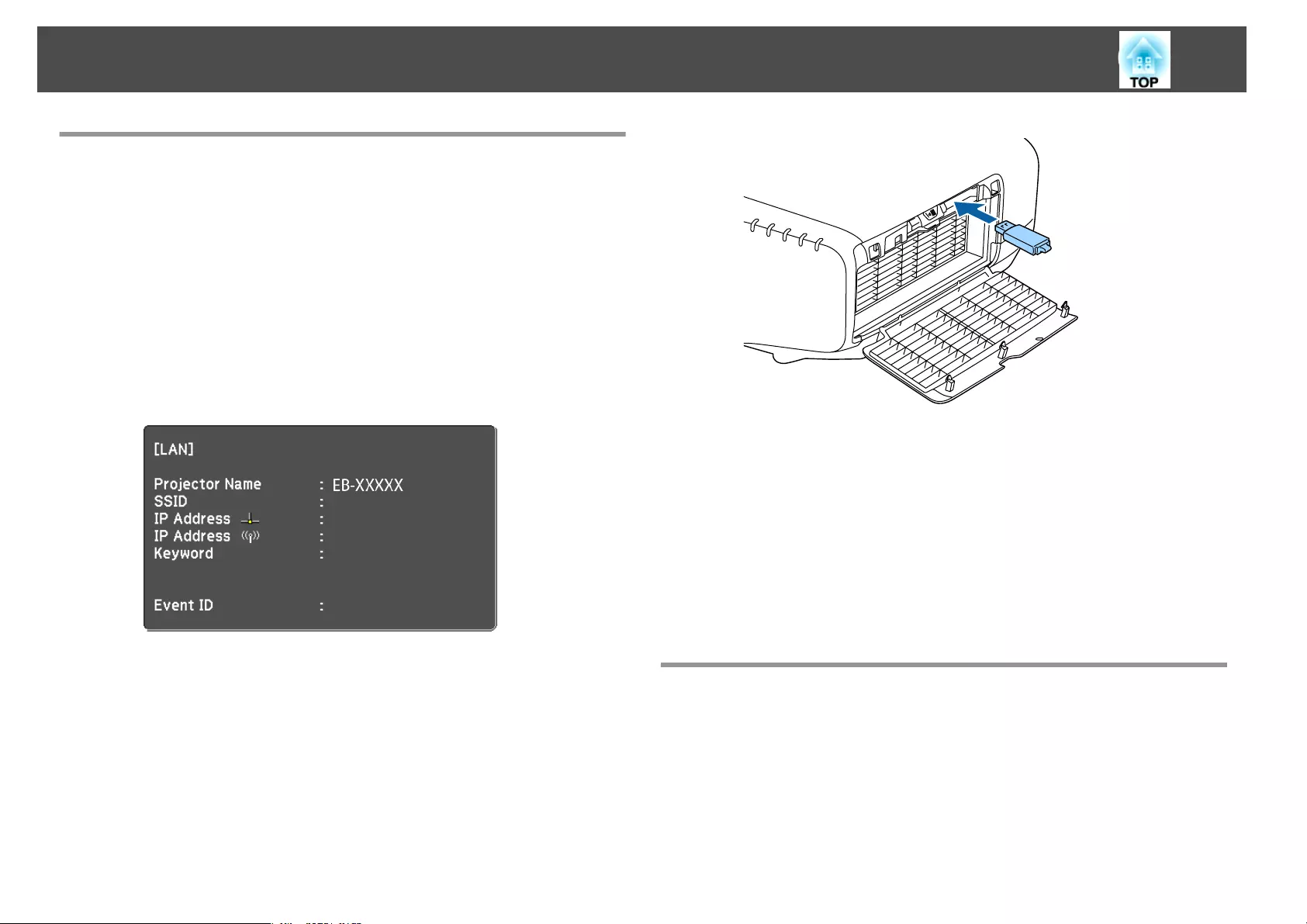
Using the Quick Wireless Connection USB Key
Connect the optional Quick Wireless Connection USB Key to the wireless
LAN unit installation section. Check the following points when connecting
a computer to the projector using wireless LAN.
•The wireless LAN unit (ELPAP10) is connected to the projector.
•The projector is setup to connect to the network using wireless LAN.
s "Wireless LAN menu" p.149
a
Turn on the projector, and then press the [LAN] button on the
remote control.
The following screen is displayed.
b
Check that the SSID and IP address information are displayed, and
then remove the wireless LAN unit.
s "Installing the Wireless LAN Unit" p.52
c
Insert the Quick Wireless Connection USB Key in the wireless LAN
unit installation section.
d
When the message "Network information update complete.
Remove the Quick Wireless Connection USB Key Adapter." is
displayed, remove the Quick Wireless Connection USB Key.
After removing the Quick Wireless Connection USB Key, reattach
the wireless LAN unit.
e
Connect the Quick Wireless Connection USB Key to the computer.
From this point on, see the user's guide supplied with the Quick
Wireless Connection USB Key.
Attaching the Cable Cover
By attaching the cable cover, you can hide the connected cables giving a
nice, clean finish to the projector installation. (The illustrations are of a
projector installed on a ceiling.)
Connecting Equipment
53
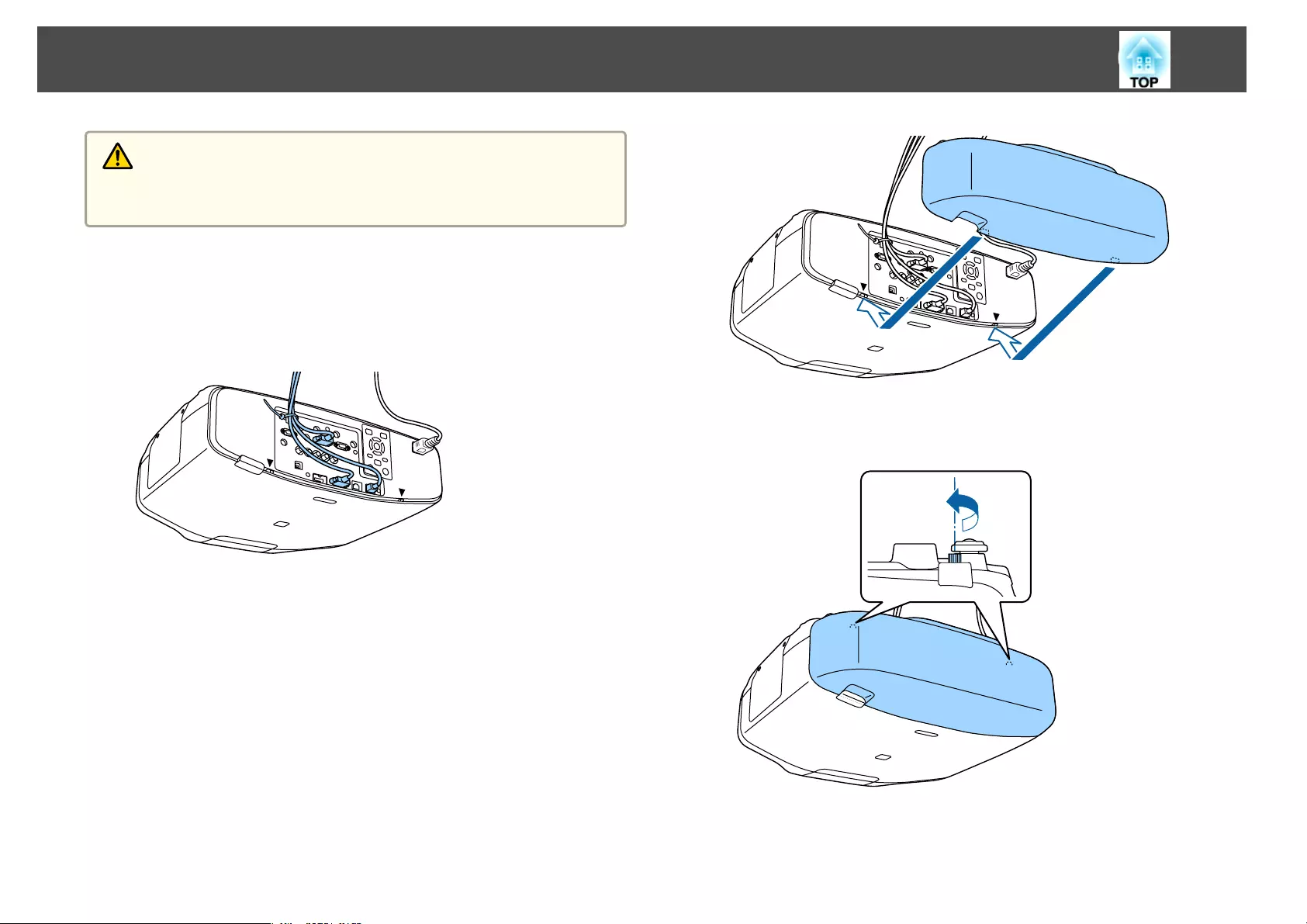
Warning
Do not tie the power cord and other connection cables together. Otherwise, it
could cause a fire.
Attaching
a
Run a commercially available cable tie through the cable holder
and tie the cables together.
b
Insert the tabs on the cable cover into the two slots on the back
of the projector.
c
Tighten the two screws on the cable cover. (You can tighten the
screws with your fingers.)
Connecting Equipment
54

Basic Usage
This chapter explains how to project and adjust images.
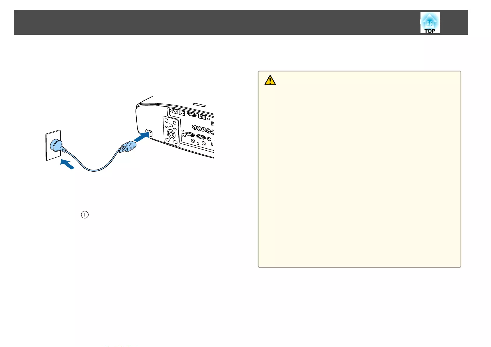
Before turning on the projector, connect your computer or video equipment
to the projector.
s "Connecting Equipment" p.46
a
Connect the projector to an electrical outlet with the power cord.
The projector's power indicator turns blue (it is in standby mode).
This indicates that the projector is receiving power, but is not yet
turned on.
b
Press the [ ] button on the control panel or remote control to
turn on the projector.
The confirmation buzzer beeps and the status indicator flashes blue
as the projector warms up. Once the projector is warmed up, the
status indicator stops flashing and turns blue.
If the image is not projected, try the following.
•Turn on the connected computer or video equipment.
•When using a laptop computer, change the screen output of the
computer.
•Insert media such as a DVD and play it back.
•Press the [Search] button on the control panel or the remote control to
detect the input source.
•Press the button for the input source that you want to project by using
the remote control.
•If the Home screen is displayed, select the input source that you want
to project.
Warning
•Do not look into the projector's lens during projection. Doing so may
damage your eyes. Be especially careful if children are present.
•During projection, do not block the light from the projector with a book and
so on. If the light from the projector is blocked for a long time, the area on
which the light shines becomes hot which could cause it to melt, burn, or
start a fire. Also, the lens may get hot due to the reflected light which could
cause the projector to malfunction. To stop projection, use the A/V Mute
function or turn off the projector.
•A mercury lamp with high internal pressure is used as the projector's light
source. If the lamp is subjected to vibrations, shocks, or if it is used for an
overly extended length of time, the lamp may explode with a loud noise or it
may not turn on. If the lamp explodes, gases may escape and small fragments
of glass may be scattered which could cause an injury. Be sure to observe the
instructions below.
- Do not disassemble or damage the lamp or subject it to any impact.
- Do not bring your face close to the projector while it is in use.
- Particular care should be taken when you must clean or replace the lamps
by yourself, as small pieces of glass may injure you or enter your eyes or
mouth. (When you open the lamp cover, small shards of glass could fall
out.)
If the lamp explodes, ventilate the area immediately, and contact a doctor if
any fragments of broken glass are inhaled or get into the eyes or mouth. In
addition, consult your local regulations regarding proper disposal and do not
place in the trash.
Turning On the Projector
56
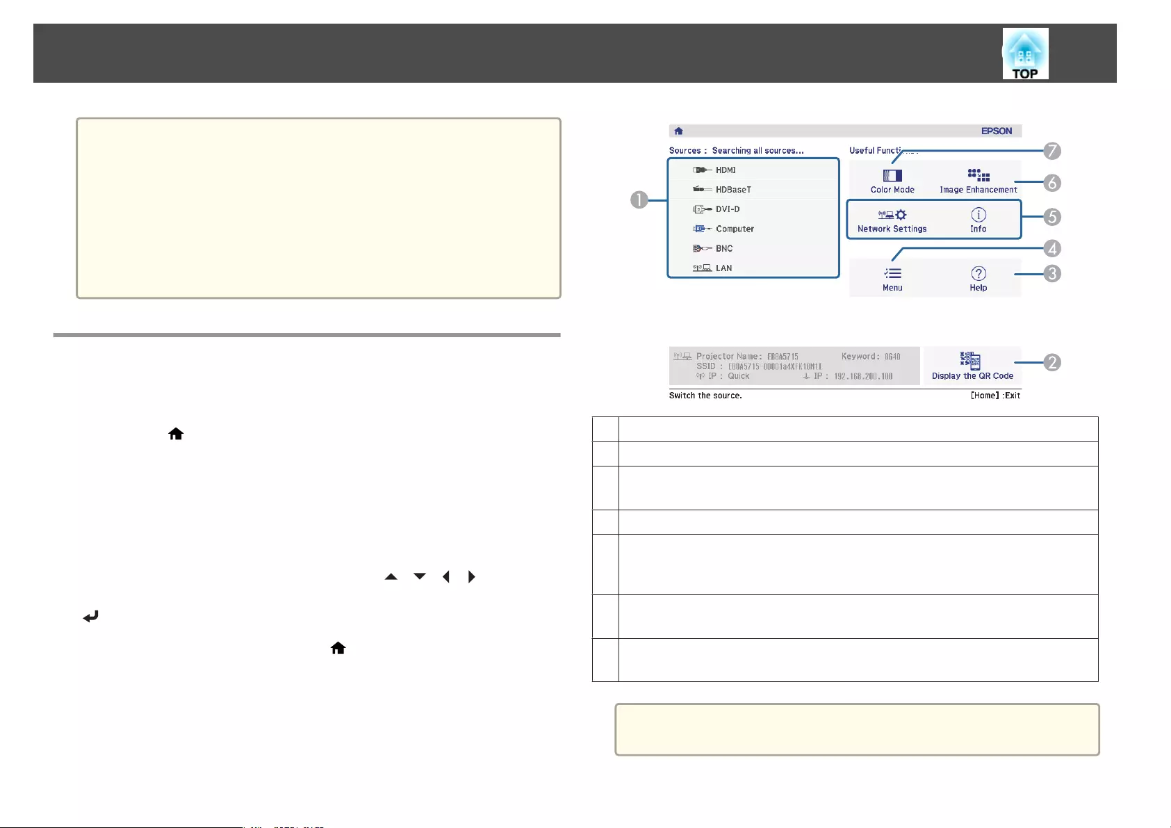
a
•If Direct Power On is set to On in the Extended menu, the
projector automatically turns on when the power cord is connected
to it. When the power cord is plugged in, note that the projector
turns on automatically in cases such as recovery from a power
outage.
s Extended - Operation - Direct Power On p.142
•If an image signal from the source selected in Auto Power On is
input, the projector automatically turns on.
s Extended - Operation - Auto Power On p.142
Home screen
You can use the Home screen to easily select input sources or frequently
used functions. The Home screen is displayed in the following situations.
•When the [ ] button on the remote control is pressed
•When the projector is turned on while Home Screen Auto Disp. is set
to On
s Extended - Home Screen - Home Screen Auto Disp. p.142
•When there is no signal from the selected input source when the
projector is turned on
When the Home screen is displayed, use the [ ][ ][ ][ ] buttons on
the control panel or remote control to select an item, and then press the
[] button.
To hide the Home screen, press the [ ] button on the remote control
again.
ASelect the input source that you want to project.
BDisplays the QR code and projects the data of a smartphone or tablet.
CDisplays the Help screen.
s "Using the Help" p.164
DDisplays the Configuration menu.
EExecutes the function assigned to Custom Function 1 or Custom Function 2 in the
Extended menu.
s Extended - Home Screen - Custom Function 1, Custom Function 2 p.142
FYou can adjust the image resolution.
s "Adjusting Image Resolution (Image Enhancement)" p.97
GSelect a color mode.
s "Selecting the Projection Quality (Selecting Color Mode)" p.87
a
The Home screen disappears after 10 minutes of inactivity.
Turning On the Projector
57
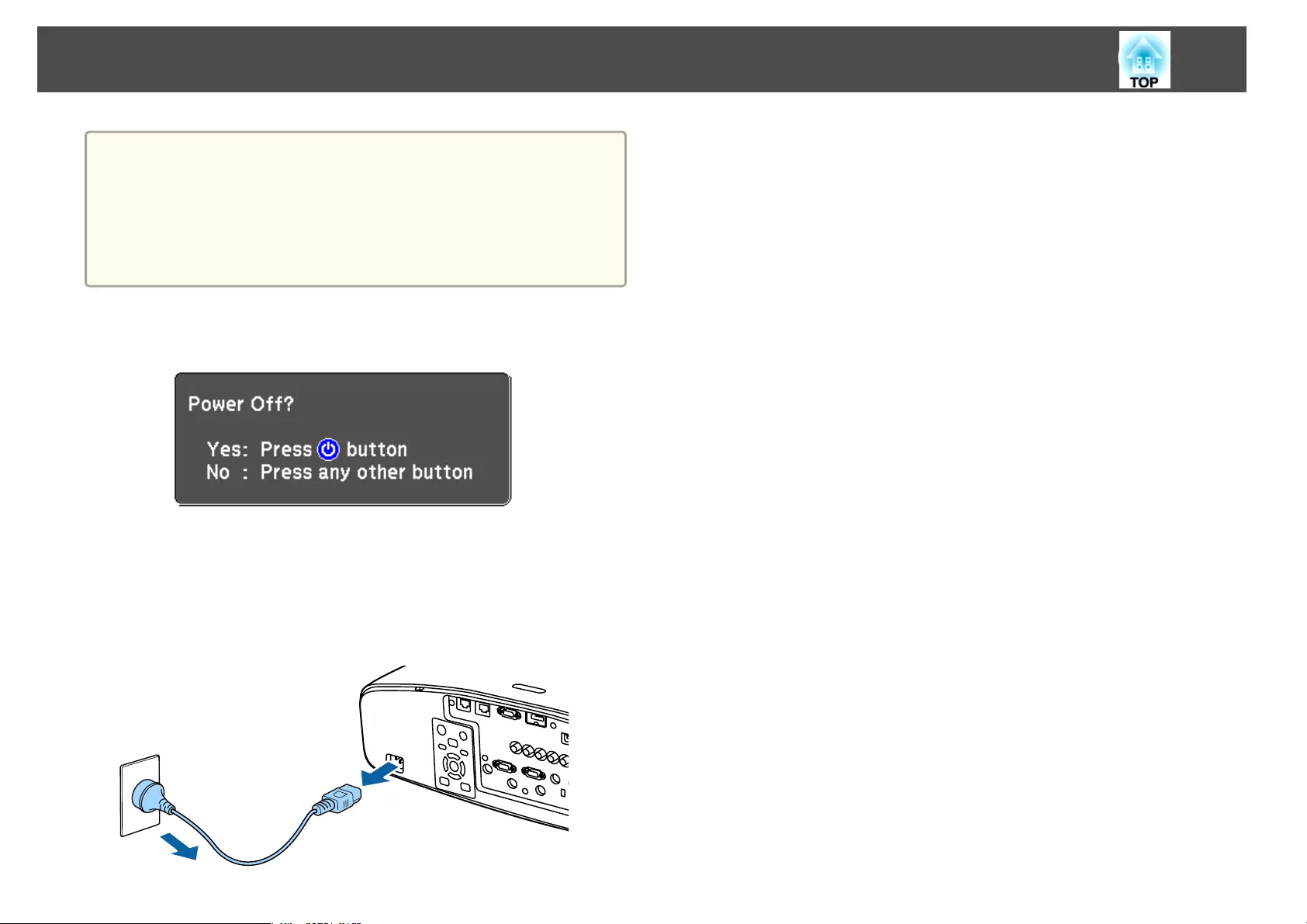
a
•To ensure a long projector service life, turn off the projector when
you are not using it. The lamp's operating life varies depending on
the Configuration menu settings, environmental conditions, and
usage conditions. The brightness of the projected image drops as
projection time elapses.
•The projector can be powered off directly by the breaker because it
supports the direct shutdown function.
a
Press the [t] button on the control panel or the remote control.
The shutdown confirmation screen is displayed.
b
Press the [t] button again. (To cancel, press any other button.)
After the buzzer beeps twice, the projected image disappears, and the
status indicator turns off.
c
Disconnect the power cord.
Turning Off the Projector
58
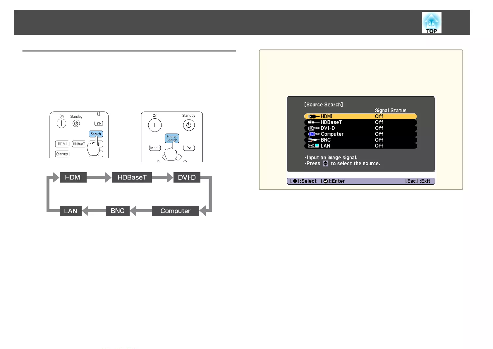
Automatically Detecting Input Signals and
Changing the Projected Image (Source Search)
Press the [Search] button to project images from the port currently
receiving an image.
Using the remote control Using the control panel
When two or more image sources are connected, repeatedly press
the [Search] button until the target image is projected.
When your video equipment is connected, start playback before beginning
this operation.
a
•You can set up the projector so that it automatically detects an
image signal from another input source and projects the image when
there is no image signal from the current input source.
s Extended - Operation - Auto Source Search p.142
•The following screen is displayed while no image signals are input.
Projecting Images
59
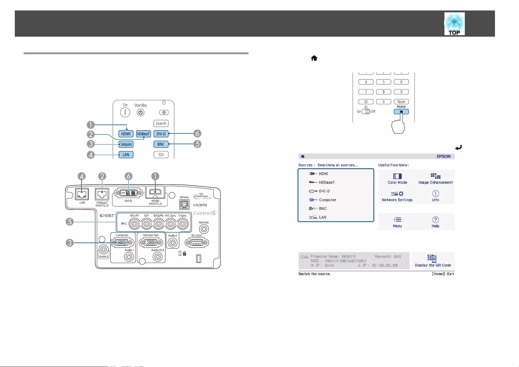
Switching to the Target Image by Remote Control
•Press the button of the input source that you want to project.
The input ports for the buttons are shown below.
Remote control
Input Port
DChanges to images from a computer connected via the network.
•Press the [ ] button.
Remote control
Select the input source to be projected, and then press the [ ] button.
Projecting Images
60
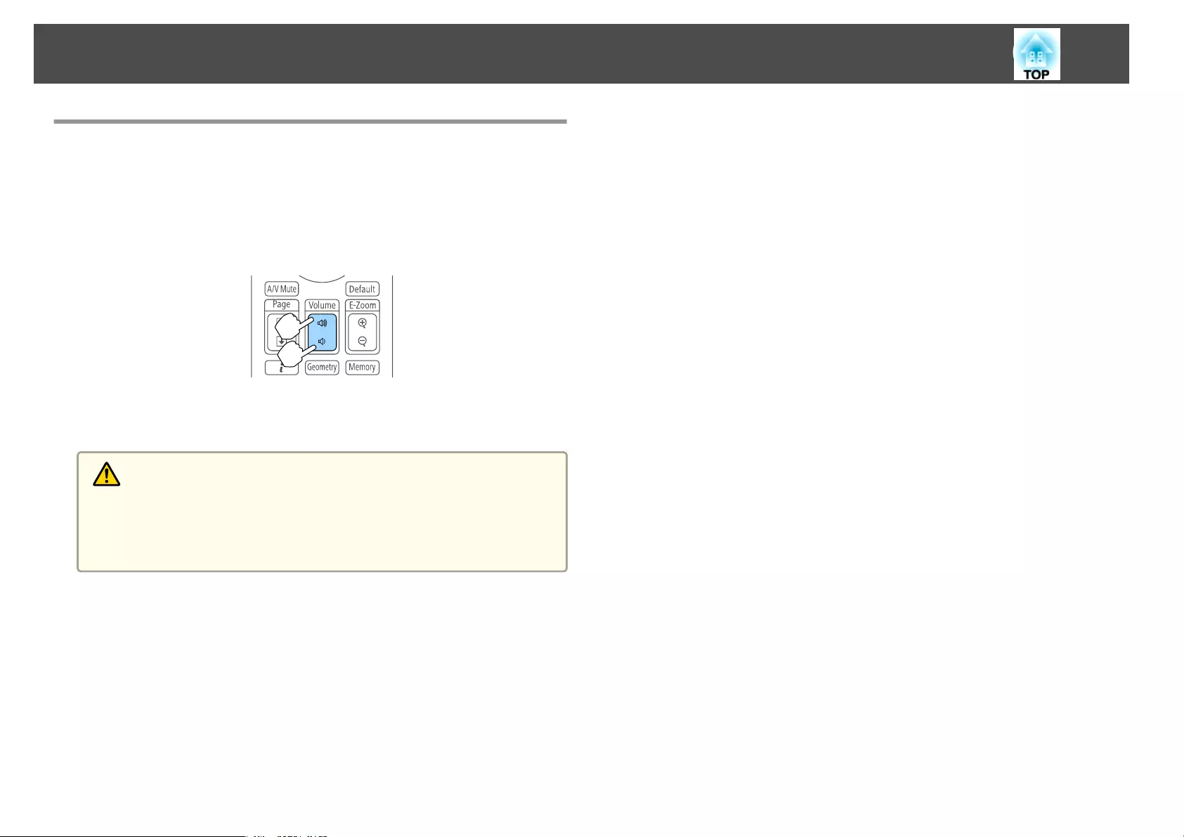
Adjusting the Volume
You can adjust the volume using one of the following methods.
•Press the [Volume] buttons on the remote control to adjust the volume.
[a] Decreases the volume.
[b] Increases the volume.
Remote control
•Adjust the volume from the Configuration menu.
s Settings - Volume p.140
Caution
Do not start at high volume.
A sudden excessive volume may cause loss of hearing. Always lower the volume
before powering off, so that you can power on and then gradually increase the
volume.
Projecting Images
61
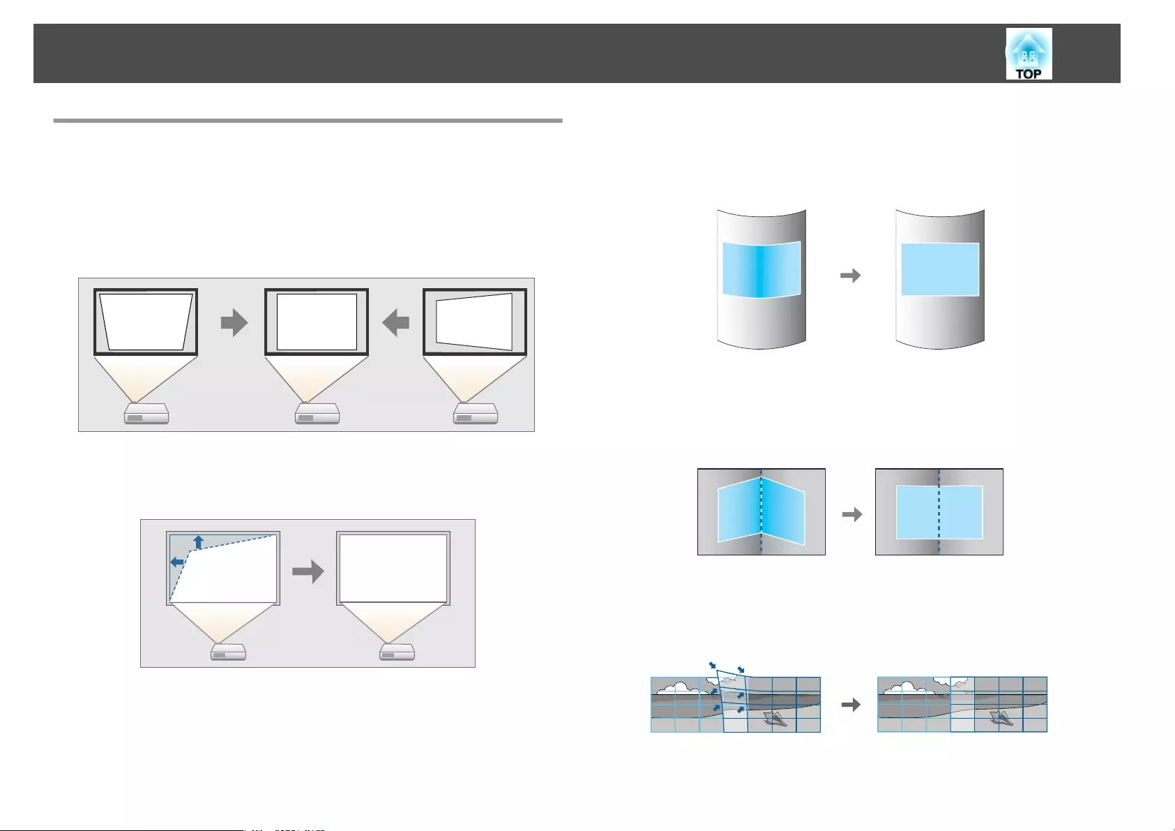
Correcting Distortion in the Projected Image
You can correct keystone distortion in projected images using one of the
following methods.
•H/V-Keystone
Correct distortion in the horizontal and vertical directions independently.
s "H/V-Keystone" p.63
•Quick Corner
Correct the four corners independently.
s "Quick Corner" p.64
•Curved Surface
Correct distortion that occurs when projecting on a curved surface, and
adjust the amount of expansion and contraction.
s "Curved Surface" p.65
•Corner Wall
Correct distortion that occurs when projecting on a surface with right
angles, such as a square pillar or the corner of a room, and adjust the
amount of expansion and contraction.
s "Corner Wall" p.76
•Point Correction
Corrects slight distortion which occurs partially, or adjusts the image
position in an overlapping area when projecting from multiple projectors.
s "Point Correction" p.86
Adjusting Projected Images
62
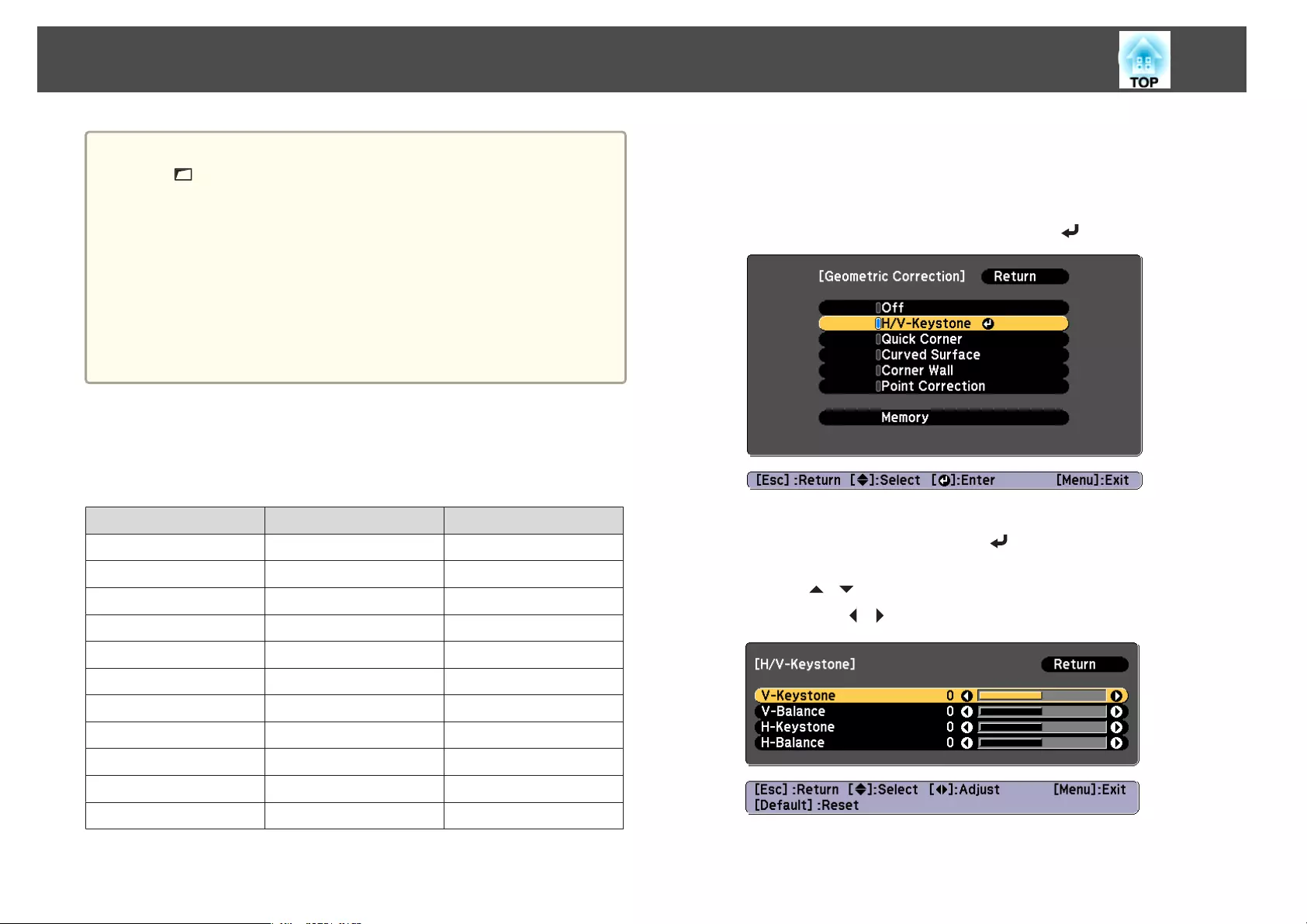
a
•By pressing the [Geometry] button on the remote control or the
[] button on the control panel, you can perform the selected
adjustment method directly.
•When you want to re-adjust the projection position and so on, if
you want to release the correction status temporarily, set the
Geometric Correction to Off. Even when it is set to Off, the
correction values are saved.
s Settings - Geometric Correction p.140
•You can save the geometric correction settings using Memory in
Geometric Correction, and load them when needed.
s "Memory Function" p.122
H/V-Keystone
This allows you to correct distortion in the horizontal and vertical
directions independently. The correction ranges are as follows.
Lens type Vertical Horizontal
ELPLM08
*
-45˚ to 45˚ -30˚ to 30˚
ELPLX01 -16˚ to 16˚ -16˚ to 16˚
ELPLU03 -28˚ to 28˚ -28˚ to 28˚
ELPLU04/ELPLU02 -35˚ to 35˚ -30˚ to 30˚
ELPLR04 -34˚ to 34˚ -30˚ to 30˚
ELPLW05 -40˚ to 40˚ -30˚ to 30˚
ELPLW06/ELPLW04 -45˚ to 45˚ -30˚ to 30˚
ELPLM09/ELPLS04 -45˚ to 45˚ -30˚ to 30˚
ELPLM10/ELPLM06 -45˚ to 45˚ -30˚ to 30˚
ELPLM11/ELPLM07 -45˚ to 45˚ -30˚ to 30˚
ELPLL08/ELPLL07 -45˚ to 45˚ -30˚ to 30˚
*The lens equipped to models with lenses.
a
Press the [Menu] button while projecting.
b
Select Geometric Correction from Settings.
c
Select H/V-Keystone, and then press the [ ] button.
If the message "If this setting is changed, the image may be
distorted." is displayed, press the [ ] button.
d
Use the [ ][ ] buttons to select the correction method, and
then use the [ ][ ] buttons to make the corrections.
Adjusting Projected Images
63
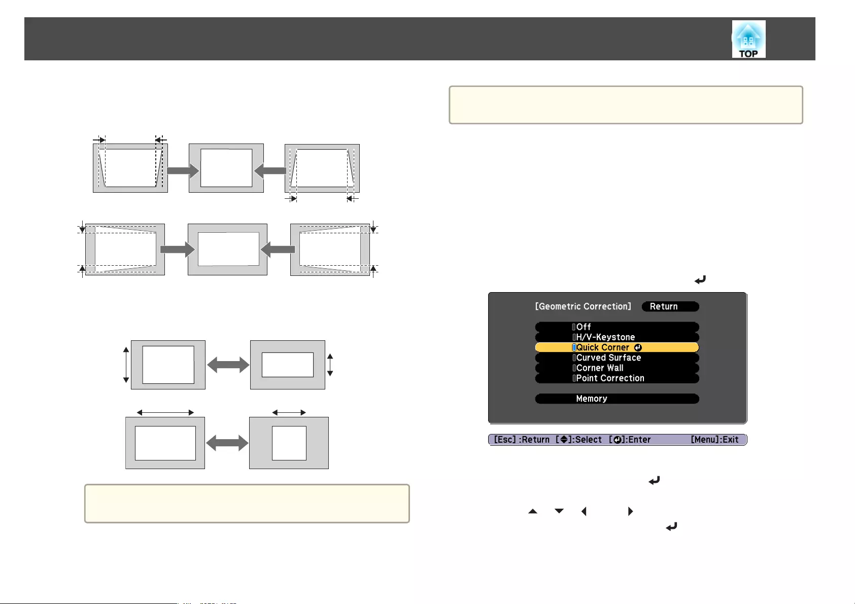
Correct the keystone distortion by using V-Keystone and H-
Keystone.
V-Keystone
H-Keystone
If the image aspect is incorrect, adjust the image balance by using
V-Balance and H-Balance.
V-Balance
H-Balance
a
When you correct keystone distortion, the projected image may
be reduced.
e
To complete the corrections, press the [Menu] button.
a
You cannot combine with other correction methods.
Quick Corner
This allows you to correct each of the four corners of the projected image
independently.
a
Press the [Menu] button while projecting.
b
Select Geometric Correction from Settings.
c
Select Quick Corner, and then press the [ ] button.
If the message "If this setting is changed, the image may be
distorted." is displayed, press the [ ] button.
d
Use the [ ], [ ], [ ], and [ ] buttons to select the corner you
want to adjust, and then press the [ ] button.
Adjusting Projected Images
64
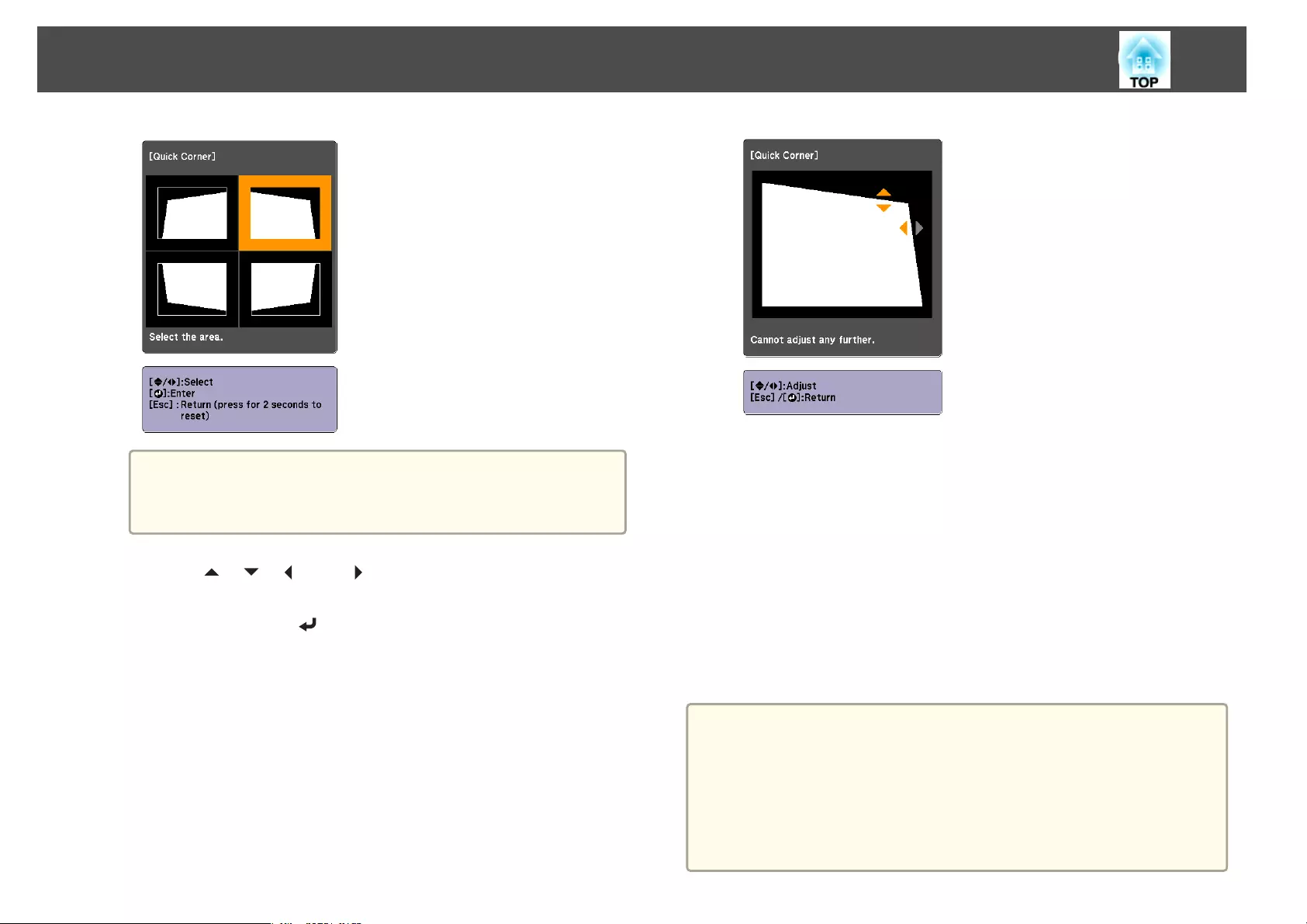
a
If the [Esc] button is pressed for approximately two seconds,
the confirm default reset screen is displayed.
Select Yes to reset the result of Quick Corner corrections.
e
Use the [ ], [ ], [ ], and [ ] buttons to correct the position of
the corner.
When you press the [ ] button, the screen shown in step 5 that
allows you to select the area to be corrected is displayed.
If the message "Cannot adjust any further."is displayed while
adjusting, you cannot adjust the shape any further in the direction
indicated by the gray triangle.
f
Repeat steps 4 and 5 as needed to adjust any remaining corners.
g
To complete the corrections, press the [Menu] button.
Curved Surface
This allows you to correct distortion that occurs when projecting on a
curved surface, and adjust the amount of expansion and contraction.
Face the projector directly opposing the screen with the lens position
moved to the home position.
s "Adjusting the Position of the Projected Image (Lens Shift)" p.33
a
•Project onto an arc surface with the same radius.
•If a large amount of adjustment is performed, the focus may not be
uniform even after making adjustments.
•If 4K Enhancement is enabled, a message is displayed. Select Yes to
disable 4K Enhancement. (EB-G7905U/EB-G7900U/EB-G7500U/EB-
G7400U only)
s Image - Image Enhancement - 4K Enhancement p.137
Adjusting Projected Images
65
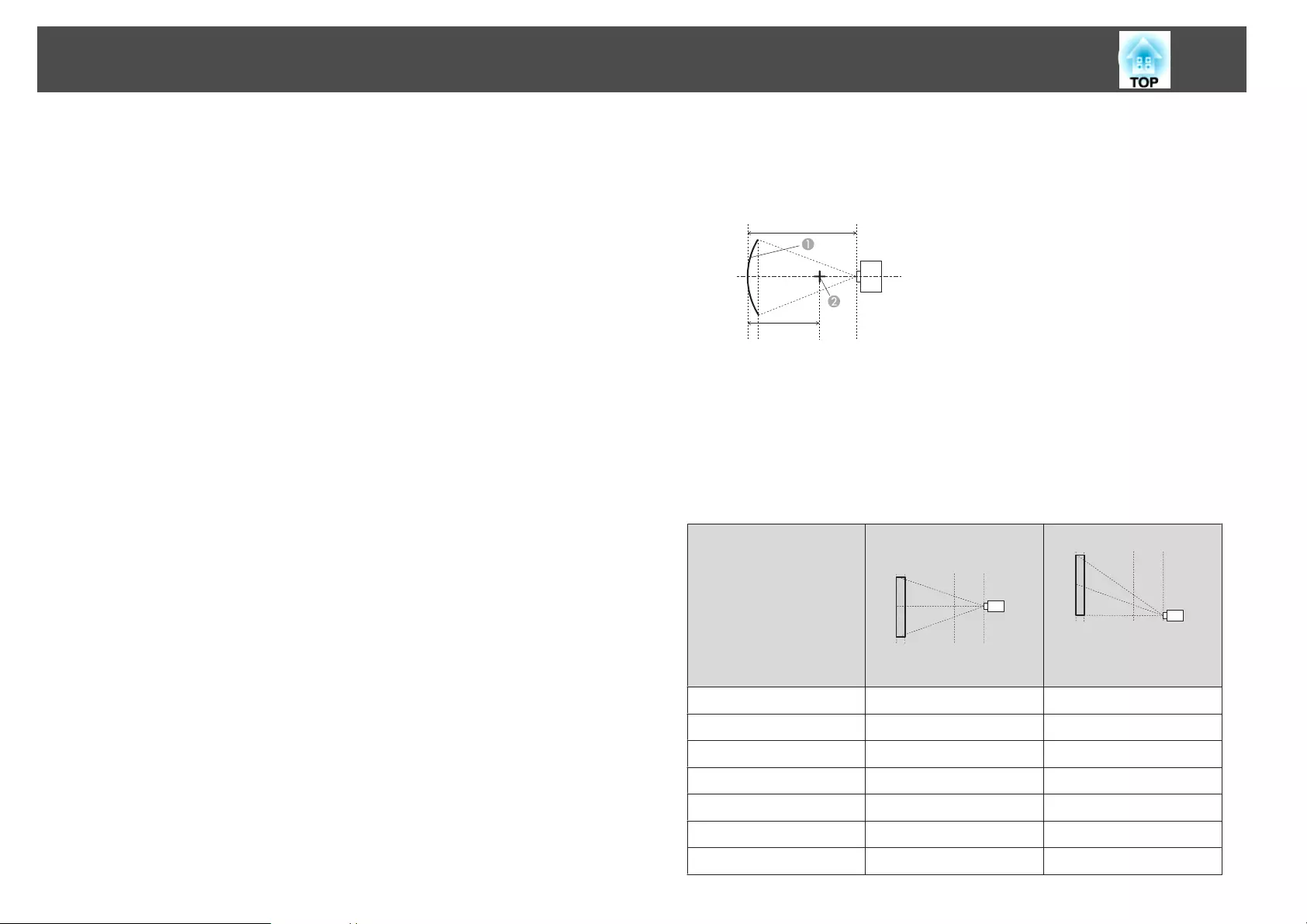
Correction range
The correction ranges are indicated in the following tables. The lens for
projectors with built-in lens is ELPLM08.
EB-G7905U/EB-G7900U/EB-G7500U/EB-G7400U/EB-G7200W/EB-
G7000W
Horizontally curved surface (concave)
L
R
AScreen
BCenter of the circle of which the
curved surface is an arc
L Projection distance
R Radius of the circle of which the
curved surface is an arc
Top view
The minimum values of R/L in the figure above are indicated in the table
below.
(Approximate value when projecting at maximum zoom. ELPLR04 does not
support lens shift.)
Lens type Vertical lens shift:
Home position
Side view
Vertical lens shift: Top
Side view
ELPLM08 0.29 0.30
ELPLX01 - 2.74
ELPLU03 0.45 0.56
ELPLU04/ELPLU02 0.39 0.40
ELPLR04 0.37 -
ELPLW05 0.35 0.37
ELPLW06/ELPLW04 0.26 0.27
Adjusting Projected Images
66
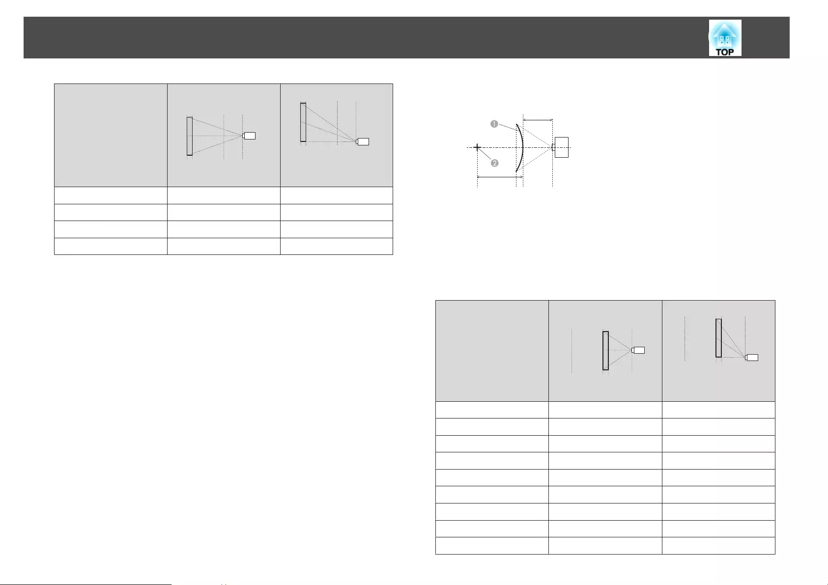
Lens type Vertical lens shift:
Home position
Side view
Vertical lens shift: Top
Side view
ELPLM09/ELPLS04 0.21 0.22
ELPLM10/ELPLM06 0.15 0.15
ELPLM11/ELPLM07 0.11 0.11
ELPLL08/ELPLL07 0.08 0.08
Horizontally curved surface (convex)
L
R
AScreen
BCenter of the circle of which the
curved surface is an arc
L Projection distance
R Radius of the circle of which the
curved surface is an arc
Top view
The minimum values of R/L in the figure above are indicated in the table
below.
(Approximate value when projecting at maximum zoom. ELPLR04 does not
support lens shift.)
Lens type Vertical lens shift:
Home position
Side view
Vertical lens shift: Top
Side view
ELPLM08 0.58 0.62
ELPLX01 - 8.45
ELPLU03 2.13 2.31
ELPLU04/ELPLU02 1.27 1.37
ELPLR04 1.10 -
ELPLW05 0.95 1.01
ELPLW06/ELPLW04 0.49 0.52
ELPLM09/ELPLS04 0.33 0.35
ELPLM10/ELPLM06 0.20 0.20
Adjusting Projected Images
67
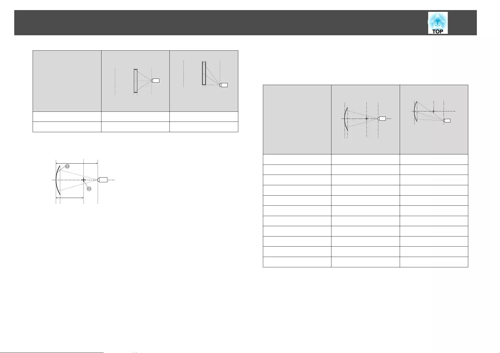
Lens type Vertical lens shift:
Home position
Side view
Vertical lens shift: Top
Side view
ELPLM11/ELPLM07 0.13 0.13
ELPLL08/ELPLL07 0.09 0.09
Vertically curved surface (concave)
L
R
AScreen
BCenter of the circle of which the
curved surface is an arc
L Projection distance
R Radius of the circle of which the
curved surface is an arc
Side view
The minimum values of R/L in the figure above are indicated in the table
below.
(Approximate value when projecting at maximum zoom. ELPLR04 does not
support lens shift.)
Lens type Vertical lens shift:
Home position
Side view
Vertical lens shift: Top
Side view
ELPLM08 0.21 0.25
ELPLX01 - 1.99
ELPLU03 0.37 0.68
ELPLU04/ELPLU02 0.31 0.44
ELPLR04 0.29 -
ELPLW05 0.27 0.35
ELPLW06/ELPLW04 0.19 0.22
ELPLM09/ELPLS04 0.15 0.17
ELPLM10/ELPLM06 0.11 0.11
ELPLM11/ELPLM07 0.08 0.08
ELPLL08/ELPLL07 0.06 0.06
Adjusting Projected Images
68
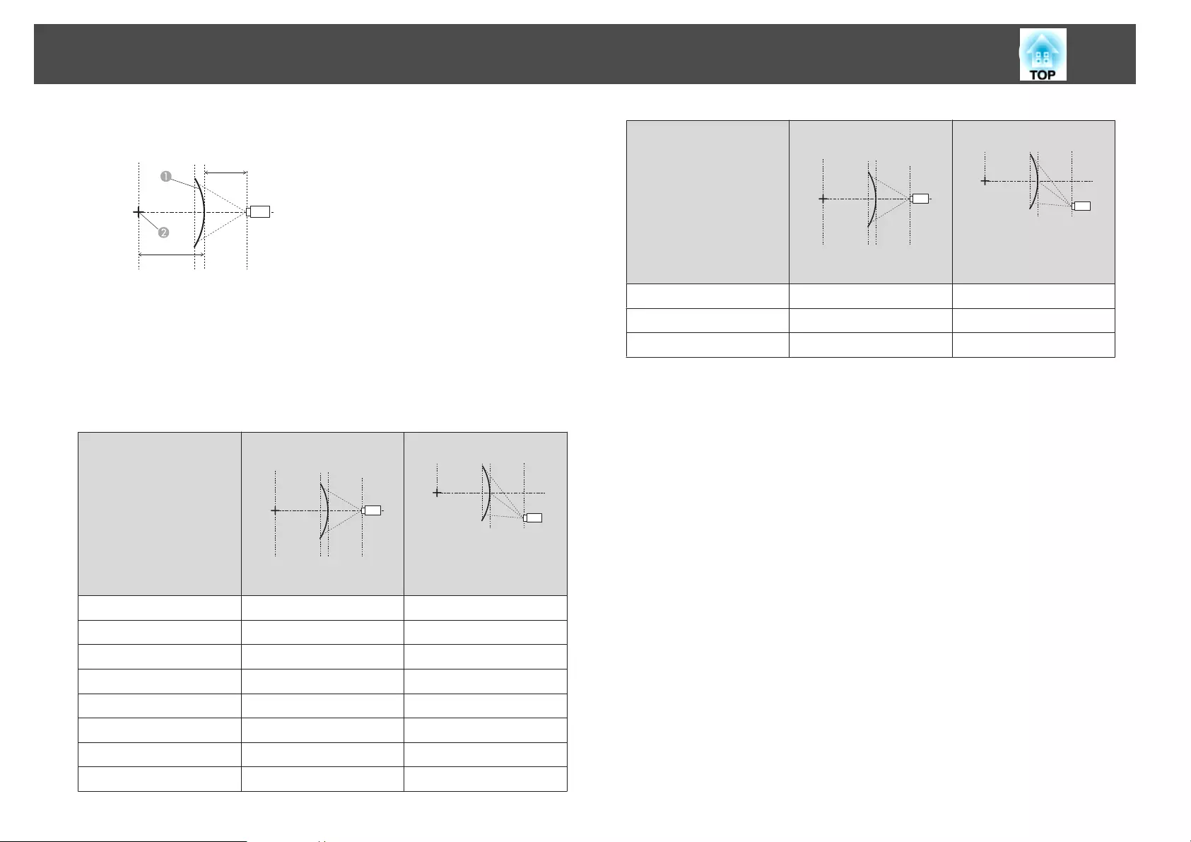
Vertically curved surface (convex)
L
R
AScreen
BCenter of the circle of which the
curved surface is an arc
L Projection distance
R Radius of the circle of which the
curved surface is an arc
Side view
The minimum values of R/L in the figure above are indicated in the table
below.
(Approximate value when projecting at maximum zoom. ELPLR04 does not
support lens shift.)
Lens type Vertical lens shift:
Home position
Side view
Vertical lens shift: Top
Side view
ELPLM08 0.31 0.37
ELPLX01 - 4.16
ELPLU03 1.07 1.29
ELPLU04/ELPLU02 0.66 0.79
ELPLR04 0.57 -
ELPLW05 0.49 0.59
ELPLW06/ELPLW04 0.26 0.32
ELPLM09/ELPLS04 0.18 0.22
Lens type Vertical lens shift:
Home position
Side view
Vertical lens shift: Top
Side view
ELPLM10/ELPLM06 0.12 0.13
ELPLM11/ELPLM07 0.08 0.08
ELPLL08/ELPLL07 0.06 0.06
Adjusting Projected Images
69
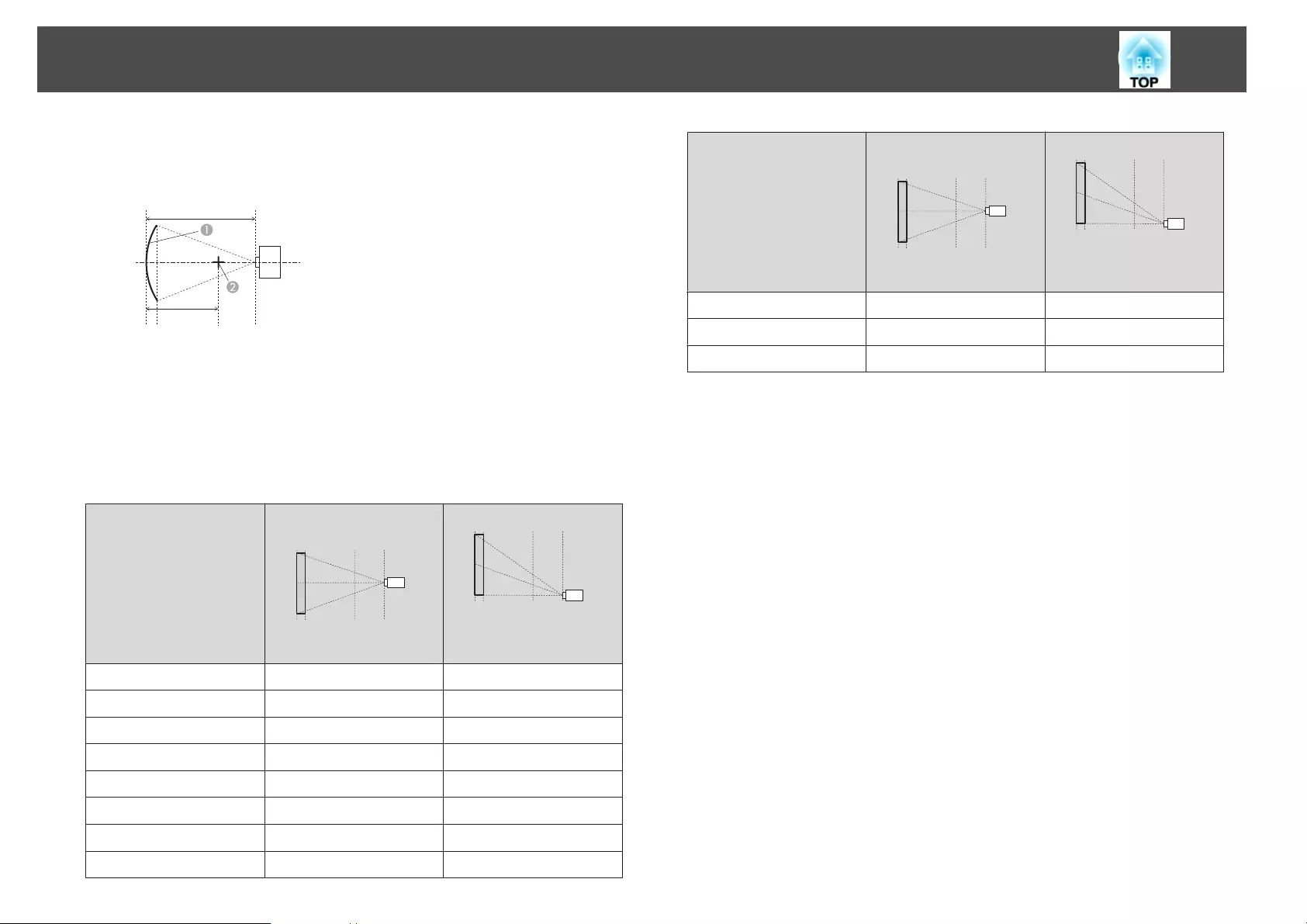
EB-G7805/EB-G7800/EB-G7100
Horizontally curved surface (concave)
L
R
AScreen
BCenter of the circle of which the
curved surface is an arc
L Projection distance
R Radius of the circle of which the
curved surface is an arc
Top view
The minimum values of R/L in the figure above are indicated in the table
below.
(Approximate value when projecting at maximum zoom. ELPLR04 does not
support lens shift.)
Lens type Vertical lens shift:
Home position
Side view
Vertical lens shift: Top
Side view
ELPLM08 0.27 0.27
ELPLX01 - 1.66
ELPLU03 0.44 0.60
ELPLU04/ELPLU02 0.37 0.40
ELPLR04 0.35 -
ELPLW05 0.33 0.34
ELPLW06/ELPLW04 0.25 0.25
ELPLM09/ELPLS04 0.20 0.20
Lens type Vertical lens shift:
Home position
Side view
Vertical lens shift: Top
Side view
ELPLM10/ELPLM06 0.14 0.14
ELPLM11/ELPLM07 0.11 0.11
ELPLL08/ELPLL07 0.08 0.08
Adjusting Projected Images
70
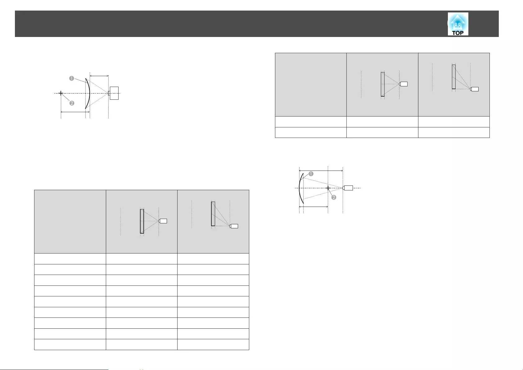
Horizontally curved surface (convex)
L
R
AScreen
BCenter of the circle of which the
curved surface is an arc
L Projection distance
R Radius of the circle of which the
curved surface is an arc
Top view
The minimum values of R/L in the figure above are indicated in the table
below.
(Approximate value when projecting at maximum zoom. ELPLR04 does not
support lens shift.)
Lens type Vertical lens shift:
Home position
Side view
Vertical lens shift: Top
Side view
ELPLM08 0.52 0.54
ELPLX01 - 6.48
ELPLU03 1.81 1.88
ELPLU04/ELPLU02 1.10 1.14
ELPLR04 0.97 -
ELPLW05 0.83 0.86
ELPLW06/ELPLW04 0.44 0.45
ELPLM09/ELPLS04 0.31 0.31
ELPLM10/ELPLM06 0.19 0.19
Lens type Vertical lens shift:
Home position
Side view
Vertical lens shift: Top
Side view
ELPLM11/ELPLM07 0.12 0.13
ELPLL08/ELPLL07 0.09 0.09
Vertically curved surface (concave)
L
R
AScreen
BCenter of the circle of which the
curved surface is an arc
L Projection distance
R Radius of the circle of which the
curved surface is an arc
Side view
Adjusting Projected Images
71
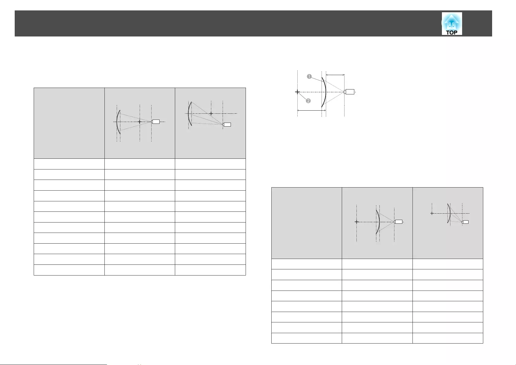
The minimum values of R/L in the figure above are indicated in the table
below.
(Approximate value when projecting at maximum zoom. ELPLR04 does not
support lens shift.)
Lens type Vertical lens shift:
Home position
Side view
Vertical lens shift: Top
Side view
ELPLM08 0.22 0.28
ELPLX01 - 1.73
ELPLU03 0.37 0.63
ELPLU04/ELPLU02 0.32 0.45
ELPLR04 - 0.30
ELPLW05 0.28 0.38
ELPLW06/ELPLW04 0.20 0.25
ELPLM09/ELPLS04 0.16 0.19
ELPLM10/ELPLM06 0.11 0.13
ELPLM11/ELPLM07 0.08 0.09
ELPLL08/ELPLL07 0.06 0.07
Vertically curved surface (convex)
L
R
AScreen
BCenter of the circle of which the
curved surface is an arc
L Projection distance
R Radius of the circle of which the
curved surface is an arc
Side view
The minimum values of R/L in the figure above are indicated in the table
below.
(Approximate value when projecting at maximum zoom. ELPLR04 does not
support lens shift.)
Lens type Vertical lens shift:
Home position
Side view
Vertical lens shift: Top
Side view
ELPLM08 0.34 0.44
ELPLX01 - 5.36
ELPLU03 1.08 1.57
ELPLU04/ELPLU02 0.66 0.94
ELPLR04 0.59 -
ELPLW05 0.50 0.71
ELPLW06/ELPLW04 0.29 0.37
ELPLM09/ELPLS04 0.21 0.26
Adjusting Projected Images
72
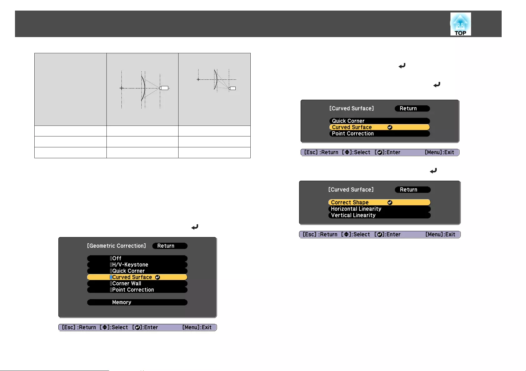
Lens type Vertical lens shift:
Home position
Side view
Vertical lens shift: Top
Side view
ELPLM10/ELPLM06 0.14 0.15
ELPLM11/ELPLM07 0.10 0.10
ELPLL08/ELPLL07 0.07 0.07
Correction method
a
Press the [Menu] button while projecting.
b
Select Geometric Correction from Settings.
c
Select Curved Surface, and then press the [ ] button.
If the message "If this setting is changed, the image may be
distorted." is displayed, press the [ ] button.
d
Select Curved Surface, and then press the [ ] button.
e
Select Correct Shape, and then press the [ ] button.
Adjusting Projected Images
73
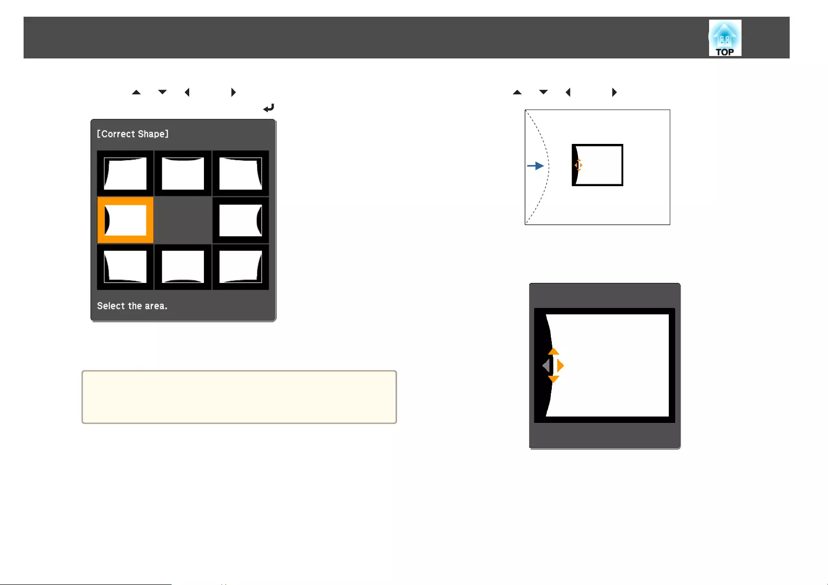
f
Use the [ ], [ ], [ ], and [ ] buttons to select the area you
want to adjust, and then press the [ ] button.
When selecting a corner, you can adjust the two sides next to the
corner.
a
If the [Esc] button is pressed for approximately two seconds,
the confirm default reset screen is displayed.
Select Yes to reset the result of Curved Surface.
g
Use the [ ], [ ], [ ], and [ ] buttons to adjust the shape.
If the triangle in the direction you are adjusting the shape turns gray,
as shown in the screenshot below, you cannot adjust the shape any
further in that direction.
h
Press the [Esc] button to return to the previous screen.
i
Repeat steps from 6 to 8 as needed to adjust any remaining
parts.
If the image expands or contracts, go to the next step and adjust the
linearity.
Adjusting Projected Images
74
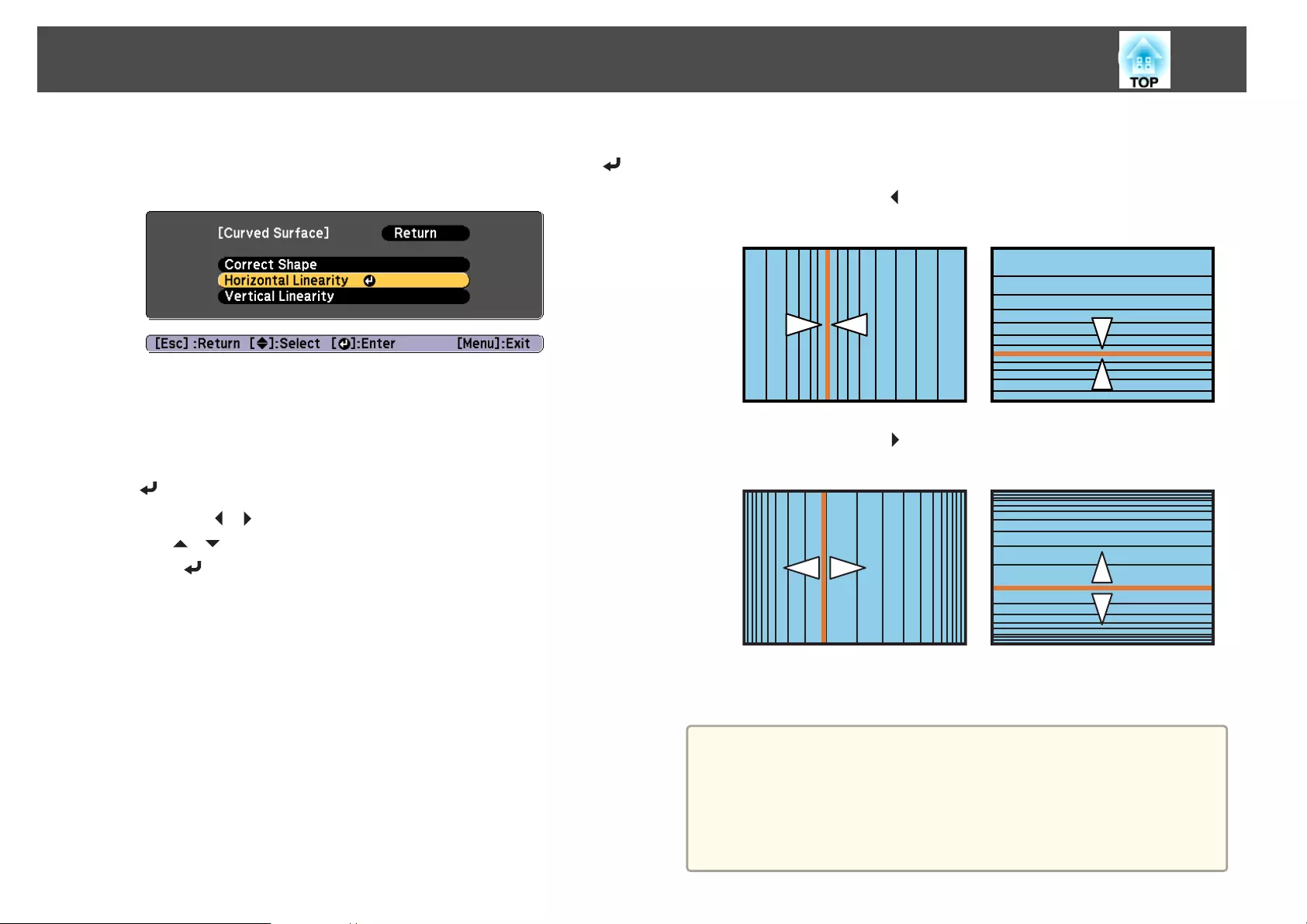
j
Press the [Esc] button to return to the screen in step 5. Select
Horizontal Linearity or Vertical Linearity, and then press the [ ]
button.
Select Horizontal Linearity to adjust the horizontal expansion or
contraction, and select Vertical Linearity to adjust the vertical
expansion or contraction.
k
Select the standard line for the adjustments, and then press the
[] button.
Press the [ ][ ] buttons when selecting Horizontal Linearity, and
the [ ][ ] buttons when selecting Vertical Linearity, and then
press [ ].
The selected standard line is displayed in flashing orange and white.
l
Adjust the linearity.
Correct it so that the distance between lines is equal.
When pressing the [ ] button
When Horizontal Linearity is selected When Vertical Linearity is selected
When pressing the [ ] button
When Horizontal Linearity is selected When Vertical Linearity is selected
m
To complete the corrections, press the [Menu] button.
a
You can fine tune the corrected results. Use Quick Corner to adjust
the tilt of the image, and then use Point Correction for fine tuning.
Select Quick Corner or Point Correction on the screen from step
4.
s "Quick Corner" p.64
s "Point Correction" p.86
Adjusting Projected Images
75
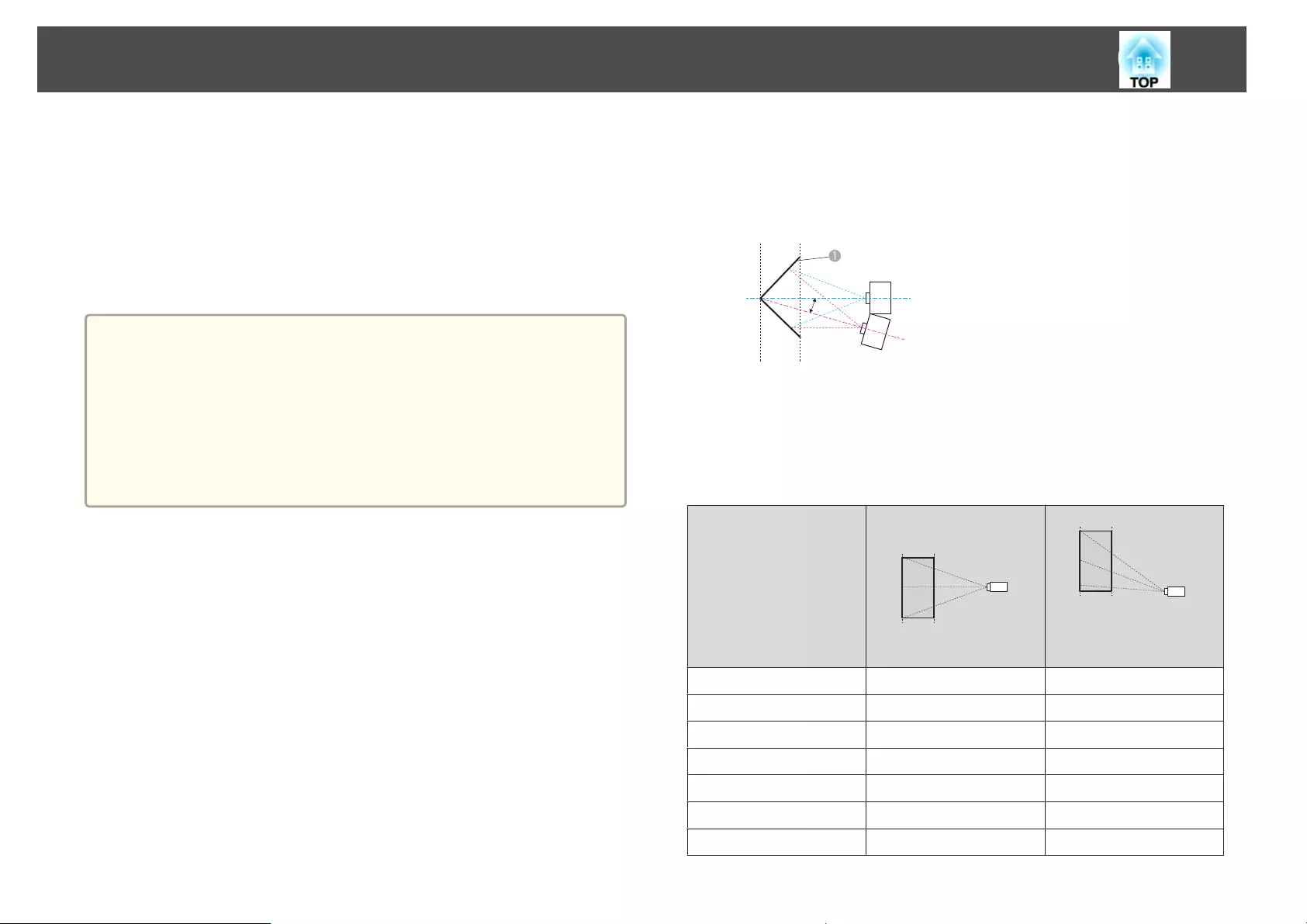
Corner Wall
This allows you to correct distortion that occurs when projecting on a
surface with right angles, such as a square pillar or the corner of a room,
and adjust the amount of expansion and contraction.
Face the projector directly opposing the screen with the lens position
moved to the home position.
s "Adjusting the Position of the Projected Image (Lens Shift)" p.33
a
•Project onto a surface with a right angle.
•If a large amount of adjustment is performed, the focus may not be
uniform even after making adjustments.
•If 4K Enhancement is enabled, a message is displayed. Select Yes to
disable 4K Enhancement. (EB-G7905U/EB-G7900U/EB-G7500U/EB-
G7400U only)
s Image - Image Enhancement - 4K Enhancement p.137
•This is not available for ELPLX01.
Correction range
The correction range is as follows. The lens for projectors with built-in lens
is ELPLM08.
EB-G7905U/EB-G7900U/EB-G7500U/EB-G7400U/EB-G7200W/EB-
G7000W
Concave horizontal corner correction (correction to bilateral symmetry by
using the corner as the center line)
Ș
AScreen
α Angle of possible projector
motion
Top view
α in the figure above is the maximum angle in which the projector can
move. See the table below for detailed values. (Approximate value when
projecting at maximum zoom. ELPLR04 does not support lens shift.)
Lens type Vertical lens shift:
Home position
Side view
Vertical lens shift: Top
Side view
ELPLM08 31˚ 23˚
ELPLX01 - -
ELPLU03 29˚ 9˚
ELPLU04/ELPLU02 31˚ 14˚
ELPLR04 32˚ -
ELPLW05 33˚ 18˚
ELPLW06/ELPLW04 31˚ 25˚
Adjusting Projected Images
76
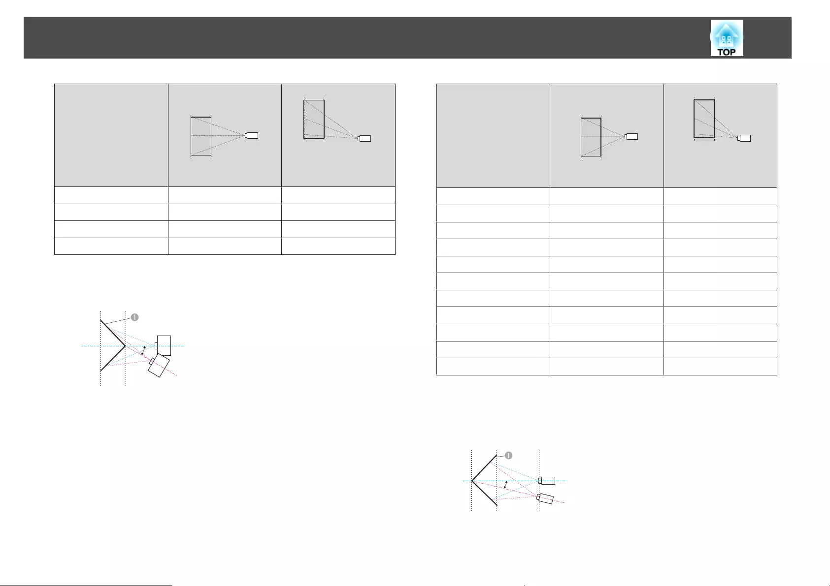
Lens type Vertical lens shift:
Home position
Side view
Vertical lens shift: Top
Side view
ELPLM09/ELPLS04 30˚ 29˚
ELPLM10/ELPLM06 29˚ 29˚
ELPLM11/ELPLM07 29˚ 28˚
ELPLL08/ELPLL07 28˚ 28˚
Convex horizontal corner correction (correction to bilateral symmetry by
using corners as the center line)
Ș
AScreen
α Angle of possible projector
motion
Top view
α in the figure above is the maximum angle in which the projector can
move. See the table below for detailed values. (Approximate value when
projecting at maximum zoom. ELPLR04 does not support lens shift.)
Lens type Vertical lens shift:
Home position
Side view
Vertical lens shift: Top
Side view
ELPLM08 14˚ 13˚
ELPLX01 - -
ELPLU03 0˚ *
ELPLU04/ELPLU02 6˚ 4˚
ELPLR04 8˚ -
ELPLW05 9˚ 8˚
ELPLW06/ELPLW04 16˚ 15˚
ELPLM09/ELPLS04 18˚ 18˚
ELPLM10/ELPLM06 22˚ 21˚
ELPLM11/ELPLM07 23˚ 23˚
ELPLL08/ELPLL07 24˚ 24˚
*Cannot be corrected accurately. Move the lens position to the home position.
Concave vertical corner correction (correction to horizontal symmetry by
using corners as the center line)
Ș
AScreen
α Angle of possible projector
motion
Side view
Adjusting Projected Images
77
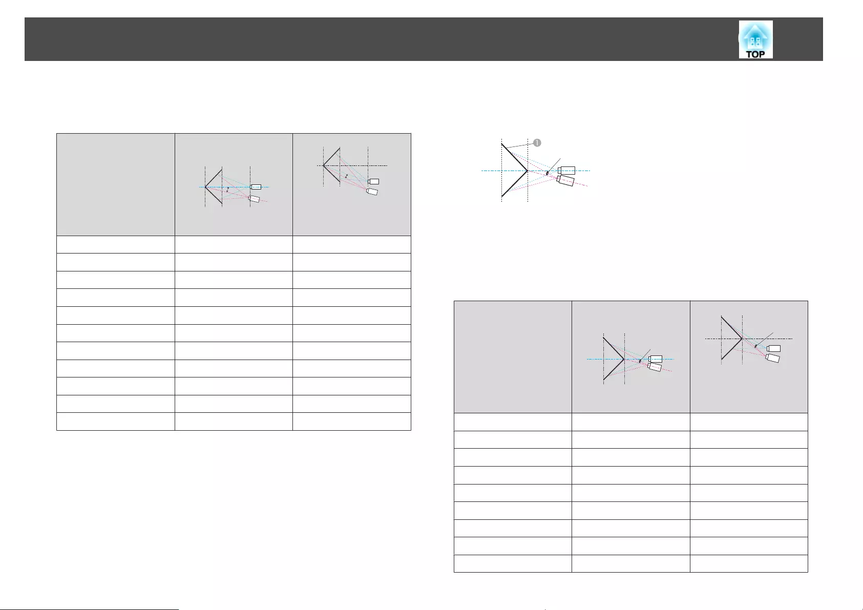
α in the figure above is the maximum angle in which the projector can
move. See the table below for detailed values. (Approximate value when
projecting at maximum zoom. ELPLR04 does not support lens shift.)
Lens type Vertical lens shift:
Home position
Ș
Side view
Vertical lens shift: Top
Ș
Side view
ELPLM08 30˚ 12˚
ELPLX01 - -
ELPLU03 33˚ *
ELPLU04/ELPLU02 31˚ 6˚
ELPLR04 31˚ -
ELPLW05 31˚ 10˚
ELPLW06/ELPLW04 28˚ 13˚
ELPLM09/ELPLS04 26˚ 14˚
ELPLM10/ELPLM06 24˚ 16˚
ELPLM11/ELPLM07 23˚ 18˚
ELPLL08/ELPLL07 23˚ 19˚
*Cannot be corrected accurately. Move the lens position to the home position.
Convex vertical corner correction (correction to horizontal symmetry by
using corners as the center line)
Ș
AScreen
α Angle of possible projector
motion
Side view
α in the figure above is the maximum angle in which the projector can
move. See the table below for detailed values. (Approximate value when
projecting at maximum zoom. ELPLR04 does not support lens shift.)
Lens type Vertical lens shift:
Home position
Ș
Side view
Vertical lens shift: Top
Ș
Side view
ELPLM08 19˚ 5˚
ELPLX01 - -
ELPLU03 9˚ *
ELPLU04/ELPLU02 14˚ *
ELPLR04 15˚ -
ELPLW05 16˚ *
ELPLW06/ELPLW04 20˚ 7˚
ELPLM09/ELPLS04 22˚ 12˚
ELPLM10/ELPLM06 22˚ 15˚
Adjusting Projected Images
78
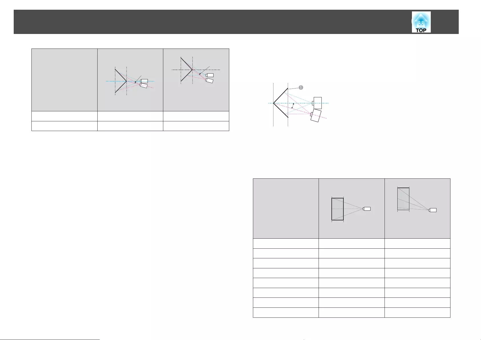
Lens type Vertical lens shift:
Home position
Ș
Side view
Vertical lens shift: Top
Ș
Side view
ELPLM11/ELPLM07 22˚ 17˚
ELPLL08/ELPLL07 22˚ 18˚
*Cannot be corrected accurately. Move the lens position to the home position.
EB-G7805/EB-G7800/EB-G7100
Concave horizontal corner correction (correction to bilateral symmetry by
using corners as the center line)
Ș
AScreen
α Angle of possible projector
motion
Top view
α in the figure above is the maximum angle in which the projector can
move. See the table below for detailed values. (Approximate value when
projecting at maximum zoom. ELPLR04 does not support lens shift.)
Lens type Vertical lens shift:
Home position
Side view
Vertical lens shift: Top
Side view
ELPLM08 31˚ 21˚
ELPLX01 - -
ELPLU03 26˚ 7˚
ELPLU04/ELPLU02 29˚ 13˚
ELPLR04 30˚ -
ELPLW05 31˚ 16˚
ELPLW06/ELPLW04 31˚ 23˚
ELPLM09/ELPLS04 30˚ 27˚
Adjusting Projected Images
79
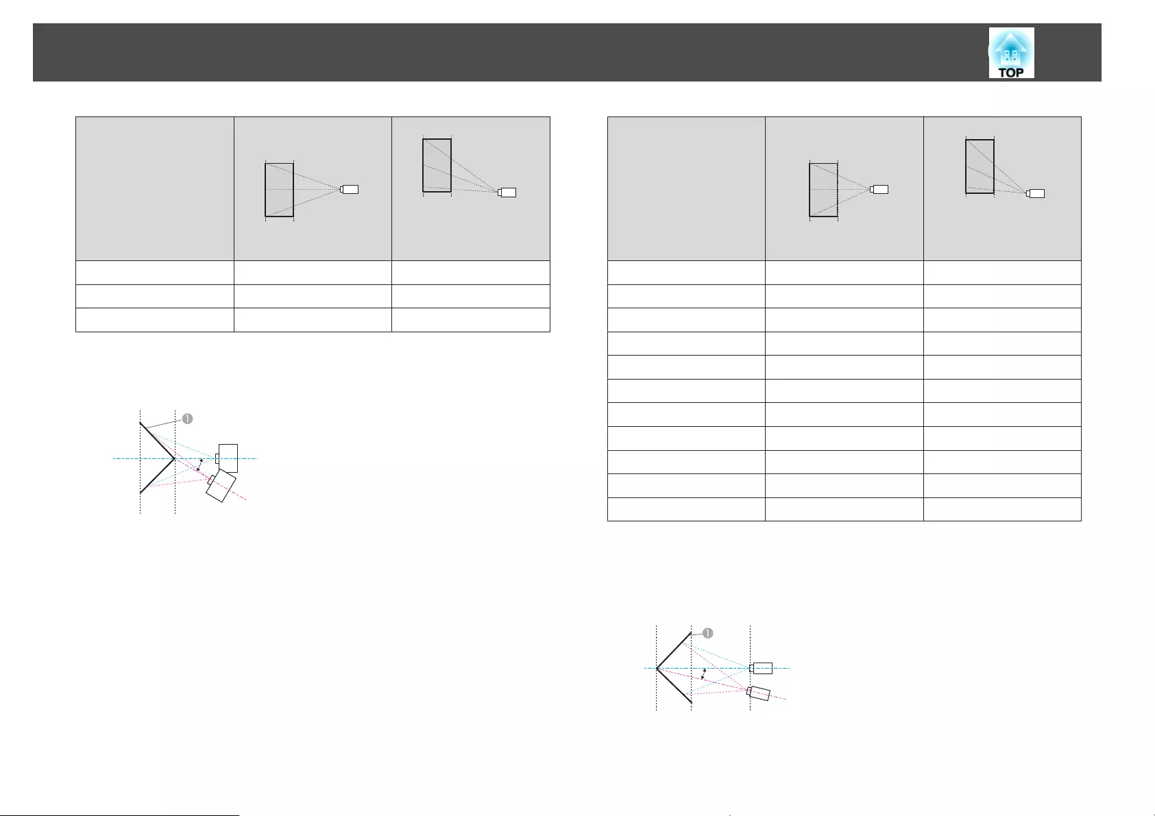
Lens type Vertical lens shift:
Home position
Side view
Vertical lens shift: Top
Side view
ELPLM10/ELPLM06 29˚ 29˚
ELPLM11/ELPLM07 29˚ 29˚
ELPLL08/ELPLL07 28˚ 28˚
Convex horizontal corner correction (correction to bilateral symmetry by
using corners as the center line)
Ș
AScreen
α Angle of possible projector
motion
Top view
α in the figure above is the maximum angle in which the projector can
move. See the table below for detailed values. (Approximate value when
projecting at maximum zoom. ELPLR04 does not support lens shift.)
Lens type Vertical lens shift:
Home position
Side view
Vertical lens shift: Top
Side view
ELPLM08 14˚ 14˚
ELPLX01 - -
ELPLU03 0˚ *
ELPLU04/ELPLU02 6˚ 2˚
ELPLR04 8˚ -
ELPLW05 10˚ 7˚
ELPLW06/ELPLW04 16˚ 16˚
ELPLM09/ELPLS04 19˚ 18˚
ELPLM10/ELPLM06 22˚ 21˚
ELPLM11/ELPLM07 23˚ 23˚
ELPLL08/ELPLL07 24˚ 24˚
*Cannot be corrected accurately. Move the lens position to the home position.
Concave vertical corner correction (correction to horizontal symmetry by
using corners as the center line)
Ș
AScreen
α Angle of possible projector
motion
Side view
Adjusting Projected Images
80
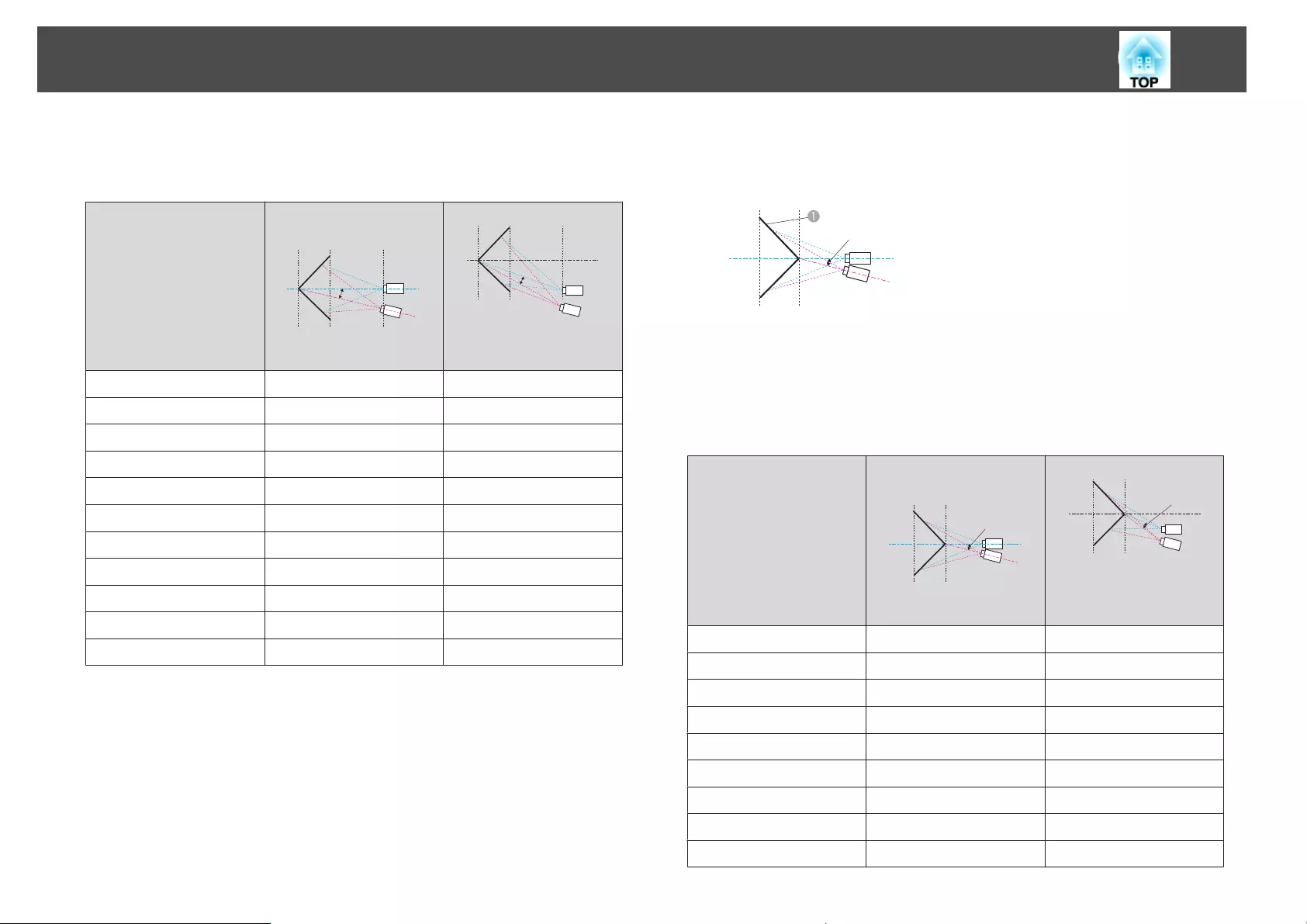
α in the figure above is the maximum angle in which the projector can
move. See the table below for detailed values. (Approximate value when
projecting at maximum zoom. ELPLR04 does not support lens shift.)
Lens type Vertical lens shift:
Home position
Ș
Side view
Vertical lens shift: Top
Ș
Side view
ELPLM08 31˚ 14˚
ELPLX01 - -
ELPLU03 33˚ *
ELPLU04/ELPLU02 32˚ 7˚
ELPLR04 32˚ -
ELPLW05 31˚ 10˚
ELPLW06/ELPLW04 30˚ 16˚
ELPLM09/ELPLS04 29˚ 17˚
ELPLM10/ELPLM06 27˚ 19˚
ELPLM11/ELPLM07 26˚ 21˚
ELPLL08/ELPLL07 26˚ 22˚
*Cannot be corrected accurately. Move the lens position to the home position.
Convex vertical corner correction (correction to horizontal symmetry by
using corners as the center line)
Ș
AScreen
α Angle of possible projector
motion
Side view
α in the figure above is the maximum angle in which the projector can
move. See the table below for detailed values. (Approximate value when
projecting at maximum zoom. ELPLR04 does not support lens shift.)
Lens type Vertical lens shift:
Home position
Ș
Side view
Vertical lens shift: Top
Ș
Side view
ELPLM08 18˚ 4˚
ELPLX01 - -
ELPLU03 6˚ *
ELPLU04/ELPLU02 12˚ *
ELPLR04 13˚ -
ELPLW05 14˚ *
ELPLW06/ELPLW04 19˚ 6˚
ELPLM09/ELPLS04 21˚ 11˚
ELPLM10/ELPLM06 23˚ 16˚
Adjusting Projected Images
81
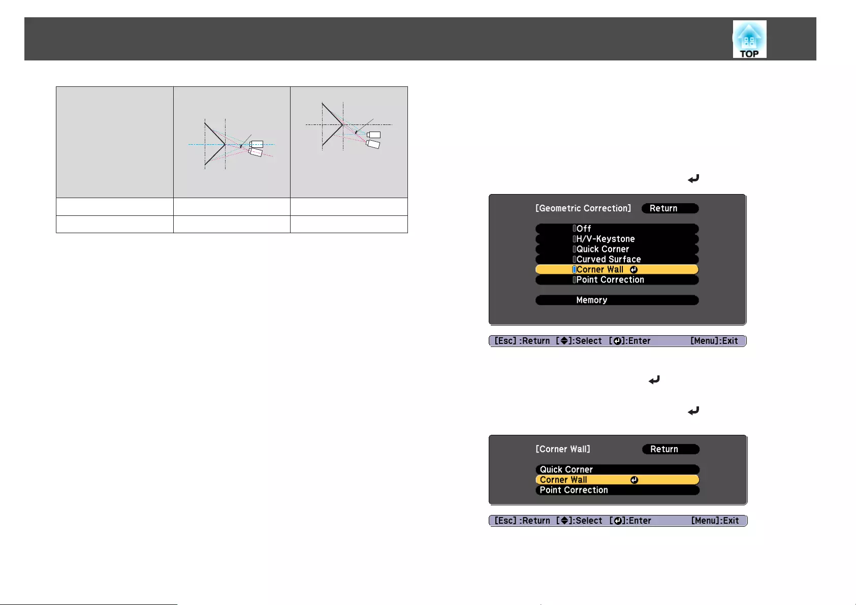
Lens type Vertical lens shift:
Home position
Ș
Side view
Vertical lens shift: Top
Ș
Side view
ELPLM11/ELPLM07 24˚ 19˚
ELPLL08/ELPLL07 25˚ 21˚
*Cannot be corrected accurately. Move the lens position to the home position.
Correction method
a
Press the [Menu] button while projecting.
b
Select Geometric Correction from Settings.
c
Select Corner Wall, and then press the [ ] button.
If the message "If this setting is changed, the image may be
distorted." is displayed, press the [ ] button.
d
Select Corner Wall, and then press the [ ] button.
Adjusting Projected Images
82
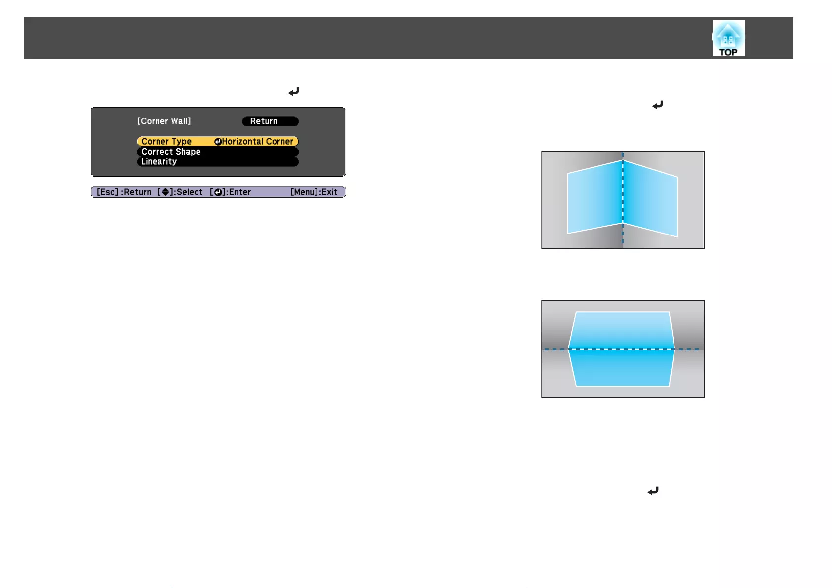
e
Select Corner Type, and then press the [ ] button.
f
According to the projection area, select Horizontal Corner or
Vertical Corner, and then press the [ ] button.
When the surfaces line up horizontally:
Select Horizontal Corner.
When the surfaces line up vertically:
Select Vertical Corner.
From here on, steps are explained using Horizontal Corner as an
example.
g
Press the [Esc] button to display the screen from step 5. Select
Correct Shape, and then press the [ ] button.
Adjusting Projected Images
83
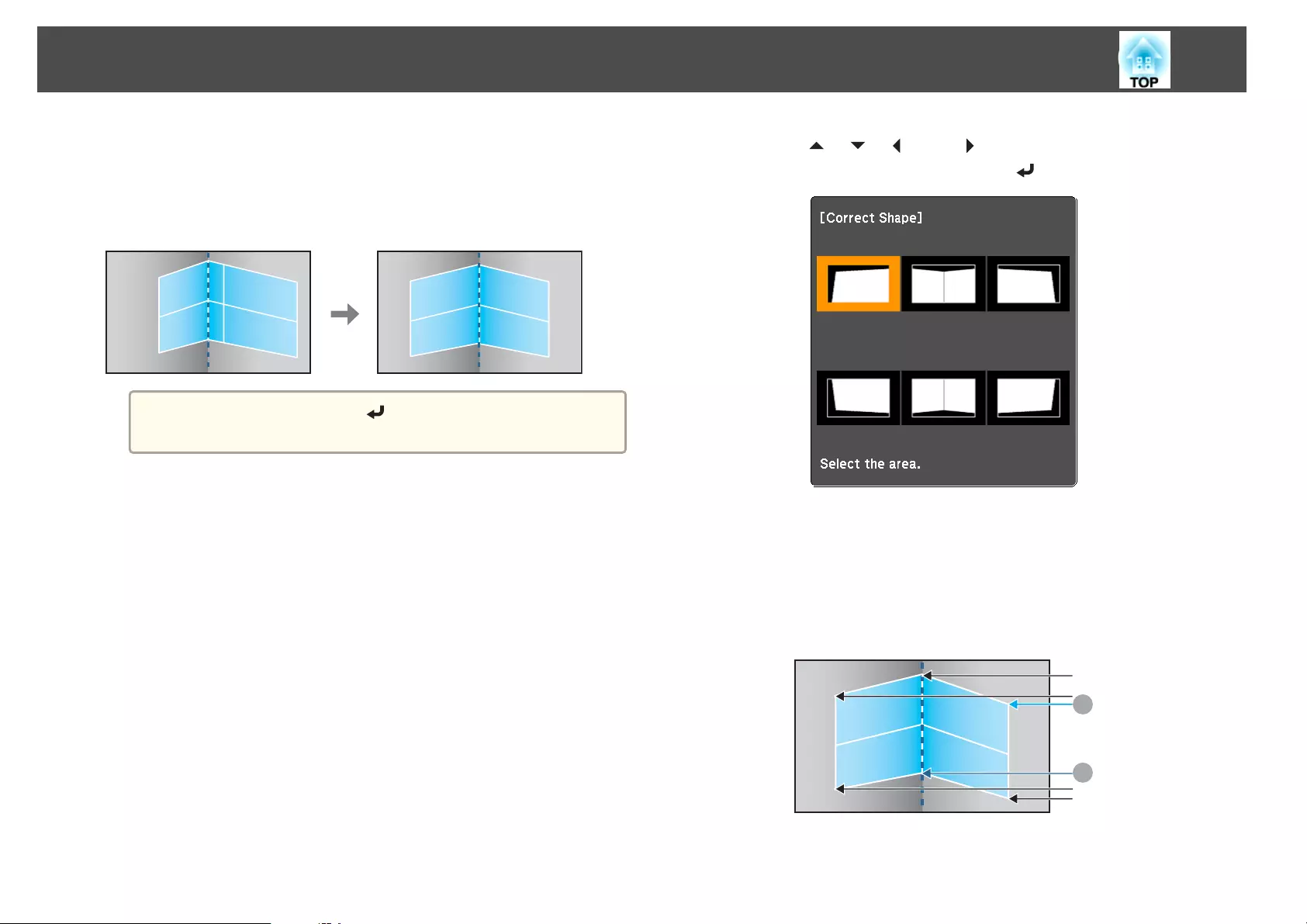
h
Adjust the position of the projector and the lens shift so that the
line in the center of the screen matches the corner (the point
where the two surfaces meet).
s "Adjusting the Position of the Projected Image (Lens Shift)"
p.33
a
Each time you press the [ ] button, you can show or hide the
image and the grid.
i
Use the [ ], [ ], [ ], and [ ] buttons to select the area you
want to adjust, and then press the [ ] button.
Adjustment tips
When Horizontal Corner is selected:
Adjust the upper area based on the lowest point (indicated by the U
arrow).
Adjust the lower area based on the highest point (indicated by the V
arrow).
A
B
Adjusting Projected Images
84
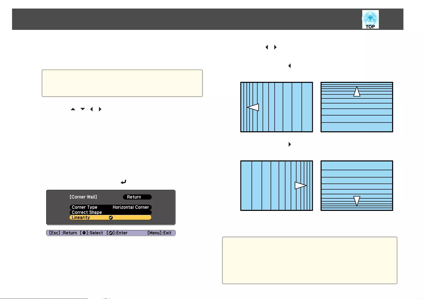
When Vertical Corner is selected:
Adjust the left and right based on the point nearest to the vertical
line in the center of the screen.
a
If the [Esc] button is pressed for approximately two seconds,
the confirm default reset screen is displayed.
Select Yes to reset the result of Corner Wall.
j
Press the [ ][ ][ ][ ] buttons to adjust the shape.
If the message "Cannot adjust any further."is displayed while
adjusting, you cannot adjust the shape any further in the direction
indicated by the gray triangle.
k
Repeat steps 9 and 10 as needed to adjust any remaining parts.
If the image expands or contracts, go to the next step and adjust the
linearity.
l
Press the [Esc] button to display the screen from step 4. Select
Linearity, and then press the [ ] button.
m
Press the [ ][ ] buttons to adjust the linearity.
Correct it so that the distance between lines is equal.
When pressing the [ ] button
When Horizontal Corner is selected When Vertical Corner is selected
When pressing the [ ] button
When Horizontal Corner is selected When Vertical Corner is selected
n
To complete the corrections, press the [Menu] button.
a
You can fine tune the corrected results. Use Quick Corner to adjust
the tilt of the image, and then use Point Correction for fine tuning.
Select Quick Corner or Point Correction on the screen from step
4.
s "Quick Corner" p.64
s "Point Correction" p.86
Adjusting Projected Images
85
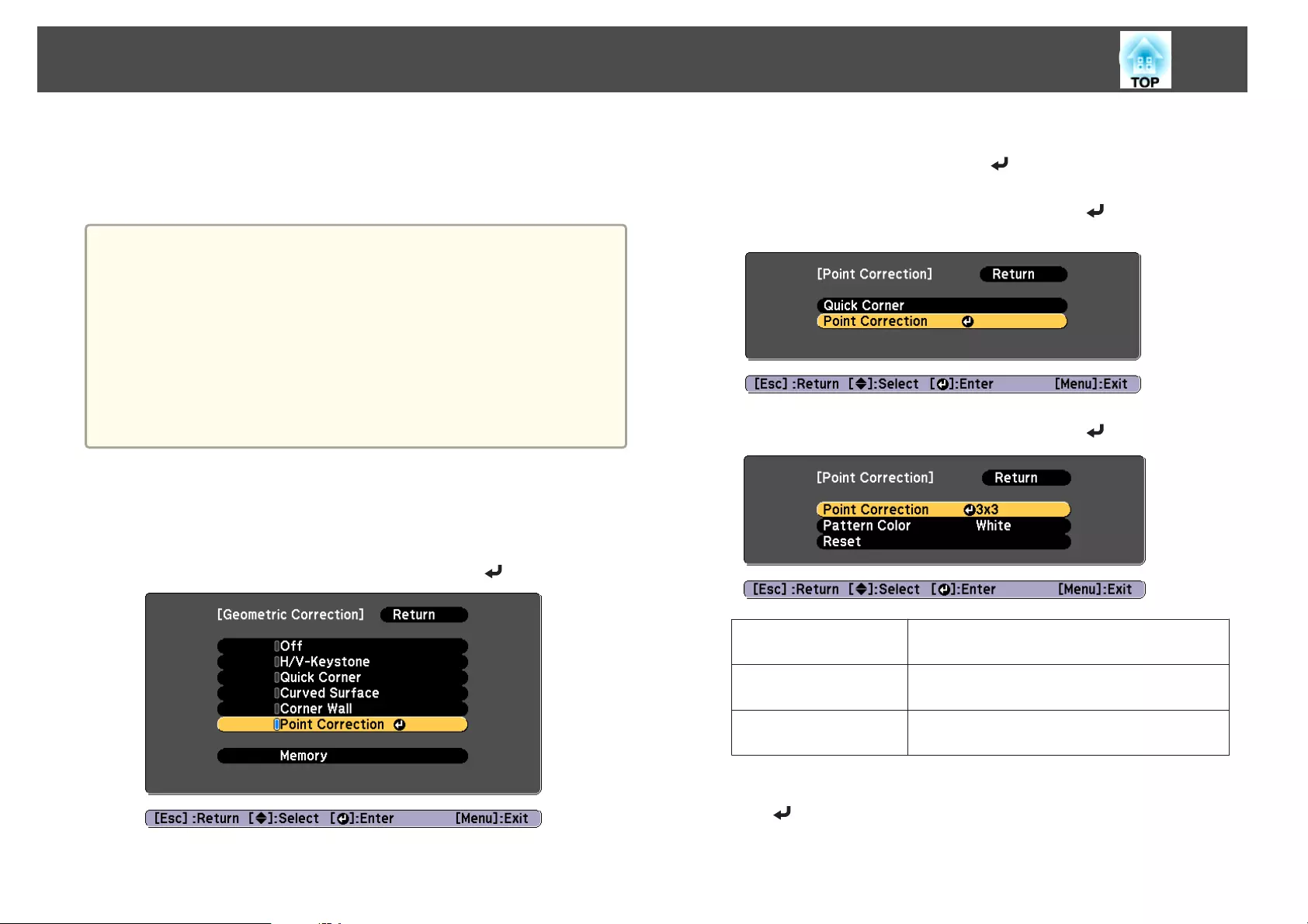
Point Correction
Divides the projected image by the grid and corrects the distortion by
moving the point of intersection from side to side and up and down.
a
•You can make corrections by 0.5 pixels in each direction in the
following ranges.
EB-G7905U/EB-G7900U/EB-G7500U/EB-G7400U: Maximum of 32
pixels in the vertical and horizontal directions
EB-G7200W/EB-G7000W/EB-G7805/EB-G7800/EB-G7100: Maximum
of 20 pixels in the vertical and horizontal directions
•If 4K Enhancement is enabled, a message is displayed. Select Yes to
disable 4K Enhancement. (EB-G7905U/EB-G7900U/EB-G7500U/EB-
G7400U only)
s Image - Image Enhancement - 4K Enhancement p.137
a
Press the [Menu] button while projecting.
b
Select Geometric Correction from Settings.
c
Select Point Correction, and then press the [ ] button.
If the message "If this setting is changed, the image may be
distorted." is displayed, press the [ ] button.
d
Select Point Correction, and then press the [ ] button.
e
Select Point Correction, and then press the [ ] button.
Point Correction Select the point number (3x3, 5x5, 9x9, 17x17),
and then make the Point Correction setting.
Pattern Color Select the color of the grid when performing
corrections.
Reset Resets all corrections for Point Correction to their
default values.
f
Select the point number (3x3, 5x5, 9x9, or 17x17), and then press
the [ ] button.
Adjusting Projected Images
86
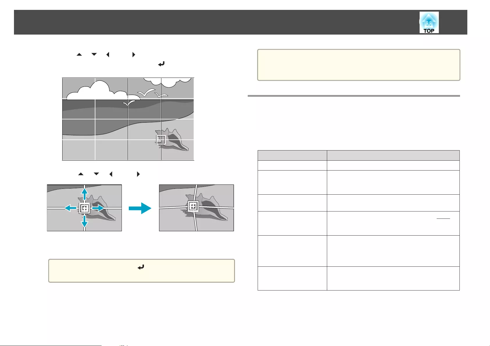
g
Use the [ ], [ ], [ ], and [ ] buttons to move to the point you
want to correct, and then press the [ ] button.
h
Use the [ ], [ ], [ ], and [ ] buttons to correct distortion.
To continue to correct another point, press the [Esc] button to
return to the previous screen, then repeat the steps 7 and 8.
a
Each time you press the [ ] button, you can show or hide the
image and the grid.
i
To complete the corrections, press the [Menu] button.
a
You can fine tune the corrected results. Select Quick Corner on the
screen from step 4 to adjust the tilt of the image.
s "Quick Corner" p.64
Selecting the Projection Quality (Selecting Color
Mode)
You can easily obtain the optimum image quality simply by selecting the
setting that best corresponds to your surroundings when projecting. The
brightness of the image varies depending on the mode selected.
Mode Application
Dynamic This is the brightest mode. Ideal for use in a bright room.
Presentation The images are vivid and brought to life. Ideal for
making presentations or watching a TV program in a
bright room.
Cinema Gives images a natural tone. Ideal for watching films in a
dark room.
sRGB This produces the images that conform to the sRGB
g
color standard and the colors are reproduced faithfully.
Ideal for projecting still pictures such as photos.
DICOM SIM This produces images with clear shadows. Ideal for
projecting X-ray photographs and other medical
images. The projector is not a medical device and cannot
be used for medical diagnosis.
Multi-Projection Minimize the color tone difference between each
projected image. Ideal for projecting from multiple
projectors.
Adjusting Projected Images
87
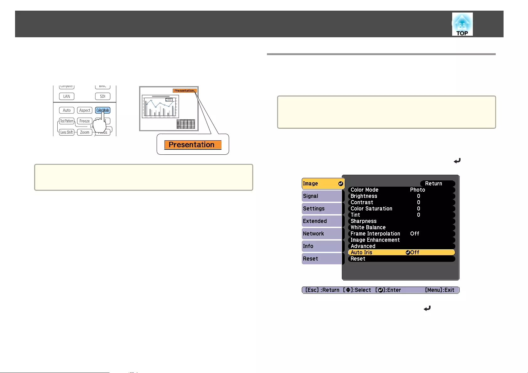
Each time you press the [Color Mode] button, the Color Mode name is
displayed on the screen and the Color Mode changes.
Remote control
a
You can set Color Mode from the Configuration menu.
s Image - Color Mode p.137
Setting Auto Iris
By automatically setting the luminance according to the brightness of the
displayed image, it lets you enjoy deep and rich images.
a
•Auto Iris can only be set when the Color Mode is set to Dynamic
or Cinema.
•When Edge Blending is set to On, Auto Iris is disabled.
a
Press the [Menu] button while projecting.
b
Select Auto Iris from Image, and then press the [ ] button.
c
Select High Speed, and then press the [ ] button.
If you are concerned about the operation noise of Auto Iris, set it to
Normal.
The setting is stored for each color mode.
Adjusting Projected Images
88
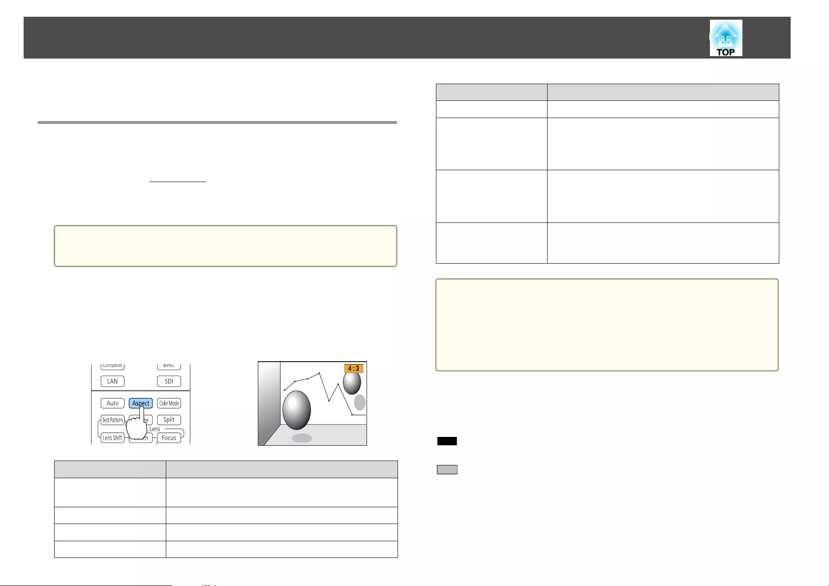
d
Press the [Menu] button to finish making settings.
Changing the Aspect Ratio of the Projected
Image
You can change the Aspect Ratio
g
of the projected image to suit the type,
the ratio of height and width, and the resolution of the input signals.
Available aspect modes vary depending on the Screen Type currently set.
a
Set the Screen Type before changing the aspect ratio.
s "Screen Settings" p.30
Changing methods
Each time you press the [Aspect] button on the remote control, the aspect
mode name is displayed on the screen and the aspect ratio changes.
Remote control
Aspect Mode Explanation
Auto Projects in an appropriate aspect ratio based on
information from the signal being input.
Normal Projects while retaining the aspect ratio of the input image.
4:3 Projects at an aspect ratio of 4:3.
16:9 Projects at an aspect ratio of 16:9.
Aspect Mode Explanation
Full Projects at the full size of the projected screen.
H-Zoom Projects by enlarging the input image to the full width of
the projected screen while retaining the aspect ratio. Areas
that exceed the edges of the projected screen are not
projected.
V-Zoom Projects by enlarging the input image to the full height of
the projected screen while retaining the aspect ratio. Areas
that exceed the edges of the projected screen are not
projected.
Native Projects to the center of the projected screen at the
resolution of the input image. Areas that exceed the edges
of the projected screen are not projected.
a
•You can also set the aspect ratio from the Configuration menu.
s Signal - Aspect p.139
•If parts of the computer image are missing, set the Resolution
setting to Wide or Normal from the Configuration menu, according
to the resolution of the computer.
s Signal - Resolution p.139
The aspect mode changes as shown in the tables below.
The following colors in screen images in the tables indicate areas that are
not displayed.
: The area where the image is not displayed depending on the screen
type setting.
: The area where the image is not displayed depending on the aspect
mode setting.
EB-G7905U/EB-G7900U/EB-G7500U/EB-G7400U/EB-G7200W/EB-G7000W
Screen type setting: 16:10
Adjusting Projected Images
89
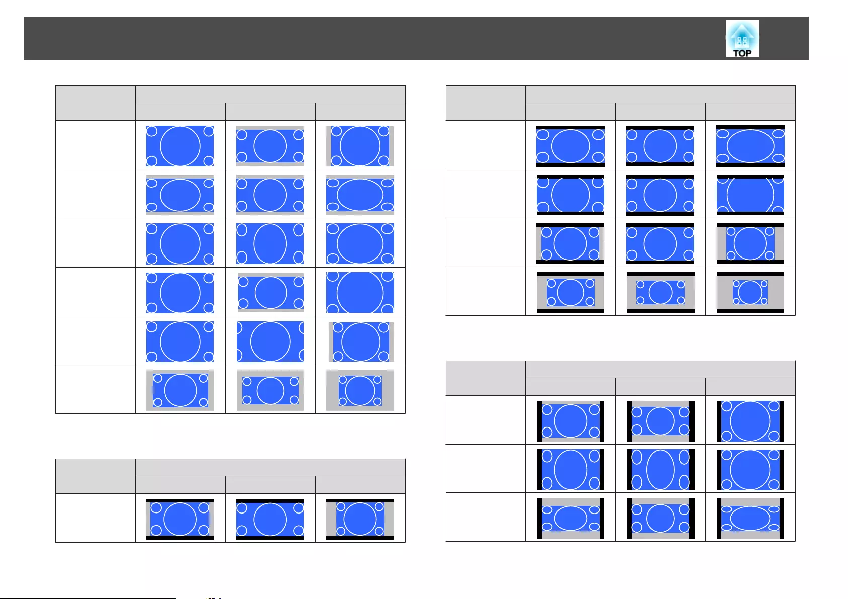
Aspect Ratio of Input Signal
16:10 16:9 4:3
Auto or Normal
16:9
Full
H-Zoom
V-Zoom
Native
*
*The image may differ depending on the resolution of the input signal.
Screen type setting: 16:9
Aspect Ratio of Input Signal
16:10 16:9 4:3
Auto or Normal
Aspect Ratio of Input Signal
16:10 16:9 4:3
Full
H-Zoom
V-Zoom
Native
*
*The image may differ depending on the resolution of the input signal.
Screen type setting: 4:3
Aspect Ratio of Input Signal
16:10 16:9 4:3
Auto or Normal
4:3
16:9
Adjusting Projected Images
90
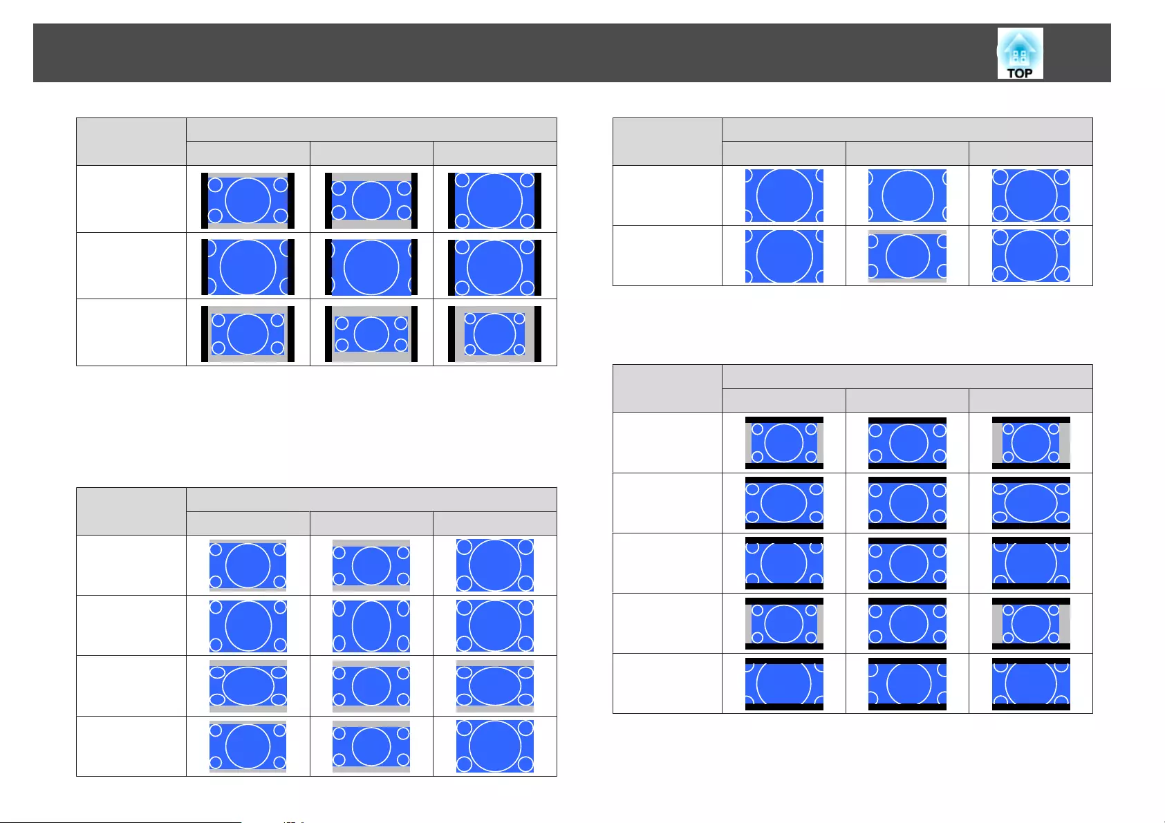
Aspect Ratio of Input Signal
16:10 16:9 4:3
H-Zoom
V-Zoom
Native
*
*Only computer images and images from the HDMI port/HDBaseT port. The
image may differ depending on the resolution of the input signal.
EB-G7805/EB-G7800/EB-G7100
Screen type setting: 4:3
Aspect Ratio of Input Signal
16:10 16:9 4:3
Auto or Normal
4:3
16:9
H-Zoom
Aspect Ratio of Input Signal
16:10 16:9 4:3
V-Zoom
Native
*
*Only computer images and images from the HDMI port/HDBaseT port. The
image may differ depending on the resolution of the input signal.
Screen type setting: 16:9
Aspect Ratio of Input Signal
16:10 16:9 4:3
Auto or Normal
Full
H-Zoom
V-Zoom
Native
*
*The image may differ depending on the resolution of the input signal.
Screen type setting: 16:10
Adjusting Projected Images
91
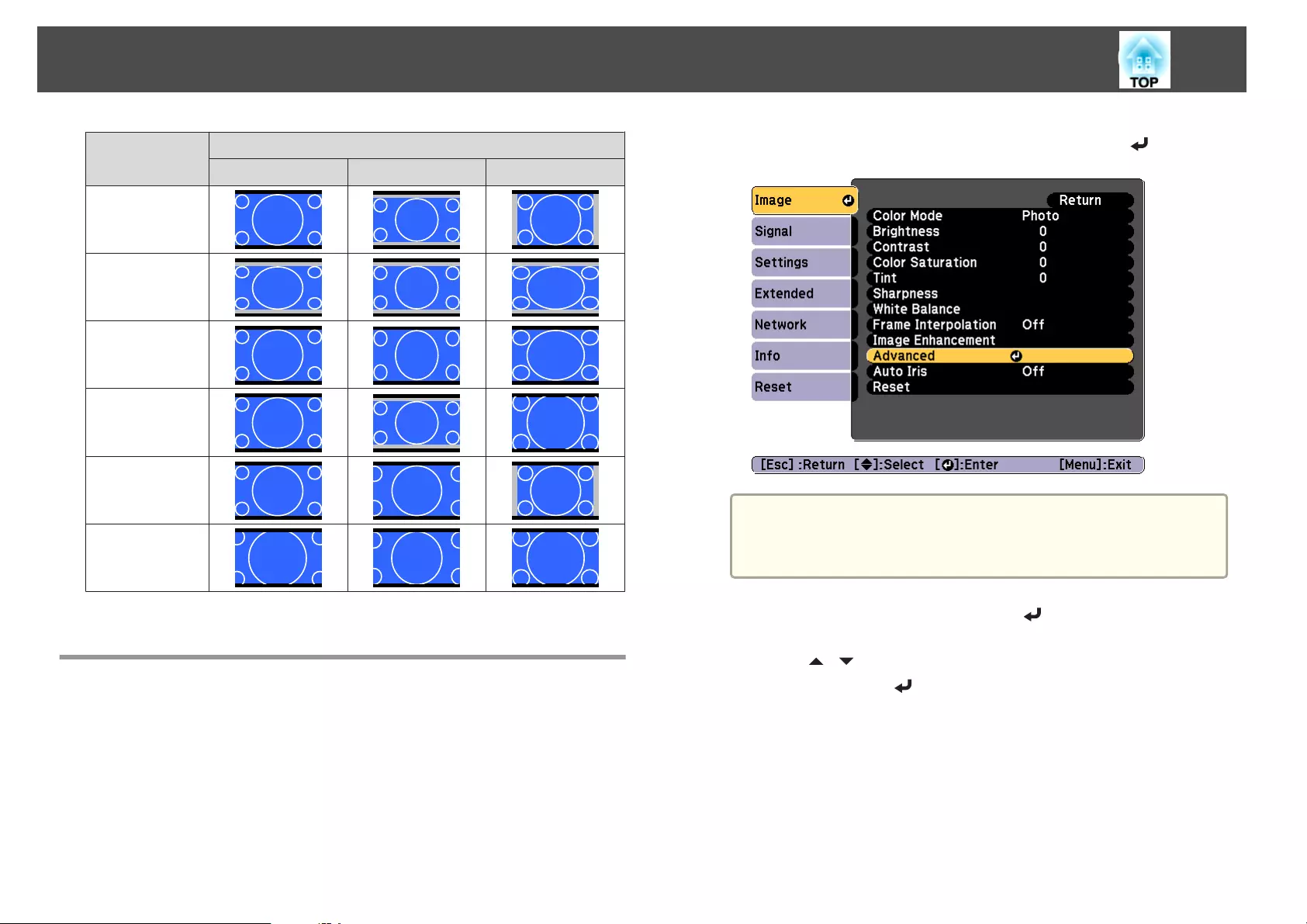
Aspect Ratio of Input Signal
16:10 16:9 4:3
Auto or Normal
16:9
Full
H-Zoom
V-Zoom
Native
*
*The image may differ depending on the resolution of the input signal.
Adjusting the Image
Hue, Saturation, and Brightness adjustment
You can adjust the Hue (tint), Saturation (vividness), and Brightness of
the six axes R (red), G (green), B (blue), C (cyan), M (magenta), and Y
(yellow) according to your preferences.
a
Press the [Menu] button while projecting.
b
Select Advanced from Image, and then press the [ ] button.
a
You can also make adjustments from Multi-Projection in the
Configuration menu.
s Extended - Multi-Projection - RGBCMY p.142
c
Select RGBCMY, and then press the [ ] button.
d
Use the [ ][ ] buttons to select the color you want to adjust,
and then press the [ ] button.
Adjusting Projected Images
92
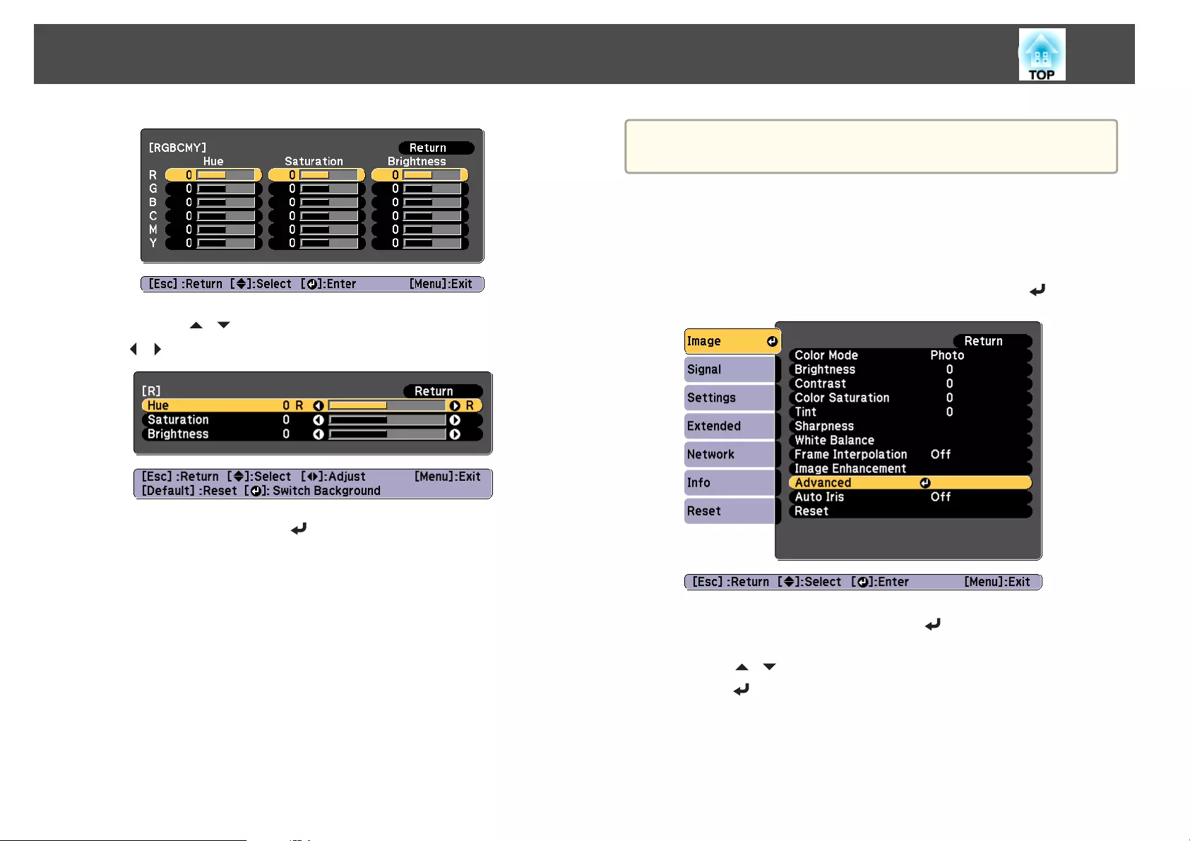
e
Use the [ ][ ] buttons to select the item, and then use the
[][ ] buttons to make the adjustments.
Each time you press the [ ] button, the adjustment screen changes.
f
To complete the corrections, press the [Menu] button.
Gamma adjustment
You can adjust differences in the halftone brightness that occurs depending
on the connected device.
You can set it by using one of the following three methods.
•Select and adjust the correction value
•Adjust while viewing the image
•Adjust using the gamma adjustment graph
a
Adjust by projecting a still picture. Gamma cannot be adjusted
correctly by using movies.
Select and adjust the correction value
a
Press the [Menu] button while projecting.
b
Select Advanced from Image, and then press the [ ] button.
c
Select Gamma, and then press the [ ] button.
d
Use the [ ][ ] buttons to select the correction value, and then
use the [ ] button to confirm the selection.
Adjusting Projected Images
93
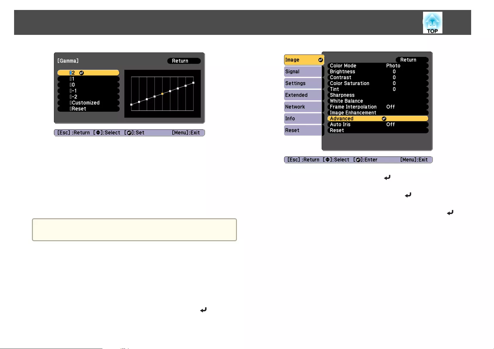
When a larger value is selected, the dark areas of images become brighter,
but the color saturation for lighter areas may become weaker.
When a smaller value is selected, you can reduce the overall brightness of
the image to make the image sharper.
If you select DICOM SIM from Color Mode on the Image menu, select the
adjustment value according to the projection size.
•If the projection size is 120 inches or less, select a small value.
•If the projection size is 120 inches or more, select a large value.
a
Medical images may not be reproduced correctly according to your
installation environment and screen specifications.
Adjust while viewing the image
Select a point on the image where you want to adjust the brightness, and
adjust only the selected tone.
a
Press the [Menu] button while projecting.
b
Select Advanced from Image, and then press the [ ] button.
c
Select Gamma, and then press the [ ] button.
d
Select Customized, and confirm using the [ ] button.
e
Select Adjust it from the image, and confirm using the [ ]
button.
Adjusting Projected Images
94
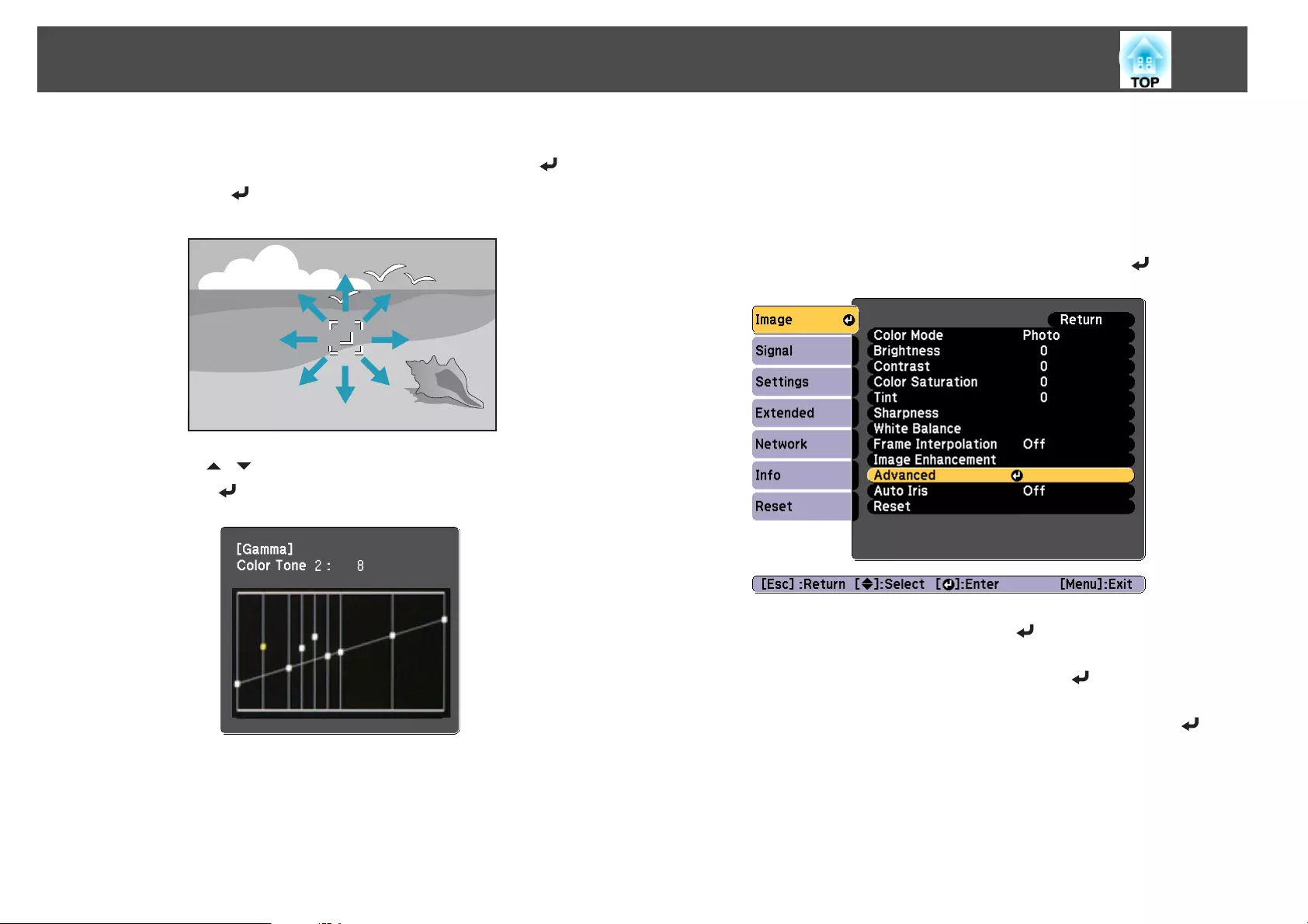
f
Move the cursor on the projected image to the part where you
want to change the brightness, and then press the [ ] button.
If you press [ ], the image flashes and you can check the tone area
of the adjustment target.
g
Use the [ ][ ] buttons to make adjustments, and then confirm
using the [ ] button.
h
When Do you want to continue adjusting the setting? is
displayed, select Yes or No.
To adjust another location, select Yes, and repeat the procedure from
step 6.
Adjust using the gamma adjustment graph
Select a tone point on the graph and make adjustments.
a
Press the [Menu] button while projecting.
b
Select Advanced from Image, and then press the [ ] button.
c
Select Gamma, and then press the [ ] button.
d
Select Customized, and confirm using the [ ] button.
e
Select Adjust it from the graph, and confirm using the [ ]
button.
Adjusting Projected Images
95
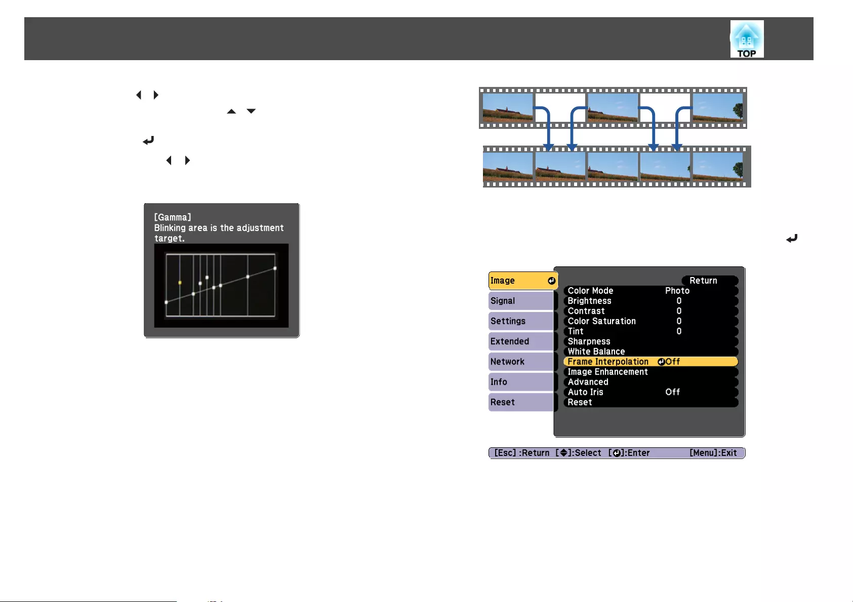
f
Use the [ ][ ] buttons to select the tone that you want to
change, and then use the [ ][ ] buttons to make the
adjustments. When you have finished making changes, confirm by
using the [ ] button.
If you use the [ ][ ] buttons to select the tone that you want to
change, the image flashes and you can check the tone area of the
adjustment target.
g
When Do you want to continue adjusting the setting? is
displayed, select Yes or No.
To adjust another tone, select Yes, and repeat the procedure from
step 6.
Frame Interpolation
The current and previous frames are used to create intermediate frames,
interpolating to produce smooth-moving images. You can resolve clumsy-
moving images, such as frame skipping when projecting a fast moving
image.
a
Press the [Menu] button while projecting.
b
Select Frame Interpolation from Image, and then press the [ ]
button.
Adjusting Projected Images
96
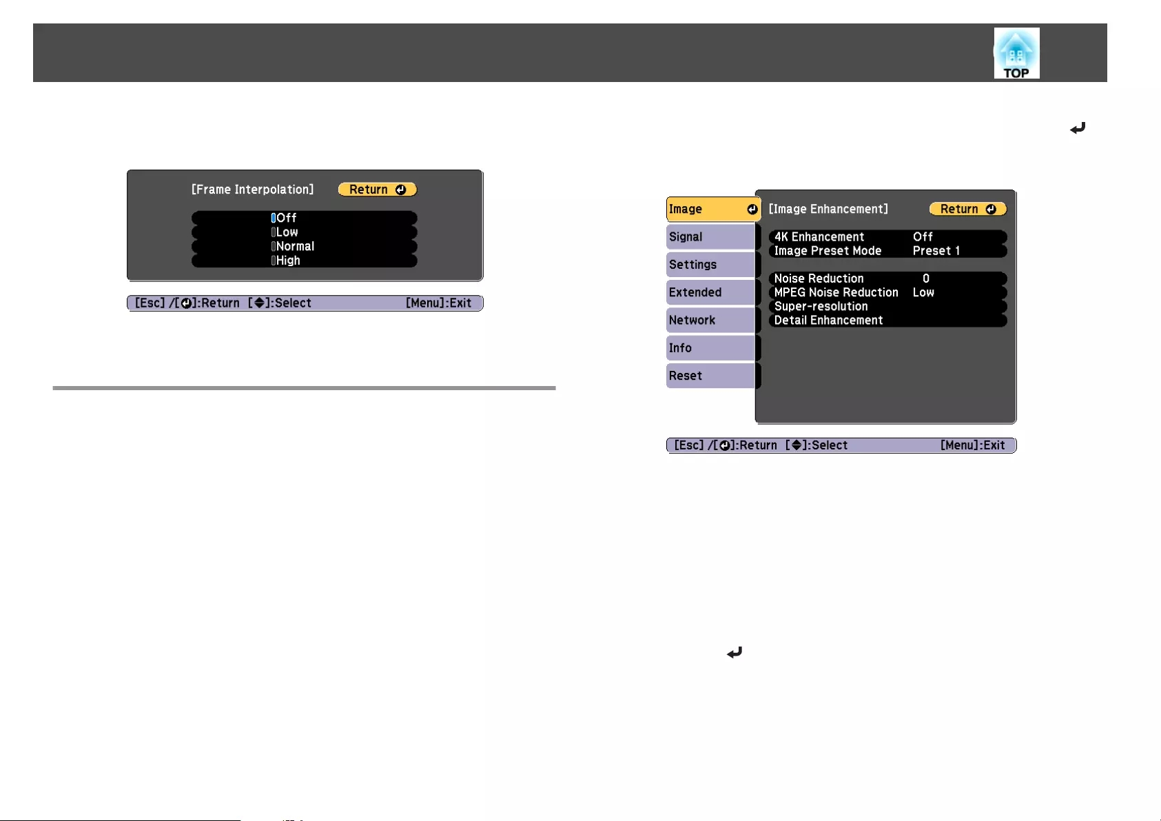
c
Select the level of interpolation from Low, Normal or High.
Set to Off if noise occurs after setting them.
d
Press the [Menu] button to finish making settings.
Adjusting Image Resolution (Image Enhancement)
You can adjust the resolution of the image using Image Enhancement to
reproduce a clear image with an emphatic texture and material feel.
a
Press the [Menu] button while projecting.
b
Select Image Enhancement from Image, and then press the [ ]
button.
The following screen is displayed.
4K Enhancement (EB-G7905U/EB-G7900U/EB-G7500U/EB-G7400U
only)
4K Enhancement is a function that projects an image at a doubled
resolution by diagonally shifting 1 pixel in increments of 0.5 pixels.
A high-resolution image signal is projected in fine detail.
a
Select 4K Enhancement from Image Enhancement, and then
press the [ ] button.
Adjusting Projected Images
97
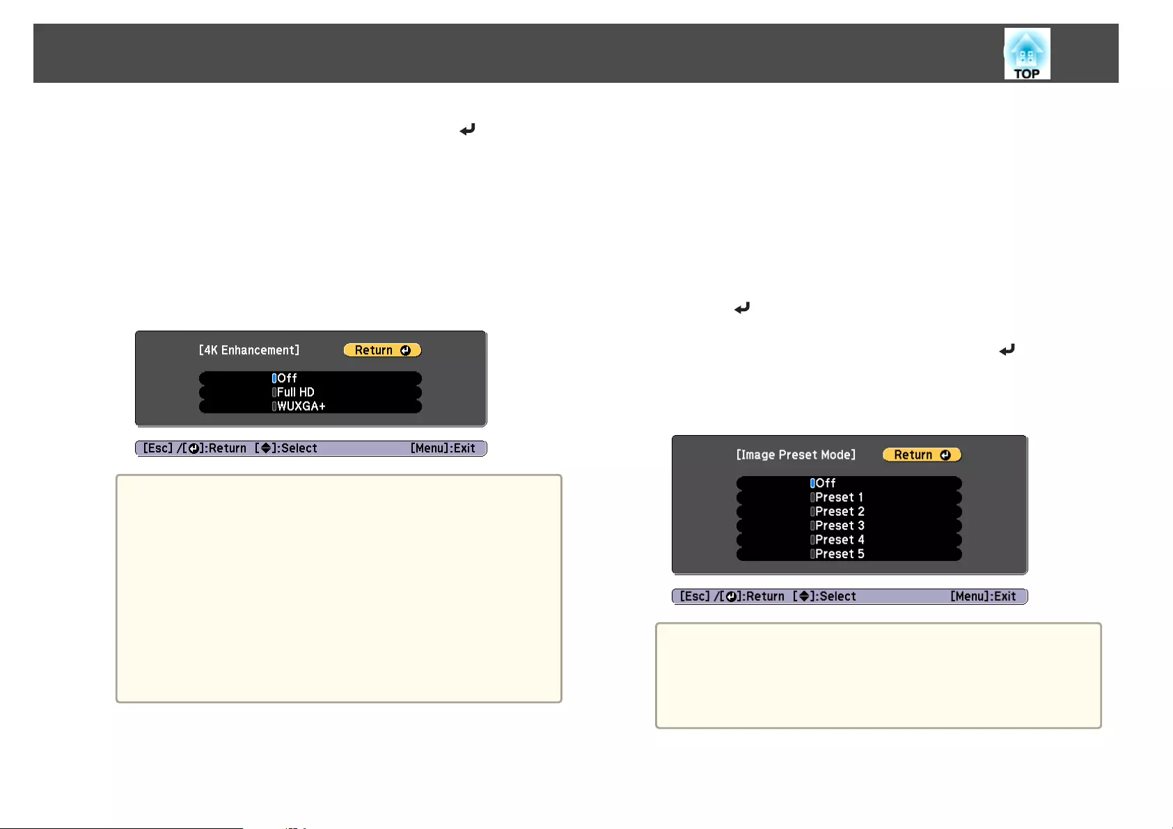
b
Select one of the following, and then press the [ ] button.
Off: Disables 4K Enhancement. If a signal that exceeds the panel
resolution of this projector is input, the image is displayed according
to the panel resolution of this projector.
Full HD: If a signal with a resolution of 1080i/1080p/WUXGA or
higher is input, 4K Enhancement is enabled.
WUXGA+: If a signal with a resolution that exceeds WUXGA is
input, 4K Enhancement is enabled. To project a high-resolution
movie, you can project a high-definition image by using this setting
with Image Preset Mode.
a
•To project from multiple projectors, select Off to unify each
image.
•Off is ideal for projecting presentation materials from
computers and so on.
•If set to Full HD or WUXGA+, the status corrected using the
following function is canceled.
Edge Blending, Scale, Curved Surface, Point Correction,
Corner Wall
When 4K Enhancement is set to Off, the settings returns to
the previous state.
•If 4K Enhancement is enabled and the surrounding
temperature gets high, the lamp may automatically dim.
c
Press the [Esc] button to return to the previous screen.
Image Preset Mode
Select the optimal setting according to the projected image from five presets
prepared in advance.
The following settings are saved in the presets.
Noise Reduction, MPEG Noise Reduction, Super-resolution, Detail
Enhancement
a
Select Image Preset Mode from Image Enhancement, and then
press the [ ] button.
b
Select one of the following, and then press the [ ] button.
Preset 1 to Preset 5: The settings saved in advance are applied to the
image.
Off: Select this to turn off presets.
a
•After selecting Preset 1 to Preset 5, you can fine tune each
setting individually. The setting after adjustment will be
overwritten.
•The setting after adjustment will be overwritten separately
when 4K Enhancement is enabled and disabled.
c
Press the [Esc] button to return to the previous screen.
Adjusting Projected Images
98
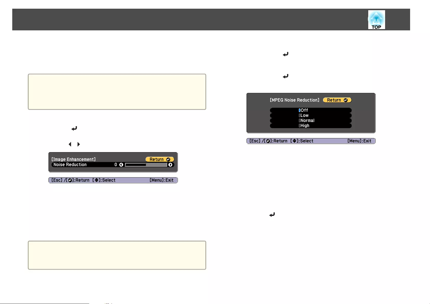
Noise Reduction
You can smooth out rough images for softer image quality when inputting
progressive signals or progressive interlace signals.
a
This is disabled in the following cases.
•When Image Processing is set to Fast 2
•When 4K Enhancement is enabled
•When a signal with a resolution that exceeds WUXGA is input
a
Select Noise Reduction from Image Enhancement, and then
press the [ ] button.
b
Use the [ ][ ] buttons to adjust the value.
c
Press the [Esc] button to return to the previous screen.
MPEG Noise Reduction
You can reduce dot and block noise that occurs in outlines when projecting
MPEG movies.
a
This is disabled in the following cases.
•When 4K Enhancement is enabled
•When a signal with a resolution that exceeds WUXGA is input
a
Select MPEG Noise Reduction from Image Enhancement, and
then press the [ ] button.
b
Select a level to reduce noise from Low, Normal, or High, and
then press the [ ] button.
If Off is selected, MPEG Noise Reduction is disabled.
c
Press the [Esc] button to return to the previous screen.
Super-resolution
To display a crisp image, you can reduce the blurring that is created on the
edge when the resolution of the image signal is scaled up and projected.
a
Select Super-resolution from Image Enhancement, and then
press the [ ] button.
Adjusting Projected Images
99
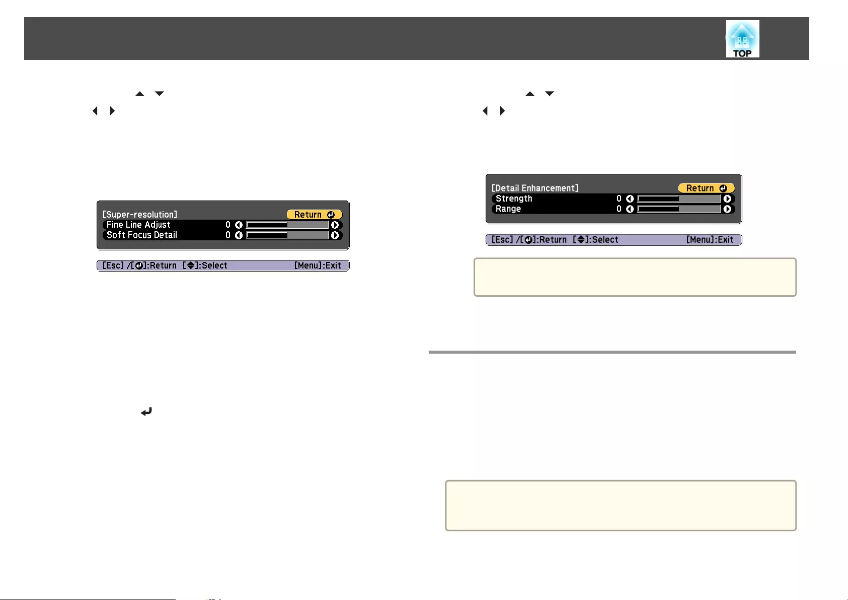
b
Use the [ ][ ] buttons to select the item, and then use the
[][ ] buttons to make the adjustments.
Fine Line Adjust: If this parameter is set to a positive value, details
such as hair or fabric patterns will be enhanced.
Soft Focus Detail: If this parameter is set to a positive value, the
outline, background, and the other main parts of the objects in the
image will be enhanced to show them clearly.
c
Press the [Esc] button to return to the previous screen.
Detail Enhancement
You can enhance the contrast in detailed areas of an image to create a more
emphatic texture and material feel.
a
Select Detail Enhancement from Image Enhancement, and then
press the [ ] button.
b
Use the [ ][ ] buttons to select the item, and then use the
[][ ] buttons to make the adjustments.
Strength: The larger the value, the more the contrast is enhanced.
Range: The larger the value, the wider the range of detail
enhancement becomes.
a
Depending on the image, a highlight may be noticeable at the
border between colors. If this bothers you, set a smaller value.
c
Press the [Esc] button to return to the previous screen.
Projecting 3D images
By using two projectors, you can project passive 3D images. The following
are required to project and view 3D images.
•Polarizer
•Passive 3D glasses
•Mount for stacking
•Silver screen for passive 3D
a
This projector arranges the direction of polarizing projection for R
(red), G (green), and B (blue). It is not necessary to inverse left and
right eye G (green) image signals.
Adjusting Projected Images
100

Useful Functions
This section describes the Multi-Projection, Split Screen, Memory, Schedule, and Security functions.
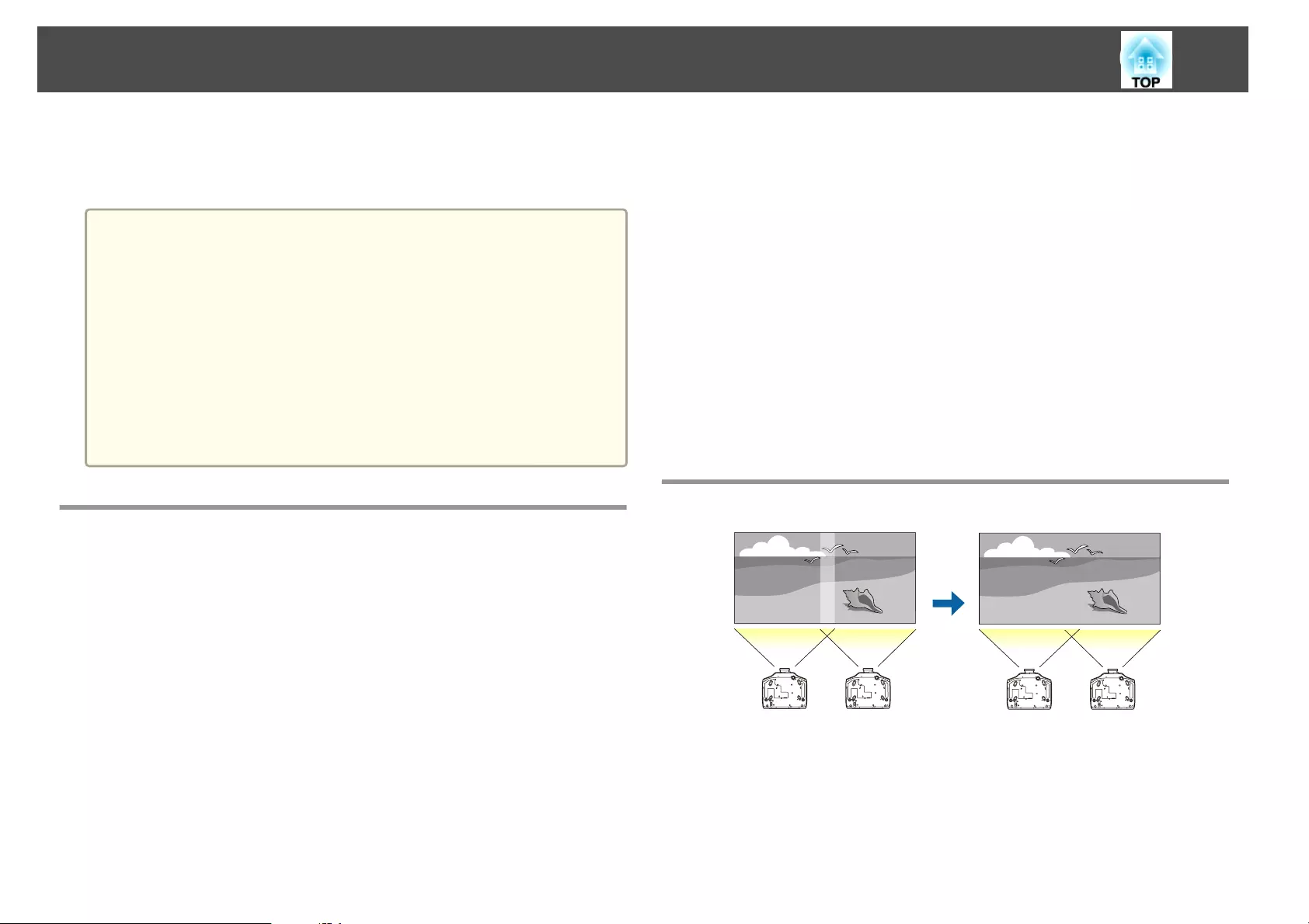
When projecting to a wide screen from multiple projectors, you can adjust
the difference of brightness and color tone between each projected image to
create a seamless screen.
a
•Set 4K Enhancement to Off. (EB-G7905U/EB-G7900U/EB-G7500U/
EB-G7400U only)
•We recommend setting the focus, zoom, and lens shift at least
20 minutes after you start the projection, because images are not
stable right after turning on the projector.
•If the values for Geometric Correction are large, the image position
adjustment for overlapping images becomes difficult.
•The Test Pattern can be displayed to adjust the projection status
without connecting video equipment.
s "Displaying a Test Pattern" p.32
•If you project a dot by dot image that can be projected without
being enlarged or reduced, you can make adjustments precisely.
Preparation
Follow the steps below to adjust the projected images for the multi-
projection function.
a
Set an ID for the projector and the remote control.
s "Set the projector ID" p.41
b
Adjust the position of the projected image in the following order
(starting from the adjustments that have larger corrections).
(1) Projector's position (angle)
s "Installation Settings" p.28
(2) Lens shift/Zoom
s "Adjusting the Position of the Projected Image (Lens Shift)" p.33
s "Adjusting the Image Size" p.36
(3) Correct the four image corners
s "Quick Corner" p.64
(4) Correct the slight position misalignment that occurs when matching the
projected images
s "Point Correction" p.86
c
Set the Color Mode to Multi-Projection with the [Color Mode]
button.
When set to another color mode (except for sRGB), the border
between multiple images may be noticable even with correction using
Edge Blending.
d
Adjusts the color tone for the whole screen as necessary.
s "Color Uniformity" p.200
Edge Blending
Follow the steps below to adjust so that the overlapping areas of the images
are less noticeable.
(1) Fine tune the overlapping areas to make seamless screen.
s "Adjust the Edges of the Images (Edge Blending)" p.103
Multi-Projection Function
102
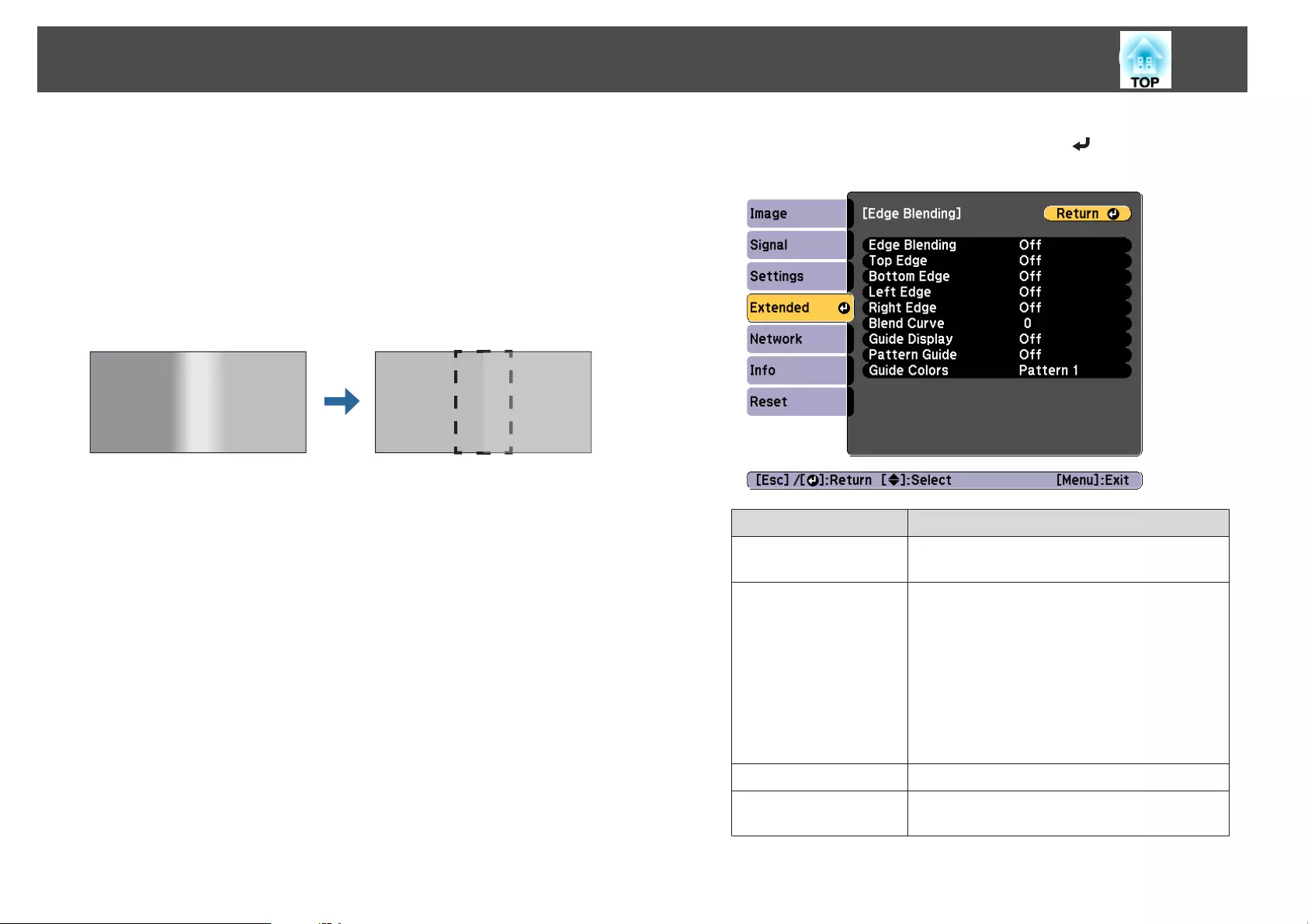
(2) Adjust the brightness difference for each projector lamp.
s "Correcting the Brightness (EB-G7905U/EB-G7900U/EB-G7500U/EB-
G7200W/EB-G7000W/EB-G7805/EB-G7800/EB-G7100 only)" p.105
(3) Adjust the color balance of the projected images.
s "Fine-tuning the color balance" p.106
Adjust the Edges of the Images (Edge Blending)
You can fine tune the overlapping areas to make seamless screen.
a
Press the [Menu] button while projecting.
s "Using the Configuration Menu" p.134
b
Select Multi-Projection from Extended.
c
Select Edge Blending, and then press the [ ] button.
The following screen is displayed.
Submenu Function
Edge Blending Set to On to activate Edge Blending. Set to Off
when not projecting from multiple projectors.
Top Edge/Bottom
Edge/Left Edge/Right
Edge
Blending: Set to On to activate Edge Blending
towards your settings, and the blend range will be
shaded.
Blend Start Position: Displays blending start
position as a red line, and adjusts at the level of one
pixel.
Blend Range: Adjusts the range to be shaded.
Adjustment is possible at the level of one pixel. The
maximum range is 45% of the resolution.
Blend Curve You can select from three ways of shading.
Guide Display Set to On to display a guide on the Edge Blending
setting range.
Multi-Projection Function
103
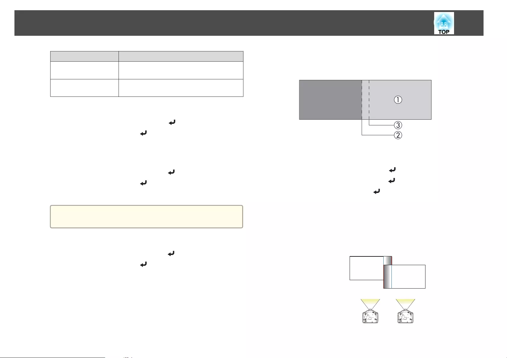
Submenu Function
Pattern Guide Set to On to display a guide to match the position of
the Edge Blending setting range.
Guide Colors Select a combination of guide colors from the three
provided.
d
Turn on Edge Blending.
(1) Select Edge Blending, and then press the [ ] button.
(2) Select On, and then press the [ ] button.
(3) Press the [Esc] button.
e
Set Guide Display to On.
(1) Select Guide Display, and then press the [ ] button.
(2) Select On, and then press the [ ] button.
(3) Press the [Esc] button.
a
If the guide is not clear, you can change the color of the guide
on Guide Colors.
f
Set Pattern Guide to On.
(1) Select Pattern Guide, and then press the [ ] button.
(2) Select On, and then press the [ ] button.
(3) Press the [Esc] button.
g
Set Top Edge, Bottom Edge, Left Edge, or Right Edge according
to the parts of the image that are overlapped.
The following shows how to set screen (1) as an example.
In the example above, you need to adjust the Left Edge because you
can see the overlapping areas on the left side of the image (1).
(1) Select Left Edge, and then press the [ ] button.
(2) Select Blending, and then press the [ ] button.
(3) Select On, and then press the [ ] button.
(4) Press the [Esc] button.
(5) In Blend Start Position, align the blending start position with the edge (2)
of the image.
(6) Press the [Esc] button.
(7) In Blend Range, adjust the range (3) to be shaded.
The value for when the overlapped range and the guide are in the same
position is the best.
(8) Press the [Esc] button.
Multi-Projection Function
104
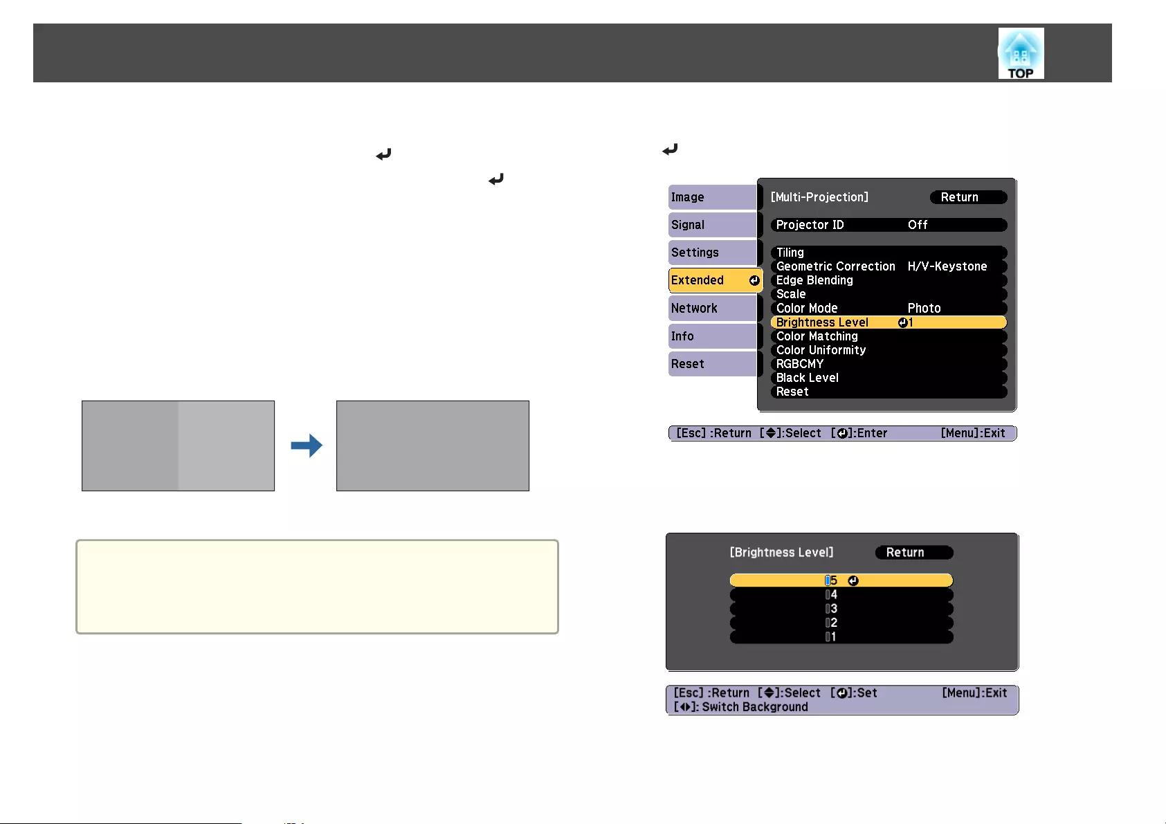
h
Set Blend Curve.
(1) Select Blend Curve, and then press the [ ] button.
(2) Select the amount of shading from 1 to 3, and then press the [ ] button.
(3) Press the [Esc] button.
i
After the settings are complete, set Guide Display and Pattern
Guide to Off to finish.
Correcting the Brightness (EB-G7905U/EB-G7900U/EB-G7500U/EB-
G7200W/EB-G7000W/EB-G7805/EB-G7800/EB-G7100 only)
You can adjust the Brightness Level so that the lamp brightness is the same
for each projector.
Adjust so that all projectors are the same brightness as the darkest lamp.
a
•Set Power Consumption to Off.
s Settings - Power Consumption p.140
•Even if you adjust the Brightness Level, the brightness of each lamp
may not match exactly.
a
Select Brightness Level from Multi-Projection, and then press the
[] button.
b
Select a brightness level.
The brightness level varies depending on the model being used and
the projection method.
Multi-Projection Function
105
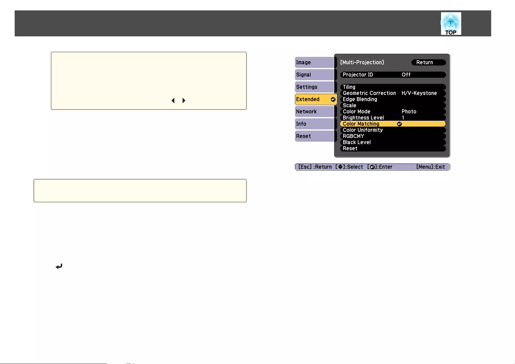
a
•When Portrait Mode is On, brightness is adjusted in three
levels.
•When Portrait Mode is Off, brightness is adjusted in three or
five levels, depending on the model being used.
•You can switch the projected image between the input image
and the white image using the [ ][ ] buttons.
c
Press the [Esc] button to return to the previous screen.
Fine-tuning the color balance
Adjust the brightness of the projected image and the color balance that was
adjusted by Edge Blending.
a
The brightness and color may not be uniform even after making
adjustments.
Color Matching
You can fine tune the color balance and brightness from black to white for
each color tone.
a
Select Color Matching from Multi-Projection, and then press the
[] button.
Multi-Projection Function
106
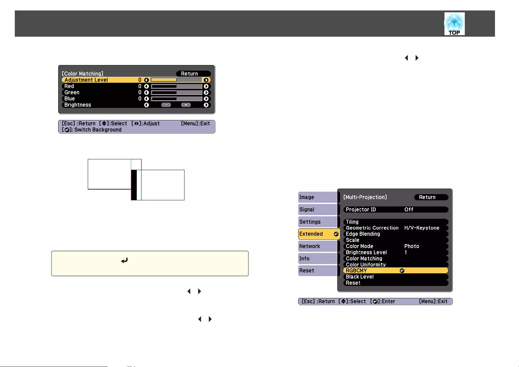
The following screen is displayed.
Half of the overlapped area is displayed in black so that it is easy to
check the edge of the image.
Adjustment Level: There are eight levels from white, through gray,
and up to black. Adjust each level individually.
Red, Green, Blue: Adjusts the tone for each color.
Brightness: Adjusts the image brightness.
a
Whenever the [ ] button is pressed, the screen changes
between the projected image and the adjustment screen.
b
Select Adjustment Level, and then use the [ ][ ] buttons to set
the adjustment level.
c
Select Red, Green, or Blue, and then press the [ ][ ] buttons to
adjust the color tone.
d
Select Brightness, and then use the [ ][ ] buttons to adjust the
brightness.
e
Return to step 2 and adjust each level.
f
Press the [Esc] button to return to the previous screen.
Adjusting RGBCMY
The Hue, Saturation, and Brightness for each of the R (red), G (green), B
(blue), C (cyan), M (magenta) and Y (yellow) color components can be
adjusted.
After adjustment using Color Matching, adjust if you are concerned about
differences of the colors.
s "Hue, Saturation, and Brightness adjustment" p.92
Multi-Projection Function
107
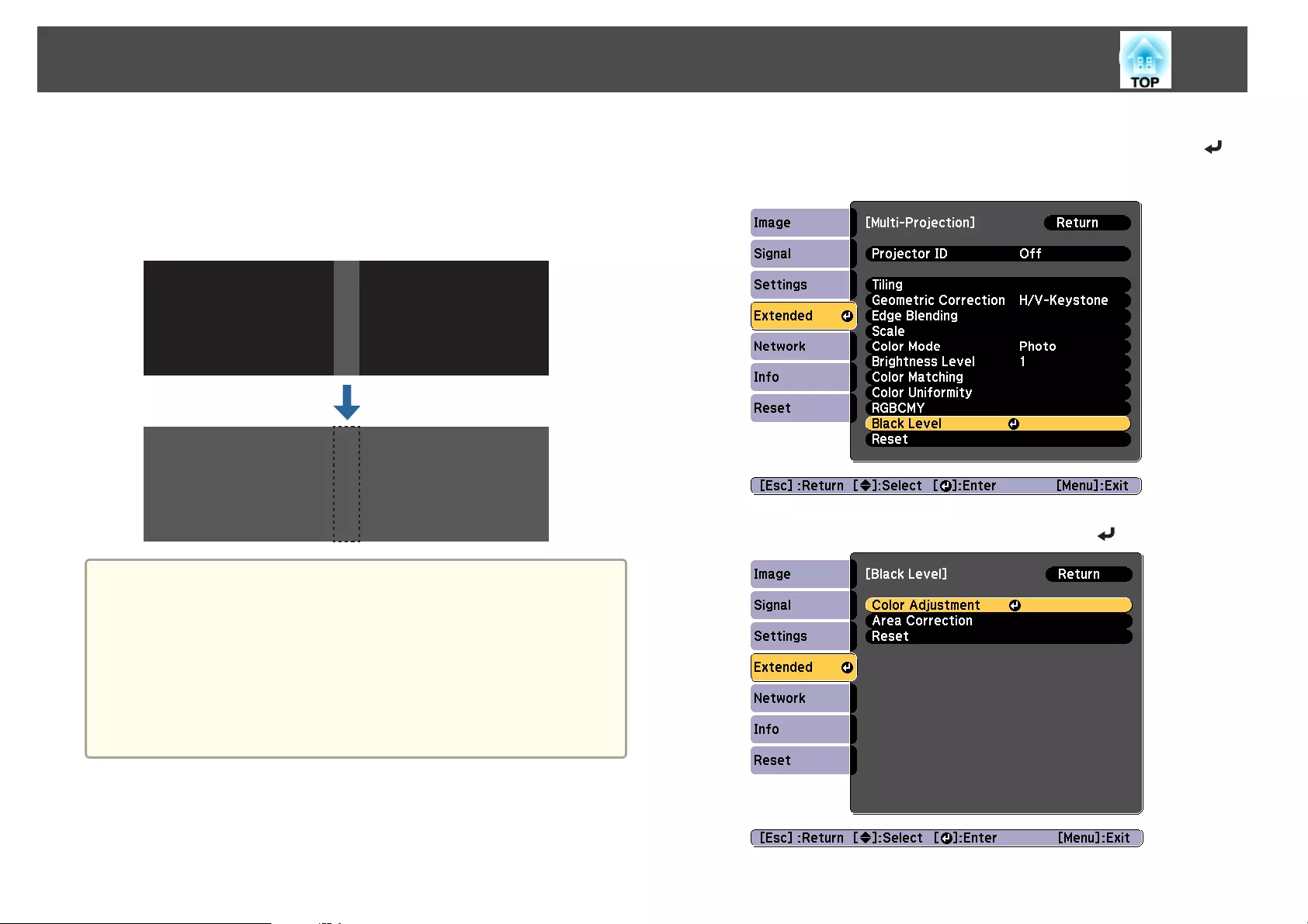
Black Level
When a black image is displayed, only areas where the images overlap
stands out. The black level function allows you to match the brightness and
tone for areas where the images do not overlap with areas where the images
overlap, to make the difference less noticeable.
a
•You cannot adjust the Black Level when a test pattern is displayed.
•If the Geometric Correction value is large, you may not be able to
adjust correctly.
•The brightness and tone may differ in areas where the images
overlap as well as in other areas even after performing black level
adjustment.
•If you change the Top Edge/Bottom Edge/Right Edge/Left Edge
setting, the Black Level is returned to its default value.
s "Adjust the Edges of the Images (Edge Blending)" p.103
a
Select Black Level from Multi-Projection, and then press the [ ]
button.
b
Select Color Adjustment, and then press the [ ] button.
Multi-Projection Function
108
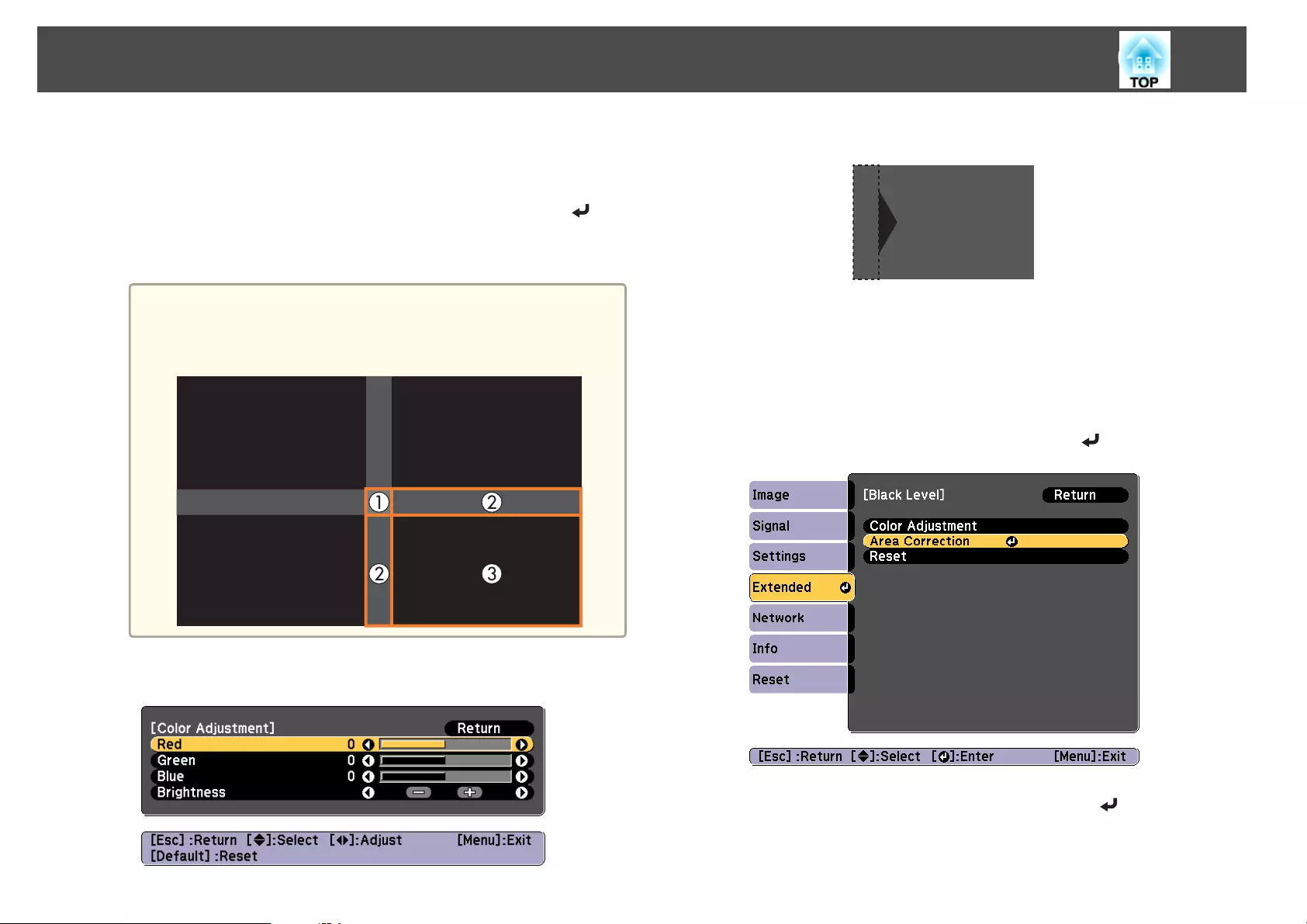
The areas are displayed based on the settings for Top Edge/Bottom
Edge/Right Edge/Left Edge.
c
Select the area you want to adjust, and then press the [ ]
button.
The selected area is displayed in orange.
a
When multiple screens are overlapping, adjust based on the area
with the most overlap (the brightest area). In the illustration
below, first align (2) with (1), and then adjust so that (3) aligns
with (2).
d
Adjust the black tone and brightness.
e
Repeat steps 3 and 4 as needed to adjust any remaining parts.
After this, if the tone for some areas do not match, adjust them by
Area Correction.
f
Press the [Esc] button, to return to the screen displayed in step
2.
g
Select Area Correction, and then press the [ ] button.
h
Select Start Adjustments, and then press the [ ] button.
Multi-Projection Function
109
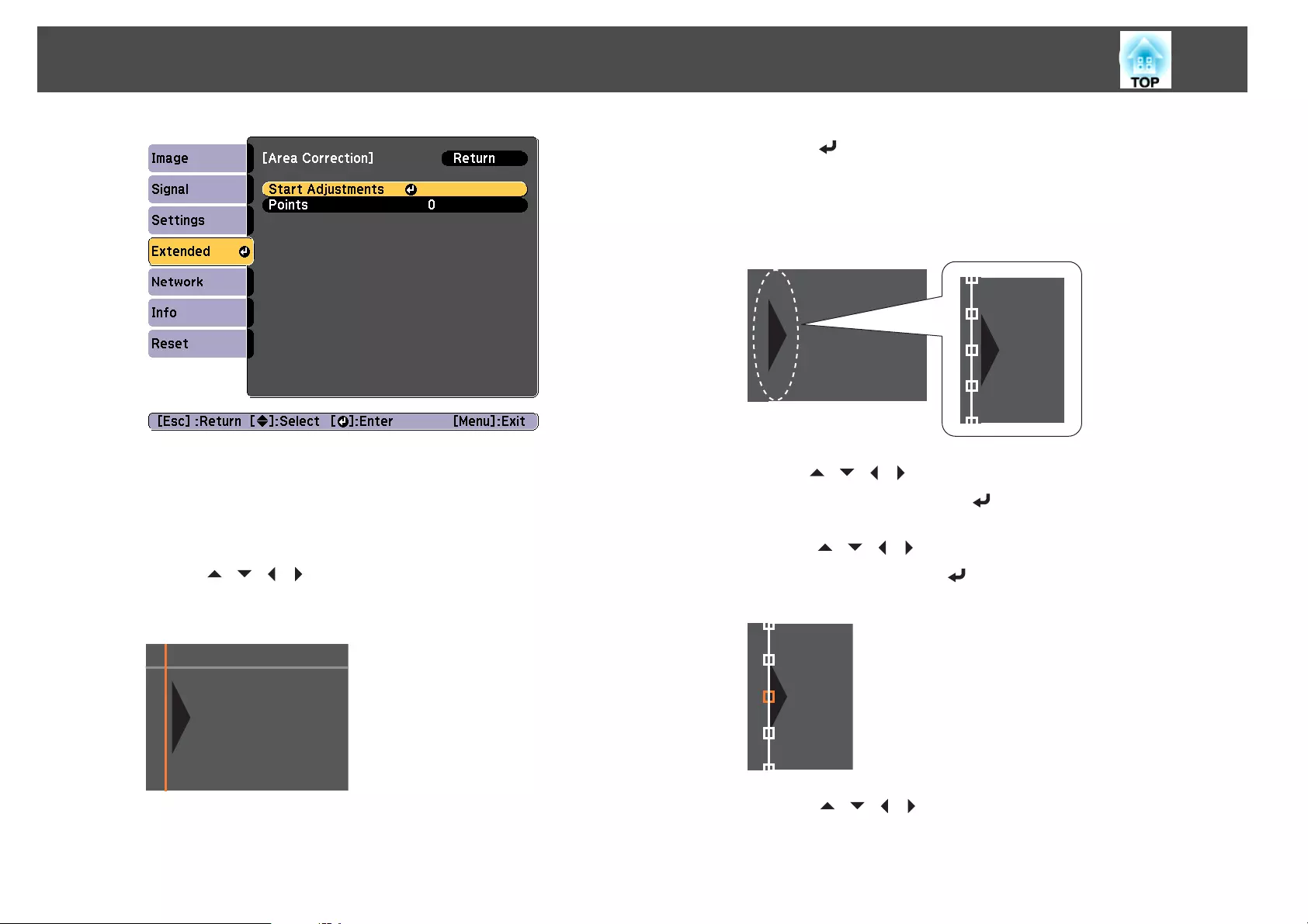
Boundary lines that indicate areas where images overlap are
displayed.
The boundary lines are displayed based on the settings for Top
Edge/Bottom Edge/Right Edge/Left Edge.
i
Use the [ ][ ][ ][ ] buttons to select a boundary line of the
area you want to adjust.
The selected line is displayed in orange.
j
Press the [ ] button to confirm the selection.
The points where you want to set the range for adjustment are
displayed.
You can change the number of points displayed on one side in
Points on the screen from step 8.
k
Use the [ ][ ][ ][ ] buttons to adjust the boundary line
positions, and then press the [ ] button.
l
Press the [ ][ ][ ][ ] buttons to select the point you want to
move, and then press the [ ] button.
The selected point is displayed in orange.
m
Press the [ ][ ][ ][ ] buttons to move the point.
Multi-Projection Function
110
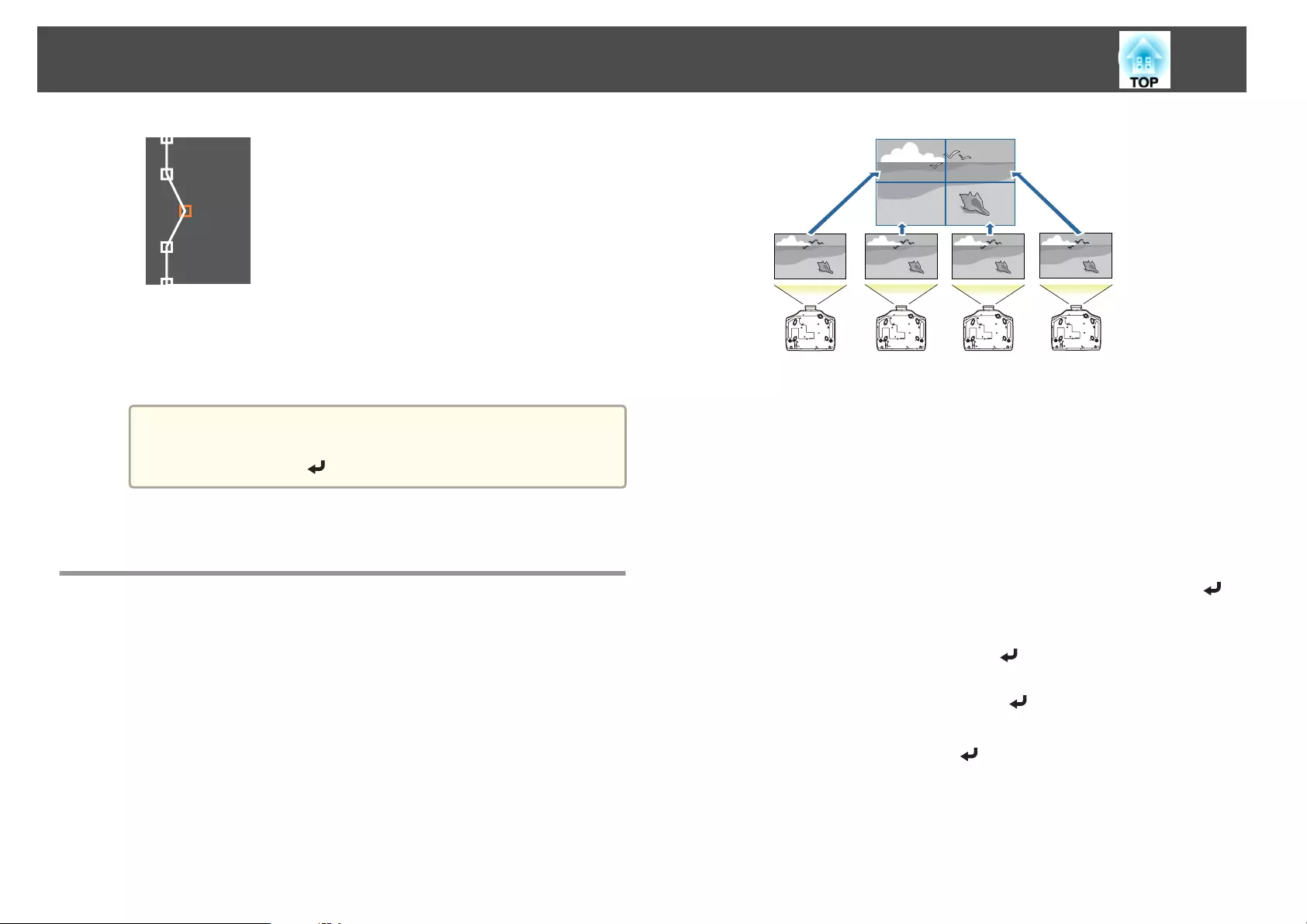
To continue to move another point, press the [Esc] button to return
to step 12, and then repeat steps 12 and 13.
To adjust another boundary line, press the [Esc] button until the
screen for selecting a boundary line from step 9 is displayed.
a
To return Black Level to its default value, press the [Esc]
button to return to the screen from step 7, select [Reset], and
then press the [ ] button.
n
To complete the adjustment, press the [Menu] button.
Tiling
Project the same image from multiple projectors to create one large image.
You can project by using up to nine projectors.
a
Set an ID for each projector to be used for tiling, and then adjust
the positions of the projected images.
s "Preparation" p.102
b
Adjust the overlapping areas of the screens using edge blending.
s "Edge Blending" p.102
c
Press the [Menu] button while projecting.
d
Select Multi-Projection from Extended, and then press the [ ]
button.
e
Select Tiling, and then press the [ ] button.
f
Select Layout, and then press the [ ] button.
(1) Set the number of projectors in Row and Column.
(2) Select Set, and then press the [ ] button.
g
Repeat steps 2 to 6 for each projector to be used for tiling.
Multi-Projection Function
111
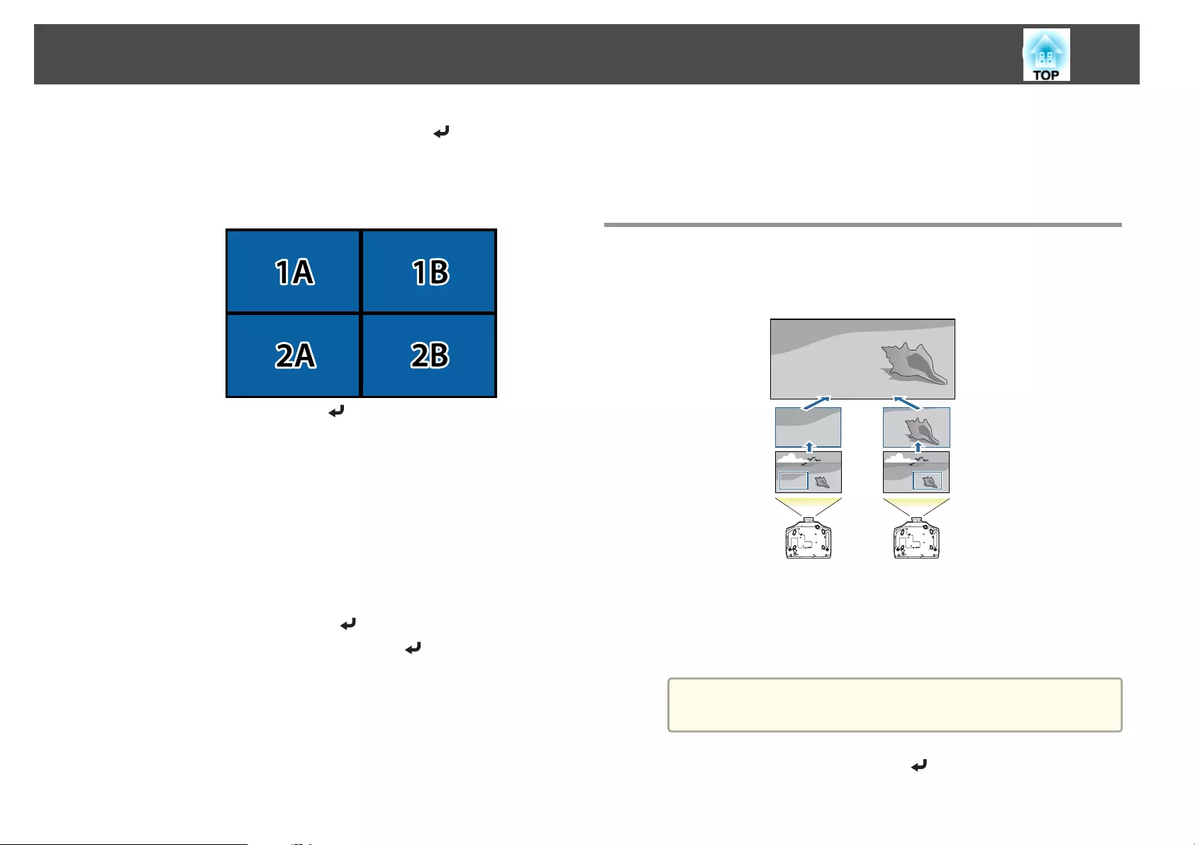
h
Select Location Setup, and then press the [ ] button.
(1) Set the positions of the projected images in Row Order and Column
Order.
Row Order: Place screens from top to bottom in the order of 1, 2, 3.
Column Order: Place screens from left to right in the order of A, B, C.
(2) Select Set, and then press the [ ] button.
i
Repeat step 8 for each projector.
j
Input the image signal to display the image.
s "Automatically Detecting Input Signals and Changing the
Projected Image (Source Search)" p.59
k
Set Scale to Auto.
(1) Select Multi-Projection from Extended.
(2) Select Scale, and then press the [ ] button.
(3) Select Auto from Scale, and then press the [ ] button.
The scale and clip range are automatically set according to the
blending width.
l
Fine tune the overlapping areas of the screens.
s "Correcting Distortion in the Projected Image" p.62
s "Adjust the Edges of the Images (Edge Blending)" p.103
Displaying a Scaled Image
A section of the image is cropped and displayed. This allows you to create
one large image by combining images projected from multiple projectors.
a
Project the image, and then press the [Menu] button.
s "Using the Configuration Menu" p.134
b
Select Multi-Projection from Extended.
a
You can also perform the same operation from Scale in
Signal.
c
Select Scale, and then press the [ ] button.
Multi-Projection Function
112
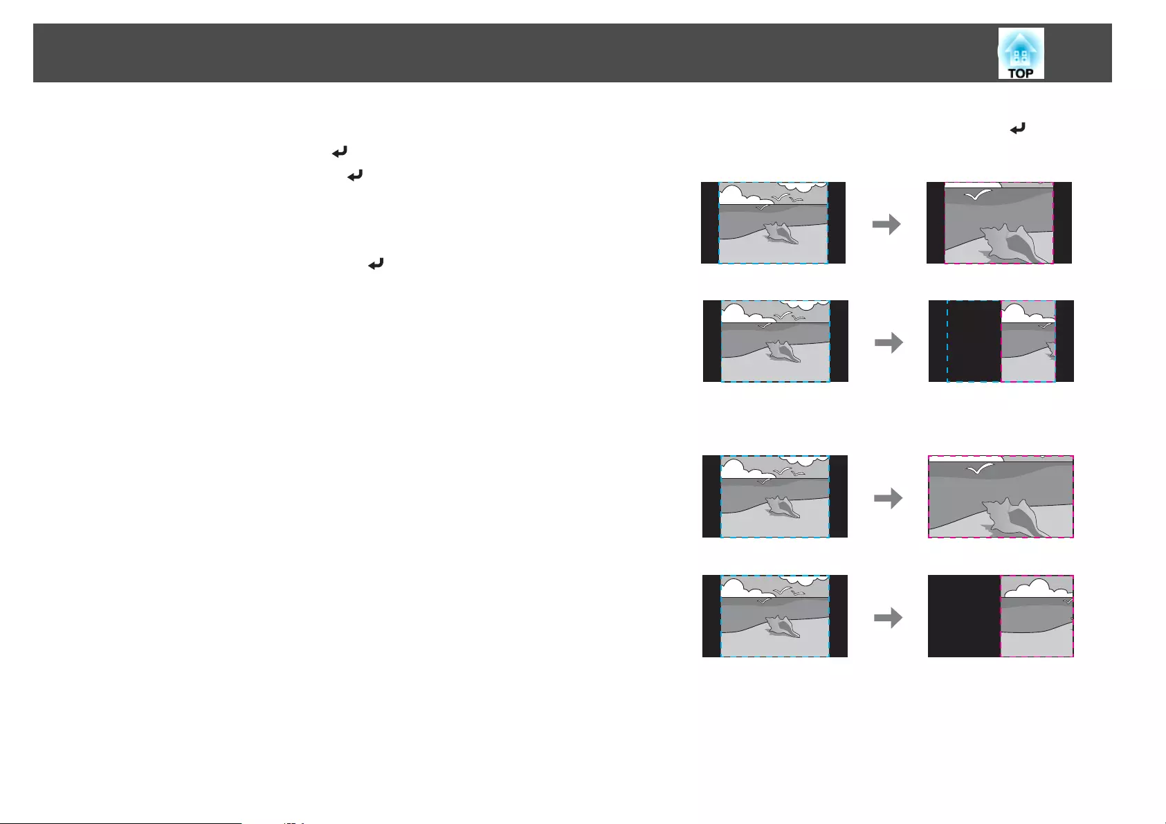
d
Turn on Scale.
(1) Select Scale, and then press the [ ] button.
(2) Select Manual, and then press the [ ] button.
(3) Press the [Esc] button to return to the previous screen.
e
Set Scale Mode.
(1) Select Scale Mode, and then press the [ ] button.
(2) Select Zoom Display or Full Display, and then press the [ ] button.
Zoom Display: Adjusts according to the image currently displayed.
Enlarge
Move
Full Display: Adjusts according to the projector's panel size (the
maximum area in which an image can be displayed).
Enlarge
Move
(3) Press the [Esc] button to return to the previous screen.
Multi-Projection Function
113

f
Adjust the scale.
Select the adjustment method with the [ ][ ] buttons, then adjust
using the [ ][ ] buttons.
- +: Enlarges or reduces an image horizontally and vertically at the
same time.
Scale Vertically: Enlarges or reduces an image vertically.
Scale Horizontally: Enlarges or reduces an image horizontally.
g
Adjust the range of the image to be cropped.
(1) Select Clip Adjustment, and then press the [ ] button.
If you select Clip Range, the range and coordinates of the image that the
projector will project is displayed.
(2) Use the [ ], [ ], [ ], and [ ] buttons to scroll the image.
Adjust the coordinates and size of each image while viewing the screen.
(3) Press the [Menu] button to finish making settings.
Multi-Projection Function
114
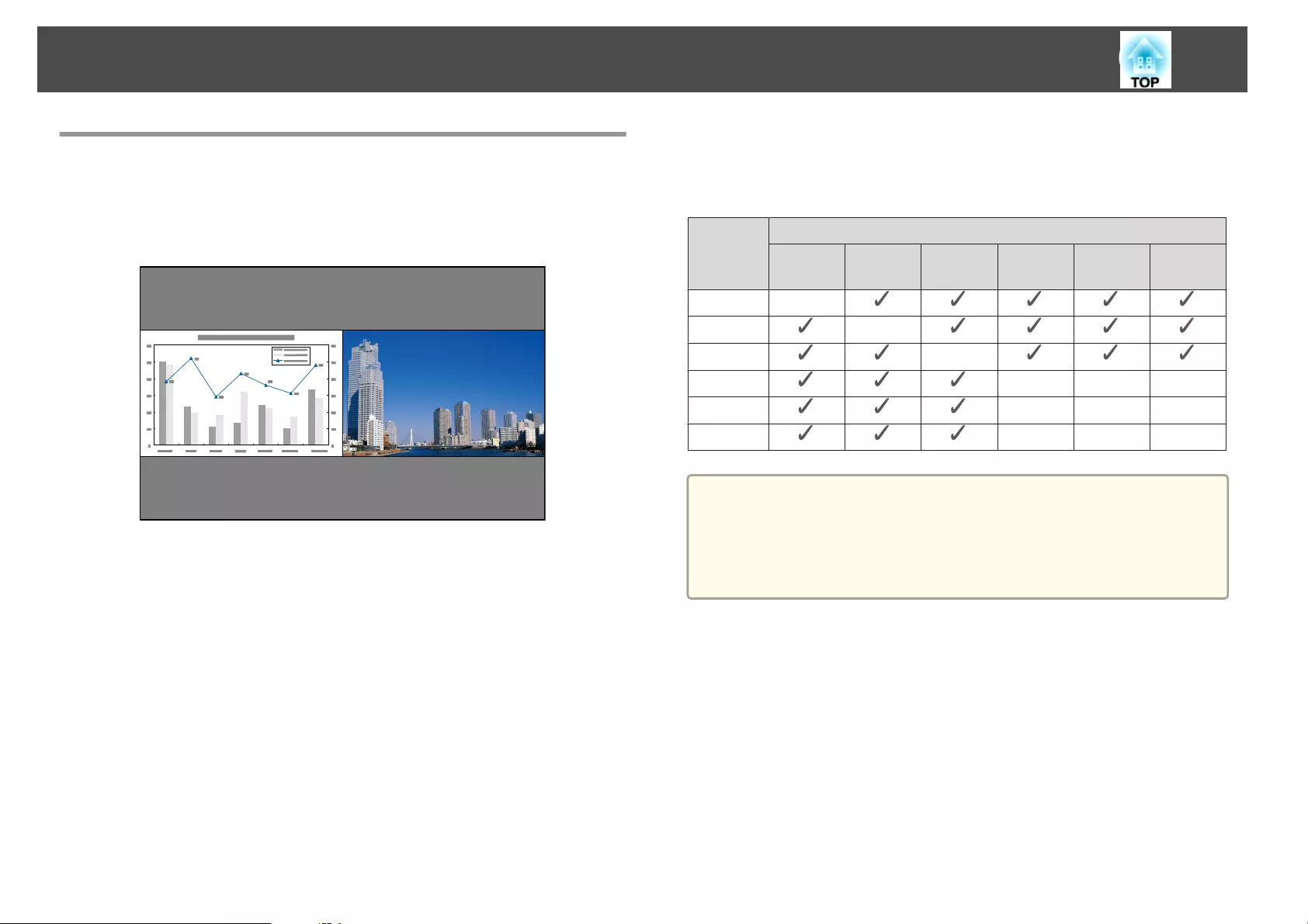
Projecting Two Images Simultaneously (Split
Screen)
You can simultaneously project images from two sources on the right and
left of the screen.
Input Sources for Split Screen Projection
The combinations of input sources that can be projected on a split screen
are listed below.
Left
Screen
Right Screen
HDMI HDBa-
seT
DVI-D Com-
puter
BNC LAN
HDMI -
HDBaseT -
DVI-D -
Computer ---
BNC ---
LAN ---
a
•Signals that exceed WUXGA are not supported.
•If 4K Enhancement is enabled, a message is displayed. Select Yes to
disable 4K Enhancement. (EB-G7905U/EB-G7900U/EB-G7500U/EB-
G7400U only)
s Image - Image Enhancement - 4K Enhancement p.137
Projection Functions
115
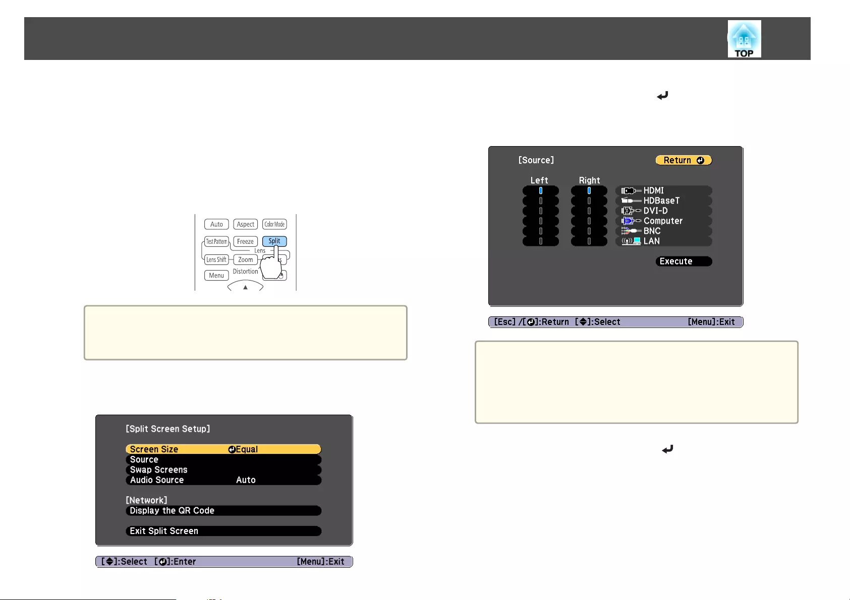
Operating procedures
Projecting on a split screen
a
Press the [Split] button on the remote control while projecting.
The currently selected input source is projected on the left of the
screen.
Remote control
a
You can perform the same operations from the configuration
menu.
s Settings - Split Screen p.140
b
Press the [Menu] button.
The Split Screen Setup screen is displayed.
c
Select Source, and then press the [ ] button.
d
Select each input source for Left and Right.
a
You can perform the same operations using the following
procedure.
s "Automatically Detecting Input Signals and Changing the
Projected Image (Source Search)" p.59
s "Switching to the Target Image by Remote Control" p.60
e
Select Execute, and then press the [ ] button.
To switch the source during split screen projection, start the
procedure from step 2.
Switching the left and right screens
Use the following procedure to switch the projected images displayed on
the left and right screens.
Projection Functions
116
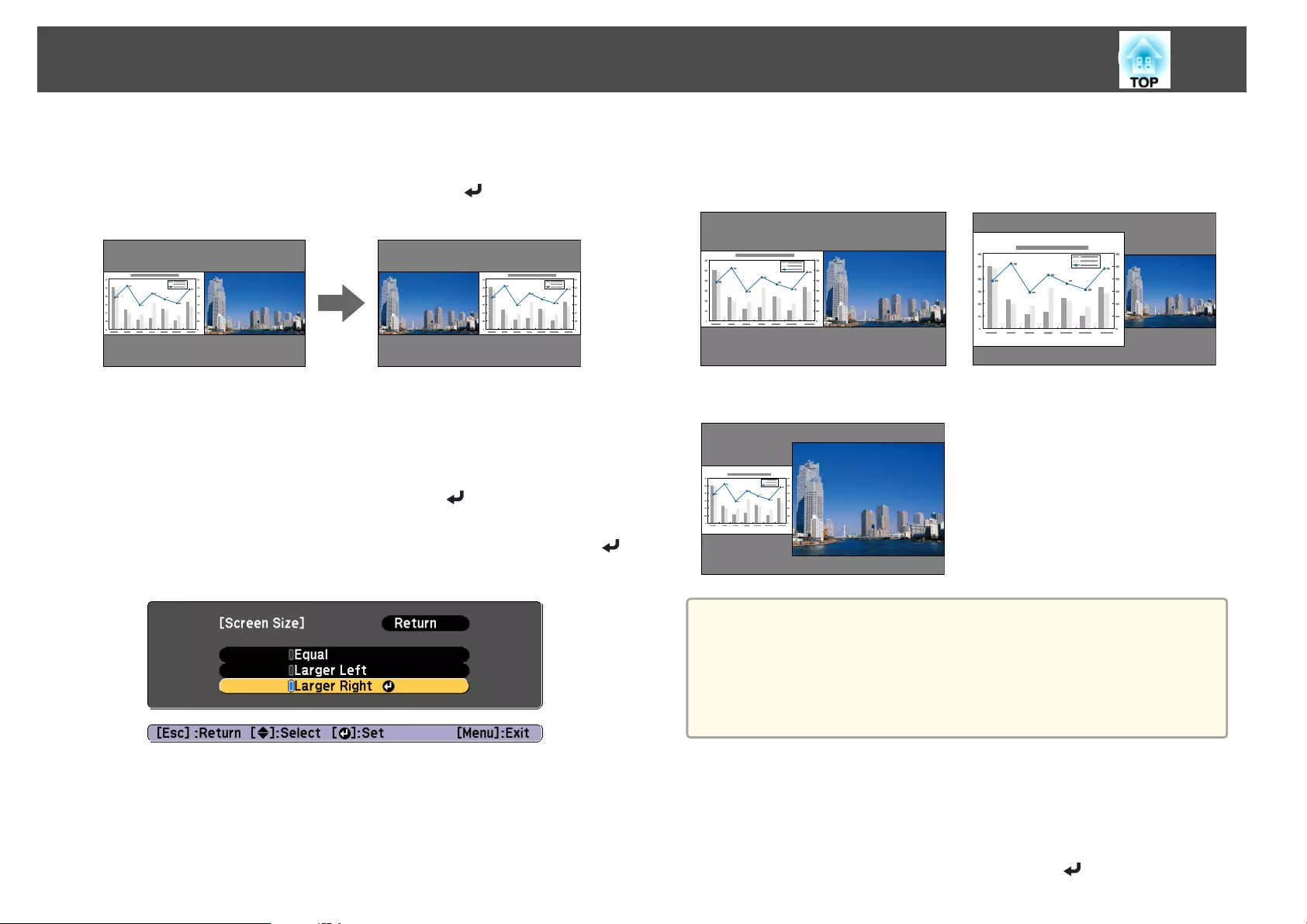
a
Press the [Menu] button during split screen projection.
b
Select Swap Screens, and then press the [ ] button.
The projected images on the left and right are swapped.
Switching the left and right image sizes
a
Press the [Menu] button during split screen projection.
b
Select Screen Size, and then press the [ ] button.
c
Select the screen size you want to display, and then press the [ ]
button.
The projected images will appear as shown below after setting the screen
size.
Equal Larger Left
Larger Right
a
•You cannot enlarge both the left screen and right screen images at
the same time.
•When one image is enlarged, the other image is reduced.
•Depending on the video signals that are input, the images on the left
and right may not appear to be the same size even if Equal is
set.
Changing the audio
a
Press the [Menu] button during split screen projection.
b
Select Audio Source, and then press the [ ] button.
Projection Functions
117
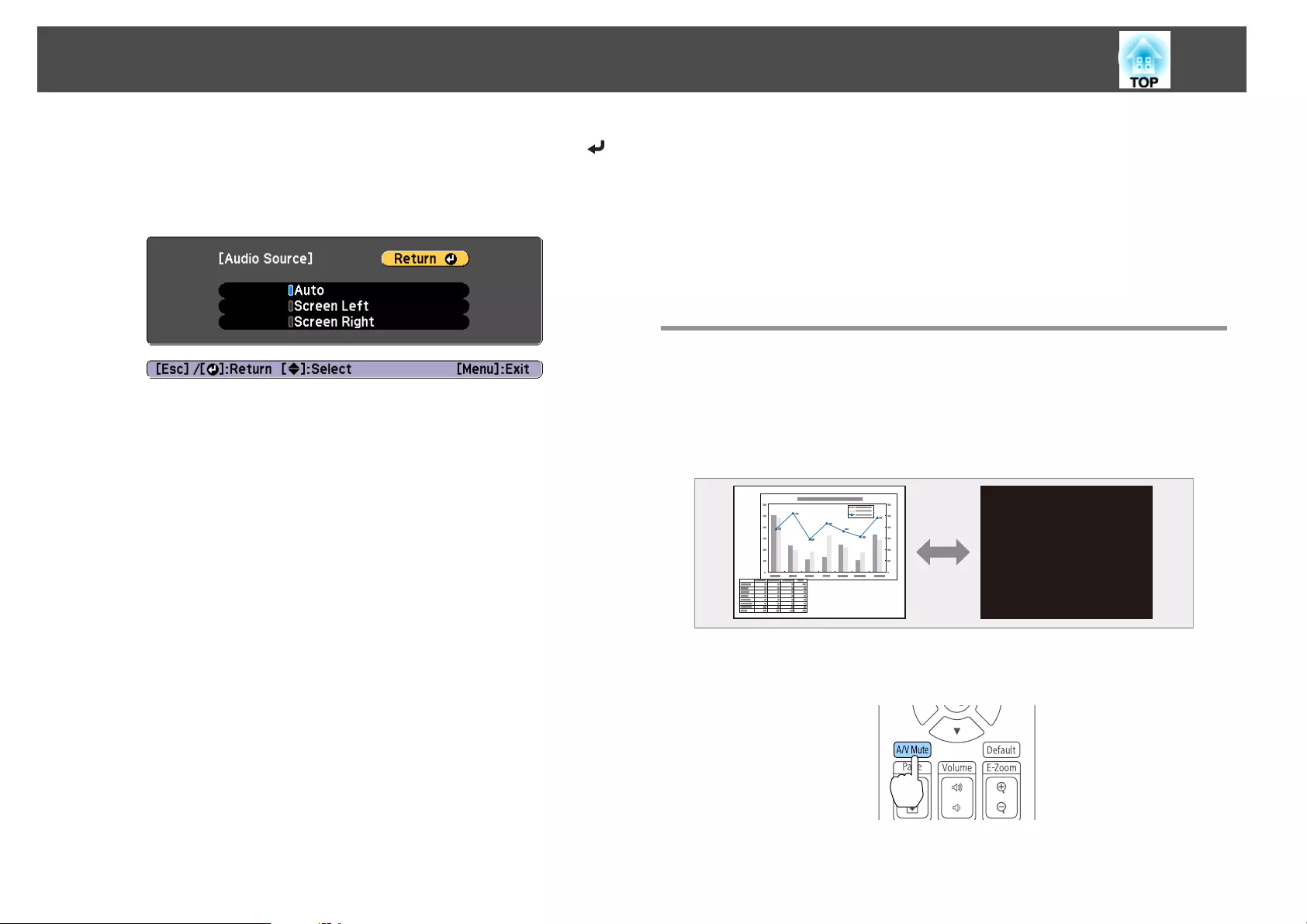
c
Select the audio you want to output, and then press the [ ]
button.
When you select Auto, audio is output for the enlarged screen. If the
screen sizes are Equal, audio is output for the screen on the left.
Ending the split screen
Press the [Esc] button to end split screen.
The following steps can also be used to end the split screen.
•Press the [Split] button on the remote control.
•Select Exit Split Screen on the Split Screen Setup screen. s p.116
Restrictions during split screen projection
Operating restrictions
The following operations cannot be performed during split screen
projection.
•Setting the configuration menu
•E-Zoom
•Changing the aspect mode
•Using the [User1], [User2], or [User3] button on the remote control
•Help can be displayed only when image signals are not input or when
an error or warning notification is displayed.
•The user's logo is not displayed.
Restriction relating to images
•For the image on the right screen, the default values for the Image
menu are applied. However, the setting values for the image projected
on the left screen are applied for Color Mode, Color Temp., and Color
Adjustment. Also, for Super-resolution in the Signal menu, the setting
values for the image projected on the left screen are applied.
•Auto Iris and Frame Interpolation are not available.
Hiding the Image and Sound Temporarily (A/V
Mute)
You can use this when you want to focus the audience's attention on what
you are saying, or if you do not want to show details such as when you are
changing between files during presentations from a computer.
Each time you press the [A/V Mute] button, A/V Mute turns on or off.
Remote control
Projection Functions
118
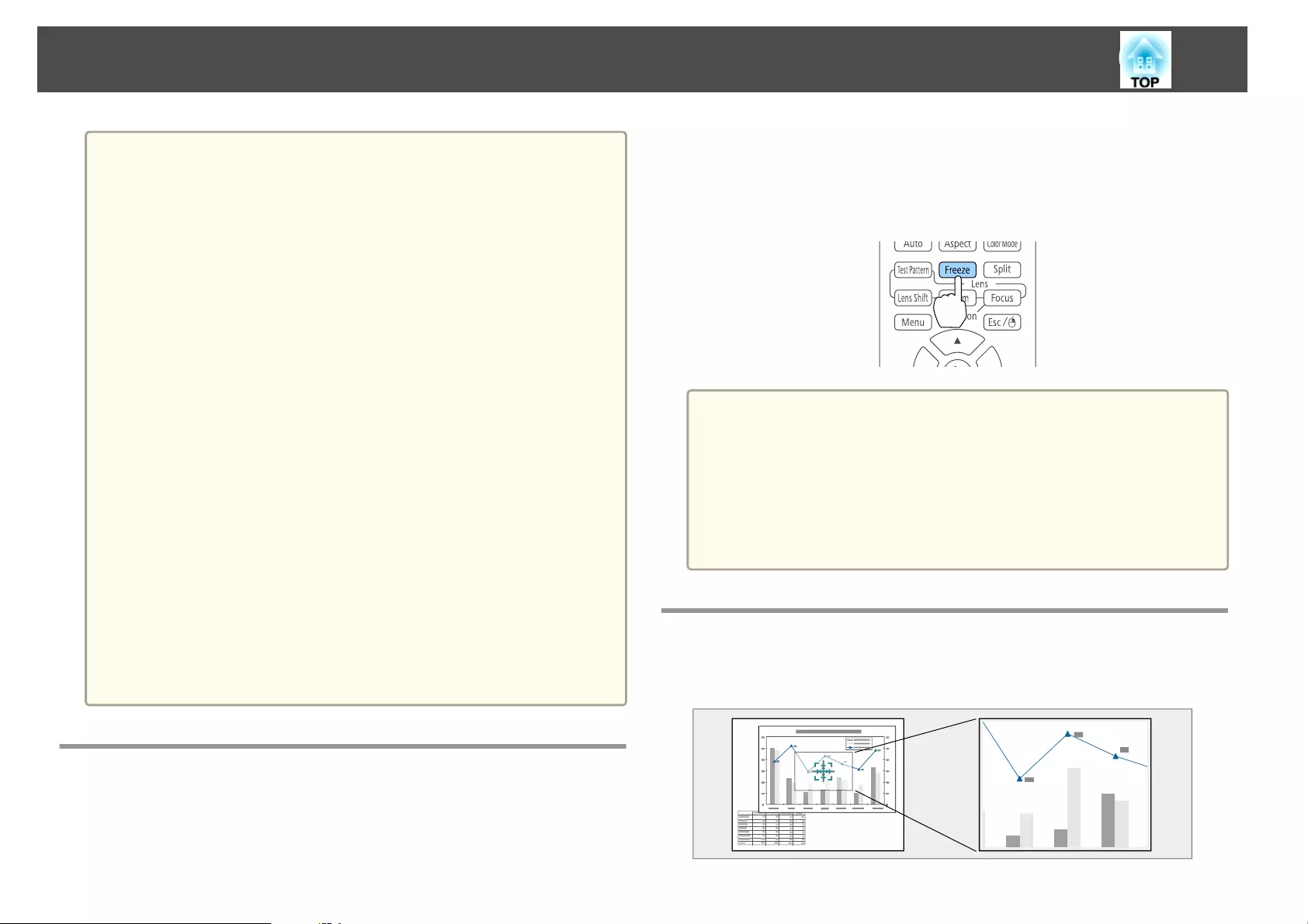
a
•If A/V mute is enabled, the electric shutter closes and projection is
blocked.
•If you want to fade out or fade in when turning the video on or off,
set the desired number of seconds in Fade-out and Fade-in.
s Extended - Operation - A/V Mute Settings - Fade-out, Fade-in
p.142
•When A/V mute is activated and no operations are performed for
about 2 hours, the projector turns off automatically. If you do not
want to turn off the power, set A/V Mute Timer to Off.
s Extended - Operation - A/V Mute Settings - A/V Mute Timer
p.142
•When A/V Mute Release is set to A/V Mute from the configuration
menu, the following operations can still be performed without
releasing A/V mute.
- Change the source with the change input buttons on the remote
control.
- Control the projector from a computer using communication
commands.
s Extended - Operation - A/V Mute Settings - A/V Mute Release
p.142
A/V mute is only released by pressing the [A/V Mute] button, or by
sending an A/V mute Off command.
•When projecting moving images, the images and sound continue to
be played back while A/V Mute is on. It is not possible to resume
projection from the point where A/V Mute was activated.
•The lamp is still lit during A/V Mute, so the lamp hours continue to
accumulate.
Freezing the Image (Freeze)
When Freeze is activated on moving images, the frozen image continues to
project on the screen, so you can project a moving image one frame at a
time like a still photo. Also, you can perform operations such as changing
between files during presentations from a computer without projecting any
images if the Freeze function is activated beforehand.
Each time you press the [Freeze] button, Freeze turns on or off.
Remote control
a
•Audio does not stop.
•When projecting moving images, the images continue to be played
back while the screen is frozen. It is not possible to resume
projection from the point where the screen was frozen.
•If the [Freeze] button is pressed while the Configuration menu or
the Help screen is displayed, the menu or the Help screen that is
displayed is closed.
•Freeze still works while E-Zoom is being used.
Enlarging Part of the Image (E-Zoom)
This is useful when you want to expand images to see them in greater
detail, such as graphs and tables.
Projection Functions
119
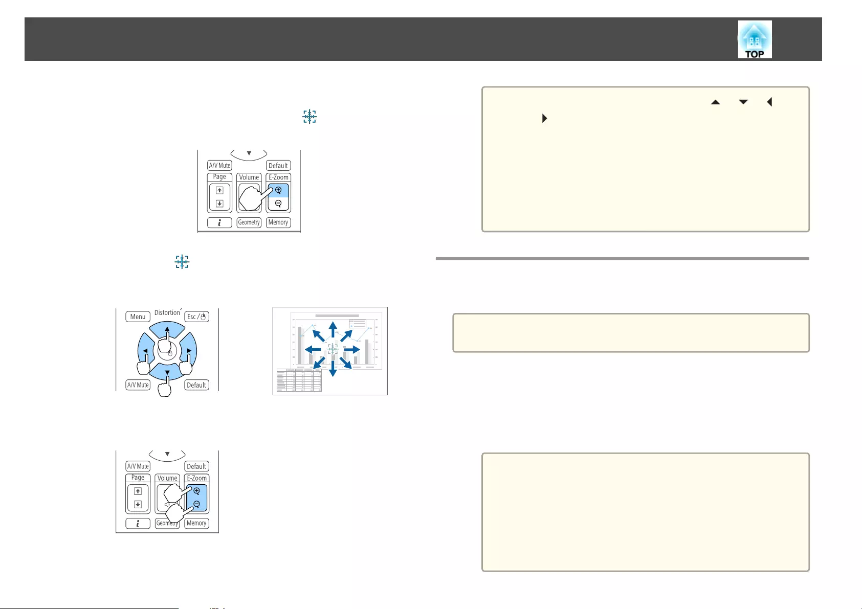
a
Start E-Zoom.
Press the [z] button to display the Cross ( ).
Remote control
b
Move the Cross ( ) to the area of the image that you want to
enlarge.
Remote control
c
Enlarge.
Remote control
[z] button: Expands the area each time
it is pressed. You can expand quickly by
holding the button down.
[x] button: Reduces images that have
been enlarged.
[Esc] button: Cancels E-Zoom.
a
•During enlarged projection, press the [ ], [ ], [ ], or
[] buttons to scroll the image.
•E-Zoom is unavailable when Scale is on.
s Signal - Scale p.139
•If 4K Enhancement is enabled, a message is displayed. Select
Yes to disable 4K Enhancement. (EB-G7905U/EB-G7900U/
EB-G7500U/EB-G7400U only)
s Image - Image Enhancement - 4K Enhancement
p.137
Saving a User's Logo
You can save the image that is currently being projected as a User's Logo.
a
Once a User's Logo has been saved, the logo cannot be returned to the
factory default.
a
Project the image you want to save as the User's Logo, and then
press the [Menu] button.
s "Using the Configuration Menu" p.134
b
Select User's Logo from Extended.
a
•When User's Logo Protection from Password Protection is
set to On, a message is displayed and the User's Logo cannot
be changed. You can make changes after setting User's Logo
Protection to Off.
s "Managing Users (Password Protection)" p.127
•If User's Logo is selected when Geometric Correction, E-
Zoom or Aspect are being performed, the function currently
being performed is temporarily cancelled.
Projection Functions
120
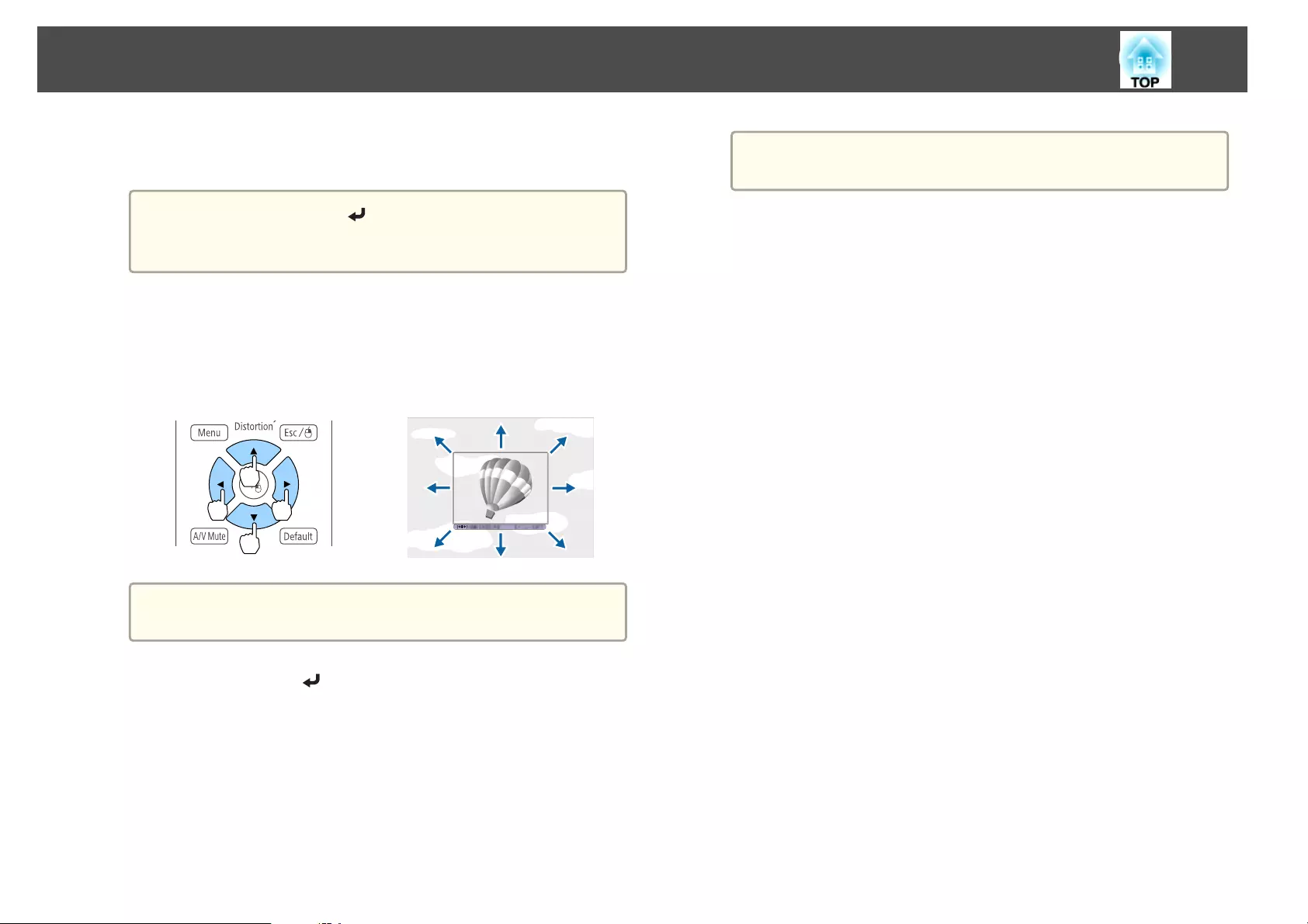
c
When the message "Choose this image as the User's Logo?" is
displayed, select Yes.
a
When you press the [ ] button, the screen size may change
depending on the signal to match the actual resolution of the
image signal.
d
Move the box to select the part of the image to use as the User's
Logo.
You can perform the same operations from the projector's control
panel.
Remote control
a
You can save at 400x300 dots in size.
e
When you press the [ ] button and the message "Select this
image?" is displayed, select Yes.
f
Select the zoom factor from the zoom setting screen.
g
When the message "Save this image as the User's Logo?" is
displayed, select Yes.
The image is saved. After the image has been saved, the message
"Completed." is displayed.
a
When a User's Logo is saved, the previous User's Logo is
erased.
Projection Functions
121
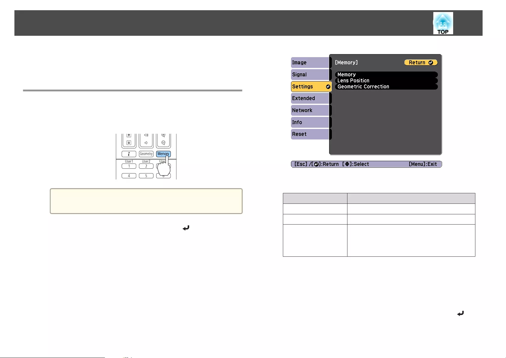
The settings for the image currently displayed and values for geometric
correction are saved as a memory, allowing you to load them when
necessary.
Saving/Loading/Erasing/Resetting the Memory
a
Press the [Memory] button while projecting.
Remote control
a
You can also operate from the Configuration menu.
s Settings - Memory p.140
b
Select a memory type, and then press the [ ] button.
Memory: Settings for the following menu items are saved in the
memory. You can register up to 10 values.
Top Menu Submenu
Image All setting items
Signal Scale
Extended Brightness Level
Edge Blending
Black Level
Color Matching
Lens Position: "Registering and Loading Lens Adjustment Values"
p.39
Geometric Correction: Adjustment value of the geometric correction
is saved. You can register up to 3 values.
c
Select the function you want to perform, then press the [ ]
button.
Memory Function
122
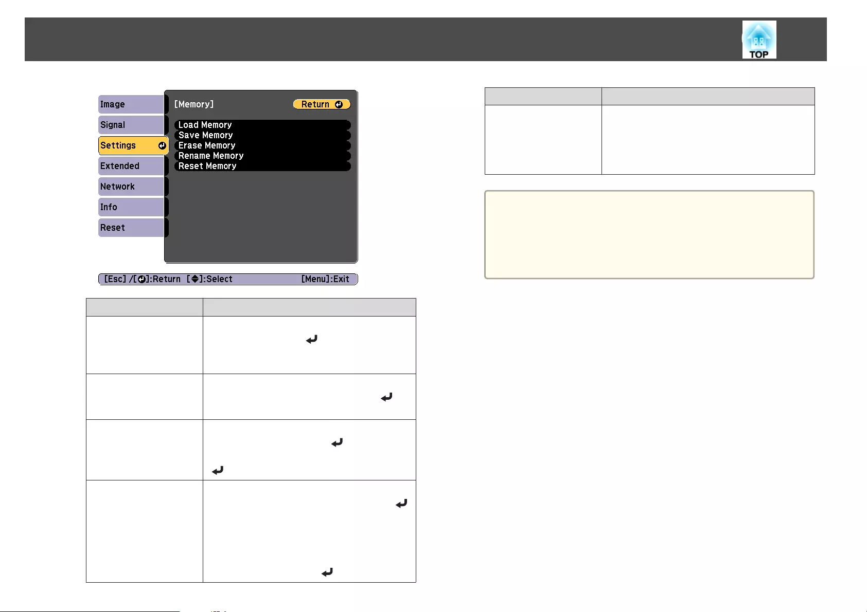
Function Explanation
Load Memory Loads the saved memory. When you select a
memory and press the [ ] button, the settings
applied to the current image are replaced with the
settings from the memory.
Save Memory Registers current settings in the memory. When
you select a memory name and press the [ ]
button, the settings are saved.
Erase Memory Erases the registered memory. When you select a
memory name and press the [ ] button, a
message is displayed. Select Yes, and then press the
[] button to erase the selected memory.
Rename Memory Changes the memory name. Select the memory
name you want to change, and then press the [ ]
button. Enter the memory name using the soft
keyboard.
s "Soft keyboard operations" p.148
When you have finished, move the cursor over
Finish, and then press the [ ] button.
Function Explanation
Reset Memory Resets the name and settings of a saved memory.
To reset all memories saved in Memory, Lens
Position, and Geometric Correction, use Reset
All Memories.
s Reset - Reset All Memories p.154
a
If the mark on the left of the memory name is turned blue, it
means the memory has already been registered. When you
select a registered memory, a message is displayed asking you to
confirm that you want to overwrite the memory. If you select
Yes, the previous settings are deleted and the current settings
are registered.
Memory Function
123
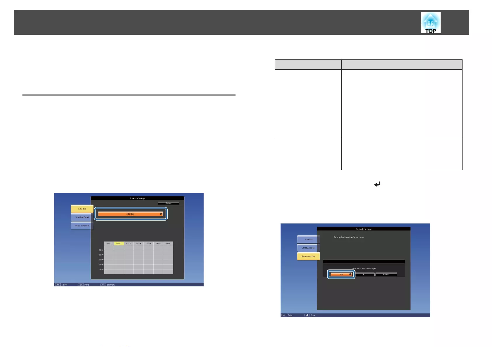
You can schedule turning the projector power on/off and switching the
input source, as events in the schedule. Registered events are executed
automatically at the specified time on the specified dates or weekly. You can
register up to 30 events.
Saving a Schedule
Setting a schedule
a
Press the [Menu] button while projecting.
s "Using the Configuration Menu" p.134
b
Select Schedule Settings from Extended.
c
Select Add New from Schedule.
d
Set the schedule.
Submenu Name Function
Event Settings Select an operation of the projector when the event
is executed. Select No Change for items that you do
not want to change when the event occurs.
You can set the following item operations.
•Power
•Source
•Power Consumption
•A/V Mute
•Volume
Date / Time Settings Set the date, day of the week, and time to execute
the event. Use the soft keyboard to enter the date
and time.
s "Soft keyboard operations" p.148
e
Select Save, and then press the [ ] button.
To register additional schedules, repeat steps 3 to 5.
f
Select Setup complete, and then select Yes to finish saving.
Scheduling Function
124
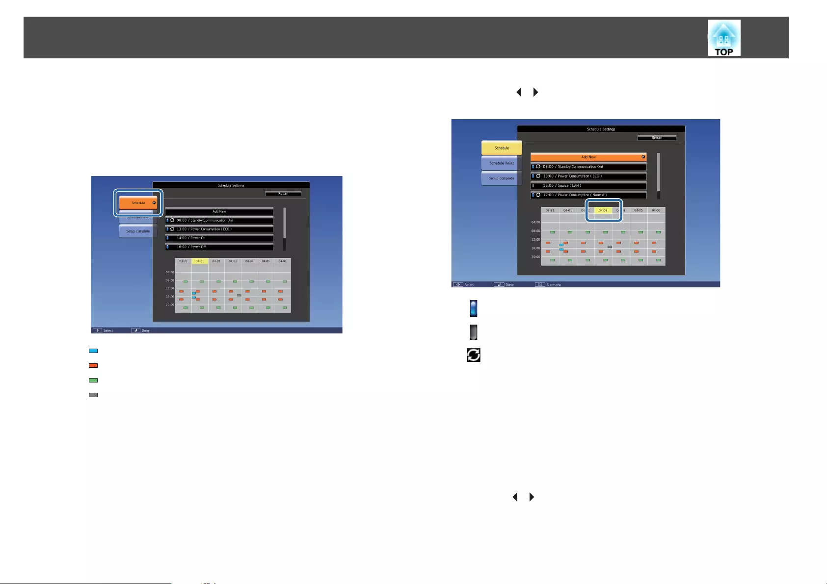
Checking a schedule
a
Press the [Menu] button while projecting.
b
Select Schedule Settings from Extended.
The indicator turns on when an event is saved.
(Aqua): Single event
(Orange): Regular event
(Green): Communication monitoring On/Off
(Gray): Disabled event
c
Press the [ ][ ] buttons to highlight the date you want to check.
The details of the events registered on the selected date are displayed.
(Blue): Enabled event
(Gray): Disabled event
: Regular event
Editing a schedule
a
Press the [Menu] button while projecting.
s "Using the Configuration Menu" p.134
b
Select Schedule Settings from Extended.
c
Use the [ ][ ] buttons to highlight the date containing the
schedule you want to edit.
Scheduling Function
125
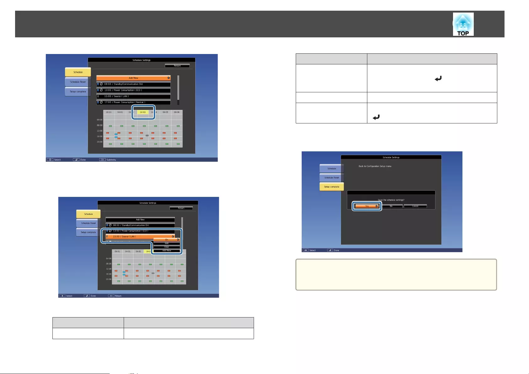
d
Highlight the event you want to edit, and then press the [Esc]
button.
e
Edit the event.
Submenu Name Function
On/Off Enable or disable the selected schedule.
Submenu Name Function
Edit Edit the content of the selected schedule. Select
Save, and then press the [ ] button to complete
the editing.
Clear Deletes the selected schedule.
Add New Save a new schedule. Select Save, and then press the
[] button to complete the saving.
f
Select Setup complete, and then select Yes to finish editing.
a
To delete all registered schedules, select Schedule Reset, and
then select Yes. Select Setup complete, and then select Yes to
delete the schedules.
Scheduling Function
126
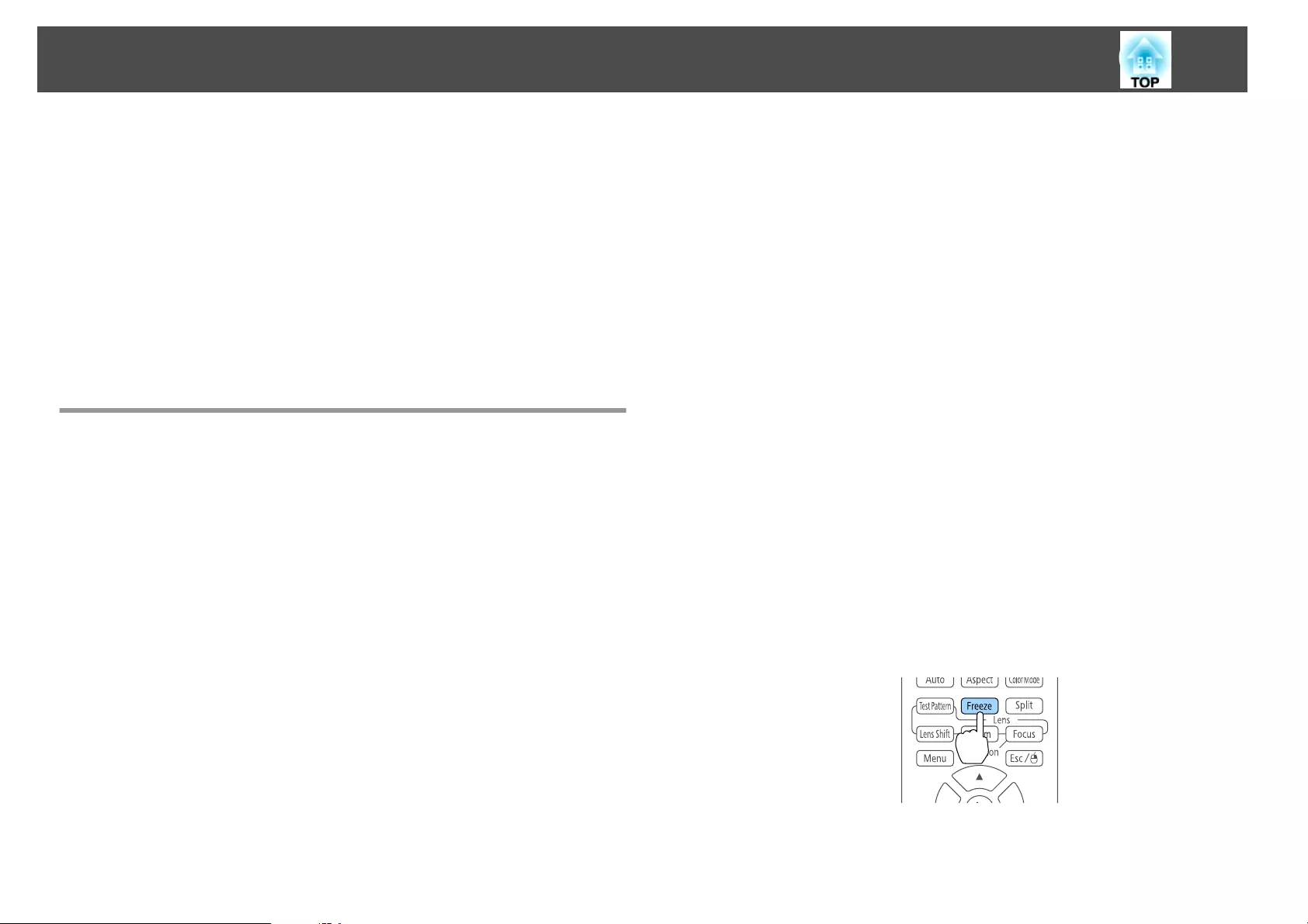
The projector has the following enhanced security functions.
•Password Protection
You can limit who can use the projector.
•Control Panel Lock/Remote Control Button Lock
You can prevent people changing the settings on the projector without
permission.
s "Restricting Operation" p.129
•Anti-Theft Lock
The projector is equipped with the following anti-theft security device.
s "Anti-Theft Lock" p.131
Managing Users (Password Protection)
When Password Protection is activated, people who do not know the
password cannot use the projector to project images even if the projector
power is on. Furthermore, the user's logo that is displayed when you turn
on the projector cannot be changed. This acts as an anti-theft function as
the projector cannot be used even if it is stolen. At the time of purchase,
Password Protection is not activated.
Kinds of Password Protection
The following four kinds of Password Protect settings can be made
according to how the projector is being used.
•Power On Protection
When Power On Protection is On, you need to enter a preset password
after the projector is plugged in and turned on (this also applies to Direct
Power On). If the correct password is not entered, projection does not
start.
•User's Logo Protection
Even if someone tries to change the User's Logo set by the owner of the
projector, it cannot be changed. When User's Logo Protection is set to
On, the following setting changes for the User's Logo are prohibited.
•Capturing a User's Logo
•Setting Display Background or Startup Screen from Display
s Extended - Display p.142
•Network Protection
When Network Protection is set to On, changing the settings for
Network is prohibited.
s "Network Menu" p.147
•Schedule Protection
When Schedule Protection is set to On, changing settings for the
projector's system time or schedules is prohibited.
Setting Password Protection
Use the following procedure to set Password Protect.
a
During projection, hold down the [Freeze] button for about five
seconds.
The Password Protection setting menu is displayed.
Remote control
Security Functions
127
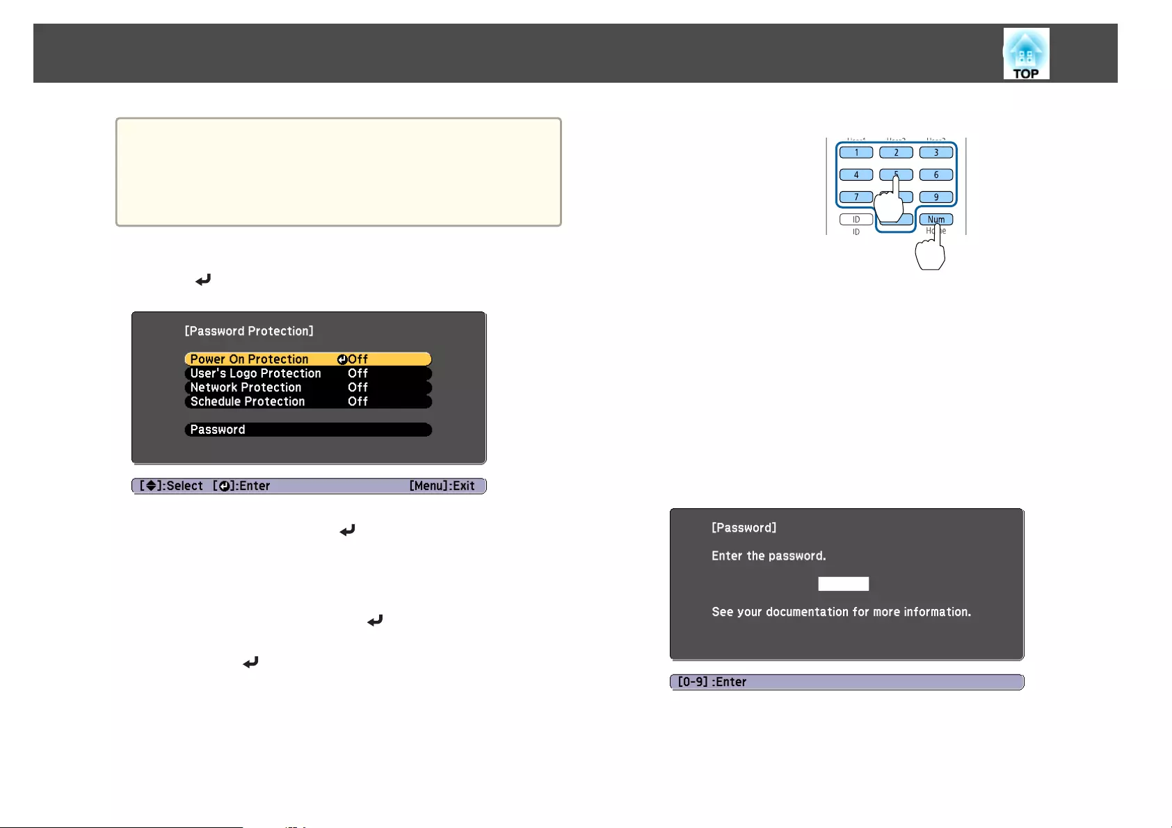
a
If Password Protection is already activated, you must enter the
password.
If the password is entered correctly, the Password Protection
setting menu is displayed.
s "Entering the password" p.128
b
Select the type of Password Protect you want to set, and then
press the [ ] button.
c
Select On, and then press the [ ] button.
Press the [Esc] button to return to the screen in step 2.
d
Set the password.
(1) Select Password, and then press the [ ] button.
(2) When the message "Change the password?" is displayed, select Yes and
then press the [ ] button. The default password is set to "0000". Change
this to your own desired password. If you select No, the screen displayed
in step 2 is displayed again.
(3) While holding down the [Num] button, enter a four digit number using
the numeric buttons. The number entered is displayed as "* * * *". When
you enter the fourth digit, the confirmation screen is displayed.
Remote control
(4) Re-enter the password.
The message "Password accepted." is displayed.
If you enter the password incorrectly, a message is displayed prompting
you to re-enter the password.
Entering the password
When the password entry screen is displayed, enter the password using the
remote control.
While holding down the [Num] button, enter the password by pressing the
numeric buttons.
When you enter the correct password, Password Protect is temporarily
released.
Security Functions
128
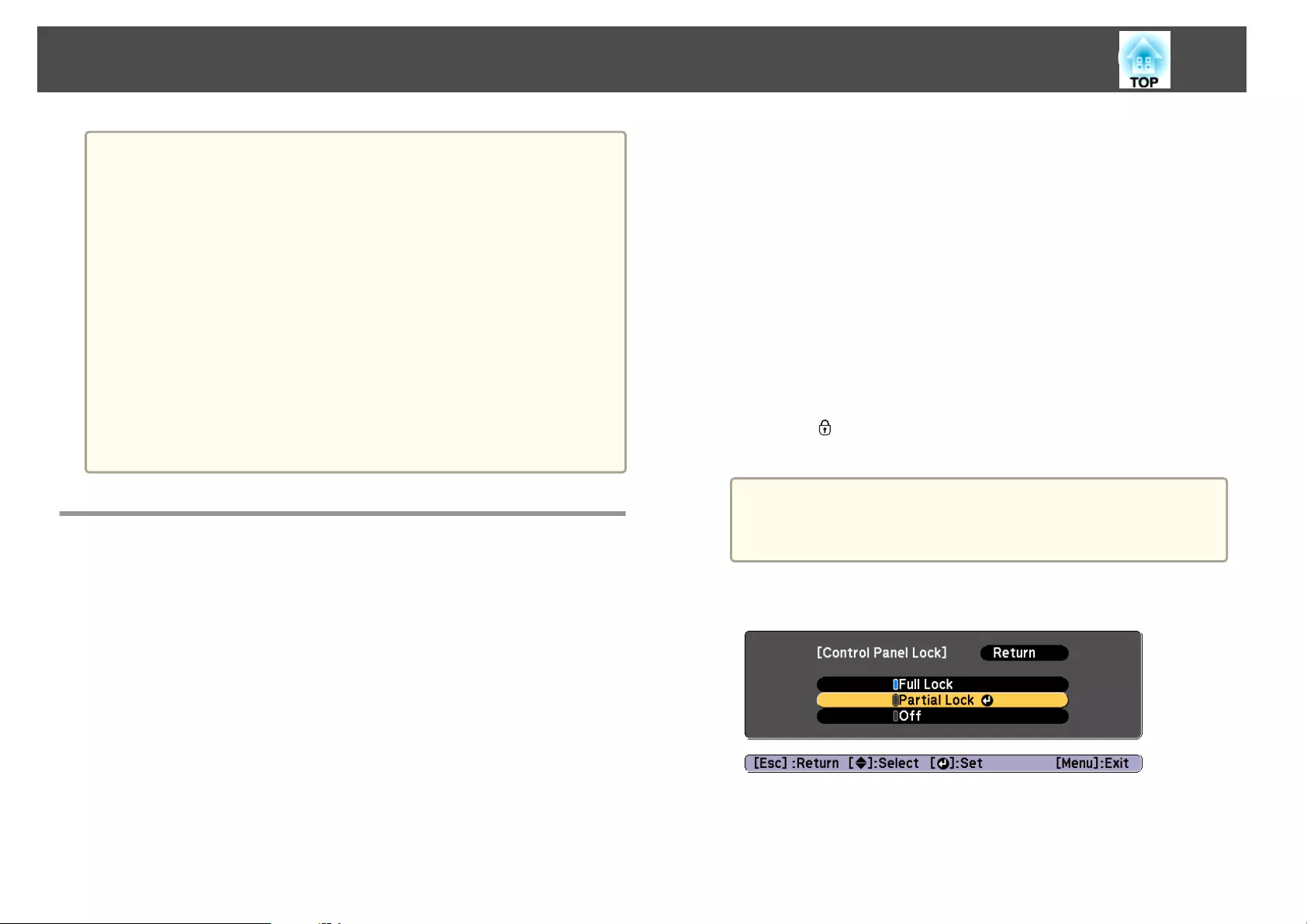
Attention
•If an incorrect password is entered three times in succession, the message
"The projector's operation will be locked." is displayed for approximately five
minutes, and then the projector switches to standby mode. If this happens,
disconnect the power plug from the electrical outlet and then reinsert it and
turn the projector's power back on. The projector displays the password entry
screen again so that you can enter the correct password.
•If you have forgotten the password, make a note of the "Request Code:
xxxxx" number that appears on the screen and contact the nearest address
provided in the Epson Projector Contact List.
s Epson Projector Contact List
•If you continue to repeat the above operation and input the wrong password
thirty times in succession, the following message is displayed and the
projector does not accept any more password entries. "The projector's
operation will be locked. Contact Epson as described in your documentation."
s Epson Projector Contact List
Restricting Operation
The following two kinds of operation restriction functions are available with
the projector.
•Control Panel Lock
This is useful at events or shows when you want to deactivate all buttons
during projection or at schools when you want to limit button operation.
•Lens Lock
This function deactivates all buttons on the remote control related to the
lens operation to prevent improper lens adjustment after it is properly
adjusted.
•Remote control button lock
This function deactivates buttons except for main buttons needed for
basic remote control operation, to prevent mistakes in operations.
Control Panel Lock
Perform one of the following to lock the operation buttons on the control
panel. Even if the control panel is locked, you can still use the remote
control as usual.
•Full Lock
All of the buttons on the control panel are locked. You cannot perform
any operations from the control panel, including turning the power on or
off.
•Partial Lock
All of the buttons on the control panel, except for the [t] button, are
locked.
a
Press the [ ] button on the control panel during projection to
display the Control Panel Lock screen.
a
You can also make settings in Control Panel Lock from the
configuration menu.
s Settings - Lock Setting - Control Panel Lock p.140
b
Select either Full Lock or Partial Lock according to your purpose.
c
Select Yes when the confirmation message is displayed.
The control panel buttons are locked according to the setting you
chose.
Security Functions
129
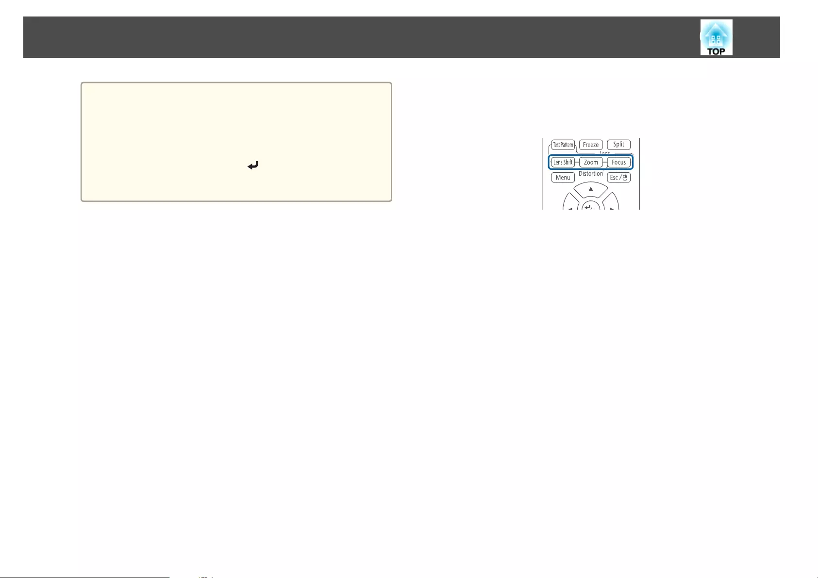
a
You can release the control panel lock by one of the following
two methods.
•Use the remote control to set Control Panel Lock to Off
from the configuration menu.
s Settings - Lock Setting - Control Panel Lock p.140
•Press and hold down the [ ] button on the control panel
for about seven seconds, a message is displayed and the lock
is released.
Lens Lock
This function locks the following buttons on the remote control related to
the lens operation.
Set the Lens Lock to On in the Configuration menu.
s Settings - Lock Setting - Lens Lock p.140
Remote control button lock
This function locks the following buttons on the remote control.
Security Functions
130
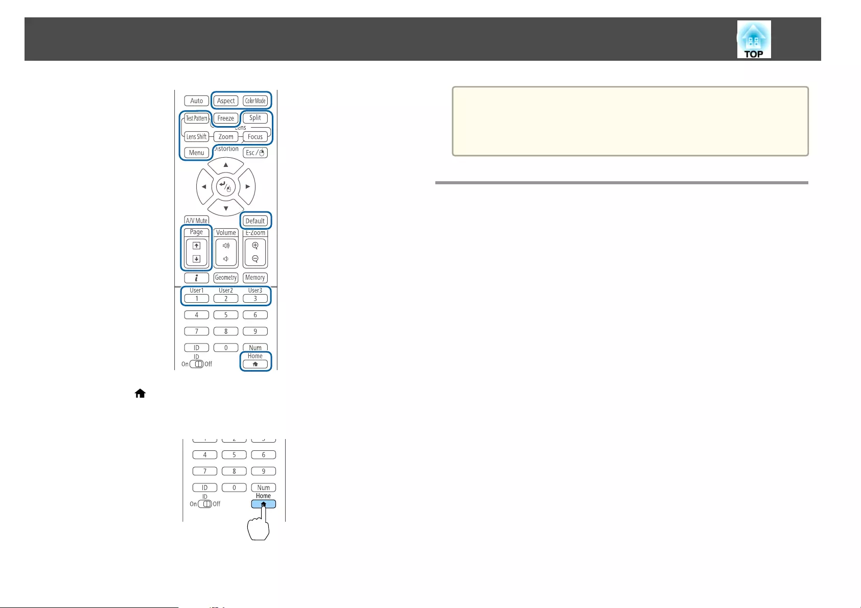
Each time the [ ] button is pressed for approximately 5 seconds, the
remote control button lock turns on or off.
Remote control
a
Even if the remote control button lock is on, the following operations
are possible.
•Resetting default for the Remote Receiver setting
•Releasing the remote control button lock
Anti-Theft Lock
The projector is equipped with the following types of anti-theft security
devices.
•Security slot
The security slot is compatible with the Microsaver Security System
manufactured by Kensington.
See the following for more details on the Microsaver Security System.
s http://www.kensington.com/
•Security cable installation point
A commercially available theft-prevention wire lock can be passed
through the installation point to secure the projector to a desk or pillar.
Installing the wire lock
Pass an anti-theft wire lock through the installation point.
See the documentation supplied with the wire lock for locking instructions.
Security Functions
131
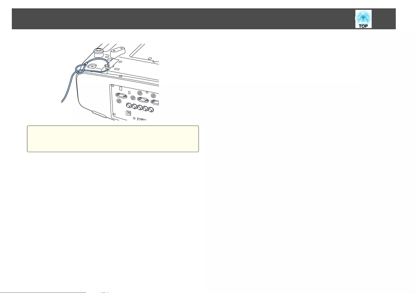
Attention
Do not pass drop-prevention wires through the security cable installation
point.
Security Functions
132

Configuration Menu
This chapter explains how to use the Configuration menu and its functions.
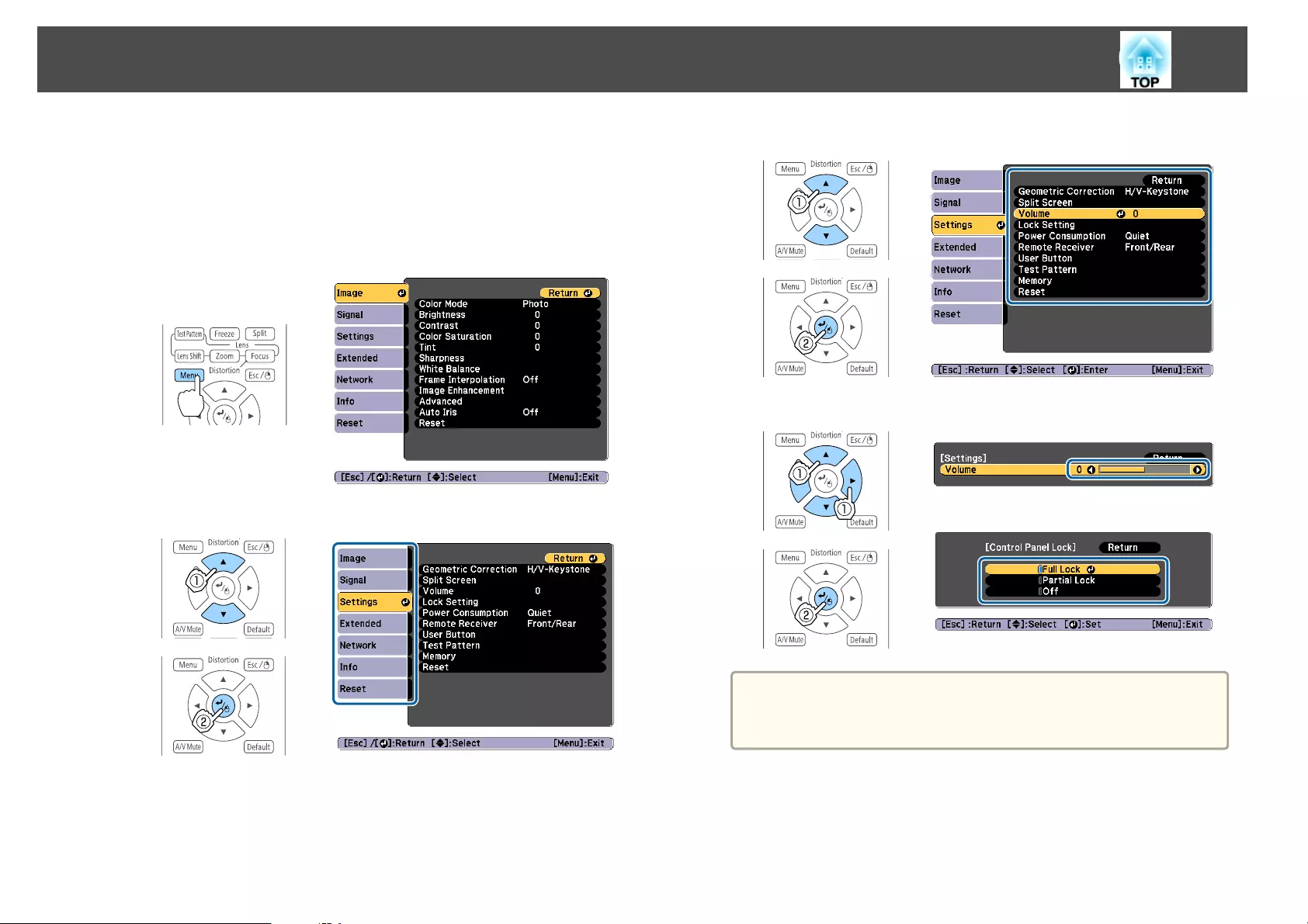
This section explains how to use the Configuration menu.
Although steps are explained using the remote control as an example, you
can perform the same operations from the control panel. Check the guide
under the menu for the available buttons and their operations.
a
Display the Configuration menu screen.
b
Select a top menu item.
c
Select a submenu item.
d
Change settings.
a
When [Default]: Reset is displayed on the guide, and you press
the [Default] button on the remote control, the settings being
adjusted are returned to their default values.
e
Press the [Menu] button to finish making settings.
Using the Configuration Menu
134
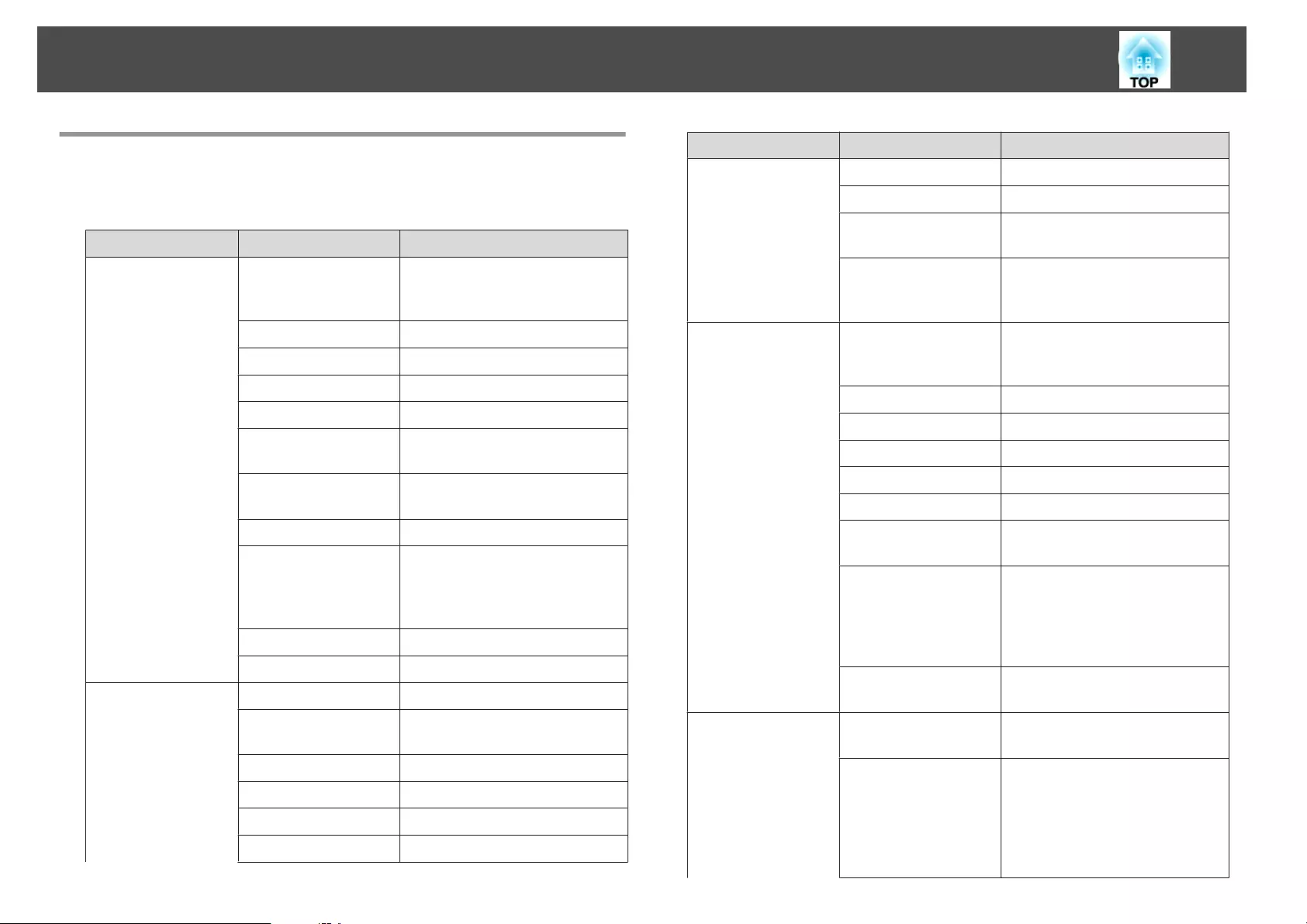
Configuration Menu Table
Settable items vary depending on the model being used and the image
signal and source being projected.
Top Menu Name Submenu Name Items or Setting Values
Image menu
s p.137
Color Mode Dynamic, Presentation, Cinema,
sRGB, DICOM SIM, Multi-
Projection
Brightness 0 - 100
Contrast 0 - 100
Color Saturation 0 - 100
Tint 0 - 100
Sharpness Standard, Thin Line Enhancement,
Thick Line Enhancement
White Balance Color Temp., G-M Correction,
Customized
Frame Interpolation Off, Low, Normal, and High
Image Enhancement 4K Enhancement, Image Preset
Mode, Noise Reduction, MPEG
Noise Reduction, Super-
resolution, Detail Enhancement
Advanced Gamma, RGBCMY, Deinterlacing
Auto Iris Off, Normal, and High Speed
Signal menu
s p.139
Resolution Auto, Wide, Normal, and Manual
Aspect Auto, Normal, 4:3, 16:9, Full, H-
Zoom, V-Zoom, Native
Tracking -
Sync. 0 - 31
Position -128 - 127
Auto Setup On and Off
Top Menu Name Submenu Name Items or Setting Values
Overscan Auto, Off, 4%, and 8%
Blanking Top, Bottom, Left, and Right
Advanced Video Range, Input Signal, Image
Processing
Scale Scale, Scale Mode, Scale Vertically,
Scale Horizontally, Clip
Adjustment, Clip Range
Settings menu
s p.140
Geometric Correction Off, H/V-Keystone, Quick Corner,
Curved Surface, Corner Wall,
Point Correction, Memory
Split Screen -
Volume 0 - 20
Lock Setting Control Panel Lock, Lens Lock
Power Consumption Off, On
Remote Receiver Front/Rear, Front, Rear, and Off
User Button User Button 1, User Button 2, and
User Button 3
Test Pattern Standard, Cross-hatching, Color
Bars V, Color Bars H, Grayscale,
Gray Bars V, Gray Bars H,
Checkerboard 1, Checkerboard 2,
White, Black, Aspect Frame
Memory Memory, Lens Position, Geometric
Correction
Extended menu
s p.142
Home Screen Home Screen Auto Disp., Custom
Function 1, Custom Function 2
Display Menu Position, Message Position,
Messages, Display Background,
Startup Screen, Standby
Confirmation, Air Filter Notice,
Screen, Panel Alignment, Color
Uniformity, OSD Rotation
List of Functions
135
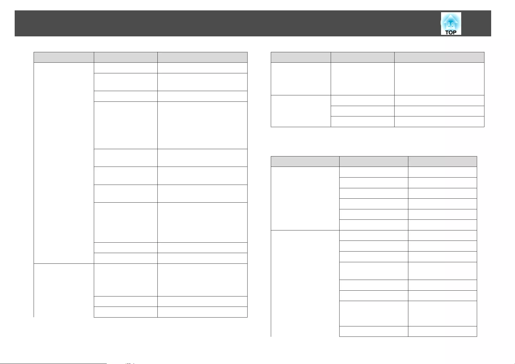
Top Menu Name Submenu Name Items or Setting Values
User's Logo -
Projection Front, Front/Ceiling, Rear, and
Rear/Ceiling
Direction Direction, Portrait Mode
Operation Direct Power On, Sleep Mode,
Sleep Mode Timer, High Altitude
Mode, Auto Source Search, Auto
Power On, A/V Mute Settings,
Advanced, Date & Time, Lens
Calibration
A/V Settings A/V Output, Monitor Out, and
Audio Settings
Standby Mode Communication On and
Communication Off
HDBaseT Control Communications, Extron
XTP
Multi-Projection Projector ID, Tiling, Geometric
Correction, Edge Blending, Scale,
Color Mode, Brightness Level,
Color Matching, Color
Uniformity, RBGCMY, Black Level
Schedule Settings -
Language 27 languages
Info menu
s p.154
Projector Info Source, Input Signal, Resolution,
Refresh Rate, Sync Info, Status,
Serial Number, Lens Type, Event
ID, HDBaseT Signal Level
Lamp Info Lamp Hours
Version Main, Video2
Top Menu Name Submenu Name Items or Setting Values
Status Information Status Information, Source, Signal
Information, Network Wired,
Network Wireless, Maintenance,
Version
Reset menu
s p.155
Reset Lamp Hours -
Reset All Memories -
Reset All Config -
Network menu
Top Menu Name Submenu Name Items or Setting Values
Basic menu s p.149 Projector Name -
PJLink Password -
Remote Password -
Web Control Password -
Projector Keyword On and Off
Display LAN Info. Text & QR Code, Text
Wireless LAN menu s
p.149
Connection Mode Quick, Advanced
Search Access Point -
SSID -
Security Open, WPA2-PSK,
WPA/WPA2-PSK
Passphrase -
Channel 1ch, 6ch, and 11ch
IP Settings DHCP, IP Address,
Subnet Mask, Gateway
Address
SSID Display On and Off
List of Functions
136
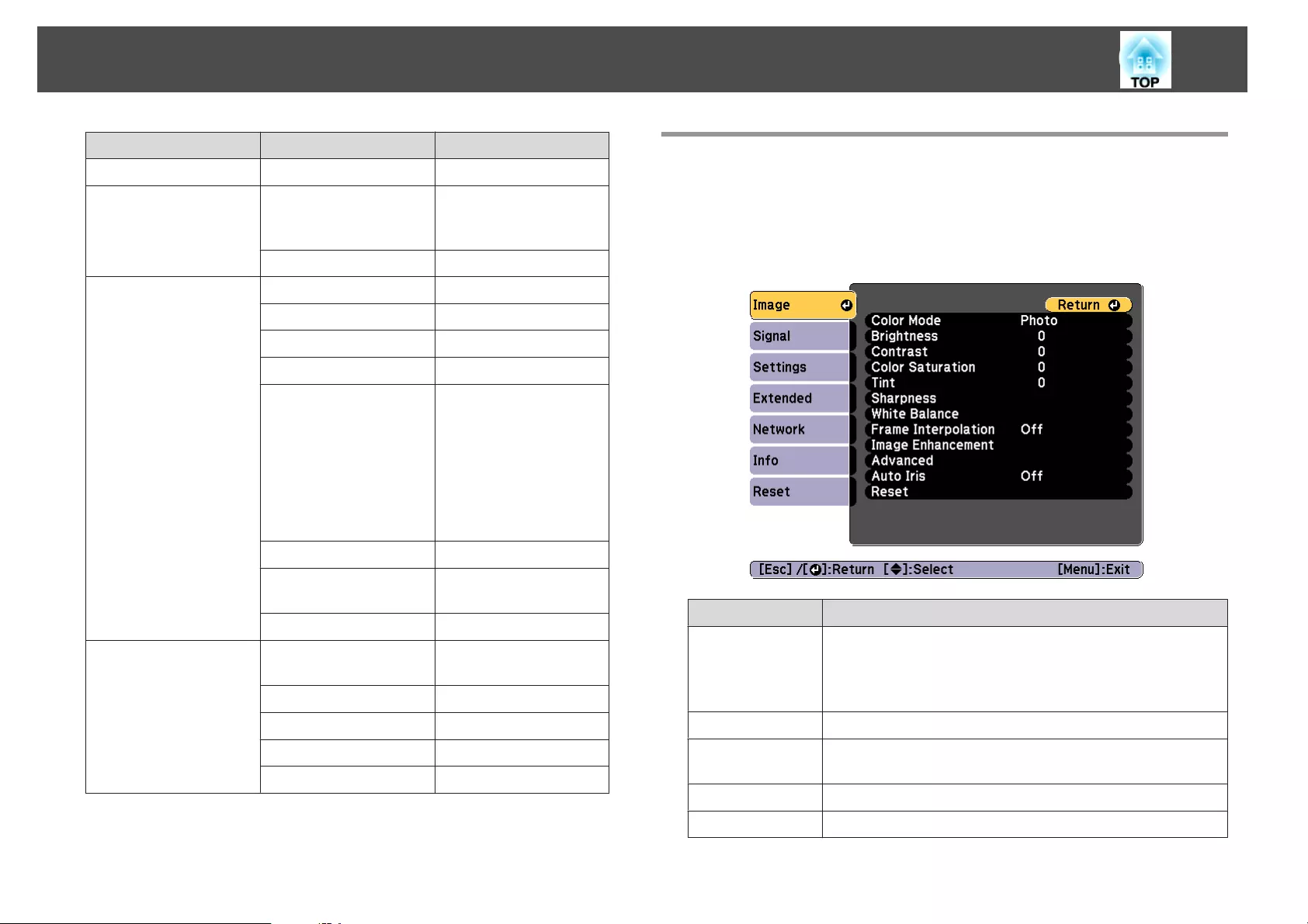
Top Menu Name Submenu Name Items or Setting Values
IP Address Display On, Off
Wired LAN menu s
p.152
IP Settings DHCP, IP Address,
Subnet Mask, Gateway
Address
IP Address Display On, Off
Notification menu
s p.153
Mail Notification On, Off
SMTP Server -
Port Number -
From -
Address 1 Setting,
Address 2 Setting,
Address 3 Setting
Email Address, No Signal,
System Error, Lamp Error,
High Temp Error, Air
Filter Error, Replace
Lamp, High Temp
Warning, Air Filter
Warning, Other Warning,
Air Filter Notice
SNMP On, Off
Trap IP Address 1, Trap IP
Address 2
-
Community Name -
Others menu s p.153 Priority Gateway Wired LAN, Wireless
LAN
AMX Device Discovery On and Off
Crestron RoomView On and Off
Control4 SDDP On and Off
Message Broadcasting On and Off
Image Menu
Settable items vary depending on the image signal and source currently
being projected. Setting details are saved for each color mode.
s "Automatically Detecting Input Signals and Changing the Projected
Image (Source Search)" p.59
Submenu Function
Color Mode You can select the quality of the image to suit your
surroundings.
s "Selecting the Projection Quality (Selecting Color
Mode)" p.87
Brightness You can adjust the image brightness.
Contrast You can adjust the difference between light and dark in the
images.
Color Saturation You can adjust the color saturation for the images.
Tint You can adjust the image tint.
List of Functions
137

Submenu Function
Sharpness Standard: You can adjust the image sharpness.
Thin Line Enhancement: If this parameter is set to a
positive value, details such as hair or fabric patterns will be
enhanced.
Thick Line Enhancement: If this parameter is set to a
positive value, the outline, background, and the other main
parts of the objects in the image will be enhanced to show
them clearly.
White Balance You can adjust the overall tint of the image.
Color Temp.: You can adjust the overall tint of the image.
When the Color Mode is set to sRGB or DICOM SIM,
adjust to 11 steps in 3200K, 5000K to 10000K. When the
Color Mode is set to anything other than sRGB and
DICOM SIM, you can adjust it in a range of 0 to 10. The
image is tinted blue when a high value is selected and tinted
red when a low value is selected.
G-M Correction: The color tone is tinted red when set to a
negative value, and tinted green when set to a positive
value.
Customized: You can adjust the offset and gain of each
color R (red), G (green), and B (blue) individually.
Frame Interpo-
lation
*1, 2, 3, 4, 5, 6, 7
You can play fast moving images smoothly by producing
intermediate frames between the original frames.
Submenu Function
Image Enhance-
ment
You can adjust the image resolution.
s "Adjusting Image Resolution (Image Enhancement)"
p.97
4K Enhancement
*8
: You can project at a doubled
resolution.
Image Preset Mode: You can select the optimal setting
according to the projected image from five presets prepared
in advance.
Noise Reduction
*2, 3, 7
: You can smooth out the roughness
in progressive images.
MPEG Noise Reduction
*2, 3
: You can reduce dot and block
noise that occurs in outlines when projecting MPEG movies.
Super-resolution: To display a crisp image, you can reduce
the blurring that is created on the edge when the resolution
of the image signal is scaled up and projected.
Detail Enhancement: You can enhance the contrast of
details in an image.
Advanced You can make adjustments by choosing the following items.
Gamma: You can adjust the coloring by selecting one of the
gamma correction values, or referring to the projected
image or a gamma graph.
RGBCMY: You can adjust the hue, saturation, and
brightness of each color R (red), G (green), B (blue), C
(cyan), M (magenta), Y (yellow) individually.
Deinterlacing
*7, 10
: You can convert interlace signals into
progressive signals. (IP conversion)
Off is ideal for images with a large amount of movement,
Video for general video images, and Film/Auto for movie
films, computer graphics, and animation.
Auto Iris
*4, 9
Set to Normal or High Speed to adjust the iris to obtain
the optimum light for images being projected. Select High
Speed to make faster iris corrections to match the speed of
the scene.
List of Functions
138
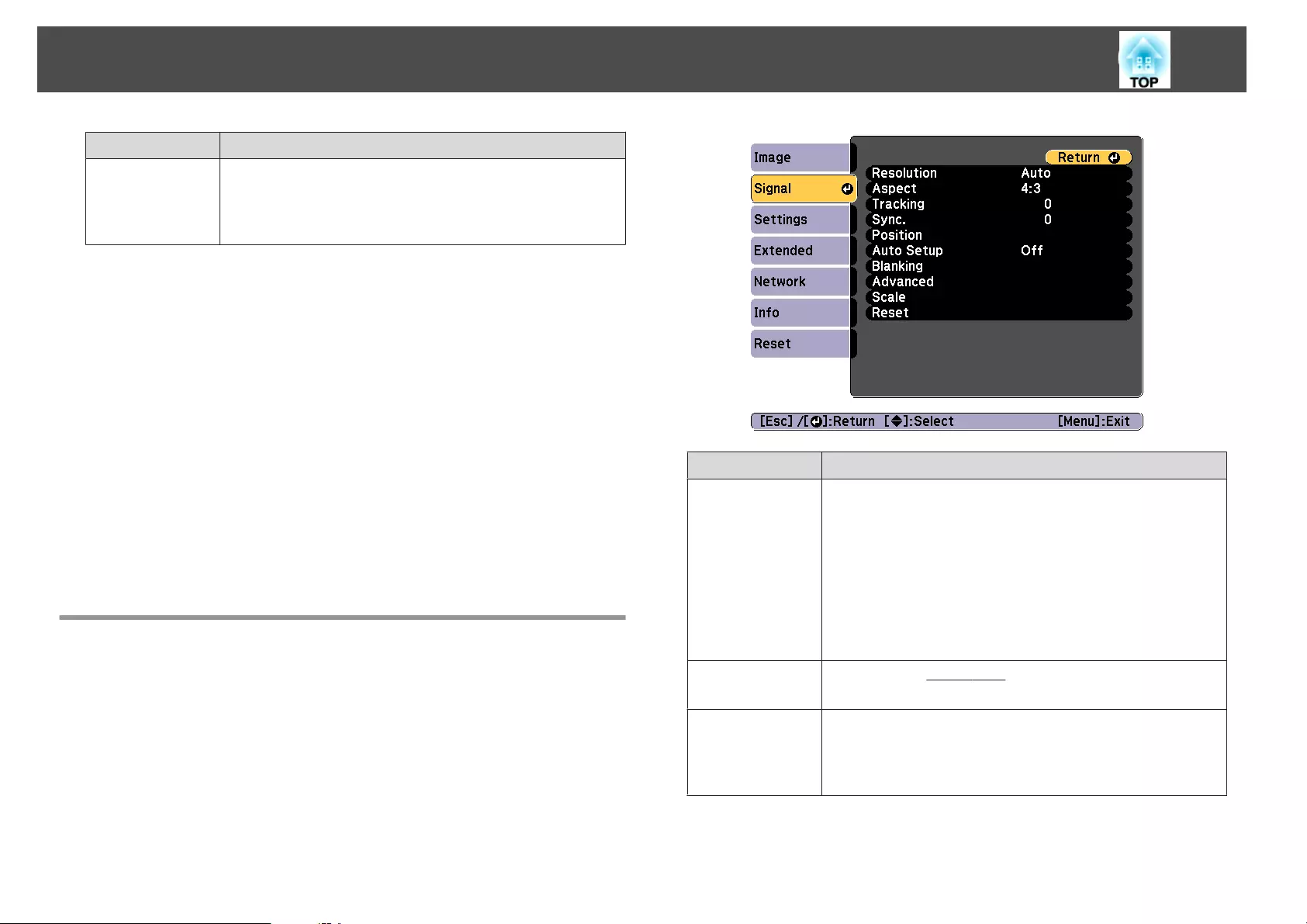
Submenu Function
Reset You can reset all adjustment values for the Image menu to
their default settings. See the following to return all menu
items to their default settings.
s "Reset Menu" p.155
*1 This cannot be set when E-Zoom is used.
*2 This cannot be set when the signal input exceeds WUXGA.
*3 This cannot be set when 4K Enhancement is enabled.
*4 This cannot be set when Edge Blending is On.
*5 This cannot be set when Scale is enabled.
*6 This cannot be set when Image Processing is set to Fast 1.
*7 This cannot be set when Image Processing is set to Fast 2.
*8 This can be set only for EB-G7905U/EB-G7900U/EB-G7500U/EB-G7400U.
*9 This can be set only if Color Mode is set to Dynamic or Cinema.
*10 This can be set only when the input signal is 480i, 576i, or 1080i.
Signal Menu
Settable items vary depending on the image signal and source currently
being projected. Setting details are saved for each image signal.
Submenu Function
Resolution (Only available when an analog RGB computer signal is being
input.)
Set to Auto to automatically identify the resolution of the input
signal. If images are not projected correctly when set to Auto, for
example if some of the image is missing, set to Wide for wide
screens, or set to Normal for 4:3 or 5:4 screens depending on the
connected computer.
Manual allows you to specify the resolution. This is ideal when
connected computer is fixed.
Aspect You can set the Aspect Ratio
g
for projected images.
s "Changing the Aspect Ratio of the Projected Image " p.89
Tracking (Only available when an analog RGB computer signal is being
input.)
You can adjust computer images when vertical stripes appear in
the images.
List of Functions
139
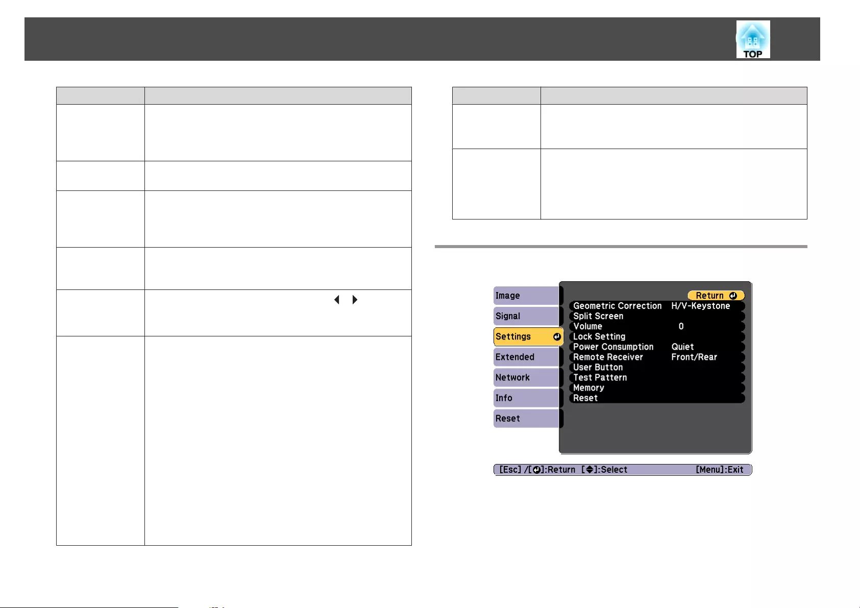
Submenu Function
Sync. (Only available when an analog RGB computer signal is being
input.)
You can adjust computer images when flickering, fuzziness, or
interference appear in the images.
Position You can adjust the display position up, down, left, and right when
a part of the image is missing so that the whole image is projected.
Auto Setup (Only available when an analog RGB computer signal is being
input.)
Set to On to automatically adjust Tracking, Sync., and Position to
the optimum state when the input signal changes.
Overscan Changes the output image ratio (the range of the projected
image). You can set the cropping range to 4% or 8%. When set to
Auto, this is automatically adjusted according to the input signal.
Blanking You can hide images in the set area. Use the [ ][ ] buttons to
adjust the area. You can adjust by using a combination of Top,
Bottom, Left, and Right.
Advanced You can set by choosing the following items.
Video Range: Select the video range for the input signal from the
HDMI port, DVI-D port, or HDBaseT port. Set to Expanded if
you are concerned about misadjusted black levels or blown out
highlights in the image.
Input Signal: Select an input signal from the Computer port or
BNC port. If set to Auto, the input signal is set automatically
according to the connected equipment. If colors do not appear
correctly when set to Auto, select the appropriate signal
according to the connected equipment.
Image Processing: Changes settings for image processing.
•Fine: When Frame Interpolation is On, Frame Interpolation
is enabled.
•Fast 1: Images are displayed quicker without any loss in image
quality.
•Fast 2: Images are displayed quicker than Fast 1.
Submenu Function
Scale When using multiple projectors to project one image, adjust the
range of the image displayed by each projector.
s "Displaying a Scaled Image" p.112
Reset You can reset all adjustment values on the Signal menu to their
default settings, except for Input Signal.
See the following to return all menu items to their default
settings.
s "Reset Menu" p.155
Settings Menu
List of Functions
140

Submenu Function
Geometric Cor-
rection
You can correct distortion.
s "Correcting Distortion in the Projected Image" p.62
•Off:
Temporarily cancels the geometric correction.
•H/V-Keystone:
Adjust V-Keystone, V-Balance, H-Keystone, and H-
Balance to correct vertical and horizontal keystone
distortion.
•Quick Corner:
Select and correct the four corners of the projected image.
•Curved Surface:
Corrects distortion that occurs when projecting on a
curved surface.
•Corner Wall:
Corrects distortion that occurs when projecting on a
surface with right angles.
•Point Correction:
Divides the projected image into a grid and corrects the
distortion by moving the selected point of intersection
from side to side and up and down.
•Memory:
You can save the adjustment value of the geometric
correction and load it when needed.
s "Memory Function" p.122
Split Screen You can split the screen into two screens.
s "Projecting Two Images Simultaneously (Split Screen) "
p.115
Volume You can adjust the volume. Setting values are saved for each
source.
Submenu Function
Lock Setting Control Panel Lock: You can use this to restrict operation
of the projector's control panel.
s "Control Panel Lock" p.129
Lens Lock: When set to On, [Lens Shift], [Zoom],
and [Focus] button operations on the remote control are
disabled.
s "Lens Lock" p.130
Power Con-
sumption
*1 *2
When set to On, the power consumption during projection
drops and the fan noise is reduced.
Remote Receiv-
er
You can limit the reception of the operation signal from the
remote control.
When set to Off, you cannot perform any operations from
the remote control. If you want to make operations from
the remote control, hold down the [Menu] button on the
remote control for at least 15 seconds to reset the setting to
its default value.
User Button Select the items in the Configuration menu that you want to
assign to the [User1], [User2], and [User3] buttons on the
remote control. The following items can be assigned.
Power Consumption
*1
, Multi-Projection, Resolution,
Image Processing, On-Screen Display, Display the QR
Code, Image Enhancement, Frame Interpolation
Test Pattern You can display a test pattern to adjust the projection
without connecting other equipment when you set up the
projector.
s "Displaying a Test Pattern" p.32
Memory Perform operations and make settings for the memory
function.
s "Memory Function" p.122
List of Functions
141
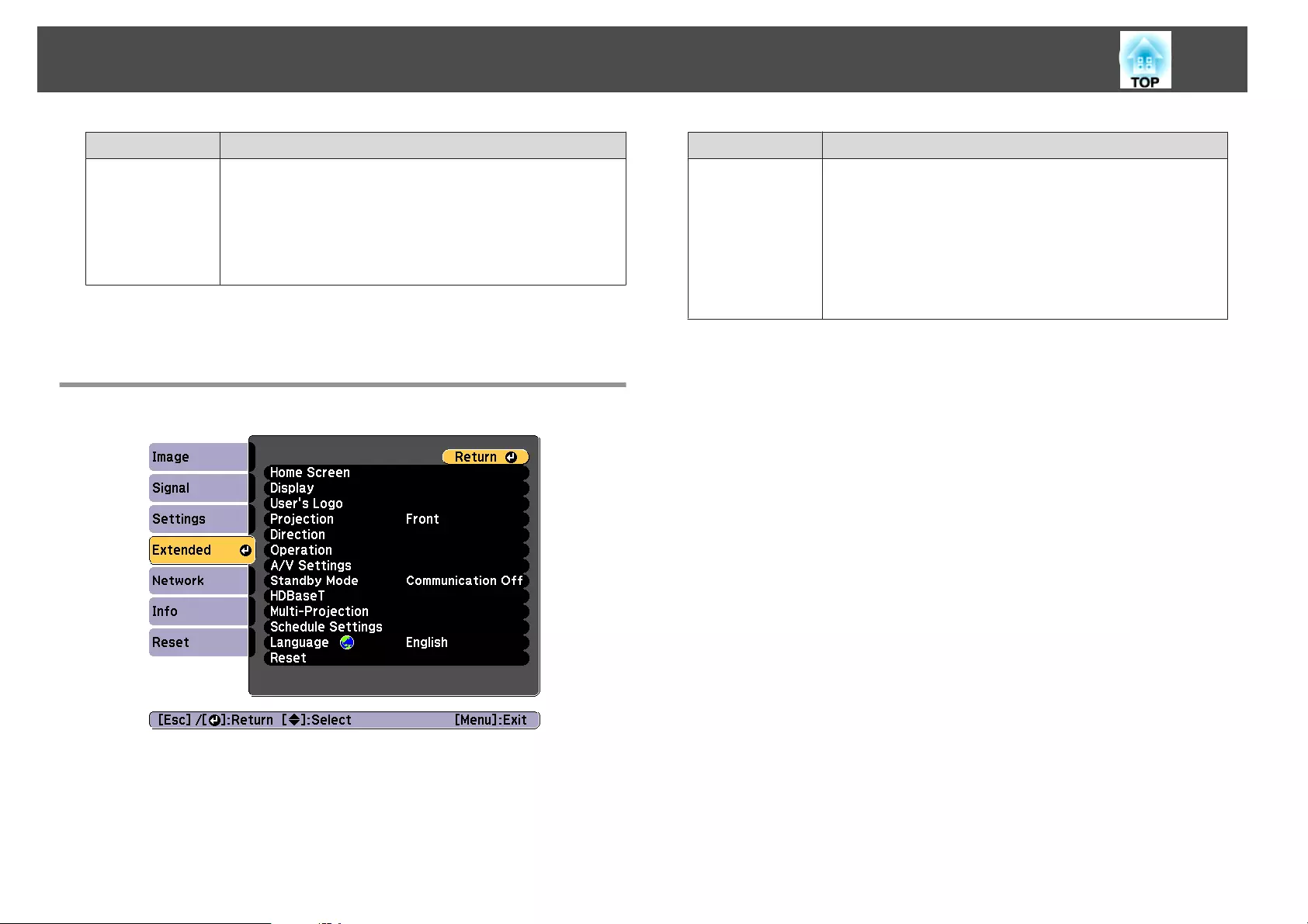
Submenu Function
Reset You can reset all adjustment values on the Settings menu to
their default settings, except for User Button and
Memory.
See the following to return all menu items to their default
settings.
s "Reset Menu" p.155
*1 Not available for EB-G7400U.
*2 This cannot be set when Portrait Mode is set to On.
Extended Menu
Submenu Function
Home Screen Home Screen Auto Disp.: When set to On, the Home
screen is displayed when the projector turns on. The Home
screen is not displayed when the selected source has an
image signal when the projector turns on.
Custom Function 1, Custom Function 2: Select functions
to be assigned to the Home screen from the following five
functions. Power Consumption
*1
, Network Settings, Info,
Frame Interpolation, Split Screen
List of Functions
142
Submenu Function
Display You can make settings related to the projector's display.
Menu Position: Select the position to display the menu on
the projected screen.
Message Position: Select the position to display the message
on the projected screen.
Messages: When set to Off, the following items will not be
displayed.
Item names when the Source, Color Mode, or Aspect is
changed, messages when no signal is being input, and
warnings such as High Temp Warning.
Display Background
*2
: You can set the screen status for
when no image signal is available to Black, Blue, or
Logo.
Startup Screen
*2
: Set to On to display the User's Logo
when projection starts.
Standby Confirmation: (This is unavailable when the
Remote Control Type is set to Simple.) If it is set to Off,
you can turn off the power simply by pressing the [t]
button once.
Air Filter Notice: You can set whether or not (On/Off) to
enable Air Filter Notice. When this is set to On and a clog
in the air filter is detected, the message is displayed on the
screen.
Screen: (This setting is unavailable when projecting images
from a computer over a network.) Set the aspect ratio and
position of the projected screen according to the type of
screen being used.
s "Screen Settings" p.30
Panel Alignment: Correct color misalignments (red and
blue) in the screen.
s "Panel Alignment" p.199
Color Uniformity: Adjusts the color tone balance for the
whole screen.
s "Color Uniformity" p.200
OSD Rotation: Rotates the menu direction by 90 degrees.
Submenu Function
User's Logo
*2
You can change the user's logo that is displayed as a
background during Display Background, A/V Mute, and so
on.
s "Saving a User's Logo" p.120
Projection Select from one of the following projection methods
depending on how the projector is installed.
Front, Front/Ceiling, Rear, and Rear/Ceiling
You can change the setting as follows by pressing down
the [A/V Mute] button for about five seconds.
FrontWFront/Ceiling
RearWRear/Ceiling
Direction Set this parameter according to the installation status of the
projector.
*3
s "Installation Settings" p.28
For portrait installation, set Portrait Mode to On.
List of Functions
143
Submenu Function
Operation Direct Power On: Set to On to turn on the projector
simply by plugging it in.
When the power cord is plugged in, note that the projector
turns on automatically in cases such as a power outage
being restored.
Sleep Mode: When set to On, this automatically stops
projection when no image signal is being input and no
operations are carried out.
Sleep Mode Timer: When Sleep Mode is set to On, you
can set the time before the projector automatically turns off
within a range of 1 to 30 minutes.
High Altitude Mode: Set to On when using the projector
above an altitude of 1,500 m.
Auto Source Search: Set to On to automatically detect an
image signal from another source and project the image
when there is no image signal from the current source.
Auto Power On: If it is set to Computer or BNC, the
projector is turned on when the signals are received from
the Computer port or BNC port, even when the projector is
in standby status.
A/V Mute Settings: Peform settings related to A/V mute.
•Fade-in: Specify the number of seconds for fade-in when
displaying an image.
•Fade-out: Specify the number of seconds for fade-out
when hiding an image.
•A/V Mute Timer: When it is set to On, if no operations
are performed for about 2 hours after A/V mute is
activated, the projector turns off automatically.
•A/V Mute Release: When it is set to A/V Mute, you can
release A/V mute only by pressing the [A/V Mute] button
(or by sending an A/V mute Off command).
When set to Any Button, A/V mute is released when any
operation is performed on the projector.
Submenu Function
s "Hiding the Image and Sound Temporarily (A/V
Mute)" p.118
Advanced: The following items can be set.
•BNC Sync Termination: Set the termination for the
signal from the BNC port. This should usually be set to
Off. Set to On when analog (75Ω) termination such as for
switchers is necessary.
•Remote Control Type: You can select Normal or Simple
depending on the type of remote control.
Set this item to Normal to use the remote control
provided with this projector. When Simple is selected, you
can use the remote control provided with other Epson
projectors to operate this projector. This is useful if you
want to use a remote control that you are already familiar
with to operate the projector.
However, you cannot use the remote control provided
with this projector if this is set to Simple. Make sure that
the setting is correct because, if the projector is mounted
on the ceiling or somewhere hard to reach, changing it
back to Normal may be difficult. Additionally, you cannot
use the functions that are not equipped with this projector
or the remote control which you use.
•Beep: When this is set to On, the confirmation buzzer
beeps to notify you that the power turns on or off, or
cooling down is finished.
•Indicators: When set to Off, the projector's indicators are
turned off, except for abnormality or warning.
•Instant Off: When set to Enabled, the projector goes into
standby status in approximately three seconds after Power
Off. If you turn the power on immediately after turning it
off, command communication may be cut off. To stabilize
command communication, set this to Disabled. When set
List of Functions
144
Submenu Function
to Disabled, the projector goes into standby status in
approximately 75 seconds after power off.
•Inv Direction Button: Set this to On when the projector
is installed on a ceiling.
•HDMI DDC Buffer: If the image from a device
connected using an HDMI extension cable is not
displayed correctly, turning this On may improve the
image.
•DVI-D DDC Buffer: If the image from a device
connected using a DVI extension cable is not displayed
correctly, turning this On may improve the image.
•Lens Type: When using the following lens, select the
model number of the lens.
ELPLS04, ELPLU02, ELPLR04, ELPLW04, ELPLM06,
ELPLM07, ELPLL07
Date & Time: Make system time settings for the projector.
s "Setting the Time" p.43
Lens Calibration: Acquires the information of the lens
installed on the projector.
Submenu Function
A/V Settings A/V Output: Set this to Always On if you want to output
audio and images to an external device even when the
projector is in standby status.
Monitor Out: Select the image source output to an external
monitor when the projector is in standby status. When set
to Auto, analog RGB signals from the Computer port or the
BNC port are output depending on which source was
selected when the projector was turned off.
Audio Settings: Perform the following audio related
settings.
•Audio Output: Select the audio to be output when
projecting images from the Computer port, BNC port, or
DVI-D port. When set to Auto, audio is output from the
audio port corresponding to each image input port.
s "Connecting Equipment" p.46
•HDMI Audio Output: Select the audio source when
projecting images from the HDMI port. If you select
HDMI, audio for the image is output as it is. If you select
Audio3, audio is output from the Audio3 port.
Standby Mode If you set Communication On, you can perform the
following operations even if the projector is in standby
mode.
•Monitor and control the projector over a network.
•Output audio and images to an external device. (Only
when A/V Output is set to Always On.)
•Communication from the HDBaseT port is enabled. (Only
when Control Communications is set to On.)
a
When monitoring or controlling the pro‐
jector using wireless LAN, set Connection
Mode to Advanced.
s Network - Wireless LAN - Connection
Mode p.149
List of Functions
145
Submenu Function
HDBaseT Control Communications: (This cannot be set when
Extron XTP is set to On.) When set to On, Ethernet
communication, serial communication, and the wired
remote control through the HDBaseT Transmitter connected
to the HDBaseT port are all enabled.
Extron XTP: Set to On when you connect the Extron XTP
transmitter or switcher to the HDBaseT port. See the
following Extron Web site for more details on the XTP
system.
http://www.extron.com/
a
•When Control Communications or Ex‐
tron XTP is set to On, Standby Mode is
automatically set to Communication On.
•When Control Communications or Ex‐
tron XTP is On, the projector's LAN
port, RS-232 port, and Remote port are
disabled.
•When Extron XTP is set to On, the fan
may rotate in standby mode but this is
not abnormal.
Submenu Function
Multi-Projection Make settings when projecting from multiple projectors.
s "Multi-Projection Function" p.102
Projector ID: Set the ID from 1 to 30. Off indicates that no
ID is set.
s "ID Settings" p.41
Tiling: Set the number of split screens and positions of each
projected image.
s "Tiling" p.111
Geometric Correction: Corrects distortion in the projected
image.
s "Correcting Distortion in the Projected Image" p.62
Edge Blending: Corrects a border between multiple images
to create a seamless screen.
s "Edge Blending" p.102
Scale: When using multiple projectors to project one image,
adjust the range of the image displayed by each projector.
s "Displaying a Scaled Image" p.112
Color Mode: Set to Multi-Projection.
Brightness Level
*1
: When the brightness of each lamp
differs, set the lamp brightness level. This item can be
adjusted only when Power Consumption is set to Off from
the Settings menu.
s "Correcting the Brightness (EB-G7905U/EB-G7900U/EB-
G7500U/EB-G7200W/EB-G7000W/EB-G7805/EB-G7800/EB-
G7100 only)" p.105
Color Matching: Corrects the difference between the tint
and brightness of each projected image.
s "Color Matching" p.106
Color Uniformity: Adjusts the color tone balance for the
whole screen.
s "Color Uniformity" p.200
RGBCMY: You can adjust the Hue, Saturation, and
Brightness for R (red), G (Green), B (Blue), C (Cyan), M
(Magenta), and Y (Yellow) color components.
s "Adjusting RGBCMY" p.107
List of Functions
146
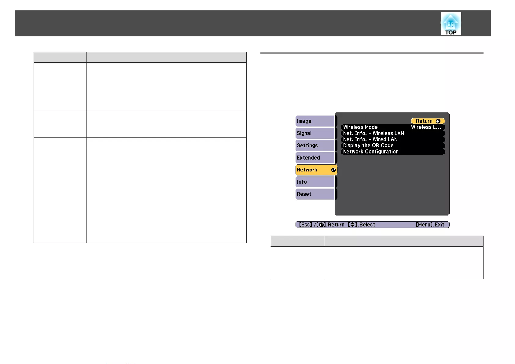
Submenu Function
Black Level: Adjusts the differences in brightness and tone
for areas where images overlap and areas where the images
do not overlap.
s "Black Level" p.108
Reset: You can reset all adjustment values for the Multi-
Projection menu to their default settings.
Schedule Set-
tings
You can set the projector's schedule so that it performs a
specific operation at a pre-scheduled time.
s "Scheduling Function" p.124
Language You can set the language for messages and menus.
Reset You can reset all adjustment values for the Extended menu
to their default settings. However, the following items are
not reset.
Screen Type, Screen Position, Projection, Direction,
Portrait Mode, High Altitude Mode, Auto Source Search,
A/V Mute Release, Remote Control Type, Inv Direction
Button, Lens Type, A/V Output, Monitor Out, Standby
Mode, Control Communications, Extron XTP, Projector
ID, Color Mode, Color Matching, Language
See the following to return all menu items to their default
settings.
s "Reset Menu" p.155
*1 Not available for EB-G7400U.
*2When User's Logo Protection is set to On in Password Protection, you
cannot change settings related to user's logo. You can make changes after
setting User's Logo Protection to Off.
s "Managing Users (Password Protection)" p.127
*3This cannot be set when Portrait Mode is set to On.
Network Menu
When Network Protection is set to On in Password Protection, a message
is displayed and the network settings cannot be changed. Set Network
Protection to Off and then configure the network.
s "Setting Password Protection" p.127
Submenu Function
Wireless Mode Set this to Wireless LAN On when connecting the projector and
a computer via a wireless LAN. If you do not want to connect via
wireless LAN, turn it Off to prevent unauthorized access by
others.
List of Functions
147
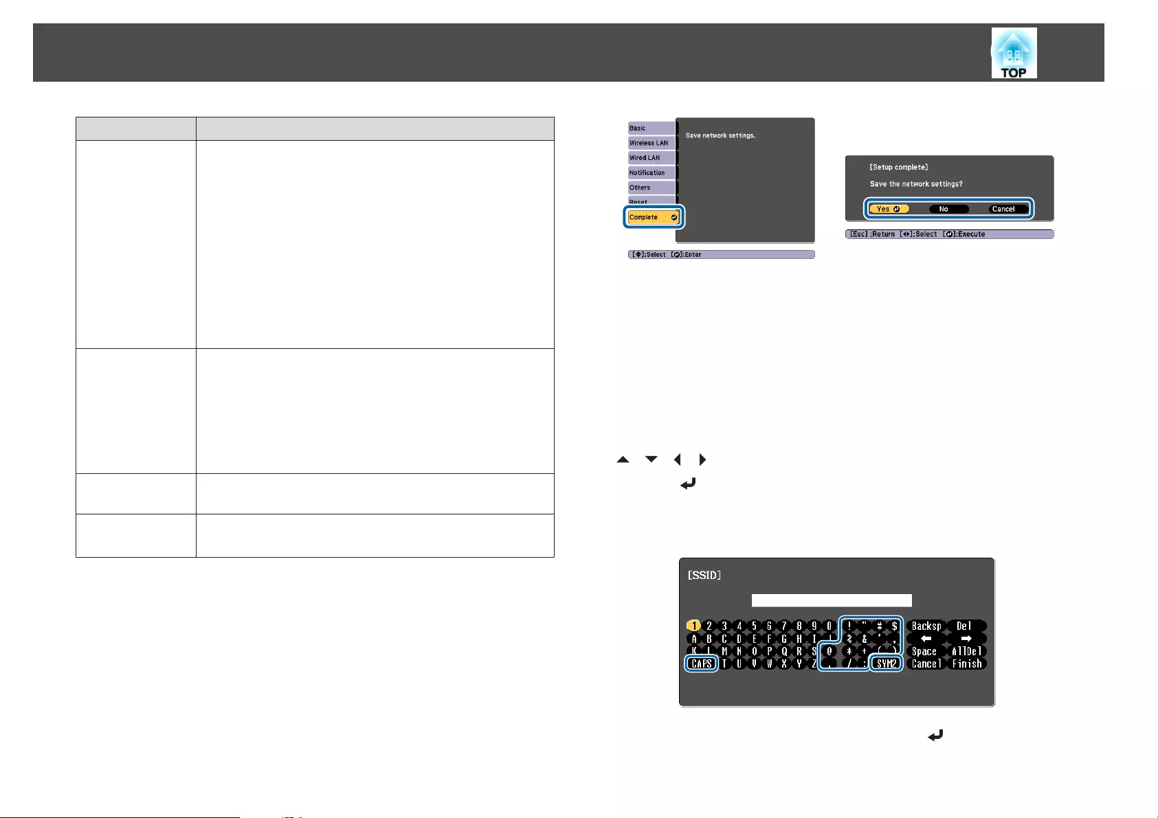
Submenu Function
Net. Info. - Wire-
less LAN
Displays the following network setting status information.
•Connection Mode
•Wireless LAN Sys.
•Antenna Level
•Projector Name
•SSID
•DHCP
•IP Address
•Subnet Mask
•Gateway Address
•MAC Address
•Region Code
Net. Info. - Wired
LAN
Displays the following network setting status information.
•Projector Name
•DHCP
•IP Address
•Subnet Mask
•Gateway Address
•MAC Address
Display the QR
Code
Displays the QR code.
Network Config-
uration
The following menus are available for setting Network items.
Basic, Wireless LAN, Wired LAN, Notification, Others, Reset
Notes on operating the Network menu
Selecting from the top menu and sub menus, and changing selected items is
the same as making operations from the Configuration menu.
When done, make sure you go to the Complete menu, and select Yes, No,
or Cancel. When you select Yes or No, you are returned to the
Configuration menu.
Yes: Saves the settings and exits the Network menu.
No: Does not save the settings and exits the Network menu.
Cancel: Continues displaying the Network menu.
Soft keyboard operations
The Network menu contains items that require input of alphanumerics
during setup. In this case, the following software keyboard is displayed. Use
[][ ][ ][ ]buttons to move the cursor to the desired key, and then
press the [ ] button to enter the selected character. Enter figures by
holding down the [Num] button on the remote control, and pressing the
numeric buttons. After inputting, press Finish on the keyboard to confirm
your input. Press Cancel on the keyboard to cancel your input.
•Each time the CAPS key is selected and the [ ] button is pressed, it
sets and changes between upper case and lower case letters.
List of Functions
148
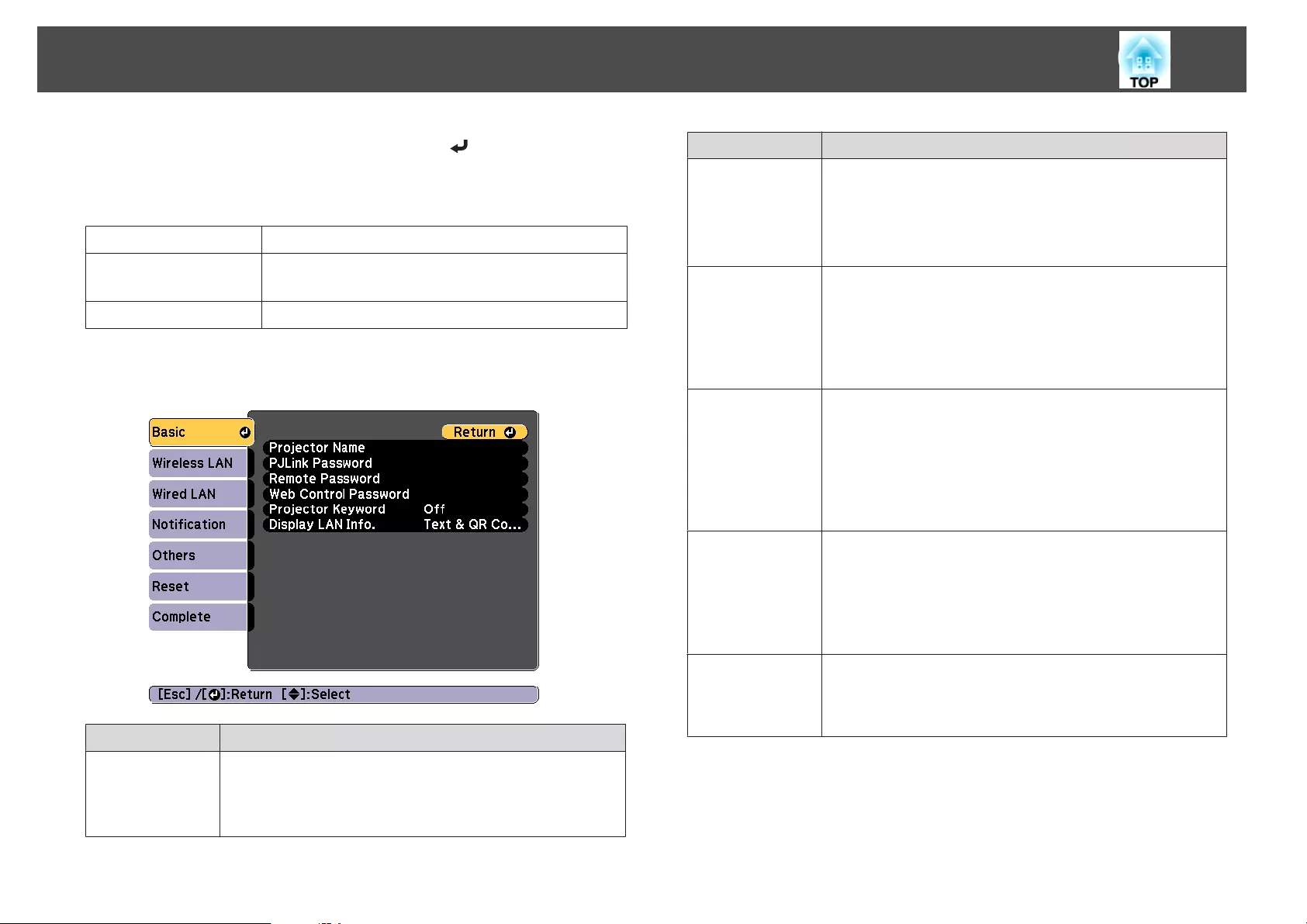
•Each time the SYM1/2 key is selected and the [ ] button is pressed, it
sets and changes the symbol keys for the section enclosed by the frame.
The following types of character can be entered.
Numbers 0123456789
Letters ABCDEFGHIJKLMNOPQRSTUVWXYZ
abcdefghijklmnopqrstuvwxyz
Symbols ! " # $ % & ' ( ) * + , - . / : ; < = > ? @ [ \ ] ^ _ ` { | } ~
Basic menu
Submenu Function
Projector Name The projector's name is displayed when using the supplied
application EasyMP Multi PC Projection.
When editing, you can enter up to 16 single-byte alphanumeric
characters. (" * + , / : ; < = > ? [ \ ] ` | and spaces cannot be used.)
Submenu Function
PJLink Password Set a password to use when you access the projector using
compatible PJLink software.
You can enter up to 32 single-byte alphanumeric characters.
(Spaces and symbols other than @ cannot be used.)
s "About PJLink" p.212
Remote Pass-
word
Set a password to use Remote in Epson Web Control. You can
enter up to 8 single-byte alphanumeric characters. (* : and spaces
cannot be used.) The default user name is "EPSONREMOTE"
and the default password is "guest".
s "Changing Settings Using a Web Browser (Epson Web
Control)" p.204
Web Control
Password
Set a password for authentication to use when making settings
and controlling the projector using Web Control in Epson Web
Control. You can enter up to eight single-byte alphanumeric
characters (* : and spaces cannot be used). The default user name
is "EPSONWEB" and the default password is "admin".
s "Changing Settings Using a Web Browser (Epson Web
Control)" p.204
Projector Key-
word
When set to On, you have to enter the keyword when you try to
connect the projector to a computer via a network. As a result,
you can prevent presentations from being interrupted by
connections from other computers.
Normally this should be set to On.
s EasyMP Multi PC Projection Operation Guide
Display LAN Info. Set the display format for the projector's network information. If
you display the QR code, you can connect to a network just by
reading the QR code in Epson iProjection. Text & QR Code is set
by default.
Wireless LAN menu
To connect the projector to a computer using a wireless LAN, install the
Wireless LAN unit (ELPAP10).
List of Functions
149
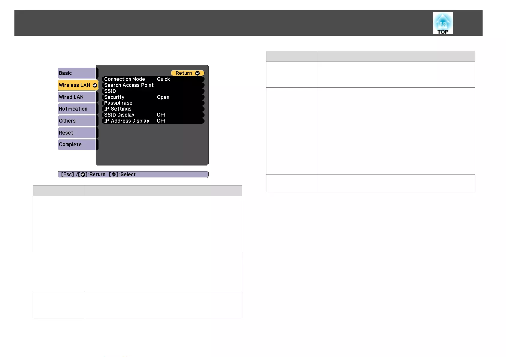
s "Installing the Wireless LAN Unit" p.52
Submenu Function
Connection
Mode
Set the connection mode to use when connecting the projector
and a computer via a wireless LAN.
Quick: Lets you directly connect to a smartphone, tablet, or
computer via a wireless LAN.
Advanced: Lets you connect to a smartphone, tablet, or
computer over a wireless LAN access point. The connection is
established in infrastructure mode.
Search Access
Point
When Connection Mode is set to Advanced, you can search for
surrounding access points, and set the SSID to be connected from
those access points. Depending on the access point settings, they
may not be displayed in the list.
s "Search Access Point screen" p.151
SSID Enter an SSID. When an SSID is provided for the wireless LAN
system in which the projector participates, enter the SSID.
You can enter up to 32 single-byte alphanumeric characters.
Submenu Function
Security Select the security type according to the wireless LAN settings.
When setting security, follow the instructions of your network
administrator.
Passphrase Enter a passphrase used to connect to the network when Security
is set to WPA2-PSK or WPA/WPA2-PSK.
You can enter at least 8 and up to 63 single-byte alphanumeric
characters.
You can enter up to 32 characters on the Configuration menu.
When entering more than 32 characters, use your Web browser
to enter the text.
s "Changing Settings Using a Web Browser (Epson Web
Control)" p.204
When Connection Mode is set to Quick, the initial passphrase is
set.
Channel You can select the channels used to connect in Quick mode. If
interference from other signals occurs, use a different channel.
List of Functions
150
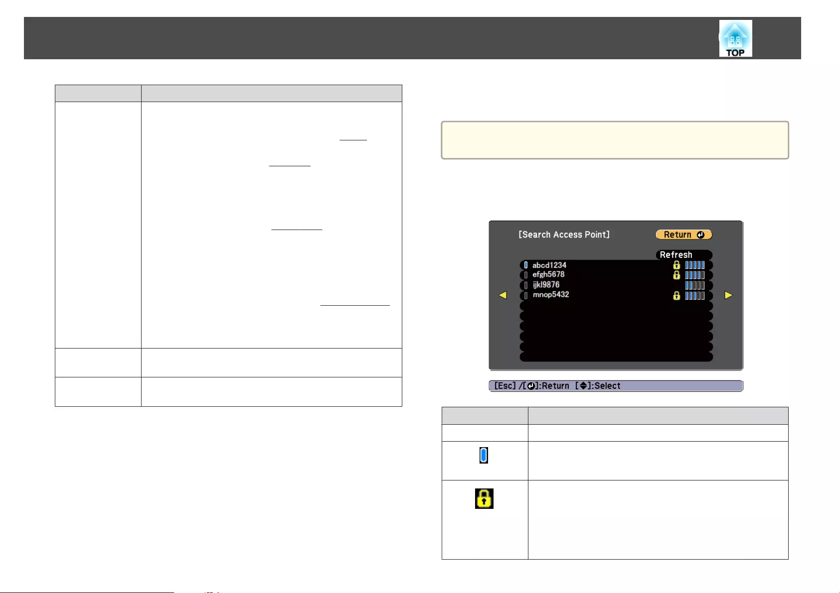
Submenu Function
IP Settings (This can only be set if Connection Mode is set to Advanced.)
Configure the network.
DHCP: Set to On to configure the network using DHCP
g
If this
is set to On, you cannot set any more addresses.
IP Address: You can enter the IP address
g
assigned to the
projector. You can enter a number from 0 to 255 in each field of
the address. However, the following IP addresses cannot be used.
0.0.0.0, 127.x.x.x, 224.0.0.0 to 255.255.255.255 (where x is a
number from 0 to 255)
Subnet Mask: You can enter the Subnet Mask
g
for the projector.
You can enter a number from 0 to 255 in each field of the address.
However, the following subnet masks cannot be used.
0.0.0.0, 255.255.255.255
Gateway Address: You can enter the IP address for the gateway
for the projector. You can enter a number from 0 to 255 in each
field of the address. However, the following Gateway Address
g
cannot be used.
0.0.0.0, 127.x.x.x, 224.0.0.0 to 255.255.255.255 (where x is a
number from 0 to 255)
SSID Display To prevent the SSID from being displayed on the LAN Standby
screen, set this to Off.
IP Address Dis-
play
To prevent the IP address from being displayed on the LAN
Standby screen, set this to Off.
Type of security
When the optional wireless LAN unit is attached and being used in
Advanced connection mode, it is strongly recommended that you set
security.
WPA is an encryption standard that improves the security for wireless
networks. The projector supports TKIP and AES encryption methods.
WPA also includes user authentication functions. WPA authentication
provides two methods: using an authentication server, or authenticating
between a computer and an access point without using a server. This
projector supports the latter method, without a server.
a
For setting details, follow the instructions from your network
administrator.
Search Access Point screen
Detected access points are displayed in a list.
Submenu Function
Refresh Searches for the access point again.
Indicates an already set access point.
Indicates the access points where security is set.
If you select an access point where security has not been set, the
Wireless LAN menu is displayed.
If you select an access point where security has been set, the
Security menu is displayed. Select a type of security according to
the security settings for the access point.
List of Functions
151
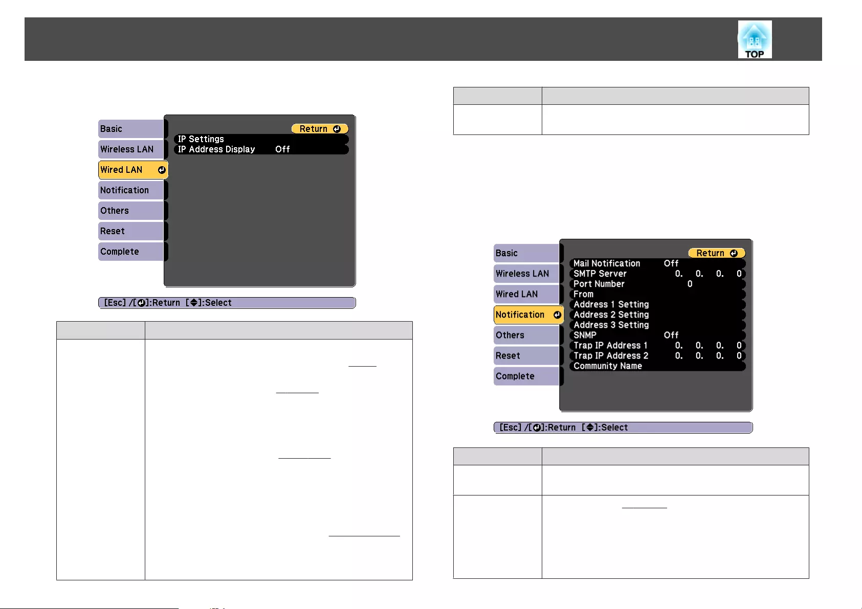
Wired LAN menu
Submenu Function
IP Settings You can make settings related to the following addresses.
DHCP: Set to On to configure the network using DHCP
g
If this
is set to On, you cannot set any more addresses.
IP Address: You can enter the IP address
g
assigned to the
projector. You can enter a number from 0 to 255 in each field of
the address. However, the following IP addresses cannot be used.
0.0.0.0, 127.x.x.x, 224.0.0.0 to 255.255.255.255 (where x is a
number from 0 to 255)
Subnet Mask: You can enter the Subnet Mask
g
for the projector.
You can enter a number from 0 to 255 in each field of the address.
However, the following subnet masks cannot be used.
0.0.0.0, 255.255.255.255
Gateway Address: You can enter the IP address for the gateway
for the projector. You can enter a number from 0 to 255 in each
field of the address. However, the following Gateway Address
g
cannot be used.
0.0.0.0, 127.x.x.x, 224.0.0.0 to 255.255.255.255 (where x is a
number from 0 to 255)
Submenu Function
IP Address Dis-
play
To prevent the IP address from being displayed on the LAN
Standby screen, set this to Off.
Notification menu
When this is set, you receive an email notification if a problem or warning
occurs in the projector.
s "Reading error notification mail" p.209
Submenu Function
Mail Notification Set to On to send an email to the preset addresses when a problem
or warning occurs with a projector.
SMTP Server You can input the IP Address
g
for the SMTP server for the
projector.
You can enter a number from 0 to 255 in each field of the address.
However, the following IP addresses cannot be used.
127.x.x.x, 224.0.0.0 to 255.255.255.255 (where x is a number from
0 to 255)
List of Functions
152
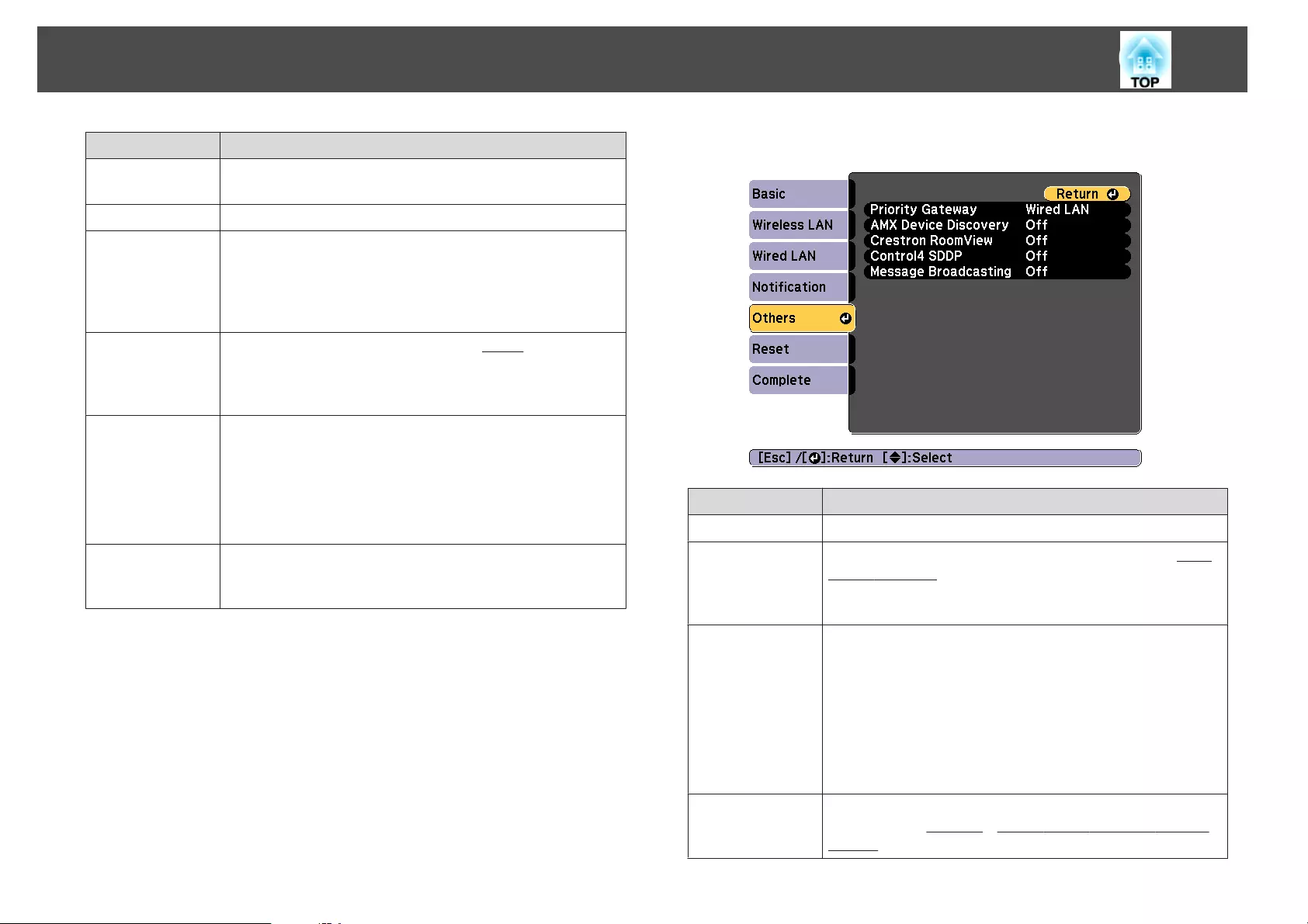
Submenu Function
Port Number You can input the port number for the SMTP server. The default
value is 25. You can input numbers between 1 to 65535.
From Enter the email address of the sender.
Address 1 Set-
ting/Address 2
Setting/Address
3 Setting
Set the destination email addresses for the notification email, and
the notification content. You can register up to three
destinations. You can enter up to 32 single-byte alphanumeric
characters for the email addresses. ( " ( ) , : ; < > [ \ ] and spaces
cannot be used.)
SNMP Set to On to monitor the projector using SNMP
g
. To monitor
the projector, you need to install the SNMP manager program on
your computer. SNMP should be managed by a network
administrator. The default value is Off.
Trap IP Address
1/Trap IP Ad-
dress 2
You can register up to two IP addresses for the SNMP trap
notification destination.
You can enter a number from 0 to 255 in each field of the address.
However, the following IP addresses cannot be used.
127.x.x.x, 224.0.0.0 to 255.255.255.255 (where x is a number from
0 to 255)
Community
Name
Set the community name of SNMP. You can enter up to 32 single-
byte alphanumeric characters. (Spaces and symbols other than @
cannot be used.)
Others menu
Submenu Function
Priority Gateway For the priority gateway, select either Wired or Wireless.
AMX Device Dis-
covery
When you want to allow the projector to be detected by AMX
Device Discovery
g
, set this to On. Set this to Off if you are not
connected to an environment controlled by a controller from
AMX or AMX Device Discovery.
Crestron Room-
View
Set this to On only when monitoring or controlling the projector
over the network using Crestron RoomView
®
. Otherwise, set
this to Off.
s "About Crestron RoomView
®
" p.212
Changes in projector settings take effect upon restarting.
When this is set to On, the following functions are not available.
•Epson Web Control
•Message Broadcasting (EasyMP Monitor plugin)
Control4 SDDP Set to On if you want to enable the acquisition of the device
information by Control4
®
Simple Device Discovery Protocol
(SDDP)
g
.
List of Functions
153
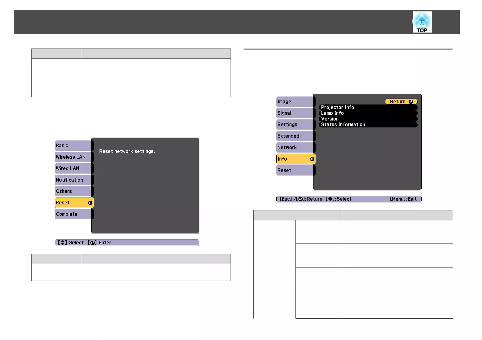
Submenu Function
Message Broad-
casting
You can switch the Message Broadcasting function to enable or
disable.
You can download Message Broadcasting and its Operation
Guide from the following Web site.
http://www.epson.com
Reset menu
Resets all of the network settings.
Submenu Function
Reset network
settings.
To reset all of the Network settings, select Yes.
Info Menu (Display Only)
Lets you check the status of the image signals being projected and the status
of the projector. Items that can be displayed vary depending on the source
currently being projected.
Submenu Function
Projector Info Source You can display the source name for the
connected equipment currently being
projected.
Input Signal You can display the content of Input
Signal set in the Signal menu according to
the source.
Resolution You can display the resolution.
Refresh Rate You can display the Refresh Rate
g
.
Sync Info You can display the image signal
information.
This information may be needed if service
is required.
List of Functions
154
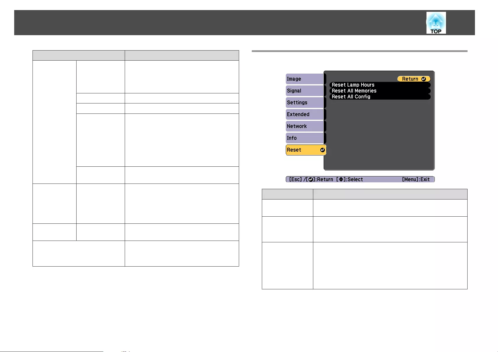
Submenu Function
Status This is information about errors that have
occurred on the projector.
This information may be needed if service
is required.
Serial Number Displays the projector's serial number.
Lens Type Displays the model number of your lens.
Event ID When problems occur when the projector
and computer are connected through the
network, information on the problem is
displayed using an Event ID. See the
following page for information on
interpreting the Event ID.
s "About Event ID" p.189
HDBaseT Sig-
nal Level
You can display the image signal
information from the HDBaseT port.
Lamp Info Lamp Hours You can display the cumulative lamp
operating time
*
.
When the lamp replacement time is
reached, the characters are displayed in
yellow.
Version Main
Video2
Displays the projector's firmware version
information.
Status Information Displays the projector's status.
s "Reading the Status Information"
p.172
*The cumulative use time is displayed as "0H" for the first 10 hours. 10 hours
and above is displayed as "10H", "11H", and so on.
Reset Menu
Submenu Function
Reset Lamp
Hours
Clears the cumulative lamp hours use time. Reset when you
replace the lamp.
Reset All Memo-
ries
Resets all names and settings saved in Memory, Lens Position,
and Geometric Correction.
s "Memory Function" p.122
Reset All Config You can reset all items in the Configuration menu to their default
settings.
The following items are not reset to their defaults: Input Signal,
Memory, User's Logo, all items for Network menus, Lamp
Hours, Language, Date & Time, Panel Alignment, Color
Uniformity, and Color Matching.
List of Functions
155
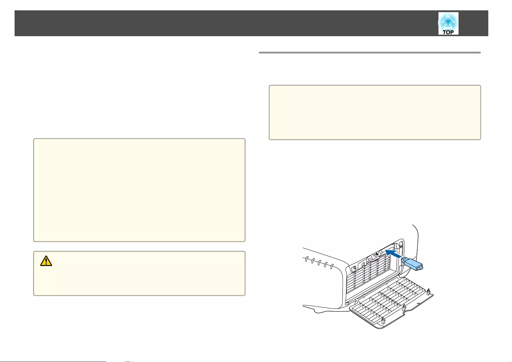
Once the Configuration menu content has been set for one projector, you
can use it to perform batch setup for multiple projectors (batch setup
function). The batch setup function is only for projectors with the same
model number.
Use one of the following methods.
•Setup using a USB flash drive.
•Setup by connecting the computer and projector with a USB cable.
•Setup using EasyMP Network Updater.
This manual explains the USB flash drive and the USB cable methods.
a
•The following content is not reflected by the batch setup function.
- The Network menu settings (except for the Notification menu and
the Others menu)
- Lamp Hours and Status in the Info menu
•Perform batch setup before adjusting the projected image.
Adjustment values for the projected image, such as Geometric
Correction are reflected by the batch setup function. If batch setup is
performed after adjusting the projected image, the adjustments you
made may change.
•By using the batch setup function, the registered User's Logo is set
for the other projectors. Do not register confidential information and
so on as the User's Logo.
Caution
Performing batch setup is the customers responsibility. If batch setup fails due
to a power failure, communication error, and so on, the customer is responsible
for any repair costs incurred.
Setup Using a USB Flash Drive
This section explains how to perform batch setup using a USB flash drive.
a
•Use a FAT format USB flash drive.
•The batch setup function cannot be used by USB flash drives that
incorporate security functions. Use a USB flash drive that does not
incorporate security functions.
•The batch setup function cannot be used by USB card readers or
USB hard disks.
Saving settings to the USB flash drive
a
Disconnect the power cord from the projector, and check that all
of the projector's indicators have turned off.
b
Connect the USB flash drive to the projector's wireless LAN unit
port.
s "Installing the Wireless LAN Unit" p.52
Batch Setup
156
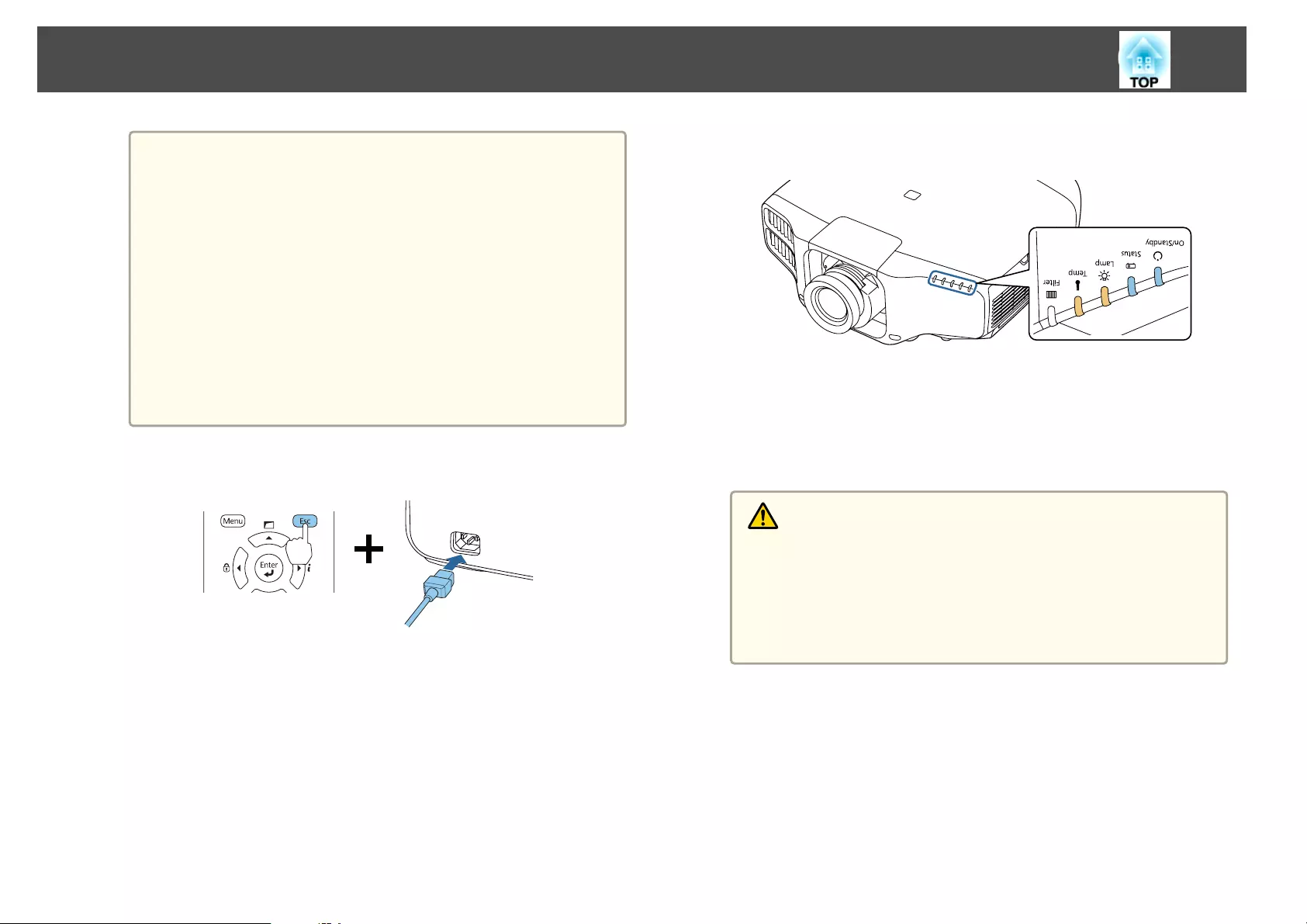
a
•Connect the USB flash drive directly to the projector. If the
USB flash drive is connected to the projector through a USB
hub, the settings may not be saved correctly.
•Connect an empty USB flash drive. If the USB flash drive
contains data other than the batch setup file, the settings may
not be saved correctly.
•If you have saved a batch setup file from another projector to
the USB flash drive, delete the file or change the file name.
The batch setup function cannot overwrite a batch setup file.
•The file name for the batch setup file is PJCONFDATA.bin. If
you need to change the file name, add text after
PJCONFDATA. If you change the file name in any other way,
the projector may not be able to recognize the file correctly.
•You can only use single-byte characters for the file name.
c
While holding down the [Esc] button on the remote control or the
control panel, connect the power cord to the projector.
When the projector's indicators turn on as follows, release the [Esc]
button.
Power Status Lamp Temp
Blue - On Blue - On Orange - On Orange - On
When all of the indicators start flashing, the batch setup file is being
written.
Caution
•Do not disconnect the power cord from the projector while the file is
being written. If the power cord is disconnected, the projector may not
start correctly.
•Do not disconnect the USB flash drive from the projector while the
file is being written. If the USB flash drive is disconnected, the
projector may not start correctly.
Batch Setup
157
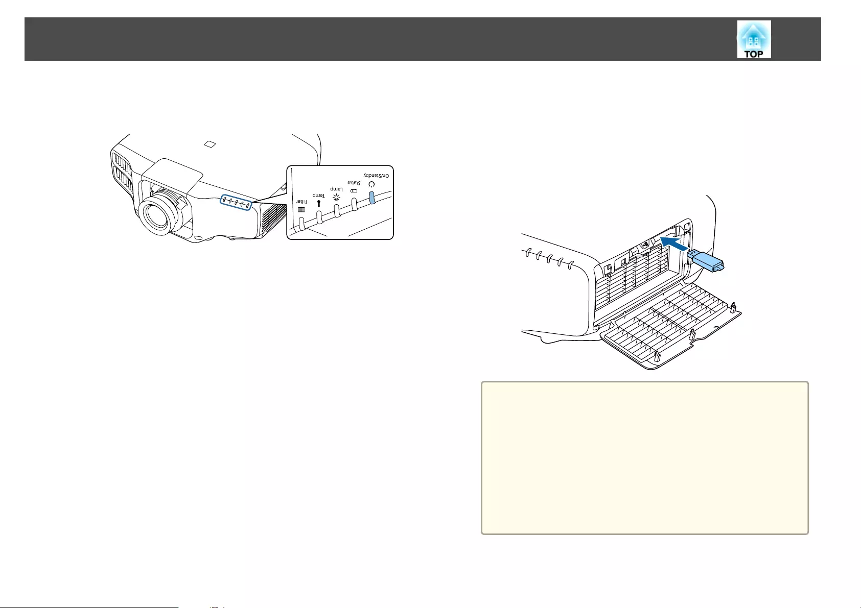
When writing completes normally, the projector enters standby
status.
Power
Blue - On
When the projector is in standby status, remove the USB flash
drive.
Reflecting saved settings to other projectors
a
Disconnect the power cord from the projector, and check that all
of the projector's indicators have turned off.
b
Connect the USB flash drive containing the saved batch setup file
to the projector's wireless LAN unit port.
a
•When the USB flash drive contains 1 to 3 types of batch
setup files, the file is reflected to the projector with the same
model number. If there are multiple files for a projector with
the same model number, the settings may not be reflected
correctly.
•When there are four or more types of batch setup files on the
USB flash drive, the settings may not be reflected correctly.
•Do not store any data except for the batch setup file on the
USB flash drive. If the USB flash drive contains data other
than the batch setup file, the settings may not be reflected
correctly.
Batch Setup
158
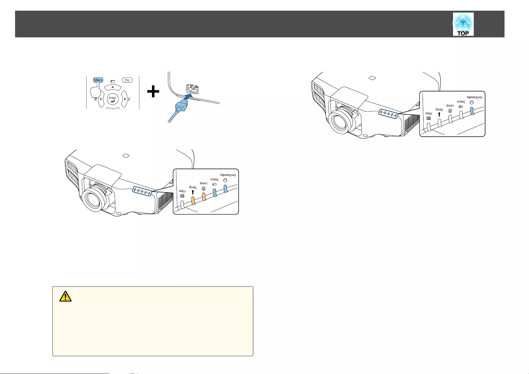
c
While holding down the [Menu] on the remote control or the
control panel, connect the power cord to the projector.
When the projector's indicators turn on as follows, release
the [Menu] button.
Power Status Lamp Temp
Blue - On Blue - On Orange - On Orange - On
The indicators remain on for about 75 seconds.
When all of the indicators start flashing, the settings are being
written.
Caution
•Do not disconnect the power cord from the projector while the
settings are being written. If the power cord is disconnected, the
projector may not start correctly.
•Do not disconnect the USB flash drive from the projector while the
settings are being written. If the USB flash drive is disconnected, the
projector may not start correctly.
d
When writing completes normally, the projector enters standby
status.
Power
Blue - On
When the projector is in standby status, remove the USB flash
drive.
Batch Setup
159
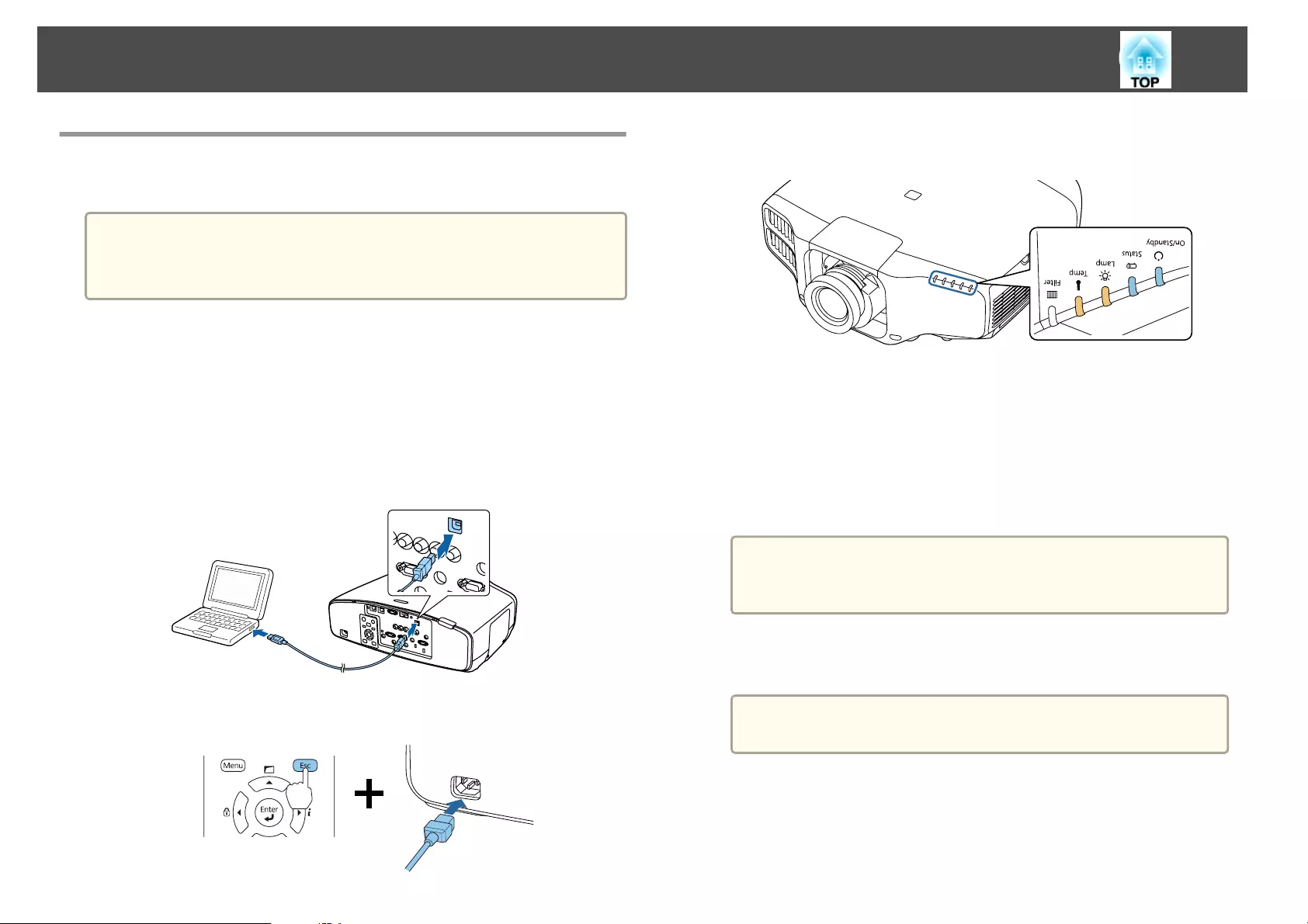
Setup by Connecting the Computer and Projector
with a USB Cable
a
The following operating systems support the batch setup function.
•Windows Vista or later
•Mac OS X 10.5.3 or later
Saving settings to a computer
a
Disconnect the power cord from the projector, and check that all
of the projector's indicators have turned off.
b
Connect the computer's USB port to the projector's Service port
with a USB cable.
c
While holding down the [Esc] button on the remote control or the
control panel, connect the power cord to the projector.
When the projector's indicators turn on as follows, release the [Esc]
button.
Power Status Lamp Temp
Blue - On Blue - On Orange - On Orange - On
The projector is recognized as a removable disk by the computer.
d
Open the removable disk, and save the batch setup file
(PJCONFDATA.bin) to the computer.
a
If you need to change the name of the batch setup file, add text
after PJCONFDATA. If you change the file name, the projector
may not be able to recognize the file correctly.
e
Perform "Remove USB device" on your computer, and then
disconnect the USB cable.
a
When using OS X, perform "Remove EPSON_PJ".
The projector enters standby status.
Batch Setup
160
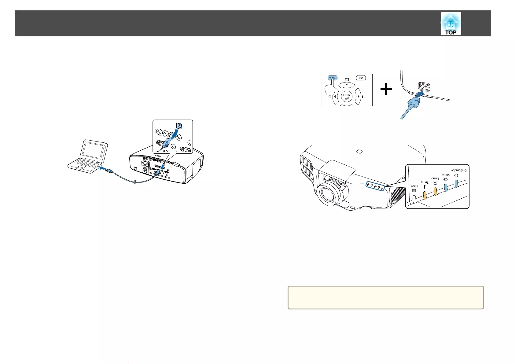
Reflecting saved settings to other projectors
a
Disconnect the power cord from the projector, and check that all
of the projector's indicators have turned off.
b
Connect the computer's USB port to the projector's Service port
with a USB cable.
c
While holding down the [Menu] on the remote control or the
control panel, connect the power cord to the projector.
When the projector's indicators turn on as follows, release
the [Menu] button.
Power Status Lamp Temp
Blue - On Blue - On Orange - On Orange - On
The projector is recognized as a removable disk by the computer.
d
Copy the batch setup file (PJCONFDATA.bin) that you saved to
your computer to the top level folder of the removable disk.
a
Do not copy any files or folders other than the batch setup file
to the removable disk.
e
Perform "Remove USB device" on your computer, and then
disconnect the USB cable.
Batch Setup
161
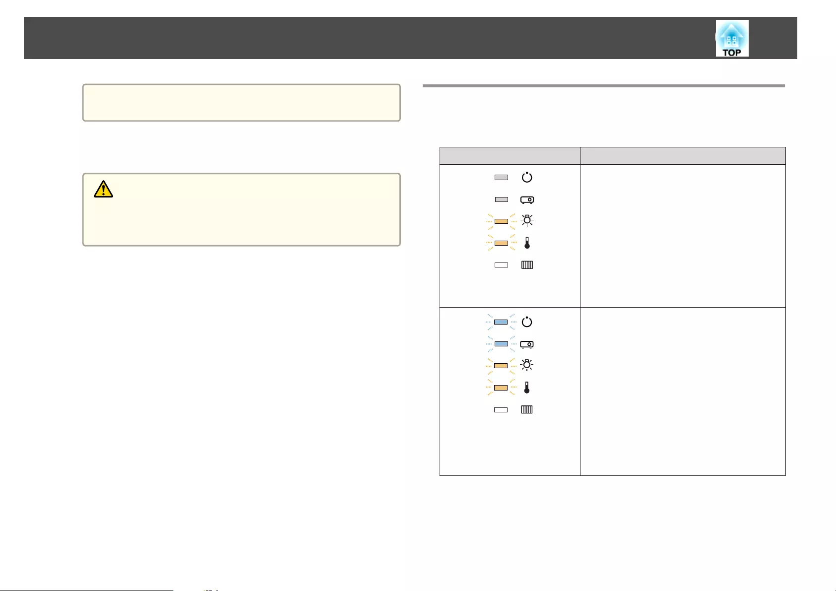
a
When using OS X, perform "Remove EPSON_PJ".
When all of the indicators start flashing, the settings are being
written.
Caution
Do not disconnect the power cord from the projector while the settings
are being written. If the power cord is disconnected, the projector may
not start correctly.
When writing completes normally, the projector enters standby
status.
When Setup Fails
The indicators notify you if an error occurs. Check the status of the
indicators.
Status of the Indicators Remedy
Lamp: Orange - flashing fast
Temp: Orange - flashing fast
The batch setup file may be corrupt, or the USB
flash drive may not be connected correctly.
Disconnect the USB flash drive, unplug and then
plug in the projector's power cord, and then try
again.
Power: Blue - flashing fast
Status: Blue - flashing fast
Lamp: Orange - flashing fast
Temp: Orange - flashing fast
Writing the settings may have failed and an error
may have occurred in the projector's firmware.
Stop using the projector, remove the power plug
from the electrical outlet, and contact your local
dealer or the nearest address provided in the Epson
Projector Contact List.
s Epson Projector Contact List
Batch Setup
162

Troubleshooting
This chapter explains how to identify problems and what to do if a problem is found.
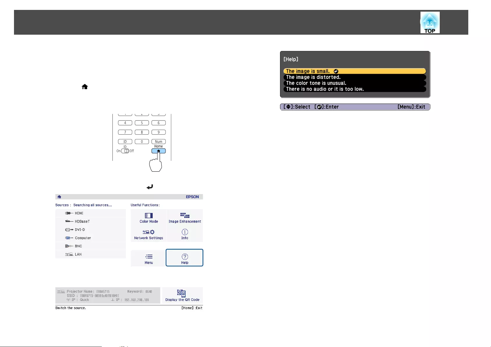
If a problem occurs with the projector, you can display the Help screen to
assist you. You can also set the projector to an appropriate state by
answering the questions.
a
Press the [ ] button.
The Home screen is displayed.
Remote control
b
Select Help, and then press the [ ] button.
The Help screen is displayed.
Using the Help
164
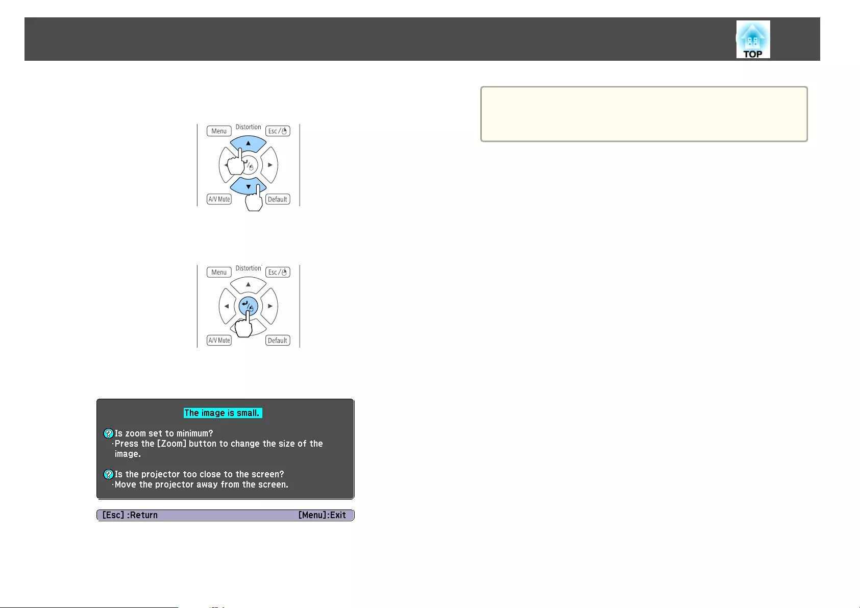
c
Select a menu item.
Remote control
d
Confirm the selection.
Remote control
Questions and solutions are displayed as shown on the screen below.
Press the [Menu] button to exit Help.
a
See the following if the Help function does not provide a
solution to the problem.
s "Reading the Indicators" p.166
Using the Help
165
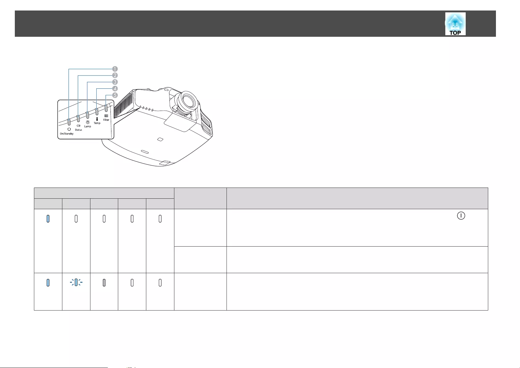
The projector is provided with the following five indicators that indicate the operating status of the projector.
APower indicator
Indicates the projector's status.
BStatus indicator
Indicates the projector's status.
CLamp indicator
Indicates the projection lamps status.
DTemp indicator
Indicates the internal temperature status. This is normally turned off.
EFilter indicator
Indicates the air filter status. This is normally turned off.
The following indicator status are used during regular operation.
Indicator Projector's Sta-
tus
Explanation
Power Status Lamp Temp Filter
Blue - On Off Off Off Off
Standby condition Power is being supplied to the projector. In this status, you can start projecting by pressing the [ ] button
on the remote control or control panel.
(Sometimes, when the power cord is unplugged, the power indicator remains lit for a short period, but this
is not a fault.)
Network monitor‐
ing status
The projector is being monitored and controlled over a network (when Standby Mode is set to
Communication On).
If the power cord is disconnected and then reconnected in this status, the power indicator flashes blue.
Blue - On Blue -
Flashing
Status
varies
Off Off
Warm-up status This is the status immediately after turning on the projector. Warm-up takes approximately 30 seconds
after the lamp turns on.
The [t] button is disabled during warm-up.
Reading the Indicators
166
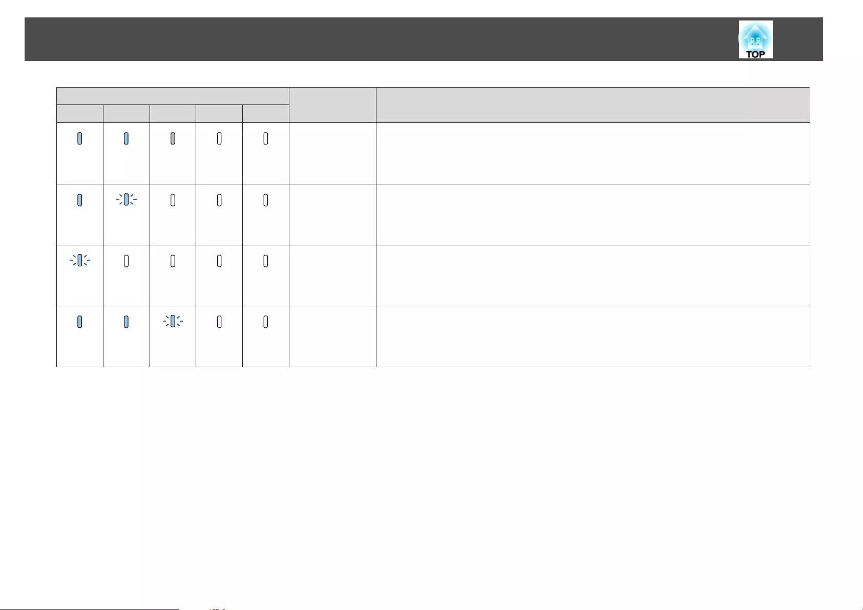
Indicator Projector's Sta-
tus
Explanation
Power Status Lamp Temp Filter
Blue - On Blue - On Status
varies
Off Off
Projecting The projector is projecting.
Blue - On Blue -
Flashing
Off Off Off
Cool down status This is the status immediately after turning off the power. In this status, all buttons are disabled.
Blue -
Flashing
Off Off Off Off
Preparing Network
monitoring
Preparing to monitor and control this projector over a network.
During network monitoring preparation, all button operations are disabled.
Blue - On Blue - On Blue -
Flashing
Off Off
A/V Mute activa‐
ted
A/V Mute is active.
Reading the Indicators
167
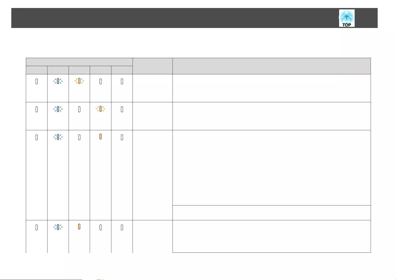
When an error has occurred in the projector, the error status is indicated by the indicator's color and combination of flashing or lit.
Refer to the following table to see what the indicators mean and how to remedy problems that they indicate.
Indicator Cause Remedy or Status
Power Status Lamp Temp Filter
Off Blue -
Flashing
Orange -
Flashing
Off Off
Internal Error Stop using the projector, remove the power plug from the electrical outlet, and contact your local dealer or
the nearest address provided in the Epson Projector Contact List.
s Epson Projector Contact List
Off Blue -
Flashing
Off Orange -
Flashing
Off
Fan Error
Sensor Error
Stop using the projector, remove the power plug from the electrical outlet, and contact your local dealer or
the nearest address provided in the Epson Projector Contact List.
s Epson Projector Contact List
Off Blue -
Flashing
Off Orange -
On
Off
High Temp Error
(Overheating)
The lamp turns off automatically and projection stops. Wait for about five minutes. After about five
minutes the projector switches to standby mode, so check the following two points.
•Check that the air filter and air exhaust vents are clear, and that the projector is not positioned against a
wall.
•If the air filter are clogged, remove the power cord from the electrical outlet, and then clean or replace
them.
s "Cleaning the Air Filter" p.191
s "Replacing the Air Filter" p.197
If the error continues after checking the points above, stop using the projector, remove the power plug
from the electrical outlet, and contact your local dealer or the nearest address provided in the Epson
Projector Contact List.
s Epson Projector Contact List
When using at an altitude of more than 1,500 m, set High Altitude Mode to On.
s Extended - Operation - High Altitude Mode p.142
Off Blue -
Flashing
Orange -
On
Off Off
Lamp Error
Lamp Failure
Check the following two points.
•Remove the lamps and check if they are cracked.
s "Replacing the Lamp" p.194
•Clean the air filter.
s "Cleaning the Air Filter" p.191
Reading the Indicators
168
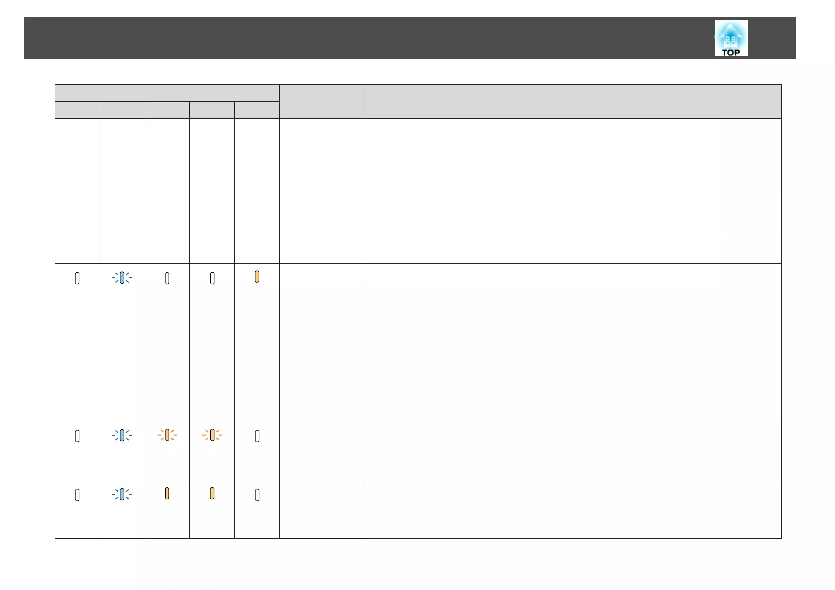
Indicator Cause Remedy or Status
Power Status Lamp Temp Filter
If the lamp is not cracked: Reinstall the lamp and turn on the power.
If the error continues: Replace the lamp with a new one and then turn on the power.
If the error continues: Stop using the projector, remove the power plug from the electrical outlet, and
contact your local dealer or the nearest address provided in the Epson Projector Contact List.
s Epson Projector Contact List
If the lamp is cracked: Contact your local dealer or the nearest address provided in the Epson Projector
Contact List. (Images cannot be projected until the lamp is replaced.)
s Epson Projector Contact List
When using at an altitude of 1500 m or more, set High Altitude Mode to On.
s Extended - Operation - High Altitude Mode p.142
Off Blue -
Flashing
Off Off Orange -
On
Filter Airflow Error Check the following two points.
•Check that the air filter and air exhaust vents are clear, and that the projector is not positioned against a
wall.
•If the air filter is clogged, turn off the power, remove the power cord from the electrical outlet, and then
clean or replace them.
s "Cleaning the Air Filter" p.191
s "Replacing the Air Filter" p.197
After checking, connect the power cord to the electrical outlet.
If the error continues after checking the points above, stop using the projector, remove the power plug
from the electrical outlet, and contact your local dealer or the nearest address provided in the Epson
Projector Contact List.
s Epson Projector Contact List
Off Blue -
Flashing
Orange -
Flashing
Orange -
Flashing
Off
Auto Iris Error Stop using the projector, remove the power plug from the electrical outlet, and contact your local dealer or
the nearest address provided in the Epson Projector Contact List.
s Epson Projector Contact List
Off Blue -
Flashing
Orange -
On
Orange -
On
Off
Power Err. (Bal‐
last)
Lens Shift Error
Stop using the projector, remove the power plug from the electrical outlet, and contact your local dealer or
the nearest address provided in the Epson Projector Contact List.
s Epson Projector Contact List
Reading the Indicators
169
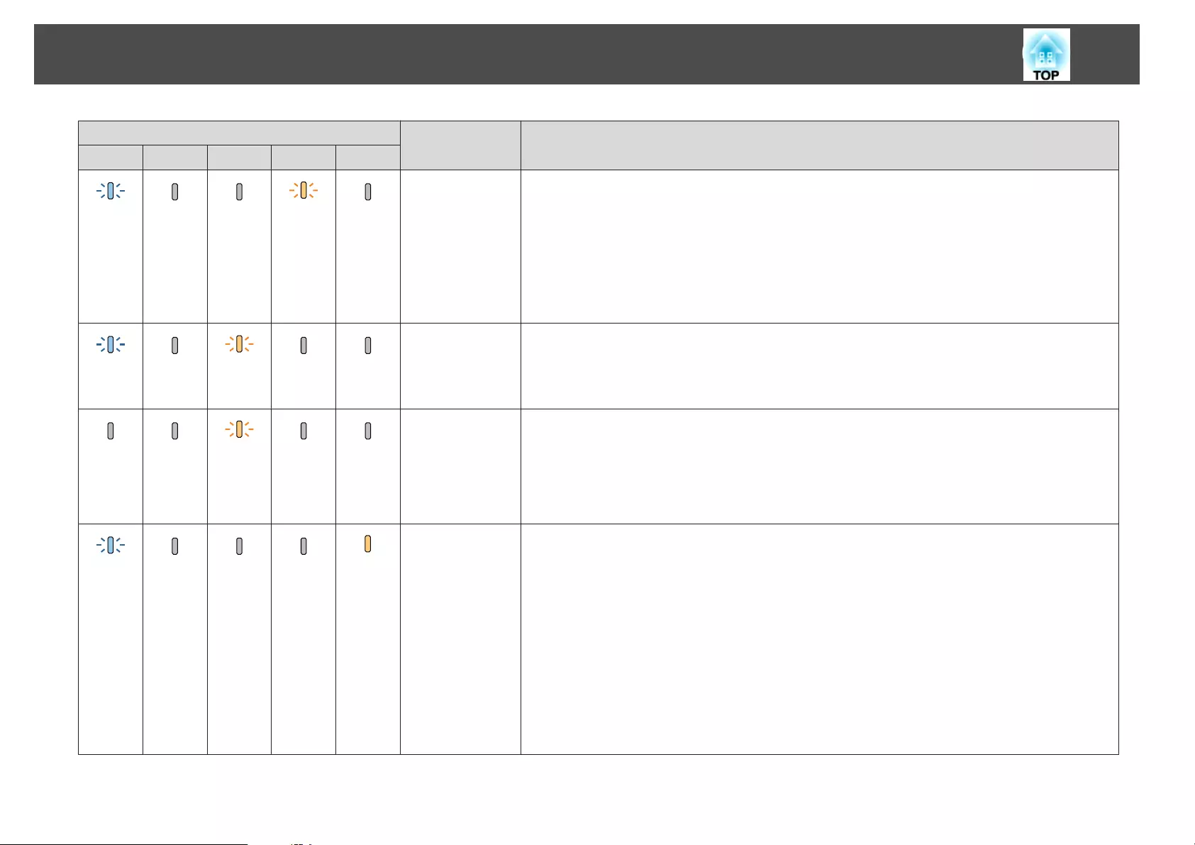
Indicator Cause Remedy or Status
Power Status Lamp Temp Filter
Blue -
Flashing
Status
varies
Status
varies
Orange -
Flashing
Status
varies
High Temp Warn‐
ing
This is not an error. However, if the temperature rises too high again, projection stops automatically.
Check the following two points.
•Check that the air filter and air exhaust vents are clear, and that the projector is not positioned against a
wall.
•If the air filter is clogged, turn off the power, remove the power cord from the electrical outlet, and then
clean or replace them.
s "Cleaning the Air Filter" p.191
s "Replacing the Air Filter" p.197
Blue -
Flashing
Status
varies
Orange -
Flashing
Status
varies
Status
varies
Replace Lamp Replace it with a new lamp.
s "Replacing the Lamp" p.194
If you continue to use the lamp after the replacement period has passed, the possibility that the lamp may
explode increases. Replace it with a new lamp as soon as possible.
Status
varies
Status
varies
Orange -
Flashing
Status
varies
Status
varies
Installation posi‐
tion warning (non-
support position,
installation angle)
A message is displayed, and projection stops automatically after about five minutes. Check the installation
angle of the projector.
•Check the guaranteed operating range.
s "Warning and Cautions on Installation" p.3
•Check if Direction in the Configuration menu is set correctly.
s "Setting the direction" p.28
Blue -
Flashing
Status
varies
Status
varies
Status
varies
Orange -
On
Low Air Flow This is not an error. However, projection stops automatically if the airflow falls any further.
"The air filter is clogged. Clean or replace the air filter."is displayed. Check the following points.
•Check that the air filter and air exhaust vents are clear, and that the projector is not positioned against a
wall.
•If the air filter is clogged, turn off the power, remove the power cord from the electrical outlet, and then
clean or replace them.
s "Cleaning the Air Filter" p.191
s "Replacing the Air Filter" p.197
If the error continues after checking the points above, stop using the projector, remove the power plug
from the electrical outlet, and contact your local dealer or the nearest address provided in the Epson
Projector Contact List.
s Epson Projector Contact List
Reading the Indicators
170
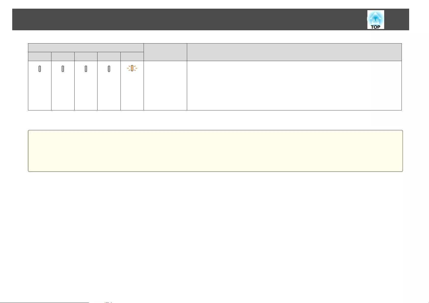
Indicator Cause Remedy or Status
Power Status Lamp Temp Filter
Status
varies
Status
varies
Status
varies
Status
varies
Orange -
Flashing
Air Filter Notice "Time to clean the air filter. Clean or replace the air filter."is displayed.
Turn off the projector's power, unplug the power cord from the electrical outlet, and then clean the air
filter.
s "Cleaning the Air Filter" p.191
The indicators or messages regarding air filter notice are displayed only when Air Filter Notice is set to On
in the Configuration menu.
s Extended - Display - Air Filter Notice p.142
a
•See the following if the projector is not operating properly, even though the indicators are all showing normal.
s "Problem Solving" p.179
•If the indicators are in a state not shown in this table, stop using the projector, remove the power plug from the electrical outlet, and contact your local dealer or
the nearest address provided in the Epson Projector Contact List.
s Epson Projector Contact List
Reading the Indicators
171
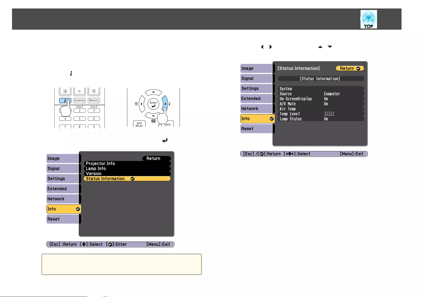
You can display the operating status of the projector on the projected
image. You can check the detailed status of the projector by using button
operations.
a
Press the [ ] button while projecting.
Remote control Control panel
b
Select Status Information, and then press the [ ] button.
a
You can also operate from the Configuration menu.
s Info - Status Information p.154
c
Use the [ ][ ] buttons or the [ ][ ] buttons to select a
category.
Each display category contains the following information.
Status Information : Operating status of the projector
Source : Input signal information
Signal Information : Input digital signal information
Network Wired : Wired LAN settings
Network Wireless : Wireless LAN settings
Maintenance : Operating time for the projector and lamps
Version : Projector's firmware version
Reading the Status Information
172
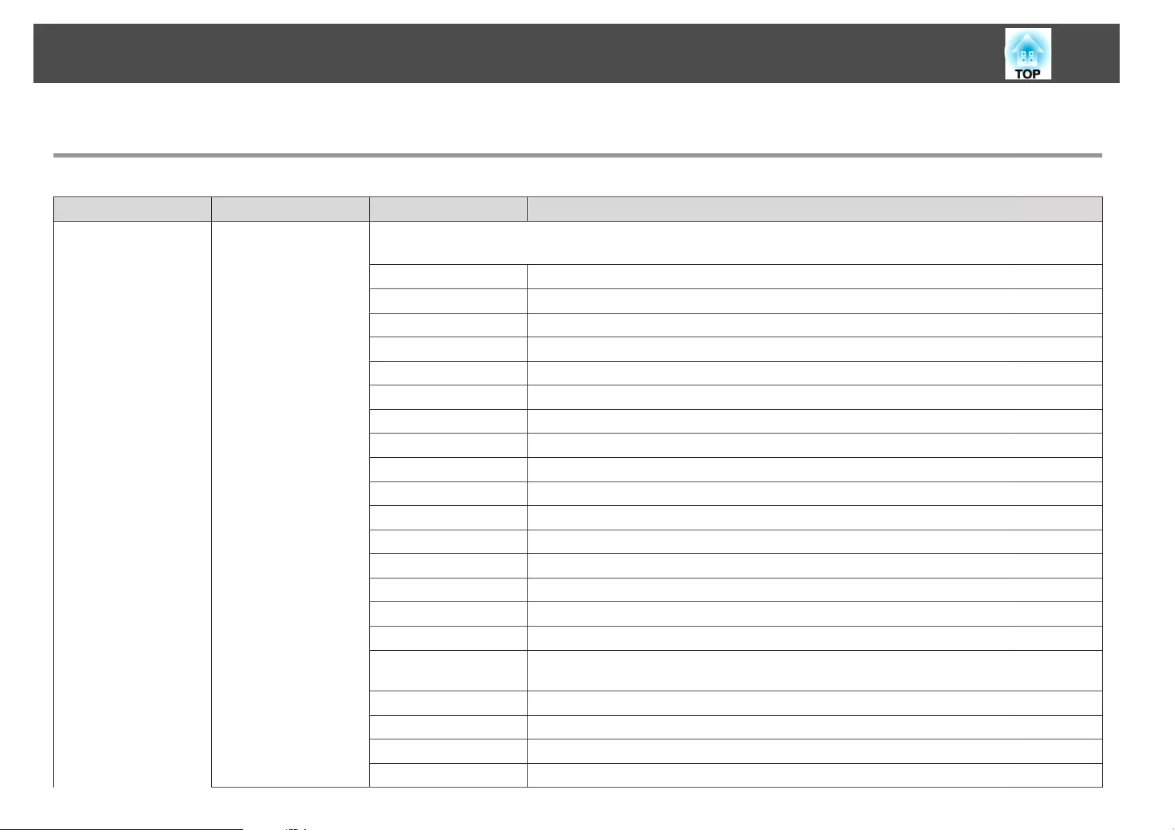
Explanations of the Display Content
Category Item Status Display Explanation
Status Information System Displays the projector's status. See the following for more information on how to remedy the errors and warnings.
s "Reading the Indicators" p.166
OK The projector is in normal status.
Warm-Up The projector is warming up.
Standby The projector is in standby status.
Cool Down The projector is in cool down status.
Temp Error A high temp error has occurred.
Fan Error A fan error has occurred.
Sensor Error A sensor error has occurred.
Lamp Error A lamp error has occurred.
Lamp Failure A lamp failure has occurred.
Power Error A power error (Ballast) has occurred.
Internal Error An internal error has occurred.
Auto Iris Error An auto iris error has occurred.
Airflow Error A filter airflow error has occurred.
Temp Warning A high temp warning has occurred.
Internal Warning A warning about the internal system has occurred.
Airflow Decline A low air flow error has occurred.
Lamp Warning A lamp warning has occurred. Perform the same remedies as when the lamp error has
occurred.
Power Warning A power warning (Ballast) has occurred.
Direction Warning The usage angle is out of range. Set it at the correct angle.
Lamp Replacement A lamp replacement recommendation has occurred.
Clean Filter An air filter notice has occurred.
Reading the Status Information
173
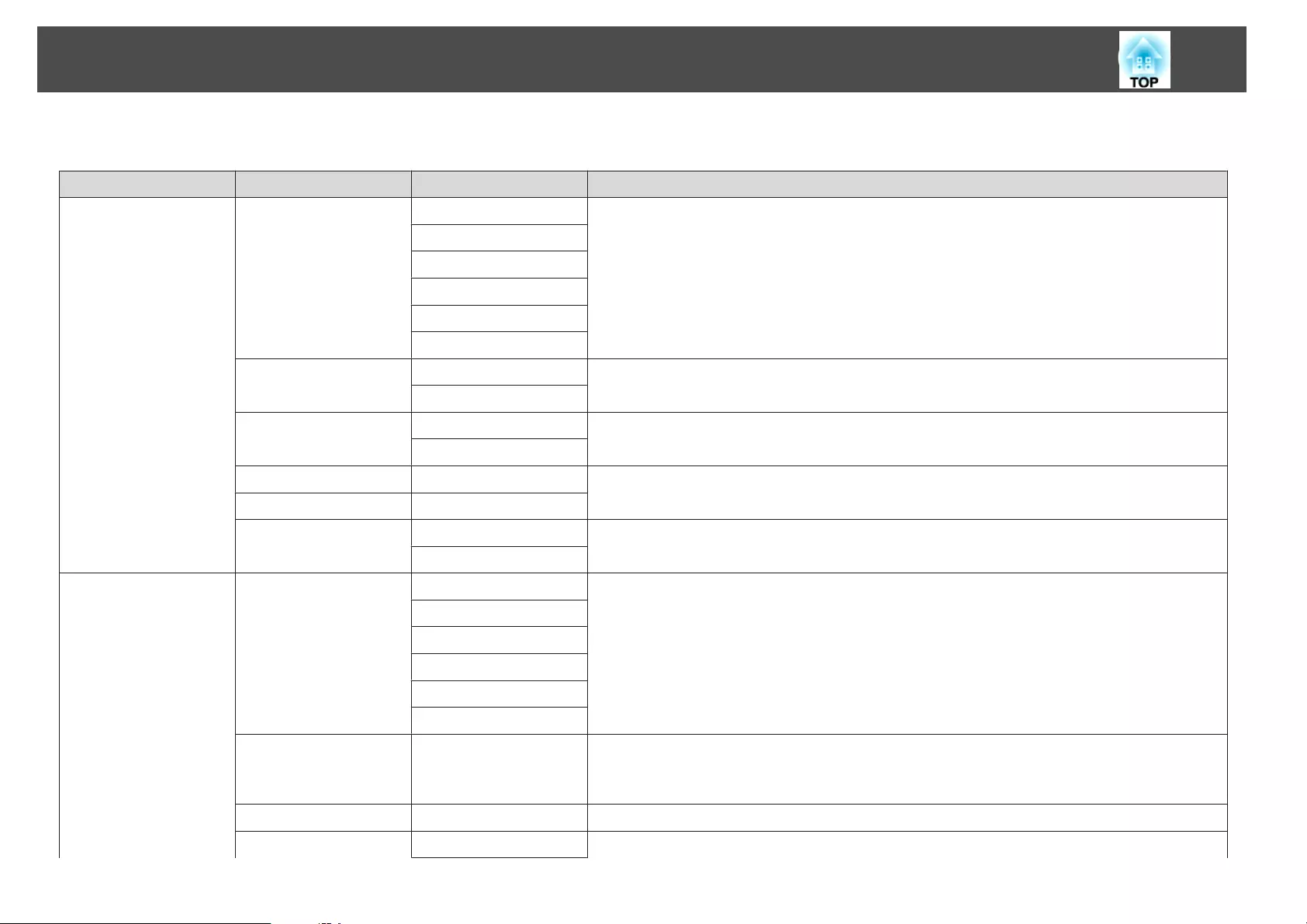
Category Item Status Display Explanation
Source HDMI Displays the source name for the connected equipment currently being projected.
HDBaseT
DVI-D
Computer
BNC
LAN
On-Screen Display On Displays the settings for the On-Screen Display. When set to Off, the menus or messages are
not displayed on the projected images.
Off
A/V Mute On Displays the operating status of A/V mute.
Off
Air Temp - Displays the usage environment temperature.
Temp Level -
Lamp Status On Displays the operating status of the lamp.
Off
Source Source HDMI Displays the source name for the connected equipment currently being projected.
HDBaseT
DVI-D
Computer
BNC
LAN
Resolution - Displays the resolution of the current input signal.
No Signal: No signals are being input.
Not Supported: The projector does not support the current input signal.
Video Signal - Displays the current input video signal.
Color Space RGB Displays the color space of the current input signal.
Reading the Status Information
174
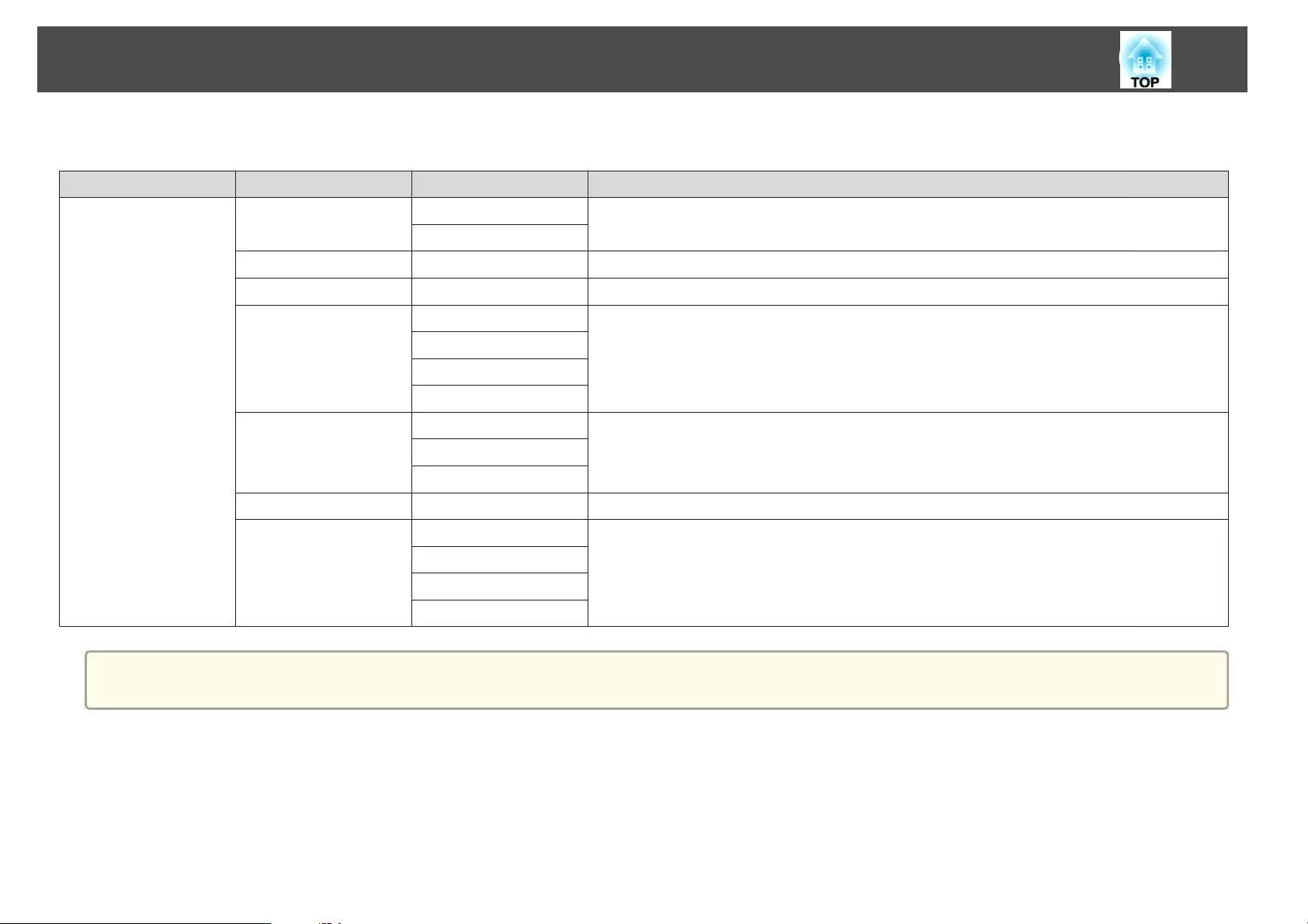
Category Item Status Display Explanation
YCbCr
YPbPr
H-Frequency - Displays the horizontal frequency of the current input signal.
V-Frequency - Displays the vertical frequency of the current input signal.
Sync Polarity H:Posi / V:Posi Displays the Sync polarity.
H:Posi / V:Nega
H:Nega / V:Posi
H:Nega / V:Nega
Sync Mode Composite Sync Displays the sync type.
Separete Sync
Sync On Green
Detected Mode - Displays the discriminant resolution of the current input signal.
Video Level Auto (Normal) Displays the video level of the projector.
Auto (Expanded)
Normal
Expanded
a
Items displayed for source vary depending on the model being used and the image signal and source being projected.
Reading the Status Information
175
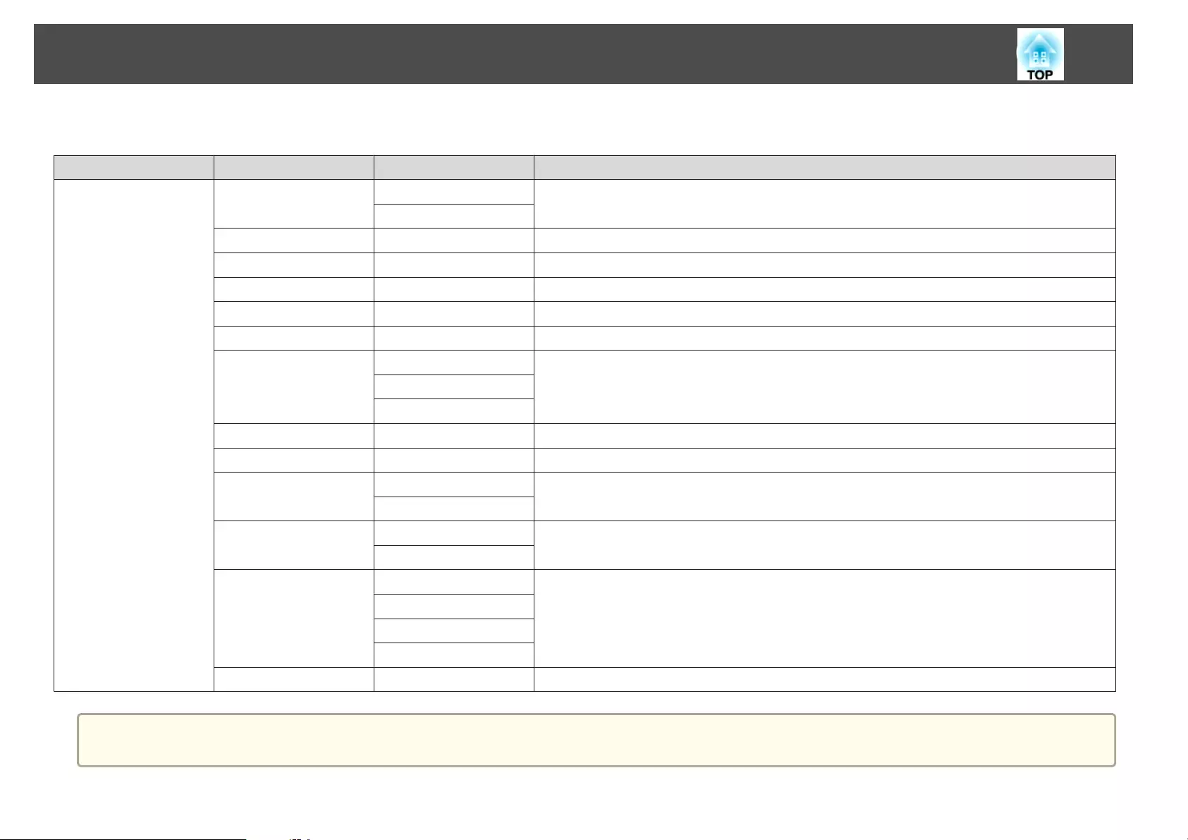
Category Item Status Display Explanation
Signal Information 5V Detection Detected Displays the detection results of 5V signals.
Not Detect
TMDS Clock - Displays the TMDS frequency of the current input signal.
TMDS H-Frequency - Displays the horizontal frequency of the current input signal.
TMDS V-Frequency - Displays the vertical frequency of the current input signal.
DetChg 5CFHMP123 - Displays the factors of signal changes.
Stable Time - Displays the operating time since the input source is determined.
HDCP Status Non-HDCP Displays the HDCP status.
Passed
Failed
HDCP Ver - Displays the HDCP version.
AVI Info VIC - Displays the VIC information (AVI) of the current input signal.
AVI InfoChecksum OK Displays the checksum result for AVI.
NG
Signal Mode HDMI Displays the signal mode.
DVI
Pixel Encoding RGB Displays the color space information (AVI) of the current input signal.
YUV4:4:4
YUV4:2:2
YUV4:2:0
HDBaseT Level - You can display the image signal information from the HDBaseT port.
a
Items displayed for Signal Information vary depending on the model being used and the image signal and source being projected.
Reading the Status Information
176
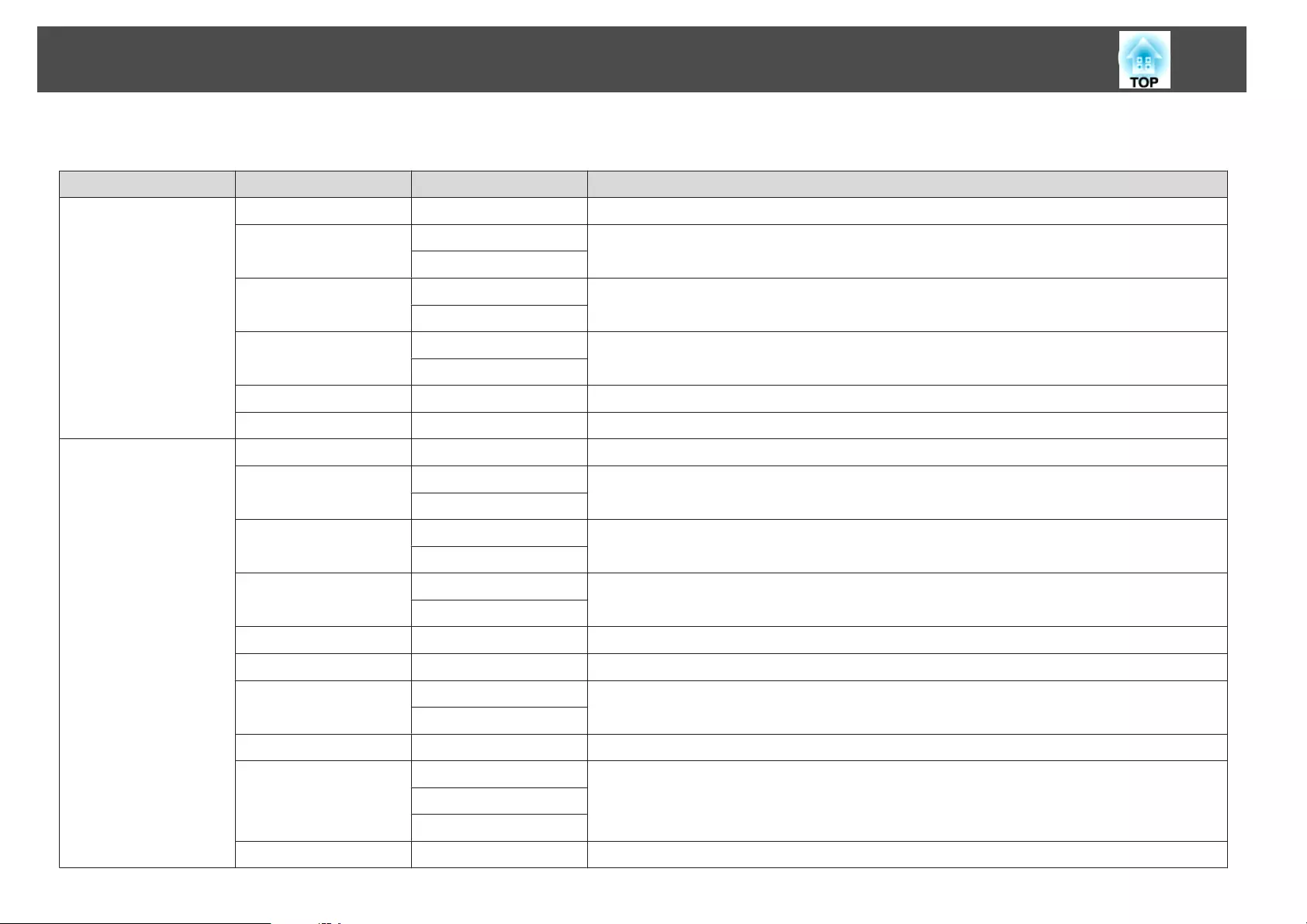
Category Item Status Display Explanation
Network Wired Projector Name - Displays the projector name used to identify the projector when connected to a network.
Connection Mode HDBaseT Displays the connection path for LAN.
LAN
DHCP On Displays the HDCP settings.
Off
IP Display On Displays the IP address display settings.
Off
IP Address - Displays the IP address.
MAC Address - Displays the MAC address.
Network Wireless Projector Name - Displays the projector name used to identify the projector when connected to a network.
Connection Mode Quick Displays the connection mode to use when connecting the projector and a computer over a
wireless LAN.
Advanced
SSID Display On Displays the SSID display settings.
Off
IP Display On Displays the IP address display settings.
Off
SSID - Displays the SSID.
IP Address - Displays the IP address.
DHCP On Displays the HDCP settings.
Off
MAC Address - Displays the MAC address.
Security No Displays the security settings.
WPA2-PSK
WPA/WPA2-PSK
Antenna Level LEVEL 0-5 Displays the reception status for Wi-Fi.
Reading the Status Information
177
Category Item Status Display Explanation
Maintenance Operation Time - Displays the total operation time of the projector.
Lamp Op.Time - Displays the cumulative lamp operating time. (Normal)
Lamp Op.Time PR - Displays the cumulative lamp operating time. (Portrait Mode)
Version Serial No. - Displays the projector's serial number.
Main - Displays the projector's firmware version information.
Video2 -
Sub -
Sub2 -
HDBaseT -
Reading the Status Information
178
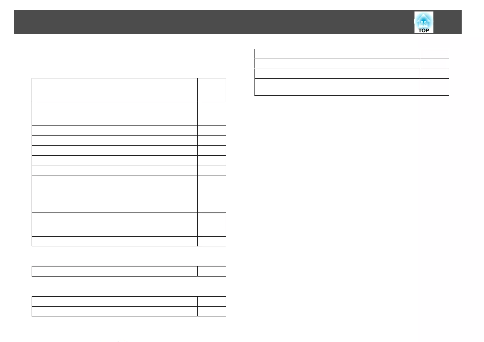
If any of the following problems occur and the indicators do not offer a
solution, refer to the pages given for each problem.
Problems relating to images
•No images appear
Projection does not start, the projection area is completely black,
or the projection area is completely blue.
sp.180
•Moving images are not displayed
Videos played back on a computer are black or no image is
projected, or the video is not played back on the computer.
sp.180
•Projection stops automatically sp.181
•The message "Not supported" is displayed sp.181
•The message "No Signal" is displayed sp.181
•Images are fuzzy, out of focus, or distorted sp.182
•Interference or distortion appear in images sp.182
•The image is truncated (large) or small, the aspect ratio is not
suitable, or the image has been reversed
Only part of the image is displayed, the height and width ratios
of the image are not correct, or the image may appear reversed
from top to bottom or left to right.
sp.183
•Image colors are not right
The whole image appears purplish or greenish, images are black
& white, or colors appear dull.
sp.184
•Images appear dark sp.184
Problems when projection starts
•The projector does not turn on sp.185
Other problems
•No sound can be heard or the sound is faint sp.186
•The remote control does not work sp.186
•Nothing appears on the external monitor sp.187
•I want to change the language for messages and menus sp.188
•Email is not received even if a problem occurs in the projector sp.188
•"The battery that saves your clock settings is running low." is
displayed
sp.188
Problem Solving
179

Problems Relating to Images
No images appear
Check Remedy
Did you press the [ ] button on the remote control or control
panel?
Press the [ ] button to turn on the power.
Are the indicators switched off? The power cord is not connected correctly or power is not being supplied.
Connect the projector's power cord correctly.
Check that your electrical outlet or power source is functioning correctly.
Is A/V Mute active? Press the [A/V Mute] button to release A/V Mute.
s "Hiding the Image and Sound Temporarily (A/V Mute)" p.118
Are the Configuration menu settings correct? Reset all of the settings.
s Reset - Reset All Config p.155
Is the image to be projected completely black?
(Only when projecting computer images)
Some input images, such as screen savers, may be completely black.
Is Windows Media Center displayed in full screen?
(Only during network connection)
When Windows Media Center is displayed at full screen, you cannot project using a network connection. Reduce the
screen size.
Is an application using the Windows DirectX function displayed?
(Only during network connection)
Applications using the Windows DirectX function may not display images correctly.
Moving images are not displayed
Check Remedy
Is the computer's image signal being output to the LCD and the
monitor?
(Only when projecting images from a laptop computer or a
computer with a built-in LCD screen)
Change the image signal from the computer to external output only. Check your computer's documentation, or contact
the computer's manufacturer.
Are the contents of the moving image you are trying to project
copyright protected?
The projector may not be able to project copyright protected moving images that are being played back on a computer.
For more details, see the user's guide supplied with the player.
Problem Solving
180

Projection stops automatically
Check Remedy
Is Sleep Mode set to On?Press the [ ] button to turn on the power. If you do not want to use Sleep Mode, change the setting to Off.
s Extended - Operation - Sleep Mode p.142
"Not supported" is displayed
Check Remedy
Do the image signal resolution and the refresh rate correspond to the
mode?
(Only when projecting computer images)
Refer to the computer's documentation for how to change the image signal resolution and the refresh rate output from
the computer.
s "Supported Monitor Displays" p.238
"No Signal" is displayed
Check Remedy
Are the cables connected correctly? Check that all the cables required for projection are securely connected.
Check that no cables are disconnected and that there are no poor contacts in the cables.
Is the correct port selected? Change the image by pressing the [Search] button.
s "Automatically Detecting Input Signals and Changing the Projected Image (Source Search)" p.59
Is the power for the computer or video source turned on? Turn the power on for the equipment.
Are the image signals being output to the projector?
(Only when projecting images from a laptop computer or a
computer with a built-in LCD screen)
If the image signals are only being output to the computer's LCD monitor or to the accessory monitor, you need to
change the output to an external destination as well as the computer's own monitor. For some computer models, when
the image signals are output externally, they no longer appear on the LCD monitor or accessory monitor.
If the connection is made while the power of the projector or computer is already turned on, the Fn key (Function key)
that changes the computer's image signal to external output may not work. Turn the power for the computer and the
projector off and then back on again.
s Computer's documentation
Problem Solving
181
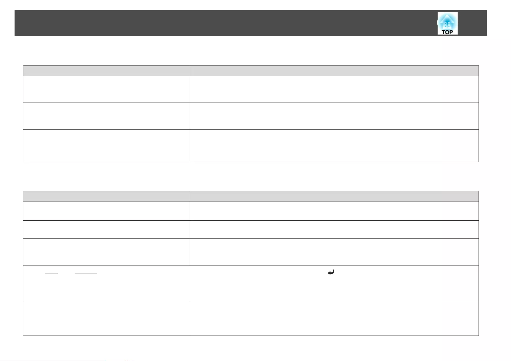
Images are fuzzy, out of focus, or distorted
Check Remedy
Is the focus adjusted correctly? Make sure that at least 20 minutes has passed after the projection starts, and press the [Focus] button on the remote
control to adjust the focus.
s "Correcting the Focus" p.37
Is the projector at the correct distance? Is it projecting outside of the recommended projection distance range?
Setup within the recommended range.
s "Screen Size and Projection Distance" p.219
Has condensation formed on the lens? If the projector is suddenly taken from a cold environment to a warm environment, or if sudden ambient temperature
changes occur, condensation may form on the surface of the lens, and this may cause the images to appear fuzzy. Set the
projector up in the room about one hour before it is used. If condensation forms on the lens, turn the projector off and
wait for the condensation to disappear.
Interference or distortion appear in images
Check Remedy
Are the cables connected correctly? Check that all the cables required for projection are securely connected.
s "Connecting Equipment" p.46
Is an extension cable being used? If an extension cable is used, electrical interference may affect the signals. Use the cables supplied with the projector to
check if the cables you are using may be causing the problem.
Is the correct resolution selected?
(Only when projecting computer images)
Set the computer so that the signals being output are compatible with the projector.
s "Supported Monitor Displays" p.238
s Computer's documentation
Are the Sync.
g
and Tracking
g
settings adjusted correctly?
(Only when projecting computer images)
Press the [Auto] button on the Remote Control or the [ ] button on the Control panel to perform automatic
adjustment. If the images are not adjusted correctly even after performing automatic adjustment, you can also make
adjustments from the Configuration menu.
s Signal - Tracking, Sync. p.139
Is the Resolution set to anything other than Auto?
(Only when projecting on a split screen)
The image may be collapsed if the Resolution on the Configuration menu and the resolution of the projected image are
not the same.
If the image is collapsed, set the Resolution to Auto.
s Signal - Resolution p.139
Problem Solving
182

The image is truncated (large) or small, the aspect is not suitable, or the image has been reversed
Check Remedy
Have the Screen been set correctly? Make the appropriate Screen for the screen being used.
s "Screen Settings" p.30
Is the aspect adjusted correctly? Press the [Aspect] button to select an aspect suitable for the input source.
s "Changing the Aspect Ratio of the Projected Image " p.89
Is a wide panel computer image being projected?
(Only when projecting computer images)
Change the setting according to the signal for the connected equipment.
s Signal - Resolution p.139
Is the image still being enlarged by E-Zoom? Press the [Esc] button on the remote control to cancel E-Zoom.
s "Enlarging Part of the Image (E-Zoom)" p.119
Is Scale turned on? Set Scale to Off on the configuration menu.
s Signal - Scale p.139
Is the display range restricted by Blanking? Appropriately set Blanking in the configuration menu.
s Signal - Blanking p.139
Is the image position adjusted correctly? (Only when projecting analog RGB signals input from the Computer port)
Press the [Auto] button on the remote control or the [ ] button on the control panel to adjust the position.
You can also adjust the position from the Configuration menu.
s Signal - Position p.139
Is the computer set for dual display?
(Only when projecting computer images)
If dual display is activated in the Display Properties of the computer's Control Panel, only about half of the image on the
computer screen is projected. To display the entire image on the computer screen, turn off the dual display setting.
s Computer video driver documentation
Is the correct resolution selected?
(Only when projecting computer images)
Set the computer so that the signals being output are compatible with the projector.
s "Supported Monitor Displays" p.238
s Computer's documentation
Is the image direction correct? Make the correct settings in Projection from the Configuration menu.
s "Installation Settings" p.28
Problem Solving
183
Image colors are not right
Check Remedy
Do the input signal settings match the signals from the connected
device?
Change the setting according to the signal for the connected equipment.
s Signal - Advanced - Input Signal p.139
Is the image brightness adjusted correctly? Adjust the Brightness setting from the Configuration menu.
s Image - Brightness p.137
Are the cables connected correctly? Check that all the cables required for projection are securely connected.
Check that no cables are disconnected and that there are no poor contacts in the cables.
s "Connecting Equipment" p.46
Is the Contrast
g
adjusted correctly? Adjust the Contrast setting from the Configuration menu.
s Image - Contrast p.137
Is the color adjustment set correctly? Adjust the Gamma or RGBCMY setting from the Configuration menu.
s Image - Advanced p.137
s "Adjusting the Image" p.92
Are the color saturation and tint adjusted correctly? Adjust the Color Saturation and Tint settings from the Configuration menu.
s Image - Color Saturation, Tint p.137
Images appear dark
Check Remedy
Is the image brightness set correctly? Check the Brightness and Power Consumption settings from the Configuration menu.
s Image - Brightness p.137
s Settings - Power Consumption p.140
Is the Contrast
g
adjusted correctly? Adjust the Contrast setting from the Configuration menu.
s Image - Contrast p.137
Is it time to replace the lamp? When the lamp is nearly ready for replacement, the images become darker and the color quality becomes poorer. When
this happens, replace the lamp with a new lamp.
s "Replacing the Lamp" p.194
Is only one projector being used? Check if the following item is set to dark.
s Extended - Multi-Projection - Brightness Level p.142
Problem Solving
184

Problems when Projection Starts
The projector does not turn on
Check Remedy
Did you press the [ ] button on the remote control or control
panel?
Press the [ ] button to turn on the power.
Are the indicators switched off? The power cord is not connected correctly or power is not being supplied.
Disconnect and then reconnect the power cord.
Check that your electrical outlet or power source is functioning correctly.
Do the indicators turn on and off when the power cord is touched? There is probably a poor contact in the power cable, or the power cable may be defective. Reinsert the power cable. If this
does not solve the problem, stop using the projector, disconnect the power cable from the electrical outlet, and contact
your local dealer or the nearest address provided in the Epson Projector Contact List.
s Epson Projector Contact List
Is the Control Panel Lock set to Full Lock?Press the [ ] button on the remote control. If you do not want to use Control Panel Lock, change the setting to
Off.
s "Control Panel Lock" p.129
Is the correct setting for the remote receiver selected? Check the Remote Receiver from the Configuration menu.
s Settings - Remote Receiver p.140
Was the power cord plugged back in or was the breaker turned on
immediately after direct power off?
When the operation to the left is performed when Direct Power On is set to On, the power may not turn back on. Press
the [ ] button to turn on the power.
Is the [ID] switch on the remote control set to On? When the switch is set to On, you can use the remote control to operate only a projector with a matching ID. Set the [ID]
switch to Off.
s "Setting the remote control ID" p.42
Are the lamp cover and lamps installed correctly? If the lamp or lamp cover is installed incorrectly, the projector cannot be turned on. Check how it is installed.
s "How to replace the lamp" p.194
Problem Solving
185

Other Problems
No sound can be heard or the sound is faint
Check Remedy
Check that the audio/video cable is securely attached to both the
projector and audio source.
Disconnect the cable from the Audio port, and then reconnect the cable.
Is the projector volume set to the minimum? Adjust the volume so that sound can be heard.
s Settings - Volume p.140
s "Adjusting the Volume" p.61
Is the volume for the computer or from the image source set to the
minimum?
Adjust the volume so that sound can be heard.
Is A/V Mute active? Press the [A/V Mute] button to release A/V Mute.
s "Hiding the Image and Sound Temporarily (A/V Mute)" p.118
Is the audio cable's specification "No resistance"? When using a commercially available audio cable, make sure it is labeled "No resistance".
Is it connected with an HDMI cable? If no audio is output when connecting via an HDMI cable, set the connected equipment to PCM output.
Is the correct audio input selected? Check the Audio Settings from the configuration menu.
s Extended - A/V Settings - Audio Settings p.142
The remote control does not work
Check Remedy
Is the remote control light-emitting area pointing towards the
remote receiver on the projector during operation?
Point the remote control towards the remote receiver.
s "Remote control operating range" p.24
Is the remote control too far from the projector? Check the operating range.
s "Remote control operating range" p.24
Is direct sunlight or strong light from fluorescent lamps shining onto
the remote receiver?
Set the projector up in a location where strong light does not shine onto the remote receiver.
Is the correct setting for the Remote Receiver selected? Check the Remote Receiver from the Configuration menu.
s Settings - Remote Receiver p.140
Problem Solving
186

Check Remedy
Are the batteries dead or have the batteries been inserted correctly? Make sure the batteries are inserted correctly or replace the batteries with new ones if necessary.
s "Replacing the remote control batteries" p.22
Are the remote control ID and the projector ID matched? Make sure the ID for the projector you want to operate and the ID for the remote control match. To operate all projectors
by remote control regardless of the ID setting, set the [ID] switch on the remote control to Off.
s "ID Settings" p.41
Does Remote Control Type match the remote control that you are
using?
Check the Remote Control Type on the configuration menu.
s Extended - Operation - Advanced - Remote Control Type p.142
Is the optional remote control cable connected to the projector's
Remote port?
When the remote control cable is connected, the projector's remote receiver is disabled. When not using the remote
control cable set, disconnect it from the Remote port.
Is Control Communications or Extron XTP set to On? The Remote port is disabled. When using the optional remote control cable set, set Control Communications or Extron
XTP to Off.
s Extended - HDBaseT p.142
Is the remote control button lock set? When the remote control button lock is set, buttons except for those needed for basic remote control operations are
deactivated. Hold down the [ ] button to cancel the remote control button lock.
s "Remote control button lock" p.130
Nothing appears on the external monitor
Check Remedy
Are images input from a port other than the Computer port or
BNC port?
Only RGB signals from the Computer port or the BNC port can be displayed on an external monitor.
Are you projecting a split screen? Only RGB signals projected on the left screen from the Computer port or the BNC port can be displayed on an
external monitor.
s "Projecting Two Images Simultaneously (Split Screen) " p.115
Is the projector in standby status? Check that Standby Mode, A/V Output, and Monitor Out from the Configuration menu are set correctly.
s Extended - Standby Mode, A/V Settings p.142
Problem Solving
187
I want to change the language for messages and menus
Check Remedy
Change the Language setting. Adjust the Language setting from the Configuration menu.
s Extended - Language p.142
Email is not received even if a problem occurs in the projector
Check Remedy
Is Standby Mode set to Communication On? To use the Mail Notification function when the projector is in standby, set Communication On in Standby Mode from
the Configuration menu.
s Extended - Standby Mode p.142
Did a fatal abnormality occur and the projector come to a sudden
stop?
When the projector comes to a sudden stop, email cannot be sent.
If the abnormal state continues, contact your local dealer or the nearest address provided in the Epson Projector Contact
List.
s Epson Projector Contact List
Is power being supplied to the projector? Check that your electrical outlet or power source is functioning correctly.
Is the Mail Notification function set correctly in the Configuration
menu?
An error notification email is sent according to the Notification settings in the Configuration menu. Check if it is set
correctly.
s "Notification menu" p.152
"The battery that saves your clock settings is running low." is displayed
Check Remedy
The internal power supply that saves your clock settings is
running low.
Contact your local dealer or the nearest address provided in the Epson Projector Contact List.
s Epson Projector Contact List
Problem Solving
188

Check the numbers and then apply the following countermeasures. If you cannot resolve the problem, contact your network administrator, or contact your local
dealer or the nearest address provided in the Epson Projector Contact List.
s Epson Projector Contact List
Event ID Cause Remedy
0432
0435
Failed to start the network software. Restart the projector.
0434
0482
0484
0485
Network communication is unstable. Check the network communication status, and reconnect after waiting for a while.
0433 Cannot play transferred images. Restart the network software.
0481 Communication was disconnected from the computer.
0483
04FE
The network software ended unexpectedly. Check the status of network communications. Restart the projector.
0479
04FF
A system error occurred in the projector. Restart the projector.
0891 Cannot find an access point with the same SSID. Set the computer, the access point, and the projector to the same SSID.
0892 The WPA/WPA2 authentication type does not match. Check that the wireless LAN security settings are correct.
s Network - Wireless LAN p.149
0893 The TKIP/AES encryption types do not match.
0894 Communication was disconnected because the projector connected
to an unauthorized access point.
Contact your network administrator for more information.
0898 Failed to acquire DHCP. Check that the DHCP server is operating correctly. If you are not using DHCP, turn off the DHCP
setting.
s Network - Wireless LAN p.149, Wired LAN p.152
0899 Other communication errors If restarting the projector or network software does not solve the problem, contact your local dealer
or the nearest address provided in the Epson Projector Contact List.
s Epson Projector Contact List
About Event ID
189

Maintenance
This chapter provides information on maintenance procedures to ensure the best level of performance from the projector for a long time to come.
You should clean the projector if it becomes dirty or if the quality of
projected images starts to deteriorate.
Caution
When cleaning, unplug the power cable from the electric outlet. Otherwise, it
could cause an electric shock.
Cleaning the Projector's Surface
Clean the projector's surface by wiping it gently with a soft cloth.
If the projector is particularly dirty, moisten the cloth with water containing
a small amount of neutral detergent, and then firmly wring the cloth dry
before using it to wipe the projector's surface.
Attention
Do not use volatile substances such as wax, alcohol, or thinner to clean the
projector's surface. The quality of the case may change or become discolored.
Cleaning the Lens
Use a commercially available cloth for cleaning glasses to gently wipe the
lens.
Warning
Do not use sprays that contain flammable gas to remove dust and lint from the
lens. The projector may catch fire due to the high internal temperature of the
lamp.
Attention
Do not rub the lens with harsh materials or subject the lens to shocks, as it
can easily become damaged.
Cleaning the Air Filter
When the following message is displayed and the filter indicator flashes
green, clean the air filter and the air intake vent.
"Time to clean the air filter. Clean or replace the air filter."
"The projector is overheating. Make sure nothing is blocking the air vent,
and clean or replace the air filter."
"The air filter is clogged. Clean or replace the air filter."
Attention
•If dust collects on the air filter, it can cause the internal temperature of the
projector to rise, and this can lead to problems with operation and shorten
the optical engine's service life. Clean the air filter immediately when the
message is displayed.
•Do not rinse the air filter in water. Do not use detergents or solvents.
•When using a brush for cleaning, use one with long soft bristles, and brush it
lightly. If it is brushed too strongly, dust will be ground into the air filter and
cannot be removed.
Cleaning the air filter
The air filter can be replaced even when the projector is suspended from a
ceiling.
a
After you turn off the projector's power and the confirmation
buzzer beeps, disconnect the power cord.
Cleaning
191
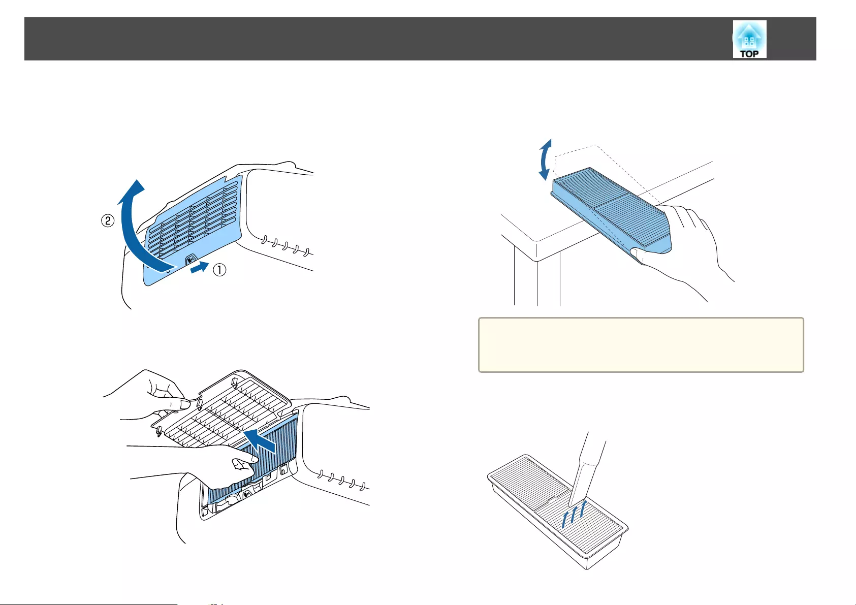
b
Open the air filter cover.
Slide the air filter cover operation knob, and open the air filter
cover.
c
Remove the air filter.
Grip the tab in the center of the air filter, and pull it straight out.
d
With the front (the side with tabs) of the air filter facing down, tap
the air filter four or five times to shake off the dust.
Turn it over and tap the other side in the same way.
Attention
If the air filter is hit too hard, it may become unusable due to
deformities and cracks.
e
Remove any dust remaining on the air filter by using a vacuum
cleaner from the front side.
Cleaning
192
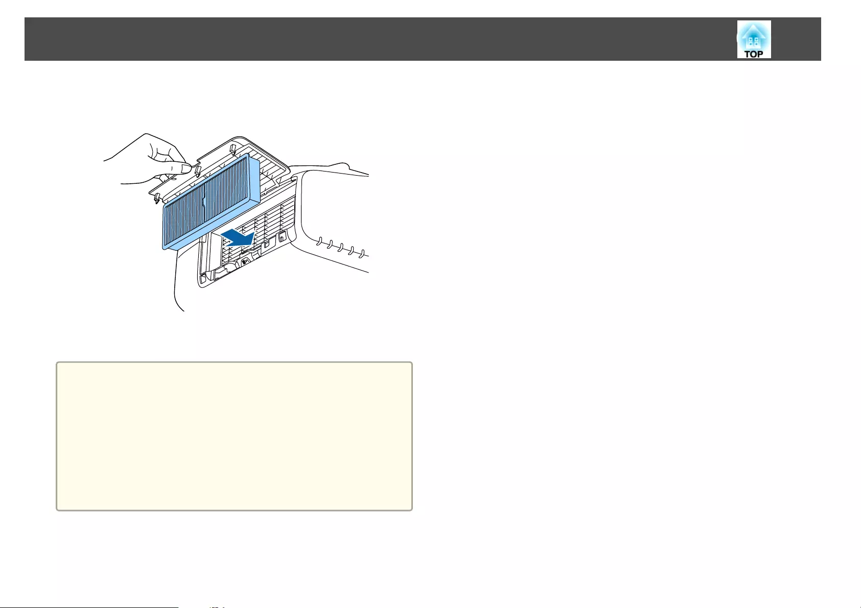
f
Replace the air filter.
Press until it clicks into place.
g
Close the air filter cover.
a
•If a message is frequently displayed, even after cleaning, it is time to
replace the air filter. Replace it with a new air filter.
s "Replacing the Air Filter" p.197
•It is recommended that you clean these parts at least once every
three months. Clean them more often than this if using the projector
in a particularly dusty environment.
•The indicators or messages regarding Air Filter Notice are displayed
only when Air Filter Notice is set to On from the Configuration
menu.
s Extended - Display - Air Filter Notice p.142
Cleaning
193
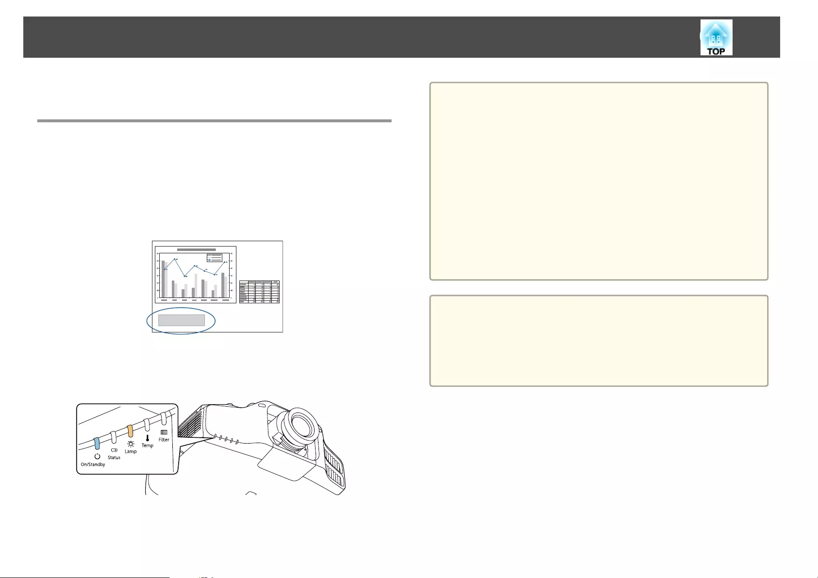
This section explains how to replace the lamp and the air filter.
Replacing the Lamp
Lamp replacement period
It is time to replace the lamp when:
•The following message is displayed.
"It is time to replace your lamp. Please contact your Epson projector
reseller or visit www.epson.com to purchase."
The message is displayed for 30 seconds.
•The power indicator is flashing blue, and the lamp indicator is flashing
orange.
•The projected image gets darker or starts to deteriorate.
Attention
•If you continue to use the lamp after the replacement period has passed, the
possibility that the lamp may explode increases. When the lamp replacement
message appears, replace the lamp with a new one as soon as possible, even if
it is still working.
•Do not repeatedly turn off the power and immediately back on. Turning the
power on and off frequently may shorten the lamp's operating life.
•Depending on the characteristics of the lamp and the way it has been used,
the lamp may become darker or stop working before the lamp warning
message appears. You should always have a spare lamp unit ready in case it is
needed.
•We recommend the use of genuine EPSON spare lamps. The use of non-
genuine lamps may affect projection quality and safety. Any damage or
malfunction caused by the use of non-genuine lamps may not be covered by
Epson's warranty.
a
•We recommend that you clean the air filter whenever you replace
the lamp.
s "Cleaning the Air Filter" p.191
•Replace the air filter if it is discolored or if a message appears even
after cleaning the air filter.
s "Replacing the Air Filter" p.197
How to replace the lamp
The lamp can be replaced even when the projector is suspended from a
ceiling.
Replacing Consumables
194
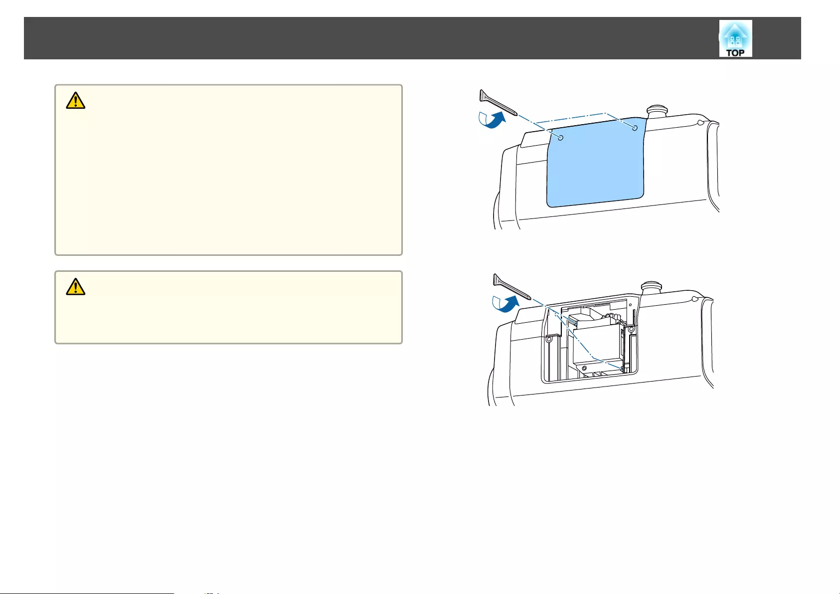
Warning
•When replacing the lamp because it has stopped illuminating, there is a
possibility that the lamp may be broken. If replacing the lamp of a projector
which has been installed on the ceiling, you should always assume that the
lamp is cracked, and you should stand to the side of the lamp cover, not
underneath it. Remove the lamp cover gently. Be careful when removing the
lamp cover as shards of glass may fall out and could cause an injury. If any
shards of glass get into your eyes or mouth, contact your local physician
immediately.
•Never disassemble or remodel the lamp. If a modified or disassembled lamp
is installed in the projector and used, it could cause a fire, electric shock, or
an accident.
Caution
Wait until the lamp has cooled down sufficiently before removing the lamp
cover. If the lamp is still hot, burns or other injuries may result. It takes about
one hour after the power has been turned off for the lamp to be cool enough.
a
After you turn off the projector's power and the confirmation
buzzer beeps, disconnect the power cord.
b
Wait until the lamp has cooled down, then remove the projector's
lamp cover.
Loosen the Lamp cover fixing screw with the screwdriver supplied
with the new lamp unit or a cross-head screwdriver, and then
remove the lamp cover. Because there is a string attached to the
lamp cover to prevent it from falling, you can replace the lamp even
when the projector is installed on a ceiling without the lamp cover
falling down.
c
Loosen the two lamp fixing screws.
d
Take out the old Lamp by pulling the handle.
If the Lamp is cracked, replace it with a new lamp, or contact your
local dealer for further advice.
s Epson Projector Contact List
Replacing Consumables
195
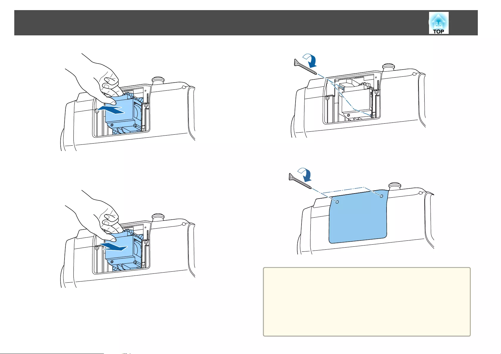
e
Install the new lamp.
Insert the lamp along the guide rail in the correct direction so that it
fits in place and press it firmly to the back.
f
Tighten the two lamp fixing screws.
g
Replace the lamp cover.
Attention
•Make sure you install the lamp and lamp cover securely. If the lamp cover is
removed, the lamps turn off automatically as a safety precaution. If the lamp
or the lamp cover is not installed correctly, the lamp will not turn on. Install
the lamp cover so that it will fit precisely and not be deformed.
•This product includes a lamp component that contains mercury (Hg). Please
consult your local regulations regarding disposal or recycling. Do not dispose
of it with normal waste.
Replacing Consumables
196
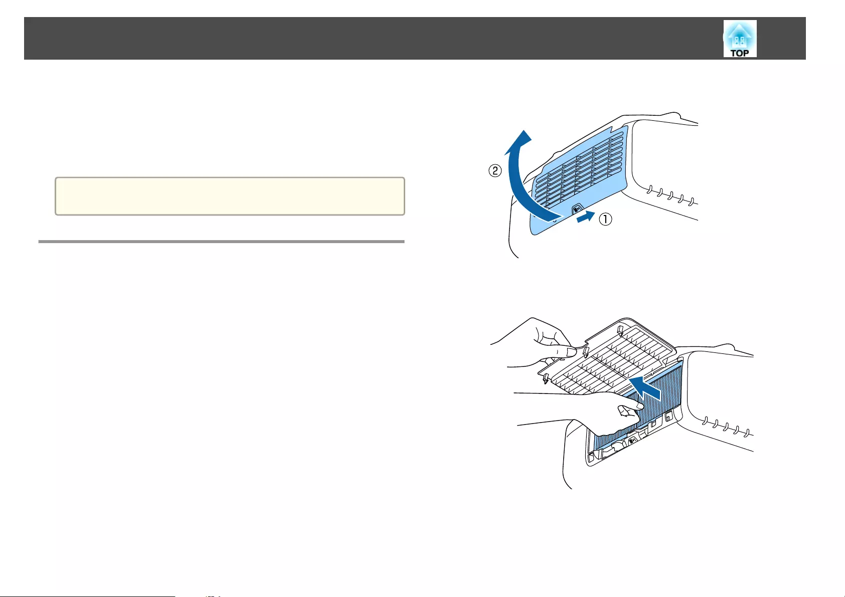
Resetting the lamp hours
The projector records how long the lamp is turned on and a message and
indicator notify you when it is time to replace the lamp. After replacing the
lamp, make sure you reset the Lamp Hours from the Configuration menu.
s "Reset Menu" p.155
a
Only reset the Lamp Hours after the lamp has been replaced.
Otherwise the lamp replacement period is not indicated correctly.
Replacing the Air Filter
Air filter replacement period
If the message is displayed frequently even though the air filter has been
cleaned, replace the air filter.
How to replace the air filter
The air filter can be replaced even when the projector is suspended from a
ceiling.
a
After you turn off the projector's power and the confirmation
buzzer beeps, disconnect the power cord.
b
Open the air filter cover.
Slide the air filter cover operation knob, and open the air filter
cover.
c
Remove the air filter.
Grip the tab in the center of the air filter, and pull it straight out.
d
Install the new air filter.
Press until it clicks into place.
Replacing Consumables
197
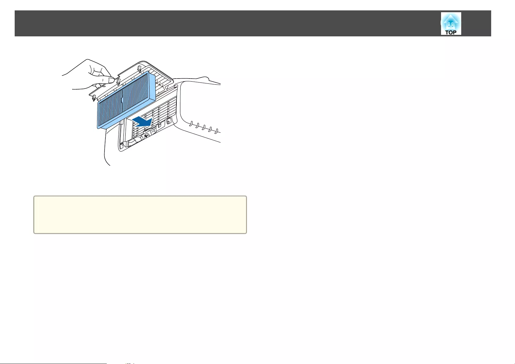
e
Close the air filter cover.
a
Dispose of used air filters properly in accordance with your local
regulations.
Material of the frame part: Polypropylene
Material of the filter part: Polypropylene
Replacing Consumables
198
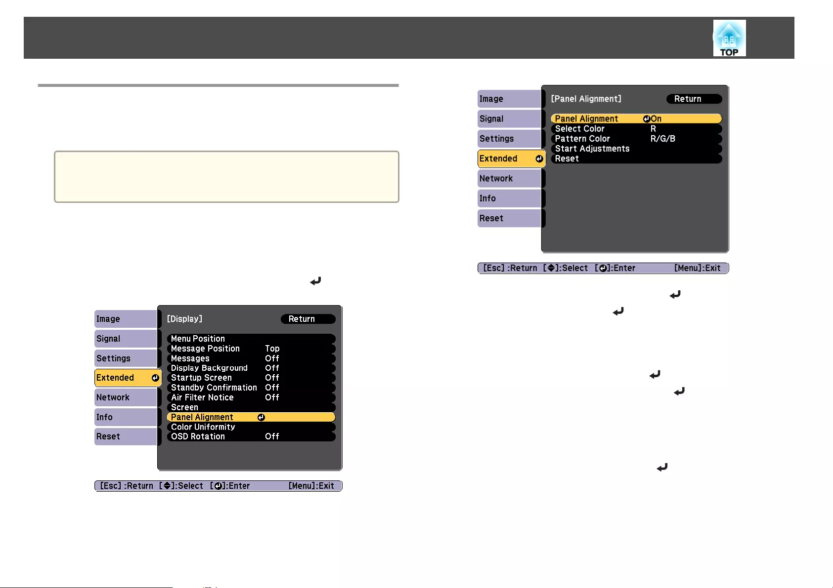
Panel Alignment
Adjusts the pixel color shift for the LCD panel. You can adjust the pixels
horizontally and vertically by 0.25 pixel within a range of ±1 pixel.
a
•Image quality may decline after performing LCD alignment.
•Images for pixels that extend beyond the edge of the projected
screen are not displayed.
a
Press the [Menu] button while projecting.
b
Select Display from Extended.
c
Select Panel Alignment, and then press the [ ] button.
d
Enable Panel Alignment.
(1) Select Panel Alignment, and then press the [ ] button.
(2) Select On, and then press the [ ] button.
(3) Press the [Esc] button to return to the previous screen.
e
Select the color you want to adjust.
(1) Select Select Color, and then press the [ ] button.
(2) Select R (red) or B (blue), and then press the [ ] button.
(3) Press the [Esc] button to return to the previous screen.
f
Select the grid color displayed when making adjustments from
Pattern Color.
(1) Select Pattern Color, and then press the [ ] button.
Image Maintenance
199
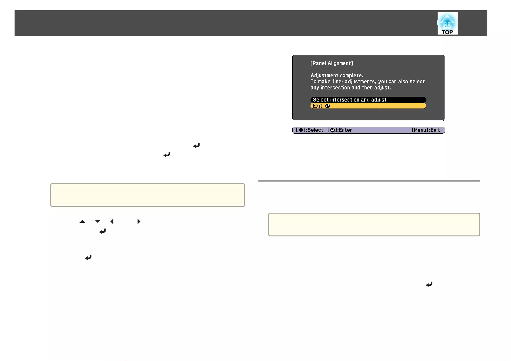
(2) Select a combination of R (red), G (green), and B (blue) for the grid color.
R/G/B: Displays a combination all three colors; red, green and blue. The
actual color of the grid is white.
R/G: This is available when R is selected from Select Color. Displays a
combination of two colors; red and green. The actual color of the grid is
yellow.
G/B: This is available when B is selected from Select Color. Displays a
combination of two colors; green and blue. The actual color of the grid is
cyan.
(3) Press the [Esc] button to return to the previous screen.
g
Select Start Adjustments, and then press the [ ] button. When
the message is displayed, press the [ ] button again.
Adjustment starts. All four corners are adjusted in order starting at
the top left.
a
The image may become distorted while adjusting. The image is
restored once adjustments are complete.
h
Use the [ ], [ ], [ ], and [ ] buttons to make adjustments, and
then press the [ ] button to move to the next adjustment point.
i
When you have adjusted all four corners, select Exit, and then
press the [ ] button.
If you feel you still need to make adjustments after correcting all
four points, select Select intersection and adjust and then continue
making adjustments.
Color Uniformity
Adjusts the color tone for the whole screen.
a
The color tone may not be uniform even after performing color
uniformity.
a
Press the [Menu] button while projecting.
b
Select Display from Extended.
c
Select Color Uniformity, and then press the [ ] button.
The following screen is displayed.
Image Maintenance
200
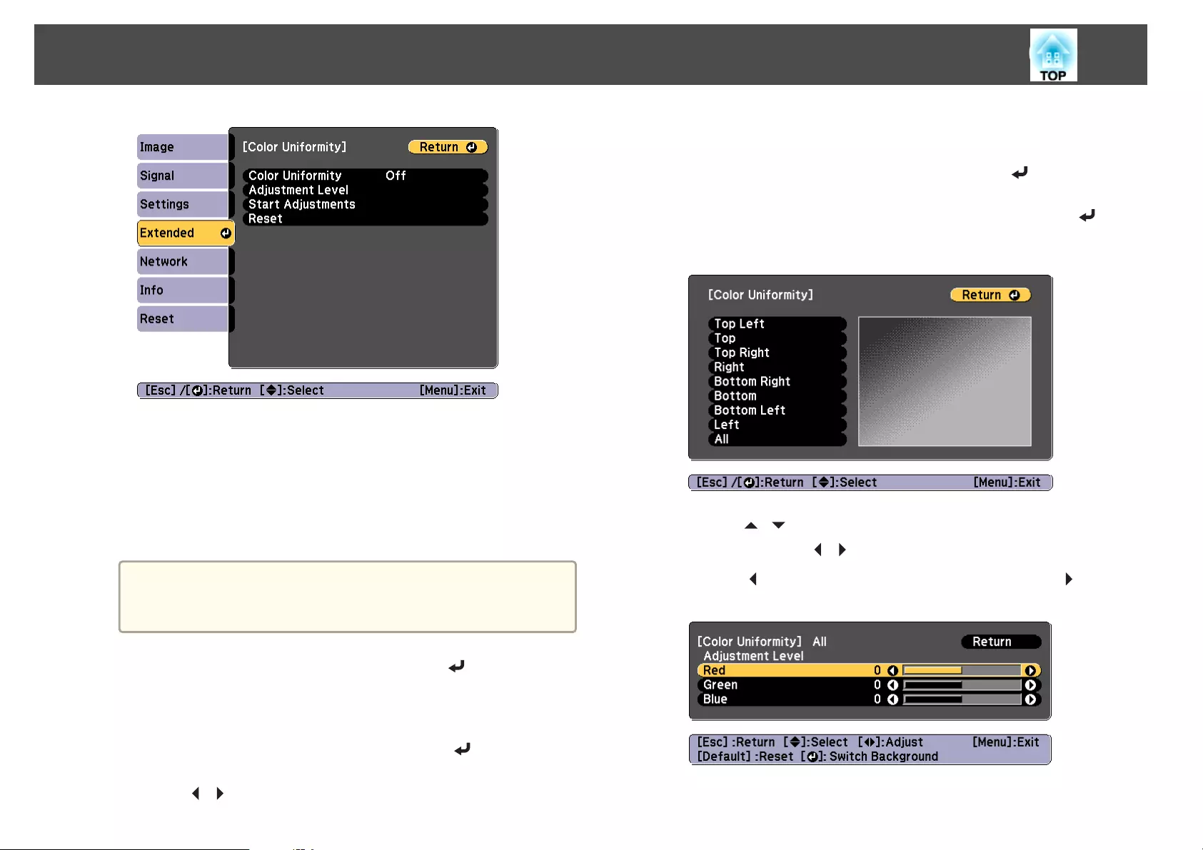
Color Uniformity: Turns color uniformity on or off.
Adjustment Level: There are eight levels from white, through gray,
and up to black. You can adjust each level individually.
Start Adjustments: Starts making color uniformity adjustments.
Reset: Resets all adjustments and settings for Color Uniformity to
their default values.
a
The image may become distorted while adjusting Color
Uniformity. The image is restored once adjustments are
complete.
d
Select Color Uniformity, and then press the [ ] button.
e
Set to On, and then press the [Esc] button.
f
Select Adjustment Level, and then press the [ ] button.
g
Use the [ ][ ] buttons to set the adjustment level.
h
Press the [Esc] button to return to the previous screen.
i
Select Start Adjustments, and then press the [ ] button.
j
Select the area you want to adjust, and then press the [ ]
button.
Adjust the outer areas first, and then adjust the whole screen.
k
Use the [ ][ ] buttons to select the color you want to adjust,
and then use the [ ][ ] buttons to adjust.
Press the [ ] button to weaken the color tone. Press the [ ] button
to strengthen the color tone.
l
Return to step 6 and adjust each level.
Image Maintenance
201

m
To complete the adjustment, press the [Menu] button.
Image Maintenance
202

Appendix
About EasyMP Monitor
EasyMP Monitor lets you carry out operations such as checking the status
of multiple Epson projectors that are connected to a network at a computer
monitor, and controlling the projectors from the computer.
You can download EasyMP Monitor from the following Web site.
http://www.epson.com
About Message Broadcasting
Message Broadcasting is plugin software for EasyMP Monitor.
Message Broadcasting can be used to send a message (JPEG file) to project
on all Epson projectors or specified projectors connected on the network.
The data can be sent manually, or sent automatically using Timer Settings
of EasyMP Monitor.
Download the Message Broadcasting software from the following website.
http://www.epson.com
Changing Settings Using a Web Browser (Epson
Web Control)
By using a Web browser of a computer or mobile device connected to the
projector on a network, you can set functions and control the projector.
This function allows you to perform setup and control operations remotely.
Also, you can operate a specific projector when using multiple projectors.
Use Internet Explorer 9.0 or later as the Web browser. Use Safari for OS
X.
a
If you set Standby Mode to Communication On, you can use the
Web browser to make settings and perform control even if the
projector is in standby mode (when the power is off).
s Extended - Standby Mode p.142
Displaying the Epson Web Control Screen
Use the following procedure to display the Epson Web Control screen.
Make sure your device and projector are ready for the network connection.
a
If your Web browser is set up to connect via a proxy server, the Epson
Web Control screen cannot be displayed. To display Web Control, you
need to make settings so that a proxy server is not used for a
connection.
a
Connect your device to the same network as the connected
projector.
The connection method varies depending on the device. See the
manual supplied with your device for details. When using a tablet,
check the Wi-Fi settings.
b
Start the Web browser on your device.
c
Connect by entering the address of the connected projector in the
URL field of the Web browser.
The Home screen is displayed.
Monitoring and Controlling
204
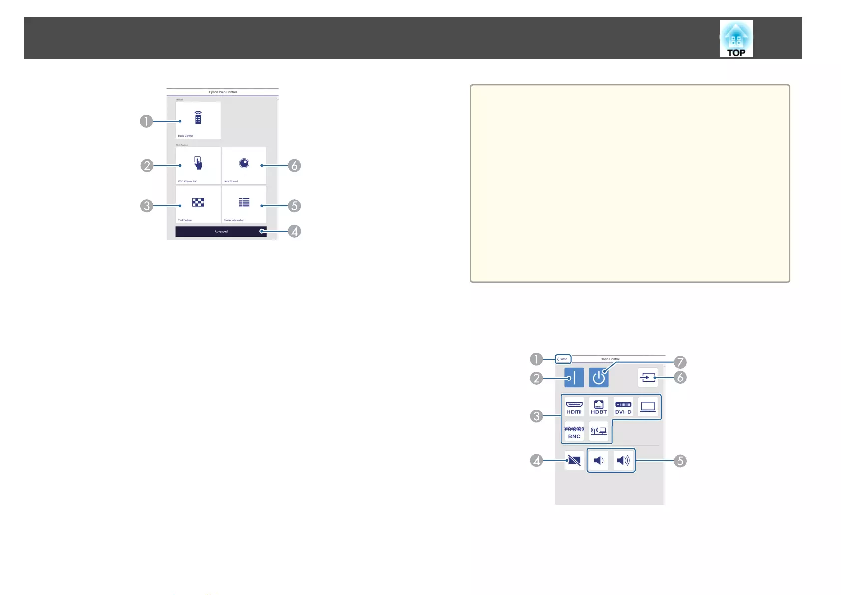
ABasic Control
s "Basic Control Screen" p.205
BOSD Control Pad
s "OSD Control Pad Screen" p.206
CTest Pattern
s "Test Pattern Operation Screen" p.208
DAdvanced
You are moved to the Advanced screen.
EStatus Information
s "Status Information Screen" p.208
FLens Control
s "Lens Control Screen" p.206
a
•When performing the functions from the Home screen, you
may be prompted to enter the user name and password.
The following two types of user names and passwords are
available.
Remote: The user name is "EPSONREMOTE" and the default
password is "guest".
Web Control: The user name is "EPSONWEB" and the default
password is "admin".
•You cannot change the user name. You can change the
password in the Network menu from the Configuration menu.
s Network - Basic - Remote Password, Web Control
Password p.136
•You must enter the user name for Web Control Password
even when the password is disabled.
Basic Control Screen
You can perform basic projector operations.
AMoves to the Home screen.
BTurns the projector on.
CSwitches to the target image.
Monitoring and Controlling
205
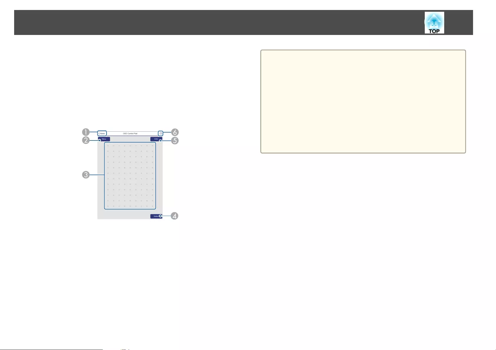
DTurns the video and audio on or off.
EYou can adjust the volume.
FAutomatically detects the input signal.
GTurns the projector off.
OSD Control Pad Screen
You can operate the Configuration menu of the projector.
AMoves to the Home screen.
BDisplays and closes the Configuration menu.
CYou can operate the Configuration menu using your finger or mouse.
Flick to select an item, and tap to confirm the selection.
DEnabled when Default: Reset is displayed on the Configuration menu guide. The
settings being adjusted are returned to their default values.
EReturns to the previous menu level in the Configuration menu.
FDisplays how to use the Control Pad.
a
Items in the Configuration menu that cannot be set in Epson Web
Control are listed below.
•Settings Menu - User Button
•Extended menu - Display - Message Position
•Extended Menu - User's Logo
•Extended menu - Operation - Advanced - BNC Sync Termination
•Extended menu - Operation - Lens Calibration
•Extended Menu - Language
•Reset Menu
The settings for items on each menu are the same as the projector's
Configuration menu.
s "Configuration Menu" p.133
Lens Control Screen
You can operate the lens of the projector.
Monitoring and Controlling
206
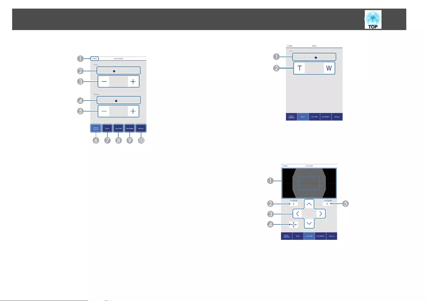
Focus/Distortion Operation Screen
AMoves to the Home screen.
BMove the slider to adjust the focus.
CPress the buttons to adjust the focus.
DMove the slider to adjust image warping.
*
EPress the buttons to adjust image warping.
*
FDisplays the Focus/Distortion operation screen.
GDisplays the Zoom operation screen.
HDisplays the Lens Shift operation screen.
IDisplays the Test Pattern operation screen.
JDisplays the Memory operation screen.
*This is not available for ELPLU02.
Zoom Operation Screen
This is not available for ELPLX01 and ELPLR04.
AMove the slider to adjust the zoom.
BPress the buttons to adjust the zoom.
Lens Shift Operation Screen
ADisplays the position of the image as a blue square. When you move the image
position, a red square is displayed at the destination.
BDisplays the vertical image position. You can directly specify the position by tap‐
ping it and entering a number.
CMoves the image position up, down, left, or right.
Monitoring and Controlling
207
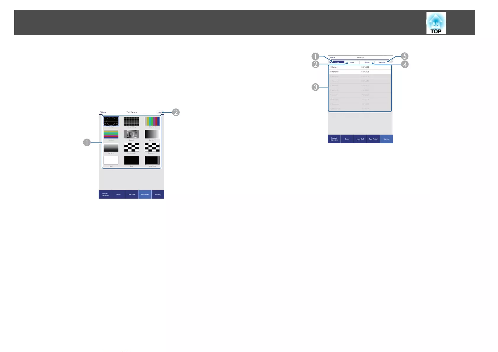
DMoves the lens position to the home position if you press the [OK] button in the
confirmation screen.
EDisplays the horizonal image position. You can directly specify the position by
tapping it and entering a number.
Test Pattern Operation Screen
ADisplays a test pattern.
BCloses the test pattern.
Memory Operation Screen
See the following for memory function details.
s "Memory Function" p.122
ALoads a memory.
BSaves a memory.
CDisplays a list of memories.
DErases a memory.
EChanges a memory name.
Status Information Screen
You can check the projector's status. See the following for display details.
s "Reading the Status Information" p.172
Monitoring and Controlling
208
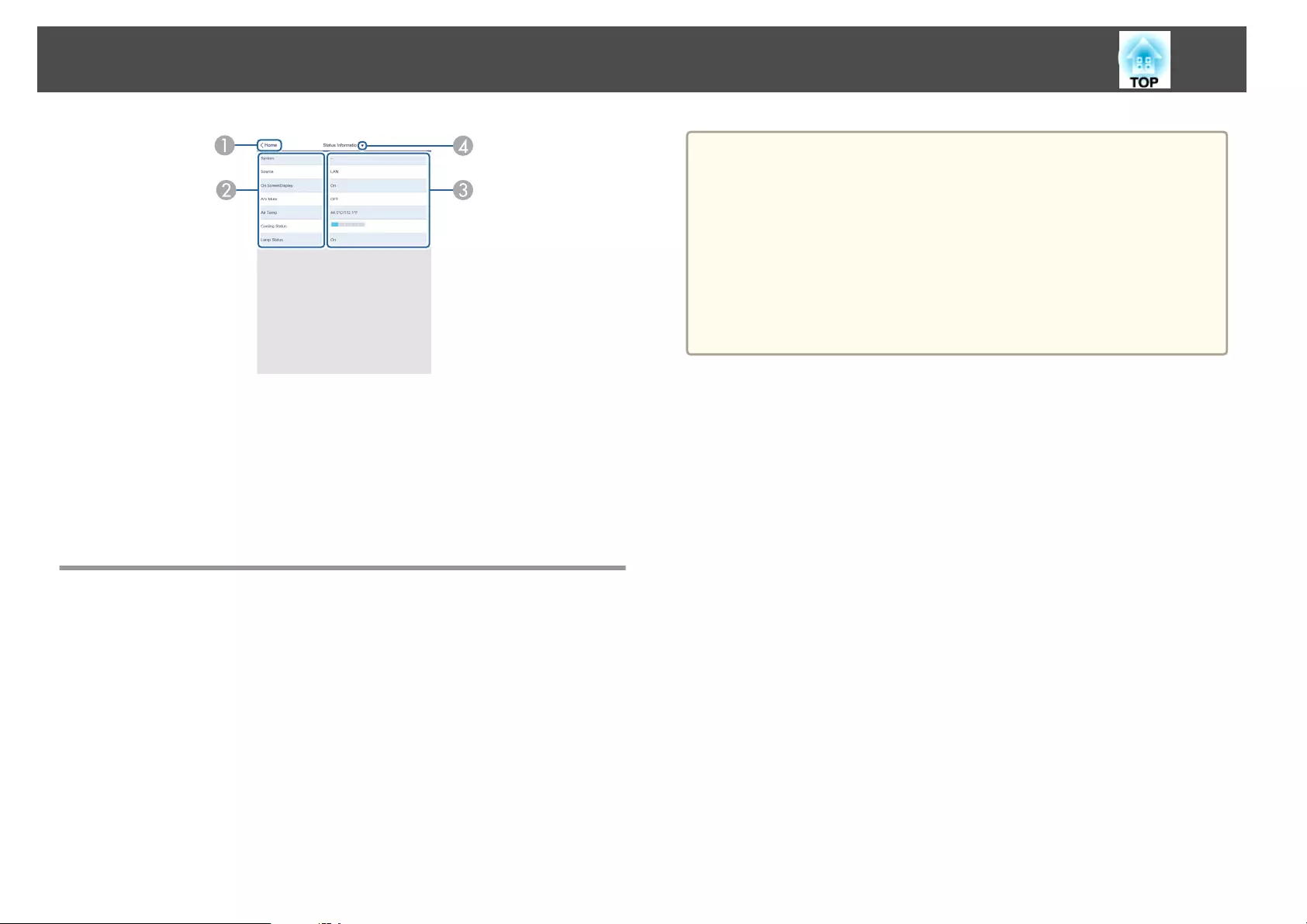
AMoves to the Home screen.
BDisplays the item name.
CDisplays the status of each item.
DSelects a category from the following.
Status Information, Source, Signal Information, Network Wired, Network
Wireless, Maintenance, Version
Using the Mail Notification Function to Report
Problems
When you set Mail Notification, notification messages are sent to the preset
email addresses when a problem or warning occurs with a projector. This
will enable the operator to be notified of problems with projectors even at
locations away from the projectors.
s Network - Notification - Mail Notification p.153
a
•Up to a maximum of three notification destinations (addresses) can
be registered, and notification messages can be sent to all three
destinations at once.
•If a projector develops a critical problem and suddenly stops
working, it may not be able to send a message notifying an operator
of the problem.
•If you set Standby Mode to Communication On, you can control
the projector even if it is in standby mode (when the power is
off).
s Extended - Standby Mode p.142
Reading error notification mail
When the Mail Notification function is set to On and a problem or warning
occurs in the projector, the following email will be sent.
Sender: The email address set in From
Subject: EPSON Projector
Line 1: The projector name where the problem has occurred
Line 2: The IP address set for the projector where the problem has
occurred.
Line 3 and on: Details of the problem
The details of the problem are listed line by line. The main message
contents are listed below.
•Clean Air Filter
•Internal error
•Fan related error
•Sensor error
•Lamp cover is open.
•Lamp timer failure
Monitoring and Controlling
209
•Lamp out
•Internal temperature error
•High-speed cooling in progress
•Lamp replacement notification
•Low Air Flow
•Low Air Flow Error
•No-signal
No Signal is input to the projector. Check the connection status or check
that the power for the signal source is turned on.
•Auto Iris Error
•Power Err. (Ballast)
•Incorrect projection mode
•Projection angle mismatch
•Lens shift error
See the following to deal with problems or warnings.
s "Reading the Indicators" p.166
Management Using SNMP
By setting SNMP to On in the Configuration menu, notification messages
are sent to the specified computer when a problem or warning occurs. This
will enable the operator to be notified of problems with projectors even at
locations away from the projectors.
s Network - Notification - SNMP p.153
a
•SNMP should be managed by a network administrator or someone
who is familiar with the network.
•To use the SNMP function to monitor the projector, you need to
install the SNMP manager program on your computer.
•The SNMP Agent for this projector complies with version 1
(SNMPv1).
•The managing function using SNMP cannot be used over wireless
LAN in Quick connection mode.
•Up to two destination IP addresses can be saved.
ESC/VP21 Commands
You can control the projector from an external device using ESC/VP21.
Command list
When the power ON command is transmitted to the projector, the power
turns on and it enters warm-up mode. When the projector's power has
turned on, a colon ":" (3Ah) is returned.
When a command is input, the projector executes the command and
returns a ":", and then accepts the next command.
If the command being processed terminates abnormally, an error message is
output and a ":" is returned.
The main contents are listed below.
Item Command
Power ON/OFF On PWR ON
Off PWR OFF
Signal selection Computer Auto SOURCE 1F
RGB SOURCE 11
Component SOURCE 14
Monitoring and Controlling
210
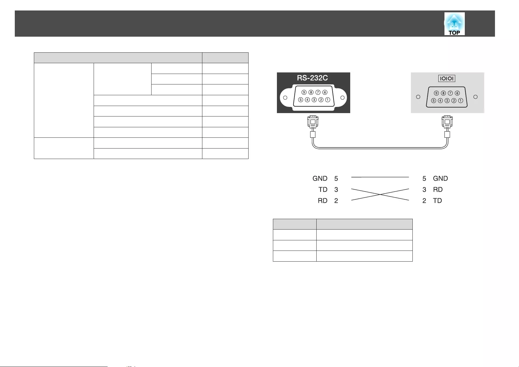
Item Command
BNC Auto SOURCE BF
RGB SOURCE B1
Component SOURCE B4
HDMI SOURCE 30
LAN SOURCE 53
DVI-D SOURCE A0
HDBaseT SOURCE 80
A/V Mute On/Off On MUTE ON
Off MUTE OFF
Add a Carriage Return (CR) code (0Dh) to the end of each command and
transmit.
For more details, contact your local dealer or the nearest address provided
in the Epson Projector Contact List.
s Epson Projector Contact List
Cable layouts
Serial connection
•Connector shape: D-Sub 9-pin (male)
•Projector input port name: RS-232C
<At the projector> <At the computer>
<At the projector> (PC serial cable) <At the computer>
Signal Name Function
GND Signal wire ground
TD Transmit data
RD Receive data
Communications protocol
•Default baud rate setting: 9600 bps
•Data length: 8 bit
•Parity: None
•Stop-bit: 1 bit
•Flow control: None
Monitoring and Controlling
211
About PJLink
PJLink Class1 was established by the JBMIA (Japan Business Machine and
Information System Industries Association) as a standard protocol for
controlling network-compatible projector's as part of their efforts to
standardize projector control protocols.
The projector complies with the PJLink Class1 standard established by the
JBMIA.
You need to make network settings before you can use PJLink. See the
following for more information on network settings.
s "Network Menu" p.147
It complies with all commands except for the following commands defined
by PJLink Class1, and agreement was confirmed by the PJLink standard
adaptability verification.
URL: http://pjlink.jbmia.or.jp/english/
•Non-compatible commands
Function PJLink Command
Mute settings Image muting set AVMT 11
Audio muting set AVMT 21
•Input names defined by PJLink and corresponding projector sources
Source PJLink Command
Computer INPT 11
BNC INPT 13
DVI-D INPT 31
HDMI INPT 32
LAN INPT 52
HDBaseT INPT 56
•Manufacturer name displayed for "Manufacture name information query"
EPSON
•Model name displayed for "Product name information query"
EPSON G7905U
EPSON G7900U
EPSON G7500U
EPSON G7400U
EPSON G7200W
EPSON G7000W
EPSON G7805
EPSON G7800
EPSON G7100
About Crestron RoomView
®
Crestron RoomView
®
is an integrated control system provided by
Crestron
®
. It can be used to monitor and control multiple devices
connected on a network.
The projector supports the control protocol, and can therefore be used in a
system built with Crestron RoomView
®
.
Visit the Crestron
®
Web site for details on Crestron RoomView
®
. (Only
English-language displays are supported.)
http://www.crestron.com
The following provides an overview of Crestron RoomView
®
.
•Remote operation using a Web browser
You can operate a projector from your computer just like using a remote
control.
Monitoring and Controlling
212
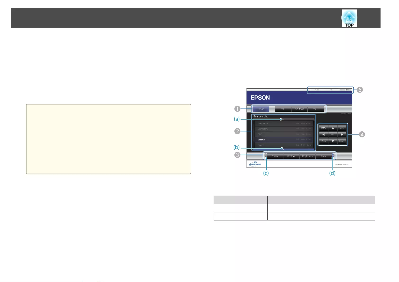
•Monitoring and control with application software
You can use Crestron RoomView
®
Express or Crestron RoomView
®
Server Edition provided by Crestron
®
to monitor devices in the system,
to communicate with the help desk, and to send emergency messages. See
the following Web site for details.
http://www.crestron.com/getroomview
This manual describes how to perform operations on your computer using
a Web browser.
a
•You can only enter single-byte alphanumeric characters and symbols.
•The following functions cannot be used while using Crestron
RoomView
®
.
s "Changing Settings Using a Web Browser (Epson Web Control)"
p.204
Message Broadcasting (EasyMP Monitor plug-in)
•If you set Standby Mode to Communication On, you can control
the projector even if it is in standby mode (when the power is
off).
s Extended - Standby Mode p.142
Operating a projector from your computer
Displaying the operation window
Check the following before carrying out any operations.
•Make sure the computer and projector are connected to the network.
•Set Crestron RoomView to On from the Network menu.
s Network - Others - Crestron RoomView p.153
a
Start the Web browser on the computer.
b
Enter the IP address of the projector in the address field of the
Web browser, and press the Enter key on the keyboard.
The operation window is displayed.
Using the operation window
AYou can perform the following operations when you click the buttons.
Button Function
Power Turns the projector power on or off.
Vol-/Vol+ Adjusts the volume.
Monitoring and Controlling
213
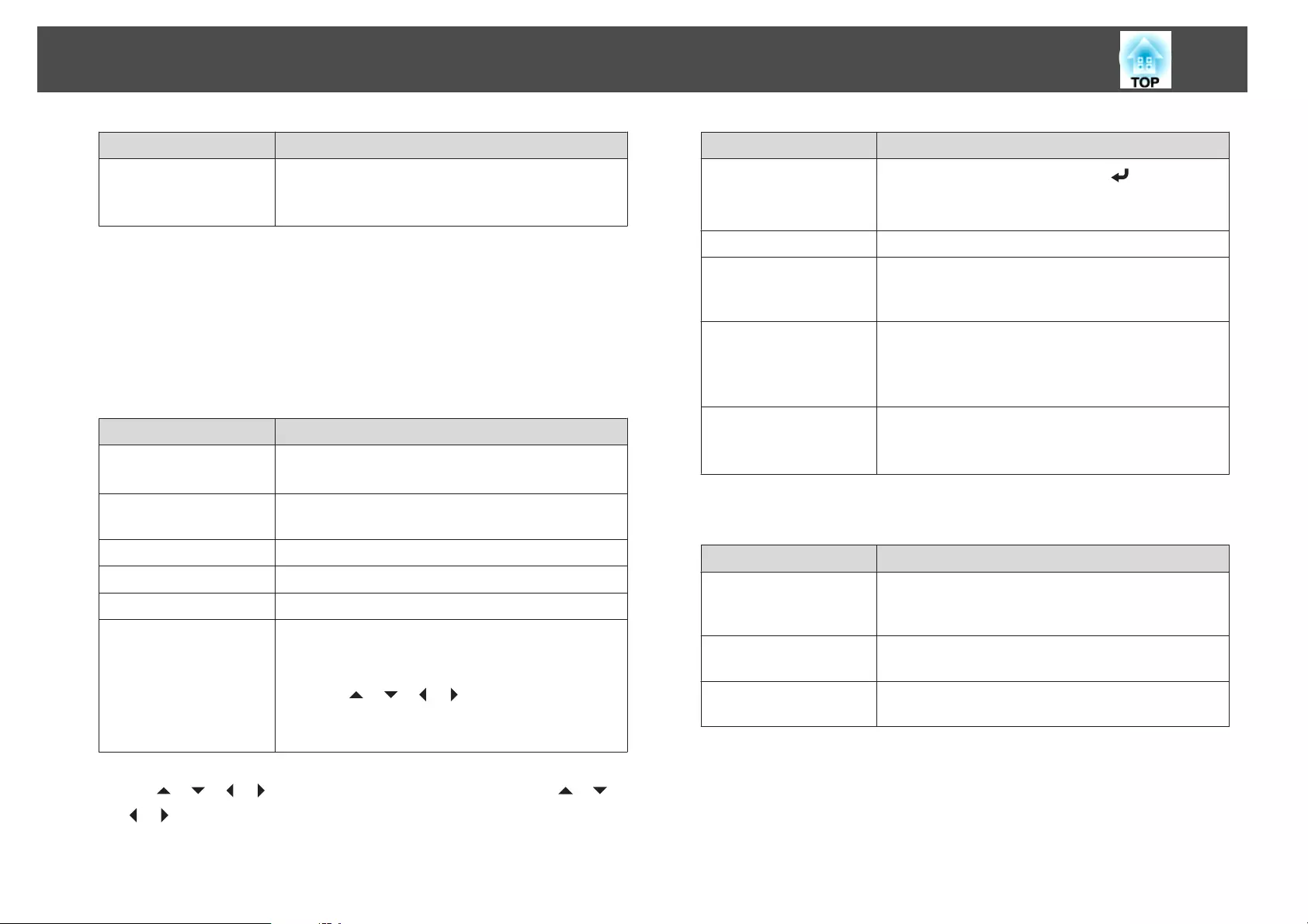
Button Function
A/V Mute Turns the video and audio on or off.
s "Hiding the Image and Sound Temporarily (A/V
Mute)" p.118
BSwitch to the image from the selected input source. To display input sources that
are not shown in Source List, click (a) or (b) to scroll up or down. The current
video signal input source is displayed in blue.
You can change the source name if necessary.
CYou can perform the following operations when you click the buttons. To display
buttons that are not shown in Source List, click (c) or (d) to scroll left or right.
Button Function
Freeze Images are paused or unpaused.
s "Freezing the Image (Freeze)" p.119
Contrast Adjusts the difference between light and shade in the
images.
Brightness Adjusts the image brightness.
Color Adjusts the color saturation for the images.
Sharpness Adjusts the image sharpness.
Zoom Click the [z] button to enlarge the image without
changing the projection size. Click the [x] button to
reduce an image that was enlarged with the [z] button.
Click the [ ] [ ] [ ] [ ] buttons to change the
position of an enlarged image.
s "Enlarging Part of the Image (E-Zoom)" p.119
DThe [ ] [ ] [ ] [ ] buttons perform the same operations as the [ ] [ ]
[] [ ] buttons on the remote control. You can perform the following
operations when you click the other buttons.
Button Function
OK Performs the same operation as the [ ] button on the
remote control.
s "Remote Control" p.19
Menu Displays and closes the Configuration menu.
Auto If clicked while projecting analog RGB signals from the
Computer port, you can automatically optimize
Tracking, Sync., and Position.
Search Changes to the next input source that is sending an
image.
s "Automatically Detecting Input Signals and
Changing the Projected Image (Source Search)" p.59
Esc Performs the same operation as the [Esc] button on the
remote control.
s "Remote Control" p.19
EYou can perform the following operations when you click the tabs.
Tab Function
Contact IT Help Displays the Help Desk window. Used to send messages
to, and receive messages from, the administrator using
Crestron RoomView
®
Express.
Info Displays information on the projector that is currently
connected.
Tools Changes settings in the projector that is currently
connected. See the next section.
Using the tools window
The following window is displayed when you click the Tools tab on the
operation window. You can use this window to change settings in the
projector that is currently connected.
Monitoring and Controlling
214
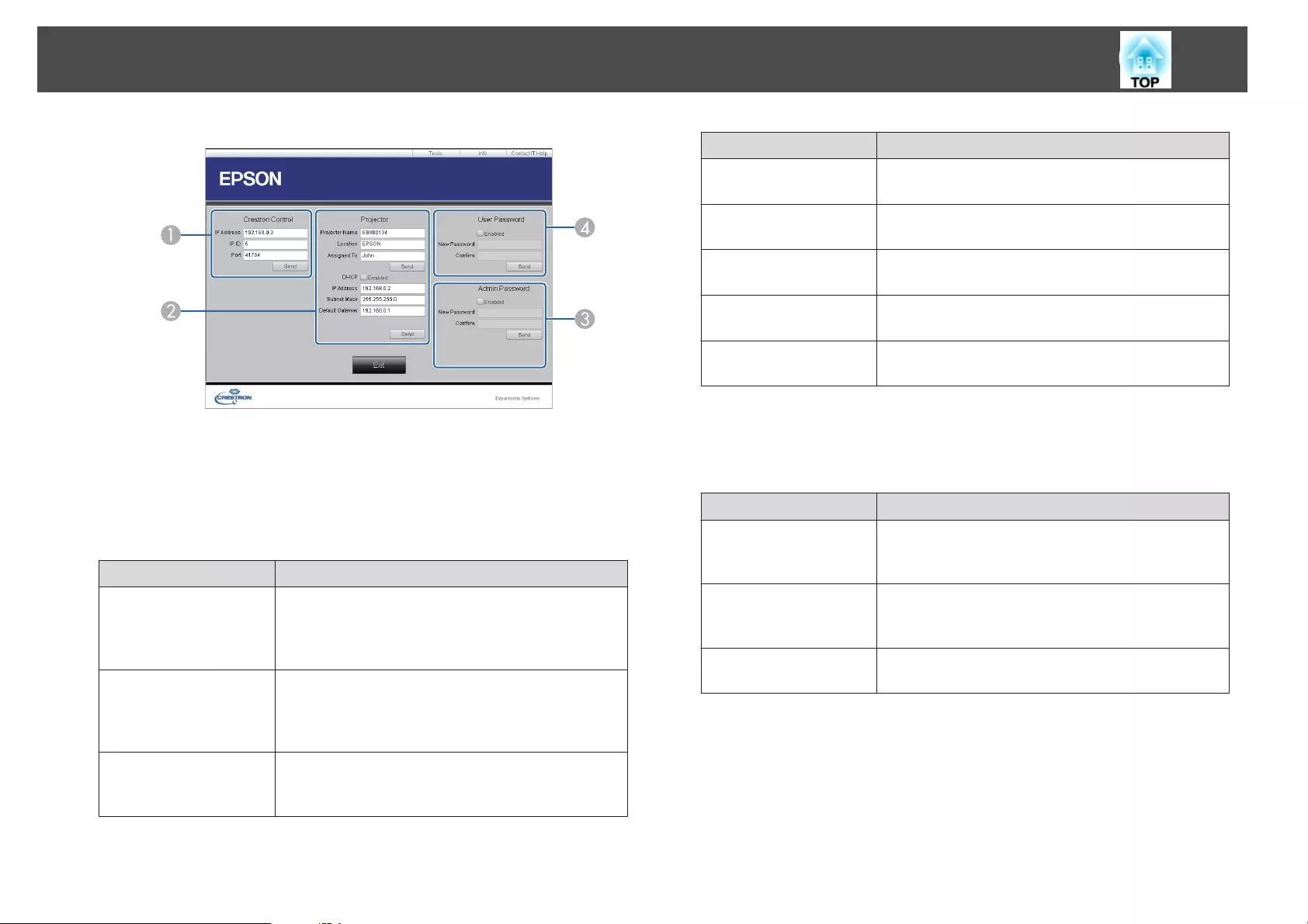
ACrestron Control
Make settings for Crestron
®
central controllers.
BProjector
The following items can be set.
Item Function
Projector Name Enter a name to differentiate the projector that is
currently connected from other projectors on the
network. (The name can contain up to 15 single-byte
alphanumeric characters.)
Location Enter an installation location name for the projector
that is currently connected on the network. (The name
can contain up to 32 single-byte alphanumeric
characters and symbols.)
Assigned To Enter a user name for the projector. (The name can
contain up to 32 single-byte alphanumeric characters
and symbols.)
Item Function
DHCP Select the Enabled check box to use DHCP. You cannot
enter an IP address if DHCP is enabled.
IP Address Enter the IP address to assign to the currently connected
projector.
Subnet Mask Enter a subnet mask for the currently connected
projector.
Default Gateway Enter the gateway address for the currently connected
projector.
Send Click this button to confirm the changes made to the
Projector.
CAdmin Password
Select the Enabled check box to require a password to open the Tools window.
The following items can be set.
Item Function
New Password Enter the new password when changing the password to
open the Tools window. (The name can contain up to 26
single-byte alphanumeric characters.)
Confirm Enter the same password as you entered in New
Password. If the passwords are not the same, an error is
displayed.
Send Click this button to confirm the changes made to the
Admin Password.
DUser Password
Select the Enabled check box to require a password to open the operation window
on the computer.
The following items can be set.
Monitoring and Controlling
215
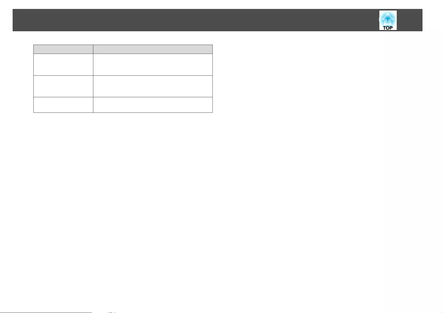
Item Function
New Password Enter the new password when changing the password to
open the operation window. (The name can contain up
to 26 single-byte alphanumeric characters.)
Confirm Enter the same password as you entered in New
Password. If the passwords are not the same, an error is
displayed.
Send Click this button to confirm the changes made to the
User Password.
Monitoring and Controlling
216
The following optional accessories and consumables are available. Please
purchase these products as and when needed. The following list of optional
accessories and consumables is current as of: January 2016. Details of
accessories are subject to change without notice and availability may vary
depending on the country of purchase.
Optional Accessories
Lens unit
ELPLX01, ELPLU03, ELPLU04, ELPLW05, ELPLW06, ELPLM08,
ELPLM09, ELPLM10, ELPLM11, ELPLL08
See the following for more information on the projection distance for each
lens.
s "Screen Size and Projection Distance" p.219
Computer cable ELPKC02
(1.8 m - for mini D-Sub15-pin/mini D-Sub 15pin)
This is the same as the computer cable supplied with the projector.
Computer cable ELPKC09
(3 m - for mini D-Sub15-pin/mini D-Sub 15pin)
Computer cable ELPKC10
(20 m - for mini D-Sub15-pin/mini D-Sub 15pin)
Use one of these longer cables if the computer cable supplied with the projector
is too short.
Component video cable ELPKC19
(3 m - for mini D-Sub 15-pin/RCA male^3)
Use to connect a Component Video
g
source.
Remote control cable set ELPKC28
(10 m 2 piece set)
Use this to guarantee operation from the remote control from a distance.
Wireless mouse receiver ELPST16
Use this to use the projector's remote control to control the mouse pointer on
the computer or to page up and down.
HDBaseT Transmitter ELPHD01
This transmitter performs long distance transmissions for HDMI signals and
control signals for one LAN cable. Based on the HDBaseT
g
standard.
(HDCP 2.2 is not supported.)
Wireless LAN unit ELPAP10
Use when connecting the projector to a computer wirelessly and projecting.
Quick Wireless Connection USB Key ELPAP09
Use when you want to quickly establish one-to-one connection between the
projector and a computer with Windows installed.
Polarizer ELPPL01
Use when stacking two projectors and projecting 3D images.
Passive 3D Glasses (standard five piece set) ELPGS02A
Passive 3D Glasses (five piece set for children) ELPGS02B
Passive polarized 3D glasses. Use these when viewing 3D images with the
projectors.
Document Camera ELPDC13, ELPDC21
Use when projecting images such as books, OHP documents, or slides.
Ceiling pipe (450 mm)
*
ELPFP13
Ceiling pipe (700 mm)
*
ELPFP14
Use when installing the projector on a high ceiling.
Ceiling mount
*
ELPMB22
Low ceiling mount
*
ELPMB47
High ceiling mount
*
ELPMB48
Use when installing the projector on a ceiling.
*Special expertise is required to suspend the projector from a ceiling. Contact
your local dealer or the nearest address provided in the Epson Projector
Contact List.
s Epson Projector Contact List
Optional Accessories and Consumables
217

Consumables
Lamp unit ELPLP93
Use as a replacement for used lamps.
Air filter ELPAF30
Use as a replacement for used air filters.
Optional Accessories and Consumables
218
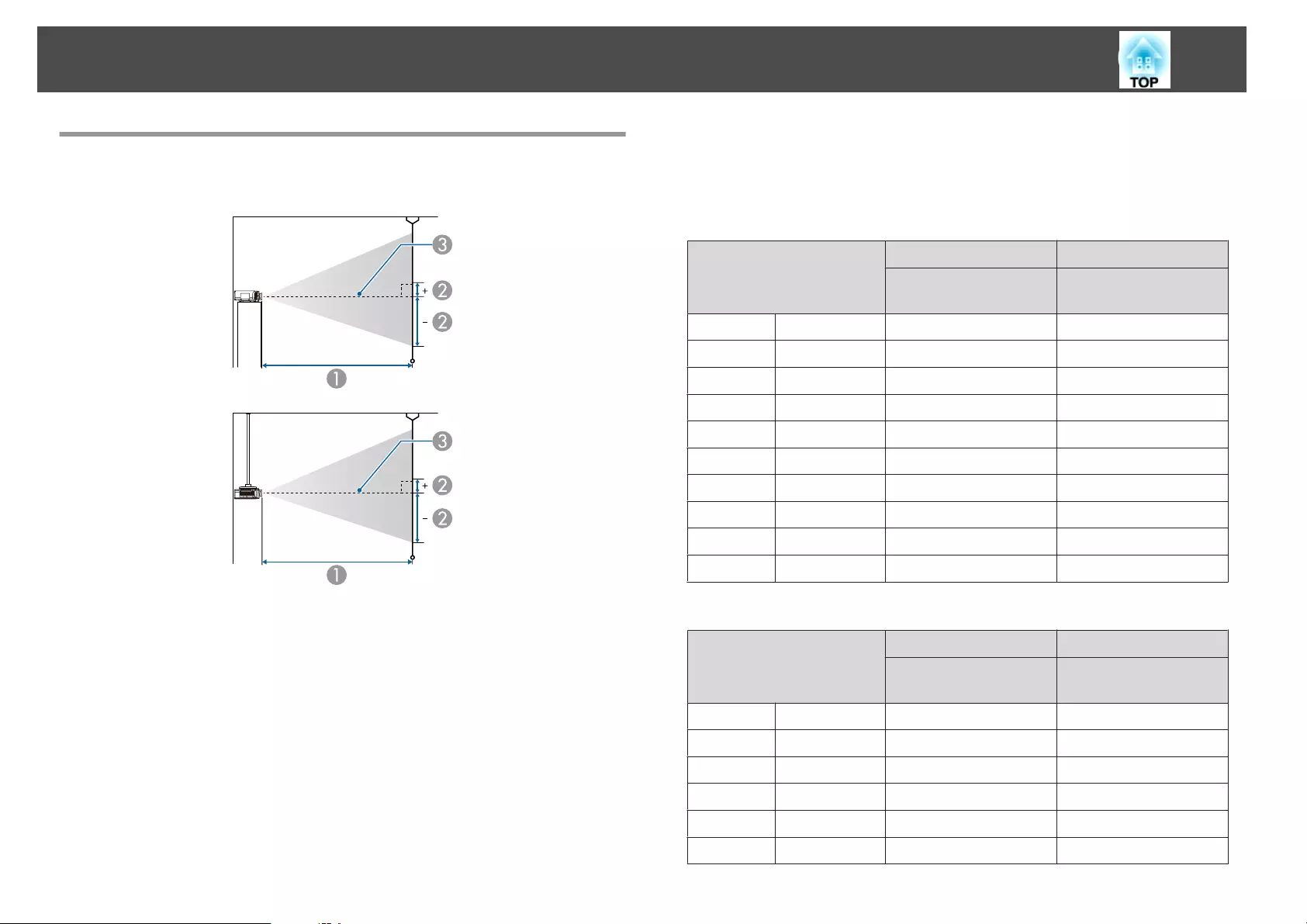
Projection Distance (For EB-G7905U/EB-G7900U/
EB-G7500U/EB-G7400U/EB-G7200W/EB-G7000W)
AProjection distance
Bis the distance from the center of the lens to the base of the screen. This
changes depending on the setting for vertical lens shift.
CCenter of lens
ELPLM08
This section shows the projection distances for models equipped with
lenses.
Unit: cm
4:3 Screen Size
AB
Minimum (Wide) to
Maximum (Tele)
Vertical Lens Shift
Top to Bottom
45" 100x75 156 - 253 -81 - +12
50" 102x76 174 - 281 -90 - +13
60" 122x91 210 - 338 -108 - +16
80" 163x122 281 - 453 -143 - +22
100" 203x152 353 - 567 -179 - +27
120" 244x183 424 - 681 -215 - +32
150" 305x229 532 - 853 -269 - +40
200" 406x305 711 - 1139 -359 - +54
250" 508x381 890 - 1424 -448 - +67
265" 539x404 943 - 1510 -475 - +71
Unit: cm
16:9 Screen Size
AB
Minimum (Wide) to
Maximum (Tele)
Vertical Lens Shift
Top to Bottom
49" 108x61 154 - 250 -76 - +15
50" 111x62 157 - 255 -78 - +16
60" 133x75 190 - 307 -94 - +19
80" 177x100 255 - 411 -125 - +25
100" 221x125 320 - 514 -156 - +31
120" 266x149 385 - 618 -187 - +38
Screen Size and Projection Distance
219
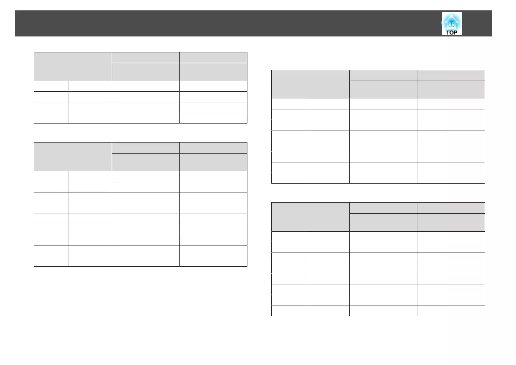
16:9 Screen Size
AB
Minimum (Wide) to
Maximum (Tele)
Vertical Lens Shift
Top to Bottom
150" 332x187 482 - 774 -234 - +47
200" 443x249 645 - 1033 -312 - +63
250" 553x311 807 - 1293 -390 - +78
290" 642x361 937 - 1500 -452 - +91
Unit: cm
16:10 Screen Size
AB
Minimum (Wide) to
Maximum (Tele)
Vertical Lens Shift
Top to Bottom
50" 108x67 153 - 248 -79 - +12
60" 130x81 185 - 298 -95 - +14
80" 172x108 248 - 399 -127 - +19
100" 215x135 311 - 500 -158 - +24
120" 258x162 374 - 601 -190 - +29
150" 323x202 469 - 753 -238 - +36
200" 431x269 627 - 1005 -317 - +48
250" 538x337 785 - 1258 -396 - +59
300" 646x404 943 - 1510 -475 - +71
ELPLX01
See the user's guide supplied with the lens unit.
ELPLU03
Unit: cm
4:3 Screen Size
AB
Minimum (Wide) to
Maximum (Tele)
Vertical Lens Shift
Top to Bottom
71" 144x108 112 - 135 -127 - +19
80" 163x122 126 - 152 -143 - +22
100" 203x152 159 - 191 -179 - +27
120" 244x183 191 - 230 -215 - +32
150" 305x229 240 - 289 -269 - +40
200" 406x305 321 - 386 -359 - +54
250" 508x381 403 - 483 -448 - +67
265" 539x404 427 - 513 -475 - +71
Unit: cm
16:9 Screen Size
AB
Minimum (Wide) to
Maximum (Tele)
Vertical Lens Shift
Top to Bottom
78" 173x97 111 - 134 -122 - +24
80" 177x100 114 - 138 -125 - +25
100" 221x125 144 - 173 -156 - +31
120" 266x149 173 - 209 -187 - +38
150" 332x187 218 - 262 -234 - +47
200" 443x249 291 - 350 -312 - +63
250" 553x311 365 - 439 -390 - +78
290" 642x361 424 - 509 -452 - +91
Screen Size and Projection Distance
220

Unit: cm
16:10 Screen Size
AB
Minimum (Wide) to
Maximum (Tele)
Vertical Lens Shift
Top to Bottom
80" 172x108 111 - 134 -127 - +19
100" 215x135 140 - 168 -158 - +24
120" 258x162 169 - 203 -190 - +29
150" 323x202 212 - 255 -238 - +36
200" 431x269 283 - 341 -317 - +48
250" 538x337 355 - 427 -396 - +59
300" 646x404 427 - 513 -475 - +71
ELPLU04/ELPLU02
Unit: cm
4:3 Screen Size
AB
Minimum (Wide) to
Maximum (Tele)
Vertical Lens Shift
Top to Bottom
45" 100x75 93 - 113 -81 - +12
50" 102x76 104 - 126 -90 - +13
60" 122x91 126 - 153 -108 - +16
80" 163x122 170 - 205 -143 - +22
100" 203x152 214 - 258 -179 - +27
120" 244x183 258 - 311 -215 - +32
150" 305x229 324 - 390 -269 - +40
200" 406x305 434 - 522 -359 - +54
250" 508x381 543 - 654 -448 - +67
265" 539x404 576 - 693 -475 - +71
Unit: cm
16:9 Screen Size
AB
Minimum (Wide) to
Maximum (Tele)
Vertical Lens Shift
Top to Bottom
49" 108x61 92 - 112 -76 - +15
50" 111x62 94 - 114 -78 - +16
60" 133x75 114 - 138 -94 - +19
80" 177x100 154 - 186 -125 - +25
100" 221x125 194 - 234 -156 - +31
120" 266x149 234 - 282 -187 - +38
150" 332x187 293 - 354 -234 - +47
200" 443x249 393 - 473 -312 - +63
250" 553x311 493 - 593 -390 - +78
290" 642x361 573 - 689 -452 - +91
Unit: cm
16:10 Screen Size
AB
Minimum (Wide) to
Maximum (Tele)
Vertical Lens Shift
Top to Bottom
50" 108x67 91 - 111 -79 - +12
60" 130x81 111 - 134 -95 - +14
80" 172x108 149 - 181 -127 - +19
100" 215x135 188 - 227 -158 - +24
120" 258x162 227 - 274 -190 - +29
150" 323x202 285 - 344 -238 - +36
200" 431x269 382 - 460 -317 - +48
250" 538x337 479 - 577 -396 - +59
300" 646x404 576 - 693 -475 - +71
Screen Size and Projection Distance
221
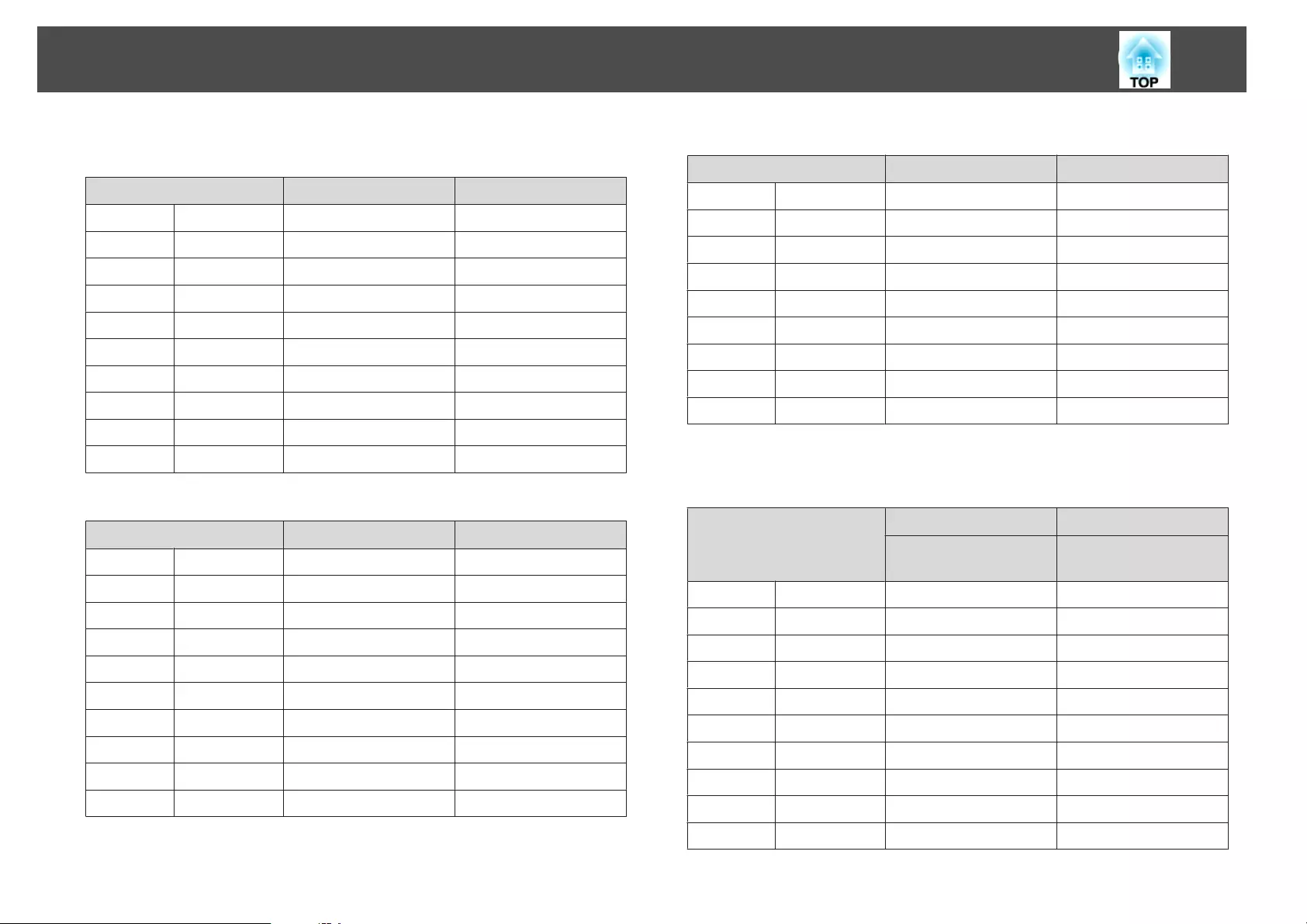
ELPLW05
Unit: cm
4:3 Screen Size AB
45" 100x75 111 - 158 -81 - +12
50" 102x76 124 - 176 -90 - +13
60" 122x91 150 - 212 -108 - +16
80" 163x122 203 - 285 -143 - +22
100" 203x152 255 - 357 -179 - +27
120" 244x183 308 - 430 -215 - +32
150" 305x229 387 - 539 -269 - +40
200" 406x305 519 - 720 -359 - +54
250" 508x381 650 - 902 -448 - +67
265" 539x404 690 - 956 -475 - +71
Unit: cm
16:9 Screen Size AB
49" 108x61 109 - 156 -76 - +15
50" 111x62 112 - 159 -78 - +16
60" 133x75 136 - 192 -94 - +19
80" 177x100 183 - 258 -125 - +25
100" 221x125 231 - 324 -156 - +31
120" 266x149 279 - 390 -187 - +38
150" 332x187 351 - 489 -234 - +47
200" 443x249 470 - 653 -312 - +63
250" 553x311 590 - 818 -390 - +78
290" 642x361 685 - 950 -452 - +91
Unit: cm
16:10 Screen Size AB
50" 108x67 109 - 155 -79 - +12
60" 130x81 132 - 187 -95 - +14
80" 172x108 178 - 251 -127 - +19
100" 215x135 225 - 315 -158 - +24
120" 258x162 271 - 379 -190 - +29
150" 323x202 341 - 475 -238 - +36
200" 431x269 457 - 636 -317 - +48
250" 538x337 573 - 796 -396 - +59
300" 646x404 690 - 956 -475 - +71
ELPLW06/ELPLW04
Unit: cm
4:3 Screen Size
AB
Minimum (Wide) to
Maximum (Tele)
Vertical Lens Shift
Top to Bottom
45" 97x61 175 - 240 -81 - +12
50" 102x76 195 - 267 -90 - +13
60" 122x91 236 - 322 -108 - +16
80" 163x122 317 - 432 -143 - +22
100" 203x152 398 - 543 -179 - +27
120" 244x183 479 - 653 -215 - +32
150" 305x229 600 - 818 -269 - +40
200" 406x305 803 - 1094 -359 - +54
250" 508x381 1005 - 1369 -448 - +67
265" 539x404 1066 - 1452 -475 - +71
Screen Size and Projection Distance
222
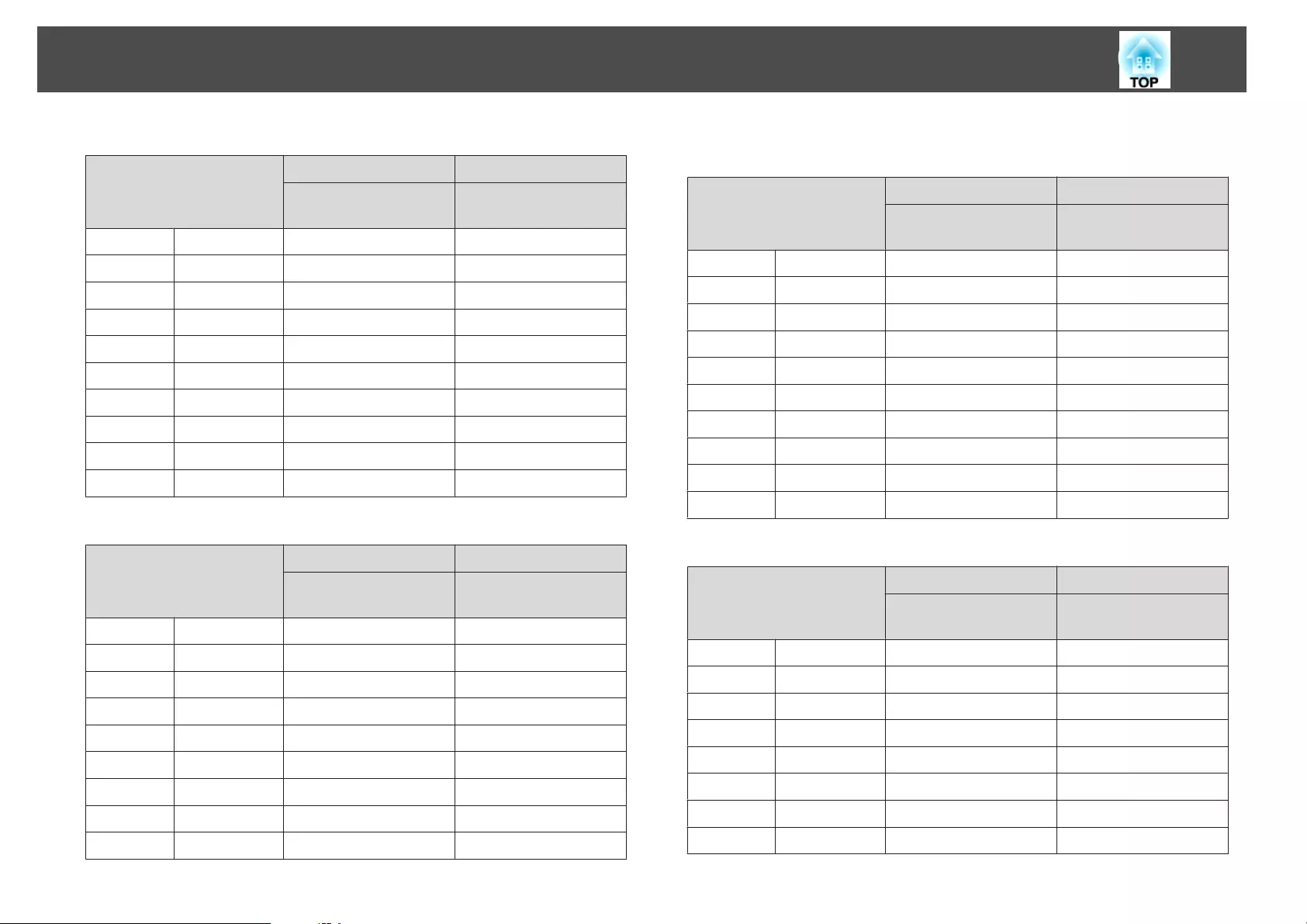
Unit: cm
16:9 Screen Size
AB
Minimum (Wide) to
Maximum (Tele)
Vertical Lens Shift
Top to Bottom
49" 108x61 173 - 237 -76 - +15
50" 111x62 176 - 242 -78 - +16
60" 133x75 213 - 292 -94 - +19
80" 177x100 287 - 392 -125 - +25
100" 221x125 360 - 492 -156 - +31
120" 266x149 434 - 592 -187 - +38
150" 332x187 544 - 742 -234 - +47
200" 443x249 728 - 992 -312 - +63
250" 553x311 912 - 1242 -390 - +78
290" 642x361 1059 - 1442 -452 - +91
Unit: cm
16:10 Screen Size
AB
Minimum (Wide) to
Maximum (Tele)
Vertical Lens Shift
Top to Bottom
50" 108x67 172 - 235 -79 - +12
60" 130x81 207 - 284 -95 - +14
80" 172x108 279 - 381 -127 - +19
100" 215x135 350 - 478 -158 - +24
120" 258x162 422 - 576 -190 - +29
150" 323x202 529 - 722 -238 - +36
200" 431x269 708 - 965 -317 - +48
250" 538x337 887 - 1208 -396 - +59
300" 646x404 1066 - 1452 -475 - +71
ELPLM09/ELPLS04
Unit: cm
4:3 Screen Size
AB
Minimum (Wide) to
Maximum (Tele)
Vertical Lens Shift
Top to Bottom
45" 100x75 233 - 379 -81 - +12
50" 102x76 260 - 422 -90 - +13
60" 122x91 313 - 508 -108 - +16
80" 163x122 420 - 679 -143 - +22
100" 203x152 527 - 851 -179 - +27
120" 244x183 635 - 1023 -215 - +32
150" 305x229 795 - 1281 -269 - +40
200" 406x305 1063 - 1711 -359 - +54
250" 508x381 1331 - 2140 -448 - +67
265" 539x404 1411 - 2269 -475 - +71
Unit: cm
16:9 Screen Size
AB
Minimum (Wide) to
Maximum (Tele)
Vertical Lens Shift
Top to Bottom
49" 108x61 230 - 374 -76 - +15
50" 111x62 235 - 382 -78 - +16
60" 133x75 284 - 460 -94 - +19
80" 177x100 381 - 616 -125 - +25
100" 221x125 478 - 772 -156 - +31
120" 266x149 575 - 928 -187 - +38
150" 332x187 721 - 1162 -234 - +47
200" 443x249 964 - 1552 -312 - +63
Screen Size and Projection Distance
223
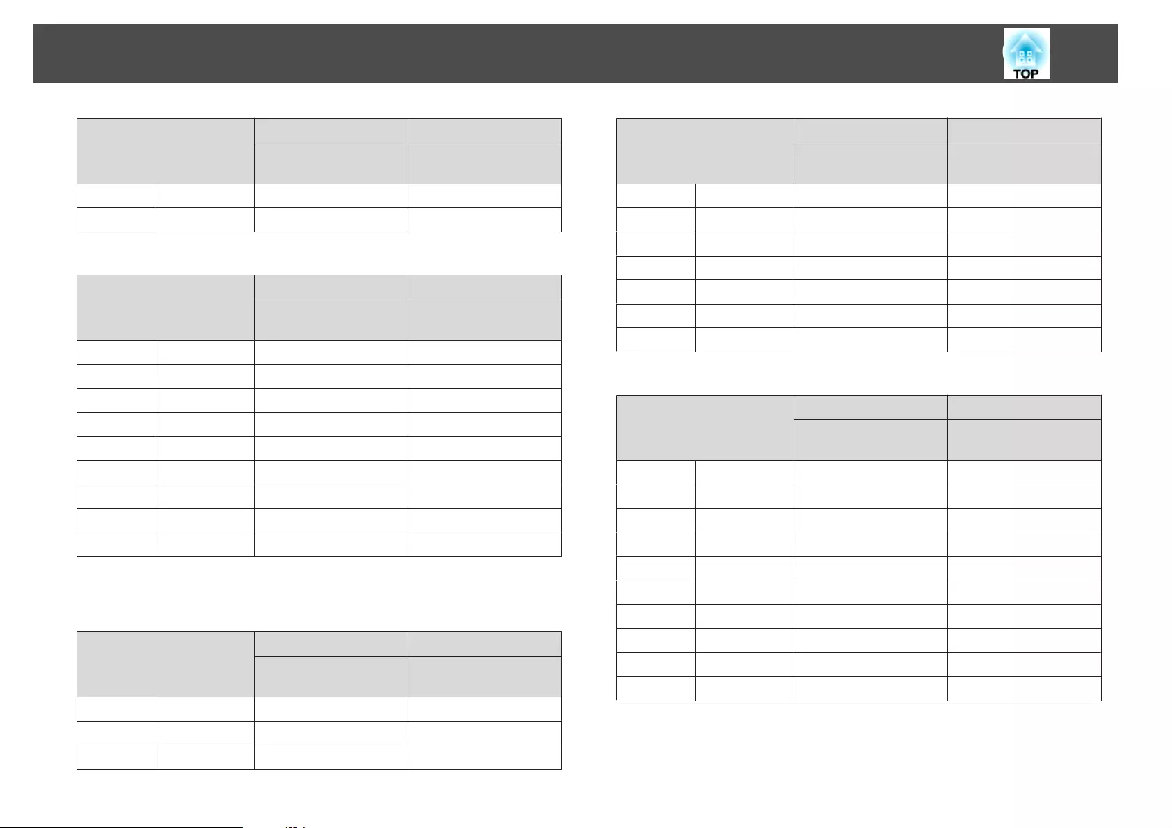
16:9 Screen Size
AB
Minimum (Wide) to
Maximum (Tele)
Vertical Lens Shift
Top to Bottom
250" 553x311 1207 - 1942 -390 - +78
290" 642x361 1402 - 2254 -452 - +91
Unit: cm
16:10 Screen Size
AB
Minimum (Wide) to
Maximum (Tele)
Vertical Lens Shift
Top to Bottom
50" 108x67 229 - 372 -79 - +12
60" 130x81 276 - 447 -95 - +14
80" 172x108 370 - 599 -127 - +19
100" 215x135 465 - 751 -158 - +24
120" 258x162 560 - 903 -190 - +29
150" 323x202 702 - 1131 -238 - +36
200" 431x269 938 - 1510 -317 - +48
250" 538x337 1175 - 1890 -396 - +59
300" 646x404 1411 - 2269 -475 - +71
ELPLM10/ELPLM06
Unit: cm
4:3 Screen Size
AB
Minimum (Wide) to
Maximum (Tele)
Vertical Lens Shift
Top to Bottom
45" 100x75 359 - 549 -81 - +12
50" 102x76 400 - 611 -90 - +13
60" 122x91 483 - 736 -108 - +16
4:3 Screen Size
AB
Minimum (Wide) to
Maximum (Tele)
Vertical Lens Shift
Top to Bottom
80" 163x122 648 - 986 -143 - +22
100" 203x152 813 - 1236 -179 - +27
120" 244x183 979 - 1485 -215 - +32
150" 305x229 1227 - 1860 -269 - +40
200" 406x305 1640 - 2484 -359 - +54
250" 508x381 2053 - 3109 -448 - +67
265" 539x404 2177 - 3296 -475 - +71
Unit: cm
16:9 Screen Size
AB
Minimum (Wide) to
Maximum (Tele)
Vertical Lens Shift
Top to Bottom
49" 108x61 355 - 542 -76 - +15
50" 111x62 362 - 554 -78 - +16
60" 133x75 437 - 667 -94 - +19
80" 177x100 587 - 894 -125 - +25
100" 221x125 737 - 1121 -156 - +31
120" 266x149 887 - 1347 -187 - +38
150" 332x187 1112 - 1687 -234 - +47
200" 443x249 1488 - 2254 -312 - +63
250" 553x311 1863 - 2821 -390 - +78
290" 642x361 2163 - 3275 -452 - +91
Screen Size and Projection Distance
224
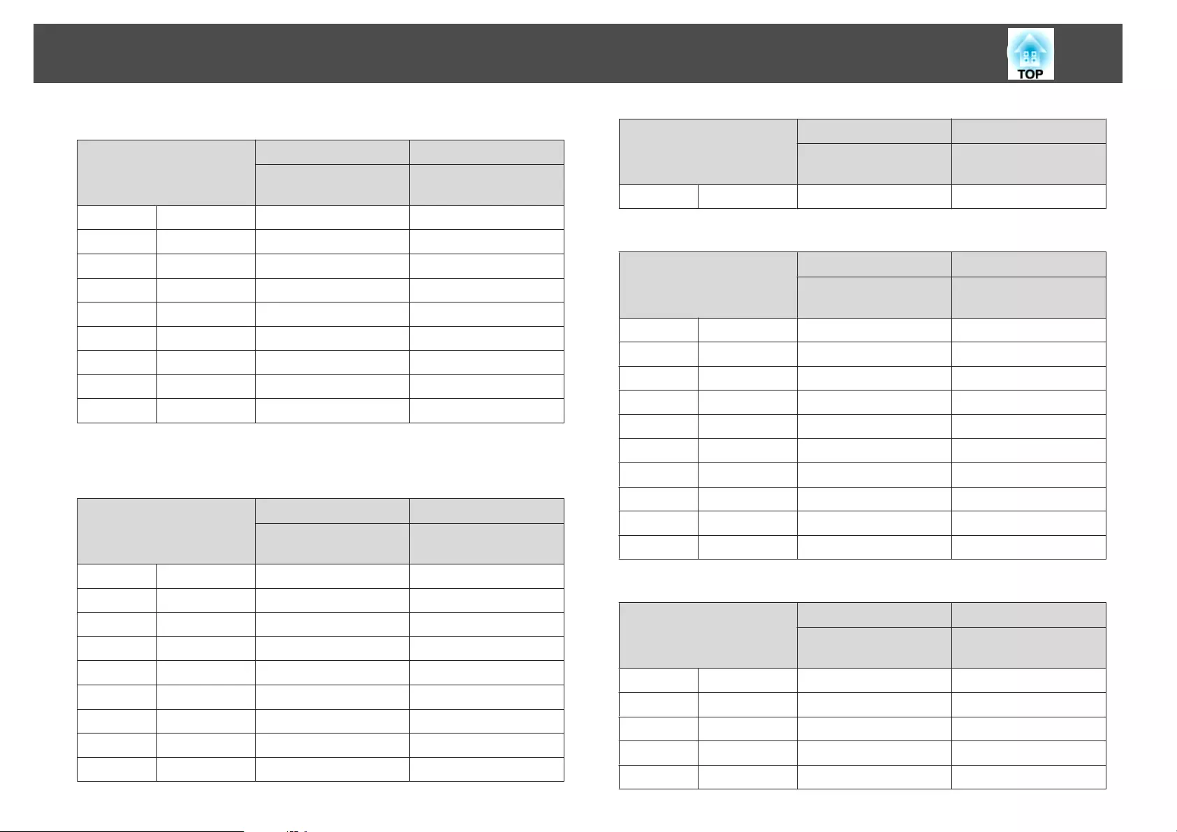
Unit: cm
16:10 Screen Size
AB
Minimum (Wide) to
Maximum (Tele)
Vertical Lens Shift
Top to Bottom
50" 108x67 352 - 538 -79 - +12
60" 130x81 425 - 649 -95 - +14
80" 172x108 571 - 869 -127 - +19
100" 215x135 717 - 1090 -158 - +24
120" 258x162 863 - 1311 -190 - +29
150" 323x202 1082 - 1641 -238 - +36
200" 431x269 1447 - 2193 -317 - +48
250" 538x337 1812 - 2744 -396 - +59
300" 646x404 2177 - 3296 -475 - +71
ELPLM11/ELPLM07
Unit: cm
4:3 Screen Size
AB
Minimum (Wide) to
Maximum (Tele)
Vertical Lens Shift
Top to Bottom
45" 100x75 521 - 799 -81 - +12
50" 102x76 582 - 890 -90 - +13
60" 122x91 703 - 1073 -108 - +16
80" 163x122 945 - 1438 -143 - +22
100" 203x152 1188 - 1804 -179 - +27
120" 244x183 1430 - 2169 -215 - +32
150" 305x229 1793 - 2717 -269 - +40
200" 406x305 2399 - 3631 -359 - +54
250" 508x381 3005 - 4544 -448 - +67
4:3 Screen Size
AB
Minimum (Wide) to
Maximum (Tele)
Vertical Lens Shift
Top to Bottom
265" 539x404 3186 - 4819 -475 - +71
Unit: cm
16:9 Screen Size
AB
Minimum (Wide) to
Maximum (Tele)
Vertical Lens Shift
Top to Bottom
49" 108x61 515 - 789 -76 - +15
50" 111x62 526 - 806 -78 - +16
60" 133x75 636 - 972 -94 - +19
80" 177x100 856 - 1304 -125 - +25
100" 221x125 1076 - 1635 -156 - +31
120" 266x149 1296 - 1967 -187 - +38
150" 332x187 1626 - 2465 -234 - +47
200" 443x249 2176 - 3294 -312 - +63
250" 553x311 2726 - 4124 -390 - +78
290" 642x361 3166 - 4787 -452 - +91
Unit: cm
16:10 Screen Size
AB
Minimum (Wide) to
Maximum (Tele)
Vertical Lens Shift
Top to Bottom
50" 108x67 511 - 784 -79 - +12
60" 130x81 618 - 945 -95 - +14
80" 172x108 832 - 1268 -127 - +19
100" 215x135 1046 - 1591 -158 - +24
120" 258x162 1260 - 1913 -190 - +29
Screen Size and Projection Distance
225
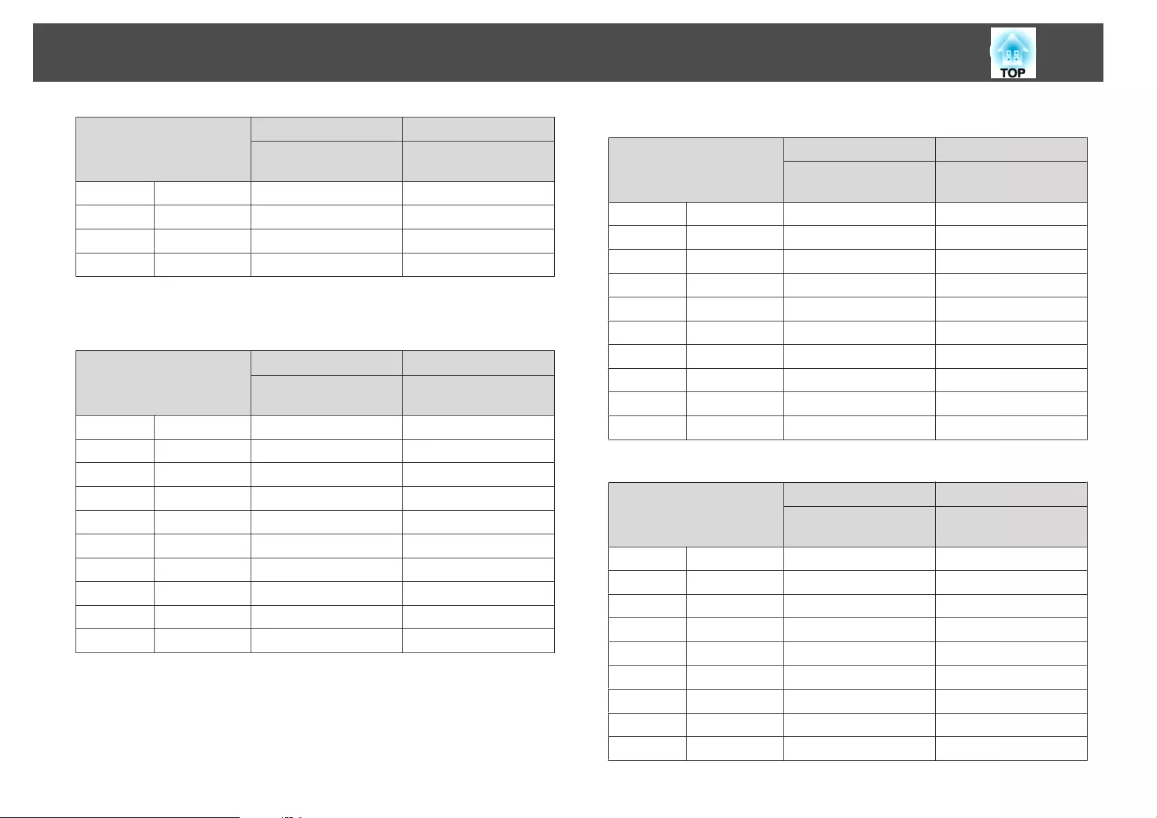
16:10 Screen Size
AB
Minimum (Wide) to
Maximum (Tele)
Vertical Lens Shift
Top to Bottom
150" 323x202 1581 - 2398 -238 - +36
200" 431x269 2116 - 3205 -317 - +48
250" 538x337 2651 - 4012 -396 - +59
300" 646x404 3186 - 4819 -475 - +71
ELPLL08/ELPLL07
Unit: cm
4:3 Screen Size
AB
Minimum (Wide) to
Maximum (Tele)
Vertical Lens Shift
Top to Bottom
45" 100x75 776 - 1095 -81 - +12
50" 102x76 866 - 1220 -90 - +13
60" 122x91 1046 - 1470 -108 - +16
80" 163x122 1405 - 1971 -143 - +22
100" 203x152 1764 - 2472 -179 - +27
120" 244x183 2124 - 2972 -215 - +32
150" 305x229 2662 - 3724 -269 - +40
200" 406x305 3561 - 4975 -359 - +54
250" 508x381 4459 - 6227 -448 - +67
265" 539x404 4728 - 6602 -475 - +71
Unit: cm
16:9 Screen Size
AB
Minimum (Wide) to
Maximum (Tele)
Vertical Lens Shift
Top to Bottom
49" 108x61 767 - 1082 -76 - +15
50" 111x62 784 - 1105 -78 - +16
60" 133x75 947 - 1332 -94 - +19
80" 177x100 1273 - 1787 -125 - +25
100" 221x125 1599 - 2241 -156 - +31
120" 266x149 1925 - 2696 -187 - +38
150" 332x187 2414 - 3378 -234 - +47
200" 443x249 3230 - 4514 -312 - +63
250" 553x311 4045 - 5650 -390 - +78
290" 642x361 4697 - 6560 -452 - +91
Unit: cm
16:10 Screen Size
AB
Minimum (Wide) to
Maximum (Tele)
Vertical Lens Shift
Top to Bottom
50" 108x67 761 - 1074 -79 - +12
60" 130x81 920 - 1295 -95 - +14
80" 172x108 1237 - 1737 -127 - +19
100" 215x135 1555 - 2180 -158 - +24
120" 258x162 1872 - 2622 -190 - +29
150" 323x202 2348 - 3285 -238 - +36
200" 431x269 3141 - 4391 -317 - +48
250" 538x337 3935 - 5497 -396 - +59
300" 646x404 4728 - 6602 -475 - +71
Screen Size and Projection Distance
226
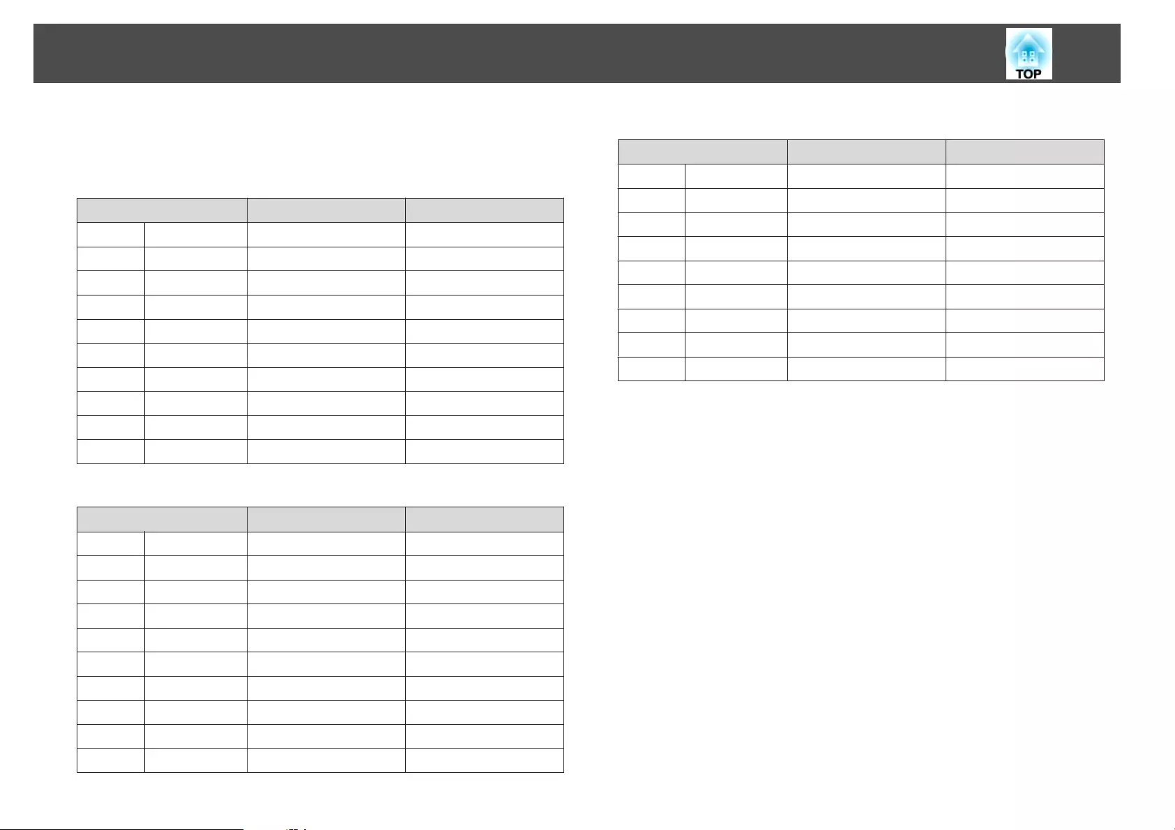
ELPLR04
Lens shift is not supported.
Unit: cm
4:3 Screen Size AB
45" 91x69 102 -34
50" 102x76 114 -38
60" 122x91 138 -46
80" 163x122 186 -61
100" 203x152 234 -76
120" 244x183 282 -91
150" 305x229 354 -114
200" 406x305 473 -152
250" 508x381 593 -191
265" 538x404 629 -202
Unit: cm
16:9 Screen Size AB
49" 108x61 101 -30
50" 111x62 103 -31
60" 133x75 124 -37
80" 177x100 168 -50
100" 221x125 212 -62
120" 266x149 255 -75
150" 332x187 320 -93
200" 443x249 429 -125
250" 553x311 538 -156
265" 587x330 625 -165
Unit: cm
16:10 Screen Size AB
50" 108x67 100 -33
60" 130x81 121 -40
80" 172x108 163 -54
100" 215x135 206 -67
120" 258x162 248 -81
150" 323x202 312 -101
200" 431x269 417 -135
250" 538x337 523 -168
300" 646x404 629 -202
Screen Size and Projection Distance
227
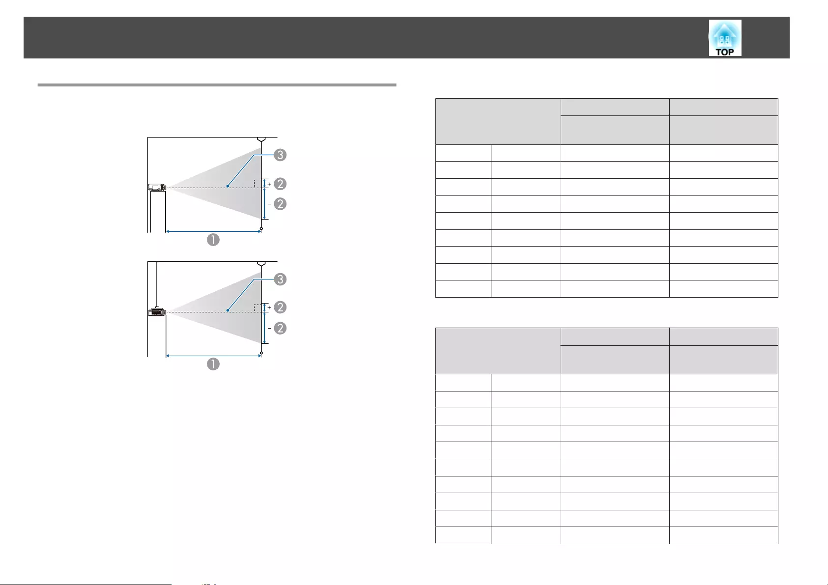
Projection Distance (For EB-G7805/EB-G7800/EB-
G7100)
AProjection distance
Bis the distance from the center of the lens to the base of the screen. This
changes depending on the setting for vertical lens shift.
CCenter of lens
ELPLM08
This section shows the projection distances for models equipped with
standard lenses.
Unit: cm
4:3 Screen Size
AB
Minimum (Wide) to
Maximum (Tele)
Vertical Lens Shift
Top to Bottom
50" 102x76 147 - 239 -82 - +6
60" 122x91 178 - 288 -98 - +7
80" 163x122 239 - 385 -131 - +9
100" 203x152 299 - 482 -164 - +12
120" 244x183 360 - 580 -197 - +14
150" 305x229 452 - 726 -246 - +17
200" 406x305 604 - 969 -328 - +23
250" 508x381 756 - 1213 -410 - +29
300" 610x457 908 - 1456 -492 - +35
Unit: cm
16:9 Screen Size
AB
Minimum (Wide) to
Maximum (Tele)
Vertical Lens Shift
Top to Bottom
46" 102x57 148 - 240 -73 - +15
50" 111x62 161 - 261 -79 - +17
60" 133x75 194 - 314 -95 - +20
80" 177x100 260 - 420 -126 - +27
100" 221x125 327 - 526 -158 - +33
120" 266x149 393 - 632 -189 - +40
150" 332x187 493 - 791 -237 - +50
200" 443x249 658 - 1057 -316 - +67
250" 553x311 824 - 1322 -395 - +83
275" 609x342 907 - 1454 -434 - +92
Screen Size and Projection Distance
228
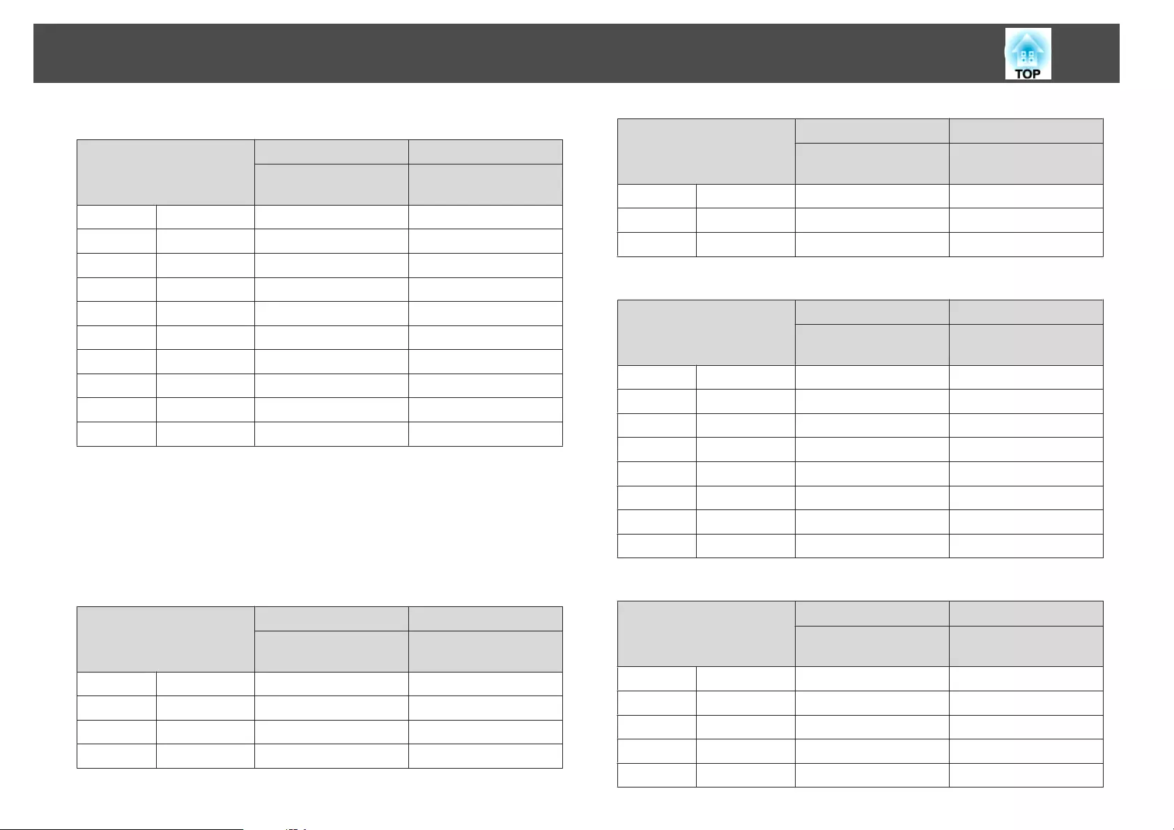
Unit: cm
16:10 Screen Size
AB
Minimum (Wide) to
Maximum (Tele)
Vertical Lens Shift
Top to Bottom
48" 103x65 150 - 243 -77 - +12
50" 108x67 156 - 254 -80 - +13
60" 130x81 189 - 305 -96 - +15
80" 172x108 253 - 408 -128 - +21
100" 215x135 318 - 512 -160 - +26
120" 258x162 382 - 615 -192 - +31
150" 323x202 479 - 770 -241 - +39
200" 431x269 640 - 1028 -321 - +51
250" 538x337 802 - 1286 -401 - +64
280" 603x377 899 - 1441 -449 - +72
ELPLX01
See the user's guide supplied with the lens unit.
ELPLU03
Unit: cm
4:3 Screen Size
AB
Minimum (Wide) to
Maximum (Tele)
Vertical Lens Shift
Top to Bottom
80" 163x122 107 - 129 -131 - +9
100" 203x152 134 - 162 -164 - +12
120" 244x183 162 - 196 -197 - +14
150" 305x229 204 - 245 -246 - +17
4:3 Screen Size
AB
Minimum (Wide) to
Maximum (Tele)
Vertical Lens Shift
Top to Bottom
200" 406x305 273 - 328 -328 - +23
250" 508x381 342 - 411 -410 - +29
300" 610x457 411 - 494 -492 - +35
Unit: cm
16:9 Screen Size
AB
Minimum (Wide) to
Maximum (Tele)
Vertical Lens Shift
Top to Bottom
74" 164x92 108 - 130 -117 - +25
80" 177x100 117 - 141 -126 - +27
100" 221x125 147 - 177 -158 - +33
120" 266x149 177 - 213 -189 - +40
150" 332x187 222 - 268 -237 - +50
200" 443x249 297 - 358 -316 - +67
250" 553x311 373 - 448 -395 - +83
275" 609x342 410 - 493 -434 - +92
Unit: cm
16:10 Screen Size
AB
Minimum (Wide) to
Maximum (Tele)
Vertical Lens Shift
Top to Bottom
76" 164x102 108 - 130 -122 - +20
80" 172x108 113 - 137 -128 - +21
100" 215x135 143 - 172 -160 - +26
120" 258x162 172 - 208 -192 - +31
150" 323x202 216 - 260 -241 - +39
Screen Size and Projection Distance
229
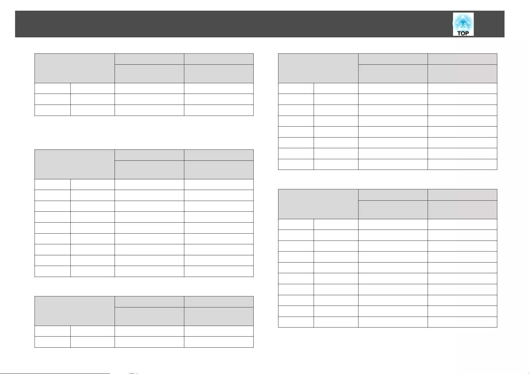
16:10 Screen Size
AB
Minimum (Wide) to
Maximum (Tele)
Vertical Lens Shift
Top to Bottom
200" 431x269 289 - 348 -321 - +51
250" 538x337 362 - 436 -401 - +64
280" 603x377 406 - 489 -449 - +72
ELPLU04/ELPLU02
Unit: cm
4:3 Screen Size
AB
Minimum (Wide) to
Maximum (Tele)
Vertical Lens Shift
Top to Bottom
50" 102x76 88 - 107 -82 - +6
60" 122x91 107 - 129 -98 - +7
80" 163x122 144 - 174 -131 - +9
100" 203x152 181 - 219 -164 - +12
120" 244x183 219 - 264 -197 - +14
150" 305x229 275 - 332 -246 - +17
200" 406x305 368 - 444 -328 - +23
250" 508x381 462 - 557 -410 - +29
300" 610x457 555 - 669 -492 - +35
Unit: cm
16:9 Screen Size
AB
Minimum (Wide) to
Maximum (Tele)
Vertical Lens Shift
Top to Bottom
46" 102x57 88 - 107 -73 - +15
50" 111x62 96 - 117 -79 - +17
16:9 Screen Size
AB
Minimum (Wide) to
Maximum (Tele)
Vertical Lens Shift
Top to Bottom
60" 133x75 117 - 141 -95 - +20
80" 177x100 157 - 191 -126 - +27
100" 221x125 198 - 240 -158 - +33
120" 266x149 239 - 289 -189 - +40
150" 332x187 300 - 362 -237 - +50
200" 443x249 402 - 485 -316 - +67
250" 553x311 504 - 607 -395 - +83
275" 609x342 555 - 669 -434 - +92
Unit: cm
16:10 Screen Size
AB
Minimum (Wide) to
Maximum (Tele)
Vertical Lens Shift
Top to Bottom
48" 103x65 90 - 109 -77 - +12
50" 108x67 93 - 114 -80 - +13
60" 130x81 113 - 138 -96 - +15
80" 172x108 153 - 185 -128 - +21
100" 215x135 193 - 233 -160 - +26
120" 258x162 232 - 281 -192 - +31
150" 323x202 292 - 352 -241 - +39
200" 431x269 391 - 471 -321 - +51
250" 538x337 490 - 591 -401 - +64
280" 603x377 549 - 662 -449 - +72
Screen Size and Projection Distance
230
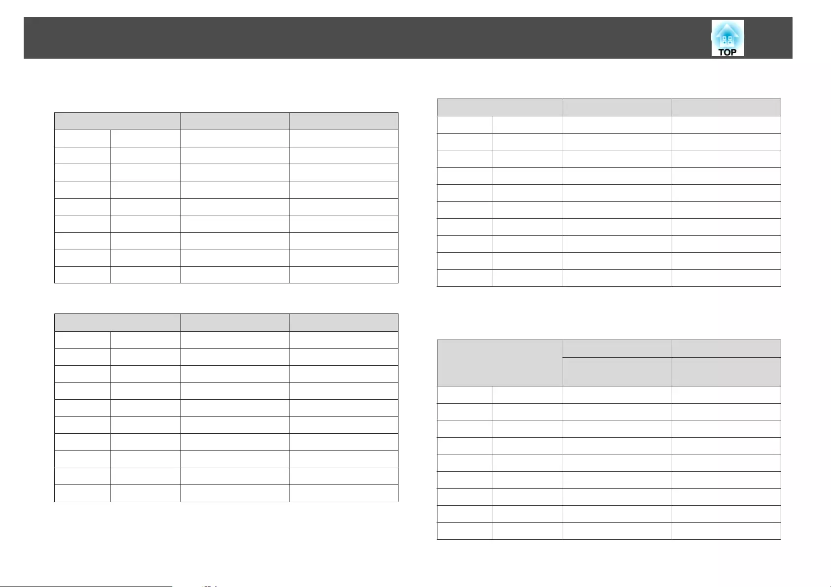
ELPLW05
Unit: cm
4:3 Screen Size AB
50" 102x76 104 - 149 -82 - +6
60" 122x91 127 - 180 -98 - +7
80" 163x122 171 - 242 -131 - +9
100" 203x152 216 - 303 -164 - +12
120" 244x183 261 - 365 -197 - +14
150" 305x229 328 - 458 -246 - +17
200" 406x305 440 - 612 -328 - +23
250" 508x381 552 - 767 -410 - +29
300" 610x457 664 - 922 -492 - +35
Unit: cm
16:9 Screen Size AB
46" 102x57 104 - 149 -73 - +15
50" 111x62 114 - 163 -79 - +17
60" 133x75 139 - 196 -95 - +20
80" 177x100 187 - 264 -126 - +27
100" 221x125 236 - 331 -158 - +33
120" 266x149 285 - 398 -189 - +40
150" 332x187 358 - 499 -237 - +50
200" 443x249 480 - 668 -316 - +67
250" 553x311 602 - 836 -395 - +83
275" 609x342 663 - 920 -434 - +92
Unit: cm
16:10 Screen Size AB
48" 103x65 106 - 151 -77 - +12
50" 108x67 111 - 158 -80 - +13
60" 130x81 135 - 191 -96 - +15
80" 172x108 182 - 256 -128 - +21
100" 215x135 230 - 322 -160 - +26
120" 258x162 277 - 387 -192 - +31
150" 323x202 348 - 486 -241 - +39
200" 431x269 467 - 650 -321 - +51
250" 538x337 586 - 813 -401 - +64
280" 603x377 657 - 912 -449 - +72
ELPLW06/ELPLW04
Unit: cm
4:3 Screen Size
AB
Minimum (Wide) to
Maximum (Tele)
Vertical Lens Shift
Top to Bottom
50" 102x76 165 - 227 -82 - +6
60" 122x91 199 - 274 -98 - +7
80" 163x122 268 - 368 -131 - +9
100" 203x152 337 - 461 -164 - +12
120" 244x183 406 - 555 -197 - +14
150" 305x229 509 - 696 -246 - +17
200" 406x305 682 - 930 -328 - +23
250" 508x381 854 - 1164 -410 - +29
300" 610x457 1026 - 1398 -492 - +35
Screen Size and Projection Distance
231
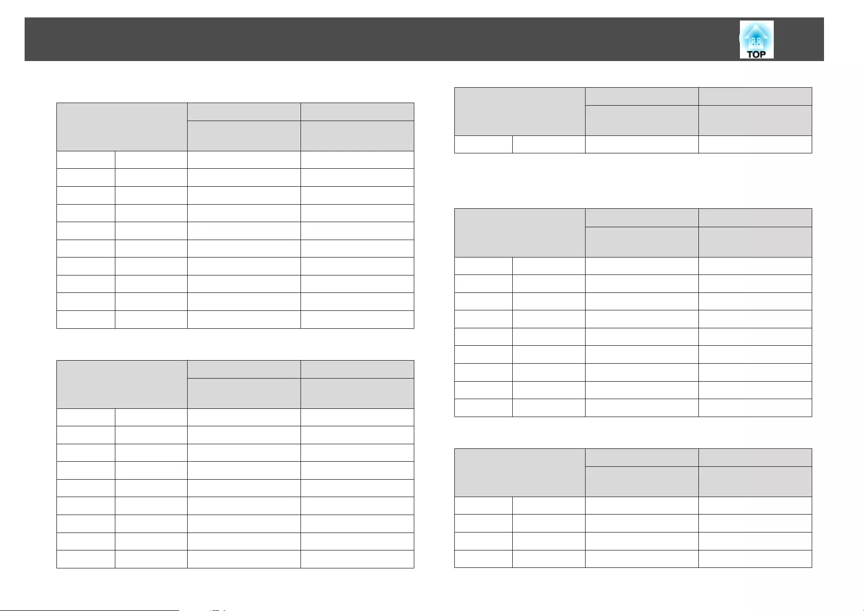
Unit: cm
16:9 Screen Size
AB
Minimum (Wide) to
Maximum (Tele)
Vertical Lens Shift
Top to Bottom
46" 102x57 165 - 228 -73 - +15
50" 111x62 180 - 248 -79 - +17
60" 133x75 218 - 299 -95 - +20
80" 177x100 293 - 401 -126 - +27
100" 221x125 368 - 503 -158 - +33
120" 266x149 443 - 605 -189 - +40
150" 332x187 556 - 759 -237 - +50
200" 443x249 743 - 1014 -316 - +67
250" 553x311 931 - 1269 -395 - +83
275" 609x342 1025 - 1397 -434 - +92
Unit: cm
16:10 Screen Size
AB
Minimum (Wide) to
Maximum (Tele)
Vertical Lens Shift
Top to Bottom
48" 98x73 168 - 231 -77 - +12
50" 108x67 175 - 241 -80 - +13
60" 130x81 212 - 291 -96 - +15
80" 172x108 285 - 390 -128 - +21
100" 215x135 358 - 489 -160 - +26
120" 258x162 431 - 589 -192 - +31
150" 323x202 540 - 738 -241 - +39
200" 431x269 723 - 986 -321 - +51
250" 538x337 906 - 1234 -401 - +64
16:10 Screen Size
AB
Minimum (Wide) to
Maximum (Tele)
Vertical Lens Shift
Top to Bottom
280" 603x377 1015 - 1383 -449 - +72
ELPLM09/ELPLS04
Unit: cm
4:3 Screen Size
AB
Minimum (Wide) to
Maximum (Tele)
Vertical Lens Shift
Top to Bottom
50" 102x76 219 - 358 -82 - +6
60" 122x91 265 - 431 -98 - +7
80" 163x122 356 - 578 -131 - +9
100" 203x152 447 - 724 -164 - +12
120" 244x183 538 - 870 -197 - +14
150" 305x229 674 - 1090 -246 - +17
200" 406x305 902 - 1456 -328 - +23
250" 508x381 1129 - 1822 -410 - +29
300" 610x457 1357 - 2188 -492 - +35
Unit: cm
16:9 Screen Size
AB
Minimum (Wide) to
Maximum (Tele)
Vertical Lens Shift
Top to Bottom
46" 102x57 220 - 359 -73 - +15
50" 111x62 240 - 391 -79 - +17
60" 133x75 289 - 471 -95 - +20
80" 177x100 389 - 630 -126 - +27
Screen Size and Projection Distance
232
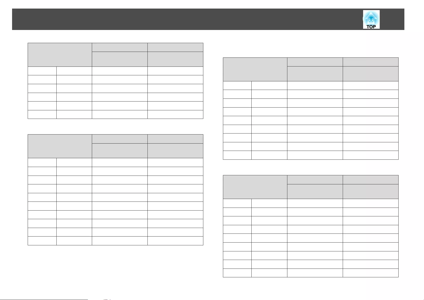
16:9 Screen Size
AB
Minimum (Wide) to
Maximum (Tele)
Vertical Lens Shift
Top to Bottom
100" 221x125 488 - 790 -158 - +33
120" 266x149 587 - 949 -189 - +40
150" 332x187 736 - 1188 -237 - +50
200" 443x249 983 - 1587 -316 - +67
250" 553x311 1231 - 1986 -395 - +83
275" 609x342 1355 - 2185 -434 - +92
Unit: cm
16:10 Screen Size
AB
Minimum (Wide) to
Maximum (Tele)
Vertical Lens Shift
Top to Bottom
48" 103x65 223 - 364 -77 - +12
50" 108x67 233 - 380 -80 - +13
60" 130x81 281 - 458 -96 - +15
80" 172x108 378 - 613 -128 - +21
100" 215x135 474 - 768 -160 - +26
120" 258x162 571 - 923 -192 - +31
150" 323x202 715 - 1156 -241 - +39
200" 431x269 957 - 1544 -321 - +51
250" 538x337 1198 - 1932 -401 - +64
280" 603x377 1342 - 2165 -449 - +72
ELPLM10/ELPLM06
Unit: cm
4:3 Screen Size
AB
Minimum (Wide) to
Maximum (Tele)
Vertical Lens Shift
Top to Bottom
50" 102x76 338 - 519 -82 - +6
60" 122x91 409 - 625 -98 - +7
80" 163x122 549 - 838 -131 - +9
100" 203x152 690 - 1051 -164 - +12
120" 244x183 831 - 1264 -197 - +14
150" 305x229 1041 - 1583 -246 - +17
200" 406x305 1393 - 2115 -328 - +23
250" 508x381 1744 - 2647 -410 - +29
300" 610x457 2096 - 3179 -492 - +35
Unit: cm
16:9 Screen Size
AB
Minimum (Wide) to
Maximum (Tele)
Vertical Lens Shift
Top to Bottom
46" 102x57 339 - 520 -73 - +15
50" 111x62 370 - 567 -79 - +17
60" 133x75 446 - 682 -95 - +20
80" 177x100 600 - 914 -126 - +27
100" 221x125 753 - 1146 -158 - +33
120" 266x149 906 - 1378 -189 - +40
150" 332x187 1136 - 1726 -237 - +50
200" 443x249 1519 - 2305 -316 - +67
250" 553x311 1902 - 2885 -395 - +83
Screen Size and Projection Distance
233
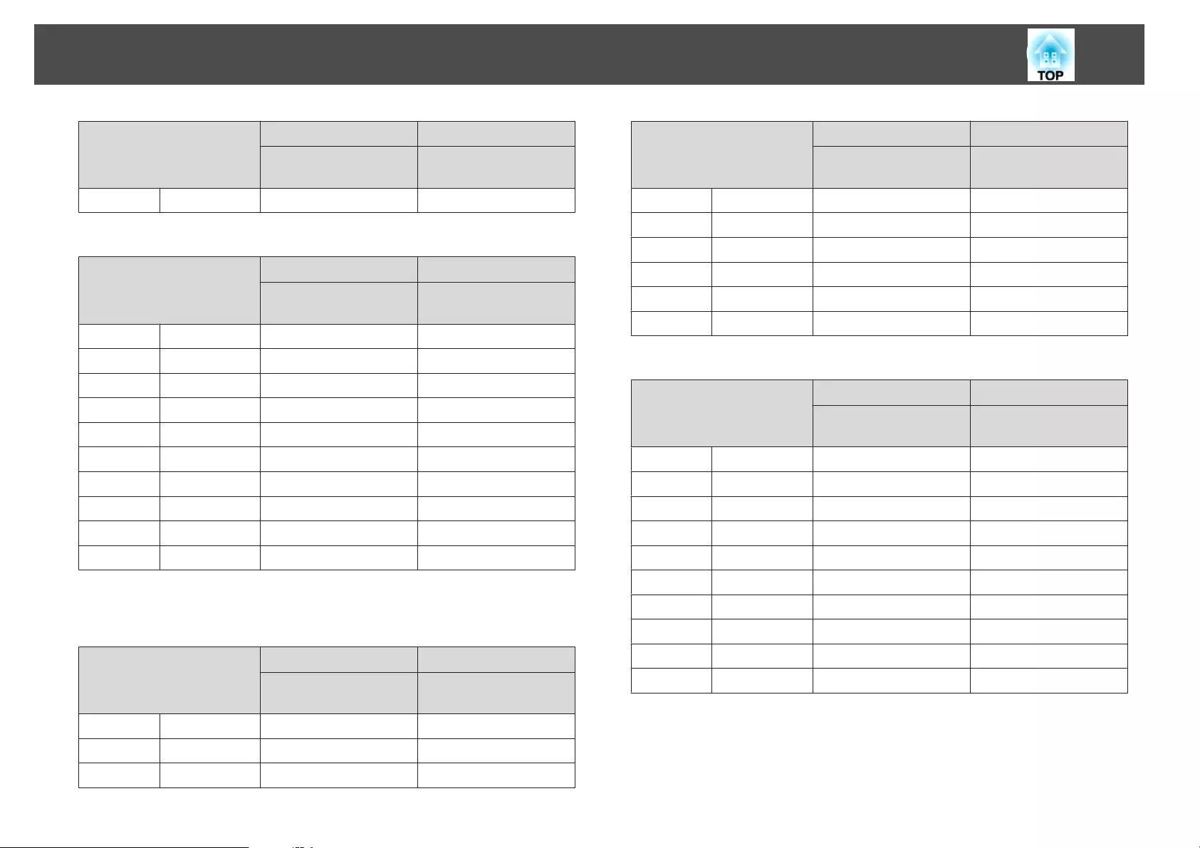
16:9 Screen Size
AB
Minimum (Wide) to
Maximum (Tele)
Vertical Lens Shift
Top to Bottom
275" 609x342 2093 - 3175 -434 - +92
Unit: cm
16:10 Screen Size
AB
Minimum (Wide) to
Maximum (Tele)
Vertical Lens Shift
Top to Bottom
48" 103x65 345 - 528 -77 - +12
50" 108x67 360 - 551 -80 - +13
60" 130x81 434 - 664 -96 - +15
80" 172x108 583 - 889 -128 - +21
100" 215x135 732 - 1115 -160 - +26
120" 258x162 881 - 1340 -192 - +31
150" 323x202 1105 - 1679 -241 - +39
200" 431x269 1477 - 2243 -321 - +51
250" 538x337 1850 - 2807 -401 - +64
280" 603x377 2073 - 3145 -449 - +72
ELPLM11/ELPLM07
Unit: cm
4:3 Screen Size
AB
Minimum (Wide) to
Maximum (Tele)
Vertical Lens Shift
Top to Bottom
50" 102x76 492 - 755 -82 - +6
60" 122x91 595 - 910 -98 - +7
80" 163x122 801 - 1221 -131 - +9
4:3 Screen Size
AB
Minimum (Wide) to
Maximum (Tele)
Vertical Lens Shift
Top to Bottom
100" 203x152 1007 - 1533 -164 - +12
120" 244x183 1213 - 1844 -197 - +14
150" 305x229 1523 - 2311 -246 - +17
200" 406x305 2038 - 3089 -328 - +23
250" 508x381 2554 - 3867 -410 - +29
300" 610x457 3069 - 4645 -492 - +35
Unit: cm
16:9 Screen Size
AB
Minimum (Wide) to
Maximum (Tele)
Vertical Lens Shift
Top to Bottom
46" 102x57 493 - 756 -73 - +15
50" 111x62 538 - 824 -79 - +17
60" 133x75 650 - 994 -95 - +20
80" 177x100 875 - 1333 -126 - +27
100" 221x125 1100 - 1672 -158 - +33
120" 266x149 1324 - 2011 -189 - +40
150" 332x187 1661 - 2519 -237 - +50
200" 443x249 2223 - 3367 -316 - +67
250" 553x311 2784 - 4215 -395 - +83
275" 609x342 3065 - 4638 -434 - +92
Screen Size and Projection Distance
234
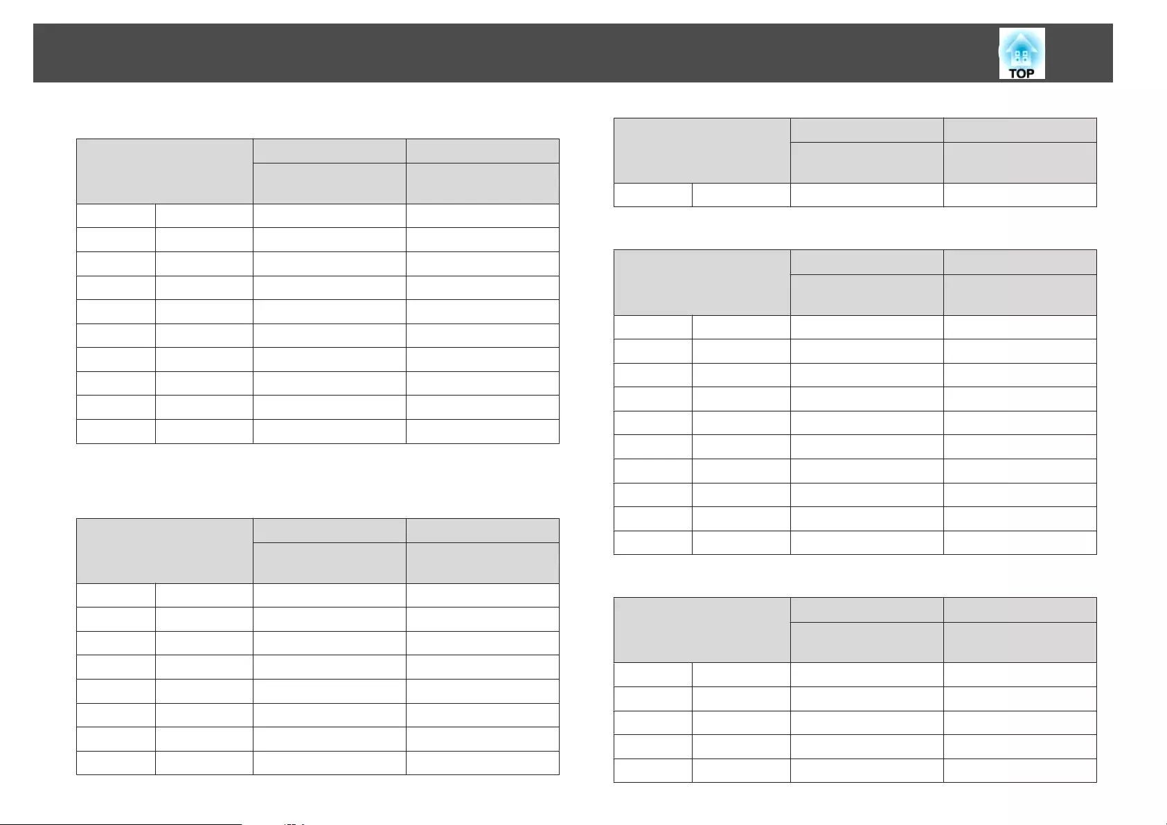
Unit: cm
16:10 Screen Size
AB
Minimum (Wide) to
Maximum (Tele)
Vertical Lens Shift
Top to Bottom
48" 103x65 501 - 768 -77 - +12
50" 108x67 523 - 801 -80 - +13
60" 130x81 632 - 966 -96 - +15
80" 172x108 851 - 1296 -128 - +21
100" 215x135 1069 - 1626 -160 - +26
120" 258x162 1288 - 1956 -192 - +31
150" 323x202 1616 - 2451 -241 - +39
200" 431x269 2162 - 3275 -321 - +51
250" 538x337 2708 - 4100 -401 - +64
280" 603x377 3036 - 4595 -449 - +72
ELPLL08/ELPLL07
Unit: cm
4:3 Screen Size
AB
Minimum (Wide) to
Maximum (Tele)
Vertical Lens Shift
Top to Bottom
50" 102x76 732 - 1034 -82 - +6
60" 122x91 885 - 1247 -98 - +7
80" 163x122 1191 - 1674 -131 - +9
100" 203x152 1497 - 2100 -164 - +12
120" 244x183 1802 - 2527 -197 - +14
150" 305x229 2261 - 3166 -246 - +17
200" 406x305 3025 - 4232 -328 - +23
250" 508x381 3790 - 5298 -410 - +29
4:3 Screen Size
AB
Minimum (Wide) to
Maximum (Tele)
Vertical Lens Shift
Top to Bottom
300" 610x457 4554 - 6364 -492 - +35
Unit: cm
16:9 Screen Size
AB
Minimum (Wide) to
Maximum (Tele)
Vertical Lens Shift
Top to Bottom
46" 102x57 734 - 1037 -73 - +15
50" 111x62 801 - 1130 -79 - +17
60" 133x75 967 - 1362 -95 - +20
80" 177x100 1300 - 1826 -126 - +27
100" 221x125 1633 - 2291 -158 - +33
120" 266x149 1967 - 2755 -189 - +40
150" 332x187 2466 - 3452 -237 - +50
200" 443x249 3299 - 4613 -316 - +67
250" 553x311 4132 - 5775 -395 - +83
275" 609x342 4548 - 6355 -434 - +92
Unit: cm
16:10 Screen Size
AB
Minimum (Wide) to
Maximum (Tele)
Vertical Lens Shift
Top to Bottom
48" 103x65 746 - 1053 -77 - +12
50" 108x67 778 - 1098 -80 - +13
60" 130x81 940 - 1324 -96 - +15
80" 172x108 1264 - 1776 -128 - +21
100" 215x135 1588 - 2228 -160 - +26
Screen Size and Projection Distance
235
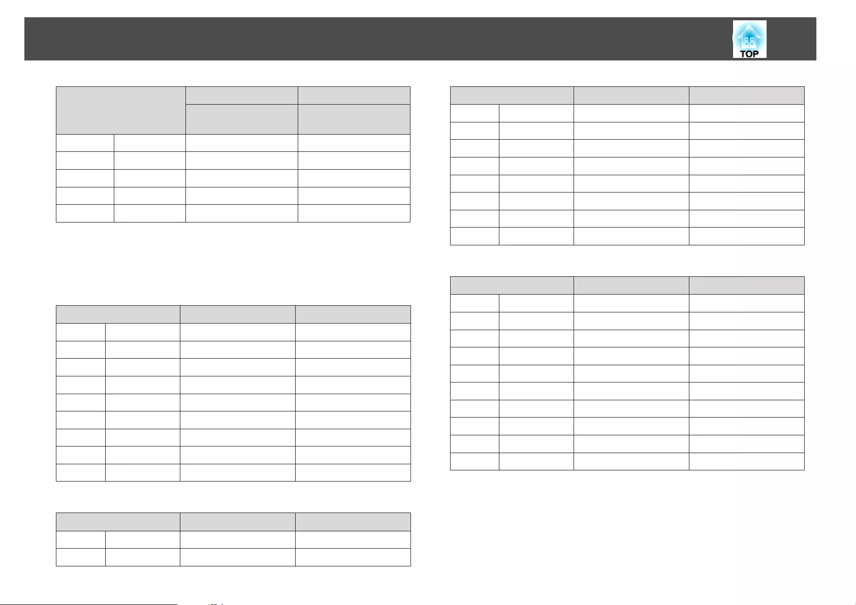
16:10 Screen Size
AB
Minimum (Wide) to
Maximum (Tele)
Vertical Lens Shift
Top to Bottom
120" 258x162 1913 - 2680 -192 - +31
150" 323x202 2399 - 3358 -241 - +39
200" 431x269 3209 - 4488 -321 - +51
250" 538x337 4019 - 5618 -401 - +64
280" 603x377 4505 - 6296 -449 - +72
ELPLR04
Lens shift is not supported.
Unit: cm
4:3 Screen Size AB
50" 102x76 96 -36
60" 122x91 116 -46
80" 163x122 157 -61
100" 203x152 198 -76
120" 244x183 239 -91
150" 305x229 300 -114
200" 406x305 402 -152
250" 508x381 504 -191
300" 610x457 606 -229
Unit: cm
16:9 Screen Size AB
46" 102x57 96 -28
50" 111x62 105 -31
16:9 Screen Size AB
60" 133x75 127 -37
80" 177x100 172 -50
100" 221x125 216 -62
120" 266x149 261 -75
150" 332x187 327 -93
200" 443x249 439 -125
250" 553x311 550 -156
275" 610x345 605 -172
Unit: cm
16:10 Screen Size AB
48" 103x65 98 -32
50" 108x67 102 -33
60" 130x81 124 -40
80" 172x108 167 -54
100" 215x135 210 -67
120" 258x162 254 -81
150" 323x202 318 -101
200" 431x269 427 -135
250" 538x337 535 -168
280" 603x377 600 -188
Screen Size and Projection Distance
236
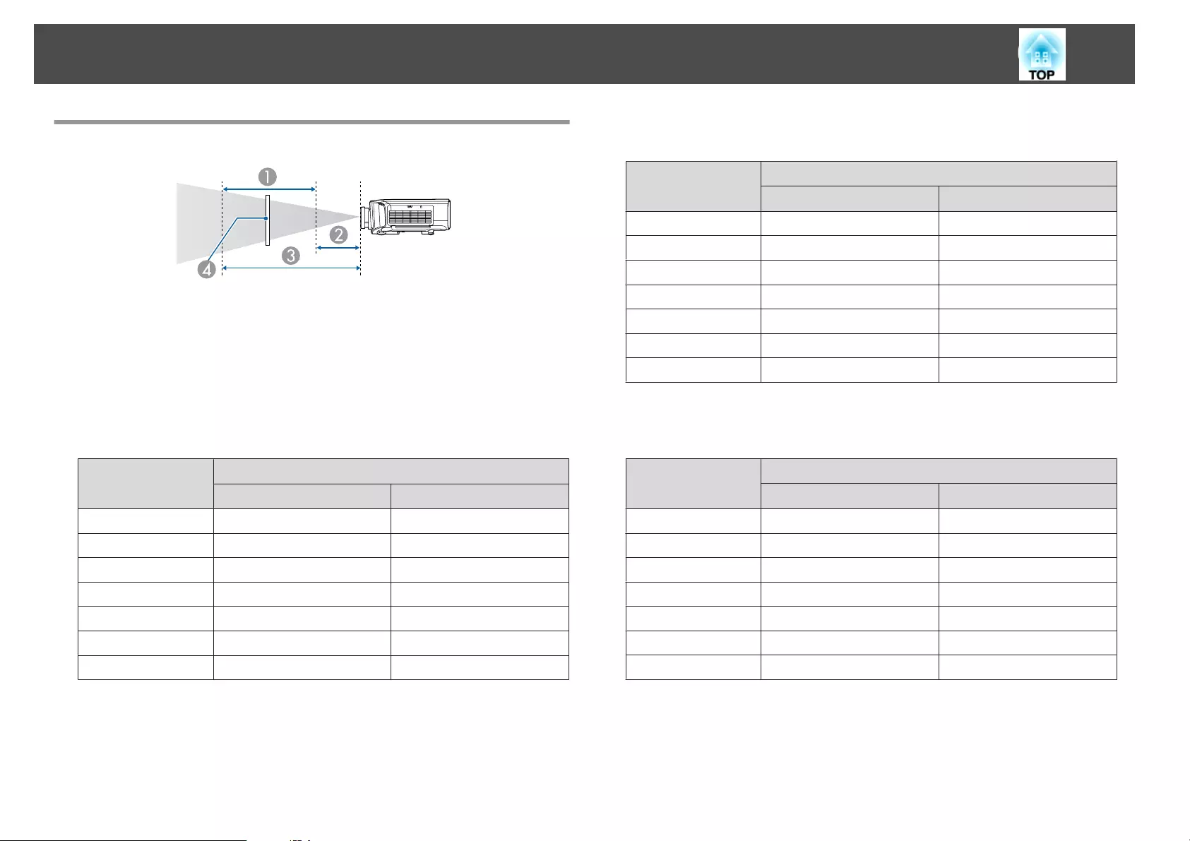
Polarizer (ELPPL01) Installation Distance
APossible installation range of the polarizer
BShortest distance from the projection lens to the polarizer
CLongest distance from the projection lens to the polarizer
DPolarizer (ELPPL01)
EB-G7905U/EB-G7900U/EB-G7500U/EB-G7400U
Units: mm
Lens type
A
BC
ELPLM08 140 170
ELPLW06 120 170
ELPLM09 180 240
ELPLM10 260 340
ELPLS04 180 240
ELPLW04 120 170
ELPLM06 260 340
EB-G7200W/EB-G7000W
Units: mm
Lens type
A
BC
ELPLM08 150 170
ELPLW06 120 170
ELPLM09 200 240
ELPLM10 300 340
ELPLS04 200 240
ELPLW04 120 170
ELPLM06 300 340
EB-G7805/EB-G7800/EB-G7100
Units: mm
Lens type
A
BC
ELPLM08 130 170
ELPLW06 120 170
ELPLM09 170 240
ELPLM10 230 340
ELPLS04 170 240
ELPLW04 120 170
ELPLM06 230 340
Screen Size and Projection Distance
237
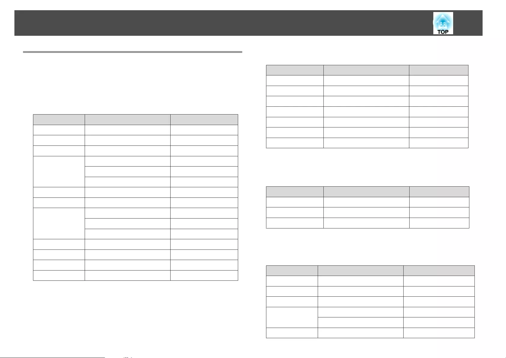
Supported Resolutions
When the resolution of the input signals is larger than the projector's panel
resolution, the image quality may decline.
Computer signals (analog RGB)
Signal Refresh Rate (Hz) Resolution (Dots)
VGA 60/72/75/85 640x480
SVGA 60/72/75/85 800x600
XGA 60/70/75/85 1024x768
WXGA 60 1280x768
60 1366x768
60/75/85 1280x800
WXGA+ 60/75/85 1440x900
WXGA++ 60 1600x900
SXGA 70/75/85 1152x864
60/75/85 1280x1024
60/75/85 1280x960
SXGA+ 60/75 1400x1050
WSXGA+
*1
60 1680x1050
UXGA 60 1600x1200
WUXGA
*2
60 1920x1200
*1 EB-G7905U/EB-G7900U/EB-G7500U/EB-G7400U/EB-G7200W/EB-G7000W
only. Only compatible when Wide is selected as the Resolution from the
Configuration menu.
*2 EB-G7905U/EB-G7900U/EB-G7500U/EB-G7400U only. Only compatible when
VESA CVT-RB (Reduced Blanking) signal is input.
Even when signals other than those mentioned above are input, it is likely that the
image can be projected. However, not all functions may be supported.
Component Video
Signal Refresh Rate (Hz) Resolution (Dots)
SDTV (480i) 60 720x480
SDTV (576i) 50 720x576
SDTV (480p) 60 720x480
SDTV (576p) 50 720x576
HDTV (720p) 50/60 1280x720
HDTV (1080i) 50/60 1920x1080
HDTV (1080p)
*
50/60 1920x1080
*Only for the input signals from the Computer port.
Composite video
Signal Refresh Rate (Hz) Resolution (Dots)
TV (NTSC) 60 720x480
TV (SECAM) 50 720x576
TV (PAL) 50/60 720x576
Input signal from the DVI-D port, HDMI port, and HDBaseT
port*1
Signal Refresh Rate (Hz) Resolution (Dots)
VGA 60 640x480
SVGA 60 800x600
XGA 60 1024x768
WXGA 60 1280x800
60 1366x768
WXGA+ 60 1440x900
Supported Monitor Displays
238
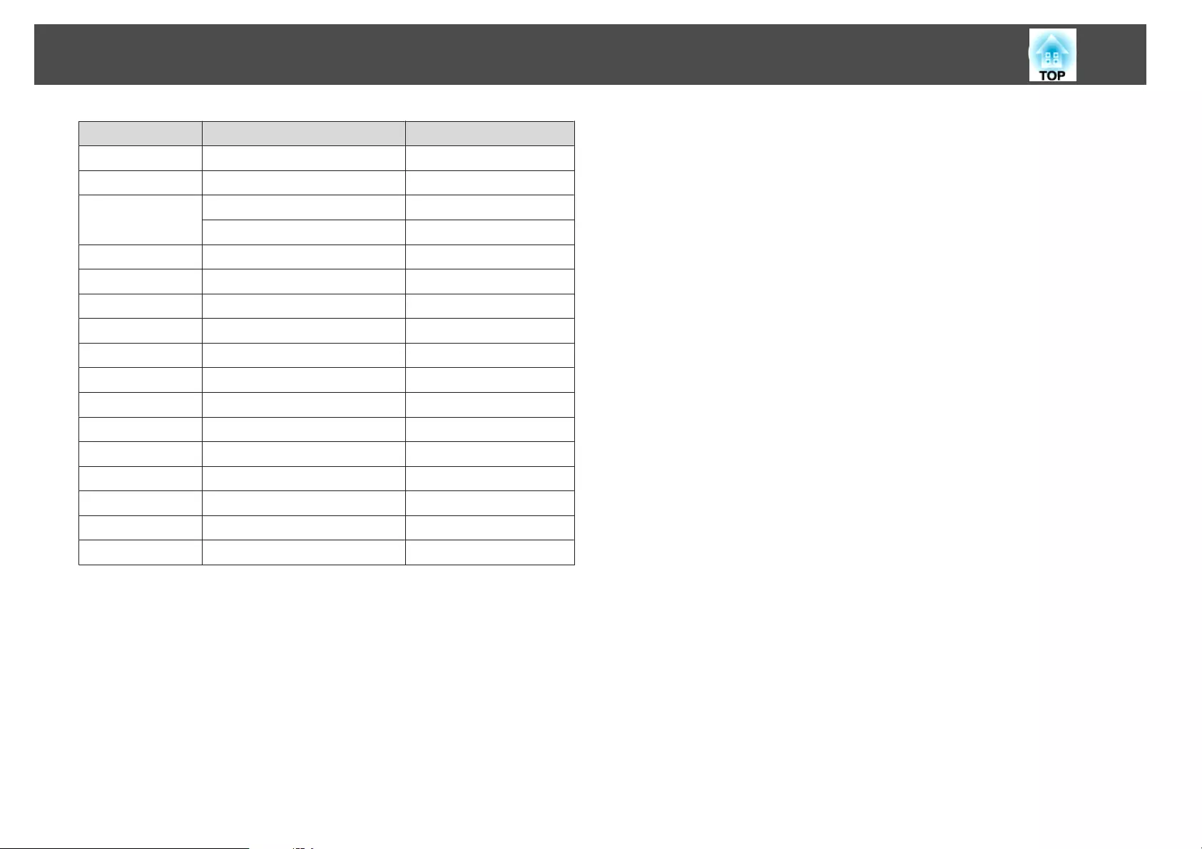
Signal Refresh Rate (Hz) Resolution (Dots)
WXGA++ 60 1600x900
WSXGA+
*2
60 1680x1050
SXGA 60 1280x960
60 1280x1024
SXGA+ 60 1400x1050
UXGA 60 1600x1200
WUXGA
*3
60 1920x1200
QXGA
*4
60 2048x1536
WQHD
*4
60 2560x1440
WQXGA
*4
60 2560x1600
SDTV (480i/480p) 60 720x480
SDTV (576i/576p) 50 720x576
HDTV (720p) 50/60 1280x720
HDTV (1080i) 50/60 1920x1080
HDTV (1080p) 24/30/50/60 1920x1080
4Kx2K
*4
24/25/30/50/60 3840x2160
4Kx2K (SMPTE)
*4
24/50/60 4096x2160
*1 When an HDMI connection is made using the optional HDBaseT Transmitter.
*2 EB-G7905U/EB-G7900U/EB-G7500U/EB-G7400U/EB-G7200W/EB-G7000W
only.
*3 Only compatible when VESA CVT-RB (Reduced Blanking) signal is input.
*4 EB-G7905U/EB-G7900U/EB-G7500U/EB-G7400U only. Only for HDMI input.
Supported Monitor Displays
239
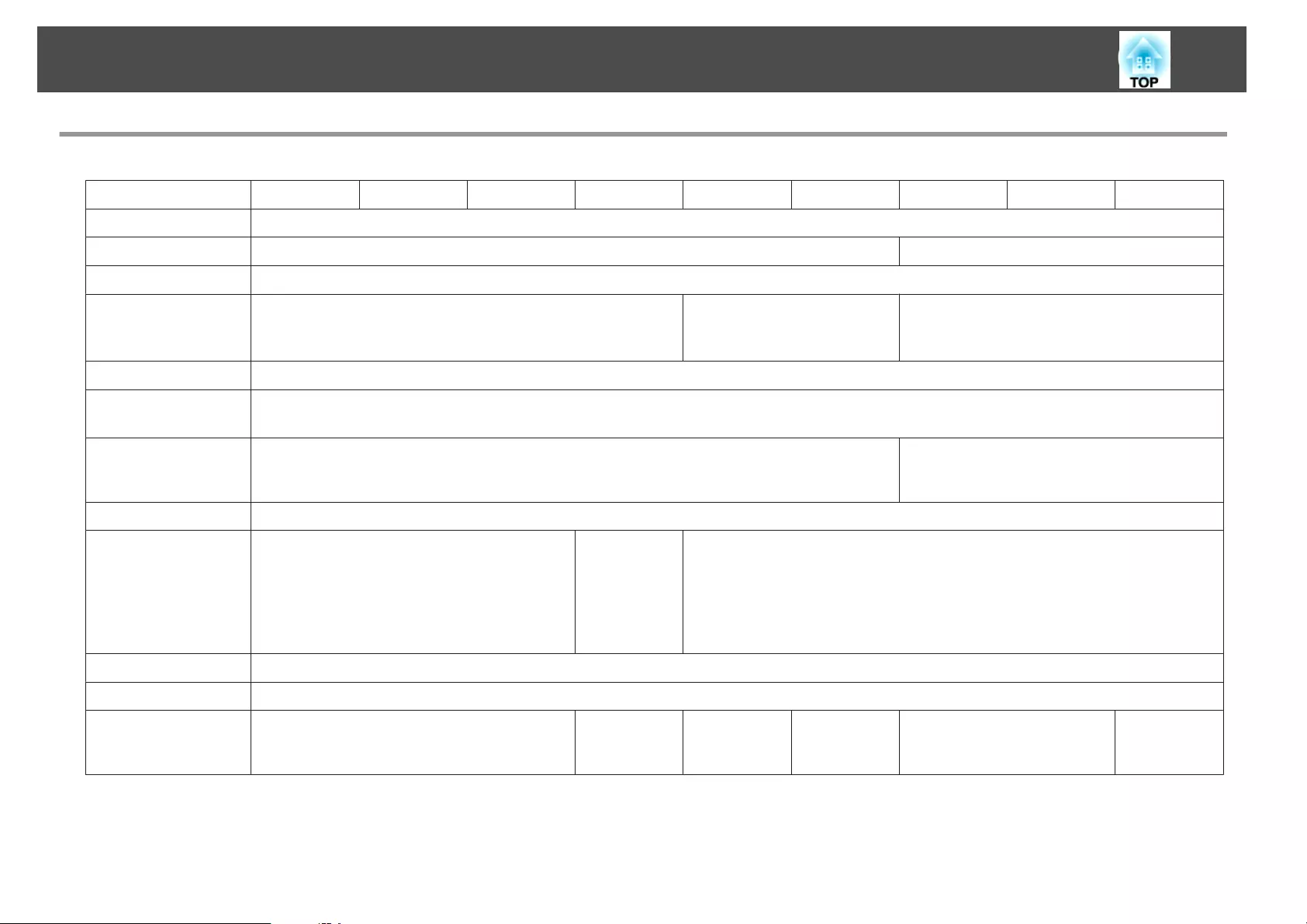
Projector General Specifications
Product name EB-G7905U EB-G7900U EB-G7500U EB-G7400U EB-G7200W EB-G7000W EB-G7805 EB-G7800 EB-G7100
Dimensions 525 (W) x 164 (H) x 425 (D) mm (not including raised section)
LCD panel size 0.76" Wide 0.79"
Display method Polysilicon TFT active matrix
Resolution 2,304,000 pixels
WUXGA (1920 (W) x 1200 (H) dots) x 3
1,024,000 pixels
WXGA (1280 (W) x 800 (H)
dots) x 3
786,432 pixels
XGA (1024 (W) x 768 (H) dots) x 3
Focus adjustment Automatic
Zoom adjust-
ment
*1
Automatic (1.6x)
Lens shift
*2
Automatic (Maximum vertical direction of approx. 67%, Maximum horizontal direction of
approx. 30%)
*3
Automatic (Maximum vertical direction of
approx. 57%, Maximum horizontal direction of
approx. 30%)
*4
Lamp UHE lamp, 400 W Model No.: ELPLP93
Lamp operating
life
About 3,000 hours (Normal, Power
Consumption: On)
About 4,000 hours (Normal, Power
Consumption: Off)
About 2,000 hours (Portrait Mode)
About 4,000
hours (Nor‐
mal)
About 2,000
hours (Por‐
trait Mode)
About 3,000 hours (Normal, Power Consumption: On)
About 4,000 hours (Normal, Power Consumption: Off)
About 2,000 hours (Portrait Mode)
Max. audio output 10 W monaural
Speaker 1
Power supply 100-240V AC±10% 50/60Hz 6.0-2.6A 100-240V AC
±10% 50/60Hz
5.0-2.2A
100-240V AC
±10% 50/60Hz
6.0-2.6A
100-240V AC
±10% 50/60Hz
5.5-2.4A
100-240V AC±10% 50/60Hz
6.0-2.6A
100-240V AC
±10% 50/60Hz
5.5-2.4A
Specifications
240

Power
con-
sump-
tion
100 to
120 V
area
Rated power consumption: 601 W
Standby power consumption (Communication
On): 2.2 W
Standby power consumption (Communication
Off): 0.22 W
Rated power
consumption:
498 W
Standby power
consumption
(Communica‐
tion On): 2.2
W
Standby power
consumption
(Communica‐
tion Off): 0.22
W
Rated power
consumption:
601 W
Standby power
consumption
(Communica‐
tion On): 2.2
W
Standby power
consumption
(Communica‐
tion Off): 0.22
W
Rated power
consumption:
540 W
Standby power
consumption
(Communica‐
tion On): 2.2
W
Standby power
consumption
(Communica‐
tion Off): 0.22
W
Rated power consumption: 601
W
Standby power consumption
(Communication On): 2.2 W
Standby power consumption
(Communication Off): 0.22 W
Rated power
consumption:
540 W
Standby power
consumption
(Communica‐
tion On): 2.2
W
Standby power
consumption
(Communica‐
tion Off): 0.22
W
220 to
240 V
area
Rated power consumption: 572 W
Standby power consumption (Communication
On): 2.3 W
Standby power consumption (Communication
Off): 0.30 W
Rated power
consumption:
477 W
Standby power
consumption
(Communica‐
tion On): 2.3
W
Standby power
consumption
(Communica‐
tion Off): 0.30
W
Rated power
consumption:
572 W
Standby power
consumption
(Communica‐
tion On): 2.3
W
Standby power
consumption
(Communica‐
tion Off): 0.30
W
Rated power
consumption:
515 W
Standby power
consumption
(Communica‐
tion On): 2.3
W
Standby power
consumption
(Communica‐
tion Off): 0.30
W
Rated power consumption: 572
W
Standby power consumption
(Communication On): 2.3 W
Standby power consumption
(Communication Off): 0.30 W
Rated power
consumption:
515 W
Standby power
consumption
(Communica‐
tion On): 2.3
W
Standby power
consumption
(Communica‐
tion Off): 0.30
W
Operating altitude Altitude 0 to 5000 m
Operating temper-
ature
*5
0 to +45˚C (Altitude of 0 to 1,500 m, no condensation)
0 to +40˚C (Altitude of 1,501 to 3,048 m, no condensation)
0 to +35˚C (Altitude of 3,049 to 5,000 m, no condensation)
Storage tempera-
ture
-10 to +60˚C (No condensation)
Specifications
241
Mass
*1
Approx. 12.9 kg
*1 The specifications are when ELPLM08 is attached.
*2 ELPLR04 does not support lens shift.
*3 ELPLX01 has a maximum upward direction of approx. 17% and a maximum horizontal direction of approx. 10%.
*4 ELPLX01 has a maximum upward direction of approx. 7% and a maximum horizontal direction of approx. 8%.
*5 If the surrounding temperature gets too high, the lamp automatically dims (about 40˚C, 35˚C, and 30˚C at an altitude of 0 to 1500 m, 1501 to 3048 m, and 3049 to 5000
m respectively).
Specifications
242

Product name EB-
G7905U
EB-
G7900U
EB-
G7500U
EB-
G7400U
EB-
G7200W
EB-
G7000W
EB-G7805 EB-G7800 EB-G7100
Connec-
tors
Computer Port 1 Mini D-Sub15-pin (female) blue
Audio1 port 1 Stereo mini jack (3.5Φ)
BNC port 1 5BNC (female)
Audio2 port 1 Stereo mini jack (3.5Φ)
DVI-D port 1 DVI-D 24pin Single link HDCP supported
HDMI port 1 HDMI HDCP
*1
supported (Audio is only
supported by PCM)
HDMI HDCP supported (Audio is only supported by PCM)
Audio3 port 1 Stereo mini jack (3.5Φ)
Audio Out port 1 Stereo mini jack (3.5Φ)
Monitor Out port 1 Mini D-Sub15-pin (female) black
HDBaseT port 1 RJ-45
*1
RJ-45
LAN port 1 RJ-45
Service port
*2
1USB connector (Type B)
RS-232C port 1 Mini D-Sub 9-pin (male)
Remote port 1 Stereo mini jack (3.5Φ)
USB port (Only for
Wireless LAN unit)
*2
1USB connector (Type A)
*1 Supports HDCP 2.2.
*2 Supports USB 2.0. However, USB ports are not guaranteed to operate all devices that support USB.
This product is also designed for IT power distribution system with phase-to-phase voltage 230V.
Specifications
243

DECLARATION of CONFORMITY
According to 47CFR, Part 2 and 15
Class B Personal Computers and Peripherals; and/or
CPU Boards and Power Supplies used with Class B Personal Computers
We: Epson America, Inc.
Located at: 3840 Kilroy Airport Way
MS: 3-13
Long Beach, CA 90806
Tel: 562-981-3840
Declare under sole responsibility that the product identified herein,
complies with 47CFR Part 2 and 15 of the FCC rules as a Class B digital
device. Each product marketed, is identical to the representative unit tested
and found to be compliant with the standards. Records maintained continue
to reflect the equipment being produced can be expected to be within the
variation accepted, due to quantity production and testing on a statistical
basis as required by 47CFR 2.909. Operation is subject to the following two
conditions : (1) this device may not cause harmful interference, and (2) this
device must accept any interference received, including interference that
may cause undesired operation.
Trade Name: EPSON
Type of Product: LCD Projector
Model: H749C/H750C/H751C/H752C/H753C/H754C/
H762C
FCC Compliance Statement
For United States Users
This equipment has been tested and found to comply with the limits for a
Class B digital device, pursuant to Part 15 of the FCC Rules. These limits
are designed to provide reasonable protection against harmful interference
in a residential installation. This equipment generates, uses, and can radiate
radio frequency energy and, if not installed and used in accordance with the
instructions, may cause harmful interference to radio communications.
However, there is no guarantee that interference will not occur in a
particular installation. If this equipment does cause interference to radio or
television reception, which can be determined by turning the equipment off
and on, the user is encouraged to try to correct the interference by one or
more of the following measures.
•Reorient or relocate the receiving antenna.
•Increase the separation between the equipment and receiver.
•Connect the equipment into an outlet on a circuit different from that to
which the receiver is connected.
•Consult the dealer or an experienced radio/TV technician for help.
WARNING
The connection of a non-shielded equipment interface cable to this
equipment will invalidate the FCC Certification or Declaration of this
device and may cause interference levels which exceed the limits established
by the FCC for this equipment. It is the responsibility of the user to obtain
and use a shielded equipment interface cable with this device. If this
equipment has more than one interface connector, do not leave cables
connected to unused interfaces. Changes or modifications not expressly
approved by the manufacturer could void the user's authority to operate the
equipment.
Specifications
244
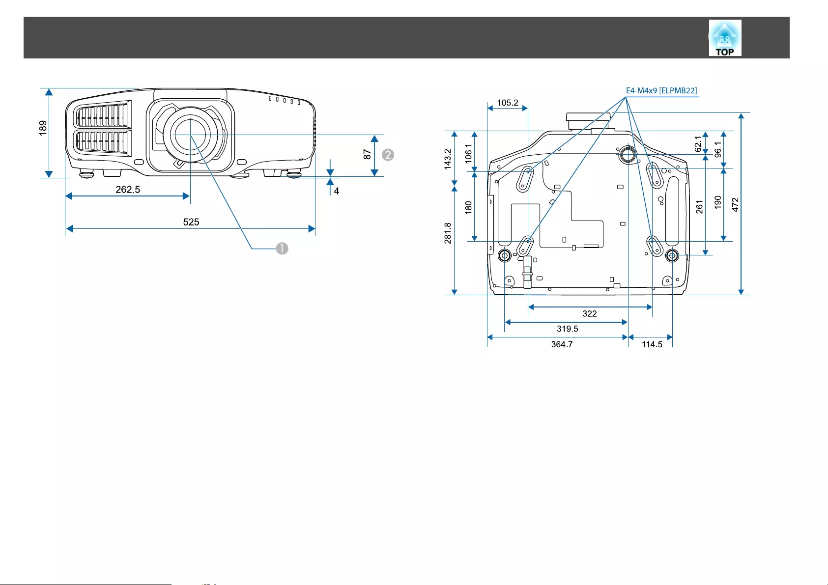
ACenter of lens
BDistance from center of lens to suspension bracket fixing point
Appearance
245
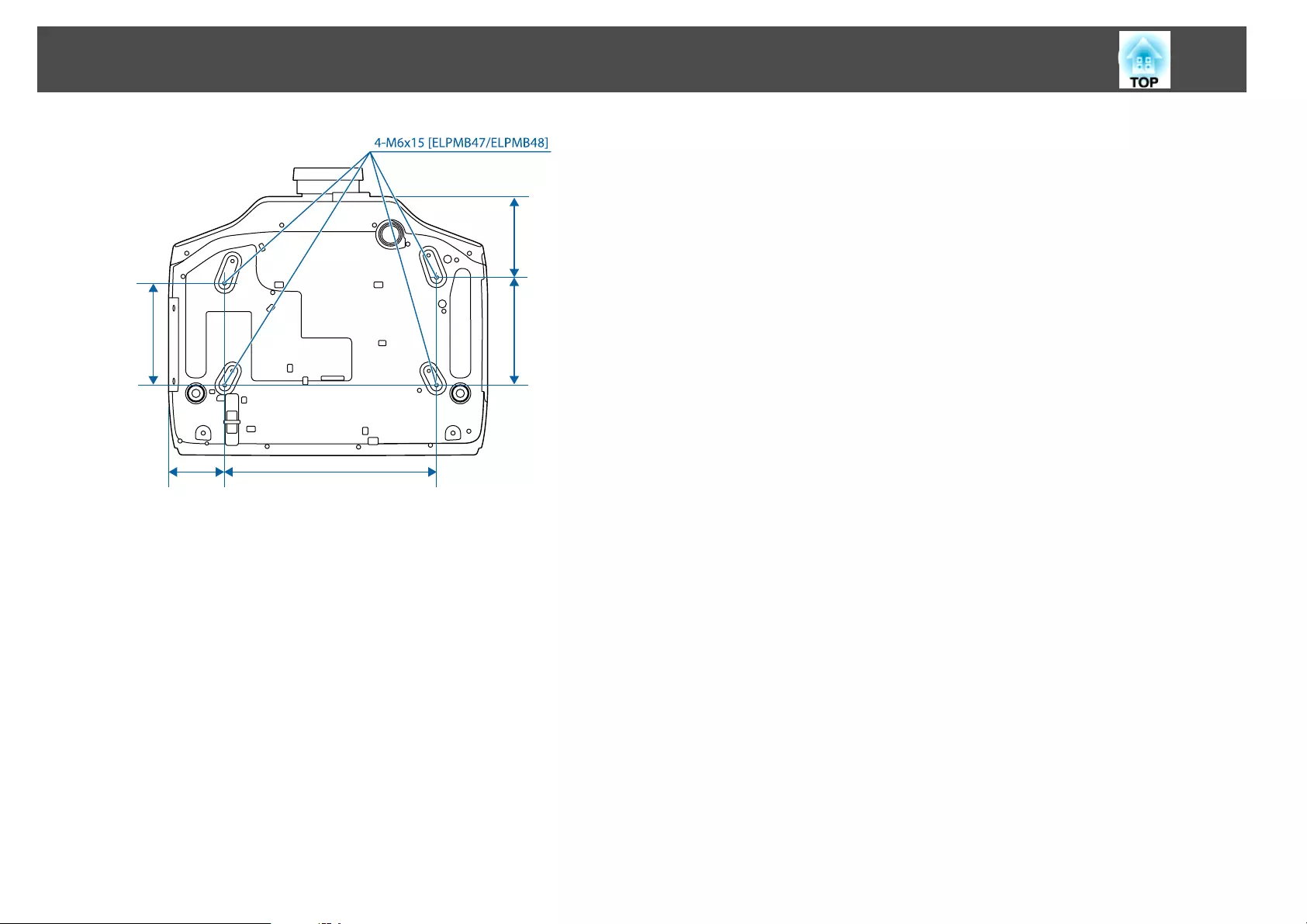
348
166
92.2
176 133.1
Units: mm
Appearance
246
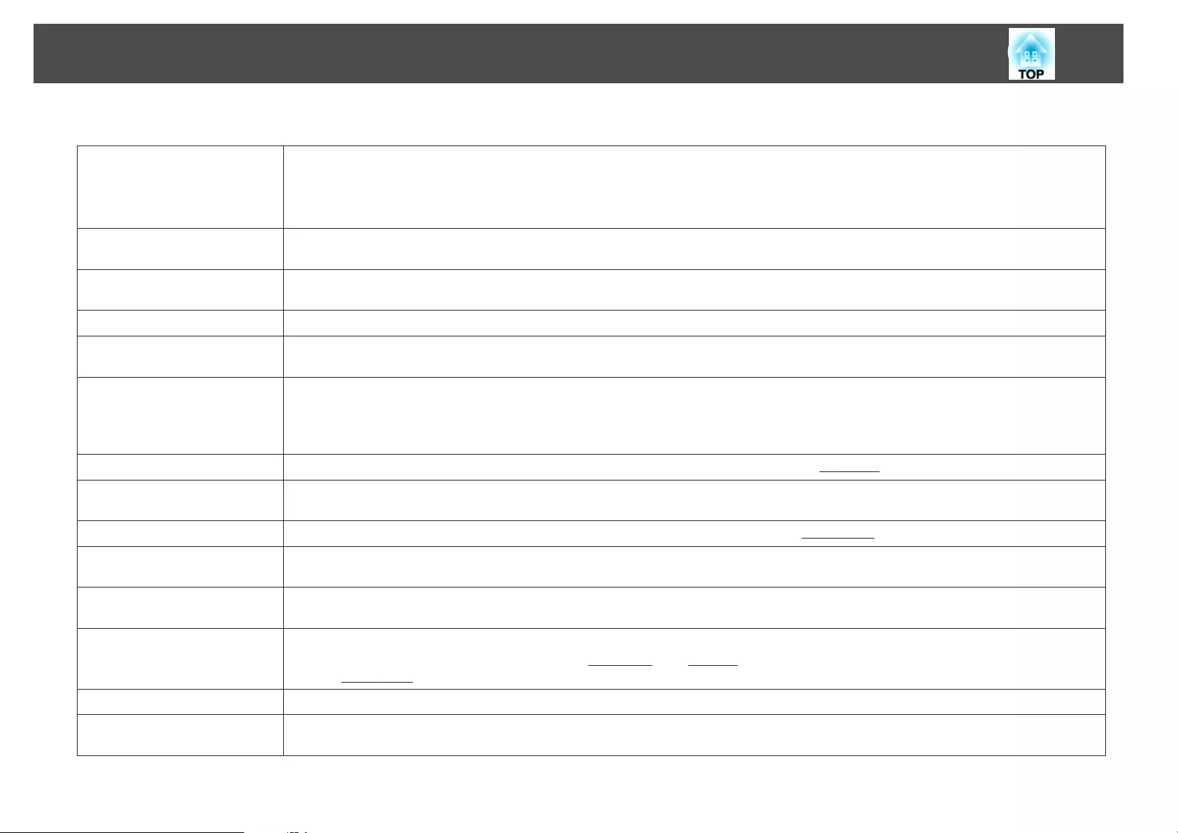
This section briefly explains the difficult terms that are not explained in the text of this guide. For details, refer to other commercially available publications.
AMX Device Discovery AMX Device Discovery is a technology developed by AMX to facilitate AMX control systems for easy operation of the target equipment.
Epson have implemented this protocol technology, and have provided a setting to enable the protocol function (ON).
See the AMX Web site for more details.
URL: http://www.amx.com/
Aspect Ratio The ratio between an image's length and its height. Screens with a horizontal:vertical ratio of 16:9, such as HDTV screens, are known as wide screens.
SDTV and general computer displays have an aspect ratio of 4:3.
Component Video A method that separates the video signal into a luminance component (Y), and a blue minus luminance (Cb or Pb) and a red minus luminance (Cr or
Pr).
Composite video A method that combines the video signal into a luminance component and a color component for transmission down a single cable.
Contrast The relative brightness of the light and dark areas of an image can be increased or decreased to make text and graphics stand out more clearly, or to
make them appear softer. Adjusting this particular property of an image is called contrast adjustment.
Control4 Simple Device
Discovery Protocol (SDDP)
Control4 SDDP is a technology developed by Control4 to allow Control4 control systems to acquire device information for the projector. Epson have
implemented this protocol technology, and have provided a setting to enable the protocol function (ON). See the Control4 Web site for more
details.
URL: http://www.control4.com/
DHCP An abbreviation of Dynamic Host Configuration Protocol, this protocol automatically assigns an IP Address
g
to equipment connected to a network.
DICOM An acronym for Digital Imaging and Communications in Medicine. An international standard that defines image standards and a communications
protocol for medical images.
Gateway Address This is a server (router) for communicating across a network (subnet) divided according to Subnet Mask
g
.
HDBaseT The connection standard for consumer electronics determined by the HDBaseT Alliance. Communicates various control signals such as
uncompressed HD video, audio and 100BASE-TX Ethernet using a LAN cable.
HDCP HDCP is an abbreviation for High-bandwidth Digital Content Protection. It is used to prevent illegal copying and protect copyrights by encrypting
digital signals sent over DVI and HDMI ports. HDCP2.2 is a copyright protection standard for 4K content.
HDTV An abbreviation for High-Definition Television that refers to high-definition systems which satisfy the following conditions.
•Vertical resolution of 720p or 1080i or greater (p = Progressive
g
, i = Interlace
g
)
•Screen Aspect Ratio
g
of 16:9
Infrastructure mode A method for wireless LAN connection in which devices communicate through access points.
Interlace Transmits information needed to create one screen by sending every other line, starting from the top of the image and working down to the bottom.
Images are more likely to flicker because one frame is displayed every other line.
Glossary
247

IP Address A number to identify a computer connected to a network.
Progressive Projects information to create one screen at a time, displaying the image for one frame. Even though the number of scan lines is the same, the amount
of flicker in images decreases because the volume of information has doubled compared with an interlace system.
Refresh Rate The light-emitting element of a display maintains the same luminosity and color for an extremely short time. Because of this, the image must be
scanned many times per second to refresh the light-emitting element. The number of refresh operations per second is called the Refresh rate and is
expressed in hertz (Hz).
SDTV An abbreviation for Standard Definition Television that refers to standard television systems which do not satisfy the conditions for HDTV
g
High-
Definition Television.
SNMP An abbreviation for Simple Network Management Protocol, which is the protocol for monitoring and controlling devices such as routers and
computers connected to a TCP/IP network.
sRGB An international standard for color intervals that was formulated so that colors that are reproduced by video equipment can be handled easily by
computer operating systems (OS) and the Internet. If the connected source has an sRGB mode, set both the projector and the connected signal source
to sRGB.
Subnet Mask This is a numerical value that defines the number of bits used for the network address on a divided network (subnet) from the IP address.
Sync. The signals output from computers have a specific frequency. If the projector frequency does not match this frequency, the resulting images are not of
a good quality. The process of matching the phases of these signals (the relative position of the crests and the troughs in the signal) is called
Synchronization. If the signals are not synchronized, flickering, blurriness, and horizontal interference occur.
Tracking The signals output from computers have a specific frequency. If the projector frequency does not match this frequency, the resulting images are not of
a good quality. The process of matching the frequency of these signals (the number of crests in the signal) is called Tracking. If Tracking is not carried
out correctly, wide vertical stripes appear in the signal.
Trap IP Address This is the IP Address
g
for the destination computer used for error notification in SNMP.
Glossary
248

All rights reserved. No part of this publication may be reproduced, stored in a retrieval
system, or transmitted in any form or by any means, electronic, mechanical,
photocopying, recording, or otherwise, without the prior written permission of Seiko
Epson Corporation. No patent liability is assumed with respect to the use of the
information contained herein. Neither is any liability assumed for damages resulting
from the use of the information contained herein.
Neither Seiko Epson Corporation nor its affiliates shall be liable to the purchaser of this
product or third parties for damages, losses, costs, or expenses incurred by the
purchaser or third parties as a result of: accident, misuse, or abuse of this product or
unauthorized modifications, repairs, or alterations to this product, or (excluding the
U.S.) failure to strictly comply with Seiko Epson Corporation's operating and
maintenance instructions.
Seiko Epson Corporation shall not be liable against any damages or problems arising
from the use of any options or any consumable products other than those designated as
Original Epson Products or Epson Approved Products by Seiko Epson Corporation.
The contents of this guide may be changed or updated without further notice.
Illustrations in this guide and the actual projector may differ.
Restriction of Use
When this product is used for applications requiring high reliability/safety such as
transportation devices related to aviation, rail, marine, automotive etc.; disaster
prevention devices; various safety devices etc; or functional/precision devices etc, you
should use this product only after giving consideration to including fail-safes and
redundancies into your design to maintain safety and total system reliability. Because
this product was not intended for use in applications requiring extremely high
reliability/safety such as aerospace equipment, main communication equipment,
nuclear power control equipment, or medical equipment related to direct medical care
etc, please make your own judgment on this product’s suitability after a full evaluation.
About Notations
Microsoft
®
Windows
®
2000 operating system
Microsoft
®
Windows
®
XP operating system
Microsoft
®
Windows Vista
®
operating system
Microsoft
®
Windows
®
7 operating system
Microsoft
®
Windows
®
8 operating system
Microsoft
®
Windows
®
8.1 operating system
Microsoft
®
Windows
®
10 operating system
In this guide, the operating systems above are referred to as "Windows
2000", "Windows XP", "Windows Vista", "Windows 7", "Windows 8",
"Windows 8.1", and "Windows 10". Furthermore, these may be referred to
as the collective term Windows, and multiple versions of Windows may be
referred to as, for example, Windows 2000/XP/Vista/7/8/8.1/10, with the
Windows notation omitted.
General Notes
249
Mac OS X 10.3.x
Mac OS X 10.4.x
Mac OS X 10.5.x
Mac OS X 10.6.x
OS X 10.7.x
OS X 10.8.x
OS X 10.9.x
OS X 10.10.x
OS X 10.11.x
In this guide, the operating systems above are referred to as "Mac OS X
10.3.x", "Mac OS X 10.4.x", "Mac OS X 10.5.x", "Mac OS X 10.6.x", "OS X
10.7.x", "OS X 10.8.x", "OS X 10.9.x", "OS X 10.10.x", and "OS X 10.11.x".
Furthermore, the collective term "OS X" is used to refer to them all.
Trademarks and Copyrights
EPSON is a registered trademark, EXCEED YOUR VISION, ELPLP and their logos are
registered trademarks or trademarks of Seiko Epson Corporation.
Mac, Mac OS, and OS X, are trademarks of Apple Inc.
Microsoft, Windows, Windows Vista, PowerPoint, and Windows logo are trademarks
or registered trademarks of Microsoft Corporation in the United States and/or other
countries.
HDMI and High-Definition Multimedia Interface are the trademarks or registered
trademarks of HDMI Licensing LLC.
PJLink trademark is a trademark applied for registration or is already registered in
Japan, the United States of America and other countries and areas.
WPA
™
and WPA2
™
are registered trademarks of the Wi-Fi Alliance.
Crestron and Crestron RoomView are registered trademarks of Crestron Electronics,
Inc.
"QR Code" is a registered trademark of DENSO WAVE INCORPORATED.
Extron
®
and XTP
®
are registered trademarks of Extron Electronics.
HDBaseT
™
and the HDBaseT Alliance logo are trademarks of the HDBaseT Alliance.
Other product names used herein are also for identification purposes only and may be
trademarks of their respective owners. Epson disclaims any and all rights in those marks.
©SEIKO EPSON CORPORATION 2016. All rights reserved.
Indication of the manufacturer and the importer in accordance with
requirements of directive 2011/65/EU (RoHS)
Manufacturer: SEIKO EPSON CORPORATION
Address: 3-5, Owa 3-chome, Suwa-shi, Nagano-ken 392-8502 Japan
Telephone: 81-266-52-3131
Importer: SEIKO EUROPE B.V.
Address: Azië building, Atlas ArenA, Hoogoorddreef 5, 1101 BA Amsterdam
Zuidoost The Netherlands
Telephone: 31-20-314-5000
General Notes
250
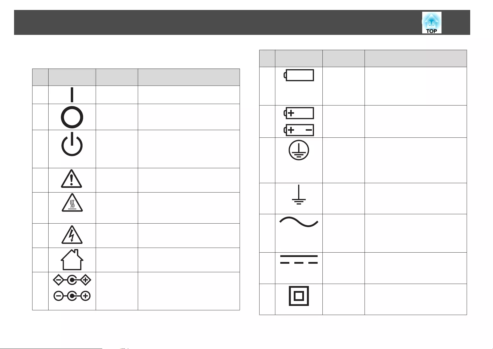
The following table lists the meaning of the safety symbols labeled on the
equipment.
No. Symbol mark Approved
standards
Meaning
AIEC60417
No. 5007
"ON" (power)
To indicate connection to the mains.
BIEC60417
No. 5008
"OFF" (power)
To indicate disconnection from the mains.
CIEC60417
No. 5009
Stand-by
To identify the switch or switch position
by means of which part of the equipment is
switched on in order to bring it into the
stand-by condition.
DISO7000
No. 0434B
IEC3864-B3.1
Caution
To identify general caution when using the
product.
EIEC60417
No. 5041
Caution, hot surface
To indicate that the marked item can be
hot and should not be touched without
taking care.
FIEC60417
No. 6042
ISO3864-B3.6
Caution, risk of electric shock
To identify equipment that has risk of
electric shock.
GIEC60417
No. 5957
For indoor use only
To identify electrical equipment designed
primarily for indoor use.
HIEC60417
No. 5926
Polarity of d.c. power connector
To identify the positive and negative
connections (the polarity) on a piece of
equipment to which a d.c. power supply
may be connected.
No. Symbol mark Approved
standards
Meaning
IIEC60417
No. 5001B
Battery, general
On battery powered equipment. To
identify a device for instance a cover for
the battery compartment, or the
connector terminals.
JIEC60417
No. 5002
Positioning of cell
To identify the battery holder itself and to
identify the positioning of the cell(s)
inside the battery holder.
KIEC60417
No. 5019
Protective earth
To identify any terminal which is intended
for connection to an external conductor
for protection against electric shock in
case of a fault, or the terminal of a
protective earth electrode.
LIEC60417
No. 5017
Earth
To identify an earth (ground) terminal in
cases where symbol No. 11 is not explicitly
required.
MIEC60417
No. 5032
Alternating current
To indicate on the rating plate that the
equipment is suitable for alternating
current only; to identify relevant
terminals.
NIEC60417
No. 5031
Direct current
To indicate on the rating plate that the
equipment is suitable for direct current
only; to identify relevant terminals.
OIEC60417
No. 5172
Class II equipment
To identify equipment meeting the safety
requirements specified for Class II
equipment according to IEC 61140.
List of Safety Symbols Compliant with IEC60950-1 A2
251
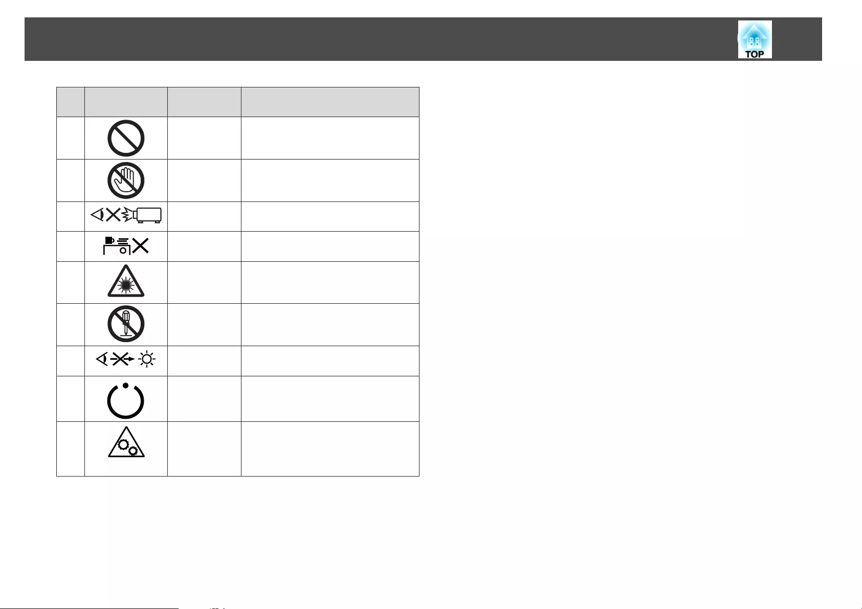
No. Symbol mark Approved
standards
Meaning
PISO 3864 General prohibition
To identify actions or operations that are
prohibited.
QISO 3864 Contact prohibition
To indicate injury that could occur due to
touching a specific part of the equipment.
R--- Never look into the projection lens while
the projector is on.
S--- To indicate that the marked item don't
place anything on projector.
TISO3864
IEC60825-1
Caution, laser radiation
To indicate the equipment has a laser
radiation part.
UISO 3864 Disassembly prohibition
To indicate a risk of injury, such as electric
shock, if the equipment is disassembled.
V--- Never look into the lens while the LED for
lighting is on.
WIEC60417
No. 5266
Standby, partial standby
To indicate that part of the equipment is in
the ready status.
XISO3864
IEC60417
No. 5057
Caution, movable parts
To indicate that you must keep away from
movable parts according to protection
standards.
List of Safety Symbols Compliant with IEC60950-1 A2
252

A
A/V Mute .............................................. 18, 118
A/V Settings ............................................... 145
Air exhaust vent ........................................... 14
Air Filter Notice ......................................... 143
Air filter replacement period ................... 197
AMX Device Discovery ............................ 153
Aspect .................................................... 89, 139
Audio Out port ............................................ 16
Audio1 port .................................................. 16
Audio2 port .................................................. 16
Audio3 port .................................................. 16
Auto Iris ................................................ 88, 138
Auto Setup .................................................. 140
B
Basic menu ................................................. 149
Batch setup function ................................. 156
Beep ............................................................. 144
Black Level .................................................. 147
BNC port ....................................................... 16
BNC Sync Termination ............................ 144
Brightness ................................................... 137
Brightness Level ......................................... 146
C
Ceiling ......................................................... 143
Ceiling mount fixing points ....................... 17
Cinema .......................................................... 87
Cleaning ...................................................... 191
Cleaning the air filter and air intake vent
........................................................................ 191
Cleaning the projector's surface .............. 191
Color Adjustment ...................................... 138
Color adjustment ....................................... 138
Color Matching .......................................... 146
Color Mode .................................. 87, 137, 146
Color Saturation ........................................ 137
Color Uniformity .............................. 143, 146
Computer port ............................................. 16
Configuration menu ................................. 134
Consumables .............................................. 218
Contrast ...................................................... 137
Control panel ............................................... 17
Control4 SDDP .......................................... 153
Corner Wall .................................................. 76
Crestron RoomView ......................... 153, 212
Cross ............................................................ 120
D
Date & Time ............................................... 145
DHCP .................................................. 151, 152
DICOM SIM ................................................. 87
Direct Power On ........................................ 144
Direction ..................................................... 143
Display ........................................................ 143
Display Background .................................. 143
Distance ...................................................... 219
Document Camera .................................... 217
DVI-D port ................................................... 16
Dynamic ........................................................ 87
E
EasyMP Monitor ....................................... 204
Edge Blending .................................... 102, 146
Epson Web Control ................................... 204
Esc .................................................................. 18
ESC/VP21 ................................................... 210
Event ID ...................................................... 155
Extended menu .......................................... 142
Extron XTP ................................................. 146
E-Zoom ....................................................... 119
F
Filter Indicator ........................................... 166
Filter indicator ........................................... 166
Focus .............................................................. 37
Freeze .......................................................... 119
Front ............................................................ 143
Front adjustable foot ................................... 17
Full Lock ..................................................... 129
G
Gateway Address ............................... 151, 152
Geometric Correction ............................... 141
H
H/V-Keystone ............................................ 141
HDBaseT ..................................................... 146
HDBaseT port .............................................. 16
HDBaseT Signal Quality ........................... 155
HDMI port ................................................... 16
Help function ............................................. 164
High Altitude Mode .................................. 144
Home screen ................................................. 57
How to replace the air filter ..................... 197
How to replace the lamp ........................... 194
Index
253

I
Image menu ................................................ 137
Indicators .................................................... 166
Info menu ................................................... 154
Input Signal ................................................ 154
Installation requirements ........................... 28
Installation settings ..................................... 28
IP Address .......................................... 151, 152
L
Lamp cover ................................................... 15
Lamp indicator ........................................... 166
Lamp replacement period ........................ 194
Language ..................................................... 147
Lens Operation Lock ................................. 130
Lens Replacement Cover ............................ 26
Lens shift ....................................................... 33
M
Mail Notification ............................... 152, 209
Memory ....................................................... 141
Menu ............................................................. 17
Message Broadcasting ....................... 154, 204
Messages ..................................................... 143
Monitor displays ........................................ 238
Monitor Out port ......................................... 16
Multi-Projection .................................. 87, 146
Multi-Projection function ........................ 102
N
Network Configuration ............................ 148
Network information ................................ 148
Network menu ........................................... 147
Notification email address 1/2/3 ............. 153
O
Operating temperature ............................. 241
Operation .................................................... 144
Optional accessories .................................. 217
Overheating ................................................ 168
Overscan ..................................................... 140
P
Panel Alignment ........................................ 143
Part names and functions ........................... 14
Password protect ....................................... 127
PJLink .......................................................... 212
PJLink Password ........................................ 149
Port Number .............................................. 153
Position ....................................................... 140
Power indicator .......................................... 166
Power inlet .................................................... 15
Power On Protection ................................ 127
Presentation .................................................. 87
Priority Gateway ........................................ 153
Projection ................................................... 143
Projection lens .............................................. 26
Projector ................................................. 56, 58
Projector ID .................................................. 41
Projector keyword ..................................... 149
Projector Name .......................................... 149
Q
Quick Corner ............................................. 141
Quick Wireless Connection USB Key ...... 53
R
Reading mail ............................................... 209
Rear .............................................................. 143
Rear feet ........................................................ 17
Refresh Rate ................................................ 154
Remote control ............................................ 19
Remote control button lock ..................... 130
Remote control ID ....................................... 42
Remote port .................................................. 16
Remote receiver ........................................... 14
Replacing batteries ....................................... 22
Reset All ...................................................... 155
Reset Memory ............................................ 155
Reset menu ................................................. 155
Resetting the lamp operating time
................................................................ 155, 197
Resolution .......................................... 139, 154
RGBCMY .................................................... 146
RoomView .................................................. 213
RS-232C port ................................................ 16
S
Scale ..................................................... 140, 146
Schedule ...................................................... 124
Schedule Settings ....................................... 147
Screen .......................................................... 143
Screen settings .............................................. 30
Screen Size .................................................. 117
Screen size ................................................... 219
Search Access Point ................................... 151
Serial Number ............................................ 155
Settings menu ............................................. 140
Sharpness .................................................... 138
Index
254

Signal menu ................................................ 139
SMTP Server ............................................... 152
SNMP .......................................................... 210
Soft keyboard ............................................. 148
Source ................................................. 116, 154
Source Search ......................................... 17, 59
Specifications ............................................. 240
Split Screen ................................................. 141
Split Screen Setup ...................................... 116
sRGB .............................................................. 87
Standby Mode ............................................ 145
Startup Screen ............................................ 143
Status ........................................................... 155
Status indicators ........................................... 14
Storage temperature .................................. 241
Subnet Mask ....................................... 151, 152
Supported monitor displays ..................... 238
Swap Screens .............................................. 117
Sync Info ..................................................... 154
Sync. ............................................................ 140
T
Temp indicator .......................................... 166
Test Pattern .......................................... 32, 141
Tint .............................................................. 137
Tracking ...................................................... 139
Trap IP Address 1/2 .................................. 153
U
User Button ................................................ 141
User's Logo ................................................. 120
User's Logo Protection .............................. 127
V
Volume ........................................................ 141
W
Web browser .............................................. 204
Web Control Password ............................. 149
White Balance ............................................ 138
Wired LAN menu ...................................... 152
Wireless LAN menu .................................. 149
Index
255