Table of Contents
Gigabyte GA-X150M-PLUS WS User Manual
Displayed below is the user manual for GA-X150M-PLUS WS by Gigabyte which is a product in the Motherboards category. This manual has pages.
Related Manuals

To reduce the impacts on global warming, the packaging materials of this product
are recyclable and reusable. GIGABYTE works with you to protect the environment.
For more product details, please visit GIGABYTE's website.
GA-X150M-PLUS WS
User's Manual
Rev. 1002
12ME-X15MPLW-1002R
Copyright
© 2016 GIGA-BYTE TECHNOLOGY CO., LTD. All rights reserved.
The trademarks mentioned in this manual are legally registered to their respective owners.
Disclaimer
Information in this manual is protected by copyright laws and is the property of GIGABYTE.
Changes to the specications and features in this manual may be made by GIGABYTE without prior notice.
No part of this manual may be reproduced, copied, translated, transmitted, or published in any form or
by any means without GIGABYTE's prior written permission.
In order to assist in the use of this product, carefully read the User's Manual.
For product-related information, check on our website at: http://www.gigabyte.com
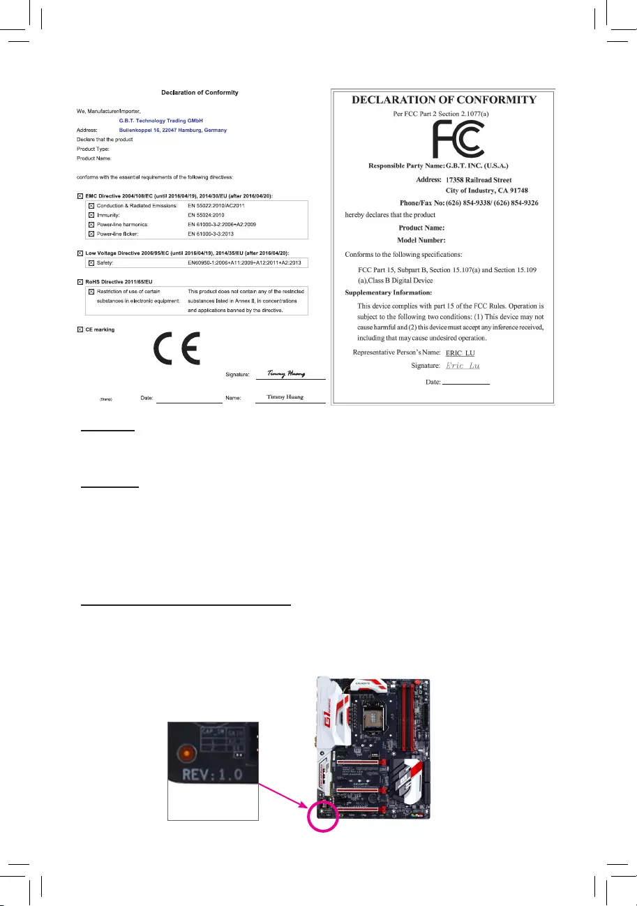
Identifying Your Motherboard Revision
The revision number on your motherboard looks like this: "REV: X.X." For example, "REV: 1.0" means
the revision of the motherboard is 1.0. Check your motherboard revision before updating motherboard
BIOS, drivers, or when looking for technical information.
Example:
Nov. 13, 2015
Motherboard
GA-X150M-PLUS WS
Motherboard
GA-X150M-PLUS WS
Nov. 13, 2015

- 3 -
Table of Contents
GA-X150M-PLUS WS Motherboard Layout ....................................................................4
Chapter 1 Hardware Installation .....................................................................................5
1-1 Installation Precautions .................................................................................... 5
1-2 ProductSpecications ...................................................................................... 6
1-3 Installing the CPU ............................................................................................ 8
1-4 Installing the Memory ....................................................................................... 8
1-5 Installing an Expansion Card ........................................................................... 9
1-6 Back Panel Connectors .................................................................................... 9
1-7 Internal Connectors ........................................................................................ 10
Chapter 2 BIOS Setup ..................................................................................................16
2-1 Startup Screen ............................................................................................... 16
2-2 M.I.T. .............................................................................................................. 17
2-3 System Information ........................................................................................ 22
2-4 BIOS Features ............................................................................................... 23
2-5 Peripherals ..................................................................................................... 26
2-6 Chipset ........................................................................................................... 28
2-7 Power Management ....................................................................................... 29
2-8 Save & Exit ..................................................................................................... 31
Chapter 3 Appendix ......................................................................................................32
3-1 ConguringaRAIDSet .................................................................................. 32
3-2 DriversInstallation .......................................................................................... 34
RegulatoryStatements .............................................................................................. 35
Contact Us ................................................................................................................ 40
- 4 -
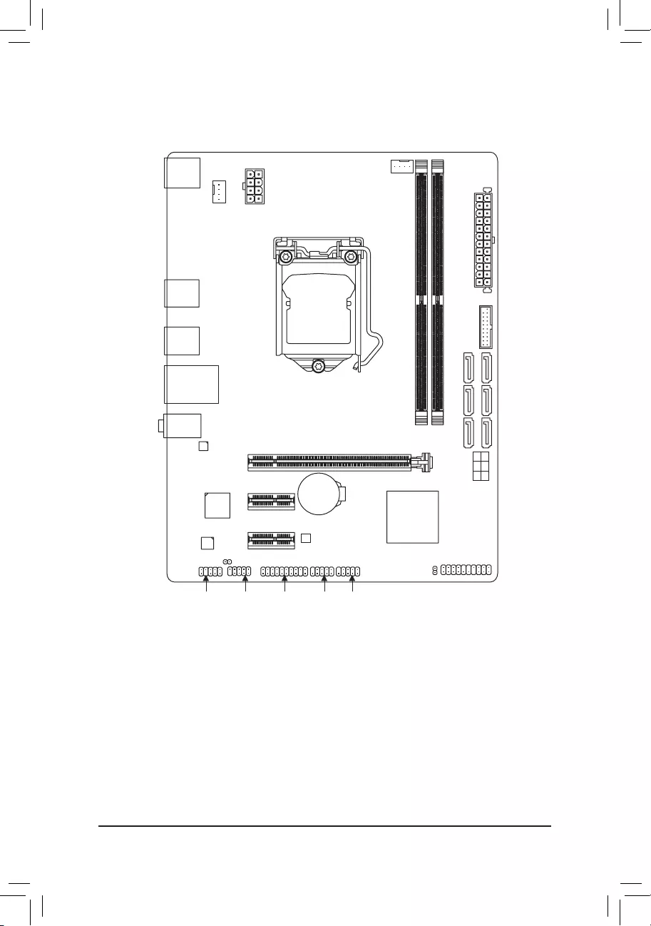
GA-X150M-PLUS WS Motherboard Layout
* The box contents above are for reference only and the actual items shall depend on the product package you obtain.
The box contents are subject to change without notice.
Box Contents
5GA-X150M-PLUS WS motherboard
5Motherboard driver disk 5Two SATA cables
5User's Manual 5I/O Shield
KB_MS
CPU_FAN
SYS_FAN
LGA1151
ATX
GA-X150M-PLUS WS
F_AUDIO
AUDIO
DDR4_1
DDR4_2
BAT
ATX_12V_2X4
Intel® C232
R_USB30_2
CODEC
CLR_CMOS
M_BIOS
USB_LAN
PCIEX16
PCIEX1_1
PCIEX1_2
iTE®
Super I/O
Realtek®
GbE LAN
F_USB1TPM F_USB2
F_PANEL
SPDIF_O
F_USB30
SATA3
5 4
3 2
1 0
R_USB30_1
COM

Chapter 1 Hardware Installation
1-1 Installation Precautions
The motherboard contains numerous delicate electronic circuits and components which can become
damagedasaresultofelectrostaticdischarge(ESD).Priortoinstallation,carefullyreadtheuser's
manual and follow these procedures:
•Prior to installation, make sure the chassis is suitable for the motherboard.
•Priortoinstallation,donotremoveorbreakmotherboardS/N(SerialNumber)stickeror
warranty sticker provided by your dealer. These stickers are required for warranty validation.
•Always remove the AC power by unplugging the power cord from the power outlet before
installing or removing the motherboard or other hardware components.
•When connecting hardware components to the internal connectors on the motherboard, make
sure they are connected tightly and securely.
•When handling the motherboard, avoid touching any metal leads or connectors.
•It is best to wear an electrostatic discharge (ESD) wrist strap when handling electronic
componentssuchasamotherboard,CPUormemory.IfyoudonothaveanESDwriststrap,
keepyourhandsdryandrsttouchametalobjecttoeliminatestaticelectricity.
•Prior to installing the motherboard, please have it on top of an antistatic pad or within an
electrostatic shielding container.
•Before connecting or unplugging the power supply cable from the motherboard, make sure
the power supply has been turned off.
•Before turning on the power, make sure the power supply voltage has been set according to
the local voltage standard.
•Before using the product, please verify that all cables and power connectors of your hardware
components are connected.
•To prevent damage to the motherboard, do not allow screws to come in contact with the
motherboard circuit or its components.
•Make sure there are no leftover screws or metal components placed on the motherboard or
within the computer casing.
•Donotplacethecomputersystemonanunevensurface.
•Donotplacethecomputersysteminahigh-temperatureorwetenvironment.
•Turning on the computer power during the installation process can lead to damage to system
components as well as physical harm to the user.
•If you are uncertain about any installation steps or have a problem related to the use of the
product,pleaseconsultacertiedcomputertechnician.
•If you use an adapter, extension power cable, or power strip, ensure to consult with its installation
and/or grounding instructions.
- 5 -
1-2 ProductSpecications
CPU Support for Intel® Xeon® E3-1200 v5 processors/Intel® Core™ i3 processors/
Intel® Pentium® processors/Intel® Celeron® processors in the LGA1151 package
(GotoGIGABYTE'swebsiteforthelatestCPUsupportlist.)
L3 cache varies with CPU
Chipset Intel® C232 Chipset
Memory 2xDDR4DIMMsocketssupportingupto32GBofsystemmemory
* DuetoaWindows32-bitoperatingsystemlimitation,whenmorethan4GBofphysical
memory is installed, the actual memory size displayed will be less than the size of
the physical memory installed.
Dualchannelmemoryarchitecture
SupportforDDR42133MHzmemorymodules
Supportfornon-ECCUDIMM1Rx8/2Rx8/1Rx16memorymodules
(Go to GIGABYTE's website for the latest supported memory speeds and
memorymodules.)
Audio Realtek® ALC887 codec
HighDenitionAudio
2/4/5.1/7.1-channel
* Tocongure7.1-channelaudio,youhavetouseanHDfrontpanelaudiomodule
and enable the multi-channel audio feature through the audio driver.
SupportforS/PDIFOut
LAN Realtek® GbELANchip(10/100/1000Mbit)
Expansion Slots 1 x PCI Express x16 slot, running at x16
2 x PCI Express x1 slots
(AllofthePCIExpressslotsconformtoPCIExpress3.0standard.)
Storage Interface Chipset:
- 6 x SATA 6Gb/s connectors
- SupportforRAID0,RAID1,RAID5,andRAID10
USB Chipset:
- 6 x USB 3.0/2.0 ports (4 ports on the back panel, 2 ports available through
theinternalUSBheader)
- 6 x USB 2.0/1.1 ports (2 ports on the back panel, 4 ports available through
theinternalUSBheaders)
Internal
Connectors
1 x 24-pin ATX main power connector
1 x 8-pin ATX 12V power connector
6 x SATA 6Gb/s connectors
1 x CPU fan header
1 x system fan header
1 x front panel header
1 x front panel audio header
1xS/PDIFOutheader
1 x USB 3.0/2.0 header
2 x USB 2.0/1.1 headers
1xTrustedPlatformModule(TPM)header
1 x serial port header
1 x Clear CMOS jumper
- 6 -
Back Panel
Connectors
1 x PS/2 mouse port
1 x PS/2 Keyboard port
4 x USB 3.0/2.0 ports
2 x USB 2.0/1.1 ports
1xRJ-45port
3xaudiojacks(LineIn,LineOut,MicIn)
I/O Controller iTE® I/O Controller Chip
Hardware
Monitor
System voltage detection
CPU/System temperature detection
CPU/System fan speed detection
CPU/System overheating warning
CPU/System fan fail warning
CPU/System fan speed control
* Whether the fan speed control function is supported will depend on the cooler you install.
BIOS 1x64Mbitash
Use of licensed AMI UEFI BIOS
PnP1.0a,DMI2.7,WfM2.0,SMBIOS2.7,ACPI5.0
Unique Features Support for APP Center
* Available applications in APP Center may vary by motherboard model. Supported
functionsofeachapplicationmayalsovarydependingonmotherboardspecications.
- @BIOS
Support for Q-Flash
Support for Smart Switch
Support for Xpress Install
Bundled
Software
Norton®InternetSecurity(OEMversion)
cFosSpeed
Operating
System
Support for Windows 10/8.1 64-bit
Support for Windows 7 32-bit/64-bit
* Please download the "Windows USB Installation Tool" from GIGABYTE's website and
install it before installing Windows 7.
Form Factor Micro ATX Form Factor; 22.6cm x 17.4cm
* GIGABYTEreservestherighttomakeanychangestotheproductspecicationsandproduct-relatedinformationwithout
prior notice.
Please visit the Support\Utility List page
on GIGABYTE's website to download the
latest version of apps.
Please visit GIGABYTE's website for
support lists of CPU, memory modules,
andSSDs.
- 7 -
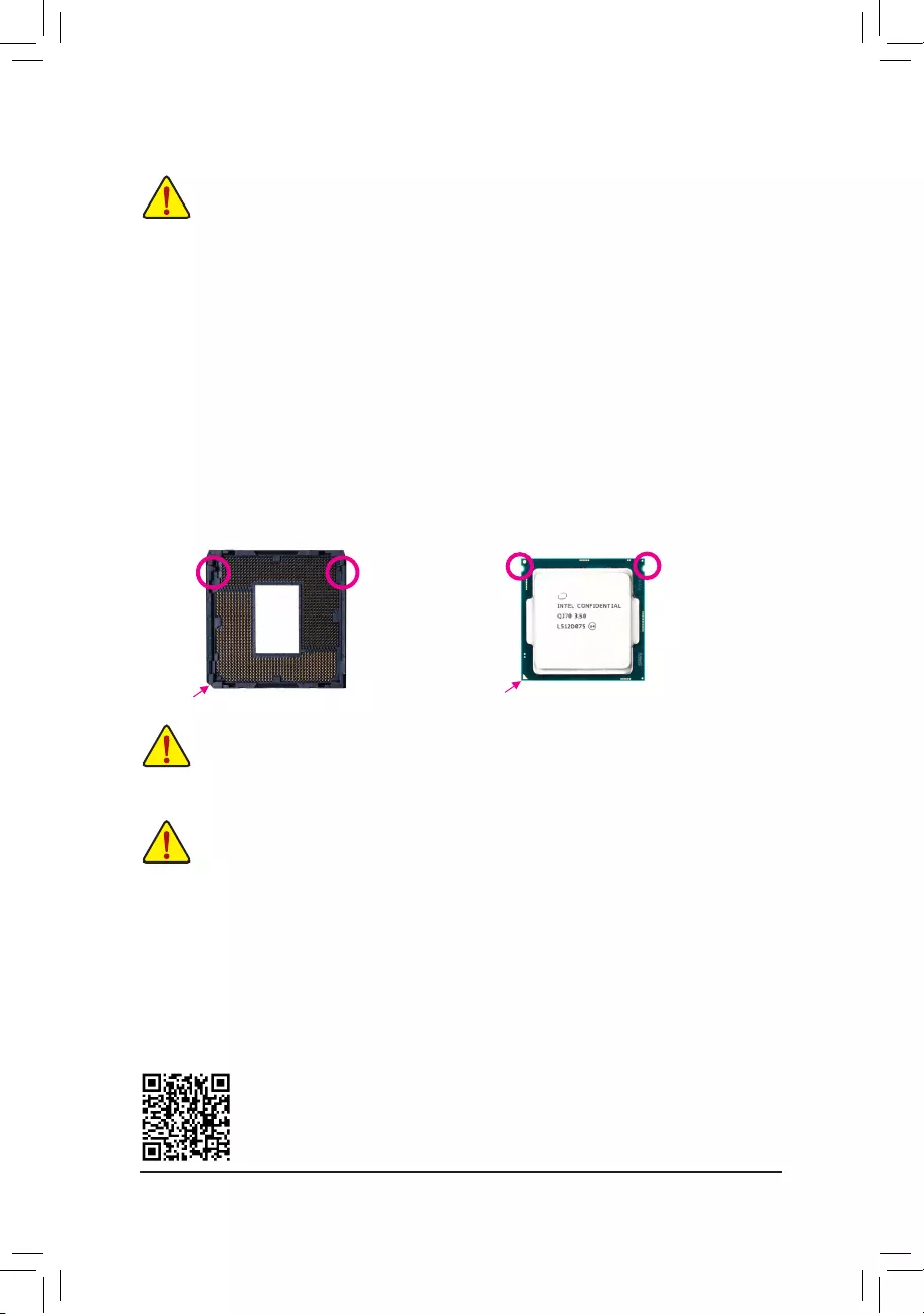
1-3 Installing the CPU
ReadthefollowingguidelinesbeforeyoubegintoinstalltheCPU:
•Make sure that the motherboard supports the CPU.
(GotoGIGABYTE'swebsiteforthelatestCPUsupportlist.)
•Always turn off the computer and unplug the power cord from the power outlet before installing the
CPU to prevent hardware damage.
•Locate the pin one of the CPU. The CPU cannot be inserted if oriented incorrectly. (Or you may locate
thenotchesonbothsidesoftheCPUandalignmentkeysontheCPUsocket.)
•Apply an even and thin layer of thermal grease on the surface of the CPU.
•DonotturnonthecomputeriftheCPUcoolerisnotinstalled,otherwiseoverheatinganddamage
of the CPU may occur.
•Setthe CPUhost frequencyinaccordancewiththe CPUspecications. Itis notrecommended
thatthesystembusfrequencybesetbeyondhardwarespecicationssinceitdoesnotmeetthe
standard requirements for the peripherals. If you wish to set the frequency beyond the standard
specications,pleasedosoaccordingtoyourhardwarespecicationsincludingtheCPU,graphics
card, memory, hard drive, etc.
Installing the CPU
Locate the alignment keys on the motherboard CPU socket and the notches on the CPU.
Do not remove the CPU socket cover before inserting the CPU. It may pop off from the load
plate automatically during the process of re-engaging the lever after you insert the CPU.
Alignment
Key
Alignment
Key
LGA1151 CPU Socket
Pin One Corner of the CPU Socket
1-4 Installing the Memory
Readthefollowingguidelinesbeforeyoubegintoinstallthememory:
•Make sure that the motherboard supports the memory. It is recommended that memory of the same
capacity, brand, speed, and chips be used.
(GotoGIGABYTE'swebsiteforthelatestsupportedmemoryspeedsandmemorymodules.)
•Always turn off the computer and unplug the power cord from the power outlet before installing the
memory to prevent hardware damage.
•Memory modules have a foolproof design. A memory module can be installed in only one direction.
If you are unable to insert the memory, switch the direction.
DualChannelMemoryConguration
ThismotherboardprovidestwomemorysocketsandsupportsDualChannelTechnology.Afterthememory
isinstalled,theBIOSwillautomaticallydetectthespecicationsandcapacityofthememory.EnablingDual
Channel memory mode will double the original memory bandwidth.
LGA1151 CPU
Notch
Notch
Please visit GIGABYTE's website for details on hardware installation.
Triangle Pin One Marking on the CPU
- 8 -
1-5 Installing an Expansion Card
Readthefollowingguidelinesbeforeyoubegintoinstallanexpansioncard:
•Make sure the motherboard supports the expansion card. Carefully read the manual that came
with your expansion card.
•Always turn off the computer and unplug the power cord from the power outlet before installing an
expansion card to prevent hardware damage.
DuetoCPUlimitations,readthefollowingguidelinesbeforeinstallingthememoryinDualChannelmode.
1. DualChannelmodecannotbeenabledifonlyonememorymoduleisinstalled.
2. WhenenablingDualChannelmodewithtwomemorymodules,itisrecommendedthatmemoryof
the same capacity, brand, speed, and chips be used for optimum performance.
The two memory sockets are divided into two channels and each channel has one memory socket as following:
ChannelA:DDR4_1
ChannelB:DDR4_2
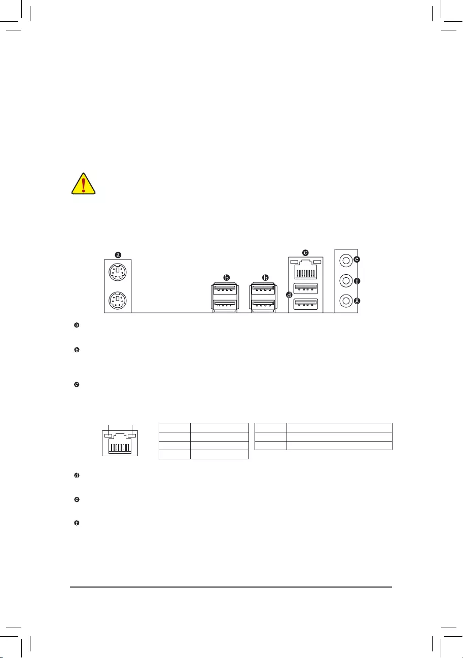
1-6 Back Panel Connectors
PS/2 Keyboard and PS/2 Mouse Port
Usetheupperport(green)toconnectaPS/2mouseandthelowerport(purple)toconnectaPS/2keyboard.
USB 3.0/2.0 Port
TheUSB3.0portsupportstheUSB3.0specicationandiscompatibletotheUSB2.0/1.1specication.
Use this port for USB devices.
RJ-45 LAN Port
The Gigabit Ethernet LAN port provides Internet connection at up to 1 Gbps data rate. The following
describesthestatesoftheLANportLEDs.
ActivityLED
Connection/
SpeedLED
LAN Port
ActivityLED:Connection/SpeedLED:
State Description
Orange 1 Gbps data rate
Green 100 Mbps data rate
Off 10 Mbps data rate
State Description
Blinking Datatransmissionorreceivingisoccurring
Off No data transmission or receiving is occurring
USB 2.0/1.1 Port
TheUSBportsupportstheUSB2.0/1.1specication.UsethisportforUSBdevices.
Line In (Blue)
The line in jack. Use this audio jack for line in devices such as an optical drive, walkman, etc.
Line Out (Green)
The line out jack. Use this audio jack for a headphone or 2-channel speaker. This jack can be used to
connectfrontspeakersina4/5.1/7.1-channelaudioconguration.
- 9 -
•Whenremovingthecableconnectedtoabackpanelconnector,rstremovethecablefromyour
device and then remove it from the motherboard.
•Whenremovingthecable,pullitstraightoutfromtheconnector.Donotrockitsidetosidetoprevent
an electrical short inside the cable connector.
Tocongure7.1-channelaudio,youhavetouseanHDfrontpanelaudiomoduleandenablethe
multi-channel audio feature through the audio driver. Please visit GIGABYTE's website for more
software information.
Mic In (Pink)
The Mic in jack.
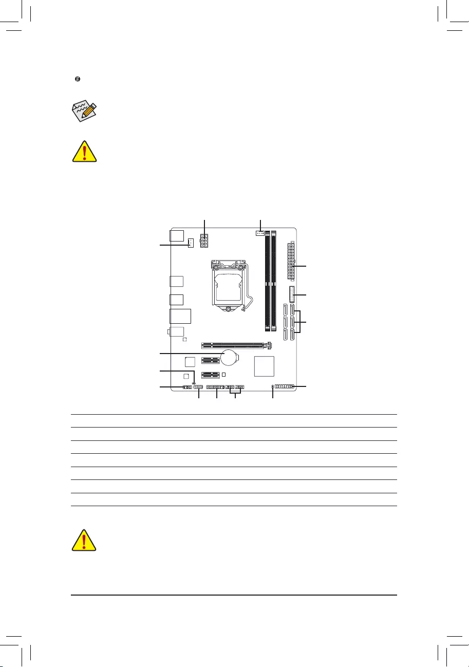
1-7 Internal Connectors
2
9
10
5
1213
1 3
4
6
7
11
14
8
1) ATX_12V_2X4
2) ATX
3) CPU_FAN
4) SYS_FAN
5) SATA3 0/1/2/3/4/5
6) F_PANEL
7) F_AUDIO
8) SPDIF_O
9) CLR_CMOS
10) F_USB30
11) F_USB1/F_USB2
12) TPM
13) COM
14) BAT
Readthefollowingguidelinesbeforeconnectingexternaldevices:
•First make sure your devices are compliant with the connectors you wish to connect.
•Before installing the devices, be sure to turn off the devices and your computer. Unplug the power
cord from the power outlet to prevent damage to the devices.
•After installing the device and before turning on the computer, make sure the device cable has been
securely attached to the connector on the motherboard.
- 10 -
DEBUG
PORT
G.QBOFM
131
2412
ATX
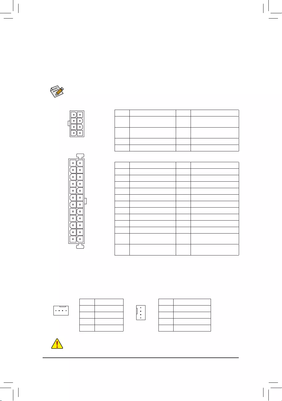
1/2) ATX_12V_2X4/ATX (2x4 12V Power Connector and 2x12 Main Power Connector)
With the use of the power connector, the power supply can supply enough stable power to all the components
onthemotherboard.Beforeconnectingthepowerconnector,rstmakesurethepowersupplyisturned
off and all devices are properly installed. The power connector possesses a foolproof design. Connect the
power supply cable to the power connector in the correct orientation.
The 12V power connector mainly supplies power to the CPU. If the 12V power connector is not connected,
the computer will not start.
To meet expansion requirements, it is recommended that a power supply that can withstand high
powerconsumptionbeused(500Worgreater).Ifapowersupplyisusedthatdoesnotprovidethe
required power, the result can lead to an unstable or unbootable system.
ATX:
Pin No. Denition Pin No. Denition
1 3.3V 13 3.3V
2 3.3V 14 -12V
3GND 15 GND
4 +5V 16 PS_ON(softOn/Off)
5GND 17 GND
6 +5V 18 GND
7GND 19 GND
8 Power Good 20 NC
95VSB(standby+5V) 21 +5V
10 +12V 22 +5V
11 +12V (Only for 2x12-pin
ATX)
23 +5V(Onlyfor2x12-pinATX)
12 3.3V (Only for 2x12-pin
ATX)
24 GND(Onlyfor2x12-pin
ATX)
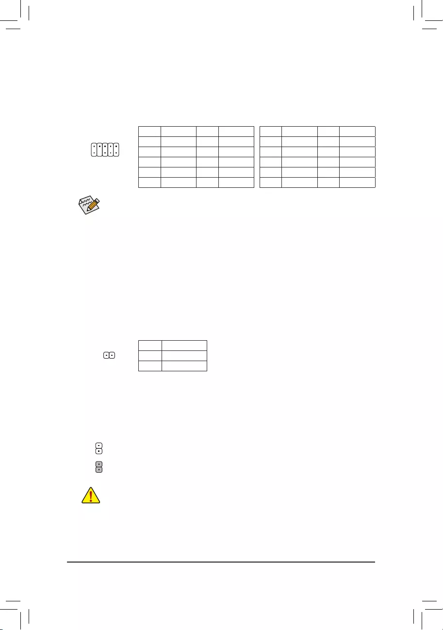
3/4) CPU_FAN/SYS_FAN (Fan Headers)
The fan headers on this motherboard are 4-pin. Most fan headers possess a foolproof insertion design.
When connecting a fan cable, be sure to connect it in the correct orientation (the black connector wire is
thegroundwire).Thespeedcontrolfunctionrequirestheuseofafanwithfanspeedcontroldesign.For
optimum heat dissipation, it is recommended that a system fan be installed inside the chassis.
CPU_FAN: SYS_FAN:
Pin No. Denition
1GND
2 +12V
3 Sense
4 Speed Control
Pin No. Denition
1GND
2 Speed Control
3 Sense
4 VCC
•Be sure to connect fan cables to the fan headers to prevent your CPU and system from overheating.
Overheating may result in damage to the CPU or the system may hang.
•Thesefanheadersarenotcongurationjumperblocks.Donotplaceajumpercapontheheaders.
CPU_FAN
DEBUG
PORT
G.QBOFM
1
DEBUG
PORT
G.QBOFM
4
1
8
5
ATX_12V_2X4
ATX_12V_2X4:
Pin No. Denition Pin No. Denition
1GND(Onlyfor2x4-pin
12V)
5+12V(Onlyfor2x4-pin12V)
2GND(Onlyfor2x4-pin
12V)
6+12V(Onlyfor2x4-pin12V)
3GND 7 +12V
4GND 8 +12V
DEBUG
PORT
G.QBOFM
1
SYS_FAN
- 11 -
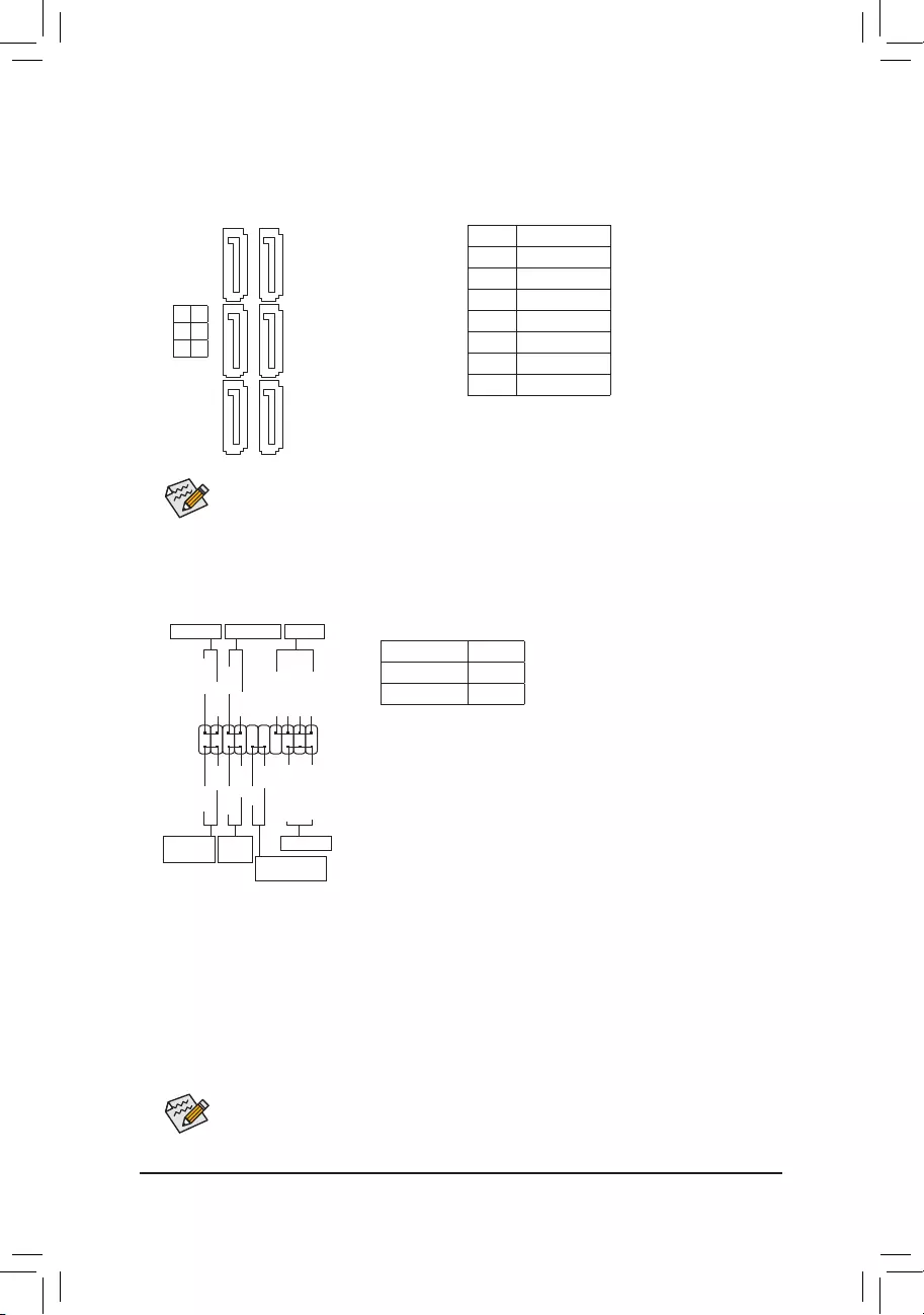
5) SATA3 0/1/2/3/4/5 (SATA 6Gb/s Connectors)
The SATA connectors conform to SATA 6Gb/s standard and are compatible with SATA 3Gb/s and SATA 1.5Gb/s
standard. Each SATA connector supports a single SATA device.
Pin No. Denition
1GND
2 TXP
3 TXN
4GND
5RXN
6RXP
7GND
To enable hot-plugging for the SATA ports, refer to Chapter 2, "BIOS Setup," "Peripherals\SATA
Conguration,"formoreinformation.
The front panel design may differ by chassis. A front panel module mainly consists of power switch,
resetswitch,powerLED,harddriveactivityLED,speakerandetc.Whenconnectingyourchassis
front panel module to this header, make sure the wire assignments and the pin assignments are
matched correctly.
6) F_PANEL (Front Panel Header)
Connect the power switch, reset switch, speaker, chassis intrusion switch/sensor and system status indicator
on the chassis to this header according to the pin assignments below. Note the positive and negative pins
before connecting the cables.
System Status LED
S0 On
S3/S4/S5 Off
•PW (PowerSwitch):
Connects to the power switch on the chassis front panel. You may
congurethewaytoturnoffyoursystemusingthepowerswitch(referto
Chapter2,"BIOSSetup,""PowerManagement,"formoreinformation).
•SPEAK (Speaker):
Connects to the speaker on the chassis front panel. The system reports
system startup status by issuing a beep code. One single short beep
will be heard if no problem is detected at system startup.
•PLED/PWR_LED (PowerLED):
Connects to the power status indicator
onthechassisfrontpanel.TheLEDison
whenthesystemisoperating.TheLEDis
off when the system is in S3/S4 sleep state
orpoweredoff(S5).
•HD (HardDriveActivityLED):
ConnectstotheharddriveactivityLEDonthechassisfrontpanel.TheLEDisonwhentheharddriveisreading
or writing data.
•RES (ResetSwitch):
Connects to the reset switch on the chassis front panel. Press the reset switch to restart the computer if the
computer freezes and fails to perform a normal restart.
•CI (ChassisIntrusionHeader):
Connects to the chassis intrusion switch/sensor on the chassis that can detect if the chassis cover has been
removed. This function requires a chassis with a chassis intrusion switch/sensor.
•NC: No connection.
PowerLED
1
2
19
20
CI-
CI+
PLED-
PW-
SPEAK+
SPEAK-
PLED+
PW+
PowerLED
HD-
RES+
HD+
RES-
HardDrive
ActivityLED
Reset
Switch Chassis Intrusion
Header
Power Switch Speaker
F_USB30 F_U
B_
F_ F_
_
B
BS_
B
SB_
B
_S
S_
_
B
_U
_
B
S
123
123
123
123
1
1
1
1
BSS
S
_S
SSU
1 2 3
S3 BSSS U
__ 3
F_USB3F
S _
S _
S _
SF
B_
F
_0
S
S
_0F
_F
_
_
__B
PWR_LED-
PWR_LED+
PWR_LED-
NC
NC
SATA3
5 4
3 2
1 0
DEBUG
PORT
G.QBOFM
DEBUG
PORT
G.QBOFM
DEBUG
PORT
G.QBOFM
DEBUG
PORT
G.QBOFM
1 1
7 7
DEBUG
PORT
G.QBOFM
DEBUG
PORT
G.QBOFM
- 12 -
7) F_AUDIO (Front Panel Audio Header)
ThefrontpanelaudioheadersupportsIntelHighDenitionaudio(HD)andAC'97audio.Youmayconnect
your chassis front panel audio module to this header. Make sure the wire assignments of the module
connector match the pin assignments of the motherboard header. Incorrect connection between the module
connector and the motherboard header will make the device unable to work or even damage it.
•ThefrontpanelaudioheadersupportsHDaudiobydefault.
•Audio signals will be present on both of the front and back panel audio connections simultaneously.
•Some chassis provide a front panel audio module that has separated connectors on each wire
instead of a single plug. For information about connecting the front panel audio module that has
different wire assignments, please contact the chassis manufacturer.
ForHDFrontPanelAudio: For AC'97 Front Panel Audio:
Pin No. Denition Pin No. Denition
1 MIC2_L 6 Sense
2GND 7FAUDIO_JD
3MIC2_R 8 No Pin
4-ACZ_DET 9 LINE2_L
5LINE2_R 10 Sense
Pin No. Denition Pin No. Denition
1 MIC 6 NC
2GND 7 NC
3 MIC Power 8 No Pin
4 NC 9 LineOut(L)
5LineOut(R) 10 NC
1
2
9
10
8) SPDIF_O (S/PDIF Out Header)
ThisheadersupportsdigitalS/PDIFOutandconnectsaS/PDIFdigitalaudiocable(providedbyexpansion
cards)fordigitalaudiooutputfromyourmotherboardtocertainexpansioncardslikegraphicscardsand
soundcards.Forexample,somegraphicscardsmayrequireyoutouseaS/PDIFdigitalaudiocablefor
digitalaudiooutputfromyourmotherboardtoyourgraphicscardifyouwishtoconnectanHDMIdisplay
tothegraphicscardandhavedigitalaudiooutputfromtheHDMIdisplayatthesametime.Forinformation
aboutconnectingtheS/PDIFdigitalaudiocable,carefullyreadthemanualforyourexpansioncard.
Pin No. Denition
1SPDIFO
2GND
9) CLR_CMOS (Clear CMOS Jumper)
UsethisjumpertocleartheBIOScongurationandresettheCMOSvaluestofactorydefaults.Toclear
the CMOS values, use a metal object like a screwdriver to touch the two pins for a few seconds.
•Always turn off your computer and unplug the power cord from the power outlet before clearing
the CMOS values.
•Aftersystemrestart,gotoBIOSSetuptoloadfactorydefaults(selectLoadOptimizedDefaults)or
manuallyconguretheBIOSsettings(refertoChapter2,"BIOSSetup,"forBIOScongurations).
Open: Normal
Short: Clear CMOS Values
1
- 13 -
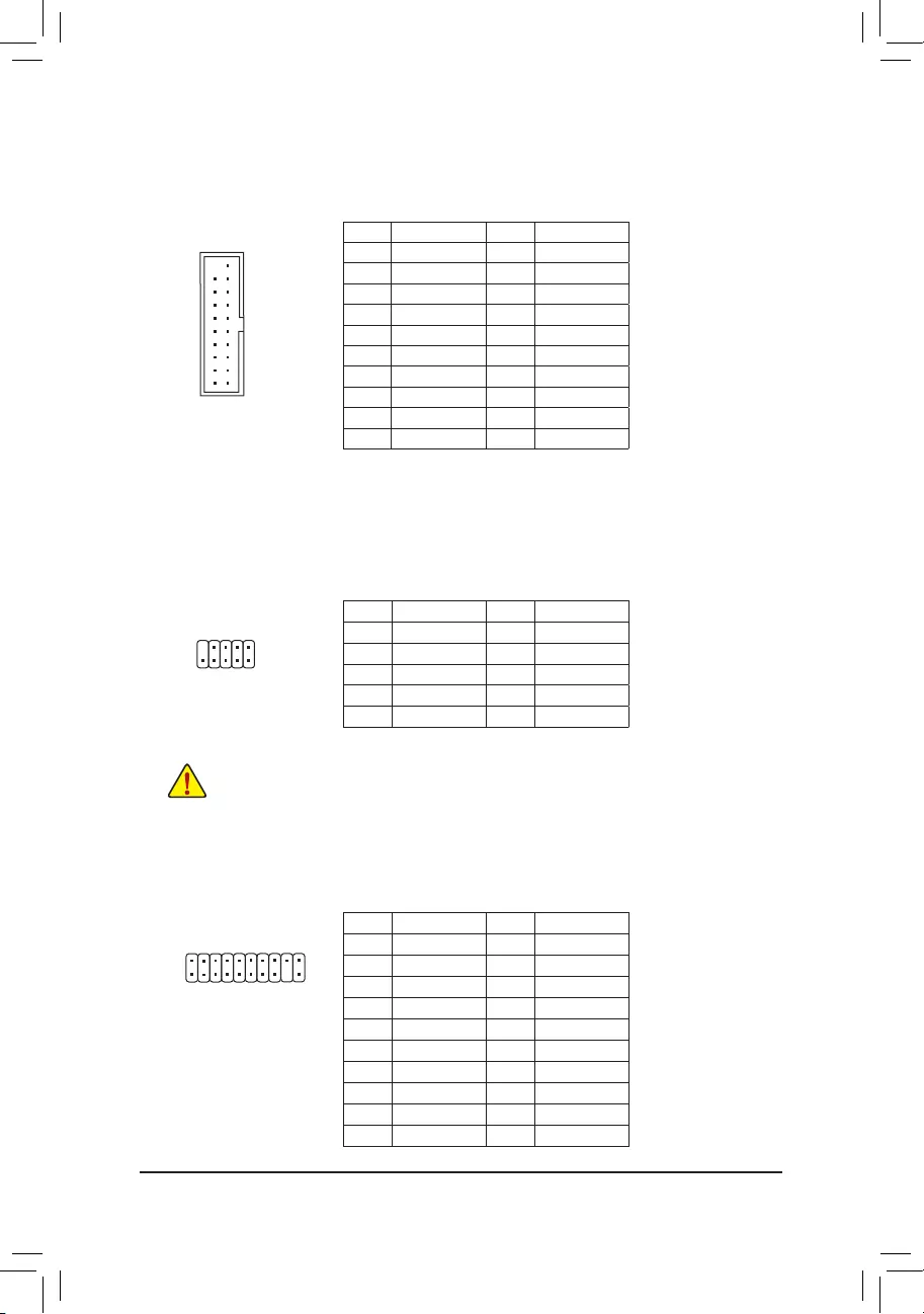
11) F_USB1/F_USB2 (USB 2.0/1.1 Headers)
TheheadersconformtoUSB2.0/1.1specication.EachUSBheadercanprovidetwoUSBportsviaan
optional USB bracket. For purchasing the optional USB bracket, please contact the local dealer.
Pin No. Denition Pin No. Denition
1Power(5V) 6USBDY+
2Power(5V) 7GND
3USBDX- 8GND
4USBDY- 9 No Pin
5USBDX+ 10 NC
•DonotplugtheIEEE1394bracket(2x5-pin)cableintotheUSB2.0/1.1header.
•Prior to installing the USB bracket, be sure to turn off your computer and unplug the power cord
from the power outlet to prevent damage to the USB bracket.
10
9
2
1
Pin No. Denition Pin No. Denition
1 VBUS 11 D2+
2SSRX1- 12 D2-
3SSRX1+ 13 GND
4GND 14 SSTX2+
5 SSTX1- 15 SSTX2-
6SSTX1+ 16 GND
7GND 17 SSRX2+
8D1- 18 SSRX2-
9D1+ 19 VBUS
10 NC 20 No Pin
10) F_USB30 (USB 3.0/2.0 Header)
Theheader conforms toUSB 3.0/2.0 specicationandeach header canprovide two USBports. For
purchasing the optional 3.5" front panel that provides two USB 3.0/2.0 ports, please contact the local dealer.
F_USB30 F_U
B_
F_ F_
_
B
BS_
B
SB_
B
_S
S_
_
B
_U
_
B
S
123
123
123
123
1
1
1
1
BSS
S
_S
SSU
1 2 3
S3 BSSS U
__ 3
F_USB3F
S _
S _
S _
SF
B_
F
_0
S
S
_0F
_F
_
_
__B
10
20 1
11
12) TPM (Trusted Platform Module Header)
YoumayconnectaTPM(TrustedPlatformModule)tothisheader.
Pin No. Denition Pin No. Denition
1 LCLK 11 LAD0
2GND 12 GND
3LFRAME 13 NC
4 No Pin 14 NC
5LRESET 15 SB3V
6 NC 16 SERIRQ
7LAD3 17 GND
8LAD2 18 NC
9 VCC3 19 NC
10 LAD1 20 SUSCLK
20
19
2
1
DEBUG
PORT
G.QBOFM
- 14 -
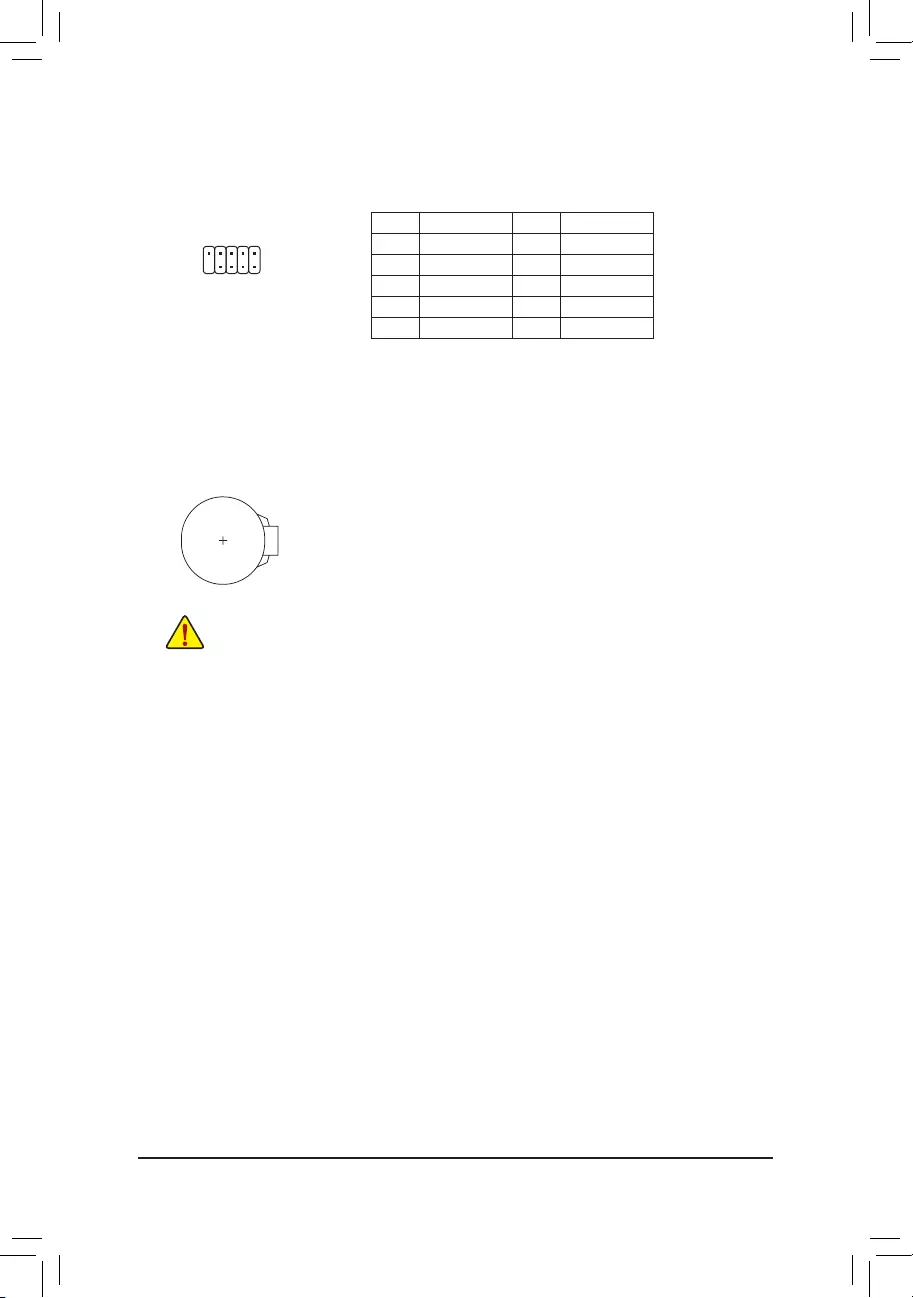
14) BAT (Battery)
Thebatteryprovidespowertokeepthevalues(suchasBIOScongurations,date,andtimeinformation)
intheCMOSwhenthecomputeristurnedoff.Replacethebatterywhenthebatteryvoltagedropstoalow
level, or the CMOS values may not be accurate or may be lost.
You may clear the CMOS values by removing the battery:
1. Turn off your computer and unplug the power cord.
2. Gently remove the battery from the battery holder and wait for one minute. (Or use a metal
object like a screwdriver to touch the positive and negative terminals of the battery holder,
makingthemshortfor5seconds.)
3. Replacethebattery.
4. Plug in the power cord and restart your computer.
•Always turn off your computer and unplug the power cord before replacing the battery.
•Replacethebatterywithanequivalentone.Dangerofexplosionifthebatteryisreplacedwith
an incorrect model.
•Contact the place of purchase or local dealer if you are not able to replace the battery by yourself
or uncertain about the battery model.
•Wheninstallingthebattery,notetheorientationofthepositiveside(+)andthenegativeside(-)of
thebattery(thepositivesideshouldfaceup).
•Used batteries must be handled in accordance with local environmental regulations.
Pin No. Denition Pin No. Denition
1NDCD- 6NDSR-
2 NSIN 7 NRTS-
3 NSOUT 8 NCTS-
4NDTR- 9NRI-
5GND 10 No Pin
13) COM (Serial Port Header)
The COM header can provide one serial port via an optional COM port cable. For purchasing the optional
COM port cable, please contact the local dealer.
10
9
2
1
- 15 -
BIOS(Basic Input andOutputSystem) records hardwareparameters of thesystem in theCMOS on the
motherboard.ItsmajorfunctionsincludeconductingthePower-OnSelf-Test(POST)duringsystemstartup,
saving system parameters and loading operating system, etc. BIOS includes a BIOS Setup program that allows
theusertomodifybasicsystemcongurationsettingsortoactivatecertainsystemfeatures.
When the power is turned off, the battery on the motherboard supplies the necessary power to the CMOS to
keepthecongurationvaluesintheCMOS.
ToaccesstheBIOSSetupprogram,pressthe<Delete>keyduringthePOSTwhenthepoweristurnedon.
To upgrade the BIOS, use either the GIGABYTE Q-Flash or @BIOS utility.
•Q-Flash allows the user to quickly and easily upgrade or back up BIOS without entering the operating system.
•@BIOS is a Windows-based utility that searches and downloads the latest version of BIOS from the Internet
and updates the BIOS.
Chapter 2 BIOS Setup
•BecauseBIOSashingispotentiallyrisky,ifyoudonotencounterproblemsusingthecurrentversionof
BIOS,itisrecommendedthatyounotashtheBIOS.ToashtheBIOS,doitwithcaution.Inadequate
BIOSashingmayresultinsystemmalfunction.
•Itisrecommendedthatyounotalterthedefaultsettings(unlessyouneedto)topreventsystem
instability or other unexpected results. Inadequately altering the settings may result in system's failure
toboot.Ifthisoccurs,trytocleartheCMOSvaluesandresettheboardtodefaultvalues.(Refer
tothe"LoadOptimizedDefaults"sectioninthischapterorintroductionsofthebattery/clearCMOS
jumperinChapter1forhowtocleartheCMOSvalues.)
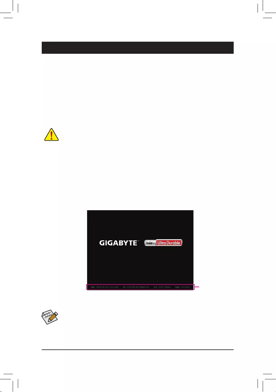
2-1 Startup Screen
The following startup Logo screen will appear when the computer boots.
(SampleBIOSVersion:E4)
Function Keys
•When the system is not stable as usual, select the Load Optimized Defaults item to set your system to its defaults.
•The BIOS Setup menus described in this chapter are for reference only and may differ by BIOS version.
OnthemainmenuoftheBIOSSetupprogram,pressarrowkeystomoveamongtheitemsandpress<Enter>
to accept or enter a sub-menu. Or you can use your mouse to select the item you want.
- 16 -
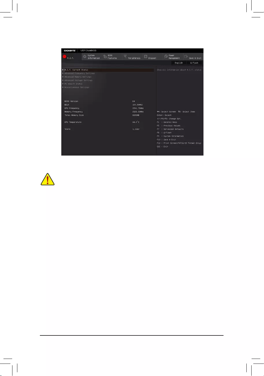
2-2 M.I.T.
This section provides information on the BIOS version, CPU base clock, CPU frequency, memory frequency,
total memory size, CPU temperature and CPU voltage, etc.
Whether the system will work stably with the overclock/overvoltage settings you made is dependent on your overall
systemcongurations.Incorrectlydoingoverclock/overvoltagemayresultindamagetoCPU,chipset,ormemory
and reduce the useful life of these components. This page is for advanced users only and we recommend you not to
alter the default settings to prevent system instability or other unexpected results. (Inadequately altering the settings
mayresultinsystem'sfailuretoboot.Ifthisoccurs,cleartheCMOSvaluesandresettheboardtodefaultvalues.)
`M.I.T. Current Status
This screen provides information on CPU/memory frequencies/parameters.
`Advanced Frequency Settings
&CPU Clock Ratio
Allows you to alter the clock ratio for the installed CPU. The adjustable range is dependent on the CPU
being installed.
&CPU Frequency
DisplaysthecurrentoperatingCPUfrequency.
`Advanced CPU Core Settings
&CPU Clock Ratio, CPU Frequency
The settings above are synchronous to those under the same items on the Advanced Frequency Settings
menu.
&Uncore Ratio
Allows you to set the CPU Uncore ratio. The adjustable range is dependent on the CPU being used.
&Uncore Frequency
DisplaysthecurrentCPUUncorefrequency.
&CPU Flex Ratio Override
EnablesordisablestheCPUFlexRatio.ThemaximumCPUclockratiowillbebasedontheCPU Flex
Ratio Settings value if CPU Clock Ratio is set to Auto.(Default:Disabled)
- 17 -

(Note) ThisitemispresentonlywhenyouinstallaCPUthatsupportsthisfeature.Formoreinformationabout
Intel® CPUs' unique features, please visit Intel's website.
&CPU Flex Ratio Settings
AllowsyoutosettheCPUFlexRatio.TheadjustablerangemayvarybyCPU.(Default:20)
&Intel(R) Turbo Boost Technology (Note)
Allows you to determine whether to enable the Intel CPU Turbo Boost technology. Auto lets the BIOS
automaticallycongurethissetting.(Default:Auto)
&Turbo Ratio (Note)
Allows you to set the CPU Turbo ratios for different number of active cores. Auto sets the CPU Turbo ratios
accordingtotheCPUspecications.(Default:Auto)
&Power Limit TDP (Watts) / Power Limit Time
AllowsyoutosetthepowerlimitforCPUTurbomodeandhowlongittakestooperateatthespecied
powerlimit.Ifthespeciedvalueisexceeded,theCPUwillautomaticallyreducethecorefrequencyin
order to reduce the power. AutosetsthecurrentlimitaccordingtotheCPUspecications.(Default:Auto)
&Core Current Limit (Amps)
AllowsyoutosetacurrentlimitforCPUTurbomode.WhentheCPUcurrentexceedsthespeciedcurrent
limit, the CPU will automatically reduce the core frequency in order to reduce the current. Auto sets the
powerlimitaccordingtotheCPUspecications.(Default:Auto)
&No. of CPU Cores Enabled (Note)
Allows you to select the number of CPU cores to enable in an Intel® multi-core CPU (the number of CPU
coresmayvarybyCPU).AutoletstheBIOSautomaticallycongurethissetting.(Default:Auto)
&Hyper-Threading Technology (Note)
Allows you to determine whether to enable multi-threading technology when using an Intel® CPU that
supports this function. This feature only works for operating systems that support multi-processor mode.
AutoletstheBIOSautomaticallycongurethissetting.(Default:Auto)
&CPU Enhanced Halt (C1E) (Note)
Enables or disables Intel®CPUEnhancedHalt(C1E)function,aCPUpower-savingfunctioninsystem
halt state. When enabled, the CPU core frequency and voltage will be reduced during system halt state to
decrease power consumption. AutoletstheBIOSautomaticallycongurethissetting.(Default:Auto)
&C3 State Support (Note)
Allows you to determine whether to let the CPU enter C3 mode in system halt state. When enabled, the
CPU core frequency and voltage will be reduced during system halt state to decrease power consumption.
The C3 state is a more enhanced power-saving state than C1. AutoletstheBIOSautomaticallycongure
thissetting.(Default:Auto)
&C6/C7 State Support (Note)
Allows you to determine whether to let the CPU enter C6/C7 mode in system halt state. When enabled, the
CPU core frequency and voltage will be reduced during system halt state to decrease power consumption.
The C6/C7 state is a more enhanced power-saving state than C3. AutoletstheBIOSautomaticallycongure
thissetting.(Default:Auto)
&C8 State Support (Note)
Allows you to determine whether to let the CPU enter C8 mode in system halt state. When enabled, the CPU
core frequency and voltage will be reduced during system halt state to decrease power consumption. The
C8 state is a more enhanced power-saving state than C6/C7. AutoletstheBIOSautomaticallycongure
thissetting.(Default:Auto)
&Package C State Limit (Note)
Allows you to specify the C-state limit for the processor. AutoletstheBIOSautomaticallycongurethis
setting.(Default:Auto)
- 18 -

(Note1) ThisitemispresentonlywhenyouinstallaCPUthatsupportsthisfeature.Formoreinformationabout
Intel® CPUs' unique features, please visit Intel's website.
(Note2) ThisitemispresentonlywhenyouinstallaCPUandamemorymodulethatsupportthisfeature.
&CPU Thermal Monitor (Note 1)
Enables or disables Intel® Thermal Monitor function, a CPU overheating protection function. When enabled,
the CPU core frequency and voltage will be reduced when the CPU is overheated. Auto lets the BIOS
automaticallycongurethissetting.(Default:Auto)
&CPU EIST Function (Note 1)
Enables or disables Enhanced Intel®SpeedStepTechnology(EIST).DependingonCPUloading,Intel®
EIST technology can dynamically and effectively lower the CPU voltage and core frequency to decrease
average power consumption and heat production. AutoletstheBIOSautomaticallycongurethissetting.
(Default:Auto)
&Voltage Optimization
Allowsyoutodeterminewhethertoenablevoltageoptimizationtoreducepowerconsumption.(Default:
Enabled)
&Residency State Regulation (RSR)
Allows you to determine whether to automatically lower the CPU turbo ratio if the CPU voltage/temperature
istoohigh.(Default:Enabled)
&Hardware Prefetcher
Allows you to determine whether to enable hardware prefetcher to prefetch data and instructions from the
memoryintothecache.(Default:Enabled)
&Adjacent Cache Line Prefetch
Allows you to determine whether to enable the adjacent cache line prefetch mechanism that lets the
processorretrievetherequestedcachelineaswellasthesubsequentcacheline.(Default:Enabled)
&System Memory Multiplier
Allows you to set the system memory multiplier. AutosetsmemorymultiplieraccordingtomemorySPD
data.(Default:Auto)
&Memory Frequency (MHz)
Therstmemoryfrequencyvalueisthenormaloperatingfrequencyofthememorybeingused;thesecond
is the memory frequency that is automatically adjusted according to the System Memory Multiplier settings.
`Advanced Memory Settings
&System Memory Multiplier, Memory Frequency(MHz)
The settings above are synchronous to those under the same items on the Advanced Frequency Settings
menu.
&Memory Boot Mode (Note 2)
Provides memory detection and training methods.
Auto LetstheBIOSautomaticallycongurethissetting.(Default)
EnableFastBoot Skipmemorydetectionandtraininginsomespeciccriteriaforfastermemory
boot.
DisableFastBoot Detectandtrainmemoryateverysingleboot.
&Memory Enhancement Settings
Providesseveralmemoryperformanceenhancementsettings:Normal(basicperformance),RelaxOC,
EnhancedStability,andEnhancedPerformance.(Default:Normal)
- 19 -

&Memory Timing Mode
Manual and Advanced Manual allows the Memory Multiplier Tweaker, Channel Interleaving, Rank
Interleaving,andmemorytimingsettingsbelowtobecongurable.Optionsare:Auto(default),Manual,
Advanced Manual.
&ProleDDRVoltage
Displaysthememoryvoltage.
&Memory Multiplier Tweaker
Providesdifferentlevelsofmemoryauto-tuning.(Default:Auto)
&Channel Interleaving
Enables or disables memory channel interleaving. Enabled allows the system to simultaneously access
different channels of the memory to increase memory performance and stability. Auto lets the BIOS
automaticallycongurethissetting.(Default:Auto)
&Rank Interleaving
Enables or disables memory rank interleaving. Enabled allows the system to simultaneously access different
ranks of the memory to increase memory performance and stability. Auto lets the BIOS automatically
congurethissetting.(Default:Auto)
`IMC Timing Settings
This sub-menu provides options for tuning memory compatibility and stability.
`Channel A/B Memory Sub Timings
This sub-menu provides memory timing settings for each channel of memory. The respective timing setting
screensarecongurableonlywhenMemory Timing Mode is set to Manual or Advanced Manual. Note: Your
system may become unstable or fail to boot after you make changes on the memory timings. If this occurs,
please reset the board to default values by loading optimized defaults or clearing the CMOS values.
`Advanced Voltage Settings
`Advanced Power Settings
&CPU Vcore Loadline Calibration
AllowsyoutocongureLoad-LineCalibrationfortheCPUVcorevoltage.Selectingahigherlevelkeeps
the CPU Vcore voltage more consistent with what is set in BIOS under heavy load. Auto lets the BIOS
automaticallycongurethissettingandsetsthevoltagefollowingIntel®'sspecications.(Default:Auto)
`CPU Core Voltage Control
This section provides CPU voltage control options.
`DRAM Voltage Control
This section provides memory voltage control options.
`Internal VR Control
ThissectionprovidesVRvoltagecontroloptions.
`PC Health Status
&Reset Case Open Status
Disabled Keepsorclearstherecordofpreviouschassisintrusionstatus.(Default)
Enabled Clears the record of previous chassis intrusion status and the Case Openeldwill
show "No" at next boot.
- 20 -

&Case Open
DisplaysthedetectionstatusofthechassisintrusiondetectiondeviceattachedtothemotherboardCI
header.Ifthesystemchassiscoverisremoved,thiseldwillshow"Yes",otherwiseitwillshow"No".To
clear the chassis intrusion status record, set Reset Case Open Status to Enabled, save the settings to
the CMOS, and then restart your system.
& CPU Vcore/CPU VCCSA/DRAM Channel A/B Voltage/+3.3V/+5V/+12V/CPU VAXG
Displaysthecurrentsystemvoltages.
&CPU/System Temperature
DisplayscurrentCPU/systemtemperature.
&CPU/System Fan Speed
DisplayscurrentCPU/systemfanspeeds.
&CPU/System Temperature Warning
Sets the warning threshold for CPU/system temperature. When temperature exceeds the threshold, BIOS
willemitwarningsound.Optionsare:Disabled(default),60oC/140oF, 70oC/158oF, 80oC/176oF, 90oC/194oF.
& CPU/System Fan Fail Warning
Allows the system to emit warning sound if the fan is not connected or fails. Check the fan condition or fan
connectionwhenthisoccurs.(Default:Disabled)
&CPU Fan Speed Control (CPU_FAN Connector)
Allows you to determine whether to enable the fan speed control function and adjust the fan speed.
Normal Allows the fan to run at different speeds according to the CPU temperature. You
can adjust the fan speed with System Information Viewer based on your system
requirements.(Default)
Silent Allows the fan to run at slow speeds.
Manual Allows you to control the fan speed under the Fan Speed Percentage item.
Full Speed Allows the fan to run at full speeds.
&Fan Speed Percentage
Allowsyoutocontrolthefanspeed.ThisitemiscongurableonlywhenCPU Fan Speed Control is set
to Manual. Options are: 0.75 PWM value /oC ~ 2.50 PWM value /oC.
&1st System Fan Speed Control (SYS_FAN Connector)
Allows you to determine whether to enable the fan speed control function and adjust the fan speed.
Normal Allows the fan to run at different speeds according to the system temperature. You
can adjust the fan speed with System Information Viewer based on your system
requirements.(Default)
Silent Allows the fan to run at slow speeds.
Manual Allows you to control the fan speed under the Fan Speed Percentage item.
Full Speed Allows the fan to run at full speeds.
&Fan Speed Percentage
Allowsyoutocontrolthefanspeed.Thisitemiscongurableonlywhen1st System Fan Speed Control
is set to Manual. Options are: 0.75 PWM value /oC ~ 2.50 PWM value /oC.
`Miscellaneous Settings
&Max Link Speed
Allows you to set the operation mode of the PCI Express slots to Gen 1, Gen 2, or Gen 3. Actual operation
modeissubjecttothehardwarespecicationofeachslot.AutoletstheBIOSautomaticallycongurethis
setting.(Default:Auto)
&3DMark01 Enhancement
Allowsyoutodeterminewhethertoenhancesomelegacybenchmarkperformance.(Default:Disabled)
- 21 -
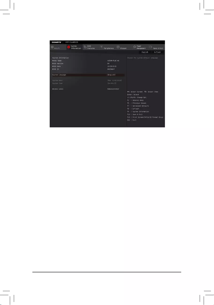
2-3 System Information
This section provides information on your motherboard model and BIOS version. You can also select the default
language used by the BIOS and manually set the system time.
&System Language
Selects the default language used by the BIOS.
&System Date
Setsthesystemdate.Thedateformatisweek(read-only),month,date,andyear.Use<Enter>toswitch
betweentheMonth,Date,andYeareldsandusethe<PageUp>or<PageDown>keytosetthedesired
value.
&System Time
Sets the system time. The time format is hour, minute, and second. For example, 1 p.m. is 13:00:00. Use
<Enter>toswitchbetweentheHour,Minute,andSecondeldsandusethe<PageUp>or<PageDown>
key to set the desired value.
&Access Level
Displaysthecurrentaccessleveldependingonthetypeofpasswordprotectionused.(Ifnopasswordis
set, the default will display as Administrator.)TheAdministratorlevelallowsyoutomakechangestoall
BIOS settings; the User level only allows you to make changes to certain BIOS settings but not all.
- 22 -
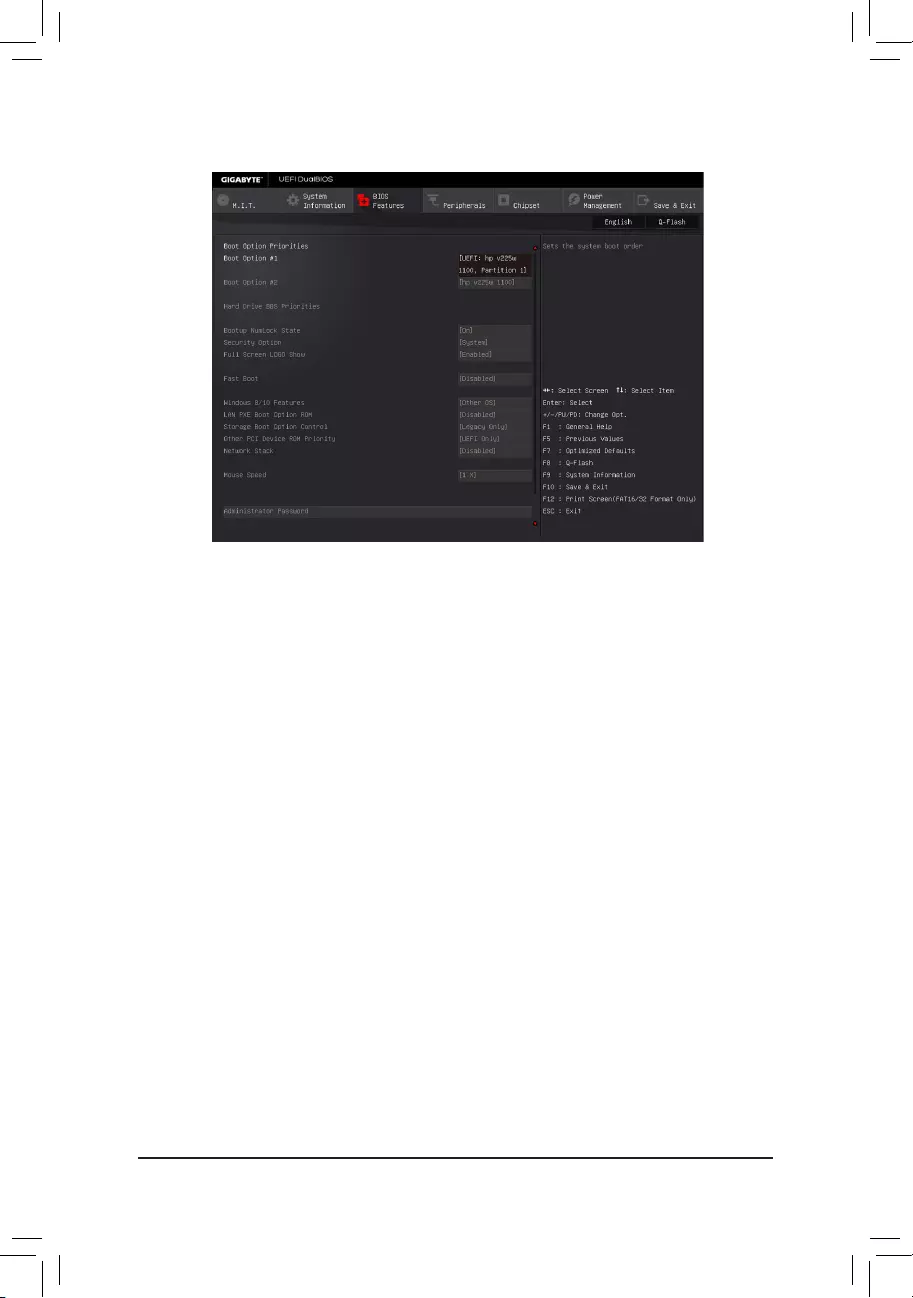
2-4 BIOS Features
&Boot Option Priorities
Speciestheoverallbootorderfromtheavailabledevices.
RemovablestoragedevicesthatsupportGPTformatwillbeprexedwith"UEFI:"stringonthebootdevice
list.TobootfromanoperatingsystemthatsupportsGPTpartitioning,selectthedeviceprexedwith"UEFI:"
string.
Or if you want to install an operating system that supports GPT partitioning such as Windows 7 64-bit, select
theopticaldrivethatcontainstheWindows764-bitinstallationdiskandisprexedwith"UEFI:"string.
& Hard Drive/CD/DVD ROM Drive/Floppy Drive/Network Device BBS Priorities
Speciesthebootorderforaspecicdevicetype,suchasharddrives,opticaldrives,oppydiskdrives,
anddevicesthatsupportBootfromLANfunction,etc.Press<Enter>onthisitemtoenterthesubmenuthat
presents the devices of the same type that are connected. This item is present only if at least one device
for this type is installed.
&Bootup NumLock State
EnablesordisablesNumlockfeatureonthenumerickeypadofthekeyboardafterthePOST.(Default:On)
&Security Option
Specieswhetherapasswordisrequiredeverytimethesystemboots,oronlywhenyouenterBIOSSetup.
Afterconguringthisitem,setthepassword(s)undertheAdministratorPassword/UserPassworditem.
Setup A password is only required for entering the BIOS Setup program.
System A password is required for booting the system and for entering the BIOS Setup program.
(Default)
&Full Screen LOGO Show
Allows you to determine whether to display the GIGABYTE Logo at system startup. Disabled skips the
GIGABYTELogowhenthesystemstartsup.(Default:Enabled)
&Fast Boot
Enables or disables Fast Boot to shorten the OS boot process. Ultra Fast provides the fastest bootup
speed.(Default:Disabled)
- 23 -

&SATA Support
AllSataDevices AllSATAdevicesarefunctionalintheoperatingsystemandduringthePOST.
(Default)
LastBootHDDOnly Exceptforthepreviousbootdrive,allSATAdevicesaredisabledbeforetheOS
boot process completes.
ThisitemiscongurableonlywhenFast Boot is set to Enabled or Ultra Fast.
&VGA Support
Allows you to select which type of operating system to boot.
Auto EnableslegacyoptionROMonly.
EFIDriver EnablesEFIoptionROM.(Default)
ThisitemiscongurableonlywhenFast Boot is set to Enabled or Ultra Fast.
&USB Support
Disabled AllUSBdevicesaredisabledbeforetheOSbootprocesscompletes.
Full Initial All USB devices are functional in the operating system and during the POST.
Partial Initial Part of the USB devices are disabled before the OS boot process completes.
(Default)
ThisitemiscongurableonlywhenFast Boot is set to Enabled. This function is disabled when Fast Boot
is set to Ultra Fast.
&PS2 Devices Support
Disabled AllPS/2devicesaredisabledbeforetheOSbootprocesscompletes.
Enabled All PS/2 devices are functional in the operating system and during the POST.
(Default)
ThisitemiscongurableonlywhenFast Boot is set to Enabled. This function is disabled when Fast Boot
is set to Ultra Fast.
&NetWork Stack Driver Support
Disabled Disablesbootingfromthenetwork.(Default)
Enabled Enables booting from the network.
ThisitemiscongurableonlywhenFast Boot is set to Enabled or Ultra Fast.
&Next Boot After AC Power Loss
NormalBoot EnablesnormalbootupuponthereturnoftheACpower.(Default)
Fast Boot Keeps the Fast Boot settings upon the return of the AC power.
ThisitemiscongurableonlywhenFast Boot is set to Enabled or Ultra Fast.
&Windows 8/10 Features
Allowsyoutoselecttheoperatingsystemtobeinstalled.(Default:OtherOS)
&CSM Support
EnablesordisablesUEFICSM(CompatibilitySupportModule)tosupportalegacyPCbootprocess.
Enabled EnablesUEFICSM.(Default)
Disabled DisablesUEFICSMandsupportsUEFIBIOSbootprocessonly.
ThisitemiscongurableonlywhenWindows8/10FeaturesissettoWindows 8/10 or Windows 8/10
WHQL.
&LAN PXE Boot Option ROM
AllowsyoutoselectwhethertoenablethelegacyoptionROMfortheLANcontroller.(Default:Disabled)
ThisitemiscongurableonlywhenCSM Support is set to Enabled.
&Storage Boot Option Control
AllowsyoutoselectwhethertoenabletheUEFIorlegacyoptionROMforthestoragedevicecontroller.
Disabled DisablesoptionROM.
UEFIOnly EnablesUEFIoptionROMonly.
LegacyOnly EnableslegacyoptionROMonly.(Default)
ThisitemiscongurableonlywhenCSM Support is set to Enabled.
- 24 -

&Other PCI Device ROM Priority
AllowsyoutoselectwhethertoenabletheUEFIorLegacyoptionROMforthePCIdevicecontrollerother
than the LAN, storage device, and graphics controllers.
Disabled DisablesoptionROM.
UEFIOnly EnablesUEFIoptionROMonly.(Default)
LegacyOnly EnableslegacyoptionROMonly.
ThisitemiscongurableonlywhenCSM Support is set to Enabled.
&Network Stack
DisablesorenablesbootingfromthenetworktoinstallaGPTformatOS,suchasinstallingtheOSfrom
theWindowsDeploymentServicesserver.(Default:Disabled)
&Ipv4 PXE Support
EnablesordisablesIPv4PXESupport.ThisitemiscongurableonlywhenNetwork Stack is enabled.
&Ipv6 PXE Support
EnablesordisablesIPv6PXESupport.ThisitemiscongurableonlywhenNetwork Stack is enabled.
&Mouse Speed
Allowsyoutosetthemousecursormovementspeed.(Default:1X)
&Administrator Password
Allowsyoutocongureanadministratorpassword.Press<Enter>onthisitem,typethepassword,and
thenpress<Enter>.Youwillberequestedtoconrmthepassword.Typethepasswordagainandpress
<Enter>.Youmustentertheadministratorpassword(oruserpassword)atsystemstartupandwhenentering
BIOSSetup.Differingfromtheuserpassword,theadministratorpasswordallowsyoutomakechangesto
all BIOS settings.
&User Password
Allowsyoutocongureauserpassword.Press<Enter>onthisitem,typethepassword,andthenpress
<Enter>.Youwillberequestedtoconrmthepassword.Typethepasswordagainandpress<Enter>.
Youmustentertheadministratorpassword(oruserpassword)atsystemstartupandwhenenteringBIOS
Setup. However, the user password only allows you to make changes to certain BIOS settings but not all.
Tocancelthepassword,press<Enter>onthepassworditemandwhenrequestedforthepassword,enter
thecorrectonerst.Whenpromptedforanewpassword,press<Enter>withoutenteringanypassword.
Press<Enter>againwhenpromptedtoconrm.
NOTE:BeforesettingtheUserPassword,besuretosettheAdministratorPasswordrst.
- 25 -
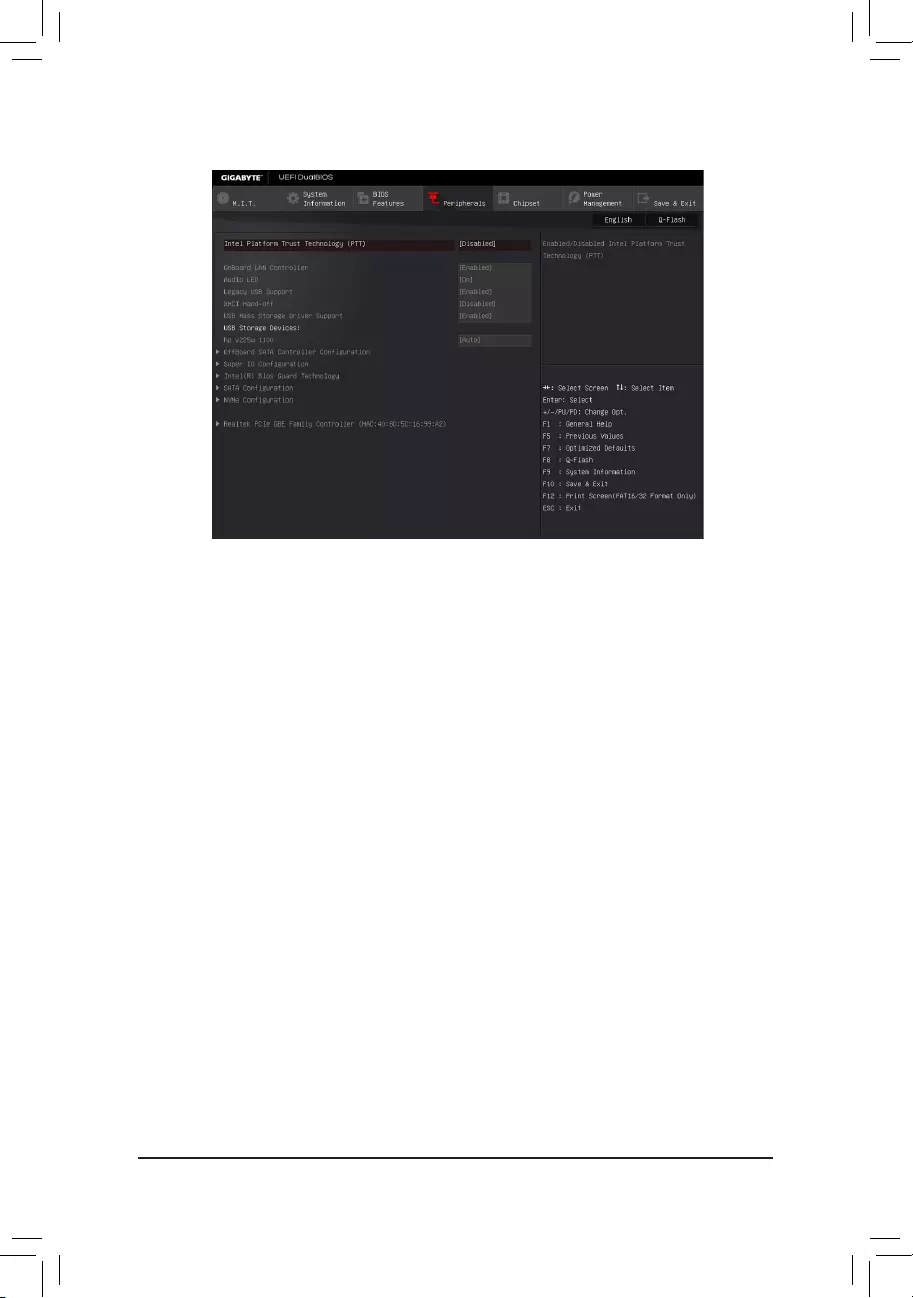
2-5 Peripherals
&Intel Platform Trust Technology (PTT)
Enables or disables Intel®PTTTechnology.(Default:Disabled)
&OnBoard LAN Controller
EnablesordisablestheonboardLANfunction.(Default:Enabled)
If you wish to install a 3rd party add-in network card instead of using the onboard LAN, set this item to
Disabled.
&Audio LED
EnablesordisablestheonboardaudioLEDfunction.(Default:On)
&Legacy USB Support
AllowsUSBkeyboard/mousetobeusedinMS-DOS.(Default:Enabled)
&XHCI Hand-off
Determineswhether to enableXHCI Hand-offfeature for anoperating system withoutXHCI Hand-off
support.(Default:Disabled)
&USB Mass Storage Driver Support
EnablesordisablessupportforUSBstoragedevices.(Default:Enabled)
&USB Storage Devices
DisplaysalistofconnectedUSBmassstoragedevices.ThisitemappearsonlywhenaUSBstoragedevice
is installed.
`OffBoardSATAControllerConguration
DisplaysinformationonyourPCIeSSDifinstalled.
`Trusted Computing 2.0
This sub-menu appears only when Intel Platform Trust Technology is set to Enabled.
&Security Device Support
EnablesordisablesTrustedPlatformModule(TPM).(Default:Enable)
- 26 -

&Pending operation
To clear TPM related settings, set this item to TPM Clear.(Default:None)
&TPM 20 InterfaceType
Allows you to select the communication interface for the TPM 2.0 device. Set to
External TPM2.0
if you
installanInneonTPM2.0module(optional).(Default:PTT)
&Device Select
Allows you to select whether to support TPM 1.2 or TPM 2.0 device. Auto lets the BIOS automatically
congurethissetting.(Default:Auto)
`SuperIOConguration
&Serial Port 1
Enablesordisablestheonboardserialport.(Default:Enabled)
`Intel(R) Bios Guard Technology
Enables or disables the Intel® BIOS Guard feature, which protects the BIOS from malicious attacks.
`SATAConguration
&SATA Controller(s)
EnablesordisablestheintegratedSATAcontrollers.(Default:Enabled)
&SATA Mode Selection
EnablesordisablesRAIDfortheSATAcontrollersintegratedintheChipsetorcongurestheSATAcontrollers
to AHCI mode.
RAID EnablesRAIDfortheSATAcontroller.
AHCI CongurestheSATAcontrollerstoAHCImode.AdvancedHostControllerInterface
(AHCI)isaninterfacespecicationthatallowsthestoragedrivertoenableadvanced
SerialATAfeaturessuchasNativeCommandQueuingandhotplug.(Default)
&Aggressive LPM Support
Enablesordisablesthepowersavingfeature,ALPM(AggressiveLinkPowerManagement),fortheChipset
SATAcontrollers.(Default:Enabled)
&Port 0/1/2/3/4/5
EnablesordisableseachSATAport.(Default:Enabled)
&Hot plug
EnablesordisablethehotplugcapabilityforeachSATAport.(Default:Disabled)
&External SATA
EnablesordisablessupportforexternalSATAdevices.(Default:Disabled)
`NVMeConguration
DisplaysinformationonyourNVMEPCIeSSDifinstalled.
`Realtek PCIe GBE Family Controller
Thissub-menuprovidesinformationonLANconguration.
- 27 -
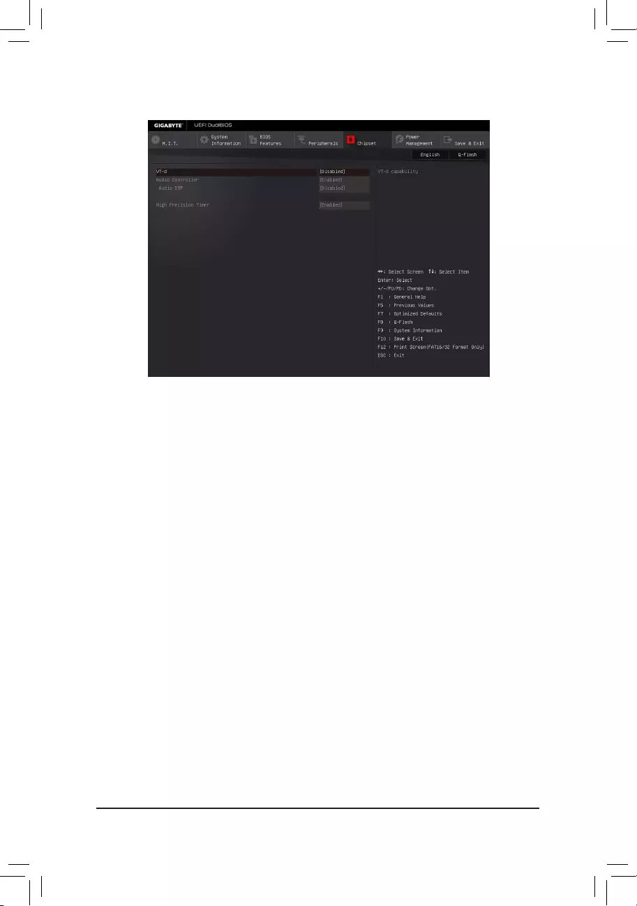
&VT-d (Note)
Enables or disables Intel®VirtualizationTechnologyforDirectedI/O.(Default:Disabled)
&Audio Controller
Enablesordisablestheonboardaudiofunction.(Default:Enabled)
If you wish to install a 3rd party add-in audio card instead of using the onboard audio, set this item to
Disabled.
&Audio DSP
EnablesordisablestheDSPfunctionalityofthePCHaudiounit.(Default:Disabled)
&High Precision Timer
EnablesordisablesHighPrecisionEventTimer(HPET)intheoperatingsystem.(Default:Enabled)
2-6 Chipset
(Note) ThisitemispresentonlywhenyouinstallaCPUthatsupportsthisfeature.Formoreinformationabout
Intel® CPUs' unique features, please visit Intel's website.
- 28 -
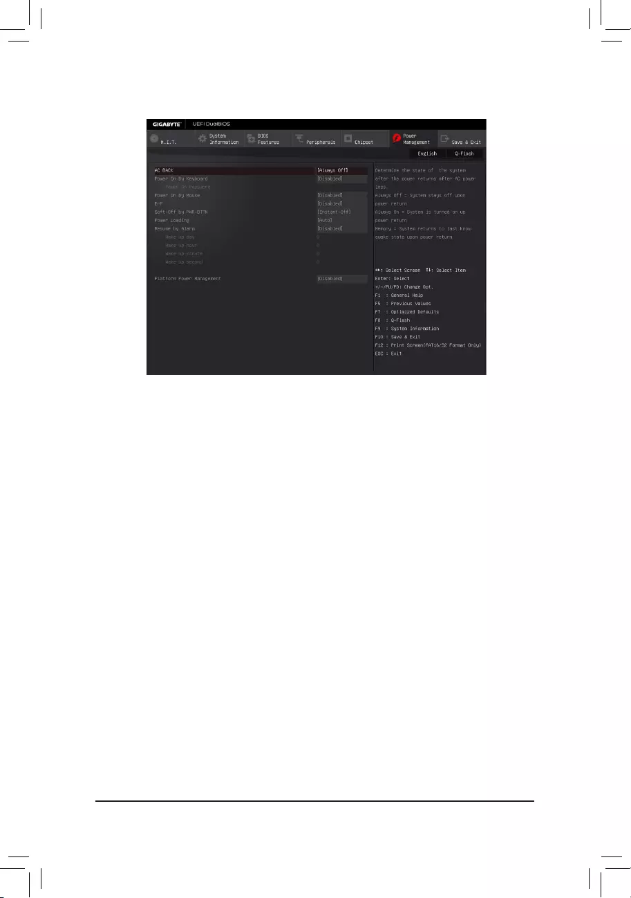
2-7 Power Management
&AC BACK
DeterminesthestateofthesystemafterthereturnofpowerfromanACpowerloss.
AlwaysOff ThesystemstaysoffuponthereturnoftheACpower.(Default)
Always On The system is turned on upon the return of the AC power.
Memory The system returns to its last known awake state upon the return of the AC power.
&Power On By Keyboard
Allows the system to be turned on by a PS/2 keyboard wake-up event.
Note: To use this function, you need an ATX power supply providing at least 1A on the +5VSB lead.
Disabled Disablesthisfunction.(Default)
Password Set a password with 1~5 characters to turn on the system.
Keyboard98 PressPOWERbuttonontheWindows98keyboardtoturnonthesystem.
Any Key Press any key to turn on the system.
&Power On Password
Set the password when Power On By Keyboard is set to Password.
Press<Enter>onthisitemandsetapasswordwithupto5charactersandthenpress<Enter>toaccept.
Toturnonthesystem,enterthepasswordandpress<Enter>.
Note:Tocancelthepassword,press<Enter>onthisitem.Whenpromptedforthepassword,press<Enter>
again without entering the password to clear the password settings.
&Power On By Mouse
Allows the system to be turned on by a PS/2 mouse wake-up event.
Note: To use this function, you need an ATX power supply providing at least 1A on the +5VSB lead.
Disabled Disablesthisfunction.(Default)
Move Move the mouse to turn on the system.
DoubleClick Doubleclickonleftbuttononthemousetoturnonthesystem.
&ErP
DetermineswhethertoletthesystemconsumeleastpowerinS5(shutdown)state.(Default:Disabled)
Note: When this item is set to Enabled,thefollowingfunctionswillbecomeunavailable:ResumebyAlarm,
PME event wake up, power on by mouse, power on by keyboard, and wake on LAN.
- 29 -

&Soft-Off by PWR-BTTN
ConguresthewaytoturnoffthecomputerinMS-DOSmodeusingthepowerbutton.
Instant-Off Pressthepowerbuttonandthenthesystemwillbeturnedoffinstantly.(Default)
Delay4Sec. Pressandholdthepowerbuttonfor4secondstoturnoffthesystem.Ifthepower
button is pressed for less than 4 seconds, the system will enter suspend mode.
&Power Loading
Enables or disables dummy load. When the power supply is at low load, a self-protection will activate causing
it to shutdown or fail. If this occurs, please set to Enabled. AutoletstheBIOSautomaticallycongurethis
setting.(Default:Auto)
&Resume by Alarm
Determineswhethertopoweronthesystematadesiredtime.(Default:Disabled)
If enabled, set the date and time as following:
Wakeupday:Turnonthesystemataspecictimeoneachdayoronaspecicdayinamonth.
Wake up hour/minute/second: Set the time at which the system will be powered on automatically.
Note: When using this function, avoid inadequate shutdown from the operating system or removal of the
AC power, or the settings may not be effective.
&Platform Power Management
EnablesordisablestheActiveStatePowerManagementfunction(ASPM).(Default:Disabled)
&PEG ASPM
Allowsyou toconguretheASPMmodefor thedevice connectedtothe CPUPEGbus. Thisitemis
congurableonlywhenPlatform Power Management is set to Enabled.(Default:Enabled)
&PCH ASPM
AllowsyoutoconguretheASPMmodeforthedeviceconnectedtoChipset'sPCIExpressbus.Thisitem
iscongurableonlywhenPlatform Power Management is set to Enabled.(Default:Enabled)
&DMI Link ASPM Control
AllowsyoutoconguretheASPMmodeforbothCPUsideandChipsetsideoftheDMIlink.Thisitemis
congurableonlywhenPlatform Power Management is set to Enabled.(Default:Enabled)
- 30 -
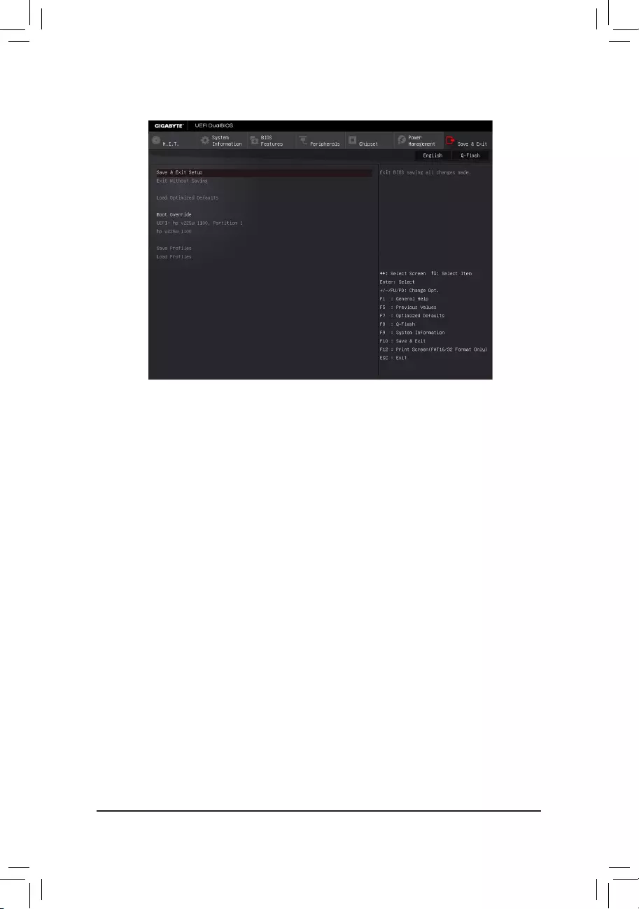
2-8 Save & Exit
&Save & Exit Setup
Press<Enter>onthisitemandselectYes. This saves the changes to the CMOS and exits the BIOS Setup
program. Select Noorpress<Esc>toreturntotheBIOSSetupMainMenu.
&Exit Without Saving
Press<Enter>onthisitemandselectYes. This exits the BIOS Setup without saving the changes made
in BIOS Setup to the CMOS. Select Noorpress<Esc>toreturntotheBIOSSetupMainMenu.
&Load Optimized Defaults
Press<Enter>onthisitemandselectYes to load the optimal BIOS default settings. The BIOS defaults
settings help the system to operate in optimum state. Always load the Optimized defaults after updating
the BIOS or after clearing the CMOS values.
&Boot Override
Allowsyoutoselectadevicetobootimmediately.Press<Enter>onthedeviceyouselectandselectYes
toconrm.Yoursystemwillrestartautomaticallyandbootfromthatdevice.
&SaveProles
ThisfunctionallowsyoutosavethecurrentBIOSsettingstoaprole.Youcancreateupto8prolesand
saveasSetupProle1~SetupProle8.Press<Enter>tocomplete.OryoucanselectSelect File in
HDD/FDD/USBtosavetheproletoyourstoragedevice.
&LoadProles
If your system becomes unstable and you have loaded the BIOS default settings, you can use this function
toloadtheBIOSsettingsfrom aprolecreatedbefore,withoutthehasslesof reconguringtheBIOS
settings.Firstselecttheproleyouwishtoloadandthenpress<Enter>tocomplete.YoucanselectSelect
File in HDD/FDD/USBtoinputtheprolepreviouslycreatedfromyourstoragedeviceorloadtheprole
automatically created by the BIOS, such as reverting the BIOS settings to the last settings that worked
properly(lastknowngoodrecord).
- 31 -
Chapter 3 Appendix
C-1.UEFIRAIDConguration
OnlyWindows10/8.164-bitsupportsUEFIRAIDconguration.
Steps:
1. In BIOS Setup, go to BIOS Features and set Windows 8/10 Features to Windows 8/10 and CSM Support
to Disabled. Save the changes and exit BIOS Setup.
2. After the system reboot, enter BIOS Setup again. Then enter the Peripherals\Intel(R) Rapid Storage
Technology sub-menu.
3. On the Intel(R) Rapid Storage Technologymenu,press<Enter>onCreate RAID Volume to enter the Create
RAID Volumescreen.Enteravolumenamewith1~16letters(letterscannotbespecialcharacters)undertheName
itemandpress<Enter>.Then,selectaRAIDlevel.RAIDlevelssupportedincludeRAID0,RAID1,Recovery,
RAID10,andRAID5(theselectionsavailabledependonthenumberoftheharddrivesbeinginstalled).Next,
use the down arrow key to move to Select Disks.
Before you begin, please prepare the following items:
•At least two SATA hard drives. (To ensure optimal performance, it is recommended that you use two hard drives
withidenticalmodelandcapacity).
•Windows setup disk.
•Motherboard driver disk.
•AUSBashdrive.
ConguringtheOnboardSATAController
A. Installing SATA hard drive(s) in your computer
Connect the SATA signal cables to SATA hard drives and the SATA ports on the motherboard. Then connect
the power connectors from your power supply to the hard drives.
B.ConguringSATAcontrollermodeinBIOSSetup
MakesuretoconguretheSATAcontrollermodecorrectlyinsystemBIOSSetup.FortheBIOSSetupmenus,
refer to Chapter 2, "BIOS Setup," "Integrated Peripherals."
Steps:
1. Turnonyourcomputerandpress<Delete>toenterBIOSSetupduringthePOST(Power-OnSelf-Test).Go
to Peripherals\SATAConguration, make sure SATA Controller(s)isenabled.TocreateRAID,setSATA
Mode Selection to RAID.
2. IfyouwanttocongureUEFIRAID,followthestepsin"C-1."ToenterthelegacyRAIDROM,savethesettings
andexitBIOSSetup.Referto"C-2"formoreinformation.
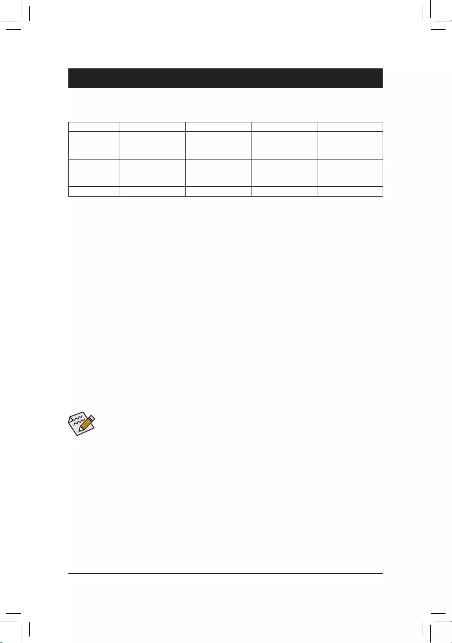
3-1 ConguringaRAIDSet
RAID Levels
RAID 0 RAID 1 RAID 5 RAID 10
Minimum
Number of Hard
Drives
≥2 2≥3 ≥4
Array Capacity Number of hard
drives * Size of the
smallest drive
Size of the smallest
drive
(Number of hard
drives-1)*Sizeof
the smallest drive
(Number of hard
drives/2)*Sizeofthe
smallest drive
Fault Tolerance No Yes Yes Yes
The BIOS Setup menus described in this section may differ from the exact settings for your motherboard.
The actual BIOS Setup menu options you will see shall depend on the motherboard you have and
the BIOS version.
- 32 -

C-2.ConguringLegacyRAIDROM
Enter the Intel®legacyRAIDBIOSsetuputilitytocongureaRAIDarray.Skipthisstepandproceedwiththe
installationofWindowsoperatingsystemforanon-RAIDconguration.
Steps:
1. After the POST memory test begins and before the operating system boot begins, look for a message which
says"Press<Ctrl-I>toenterCongurationUtility".Press<Ctrl>+<I>toentertheRAIDCongurationUtility.
2. Afteryoupress<Ctrl>+<I>,theMAIN MENUscreenwillappear.IfyouwanttocreateaRAIDarray,select
Create RAID Volume in MAIN MENUandpress<Enter>.
3. After entering the CREATE VOLUME MENU screen, enter a volume name with 1~16 letters (letters cannot be
specialcharacters)undertheNameitemandpress<Enter>.Then,selectaRAIDlevel.RAIDlevelssupported
includeRAID0,RAID1,Recovery,RAID10,andRAID5(theselectionsavailabledependonthenumberof
theharddrivesbeinginstalled).Press<Enter>toproceed.
4. Under Disksitem,selecttheharddrivestobeincludedintheRAIDarray.Ifonlytwoharddrivesareinstalled,
they will be automatically assigned to the array. Set the stripe block size if necessary. The stripe block size can
besetfrom4KBto128KB.Onceyouhaveselectedthestripeblocksize,press<Enter>.
5. Enterthearraycapacityandpress<Enter>.Finallypress<Enter>ontheCreate Volume item to begin creating
theRAIDarray.Whenpromptedtoconrmwhethertocreatethisvolume,press<Y>toconrmor<N>tocancel.
6. Whencompleted,youcanseedetailedinformationabouttheRAIDarrayintheDISK/VOLUME INFORMATION
section,includingtheRAIDlevel,stripeblocksize,arrayname,andarraycapacity,etc.ToexittheRAIDBIOS
utility,press<Esc>orselect6. Exit in MAIN MENU.
Installing the SATA RAID/AHCI Driver and Operating System
With the correct BIOS settings, you are ready to install the operating system.
Installing the Operating System
As some operating systems already include Intel®SATARAID/AHCIdriver,youdonotneedtoinstallseparate
RAID/AHCIdriverduringtheWindowsinstallationprocess.Aftertheoperatingsystemisinstalled,werecommend
that you install all required drivers from the motherboard driver disk using "Xpress Install" to ensure system
performance and compatibility. If the operating system to be installed requires that you provide additional SATA
RAID/AHCIdriverduringtheOSinstallationprocess,pleaserefertothestepsbelow:
1. Copy the RSTe_f6_iaStorA_winxxxfolder(dependingonyourOSversion)undertheBoot/RSTe folder in
the driver disk to your USB thumb drive.
2. Boot from the Windows setup disk and perform standard OS installation steps. When the screen requesting
you to load the driver appears, select Browse.
3. Insert the USB thumb drive and then browse to the folder that you previously copied.
4. When a screen appears, select Intel Chipset SATA RAID Controller and click Next to load the driver and
continue the OS installation.
4. Under Select Disksitem,selecttheharddrivestobeincludedintheRAIDarray.Pressthe<Space>keyonthe
harddrivestobeselected(selectedharddrivesaremarkedwith"X").Thensetthestripeblocksize.Thestripe
block size can be set from 4 KB to 128 KB. Once you have selected the stripe block size, set the volume capacity.
5. After setting the capacity, move to Create Volumeandpress<Enter>tobegin.
6. After completing, you'll be brought back to the Intel(R) Rapid Storage Technology screen. Under RAID
VolumesyoucanseethenewRAIDvolume.Toseemoredetailedinformation,press<Enter>onthevolume
tocheckforinformationonRAIDlevel,stripeblocksize,arrayname,andarraycapacity,etc.
PleasevisitGIGABYTE'swebsitefordetailsonconguringaRAIDarray.
- 33 -
•Beforeinstallingthedrivers,rstinstalltheoperatingsystem.(ThefollowinginstructionsuseWindows
8.1astheexampleoperatingsystem.)
•After installing the operating system, insert the motherboard driver disk into your optical drive. Click
on the message "Tap to choose what happens with this disc" on the top-right corner of the screen
andselect"RunRun.exe." (Or go to My Computer, double-click the optical drive and execute the
Run.exeprogram.)
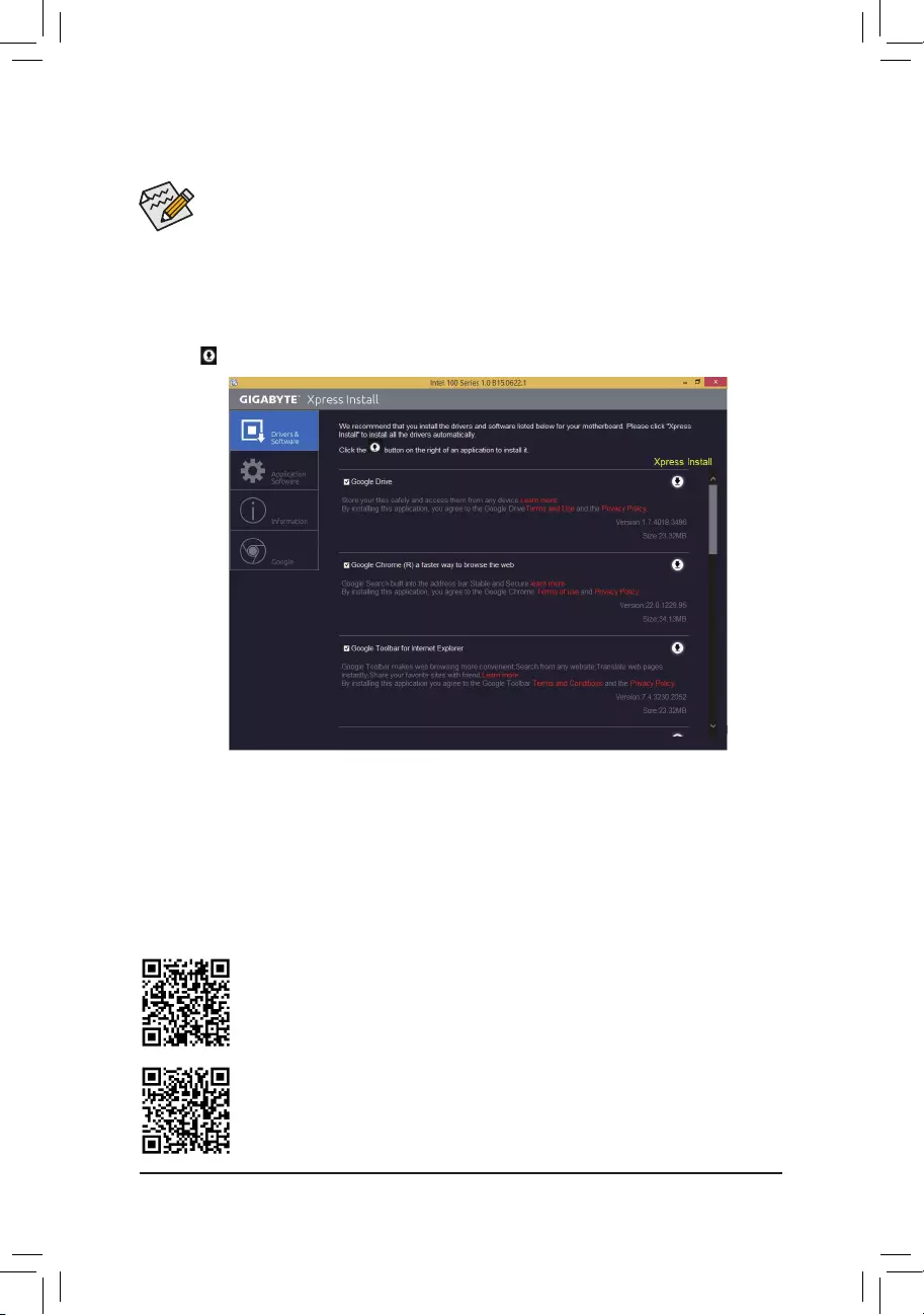
"Xpress Install" will automatically scan your system and then list all of the drivers that are recommended to
install. You can click the Xpress Install button and "Xpress Install" will install all of the selected drivers. Or click
the arrow icon to individually install the drivers you need.
Please visit GIGABYTE's website for more software information.
PleasevisitGIGABYTE'swebsitefordetailsonconguringtheaudiosoftware.
3-2 Drivers Installation
- 34 -

Regulatory Statements
Regulatory Notices
This document must not be copied without our written permission, and the contents there of must not be imparted
to a third party nor be used for any unauthorized purpose.
Contravention will be prosecuted. We believe that the information contained herein was accurate in all respects
at the time of printing. GIGABYTE cannot, however, assume any responsibility for errors or omissions in this text.
Also note that the information in this document is subject to change without notice and should not be construed
as a commitment by GIGABYTE.
Our Commitment to Preserving the Environment
Inaddition to high-efciencyperformance, all GIGABYTEmotherboards fulllEuropeanUnion regulations
forRoHS(RestrictionofCertainHazardousSubstancesinElectricalandElectronicEquipment)andWEEE
(WasteElectricalandElectronicEquipment)environmentaldirectives,aswellasmostmajorworldwidesafety
requirements. To prevent releases of harmful substances into the environment and to maximize the use of our
natural resources, GIGABYTE provides the following information on how you can responsibly recycle or reuse
most of the materials in your "end of life" product.
Restriction of Hazardous Substances (RoHS) Directive Statement
GIGABYTEproductshavenotintendedtoaddandsafefromhazardoussubstances(Cd,Pb,Hg,Cr+6,PBDE
andPBB).ThepartsandcomponentshavebeencarefullyselectedtomeetRoHSrequirement.Moreover,weat
GIGABYTE are continuing our efforts to develop products that do not use internationally banned toxic chemicals.
Waste Electrical & Electronic Equipment (WEEE) Directive Statement
GIGABYTEwillfulllthenationallawsasinterpretedfromthe2002/96/ECWEEE(WasteElectricalandElectronic
Equipment)directive.TheWEEEDirectivespeciesthetreatment,collection,recyclinganddisposalofelectric
andelectronicdevicesandtheircomponents.UndertheDirective,usedequipmentmustbemarked,collected
separately, and disposed of properly.
WEEE Symbol Statement
The symbol shown below is on the product or on its packaging, which indicates that this product
must not be disposed of with other waste. Instead, the device should be taken to the waste collection
centers for activation of the treatment, collection, recycling and disposal procedure. The separate
collection and recycling of your waste equipment at the time of disposal will help to conserve
natural resources and ensure that it is recycled in a manner that protects human health and the environment.
For more information about where you can drop off your waste equipment for recycling, please contact your
localgovernmentofce,yourhouseholdwastedisposalserviceorwhereyoupurchasedtheproductfordetails
of environmentally safe recycling.
When your electrical or electronic equipment is no longer useful to you, "take it back" to your local or regional
waste collection administration for recycling.
If you need further assistance in recycling, reusing in your "end of life" product, you may contact us at the
Customer Care number listed in your product's user's manual and we will be glad to help you with your effort.
Finally, we suggest that you practice other environmentally friendly actions by understanding and using the
energy-savingfeaturesofthisproduct(whereapplicable),recyclingtheinnerandouterpackaging(including
shippingcontainers)thisproductwasdeliveredin,andbydisposingoforrecyclingusedbatteriesproperly.
With your help, we can reduce the amount of natural resources needed to produce electrical and electronic
equipment,minimizetheuseoflandllsforthedisposalof"endoflife"products,andgenerallyimproveour
quality of life by ensuring that potentially hazardous substances are not released into the environment and are
disposed of properly.
- 35 -

FCC Notice (U.S.A. Only)
This equipment has been tested and found to comply with the limits for a Class B digital device, pursuant to Part
15oftheFCCRules.Theselimitsaredesignedtoprovidereasonableprotectionagainstharmfulinterference
in a residential installation. This equipment generates, uses, and can radiate radio frequency energy and, if not
installed and used in accordance with the instructions, may cause harmful interference to radio communications.
However, there is no guarantee that interference will not occur in a particular installation. If this equipment does
cause harmful interference to radio or television reception, which can be determined by turning the equipment
off and on, the user is encouraged to try to correct the interference by one or more of the following measures:
Reorientorrelocatethereceivingantenna.
Increase the separation between the equipment and receiver.
Connect the equipment into an outlet on a circuit different from that to which the receiver is connected.
Consult a dealer or experienced TV/radio technician for help.
Canada, Industry Canada (IC) Notices / Canada, avis d'Industry Canada (IC)
ThisClassBdigitalapparatuscomplieswithCanadianICES-003andRSS-210.
Operationissubjecttothefollowingtwoconditions:(1)thisdevicemaynotcauseinterference,and(2)this
device must accept any interference, including interference that may cause undesired operation of the device.
CetappareilnumériquedeclasseBestconformeauxnormescanadiennesICES-003etRSS-210.
Sonfonctionnementestsoumisauxdeuxconditionssuivantes:(1)cetappareilnedoitpascauserd'interférence
et(2) cet appareildoit accepter touteinterférence, notammentles interférences quipeuvent affecterson
fonctionnement.
- 36 -

- 37 -

- 38 -

- 39 -
Contact Us
GIGA-BYTE TECHNOLOGY CO., LTD.
Address:No.6,BaoqiangRd.,XindianDist.,NewTaipeiCity231,Taiwan
TEL: +886-2-8912-4000, FAX: +886-2-8912-4005
Tech.andNon-Tech.Support(Sales/Marketing):http://esupport.gigabyte.com
WEBaddress(English):http://www.gigabyte.com
WEBaddress(Chinese):http://www.gigabyte.tw
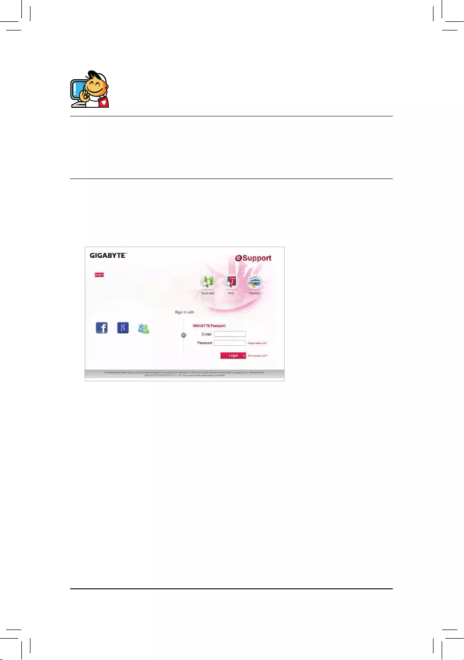
•GIGABYTE eSupport
Tosubmitatechnicalornon-technical(Sales/Marketing)question,pleaselinkto:
http://esupport.gigabyte.com
- 40 -