Table of Contents
- The battery cartridge typically lasts 3 to 6 years, a shorter period if subjected to frequent out...
- If the Back-UPS arrived damaged, notify the carrier.
- If the Back-UPS requires service, do not return it to the dealer.
- Have the Back-UPS model number, serial number and date of purchase available. Be prepared to trou...
- If this is not successful, APC will issue a Return Merchandise Authorization (RMA) number and a s...
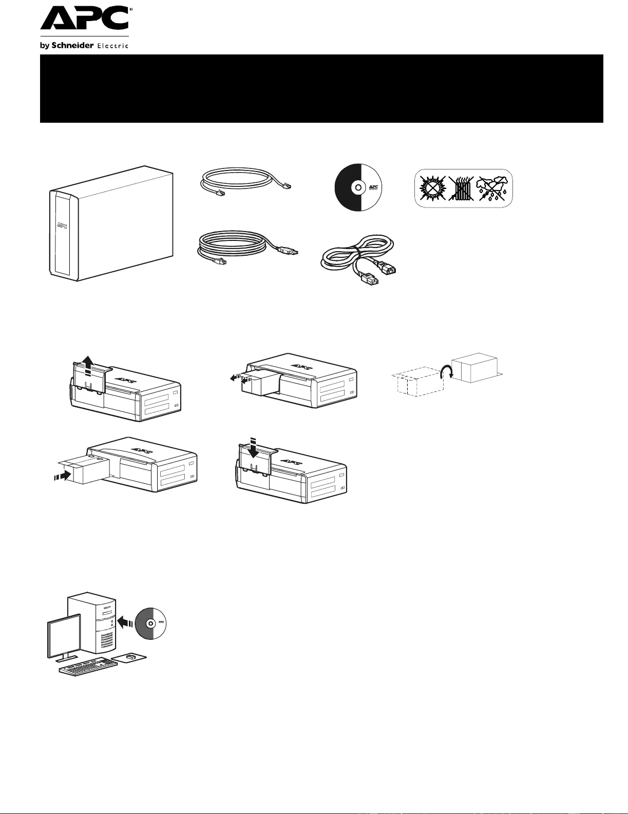
- Inventory
- Safety
- Connect the battery
- Install PowerChute® Personal Edition Software
- Connect the equipment
- When the Back-UPS is receiving input power, the Battery Backup with Surge Protection outlets will...
- Connect equipment such as printers, fax machines, scanners, or other peripherals that do not need...
- To conserve electricity, when the device connected to Master Outlet goes into Sleep or Standby mo...
- Connect a master device, such as a desktop computer or audio/visual receiver to the Master outlet...
- USB and Serial Data port
- To use PowerChute Personal Edition, connect a serial cable or USB cable.
- Telephone cable surge- protected ports
- Connect a telephone cable to the In port, and connect a modem to the Out port.
- Ground screw
- Connect the ground lead of additional surge suppression devices such as network and data line sur...
- Surge Protected outlets, controlled by the Master outlet
- These outlets are protected from electrical surges, and will disconnect from utility power during...
- Surge Protected outlets
- These outlets provide full-time protection from surges, even if the Back-UPS is off. Connect equi...
- AC power outlet
- Connect the unit to utility power, use the supplied power cord.
- Battery Backup outlets with Surge Protection
- During a power outage or other utility problems, the Battery Backup outlets receive power for a l...
- Battery Backup outlet with Surge Protection, controlled by the Master outlet
- These outlets will supply battery power to the connected equipment during a power outage. Power w...
- Master outlet
- Connect the master device to this outlet, in most scenarios, this will be the main computer.
- External Battery Pack connector (BR1500GI only)
- Connect an external battery pack to provide additional battery backup runtime (Back-UPS Pro 1500 ...
- In & Out Ethernet surge- protected ports
- Use an ethernet cable to connect a cable modem to the In port, and connect a computer to the Out ...
- Operation
- To conserve electricity, configure the Back-UPS to recognize a Master device, such as a desktop c...
- Enable the Power-Saving function
- Disable the Power-Saving function.
- Setting the threshold
- The amount of power used by a device in Sleep or Standby mode varies between devices. It may be n...
- 1 . Ensure a master device is connected to the Master outlet. Put that device into Sleep or Stand...
- 2 . Press Display and Mute simultaneously and hold for six seconds, until the leaf icon flashes t...
- 3 . The Back-UPS will now recognize the threshold level of the Master device and save it as the n...
- The display interface can be configured to be continuously illuminated, or to save energy, it can...
- 1 . Full Time Mode: Press and hold DISPLAY for two seconds. The display will illuminate and the B...
- 2 . Power-Saving Mode: Press and hold DISPLAY for two seconds. The display will darken and the Ba...
- Adjust the sensitivity of the Back-UPS to control when it will switch to battery power; the highe...
- 1 . Ensure the Back-UPS is connected to utility power, but is OFF.
- 2 . Press and hold the Power button for six seconds. The Load Capacity bar will flash on and off,...
- 3 . Press Power again to rotate through the menu options. Stop at selected sensitivity. The Back-...
- Use the three buttons on the front panel of the Back-UPS and the display interface to configure t...
- Mute button
- Power On/Off button
- Display button
- Display interface
- On Line—The Back-UPS is supplying conditioned utility power to connected equipment
- Power-Saving—Master and Controlled outlets are enabled, saving power when the master device goes ...
- Load Capacity—The load is indicated by the number of sections illuminated, one to five. Each bar ...
- Battery Charge—The battery charge level is indicated by the number of sections illuminated. When ...
- Overload—The power demand from the load has exceeded the capacity of the Back-UPS.
- Event—The event counter shows the number of events that occurred that caused the Back-UPS to swit...
- Automatic Voltage Regulation—The Back-UPS can compensate for high or low input voltage.
- When illuminated, the Back-UPS is compensating for low input voltage.
- When illuminated, the Back-UPS is compensating for high input voltage.
- Input voltage.
- Output voltage.
- System Faults—The system has a fault. The fault number will illuminate on the display interface. ...
- Mute—If the line through the speaker icon is illuminated, the audible alarm has been turned off.
- Replace Battery—The battery is not connected or is nearing the end of its useful life. Replace th...
- On Battery—The Back-UPS is supplying battery backup power to the connected equipment, it will bee...
- Warnings and System Faults
- Four Beeps Every 30 Seconds
- Continuous Beeping
- Continuous tone
- Chirps for 1 Minute every 5 hours
- Battery fails the automatic diagnostic test and should be replaced.
- The Back-UPS is operating on utility power, but is overloaded. Disconnect one of the items connec...
- The Back-UPS is operating on battery power, but is overloaded. Disconnect one of the items connec...
- The Back-UPS is operating on utility power, but the battery is not functioning properly. Contact ...
- The Back-UPS is operating on battery power and the battery power is getting low. Shut down all co...
- The Back-UPS will display these fault messages. For faults F01 and F02, contact APC Technical Sup...
- F01
- F02
- F03
- F04
- F05
- F06
- F07
- F08
- F09
- Function Button Quick-Reference
- 0.2
- Off
- 2
- On
- 0.2
- On
- 2
- On
- 0.2
- On
- 2
- On
- 6
- Off
- 2
- On
- 6
- On
- 6
- On
- 0.2
- On
- 2
- Fault
- After a fault has been identified, press Power to remove the visual indication and return to stan...
- Troubleshooting
- Specifications
- Model
- BR1200GI
- BR1500GI
- VA
- 1200 VA
- 1500 VA
- Maximum Load
- 720 W
- 865 W
- Nominal Input Voltage
- 230 V
- Online Input Voltage Range
- 176 - 294 V
- Automatic Voltage Regulation
- (188-216) +11.2%
- (252-282) -11.2%
- Frequency Range
- 50/60 Hz ± 1 Hz
- On-battery Waveshape
- Step-approximated sine-wave
- Typical Recharge Time
- 8 hours
- Transfer Time
- 10 ms, maximum
- Operating Temperature
- 08 to 408C (328 to 1048F)
- Storage Temperature
- -158 to 458C (238 to 1138F)
- Unit Dimensions
- 30.1 ° 11.2 ° 38.2 cm (11.9 ° 4.4 ° 15.0 in)
- Unit Weight
- 12.8 kg (28.2 lbs)
- 13.4 kg (29.5 lbs)
- Interface
- Serial, USB
- On-Battery Runtime
- Go to: www.apc.com
- EMI Classification
- CE, C-Tick, KETI
- Approvals
- CE, TUV-GS, GOST, A-Tick, KETI, TISI
- The standard warranty is three (3) years from the date of purchase, valid in European Community. ...
APC Back-UPS Pro User Manual
Displayed below is the user manual for Back-UPS Pro by APC which is a product in the Uninterruptible Power Supplies (UPSs) category. This manual has pages.
Related Manuals
Back-UPS® Pro 1200/1500 230V
Installation and Operation
Connect the battery
Install PowerChute® Personal Edition Software
APC PowerChut e Persona l Edition software prov ides automatic file saving and shutdown of
your computer in the event of a power failur e. Use the cable supplied with the Back- UPS to
connect the data port on the Back-UP S to the USB port on your computer. Place the CD into
your computer, an d follow the on-scree n instructions.
Inventory Safety
Do not install the Back-UPS in di rect
sunlight , in excessive heat, hum idity, or
in contact with fluids.
bu001a
(2)
bu055a
bu057a
bu059a
bu058a
bu060a
Back-UPS Pro 1200 & 1500 230 V Installation and Operation2
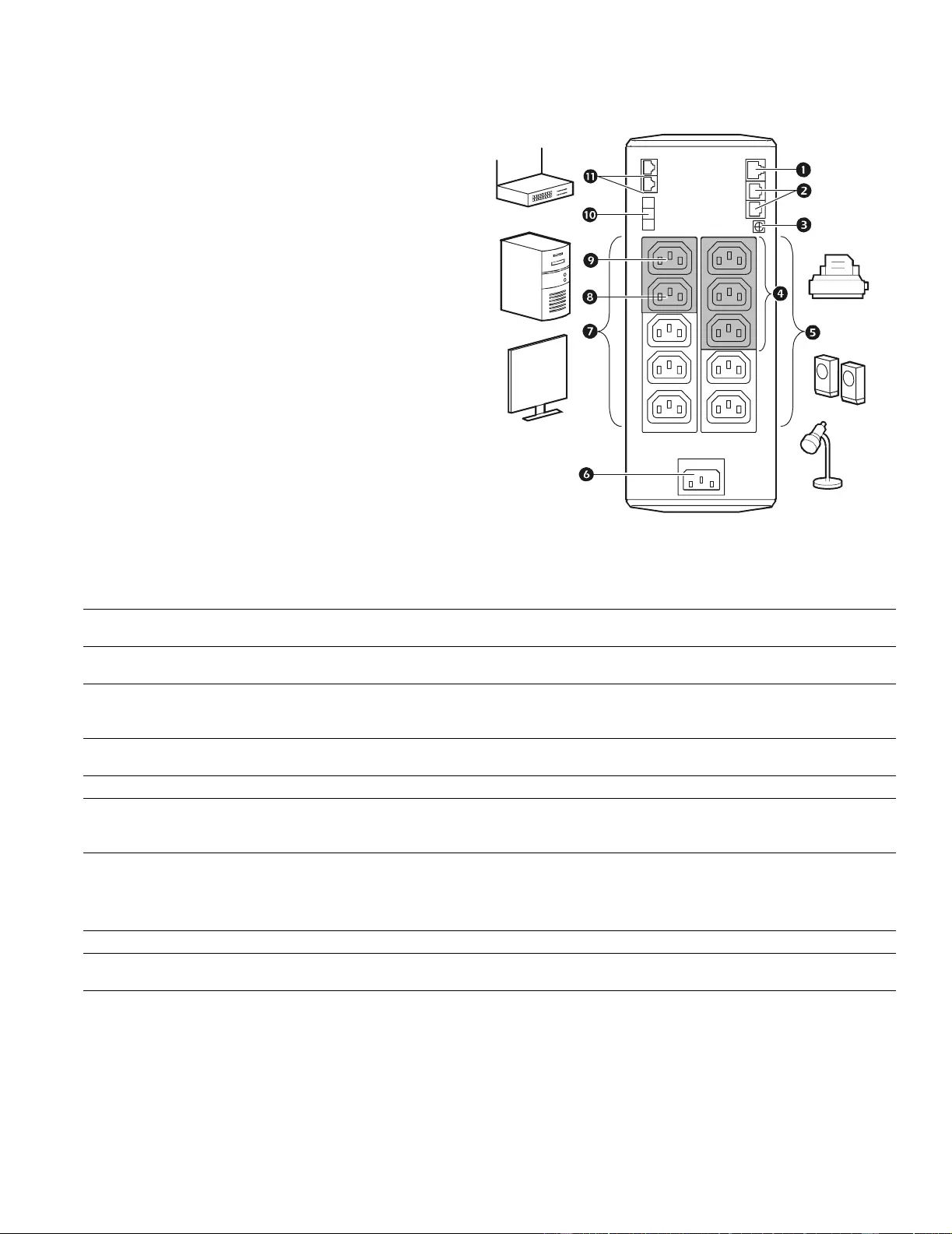
Connect the equipment
Battery Backup and Surge Protected outlets
When the Ba ck-UPS is receiving input power, the
Battery Backup with Surge Protection outlets will
supply power to connected equipment. During a
power outage or other utilit y problems, the Batte ry
Backup outlets r eceive power for a limite d time from
the Back-UP S.
Connect equipment such as printer s, fax machin es,
scanners, or other peripherals that do not need
battery backup power to the Surge Protection Only
outlets. These outl ets provide full- time protecti on
fro m s urges ev en if the Back -UP S i s sw itched OFF.
Master and Controlled outlets
To conserve electricity, when the device connected
to Master Outle t goes into Sl eep or S tandby mode, or
turns Off , the Contr olled de vice(s) will shu t down as
well, saving e lectri city.
Connect a master device, such as a desktop
computer or audio/visual receiver to the Master
outlet. Connect peripher al devices suc h as a printer, speakers, or a scanner to the Controlled outlets.
USB and Serial Data port To use PowerChute Personal Edition, connect a serial cable or USB cable.
Telephone cable surge-
protected ports Connect a telephone cable to the I N port, an d connect a modem to the OUT port.
Ground scr ew Connect t he ground lea d of addi tiona l surg e supp ressio n device s suc h as networ k an d data line
surge prot ectors.
Surge Protected outlets,
con trolled by the Master
outlet
These outlets are protected from electrical surges, and will disconnect from utility power d uring
a power outage, or if the Master dev ice goes into Sl eep or Stand by mo de.
Surge Protected outlets These outlets provide full-time protection from surges, even if the Back-UPS is off. Connect
equipment such as pr inters and scanners that do not r equire battery backup protection.
AC power outl et Connect the unit to utility power, use the supplied power cord.
Batter y Backup outlets wit h
Surge Protection During a power outage or other utili ty problems, t he Battery Backup out lets recei ve power for a
limited time from the Back-UPS. Co nnect critical equip me nt such as deskt op computer,
computer monitor, modem or othe r dat a sensitive devices int o these outlets.
Batter y Backup outlet with
Surge Prot ection, controlled
by the Master outlet
These outl ets will supply batte ry power to t he connected equipment during a power outage.
Power will be dis connected to these outlets if the Mast er devi ce goes into Sleep or Standby
mode. Connect equi pment such as a computer monit or t o these outlets.
Master outlet Connect the master device to this outlet, in most scenarios, this will be the main com puter.
External Battery Pack
connector (BR1500GI only) Connect an ext ernal battery pack to provide addi ti onal battery back up runt ime (Back-UPS Pro
1500 only).
In & Out Etherne t surge-
protected ports Use an ethernet cable to connect a cab le modem to the IN port, and connect a c om puter to the
OUT port.
bu146a

Back-UPS Pro 1200 & 1500 230 V Installation and Operation 3
Operation
Power-Sa ving Functio n
To conserve electr icity, con fi gure the Back-UPS to recogniz e a Mas ter device, such as a desktop
computer or an A/V receiver, and Controlled peripheral devices, such as a printer, speakers, or a scanner.
When the Master device goes into Sleep or Standby m ode, or is switched OFF, the C ontrolled device(s)
will be switched off as well, saving elec tricity.
Enable the Power-Saving function. Press and hold MUTE and DISPLAY simultaneously for two second s. The
Back-UPS will beep to indicate that the feature is enabled. The leaf icon on the display will illumin ate.
Disable the Power-Saving function. Press and hold MUTE and DISPLAY simulta neously for two se conds. The
Back-UPS will beep to indicate that the feature is disabled. The leaf icon on the displa y will darken.
Setting the threshold. The amount of power used by a device in Sleep or Sta ndby mode varies between devic es. It
may be necessary to adju st the threshold at which the Master outle t signals the Controlled outlets to shut down.
1. Ensure a master device is connect ed to the Maste r outlet. Pu t that device into Slee p or Standby mode, or turn it
OFF.
2. Press DISPLAY and MUTE simultane ously a nd hold for six seconds, until the leaf icon flashes three tim es and the
Back-UPS beeps three times.
3. The Back-UPS will now recognize the thr eshold leve l of the Master device and save it as the new threshold setting.
Power-Saving Display
The display interface can be configured to be c ontinuously illuminated, or to save energy, it can be configured to
darken after a period of inact ivity.
1. Full Time Mode: Press and hold DISPLAY for two seco nds. The display will illumina te and the Back-UPS will beep
to confirm the Full-Tim e mode.
2. Power-Saving Mode: Press and hold DISPLAY for two seconds. The displa y will darken and the Back-UPS will
beep to confirm the Power-Saving mode. While in Power-Saving Mode, the display will illuminate if a button is
pressed, it then darkens after 60 seconds of no activity.
Unit sensitivity
Adjust the sensitivity of the Back-UPS to control when it will switch to battery power; the higher the sensitivity, the
more often the Back-UPS will switch to battery power.
1. Ensure the Back-UPS is connecte d to utility power, but is OFF.
2. Press a nd hold the POWER button for six seconds. The LOAD CAPACITY bar will fla sh on and off, i ndicating that the
Back-UPS is in programming mode.
3. Press POWER aga in to rotate through the menu options. Stop at sele cted se nsitivity. The Back-UPS will beep to
confirm the selection.
Low sensitivity Medium sensitivity (Default) High sensitivity
156-300 Vac 176-294 Vac 176-288 Vac
Input voltage i s extremely low or
high. (Not recommended for
com puter loads.)
The Back-UPS frequently swi tches to
batter y power. The connected equipment is
sensitive to voltage fluctuations.
Back-UPS Pro 1200 & 1500 230 V Installation and Operation4
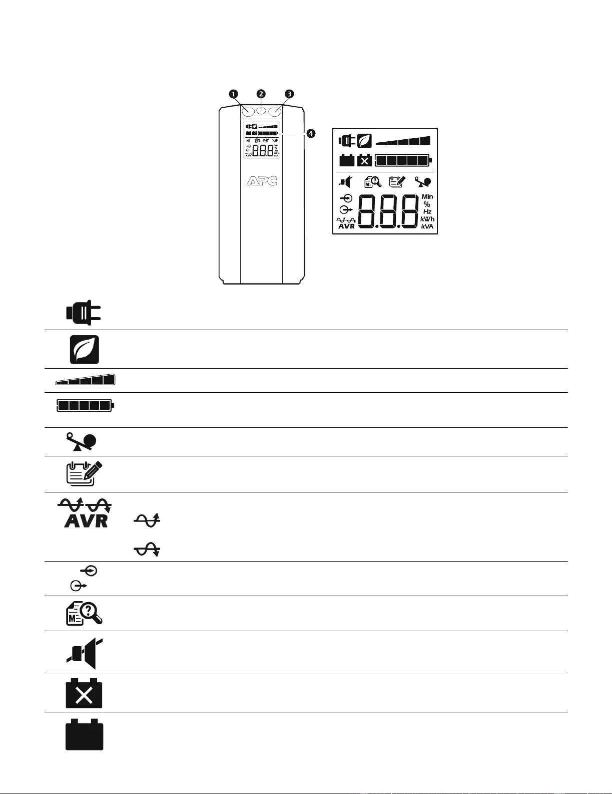
Front Panel Butto ns and Display Interfac e
Use the three buttons on the front panel of the Back-UPS and the display inte rface to confi gure the Back-UPS.
Front panel
Mute button
Power On/Off button
Displ ay but ton
Displ ay interface
On Line—The Back-UPS is supplying conditioned utility power to connected equipment
Power-Saving—Master and Contr olle d outl ets are enabled, saving power when the master devi ce goes int o
sleep or standby mode
Load Capacity—The load is indicated by the number of sect ions illumi nated, one to five. Each bar represents
20% of the load.
Battery Charge—T he battery charge le vel is indicated by the number of sections illuminated. When all fi ve
bloc ks are il luminat ed, the Back -UPS is at full ch arge. When one bl ock is fill ed, the Back -UPS is near the end of
its battery capacity, the indicator will fl ash and the Back-UPS will beep continu ously.
Overload—The power demand from the lo ad has exceeded the cap acity of the Back-UPS.
Event—The event counte r shows the number of events that occurred that caused the Back -UPS to switch to
on-batt e ry op erati o n.
Automatic Volt age Regulation—The Back-UPS can compensate for high or low input voltage.
When ill um inate d, th e Back-UPS is compen satin g for low inp ut vol tage.
When i lluminat ed, the Back-UPS is compensati ng for high input voltage.
Input voltage.
Output voltage.
System Fault s—Th e system has a fault. The fault num ber wil l i lluminate on the display interf ace. See “Syst em
Faults” on page 5.
Mute—If the l ine through the speaker icon is illum inated, the audible alarm has been turned off.
Replace Battery—The batter y is not connected or is nearing the end of its useful life. Replace the battery.
On Battery—The Back-UPS is supplyin g batt ery backup power to the connected equipment, it will beep four
tim es every 30 seconds.
bu044a
bu002a
Back-UPS Pro 1200 & 1500 230 V Installation and Operation 5
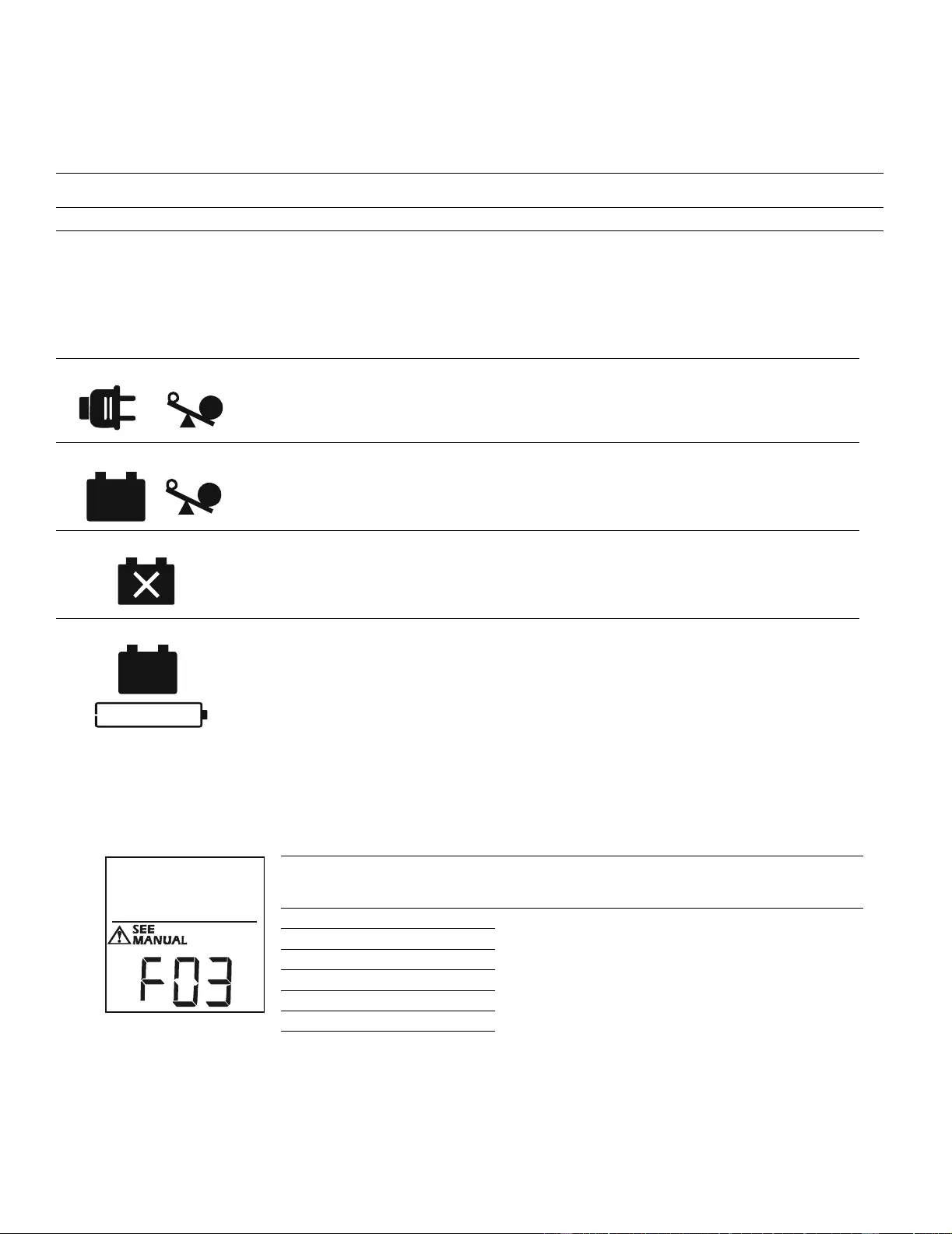
Warnings and System Faults
Au dible Wa rn ings
Wa rning Icons
System Faults
The Back-UP S will display these fault messages. For faults F01 and F 02, c ontact APC Technical S upport.
Fo ur Beeps E v ery 30 Seconds Back-UPS is running on battery. You should consider saving any work in progress.
Contin uous Beep ing Low batt ery condi tion and batter y run-t ime is ver y low. Promptl y save any wor k in progr ess, exi t
all ope n applications , and shut down the operating system.
Contin uous tone Battery Backup outputs are overloa ded.
Chi rp s f o r 1 Mi n ut e ev er y 5 hours Battery fail s the automatic diagnostic tes t and should be replaced.
If these ic o ns are
illumina ted... T his may be the problem.
The Back-UPS is operating on util it y power, but is overl oaded. Disconnect one of the items
connected to the Back-UPS. If the Overload icon stops fl ashing, the Back-UPS is no longer
overloaded and will conti nue to operat e normally.
The Back-UPS is operating on battery power, but is overl oaded. Disconnect one of the items
connected to the Back-UPS. If the Overload icon stops fl ashing, the Back-UPS is no longer
overloaded and will conti nue to operat e normally.
The Back-UPS i s operati ng on uti lity power, but the batt ery is not funct ioni ng properly. Cont act APC
Customer Service to order a repl acem ent battery. See “Replacem ent Battery” on page 8.
The Back-UPS is operating on battery power and the battery power is gett ing low. Shut down all
connected equipment to avoid losing an unsaved dat a. When possible, connect the Back-UPS to
utility power to recharge the batter.
F01 On- Battery Overload Turn t he Back-U PS off. Disconnect non-essential
equipment from the Battery Backup outlets and the t urn
Back-UPS on.
F02 On- Battery Output Short Turn the Back-U PS off. Disconnect non-essential
equipment from the Battery Backup outlets and the t urn
Back-UPS on.
F03 On- Battery Xcap Overload
Faults F03-F09 cannot be corrected by the user, contact
APC Technical Support for assistance.
F04 Clamp Sho r t
F05 Charge Fault
F06 Relay Welding
F07 Temperature
F08 Fan Fault
F09 I nternal Fault
b
u
0
8
8
a
Back-UPS Pro 1200 & 1500 230 V Installation and Operation6
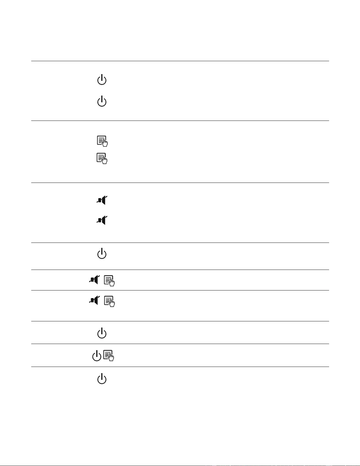
Function Button Quick-Reference
Function Button Timing
(seconds) UPS
Status Description
Power
Power On 0.2 Off Press POWER to start receiving input utility power. If A/C input
power is not available, t he Back-UPS will run on battery power.
Power Off 2On
The Back-UPS is not receiving input ut il ity power, but i s providing
surge protec ti on.
Display
Stat us Inquiry 0.2 On Verify the statu s or conditi on of th e Back-UPS. The LCD will
illuminate for 60 seconds.
Full-Time/Power-
Saving mode 2On
The LCD will illumina te and the Back-UPS will beep to co nfi rm the
Full-Time mode. The LCD will darken and the Back-UPS will beep
to conf ir m the Power-Saving mode. Whi le in Power-Saving Mode,
the LCD will i lluminat e if a but ton is pressed, then dark ens afte r 60
seconds of no activity.
Mute
Event Specific 0.2 On Disabl e any audible alarms caused by an event.
General Status Enable/
Disable 2On
Enable or disable the audible ala rms. The Mu te icon will illumina te
and the Back-UPS will beep one time. The Mute function will not
activate unless the Back-UPS is operating on battery power.
Sensitivity 6Off
The Load Capacity icon will b lin k , ind ic a tin g th at the B ack -U P S is
in programming mode. Use the POWER button to scroll thr ough
Low, Medium, and High, stop at selected sensitivity. The Back-
UPS will beep to conf irm selectio n. See Conf iguration for details.
Master/Controll ed
outlet Enable/ D isable 2On
The leaf icon will darken indicat ing that the Master Outl et feature is
disabl ed or illuminate to indicate the Master Outlet feature is
enabled. The Back-UPS will beep once.
Master/Enable
Threshold Calibr ation 6On
While cal ibrat ing the thr eshold setting, the device connect ed to the
Master Outlet should be tu rned of f or placed in Standby or Sle ep
mode. Upon completion, Power-Saving icon will flash 3 and beep
3 times.
Self -Test ( manual) 6On
The Back- UPS will perf orm a tes t of t he int ernal batte ry. Note: Thi s
will happen automatically when the Back-UPS is tur ned O N.
Event Reset 0.2 On When the Event screen is visi ble, press and hold DISPLAY, th e n
press POWER, to clear the utility fai lure event counter.
Fault Reset 2Fault
After a faul t has been iden ti fied, press POWER to remove the
visual indication and return t o standby status.

Back-UPS Pro 1200 & 1500 230 V Installation and Operation 7
Troubleshooting
Pro b lem Po ssible Cause Corrective Ac tion
Back-UPS will not switch on. The Ba ck-UPS is not connected to utility
power. Ensure that the Back-UPS is secur ely connected
to an A C outlet.
The circuit breaker has be en tripped. Disc onnect no n-essential equipment from the
Back- UPS. Reset the ci rcuit break er . Re-connect
equ i pmen t on e it em at a tim e . If th e ci r cu i t
breaker is tripped again, disconnect the device
tha t cau s ed th e trip .
The internal battery is not connected. Connect the battery.
The ut ility input voltage is out of range. Adj us t the transf er voltage and sens itivity range.
The Back - UPS d o es not
provide power during a utility
power outage.
En su r e th at es s e n t ia l equ ip men t is not
plugged into a SURGE ONLY outlet. Disc onnect equipment from the SURGE ONLY
outlet and re-connect to a Bat tery Backup outlet.
The Back-UPS is operating on
battery power, while connected
to utility power.
The pl ug has partially pulled o ut of the wall
outlet, the wall outlet is no longer receiving
utility powe r, or the ci rcuit breake r has been
tripped.
En su r e that th e pl ug is f u ll y in s er te d in to th e
wa ll outlet. Ensure that the wall outle t is
receiving utility power by checking it with
another device.
The Back-UPS is performing an automatic
self test. No ac tion is necessary.
The ut ility input voltage is out of range, the
frequency is out of range , or the waveform
is di st orted.
Adjust the transf er voltage and sens itivity range.
The Back - UPS d o es not
provide the expected amount of
backup time.
Battery Backup outlets may be fully or
improperly loaded . Disconnect non-essential equipment from the
Battery Backup outlets and connect the
equipment to SURGE ONLY outlets.
The batte ry was recently disc har ged du e to a
power outage and has not fully recha rged. Charge the battery cartridge for 16 hours.
The battery has rea ched the end of its useful
life. Replace the battery.
The REPLACE BATTERY
indicator is illuminated. The battery has rea ched the end of its useful
life. Replace the battery.
The OVERLOAD indicator is
illuminated. The equipm ent connected to the Back-UPS
is draw i n g m o re p o w er th an th e B ack- UP S
can provide.
Disconnect non-essential equipment from the
Battery Backup outlets and connect the
equipment to SURGE ONLY outlets.
The SYSTEM FAULT i nd icator is
illuminated, all the front panel
indicators are flashing.
There is an internal fault. De termine wh ich internal fault mess age is
displayed by matchi ng the number displayed on
the LC D with the corresponding Fault Mes s age
(se e Syst em Faults) and contact APC Technical
Support.
Power is not supplied to some
outlets. Power to the Controlled outlets has
intentionally been turned off. Con f ir m that the correct p er ipherals are
connected to Cont rolled ou tlets. If this feature is
not desired, disable the Power-Saving Master
and Controlled outlets.
Th e C on t roll ed ou tl et s are not
su pp lying p o w er, even though
the M aster devi ce is not in slee p
mode.
The Mast er Outlet thresh old m ay be
incorrectly set. Adjust the threshold when the Mast er outlet
signals the Cont rolled outlets to shut down.

Cust omer support and warranty information is availabl e at the APC Web site, www.apc.com.
© 03/2010 APC by Schneider Electric. All trademarks are owned by Schnei der Electri c Industries S.A.S., Ameri can
Power Conversio n Corporati o n, or their affiliate d com panies. 990-3889A
3/2010
Specifications
t
Warranty
The standard warranty is three (3) ye ars fro m t he date of purc hase, va lid in Eur opean Com munity. For all other regions, the standard warranty
is two (2) years fro m the date of pur chase. APC’s standard pro cedure is to replace the orig inal unit with a factory r econditi oned unit.
Custom ers who mu st hav e the original unit b ack due to the assignment of asset ta gs and set depreciati on schedul es must declar e such a need at
first contact with an APC Technic al Support represent ative. APC will ship the replaceme nt unit once the defective unit has be en re ce ive d by
the repair d epartment, o r cross-ship upon the receipt of a v alid credit card num ber. The customer pays for shipping the unit to APC. APC pays
ground freight transportation costs to sh ip the repl acement unit to the customer.
APC Worldwide Cu stom er Suppor t
Model BR1200GI BR1500GI
VA 1200 VA 1500 VA
Maximum Load 720 W 865 W
Nominal Input Voltage 230 V
Onl ine Input Voltage Range 176 - 294 V
Automa tic Voltage Regulation (188-216) +11.2%
(252-282) -11.2%
Frequency Range 50/60 Hz ± 1 Hz
On-battery Waveshape Step-approximated sine-wave
Typical Recharge Ti me 8 hour s
Transfer Time 10 ms, maximum
Oper ating Temperature 0 to 40C (32 to 104F)
S torage Te m peratur e -15 to 45C (23 to 113F)
Unit Dim ensions 30.1 × 11.2 × 38.2 cm (11. 9 × 4.4 × 15.0 in)
Uni t Weig ht 12 .8 kg (28.2 lbs) 13.4 kg (29.5 lbs)
Interface Serial, USB
On -B a tt e ry Ru nt im e Go to : w w w. ap c .c om
EMI Classif ic ation CE, C-Tick, KETI
Approvals CE, TUV-GS, GOST, A-Tick, KETI, TI SI
Internet http://www.apc.com
Worldwide +1 888 272-3858
Replacement Battery
The battery cartridge typically lasts 3 to 6 years, a shorter
period if s ubjected to frequ ent outa ges or elevated
temperatures. Battery replacement part for Back-UPS Pro 1200
and 1500 is APCRBC124. Please recycle spent battery
cartridges.
Service
If the Bac k-UPS a rrived damaged, notify the ca rrier.
If the Back-UP S requires service, do not return it to the dealer.
1. Consult the Troubleshooting secti on to eliminate com mon
problems.
2. If the problem persists, go to http://www.apc.com/support/ .
3. If the problem still persists, contact APC Technical Support.
Have the Back-UPS mod el number, serial number and date of
pu rchase av ailable. Be prepared to troubl eshoot the problem
with an APC Technical Support representa tive.
I f this is not successful, APC will issue a Ret urn Merchandise
Authorization (RMA) number an d a shipping address.