Table of Contents
- Inventory
- Safety
- Connect the battery
- PowerChute® Personal Edition Software
- Overview
- Compatibility
- Installation
- Connect the equipment
- Battery Backup and Surge Protected outlets
- Master and Controlled outlets
- Operation
- Power-Saving Function
- Power-Saving Display
- Unit sensitivity
- Front Panel Buttons and Display Interface
- Warnings and System Faults
- Audible Warnings
- Warning Icons
- System Faults
- Function Button Quick-Reference
- Troubleshooting
- Specifications
- APC Customer Support Worldwide
- Warranty
- Service
APC Back-UPS Pro User Manual
Displayed below is the user manual for Back-UPS Pro by APC which is a product in the Uninterruptible Power Supplies (UPSs) category. This manual has pages.
Related Manuals
Installation and Operation Manual
Back-UPS® BR900G-GR
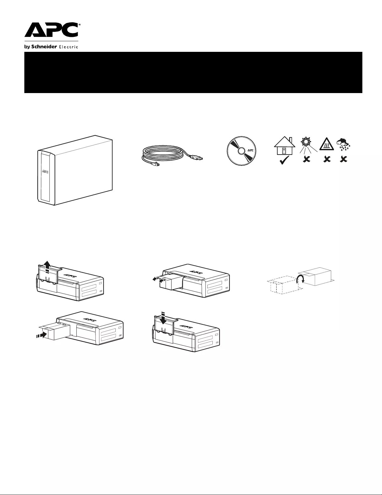
Connect the battery
Inventory Safety
This unit is intended for in door use
only .
Do not operate thi s unit in direct
sunl ig ht, in cont act with flu ids , or where
there is excessive dust or humidity.
123
45 Ch arg e th e ba tt er y fo r at lea st 1 6
hours bef ore use
bu001a
bu055a
bu057a
bu059a
bu058a
bu060a

Back-UPS BR900G-GR Insta ll ation and Operati on2
PowerChute® Personal Edition Software
Overview
PowerChute Personal Editi on Software allows you to use your computer to access additional power pro tection and
management features of the Back-UPS.
Using PowerChute, you can:
• Preserve work in progress duri ng a power outage by putting your computer into Hibe rnate mode. When the
power returns, the computer will appear exactly as it did before the power outage.
• Configure the Back-UPS management features, such as power-saving outlets, shutdown parameters, audible
alar ms , and more.
• Monitor and view the status of the Back-UPS, including the estimated runtime, power consumption, power
event history, and more.
Available features will vary by Back-UP S model and opera ting system.
If you choose not to install PowerChut e, the Back- UPS will still provide backup power and power protection to
connected equipment. However, you will only be able to configure a limited number of features using the display
interface.
Compatibility
PowerChute is compatible with Windows operating systems only. For a detailed li st of supp orted operating systems,
go to www.apc.com, select Software & Firm ware.
For Mac operating systems, we recommend using the native shutdown appl ication (wit hin System Preferences)
which recognizes your battery backup and allows you to confi gure shutdown of your system during power outages.
To access this application, connect a USB cable from the Back-UPS DATA P ORT (POWERCHUTE PORT) to a USB port
on your computer, and see the documentat ion provided with your computer.
Installation
Connect the Back-UPS to a computer using a USB cable. Plug one end into the POWERCHUTE PORT on the rear panel
of the Back-UPS and the other into a USB port on your computer.
Insert the Po werChute CD into your computer and follow the on-screen ins truct ions. If your Back-UPS did not come
with a PowerChute CD, download the software from www.apc.com, se lec t Software & Firmware.
Back-UPS BR900G-GR Install ation and Operation 3
Connect the equipment
Battery Backup and Surg e Protected outl ets
When the Back-UPS is receiving input power, the
Surge Protect ion only outlet s and the Battery
Backup with Surge Prote ction outlets will supply
power to connected equipment. Duri ng a power
outage or other utility problems, only the Battery
Backup outlets receive power for a limited time
fro m the Back -U P S.
Connect equipment such as print ers, FAX
machines, scann ers, or othe r perip herals that do not
need battery backup power to the Surge Protection
Only outlets. These outlets provide full time
protection from sur ges even if the Back-UPS is
switched off.
Master and Controlled outlets
To conserve electric ity, whe n the devic e connected
to Master Outle t goes into Sleep or Standby mode,
or turns off, the Controlle d by Master device(s)
will shut down as we ll, saving electricity.
Connect a master device, such as a desktop
computer or audio/visual receiver to the Master
outlet. Connect pe ripheral device s such as a printer ,
speakers, or a scanner to the Controlled by Master
outlets.
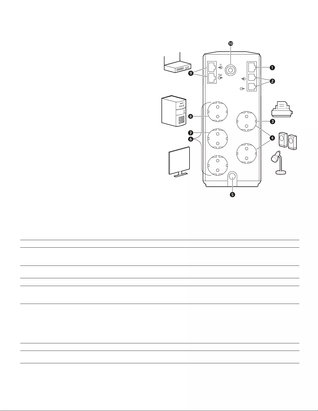
1USB and Serial Data port To use PowerCh ute Personal Edi ti on, connect the suppl ied USB software cable or seri al cable
(not incl uded).
2Telephone ports Connect a telephone cable to t he IN port , and a modem to t he OUT port.
3Surge Prot ection outlets,
Controlled by Master out let These outle ts provide surge protection during a power outage. These outl ets will disconnect
from A/C power durin g a power outag e, or in the event that the Mast er outlet goes into Sleep
mode.
4Surge Prot ection outlets These outle ts provide full -time surge protecti on, when the unit is turne d on or of f. Conne ct a
printer, scanner or other devices t hat do not requir e battery backup protection.
5AC Power Cable Connect the Back- UPS to A/C power.
6Battery Backup outle ts with
Surge Protection During a power outage or other utility problems, these outlets provide power from the
Back-UPS battery. Connect critical equipment suc h as desktop computer, computer moni tor,
mode m or other data sensitive devices to these outle ts.
7Battery Backup, Contr olled by
Master outle t with Surge
Protection
During a power outage or other utility problems, these outlets provide power from the
Back-UPS battery.
These outle ts will disconnec t from A/C power during a power outage, or in the event that th e
Mas ter outl et goes i nto Sl eep m ode.
Connect critical equipment such as desktop computer, computer moni tor, modem or other d a ta
sensitive devices t o these outlets.
8Master outlet Connect the master device to t his outlet, in most scenarios, t his will be the main computer.
9Gigabi t Ethe rnet
surge-prot ected ports Use an Ethernet cable to connect a modem to the IN port, and a computer to the OUT por t.
:Circuit breaker Use to reset the syst em after an overload or short cir cuit.
bu214a
Tel Out
Tel In
USB &
Serial
Battery
Backup Surge
Only
MASTER
Controlled by MASTER
Controlled by MASTER

Back-UPS BR900G-GR Insta ll ation and Operati on4
Operation
Power -Saving Fun ction
To conserve electricity, configure the Back-UPS to recognize a Master device, such as a desktop
computer or an A/V r eceiver, and Cont rolled peripheral devices, such a s a printer, speak ers, or a scanner.
When the Master device goes into Sleep or Sta ndby mode, or is switched OFF, the Controlled device( s)
will be switched off as well, saving electricity.
Notes: De vices that provide network services (such as route rs, modems, or wireless printers) should not be plugged into the
Controlled ou tlets. The Back-UPS Pro ships with this Power-Saving fea ture DISABLED. If you wish to use this feature, follow
the instructions below:
Enable the Power-Saving function. Press and hold MUTE and DISPLAY simultaneously for two seconds . The
Back-UPS will beep to indicate that the feature is enabl ed. The leaf icon on the displa y will illuminate .
Disable the Power-Saving function. Pre ss and hold MUTE and DISPLAY simultaneously for two seconds. The
Back-UPS will beep to indicate that the feature is disabled. The leaf icon on the display will extinguish.
Setting the threshold. The amount of p ower used by a device in Sleep or S tandby mode va ries betwee n devices. It
may be necessary to adjust the threshold at which the Master outlet signals the Controlled outlets to shut down.
1. Ensure a master device is connected to the Master outle t. Put that device into Sleep or Standby mode, or turn it
OFF.
2. Press DISPLAY and MUTE simult aneously and hold for six seconds, until the leaf icon flashes three times and the
Back - U PS b eeps thre e times.
3. The Back-UPS will now recognize the threshold level of the Master de vic e and save it as the new threshold
setting.
Power-Saving Display
The display interface can be configured to be continuously illu minated, or to save energy, it can be configured to
extinguish after a period of inactivity.
1. Full Time Mode: Pre ss and hold DISPLAY for two se conds. The displ ay will i llum inate a nd the Back- UPS will beep
to confirm the Full-Time mode.
2. Power-Saving Mode: Pre ss and hold DISPLAY for two seconds. The display will go dark and the Back-UPS will
beep to confirm the Power-Saving mode. W hile in Power-Saving Mode, the display w ill illum inate if a button is
pressed, it then goes dark afte r 60 seconds of no activity.
Unit sen sitivity
In situati ons whe re the Back- UPS or c onnected equip ment appe ars t oo sensiti ve to inpu t volt age, it m ay be neces sary
to adjust the tr ansfer voltage. Adjust the sensiti vity of th e Back-UPS to contr ol when i t will switch to bat tery power;
the higher the sensitivity, the more often the Back-UPS will switch to battery power.
1. Ensure the Back-UPS is connected to A/C power, but is OFF.
2. Press and hold the POWER button for six seconds. The LOAD CAPACITY bar will fla sh on and off, indicating that the
Back-UPS is in programming mode.
3. Press POWER again to rotate through the menu options. Stop at se lected sensitivity. The B ack-UPS will beep to
confirm the selection.
Generator Sensitivity Default Sensitive Loads
Low sensi tivity Medium sensitivity (Default) High sensiti vity
156-300 Vac 176-294 Vac 176-288 Vac
Input voltage is extremely low or
high. Not recommended for
computers.
The Back-UPS fr equentl y swi tches to
battery power. The connected equipment is
sensitive t o voltage fluctuations.
Back-UPS BR900G-GR Install ation and Operation 5
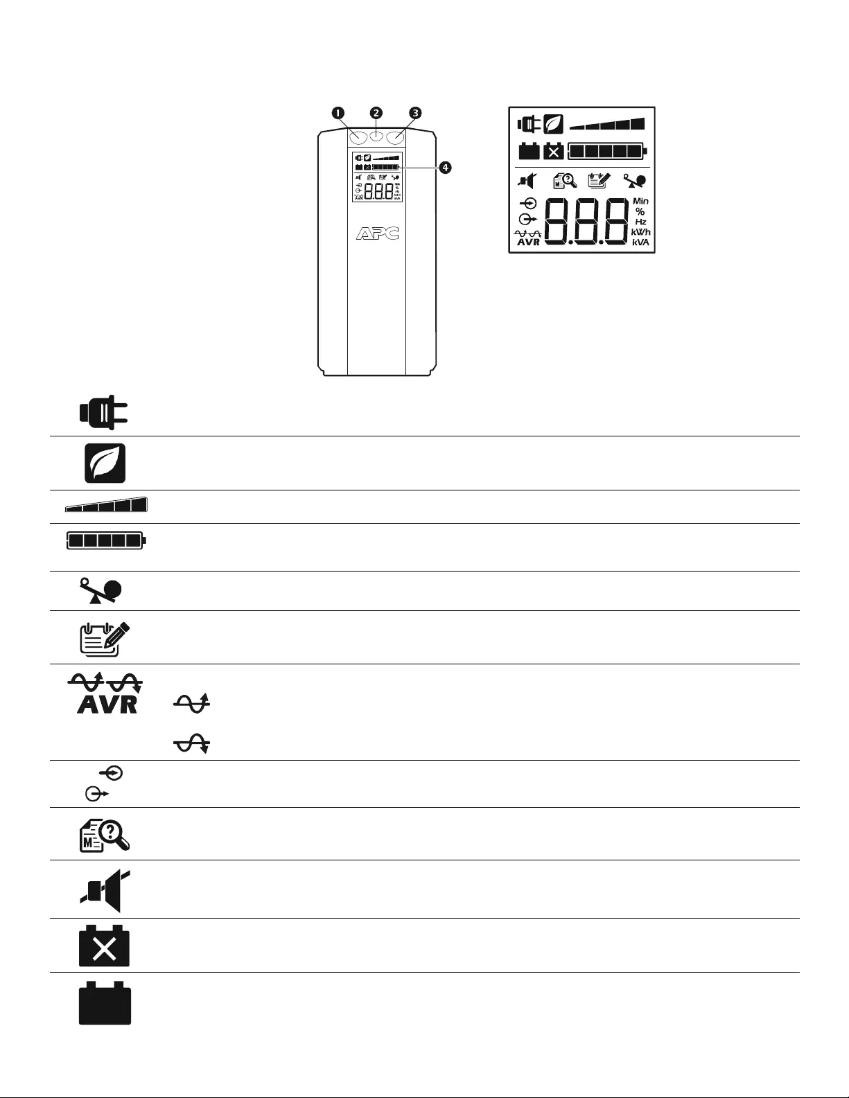
Front Panel Buttons and Display Interface
Use the three buttons on the front panel of the Back-UPS and the display inte r face to configur e the Back -UPS.
Fron t panel
1Mute button
2Power On/Off button
3Display button
4Display i nterface
On Line—The Back-UPS is supplying conditioned A/C power to connected equipment
Power-Saving—Master and Controlled outlets are enabled, saving power when the master devi ce goes into sleep
or standb y mo de
Load Capacity—The load is indi cated by the number of sect ions ill um inated, one to five. Each bar represents 20%
of the load.
Battery Charge—T he battery charge level is indi cated by the numbe r of sections illu minated. Whe n all five blocks
are illumi nated, the Back-UPS is at full charge. When one block is fil led, the Back-UPS is near th e end of i ts battery
capacity, the indicator wi ll fl ash and the Back-UPS will beep continuously.
Overload—The power demand from the load has exceeded the capacity of t he Back-UPS.
Event—The event counter shows t he num ber of events that occurre d that caused the Back-UPS to swit ch to on-
battery operation.
Automatic Voltage Regulation—The Back-UPS can compensat e for high or low input voltage.
When ill um inated, th e Back-UPS is compen sating for low inp ut vol tag e.
When illuminated, the Back-UPS is compensating for high input voltage.
Input voltage.
Output voltage.
System Faults—The system has a faul t. The faul t number wi ll il lumina te on t he display int erfac e.
See “System Faults” on page 6.
Mute—If the line through the speaker icon is illum inated, the audible alarm has been turned off.
Replace Battery—The battery i s not connected or is nearing the end of its useful life. Repl ace the battery.
On Battery—The Back-UPS is supply ing battery backup power to the connected equipment, it will beep four times
every 30 seconds.
bu044a
bu002a
Back-UPS BR900G-GR Insta ll ation and Operati on6
Warnings and System Faults
Au dible Warn ings
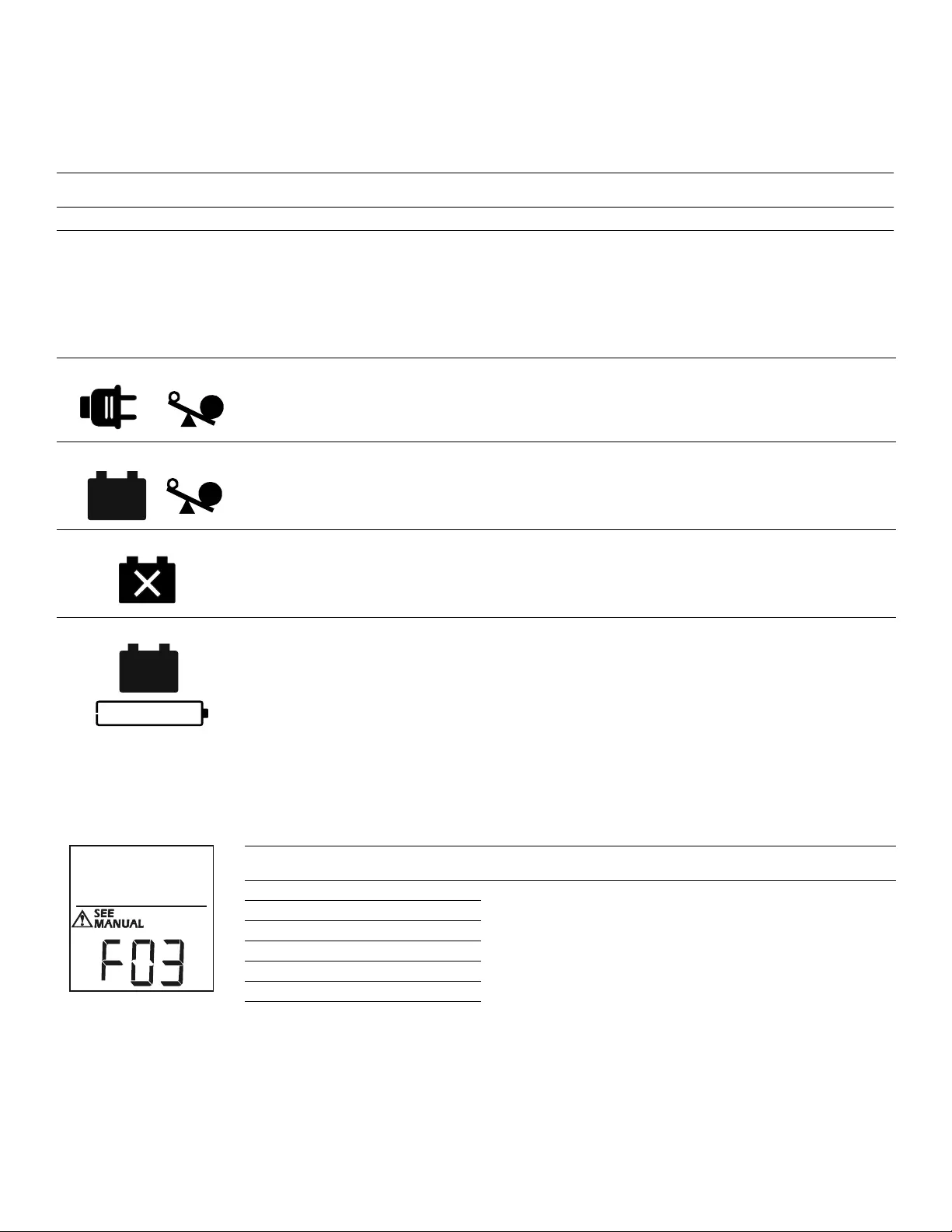
Warning Icons
System Faults
T h e Ba ck - U PS w il l dis pl ay th ese f au lt messag es.
Four Beeps E very 30 Seconds Back-UPS is running on bat tery. You should consider saving any work in pro gress.
Continuous Beeping Low batter y condition and bat ter y run-time is very low. Prompt ly save any work in pr ogress, exit
all open appli cations, and shut down the opera ti ng system.
Continuous tone Batter y Backup outputs are overloaded.
Chirps for 1 Mi n ut e ev ery 5 h ou rs Batter y fails the automatic dia gnostic test and sho uld be replaced.
If these ic o ns are
illum ina ted... This m ay be the problem.
The Back-UPS is oper ating on A/C power, but is overloaded. Disconnect one of the devices connected to
the Back-UPS. I f the Overload icon st ops flashing, the Back-UPS is no longer overloaded and will
continue to operat e normally.
The Back- UPS is oper at ing on b atter y po we r , but i s overl oaded. Disconn ect one of t he devices conn ected
to the Back- UPS. I f th e Ove rl oad icon stops fl ashing, the Back-UPS is no lon ger overloaded and will
continue to operat e normally.
The Back-UPS is operating on A/C power, but the bat tery is not funct ioning properly.
Contact APC Customer Serv ice to order a replacement batt ery.
See “Replac em ent Battery” on page 9.
The Back-UPS is operating on batt ery power and the bat tery power is gett ing low. Shut down all
connected equipment to avoid losing unsaved data. When possible, connect the Back-UPS to A/ C power
to rechar ge the battery.
F01 On-Battery Overl oad Turn the Back-UPS of f. Disconnect non-essenti al equipmen t from
the Batt ery Backu p outlets and the turn Back-UPS on.
F02 On-Battery Output Short Turn the Back-UPS of f. Disconnect non-essential equipment from
the Batt ery Backu p outlets and the turn Back-UPS on.
F03 On-Battery Xcap Overlo ad
Fault s F03-F09 cannot be corr ected by the user. Conta ct APC
Te chnical Support for assistance.
F04 Clamp Shor t
F05 Charge Fault
F06 Relay Welding
F07 Temperature
F08 Fan Faul t
F09 Internal Faul t
bu088a
Back-UPS BR900G-GR Install ation and Operation 7
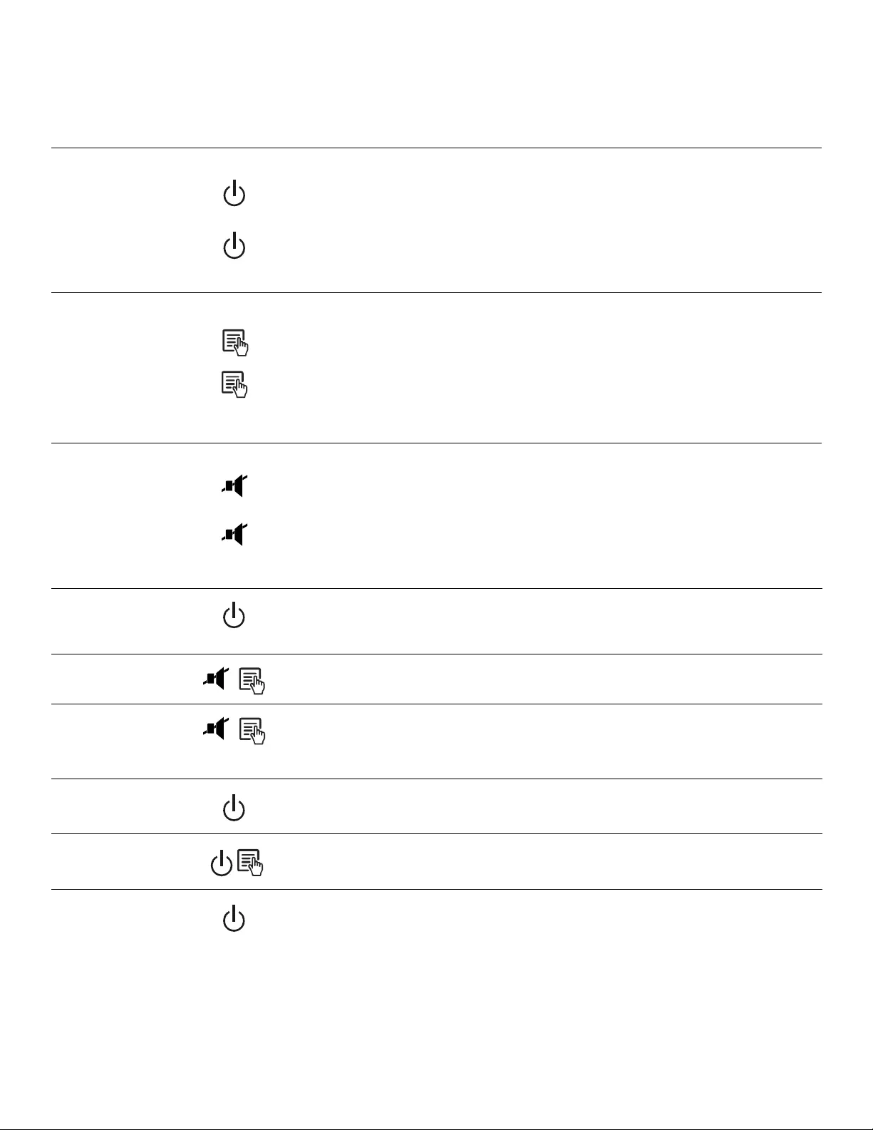
Function Button Quick-Reference
Function Button Timing
(seconds) UPS Status Descriptio n
Power
Power On 0.2 Off Press POWER to sta rt recei ving input A/C power. If A/C input power is
not availabl e, the Back-UPS will run on battery power.
Power Of f 2On
The Back-UPS is not rec eiving inp ut A/ C power, but is providing surge
protection.
Display
Status Inquiry 0.2 On Verify the status or condi tion of the Back-UPS. The LCD wil l i ll uminate
for 60 seconds.
Full-Time/
Power-Saving modes 2On
The LCD wil l i ll um inate and the Back-UPS will beep to confir m the
Full -T ime mode. The LCD will not i llum inate and the Back-UPS will
beep to confirm the Power-Saving mode. While in Power-Saving
Mod e, t he LCD wil l i ll um inate if a button is pressed, then goes dar k
after 60 seconds of no activity.
Mute
Event Specific 0.2 On Disabl e any audible alarms caused by an event.
General Status
Enable/Disable 2On
Enable or disa ble the audible al arms. The M ute icon will illuminate and
the Back-UPS will beep one time. The Mute fu nction wil l not acti vate
unless the Back-UPS is operating on battery power.
Sensitivity 6Off
The Load Capacity icon will blin k, indicating that the Back-UPS is in
program mode. Use the POWER butt on to scr oll through Low, Medium,
and High, stop at sel ected sensiti vity. The Back-UPS will beep to
confir m selection. See Config uration for details.
Master/Cont rolled outlet
Enable/Disable 2On
The leaf icon wi ll not illum inate indi cati ng that t he Master Out let fe ature
is disab led, or illuminate to indicate the Master Outlet feature i s
enabled. The Back-UPS will beep once.
Master /Enable Thr eshold
Calibration 6On
While calibrating the threshold setting, the device connected to the
Master Out let s hould be t ur ned of f or pl ac ed in Standb y or Sle ep mode.
Upon completion, Power-Saving icon will flash 3 times and beep 3
times.
Self- Test (man ual) 6On
The Back-UPS will pe rform a test of the i nternal batter y. Note: This will
happen automatically when the Back-UPS is turned ON.
Event Reset 0.2 On When the Even t screen is vis ible, press and hold DISPLAY, then press
POWER, to cl ear the A/C failure event counter.
Fault Reset 2Fault
After a fault has been identified, press POWER to remove the visual
indic ation and return to standby status.

Back-UPS BR900G-GR Install ation and Operation
8
Troubleshooting
Problem Possi ble Cause Corrective Action
Back-UPS will not turn on. The Ba ck-UPS is not connected to A/C
power. Ensure that the Back-UPS is securely connected
to an A/C outlet.
The circuit br ea ker has been tr ipped. Disco nnect non- essential equipm ent from the
Back-UPS . Reset t he ci rcuit breaker. Re-connec t
equipm en t o n e item at a ti me. If th e circuit
breaker is trippe d again, disconnect the device
tha t caused the trip.
The internal batt ery is not connected. Connect the battery.
The A/C input voltage is out of range. Adjust the transfer voltage and sensitivity range.
The Bac k-UPS does not provide
power during a A/C power
outage.
En su r e th at essenti a l eq u ip m en t is not
plugged int o a SURGE ONLY outlet. Disconnect equipm ent from the SURGE ONLY
outlet and re-connec t to a Batt ery Backu p outlet.
The Bac k-UPS is operating on
ba tte ry p o w er, wh il e co n n ect ed
to A/C power.
The pl ug has partially pulled out of the wal l
ou tlet, the wall outlet is no long er r eceiv ing
A/C power, or the circuit breake r has bee n
tripped.
Ensure that the plug is f u lly inserted into the wal l
outlet . E nsure t hat the wa ll out let is recei vin g A/C
power by checking it with another device.
The Ba ck-UPS is performing an automatic
self te st. No acti o n is necessar y.
The A/C input voltage is out of range, the
frequency is out of range, or the waveform is
distorted.
Adjust the transfer volta ge and sensitivit y range.
The Bac k-UPS does not provide
the ex p e ct ed amou nt of backup
time.
Batte ry Backup outlets may be fully or
improper ly loaded. Disco nnect non- es sential equipment from the
Batte ry Backup outle ts and connect t he equipment
to SURGE ONLY outlets.
The battery was recentl y dis cha rged due to a
power outage and has not fully recharged. Charge the batter y cartridge for 16 hours.
The battery ha s re ac hed the end of its use ful
life. R e pl ace th e bat t er y.
The REPLACE BATTERY i ndica tor
is il l u min a t ed . The battery ha s re ac hed the end of its use ful
life. R e pl ace th e bat t er y.
The OVERLOAD indicator is
illuminated. The equipm en t connected to the Back -UPS is
dra w i ng m o r e pow er th an th e Ba ck - U PS ca n
provide.
Disco nnect non- es sential equipment from the
Batte ry Backup outle ts and connect t he equipment
to SURGE ONLY outlets.
The SYSTEM FAULT indicator is
illuminated, all the front panel
i ndi cators a re fla shing.
There is an inter nal fault. Determ ine which internal fault message is
displayed by matching the number displayed on
the LCD with the corresponding Fault Message
(see Syste m Faults) a nd contact APC Technica l
Support.
Power is not supp lied to some
outlets. Power to the Controlled outle ts has
intentionally been turned off. Confirm that t he correc t periph erals are c onnect ed
to Contr olled ou tlets. If this feature is not desired,
disable the Power-S aving Master and Controlled
outlets.
The Controlled outlets are not
supplying power, even though
the M a s ter dev ice is n o t in slee p
mode.
The Mast er Outlet threshold may be
incorr ect ly s et . Adjust the threshold for when the Master outlet
signals the Controlled outlets to shut down.

Back-UPS BR900G-GR Install ation and Operation 9
Specifications
t
APC Customer Support Worldwide
Warranty
The standar d w arranty is two (2) years from the da te of pur chase. APC standard proc edure is to replace the original unit with a fa ctory
reconditioned unit. Customers who must have the original unit ba ck due to the assignment of asset t ags and set depreciation sc hedules must
declare such a need at firs t contact with an APC Techn ical Support rep resentative. A PC wi ll shi p the replacement uni t once the def ective unit
has bee n re cei ved by t he r epa ir dep ar tment, or cross- sh ip u pon the r ec eipt o f a va lid cr ed it car d nu mber. The cus tome r pays for shipping the unit
to APC. A P C pays ground freight transpo rtat ion costs to ship the replace me nt uni t to the cu stomer.
Model BR900G-GR
VA 900 VA
Maximum Load 540 W
Nominal Input Voltage 230 V
Online Input Volt age Range 176 V to 294 V
Automatic Voltage Regulation 188 V- 216 V +11.2%
252 V- 282 V -11.2%
Frequency Range 50/60 Hz ± 1 Hz
On-battery wave shape Step-approxim ated sine -wave
Typical Recharge Time 8 hours
Transfer Tim e 10 ms, maximu m
Operati ng Temperature 0° to 40° C (32° to 104°F)
Storage Temp erat ure -5° to 45° C (23° t o 113° F)
Unit Dime nsions 25 × 10 × 38.2 cm (9.8 × 3.9 × 15 in)
Unit Wei ght 11 kg (24 lbs)
In te rface Serial , USB
On-Batt ery Runtime Go to: www.apc. com
Replacement Battery T he bat tery cartridge typica lly lasts 3 to 6 years. Environmental factors impact battery life. High
temperatures, poor quality A/C power, and frequent, short deration discharges will shorten ba ttery
life. To order replac ement bat tery cartridge APCRBC123, refer to the APC Web site, www.apc.com.
Recycle used battery cartridges.
Internet http://www.apc.com/support
Telephone + 888 272 3858

© 2010 APC by Schneider Electric. APC, the APC logo, Back-UPS and PowerChute are
owned b y Schneider Electr ic Industries S.A.S., American Pow er Conver sion Corporatio n, or
their affiliated companies. All other trademarks are property of their respective owners. 990-3972A
03/2011
Service
If the unit requir es service, do not return it to the dealer. Follow these steps:
1. Review the TROUBLESHOOTING section of the manual to eliminate common problems.
2. If the proble m persists, contact APC Customer Sup port through the APC W e b site, www.apc.com.
a. Note the model number and serial number and the date of purcha se. The model and
serial numbers are located on the rear panel of the unit and are available through the
LCD display on select models.
b. Call APC Customer Support and a technician will attempt to solve the problem over the
phone. If this is not possible, the technician will issue a Returne d Material
Authorization Number (RMA#).
c. If the unit is under warranty, the repairs are free.
d. Service proce dures and r eturns may vary inte rnat ionally. Refer to the APC Web sit e for
country specif ic instructions.
3. Pack the unit properly to avoid damage in transit. Never use foam bea ds for packaging. Damage
sustained in transit is not covered under warranty. For the UPS, always DIS CONNECT THE
BATTER Y before ship ping in compliance with U.S. Departme nt of Transportation (DOT)
and IATA regulations . The battery may remain in the unit.
4. Writ e the RMA# provided by Customer Support on the outside of the package.
5. Return the unit by insured, pre-pa id carrie r to the addre ss provided by Custo mer Support.