Table of Contents
- Back-UPS® BR1200G-GR/BR1500G-GR
- Inventory
- Safety
- Connect the battery
- PowerChute® Personal Edition Software
- Overview
- Compatibility
- Installation
- Connect the equipment
- Battery Backup and Surge Protected outlets
- Master and Controlled outlets
- Operation
- Power-Saving Function
- Power-Saving Display
- Unit sensitivity
- Front Panel Buttons and Display Interface
- Warnings and System Faults
- Audible Warnings
- Warning Icons
- System Faults
- Function Button Quick-Reference
- Troubleshooting
- Specifications
- APC Customer Support
- Internet www.apc.com
- Telephone +1 888 272 3858
- Warranty
- Service
APC Back-UPS Pro User Manual
Displayed below is the user manual for Back-UPS Pro by APC which is a product in the Uninterruptible Power Supplies (UPSs) category. This manual has pages.
Related Manuals
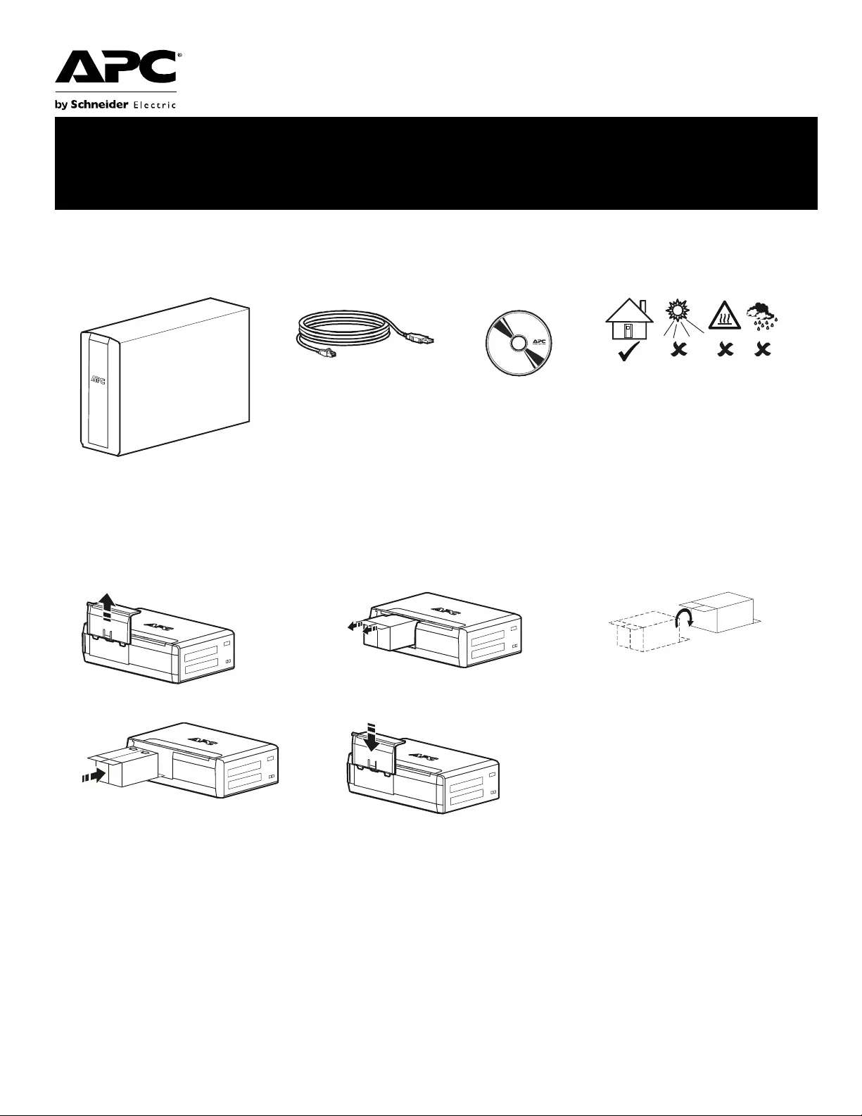
Connect the battery
Inventory Safety
This uni t is inten ded for indoor use only.
Do not operate this unit in direct sun li ght,
in cont act with f lui ds, or where there is
excessive dust or humidity.
123
45 Charge the battery for at least 16
hours before use.
bu001a
bu055a
bu057a
bu059a
bu058a
bu060a
Installation and Operation Manual
Back-UPS® BR1200G-GR/BR1500G-GR

Back-UPS BR1200G-GR/BR1500G-GR Installation and Operation2
PowerChute® Personal Edition Software
Overview
PowerChute Personal Edition Software allows you to use your computer t o access a dditional power protection and
management features of the Back-UPS.
Using PowerChute, you can:
• Preserve work in progr ess d uring a power outage by putting your compute r into Hibernate mode. When the power
returns, the computer will appear exactly as it did before the power outage.
• Configure the Back-UPS management features, such as power-saving outlets, shutdown parameters, audible alarms, and
more.
• Monitor and view the status of the Back-UPS, including t he estimated runtime, power consumption, power event history,
and more.
Available fea tures will vary by Back-UPS model and operating system.
If you choose not to install PowerChute, the Back-UPS wi ll still provide bac kup power and power protection to
connected equipment. However, you will only be able to configure a limited number of features using the display
interface.
Compatibility
PowerChute is compatible with Windows operating systems only. For a detailed list of supported operating systems,
go to www.apc.com, select Software & Firmware.
For Mac operating systems, we recommend using the native shutdown application (within System Preferences)
which recognizes your battery backup and allows you to configure shutdown o f your system during power outages.
To access this application, connect a USB cable from the Back-UPS DATA PORT (POWERCHUTE POR T) to a USB port
on your computer, and see the documentation provided wi th your comp uter.
Installation
Connect the Back-UPS to a computer us ing a USB cable. Pl ug one end into the POWERCHUTE PORT on the rear pa nel
of the Back-UPS and the other into a USB port on your computer.
Insert the Po werChute CD into your computer and follow the on-scr een ins tructions. If your Bac k-UPS did not come
with a PowerChute CD, download the software from www.apc.com, sele c t Software & Firmwar e.
Connect the equipment
Battery Backup and Surge Protected outlets
When the Ba ck-UPS is receiving input p ower, the Surge Protection only outlets and the Battery Backup with Su rge
Protection outlets will supply power to connected equipment. During a power outage or other utility problems, only
the Battery Backup outlets receive power for a li mited time from the Back-UPS.
Connect equipment such as printers, FAX machines, scanners, or other peripherals that do not need batt ery backup
power to the Surge Protection Onl y outlets. These outle ts provide full time protection from surges even if the
Back-UPS is switched off.
Master and Controlled outlets
To conserve electricity, when the device connected to Master Outlet goes into Sleep or Standby mode, or turns off,
the Controlled by Master device(s) will shut down as well, saving electricity.
Connect a master device, such as a desktop computer or audio/visual receiver to the Master outlet. Connect
peripheral devices such as a print er, speakers, or a scanne r to the Controlled by Master outlets.
Back-UPS BR1200G-GR/BR150 0G -GR Installation and Operation 3
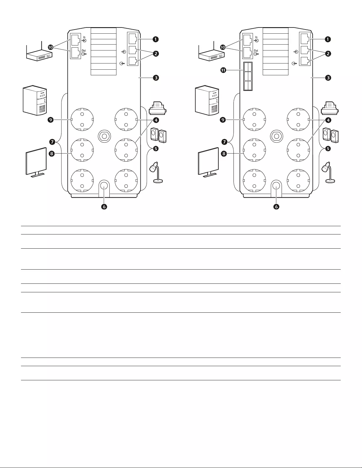
1USB and Serial Data port To use PowerChute Pers onal Editi on, connect the supplied USB sof tware cable or serial cable.
2Telephone por ts Connect a telephone cable to the In port, and a modem to the Out por t.
3Ground screw Connect the ground wir e fr om another surge suppression device such as a network or dat a line
surge protecto r to t he ground screw on the Back-UPS.
4Surge Protection outlets,
Control led by Master outlet These outlets provide surge protection during a power outage. These outlets will disconnect
from A/C power duri ng a power outage, or in the event th at the Mas ter outlet goes into Sleep
mode.
5Surge Protection outlets These outlets provide full-time surge protection, when the unit is turned on or off . C onnect a
printer, scanner or other devices that do not require batter y backup protection.
6AC Power Cable Connect t he Back-UPS to A/C power.
7Batter y Backup outl ets wit h
Surge Protection During a powe r outage or othe r utility problems, these outlets provide power from the
Back-UPS battery. Connect crit ical equipment such as deskt op com puter, computer monitor,
modem or other data sensitive devices to these outlets.
8Battery Backup, Controlled by
Master outl et with Surge
Protection
During a powe r outage or othe r utility problems, these outlets provide power from the
Back-UPS battery.
These outlets will disconnect from A/C power during a power outage, or in the event that the
Master outlet goes into Sleep mode.
Connect critical equipment such as desk top computer, computer monitor, modem or other data
sensitive devi ces to these outlets.
9Master outl et Connect the master device to thi s outlet, in most scenarios, thi s will be the main computer.
:Gigabit Ethernet
surge-protected ports Use an Ethernet cable to connect a modem to the IN port, and a comput er to the OUT port.
;External Battery Pack connector
BR1500G-GR model only
Connect an external b att ery pac k to provide addi tional bat tery backup runtime.
bu219a
Tel Out
Tel In
USB &
Serial
Battery
Backup Surge
Only
TVSS
GND
Circuit Breaker
Push to Reset
BR1500G-GR
MASTER
Controlled by MASTER Controlled by MASTER
Controlled by MASTER
bu218a
Tel Out
Tel In
USB &
Serial
Battery
Backup Surge
Only
TVSS
GND
Circuit Breaker
Push to Reset
BR1200G-GR
MASTER
Controlled by MASTER Controlled by MASTER
Controlled by MASTER

Back-UPS BR1200G-GR/BR1500G-GR Installation and Operation4
Operation
Power -Saving Fun ction
To conserve electricity, configure the Back-UPS to recognize a Master device, such as a desktop
computer or an A/V receiver, and Cont rolled peripheral devices, suc h as a printer, speakers, or a sc anner.
When the Master device goes into Sleep or Standby mode, or is switched OFF, the Controlled device( s)
will be switched off as well, saving electri city.
Enable the Power-Saving function. Press and hold MUTE and DISPLAY simultaneously for two seconds. The
Back-UPS will beep to indicate that the fea ture is enabled. The lea f icon on the display will illuminate.
Disable the Power-Saving function. Press and hold MUTE and DISPLAY simultaneously for two seconds. The
Back-UPS will beep to indicate that the feature is disabled. The leaf icon on the display will go dark.
Setting the threshold. The amount of power used by a device in Sleep or S tandby mode va ries betwee n devices. It
may be necessary to adjust the threshold at which the Master outlet signals the Controlled outlets to shut down.
1. Ensure a master device is connected to the Master outlet. Put that device into Sleep or Standby mode, or turn it
OFF.
2. Press DISPLAY and MUTE simultan eously and hold for six seconds, until the leaf icon flashes three times and the
Back - U PS b eeps thre e times .
3. The Back-UPS will now recognize the threshold le vel of the Master device and save it as the new threshold
setting.
Power-Saving Display
The display interface can be configur ed to be continuously illuminated, or to save energy, it can be configure d to go
dark after a period of inactivit y.
1. Full Time Mode: Press and hold DISPLAY f or two se conds. The displ ay will i llumina te and the Back- UPS will beep
to confirm the Full-Time mode.
2. Power-Saving Mode: Press and hol d DISPLAY for two seconds. The display will go dark and the Back-UPS will
beep to confirm the Power-Saving mode. While in Power-Saving Mode, the display will illuminate if a button is
pressed, it goes dark after 60 seconds of no acti vity.
Unit sensitivity
Adjust the sensitivity of the Back-UPS to control when it will switch to battery power; the high er the sensitivity, the
more often the Back-UPS will switch to battery power.
1. Ensure the Back-UPS is connected to A/C power, but is OFF.
2. Press and hold the POWER button fo r six seconds. The LOAD CAPACITY bar will flash on and off, indic ating that the
Back-UPS is in programming mode.
3. Press POWER again to rotate through the menu options. Stop at selected sensitivity. The Back-UPS will beep to
confirm the selection.
Low sensitivity Medium sensitivity (Default) High sensitivity
156-300 Vac 176-294 Vac 176-288 Vac
Input voltage is extremely low or
high. (Not recommended for
computers.)
The Back-UPS fr equently swi tches to
battery power . The connected equipm ent is
sensitive to voltage fluctuations.
Back-UPS BR1200G-GR/BR150 0G -GR Installation and Operation 5
Front Panel Buttons and Display Interface
Use the three buttons on t he front p anel of the Back-UPS and the di splay interface to configure the Back -UPS.
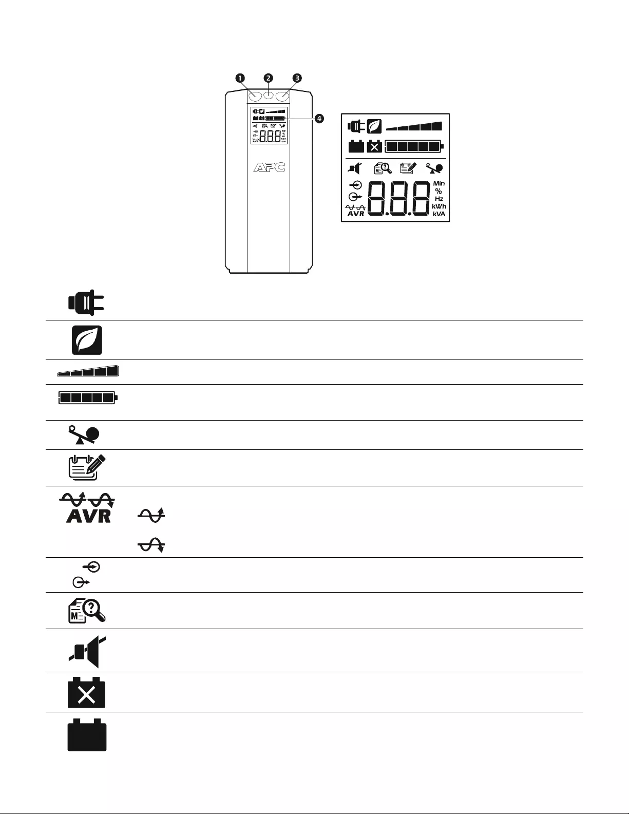
Fro nt panel
1Mute button
2Po w e r On /O ff bu t to n
3Display button
4Display interface
On Line—The Back-UPS is supplying conditi oned A/C power to connect ed equipment
Power-Saving—Mast er and Controll ed outlets are enabl ed, saving power when the master devi ce goes into
sleep or standby mode
Load Capacity—T he load is indi cated by the numbe r of sections il luminated, one to five. Each bar represents
20% of the load.
Battery Charge—The battery charge level is indicat ed by the number of sect ions ill um inated. When all five
blocks are illum inated , the Back-UPS is at full charge. When one block is fil led, t he Ba ck-UPS is near the end of
its b att ery cap acity, the indicator wil l flash and the Back-UPS will beep continuous ly.
Overload—The power demand from the load has ex ceeded the capacity of the Back-UPS.
Event—Th e event counter sh ows the number of events that occ urred that caused the Back-UPS to switch to
on-battery oper ation.
Automatic Voltage Regulation—T he Back-UPS can compens ate for high or low in put vol tage.
When illuminat ed, the Back-UPS is compensating for low input voltage.
When illuminat ed, the Back-UPS is compensating for high inp ut vol tage .
Input voltage.
Output vol tag e.
System Faults—The system has a fault. The faul t number will illuminate on the displ ay interface.
See “System Faults” on pag e 6.
Mute—If the line thr ough the speaker icon is illuminated, the audi ble alarm has been turned off.
Replace Batt ery—The batt ery is not connected or is nearing the end of its useful life. Replace the batt ery.
On B a tte r y —The Back-UPS is supplying batter y backup power to the connected equ ipment, it wil l beep four
times every 30 seconds.
bu044a
bu002a
Back-UPS BR1200G-GR/BR1500G-GR Installation and Operation6
Warnings and System Faults
Au dible Warn ings
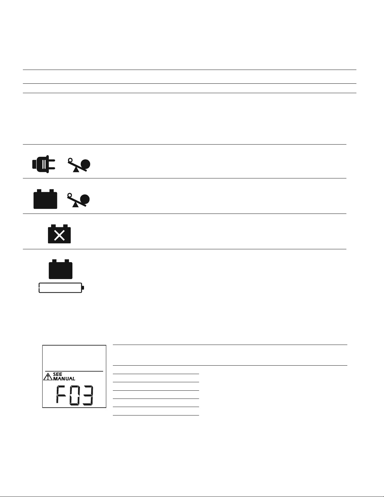
Warning Icons
System Faults
The Back-UPS will display these fault message s. Contact APC Technical Suppor t.
Four Beeps E very 30 Seconds Back-UPS is running on battery. You should consider sa ving any work in pro gress.
Continuous Beeping Low batte ry condi tion and ba ttery run-tim e is ver y low . Promptl y save any work in progr ess, exi t
all open appli cations, and shut down the op erating system.
Continuous tone Batter y Backup outp uts are overl oaded.
Chirps fo r 1 Mi n ut e ev e ry 5 hours Batter y fails th e automatic diagnostic test and should be repl aced.
If these ic o ns are
illum ina ted... This m ay be the problem.
The Back-UPS is operating on A/C power, but is overloaded. Disconnect one of th e items
connected to the Back-UPS. If the Overl oad icon stops flashi ng, the Back-UPS is no longer
overloaded and will continue to operate nor mall y.
The Back-UPS is operating on battery power, but is overloaded. Disconnect one of the items
connected to the Back-UPS. If the Overl oad icon stops flashi ng, the Back-UPS is no longer
overloaded and will continue to operate nor mall y.
The Back-UPS is operat ing on A/C power, but the bat tery is not funct ioning properly. Cont act APC
Customer Service to order a re placement battery. See “Replacem ent Batter y” on page 8.
The Back-UPS is operating on battery power and the bat tery power is gett ing low. Shut down al l
connected equipm ent to avoid losing unsave d data. When pos sible, connect the Back -UPS to A/ C
power to recharge the battery.
F01 On-Battery Overload Turn the Back-UPS off. Disconn ect non-essential
equipment from the Battery Backup out lets and the turn
Back-UPS on.
F02 On-Battery Output Short Turn the Back-UPS off. Disconn ect non-essential
equipment from the Battery Backup out lets and the turn
Back-UPS on.
F03 On-B attery Xcap Over load
Faults F03-F09 cannot be corrected by the user. Contact
APC Technical Support for assistance.
F04 Clamp Short
F05 Charge Fault
F06 Relay Welding
F07 Temperature
F08 Fan Fault
F09 Internal Fault
b
u
0
8
8
a
Back-UPS BR1200G-GR/BR150 0G -GR Installation and Operation 7
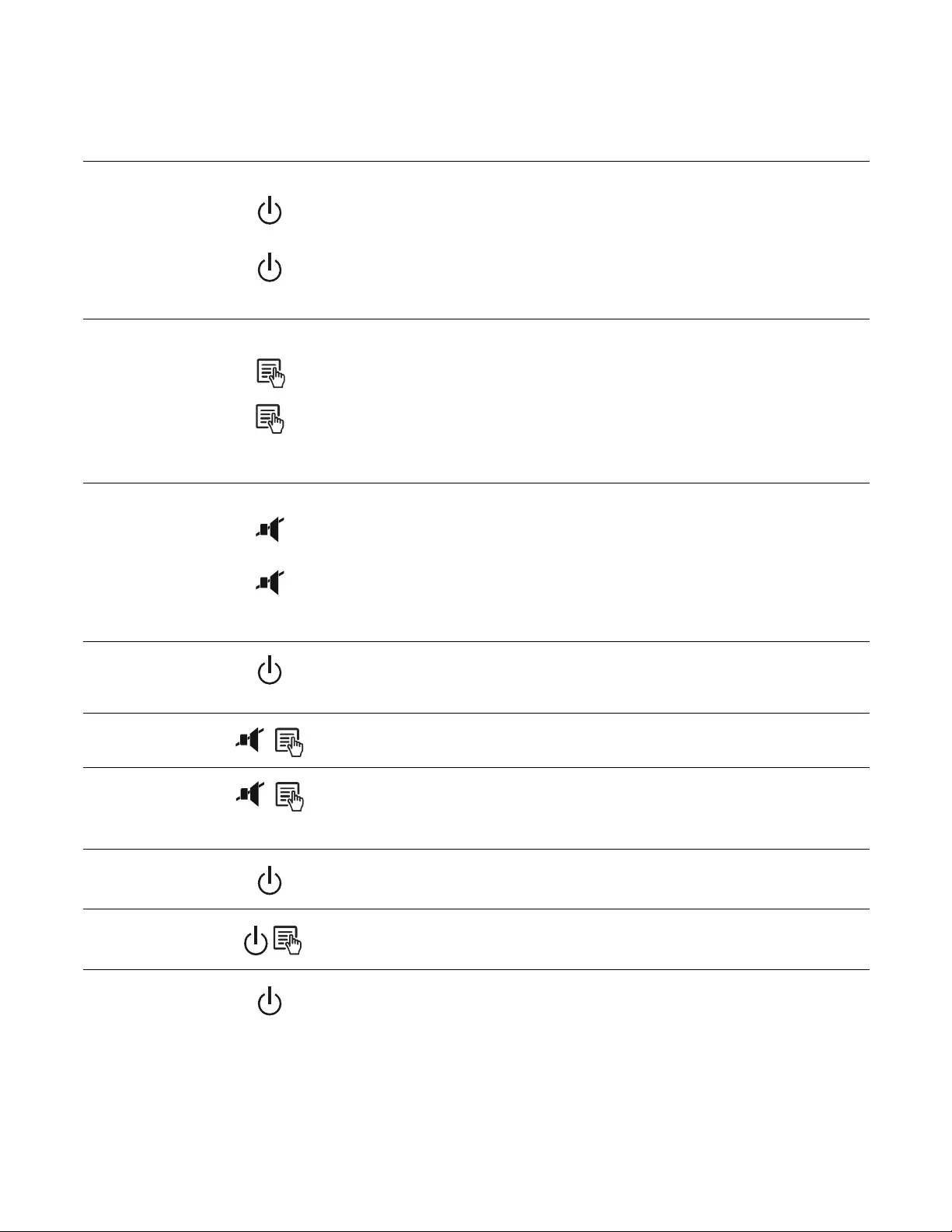
Functio n Button Quick-Reference
Function Button Timing
(seconds) UPS
Status Description
Power
Power On 0.2 Off Press POWER to start receiving input A/C power. If A/C input
power is not available, the Back-UPS will run on battery power.
Power Off 2On
The Back-UPS is not receiving input A/C power, but is providing
surge protection.
Display
Status Inquiry 0.2 On Verify the status or condition of the Back-UPS. The LCD will
illuminat e for 60 s econds.
Full-Time/Power-
Saving mode 2On
The LCD will illuminate and the Back-UPS will beep to confirm the
Full -T ime mode. The LCD will go dark and the Back-UPS will beep
to confirm t he Power-Saving mode. While in Power -Saving Mode,
the LCD will illuminate if a button is pressed, then goes dark after
60 seconds of no activity.
Mute
Event Specific 0.2 On Disable any audible alarm s caused by an event.
General Status Enable/
Disable 2On
Enable or disabl e the audib le alarms . The Mute icon wil l illumi nate
and the Back-UPS will beep one ti me. The Mute function will not
acti vate unless the Back-UPS is ope rating on battery power.
Sensitivity 6Off
The Load Capaci ty i con wi ll bli nk, indic ati ng that the Back-UPS is
in programming mode. Use the POWER button to scr oll thro ugh
Low, Medium, and High, stop at sele cted sensitivity. The Back-
UPS will beep to confirm selection. See Confi guration for details.
Master/Controlled
outlet Enable/Disable 2On
The leaf icon will go dar k indicating that the Master Outlet feature
is di sabled or il luminate to indicate the Master Outlet featu re i s
enabled. The Back-UPS will beep once.
Master/Enable
Threshold Calibration 6On
While cal ibra ting the t hreshol d s etting, t he devi ce c onnected to t he
Master Outlet should be turned off or placed in Standby or Sleep
mode . Upon completi on, Power-Savi ng icon will fl ash 3 times and
beep 3 times.
Self-Test (manual) 6On
The Back -UPS wi ll perform a test of th e inte rnal ba tter y. Note: Thi s
wil l happen automati cally when the Back-UPS is turned ON.
Event Reset 0.2 On When the Event screen is visible, press and hold DISPLAY, then
press POWER, to clear the utility failure event counter.
Fault Reset 2Fault
After a faul t has been identified, press POWER to remove the
visual indication and return to standby status.

Back-UPS BR1200G-GR/BR1500G-GR Installation and Operation8
Troubleshooting
Problem Possible Caus e Correc tiv e Action
Back-UPS will not turn on. The Back-UPS is not conne cted to A/C
power. Ensure th at the Back-U PS is secur ely connected
to an A/C outle t.
The circuit breaker has been tripped. Disconnect non-essential equipment from the
Bac k-UPS. Re set th e circuit br eaker . Re-connect
equipment one item at a time. If the circuit
br eaker is tripped again, dis connect the device
that ca used th e tr i p.
The i nternal battery is no t connected. Connect the battery.
The A/C input voltage is out of range. Adjust the transfer voltage and sensitivity range.
Th e Ba c k -U PS do es not
provide power during a A/C
power outage.
Ensure that essential equipment is not
plugged int o a SURGE ONLY outlet. Disconnect equipment from the SURGE ONLY
outlet and re-connect to a Bat tery Backup outl et.
The Back-UPS is operating on
battery power, while co nnected
to A/C power.
The plug has parti ally pulled out of the wal l
o utlet, the wall outle t is no longer r ece iving
A/C power, or the circuit breaker has be en
tripped.
Ensure that the plug is fully inserted into the
wall outlet. Ensure that the wall outlet is
rece iving A/C powe r by checking it with
another devic e.
The Back-UPS is per f orming an automatic
self test. No action is necessary.
The A/C input voltage is out of range, the
frequency is out of range, or the waveform
is distorted.
Adjust the tra nsfer voltage and sens itivi ty range.
Th e Ba c k -U PS do es not
pr ovid e the expe cted amount of
backup time.
Battery Backup outlets may be fully or
improperly loaded. Disconnect non-essential equipment from the
Battery Backup outlets and connect the
equipment to SURGE ONLY outlets.
The battery was recently discharged due to a
power outage and has not fully recharged. Charge the ba ttery cartridge for 16 hours .
The battery has re ached the end of its usef ul
life. Replac e the battery.
The REPLACE BATTERY
indicator is illuminated. The battery has re ached the end of its usef ul
life. Replac e the battery.
The OVERLOAD in dica t o r is
illuminated. The equipment connected to the Back-UPS
is d raw i ng mo r e p ow e r th an th e Ba ck - U PS
ca n pr ov ide.
Disconnect non-essential equipment from the
Battery Backup outlets and connect the
equipment to SURGE ONLY outlets.
The SYSTEM FAULT indicator is
illuminated , all the front panel
i nd icato rs are flas hing.
There is an inter n al fau lt. De termine which internal fault message is
displayed by matching the num ber displa yed on
the L CD with the correspondi ng F ault Messag e
(see System Faults) and contact APC Technical
Support.
Power is not supplied to some
outlets. Powe r to the Contr o lled outlets has
intentionally been turned off. Confirm that the correct peripherals are
connected to Controlled o utlets. If this feature is
not des ired, dis able the Power-Sa ving Maste r
and Controll ed outlets.
Th e C o nt rol le d out l et s a re not
supplying power, even though
the Master device is not in sleep
mode.
The Master Outlet threshold may be
incorrectly set. Adjust the threshold when the Master outlet
signals the Controlled outlets to shut do wn .

Back-UPS BR1200G-GR/BR150 0G -GR Installation and Operation 9
Specifications
t
APC Customer Support
Inte r n et w ww.a pc. co m
Telephone +1 888 272 3858
Warranty
The standard warranty is two (2) years from the date of purchase. APC standard procedure is to replace the original
unit with a factor y recondi tioned unit. Customer s who must have the origin al unit back due t o t he assignment of asset
tags and set depreciation sche dules must declare such a need at first contact with an APC Technical Support
represe ntative . APC wil l shi p the r eplacem ent unit once the def ectiv e unit has been recei ved by t he repair depa rtment,
or cross-ship upon the receipt of a valid credit card number. The customer pays for shipping the unit to APC. APC
pays ground freight transportation costs to ship the replace ment unit to the customer.
Model BR1200G-GR BR1500G-GR
VA 1200 VA 1500 VA
Maximum Load 720 W 865 W
Nominal Input Voltage 230 V
Online Input Voltage Range 176 V- 294 V
Automatic Voltage Regulation 188 V- 216 V +11.2%
252 V- 282 V -11.2%
Frequency Range 50/60 Hz ± 1 Hz
On-battery wave shape Step-approximated sine-wave
Typical Recharge Time 8 hours
Transfer Time 10 ms, maximum
Ope rating Temperat ure 0º to 40 º C (32º to 104º F)
S tora ge Temperat ure 5º to 45º C (23º to 113º F)
Uni t Dimensions 30.1 × 11.2 × 39 cm (11.9 × 4.4 × 15.3 in)
Uni t Weight 12.8 kg (28.2 lbs) 13.4 kg (29.5 lbs)
In terface Serial, USB
On-Batte ry R u ntime Go to: ww w.a pc.com
Rep lacement Battery The batter y cart ridge typic ally lasts 3 t o 6 years. Enviro nmental factors im pact
battery life. High temperatures, poor quality A/C power, and frequent, short
deration discharges will shorten battery li fe. To order repl acement battery
cart ridge APCRBC124, refe r to the APC Web site , www.apc.com.
Rec ycle used batter y cartridges.

© 2010 APC by Schne ider Electric. APC, the APC logo, Back-UPS and Power Chute a re
own ed by Schneider El ectr ic Industri es S.A. S., American Power Conversio n Corporation, or
their affiliated companies. All other trademarks are property of their respective owners. 990-3973A
03/2011
Service
If the unit requires service, do not return it to the dealer. Follow these steps:
1. Review the TROUBLESHOOTING section of the manual to eli minate common problems.
2. If the proble m persists, contact APC Customer Sup port through the APC W e b site, www.apc.com.
a. Note the model number and serial number and the date of purchase. The model and
serial numbers are located on the rear panel of the unit and are available through the
LCD display on select models.
b. Call APC Customer Support and a technici an will attempt to solve the problem over the
phone. If this is not possible, the technician will i ssue a Returned Material
Authorization Number (RMA#).
c. If the unit is under warranty, the repairs are free.
d. Service procedur es and return s may vary i nternat ionally. Ref er to the APC Web site for
country specific instructions.
3. Pack the unit properly to avoid damage in trans it. Never use foam beads for packaging. Damage
sustained in transit is not covered under warranty. For the UPS, alw ays DISCONNECT THE
BATTERY befor e shipping in compliance with U.S. Departme nt of Transportati on (DOT)
and IATA regulations. The battery may remain in the unit.
4. Write the RMA# provided by Customer Support on the outside of the packa ge.
5. Return the unit by insured, pre-pa id car rier to the address provided by Customer Support.