Table of Contents
- Easy UPS 3S
- Important Safety Instructions — SAVE THESE INSTRUCTIONS
- System Overview
- Technical Data for 400 V Systems
- Technical Data for 208 V Systems
- Technical Data
- Facility Planning for Easy UPS 3S 3:3 400 V
- Input Specifications – 3:3 UPSs
- Bypass Specifications – 3:3 UPSs
- Output Specifications – 3:3 UPSs
- Battery Specifications – 3:3 UPSs with Internal Batteries
- Battery Specifications – 3:3 UPSs for External Batteries
- Required Upstream Protection and Cable Sizes – 3:3 UPSs
- UPS Weights and Dimensions – 3:3 UPSs
- UPS Shipping Weights and Dimensions – 3:3 UPSs
- Facility Planning for Easy UPS 3S 3:1 400 V
- Input Specifications – 3:1 UPSs
- Bypass Specifications – 3:1 UPSs
- Output Specifications – 3:1 UPSs
- Battery Specifications – 3:1 UPSs with Internal Batteries
- Battery Specifications – 3:1 UPSs for External Batteries
- Required Upstream and Downstream Protection and Cable Sizes – 3:1 UPSs
- Weights and Dimensions – 3:1 UPSs
- Shipping Weights and Dimensions – 3:1 UPSs
- Facility Planning for Easy UPS 3S 3:3 208 V
- Input Specifications – 3:3 UPSs
- Bypass Specifications – 3:3 UPSs
- Output Specifications – 3:3 UPSs
- Battery Specifications – 3:3 UPSs with Internal Batteries
- Battery Specifications – 3:3 UPSs for External Batteries
- Required Upstream Protection and Cable Sizes – 3:3 UPSs
- UPS Weights and Dimensions – 3:3 UPSs
- UPS Shipping Weights and Dimensions – 3:3 UPSs
- Facility Planning
- Drawings
- Options
- Limited Factory Warranty
APC E3SUPS30K3I User Manual
Displayed below is the user manual for E3SUPS30K3I by APC which is a product in the Uninterruptible Power Supplies (UPSs) category. This manual has pages.
Related Manuals
Easy UPS 3S
10-40 kVA 400 V & 10-20 kVA 208 V 3:3,
10-30 kVA 400 V 3:1
Technical Specifications
03/2020
www.schneider-electric.com

Legal Information
The Schneider Electric brand and any trademarks of Schneider Electric SE and its
subsidiaries referred to in this guide are the property of Schneider Electric SE or its
subsidiaries. All other brands may be trademarks of their respective owners.
This guide and its content are protected under applicable copyright laws and
furnished for informational use only. No part of this guide may be reproduced or
transmitted in any form or by any means (electronic, mechanical, photocopying,
recording, or otherwise), for any purpose, without the prior written permission of
Schneider Electric.
Schneider Electric does not grant any right or license for commercial use of the guide
or its content, except for a non-exclusive and personal license to consult it on an "as
is" basis. Schneider Electric products and equipment should be installed, operated,
serviced, and maintained only by qualified personnel.
As standards, specifications, and designs change from time to time, information
contained in this guide may be subject to change without notice.
To the extent permitted by applicable law, no responsibility or liability is assumed by
Schneider Electric and its subsidiaries for any errors or omissions in the informational
content of this material or consequences arising out of or resulting from the use of the
information contained herein.

10-40 kVA 400 V & 10-20 kVA 208 V 3:3,10-30 kVA 400 V 3:1
Table of Contents
Important Safety Instructions — SAVE THESE
INSTRUCTIONS.........................................................................................5
Electromagnetic Compatibility .....................................................................6
Safety Precautions .....................................................................................6
System Overview........................................................................................8
Model List ..................................................................................................9
User Interface ..........................................................................................10
Display Interface.................................................................................13
Overview of Single UPS ............................................................................13
Overview of 1+1 Redundant Parallel System with Common Battery
Bank........................................................................................................14
Overview of Parallel System......................................................................15
Location of Breakers - 400 V Systems ........................................................17
Location of Breakers - 208 V Systems ........................................................21
Technical Data for 400 V Systems .........................................................23
Input Power Factor ...................................................................................23
Efficiency – 3:3 UPSs................................................................................23
Efficiency – 3:1 UPSs................................................................................24
Technical Data for 208 V Systems .........................................................25
Input Power Factor ...................................................................................25
Efficiency – 3:3 UPSs................................................................................25
Technical Data...........................................................................................26
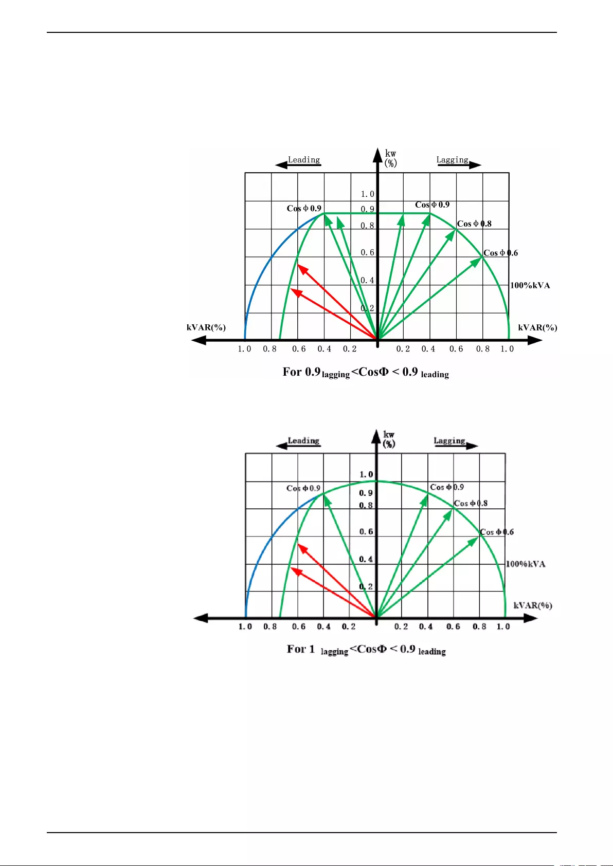
Derating Due to Load Power Factor ...........................................................26
Batteries ..................................................................................................27
End of Discharge Voltage ....................................................................27
Battery Gassing Rates for Modular Battery Cabinets and UPSs with
Internal Batteries ................................................................................27
Electrolyte Values for Modular Battery Cabinet and UPSs with
Internal Batteries ................................................................................27
Compliance..............................................................................................28
Communication and Management .............................................................28
Facility Planning for Easy UPS 3S 3:3 400 V .......................................29
Input Specifications – 3:3 UPSs .................................................................29
Bypass Specifications – 3:3 UPSs .............................................................29
Output Specifications – 3:3 UPSs ..............................................................30
Battery Specifications – 3:3 UPSs with Internal Batteries .............................30
Battery Specifications – 3:3 UPSs for External Batteries ..............................31
Required Upstream Protection and Cable Sizes – 3:3 UPSs ........................31
UPS Weights and Dimensions – 3:3 UPSs .................................................33
UPS Shipping Weights and Dimensions – 3:3 UPSs....................................33
Facility Planning for Easy UPS 3S 3:1 400 V .......................................34
Input Specifications – 3:1 UPSs .................................................................34
Bypass Specifications – 3:1 UPSs .............................................................34
Output Specifications – 3:1 UPSs ..............................................................35
Battery Specifications – 3:1 UPSs with Internal Batteries .............................35
Battery Specifications – 3:1 UPSs for External Batteries ..............................36
990-91077E-001 3

10-40 kVA 400 V & 10-20 kVA 208 V 3:3,10-30 kVA 400 V 3:1
Required Upstream and Downstream Protection and Cable Sizes – 3:1
UPSs.......................................................................................................36
Weights and Dimensions – 3:1 UPSs .........................................................37
Shipping Weights and Dimensions – 3:1 UPSs ...........................................38
Facility Planning for Easy UPS 3S 3:3 208 V .......................................39
Input Specifications – 3:3 UPSs .................................................................39
Bypass Specifications – 3:3 UPSs .............................................................39
Output Specifications – 3:3 UPSs ..............................................................40
Battery Specifications – 3:3 UPSs with Internal Batteries .............................40
Battery Specifications – 3:3 UPSs for External Batteries ..............................41
Required Upstream Protection and Cable Sizes – 3:3 UPSs ........................41
UPS Weights and Dimensions – 3:3 UPSs .................................................42
UPS Shipping Weights and Dimensions – 3:3 UPSs....................................42
Facility Planning........................................................................................43
Recommended Bolts and Cable Lugs ........................................................43
Torque Specifications................................................................................43
Clearance ................................................................................................43
Environmental ..........................................................................................45
Heat Dissipation for 400 V Systems......................................................45
Heat Dissipation for 208 V Systems......................................................45
Airflow Requirement for 400 V Systems ................................................45
Airflow Requirement for 208 V Systems ................................................45
Battery Breaker Box Weights and Dimensions ............................................46
Modular Battery Cabinet Weights and Dimensions ......................................46
Modular Battery Cabinet Shipping Weights and Dimensions ........................46
Drawings ....................................................................................................47
Easy UPS 3S for External Batteries – Single Mains System .........................47
Easy UPS 3S for External Batteries – Dual Mains System ...........................48
Easy UPS 3S with Internal Batteries – Single Mains System ........................49
Easy UPS 3S with Internal Batteries – Dual Mains System...........................50
Options .......................................................................................................51
Settings ...................................................................................................51
Limited Factory Warranty.........................................................................53
4 990-91077E-001
Important Safety Instructions — SAVE THESE
INSTRUCTIONS 10-40 kVA 400 V & 10-20 kVA 208 V 3:3,10-30 kVA 400 V 3:1
Important Safety Instructions — SAVE THESE
INSTRUCTIONS
Read these instructions carefully and look at the equipment to become familiar
with it before trying to install, operate, service or maintain it. The following safety
messages may appear throughout this manual or on the equipment to warn of
potential hazards or to call attention to information that clarifies or simplifies a
procedure.
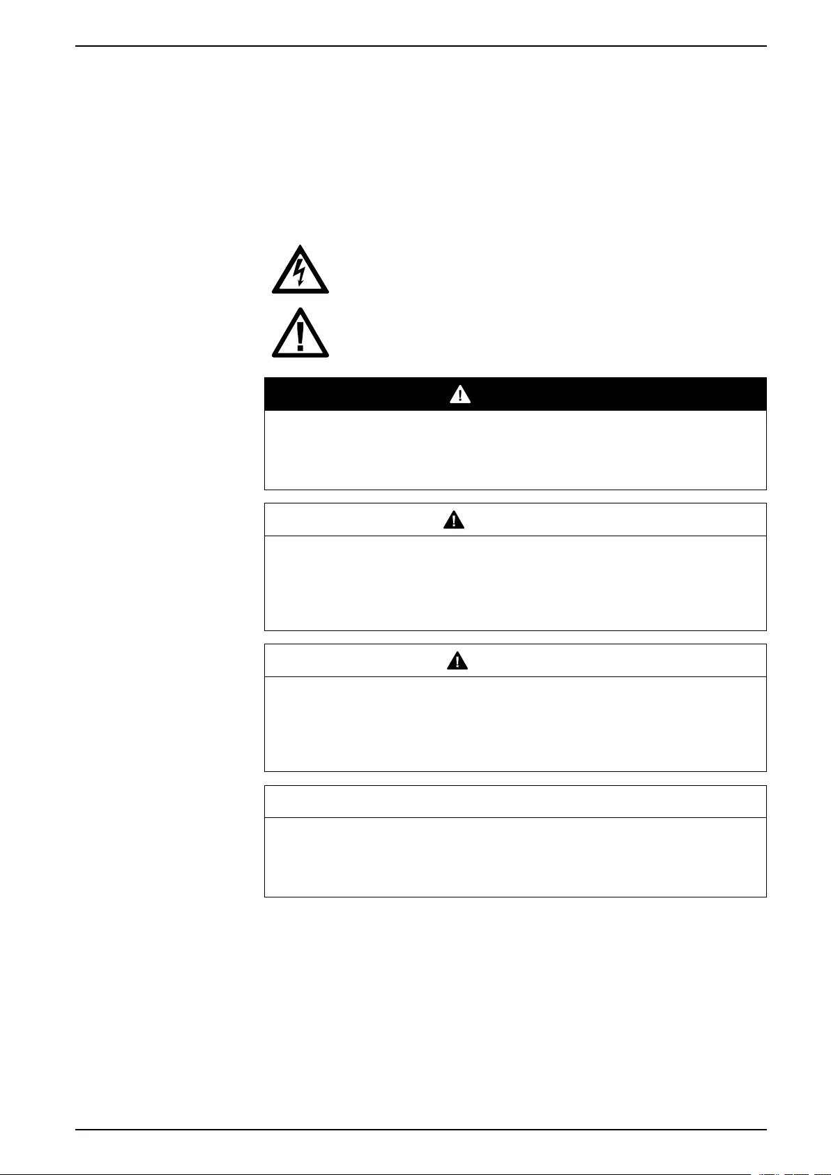
The addition of this symbol to a “Danger” or “Warning” safety
message indicates that an electrical hazard exists which will result in
personal injury if the instructions are not followed.
This is the safety alert symbol. It is used to alert you to potential
personal injury hazards. Obey all safety messages with this symbol
to avoid possible injury or death.
DANGER
DANGER indicates a hazardous situation which, if not avoided, will result in
death or serious injury.
Failure to follow these instructions will result in death or serious injury.
WARNING
WARNING indicates a hazardous situation which, if not avoided, could result
in death or serious injury.
Failure to follow these instructions can result in death, serious injury, or
equipment damage.
CAUTION
CAUTION indicates a hazardous situation which, if not avoided, could result in
minor or moderate injury.
Failure to follow these instructions can result in injury or equipment
damage.
NOTICE
NOTICE is used to address practices not related to physical injury. The safety
alert symbol shall not be used with this type of safety message.
Failure to follow these instructions can result in equipment damage.
Please Note
Electrical equipment should only be installed, operated, serviced, and maintained
by qualified personnel. No responsibility is assumed by Schneider Electric for any
consequences arising out of the use of this material.
A qualified person is one who has skills and knowledge related to the construction,
installation, and operation of electrical equipment and has received safety training
to recognize and avoid the hazards involved.
990-91077E-001 5

10-40 kVA 400 V & 10-20 kVA 208 V 3:3,10-30 kVA 400 V 3:1
Important Safety Instructions — SAVE THESE
INSTRUCTIONS
Electromagnetic Compatibility
NOTICE
RISK OF ELECTROMAGNETIC DISTURBANCE
This is a product Category C3 according to IEC 62040-2. This is a product for
commercial and industrial applications in the second environment - installation
restrictions or additional measures may be needed to prevent disturbances. The
second environment includes all commercial, light industry, and industrial
locations other than residential, commercial, and light industrial premises
directly connected without intermediate transformer to a public low-voltage
mains supply. The installation and cabling must follow the electromagnetic
compatibility rules, e.g.:
• the segregation of cables,
• the use of shielded or special cables when relevant,
• the use of grounded metallic cable tray and supports.
Failure to follow these instructions can result in equipment damage.
Safety Precautions
DANGER
HAZARD OF ELECTRIC SHOCK, EXPLOSION, OR ARC FLASH
• The product must be installed according to the specifications and
requirements as defined by Schneider Electric. It concerns in particular the
external and internal protections (upstream circuit breakers, battery circuit
breakers, cabling, etc.) and environmental requirements. No responsibility is
assumed by Schneider Electric if these requirements are not respected.
• After the UPS system has been electrically wired, do not start up the system.
Start-up must only be performed by Schneider Electric.
Failure to follow these instructions will result in death or serious injury.
DANGER
HAZARD OF ELECTRIC SHOCK, EXPLOSION, OR ARC FLASH
The UPS System must be installed according to local and national regulations.
Install the UPS according to:
• IEC 60364 (including 60364–4–41- protection against electric shock, 60364–
4–42 - protection against thermal effect, and 60364–4–43 - protection
against overcurrent), or
• NEC NFPA 70
depending on which one of the standards apply in your local area.
Failure to follow these instructions will result in death or serious injury.
DANGER
HAZARD OF ELECTRIC SHOCK, EXPLOSION, OR ARC FLASH
• Install the UPS system in a temperature controlled area free of conductive
contaminants and humidity.
• Install the UPS system on a non-inflammable, level, and solid surface (e.g.
concrete) that can support the weight of the system.
Failure to follow these instructions will result in death or serious injury.
6 990-91077E-001

Important Safety Instructions — SAVE THESE
INSTRUCTIONS 10-40 kVA 400 V & 10-20 kVA 208 V 3:3,10-30 kVA 400 V 3:1
DANGER
HAZARD OF ELECTRIC SHOCK, EXPLOSION, OR ARC FLASH
The UPS is not designed for and must therefore not be installed in the following
unusual operating environments:
• Damaging fumes
• Explosive mixtures of dust or gases, corrosive gases, or conductive or
radiant heat from other sources
• Moisture, abrasive dust, steam or in an excessively damp environment
• Fungus, insects, vermin
• Salt-laden air or contaminated cooling refrigerant
• Pollution degree higher than 2 according to IEC 60664-1
• Exposure to abnormal vibrations, shocks, and tilting
• Exposure to direct sunlight, heat sources, or strong electromagnetic fields
Failure to follow these instructions will result in death or serious injury.
NOTICE
RISK OF OVERHEATING
Respect the clearance requirements around the UPS system and do not cover
the product’s ventilation openings when the UPS system is in operation.
Failure to follow these instructions can result in equipment damage.
NOTICE
RISK OF EQUIPMENT DAMAGE
The UPS must use an external regenerative braking kit to dissipate energy
when connected to regenerative loads including photovoltaic systems and
speed drives.
Failure to follow these instructions can result in equipment damage.
990-91077E-001 7

System Overview 10-40 kVA 400 V & 10-20 kVA 208 V 3:3,10-30 kVA 400 V 3:1
Model List
400 V UPSs
3:3 UPS 3:1 UPS
• E3UPS10KH: Easy UPS 3S 10 kVA 400 V 3:3
UPS for external batteries
• E3UPS15KH: Easy UPS 3S 15 kVA 400 V 3:3
UPS for external batteries
• E3UPS20KH: Easy UPS 3S 20 kVA 400 V 3:3
UPS for external batteries
• E3UPS30KH: Easy UPS 3S 30 kVA 400 V 3:3
UPS for external batteries
• E3UPS40KH: Easy UPS 3S 40 kVA 400 V 3:3
UPS for external batteries
• E3SUPS10KHB: Easy UPS 3S 10 kVA 400 V 3:3
UPS for internal batteries1
• E3SUPS15KHB: Easy UPS 3S 15 kVA 400 V 3:3
UPS for internal batteries1
• E3SUPS20KHB: Easy UPS 3S 20 kVA 400 V 3:3
UPS for internal batteries1
• E3SUPS30KHB: Easy UPS 3S 30 kVA 400 V 3:3
UPS for internal batteries1
• E3SUPS40KHB: Easy UPS 3S 40 kVA 400 V 3:3
UPS for internal batteries1
• E3SUPS10KHB1: Easy UPS 3S 10 kVA 400 V
3:3 UPS with internal batteries - 15 minutes
runtime1
• E3SUPS10KHB2: Easy UPS 3S 10 kVA 400 V
3:3 UPS with internal batteries - 40 minutes
runtime1
• E3SUPS15KHB1: Easy UPS 3S 15 kVA 400 V
3:3 UPS with internal batteries - 9 minutes
runtime1
• E3SUPS15KHB2: Easy UPS 3S 15 kVA 400 V
3:3 UPS with internal batteries - 25 minutes
runtime1
• E3SUPS20KHB1: Easy UPS 3S 20 kVA 400 V
3:3 UPS with internal batteries - 15 minutes
runtime1
• E3SUPS20KHB2: Easy UPS 3S 20 kVA 400 V
3:3 UPS with internal batteries - 30 minutes
runtime1
• E3SUPS30KHB1: Easy UPS 3S 30 kVA 400 V
3:3 UPS with internal batteries - 9 minutes
runtime1
• E3SUPS30KHB2: Easy UPS 3S 30 kVA 400 V
3:3 UPS with internal batteries - 25 minutes
runtime1
• E3SUPS40KHB1: Easy UPS 3S 40 kVA 400 V
3:3 UPS with internal batteries - 10 minutes
runtime1
• E3SUPS40KHB2: Easy UPS 3S 40 kVA 400 V
3:3 UPS with internal batteries - 15 minutes
runtime1
• E3SUPS10K3I: Easy UPS 3S 10 kVA 400 V 3:1
UPS for external batteries
• E3SUPS15K3I: Easy UPS 3S 15 kVA 400 V 3:1
UPS for external batteries
• E3SUPS20K3I: Easy UPS 3S 20 kVA 400 V 3:1
UPS for external batteries
• E3SUPS30K3I: Easy UPS 3S 30 kVA 400 V 3:1
UPS for external batteries
• E3SUPS10K3IB: Easy UPS 3S 10 kVA 400 V 3:1
UPS for internal batteries1
• E3SUPS15K3IB: Easy UPS 3S 15 kVA 400 V 3:1
UPS for internal batteries1
• E3SUPS20K3IB: Easy UPS 3S 20 kVA 400 V 3:1
UPS for internal batteries1
• E3SUPS30K3IB: Easy UPS 3S 30 kVA 400 V 3:1
UPS for internal batteries1
• E3SUPS10K3IB1: Easy UPS 3S 10 kVA 400 V
3:1 UPS with internal batteries - 15 minutes
runtime1
• E3SUPS10K3IB2: Easy UPS 3S 10 kVA 400 V
3:1 UPS with internal batteries - 40 minutes
runtime1
• E3SUPS15K3IB1: Easy UPS 3S 15 kVA 400 V
3:1 UPS with internal batteries - 9 minutes
runtime1
• E3SUPS15K3IB2: Easy UPS 3S 15 kVA 400 V
3:1 UPS with internal batteries - 25 minutes
runtime1
• E3SUPS20K3IB1: Easy UPS 3S 20 kVA 400 V
3:1 UPS with internal batteries - 15 minutes
runtime1
• E3SUPS20K3IB2: Easy UPS 3S 20 kVA 400 V
3:1 UPS with internal batteries - 30 minutes
runtime1
• E3SUPS30K3IB1: Easy UPS 3S 30 kVA 400 V
3:1 UPS with internal batteries - 9 minutes
runtime1
• E3SUPS30K3IB2: Easy UPS 3S 30 kVA 400 V
3:1 UPS with internal batteries - 25 minutes
runtime1
990-91077E-001 9
1. Not available in India and China
10-40 kVA 400 V & 10-20 kVA 208 V 3:3,10-30 kVA 400 V 3:1 System Overview
208 V UPSs
3:3 UPS
• E3SUPS10KFB1: Easy UPS 3S 10 kVA 208 V
3:3 UPS 15 minutes runtime2
• E3SUPS15KFB1: Easy UPS 3S 15 kVA 208 V
3:3 UPS 9 minutes runtime2
• E3SUPS20KFB1: Easy UPS 3S 20 kVA 208 V
3:3 UPS 10 minutes runtime2
Options
• E3SOPT001: Easy UPS 3S network card
• E3SOPT002: Easy UPS 3S parallel kit
• E3SOPT003: Easy UPS 3S temperature sensor kit for external battery
system
• E3SOPT004: Easy UPS 3S cold start kit
• E3SOPT006: Easy UPS 3S Parallel Maintenance Bypass Panel for up to 2
Units 10-40 kVA
• E3SOPT007: Easy UPS 3S battery breaker box
• E3SOPT008: Easy UPS 3S battery breaker kit
• E3SOPT009: Easy UPS battery connector kit
• GVEBC7: Empty battery cabinet, 700 mm wide
• GVEBC11: Empty battery cabinet, 1100 mm wide
Batteries
• E3SXR6: Easy UPS 3S modular battery cabinet
• E3SBTU: Easy UPS 3S standard battery module
• E3SBTHU: Easy UPS 3S high performance battery module
• E3SBT4: Easy UPS 3S standard battery string
• E3SBTH4: Easy UPS 3S high performance battery string
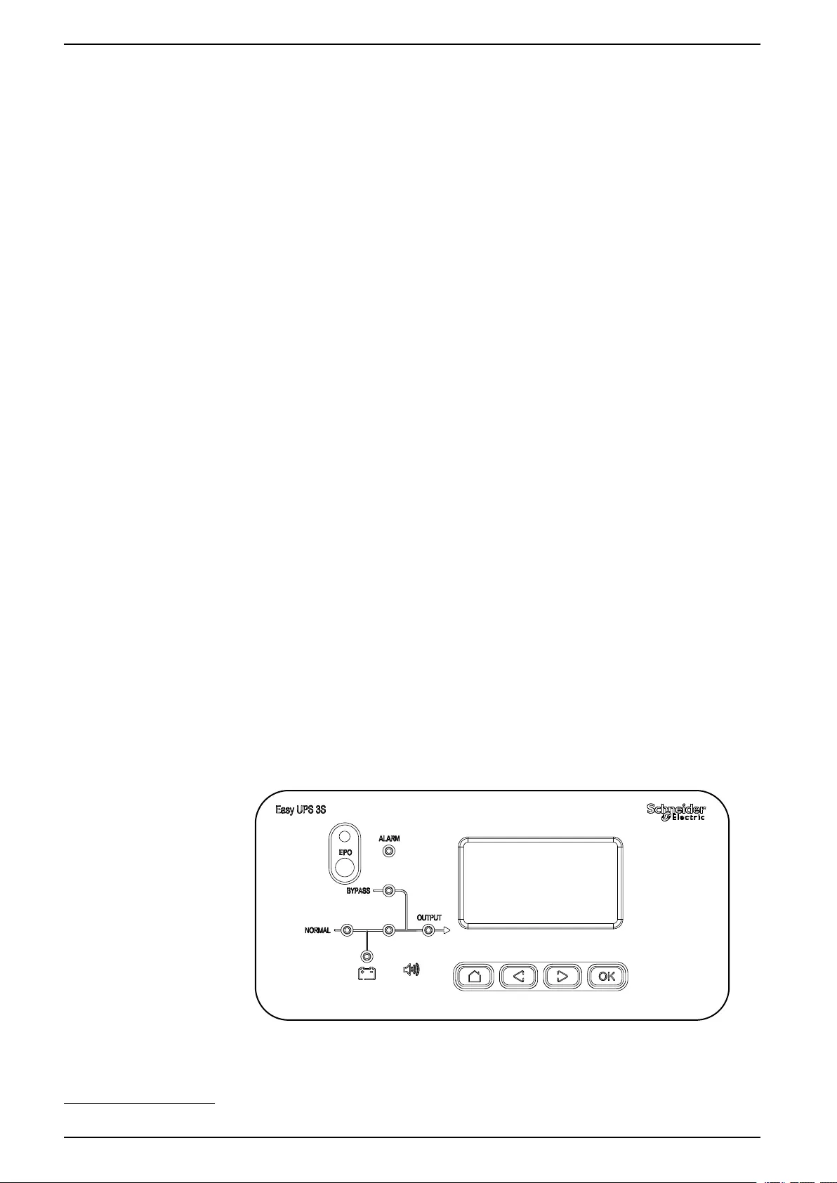
User Interface
10 990-91077E-001
2. The product is not UL-certified.
System Overview 10-40 kVA 400 V & 10-20 kVA 208 V 3:3,10-30 kVA 400 V 3:1
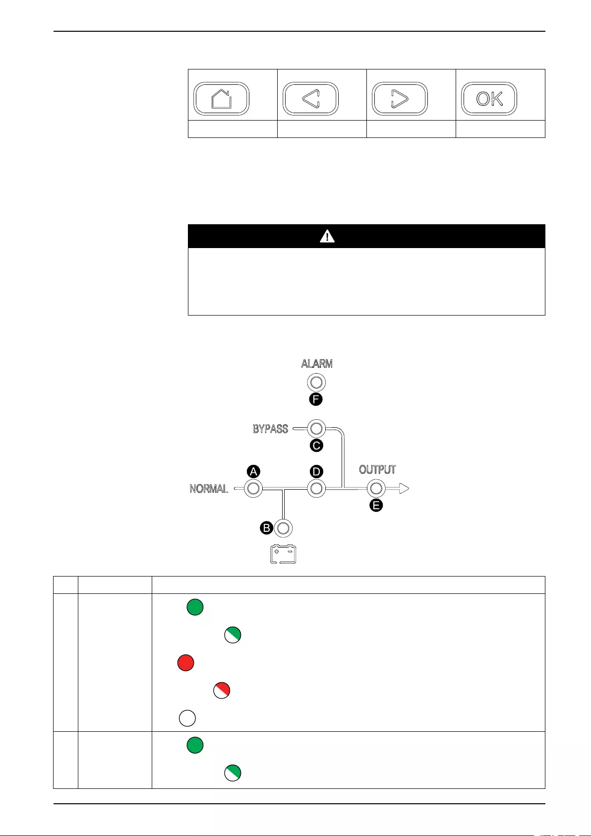
Keys
Home Previous Next Confirm
EPO
Only use the EPO button in case of emergency. When the EPO button is pushed,
the system turns off the rectifier and the inverter, and stops supplying the load
immediately.
DANGER
HAZARD OF ELECTRIC SHOCK, EXPLOSION, OR ARC FLASH
The UPS control circuit will remain active after the EPO has been pushed if
mains is available.
Failure to follow these instructions will result in death or serious injury.
Status LEDs
LED Status
ARectifier
Green : Rectifier is working correctly.
Flashing green : Rectifier is working correctly and mains is normal.
Red : Rectifier is inoperable.
Flashing red : Mains is unavailable.
OFF : Rectifier is off.
B Battery
Green : Battery is charging.
Flashing green : Battery is discharging.
990-91077E-001 11
10-40 kVA 400 V & 10-20 kVA 208 V 3:3,10-30 kVA 400 V 3:1 System Overview
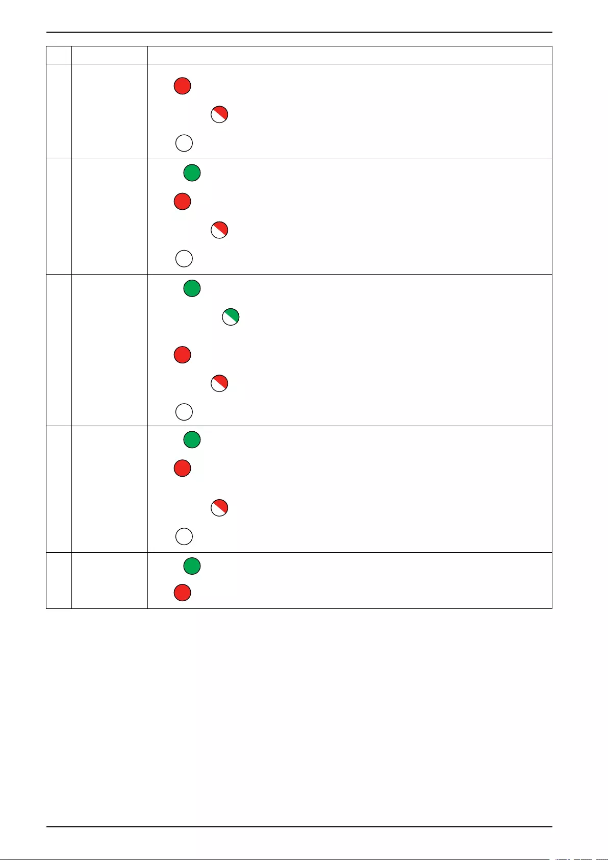
LED Status
Red : Battery is inoperable.
Flashing red : Battery low voltage.
OFF : Battery and battery charger are normal, battery is not charging.
CBypass
Green : Load supplied by bypass source.
Red : Bypass source is unavailable or static bypass switch is inoperable.
Flashing red : Bypass voltage is out of tolerance.
OFF : Bypass source is normal.
D Inverter
Green : Load supplied by inverter.
Flashing green : Inverter on, start, synchronization or standby (ECO mode) for at
least one module.
Red : Load not supplied by inverter, inverter is inoperable.
Flashing red : Load supplied by inverter, but an inverter alarm is present.
OFF : Inverter is off.
E Load
Green : UPS output is on.
Red : Overload on UPS output for too long, or output has shorted, or no output
power present.
Flashing red : Overload on UPS output.
OFF : UPS output is off.
FStatus
Green : Normal mode.
Red : Inoperable status.
12 990-91077E-001
System Overview 10-40 kVA 400 V & 10-20 kVA 208 V 3:3,10-30 kVA 400 V 3:1
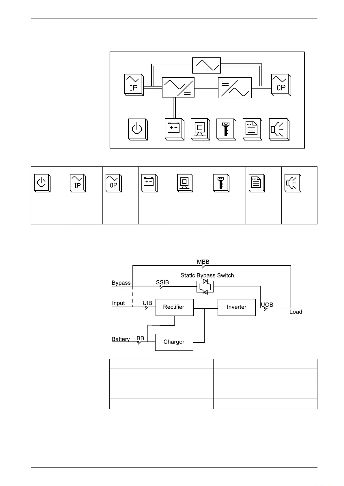
Display Interface
Home Screen
Buttons
Power On/
Off
Input and
bypass
status
information
Output
status
information
Battery
status
information
UPS status Function
settings
Log Mute
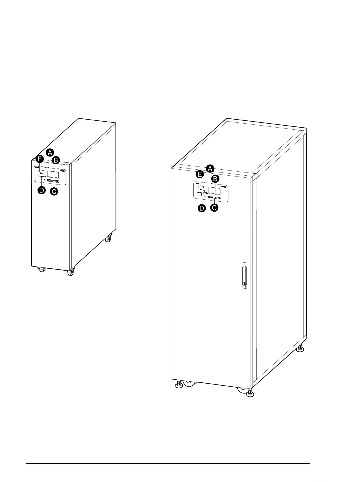
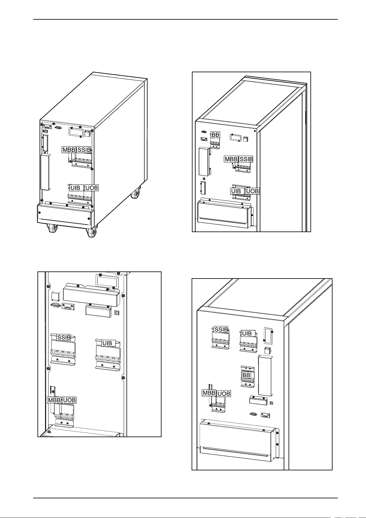
Overview of Single UPS
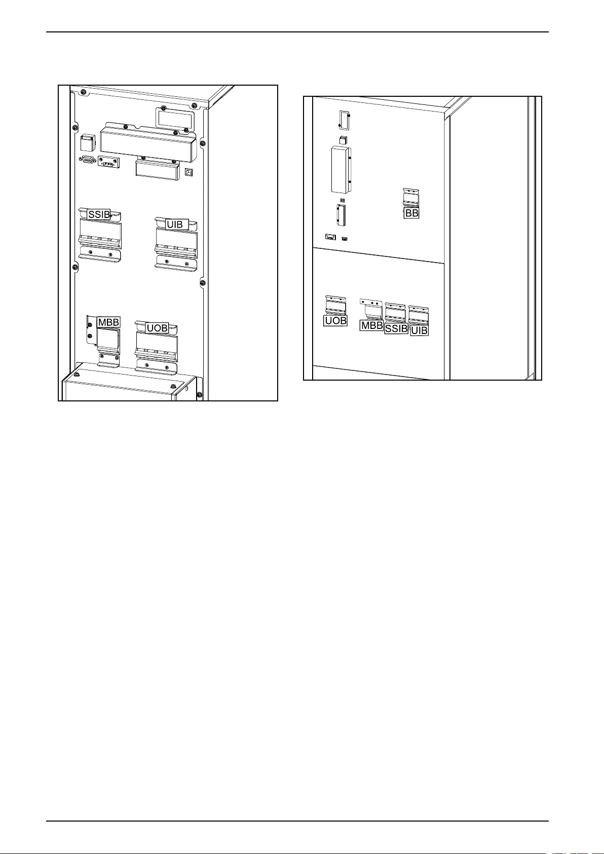
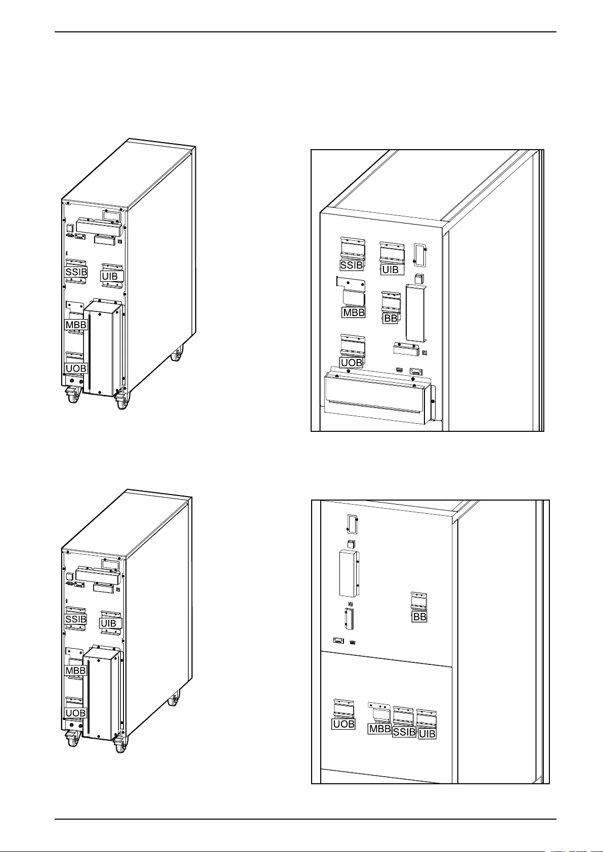
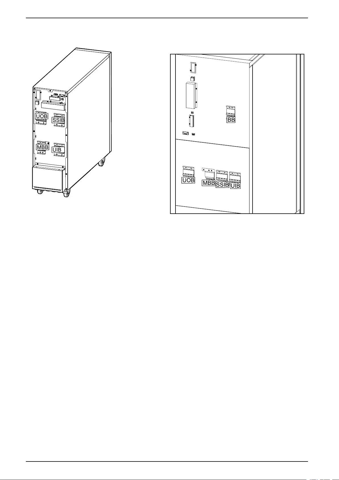
UIB Unit input breaker
SSIB Static switch input breaker
UOB Unit output breaker
MBB Maintenance bypass breaker
BB Battery breaker
990-91077E-001 13
10-40 kVA 400 V & 10-20 kVA 208 V 3:3,10-30 kVA 400 V 3:1 System Overview
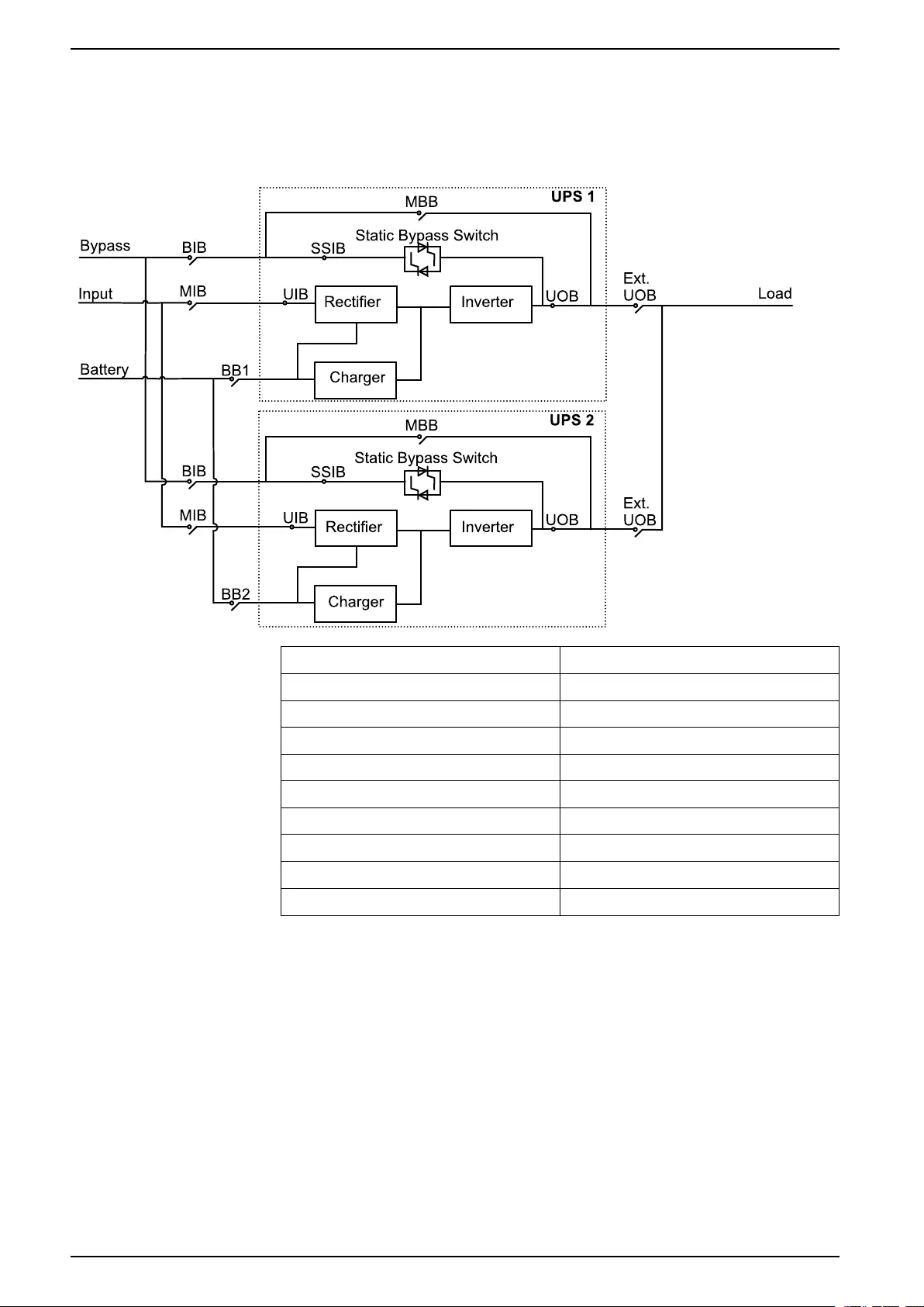
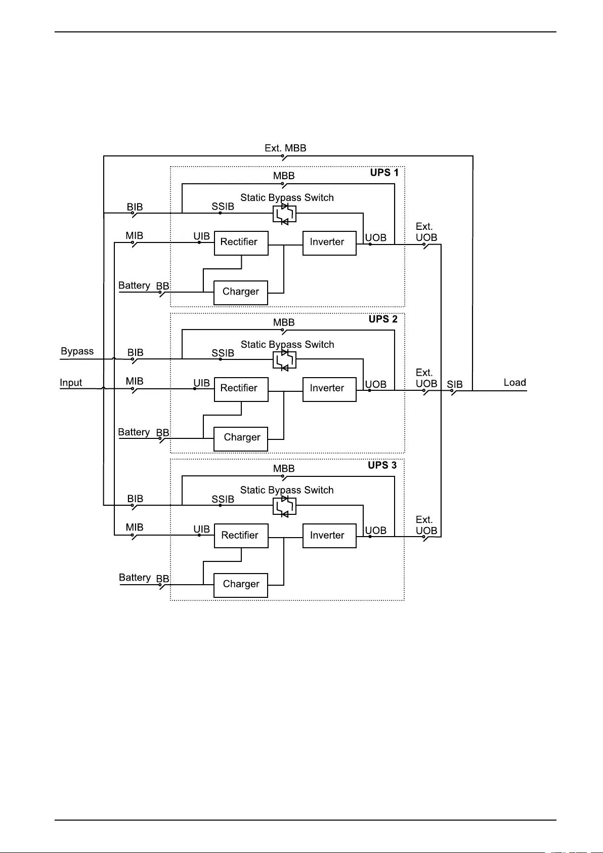
Overview of 1+1 Redundant Parallel System with Common
Battery Bank
NOTE: For UPS with internal batteries, the batteries must be removed and the
internal battery breaker (BB) must be opened.
MIB Mains input breaker
BIB Bypass input breaker
UIB Unit input breaker
SSIB Static switch input breaker
UOB Unit output breaker
Ext. UOB External unit output breaker
MBB Maintenance bypass breaker
Ext. MBB External maintenance bypass breaker
BB1 Battery breaker 1
BB2 Battery breaker 2
14 990-91077E-001
10-40 kVA 400 V & 10-20 kVA 208 V 3:3,10-30 kVA 400 V 3:1 System Overview
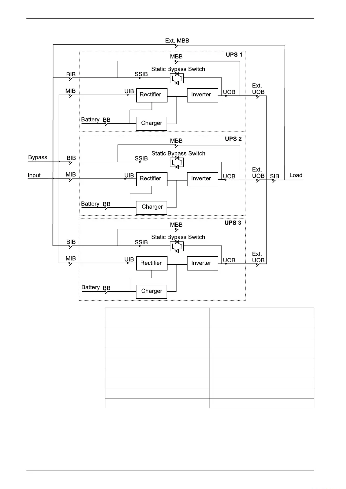
UPSs for Internal Batteries
MIB Mains input breaker
BIB Bypass input breaker
UIB Unit input breaker
SSIB Static switch input breaker
UOB Unit output breaker
Ext. UOB External unit output breaker
MBB Maintenance bypass breaker
Ext. MBB External maintenance bypass breaker
SIB System isolation breaker
BB Battery breaker
16 990-91077E-001
System Overview 10-40 kVA 400 V & 10-20 kVA 208 V 3:3,10-30 kVA 400 V 3:1
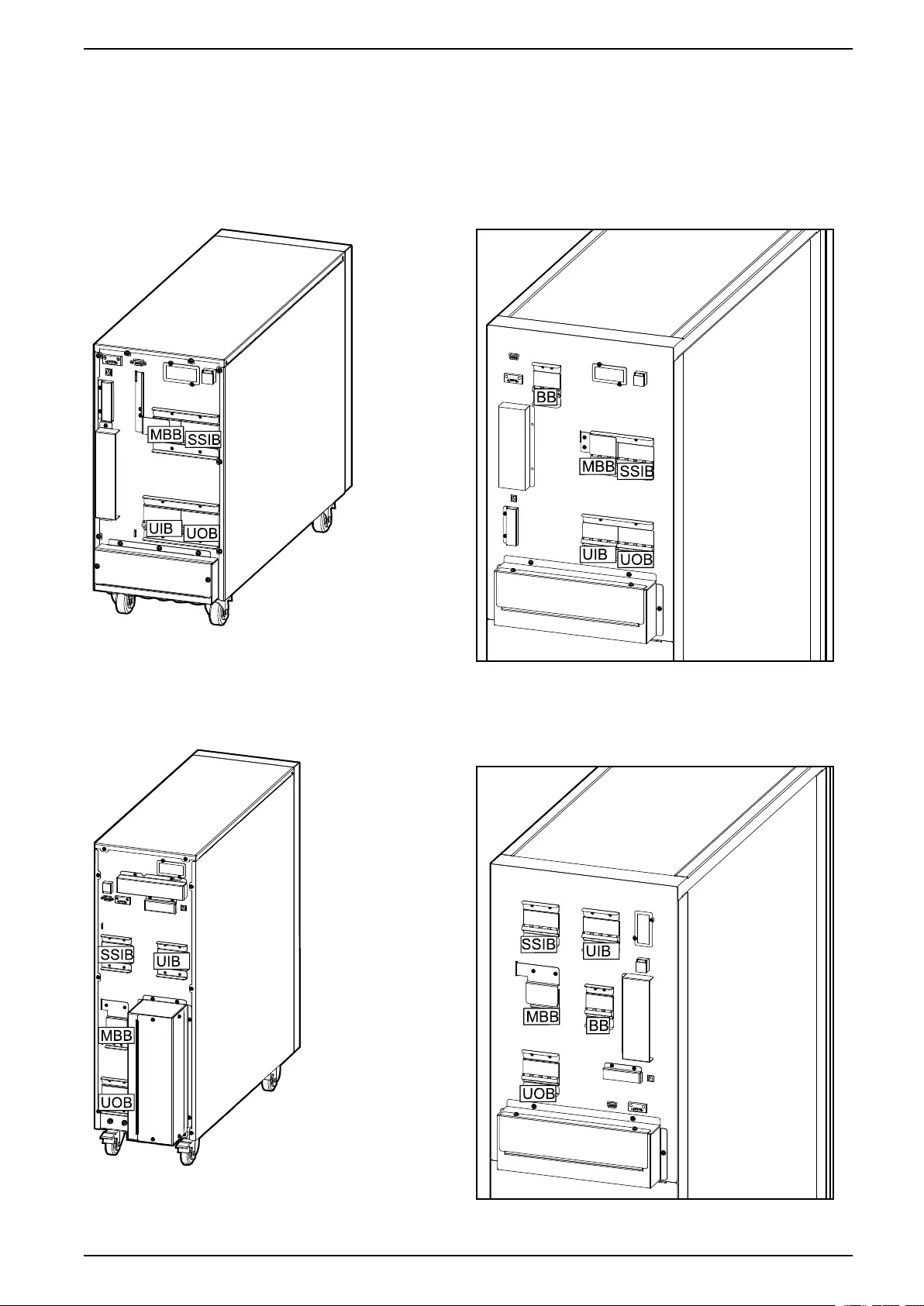
Location of Breakers - 400 V Systems
Location of Breakers in 3:3 UPSs
Rear View of the 10–15 kVA UPS for External
Batteries
Rear View of the 10–15 kVA UPS with Internal
Batteries
Rear View of the 20 kVA UPS for External Batteries Rear View of the 20 kVA UPS with Internal
Batteries
990-91077E-001 17
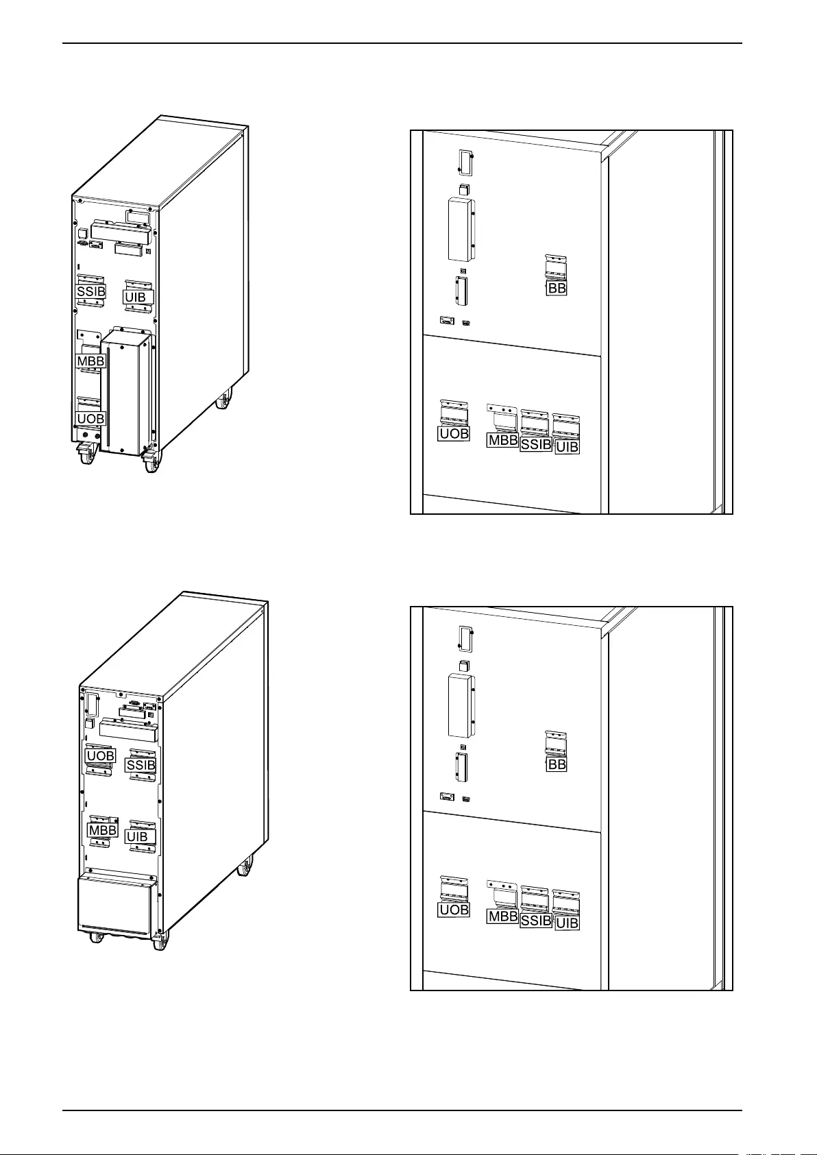
System Overview 10-40 kVA 400 V & 10-20 kVA 208 V 3:3,10-30 kVA 400 V 3:1
Location of Breakers in 3:1 UPSs
Rear View of the 10–15 kVA UPS for External
Batteries
Rear View of the 10–15 kVA UPS with Internal
Batteries
Rear View of the 20 kVA UPS for External Batteries Rear View of the 20 kVA UPS with Internal
Batteries
990-91077E-001 19
System Overview 10-40 kVA 400 V & 10-20 kVA 208 V 3:3,10-30 kVA 400 V 3:1
Location of Breakers - 208 V Systems
Location of Breakers in 3:3 UPSs
Rear View of the 10 kVA UPS for External Batteries Rear View of the 10 kVA UPS with Internal
Batteries
Rear View of the 15 kVA UPS for External Batteries Rear View of the 15 kVA UPS with Internal
Batteries
990-91077E-001 21

Technical Data for 400 V Systems 10-40 kVA 400 V & 10-20 kVA 208 V 3:3,10-30 kVA 400 V 3:1
Technical Data for 400 V Systems
Input Power Factor
Input Power Factor – 3:3 UPSs
The values are at a 400 V, 50 Hz load.
10 kVA 15 kVA 20 kVA 30 kVA 40 kVA
25% load 0.90 0.92 0.93 0.97 0.96
50% load 0.98 0.98 0.99 0.99 0.99
75% load 0.99 0.99 0.99 0.99 0.99
100% load 0.99 0.99 0.99 0.99 0.99
Input Power Factor – 3:1 UPSs
10 kVA 15 kVA 20 kVA 30 kVA
25% load 0.96 0.97 0.94 0.96
50% load 0.99 0.99 0.99 0.99
75% load 0.99 0.99 0.99 0.99
100% load 0.99 0.99 0.99 0.99
Efficiency – 3:3 UPSs
Efficiency in Normal Mode
The values are at a 400 V, 50 Hz load.
10 kVA 15 kVA 20 kVA 30 kVA 40 kVA
25% load 94.4 94.0 95.0 95.3 95.2
50% load 95.3 95.1 95.8 95.9 95.8
75% load 95.3 95.0 95.8 95.8 95.7
100% load 94.9 94.7 95.5 95.3 95.3
Efficiency in ECO Mode
10 kVA 15 kVA 20 kVA 30 kVA 40 kVA
25% load 95.1 96.3 97.0 97.9 98.0
50% load 97.3 97.9 98.1 98.6 98.8
75% load 98.0 98.5 98.6 99.0 99.0
100% load 98.4 98.7 98.8 99.1 99.1
Efficiency in Battery Mode
10 kVA 15 kVA 20 kVA 30 kVA 40 kVA
25% load 94.0 93.3 94.5 94.7 94.7
50% load 94.9 94.6 95.2 95.4 95.2
990-91077E-001 23

10-40 kVA 400 V & 10-20 kVA 208 V 3:3,10-30 kVA 400 V 3:1 Technical Data for 400 V Systems
10 kVA 15 kVA 20 kVA 30 kVA 40 kVA
75% load 94.7 94.5 95.2 95.2 95.1
100% load 94.3 94.0 94.9 94.6 94.6
Efficiency – 3:1 UPSs
Efficiency in Normal Mode
The values are at a 400 V, 50 Hz load.
10 kVA 15 kVA 20 kVA 30 kVA
25% load 94.2 94.2 94.6 95.1
50% load 95.2 95.0 95.5 95.6
75% load 94.9 94.8 95.3 95.2
100% load 94.4 94.4 95.0 94.7
Efficiency in ECO Mode
10 kVA 15 kVA 20 kVA 30 kVA
25% load 94.0 94.9 95.2 96.4
50% load 96.2 96.7 97.4 98.0
75% load 97.3 97.6 98.0 98.5
100% load 97.8 98.1 98.4 98.7
Efficiency in Battery Mode
10 kVA 15 kVA 20 kVA 30 kVA
25% load 94.0 93.3 94.5 94.7
50% load 94.9 94.6 95.2 95.4
75% load 94.7 94.5 95.2 95.2
100% load 94.3 94.0 94.9 94.6
24 990-91077E-001

Technical Data for 208 V Systems 10-40 kVA 400 V & 10-20 kVA 208 V 3:3,10-30 kVA 400 V 3:1
Technical Data for 208 V Systems
Input Power Factor
Input Power Factor – 3:3 UPSs
The values are at 208 V, 60 Hz load.
10 kVA 15 kVA 20 kVA
25% load 0.98 0.99 0.97
50% load 0.99 0.99 0.99
75% load 0.99 0.99 0.99
100% load 0.99 0.99 0.99
Efficiency – 3:3 UPSs
Efficiency in Normal Mode
The values are at a 208 V, 60 Hz load.
10 kVA 15 kVA 20 kVA
25% load 90.7 92.8 93.1
50% load 92.1 92.9 93.5
75% load 91.9 92.0 92.7
100% load 91.6 91.1 92.1
Efficiency in ECO Mode
10 kVA 15 kVA 20 kVA
25% load 96.5 96.1 96.5
50% load 97.5 97.3 97.5
75% load 97.8 97.4 98.6
100% load 98.0 97.7 98.0
Efficiency in Battery Mode
10 kVA 15 kVA 20 kVA
25% load 90.4 92.4 92.6
50% load 91.8 93.3 93.4
75% load 92.0 92.8 93.0
100% load 91.8 91.8 92.5
990-91077E-001 25
Technical Data 10-40 kVA 400 V & 10-20 kVA 208 V 3:3,10-30 kVA 400 V 3:1
Batteries
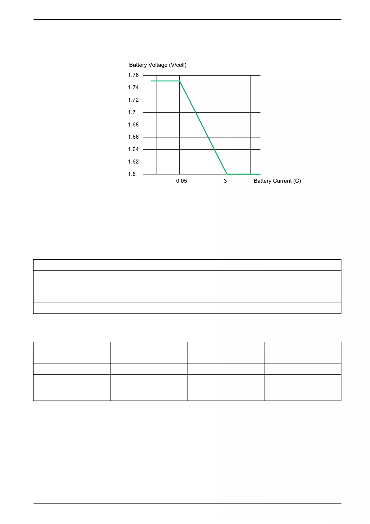
End of Discharge Voltage
Battery Gassing Rates for Modular Battery Cabinets and UPSs with Internal Batteries
The battery gassing rates are calculated based on:
• Gassing Rate at 2.4 V/cell (ft3 /hr) assuming 97% recombination efficiency
• Six cells per battery module
• Ten batteries per cartridge
Commercial Reference Description Typical cm³/hr (ml/hr)
E3SBTU Standard battery module 10.73 (10.73)
E3SBT4 Standard battery string 42.93 (42.93)
E3SBTHU High performance battery module 12.67 (12.67)
E3SBTH4 High performance battery string 50.68 (50.68)
Electrolyte Values for Modular Battery Cabinet and UPSs with Internal Batteries
Commercial Reference Description Electrolyte Volume L (gal) Electrolyte Weight kg (lbs)
E3SBTU Standard battery module 3.780 (1) 5 (11.1)
E3SBT4 Standard battery string 15.120 (4) 20 (44.4)
E3SBTHU High performance battery
module
3.330 (0.9) 4.4 (9.8)
E3SBTH4 High performance battery string 13.320 (3.6) 17.6 (39.2)
990-91077E-001 27

10-40 kVA 400 V & 10-20 kVA 208 V 3:3,10-30 kVA 400 V 3:1 Technical Data
Compliance
Safety IEC 62040-1: 2008-06, 1st edition Uninterruptible Power Systems (UPS) - Part 1: General and safety requirements
for UPS
IEC 62040-1: 2013-01, 1st edition amendment 1
EMC/EMI/RFI IEC 62040-2: 2005-10, 2nd edition Uninterruptible Power Systems (UPS) - Part 2: Electromagnetic compatibility
(EMC) requirements
Performance IEC 62040-3: 2011-03, 2nd edition Uninterruptible Power Systems (UPS) - Part 3: Method of specifying the
performance and test requirements
Environmental IEC 62040-4: 2013-04, 1st edition Uninterruptible Power Systems (UPS) - Part 4: Environmental aspects –
Requirements and reporting
Markings CE, RCM, EAC, WEEE
Transportation ISTA 2B
Communication and Management
• User interface with status LEDs and display
• RS232
• RS485
• SNMP (option)
• Dry contacts
• USB
28 990-91077E-001

Facility Planning for Easy UPS 3S 3:3 400 V 10-40 kVA 400 V & 10-20 kVA 208 V 3:3,10-30 kVA 400 V 3:1
Facility Planning for Easy UPS 3S 3:3 400 V
Input Specifications – 3:3 UPSs
10 kVA 15 kVA 20 kVA 30 kVA 40 kVA
Voltage (V) 380 400 415 380 400 415 380 400 415 380 400 415 380 400 415
Connections L1, L2, L3, N, PE
Input voltage range (V) 304–477
Frequency range (Hz) 45–65
Nominal input current (A) 16 15 15 24 23 22 32 31 30 48 46 44 65 61 59
Maximum input current (A) 19 18 18 29 28 26 38 37 36 58 55 53 78 73 71
Input current limitation (A) 22 20 20 33 31 30 44 42 41 65 63 60 89 83 80
Total harmonic distortion
(THDI)
<3% for 10 kVA UPS
<4% for 15–40 kVA UPS
Input power factor > 0.99
Maximum input shortcircuit
withstand
Icc=10 kA
Protection Circuit breaker and fuse Switch and fuse
Ramp-in 15 seconds
Bypass Specifications – 3:3 UPSs
10 kVA 15 kVA 20 kVA 30 kVA 40 kVA
Voltage (V) 380 400 415 380 400 415 380 400 415 380 400 415 380 400 415
Connections L1, L2, L3, N, PE
Overload capacity 125% continuous
125–130% for 10 minutes
130–150% for 1 minute
>150% for 300 milliseconds
Minimum bypass voltage (V) 304 320 332 304 320 332 304 320 332 304 320 332 304 320 332
Maximum bypass voltage (V) 437 460 477 437 460 477 437 460 477 437 460 477 437 460 477
Frequency (Hz) 50 or 60
Nominal bypass current (A) 15 14 14 23 22 21 30 29 28 46 43 42 61 58 56
Maximum input short circuit
withstand
Icc=10 kA
990-91077E-001 29

10-40 kVA 400 V & 10-20 kVA 208 V 3:3,10-30 kVA 400 V 3:1 Facility Planning for Easy UPS 3S 3:3 400 V
Output Specifications – 3:3 UPSs
10 kVA 15 kVA 20 kVA 30 kVA 40 kVA
Voltage (V) 380 400 415 380 400 415 380 400 415 380 400 415 380 400 415
Connections L1, L2, L3, N, PE
Overload capacity 110% for 60 minutes
125% for 10 minutes
150% for 1 minute
>150% for less than 200 milliseconds
Output voltage tolerance ± 1%
Dynamic load response 40 milliseconds
Output power factor 1.0 1.03
Nominal output current (A) 15 14 14 23 22 21 30 29 28 46 43 42 61 58 56
Total harmonic distortion
(THDU)
<3% at 100% linear load
<5.5% at 100% non-linear load
Output frequency (Hz) 50 or 60
Slew rate (Hz/sec) Programmable: 0.1 to 5.0. Default is 2.0.
Output performance
classification (according to
EN62040–3)
VFI-SS–111
Battery Specifications – 3:3 UPSs with Internal Batteries
10 kVA 15 kVA 20 kVA 30 kVA 40 kVA
Charging power Programmable from 1% to 20% of UPS capacity. Default is 10%.
Maximum charging power
(W)
2000 3000 4000 6000 8000
Nominal battery voltage
(VDC)
± 240
Nominal float voltage (VDC) ± 270
End of discharge voltage (full
load) (VDC)
± 192
End of discharge voltage (no
load) (VDC)
± 210
Battery current at full load
and nominal battery voltage
(A)
22 33 44 66 89
Battery current at full load
and minimum battery voltage
(A)
27 40 54 81 107
Temperature compensation
(per cell)
Programmable from 0–5 mV. Default is 3 mV.
Ripple current < 5% C10
30 990-91077E-001
3. When ambient temperature is below 30 °C. When the ambient temperature is above 30 °C, the power factor is 0.9.

Facility Planning for Easy UPS 3S 3:3 400 V 10-40 kVA 400 V & 10-20 kVA 208 V 3:3,10-30 kVA 400 V 3:1
Battery Specifications – 3:3 UPSs for External Batteries
10 kVA 15 kVA 20 kVA 30 kVA 40 kVA
Charging power Programmable from 1% to 20% of UPS capacity. Default is 10%.
Maximum charging power
(W)
2000 3000 4000 6000 8000
Nominal battery voltage (16–
20 blocks) (VDC)
±192 to ± 240
Nominal float voltage (16–20
blocks) (VDC)
± 216 to ± 270
End of discharge voltage
(16–20 blocks) (full load)
(VDC)
± 153 to ± 192
End of discharge voltage
(16–20 blocks) (no load)
(VDC)
± 168 to ± 210
Battery current at full load
and nominal battery voltage
(16–20 blocks) (A)
28–22 42–33 55–44 83–66 111–89
Battery current at full load
and minimum battery voltage
(16–20 blocks) (A)
34–27 50–40 67–54 101–81 134–107
Temperature compensation
(per cell)
Programmable from 0–5 mV. Default is 3 mV.
Ripple current < 5% C10
Required Upstream Protection and Cable Sizes – 3:3 UPSs
NOTE: Overcurrent protection must be provided by others.
Cable sizes in this manual are based on:
• Single core cables type U1000 R02V
• Specific to AC cables: Maximum length 70 m with a line voltage drop <3%
installed on perforated cable trays, XLPE-type insulation, single layer trefoil
formation, THDI between 15% and 33%, 35 °C at 400 V grouped in four
touching cables
• Specific to DC cables: Maximum length 15 m with a line voltage drop <1%
NOTE: If neutral conductor is expected to carry a high current, due to line-
neutral non-linear load, the circuit breaker must be rated according to
expected neutral current.
10 kVA UPS
Breaker type Cable Size per Phase
(mm2)
PE Cable Size (mm2)
Input – single mains
Input – dual mains
iC65H-C-20A / C60H-C-20A
iC65H-C-20A / C60H-C-20A
6 6
Bypass iC65H-C-20A / C60H-C-20A 6 6
Output C65N-B-4P-10A/C60N-B-4P-10A/
C65N-B-4P-10A /C60N-C-4P-6A
6 6
Battery Compact NSX100F DC TM50D - 3P 8 6
990-91077E-001 31

10-40 kVA 400 V & 10-20 kVA 208 V 3:3,10-30 kVA 400 V 3:1 Facility Planning for Easy UPS 3S 3:3 400 V
15 kVA UPS
Breaker type Cable Size per Phase
(mm2)
PE Cable Size (mm2)
Input – single mains
Input – dual mains
iC65H-C-32A / C60H-C-32A
iC65H-C-32A / C60H-C-32A
6 6
Bypass iC65H-C-32A / C60H-C-32A 6 6
Output C65N-B-4P-10A/C60N-B-4P-10A/
C65N-B-4P-10A /C60N-C-4P-6A
6 6
Battery Compact NSX100F DC TM63D - 3P 8 6
20 kVA UPS
Breaker type Cable Size per Phase
(mm2)
PE Cable Size (mm2)
Input – single mains
Input – dual mains
iC65H-C-40A / C60H-C-40A
iC65H-C-40A / C60H-C-40A
10 10
Bypass iC65H-C-40A / C60H-C-40A 10 10
Output C65N-B-4P-10A/C60N-B-4P-10A/
C65N-B-4P-10A /C60N-C-4P-6A
10 10
Battery Compact NSX100F DC TM80D - 3P 25 10
30 kVA UPS
Breaker type Cable Size per Phase
(mm2)
PE Cable Size (mm2)
Input – single mains
Input – dual mains
iC65H-C-63A / C60H-C-63A /C120H-C-63A
iC65H-C-63A / C60H-C-63A /C120H-C-63A
16 16
Bypass iC65H-C-63A / C60H-C-63A /C120H-C-63A 16 16
Output C65N-B-4P-16A/C60N-B-4P-16A/
C65N-C-4P-10A /C60N-C-4P-10A
16 16
Battery Compact NSX160F DC TM125D - 3P 25 16
40 kVA UPS
Breaker type Cable Size per Phase
(mm2)
PE Cable Size (mm2)
Input – single mains
Input – dual mains
C120H-C-80A / NSX100F TM80C 80A
C120H-C-80A / NSX100F TM80C 80A
25 16
Bypass C120H-C-80A / NSX100F TM80C 80A 25 16
Output C65N-B-4P-20A/C60N-B-4P-20A/
C65N-C-4P-10A /C60N-C-4P-10A
25 16
Battery Compact NSX160F DC TM160D - 3P 35 16
32 990-91077E-001

Facility Planning for Easy UPS 3S 3:3 400 V 10-40 kVA 400 V & 10-20 kVA 208 V 3:3,10-30 kVA 400 V 3:1
UPS Weights and Dimensions – 3:3 UPSs
UPS Weight kg Height mm Width mm Depth mm
10 kVA UPS for external
batteries
36 530 250 700
15 kVA UPS for external
batteries
36 530 250 700
20 kVA UPS for external
batteries
58 770 250 800
30 kVA UPS for external
batteries
60 770 250 800
40 kVA UPS for external
batteries
70 770 250 900
10 kVA UPS with internal
batteries
11241400 380 928
15 kVA UPS with internal
batteries
11241400 380 928
20 kVA UPS with internal
batteries
12241400 380 928
30 kVA UPS with internal
batteries
15241400 500 969
40 kVA UPS with internal
batteries
15841400 500 969
Battery 27 157 107 760
UPS Shipping Weights and Dimensions – 3:3 UPSs
UPS Weight kg Height mm Width mm Depth mm
10 kVA UPS for external
batteries
50 772 400 857
15 kVA UPS for external
batteries
50 772 400 857
20 kVA UPS for external
batteries
75 1015 400 982
30 kVA UPS for external
batteries
77 1015 400 982
40 kVA UPS for external
batteries
86 1015 400 1050
10 kVA UPS with internal
batteries
14541640 563 1014
15 kVA UPS with internal
batteries
14541640 563 1014
20 kVA UPS with internal
batteries
15841640 563 1014
30 kVA UPS with internal
batteries
19041640 683 1114
40 kVA UPS with internal
batteries
19541640 683 1114
Battery 28 180 140 820
990-91077E-001 33
4. Weight without batteries

10-40 kVA 400 V & 10-20 kVA 208 V 3:3,10-30 kVA 400 V 3:1 Facility Planning for Easy UPS 3S 3:1 400 V
Facility Planning for Easy UPS 3S 3:1 400 V
Input Specifications – 3:1 UPSs
10 kVA 15 kVA 20 kVA 30 kVA
Voltage (V) 380 400 415 380 400 415 380 400 415 380 400 415
Connections L1, L2, L3, N, PE
Input voltage range (V) 304–477
Frequency range (Hz) 45–65
Nominal input current (A) 16 15 15 24 23 22 32 31 30 48 46 44
Maximum input current (A) 19 18 18 29 28 26 38 37 36 58 55 53
Input current limitation (A) 22 20 20 33 31 30 44 42 41 65 63 60
Total harmonic distortion (THDI) <4% for 10 kVA UPS
<5% for 15–30 kVA UPS
Input power factor > 0.99
Maximum input shortcircuit withstand Icc=10 kA
Protection Circuit breaker and fuse Switch and fuse
Ramp-in 15 seconds
Bypass Specifications – 3:1 UPSs
10 kVA 15 kVA 20 kVA 30 kVA
Voltage (V) 220 230 240 220 230 240 220 230 240 220 230 240
Connections L, N, PE
Overload capacity 125% continuous
125–130% for 10 minutes
130–150% for 1 minute
>150% for 300 milliseconds
Minimum bypass voltage (V) 176 184 192 176 184 192 176 184 192 176 184 192
Maximum bypass voltage (V) 253 264 276 253 264 276 253 264 276 253 264 276
Frequency (Hz) 50 or 60
Nominal bypass current (A) 46 43 42 69 66 63 91 87 84 137 131 125
Maximum input short circuit withstand Icc=10 kA
34 990-91077E-001

Facility Planning for Easy UPS 3S 3:1 400 V 10-40 kVA 400 V & 10-20 kVA 208 V 3:3,10-30 kVA 400 V 3:1
Output Specifications – 3:1 UPSs
10 kVA 15 kVA 20 kVA 30 kVA
Voltage (V) 220 230 240 220 230 240 220 230 240 220 230 240
Connections L, N, PE
Overload capacity 110% for 60 minutes
125% for 10 minutes
150% for 1 minute
>150% for less than 200 milliseconds
Output voltage tolerance ± 1%
Dynamic load response 40 milliseconds
Output power factor 1.0 1.05
Nominal output current (A) 46 43 42 69 66 63 91 87 84 137 131 125
Total harmonic distortion (THDU) <3% at 100% linear load
<5.5% at 100% non-linear load
Output frequency (Hz) 50 or 60
Slew rate (Hz/sec) Programmable: 0.1 to 5.0. Default is 2.0.
Output performance classification (according to
EN62040–3)
VFI-SS–111
Battery Specifications – 3:1 UPSs with Internal Batteries
10 kVA 15 kVA 20 kVA 30 kVA
Charging power Programmable from 1% to 20% of UPS capacity. Default is 10%.
Maximum charging power (W) 2000 3000 4000 6000
Nominal battery voltage (VDC) ± 240
Nominal float voltage (VDC) ± 270
End of discharge voltage (full load) (VDC) ± 198
End of discharge voltage (no load) (VDC) ± 210
Battery current at full load and nominal battery
voltage (A)
22 33 44 66
Battery current at full load and minimum battery
voltage (A)
27 40 54 81
Temperature compensation (per cell) Programmable from 0–5 mV. Default is 3 mV.
Ripple current < 5% C10
990-91077E-001 35
5. When ambient temperature is below 30 °C. When the ambient temperature is above 30 °C, the power factor is 0.9.

10-40 kVA 400 V & 10-20 kVA 208 V 3:3,10-30 kVA 400 V 3:1 Facility Planning for Easy UPS 3S 3:1 400 V
Battery Specifications – 3:1 UPSs for External Batteries
10 kVA 15 kVA 20 kVA 30 kVA
Charging power Programmable from 1% to 20% of UPS capacity. Default is 10%.
Maximum charging power (W) 2000 3000 4000 6000
Nominal battery voltage (16–20 blocks) (VDC) ± 192 to ± 240
Nominal float voltage (16–20 blocks) (VDC) ± 216 to ± 270
End of discharge voltage (16–20 blocks) (full load)
(VDC)
± 158 to ± 198
End of discharge voltage (16–20 blocks) (no load)
(VDC)
± 168 to ± 210
Battery current at full load and nominal battery
voltage (16–20 blocks) (A)
28–22 42–33 55–44 83–66
Battery current at full load and minimum battery
voltage (16–20 blocks) (A)
34–27 50–40 67–54 101–81
Temperature compensation (per cell) Programmable from 0–5 mV. Default is 3 mV.
Ripple current < 5% C10
Required Upstream and Downstream Protection and Cable Sizes
– 3:1 UPSs
NOTE: Overcurrent protection must be provided by others.
Cable sizes in this manual are based on:
• Single core cables type U1000 R02V
• Specific to AC cables: Maximum length 70 m with a line voltage drop <3%
installed on perforated cable trays, XLPE-type insulation, single layer trefoil
formation, THDI between 15% and 33% , 35 °C at 400 V grouped in four
touching cables
• Specific to DC cables: Maximum length 15 m with a line voltage drop <1%
NOTE: If neutral conductor is expected to carry a high current, due to line-
neutral non-linear load, the circuit breaker must be rated according to
expected neutral current.
10 kVA UPS
Breaker type Cable Size per Phase
(mm2)
PE Cable Size (mm2)
Input – single mains
Input – dual mains
iC65H-C-50A / C60H-C-50A
iC65H-C-20A / C60H-C-20A
16
6
6
Bypass iC65H-C-50A / C60H-C-50A 16 6
Output C65N-B-2P-25A/
C60N-B-2P-25A
16 6
Battery Compact NSX100F DC TM50D - 3P 8 6
15 kVA UPS
Breaker type Cable Size per Phase
(mm2)
PE Cable Size (mm2)
Input – single mains
Input – dual mains
C120H-C-80A / NSX100F TM80C 80A
iC65H-C-32A / C60H-C-32A
25
6
6
Bypass C120H-C-80A / NSX100F TM80C 80A 25 6
36 990-91077E-001

Facility Planning for Easy UPS 3S 3:1 400 V 10-40 kVA 400 V & 10-20 kVA 208 V 3:3,10-30 kVA 400 V 3:1
Breaker type Cable Size per Phase
(mm2)
PE Cable Size (mm2)
Output C65N-B-2P-25A/
C60N-B-2P-25A
25 6
Battery Compact NSX100F DC TM63D - 3P 8 6
20 kVA UPS
Breaker type Cable Size per Phase
(mm2)
PE Cable Size (mm2)
Input – single mains
Input – dual mains
C120H-C-100A / NSX100F TM100C 100A
iC65H-C-40A / C60H-C-40A
35
10
10
Bypass C120H-C-100A / NSX100F TM100C 100A 35 10
Output C65N-B-2P-32A/
C60N-B-2P-32A
35 10
Battery Compact NSX100F DC TM80D - 3P 16 10
30 kVA UPS
Breaker type Cable Size per Phase
(mm2)
PE Cable Size (mm2)
Input – single mains
Input – dual mains
Compact NSX160F TM160C 160A
iC65H-C-63A / C60H-C-63A / C120H-C-63A
50
16
16
Bypass Compact NSX160F TM160C 160A 50 16
Output C65N-B-2P-50A/
C60N-B-2P-50A
50 16
Battery Compact NSX160F DC TM125D - 3P 25 16
Weights and Dimensions – 3:1 UPSs
UPS Weight kg Height mm Width mm Depth mm
10 kVA 3:1 UPS for
external batteries
36 530 250 700
15 kVA 3:1 UPS for
external batteries
36 530 250 700
20 kVA 3:1 UPS for
external batteries
58 770 250 800
30 kVA 3:1 UPS for
external batteries
60 770 250 800
10 kVA 3:1 UPS with
internal batteries
13061400 380 907
15 kVA 3:1 UPS with
internal batteries
13061400 380 907
20 kVA 3:1 UPS with
internal batteries
15061400 380 907
30 kVA 3:1 UPS with
internal batteries
18561400 500 996
Battery 27 157 107 760
990-91077E-001 37
6. Weight without batteries.

10-40 kVA 400 V & 10-20 kVA 208 V 3:3,10-30 kVA 400 V 3:1 Facility Planning for Easy UPS 3S 3:1 400 V
Shipping Weights and Dimensions – 3:1 UPSs
UPS Weight kg Height mm Width mm Depth mm
10 kVA 3:1 UPS for
external batteries
50 772 400 857
15 kVA 3:1UPS for
external batteries
50 772 400 857
20 kVA 3:1 UPS for
external batteries
75 1015 400 982
30 kVA 3:1 UPS for
external batteries
77 1015 400 982
10 kVA 3:1 UPS with
internal batteries
14571640 563 1014
15 kVA 3:1 UPS with
internal batteries
14571640 563 1014
20 kVA 3:1 UPS with
internal batteries
15871640 563 1014
30 kVA 3:1 UPS with
internal batteries
18571640 683 1114
Battery 28 180 140 820
38 990-91077E-001
7. Weight without batteries.

Facility Planning for Easy UPS 3S 3:3 208 V 10-40 kVA 400 V & 10-20 kVA 208 V 3:3,10-30 kVA 400 V 3:1
Facility Planning for Easy UPS 3S 3:3 208 V
Input Specifications – 3:3 UPSs
10 kVA 15 kVA 20 kVA
Voltage (V) 200 208 220 200 208 220 200 208 220
Connections L1, L2, L3, N, PE
Input voltage range (V) 180-253
Frequency range (Hz) 45–65
Nominal input current (A) 32 31 29 48 46 43 63 61 58
Maximum input current (A) 36 34 32 53 51 49 70 68 65
Input current limitation (A) 42 40 38 63 60 57 83 80 76
Total harmonic distortion (THDI) <4%
Input power factor > 0.99
Maximum input shortcircuit withstand Icc=10 kA
Protection Circuit breaker
and fuse
Switch and fuse
Ramp-in 15 seconds
Bypass Specifications – 3:3 UPSs
10 kVA 15 kVA 20 kVA
Voltage (V) 200 208 220 200 208 220 200 208 220
Connections L1, L2, L3, N, PE
Overload capacity 110% continuous
110–120% for 10 minutes
120–135% for 1 minute
>135% for 300 milliseconds
Minimum bypass voltage (V) 180 187 198 180 187 198 180 187 198
Maximum bypass voltage (V) 230 240 253 230 240 253 230 240 253
Frequency (Hz) 50 or 60
Nominal bypass current (A) 29 28 27 44 42 40 58 56 53
Maximum input short circuit withstand Icc=10 kA
990-91077E-001 39

10-40 kVA 400 V & 10-20 kVA 208 V 3:3,10-30 kVA 400 V 3:1 Facility Planning for Easy UPS 3S 3:3 208 V
Output Specifications – 3:3 UPSs
10 kVA 15 kVA 20 kVA
Voltage (V) 200 208 220 200 208 220 200 208 220
Connections L1, L2, L3, N, PE
Overload capacity 110% for 60 minutes
125% for 10 minutes
150% for 1 minute
>150% for less than 200 milliseconds
Output voltage tolerance ± 1%
Dynamic load response 40 milliseconds
Output power factor 1.0
Nominal output current (A) 29 28 27 44 42 40 58 56 53
Total harmonic distortion (THDU) <2% at 100% linear load
<6% at 100% non-linear load
Output frequency (Hz) 50 or 60
Slew rate (Hz/sec) Programmable: 0.1 to 5.0. Default is 2.0.
Output performance classification (according to EN62040–3) VFI-SS–111
Battery Specifications – 3:3 UPSs with Internal Batteries
10 kVA 15 kVA 20 kVA
Charging power Programmable from 1% to 20% of UPS capacity. Default is
10%.
Maximum charging power (W) 2000 3000 4000
Nominal battery voltage (VDC) ± 120
Nominal float voltage (VDC) ± 135
End of discharge voltage (full load) (VDC) ± 96
End of discharge voltage (no load) (VDC) ± 105
Battery current at full load and nominal battery voltage (A) 46 68 92
Battery current at full load and minimum battery voltage (A) 56 83 111
Temperature compensation (per cell) Programmable from 0-5 mV. Default is 3 mV.
Ripple current < 5% C10
40 990-91077E-001

Facility Planning for Easy UPS 3S 3:3 208 V 10-40 kVA 400 V & 10-20 kVA 208 V 3:3,10-30 kVA 400 V 3:1
Battery Specifications – 3:3 UPSs for External Batteries
10 kVA 15 kVA 20 kVA
Charging power Programmable from 1% to 20% of UPS capacity. Default is
10%.
Maximum charging power (W) 2000 3000 4000
Nominal battery voltage (10 blocks) (VDC) ±120
Nominal float voltage (10 blocks) (VDC) ± 135
End of discharge voltage (10 blocks) (full load) (VDC) ± 96
End of discharge voltage (10 blocks) (no load) (VDC) ± 105
Battery current at full load and nominal battery voltage (10 blocks) (A) 46 68 92
Battery current at full load and minimum battery voltage (10 blocks) (A) 56 83 111
Temperature compensation (per cell) Programmable from 0–5 mV. Default is 3 mV.
Ripple current < 5% C10
Required Upstream Protection and Cable Sizes – 3:3 UPSs
NOTE: Overcurrent protection must be provided by others.
Cable sizes in this manual are based on:
• Single core cables type U1000 R02V
• Specific to AC cables: Maximum length 70 m with a line voltage drop <3%
installed on perforated cable trays, XLPE-type insulation, single layer trefoil
formation, THDI between 15% and 33%, 35 °C at 208 V grouped in four
touching cables
• Specific to DC cables: Maximum length 15 m with a line voltage drop <1%
NOTE: If neutral conductor is expected to carry a high current, due to line-
neutral non-linear load, the circuit breaker must be rated according to
expected neutral current.
10 kVA UPS
Breaker type Cable Size per Phase
(mm2)
PE Cable Size (mm2)
Input – single mains
Input – dual mains
iC65H-C-40A / C60H-C-40A
iC65H-C-40A / C60H-C-40A
10 10
Bypass iC65H-C-40A / C60H-C-40A 10 10
Output C65N-B-4P-10A/C60N-B-4P-10A/
C65N-B-4P-10A /C60N-C-4P-6A
10 10
Battery Compact NSX100F DC TM80D - 3P 25 10
15 kVA UPS
Breaker type Cable Size per Phase
(mm2)
PE Cable Size (mm2)
Input – single mains
Input – dual mains
iC65H-C-63A / C60H-C-63A /C120H-C-63A
iC65H-C-63A / C60H-C-63A /C120H-C-63A
16 16
Bypass iC65H-C-63A / C60H-C-63A /C120H-C-63A 16 16
Output C65N-B-4P-16A/C60N-B-4P-16A/
C65N-C-4P-10A /C60N-C-4P-10A
16 16
Battery Compact NSX160F DC TM125D - 3P 25 16
990-91077E-001 41

10-40 kVA 400 V & 10-20 kVA 208 V 3:3,10-30 kVA 400 V 3:1 Facility Planning for Easy UPS 3S 3:3 208 V
20 kVA UPS
Breaker type Cable Size per Phase
(mm2)
PE Cable Size (mm2)
Input – single mains
Input – dual mains
C120H-C-80A / NSX100F TM80C 80A
C120H-C-80A / NSX100F TM80C 80A
25 16
Bypass C120H-C-80A / NSX100F TM80C 80A 25 16
Output C65N-B-4P-20A/C60N-B-4P-20A/
C65N-C-4P-10A /C60N-C-4P-10A
25 16
Battery Compact NSX160F DC TM160D - 3P 35 16
UPS Weights and Dimensions – 3:3 UPSs
UPS Weight kg Height mm Width mm Depth mm
10 kVA UPS for external
batteries
58 770 250 800
15 kVA UPS for external
batteries
60 770 250 800
20 kVA UPS for external
batteries
70 770 250 900
10 kVA UPS with internal
batteries
12281400 380 928
15 kVA UPS with internal
batteries
15281400 500 969
20 kVA UPS with internal
batteries
15881400 500 969
Battery 27 157 107 760
UPS Shipping Weights and Dimensions – 3:3 UPSs
UPS Weight kg Height mm Width mm Depth mm
10 kVA UPS for external
batteries
75 1015 400 982
15 kVA UPS for external
batteries
77 1015 400 982
20 kVA UPS for external
batteries
86 1015 400 1050
10 kVA UPS with internal
batteries
15881640 563 1014
15 kVA UPS with internal
batteries
19081640 683 1114
20 kVA UPS with internal
batteries
19581640 683 1114
Battery 28 180 140 820
42 990-91077E-001
8. Weight without batteries

Facility Planning 10-40 kVA 400 V & 10-20 kVA 208 V 3:3,10-30 kVA 400 V 3:1
Facility Planning
Recommended Bolts and Cable Lugs
Cable Size (mm²) Bolt Size Cable Lug Type
6 M5 KST TLK6-5
8 M5 KST RNBS8-5
10 M6 KST TLK10-6
16 M6 KST TLK16-6
25 M6 KST DRNB6-25
35 M6 KST TLK35-6
50 M8 KST TLK50-8
Torque Specifications
Bolt Size Torque
M5 4 Nm
M6 5 Nm
M8 12 Nm
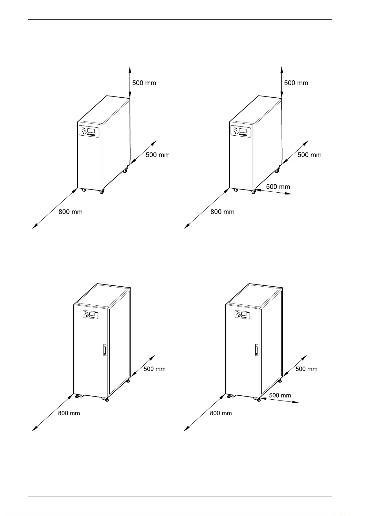
Clearance
NOTE: Clearance dimensions are published for airflow and service access
only. Consult with the local safety codes and standards for additional
requirements in your local area.
NOTE: If the UPS is installed without side access, the length of the cables
connected to the UPS must allow for rolling out the UPS.
990-91077E-001 43

Facility Planning 10-40 kVA 400 V & 10-20 kVA 208 V 3:3,10-30 kVA 400 V 3:1
Environmental
Operation Storage
Temperature 0 °C to 40 °C9-15 °C to 40 °C for systems with batteries
-25 °C to 55 °C for systems without batteries
Relative humidity 0–95% non-condensing
Elevation derating according to
IEC 62040–3
1000 m: 1.000
1500 m: 0.975
2000 m: 0.950
< 15000 m above sea level (or in an
environment with equivalent air pressure)
Audible noise 10–20 kVA 400 V: <60 dBA at full load
30–40 kVA 400 V: <63 dBA at full load
10–20 kVA 208 V: <63 dBA at full load
Protection class IP20 (dust filter as standard)
Color RAL 9003
Heat Dissipation for 400 V Systems
10 kVA 15 kVA 20 kVA 30 kVA 40 kVA
Normal mode (W) 516 852 870 1410 1810
Battery mode (W) 600 950 1080 1700 2270
ECO mode (W) 135 223 240 370 480
Heat Dissipation for 208 V Systems
10 kVA 15 kVA 20 kVA
Normal mode (W) 920 1469 1701
Battery mode (W) 948 1247 1861
ECO mode (W) 245 358 415
Airflow Requirement for 400 V Systems
NOTE: The UPS requires a sufficient amount of fresh air in the installation
room.
10 kVA 15 kVA 20 kVA 30 kVA 40 kVA
Fan air throughput
(m³/min)
6.20 8.25 10.85 15.57 16.38
Airflow Requirement for 208 V Systems
NOTE: The UPS requires a sufficient amount of fresh air in the installation
room.
10 kVA 15 kVA 20 kVA
Fan air throughput (m³/min) 10.85 15.57 16.38
990-91077E-001 45
9. The optimal operation temperature for batteries is 20 °C to 25 °C

10-40 kVA 400 V & 10-20 kVA 208 V 3:3,10-30 kVA 400 V 3:1 Facility Planning
Battery Breaker Box Weights and Dimensions
Weight kg Height mm Width mm Depth mm
Battery breaker box
(E3SOPT007)
25 650 500 280
Modular Battery Cabinet Weights and Dimensions
Weight kg Height mm Width mm Depth mm
Modular battery cabinet 125 1400 500 851
Modular Battery Cabinet Shipping Weights and Dimensions
Weight kg Height mm Width mm Depth mm
Modular battery cabinet 140 1620 650 1020
46 990-91077E-001
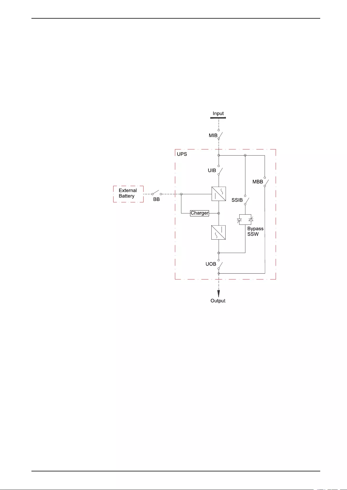
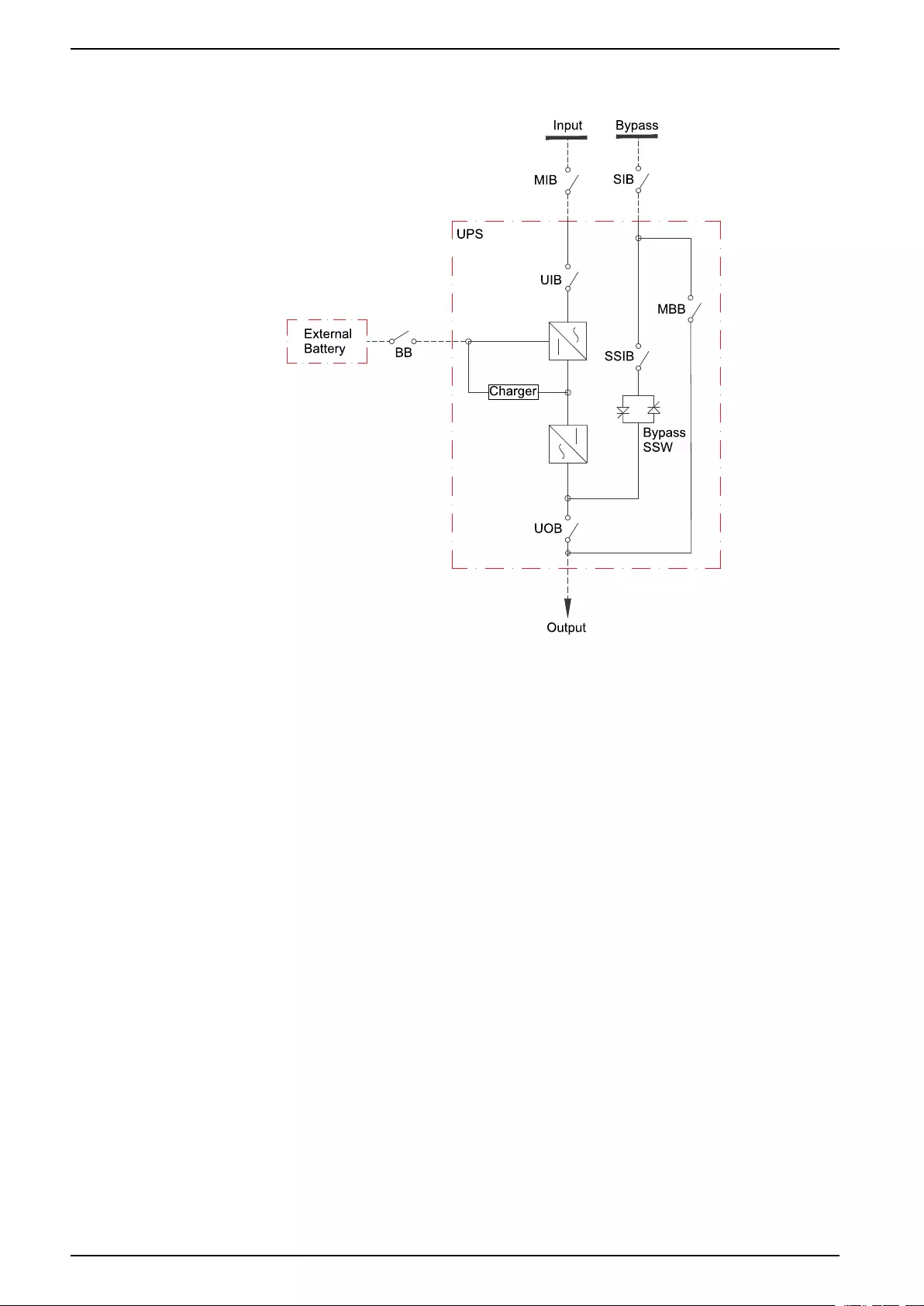
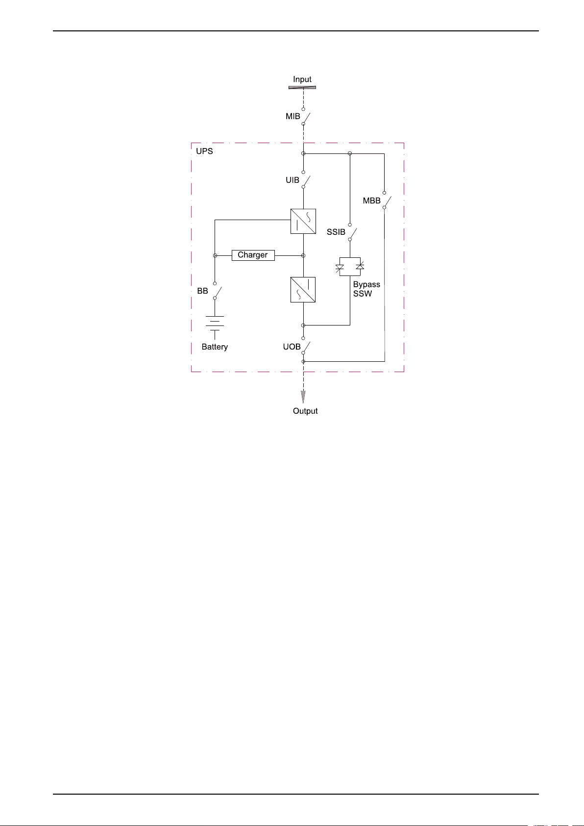
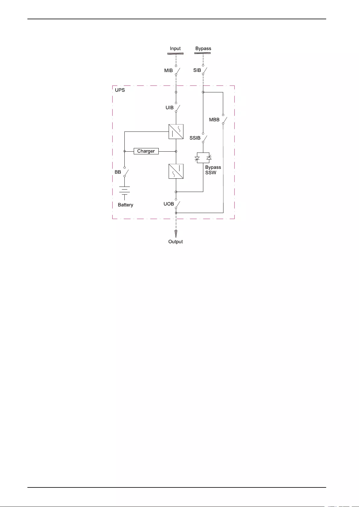
Drawings 10-40 kVA 400 V & 10-20 kVA 208 V 3:3,10-30 kVA 400 V 3:1
Drawings
NOTE: A comprehensive set of drawings is available on www.schneider-
electric.com.
NOTE: These drawings are for reference ONLY – subject to change without
notice.
Easy UPS 3S for External Batteries – Single Mains System
990-91077E-001 47

Options 10-40 kVA 400 V & 10-20 kVA 208 V 3:3,10-30 kVA 400 V 3:1
Options
Hardware Options
• E3SOPT001: Easy UPS 3S network card
• E3SOPT002: Easy UPS 3S parallel kit
• E3SOPT003: Easy UPS 3S temperature sensor kit for external battery
system
• E3SOPT004: Easy UPS 3S cold start kit
• E3SOPT006: Easy UPS 3S parallel maintenance bypass panel for up to 2
units 10-40 kVA
• E3SXR6: Easy UPS 3S modular battery cabinet
• E3SOPT007: Easy UPS 3S battery breaker box
• E3SOPT008: Easy UPS 3S battery breaker kit
• E3SOPT009: Easy UPS battery connector kit
• GVEBC7: Empty battery cabinet, 700 mm wide
• GVEBC11: Empty battery cabinet, 1100 mm wide
Configuration Options
• Single or dual mains
• Bottom cable entry
• Up to four UPSs in parallel
• ECO mode
Settings
Setting Default Value Available Settings
LCD contrast 60 0 to 100
Date and Time 05/07/2013 08:55:55 Year > 2000
Language English Chinese simplified, English, Italian,
German, Russian, Spanish, Portuguese
Brazilian, and French
Input voltage 400 V 200 V/208 V/220 V or 380 V/400 V/415 V
Bypass voltage 400 V for 3:3 UPSs
230 V for 3:1 UPSs
200 V/208 V/220 V or 380 V/400 V/415 V for
3:3 UPSs
220 V/230 V/240 V for 3:1 UPSs
Input frequency 50 Hz 60 Hz
Output voltage 400 V for 3:3 UPSs
230 V for 3:1 UPSs
200 V/208 V/220 V or 380 V/400 V/415 V for
3:3 UPSs
220 V/230 V/240 V for 3:1 UPSs
Output frequency 50 Hz 60 Hz
Output phase 3 for 3:3 UPSs
1 for 3:1 UPSs
3/1
Auto boost disable enable
Auto maint disable enable
System mode single parallel/ECO/parallel ECO/self aging
United number 1 1 to 4
System ID 0 0 to 3
990-91077E-001 51

10-40 kVA 400 V & 10-20 kVA 208 V 3:3,10-30 kVA 400 V 3:1 Options
Setting Default Value Available Settings
Adjusted output voltage 400 V for 3:3 UPSs
230 V for 3:1 UPSs
Output voltage ±10 V
Frequency slew rate 2 Hz/s 0.1 to 5.0 Hz/s
Frequency synchronization window 3 Hz 0.5 to 5.0 Hz
Monochrome LCD time (min) 10 1/3/5/10/20/30
Bypass voltage upper limit (%) 15 10/20/25
Bypass voltage lower limit (%) -20 -10/-15/-30/-40
Bypass frequency limited (Hz) ±5 ±1/±3/±5
System restart mode after end of discharge Normal bypass only/ no output
Fan maintenance period 34560 hours (48 months) 0 to 60000 hours
DC capacitor maintenance period 34560 hours (48 months) 0 to 60000 hours
warranty period 9 months 1 to 36 months
AC capacitor maintenance period 120 months 60 to 120 months
APS maintenance period 84 months 36 to 120 months
Dust filter maintenance period 3 months 0/3/4/5/12 months
Battery maintenance period 4 years 2 to 10 years
Battery number 32 for UPSs for external batteries
40 for UPSs with internal batteries
20/32/34/36/38/40
Battery AH 1 1 to 30000
Float charge voltage/cell (V) 2.25 2.10 to 2.35
Boost charge voltage/cell (V) 2.25 2.20 to 2.45
End of discharge voltage/cell, at 3 C current
(V)
1.6 1.50 to 1.85
End of discharge voltage/cell, at 0.05 C
current (V)
1.75 1.55 to 1.90
Charge current percent limit (%) 10 1 to 20
Battery temperature compensation 0 0 to 5 mV/℃
Boost charge time limit 12 hours 1 to 48 hours
Auto boost period 2160 hours (3 months) 720 to 30000 hours, available when auto
boost is enabled
Auto maintenance discharge period 6480 hours (9 months) 720 to 30000 hours, available when auto
maintenance is enabled
Critical battery temperature 45 ℃25 ℃to 70 ℃
Critical ambient temperature 40 ℃25 ℃to 70 ℃
52 990-91077E-001

Limited Factory Warranty 10-40 kVA 400 V & 10-20 kVA 208 V 3:3,10-30 kVA 400 V 3:1
Limited Factory Warranty
One-Year Factory Warranty
The limited warranty provided by Schneider Electric in this Statement of Limited
Factory Warranty applies only to products you purchase for your commercial or
industrial use in the ordinary course of your business.
Terms of Warranty
Schneider Electric warrants that the product shall be free from defects in materials
and workmanship for a period of one year from the date of product start-up when
start-up is performed by Schneider Electric-authorized service personnel and
occurs within six months of the Schneider Electric shipment date. This warranty
covers repairing or replacing any defective parts including on-site labor and travel.
In the event that the product fails to meet the foregoing warranty criteria, the
warranty covers repairing or replacing defective parts at the sole discretion of
Schneider Electric for a period of one year from the shipment date. For Schneider
Electric cooling solutions, this warranty does not cover circuit breaker resetting,
loss of refrigerant, consumables, or preventive maintenance items. Repair or
replacement of a defective product or part thereof does not extend the original
warranty period. Any parts furnished under this warranty may be new or factory-
remanufactured.
Non-transferable Warranty
This warranty is extended to the first person, firm, association or corporation
(herein referred to by “You” or “Your”) for whom the Schneider Electric product
specified herein has been purchased. This warranty is not transferable or
assignable without the prior written permission of Schneider Electric.
Assignment of Warranties
Schneider Electric will assign you any warranties which are made by
manufacturers and suppliers of components of the Schneider Electric product and
which are assignable. Any such warranties are assigned “AS IS” and Schneider
Electric makes no representation as to the effectiveness or extent of such
warranties, assumes no responsibility for any matters which may be warranted by
such manufacturers or suppliers and extends no coverage under this Warranty to
such components.
Drawings, Descriptions
Schneider Electric warrants for the warranty period and on the terms of the
warranty set forth herein that the Schneider Electric product will substantially
conform to the descriptions contained in the Schneider Electric Official Published
Specifications or any of the drawings certified and agreed to by contract with
Schneider Electric if applicable thereto (“Specifications”). It is understood that the
Specifications are not warranties of performance and not warranties of fitness for
a particular purpose.
990-91077E-001 53

10-40 kVA 400 V & 10-20 kVA 208 V 3:3,10-30 kVA 400 V 3:1 Limited Factory Warranty
Exclusions
Schneider Electric shall not be liable under the warranty if its testing and
examination disclose that the alleged defect in the product does not exist or was
caused by end user or any third person misuse, negligence, improper installation
or testing. Further, Schneider Electric shall not be liable under the warranty for
unauthorized attempts to repair or modify wrong or inadequate electrical voltage
or connection, inappropriate on-site operation conditions, corrosive atmosphere,
repair, installation, start-up by non-Schneider Electric designated personnel, a
change in location or operating use, exposure to the elements, Acts of God, fire,
theft, or installation contrary to Schneider Electric recommendations or
specifications or in any event if the Schneider Electric serial number has been
altered, defaced, or removed, or any other cause beyond the range of the
intended use.
THERE ARE NO WARRANTIES, EXPRESS OR IMPLIED, BY OPERATION OF
LAW OR OTHERWISE, OF PRODUCTS SOLD, SERVICED OR FURNISHED
UNDER THIS AGREEMENT OR IN CONNECTION HEREWITH. SCHNEIDER
ELECTRIC DISCLAIMS ALL IMPLIED WARRANTIES OF MERCHANTABILITY,
SATISFACTION AND FITNESS FOR A PARTICULAR PURPOSE. SCHNEIDER
ELECTRIC EXPRESS WARRANTIES WILL NOT BE ENLARGED, DIMINISHED,
OR AFFECTED BY AND NO OBLIGATION OR LIABILITY WILL ARISE OUT OF,
SCHNEIDER ELECTRIC RENDERING OF TECHNICAL OR OTHER ADVICE OR
SERVICE IN CONNECTION WITH THE PRODUCTS. THE FOREGOING
WARRANTIES AND REMEDIES ARE EXCLUSIVE AND IN LIEU OF ALL OTHER
WARRANTIES AND REMEDIES. THE WARRANTIES SET FORTH ABOVE
CONSTITUTE SCHNEIDER ELECTRIC SOLE LIABILITY AND PURCHASER’S
EXCLUSIVE REMEDY FOR ANY BREACH OF SUCH WARRANTIES.
SCHNEIDER ELECTRIC WARRANTIES RUN ONLY TO PURCHASER AND ARE
NOT EXTENDED TO ANY THIRD PARTIES.
IN NO EVENT SHALL SCHNEIDER ELECTRIC, ITS OFFICERS, DIRECTORS,
AFFILIATES OR EMPLOYEES BE LIABLE FOR ANY FORM OF INDIRECT,
SPECIAL, CONSEQUENTIAL OR PUNITIVE DAMAGES, ARISING OUT OF THE
USE, SERVICE OR INSTALLATION, OF THE PRODUCTS, WHETHER SUCH
DAMAGES ARISE IN CONTRACT OR TORT, IRRESPECTIVE OF FAULT,
NEGLIGENCE OR STRICT LIABILITY OR WHETHER SCHNEIDER ELECTRIC
HAS BEEN ADVISED IN ADVANCE OF THE POSSIBILITY OF SUCH
DAMAGES, SPECIFICALLY, SCHNEIDER ELECTRIC IS NOT LIABLE FOR ANY
COSTS, SUCH AS LOST PROFITS OR REVENUE, LOSS OF EQUIPMENT,
LOSS OF USE OF EQUIPMENT, LOSS OF SOFTWARE, LOSS OF DATA,
COSTS OF SUBSTITUANTS, CLAIMS BY THIRD PARTIES, OR OTHERWISE.
NO SALESMAN, EMPLOYEE OR AGENT OF SCHNEIDER ELECTRIC IS
AUTHORIZED TO ADD TO OR VARY THE TERMS OF THIS WARRANTY.
WARRANTY TERMS MAY BE MODIFIED, IF AT ALL, ONLY IN WRITING
SIGNED BY AN SCHNEIDER ELECTRIC OFFICER AND LEGAL DEPARTMENT.
Warranty Claims
Customers with warranty claims issues may access the SCHNEIDER ELECTRIC
worldwide customer support network through the SCHNEIDER ELECTRIC web
site: http://www.schneider-electric.com. Select your country from the country
selection pull-down menu. Open the Support tab at the top of the web page to
obtain contact information for customer support in your region.
54 990-91077E-001


Schneider Electric
35 rue Joseph Monier
92500 Rueil Malmaison
France
+ 33 (0) 1 41 29 70 00
*990-91077E-001*
As standards, specifications, and design change from time to time,
please ask for confirmation of the information given in this publication.
© 2017 – 2020 Schneider Electric. All rights reserved.
990-91077E-001