Table of Contents
- Easy UPS 3S
- Important Safety Instructions — SAVE THESE INSTRUCTIONS
- Overview
- Operation Modes
- Operation Procedures
- Initial Start-Up of the UPS Using the Wizard – Only Applicable to Single UPSs with Internal Batteries
- Start Up a Single UPS in Normal Mode
- Transfer a Single UPS from Normal Mode to Static Bypass Mode
- Transfer a Single UPS from Static Bypass Mode to Normal Mode
- Transfer a Single UPS from Normal Mode to Maintenance Bypass Mode
- Transfer a Single UPS from Maintenance Bypass Mode to Normal Mode
- Transfer a Parallel System from Normal Mode to Maintenance Bypass Mode
- Transfer a Parallel System from Maintenance Bypass Mode to Normal Mode
- Isolate a Single UPS from the Parallel System
- Start Up and Add a UPS to a Running Parallel System
- Configuration
- Tests
- Maintenance
- Troubleshooting
APC E3SUPS30K3IB1 User Manual
Displayed below is the user manual for E3SUPS30K3IB1 by APC which is a product in the Uninterruptible Power Supplies (UPSs) category. This manual has pages.
Related Manuals
Easy UPS 3S
10-40 kVA
Operation
09/2019
www.schneider-electric.com

Legal Information
The Schneider Electric brand and any trademarks of Schneider Electric SE and its
subsidiaries referred to in this guide are the property of Schneider Electric SE or its
subsidiaries. All other brands may be trademarks of their respective owners.
This guide and its content are protected under applicable copyright laws and
furnished for informational use only. No part of this guide may be reproduced or
transmitted in any form or by any means (electronic, mechanical, photocopying,
recording, or otherwise), for any purpose, without the prior written permission of
Schneider Electric.
Schneider Electric does not grant any right or license for commercial use of the guide
or its content, except for a non-exclusive and personal license to consult it on an "as
is" basis. Schneider Electric products and equipment should be installed, operated,
serviced, and maintained only by qualified personnel.
As standards, specifications, and designs change from time to time, information
contained in this guide may be subject to change without notice.
To the extent permitted by applicable law, no responsibility or liability is assumed by
Schneider Electric and its subsidiaries for any errors or omissions in the informational
content of this material or consequences arising out of or resulting from the use of the
information contained herein.
Go to http://www.productinfo.schneider-electric.com/portals/ui/easyups3s/ for
translations.
Rendez-vous sur http://www.productinfo.schneider-electric.com/portals/ui/
easyups3s/ pour accéder aux traductions.
Vaya a http://www.productinfo.schneider-electric.com/portals/ui/easyups3s/ para
obtener las traducciones.
Gehe zu http://www.productinfo.schneider-electric.com/portals/ui/easyups3s/ für
Übersetzungen.
Vai a http://www.productinfo.schneider-electric.com/portals/ui/easyups3s/ per le
traduzioni.
Vá para http://www.productinfo.schneider-electric.com/portals/ui/easyups3s/ para
obter as traduções.
Перейдите по ссылке http://www.productinfo.schneider-electric.com/portals/ui/
easyups3s/ для просмотра переводов.
前往 http://www.productinfo.schneider-electric.com/portals/ui/easyups3s/ 查看译文。
前往 http://www.productinfo.schneider-electric.com/portals/ui/easyups3s/ 查看譯文。

10-40 kVA
Table of Contents
Important Safety Instructions — SAVE THESE
INSTRUCTIONS.........................................................................................5
Electromagnetic Compatibility .....................................................................6
Safety Precautions .....................................................................................6
Overview ......................................................................................................7
User Interface ............................................................................................7
Display Interface...................................................................................9
Overview of Single UPS............................................................................10
Overview of 1+1 Redundant Parallel System with Common Battery
Bank........................................................................................................ 11
Overview of Parallel System......................................................................12
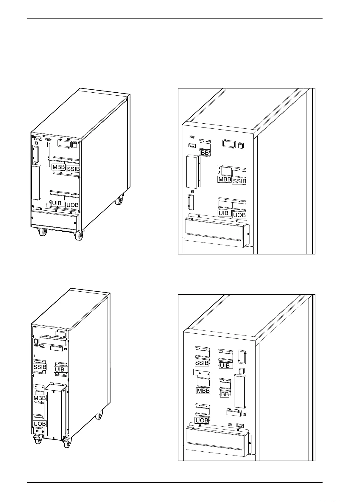
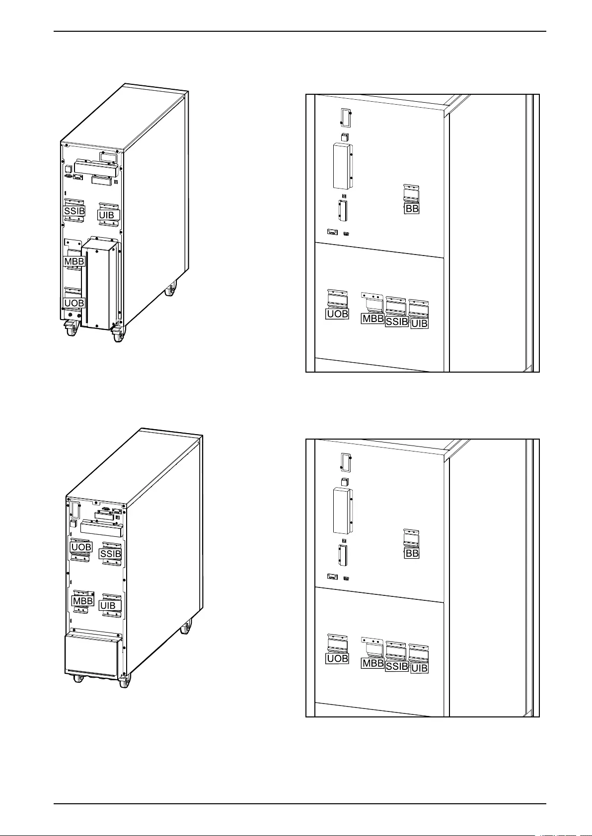
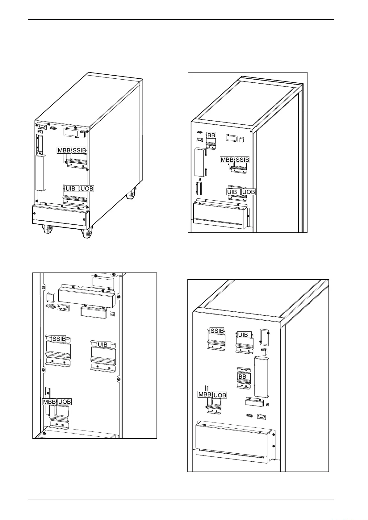
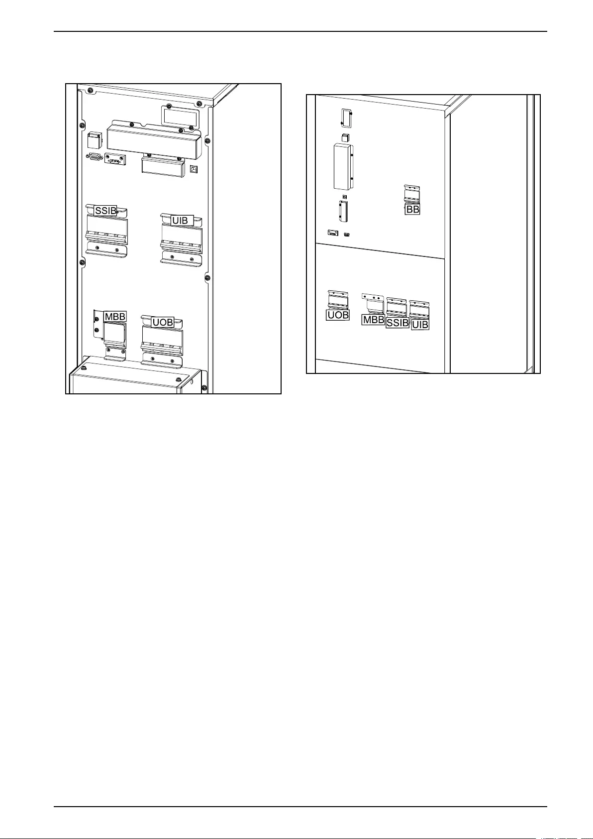
Location of Breakers.................................................................................14
Operation Modes ......................................................................................18
Operation Procedures..............................................................................22
Initial Start-Up of the UPS Using the Wizard – Only Applicable to Single
UPSs with Internal Batteries ......................................................................22
Start-Up Checklist – Only Applicable to Single UPSs with Internal
Batteries ............................................................................................23
Start Up a Single UPS in Normal Mode ......................................................23
Transfer a Single UPS from Normal Mode to Static Bypass Mode.................25
Transfer a Single UPS from Static Bypass Mode to Normal Mode.................25
Transfer a Single UPS from Normal Mode to Maintenance Bypass
Mode.......................................................................................................26
Transfer a Single UPS from Maintenance Bypass Mode to Normal
Mode.......................................................................................................27
Transfer a Parallel System from Normal Mode to Maintenance Bypass
Mode.......................................................................................................28
Transfer a Parallel System from Maintenance Bypass Mode to Normal
Mode.......................................................................................................29
Isolate a Single UPS from the Parallel System ............................................29
Start Up and Add a UPS to a Running Parallel System ................................30
Configuration .............................................................................................33
Register Your Easy UPS 3S ......................................................................33
Set the Display Language .........................................................................33
Set the Date and Time ..............................................................................34
Set the UPS Settings ................................................................................34
Set the Battery Settings.............................................................................35
Recommended Settings for UPSs with Internal Batteries and Modular
Battery Cabinets .................................................................................36
Set the Life Cycle Monitoring .....................................................................38
Settings ...................................................................................................39
Tests............................................................................................................41
Perform a Battery Maintenance Test ..........................................................41
Perform a Battery Test ..............................................................................41
Maintenance ..............................................................................................42
Parts Replacement ...................................................................................42
Determine if you need a Replacement Part ...........................................42
990-91079E-001 3

10-40 kVA
Replace the Dust Filter..............................................................................42
Troubleshooting ........................................................................................45
View the Active Alarms..............................................................................45
Buzzer.....................................................................................................45
Status and Alarm Messages......................................................................45
4 990-91079E-001
Important Safety Instructions — SAVE THESE
INSTRUCTIONS 10-40 kVA
Important Safety Instructions — SAVE THESE
INSTRUCTIONS
Read these instructions carefully and look at the equipment to become familiar
with it before trying to install, operate, service or maintain it. The following safety
messages may appear throughout this manual or on the equipment to warn of
potential hazards or to call attention to information that clarifies or simplifies a
procedure.
The addition of this symbol to a “Danger” or “Warning” safety
message indicates that an electrical hazard exists which will result in
personal injury if the instructions are not followed.
This is the safety alert symbol. It is used to alert you to potential
personal injury hazards. Obey all safety messages with this symbol
to avoid possible injury or death.
DANGER
DANGER indicates a hazardous situation which, if not avoided, will result in
death or serious injury.
Failure to follow these instructions will result in death or serious injury.
WARNING
WARNING indicates a hazardous situation which, if not avoided, could result
in death or serious injury.
Failure to follow these instructions can result in death, serious injury, or
equipment damage.
CAUTION
CAUTION indicates a hazardous situation which, if not avoided, could result in
minor or moderate injury.
Failure to follow these instructions can result in injury or equipment
damage.
NOTICE
NOTICE is used to address practices not related to physical injury. The safety
alert symbol shall not be used with this type of safety message.
Failure to follow these instructions can result in equipment damage.
Please Note
Electrical equipment should only be installed, operated, serviced, and maintained
by qualified personnel. No responsibility is assumed by Schneider Electric for any
consequences arising out of the use of this material.
A qualified person is one who has skills and knowledge related to the construction,
installation, and operation of electrical equipment and has received safety training
to recognize and avoid the hazards involved.
990-91079E-001 5
10-40 kVA
Important Safety Instructions — SAVE THESE
INSTRUCTIONS
Electromagnetic Compatibility
NOTICE
RISK OF ELECTROMAGNETIC DISTURBANCE
This is a product Category C3 according to IEC 62040-2. This is a product for
commercial and industrial applications in the second environment - installation
restrictions or additional measures may be needed to prevent disturbances. The
second environment includes all commercial, light industry, and industrial
locations other than residential, commercial, and light industrial premises
directly connected without intermediate transformer to a public low-voltage
mains supply. The installation and cabling must follow the electromagnetic
compatibility rules, e.g.:
• the segregation of cables,
• the use of shielded or special cables when relevant,
• the use of grounded metallic cable tray and supports.
Failure to follow these instructions can result in equipment damage.
Safety Precautions
DANGER
HAZARD OF ELECTRICAL SHOCK, EXPLOSION OR ARC FLASH
All safety instructions in this document must be read, understood and followed.
Failure to follow these instructions will result in death or serious injury.
DANGER
HAZARD OF ELECTRICAL SHOCK, EXPLOSION OR ARC FLASH
After the UPS system has been electrically wired, do not start up the system.
Start-up must only be performed by Schneider Electric.
Failure to follow these instructions will result in death or serious injury.
6 990-91079E-001
Overview 10-40 kVA
Overview
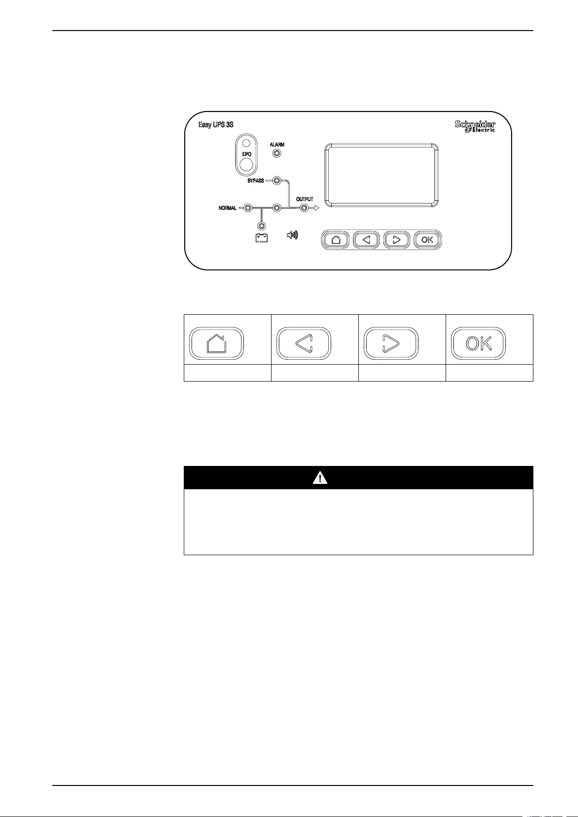
User Interface
Keys
Home Previous Next Confirm
EPO
Only use the EPO button in case of emergency. When the EPO button is pushed,
the system turns off the rectifier and the inverter, and stops supplying the load
immediately.
DANGER
HAZARD OF ELECTRIC SHOCK, EXPLOSION, OR ARC FLASH
The UPS control circuit will remain active after the EPO has been pushed if
mains is available.
Failure to follow these instructions will result in death or serious injury.
990-91079E-001 7
10-40 kVA Overview
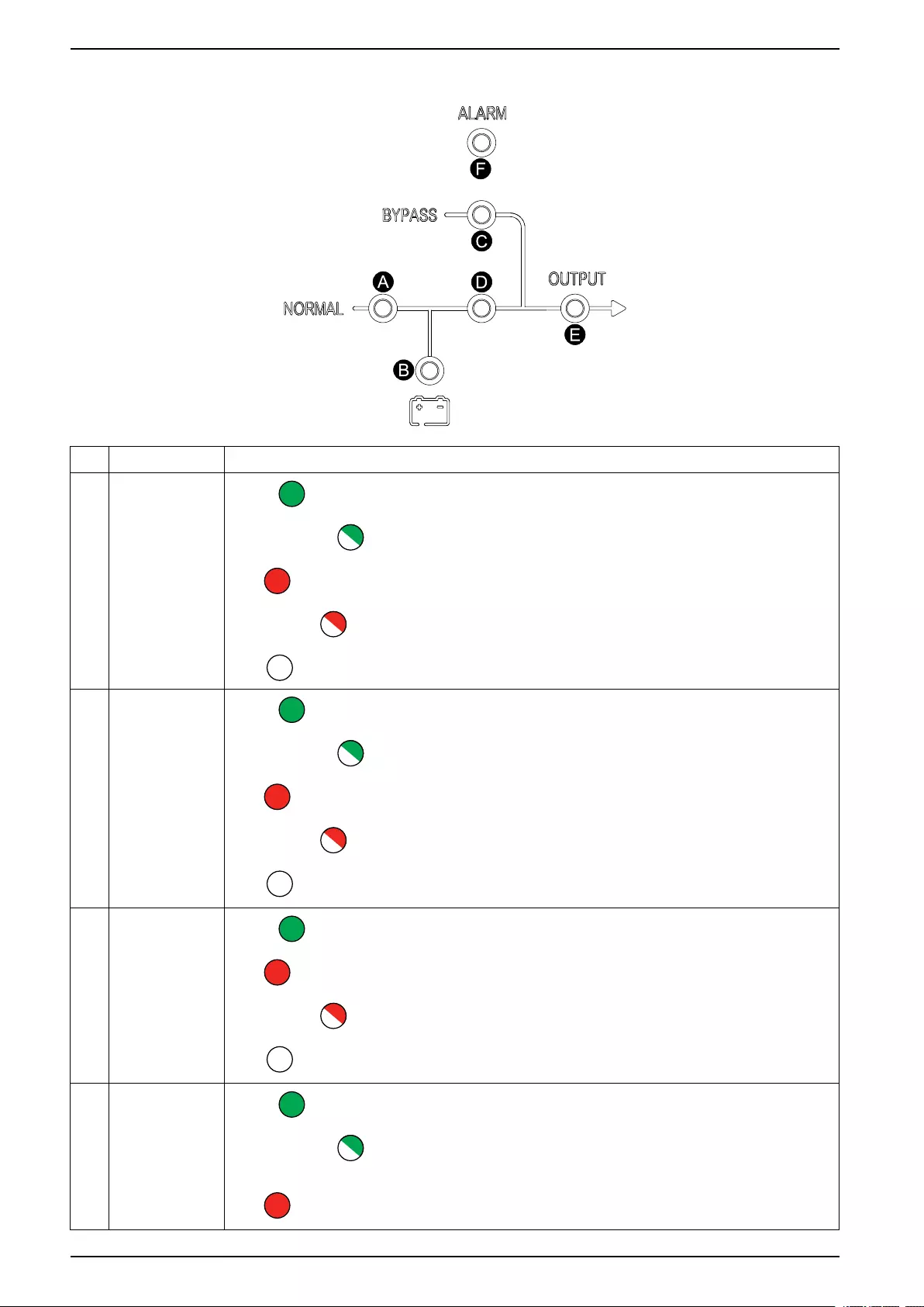
Status LEDs
LED Status
ARectifier Green : Rectifier is working correctly.
Flashing green : Rectifier is working correctly and mains is normal.
Red : Rectifier is inoperable.
Flashing red : Mains is unavailable.
OFF : Rectifier is off.
B Battery Green : Battery is charging.
Flashing green : Battery is discharging.
Red : Battery is inoperable.
Flashing red : Battery low voltage.
OFF : Battery and battery charger are normal, battery is not charging.
CBypass Green : Load supplied by bypass source.
Red : Bypass source is unavailable or static bypass switch is inoperable.
Flashing red : Bypass voltage is out of tolerance.
OFF : Bypass source is normal.
D Inverter Green : Load supplied by inverter.
Flashing green : Inverter on, start, synchronization or standby (ECO mode) for at
least one module.
Red : Load not supplied by inverter, inverter is inoperable.
8 990-91079E-001
Overview 10-40 kVA
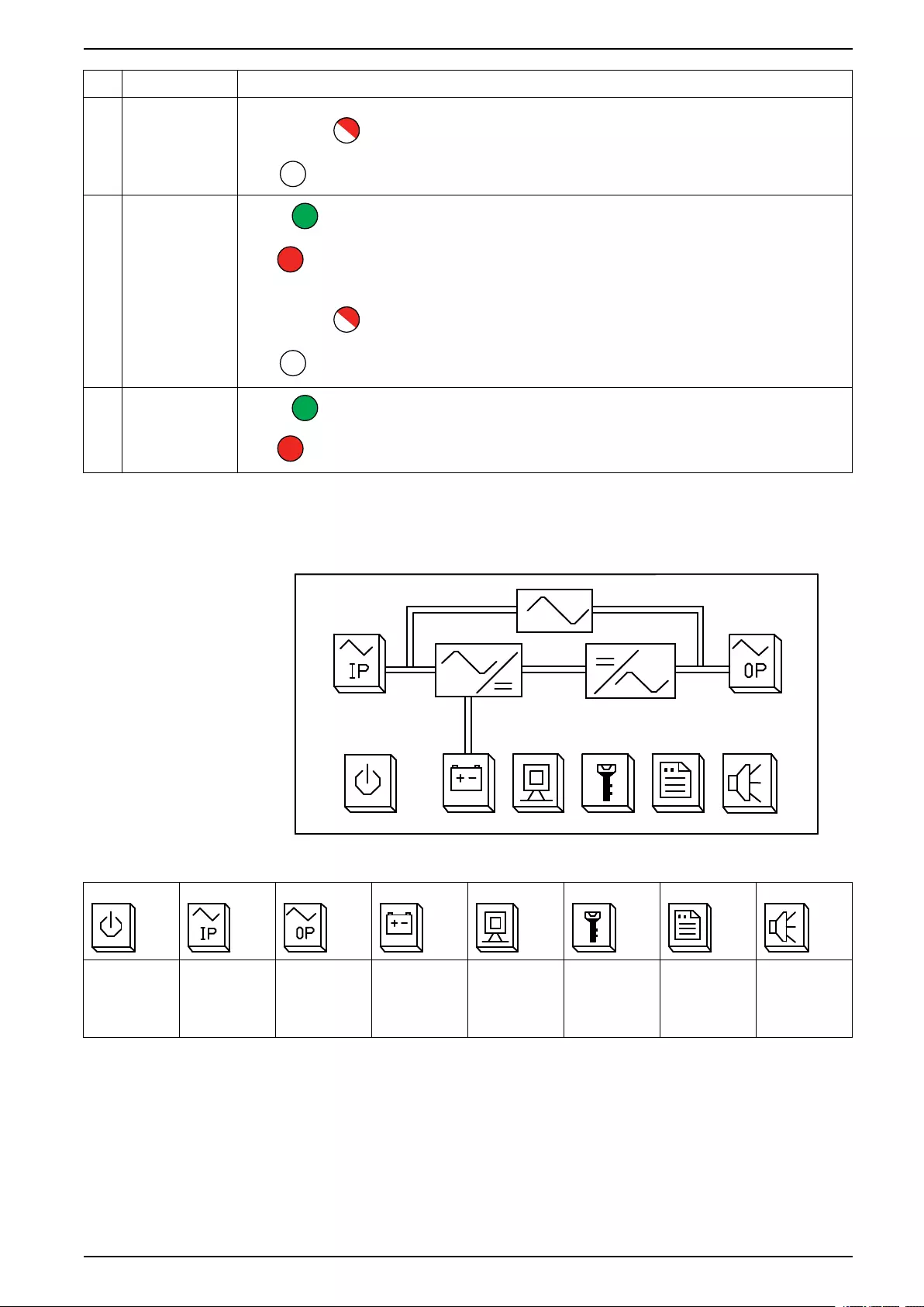
LED Status
Flashing red : Load supplied by inverter, but an inverter alarm is present.
OFF : Inverter is off.
E Load Green : UPS output is on.
Red : Overload on UPS output for too long, or output has shorted, or no output
power present.
Flashing red : Overload on UPS output.
OFF : UPS output is off.
FStatus Green : Normal mode.
Red : Inoperable status.
Display Interface
Home Screen
Buttons
Power On/
Off
Input and
bypass
status
information
Output
status
information
Battery
status
information
UPS status Function
settings
Log Mute
990-91079E-001 9
Overview 10-40 kVA
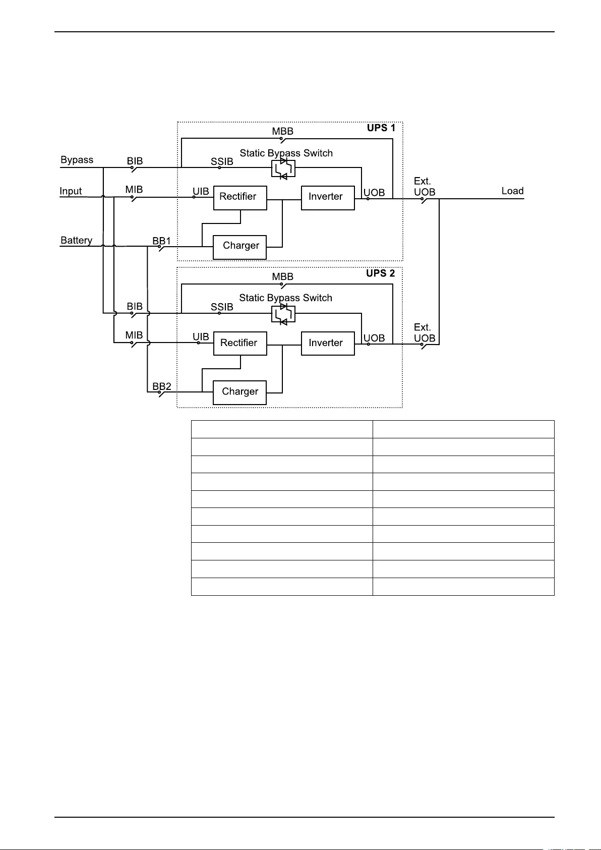
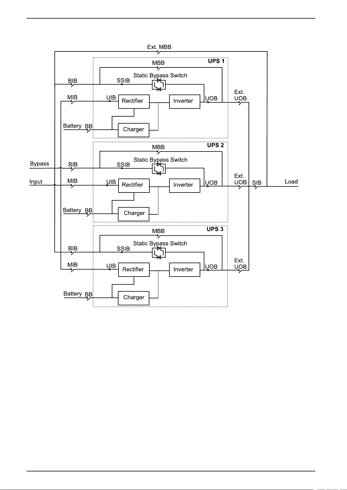
Overview of 1+1 Redundant Parallel System with Common
Battery Bank
NOTE: For UPS with internal batteries, the batteries must be removed and the
internal battery breaker (BB) must be opened.
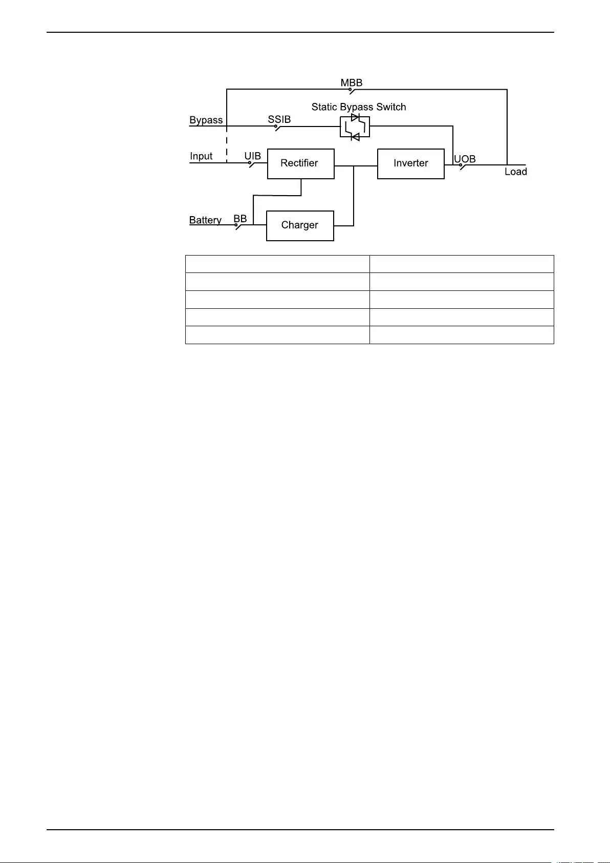
MIB Mains input breaker
BIB Bypass input breaker
UIB Unit input breaker
SSIB Static switch input breaker
UOB Unit output breaker
Ext. UOB External unit output breaker
MBB Maintenance bypass breaker
Ext. MBB External maintenance bypass breaker
BB1 Battery breaker 1
BB2 Battery breaker 2
990-91079E-001 11
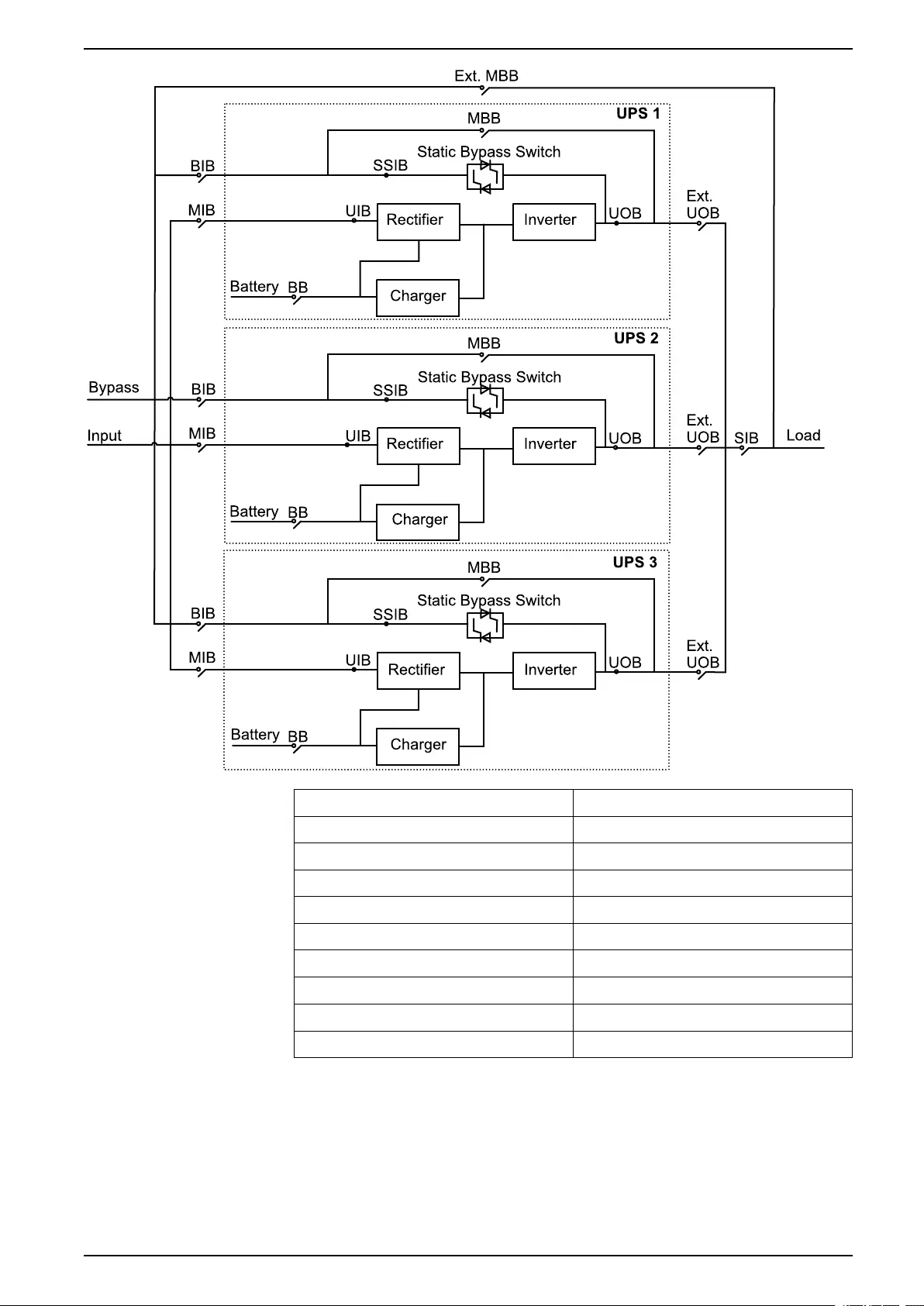
Overview 10-40 kVA
MIB Mains input breaker
BIB Bypass input breaker
UIB Unit input breaker
SSIB Static switch input breaker
UOB Unit output breaker
Ext. UOB External unit output breaker
MBB Maintenance bypass breaker
Ext. MBB External maintenance bypass breaker
SIB System isolation breaker
BB Battery breaker
990-91079E-001 13
10-40 kVA Operation Modes
Operation Modes
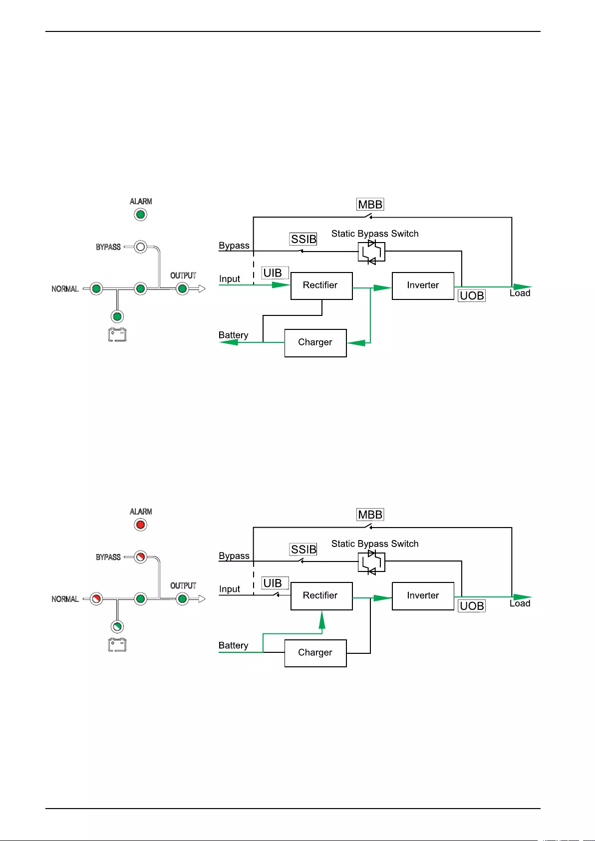
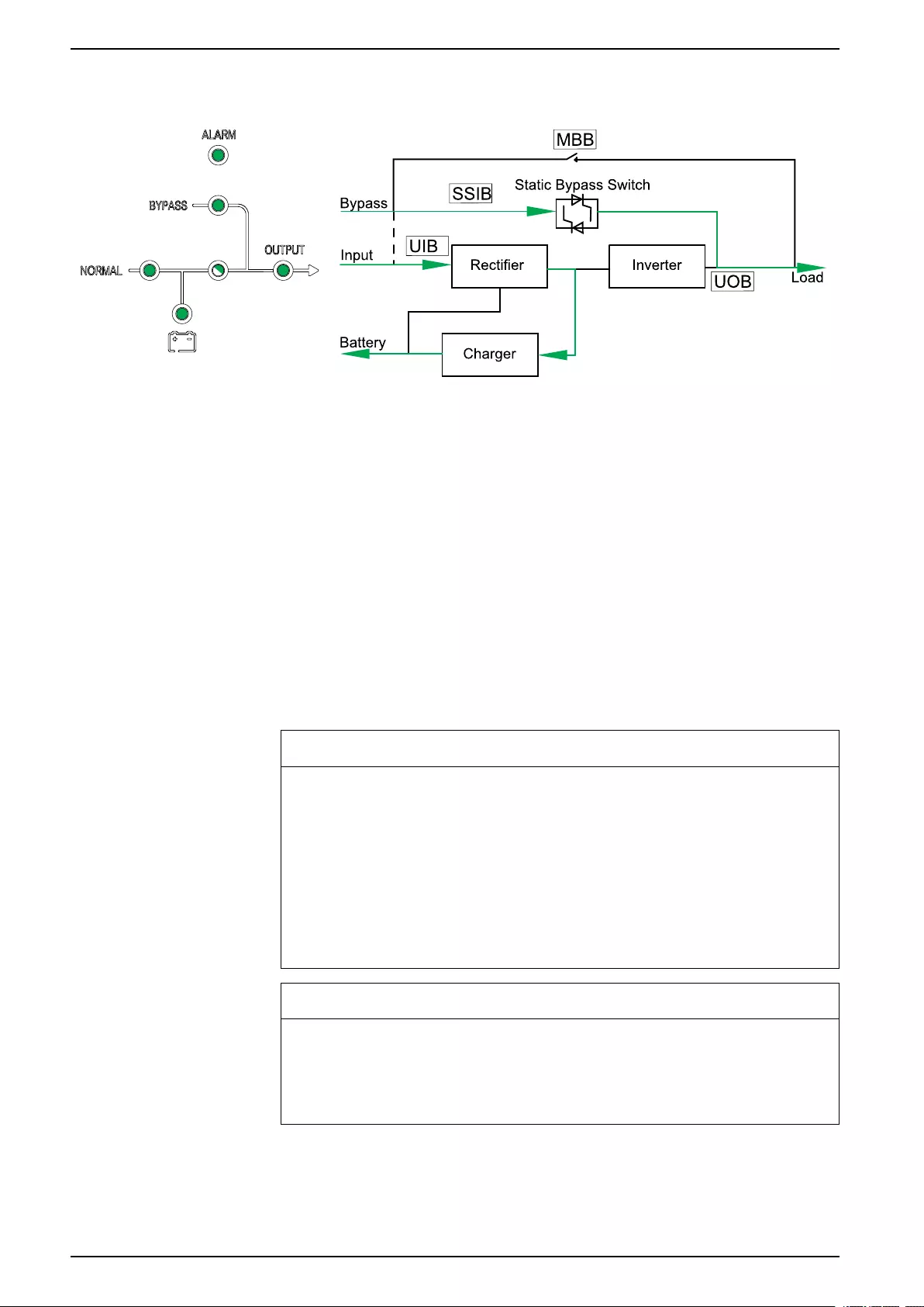
Normal Mode
The UPS provides power to the connected load from mains. The UPS converts
mains to conditioned power for the connected load while recharging the batteries
(float or boost charge).
LED Status Power Flow
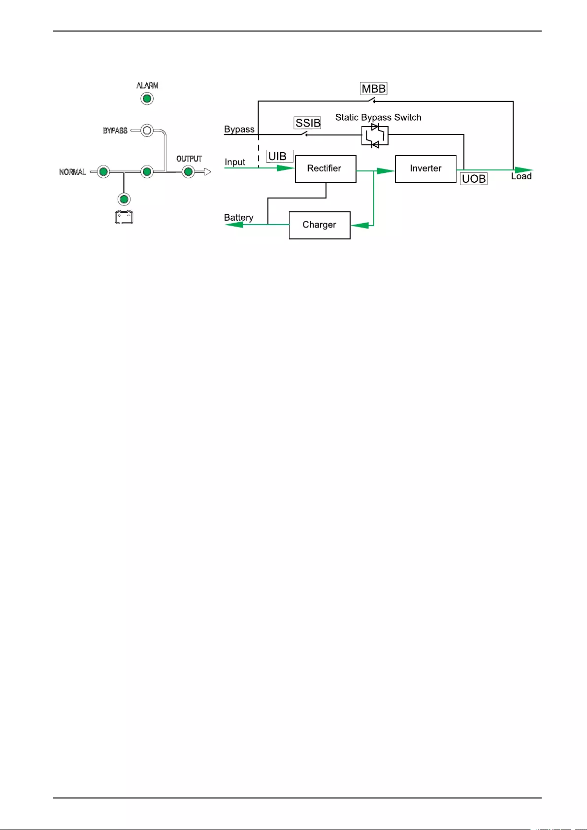
Battery Mode
The UPS transfers to battery mode if the mains supply fails. The UPS provides
power to the connected load from the connected batteries for a finite period. When
the mains supply returns, the UPS transfers back to normal mode.
LED Status Power Flow
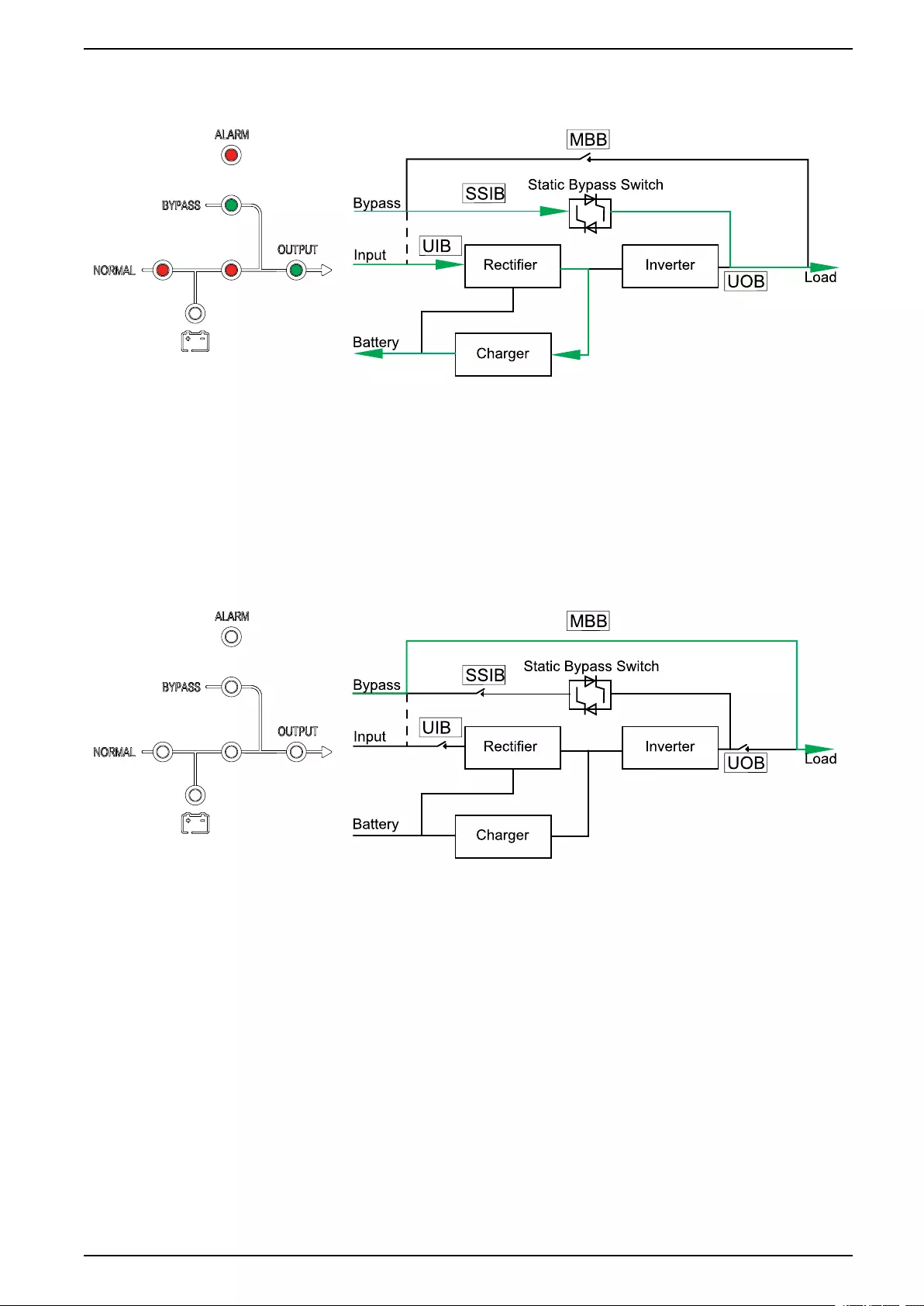
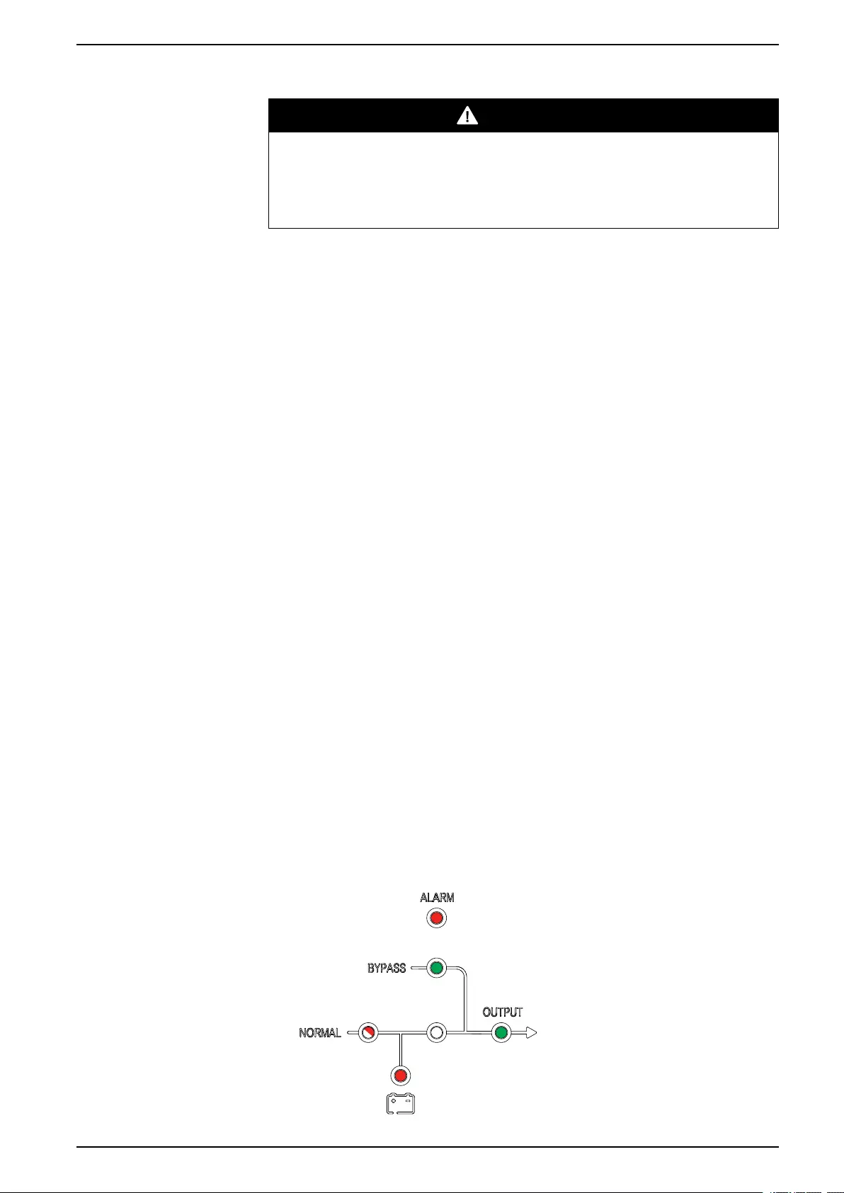
Static Bypass Mode
The UPS supplies the load with power from the bypass source. If the conditions
for normal or battery mode are not met, the load will be transferred from the
inverter to the bypass source with no interruption in power to the load.
18 990-91079E-001
Operation Modes 10-40 kVA
LED Status Power Flow
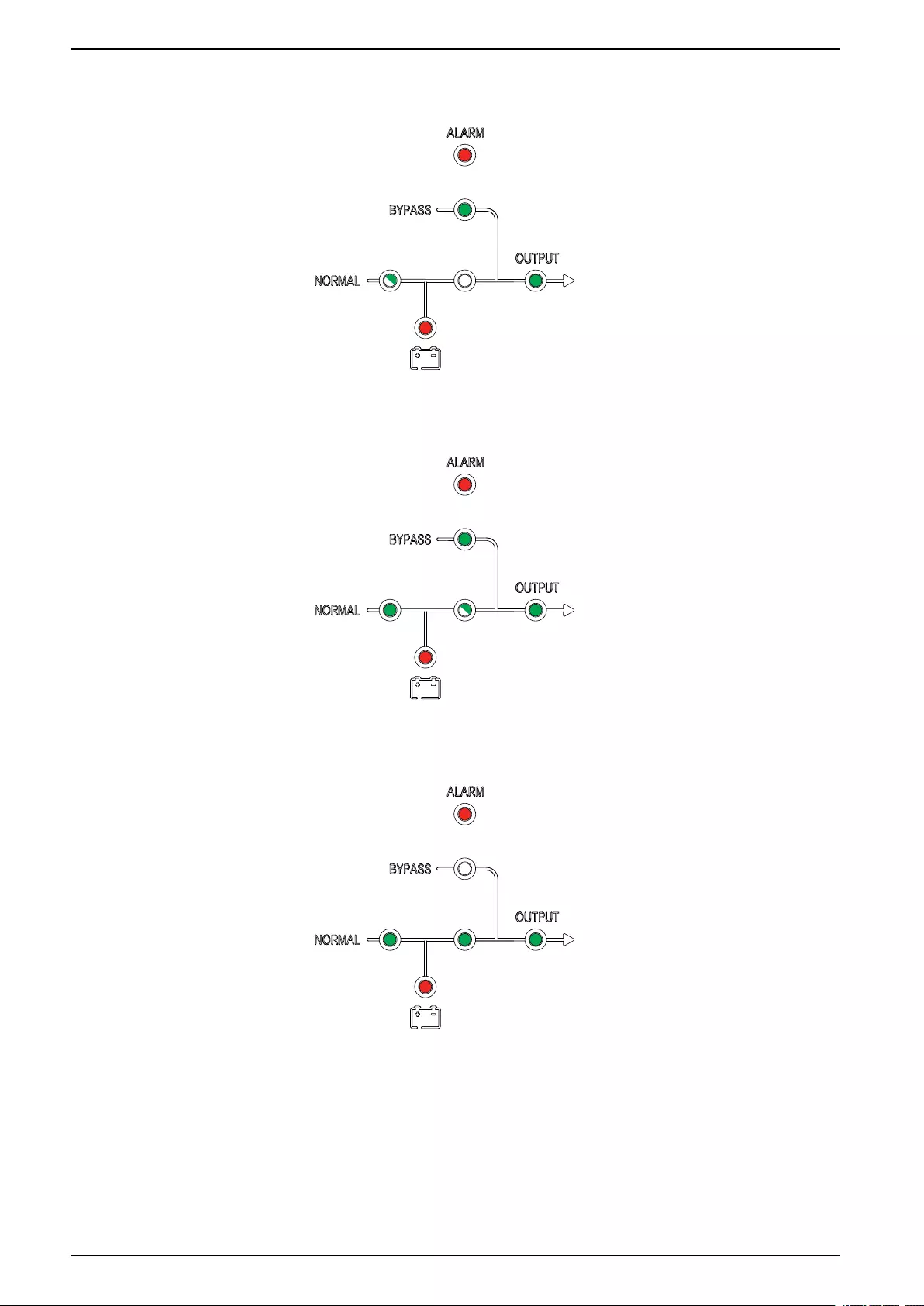
Maintenance Bypass Mode
In maintenance bypass mode, the mains is sent via the (external) maintenance
bypass breaker (MBB) to the load. Battery backup is not available in maintenance
bypass mode.
LED Status Power Flow
ECO Mode
In ECO mode the UPS is configured to use static bypass mode as the preferred
operation mode under predefined circumstances. The inverter is in standby in
ECO mode and in case of interruption to the mains, the UPS transfers to battery
mode and the load is supplied from the inverter.
990-91079E-001 19
10-40 kVA Operation Modes
LED Status Power Flow
Autostart Mode
The batteries will reach end of discharge if the interruption to the mains is longer
than the battery runtime. If the UPS is programmed to auto-restart after end of
discharge, the system will automatically restart after a delay when the mains
returns.
NOTE: If autostart is disabled, the inverter and bypass will not restart
automatically when the mains return.
Frequency Converter Mode
In frequency converter mode, the UPS presents a stable output frequency (at 50
or 60 Hz) and the static bypass switch is not available.
NOTICE
RISK OF EQUIPMENT DAMAGE OR LOAD DROP
In frequency converter mode the UPS cannot run in static bypass or
maintenance bypass mode. Before turning the UPS into frequency converter
mode, you must contact a Schneider Electric-certified partner to make sure
• the static switch input breaker SSIB and the maintenance bypass breaker
MBB are in the OFF (opened) position (Schneider Electric strongly
recommends to lock these with a padlock available from Schneider Electric)
• no cables are connected to the bypass terminals
Failure to follow these instructions can result in equipment damage.
NOTICE
RISK OF LOAD DROP
When the unit output breaker UOB is opened while the UPS is in frequency
converter mode, the load will not be transferred, but will be dropped.
Failure to follow these instructions can result in equipment damage.
20 990-91079E-001

10-40 kVA Operation Procedures
Operation Procedures
Initial Start-Up of the UPS Using the Wizard – Only Applicable to
Single UPSs with Internal Batteries
DANGER
HAZARD OF ELECTRIC SHOCK, EXPLOSION, OR ARC FLASH
Parallel systems and UPSs for external batteries must only be started up by
Schneider Electric.
Failure to follow these instructions will result in death or serious injury.
Before starting up the UPS, confirm that:
• The room temperature is between 0 °C to 40 °C
• The UPS has been installed according to the specified clearance dimensions.
1. Turn the unit input breaker UIB to the ON (closed) position.
The display turns on.
2. Select to register the UPS or select Skip to continue. See Register Your Easy
UPS 3S, page 33 for more information.
3. When the Change language prompt appears, do one of the following:
– Select Yes and select the preferred language using the navigation keys.
Select Yes again to confirm.
– Select No to keep the current selection.
4. When the Change voltage prompt appears, do one of the following:
– Select Yes and select the preferred voltage using the navigation keys.
Select Yes again to confirm.
– Select No to keep the current selection.
5. When the Change freq. prompt appears, do one of the following:
– Select Yes and select the preferred output frequency using the navigation
keys. Select Yes again to confirm.
– Select No to keep the current selection.
6. When the Change mode prompt appears, do one of the following:
– Select Yes and select Normal mode,Parallel mode, or Frequency
converter mode using the navigation keys. Select Yes again to confirm.
– Select No to keep the current selection.
7. When the Save new settings prompt appears, select Yes.
8. When the Disable wizard prompt appears, do one of the following:
– Select Yes to disable the wizard and go to the default screen.
NOTE: Schneider Electric recommends to disable the wizard to allow
for automatic start.
– Select No to go to the default screen without disabling the wizard.
Post-requisite: For systems with internal batteries, go to Set the Battery Settings,
page 35.
22 990-91079E-001
Operation Procedures 10-40 kVA
Start-Up Checklist – Only Applicable to Single UPSs with Internal Batteries
DANGER
HAZARD OF ELECTRIC SHOCK, EXPLOSION, OR ARC FLASH
Parallel systems and UPSs for external batteries must only be started up by
Schneider Electric.
Failure to follow these instructions will result in death or serious injury.
• I have positioned the UPS according to the installation manual and the
recommended clearances are respected.
• I have verified that the environmental conditions including temperature,
humidity, and airflow stated in the installation manual are respected.
• I have verified that the input voltage and frequency are within the tolerances
specified in the installation manual.
• I have verified that the upstream protection is in accordance with the
recommendations in the installation manual and that the power cables have
been connected correctly.
• I have installed the batteries as specified in the installation manual.
• I have followed the Initial Start-Up of the UPS Using the Wizard – Only
Applicable to Single UPSs with Internal Batteries, page 22.
• I have made all settings (including battery settings and life cycle monitoring)
described in this manual.
• I have completed all functional tests successfully (normal mode, battery
mode, and static bypass mode).
• I have successfully entered the UPS passcode provided by Schneider
Electric.
• I confirm the installation has been completed and the UPS is running in
normal mode and is powering the load.
Start Up a Single UPS in Normal Mode
NOTE: When the UPS starts, the stored settings will be used.
NOTE: The log can be accessed during start-up.
1. Check that all breakers are in the OFF (open) position.
2. Turn the static switch input breaker SSIB to the ON (closed) position.
The display turns on and the Home screen is shown.
3. Turn the unit output breaker UOB to the ON (closed) position.
Wait approximately 20 seconds until the bypass and output LEDs turn green.
The UPS starts up in static bypass mode.
990-91079E-001 23
10-40 kVA Operation Procedures
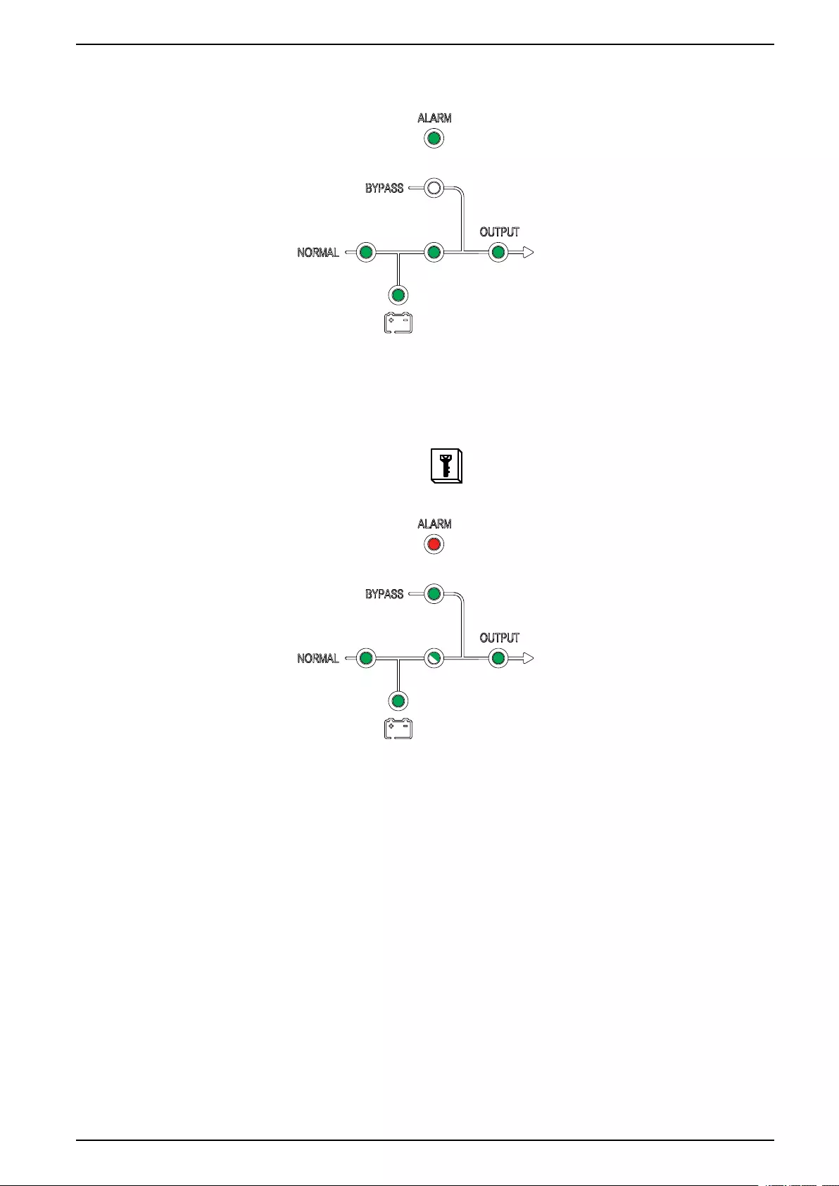
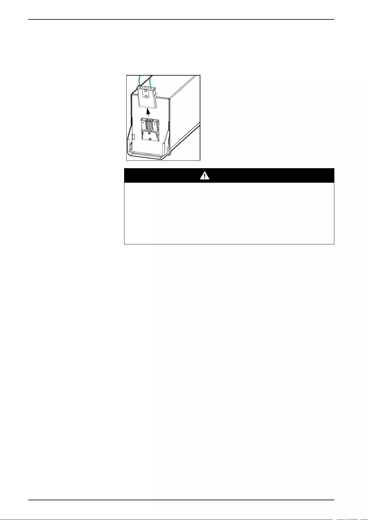
4. Turn the unit input breaker UIB to the ON (closed) position.
The rectifier ramps up and the LEDs on the user interface show as follows:
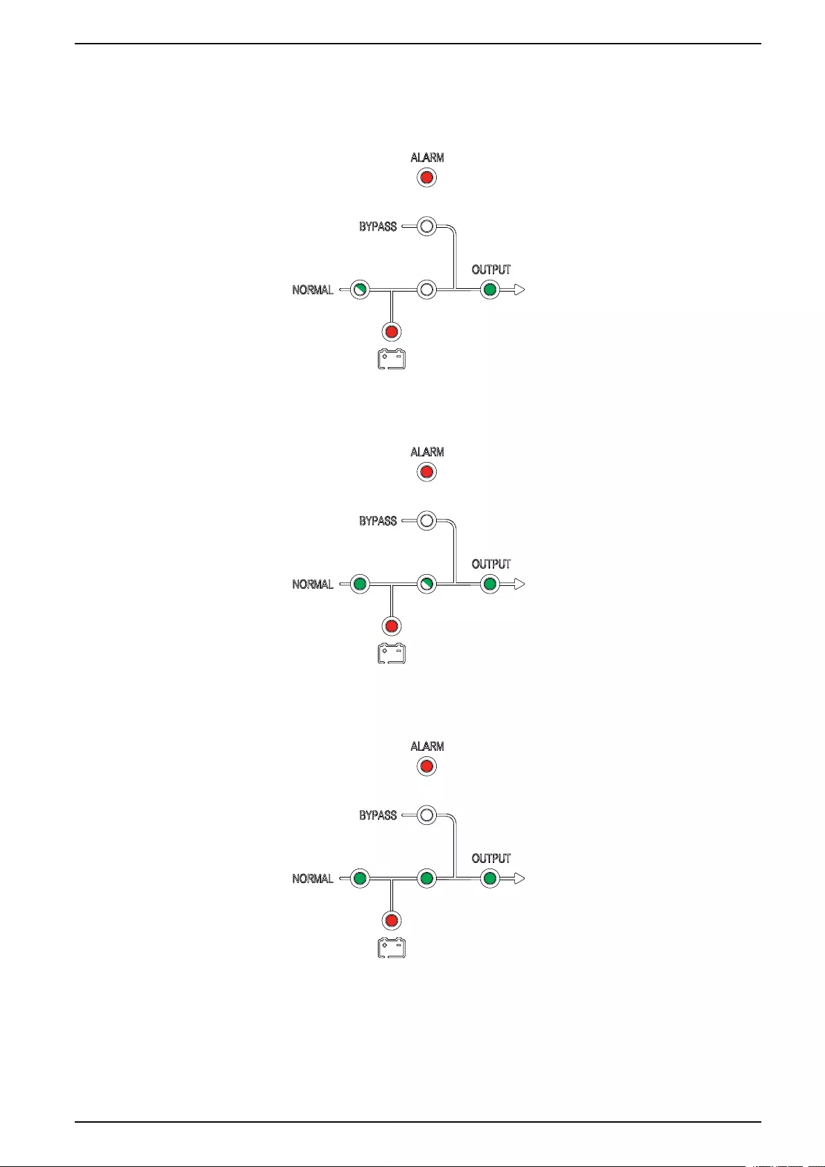
5. When the rectifier LED turns steady green, the inverter synchronizes with
bypass.
The LEDs on the user interface show as follows:
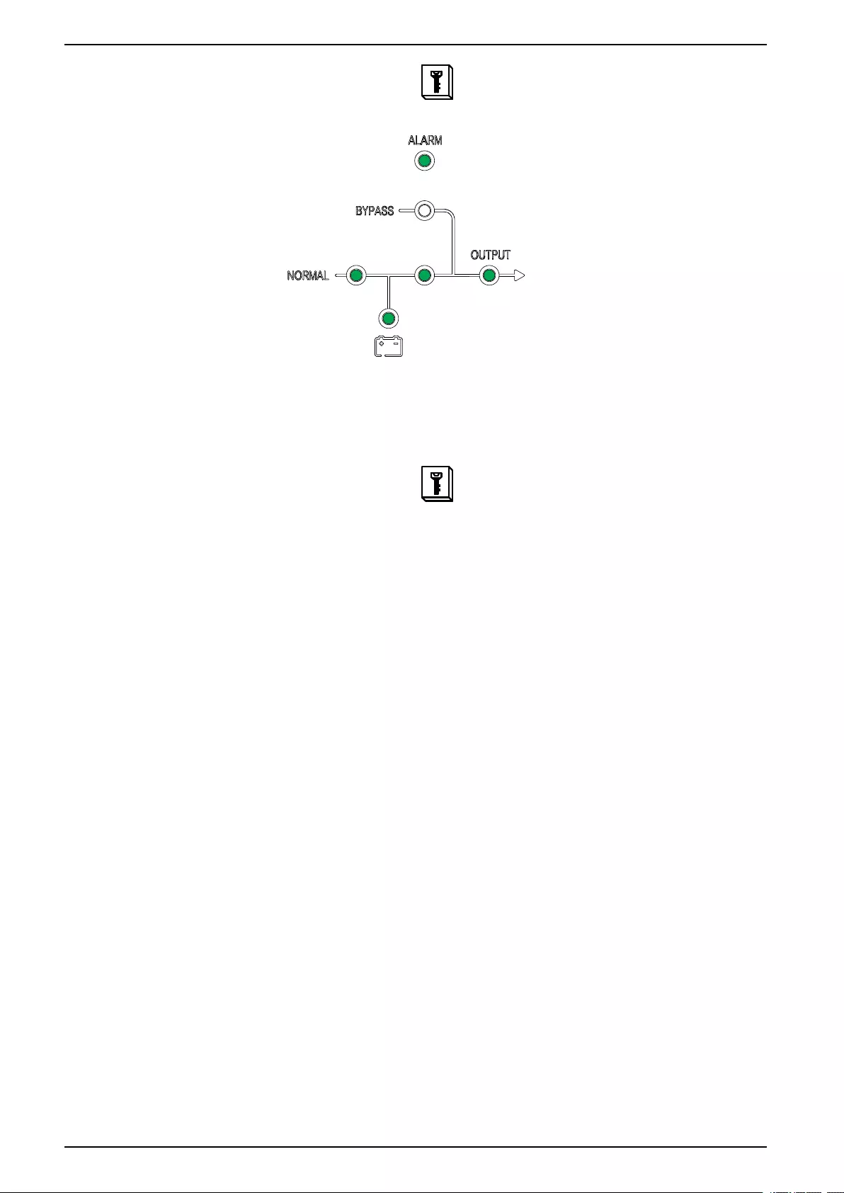
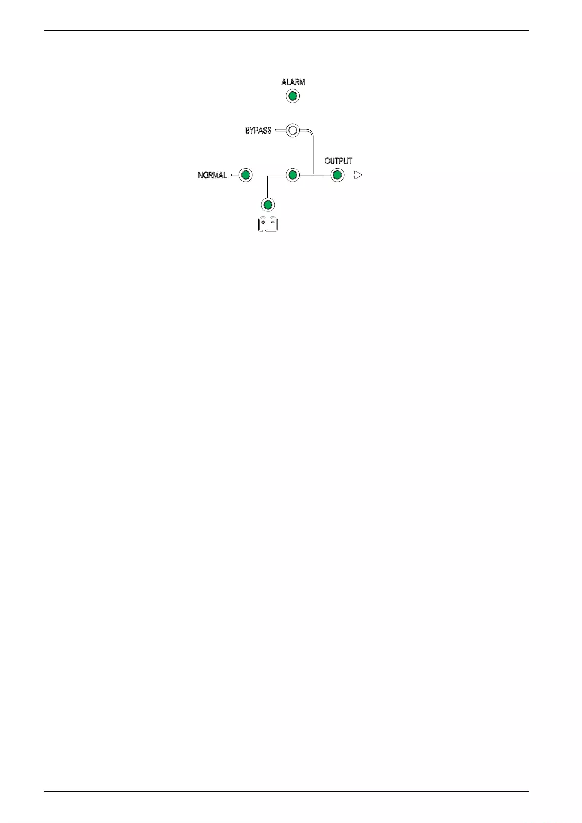
6. Wait approximately 20 seconds until inverter LED turns steady green, the
UPS transfers automatically from static bypass mode to normal mode.
The LEDs on the user interface show as follows:
24 990-91079E-001
Operation Procedures 10-40 kVA
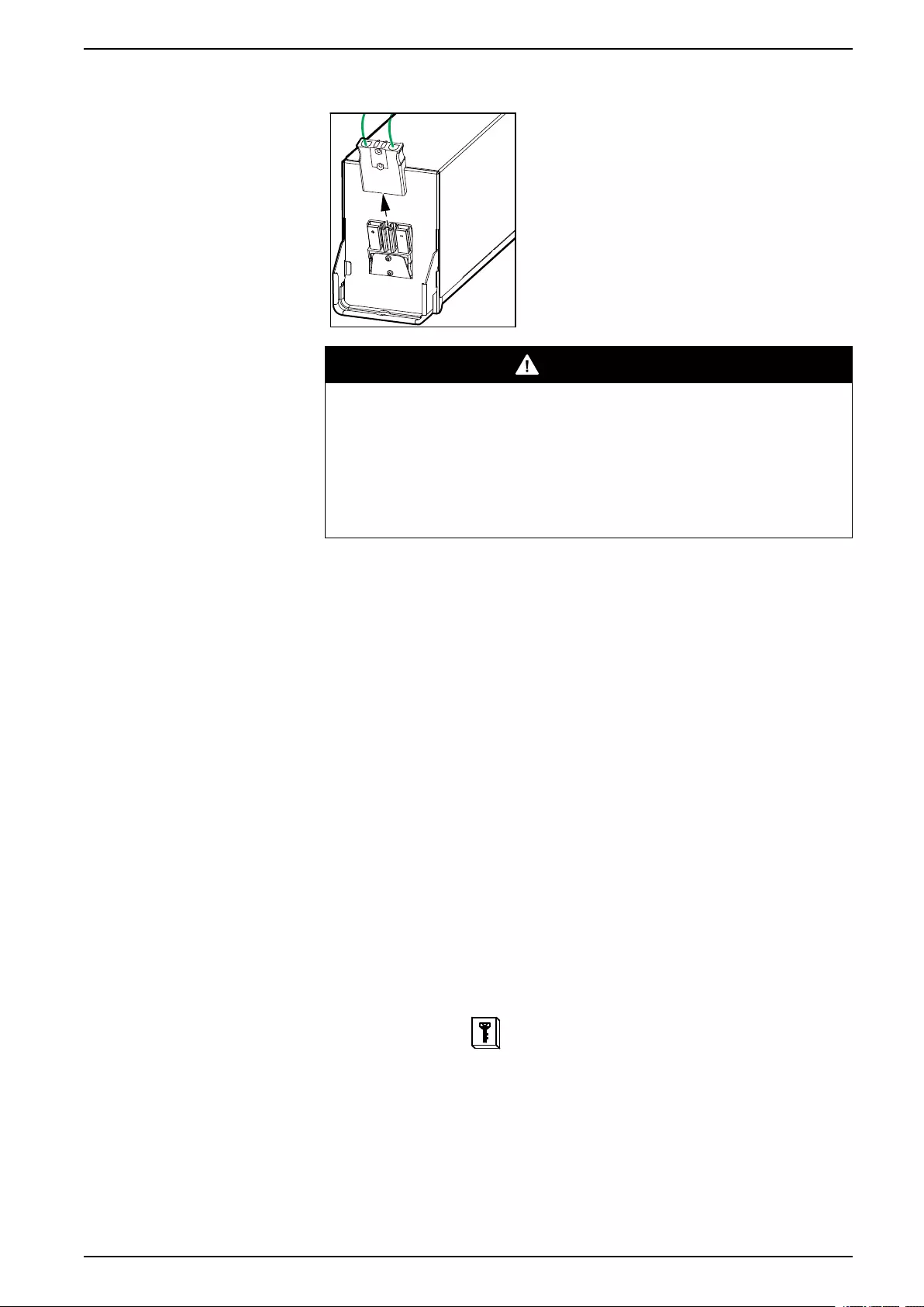
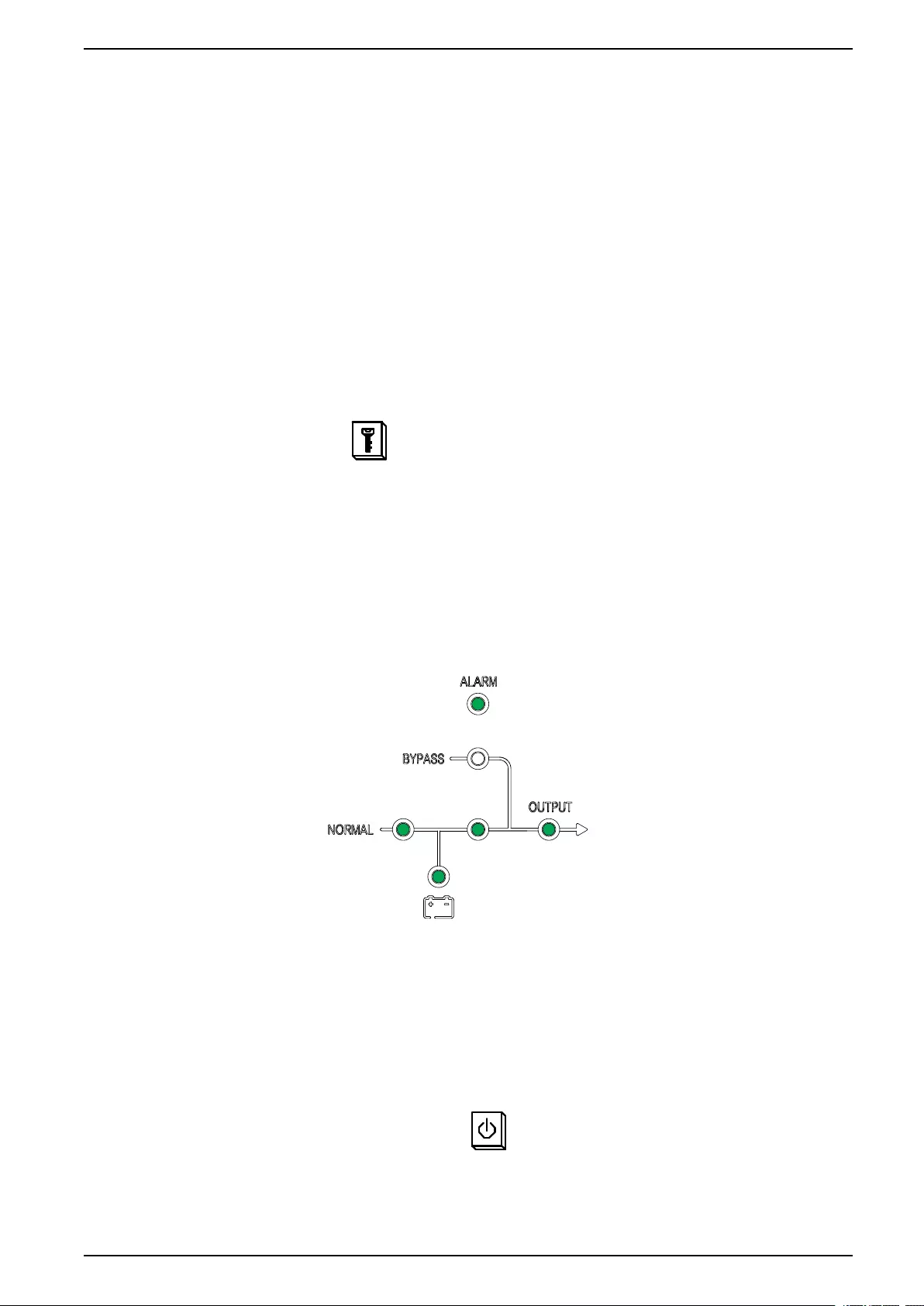
7. Turn the battery breaker(s) BB to the ON (closed) position.
The LEDs on the user interface show as follows:
The UPS is now in normal mode.
Transfer a Single UPS from Normal Mode to Static Bypass Mode
1. On the display, select and then select Function > To bypass.
The LEDs on the user interface show as follows:
Transfer a Single UPS from Static Bypass Mode to Normal Mode
NOTE: The UPS will normally transfer automatically from static bypass to
normal mode. This procedure can be used to manually transfer to normal
mode if the bypass frequency is above the specified limits.
990-91079E-001 25
10-40 kVA Operation Procedures
1. On the display, select and then select ESC bypass.
The LEDs on the user interface show as follows:
Transfer a Single UPS from Normal Mode to Maintenance Bypass
Mode
1. On the display, select and then select Function > To bypass.
2. Remove the cover from the maintenance bypass breaker MBB. Refer to
Location of Breakers, page 14.
NOTE: When the cover of the MBB is removed, the system automatically
transfers to maintenance bypass mode.
3. Turn the maintenance bypass breaker MBB to the ON (closed) position.
The load is now supplied via the maintenance bypass breaker.
4. Turn the battery breaker(s) BB to the OFF (open) position.
5. Turn the unit input breaker UIB to the OFF (open) position.
6. Turn the static switch input breaker SSIB to the OFF (open) position.
7. Turn the unit output breaker UOB to the OFF (open) position.
26 990-91079E-001
Operation Procedures 10-40 kVA
8. For the UPS with internal batteries, disconnect all batteries on the front of the
UPS.
DANGER
HAZARD OF ELECTRICAL SHOCK, EXPLOSION OR ARC FLASH
• Wait at least 5 minutes before removing the cover of the UPS after the
display has turned off to allow for the capacitors to fully discharged.
• Always measure for hazardous voltages on all terminals before working
on the UPS.
Failure to follow these instructions will result in death or serious
injury.
Transfer a Single UPS from Maintenance Bypass Mode to Normal
Mode
1. Check that all breakers are in the OFF (open) position.
2. Turn the static switch input breaker SSIB to the ON (closed) position.
The display turns on and the Home screen is shown.
3. Turn the unit output breaker UOB to the ON (closed) position.
The UPS starts up in static bypass mode.
4. Turn the unit input breaker UIB to the ON (closed) position.
The rectifier ramps up.
5. When the rectifier LED turns steady green, the inverter synchronizes with
bypass.
6. Turn the battery breaker(s) BB to the ON (closed) position.
7. Reinstall the cover on the maintenance bypass breaker MBB. Refer to
Location of Breakers, page 14
NOTE: The system will not transfer to normal mode before the
maintenance bypass cover has been reinstalled.
8. On the display select and then select Function > Clear alarm.
NOTE: The system will not transfer to normal mode before the
maintenance bypass cover has been reinstalled and the alarm has been
cleared.
990-91079E-001 27
10-40 kVA Operation Procedures
9. After approximately 60 seconds, the UPS will automatically transfer to normal
mode.
The LEDs on the user interface show as follows:
Transfer a Parallel System from Normal Mode to Maintenance
Bypass Mode
1. On all UPS displays, select and then select Function > To bypass.
The parallel system will transfer to static bypass mode.
2. Turn the external maintenance bypass breaker Ext. MBB to the ON (closed)
position.
The load is now supplied via the external maintenance bypass breaker.
3. Turn the battery breakers BB of all UPSs to the OFF (open) position.
4. Turn the mains input breakers MIB and the bypass input breakers BIB of all
UPSs to the OFF (open) position.
5. Turn the system isolation breaker SIB to OFF (open) position.
6. For the UPS with internal batteries, disconnect all batteries on the front of the
UPS.
DANGER
HAZARD OF ELECTRICAL SHOCK, EXPLOSION OR ARC FLASH
• Wait at least 5 minutes before removing the cover of the UPS after the
display has turned off to allow for the capacitors to fully discharged.
• Always measure for hazardous voltages on all terminals before working
on the UPS.
Failure to follow these instructions will result in death or serious
injury.
28 990-91079E-001
Operation Procedures 10-40 kVA
Transfer a Parallel System from Maintenance Bypass Mode to
Normal Mode
1. Check that:
• all UPS breakers (unit input breaker UIB, static switch input breaker
SSIB, and unit output breaker UOB) and the external unit output breaker
Ext. UOB are in the ON (closed) position
• the battery breakers BB are in the OFF (open) position
2. Turn the system isolation breaker SIB to ON (closed) position.
3. Turn the bypass input breakers BIB of all UPSs to the ON (closed) position.
Wait approximately 20 seconds until the bypass and the output LEDs turn
green.
4. Turn the external maintenance bypass breaker Ext. MBB to the OFF (open)
position.
NOTE: If the parallel system has dry contacts with Maint CB signal, select
and then select Function > Clear alarm on all UPS displays.
5. Turn the mains input breakers MIB of all UPSs to the ON (closed) position.
The rectifier ramps up.
6. When the rectifier LED turns steady green, the inverter synchronizes with
bypass.
7. When the inverter LED turns steady green, the parallel system automatically
transfers from static bypass to normal mode.
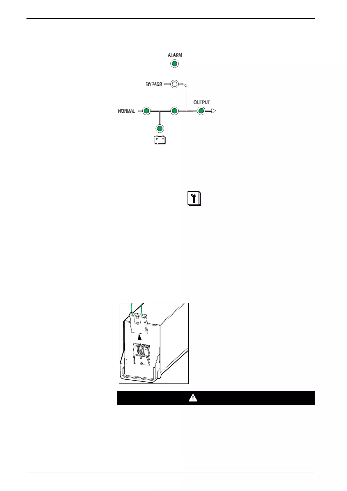
8. Turn the battery breakers BB of all UPSs to the ON (closed) position.
The LEDs on the user interfaces show as follows:
The parallel system is now in normal mode.
Isolate a Single UPS from the Parallel System
Use this procedure to shut down one UPS in a running parallel system.
NOTE: Before initiating this procedure, ensure that the remaining UPS units
can supply the load.
1. On the display select and then select confirm to power off the UPS.
2. Turn the battery breaker(s) BB of the UPS to the OFF (open) position.
3. Turn the mains input breaker MIB of the UPS to the OFF (open) position.
990-91079E-001 29
10-40 kVA Operation Procedures
4. Turn the bypass input breaker BIB of the UPS to the OFF (open) position.
5. Turn the external unit output breaker Ext. UOB of the UPS to the OFF (open)
position.
6. For the UPS with internal batteries, disconnect all batteries on the front of the
UPS.
DANGER
HAZARD OF ELECTRICAL SHOCK, EXPLOSION OR ARC FLASH
• Wait at least 5 minutes before removing the cover of the UPS after the
display has turned off to allow for the capacitors to fully discharged.
• Always measure for hazardous voltages on all terminals before working
on the UPS.
Failure to follow these instructions will result in death or serious
injury.
Start Up and Add a UPS to a Running Parallel System
Use this procedure to start up a UPS and add it to a running parallel system.
IMPORTANT: Before a UPS can be added to a parallel system, the parallel
system must be configured by Schneider Electric.
1. On the new UPS check that:
• all UPS breakers (unit input breaker UIB, static switch input breaker
SSIB, and unit output breaker UOB) and the external unit output breaker
Ext. UOB are in the ON (closed) position
• the battery breaker(s) BB are in the OFF (open) position
2. Turn the external unit output breaker Ext. UOB of the UPS to the ON (closed)
position.
30 990-91079E-001
Operation Procedures 10-40 kVA
3. Turn the mains input breaker MIB and the bypass input breaker BIB of the
UPS to the ON (closed) position.
The display turns on and the Home screen is shown.
The LEDs on the user interface show as follows:
4. When the rectifier LED turns steady green, the UPS transfers to static bypass
mode.
The LEDs on the user interface show as follows:
5. When the inverter LED turns steady green, the UPS automatically transfers
from static bypass to normal mode and joins the running parallel system.
The LEDs on the user interface show as follows:
990-91079E-001 31
Configuration 10-40 kVA
Configuration
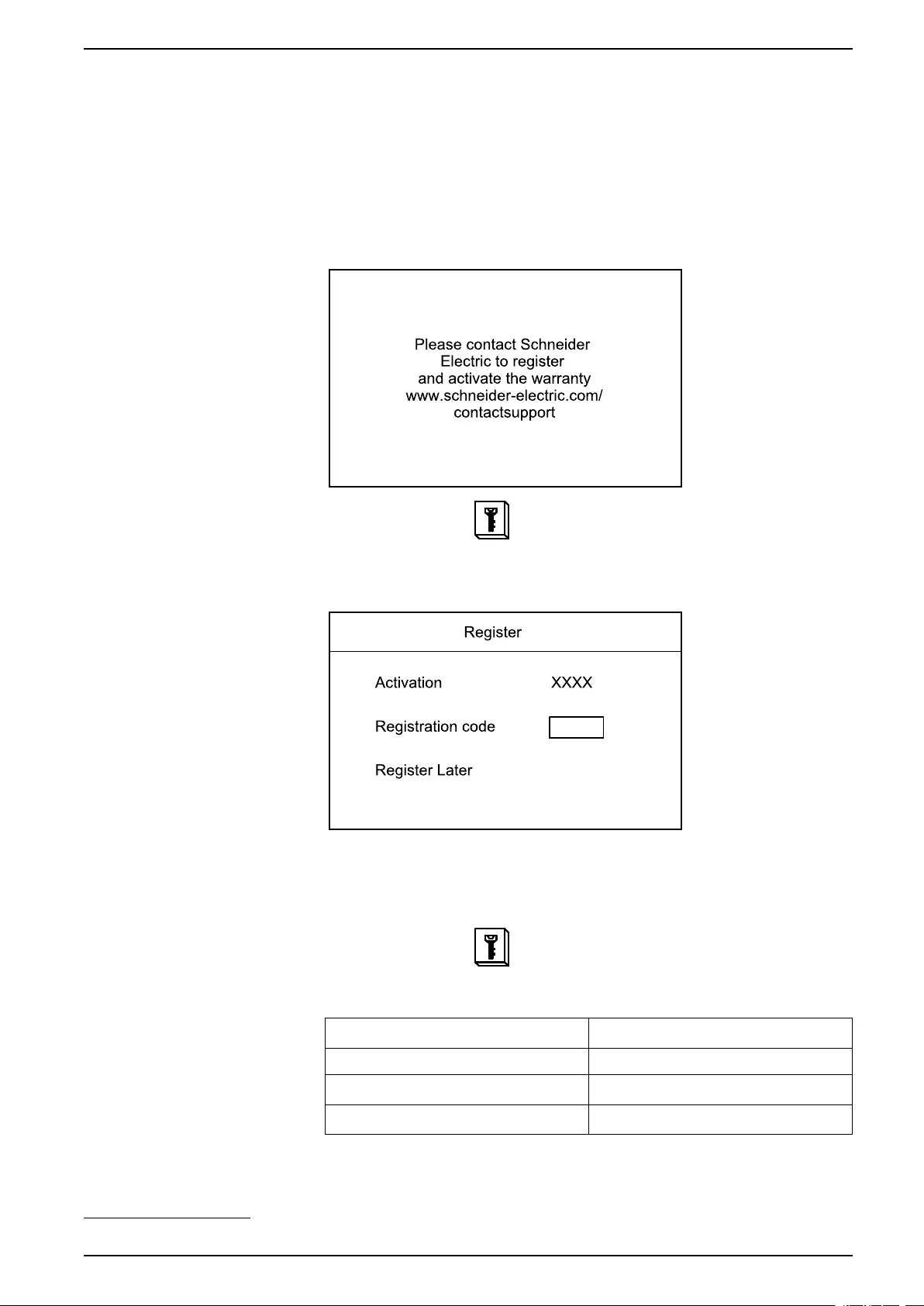
Register Your Easy UPS 3S
NOTE: The single Easy UPS 3S can also be registered using the
mySchneider app which can be downloaded from App Store and Google Play.
1. When prompted for registration, go to www.schneider-electric.com/
contactsupport to find your local service contact number.
2. On the display, select and then select Register1.
3. Call Schneider Electric and provide your four-digit activation code.
4. Type in the registration code provided by Schneider Electric.
Set the Display Language
1. On the display, select and then select Language.
2. Select your language from the list:
en: English pt: Portuguese Brazilian
fr: French ru: Russian
cn: Simplified Chinese de: German
it: Italian es: European Spanish
990-91079E-001 33
1. You can also select Register Later to postpone your registration
10-40 kVA Configuration
Set the Date and Time
1. On the display, select and then select Time.
2. Set the date and time.
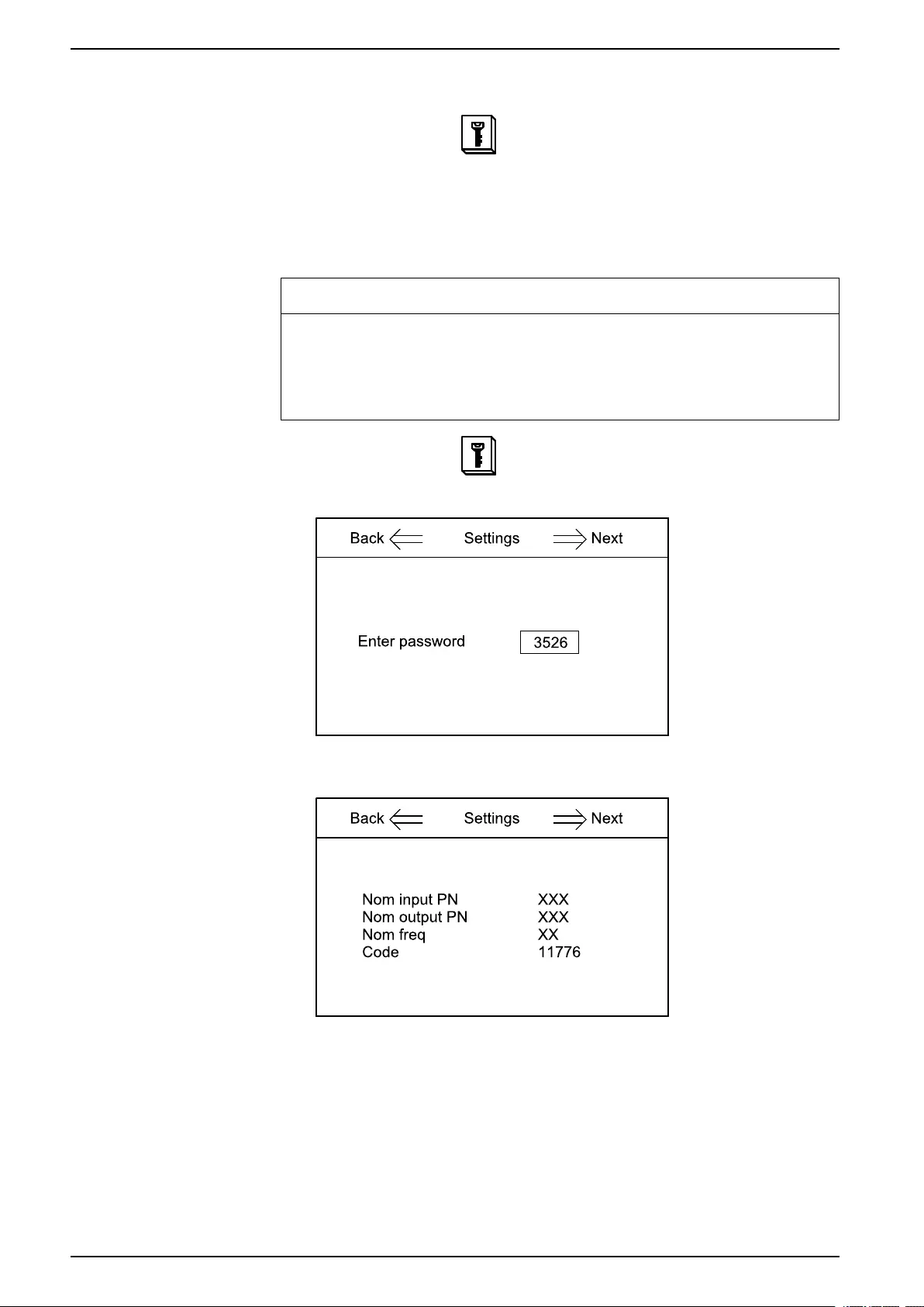
Set the UPS Settings
NOTICE
RISK OF EQUIPMENT DAMAGE
Only trained personnel following the required training course may undertake
modifications to UPS system parameters.
Failure to follow these instructions can result in equipment damage.
1. On the display, select and then select Setting.
2. Enter the password 3526.
3. Set the nominal input voltage (phase-neutral), the nominal output voltage
(phase-neutral), and the nominal frequency.
4. Restart the UPS to activate the settings.
34 990-91079E-001
Configuration 10-40 kVA
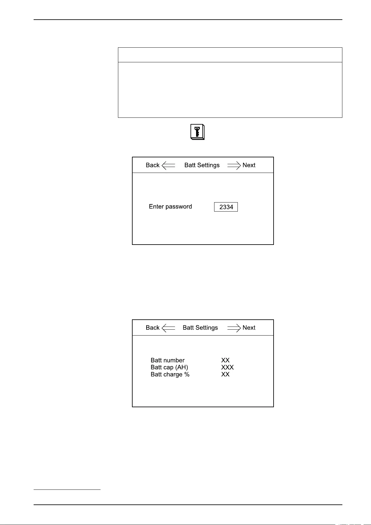
Set the Battery Settings
NOTICE
RISK OF EQUIPMENT DAMAGE
• Only trained personnel following the required training course may undertake
modifications to UPS system parameters.
• The battery parameters must set according to the actual installation before
starting up the UPS.
Failure to follow these instructions can result in equipment damage.
1. On the display, select and then select Batt Settings.
2. Enter the password 2334.
3. Set the battery settings (refer to the section Recommended Settings for UPSs
with Internal Batteries and Modular Battery Cabinets, page 36):
a. Batt number: Set the number of battery blocks in one battery string.
b. Batt cap (AH): Set the battery capacity (battery block capacity (AH) x
number of battery strings).2
c. Batt charge %: Set the battery charge percentage (between 1% and
20%).
990-91079E-001 35
2. In a 1+1 redundant parallel system with a common battery bank, insert half of the battery capacity in each UPS.

10-40 kVA Configuration
Recommended Settings for UPSs with Internal Batteries and Modular Battery Cabinets
10 kVA UPS
Number of
battery strings3
Settings with 7 Ah Batteries (E3SBT4) @ 0.1C Settings with 9 Ah Batteries (E3SBTH4) @ 0.1C
Batt number Batt cap (AH) Batt charge % Batt number Batt cap (AH) Batt charge %
1 40 7 4 40 9 5
2 80 14 8 80 18 10
3 120 21 12 120 27 15
4 160 28 16 160 36 20
5 200 35 20 200 45 20
6 240 42 20 240 54 20
7 280 49 20 280 63 20
8 320 56 20 320 72 20
9 360 63 20 360 81 20
15 kVA UPS
Number of
battery strings3
Settings with 7 Ah Batteries (E3SBT4) @ 0.1C Settings with 9 Ah Batteries (E3SBTH4) @ 0.1C
Batt number Batt cap (AH) Batt charge % Batt number Batt cap (AH) Batt charge %
1 40 7 3 40 9 4
2 80 14 5 80 18 7
3 120 21 8 120 27 10
4 160 28 11 160 36 14
5 200 35 13 200 45 17
6 240 42 16 240 54 20
7 280 49 19 280 63 20
8 320 56 20 320 72 20
9 360 63 20 360 81 20
10 400 70 20 400 90 20
11 440 77 20 440 99 20
12 480 84 20 480 108 20
13 520 91 20 520 117 20
14 560 98 20 560 126 20
15 600 105 20 600 135 20
20 kVA UPS
Number of
battery strings3
Settings with 7 Ah Batteries (E3SBT4) @ 0.1C Settings with 9 Ah Batteries (E3SBTH4) @ 0.1C
Batt number Batt cap (AH) Batt charge % Batt number Batt cap (AH) Batt charge %
1 40 7 2 40 9 3
2 80 14 4 80 18 5
3 120 21 6 120 27 8
4 160 28 8 160 36 10
5 200 35 10 200 45 13
6 240 42 12 240 54 15
7 280 49 14 280 63 18
8 320 56 16 320 72 20
36 990-91079E-001
3. Total number of battery strings in UPS and modular battery cabinet.

Configuration 10-40 kVA
20 kVA UPS (Continued)
Number of
battery strings4
Settings with 7 Ah Batteries (E3SBT4) @ 0.1C Settings with 9 Ah Batteries (E3SBTH4) @ 0.1C
Batt number Batt cap (AH) Batt charge % Batt number Batt cap (AH) Batt charge %
9 360 63 18 360 81 20
10 400 70 20 400 90 20
11 440 77 20 440 99 20
12 480 84 20 480 108 20
13 520 91 20 520 117 20
14 560 98 20 560 126 20
15 600 105 20 600 135 20
30 kVA UPS
Number of
battery strings4
Settings with 7 Ah Batteries (E3SBT4) @ 0.1C Settings with 9 Ah Batteries (E3SBTH4) @ 0.1C
Batt number Batt cap (AH) Batt charge % Batt number Batt cap (AH) Batt charge %
1 40 7 2 40 9 2
2 80 14 3 80 18 4
3 120 21 4 120 27 5
4 160 28 6 160 36 7
5 200 35 7 200 45 9
6 240 42 8 240 54 10
7 280 49 10 280 63 12
8 320 56 11 320 72 14
9 360 63 12 360 81 16
10 400 70 13 400 90 17
11 440 77 15 440 99 19
12 480 84 16 480 108 20
13 520 91 17 520 117 20
14 560 98 19 560 126 20
15 600 105 20 600 135 20
16 640 112 20 640 144 20
17 680 119 20 680 153 20
18 720 126 20 720 162 20
19 760 133 20 760 171 20
20 800 140 20 800 180 20
21 840 147 20 840 189 20
22 880 154 20 880 198 20
23 920 161 20 920 207 20
24 960 168 20 960 216 20
25 1000 175 20 1000 225 20
26 1040 182 20 1040 234 20
27 1080 189 20 1080 243 20
28 1120 196 20 1120 252 20
990-91079E-001 37
4. Total number of battery strings in UPS and modular battery cabinet.

10-40 kVA Configuration
40 kVA UPS
Number of
battery strings5
Settings with 7 Ah Batteries (E3SBT4) @ 0.1C Settings with 9 Ah Batteries (E3SBTH4) @ 0.1C
Batt number Batt cap (AH) Batt charge % Batt number Batt cap (AH) Batt charge %
1 40 7 1 40 9 2
2 80 14 2 80 18 3
3 120 21 3 120 27 4
4 160 28 4 160 36 5
5 200 35 5 200 45 7
6 240 42 6 240 54 8
7 280 49 7 280 63 9
8 320 56 8 320 72 11
9 360 63 9 360 81 12
10 400 70 10 400 90 13
11 440 77 11 440 99 14
12 480 84 12 480 108 16
13 520 91 13 520 117 17
14 560 98 14 560 126 18
15 600 105 15 600 135 19
16 640 112 16 640 144 20
17 680 119 17 680 153 20
18 720 126 18 720 162 20
19 760 133 19 760 171 20
20 800 140 20 800 180 20
21 840 147 20 840 189 20
22 880 154 20 880 198 20
23 920 161 20 920 207 20
24 960 168 20 960 216 20
25 1000 175 20 1000 225 20
26 1040 182 20 1040 234 20
27 1080 189 20 1080 243 20
28 1120 196 20 1120 252 20
Set the Life Cycle Monitoring
NOTICE
RISK OF EQUIPMENT DAMAGE
Only trained personnel following the required training course may undertake
modifications to UPS system parameters.
Failure to follow these instructions can result in equipment damage.
1. On the display, select and then select LCM Set.
38 990-91079E-001
5. Total number of battery strings in UPS and modular battery cabinet.

Configuration 10-40 kVA
2. You now have the following options:
– Select Set dust filter expiration to set the service life of the dust filter.
Settings
Setting Default Value Available Settings
LCD contrast 60 0 to 100
Date and Time 05/07/2013 08:55:55 Year > 2000
Language English Chinese simplified, English, Italian,
German, Russian, Spanish, Portuguese
Brazilian, and French
Input voltage 400 V 380 V/400 V/415 V
Bypass voltage 400 V for 3:3 UPSs
230 V for 3:1 UPSs
380 V/400 V/415 V for 3:3 UPSs
220 V/230 V/240 V for 3:1 UPSs
Input frequency 50 Hz 60 Hz
Output voltage 400 V for 3:3 UPSs
230 V for 3:1 UPSs
380 V/400 V/415 V for 3:3 UPSs
220 V/230 V/240 V for 3:1 UPSs
Output frequency 50 Hz 60 Hz
Output phase 3 for 3:3 UPSs
1 for 3:1 UPSs
3/1
Auto boost disable enable
Auto maint disable enable
System mode single parallel/ECO/parallel ECO/self aging
United number 1 1 to 4
System ID 0 0 to 3
Adjusted output voltage 400 V for 3:3 UPSs
230 V for 3:1 UPSs
Output voltage ±10 V
Frequency slew rate 2 Hz/s 0.1 to 5.0 Hz/s
Frequency synchronization window 3 Hz 0.5 to 5.0 Hz
Monochrome LCD time (min) 10 1/3/5/10/20/30
Bypass voltage upper limit (%) 15 10/20/25
Bypass voltage lower limit (%) -20 -10/-15/-30/-40
Bypass frequency limited (Hz) ±5 ±1/±3/±5
System restart mode after end of discharge Normal bypass only/ no output
Fan maintenance period 34560 hours (48 months) 0 to 60000 hours
DC capacitor maintenance period 34560 hours (48 months) 0 to 60000 hours
warranty period 9 months 1 to 36 months
AC capacitor maintenance period 120 months 60 to 120 months
990-91079E-001 39

10-40 kVA Configuration
Setting Default Value Available Settings
APS maintenance period 84 months 36 to 120 months
Dust filter maintenance period 3 months 0/3/4/5/12 months
Battery maintenance period 1440 days (48 months) 100 to 3000 days
Battery number 32 for UPSs for external batteries
40 for UPSs with internal batteries
32/34/36/38/40
Battery AH 1 1 to 30000
Float charge voltage/cell (V) 2.25 2.10 to 2.35
Boost charge voltage/cell (V) 2.25 2.20 to 2.45
End of discharge voltage/cell, at 3 C current
(V)
1.65 1.50 to 1.85
End of discharge voltage/cell, at 0.05 C
current (V)
1.75 1.55 to 1.90
Charge current percent limit (%) 10 1 to 20
Battery temperature compensation 0 0 to 5 mV/℃
Boost charge time limit 12 hours 1 to 48 hours
Auto boost period 2160 hours (3 months) 720 to 30000 hours, available when auto
boost is enabled
Auto maintenance discharge period 6480 hours (9 months) 720 to 30000 hours, available when auto
maintenance is enabled
Critical battery temperature 45 ℃25 ℃to 70 ℃
Critical ambient temperature 40 ℃25 ℃to 70 ℃
40 990-91079E-001

Tests 10-40 kVA
Tests
Perform a Battery Maintenance Test
Prerequisite:
• The bypass supply must be within specifications.
• The battery capacity must be above 25%.
The battery maintenance test is used to test the condition of the batteries.
During the battery maintenance test, the system transfers to battery mode and
discharges the batteries until the battery low voltage alarm is reached.
1. On the display, select and then select Maint test.
NOTE: If you wish to manually stop the battery test, select Stop test.
If the battery maintenance test is passed, Battery maintenance OK will be
recorded in the log. If the battery maintenance test is not passed, Batt maint
incomplete will be recorded in the log.
Perform a Battery Test
The purpose of the battery test to verify the connection of the batteries and to
check the battery capacity.
Prerequisite:
• The bypass supply must be within specifications.
• The battery capacity must be above 25%.
• The battery voltage must be above 95% of the float voltage.
During the battery test, the system transfers to battery mode for approximately 30
seconds and then returns to normal mode.
1. On the display, select and then select Battery test.
990-91079E-001 41

10-40 kVA Maintenance
Maintenance
Parts Replacement
Determine if you need a Replacement Part
To determine if you need a replacement part, contact Schneider Electric and
follow the procedure below so that the representative can assist you promptly:
1. In the event of an alarm condition, scroll through the alarm lists, record the
information, and provide it to the representative.
2. Write down the serial number of the unit so that you will have it easily
accessible when you contact Schneider Electric.
3. If possible, call Schneider Electric from a telephone that is within reach of the
display so that you can gather and report additional information to the
representative.
4. Be prepared to provide a detailed description of the problem. A representative
will help you solve the problem over the telephone, if possible, or will assign a
return material authorization (RMA) number to you. If a module is returned to
Schneider Electric, this RMA number must be clearly printed on the outside of
the package.
5. If the unit is within the warranty period and has been started up by Schneider
Electric, repairs or replacements will be performed free of charge. If it is not
within the warranty period, there will be a charge.
6. If the unit is covered by a Schneider Electric service contract, have the
contract available to provide information to the representative.
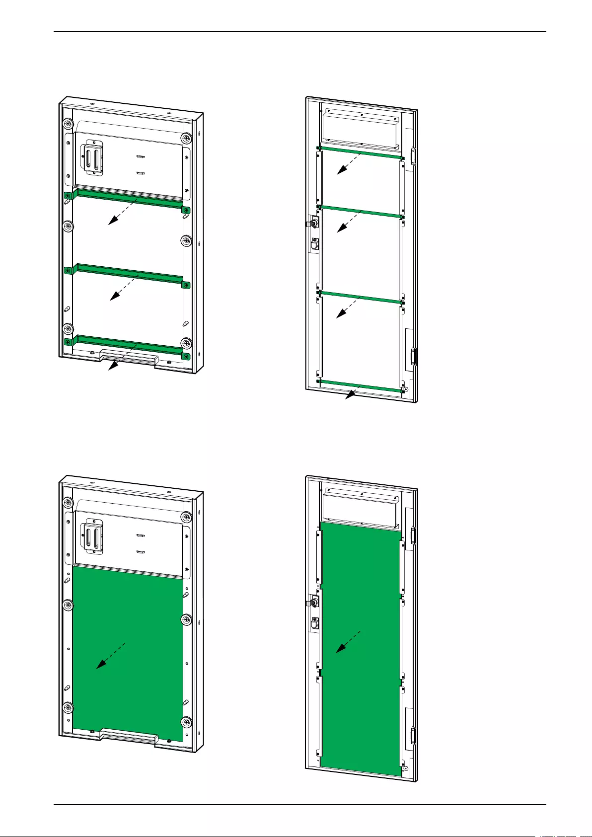
Replace the Dust Filter
1. Lift the front panel free of the UPS cabinet.
NOTE: Be careful not to disconnect the cable on the rear side of the front
panel.
42 990-91079E-001

Troubleshooting 10-40 kVA
Troubleshooting
View the Active Alarms
1. On the display select .
See Status and Alarm Messages, page 45 for a list of alarm messages and
corrective actions.
2. Use and to go through the list of active alarms.
Buzzer
NOTE: The buzzer turns on as soon as an alarm condition is detected. The
buzzer makes two short beeps and a long beep for general system alarms.
The buzzer makes a continuous beep for critical alarms. It can be turned off by
selecting on the home screen.
Status and Alarm Messages
This section lists status and alarm messages from the display. The display
messages are listed in alphabetical order, and a suggested corrective action is
listed with the display alarm message to help you troubleshoot problems.
Display text Description Corrective action
Battery boost charging The batteries are charged with the
configured boost charge voltage.
Battery connected The batteries are connected.
Battery discharging The load is drawing more power
than the UPS can draw from the
input, causing the UPS to draw
power from the batteries.
Reduce the load. Please contact
Schneider Electric.
Battery disconnected The batteries are not connected. Connect the batteries.
Battery expired The battery service life has
expired.
Replace the battery.
Battery end of discharge The battery capacity is below the
minimum acceptable value.
Recharge the batteries.
Battery float charging The batteries are charged with the
configured float charge voltage.
Battery log reset Reset the battery log.
Batt maint incomplete The battery maintenance test was
not passed.
Battery maintenance Start the battery maintenance test.
Battery maintenance OK The battery maintenance test has
been successfully completed.
Battery temperature high The battery temperature is too
high.
Check the battery temperature.
Battery test Start the battery test.
990-91079E-001 45

10-40 kVA Troubleshooting
Display text Description Corrective action
Battery test incomplete The battery test was not passed.
Battery test OK The battery test has been
successfully completed.
Battery voltage low Low voltage on battery. Check the battery.
Battery wiring incorrect The battery wiring is incorrect. Check the battery wiring. Please
contact Schneider Electric.
Battery/charger inoperable The battery or charger is
inoperable.
Check the battery. Check the
charger. Please contact Schneider
Electric.
Byp freq exceeds limits The bypass frequency exceeds the
limit.
Check the status of the bypass
source. Please contact Schneider
Electric.
Bypass fan inoperable The UPS has one or more
inoperable fans.
Check the fans.
Bypass fan time reset Reset the service life timer for the
fan.
Bypass out of tolerance The bypass voltage is out of
tolerance.
Check the status of the bypass
source. Please contact Schneider
Electric.
Bypass overload The load is drawing more power
than the bypass source can supply.
Reduce the load. Please contact
Schneider Electric.
Bypass overload timeout The UPS can no longer sustain a
Bypass overload situation.
Reduce the load. Please contact
Schneider Electric.
Bypass sequence incorrect The phase rotation on bypass is
incorrect.
Check the status of the bypass
source. Please contact Schneider
Electric.
Bypass unavailable The bypass source is not available. Check the status of the bypass
source. Please contact Schneider
Electric.
Capacitor expired Capacitor service life has expired. Replace the capacitor.
Capacitor time reset Capacitor service life timer has
been reset.
Clear log Clear the log.
DC bus overvoltage Overvoltage on the DC bus.
Dust filter expired The dust filter service life has
expired.
Replace the Dust Filter, page 42.
EPO An EPO (emergency power off)
device is activated.
Deactivate the EPO (emergency
power off) device.
Fan expired Fan service life has expired. Replace the fan.
Fan inoperable The UPS has one or more
inoperable fans.
Check the fans. Please contact
Schneider Electric.
Fan time reset The fan service life timer has been
reset.
Firmware incompatible The firmware is detected as
incompatible with the rest of the
system.
Perform a firmware update.
Generator input Generator is supplying the UPS.
Inhibit transfer to inv. Inhibit transfer to inverter
operation.
46 990-91079E-001

Troubleshooting 10-40 kVA
Display text Description Corrective action
Inlet temperature high Air inlet temperature is too high. Check the status of the air inlet.
Reduce the room temperature.
Inlet/outlet temp Air inlet and outlet temperature.
Input current unbalanced Input current is unbalanced. Check the status of the input
source. Please contact Schneider
Electric.
Input neutral unavailable Input neutral is not available. Check the status of the input
neutral. Please contact Schneider
Electric.
Input out of tolerance The input voltage is out of
tolerance.
Check the status of the input
source. Please contact Schneider
Electric.
Input overcurrent timeout The UPS can no longer sustain an
Input overcurrent situation.
Check the status of the input
source. Please contact Schneider
Electric.
Input SCR fan inoperable Input SCR fan is inoperable. Check the status of the input SCR
fan. Please contact Schneider
Electric.
Input SCR temp high Input SCR temperature is too high. Check the status of the input SCR
fan. Please contact Schneider
Electric.
Inverter high temp Inverter temperature is too high. Check the status of the inverter.
Please contact Schneider Electric.
Inverter IGBT inoperable The inverter IGBT is inoperable. Check the status of the inverter
IGBT. Please contact Schneider
Electric.
Inverter inoperable The inverter is inoperable. Check the status of the inverter.
Please contact Schneider Electric.
Inverter overload timeout The UPS can no longer sustain an
Inverter overload situation.
Check the status of the inverter.
Please contact Schneider Electric.
Inverter shutdown The inverter is shutting down.
Inv DATA CAN incorrect Inverter DATA CAN is incorrect.
Inv IO CAN incorrect Inverter IO CAN is incorrect.
Load on bypass The UPS is in static bypass mode
and the load is supplied by the
bypass source.
Load disconnected The load has been disconnected or
the unit output breaker UOB is
open.
Check the load. Close the unit
output breaker UOB.
Load on inverter The UPS is in inverter operation
mode and the load is supplied by
the UPS.
Low battery shutdown The UPS is shutting down due to
battery end of discharge
Recharge the batteries and restart
the UPS. If auto-restart mode is
configured, the UPS will start
automatically restart when the
mains return.
Man. transfer to inverter Manual transfer to inverter
operation.
Manual shutdown Manual shutdown.
MBB closed The maintenance bypass breaker
MBB is closed, supplying the load
990-91079E-001 47

10-40 kVA Troubleshooting
Display text Description Corrective action
with unprotected power from the
bypass source.
MBB open The maintenance bypass breaker
is open.
Module ID duplicate The module ID has a duplicate.
The module ID must be unique.
Check the ID of the modules.
No inlet temp sensor No inlet temperature sensor
present.
Check the status of the inlet
temperature sensor.
No input temp sensor No input temperature sensor
present.
Check the status of the input
temperature sensor.
No outlet temp sensor No outlet temperature sensor
present.
Check the status of the outlet
temperature sensor.
Nom power out of tolerance Input is out of tolerance Check the status of the input
source. Please contact Schneider
Electric.
Outlet temperature high Air outlet temperature is too high. Check the status of the air outlet.
Please contact Schneider Electric.
Output short circuit A short circuit is present on the
output.
Check the status of the output.
Please contact Schneider Electric.
Output overload The load is drawing more power
than the UPS system can supply.
Reduce the load. Contact
Schneider Electric.
Parallel cabling incorrect The parallel cabling is incorrect. Check the status of the parallel
cables. Please contact Schneider
Electric.
Power sharing incorrect The power sharing between the
UPS units is incorrect.
Please check the load sharing on
the UPS units. Redistribute the
load between UPS units. Please
contact Schneider Electric.
PWM sync unavailable The PWM synchronization is
unavailable.
Check the status of the PWM sync.
Please contact Schneider Electric.
Rec soft start unavailable The rectifier soft start is
unavailable.
Check the status of the rectifier.
Please contact Schneider Electric.
Rectifier high temp The rectifier temperature is too
high.
Check the status of the rectifier.
Please contact Schneider Electric.
Rectifier inoperable The rectifier is inoperable. Check the status of the rectifier.
Please contact Schneider Electric.
Relay disconnected A relay is disconnected. Check the status of the relays.
Please contact Schneider Electric.
Relay short-circuit A relay has short-circuited. Check the status of the relays.
Please contact Schneider Electric.
Room temp high The room temperature is high. Reduce the room temperature.
Shutdown UPS shutdown.
Signal cable disconnect Signal cable is disconnected. Check the signal cable.
Sync pulse unavailable Sync pulse is unavailable. The
UPS is not able to synchronize.
Check the sync pulse. Please
contact Schneider Electric.
System overload The load is drawing more power
than the UPS system can supply.
Reduce the load. Contact
Schneider Electric.
System setting incorrect The system settings are incorrect. Check the system settings. Contact
Schneider Electric.
48 990-91079E-001

Troubleshooting 10-40 kVA
Display text Description Corrective action
Technical check recommended A technical check is
recommended.
Contact Schneider Electric.
Transfer to bypass Transfer the UPS to static bypass
mode.
Transfer to inverter Transfer the UPS to inverter
operation.
Transfers exceed limits There have been too many
transfers between operation modes
in a given time period.
Contact Schneider Electric.
Warranty expiring soon Warranty is expiring soon. Contact Schneider Electric.
990-91079E-001 49


Schneider Electric
35 rue Joseph Monier
92500 Rueil Malmaison
France
+ 33 (0) 1 41 29 70 00
*990-91079E-001*
As standards, specifications, and design change from time to time,
please ask for confirmation of the information given in this publication.
© 2017 – 2019 Schneider Electric. All rights reserved.
990-91079E-001