Table of Contents
- CM1164A User Manual
- Preface
- Chapter 1 Introduction
- Chapter 2 Hardware Setup
- Chapter 3 Basic Operation
- Chapter 4 Hotkey Operation
- Chapter 5 OSD Operation
- Chapter 6 RS-232 Operation
- Overview
- Setup
- RS-232 Commands
- Verification
- Login
- Logout
- Open/Close RS-232 Link
- Switch Port
- PiP Mode
- Quad View Mode
- Change Display Mode
- Port Disable
- OSD Language
- Keyboard Language Layout
- Set Operating System
- Auto Scan
- Port ID Display
- Security
- Station
- DCC Control
- Mouse Emulation
- Keyboard Emulation
- Video Dynasync
- Hardware Cursor
- Activate Beeper
- Hotkey Setting
- OSD Hotkey
- Power on Detection
- Fn Key
- USB Reset
- Restore Default Value
- Firmware Upgrade
- KVM Status
- Hotkey List
- Info
- Chapter 7 System Maintenance
- Appendix
ATEN CM1164A User Manual
Displayed below is the user manual for CM1164A by ATEN which is a product in the KVM Switches category. This manual has pages.
Related Manuals
4-port USB DVI Multi-view KVMPTM Switch
CM1164A
User Manual
www.aten.com

CM1164A User Manual
ii
Preface
EMC Information
FEDERAL COMMUNICATIONS COMMISSION INTERFERENCE
STATEMENT: This equipment has been tested and found to comply with the
limits for a Class A digital device, pursuant to Part 15 of the FCC Rules. These
limits are designed to provide reasonable protection against harmful
interference when the equipment is operated in a commercial environment.
This equipment generates, uses, and can radiate radio frequency energy and, if
not installed and used in accordance with the instruction manual, may cause
harmful interference to radio communications. Operation of this equipment in
a residential area is likely to cause harmful interference in which case the user
will be required to correct the interference at his own expense.
The device complies with Part 15 of the FCC Rules. Operation is subject to the
following two conditions: (1) this device may not cause harmful interference,
and (2) this device must accept any interference received, including
interference that may cause undesired operation.
FCC Caution: Any changes or modifications not expressly approved by the
party responsible for compliance could void the user's authority to operate this
equipment.
Warning: Operation of this equipment in a residential environment could
cause radio interference.
KCC Statement
유선 제품용 / A 급 기기 ( 업무용 방송 통신 기기 )
이 기기는 업무용 (A 급) 전자파적합기기로서 판매자 또는 사용자는 이
점을 주의하시기 바라며 , 가정 외의 지역에서 사용하는 것을 목적으로
합니다 .
RoHS
This product is RoHS compliant.

CM1164A User Manual
iii
User Information
Online Registration
Be sure to register your product at our online support center:
Telephone Support
For telephone support, call this number:
User Notice
All information, documentation, and specifications contained in this manual
are subject to change without prior notification by the manufacturer. The
manufacturer makes no representations or warranties, either expressed or
implied, with respect to the contents hereof and specifically disclaims any
warranties as to merchantability or fitness for any particular purpose. Any of
the manufacturer's software described in this manual is sold or licensed as is.
Should the programs prove defective following their purchase, the buyer (and
not the manufacturer, its distributor, or its dealer), assumes the entire cost of all
necessary servicing, repair and any incidental or consequential damages
resulting from any defect in the software.
The manufacturer of this system is not responsible for any radio and/or TV
interference caused by unauthorized modifications to this device. It is the
responsibility of the user to correct such interference.
The manufacturer is not responsible for any damage incurred in the operation
of this system if the correct operational voltage setting was not selected prior
to operation. PLEASE VERIFY THAT THE VOLTAGE SETTING IS
CORRECT BEFORE USE.
International http://eservice.aten.com
International 886-2-8692-6959
China 86-400-810-0-810
Japan 81-3-5615-5811
Korea 82-2-467-6789
North America 1-888-999-ATEN ext 4988 or 1-949-428-1111

CM1164A User Manual
iv
Package Contents
The CM1164A package consists of:
1 CM1164A 4-port USB DVI Multi-view KVMPTM Switch
4 KVM Cables (DVI-D, USB, Audio)
1Power Cord
1 IR Remote Control
1 Rack Mount Kit
4 Foot Pads
1 User Instructions*
Check to make sure that all the components are present and that nothing got
damaged in shipping. If you encounter a problem, contact your dealer.
Read this manual thoroughly and follow the installation and operation
procedures carefully to prevent any damage to the unit, and/or any of the
devices connected to it.
*Features may have been added to the CM1164A since this manual was
printed. Please visit our website to download the most up-to-date version.
© Copyright 2018 ATEN® International Co., Ltd.
F/W Version: v1.0.097
Manual Date: 2018-07-10
ATEN and the ATEN logo are registered trademarks of ATEN International Co., Ltd. All rights reserved.
All other brand names and trademarks are the registered property of their respective owners.

CM1164A User Manual
v
Contents
Preface
EMC Information . . . . . . . . . . . . . . . . . . . . . . . . . . . . . . . . . . . . . . . . . . . . . ii
User Information . . . . . . . . . . . . . . . . . . . . . . . . . . . . . . . . . . . . . . . . . . . . .iii
Online Registration . . . . . . . . . . . . . . . . . . . . . . . . . . . . . . . . . . . . . . . .iii
Telephone Support . . . . . . . . . . . . . . . . . . . . . . . . . . . . . . . . . . . . . . . .iii
User Notice . . . . . . . . . . . . . . . . . . . . . . . . . . . . . . . . . . . . . . . . . . . . . .iii
Package Contents . . . . . . . . . . . . . . . . . . . . . . . . . . . . . . . . . . . . . . . . . . iv
Contents . . . . . . . . . . . . . . . . . . . . . . . . . . . . . . . . . . . . . . . . . . . . . . . . . . . v
About this Manual . . . . . . . . . . . . . . . . . . . . . . . . . . . . . . . . . . . . . . . . . . ix
Conventions . . . . . . . . . . . . . . . . . . . . . . . . . . . . . . . . . . . . . . . . . . . . . . . . x
Product Information. . . . . . . . . . . . . . . . . . . . . . . . . . . . . . . . . . . . . . . . . . . x
1. Introduction
Overview . . . . . . . . . . . . . . . . . . . . . . . . . . . . . . . . . . . . . . . . . . . . . . . . . . . 1
Features . . . . . . . . . . . . . . . . . . . . . . . . . . . . . . . . . . . . . . . . . . . . . . . . . . . 3
Requirements . . . . . . . . . . . . . . . . . . . . . . . . . . . . . . . . . . . . . . . . . . . . . . . 4
Console . . . . . . . . . . . . . . . . . . . . . . . . . . . . . . . . . . . . . . . . . . . . . . . . 4
Computers. . . . . . . . . . . . . . . . . . . . . . . . . . . . . . . . . . . . . . . . . . . . . . . 4
Cables . . . . . . . . . . . . . . . . . . . . . . . . . . . . . . . . . . . . . . . . . . . . . . . . . .4
Operating Systems . . . . . . . . . . . . . . . . . . . . . . . . . . . . . . . . . . . . . . . . 5
Optional Equipment . . . . . . . . . . . . . . . . . . . . . . . . . . . . . . . . . . . . . . . 5
Components . . . . . . . . . . . . . . . . . . . . . . . . . . . . . . . . . . . . . . . . . . . . . . . .6
Front View . . . . . . . . . . . . . . . . . . . . . . . . . . . . . . . . . . . . . . . . . . . . . . 6
Rear View . . . . . . . . . . . . . . . . . . . . . . . . . . . . . . . . . . . . . . . . . . . . . . . 8
IR Remote Control . . . . . . . . . . . . . . . . . . . . . . . . . . . . . . . . . . . . . . . .9
2. Hardware Setup
Rack Mounting . . . . . . . . . . . . . . . . . . . . . . . . . . . . . . . . . . . . . . . . . . . . .11
Grounding . . . . . . . . . . . . . . . . . . . . . . . . . . . . . . . . . . . . . . . . . . . . . . 13
Installation . . . . . . . . . . . . . . . . . . . . . . . . . . . . . . . . . . . . . . . . . . . . . . . .14
Single Station Installation . . . . . . . . . . . . . . . . . . . . . . . . . . . . . . . . . .14
Single Station Installation Diagram . . . . . . . . . . . . . . . . . . . . . . . . . . . 15
Daisy Chaining . . . . . . . . . . . . . . . . . . . . . . . . . . . . . . . . . . . . . . . . . . 16
Daisy Chain Installation Diagram. . . . . . . . . . . . . . . . . . . . . . . . . .17
Cascading . . . . . . . . . . . . . . . . . . . . . . . . . . . . . . . . . . . . . . . . . . . . .18
Cascade Installation Diagram . . . . . . . . . . . . . . . . . . . . . . . . . . . . 19
3. Basic Operation
Overview . . . . . . . . . . . . . . . . . . . . . . . . . . . . . . . . . . . . . . . . . . . . . . . . . . 21
Identifying the Source Device . . . . . . . . . . . . . . . . . . . . . . . . . . . . . . . . . . 21
Switching. . . . . . . . . . . . . . . . . . . . . . . . . . . . . . . . . . . . . . . . . . . . . . . . . .22
Manual Switching . . . . . . . . . . . . . . . . . . . . . . . . . . . . . . . . . . . . . . . . 22

CM1164A User Manual
vi
Hotkey Switching . . . . . . . . . . . . . . . . . . . . . . . . . . . . . . . . . . . . . . . . 24
Remote Switching . . . . . . . . . . . . . . . . . . . . . . . . . . . . . . . . . . . . . . . 24
OSD Switching . . . . . . . . . . . . . . . . . . . . . . . . . . . . . . . . . . . . . . . . . . 25
Display Modes . . . . . . . . . . . . . . . . . . . . . . . . . . . . . . . . . . . . . . . . . . . . . 27
Quad View. . . . . . . . . . . . . . . . . . . . . . . . . . . . . . . . . . . . . . . . . . . . . . 28
Picture in Picture - Dual . . . . . . . . . . . . . . . . . . . . . . . . . . . . . . . . . . . 29
Picture in Picture - Triple . . . . . . . . . . . . . . . . . . . . . . . . . . . . . . . . . . 30
Picture in Picture - Quad . . . . . . . . . . . . . . . . . . . . . . . . . . . . . . . . . . 31
Picture on Picture . . . . . . . . . . . . . . . . . . . . . . . . . . . . . . . . . . . . . . . . 32
Picture by Picture - Dual . . . . . . . . . . . . . . . . . . . . . . . . . . . . . . . . . . 33
Picture by Picture - Triple . . . . . . . . . . . . . . . . . . . . . . . . . . . . . . . . . . 34
Picture by Picture - Quad . . . . . . . . . . . . . . . . . . . . . . . . . . . . . . . . . . 35
Preset Configuration . . . . . . . . . . . . . . . . . . . . . . . . . . . . . . . . . . . . . . . . 36
4. Hotkey Operation
Open the OSD Menu . . . . . . . . . . . . . . . . . . . . . . . . . . . . . . . . . . . . . . . . 39
Hotkey Setting Mode . . . . . . . . . . . . . . . . . . . . . . . . . . . . . . . . . . . . . . . . 40
Invoking HSM . . . . . . . . . . . . . . . . . . . . . . . . . . . . . . . . . . . . . . . . . . . 40
Auto Scanning . . . . . . . . . . . . . . . . . . . . . . . . . . . . . . . . . . . . . . . . . . 43
Auto Scanning - Display Modes . . . . . . . . . . . . . . . . . . . . . . . . . . 43
Display Mode . . . . . . . . . . . . . . . . . . . . . . . . . . . . . . . . . . . . . . . . . . . 44
Fn Key . . . . . . . . . . . . . . . . . . . . . . . . . . . . . . . . . . . . . . . . . . . . . . . . 44
Hotkey Steps . . . . . . . . . . . . . . . . . . . . . . . . . . . . . . . . . . . . . . . . . . . . . . 45
List Current KVM Settings. . . . . . . . . . . . . . . . . . . . . . . . . . . . . . . . . . 45
USB Reset . . . . . . . . . . . . . . . . . . . . . . . . . . . . . . . . . . . . . . . . . . . . . 45
Port Switching . . . . . . . . . . . . . . . . . . . . . . . . . . . . . . . . . . . . . . . . . . 45
5. OSD Operation
Overview. . . . . . . . . . . . . . . . . . . . . . . . . . . . . . . . . . . . . . . . . . . . . . . . . . 47
The Quick Access Toolbar . . . . . . . . . . . . . . . . . . . . . . . . . . . . . . . . . . . . 47
The Editor Mode . . . . . . . . . . . . . . . . . . . . . . . . . . . . . . . . . . . . . . . . . . . 49
The OSD Menu . . . . . . . . . . . . . . . . . . . . . . . . . . . . . . . . . . . . . . . . . . . . 51
6. RS-232 Operation
Overview. . . . . . . . . . . . . . . . . . . . . . . . . . . . . . . . . . . . . . . . . . . . . . . . . . 57
Setup . . . . . . . . . . . . . . . . . . . . . . . . . . . . . . . . . . . . . . . . . . . . . . . . . . . . 57
Hardware Connection . . . . . . . . . . . . . . . . . . . . . . . . . . . . . . . . . . 57
Console Login - HyperTerminal. . . . . . . . . . . . . . . . . . . . . . . . . . . 58
RS-232 Commands . . . . . . . . . . . . . . . . . . . . . . . . . . . . . . . . . . . . . . . . . 59
Verification . . . . . . . . . . . . . . . . . . . . . . . . . . . . . . . . . . . . . . . . . . . . . 59
Login . . . . . . . . . . . . . . . . . . . . . . . . . . . . . . . . . . . . . . . . . . . . . . . . . 60
Logout . . . . . . . . . . . . . . . . . . . . . . . . . . . . . . . . . . . . . . . . . . . . . . . . 61
Open/Close RS-232 Link . . . . . . . . . . . . . . . . . . . . . . . . . . . . . . . . . . 62
Switch Port . . . . . . . . . . . . . . . . . . . . . . . . . . . . . . . . . . . . . . . . . . . . . 63
PiP Mode . . . . . . . . . . . . . . . . . . . . . . . . . . . . . . . . . . . . . . . . . . . . . . 64
Quad View Mode . . . . . . . . . . . . . . . . . . . . . . . . . . . . . . . . . . . . . . . . 65

CM1164A User Manual
vii
Change Display Mode . . . . . . . . . . . . . . . . . . . . . . . . . . . . . . . . . . . .66
Port Disable . . . . . . . . . . . . . . . . . . . . . . . . . . . . . . . . . . . . . . . . . . . .67
OSD Language . . . . . . . . . . . . . . . . . . . . . . . . . . . . . . . . . . . . . . . . . . 68
Keyboard Language Layout . . . . . . . . . . . . . . . . . . . . . . . . . . . . . . . . 69
Set Operating System . . . . . . . . . . . . . . . . . . . . . . . . . . . . . . . . . . . . 70
Auto Scan . . . . . . . . . . . . . . . . . . . . . . . . . . . . . . . . . . . . . . . . . . . . . .71
Port ID Display . . . . . . . . . . . . . . . . . . . . . . . . . . . . . . . . . . . . . . . . . . 72
Security . . . . . . . . . . . . . . . . . . . . . . . . . . . . . . . . . . . . . . . . . . . . . . .73
Formula:. . . . . . . . . . . . . . . . . . . . . . . . . . . . . . . . . . . . . . . . . . . . . 73
Station . . . . . . . . . . . . . . . . . . . . . . . . . . . . . . . . . . . . . . . . . . . . . . . . 74
DCC Control . . . . . . . . . . . . . . . . . . . . . . . . . . . . . . . . . . . . . . . . . . . . 75
Mouse Emulation . . . . . . . . . . . . . . . . . . . . . . . . . . . . . . . . . . . . . . . . 76
Keyboard Emulation . . . . . . . . . . . . . . . . . . . . . . . . . . . . . . . . . . . . . . 77
Video Dynasync . . . . . . . . . . . . . . . . . . . . . . . . . . . . . . . . . . . . . . . . .78
Hardware Cursor . . . . . . . . . . . . . . . . . . . . . . . . . . . . . . . . . . . . . . . .79
Activate Beeper . . . . . . . . . . . . . . . . . . . . . . . . . . . . . . . . . . . . . . . . . 80
Hotkey Setting . . . . . . . . . . . . . . . . . . . . . . . . . . . . . . . . . . . . . . . . . .81
OSD Hotkey . . . . . . . . . . . . . . . . . . . . . . . . . . . . . . . . . . . . . . . . . . . .82
Power on Detection . . . . . . . . . . . . . . . . . . . . . . . . . . . . . . . . . . . . . . 83
Fn Key . . . . . . . . . . . . . . . . . . . . . . . . . . . . . . . . . . . . . . . . . . . . . . . . 84
USB Reset . . . . . . . . . . . . . . . . . . . . . . . . . . . . . . . . . . . . . . . . . . . . .85
Restore Default Value . . . . . . . . . . . . . . . . . . . . . . . . . . . . . . . . . . . . 86
Firmware Upgrade . . . . . . . . . . . . . . . . . . . . . . . . . . . . . . . . . . . . . . . 87
KVM Status . . . . . . . . . . . . . . . . . . . . . . . . . . . . . . . . . . . . . . . . . . . .88
Hotkey List . . . . . . . . . . . . . . . . . . . . . . . . . . . . . . . . . . . . . . . . . . . . .89
Info . . . . . . . . . . . . . . . . . . . . . . . . . . . . . . . . . . . . . . . . . . . . . . . . . . . 90
7. System Maintenance
Firmware Upgrades. . . . . . . . . . . . . . . . . . . . . . . . . . . . . . . . . . . . . . . . . . 91
http://www.aten.com . . . . . . . . . . . . . . . . . . . . . . . . . . . . . . . . . . . . . .91
Before you Begin. . . . . . . . . . . . . . . . . . . . . . . . . . . . . . . . . . . . . . . . . 91
Starting the Upgrade . . . . . . . . . . . . . . . . . . . . . . . . . . . . . . . . . . . . .92
Unsuccessful Upgrades . . . . . . . . . . . . . . . . . . . . . . . . . . . . . . . . . . . 94
Backup / Restore . . . . . . . . . . . . . . . . . . . . . . . . . . . . . . . . . . . . . . . . . . .95
Powering Off and Restarting . . . . . . . . . . . . . . . . . . . . . . . . . . . . . . . . . .98
Restoring to Default Settings . . . . . . . . . . . . . . . . . . . . . . . . . . . . . . . . . . 98
Appendix
Safety Instructions. . . . . . . . . . . . . . . . . . . . . . . . . . . . . . . . . . . . . . . . . . .99
General . . . . . . . . . . . . . . . . . . . . . . . . . . . . . . . . . . . . . . . . . . . . . . . . 99
Rack Mounting . . . . . . . . . . . . . . . . . . . . . . . . . . . . . . . . . . . . . . . . . 101
Technical Support . . . . . . . . . . . . . . . . . . . . . . . . . . . . . . . . . . . . . . . . .102
International . . . . . . . . . . . . . . . . . . . . . . . . . . . . . . . . . . . . . . . . . . . 102
North America . . . . . . . . . . . . . . . . . . . . . . . . . . . . . . . . . . . . . . . . .102
Specifications . . . . . . . . . . . . . . . . . . . . . . . . . . . . . . . . . . . . . . . . . . . . . 103
Troubleshooting . . . . . . . . . . . . . . . . . . . . . . . . . . . . . . . . . . . . . . . . . . .104

CM1164A User Manual
viii
Display Mode Reference . . . . . . . . . . . . . . . . . . . . . . . . . . . . . . . . . . . . 105
Fn Key Reference . . . . . . . . . . . . . . . . . . . . . . . . . . . . . . . . . . . . . . . . . 106
Mac Keyboard Emulation . . . . . . . . . . . . . . . . . . . . . . . . . . . . . . . . . . . . 107
Sun Keyboard Emulation . . . . . . . . . . . . . . . . . . . . . . . . . . . . . . . . . . . . 108
Factory Default Hotkeys and Settings . . . . . . . . . . . . . . . . . . . . . . . . . . 109
Limited Warranty. . . . . . . . . . . . . . . . . . . . . . . . . . . . . . . . . . . . . . . . . . . 110

CM1164A User Manual
ix
About this Manual
This User Manual is provided to help you get the most from your system. It
covers all aspects of installation, configuration and operation. An overview of
the information found in the manual is provided below.
Chapter 1, Introduction, introduces you to the CM1164A system. Its
purpose, features and benefits are presented, and its front and back panel
components are described.
Chapter 2, Hardware Setup, describes how to set up your installation.
Diagrams showing the necessary steps are provided.
Chapter 3, Basic Operation, explains the fundamental concepts involved
in operating the CM1164A.
Chapter 4, Keyboard Port Operation, details all of the concepts and
procedures involved in the Hotkey operation of your CM1164A installation.
Chapter 5, OSD Operation, provides a complete description of the
CM1164A’s On-Screen Display (OSD), and how to work with it.
Chapter 6, RS-232 Commands, provides details on the functions and
RS-232 commands that you can use to control the CM1164A using a serial
controller.
Chapter 7, Maintenance, provides step-by-step information on firmware
upgrades, restoring the device default, and how to safely restart your
CM1164A.
An Appendix, provides specifications and other technical information
regarding the CM1164A.

CM1164A User Manual
x
Conventions
This manual uses the following conventions:
Product Information
For information about all ATEN products and how they can help you connect
without limits, visit ATEN on the Web or contact an ATEN Authorized
Reseller. Visit ATEN on the Web for a list of locations and telephone numbers:
Monospaced Indicates text that you should key in.
[ ] Indicates keys you should press. For example, [Enter] means to
press the Enter key. If keys need to be chorded, they appear
together in the same bracket with a plus sign between them:
[Ctrl+Alt].
1. Numbered lists represent procedures with sequential steps.
♦Bullet lists provide information, but do not involve sequential steps.
→Indicates selecting the option (on a menu or dialog box, for
example), that comes next. For example, Start → Run means to
open the Start menu, and then select Run.
Indicates critical information.
International http://www.aten.com
North America http://www.aten-usa.com

1
Chapter 1
Introduction
Overview
The CM1164A 4-port 4-port USB DVI Multi-view KVMPTM Switch charts a
revolutionary new direction in KVM switch functionality by combining a
4-port DVI-D switch with a 2-port USB hub, and providing different display
modes, including Quad View mode, Picture in Picture mode (Dual, Triple, or
Quad), Picture by Picture mode (Dual, Triple, or Quad), Picture on Picture
mode, and Full Screen mode. There are many ways to control and switch
between computers/video sources – simply select which source you want to
view on the console display via the front-panel pushbuttons, using an IR
remote control, the On-Screen Display (OSD), or through hotkey combinations
entered from the console keyboard.
The CM1164A allows users to access 4 computers/devices from a single
console, consisting of a USB keyboard, USB mouse, and DVI-D monitor. As
USB hub, it permits each computer to access connected peripherals on a one-
computer-at-a-time basis. The CM1164A’s independent switching feature
allows the KVM focus to be on one computer while the USB peripheral focus
is on another. There is no need to purchase a separate USB hub, as well as
separate stand-alone peripheral sharers.
The CM1164A further improves on previous designs with DVI-D connectors,
and the transfer of keyboard and mouse data to the computers via a fast, reliable
USB connection. As with the USB peripherals, the audio focus can be
independent of the KVM focus.
A Daisy Chain Control (DCC) port allows the user to connect and control up
to four CM1164A units via a single set of keyboard and mouse. This enables
the use of only one keyboard/mouse over several computers by switching the
console keyboard and mouse focus to the monitor of each secondary
CM1164A station. This is convenient for growing networks that need to
monitor and manage more computers – daisy chain up to four units and switch
between up to 16 computers/video sources. You can also choose to have all
sources displayed on one monitor by cascading, where CM1164A units are
connected to one CM1164A unit via its KVM Ports. In a cascade setup, you

CM1164A User Manual
2
can control and monitor up to 16 computers (4 additional CM1164A units)
using a single console.
Setup is fast and easy; simply plug cables into their appropriate ports. There is
no software to configure, no installation routines, and no incompatibility
problems. Since the CM1164A intercepts keyboard input directly, it will work
on Microsoft Windows, Linux, Sun and Mac platforms.
The CM1164A 4-port USB DVI Multi-view KVMPTM Switch provides
improves operational efficiency for a wide range of practical applications,
including control rooms, monitoring systems, and traffic control centers, as
well as process control centers, server rooms, medical industries, broadcasting,
production and automation, aircraft and vehicles. In combination with
projectors, it is also used in presentations and conference rooms. Allowing you
to switch seamlessly between four DVI-enabled PCs, and share USB
peripherals and high-definition audio from a dual-display console, the
CM1164A is ideal for multimedia applications, and offers the ultimate in
space-saving, streamlined KVM technology.

Chapter 1. Introduction
3
Features
Multi-view console controls up to four video sources on one screen with
display modes including Quad View, Picture in Picture (PiP), Picture by
Picture (PbP), and Picture on Picture (PoP)
System configuration (display mode and port selection) via front panel,
OSD, IR Remote
Easily resize and/or reposition any PiP or PbP to suit users’ viewing needs
DCC (Daisy Chain Control) – Controls up to 3 additional CM1164A units
from a single console
Cascade up to 2 levels – Controls up to 16 computers (with up to 4 x 4
Multi-view mode)
Boundless Switching – Simply moves the mouse cursor across windows to
switch to other video sources
Video DynaSync™ – exclusive ATEN technology that eliminates boot-up
display problems and optimizes the resolution when switching among
different sources
Supports RS-232 commands
Drop-down menu – edit display windows and other functions with the
console mouse and on-screen control panel
Console mouse port emulation / bypass feature that supports most mouse
drivers and multifunction mice
Console keyboard emulation / bypass feature that support most
multimedia keyboards
Independent switching for USB peripheral port, audio function and KVM
switch focus
Auto Scan feature
Power on detection
Multilingual keyboard mapping – supports English, French, Japanese, and
German keyboards
Full bass response provides a rich experience for 2.1 channel audio
Supports keyboard combinations via emulation (for Sun / Mac)

CM1164A User Manual
4
Requirements
Console
A DVI-D Single Link display capable of the highest possible resolution
A USB mouse
A USB keyboard
Microphone and speakers (optional)
Computers
The following must be available on each computer:
A DVI port
Note: The quality of the display is affected by the quality of the display
card. We recommend you purchase a high quality product.
USB Type A port
Audio ports (optional)
Cables
Custom KVM cable (Single Link DVI-D, 2.1 channel audio, USB 2.0)
IEC60320-1 Power Cord
RJ-45 cable(s) for Daisy Chain Control
IR Extension cable, sold separately

Chapter 1. Introduction
5
Operating Systems
Supported operating systems are shown in the table below:
Optional Equipment
An IR extension cable is available for the CM1164A but is sold separately. To
purchase the IR extension cable, contact your ATEN dealer and refer to part #
2XRT-0003G.
OS Version
Windows 7, 8.1, 10
Linux RedHat CentOS 7, Ubuntu 16.04
SuSE OpenSuSE 13.2
UNIX Sun 10
Novell Netware X
Mac 10.12
CM1164A User Manual
6
Components
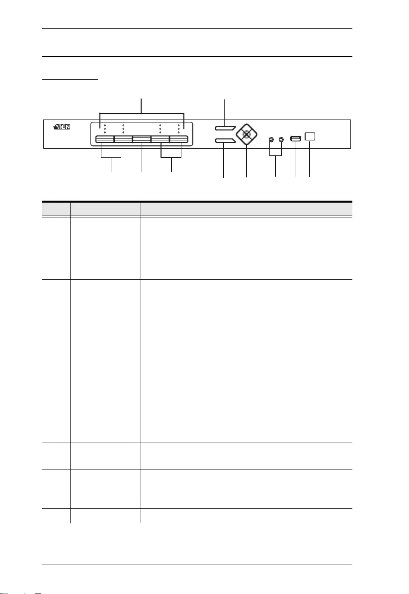
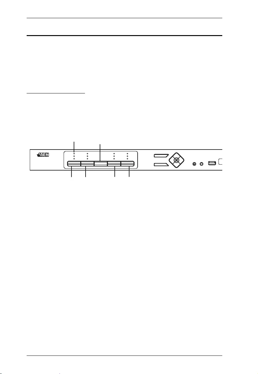
Front View
No. Component Description
1 KVM Status Panel This panel contains LED icons that light to indicate mode
and port status. The Mode and Port Selection Pushbuttons
each have three corresponding LED icons that represent
audio, KVM, and USB Link status. See Display Modes,
page 27, for full details.
2 Port Selection
Pushbuttons
Press the Port Selection Pushbuttons to manually
switch ports. See Display Modes, page 27, for full
details.
In a cascade setup, press a Port Selection Pushbutton
to switch the console display to the corresponding
secondary CM1164A unit.
Press and hold Port Selection Pushbuttons 1 and 2
simultaneously for 2 seconds to start Auto Scan Mode.
See Auto Scanning, page 43, for full details.
Press and hold Port Selection Pushbuttons 3 and 4
simultaneously for 2 seconds to detect the console
keyboard and mouse again.
3 Mode Selection
Pushbutton
This pushbutton allows you to cycle through the three
modes of focus – KVM, audio, and USB Link.
4 OSD (Esc) button Press this to invoke the on-screen display (OSD) menu.
When the OSD menu is enabled, press the OSD button to
go back to the previous menu/submenu.
5 Select button Press this to select an option in the OSD menu.
14
5
2 23
6789

Chapter 1. Introduction
7
6 Direction /
Function buttons
Use these buttons to:
Switch between different preset configurations (Fn1 to
Fn4). For details about Function modes, see Preset
Configuration, page 37.
Cycle through the OSD menu/selection. See IR
Remote Control, page 9 for details.
7 Console Audio
Ports
Your speakers and microphone plug in here.
8 USB 2.0
Peripheral Port
USB 2.0 peripherals (printers, scanners, etc.) plug into this
port.
9 IR Receiver This receives signals from the IR remote control.
No. Component Description
CM1164A User Manual
8
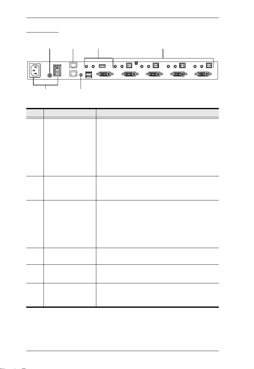
Rear View
No. Component Description
1 Daisy Chain Control
In / Out ports
(DCC port)
Use these ports to connect to another CM1164A’s
DCC port to pass keyboard and mouse signals.
You can daisy chain up to four CM1164A units.
If the CM1164A is set up as a single station, you
can control the CM1164A by sending serial
commands through the DCC In port. For details,
see Chapter 6, RS-232 Operation.
2 Console Ports The cables from your USB keyboard, USB mouse, DVI
console display, a USB peripheral, microphone and
speakers plug into this section.
3 KVM Ports The cables that link the CM1164A to your DVI-D
Single Link computers plug in here. Each DVI
KVM port is comprised of a microphone jack,
speaker jack, USB type B socket, and a DVI
Single Link connector.You can initiate a firmware
upgrade from the computer connected to these
ports.
4 Power Socket / Power
Switch
Plug in the power cord to the power socket and use
the switch to power on the CM1164A.
5 Grounding Terminal The grounding wire (used to ground the unit) attaches
here.
6 IR Receiver
(Extension)
This receives signals from the IR remote control
through an IR extension, which can be purchased
separately (see Optional Equipment, page 5).
3
2
4
15
6
Chapter 1. Introduction
9
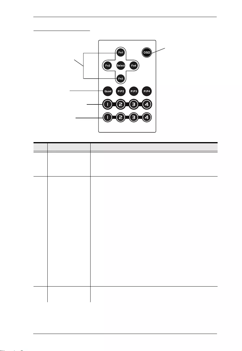
IR Remote Control
No. Component Description
1 OSD button Press this to turn on/turn off the OSD menu.
When the OSD menu is enabled, press the OSD button to
go back to the previous menu/submenu.
2 Fn1 / Fn2 / Fn3 /
Fn4 Buttons and
Select Button
Use these buttons to switch between Function modes (Fn1
to Fn4), and to cycle through the OSD menu/selection.
See Preset Configuration, page 37 for details on how to
store function mode settings, which you can invoke for later
use.
The Fn1~Fn4 buttons are positioned to correspond to the
up / down / left / right direction.
When cycling through the menu options, press the Select
button to go the submenu.
If you want to change or adjust a selection/value, press
the Select button then the Fn1 (up) / Fn2 (left) / Fn3
(down) / Fn4 (right) buttons to go through all the
selections/values. Press the Select button again to
confirm a selection.
3 Display Mode
buttons
Select the Display Mode you want to view. See Display
Modes, page 27.
2
5
3
4
1

CM1164A User Manual
10
4 Port Selection
Buttons 1~4
Press these buttons to switch ports (1~4).
In a cascade setup, press these buttons to switch the
console display to the corresponding secondary
CM1164A unit.
5 Station Selection
Buttons
If the CM1164A is daisy chained to one or several units (up
to 4), press the button corresponding to the CM1164A
device that you want to configure or operate.
No. Component Description
11
Chapter 2
Hardware Setup
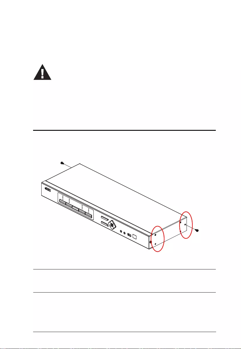
Rack Mounting
For convenience and flexibility, the CM1164A can be mounted on system
racks. To rack mount a unit, do the following:
1. Remove the screws attached to the unit as shown in the diagram below:
Note: You can remove the screws on the front side panels or the back side
panels. The succeeding diagrams show the rack mounting steps for the
back panel.
1. Important safety information regarding the placement of this
device is provided on page 99. Please review it before
proceeding.
2. Make sure that the power to all devices connected to the
installation is turned off. You must unplug the power cords of
any computers that have the Keyboard Power On function.
Front
Back
CM1164A User Manual
12
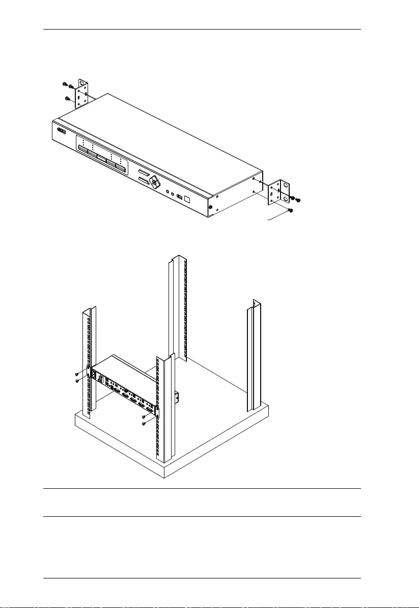
2. Using the screws provided in the Mounting Kit (not included with this
package), screw the mounting bracket into the side of the unit as show in
the diagram below:
3. Screw the bracket into any convenient location on the rack.
Note: These screws are not provided in the Mounting Kit. We recommend that
you use M5 x 12 Phillips Type I cross, recessed type screws.
Phillips hex headPhillips hex head
M3x6M3x6

Chapter 2. Hardware Setup
13
Grounding
To prevent damage to your installation it is important that all devices are
properly grounded.
Note: The grounding wire is not included in the package. Please contact your
dealer for the appropriate cable.
1. Use a grounding wire to ground the CM1164A by connecting one end of
the wire to the grounding terminal, and the other end of the wire to a
suitable grounded object.
2. Make sure that the computer(s)/device(s) that the CM1164A connects to
are properly grounded.

CM1164A User Manual
14
Installation
You can install the CM1164A as a single station, daisy chain up to 4 CM1164A
units, or cascade up to 4 additional CM1164A units to a primary CM1164A.
Single Station Installation
To set up a single CM1164A unit, refer to the installation diagram on page 15
(the numbers in the diagrams correspond to the steps below), and do the
following:
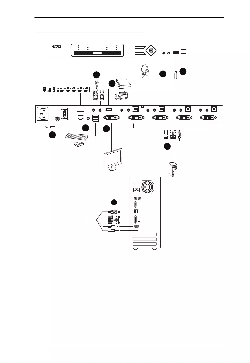
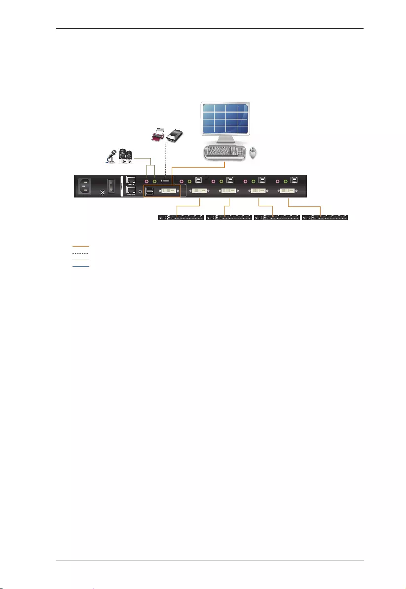
1. Plug your USB keyboard and USB mouse into the USB Console Ports
located on the unit’s rear panel.
2. Plug your DVI display into the Console DVI Single Link Port located on
the unit’s rear panel.
3. If you are using separate microphone and speakers, plug them into the
analog audio ports on the unit’s front panel. These audio ports have
priority over those on the rear panel.
4. If you are using separate speakers and microphone, plug them into the
console analog audio ports on the unit’s rear panel.
5. Using the USB DVI KVM cable, plug the DVI-D Single Link cable
connector and the accompanying USB and audio connectors their
corresponding sockets on the rear of the KVM switch.
6. At the other end of the cable, plug the DVI and USB cables into their
respective ports on the computer(s) that is (are) the source of DVI content.
7. Plug your USB peripherals into the Type A sockets (one easy-access port
is located on the front for portable devices; the second is located on the
rear).
8. Plug the power cord into the CM1164A power jack, then plug the other
end of the power cord into an AC power source.
9. Power on the displays and the computers/devices.
Note: The recommended power-on sequence is Port 1–Port 2–Port 3–Port
4.
Chapter 2. Hardware Setup
15
Single Station Installation Diagram
7
8
1
4
2
DVI
7
6
3
5

CM1164A User Manual
16
Daisy Chaining
To display even more computers/video source devices, up to 3 additional
CM1164A units can be daisy chained from the original CM1164A. As many as
16 computers/video source devices can be controlled from a single console in
a complete daisy chain installation. Each CM1164A in a daisy chain requires
its own monitor as the video signals cannot be passed through to other units on
a daisy chain.
To set up a daisy chain installation, make sure that the power to all devices has
been turned off, and do the following:
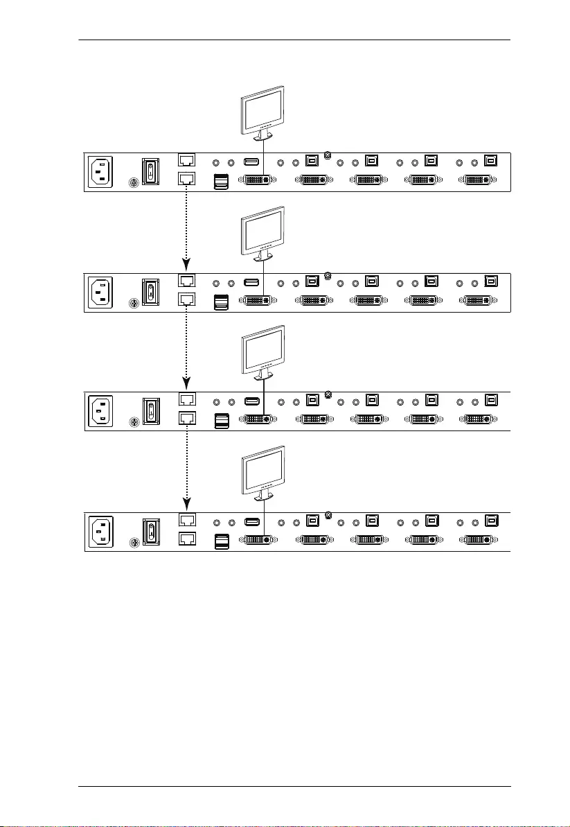
1. Use an RJ-45 cable to connect the DCC Out port of the primary CM1164A
to the DCC In port of the secondary CM1164A unit(s) (first station out to
second station in, second station out to third station in, etc.).
2. Plug a DVI display into the Console DVI Port located on each unit’s rear
panel.
3. Cable up the computer and the switch according to the information
provided under Single Station Installation, page 14.
4. Repeat the above for any other switches you want to add to the chain (up
to three).
5. Power up the installation: plug in the power cord for the first station, then
power on each station on the installation in turn (second station, then third
station, etc.). After all the stations are up, power on the computers/video
source devices.
6. Make sure the Expansion setting is set to Daisy Chain in the OSD menu
(Advance > Expansion).
7. To switch to a computer in a daisy chain, select from the Control Station
setting in the OSD menu (Advance > Control Station). When switching
to a computer, only the keyboard and mouse signals are connected.
Note: The second, third and forth units in a daisy chain will not be able to
use the IR remote for control. Only the first (primary) CM1164A
can use the IR remote for control.
Chapter 2. Hardware Setup
17
Daisy Chain Installation Diagram
Primary unit
DVI
DVI
DVI
DVI
Secondary unit
Secondary unit
Secondary unit

CM1164A User Manual
18
Cascading
To centrally control up to 4 CM1164A units (16 computers/video sources),
cascade 4 additional CM1164A units to another CM1164A. As many as 16
computers/video source devices can be controlled from a single CM1164A
console in a complete cascade installation.
To set up a cascade installation, make sure that the power to all devices has
been turned off, and then do the following:
1. Connect the console ports of a secondary CM1164A to any of the DVI
KVM Ports on the primary CM1164A using the provided KVM cables.
2. To cascade another CM1164A, repeat step 1.
3. Connect the secondary CM1164A units with computers/video sources. For
detailed steps, see Single Station Installation, page 14.
4. Connect the primary CM1164A with a USB keyboard and a USB mouse.
5. Power up the installed CM1164A units. After all the stations are up, power
on the connected computers/video source devices.
6. Change the installation setting from Daisy Chain to Cascade in the OSD
menu (Advance > Expansion).
7. Each secondary CM1164A unit is recognized as an input source (port 1 ~
4) to the primary CM1164A. To only display the sources of a particular
secondary CM1164A, use any of the following methods:
Press the corresponding front-panel port pushbutton
Press the corresponding port button on the remote control
Chapter 2. Hardware Setup
19
Cascade Installation Diagram
CM1164A Primary Unit
(4X4 multi-view)
USB
Audio
Cat 5e Cable
Video / Keyboard / Mouse
5
13
7
15
2
10
4
12
1
9
3
11
6
8
14
16
Secondary Unit Secondary Unit Secondary Unit Secondary Unit

CM1164A User Manual
20
This Page Intentionally Left Blank
21
Chapter 3
Basic Operation
Overview
This chapter explains the basic components used to switch and display
computers connected to the CM1164A.
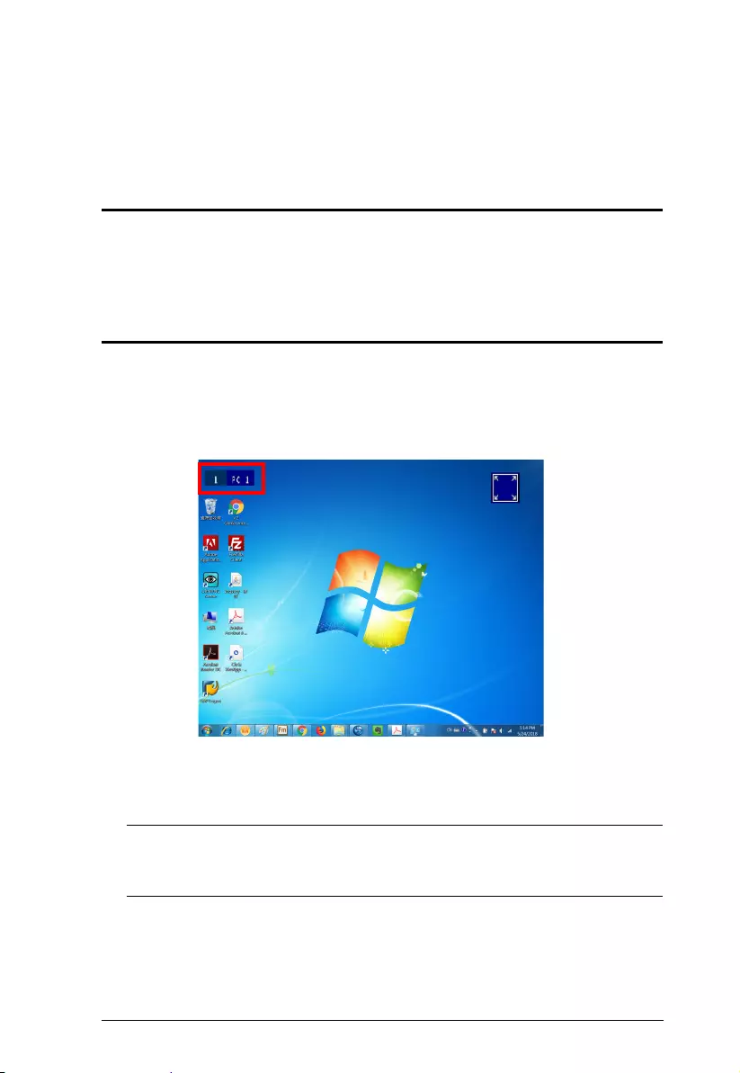
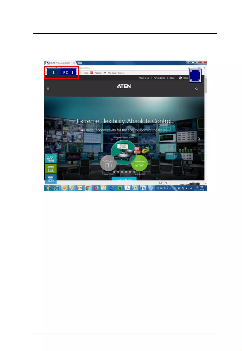
Identifying the Source Device
You can identify each source connected to the CM1164A by the port ID
number and the device name at the top-left corner in the screen. In the
following example, the port ID number for this computer is 1, and its device
name is PC 1.
Port ID number: This number is assigned according to the port that the
computer is connected to on the rear of the CM1164A. For example, a
computer connected to port 1 is assigned port ID 1.
Note: In a cascade setup, a port ID number of “1-3” indicates that the video
source comes from the third port of the secondary CM1164A
connected to port 1 of the primary CM1164A.
Device name: By default, the computer connected to port 1 is named PC 1,
the computer connected to port 2 is named PC 2, and so forth. To change
the device name, go to System Settings > Port Configuration.
CM1164A User Manual
22
Switching
When you switch to a computer, you switch to its three sources: KVM
(keyboard, video, mouse), Audio, and USB. You can also switch to these three
sources independently, on different computers. This allows you to work on one
computer (KVM), access the audio on another (Audio), and connect to
peripheral devices on a third (USB).
Manual Switching
To manually switch sources, use the Port Selection and Mode pushbuttons
located on the front panel. The selected sources are indicated with LEDs on the
front panel. For more information about LED indicators, see LED Display,
page 23.
To switch KVM, Audio, and USB access to a computer, press the Mode
Selection pushbutton twice, and then press the Port Selection pushbutton
of the computer you want to access.
To switch KVM access to a computer, press Mode 2 times, and then press
the Port Selection pushbutton of the computer.
To switch Audio access to a computer, press Mode 3 times, and then press
the Port Selection pushbutton of the computer.
To switch USB access to a computer, press Mode 4 times, and then press
the Port Selection pushbutton of the computer.
Press Port Selection pushbuttons 1 and 2 – for 2 seconds to start Auto
Scan Mode. To stop auto scan, press and release either port selection
pushbutton.
1234
MODE
LED
Port Selection
Chapter 3. Basic Operation
23
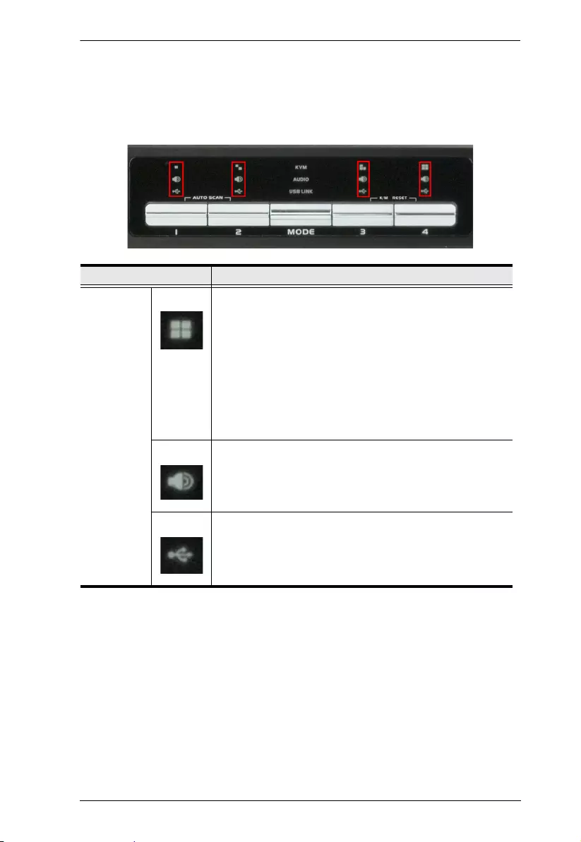
LED Display
The front panel has three LEDs that represent the KVM, Audio and USB
source. The LEDs light green or orange depending on which source is being
accessed on what computer, as explained in the table.
LED Indication
Icon KVM
Lights BRIGHT ORANGE to indicate KVM is selected.
Flashes ORANGE to indicate that the computer is being
accessed in Auto Scan Mode.
All flash ORANGE to indicate the Firmware Upgrade
has been invoked.
The corresponding port LED of the USB keyboard/
mouse flashes when Keyboard Bypass is enabled.
Lights a faint ORANGE to indicate that a computer is
powered on
Audio Lights BRIGHT GREEN to indicate Audio is selected.
Flashes GREEN to indicate that Audio is selected on a
computer in a Daisy Chain setup
USB Link Lights BRIGHT GREEN to indicate USB is selected.
Flashes GREEN to indicate that USB Link is selected on
a computer in a Daisy Chain setup
CM1164A User Manual
24
Hotkey Switching
You can switch to a computer using hotkeys from the keyboard.
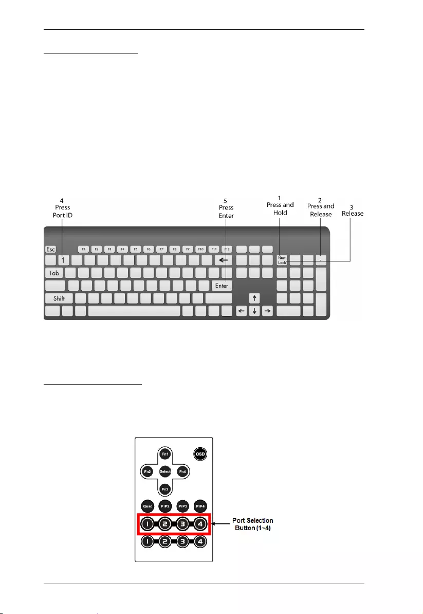
To switch to computer 1, do the following:
1. Press and hold down [Num Lock].
2. Press and release [-].
3. Release [Num Lock].
4. Press [1].
5. Press [Enter].
Repeat the steps using Port ID (1, 2, 3, 4) in step 4 to switch to the computer
connected to that port. For more hotkeys, see Hotkey Operation, page 39.
Remote Switching
You can switch to a computer with the remote control. Point the remote at the
CM1164A and press the Port Selection button of the computer you want to
access.
Chapter 3. Basic Operation
25
OSD Switching
You can switch to a computer using the OSD (On-screen Display) menu. The
OSD is the CM1164A’s software that allows you to configure the CM1164A.
Use the mouse or keyboard (arrow keys) to move through the OSD.
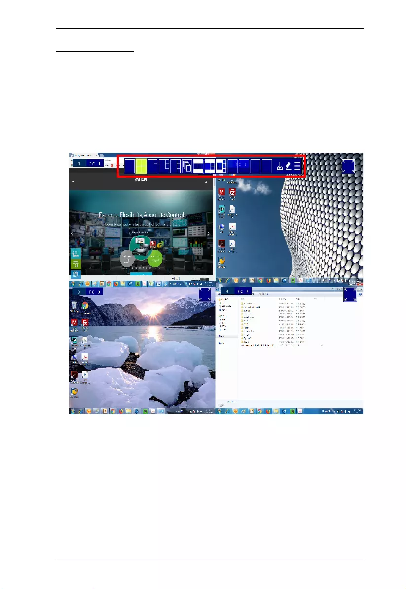
To switch computers with the OSD, do the following:
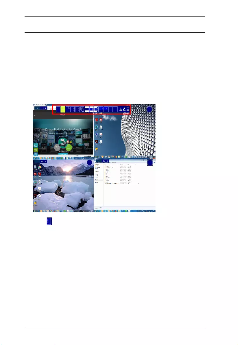
1. Move the cursor to the top of the OSD to display the Quick Access Bar.
CM1164A User Manual
26
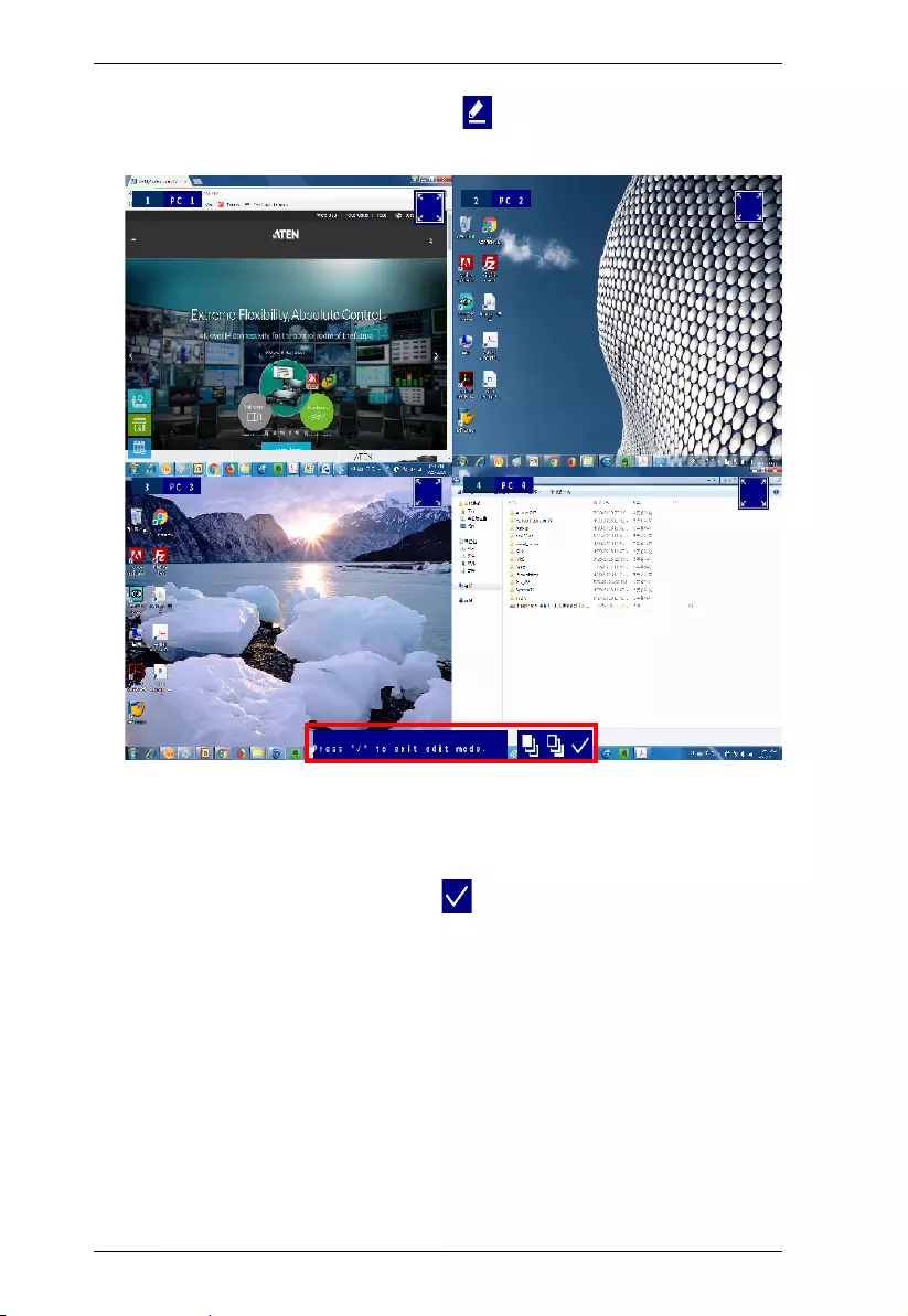
2. From the Quick Access Toolbar, click to activate the editor mode. This
screen appears.
3. Click the port number at the top-left corner to open drop-down list, and
then select a computer: 1, 2, 3, or 4. The display is immediately switched
to the selected computer.
4. When you finish configuring, click to end the editor mode.
Chapter 3. Basic Operation
27
Display Modes
The CM1164A has various display modes so that you can view multiple
computers at one time on the same screen using different layout.
In the sections that follow a table is provided with the methods for switching
display modes. To return to a normal full screen, like the one above, simply
press a Port Selection pushbutton.
CM1164A User Manual
28
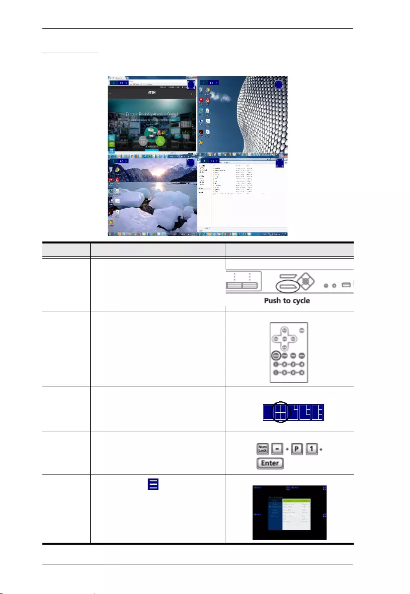
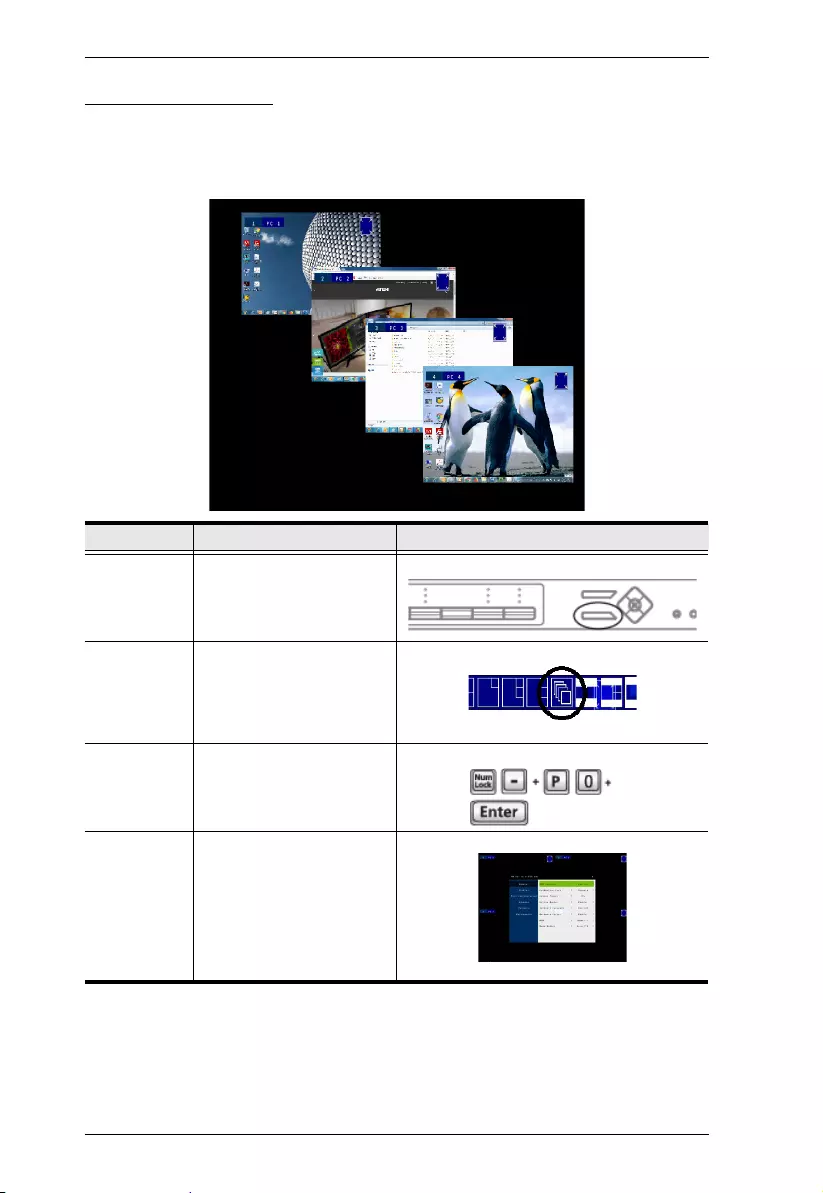
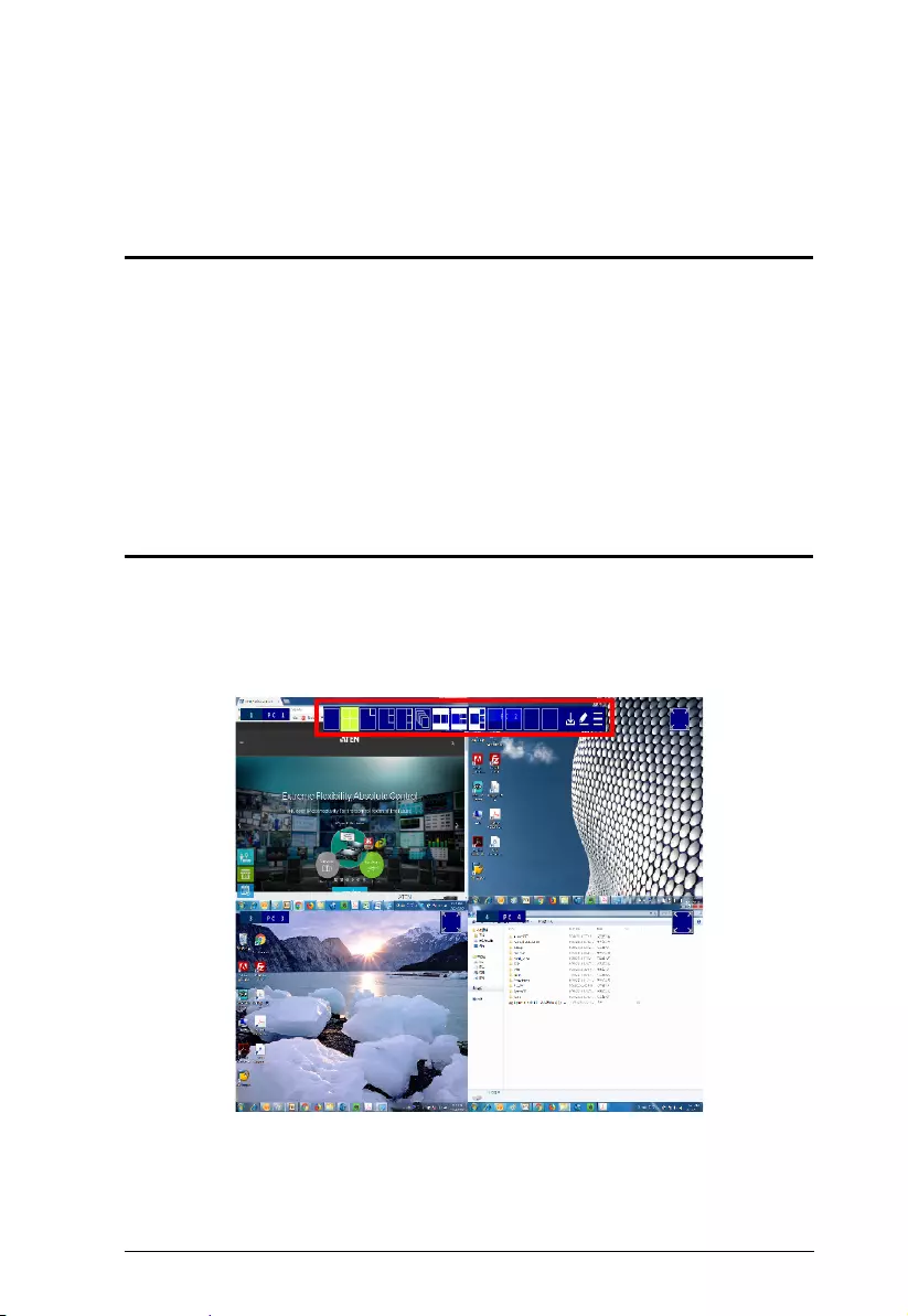
Quad View
A quad view displays four computers on the monitor in equal sized windows.
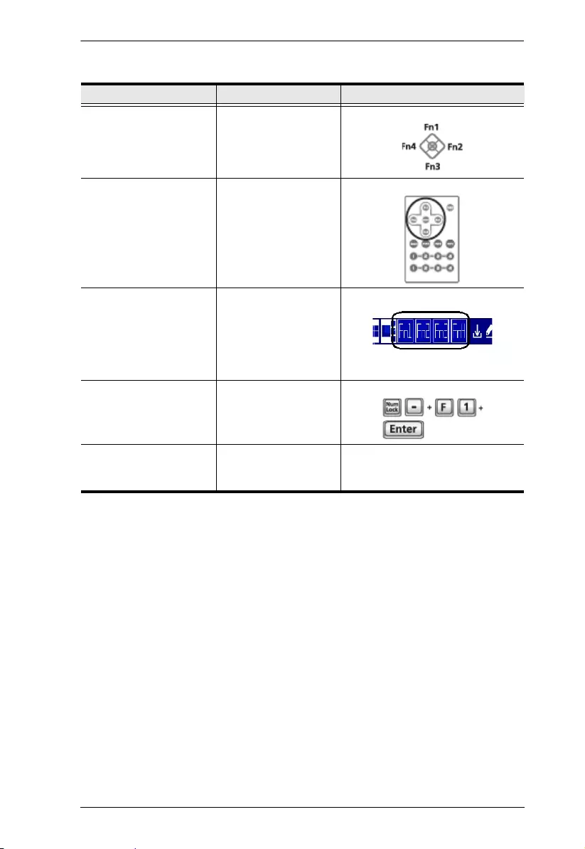
Method Action Description
Front Panel Press Select to cycle through display
modes.
IR Remote
Control
Press the Quad button.
Quick Access
Toolbar
Move mouse to top center of the OSD and
select from the Quick Access Toolbar.
Note: Hardware Cursor Mode must be
enabled, see The OSD Menu, page 51.
Hotkey See Hotkey Setting Mode, page 40 for
hotkey instructions.
OSD Menu In the OSD, click from the Quick
Access Toolbar, go to Display >
Multiview Mode, and then select Quad.
Chapter 3. Basic Operation
29
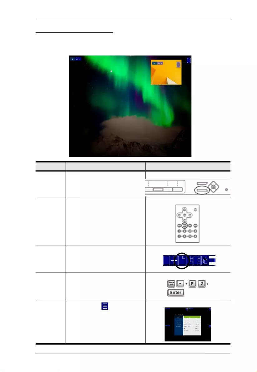
Picture in Picture - Dual
A dual PiP view shows 2 computers on the monitor with one as the main
display, and the other overlapping the main display in an inset window.
Method Action Description
Front Panel Press Select to cycle through display
modes.
IR Remote
Control
Press the PiP2 button.
Quick Access
Toolbar
Move mouse to top center of the OSD
and select from the Quick Access
Toolbar.
Note: Hardware Cursor Mode must be
enabled, see The OSD Menu, page 51.
Hotkey See Hotkey Setting Mode, page 40 for
hotkey instructions.
OSD Menu In the OSD, click from the Quick
Access Toolbar, go to Display >
Multiview Mode, and then select PiP2.
CM1164A User Manual
30
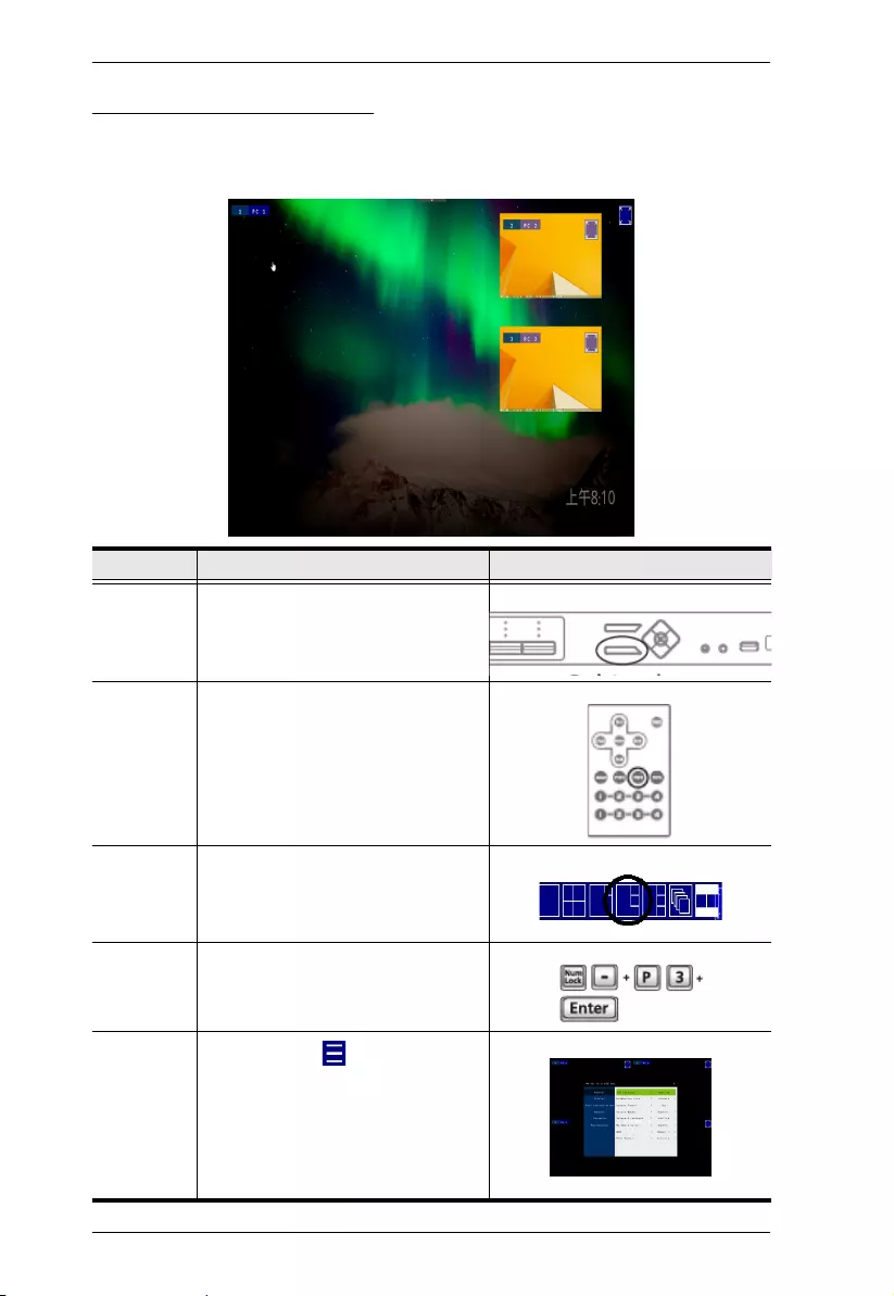
Picture in Picture - Triple
A triple PiP view has 3 computers on the monitor with one computer as the
main display and the other two overlapping the main display in inset windows.
Method Action Description
Front Panel Press Select to cycle through display
modes.
Remote
Control
Press the PiP3 button
Quick Access
Toolbar
Move mouse to top center of the OSD
and select from the Quick Access
Toolbar.
Note: Hardware Cursor Mode must be
enabled, see The OSD Menu, page 51.
Hotkey See Hotkey Setting Mode, page 40 for
hotkey instructions.
OSD Menu In the OSD, click from the Quick
Access Toolbar, go to Display >
Multiview Mode, and then select PiP3.
Chapter 3. Basic Operation
31
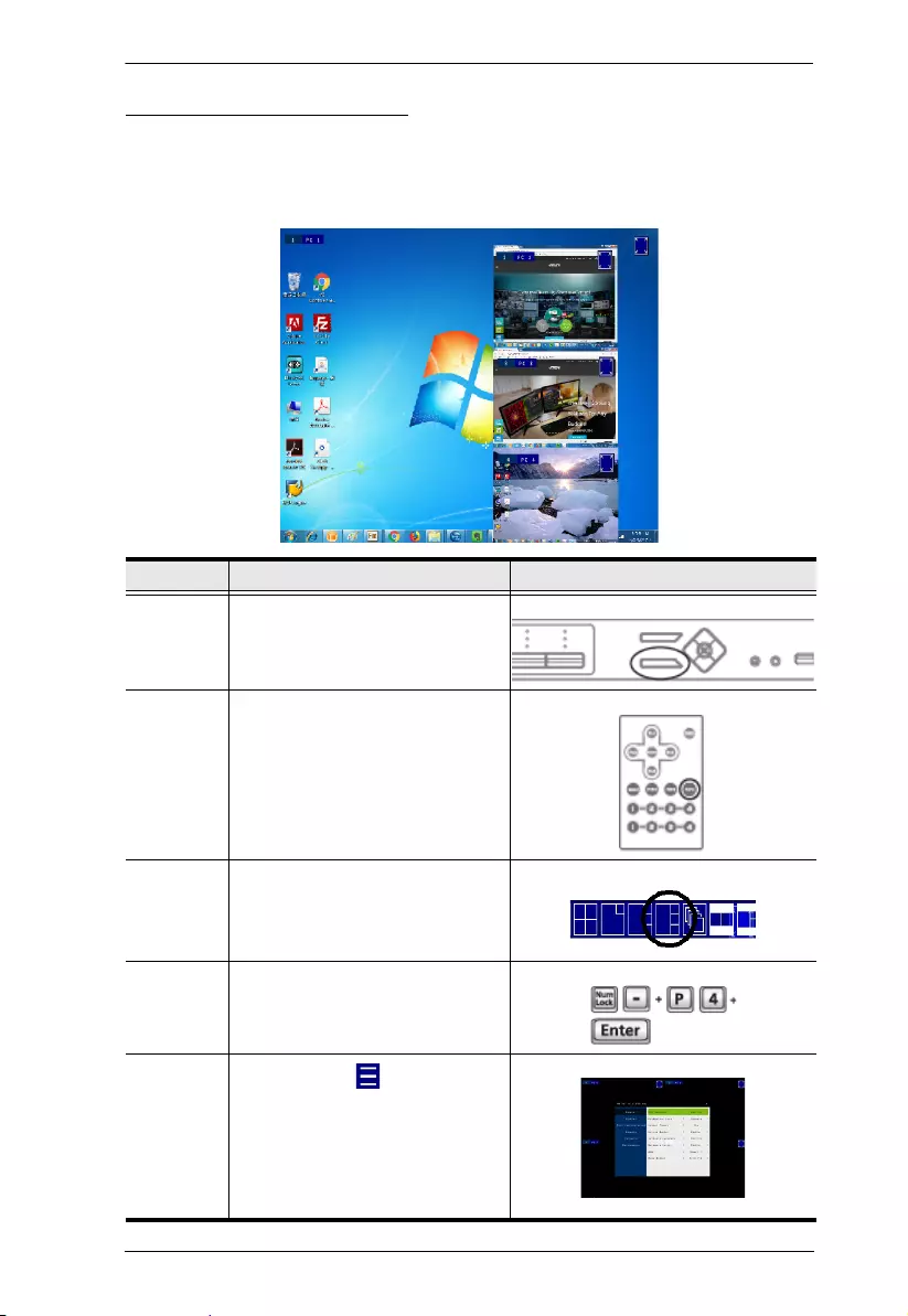
Picture in Picture - Quad
A quad PiP view has 4 computers on the monitor with one computer as the
main display and the other three overlapping the main display in inset
windows.
Method Action Description
Front Panel Press Select to cycle through display
modes.
Remote
Control
Press the PiP4 button.
Quick
Access
Toolbar
Move mouse to top center of the OSD
and select from the Quick Access
Toolbar.
Note: Hardware Cursor Mode must be
enabled, see The OSD Menu, page 51.
Hotkey See Hotkey Setting Mode, page 40 for
hotkey instructions.
OSD Menu In the OSD, click from the Quick
Access Toolbar, go to Display >
Multiview Mode, and then select PiP4.
CM1164A User Manual
32
Picture on Picture
A picture-on-picture (PoP) view shows 4 computers in separate windows on
the monitor. In editor mode, you can use the console mouse to resize and
re-position each window on the screen.
Method Action Description
Front Panel Press Select to cycle through
display modes.
Quick Access
Toolbar
Move mouse to top center of
the OSD and select from the
Quick Access Toolbar.
Note: Hardware Cursor Mode
must be enabled, see The
OSD Menu, page 51.
Hotkey See Hotkey Setting Mode,
page 40 for hotkey
instructions.
OSD Menu In the OSD, go to Display >
Multiview Mode, and then
select PoP.
Chapter 3. Basic Operation
33
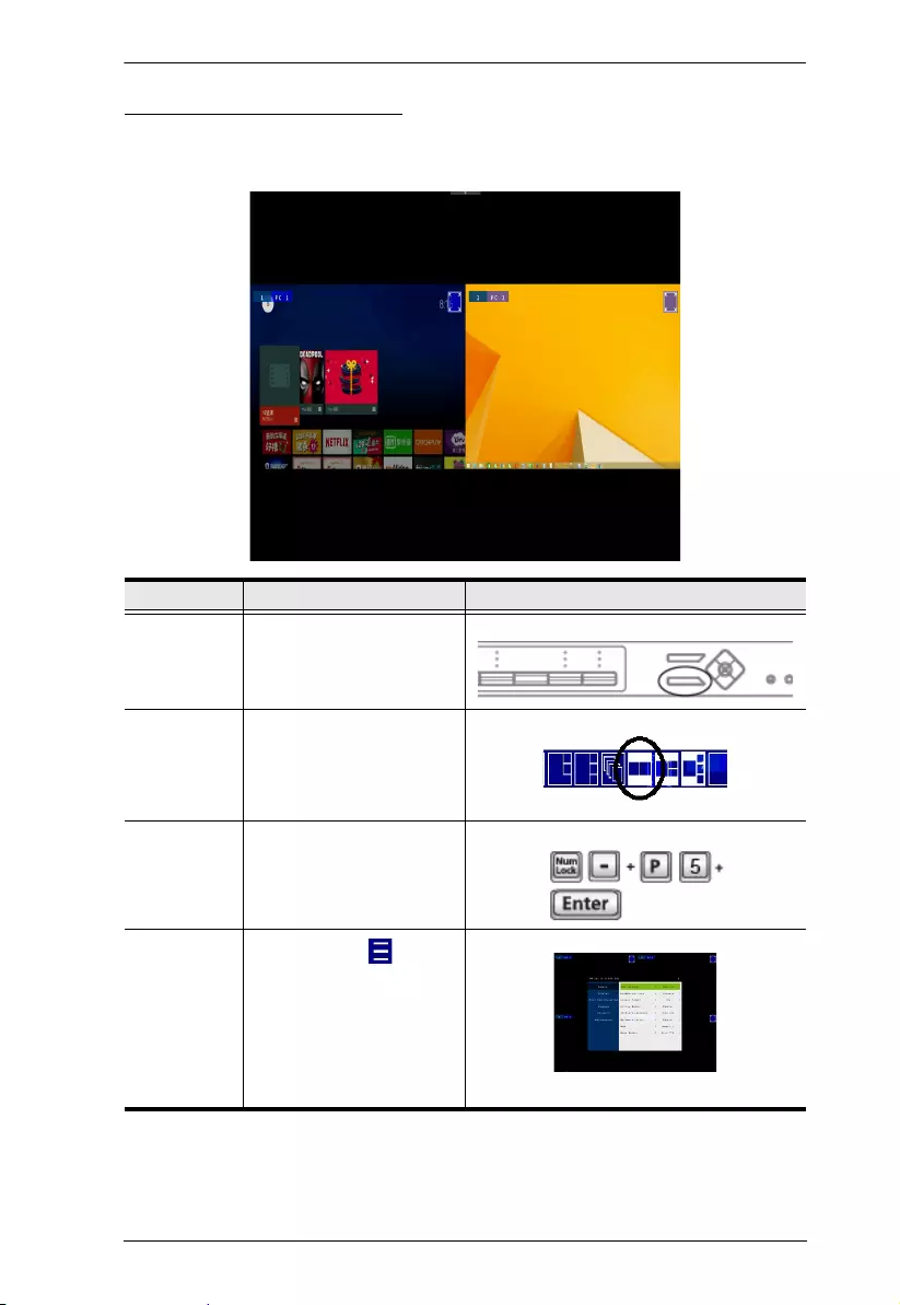
Picture by Picture - Dual
The picture-by-picture (dual) view displays 2 computers side by side on the
monitor.
Method Action Description
Front Panel Press Select to cycle through
display modes.
Quick Access
Toolbar
Move mouse to top center of
the OSD and select from the
Quick Access Toolbar.
Note: Hardware Cursor Mode
must be enabled, see The
OSD Menu, page 51.
Hotkey See Hotkey Setting Mode,
page 40 for hotkey
instructions.
OSD Menu In the OSD, click from the
Quick Access Toolbar, go to
Display > Multiview Mode,
and then select PbP1.
CM1164A User Manual
34
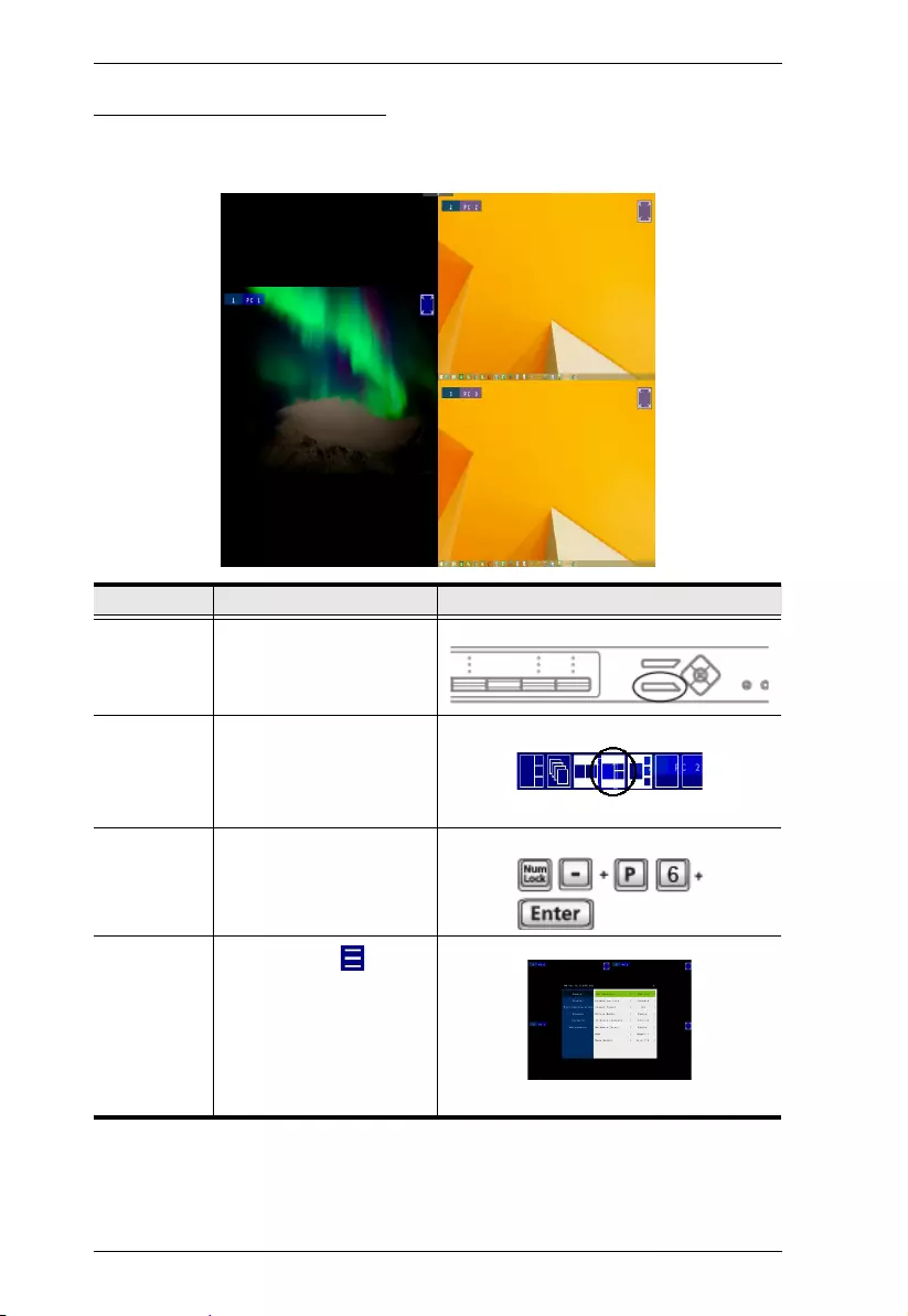
Picture by Picture - Triple
The picture-by-picture (triple) view displays 3 computers side by side on the
monitor.
Method Action Description
Front Panel Press Select to cycle through
display modes.
Quick Access
Toolbar
Move mouse to top center of
the OSD and select from the
Quick Access Toolbar.
Note: Hardware Cursor Mode
must be enabled, see The
OSD Menu, page 51.
Hotkey See Hotkey Setting Mode,
page 40 for hotkey
instructions.
OSD Menu In the OSD, click from the
Quick Access Toolbar, go to
Display > Multiview Mode,
and then select PbP2.
Chapter 3. Basic Operation
35
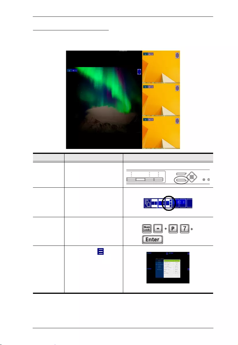
Picture by Picture - Quad
The picture-by-picture (quad) view displays 4 computers side by side on the
monitor.
Method Action Description
Front Panel Press Select to cycle through
display modes.
Quick Access
Toolbar
Move mouse to top center of
the OSD and select from the
Quick Access Toolbar.
Note: Hardware Cursor Mode
must be enabled, see The
OSD Menu, page 51.
Hotkey See Hotkey Setting Mode,
page 40 for hotkey
instructions.
OSD Menu In the OSD, click from the
Quick Access Toolbar, go to
Display > Multiview Mode,
and then select PbP3.
CM1164A User Manual
36
Preset Configuration
You can save up to 4 sets of configuration, including the display mode, source
assignment, division sizes, division locations, and KVM/Audio/USB focus
status to easily toggle between different display configurations.
To save a configuration, follow the steps below.
1. Configure the display settings as required.
2. Move the console mouse to the top of the screen. The Quick Access
Toolbar appears.
3. Click and select an Fn to save the current configuration.
Chapter 3. Basic Operation
37
To apply a preset configuration, use any of the following methods.
Method Action Description
Front Panel Pushbutton Press the Fn1, Fn2,
Fn3, or Fn4
pushbutton.
Remote Control Press the Fn1, Fn2,
Fn3, or Fn4 button.
Quick Access Toolbar
(Hardware Cursor Mode
must be enabled, see
The OSD Menu,
page 51)
Move mouse to top center
of the OSD and select
from the Quick Access
Toolbar.
Note: Hardware Cursor
Mode must be enabled,
see The OSD Menu,
page 51.
Hotkey See Hotkey Setting
Mode, page 40 for
hotkey instructions.
3-button wheel mouse Use the mouse wheel
to toggle between
different Fn settings.
N/A

CM1164A User Manual
38
This Page Intentionally Left Blank

39
Chapter 4
Hotkey Operation
The CM1164A provides easy-to-use hotkeys to control and configure your
KVM installation from the keyboard.
Open the OSD Menu
To activate the OSD using your keyboard, tap the Scroll Lock key twice:
[Scroll Lock] [Scroll Lock]
You can close the OSD menu by pressing [Esc] or Spacebar.
[Esc] returns to the previous page.
Spacebar immediately exits the OSD.
Note: The hotkey to activate the OSD can be change to the Ctrl key. See The
OSD Menu, page 51 for details.

CM1164A User Manual
40
Hotkey Setting Mode
Hotkey Setting Mode is used to configure your CM1164A with hotkeys. All
hotkey operations begin with invoking Hotkey Setting Mode (HSM) – then
hotkeys can be used to make changes.
Invoking HSM
To invoke HSM do the following:
1. Press and hold down [Num Lock].
2. Press and release [-].
3. Release [Num Lock].
Note: The keys for invoking HSM can be change. See The OSD Menu,
page 51 for details.
When HSM is active, the Caps Lock, and Scroll Lock LEDs flash in succession
to indicate that HSM is in effect. They stop flashing when you exit HSM.
Ordinary keyboard and mouse functions are suspended – only Hotkey
keystrokes can be input.
At the conclusion of some hotkeys, you automatically exit HSM. With other
operations, you must manually exit HSM. To exit HSM manually, press [Esc]
or Spacebar.
The table below describes the actions of each hotkey. First invoke HSM then
enter the hotkey.
Hotkey Action
[A][N][Enter] Starts Auto Scan at an interval of 5 seconds.
See Auto Scanning, page 43 for more information.
[Enter] Switch to the next computer.
(1 to 2, 2 to 3, 3 to 4, and 4 to 1.)
[Port ID] [Enter] Switch to the computer device that corresponds to
the Port ID (1, 2, 3, or 4) entered.
[Port ID] [K] [Enter] Brings only the KVM focus from the port that
currently has it to the computer that corresponds to
the Port ID entered. The USB and audio focus do not
change.

Chapter 4. Hotkey Operation
41
[Port ID] [U] [Enter] Brings only the USB hub focus from the port that
currently has it to the computer that corresponds to
the Port ID entered. The KVM and audio focus do not
change.
[Port ID] [S] [Enter] Brings only the audio focus from the port that
currently has it to the computer that corresponds to
the Port ID entered. The KVM and USB hub focus do
not change.
[Station ID] [Port ID] [K] [Enter] Brings only the KVM focus to the computer that
corresponds to the Port ID entered, on the CM1164A
that corresponds to the Station ID entered, when a
daisy chain is setup. See Daisy Chaining, page 16.
[F1] Sets the operating system to SPC.
[F2] Enables or disables Mac keyboard emulation.
[F3] Enables or disables Sun keyboard emulation.
[F4] Lists the KVM’s current settings. See Press the port
number [1], [2], [3], or [4] and [Enter]., page 45.
[F5] If any USB devices lose focus or connectivity, a USB
reset my solve the issue. See USB Reset, page 45.
[F6] [N] [Enter] Sets the keyboard language (N):
N = 08 (French)
N = 09 (German)
N = 33 (English)
N = 15 (Japanese)
[B] Enable or disable the beeper.
[V] [N] Sets the EDID to the specified mode (N):
N = 1 (Port 1 mode)
N = 2 (Port 2 mode)
N = 3 (Remix mode)
N = 4 (ATEN default mode, 1920 x 1080 at 60Hz)
[E] Enables or disables Power On Detection, with which
the CM1164A switches to the next powered-on
computer when a computer that has KVM focus is
powered off.
Hotkey Action

CM1164A User Manual
42
[H] Enables or disables the Hardware Cursor Mode. For
details, see The OSD Menu, page 51.
[L] Locks or unlocks the front-panel pushbuttons.
[N] / [n] Enables or disables keyboard emulation.
[M] / [m] Enables or disables mouse emulation.
[W] / [w] Enables or disables mouse port switching.
[u] [p] [g] [r] [a] [d] [e] [Enter] Enables the firmware upgrade mode.
Hotkey Action

Chapter 4. Hotkey Operation
43
Auto Scanning
The Auto Scan feature automatically cycles the KVM focus through the
computer ports at regular intervals. This allows you to monitor the computer
activity without having to switch from port to port manually. Although the
video focus switches from port to port, the keyboard, mouse, and USB focus
do not switch. They stay with the port they were on when Auto Scanning
started.
The table below describes the actions of each hotkey. First invoke HSM then
enter the hotkey.
While Auto Scan Mode is in effect, ordinary keyboard and mouse functions are
suspended – only Auto Scan Mode keystrokes and mouse clicks can be input.
You must exit Auto Scan Mode in order to regain normal control of the
console.
Auto Scanning - Display Modes
Auto scan can be invoked with Full Screen, PiP Dual, PiP Triple, PbP Dual,
and PbP Triple modes. When you start auto scan with PiP Dual or PiP Triple
one of the secondary windows (channels) is used to auto scan two or three
computers.
Auto Scan mode does not work with Quad View, PiP Quad, or PoP modes as
these modes already display all computers on the screen. (see Display Modes,
page 27).
Hotkey Action
[A] [Enter] Invokes Auto Scan. The KVM focus cycles from port to port
at 5 second intervals. This is the Default setting.
[A] [n] [Enter] The KVM focus cycles from port to port at n second intervals.
Note: The n stands for the number of seconds that the
CM1164A should dwell on a port before moving on to the
next. Replace the n with 5, 10, 15, 30, 60 or 90 when
entering this hotkey combination.

CM1164A User Manual
44
Display Mode
Use the Display Mode hotkeys to switch between the different display modes.
For more information on display modes, See Display Modes, page 27.
The table below describes the actions of each hotkey. First invoke HSM then
enter the hotkey.
To return to the normal single computer display mode, switch to a computer by
invoking HSM and use the hotkey [Port ID] [Enter].
Fn Key
Use the Fn hotkeys to apply preset configurations. For more information on Fn
keys, see Preset Configuration, page 36. The table below describes the actions
of each hotkey. First invoke HSM then enter the hotkey.
Hotkey Action
[P] [N] [Enter] Applies the specified display mode (N):
N = 0 (PoP)
N= 1 (quad view)
N = 2 (PiP dual view)
N = 3 (PiP triple view)
N = 4 (PiP quad view)
N = 5 (PbP dual view)
N = 6 (PbP triple view)
N = 7 (PbP quad view)
Hotkey Action
[F] [1] [Enter] Implements the Fn1 key configuration.See Preset
Configuration, page 36.
[F] [2] [Enter] Implements the Fn2 key configuration. See Preset
Configuration, page 36.
[F] [3] [Enter] Implements the Fn3 key configuration. See Preset
Configuration, page 36.
[F] [4] [Enter] Implements the Fn4 key configuration. See Preset
Configuration, page 36.

Chapter 4. Hotkey Operation
45
Hotkey Steps
List Current KVM Settings
To see a listing of the current switch settings, do the following:
1. Open a text editor or word processor and place the cursor in the page
window.
2. Invoke HSM (see page 40).
3. Press and release [F4] to display the settings.
USB Reset
If the USB loses focus and needs to be reset, do the following:
1. Invoke HSM (see page 40).
2. Press and release [F5]
Video DynaSync
The CM1164A is built with Video DynaSync, ATEN’s exclusive technology
of storing a console monitor’s EDID to eliminate boot-up display problems and
optimize resolution when switching between ports.
Port Switching
To switch to another computer, do the following:
1. Invoke HSM (see page 40).
2. Press the port number [1], [2], [3], or [4] and [Enter].

CM1164A User Manual
46
This Page Intentionally Left Blank
47
Chapter 5
OSD Operation
Overview
The CM1164A can be operated and configured via the following OSD
components:
Quick Access Toolbar: This toolbar provides quick access for changing
the display mode, saving display templates, and customizing division
sizes. For details, see The Quick Access Toolbar, page 47.
OSD Menu: This contains controls for all system settings. For details, see
The OSD Menu, page 51.
The Quick Access Toolbar
You can use the Quick Access Toolbar to conveniently switch display modes,
apply/configure display templates, and enable the editor mode for source
assignment and window resizing.

CM1164A User Manual
48
To display the Quick Access Toolbar, move the console mouse to the top of the
screen. The Quick Access Toolbar provides the following controls:
: Click an icon to apply the display mode.
: Click this icon to enable the editor mode to allow you to assign source to
a particular channel and resize inset windows.
: Click a Function icon to apply the selected display template.
: Click this icon to save the current display configuration to a display
template.
: Click this icon to open the OSD menu. For details, see The OSD Menu,
page 51.
Note:
Make sure to enable Hardware Cursor and Mouse Emulation to access the
Quick Access Toolbar using the console mouse.
To change the display position, go to Display > Toolbar Position in the
OSD menu.
Chapter 5. OSD Operation
49
The Editor Mode
Use the editor mode to customize the source display. You can resize windows,
change the display source, or relocate windows. To enable the editor mode,
follow the steps below.
1. Make sure the following functions are enabled to allow console mouse to
operate. For details, see see The OSD Menu, page 51.
Hardware Cursor
Mouse Emulation
2. Move the console mouse to the top of the screen to display the Quick
Access Toolbar.
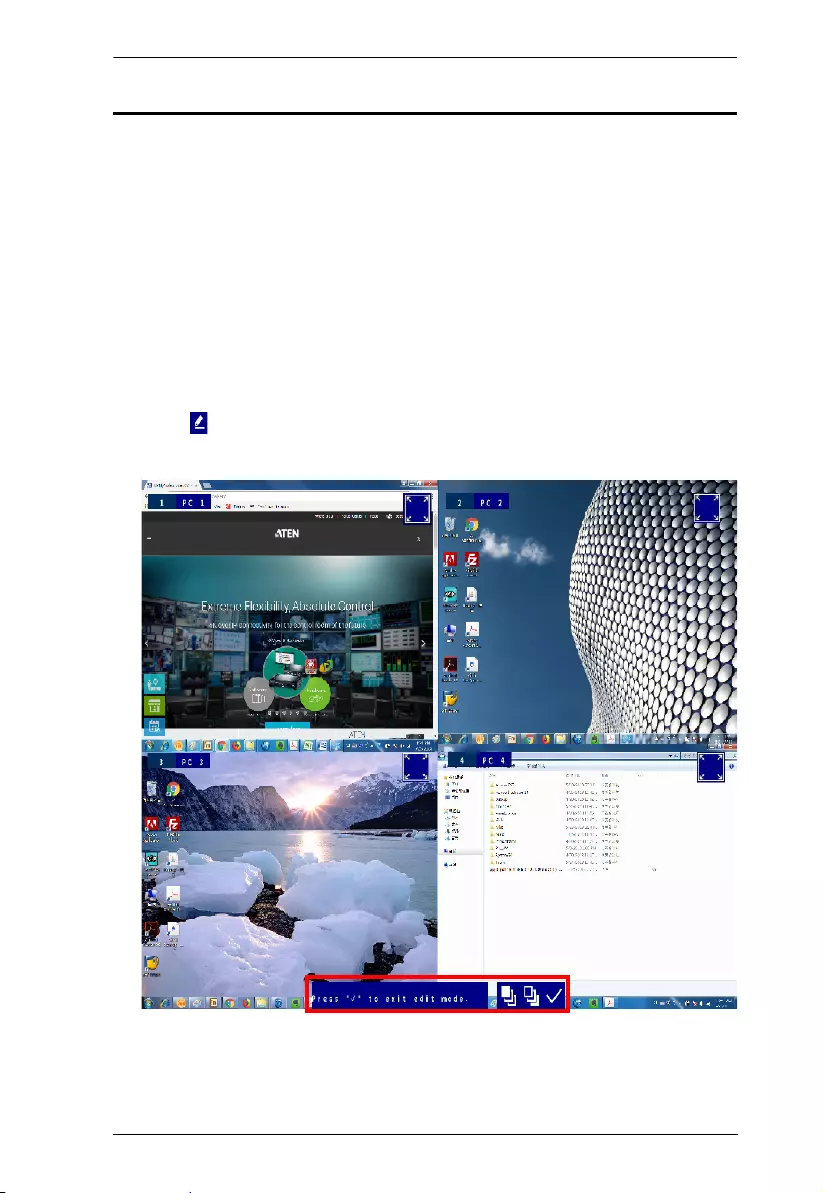
3. Click from the Quick Access Tool. A Press “9“ to quit edit mode
message appears to indicate that the editor mode is enabled.
CM1164A User Manual
50
4. Configure and adjust the display as required. You can do the following
when the editor mode is enabled:
Note: When the editor mode is enabled, the OSD menu will not be
accessible and the hotkeys functionality will be disabled.
5. When you finish configuring, click to quit the editor mode.
Function Action
Change the display mode Click a display mode from the Quick Access Toolbar.
Apply a preset configuration Click an Fn icon from the Quick Access Toolbar. For
more information, see Preset Configuration,
page 36.
Change the source Click the port number and select a port.
Resize the window Click on a window, move the cursor to a corner of
the window, and drag the corner to resize the
window.
Relocate the window Click and hold on a window to drag it to a desired
location on the screen.
Change the display order
when windows overlap
Click a window and then click to keep the
window on top of other windows, or click to keep
the it at the bottom.
Chapter 5. OSD Operation
51
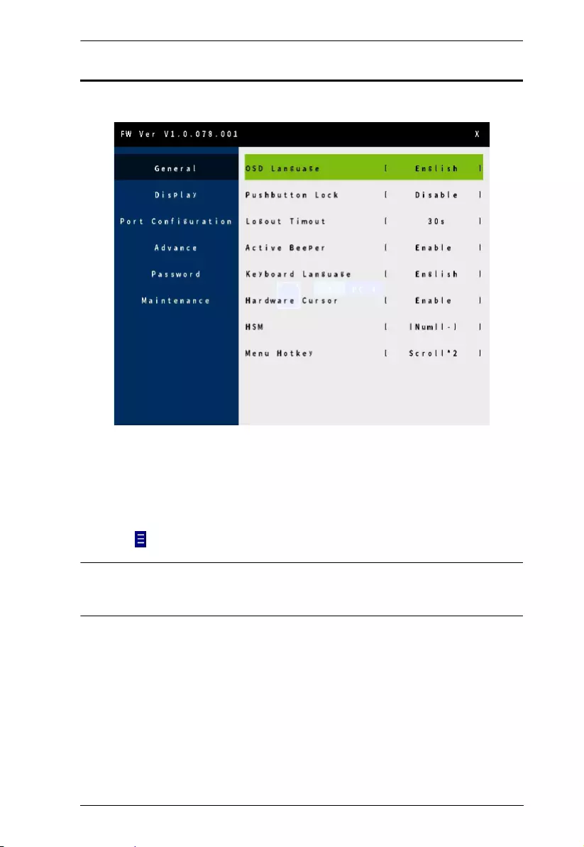
The OSD Menu
Access the OSD menu to configure the CM1164A’s settings.
To display the OSD menu, use any of the following methods:
Press the OSD pushbutton on the front panel
Press the OSD button on the IR remote control
Tap [Scroll Lock] twice on the console keyboard
Click from the Quick Access Toolbar using the console mouse
Note: By default, the OSD menu is password protected. The default password
is password. To disable password protection to the OSD menu, go to
Password > Password Protection in the OSD menu.

CM1164A User Manual
52
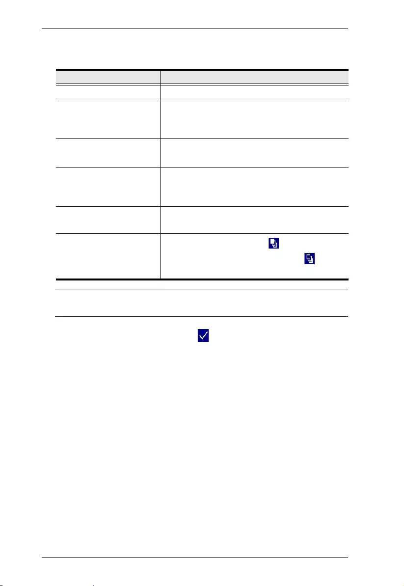
The following settings are available in the OSD menu. Default settings are
indicated in bold.
Setting Options Description
General
OSD Language English / Chinese TW /
Chinese CN /
Japanese, Korean /
French / German /
Italian / Russian
Sets the language for the OSD menu.
Pushbutton Lock Enable / Disable Locks or unlocks the CM1164A’s panel
pushbuttons.
Logout Timeout Never / 10s / 30s / 60s
/ 5 mins / 10 mins
Sets how long the OSD waits (or the
RS-232 controller remains linked to the
CM1164A) after the last input (or
command) before automatically logging
out a user.
Active Beeper Enable / Disable Enable this function for CM1164A to
sound a beep to indicate and confirm
user configuration.
Keyboard Language English / German /
Japanese / French
Sets the language of the console
keyboard. For these options to be
available, make sure to enable
Keyboard Emulation in the OSD menu.
Hardware Cursor Enable / Disable Enable this function to allow the use of
console mouse to customize division
sizes, shift between divisions, and
display the Quick Access Toolbar. The
Channel Editor provides a way to
change display modes and other
settings with the mouse and an on-
screen control panel.
Note: Mouse Emulation must be
enabled for Hardware Cursor Mode to
work (see Mouse Emulation, page 62).
HSM [Num][-] / [Ctrl][F12] Defines the hotkey combination for
enabling the Hotkey Setting Mode
(HSM).
Menu Hotkey Scroll*2 / Ctrl*2 Sets the hotkey combination for
opening the menu.
Display

Chapter 5. OSD Operation
53
Channel Info Enable / Disable Enable this setting to display port ID
numbers and device names.
Multiview Mode Single / Quad / PiP2 /
PiP3 / PiP4 / PoP /
PbP1 / PbP2 / PbP3 /
Fn1 / Fn2 / Fn3 / Fn4
Sets or changes the display mode for
the CM1164A. For details about each
display mode, see Display Modes,
page 27.
Channel 1 Port 1 / Port 2 / Port 3 /
Port 4 Sets the source assignment for each
channel. For example, if you select
Port 2 for Channel 1, port 2 source will
be displayed on Channel 1, and port 1
source will be displayed at Channel 2.
Channel 2 Port 1 / Port 2 / Port 3 /
Port 4
Channel 3 Port 1 / Port 2 / Port 3 /
Port 4
Channel 4 Port 1 / Port 2 / Port 3 /
Port 4
Save to Fn Fn1 / Fn2 / Fn3 / Fn4 Saves the view mode settings to the
selected Function mode.
Toolbar Position Top / Bottom Sets the position of the Quick Access
Toolbar.
Port Configuration
Port 1 Name N/A Type to name the computers
connected to port 1 / port 2 / port 3 /
port 4 on the CM1164A. The CM1164A
only supports English characters of
upper and lower cases, numbers,
hyphens, and underscores.
Port 2 Name N/A
Port 3 Name N/A
Port 4 Name N/A
Port 1 OS Win / Mac / SUN / SPC
Defines the operating system for each
of the connected computers.
Port 2 OS Win / Mac / SUN / SPC
Port 3 OS Win / Mac / SUN / SPC
Port 4 OS Win / Mac / SUN / SPC
Advance
Expansion Daisy Chain / Cascade Sets the CM1164A’s deployment type.
Control Station Station 1 / Station 2 /
Station 3 / Station 4
This setting is only available when
Expansion is set to Daisy Chain.
Select a daisy-chained CM1164A
station for keyboard and mouse
control.
Setting Options Description

CM1164A User Manual
54
Auto Scan Enable / Disable Enable this function to have the
CM1164A cycle from port to port at the
defined Auto Scan Duration. This gives
users an automated way of viewing all
the computers connected to the ports.c
Double-click the mouse wheel to switch
to the next port.
Auto Scan Duration 5s / 10s / 15s / 30s /
60s / 90s
This setting is only available when Auto
Scan is enabled. Sets the duration that
a port has KVM focus before the focus
switches to the next port.
Auto Scan Mode Cycle / Powered-on
PC
This setting is only available when Auto
Scan is enabled.
Cycle: Sets the Auto Scan to cycle
through all computers.
Powered on: Sets the Auto Scan to
only scan powered on computers.
EDID Mode Display A / ATEN
Default
Display A: This mode sends the
EDID of the connected display to
the connected sources.
Note: When an error occurs and
the video can not be displayed
using the Display A EDID mode,
the CM1164A will automatically
default the setting to ATEN
Default.
ATEN Default: This mode sends
ATEN-predefined EDID to the
connected sources.
Keyboard Emulation Enable / Disable Enable keyboard emulation to allow for
error-free booting and hotkey
functionality.
Note:
PC keyboard combinations
emulate Sun/Mac keyboards.
Sun/Mac keyboards only work with
their own computers.
Setting Options Description

Chapter 5. OSD Operation
55
Mouse Emulation Enable / Disable Enable mouse emulation to allow for
error-free booting. Mouse emulation
must be enabled for Hardware Cursor
Mode, Channel Wheel Mode, and
Mouse Switching to work.
Mouse Wheel
Switching
Enable / Disable Enable this function to allow the mouse
wheel to switch to the next port when it
is clicked twice.
Note: This function applies to 3-key
USB wheel mice only.
Power On Detection Enable / Disable Enable this function to have the
CM1164A switch to the next powered-
on computer when a computer that has
KVM focus is powered off.
Password
Password Protection Enable / Disable Enable this function to password
protect access to the OSD menu. The
default password is password.
Change Password Enable / Disable Enable this function to change the login
password for the OSD menu. This
setting is only available when
Password Protection is enabled.
Note: The password is case-sensitive
and only supports English alphabets
and/or numeric characters.
Maintenance
Firmware Upgrade Yes / No Select Yes to perform a firmware
upgrade. For details about firmware
upgrades, see Firmware Upgrades,
page 91.
Save Configuration Profile 1 / Profile 2 /
Profile 3 / Profile 4
Select an option to back up the current
OSD configuration.
Load Configuration Profile 1 / Profile 2 /
Profile 3 / Profile 4
Select an option load a previously
backed up OSD configuration.
Reset to Default Yes / No Select Yes to set the CM1164A to
default.
MFG No. Read-only information Displays the manufacturing code of the
CM1164A.
Setting Options Description

CM1164A User Manual
56
This Page Intentionally Left Blank
57
Chapter 6
RS-232 Operation
Overview
The CM1164A’s built-in bi-directional RS-232 serial interface allows system
control through a high-end controller or PC. RS-232 serial operations in a
CM1164A installation are managed via HyperTerminal sessions on systems
that are running Windows. In order to use this feature to send commands to the
CM1164A, you must first download and install a HyperTerminal application.
For more detailed instructions and information about each of the commands
provided in this manual, please refer to the original CM1164A user manual.
Setup
Install a HyperTerminal application on a computer that is not part of the
CM1164A setup, which will be connected and used to control the CM1164A
via RS-232. HyperTerminal applications can be download from the Internet,
and many operating systems are embedded with HyperTerminal applications.
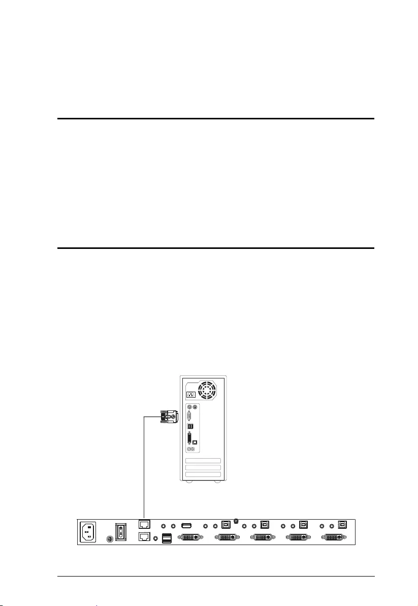
Hardware Connection
Use an RJ-45 to DB-9 serial adapter (SA0141) to connect the computer’s serial
port to the DCC In port of the CM1164A, as shown below:
SA0141
CM1164A User Manual
58
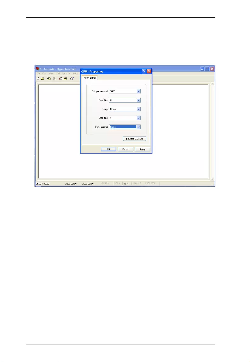
Console Login - HyperTerminal
Once a physical connection from the computer to the CM1164A has been
made, you can establish a HyperTerminal session using the instructions below.
1. Open the HyperTerminal application and the COM1 Properties screen.
2. Configure the port settings for the COM1 port to the following:
Bits per Second: 19200
Data Bits: 8
Parity: None
Stop bits: 1
Flow Control: None.
3. When configured correctly, log in using the password password.

Chapter 6. RS-232 Operation
59
RS-232 Commands
After you login via HyperTerminal (see Console Login - HyperTerminal,
page 58), you can use the instructions below to send RS-232 commands to
control the CM1164 from a remote system. For more detailed instructions and
information about each of the RS-232 commands listed below, please refer to
the original CM1164A user manual.
Verification
After entering a command, a verification message appears, as shown below, at
the end of the command line, as follows:
Response Message Description
Command OK Command or parameter is correct.
Command incorrect Command or parameter is incorrect.
NOT Login Command sent without RS232 login.
login OK Password correct and login successful.
login FAIL Incorrect password.
SETTING OK Some commands support the “save” parameter, so when you
input “save” the system will check all current input commands
and parameters, and a feedback message of “SETTING OK”
will return if all commands and parameters are correct.
Otherwise the system will return a “SETTING FAIL” message.
SETTING FAIL Some commands support the “save” parameter, so when you
input “save” the system will check all current input commands
and parameters, and a feedback message of “SETTING FAIL”
will return if a command or parameter is incorrect.

CM1164A User Manual
60
Login
The Login command allows you to login to the CM1164A and begin sending
RS-232 commands. When you login the RS-232 link is “opened” and the
CM1164 will not respond to front panel pushbuttons, hotkeys, OSD, or remote
control commands - until the RS-232 link is closed (see Open/Close RS-232
Link, page 62). For username/password information, see Security, page 73.
Type your command in the following format:
Command + Control + Number + [Enter]
For example, to login to the system with the password 123456, type the
following:
login p123456 [Enter]
Note: Each command string can be separated with a space.
Command Description
login Login Command
Control Description
p Input password
Number Description
xxxxxx Sets 6 digit password, x= 0~9

Chapter 6. RS-232 Operation
61
Logout
The Logout command allows you to logout of the CM1164A and close the RS-
232 link. Type your command in the following format:
Command + [Enter]
For example, to logout of the CM1164A, type the following:
logout [Enter]
Note: Each command string can be separated with a space.
Command Description
logout Logout Command

CM1164A User Manual
62
Open/Close RS-232 Link
The Open/Close RS-232 Link command allows you to open/close the link
between the computer sending RS-232 commands and the CM1164A. When
the link is “open” the CM1164A only accepts RS-232 commands and will not
respond to front-panel pushbuttons, hotkeys, OSD, or remote control
commands - until the link is closed. The link opens when you log in and closes
after 30seconds if no command is sent. To change the timeout settings,
configure the Logout Timeout setting in the OSD menu (see page 51). Type
your command in the following format:
Command + [Enter]
For example, to open the RS-232 Link between the computer and CM1164A,
type the following:
open [Enter]
For example, to close the RS-232 Link between the computer and CM1164A,
type the following:
close [Enter]
Command Description
open Open RS-232 Link Command
close Close RS-232 Link Command

Chapter 6. RS-232 Operation
63
Switch Port
The switch port command allows you to switch between computers connected
to the CM1164A’s ports. Type your command in the following format:
Command + Input Command + [Enter]
For example, to switch to port 2, type the following:
sw p2 [Enter]
Note: 1. Each command string can be separated with a space.
2. The Port Number command string can be skipped, and the default
value will be used.
Command Description
sw Switch Port Command
Input Command Description
px Input port number,
x= 1~4 (Default: 1)
Example: p2
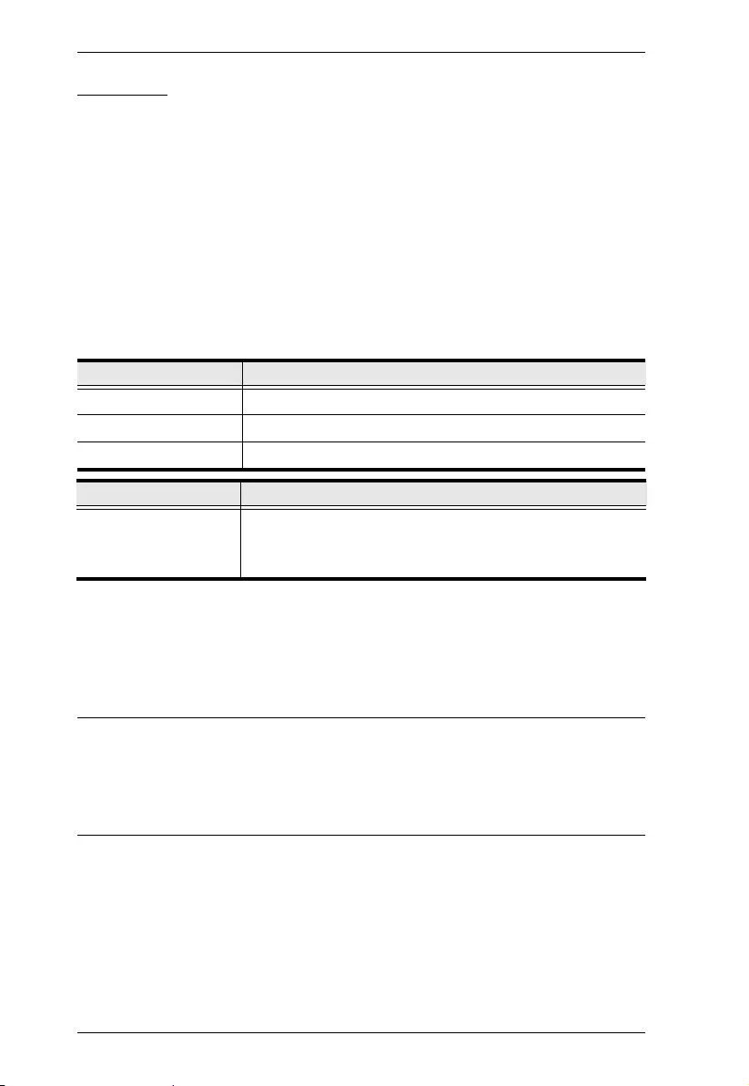
CM1164A User Manual
64
PiP Mode
The PiP Mode command allows you to change the Picture in Picture display
mode settings. Type your command in the following format:
PiP Configuration Setting:
Command + Config1 + Config2 + Config3 + Config4 + Config5 + [Enter]
PiP Setting Execute:
Command + Execute + [Enter]
PiP Advance Setting:
Command + Control1 + Control2 + Config1 + Config2 + Execute + [Enter]
For example, to Enable Channel Scan for Picture in Picture Triple Mode, type
the following:
pip3 c2scanon [Enter]
Note:
Each command string can be separated with a space.
The Port Number command string can be skipped, and the default value
will be used.
Command Description
pip2 Picture in Picture Dual Mode
pip3 Picture in Picture Triple Mode
pip4 Picture in Picture Quad Mode
Control Description
cxpy c: Output channel, x= 1~4
p: Input port, y= 1~4
Example: c2p4

Chapter 6. RS-232 Operation
65
Quad View Mode
The Quad View Mode command allows you to change the Quad View display
mode settings. Type your command in the following format:
Command + Control1 + Control2 + Control3 + Control4 + [Enter]
Command + Control + [Enter]
For example, to set Quad View Mode you must configure the four channels, as
follows:
quad c1p1 c2p2 c3p3 c4p4 [Enter]
For example, to set Quad View Mode to the default settings, type the
following:
quad default [Enter]
Note: Each command string can be separated with a space.
Command Description
quad Quad View Mode Command
Control Description
cxpy c: Output channel, x= 1~4
p: Input port, y= 1~4
Example: c2p4
default Resets Quad View Mode back to the default setting Example:
c1p1~c4p4

CM1164A User Manual
66
Change Display Mode
The Change Display Mode command allows you to change the Display mode
being used. Type your command in the following format:
Command + Control + [Enter]
For example, to set the Quad display mode, type the following:
display quad [Enter]
Note: Each command string can be separated with a space.
Command Description
display Change Display Mode Command
Control Description
full Enable console port to full screen display
quad Enable Quad display mode, console port focus remains the
same
pip2 Enable PiP Dual display, console port focus remains the
same on channel 1, and channel 2, displays the video of the
port next to the console port being displayed
pip3 Enable PiP Triple display, console port focus remains the
same on channel 1, with channel 2 and channel 3 displaying
the video of the ports next to the console port being displayed
pip4 Enable PiP Quad display, console port focus remains the
same on channel 1, with channel 2, channel 3, and channel 4
displaying the video of the ports next to the console port
being displayed

Chapter 6. RS-232 Operation
67
Port Disable
The Port Disable command allows you to disable a ports display from being
shown. Type your command in the following format:
Command + Control + Control + [Enter]
For example, to set disable the video output of port 4, type the following:
chn p4 on [Enter]
For example, to set enable the video output of port 1, type the following:
chn p1 off [Enter]
Note: Each command string can be separated with a space.
Command Description
chn Port Disable Command
Control Description
px Disable video out of port number, x= 1~4
Example: p3
on Disable channel display
off Enable channel display

CM1164A User Manual
68
OSD Language
The OSD Language command allows you to change the OSD language setting.
Type your command in the following format:
Command + Control + [Enter]
For example, to change the OSD Language to Traditional Chinese, type the
following:
lang tc [Enter]
Note: Each command string can be separated with a space.
Command Description
lang OSD Language Command
Control Description
en Change OSD language to English.
ger Change OSD language to German.
fr Change OSD language to French.
jp Change OSD language to Japanese.
tc Change OSD language to Traditional Chinese.
sc Change OSD language to Simplified Chinese.
ru Change OSD language to Russian.
ita Change OSD language to Italian.
kr Change OSD language to Korean.

Chapter 6. RS-232 Operation
69
Keyboard Language Layout
The Keyboard Language Layout command allows you to change the keyboard
language layout. Type your command in the following format:
Command + Control + [Enter]
For example, to change the keyboard language layout to Japanese, type the
following:
layout jp [Enter]
Note: Each command string can be separated with a space.
Command Description
layout Keyboard Language Layout Command
Control Description
en Change the keyboard language layout to English.
ger Change the keyboard language layout to German.
fr Change the keyboard language layout to French.
jp Change the keyboard language layout to Japanese.

CM1164A User Manual
70
Set Operating System
The Set Operating System command allows you to set the operating system for
a port. Type your command in the following format:
Command + Control + Control1 + [Enter]
For example, to change port 3’s operating system to Mac, type the following:
os p3 mac [Enter]
For example, to change port 2’s operating system to Auto Detect, type the
following:
os p2 auto [Enter]
Note: Each command string can be separated with a space.
Command Description
os Set Operating System Command
Control Description
px p: Port number, x= 1~4
Example: p2
Control1 Description
auto Change operating system to Windows
mac Change operating system to Mac
sun Change operating system to Sun
spc Change operating system to SPC (Linux)

Chapter 6. RS-232 Operation
71
Auto Scan
The Auto Scan command allows you to set and enable Auto scan mode. Type
your command in the following format:
Command + Control + [Enter]
For example, to auto scan all ports, type the following:
scan all [Enter]
For example, to set the scan’s focus on each port for a duration of 15 seconds
before continuing on, type the following:
scan t15 [Enter]
Note: Each command string can be separated with a space.
Command Description
scan Auto Scan Command
Control Description
all Auto scan all ports
pon Auto scan all ports with computers powered on
txx Sets the KVM focus duration when scanning, xx= 5, 10, 15,
60, 90 seconds
Example: t60

CM1164A User Manual
72
Port ID Display
The Port ID Display command allows you to configure the port ID for each
port. Type your command in the following format:
Command + Control + [Enter]
For example, to set all port ID’s to the factory default, type the following:
portid default [Enter]
For example, to change port 4’s ID number to Computer_A, type the
following:
portid pComputer_A [Enter]
Note: Each command string can be separated with a space.
Command Description
portid Port ID Display Command
Control Description
pxyy Change the port ID number.
x= 1~4 (Current Port ID)
yy = A ~ Z, a ~ z, 0 ~ 9, dash, underscore, maximum 20
characters (New Port ID)
default Reset all port IDs to the factory default.

Chapter 6. RS-232 Operation
73
Security
The Security command allows you to password protect the OSD menu. Use the
Formula - to set Parameters - to create a Command.
Formula:
Command + Control + [Enter]
For example, to enable password protection of the OSD menu, type the
following:
security on [Enter]
Note: Each command string can be separated with a space.
Command Description
security Security Command
Control Description
off Disable password protection to the OSD menu.
on Enable password protection to the OSD menu.

CM1164A User Manual
74
Station
The Station command allows you to switch the console focus to the next station
in a daisy chain setup. Type your command in the following format:
Command + Control + Number + [Enter]
For example, to switch the console to station 2 of a daisy chain, type the
following:
station id2 [Enter]
Note: Each command string can be separated with a space.
Command Description
station Station Command
Control Description
id Station ID
Number Description
x Station number of switch in daisy chain, x= 1~4

Chapter 6. RS-232 Operation
75
DCC Control
The DCC Control command allows you to enable/disable the DCC Control
mode for the CM1164A. Type your command in the following format:
Command + Control + [Enter]
For example, to enable DCC control, type the following:
dcc on [Enter]
Note: Each command string can be separated with a space.
Command Description
clone Sets the default DCC clone mode
Control Description
off Disables DCC function
on Enables DCC function

CM1164A User Manual
76
Mouse Emulation
The Mouse Emulation command allows you to set mouse emulation and mouse
switching features. Type your command in the following format:
Command + Control + [Enter]
Command + Control2 + [Enter]
For example, to disable mouse emulation, type the following:
msemu off [Enter]
For example, to enable mouse switching, type the following:
msemu wheelon [Enter]
Note: Each command string can be separated with a space.
Command Description
msemu Mouse Emulation Command
Control Description
off Disable mouse emulation function
on Enable mouse emulation function
Control2 Description
wheeloff Disable mouse switching function
wheelon Enable mouse switching function

Chapter 6. RS-232 Operation
77
Keyboard Emulation
The Keyboard Emulation command allows you to enable/disable the keyboard
emulation feature. Type your command in the following format:
Command + Control + [Enter]
For example, to disable keyboard emulation, type the following:
kbemu off [Enter]
For example, to enable keyboard emulation, type the following:
kbemu on [Enter]
Note: Each command string can be separated with a space.
Command Description
kbemu Keyboard Emulation Command
Control Description
off Disable keyboard emulation function
on Enable keyboard emulation function

CM1164A User Manual
78
Video Dynasync
The Video Dynasync command allows you to set the EDID settings. Type your
command in the following format:
Command + Control + [Enter]
For example, to set the default EDID setting, type the following:
vds default [Enter]
For example, to enable EDID detection, type the following:
vds on [Enter]
Note: Each command string can be separated with a space.
Command Description
vds Video Dynasync Command
Control Description
default Set the default EDID.
port 1 Set the EDID to the EDID of the monitor connected to port 1
on the CM1164A.

Chapter 6. RS-232 Operation
79
Hardware Cursor
The Hardware Cursor command allows you to enable/disable the hardware
cursor feature. Type your command in the following format:
Command + Control + [Enter]
For example, to enable the hardware cursor, type the following:
hc on [Enter]
Note: Each command string can be separated with a space.
Command Description
hc Hardware Cursor Command
Control Description
off Disable the hardware cursor
on Enable the hardware cursor

CM1164A User Manual
80
Activate Beeper
The Activate Beeper command allows you to enable/disable the beeper
function. Type your command in the following format:
Command + Control + [Enter]
For example, to enable the beeper, type the following:
beeper on [Enter]
Note: Each command string can be separated with a space.
Command Description
beeper Activate Beeper Command
Control Description
off Disable beeper
on Enable beeper

Chapter 6. RS-232 Operation
81
Hotkey Setting
The Hotkey Setting command allows you to enable/disable and change the
hotkey used to invoke the HSM (Hotkey Setting Mode). Type your command
in the following format:
Command + Control + [Enter]
For example, to enable the hotkey function, type the following:
hotkey on [Enter]
For example, to change the HSM invoke key to [Ctrl] + [F12], type the
following:
hotkey f12 [Enter]
Note: Each command string can be separated with a space.
Command Description
hotkey Hotkey Setting Command
Control Description
num Change the HSM invoke key to:
[Num Lock] + [-]
f12 Change the HSM invoke key to:
[Ctrl] + [F12]
off Disable hotkey function
on Enable hotkey function

CM1164A User Manual
82
OSD Hotkey
The OSD Hotkey command allows you to change the hotkey used to invoke the
OSD. Type your command in the following format:
Command + Control + [Enter]
For example, to change the OSD invoke key to [Scroll] + [Scroll], type the
following:
osdkey scroll [Enter]
For example, to change the OSD invoke key to [Ctrl] + [Ctrl], type the
following:
osdkey ctrl [Enter]
Note: Each command string can be separated with a space.
Command Description
osdkey OSD Hotkey Command
Control Description
scroll Change OSD invoke key to: [Scroll] [Scroll]
ctrl Change OSD invoke key to: [Ctrl] [Ctrl]

Chapter 6. RS-232 Operation
83
Power on Detection
The Power on Detection command allows you to enable/disable the power on
detection feature. Type your command in the following format:
Command + Control + [Enter]
For example, to enable power on detection, type the following:
pod on [Enter]
Note: Each command string can be separated with a space.
Command Description
pod Power on Detection Command
Control Description
on Enable power on detection function
off Disable power on detection function

CM1164A User Manual
84
Fn Key
The Fn Key command allows you to save and select Fn keys for a focused ports
display settings. Type your command in the following format:
Command + Control + [Enter]
For example, to save the display setting and current port focus as Fn1, type the
following:
fn save1 [Enter]
For example, to set all Fn keys back to the default, type the following:
fn default [Enter]
Note: Each command string can be separated with a space.
Command Description
fn Fn Key Command
Control Description
savex Save display setting for current port focus, x= 1~4
Example: save3
default Restore all Fn key settings to the default
selectx Enable display setting for current port focus, x= 1~4
Example: select2

Chapter 6. RS-232 Operation
85
USB Reset
The USB Reset command allows you to reset the USB connection. Type your
command in the following format:
Command + Control + [Enter]
For example, to reset the USB connection, type the following:
usbreset on [Enter]
Note: Each command string can be separated with a space.
Command Description
usbreset USB Reset Command
Control Description
on Enable USB reset connection

CM1164A User Manual
86
Restore Default Value
The Restore Default Value command allows you to reset all of the CM1164A’s
settings back to the default. Type your command in the following format:
Command + Control + [Enter]
For example, to restore all CM1164A settings back to the default, type the
following:
redefault on [Enter]
Note: Each command string can be separated with a space.
Command Description
redefault Restore Default Value Command
Control Description
on Enable restore default values

Chapter 6. RS-232 Operation
87
Firmware Upgrade
The Firmware Upgrade command allows you to enable the firmware upgrade
mode. Type your command in the following format:
Command + Control + [Enter]
For example, to enable firmware upgrade mode, type the following:
upgrade on [Enter]
Note: Each command string can be separated with a space.
Command Description
upgrade Firmware Upgrade Command
Control Description
on Enable firmware upgrade mode

CM1164A User Manual
88
KVM Status
The KVM Status command allows you to display read-only information about
the CM1164A’s current configuration status. Type your command in the
following format:
Command + [Enter]
For example, to display the CM1164A’s configuration status, type the
following:
status [Enter]
Command Description
status KVM Status Command

Chapter 6. RS-232 Operation
89
Hotkey List
The Hotkey List command allows you to display a list of the KVM’s hotkeys.
Type your command in the following format:
Command + [Enter]
For example, to display the KVM’s hotkey list, type the following:
list [Enter]
Command Description
list Hotkey List Command

CM1164A User Manual
90
Info
The Info command allows you to display the CM1164A’s current firmware
version and copyright information. Type your command in the following
format:
Command + [Enter]
For example, to display the CM1164A’s device information, type the
following:
info [Enter]
Command Description
info Info Command

91
Chapter 7
System Maintenance
Firmware Upgrades
The Windows-based Firmware Management Utility provides a smooth,
automated process for upgrading the CM1164A’s firmware. New firmware
upgrade packages are posted on our Website as new firmware revisions
become available. Check the web site regularly to find the latest packages and
information relating to them:
http://www.aten.com
Before you Begin
To prepare for the Firmware Upgrade, do the following:
1. From a computer connected to the CM1164A unit (via the KVM Ports, see
Rear View, page 8), go to our Internet support site and choose the model
name of your device (CM1164A) to get a list of available Firmware
Upgrade Packages.
2. Download the Firmware Upgrade Package you want to install (usually the
most recent) to the computer.
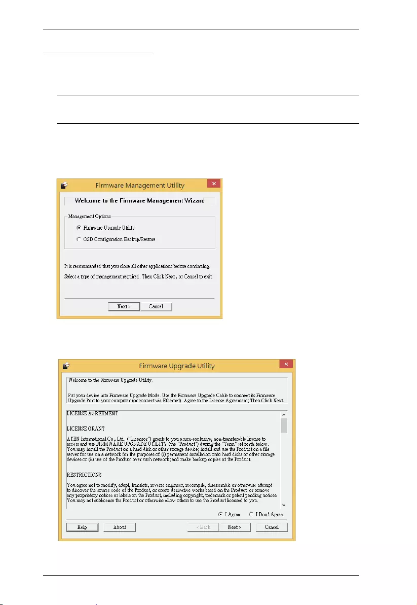
CM1164A User Manual
92
Starting the Upgrade
1. From the OSD menu, set the Firmware Upgrade setting to Ye s. All the
LEDs flash orange to indicate that Firmware Upgrade Mode is in effect.
Note: The console mouse and hotkey functionality will be suspended
while the upgrade is in progress.
2. Run the downloaded Firmware Upgrade Package file – either by double
clicking the file icon, or by opening a command line and entering the full
path to it. This screen appears.
3. Select the Firmware Upgrade Utility button and click Next. The Firmware
Upgrade Utility Welcome screen appears.
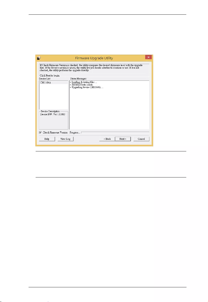
Chapter 7. System Maintenance
93
4. Read the License Agreement, select I Agree, and click Next. The
Firmware Upgrade Utility main screen appears. All the devices capable of
being upgraded by the package are listed in the Device List panel.
5. Select a device from the Device List. The device description appears in the
Device Description panel. Click Next to start the upgrade.
Note: Select Check Firmware Version for the Utility to compare the
device’s firmware version with that of the upgrade files. If the
device’s firmware is of a newer version, you will be prompted to
verify if you wish to proceed with the downgrade.
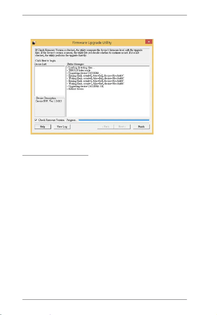
CM1164A User Manual
94
6. After the upgrade is complete, a screen appears to inform you that the
procedure is successful and the CM1164A restarts itself.
Unsuccessful Upgrades
If the Firmware upgrade: OK message did not appear, it means that the
upgrade was not successful. In this case follow the steps below to perform the
upgrade again:
1. Power off the CM1164A by removing the power cord.
2. Invoke Firmware Upgrade Mode by holding down the front panel Mode
Selection pushbutton (see Components, page 6) and power on the
CM1164A. The KVM LEDs flash orange together.
3. Repeat the firmware upgrade procedure described in Starting the Upgrade,
page 92.
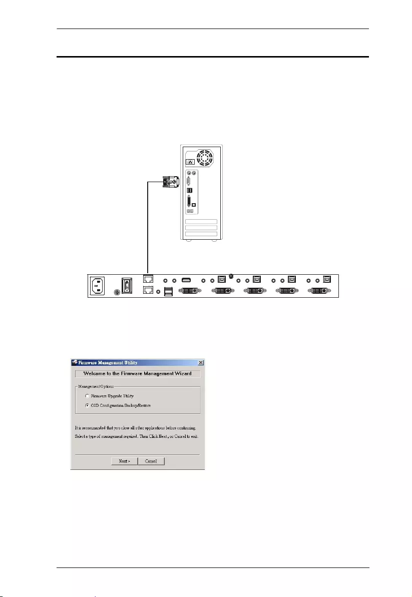
Chapter 7. System Maintenance
95
Backup / Restore
To backup/restore the OSD configuration, do the following:
1. Download the most recent firmware package from our website.
2. Use an RJ-45 to DB-9 serial adapter (SA0141) to connect the computer's
serial port to the RS232 In port on the CM1164A.
3. Open the OSD and go to Configuration - OSD Config Backup Restore.
4. Run the Firmware Management Utility, select OSD Configuration Backup/
Restore and click Next
SA0141
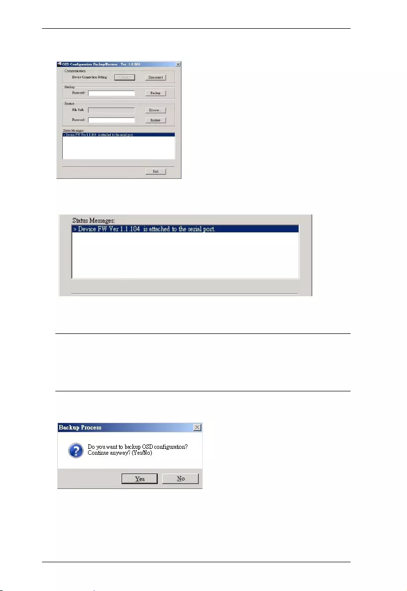
CM1164A User Manual
96
5. At the next screen click Connect.
6. If the computer is connected correctly a message will appear in the Status
Messages:
7. To backup the OSD configuration, in the Password field, key in a
password for the file and click Backup.
Note: 1. Setting a password is optional. If you do not set one, the file can
be restored without specifying a password.
2. If you do set a password, make a note of it, since you will need it
to be able to restore the file.
8. When the confirmation message appears, click Yes .
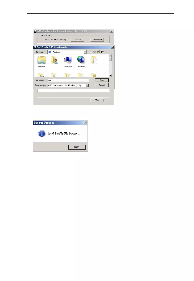
Chapter 7. System Maintenance
97
9. Provide a name for the backup and click Save.
10. A message appears indicating the backup was successful.
11. To restore an OSD configuration, in the Password field, key in a password
for the file (optional) and click Browse.
12. Open the restore file and click Yes .
13. The OSD configuration is restored.

CM1164A User Manual
98
Powering Off and Restarting
If it becomes necessary to power off the unit, before starting it back up you
must do the following:
1. Shut down all the computers that are attached to the switch.
2. Unplug the switch’s power adapter cable.
3. Wait 10 seconds, then plug the switch’s power adapter cable back in.
4. After the switch is up, Power On the computers.
Restoring to Default Settings
To reset your complete KVM installation to the factory default settings, set the
Reset to Default setting to Yes in the OSD menu.

99
Appendix
Safety Instructions
General
This product is for indoor use only.
Read all of these instructions. Save them for future reference.
Follow all warnings and instructions marked on the device.
Do not place the device on any unstable surface (cart, stand, table, etc.). If
the device falls, serious damage will result.
Do not use the device near water.
Do not place the device near, or over, radiators or heat registers.
The device cabinet is provided with slots and openings to allow for
adequate ventilation. To ensure reliable operation, and to protect against
overheating, these openings must never be blocked or covered.
The device should never be placed on a soft surface (bed, sofa, rug, etc.) as
this will block its ventilation openings. Likewise, the device should not be
placed in a built in enclosure unless adequate ventilation has been provided.
Never spill liquid of any kind on the device.
Unplug the device from the wall outlet before cleaning. Do not use liquid
or aerosol cleaners. Use a damp cloth for cleaning.
Avoid circuit overloads. Before connecting equipment to a circuit, know
the power supply’s limit and never exceed it. Always review the electrical
specifications of a circuit to ensure that you are not creating a dangerous
condition or that one doesn’t already exist. Circuit overloads can cause a
fire and destroy equipment.
The device should be operated from the type of power source indicated on
the marking label. If you are not sure of the type of power available,
consult your dealer or local power company.
The device is designed for IT power distribution systems with 230V
phase-to-phase voltage.
To prevent damage to your installation, it is important that all devices are
properly grounded.
The device is equipped with a 3-wire grounding type plug. This is a safety
feature. If you are unable to insert the plug into the outlet, contact your

CM1164A User Manual
100
electrician to replace your obsolete outlet. Do not attempt to defeat the
purpose of the grounding-type plug. Always follow your local/national
wiring codes.
Do not allow anything to rest on the power cord or cables. Route the
power cord and cables so that they cannot be stepped on or tripped over.
If an extension cord is used with this device make sure that the total of the
ampere ratings of all products used on this cord does not exceed the
extension cord ampere rating. Make sure that the total of all products
plugged into the wall outlet does not exceed 15 amperes.
To help protect your system from sudden, transient increases and
decreases in electrical power, use a surge suppressor, line conditioner, or
un-interruptible power supply (UPS).
Position system cables and power cables carefully; Be sure that nothing
rests on any cables.
Never push objects of any kind into or through cabinet slots. They may
touch dangerous voltage points or short out parts resulting in a risk of fire
or electrical shock.
Do not attempt to service the device yourself. Refer all servicing to
qualified service personnel.
If the following conditions occur, unplug the device from the wall outlet
and bring it to qualified service personnel for repair.
The power cord or plug has become damaged or frayed.
Liquid has been spilled into the device.
The device has been exposed to rain or water.
The device has been dropped, or the cabinet has been damaged.
The device exhibits a distinct change in performance, indicating a need
for service.
The device does not operate normally when the operating instructions
are followed.
Only adjust those controls that are covered in the operating instructions.
Improper adjustment of other controls may result in damage that will
require extensive work by a qualified technician to repair.

Appendix
101
Rack Mounting
Before working on the rack, make sure that the stabilizers are secured to
the rack, extended to the floor, and that the full weight of the rack rests on
the floor. Install front and side stabilizers on a single rack or front
stabilizers for joined multiple racks before working on the rack.
Always load the rack from the bottom up, and load the heaviest item in the
rack first.
Make sure that the rack is level and stable before extending a device from
the rack.
Use caution when pressing the device rail release latches and sliding a
device into or out of a rack; the slide rails can pinch your fingers.
After a device is inserted into the rack, carefully extend the rail into a
locking position, and then slide the device into the rack.
Do not overload the AC supply branch circuit that provides power to the rack.
The total rack load should not exceed 80 percent of the branch circuit rating.
Make sure that all equipment used on the rack – including power strips and
other electrical connectors – is properly grounded.
Ensure that proper airflow is provided to devices in the rack.
Ensure that the operating ambient temperature of the rack environment
does not exceed the maximum ambient temperature specified for the
equipment by the manufacturer
Do not step on or stand on any device when servicing other devices in a rack.

CM1164A User Manual
102
Technical Support
International
For online technical support – including troubleshooting, documentation,
and software updates: http://eservice.aten.com
For telephone support, Telephone Support, page iii.
North America
When you contact us, please have the following information ready beforehand:
Product model number, serial number, and date of purchase.
Your computer configuration, including operating system, revision level,
expansion cards, and software.
Any error messages displayed at the time the error occurred.
The sequence of operations that led up to the error.
Any other information you feel may be of help.
Email Support support@aten-usa.com
Online
Technical
Support
Troubleshooting
Documentation
Software Updates
http://www.aten-usa.com/support
Telephone Support 1-888-999-ATEN ext 4988

Appendix
103
Specifications
Function CM1164A
Computer Connections 4
Port Selection Front-panel Pushbuttons, Hotkeys, IR Remote Control,
On-screen Display (OSD), Mouse, RS-232 Commands
Connectors Console
Ports
Keyboard 1 x USB Type A Female (Black, rear panel)
Video 1 x Single Link DVI-D Female (White)
Mouse 1 x USB Type A Female (Black, rear panel)
Speaker 2 x 3.5mm Audio Jack Female
(Green; 1 x front panel,1 x rear panel)
Mic. 2 x 3.5mm Audio Jack Female (Pink; 1 x front, 1 x rear)
DC
Control
2 x RJ-45
KVM
Ports
KB/Mouse 4 x USB Type B Female (White)
Video 4 x Single Link DVI-D Female (White)
Speaker 4 x Mini Stereo Jack Female (Green)
Mic. 4 x Mini Stereo Jack Female (Pink)
Power 1 x IEC60320-1 Appliance Inlet (Type C14)
USB Hub 2 x USB 2.0 Type A Female
Emulation Keyboard / Mouse USB
Switches Selected 11 pushbuttons
Video 1920 x 1200 @ 60Hz (DVI-D)
LEDs KVM 4 (Orange)
Audio 4 (Green)
USB 4 (Green)
Scan Interval 5, 10, 15, 30, 60, 90 secs (Default: 5 secs)
Power Consumption AC110V: 9.7W; AC220V: 9.5W
Environment Operating Temp. 0–40ºC
Storage Temp. -10–60ºC
Humidity 0–80% RH, Non-condensing
Physical
Properties
Housing Metal
Weight 2.46 kg
Dimensions (L x W x H) 43.72 x 16.40 x 4.40 cm

CM1164A User Manual
104
Troubleshooting
Operation problems can be due to a variety of causes. The first step in solving
them is to make sure that all cables are securely attached and seated completely
in their sockets. In addition, updating the product’s firmware may solve
problems that have been discovered and resolved since the prior version was
released. If your product is not running the latest firmware version, we strongly
recommend that you upgrade. For details, see Firmware Upgrades, page 91.
Symptom Possible Cause Action
Mouse and/or
Keyboard not
responding.
Improper mouse
and/or keyboard
reset.
Unplug the cable(s) from the console port(s),
then plug it/them back in.
KVM switch
needs to be reset.
Power off all devices on the installation (see
safety note, page 11); power off the KVM
switch; wait five seconds; then power up
USB devices not
responding.
USB ports need to
reset.
Unplug the device’s USB cable from the USB
port on the switch’s rear panel, then plug it
back in.
PC or OS does
not support USB
2.0.
The CM1164A has a built-in USB 2.0 hub, so
does not support PCs or OS that do not
support USB 2.0.
Device not
recognized
(Windows).
Windows timing
problem.
Unplug the KVM cable from the computer’s
USB port; go into Windows’ System Settings
and remove the Unknown Device entry; plug
the KVM cable back in. Windows now
recognizes the device.
Cannot switch
ports by pressing
[Scroll Lock] twice
Keyboard is
incompatible with
Scroll Lock
invocation.
Press Ctrl key instead.
Monitor does not
display after a
KVM cable is hot
plugged.
Some DVI
graphics cards
are incompatible
with the KVM
cable hot
plugging.
Power off all devices on the installation (see
safety note, page 11); power off the CM1164A;
confirm all KVM cables are properly
connected; power on the CM1164A; power on
the computers
When switching
ports, the monitor
does not display.
Monitor is new or
this is a first time
installation.
Switch ports again and wait two or more
seconds for the PC’s EDID to pass to the
monitor.
The GUI
connection
window stalls /
does not connect
The CM1164A
needs to be reset.
Perform a KVM reset or reinstall the latest
CM1164A software on all your computers.
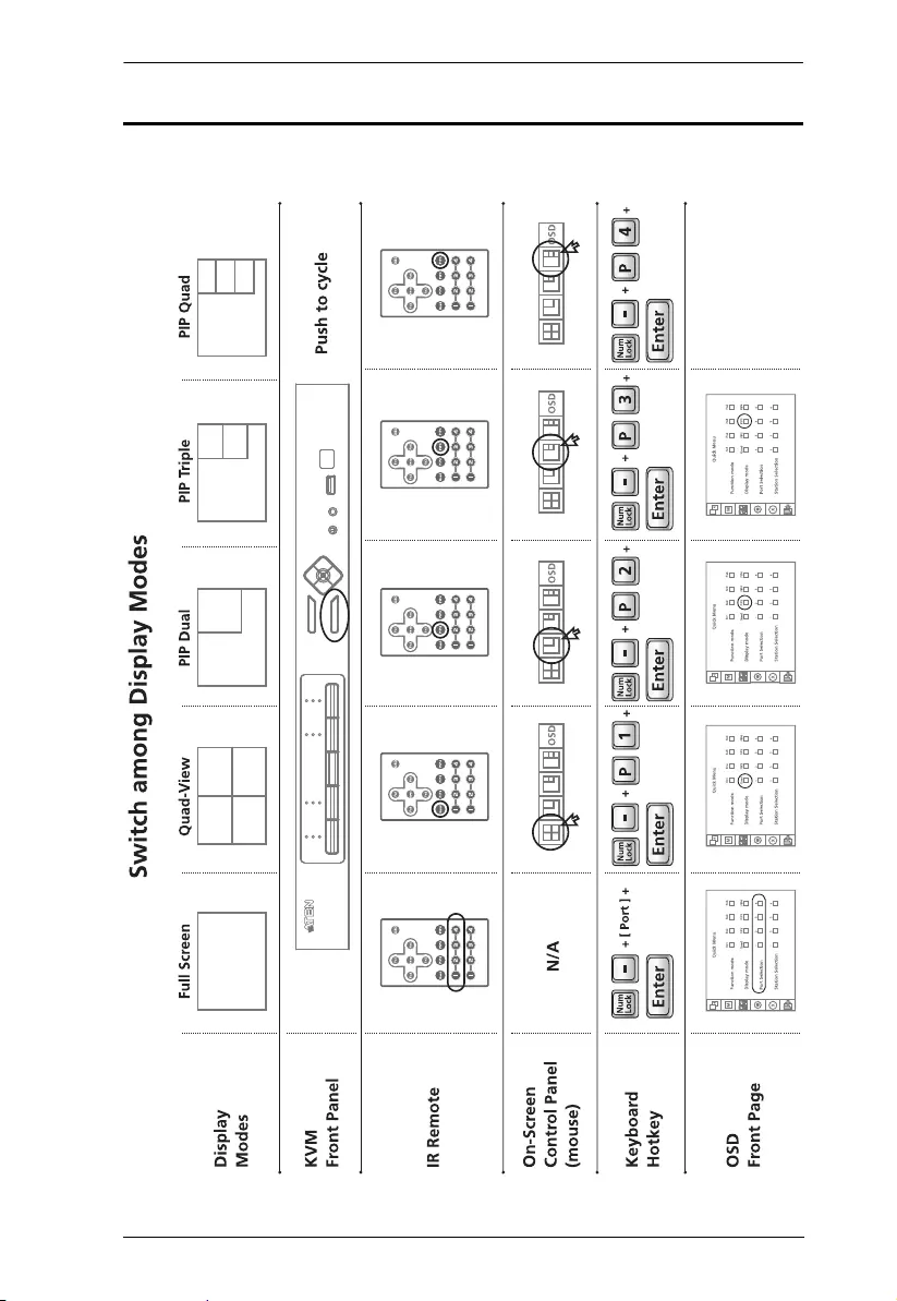
Appendix
105
Display Mode Reference
Use the information below as a quick reference to invoke the display modes.
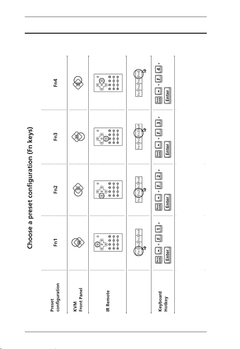
CM1164A User Manual
106
Fn Key Reference
Use the information below as a quick reference to invoke the Fn keys.
Quick Access
Toolbar (mouse)
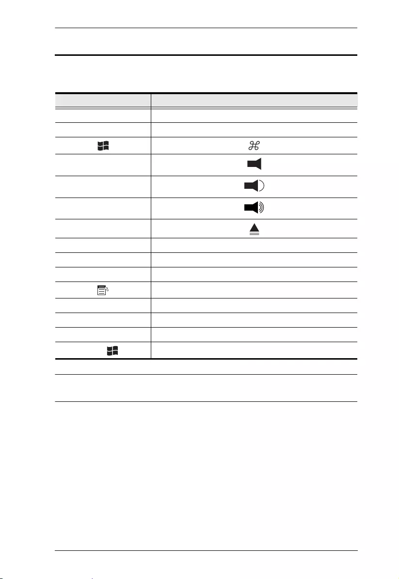
Appendix
107
Mac Keyboard Emulation
The PC compatible (101/104 key) keyboard can emulate the functions of the
Mac keyboard. The emulation mappings are listed in the table below.
Note: When using key combinations, press and release the first key (Ctrl),
then press and release the activation key.
PC Keyboard Mac Keyboard
[Shift] Shift
[Ctrl] Ctrl
[Ctrl] [1]
[Ctrl] [2]
[Ctrl] [3]
[Ctrl] [4]
[Alt] Alt
[Print Screen] F13
[Scroll Lock] F14
=
[Enter] Return
[Backspace] Delete
[Insert] Help
[Ctrl] F15
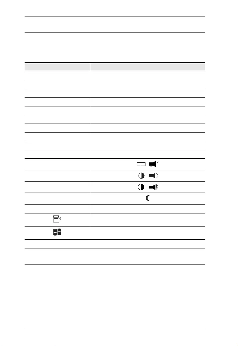
CM1164A User Manual
108
Sun Keyboard Emulation
The PC compatible (101/104 key) keyboard can emulate the functions of the
Sun keyboard when the Control key [Ctrl] is used in conjunction with other
keys. The corresponding functions are shown in the table below.
Note: When using key combinations, press and release the first key (Ctrl),
then press and release the activation key.
PC Keyboard Sun Keyboard
[Ctrl] [T] Stop
[Ctrl] [F2] Again
[Ctrl] [F3] Props
[Ctrl] [F4] Undo
[Ctrl] [F5] Front
[Ctrl] [F6] Copy
[Ctrl] [F7] Open
[Ctrl] [F8] Paste
[Ctrl] [F9] Find
[Ctrl] [F10] Cut
[Ctrl] [1]
[Ctrl] [2]
[Ctrl] [3]
[Ctrl] [4]
[Ctrl] [H] Help
Compose
-
+

Appendix
109
Factory Default Hotkeys and Settings
Setting Hotkey Default
Invoking HSM [H] [Number Lock] [-]
Port Switching (Default / Alternate) [T] [Scroll Lock] [Scroll Lock]
Auto Scan Interval [Scroll Lock]
[Scroll Lock]
[A] [Enter]
5 seconds
Keyboard Operating Platform [F10] PC Compatible
Mouse Emulation [M] Enabled
Keyboard Emulation [N] Enabled
Mouse Wheel Support [W] Disabled
Buzzer [B] Enabled
Keyboard Language [F6] [nn] [Enter]
Note: nn is the
language number
English

CM1164A User Manual
110
Limited Warranty
ATEN warrants its hardware in the country of purchase against flaws in
materials and workmanship for a Warranty Period of two [2] years (warranty
period may vary in certain regions/countries) commencing on the date of
original purchase. This warranty period includes the LCD panel of ATEN LCD
KVM switches. Select products are warranted for an additional year (see A+
Warranty for further details). Cables and accessories are not covered by the
Standard Warranty.
What is covered by the Limited Hardware Warranty
ATEN will provide a repair service, without charge, during the Warranty Period.
If a product is detective, ATEN will, at its discretion, have the option to (1) repair
said product with new or repaired components, or (2) replace the entire product
with an identical product or with a similar product which fulfills the same function
as the defective product. Replaced products assume the warranty of the original
product for the remaining period or a period of 90 days, whichever is longer.
When the products or components are replaced, the replacing articles shall
become customer property and the replaced articles shall become the property
of ATEN.
To learn more about our warranty policies, please visit our website:
http://www.aten.com/global/en/legal/policies/warranty-policy/