Chief HB44E User Manual
Displayed below is the user manual for HB44E by Chief which is a product in the Projector Mount Accessories category. This manual has pages.
Related Manuals
INSTALLATION INSTRUCTIONS
Milestone AV Technolo gies, Inc., and its affiliated corporati ons and subs idiaries ( collectively, "Milest one"), i ntend to mak e this manual a ccurate and complet e. However, Mileston e
makes no claim that the information co ntai ned herein co vers all details, c onditions or variations , nor does it prov ide for every pos sible contingenc y in connection with the i nsta llation
or u se of thi s product . The i nformati on contai ned in t his doc ument is s ubje ct to change withou t noti ce or obl igation of any k ind. Miles tone m akes no r eprese ntation of warran ty, ex-
press ed or implied, regar ding the information conta ined herei n. Milestone assume s no respo nsibility for accuracy, completenes s or sufficiency of t he information contai ned in th is
document.
Chief Manufacturing, a products division of Milestone AV Technologies
8401 Eagle Creek Parkway, Savage, MN 55378
• P: 800.582.6480 / 952.894.6280 • F:877.894.6918 / 952.894.6918
8803-002022 Rev00
©2011 Mile ston e AV Tech no lo gies ,
a Ducho ss ois G roup C ompa ny
01/11
Continued. . .
MO DEL: HB-44E Custom Projector Bracket
Unpack carton and verify contents. If any listed parts are missing, immediately contact a Chief Customer Service representative.
PARTS
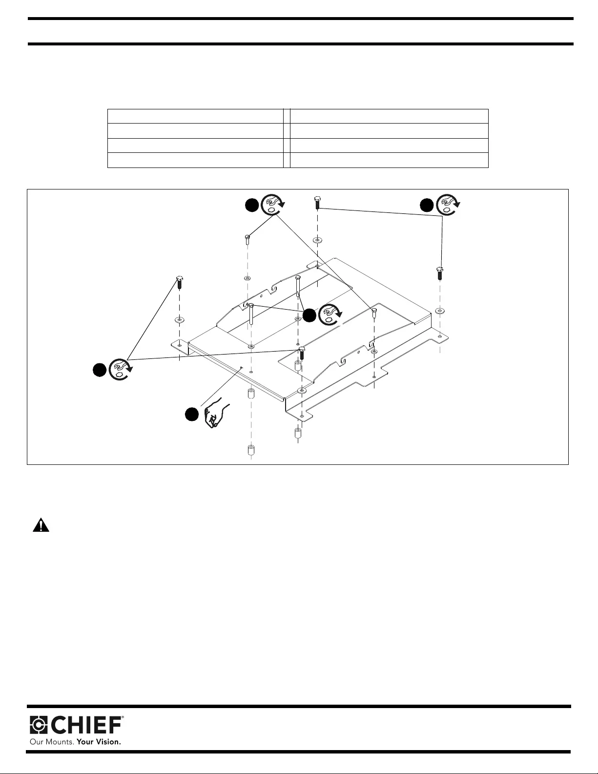
Figure 1
INSTALLATION
WARNING: IMPROPER INSTALLATION MAY RESULT IN SERIOUS PERSONAL INJURY! All components must b e securely fastened
to each other and to the ceiling, and the ceiling must be capable of supporting five times the total weight of the installation.
1. Lower custom HB bracket onto top of projector. Ensure that triangle in bracket points toward front of projector. (See Figure 1)
2. Attach HB bracket to p rojector using four M10 x 35mm hex head sc rews through four M10 washers and four outer corner holes in the HB
bracket. (See Figure 1)
3. Continue attaching bracket to projector using two M8 x 25mm hex head screws through two M8 washers into two outer center holes in
bracket. (See Figure 1)
4. Finish attaching bracket to projector using two M8 x 70mm hex head screws through four nylon spacers (2 spacers per hex head screw)
and two M8 washers into two center holes in bracket. (See Figure 1)
(1) BRACKET, Custom HB (4) SCREW, Hex head cap screw, M10 x 35mm
(4) NUT, Flange, Hex, 5/16-18 (2) SCREW, Hex head cap screw, M8 x 25mm
(4) WASHER, Flat, M10 (2) SCREW, Hex head cap screw, M8 x 70mm
(4) WASHER, Flat, M8 (4) SPACER, Nylon, .74 x .391 x 1.0"
1
4
x 2
3
x 2
2
x 2
2
x 2
INSTALLATION INSTRUCTIONS
Continued . .
CAUTION: Installing a ceiling mount requires the presence of two persons familiar with mechanical installations. A third assistant is
recommended.
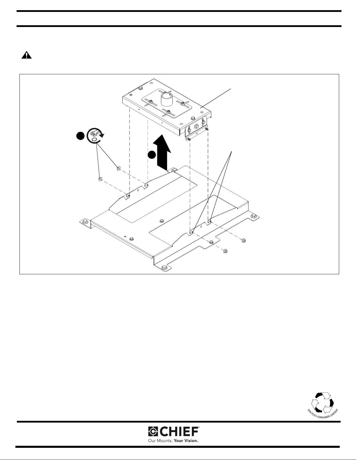
Figure 2
5. Attach VCM housing to your method of support and tighten firmly so the VCM housing is square to the screen.
6. With hel p of a ssistants, lift the projector and i nst all it to t he fo ur st uds ext endi ng fr om the VCM hous ing . Ensur e that the VCM hou sing is
seated in slots on HB bracket. (See Figure 2)
7. Tighten the four 5/16" flange nuts. (See Figure 2)
6
7
VCM Housing
x 4 Seat VCM in HB
bracket slots