Table of Contents
- 1. Preface
- 1.1 Scope
- 1.2 Audience
- 1.3 Safety Instructions
- 1.4 Documentation Conventions
- 2. Overview
- 2.1 Faceplate
- 2.2 Front Panel Introduction
- 2.3 Top Panel Introduction
- 3. Quick Installation
- 3.1 Mounting the RGS Series (DIN-Rail)
- 3.2 Mounting the RGS Series (Wall mount)
- 3.3 Ground Connections
- 3.4 Connecting the Ethernet Interface (RJ45 Ethernet)
- 3.5 Connecting the Ethernet Interface (Fiber)
- 3.6 Power Connection
- 3.7 Console Connection
- 3.8 SYSTEM RESET
- 3.9 Web Interface Initialization (Optional)
- 3.10 CLI Initialization & Configuration (Optional)
- 3.11 Monitoring the Ethernet Interface
- 3.12 Upgrade Software
- 3.13 Reset to Default and Save Configure
- 3.14 DIP Switch Setting for RGS100-5P
- 3.15 LED STATUS INDICATIONS
- 4. Introduction
- 4.1 System Description
- 4.2 Using the Web Interface
- 4.3 Using the Online Help
- 5. Using the Web
- 5.1 Login
- 5.2 Tree View
- 5.3 Configuration
- 5.3.1 System Information
- 5.3.2 System IP
- 5.3.3 System NTP
- 5.3.4 System Time
- 5.3.5 System Log
- 5.3.6 System Alarm Profile
- 5.3.7 EEE
- 5.3.8 Port Power Savings
- 5.3.9 Port
- 5.3.10 DHCP Snooping
- 5.3.11 DHCP Relay
- 5.3.12 Security
- 5.3.13 Switch
- 5.3.14 Users
- 5.3.15 Privilege Level
- 5.3.16 Authentication Method
- 5.3.17 SSH
- 5.3.18 HTTPS
- 5.3.19 Access Management
- 5.3.20 SNMP System Configuration
- 5.3.21 SNMP Trap Configuration
- 5.3.22 SNMP Communities
- 5.3.23 SNMP Users
- 5.3.24 SNMP Groups
- 5.3.25 SNMP Views
- 5.3.26 SNMP Access
- 5.3.27
- 5.3.28 RMON Statistics
- 5.3.29 RMON History
- 5.3.30 RMON Alarm
- 5.3.31 RMON Event
- 5.3.32 Network
- 5.3.33 Limit Control
- 5.3.34 ACL
- 5.3.35 ACL Port
- 5.3.36 ACL Rate Limiters
- 5.3.37 Access Control List
- 5.3.38 IP Source Guard
- 5.3.39 IP Source Guard Configuration
- 5.3.40 IP Source Guard Static Table
- 5.3.41 ARP Inspection
- 5.3.42 Port Configuration
- 5.3.43 VLAN Configuration
- 5.3.44 Static Table
- 5.3.45 Dynamic Table
- 5.3.46 AAA
- 5.3.47 RADIUS
- 5.3.48 TACACS+
- 5.3.49 Aggregation
- 5.3.50 Static Aggregation
- 5.3.51 LACP Aggregation
- 5.3.52 Loop Protection
- 5.3.53 Spanning Tree
- 5.3.54 Bridge Settings
- 5.3.55 MSTI Mapping
- 5.3.56 MSTI Priorities
- 5.3.57 CIST Ports
- 5.3.58 MSTI Ports
- 5.3.59 IPMC Profile
- 5.3.60 Profile Table
- 5.3.61 Address Entry
- 5.3.62 MVR
- 5.3.63 IPMC
- 5.3.64 IGMP Snooping
- 5.3.65 Basic Configuration
- 5.3.66 VLAN Configuration
- 5.3.67 Port Filtering Profile
- 5.3.68 MLD Snooping
- 5.3.69 Basic Configuration
- 5.3.70 VLAN Configuration
- 5.3.71 Port Filtering Profile
- 5.3.72 LLDP
- 5.3.73 LLDP
- 5.3.74 LLDP-MED
- 5.3.75 PoE
- 5.3.76 PoE Scheduler
- 5.3.77 Power Reset
- 5.3.78 MAC Table
- 5.3.79 VLANs
- 5.3.80 Voice VLAN
- 5.3.81 Voice VLAN Configuration
- 5.3.82 Voice VLAN OUI
- 5.3.83 QoS
- 5.3.84 Port Classification
- 5.3.85 Port Policing
- 5.3.86 Port Scheduler
- 5.3.87 Port Shaping
- 5.3.88 Port Tag Remarking
- 5.3.89 Port DSCP
- 5.3.90 DSCP-Based QoS
- 5.3.91 DSCP Translation
- 5.3.92 DSCP Classification
- 5.3.93 QoS Control List
- 5.3.94 Storm Control
- 5.3.95 Mirror
- 5.3.96 GVRP
- 5.3.97 Global Config
- 5.3.98 Port Config
- 5.3.99 RingV2
- 5.3.100 DDMI
- 5.4 Monitor
- 5.4.1 System
- 5.4.2 System Information
- 5.4.3 CPU Load
- 5.4.4 IP Status
- 5.4.5 System Log
- 5.4.6 System Detailed Log
- 5.4.7 System Alarm
- 5.4.8 EEE
- 5.4.9 Port Power Saving
- 5.4.10 Ports
- 5.4.11 Ports State
- 5.4.12 Traffic Overview
- 5.4.13 QoS Statistics
- 5.4.14 QCL Status
- 5.4.15 Detailed Statistics
- 5.4.16 DHCP Snooping Table
- 5.4.17 DHCP Relay Statistics
- 5.4.18 DHCP Detailed Statistics
- 5.4.19 Security
- 5.4.20 Access Management Statistics
- 5.4.21 Network
- 5.4.22 Port Security
- 5.4.23 Switch
- 5.4.24 Port
- 5.4.25 ACL Status
- 5.4.26 ARP Inspection
- 5.4.27 IP Source Guard
- 5.4.28 AAA
- 5.4.29 RADIUS Overview
- 5.4.30 RADIUS Details
- 5.4.31 Switch
- 5.4.32 RMON
- 5.4.33 Statistics
- 5.4.34 History
- 5.4.35 Alarm
- 5.4.36 Event
- 5.4.37 LACP
- 5.4.38 System Status
- 5.4.39 Port Status
- 5.4.40 Port Statistics
- 5.4.41 Loop Protection
- 5.4.42 Spanning Tree
- 5.4.43 Bridge Status
- 5.4.44 Port Status
- 5.4.45 Port Statistics
- 5.4.46 MVR
- 5.4.47 MVR Statistics
- 5.4.48 MVR Channel Groups
- 5.4.49 MVR SFM Information
- 5.4.50 IPMC
- 5.4.51 IGMP Snooping
- 5.4.52 IGMP Snooping Status
- 5.4.53 Groups Information
- 5.4.54 IPv4 SFM Information
- 5.4.55 MLD Snooping
- 5.4.56 MLD Snooping Status
- 5.4.57 Groups Information
- 5.4.58 IPv6 SFM Information
- 5.4.59 LLDP
- 5.4.60 Neighbors
- 5.4.61 LLDP-MED Neighbors
- 5.4.62 PoE Status
- 5.4.63 EEE
- 5.4.64 Port Statistics
- 5.4.65 MAC Table
- 5.4.66 VLANs
- 5.4.67 VLANs Membership
- 5.4.68 VLANs Ports
- 5.4.69 RingV2
- 5.4.70 DDMI Overview
- 5.4.71 DDMI Detailed
- 5.5 Diagnostics
- 5.6 Maintenance
- 6. Legal Information
- 7. Customer Support
Zyxel RGS100-5P User Manual
Displayed below is the user manual for RGS100-5P by Zyxel which is a product in the Network Switches category. This manual has pages.
Related Manuals


IMPORTANT!
READ CAREFULLY BEFORE USE.
KEEP THIS GUIDE FOR FUTURE REFERENCE.
This is a User’s Guide for a series of products. Not all products support all firmware features.
Screenshots and graphic s in this book may differ slightly from your pro d uct due to dif ferences in your
product firmware or your computer operating system. Every effort has been made to ensur e that the
information in this manual is accurate.
Relat e d Doc um e ntation
• CLI Reference Guide
The CLI Reference Guide explains how to use the Command-Line Interface (CLI) to configure
the
Switch.
Note: It is recommended you use the Web Configurator to configure the Switch.
• Web Configurator Online Help
Click the help icon in any screen for help in configuring that screen and
supplementary information.
• More Information
Go to support.zyxel.com to find other information on the Switch.
2

[CONTENTS]
1. Preface .................................................................................................................. 9
1.1 Scope .................................................................................................................. 9
1.2 Audience ............................................................................................................. 9
1.3 Safety Instructions ............................................................................................... 9
1.4 Documentation Conventions ................................................................................ 9
2. Overview .............................................................................................................. 11
2.1 Faceplate ........................................................................................................... 11
2.2 Front Panel Introduction .................................................................................... 12
2.3 Top Panel Introduction ....................................................................................... 13
3. Quick Installation ................................................................................................. 15
3.1 Mounting the RGS Series (DIN-Rail) ................................................................. 15
3.2 Mounting the RGS Series (Wall mount) ............................................................. 16
3.3 Ground Connections.......................................................................................... 17
3.4 Connecting the Ethernet Interface (RJ45 Ethernet) ........................................... 18
3.5 Connecting the Ethernet Interface (Fiber) .......................................................... 19
3.6 Power Connection ............................................................................................. 20
3.7 Console Connection .......................................................................................... 21
3.8 SYSTEM RESET ............................................................................................... 22
3.9 Web Interface Initialization (Optional) ................................................................ 22
3.10 CLI Initialization & Configuration (Optional) ....................................................... 24
3.11 Monitoring the Ethernet Interface....................................................................... 25
3.12 Upgrade Software ............................................................................................. 25
3.13 Reset to Default and Save Configure ................................................................ 26
3.14 DIP Switch Setting for RGS100-5P .................................................................... 29
3.15 LED STAT US INDICATIONS ............................................................................. 29
4. Introduction .......................................................................................................... 31
4.1 System Description ........................................................................................... 31
4.2 Using the Web Interface .................................................................................... 31
4.2.1 Web Browser Support ....................................................................................... 31
4.2.2 Navigation ......................................................................................................... 32
4.2.3 Title Bar Icons ................................................................................................... 32
4.2.4 Ending a Session .............................................................................................. 32
4.3 Using the Online Help ........................................................................................ 33
5. Using the Web ..................................................................................................... 34
5.1 Login ................................................................................................................. 34
5.2 Tree View .......................................................................................................... 34
5.2.1 Configuration Menu ........................................................................................... 35
5.2.2 Monitor Menu .................................................................................................... 36
5.2.3 Diagnostics Menu .............................................................................................. 37
5.2.4 Maintenance Menu ............................................................................................ 37
5.3 Configuration ..................................................................................................... 38
5.3.1 System Information ........................................................................................... 38
5.3.2 System IP .......................................................................................................... 39
5.3.3 System NTP ...................................................................................................... 41
5.3.4 Sys tem T ime ..................................................................................................... 42
5.3.5 System Log ....................................................................................................... 44
3

5.3.6 System Alarm Profile ......................................................................................... 45
5.3.7 EEE ................................................................................................................... 46
5.3.8 Port Power Savings ........................................................................................... 46
5.3.9 Port ................................................................................................................... 48
5.3.10 DHCP Snooping ................................................................................................ 49
5.3.11 DHCP Relay ...................................................................................................... 50
5.3.12 Security ............................................................................................................. 52
5.3.13 Switch ............................................................................................................... 52
5.3.14 Users ................................................................................................................. 52
5.3.15 Privilege Level ................................................................................................... 53
5.3.16 Authentication Method ....................................................................................... 55
5.3.17 SSH ................................................................................................................... 56
5.3.18 HTTPS .............................................................................................................. 57
5.3.19 Access Management ......................................................................................... 58
5.3.20 S NMP Sy stem Configuration ............................................................................. 59
5.3.21 SNMP T rap Configuration .................................................................................. 61
5.3.22 SNMP Communities .......................................................................................... 64
5.3.23 S NMP Us ers ...................................................................................................... 65
5.3.24 SNMP Groups ................................................................................................... 67
5.3.25 S NMP Views ..................................................................................................... 68
5.3.26 SNMP Access .................................................................................................... 69
5.3.28 RMON Statistics ................................................................................................ 70
5.3.29 RMON Hist o ry ................................................................................................... 71
5.3.30 RMON Alarm ..................................................................................................... 72
5.3.31 RMON Event ..................................................................................................... 74
5.3.32 Network ............................................................................................................. 75
5.3.33 Limit Control ...................................................................................................... 75
5.3.34 ACL ................................................................................................................... 78
5.3.35 ACL Port ............................................................................................................ 78
5.3.36 ACL Rate Limiters ............................................................................................. 79
5.3.37 Access Control List ............................................................................................ 81
5.3.38 IP Source Guard ................................................................................................ 88
5.3.39 IP Source Guard Configuration .......................................................................... 88
5.3.40 IP Source Guard Static Table............................................................................. 90
5.3.41 ARP Inspection .................................................................................................. 91
5.3.42 Port Configuration ............................................................................................. 91
5.3.43 VLAN Configuration ........................................................................................... 93
5.3.44 Static Table ........................................................................................................ 94
5.3.45 Dynamic Table ................................................................................................... 95
5.3.46 AAA ................................................................................................................... 96
5.3.47 RADIUS ............................................................................................................. 96
5.3.48 TACACS+ .......................................................................................................... 98
5.3.49 Aggregation ..................................................................................................... 100
5.3.50 Static Aggregation ........................................................................................... 100
5.3.51 LACP Aggregation ........................................................................................... 102
5.3.52 Loop Protection ............................................................................................... 104
5.3.53 Spanning Tree ................................................................................................. 106
5.3.54 Bridge Set ting s ................................................................................................ 106
5.3.55 MSTI Mapping ................................................................................................. 108
5.3.56 MSTI Priorities .................................................................................................. 110
4

5.3.57 CIST Por ts ........................................................................................................ 111
5.3.58 MSTI Po rts ....................................................................................................... 113
5.3.59 IPMC Profile ..................................................................................................... 116
5.3.60 Profile Table...................................................................................................... 116
5.3.61 Address Entry ................................................................................................... 118
5.3.62 MVR ................................................................................................................. 119
5.3.63 IPMC ............................................................................................................... 121
5.3.64 IGMP Snooping ............................................................................................... 121
5.3.65 Basic Configuratio n ......................................................................................... 121
5.3.66 VLAN Configuration ......................................................................................... 123
5.3.67 Port F iltering Profile ......................................................................................... 125
5.3.68 MLD Snooping ................................................................................................. 126
5.3.69 Basic Configuratio n ......................................................................................... 126
5.3.70 VLAN Configuration ......................................................................................... 128
5.3.71 Port Filtering Profile ......................................................................................... 130
5.3.72 LLDP ............................................................................................................... 131
5.3.73 LLDP ............................................................................................................... 131
5.3.74 LLDP-MED ...................................................................................................... 133
5.3.75 PoE ................................................................................................................. 137
5.3.76 PoE Scheduler ................................................................................................ 139
5.3.77 Power Reset .................................................................................................... 140
5.3.78 MAC Table ....................................................................................................... 141
5.3.79 VLANs ............................................................................................................. 142
5.3.80 Voice VLAN ..................................................................................................... 145
5.3.81 Voic e VL AN Co nfiguration ............................................................................... 145
5.3.82 Voice VL AN OUI .............................................................................................. 147
5.3.83 QoS ................................................................................................................. 148
5.3.84 Port Cla s s ification ............................................................................................ 148
5.3.85 Port P olic in g .................................................................................................... 151
5.3.86 Port Scheduler ................................................................................................. 152
5.3.87 Port Shaping ................................................................................................... 153
5.3.88 Port Tag Remarking ......................................................................................... 154
5.3.89 Port DS CP ....................................................................................................... 155
5.3.90 DSCP-Based QoS ........................................................................................... 157
5.3.91 DSCP T ranslation ............................................................................................ 159
5.3.92 DSCP Classific ation ........................................................................................ 161
5.3.93 QoS Control List .............................................................................................. 162
5.3.94 Storm Control .................................................................................................. 165
5.3.95 Mirror ............................................................................................................... 166
5.3.96 GVRP .............................................................................................................. 168
5.3.97 Global Config................................................................................................... 168
5.3.98 Port Config ...................................................................................................... 169
5.3.99 RingV2 ............................................................................................................ 170
5.3.100 DDMI ............................................................................................................... 172
5.4 Monitor ............................................................................................................ 173
5.4.1 System ............................................................................................................ 173
5.4.2 System Information ......................................................................................... 173
5.4.3 CPU Load ........................................................................................................ 174
5.4.4 IP Status .......................................................................................................... 175
5.4.5 System Log ..................................................................................................... 176
5

5.4.6 System Detailed Log ....................................................................................... 177
5.4.7 System Alarm .................................................................................................. 177
5.4.8 EEE ................................................................................................................. 178
5.4.9 Port Power Saving ........................................................................................... 178
5.4.10 Ports ................................................................................................................ 179
5.4.11 Ports State ...................................................................................................... 179
5.4.12 Traffic Overview ............................................................................................... 180
5.4.13 QoS Statistics .................................................................................................. 181
5.4.14 QCL Status ...................................................................................................... 182
5.4.15 Detaile d S tatistics ............................................................................................ 183
5.4.16 DHCP Snooping Table ..................................................................................... 185
5.4.17 DHCP Relay Statis tics ..................................................................................... 186
5.4.18 DHCP Detailed Statistics ................................................................................. 187
5.4.19 Security ........................................................................................................... 188
5.4.20 Access Management Statistics ........................................................................ 188
5.4.21 Network ........................................................................................................... 189
5.4.22 Port Sec urit y .................................................................................................... 189
5.4.23 Switch ............................................................................................................. 189
5.4.24 Port ................................................................................................................. 191
5.4.25 ACL Status ...................................................................................................... 192
5.4.26 ARP Inspection ................................................................................................ 193
5.4.27 IP Source Guard .............................................................................................. 194
5.4.28 AAA ................................................................................................................. 195
5.4.29 RADIUS O ver view ........................................................................................... 195
5.4.30 RADIUS Details ............................................................................................... 196
5.4.31 Switch ............................................................................................................. 197
5.4.32 RMON ............................................................................................................. 197
5.4.33 Statistics .......................................................................................................... 197
5.4.34 History ............................................................................................................. 199
5.4.35 Alarm ............................................................................................................... 200
5.4.36 Event ............................................................................................................... 201
5.4.37 LACP ............................................................................................................... 202
5.4.38 System Status ................................................................................................. 202
5.4.39 Port Status ...................................................................................................... 203
5.4.40 Port Statistics .................................................................................................. 204
5.4.41 Loop Protection ............................................................................................... 205
5.4.42 Spanning Tree ................................................................................................. 206
5.4.43 Bridge Sta tus ................................................................................................... 206
5.4.44 Port Status ...................................................................................................... 207
5.4.45 Port Statistics .................................................................................................. 208
5.4.46 MVR ................................................................................................................ 209
5.4.47 MVR Stat is tics ................................................................................................. 209
5.4.48 MVR Channel Groups ..................................................................................... 210
5.4.49 MVR SFM I nfor mation ...................................................................................... 211
5.4.50 IPMC ............................................................................................................... 212
5.4.51 IGMP Snooping ............................................................................................... 212
5.4.52 IGMP Snooping Status .................................................................................... 212
5.4.53 Groups Information .......................................................................................... 213
5.4.54 IPv4 SFM Information ...................................................................................... 214
5.4.55 MLD Snooping ................................................................................................. 215
6

5.4.56 MLD Snooping Status ...................................................................................... 215
5.4.57 Groups Information .......................................................................................... 216
5.4.58 IPv6 SFM Information ...................................................................................... 217
5.4.59 LLDP ............................................................................................................... 218
5.4.60 Neighbors ........................................................................................................ 218
5.4.61 LLDP-MED Neighbors ..................................................................................... 219
5.4.62 PoE Stat u s ...................................................................................................... 223
5.4.63 EEE ................................................................................................................. 225
5.4.64 Port Statistics .................................................................................................. 227
5.4.65 MAC Table ....................................................................................................... 228
5.4.66 VLANs ............................................................................................................. 230
5.4.67 VLANs Membership......................................................................................... 230
5.4.68 VLANs Ports .................................................................................................... 231
5.4.69 RingV2 ............................................................................................................ 233
5.4.70 DDMI Overview ............................................................................................... 233
5.4.71 DDMI Det a iled ................................................................................................. 234
5.5 Diagnostics ...................................................................................................... 235
5.5.1 Ping ................................................................................................................. 235
5.5.2 Ping6 ............................................................................................................... 237
5.5.3 VeriPHY ........................................................................................................... 239
5.6 Maintenance .................................................................................................... 241
5.6.1 Resta rt De vice ................................................................................................. 241
5.6.2 Factory Default ................................................................................................ 242
5.6.3 Software .......................................................................................................... 243
5.6.3.1 Software Upload .............................................................................................. 243
5.6.3.2 Image s elec t .................................................................................................... 244
5.6.4 Configuration ................................................................................................... 246
5.6.4.1 Save startup-config ......................................................................................... 246
5.6.4.2 Download ........................................................................................................ 246
5.6.4.3 Upload ............................................................................................................. 247
5.6.4.4 Activate ........................................................................................................... 248
5.6.4.5 Delete .............................................................................................................. 249
6. Legal Information ............................................................................................... 250
7. Customer Support.............................................................................................. 255
7

Preface
Scope
Audience
Safety Instructions
Docume nta ti on Conv entions
8

1.1 Scope
This document provides an overview on RGS200-12P. It contains:
• Descriptive material about the RGS200-12P Hardware Installation Guide.
1.2 Audience
The guide is intended for system engineers or operating personnel who want to have a basic
understanding of RGS200-12P.
1.3 Safety Instructio n s
Wh en a connector is re moved during installation, testing, or s ervicing, or when an ene rgized fiber is broken,
a risk of ocular exposure to optical energy that may be potentially hazardous occurs, depending on the
laser output power.
The primary hazards of exposure to laser radiation from an optical-fiber communication system are:
• Damage to the eye by accidental exposure to a beam emitted by a laser source.
• Damage to the ey e from viewing a connector attached to a broken fiber or an energized fiber.
1.4 Documentation Conventions
The following conventions are used in this manual to emphasize information that will be of interest to the
reader.
Danger — The described activity or situation might or will cause personal injury.
Warning — The described activity or situation might or will cause equipment damage.
Caution — The described activity or situation might or will cause service interruption.
Note — The information supplements the text or highlights important points.
1.
Preface
9

Overview
Overview
Faceplate
Panel Introduction
10
RGS Series industrial Ethernet solutions deliver high quality, wide operation temperature range, extended
power input range and advanced VLAN & QoS features. It’s ideal for harsh environments and mission
critical applications.
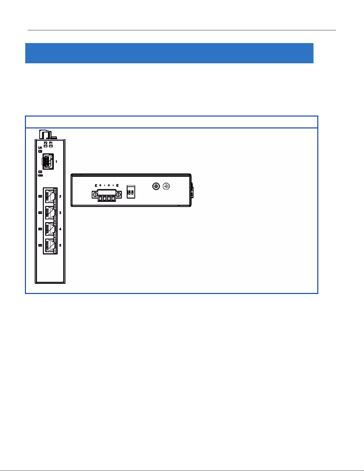
2.1 Faceplate
5-Port Series
2. Overview
11
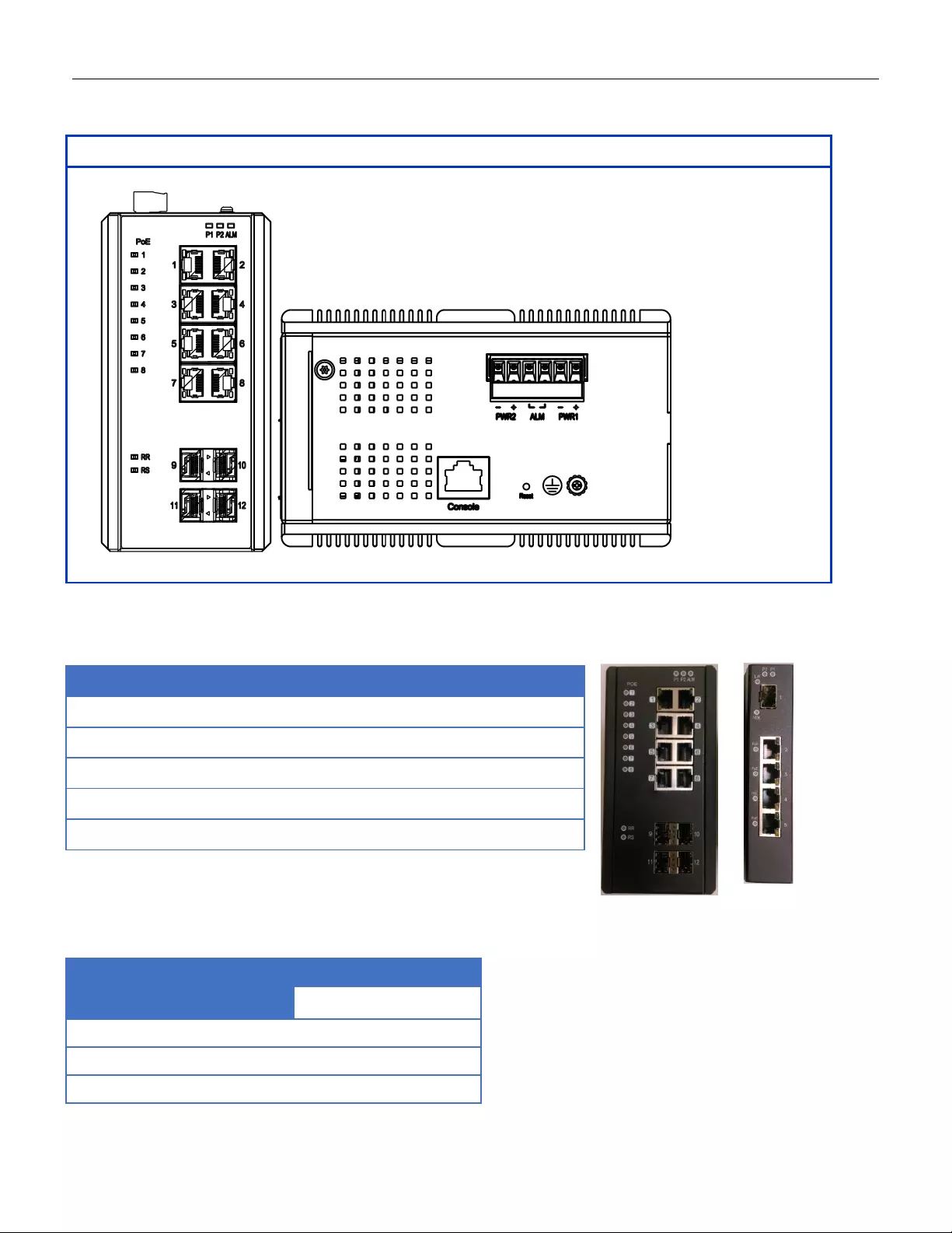
12-Port Series
2.2 Front Panel In t r o duc t ion
Front Panel
System Status LED
P1, P2 and Alarm
Gigabit Ethernet Copper Ports
RJ45
Gigabit Ethernet SFP ports
SFP Slots
POE LED
POE port status
RR/RS LED
Device info/status
Models
L2+ Managed Switch
RGS200-12P
Total Gigabit Ethernet Ports
12
10/100/1000 BaseT(X)
8
100/1000 Base SFP
4
12
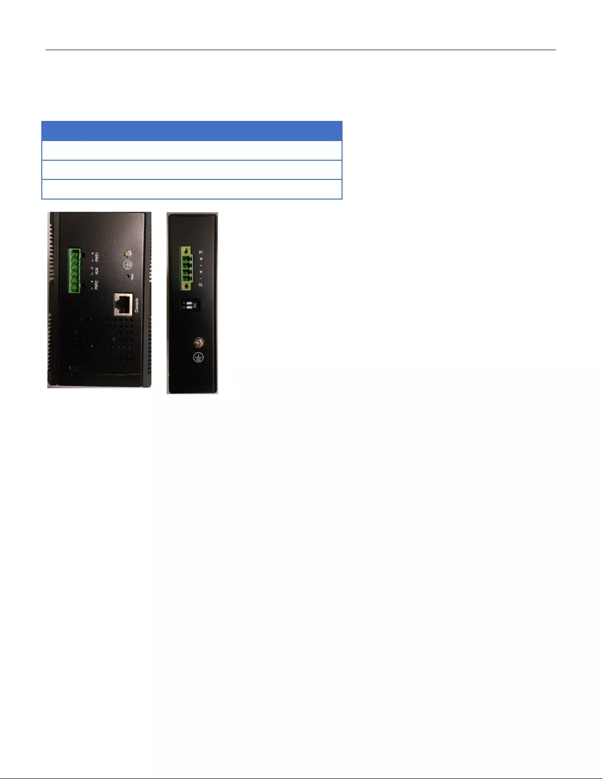
2.3 Top Panel Introduction
Top Panel
Power Input (Dua l)
6P Terminal Block
Console (RS232)
RJ45
Reset
Push Button
13

Quick Installation
Equipment Mountin g
Cable Connecting
Equipment Configuration
14
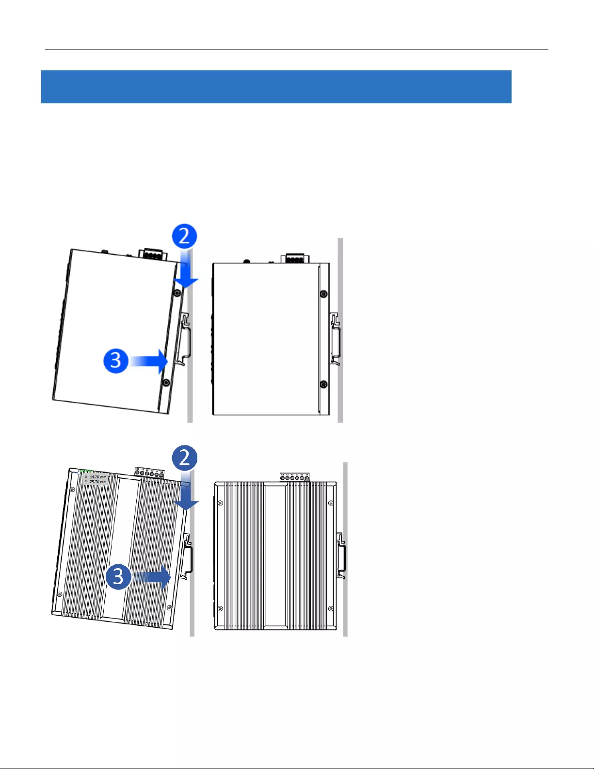
3.1 Mounting the RGS Series (DIN-Rail)
Mounting step:
1. Screw the DIN-Rail bracket on with the bracket and screws in the accessory kit.
2. Hook the unit over the DIN rail.
3. Push the bottom of the unit towards the DIN Rail until it snaps into place.
Figure 1 RGS100-5P DIN-Rail Mounting
Figure 2 RGS200-12P DIN-Rail Mounting
3.Quick Installation
15
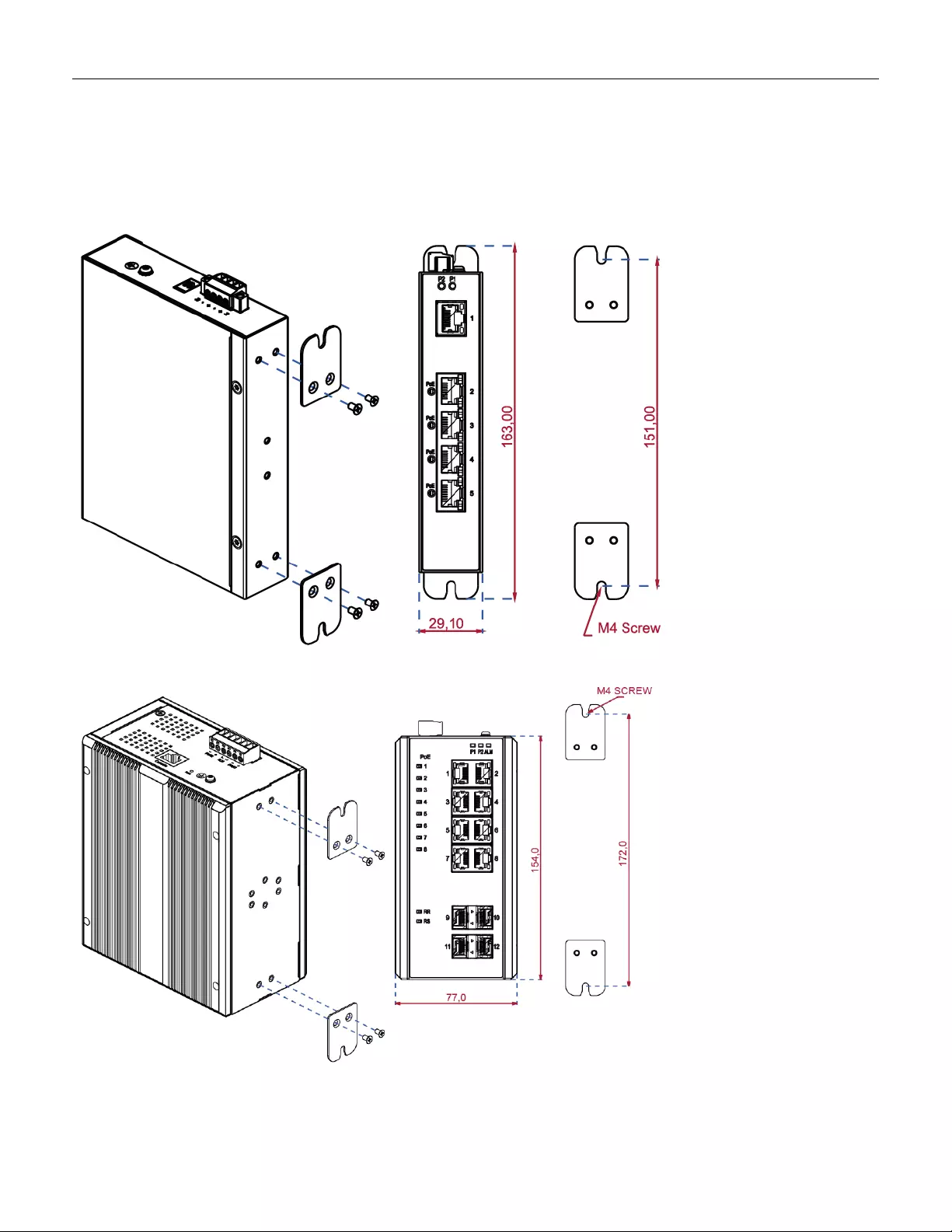
3.2 Mounting the RGS Series (Wall mount)
Mounting step:
1. Screw on the wall-mounting plate on with the plate and screws in the accessory kit.
Figure 3 RGS100-5P Series Wall Mounting
Figure 4 RGS200-12P Series Wall Mounting
16
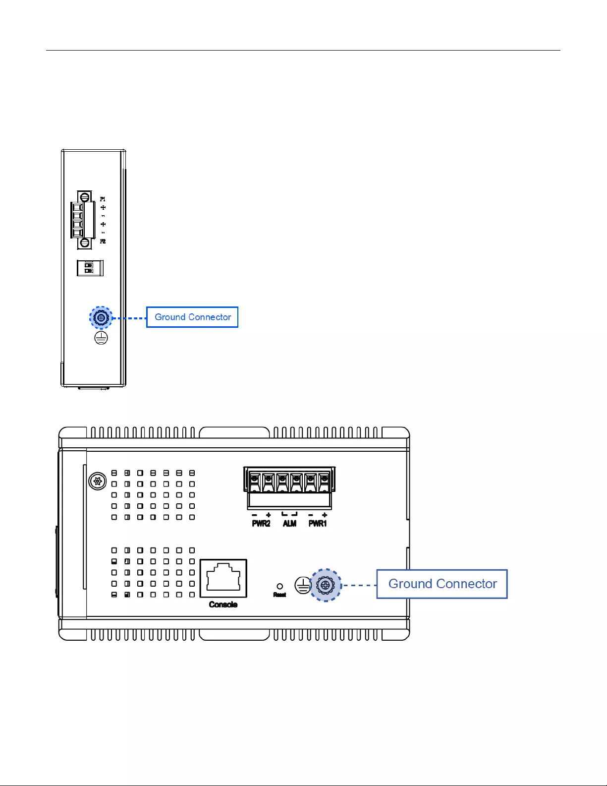
3.3 Ground Connections
RGS Ser ies m ust be properly grounded for optimum system performance.
Figure 5 RGS100-5P Series Ground Co nne c tions
Figure 6 RGS200-12P Series Ground Connecti ons
17
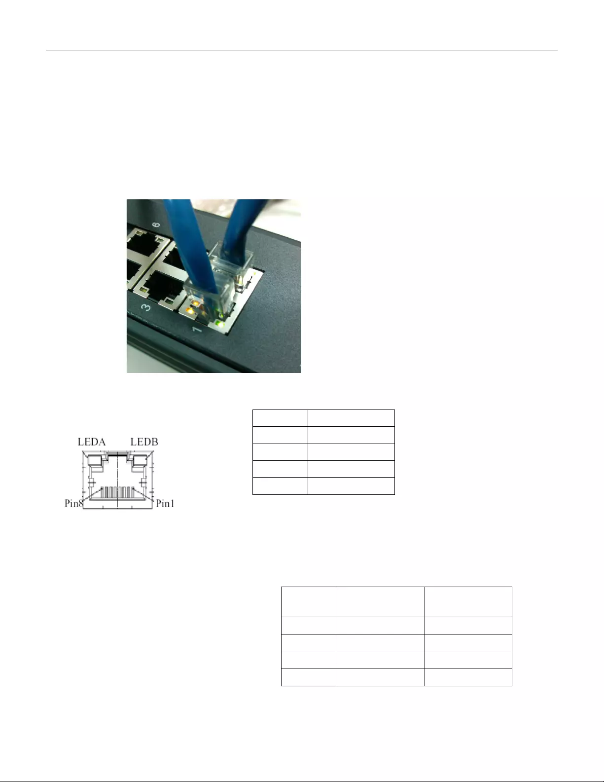
3.4 Connecting the Ethernet Interface ( RJ45 Ethernet)
The switch provides two types of Ethernet interfaces: electrical (RJ45) and optical (SFP) interfaces.
Connecting the Ethernet interface via RJ45:
• To connect the switch to a PC, use straight-through or cross-over Ethernet cables.
• To connect the switch to an Ethernet device, use UTP (Unshielded Twisted Pair) or STP (Shielded Twisted
Pair) Ethernet cables.
The pin assignment of RJ-45 connector is shown in the following figure and table.
The pin assignment of RJ-45 connector is shown in the following figure an d table.
RGS Series
RGS200-12P series
Pin Assignment PoE
Assignment
1,2 T/Rx+,T/Rx- Positive VPort
3,6 T/Rx+,T/Rx- Negative VPort
4,5 T/Rx+,T/Rx- X
7,8 T/Rx+,T/Rx- X
Pin Assignment
1,2 T/Rx+,T/Rx-
3,6 T/Rx+,T/Rx-
4,5 T/Rx+,T/Rx-
7,8 T/Rx+,T/Rx-
18
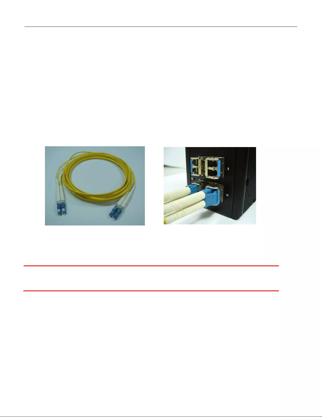
3.5 Connecting the Ethernet Interface (Fiber)
Prepare a proper SFP module and install it into the optical port. Then you can connect fiber optics cabling
that uses LC connec tors or SC connectors (w ith the use o f an op tional SC-to-LC adapter) to the fiber optics
connector. For a 100 Mbps fiber port available, please prepare the LC connectors or SC connectors (with the use of
an optional SC-to-LC adapter). They are also available with multimode, single mode, long-haul (for connections up to
120+ km) or special-application transceivers.
For a 1000 Mbps fiber port available, please use the mini-GBIC SFP (small form pluggable). These accept plug in
fiber transceivers that typically have an LC style connector . They are available with multimode, single mode, long-haul
(for connections up to 80+ km) or special-application transceivers.
For each fiber port there is a transmit (TX) and receive (RX) signal. Please make sure that the transmit (TX) port of
the switch connects to the receiver (RX) port of the other device, and the receive (RX) port of the switch connects to
the transmit (TX) port of the other device when making your fiber optic connections.
Refer to Table 1 for the normal operational LED status.
Fiber optic s cable with LC duplex
connector
Connect the optical fiber to the SFP
socket
DANGER:
Never attempt to view optical connectors that might be emitting laser energy.
Do not power up the lase r p roduct without connecting the laser to the optical fiber and
putting the cover in position, as laser outputs will emit infrared laser light at this point.
19
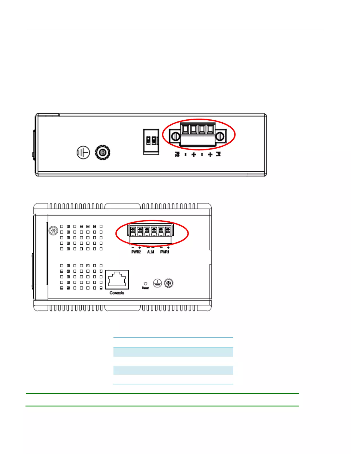
3.6 P ower Conn ection
The DC power interface is a 6-pin terminal block with polarity signs on the top panel.
The RGS200-12P can be powered from two power supply (input range 12V – 58V). The DC power
connector is a 6-pin terminal block; there is alarm contact on the middle terminal block.
Refer to Table 1 for the normal operational LED status.
Figure 7 RGS100-5P Series Power Connections
Figure 8 RGS200-12P Seri e s Ground Co nnections
Note: 1. The DC power should be connected to a well-fused power supply.
Power Connector (6P Terminal Block)
Input
DC 12-58V
PWR1 +/-
Power Input 1 +/-
PWR2 +/-
Power Input 2 +/-
ALM
Alarm relay output
20
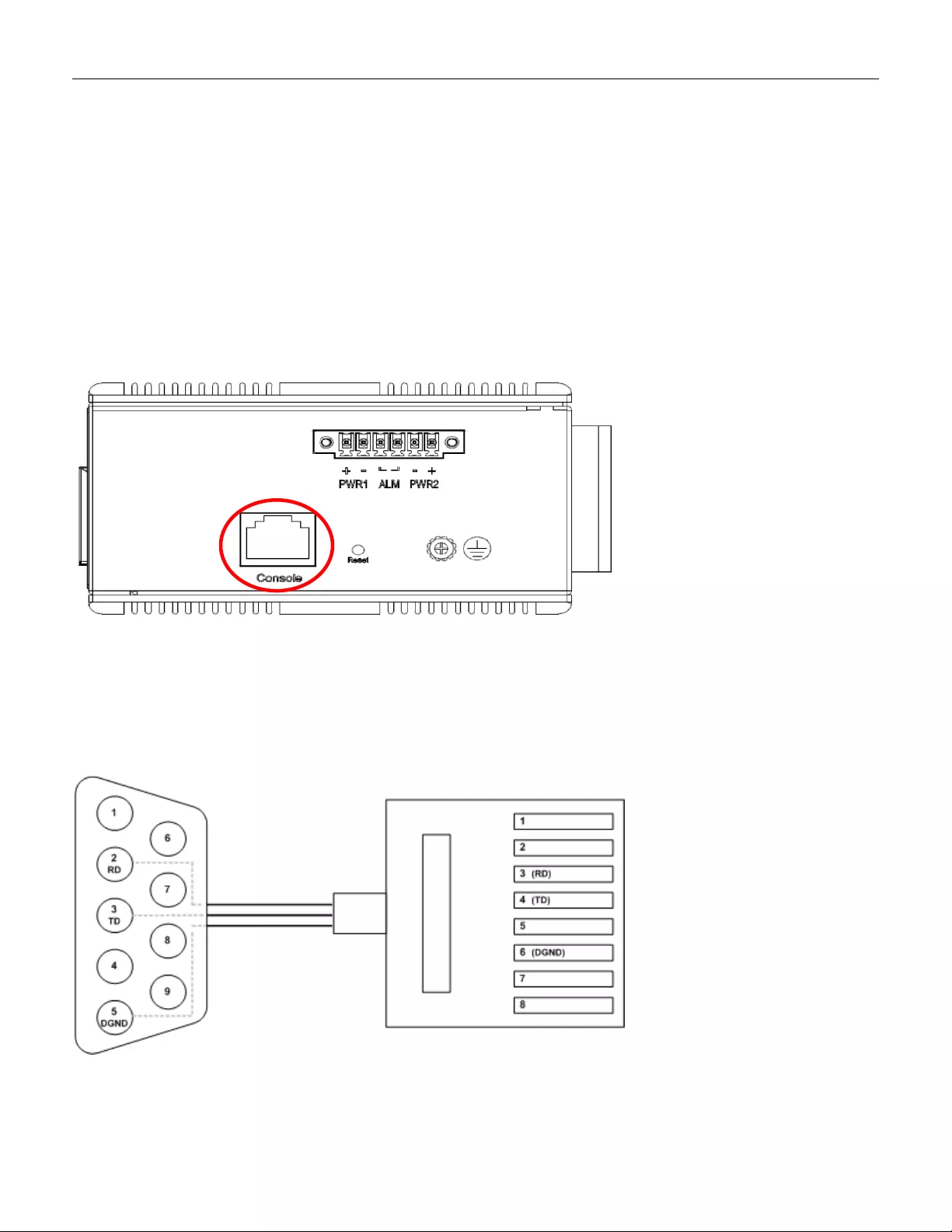
3.7 Console Connection
The Console port is for local management by using a terminal emulator or a computer with terminal
emulation software.
• DB9 connector connect to computer COM port
• Baud rate: 115200bps
• 8 data bits, 1 stop bit
• None parity
• None flow control
Figure 10 RGS200-12P Seri e s Ground Connections
To connect the host PC to the console port, a RJ45 (male) connector-to-RS232 DB9 (female) connector
cable is required. The RJ45 connector of the cable is connected to the CID port of RGS200-12P; the DB9
connector of the cable is connected to the PC COM port. The pi n assi gnment of the console cable i s show n
below:
21
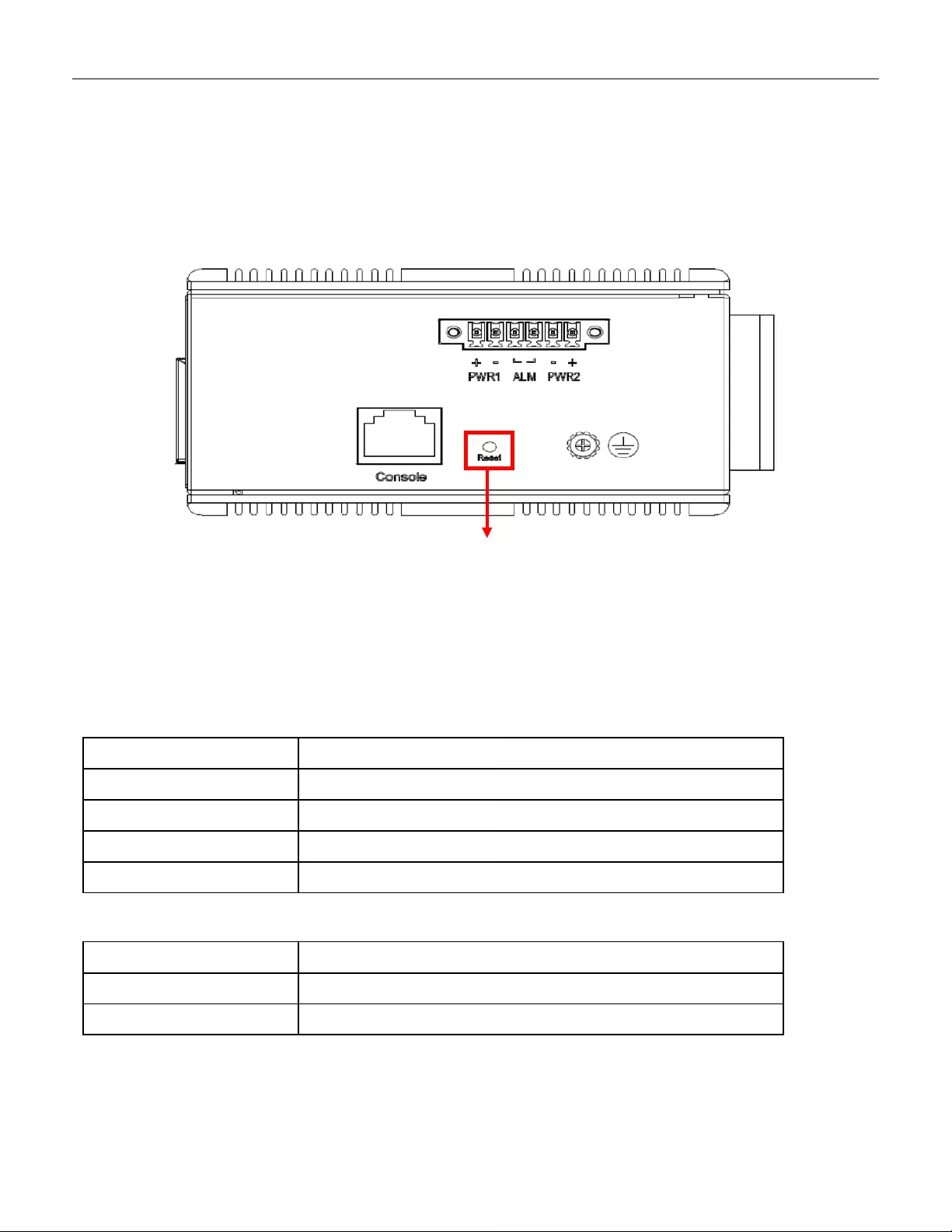
3.8 SYST EM RESET
The Reset button is provided to reboot the system without the need to remove power. Under normal
circumstances, you will not have to use it. However, or rare occasions, the RGS200-12P may not respond;
then you may need to push the Reset button.
3.9 Web Interface Initialization (Optional)
Web Browser Support
IE 7 (or newer version) with the following default settings is recommended:
Language script Latin based
Web page font Times New Roman
Plain text font Courier New
Encoding Unicode (UTF-8)
Text size Medium
Firefox w ith t he following defau lt set tings is reco m mended:
Web page font Times New Roman
Encoding Unicode (UTF-8)
Text size 16
Reset Button
22

Google Chrome with the following default settings is recommended:
Web page font Times New Roman
Encoding Unicode (UTF-8)
Text size Medium
Connect & Login to RGS200-12P
1. Connecting to RGS200-12P Ethernet port (RJ45 Ethernet port).
2. Factory default IP: 192.168.1.1
3. Login with default account and password.
Username: admin
Password: 1234
23
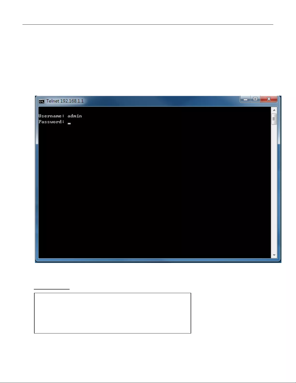
3.10 CLI Initialization & Configuration (Optional)
1. Connecting to RGS200-12P Ethernet port(RJ45 Ethernet port)
2. Key-in the command under Telnet: telnet 192.168.1.1
3. Login with default account and password.
Username: admin
Password: 1234
4. Change the IP with commands listed below:
CLI Command:
enable
configure terminal
interface vlan 1
ip address xxx.xxx.xxx.xxx xxx.xxx.xxx.xxx
exit
24
3.11 Monitoring the Ethernet Interface
By RJ45 Ethernet:
Refer to Figure 11 LED I ndicat or s for monitoring 8 Gigabit Ethernet with copper connector (RJ45). Also
refer to Table 1 for the normal operational LED status.
By SFP:
Refer to Figure 11 LED I ndicat or s for monitoring 4 Gigabit Ethernet with SFP connector. Also refer to
Table 1 for the normal operational LED status.
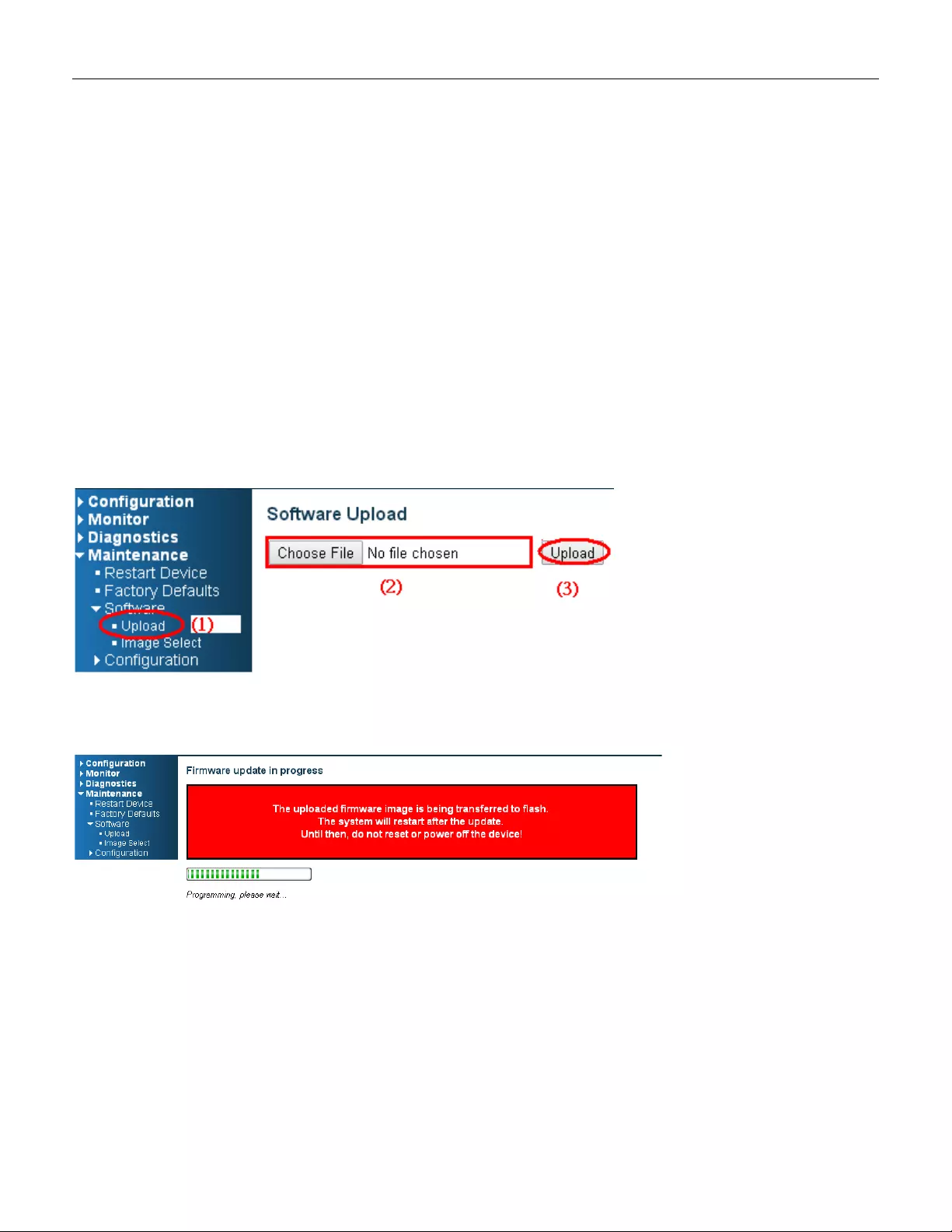
3.12 Upgrade Software
1. In Web UI, go to “MaintenanceSoftwareUpload” page.
2. Select software file, and click “Upload” button.
3. After starting to upload software to devi ce, please don’ t col d/w arm s tart device and wait it auto reboot,
then upgrade finished .
25
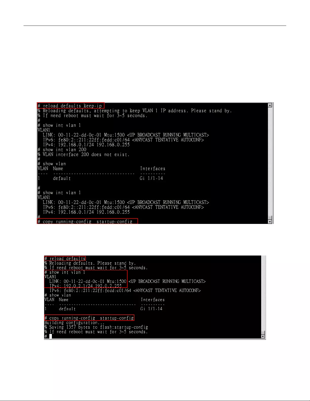
3.13 Reset to Default and Save Configure
Configur a t ion via CLI command
To see what current interface and IP address is:
If the manager wants to reset the configuration to default, but keep management IP setting.
(1) Please execute this command: reload defaults keep-ip
(2) Check interface VLAN and IP address; confirm only management IP setting kept.
(3) Execute this command: copy running-config startup-config
If manager want to reset the all configuration to default completely
(1) Please execute this command: reload defaults
(2) Check interface VLAN and IP address, confirm they all change to default setting.
(3) Execute this command: copy running-config startup-config
26

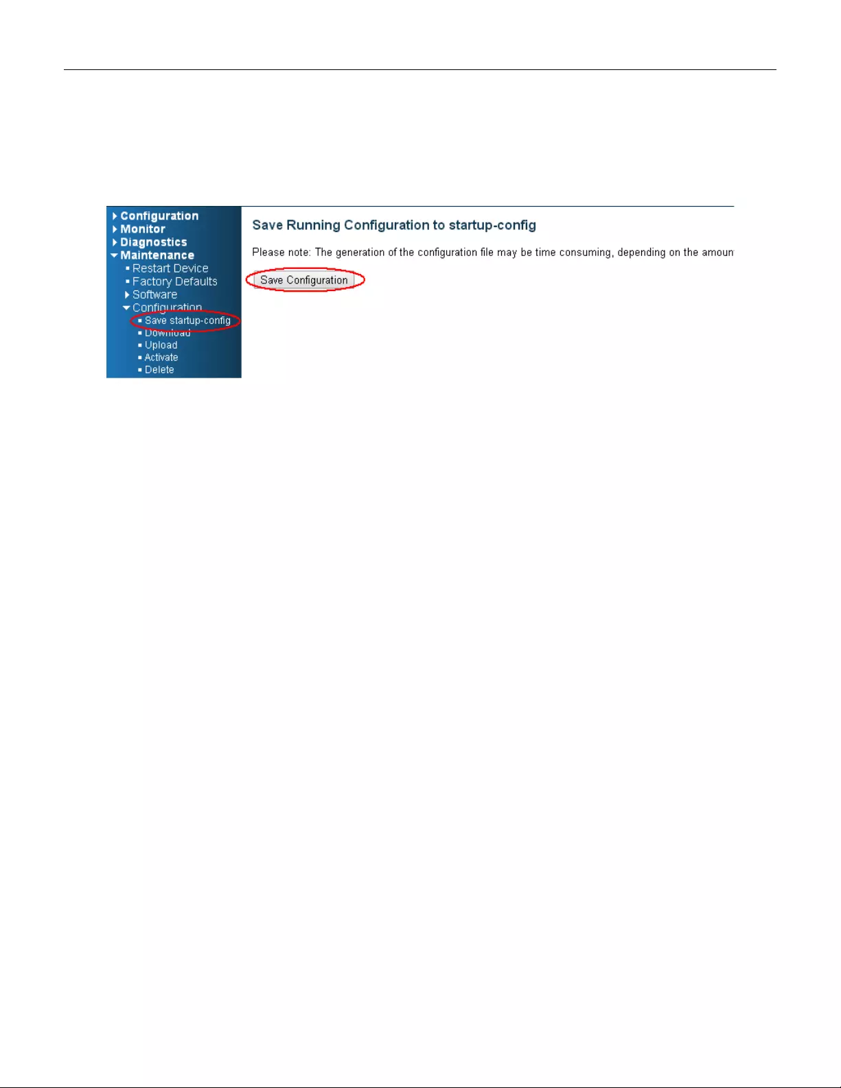
Configur a t ion via WEB UI
If manager want to reset the configuration to default but keep management IP setting
(1)Go to “Maintenance”” Fact ory Defaults” pagination to Click “Yes” button.
(2) Go to “Maintenance” “Configuration””Save startup-config” pagination, then click “Sav e
Configuration” button, then reset successfully
.
If manager want to reset the all configuration to default completely
(1) Go to “Maintenance” “Configuration””Activate” pagination to select “default-config”, then click
“Activate Configura tion” button
27
(2) Change W EB’s IP be 192.0.2.1(default IP) to login DUT’s Web UI.
(3) Go to “Maintenance” “Configuration””Save startup-config” pagination, then click “Save
Configuration” button, then reset successfully.
28

3.14 DIP Switch Setting for RGS100-5P
Pin
No#
Status
5-Port (4TX+1SFP) with PoE
Pin 1
ON
To enable Broadcast storm rate limit
OFF
To disable Broadcast storm rate limit
Pin 2
ON
NOT USED
OFF
NOT USED
3.15 LED STATUS INDIC ATIONS
Table 1 LED Status Indica t ors
LED
Name Indicator
/color Condition
P1/P2 On Green P1/P2 power line has power
Off
P1/P2 power line disconnect or does not have power supplied
Alarm
On Red
Ethernet link fails, alar m or power failure alarm occurs
Off No Ethernet link fails and no power failure alarm
Copper
port
Link/Act
On Green
Ethernet link up but no traffic is detected
Flashing
Green Ethernet link up and there is traffic detected
Off
Ethernet link down
Copper
port
Speed
On Yellow
A 1000Mbps connection is detected
Off No link, a 10Mbps or 100 Mbps connection is detected
SFP
port
Link/A
ct
On Green Ethernet link up
Off Ethernet link down
SFP
port
Speed
On Yellow SFP port speed 1000Mbps connection is detected.
Off No link or a SFP port speed 100Mbps connection is detected
POE On Green POE is work in g
Off POE is not working
29
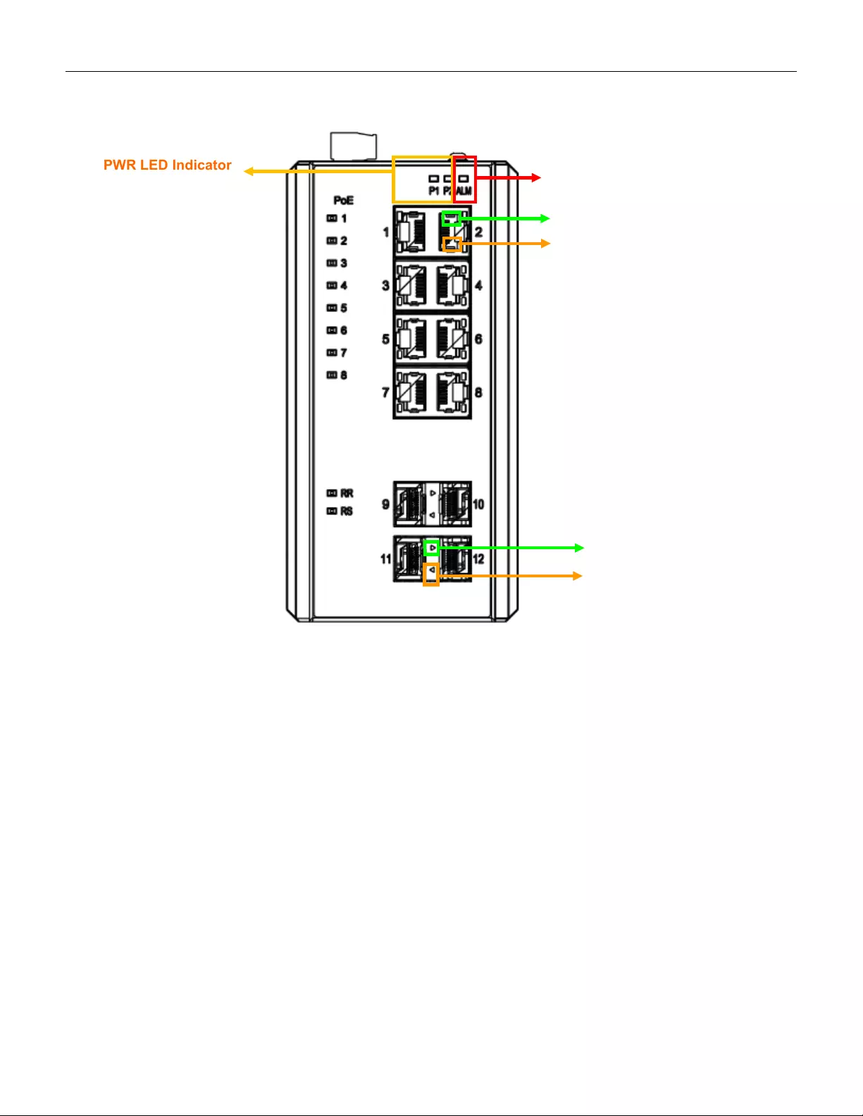
PWR LED Indicator
Figure 11 LED Indicators
ALM LED Indicator
Copper Speed LED
Copper Link/Act LED
SFP Speed LED
Indicator
SFP Link LED Indicator
30
4.1 S ystem Description
RGS Series delivers high quality, wide operating temperature range, extended power input range, IP-30
design, and advanced VLAN & QoS features. It’s ideal for harsh environments and mission critical
applications.
RGS Series Managed QoS provides enterprise-class networking features to fulfill the needs of large
network infrastructure and extreme environments.
RGS Series eases the effort to build a network infrastruct ure which offers a reliable, well managed and
good QoS networking for any business requiring continuous and well-protected services in management
environments. With the features such as Fast Failover ring protection and QoS, customers can ensure
their network is qualified to deliver any real-time and high quality applications.
4.2 Using the Web Interf ace
The object of this document “RGS Web Configuration Tool Guide” is to address the web feature, design
layout and descript how to use the web interface.
4.2.1 Web Browser Support
IE 7 (or newer version) with the following default settings is recommended:
Language script Latin based
Web page font Times New Roman
Plain text fon t Courier New
Encoding Unicode (UTF-8)
Text size Medium
Firefox with the following default settings is recommended:
Web page font Times New Roman
Encoding Unicode (UTF-8)
Text size 16
Google Chrome with the following default settings is recommended:
Web page font Times New Roman
Encoding Unicode (UTF-8)
4. Introduction
Note: The following web user guide is for RGS200-12P model.
31
Text size Medium
4.2.2 Navigation
All main screens of the web interface can be reached by clicking on hyperlinks in the four menu boxes on
the left side of the screen:
Configuration
Monitor
Diagnostics
Maintenance
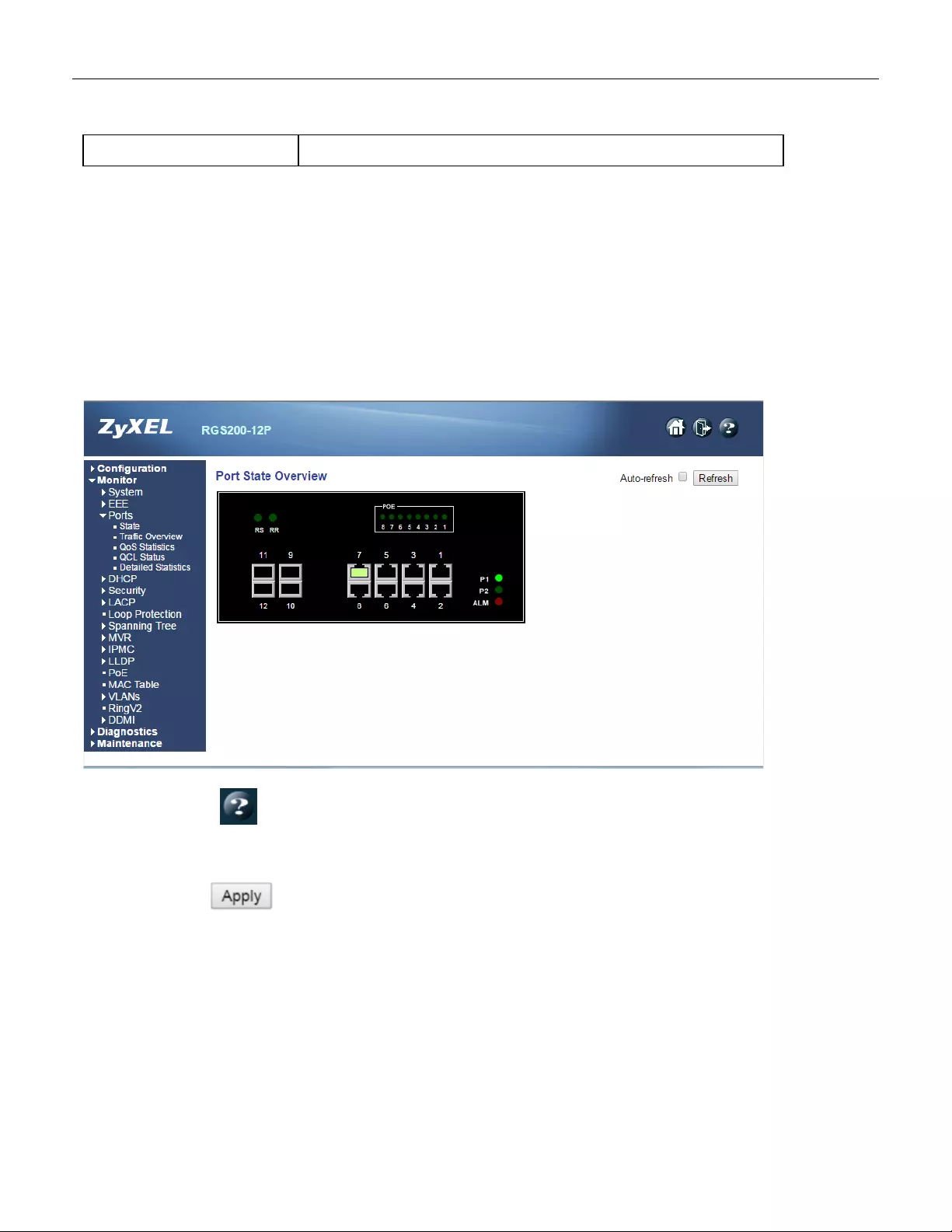
4.2.3 Title Bar Icons
Help Button
For more information about any screen, click on the Help button on the screen.
Help information is displayed in the same window.
Apply Button
Click Apply to apply the config uration changes to the device.
4.2.4 Ending a Session
To end a session, close your web browser. This prevents an unauthorized user from accessing the system
using your user name and password.
32

4.3 Using the Online Help
Each screen has a Help button that invokes a page of information relevant to the particular screen. The
Help is displayed in a new window.
Each web page of Configuration/Status/System functions has a corresponding help page.
33
5. Using the Web
5.1 Login
5.2 Tree View
The tree view is a menu o f the web. It of fers user quickly to get the pa ge for expected data or con figuration.
Operation 1. Fill Username and Password
2. Click “Sign in”
Field Description
Username Login user name. The maximum length is 32.
Default: admin
Password Login user password. The maximum length is 32.
Default: none
34

5.2.1 Configuration Menu
35
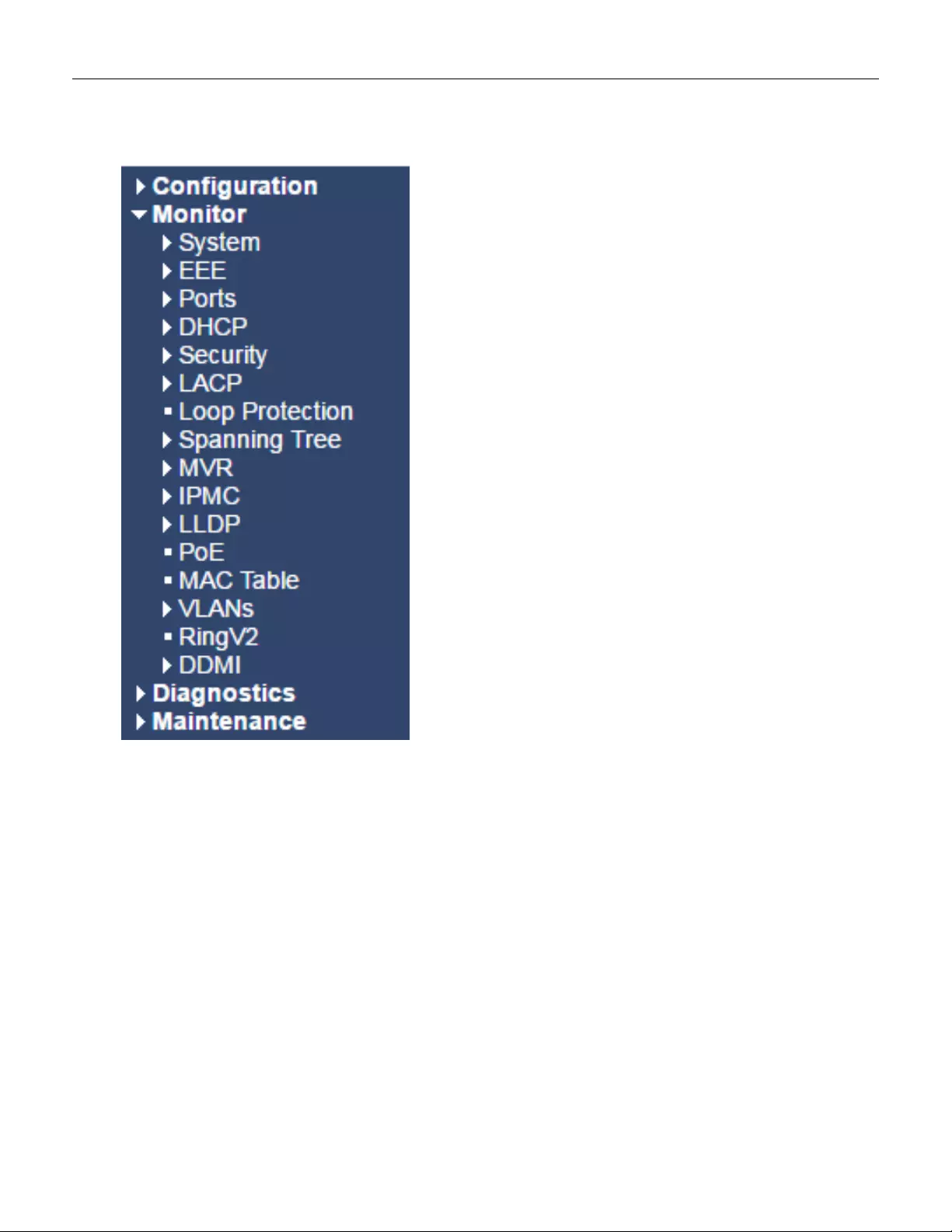
5.2.2 Monitor Menu
36
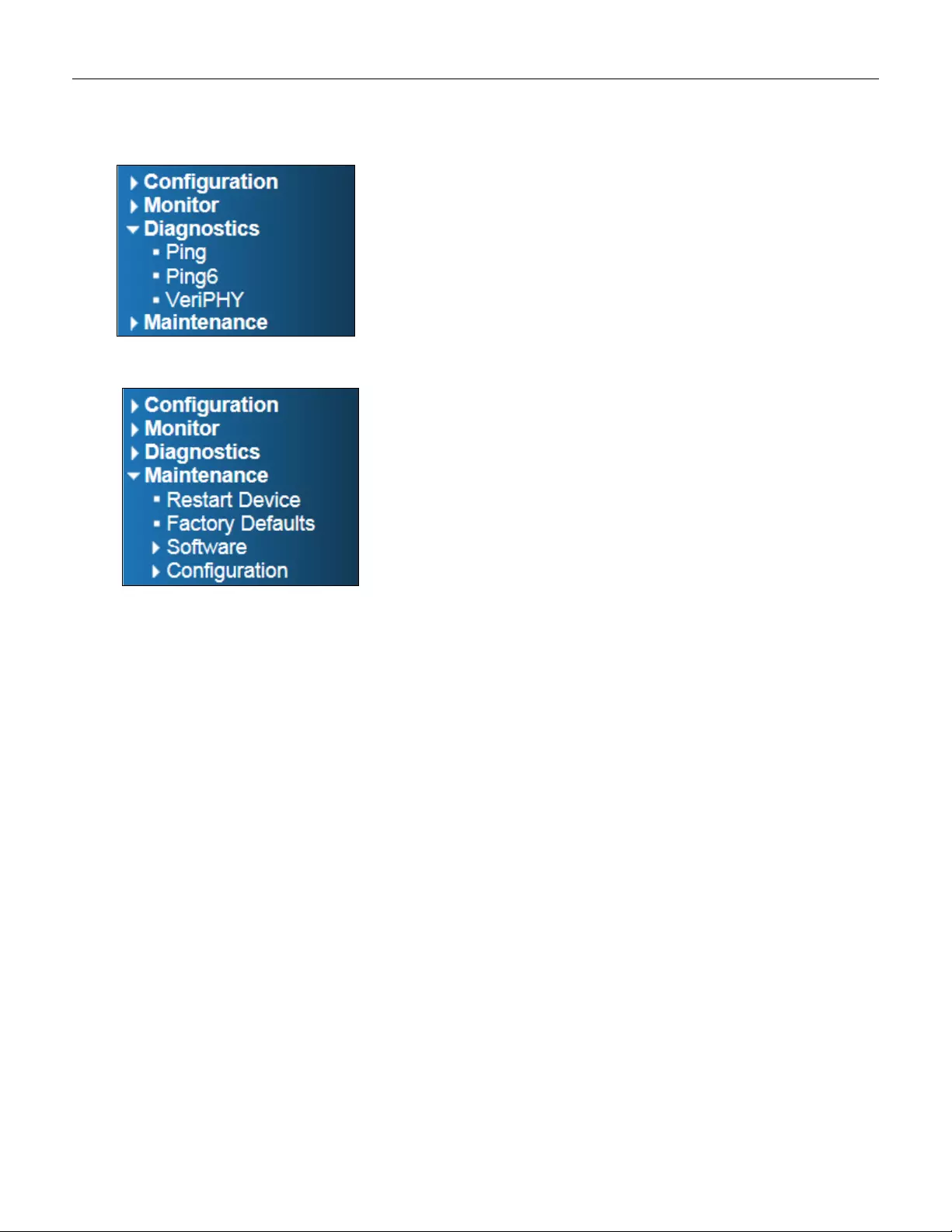
5.2.3 Diagnostics Menu
5.2.4 Maintenance Menu
37
5.3 Configuration
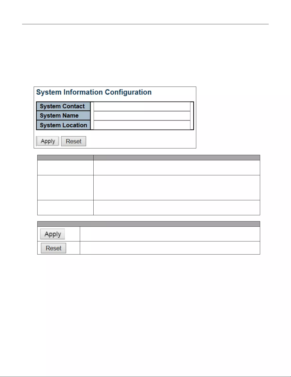
5.3.1 System Information
The switch system information is provided here.
Object
Description
System Contact
The textual identification of the contact person for this managed node, together with
information on how to contact this person. The allowed string length is 0 to 255, and
the allowed content is the ASCII characters from 32 to 126.
System Name
An administratively assigned name for this managed node. By convention, this is the
node's fully -qualified domain name. A domain name is a text string drawn from the
alphabet (A-Za-z), digits (0-9), minu s sign (-). No space char a cters are perm itte d as
part of a name. The first character must be an alpha character. And the first or last
character must not be a minus sign. The allowed string length is 0 to 255.
System Location
The physical location of this node (e.g., telephone closet, 3rd floor). The allowed
string length is 0 to 255, and the allowed content is the ASCII characters from 32 to
126.
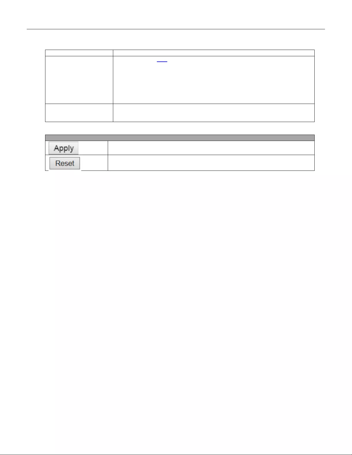
Buttons
Click to apply changes.
Click to revert to previously saved values.
38
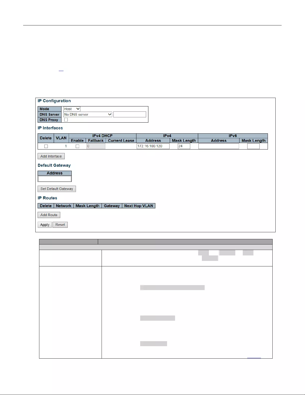
5.3.2 System IP
Configure IP basic settings, control IP interfaces and IP routes.
The maximum number of interfaces supported is 8 and the maximum number of routes is 32.
Object
Description
IP Configuration
Mode
Configure whether the IP stack should act as a Host or a Router. In Host mode,
IP traffic between interfaces will not be routed. In Router mode t raffic is routed
between all interfaces.
DNS Server
This setting controls the DNS name resolution done by the switch. The
following mod es are supp orted :
• From any DHCP interfaces
The first DNS server offered from a DHCP lease to a
DHCP-enabled interface will be used.
• No DNS server
No DNS server will be used.
• Configured
Explicitly provide the IP address of the DNS Server in dotted
39

decimal notation.
• From this DHCP interface
Specify from which DHCP-ena bled interface a provide d DNS
server should be preferred.
DNS Proxy
When DNS proxy is enabled, system will relay DNS requests to the currently
configured DNS server, and reply as a DNS resolver to the client devices on the
network.
IP Interfaces
Delete
Select this option to delete an ex isting IP int er fa ce.
VLAN
The VLAN associated with the IP interface. Only ports in this VLAN will be able to
access the IP interface. This field is only availabl e for inp ut when cr eat ing a new
interface.
IPv4 DHCP Enabled
Enable the DHCP client by checking this box. If this option is enabled, the system
will configure the IPv4 address and mask of the interface using the DHCP protocol.
The DHCP client will announce the configured System Name as hostname to
provide DNS lookup.
IPv4 DHCP Fallback
Timeout
The number of seconds for trying to obtain a DHCP lease. After this period expires,
a configured IPv4 address will be used as IPv4 interface address. A value of zero
disables the fallback mechanism, such that DHCP will keep retrying until a valid
lease is obtain ed. Legal value s are 0 to 4294967295 se con d s.
IPv4 DHCP Current Lease
For DHCP interfaces with an active lease, this column shows the current int erfa ce
address, as provided by the DHCP server.
IPv4 A ddress
The IPv4 address of the interface in dotted deci mal nota t ion .
If DHCP is enabled, this field configures the fallback address. The field may be left
blank if IPv 4 opera tion o n t he i nterface is not de sire d - or no DHCP fallback addre s s
is desired.
IPv4 Mask
The IPv 4 netw ork mask, in n umber of bits ( prefix l ength) . Valid values are b etw een 0
and 30 bits for an IPv4 address.
If DHCP
is enabl ed, this field co nfigures the fallbac k addre ss n et w or k mask . The fie l d
may be left blank if IPv4 opera tion on the inter fa ce is not des i red - or no DHCP
fallback address is desired.
IPv6 A ddress
The IPv 6 a ddress of th e interf a ce. An IPv6 address is in 128-bit r ec or ds re pres ent e d
as eight fields of up to four hexadecimal digits with a colon separating each field (:).
For example, fe80::215:c5ff:fe03:4dc7. The symb ol :: is a special syntax
that can be used as a shorthand way of representing multiple 16-bit groups of
contiguous zeros; but it can appear only once. It can also represent a legally valid
IPv4 address. For example, ::192.1.2.34.
The field may be left blank if IPv6 operation on the interface is not desired.
IPv6 Mask
The IPv 6 netw ork mask, in n umber of bits ( prefix l ength) . Valid values are b etw een 1
and 128 bits for an IPv6 address.
The field may be left blank if IPv6 operation on the interface is not desired.
Default Gateway
Address
The IP address of the gateway valid format is dot ted dec ima l notation.
IP Routes
Delete
Select this option to delete an existing IP route.
Network
The destination IP network or host address of this route. Valid format is
notation
or a valid IPv6 notation. A default route can use the value 0.0.0.0or IPv6 ::
notation.
Mask Length
The destination IP network or host mask, in number of bits (prefix length). It defines
how much of a network address that must match, in order to qualify for this route.
Val id values are between 0 and 32 bits respectively 128 for IPv6 routes. Only a
default route will have a mask length of 0 (as it will match anything).
Gateway
The IP address of the I P gat eway. Valid format is
notation or
a valid IPv 6 notation.
Gateway and Network must be of the same type.
Next Hop VLAN(Only for
IPv6)
The VLAN ID (VID) of the specific IPv6 interface associated with the gateway.
The given VID ranges from 1 to 4094 and will be effective only when the
40
corresponding IPv6 interface is valid.
If the IPv6 gateway address is link-local, it must specify the next hop VLAN for the
gateway.
If the IPv6 gateway address is not link-local, system ignores the next hop VLAN for
the gateway.
Buttons
Click to add a new IP interface. A maximum of 8 interfaces is supported.
Click to save changes.
Click to add a new IP route. A maximum of 32 r out es is sup p orted.
Click to apply changes.
Click to revert to previously saved values.
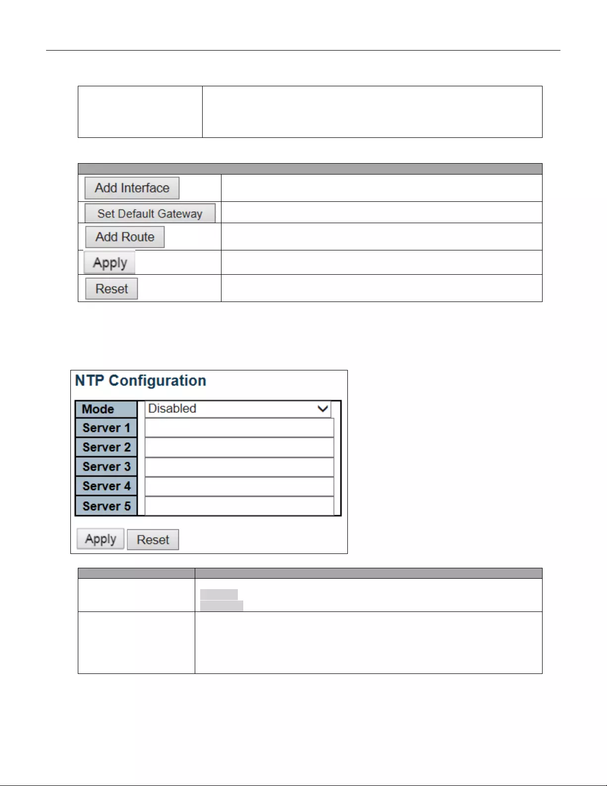
5.3.3 System NTP
Configure NTP on this page.
Object
Description
Mode
Indicates the NTP mode operation. Possible modes are:
Enabled: Enable NTP client mode operation.
Disabled: Disable NTP client mode operation.
Server #
Provide the IPv4 or IPv6 address of a NTP server. IPv6 address is in 128-bit records
represented as eight fields of up to four hexadecimal digits with a col on separ ati ng
each field (:). For example, 'fe80::215:c5ff:fe03:4dc7'. The symbol '::' is a special
syntax that can be used as a shorthand way of representing multiple 16-bit group s of
contiguous zeros; but it can appear only once. It can also represent a legally valid
IPv4 address. For example, '::192.1.2.34'.
41
Buttons
Click to apply changes.
Click to undo any changes made locally and revert to previously saved values.
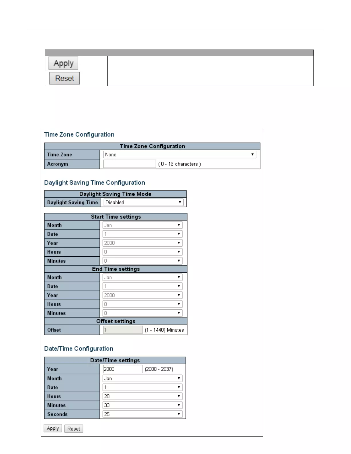
5.3.4 System Time
This page allows you to configure the Time Zone.
42

Object
Description
Time Zone Configur ati on
Time Zone
Lists various Time Zones worldwide. Select appropriate Time Zone from the drop
down and click Save to set.
Acronym
User can set the acronym of the time zone. This is a User configurable acronym to
identify the time zone. ( Range : Up to 16 characters )
Daylight Saving Time Configuration
Daylight Saving Time
This is used to set the clock forward or backward according to the configurations set
below for a defined Daylight Saving Time duration. Select 'Disable' to disable the
Daylight Saving Time configuration. Select 'Recurring' and configure the Daylight
Saving Time duration to repeat the configuration every year. Select 'Non-Recurring'
and configure the Daylight Saving Time duration for single time configuration.
( Default : Disabled )
Recurring Configurations
Start time settings
Week
Select the starting week number.
Day
Select the starting day.
Month
Select the starting month.
Hours
Select the starting hour.
Minutes
Select the starting minute
End time settin gs
Week
Select the ending week number.
Day
Select the ending day.
Month
Select the ending month.
Hours
Select the ending hour.
Minutes
Select the ending minute
Offset settings
Offset
Enter the numb er of m inut es t o add during Dayli ght Sav ing Time. ( Range: 1 to 1 440 )
Non Recurring Configurations
Start time settings
Month
Select the starting month.
Date
Select the starting date.
Year
Select the starting year.
Hours
Select the starting hour.
Minutes
Select the starting minute
End time settings
Month
Select the ending month.
Date
Select the ending date.
Year
Select the ending year.
Hours
Select the ending hour.
Minutes
Select the ending minute
Offset settings
Offset
Enter the numb er of m inut es t o add during Dayli ght Sav ing Time. ( Ran ge: 1 to 1 440 )
Date/Time Configuration
Date/Time Settings
Year
Year of current datetime. ( Range: 2000 to 2037 )
Month
Month of current datetime.
Date
Date of current datetime.
Hours
Hour of current datetime.
Minutes
Minute of current datetime.
Seconds
Second of current datetime.
43
Buttons
Click to apply changes.
Click to undo any changes made locally and revert to previously saved values.
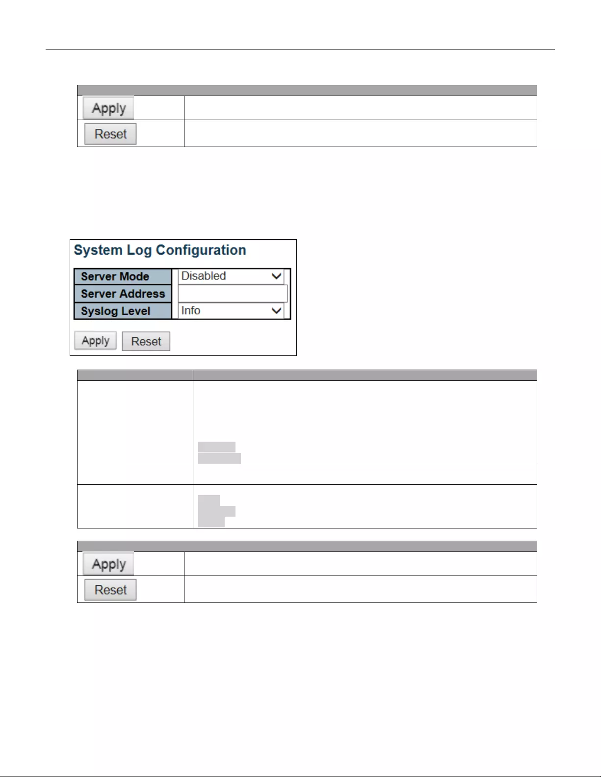
5.3.5 System Lo g
Configure System Log on this page.
Object
Description
Server Mode
Indicates th e ser v er m ode ope r ation . When the mode op er ati on i s en abl ed, t he sy sl o g
message will send out to syslog server. The syslog protocol is based on UDP
communication and received on UDP port 514 and the syslog server will not send
acknowledgments back sender since UDP is a connectionless protocol and it does
not provide acknowledgments. The syslog packet will always send out even if the
syslog server does not exist. Possible modes are:
Enabled: Enable server mode operation.
Disabled: Disable server mode operation.
Server Ad dress
Indicates the IPv4 host address of syslog server. If the switch provide DNS feature, it
also can be a host name.
Syslog Level
Indicates what kind of message will send to syslog server. Possible modes are:
Info: Send information, w arnings and error s .
Warning: Send warnings and errors.
Error: Send errors.
Buttons
Click to apply changes.
Click to undo any changes made locally and revert to previously saved values.
44
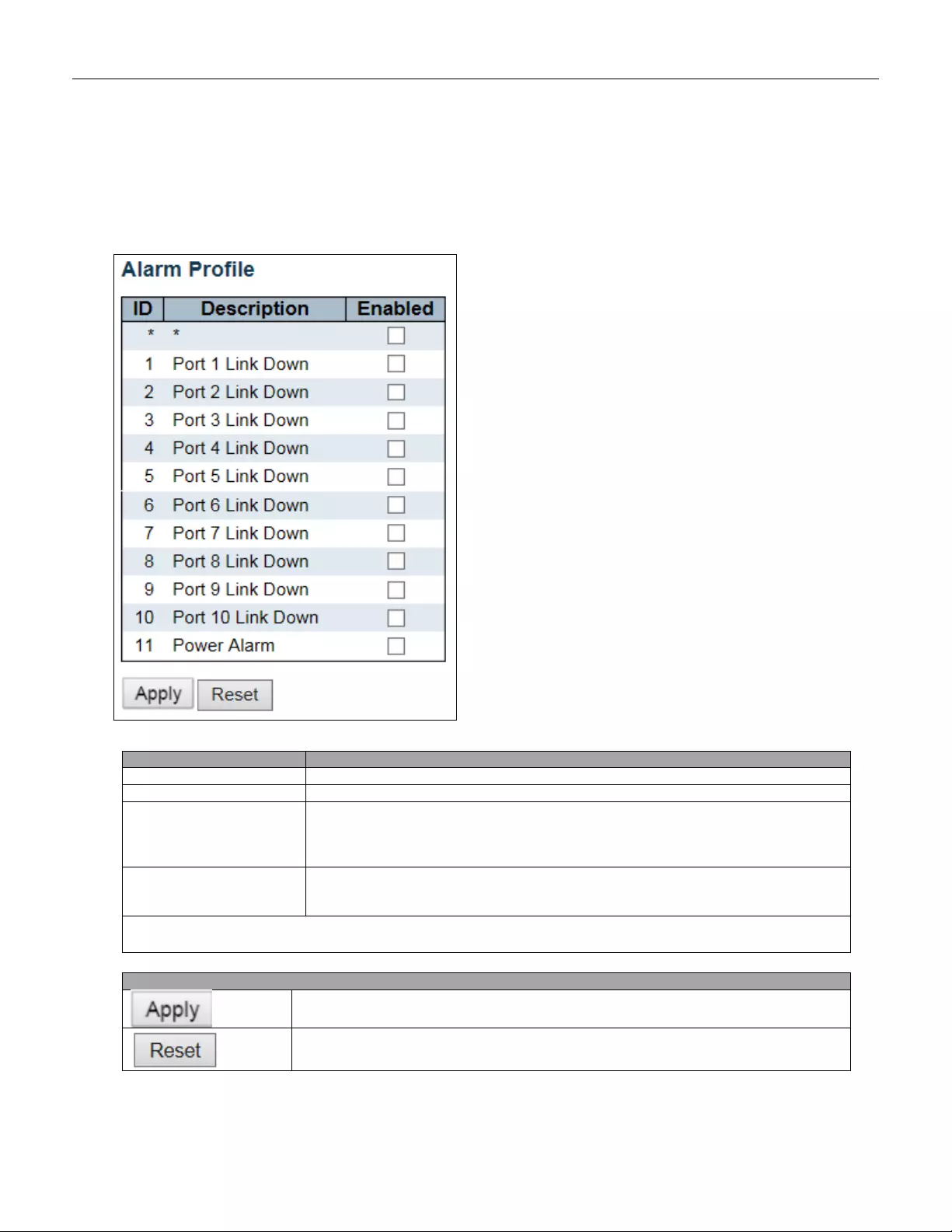
5.3.6 System Alarm Profile
Alarm Profile is provided here to enable/disable alarm.
Object
Description
ID
The identification of the Alarm Profile entry.
Description
Alarm Type D escr ipti on.
Enabled
If alarm entry is Enabled, then alarm will be shown in alarm history/current when it
occurs.
Alarm LED will be on (lighted), Alarm Relay also be enabled.
SNMP trap will be sent if any SNMP trap entry exists and enabled.
Disabled
If alarm entry is Disabled, then alarm will not be captured/shown in alarm
history/current when alarm occurs;
then it will not trigger the Alarm LED change, Alarm Relay and SNMP trap either.
Note: When any alarm exists, the Alarm LED will be on (lighted), Alarm Output Relay will also be
enabled.
Buttons
Click to apply changes.
Click to undo any changes made locally and revert to previously saved values.
45
5.3.7 EEE
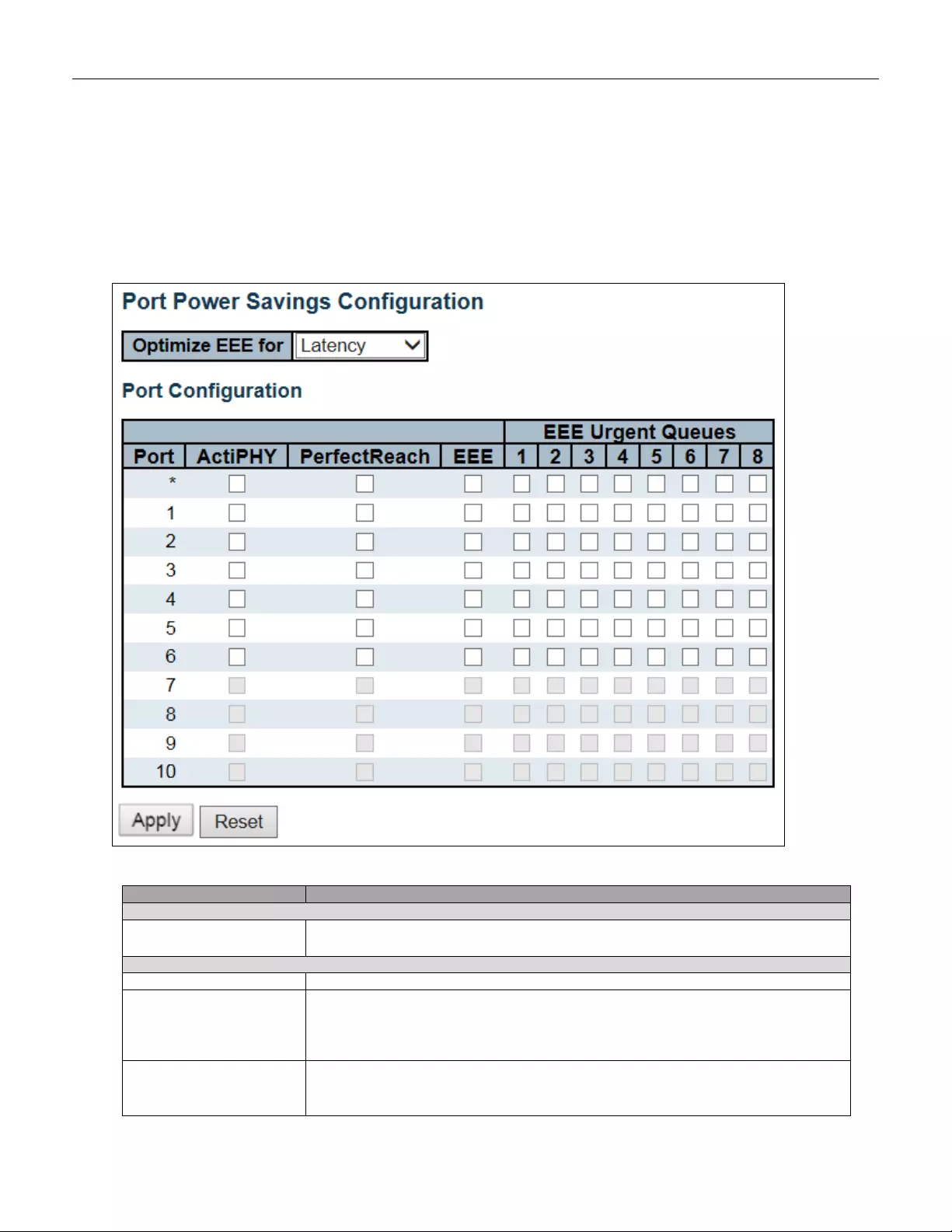
5.3.8 Port Power Savings
This page allows the user to configure the port power savings features.
Object
Description
Port Power Savings Configuration
Optimize EEE for
The switch can be set to optimize EEE for either best power saving or least
traffic latency.
Port Configuration
Port
The switch port number of the logical port.
ActiPHY
Link down power savings enabled.
ActiPHY works by lowering the power for a port when there is no link. The port is
power up for short moment in order to determine if cable is inserted.
PerfectReach
Cable length power savings enabled.
PerfectReach works by determining the cable length and lowering the power for ports
46
with short cables .
EEE
Controls whether EEE is enabled for this switch port.
For maximizing power savings, the circuit isn't started at once transmit data is ready
for a port, but is instead queued until a burst of data is ready to be transmitted. This
will give some traffic latency.
If desired it is possible to minimize the latency for specific frames, by mapping the
frames to a specific queue (done with QOS), and then mark the queue as an urgent
queue. When an urgent queue gets data to be transmitted, the circuits will be
powered up at once and the latency will be reduced to the wakeup time.
EEE Urgent Queues
Queues set will activate transmission of frames as soon as data is available.
Otherwise the queue will postpone transmission until a burst of frames can be
transmitted.
Buttons
Click to apply changes.
Click to undo any changes made locally and revert to previously saved values.
47
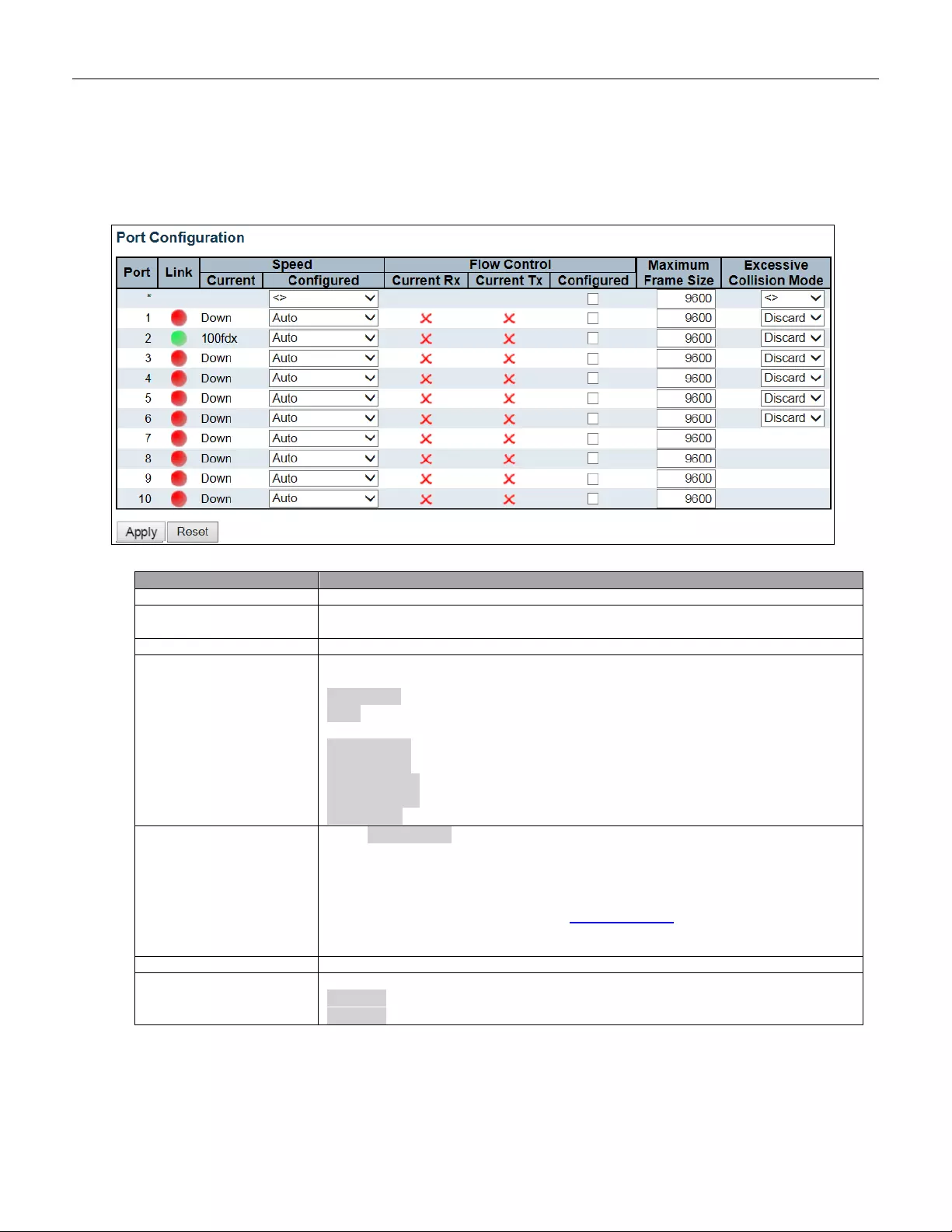
5.3.9 Port
This page displays current port configurations. Ports can also be configured here.
Object
Description
Port
This is the logical port number for this row.
Link
The current link state is displayed graphically. Green indicates the link is up and red
that it is down.
Current Link Speed
Provides the current link speed of the port.
Configured Link Speed
Selects any available link speed for the given switch port. Only speeds supported by
the specific port are shown. Possible speeds are:
Disabled - Disables the switch port operation.
Auto - Por t aut o negotiating s peed with the li nk partner and sele ct s th e highest s pee d
that is compatible with the link partner.
10Mbps HDX - Forces the cu port in 10Mbps half duplex mode.
10Mbps FDX - Forces the cu port in 10Mbps full duplex mode.
100Mbps HDX - Forces the cu port in 100Mbps half duplex mode.
100Mbps FDX - Forces the cu port in 100Mbps full duplex mode.
1Gbps FDX - Forces the port in 1Gbps full duplex.
Flow Control
When Auto Speed is selected on a port, this section indicates the flow control
capability that is advertised to the link partner.
When a fixed-speed setting is selected, that is what is used. The Current Rx column
indicates whether pause frames on the port are obeyed, and the Current Tx column
indicates whether pause frames on the port are transmitted. The Rx and Tx settings
are determined by the result of the last Auto-Negotiation.
Check the configured column to use flow control. This setting is related to the setting
for Configured Link Speed.
Maximum Frame Size
Enter the maximum frame siz e allowed for the sw itch port, in clud ing FC S.
Excessive Collision
Mode
Configure port transmit collision behavior.
Discard: Discard frame after 16 collisions (default).
Restart: Restart backof f alg o rithm after 16 collision s.
48
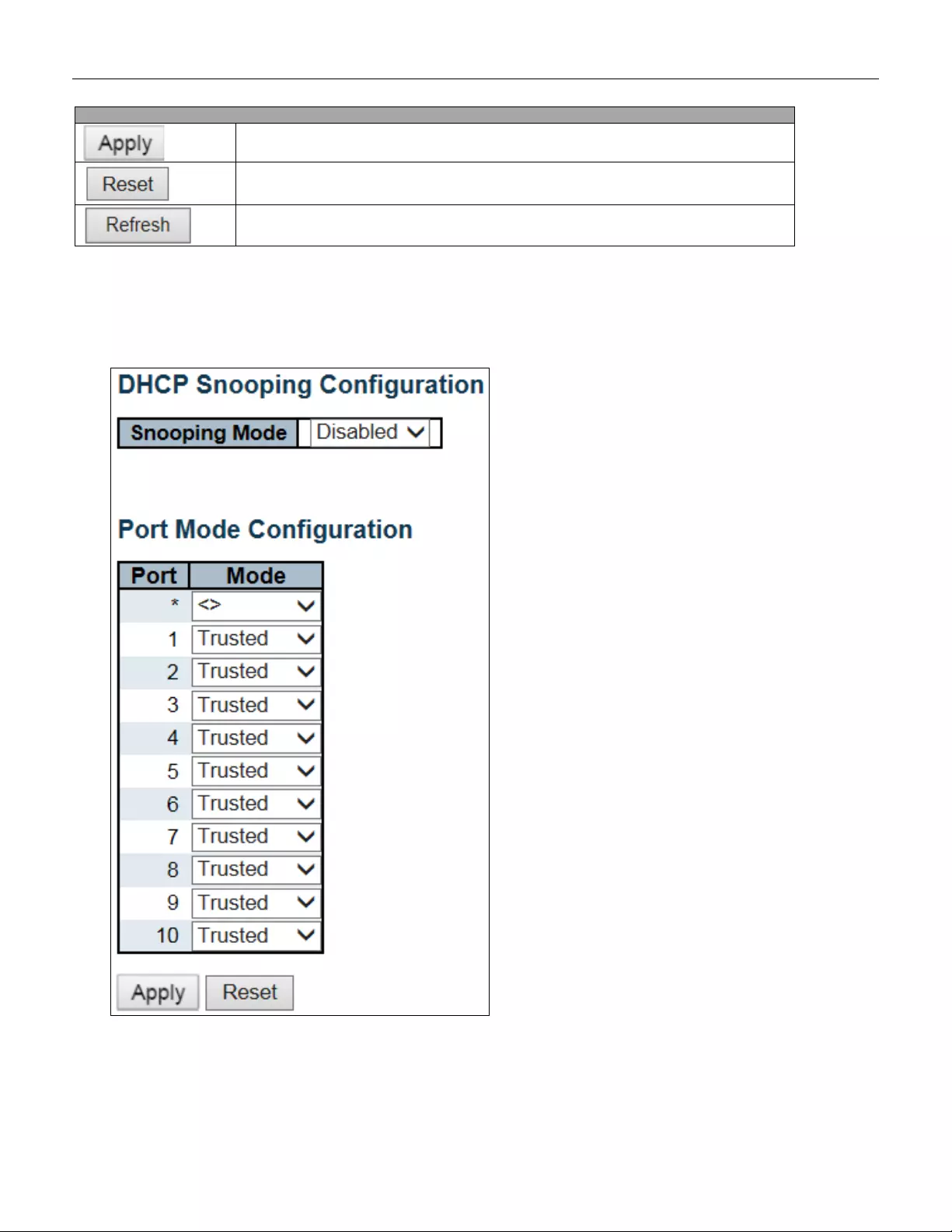
5.3.10 DHCP Snooping
Configure DHCP Snooping on this page.
Buttons
Click to apply changes.
Click to undo any changes made locally and revert to previously saved values.
Click to refresh the page. Any changes made locally will be undone.
49
Object
Description
Snooping Mode
Indicates the DHCP snooping mode operation. Possible modes are:
Enabled: Enable DHCP snooping mode operation. When DHCP snooping mode
operation is ena bled , the DHC P requests messages will be forwarded to trusted ports
and only allow reply packets from trusted ports.
Disabled: Disable DHCP snooping mode operation.
Port Mode Configuration
Indicates the DHCP snooping port mode. Possible port modes are:
Trusted: Configures the port as trusted source of the DHCP messages.
Untrusted: Configures the port as untrusted source of the DHCP messages.
Buttons
Click to apply changes.
Click to undo any changes made locally and revert to previously saved values.
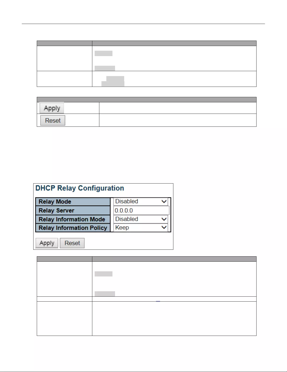
5.3.11 DHCP Relay
A DHCP relay agent is used to forward and to transfer DHCP messages between the clients and the server
when they are not in the same subnet domain. It stores the incoming interface IP address in the GIADDR field of
the DHCP packet. The DHCP server can use the value of GIADDR field to determine the assigned subnet. For
such condition, please make sure the switch configuration of VLAN interface IP address and PVID (Port VLAN
ID) correctly.
Object
Description
Relay Mode
Indicates the DHCP relay mode operation.
Possible modes are:
Enabled: Enable DHCP relay mode operation. When DHCP relay mode operation is
enabled, the agen t forw ards a nd tran sfer s DHC P mes sag es betw een the clients and
the server when they are not in the same subnet domain. And the DHCP broadcast
message won't be flooded for security considerations.
Disabled: Disable DHCP relay mode operation.
Relay Server
Indicates the DHCP relay server IP address.
Relay Information Mode
Indicates the DHCP relay information mode opt ion oper at io n. The option 82 circuit ID
format as "[vlan_id][module_id][port_no]". The first four characters represent the
VLAN ID, the fifth and sixth characters are the module ID (in standalone dev ice it
always equal 0, in stackable device it means switch ID), and the last two characters
are the port number. For example, "00030108" means the DHCP message receives
form VLAN ID 3 , sw itch ID 1, por t No 8. A nd th e option 82 re mote ID val ue is eq ual t he
switch MAC address.
50
Possible modes are:
Enabled: Enable DHCP relay information mode operation. When DHCP relay
information mode operation is enabled, the agent inserts specific information (option
82) into a DHCP message when forwarding to DHCP server and removes it from a
DHCP message when transferring to DHCP client. It only works when DHCP relay
operation mode is enabled.
Disabled: Disable DHCP relay information mode operation.
Relay Information Policy
Indicates the DHCP relay information option policy. When DHCP relay information
mode operation is enabled, if the agent receives a DHCP message that already
contains relay agent information it will enforce the policy. The 'Replace' policy is
invalid when relay information mode is disabled. Possible policies are:
Keep: Keep the original relay information when a DHCP message that already
contains it is received.
Buttons
Click to apply changes.
Click to undo any changes made locally and revert to previously saved values.
51
5.3.12 Security
5.3.13 Switch
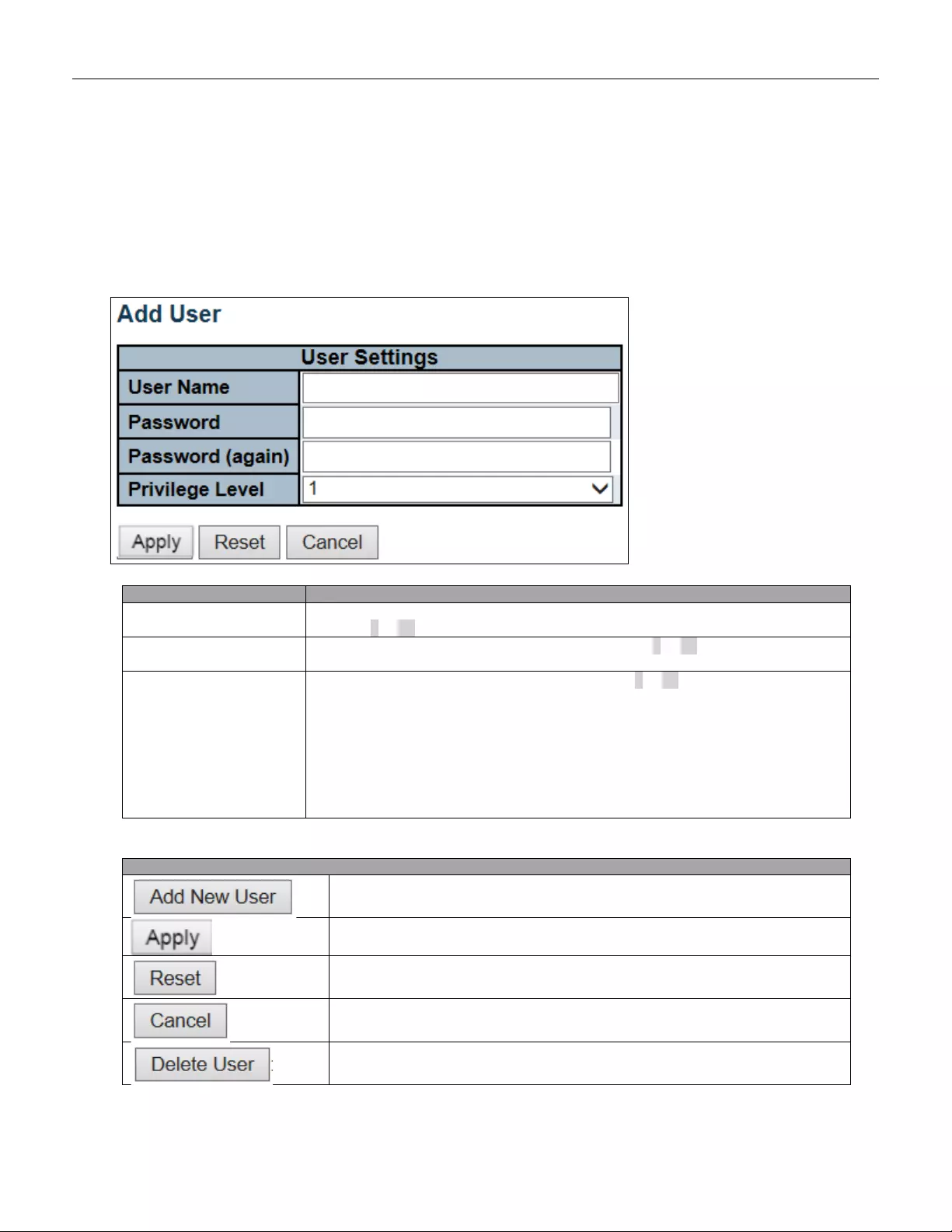
5.3.14 Users
This page provides an overview of the current users. Currently the only way to login as another user on the web
server is to close and reopen the browser.
Object
Description
User Name
A s tring identifying the user name that this entry should belong to. The allowed string
length is 1 to 31. The valid user name allows letters, numbers and underscores.
Password
The password of the user. The allowed string length is 0 to 31. Any printable
characters including space are accepted.
Privilege Level
The priv ile ge lev el of t he u ser. T he allowed r ang e i s 1 to 15. If the privileg e l ev el v al ue
is 15, it can access all groups, i.e. that is granted the fully control of the device. But
others value need to refer to each group privilege level. User's privilege should be
same or greater than the group privilege level to have the access of that group. By
default setting, most group privilege level 5 has the read-onl y access and privile ge
level 10 has the read-write access. And the system maintenance (software upload,
factory def ault s an d etc.) n eed user priv il ege level 15. G ener ally, the privile ge lev el 1 5
can be used for an administrator account, privilege level 10 for a standard user
account and privilege level 5 for a guest account.
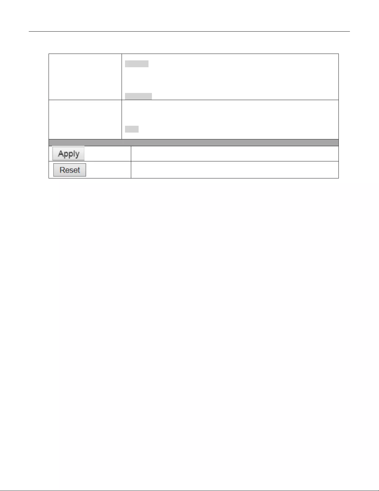
Buttons
Click to add a new user.
Click to apply changes.
Click to undo any changes made locally and revert to previously saved values.
Click to undo any changes made locally and return to the Users.
Delete the current user. This button is not available for new configurations
(Add new user)
52

5.3.15 Privilege Level
This page provides an overview of the privilege levels.
53
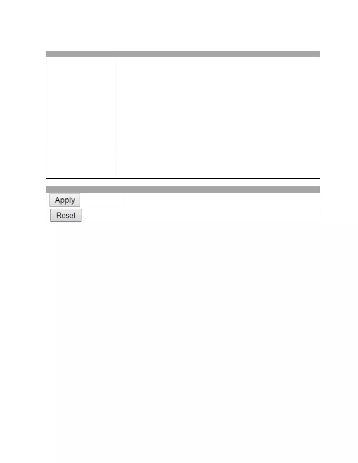
Object
Description
Group Name
The name identifying the privilege group. In most cases, a privilege level group
consists of a single module (e.g. LACP, RSTP or QoS), but a few of them contains
more than one. The following description defines these privilege level groups in
details:
System: Conta ct, Na me, Loc at ion, Timezone, Daylight Saving Time, Log.
Security: Authentication, System Access Management, Port (contains Dot1x port,
MAC based and the MAC Address Limit), ACL , HTTPS, SSH, ARP Inspection, IP
source guard.
IP: Everything except 'ping'.
Port: Everything except 'VeriPHY'.
Diagnostics: 'ping' and 'VeriPHY'.
Maintenance: CLI- System Reboot, System Restore Default, System Password,
Configuration Save, Configuration Load and Firmware Load. Web- Users, Privilege
Levels and every thing in M aint enan ce.
Debug: Only present in CLI.
Privilege Levels
Every group has an authorization Privilege level for the following sub groups:
configuration read-only, configuration/execute read-w rite, sta tus/stat istic s read-only,
status/statistics read-write (e.g. for clearing of statistics). User Privilege should be
same or greater than the authorization Privilege level to have the access to that
group.
Buttons
Click to apply changes.
Click to undo any changes made locally and revert to previously saved values.
54
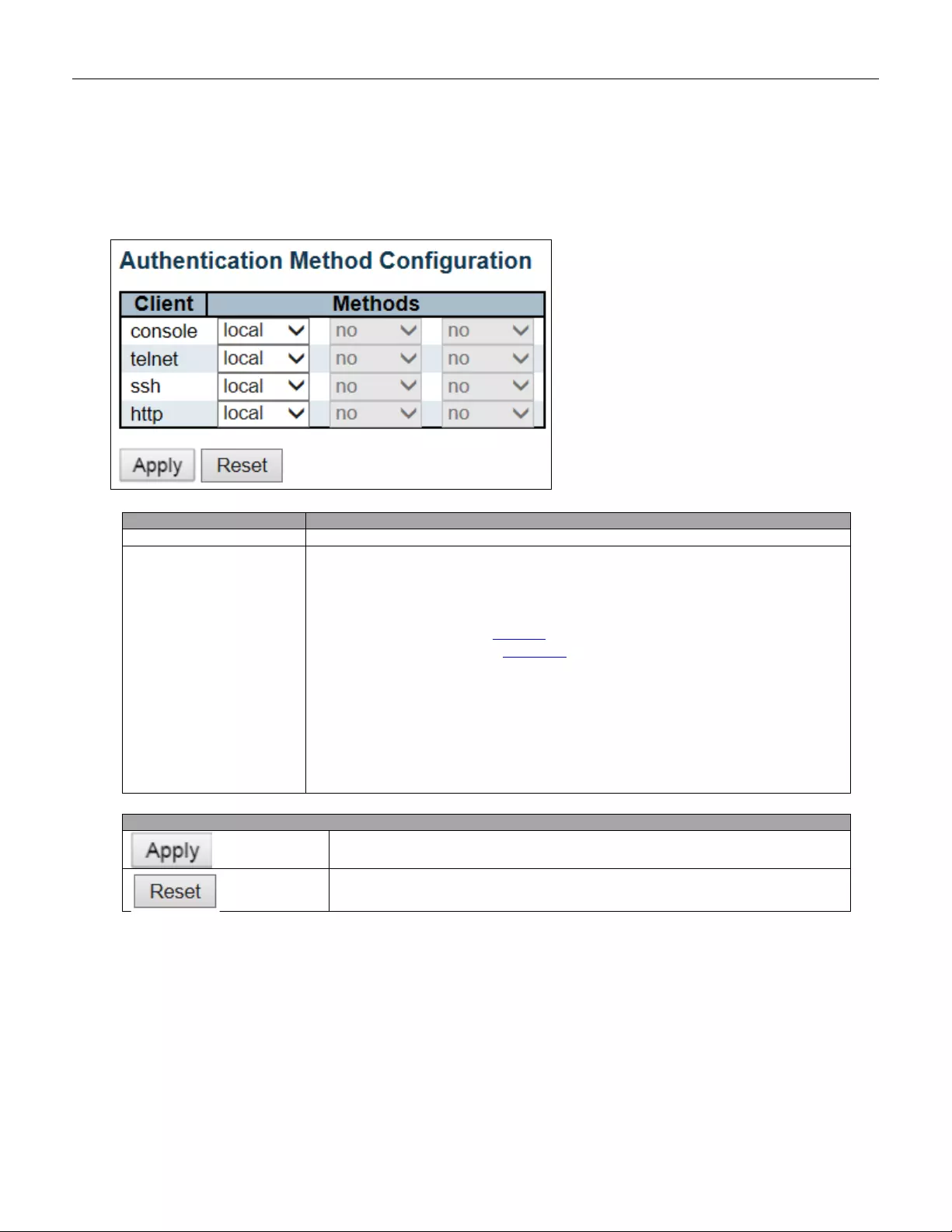
5.3.16 Authentication Method
This page allows you to configure how a user is authenticated when he logs into the switch via one of the
management client interfaces.
Object
Description
Client
The management client for which the configuration below applies.
Methods
Method can be set to one of the following values:
• no: Authentication is disabled and login is not possible.
• local: Use the local user database on the switch for authentication.
• radius: Use remote RADIUS server( s) for authentication .
• tacacs+: Use remote TACACS+ server(s) for authenti cat ion.
Methods that involve remote servers are timed out if the remote servers are offline. In
this case th e nex t metho d i s tried. Ea ch m etho d is tried f ro m l eft t o right and c ontinues
until a method either approves or rejects a user. If a remote server is used for primary
authentication it is recommended to configure secondary authentication as 'local'.
This will enable the management client to login via the local user database if none of
the configured authentication servers are alive.
Buttons
Click to apply changes.
Click to undo any changes made locally and revert to previously saved values.
55
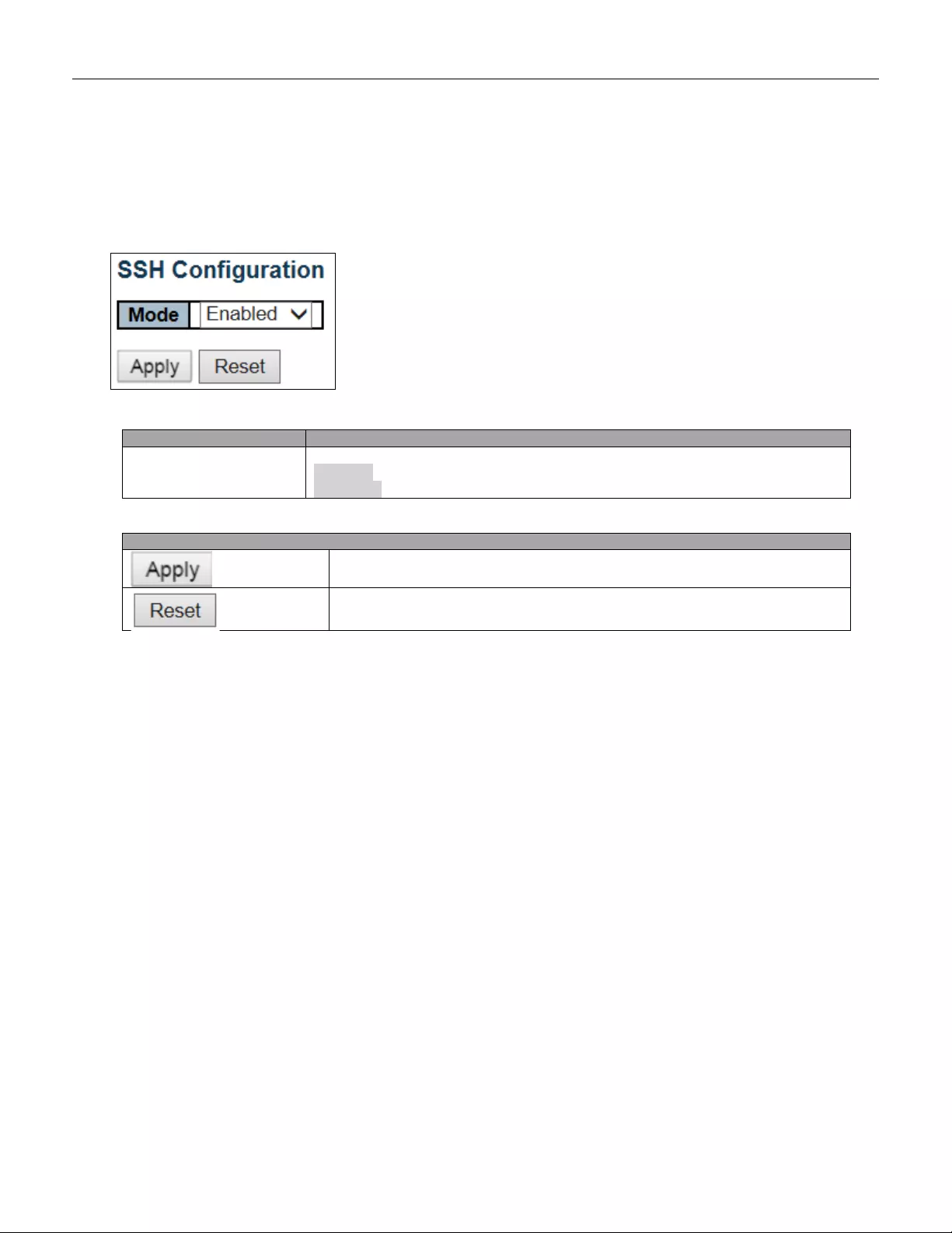
5.3.17 SSH
Configure SSH on this page.
Object
Description
Mode
Indicates the SSH mode operation. Possible modes are:
Enabled: Enable SSH mode operation.
Disabled: Disable SSH mode operation.
Buttons
Click to apply changes.
Click to undo any changes made locally and revert to previously saved values.
56
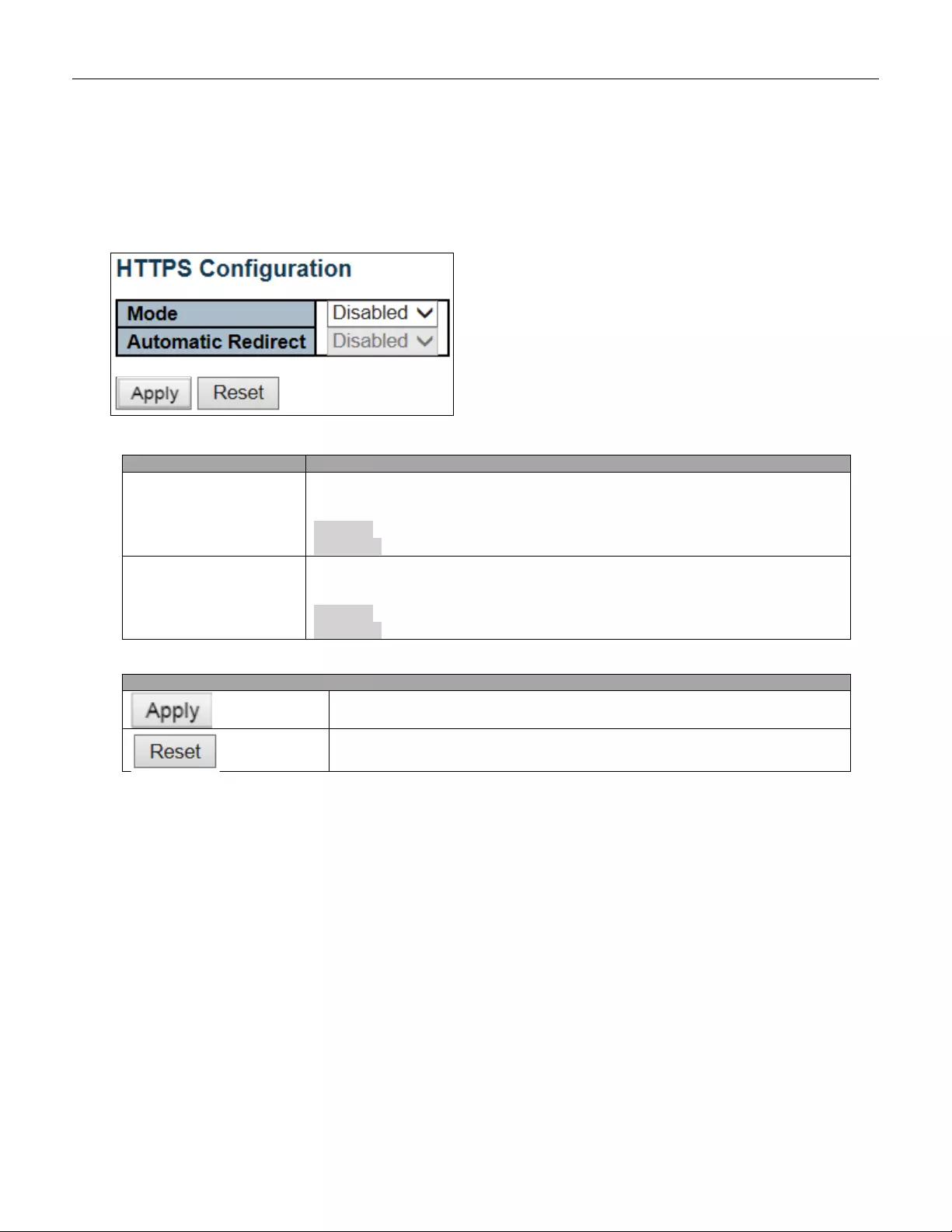
5.3.18 HTTPS
Configure HTTPS on this page.
Object
Description
Mode
Indicates the HTTPS mode operation. When the current connection is HTTPS, to
apply HTTPS disabled mode operation will automatically redirect web browser to an
HTTP connection. Possible modes are:
Enabled: Enable HTTPS mode operation.
Disabled: Disable HTTPS mode operation.
Automatic Redirect
Indicates the HTTPS redirect mode operation. It only significant if HTTPS mode
"Enabled" is selected. Automatically redirects web browser to an HTTPS connection
when both HTTPS mode and Automatic Redirect are enable d. Possib le mod es are:
Enabled: Enable HTTPS redirect mode operation.
Disabled: Disable HTTPS redirect mode operation.
Buttons
Click to apply changes.
Click to undo any changes made locally and revert to previously saved values.
57

5.3.19 Access Management
Configure access management table on this page. The maximum number of entries is 16. If the application's
type matches any one of the access management entries, it will allow access to the switch.
Object
Description
Mode
Indicates the access management mode operation. Possible modes are:
Enabled: Enable access management mode operation.
Disabled: Disable access management mode operation.
Delete
Check to delete the entry. It will be deleted during the next save.
VLAN ID
Indicates the VLAN ID for the access management entry.
Start IP address
Indicates the start IP address for the access management entry.
End IP address
Indicates the end IP address for the access management entry.
HTTP/HTTPS
Indicates that the host can access the switch from HTTP/HTTPS interface if the host
IP address matches the IP address range provided in the entry.
SNMP
Indicates that the host can access the switch from SNMP interface if the host IP
address matches the IP address range provided in the entry.
TELNET/SSH
Indicates that the host can access the switch from TELNET/SSH interface if the host
IP address matches the IP address range provided in the entry.
Buttons
Click to add a new access management entry.
Click to apply changes.
Click to undo any changes made locally and revert to previously saved values.
58
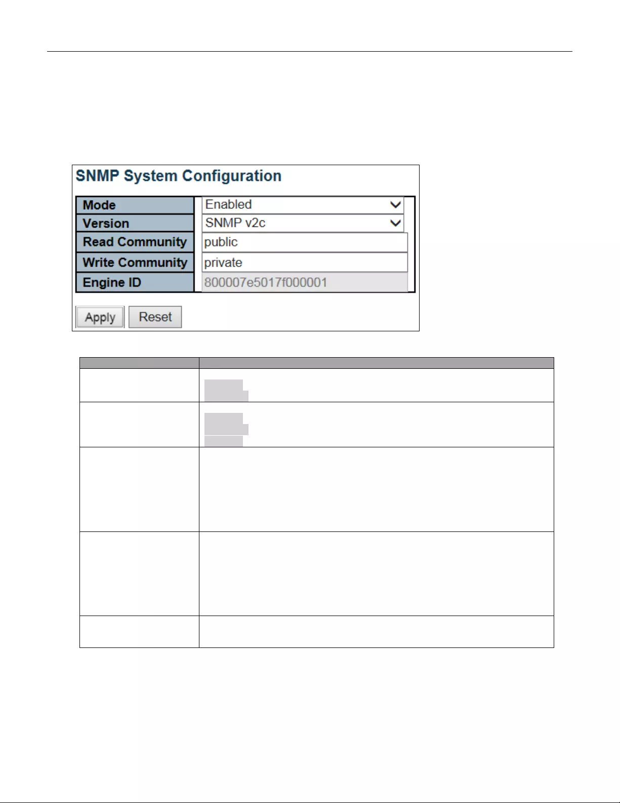
5.3.20 SNMP System Configuration
Configure SNMP on this page.
Object
Description
Mode
Indicates the SNMP mode operation. Possible modes are:
Enabled: Enable SNMP mode operation.
Disabled: Disable SNMP mode operation.
Version
Indicates the SNMP supported version. Possible versions are:
SNMP v1: Set SNMP supported version 1.
SNMP v2c: Set SNMP supported version 2c.
SNMP v3: Set SNMP supported version 3.
Read Community
Indicates the community read access string to permit access to SNMP agent. The
allowed str ing leng t h i s 0 t o 25 5, and the allowed conte nt i s t he AS CII ch ara cters from
33 to 126.
The field is applicable only when SNMP version is SNMPv1 or SNMPv2c. If SNMP
version is SNMPv3, the community string will be associated with SNMPv3
communities table. It provides more flexibility to configure security name than a
SNMPv1 or SNMPv2c community string. In addition to community string, a particular
range of source addre sse s ca n be used to restrict source subnet.
Write Community
Indicates the community writes access string to permit access to SNMP agent. The
allowed str ing leng t h i s 0 t o 25 5, and the allowed conte nt i s t he AS CII ch ara cters from
33 to 126.
The field is applicable only when SNMP version is SNMPv1 or SNMPv2c. If SNMP
version is SNMPv3, the community string will be associated with SNMPv3
communities table. It provides more flexibility to configure security name than a
SNMPv1 or SNMPv2c community string. In addition to community string, a particular
range of source addresses can be used to restrict source subnet.
Engine ID
Indicates the SNMPv 3 engine ID. T he string mu st conta in an ev en number (in
hexadecimal format) with number of digits between 10 and 64, but all-z er os and
all-'F's are not allowed. Change of the Engine ID will clear all original local users.
59

Buttons
Click to apply changes.
Click to undo any changes made locally and revert to previously saved values.
60
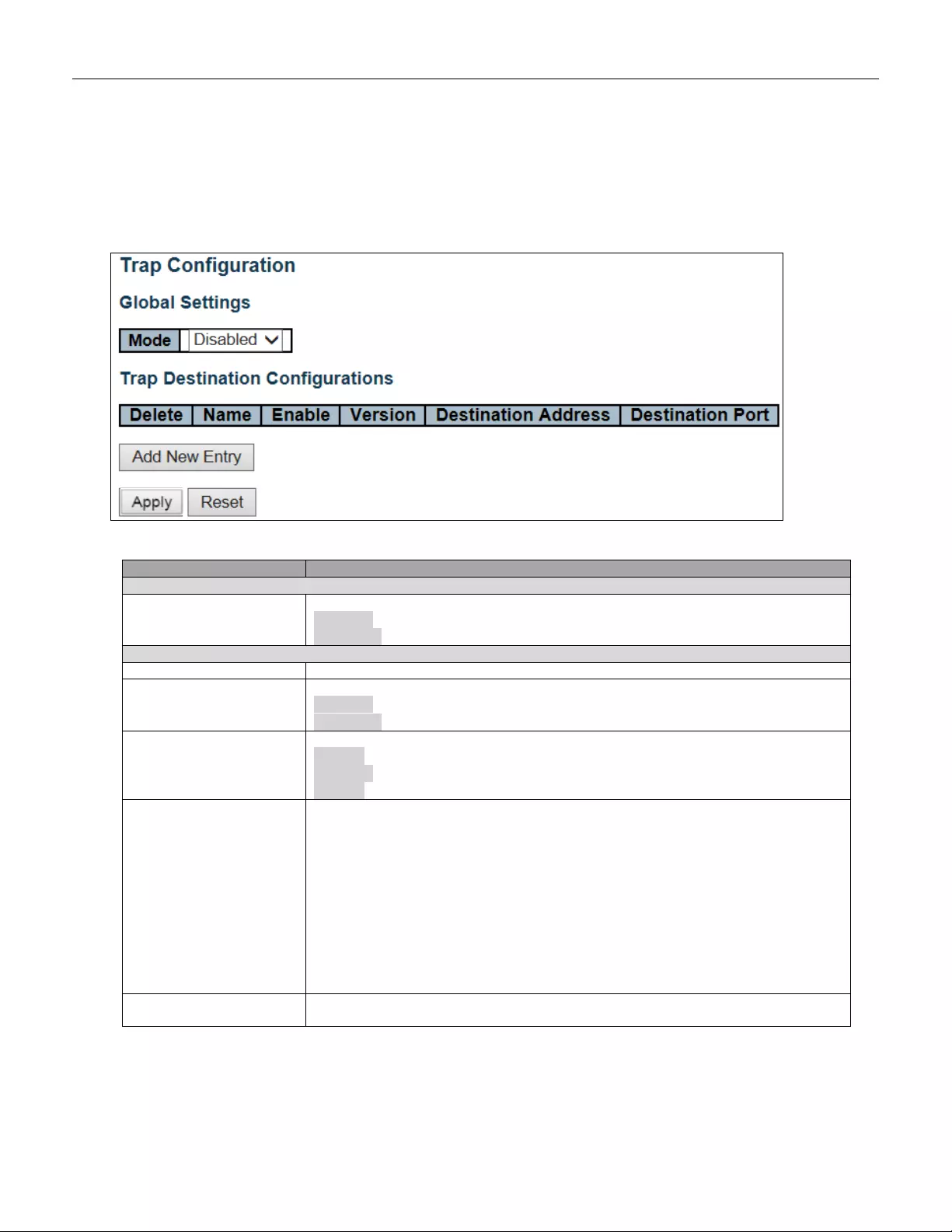
5.3.21 SNMP Trap Configuration
Configure SNMP trap on this page.
Object
Description
Global Settings
Mode
Indicates the trap mode operation. Possible modes are:
Enabled: Enable SNMP trap mode operation.
Disabled: Disable SNMP trap mode operation.
Trap Destination Configurations
Name
Indicates the trap Configuration's name. Indicates the trap destination's name.
Enable
Indicates the trap destination mode operation. Possible modes are:
Enabled: Enable SNMP trap mode operation.
Disabled: Disable SNMP trap mode operation.
Version
Indicates the SNMP trap supported version. Possible versions are:
SNMPv1: Set SNMP trap supported version 1.
SNMPv2c: Set SNMP trap supported version 2c.
SNMPv3: Set SNMP trap supported version 3.
Destinatio n Address
Indicates the SNMP trap destination address. It allows a valid IP address in dotted
decimal notation ('x.y.z.w').
And it also allows a valid hostname. A valid hostname is a string drawn from the
alphabet (A-Za-z), digits (0-9), dot (.), das h (-). Spaces are not allowed, the first
character must be an alpha character, and the first and last characters must not be a
dot or a dash.
Indicates the SNMP trap destination IPv6 address. IPv6 address is in 128-bit records
represented as eight fields of up to four hexadecimal digits with a colon separating
each field (:). For example, 'fe80::215:c5ff:fe03:4dc7'. The symbol '::' is a special
syntax that can be used as a shorthand way of representing multiple 16-bit group s of
contiguous zeros; but it can appear only once. It can also represent a legally valid
IPv4 address. For example, '::192.1.2.34'.
Destination port
Indicates the SNMP trap destination port. SNMP Agent will send SNMP message via
this port, the port range is 1~65535.
61
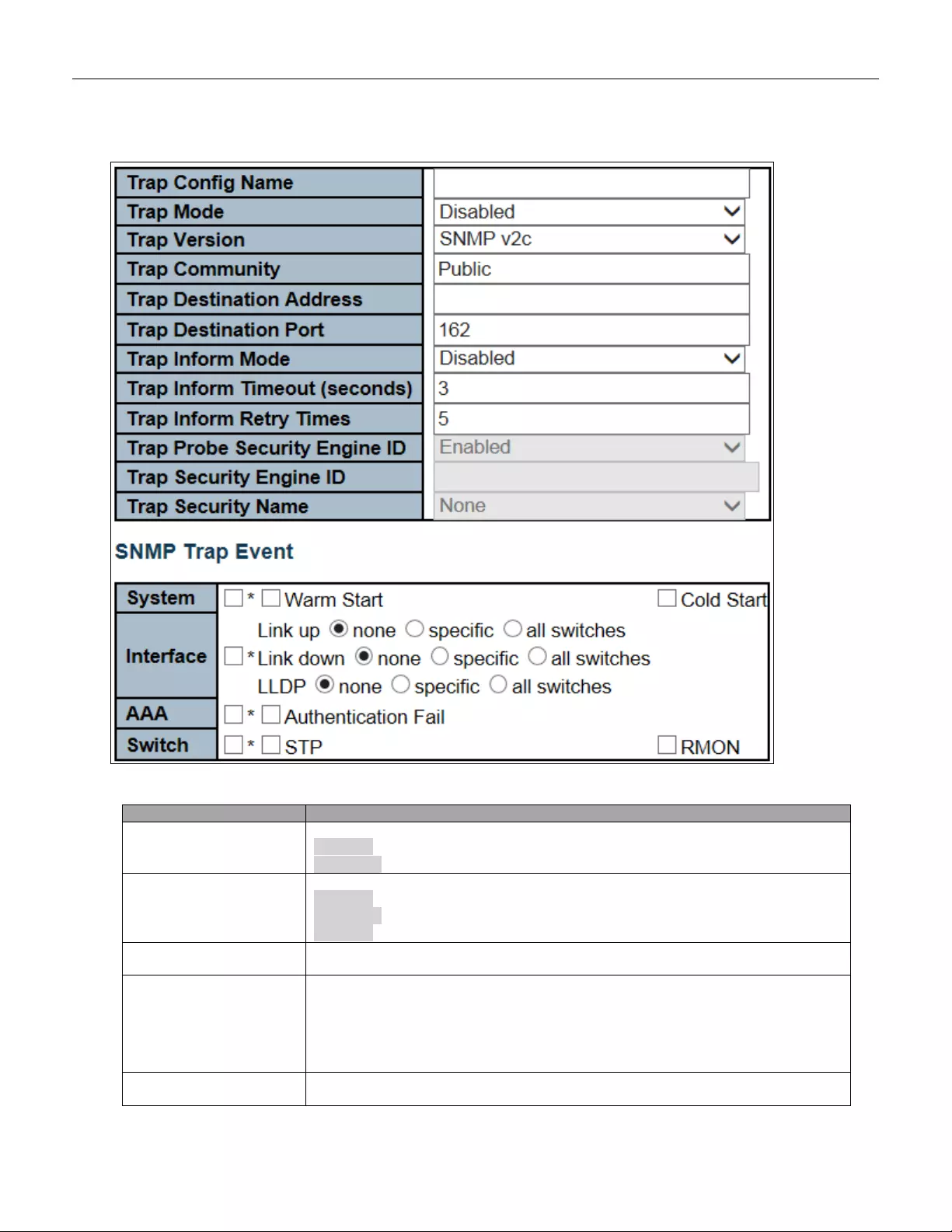
The SNMP Trap Configuration page includes the following fields:
Object
Description
Trap Mode
Indicates the SNMP trap mode operation. Possible modes are:
Enabled: Enable SNMP trap mode operation.
Disabled: Disable SNMP trap mode operation.
Trap Version
Indicates the SNMP trap supported version. Possible versions are:
SNMP v1: Set SNMP trap supported version 1.
SNMP v2c: Set SNMP trap supported version 2c.
SNMP v3: Set SNMP trap supported version 3.
Trap Community
Indicates the community access string when sending SNMP trap packet. The allowed
string length is 0 to 255, and the allowed content is ASCII characters from 33 to 126.
Trap Destination
Address
Indicates the SNMP trap destination address. It allows a valid IP address in dotted
decimal notation ('x.y.z.w').
And it also allows a valid hostname. A valid hostname is a string drawn from the
alphabet (A-Za-z), digits (0-9), dot (.), das h (-). Spaces are not allowed, the first
character must be an alpha character, and the first and last characters must not be a
dot or a dash
Trap Destination IIPv6
Address
Indicates the SNMP trap destination IPv6 address. IPv6 address is in 128-bit records
represented as eight fields of up to four hexadecimal digits with a colon separating
62
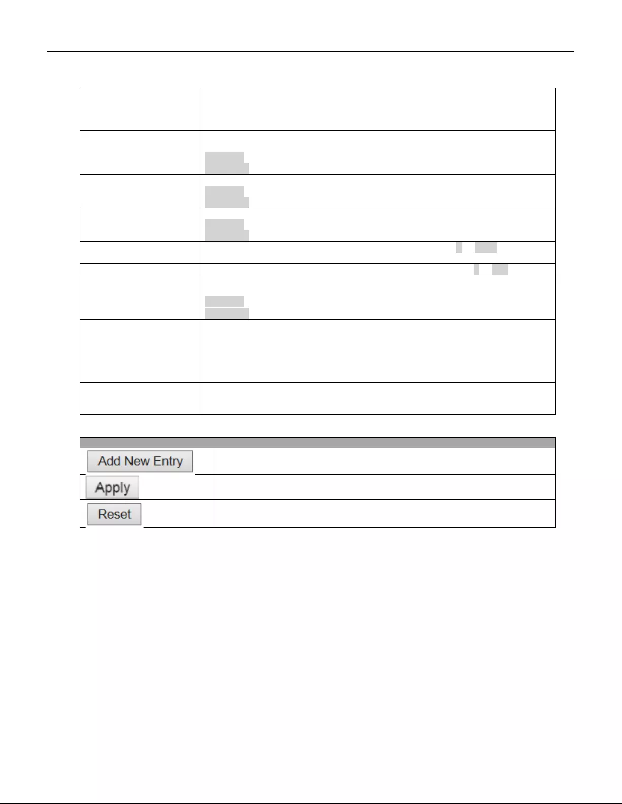
each field (:). For example, 'fe80::215:c5ff:fe03:4dc7'. The symbol '::' is a special
syntax that can be used as a shorthand way of representing multiple 16-bit group s of
contiguous zeros; but it can appear only once. It can also represent a legally valid
IPv4 address. For example, '::192.1.2.34'.
T rap A uthentication
Failure
Indicates that the SNMP entity is permitted to generate authentication failure traps.
Possible modes are:
Enabled: Enable SNMP trap authentication failure.
Disabled: Disable SNMP trap authentication failure.
Trap Link-up and
Link-down
Indicates the SNMP trap link-u p and link-down mode operation. Possible modes are:
Enabled: Enable SNMP trap link-up and link-down mode operation.
Disabled: Disable SNMP trap link-up and link-dow n mode operation.
Trap Inform Mode
Indicates the SNMP trap inform mode operation. Possible modes are:
Enabled: Enable SNMP trap inform mode operation.
Disabled: Disable SNMP trap inform mode operation.
Trap Inform Timeout
(seconds)
Indicates the SNMP trap inform timeout. The allowed range is 0 to 2147.
Trap Inform Retry Times
Indicates the SNMP trap informs retry times. The allowed range is 0 to 255.
Trap Probe Security
Engine ID
Indicates the SNMP trap probe security engine ID mode of operation. Possible values
are:
Enabled: Enable SNMP trap probe security engine ID mode of operation.
Disabled: Disable SNMP trap probe security engine ID mode of operation.
Trap Security Engine ID
Indicates the SNMP trap security engine ID. SNMPv3 sends traps and informs using
USM for authentication and privacy. A unique engine ID for these traps and informs is
needed. When "Trap Probe Security Engine ID" is enabled, the ID will be probed
automatically. Otherwise, the ID specified in this field is used. The string must contain
an even number (in hexadecimal format) with number of digits between 10 and 64,
but all-zeros and all-'F's are not allowed.
Trap Security Name
Indicates the SNMP trap security name. SNMPv3 traps and informs using USM for
authentication and privacy. A unique security name is needed when traps and informs
are enabled.
Buttons
Click to add a new user.
Click to apply changes.
Click to undo any changes made locally and revert to previously saved values.
63
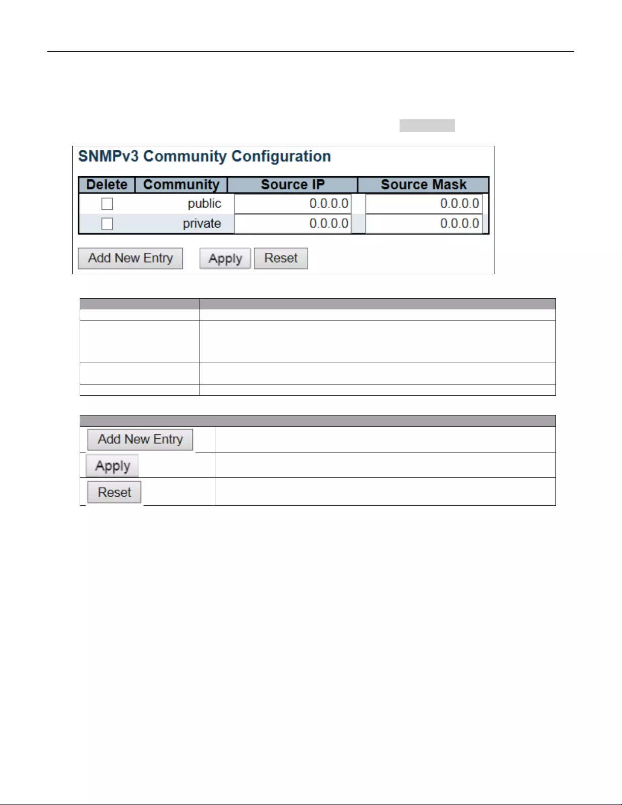
5.3.22 SNMP Communities
Configure SNMPv3 community table on this page. The entry index key is Community.
Object
Description
Delete
Check to delete the entry. It will be deleted during the next save.
Community
Indicates the community access string to permit access to SNMPv3 agent. The
allowed str ing len gth is 1 to 3 2, and t he a llowed c ontent is AS CII char act ers from 33 t o
126. T he community string will be treated as security name and map a SNMPv1 or
SNMPv2c community string.
Source IP
Indicates the SNMP access source address. A particular range of source addresses
can be used to restrict source subnet when combined with source mask.
Source Mask
Indicates the SNMP access source address mask.
Buttons
Click to add a new community entr y.
Click to apply changes.
Click to undo any changes made locally and revert to previously saved values.
64
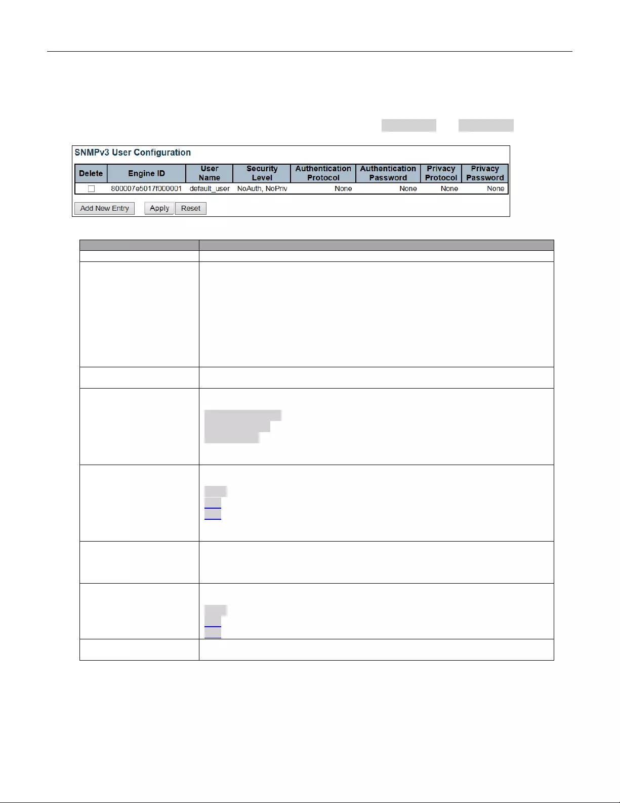
5.3.23 SNMP Users
Configure SNMPv3 user table on this page. The entry index keys are Engine ID and User Name.
Object
Description
Delete
Check to delete the entry. It will be deleted during the next save.
Engine ID
An octet string identifying the engine ID that this entry should belong to. T he stri ng
must contain an even number ( in hexadecimal format) with number of digits between
10 and 64, but all-z er os and all-'F's are not allowed. The SNMPv3 architecture uses
the User-based Security Model (USM) for message security and the View-based
Access Control Model (VACM) for access control. For the USM entry, the
usmUserEngineID and usmUserName are the entry's keys. In a simple agent,
usmUserEngineID is always that agent's own snmpEngineID value. The value can
also take the value of the snmpEngineID of a remote SNMP engine with which this
user can communicate. In other words, if user engine ID equal system engine ID then
it is local user; otherwise it's remote user.
User name
A s tring identifying the user name that this entry should belong to. The allowed string
length is 1 to 32, and the allowed content is ASCII characters from 33 to 126.
Security Level
Indicates the security m odel t hat this entr y sh ould belong t o. Poss ible se curity m ode ls
are:
NoAuth, NoPriv: No authentication and no privacy.
Auth, NoPriv: Authentication and no privacy.
Auth, Priv: Authenti cation and priv acy .
The value of security level cannot be modified if entry already exists. That means it
must first be ensured that the value is set correctly.
Authentication Protocol
Indicates the authentication protocol that this entry should belong to. Possible
authentication protocols are:
None: No authentication protocol.
MD5: An optional flag to indicate that this user uses MD5 authentication protocol.
SHA: An optional flag to indicate that this user uses SHA authentication protocol.
The value of security level cannot be modified if entry already exists. That mean s
must first ensure that the value is set correctly.
Authentication
Password
A s tring identifying the authentication password phrase. For MD5 authentication
protocol, the allowed string length is 8 to 32. For SHA authentication protocol, the
allowed string length is 8 to 40. The allowed content is ASCII characters from 33 to
126.
Privacy Protocol
Indicates the privacy protocol that this entry should belong to. Possible privacy
protocols are:
None: No privacy protocol.
DES: An optional flag to indicate that this user uses DES authentication protocol.
AES: An optional flag to indicate that this user uses AES authentication protocol.
Privacy Password
A s tring identifying the privacy password phrase. The allowed string length is 8 to 32,
and the allowed content is ASCII characters from 33 to 126.
65

Buttons
Click to add a new user entry.
Click to apply changes.
Click to undo any changes made locally and revert to previously saved values.
66
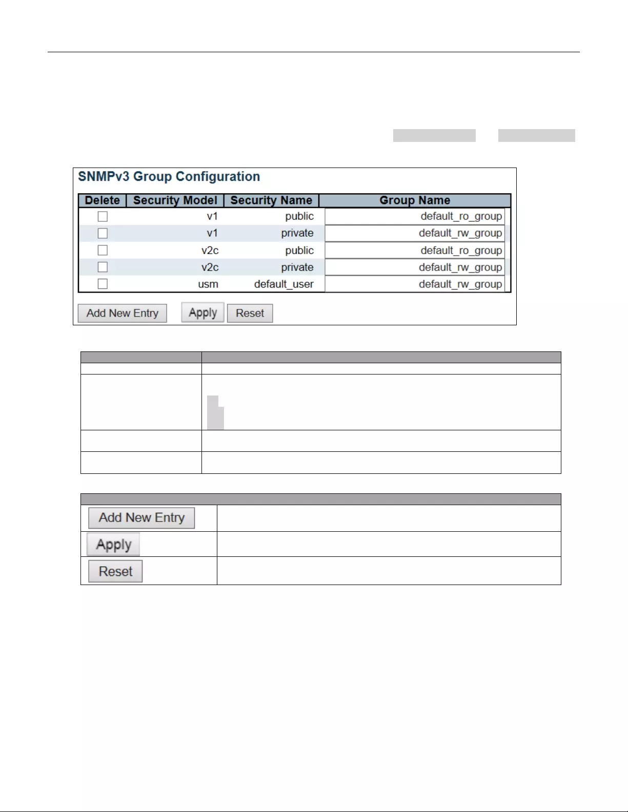
5.3.24 SNMP Groups
Configure SNMPv3 group table on this page. The entry index keys are Security Model and Security Name.
Object
Description
Delete
Check to delete the entry. It will be deleted during the next save.
Security Model
Indicates the security m odel t hat this entr y sh ould belong t o. Poss ible se curity m ode ls
are:
v1: Reserved for SNMPv1.
v2c: Reserved for SNMPv2c.
usm: User-based Security Model (USM).
Security Name
A s tring identifying the security name that this entry should belong to. The allowed
string length is 1 to 32, and the allowed content is ASCII characters from 33 to 126.
Group Name
A str ing identify ing the group name that this entry shou ld belo ng to. The allow ed stri ng
length is 1 to 32, and the allowed content is ASCII characters from 33 to 126.
Buttons
Click to add a new group entry
Click to apply changes.
Click to undo any changes made locally and revert to previously saved values.
67
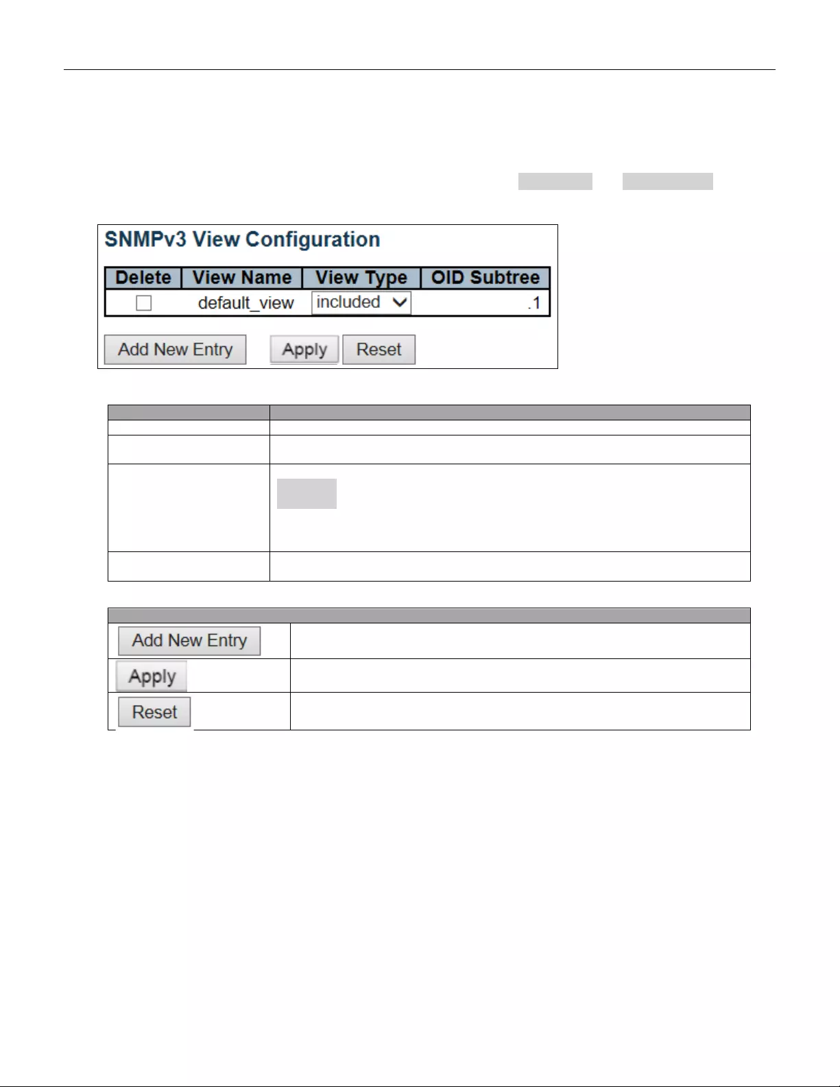
5.3.25 SNMP Views
Configure SNMPv3 view table on this page. The entry index keys are View Name and OID Subtree.
Object
Description
Delete
Check to delete the entry. It will be deleted during the next save.
View Name
A s tring identifying the view name that this entry should belong to. The allowed string
length is 1 to 32, and the allowed content is ASCII characters from 33 to 126.
View Type
Indicates the view type that this entry should belong to. Possible view types are:
included: An option al flag to indicate that this view subtree should be included.
excluded: An optional flag to indicate that this view subtree should be excluded.
In general, if a view entry's view type is 'excluded', there should be another view entry
existing with view type as 'included' and its OID subtree should overstep the
'excluded' view entry.
OID Subtree
The OID defining the root of the subtree to add to the named view. The allowed OID
length is 1 to 128. The allowed string content is digital number or asterisk(*).
Buttons
Click to add a new view entry.
Click to apply changes.
Click to undo any changes made locally and revert to previously saved values.
68
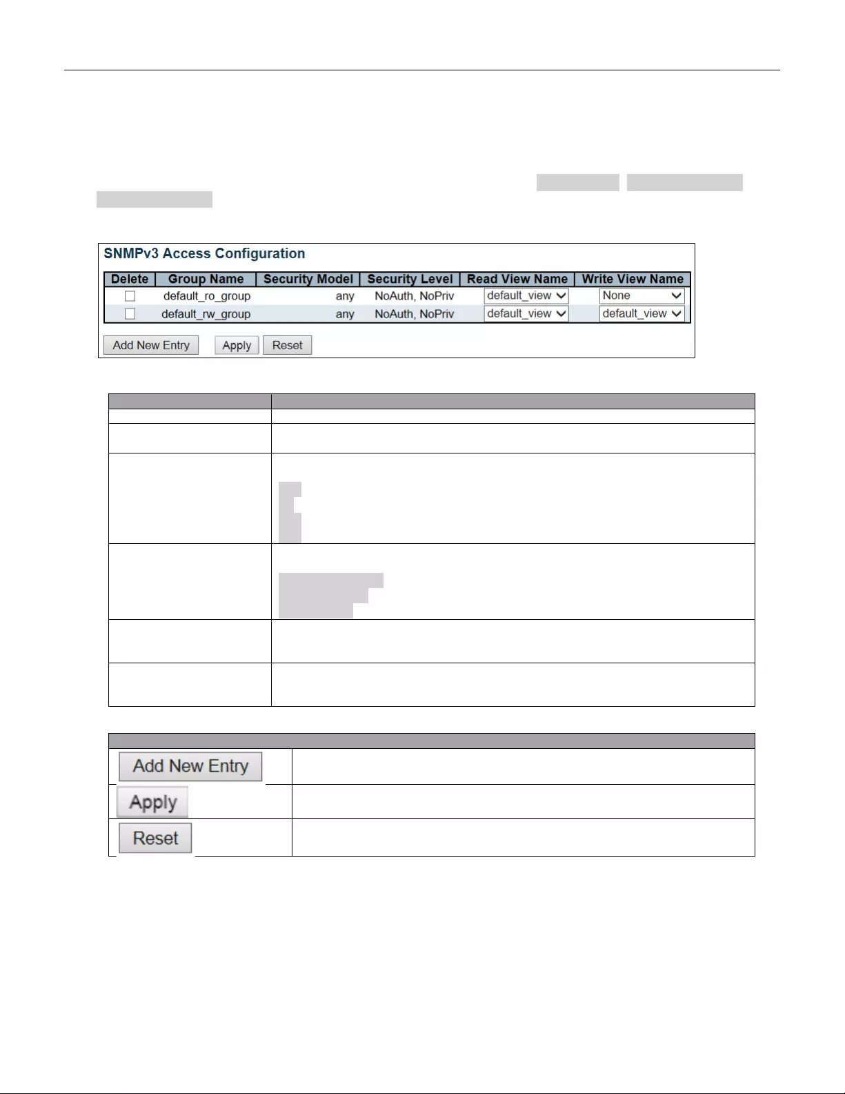
5.3.26 SNMP Access
Configure SNMPv3 access table on this page. The entry index keys are Group Name, Security Model and
Security Level.
Object
Description
Delete
Check to delete the entry. It will be deleted during the next save.
Group Name
A str ing identify ing the group name that this entry shou ld belo ng to. The allow ed stri ng
length is 1 to 32, and the allowed content is ASCII characters from 33 to 126.
Security Model
Indicates the security m odel t hat this entr y sh ould belong t o. Poss ible se curity m ode ls
are:
any: Any securit y model accepted (v1|v2c|usm).
v1: Reserved for SNMPv1.
v2c: Reserved for SNMPv2c.
usm: User-based Security Model (USM).
Security Level
Indicates the security m odel t hat this entr y sh ould belong t o. Poss ible se curity m ode ls
are:
NoAuth, NoPriv: No authentication and no privacy.
Auth, NoPriv: Authentication and no privacy.
Auth, Priv: Authenti cation and priv acy .
Read View Name
The name of t he M IB view defining the M IB objects for w hich this reque st may request
the current values. The allowed string length is 1 to 32, and the allowed content is
ASCII characters from 33 to 126.
Write View Name
The name of the MIB view defining the MIB objects for which this request may
potentially set new values. The allowed string length is 1 to 32, and the allowed
content is ASCII characters from 33 to 126.
Buttons
Click to add a new access entry.
Click to apply changes.
Click to undo any changes made locally and revert to previously saved values.
69
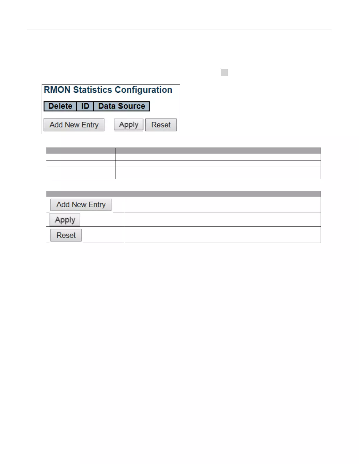
5.3.28 RMON Statistics
Configure RMON Statistics table on this page. The entry index key is ID.
Object
Description
Delete
Check to delete the entry. It will be deleted during the next save.
ID
Indicates the index of the entry. The range is from 1 to 65535.
Data Source
Indicates th e por t ID w hich w ants to be monitor ed. If in stacking sw itch, the va lue mu st
add 1000*(switch ID-1), for exampl e, if the port is switch 3 port 5, the value is 2005
Buttons
Click to add a new community entr y.
Click to apply changes.
Click to undo any changes made locally and revert to previously saved values.
70
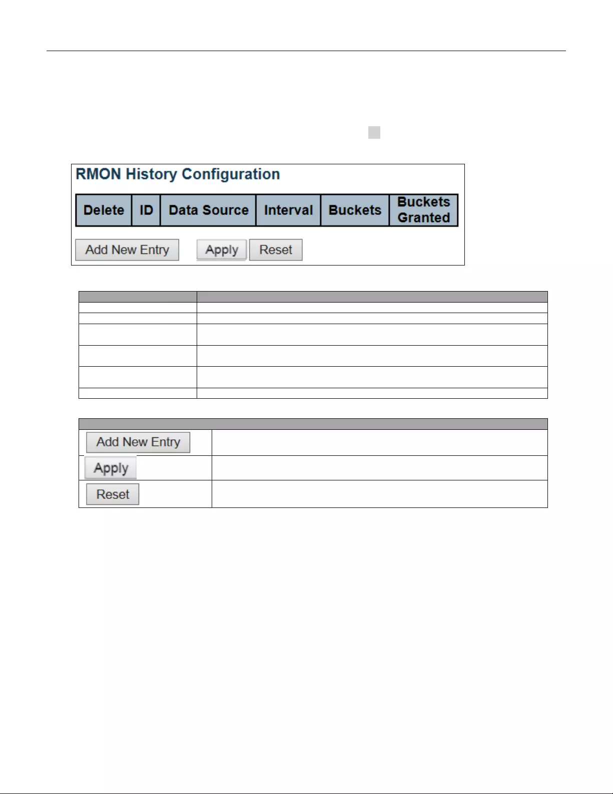
5.3.29 RMON Histor y
Configure RMON History table on this page. The entry index key is ID.
Object
Description
Delete
Check to delete the entry. It will be deleted during the next save.
ID
Indicates the index of the entry. The range is from 1 to 65535.
Data Source
Indicates th e por t ID w hich w ants to be monitor ed. If in stacking sw itch, the va lue mu st
add 1000*(switch ID-1), for example, if the port is switch 3 port 5, the value is 2005.
Interval
Indicates the interval in seconds for sampling the history statistics data. The range is
from 1 to 3600, default value is 1800 seconds.
Buckets
Indicates the maximum data entries associated this History control entry stored in
RMON. The range is from 1 to 3600, default value is 50.
Buckets Granted
The number of data shall be saved in the RMON.
Buttons
Click to add a new community entr y.
Click to apply changes.
Click to undo any changes made locally and revert to previously saved values.
71
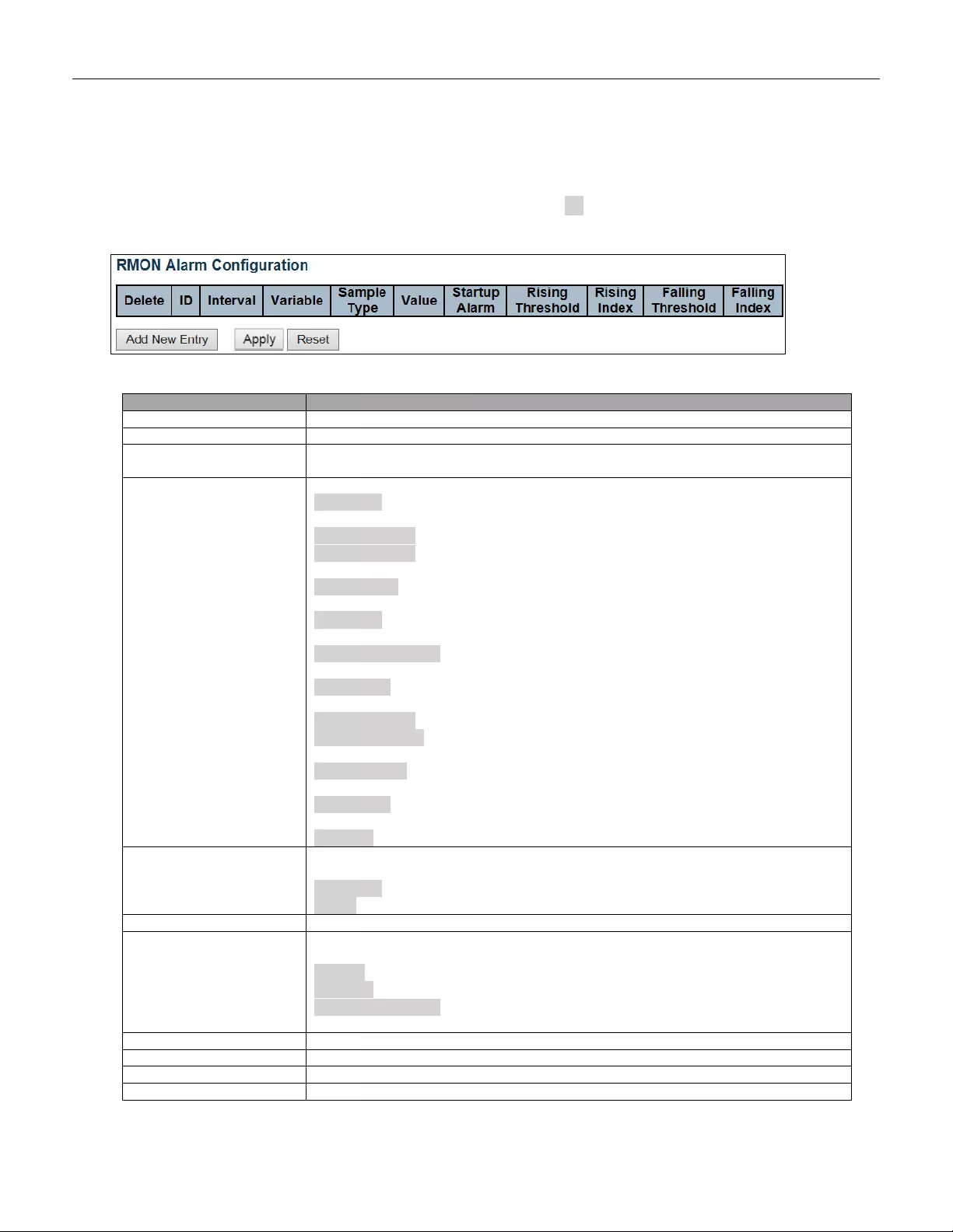
5.3.30 RMON A larm
Configure RMON Alarm table on this page. The entry index key is ID.
Object
Description
Delete
Check to delete the entry. It will be deleted during the next save.
ID
Indicates the index of the entry. The range is from 1 to 65
Interval
Indicates the interval in seconds for sampling and comparing the rising and falling
threshold . T he ra nge is from 1 to 2^31-1.
Variable
Indicates the particular variable to be sampled, the possible variables are:
InOctets: The total number of octets received on the interface, including framing
characters.
InUcastPkts: The number of uni-cast packets delivered to a higher-layer protocol.
InNUcastPkts: The number of broad-c ast and mu lti-cast packets delivered to a
higher-layer protocol.
InDiscards: The number of inbound packets that are discarded even the packets
are normal.
InErrors: The number of inb ound packets that contained errors preventing them
from being deliverable to a higher-layer protocol.
InUnknownProtos: the number of the inbound packets that were discarded
because of the unknown or un-support protocol.
OutOctets: The number of octets transmitted out of the interface , including framing
characters.
OutUcastPkts: The number of uni-cast packets that request to transmit.
OutNUcastPkts: The number of broad-cast and multi-cast packets that request to
transmit.
OutDiscards: The number of outbound pa ckets that are discarded event the
packets are normal.
OutErrors: The number of outbound packets that could not be transmitted because
of errors.
OutQLen: The length of the output packet queue (in packets).
Sample Type
The method of sampling the selected variable and calculating the value to be
compared against the thresholds, possible sample types are:
Absolute: Get the sample directly.
Delta: Calculate the difference between samples (default).
Value
The value of the statistic during the last sampling period.
Startup Alarm
The method of sampling the selected variable and calculating the value to be
compared against the thresholds, possible sample types are:
RisingTrigger alarm when the first value is larger than the rising threshold.
FallingTrigger alarm when the first value is less than the falling threshold.
RisingOrFallingTrigger alarm when the first value is larger than the rising
threshold or less than the falling threshold (default).
Rising Threshold
Rising threshold value (-2147483648-2147483647).
Rising Index
Rising event index (1-65535).
Falling Threshold
Falling threshold value (-2147483648-2147483647)
Falling Index
Falling event index (1-65535).
72
Buttons
Click to add a new community entr y.
Click to apply changes.
Click to undo any changes made locally and revert to previously saved values.
73
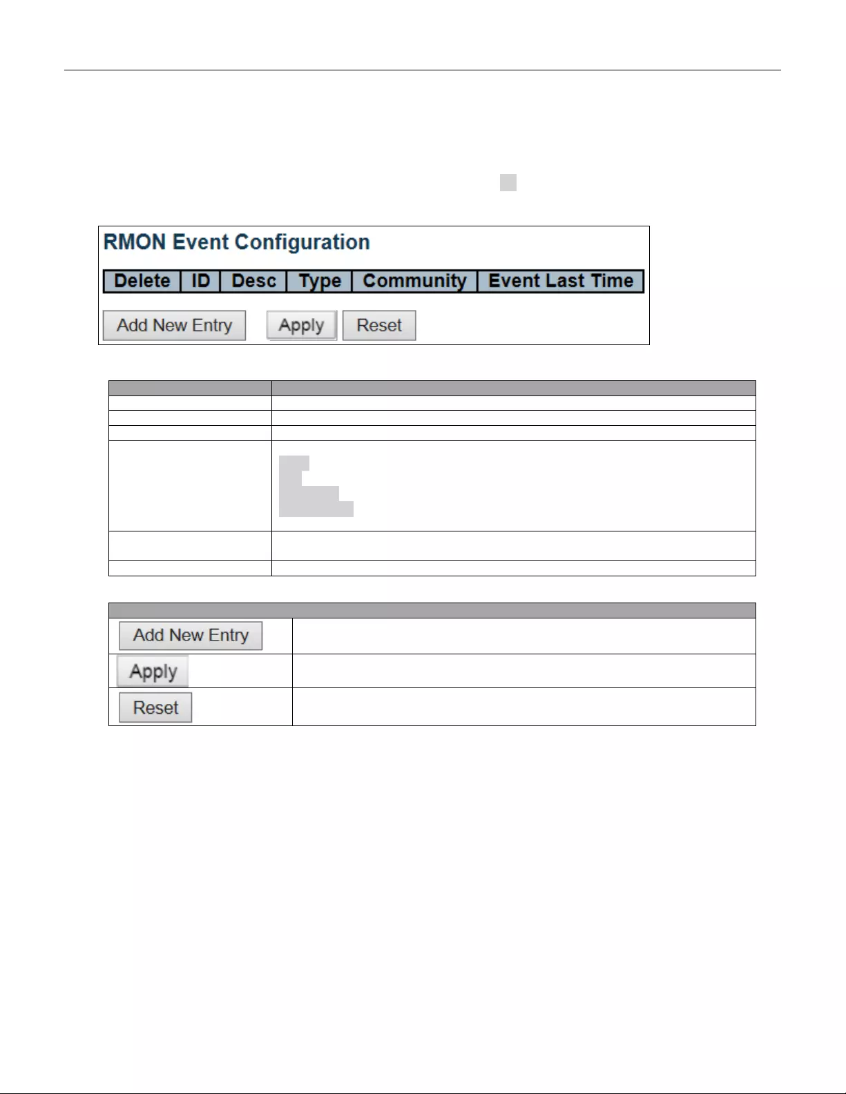
5.3.31 RMON Event
Configure RMON Event table on this page. The entry index key is ID.
Object
Description
Delete
Check to delete the entry. It will be deleted during the next save.
ID
Indicates the index of the entry. The range is from 1 to 65535.
Desc
Indicates this event, the string length is from 0 to 127, default is a null string.
Type
Indicates the notification of the event, the possible types are:
none: No SNMP log is created, no SNMP trap is sent.
log: Create SNMP log entry when the event is triggered.
snmptrap: Send SNMP trap when the event is triggered.
logandtrap: Create SNMP log entry and sent SNMP trap when the event is
triggered.
Community
Specify the community when trap is sent, the string length is from 0 to 127, default is
"public".
Event Last Time
Indicates the value of sysUpTime at the time this event entry last generated an event.
Buttons
Click to add a new community entr y.
Click to apply changes.
Click to undo any changes made locally and revert to previously saved values.
74
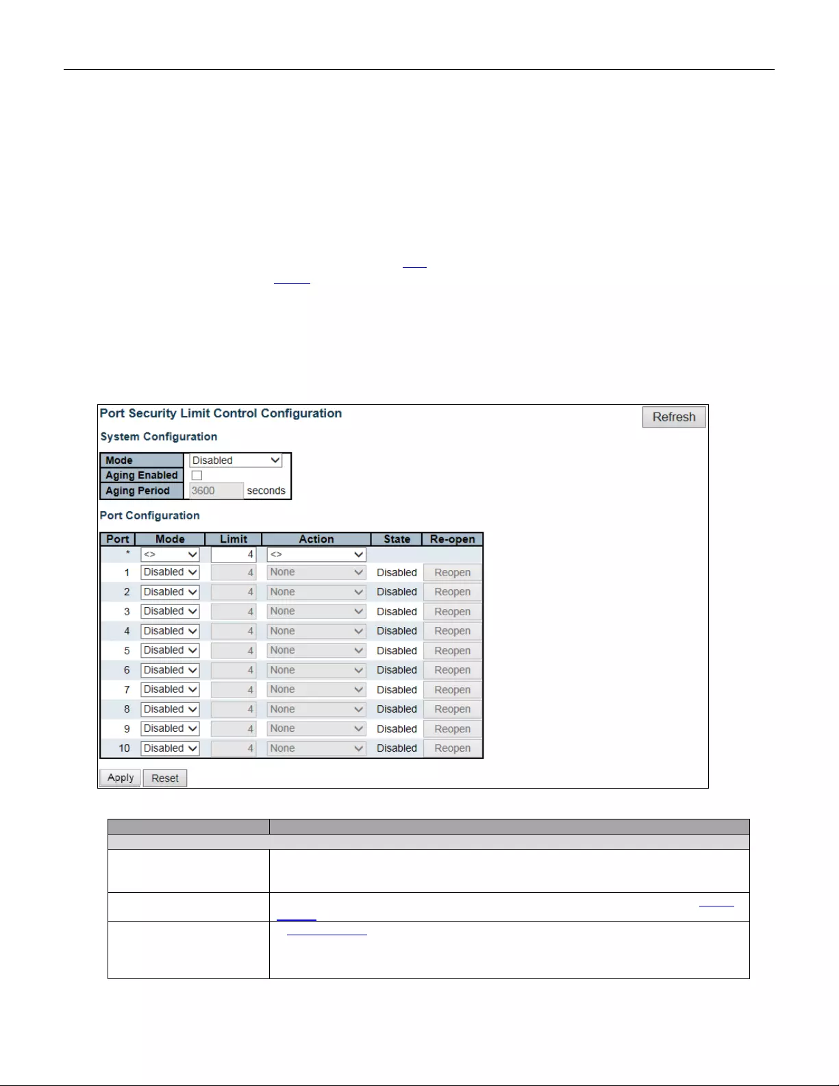
5.3.32 Network
5.3.33 Limit Control
This page allows you to configure the Port Security Limit Control system and port settings.
Limit Control allows for limiting the number of users on a given port. A user is identified by a MAC address and
VLAN ID. If Limit Control is enabled on a port, the limit specifies the maximum number of users on the port. If
this number is exceeded, an action is taken. The action can be one of the four different actions as described
below.
The Limit Control module utilizes a lower-layer module, Port Security module, which manages MAC addresses
learnt on the port.
The Limit Control configuration consists of two sections, a system- and a port-wide.
Object
Description
System Configuration
Mode
Indicates if Limit Control is globally enabled or disabled on the switch. If globally
disabled, other modules may still use the underlying functionality, but limit checks and
corresponding actions are disabled.
Aging Enabled
If checked, secured MAC addresses are subject to aging as discussed under Aging
Period .
Aging Period
If Agin g Enab led is che cked, then the aging period is co ntrol l ed with thi s inp ut. If othe r
modules ar e
using t he un derly i ng port secur i ty for secur ing M A C addresses, th ey m ay
have other requirements to the aging period. The underlying port security will use the
shorter requested aging period of all modules that use the functionality.
75

The Aging Period can be set to a number between 10 and 10,000,000 seconds.
To understand why aging may be desired, consider the following scenario: Suppose
an end-host is connected to a 3rd party switch or hub, which in turn is connected to a
port on this switch on which Limit Control is enabled. The end-host will be allowed to
forward if the limit is not exceeded. Now suppose that the end-hos t logs of f or pow ers
down. If it wasn't for aging, the end-host would still take up resources on this switch
and will be allowed to forward. To overcome this situation, enable aging. With aging
enabled, a timer is start ed onc e the end-host gets secured. When the timer expires,
the switch starts loo king for frames fr om th e end-hos t, and if such fr ames ar e not see n
within the next Aging Period, the end-host is assumed to be disconnected, and the
corresponding resources are freed on the switch.
Port Configuration
Port
The port number to which the configuration below applies.
Mode
Controls whether Limit Control is enabled on this port. Both this and the Global Mode
must be set to E na ble d for Li m it C ontro l t o be in e ffect. N ot ic e t hat o ther module s m ay
still use the underlying port security features without enabling Limit Control on a giv en
port.
Limit
The maximum number of MAC addresses that can be secured on this port. This
number cannot exceed 1024. If the limit is exceeded, the corresponding action is
taken.
The switch is "born" with a total number of MAC addresses from which all ports draw
whenev er a new M AC address is see n on a Port S ecurity -enabled por t. Sin ce all port s
draw from the same pool, it may happen that a configured maximum cannot be
granted, if the remaining ports have already used all available MAC addresses.
Action
If Limit is reached, the switch can take one of the following actions:
None: Do not allow more than Limit MAC addresses on the port, but take no further
action.
Trap: If Limit + 1 MAC addresses are seen on the port, send an SNMP trap. If Aging
is disable d, only one SNM P trap w ill be s ent, but w ith A ging enable d, new SNM P traps
will be sent every time the limit gets exceeded.
Shutdown: If Limit + 1 MAC addresses is seen on the port, shut down the port. This
implies that all secured MAC addresses will be removed from the port, and no new
address will be learned. Even if the link is physically disconnected and reconnected
on the port (by disconnecting the cable), the port will remain shut down. There are
three ways to re-open the port:
1) Boot the switch,
2) Disable and re-enable Limit Control on the port or the switch,
3) Click the Reopen button.
Trap & Shutdown: If Limit + 1 MAC addresses is seen on the port, both the "Trap"
and the "Shutdown" actions described above will be taken.
State
This column shows the current state of the port as seen from the Limit Control's point
of view. The state takes one of four values:
Disabled: Limit Control is either globally disabled or disabled on the port.
Ready: The limit is not yet rea ched . T his ca n be show n for all actions.
Limit Reached: Indicate s tha t the limi t is r eached on this p ort. This st ate can o nly be
shown if Action is set to None or Trap.
Shutdown: Indicates that the port is shut down by the Limit Control module. This
state can only be shown if Action is set to Shutdown or Trap & Shutdown.
Re-open Button
If a port is shutdown by this module, you may reopen it by clicking this button, which
will only be enabled if this is the case. For other methods, refer to Shutdown in the
Action section.
Note that clicking the reopen button causes the page to be refreshed, so
non-committed changes will be lost.
76

Buttons
Click to refresh the page. Note that non-com mit ted cha nge s will be lost.
Click to apply changes.
Click to undo any changes made locally and revert to previously saved values.
77
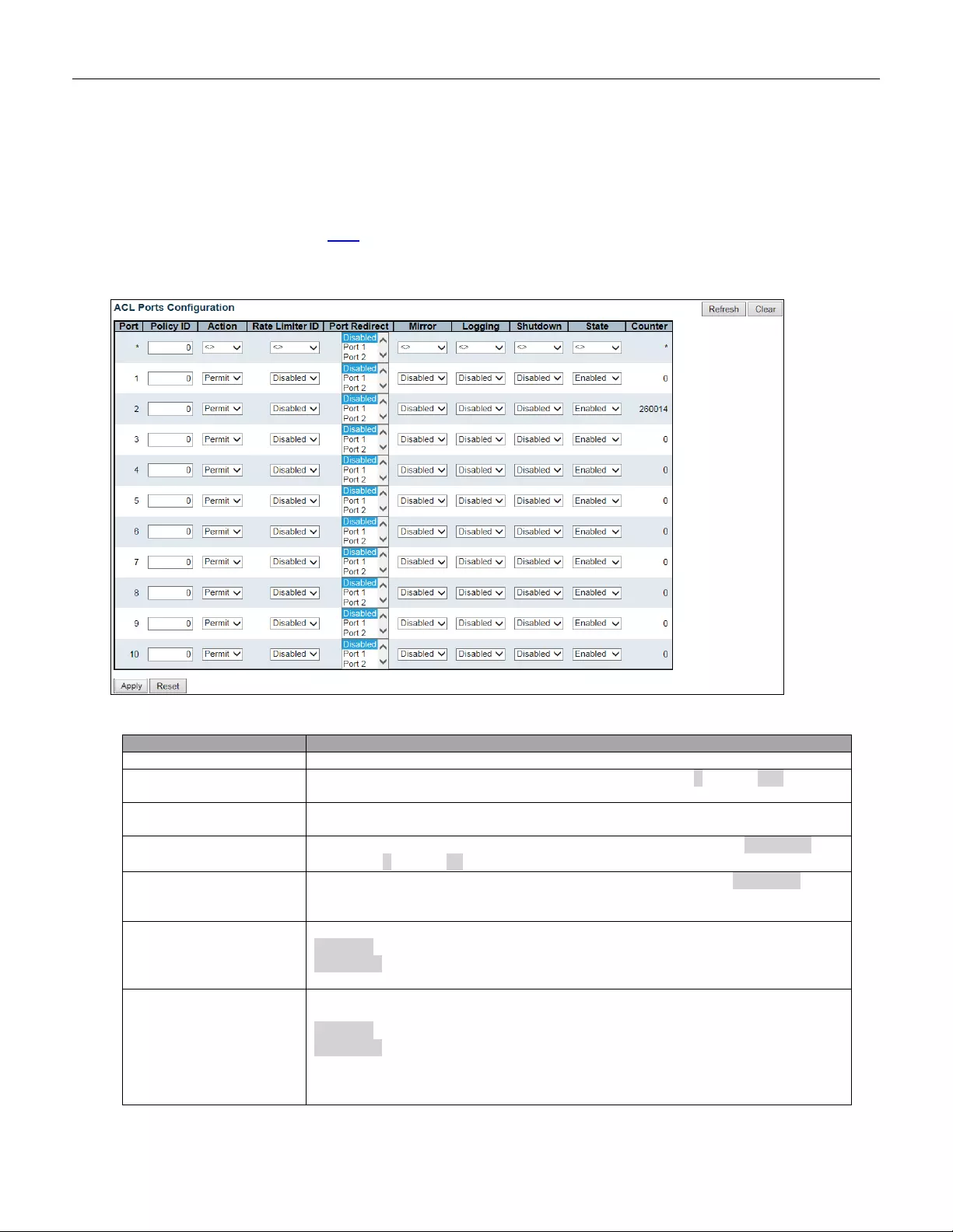
5.3.34 ACL
5.3.35 ACL Port
Configure the ACL parameters (ACE) of each switch port. These parameters wi ll affect frames received on a port
unless the frame matches a specific ACE.
Object
Description
Port
The logical port for the settings contained in the same row.
Policy ID
Select the policy to apply to this port. The allowed values are 0 through 255. The
default value is 0.
Action
Select whether forwarding is permitted ("Permit") or denied ("Deny"). The default
value is "Permit".
Rate Limiter ID
Select which rate limiter to apply on this port. The allowed values are Disabled or
the values 1 through 16. The default value is "Disabled".
Port Redire ct
Select which port frames are redirected on. The allowed values are Disabled or a
specific port number and it can't be set when action is permitted. The default value is
"Disabled".
Mirror
Specify the mirror operation of this port. The allowed values are:
Enabled: Frames received on the port are mirrored.
Disabled: Frames received on the port are not mirrored.
The default value is "Disabled".
Logging
Specify the logging operation of this port. Notice that the logging message doesn't
include the 4 bytes CRC. T he allowed values are:
Enabled: Frames received on the port are stored in the System Log.
Disabled: Frames received on the port are not logged.
The defau lt v al ue is "Disab led " . N ote: The l oggi ng featur e onl y works w hen the pa ck et
length is less than 1518(without VLAN tags) and the System Log memory size and
logging rate is limited .
78
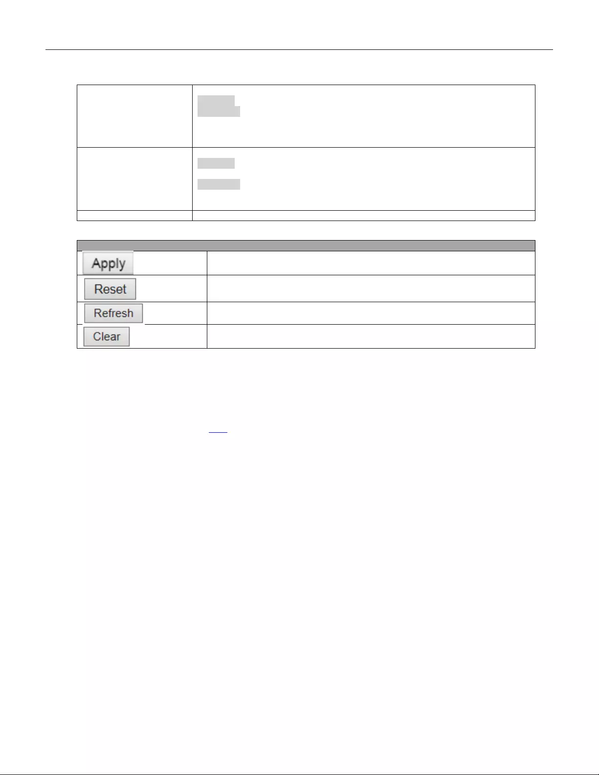
Shutdown
Specify the port shut down operation of this port. The allowed values are:
Enabled: If a frame is received on the port, the port will be disabled.
Disabled: Port shut down is disabled.
The default value is "Disabled".
Note: The shutdown feature only works when the packet length is less than
1518(without VLAN tags).
State
Specify the port state of this port. The allowed values are:
Enabled
: To reopen ports by changing the volatile port configuration of the ACL user
module.
Disabled: To close ports by changing the volatile port configuration of the ACL user
module.
The default value is "Enabled".
Counter
Counts the number of frames that match this ACE.
Buttons
Click to apply changes.
Click to undo any changes made locally and revert to previously saved values.
Click to refresh the page; any changes made locally will be undone.
Click to clear the counters.
5.3.36 ACL Rate Limiters
Configure the rate limiter for the ACL of the switch.
79
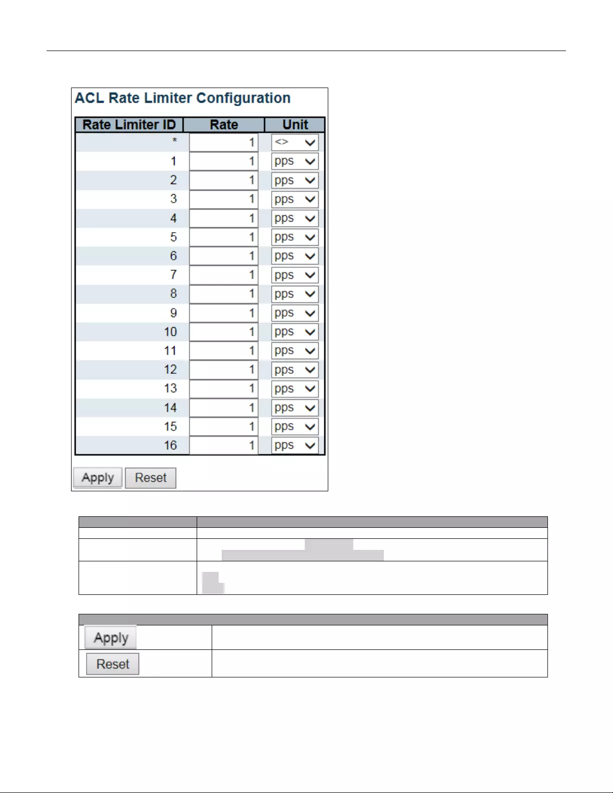
Object
Description
Rate Limiter ID
The rate limiter ID for the settings contained in the same row.
Rate
The rate range is located 0-3276700 in pps.
Or 0, 100, 200, 300, ..., 1000000 in kbps.
Unit
Specify the rate unit. The allowed values are:
pps: packets per second.
kbps: Kbits per second.
Buttons
Click to apply changes.
Click to undo any changes made locally and revert to previously saved values.
80
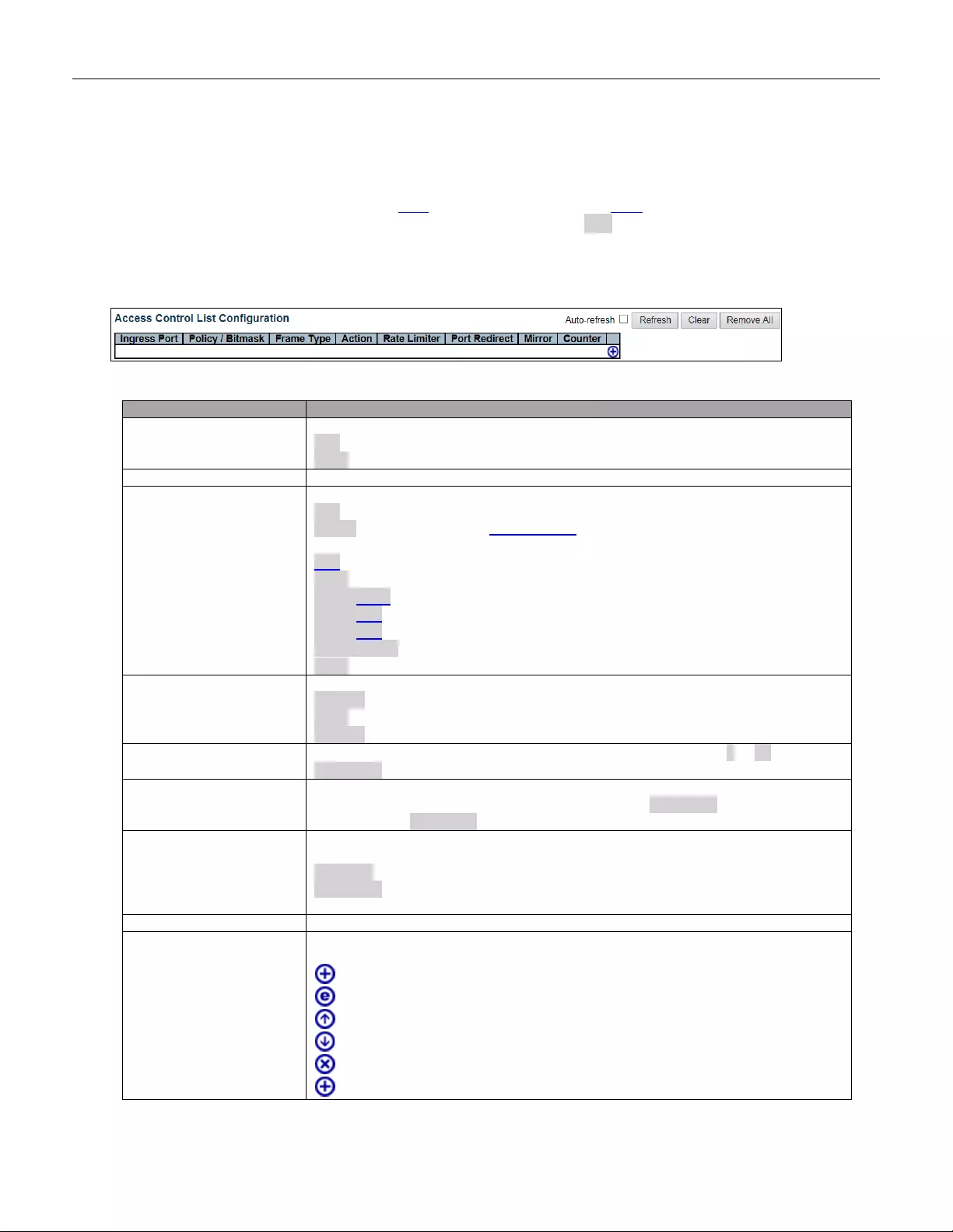
5.3.37 Access Control List
This page shows the Access Control List (ACL), which is made up of the ACEs defined on this switch. Each row
describes the ACE that is defined. The maximum number of ACEs is 256 on each switch.
Click on the lowest plus sign to add a new ACE to the list. The reserved ACEs used for internal protocol, cannot
be edited or deleted, the order sequence cannot be changed and the priority is highest.
Object
Description
Ingress Port
Indicates the ingress port of the ACE. Possible values are:
All: The ACE will match all ingress port.
Port: The ACE will match a specific ingress port.
Policy / Bitmask
Indicates the policy number and bitmask of the ACE.
Frame Type
Indicates the frame type of the ACE. Possible values are:
Any: The ACE will match any frame type.
EType: The ACE will match Et hernet Type frames. Note that an Ethernet Type based
ACE will not get matched by IP and ARP frames.
ARP: The ACE will match ARP/RARP frames.
IPv4: The ACE will match all IPv4 frames.
IPv4/ICMP: The ACE will match IPv4 frames with ICMP protocol.
IPv4/UDP: The ACE will match IPv4 frames with UDP protocol.
IPv4/TCP: The ACE will match IPv4 frames with TCP protocol.
IPv4/Other: The ACE will match IPv4 frames, which are not ICMP/UDP/TCP.
IPv6: The ACE will match all IPv6 standard frames.
Action
Indicates the forwarding action of the ACE.
Permit: Frames matching the ACE may be forwarded and learned.
Deny: Frames matching the ACE are dropped.
Filter: Frames matching the ACE are filtered.
Rate Limiter
Indicates the rate limiter number of the ACE. The allowed range is 1 to 16. When
Disabled is displayed, the rate limiter operation is disabled.
Port Redire ct
Indicates the port redirect operation of the ACE. Frames matching the ACE are
redirected to the port number. The allowed values are Disabled or a specific port
number. When Disabled is displayed, the port redirect operation is disabled.
Mirror
Specify t he m irror operation of this port. Fr ame s mat chi ng the ACE are mirr ored t o th e
destination mirror port. The allowed values are:
Enabled: Frames received on the port are mirrored.
Disabled: Frames received on the port are not mirrored.
The default value is "Disabled".
Counter
The counter indicates the number of times the ACE was hit by a frame.
Modification Buttons
You can modify each ACE (Access Control Entry) in the table using the following
buttons:
: Inserts a new ACE before the current row.
: Edits the ACE row.
: Moves the ACE up the list.
: Moves the ACE down the list.
: Deletes the ACE.
: The lowest plus sign adds a new entry at the bottom of the ACE listings.
81
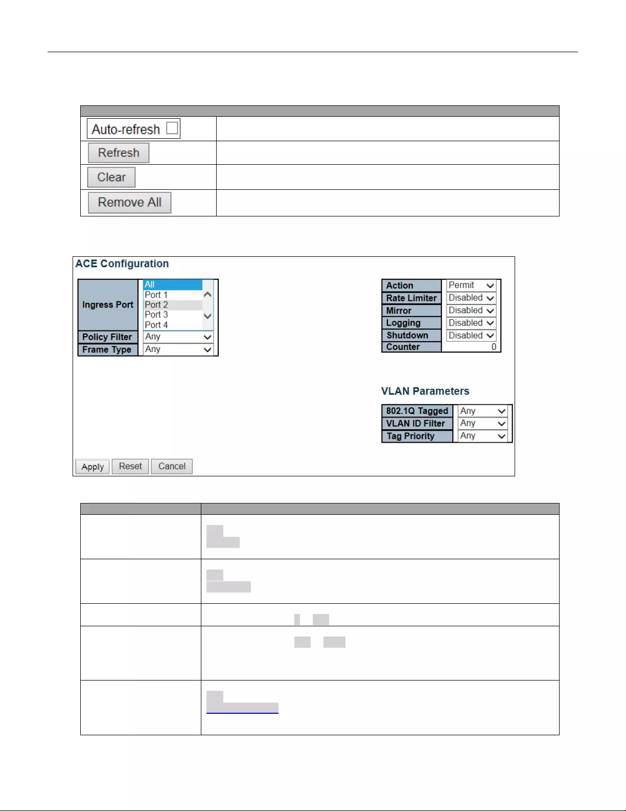
Buttons
Check thi s box to refr esh the page a utomati cally. Auto matic r efresh oc curs ev ery 3
seconds.
Click to refresh the page; any changes made locally will be undone.
Click to clear the counters.
Click to remove all ACEs.
The ACE Configuration page includes the following fields:
Object
Description
Ingress Port
Select the ingress port for which this ACE applies.
All: The ACE applies to all port.
Port n: The ACE applies to this port number, where n is the number of the switch
port.
Policy Filter
Specify the policy number filter for this ACE.
Any: No policy filter is specified. (policy filter status is "don't-care".)
Specific: If you want to filter a specific policy with this ACE, choose this value. Two
field for entering a policy value and bitmask appears.
Policy Value
When "Specific" is selected for the policy filter, you can enter a specific policy value.
The allowed range is 0 to 255.
Policy Bitmask
When "Spec ific" i s selected f or the policy filter, you can e nter a specif ic poli cy bitm ask.
The allowed range is 0x0 to 0xff. Notice the usage of bitmask, if the binary bit value
is "0", it means this bit is "don't-care". The real matched pattern is [policy_value &
policy_bit ma sk]. For example, if the pol icy v a lue i s 3 and the policy b itma sk i s 0x10(bit
0 is "don't-care" bit), then policy 2 and 3 are applied to this rule.
Frame Type
Select the frame type for this ACE. These frame types are mutually exclusive.
Any: Any frame can match this ACE.
Ethernet Type: Only Ethernet Type frames can match this ACE. The IEEE 802.3
describes the value of Length/Type Field specifications to be greater than or equal to
1536 decimal (equal to 0600 hexadecimal).
82
ARP: On ly ARP frames can match this ACE. Notice the ARP frames won't match the
ACE with Ethernet type.
IPv4: Only IPv4 frames can match this ACE. Notice the IPv4 frames won't match the
ACE with Ethernet type.
IPv6: Only IPv6 frames can match this ACE. Notice the IPv6 frames won't match the
ACE with Ethernet type.
Action
Specify the action to take with a frame that hits this ACE.
Permit: The frame that hits this ACE is granted permission for the ACE operation.
Deny: The frame that hits this ACE is dropped.
Filter: Frames matching the ACE are filtered.
Rate Limiter
Specify the rate limiter in number of base units. The allowed range is 1 to 16.
Disabled indicates that the rate limiter operation is disabled.
Port Redire ct
Frames that hit the ACE are redirected to the port number specif ied here. The rat e
limiter will affect these ports. The allowed range is the same as the switch port
number range. Disabled indicates that the port redirect operation is disabled and
the specific port number of 'Port Redirect' can't be set when action is permitted.
Mirror
Specify t he m irror opera t io n of t his port . F r ame s mat chi ng t he ACE are mirror ed to the
destination mirror port. The rate limiter will not affect frames on the mirror port. The
allowed values are:
Enabled: Frames received on the port are mirrored.
Disabled: Frames received on the port are not mirrored.
The default value is "Disabled".
Logging
Specify the logging operation of the ACE. Notice that the logging message doesn't
include the 4 bytes CRC information. The allowed values are:
Enabled: Frames matching the ACE are stored in the System Log.
Disabled: Frames matching the ACE are not logged.
Note: The logging feature only works when the packet length is less than
1518(without VLAN tags) and the System Log memory size and logging rate is
limited.
Shutdown
Specify the port shut down operation of the ACE. The allowed values are:
Enabled: If a frame matches the ACE, the ingress port will be disabled.
Disabled: Port shut down is disabled for the ACE.
Note: The shut down feature only works when the packet length is less than
1518(without VLAN tags).
Counter
The counter indicates the number of times the ACE was hit by a frame.
MAC Parameters
SMAC Filter
(Only displayed when the frame type is Ethernet Type or ARP.)
Specify the sour ce MAC filter for this ACE.
Any: No SMAC filter is specified. (SMAC filter status is "don't-care".)
Specific: If you want to filter a specific source MAC address with this ACE, choose
this value. A field for entering an SMAC value appears.
SMAC Value
When "Specific" is selected for the SMAC filter, you can enter a specific source MAC
address. The legal format is "xx-xx-xx-xx-xx-xx" or "xx.xx.xx.xx.xx.xx" or
"xxxxxxxxxxxx" (x is a hexadecimal digit). A frame that hits this ACE matches this
SMAC value.
DMAC Filter
Specify the destination MAC filter for this ACE.
Any: No DMAC filter is specified. (DMAC filter status is "don't-care".)
MC: Frame must be multicast.
BC: Frame must be broadcast.
UC: Frame must be unicast.
Specific: If you want to filter a specific destination MAC address with this ACE,
choose this value. A field for entering a DMAC value appears.
DMAC Value
When "Specific" is selected for the DMAC filter, you can enter a specific destination
MAC address. T he lega l for ma t is "xx-xx-xx-xx-xx-xx" or "xx.xx.xx.xx.xx.xx" or
"xxxxxxxxxxxx" (x is a hexadecimal digit). A frame that hits this ACE matches this
DMAC value.
VLAN Parameters
802.1Q Tagged
Specify whether frames can hit the action according to the 802.1Q tagged. The
83
allowed values are:
Any: Any value is allowed ("don't-care").
Enabled: Tagged frame only.
Disabled: Untagged frame only.
The default value is "Any".
VLAN ID Filter
Specify the VLAN ID filter for this ACE.
Any: No VLAN ID filter is specified. (VLAN ID filter status is "don't-care".)
Specific
: If you want to filter a specific VLAN ID with this ACE, choose this value. A
field for entering a VLAN ID number appears.
VLAN ID
When "Specific" is selected for the VLAN ID filter, you can enter a specific VLAN ID
number. The allow ed range is 1 to 4095. A frame that hits this ACE matches this
VLAN ID value.
Tag Prio rity
Specify the tag priority for this ACE. A frame that hits this ACE matches this tag
priority. The allowed number range is 0 to 7 or range 0-1, 2-3, 4-5, 6-7, 0-3 and
4-7. The value Any means t h at no tag pr iority i s s pec ifie d (tag pri ority is "do n' t-care".)
ARP Parameters
ARP/RARP
Specify the available ARP/RARP opcode (OP) flag for this ACE.
Any: No ARP/RARP OP flag is specified. (OP is "don't-care".)
ARP: Frame must have AR P opcod e set to ARP.
RARP: Frame must have RARP opcode set to RARP.
Other: Frame has unknown ARP/RARP Opcode flag.
Request/Reply
Specify the available Request/Reply opcode (OP) flag for this ACE.
Any: No Request/Reply OP flag is specified. (OP is "don't-care".)
Request: Frame must have ARP Request or RARP Request OP flag set.
Reply: Frame must have ARP Reply or RARP Reply OP flag.
Sender IP Filter
Specify the sender IP filter for this ACE.
Any: No sender IP filter is specified. (Sender IP filter is "don't-care".)
Host
: Sender IP filter is set to H ost. S pec if y the s ender I P ad dres s i n th e S IP Address
field that appears.
Network: Sender IP filter is set to Network. Specify the sender IP address and
sender IP mask in the SIP Address and SIP Mask fields that appear.
Sender IP Address
When "Host" or "Network" is selected for the sender IP filter, you can enter a specific
sender IP address in dotted decimal notation.
Sender IP Mask
When "Network" is selected for the sender IP filter, you can enter a specific sender IP
mask in dot ted dec im al notation.
Target IP Filter
Specify the target IP filter for this spe cific ACE .
Any: No target IP filter is specified. (Target IP filter is "don't-care".)
Host: Target IP filter is set to Host. Specify the target IP address in the Target IP
Address field that appears. Network: Target IP filter is set to Network. Specify the
target IP address and target IP mask in the Target IP Address and Target IP Mask
fields that appear.
Target IP Addr ess
When "Host" or "Network" is selected for the target IP filter, you can enter a specific
target IP addr e ss in dotted decimal notation.
Target IP Mask
When "Network" is selected for the target IP filter, you can enter a specific target IP
mask in dot ted dec im al notation.
ARP Sender MAC Match
Specify whether frame s ca n hit t he act ion a cc ordi ng to their s ender h ardware addre s s
field (SHA) settings.
0: ARP frames where SHA is not equal to the SMAC address.
1: ARP frames where SHA is equal to the SMAC address.
Any: Any value is allowed ("don't-care").
RARP Target MAC Match
Specify whether frames can hit the action according to their target hardware address
field (THA) settings.
0: RARP frames where THA is not equal to the target MAC address.
1: RARP frames where THA is equal to the target MAC address.
Any: Any value is allowed ("don't-care").
IP/Ethernet Length
Specify whether frames can hit the action according to their ARP/RARP hardware
address length (HLN ) and protocol addres s length (PLN) settings.
0: ARP/RARP frames where the HLN is not equal to Ethernet (0x06) or the (PLN) is
84
not equal to IPv4 (0x04).
1: ARP/RARP frames where the HLN is equal to Ethernet (0x06) and the (PLN) is
equal to IPv4 (0x04).
Any: Any value is allowed ("don't-care").
IP
Specify whether frames can hit the action according to their ARP/RARP hardware
address space (HRD ) setti ng s.
0: ARP/RARP frames where the HLD is not equal to Ethernet (1).
1: ARP/RARP frames where the HLD is equal to Ethernet (1).
Any: Any value is allowed ("don't-care").
Ethernet
Specify whether frames can hit the action according to their ARP/RARP protocol
address space (PRO) settings.
0: ARP/RARP frames where the PRO is not equal to IP (0x800).
1: ARP/RARP frames where the PRO is equal to IP (0x800).
Any: Any value is allowed ("don't-care").
IP Parameters
IP Protocol Filter
Specify the IP protocol filter for this ACE.
Any: No IP protocol filter is specified ("don't-care").
Specific: If you want to filter a specific IP protocol filter with this ACE, choose this
value. A field for entering an IP protocol filter appears.
ICMP: Select ICMP to filter IPv4 ICMP protocol frames. Extra fields for defining ICMP
parameters will appear. These fields are explained later in this help file.
UDP: Select UDP to filter IPv4 UDP protocol frames. Extra fields for defining UDP
parameters will appear. These fields are explained later in this help file.
TCP: Select TCP to filter IPv4 TCP protocol frames. Extra fields for defining TCP
parameters will appear. These fields are explained later in this help file.
IP Protocol Value
When "Specific" is selected for the IP protocol value, you can enter a specific value.
The allowed range is 0 to 255. A frame that hits this ACE matches this IP protocol
value.
IP TTL
Specify the Time-to-Live settings for this ACE.
zero: IPv4 frames with a Time-to-Live field greater than zero must not be able to
match this entry.
non-zero: IPv4 frames with a Time-to-Live field greater than zero must be able to
match this entry.
Any: Any value is allowed ("don't-care").
IP Fragment
Specify the fragment offset settings for this ACE. This involves the settings for the
More Fragments (MF) bit and the Fragment Offset (FRAG OFFSET) field for an IPv4
frame.
No: IPv4 frames where the MF bit is set or the FRAG OFFSET field is greater than
zero must not be able to match this entry.
Yes: IPv4 frames where the MF bit is set or the FRAG OFFSET field is greater than
zero must be able to match this entry.
Any: Any value is allowed ("don't-care").
IP Option
Specify the options flag setting for this ACE.
No: IPv4 frames where the options flag is set must not be able to match this entry.
Yes: IPv4 frames where the options flag is set must be able to match this entry.
Any: Any value is allowed ("don't-care").
SIP Filter
Specify the source IP filter for this ACE.
Any: No source IP filter is specified. (Source IP filter is "don't-care".)
Host
: Source IP filter is set to Host. Spe cify the source IP a d dres s in the S I P Ad dr es s
field that appears.
Network: Source IP fi lter i s se t to Network. Spe cify t he sourc e IP address and source
IP mask in the SIP Address and SIP Mask fields that appear.
SIP A ddress
When "Host" or "Network" is selected for the source IP filter, you can enter a specific
SIP address in dotted dec imal not at ion.
SI P Mask
When "Network" is selected for the source IP filter, you can enter a specific SIP mask
in dotted decim al notation.
DIP Filter
Specify the destination IP filter for this ACE.
Any: No destination IP filter is specified. (Destination IP filter is "don't-care".)
85
Host: Destination IP filter is set to Host. Specify the destination IP address in the DIP
Address field that appears.
Network: Destination IP filter is set to Network. Specify the destination IP address
and destination IP mask in the DIP Address and DIP Mask fields that appear.
DIP Address
When "Host" or "Network" is selected for the destination IP filter, you can enter a
specific DIP address in dott ed deci mal not ati on.
DI P Mask
When "Network" is selected for the destination IP filter, you can enter a specific DIP
mask in dot ted dec im al notation.
IPv6 Parameters
Next Header Filter
Specify the IPv6 next header filter for this ACE.
Any: No IPv6 next header filter is specified ("don't-care").
Specific: If you want to f ilter a spe cifi c IP v 6 next header f ilt er with this A CE , choo s e
this value. A field for entering an IPv6 next header filter appears.
ICMP: Select ICMP to filter IPv6 ICMP protocol frames. Extra fields for defining ICMP
parameters will appear. These fields are explained later in this help file.
UDP: Select UDP to filter IPv6 UDP protocol frames. Extra fields for defining UDP
parameters will appear. These fields are explained later in this help file.
TCP: Select TCP to filter IPv6 TCP protocol frames. Extra fields for defining TCP
parameters will appear. These fields are explained later in this help file.
Next Header Value
When "Specific" is selected for the IPv6 next header value, you can enter a specific
value. The allow ed range is 0 to 255. A frame that hits this ACE matches this IPv6
protocol value.
SIP Filter
Specify the source IPv6 filter for this ACE.
Any: No source IPv6 filter is specified. (Source IPv6 filter is "don't-care".)
Specific: Source IPv6 filter is set to Network. Specify the source IPv6 address and
source IPv6 mask in the SIP Address fields that appear.
SIP address
When "Specific" is selected for the source IPv6 filter, you can enter a specific SIPv6
address. The field only supported last 32 bits for IPv6 address.
SIP BitMask
When "Specific" is selected for the source IPv6 filter, you can enter a specific SIPv6
mask. The field only supported last 32 bits for IPv6 address. Notice the usage of
bitmask, if the binary bit v alue i s "0 ", i t means this bit is "do n' t -care" . T he r ea l m atched
pattern is [sipv6_address & sipv6_bitmask] (last 32 bits). For example, if the SIPv6
address is 2001::3 and the SIPv6 bitmask is 0xFFFFFFFE(bit 0 is "don't-care" bit) ,
then SIPv6 address 2001::2 and 2001::3 are applied to this rule.
Hop Limit
Specify the hop limit settings for this ACE.
zero: IPv6 frames with a hop limit field greater than zero must not be able to match
this entry.
non-zero: IPv6 frames with a hop limit field greater than zero must be able to match
this entry.
Any: Any value is allowed ("don't-care").
ICMP Parameters
ICMP Type Filter
Specify the ICMP filter for this ACE.
Any: No ICMP filter is specified (ICMP filter status is "don't-care").
Specific: If you want to filter a specific ICMP filter with this ACE, you can enter a
specific ICMP value. A field for entering an ICMP value appears.
ICMP Type Value
When "Specific" is selected for the ICMP filter, you can enter a specific ICMP value.
The allowed range is 0 to 255. A frame that hits this ACE matches this ICMP value.
ICMP Code Filter
Specify the ICMP code filter for this ACE.
Any: No ICMP code filter is specified (ICMP code filter status is "don't-care").
Specific: If you w ant to filter a specif ic ICM P code filt er w ith this ACE, y ou can e nte r
a specific ICMP code value. A field for entering an ICMP code value appears.
ICMP Code Value
When "Specific" is selected for the ICMP code filter, you can enter a specific ICMP
code value. The allowed range is 0 to 255. A frame that hits this ACE matches this
ICMP code value.
TCP/UDP Parameters
TCP/UDP Source Filte r
Specify the TCP/UDP source filter for this ACE.
Any: No TCP/UDP source filter is specified (TCP/UDP source filter status is
"don't-care").
86
Specific: If you want to filter a specific TCP/UDP source filter with this ACE, you
can enter a specific T C P/ UD P source value. A fie ld for enteri ng a TCP/U DP source
value appears.
Range: If you want to filter a specific TCP/UDP source range filter with this ACE, you
can enter a specific T C P/ UD P source range value. A fi eld for enter i ng a TCP/UDP
source value appears.
TCP/UDP Source No.
When "Specific" is selected for the TCP/UDP source filter, you can enter a specific
TCP/UDP source value. The allowed range is 0 to 65535. A frame that hits this ACE
matches this TCP/UDP source value.
TCP/UDP Source Range
When "Range" is selecte d for the TCP/UD P source filter, you can enter a specific
TCP/UDP source range value. The allowed range is 0 to 65535. A frame that hits this
ACE matches this TCP/UDP source value.
TCP/UDP Destination
Filter
Specify the TCP/UDP destination filter for this ACE.
Any: No TCP/UDP destination filter is specified (TCP/UDP destination filter status is
"don't-care").
Specific: If you want to filter a specific TCP/UDP destination filter with this ACE,
you can enter a specific TCP/UDP destination value. A field for entering a TCP/UDP
destination value appears.
Range: If you want to filter a specific range TCP/UDP destination filter with this ACE,
you can enter a specific TCP/UDP destination range value. A field for entering a
TCP/UDP destination value appears.
TCP/UDP Destination
Number
When "Specific" is selected for the TCP/UDP destination filter, you can enter a
specific T C P/U DP destination value. T he all owed range is 0 to 65535. A frame that
hits this ACE matches this TCP/UDP destination value.
TCP/UDP Destination
Range
When "Range" is selected for the TCP/UDP destination filter, you can enter a specific
TCP/UDP destination range value. The allowed range is 0 to 65535. A frame that hits
this ACE matches this TCP/UDP destination value.
TCP FIN
Specify the TCP "No more data from sender" (FIN) value for this ACE.
0: TCP frames where the FIN field is set must not be able to match this entry.
1: TCP frames where the FIN field is set must be able to match this entry.
Any: Any value is allowed ("don't-care").
TCP SYN
Specify the TCP "Synchronize sequence numbers" (SYN) value for this ACE.
0: TCP frames where the SYN field is set must not be able to match this entry.
1: TCP frames where the SYN field is set must be able to match this entry.
Any: Any value is allowed ("don't-care").
TCP RST
Specify the TCP "Reset the connection" (RST) value for this ACE.
0: TCP frames where the RST field is set must not be able to match this entry.
1: TCP frames where the RST field is set must be able to match this entry.
Any: Any value is allowed ("don't-care").
TCP PSH
Specify the TCP "Push Function" (PSH) value for this ACE.
0: TCP frames where the PSH field is set must not be able to match this entry.
1: TCP frames where the PSH field is set must be able to match this entry.
Any: Any value is allowed ("don't-care").
TCP ACK
Specify the TCP "Acknowledgment field significant" (ACK) value for this ACE.
0: TCP frames where the ACK field is set must not be able to match this entry.
1: TCP frames where the ACK field is set must be able to match this entry.
Any: Any value is allowed ("don't-care").
TCP URG
Specify the TCP "Urgent Pointer field significant" (URG) value for this ACE.
0: TCP frames where the URG field is set must not be able to match this entry.
1: TCP frames where the URG field is set must be able to match this entry.
Any: Any value is allowed ("don't-care").
Ethernet Type Parameters
EtherType Filter
Specify the Ethernet type filter for this ACE.
Any: No EtherType filter is specified (EtherType filter status is "don't-care").
Specific
: If you want to filter a specific EtherType filter with this ACE, you can enter
a specific EtherType value. A field for entering an EtherType value appears.
Ethernet Type Value
When "Spe cific" is selecte d for the Ethe rType filter, you can e nter a specifi c Ether Type
value. The allow ed range is 0x600 to 0xFFFF but ex cludi ng 0x800(IPv 4) ,
87
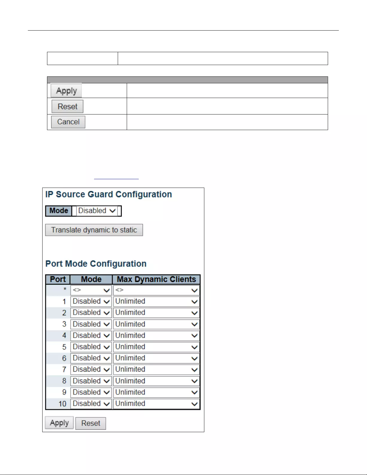
0x806(ARP) and 0x86DD(IPv6). A frame that hits this ACE matches this EtherType
value.
Buttons
Click to apply changes.
Click to undo any changes made locally and revert to previously saved values.
Return to the previous page.
5.3.38 IP Source Guard
5.3.39 IP Source Guard Configuration
This page provides IP Source Guard related configuration.
88
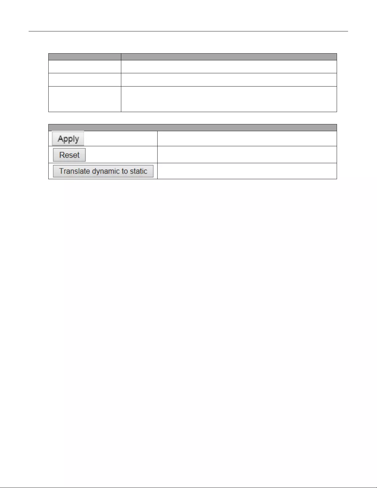
Object
Description
Mode of IP Source Guard
Configuration
Enable the Global IP Source Guard or disable the Global IP Source Guard. All
configure d ACEs will be lost when the mode is enabled.
Port Mode Configuration
Specify I P S o urce G uard is enabled on which port s . O nly when bo th G lo bal Mode an d
Port M ode on a given port are enabled, IP So urce Guar d is e nabled on thi s given p ort.
Max Dynamic Clients
Specify the maximum number of dynamic clients that can be learne d on given port.
This value can be 0, 1, 2 or unlimited. If the port mode is enabled and the value of
max dynamic client is equ al to 0, it means only allow the IP packet s forwarding that
are matched in static entries on the specific port.
Buttons
Click to apply changes.
Click to undo any changes made locally and revert to previously saved
values.
Click to translate all dynamic entries to static entries.
89
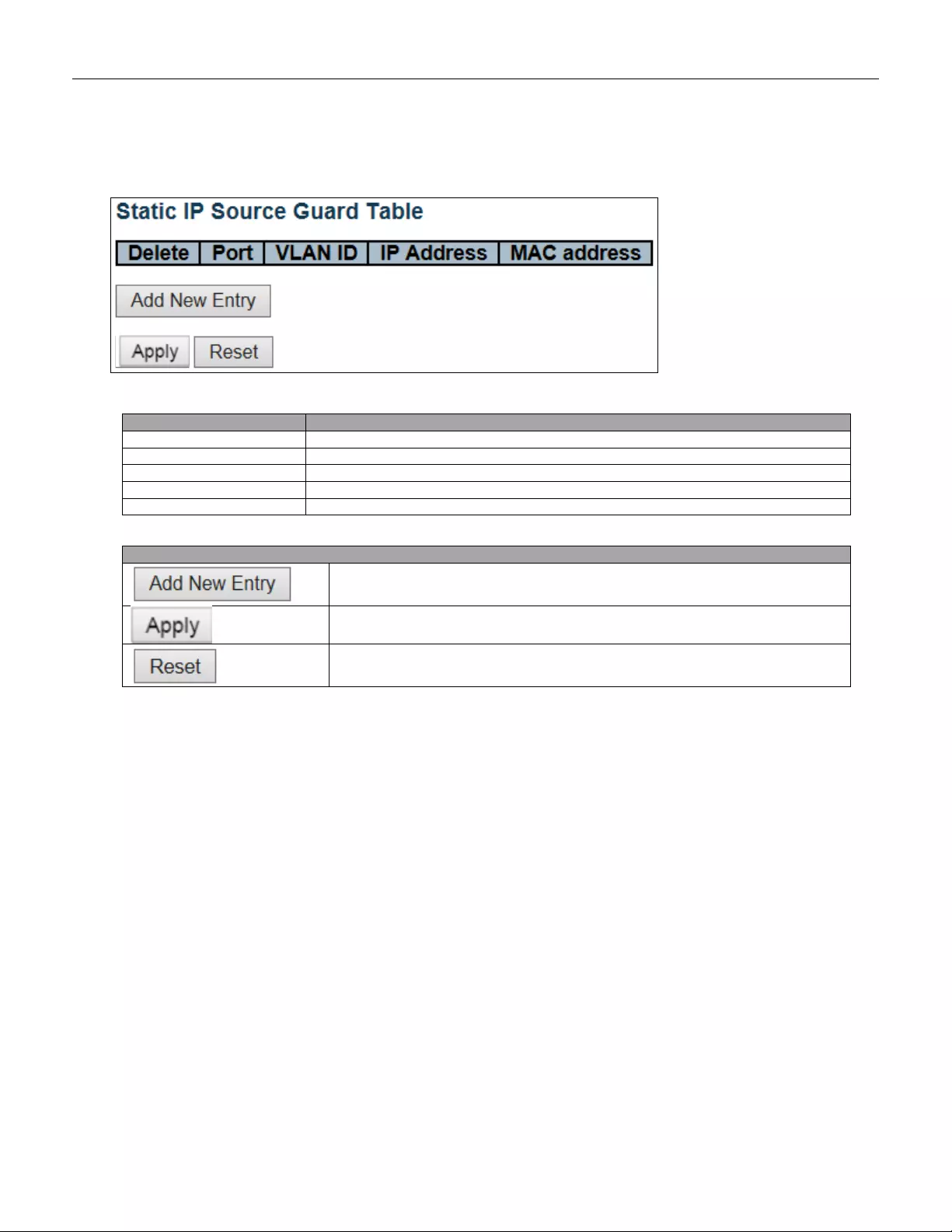
5.3.40 IP Source Guard Static Table
Object
Description
Delete
Check to delete the entry. It will be deleted during the next save.
Port
The logical port for the settings.
VLAN ID
The vlan id for the settings.
IP A ddress
Allowed Source IP address.
MAC address
Allowed Source MAC address.
Buttons
Click to add a new entry to the Static IP Source Guard table.
Click to apply changes.
Click to undo any changes made locally and revert to previously saved values.
90
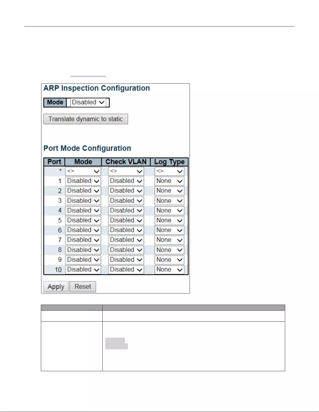
5.3.41 ARP Inspection
5.3.42 Port Configuration
This page provides ARP Inspection related configuration.
Object
Description
Mode of A RP Inspection
Configuration
Enable the Global ARP Inspection or disable the Global ARP Inspection.
Port Mode Configuration
Specify ARP Inspection is enabled on which ports. Only when both Global Mode and
Port Mode on a given port are enabled, ARP Inspection is enabled on this given port.
Possible modes are:
Enabled: Enable ARP Inspection operation.
Disabled: Disable ARP Inspection operation.
If you want to inspect the VLAN configuration, you have to enable the setting of
"Check VLAN". The default setting of "Check VLAN" is disabled. When the setting of
"Check VLAN" is disabled, the log type of ARP Inspection will refer to the port setting.
And the setting of "Check VLAN" is enabled, the log type of ARP Inspection will refer
91
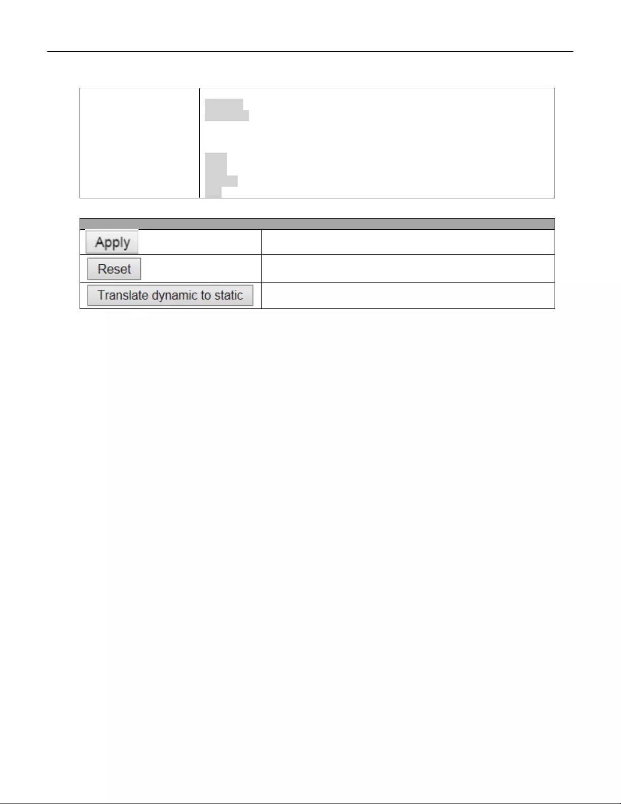
to the VLAN setting. Possible setting of "Check VLAN" are:
Enabled: Enable check VLAN operation.
Disabled: Disable check VLAN operation.
Only the Global Mode and Port Mode on a given port are enabled, and the setting of
"Check VLAN" is disabled, the log type of ARP Inspection will refer to the port setting.
There are four log types and possible types are:
None: Log nothing.
Deny: Log denied entries.
Permit: Log permitted entries.
ALL: Log all entries.
Buttons
Click to apply changes.
Click t o u ndo any cha nge s ma de l oc ally and rever t to pr ev io u sly s av ed
values.
Click to translate all dynamic entries to static entries.
92
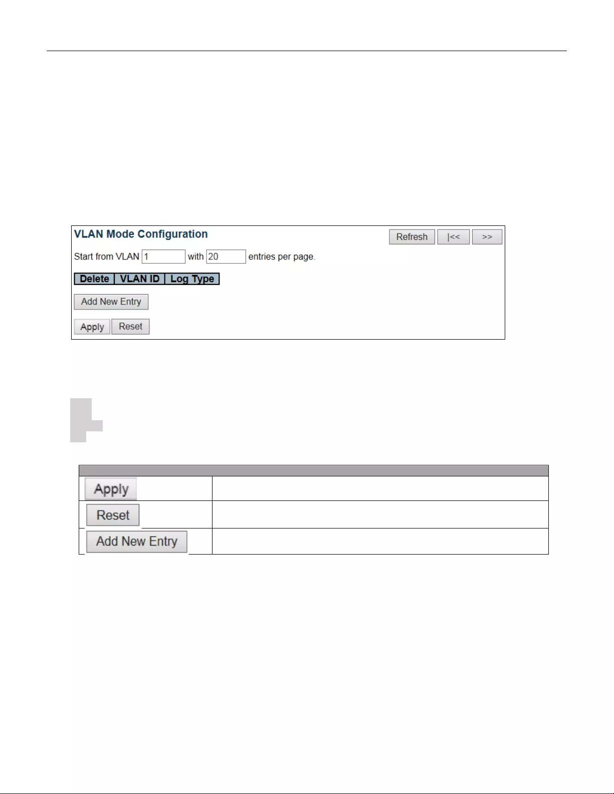
5.3.43 VLAN Configuration
Each page shows up to 9999 entries from the VLAN table, default being 20, selected through the "entries per
page" input field. When first visited, the web page will show the first 20 entries from the beginning of the VLAN
Table. The first displayed will be the one with the lowest VLAN ID found in the VLAN Table.
The "VLAN" input fields allow the user to select the starting point in the VLAN Table. Clicking the button will
update the displayed table starting from that or the closest next VLAN Table match. The will use the next entry of
the currently displayed VLAN entry as a basis for the next lookup. When the end is reached the warning
message is shown in the displayed table. Use the button to start over.
Specify ARP Inspection is enabled on which VLANs. First, you have to enable the port setting on Port mode configuration
web page. O nly when both G l o bal Mode a nd P or t Mode o n a giv en p or t are enabled , A RP I n spe ctio n i s enabled on this given
port. Second, you can specify which VLAN will be inspected on VLAN mode configuration web page. The log type also can
be configured on per VLAN setting.
Possible types are:
None: Log nothing.
Deny: Log denied entries.
Permit: Log permitted entries.
ALL: Log all entries
Buttons
Click to apply changes.
Click to undo any changes made locally and revert to previously saved values.
Click to add a new VLAN to the ARP Inspection VLAN table.
93

5.3.44 Static Table
Object
Description
Delete
Check to delete the entry. It will be deleted during the next save.
Port
The logical port for the settings
VLAN ID
The vlan id for the settings.
MAC Address
Allowed Source MAC address in ARP request packets.
IP A ddress
Allowed Source IP address in ARP request packets.
Buttons
Click to add a new entry to the Static ARP Inspection table.
Click to apply changes.
Click to undo any changes made locally and revert to previously saved values.
94
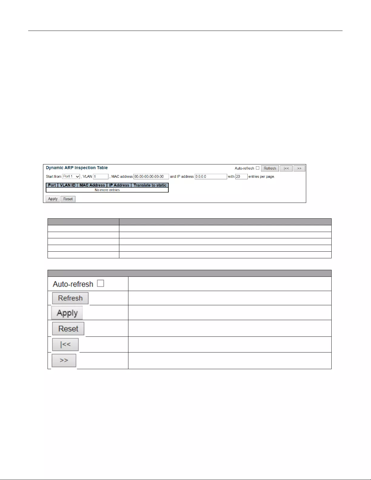
5.3.45 Dynamic Table
Each page shows up to 99 entries from the Dynamic ARP Inspection table, default being 20, selected through
the "entries per page" input field. When first visited, the web page will show the first 20 entries from the
beginning of the Dynamic ARP Inspection Table.
The "Start from port address", "VLAN", "MAC address" and "IP address" input fields allow the user to select the
starting po int in the D ynam ic AR P Inspection Table. C li cking the button will update the disp layed table start in g
from that or the closest next Dynamic ARP Inspection Table match. In addition, the two input fields will - upon a
button click - assume the value of the first displayed entry, allowing for continuous refresh with the same start
address.
The will use the last entry of the currently displayed table as a basis for the next lookup. When the end is
reached the text "No more entries" is shown in the displayed table. Use the button to start over.
Object
Description
Port
Switch Port Number for which the entries are displayed.
VLAN ID
VLAN-ID in which the ARP traffic is permitted.
MAC Address
User MAC address of the entry.
IP A ddress
User IP addr es s of the entry.
Translate to static
Select the checkbox to translate the entry to static entry.
Buttons
Check this box to refresh the page automatically. Automatic refresh
occurs every 3 seconds.
Refreshes the displayed table starting from the input fields.
Click to apply changes.
Click to undo any changes made locally and revert to previously saved
values.
Updates the table starting from the first entry in the Dynamic ARP
Inspection Table.
Updates the table, starting with the entry after the last entry currently
displayed.
95
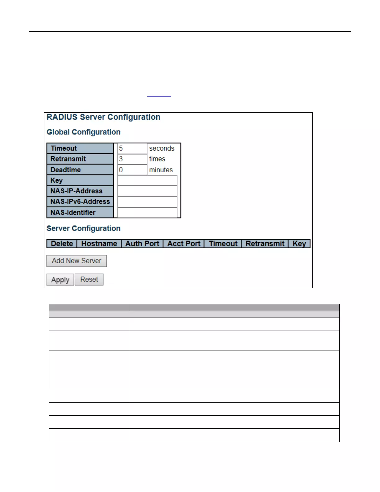
5.3.46 AAA
5.3.47 RADIUS
This page allows you to configure the RADIUS servers.
Object
Description
Global Configuration
Timeout
Timeout i s t he number of se co nds, in the range 1 to 1000, t o wait for a re ply fr o m a
RADIUS server before retransmitting the request.
Retransmit
Retransmit is the number of times, in the range 1 to 1000, a RADIUS request is
retransmitted to a server that is not responding. If the server has not responded
after the last retransmit it is considered to be dead.
Deadtime
Deadtime, which can be set to a number between 0 to 1440 minutes, is the period
during which the switch will not send new requests to a server that has failed to
respond to a previous request. This will stop the switch from continually trying to
contact a server that it has already deter mined as dea d.
Setting the Deadtime to a value greater than 0 (zero) will enable this feature, but
only if more than one server h as been conf igur ed.
Key
The secret key - up to 63 characters long - shared between the RADIUS server
and the switch.
NAS-IP-Address(Attribute
4)
The IPv4 address to be used as attribute 4 in RADIUS Access-Request packet s. If
this field is left blank, the IP address of the outgoing interface is used.
NAS-IPv6-Address(Attribute
95)
The IPv6 address to be used as attribute 95 in RADIUS Access-Request packets.
If this field is left blank, the IP address of the outgoing interface is used.
NAS-I d entifier (Attribute 32)
The identifier - up to 253 chara cters long - to be used as attribute 32 in RADIUS
Access-R e que st pa ck ets. I f thi s fie ld i s left blank, t he N AS -Id entifier is not included
96
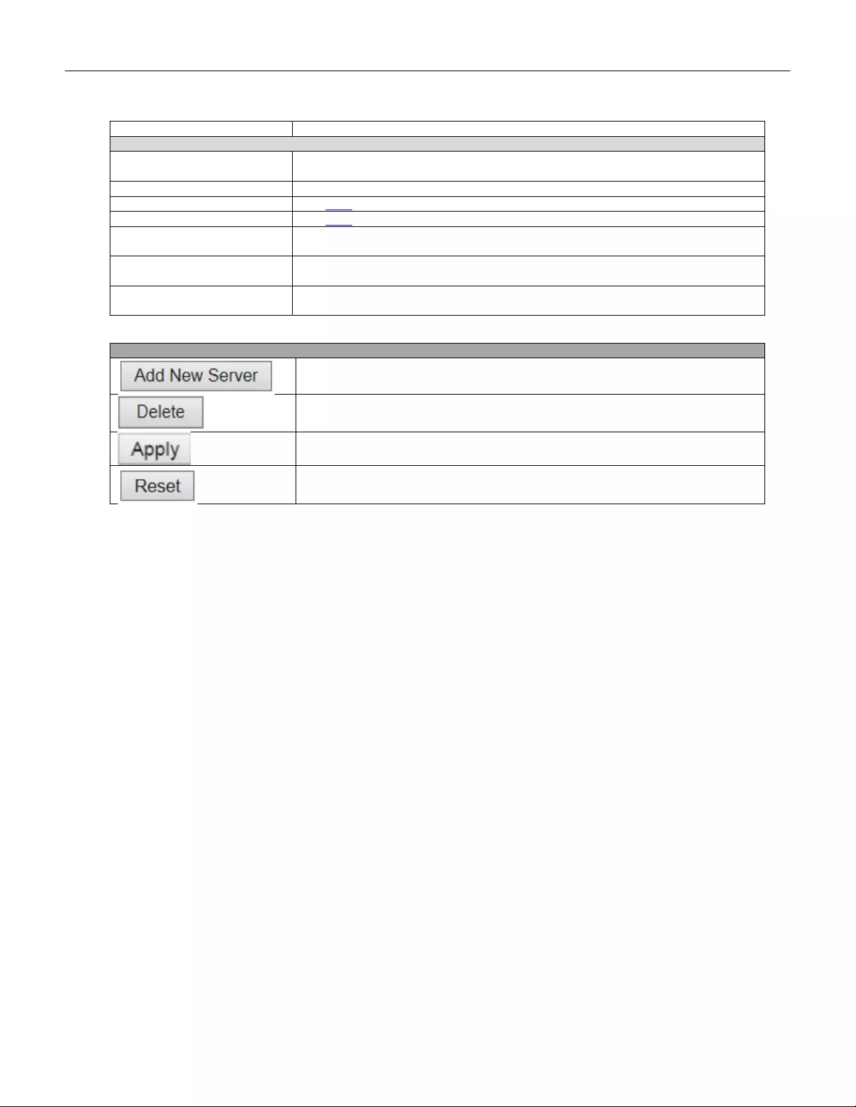
in the packet.
Server Configuration
Delete
To delete a RADIUS server entry, check this box. The entry will be deleted during
the next Save.
Hostname
The IP address or hostna me of the RADIUS server.
Auth Port
The UDP port to use on the RADIUS server for authentication.
Acct Port
The UDP port to use on the RADIUS server for accounting.
Timeout
This optional setting overrides the global timeout value. Leaving it blank will use
the global timeout value.
Retransmit
This optional setting overrides the global retransmit value. Leaving it blank will use
the global retransmit value.
Key
This optional setting overrides the global key. Leaving it blank will use the global
key.
Buttons
Click to add a new RADIUS server, up to 5 servers are supported.
The button can be used to undo the addition of the new server.
Click to apply changes.
Click to undo any changes made locally and revert to previously saved values.
97

5.3.48 TACACS+
This page allows you to configure the TACACS+ servers.
Object
Description
Global Configuration
Timeout
Timeout is the number of seconds, in the range 1 to 1000, to wait for a reply from a
TACACS+ server before it is considered to be dead.
Deadtime
Deadtime, which can be set to a number between 0 to 1440 minutes, is the period
during which the switch will not send new requests to a server that has failed to
respond to a previous request. This will stop the switch from continually trying to
contact a server that it has already deter mined as dea d.
Setting the Deadtime to a value greater than 0 (zero) will enable this feature, but only
if more than one server has been configured.
Key
The secret key - up to 63 characters long - shared between the TACACS+ server and
the switch.
Server Configuration
Delete
To delete a TACACS+ server entry, check this box. The entry will be deleted during
the next Save.
Hostname
The IP address or hostna me of the TACACS+ server.
Port
The TCP port to use on the TACACS+ server for authentication.
Timeout
This optional setting overrides the global timeout value. Leaving it blank will use the
global timeout value.
Key
This optional setting overrides the global key. Leaving it blank will use the global key.
98
Buttons
Click to add a new TACACS+ server, up to 5 servers are supported.
The button can be used to undo the addition of the new server.
Click to apply changes.
Click to undo any changes made locally and revert to previously saved values.
99
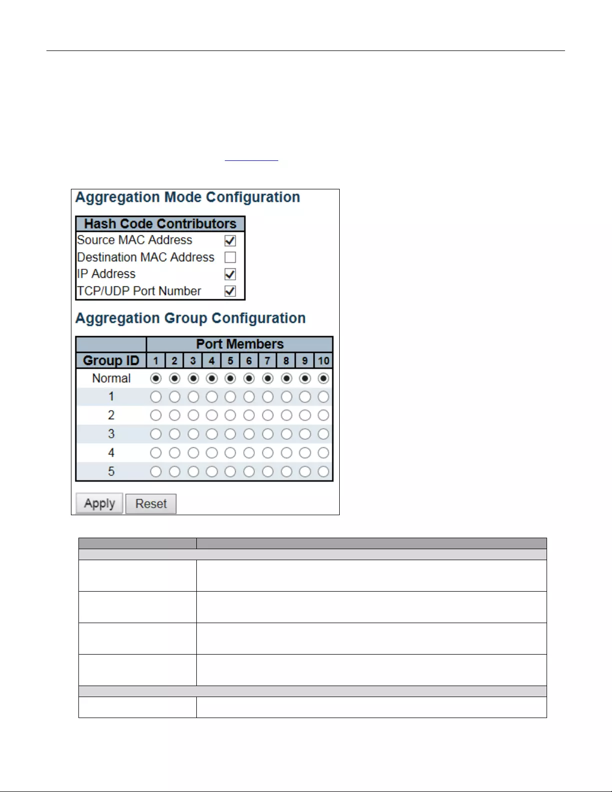
5.3.49 Aggregation
5.3.50 Static Aggregation
This page is used to configure the Aggregation hash mode and the aggregation group.
Object
Description
Hash Code Contributors
Source MA C Address
The Source MAC address can be used to calculate the destination port for the frame.
Check to enable the use of the Source MAC address, or uncheck to disable. By
default, Source MAC Address is enabled.
Destination MAC
Address
The Destination MAC Address can be used to calculate the destination port for the
frame. Check to enable the use of the Destination MAC Address, or uncheck to
disable. By default, Destination MAC Address is disabled.
IP A ddress
The IP address can be used to calculate the destination port for the frame. Check to
enable the use of the IP Address, or uncheck to disable. By default, IP Address is
enabled.
TCP/UDP Port Number
The T CP/UD P por t number c an be u sed to calcu late the des tinatio n por t for the fram e.
Check to enable the use of the TCP/UDP Port Number, or uncheck to disable. By
default, TCP/UDP Port Number is enabled.
Aggregation Group Configuration
Group ID
Indicates the group ID for the settings contained in the same row. Group ID "Normal"
indicates there is no aggregation. Only one group ID is valid per port.
100
Port Members
Each switch port is listed for each group ID. Select a radio button to include a port in
an aggregation, or clear the radio button to remove the port from the aggregation. By
default, no ports belong to any aggregation group. Only full duplex ports can joi n an
aggregation and ports must be in the same speed in each group.
Buttons
Click to apply changes.
Click to undo any changes made locally and revert to previously saved values.
101
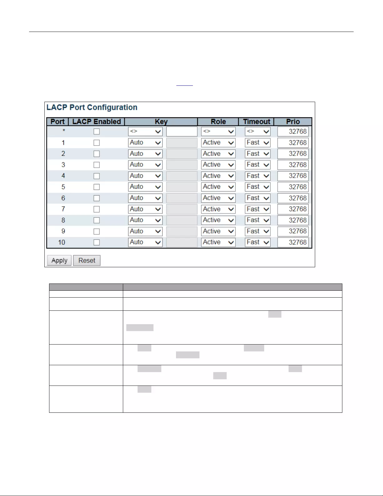
5.3.51 LA CP A ggrega tion
This page allows the user to inspect the current LACP port configurations, and possibly change them as well.
Object
Description
Port
The switch port number.
LACP Enabled
Controls whether LACP is enabled on this switch port. LACP will form an aggregation
when 2 or more ports are connected to the same partner.
Key
The Key value incurred by the port, range 1-65535 . The Auto setting will set the key
as appropriate by the physical link speed, 10Mb = 1, 100Mb = 2, 1Gb = 3. Using the
Specific setting, a user-defined value can be entered. Ports with the same Key
value can participate in the same aggregation group, while ports with different keys
cannot.
Role
The Role shows the LACP activity status. The Active will transmit LACP packets
each second, while Passive will wait for a LACP packet from a partner (speak if
spoken to).
Timeout
The Timeout controls the period between BPDU transmissions. Fast will transmit
LACP packets each second, while Slow will wait for 30 seconds before sending a
LAC P packet.
Prio
The Prio controls the priority of the port. If the LACP partner wants to form a larger
group than is supported by this device then this parameter will control which ports will
be active and which ports will be in a backup role. Lower number mea ns great er
priority.
102

Buttons
Click to apply changes.
Click to undo any changes made locally and revert to previously saved values.
103
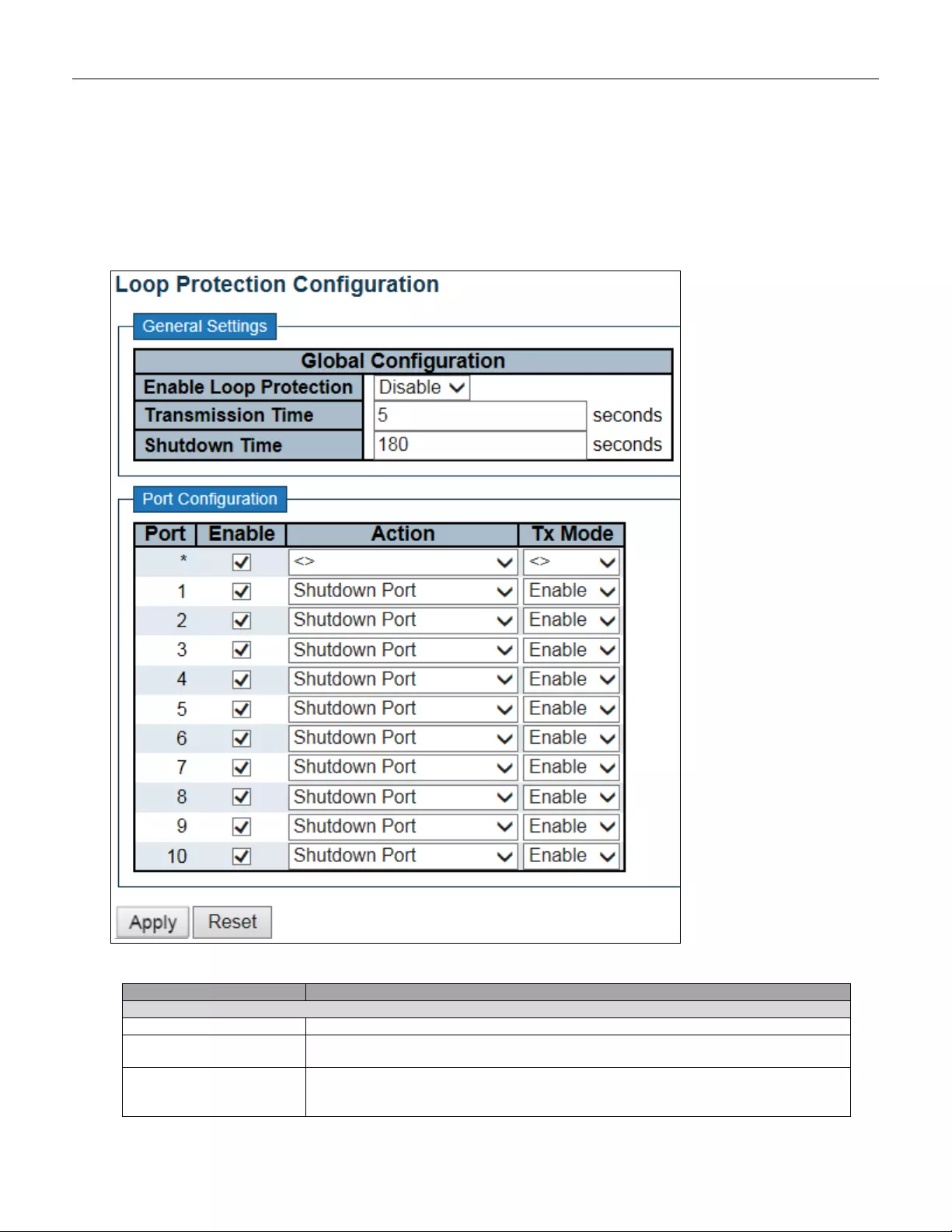
5.3.52 Loop Protection
This page allows the user to inspect the current Loop Protection configurations, and possibly change them as
well.
Object
Description
General Settings
Enable Loop Protection
Controls w hether loop prot ect i ons is enab led (as a whole) .
Transmission Time
The interval between each loop protection PDU sent on each port, valid values are 1
to 10 seconds.
Shutdown Time
The period (in seconds) for which a port will be kept disabled in the event of a loop is
detected (and the port action shuts down the port). Valid values are 0 to 604800
seconds (7 days). A value of zero will keep a port disabled (until next device restart).
104
Port Configuration
Port
The switch port number of the port.
Enable
Controls whether loop protection is enabled on this switch port.
Action
Configures the act ion per for m ed w hen a loop is detecte d on a port. Valid values are
Shutdown Port, Shutdown Port and Log or Log Only.
Tx Mode
Controls whether the port is actively generating loop protection PDU's, or whether it is
just passively looking for looped PDU's.
Buttons
Click to apply changes.
Click to undo any changes made locally and revert to previously saved values.
105
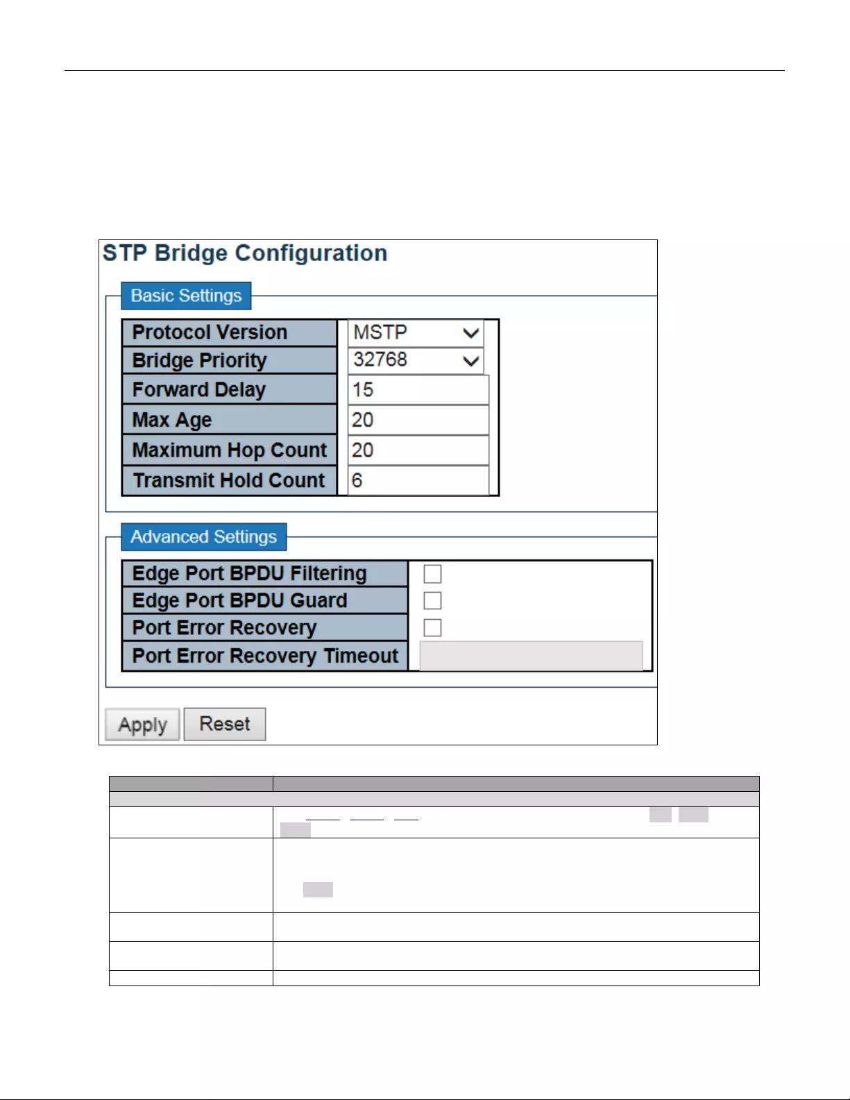
5.3.53 Spanni ng Tree
5.3.54 Bridge Settings
This page allows y ou to configure STP system settings. The settings are used by all STP Bridge instances in the
Switch.
Object
Description
Basic Settings
Protocol Version
The MSTP / RSTP / STP protocol version setting. Valid values are STP, RSTP and
MSTP.
Bridge Prio rity
Controls the bridge priority. Lower numeric values have better priority. The bridge
priority pl us t he MSTI instan ce numb er, concaten ated with th e 6-by te MAC addr ess of
the switch forms a Bridge Identifier.
For MSTP
operation, this is the priority of the CIST. Otherwise, this is the priority of the
STP/RSTP bridge
Forward Delay
The delay used by STP Bridges to transit Root and Designated Ports to Forwarding
(used in STP compatible mode). Valid values are in the range 4 to 30 seconds.
Max Age
The maximum age of the information transmitted by the Bridge when it is the Root
Bridge. Valid values are in the range 6 to 40 seconds
Maximum Hop Count
This defines the initial value of remaining Hops for MSTI information generated at the
106
boundary of an MSTI region. It defines how many bridges a root bridge can distribute
its BPDU information to. Valid values are in the range 6 to 40 hops.
Transmit Hold Count
The number of BPDU's a bridge port can send per second. When exceeded,
transmission of the next BPDU will be delayed. Valid values are in the range 1 to 10
BPDU's per second.
Advanced Settings
Edge Port BPDU
Filtering
Control whether a port explicitly c onfigured as Edge will transmit and receive BPDUs.
Edge Port BPDU Gu ard
Control whether a port explicitly c onfigured as Edge will disable itself upon reception
of a BPDU. The port will enter the error-disabled state, and will be removed from the
active topology.
Port Error Recovery
Control whether a port in the error-disabled state automatically will be enabled after a
certain time. If recovery is not enabled, ports have to be disabled and re-enabled for
normal STP operation. The condition is also cleared by a system reboot.
Port Error Recovery
Timeout
The time t o pa ss bef ore a port in t he error-disabled state can be en able d. Valid values
are between 30 and 86400 seconds (24 hours).
Buttons
Click to apply changes.
Click to undo any changes made locally and revert to previously saved values.
107
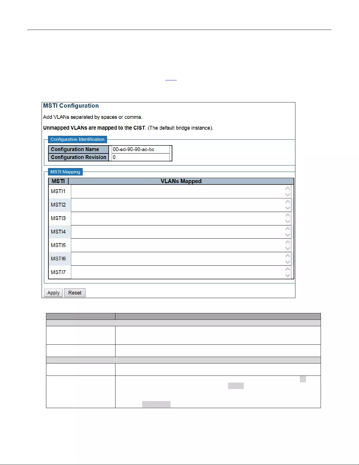
5.3.55 MSTI Mapping
This page allows the user to inspect the current STP MSTI bridge instance priority configurations, and possibly
change them as well.
Object
Description
Configuration Identification
Configuration Name
The name identifying the VLAN to MSTI mapping. Bridges must share the name and
revision (see below), as well as the VLAN-to-MSTI mapping configuration in order to
share spanning trees for MSTI's (Intra-reg ion). The name is at most 32 characters.
Configuration Revision
The revision of the MSTI configuration named above. This must be an integer
between 0 and 65535.
MSTI Mapping
MSTI
The bridge instance. The CIST is not available for explicit mapping, as it will receive
the VLANs not explicitly mapped.
VLANs Mapped
The list of VLANs mapped to the MSTI. The VLANs can be given as a single (xx, xx
being between 1 and 4094) VLAN, or a range (xx-yy), each of which must be
separated with comma and/or space. A VLAN can only be m apped to one M STI. An
unused MSTI should just be left empty. (I.e. not having any VLANs mapped to it.)
Example: 2,5,20-40.
108

Buttons
Click to apply changes.
Click to undo any changes made locally and revert to previously saved values.
109
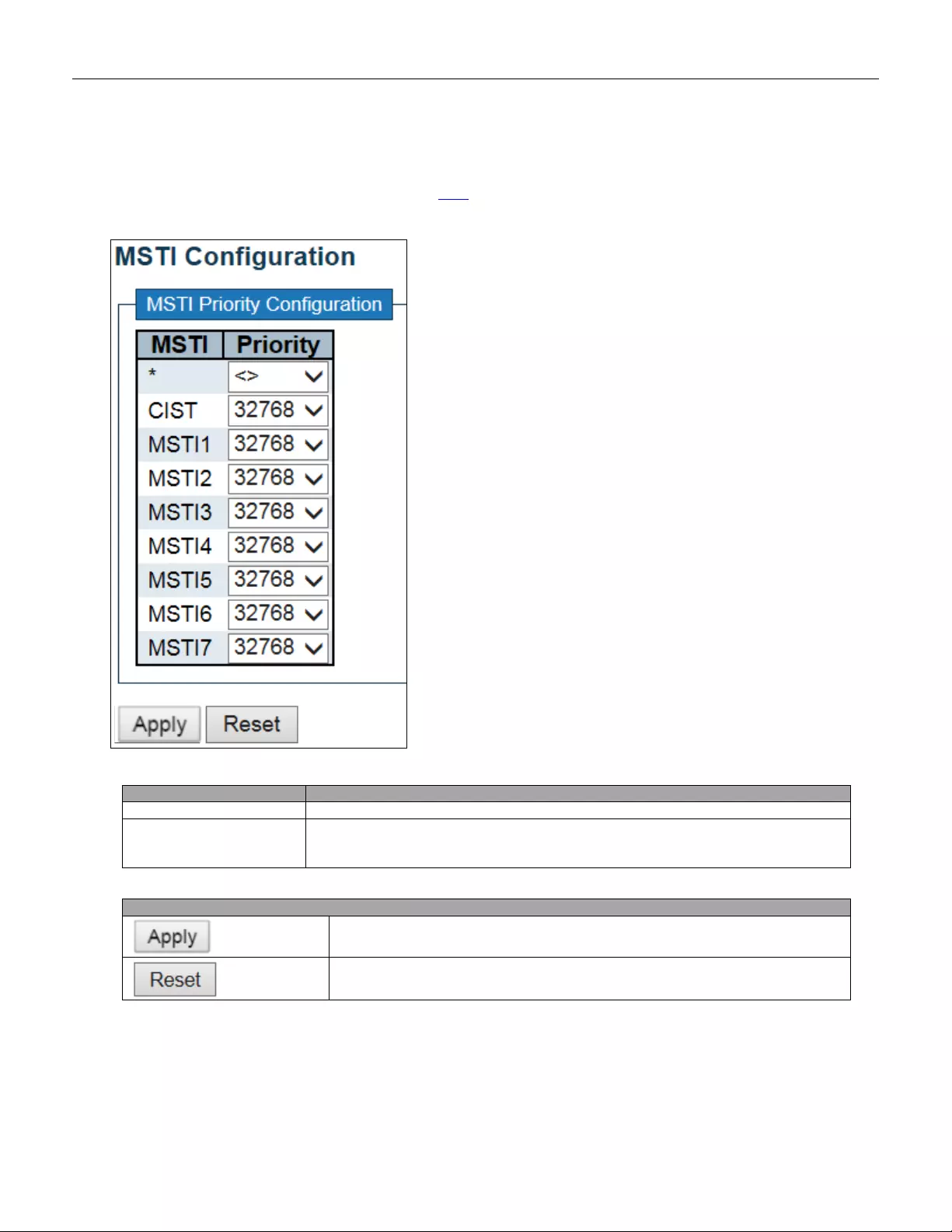
5.3.56 MSTI Priorities
This page allows the user to inspect the current STP MSTI bridge instance priority configurations, and possibly
change them as well.
Object
Description
MSTI
The bridge instance. The CIST is the default instance, which is always active.
Priorities
Controls the bridge priority. Lower numeric values have better priority. The bridge
priority pl us t he MSTI instan ce numb er, concaten ated with th e 6-by te MAC addr ess of
the switch for ms a Bridge Identifier.
Buttons
Click to apply changes.
Click to undo any changes made locally and revert to previously saved values.
110
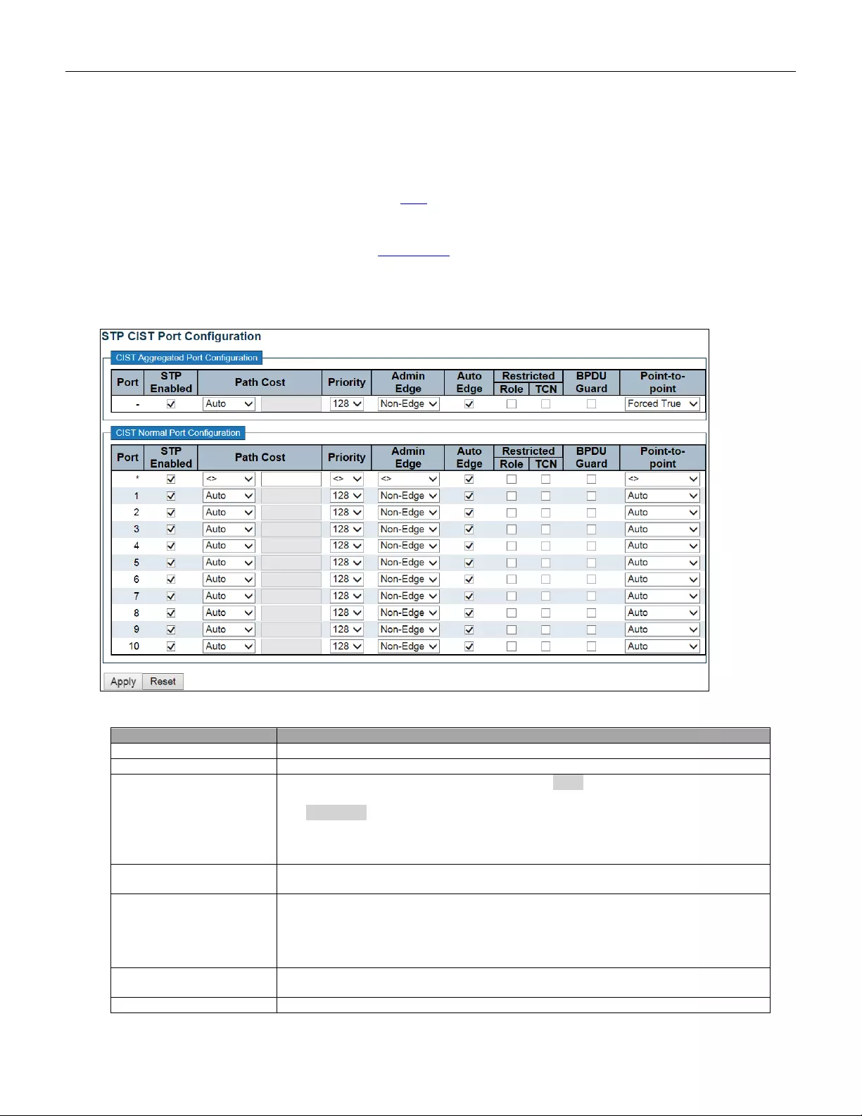
5.3.57 CIST Ports
This page allows the user to inspect the current STP CIST port configurations, and possibly change them as
well.
This page contains settings for physical and aggregated ports.
Object
Description
Port
The switch port number of the logical STP port.
STP Enabled
Controls whether STP is enabled on this switch port.
Path Cost
Controls the path cost incurred by the port. The Auto setting will set the path cost as
appropriat e by the phys ica l lin k spee d, us ing the 802.1D recommended values. Using
the Specific setting, a user-defined value can be entered. The path cost is used
when establishing the active topology of the network. Lower path cost ports are
chosen as forwarding ports in favor of higher path cost ports. Valid values are in the
range 1 to 200000000.
Priority
Controls the port priority. This can be used to control priority of ports having identical
port cost. (See above).
operEdge (state flag)
Operational flag describing whether the port is connecting directly to edge devices.
(No Bridges attached). Transition to the forwarding state is faster for edge ports
(having operEdge true) than for other ports. The value of this flag is based on
AdminEdge an d Aut oEdge fiel ds. T his flag is di splayed as E dge in Monitor->Spanning
Tree -> STP Detailed Bridge Status.
AdminEdge
Controls whether the operEdge flag should start as set or cleared. (The initial
operEdge state when a port is initialized).
AutoEdge
Controls whether the bridge should enable automatic edge detection on the bridge
111
port. Thi s allows operEdge to be derived from whether BPDU's are received on the
port or not.
Restricted Role
If enabled, causes the port not to be selected as Root Port for the CIST or any MSTI,
even if it has the best spanning tree priority vector. Such a port will be selected as an
Alternate Port after the Root Port has been selected. If set, it can cause lack of
spanning tree connectivity. It can be set by a network administrator to prevent bridges
external to a core region of the network influence the spanning tree active topology,
possibly bec aus e tho se bridges are not under t he ful l c ontrol of the admin istra t or. This
feature is also known as Root Guar d.
Restricted TC N
If enabled, causes the port not to propagate received topology change notifications
and topology changes to other ports. If set it can cause temporary loss of connectivity
after changes in a spanning tree's active topology as a result of persistently incorrect
learned station location information. It is set by a network administrator to prevent
bridges external to a core region of the network, causing address flushing in that
region, possibly because those bridges are not under the full control of the
administrator or the physical link state of the attached LANs transit s frequ ent ly.
BPDU Guard
If enabled, causes the port to disable itself upon receiving valid BPDU's. Contrary to
the similar brid ge setti ng, the p or t Edge status does not effect this setting.
A port entering error-disabled state due to this setting is subject to the bridge Port
Error Recovery setting as well.
Point-to-Point
Controls whether the port connects to a point-to-point LAN rat her than to a shared
medium. T his can be automatically determined, or forced either true or false.
Transition to the forwarding state is faster for point-to-p oint L AN s than for shar ed
media.
Buttons
Click to apply changes.
Click to undo any changes made locally and revert to previously saved values.
112
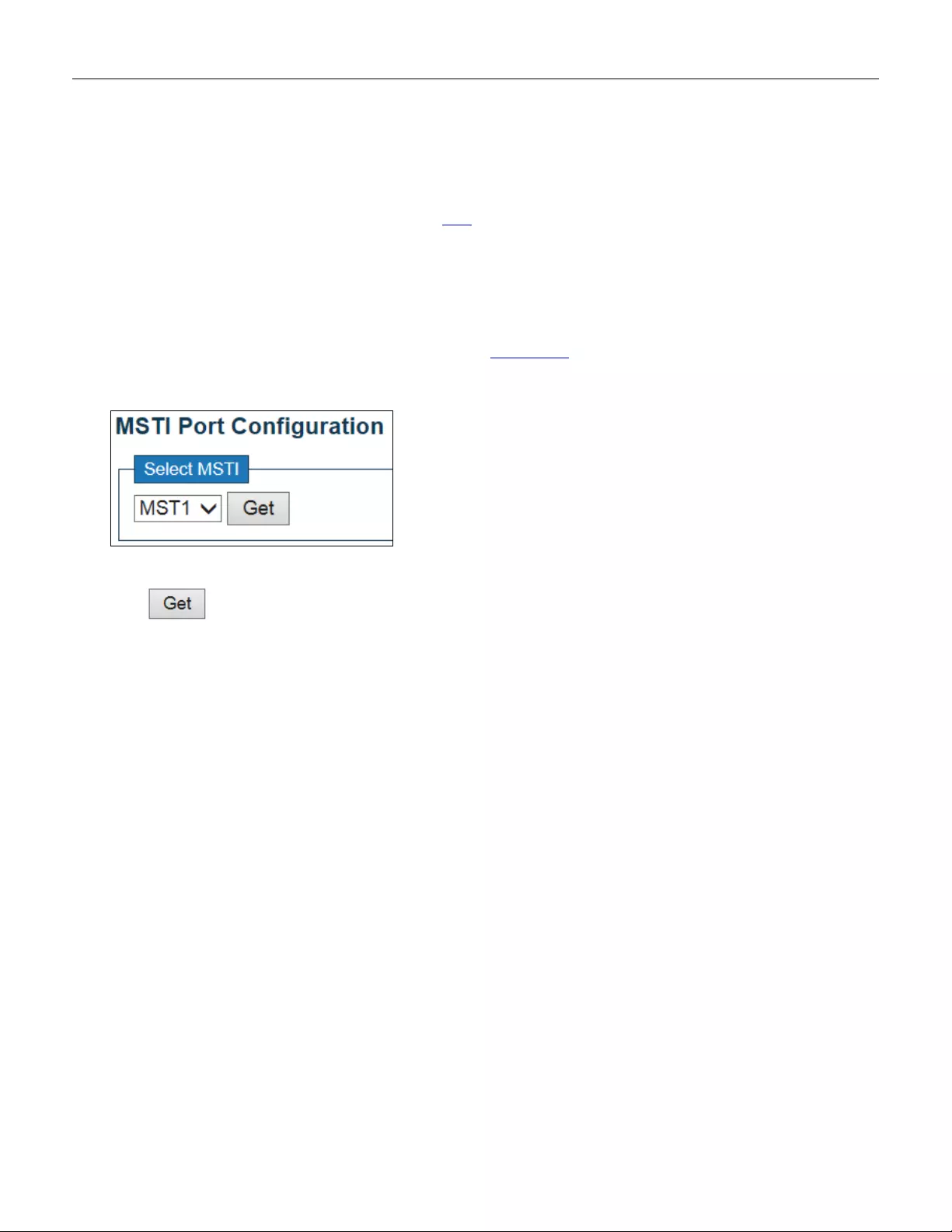
5.3.58 MSTI Ports
This page allows the user to inspect the current STP MSTI port configurations, and possibly change them as
well.
An MSTI port is a virtual port, which is instantiated separately for each active CIST (phy sical) port for each MSTI
instance configured on and applicable to the port. The MSTI instance must be selected before displaying actual MSTI
port configuration options.
This page contains MSTI port settings for physical and aggregated ports.
Click to retrieve settings for a specific MSTI, the page displayed as follow.
113
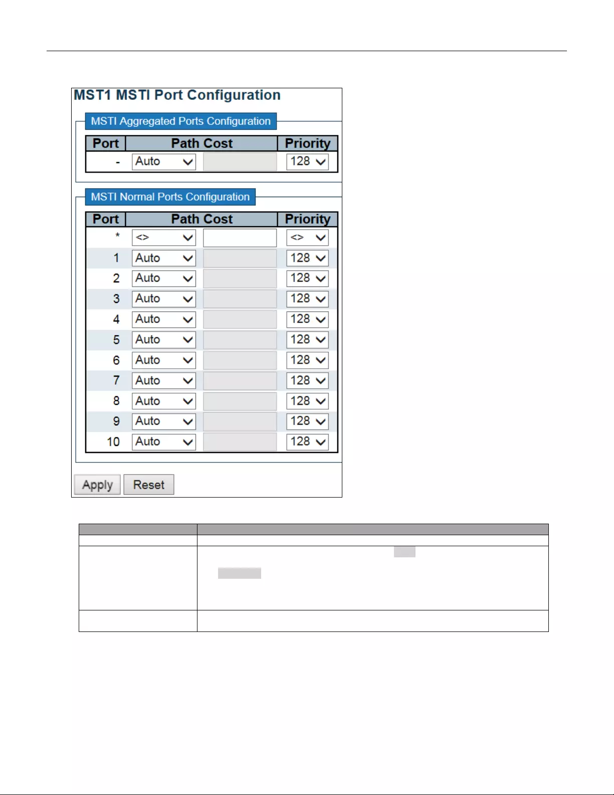
Object
Description
Port
The switch port number of the corresponding STP CIST (and MSTI) port.
Path Cost
Controls the path cost incurred by the port. The Auto setting will set the path cost as
appropriate by the physical link speed, using the 802.1D recommended values. Using
the Specific setting, a user-defined value can be entered. The path cost is used
when establishing the active topology of the network. Lower path cost ports are
chosen as forwarding ports in favor of higher path cost ports. Valid values are in the
range 1 to 200000000.
Priority
Controls the port priority. This can be used to control priority of ports having identical
port cost. (See above).
114

Buttons
Click to retrieve settings for a specific MSTI.
Click to apply changes.
Click to undo any changes made locally and revert to previously saved values.
115

5.3.59 IPMC Profile
5.3.60 Profile Table
This page provides IPMC Profile related configurations.
The IPMC profile is used to deploy the access control on IP multicast streams. It is allowed to create at
maximum 64 Profiles with at maximum 128 corresponding rules for each.
Object
Description
Global Profile Mode
Enable/Disable the Global IPMC Profile.
System starts to do filtering based on profile settings only when the global profile
mode is enabled.
Delete
Check to delete the entry.
The designated entry will be deleted during the next save.
Profile Name
The name used for indexing the profile table.
Each entry has the unique name which is composed of at maximum 16 alphabetic
and numeric characters. At least one alphabet must be present.
Profile Description
Additional description, which is composed of at max imum 64 alphabet ic and num eric
characters, about the profile.
No blank or space characters are permitted as part of description. Use "_" or "-" to
separate the description sentence.
Rule
When the profile is created, click the edit button to enter the rule setting page of the
designated profile. Summary about the designated profile will be shown by clicking
the view button. You can manage or inspect the rules of the designated profile by
using the following buttons:
: List the rules associated with the designated profile.
: Adjust the rules associated with the designated profile.
116

Buttons
Click to add new IPMC profile. Specify the name and configure the new
entry. Click "Save".
Click to apply changes.
Click to undo any c
hanges made locally and revert to previously saved
values.
117
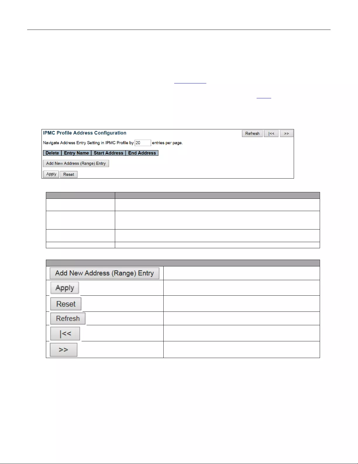
5.3.61 Address Entry
This page provides address range settings used in IPMC profile.
The address entry is used to specify the address range that will be associated with IPMC Profile. It is allowed to
create at maximum 128 address entries in the system.
Object
Description
Delete
Check to delete the entry.
The designated entry will be deleted during the next save.
Entry Name
The name used for indexing the address entry table.
Each entry has the unique name which is composed of at maximum 16 alphabetic
and numeric characters. At least one alphabet must be present.
Start Address
The starting IPv4/IPv6 Multicast Group Address that will be used as an address
range.
End Addr ess
The ending IPv 4/ IP v 6 Multicast G roup Address that will be used as a n address rang e.
Buttons
Click to a dd new address rang e. Spe cify the name an d co nfi gure
the addresses. Click " Save"
Click to apply changes.
Click to undo any changes made locally and revert to previously
saved values.
Refreshes the dis play ed tab le start i ng from the inpu t field s.
Updates the table starting from the first entry in the IPMC Profile
Address Configuration.
Updates the table, starting with the entry after the last entry
currently displayed.
118
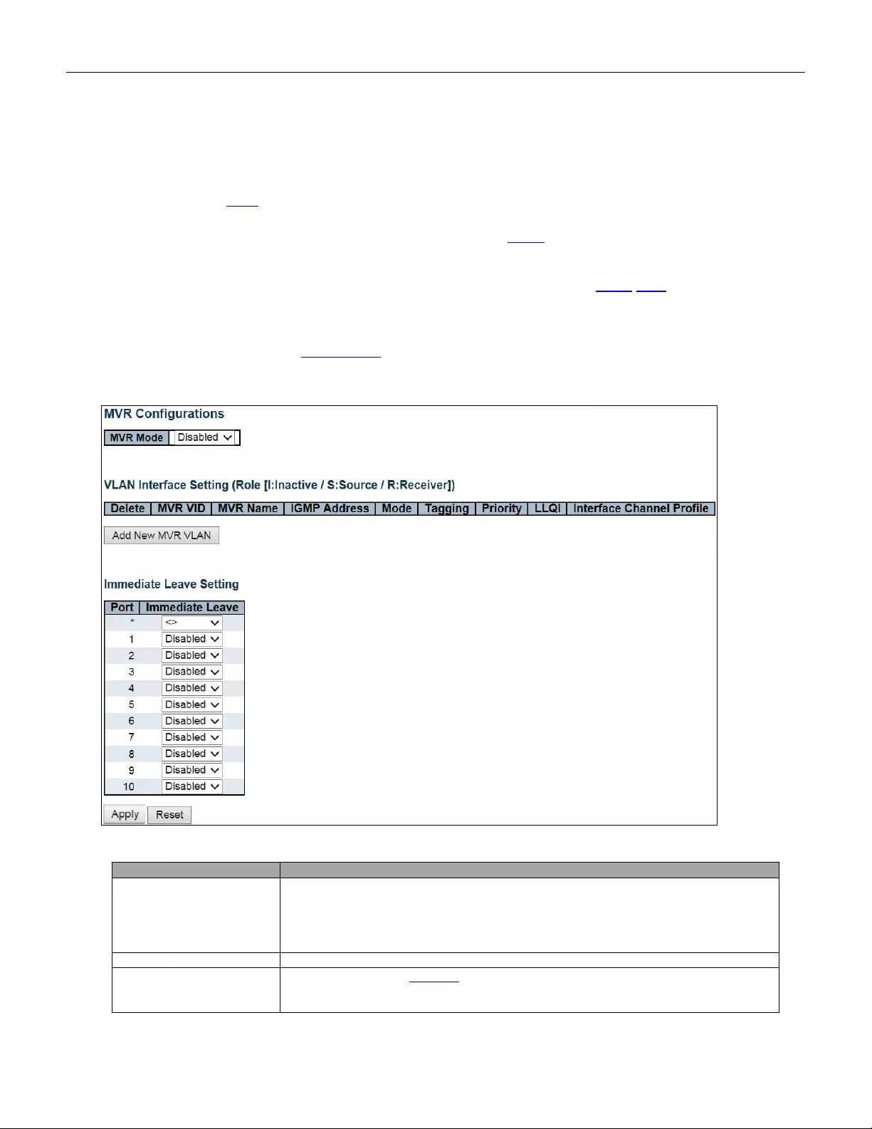
5.3.62 MVR
This page provides MVR related configurations.
The MVR feature enables multicast traffic forwarding on the Multicast VLANs.
In a multicast television application, a PC or a network television or a set-top box can receive the multicast stream.
Multiple set-top boxes or PCs can be connected to one subscriber port, which is a switch port configured as an MVR
receiver port. When a subscriber selects a channel, the set-top box or PC sends an IGMP/MLD report message to
Switch A to join the appropriate multicast group address. Uplink ports that send and receive multicast data to and
from the multicast VLAN are called MVR source ports.
It is allowed to create at maximum 4 MVR VLANs with corresponding channel profile for each Multicast VLAN.
The channel profile is defined by the IPMC Profile which provides the filtering conditions.
Object
Description
MVR Mode
Enable/Disable the Global MVR.
The Unregist ered F looding control d epen ds on the current config uration in IGM P /MLD
Snooping.
It is suggested to enable Unregistered Flooding control when the MVR group table is
full.
Delete
Check to delete the entry. The designated entry will be deleted during the next save.
MVR VID
Specify the Multicast VLA N ID.
Be Caution: MVR source ports are not recommended to be overlapped with
management VLAN ports.
119
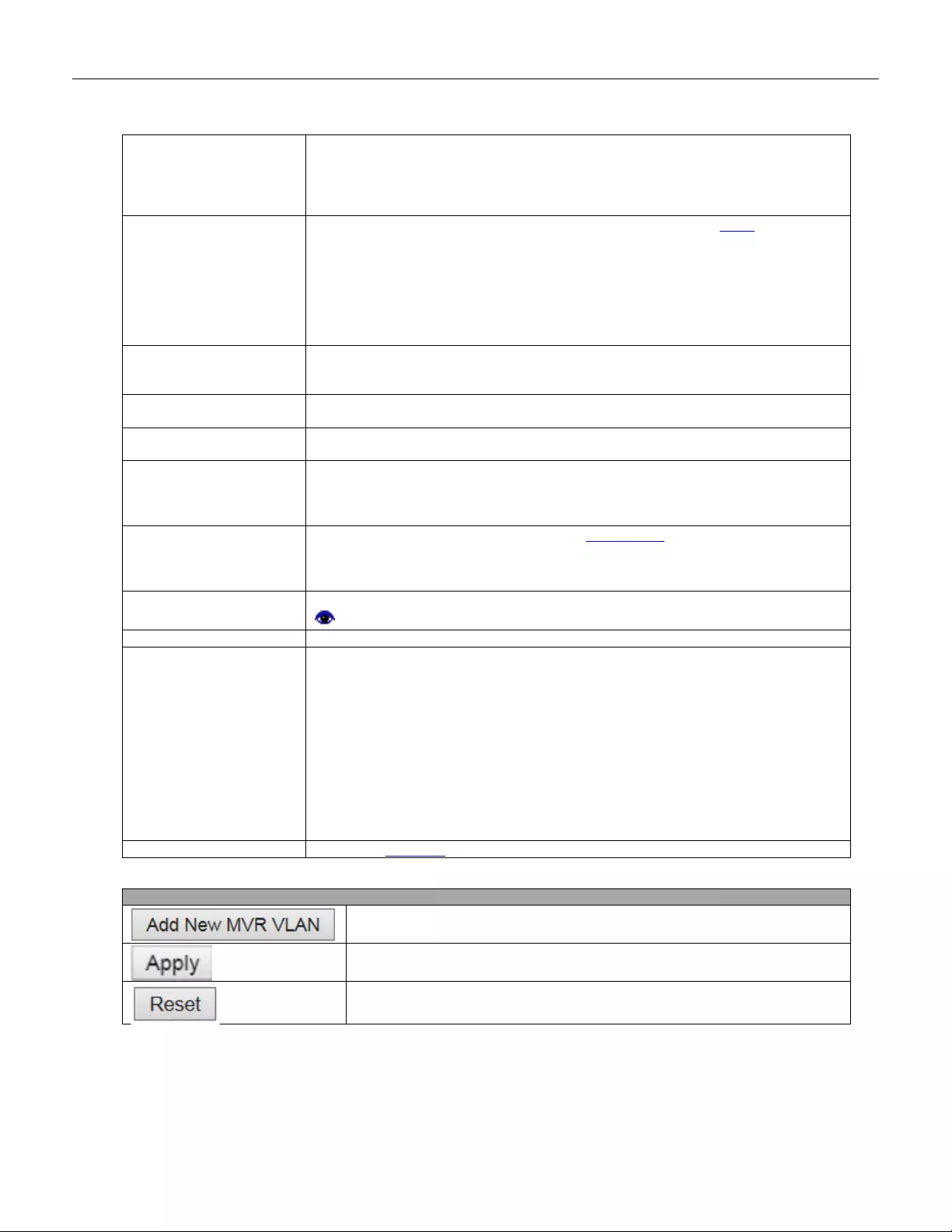
MVR Name
MVR Name is an optional attribute to indicate the name of the specific MVR VLAN.
Maximum length of the MVR VLAN Name string is 16. MVR VLAN Name can only
contain alphabet s or number s. When the optional M VR VLAN name is given, it should
contain at least one alphabet. MVR VLAN name can be edited for the existing MVR
VLAN entries or it can be added to the new entries.
IGMP A ddress
Define the IPv4 address as source address used in IP header for IGMP control
frames.
The default IGMP address is not set (0.0.0.0).
When the IGMP address is not set, system uses IPv4 management address of the IP
interface as so ciat ed with th is VLAN .
When the IPv4 management address is not set, system uses the first av aila ble IP v 4
management address.
Otherw ise, syst em uses a pre-defined value. By default, this value will be 192.0.2.1.
Mode
Specify the MVR mode of operation. In Dynamic mode, MVR allows dynamic MVR
membership reports on source ports. In Compatible mode, MVR membership reports
are forbidden on source ports. The default is Dynamic mode.
Tagging
Specify whether the traversed IGMP/MLD control frames will be sent as Untagged or
Tagged with MVR VID. The default is Tagged.
Priority
Specify how the traversed IGMP/MLD control frames will be sent in prioritized
manner. The default Prior i ty is 0.
LLQI
Define the maximum time to wait for IGMP/MLD report memberships on a receiver
port before removing the port from multicast group membership. The value is in units
of tenths of a second. The range is from 0 to 31744. The default LLQI is 5 tenths or
one-half second.
Interface Channel Profile
When the MVR VLAN is created, select the IPMC Profile as the channel filtering
condition for the specific MVR VLAN. Summary about the Interface Channel Profiling
(of the MVR VLAN) will be shown by clicking the view button. Profile selected for
designated interf ac e chan nel i s no t a llowed to hav e ov erlapped pe r mit gro up address.
Profile Management
Button
You can inspect the rules of the designated profile by using the following button:
: List the rules associated with the designated profile.
Port
The logical port for the settings.
Port Role
Configure an MVR port of the designated MVR VLAN as one of the following roles.
Inactive: The des ign ated por t does not parti ci pate M VR operations.
Source: Configure uplink ports that receive and send multicast data as source ports.
Subscribers cannot be directly connected to source ports.
Receiver: Configure a port as a receiver port if it is a subscriber port and should only
receive multi cast data. It doe s not receiv e data unl es s it beco mes a member of the
multicast group by issuing IGMP/MLD messages.
Be Caution: MVR source ports are not recommended to be overlapped with
management VLAN ports.
Select the port role by clicking the Role symbol to switch the setting.
I indicates Inactive; S indicates Source; R indicates Receiver
The default Role is Inactive.
Immediate Leave
Enable the fast leave on the port.
Buttons
Click to add new MVR VLAN. Specify the VID and configure the new entry.
Click "Save".
Click to apply changes.
Click to undo any changes made locally and revert to previously saved values.
120
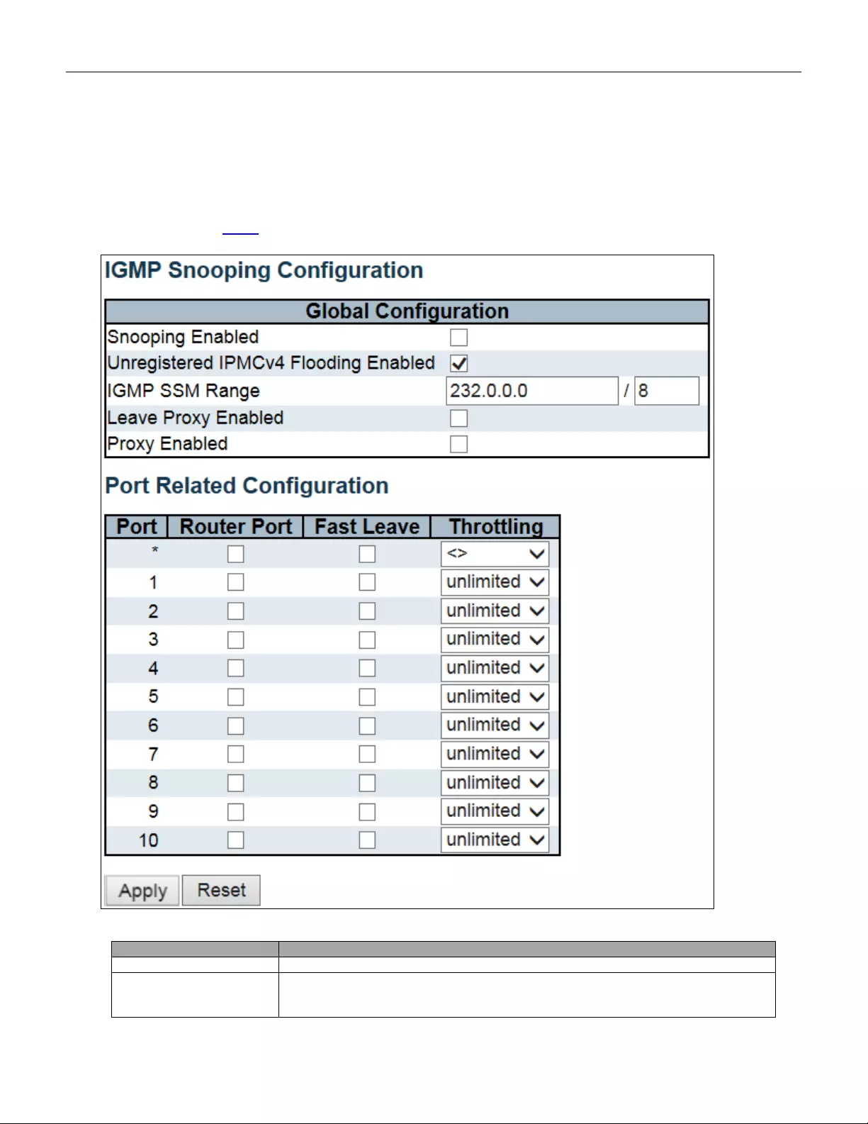
5.3.63 IPMC
5.3.64 IGMP Snooping
5.3.65 Basic Configuration
This page provides IGMP Snooping related configuration.
Object
Description
Snooping Enabled
Enable the Global IGMP Snooping.
Unregistered IPMC v 4
Flooding Enabled
Enable unregistered IPMCv4 traffic flooding.
The flooding control takes effect only when IGMP Snooping is enabled.
When IGMP Snooping is disab led, unr eg istered IPMCv4 traffic flooding is always
121
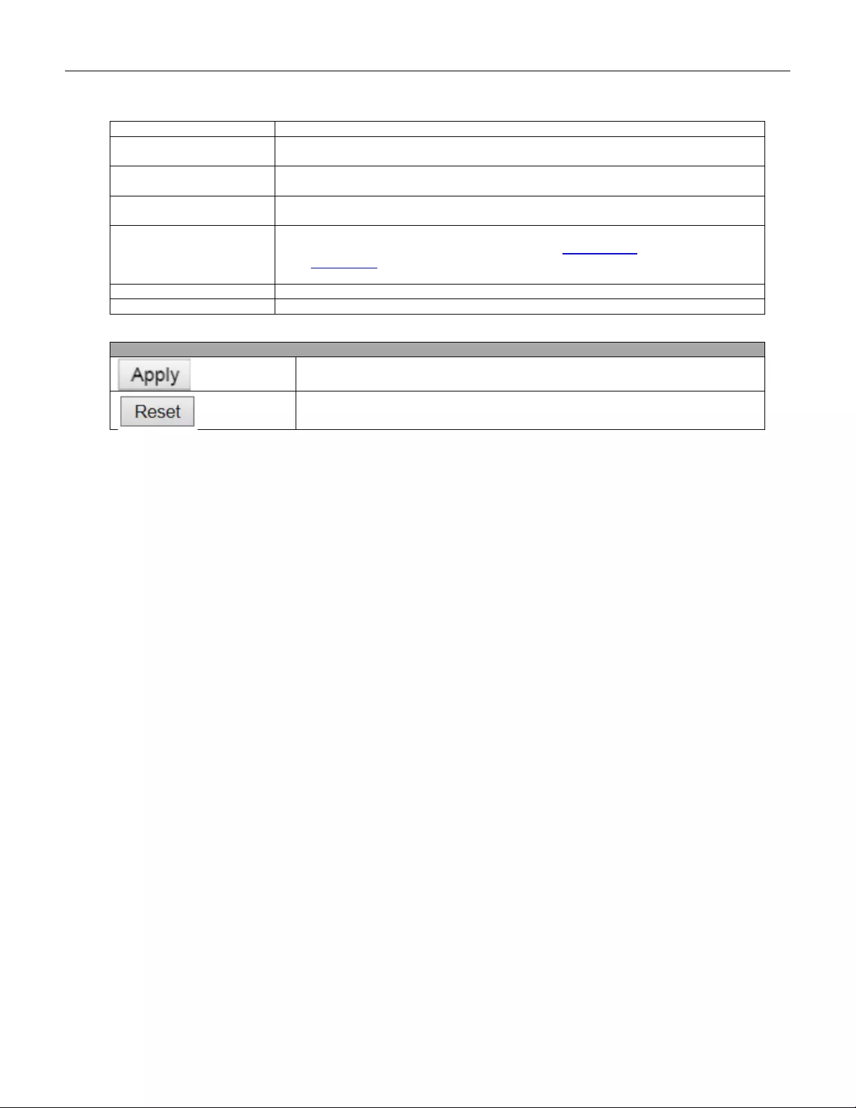
active in spite of this setting.
IGMP SSM Range
SSM (Source-Specific Multicast) Range allows the SSM-aware hosts and routers run
the SSM service model for the groups in the address range.
Leave Proxy Enabled
Enable IGM P Leave Proxy. This feature ca n b e used to av oid f orwarding unnecessary
leave messages to the router side.
Proxy Enabled
Enable IGMP Proxy. This feature can be used to avoid forwarding unnecessary join
and leave messages to the router side.
Router Port
Specify which ports act as router ports. A router port is a port on the Ethernet switch
that leads towards the Layer 3 multicast device or IGMP querier.
If an aggregation member port is selected as a router port, the whole aggregation will
act as a router port.
Fast Leave
Enable the fast leave on the port.
Throttling
Enable to limit the number of multicast groups to which a switch port can belong.
Buttons
Click to apply changes.
Click to undo any changes made locally and revert to previously saved values.
122
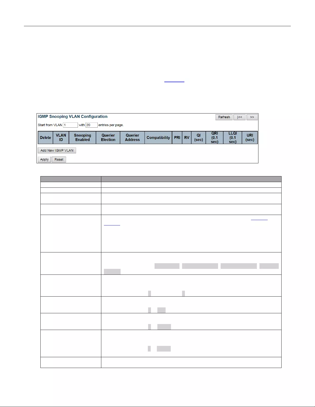
5.3.66 VLAN Configuration
Each page shows up to 99 entries from the VLAN table, default being 20, selected through the "entries per
page" input field. When first visited, the web page will show the first 20 entries from the beginning of the VLAN
Table. The first displayed will be the one with the lowest VLAN ID found in the VLA N Table.
The "VLAN" input fields allow the user to select the starting point in the VLAN Table.
Object
Description
Delete
Check to delete the entry. The designated entry will be deleted during the next save.
VLAN ID
The VLAN ID of the entry.
IGMP Snooping Enabled
Enable the per-VLAN IGMP Snooping. Up to 32 VLANs can be selected for IGMP
Snooping.
Querier Election
Enable to join IGMP Querier election in the VLAN. Disable to act as an IGMP
Non-Querier.
Querier A ddress
Define the IPv4 address as source address used in IP header for IGMP Querier
election.
When the Querier address is not set, system uses IPv4 management address of the
IP interface associated with this VLAN.
When the IPv4 management address is not set, system uses the first available IPv4
management address.
Otherw ise, syst em uses a pre-defined value. By default, this value will be 192.0.2.1.
Compatibility
Compatibility is ma inta ined by host s a nd r out ers t ak ing ap pro pr iate a ctio ns dependin g
on the versions of IGMP operating on hosts and routers within a network.
The allowed selection is IGMP-Auto, Forced IGMPv1, Forced IGMPv2, Forced
IGMPv3, default compat ibi lity v alue is IGMP-Auto.
PRI
Priority of Interf ac e.
It indicates the IGMP control frame priority level generated by the system. These
values can be used to prioritize different classes of traffic.
The allowed range is 0 (be st effort) to 7 (highest), default interface priority value is 0.
RV
Robustness Variable.
The Robustness Variable allows tuning for the expected packet loss on a network.
The allowed range is 1 to 255, default robustness variable value is 2.
QI
Query Interval.
The Query Interval is the interval between General Queries sent by the Querier.
The allowed range is 1 to 31744 seconds, default query interval is 125 seconds.
QRI
Query Response Interval.
The Maximum Response Delay used to calculate the Maximum Response Code
inserted into the periodi c General Queries.
The allow ed range is 0 to 31744 in tenths of s eco nds , default query r es pon se i nterv al
is 100 in tenths of seconds (10 seconds).
LLQI(LMQI for IGMP)
Last Member Query Interval.
The Last Member Query Time is the time value represented by the Last Member
123
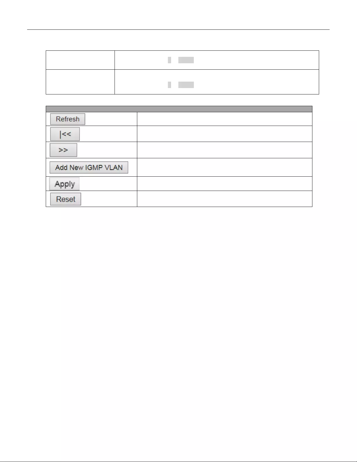
Query Interval, multiplied by the Last Member Query Count.
The allowed range is 0 to 31744 in tenths of seconds, default last member query
interval is 10 in tenths of seconds (1 second).
URI
Unsolicited Report Interval. The Unsolicited Report Interval is the time between
repetitions of a host's initial report of membership in a group.
The allowed range is 0 to 31744 seconds, default unsolicited report interval is 1
second.
Buttons
Refreshes the dis play ed tab le start i ng from the "V LAN" input fields.
Updates the table starting from the first entry in the VLAN Table, i.e. the
entry with the lowest VLAN ID.
Updates the table, starting with the entry after the last entry currently
displayed.
Click to add new IGMP VLAN. Specify the VID and configure the new
entry. Click "Save". The specific IGMP VLAN starts working after the
corresponding static VLAN is also created.
Click to apply changes.
Click to undo any changes made locally and revert to previously saved
values.
124
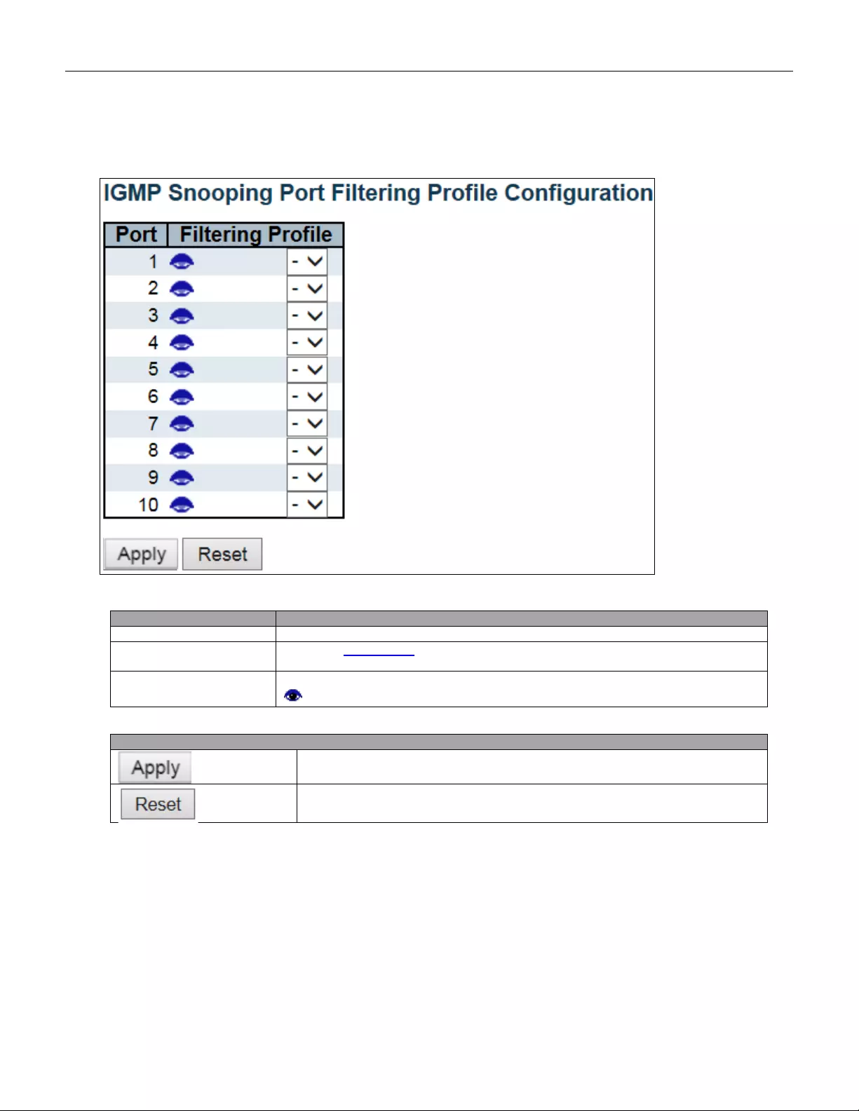
5.3.67 Port Filtering Profile
Object
Description
Port
The logical port for the settings.
Filtering Profile
Select the IPMC Profile as the filtering condition for the specific port. Summary about
the designated profile will be shown by clicking the view button.
Profile Management
Button
You can inspect the rules of the designated profile by using the following button:
: List the rules associated with the designated profile.
Buttons
Click to apply changes.
Click to undo any changes made locally and revert to previously saved values.
125

5.3.68 MLD Snooping
5.3.69 Basic Configuration
This page provides MLD Snooping related configuration.
Object
Description
Snooping Enable
Enable the Global MLD Snooping.
Unregistered IPMC v 6
Flooding Enable
Enable unregistered IPMCv6 traffic flooding.
The flooding control takes effect only when MLD Snooping is enabled.
When MLD Snooping is disabled, unregistered IPMCv6 traffic flooding is always
active in spite of this setting.
MLD SSM Range
SSM (Source-Specific Multicast) Range allows the SSM-aware hosts and routers run
the SSM service model for the groups in the address range.
Leave Proxy Enable
Enable MLD Leave Proxy. This feature can be used to avoid forwarding unnecessary
leave messages to the router side.
Proxy Enable
Enable MLD Proxy. This feature can be used to avoid forwarding unnecessary join
and leave messages to the router side.
Router Port
Specify which ports act as router ports. A router port is a port on the Ethernet switch
that leads towards the Layer 3 multicast device or MLD querier.
If an aggregation member port is selected as a router port, the whole aggregation will
act as a router port.
Fast Leave
Enable the fast leave on the port.
Throttling
Enable to limit the number of multicast groups to which a switch port can belong.
126

Buttons
Click to apply changes.
Click to undo any changes made locally and revert to previously saved values.
127
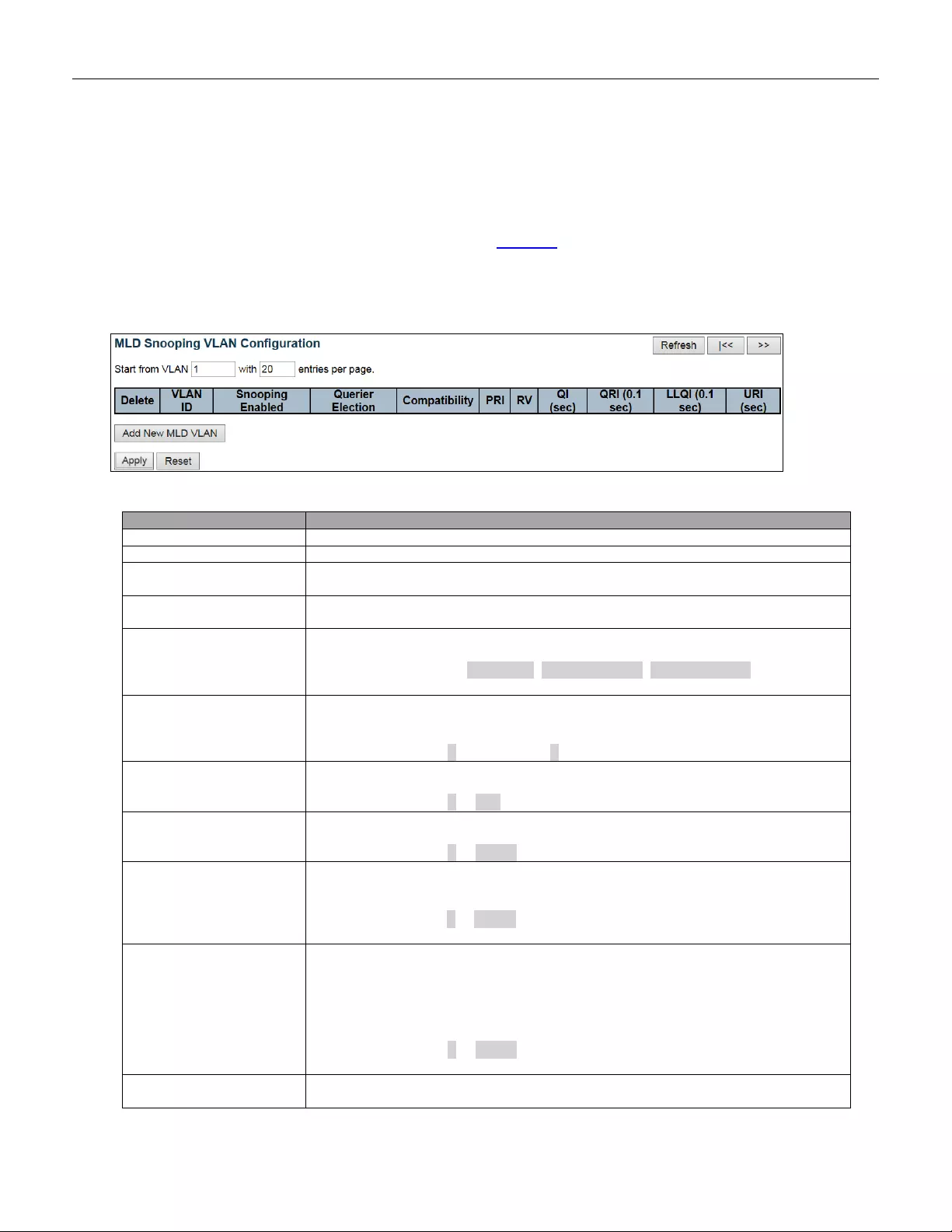
5.3.70 VLAN Configuration
Each page shows up to 99 entries from the VLAN table, default being 20, selected through the "entries per
page" input field. When first visited, the web page will show the first 20 entries from the beginning of the VLAN
Table. The first displayed will be the one with the lowest VLAN ID found in the VL AN Table.
The "VLAN" input fields allow the user to select the starting point in the VLAN Table.
Object
Description
Delete
Check to delete the entry. The designated entry will be deleted during the next save.
VLAN ID
The VLAN ID of the entry.
MLD Snooping Enabled
Enable the per-VLAN MLD Snooping. Up to 32 VLANs can be selected for MLD
Snooping.
Querier Election
Enable to join MLD Querier election in the VLAN. Disable to act as a MLD
Non-Querier.
Compatibility
Compatibi lity i s ma inta ined by hosts a nd routers t ak ing ap pro pr iate a ctio ns dependin g
on the versions of MLD operating on hosts and routers within a network.
The allowed selection is MLD-Auto, Forced MLDv1, Forced MLDv2, default
compatibility value is M LD -Auto.
PRI
Priority of Interf ac e.
It indicates the MLD control frame priority level generated by the system. These
values can be used to prioritize different classes of traffic.
The allowed range is 0 (be st effort) to 7 (highest), default interface priority value is 0.
RV
Robustness Variable.
The Robustness Variable allows tuning for the expected packet loss on a link.
The allowed range is 1 to 255, default robustness variable value is 2.
QI
Query Interval.
The Query Interval is the interval between General Queries sent by the Querier.
The allowed range is 1 to 31744 seconds, default query interval is 125 seconds.
QRI
Query Response Interval.
The Maximum Response Delay used to calculate the Maximum Response Code
inserted into the periodi c Gene ral Queries.
The allow ed range is 0 to 31744 in tenths of s eco nds , default query r es pon se i nterv al
is 100 in tenths of seconds (10 seconds).
LLQI
Last Listener Query Interval.
The Last Listener Query Interval is the Maximum Response Delay used to calculate
the Maximum Response Code inserted into Multicast Address Specific Queries sent
in response to Version 1 Multicast Listener Done messages. It is also the Maximum
Response Delay used to calculate the Maximum Response Code inserted into
Multicast A ddress and Source Specific Query messages.
The allowed range is 0 to 31744 in tenths of seconds, default last listener query
interval is 10 in tenths of seconds (1 second).
URI
Unsolicited Report Interval.
The Unsol icited Re port Interv al is the t ime be tw een repet ition s of a n ode's initia l repor t
128
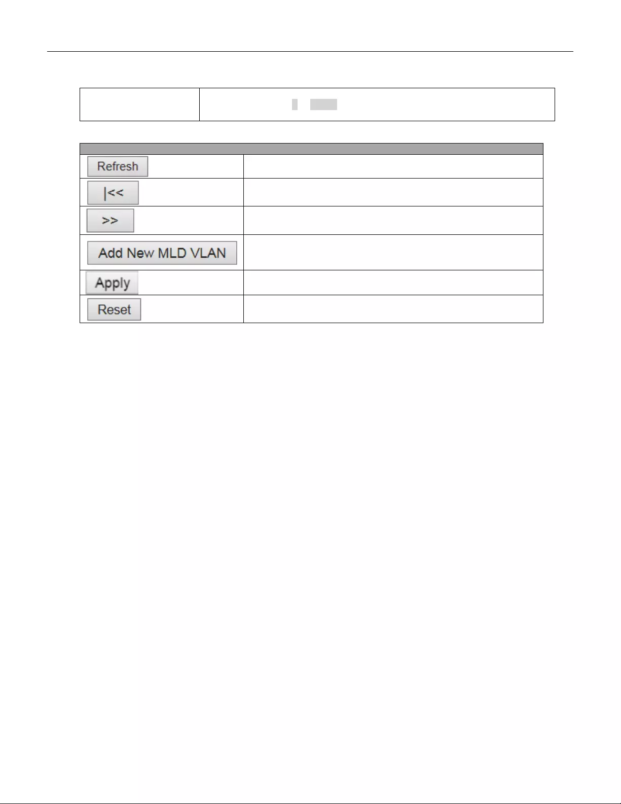
of interest in a multicast address.
The allowed range is 0 to 31744 seconds, default unsolicited report interval is 1
second.
Buttons
Refreshes the displayed table starting from the "VLAN" input
fields.
Updates t he table star ting f rom the firs t entr y in the VL AN Table,
i.e. the entry with the lowest VLAN ID.
Updates the table, starting with the entry after the last entry
currently displayed.
Click t o add ne w MLD VLA N. Specif y the VID and con figure th e
new entry. Click "Save". The specific MLD VLAN starts working
after the corresponding static VLAN is also created.
Click to apply changes.
Click to undo any changes made locally and revert to previously saved
values.
129
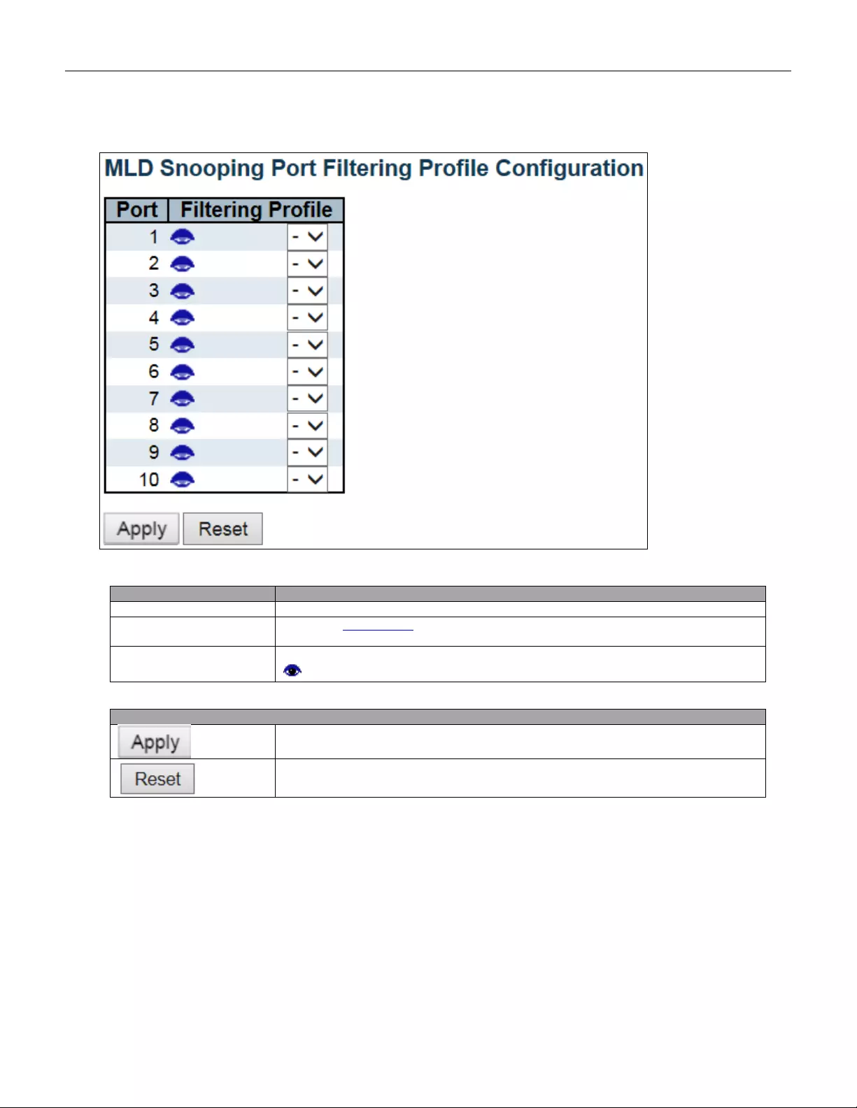
5.3.71 Port Filtering Profile
Object
Description
Port
The logical port for the settings.
Filtering Profile
Select the IPMC Profile as the filtering condition for the specific port. Summary about
the designated profile will be shown by clicking the view button.
Profile Management
Button
You can inspect the rules of the designated profile by using the following button:
: List the rules associated with the designated profile.
Buttons
Click to apply changes.
Click to undo any changes made locally and revert to previously saved values.
130
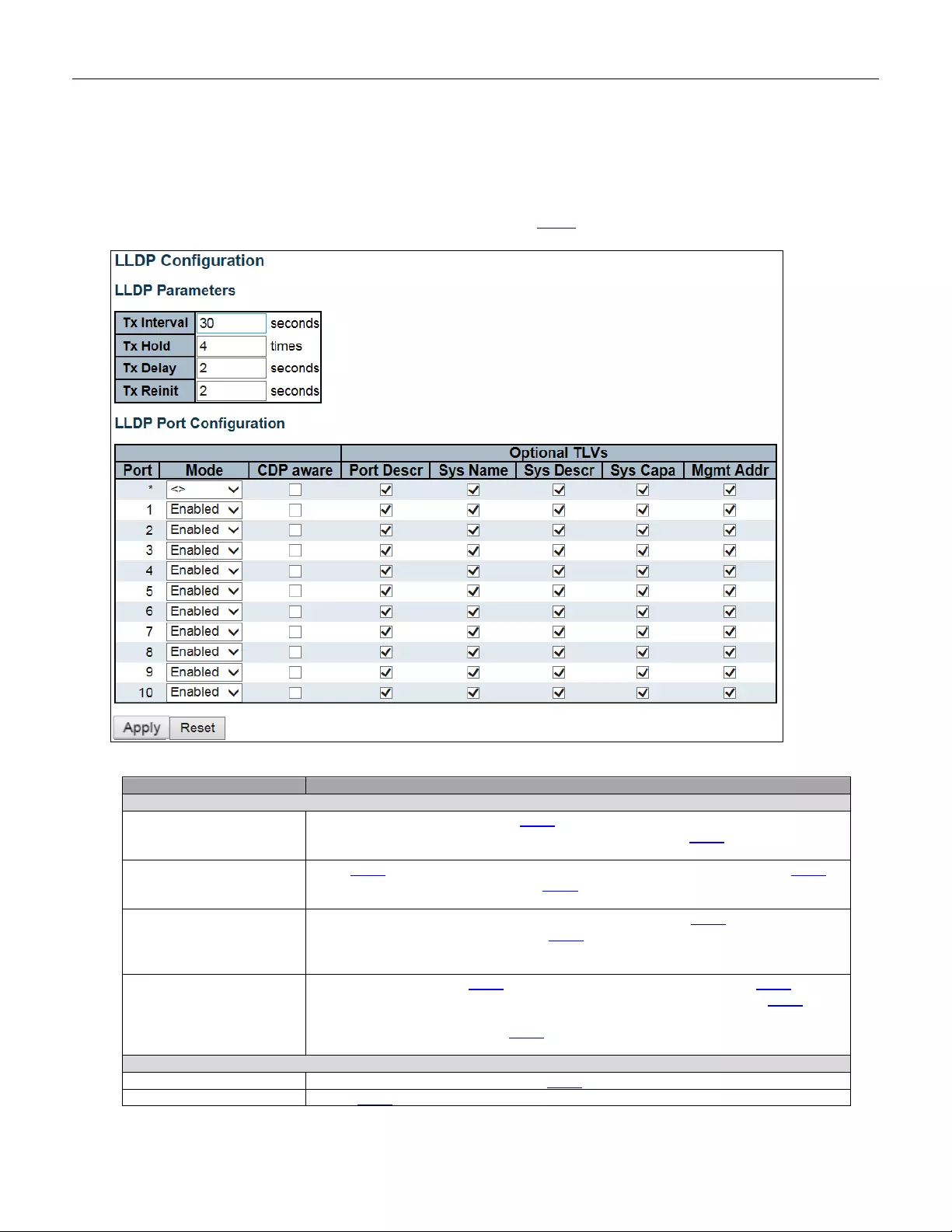
5.3.72 LLDP
5.3.73 LLDP
This page allows the user to inspect and configure the current LLDP port settings.
Object
Description
LLDP Parameters
Tx Interval
The switch periodically transmits LLDP frames to its neighbors for having the network
discovery information up-to-date. The inter v al between each LLDP frame is
determine d by the Tx Int erv al value. Valid values are restricted to 5 - 32768 second s.
Tx Hold
Each LLDP fr a me cont ain s information about how long the information in the LLDP
frame shall be consid ered val i d. T he LLDP information valid period is set to Tx Hold
multiplied by Tx Interval seconds. Valid values are restricted to 2 - 10 times.
Tx Delay
If some configuration is changed (e.g. the IP address) a new LLDP frame is
transmitt ed, but the time between the LLDP frames will always be at least the value
of Tx D elay seconds. Tx Delay cannot be larger than 1/4 of the Tx Interval value.
Val id values are restricted to 1 - 8192 seconds.
Tx Reinit
When a port is disabled, LLDP is disabled or the switch is rebooted, an LLDP
shutdown frame is transmitted to the neighbor ing units, signaling that the LLDP
information isn't valid anymore. Tx Reinit controls the amount of seconds between
the shutdow n fra me and a new LLDP initialization. Valid values are restricted to 1 - 10
seconds.
LLDP Port Parameters
Port
The switch port number of the logical LLDP port.
Mode
Select LLDP mode.
131

Rx only The switch will not send out LLDP information, but LLDP informati on from
neighbor units is analyzed.
Tx only The switch will dr op LLDP informa tion r e ceived fro m nei ghbor s, but w ill s end
out LLDP information.
Disabled The switch will not send out LLDP information, and will drop LLDP
information received from neighbors.
Enabled The sw itch will send out LLDP information, and will analyze LLDP
information received from neighbors.
CDP A ware
Select CDP awareness.
The CDP operation is restricted to decoding incoming CDP frames (The switch
doesn't transmit CDP frames). CDP frames are only decoded if LLDP on the port is
enabled.
Only CDP TLVs that can be mapped to a corresponding field in the LLDP neighbors'
table are decoded. All other TLVs are discarded (Unrecognized CDP TLVs and
discarded CDP frames are not shown in the LLDP statistics.). CDP TLVs are mapped
onto LLDP neighbors' table as shown below.
CDP TLV "Device ID" is mapped to the LLDP "Chassis ID" field.
CDP TLV "Address" is mapped to the LLDP "Management Address" field. T he CDP
address TLV can contain mu lti ple a ddresses, but only t he first address i s s hown in th e
LLDP neighbors table.
CDP TLV "Port ID" is mapped to the LLDP "Port ID" field.
CDP TLV "Version and Platform" is mapped to the LLDP "System Description" field.
Both the CDP and LLDP support "system capabilities", but the CDP capabilitie s cov er
capabilities that are not part of the LLDP. These capabilities are shown as "others" in
the LLDP neighbors' table.
If all ports have CDP awareness disabled the switch forwards CDP frames received
from neighbor devices. If at least one port has CDP awaren ess ena bled all CDP
frames are terminated by the switch.
Note: Wh en CDP awareness on a port is disabled the CDP information isn't removed
immediately, but gets removed when the hold time is exceeded.
Port Descr
Optional T LV: When checked the "port description" is included in LLDP information
transmitted.
Sys Name
Optional T LV: When checked the "system name" is included in LLDP information
transmitted.
Sys Descr
Optional T LV: When checked t he "syste m descri ption" is inclu ded in LLDP information
transmitted.
Sys Capa
Optional T LV: When checked the "system capability" is included in LLDP information
transmitted.
Mgmt Addr
Optional T LV: When checked the "management address" is included in LLDP
information transmitted.
Buttons
Click to apply changes.
Click to undo any changes made locally and revert to previously saved values.
132
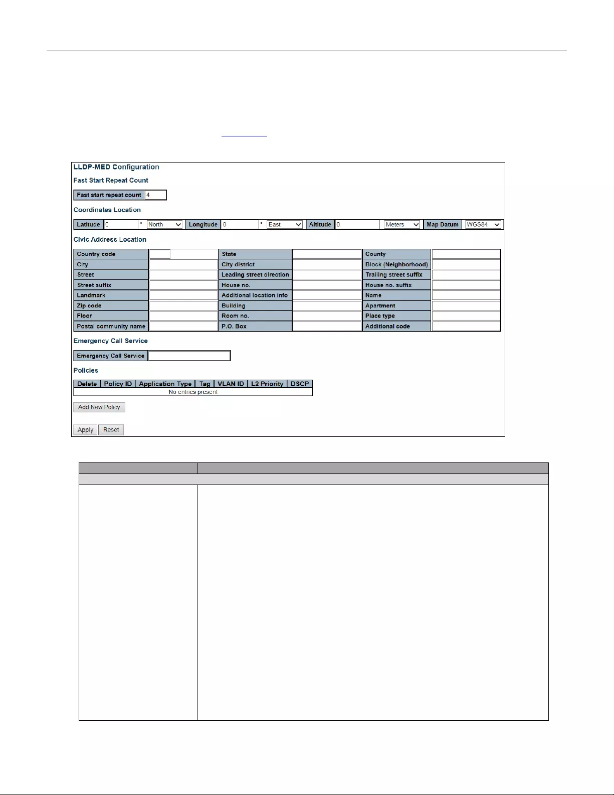
5.3.74 LLDP-MED
This page allows you to configure the LLDP-MED. This function applies to VoIP devices which support LLDP-MED.
Object
Description
Fast start repeat count
Fast start repeat count
Rapid startup and Emergency Call Service Location Identification Discovery of
endpoints is a critically important aspect of VoIP systems in general. In addition, it is
best to advertise only those pieces of information which are specifically relevant to
particular endpoint types (for example only advertise the voice network policy to
permitted voice-capable devices), both in order to conserve the limited LLDPU space
and to reduce security and system integrity issues that can come with inappropriate
knowledge of the network policy.
With this in mind LLDP-MED defines an LLDP-MED Fast Start interaction between
the protoc
ol and the ap pli cation lay er s on top of the proto col, in o rder to achieve th es e
related properties. Initially, a Network Connectivity Device will only transmit LLDP
TLVs in an LLDPDU. Only after an LLDP-MED Endpoint Device is detected, will an
LLDP-MED capable Network Connectivity Device start to advertise LLDP-MED TLVs
in outgoing LLDPDUs on the associated port. The LLDP-MED application will
temporarily speed up the transmission of the LLDPDU to start within a second, when
a new LLDP-MED neighbor has been det ect ed in order share LLDP-MED information
as fast as possible to new neighbors.
Because there is a risk of an LLDP frame being lost during transmission between
neighbors, it is recommended to repeat the fast start transmission multiple times to
increase the possibility of the neighbors receiving the LLDP frame. With Fast start
repeat count it is possible to specify the number of times the fast start transmission
133

would be repeated. The recommended value is 4 times, given that 4 LLDP frames
with a 1 sec ond interv al will b e t ransmitt ed, w hen an LLDP frame w ith new inform ation
is receiv ed.
It should be noted that LLDP-MED and the LLDP-MED Fast Start mechanism is only
intended to run on links between LLDP-MED Network Connectivity Devices and
Endpoint Devices, and as such does not apply to links between LAN infrastructure
elements, including Network Connectivity Devices, or other types of links.
Coordinates Location
Latitude
Latitude SHOULD be normalized to within 0-90 degrees with a maximum of 4 digits.
It is possible to specify the dir e ctio n to either North of the equator or South of the
equator.
Longitude
Longitude SHOULD be normalized to within 0-180 degrees with a maximum of 4
digits.
It is possible to specify the dire ctio n to eith er East of the prime meridian or West of
the prime meridian.
Altitude
Altitude SHOULD be normalized to within -32767 to 32767 with a maximum of 4
digits.
It is possible to select between two altitude types (floors or meters).
Meters: Representing meters of Altitude defined by the vertical datum specified.
Floors: Representing altitude in a form more relevant in buildings which have
different floor-to-floor dimensions. An altitude = 0.0 is meaningful even outside a
building, and represents ground level at the given latitude and lon gitu de. I ns ide a
building, 0.0 represents the floor level associated with ground level at the main
entrance.
Map Datum
The Map Datum is used for the coordinates given in these options:
WGS84: (Geographical 3D) - World Geodesic System 1984, CRS Code 4327, Prime
Meridian Name: Greenwich.
NAD83/NAVD88: North American Datum 1983, CRS Code 4269, Prime Meridian
Name: Greenwich; The associated vertical datum is the North American Vertical
Datum of 1988 (NAVD88). This datum pair is to be used when referencing locations
on land, not near tidal water (which would use Datum = NAD83/MLLW).
NAD83/MLLW: North American Datum 1983, CRS Code 4269, Prime Meridian
Name: Greenwich; The associated vertical datum is Mean Lower Low Water (MLLW).
This datum pair is to be used when referencing locations on water/sea/ocean.
Civic A ddress Location
Country code
The two-letter ISO 3166 country code in capital ASCII letters - Example: DK, DE or
US.
State
National subd iv isi ons (state, c anton, region, prov in ce, prefecture) .
County
County, pari sh, gun (Jap an), di stri ct.
City
City, township, shi (Japan) - Example: Copenhagen.
City district
City division, borough, city district, ward, chou (Japan).
Block (Neighborhood)
Neighborhood, block.
Street
Street - Example: Poppelvej.
Leading street direct i on
Leading stree t direct ion - Example: N.
Tr ailing str eet suff ix
Tr ailing street suf fix - Example: SW.
Street suffix
Street suffix - Example: Ave, Platz.
House no.
House number - Example: 21.
House no. suffix
House number suffix - Example: A, 1/ 2.
134

Landmark
Landmark or vanity address - Example: Columbia University.
Additional location info
Additiona l locat ion info - Ex ample: Sout h Wing .
Name
Name (residence and office occupant) - Example: Flem ming Jahn .
Zip code
Postal/zip code - Exampl e: 2791.
Building
Building (structure) - Example: Low Library.
Apartment
Unit (Apartme nt, suit e) - Ex ample: Apt 42.
Floor
Floor - Example: 4.
Room no.
Room number - Example: 450F.
Place type
Place type - Example: Office.
Postal community name
Postal community name - Example: Leonia.
P.O. Box
Post office box (P.O. BOX) - Example: 12345.
Additional code
Additional code - Example: 1320300003.
Emergency Call Service
Emergency Call Service
Emergency Call Service ELIN identifier data format is defined to carry the ELIN
identifier as used during emergency call setup to a traditional CAMA or ISDN
trunk-based PSAP. T hi s format consists of a numeri cal digit st ring, corr e spo ndi ng to
the ELIN to be used for emergency calling.
Policies
Delete
Check to delete the policy. It will be deleted during the next save.
Policy ID
ID for the policy. This is auto generated and shall be used when selecting the policies
that shall be mapped to the specif ic ports.
Application Type
Intended use of the application types:
1. Voice - for use by dedicated IP Telephony handsets and other similar appliances
supporting interactive voice services. These devices are typically deployed on a
separate VLAN for ease of deployment and enhanced security by isolation from data
applications.
2. Voice Signalling (conditional) - for use in network topologies that require a
different policy for the voice signaling than for the voice media. This application type
should not be advertised if all the same network policies apply as those advertised in
the Voice appli cat ion pol icy .
3. Guest Voice - support a separate 'limited feature-set' voice service for guest users
and visitors with their own IP Telephony handsets and other similar appliances
supporting interactive voice services.
4. Guest Voice Signaling (conditional) - for use in network topologies that require a
different policy for the guest voice signaling than for the guest voice media. This
application type should not be advertised if all the same network policies apply as
those advertised in the Gu est Vo ice application policy .
5. Softphone Voice - for use by softphone applications on typical data centric
devices, such as PCs or laptops. This class of endpoints frequently does not support
multiple VLANs, if at all, and are typically configured to use an 'untagged' VLAN or a
single 'tagged' data specific VLAN. When a network policy is defined for use with an
'untagged' VLAN (se e T agged flag b elow ), then t he L2 prior ity field is i gnored an d only
the DSCP value has relevance.
6. Video Conferencing - for use by dedicated Video Conferencing equipment and
other similar appli anc es supporting real-time interactive video/audio services.
7. Streaming Video - for use by broadcast or multicast based video content
distribut ion and other simi lar appli cations supporting streaming video services that
require specific network policy treatment. Video applications relying on TCP with
buffering would not be an intended use of this application type.
135
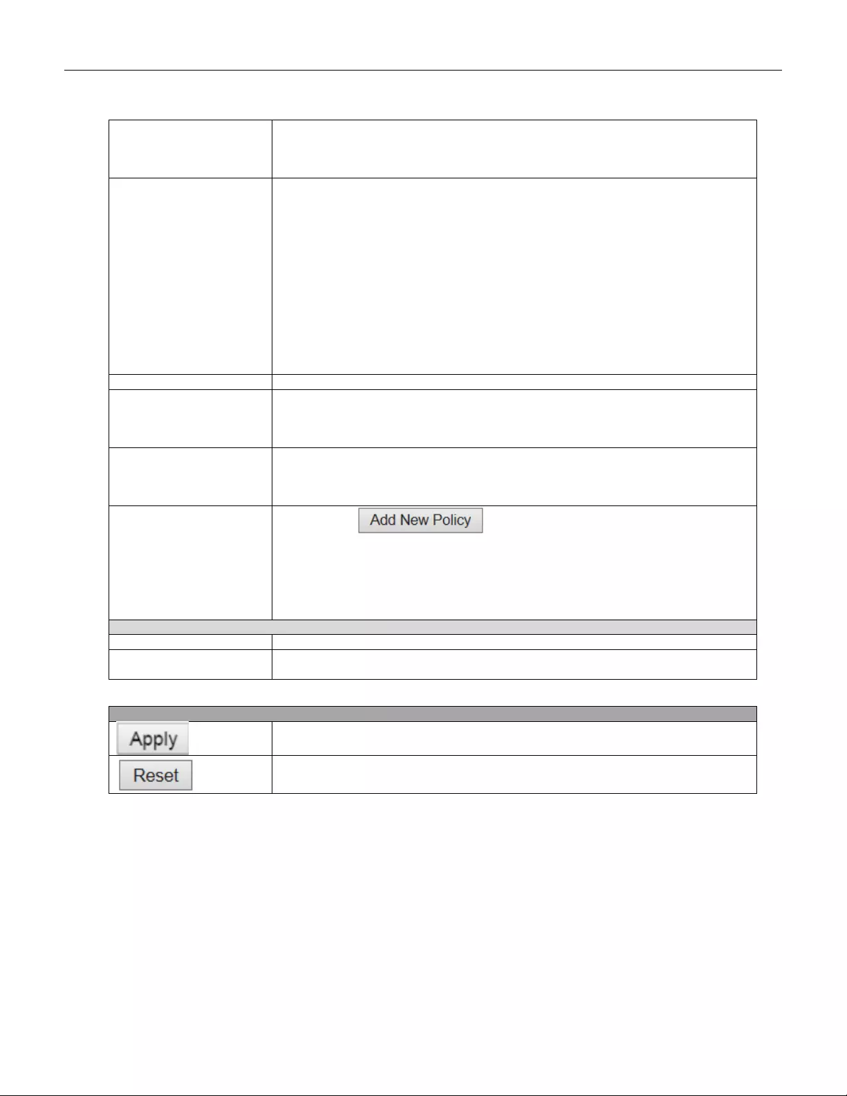
8. Video Signaling (conditional) - for use in network topologies that require a
separate policy for the video signaling than for the video media. This application type
should not be advertised if all the same network policies apply as those advertised in
the Video Conferencing application policy.
Tag
Tag indicating whet her the sp ecif ied app lic atio n type is usi n g a 'tagged' or an
'untagged' VLAN.
Untagged indicates that the device is using an untagged frame format and as such
does not inclu de a tag header as defined by IEE E 802.1Q-2003. In t hi s case, both the
VLAN ID and the Layer 2 priority fields are ignored and only the DSCP value has
relevance.
Tagged indicates that the device is using the IEEE 802.1Q tagged frame format, and
that both the VLAN ID and the Layer 2 priority values are being used, as well as the
DSCP
value. The tagged f or m at i ncl udes an addi tional fie ld, known as th e tag head er .
The tagged frame format also includes priority tagged frames as defined by IEEE
802.1Q-2003.
VLAN ID
VLAN identifier (VID) for the port as defined in IEEE 802.1Q-2003.
L2 Priority
L2 Priority is the Layer 2 priority to be used for the specified application type. L2
Priority may specify one of eight priority levels (0 through 7), as defined by IEEE
802.1D-2004. A value of 0 represents use of the default priority as defined in IEEE
802.1D-2004.
DSCP
DSCP value to be used to provide Diffserv node behavior for the specified application
type as defined in IETF RFC 2474. DSCP may contain one of 64 code point values (0
through 63). A value of 0 represents use of the default DSCP value as defined in RFC
2475.
Adding a new policy
Click to add a new policy. Specify the Application
type, Tag, VLAN ID, L2 Priority and DSCP for the new policy. Click "Save".
The number of policies supported is 32
Port Policies Configuration
Port
The port number to which the configuration applies.
Policy Id
The set of policies that shall apply to a given port. The set of policies is selected by
check marking the checkboxes that corresponds to the policies.
Buttons
Click to apply changes.
Click to undo any changes made locally and revert to previously saved values.
136
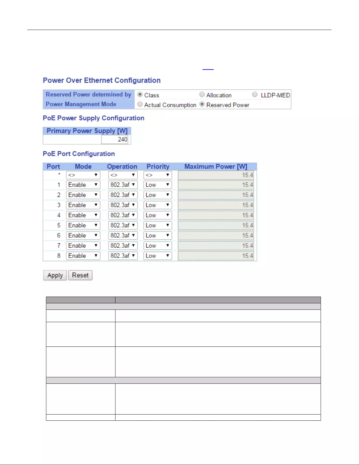
5.3.75 PoE
This page allows the user to inspect and configure the current PoE port settings.
Object
Description
Reserved Power determined by
Allocated mode
In this mode the user allocates the amount of power that each port may reserve. The
allocated/reserved power for each port/PD is specified in the Maximum Power fields.
Class mode
In this mode each port automatically determines how much power to reserve
according to the class the connected PD belongs to, and reserves the power
accordingly. Four different port classes exist and one for 4, 7, 15.4 or 30 Watts.
In this mode the Maximum Power fields have no effect.
LLDP-MED mode
This mode is similar to the Class mode expect that each port determine the amount
power it reserves by exchanging PoE information using the LLDP protocol and
reserves power accordingly. If no LLDP information is available for a port, the port will
reserve power using the class mode.
In this mode the Maximum Power fields have no effect.
Power Management Mode
Actual Consumption
In this mode the ports are shut down when the actual power consumption for all ports
exceeds the amount of power that the power supply can deliver or if the actual power
consumption for a given port exceeds the reserved power for that port. The ports are
shut down according to the ports priority. If two ports have the same priority the port
with the highest port number is shut down.
Reserved Power
In this mode the ports are shut down when total reserved powered exceeds the
137
amount of power that the power supply can deliver. In this mode the port power is not
turned on if the PD requests more power than available from the power supply.
Power Supply Configuration
Power Source
For being able to determine the amount of power the PD may use, it must be defined
what amount of power a power source can deliver.
Val id values are in the range 0 to 240 Watts.
Port Configuration
Port
This is the logical port number for this row.
Ports that are not PoE-capable are grayed out and thus impossible to configure PoE
for.
PoE Mode
Disable
PoE disabled for the port.
Enable
Enables PoE for the port.
Schedule
Enables PoE for the port by scheduling.
Operation Mode
802.3af
Sets PoE protocol to IEEE 802.3af.
802.3at
Sets PoE protocol to IEEE 802.3at.
Priority
The priority is used in the case where the remote devices require more power than the power supply can deliver. In
this case the port with the lowest priority will be turn off starting from the port with the highest port number.
Low
The lowest priority
High
The medium prior ity
Critical
The highest priority
Maximum Power
The Maximum Power value contains a numerical value that indicates the maximum power in watts that can be
delivered to a remote device.
The maximum power for each port is 30W.
Buttons
Click to apply changes.
Click to undo any changes made locally and revert to previously saved values.
138
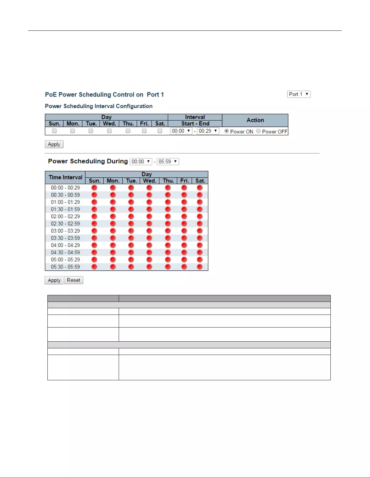
5.3.76 PoE Scheduler
This page provides power scheduling configurations.
The entry is used to control the power alive interval on PoE port.
It is allowed to set the specific interval to schedule power on/off in one week.
Object
Description
Power Scheduling Interval Configuration
Day
Checkmarks indicate which day are members of the set.
Interval
Start - Select the start hour and minute.
End - Select the end hour and minu te.
Action
Power On - Select the radio button to apply power on during the interval.
Power Off - Select the radio button to apply power off during the interval.
Power Scheduling During
Time Inter v al
There are 48 time interval one day. Each interval has 30 minutes.
Day
The current scheduling state is displayed graphically during the week.
Green indicates the power is on and red that it is off.
Directly changes checkmarks to indicate which day are members of the time interval.
Check or uncheck as needed to modify the scheduling table.
139
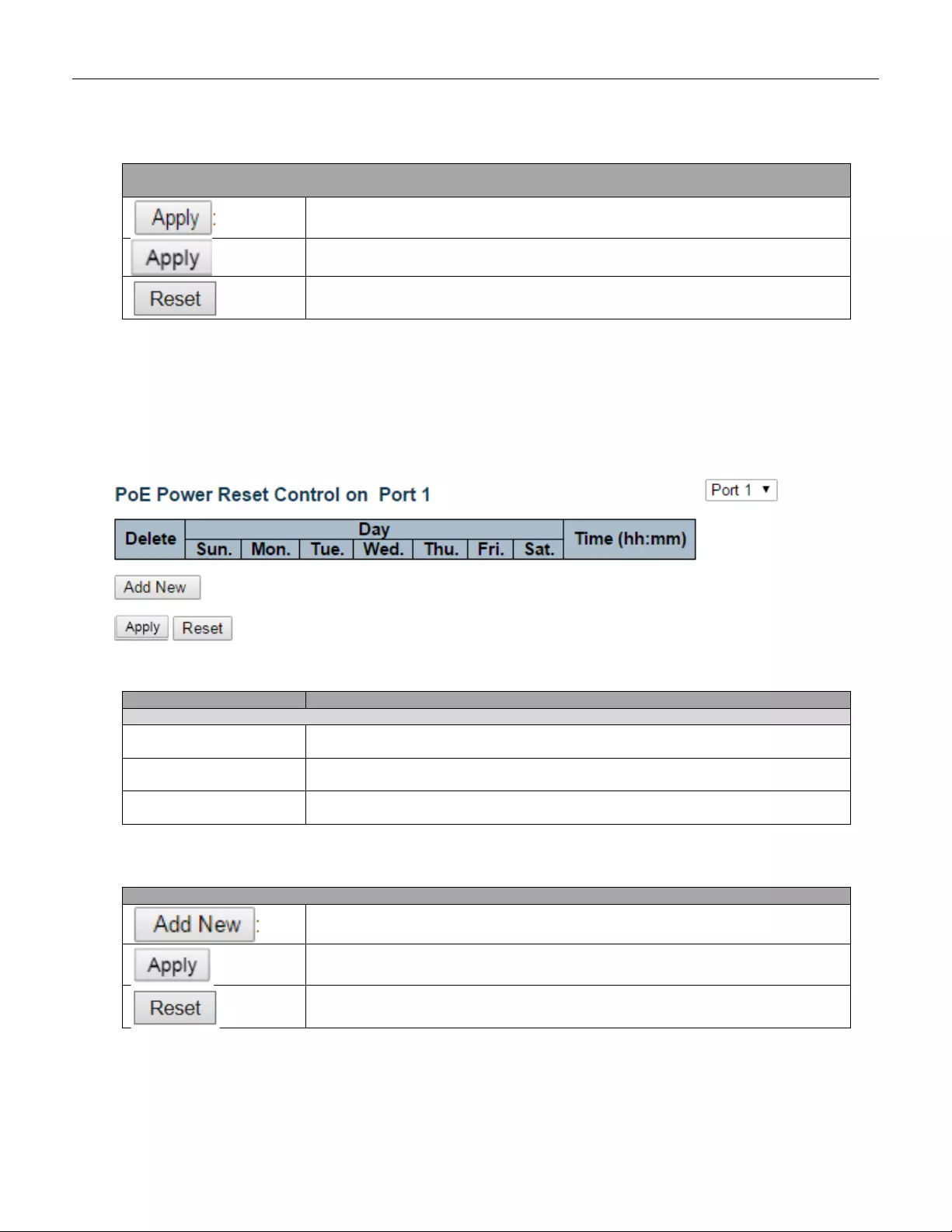
Buttons
Click to apply the power scheduling interval.
Click to apply changes.
Click to undo any changes made locally and revert to previously saved values.
5.3.77 Power Reset
This page provides power reset entry configurations.
The entry is used to control the power reset time on PoE port.
It is allowed to create at maximum 5 entries for each PoE port.
Object
Description
Delete
Check to delete the entry.
The designated entry will be deleted during the next save.
Day
Checkmarks indicate which day are members of the entry. Check or uncheck as
needed to modify the entry.
Time (hh:mm)
hh - Select the hour.
mm - Select the minute.
Buttons
Click to add new reset entry
Click to apply changes.
Click to undo any changes made locally and revert to previously saved values.
140
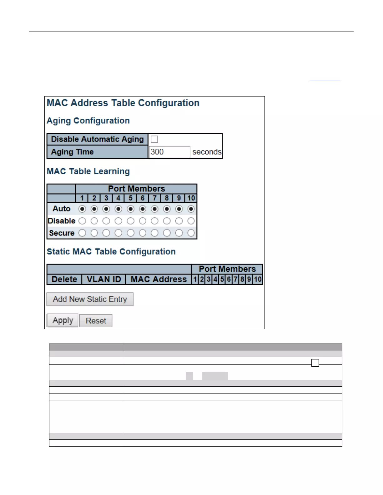
5.3.78 MAC Table
The MAC Address Table is configured on this page. Set timeouts for entries in the dynamic MAC Table and
configure the static MAC table here.
Object
Description
Aging Configuration
Disable A utomatic Agi ng
Disable the automatic aging of dynamic entries by ticking the item.
Aging Time
Enter a value in seconds .
The allowed range is 10 to 1000000 seconds.
MAC Table Learning
Auto
Learning is done aut omatically as soon as a frame with unknown SMAC is received.
Disable
No learning is done.
Secure
Only static MAC entries are learned, all other frames are dropped.
Note:
Make sure that the li nk used for m anaging the switch is added to the S t ati c Mac
Table before changing to secure learning mode, otherwise the management link is
lost and can only be restored by using another non-se cure p ort or by connect ing to
the switch via the serial interface.
Static MAC Table Learning
Delete
Check to delete the entry. It will be deleted during the next save.
141
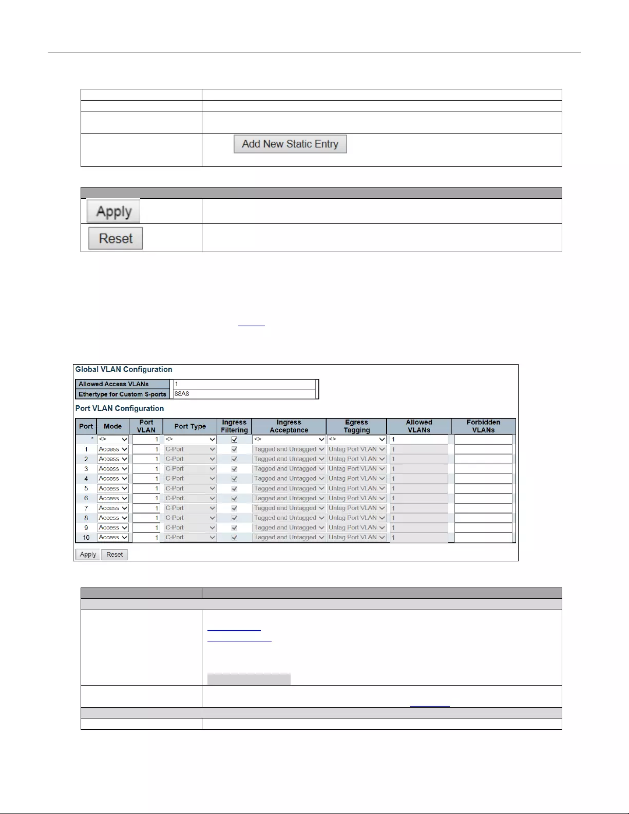
VLAN ID
The VLAN ID of the entry.
MAC Address
The MAC address of the entry.
Port Members
Checkmarks indicate which ports are members of the entry. Check or uncheck as
needed to modify the entry.
Adding a New Static
Entry Click to add a new entry to the static MAC table. Specify
the VLAN ID, MAC address, and port members for the new entry. Click "Save".
Buttons
Click to apply changes.
Click to undo any changes made locally and revert to previously saved values.
5.3.79 VLANs
This page allows for controlling VLAN configuration on the switch.
The page is divided into a global section and a per-port configuration section.
Object
Description
Global VLAN Configuration
Allowed A ccess VLA Ns
This field shows the allowed Access VLANs, i.e. it only affects ports configured as
Access po rts. Ports in other modes are members of all VLANs specified in the
Allowed VLANs field. By default, only VLAN 1 is enabled. More VLANs may be
created by using a list syntax where the individual elements are separated by
commas. Ranges are specified with a dash separating the lower and upper bound.
The following example will create VLANs 1, 10, 11, 12, 13, 200, and 300:
1,10-13,200,300. Spaces are allowed in between the delimiters.
Ethertype for Custom
S-ports
This field specifi es the ether type/T PID (specifi ed in hexadecimal) use d for Cust om
S-ports. The setting is in force for all ports whose Port Type is set to S-Custom-Port.
Port VLAN Configuration
Port
This is the logical port number of this row.
142

Mode
The port mode (default is Access) determines the fundamental behavior of the port in
question. A port can be in one of three modes as described below.
Whenever a particular mode is selected, the remaining fields in that row will be either
grayed out or made changeable depending on the mode in question.
Grayed out fields show the value that the port will get when the mode is applied.
Access:
Access ports are normally used to connect to end stations. Dynamic features like
Voice VLAN may add the port to more VLANs behind the scenes. Access ports have
the following char act er is tic s:
• Member of exactly one VLAN, the Port VLAN (a.k.a. Access VLAN), which
by default is 1
• Accepts untagged and C-tagged frames
• Discards all frames that are not classified to the Access VLAN
• On egress all frames classified to the Access VLAN are transmitted
untagged. Other (dynamically added VLANs) are transmitted tagged
Trunk:
Trunk ports can carry traffic on multiple VLANs simultaneously, and are
normally used to connect to other switches. Trunk ports have the following
characteristics:
• By default, a trunk port is member of all VLANs (1-4095)
• The VLANs that a trunk port is member of may be limited by the use of
Allowed VLANs
• Frames classified to a VLAN that the port is not a member of are discarded
• By default, all frames but frames classified to the Port VLAN (a.k.a. Native
VLAN) get tagged on egress. Frames classified to the Port VLAN do not get
C-tagged on egress
• Egress tagging can be changed to tag all frames, in which case only tagged
frames are accepted on ingress
Hybrid:
Hybrid ports resemble trunk ports in many ways, but add ad ditio nal port con figuration
features. In addition to the characteristics described for trunk ports, hybrid ports have
these abilities:
• Can be configured to be VLAN tag unaware, C-tag aware, S-tag aware, or
S-custom-tag aware
• Ingress filtering can be controlled
• Ingress acceptance of frames and configuration of egress tagging can be
configured independently
Port VLAN
Determines the port's VLAN ID (a.k.a. PVID). Allowed VLANs are in the range 1
through 4095, default being 1.
On ingress, frames get classified to the Port VLAN if the port is configured as VLAN
unaware, the frame is untagged, or VLAN awareness is enabled on the port, but the
frame is priority tagged (VLAN ID = 0).
On egress, frames classified to the Port VLAN do not get tagged if Egr e ss Tagging
configuration is set to untag Port VLAN.
The Port VLAN is called an "Access VLAN" for ports in Access mode and Native
VLAN for ports in Trunk or Hybrid mode.
Port Typ e
Ports in hy bri d mo de a llow for chan gin g the port ty pe, th at is, whether a fra me' s V LAN
tag is used to c lassify the f rame on in gress to a p arti cular VL AN, and if so, w hich TP ID
it reacts on.
Likew ise, on egr ess, th e Port Type determine s the T PID of the tag, if a t ag
is required.
143

Unaware:
On ingress, all frames, whether carrying a VLAN tag or not, get classified to the Port
VLAN, and possible tags are not removed on egress.
C-Port:
On ingress, fram es w it h a V LAN tag with TP ID = 0x8100 get cla ssi fie d to the VLAN I D
embedded in the tag. If a frame is untagged or priority tagged, the frame gets
classified to the Port VLAN. If frames must be tagged on egress, they will be tagged
with a C-tag.
S-Port:
On ingress, frames with a VLAN tag with TPID = 0x8100 or 0x88A8 get classified to
the VLAN ID embedded in the tag. If a frame is untagged or priority tagged, the frame
gets classified to the Port VLAN. If frames must be tagged on egress, they will be
tagged with an S-tag.
S-Custom-Port:
On ingress, frames with a VLAN tag with a TPID = 0x8100 or equal to the Ethertype
configured for Custom-S ports get classified to the VLAN ID embedded in the tag. If a
frame is untagged or priority tagged, the frame gets classified to the Port VLAN. If
frames must be tagged on egress, they will be tagged with the custom S-tag.
Ingress Filtering
Hybrid ports allow for changing ingress filtering. Access and Trunk ports always have
ingress filter in g enabl ed.
If ingress filtering is enabled (checkbox is checked), frames classified to a VLAN that
the port is not a member of get discarded.
If ingress filtering is disabled, frames classified to a VLAN that the port is not a
member of are accepted and forwarded to the switch engine. However, the port will
never transmit frames classified to VLANs that it is not a member of.
Ingress A cceptance
Hybrid ports allow for changing the type of frames that are accepted on ingress.
Tagged and Untagged
Both tagged and untagged frames are accepted.
Tagged Only
Only tagged frames are accepted on ingress. Untagged frames are discarded.
Untagged Only
Only untagged frames are accepted on ingress. Tagged frames are discarded.
Egress Tagging
Ports in Trunk and Hybrid mode may control the tagging of frames on egress.
Untag Port VLAN
Frames classified to the Port VLAN are transmitted untagged. Other frames are
transmitted with the relevant tag.
Tag All
All frames, whether classified to the Port VLAN or not, are transmitted with a tag.
Untag All
All frames, whether classified to the Port VLAN or not, are transmitted without a tag.
This option is only available for ports in Hybrid mode.
Allowed VLANs
Ports in Trunk and Hybrid mode may control which VLANs they are allowed to
become members of. Access ports can only be member of one VLAN, the Access
VLAN.
The field's syntax is identical to the syntax used in the Enabled VLANs field. By
default, a Trunk or Hybrid port will become member of all VLANs, and is therefore set
to 1-4095.
The fie ld may be lef t e mpty, which mean s that the port w ill n ot become m emb er of any
VLANs.
Forbidden VLANs
A port may be configured to never be member of one or more VLANs. This is
particularly useful when dynamic VLAN protocols like MVRP and GVRP must be
prevented from dynamically adding ports to VLANs.
The trick is to mark such VLANs as forbidden on the port in question. The syntax is
identical to the syntax used in the Enabled VLANs field.
By default, the field is left blank, which means that the port may become a member of
all possible VLANs.
144

Buttons
Click to apply changes.
Click to undo any changes made locally and revert to previously saved values.
5.3.80 Voice VLAN
5.3.81 Voice VLAN Configuration
The Voice VLAN feature enables voice traffic forwarding on the Voice VLAN, then the switch can classify
and schedule network traffic. It is recommended that there be two VLANs on a port - one for voice, one for data.
Before connecting the IP device to the switch, the IP phone should configure the voice VLAN ID correctly. It
should be configured through its own GUI.
145
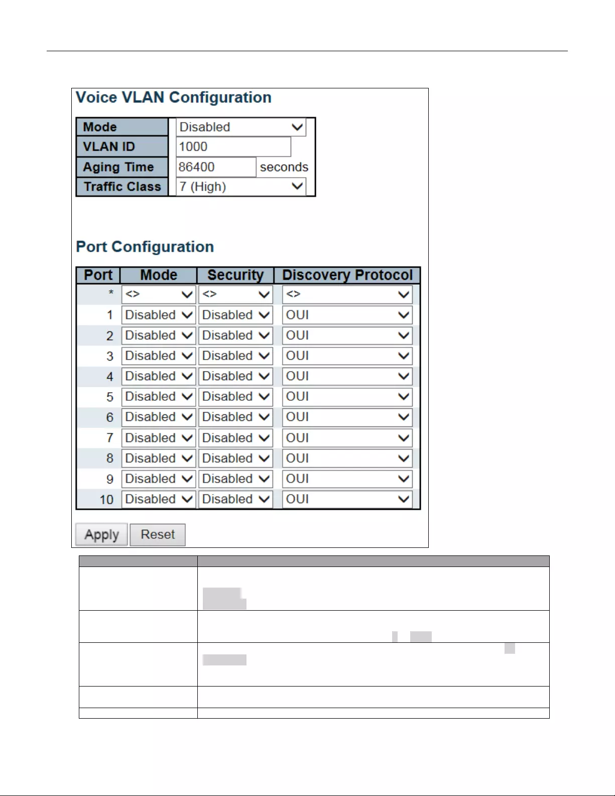
Object
Description
Mode
Indicates the Voice VLAN mode operation. We must disable MSTP feature before we
enable Voice VLAN. It can avoid th e confl ict of ingress filterin g. Pos sib le modes ar e:
Enabled: Enable Voice VLAN mode operation.
Disabled: Disable Voice VLAN mode operation.
VLAN ID
Indicates the Voice VLAN ID . It should be a un ique VLAN ID i n the syste m a nd can not
equal each port PVID. It is a conflict in configuration if the value equals management
VID, MVR VID, PVID etc. The allowed range is 1 to 4095.
Aging Time
Indicates the Voice VLAN secure learning aging time. The allowed range is 10 to
10000000 second s. It is us ed w hen secur ity mo de o r auto detect mode i s en abl ed. In
other cases, it will be based on hardware aging time. The actual aging time will be
situated between the [age_time; 2 * age_time] interval.
Traffic Class
Indicates the Voic e VLAN traffic class. All traffic on t he Voice VLAN will apply this
class.
Port Mode
Indicates the Voice VLAN port mode. Possible port modes are:
146
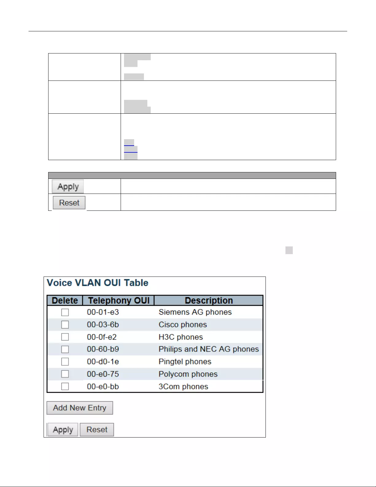
Disabled: Disjoin from Voice VLAN.
Auto: Enable auto detect mode. It detects whether there is VoIP phone attached to
the specific port and configures the Voice VLAN members automatically.
Forced: Force join to Voice VLAN.
Port Security
Indicates the Voice VLAN port security mode. When the function is enabled, all
non-telephonic MAC addresses in the Voice VLAN will be blocked for 10 seconds.
Possible port modes are:
Enabled: Enable Voice VLAN security mode operation.
Disabled: Disable Voice VLAN security mode operation.
Port Discovery Protocol
Indicates the Voice VLAN port discovery protocol. It will only work when auto detect
mode is enabled. We should enable LLDP feature before configuring discovery
protocol to "LLDP" or "Both". Changing the discovery protocol to "OUI" or "LLDP" will
restart auto detect process. Possible discovery protocols are:
OUI: Detect telephony device by OUI address.
LLDP: Detect telephony device by LLDP.
Both: Both OUI and LLDP.
Buttons
Click to apply changes.
Click to undo any changes made locally and revert to previously saved values.
5.3.82 Voice VLAN OUI
Configure VOICE VLAN OUI table on this page. The maximum number of entries is 16. Modifying the OUI
table will restart auto detection of OUI process.
147
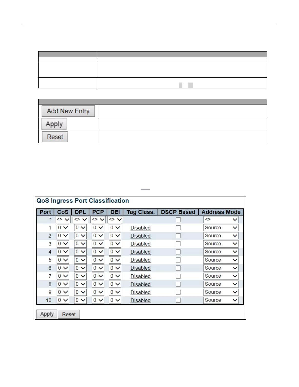
Object
Description
Delete
Check to delete the entry. It will be deleted during the next save.
Telephony OUI
A telephony OUI address is a globally unique identifier assigned to a vendor by IEEE.
It must be 6 characters long and the input format is "xx-xx-xx" (x is a hexadecimal
digit).
Description
The descript i on of O UI addr e s s. Nor ma lly, it describes which v endor tel ephony dev ic e
it belongs to. The allowed string length is 0 to 32.
Buttons
Click to add a new access management entry.
Click to apply changes.
Click to undo any changes made locally and revert to previously saved values.
5.3.83 QoS
5.3.84 Port Classification
This page allows you to configure the basic QoS Ingress Classification settings for all switch ports.
148

Object
Description
Port
The port number for which the configuration below applies.
CoS
Controls the default class of service.
All frames are classified to a CoS. There is a one to one mapping between CoS,
queue and priority. A CoS of 0 (zero) has the lowest priority.
If the port is VLAN aware, the frame is tagged and Tag Class is enabled, then the
frame is classified to a CoS that is mapped from the PCP and DEI value in the tag.
Otherwise the frame is classified to the default CoS.
The classified CoS can be overruled by a QCL entry.
Note: If the default CoS has been dynamically changed, then the actual default CoS
is shown in parentheses after the configured default CoS.
DPL
Controls the default drop precedence level.
All frames are classified to a drop precedence level.
If the port is VLAN aware and the frame is tagged, then the frame is classified to a
DPL that is equal to the DEI value in the tag. Otherwise the frame is classified to the
default DPL.
If the port is VLAN aware, the frame is tagged and Tag Class. Is enabl ed, t hen the
frame is classified to a DPL that is mapped from the PCP and DEI value in the tag.
Otherwise the frame is classified to the default DPL.
The classified DPL can be overruled by a QCL entry.
PCP
Controls the default PCP value.
All frames are classified to a PCP value.
If the port is VLAN aware and the frame is tagged, then the frame is classified to the
PCP value in the tag. Otherwise the frame is classified to the default PCP value.
DEI
Controls the default DEI value.
All frames are classified to a DEI value.
If the port is VLAN aware and the frame is tagged, then the frame is classified to the
DEI value in the tag. Otherwise the frame is classified to the default DEI value.
Tag Class.
Shows the classification mode for tagged frames on this port.
Disabled: Use default CoS and DPL for tagged frames.
Enabled: Use mapped versions of PCP and DEI for tagged frames.
Click on the mode in order to configure the mode and/or mapping.
Note: This setting has no effect if the port is VLAN unaware. Tagged frames received
on VLAN unaware ports are always classified to the default CoS and DPL.
DSCP Based
Click to Enable DSCP Based QoS Ingress Port Classification.
Address Mode
The IP/MAC address mode specifying whether the QCL classification must be based
on source (SMAC/SIP) or destination (DMAC/DIP) addresses on this port. The
allowed values are:
Source: Enable SMAC/SIP matching.
Destination: Enable DMAC/DIP matching.
149

Buttons
Click to apply changes.
Click to undo any changes made locally and revert to previously saved values.
150
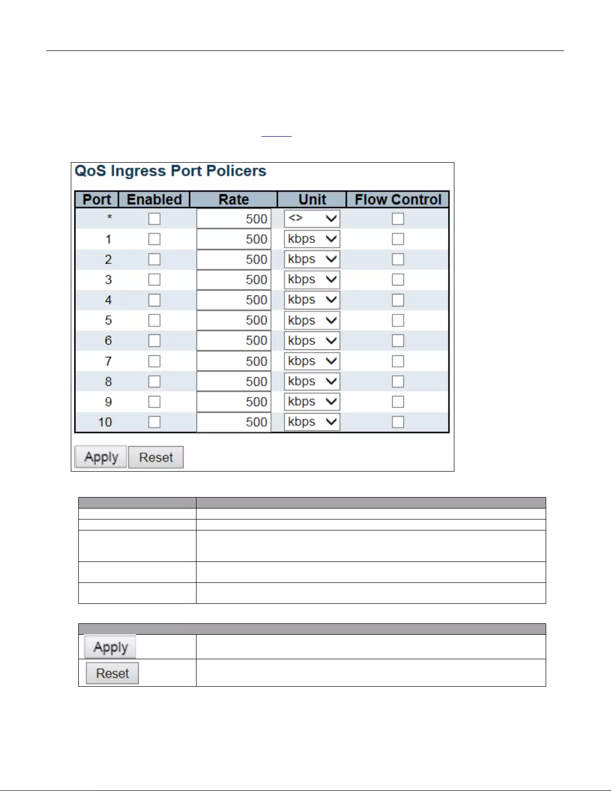
5.3.85 Port Policing
This page allows you to configure the Policer settings for all switch ports.
Object
Description
Port
The port number for which the configuration below applies.
Enabled
Controls whether the policer is enabled on this switch port.
Rate
Controls the rate for the policer. The default value is 500. This value is restricted to
100-1000000 when the "Unit" is "kbps" or "fps", and it is restricted to 1-3300 when the
"Unit" is "Mbps" or "kfps".
Unit
Controls the unit of measure for the policer rate as kbps, Mbps, fps or kfps. The
default value is "kbps".
Flow Control
If flow control is enabled and the port is in flow control mode, then pause frames are
sent instead of discar ding frames.
Buttons
Click to apply changes.
Click to undo any changes made locally and revert to previously saved values.
151
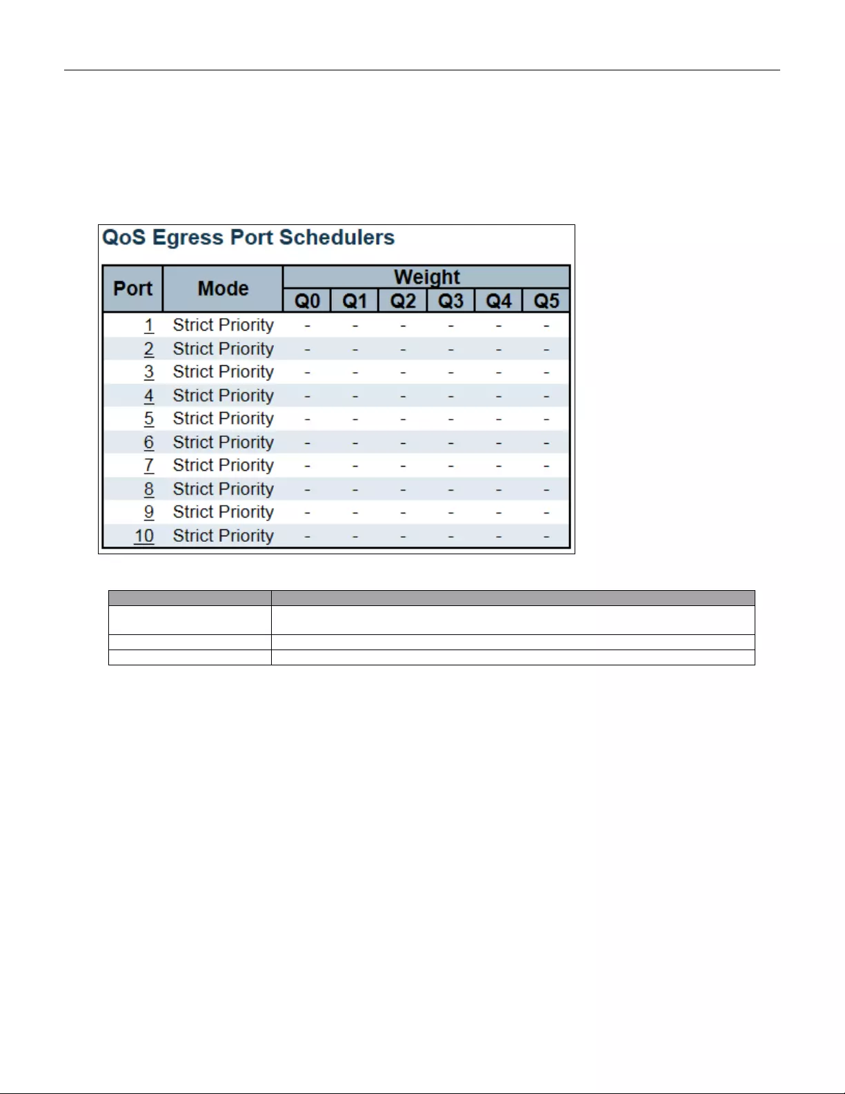
5.3.86 Port Scheduler
This page provides an overview of QoS Egress Port Schedulers for all switch ports.
Object
Description
Port
The logical port for the settings contained in the same row.
Click on the port number in order to configure the schedulers.
Mode
Shows the scheduling mode for this port.
Qn
Shows the weight for this queue and port.
152
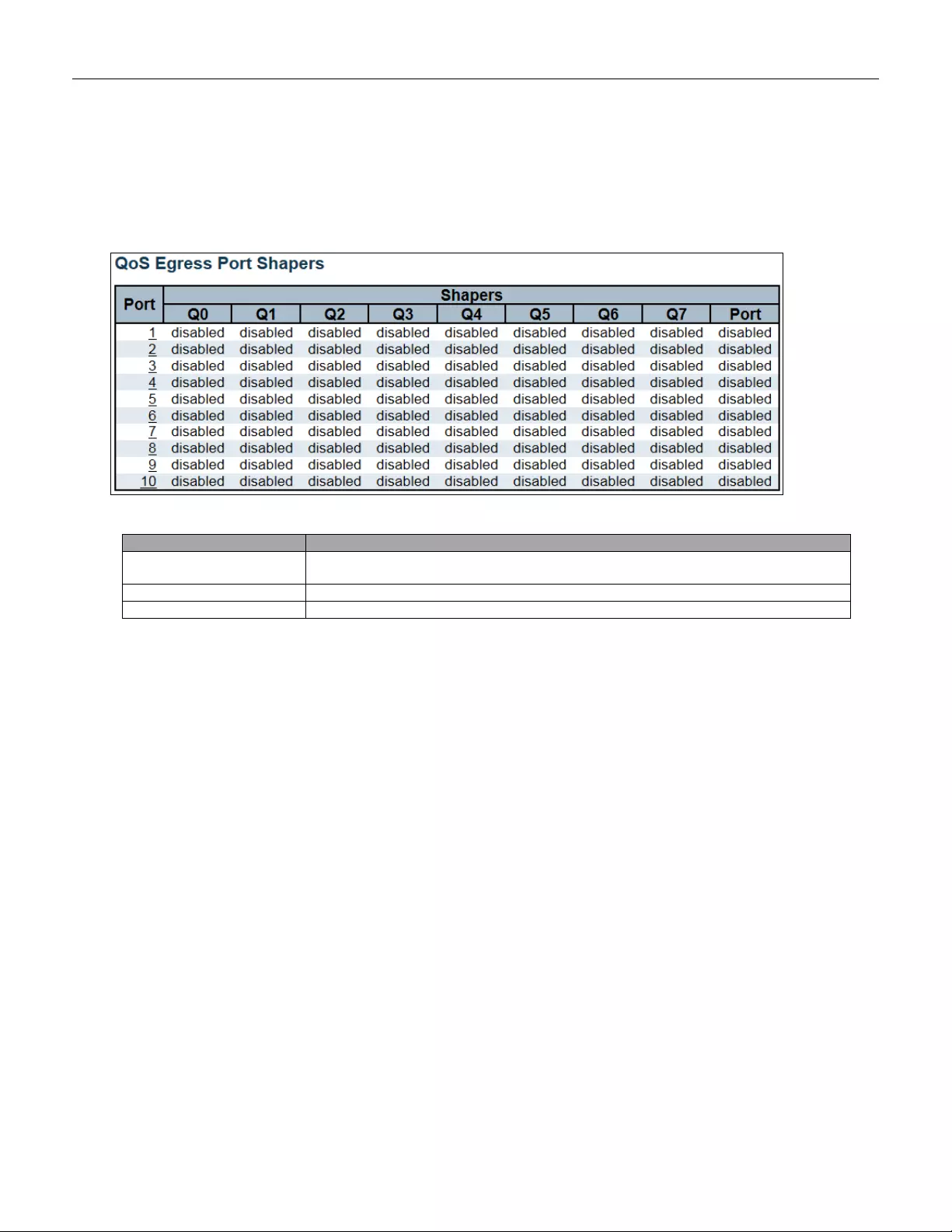
5.3.87 Port Shaping
This page provides an overview of QoS Egress Port Shapers for all switch ports.
Object
Description
Port
The logical port for the settings contained in the same row.
Click on the port number in order to configure the shapers.
Qn
Shows "disabled" or actual queue shaper rate - e.g. "800 Mbps".
Port #
Shows "disabled" or actual port shaper rate - e.g. "800 M bps" .
153

5.3.88 Port Tag Remarking
This page provides an overview of QoS Egress Port Tag Remarking for all switch ports.
Object
Description
Port
The logical port for the settings contained in the same row.
Click on the port number in order to configure tag remarking.
Mode
Shows the tag remarking mode for this port.
Classified: Use classified PCP/DEI values.
Default: Use default PCP/DEI values.
Mapped: Use mapped versions of QoS cl a ss and DP level.
154
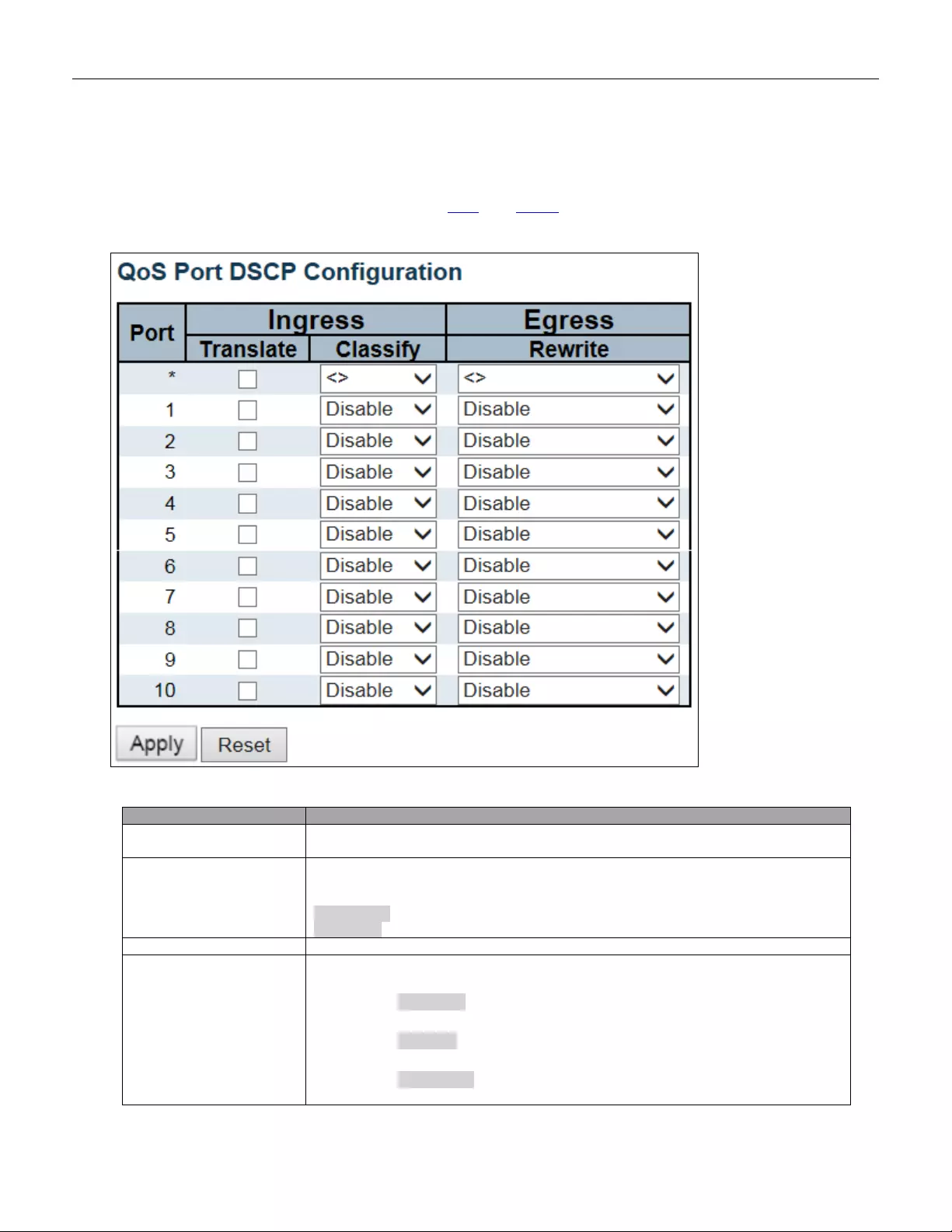
5.3.89 Port DSCP
This page allows you to configure the basic QoS Port DSCP Configuration settings for all switch ports.
Object
Description
Port
The Port column shows the list of ports for which you can configure dscp ingress and
egress settings.
Ingress
In Ingress settings you can change ingress translation and classification settings for
individual ports.
There are two configuration parameters available in Ingress:
Translate
Classify
Translate
To Enable the Ingress Translation cli ck the check box.
Classify
Classification for a port has 4 different values.
-Disable: No Ingress DSCP Classification.
-DSCP=0: Classify if incoming (or translated if enabled) DSCP is 0.
-Selected: Classify only selected DSCP for which classification is
enabled as specified in DSCP Translation window for the specific
155
DSCP.
-All: Classify all DSCP.
Egress
Port Egress Rewriting can be one of -
-Disable: No Egress rewrite.
-Enable: Rewrite enabled without remapping.
-Remap DP Unaware: DSCP from analyzer is remapped and frame is
remarked with remapped DSCP value. The remapped DSCP value is
always taken from the 'DSCP Translation->Egress Remap DP0' table.
-Remap DP Aware: DSCP from analyzer is remapped and frame is
remarked w ith re mapped DSC P v alue. Dep ending o n the D P level of t h e
frame, the remapped DSCP value is either taken from the 'DSCP
Translation->Egress Remap DP0' table or from the 'DSCP
Translation->Egress Remap DP1' table.
Buttons
Click to apply changes.
Click to undo any changes made locally and revert to previously saved values.
156
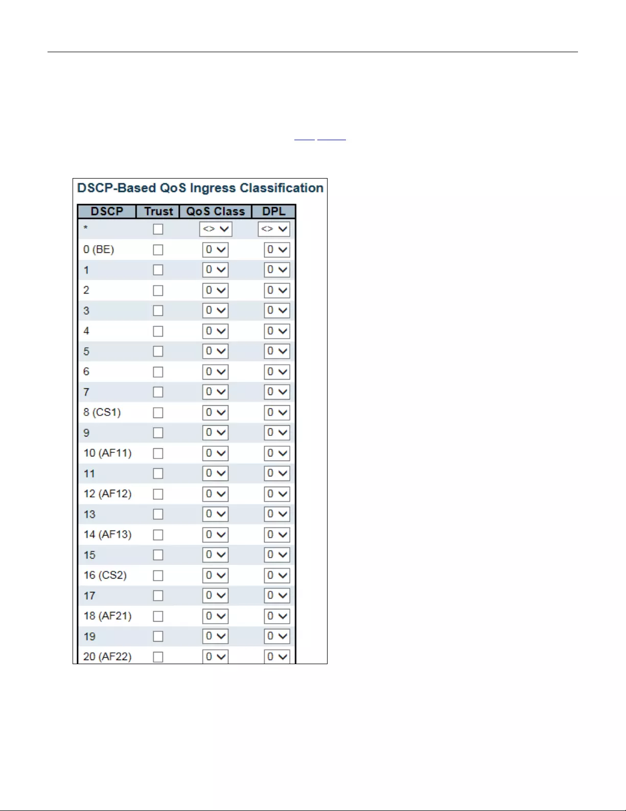
Object
Description
DSCP
Maximum number of supported DSCP values is 64.
Trust
Controls whether a specific DSCP value is trusted. Only frames with trusted DSCP
values are mapp ed to a specif i c QoS class and Drop Precedence Level. Frames with
untrusted DSCP values are treated as a non-IP frame.
QoS Class
QoS class value can be any of (0-7)
DPL
Drop Precedence Level (0-1)
Buttons
Click to apply changes.
Click to undo any changes made locally and revert to previously saved values.
158
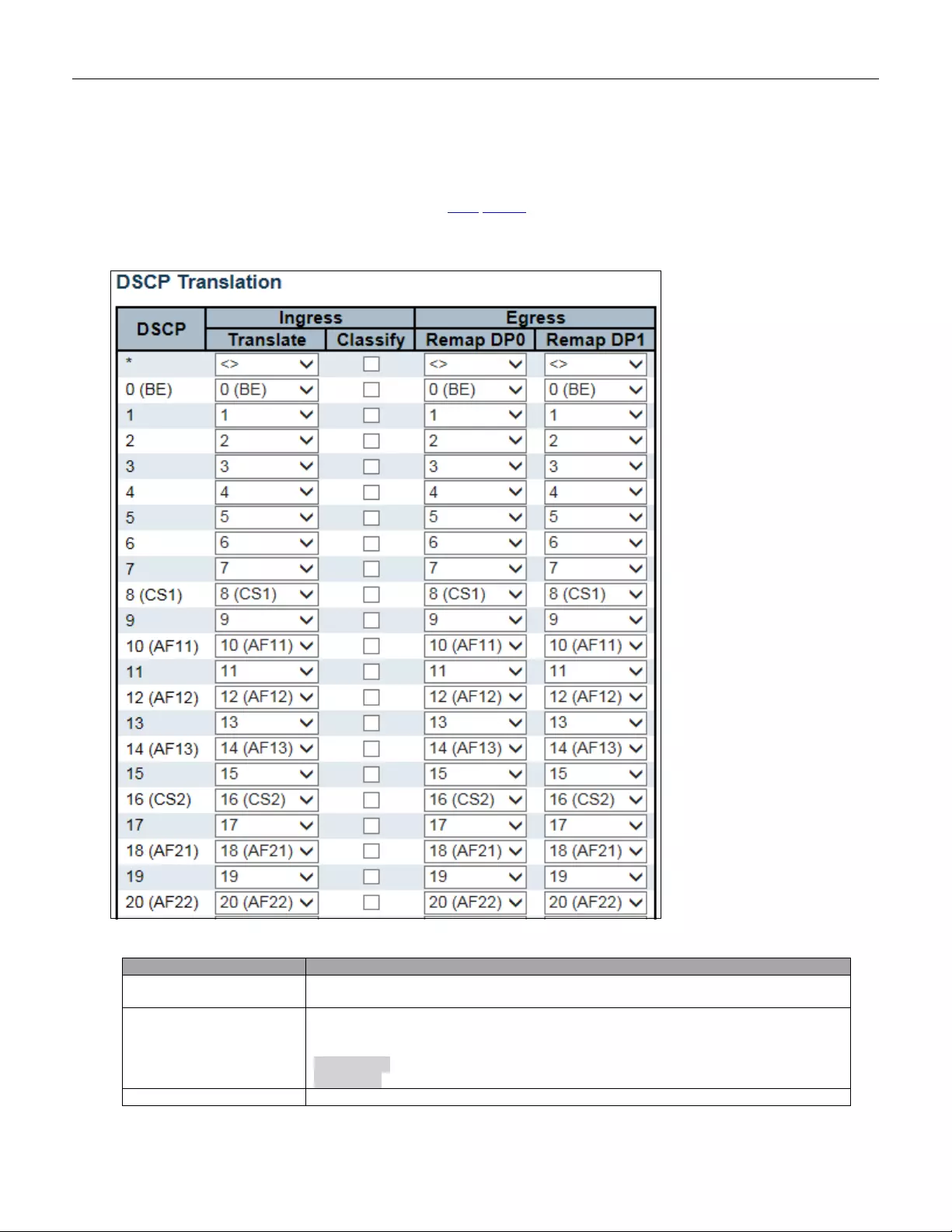
5.3.91 DSCP Translation
This page allows you to configure the basic QoS DSCP Translation settings for all switches. DSCP
translation can be done in Ingress or Egress.
Object
Description
DSCP
Maximum number of supported DSCP values are 64 and valid DSCP value ranges
from 0 to 63.
Ingress
Ingress side DSCP can be first translated to new DSCP before using the DSCP for
QoS class and DPL map.
There are two configuration parameters for DSCP Translation -
Translate
Classify
Translation
DSCP at Ingress side can be translated to any of (0-63) DSCP values.
159
Classify
Click to enable Classification at Ingress side.
Egress
There are the following configurable parameters for Egress side -
Remap DP0 Controls the remapping for frames with DP level 0.
Remap DP1 Controls the remapping for frames with DP level 1.
Remap DP0
Select the DSCP value from select menu to which you want to remap. DSCP value
ranges from 0 to 63.
Remap DP1
Select the DSCP value from select menu to which you want to remap. DSCP value
ranges from 0 to 63.
Buttons
Click to apply changes.
Click to undo any changes made locally and revert to previously saved values.
160
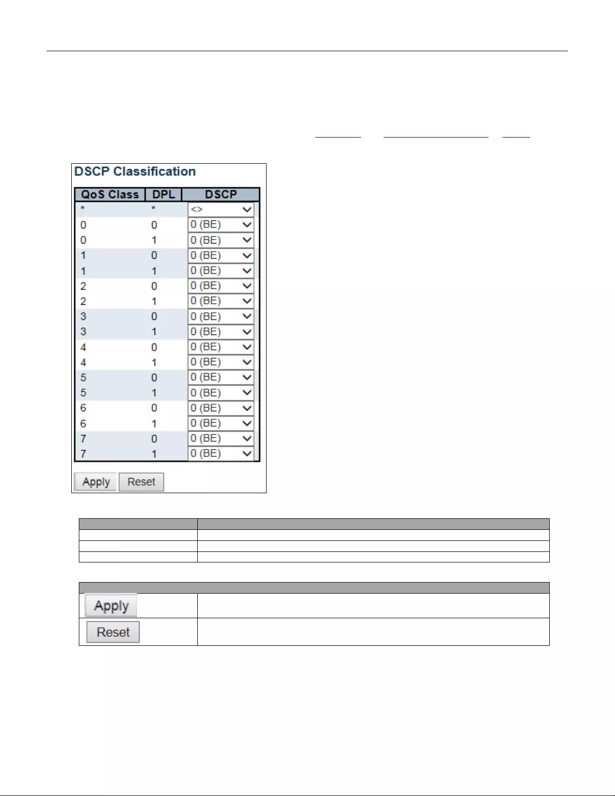
5.3.92 DSCP Classification
This page allows you to configure the mapping of QoS class and Drop Precedence Level to DSCP value.
Object
Description
QoS Class
Actual QoS class.
DPL
Actual Drop Precedence Level.
DSCP
Select the classified DSCP value (0-63).
Buttons
Click to apply changes.
Click to undo any changes made locally and revert to previously saved values.
161
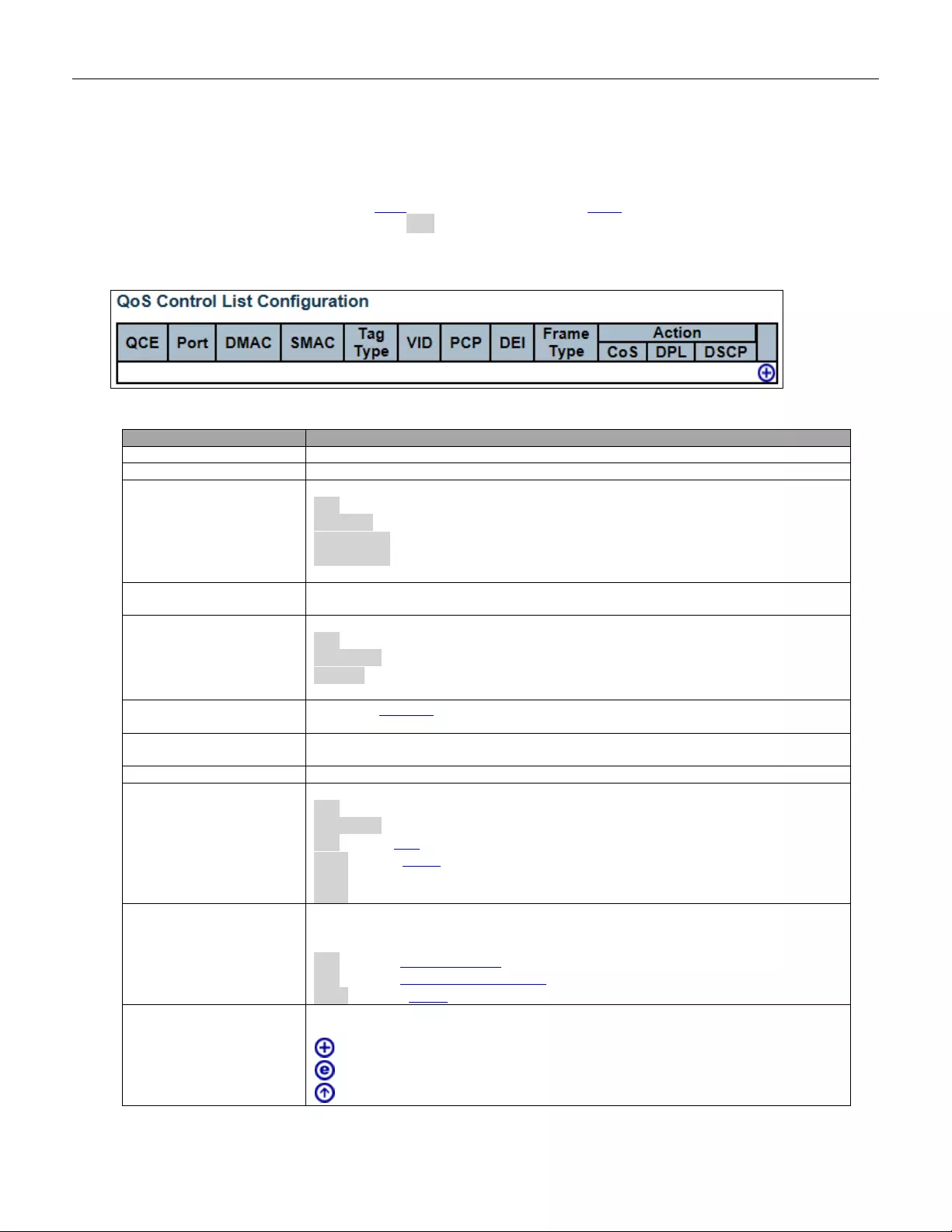
5.3.93 QoS Control List
This page shows the QoS Control List(QCL), which is made up of the QCEs. Each row describes a QCE that is
defined. The maximum number of QCEs is 256 on each switch.
Click on the lowest plus sign to add a new QCE to the list.
Object
Description
QCE
Indicates the QCE id.
Port
Indicates the list of ports configured with the QCE.
DMAC
Indicates the destination MAC address. Possible values are:
Any: Match any DMAC.
Unicast: Match unicast DMAC.
Multicast: Match multicast DMAC.
Broadcast: Match broadcast DMAC.
The default value is 'Any'.
SMAC
Match specific source MAC address or 'Any'.
If a port is configured to match on DMAC/DIP, this field indicates the DMAC.
Tag Type
Indicates tag type. Possible values are:
Any: Match tagged and untagged frames.
Untagged: Match untagged frames.
Tagged: Match tagged frames.
The default value is 'Any'.
VID
Indicates (VLAN ID), either a specific VID or range of VIDs. VID can be in the range
1-4095 or 'Any'
PCP
Priority C o de P oint : Valid val ue s of PC P are speci fic( 0, 1, 2, 3, 4, 5, 6, 7) or range(0-1,
2-3, 4-5, 6-7, 0-3, 4-7) or 'Any'.
DEI
Drop Eligible Indicator: Valid value of DEI is 0, 1 or 'Any'.
Frame Type
Indicates the type of frame. Possible values are:
Any: Match any frame type.
Ethernet: Match EtherType frames.
LLC: Match (LLC) frames.
SNAP: Match (SNAP) frames.
IPv4: Match IPv4 frames.
IPv6: Match IPv6 frames.
Action
Indicates the classification action taken on ingress frame if parameters configured are
matched with the frame's content.
Possible actions are:
CoS: Classify Class of Servic e.
DPL: Classify Drop Precedence Level.
DSCP: Classify DSCP value.
Modification Buttons
You can modify each QCE (QoS Control Entry) in the table using the following
buttons:
: Inserts a new QCE before the current row.
: Edits the QCE.
: Moves the QCE up the list.
162
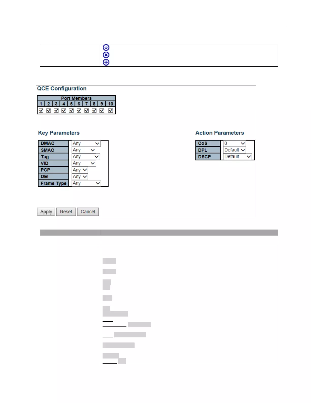
: Moves the QCE down the list.
: Deletes the QCE.
: The lowest plus sign adds a new entry at the bottom of the QCE listings.
The QCE page includes the following fields:
Object
Description
Port Members
Check the checkbox button to include the port in the QCL entry. By default all port s
are included.
Key parameters
Key configuration is described as below:
DMAC Destination MAC address: Possible values are 'Unicast', 'Multicast',
'Broadcast' or 'Any'.
SMAC Source MAC address: xx-xx-xx-xx-xx-xx or 'Any'. If a port is configured to
match on DMAC/DIP, this field is the Destination MAC address.
Tag Value of Tag field can be 'Untagged', 'Tagged' or 'Any'.
VID Valid value of VLAN ID can be any value in the range 1-4095 or 'Any'; user can
enter either a specific value or a range of VIDs.
PCP Valid value PCP are specific (0, 1, 2, 3, 4, 5, 6, 7) or range (0-1, 2-3, 4-5, 6-7,
0-3, 4-7) or 'Any'.
DEI Valid value of DEI can be '0', '1' or 'Any'.
Frame Type Frame Type can have any of the following values:
Any: Allow all types of frames.
EtherType: Ether Type Valid Ether Type can be 0x600-0xFFFF excluding
0x800(IPv4) and 0x86DD(IPv6) or 'Any'.
LLC: SSAP Address Valid SSAP (Source Service Access Point) can vary from 0x00
to 0xFF or 'Any'.
DSAP Address Valid DSAP (Destin atio n S erv ic e Access Po int) c an v ar y fro m 0x00 to
0xFF or 'Any'.
Control Valid Control field can vary from 0x00 to 0xFF or 'Any'.
SNAP: PID Valid PID (a.k.a Ether Type) can be 0x0000-0xFFFF or 'Any'.
163
IPv4: Protocol IP protocol number: (0-255, 'TCP' or 'UDP') or 'Any'.
Source IP Specific Source IP address in value/mask format or 'Any'. IP and Mask are
in the format x.y.z.w where x, y, z, and w are decimal numbers between 0 and 255.
When Mask is converte d to a 32-bit binary string and read from left to right, all bits
following the first zero must also be zero. If a port is configured to match on
DMAC/DIP, this field is the Destination IP address.
IP Fragment IPv4 frame fragmented option: 'Yes', 'No' or 'Any'.
DSCP D iffserv Code Point v alue ( DSCP) : It can be a spec ific value, r ange o f value s or
'Any'. DSCP values are in the range 0-63 including BE, CS1-CS7, EF or AF11-AF43.
Sport Sourc e T C P/U DP port:(0-65535) or 'Any', specific or port range applicable for
IP protocol UDP/TCP.
Dport Destination T C P/U D P port :(0-65535) or 'Any', specific or port range applicable
for IP protocol UDP/TCP.
IPv6: Protocol IP protocol number: (0-255, 'TCP' or 'UDP') or 'Any'.
Source IP 32 LS bits of IPv6 source address in value/mask format or 'Any'. If a port is
configured to match on DMAC/DIP, this field is the Destination IP address.
DSCP D iffserv Code Point v alue ( DSCP) : It can be a spec ific value, r ange o f value s or
'Any'. DSCP values are in the range 0-63 including BE, CS1-CS7, EF or AF11-AF43.
Sport Source TCP/UDP port :( 0-65535) or 'Any', specific or port range applicable for
IP protocol UDP/TCP.
Dport Destination TCP/UDP port :( 0-655 35) or 'A ny', specific or port range appli cabl e
for IP protocol UDP/TCP.
Action Parameters
CoS Class of Service: (0-7) or 'Default'.
DP Drop Precedence Level: (0-1) or 'Default'.
DSCP DSCP: (0-63, BE, CS1-CS7, EF or AF11-AF43) or 'Default'.
'Default' means that the default classified value is not modified by this QCE.
Buttons
Click to apply the configuration and move to main QCL page.
Click to undo any changes made locally and revert to previously saved values.
Return to the previous page without saving the configuration change.
164
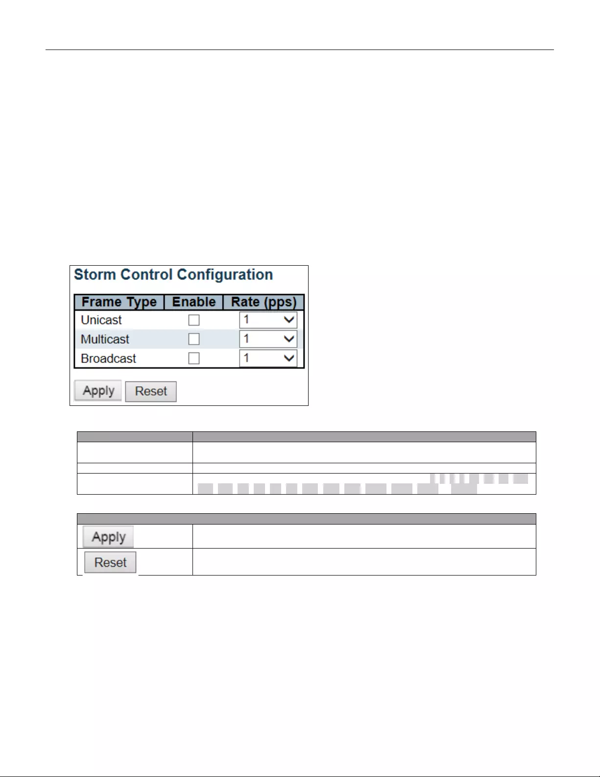
5.3.94 Storm Control
Storm control for the switch is configured on this page.
There is a unicast storm rate control, multicast storm rate control, and a broadcast storm rate control. These
only affect flooded frames, i.e. frames w ith a (VLAN ID, DMAC) pair not present on the MAC Address table.
The configuration indicates the permitted packet rate for unicast, multicast or broadcast traffic across the switch.
Object
Description
Frame Type
The settings in a particular row apply to the frame type listed here: Unicast, Multicast
or Broadcast.
Enable
Enable or disable the storm control status for the given frame type.
Rate
The rate unit is packets per second (pps). Valid values are: 1, 2, 4, 8, 16, 32, 64, 128,
256, 512, 1K, 2K, 4K, 8K, 16K, 32K, 64K, 128K, 256K, 512K or 1024K.
Buttons
Click to apply changes.
Click to undo any changes made locally and revert to previously saved values.
165
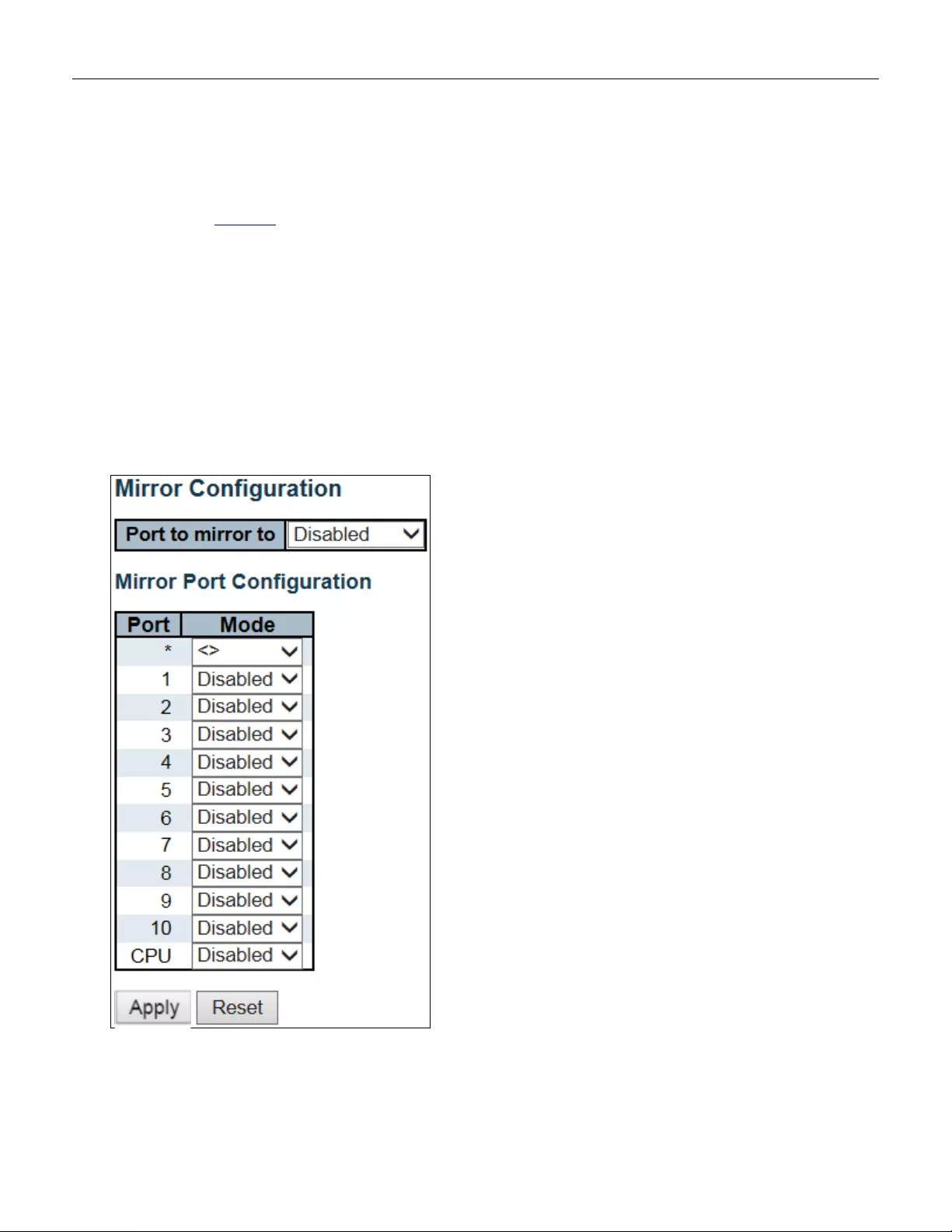
5.3.95 Mirror
Configure port Mirroring on this page.
To debug network problems, selected traffic can be copied, or mirrored, on a mirror port where a frame
analyzer can be attached to analyze the frame flow.
The traffic to be copied on the mirror port is selected as follows:
• All frames received on a given port (also known as ingress or source mirroring).
• All frames transmitted on a given port (also known as egress or destination mirroring).
166
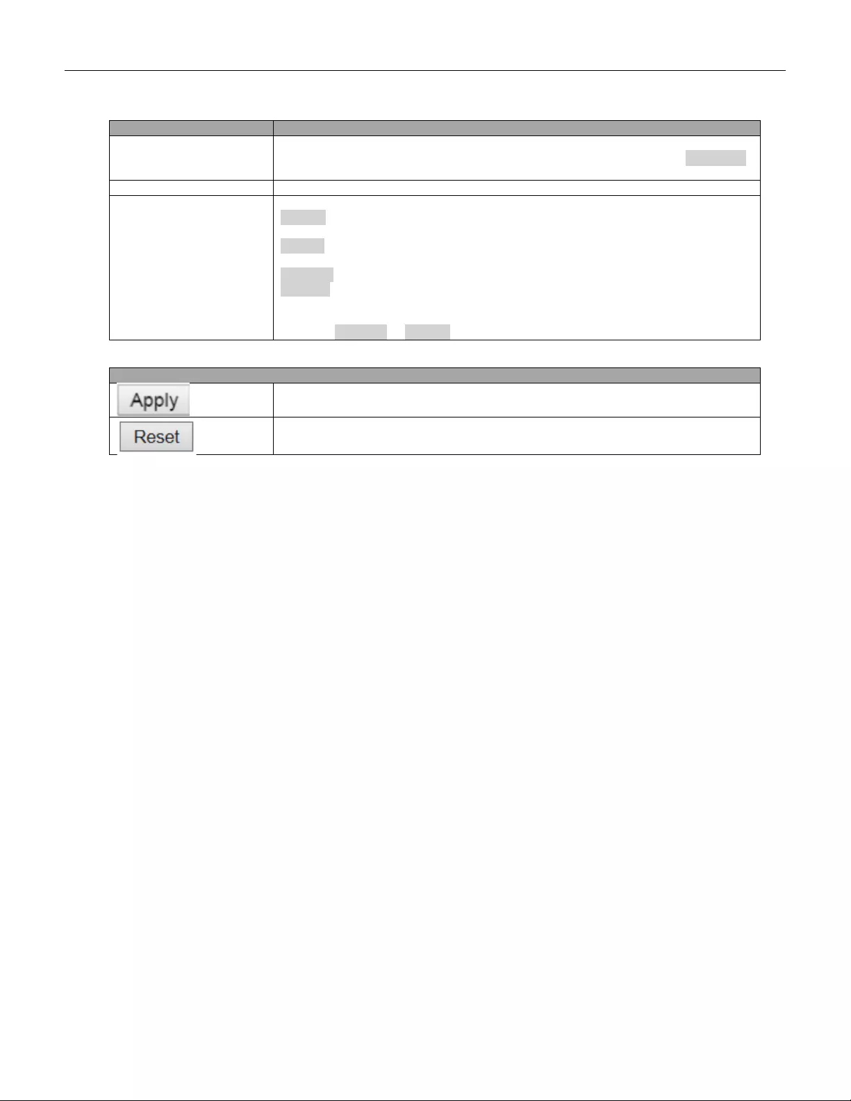
Object
Description
Port to mirro r
Port to mirro r also known as the mirror port. Frames from ports that have either
source (rx) or destination (tx) mirroring enabled are mirrored on this port. Disabled
disables mirroring.
Port
The logical port for the settings contained in the same row.
Mode
Select mirror mode .
Rx only Frames received on this port are mirrored on the mirror port. Frames
transmitted are not mirrored.
Tx only Frames transmitted on this port are mirrored on the mirror port. Frames
received are not mirro red.
Disabled Neither frames transmitted nor frames received are mirrored.
Enabled Frames received and frames transmitted are mirrored on the mirror port.
Note: For a given port, a frame is only transmitted once. It is therefore not possible to
mirror mirror po rt Tx frames. Because of this, mode for the selecte d mirror port is
limited to Disabled or Rx only.
Buttons
Click to apply changes.
Click to undo any changes made locally and revert to previously saved values.
167
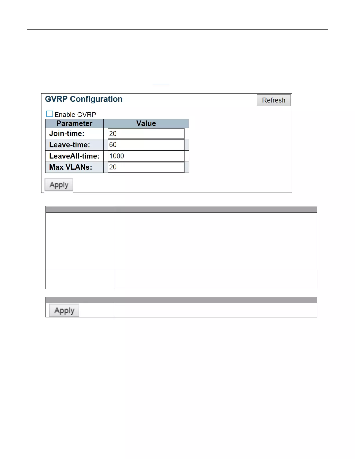
5.3.96 GVRP
5.3.97 Global Config
This page allows you to configure the basic GVRP Configuration settings for all switch ports.
Object
Description
GVRP Protocol timers
Join-time is a value in the range 1-20 in the units of centi seconds, i.e. in units
of one hundredth of a second. The default is 20.
Leave-time is a value in the range 60-300 in the units of centi seconds, i.e. in
units of one hundredth of a second. The default is 60.
LeaveAll-time is a value in the range 1000-5000 in the units of centi seconds,
i.e. in units of one hundredth of a second. The default is 1000.
Max number of VLANs
When GVRP is enabled a maximum number of VLANs supported by GVRP
is specified. By default this number is 20. This number can only be changed
when GVRP is turned off.
Buttons
Click to apply changes.
168
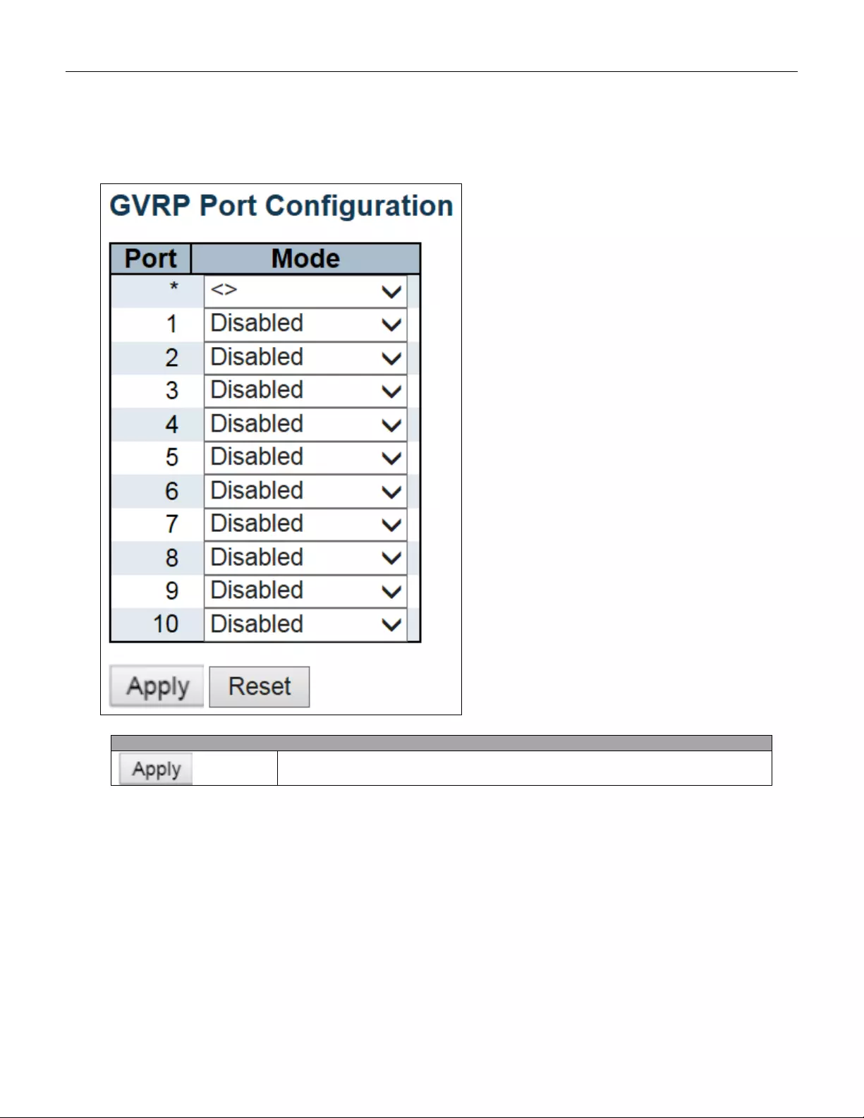
5.3.98 Port Config
This page allows you to enable a port for GVRP.
Buttons
Click to apply changes.
169
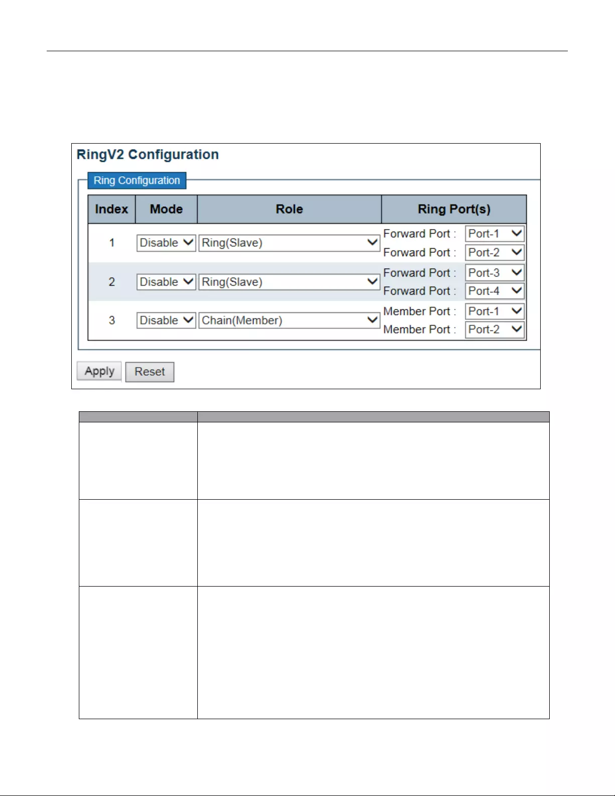
5.3.99 RingV2
This page provides Ring related configuration.
Object
Description
Index
The group index. This parameter is used for easy identifying the ring when user
configures it.
Group 1 (Index 1) - It supports configuration of ring.
Group 2 (Index 2) - It supports configuration of ring, coupling and dual-homing.
Group 3 (Index 3) - It supports configuration of chain and balancing-chain.
Mode
Enable Ring on the spe cif ic group.
When Group 1 or 2 is enabled, all configuration of Group 3 will be reset to default.
Group 3 all configuration options will be locked.
To configure Group 3, both Group1 and 2 should be disabled first. When Group 3 is
enabled, all configuration of Group1 and 2 will be reset to default. Group 1 and 2 all
configuration options will be locked.
Role
Configure the Ring group on this switch as specific role.
Group 1 - support option of ring-master and ring-slave.
# Ring - it could be master or slave.
Group 2 - support configuration of the ring, coupling and dual-homing.
# Ring - it could be mast er or slav e.
# Coupling - it could be primary and backup.
# Dual-Homing
Group 3 - sup port con figur ation of the chain and balancing-chain.
# Chain - it could be head, tail or member.
170

# Balancing Chain - it could be central -block, terminal-1/2 or member.
Note 1 - Group 1 must be enabled before enable Group 2 to coupling.
Note 2 - When Group 1 or 2 is enabled, the configuration of Group 3 will be
disabled.
Note 3 - When Gr oup 3 i s e na bled, t he co nfig urat i on of G roup 1 and 2 will be
disabled.
Ring Port(s)
Selecting ring port(s).
Each ring port must be unique, CANNOT be configured in different groups; 2 ring
ports between ring/chain CANNOT be the same.
# When role is ring/master, one ring port is forward port and another is block port.
The block port is redundant port; it is blocking port in normal state.
# When role is ring/slave, both ring ports are forward port.
# When role is coupling/primary, only need one ring port named primary port.
# When role is coupling/backup, only need one ring port named backup port. This
backup port is redundant port; it is blocking port in normal state.
# When role is dual-homing, one ring port is primary port and anot her is backup
port. This backup port is redundant port; it is blocking port in normal state.
# When role is chain/head, one ring port is member port and another is head port.
Both ring ports are forwarding port in normal state.
# When role is chain/tail, one ring port is m ember por t an d another is tail port. The
tail port is redundant port; it is blocking port in normal state.
# When role is chain/member, both ring ports are member port. Both ring ports are
forwarding port in normal state.
# When role is balancing -chain/central-block, one ring port is member port and
another is block port. The block port is redundant port; it is blocking port in normal
state.
# When role is balancing-chain/terminal-1/2, one ring port is member por t and
another is terminal port. Both ring port s are forw arding port i n normal stat e.
# When role is balancing -c hain/member, both ring ports are member por t. Both ring
ports are forwarding port in normal stat e.
Buttons
Click to apply changes.
Click to undo any changes made locally and revert to previously saved values.
171
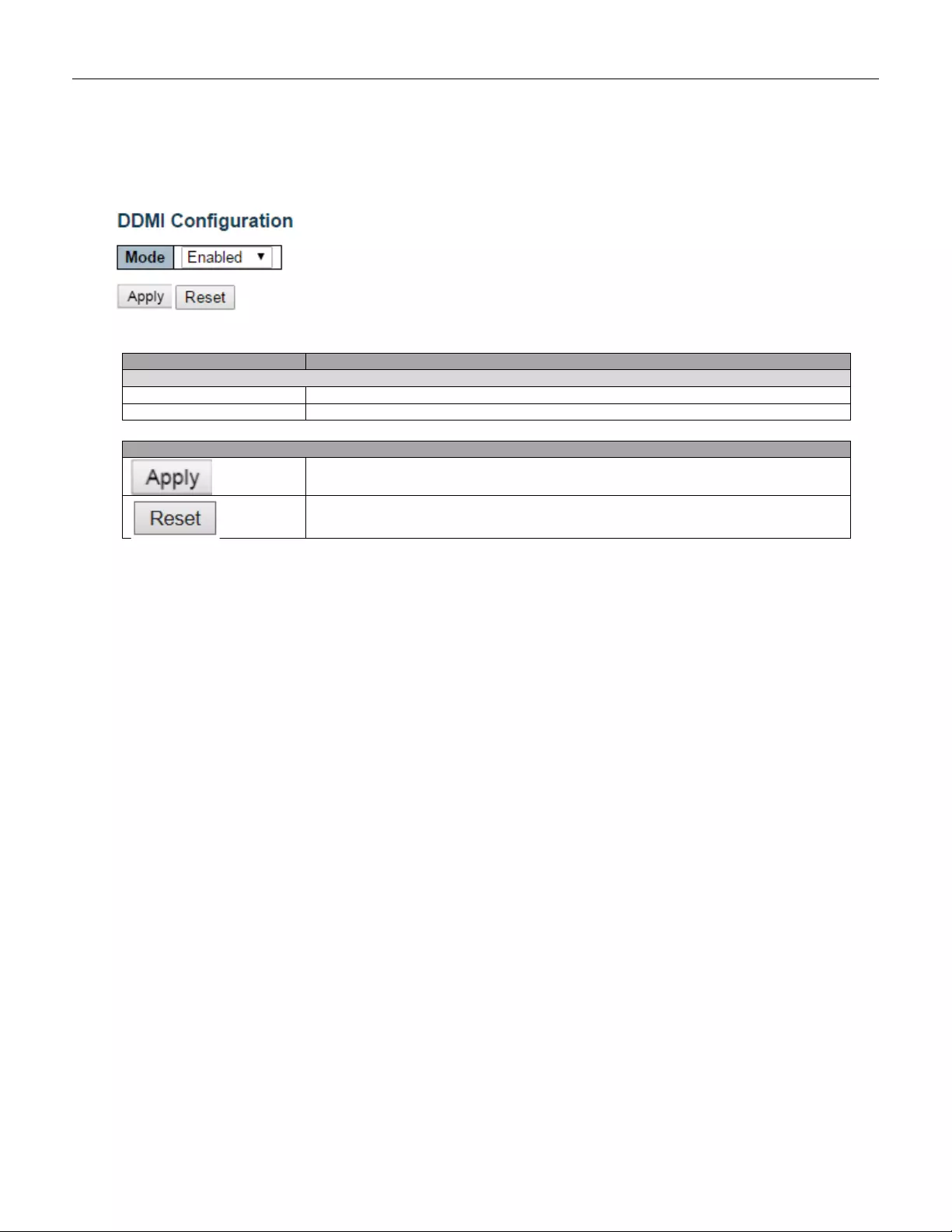
5.3.100 DDMI
Configure DDMI on this page.
Object
Description
Mode
Enabled
Enable DDMI mode operation.
Disabled
Disable DDMI mode operation.
Buttons
Click to apply changes.
Click to undo any changes made locally and revert to previously saved values.
172
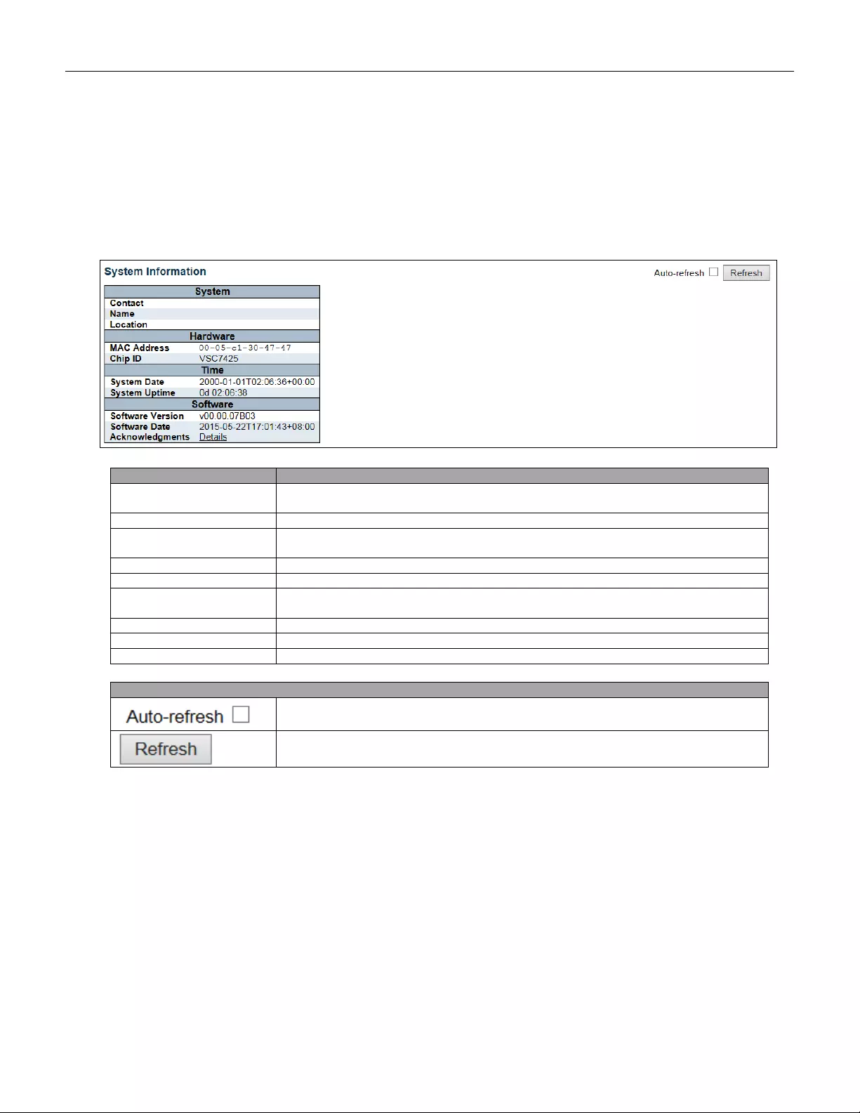
5.4 Monitor
5.4.1 System
5.4.2 System Information
The switch system information is provided here.
Object
Description
Contact
The system contact configured in Configuration | System | Information | System
Contact.
Name
The system name configured in Configuration | System | Information | System Name.
Location
The system location configured in Configuration | System | Information | System
Location.
MAC Address
The MAC Address of this switch.
Chip ID
The Chip ID of this switch.
System Date
The current (GMT) system time and date. The system time is obtained through the
Timing server running on the switch, if any.
System Uptime
The period of time the device has been operational.
Software Version
The software version of this switch.
Software Date
The date when the switch software was produced.
Buttons
Check this box to refresh the page automatically. Automatic refresh occurs every 3
seconds.
Click to refresh the page.
173

5.4.3 CPU Load
This page displays the CPU load, using line chart.
The load is measured as averaged over the last 100ms, 1sec and 10 seconds intervals. The last 1~256 samples
(maximum 256) are graphed, and the last numbers are displayed as text as well.
Buttons
Check this box to refresh the page automatically. Automatic refresh occurs every 3
seconds.
174
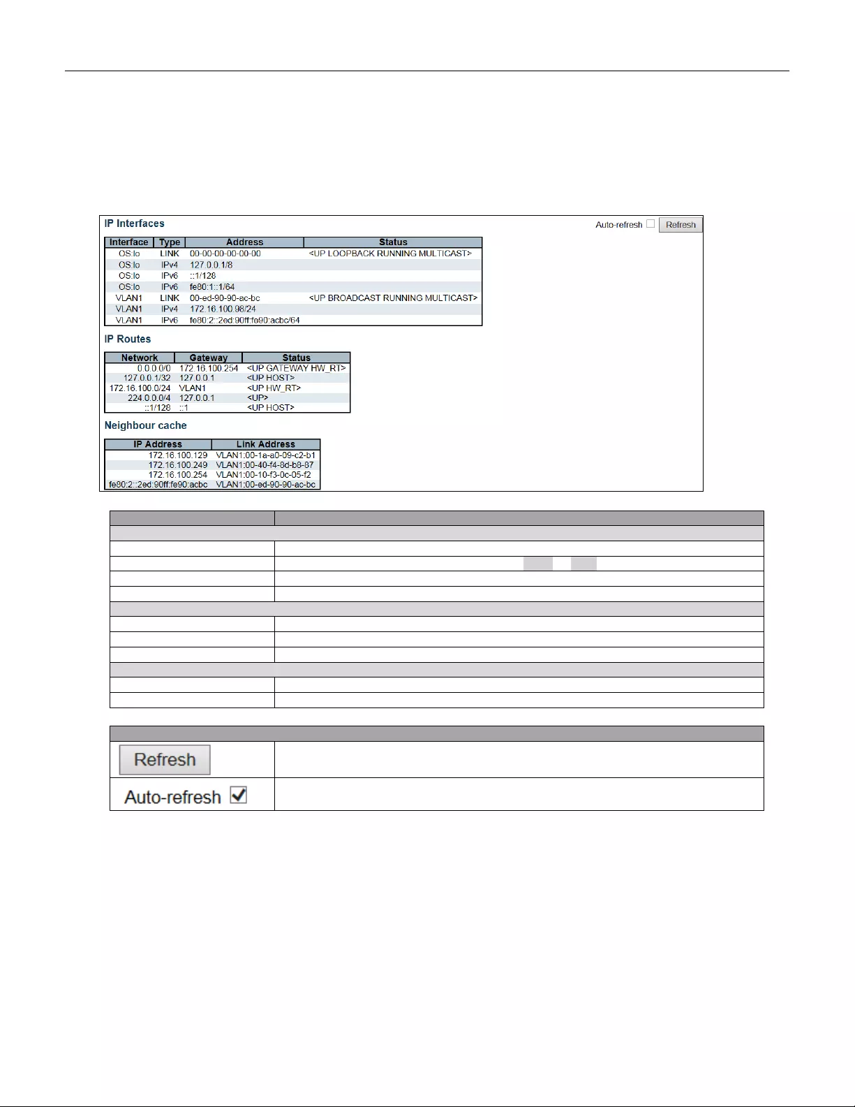
5.4.4 IP Status
This page displays the status of the IP protocol layer. The status is defined by the IP interfaces, the IP
routes and the neighbour cache (ARP cache) status.
Object
Description
IP Interfaces
Interface
The name of the interface.
Type
The address type of the entry. This may be LINK or IPv4.
Address
The current address of the interface (of the given type).
Status
The status flags of the interface (and/or address).
IP Routes
Network
The destination IP network or host address of this route.
Gateway
The gateway address of this route.
Status
The status flags of the route.
Neighbor cache
IP A ddress
The IP address of the entry.
Link Address
The Link (MAC) address for which a binding to the IP address given exist..
Buttons
Click to refresh the page.
Check this box to refresh the page automatically. Automatic refresh occurs
every 3 seconds.
175
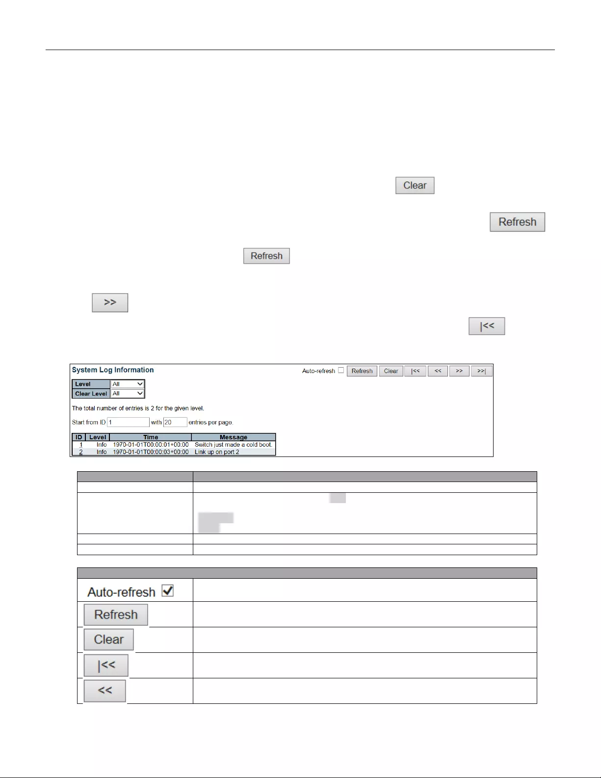
5.4.5 System Lo g
Each page shows up to 999 table entries, selected through the "entries per page" input field. When first visited,
the web page will show the beginning entries of this table.
The "Level" input field is used to filter the display system log entries.
The "Clear Level" input field is used to specify which system log entries will be cleared.
To clear specific system log entries, select the clear level first then click the button.
The "Start from ID" input field allow the user to change the starting point in this table. Clicking the
button will update the displayed table starting from that or the closest next entry match.
In addition, these input fields will upon a button click - assume the value of the first displayed entry,
allowing for continuous refresh with the same start input field.
The will use the last entry of the currently displayed table as a basis for the next lookup.
When the end is reached the text "No more entries" is shown in the displayed table. Use the button to
start over.
Object
Description
ID
The identification of the system log entry.
Level
The level of the system log entry. Info: The system log entry is belonged information
level.
Warning: The system log entry is belonged warning level.
Error: The system log entry is belonged error level.
Time
The occurred time of the system log entry.
Message
The detail message of the system log entry.
Buttons
Check this box to refresh the page automatically. Automatic refresh occurs every 3
seconds.
Updates the table entries, starting from the current entry.
Flushes the select ed entr i es.
Updates the table entries, starting from the first available entry.
Updates the table entries, ending at the last entry currently displayed.
176
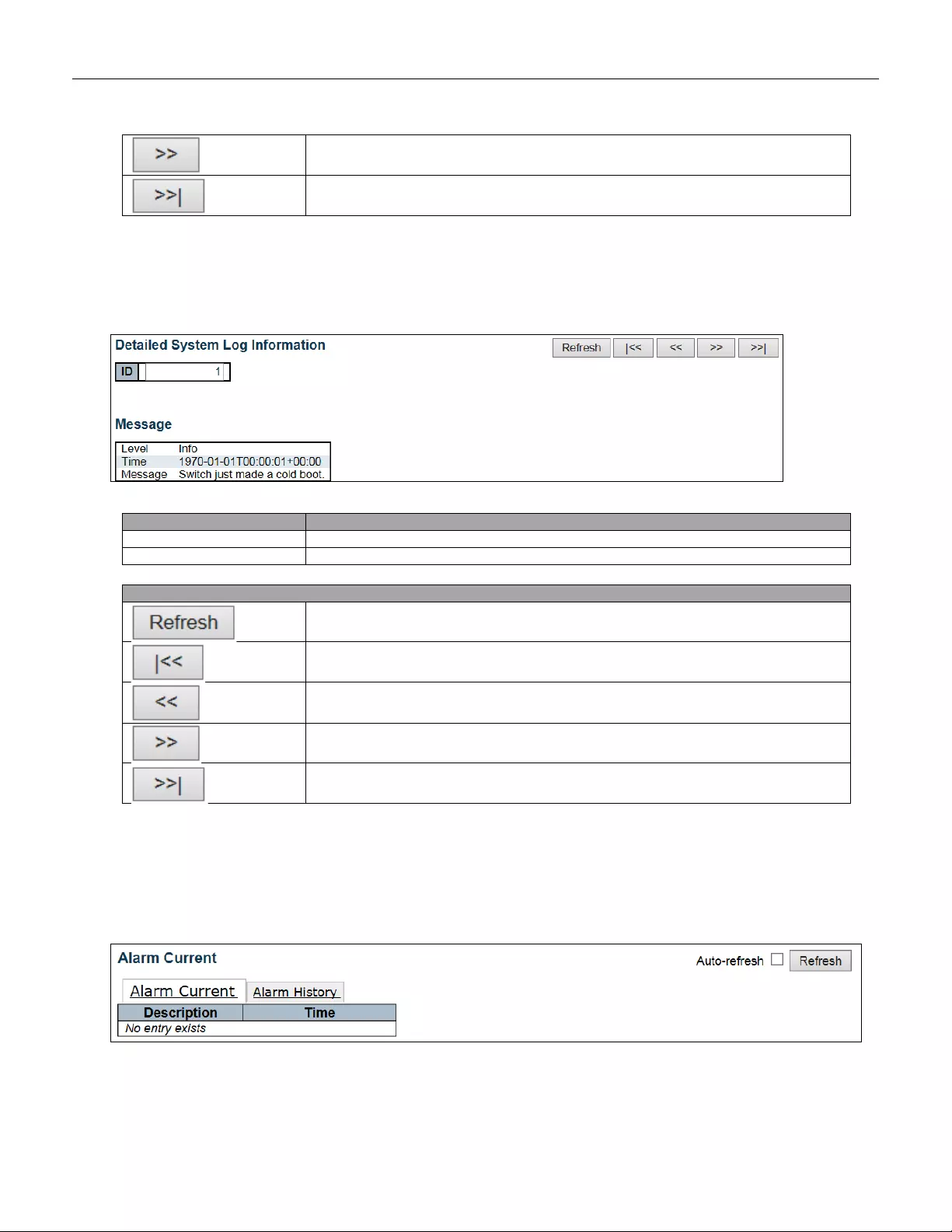
Updates the table entries, starting from the last entry currently displayed.
Updates the table entries, ending at the last available entry.
5.4.6 System Detailed Log
The switch system detailed log information is provided here.
Object
Description
ID
The ID (>= 1) of the system log entry.
Message
The detailed message of the system log entry.
Buttons
Updates the system log entry to the current entry ID.
Updates the system log entry to the first available entry ID.
Updates the system log entry to the previous available entry ID.
Updates the system log entry to the next available entry ID.
Updates the system log entry to the last available entry ID.
5.4.7 System Alarm
Current Alarm is provided on this page.
177
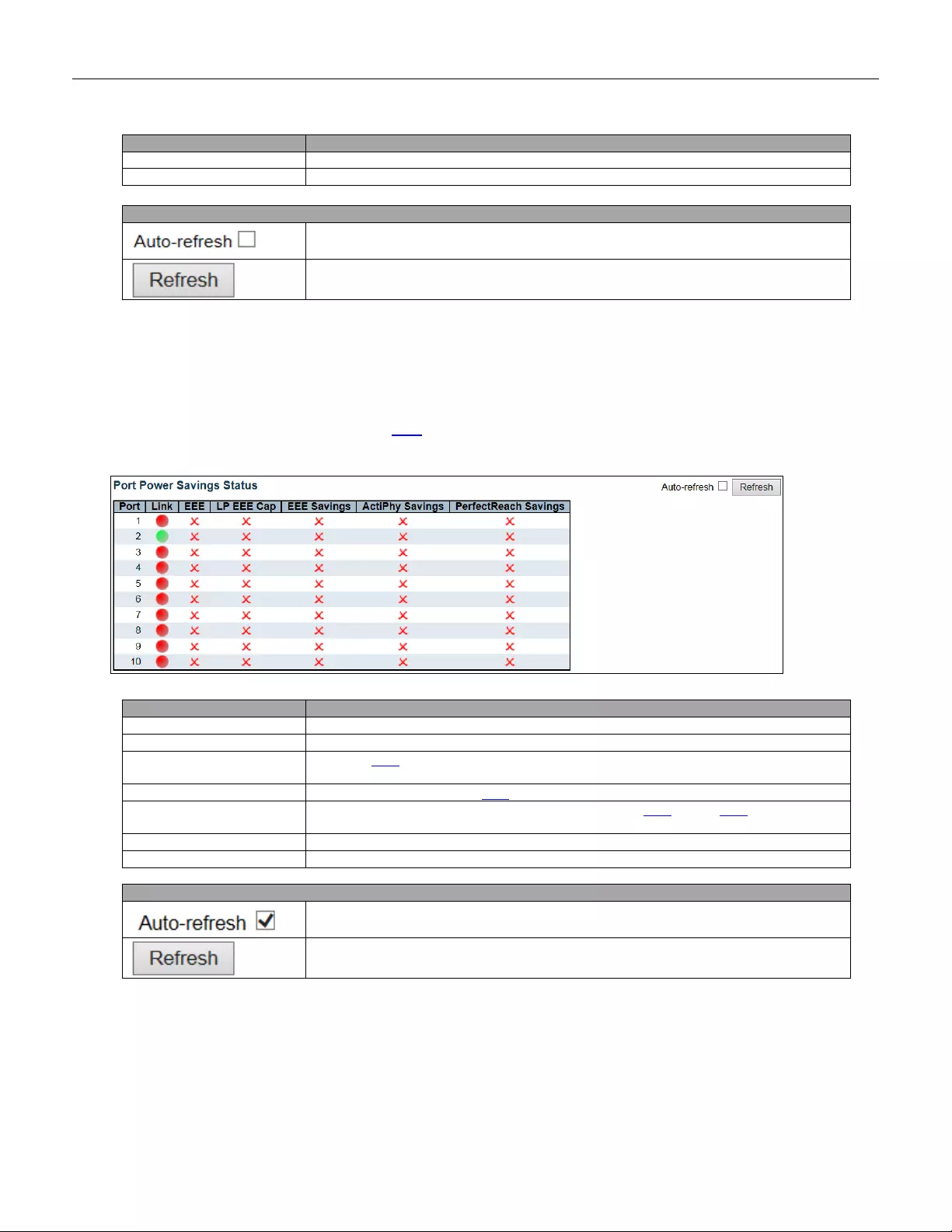
Object
Description
Description
Alarm Type D escription.
Time
Alarm occurren ce date time.
Buttons
Check this box to refresh the page automatically. Automatic refresh occurs
every 3 seconds.
Click to refresh data.
5.4.8 EEE
5.4.9 Port Power Saving
This page provides the current status for EEE.
Object
Description
Port
This is the logical port number for this row.
Link
Shows if the link is up for the port (green = link up, red = link down).
EEE
Shows if EEE is enabled for the port (reflects the settings at the Port Power Savings
configuration page).
LP EEE cap
Shows if the link partner is EEE capable.
EEE Savings
Shows if the system is currently saving power due to EEE. When EEE is enabled, the
system will powered down if no frame has been received or transmitted in 5 uSec.
Actiphy Saving
Shows if the system is currently saving power due to ActiPhy.
PerfectReach Savings
Shows if the system is currently saving power due to PerfectReach.
Buttons
Check this box to refresh the page automatically. Automatic refresh occurs every 3
seconds.
Click to refresh the page.
178
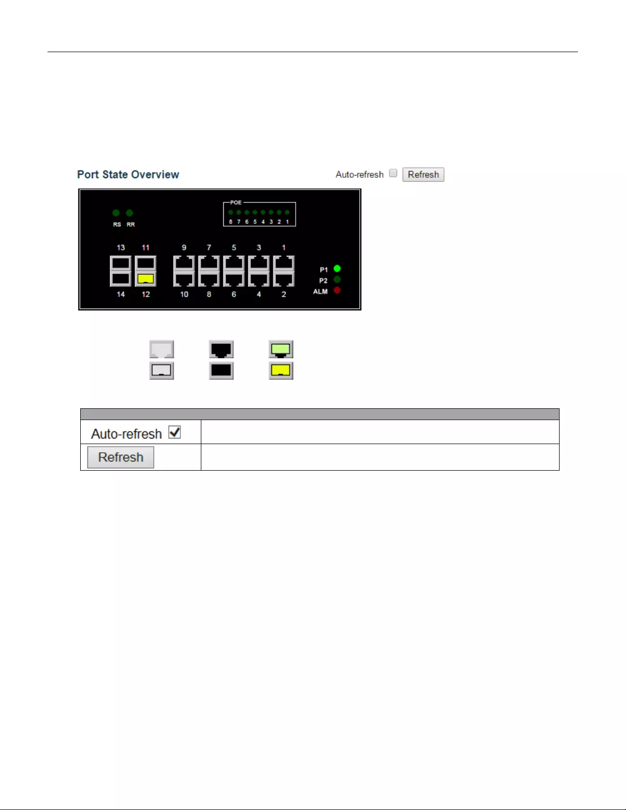
5.4.10 Ports
5.4.11 Ports State
This page provides an overview of the current switch port states.
The port states are illustrated as follows:
RJ45 ports
SFP ports
State
Disabled
Down
Link
Buttons
Check this box to refresh the page automatically. Automatic refresh occurs every 3
seconds.
Click to refresh the page.
179
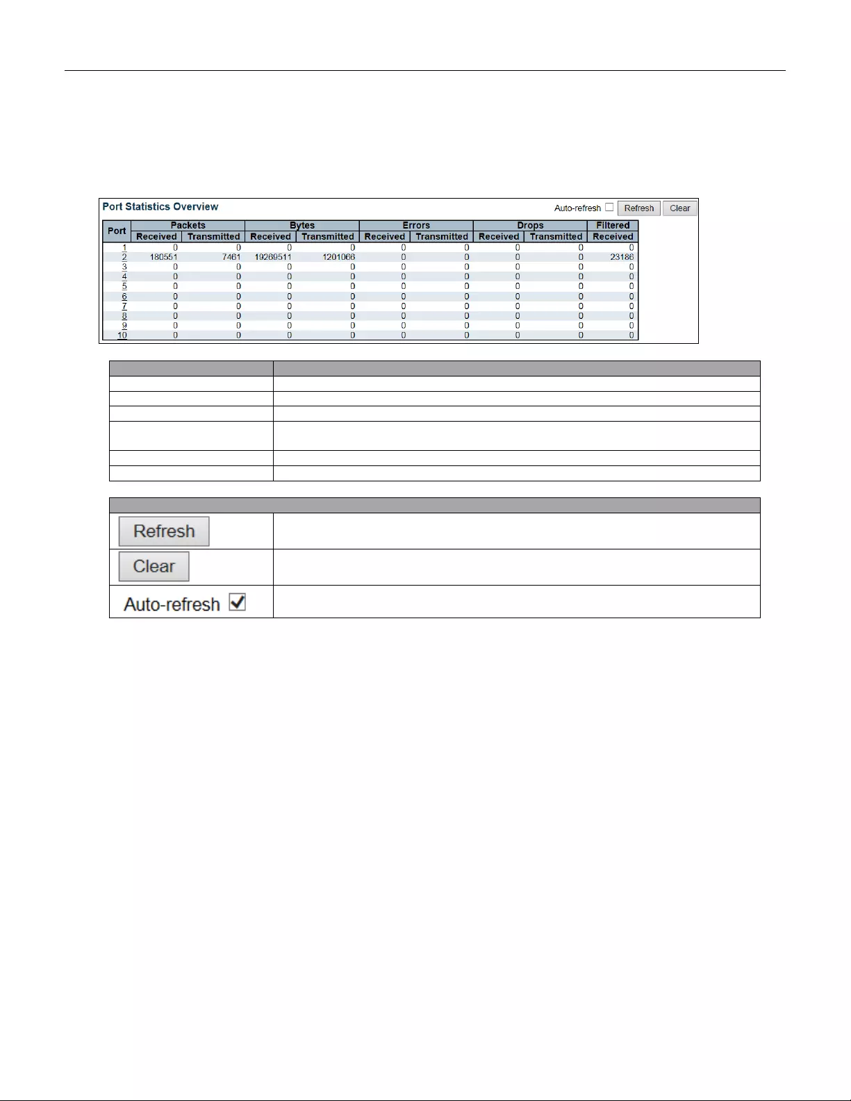
5.4.12 Traffic Overview
This page provides an overview of general traffic statistics for all switch ports.
Object
Description
Port
The logical port for the settings contained in the same row.
Packet
The number of received and transmitted packets per port.
Bytes
The number of received and transmitted bytes per port.
Errors
The number of frames received in error and the number of incomplete transmissions
per port.
Drops
The number of frames discarded due to ingress or egress congestion.
Filtered
The number of received frames filtered by the forw arding pr o ces s.
Buttons
Click to refresh the page immediately.
Clears the counter s for all ports.
Check this box to refresh the page automatically. Automatic refresh occurs every 3
seconds.
180
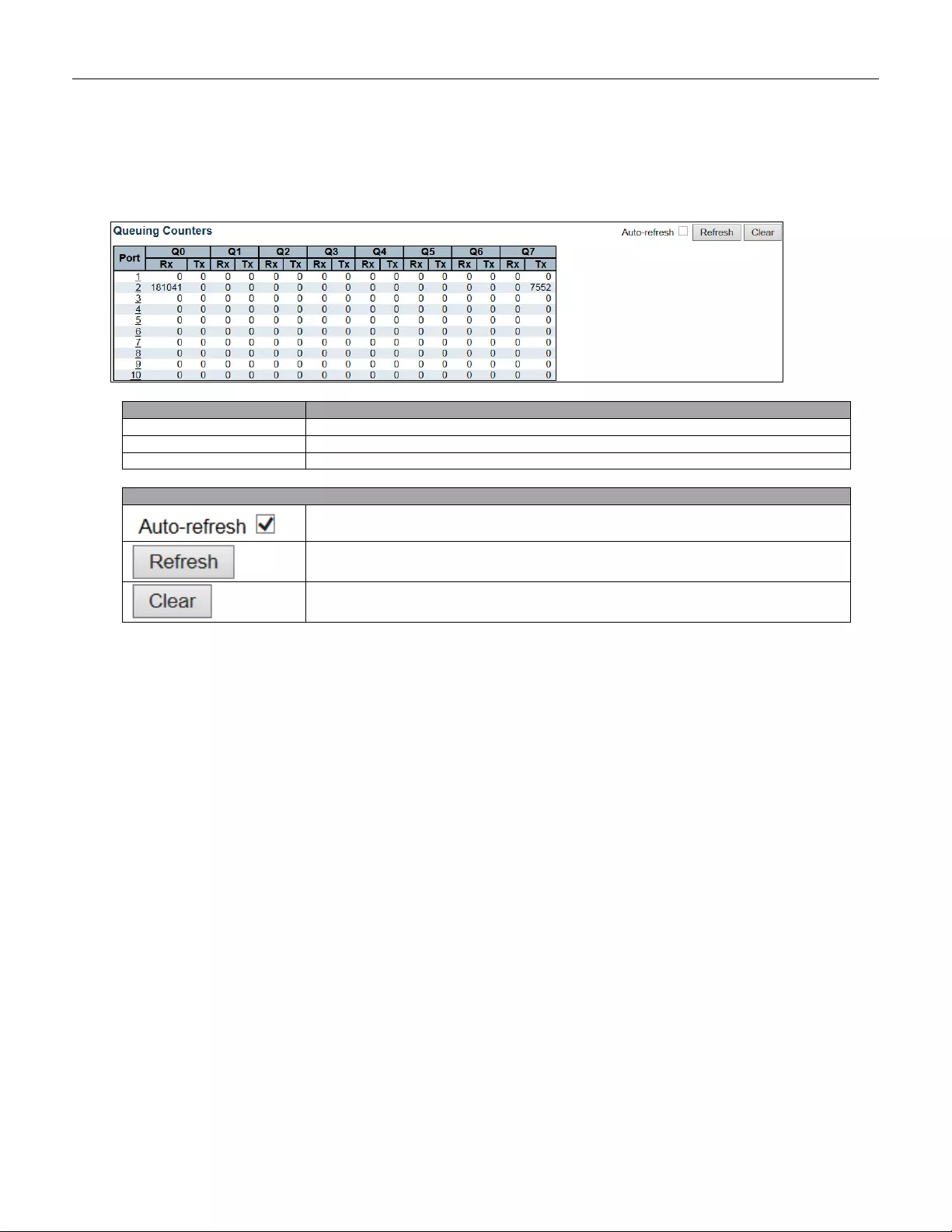
5.4.13 QoS Statistics
This page provides statistics for the different queues for all switch ports.
Object
Description
Port
The logical port for the settings contained in the same row.
Qn
There are 8 QoS queues per port. Q0 is the lowest priority queue.
Rx/Tx
The number of received and transmitted packets per queue
Buttons
Check this box to refresh the page automatically. Automatic refresh occurs every 3
seconds.
Click to refresh the page immediately.
Clears the counter s for all ports.
181
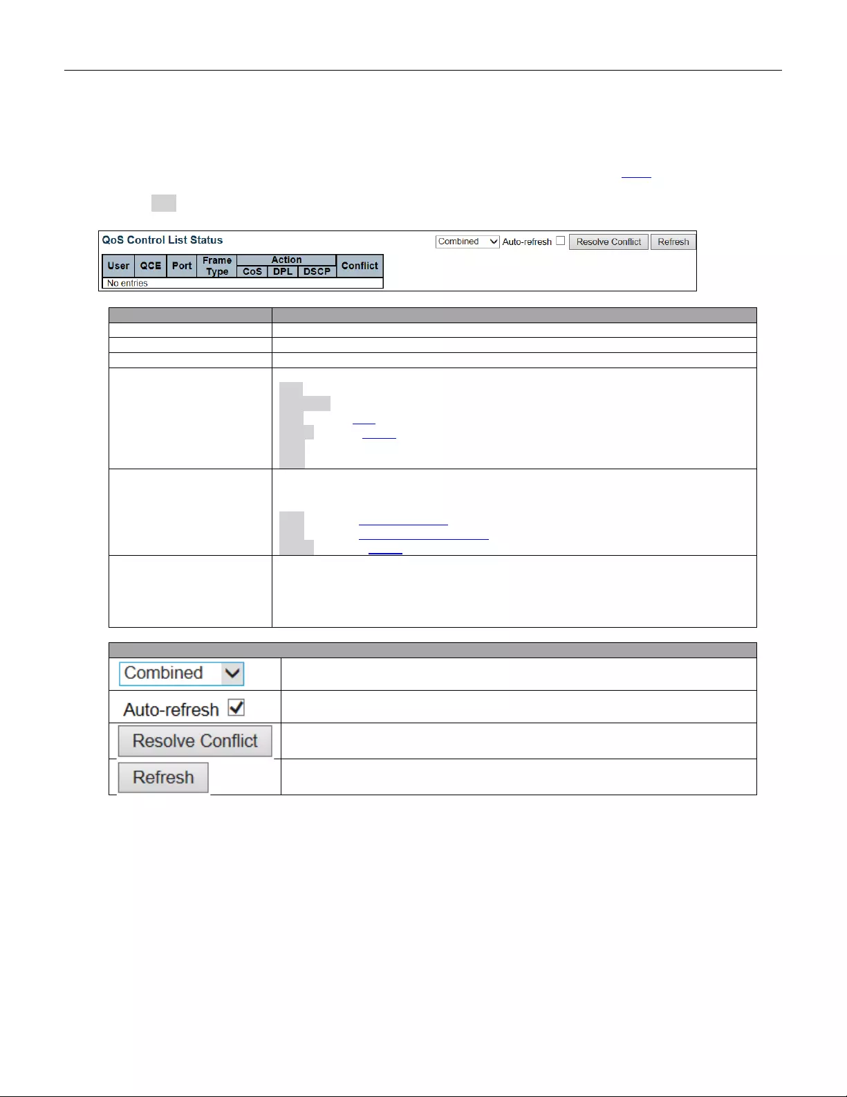
5.4.14 QCL Status
This page shows the QCL status by different QCL users. Each row describes the QCE that is defined. It is a
conflict if a specific QCE is not applied to the hardware due to hardware limitations. The maximum number of
QCEs is 256 on each switch.
Object
Description
User
Indicates the QCL user.
QCE
Indicates the QCE id.
Port
Indicates the list of ports configured with the QCE.
Frame Type
Indicates the type of frame. Possible values are:
Any: Match any frame type.
Ethernet: Match EtherType frames.
LLC: Match (LLC) frames.
SNAP: Match (SNAP) frames.
IPv4: Match IPv4 frames.
IPv6: Match IPv6 frames
Action
Indicates the classification action taken on ingress frame if parameters configured are
matched with the frame's content.
Possible actions are:
CoS: Classify Cl ass of Service.
DPL: Classify Drop Precedence Level.
DSCP: Cl assify DSCP value.
Conflict
Displays Conflict status of QCL entries. As H/W resources ar e shared by multipl e
applications. It may happen that resources required to add a QCE may not be
available, in that case it shows conflict status as 'Yes', otherwise it is always 'No'.
Please note that conflict can be resolved by releasing the H/W resources required to
add QCL entry on pressing 'Resolve Conflict' button.
Buttons
Select the QCL status from this drop down list.
Check this box to refresh the page automatically. Automatic refresh occurs every 3
seconds.
Click to releas
e the resources required to add QCL entry, in case the conflict status
for any QCL entry is 'yes'.
Click to refresh the page.
182

5.4.15 Detailed Statistics
This page provides detailed traffic statistics for a specific switch port. Use the port select box to select which
switch port details to display.
The displayed counters are the totals for receive and transmit, the size counters for receive and transmit, and the
error counters for receive and transmit.
Object
Description
Receive Total and Transmit Total
Rx and Tx Packets
The number of received and transmitted (good and bad) packets.
Rx and Tx Octets
The number of received and transmitted (good and bad) bytes. Includes FCS , but exc ludes
framing bits.
Rx and Tx Unicast
The number of received and transmitted (good and bad) unicast packets.
Rx and Tx Multicast
The number of received and transmitted (good and bad) multicast packets.
Rx and Tx Broadcast
The number of received and transmitted (good and bad) broadcast packets.
Rx and Tx Pause
A co unt of the M AC C ontrol fr a mes re ceiv ed or tran smitt e d o n th is por t th at hav e a n o pc od e
indicating a PAUSE operation.
Receive and Transmit Size Counters
The number of received and transmitted (good and bad) packets split into categories based on their
respective frame sizes.
Receive and Transmit Queue Counters
The number of received and transmitted packets per input and output queue.
Receive Error Counters
Rx Drops
The number of frames dropped due to lack of receive buffers or egress congestion.
Rx CRC/Alignment
The number of frames received with CRC or alignment errors.
Rx Undersize
The number of short 1 frames received with valid CRC.
Rx Oversize
The number of long 2 frames received with valid CRC.
Rx Fragments
The number of short 1 frames received with invalid CRC.
Rx Jabber
The number of long 2 frames received with invalid CRC.
183

Buttons
Click to refresh the page immediately.
Click to refresh the page immediately.
Check this box to refresh the page automatically. Automatic refresh occurs every 3
seconds.
Rx Filtered
The number of received frames filtered by the forwarding process.
1 Short frames are frames that are smaller than 64 bytes.
2 Long frames are frames that are longer than the configured maximu m frame
length for this port.
Transmit Error Counters
Tx Drops
The number of frames dropped due to output buffer congestion.
Tx Late/Exc. Coll
The number of frames dropped due to excessive or late collisions.
184
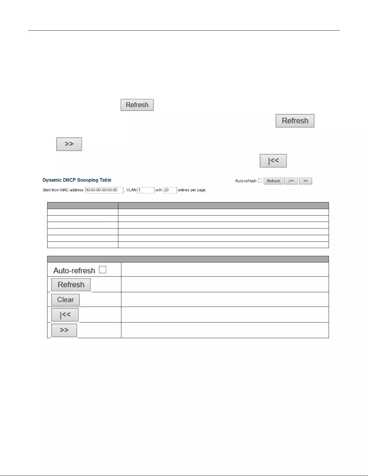
5.4.16 DHCP Snooping Table
Each page shows up to 99 entries from the Dynamic DHCP snooping table, default being 20, selected through
the "entries per page" input field. When first visited, the web page will show the first 20 entries from the
beginning of the Dynamic DHCP snooping Table.
The "MAC address" and "VLAN" input fields allow the user to select the starting point in the Dynamic DHCP
snooping Table. Clicking the button will update the displayed table starting from that or the closest
next Dynamic DHCP snooping Table match. In addition, the two input fields will - upon a button
click - assume the value of the first displayed entry, allowing for continuous refresh with the same start address.
The will use the last entry of the currently displayed table as a basis for the next lookup. When the
end is reached the text "No more entries" is shown in the displayed table. Use the button to start
over.
Object
Description
MAC Address
User MAC address of the entry.
VLAN ID
VLAN-ID in which the DHCP traffic is permitted.
Source Port
Switch Port Number for which the entries are displayed.
IP A ddress
User IP addr es s of the entry.
IP Subnet Mask
User IP subnet ma sk of the entr y.
DHCP Server Address
DHCP Server address of the entry.
Buttons
Check this box to refresh the page automatically. Automatic refresh occurs every 3
seconds.
Refreshes the dis play ed tab le start i ng from the inpu t field s.
Flushes all dynamic entries.
Updates the table starting from the first entry in the Dynamic DHCP snooping Table.
Updates the table, starting with the entry after the last entry currently displayed.
185

5.4.17 DHCP Relay Statistics
This page provides statistics for DHCP relay.
Object
Description
Server Statistics
Transmit to Server
The number of packets that are relayed from client to server.
Transmit Error
The number of packets that resulted in errors while being sent to clients.
Receive from Server
The number of packets received from server.
Receive Missing Agent
Option
The number of packets received without agent information options.
Receive Missing Circuit
ID
The number of packets received with the Circuit ID option missing.
Receive Missing Remote
ID
The number of packets received with the Remote ID option missing.
Receive Bad Circuit ID
The number of packets whose Circuit ID option did not match known circuit ID.
Receive Bad Remote ID
The number of packets whose Remote ID option did not match known Remote ID.
Client Statistics
Transmit to Client
The number of relayed packets from server to client.
Transmit Error
The number of packets that resulted in error while being sent to servers.
Receive from Client
The number of received packets from server.
Receive A gent O ption
The number of received packets with relay agent information option.
Replace Agent Option
The number of packets which were replaced with relay agent information option.
Keep Agent Option
The number of packets whose relay agent information was retained.
Drop A gent Option
The number of packets that were dropped which were received with relay agent
information.
Buttons
Check this box to refresh the page automatically. Automatic refresh occurs every 3
seconds.
Click to refresh th e page im me diate ly.
Clear all statistics.
186
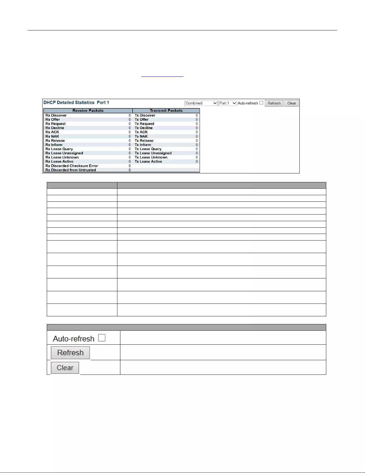
5.4.18 DHCP Detailed Statistics
This page provides statistics for DHCP snooping. Notice that the normal forward per-port TX statistics isn't
increased if the incoming DHCP packet is done by L3 forwarding mechanism. And clear the statistics on specific
port may not take effect on global statistics since it gathers the different layer overview.
Object
Description
Rx and Tx Discover
The number of discover (option 53 with value 1) packets received and transmitted.
Rx and Tx Offer
The number of offer (option 53 with value 2) packets received and transmitted.
Rx and Tx Request
The number of request (option 53 with value 3) packets received and transmitted.
Rx and Tx Delcine
The number of decline (option 53 with value 4) packets received and transmitted.
Rx and Tx ACK
The number of ACK (option 53 with value 5) packets received and transmitted.
Rx and Tx NAK
The number of NAK (option 53 with value 6) packets received and transmitted.
Rx and Tx Release
The number of release (option 53 with value 7) packets received and transmitted.
Rx and Tx Inform
The number of inform (option 53 with value 8) packets received and transmitted.
Rx and Tx Lease Query
The number of lease query (option 53 with value 10) packets received and
transmitted.
Rx and Tx Lease
Unassigned
The number of lease unassigned (option 53 with value 11) packets received and
transmitted.
Rx and Tx Unknown
The number of lease unknown (option 53 with value 12) packets received and
transmitted.
Rx and Tx Active
The number of lease active (option 53 with value 13) packets received and
transmitted.
Rx Discarded checksum
error
The number of discard packet that IP/UDP checksum is error.
Rx Discarded from
Untrusted
The number of discarded packet that are coming from untrusted port.
Buttons
Check this box to refresh the page automatically. Autom atic refresh occurs
every 3 seconds.
Refreshes the dis play ed tab le start i ng from the inpu t field s.
Flushes all dynamic entries.
187
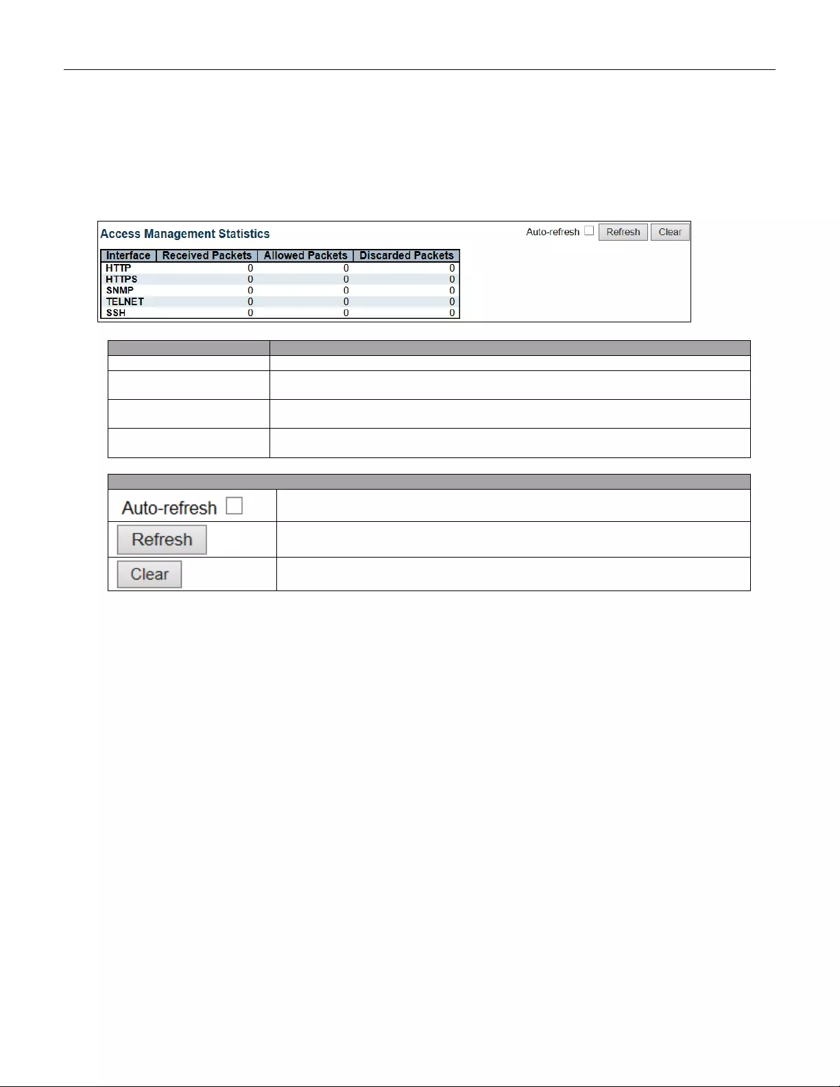
5.4.19 Security
5.4.20 Access Management Statistics
This page provides statistics for access management.
Object
Description
Interface
The interface type through which the remote host can access the switch.
Received Packets
Number of received packets from the interface when access management mode is
enabled.
Allowed Packets
Number of allowed packets from the interface when access management mode is
enabled.
Discarded Packets
Number of discarded packets from the interface when access management mode is
enabled.
Buttons
Check this box to refresh the page automatically. Automatic refresh occurs every 3
seconds.
Click to refresh the page immediately.
Clear all statistics.
188
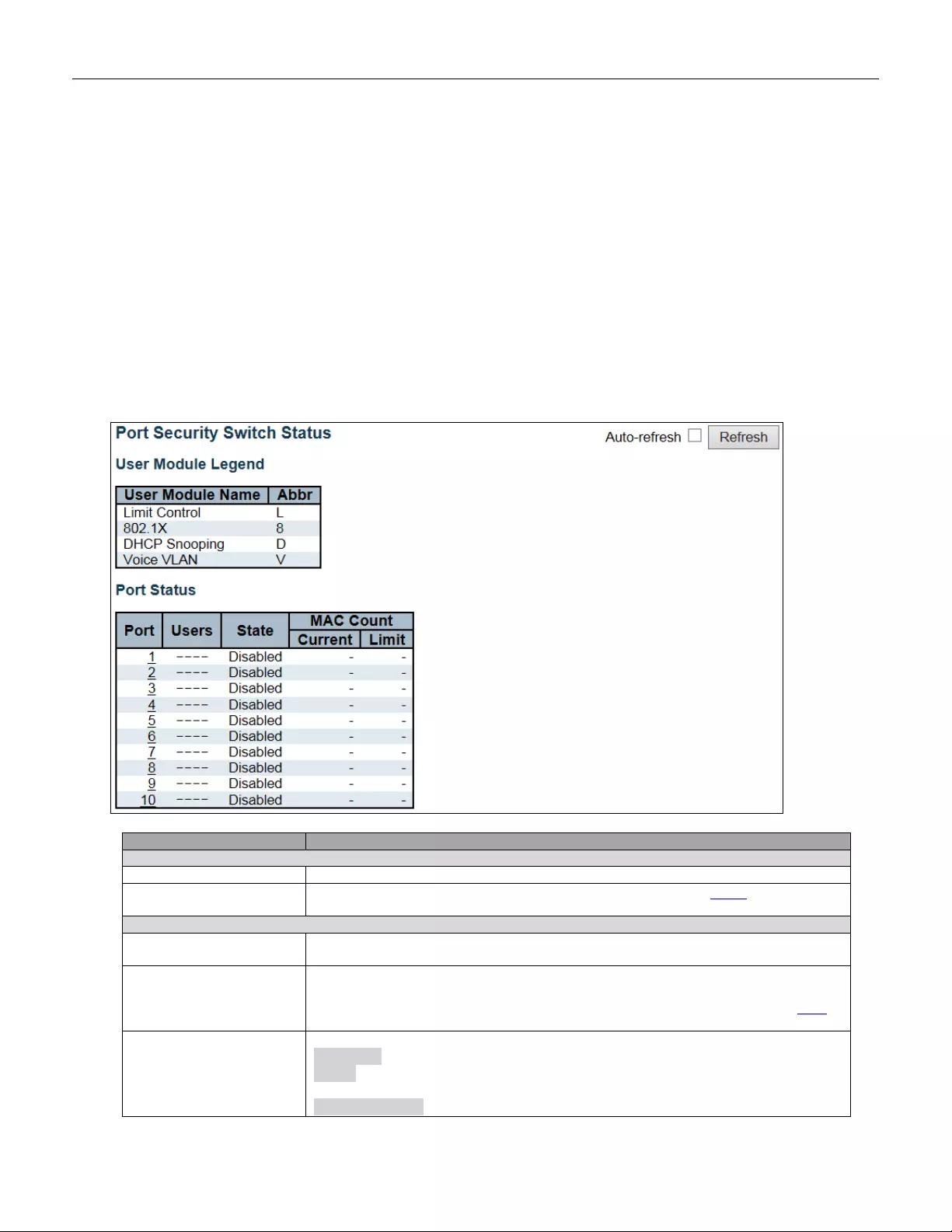
5.4.21 Network
5.4.22 Port Security
5.4.23 Switch
This page shows the Port Security status. Port Security is a module with no direct configuration.
Configuration comes indirectly from other modules - the user modules. When a user module has enabled port
security on a port, the port is set-up for software-based learning. In this mode, frames from unknow n MAC
addresses are passed on to the port security module, which in turn asks all user modules whether to allow this
new MAC address to forward or block it. For a MAC address to be set in the forwarding state, all enabled user
modules must unanimously agree on allowing the MAC address to forward. If only one chooses to block it, it will
be blocked until that user module decides otherwise.
The status page is divided into two sections - one with a legend of user modules and one with the actual port
status.
Object
Description
User Module Legend
User Module Name
The full name of a module that may request Port Security services.
Abbr
A one-letter abbreviation of the user module. This is used in the Users colu mn in the
port status table.
Port Status
Port
The port number for which the status applies. Click the port number to see the status
for this particular port.
Users
Each of the user modules has a column that shows whether that module has enabled
Port Security or not. A '-' means that the corresponding user module is not enabled,
whereas a letter indicates that the user module abbreviated by that letter (see Abbr)
has enabled port securit y.
State
Shows the current state of the port. It can take one of four values:
Disabled: No user modules are currently using the Port Security service.
Ready: The Port Security service is in use by at least one user module, and is
awaiting frames from unknown MAC addresses to arrive.
Limit Reached: The Port Security service is enabled by at least the Limit Control
189
user module, and that module has indicated that the limit is reached and no more
MAC addresses should be taken in.
Shutdown: The Port Security service is enabled by at least the Limit Control user
module, and that module has indicated that the limit is exceeded. No MAC addresses
can be learned on the port until it is administratively re-opened on the Limit Control
configura tion Web-page.
MAC Count (Curren t ,
Limit)
The two columns indicate the number of currently learned MAC addresses
(forw arding as well a s b loc ked ) and the m aximum num ber of M A C addr esses that can
be learned on the port, respectively.
If no user modules are enabled on the port, the Current column will show a dash (-).
If the Limit Control user module is not enabled on the port, the Limit column will show
a dash (-).
Buttons
Check this box to refresh the page automatically. Autom atic refresh occurs
every 3 seconds
Click to refresh the page immediately.
190
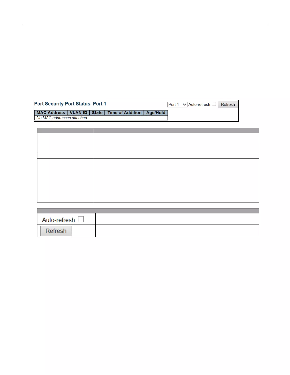
5.4.24 Port
This page shows the MAC addresses secured by the Port Security module. Port Security is a module with
no direct configuration. Configuration comes indirectly from other modules - the user modules. When a user
module has enabled port security on a port, the port is set-up for software-based learning. In this mode, frames
from unknown MAC addresses are passed on to the port security module, which in turn asks all user modules
whether to allow this new MAC address to forward or block it. For a MAC address to be set in the forw arding
state, all enabled user modules must unanimously agree on allowing the MAC address to forward. If only one
chooses to block it, it will be blocked until that user module decides otherwise.
Object
Description
MAC Address & VLAN ID
The MAC address and VLAN ID that is seen on this port. If no MAC addresses are
learned, a single row stating "No MAC addresses attached" is displayed.
State
Indicates whether the corresponding MAC address is blocked or forwarding. In the
blocked state, it will not be allowed to transmit or receive traffic.
Time of Addition
Shows the date and time when this MAC address was first seen on the port.
Age/Hold
If at least one user module has decided to block this MAC address, it will stay in the
blocked state until the hold time (measured in seconds) expires. If all user modules
have decided to allow this MAC address to forward, and aging is enabled, the Port
Security module will periodically check that this MAC address still forwards traffic. If
the age period (measured in seconds) expires and no frames have been seen, the
MAC address will be removed from the MAC table. Otherwise a new age period will
begin.
If aging is disabled or a user module has decided to hold the MAC address
indefinitely, a dash (-) will be shown.
Buttons
Check this box to refresh the page automatically. Automatic refresh occurs every 3
seconds.
Click to refresh the page immediately.
191
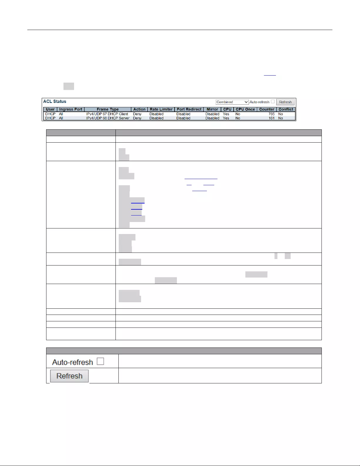
5.4.25 ACL Status
This page shows the ACL status by different ACL users. Each row describes the ACE that is defined. It is a
conflict if a specific ACE i s not applied to the hardware due to hardware limitations. The maximum number of
ACEs is 256 on each switch.
Object
Description
User
Indicates the ACL user.
Ingress Port
Indicates the ingress port of the ACE. Possible values are:
All: The ACE will match all ingress port.
Port: The ACE will match a specific ingress port.
Frame Type
Indicates the frame type of the ACE. Possible values are:
Any: The ACE will match any frame type.
EType: The ACE will match Ethernet Type frames. Note that an Ethernet Type based
ACE will not get matched by IP and ARP frames.
ARP: The ACE will match ARP/RARP frames.
IPv4: T he ACE will match all IPv4 frame s.
IPv4/ICMP: The AC E w ill match IPv 4 frames with ICMP protocol.
IPv4/UDP: The ACE will match IPv4 frames with UDP protocol.
IPv4/TCP: The ACE will match IPv4 frames with TCP protocol.
IPv4/Other: The ACE will match IPv4 frames, which are not ICMP/UDP/TCP.
IPv6: The ACE will match all IPv6 standard frames.
Action
Indicates the forwarding action of the ACE.
Permit: Frames matching the ACE may be forwarded and learned.
Deny: Frames matching the ACE are dropped.
Filter: Frames matching the ACE are filtered.
Rate limiter
Indicates the rate limiter number of the ACE. The allowed range is 1 to 16. When
Disabled is displayed, the rate limiter operation is disabled.
Port Redire ct
Indicates the port redirect operation of the ACE. Frames matching the ACE are
redirected to the port number. The allowed values are Disabled or a specific port
number. When Disabled is displayed, the port redirect operation is disabled.
Mirror
Specify the mirror operation of this port. The allowed values are:
Enabled: Frames received on the port are mirrored.
Disabled: Frames received on the port are not mirrored.
The default value is "Disabled".
CPU
Forward packet that matched the specific ACE to CPU.
CPU Once
Forward first packet that matched the specific ACE to CPU.
Counter
The counter indicates the number of times the ACE was hit by a frame.
Conflict
Indicates the hardware status of the specific ACE. The specific ACE is not applied to
the hardware due to hardware limitations.
Buttons
Check this box to refresh the page automatically. Automatic refresh occurs every 3
seconds.
Click to refresh the page.
192

5.4.26 ARP Inspection
Each page shows up to 99 entries from the Dynamic ARP Inspection table, default being 20, selected through
the "entries per page" input field. When first visited, the web page will show the first 20 entries from the
beginning of the Dynamic ARP Inspection Table.
The "Start from port address", "VLAN", "MAC address" and "IP address" input fields allow the user to select the
starting po int in the D ynam ic AR P Inspection Table. C li cking the button will update the displayed
table starting from that or the closest next Dynamic ARP Inspection Table match. In addition, the two input fields
will - up on a button click - assume the value of the first displayed entry, allowing for continuous
refresh wi th the same start address.
The will use the last entry of the currently displayed table as a basis for the next lookup. When the end
is reached the text "No more entries" is shown in the displayed table. Use the button to start over.
Object
Description
Port
Switch Port Number for which the entries are displayed.
VLAN ID
VLAN-ID in which the ARP traffic is permitted.
MAC Address
User MAC address of the entry.
IP A ddress
User IP addr es s of the entry.
Buttons
Check this box to refresh the page automatically. Automatic refresh occurs every 3
seconds.
Refreshes the dis play ed tab le start i ng from the inpu t field s.
Flushes all dynamic entries.
Updates the table starting from the first entry in the Dynamic ARP Inspection Table.
Updates the table, starting with the entry after the last entry currently displayed.
193
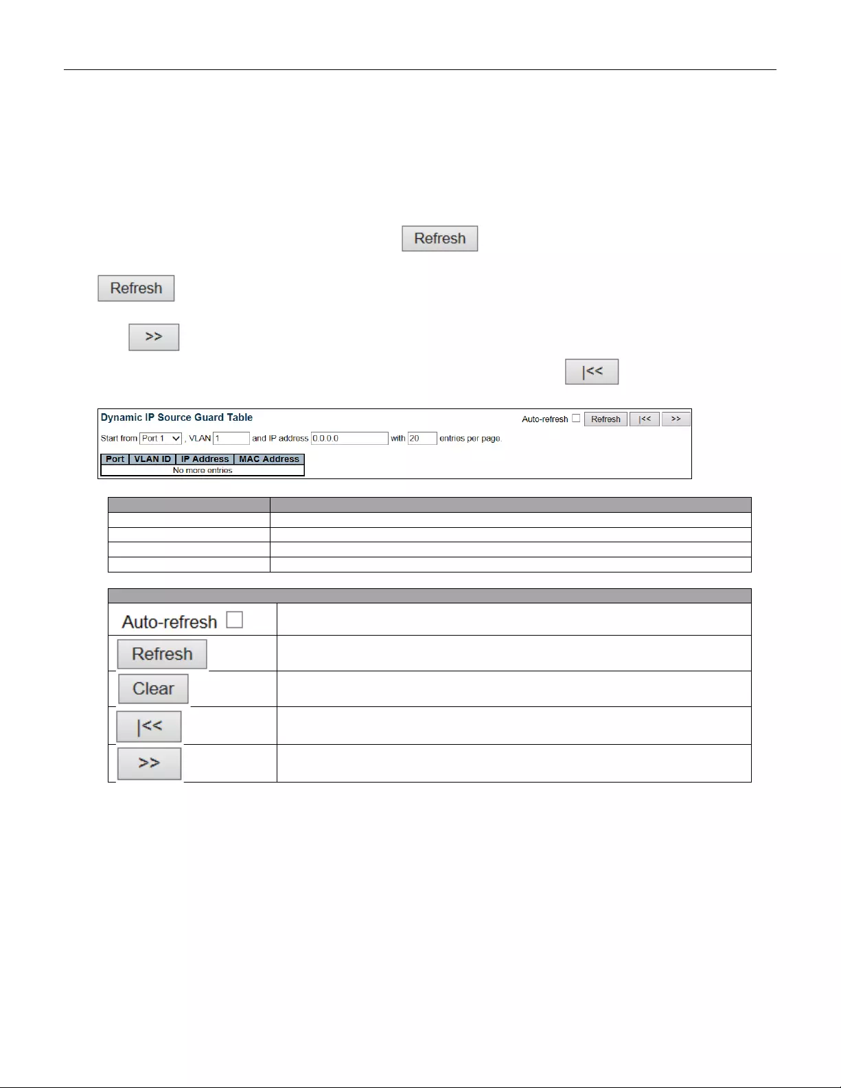
5.4.27 IP Source Guard
Each page shows up to 99 entries from the Dynamic IP Source Guard table, default being 20, selected through
the "entries per page" input field. When first visited, the web page will show the first 20 entries from the
beginning of the Dynamic IP Source Guard Table.
The "Start from port address", "VLAN" and "IP address" input fields allow the user to select the starting point in
the Dynamic IP Source Guard Table. Clicking the button will update the displayed table starting
from that or the closest next Dynamic IP Source Guard Table match. In addition, the two input fields will - upon a
button click - assume the value of the first displayed entry, allowing for continuous refresh with the
same start address.
The will use the last entry of the currently displayed table as a basis for the next lookup. When the end
is reached the text "No more entries" is shown in the displayed table. Use the button to start over.
Object
Description
Port
Switch Port Number for which the entries are displayed.
VLAN ID
VLAN-ID in which the IP traffic is permit ted.
IP A ddress
User IP addr es s of the entry.
MAC Address
Source MAC address.
Buttons
Check this box to refresh the page automatically. Automatic refresh occurs every 3
seconds.
Refresh the displayed table starting from the input fields.
Flush all dynamic entries.
Update the table starting from the first entry in the Dynamic IP Source Guard Table.
Updates the table, starting with the entry after the last entry currently displayed.
194
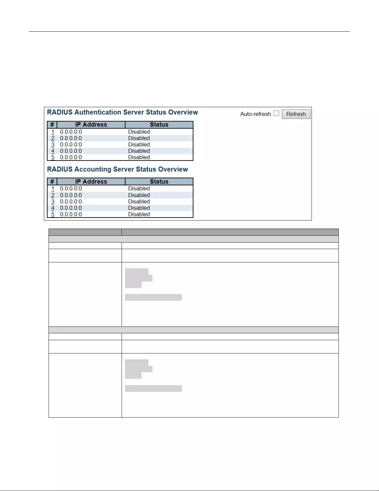
5.4.28 AAA
5.4.29 RADIUS Overview
This page provides an overview of the status of the RADIUS servers configurable on the Authentication
configuration page.
Object
Description
RADIUS Authentication Servers
#
The RADIUS server number. Click to navigate to detailed statistics for this server.
IP A ddress
The IP address and UDP port number (in <IP Address> :< UDP Port> notation) of this
server.
Status
The current status of the server. This field takes one of the following values:
Disabled: The server is disabled.
Not Ready: T he server is enabled, but IP communication is not yet up and running.
Ready: The server is enabled, IP communication is up and running and the RADIUS
module is ready to accept ac c ess atte mpt s.
Dead (X seconds left): Access attempts were made to this server, but it did not reply
within the configured timeout. The server has temporarily been disabled, but will get
re-enabled when the dead-time ex pires. T he num ber of seco nds left befor e th is
occurs is displayed in par en th ese s. T his state is only reacha ble when more t han one
server is enabled.
RADIUS Accounting Servers
#
The RADIUS server number. Click to navigate to detailed statistics for this server.
IP A ddress
The IP address and UDP port number (in <IP Address> :< UDP Port> notation) of this
server.
Status
The current status of the server. This field takes one of the following values:
Disabled: The server is disabled.
Not Ready: The server is enabled, but IP communication is not yet up and running.
Ready: The server is enabled, IP communication is up and running and the RADIUS
module is ready to accept accounting attempts.
Dead (X seconds left): Accounting attempts were made to this server, but it did not
reply within the configured timeout. The server has temporarily been disabled, but will
get re-enabled when the dead-time expires. The number of secon ds left before this
occurs is displayed in par en th ese s. T his state is only reacha ble when more t han one
server is enabled.
195
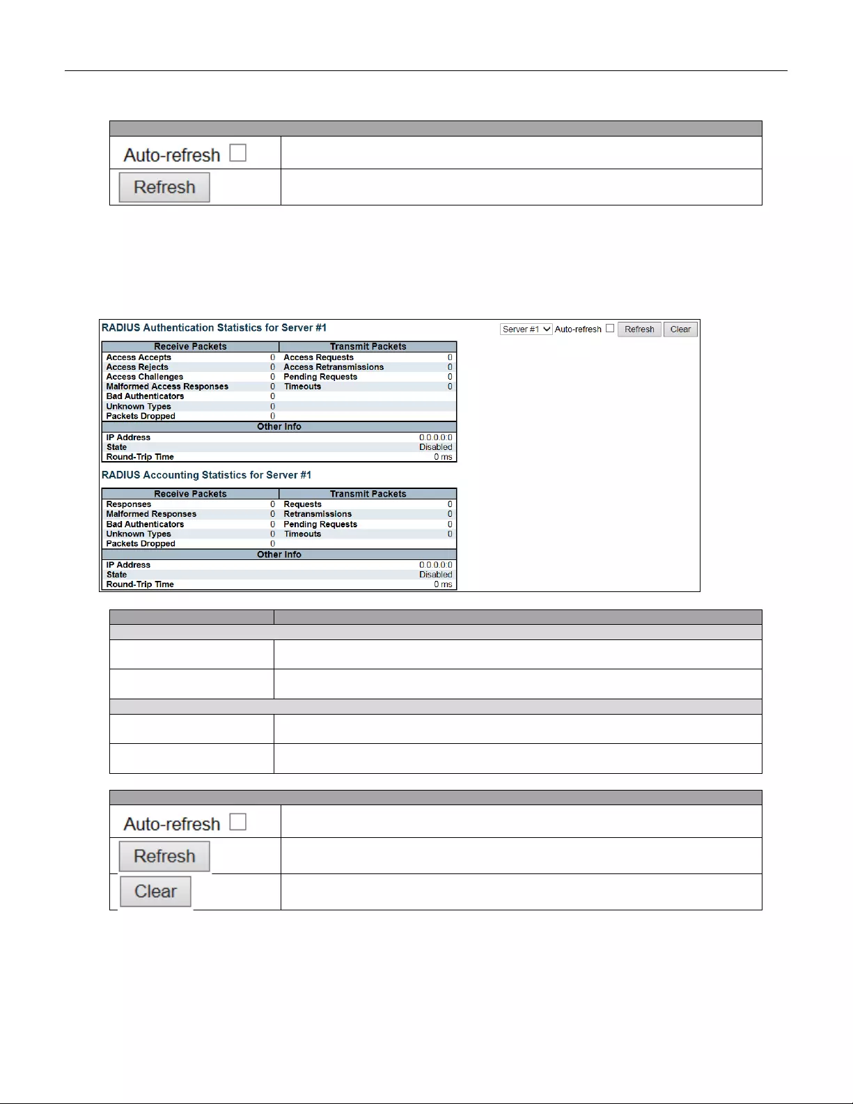
Buttons
Check this box to refresh the page automatically. Automatic refresh occurs every 3
seconds.
Click to refresh the page immediately.
5.4.30 RADIUS Details
This page provides detailed statistics for a particular RADIUS server.
Object
Description
RADIUS Authentication Statistics
Packet Counters
RADIUS authentication server packet counter. There are seven receive and four
transmit counters.
Other Info
This section contains information about the state of the server and the latest
round-trip time.
RADIUS Accounting Stat istics
Packet Counters
RADIUS accounting server packet counter. There are five receive and four transmit
counters.
Other Info
This section contains information about the state of the server and the latest
round-trip time.
Buttons
Check this box to refresh the page automatically. Automatic refresh occurs every 3
seconds.
Click to refresh the page immediately.
Clears the counters for the selected server. The "Pending Requests" counter will not
be cleared by this operation.
196
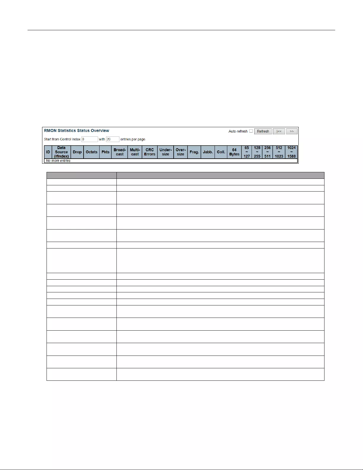
5.4.31 Switch
5.4.32 RMON
5.4.33 Statistics
This page provides an overview of RMON Statistics entries. Each page shows up to 99 entries from the
Statistics table, default being 20, selected through the "entries per page" input field. When first visited, the web
page will show the first 20 entries from the beginning of the Statistics table. The first displayed will be the one
with the lowest ID found in the Statistics table.
Object
Description
ID
Indicates the index of Statistics entry.
Data Source(iflndex)
The port ID which wants to be monitored.
Drop
The total nu mber of ev en ts in which packet s w er e dro pped by the probe due to lack of
resources.
Octets
The total number of octets of data (including those in bad packets) received on the
network.
Pkts
The total number of packets (including bad packets, broadcast packets, and multicast
packets) received.
Broad-cast
The total number of good packets received that were directed to the broadcast
address.
Multi-cast
The total number of good packets received that were directed to a multicast address.
CRC Errors
The total number of packets received that had a length (excluding f ram ing bit s, but
including FCS octets) of between 64 and 1518 octets, inclusive, but had either a bad
Frame Check Se que nce (F CS) w ith an integr al n um ber of o c t ets (FCS Er ror) or a ba d
FCS with a non-integral number of octets (Alignment Error).
Under-Size
The total number of packets received that were less than 64 octets.
Over-size
The total number of packets received that were longer than 1518 octets.
Frag.
The number of frames which size is less than 64 octets received with invalid CRC.
Jabb.
The number of frames which size is larger than 64 octets received with invalid CRC.
Coll.
The best estimate of the total numb er of colli sio ns on this Ethernet segme nt .
64
The total number of packets (including bad packets) received that were 64 octets in
length.
65~127
The total number of packets (including bad packets) received that were between 65
and 127 octets in length.
128~255
The total number of packets (including bad packets) received that were between 128
and 255 octets in length.
256~511
The total number of packets (including bad packets) received that were between 256
and 511 octets in length.
512~1023
The total number of packets (including bad packets) received that were between 512
and 1023 octet s in lengt h.
1024~1588
The total num ber of packet s (including bad packets) received that were betw een 102 4
and 1588 octet s in lengt h.
197
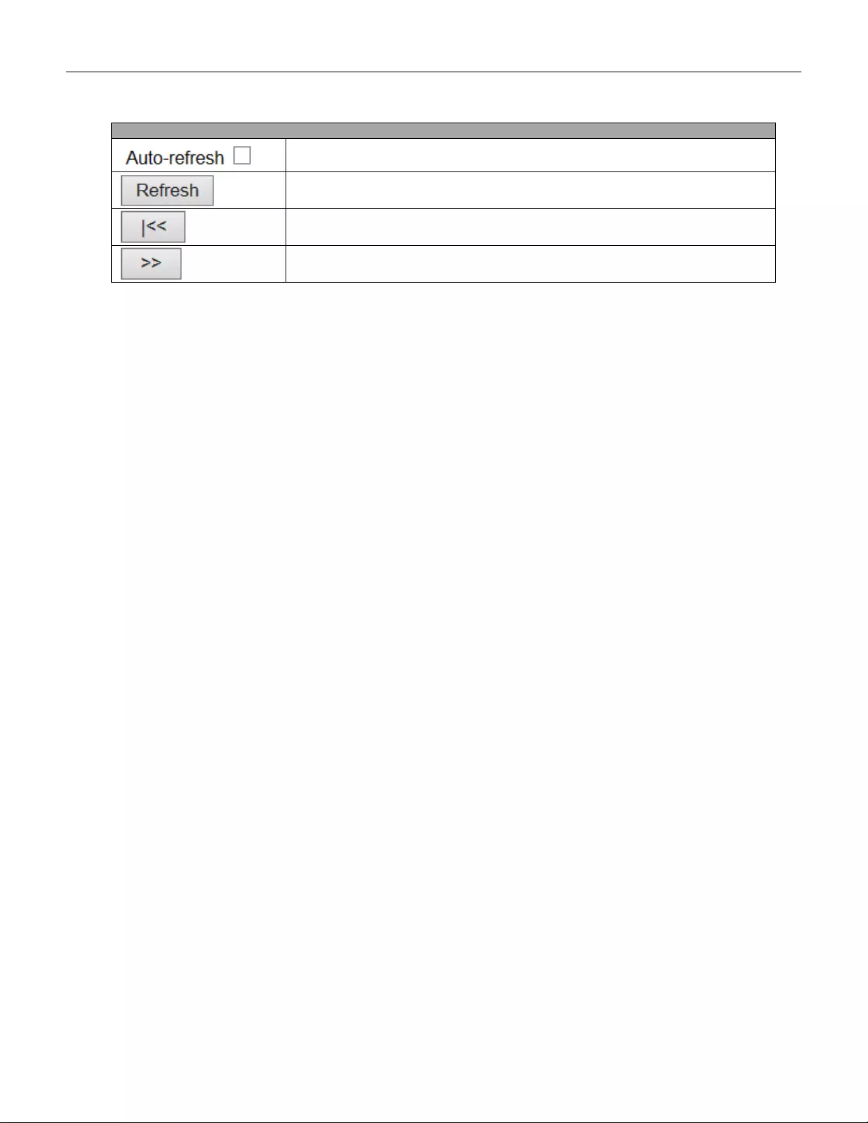
Buttons
Check this box to refresh the page automatically. Automatic refresh occurs every 3
seconds.
Click to refresh the page immediately.
Updates the ta ble starting fro m the first entry in the Statis tics t able, i.e. th e entry with
the lowest ID.
Updates the table, starting with the entry after the last entry currently displayed.
198
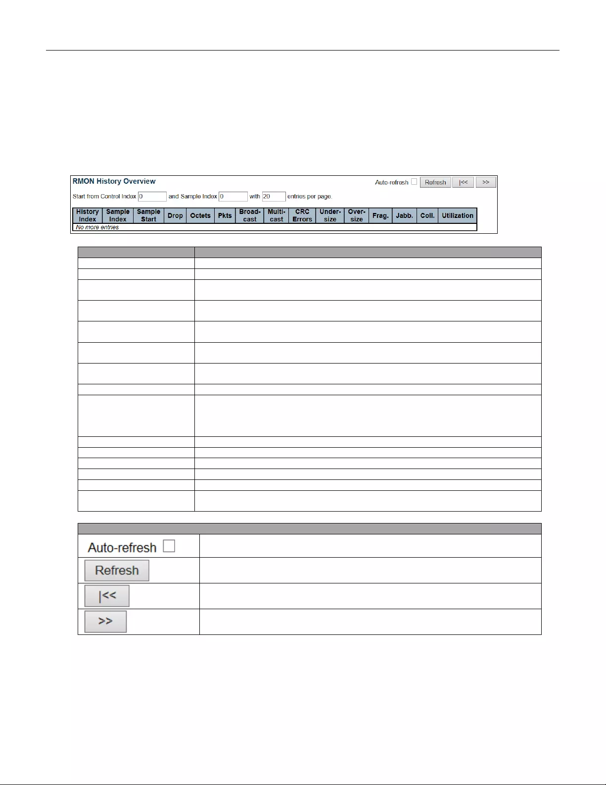
5.4.34 History
This page provides an overview of RMON History entries. Each page shows up to 99 entries from the
History table, default being 20, selected through the "entries per page" input field. When first visited, the web
page will show the first 20 entries from the beginning of the History table. The first displayed will be the one with
the lowest History Index and Sample Index found in the History table.
Object
Description
History Index
Indicates the index of History control entry.
Sample Index
Indicates the index of the data entry associated with the control entry.
Sample Start
The value of sysUpTime at the start of the interval over which this sample was
measured.
Drop
The total nu mber of ev en ts in which packet s w er e dro pped by the probe due to lack o f
resources.
Octets
The total number of octets of data (including thos e in bad pac kets) receiv ed on the
network.
Pkts
The total number of packets (including bad packets, broadcast packets, and multicast
packets) received.
Broadcast
The total number of good packets received that were directed to the broadcast
address.
Multicast
The total number of good packets received that were directed to a multicast address.
CRCErrors
The total number of packets received that had a length (excluding framing bits, but
including FCS octets) of between 64 and 1518 octets, inclusive, but had either a bad
Frame Check Se que nce (F CS) w ith an integr al n um ber of o c t ets (FCS Er ror) or a ba d
FCS with a non-integral number of octets (Alignment Error).
Undersize
The total number of packets received that were less than 64 octets.
Oversize
The total number of packets received that were longer than 1518 octets.
Frag.
The number of frames which size is less than 64 octets received with invalid CRC.
Jabb.
The number of frames which size is larger than 64 octets received with invalid CRC.
Coll.
The best estima te of the total numb er of colli sio ns on this Ethernet se gme nt.
Utilization
The best estimate of the mean physical layer network utilization on this interface
during this sampling interval, in hundredths of a percent.
Buttons
Check this box to refresh the page automatically. Automatic refresh occurs
every 3 seconds.
Click to refresh the page immediately.
Updates the table starting from the first entry in the History table, i.e., the entry with
the lowest History Index and Sample Index.
Updates the table, starting with the entry after the last entry currently displayed.
199
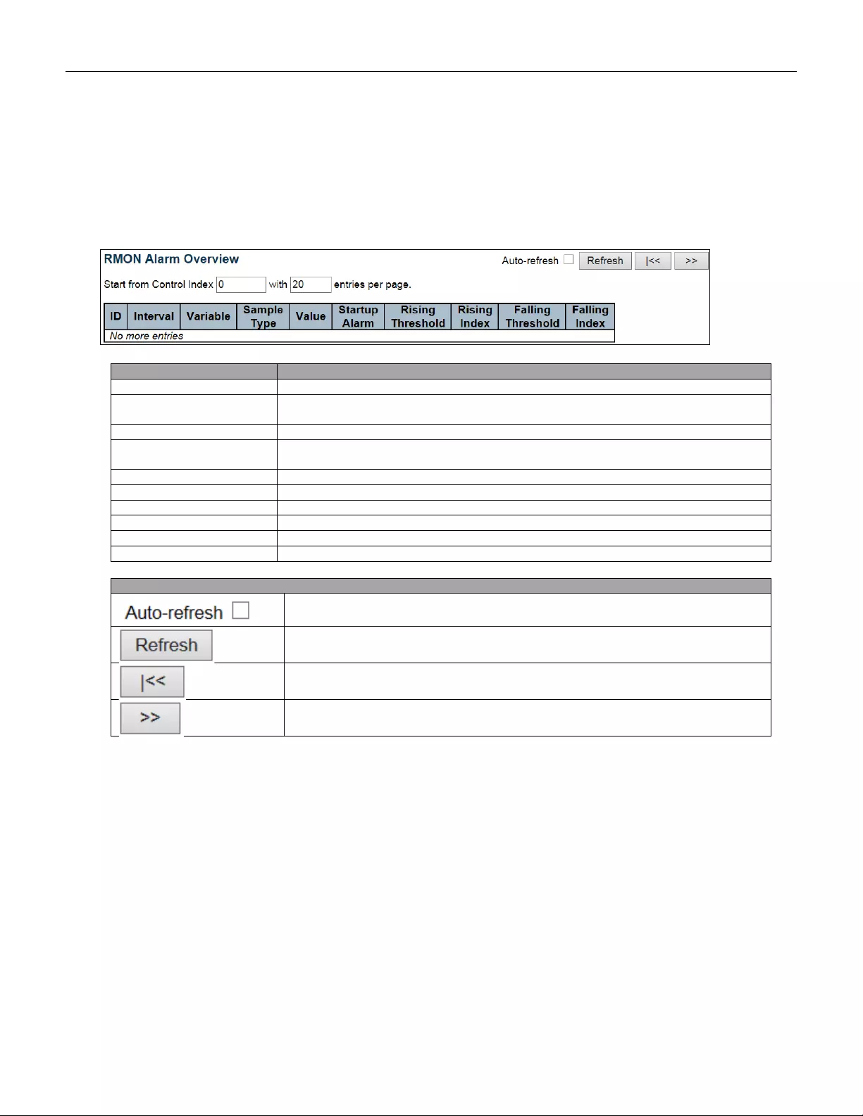
5.4.35 Alarm
This page provides an overview of RMON Alarm entries. Each page shows up to 99 entries from the A larm table,
default being 20, selected through the "entries per page" input field. When first visited, the web page will show
the first 20 entries from the beginning of the Alarm table. The first displayed will be the one with the lowest ID
found in the Alarm table.
Object
Description
ID
Indicates the index of Alar m control entry .
Interval
Indicates the interval in seconds for sampling and comparing the rising and falling
threshold.
Variable
Indicates the particular variable to be sampled.
Sample Type
The method of sampling the selected variable and calculating the value to be
compared against the thresholds.
Value
The value of the statistic during the last sampling period.
Startup Alarm
The alarm that may be sent when this entry is first set to valid.
Rising Threshold
Rising threshold value.
Rising Index
Rising event index.
Falling Threshold
Falling threshold value.
Falling Index
Falling event index.
Buttons
Check this box to refresh the page automatically. Automatic refresh occurs every 3
seconds.
Click to refresh the page immediately.
Updates the table starting from the first entry in the Alarm Table, i.e. the entry with
the lowest ID.
Updates the table, starting with the entry after the last entry currently displayed.
200
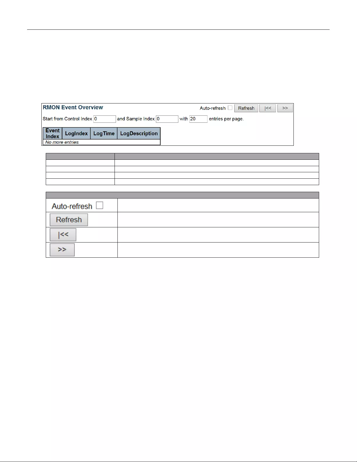
5.4.36 Event
This page provides an overview of RMON Event table entr ies. Eac h page shows up to 99 entries from the Event
table, default being 20, selected through the "entries per page" input field. When first visited, the web page will
show the first 20 entries from the beginning of the Event table. The first displayed will be the one with the lowest
Event Index and Log Index found in the Event table.
Object
Description
Event Index
Indicates the index of the event entry.
Log Index
Indicates the index of the log entry.
Log Time
Indicates Event log tim e.
LogDescription
Indicates the Event description.
Buttons
Check this box to refresh the page automatically. Automatic refresh occurs every 3
seconds.
Click to refresh the page immediately.
Updates the table starting from the first entry in the Event Table, i.e. the entry with
the lowest Event Index and Log Index.
Updates the table, starting with the entry after the last entry currently displayed.
201
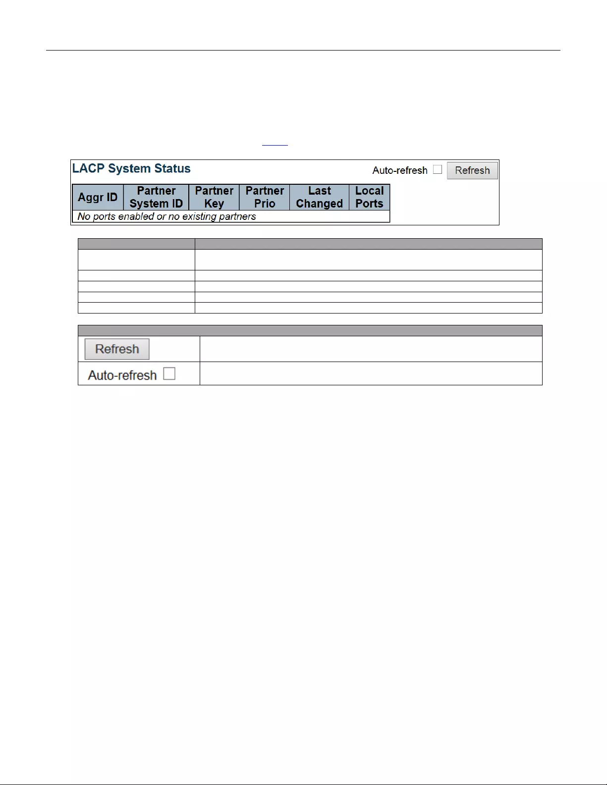
5.4.37 LACP
5.4.38 System Status
This page provides a status overview for all LACP instances.
Object
Description
Aggr ID
The Aggregation ID associated with this aggregation instance. For LLAG the id is
shown as 'isid:aggr-id' and for GLAGs as 'aggr-id'
Partner System ID
The system ID (MAC address) of the aggregation partner.
Partner Key
The Key that the partner has assigned to this aggregation ID.
Last Changed
The time since this aggregation changed.
Local Ports
Shows which ports are a part of this aggregation for this switch.
Buttons
Click to refresh the page immediately.
Check this box to refresh the page automatically. Automatic refresh occurs every 3
seconds.
202

5.4.39 Port Status
This page provides a status overview for LACP status for all ports.
Object
Description
Port
The switch port number.
LACP
'Yes' means that LACP is enabled and the port link is up. 'No' means that LACP is not
enabled or that the port link is down. 'Backup' means that the port could not join the
aggregation group but will join if other port leaves. Meanwhile its LACP status is
disabled.
Key
The key assigned to this port. Only ports with the same key can aggregate together.
Aggr ID
The Aggregation ID assigned to this aggregation group.
Partner System ID
The partner's System ID (MAC address).
Partner Port
The partner's port number connected to this port.
Partner Prio
The partner's port priority.
Buttons
Click to refresh the page immediately.
Check this box to refresh the page automatically. Automatic refresh occurs every 3
seconds.
203
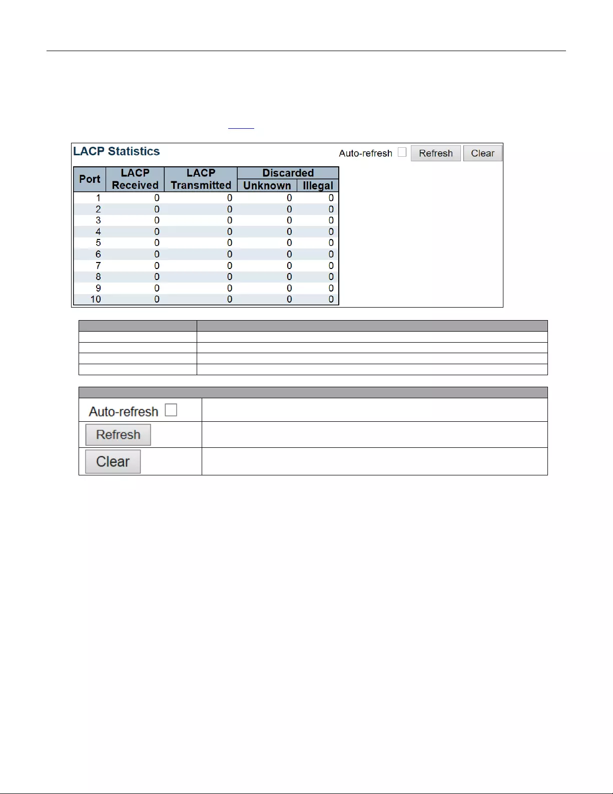
5.4.40 Port Statistics
This page provides an overvi e w for LACP statistics for all ports.
Object
Description
Port
The switch port number.
LACP Received
Shows how many LACP frames have been received at each port.
LACP Transmitted
Shows how many LACP frames have been sent from each port.
Discarded
Shows how many unknown or illegal LACP frames have been discarded at each port.
Buttons
Check this box to refresh the page automatically. Automatic refresh occurs every 3
seconds.
Click to refresh the page immediately.
Clears the counter s for all ports.
204
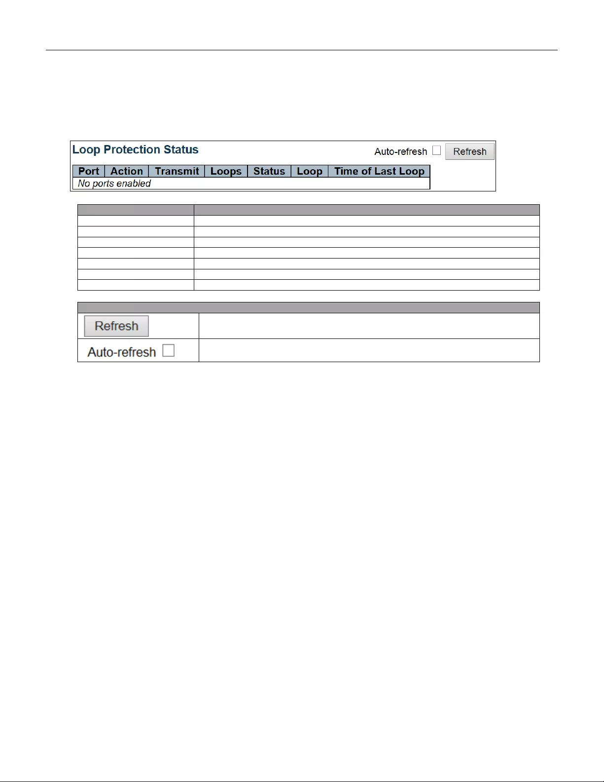
5.4.41 Loop Protection
This page displays the loop protection port status the ports of the switch.
Object
Description
Port
The switch port number of the logical port.
Action
The currently config ured por t a ctio n.
Transmit
The currently configured port transmit mode.
Loops
The number of loops detected on this port.
Status
The current loop protection status of the port.
Loop
Whether a loop is currently detected on the port.
Time of Last Loop
The time of the last loop event detected.
Buttons
Click to refresh the page immediately.
Check this box to enable an automatic refresh of the page at regular intervals.
205
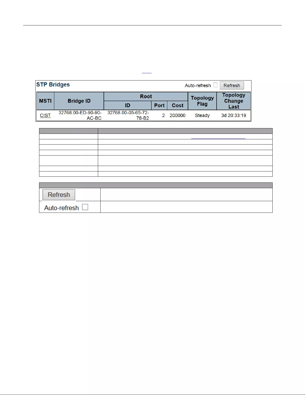
5.4.42 Spanni ng Tree
5.4.43 Bridge Status
This page provides a status overview of all STP bridge instances.
Object
Description
MSTI
The Bridge Instance. This is also a link to the STP Detailed Bridge Status.
Bridge ID
The Bridge ID of this Bridge instance.
Root ID
The Bridge ID of the currently elected root bridge.
Root Port
The switch port currently assigned the root port role.
Root Cost
Root Path Cost. For the Root Bridge it is zero. For all other Bridges, it is the sum of
the Port Path Costs on the least cost path to the Root Bridge.
Topology Flag
The current state of the Topology Change Flag of this Bridge instance.
Topology Change Last
The time since la st Topology Change occurr e d.
Buttons
Click to refresh the page immediately.
Check this box to refresh the page automatically. Automatic refresh occurs every 3
seconds.
206
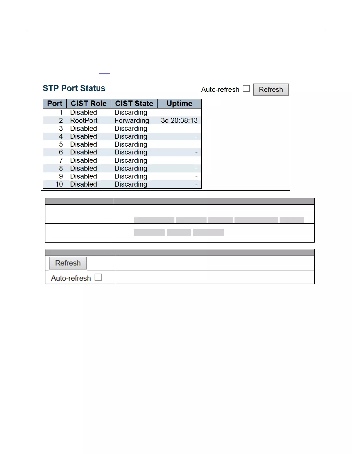
5.4.44 Port Status
This page displays the STP CIST port status for physical ports of the switch.
Object
Description
Port
The switch port number of the logical STP port.
CIST Role
The current STP port role of the CIST port. The port role ca n be one of the foll ow ing
values: AlternatePort BackupPort RootPort DesignatedPort Disabled.
CIST State
The curren t S T P port state of the CIST port. The port st ate ca n be one of t he f oll owing
values: Discarding Learning Forwarding.
Uptime
The time since the bridge por t was last initializ ed.
Buttons
Click to refresh the page immediately.
Check this box to refresh the page automatically. Automatic refresh occurs every 3
seconds.
207
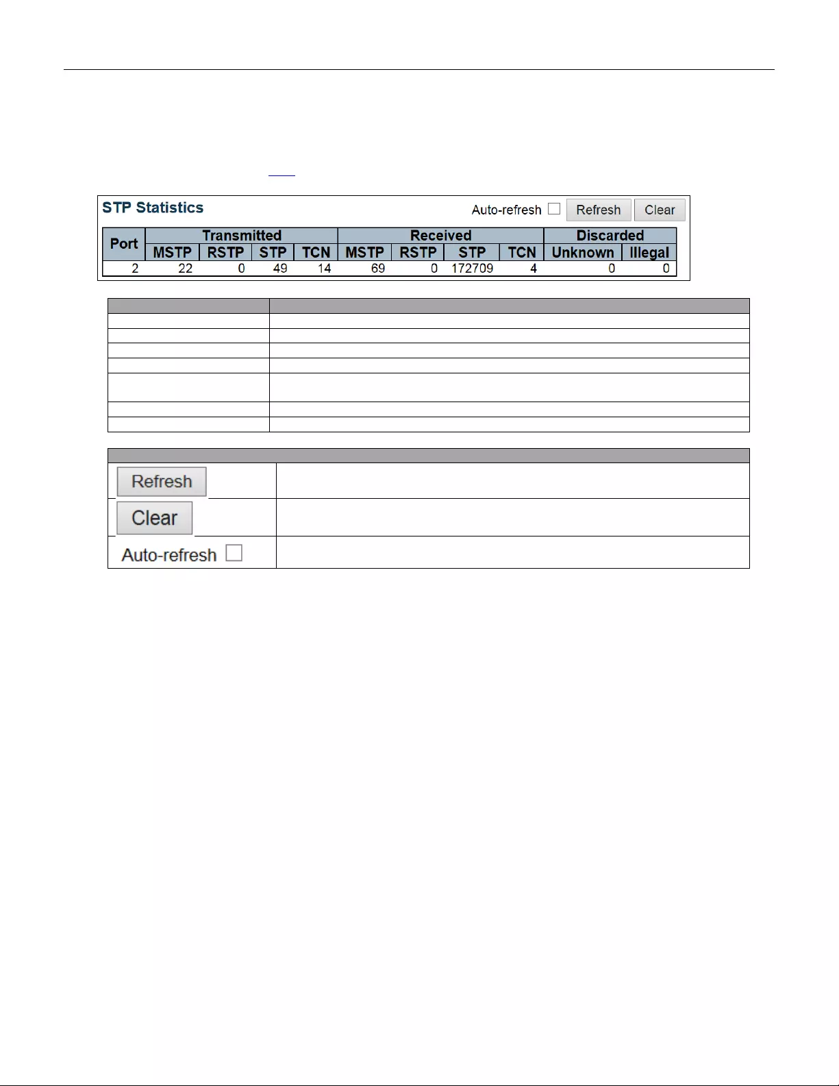
5.4.45 Port Statistics
This page displays the STP port statistics counters of bridge ports in the switch.
Object
Description
Port
The switch port number of the logical STP port.
MSTP
The number of MSTP BPDU's received/transmitted on the por t.
RSTP
The number of RSTP BPDU's received/transmitted on the port.
STP
The number of legacy STP Configuration BPDU's received/transmitted on the port.
TCN
The number of (legacy) Topology Change Notification BPDU's received/transmitted
on the port.
Discarded Unknown
The number of unk nown Span ning Tree BPDU's receive d (a nd disc arde d) on the port .
Discarded Illeg al
The number of illegal Spanning Tree BPDU's received (and discarded) on the port.
Buttons
Click to refresh the page immediately.
Click to reset the counters.
Check this box to refresh the page automatically. Automatic refresh occurs every 3
seconds.
208
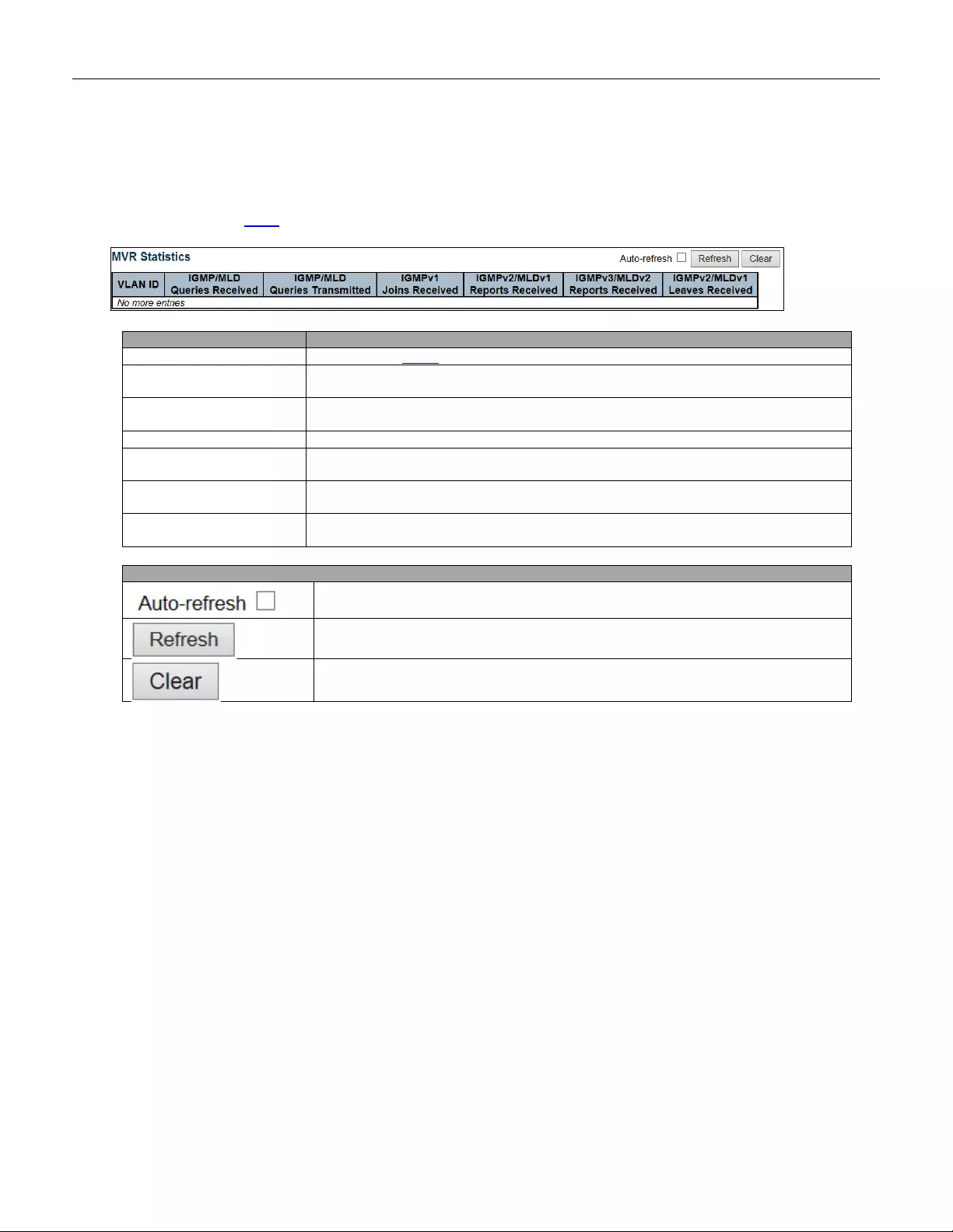
5.4.46 MVR
5.4.47 MVR Statistics
This page provides MVR Statistics information.
Object
Description
VLAN ID
The Multicast VLAN ID
IGMP/MLD Queries
Received
The number of Received Queries for IGMP and MLD, respectively.
IGMP/MLD Queries
Transmitted
The number of Transmitted Queries for IGMP and MLD, respectively.
IGMPv1 Joins Received
The number of Received IGMPv1 Join's.
IGMPv2/MLDv1 Report’s
Received
The number of Received IGMPv2 Join's and MLDv1 Report's, respectively.
IGMPv3/MLDv2 Report’s
Received
The number of Received IGMPv1 Join's and MLDv2 Report's, respectively.
IGMPv2/MLDv1 Leave’s
Received
The number of Received IGMPv2 Leave's and MLDv1 Done's, respectively.
Buttons
Check this box to refresh the page automatically. Automatic refresh occurs every 3
seconds.
Click to refresh the page immediately.
Clears all Statistics counters.
209
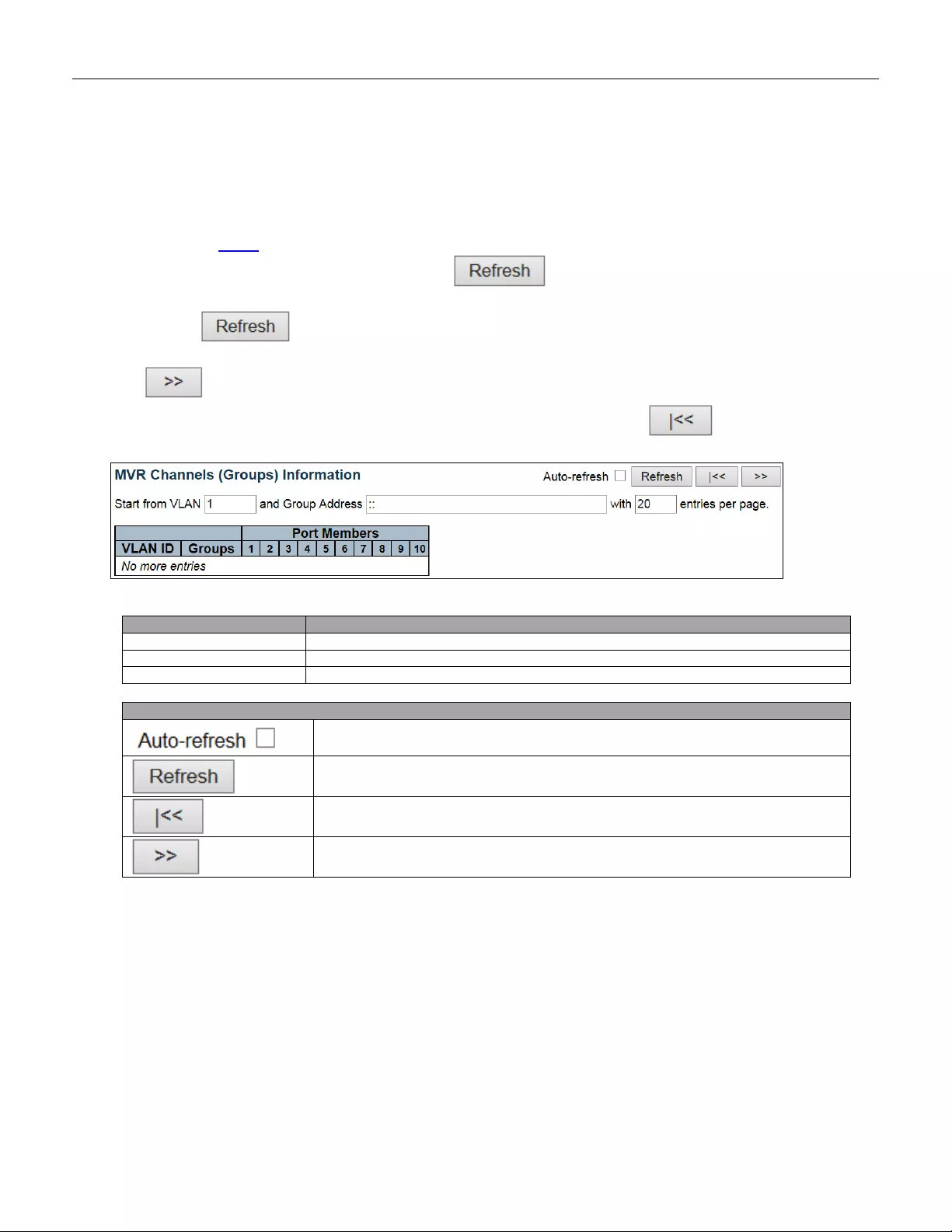
5.4.48 MVR Channel Groups
Each page shows up to 99 entries from the MVR Group table, default being 20, selected through the "entries per
page" input field. When first visited, the web page will show the first 20 entries from the beginning of the MVR
Channels (Groups) Information Table.
The "Start from VLAN", and "Group Address" input fields allow the user to select the starting point in the MVR
Channels (Groups) Information Table. Clicking the button will update the displayed table starting
from that or the closest next MVR Channels (Groups) Information Table match. In addition, the two input fields
will - up on a button click - assume the value of the first displayed entry, allowing for continuous
refresh wi th the same start address.
The will use the last entry of the currently displayed table as a basis for the next lookup. When the end
is reached the text "No more entries" is shown in the displayed table. Use the button to start over.
Object
Description
VLAN ID
VLAN ID of the group.
Groups
Group ID of the group displayed.
Port Members
Ports under this group.
Buttons
Check this box to refresh the page automatically. Automatic refresh occurs every 3
seconds.
Refreshes the displayed table starting from the input fields.
Updates the table starting from the first entry in the MVR Channels (Groups)
Information Table.
Updates the table, starting with the entry after the last entry currently
displayed.
210
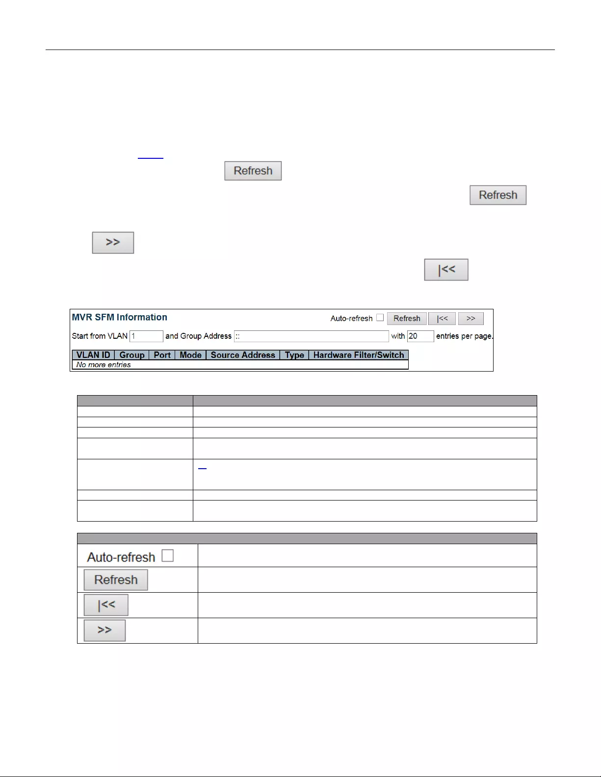
5.4.49 MVR SFM Information
Each page shows up to 99 entries from the MVR SFM Information Table, default being 20, selected through the
"entries per page" input field. When first visited, the web page will show the first 20 entries from the beginning of
the MVR SFM Infor mation Table.
The "Start from VLAN", and "Group Address" input fields allow the user to select the starting point in the MVR
SFM Information Table. Clicking the button will update the displayed table starting from that or the
closest next MVR SFM Information Table match. In addition, the two input fields will - upon a
button click - assume the value of the first displayed entry, allowing for continuous refresh with the same start
address.
The will use the last entry of the currently displayed table as a basis for the next lookup. When the
end is reached the text "No more entries" is shown in the displayed table. Use the button to start
over.
Object
Description
VLAN ID
VLAN ID of the group.
Group
Group address of the group displayed.
Port
Switch port number.
Mode
Indicates the filtering mode maintained per (VLAN ID, port number, Group Address)
basis. It can be either Include or Exclude.
Source Addr ess
IP Address of the source. Currently, system limits the total number of IP source
addresses for filtering to be 128. When there is no any source filtering address, the
text "None" is shown in the Source Address field.
Type
Indicates the Type. It can be either Allow or Deny.
Hardware Filter/Switch
Indicates whether data plane destined to the specific group address from the source
IPv4/IPv6 address could be handled by chip or not.
Buttons
Check this box to refresh the page automatically. Automatic refresh occurs every 3
seconds.
Refreshes the dis play ed tab le start i ng from the inpu t field s.
Updates the table starting from the first entry in the MVR SFM Information Table.
Updates the table, starting with the entry after the last entry currently displayed.
211
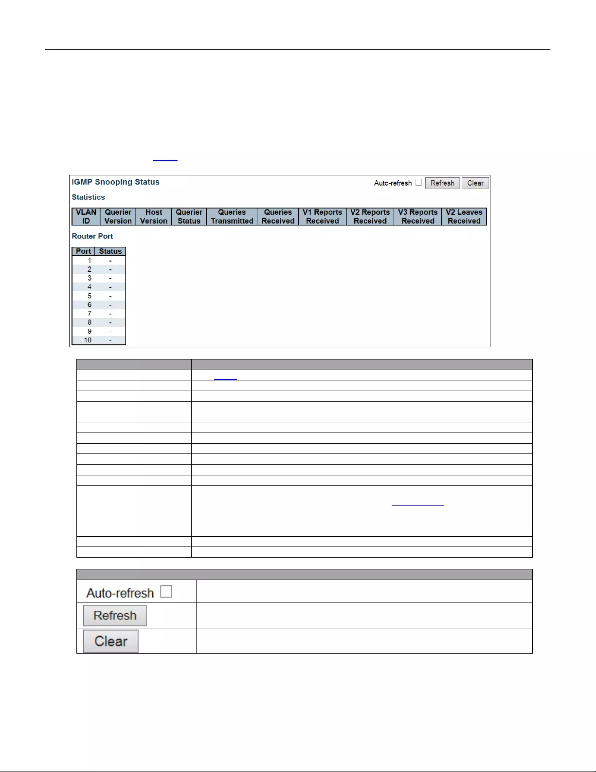
5.4.50 IPMC
5.4.51 IGMP Snooping
5.4.52 IGMP Snooping Status
This page provides IGMP Snooping status.
Object
Description
VLAN ID
The VLAN ID of the entry.
Querier Version
Work ing Quer ier Version currently.
Host Version
Working Host Version currently.
Querier Status
Shows the Querier status is "ACTIVE" or "IDLE".
"DISABLE" denotes the specific interface is administratively disabled.
Querier Transmitted
The number of Transmitted Queries.
Queries Received
The number of Received Queries.
V1 Report Received
The number of Received V1 Reports.
V2 Report Received
The number of Received V2 Reports.
V3 Report Received
The number of Received V3 Reports.
V2 Leaves Received
The number of Received V2 Leaves.
Router Port
Display which ports act as router ports. A router port is a port on the Ethernet switch
that leads towards the Layer 3 multicast device or IGMP querier.
Static denotes the specific port is configured to be a router port.
Dynamic denotes the specific port is learnt to be a router port.
Both denote the specific port is configured or learnt to be a router port.
Port
Switch port number.
Status
Indicate whether specific port is a router port or not.
Buttons
Check this box to refresh the page automatically. Automatic refresh occurs every 3
seconds.
Click to refresh the page immediately.
Clears all Statistics counters.
212
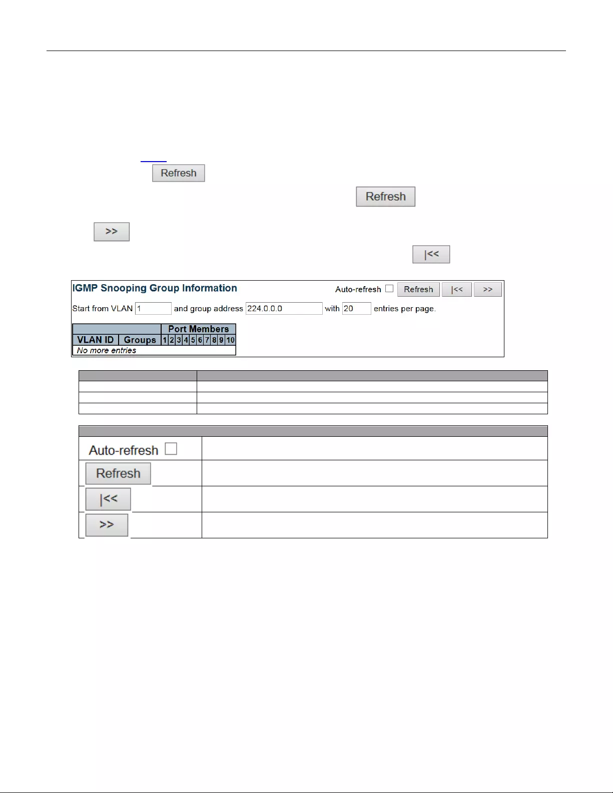
5.4.53 Groups Information
Each page shows up to 99 entries from the IGMP Group table, default being 20, selected through the "entries
per page" input field. When first visited, the web page will show the first 20 entries from the beginning of the
IGMP Group Table.
The "Start from VLAN", and "group" input fields allow the user to select the starting point in the IGMP Group
Table. Clicking the button will update the displayed table starting from that or the closest next IGMP
Group Table match. In addition, the two input fields will - upon a button click - assume the value of
the first displayed entry, allowing for continuous refresh with the same start address.
The will use the last entry of the currently displayed table as a basis for the next lookup. When the end
is reached the text "No more entries" is shown in the displayed table. Use the button to start over.
Object
Description
VLAN ID
VLAN ID of the group.
Groups
Group address of the group displayed.
Port Members
Ports under this group.
Buttons
Check this box to refresh the page automatically. Automatic refresh occurs every 3
seconds.
Refreshes the dis play ed tab le start i ng from the inpu t field s.
Updates the table, starting with the first entry in the IGMP Group Table.
Updates the table, starting with the entry after the last entry currently displayed.
213
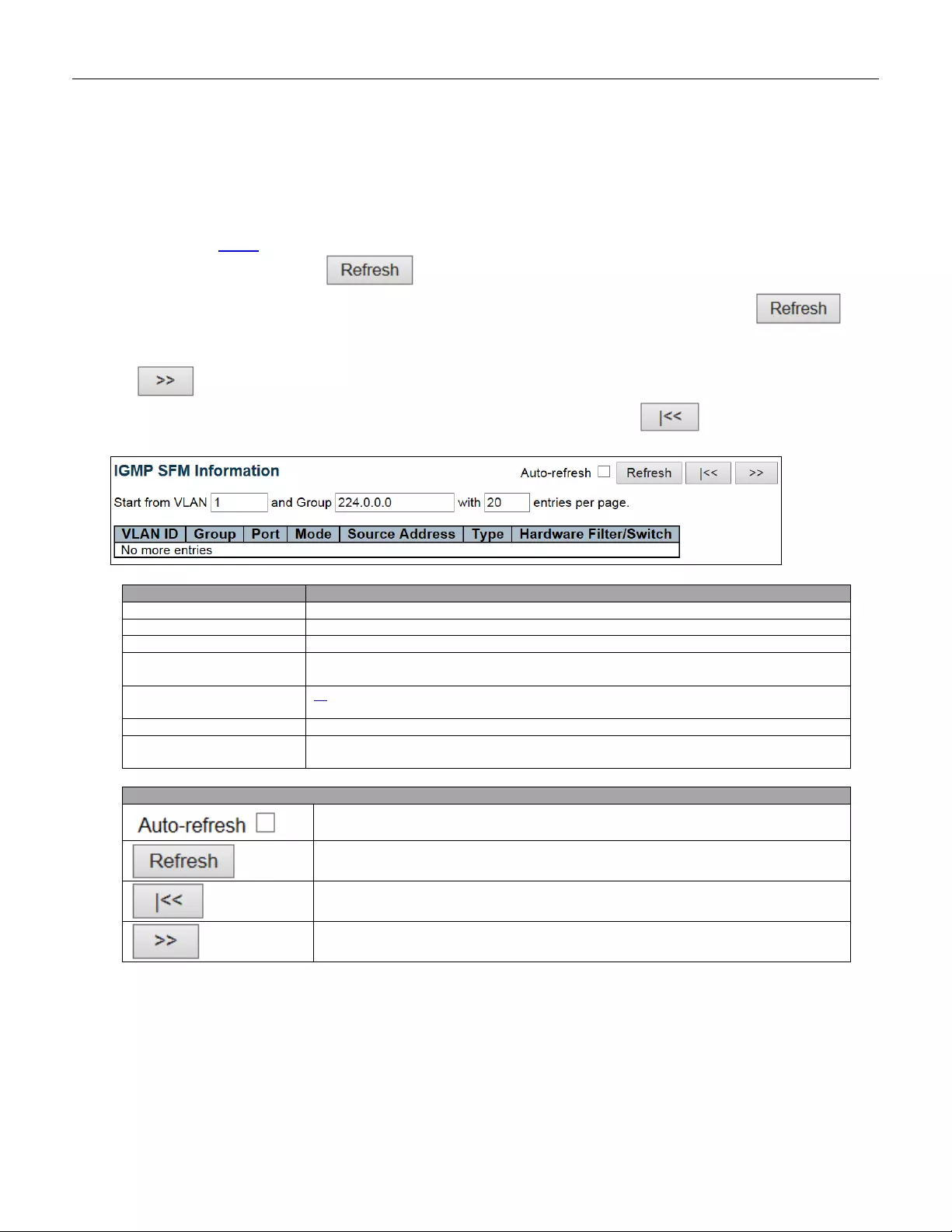
5.4.54 IPv4 SFM Information
Each page shows up to 99 entries from the IGMP SFM Information table, default being 20, selected through the
"entries per page" input field. When first visited, the web page will show the first 20 entries from the beginning of
the IGMP SFM Information Table.
The "Start from VLAN", and "group" input fields allow the user to select the starting point in the IGMP SFM
Information Table. Clicking the button will update the displayed table starting from that or the
closest next IGMP SFM Information Table match. In addition, the two input fields will - upon a
button click - assume the value of the first displayed entry, allowing for continuous refresh with the same start
address.
The will use the last entry of the currently displayed table as a basis for the next lookup. When the end
is reached the text "No more entries" is shown in the displayed table. Use the button to start over.
Object
Description
VLAN ID
VLAN ID of the group.
Group
Group address of the group displayed.
Port
Switch port number.
Mode
Indicates the filtering mode maintained per (VLAN ID, port number, Group Address)
basis. It can be either Include or Exclude.
Source Add ress
IP Address of the source. Currently, system limits the total number of IP source
addresses for filtering to be 128.
Type
Indicates the Type. It can be either Allow or Deny.
Hardware Filter/Switch
Indicates whether data plane destined to the specific group address from the source
IPv4 address could be handled by chip or not.
Buttons
Check this box to refresh the page automatically. Automatic refresh occurs every 3
seconds.
Refreshes the dis play ed tab le start i ng from the inpu t field s.
Updates the table starting from the first entry in the IGMP SFM Information Table.
Updates the table, starting with the entry after the last entry currently displayed.
214
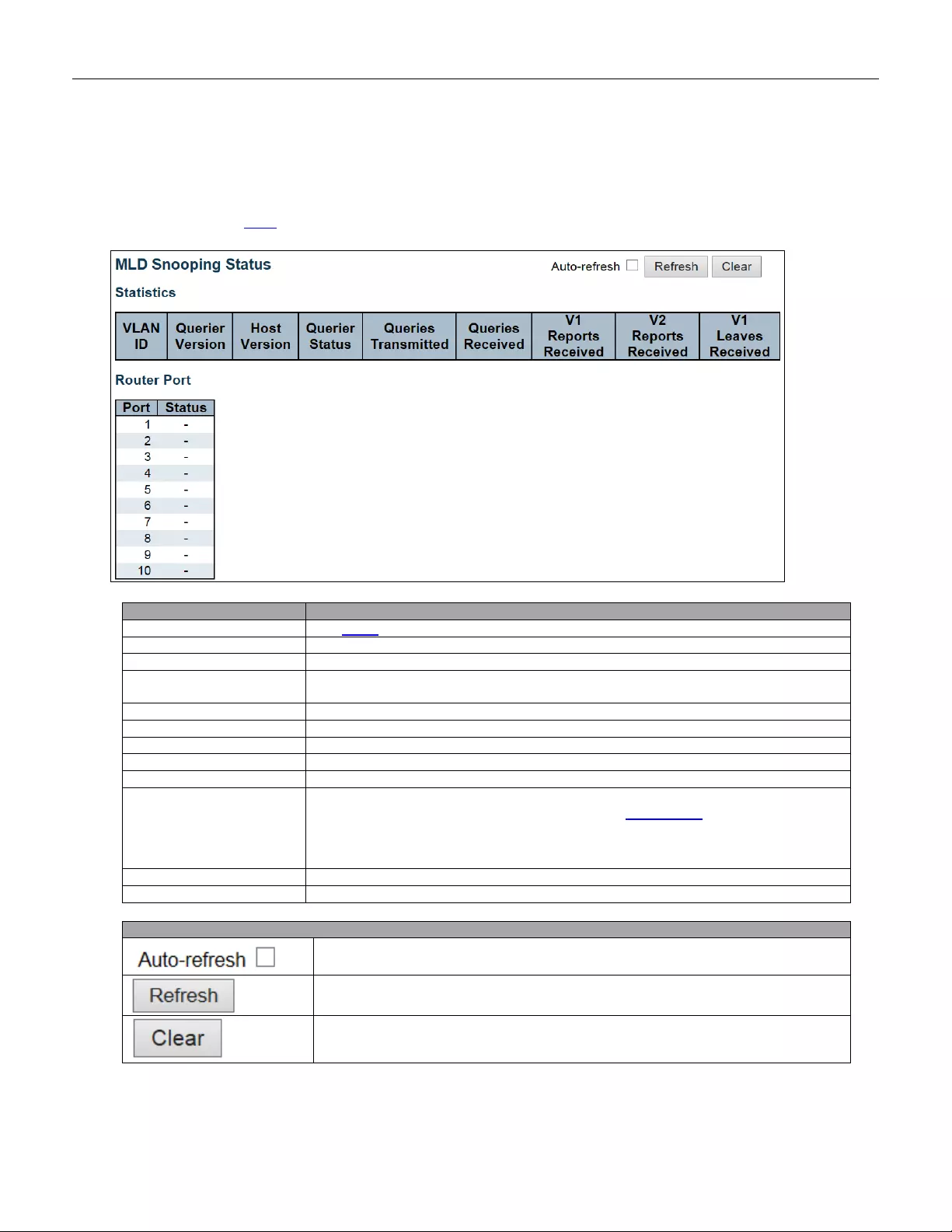
5.4.55 MLD Snooping
5.4.56 MLD Snooping Status
This page provides MLD Snooping status.
Object
Description
VLAN ID
The VLAN ID of the entry.
Querier Version
Work ing Quer ier Version currently.
Host Version
Working Host Version currently.
Querier Status
Shows the Querier status is "ACTIVE" or "IDLE".
"DISABLE" denotes the specific interface is administratively disabled.
Queries Transmitted
The number of Transmitted Queries.
Queries Received
The number of Received Queries.
V1 Report Received
The number of Received V1 Reports.
V2 Report Received
The number of Received V2 Reports.
V1 Leaves Received
The number of Received V1 Leaves.
Router Port
Display which ports act as router ports. A router port is a port on the Ethernet switch
that leads towards the Layer 3 multicast device or MLD querier.
Static denotes the specific port is configured to be a router port.
Dynamic denotes the specific port is learnt to be a router port.
Both denote the specific port is configured or learnt to be a router port.
Port
Switch port number.
status
Indicate whether specific port is a router port or not.
Buttons
Check this box to refresh the page automatically. Automatic refresh occurs every 3
seconds.
Click to refresh the page immediately.
Clears all Statistics counters.
215
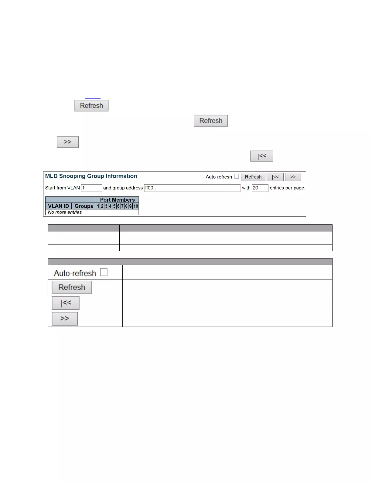
5.4.57 Groups Information
Each page shows up to 99 entries from the MLD Group table, default being 20, selected through the "entries per
page" input field. When first visited, the web page will show the first 20 entries from the beginning of the MLD
Group Table.
The "Start from VLAN", and "group" input fields allow the user to select the starting point in the MLD Group Table.
Clicking the button w ill update the displayed table starting from that or the closest next MLD Group
Table match. In addition, the two input fields will - upon a button click - assume the value of the first
displayed entry, allowing for continuous refresh with the same start address.
The will use the last entry of the currently displayed table as a basis for the next lookup. When the end
is reached the text "No more entries" is shown in the displayed table. Use the button to start over.
Object
Description
VLAN ID
VLAN ID of the group.
Groups
Group address of the group displayed.
Port Members
Ports under this group.
Buttons
Check this box to refresh the page automatically. Automatic refresh occurs every 3
seconds.
Refreshes the dis play ed tab le start i ng from the inpu t field s.
Updates the table, starting with the first entry in the MLD Group Table.
Updates the table, starting with the entry after the last entry currently displayed.
216
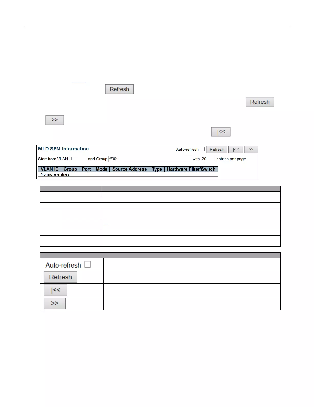
5.4.58 IPv6 SFM Information
Each page shows up to 99 entries from the MLD SFM Information table, default being 20, selected through the
"entries per page" input field. When first visited, the web page will show the first 20 entries from the beginning of
the MLD SFM Information Table.
The "Start from VLAN", and "group" input fields allow the user to select the starting point in the MLD SFM
Information Table. Clicking the button will update the displayed table starting from that or the
closest next MLD SFM Information Table match. In addition, the two input fields w ill - upon a button
click - assume the value of the first displayed entry, allowing for continuous refresh with the same start address.
The will use the last entry of the currently displayed table as a basis for the next lookup. When the end
is reached the text "No more entries" is shown in the displayed table. Use the button to start over.
Object
Description
VLAN ID
VLAN ID of the group.
Group
Group address of the group displayed.
Port
Switch port number.
Mode
Indicates the filtering mode maintained per (VLAN ID, port number, Group Address)
basis. It can be either Include or Exclude.
Source Addr ess
IP Address of the source. Currently, system limits the total number of IP source
addresses for filtering to be 128.
Type
Indicates the Type. It can be either Allow or Deny.
Hardware Filter/Switch
Indicates whether data plane destined to the specific group address from the source
IPv6 address could be handled by chip or not.
Buttons
Check this box to refresh the page automatically. Automatic refresh occurs every 3
seconds.
Refreshes the displayed table starti ng fr om the inpu t field s.
Updates the table starting from the first entry in the MLD SFM Information Table.
Updates the table, starting with the entry after the last entry currently displayed.
217
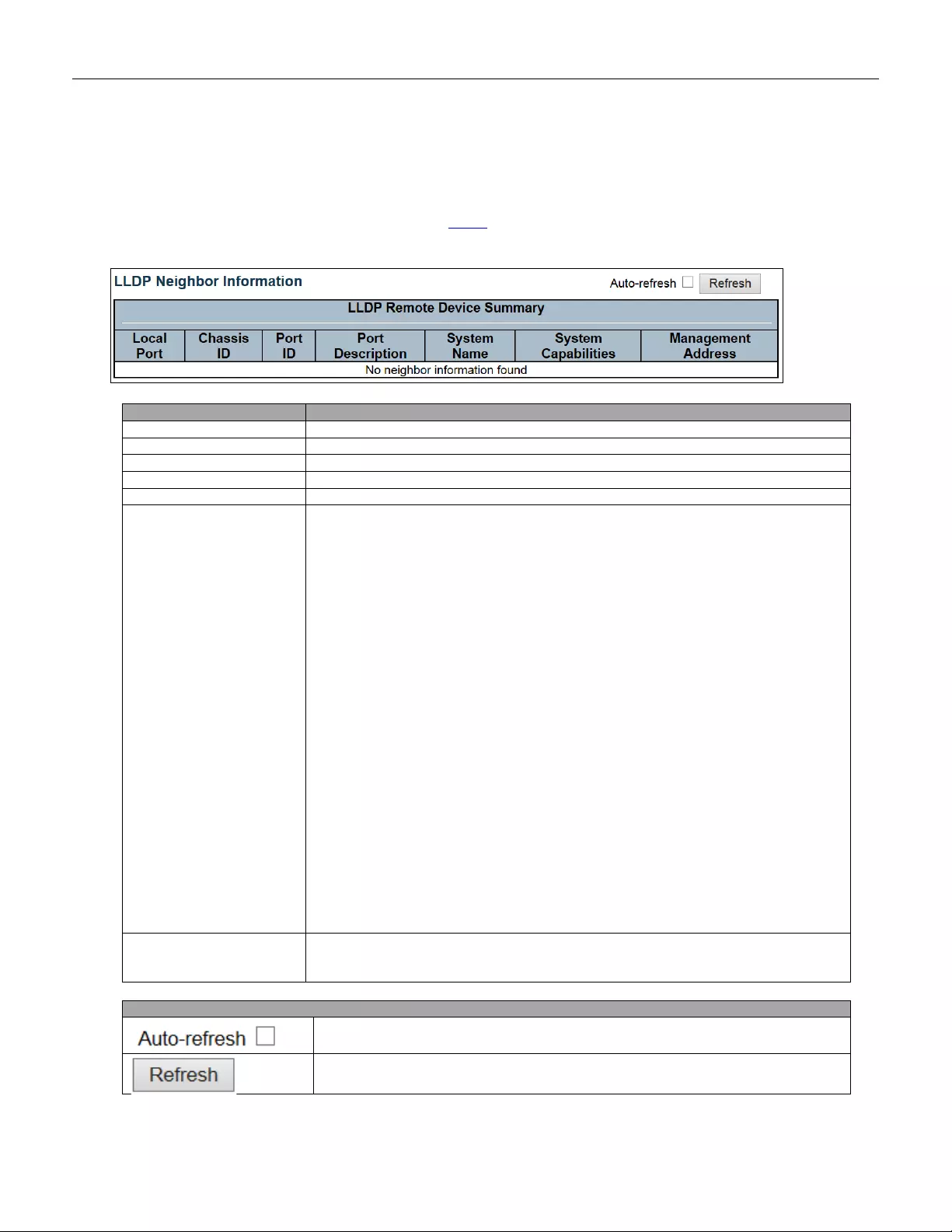
5.4.59 LLDP
5.4.60 Neighbors
This page provides a status overview for all LLDP neighbors. The displayed table contains a row for each
port on which an LLDP neighbor is detected.
Object
Description
Local Port
The port on which the LLDP frame was received.
Chassis ID
The Chassis ID is the identification of the neighbor's LLDP frames.
Port ID
The Port ID is the identification of the neighbor port.
Port Description
Port Description is the port description advertised by the neighbor unit.
System Name
System Name is the name advertised by the neighbor unit.
System Capabilities
Sy stem C apabili tie s des crib e s th e n eighbor unit's cap abi liti e s. The pos sib le
capabilities are:
1. Other
2. Repeater
3. Bridge
4. WLAN Access Point
5. Router
6. Telephone
7. DOCSIS cable device
8. Station only
9. Reserved
When a capability is enabled, the capability is followed by (+). If the capability is
disabled, the capability is followed by (-).
Managemen t Address
Managemen t Address is the neighbor unit's address that is used for higher layer
entities to assist discovery by the network management. This could for instance hold
the neighbor's IP address.
Buttons
Check this box to refresh the page automatically. Automatic refresh occurs every 3
seconds.
Click to refresh the page.
218
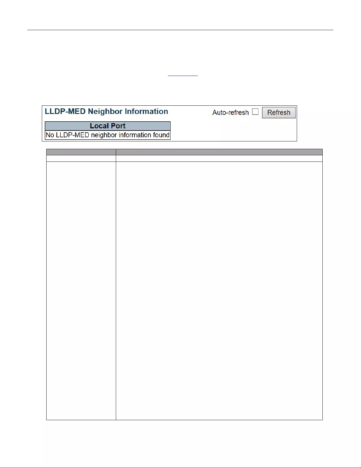
5.4.61 LLDP-MED Neighbors
This page provides a status overview of all LLDP-MED neighbors. The displayed table contains a row for
each port on which an LLDP neighbor is detected. This function applies to VoIP devices which support
LLDP-MED.
Object
Description
Port
The port on which the LLDP frame was received.
Device Type
LLDP-MED Devices are comprised of two primary Device Types: Network
Connectivity Devices and Endpoint Devices.
LLDP-MED Network Connectivity Device Definition
LLDP-MED Network Connectivity Devices, as defined in TIA-1057, prov ide acce ss to
the IEEE 802 based LAN infrastructure for LLDP-MED Endpoint Devices. An
LLDP-MED Network Connectivity Device is a LAN access device based on any of the
following technologies:
1. LAN Switch/Router
2. IEEE 802.1 Bridge
3. IEEE 802.3 Repeater (included for historical reasons)
4. IEEE 802.11 Wireless Access Point
5. Any device that supports the IEEE 802.1AB and MED extensions defined by
TIA-1057 and can relay IEEE 802 frames via any method.
LLDP-MED Endpoint Device Definition
LLDP-MED Endpoint Devices, as defined in TIA-1057, are located at the IEEE 802
LAN network edge, and parti ci pate in IP commu ni cati on serv i ce usin g the LLDP-MED
framework.
Within the LLDP-MED Endpoint Device category, the LLDP-MED scheme is broken
into further Endpoint Device Classes, as defined in the following.
Each LLDP-MED Endpoint Device Class is defined to build upon the capabilities
defined for the previous Endpoint Device Class. For-example will any LLDP-MED
Endpoint Device claiming compliance as a Media Endpoint (Class II) also support all
aspects of TIA-1057 applicable to Generic Endpoints (Class I), and any LLDP-MED
Endpoint Device claiming compliance as a Communication Device (Class III) will also
support all aspects of TIA-1057 applicable to both Media Endpoints (Class II) and
Generic Endpoints (Class I).
219

LLDP-MED Generic Endpoint (Class I)
The LLDP-MED Generic Endpoint (Class I) definition is applicable to all endpoint
products t hat re quire the bas e LLDP dis cov ery serv i ces defi n ed in TIA-105 7, however
do not support IP media or act as an end-user communication appliance. Such
devices may include (but are not limited to) IP Communication Controllers, other
communication related servers, or any device requiring basic services as defined in
TIA-1057.
Discovery services defined in this class include LAN configuration, device location,
network policy, power management, and inventory management.
LLDP-MED Media Endpoint (Class II)
The LLDP-MED Media Endpoint (Class II) definition is applicable to all endpoint
products that have IP media capabilities however may or may not be associated with
a particular end user. Capabilities include all of the capabilities defined for the
previous Generic Endpoint Class (Class I), and are extended to include aspects
related to media streaming. Example product categories expected to adhere to this
class include (but are not limited to) Voice / Media Gateways, Conference Bridges,
Media Servers, and similar.
Discovery services defined in this class include media-type-specific network layer
policy discovery.
LLDP-MED Communication Endpoint (Class III)
The LLDP-MED Communication Endpoint (Class III) definition is applicable to all
endpoint products that act as end user communication appliances supporting IP
media. Capabilities include all of the capabilities defined for the previous Generic
Endpoint (C l as s I) a nd Media Endpoi nt (Class II) cla ss es, an d ar e extende d to inc lud e
aspects related to end user devices. Example product categories expected to adhere
to this class include (but are not limited to) end user communication appliances, such
as IP Phones, PC-based softphones, or other communication appliances that directly
support the end user.
Discovery services defined in this class include provision of location identifier
(including ECS / E911 information), embedded L2 switch support, and inventory
management.
LLDP-MED Capabilities
LLDP-MED Capabilities describes the neighbor unit's LLDP-MED capabilities. The
possible capabilities are:
1. LLDP-MED capabilities
2. Network Policy
3. Location Identification
4. Extended Power via MDI - PSE
5. Extended Power via MDI - PD
6. Inventory
7. Reserved
220

Application Type
Application Type indicating the primary function of the application(s) defined for this
network policy, advertised by an Endpoint or Network Connectivity Device. The
possible appli cat ion types are shown below.
1. Voice - for use by dedicated IP Telephony handsets and other similar appliances
supporting interactive voice services. These devices are typically deployed on a
separate VLAN for ease of deployment and enhanced security by isolation from data
applications.
2. Voice Signaling - for use in network topologies that require a different policy for the
voice signaling than for the voice media.
3. Guest V oice - to supp ort a s eparate li mited f eature-set voi ce servic e for g uest us ers
and visitors with their ow n IP Teleph ony hands ets and othe r sim ilar app liances
supporting interactive voice services.
4. Guest Voice Signaling - for use in network topologies that require a different policy
for the guest voice signaling than for the gue st voi ce media.
5. Softphone Voic e - for use b y softpho ne applicat ion s on ty pica l dat a cen tr i c dev ic es ,
such as PCs or laptops.
6. Video Conferencing - for use by dedicated Video Conferencing equipment and
other similar appli anc es supporting real-time interactive video/audio services.
7. Streaming Video - for use by broadcast or multicast based video content
distribution and other similar applications supporting streaming video services that
require specific network policy treatment. Video applications relying on TCP with
buffering would not be an intended use of this application type.
8. Video Signaling - for u se in network top olo gie s th at r equire a s eparate pol icy for the
video signaling than for the video media.
Policy
Policy indicates t hat an Endpoint D ev ic e w ant s to explicitly adv ertise that the pol icy i s
required by the device. Can be either Defined or Unknown
Unknown: The network policy for the specified application type is currently unknown.
Defined: The network policy is defined.
TAG
TAG i s indicative of whether the specified application type is using a tagged or an
untagged VLAN. Can be Tagged or Untagged.
Untagged: The device is using an untagged frame format and as such does not
include a tag header as defined by IEEE 802.1Q-2003.
Tagged: The device is using the IEEE 802.1Q tagged frame format.
VLAN ID
VLAN ID is the VLAN identifier (VID) for the port as defined in IEEE 802.1Q-20 03. A
value of 1 through 4094 is used to define a valid VLAN ID. A value of 0 (Priority
Tagged) is used if the device is using priority tagged frames as defined by IEEE
802.1Q-2003, meaning that only the IEEE 802.1D priority level is significant and the
default PVID of the ingress port is used instead.
Priority
Priority i s the Layer 2 priority to be used for the specified application type. One of the
eight priority levels (0 through 7).
DSCP
DSCP is the DSCP value to be used to provide Diffserv node behavior for the
specified application type as defined in IETF RFC 2474. Contain one of 64 code point
values (0 through 63).
Auto-negotiation
Auto-negotiation identifi es if MAC /PHY auto-negotiation is supported by the link
221
partner.
Auto-negotiation status
Auto-negotiation status identifies if auto-negotiation is currently enabled at the link
partner. If Auto-negotiation is supported and Auto-negotiation status is dis abled,
the 802.3 PMD operating mode will be determined the operational MAU type field
value rather than by auto-negotiation.
Auto-negotiation
Capabilities
Auto-negotiation Capabilities shows the link partners MAC/PHY capabilities.
Buttons
Check this box to refresh the page automatically. Automatic refresh occurs every 3
seconds.
Click to refresh the page.
222
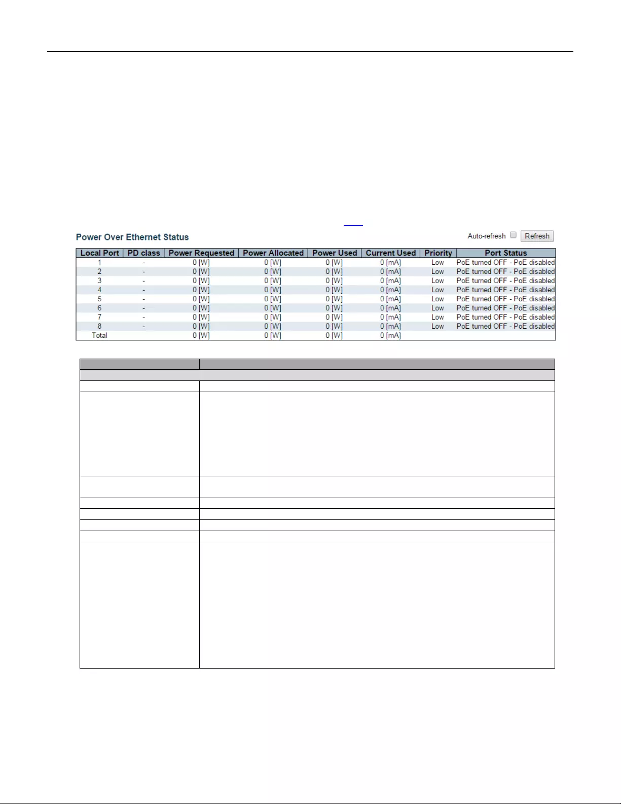
5.4.62 PoE Status
The PoE model(s) supports the IEEE802.3at High Power over Ethernet (PoE) standard.
A powered device (PD) is a device such as an access point or a switch that supports PoE (Power over Ethernet) so
that it can receive power from another device through an Ethernet port.
Note: The POE (Power over Ethernet) devices that supply or receive power and their connected Ethernet
cables must all be completely indoors.
This page allows the user to inspect the current status for all PoE ports.
Object
Description
PoE Status
Local Port
This is the logical port number for this row.
PD Class
Each PD is classified according to a class that defines the maximum power the PD
will use. T he PD Class show s the PDs cla ss.
Five Classes are defined:
Class 0: Max. power 15.4 W
Class 1: Max. power 4.0 W
Class 2: Max. power 7.0 W
Class 3: Max. power 15.4 W
Class 4: Max. power 30.0 W
Power Requested
The Power Requested shows the requested amount of power the PD wants to be
reserved.
Power Al located
The Power Allocated shows the amount of power the switch has allocated for the PD.
Power Us ed
The Power Used shows how much power the PD currently is using.
Current Use d
The Power Used shows how much current the PD currently is using.
Priority
The Priority shows the port's priority configured by the user.
Port Status
The Port Status shows the port's status. The status can be one of the following
values:
PoE not available - No PoE chip found - PoE not supported for the port.
PoE turned OFF - PoE disabled - PoE is disabled by user.
PoE turned OFF - Power budget exceeded - The tota l requested or used power by
the PDs exceeds the maximum power the Power Supply can deliver, and port(s) with
the lowest priority is/are powered down.
No PD detected - No PD detected for the port.
PoE turned OFF - PD overload - The PD has requested or used more power than
the port can deliver, and is powered down.
PoE turned OFF - PD is off.
Invalid PD - PD detected, but is not working correctly.
223

Buttons
Check this box to refresh the page automatically. Automatic refresh occurs every 3
seconds.
Click to refresh the page.
224

5.4.63 EEE
By using EEE power savings can be achieved at the expense of traffic latency. This latency occurs due to that
the circuits EEE turn off to save power, need time to boot up before sending traffic over the link. This time is called
"wakeup time". To achieve minimal latency, devices can use LLDP to exchange information about their respective tx
and rx "wakeup time ", as a way to agree upon the minimum wakeup time they need.
This page provides an overview of EEE information exchanged by LLDP.
Object
Description
Local Port
The port on which LLDP frames are received or transmitted.
Tx Tw
The link partner's maximum time that transmit path can hold-off sending data after
deassertion of LPI.
Rx Tw
The link partner's time that receiver would like the transmitter to hold-off to allow time
for the receiver to wake from sleep.
Fallback Receive Tw
The link partner's fallback receive Tw.
A receiving link partner may inform the transmitter of an alternate desired Tw_sys_tx.
Since a receiving link partner is likely to have discrete levels for savings, this provides
the transmitter with additional information that it may use for a more efficient
allocation. S y ste ms t hat d o not impleme nt thi s opt ion d efault the v alue t o b e the s am e
as that of the Receive Tw_sys_tx.
Echo Tx Tw
The link partner's Echo Tx Tw value.
The respective echo values shall be defined as the l ocal link partner’s reflection
(echo) of the remote link partners respective values. When a local link partner
receives its echoed values from the remote link partner it can determine whether or
not the remote link partner has received, registered and processed its most recent
values. For example, if the local link partner receives echoed parameters that do not
match the values in its local MIB, then the local link partner infers that the remote link
partners request was based on stale information.
Echo Rx Tw
The link partner's Echo Rx Tw value.
Resolved Tx Tw
The resolved Tx Tw for this link. Note : NOT the link partner
The resolved v alue t hat is the actual "tx w akeup time” u sed f or thi s link ( based o n EEE
information exchanged via LLDP).
Resolved Rx Tw
The resolved Rx Tw for this link. Note : NOT the link partner
The resolved v alue t hat is the actual "tx w akeup time” used f or this li nk (bas ed on EEE
information exchanged via LLDP).
EEE in Sync
Shows whether the switch and the link partner have agreed on wake times.
Red - Switch and link partner have not agreed on wakeup times.
Green - Switch and link partner have agreed on wakeup times.
225

Buttons
Check this box to refresh the page automatically. Automatic refresh occurs every 3
seconds.
Click to refresh the page.
226
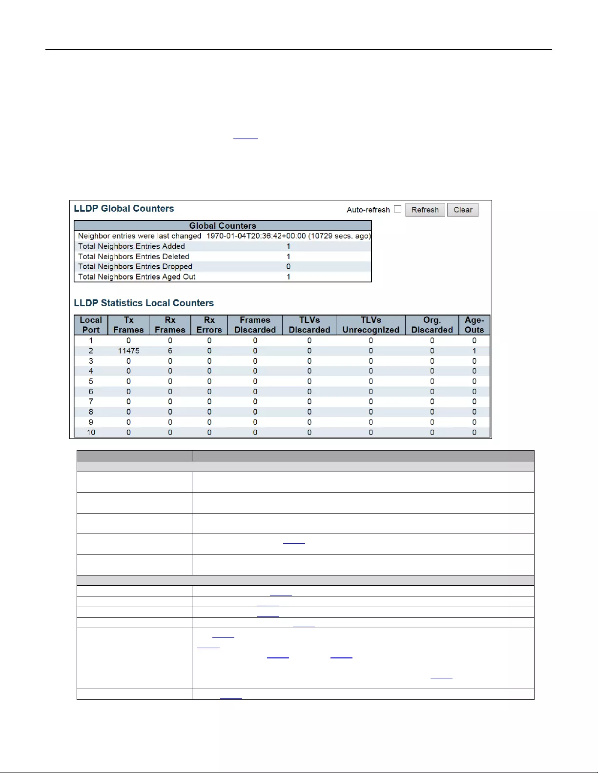
5.4.64 Port Statistics
This page provides an overview of all LLDP traffic.
Two types of counters are shown. Global counters are counters that refer to the whole switch, while local
counters refer to per port counters for the currently selected switch.
Object
Description
Global Counters
Neighbor entri es were
last change
Shows the time when the last entry was last deleted or added. It also shows the time
elapsed since the las t chang e was detected.
Total Neighbors Entries
Added
Shows the number of new entries added since switch reboot.
Total Neighbors Entries
Deleted
Shows the number of new entries deleted since switch reboot.
Total Neighbors Entries
Dropped
Shows the number of LLDP frames dropped due to the entry table being full.
Total Neighbors Entries
Aged Out
Shows the number of entries deleted due to Time-To-Live expiring.
Local Counters
Local Port
The port on which LLDP frames are received or transmitted.
Tx Frames
The number of LLDP frames transmitted on the port.
Rx Frames
The number of LLDP fr a me s receiv ed on the port.
Rx Errors
The number of received LLDP frames containing some kind o f error.
Frames Discarded
If a LLDP frame is received on a port, and the switch's internal table has run full, the
LLDP frame is counted and discarded. This situation is known as "Too Many
Neighbors" in the LLDP standard. LLDP frames require a new entry in the table when
the Chas si s ID or Remo te Port I D i s not already contain ed within the tab le. Entr ies are
removed from the tabl e when a given port 's lin k is dow n, an LLDP shutdown frame is
received, or when the entry ages out.
TLVs Discarded
Each LLDP frame can contain multiple pieces of information, known as TLVs (TLV is
227
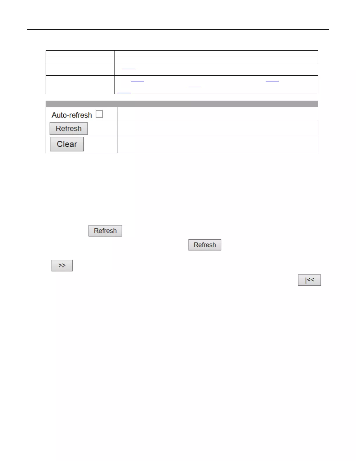
short for "Type Length Value"). If a TLV is malformed, it is counted and discarded.
TLVs Unrecognized
The number of well-formed TLVs, but with an unknown type value.
Org. Discarded
If LLDP frame is received with an organizationally TLV, but the TLV is not supported
the TLV is discarded and counted.
Age-Outs
Each LLDP frame contains information about how long time the LLDP information is
valid (age-out time). If no new LLDP frame is received within the age out time, the
LLDP information is removed, and the Age-Out counter is incremente d.
Buttons
Check this box to refresh the page automatically. Automatic refresh occurs every 3
seconds.
Click to refresh the page.
Clears the local counters. All counters (including global counters) are cleared
upon reboot.
5.4.65 MAC Table
Each page shows up to 999 entries from the MAC table, default being 20, selected through the "entries per
page" input field. When first visited, the web page will show the first 20 entries from the beginning of the MAC
Table. The first displayed will be the one with the lowest VLAN ID and the lowest MAC address found in the MAC
Table.
The "Start from MAC address" and "VLAN" input fields allow the user to select the starting point in the MAC
Table. Clicking the button will update the displayed table starting from that or the closest next MAC
Table match. In addition, the two input fields will - upon a button click - assume the value of the first
displayed entry, allowing for continuous refresh with the same start address.
The will use the last entry of the currently displayed VLAN/MAC address pairs as a basis for the next
lookup. When the end is reached the text "No more entries" is shown in the displayed table. Use the
button to start over.
228
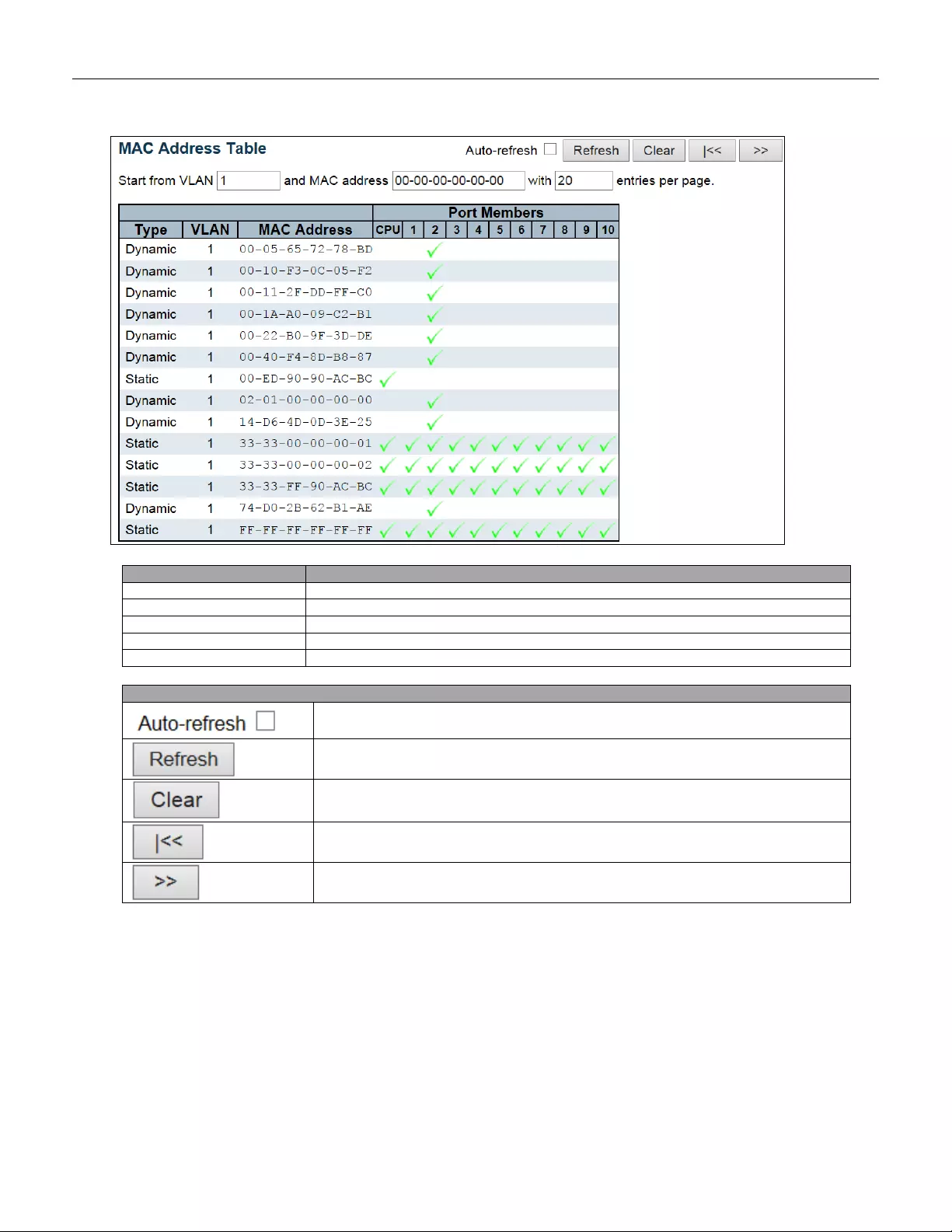
Object
Description
Switch (stack only)
The stack unit where the entry is learned.
Type
Indicates whether the entry is a static or a dynamic entry.
MAC Address
The MAC address of the entry.
VLAN
The VLAN ID of the entry.
Port Members
The ports that are members of the entry.
Buttons
Check this box to refresh the page automatically. Automatic refresh occurs every 3
seconds.
Refreshes the displayed table starting from the "Start from MAC address" and
"VLAN" input fie lds .
Flushes all dynamic entries.
Updates th e ta ble start ing fro m t he f irst ent ry i n th e MAC Table, i.e. the entry with the
lowest VLAN ID and MAC address.
Updates the table, starting with the entry after the last entry currently displayed.
229
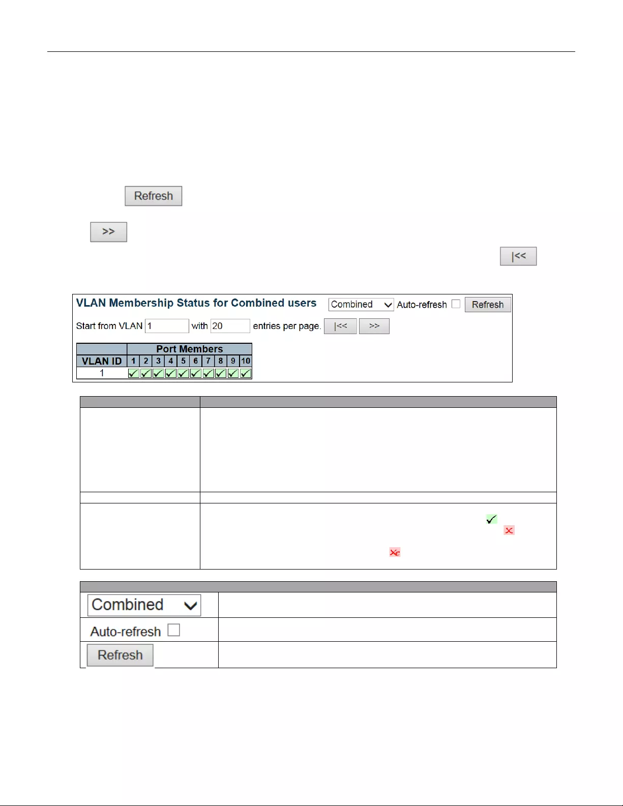
5.4.66 VLANs
5.4.67 VLANs Membership
Each page shows up to 99 entries from the VLAN table (default being 20), selected through the "entries per
page" input field. When first visited, the web page will show the first 20 entries from the beginning of the VLAN
Table. The first displayed will be the one with the lowest VLAN ID found in the VLAN Table.
The "VLAN" input field allows the user to select the starting point in the VLAN Table.
Clicking the button w ill update the displayed table starting from that or the closest next VLAN Table
match.
The will use the last entry of the currently displayed VLAN entry as a basis for the next lookup. When
the end is reached, the text "No data exists for the selected user" is shown in the table. Use the button
to start over.
Object
Description
VLAN User
Various internal software modules may use VLAN services to configure VLAN
memberships on the fly.
The drop-down list on the right allows for selecting between showing VLAN
memberships as configured by an administrator (Admin) or as configured by one of
these internal software modules.
The "Combined" entry will show a combination of the administrator and internal
software modules configuration, and basically reflects what is actually configured in
hardware.
VLAN ID
VLAN ID for which the Port members are displayed.
Port Members
A row of check boxes for each port is displayed for each VLAN ID.
If a port is included in a VLAN, the following image will be displayed:
If a port is in the forbidden port list, the following image will be displayed:
If a port is in the f orbidden port list and at the same time attempted included in the
VLAN, the foll owing image will be displayed: . The port w ill not be a me mber of th e
VLAN in this case.
Buttons
Select VLAN Users from this drop down list.
Check this box to refresh the page automatically. Automatic refresh occurs every
3 seconds.
Click to refresh the page immediately.
230
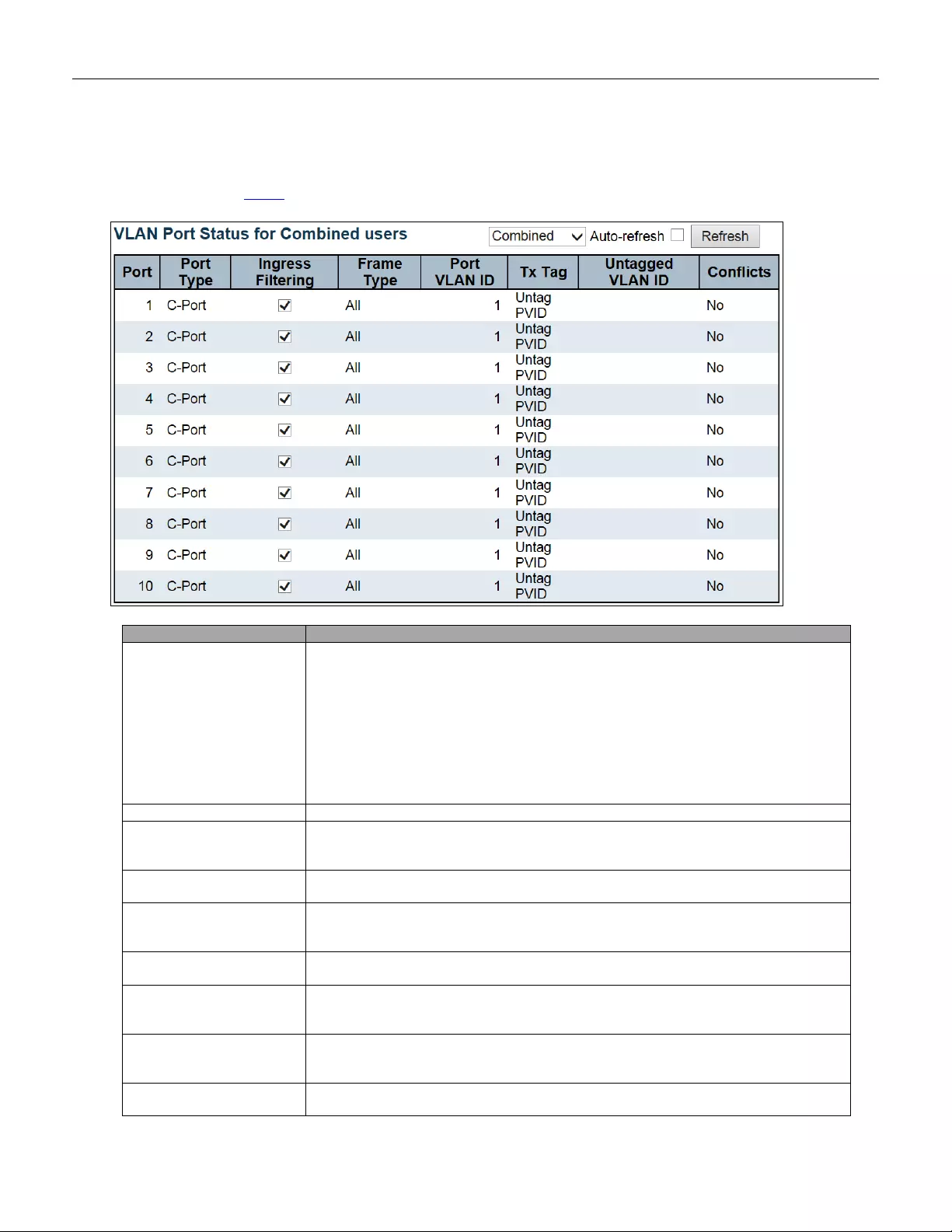
5.4.68 VLANs Ports
This page provides VLAN Port Status.
Object
Description
VLAN User
Various internal software modules may use VLAN services to configure VLAN port
configuration on the fly.
The drop-down list on the right allows for selecting between showing VLAN
memberships as configured by an administrator (Admin) or as configured by one of
these internal software modules.
The "Combined" entry will show a combination of the administrator and internal
software modules configuration, and basically reflects what is actually configured in
hardware.
If a given software modules hasn't overridden any of the port settings, the text "No
data exists for the selected user" is shown in the table.
Port
The logical port for the settings contained in the same row.
Port Typ e
Shows the port type (Unaware, C-Port, S-Port, S-Custom-Port.) that a given user
wants to configure on the port.
The field is empty if not overridden by the selected user.
Ingress Filtering
Shows whether a given user wants ingress filtering enabled or not.
The field is empty if not overridden by the selected user.
Frame Type
Shows the acceptable frame types (All, Taged, Untagged) that a given user wants to
configure on the port.
The field is empty if not overridden by the selected user.
Port VALN ID
Shows the Port VLAN ID (PVID) that a given user wants the port to have.
The field is empty if not overridden by the selected user.
Tx Tag
Shows the T x Tag requirements (Tag A l l, Tag PVID, Tag UVID , Unt ag All, Untag PVID ,
Untag UVID) that a given user has on a port.
The field is empty if not overridden by the selected user.
Untagged VLAN ID
If Tx Tag is overridden by the selected user and is set to Tag or Untag UVID, then this
field will show the VLAN ID the user wants to tag or untag on egress.
The field is empty if not overridden by the selected user.
Conflicts
Two users may have conflicting requirements to a port's configuration. For instance,
one user may require all frames to be tagged on egress while another requires all
231
frames to be untagged on egress.
Since both users cannot win, this gives rise to a conflict, which is solved in a
prioritized way. The Administrator has the least priority. Other software modules are
prioritized according to their position in the drop-down list: The higher in the list, the
higher priority.
If conflicts exist, it will be displayed as "Yes" for the "Combined" user and t he
offending software module.
The "Combined" user reflects what is actually configured in hardware.
Buttons
Select VLAN Users from this drop down list.
Check this box to refresh the page automatically. Automatic refresh occurs every 3
seconds.
Click to refresh the page immediately.
232

5.4.69 RingV2
This page provides a status overview for all of Ring status.
Object
Description
Group Index
The group index. This parameter is used for easy identifying which ring group.
Mode
It indicates whether the group is enabled.
Role
It indicates group is configured as which role.
State
When ring is complete, it w ill show "Normal".
When ring is incomplete (at least one link is down), it will show "Fail".
Ring Port(s)
Describes current status of ring port(s).
Buttons
Check this box to refresh the page automatically. Automatic refresh occurs every 3
seconds.
Click to refresh the page.
5.4.70 DDMI Overview
Display DDMI overview information on this page.
Object
Description
Port
DDMI port.
Vendor
Indicates Vendor name SFP vendor name.
Part Number
Indicates Vendor PN Part number provided by SFP vendor.
Serial Number
Indicates Vendor SN Serial number provided by vendor.
Revision
Indicates Vendor rev Revision level for part number provided by vendor.
Date Code
Indicates Date code Vendor's manufacturing date code.
Transceiver
Indicates Transceiver co mpat i bility.
233
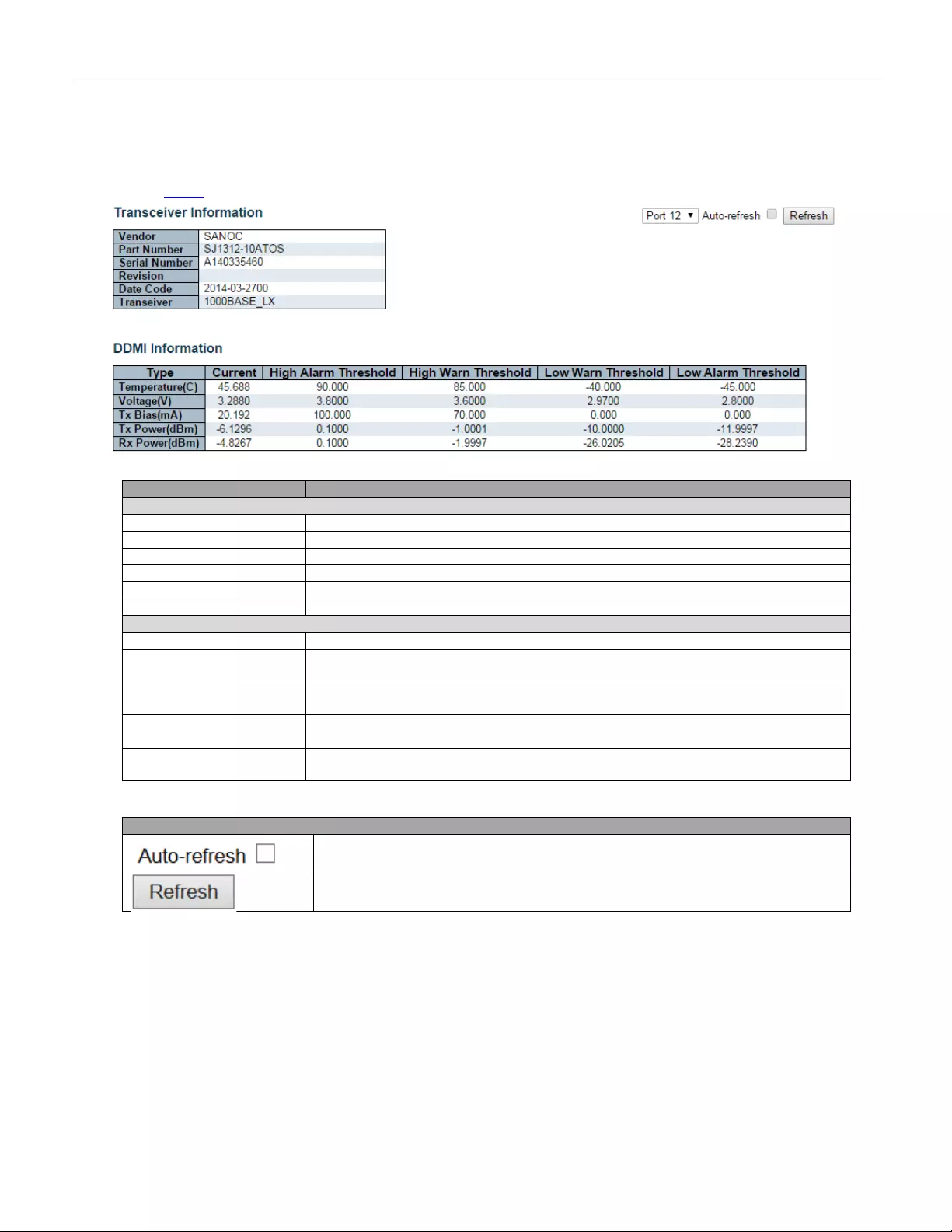
5.4.71 DDMI Detailed
Display DDMI detailed information on this page.
Object
Description
Transceiver Information
Vendor
Indicates Vendor name SFP vendor name.
Part Number
Indicates Vendor PN Part number provided by SFP vendor.
Serial Number
Indicates Vendor SN Serial number provided by vendor.
Revision
Indicates Vendor rev Revision level for part number provided by vendor.
Date Code
Indicates Date code Vendor's manufacturing date code.
Transceiver
Indicates Transceiver co mpat i bility.
DDMI Information
Current
The current value of temperature, voltage, TX bias, TX power, and RX power.
High Alar m Threshold
The high alarm threshold value of temperature, voltage, TX bias, TX power, and RX
power.
High Warn Threshold
The high warn threshold value of temperature, voltage, TX bias, TX power, and RX
power.
Low Warn Threshold
The low warn threshold value of temperature, voltage, TX bias, TX power, and RX
power.
Low Alarm Threshold
The low alarm threshold value of temperature, voltage, TX bias, TX power, and RX
power.
Buttons
Check this box to refresh the page automatically. Automatic refresh occurs every 3
seconds.
Click to refresh the page.
234
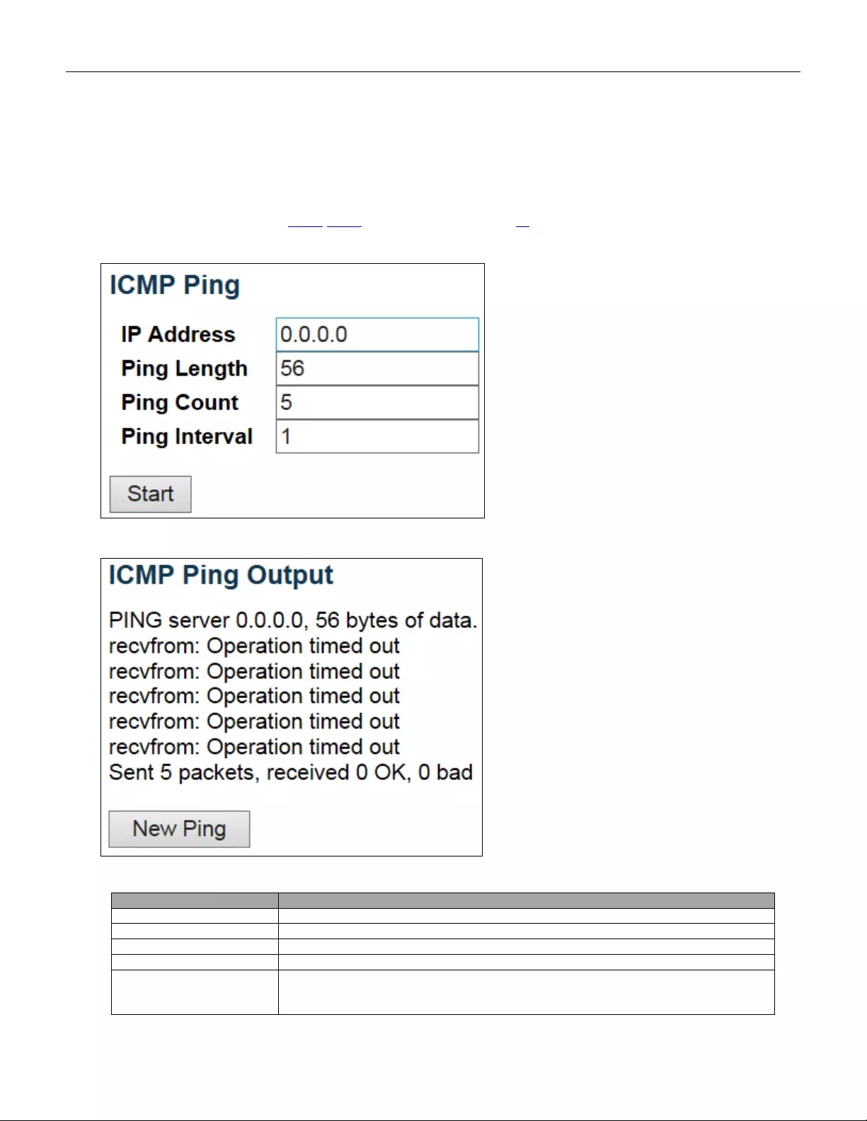
5.5 Diagnostics
5.5.1 Ping
This page allows you to issue ICMP PING packets to troubleshoot IP conn ec ti vit y issues .
Object
Description
IP A ddress
The destinat ion IP Ad dress.
Ping Length
The payload size of the ICMP packet. Values range from 2 bytes to 1452 bytes.
Ping Count
The count of the ICMP packet. Values range from 1 time to 60 times.
Ping Interval
The interval of the ICMP packet. Val ues range from 0 second to 30 seconds.
Egress Interface
(only for IPv6)
The VLAN ID (VID) of the specific egress IPv6 interface which ICMP packet goes.
The given VID ranges from 1 to 4094 and will be effective only when the
corresponding IPv6 interface is valid.
235
When the egress interface is not given, PING6 finds the best match interface for
destination.
Do not specify egress interface for loopback address.
Do specify egress interface for link-local or multica st addr e ss.
Buttons
Click to start transmitting ICMP packets.
Click to re-start diagnostics with PING.
236
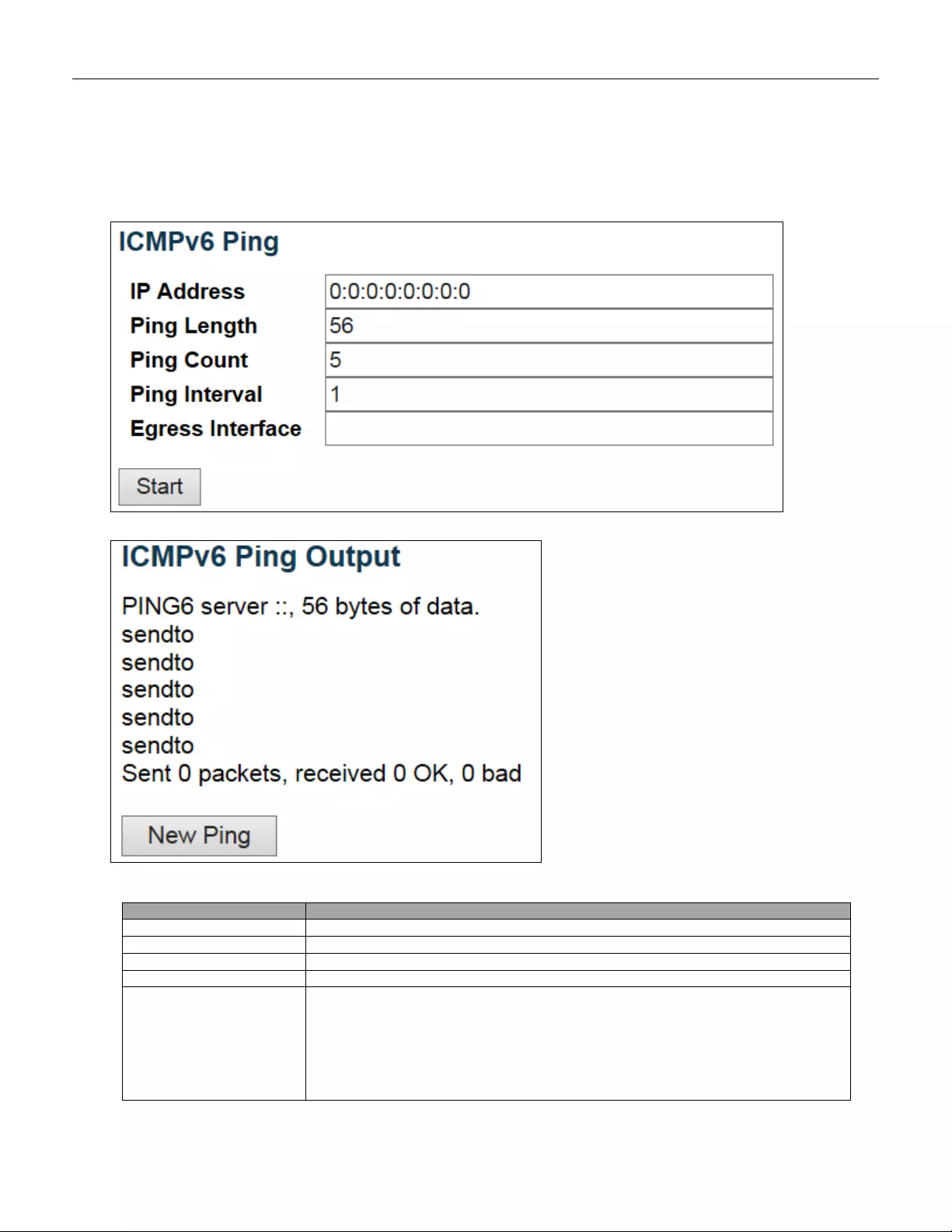
5.5.2 Ping6
This page allows you to issue ICMPv6 PING packets to troubleshoot IPv6 connectivity issues.
Object
Description
IP A ddress
The destination IP Address.
Ping Length
The payload size of the ICMP packet. Values range from 2 bytes to 1452 bytes.
Ping Count
The count of the ICMP packet. Values range from 1 time to 60 times.
Ping Interval
The interval of the ICMP packet. Val ues range from 0 second to 30 seconds.
Egress Interface
(only for IPv6)
The VLAN ID (VID) of the specific egress IPv6 interface which ICMP packet goes.
The given VID ranges from 1 to 4094 and will be effective only when the
corresponding IPv6 interface is valid.
When the egress interface is not given, PING6 finds the best match interf a ce for
destination.
Do not specify egress interface for loopback address.
Do specify egress interface for link-local or multica st addr e ss.
237

Buttons
Click to start transmitting ICMP packets.
Click to re-start diagnostics with PING.
238
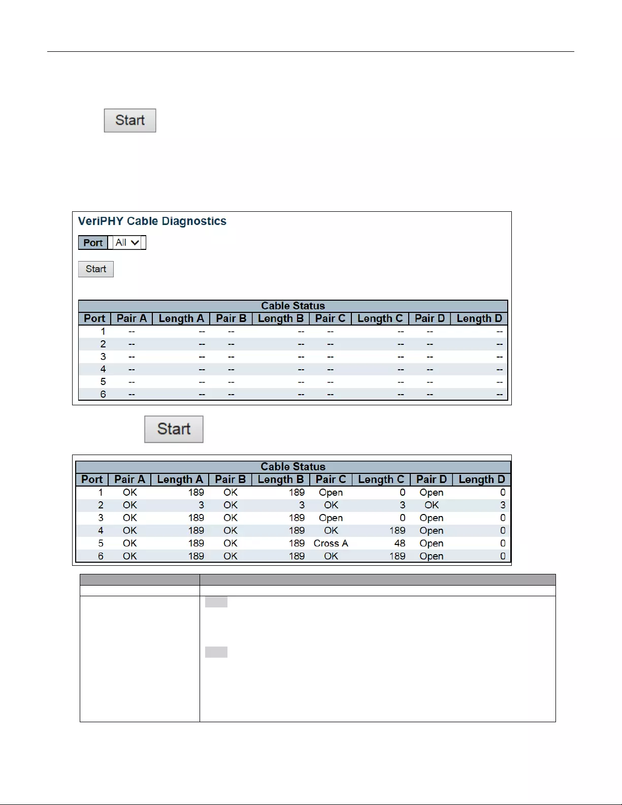
5.5.3 VeriPHY
Press to run the diagnostics. This will take approximately 5 seconds. If all ports are selected, this
can take approximately 15 seconds. When completed, the page refreshes automatically, and you can view the
cable diagnostics results in the cable status table. Note that VeriPHY is only accurate for cables of length 7 - 140
meters.
10 and 100 Mbps ports will be linked down while running VeriPHY. Therefore, running VeriPHY on a 10 or 100
Mbps management port will cause the switch to stop responding until VeriPHY is complete.
After pressi ng , following table show up.
Object
Description
Port
The port where you are requesting VeriPHY Cable Diagnostics.
Cable Status
Port:
Port number.
Pair:
The status of the cable pair.
OK - Correctly terminated pair
239
Open - Open pair
Short - Shorted pair
Short A - Cross-pair short to pair A
Short B - Cross-pair short to pair B
Short C - Cross-pair short to p air C
Short D - Cross-pair short to p air D
Cross A - Abnormal cross-pair coupling with pair A
Cross B - Abnormal cross-pair coupling with pair B
Cross C - Abnormal cross-pair coupling with pair C
Cross D - Abnormal cross-pair coupling with pair D
Length:
The length (in meters) of the cable pair. The resolution is 3 meters
Buttons
Click to run the diagnostics.
240
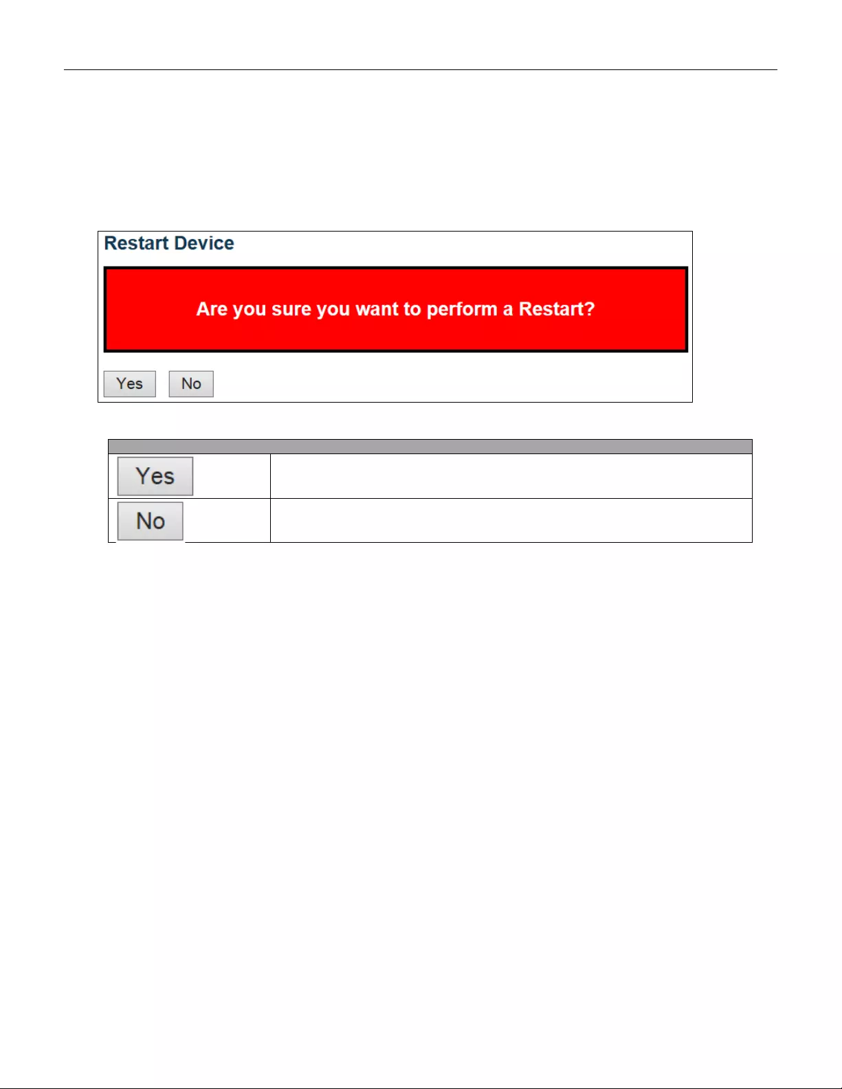
5.6 Maintenance
5.6.1 Restart Device
You can restart the switch on this page. After restart, the switch will boot normally.
Buttons
Click to restart device.
Click to return to the Port State page without restarting.
241
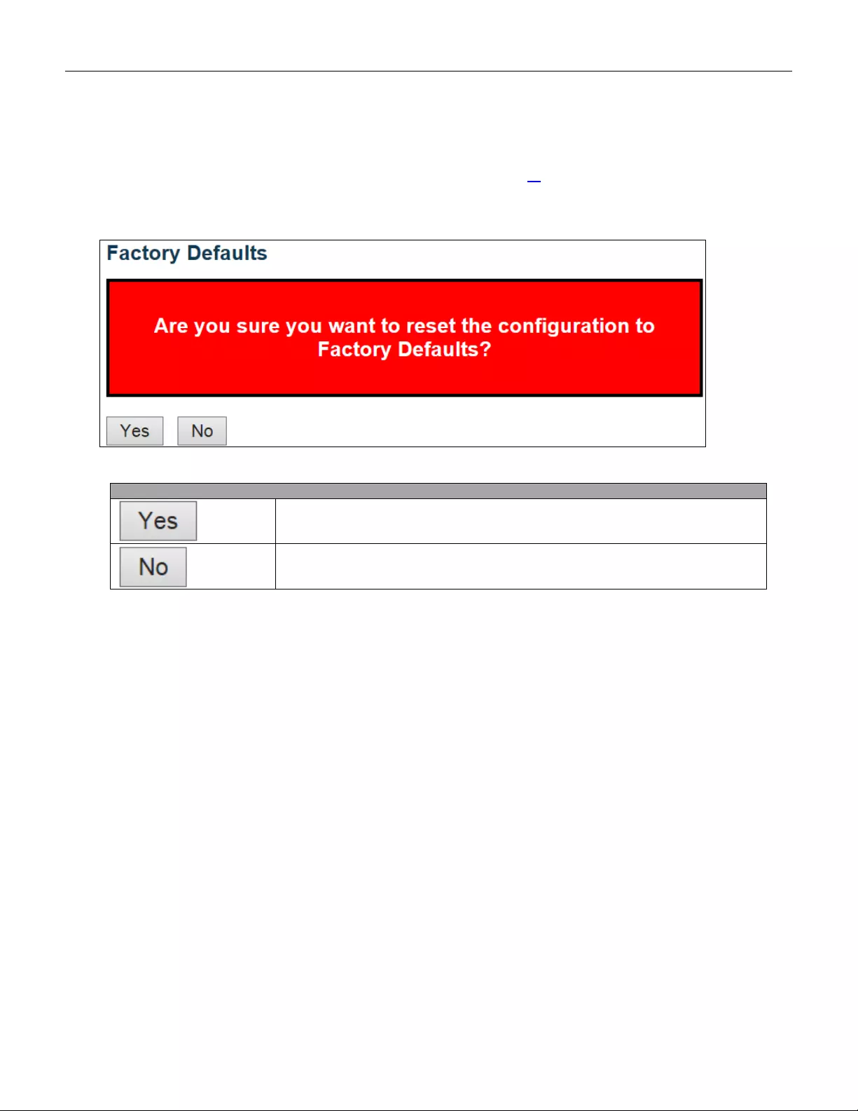
5.6.2 Factory Default
You can reset the configuration of the switch on this page. Only the IP configuration is retained.
The new configuration is available immediately, which means that no restart is necessary.
Buttons
Click to reset the configuration to Factory Defaults.
Click to return to the Port State page without resetting the configuration.
242
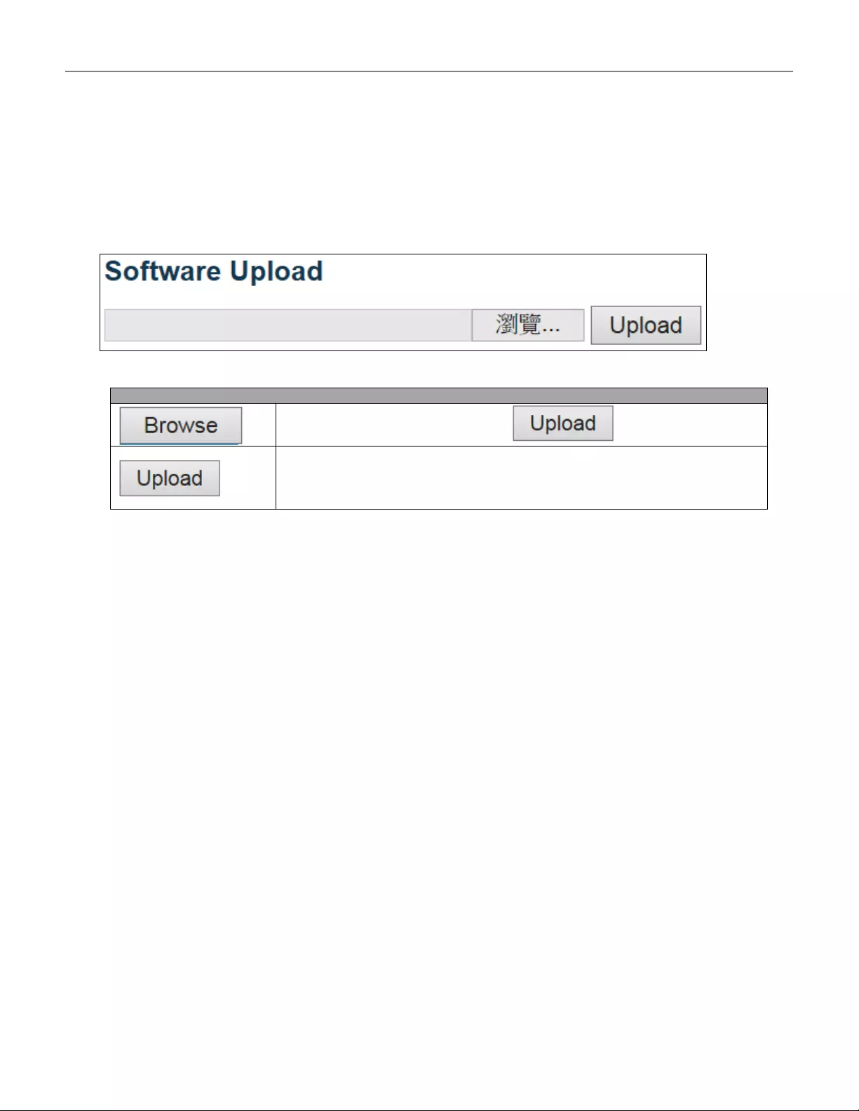
5.6.3 Software
5.6.3.1 Software Upload
This page facilitates an update of the firmware controlling the switch.
Buttons
Go to find the software image and click. .
After finding the software image, click the button to update firmware.
After the software image is uploaded, a page announces that the firmware
update is initiated. After about a minute, the firmware is updated and the
switch restarts.
Warning: While the firmware is being updated, Web access appears to be defunct. The front LED flashes
Green/Off with a frequency of 10 Hz while the firmware update is in progress. Do not restar t or power off the
device at this time or the switch may fail to function afterwards.
243
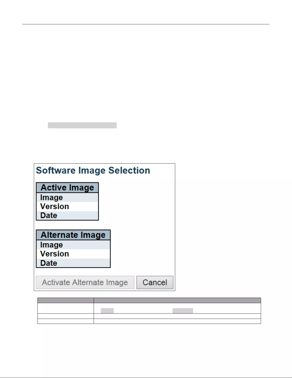
5.6.3.2 Image select
This page provides information about the active and alternate (backup) firmware images in the device, and
allows you to revert to the alternate image.
The web page displays two tables with information about the active and alternate firmware images.
Note:
1. In case the active firmware image is the alternate image, only the "Active Image" table is shown. In this case,
the Activate Alternate Image butt on is also dis abl ed.
2. If the alternate image is active (due to a corruption of the primary image or by manual intervention), uploading
a new firmware image to the device will automatically use the primary image slot and activate this.
3. The firmware version and date information may be empty for older firmware releases. This does not
constitute an error.
Object
Description
Image
The flash index name of the firmware image. The name of primary (preferred) image
is image, the alternate image is named image.bk.
Version
The version of the firmware image.
Data
The date where the firmware was produced.
244

Buttons
Click to use the alternate image. This button may be
disabled depending on system state.
Cancel activating the backup image. Navigates away from
this page.
245
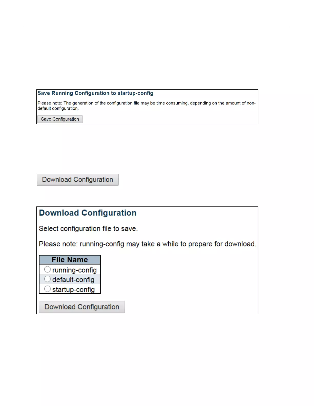
5.6.4 Configuration
5.6.4.1 Save startup-config
Copy running-config to startup-config, thereby ensuring that the currently active configuration will be used at the
next reboot.
5.6.4.2 Download
It is possible to download any of the files on the switch to the web browser. Select the file and click
.
Download running-config may take a little while to complete, as the file must be prepared for dow nload.
246
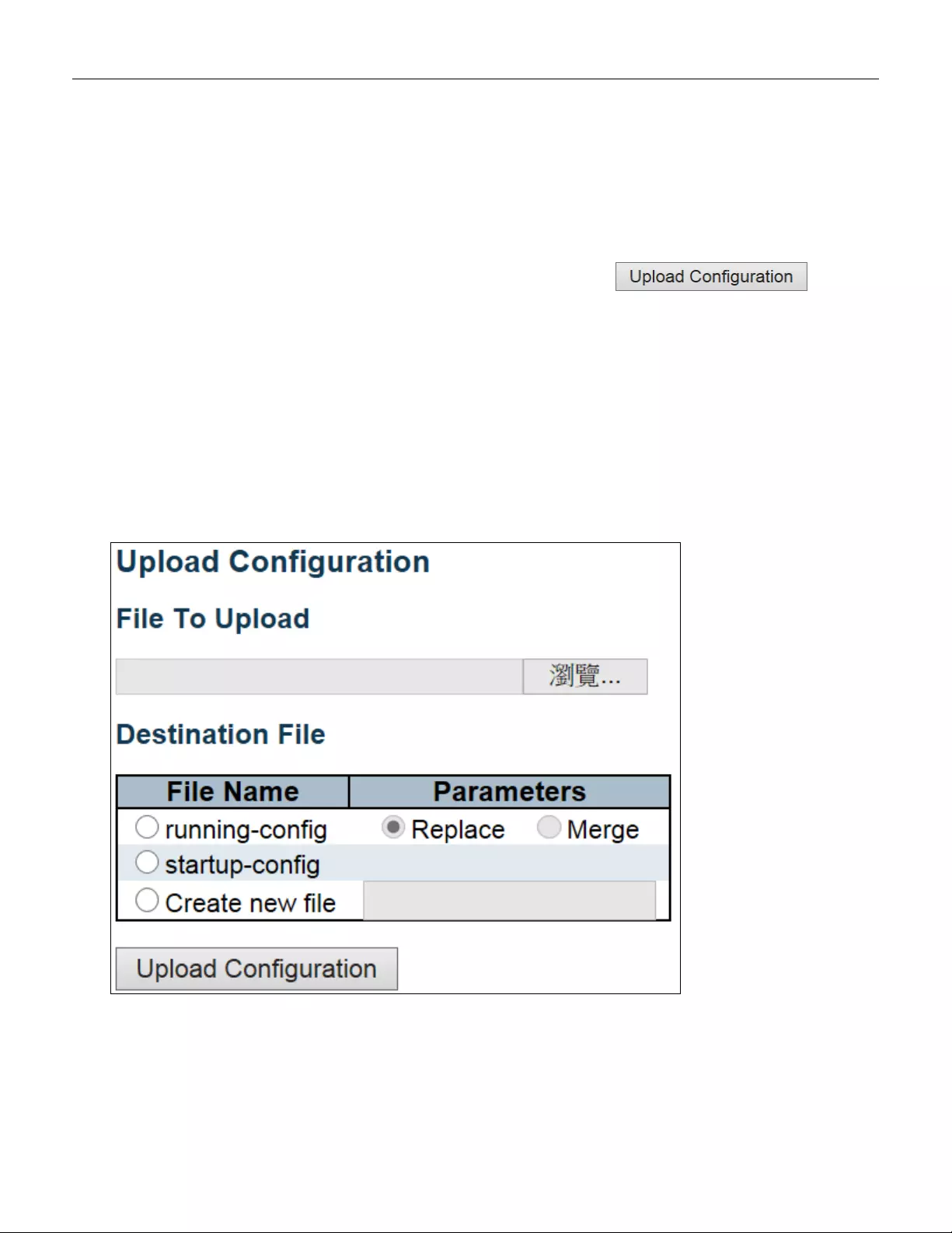
5.6.4.3 Upload
It is possible to upload a file from the web browser to all the files on the switch, except default-config, which is
read-only.
Select the file to upload, select the destination file on the target, then click .
If the destination is running-config, the file will be applied to the switch configuration. This can be done in two
ways:
- Replace mode: The current configuration is fully replaced with the configuration in the uploaded file.
- Merge mode: The uploaded file is merged into running-config.
If the file sy stem is full (i.e. contains the three system files mentioned above plus two other files), it is not possible
to create new files, but an existing file must be overwritten or another deleted first.
247
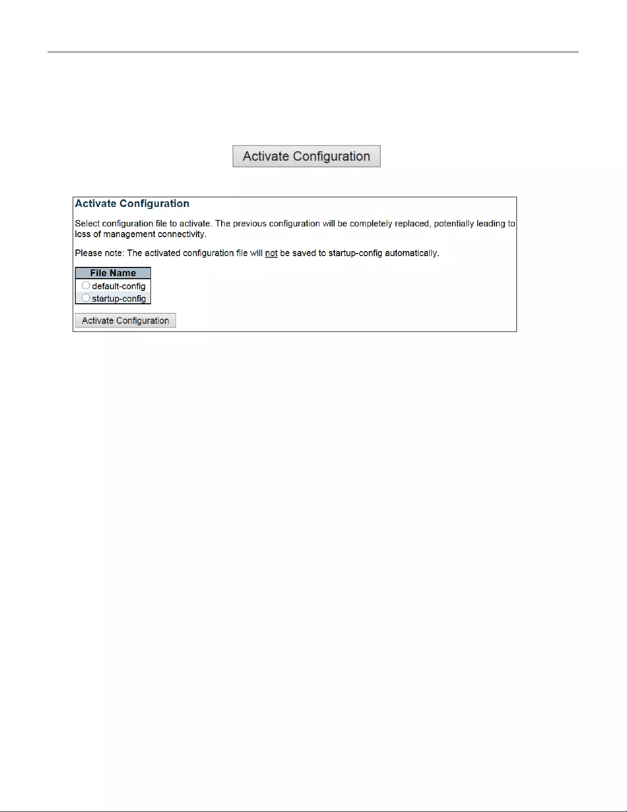
5.6.4.4 Activate
It is possible to activate any of the configuration files present on the switch, except for running-config which
represents the currently active configuration.
Select the file to activate and click . This will initiate the process of completely
replacing the existing configuration with that of the selected file.
248
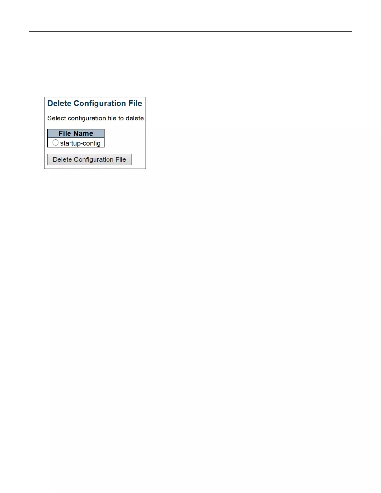
5.6.4.5 Delete
It is possible to delete any of the w ritable files stored in flash, including startup-config. If this is done and the
switch is rebooted without a prior Save operation, this effectively resets the switch to default configuration.
249

Copyright
Copyright © 2016 by Zyxel Communications Corporation.
The contents of this publication may not be reproduced in any part or as a whole, transcribed, stored in a retrieval system, translated into any language, or transmitted in any
form or by any means, electronic, mechanical, magnetic, optical, chemical, photocopying, manual, or otherwise, without the prior written permission of Zyxel
Communications Corporation.
Published by Zyxel Communications Corporation. All rights reserved.
Disclaimer
Zyxel does not assume any liability arising out of the application or use of any products, or software described herein. Neither does it convey any license under its patent
rights nor the patent rights of others. Zyxel further reserves the right to make changes in any products described herein without notice. This publication is subject to
change without notice.
Trademarks
ZyNOS (Zyxel Network Operating System) and ZON (Zyxel One Network)are registered trademarks of Zyxel Communications,
Inc. Other
trademarks mentioned in this
publication are used for identification purposes only and may be properties of their respective owners.
Regulatory Notice and Statement
United States of America
The following information applies if you use the product within USA area.
Federal Communications Commission (FCC) EMC Statement
• This device complies with Part 15 of FCC rules. Operation is subject to the following two conditions: (1) This device may not
cause harmful interference.
(2) This device must accept any interference received, including interference that may cause undesired operations.
• Changes or modifications not expressly approved by the party responsible for compliance could void the user’s authority to operate the equipment.
• This equipment has been tested and found to comply with the limits for a Class A digital device, pursuant to part 15 of the FCC Rules.
These limits are designed to provide reasonable protection against harmful interference when the equipment is operated in a commercial environment. This
equipment generates, uses, and can radiate radio frequency energy and, if not installed and used in accordance with the instruction manual, may cause harmful
interference to radio communications. Operation of this equipment in a residential area is likely to cause harmful interference in which case the user will be required
to correct the interference at his own expense.
Canada
The following information applies if you use the product within Canada area
Industry Canada ICES statement
CAN ICES-3 (A)/NMB-3(A)
European Union
The following information applies if you use the product within the European Union.
6. Legal Information
250

CE EMC statement
This is Class A Product. In domestic environment this product may cause radio interference in which case the user may be required to take
adequate measures.
List of National Codes
COUNTRY
ISO 3166 2 LETTER CODE
COUNTRY
ISO 3166 2 LETTER CODE
Austria
AT
Liechtenstein
LI
Belgium
BE
Lithuania
LT
Bulgaria
BG
Luxembourg
LU
Croatia
HR
Malta
MT
Cyprus
CY
Netherlands
NL
Czech Republic
CR
Norway
NO
Denmark
DK
Poland
PL
Estonia
EE
Portugal
PT
Finland
FI
Romania
RO
France
FR
Serbia
RS
Germany
DE
Slovakia
SK
Greece
GR
Slovenia
SI
Hungary
HU
Spain
ES
Iceland
IS
Sweden
SE
Ireland
IE
Switzerland
CH
Italy
IT
Turkey
TR
Latvia
LV
United Kingdom
GB
Notices
CLASS 1 LASER PRODUCT
APPAREIL À LASER DE CLASS 1
PRODUCT COMPLIES WITH 21 CFR 1040.10 AND 1040.11.
PRODUIT CONFORME SELON 21 CFR 1040.10 ET 1040.11.
Safety Warnings
• Do NOT use this product near water, for example, in a wet basement or near a swimming pool.
• Do NOT expose your device to dampness, dust or corrosive liquids.
• Do NOT store things on the device.
• Do NOT install, use, or service this device during a thunderstorm. There is a remote risk of electric shock from lightning.
• Do NOT obstruct the device ventilation slots as insufficient airflow may harm your device. For example, do not place the device in an
enclosed space such as a box or on a very soft surface such as a bed or sofa.
• Connect ONLY suitable accessories to the device.
• Do NOT open the device or unit. Opening or removing covers can expose you to dangerous high voltage points or other risks. ONLY
qualified service personnel should service or disassemble this device. Please contact your vendor for further information.
• Make sure to connect the cables to the correct ports.
• Place connecting cables carefully so that no one will step on them or stumble over them.
• Always disconnect all cables from this device before servicing or disassembling.
• Use ONLY an appropriate power adaptor or cord for your device. Connect it to the right supply voltage (for example, 110V AC in North
America or 230V AC in Europe).
• DO NOT remove the plug and connect it to a power outlet by itself; always attach the plug to the power adaptor first before connecting it
to a power outlet.
• Use ONLY power wires of the appropriate wire gauge for your device. Connect it to a power supply of the correct voltage.
• Do NOT allow anything to rest on the power adaptor or cord and do NOT place the product where anyone can walk on the power
adaptor or cord.
• Do NOT use the device if the power adaptor or cord is damaged as it might cause electrocution.
• If the power adaptor or cord is damaged, remove it from the device and the power source.
• Do NOT attempt to repair the power adaptor or cord. Contact your local vendor to order a new one.
• Fuse Warning! Replace a fuse only with a fuse of the same type and rating.
• The POE (Power over Ethernet) devices that supply or receive power and their connected Ethernet cables must all be completely
indoors.
• DO NOT use the device outside, and make sure all the connections are indoors. There is a remote risk of electric shock from lightning.
• CAUTION: RISK OF EXPLOSION IF BATTERY (on the motherboard) IS REPLACED BY AN INCORRECT TYPE. DISPOSE OF USED
BATTERIES ACCORDING TO THE INSTRUCTIONS. Dispose them at the applicable collection point for the recycling of electrical and
electronic equipment. For detailed information about recycling of this product, please contact your local city office, your household
waste disposal service or the store where you purchased the product.
The following warning statements apply, where the disconnect device is not incorporated in the equipment or where the plug on the power
supply cord is intended to serve as the disconnect device,
• For PERMANENTLY CONNECTED EQUIPMENT, a readily accessible disconnect device shall be incorporated external to the equipment;
251

• For PLUGGABLE EQUIPMENT, the socket-outlet shall be installed near the equipment and shall be easily accessible.
Environment Statement
European Union - Disposal and Recycling Information
The symbol below means that according to local regulations your product and/or its battery shall be disposed of separately from domestic
waste. If this product is end of life, take it to a recycling station designated by local authorities. At the time of disposal, the separate collection
of your product and/or its battery will help save natural resources and ensure that the environment is sustainable development.
Die folgende Symbol bedeutet, dass Ihr Produkt und/oder seine Batterie gemäß den örtlichen Bestimmungen getrennt vom Hausmüll
entsorgt werden muss. Wenden Sie sich an eine Recyclingstation, wenn dieses Produkt das Ende seiner Lebensdauer erreicht hat. Zum
Zeitpunkt der Entsorgung wird die getrennte Sammlung von Produkt und/oder seiner Batterie dazu beitragen, natürliche Ressourcen zu
sparen und die Umwelt und die menschliche Gesundheit zu schützen.
El símbolo de abajo indica que según las regulaciones locales, su producto y/o su batería deberán depositarse como basura separada de la
doméstica. Cuando este producto alcance el final de su vida útil, llévelo a un punto limpio. Cuando llegue el momento de desechar el
producto, la recogida por separado éste y/o su batería ayudará a salvar los recursos naturales y a proteger la salud humana y
medioambiental.
Le symbole ci-dessous signifie que selon les réglementations locales votre produit et/ou sa batterie doivent être éliminés séparément des
ordures ménagères. Lorsque ce produit atteint sa fin de vie, amenez-le à un centre de recyclage. Au moment de la mise au rebut, la collecte
séparée de votre produit et/ou de sa batterie aidera à économiser les ressources naturelles et protéger l'environnement et la santé humaine.
Il simbolo sotto significa che secondo i regolamenti locali il vostro prodotto e/o batteria deve essere smaltito separatamente dai rifiuti
domestici. Quando questo prodotto raggiunge la fine della vita di servizio portarlo a una stazione di riciclaggio. Al momento dello
smaltimento, la raccolta separata del vostro prodotto e/o della sua batteria aiuta a risparmiare risorse naturali e a proteggere l'ambiente e
la salute umana.
Symbolen innebär att enligt lokal lagstiftning ska produkten och/eller dess batteri kastas separat från hushållsavfallet. När den här
produkten når slutet av sin livslängd ska du ta den till en återvinningsstation. Vid tiden för kasseringen bidrar du till en bättre miljö och
mänsklig hälsa genom att göra dig av med den på ett återvinningsställe.
252
Environmental Product Declaration
253

台灣
警告使用者
• 這是甲類的資訊產品,在居住的環境中使用時,可能會造成射頻干擾,在這種情況下,使用者會被要求採取某些適當的對策。
安全警告 - 為了您的安全,請先閱讀以下警告及指示:
• 請勿將此產品接近水、火焰或放置在高溫的環境。
• 避免設備接觸
- 任何液體 - 切勿讓設備接觸水、雨水、高濕度、污水腐蝕性的液體或其他水份。
- 灰塵及污物 - 切勿接觸灰塵、污物、沙土、食物或其他不合適的材料。
• 雷雨天氣時,不要安裝,使用或維修此設備。有遭受電擊的風險。
• 切勿重摔或撞擊設備,並勿使用不正確的電源變壓器。
• 若接上不正確的電源變壓器會有爆炸的風險。
• 請勿隨意更換產品內的電池。
• 如果更換不正確之電池型式,會有爆炸的風險,請依製造商說明書處理使用過之電池。
• 請將廢電池丟棄在適當的電器或電子設備回收處。
• 請勿將設備解體。
• 請勿阻礙設備的散熱孔,空氣對流不足將會造成設備損害。
• 請插在正確的電壓供給插座(如:北美/台灣電壓 110V AC,歐洲是 230V AC)。
• 假若電源變壓器或電源變壓器的纜線損壞,請從插座拔除,若您還繼續插電使用,會有觸電死亡的風險。
• 請勿試圖修理電源變壓器或電源變壓器的纜線,若有毀損,請直接聯絡您購買的店家,購買一個新的電源變壓器。
• 請勿將此設備安裝於室外,此設備僅適合放置於室內。
• 請勿隨一般垃圾丟棄。
• 請參閱產品背貼上的設備額定功率。
• 請參考產品型錄或是彩盒上的作業溫度。
• 設備必須接地,接地導線不允許被破壞或沒有適當安裝接地導線,如果不確定接地方式是否符合要求可聯繫相應的電氣檢驗機構檢。
• 產品沒有斷電裝置或者採用電源線的插頭視為斷電裝置的一部分,以下警語將適用:
- 對永久連接之設備, 在設備外部須安裝可觸及之斷電裝置;
- 對插接式之設備, 插座必須接近安裝之地點而且是易於觸及的。
Viewing Certifications
Go to http://www.zyxel.com to view this product’s documentation and certifications.
ZyXEL Limite d Warranty
ZyXEL warrants to the original end user (purchaser) that this product is free from any defects in material or workmanship for a specific period (the Warranty
Period) from the date of purchase. The W arranty Period v aries by region. Check with your vendor and/or the authorized Z yXEL local distributor f or details about
the Warranty Period of this product. During the warranty period, and upon proof of purchase, should the product have indications of failure due to faulty
workmanship and/or materials, Z yXEL will, at its discretion, repair or replace the defective products or components without charge for either parts or labor, and
to whatever extent it shall deem necessary to restore the product or components to proper operating condition. Any replacement will consist of a new or
re-manufactured functionally equivalent product of equal or higher value, and will be solely at the discretion of ZyXEL. This warranty shall not apply if the product
has been modified, misused, tampered with, damaged by an act of God, or subjected to abnormal working conditions.
Note
Repair or replacement, as provided under this warranty, is the exclusive remedy of the purchaser. This warranty is in lieu of all other warranties, express or
implied, including any implied warranty of merchantability or fitness for a particular use or purpose. ZyXEL shall in no event be held liable for indirect or
consequential damages of any kind to the purchaser.
To obtain the services of this warranty, contact your vendor. You may also refer to the warranty policy for the region in which you bought the device at
http://www.zyxel.com/web/support_warranty_info.php.
Registration
Register your product online to receive e-mail notices of firmw are upgr ades an d infor mation at www .z yxel.c om for globa l produc ts, or at w ww .us.z yxel.c om for
North American products.
Trademarks
ZyNOS (ZyXEL Network Operating System) and ZON (ZyXEL One Network)are registered trademarks of ZyXEL Communications, Inc. Other tradema rks
mentioned in this publication are used for identification purposes only and may be properties of their respective owners.
Open Source Licenses
This product contains in part some free software distributed under GPL license terms and/or GPL like licenses. Open source licenses are provided with the
firmware package. You can download the latest firmware at www.zyxel.com. To obtain the source code covered under those Licenses, please contact
support@zyxel.com.tw to get it.
254

In the event of problems that cannot be solved by using this manual, you should contact your vendor.
If you cannot contact your vendor, then contact a ZyXEL office for the region in which you bought the
device.
See http://www.zyxel.com/homepage.shtml and also
http://www.zyxel.com/about_zyxel/zyxel_worldwide.shtml for the latest information .
Please have the following information ready when you contact an office.
Required Inform ation
• Product model and s e r ia l number.
• Warranty Information.
• Date that you r ec eived your devic e.
• Brief des c r iption of the problem and th e s teps you took to solve it.
Corporate Headquarters (Worldwide)
Taiwan
• ZyXEL Communications Corporation
• http://www.zyxel.com
Asia
China
• ZyXEL Communications (Shanghai) Corp.
ZyXEL Com m unications (Beijing) Corp.
ZyXEL Com m unications (Tianjin) Corp.
• http://www.zyxel.cn
India
• ZyXEL Technology I ndia Pvt Ltd
• http://www.zyxel.in
Kazakhstan
• ZyXEL Kazakhstan
• http://www.zyxel.kz
Korea
• ZyXEL Korea Corp.
• http://www.zyxel.kr
7.Customer Support
255

Malaysia
• ZyXEL Malaysia Sdn Bhd.
• http://www.zyxel.com.my
Pakistan
• ZyXEL Pakistan (Pvt.) Ltd.
• http://www.zyxel.com.pk
Philippines
• ZyXE L Philippines
• http://www.zyxel.com.ph
Singapore
• ZyXEL Singapore Pte Ltd.
• http://www.zyxel.com.sg
Taiwan
• ZyXEL Communications Corporation
• http://www.zyxel.com/tw/zh/
Thailand
• ZyXEL Thailand Co., Ltd
• http://www.zyxel.co.th
Vietnam
• ZyXEL Communications Corporation-Vietnam Office
• http://www.zyxel.com/vn/vi
Europe
Austria
• ZyXEL Deutschland GmbH
• http://www.zyxel.de
Belarus
• ZyXEL BY
• http://www.zyxel.by
256

Belgium
• ZyXEL Communications B.V.
• http://www.zyxel.com/be/nl/
• http://www.zyxel.com/be/fr/
Bulgaria
• ZyXEL България
• http://www.zyxel.com/bg/bg/
Czech Republic
• ZyXEL Communications C zech s.r.o
• http://www.zyxel.cz
Denmark
• ZyXEL Communications A /S
• http://www.zyxel.dk
Estonia
• ZyXEL Estonia
• http://www.zyxel.com/ee/et/
Finland
• ZyXEL Communications
• http://www.zyxel.fi
France
• ZyXEL France
• http://www.zyxel.fr
Germany
• ZyXEL Deutschland GmbH
• http://www.zyxel.de
Hungary
• ZyXEL Hungary & SEE
• http://www.zyxel.hu
Italy
• ZyXEL Communications Italy
• http://www.zyxel.it/
257

Latvia
• ZyXEL Latvia
• http://www.zyxel.com/lv/lv/homepage.shtml
Lithuania
• ZyXEL Lithuania
• http://www.zyxel.com/lt/lt/homepage.shtml
Netherlands
• ZyXEL Bene l ux
• http://www.zyxel.nl
Norway
• ZyXEL Communications
• http://www.zyxel.no
Poland
• ZyXEL Communications Poland
• http://www.zyxel.pl
Romania
• ZyXEL Romania
• http://www.zyxel.com/ro/ro
Russia
• ZyXEL Russia
• http://www.zyxel.ru
Slovakia
• ZyXEL Communications C zech s.r.o. organizacna zlozka
• http://www.zyxel.sk
Spain
• ZyXEL Communications ES Ltd
• http://www.zyxel.es
Sweden
• ZyXEL Communications
• http://www.zyxel.se
258

Switzerland
• Studerus AG
• http://www.zyxel.ch/
Turkey
• ZyXEL Turkey A.S.
• http://www.zyxel.com.tr
UK
• ZyXEL Communications UK Ltd.
• http://www.zyxel.co.uk
Ukraine
• ZyXEL Ukraine
• http://www.ua.zyxel.com
Latin America
Argentina
• ZyXEL Communication Corporation
• http://www.zyxel.com/ec/es/
Brazil
• ZyXEL Communications B rasil Ltda.
• https://www.zyxel.com/br/pt/
Ecuador
• ZyXEL Communication Corporation
• http://www.zyxel.com/ec/es/
Middle East
Israel
• ZyXEL Communication Corporation
• http://il.zyxel.com/homepage.shtml
Middle East
• ZyXEL Communication Corporation
• http://www.zyxel.com/me/en/
259
