Table of Contents
- Command Reference for AlliedWare Plus™ Version 5.4.8-0.x
- Contents
- List of Commands
- Part 1: Setup and Troubleshooting
- CLI Navigation Commands
- File and Configuration Management Commands
- Introduction
- autoboot enable
- boot config-file
- boot config-file backup
- boot system
- boot system backup
- cd
- copy (filename)
- copy current-software
- copy debug
- copy running-config
- copy startup-config
- copy zmodem
- create autoboot
- delete
- delete debug
- dir
- edit
- edit (filename)
- erase factory-default
- erase startup-config
- ip tftp source-interface
- ipv6 tftp source-interface
- mkdir
- move
- move debug
- pwd
- rmdir
- show autoboot
- show boot
- show file
- show file systems
- show running-config
- show running-config interface
- show startup-config
- show version
- unmount
- write file
- write memory
- write terminal
- User Access Commands
- Introduction
- clear line console
- clear line vty
- enable password
- enable secret
- exec-timeout
- flowcontrol hardware (asyn/console)
- length (asyn)
- line
- privilege level
- security-password history
- security-password forced-change
- security-password lifetime
- security-password min-lifetime-enforce
- security-password minimum-categories
- security-password minimum-length
- security-password reject-expired-pwd
- security-password warning
- service advanced-vty
- service password-encryption
- service telnet
- show privilege
- show security-password configuration
- show security-password user
- show telnet
- show users
- telnet
- telnet server
- terminal length
- terminal resize
- username
- GUI Commands
- Update Manager Commands
- System Configuration and Monitoring Commands
- Introduction
- banner exec
- banner login (system)
- banner motd
- clock set
- clock summer-time date
- clock summer-time recurring
- clock timezone
- hostname
- max-fib-routes
- max-static-routes
- no debug all
- reboot
- reload
- show clock
- show cpu
- show cpu history
- show debugging
- show interface memory
- show memory
- show memory allocations
- show memory history
- show memory pools
- show memory shared
- show process
- show reboot history
- show router-id
- show system
- show system environment
- show system interrupts
- show system mac
- show system pci device
- show system pci tree
- show system serialnumber
- show tech-support
- speed (asyn)
- terminal monitor
- undebug all
- Logging Commands
- Introduction
- clear exception log
- clear log
- clear log buffered
- clear log external
- clear log permanent
- connection-log events
- copy buffered-log
- copy permanent-log
- default log buffered
- default log console
- default log email
- default log external
- default log host
- default log monitor
- default log permanent
- log buffered
- log buffered (filter)
- log buffered exclude
- log buffered size
- log console
- log console (filter)
- log console exclude
- log date-format
- log email
- log email (filter)
- log email exclude
- log email time
- log external
- log external (filter)
- log external exclude
- log external rotate
- log external size
- log facility
- log host
- log host (filter)
- log host exclude
- log host source
- log host time
- log monitor (filter)
- log monitor exclude
- log permanent
- log permanent (filter)
- log permanent exclude
- log permanent size
- log-rate-limit nsm
- log trustpoint
- log url-requests
- show connection-log events
- show counter log
- show exception log
- show log
- show log config
- show log external
- show log permanent
- show running-config log
- unmount
- Scripting Commands
- Interface Commands
- USB Cellular Modem Commands
- Port Mirroring Commands
- Part 2: Interfaces and Layer 2
- Switching Commands
- Introduction
- backpressure
- clear mac address-table dynamic
- clear mac address-table static
- clear port counter
- debug platform packet
- duplex
- flowcontrol (switch port)
- linkflap action
- mac address-table acquire
- mac address-table ageing-time
- mac address-table static
- platform load-balancing
- polarity
- show debugging platform packet
- show flowcontrol interface
- show interface err-disabled
- show interface switchport
- show mac address-table
- show platform
- show platform port
- show storm-control
- speed
- storm-control level
- undebug platform packet
- Bridging Commands
- Introduction
- ageing-time
- bridge
- bridge-group
- clear mac-filter counter
- default-action
- default-protocol-action
- l3-filtering enable
- mac-filter-group egress
- mac-filter
- mac-filter-group
- mac-learning
- protocol ethii (macfilter)
- protocol novell (macfilter)
- protocol sap (macfilter)
- protocol snap (macfilter)
- rule (macfilter)
- rule ip (macfilter)
- rule ipv6 (macfilter)
- show bridge
- show bridge macaddr
- show mac-filter
- VLAN Commands
- Spanning Tree Commands
- Introduction
- clear spanning-tree statistics
- clear spanning-tree detected protocols (RSTP and MSTP)
- debug mstp (RSTP and STP)
- instance priority (MSTP)
- instance vlan (MSTP)
- region (MSTP)
- revision (MSTP)
- show debugging mstp
- show spanning-tree
- show spanning-tree brief
- show spanning-tree mst
- show spanning-tree mst config
- show spanning-tree mst detail
- show spanning-tree mst detail interface
- show spanning-tree mst instance
- show spanning-tree mst instance interface
- show spanning-tree mst interface
- show spanning-tree mst detail interface
- show spanning-tree statistics
- show spanning-tree statistics instance
- show spanning-tree statistics instance interface
- show spanning-tree statistics interface
- show spanning-tree vlan range-index
- spanning-tree autoedge (RSTP and MSTP)
- spanning-tree cisco-interoperability (MSTP)
- spanning-tree edgeport (RSTP and MSTP)
- spanning-tree enable
- spanning-tree errdisable-timeout enable
- spanning-tree errdisable-timeout interval
- spanning-tree force-version
- spanning-tree forward-time
- spanning-tree guard root
- spanning-tree hello-time
- spanning-tree link-type
- spanning-tree max-age
- spanning-tree max-hops (MSTP)
- spanning-tree mode
- spanning-tree mst configuration
- spanning-tree mst instance
- spanning-tree mst instance path-cost
- spanning-tree mst instance priority
- spanning-tree mst instance restricted-role
- spanning-tree mst instance restricted-tcn
- spanning-tree path-cost
- spanning-tree portfast (STP)
- spanning-tree portfast bpdu-filter
- spanning-tree portfast bpdu-guard
- spanning-tree priority (bridge priority)
- spanning-tree priority (port priority)
- spanning-tree restricted-role
- spanning-tree restricted-tcn
- spanning-tree transmit-holdcount
- undebug mstp
- Link Aggregation Commands
- Introduction
- channel-group
- clear lacp counters
- debug lacp
- lacp global-passive-mode enable
- lacp port-priority
- lacp system-priority
- lacp timeout
- show debugging lacp
- show diagnostic channel-group
- show etherchannel
- show etherchannel detail
- show etherchannel summary
- show lacp sys-id
- show lacp-counter
- show port etherchannel
- show static-channel-group
- static-channel-group
- undebug lacp
- 802.1Q Encapsulation Commands
- PPP Commands
- Introduction
- debug ppp
- encapsulation ppp
- interface (PPP)
- ip address negotiated
- ip tcp adjust-mss
- ip unnumbered
- ipv6 tcp adjust-mss
- keepalive (PPP)
- mtu (PPP)
- peer default ip address
- peer neighbor-route
- ppp authentication
- ppp authentication refuse
- ppp hostname
- ppp ipcp dns
- ppp ipcp dns suffix-list
- ppp ipcp ip-override
- ppp password
- ppp service-name (PPPoE)
- ppp timeout idle
- ppp username
- show debugging ppp
- show interface (PPP)
- undebug ppp
- PPP over Ethernet (PPPoE) Commands
- Introduction
- clear pppoe-ac statistics
- debug pppoe-ac
- destination l2tp
- l2tp peer-address dns-lookup
- l2tp peer-address radius-lookup group
- l2tp peer-address static
- l2tp profile
- ppp-auth-protocol
- pppoe-ac
- pppoe-ac-service
- proxy-auth
- service-name
- show debugging pppoe ac
- show pppoe-ac config-check
- show pppoe-ac connections
- show pppoe-ac statistics
- show running-config pppoe-ac
- Switching Commands
- Part 3: Routing
- IP Addressing and Protocol Commands
- Introduction
- arp-aging-timeout
- arp (IP address MAC)
- arp log
- arp opportunistic-nd
- arp-reply-bc-dmac
- clear arp-cache
- debug ip packet interface
- ip address (IP Addressing and Protocol)
- ip directed-broadcast
- ip forward-protocol udp
- ip gratuitous-arp-link
- ip helper-address
- ip limited-local-proxy-arp
- ip local-proxy-arp
- ip proxy-arp
- ip redirects
- ip tcp synack-retries
- ip tcp timeout established
- ip unreachables
- local-proxy-arp
- optimistic-nd
- ping
- show arp
- show debugging ip packet
- show ip forwarding
- show ip interface
- show ip interface vrf
- show ip sockets
- show ip traffic
- tcpdump
- traceroute
- undebug ip packet interface
- Domain Name Service (DNS) Commands
- Introduction
- clear ip dns forwarding cache
- ddns enable
- ddns-update-method
- ddns-update now
- debug ddns
- debug ip dns forwarding
- description (Domain List)
- domain (Domain List)
- host-name (DDNS)
- ip ddns-update-method
- ip dns forwarding
- ip dns forwarding cache
- ip dns forwarding dead-time
- ip dns forwarding domain-list
- ip dns forwarding retry
- ip dns forwarding source-interface
- ip dns forwarding timeout
- ip domain-list
- ip domain-lookup
- ip domain-name
- ip name-server
- ipv6 ddns-update-method
- password (DDNS)
- ppp ipcp dns
- ppp ipcp dns suffix-list
- retry-interval (DDNS)
- show ddns-update-method status
- show debugging ip dns forwarding
- show hosts
- show ip dns forwarding
- show ip dns forwarding cache
- show ip dns forwarding server
- show ip domain-list
- show ip domain-name
- show ip name-server
- suppress-ipv4-updates (DDNS)
- undebug (DDNS)
- update-interval (DDNS)
- update-url (DDNS)
- use-ipv4-for-ipv6-updates (DDNS)
- username (DDNS)
- IPv6 Commands
- Introduction
- clear ipv6 neighbors
- ipv6 address
- ipv6 address autoconfig
- ipv6 enable
- ipv6 eui64-linklocal
- ipv6 forwarding
- ipv6 multicast forward-slow-path-packet
- ipv6 nd accept-ra-pinfo
- ipv6 nd current-hoplimit
- ipv6 nd managed-config-flag
- ipv6 nd minimum-ra-interval
- ipv6 nd other-config-flag
- ipv6 nd prefix
- ipv6 nd ra-interval
- ipv6 nd ra-lifetime
- ipv6 nd reachable-time
- ipv6 nd retransmission-time
- ipv6 nd suppress-ra
- ipv6 neighbor
- ipv6 opportunistic-nd
- ipv6 route
- ipv6 unreachables
- ping ipv6
- show ipv6 forwarding
- show ipv6 interface brief
- show ipv6 neighbors
- show ipv6 route
- show ipv6 route summary
- traceroute ipv6
- Routing Commands
- RIP Commands
- Introduction
- accept-lifetime
- address-family ipv4 (RIP)
- alliedware-behavior
- cisco-metric-behavior (RIP)
- clear ip rip route
- debug rip
- default-information originate (RIP)
- default-metric (RIP)
- distance (RIP)
- distribute-list (RIP)
- fullupdate (RIP)
- ip summary-address rip
- ip prefix-list
- ip rip authentication key-chain
- ip rip authentication mode
- ip rip authentication string
- ip rip receive-packet
- ip rip receive version
- ip rip send-packet
- ip rip send version
- ip rip send version 1-compatible
- ip rip split-horizon
- key
- key chain
- key-string
- maximum-prefix
- neighbor (RIP)
- network (RIP)
- passive-interface (RIP)
- recv-buffer-size (RIP)
- redistribute (RIP)
- restart rip graceful
- rip restart grace-period
- route (RIP)
- router rip
- send-lifetime
- show debugging rip
- show ip prefix-list
- show ip protocols rip
- show ip rip
- show ip rip database
- show ip rip interface
- show ip rip vrf database
- show ip rip vrf interface
- timers (RIP)
- undebug rip
- version (RIP)
- RIPng for IPv6 Commands
- Introduction
- aggregate-address (IPv6 RIPng)
- clear ipv6 rip route
- debug ipv6 rip
- default-information originate (IPv6 RIPng)
- default-metric (IPv6 RIPng)
- distribute-list (IPv6 RIPng)
- ipv6 prefix-list
- ipv6 rip metric-offset
- ipv6 rip split-horizon
- ipv6 router rip
- neighbor (IPv6 RIPng)
- passive-interface (IPv6 RIPng)
- recv-buffer-size (IPv6 RIPng)
- redistribute (IPv6 RIPng)
- route (IPv6 RIPng)
- router ipv6 rip
- show debugging ipv6 rip
- show ipv6 prefix-list
- show ipv6 protocols rip
- show ipv6 rip
- show ipv6 rip database
- show ipv6 rip interface
- timers (IPv6 RIPng)
- undebug ipv6 rip
- OSPF Commands
- Introduction
- area default-cost
- area authentication
- area filter-list
- area nssa
- area range
- area stub
- area virtual-link
- auto-cost reference bandwidth
- bandwidth
- capability opaque
- capability restart
- clear ip ospf process
- compatible rfc1583
- debug ospf events
- debug ospf ifsm
- debug ospf lsa
- debug ospf nfsm
- debug ospf nsm
- debug ospf packet
- debug ospf route
- default-information originate
- default-metric (OSPF)
- distance (OSPF)
- enable db-summary-opt
- host area
- ip ospf authentication
- ip ospf authentication-key
- ip ospf cost
- ip ospf database-filter
- ip ospf dead-interval
- ip ospf disable all
- ip ospf hello-interval
- ip ospf message-digest-key
- ip ospf mtu
- ip ospf mtu-ignore
- ip ospf network
- ip ospf priority
- ip ospf resync-timeout
- ip ospf retransmit-interval
- ip ospf transmit-delay
- max-concurrent-dd
- maximum-area
- neighbor (OSPF)
- network area
- ospf abr-type
- ospf restart grace-period
- ospf restart helper
- ospf router-id
- overflow database
- overflow database external
- passive-interface (OSPF)
- redistribute (OSPF)
- restart ospf graceful
- router ospf
- router-id
- show debugging ospf
- show ip ospf
- show ip ospf border-routers
- show ip ospf database
- show ip ospf database asbr-summary
- show ip ospf database external
- show ip ospf database network
- show ip ospf database nssa-external
- show ip ospf database opaque-area
- show ip ospf database opaque-as
- show ip ospf database opaque-link
- show ip ospf database router
- show ip ospf database summary
- show ip ospf interface
- show ip ospf neighbor
- show ip ospf route
- show ip ospf virtual-links
- show ip protocols ospf
- summary-address
- timers spf exp
- undebug ospf events
- undebug ospf ifsm
- undebug ospf lsa
- undebug ospf nfsm
- undebug ospf nsm
- undebug ospf packet
- undebug ospf route
- OSPFv3 for IPv6 Commands
- Introduction
- abr-type
- area authentication ipsec spi
- area default-cost (IPv6 OSPF)
- area encryption ipsec spi esp
- area range (IPv6 OSPF)
- area stub (IPv6 OSPF)
- area virtual-link (IPv6 OSPF)
- area virtual-link authentication ipsec spi
- area virtual-link encryption ipsec spi
- auto-cost reference bandwidth (IPv6 OSPF)
- bandwidth
- clear ipv6 ospf process
- debug ipv6 ospf events
- debug ipv6 ospf ifsm
- debug ipv6 ospf lsa
- debug ipv6 ospf nfsm
- debug ipv6 ospf packet
- debug ipv6 ospf route
- default-information originate
- default-metric (IPv6 OSPF)
- distance (IPv6 OSPF)
- ipv6 ospf authentication spi
- ipv6 ospf cost
- ipv6 ospf dead-interval
- ipv6 ospf display route single-line
- ipv6 ospf encryption spi esp
- ipv6 ospf hello-interval
- ipv6 ospf neighbor
- ipv6 ospf network
- ipv6 ospf priority
- ipv6 ospf retransmit-interval
- ipv6 ospf transmit-delay
- ipv6 router ospf area
- max-concurrent-dd (IPv6 OSPF)
- passive-interface (IPv6 OSPF)
- redistribute (IPv6 OSPF)
- restart ipv6 ospf graceful
- router ipv6 ospf
- router-id (IPv6 OSPF)
- show debugging ipv6 ospf
- show ipv6 ospf
- show ipv6 ospf database
- show ipv6 ospf database external
- show ipv6 ospf database grace
- show ipv6 ospf database inter-prefix
- show ipv6 ospf database inter-router
- show ipv6 ospf database intra-prefix
- show ipv6 ospf database link
- show ipv6 ospf database network
- show ipv6 ospf database router
- show ipv6 ospf interface
- show ipv6 ospf neighbor
- show ipv6 ospf route
- show ipv6 ospf virtual-links
- summary-address (IPv6 OSPF)
- timers spf (IPv6 OSPF) (deprecated)
- timers spf exp (IPv6 OSPF)
- undebug ipv6 ospf events
- undebug ipv6 ospf ifsm
- undebug ipv6 ospf lsa
- undebug ipv6 ospf nfsm
- undebug ipv6 ospf packet
- undebug ipv6 ospf route
- BGP and BGP4+ Commands
- Introduction
- address-family
- aggregate-address
- auto-summary (BGP only)
- bgp aggregate-nexthop-check
- bgp always-compare-med
- bgp bestpath as-path ignore
- bgp bestpath compare-confed-aspath
- bgp bestpath compare-routerid
- bgp bestpath med
- bgp bestpath med remove-recv-med
- bgp bestpath med remove-send-med
- bgp client-to-client reflection
- bgp cluster-id
- bgp confederation identifier
- bgp confederation peers
- bgp config-type
- bgp dampening
- bgp damp-peer-oscillation (BGP only)
- bgp default ipv4-unicast
- bgp default local-preference (BGP only)
- bgp deterministic-med
- bgp enforce-first-as
- bgp fast-external-failover
- bgp graceful-restart
- bgp graceful-restart graceful-reset
- bgp log-neighbor-changes
- bgp memory maxallocation
- bgp nexthop-trigger-count
- bgp nexthop-trigger delay
- bgp nexthop-trigger enable
- bgp rfc1771-path-select (BGP only)
- bgp rfc1771-strict (BGP only)
- bgp router-id
- bgp scan-time (BGP only)
- bgp update-delay
- clear bgp *
- clear bgp (IPv4 or IPv6 address)
- clear bgp (ASN)
- clear bgp external
- clear bgp peer-group
- clear bgp ipv6 (ipv6 address) (BGP4+ only)
- clear bgp ipv6 dampening (BGP4+ only)
- clear bgp ipv6 flap-statistics (BGP4+ only)
- clear bgp ipv6 (ASN) (BGP4+ only)
- clear bgp ipv6 external (BGP4+ only)
- clear bgp ipv6 peer-group (BGP4+ only)
- clear ip bgp * (BGP only)
- clear ip bgp (IPv4) (BGP only)
- clear ip bgp dampening (BGP only)
- clear ip bgp flap-statistics (BGP only)
- clear ip bgp (ASN) (BGP only)
- clear ip bgp external (BGP only)
- clear ip bgp peer-group (BGP only)
- clear ip prefix-list
- debug bgp (BGP only)
- distance (BGP and BGP4+)
- exit-address-family
- ip community-list
- ip community-list expanded
- ip community-list standard
- ip extcommunity-list expanded
- ip extcommunity-list standard
- ip prefix-list
- ipv6 prefix-list
- match as-path
- match community
- max-paths
- neighbor activate
- neighbor advertisement-interval
- neighbor allowas-in
- neighbor as-origination-interval
- neighbor attribute-unchanged
- neighbor capability graceful-restart
- neighbor capability orf prefix-list
- neighbor capability route-refresh
- neighbor collide-established
- neighbor default-originate
- neighbor description
- neighbor disallow-infinite-holdtime
- neighbor dont-capability-negotiate
- neighbor ebgp-multihop
- neighbor enforce-multihop
- neighbor filter-list
- neighbor interface
- neighbor local-as
- neighbor maximum-prefix
- neighbor next-hop-self
- neighbor override-capability
- neighbor passive
- neighbor password
- neighbor peer-group (add a neighbor)
- neighbor peer-group (create a peer-group)
- neighbor port
- neighbor prefix-list
- neighbor remote-as
- neighbor remove-private-AS (BGP only)
- neighbor restart-time
- neighbor route-map
- neighbor route-reflector-client (BGP only)
- neighbor route-server-client (BGP only)
- neighbor send-community
- neighbor shutdown
- neighbor soft-reconfiguration inbound
- neighbor timers
- neighbor transparent-as
- neighbor transparent-nexthop
- neighbor unsuppress-map
- neighbor update-source
- neighbor version (BGP only)
- neighbor weight
- network (BGP and BGP4+)
- network synchronization
- redistribute (into BGP or BGP4+)
- restart bgp graceful (BGP only)
- router bgp
- route-map
- set as-path
- set community
- show bgp ipv6 (BGP4+ only)
- show bgp ipv6 community (BGP4+ only)
- show bgp ipv6 community-list (BGP4+ only)
- show bgp ipv6 dampening (BGP4+ only)
- show bgp ipv6 filter-list (BGP4+ only)
- show bgp ipv6 inconsistent-as (BGP4+ only)
- show bgp ipv6 longer-prefixes (BGP4+ only)
- show bgp ipv6 neighbors (BGP4+ only)
- show bgp ipv6 paths (BGP4+ only)
- show bgp ipv6 prefix-list (BGP4+ only)
- show bgp ipv6 quote-regexp (BGP4+ only)
- show bgp ipv6 regexp (BGP4+ only)
- show bgp ipv6 route-map (BGP4+ only)
- show bgp ipv6 summary (BGP4+ only)
- show bgp memory maxallocation (BGP only)
- show bgp nexthop-tracking (BGP only)
- show bgp nexthop-tree-details (BGP only)
- show debugging bgp (BGP only)
- show ip bgp (BGP only)
- show ip bgp attribute-info (BGP only)
- show ip bgp cidr-only (BGP only)
- show ip bgp community (BGP only)
- show ip bgp community-info (BGP only)
- show ip bgp community-list (BGP only)
- show ip bgp dampening (BGP only)
- show ip bgp filter-list (BGP only)
- show ip bgp inconsistent-as (BGP only)
- show ip bgp longer-prefixes (BGP only)
- show ip bgp neighbors (BGP only)
- show ip bgp neighbors connection-retrytime (BGP only)
- show ip bgp neighbors hold-time (BGP only)
- show ip bgp neighbors keepalive (BGP only)
- show ip bgp neighbors keepalive-interval (BGP only)
- show ip bgp neighbors notification (BGP only)
- show ip bgp neighbors open (BGP only)
- show ip bgp neighbors rcvd-msgs (BGP only)
- show ip bgp neighbors sent-msgs (BGP only)
- show ip bgp neighbors update (BGP only)
- show ip bgp paths (BGP only)
- show ip bgp prefix-list (BGP only)
- show ip bgp quote-regexp (BGP only)
- show ip bgp regexp (BGP only)
- show ip bgp route-map (BGP only)
- show ip bgp scan (BGP only)
- show ip bgp summary (BGP only)
- show ip community-list
- show ip extcommunity-list
- show ip prefix-list
- show ipv6 prefix-list
- show ip protocols bgp (BGP only)
- show route-map
- synchronization
- timers (BGP)
- undebug bgp (BGP only)
- Route Map Commands
- Introduction
- match as-path
- match community
- match interface
- match ip address
- match ip next-hop
- match ipv6 address
- match ipv6 next-hop
- match metric
- match origin
- match route-type
- match tag
- route-map
- set aggregator
- set as-path
- set atomic-aggregate
- set comm-list delete
- set community
- set dampening
- set extcommunity
- set ip next-hop (route map)
- set ipv6 next-hop
- set local-preference
- set metric
- set metric-type
- set origin
- set originator-id
- set tag
- set weight
- show route-map
- Policy-based Routing Commands
- VRF-lite Commands
- Introduction
- address-family
- address-family ipv4 (RIP)
- arp (IP address MAC)
- arp opportunistic-nd
- clear arp-cache
- clear ip bgp * (BGP only)
- clear ip bgp (IPv4) (BGP only)
- clear ip rip route
- crypto key pubkey-chain knownhosts
- default-metric (RIP)
- description (VRF)
- distance (RIP)
- distribute-list (RIP)
- export map
- fullupdate (RIP)
- import map
- ip route static inter-vrf
- ip route
- ip vrf
- ip vrf forwarding
- max-fib-routes (VRF)
- max-static-routes (VRF)
- neighbor next-hop-self
- neighbor remote-as
- neighbor password
- network (RIP)
- passive-interface (RIP)
- ping
- rd (route distinguisher)
- redistribute (into BGP or BGP4+)
- redistribute (OSPF)
- redistribute (RIP)
- route (RIP)
- route-target
- router ospf
- router-id (VRF)
- show arp
- show crypto key pubkey-chain knownhosts
- show ip bgp cidr-only (BGP only)
- show ip bgp community (BGP only)
- show ip bgp community-list (BGP only)
- show ip bgp dampening (BGP only)
- show ip bgp filter-list (BGP only)
- show ip bgp inconsistent-as (BGP only)
- show ip bgp longer-prefixes (BGP only)
- show ip bgp prefix-list (BGP only)
- show ip bgp quote-regexp (BGP only)
- show ip bgp regexp (BGP only)
- show ip bgp route-map (BGP only)
- show ip bgp summary (BGP only)
- show ip interface vrf
- show ip rip vrf database
- show ip rip vrf interface
- show ip route
- show ip route database
- show ip route summary
- show ip vrf
- show ip vrf detail
- show ip vrf interface
- show running-config vrf
- ssh
- tcpdump
- telnet
- timers (RIP)
- traceroute
- version (RIP)
- SD-WAN Commands
- Introduction
- application-decision
- debug linkmon
- destination (linkmon-probe)
- dscp (linkmon-probe)
- egress interface (linkmon-probe)
- enable (linkmon-probe)
- interval (linkmon-probe)
- ip policy-route
- ip-version (linkmon-probe)
- ipv6 policy-route
- jitter
- latency
- linkmon probe-history
- linkmon probe
- linkmon profile
- member (linkmon-group)
- pktloss
- preference
- sample-size (linkmon-probe)
- show debugging linkmon
- show linkmon probe
- show linkmon probe-history
- show pbr rules
- show pbr rules brief
- size (linkmon-probe)
- source (linkmon-probe)
- IP Addressing and Protocol Commands
- Part 4: Multicast Applications
- IGMP and IGMP Snooping Commands
- Introduction
- clear ip igmp
- clear ip igmp group
- clear ip igmp interface
- debug igmp
- ip igmp
- ip igmp flood specific-query
- ip igmp last-member-query-count
- ip igmp last-member-query-interval
- ip igmp maximum-groups
- ip igmp mroute-proxy
- ip igmp proxy-service
- ip igmp querier-timeout
- ip igmp query-holdtime
- ip igmp query-interval
- ip igmp query-max-response-time
- ip igmp ra-option
- ip igmp robustness-variable
- ip igmp snooping
- ip igmp snooping fast-leave
- ip igmp snooping mrouter
- ip igmp snooping querier
- ip igmp snooping report-suppression
- ip igmp snooping routermode
- ip igmp snooping source-timeout
- ip igmp snooping tcn query solicit
- ip igmp source-address-check
- ip igmp startup-query-count
- ip igmp startup-query-interval
- ip igmp trusted
- ip igmp version
- show debugging igmp
- show ip igmp groups
- show ip igmp interface
- show ip igmp proxy
- show ip igmp proxy groups
- show ip igmp snooping mrouter
- show ip igmp snooping routermode
- show ip igmp snooping source-timeout
- show ip igmp snooping statistics
- undebug igmp
- MLD and MLD Snooping Commands
- Introduction
- clear ipv6 mld
- clear ipv6 mld group
- clear ipv6 mld interface
- debug mld
- ipv6 mld
- ipv6 mld last-member-query-count
- ipv6 mld last-member-query-interval
- ipv6 mld querier-timeout
- ipv6 mld query-interval
- ipv6 mld query-max-response-time
- ipv6 mld robustness-variable
- ipv6 mld snooping
- ipv6 mld snooping fast-leave
- ipv6 mld snooping mrouter
- ipv6 mld snooping querier
- ipv6 mld snooping report-suppression
- ipv6 mld ssm-map enable
- ipv6 mld static-group
- ipv6 mld version
- show debugging mld
- show ipv6 mld groups
- show ipv6 mld interface
- show ipv6 mld snooping mrouter
- show ipv6 mld snooping statistics
- Multicast Commands
- Introduction
- clear ip mroute
- clear ip mroute statistics
- clear ipv6 mroute
- clear ipv6 mroute statistics
- debug nsm
- debug nsm mcast
- debug nsm mcast6
- ip mroute
- ip multicast route
- ip multicast route-limit
- ip multicast wrong-vif-suppression
- ip multicast-routing
- ipv6 mroute
- ipv6 multicast route
- ipv6 multicast route-limit
- ipv6 multicast-routing
- multicast
- show debugging nsm mcast
- show ip mroute
- show ip mvif
- show ip rpf
- show ipv6 mroute
- show ipv6 multicast forwarding
- show ipv6 mif
- PIM-SM Commands
- Introduction
- clear ip pim sparse-mode bsr rp-set *
- clear ip pim sparse-mode packet statistics
- clear ip mroute pim sparse-mode
- debug pim sparse-mode
- debug pim sparse-mode timer
- ip pim anycast-rp
- ip pim bsr-border
- ip pim bsr-candidate
- ip pim cisco-register-checksum
- ip pim crp-cisco-prefix
- ip pim dr-priority
- ip pim exclude-genid
- ip pim ext-srcs-directly-connected
- ip pim hello-holdtime (PIM-SM)
- ip pim hello-interval (PIM-SM)
- ip pim ignore-rp-set-priority
- ip pim jp-timer
- ip pim register-rate-limit
- ip pim register-rp-reachability
- ip pim register-source
- ip pim register-suppression
- ip pim rp-address
- ip pim rp-candidate
- ip pim rp-register-kat
- ip pim sparse-mode
- ip pim sparse-mode passive
- ip pim spt-threshold
- ip pim ssm
- show debugging pim sparse-mode
- show ip pim sparse-mode bsr-router
- show ip pim sparse-mode interface
- show ip pim sparse-mode interface detail
- show ip pim sparse-mode local-members
- show ip pim sparse-mode mroute
- show ip pim sparse-mode mroute detail
- show ip pim sparse-mode neighbor
- show ip pim sparse-mode nexthop
- show ip pim sparse-mode packet statistics
- show ip pim sparse-mode rp-hash
- show ip pim sparse-mode rp mapping
- undebug all pim sparse-mode
- PIM-SMv6 Commands
- Introduction
- clear ipv6 mroute pim
- clear ipv6 mroute pim sparse-mode
- clear ipv6 pim sparse-mode bsr rp-set *
- debug ipv6 pim sparse-mode
- debug ipv6 pim sparse-mode packet
- debug ipv6 pim sparse-mode timer
- ipv6 pim anycast-rp
- ipv6 pim bsr-border
- ipv6 pim bsr-candidate
- ipv6 pim cisco-register-checksum
- ipv6 pim crp-cisco-prefix
- ipv6 pim dr-priority
- ipv6 pim exclude-genid
- ipv6 pim ext-srcs-directly-connected
- ipv6 pim hello-holdtime
- ipv6 pim hello-interval
- ipv6 pim ignore-rp-set-priority
- ipv6 pim jp-timer
- ipv6 pim neighbor-filter
- ipv6 pim register-rate-limit
- ipv6 pim register-rp-reachability
- ipv6 pim register-source
- ipv6 pim register-suppression
- ipv6 pim rp-address
- ipv6 pim rp-candidate
- ipv6 pim rp embedded
- ipv6 pim rp-register-kat
- ipv6 pim sparse-mode
- ipv6 pim sparse-mode passive
- ipv6 pim spt-threshold
- ipv6 pim ssm
- ipv6 pim unicast-bsm
- show debugging ipv6 pim sparse-mode
- show ipv6 pim sparse-mode bsr-router
- show ipv6 pim sparse-mode interface
- show ipv6 pim sparse-mode interface detail
- show ipv6 pim sparse-mode local-members
- show ipv6 pim sparse-mode mroute
- show ipv6 pim sparse-mode mroute detail
- show ipv6 pim sparse-mode neighbor
- show ipv6 pim sparse-mode nexthop
- show ipv6 pim sparse-mode rp-hash
- show ipv6 pim sparse-mode rp mapping
- show ipv6 pim sparse-mode rp nexthop
- undebug all ipv6 pim sparse-mode
- undebug ipv6 pim sparse-mode
- IGMP and IGMP Snooping Commands
- Part 5: Access and Security
- Traffic Control Commands
- Introduction
- class (htb)
- class (priority)
- class (wrr)
- debug traffic-control
- interface (traffic-control)
- l3-filtering enable
- move rule (traffic-control)
- policy (traffic-control)
- red-curve
- rule (traffic-control)
- show debugging traffic-control
- show running-config traffic-control
- show traffic-control counters
- show traffic-control interface
- show traffic-control policy
- show traffic-control red-curve
- show traffic-control rule config-check
- show traffic-control rule
- show traffic-control
- sub-class (htb)
- sub-class (priority)
- sub-class (wrr)
- sub-sub-class (htb)
- sub-sub-class (priority)
- sub-sub-class (wrr)
- traffic-control enable
- traffic-control
- Authentication Commands
- Introduction
- auth critical
- auth host-mode
- auth log
- auth max-supplicant
- auth profile (Global Configuration)
- auth profile (Interface Configuration)
- auth reauthentication
- auth supplicant-ip
- auth supplicant-mac
- auth timeout connect-timeout
- auth timeout quiet-period
- auth timeout reauth-period
- auth timeout server-timeout
- auth-web accounting
- auth-web authentication
- auth-web enable
- auth-web forward
- auth-web idle-timeout enable
- auth-web idle-timeout timeout
- auth-web max-auth-fail
- auth-web method
- auth-web-server dhcp ipaddress
- auth-web-server dhcp lease
- auth-web-server dhcp-wpad-option
- auth-web-server host-name
- auth-web-server intercept-port
- auth-web-server ipaddress
- auth-web-server page language
- auth-web-server login-url
- auth-web-server page logo
- auth-web-server page sub-title
- auth-web-server page success-message
- auth-web-server page title
- auth-web-server page welcome-message
- auth-web-server ping-poll enable
- auth-web-server ping-poll failcount
- auth-web-server ping-poll interval
- auth-web-server ping-poll reauth-timer-refresh
- auth-web-server ping-poll timeout
- auth-web-server port
- auth-web-server redirect-delay-time
- auth-web-server redirect-url
- auth-web-server session-keep
- auth-web-server ssl
- auth-web-server ssl intercept-port
- copy proxy-autoconfig-file
- copy web-auth-https-file
- description (Authentication Profile)
- erase proxy-autoconfig-file
- erase web-auth-https-file
- show auth
- show auth diagnostics
- show auth interface
- show auth sessionstatistics
- show auth statistics interface
- show auth supplicant
- show auth supplicant interface
- show auth-web-server
- show auth-web-server page
- show proxy-autoconfig-file
- AAA Commands
- Introduction
- aaa accounting auth-web
- aaa accounting commands
- aaa accounting login
- aaa authentication auth-web
- aaa authentication enable default group tacacs+
- aaa authentication enable default local
- aaa authentication login
- aaa authentication openvpn
- aaa authorization commands
- aaa authorization config-commands
- aaa group server
- aaa local authentication attempts lockout-time
- aaa local authentication attempts max-fail
- aaa login fail-delay
- accounting login
- authorization commands
- clear aaa local user lockout
- debug aaa
- login authentication
- proxy-port
- radius-secure-proxy aaa
- server (radsecproxy-aaa)
- server mutual-authentication
- server name-check
- server trustpoint
- show aaa local user locked
- show aaa server group
- show debugging aaa
- show radius server group
- undebug aaa
- RADIUS Commands
- Local RADIUS Server Commands
- Introduction
- attribute
- authentication
- client (radsecproxy-srv)
- client mutual-authentication
- client name-check
- client trustpoint
- clear radius local-server statistics
- copy fdb-radius-users (to file)
- copy local-radius-user-db (from file)
- copy local-radius-user-db (to file)
- crypto pki enroll local (deleted)
- crypto pki enroll local local-radius-all-users (deleted)
- crypto pki enroll local user (deleted)
- crypto pki export local pem (deleted)
- crypto pki export local pkcs12 (deleted)
- crypto pki trustpoint local (deleted)
- debug crypto pki (deleted)
- domain-style
- egress-vlan-id
- egress-vlan-name
- group
- nas
- radius-secure-proxy local-server
- radius-server local
- server auth-port
- server enable
- show crypto pki certificates (deleted)
- show crypto pki certificates local-radius-all-users (deleted)
- show crypto pki certificates user (deleted)
- show crypto pki trustpoints (deleted)
- show radius local-server group
- show radius local-server nas
- show radius local-server statistics
- show radius local-server user
- user (RADIUS server)
- vlan (RADIUS server)
- Public Key Infrastructure Commands
- Introduction
- crypto key generate rsa
- crypto key zeroize
- crypto pki authenticate
- crypto pki enroll
- crypto pki enroll user
- crypto pki export pem
- crypto pki export pkcs12
- crypto pki import pem
- crypto pki import pkcs12
- crypto pki trustpoint
- enrollment (trustpoint configuration mode)
- fingerprint (trustpoint configuration mode)
- no crypto pki certificate
- rsakeypair (trustpoint configuration mode)
- show crypto key mypubkey rsa
- show crypto pki certificates
- show crypto pki enrollment user
- show crypto pki trustpoint
- subject-name (trustpoint configuration)
- TACACS+ Commands
- Traffic Control Commands
- Part 6: High Availability
- High Availability Commands
- VRRP Commands
- Introduction
- advertisement-interval
- alternate-checksum-mode
- circuit-failover
- debug vrrp
- debug vrrp events
- debug vrrp packet
- disable (VRRP)
- enable (VRRP)
- preempt-mode
- priority
- router ipv6 vrrp (interface)
- router vrrp (interface)
- show debugging vrrp
- show running-config router ipv6 vrrp
- show running-config router vrrp
- show vrrp
- show vrrp counters
- show vrrp ipv6
- show vrrp (session)
- transition-mode
- undebug vrrp
- undebug vrrp events
- undebug vrrp packet
- virtual-ip
- virtual-ipv6
- vrrp vmac
- Part 7: Network Management
- Allied Telesis Management Framework™ (AMF) Commands
- Introduction
- area-link
- atmf area
- atmf area password
- atmf authorize
- atmf authorize provision
- atmf backup
- atmf backup area-masters delete
- atmf backup area-masters enable
- atmf backup area-masters now
- atmf backup area-masters synchronize
- atmf backup bandwidth
- atmf backup delete
- atmf backup enable
- atmf backup guests delete
- atmf backup guests enable
- atmf backup guests now
- atmf backup guests synchronize
- atmf backup now
- atmf backup redundancy enable
- atmf backup server
- atmf backup stop
- atmf backup synchronize
- atmf cleanup
- atmf container
- atmf container login
- atmf controller
- atmf distribute firmware
- atmf domain vlan
- atmf enable
- atmf group (membership)
- atmf guest-class
- atmf log-verbose
- atmf management subnet
- atmf management vlan
- atmf master
- atmf mtu
- atmf network-name
- atmf provision
- atmf provision node clone
- atmf provision node configure boot config
- atmf provision node configure boot system
- atmf provision node create
- atmf provision node delete
- atmf provision node identity
- atmf provision node license-cert
- atmf provision node locate
- atmf reboot-rolling
- atmf recover
- atmf recover guest
- atmf recover led-off
- atmf recovery-server
- atmf remote-login
- atmf restricted-login
- atmf secure-mode
- atmf secure-mode certificate expire
- atmf secure-mode certificate expiry
- atmf secure-mode certificate renew
- atmf secure-mode enable-all
- atmf select-area
- atmf topology-gui enable
- atmf virtual-crosslink
- atmf virtual-link
- atmf working-set
- bridge-group
- clear atmf links statistics
- clear atmf recovery-file
- clear atmf secure-mode certificates
- clear atmf secure-mode statistics
- debug atmf
- debug atmf packet
- discovery
- description (amf container)
- erase factory-default
- http-enable
- log event-host
- modeltype
- show atmf
- show atmf area
- show atmf area guests
- show atmf area guests-detail
- show atmf area nodes
- show atmf area nodes-detail
- show atmf area summary
- show atmf authorization
- show atmf backup
- show atmf backup area
- show atmf backup guest
- show atmf container
- show atmf detail
- show atmf group
- show atmf group members
- show atmf guests
- show atmf guests detail
- show atmf links
- show atmf links detail
- show atmf links guest
- show atmf links guest detail
- show atmf links statistics
- show atmf nodes
- show atmf provision nodes
- show atmf recovery-file
- show atmf secure-mode
- show atmf secure-mode audit
- show atmf secure-mode audit link
- show atmf secure-mode certificates
- show atmf secure-mode sa
- show atmf secure-mode statistics
- show atmf tech
- show atmf virtual-links
- show atmf working-set
- show debugging atmf
- show debugging atmf packet
- show running-config atmf
- state
- switchport atmf-agentlink
- switchport atmf-arealink remote-area
- switchport atmf-crosslink
- switchport atmf-guestlink
- switchport atmf-link
- type atmf node
- undebug atmf
- username
- Autonomous Wave Control Commands
- Introduction
- airtime-fairness enable (wireless-ap-prof-radio)
- antenna (wireless-ap-prof-radio)
- ap-profile (wireless)
- ap-profile (wireless-ap)
- ap
- authentication (wireless-sec-wep)
- band-steering (wireless-network)
- band
- bandwidth (wireless-ap-prof-radio)
- bcast-key-refresh-interval (wireless-sec-wpa-ent)
- bcast-key-refresh-interval (wireless-sec-wpa-psnl)
- channel (wireless-ap-prof-radio)
- channel (wireless-ap-radio)
- ciphers (wireless-sec-wpa-ent)
- ciphers (wireless-sec-wpa-psnl)
- country-code
- day (wireless-task)
- description (wireless-ap)
- description (wireless-ap-prof)
- description (wireless-network)
- description (wireless-task)
- enable (wireless-sec-wep)
- enable (wireless-ap)
- enable (wireless-wds)
- enable (wireless-ap-prof-radio)
- enable (wireless)
- enable (wireless-task)
- force-disable (wireless-ap-radio)
- hide-ssid (wireless-network)
- hwtype
- index
- initialization-button enable
- ip-address (wireless-ap)
- key (wireless-sec-wep)
- key (wireless-sec-wpa-psnl)
- led enable
- length (wireless-sec-wep)
- login-password (wireless-ap)
- login username (wireless-ap)
- mac-address (wireless-ap)
- mac-auth radius auth group (wireless-network)
- management address
- management-frame-protection enable (wireless-sec-wpa-ent)
- management-frame-protection (wireless-sec-wpa-psnl)
- max-clients
- mode (wireless-ap-prof-radio)
- network (wireless)
- ntp designated-server
- ntp designated-server enable
- ntp designated-server period
- outdoor
- peer (wireless-wds)
- power (wireless-ap-radio)
- pre-authentication enable (wireless-sec-wpa-ent)
- radio (wireless-ap)
- radio (wirless-ap-profile)
- radius auth group (wireless-sec-wpa-ent)
- rogue-ap-detection enable (wireless)
- security (wireless-wds)
- security (wireless)
- security (wireless-network)
- session-key-refresh-interval
- show wireless
- show wireless ap
- show wireless ap capability
- show wireless ap client
- show wireless ap neighbors
- show wireless ap power-channel
- show wireless ap-profile
- show wireless country-code
- show wireless network
- show wireless power-channel calculate
- show wireless security
- show wireless task
- show wireless wds
- ssid (wireless-network)
- station-isolation enable (wireless-ap-prof-radio)
- task
- time (wireless-task)
- type ap-configuration apply ap
- type download ap (wireless-task)
- type power-channel ap all
- type (wireless-sec-wep)
- vap network (wireless-ap-prof-radio)
- versions (wireless-sec-wpa-ent)
- versions (wireless-sec-wpa-psnl)
- vlan (wireless-network)
- wds
- wds radio (wireless-ap)
- web-auth radius auth group
- wireless
- wireless ap-configuration apply ap
- wireless download ap url
- wireless power-channel ap all
- wireless reset ap
- Dynamic Host Configuration Protocol (DHCP) Commands
- Introduction
- bootfile
- clear ip dhcp binding
- default-router
- dns-server
- domain-name
- host (DHCP)
- ip address dhcp
- ip dhcp bootp ignore
- ip dhcp leasequery enable
- ip dhcp option
- ip dhcp pool
- ip dhcp-client default-route distance
- ip dhcp-client request vendor-identifying-specific
- ip dhcp-client vendor-identifying-class
- ip dhcp-relay agent-option
- ip dhcp-relay agent-option checking
- ip dhcp-relay agent-option remote-id
- ip dhcp-relay information policy
- ip dhcp-relay maxhops
- ip dhcp-relay max-message-length
- ip dhcp-relay server-address
- lease
- network (DHCP)
- next-server
- option
- probe enable
- probe packets
- probe timeout
- probe type
- range
- route
- service dhcp-relay
- service dhcp-server
- show counter dhcp-client
- show counter dhcp-relay
- show counter dhcp-server
- show dhcp lease
- show ip dhcp binding
- show ip dhcp pool
- show ip dhcp-relay
- show ip dhcp server statistics
- show ip dhcp server summary
- subnet-mask
- DHCP for IPv6 (DHCPv6) Commands
- Introduction
- address prefix
- address range
- clear counter ipv6 dhcp-client
- clear counter ipv6 dhcp-server
- clear ipv6 dhcp binding
- clear ipv6 dhcp client
- dns-server (DHCPv6)
- domain-name (DHCPv6)
- ipv6 address (DHCPv6 PD)
- ipv6 address dhcp
- ipv6 dhcp client pd
- ipv6 dhcp option
- ipv6 dhcp pool
- ipv6 dhcp server
- ipv6 local pool
- ipv6 nd prefix (DHCPv6)
- link-address
- option (DHCPv6)
- prefix-delegation pool
- show counter ipv6 dhcp-client
- show counter ipv6 dhcp-server
- show ipv6 dhcp
- show ipv6 dhcp binding
- show ipv6 dhcp interface
- show ipv6 dhcp pool
- sntp-address
- NTP Commands
- SNMP Commands
- Introduction
- debug snmp
- show counter snmp-server
- show debugging snmp
- show running-config snmp
- show snmp-server
- show snmp-server community
- show snmp-server group
- show snmp-server user
- show snmp-server view
- snmp trap link-status
- snmp trap link-status suppress
- snmp-server
- snmp-server community
- snmp-server contact
- snmp-server enable trap
- snmp-server engineID local
- snmp-server engineID local reset
- snmp-server group
- snmp-server host
- snmp-server legacy-ifadminstatus
- snmp-server location
- snmp-server source-interface
- snmp-server startup-trap-delay
- snmp-server user
- snmp-server view
- undebug snmp
- SMTP Commands
- Secure Shell (SSH) Commands
- Introduction
- banner login (SSH)
- clear ssh
- crypto key destroy hostkey
- crypto key destroy userkey
- crypto key generate hostkey
- crypto key generate userkey
- crypto key pubkey-chain knownhosts
- crypto key pubkey-chain userkey
- debug ssh client
- debug ssh server
- service ssh
- show banner login
- show crypto key hostkey
- show crypto key pubkey-chain knownhosts
- show crypto key pubkey-chain userkey
- show crypto key userkey
- show running-config ssh
- show ssh
- show ssh client
- show ssh server
- show ssh server allow-users
- show ssh server deny-users
- ssh
- ssh client
- ssh server
- ssh server allow-users
- ssh server authentication
- ssh server deny-users
- ssh server max-auth-tries
- ssh server resolve-host
- ssh server scp
- ssh server sftp
- undebug ssh client
- undebug ssh server
- Trigger Commands
- Introduction
- active (trigger)
- day
- debug trigger
- description (trigger)
- repeat
- script
- show debugging trigger
- show running-config trigger
- show trigger
- test
- time (trigger)
- trap
- trigger
- trigger activate
- type atmf node
- type cpu
- type interface
- type log
- type memory
- type periodic
- type ping-poll
- type reboot
- type time
- type usb
- undebug trigger
- Ping-Polling Commands
- Allied Telesis Management Framework™ (AMF) Commands
- Part 8: Firewall and Network Address Translation (NAT)
- Firewall Commands
- Introduction
- clear firewall connections
- connection-limit (Firewall)
- connection-log events
- firewall
- debug firewall
- ip tcp timeout established
- move rule (Firewall)
- protect (Firewall)
- rule (Firewall)
- show connection-log events
- show firewall
- show firewall connections
- show firewall connections limits
- show firewall connections limits config-check
- show firewall rule
- show firewall rule config-check
- show debugging firewall
- show running-config firewall
- Application and Entity Commands
- NAT Commands
- Firewall Commands
- Part 9: Advanced Network Protection
- Part 10: Virtual Private Networks (VPNs)
- IPsec Commands
- Introduction
- clear isakmp sa
- crypto ipsec profile
- crypto isakmp key
- crypto isakmp peer
- crypto isakmp profile
- debug isakmp
- dpd-interval
- dpd-timeout
- interface tunnel
- lifetime (IPsec Profile)
- lifetime (ISAKMP Profile)
- no debug isakmp
- pfs
- show debugging isakmp
- show interface tunnel (IPsec)
- show ipsec counters
- show ipsec peer
- show ipsec policy
- show ipsec profile
- show ipsec sa
- show isakmp counters
- show isakmp key (IPsec)
- show isakmp peer
- show isakmp profile
- show isakmp sa
- transform (IPsec Profile)
- transform (ISAKMP Profile)
- tunnel destination (IPsec)
- tunnel local name (IPsec)
- tunnel local selector
- tunnel mode ipsec
- tunnel protection ipsec (IPsec)
- tunnel remote name (IPsec)
- tunnel remote selector
- tunnel security-reprocessing
- tunnel source (IPsec)
- undebug isakmp
- version (ISAKMP)
- GRE Tunneling Commands
- OpenVPN Commands
- Introduction
- ip tcp adjust-mss
- ipv6 tcp adjust-mss
- show interface tunnel (OpenVPN)
- show openvpn connections
- show openvpn connections detail
- tunnel openvpn authentication
- tunnel openvpn cipher
- tunnel mode openvpn tap
- tunnel mode openvpn tun
- tunnel openvpn expiry-bytes
- tunnel openvpn expiry-seconds
- tunnel openvpn port
- tunnel openvpn tagging
- tunnel security-reprocessing
- L2TPv2 PPP Commands
- Introduction
- debug l2tp
- destination
- encapsulation ppp
- ip-version
- l2tp tunnel
- l2tp unmanaged port
- l2tp-profile
- local-subaddress
- protection ipsec
- protection local-name
- protection profile
- protection remote-name
- remote-subaddress
- shared-secret
- show debugging l2tp
- show l2tp session
- show l2tp tunnel
- show l2tp tunnel config-check
- show running-config l2tp-profile
- show running-config l2tp-tunnel
- source
- version
- L2TPv3 Ethernet Pseudowire Commands
- Dual Stack Lite (DS-Lite) Commands
- IPsec Commands
Allied Telesis AT-AR1050V-60 User Manual
Displayed below is the user manual for AT-AR1050V-60 by Allied Telesis which is a product in the Wired Routers category. This manual has pages.
Related Manuals

C613-50228-01 Rev A
AR2050V
SECURE VPN ROUTER
Command Reference for
AlliedWare Plus™ Version 5.4.8-0.x

Acknowledgments
This product includes software developed by the University of California, Berkeley and its contributors.
Copyright ©1982, 1986, 1990, 1991, 1993 The Regents of the University of California.
All rights reserved.
This product includes software developed by the OpenSSL Project for use in the OpenSSL Toolkit. For information about this see
www.openssl.org/
Copyright ©1998-2008 The OpenSSL Project. All rights reserved.
This product includes software licensed under v2 and v3 of the GNU General Public License, available from: www.gnu.org/licenses/
gpl2.html and www.gnu.org/licenses/gpl.html respectively.
Source code for all GPL licensed software in this product can be obtained from the Allied Telesis GPL Code Download Center at:
www.alliedtelesis.com/support/
Allied Telesis is committed to meeting the requirements of the open source licenses including the GNU General Public License (GPL) and
will make all required source code available.
If you would like a copy of the GPL source code contained in Allied Telesis products, please send us a request by registered mail including
a check for US$15 to cover production and shipping costs and a CD with the GPL code will be mailed to you.
GPL Code Request
Allied Telesis Labs (Ltd)
PO Box 8011
Christchurch
New Zealand
Allied Telesis, AlliedWare Plus, Allied Telesis Management Framework, EPSRing, SwitchBlade, VCStack, and VCStack Plus are trademarks or
registered trademarks in the United States and elsewhere of Allied Telesis, Inc.
Microsoft and Internet Explorer are registered trademarks of Microsoft Corporation. All other product names, company names, logos or
other designations mentioned herein may be trademarks or registered trademarks of their respective owners.
2018 Allied Telesis, Inc.
All rights reserved. No part of this publication may be reproduced without prior written permission from Allied Telesis, Inc.
Allied Telesis, Inc. reserves the right to make changes in specifications and other information contained in this document without prior
written notice. The information provided herein is subject to change without notice. In no event shall Allied Telesis, Inc. be liable for any
incidental, special, indirect, or consequential damages whatsoever, including but not limited to lost profits, arising out of or related to this
manual or the information contained herein, even if Allied Telesis, Inc. has been advised of, known, or should have known, the possibility
of such damages.

C613-50228-01 Rev A Command Reference for AR2050V 3
AlliedWare Plus™ Operating System - Version 5.4.8-0.x
Contents
PART 1: Setup and Troubleshooting . . . . . . . . . . . . . . . . . . . . . . . . . . . 103
Chapter 1: CLI Navigation Commands . . . . . . . . . . . . . . . . . . . . . . . . . . . . 104
Introduction . . . . . . . . . . . . . . . . . . . . . . . . . . . . . . . . . . . . . . . . 104
configure terminal . . . . . . . . . . . . . . . . . . . . . . . . . . . . . . . . . . . . 105
disable (Privileged Exec mode) . . . . . . . . . . . . . . . . . . . . . . . . . . . . 106
do . . . . . . . . . . . . . . . . . . . . . . . . . . . . . . . . . . . . . . . . . . . . . . . 107
enable (Privileged Exec mode) . . . . . . . . . . . . . . . . . . . . . . . . . . . . 108
end . . . . . . . . . . . . . . . . . . . . . . . . . . . . . . . . . . . . . . . . . . . . . . 110
exit . . . . . . . . . . . . . . . . . . . . . . . . . . . . . . . . . . . . . . . . . . . . . . 111
help . . . . . . . . . . . . . . . . . . . . . . . . . . . . . . . . . . . . . . . . . . . . . 112
logout . . . . . . . . . . . . . . . . . . . . . . . . . . . . . . . . . . . . . . . . . . . . 113
show history . . . . . . . . . . . . . . . . . . . . . . . . . . . . . . . . . . . . . . . . 114
Chapter 2: File and Configuration Management Commands . . . . . . . . . . . . . . 115
Introduction . . . . . . . . . . . . . . . . . . . . . . . . . . . . . . . . . . . . . . . . 115
autoboot enable . . . . . . . . . . . . . . . . . . . . . . . . . . . . . . . . . . . . . 118
boot config-file . . . . . . . . . . . . . . . . . . . . . . . . . . . . . . . . . . . . . . 119
boot config-file backup . . . . . . . . . . . . . . . . . . . . . . . . . . . . . . . . . 121
boot system . . . . . . . . . . . . . . . . . . . . . . . . . . . . . . . . . . . . . . . . 122
boot system backup . . . . . . . . . . . . . . . . . . . . . . . . . . . . . . . . . . . 123
cd . . . . . . . . . . . . . . . . . . . . . . . . . . . . . . . . . . . . . . . . . . . . . . . 124
copy (filename) . . . . . . . . . . . . . . . . . . . . . . . . . . . . . . . . . . . . . . 125
copy current-software . . . . . . . . . . . . . . . . . . . . . . . . . . . . . . . . . . 127
copy debug . . . . . . . . . . . . . . . . . . . . . . . . . . . . . . . . . . . . . . . . 128
copy running-config . . . . . . . . . . . . . . . . . . . . . . . . . . . . . . . . . . . 129
copy startup-config . . . . . . . . . . . . . . . . . . . . . . . . . . . . . . . . . . . 130
copy zmodem . . . . . . . . . . . . . . . . . . . . . . . . . . . . . . . . . . . . . . . 131
create autoboot . . . . . . . . . . . . . . . . . . . . . . . . . . . . . . . . . . . . . . 132
delete . . . . . . . . . . . . . . . . . . . . . . . . . . . . . . . . . . . . . . . . . . . . 133
delete debug . . . . . . . . . . . . . . . . . . . . . . . . . . . . . . . . . . . . . . . . 134
dir . . . . . . . . . . . . . . . . . . . . . . . . . . . . . . . . . . . . . . . . . . . . . . . 135
edit . . . . . . . . . . . . . . . . . . . . . . . . . . . . . . . . . . . . . . . . . . . . . . 137
edit (filename) . . . . . . . . . . . . . . . . . . . . . . . . . . . . . . . . . . . . . . . 138

C613-50228-01 Rev A Command Reference for AR2050V 4
AlliedWare Plus™ Operating System - Version 5.4.8-0.x
erase factory-default . . . . . . . . . . . . . . . . . . . . . . . . . . . . . . . . . . . 139
erase startup-config . . . . . . . . . . . . . . . . . . . . . . . . . . . . . . . . . . . 140
ip tftp source-interface . . . . . . . . . . . . . . . . . . . . . . . . . . . . . . . . . 141
ipv6 tftp source-interface . . . . . . . . . . . . . . . . . . . . . . . . . . . . . . . . 142
mkdir . . . . . . . . . . . . . . . . . . . . . . . . . . . . . . . . . . . . . . . . . . . . . 143
move . . . . . . . . . . . . . . . . . . . . . . . . . . . . . . . . . . . . . . . . . . . . . 144
move debug . . . . . . . . . . . . . . . . . . . . . . . . . . . . . . . . . . . . . . . . 145
pwd . . . . . . . . . . . . . . . . . . . . . . . . . . . . . . . . . . . . . . . . . . . . . 146
rmdir . . . . . . . . . . . . . . . . . . . . . . . . . . . . . . . . . . . . . . . . . . . . . 147
show autoboot . . . . . . . . . . . . . . . . . . . . . . . . . . . . . . . . . . . . . . 148
show boot . . . . . . . . . . . . . . . . . . . . . . . . . . . . . . . . . . . . . . . . . 149
show file . . . . . . . . . . . . . . . . . . . . . . . . . . . . . . . . . . . . . . . . . . . 151
show file systems . . . . . . . . . . . . . . . . . . . . . . . . . . . . . . . . . . . . . 152
show running-config . . . . . . . . . . . . . . . . . . . . . . . . . . . . . . . . . . . 154
show running-config interface . . . . . . . . . . . . . . . . . . . . . . . . . . . . 158
show startup-config . . . . . . . . . . . . . . . . . . . . . . . . . . . . . . . . . . . 160
show version . . . . . . . . . . . . . . . . . . . . . . . . . . . . . . . . . . . . . . . . 161
unmount . . . . . . . . . . . . . . . . . . . . . . . . . . . . . . . . . . . . . . . . . . 166
write file . . . . . . . . . . . . . . . . . . . . . . . . . . . . . . . . . . . . . . . . . . . 167
write memory . . . . . . . . . . . . . . . . . . . . . . . . . . . . . . . . . . . . . . . 168
write terminal . . . . . . . . . . . . . . . . . . . . . . . . . . . . . . . . . . . . . . . 169
Chapter 3: User Access Commands . . . . . . . . . . . . . . . . . . . . . . . . . . . . . . 170
Introduction . . . . . . . . . . . . . . . . . . . . . . . . . . . . . . . . . . . . . . . . 170
clear line console . . . . . . . . . . . . . . . . . . . . . . . . . . . . . . . . . . . . . 172
clear line vty . . . . . . . . . . . . . . . . . . . . . . . . . . . . . . . . . . . . . . . . 173
enable password . . . . . . . . . . . . . . . . . . . . . . . . . . . . . . . . . . . . . 174
enable secret . . . . . . . . . . . . . . . . . . . . . . . . . . . . . . . . . . . . . . . . 177
exec-timeout . . . . . . . . . . . . . . . . . . . . . . . . . . . . . . . . . . . . . . . . 180
flowcontrol hardware (asyn/console) . . . . . . . . . . . . . . . . . . . . . . . . 182
length (asyn) . . . . . . . . . . . . . . . . . . . . . . . . . . . . . . . . . . . . . . . . 184
line . . . . . . . . . . . . . . . . . . . . . . . . . . . . . . . . . . . . . . . . . . . . . . 185
privilege level . . . . . . . . . . . . . . . . . . . . . . . . . . . . . . . . . . . . . . . 187
security-password history . . . . . . . . . . . . . . . . . . . . . . . . . . . . . . . . 188
security-password forced-change . . . . . . . . . . . . . . . . . . . . . . . . . . 189
security-password lifetime . . . . . . . . . . . . . . . . . . . . . . . . . . . . . . . 190
security-password min-lifetime-enforce . . . . . . . . . . . . . . . . . . . . . . 191
security-password minimum-categories . . . . . . . . . . . . . . . . . . . . . . 192
security-password minimum-length . . . . . . . . . . . . . . . . . . . . . . . . . 193
security-password reject-expired-pwd . . . . . . . . . . . . . . . . . . . . . . . 194
security-password warning . . . . . . . . . . . . . . . . . . . . . . . . . . . . . . . 195
service advanced-vty . . . . . . . . . . . . . . . . . . . . . . . . . . . . . . . . . . . 196
service password-encryption . . . . . . . . . . . . . . . . . . . . . . . . . . . . . 197
service telnet . . . . . . . . . . . . . . . . . . . . . . . . . . . . . . . . . . . . . . . . 198
show privilege . . . . . . . . . . . . . . . . . . . . . . . . . . . . . . . . . . . . . . . 199
show security-password configuration . . . . . . . . . . . . . . . . . . . . . . . 200
show security-password user . . . . . . . . . . . . . . . . . . . . . . . . . . . . . 201
show telnet . . . . . . . . . . . . . . . . . . . . . . . . . . . . . . . . . . . . . . . . . 202
show users . . . . . . . . . . . . . . . . . . . . . . . . . . . . . . . . . . . . . . . . . 203
telnet . . . . . . . . . . . . . . . . . . . . . . . . . . . . . . . . . . . . . . . . . . . . . 204
telnet server . . . . . . . . . . . . . . . . . . . . . . . . . . . . . . . . . . . . . . . . 205
terminal length . . . . . . . . . . . . . . . . . . . . . . . . . . . . . . . . . . . . . . 206
terminal resize . . . . . . . . . . . . . . . . . . . . . . . . . . . . . . . . . . . . . . . 207

C613-50228-01 Rev A Command Reference for AR2050V 5
AlliedWare Plus™ Operating System - Version 5.4.8-0.x
username . . . . . . . . . . . . . . . . . . . . . . . . . . . . . . . . . . . . . . . . . . 208
Chapter 4: GUI Commands . . . . . . . . . . . . . . . . . . . . . . . . . . . . . . . . . . . 210
Introduction . . . . . . . . . . . . . . . . . . . . . . . . . . . . . . . . . . . . . . . . 210
atmf topology-gui enable . . . . . . . . . . . . . . . . . . . . . . . . . . . . . . . 211
http port . . . . . . . . . . . . . . . . . . . . . . . . . . . . . . . . . . . . . . . . . . 212
http secure-port . . . . . . . . . . . . . . . . . . . . . . . . . . . . . . . . . . . . . . 213
log event-host . . . . . . . . . . . . . . . . . . . . . . . . . . . . . . . . . . . . . . . 214
service http . . . . . . . . . . . . . . . . . . . . . . . . . . . . . . . . . . . . . . . . . 215
show http . . . . . . . . . . . . . . . . . . . . . . . . . . . . . . . . . . . . . . . . . . 216
update webgui now . . . . . . . . . . . . . . . . . . . . . . . . . . . . . . . . . . . 217
Chapter 5: Update Manager Commands . . . . . . . . . . . . . . . . . . . . . . . . . . . 218
Introduction . . . . . . . . . . . . . . . . . . . . . . . . . . . . . . . . . . . . . . . . 218
show resource . . . . . . . . . . . . . . . . . . . . . . . . . . . . . . . . . . . . . . . 219
update webgui now . . . . . . . . . . . . . . . . . . . . . . . . . . . . . . . . . . . 220
Chapter 6: System Configuration and Monitoring Commands . . . . . . . . . . . . 221
Introduction . . . . . . . . . . . . . . . . . . . . . . . . . . . . . . . . . . . . . . . . 221
banner exec . . . . . . . . . . . . . . . . . . . . . . . . . . . . . . . . . . . . . . . . 223
banner login (system) . . . . . . . . . . . . . . . . . . . . . . . . . . . . . . . . . . 225
banner motd . . . . . . . . . . . . . . . . . . . . . . . . . . . . . . . . . . . . . . . . 227
clock set . . . . . . . . . . . . . . . . . . . . . . . . . . . . . . . . . . . . . . . . . . . 229
clock summer-time date . . . . . . . . . . . . . . . . . . . . . . . . . . . . . . . . 230
clock summer-time recurring . . . . . . . . . . . . . . . . . . . . . . . . . . . . . 232
clock timezone . . . . . . . . . . . . . . . . . . . . . . . . . . . . . . . . . . . . . . 234
hostname . . . . . . . . . . . . . . . . . . . . . . . . . . . . . . . . . . . . . . . . . . 235
max-fib-routes . . . . . . . . . . . . . . . . . . . . . . . . . . . . . . . . . . . . . . . 237
max-static-routes . . . . . . . . . . . . . . . . . . . . . . . . . . . . . . . . . . . . . 239
no debug all . . . . . . . . . . . . . . . . . . . . . . . . . . . . . . . . . . . . . . . . 240
reboot . . . . . . . . . . . . . . . . . . . . . . . . . . . . . . . . . . . . . . . . . . . . 242
reload . . . . . . . . . . . . . . . . . . . . . . . . . . . . . . . . . . . . . . . . . . . . 243
show clock . . . . . . . . . . . . . . . . . . . . . . . . . . . . . . . . . . . . . . . . . 244
show cpu . . . . . . . . . . . . . . . . . . . . . . . . . . . . . . . . . . . . . . . . . . 246
show cpu history . . . . . . . . . . . . . . . . . . . . . . . . . . . . . . . . . . . . . 249
show debugging . . . . . . . . . . . . . . . . . . . . . . . . . . . . . . . . . . . . . 251
show interface memory . . . . . . . . . . . . . . . . . . . . . . . . . . . . . . . . . 252
show memory . . . . . . . . . . . . . . . . . . . . . . . . . . . . . . . . . . . . . . . 254
show memory allocations . . . . . . . . . . . . . . . . . . . . . . . . . . . . . . . 256
show memory history . . . . . . . . . . . . . . . . . . . . . . . . . . . . . . . . . . 258
show memory pools . . . . . . . . . . . . . . . . . . . . . . . . . . . . . . . . . . . 259
show memory shared . . . . . . . . . . . . . . . . . . . . . . . . . . . . . . . . . . 260
show process . . . . . . . . . . . . . . . . . . . . . . . . . . . . . . . . . . . . . . . 261
show reboot history . . . . . . . . . . . . . . . . . . . . . . . . . . . . . . . . . . . 263
show router-id . . . . . . . . . . . . . . . . . . . . . . . . . . . . . . . . . . . . . . . 264
show system . . . . . . . . . . . . . . . . . . . . . . . . . . . . . . . . . . . . . . . . 265
show system environment . . . . . . . . . . . . . . . . . . . . . . . . . . . . . . . 266
show system interrupts . . . . . . . . . . . . . . . . . . . . . . . . . . . . . . . . . 267
show system mac . . . . . . . . . . . . . . . . . . . . . . . . . . . . . . . . . . . . . 268
show system pci device . . . . . . . . . . . . . . . . . . . . . . . . . . . . . . . . . 269
show system pci tree . . . . . . . . . . . . . . . . . . . . . . . . . . . . . . . . . . . 270
show system serialnumber . . . . . . . . . . . . . . . . . . . . . . . . . . . . . . . 271

C613-50228-01 Rev A Command Reference for AR2050V 6
AlliedWare Plus™ Operating System - Version 5.4.8-0.x
show tech-support . . . . . . . . . . . . . . . . . . . . . . . . . . . . . . . . . . . . 272
speed (asyn) . . . . . . . . . . . . . . . . . . . . . . . . . . . . . . . . . . . . . . . . 274
terminal monitor . . . . . . . . . . . . . . . . . . . . . . . . . . . . . . . . . . . . . 276
undebug all . . . . . . . . . . . . . . . . . . . . . . . . . . . . . . . . . . . . . . . . 277
Chapter 7: Logging Commands . . . . . . . . . . . . . . . . . . . . . . . . . . . . . . . . 278
Introduction . . . . . . . . . . . . . . . . . . . . . . . . . . . . . . . . . . . . . . . . 278
clear exception log . . . . . . . . . . . . . . . . . . . . . . . . . . . . . . . . . . . . 281
clear log . . . . . . . . . . . . . . . . . . . . . . . . . . . . . . . . . . . . . . . . . . . 282
clear log buffered . . . . . . . . . . . . . . . . . . . . . . . . . . . . . . . . . . . . . 283
clear log external . . . . . . . . . . . . . . . . . . . . . . . . . . . . . . . . . . . . . 284
clear log permanent . . . . . . . . . . . . . . . . . . . . . . . . . . . . . . . . . . . 285
connection-log events . . . . . . . . . . . . . . . . . . . . . . . . . . . . . . . . . . 286
copy buffered-log . . . . . . . . . . . . . . . . . . . . . . . . . . . . . . . . . . . . . 287
copy permanent-log . . . . . . . . . . . . . . . . . . . . . . . . . . . . . . . . . . . 288
default log buffered . . . . . . . . . . . . . . . . . . . . . . . . . . . . . . . . . . . 289
default log console . . . . . . . . . . . . . . . . . . . . . . . . . . . . . . . . . . . . 290
default log email . . . . . . . . . . . . . . . . . . . . . . . . . . . . . . . . . . . . . 291
default log external . . . . . . . . . . . . . . . . . . . . . . . . . . . . . . . . . . . . 292
default log host . . . . . . . . . . . . . . . . . . . . . . . . . . . . . . . . . . . . . . 293
default log monitor . . . . . . . . . . . . . . . . . . . . . . . . . . . . . . . . . . . . 294
default log permanent . . . . . . . . . . . . . . . . . . . . . . . . . . . . . . . . . . 295
log buffered . . . . . . . . . . . . . . . . . . . . . . . . . . . . . . . . . . . . . . . . 296
log buffered (filter) . . . . . . . . . . . . . . . . . . . . . . . . . . . . . . . . . . . . 297
log buffered exclude . . . . . . . . . . . . . . . . . . . . . . . . . . . . . . . . . . . 300
log buffered size . . . . . . . . . . . . . . . . . . . . . . . . . . . . . . . . . . . . . 303
log console . . . . . . . . . . . . . . . . . . . . . . . . . . . . . . . . . . . . . . . . . 304
log console (filter) . . . . . . . . . . . . . . . . . . . . . . . . . . . . . . . . . . . . . 305
log console exclude . . . . . . . . . . . . . . . . . . . . . . . . . . . . . . . . . . . 308
log date-format . . . . . . . . . . . . . . . . . . . . . . . . . . . . . . . . . . . . . . 311
log email . . . . . . . . . . . . . . . . . . . . . . . . . . . . . . . . . . . . . . . . . . 312
log email (filter) . . . . . . . . . . . . . . . . . . . . . . . . . . . . . . . . . . . . . . 313
log email exclude . . . . . . . . . . . . . . . . . . . . . . . . . . . . . . . . . . . . . 316
log email time . . . . . . . . . . . . . . . . . . . . . . . . . . . . . . . . . . . . . . . 319
log external . . . . . . . . . . . . . . . . . . . . . . . . . . . . . . . . . . . . . . . . . 321
log external (filter) . . . . . . . . . . . . . . . . . . . . . . . . . . . . . . . . . . . . 323
log external exclude . . . . . . . . . . . . . . . . . . . . . . . . . . . . . . . . . . . 326
log external rotate . . . . . . . . . . . . . . . . . . . . . . . . . . . . . . . . . . . . 329
log external size . . . . . . . . . . . . . . . . . . . . . . . . . . . . . . . . . . . . . . 331
log facility . . . . . . . . . . . . . . . . . . . . . . . . . . . . . . . . . . . . . . . . . . 332
log host . . . . . . . . . . . . . . . . . . . . . . . . . . . . . . . . . . . . . . . . . . . 334
log host (filter) . . . . . . . . . . . . . . . . . . . . . . . . . . . . . . . . . . . . . . . 336
log host exclude . . . . . . . . . . . . . . . . . . . . . . . . . . . . . . . . . . . . . . 339
log host source . . . . . . . . . . . . . . . . . . . . . . . . . . . . . . . . . . . . . . 342
log host time . . . . . . . . . . . . . . . . . . . . . . . . . . . . . . . . . . . . . . . . 343
log monitor (filter) . . . . . . . . . . . . . . . . . . . . . . . . . . . . . . . . . . . . 345
log monitor exclude . . . . . . . . . . . . . . . . . . . . . . . . . . . . . . . . . . . 348
log permanent . . . . . . . . . . . . . . . . . . . . . . . . . . . . . . . . . . . . . . . 351
log permanent (filter) . . . . . . . . . . . . . . . . . . . . . . . . . . . . . . . . . . 352
log permanent exclude . . . . . . . . . . . . . . . . . . . . . . . . . . . . . . . . . 355
log permanent size . . . . . . . . . . . . . . . . . . . . . . . . . . . . . . . . . . . . 358
log-rate-limit nsm . . . . . . . . . . . . . . . . . . . . . . . . . . . . . . . . . . . . . 359
log trustpoint . . . . . . . . . . . . . . . . . . . . . . . . . . . . . . . . . . . . . . . 360

C613-50228-01 Rev A Command Reference for AR2050V 7
AlliedWare Plus™ Operating System - Version 5.4.8-0.x
log url-requests . . . . . . . . . . . . . . . . . . . . . . . . . . . . . . . . . . . . . . 361
show connection-log events . . . . . . . . . . . . . . . . . . . . . . . . . . . . . . 362
show counter log . . . . . . . . . . . . . . . . . . . . . . . . . . . . . . . . . . . . . 363
show exception log . . . . . . . . . . . . . . . . . . . . . . . . . . . . . . . . . . . 364
show log . . . . . . . . . . . . . . . . . . . . . . . . . . . . . . . . . . . . . . . . . . 365
show log config . . . . . . . . . . . . . . . . . . . . . . . . . . . . . . . . . . . . . . 367
show log external . . . . . . . . . . . . . . . . . . . . . . . . . . . . . . . . . . . . . 369
show log permanent . . . . . . . . . . . . . . . . . . . . . . . . . . . . . . . . . . . 370
show running-config log . . . . . . . . . . . . . . . . . . . . . . . . . . . . . . . . 371
unmount . . . . . . . . . . . . . . . . . . . . . . . . . . . . . . . . . . . . . . . . . . 372
Chapter 8: Scripting Commands . . . . . . . . . . . . . . . . . . . . . . . . . . . . . . . . 373
Introduction . . . . . . . . . . . . . . . . . . . . . . . . . . . . . . . . . . . . . . . . 373
activate . . . . . . . . . . . . . . . . . . . . . . . . . . . . . . . . . . . . . . . . . . . 374
echo . . . . . . . . . . . . . . . . . . . . . . . . . . . . . . . . . . . . . . . . . . . . . 375
wait . . . . . . . . . . . . . . . . . . . . . . . . . . . . . . . . . . . . . . . . . . . . . . 376
Chapter 9: Interface Commands . . . . . . . . . . . . . . . . . . . . . . . . . . . . . . . . 377
Introduction . . . . . . . . . . . . . . . . . . . . . . . . . . . . . . . . . . . . . . . . 377
description (interface) . . . . . . . . . . . . . . . . . . . . . . . . . . . . . . . . . . 378
interface (to configure) . . . . . . . . . . . . . . . . . . . . . . . . . . . . . . . . . 379
ip tcp adjust-mss . . . . . . . . . . . . . . . . . . . . . . . . . . . . . . . . . . . . . 381
ipv6 tcp adjust-mss . . . . . . . . . . . . . . . . . . . . . . . . . . . . . . . . . . . . 383
mru jumbo . . . . . . . . . . . . . . . . . . . . . . . . . . . . . . . . . . . . . . . . . 385
mtu . . . . . . . . . . . . . . . . . . . . . . . . . . . . . . . . . . . . . . . . . . . . . . 386
service statistics interfaces counter . . . . . . . . . . . . . . . . . . . . . . . . . . 388
show interface . . . . . . . . . . . . . . . . . . . . . . . . . . . . . . . . . . . . . . . 389
show interface brief . . . . . . . . . . . . . . . . . . . . . . . . . . . . . . . . . . . 393
show interface memory . . . . . . . . . . . . . . . . . . . . . . . . . . . . . . . . . 394
show interface status . . . . . . . . . . . . . . . . . . . . . . . . . . . . . . . . . . 396
shutdown . . . . . . . . . . . . . . . . . . . . . . . . . . . . . . . . . . . . . . . . . . 398
Chapter 10: USB Cellular Modem Commands . . . . . . . . . . . . . . . . . . . . . . . . 399
Introduction . . . . . . . . . . . . . . . . . . . . . . . . . . . . . . . . . . . . . . . . 399
apn . . . . . . . . . . . . . . . . . . . . . . . . . . . . . . . . . . . . . . . . . . . . . . 400
chat-script . . . . . . . . . . . . . . . . . . . . . . . . . . . . . . . . . . . . . . . . . 402
encapsulation ppp . . . . . . . . . . . . . . . . . . . . . . . . . . . . . . . . . . . . 403
show cellular . . . . . . . . . . . . . . . . . . . . . . . . . . . . . . . . . . . . . . . . 405
show system usb . . . . . . . . . . . . . . . . . . . . . . . . . . . . . . . . . . . . . 408
usb mode-switch . . . . . . . . . . . . . . . . . . . . . . . . . . . . . . . . . . . . . 410
Chapter 11: Port Mirroring Commands . . . . . . . . . . . . . . . . . . . . . . . . . . . . 412
Introduction . . . . . . . . . . . . . . . . . . . . . . . . . . . . . . . . . . . . . . . . 412
mirror interface . . . . . . . . . . . . . . . . . . . . . . . . . . . . . . . . . . . . . . 413
show mirror . . . . . . . . . . . . . . . . . . . . . . . . . . . . . . . . . . . . . . . . 415
show mirror interface . . . . . . . . . . . . . . . . . . . . . . . . . . . . . . . . . . 416
PART 2: Interfaces and Layer 2 . . . . . . . . . . . . . . . . . . . . . . . . . . . . . . . 417
Chapter 12: Switching Commands . . . . . . . . . . . . . . . . . . . . . . . . . . . . . . . 418
Introduction . . . . . . . . . . . . . . . . . . . . . . . . . . . . . . . . . . . . . . . . 418

C613-50228-01 Rev A Command Reference for AR2050V 8
AlliedWare Plus™ Operating System - Version 5.4.8-0.x
backpressure . . . . . . . . . . . . . . . . . . . . . . . . . . . . . . . . . . . . . . . . 420
clear mac address-table dynamic . . . . . . . . . . . . . . . . . . . . . . . . . . . 422
clear mac address-table static . . . . . . . . . . . . . . . . . . . . . . . . . . . . . 424
clear port counter . . . . . . . . . . . . . . . . . . . . . . . . . . . . . . . . . . . . . 425
debug platform packet . . . . . . . . . . . . . . . . . . . . . . . . . . . . . . . . . 426
duplex . . . . . . . . . . . . . . . . . . . . . . . . . . . . . . . . . . . . . . . . . . . . 428
flowcontrol (switch port) . . . . . . . . . . . . . . . . . . . . . . . . . . . . . . . . 430
linkflap action . . . . . . . . . . . . . . . . . . . . . . . . . . . . . . . . . . . . . . . 432
mac address-table acquire . . . . . . . . . . . . . . . . . . . . . . . . . . . . . . . 433
mac address-table ageing-time . . . . . . . . . . . . . . . . . . . . . . . . . . . . 434
mac address-table static . . . . . . . . . . . . . . . . . . . . . . . . . . . . . . . . 435
platform load-balancing . . . . . . . . . . . . . . . . . . . . . . . . . . . . . . . . 436
polarity . . . . . . . . . . . . . . . . . . . . . . . . . . . . . . . . . . . . . . . . . . . 437
show debugging platform packet . . . . . . . . . . . . . . . . . . . . . . . . . . 438
show flowcontrol interface . . . . . . . . . . . . . . . . . . . . . . . . . . . . . . . 439
show interface err-disabled . . . . . . . . . . . . . . . . . . . . . . . . . . . . . . 440
show interface switchport . . . . . . . . . . . . . . . . . . . . . . . . . . . . . . . 441
show mac address-table . . . . . . . . . . . . . . . . . . . . . . . . . . . . . . . . 442
show platform . . . . . . . . . . . . . . . . . . . . . . . . . . . . . . . . . . . . . . . 444
show platform port . . . . . . . . . . . . . . . . . . . . . . . . . . . . . . . . . . . . 445
show storm-control . . . . . . . . . . . . . . . . . . . . . . . . . . . . . . . . . . . 447
speed . . . . . . . . . . . . . . . . . . . . . . . . . . . . . . . . . . . . . . . . . . . . 448
storm-control level . . . . . . . . . . . . . . . . . . . . . . . . . . . . . . . . . . . . 450
undebug platform packet . . . . . . . . . . . . . . . . . . . . . . . . . . . . . . . 451
Chapter 13: Bridging Commands . . . . . . . . . . . . . . . . . . . . . . . . . . . . . . . . 452
Introduction . . . . . . . . . . . . . . . . . . . . . . . . . . . . . . . . . . . . . . . . 452
ageing-time . . . . . . . . . . . . . . . . . . . . . . . . . . . . . . . . . . . . . . . . 454
bridge . . . . . . . . . . . . . . . . . . . . . . . . . . . . . . . . . . . . . . . . . . . . 455
bridge-group . . . . . . . . . . . . . . . . . . . . . . . . . . . . . . . . . . . . . . . . 456
clear mac-filter counter . . . . . . . . . . . . . . . . . . . . . . . . . . . . . . . . . 457
default-action . . . . . . . . . . . . . . . . . . . . . . . . . . . . . . . . . . . . . . . 458
default-protocol-action . . . . . . . . . . . . . . . . . . . . . . . . . . . . . . . . . 460
l3-filtering enable . . . . . . . . . . . . . . . . . . . . . . . . . . . . . . . . . . . . . 461
mac-filter-group egress . . . . . . . . . . . . . . . . . . . . . . . . . . . . . . . . . 462
mac-filter . . . . . . . . . . . . . . . . . . . . . . . . . . . . . . . . . . . . . . . . . . 463
mac-filter-group . . . . . . . . . . . . . . . . . . . . . . . . . . . . . . . . . . . . . . 464
mac-learning . . . . . . . . . . . . . . . . . . . . . . . . . . . . . . . . . . . . . . . . 465
protocol ethii (macfilter) . . . . . . . . . . . . . . . . . . . . . . . . . . . . . . . . 466
protocol novell (macfilter) . . . . . . . . . . . . . . . . . . . . . . . . . . . . . . . 468
protocol sap (macfilter) . . . . . . . . . . . . . . . . . . . . . . . . . . . . . . . . . 470
protocol snap (macfilter) . . . . . . . . . . . . . . . . . . . . . . . . . . . . . . . . 472
rule (macfilter) . . . . . . . . . . . . . . . . . . . . . . . . . . . . . . . . . . . . . . . 474
rule ip (macfilter) . . . . . . . . . . . . . . . . . . . . . . . . . . . . . . . . . . . . . 476
rule ipv6 (macfilter) . . . . . . . . . . . . . . . . . . . . . . . . . . . . . . . . . . . . 478
show bridge . . . . . . . . . . . . . . . . . . . . . . . . . . . . . . . . . . . . . . . . 480
show bridge macaddr . . . . . . . . . . . . . . . . . . . . . . . . . . . . . . . . . . 482
show mac-filter . . . . . . . . . . . . . . . . . . . . . . . . . . . . . . . . . . . . . . 483
Chapter 14: VLAN Commands . . . . . . . . . . . . . . . . . . . . . . . . . . . . . . . . . . 485
Introduction . . . . . . . . . . . . . . . . . . . . . . . . . . . . . . . . . . . . . . . . 485
show vlan . . . . . . . . . . . . . . . . . . . . . . . . . . . . . . . . . . . . . . . . . . 486

C613-50228-01 Rev A Command Reference for AR2050V 9
AlliedWare Plus™ Operating System - Version 5.4.8-0.x
switchport access vlan . . . . . . . . . . . . . . . . . . . . . . . . . . . . . . . . . . 487
switchport mode access . . . . . . . . . . . . . . . . . . . . . . . . . . . . . . . . . 488
switchport mode trunk . . . . . . . . . . . . . . . . . . . . . . . . . . . . . . . . . 489
switchport trunk allowed vlan . . . . . . . . . . . . . . . . . . . . . . . . . . . . . 490
switchport trunk native vlan . . . . . . . . . . . . . . . . . . . . . . . . . . . . . . 493
vlan . . . . . . . . . . . . . . . . . . . . . . . . . . . . . . . . . . . . . . . . . . . . . . 494
vlan database . . . . . . . . . . . . . . . . . . . . . . . . . . . . . . . . . . . . . . . 495
Chapter 15: Spanning Tree Commands . . . . . . . . . . . . . . . . . . . . . . . . . . . . 496
Introduction . . . . . . . . . . . . . . . . . . . . . . . . . . . . . . . . . . . . . . . . 496
clear spanning-tree statistics . . . . . . . . . . . . . . . . . . . . . . . . . . . . . . 498
clear spanning-tree detected protocols (RSTP and MSTP) . . . . . . . . . . . 499
debug mstp (RSTP and STP) . . . . . . . . . . . . . . . . . . . . . . . . . . . . . . 500
instance priority (MSTP) . . . . . . . . . . . . . . . . . . . . . . . . . . . . . . . . . 504
instance vlan (MSTP) . . . . . . . . . . . . . . . . . . . . . . . . . . . . . . . . . . . 506
region (MSTP) . . . . . . . . . . . . . . . . . . . . . . . . . . . . . . . . . . . . . . . 508
revision (MSTP) . . . . . . . . . . . . . . . . . . . . . . . . . . . . . . . . . . . . . . 509
show debugging mstp . . . . . . . . . . . . . . . . . . . . . . . . . . . . . . . . . 510
show spanning-tree . . . . . . . . . . . . . . . . . . . . . . . . . . . . . . . . . . . 511
show spanning-tree brief . . . . . . . . . . . . . . . . . . . . . . . . . . . . . . . . 514
show spanning-tree mst . . . . . . . . . . . . . . . . . . . . . . . . . . . . . . . . 515
show spanning-tree mst config . . . . . . . . . . . . . . . . . . . . . . . . . . . . 516
show spanning-tree mst detail . . . . . . . . . . . . . . . . . . . . . . . . . . . . 517
show spanning-tree mst detail interface . . . . . . . . . . . . . . . . . . . . . . 519
show spanning-tree mst instance . . . . . . . . . . . . . . . . . . . . . . . . . . . 521
show spanning-tree mst instance interface . . . . . . . . . . . . . . . . . . . . 522
show spanning-tree mst interface . . . . . . . . . . . . . . . . . . . . . . . . . . 523
show spanning-tree mst detail interface . . . . . . . . . . . . . . . . . . . . . . 524
show spanning-tree statistics . . . . . . . . . . . . . . . . . . . . . . . . . . . . . 526
show spanning-tree statistics instance . . . . . . . . . . . . . . . . . . . . . . . 528
show spanning-tree statistics instance interface . . . . . . . . . . . . . . . . . 529
show spanning-tree statistics interface . . . . . . . . . . . . . . . . . . . . . . . 531
show spanning-tree vlan range-index . . . . . . . . . . . . . . . . . . . . . . . . 533
spanning-tree autoedge (RSTP and MSTP) . . . . . . . . . . . . . . . . . . . . . 534
spanning-tree cisco-interoperability (MSTP) . . . . . . . . . . . . . . . . . . . . 535
spanning-tree edgeport (RSTP and MSTP) . . . . . . . . . . . . . . . . . . . . . 536
spanning-tree enable . . . . . . . . . . . . . . . . . . . . . . . . . . . . . . . . . . 537
spanning-tree errdisable-timeout enable . . . . . . . . . . . . . . . . . . . . . . 539
spanning-tree errdisable-timeout interval . . . . . . . . . . . . . . . . . . . . . 540
spanning-tree force-version . . . . . . . . . . . . . . . . . . . . . . . . . . . . . . 541
spanning-tree forward-time . . . . . . . . . . . . . . . . . . . . . . . . . . . . . . 542
spanning-tree guard root . . . . . . . . . . . . . . . . . . . . . . . . . . . . . . . . 543
spanning-tree hello-time . . . . . . . . . . . . . . . . . . . . . . . . . . . . . . . . 544
spanning-tree link-type . . . . . . . . . . . . . . . . . . . . . . . . . . . . . . . . . 545
spanning-tree max-age . . . . . . . . . . . . . . . . . . . . . . . . . . . . . . . . . 546
spanning-tree max-hops (MSTP) . . . . . . . . . . . . . . . . . . . . . . . . . . . 547
spanning-tree mode . . . . . . . . . . . . . . . . . . . . . . . . . . . . . . . . . . . 548
spanning-tree mst configuration . . . . . . . . . . . . . . . . . . . . . . . . . . . 549
spanning-tree mst instance . . . . . . . . . . . . . . . . . . . . . . . . . . . . . . 550
spanning-tree mst instance path-cost . . . . . . . . . . . . . . . . . . . . . . . . 551
spanning-tree mst instance priority . . . . . . . . . . . . . . . . . . . . . . . . . 553
spanning-tree mst instance restricted-role . . . . . . . . . . . . . . . . . . . . . 554
spanning-tree mst instance restricted-tcn . . . . . . . . . . . . . . . . . . . . . 556

C613-50228-01 Rev A Command Reference for AR2050V 10
AlliedWare Plus™ Operating System - Version 5.4.8-0.x
spanning-tree path-cost . . . . . . . . . . . . . . . . . . . . . . . . . . . . . . . . 557
spanning-tree portfast (STP) . . . . . . . . . . . . . . . . . . . . . . . . . . . . . . 558
spanning-tree portfast bpdu-filter . . . . . . . . . . . . . . . . . . . . . . . . . . 560
spanning-tree portfast bpdu-guard . . . . . . . . . . . . . . . . . . . . . . . . . 562
spanning-tree priority (bridge priority) . . . . . . . . . . . . . . . . . . . . . . . 564
spanning-tree priority (port priority) . . . . . . . . . . . . . . . . . . . . . . . . . 565
spanning-tree restricted-role . . . . . . . . . . . . . . . . . . . . . . . . . . . . . 566
spanning-tree restricted-tcn . . . . . . . . . . . . . . . . . . . . . . . . . . . . . . 567
spanning-tree transmit-holdcount . . . . . . . . . . . . . . . . . . . . . . . . . . 568
undebug mstp . . . . . . . . . . . . . . . . . . . . . . . . . . . . . . . . . . . . . . . 569
Chapter 16: Link Aggregation Commands . . . . . . . . . . . . . . . . . . . . . . . . . . 570
Introduction . . . . . . . . . . . . . . . . . . . . . . . . . . . . . . . . . . . . . . . . 570
channel-group . . . . . . . . . . . . . . . . . . . . . . . . . . . . . . . . . . . . . . . 572
clear lacp counters . . . . . . . . . . . . . . . . . . . . . . . . . . . . . . . . . . . . 574
debug lacp . . . . . . . . . . . . . . . . . . . . . . . . . . . . . . . . . . . . . . . . . 575
lacp global-passive-mode enable . . . . . . . . . . . . . . . . . . . . . . . . . . . 576
lacp port-priority . . . . . . . . . . . . . . . . . . . . . . . . . . . . . . . . . . . . . 577
lacp system-priority . . . . . . . . . . . . . . . . . . . . . . . . . . . . . . . . . . . 578
lacp timeout . . . . . . . . . . . . . . . . . . . . . . . . . . . . . . . . . . . . . . . . 579
show debugging lacp . . . . . . . . . . . . . . . . . . . . . . . . . . . . . . . . . . 581
show diagnostic channel-group . . . . . . . . . . . . . . . . . . . . . . . . . . . 582
show etherchannel . . . . . . . . . . . . . . . . . . . . . . . . . . . . . . . . . . . . 583
show etherchannel detail . . . . . . . . . . . . . . . . . . . . . . . . . . . . . . . . 584
show etherchannel summary . . . . . . . . . . . . . . . . . . . . . . . . . . . . . 585
show lacp sys-id . . . . . . . . . . . . . . . . . . . . . . . . . . . . . . . . . . . . . . 586
show lacp-counter . . . . . . . . . . . . . . . . . . . . . . . . . . . . . . . . . . . . 587
show port etherchannel . . . . . . . . . . . . . . . . . . . . . . . . . . . . . . . . . 588
show static-channel-group . . . . . . . . . . . . . . . . . . . . . . . . . . . . . . . 589
static-channel-group . . . . . . . . . . . . . . . . . . . . . . . . . . . . . . . . . . . 590
undebug lacp . . . . . . . . . . . . . . . . . . . . . . . . . . . . . . . . . . . . . . . 592
Chapter 17: 802.1Q Encapsulation Commands . . . . . . . . . . . . . . . . . . . . . . . 593
Introduction . . . . . . . . . . . . . . . . . . . . . . . . . . . . . . . . . . . . . . . . 593
encapsulation dot1q . . . . . . . . . . . . . . . . . . . . . . . . . . . . . . . . . . . 594
Chapter 18: PPP Commands . . . . . . . . . . . . . . . . . . . . . . . . . . . . . . . . . . . 596
Introduction . . . . . . . . . . . . . . . . . . . . . . . . . . . . . . . . . . . . . . . . 596
debug ppp . . . . . . . . . . . . . . . . . . . . . . . . . . . . . . . . . . . . . . . . . 598
encapsulation ppp . . . . . . . . . . . . . . . . . . . . . . . . . . . . . . . . . . . . 601
interface (PPP) . . . . . . . . . . . . . . . . . . . . . . . . . . . . . . . . . . . . . . . 603
ip address negotiated . . . . . . . . . . . . . . . . . . . . . . . . . . . . . . . . . . 604
ip tcp adjust-mss . . . . . . . . . . . . . . . . . . . . . . . . . . . . . . . . . . . . . 606
ip unnumbered . . . . . . . . . . . . . . . . . . . . . . . . . . . . . . . . . . . . . . 608
ipv6 tcp adjust-mss . . . . . . . . . . . . . . . . . . . . . . . . . . . . . . . . . . . . 610
keepalive (PPP) . . . . . . . . . . . . . . . . . . . . . . . . . . . . . . . . . . . . . . 612
mtu (PPP) . . . . . . . . . . . . . . . . . . . . . . . . . . . . . . . . . . . . . . . . . . 614
peer default ip address . . . . . . . . . . . . . . . . . . . . . . . . . . . . . . . . . 615
peer neighbor-route . . . . . . . . . . . . . . . . . . . . . . . . . . . . . . . . . . . 617
ppp authentication . . . . . . . . . . . . . . . . . . . . . . . . . . . . . . . . . . . . 619
ppp authentication refuse . . . . . . . . . . . . . . . . . . . . . . . . . . . . . . . 621
ppp hostname . . . . . . . . . . . . . . . . . . . . . . . . . . . . . . . . . . . . . . . 623

C613-50228-01 Rev A Command Reference for AR2050V 11
AlliedWare Plus™ Operating System - Version 5.4.8-0.x
ppp ipcp dns . . . . . . . . . . . . . . . . . . . . . . . . . . . . . . . . . . . . . . . . 625
ppp ipcp dns suffix-list . . . . . . . . . . . . . . . . . . . . . . . . . . . . . . . . . 627
ppp ipcp ip-override . . . . . . . . . . . . . . . . . . . . . . . . . . . . . . . . . . . 629
ppp password . . . . . . . . . . . . . . . . . . . . . . . . . . . . . . . . . . . . . . . 630
ppp service-name (PPPoE) . . . . . . . . . . . . . . . . . . . . . . . . . . . . . . . 631
ppp timeout idle . . . . . . . . . . . . . . . . . . . . . . . . . . . . . . . . . . . . . 632
ppp username . . . . . . . . . . . . . . . . . . . . . . . . . . . . . . . . . . . . . . . 633
show debugging ppp . . . . . . . . . . . . . . . . . . . . . . . . . . . . . . . . . . 634
show interface (PPP) . . . . . . . . . . . . . . . . . . . . . . . . . . . . . . . . . . . 635
undebug ppp . . . . . . . . . . . . . . . . . . . . . . . . . . . . . . . . . . . . . . . 639
Chapter 19: PPP over Ethernet (PPPoE) Commands . . . . . . . . . . . . . . . . . . . . 640
Introduction . . . . . . . . . . . . . . . . . . . . . . . . . . . . . . . . . . . . . . . . 640
clear pppoe-ac statistics . . . . . . . . . . . . . . . . . . . . . . . . . . . . . . . . . 641
debug pppoe-ac . . . . . . . . . . . . . . . . . . . . . . . . . . . . . . . . . . . . . 642
destination l2tp . . . . . . . . . . . . . . . . . . . . . . . . . . . . . . . . . . . . . . 643
l2tp peer-address dns-lookup . . . . . . . . . . . . . . . . . . . . . . . . . . . . . 644
l2tp peer-address radius-lookup group . . . . . . . . . . . . . . . . . . . . . . . 646
l2tp peer-address static . . . . . . . . . . . . . . . . . . . . . . . . . . . . . . . . . 647
l2tp profile . . . . . . . . . . . . . . . . . . . . . . . . . . . . . . . . . . . . . . . . . 649
ppp-auth-protocol . . . . . . . . . . . . . . . . . . . . . . . . . . . . . . . . . . . . 651
pppoe-ac . . . . . . . . . . . . . . . . . . . . . . . . . . . . . . . . . . . . . . . . . . 652
pppoe-ac-service . . . . . . . . . . . . . . . . . . . . . . . . . . . . . . . . . . . . . 653
proxy-auth . . . . . . . . . . . . . . . . . . . . . . . . . . . . . . . . . . . . . . . . . 654
service-name . . . . . . . . . . . . . . . . . . . . . . . . . . . . . . . . . . . . . . . . 655
show debugging pppoe ac . . . . . . . . . . . . . . . . . . . . . . . . . . . . . . . 657
show pppoe-ac config-check . . . . . . . . . . . . . . . . . . . . . . . . . . . . . 658
show pppoe-ac connections . . . . . . . . . . . . . . . . . . . . . . . . . . . . . . 660
show pppoe-ac statistics . . . . . . . . . . . . . . . . . . . . . . . . . . . . . . . . 662
show running-config pppoe-ac . . . . . . . . . . . . . . . . . . . . . . . . . . . . 665
PART 3: Routing . . . . . . . . . . . . . . . . . . . . . . . . . . . . . . . . . . . . . . . . 666
Chapter 20: IP Addressing and Protocol Commands . . . . . . . . . . . . . . . . . . . . 667
Introduction . . . . . . . . . . . . . . . . . . . . . . . . . . . . . . . . . . . . . . . . 667
arp-aging-timeout . . . . . . . . . . . . . . . . . . . . . . . . . . . . . . . . . . . . 669
arp (IP address MAC) . . . . . . . . . . . . . . . . . . . . . . . . . . . . . . . . . . . 670
arp log . . . . . . . . . . . . . . . . . . . . . . . . . . . . . . . . . . . . . . . . . . . . 672
arp opportunistic-nd . . . . . . . . . . . . . . . . . . . . . . . . . . . . . . . . . . . 675
arp-reply-bc-dmac . . . . . . . . . . . . . . . . . . . . . . . . . . . . . . . . . . . . 677
clear arp-cache . . . . . . . . . . . . . . . . . . . . . . . . . . . . . . . . . . . . . . 678
debug ip packet interface . . . . . . . . . . . . . . . . . . . . . . . . . . . . . . . . 680
ip address (IP Addressing and Protocol) . . . . . . . . . . . . . . . . . . . . . . . 682
ip directed-broadcast . . . . . . . . . . . . . . . . . . . . . . . . . . . . . . . . . . 684
ip forward-protocol udp . . . . . . . . . . . . . . . . . . . . . . . . . . . . . . . . 686
ip gratuitous-arp-link . . . . . . . . . . . . . . . . . . . . . . . . . . . . . . . . . . 688
ip helper-address . . . . . . . . . . . . . . . . . . . . . . . . . . . . . . . . . . . . . 690
ip limited-local-proxy-arp . . . . . . . . . . . . . . . . . . . . . . . . . . . . . . . . 692
ip local-proxy-arp . . . . . . . . . . . . . . . . . . . . . . . . . . . . . . . . . . . . . 694
ip proxy-arp . . . . . . . . . . . . . . . . . . . . . . . . . . . . . . . . . . . . . . . . 695
ip redirects . . . . . . . . . . . . . . . . . . . . . . . . . . . . . . . . . . . . . . . . . 696
ip tcp synack-retries . . . . . . . . . . . . . . . . . . . . . . . . . . . . . . . . . . . 697

C613-50228-01 Rev A Command Reference for AR2050V 12
AlliedWare Plus™ Operating System - Version 5.4.8-0.x
ip tcp timeout established . . . . . . . . . . . . . . . . . . . . . . . . . . . . . . . 698
ip unreachables . . . . . . . . . . . . . . . . . . . . . . . . . . . . . . . . . . . . . . 699
local-proxy-arp . . . . . . . . . . . . . . . . . . . . . . . . . . . . . . . . . . . . . . 701
optimistic-nd . . . . . . . . . . . . . . . . . . . . . . . . . . . . . . . . . . . . . . . . 702
ping . . . . . . . . . . . . . . . . . . . . . . . . . . . . . . . . . . . . . . . . . . . . . 703
show arp . . . . . . . . . . . . . . . . . . . . . . . . . . . . . . . . . . . . . . . . . . 705
show debugging ip packet . . . . . . . . . . . . . . . . . . . . . . . . . . . . . . . 708
show ip forwarding . . . . . . . . . . . . . . . . . . . . . . . . . . . . . . . . . . . . 710
show ip interface . . . . . . . . . . . . . . . . . . . . . . . . . . . . . . . . . . . . . 711
show ip interface vrf . . . . . . . . . . . . . . . . . . . . . . . . . . . . . . . . . . . 712
show ip sockets . . . . . . . . . . . . . . . . . . . . . . . . . . . . . . . . . . . . . . 714
show ip traffic . . . . . . . . . . . . . . . . . . . . . . . . . . . . . . . . . . . . . . . 717
tcpdump . . . . . . . . . . . . . . . . . . . . . . . . . . . . . . . . . . . . . . . . . . 719
traceroute . . . . . . . . . . . . . . . . . . . . . . . . . . . . . . . . . . . . . . . . . . 720
undebug ip packet interface . . . . . . . . . . . . . . . . . . . . . . . . . . . . . . 721
Chapter 21: Domain Name Service (DNS) Commands . . . . . . . . . . . . . . . . . . . 722
Introduction . . . . . . . . . . . . . . . . . . . . . . . . . . . . . . . . . . . . . . . . 722
clear ip dns forwarding cache . . . . . . . . . . . . . . . . . . . . . . . . . . . . . 724
ddns enable . . . . . . . . . . . . . . . . . . . . . . . . . . . . . . . . . . . . . . . . 725
ddns-update-method . . . . . . . . . . . . . . . . . . . . . . . . . . . . . . . . . . 726
ddns-update now . . . . . . . . . . . . . . . . . . . . . . . . . . . . . . . . . . . . . 727
debug ddns . . . . . . . . . . . . . . . . . . . . . . . . . . . . . . . . . . . . . . . . 728
debug ip dns forwarding . . . . . . . . . . . . . . . . . . . . . . . . . . . . . . . . 729
description (Domain List) . . . . . . . . . . . . . . . . . . . . . . . . . . . . . . . . 730
domain (Domain List) . . . . . . . . . . . . . . . . . . . . . . . . . . . . . . . . . . 731
host-name (DDNS) . . . . . . . . . . . . . . . . . . . . . . . . . . . . . . . . . . . . 732
ip ddns-update-method . . . . . . . . . . . . . . . . . . . . . . . . . . . . . . . . 733
ip dns forwarding . . . . . . . . . . . . . . . . . . . . . . . . . . . . . . . . . . . . . 734
ip dns forwarding cache . . . . . . . . . . . . . . . . . . . . . . . . . . . . . . . . . 735
ip dns forwarding dead-time . . . . . . . . . . . . . . . . . . . . . . . . . . . . . . 736
ip dns forwarding domain-list . . . . . . . . . . . . . . . . . . . . . . . . . . . . . 737
ip dns forwarding retry . . . . . . . . . . . . . . . . . . . . . . . . . . . . . . . . . 738
ip dns forwarding source-interface . . . . . . . . . . . . . . . . . . . . . . . . . . 739
ip dns forwarding timeout . . . . . . . . . . . . . . . . . . . . . . . . . . . . . . . 740
ip domain-list . . . . . . . . . . . . . . . . . . . . . . . . . . . . . . . . . . . . . . . 741
ip domain-lookup . . . . . . . . . . . . . . . . . . . . . . . . . . . . . . . . . . . . . 742
ip domain-name . . . . . . . . . . . . . . . . . . . . . . . . . . . . . . . . . . . . . 743
ip name-server . . . . . . . . . . . . . . . . . . . . . . . . . . . . . . . . . . . . . . . 744
ipv6 ddns-update-method . . . . . . . . . . . . . . . . . . . . . . . . . . . . . . . 746
password (DDNS) . . . . . . . . . . . . . . . . . . . . . . . . . . . . . . . . . . . . . 747
ppp ipcp dns . . . . . . . . . . . . . . . . . . . . . . . . . . . . . . . . . . . . . . . . 748
ppp ipcp dns suffix-list . . . . . . . . . . . . . . . . . . . . . . . . . . . . . . . . . 750
retry-interval (DDNS) . . . . . . . . . . . . . . . . . . . . . . . . . . . . . . . . . . . 752
show ddns-update-method status . . . . . . . . . . . . . . . . . . . . . . . . . . 753
show debugging ip dns forwarding . . . . . . . . . . . . . . . . . . . . . . . . . 754
show hosts . . . . . . . . . . . . . . . . . . . . . . . . . . . . . . . . . . . . . . . . . 755
show ip dns forwarding . . . . . . . . . . . . . . . . . . . . . . . . . . . . . . . . . 756
show ip dns forwarding cache . . . . . . . . . . . . . . . . . . . . . . . . . . . . . 757
show ip dns forwarding server . . . . . . . . . . . . . . . . . . . . . . . . . . . . . 759
show ip domain-list . . . . . . . . . . . . . . . . . . . . . . . . . . . . . . . . . . . 761
show ip domain-name . . . . . . . . . . . . . . . . . . . . . . . . . . . . . . . . . . 762
show ip name-server . . . . . . . . . . . . . . . . . . . . . . . . . . . . . . . . . . . 763

C613-50228-01 Rev A Command Reference for AR2050V 13
AlliedWare Plus™ Operating System - Version 5.4.8-0.x
suppress-ipv4-updates (DDNS) . . . . . . . . . . . . . . . . . . . . . . . . . . . . 765
undebug (DDNS) . . . . . . . . . . . . . . . . . . . . . . . . . . . . . . . . . . . . . 766
update-interval (DDNS) . . . . . . . . . . . . . . . . . . . . . . . . . . . . . . . . . 767
update-url (DDNS) . . . . . . . . . . . . . . . . . . . . . . . . . . . . . . . . . . . . 768
use-ipv4-for-ipv6-updates (DDNS) . . . . . . . . . . . . . . . . . . . . . . . . . . 771
username (DDNS) . . . . . . . . . . . . . . . . . . . . . . . . . . . . . . . . . . . . . 772
Chapter 22: IPv6 Commands . . . . . . . . . . . . . . . . . . . . . . . . . . . . . . . . . . . 773
Introduction . . . . . . . . . . . . . . . . . . . . . . . . . . . . . . . . . . . . . . . . 773
clear ipv6 neighbors . . . . . . . . . . . . . . . . . . . . . . . . . . . . . . . . . . . 775
ipv6 address . . . . . . . . . . . . . . . . . . . . . . . . . . . . . . . . . . . . . . . . 776
ipv6 address autoconfig . . . . . . . . . . . . . . . . . . . . . . . . . . . . . . . . . 778
ipv6 enable . . . . . . . . . . . . . . . . . . . . . . . . . . . . . . . . . . . . . . . . . 780
ipv6 eui64-linklocal . . . . . . . . . . . . . . . . . . . . . . . . . . . . . . . . . . . . 782
ipv6 forwarding . . . . . . . . . . . . . . . . . . . . . . . . . . . . . . . . . . . . . . 783
ipv6 multicast forward-slow-path-packet . . . . . . . . . . . . . . . . . . . . . . 784
ipv6 nd accept-ra-pinfo . . . . . . . . . . . . . . . . . . . . . . . . . . . . . . . . . 785
ipv6 nd current-hoplimit . . . . . . . . . . . . . . . . . . . . . . . . . . . . . . . . 786
ipv6 nd managed-config-flag . . . . . . . . . . . . . . . . . . . . . . . . . . . . . 788
ipv6 nd minimum-ra-interval . . . . . . . . . . . . . . . . . . . . . . . . . . . . . 789
ipv6 nd other-config-flag . . . . . . . . . . . . . . . . . . . . . . . . . . . . . . . . 791
ipv6 nd prefix . . . . . . . . . . . . . . . . . . . . . . . . . . . . . . . . . . . . . . . 792
ipv6 nd ra-interval . . . . . . . . . . . . . . . . . . . . . . . . . . . . . . . . . . . . 794
ipv6 nd ra-lifetime . . . . . . . . . . . . . . . . . . . . . . . . . . . . . . . . . . . . 795
ipv6 nd reachable-time . . . . . . . . . . . . . . . . . . . . . . . . . . . . . . . . . 796
ipv6 nd retransmission-time . . . . . . . . . . . . . . . . . . . . . . . . . . . . . . 798
ipv6 nd suppress-ra . . . . . . . . . . . . . . . . . . . . . . . . . . . . . . . . . . . 800
ipv6 neighbor . . . . . . . . . . . . . . . . . . . . . . . . . . . . . . . . . . . . . . . 801
ipv6 opportunistic-nd . . . . . . . . . . . . . . . . . . . . . . . . . . . . . . . . . . 802
ipv6 route . . . . . . . . . . . . . . . . . . . . . . . . . . . . . . . . . . . . . . . . . . 803
ipv6 unreachables . . . . . . . . . . . . . . . . . . . . . . . . . . . . . . . . . . . . 804
ping ipv6 . . . . . . . . . . . . . . . . . . . . . . . . . . . . . . . . . . . . . . . . . . 805
show ipv6 forwarding . . . . . . . . . . . . . . . . . . . . . . . . . . . . . . . . . . 806
show ipv6 interface brief . . . . . . . . . . . . . . . . . . . . . . . . . . . . . . . . 807
show ipv6 neighbors . . . . . . . . . . . . . . . . . . . . . . . . . . . . . . . . . . . 808
show ipv6 route . . . . . . . . . . . . . . . . . . . . . . . . . . . . . . . . . . . . . . 809
show ipv6 route summary . . . . . . . . . . . . . . . . . . . . . . . . . . . . . . . 811
traceroute ipv6 . . . . . . . . . . . . . . . . . . . . . . . . . . . . . . . . . . . . . . 812
Chapter 23: Routing Commands . . . . . . . . . . . . . . . . . . . . . . . . . . . . . . . . 813
Introduction . . . . . . . . . . . . . . . . . . . . . . . . . . . . . . . . . . . . . . . . 813
ip route . . . . . . . . . . . . . . . . . . . . . . . . . . . . . . . . . . . . . . . . . . . 814
ipv6 route . . . . . . . . . . . . . . . . . . . . . . . . . . . . . . . . . . . . . . . . . . 817
max-fib-routes . . . . . . . . . . . . . . . . . . . . . . . . . . . . . . . . . . . . . . . 818
max-static-routes . . . . . . . . . . . . . . . . . . . . . . . . . . . . . . . . . . . . . 820
maximum-paths . . . . . . . . . . . . . . . . . . . . . . . . . . . . . . . . . . . . . . 821
show ip route . . . . . . . . . . . . . . . . . . . . . . . . . . . . . . . . . . . . . . . 822
show ip route database . . . . . . . . . . . . . . . . . . . . . . . . . . . . . . . . . 825
show ip route summary . . . . . . . . . . . . . . . . . . . . . . . . . . . . . . . . . 828
show ipv6 route . . . . . . . . . . . . . . . . . . . . . . . . . . . . . . . . . . . . . . 830
show ipv6 route summary . . . . . . . . . . . . . . . . . . . . . . . . . . . . . . . 832

C613-50228-01 Rev A Command Reference for AR2050V 14
AlliedWare Plus™ Operating System - Version 5.4.8-0.x
Chapter 24: RIP Commands . . . . . . . . . . . . . . . . . . . . . . . . . . . . . . . . . . . . 833
Introduction . . . . . . . . . . . . . . . . . . . . . . . . . . . . . . . . . . . . . . . . 833
accept-lifetime . . . . . . . . . . . . . . . . . . . . . . . . . . . . . . . . . . . . . . . 835
address-family ipv4 (RIP) . . . . . . . . . . . . . . . . . . . . . . . . . . . . . . . . 837
alliedware-behavior . . . . . . . . . . . . . . . . . . . . . . . . . . . . . . . . . . . 838
cisco-metric-behavior (RIP) . . . . . . . . . . . . . . . . . . . . . . . . . . . . . . . 840
clear ip rip route . . . . . . . . . . . . . . . . . . . . . . . . . . . . . . . . . . . . . . 841
debug rip . . . . . . . . . . . . . . . . . . . . . . . . . . . . . . . . . . . . . . . . . . 843
default-information originate (RIP) . . . . . . . . . . . . . . . . . . . . . . . . . . 844
default-metric (RIP) . . . . . . . . . . . . . . . . . . . . . . . . . . . . . . . . . . . . 845
distance (RIP) . . . . . . . . . . . . . . . . . . . . . . . . . . . . . . . . . . . . . . . . 846
distribute-list (RIP) . . . . . . . . . . . . . . . . . . . . . . . . . . . . . . . . . . . . 847
fullupdate (RIP) . . . . . . . . . . . . . . . . . . . . . . . . . . . . . . . . . . . . . . 848
ip summary-address rip . . . . . . . . . . . . . . . . . . . . . . . . . . . . . . . . . 849
ip prefix-list . . . . . . . . . . . . . . . . . . . . . . . . . . . . . . . . . . . . . . . . . 850
ip rip authentication key-chain . . . . . . . . . . . . . . . . . . . . . . . . . . . . 852
ip rip authentication mode . . . . . . . . . . . . . . . . . . . . . . . . . . . . . . . 854
ip rip authentication string . . . . . . . . . . . . . . . . . . . . . . . . . . . . . . . 857
ip rip receive-packet . . . . . . . . . . . . . . . . . . . . . . . . . . . . . . . . . . . 859
ip rip receive version . . . . . . . . . . . . . . . . . . . . . . . . . . . . . . . . . . . 860
ip rip send-packet . . . . . . . . . . . . . . . . . . . . . . . . . . . . . . . . . . . . . 861
ip rip send version . . . . . . . . . . . . . . . . . . . . . . . . . . . . . . . . . . . . 862
ip rip send version 1-compatible . . . . . . . . . . . . . . . . . . . . . . . . . . . 865
ip rip split-horizon . . . . . . . . . . . . . . . . . . . . . . . . . . . . . . . . . . . . 867
key . . . . . . . . . . . . . . . . . . . . . . . . . . . . . . . . . . . . . . . . . . . . . . 868
key chain . . . . . . . . . . . . . . . . . . . . . . . . . . . . . . . . . . . . . . . . . . 869
key-string . . . . . . . . . . . . . . . . . . . . . . . . . . . . . . . . . . . . . . . . . . 870
maximum-prefix . . . . . . . . . . . . . . . . . . . . . . . . . . . . . . . . . . . . . 871
neighbor (RIP) . . . . . . . . . . . . . . . . . . . . . . . . . . . . . . . . . . . . . . . 872
network (RIP) . . . . . . . . . . . . . . . . . . . . . . . . . . . . . . . . . . . . . . . . 873
passive-interface (RIP) . . . . . . . . . . . . . . . . . . . . . . . . . . . . . . . . . . 875
recv-buffer-size (RIP) . . . . . . . . . . . . . . . . . . . . . . . . . . . . . . . . . . . 876
redistribute (RIP) . . . . . . . . . . . . . . . . . . . . . . . . . . . . . . . . . . . . . 877
restart rip graceful . . . . . . . . . . . . . . . . . . . . . . . . . . . . . . . . . . . . 879
rip restart grace-period . . . . . . . . . . . . . . . . . . . . . . . . . . . . . . . . . 880
route (RIP) . . . . . . . . . . . . . . . . . . . . . . . . . . . . . . . . . . . . . . . . . . 881
router rip . . . . . . . . . . . . . . . . . . . . . . . . . . . . . . . . . . . . . . . . . . 882
send-lifetime . . . . . . . . . . . . . . . . . . . . . . . . . . . . . . . . . . . . . . . . 883
show debugging rip . . . . . . . . . . . . . . . . . . . . . . . . . . . . . . . . . . . 885
show ip prefix-list . . . . . . . . . . . . . . . . . . . . . . . . . . . . . . . . . . . . . 886
show ip protocols rip . . . . . . . . . . . . . . . . . . . . . . . . . . . . . . . . . . . 887
show ip rip . . . . . . . . . . . . . . . . . . . . . . . . . . . . . . . . . . . . . . . . . 888
show ip rip database . . . . . . . . . . . . . . . . . . . . . . . . . . . . . . . . . . . 889
show ip rip interface . . . . . . . . . . . . . . . . . . . . . . . . . . . . . . . . . . . 890
show ip rip vrf database . . . . . . . . . . . . . . . . . . . . . . . . . . . . . . . . . 891
show ip rip vrf interface . . . . . . . . . . . . . . . . . . . . . . . . . . . . . . . . . 892
timers (RIP) . . . . . . . . . . . . . . . . . . . . . . . . . . . . . . . . . . . . . . . . . 893
undebug rip . . . . . . . . . . . . . . . . . . . . . . . . . . . . . . . . . . . . . . . . 895
version (RIP) . . . . . . . . . . . . . . . . . . . . . . . . . . . . . . . . . . . . . . . . 896
Chapter 25: RIPng for IPv6 Commands . . . . . . . . . . . . . . . . . . . . . . . . . . . . 898
Introduction . . . . . . . . . . . . . . . . . . . . . . . . . . . . . . . . . . . . . . . . 898

C613-50228-01 Rev A Command Reference for AR2050V 15
AlliedWare Plus™ Operating System - Version 5.4.8-0.x
aggregate-address (IPv6 RIPng) . . . . . . . . . . . . . . . . . . . . . . . . . . . . 900
clear ipv6 rip route . . . . . . . . . . . . . . . . . . . . . . . . . . . . . . . . . . . . 901
debug ipv6 rip . . . . . . . . . . . . . . . . . . . . . . . . . . . . . . . . . . . . . . . 902
default-information originate (IPv6 RIPng) . . . . . . . . . . . . . . . . . . . . . 903
default-metric (IPv6 RIPng) . . . . . . . . . . . . . . . . . . . . . . . . . . . . . . . 904
distribute-list (IPv6 RIPng) . . . . . . . . . . . . . . . . . . . . . . . . . . . . . . . 905
ipv6 prefix-list . . . . . . . . . . . . . . . . . . . . . . . . . . . . . . . . . . . . . . . 906
ipv6 rip metric-offset . . . . . . . . . . . . . . . . . . . . . . . . . . . . . . . . . . . 908
ipv6 rip split-horizon . . . . . . . . . . . . . . . . . . . . . . . . . . . . . . . . . . . 910
ipv6 router rip . . . . . . . . . . . . . . . . . . . . . . . . . . . . . . . . . . . . . . . 912
neighbor (IPv6 RIPng) . . . . . . . . . . . . . . . . . . . . . . . . . . . . . . . . . . 913
passive-interface (IPv6 RIPng) . . . . . . . . . . . . . . . . . . . . . . . . . . . . . 914
recv-buffer-size (IPv6 RIPng) . . . . . . . . . . . . . . . . . . . . . . . . . . . . . . 915
redistribute (IPv6 RIPng) . . . . . . . . . . . . . . . . . . . . . . . . . . . . . . . . 916
route (IPv6 RIPng) . . . . . . . . . . . . . . . . . . . . . . . . . . . . . . . . . . . . . 917
router ipv6 rip . . . . . . . . . . . . . . . . . . . . . . . . . . . . . . . . . . . . . . . 918
show debugging ipv6 rip . . . . . . . . . . . . . . . . . . . . . . . . . . . . . . . . 919
show ipv6 prefix-list . . . . . . . . . . . . . . . . . . . . . . . . . . . . . . . . . . . 920
show ipv6 protocols rip . . . . . . . . . . . . . . . . . . . . . . . . . . . . . . . . . 921
show ipv6 rip . . . . . . . . . . . . . . . . . . . . . . . . . . . . . . . . . . . . . . . . 922
show ipv6 rip database . . . . . . . . . . . . . . . . . . . . . . . . . . . . . . . . . 923
show ipv6 rip interface . . . . . . . . . . . . . . . . . . . . . . . . . . . . . . . . . 924
timers (IPv6 RIPng) . . . . . . . . . . . . . . . . . . . . . . . . . . . . . . . . . . . . 925
undebug ipv6 rip . . . . . . . . . . . . . . . . . . . . . . . . . . . . . . . . . . . . . 926
Chapter 26: OSPF Commands . . . . . . . . . . . . . . . . . . . . . . . . . . . . . . . . . . 927
Introduction . . . . . . . . . . . . . . . . . . . . . . . . . . . . . . . . . . . . . . . . 927
area default-cost . . . . . . . . . . . . . . . . . . . . . . . . . . . . . . . . . . . . . 930
area authentication . . . . . . . . . . . . . . . . . . . . . . . . . . . . . . . . . . . . 931
area filter-list . . . . . . . . . . . . . . . . . . . . . . . . . . . . . . . . . . . . . . . . 932
area nssa . . . . . . . . . . . . . . . . . . . . . . . . . . . . . . . . . . . . . . . . . . 933
area range . . . . . . . . . . . . . . . . . . . . . . . . . . . . . . . . . . . . . . . . . 935
area stub . . . . . . . . . . . . . . . . . . . . . . . . . . . . . . . . . . . . . . . . . . 937
area virtual-link . . . . . . . . . . . . . . . . . . . . . . . . . . . . . . . . . . . . . . 938
auto-cost reference bandwidth . . . . . . . . . . . . . . . . . . . . . . . . . . . . 941
bandwidth . . . . . . . . . . . . . . . . . . . . . . . . . . . . . . . . . . . . . . . . . 943
capability opaque . . . . . . . . . . . . . . . . . . . . . . . . . . . . . . . . . . . . . 944
capability restart . . . . . . . . . . . . . . . . . . . . . . . . . . . . . . . . . . . . . 945
clear ip ospf process . . . . . . . . . . . . . . . . . . . . . . . . . . . . . . . . . . . 946
compatible rfc1583 . . . . . . . . . . . . . . . . . . . . . . . . . . . . . . . . . . . . 947
debug ospf events . . . . . . . . . . . . . . . . . . . . . . . . . . . . . . . . . . . . 948
debug ospf ifsm . . . . . . . . . . . . . . . . . . . . . . . . . . . . . . . . . . . . . . 949
debug ospf lsa . . . . . . . . . . . . . . . . . . . . . . . . . . . . . . . . . . . . . . . 950
debug ospf nfsm . . . . . . . . . . . . . . . . . . . . . . . . . . . . . . . . . . . . . 951
debug ospf nsm . . . . . . . . . . . . . . . . . . . . . . . . . . . . . . . . . . . . . . 952
debug ospf packet . . . . . . . . . . . . . . . . . . . . . . . . . . . . . . . . . . . . 953
debug ospf route . . . . . . . . . . . . . . . . . . . . . . . . . . . . . . . . . . . . . 954
default-information originate . . . . . . . . . . . . . . . . . . . . . . . . . . . . . 955
default-metric (OSPF) . . . . . . . . . . . . . . . . . . . . . . . . . . . . . . . . . . 956
distance (OSPF) . . . . . . . . . . . . . . . . . . . . . . . . . . . . . . . . . . . . . . 957
enable db-summary-opt . . . . . . . . . . . . . . . . . . . . . . . . . . . . . . . . 959
host area . . . . . . . . . . . . . . . . . . . . . . . . . . . . . . . . . . . . . . . . . . 960
ip ospf authentication . . . . . . . . . . . . . . . . . . . . . . . . . . . . . . . . . . 961

C613-50228-01 Rev A Command Reference for AR2050V 16
AlliedWare Plus™ Operating System - Version 5.4.8-0.x
ip ospf authentication-key . . . . . . . . . . . . . . . . . . . . . . . . . . . . . . . 962
ip ospf cost . . . . . . . . . . . . . . . . . . . . . . . . . . . . . . . . . . . . . . . . . 964
ip ospf database-filter . . . . . . . . . . . . . . . . . . . . . . . . . . . . . . . . . . 965
ip ospf dead-interval . . . . . . . . . . . . . . . . . . . . . . . . . . . . . . . . . . . 966
ip ospf disable all . . . . . . . . . . . . . . . . . . . . . . . . . . . . . . . . . . . . . 967
ip ospf hello-interval . . . . . . . . . . . . . . . . . . . . . . . . . . . . . . . . . . . 968
ip ospf message-digest-key . . . . . . . . . . . . . . . . . . . . . . . . . . . . . . 969
ip ospf mtu . . . . . . . . . . . . . . . . . . . . . . . . . . . . . . . . . . . . . . . . . 971
ip ospf mtu-ignore . . . . . . . . . . . . . . . . . . . . . . . . . . . . . . . . . . . . 972
ip ospf network . . . . . . . . . . . . . . . . . . . . . . . . . . . . . . . . . . . . . . 973
ip ospf priority . . . . . . . . . . . . . . . . . . . . . . . . . . . . . . . . . . . . . . . 974
ip ospf resync-timeout . . . . . . . . . . . . . . . . . . . . . . . . . . . . . . . . . . 975
ip ospf retransmit-interval . . . . . . . . . . . . . . . . . . . . . . . . . . . . . . . 976
ip ospf transmit-delay . . . . . . . . . . . . . . . . . . . . . . . . . . . . . . . . . . 977
max-concurrent-dd . . . . . . . . . . . . . . . . . . . . . . . . . . . . . . . . . . . . 978
maximum-area . . . . . . . . . . . . . . . . . . . . . . . . . . . . . . . . . . . . . . 979
neighbor (OSPF) . . . . . . . . . . . . . . . . . . . . . . . . . . . . . . . . . . . . . . 980
network area . . . . . . . . . . . . . . . . . . . . . . . . . . . . . . . . . . . . . . . . 981
ospf abr-type . . . . . . . . . . . . . . . . . . . . . . . . . . . . . . . . . . . . . . . . 983
ospf restart grace-period . . . . . . . . . . . . . . . . . . . . . . . . . . . . . . . . 984
ospf restart helper . . . . . . . . . . . . . . . . . . . . . . . . . . . . . . . . . . . . 985
ospf router-id . . . . . . . . . . . . . . . . . . . . . . . . . . . . . . . . . . . . . . . 987
overflow database . . . . . . . . . . . . . . . . . . . . . . . . . . . . . . . . . . . . 988
overflow database external . . . . . . . . . . . . . . . . . . . . . . . . . . . . . . . 989
passive-interface (OSPF) . . . . . . . . . . . . . . . . . . . . . . . . . . . . . . . . . 990
redistribute (OSPF) . . . . . . . . . . . . . . . . . . . . . . . . . . . . . . . . . . . . 991
restart ospf graceful . . . . . . . . . . . . . . . . . . . . . . . . . . . . . . . . . . . 993
router ospf . . . . . . . . . . . . . . . . . . . . . . . . . . . . . . . . . . . . . . . . . 994
router-id . . . . . . . . . . . . . . . . . . . . . . . . . . . . . . . . . . . . . . . . . . . 996
show debugging ospf . . . . . . . . . . . . . . . . . . . . . . . . . . . . . . . . . . 997
show ip ospf . . . . . . . . . . . . . . . . . . . . . . . . . . . . . . . . . . . . . . . . 998
show ip ospf border-routers . . . . . . . . . . . . . . . . . . . . . . . . . . . . . 1001
show ip ospf database . . . . . . . . . . . . . . . . . . . . . . . . . . . . . . . . . 1002
show ip ospf database asbr-summary . . . . . . . . . . . . . . . . . . . . . . . 1004
show ip ospf database external . . . . . . . . . . . . . . . . . . . . . . . . . . . 1005
show ip ospf database network . . . . . . . . . . . . . . . . . . . . . . . . . . . 1007
show ip ospf database nssa-external . . . . . . . . . . . . . . . . . . . . . . . . 1008
show ip ospf database opaque-area . . . . . . . . . . . . . . . . . . . . . . . . 1010
show ip ospf database opaque-as . . . . . . . . . . . . . . . . . . . . . . . . . 1011
show ip ospf database opaque-link . . . . . . . . . . . . . . . . . . . . . . . . 1012
show ip ospf database router . . . . . . . . . . . . . . . . . . . . . . . . . . . . 1013
show ip ospf database summary . . . . . . . . . . . . . . . . . . . . . . . . . . 1015
show ip ospf interface . . . . . . . . . . . . . . . . . . . . . . . . . . . . . . . . . 1018
show ip ospf neighbor . . . . . . . . . . . . . . . . . . . . . . . . . . . . . . . . . 1019
show ip ospf route . . . . . . . . . . . . . . . . . . . . . . . . . . . . . . . . . . . 1021
show ip ospf virtual-links . . . . . . . . . . . . . . . . . . . . . . . . . . . . . . . 1022
show ip protocols ospf . . . . . . . . . . . . . . . . . . . . . . . . . . . . . . . . 1023
summary-address . . . . . . . . . . . . . . . . . . . . . . . . . . . . . . . . . . . . 1024
timers spf exp . . . . . . . . . . . . . . . . . . . . . . . . . . . . . . . . . . . . . . 1025
undebug ospf events . . . . . . . . . . . . . . . . . . . . . . . . . . . . . . . . . 1026
undebug ospf ifsm . . . . . . . . . . . . . . . . . . . . . . . . . . . . . . . . . . . 1027
undebug ospf lsa . . . . . . . . . . . . . . . . . . . . . . . . . . . . . . . . . . . . 1028
undebug ospf nfsm . . . . . . . . . . . . . . . . . . . . . . . . . . . . . . . . . . 1029

C613-50228-01 Rev A Command Reference for AR2050V 17
AlliedWare Plus™ Operating System - Version 5.4.8-0.x
undebug ospf nsm . . . . . . . . . . . . . . . . . . . . . . . . . . . . . . . . . . . 1030
undebug ospf packet . . . . . . . . . . . . . . . . . . . . . . . . . . . . . . . . . 1031
undebug ospf route . . . . . . . . . . . . . . . . . . . . . . . . . . . . . . . . . . 1032
Chapter 27: OSPFv3 for IPv6 Commands . . . . . . . . . . . . . . . . . . . . . . . . . . 1033
Introduction . . . . . . . . . . . . . . . . . . . . . . . . . . . . . . . . . . . . . . . 1033
abr-type . . . . . . . . . . . . . . . . . . . . . . . . . . . . . . . . . . . . . . . . . . 1036
area authentication ipsec spi . . . . . . . . . . . . . . . . . . . . . . . . . . . . . 1037
area default-cost (IPv6 OSPF) . . . . . . . . . . . . . . . . . . . . . . . . . . . . 1039
area encryption ipsec spi esp . . . . . . . . . . . . . . . . . . . . . . . . . . . . 1040
area range (IPv6 OSPF) . . . . . . . . . . . . . . . . . . . . . . . . . . . . . . . . . 1043
area stub (IPv6 OSPF) . . . . . . . . . . . . . . . . . . . . . . . . . . . . . . . . . 1045
area virtual-link (IPv6 OSPF) . . . . . . . . . . . . . . . . . . . . . . . . . . . . . 1046
area virtual-link authentication ipsec spi . . . . . . . . . . . . . . . . . . . . . 1048
area virtual-link encryption ipsec spi . . . . . . . . . . . . . . . . . . . . . . . . 1050
auto-cost reference bandwidth (IPv6 OSPF) . . . . . . . . . . . . . . . . . . . 1053
bandwidth . . . . . . . . . . . . . . . . . . . . . . . . . . . . . . . . . . . . . . . . 1055
clear ipv6 ospf process . . . . . . . . . . . . . . . . . . . . . . . . . . . . . . . . 1056
debug ipv6 ospf events . . . . . . . . . . . . . . . . . . . . . . . . . . . . . . . . 1057
debug ipv6 ospf ifsm . . . . . . . . . . . . . . . . . . . . . . . . . . . . . . . . . . 1058
debug ipv6 ospf lsa . . . . . . . . . . . . . . . . . . . . . . . . . . . . . . . . . . . 1059
debug ipv6 ospf nfsm . . . . . . . . . . . . . . . . . . . . . . . . . . . . . . . . . 1060
debug ipv6 ospf packet . . . . . . . . . . . . . . . . . . . . . . . . . . . . . . . . 1061
debug ipv6 ospf route . . . . . . . . . . . . . . . . . . . . . . . . . . . . . . . . . 1062
default-information originate . . . . . . . . . . . . . . . . . . . . . . . . . . . . 1063
default-metric (IPv6 OSPF) . . . . . . . . . . . . . . . . . . . . . . . . . . . . . . 1064
distance (IPv6 OSPF) . . . . . . . . . . . . . . . . . . . . . . . . . . . . . . . . . . 1065
ipv6 ospf authentication spi . . . . . . . . . . . . . . . . . . . . . . . . . . . . . 1067
ipv6 ospf cost . . . . . . . . . . . . . . . . . . . . . . . . . . . . . . . . . . . . . . 1069
ipv6 ospf dead-interval . . . . . . . . . . . . . . . . . . . . . . . . . . . . . . . . 1071
ipv6 ospf display route single-line . . . . . . . . . . . . . . . . . . . . . . . . . 1072
ipv6 ospf encryption spi esp . . . . . . . . . . . . . . . . . . . . . . . . . . . . . 1073
ipv6 ospf hello-interval . . . . . . . . . . . . . . . . . . . . . . . . . . . . . . . . 1076
ipv6 ospf neighbor . . . . . . . . . . . . . . . . . . . . . . . . . . . . . . . . . . . 1077
ipv6 ospf network . . . . . . . . . . . . . . . . . . . . . . . . . . . . . . . . . . . . 1079
ipv6 ospf priority . . . . . . . . . . . . . . . . . . . . . . . . . . . . . . . . . . . . 1080
ipv6 ospf retransmit-interval . . . . . . . . . . . . . . . . . . . . . . . . . . . . . 1081
ipv6 ospf transmit-delay . . . . . . . . . . . . . . . . . . . . . . . . . . . . . . . 1082
ipv6 router ospf area . . . . . . . . . . . . . . . . . . . . . . . . . . . . . . . . . . 1083
max-concurrent-dd (IPv6 OSPF) . . . . . . . . . . . . . . . . . . . . . . . . . . . 1085
passive-interface (IPv6 OSPF) . . . . . . . . . . . . . . . . . . . . . . . . . . . . 1086
redistribute (IPv6 OSPF) . . . . . . . . . . . . . . . . . . . . . . . . . . . . . . . . 1087
restart ipv6 ospf graceful . . . . . . . . . . . . . . . . . . . . . . . . . . . . . . . 1089
router ipv6 ospf . . . . . . . . . . . . . . . . . . . . . . . . . . . . . . . . . . . . . 1090
router-id (IPv6 OSPF) . . . . . . . . . . . . . . . . . . . . . . . . . . . . . . . . . . 1091
show debugging ipv6 ospf . . . . . . . . . . . . . . . . . . . . . . . . . . . . . . 1092
show ipv6 ospf . . . . . . . . . . . . . . . . . . . . . . . . . . . . . . . . . . . . . 1093
show ipv6 ospf database . . . . . . . . . . . . . . . . . . . . . . . . . . . . . . . 1095
show ipv6 ospf database external . . . . . . . . . . . . . . . . . . . . . . . . . 1097
show ipv6 ospf database grace . . . . . . . . . . . . . . . . . . . . . . . . . . . 1098
show ipv6 ospf database inter-prefix . . . . . . . . . . . . . . . . . . . . . . . 1099
show ipv6 ospf database inter-router . . . . . . . . . . . . . . . . . . . . . . . 1100
show ipv6 ospf database intra-prefix . . . . . . . . . . . . . . . . . . . . . . . 1101

C613-50228-01 Rev A Command Reference for AR2050V 18
AlliedWare Plus™ Operating System - Version 5.4.8-0.x
show ipv6 ospf database link . . . . . . . . . . . . . . . . . . . . . . . . . . . . 1102
show ipv6 ospf database network . . . . . . . . . . . . . . . . . . . . . . . . . 1103
show ipv6 ospf database router . . . . . . . . . . . . . . . . . . . . . . . . . . . 1105
show ipv6 ospf interface . . . . . . . . . . . . . . . . . . . . . . . . . . . . . . . 1110
show ipv6 ospf neighbor . . . . . . . . . . . . . . . . . . . . . . . . . . . . . . . 1112
show ipv6 ospf route . . . . . . . . . . . . . . . . . . . . . . . . . . . . . . . . . . 1114
show ipv6 ospf virtual-links . . . . . . . . . . . . . . . . . . . . . . . . . . . . . 1116
summary-address (IPv6 OSPF) . . . . . . . . . . . . . . . . . . . . . . . . . . . . 1117
timers spf (IPv6 OSPF) (deprecated) . . . . . . . . . . . . . . . . . . . . . . . . 1119
timers spf exp (IPv6 OSPF) . . . . . . . . . . . . . . . . . . . . . . . . . . . . . . 1120
undebug ipv6 ospf events . . . . . . . . . . . . . . . . . . . . . . . . . . . . . . 1121
undebug ipv6 ospf ifsm . . . . . . . . . . . . . . . . . . . . . . . . . . . . . . . . 1122
undebug ipv6 ospf lsa . . . . . . . . . . . . . . . . . . . . . . . . . . . . . . . . . 1123
undebug ipv6 ospf nfsm . . . . . . . . . . . . . . . . . . . . . . . . . . . . . . . 1124
undebug ipv6 ospf packet . . . . . . . . . . . . . . . . . . . . . . . . . . . . . . 1125
undebug ipv6 ospf route . . . . . . . . . . . . . . . . . . . . . . . . . . . . . . . 1126
Chapter 28: BGP and BGP4+ Commands . . . . . . . . . . . . . . . . . . . . . . . . . . 1127
Introduction . . . . . . . . . . . . . . . . . . . . . . . . . . . . . . . . . . . . . . . 1127
address-family . . . . . . . . . . . . . . . . . . . . . . . . . . . . . . . . . . . . . . 1133
aggregate-address . . . . . . . . . . . . . . . . . . . . . . . . . . . . . . . . . . . 1135
auto-summary (BGP only) . . . . . . . . . . . . . . . . . . . . . . . . . . . . . . . 1138
bgp aggregate-nexthop-check . . . . . . . . . . . . . . . . . . . . . . . . . . . 1139
bgp always-compare-med . . . . . . . . . . . . . . . . . . . . . . . . . . . . . . 1140
bgp bestpath as-path ignore . . . . . . . . . . . . . . . . . . . . . . . . . . . . . 1141
bgp bestpath compare-confed-aspath . . . . . . . . . . . . . . . . . . . . . . 1142
bgp bestpath compare-routerid . . . . . . . . . . . . . . . . . . . . . . . . . . 1143
bgp bestpath med . . . . . . . . . . . . . . . . . . . . . . . . . . . . . . . . . . . 1144
bgp bestpath med remove-recv-med . . . . . . . . . . . . . . . . . . . . . . . 1146
bgp bestpath med remove-send-med . . . . . . . . . . . . . . . . . . . . . . . 1147
bgp client-to-client reflection . . . . . . . . . . . . . . . . . . . . . . . . . . . . 1148
bgp cluster-id . . . . . . . . . . . . . . . . . . . . . . . . . . . . . . . . . . . . . . 1149
bgp confederation identifier . . . . . . . . . . . . . . . . . . . . . . . . . . . . . 1151
bgp confederation peers . . . . . . . . . . . . . . . . . . . . . . . . . . . . . . . 1152
bgp config-type . . . . . . . . . . . . . . . . . . . . . . . . . . . . . . . . . . . . . 1154
bgp dampening . . . . . . . . . . . . . . . . . . . . . . . . . . . . . . . . . . . . . 1156
bgp damp-peer-oscillation (BGP only) . . . . . . . . . . . . . . . . . . . . . . . 1158
bgp default ipv4-unicast . . . . . . . . . . . . . . . . . . . . . . . . . . . . . . . 1159
bgp default local-preference (BGP only) . . . . . . . . . . . . . . . . . . . . . 1160
bgp deterministic-med . . . . . . . . . . . . . . . . . . . . . . . . . . . . . . . . 1161
bgp enforce-first-as . . . . . . . . . . . . . . . . . . . . . . . . . . . . . . . . . . 1163
bgp fast-external-failover . . . . . . . . . . . . . . . . . . . . . . . . . . . . . . . 1164
bgp graceful-restart . . . . . . . . . . . . . . . . . . . . . . . . . . . . . . . . . . 1165
bgp graceful-restart graceful-reset . . . . . . . . . . . . . . . . . . . . . . . . . 1167
bgp log-neighbor-changes . . . . . . . . . . . . . . . . . . . . . . . . . . . . . . 1168
bgp memory maxallocation . . . . . . . . . . . . . . . . . . . . . . . . . . . . . 1170
bgp nexthop-trigger-count . . . . . . . . . . . . . . . . . . . . . . . . . . . . . 1171
bgp nexthop-trigger delay . . . . . . . . . . . . . . . . . . . . . . . . . . . . . . 1172
bgp nexthop-trigger enable . . . . . . . . . . . . . . . . . . . . . . . . . . . . . 1173
bgp rfc1771-path-select (BGP only) . . . . . . . . . . . . . . . . . . . . . . . . 1174
bgp rfc1771-strict (BGP only) . . . . . . . . . . . . . . . . . . . . . . . . . . . . . 1175
bgp router-id . . . . . . . . . . . . . . . . . . . . . . . . . . . . . . . . . . . . . . . 1176
bgp scan-time (BGP only) . . . . . . . . . . . . . . . . . . . . . . . . . . . . . . . 1177

C613-50228-01 Rev A Command Reference for AR2050V 19
AlliedWare Plus™ Operating System - Version 5.4.8-0.x
bgp update-delay . . . . . . . . . . . . . . . . . . . . . . . . . . . . . . . . . . . . 1178
clear bgp * . . . . . . . . . . . . . . . . . . . . . . . . . . . . . . . . . . . . . . . . 1179
clear bgp (IPv4 or IPv6 address) . . . . . . . . . . . . . . . . . . . . . . . . . . . 1180
clear bgp (ASN) . . . . . . . . . . . . . . . . . . . . . . . . . . . . . . . . . . . . . 1182
clear bgp external . . . . . . . . . . . . . . . . . . . . . . . . . . . . . . . . . . . . 1183
clear bgp peer-group . . . . . . . . . . . . . . . . . . . . . . . . . . . . . . . . . 1184
clear bgp ipv6 (ipv6 address) (BGP4+ only) . . . . . . . . . . . . . . . . . . . . 1185
clear bgp ipv6 dampening (BGP4+ only) . . . . . . . . . . . . . . . . . . . . . 1186
clear bgp ipv6 flap-statistics (BGP4+ only) . . . . . . . . . . . . . . . . . . . . 1187
clear bgp ipv6 (ASN) (BGP4+ only) . . . . . . . . . . . . . . . . . . . . . . . . . 1188
clear bgp ipv6 external (BGP4+ only) . . . . . . . . . . . . . . . . . . . . . . . 1189
clear bgp ipv6 peer-group (BGP4+ only) . . . . . . . . . . . . . . . . . . . . . 1190
clear ip bgp * (BGP only) . . . . . . . . . . . . . . . . . . . . . . . . . . . . . . . 1191
clear ip bgp (IPv4) (BGP only) . . . . . . . . . . . . . . . . . . . . . . . . . . . . 1193
clear ip bgp dampening (BGP only) . . . . . . . . . . . . . . . . . . . . . . . . 1194
clear ip bgp flap-statistics (BGP only) . . . . . . . . . . . . . . . . . . . . . . . 1195
clear ip bgp (ASN) (BGP only) . . . . . . . . . . . . . . . . . . . . . . . . . . . . 1196
clear ip bgp external (BGP only) . . . . . . . . . . . . . . . . . . . . . . . . . . . 1197
clear ip bgp peer-group (BGP only) . . . . . . . . . . . . . . . . . . . . . . . . . 1198
clear ip prefix-list . . . . . . . . . . . . . . . . . . . . . . . . . . . . . . . . . . . . 1199
debug bgp (BGP only) . . . . . . . . . . . . . . . . . . . . . . . . . . . . . . . . . 1200
distance (BGP and BGP4+) . . . . . . . . . . . . . . . . . . . . . . . . . . . . . . 1201
exit-address-family . . . . . . . . . . . . . . . . . . . . . . . . . . . . . . . . . . . 1203
ip community-list . . . . . . . . . . . . . . . . . . . . . . . . . . . . . . . . . . . . 1204
ip community-list expanded . . . . . . . . . . . . . . . . . . . . . . . . . . . . . 1206
ip community-list standard . . . . . . . . . . . . . . . . . . . . . . . . . . . . . . 1208
ip extcommunity-list expanded . . . . . . . . . . . . . . . . . . . . . . . . . . . 1210
ip extcommunity-list standard . . . . . . . . . . . . . . . . . . . . . . . . . . . . 1212
ip prefix-list . . . . . . . . . . . . . . . . . . . . . . . . . . . . . . . . . . . . . . . . 1214
ipv6 prefix-list . . . . . . . . . . . . . . . . . . . . . . . . . . . . . . . . . . . . . . 1216
match as-path . . . . . . . . . . . . . . . . . . . . . . . . . . . . . . . . . . . . . . 1218
match community . . . . . . . . . . . . . . . . . . . . . . . . . . . . . . . . . . . 1219
max-paths . . . . . . . . . . . . . . . . . . . . . . . . . . . . . . . . . . . . . . . . 1221
neighbor activate . . . . . . . . . . . . . . . . . . . . . . . . . . . . . . . . . . . . 1222
neighbor advertisement-interval . . . . . . . . . . . . . . . . . . . . . . . . . . 1225
neighbor allowas-in . . . . . . . . . . . . . . . . . . . . . . . . . . . . . . . . . . 1228
neighbor as-origination-interval . . . . . . . . . . . . . . . . . . . . . . . . . . 1231
neighbor attribute-unchanged . . . . . . . . . . . . . . . . . . . . . . . . . . . 1233
neighbor capability graceful-restart . . . . . . . . . . . . . . . . . . . . . . . . 1236
neighbor capability orf prefix-list . . . . . . . . . . . . . . . . . . . . . . . . . . 1239
neighbor capability route-refresh . . . . . . . . . . . . . . . . . . . . . . . . . . 1242
neighbor collide-established . . . . . . . . . . . . . . . . . . . . . . . . . . . . . 1245
neighbor default-originate . . . . . . . . . . . . . . . . . . . . . . . . . . . . . . 1247
neighbor description . . . . . . . . . . . . . . . . . . . . . . . . . . . . . . . . . . 1250
neighbor disallow-infinite-holdtime . . . . . . . . . . . . . . . . . . . . . . . . 1253
neighbor dont-capability-negotiate . . . . . . . . . . . . . . . . . . . . . . . . 1255
neighbor ebgp-multihop . . . . . . . . . . . . . . . . . . . . . . . . . . . . . . . 1258
neighbor enforce-multihop . . . . . . . . . . . . . . . . . . . . . . . . . . . . . 1261
neighbor filter-list . . . . . . . . . . . . . . . . . . . . . . . . . . . . . . . . . . . . 1264
neighbor interface . . . . . . . . . . . . . . . . . . . . . . . . . . . . . . . . . . . 1267
neighbor local-as . . . . . . . . . . . . . . . . . . . . . . . . . . . . . . . . . . . . 1268
neighbor maximum-prefix . . . . . . . . . . . . . . . . . . . . . . . . . . . . . . 1270
neighbor next-hop-self . . . . . . . . . . . . . . . . . . . . . . . . . . . . . . . . 1273

C613-50228-01 Rev A Command Reference for AR2050V 20
AlliedWare Plus™ Operating System - Version 5.4.8-0.x
neighbor override-capability . . . . . . . . . . . . . . . . . . . . . . . . . . . . . 1276
neighbor passive . . . . . . . . . . . . . . . . . . . . . . . . . . . . . . . . . . . . 1278
neighbor password . . . . . . . . . . . . . . . . . . . . . . . . . . . . . . . . . . . 1280
neighbor peer-group (add a neighbor) . . . . . . . . . . . . . . . . . . . . . . 1284
neighbor peer-group (create a peer-group) . . . . . . . . . . . . . . . . . . . 1286
neighbor port . . . . . . . . . . . . . . . . . . . . . . . . . . . . . . . . . . . . . . 1287
neighbor prefix-list . . . . . . . . . . . . . . . . . . . . . . . . . . . . . . . . . . . 1289
neighbor remote-as . . . . . . . . . . . . . . . . . . . . . . . . . . . . . . . . . . 1292
neighbor remove-private-AS (BGP only) . . . . . . . . . . . . . . . . . . . . . 1295
neighbor restart-time . . . . . . . . . . . . . . . . . . . . . . . . . . . . . . . . . 1297
neighbor route-map . . . . . . . . . . . . . . . . . . . . . . . . . . . . . . . . . . 1299
neighbor route-reflector-client (BGP only) . . . . . . . . . . . . . . . . . . . . 1303
neighbor route-server-client (BGP only) . . . . . . . . . . . . . . . . . . . . . . 1305
neighbor send-community . . . . . . . . . . . . . . . . . . . . . . . . . . . . . . 1306
neighbor shutdown . . . . . . . . . . . . . . . . . . . . . . . . . . . . . . . . . . 1309
neighbor soft-reconfiguration inbound . . . . . . . . . . . . . . . . . . . . . . 1311
neighbor timers . . . . . . . . . . . . . . . . . . . . . . . . . . . . . . . . . . . . . 1314
neighbor transparent-as . . . . . . . . . . . . . . . . . . . . . . . . . . . . . . . 1317
neighbor transparent-nexthop . . . . . . . . . . . . . . . . . . . . . . . . . . . 1319
neighbor unsuppress-map . . . . . . . . . . . . . . . . . . . . . . . . . . . . . . 1321
neighbor update-source . . . . . . . . . . . . . . . . . . . . . . . . . . . . . . . 1324
neighbor version (BGP only) . . . . . . . . . . . . . . . . . . . . . . . . . . . . . 1327
neighbor weight . . . . . . . . . . . . . . . . . . . . . . . . . . . . . . . . . . . . 1329
network (BGP and BGP4+) . . . . . . . . . . . . . . . . . . . . . . . . . . . . . . 1332
network synchronization . . . . . . . . . . . . . . . . . . . . . . . . . . . . . . . 1335
redistribute (into BGP or BGP4+) . . . . . . . . . . . . . . . . . . . . . . . . . . 1336
restart bgp graceful (BGP only) . . . . . . . . . . . . . . . . . . . . . . . . . . . 1338
router bgp . . . . . . . . . . . . . . . . . . . . . . . . . . . . . . . . . . . . . . . . 1339
route-map . . . . . . . . . . . . . . . . . . . . . . . . . . . . . . . . . . . . . . . . 1340
set as-path . . . . . . . . . . . . . . . . . . . . . . . . . . . . . . . . . . . . . . . . 1343
set community . . . . . . . . . . . . . . . . . . . . . . . . . . . . . . . . . . . . . . 1344
show bgp ipv6 (BGP4+ only) . . . . . . . . . . . . . . . . . . . . . . . . . . . . . 1346
show bgp ipv6 community (BGP4+ only) . . . . . . . . . . . . . . . . . . . . . 1347
show bgp ipv6 community-list (BGP4+ only) . . . . . . . . . . . . . . . . . . 1349
show bgp ipv6 dampening (BGP4+ only) . . . . . . . . . . . . . . . . . . . . . 1350
show bgp ipv6 filter-list (BGP4+ only) . . . . . . . . . . . . . . . . . . . . . . . 1351
show bgp ipv6 inconsistent-as (BGP4+ only) . . . . . . . . . . . . . . . . . . 1352
show bgp ipv6 longer-prefixes (BGP4+ only) . . . . . . . . . . . . . . . . . . 1353
show bgp ipv6 neighbors (BGP4+ only) . . . . . . . . . . . . . . . . . . . . . . 1354
show bgp ipv6 paths (BGP4+ only) . . . . . . . . . . . . . . . . . . . . . . . . . 1357
show bgp ipv6 prefix-list (BGP4+ only) . . . . . . . . . . . . . . . . . . . . . . 1358
show bgp ipv6 quote-regexp (BGP4+ only) . . . . . . . . . . . . . . . . . . . 1359
show bgp ipv6 regexp (BGP4+ only) . . . . . . . . . . . . . . . . . . . . . . . . 1360
show bgp ipv6 route-map (BGP4+ only) . . . . . . . . . . . . . . . . . . . . . 1361
show bgp ipv6 summary (BGP4+ only) . . . . . . . . . . . . . . . . . . . . . . 1362
show bgp memory maxallocation (BGP only) . . . . . . . . . . . . . . . . . . 1363
show bgp nexthop-tracking (BGP only) . . . . . . . . . . . . . . . . . . . . . . 1364
show bgp nexthop-tree-details (BGP only) . . . . . . . . . . . . . . . . . . . . 1365
show debugging bgp (BGP only) . . . . . . . . . . . . . . . . . . . . . . . . . . 1366
show ip bgp (BGP only) . . . . . . . . . . . . . . . . . . . . . . . . . . . . . . . . 1367
show ip bgp attribute-info (BGP only) . . . . . . . . . . . . . . . . . . . . . . . 1368
show ip bgp cidr-only (BGP only) . . . . . . . . . . . . . . . . . . . . . . . . . . 1369
show ip bgp community (BGP only) . . . . . . . . . . . . . . . . . . . . . . . . 1370

C613-50228-01 Rev A Command Reference for AR2050V 21
AlliedWare Plus™ Operating System - Version 5.4.8-0.x
show ip bgp community-info (BGP only) . . . . . . . . . . . . . . . . . . . . . 1372
show ip bgp community-list (BGP only) . . . . . . . . . . . . . . . . . . . . . . 1373
show ip bgp dampening (BGP only) . . . . . . . . . . . . . . . . . . . . . . . . 1374
show ip bgp filter-list (BGP only) . . . . . . . . . . . . . . . . . . . . . . . . . . 1376
show ip bgp inconsistent-as (BGP only) . . . . . . . . . . . . . . . . . . . . . . 1377
show ip bgp longer-prefixes (BGP only) . . . . . . . . . . . . . . . . . . . . . . 1378
show ip bgp neighbors (BGP only) . . . . . . . . . . . . . . . . . . . . . . . . . 1379
show ip bgp neighbors connection-retrytime (BGP only) . . . . . . . . . . . 1382
show ip bgp neighbors hold-time (BGP only) . . . . . . . . . . . . . . . . . . 1383
show ip bgp neighbors keepalive (BGP only) . . . . . . . . . . . . . . . . . . 1384
show ip bgp neighbors keepalive-interval (BGP only) . . . . . . . . . . . . . 1385
show ip bgp neighbors notification (BGP only) . . . . . . . . . . . . . . . . . 1386
show ip bgp neighbors open (BGP only) . . . . . . . . . . . . . . . . . . . . . 1387
show ip bgp neighbors rcvd-msgs (BGP only) . . . . . . . . . . . . . . . . . . 1388
show ip bgp neighbors sent-msgs (BGP only) . . . . . . . . . . . . . . . . . . 1389
show ip bgp neighbors update (BGP only) . . . . . . . . . . . . . . . . . . . . 1390
show ip bgp paths (BGP only) . . . . . . . . . . . . . . . . . . . . . . . . . . . . 1391
show ip bgp prefix-list (BGP only) . . . . . . . . . . . . . . . . . . . . . . . . . . 1392
show ip bgp quote-regexp (BGP only) . . . . . . . . . . . . . . . . . . . . . . . 1393
show ip bgp regexp (BGP only) . . . . . . . . . . . . . . . . . . . . . . . . . . . 1395
show ip bgp route-map (BGP only) . . . . . . . . . . . . . . . . . . . . . . . . . 1397
show ip bgp scan (BGP only) . . . . . . . . . . . . . . . . . . . . . . . . . . . . . 1398
show ip bgp summary (BGP only) . . . . . . . . . . . . . . . . . . . . . . . . . . 1399
show ip community-list . . . . . . . . . . . . . . . . . . . . . . . . . . . . . . . . 1401
show ip extcommunity-list . . . . . . . . . . . . . . . . . . . . . . . . . . . . . . 1402
show ip prefix-list . . . . . . . . . . . . . . . . . . . . . . . . . . . . . . . . . . . . 1403
show ipv6 prefix-list . . . . . . . . . . . . . . . . . . . . . . . . . . . . . . . . . . 1404
show ip protocols bgp (BGP only) . . . . . . . . . . . . . . . . . . . . . . . . . 1405
show route-map . . . . . . . . . . . . . . . . . . . . . . . . . . . . . . . . . . . . 1406
synchronization . . . . . . . . . . . . . . . . . . . . . . . . . . . . . . . . . . . . . 1407
timers (BGP) . . . . . . . . . . . . . . . . . . . . . . . . . . . . . . . . . . . . . . . 1408
undebug bgp (BGP only) . . . . . . . . . . . . . . . . . . . . . . . . . . . . . . . 1409
Chapter 29: Route Map Commands . . . . . . . . . . . . . . . . . . . . . . . . . . . . . . 1410
Introduction . . . . . . . . . . . . . . . . . . . . . . . . . . . . . . . . . . . . . . . 1410
match as-path . . . . . . . . . . . . . . . . . . . . . . . . . . . . . . . . . . . . . . 1412
match community . . . . . . . . . . . . . . . . . . . . . . . . . . . . . . . . . . . 1413
match interface . . . . . . . . . . . . . . . . . . . . . . . . . . . . . . . . . . . . . 1415
match ip address . . . . . . . . . . . . . . . . . . . . . . . . . . . . . . . . . . . . 1416
match ip next-hop . . . . . . . . . . . . . . . . . . . . . . . . . . . . . . . . . . . 1418
match ipv6 address . . . . . . . . . . . . . . . . . . . . . . . . . . . . . . . . . . . 1419
match ipv6 next-hop . . . . . . . . . . . . . . . . . . . . . . . . . . . . . . . . . . 1421
match metric . . . . . . . . . . . . . . . . . . . . . . . . . . . . . . . . . . . . . . . 1422
match origin . . . . . . . . . . . . . . . . . . . . . . . . . . . . . . . . . . . . . . . 1423
match route-type . . . . . . . . . . . . . . . . . . . . . . . . . . . . . . . . . . . . 1425
match tag . . . . . . . . . . . . . . . . . . . . . . . . . . . . . . . . . . . . . . . . . 1426
route-map . . . . . . . . . . . . . . . . . . . . . . . . . . . . . . . . . . . . . . . . 1427
set aggregator . . . . . . . . . . . . . . . . . . . . . . . . . . . . . . . . . . . . . . 1430
set as-path . . . . . . . . . . . . . . . . . . . . . . . . . . . . . . . . . . . . . . . . 1431
set atomic-aggregate . . . . . . . . . . . . . . . . . . . . . . . . . . . . . . . . . 1432
set comm-list delete . . . . . . . . . . . . . . . . . . . . . . . . . . . . . . . . . . 1433
set community . . . . . . . . . . . . . . . . . . . . . . . . . . . . . . . . . . . . . . 1434
set dampening . . . . . . . . . . . . . . . . . . . . . . . . . . . . . . . . . . . . . 1436

C613-50228-01 Rev A Command Reference for AR2050V 22
AlliedWare Plus™ Operating System - Version 5.4.8-0.x
set extcommunity . . . . . . . . . . . . . . . . . . . . . . . . . . . . . . . . . . . 1438
set ip next-hop (route map) . . . . . . . . . . . . . . . . . . . . . . . . . . . . . 1440
set ipv6 next-hop . . . . . . . . . . . . . . . . . . . . . . . . . . . . . . . . . . . . 1441
set local-preference . . . . . . . . . . . . . . . . . . . . . . . . . . . . . . . . . . 1442
set metric . . . . . . . . . . . . . . . . . . . . . . . . . . . . . . . . . . . . . . . . . 1443
set metric-type . . . . . . . . . . . . . . . . . . . . . . . . . . . . . . . . . . . . . 1445
set origin . . . . . . . . . . . . . . . . . . . . . . . . . . . . . . . . . . . . . . . . . 1446
set originator-id . . . . . . . . . . . . . . . . . . . . . . . . . . . . . . . . . . . . . 1447
set tag . . . . . . . . . . . . . . . . . . . . . . . . . . . . . . . . . . . . . . . . . . . 1448
set weight . . . . . . . . . . . . . . . . . . . . . . . . . . . . . . . . . . . . . . . . . 1449
show route-map . . . . . . . . . . . . . . . . . . . . . . . . . . . . . . . . . . . . 1450
Chapter 30: Policy-based Routing Commands . . . . . . . . . . . . . . . . . . . . . . . 1451
Introduction . . . . . . . . . . . . . . . . . . . . . . . . . . . . . . . . . . . . . . . 1451
application-decision . . . . . . . . . . . . . . . . . . . . . . . . . . . . . . . . . . 1452
debug policy-based-routing . . . . . . . . . . . . . . . . . . . . . . . . . . . . . 1454
ip policy-route . . . . . . . . . . . . . . . . . . . . . . . . . . . . . . . . . . . . . . 1455
ipv6 policy-route . . . . . . . . . . . . . . . . . . . . . . . . . . . . . . . . . . . . 1457
policy-based-routing . . . . . . . . . . . . . . . . . . . . . . . . . . . . . . . . . . 1459
policy-based-routing enable . . . . . . . . . . . . . . . . . . . . . . . . . . . . . 1460
show ip pbr route . . . . . . . . . . . . . . . . . . . . . . . . . . . . . . . . . . . . 1461
show ipv6 pbr route . . . . . . . . . . . . . . . . . . . . . . . . . . . . . . . . . . 1463
show pbr rules . . . . . . . . . . . . . . . . . . . . . . . . . . . . . . . . . . . . . . 1465
show pbr rules brief . . . . . . . . . . . . . . . . . . . . . . . . . . . . . . . . . . 1470
Chapter 31: VRF-lite Commands . . . . . . . . . . . . . . . . . . . . . . . . . . . . . . . 1472
Introduction . . . . . . . . . . . . . . . . . . . . . . . . . . . . . . . . . . . . . . . 1472
address-family . . . . . . . . . . . . . . . . . . . . . . . . . . . . . . . . . . . . . . 1475
address-family ipv4 (RIP) . . . . . . . . . . . . . . . . . . . . . . . . . . . . . . . 1477
arp (IP address MAC) . . . . . . . . . . . . . . . . . . . . . . . . . . . . . . . . . . 1478
arp opportunistic-nd . . . . . . . . . . . . . . . . . . . . . . . . . . . . . . . . . . 1480
clear arp-cache . . . . . . . . . . . . . . . . . . . . . . . . . . . . . . . . . . . . . 1482
clear ip bgp * (BGP only) . . . . . . . . . . . . . . . . . . . . . . . . . . . . . . . 1484
clear ip bgp (IPv4) (BGP only) . . . . . . . . . . . . . . . . . . . . . . . . . . . . 1486
clear ip rip route . . . . . . . . . . . . . . . . . . . . . . . . . . . . . . . . . . . . . 1487
crypto key pubkey-chain knownhosts . . . . . . . . . . . . . . . . . . . . . . . 1489
default-metric (RIP) . . . . . . . . . . . . . . . . . . . . . . . . . . . . . . . . . . . 1491
description (VRF) . . . . . . . . . . . . . . . . . . . . . . . . . . . . . . . . . . . . 1492
distance (RIP) . . . . . . . . . . . . . . . . . . . . . . . . . . . . . . . . . . . . . . . 1493
distribute-list (RIP) . . . . . . . . . . . . . . . . . . . . . . . . . . . . . . . . . . . 1494
export map . . . . . . . . . . . . . . . . . . . . . . . . . . . . . . . . . . . . . . . . 1495
fullupdate (RIP) . . . . . . . . . . . . . . . . . . . . . . . . . . . . . . . . . . . . . 1496
import map . . . . . . . . . . . . . . . . . . . . . . . . . . . . . . . . . . . . . . . . 1497
ip route static inter-vrf . . . . . . . . . . . . . . . . . . . . . . . . . . . . . . . . . 1498
ip route . . . . . . . . . . . . . . . . . . . . . . . . . . . . . . . . . . . . . . . . . . 1499
ip vrf . . . . . . . . . . . . . . . . . . . . . . . . . . . . . . . . . . . . . . . . . . . . 1502
ip vrf forwarding . . . . . . . . . . . . . . . . . . . . . . . . . . . . . . . . . . . . 1503
max-fib-routes (VRF) . . . . . . . . . . . . . . . . . . . . . . . . . . . . . . . . . . 1504
max-static-routes (VRF) . . . . . . . . . . . . . . . . . . . . . . . . . . . . . . . . 1506
neighbor next-hop-self . . . . . . . . . . . . . . . . . . . . . . . . . . . . . . . . 1507
neighbor remote-as . . . . . . . . . . . . . . . . . . . . . . . . . . . . . . . . . . 1510
neighbor password . . . . . . . . . . . . . . . . . . . . . . . . . . . . . . . . . . . 1513

C613-50228-01 Rev A Command Reference for AR2050V 23
AlliedWare Plus™ Operating System - Version 5.4.8-0.x
network (RIP) . . . . . . . . . . . . . . . . . . . . . . . . . . . . . . . . . . . . . . . 1517
passive-interface (RIP) . . . . . . . . . . . . . . . . . . . . . . . . . . . . . . . . . 1519
ping . . . . . . . . . . . . . . . . . . . . . . . . . . . . . . . . . . . . . . . . . . . . 1520
rd (route distinguisher) . . . . . . . . . . . . . . . . . . . . . . . . . . . . . . . . 1522
redistribute (into BGP or BGP4+) . . . . . . . . . . . . . . . . . . . . . . . . . . 1523
redistribute (OSPF) . . . . . . . . . . . . . . . . . . . . . . . . . . . . . . . . . . . 1525
redistribute (RIP) . . . . . . . . . . . . . . . . . . . . . . . . . . . . . . . . . . . . 1527
route (RIP) . . . . . . . . . . . . . . . . . . . . . . . . . . . . . . . . . . . . . . . . . 1529
route-target . . . . . . . . . . . . . . . . . . . . . . . . . . . . . . . . . . . . . . . 1530
router ospf . . . . . . . . . . . . . . . . . . . . . . . . . . . . . . . . . . . . . . . . 1532
router-id (VRF) . . . . . . . . . . . . . . . . . . . . . . . . . . . . . . . . . . . . . . 1534
show arp . . . . . . . . . . . . . . . . . . . . . . . . . . . . . . . . . . . . . . . . . 1535
show crypto key pubkey-chain knownhosts . . . . . . . . . . . . . . . . . . . 1538
show ip bgp cidr-only (BGP only) . . . . . . . . . . . . . . . . . . . . . . . . . . 1540
show ip bgp community (BGP only) . . . . . . . . . . . . . . . . . . . . . . . . 1541
show ip bgp community-list (BGP only) . . . . . . . . . . . . . . . . . . . . . . 1543
show ip bgp dampening (BGP only) . . . . . . . . . . . . . . . . . . . . . . . . 1544
show ip bgp filter-list (BGP only) . . . . . . . . . . . . . . . . . . . . . . . . . . 1546
show ip bgp inconsistent-as (BGP only) . . . . . . . . . . . . . . . . . . . . . . 1547
show ip bgp longer-prefixes (BGP only) . . . . . . . . . . . . . . . . . . . . . . 1548
show ip bgp prefix-list (BGP only) . . . . . . . . . . . . . . . . . . . . . . . . . . 1549
show ip bgp quote-regexp (BGP only) . . . . . . . . . . . . . . . . . . . . . . . 1550
show ip bgp regexp (BGP only) . . . . . . . . . . . . . . . . . . . . . . . . . . . 1552
show ip bgp route-map (BGP only) . . . . . . . . . . . . . . . . . . . . . . . . . 1554
show ip bgp summary (BGP only) . . . . . . . . . . . . . . . . . . . . . . . . . . 1555
show ip interface vrf . . . . . . . . . . . . . . . . . . . . . . . . . . . . . . . . . . 1557
show ip rip vrf database . . . . . . . . . . . . . . . . . . . . . . . . . . . . . . . . 1559
show ip rip vrf interface . . . . . . . . . . . . . . . . . . . . . . . . . . . . . . . . 1560
show ip route . . . . . . . . . . . . . . . . . . . . . . . . . . . . . . . . . . . . . . 1561
show ip route database . . . . . . . . . . . . . . . . . . . . . . . . . . . . . . . . 1564
show ip route summary . . . . . . . . . . . . . . . . . . . . . . . . . . . . . . . . 1567
show ip vrf . . . . . . . . . . . . . . . . . . . . . . . . . . . . . . . . . . . . . . . . 1569
show ip vrf detail . . . . . . . . . . . . . . . . . . . . . . . . . . . . . . . . . . . . 1570
show ip vrf interface . . . . . . . . . . . . . . . . . . . . . . . . . . . . . . . . . . 1571
show running-config vrf . . . . . . . . . . . . . . . . . . . . . . . . . . . . . . . 1572
ssh . . . . . . . . . . . . . . . . . . . . . . . . . . . . . . . . . . . . . . . . . . . . . 1573
tcpdump . . . . . . . . . . . . . . . . . . . . . . . . . . . . . . . . . . . . . . . . . 1575
telnet . . . . . . . . . . . . . . . . . . . . . . . . . . . . . . . . . . . . . . . . . . . . 1576
timers (RIP) . . . . . . . . . . . . . . . . . . . . . . . . . . . . . . . . . . . . . . . . 1577
traceroute . . . . . . . . . . . . . . . . . . . . . . . . . . . . . . . . . . . . . . . . . 1579
version (RIP) . . . . . . . . . . . . . . . . . . . . . . . . . . . . . . . . . . . . . . . 1580
Chapter 32: SD-WAN Commands . . . . . . . . . . . . . . . . . . . . . . . . . . . . . . . 1582
Introduction . . . . . . . . . . . . . . . . . . . . . . . . . . . . . . . . . . . . . . . 1582
application-decision . . . . . . . . . . . . . . . . . . . . . . . . . . . . . . . . . . 1584
debug linkmon . . . . . . . . . . . . . . . . . . . . . . . . . . . . . . . . . . . . . 1586
destination (linkmon-probe) . . . . . . . . . . . . . . . . . . . . . . . . . . . . . 1588
dscp (linkmon-probe) . . . . . . . . . . . . . . . . . . . . . . . . . . . . . . . . . 1589
egress interface (linkmon-probe) . . . . . . . . . . . . . . . . . . . . . . . . . . 1590
enable (linkmon-probe) . . . . . . . . . . . . . . . . . . . . . . . . . . . . . . . . 1591
interval (linkmon-probe) . . . . . . . . . . . . . . . . . . . . . . . . . . . . . . . 1592
ip policy-route . . . . . . . . . . . . . . . . . . . . . . . . . . . . . . . . . . . . . . 1593
ip-version (linkmon-probe) . . . . . . . . . . . . . . . . . . . . . . . . . . . . . . 1595

C613-50228-01 Rev A Command Reference for AR2050V 24
AlliedWare Plus™ Operating System - Version 5.4.8-0.x
ipv6 policy-route . . . . . . . . . . . . . . . . . . . . . . . . . . . . . . . . . . . . 1596
jitter . . . . . . . . . . . . . . . . . . . . . . . . . . . . . . . . . . . . . . . . . . . . 1598
latency . . . . . . . . . . . . . . . . . . . . . . . . . . . . . . . . . . . . . . . . . . . 1600
linkmon probe-history . . . . . . . . . . . . . . . . . . . . . . . . . . . . . . . . . 1602
linkmon probe . . . . . . . . . . . . . . . . . . . . . . . . . . . . . . . . . . . . . . 1604
linkmon profile . . . . . . . . . . . . . . . . . . . . . . . . . . . . . . . . . . . . . 1606
member (linkmon-group) . . . . . . . . . . . . . . . . . . . . . . . . . . . . . . . 1607
pktloss . . . . . . . . . . . . . . . . . . . . . . . . . . . . . . . . . . . . . . . . . . . 1609
preference . . . . . . . . . . . . . . . . . . . . . . . . . . . . . . . . . . . . . . . . 1611
sample-size (linkmon-probe) . . . . . . . . . . . . . . . . . . . . . . . . . . . . . 1613
show debugging linkmon . . . . . . . . . . . . . . . . . . . . . . . . . . . . . . 1614
show linkmon probe . . . . . . . . . . . . . . . . . . . . . . . . . . . . . . . . . . 1615
show linkmon probe-history . . . . . . . . . . . . . . . . . . . . . . . . . . . . . 1618
show pbr rules . . . . . . . . . . . . . . . . . . . . . . . . . . . . . . . . . . . . . . 1620
show pbr rules brief . . . . . . . . . . . . . . . . . . . . . . . . . . . . . . . . . . 1625
size (linkmon-probe) . . . . . . . . . . . . . . . . . . . . . . . . . . . . . . . . . . 1627
source (linkmon-probe) . . . . . . . . . . . . . . . . . . . . . . . . . . . . . . . . 1628
PART 4: Multicast Applications . . . . . . . . . . . . . . . . . . . . . . . . . . . . . . 1629
Chapter 33: IGMP and IGMP Snooping Commands . . . . . . . . . . . . . . . . . . . . 1630
Introduction . . . . . . . . . . . . . . . . . . . . . . . . . . . . . . . . . . . . . . . 1630
clear ip igmp . . . . . . . . . . . . . . . . . . . . . . . . . . . . . . . . . . . . . . . 1632
clear ip igmp group . . . . . . . . . . . . . . . . . . . . . . . . . . . . . . . . . . 1633
clear ip igmp interface . . . . . . . . . . . . . . . . . . . . . . . . . . . . . . . . . 1634
debug igmp . . . . . . . . . . . . . . . . . . . . . . . . . . . . . . . . . . . . . . . 1635
ip igmp . . . . . . . . . . . . . . . . . . . . . . . . . . . . . . . . . . . . . . . . . . 1636
ip igmp flood specific-query . . . . . . . . . . . . . . . . . . . . . . . . . . . . . 1637
ip igmp last-member-query-count . . . . . . . . . . . . . . . . . . . . . . . . . 1638
ip igmp last-member-query-interval . . . . . . . . . . . . . . . . . . . . . . . . 1639
ip igmp maximum-groups . . . . . . . . . . . . . . . . . . . . . . . . . . . . . . 1640
ip igmp mroute-proxy . . . . . . . . . . . . . . . . . . . . . . . . . . . . . . . . . 1642
ip igmp proxy-service . . . . . . . . . . . . . . . . . . . . . . . . . . . . . . . . . 1643
ip igmp querier-timeout . . . . . . . . . . . . . . . . . . . . . . . . . . . . . . . 1644
ip igmp query-holdtime . . . . . . . . . . . . . . . . . . . . . . . . . . . . . . . . 1645
ip igmp query-interval . . . . . . . . . . . . . . . . . . . . . . . . . . . . . . . . . 1647
ip igmp query-max-response-time . . . . . . . . . . . . . . . . . . . . . . . . . 1649
ip igmp ra-option . . . . . . . . . . . . . . . . . . . . . . . . . . . . . . . . . . . . 1651
ip igmp robustness-variable . . . . . . . . . . . . . . . . . . . . . . . . . . . . . 1652
ip igmp snooping . . . . . . . . . . . . . . . . . . . . . . . . . . . . . . . . . . . . 1653
ip igmp snooping fast-leave . . . . . . . . . . . . . . . . . . . . . . . . . . . . . 1654
ip igmp snooping mrouter . . . . . . . . . . . . . . . . . . . . . . . . . . . . . . 1655
ip igmp snooping querier . . . . . . . . . . . . . . . . . . . . . . . . . . . . . . . 1656
ip igmp snooping report-suppression . . . . . . . . . . . . . . . . . . . . . . . 1657
ip igmp snooping routermode . . . . . . . . . . . . . . . . . . . . . . . . . . . 1658
ip igmp snooping source-timeout . . . . . . . . . . . . . . . . . . . . . . . . . 1660
ip igmp snooping tcn query solicit . . . . . . . . . . . . . . . . . . . . . . . . . 1661
ip igmp source-address-check . . . . . . . . . . . . . . . . . . . . . . . . . . . . 1663
ip igmp startup-query-count . . . . . . . . . . . . . . . . . . . . . . . . . . . . . 1664
ip igmp startup-query-interval . . . . . . . . . . . . . . . . . . . . . . . . . . . 1665
ip igmp trusted . . . . . . . . . . . . . . . . . . . . . . . . . . . . . . . . . . . . . 1666
ip igmp version . . . . . . . . . . . . . . . . . . . . . . . . . . . . . . . . . . . . . 1667

C613-50228-01 Rev A Command Reference for AR2050V 25
AlliedWare Plus™ Operating System - Version 5.4.8-0.x
show debugging igmp . . . . . . . . . . . . . . . . . . . . . . . . . . . . . . . . 1668
show ip igmp groups . . . . . . . . . . . . . . . . . . . . . . . . . . . . . . . . . 1669
show ip igmp interface . . . . . . . . . . . . . . . . . . . . . . . . . . . . . . . . 1671
show ip igmp proxy . . . . . . . . . . . . . . . . . . . . . . . . . . . . . . . . . . 1673
show ip igmp proxy groups . . . . . . . . . . . . . . . . . . . . . . . . . . . . . 1674
show ip igmp snooping mrouter . . . . . . . . . . . . . . . . . . . . . . . . . . 1676
show ip igmp snooping routermode . . . . . . . . . . . . . . . . . . . . . . . . 1677
show ip igmp snooping source-timeout . . . . . . . . . . . . . . . . . . . . . 1678
show ip igmp snooping statistics . . . . . . . . . . . . . . . . . . . . . . . . . . 1679
undebug igmp . . . . . . . . . . . . . . . . . . . . . . . . . . . . . . . . . . . . . 1681
Chapter 34: MLD and MLD Snooping Commands . . . . . . . . . . . . . . . . . . . . . 1682
Introduction . . . . . . . . . . . . . . . . . . . . . . . . . . . . . . . . . . . . . . . 1682
clear ipv6 mld . . . . . . . . . . . . . . . . . . . . . . . . . . . . . . . . . . . . . . 1684
clear ipv6 mld group . . . . . . . . . . . . . . . . . . . . . . . . . . . . . . . . . . 1685
clear ipv6 mld interface . . . . . . . . . . . . . . . . . . . . . . . . . . . . . . . . 1686
debug mld . . . . . . . . . . . . . . . . . . . . . . . . . . . . . . . . . . . . . . . . 1687
ipv6 mld . . . . . . . . . . . . . . . . . . . . . . . . . . . . . . . . . . . . . . . . . . 1688
ipv6 mld last-member-query-count . . . . . . . . . . . . . . . . . . . . . . . . 1689
ipv6 mld last-member-query-interval . . . . . . . . . . . . . . . . . . . . . . . 1690
ipv6 mld querier-timeout . . . . . . . . . . . . . . . . . . . . . . . . . . . . . . . 1691
ipv6 mld query-interval . . . . . . . . . . . . . . . . . . . . . . . . . . . . . . . . 1692
ipv6 mld query-max-response-time . . . . . . . . . . . . . . . . . . . . . . . . 1693
ipv6 mld robustness-variable . . . . . . . . . . . . . . . . . . . . . . . . . . . . 1694
ipv6 mld snooping . . . . . . . . . . . . . . . . . . . . . . . . . . . . . . . . . . . 1695
ipv6 mld snooping fast-leave . . . . . . . . . . . . . . . . . . . . . . . . . . . . 1697
ipv6 mld snooping mrouter . . . . . . . . . . . . . . . . . . . . . . . . . . . . . 1698
ipv6 mld snooping querier . . . . . . . . . . . . . . . . . . . . . . . . . . . . . . 1700
ipv6 mld snooping report-suppression . . . . . . . . . . . . . . . . . . . . . . 1701
ipv6 mld ssm-map enable . . . . . . . . . . . . . . . . . . . . . . . . . . . . . . 1703
ipv6 mld static-group . . . . . . . . . . . . . . . . . . . . . . . . . . . . . . . . . 1704
ipv6 mld version . . . . . . . . . . . . . . . . . . . . . . . . . . . . . . . . . . . . 1706
show debugging mld . . . . . . . . . . . . . . . . . . . . . . . . . . . . . . . . . 1707
show ipv6 mld groups . . . . . . . . . . . . . . . . . . . . . . . . . . . . . . . . . 1708
show ipv6 mld interface . . . . . . . . . . . . . . . . . . . . . . . . . . . . . . . . 1709
show ipv6 mld snooping mrouter . . . . . . . . . . . . . . . . . . . . . . . . . 1710
show ipv6 mld snooping statistics . . . . . . . . . . . . . . . . . . . . . . . . . 1711
Chapter 35: Multicast Commands . . . . . . . . . . . . . . . . . . . . . . . . . . . . . . . 1712
Introduction . . . . . . . . . . . . . . . . . . . . . . . . . . . . . . . . . . . . . . . 1712
clear ip mroute . . . . . . . . . . . . . . . . . . . . . . . . . . . . . . . . . . . . . 1714
clear ip mroute statistics . . . . . . . . . . . . . . . . . . . . . . . . . . . . . . . 1715
clear ipv6 mroute . . . . . . . . . . . . . . . . . . . . . . . . . . . . . . . . . . . . 1716
clear ipv6 mroute statistics . . . . . . . . . . . . . . . . . . . . . . . . . . . . . . 1717
debug nsm . . . . . . . . . . . . . . . . . . . . . . . . . . . . . . . . . . . . . . . . 1718
debug nsm mcast . . . . . . . . . . . . . . . . . . . . . . . . . . . . . . . . . . . . 1719
debug nsm mcast6 . . . . . . . . . . . . . . . . . . . . . . . . . . . . . . . . . . . 1720
ip mroute . . . . . . . . . . . . . . . . . . . . . . . . . . . . . . . . . . . . . . . . . 1721
ip multicast route . . . . . . . . . . . . . . . . . . . . . . . . . . . . . . . . . . . . 1723
ip multicast route-limit . . . . . . . . . . . . . . . . . . . . . . . . . . . . . . . . 1725
ip multicast wrong-vif-suppression . . . . . . . . . . . . . . . . . . . . . . . . 1726
ip multicast-routing . . . . . . . . . . . . . . . . . . . . . . . . . . . . . . . . . . 1727

C613-50228-01 Rev A Command Reference for AR2050V 26
AlliedWare Plus™ Operating System - Version 5.4.8-0.x
ipv6 mroute . . . . . . . . . . . . . . . . . . . . . . . . . . . . . . . . . . . . . . . 1728
ipv6 multicast route . . . . . . . . . . . . . . . . . . . . . . . . . . . . . . . . . . 1730
ipv6 multicast route-limit . . . . . . . . . . . . . . . . . . . . . . . . . . . . . . . 1732
ipv6 multicast-routing . . . . . . . . . . . . . . . . . . . . . . . . . . . . . . . . . 1733
multicast . . . . . . . . . . . . . . . . . . . . . . . . . . . . . . . . . . . . . . . . . 1734
show debugging nsm mcast . . . . . . . . . . . . . . . . . . . . . . . . . . . . . 1735
show ip mroute . . . . . . . . . . . . . . . . . . . . . . . . . . . . . . . . . . . . . 1736
show ip mvif . . . . . . . . . . . . . . . . . . . . . . . . . . . . . . . . . . . . . . . 1738
show ip rpf . . . . . . . . . . . . . . . . . . . . . . . . . . . . . . . . . . . . . . . . 1739
show ipv6 mroute . . . . . . . . . . . . . . . . . . . . . . . . . . . . . . . . . . . 1740
show ipv6 multicast forwarding . . . . . . . . . . . . . . . . . . . . . . . . . . . 1742
show ipv6 mif . . . . . . . . . . . . . . . . . . . . . . . . . . . . . . . . . . . . . . 1743
Chapter 36: PIM-SM Commands . . . . . . . . . . . . . . . . . . . . . . . . . . . . . . . . 1744
Introduction . . . . . . . . . . . . . . . . . . . . . . . . . . . . . . . . . . . . . . . 1744
clear ip pim sparse-mode bsr rp-set * . . . . . . . . . . . . . . . . . . . . . . . 1746
clear ip pim sparse-mode packet statistics . . . . . . . . . . . . . . . . . . . . 1747
clear ip mroute pim sparse-mode . . . . . . . . . . . . . . . . . . . . . . . . . . 1748
debug pim sparse-mode . . . . . . . . . . . . . . . . . . . . . . . . . . . . . . . 1749
debug pim sparse-mode timer . . . . . . . . . . . . . . . . . . . . . . . . . . . 1750
ip pim anycast-rp . . . . . . . . . . . . . . . . . . . . . . . . . . . . . . . . . . . . 1752
ip pim bsr-border . . . . . . . . . . . . . . . . . . . . . . . . . . . . . . . . . . . . 1753
ip pim bsr-candidate . . . . . . . . . . . . . . . . . . . . . . . . . . . . . . . . . . 1754
ip pim cisco-register-checksum . . . . . . . . . . . . . . . . . . . . . . . . . . . 1755
ip pim crp-cisco-prefix . . . . . . . . . . . . . . . . . . . . . . . . . . . . . . . . . 1756
ip pim dr-priority . . . . . . . . . . . . . . . . . . . . . . . . . . . . . . . . . . . . 1757
ip pim exclude-genid . . . . . . . . . . . . . . . . . . . . . . . . . . . . . . . . . 1758
ip pim ext-srcs-directly-connected . . . . . . . . . . . . . . . . . . . . . . . . . 1759
ip pim hello-holdtime (PIM-SM) . . . . . . . . . . . . . . . . . . . . . . . . . . . 1760
ip pim hello-interval (PIM-SM) . . . . . . . . . . . . . . . . . . . . . . . . . . . . 1761
ip pim ignore-rp-set-priority . . . . . . . . . . . . . . . . . . . . . . . . . . . . . 1762
ip pim jp-timer . . . . . . . . . . . . . . . . . . . . . . . . . . . . . . . . . . . . . . 1763
ip pim register-rate-limit . . . . . . . . . . . . . . . . . . . . . . . . . . . . . . . 1764
ip pim register-rp-reachability . . . . . . . . . . . . . . . . . . . . . . . . . . . . 1765
ip pim register-source . . . . . . . . . . . . . . . . . . . . . . . . . . . . . . . . . 1766
ip pim register-suppression . . . . . . . . . . . . . . . . . . . . . . . . . . . . . 1767
ip pim rp-address . . . . . . . . . . . . . . . . . . . . . . . . . . . . . . . . . . . . 1768
ip pim rp-candidate . . . . . . . . . . . . . . . . . . . . . . . . . . . . . . . . . . 1769
ip pim rp-register-kat . . . . . . . . . . . . . . . . . . . . . . . . . . . . . . . . . 1770
ip pim sparse-mode . . . . . . . . . . . . . . . . . . . . . . . . . . . . . . . . . . 1771
ip pim sparse-mode passive . . . . . . . . . . . . . . . . . . . . . . . . . . . . . 1772
ip pim spt-threshold . . . . . . . . . . . . . . . . . . . . . . . . . . . . . . . . . . 1773
ip pim ssm . . . . . . . . . . . . . . . . . . . . . . . . . . . . . . . . . . . . . . . . 1774
show debugging pim sparse-mode . . . . . . . . . . . . . . . . . . . . . . . . 1775
show ip pim sparse-mode bsr-router . . . . . . . . . . . . . . . . . . . . . . . 1776
show ip pim sparse-mode interface . . . . . . . . . . . . . . . . . . . . . . . . 1777
show ip pim sparse-mode interface detail . . . . . . . . . . . . . . . . . . . . 1779
show ip pim sparse-mode local-members . . . . . . . . . . . . . . . . . . . . 1780
show ip pim sparse-mode mroute . . . . . . . . . . . . . . . . . . . . . . . . . 1781
show ip pim sparse-mode mroute detail . . . . . . . . . . . . . . . . . . . . . 1783
show ip pim sparse-mode neighbor . . . . . . . . . . . . . . . . . . . . . . . . 1785
show ip pim sparse-mode nexthop . . . . . . . . . . . . . . . . . . . . . . . . 1786
show ip pim sparse-mode packet statistics . . . . . . . . . . . . . . . . . . . . 1787

C613-50228-01 Rev A Command Reference for AR2050V 27
AlliedWare Plus™ Operating System - Version 5.4.8-0.x
show ip pim sparse-mode rp-hash . . . . . . . . . . . . . . . . . . . . . . . . . 1788
show ip pim sparse-mode rp mapping . . . . . . . . . . . . . . . . . . . . . . 1789
undebug all pim sparse-mode . . . . . . . . . . . . . . . . . . . . . . . . . . . . 1790
Chapter 37: PIM-SMv6 Commands . . . . . . . . . . . . . . . . . . . . . . . . . . . . . . 1791
Introduction . . . . . . . . . . . . . . . . . . . . . . . . . . . . . . . . . . . . . . . 1791
clear ipv6 mroute pim . . . . . . . . . . . . . . . . . . . . . . . . . . . . . . . . . 1794
clear ipv6 mroute pim sparse-mode . . . . . . . . . . . . . . . . . . . . . . . . 1795
clear ipv6 pim sparse-mode bsr rp-set * . . . . . . . . . . . . . . . . . . . . . . 1796
debug ipv6 pim sparse-mode . . . . . . . . . . . . . . . . . . . . . . . . . . . . 1797
debug ipv6 pim sparse-mode packet . . . . . . . . . . . . . . . . . . . . . . . 1799
debug ipv6 pim sparse-mode timer . . . . . . . . . . . . . . . . . . . . . . . . 1800
ipv6 pim anycast-rp . . . . . . . . . . . . . . . . . . . . . . . . . . . . . . . . . . 1802
ipv6 pim bsr-border . . . . . . . . . . . . . . . . . . . . . . . . . . . . . . . . . . 1804
ipv6 pim bsr-candidate . . . . . . . . . . . . . . . . . . . . . . . . . . . . . . . . 1806
ipv6 pim cisco-register-checksum . . . . . . . . . . . . . . . . . . . . . . . . . 1808
ipv6 pim crp-cisco-prefix . . . . . . . . . . . . . . . . . . . . . . . . . . . . . . . 1809
ipv6 pim dr-priority . . . . . . . . . . . . . . . . . . . . . . . . . . . . . . . . . . . 1810
ipv6 pim exclude-genid . . . . . . . . . . . . . . . . . . . . . . . . . . . . . . . . 1812
ipv6 pim ext-srcs-directly-connected . . . . . . . . . . . . . . . . . . . . . . . 1813
ipv6 pim hello-holdtime . . . . . . . . . . . . . . . . . . . . . . . . . . . . . . . 1814
ipv6 pim hello-interval . . . . . . . . . . . . . . . . . . . . . . . . . . . . . . . . . 1815
ipv6 pim ignore-rp-set-priority . . . . . . . . . . . . . . . . . . . . . . . . . . . 1816
ipv6 pim jp-timer . . . . . . . . . . . . . . . . . . . . . . . . . . . . . . . . . . . . 1817
ipv6 pim neighbor-filter . . . . . . . . . . . . . . . . . . . . . . . . . . . . . . . . 1818
ipv6 pim register-rate-limit . . . . . . . . . . . . . . . . . . . . . . . . . . . . . . 1819
ipv6 pim register-rp-reachability . . . . . . . . . . . . . . . . . . . . . . . . . . 1820
ipv6 pim register-source . . . . . . . . . . . . . . . . . . . . . . . . . . . . . . . 1821
ipv6 pim register-suppression . . . . . . . . . . . . . . . . . . . . . . . . . . . . 1822
ipv6 pim rp-address . . . . . . . . . . . . . . . . . . . . . . . . . . . . . . . . . . 1823
ipv6 pim rp-candidate . . . . . . . . . . . . . . . . . . . . . . . . . . . . . . . . . 1825
ipv6 pim rp embedded . . . . . . . . . . . . . . . . . . . . . . . . . . . . . . . . 1826
ipv6 pim rp-register-kat . . . . . . . . . . . . . . . . . . . . . . . . . . . . . . . . 1827
ipv6 pim sparse-mode . . . . . . . . . . . . . . . . . . . . . . . . . . . . . . . . . 1828
ipv6 pim sparse-mode passive . . . . . . . . . . . . . . . . . . . . . . . . . . . . 1829
ipv6 pim spt-threshold . . . . . . . . . . . . . . . . . . . . . . . . . . . . . . . . 1830
ipv6 pim ssm . . . . . . . . . . . . . . . . . . . . . . . . . . . . . . . . . . . . . . . 1831
ipv6 pim unicast-bsm . . . . . . . . . . . . . . . . . . . . . . . . . . . . . . . . . 1832
show debugging ipv6 pim sparse-mode . . . . . . . . . . . . . . . . . . . . . 1833
show ipv6 pim sparse-mode bsr-router . . . . . . . . . . . . . . . . . . . . . . 1834
show ipv6 pim sparse-mode interface . . . . . . . . . . . . . . . . . . . . . . . 1835
show ipv6 pim sparse-mode interface detail . . . . . . . . . . . . . . . . . . . 1837
show ipv6 pim sparse-mode local-members . . . . . . . . . . . . . . . . . . . 1838
show ipv6 pim sparse-mode mroute . . . . . . . . . . . . . . . . . . . . . . . . 1840
show ipv6 pim sparse-mode mroute detail . . . . . . . . . . . . . . . . . . . . 1842
show ipv6 pim sparse-mode neighbor . . . . . . . . . . . . . . . . . . . . . . 1844
show ipv6 pim sparse-mode nexthop . . . . . . . . . . . . . . . . . . . . . . . 1845
show ipv6 pim sparse-mode rp-hash . . . . . . . . . . . . . . . . . . . . . . . 1846
show ipv6 pim sparse-mode rp mapping . . . . . . . . . . . . . . . . . . . . . 1847
show ipv6 pim sparse-mode rp nexthop . . . . . . . . . . . . . . . . . . . . . 1848
undebug all ipv6 pim sparse-mode . . . . . . . . . . . . . . . . . . . . . . . . 1850
undebug ipv6 pim sparse-mode . . . . . . . . . . . . . . . . . . . . . . . . . . 1851

C613-50228-01 Rev A Command Reference for AR2050V 28
AlliedWare Plus™ Operating System - Version 5.4.8-0.x
PART 5: Access and Security . . . . . . . . . . . . . . . . . . . . . . . . . . . . . . . . 1853
Chapter 38: Traffic Control Commands . . . . . . . . . . . . . . . . . . . . . . . . . . . 1854
Introduction . . . . . . . . . . . . . . . . . . . . . . . . . . . . . . . . . . . . . . . 1854
class (htb) . . . . . . . . . . . . . . . . . . . . . . . . . . . . . . . . . . . . . . . . . 1856
class (priority) . . . . . . . . . . . . . . . . . . . . . . . . . . . . . . . . . . . . . . 1858
class (wrr) . . . . . . . . . . . . . . . . . . . . . . . . . . . . . . . . . . . . . . . . . 1860
debug traffic-control . . . . . . . . . . . . . . . . . . . . . . . . . . . . . . . . . . 1862
interface (traffic-control) . . . . . . . . . . . . . . . . . . . . . . . . . . . . . . . 1863
l3-filtering enable . . . . . . . . . . . . . . . . . . . . . . . . . . . . . . . . . . . . 1864
move rule (traffic-control) . . . . . . . . . . . . . . . . . . . . . . . . . . . . . . 1865
policy (traffic-control) . . . . . . . . . . . . . . . . . . . . . . . . . . . . . . . . . 1866
red-curve . . . . . . . . . . . . . . . . . . . . . . . . . . . . . . . . . . . . . . . . . 1868
rule (traffic-control) . . . . . . . . . . . . . . . . . . . . . . . . . . . . . . . . . . . 1870
show debugging traffic-control . . . . . . . . . . . . . . . . . . . . . . . . . . . 1872
show running-config traffic-control . . . . . . . . . . . . . . . . . . . . . . . . 1873
show traffic-control counters . . . . . . . . . . . . . . . . . . . . . . . . . . . . 1875
show traffic-control interface . . . . . . . . . . . . . . . . . . . . . . . . . . . . 1877
show traffic-control policy . . . . . . . . . . . . . . . . . . . . . . . . . . . . . . 1879
show traffic-control red-curve . . . . . . . . . . . . . . . . . . . . . . . . . . . . 1881
show traffic-control rule config-check . . . . . . . . . . . . . . . . . . . . . . . 1883
show traffic-control rule . . . . . . . . . . . . . . . . . . . . . . . . . . . . . . . . 1884
show traffic-control . . . . . . . . . . . . . . . . . . . . . . . . . . . . . . . . . . 1885
sub-class (htb) . . . . . . . . . . . . . . . . . . . . . . . . . . . . . . . . . . . . . . 1886
sub-class (priority) . . . . . . . . . . . . . . . . . . . . . . . . . . . . . . . . . . . 1888
sub-class (wrr) . . . . . . . . . . . . . . . . . . . . . . . . . . . . . . . . . . . . . . 1890
sub-sub-class (htb) . . . . . . . . . . . . . . . . . . . . . . . . . . . . . . . . . . . 1892
sub-sub-class (priority) . . . . . . . . . . . . . . . . . . . . . . . . . . . . . . . . 1894
sub-sub-class (wrr) . . . . . . . . . . . . . . . . . . . . . . . . . . . . . . . . . . . 1896
traffic-control enable . . . . . . . . . . . . . . . . . . . . . . . . . . . . . . . . . . 1898
traffic-control . . . . . . . . . . . . . . . . . . . . . . . . . . . . . . . . . . . . . . 1899
Chapter 39: Authentication Commands . . . . . . . . . . . . . . . . . . . . . . . . . . . 1901
Introduction . . . . . . . . . . . . . . . . . . . . . . . . . . . . . . . . . . . . . . . 1901
auth critical . . . . . . . . . . . . . . . . . . . . . . . . . . . . . . . . . . . . . . . . 1904
auth host-mode . . . . . . . . . . . . . . . . . . . . . . . . . . . . . . . . . . . . . 1905
auth log . . . . . . . . . . . . . . . . . . . . . . . . . . . . . . . . . . . . . . . . . . 1907
auth max-supplicant . . . . . . . . . . . . . . . . . . . . . . . . . . . . . . . . . . 1909
auth profile (Global Configuration) . . . . . . . . . . . . . . . . . . . . . . . . . 1911
auth profile (Interface Configuration) . . . . . . . . . . . . . . . . . . . . . . . 1912
auth reauthentication . . . . . . . . . . . . . . . . . . . . . . . . . . . . . . . . . 1913
auth supplicant-ip . . . . . . . . . . . . . . . . . . . . . . . . . . . . . . . . . . . 1914
auth supplicant-mac . . . . . . . . . . . . . . . . . . . . . . . . . . . . . . . . . . 1916
auth timeout connect-timeout . . . . . . . . . . . . . . . . . . . . . . . . . . . 1919
auth timeout quiet-period . . . . . . . . . . . . . . . . . . . . . . . . . . . . . . 1921
auth timeout reauth-period . . . . . . . . . . . . . . . . . . . . . . . . . . . . . 1922
auth timeout server-timeout . . . . . . . . . . . . . . . . . . . . . . . . . . . . . 1924
auth-web accounting . . . . . . . . . . . . . . . . . . . . . . . . . . . . . . . . . 1925
auth-web authentication . . . . . . . . . . . . . . . . . . . . . . . . . . . . . . . 1926
auth-web enable . . . . . . . . . . . . . . . . . . . . . . . . . . . . . . . . . . . . 1927
auth-web forward . . . . . . . . . . . . . . . . . . . . . . . . . . . . . . . . . . . 1929
auth-web idle-timeout enable . . . . . . . . . . . . . . . . . . . . . . . . . . . . 1932

C613-50228-01 Rev A Command Reference for AR2050V 29
AlliedWare Plus™ Operating System - Version 5.4.8-0.x
auth-web idle-timeout timeout . . . . . . . . . . . . . . . . . . . . . . . . . . . 1933
auth-web max-auth-fail . . . . . . . . . . . . . . . . . . . . . . . . . . . . . . . . 1934
auth-web method . . . . . . . . . . . . . . . . . . . . . . . . . . . . . . . . . . . 1936
auth-web-server dhcp ipaddress . . . . . . . . . . . . . . . . . . . . . . . . . . 1937
auth-web-server dhcp lease . . . . . . . . . . . . . . . . . . . . . . . . . . . . . 1938
auth-web-server dhcp-wpad-option . . . . . . . . . . . . . . . . . . . . . . . . 1939
auth-web-server host-name . . . . . . . . . . . . . . . . . . . . . . . . . . . . . 1940
auth-web-server intercept-port . . . . . . . . . . . . . . . . . . . . . . . . . . . 1941
auth-web-server ipaddress . . . . . . . . . . . . . . . . . . . . . . . . . . . . . . 1942
auth-web-server page language . . . . . . . . . . . . . . . . . . . . . . . . . . 1943
auth-web-server login-url . . . . . . . . . . . . . . . . . . . . . . . . . . . . . . . 1944
auth-web-server page logo . . . . . . . . . . . . . . . . . . . . . . . . . . . . . 1945
auth-web-server page sub-title . . . . . . . . . . . . . . . . . . . . . . . . . . . 1946
auth-web-server page success-message . . . . . . . . . . . . . . . . . . . . . 1947
auth-web-server page title . . . . . . . . . . . . . . . . . . . . . . . . . . . . . . 1948
auth-web-server page welcome-message . . . . . . . . . . . . . . . . . . . . 1949
auth-web-server ping-poll enable . . . . . . . . . . . . . . . . . . . . . . . . . 1950
auth-web-server ping-poll failcount . . . . . . . . . . . . . . . . . . . . . . . . 1951
auth-web-server ping-poll interval . . . . . . . . . . . . . . . . . . . . . . . . . 1952
auth-web-server ping-poll reauth-timer-refresh . . . . . . . . . . . . . . . . 1953
auth-web-server ping-poll timeout . . . . . . . . . . . . . . . . . . . . . . . . . 1954
auth-web-server port . . . . . . . . . . . . . . . . . . . . . . . . . . . . . . . . . 1955
auth-web-server redirect-delay-time . . . . . . . . . . . . . . . . . . . . . . . 1956
auth-web-server redirect-url . . . . . . . . . . . . . . . . . . . . . . . . . . . . . 1957
auth-web-server session-keep . . . . . . . . . . . . . . . . . . . . . . . . . . . . 1958
auth-web-server ssl . . . . . . . . . . . . . . . . . . . . . . . . . . . . . . . . . . . 1959
auth-web-server ssl intercept-port . . . . . . . . . . . . . . . . . . . . . . . . . 1960
copy proxy-autoconfig-file . . . . . . . . . . . . . . . . . . . . . . . . . . . . . . 1961
copy web-auth-https-file . . . . . . . . . . . . . . . . . . . . . . . . . . . . . . . 1962
description (Authentication Profile) . . . . . . . . . . . . . . . . . . . . . . . . 1963
erase proxy-autoconfig-file . . . . . . . . . . . . . . . . . . . . . . . . . . . . . . 1964
erase web-auth-https-file . . . . . . . . . . . . . . . . . . . . . . . . . . . . . . . 1965
show auth . . . . . . . . . . . . . . . . . . . . . . . . . . . . . . . . . . . . . . . . 1966
show auth diagnostics . . . . . . . . . . . . . . . . . . . . . . . . . . . . . . . . . 1967
show auth interface . . . . . . . . . . . . . . . . . . . . . . . . . . . . . . . . . . 1968
show auth sessionstatistics . . . . . . . . . . . . . . . . . . . . . . . . . . . . . . 1971
show auth statistics interface . . . . . . . . . . . . . . . . . . . . . . . . . . . . 1972
show auth supplicant . . . . . . . . . . . . . . . . . . . . . . . . . . . . . . . . . 1973
show auth supplicant interface . . . . . . . . . . . . . . . . . . . . . . . . . . . 1976
show auth-web-server . . . . . . . . . . . . . . . . . . . . . . . . . . . . . . . . . 1977
show auth-web-server page . . . . . . . . . . . . . . . . . . . . . . . . . . . . . 1978
show proxy-autoconfig-file . . . . . . . . . . . . . . . . . . . . . . . . . . . . . . 1979
Chapter 40: AAA Commands . . . . . . . . . . . . . . . . . . . . . . . . . . . . . . . . . . 1980
Introduction . . . . . . . . . . . . . . . . . . . . . . . . . . . . . . . . . . . . . . . 1980
aaa accounting auth-web . . . . . . . . . . . . . . . . . . . . . . . . . . . . . . . 1982
aaa accounting commands . . . . . . . . . . . . . . . . . . . . . . . . . . . . . . 1984
aaa accounting login . . . . . . . . . . . . . . . . . . . . . . . . . . . . . . . . . . 1986
aaa authentication auth-web . . . . . . . . . . . . . . . . . . . . . . . . . . . . 1989
aaa authentication enable default group tacacs+ . . . . . . . . . . . . . . . 1991
aaa authentication enable default local . . . . . . . . . . . . . . . . . . . . . . 1993
aaa authentication login . . . . . . . . . . . . . . . . . . . . . . . . . . . . . . . 1994
aaa authentication openvpn . . . . . . . . . . . . . . . . . . . . . . . . . . . . . 1996

C613-50228-01 Rev A Command Reference for AR2050V 30
AlliedWare Plus™ Operating System - Version 5.4.8-0.x
aaa authorization commands . . . . . . . . . . . . . . . . . . . . . . . . . . . . 1997
aaa authorization config-commands . . . . . . . . . . . . . . . . . . . . . . . . 1999
aaa group server . . . . . . . . . . . . . . . . . . . . . . . . . . . . . . . . . . . . 2000
aaa local authentication attempts lockout-time . . . . . . . . . . . . . . . . . 2001
aaa local authentication attempts max-fail . . . . . . . . . . . . . . . . . . . . 2002
aaa login fail-delay . . . . . . . . . . . . . . . . . . . . . . . . . . . . . . . . . . . 2003
accounting login . . . . . . . . . . . . . . . . . . . . . . . . . . . . . . . . . . . . 2004
authorization commands . . . . . . . . . . . . . . . . . . . . . . . . . . . . . . . 2005
clear aaa local user lockout . . . . . . . . . . . . . . . . . . . . . . . . . . . . . . 2007
debug aaa . . . . . . . . . . . . . . . . . . . . . . . . . . . . . . . . . . . . . . . . 2008
login authentication . . . . . . . . . . . . . . . . . . . . . . . . . . . . . . . . . . 2009
proxy-port . . . . . . . . . . . . . . . . . . . . . . . . . . . . . . . . . . . . . . . . 2010
radius-secure-proxy aaa . . . . . . . . . . . . . . . . . . . . . . . . . . . . . . . . 2011
server (radsecproxy-aaa) . . . . . . . . . . . . . . . . . . . . . . . . . . . . . . . 2012
server mutual-authentication . . . . . . . . . . . . . . . . . . . . . . . . . . . . 2014
server name-check . . . . . . . . . . . . . . . . . . . . . . . . . . . . . . . . . . . 2015
server trustpoint . . . . . . . . . . . . . . . . . . . . . . . . . . . . . . . . . . . . 2016
show aaa local user locked . . . . . . . . . . . . . . . . . . . . . . . . . . . . . . 2018
show aaa server group . . . . . . . . . . . . . . . . . . . . . . . . . . . . . . . . 2019
show debugging aaa . . . . . . . . . . . . . . . . . . . . . . . . . . . . . . . . . . 2020
show radius server group . . . . . . . . . . . . . . . . . . . . . . . . . . . . . . . 2021
undebug aaa . . . . . . . . . . . . . . . . . . . . . . . . . . . . . . . . . . . . . . . 2023
Chapter 41: RADIUS Commands . . . . . . . . . . . . . . . . . . . . . . . . . . . . . . . . 2024
Introduction . . . . . . . . . . . . . . . . . . . . . . . . . . . . . . . . . . . . . . . 2024
deadtime (RADIUS server group) . . . . . . . . . . . . . . . . . . . . . . . . . . 2025
debug radius . . . . . . . . . . . . . . . . . . . . . . . . . . . . . . . . . . . . . . . 2026
ip radius source-interface . . . . . . . . . . . . . . . . . . . . . . . . . . . . . . . 2027
radius-server deadtime . . . . . . . . . . . . . . . . . . . . . . . . . . . . . . . . 2028
radius-server host . . . . . . . . . . . . . . . . . . . . . . . . . . . . . . . . . . . . 2029
radius-server key . . . . . . . . . . . . . . . . . . . . . . . . . . . . . . . . . . . . 2032
radius-server retransmit . . . . . . . . . . . . . . . . . . . . . . . . . . . . . . . . 2033
radius-server timeout . . . . . . . . . . . . . . . . . . . . . . . . . . . . . . . . . 2035
server (server group) . . . . . . . . . . . . . . . . . . . . . . . . . . . . . . . . . . 2037
show debugging radius . . . . . . . . . . . . . . . . . . . . . . . . . . . . . . . . 2039
show radius . . . . . . . . . . . . . . . . . . . . . . . . . . . . . . . . . . . . . . . 2040
undebug radius . . . . . . . . . . . . . . . . . . . . . . . . . . . . . . . . . . . . . 2043
Chapter 42: Local RADIUS Server Commands . . . . . . . . . . . . . . . . . . . . . . . 2044
Introduction . . . . . . . . . . . . . . . . . . . . . . . . . . . . . . . . . . . . . . . 2044
attribute . . . . . . . . . . . . . . . . . . . . . . . . . . . . . . . . . . . . . . . . . . 2046
authentication . . . . . . . . . . . . . . . . . . . . . . . . . . . . . . . . . . . . . . 2049
client (radsecproxy-srv) . . . . . . . . . . . . . . . . . . . . . . . . . . . . . . . . 2050
client mutual-authentication . . . . . . . . . . . . . . . . . . . . . . . . . . . . 2052
client name-check . . . . . . . . . . . . . . . . . . . . . . . . . . . . . . . . . . . 2053
client trustpoint . . . . . . . . . . . . . . . . . . . . . . . . . . . . . . . . . . . . . 2054
clear radius local-server statistics . . . . . . . . . . . . . . . . . . . . . . . . . . 2055
copy fdb-radius-users (to file) . . . . . . . . . . . . . . . . . . . . . . . . . . . . 2056
copy local-radius-user-db (from file) . . . . . . . . . . . . . . . . . . . . . . . . 2058
copy local-radius-user-db (to file) . . . . . . . . . . . . . . . . . . . . . . . . . . 2059
crypto pki enroll local (deleted) . . . . . . . . . . . . . . . . . . . . . . . . . . . 2060
crypto pki enroll local local-radius-all-users (deleted) . . . . . . . . . . . . . 2061

C613-50228-01 Rev A Command Reference for AR2050V 31
AlliedWare Plus™ Operating System - Version 5.4.8-0.x
crypto pki enroll local user (deleted) . . . . . . . . . . . . . . . . . . . . . . . . 2062
crypto pki export local pem (deleted) . . . . . . . . . . . . . . . . . . . . . . . 2063
crypto pki export local pkcs12 (deleted) . . . . . . . . . . . . . . . . . . . . . 2064
crypto pki trustpoint local (deleted) . . . . . . . . . . . . . . . . . . . . . . . . 2065
debug crypto pki (deleted) . . . . . . . . . . . . . . . . . . . . . . . . . . . . . . 2066
domain-style . . . . . . . . . . . . . . . . . . . . . . . . . . . . . . . . . . . . . . . 2067
egress-vlan-id . . . . . . . . . . . . . . . . . . . . . . . . . . . . . . . . . . . . . . 2068
egress-vlan-name . . . . . . . . . . . . . . . . . . . . . . . . . . . . . . . . . . . . 2069
group . . . . . . . . . . . . . . . . . . . . . . . . . . . . . . . . . . . . . . . . . . . 2070
nas . . . . . . . . . . . . . . . . . . . . . . . . . . . . . . . . . . . . . . . . . . . . . 2071
radius-secure-proxy local-server . . . . . . . . . . . . . . . . . . . . . . . . . . 2072
radius-server local . . . . . . . . . . . . . . . . . . . . . . . . . . . . . . . . . . . 2073
server auth-port . . . . . . . . . . . . . . . . . . . . . . . . . . . . . . . . . . . . . 2074
server enable . . . . . . . . . . . . . . . . . . . . . . . . . . . . . . . . . . . . . . . 2075
show crypto pki certificates (deleted) . . . . . . . . . . . . . . . . . . . . . . . 2076
show crypto pki certificates local-radius-all-users (deleted) . . . . . . . . . 2077
show crypto pki certificates user (deleted) . . . . . . . . . . . . . . . . . . . . 2078
show crypto pki trustpoints (deleted) . . . . . . . . . . . . . . . . . . . . . . . 2079
show radius local-server group . . . . . . . . . . . . . . . . . . . . . . . . . . . 2080
show radius local-server nas . . . . . . . . . . . . . . . . . . . . . . . . . . . . . 2081
show radius local-server statistics . . . . . . . . . . . . . . . . . . . . . . . . . . 2082
show radius local-server user . . . . . . . . . . . . . . . . . . . . . . . . . . . . 2083
user (RADIUS server) . . . . . . . . . . . . . . . . . . . . . . . . . . . . . . . . . . 2085
vlan (RADIUS server) . . . . . . . . . . . . . . . . . . . . . . . . . . . . . . . . . . 2087
Chapter 43: Public Key Infrastructure Commands . . . . . . . . . . . . . . . . . . . . 2088
Introduction . . . . . . . . . . . . . . . . . . . . . . . . . . . . . . . . . . . . . . . 2088
crypto key generate rsa . . . . . . . . . . . . . . . . . . . . . . . . . . . . . . . . 2089
crypto key zeroize . . . . . . . . . . . . . . . . . . . . . . . . . . . . . . . . . . . 2090
crypto pki authenticate . . . . . . . . . . . . . . . . . . . . . . . . . . . . . . . . 2091
crypto pki enroll . . . . . . . . . . . . . . . . . . . . . . . . . . . . . . . . . . . . . 2092
crypto pki enroll user . . . . . . . . . . . . . . . . . . . . . . . . . . . . . . . . . 2093
crypto pki export pem . . . . . . . . . . . . . . . . . . . . . . . . . . . . . . . . . 2095
crypto pki export pkcs12 . . . . . . . . . . . . . . . . . . . . . . . . . . . . . . . 2096
crypto pki import pem . . . . . . . . . . . . . . . . . . . . . . . . . . . . . . . . . 2098
crypto pki import pkcs12 . . . . . . . . . . . . . . . . . . . . . . . . . . . . . . . 2100
crypto pki trustpoint . . . . . . . . . . . . . . . . . . . . . . . . . . . . . . . . . . 2101
enrollment (trustpoint configuration mode) . . . . . . . . . . . . . . . . . . . 2102
fingerprint (trustpoint configuration mode) . . . . . . . . . . . . . . . . . . . 2103
no crypto pki certificate . . . . . . . . . . . . . . . . . . . . . . . . . . . . . . . . 2105
rsakeypair (trustpoint configuration mode) . . . . . . . . . . . . . . . . . . . 2106
show crypto key mypubkey rsa . . . . . . . . . . . . . . . . . . . . . . . . . . . 2107
show crypto pki certificates . . . . . . . . . . . . . . . . . . . . . . . . . . . . . 2108
show crypto pki enrollment user . . . . . . . . . . . . . . . . . . . . . . . . . . 2110
show crypto pki trustpoint . . . . . . . . . . . . . . . . . . . . . . . . . . . . . . 2111
subject-name (trustpoint configuration) . . . . . . . . . . . . . . . . . . . . . 2112
Chapter 44: TACACS+ Commands . . . . . . . . . . . . . . . . . . . . . . . . . . . . . . 2114
Introduction . . . . . . . . . . . . . . . . . . . . . . . . . . . . . . . . . . . . . . . 2114
authorization commands . . . . . . . . . . . . . . . . . . . . . . . . . . . . . . . 2115
aaa authorization commands . . . . . . . . . . . . . . . . . . . . . . . . . . . . 2117
aaa authorization config-commands . . . . . . . . . . . . . . . . . . . . . . . . 2119

C613-50228-01 Rev A Command Reference for AR2050V 32
AlliedWare Plus™ Operating System - Version 5.4.8-0.x
ip tacacs source-interface . . . . . . . . . . . . . . . . . . . . . . . . . . . . . . . 2120
show tacacs+ . . . . . . . . . . . . . . . . . . . . . . . . . . . . . . . . . . . . . . 2121
tacacs-server host . . . . . . . . . . . . . . . . . . . . . . . . . . . . . . . . . . . . 2123
tacacs-server key . . . . . . . . . . . . . . . . . . . . . . . . . . . . . . . . . . . . 2125
tacacs-server timeout . . . . . . . . . . . . . . . . . . . . . . . . . . . . . . . . . 2126
PART 6: High Availability . . . . . . . . . . . . . . . . . . . . . . . . . . . . . . . . . 2127
Chapter 45: High Availability Commands . . . . . . . . . . . . . . . . . . . . . . . . . . 2128
Introduction . . . . . . . . . . . . . . . . . . . . . . . . . . . . . . . . . . . . . . . 2128
ha associate . . . . . . . . . . . . . . . . . . . . . . . . . . . . . . . . . . . . . . . 2129
Chapter 46: VRRP Commands . . . . . . . . . . . . . . . . . . . . . . . . . . . . . . . . . 2131
Introduction . . . . . . . . . . . . . . . . . . . . . . . . . . . . . . . . . . . . . . . 2131
advertisement-interval . . . . . . . . . . . . . . . . . . . . . . . . . . . . . . . . 2133
alternate-checksum-mode . . . . . . . . . . . . . . . . . . . . . . . . . . . . . . 2135
circuit-failover . . . . . . . . . . . . . . . . . . . . . . . . . . . . . . . . . . . . . . 2136
debug vrrp . . . . . . . . . . . . . . . . . . . . . . . . . . . . . . . . . . . . . . . . 2138
debug vrrp events . . . . . . . . . . . . . . . . . . . . . . . . . . . . . . . . . . . 2139
debug vrrp packet . . . . . . . . . . . . . . . . . . . . . . . . . . . . . . . . . . . 2140
disable (VRRP) . . . . . . . . . . . . . . . . . . . . . . . . . . . . . . . . . . . . . . 2141
enable (VRRP) . . . . . . . . . . . . . . . . . . . . . . . . . . . . . . . . . . . . . . 2142
preempt-mode . . . . . . . . . . . . . . . . . . . . . . . . . . . . . . . . . . . . . 2143
priority . . . . . . . . . . . . . . . . . . . . . . . . . . . . . . . . . . . . . . . . . . . 2145
router ipv6 vrrp (interface) . . . . . . . . . . . . . . . . . . . . . . . . . . . . . . 2147
router vrrp (interface) . . . . . . . . . . . . . . . . . . . . . . . . . . . . . . . . . 2149
show debugging vrrp . . . . . . . . . . . . . . . . . . . . . . . . . . . . . . . . . 2151
show running-config router ipv6 vrrp . . . . . . . . . . . . . . . . . . . . . . . 2152
show running-config router vrrp . . . . . . . . . . . . . . . . . . . . . . . . . . 2153
show vrrp . . . . . . . . . . . . . . . . . . . . . . . . . . . . . . . . . . . . . . . . . 2154
show vrrp counters . . . . . . . . . . . . . . . . . . . . . . . . . . . . . . . . . . . 2156
show vrrp ipv6 . . . . . . . . . . . . . . . . . . . . . . . . . . . . . . . . . . . . . . 2159
show vrrp (session) . . . . . . . . . . . . . . . . . . . . . . . . . . . . . . . . . . . 2160
transition-mode . . . . . . . . . . . . . . . . . . . . . . . . . . . . . . . . . . . . . 2162
undebug vrrp . . . . . . . . . . . . . . . . . . . . . . . . . . . . . . . . . . . . . . 2164
undebug vrrp events . . . . . . . . . . . . . . . . . . . . . . . . . . . . . . . . . . 2165
undebug vrrp packet . . . . . . . . . . . . . . . . . . . . . . . . . . . . . . . . . 2166
virtual-ip . . . . . . . . . . . . . . . . . . . . . . . . . . . . . . . . . . . . . . . . . 2167
virtual-ipv6 . . . . . . . . . . . . . . . . . . . . . . . . . . . . . . . . . . . . . . . . 2169
vrrp vmac . . . . . . . . . . . . . . . . . . . . . . . . . . . . . . . . . . . . . . . . . 2171
PART 7: Network Management . . . . . . . . . . . . . . . . . . . . . . . . . . . . . . 2172
Chapter 47: Allied Telesis Management Framework™ (AMF) Commands . . . . . . 2173
Introduction . . . . . . . . . . . . . . . . . . . . . . . . . . . . . . . . . . . . . . . 2173
area-link . . . . . . . . . . . . . . . . . . . . . . . . . . . . . . . . . . . . . . . . . . 2178
atmf area . . . . . . . . . . . . . . . . . . . . . . . . . . . . . . . . . . . . . . . . . 2180
atmf area password . . . . . . . . . . . . . . . . . . . . . . . . . . . . . . . . . . 2182
atmf authorize . . . . . . . . . . . . . . . . . . . . . . . . . . . . . . . . . . . . . . 2184
atmf authorize provision . . . . . . . . . . . . . . . . . . . . . . . . . . . . . . . 2186
atmf backup . . . . . . . . . . . . . . . . . . . . . . . . . . . . . . . . . . . . . . . 2188
atmf backup area-masters delete . . . . . . . . . . . . . . . . . . . . . . . . . . 2189

C613-50228-01 Rev A Command Reference for AR2050V 33
AlliedWare Plus™ Operating System - Version 5.4.8-0.x
atmf backup area-masters enable . . . . . . . . . . . . . . . . . . . . . . . . . 2190
atmf backup area-masters now . . . . . . . . . . . . . . . . . . . . . . . . . . . 2191
atmf backup area-masters synchronize . . . . . . . . . . . . . . . . . . . . . . 2192
atmf backup bandwidth . . . . . . . . . . . . . . . . . . . . . . . . . . . . . . . 2193
atmf backup delete . . . . . . . . . . . . . . . . . . . . . . . . . . . . . . . . . . . 2194
atmf backup enable . . . . . . . . . . . . . . . . . . . . . . . . . . . . . . . . . . 2195
atmf backup guests delete . . . . . . . . . . . . . . . . . . . . . . . . . . . . . . 2196
atmf backup guests enable . . . . . . . . . . . . . . . . . . . . . . . . . . . . . . 2197
atmf backup guests now . . . . . . . . . . . . . . . . . . . . . . . . . . . . . . . 2198
atmf backup guests synchronize . . . . . . . . . . . . . . . . . . . . . . . . . . 2199
atmf backup now . . . . . . . . . . . . . . . . . . . . . . . . . . . . . . . . . . . . 2200
atmf backup redundancy enable . . . . . . . . . . . . . . . . . . . . . . . . . . 2202
atmf backup server . . . . . . . . . . . . . . . . . . . . . . . . . . . . . . . . . . . 2203
atmf backup stop . . . . . . . . . . . . . . . . . . . . . . . . . . . . . . . . . . . . 2205
atmf backup synchronize . . . . . . . . . . . . . . . . . . . . . . . . . . . . . . . 2206
atmf cleanup . . . . . . . . . . . . . . . . . . . . . . . . . . . . . . . . . . . . . . . 2207
atmf container . . . . . . . . . . . . . . . . . . . . . . . . . . . . . . . . . . . . . . 2208
atmf container login . . . . . . . . . . . . . . . . . . . . . . . . . . . . . . . . . . 2209
atmf controller . . . . . . . . . . . . . . . . . . . . . . . . . . . . . . . . . . . . . . 2210
atmf distribute firmware . . . . . . . . . . . . . . . . . . . . . . . . . . . . . . . 2211
atmf domain vlan . . . . . . . . . . . . . . . . . . . . . . . . . . . . . . . . . . . . 2213
atmf enable . . . . . . . . . . . . . . . . . . . . . . . . . . . . . . . . . . . . . . . 2216
atmf group (membership) . . . . . . . . . . . . . . . . . . . . . . . . . . . . . . 2217
atmf guest-class . . . . . . . . . . . . . . . . . . . . . . . . . . . . . . . . . . . . . 2219
atmf log-verbose . . . . . . . . . . . . . . . . . . . . . . . . . . . . . . . . . . . . 2221
atmf management subnet . . . . . . . . . . . . . . . . . . . . . . . . . . . . . . 2222
atmf management vlan . . . . . . . . . . . . . . . . . . . . . . . . . . . . . . . . 2225
atmf master . . . . . . . . . . . . . . . . . . . . . . . . . . . . . . . . . . . . . . . 2227
atmf mtu . . . . . . . . . . . . . . . . . . . . . . . . . . . . . . . . . . . . . . . . . 2228
atmf network-name . . . . . . . . . . . . . . . . . . . . . . . . . . . . . . . . . . 2229
atmf provision . . . . . . . . . . . . . . . . . . . . . . . . . . . . . . . . . . . . . . 2230
atmf provision node clone . . . . . . . . . . . . . . . . . . . . . . . . . . . . . . 2231
atmf provision node configure boot config . . . . . . . . . . . . . . . . . . . 2233
atmf provision node configure boot system . . . . . . . . . . . . . . . . . . . 2234
atmf provision node create . . . . . . . . . . . . . . . . . . . . . . . . . . . . . . 2235
atmf provision node delete . . . . . . . . . . . . . . . . . . . . . . . . . . . . . . 2237
atmf provision node identity . . . . . . . . . . . . . . . . . . . . . . . . . . . . . 2239
atmf provision node license-cert . . . . . . . . . . . . . . . . . . . . . . . . . . 2241
atmf provision node locate . . . . . . . . . . . . . . . . . . . . . . . . . . . . . . 2243
atmf reboot-rolling . . . . . . . . . . . . . . . . . . . . . . . . . . . . . . . . . . . 2244
atmf recover . . . . . . . . . . . . . . . . . . . . . . . . . . . . . . . . . . . . . . . 2248
atmf recover guest . . . . . . . . . . . . . . . . . . . . . . . . . . . . . . . . . . . 2250
atmf recover led-off . . . . . . . . . . . . . . . . . . . . . . . . . . . . . . . . . . 2251
atmf recovery-server . . . . . . . . . . . . . . . . . . . . . . . . . . . . . . . . . . 2252
atmf remote-login . . . . . . . . . . . . . . . . . . . . . . . . . . . . . . . . . . . 2254
atmf restricted-login . . . . . . . . . . . . . . . . . . . . . . . . . . . . . . . . . . 2256
atmf secure-mode . . . . . . . . . . . . . . . . . . . . . . . . . . . . . . . . . . . 2258
atmf secure-mode certificate expire . . . . . . . . . . . . . . . . . . . . . . . . 2260
atmf secure-mode certificate expiry . . . . . . . . . . . . . . . . . . . . . . . . 2261
atmf secure-mode certificate renew . . . . . . . . . . . . . . . . . . . . . . . . 2262
atmf secure-mode enable-all . . . . . . . . . . . . . . . . . . . . . . . . . . . . 2263
atmf select-area . . . . . . . . . . . . . . . . . . . . . . . . . . . . . . . . . . . . . 2265
atmf topology-gui enable . . . . . . . . . . . . . . . . . . . . . . . . . . . . . . 2266

C613-50228-01 Rev A Command Reference for AR2050V 34
AlliedWare Plus™ Operating System - Version 5.4.8-0.x
atmf virtual-crosslink . . . . . . . . . . . . . . . . . . . . . . . . . . . . . . . . . . 2267
atmf virtual-link . . . . . . . . . . . . . . . . . . . . . . . . . . . . . . . . . . . . . 2269
atmf working-set . . . . . . . . . . . . . . . . . . . . . . . . . . . . . . . . . . . . 2271
bridge-group . . . . . . . . . . . . . . . . . . . . . . . . . . . . . . . . . . . . . . . 2273
clear atmf links statistics . . . . . . . . . . . . . . . . . . . . . . . . . . . . . . . 2274
clear atmf recovery-file . . . . . . . . . . . . . . . . . . . . . . . . . . . . . . . . 2275
clear atmf secure-mode certificates . . . . . . . . . . . . . . . . . . . . . . . . 2276
clear atmf secure-mode statistics . . . . . . . . . . . . . . . . . . . . . . . . . . 2277
debug atmf . . . . . . . . . . . . . . . . . . . . . . . . . . . . . . . . . . . . . . . . 2278
debug atmf packet . . . . . . . . . . . . . . . . . . . . . . . . . . . . . . . . . . . 2280
discovery . . . . . . . . . . . . . . . . . . . . . . . . . . . . . . . . . . . . . . . . . 2283
description (amf container) . . . . . . . . . . . . . . . . . . . . . . . . . . . . . . 2285
erase factory-default . . . . . . . . . . . . . . . . . . . . . . . . . . . . . . . . . . 2286
http-enable . . . . . . . . . . . . . . . . . . . . . . . . . . . . . . . . . . . . . . . . 2287
log event-host . . . . . . . . . . . . . . . . . . . . . . . . . . . . . . . . . . . . . . 2289
modeltype . . . . . . . . . . . . . . . . . . . . . . . . . . . . . . . . . . . . . . . . 2290
show atmf . . . . . . . . . . . . . . . . . . . . . . . . . . . . . . . . . . . . . . . . 2291
show atmf area . . . . . . . . . . . . . . . . . . . . . . . . . . . . . . . . . . . . . 2295
show atmf area guests . . . . . . . . . . . . . . . . . . . . . . . . . . . . . . . . . 2298
show atmf area guests-detail . . . . . . . . . . . . . . . . . . . . . . . . . . . . 2300
show atmf area nodes . . . . . . . . . . . . . . . . . . . . . . . . . . . . . . . . . 2302
show atmf area nodes-detail . . . . . . . . . . . . . . . . . . . . . . . . . . . . . 2304
show atmf area summary . . . . . . . . . . . . . . . . . . . . . . . . . . . . . . . 2306
show atmf authorization . . . . . . . . . . . . . . . . . . . . . . . . . . . . . . . 2307
show atmf backup . . . . . . . . . . . . . . . . . . . . . . . . . . . . . . . . . . . 2310
show atmf backup area . . . . . . . . . . . . . . . . . . . . . . . . . . . . . . . . 2314
show atmf backup guest . . . . . . . . . . . . . . . . . . . . . . . . . . . . . . . 2316
show atmf container . . . . . . . . . . . . . . . . . . . . . . . . . . . . . . . . . . 2318
show atmf detail . . . . . . . . . . . . . . . . . . . . . . . . . . . . . . . . . . . . 2321
show atmf group . . . . . . . . . . . . . . . . . . . . . . . . . . . . . . . . . . . . 2323
show atmf group members . . . . . . . . . . . . . . . . . . . . . . . . . . . . . 2325
show atmf guests . . . . . . . . . . . . . . . . . . . . . . . . . . . . . . . . . . . . 2327
show atmf guests detail . . . . . . . . . . . . . . . . . . . . . . . . . . . . . . . . 2329
show atmf links . . . . . . . . . . . . . . . . . . . . . . . . . . . . . . . . . . . . . 2332
show atmf links detail . . . . . . . . . . . . . . . . . . . . . . . . . . . . . . . . . 2334
show atmf links guest . . . . . . . . . . . . . . . . . . . . . . . . . . . . . . . . . 2343
show atmf links guest detail . . . . . . . . . . . . . . . . . . . . . . . . . . . . . 2345
show atmf links statistics . . . . . . . . . . . . . . . . . . . . . . . . . . . . . . . 2349
show atmf nodes . . . . . . . . . . . . . . . . . . . . . . . . . . . . . . . . . . . . 2352
show atmf provision nodes . . . . . . . . . . . . . . . . . . . . . . . . . . . . . . 2354
show atmf recovery-file . . . . . . . . . . . . . . . . . . . . . . . . . . . . . . . . 2355
show atmf secure-mode . . . . . . . . . . . . . . . . . . . . . . . . . . . . . . . 2356
show atmf secure-mode audit . . . . . . . . . . . . . . . . . . . . . . . . . . . . 2358
show atmf secure-mode audit link . . . . . . . . . . . . . . . . . . . . . . . . . 2359
show atmf secure-mode certificates . . . . . . . . . . . . . . . . . . . . . . . . 2360
show atmf secure-mode sa . . . . . . . . . . . . . . . . . . . . . . . . . . . . . . 2363
show atmf secure-mode statistics . . . . . . . . . . . . . . . . . . . . . . . . . 2366
show atmf tech . . . . . . . . . . . . . . . . . . . . . . . . . . . . . . . . . . . . . 2368
show atmf virtual-links . . . . . . . . . . . . . . . . . . . . . . . . . . . . . . . . 2371
show atmf working-set . . . . . . . . . . . . . . . . . . . . . . . . . . . . . . . . 2373
show debugging atmf . . . . . . . . . . . . . . . . . . . . . . . . . . . . . . . . . 2374
show debugging atmf packet . . . . . . . . . . . . . . . . . . . . . . . . . . . . 2375
show running-config atmf . . . . . . . . . . . . . . . . . . . . . . . . . . . . . . 2376

C613-50228-01 Rev A Command Reference for AR2050V 35
AlliedWare Plus™ Operating System - Version 5.4.8-0.x
state . . . . . . . . . . . . . . . . . . . . . . . . . . . . . . . . . . . . . . . . . . . . 2377
switchport atmf-agentlink . . . . . . . . . . . . . . . . . . . . . . . . . . . . . . 2379
switchport atmf-arealink remote-area . . . . . . . . . . . . . . . . . . . . . . . 2380
switchport atmf-crosslink . . . . . . . . . . . . . . . . . . . . . . . . . . . . . . . 2382
switchport atmf-guestlink . . . . . . . . . . . . . . . . . . . . . . . . . . . . . . 2384
switchport atmf-link . . . . . . . . . . . . . . . . . . . . . . . . . . . . . . . . . . 2386
type atmf node . . . . . . . . . . . . . . . . . . . . . . . . . . . . . . . . . . . . . 2387
undebug atmf . . . . . . . . . . . . . . . . . . . . . . . . . . . . . . . . . . . . . . 2390
username . . . . . . . . . . . . . . . . . . . . . . . . . . . . . . . . . . . . . . . . . 2391
Chapter 48: Autonomous Wave Control Commands . . . . . . . . . . . . . . . . . . . 2393
Introduction . . . . . . . . . . . . . . . . . . . . . . . . . . . . . . . . . . . . . . . 2393
airtime-fairness enable (wireless-ap-prof-radio) . . . . . . . . . . . . . . . . . 2398
antenna (wireless-ap-prof-radio) . . . . . . . . . . . . . . . . . . . . . . . . . . 2400
ap-profile (wireless) . . . . . . . . . . . . . . . . . . . . . . . . . . . . . . . . . . 2401
ap-profile (wireless-ap) . . . . . . . . . . . . . . . . . . . . . . . . . . . . . . . . 2402
ap . . . . . . . . . . . . . . . . . . . . . . . . . . . . . . . . . . . . . . . . . . . . . . 2403
authentication (wireless-sec-wep) . . . . . . . . . . . . . . . . . . . . . . . . . 2404
band-steering (wireless-network) . . . . . . . . . . . . . . . . . . . . . . . . . . 2405
band . . . . . . . . . . . . . . . . . . . . . . . . . . . . . . . . . . . . . . . . . . . . 2406
bandwidth (wireless-ap-prof-radio) . . . . . . . . . . . . . . . . . . . . . . . . 2407
bcast-key-refresh-interval (wireless-sec-wpa-ent) . . . . . . . . . . . . . . . 2408
bcast-key-refresh-interval (wireless-sec-wpa-psnl) . . . . . . . . . . . . . . . 2409
channel (wireless-ap-prof-radio) . . . . . . . . . . . . . . . . . . . . . . . . . . 2410
channel (wireless-ap-radio) . . . . . . . . . . . . . . . . . . . . . . . . . . . . . . 2411
ciphers (wireless-sec-wpa-ent) . . . . . . . . . . . . . . . . . . . . . . . . . . . 2412
ciphers (wireless-sec-wpa-psnl) . . . . . . . . . . . . . . . . . . . . . . . . . . . 2413
country-code . . . . . . . . . . . . . . . . . . . . . . . . . . . . . . . . . . . . . . . 2414
day (wireless-task) . . . . . . . . . . . . . . . . . . . . . . . . . . . . . . . . . . . 2415
description (wireless-ap) . . . . . . . . . . . . . . . . . . . . . . . . . . . . . . . 2416
description (wireless-ap-prof) . . . . . . . . . . . . . . . . . . . . . . . . . . . . 2417
description (wireless-network) . . . . . . . . . . . . . . . . . . . . . . . . . . . 2418
description (wireless-task) . . . . . . . . . . . . . . . . . . . . . . . . . . . . . . 2419
enable (wireless-sec-wep) . . . . . . . . . . . . . . . . . . . . . . . . . . . . . . 2420
enable (wireless-ap) . . . . . . . . . . . . . . . . . . . . . . . . . . . . . . . . . . 2421
enable (wireless-wds) . . . . . . . . . . . . . . . . . . . . . . . . . . . . . . . . . 2422
enable (wireless-ap-prof-radio) . . . . . . . . . . . . . . . . . . . . . . . . . . . 2423
enable (wireless) . . . . . . . . . . . . . . . . . . . . . . . . . . . . . . . . . . . . 2424
enable (wireless-task) . . . . . . . . . . . . . . . . . . . . . . . . . . . . . . . . . 2425
force-disable (wireless-ap-radio) . . . . . . . . . . . . . . . . . . . . . . . . . . 2426
hide-ssid (wireless-network) . . . . . . . . . . . . . . . . . . . . . . . . . . . . . 2427
hwtype . . . . . . . . . . . . . . . . . . . . . . . . . . . . . . . . . . . . . . . . . . 2428
index . . . . . . . . . . . . . . . . . . . . . . . . . . . . . . . . . . . . . . . . . . . . 2430
initialization-button enable . . . . . . . . . . . . . . . . . . . . . . . . . . . . . 2431
ip-address (wireless-ap) . . . . . . . . . . . . . . . . . . . . . . . . . . . . . . . . 2432
key (wireless-sec-wep) . . . . . . . . . . . . . . . . . . . . . . . . . . . . . . . . . 2433
key (wireless-sec-wpa-psnl) . . . . . . . . . . . . . . . . . . . . . . . . . . . . . 2435
led enable . . . . . . . . . . . . . . . . . . . . . . . . . . . . . . . . . . . . . . . . . 2436
length (wireless-sec-wep) . . . . . . . . . . . . . . . . . . . . . . . . . . . . . . . 2437
login-password (wireless-ap) . . . . . . . . . . . . . . . . . . . . . . . . . . . . . 2438
login username (wireless-ap) . . . . . . . . . . . . . . . . . . . . . . . . . . . . 2439
mac-address (wireless-ap) . . . . . . . . . . . . . . . . . . . . . . . . . . . . . . 2440
mac-auth radius auth group (wireless-network) . . . . . . . . . . . . . . . . 2441

C613-50228-01 Rev A Command Reference for AR2050V 36
AlliedWare Plus™ Operating System - Version 5.4.8-0.x
management address . . . . . . . . . . . . . . . . . . . . . . . . . . . . . . . . . 2442
management-frame-protection enable (wireless-sec-wpa-ent) . . . . . . . 2443
management-frame-protection (wireless-sec-wpa-psnl) . . . . . . . . . . . 2444
max-clients . . . . . . . . . . . . . . . . . . . . . . . . . . . . . . . . . . . . . . . . 2445
mode (wireless-ap-prof-radio) . . . . . . . . . . . . . . . . . . . . . . . . . . . . 2446
network (wireless) . . . . . . . . . . . . . . . . . . . . . . . . . . . . . . . . . . . 2448
ntp designated-server . . . . . . . . . . . . . . . . . . . . . . . . . . . . . . . . . 2449
ntp designated-server enable . . . . . . . . . . . . . . . . . . . . . . . . . . . . 2450
ntp designated-server period . . . . . . . . . . . . . . . . . . . . . . . . . . . . 2451
outdoor . . . . . . . . . . . . . . . . . . . . . . . . . . . . . . . . . . . . . . . . . . 2452
peer (wireless-wds) . . . . . . . . . . . . . . . . . . . . . . . . . . . . . . . . . . . 2453
power (wireless-ap-radio) . . . . . . . . . . . . . . . . . . . . . . . . . . . . . . . 2455
pre-authentication enable (wireless-sec-wpa-ent) . . . . . . . . . . . . . . . 2456
radio (wireless-ap) . . . . . . . . . . . . . . . . . . . . . . . . . . . . . . . . . . . 2457
radio (wirless-ap-profile) . . . . . . . . . . . . . . . . . . . . . . . . . . . . . . . 2458
radius auth group (wireless-sec-wpa-ent) . . . . . . . . . . . . . . . . . . . . 2459
rogue-ap-detection enable (wireless) . . . . . . . . . . . . . . . . . . . . . . . 2460
security (wireless-wds) . . . . . . . . . . . . . . . . . . . . . . . . . . . . . . . . . 2461
security (wireless) . . . . . . . . . . . . . . . . . . . . . . . . . . . . . . . . . . . . 2462
security (wireless-network) . . . . . . . . . . . . . . . . . . . . . . . . . . . . . . 2464
session-key-refresh-interval . . . . . . . . . . . . . . . . . . . . . . . . . . . . . 2465
show wireless . . . . . . . . . . . . . . . . . . . . . . . . . . . . . . . . . . . . . . 2466
show wireless ap . . . . . . . . . . . . . . . . . . . . . . . . . . . . . . . . . . . . 2467
show wireless ap capability . . . . . . . . . . . . . . . . . . . . . . . . . . . . . 2472
show wireless ap client . . . . . . . . . . . . . . . . . . . . . . . . . . . . . . . . 2474
show wireless ap neighbors . . . . . . . . . . . . . . . . . . . . . . . . . . . . . 2475
show wireless ap power-channel . . . . . . . . . . . . . . . . . . . . . . . . . . 2476
show wireless ap-profile . . . . . . . . . . . . . . . . . . . . . . . . . . . . . . . 2477
show wireless country-code . . . . . . . . . . . . . . . . . . . . . . . . . . . . . 2479
show wireless network . . . . . . . . . . . . . . . . . . . . . . . . . . . . . . . . 2480
show wireless power-channel calculate . . . . . . . . . . . . . . . . . . . . . . 2482
show wireless security . . . . . . . . . . . . . . . . . . . . . . . . . . . . . . . . . 2483
show wireless task . . . . . . . . . . . . . . . . . . . . . . . . . . . . . . . . . . . 2486
show wireless wds . . . . . . . . . . . . . . . . . . . . . . . . . . . . . . . . . . . 2489
ssid (wireless-network) . . . . . . . . . . . . . . . . . . . . . . . . . . . . . . . . 2491
station-isolation enable (wireless-ap-prof-radio) . . . . . . . . . . . . . . . . 2492
task . . . . . . . . . . . . . . . . . . . . . . . . . . . . . . . . . . . . . . . . . . . . . 2493
time (wireless-task) . . . . . . . . . . . . . . . . . . . . . . . . . . . . . . . . . . . 2494
type ap-configuration apply ap . . . . . . . . . . . . . . . . . . . . . . . . . . . 2495
type download ap (wireless-task) . . . . . . . . . . . . . . . . . . . . . . . . . . 2496
type power-channel ap all . . . . . . . . . . . . . . . . . . . . . . . . . . . . . . 2497
type (wireless-sec-wep) . . . . . . . . . . . . . . . . . . . . . . . . . . . . . . . . 2498
vap network (wireless-ap-prof-radio) . . . . . . . . . . . . . . . . . . . . . . . 2499
versions (wireless-sec-wpa-ent) . . . . . . . . . . . . . . . . . . . . . . . . . . . 2500
versions (wireless-sec-wpa-psnl) . . . . . . . . . . . . . . . . . . . . . . . . . . 2501
vlan (wireless-network) . . . . . . . . . . . . . . . . . . . . . . . . . . . . . . . . 2502
wds . . . . . . . . . . . . . . . . . . . . . . . . . . . . . . . . . . . . . . . . . . . . . 2503
wds radio (wireless-ap) . . . . . . . . . . . . . . . . . . . . . . . . . . . . . . . . 2504
web-auth radius auth group . . . . . . . . . . . . . . . . . . . . . . . . . . . . . 2505
wireless . . . . . . . . . . . . . . . . . . . . . . . . . . . . . . . . . . . . . . . . . . 2506
wireless ap-configuration apply ap . . . . . . . . . . . . . . . . . . . . . . . . . 2507
wireless download ap url . . . . . . . . . . . . . . . . . . . . . . . . . . . . . . . 2508
wireless power-channel ap all . . . . . . . . . . . . . . . . . . . . . . . . . . . . 2510

C613-50228-01 Rev A Command Reference for AR2050V 37
AlliedWare Plus™ Operating System - Version 5.4.8-0.x
wireless reset ap . . . . . . . . . . . . . . . . . . . . . . . . . . . . . . . . . . . . . 2511
Chapter 49: Dynamic Host Configuration Protocol (DHCP) Commands . . . . . . . 2512
Introduction . . . . . . . . . . . . . . . . . . . . . . . . . . . . . . . . . . . . . . . 2512
bootfile . . . . . . . . . . . . . . . . . . . . . . . . . . . . . . . . . . . . . . . . . . 2514
clear ip dhcp binding . . . . . . . . . . . . . . . . . . . . . . . . . . . . . . . . . 2515
default-router . . . . . . . . . . . . . . . . . . . . . . . . . . . . . . . . . . . . . . 2516
dns-server . . . . . . . . . . . . . . . . . . . . . . . . . . . . . . . . . . . . . . . . . 2517
domain-name . . . . . . . . . . . . . . . . . . . . . . . . . . . . . . . . . . . . . . 2518
host (DHCP) . . . . . . . . . . . . . . . . . . . . . . . . . . . . . . . . . . . . . . . 2519
ip address dhcp . . . . . . . . . . . . . . . . . . . . . . . . . . . . . . . . . . . . . 2520
ip dhcp bootp ignore . . . . . . . . . . . . . . . . . . . . . . . . . . . . . . . . . 2522
ip dhcp leasequery enable . . . . . . . . . . . . . . . . . . . . . . . . . . . . . . 2523
ip dhcp option . . . . . . . . . . . . . . . . . . . . . . . . . . . . . . . . . . . . . . 2524
ip dhcp pool . . . . . . . . . . . . . . . . . . . . . . . . . . . . . . . . . . . . . . . 2526
ip dhcp-client default-route distance . . . . . . . . . . . . . . . . . . . . . . . 2527
ip dhcp-client request vendor-identifying-specific . . . . . . . . . . . . . . . 2529
ip dhcp-client vendor-identifying-class . . . . . . . . . . . . . . . . . . . . . . 2530
ip dhcp-relay agent-option . . . . . . . . . . . . . . . . . . . . . . . . . . . . . . 2531
ip dhcp-relay agent-option checking . . . . . . . . . . . . . . . . . . . . . . . 2533
ip dhcp-relay agent-option remote-id . . . . . . . . . . . . . . . . . . . . . . . 2535
ip dhcp-relay information policy . . . . . . . . . . . . . . . . . . . . . . . . . . 2537
ip dhcp-relay maxhops . . . . . . . . . . . . . . . . . . . . . . . . . . . . . . . . 2539
ip dhcp-relay max-message-length . . . . . . . . . . . . . . . . . . . . . . . . 2540
ip dhcp-relay server-address . . . . . . . . . . . . . . . . . . . . . . . . . . . . . 2542
lease . . . . . . . . . . . . . . . . . . . . . . . . . . . . . . . . . . . . . . . . . . . . 2544
network (DHCP) . . . . . . . . . . . . . . . . . . . . . . . . . . . . . . . . . . . . . 2546
next-server . . . . . . . . . . . . . . . . . . . . . . . . . . . . . . . . . . . . . . . . 2547
option . . . . . . . . . . . . . . . . . . . . . . . . . . . . . . . . . . . . . . . . . . . 2548
probe enable . . . . . . . . . . . . . . . . . . . . . . . . . . . . . . . . . . . . . . . 2550
probe packets . . . . . . . . . . . . . . . . . . . . . . . . . . . . . . . . . . . . . . 2551
probe timeout . . . . . . . . . . . . . . . . . . . . . . . . . . . . . . . . . . . . . . 2552
probe type . . . . . . . . . . . . . . . . . . . . . . . . . . . . . . . . . . . . . . . . 2553
range . . . . . . . . . . . . . . . . . . . . . . . . . . . . . . . . . . . . . . . . . . . . 2554
route . . . . . . . . . . . . . . . . . . . . . . . . . . . . . . . . . . . . . . . . . . . . 2555
service dhcp-relay . . . . . . . . . . . . . . . . . . . . . . . . . . . . . . . . . . . 2556
service dhcp-server . . . . . . . . . . . . . . . . . . . . . . . . . . . . . . . . . . . 2557
show counter dhcp-client . . . . . . . . . . . . . . . . . . . . . . . . . . . . . . 2558
show counter dhcp-relay . . . . . . . . . . . . . . . . . . . . . . . . . . . . . . . 2559
show counter dhcp-server . . . . . . . . . . . . . . . . . . . . . . . . . . . . . . 2563
show dhcp lease . . . . . . . . . . . . . . . . . . . . . . . . . . . . . . . . . . . . 2565
show ip dhcp binding . . . . . . . . . . . . . . . . . . . . . . . . . . . . . . . . . 2567
show ip dhcp pool . . . . . . . . . . . . . . . . . . . . . . . . . . . . . . . . . . . 2569
show ip dhcp-relay . . . . . . . . . . . . . . . . . . . . . . . . . . . . . . . . . . . 2573
show ip dhcp server statistics . . . . . . . . . . . . . . . . . . . . . . . . . . . . 2575
show ip dhcp server summary . . . . . . . . . . . . . . . . . . . . . . . . . . . . 2577
subnet-mask . . . . . . . . . . . . . . . . . . . . . . . . . . . . . . . . . . . . . . . 2578
Chapter 50: DHCP for IPv6 (DHCPv6) Commands . . . . . . . . . . . . . . . . . . . . . 2579
Introduction . . . . . . . . . . . . . . . . . . . . . . . . . . . . . . . . . . . . . . . 2579
address prefix . . . . . . . . . . . . . . . . . . . . . . . . . . . . . . . . . . . . . . 2581
address range . . . . . . . . . . . . . . . . . . . . . . . . . . . . . . . . . . . . . . 2583

C613-50228-01 Rev A Command Reference for AR2050V 38
AlliedWare Plus™ Operating System - Version 5.4.8-0.x
clear counter ipv6 dhcp-client . . . . . . . . . . . . . . . . . . . . . . . . . . . . 2585
clear counter ipv6 dhcp-server . . . . . . . . . . . . . . . . . . . . . . . . . . . 2586
clear ipv6 dhcp binding . . . . . . . . . . . . . . . . . . . . . . . . . . . . . . . . 2587
clear ipv6 dhcp client . . . . . . . . . . . . . . . . . . . . . . . . . . . . . . . . . 2589
dns-server (DHCPv6) . . . . . . . . . . . . . . . . . . . . . . . . . . . . . . . . . . 2590
domain-name (DHCPv6) . . . . . . . . . . . . . . . . . . . . . . . . . . . . . . . 2592
ipv6 address (DHCPv6 PD) . . . . . . . . . . . . . . . . . . . . . . . . . . . . . . 2593
ipv6 address dhcp . . . . . . . . . . . . . . . . . . . . . . . . . . . . . . . . . . . 2596
ipv6 dhcp client pd . . . . . . . . . . . . . . . . . . . . . . . . . . . . . . . . . . . 2598
ipv6 dhcp option . . . . . . . . . . . . . . . . . . . . . . . . . . . . . . . . . . . . 2600
ipv6 dhcp pool . . . . . . . . . . . . . . . . . . . . . . . . . . . . . . . . . . . . . 2602
ipv6 dhcp server . . . . . . . . . . . . . . . . . . . . . . . . . . . . . . . . . . . . 2604
ipv6 local pool . . . . . . . . . . . . . . . . . . . . . . . . . . . . . . . . . . . . . . 2605
ipv6 nd prefix (DHCPv6) . . . . . . . . . . . . . . . . . . . . . . . . . . . . . . . . 2607
link-address . . . . . . . . . . . . . . . . . . . . . . . . . . . . . . . . . . . . . . . 2609
option (DHCPv6) . . . . . . . . . . . . . . . . . . . . . . . . . . . . . . . . . . . . 2611
prefix-delegation pool . . . . . . . . . . . . . . . . . . . . . . . . . . . . . . . . . 2613
show counter ipv6 dhcp-client . . . . . . . . . . . . . . . . . . . . . . . . . . . 2615
show counter ipv6 dhcp-server . . . . . . . . . . . . . . . . . . . . . . . . . . . 2617
show ipv6 dhcp . . . . . . . . . . . . . . . . . . . . . . . . . . . . . . . . . . . . . 2619
show ipv6 dhcp binding . . . . . . . . . . . . . . . . . . . . . . . . . . . . . . . 2620
show ipv6 dhcp interface . . . . . . . . . . . . . . . . . . . . . . . . . . . . . . . 2623
show ipv6 dhcp pool . . . . . . . . . . . . . . . . . . . . . . . . . . . . . . . . . . 2625
sntp-address . . . . . . . . . . . . . . . . . . . . . . . . . . . . . . . . . . . . . . . 2627
Chapter 51: NTP Commands . . . . . . . . . . . . . . . . . . . . . . . . . . . . . . . . . . 2628
Introduction . . . . . . . . . . . . . . . . . . . . . . . . . . . . . . . . . . . . . . . 2628
ntp authenticate . . . . . . . . . . . . . . . . . . . . . . . . . . . . . . . . . . . . 2629
ntp authentication-key . . . . . . . . . . . . . . . . . . . . . . . . . . . . . . . . 2630
ntp broadcastdelay . . . . . . . . . . . . . . . . . . . . . . . . . . . . . . . . . . . 2631
ntp discard . . . . . . . . . . . . . . . . . . . . . . . . . . . . . . . . . . . . . . . . 2632
ntp master . . . . . . . . . . . . . . . . . . . . . . . . . . . . . . . . . . . . . . . . 2633
ntp peer . . . . . . . . . . . . . . . . . . . . . . . . . . . . . . . . . . . . . . . . . . 2634
ntp restrict . . . . . . . . . . . . . . . . . . . . . . . . . . . . . . . . . . . . . . . . 2636
ntp server . . . . . . . . . . . . . . . . . . . . . . . . . . . . . . . . . . . . . . . . . 2638
ntp source . . . . . . . . . . . . . . . . . . . . . . . . . . . . . . . . . . . . . . . . 2640
ntp trusted-key (deprecated) . . . . . . . . . . . . . . . . . . . . . . . . . . . . 2642
show counter ntp (deprecated) . . . . . . . . . . . . . . . . . . . . . . . . . . . 2643
show ntp associations . . . . . . . . . . . . . . . . . . . . . . . . . . . . . . . . . 2644
show ntp counters . . . . . . . . . . . . . . . . . . . . . . . . . . . . . . . . . . . 2646
show ntp counters associations . . . . . . . . . . . . . . . . . . . . . . . . . . . 2648
show ntp status . . . . . . . . . . . . . . . . . . . . . . . . . . . . . . . . . . . . . 2650
Chapter 52: SNMP Commands . . . . . . . . . . . . . . . . . . . . . . . . . . . . . . . . . 2651
Introduction . . . . . . . . . . . . . . . . . . . . . . . . . . . . . . . . . . . . . . . 2651
debug snmp . . . . . . . . . . . . . . . . . . . . . . . . . . . . . . . . . . . . . . . 2653
show counter snmp-server . . . . . . . . . . . . . . . . . . . . . . . . . . . . . . 2654
show debugging snmp . . . . . . . . . . . . . . . . . . . . . . . . . . . . . . . . 2658
show running-config snmp . . . . . . . . . . . . . . . . . . . . . . . . . . . . . . 2659
show snmp-server . . . . . . . . . . . . . . . . . . . . . . . . . . . . . . . . . . . 2660
show snmp-server community . . . . . . . . . . . . . . . . . . . . . . . . . . . 2661
show snmp-server group . . . . . . . . . . . . . . . . . . . . . . . . . . . . . . . 2662

C613-50228-01 Rev A Command Reference for AR2050V 39
AlliedWare Plus™ Operating System - Version 5.4.8-0.x
show snmp-server user . . . . . . . . . . . . . . . . . . . . . . . . . . . . . . . . 2663
show snmp-server view . . . . . . . . . . . . . . . . . . . . . . . . . . . . . . . . 2664
snmp trap link-status . . . . . . . . . . . . . . . . . . . . . . . . . . . . . . . . . 2665
snmp trap link-status suppress . . . . . . . . . . . . . . . . . . . . . . . . . . . 2667
snmp-server . . . . . . . . . . . . . . . . . . . . . . . . . . . . . . . . . . . . . . . 2669
snmp-server community . . . . . . . . . . . . . . . . . . . . . . . . . . . . . . . 2671
snmp-server contact . . . . . . . . . . . . . . . . . . . . . . . . . . . . . . . . . . 2672
snmp-server enable trap . . . . . . . . . . . . . . . . . . . . . . . . . . . . . . . 2673
snmp-server engineID local . . . . . . . . . . . . . . . . . . . . . . . . . . . . . 2675
snmp-server engineID local reset . . . . . . . . . . . . . . . . . . . . . . . . . . 2677
snmp-server group . . . . . . . . . . . . . . . . . . . . . . . . . . . . . . . . . . . 2678
snmp-server host . . . . . . . . . . . . . . . . . . . . . . . . . . . . . . . . . . . . 2680
snmp-server legacy-ifadminstatus . . . . . . . . . . . . . . . . . . . . . . . . . 2682
snmp-server location . . . . . . . . . . . . . . . . . . . . . . . . . . . . . . . . . 2683
snmp-server source-interface . . . . . . . . . . . . . . . . . . . . . . . . . . . . 2684
snmp-server startup-trap-delay . . . . . . . . . . . . . . . . . . . . . . . . . . . 2685
snmp-server user . . . . . . . . . . . . . . . . . . . . . . . . . . . . . . . . . . . . 2686
snmp-server view . . . . . . . . . . . . . . . . . . . . . . . . . . . . . . . . . . . . 2689
undebug snmp . . . . . . . . . . . . . . . . . . . . . . . . . . . . . . . . . . . . . 2690
Chapter 53: SMTP Commands . . . . . . . . . . . . . . . . . . . . . . . . . . . . . . . . . 2691
Introduction . . . . . . . . . . . . . . . . . . . . . . . . . . . . . . . . . . . . . . . 2691
debug mail . . . . . . . . . . . . . . . . . . . . . . . . . . . . . . . . . . . . . . . . 2692
delete mail . . . . . . . . . . . . . . . . . . . . . . . . . . . . . . . . . . . . . . . . 2693
mail . . . . . . . . . . . . . . . . . . . . . . . . . . . . . . . . . . . . . . . . . . . . . 2694
mail from . . . . . . . . . . . . . . . . . . . . . . . . . . . . . . . . . . . . . . . . . 2695
mail smtpserver . . . . . . . . . . . . . . . . . . . . . . . . . . . . . . . . . . . . . 2696
show counter mail . . . . . . . . . . . . . . . . . . . . . . . . . . . . . . . . . . . 2697
show mail . . . . . . . . . . . . . . . . . . . . . . . . . . . . . . . . . . . . . . . . . 2698
undebug mail . . . . . . . . . . . . . . . . . . . . . . . . . . . . . . . . . . . . . . 2699
Chapter 54: Secure Shell (SSH) Commands . . . . . . . . . . . . . . . . . . . . . . . . . 2700
Introduction . . . . . . . . . . . . . . . . . . . . . . . . . . . . . . . . . . . . . . . 2700
banner login (SSH) . . . . . . . . . . . . . . . . . . . . . . . . . . . . . . . . . . . 2702
clear ssh . . . . . . . . . . . . . . . . . . . . . . . . . . . . . . . . . . . . . . . . . . 2703
crypto key destroy hostkey . . . . . . . . . . . . . . . . . . . . . . . . . . . . . . 2704
crypto key destroy userkey . . . . . . . . . . . . . . . . . . . . . . . . . . . . . . 2705
crypto key generate hostkey . . . . . . . . . . . . . . . . . . . . . . . . . . . . . 2706
crypto key generate userkey . . . . . . . . . . . . . . . . . . . . . . . . . . . . . 2708
crypto key pubkey-chain knownhosts . . . . . . . . . . . . . . . . . . . . . . . 2709
crypto key pubkey-chain userkey . . . . . . . . . . . . . . . . . . . . . . . . . . 2711
debug ssh client . . . . . . . . . . . . . . . . . . . . . . . . . . . . . . . . . . . . . 2713
debug ssh server . . . . . . . . . . . . . . . . . . . . . . . . . . . . . . . . . . . . 2714
service ssh . . . . . . . . . . . . . . . . . . . . . . . . . . . . . . . . . . . . . . . . 2715
show banner login . . . . . . . . . . . . . . . . . . . . . . . . . . . . . . . . . . . 2717
show crypto key hostkey . . . . . . . . . . . . . . . . . . . . . . . . . . . . . . . 2718
show crypto key pubkey-chain knownhosts . . . . . . . . . . . . . . . . . . . 2720
show crypto key pubkey-chain userkey . . . . . . . . . . . . . . . . . . . . . . 2722
show crypto key userkey . . . . . . . . . . . . . . . . . . . . . . . . . . . . . . . 2723
show running-config ssh . . . . . . . . . . . . . . . . . . . . . . . . . . . . . . . 2724
show ssh . . . . . . . . . . . . . . . . . . . . . . . . . . . . . . . . . . . . . . . . . 2726
show ssh client . . . . . . . . . . . . . . . . . . . . . . . . . . . . . . . . . . . . . 2728

C613-50228-01 Rev A Command Reference for AR2050V 40
AlliedWare Plus™ Operating System - Version 5.4.8-0.x
show ssh server . . . . . . . . . . . . . . . . . . . . . . . . . . . . . . . . . . . . . 2729
show ssh server allow-users . . . . . . . . . . . . . . . . . . . . . . . . . . . . . 2731
show ssh server deny-users . . . . . . . . . . . . . . . . . . . . . . . . . . . . . 2732
ssh . . . . . . . . . . . . . . . . . . . . . . . . . . . . . . . . . . . . . . . . . . . . . 2733
ssh client . . . . . . . . . . . . . . . . . . . . . . . . . . . . . . . . . . . . . . . . . 2735
ssh server . . . . . . . . . . . . . . . . . . . . . . . . . . . . . . . . . . . . . . . . . 2737
ssh server allow-users . . . . . . . . . . . . . . . . . . . . . . . . . . . . . . . . . 2739
ssh server authentication . . . . . . . . . . . . . . . . . . . . . . . . . . . . . . . 2741
ssh server deny-users . . . . . . . . . . . . . . . . . . . . . . . . . . . . . . . . . 2743
ssh server max-auth-tries . . . . . . . . . . . . . . . . . . . . . . . . . . . . . . . 2745
ssh server resolve-host . . . . . . . . . . . . . . . . . . . . . . . . . . . . . . . . 2746
ssh server scp . . . . . . . . . . . . . . . . . . . . . . . . . . . . . . . . . . . . . . 2747
ssh server sftp . . . . . . . . . . . . . . . . . . . . . . . . . . . . . . . . . . . . . . 2748
undebug ssh client . . . . . . . . . . . . . . . . . . . . . . . . . . . . . . . . . . . 2749
undebug ssh server . . . . . . . . . . . . . . . . . . . . . . . . . . . . . . . . . . 2750
Chapter 55: Trigger Commands . . . . . . . . . . . . . . . . . . . . . . . . . . . . . . . . 2751
Introduction . . . . . . . . . . . . . . . . . . . . . . . . . . . . . . . . . . . . . . . 2751
active (trigger) . . . . . . . . . . . . . . . . . . . . . . . . . . . . . . . . . . . . . . 2753
day . . . . . . . . . . . . . . . . . . . . . . . . . . . . . . . . . . . . . . . . . . . . . 2754
debug trigger . . . . . . . . . . . . . . . . . . . . . . . . . . . . . . . . . . . . . . 2756
description (trigger) . . . . . . . . . . . . . . . . . . . . . . . . . . . . . . . . . . 2757
repeat . . . . . . . . . . . . . . . . . . . . . . . . . . . . . . . . . . . . . . . . . . . 2758
script . . . . . . . . . . . . . . . . . . . . . . . . . . . . . . . . . . . . . . . . . . . . 2759
show debugging trigger . . . . . . . . . . . . . . . . . . . . . . . . . . . . . . . 2761
show running-config trigger . . . . . . . . . . . . . . . . . . . . . . . . . . . . . 2762
show trigger . . . . . . . . . . . . . . . . . . . . . . . . . . . . . . . . . . . . . . . 2763
test . . . . . . . . . . . . . . . . . . . . . . . . . . . . . . . . . . . . . . . . . . . . . 2768
time (trigger) . . . . . . . . . . . . . . . . . . . . . . . . . . . . . . . . . . . . . . . 2769
trap . . . . . . . . . . . . . . . . . . . . . . . . . . . . . . . . . . . . . . . . . . . . . 2771
trigger . . . . . . . . . . . . . . . . . . . . . . . . . . . . . . . . . . . . . . . . . . . 2772
trigger activate . . . . . . . . . . . . . . . . . . . . . . . . . . . . . . . . . . . . . 2773
type atmf node . . . . . . . . . . . . . . . . . . . . . . . . . . . . . . . . . . . . . 2774
type cpu . . . . . . . . . . . . . . . . . . . . . . . . . . . . . . . . . . . . . . . . . . 2777
type interface . . . . . . . . . . . . . . . . . . . . . . . . . . . . . . . . . . . . . . 2778
type log . . . . . . . . . . . . . . . . . . . . . . . . . . . . . . . . . . . . . . . . . . 2779
type memory . . . . . . . . . . . . . . . . . . . . . . . . . . . . . . . . . . . . . . . 2780
type periodic . . . . . . . . . . . . . . . . . . . . . . . . . . . . . . . . . . . . . . . 2781
type ping-poll . . . . . . . . . . . . . . . . . . . . . . . . . . . . . . . . . . . . . . 2782
type reboot . . . . . . . . . . . . . . . . . . . . . . . . . . . . . . . . . . . . . . . . 2783
type time . . . . . . . . . . . . . . . . . . . . . . . . . . . . . . . . . . . . . . . . . 2784
type usb . . . . . . . . . . . . . . . . . . . . . . . . . . . . . . . . . . . . . . . . . . 2785
undebug trigger . . . . . . . . . . . . . . . . . . . . . . . . . . . . . . . . . . . . 2786
Chapter 56: Ping-Polling Commands . . . . . . . . . . . . . . . . . . . . . . . . . . . . 2787
Introduction . . . . . . . . . . . . . . . . . . . . . . . . . . . . . . . . . . . . . . . 2787
active (ping-polling) . . . . . . . . . . . . . . . . . . . . . . . . . . . . . . . . . . 2789
clear ping-poll . . . . . . . . . . . . . . . . . . . . . . . . . . . . . . . . . . . . . . 2790
critical-interval . . . . . . . . . . . . . . . . . . . . . . . . . . . . . . . . . . . . . . 2791
debug ping-poll . . . . . . . . . . . . . . . . . . . . . . . . . . . . . . . . . . . . . 2792
description (ping-polling) . . . . . . . . . . . . . . . . . . . . . . . . . . . . . . . 2793
fail-count . . . . . . . . . . . . . . . . . . . . . . . . . . . . . . . . . . . . . . . . . 2794

C613-50228-01 Rev A Command Reference for AR2050V 41
AlliedWare Plus™ Operating System - Version 5.4.8-0.x
ip (ping-polling) . . . . . . . . . . . . . . . . . . . . . . . . . . . . . . . . . . . . . 2795
length (ping-poll data) . . . . . . . . . . . . . . . . . . . . . . . . . . . . . . . . . 2796
normal-interval . . . . . . . . . . . . . . . . . . . . . . . . . . . . . . . . . . . . . 2797
ping-poll . . . . . . . . . . . . . . . . . . . . . . . . . . . . . . . . . . . . . . . . . 2798
sample-size . . . . . . . . . . . . . . . . . . . . . . . . . . . . . . . . . . . . . . . . 2799
show counter ping-poll . . . . . . . . . . . . . . . . . . . . . . . . . . . . . . . . 2801
show ping-poll . . . . . . . . . . . . . . . . . . . . . . . . . . . . . . . . . . . . . 2803
source-ip . . . . . . . . . . . . . . . . . . . . . . . . . . . . . . . . . . . . . . . . . 2807
timeout (ping polling) . . . . . . . . . . . . . . . . . . . . . . . . . . . . . . . . . 2809
up-count . . . . . . . . . . . . . . . . . . . . . . . . . . . . . . . . . . . . . . . . . 2810
undebug ping-poll . . . . . . . . . . . . . . . . . . . . . . . . . . . . . . . . . . . 2811
PART 8: Firewall and Network Address Translation (NAT) . . . . . . . . . . . . . 2812
Chapter 57: Firewall Commands . . . . . . . . . . . . . . . . . . . . . . . . . . . . . . . 2813
Introduction . . . . . . . . . . . . . . . . . . . . . . . . . . . . . . . . . . . . . . . 2813
clear firewall connections . . . . . . . . . . . . . . . . . . . . . . . . . . . . . . . 2815
connection-limit (Firewall) . . . . . . . . . . . . . . . . . . . . . . . . . . . . . . 2816
connection-log events . . . . . . . . . . . . . . . . . . . . . . . . . . . . . . . . . 2817
firewall . . . . . . . . . . . . . . . . . . . . . . . . . . . . . . . . . . . . . . . . . . . 2818
debug firewall . . . . . . . . . . . . . . . . . . . . . . . . . . . . . . . . . . . . . . 2819
ip tcp timeout established . . . . . . . . . . . . . . . . . . . . . . . . . . . . . . 2820
move rule (Firewall) . . . . . . . . . . . . . . . . . . . . . . . . . . . . . . . . . . 2821
protect (Firewall) . . . . . . . . . . . . . . . . . . . . . . . . . . . . . . . . . . . . 2822
rule (Firewall) . . . . . . . . . . . . . . . . . . . . . . . . . . . . . . . . . . . . . . 2823
show connection-log events . . . . . . . . . . . . . . . . . . . . . . . . . . . . . 2825
show firewall . . . . . . . . . . . . . . . . . . . . . . . . . . . . . . . . . . . . . . . 2826
show firewall connections . . . . . . . . . . . . . . . . . . . . . . . . . . . . . . 2827
show firewall connections limits . . . . . . . . . . . . . . . . . . . . . . . . . . 2828
show firewall connections limits config-check . . . . . . . . . . . . . . . . . 2829
show firewall rule . . . . . . . . . . . . . . . . . . . . . . . . . . . . . . . . . . . . 2830
show firewall rule config-check . . . . . . . . . . . . . . . . . . . . . . . . . . . 2832
show debugging firewall . . . . . . . . . . . . . . . . . . . . . . . . . . . . . . . 2833
show running-config firewall . . . . . . . . . . . . . . . . . . . . . . . . . . . . 2834
Chapter 58: Application and Entity Commands . . . . . . . . . . . . . . . . . . . . . . 2835
Introduction . . . . . . . . . . . . . . . . . . . . . . . . . . . . . . . . . . . . . . . 2835
application . . . . . . . . . . . . . . . . . . . . . . . . . . . . . . . . . . . . . . . . 2837
dport . . . . . . . . . . . . . . . . . . . . . . . . . . . . . . . . . . . . . . . . . . . . 2839
dscp . . . . . . . . . . . . . . . . . . . . . . . . . . . . . . . . . . . . . . . . . . . . 2841
host (Entity) . . . . . . . . . . . . . . . . . . . . . . . . . . . . . . . . . . . . . . . 2843
icmp-code . . . . . . . . . . . . . . . . . . . . . . . . . . . . . . . . . . . . . . . . 2845
icmp-type . . . . . . . . . . . . . . . . . . . . . . . . . . . . . . . . . . . . . . . . . 2847
ip address (Entity) . . . . . . . . . . . . . . . . . . . . . . . . . . . . . . . . . . . . 2849
ip subnet . . . . . . . . . . . . . . . . . . . . . . . . . . . . . . . . . . . . . . . . . 2851
ipv6 address (Entity) . . . . . . . . . . . . . . . . . . . . . . . . . . . . . . . . . . 2853
ipv6 subnet . . . . . . . . . . . . . . . . . . . . . . . . . . . . . . . . . . . . . . . . 2855
network (Entity) . . . . . . . . . . . . . . . . . . . . . . . . . . . . . . . . . . . . . 2857
protocol . . . . . . . . . . . . . . . . . . . . . . . . . . . . . . . . . . . . . . . . . . 2859
show application . . . . . . . . . . . . . . . . . . . . . . . . . . . . . . . . . . . . 2861
show application detail . . . . . . . . . . . . . . . . . . . . . . . . . . . . . . . . 2862
show entity . . . . . . . . . . . . . . . . . . . . . . . . . . . . . . . . . . . . . . . . 2865

C613-50228-01 Rev A Command Reference for AR2050V 42
AlliedWare Plus™ Operating System - Version 5.4.8-0.x
sport . . . . . . . . . . . . . . . . . . . . . . . . . . . . . . . . . . . . . . . . . . . . 2867
zone . . . . . . . . . . . . . . . . . . . . . . . . . . . . . . . . . . . . . . . . . . . . 2869
Chapter 59: NAT Commands . . . . . . . . . . . . . . . . . . . . . . . . . . . . . . . . . . 2871
Introduction . . . . . . . . . . . . . . . . . . . . . . . . . . . . . . . . . . . . . . . 2871
enable (NAT) . . . . . . . . . . . . . . . . . . . . . . . . . . . . . . . . . . . . . . . 2873
ip limited-local-proxy-arp . . . . . . . . . . . . . . . . . . . . . . . . . . . . . . . 2874
local-proxy-arp . . . . . . . . . . . . . . . . . . . . . . . . . . . . . . . . . . . . . 2876
move rule (NAT) . . . . . . . . . . . . . . . . . . . . . . . . . . . . . . . . . . . . . 2877
nat . . . . . . . . . . . . . . . . . . . . . . . . . . . . . . . . . . . . . . . . . . . . . 2878
rule (NAT) . . . . . . . . . . . . . . . . . . . . . . . . . . . . . . . . . . . . . . . . . 2879
show nat . . . . . . . . . . . . . . . . . . . . . . . . . . . . . . . . . . . . . . . . . 2883
show nat rule . . . . . . . . . . . . . . . . . . . . . . . . . . . . . . . . . . . . . . 2884
show nat rule config-check . . . . . . . . . . . . . . . . . . . . . . . . . . . . . . 2886
show running-config nat . . . . . . . . . . . . . . . . . . . . . . . . . . . . . . . 2887
PART 9: Advanced Network Protection . . . . . . . . . . . . . . . . . . . . . . . . 2888
Chapter 60: IPS Commands . . . . . . . . . . . . . . . . . . . . . . . . . . . . . . . . . . . 2889
Introduction . . . . . . . . . . . . . . . . . . . . . . . . . . . . . . . . . . . . . . . 2889
category action (IPS) . . . . . . . . . . . . . . . . . . . . . . . . . . . . . . . . . . 2890
ips . . . . . . . . . . . . . . . . . . . . . . . . . . . . . . . . . . . . . . . . . . . . . . 2891
protect (IPS) . . . . . . . . . . . . . . . . . . . . . . . . . . . . . . . . . . . . . . . 2892
show ips . . . . . . . . . . . . . . . . . . . . . . . . . . . . . . . . . . . . . . . . . . 2893
show ips categories . . . . . . . . . . . . . . . . . . . . . . . . . . . . . . . . . . 2894
show running-config ips . . . . . . . . . . . . . . . . . . . . . . . . . . . . . . . 2896
Chapter 61: URL Filtering Commands . . . . . . . . . . . . . . . . . . . . . . . . . . . . 2897
Introduction . . . . . . . . . . . . . . . . . . . . . . . . . . . . . . . . . . . . . . . 2897
blacklist . . . . . . . . . . . . . . . . . . . . . . . . . . . . . . . . . . . . . . . . . . 2899
log url-requests . . . . . . . . . . . . . . . . . . . . . . . . . . . . . . . . . . . . . 2900
protect (URL filtering) . . . . . . . . . . . . . . . . . . . . . . . . . . . . . . . . . 2901
show running-config url-filter . . . . . . . . . . . . . . . . . . . . . . . . . . . . 2902
show url-filter . . . . . . . . . . . . . . . . . . . . . . . . . . . . . . . . . . . . . . 2903
url-filter reload custom-lists . . . . . . . . . . . . . . . . . . . . . . . . . . . . . 2904
url-filter . . . . . . . . . . . . . . . . . . . . . . . . . . . . . . . . . . . . . . . . . . 2905
whitelist . . . . . . . . . . . . . . . . . . . . . . . . . . . . . . . . . . . . . . . . . . 2906
Chapter 62: Application Awareness Commands . . . . . . . . . . . . . . . . . . . . . 2907
Introduction . . . . . . . . . . . . . . . . . . . . . . . . . . . . . . . . . . . . . . . 2907
dpi . . . . . . . . . . . . . . . . . . . . . . . . . . . . . . . . . . . . . . . . . . . . . 2908
enable (DPI) . . . . . . . . . . . . . . . . . . . . . . . . . . . . . . . . . . . . . . . 2909
provider . . . . . . . . . . . . . . . . . . . . . . . . . . . . . . . . . . . . . . . . . . 2911
show dpi . . . . . . . . . . . . . . . . . . . . . . . . . . . . . . . . . . . . . . . . . 2912
show dpi statistics . . . . . . . . . . . . . . . . . . . . . . . . . . . . . . . . . . . 2913
show running-config dpi . . . . . . . . . . . . . . . . . . . . . . . . . . . . . . . 2914
PART 10: Virtual Private Networks (VPNs) . . . . . . . . . . . . . . . . . . . . . . . 2915
Chapter 63: IPsec Commands . . . . . . . . . . . . . . . . . . . . . . . . . . . . . . . . . 2916
Introduction . . . . . . . . . . . . . . . . . . . . . . . . . . . . . . . . . . . . . . . 2916

C613-50228-01 Rev A Command Reference for AR2050V 43
AlliedWare Plus™ Operating System - Version 5.4.8-0.x
clear isakmp sa . . . . . . . . . . . . . . . . . . . . . . . . . . . . . . . . . . . . . 2918
crypto ipsec profile . . . . . . . . . . . . . . . . . . . . . . . . . . . . . . . . . . . 2919
crypto isakmp key . . . . . . . . . . . . . . . . . . . . . . . . . . . . . . . . . . . 2921
crypto isakmp peer . . . . . . . . . . . . . . . . . . . . . . . . . . . . . . . . . . . 2923
crypto isakmp profile . . . . . . . . . . . . . . . . . . . . . . . . . . . . . . . . . 2925
debug isakmp . . . . . . . . . . . . . . . . . . . . . . . . . . . . . . . . . . . . . . 2927
dpd-interval . . . . . . . . . . . . . . . . . . . . . . . . . . . . . . . . . . . . . . . 2929
dpd-timeout . . . . . . . . . . . . . . . . . . . . . . . . . . . . . . . . . . . . . . . 2930
interface tunnel . . . . . . . . . . . . . . . . . . . . . . . . . . . . . . . . . . . . . 2931
lifetime (IPsec Profile) . . . . . . . . . . . . . . . . . . . . . . . . . . . . . . . . . 2932
lifetime (ISAKMP Profile) . . . . . . . . . . . . . . . . . . . . . . . . . . . . . . . 2933
no debug isakmp . . . . . . . . . . . . . . . . . . . . . . . . . . . . . . . . . . . . 2934
pfs . . . . . . . . . . . . . . . . . . . . . . . . . . . . . . . . . . . . . . . . . . . . . 2935
show debugging isakmp . . . . . . . . . . . . . . . . . . . . . . . . . . . . . . . 2937
show interface tunnel (IPsec) . . . . . . . . . . . . . . . . . . . . . . . . . . . . 2938
show ipsec counters . . . . . . . . . . . . . . . . . . . . . . . . . . . . . . . . . . 2939
show ipsec peer . . . . . . . . . . . . . . . . . . . . . . . . . . . . . . . . . . . . . 2940
show ipsec policy . . . . . . . . . . . . . . . . . . . . . . . . . . . . . . . . . . . . 2941
show ipsec profile . . . . . . . . . . . . . . . . . . . . . . . . . . . . . . . . . . . 2942
show ipsec sa . . . . . . . . . . . . . . . . . . . . . . . . . . . . . . . . . . . . . . 2944
show isakmp counters . . . . . . . . . . . . . . . . . . . . . . . . . . . . . . . . . 2945
show isakmp key (IPsec) . . . . . . . . . . . . . . . . . . . . . . . . . . . . . . . . 2946
show isakmp peer . . . . . . . . . . . . . . . . . . . . . . . . . . . . . . . . . . . 2947
show isakmp profile . . . . . . . . . . . . . . . . . . . . . . . . . . . . . . . . . . 2948
show isakmp sa . . . . . . . . . . . . . . . . . . . . . . . . . . . . . . . . . . . . . 2950
transform (IPsec Profile) . . . . . . . . . . . . . . . . . . . . . . . . . . . . . . . . 2951
transform (ISAKMP Profile) . . . . . . . . . . . . . . . . . . . . . . . . . . . . . . 2952
tunnel destination (IPsec) . . . . . . . . . . . . . . . . . . . . . . . . . . . . . . . 2954
tunnel local name (IPsec) . . . . . . . . . . . . . . . . . . . . . . . . . . . . . . . 2956
tunnel local selector . . . . . . . . . . . . . . . . . . . . . . . . . . . . . . . . . . 2957
tunnel mode ipsec . . . . . . . . . . . . . . . . . . . . . . . . . . . . . . . . . . . 2959
tunnel protection ipsec (IPsec) . . . . . . . . . . . . . . . . . . . . . . . . . . . 2960
tunnel remote name (IPsec) . . . . . . . . . . . . . . . . . . . . . . . . . . . . . 2961
tunnel remote selector . . . . . . . . . . . . . . . . . . . . . . . . . . . . . . . . 2962
tunnel security-reprocessing . . . . . . . . . . . . . . . . . . . . . . . . . . . . . 2964
tunnel source (IPsec) . . . . . . . . . . . . . . . . . . . . . . . . . . . . . . . . . . 2965
undebug isakmp . . . . . . . . . . . . . . . . . . . . . . . . . . . . . . . . . . . . 2967
version (ISAKMP) . . . . . . . . . . . . . . . . . . . . . . . . . . . . . . . . . . . . 2968
Chapter 64: GRE Tunneling Commands . . . . . . . . . . . . . . . . . . . . . . . . . . . 2969
Introduction . . . . . . . . . . . . . . . . . . . . . . . . . . . . . . . . . . . . . . . 2969
interface tunnel . . . . . . . . . . . . . . . . . . . . . . . . . . . . . . . . . . . . . 2970
show interface tunnel (GRE) . . . . . . . . . . . . . . . . . . . . . . . . . . . . . 2971
tunnel checksum . . . . . . . . . . . . . . . . . . . . . . . . . . . . . . . . . . . . 2972
tunnel dscp . . . . . . . . . . . . . . . . . . . . . . . . . . . . . . . . . . . . . . . . 2973
tunnel destination (GRE) . . . . . . . . . . . . . . . . . . . . . . . . . . . . . . . 2974
tunnel local name (GRE) . . . . . . . . . . . . . . . . . . . . . . . . . . . . . . . . 2976
tunnel mode gre . . . . . . . . . . . . . . . . . . . . . . . . . . . . . . . . . . . . 2977
tunnel protection ipsec (GRE) . . . . . . . . . . . . . . . . . . . . . . . . . . . . 2978
tunnel remote name (GRE) . . . . . . . . . . . . . . . . . . . . . . . . . . . . . . 2979
tunnel security-reprocessing . . . . . . . . . . . . . . . . . . . . . . . . . . . . . 2980
tunnel source (GRE) . . . . . . . . . . . . . . . . . . . . . . . . . . . . . . . . . . 2981
tunnel ttl . . . . . . . . . . . . . . . . . . . . . . . . . . . . . . . . . . . . . . . . . 2983

C613-50228-01 Rev A Command Reference for AR2050V 44
AlliedWare Plus™ Operating System - Version 5.4.8-0.x
Chapter 65: OpenVPN Commands . . . . . . . . . . . . . . . . . . . . . . . . . . . . . . 2984
Introduction . . . . . . . . . . . . . . . . . . . . . . . . . . . . . . . . . . . . . . . 2984
ip tcp adjust-mss . . . . . . . . . . . . . . . . . . . . . . . . . . . . . . . . . . . . 2986
ipv6 tcp adjust-mss . . . . . . . . . . . . . . . . . . . . . . . . . . . . . . . . . . . 2988
show interface tunnel (OpenVPN) . . . . . . . . . . . . . . . . . . . . . . . . . 2990
show openvpn connections . . . . . . . . . . . . . . . . . . . . . . . . . . . . . 2991
show openvpn connections detail . . . . . . . . . . . . . . . . . . . . . . . . . 2992
tunnel openvpn authentication . . . . . . . . . . . . . . . . . . . . . . . . . . . 2993
tunnel openvpn cipher . . . . . . . . . . . . . . . . . . . . . . . . . . . . . . . . 2994
tunnel mode openvpn tap . . . . . . . . . . . . . . . . . . . . . . . . . . . . . . 2996
tunnel mode openvpn tun . . . . . . . . . . . . . . . . . . . . . . . . . . . . . . 2997
tunnel openvpn expiry-bytes . . . . . . . . . . . . . . . . . . . . . . . . . . . . 2998
tunnel openvpn expiry-seconds . . . . . . . . . . . . . . . . . . . . . . . . . . 2999
tunnel openvpn port . . . . . . . . . . . . . . . . . . . . . . . . . . . . . . . . . . 3000
tunnel openvpn tagging . . . . . . . . . . . . . . . . . . . . . . . . . . . . . . . 3001
tunnel security-reprocessing . . . . . . . . . . . . . . . . . . . . . . . . . . . . . 3002
Chapter 66: L2TPv2 PPP Commands . . . . . . . . . . . . . . . . . . . . . . . . . . . . . 3003
Introduction . . . . . . . . . . . . . . . . . . . . . . . . . . . . . . . . . . . . . . . 3003
debug l2tp . . . . . . . . . . . . . . . . . . . . . . . . . . . . . . . . . . . . . . . . 3005
destination . . . . . . . . . . . . . . . . . . . . . . . . . . . . . . . . . . . . . . . . 3006
encapsulation ppp . . . . . . . . . . . . . . . . . . . . . . . . . . . . . . . . . . . 3007
ip-version . . . . . . . . . . . . . . . . . . . . . . . . . . . . . . . . . . . . . . . . . 3009
l2tp tunnel . . . . . . . . . . . . . . . . . . . . . . . . . . . . . . . . . . . . . . . . 3010
l2tp unmanaged port . . . . . . . . . . . . . . . . . . . . . . . . . . . . . . . . . 3012
l2tp-profile . . . . . . . . . . . . . . . . . . . . . . . . . . . . . . . . . . . . . . . . 3013
local-subaddress . . . . . . . . . . . . . . . . . . . . . . . . . . . . . . . . . . . . 3014
protection ipsec . . . . . . . . . . . . . . . . . . . . . . . . . . . . . . . . . . . . . 3015
protection local-name . . . . . . . . . . . . . . . . . . . . . . . . . . . . . . . . . 3016
protection profile . . . . . . . . . . . . . . . . . . . . . . . . . . . . . . . . . . . . 3018
protection remote-name . . . . . . . . . . . . . . . . . . . . . . . . . . . . . . . 3019
remote-subaddress . . . . . . . . . . . . . . . . . . . . . . . . . . . . . . . . . . . 3021
shared-secret . . . . . . . . . . . . . . . . . . . . . . . . . . . . . . . . . . . . . . 3022
show debugging l2tp . . . . . . . . . . . . . . . . . . . . . . . . . . . . . . . . . 3023
show l2tp session . . . . . . . . . . . . . . . . . . . . . . . . . . . . . . . . . . . . 3024
show l2tp tunnel . . . . . . . . . . . . . . . . . . . . . . . . . . . . . . . . . . . . 3026
show l2tp tunnel config-check . . . . . . . . . . . . . . . . . . . . . . . . . . . 3030
show running-config l2tp-profile . . . . . . . . . . . . . . . . . . . . . . . . . . 3032
show running-config l2tp-tunnel . . . . . . . . . . . . . . . . . . . . . . . . . . 3033
source . . . . . . . . . . . . . . . . . . . . . . . . . . . . . . . . . . . . . . . . . . . 3034
version . . . . . . . . . . . . . . . . . . . . . . . . . . . . . . . . . . . . . . . . . . . 3035
Chapter 67: L2TPv3 Ethernet Pseudowire Commands . . . . . . . . . . . . . . . . . . 3036
Introduction . . . . . . . . . . . . . . . . . . . . . . . . . . . . . . . . . . . . . . . 3036
interface tunnel . . . . . . . . . . . . . . . . . . . . . . . . . . . . . . . . . . . . . 3037
l2tp unmanaged port . . . . . . . . . . . . . . . . . . . . . . . . . . . . . . . . . 3038
show interface tunnel (L2TPv3) . . . . . . . . . . . . . . . . . . . . . . . . . . . 3039
tunnel destination (L2TPv3) . . . . . . . . . . . . . . . . . . . . . . . . . . . . . 3040
tunnel local id . . . . . . . . . . . . . . . . . . . . . . . . . . . . . . . . . . . . . . 3042
tunnel mode l2tp v3 . . . . . . . . . . . . . . . . . . . . . . . . . . . . . . . . . . 3043
tunnel protection ipsec . . . . . . . . . . . . . . . . . . . . . . . . . . . . . . . . 3044
tunnel remote id . . . . . . . . . . . . . . . . . . . . . . . . . . . . . . . . . . . . 3045

C613-50228-01 Rev A Command Reference for AR2050V 45
AlliedWare Plus™ Operating System - Version 5.4.8-0.x
tunnel security-reprocessing . . . . . . . . . . . . . . . . . . . . . . . . . . . . . 3046
tunnel source (L2TPv3) . . . . . . . . . . . . . . . . . . . . . . . . . . . . . . . . 3047
Chapter 68: Dual Stack Lite (DS-Lite) Commands . . . . . . . . . . . . . . . . . . . . . 3049
Introduction . . . . . . . . . . . . . . . . . . . . . . . . . . . . . . . . . . . . . . . 3049
ds-lite adjust-mss . . . . . . . . . . . . . . . . . . . . . . . . . . . . . . . . . . . . 3050
ds-lite default-route distance . . . . . . . . . . . . . . . . . . . . . . . . . . . . 3052
ds-lite enable . . . . . . . . . . . . . . . . . . . . . . . . . . . . . . . . . . . . . . 3053
ds-lite mtu . . . . . . . . . . . . . . . . . . . . . . . . . . . . . . . . . . . . . . . . 3054
ds-lite static-aftr-name . . . . . . . . . . . . . . . . . . . . . . . . . . . . . . . . 3055
ds-lite upstream-interface . . . . . . . . . . . . . . . . . . . . . . . . . . . . . . 3056
show ds-lite . . . . . . . . . . . . . . . . . . . . . . . . . . . . . . . . . . . . . . . 3057
show running-config ds-lite . . . . . . . . . . . . . . . . . . . . . . . . . . . . . 3058
tunnel security-reprocessing . . . . . . . . . . . . . . . . . . . . . . . . . . . . . 3059

C613-50228-01 Rev A Command Reference for AR2050V 46
AlliedWare Plus™ Operating System - Version 5.4.8-0.x
List of Commands
aaa accounting auth-web . . . . . . . . . . . . . . . . . . . . . . . . . . . . . . . . . . . . . . . . . . . . . . 1982
aaa accounting commands. . . . . . . . . . . . . . . . . . . . . . . . . . . . . . . . . . . . . . . . . . . . . 1984
aaa accounting login. . . . . . . . . . . . . . . . . . . . . . . . . . . . . . . . . . . . . . . . . . . . . . . . . . . 1986
aaa authentication auth-web. . . . . . . . . . . . . . . . . . . . . . . . . . . . . . . . . . . . . . . . . . . 1989
aaa authentication enable default group tacacs+ . . . . . . . . . . . . . . . . . . . . . . . 1991
aaa authentication enable default local. . . . . . . . . . . . . . . . . . . . . . . . . . . . . . . . . 1993
aaa authentication login . . . . . . . . . . . . . . . . . . . . . . . . . . . . . . . . . . . . . . . . . . . . . . . 1994
aaa authentication openvpn . . . . . . . . . . . . . . . . . . . . . . . . . . . . . . . . . . . . . . . . . . . 1996
aaa authorization commands . . . . . . . . . . . . . . . . . . . . . . . . . . . . . . . . . . . . . . . . . . 1997
aaa authorization commands . . . . . . . . . . . . . . . . . . . . . . . . . . . . . . . . . . . . . . . . . . 2117
aaa authorization config-commands . . . . . . . . . . . . . . . . . . . . . . . . . . . . . . . . . . . 1999
aaa authorization config-commands . . . . . . . . . . . . . . . . . . . . . . . . . . . . . . . . . . . 2119
aaa group server. . . . . . . . . . . . . . . . . . . . . . . . . . . . . . . . . . . . . . . . . . . . . . . . . . . . . . . 2000
aaa local authentication attempts lockout-time . . . . . . . . . . . . . . . . . . . . . . . . . 2001
aaa local authentication attempts max-fail. . . . . . . . . . . . . . . . . . . . . . . . . . . . . . 2002
aaa login fail-delay. . . . . . . . . . . . . . . . . . . . . . . . . . . . . . . . . . . . . . . . . . . . . . . . . . . . . 2003
abr-type . . . . . . . . . . . . . . . . . . . . . . . . . . . . . . . . . . . . . . . . . . . . . . . . . . . . . . . . . . . . . . . 1036
accept-lifetime . . . . . . . . . . . . . . . . . . . . . . . . . . . . . . . . . . . . . . . . . . . . . . . . . . . . . . . . . .835
accounting login. . . . . . . . . . . . . . . . . . . . . . . . . . . . . . . . . . . . . . . . . . . . . . . . . . . . . . . 2004
activate. . . . . . . . . . . . . . . . . . . . . . . . . . . . . . . . . . . . . . . . . . . . . . . . . . . . . . . . . . . . . . . . . .374
active (ping-polling) . . . . . . . . . . . . . . . . . . . . . . . . . . . . . . . . . . . . . . . . . . . . . . . . . . . 2789
active (trigger) . . . . . . . . . . . . . . . . . . . . . . . . . . . . . . . . . . . . . . . . . . . . . . . . . . . . . . . . . 2753
address prefix . . . . . . . . . . . . . . . . . . . . . . . . . . . . . . . . . . . . . . . . . . . . . . . . . . . . . . . . . 2581
address range . . . . . . . . . . . . . . . . . . . . . . . . . . . . . . . . . . . . . . . . . . . . . . . . . . . . . . . . . 2583
address-family ipv4 (RIP) . . . . . . . . . . . . . . . . . . . . . . . . . . . . . . . . . . . . . . . . . . . . . . . 1477

C613-50228-01 Rev A Command Reference for AR2050V 47
AlliedWare Plus™ Operating System - Version 5.4.8-0.x
address-family ipv4 (RIP) . . . . . . . . . . . . . . . . . . . . . . . . . . . . . . . . . . . . . . . . . . . . . . . . . 837
address-family. . . . . . . . . . . . . . . . . . . . . . . . . . . . . . . . . . . . . . . . . . . . . . . . . . . . . . . . . .1133
address-family. . . . . . . . . . . . . . . . . . . . . . . . . . . . . . . . . . . . . . . . . . . . . . . . . . . . . . . . . .1475
advertisement-interval. . . . . . . . . . . . . . . . . . . . . . . . . . . . . . . . . . . . . . . . . . . . . . . . . .2133
ageing-time . . . . . . . . . . . . . . . . . . . . . . . . . . . . . . . . . . . . . . . . . . . . . . . . . . . . . . . . . . . . . 454
aggregate-address (IPv6 RIPng) . . . . . . . . . . . . . . . . . . . . . . . . . . . . . . . . . . . . . . . . . . 900
aggregate-address. . . . . . . . . . . . . . . . . . . . . . . . . . . . . . . . . . . . . . . . . . . . . . . . . . . . . .1135
airtime-fairness enable (wireless-ap-prof-radio). . . . . . . . . . . . . . . . . . . . . . . . . .2398
alliedware-behavior . . . . . . . . . . . . . . . . . . . . . . . . . . . . . . . . . . . . . . . . . . . . . . . . . . . . . 838
alternate-checksum-mode . . . . . . . . . . . . . . . . . . . . . . . . . . . . . . . . . . . . . . . . . . . . . .2135
antenna (wireless-ap-prof-radio) . . . . . . . . . . . . . . . . . . . . . . . . . . . . . . . . . . . . . . . .2400
ap. . . . . . . . . . . . . . . . . . . . . . . . . . . . . . . . . . . . . . . . . . . . . . . . . . . . . . . . . . . . . . . . . . . . . .2403
apn . . . . . . . . . . . . . . . . . . . . . . . . . . . . . . . . . . . . . . . . . . . . . . . . . . . . . . . . . . . . . . . . . . . . . 400
application . . . . . . . . . . . . . . . . . . . . . . . . . . . . . . . . . . . . . . . . . . . . . . . . . . . . . . . . . . . . .2837
application-decision . . . . . . . . . . . . . . . . . . . . . . . . . . . . . . . . . . . . . . . . . . . . . . . . . . . .1452
application-decision . . . . . . . . . . . . . . . . . . . . . . . . . . . . . . . . . . . . . . . . . . . . . . . . . . . .1584
ap-profile (wireless). . . . . . . . . . . . . . . . . . . . . . . . . . . . . . . . . . . . . . . . . . . . . . . . . . . . .2401
ap-profile (wireless-ap) . . . . . . . . . . . . . . . . . . . . . . . . . . . . . . . . . . . . . . . . . . . . . . . . .2402
area authentication ipsec spi. . . . . . . . . . . . . . . . . . . . . . . . . . . . . . . . . . . . . . . . . . . .1037
area authentication. . . . . . . . . . . . . . . . . . . . . . . . . . . . . . . . . . . . . . . . . . . . . . . . . . . . . . 931
area default-cost (IPv6 OSPF). . . . . . . . . . . . . . . . . . . . . . . . . . . . . . . . . . . . . . . . . . . .1039
area default-cost. . . . . . . . . . . . . . . . . . . . . . . . . . . . . . . . . . . . . . . . . . . . . . . . . . . . . . . . . 930
area encryption ipsec spi esp. . . . . . . . . . . . . . . . . . . . . . . . . . . . . . . . . . . . . . . . . . . .1040
area filter-list . . . . . . . . . . . . . . . . . . . . . . . . . . . . . . . . . . . . . . . . . . . . . . . . . . . . . . . . . . . . 932
area nssa . . . . . . . . . . . . . . . . . . . . . . . . . . . . . . . . . . . . . . . . . . . . . . . . . . . . . . . . . . . . . . . . 933
area range (IPv6 OSPF) . . . . . . . . . . . . . . . . . . . . . . . . . . . . . . . . . . . . . . . . . . . . . . . . . .1043
area range. . . . . . . . . . . . . . . . . . . . . . . . . . . . . . . . . . . . . . . . . . . . . . . . . . . . . . . . . . . . . . . 935
area stub (IPv6 OSPF) . . . . . . . . . . . . . . . . . . . . . . . . . . . . . . . . . . . . . . . . . . . . . . . . . . .1045
area stub . . . . . . . . . . . . . . . . . . . . . . . . . . . . . . . . . . . . . . . . . . . . . . . . . . . . . . . . . . . . . . . . 937
area virtual-link (IPv6 OSPF) . . . . . . . . . . . . . . . . . . . . . . . . . . . . . . . . . . . . . . . . . . . . .1046
area virtual-link authentication ipsec spi. . . . . . . . . . . . . . . . . . . . . . . . . . . . . . . . .1048
area virtual-link encryption ipsec spi . . . . . . . . . . . . . . . . . . . . . . . . . . . . . . . . . . . .1050
area virtual-link . . . . . . . . . . . . . . . . . . . . . . . . . . . . . . . . . . . . . . . . . . . . . . . . . . . . . . . . . . 938
area-link. . . . . . . . . . . . . . . . . . . . . . . . . . . . . . . . . . . . . . . . . . . . . . . . . . . . . . . . . . . . . . . .2178
arp (IP address MAC). . . . . . . . . . . . . . . . . . . . . . . . . . . . . . . . . . . . . . . . . . . . . . . . . . . .1478

C613-50228-01 Rev A Command Reference for AR2050V 48
AlliedWare Plus™ Operating System - Version 5.4.8-0.x
arp (IP address MAC). . . . . . . . . . . . . . . . . . . . . . . . . . . . . . . . . . . . . . . . . . . . . . . . . . . . . 670
arp log . . . . . . . . . . . . . . . . . . . . . . . . . . . . . . . . . . . . . . . . . . . . . . . . . . . . . . . . . . . . . . . . . . 672
arp opportunistic-nd. . . . . . . . . . . . . . . . . . . . . . . . . . . . . . . . . . . . . . . . . . . . . . . . . . . .1480
arp opportunistic-nd. . . . . . . . . . . . . . . . . . . . . . . . . . . . . . . . . . . . . . . . . . . . . . . . . . . . . 675
arp-aging-timeout . . . . . . . . . . . . . . . . . . . . . . . . . . . . . . . . . . . . . . . . . . . . . . . . . . . . . . . 669
arp-reply-bc-dmac. . . . . . . . . . . . . . . . . . . . . . . . . . . . . . . . . . . . . . . . . . . . . . . . . . . . . . . 677
atmf area password. . . . . . . . . . . . . . . . . . . . . . . . . . . . . . . . . . . . . . . . . . . . . . . . . . . . .2182
atmf area. . . . . . . . . . . . . . . . . . . . . . . . . . . . . . . . . . . . . . . . . . . . . . . . . . . . . . . . . . . . . . .2180
atmf authorize provision . . . . . . . . . . . . . . . . . . . . . . . . . . . . . . . . . . . . . . . . . . . . . . . .2186
atmf authorize. . . . . . . . . . . . . . . . . . . . . . . . . . . . . . . . . . . . . . . . . . . . . . . . . . . . . . . . . .2184
atmf backup area-masters delete. . . . . . . . . . . . . . . . . . . . . . . . . . . . . . . . . . . . . . . .2189
atmf backup area-masters enable . . . . . . . . . . . . . . . . . . . . . . . . . . . . . . . . . . . . . . .2190
atmf backup area-masters now. . . . . . . . . . . . . . . . . . . . . . . . . . . . . . . . . . . . . . . . . .2191
atmf backup area-masters synchronize . . . . . . . . . . . . . . . . . . . . . . . . . . . . . . . . . .2192
atmf backup bandwidth . . . . . . . . . . . . . . . . . . . . . . . . . . . . . . . . . . . . . . . . . . . . . . . .2193
atmf backup delete . . . . . . . . . . . . . . . . . . . . . . . . . . . . . . . . . . . . . . . . . . . . . . . . . . . . .2194
atmf backup enable . . . . . . . . . . . . . . . . . . . . . . . . . . . . . . . . . . . . . . . . . . . . . . . . . . . .2195
atmf backup guests delete . . . . . . . . . . . . . . . . . . . . . . . . . . . . . . . . . . . . . . . . . . . . . .2196
atmf backup guests enable . . . . . . . . . . . . . . . . . . . . . . . . . . . . . . . . . . . . . . . . . . . . .2197
atmf backup guests now. . . . . . . . . . . . . . . . . . . . . . . . . . . . . . . . . . . . . . . . . . . . . . . .2198
atmf backup guests synchronize . . . . . . . . . . . . . . . . . . . . . . . . . . . . . . . . . . . . . . . .2199
atmf backup now. . . . . . . . . . . . . . . . . . . . . . . . . . . . . . . . . . . . . . . . . . . . . . . . . . . . . . .2200
atmf backup redundancy enable . . . . . . . . . . . . . . . . . . . . . . . . . . . . . . . . . . . . . . . .2202
atmf backup server . . . . . . . . . . . . . . . . . . . . . . . . . . . . . . . . . . . . . . . . . . . . . . . . . . . . .2203
atmf backup stop. . . . . . . . . . . . . . . . . . . . . . . . . . . . . . . . . . . . . . . . . . . . . . . . . . . . . . .2205
atmf backup synchronize . . . . . . . . . . . . . . . . . . . . . . . . . . . . . . . . . . . . . . . . . . . . . . .2206
atmf backup. . . . . . . . . . . . . . . . . . . . . . . . . . . . . . . . . . . . . . . . . . . . . . . . . . . . . . . . . . . .2188
atmf cleanup . . . . . . . . . . . . . . . . . . . . . . . . . . . . . . . . . . . . . . . . . . . . . . . . . . . . . . . . . . .2207
atmf container login . . . . . . . . . . . . . . . . . . . . . . . . . . . . . . . . . . . . . . . . . . . . . . . . . . . .2209
atmf container. . . . . . . . . . . . . . . . . . . . . . . . . . . . . . . . . . . . . . . . . . . . . . . . . . . . . . . . . .2208
atmf controller . . . . . . . . . . . . . . . . . . . . . . . . . . . . . . . . . . . . . . . . . . . . . . . . . . . . . . . . .2210
atmf distribute firmware . . . . . . . . . . . . . . . . . . . . . . . . . . . . . . . . . . . . . . . . . . . . . . . .2211
atmf domain vlan. . . . . . . . . . . . . . . . . . . . . . . . . . . . . . . . . . . . . . . . . . . . . . . . . . . . . . .2213
atmf enable . . . . . . . . . . . . . . . . . . . . . . . . . . . . . . . . . . . . . . . . . . . . . . . . . . . . . . . . . . . .2216
atmf group (membership) . . . . . . . . . . . . . . . . . . . . . . . . . . . . . . . . . . . . . . . . . . . . . .2217

C613-50228-01 Rev A Command Reference for AR2050V 49
AlliedWare Plus™ Operating System - Version 5.4.8-0.x
atmf guest-class . . . . . . . . . . . . . . . . . . . . . . . . . . . . . . . . . . . . . . . . . . . . . . . . . . . . . . . .2219
atmf log-verbose . . . . . . . . . . . . . . . . . . . . . . . . . . . . . . . . . . . . . . . . . . . . . . . . . . . . . . .2221
atmf management subnet . . . . . . . . . . . . . . . . . . . . . . . . . . . . . . . . . . . . . . . . . . . . . .2222
atmf management vlan . . . . . . . . . . . . . . . . . . . . . . . . . . . . . . . . . . . . . . . . . . . . . . . . .2225
atmf master . . . . . . . . . . . . . . . . . . . . . . . . . . . . . . . . . . . . . . . . . . . . . . . . . . . . . . . . . . . .2227
atmf mtu . . . . . . . . . . . . . . . . . . . . . . . . . . . . . . . . . . . . . . . . . . . . . . . . . . . . . . . . . . . . . . .2228
atmf network-name . . . . . . . . . . . . . . . . . . . . . . . . . . . . . . . . . . . . . . . . . . . . . . . . . . . .2229
atmf provision node clone . . . . . . . . . . . . . . . . . . . . . . . . . . . . . . . . . . . . . . . . . . . . . .2231
atmf provision node configure boot config . . . . . . . . . . . . . . . . . . . . . . . . . . . . . .2233
atmf provision node configure boot system . . . . . . . . . . . . . . . . . . . . . . . . . . . . .2234
atmf provision node create . . . . . . . . . . . . . . . . . . . . . . . . . . . . . . . . . . . . . . . . . . . . .2235
atmf provision node delete . . . . . . . . . . . . . . . . . . . . . . . . . . . . . . . . . . . . . . . . . . . . .2237
atmf provision node identity . . . . . . . . . . . . . . . . . . . . . . . . . . . . . . . . . . . . . . . . . . . .2239
atmf provision node license-cert . . . . . . . . . . . . . . . . . . . . . . . . . . . . . . . . . . . . . . . .2241
atmf provision node locate. . . . . . . . . . . . . . . . . . . . . . . . . . . . . . . . . . . . . . . . . . . . . .2243
atmf provision. . . . . . . . . . . . . . . . . . . . . . . . . . . . . . . . . . . . . . . . . . . . . . . . . . . . . . . . . .2230
atmf reboot-rolling . . . . . . . . . . . . . . . . . . . . . . . . . . . . . . . . . . . . . . . . . . . . . . . . . . . . .2244
atmf recover guest. . . . . . . . . . . . . . . . . . . . . . . . . . . . . . . . . . . . . . . . . . . . . . . . . . . . . .2250
atmf recover led-off. . . . . . . . . . . . . . . . . . . . . . . . . . . . . . . . . . . . . . . . . . . . . . . . . . . . .2251
atmf recover. . . . . . . . . . . . . . . . . . . . . . . . . . . . . . . . . . . . . . . . . . . . . . . . . . . . . . . . . . . .2248
atmf recovery-server. . . . . . . . . . . . . . . . . . . . . . . . . . . . . . . . . . . . . . . . . . . . . . . . . . . .2252
atmf remote-login . . . . . . . . . . . . . . . . . . . . . . . . . . . . . . . . . . . . . . . . . . . . . . . . . . . . . .2254
atmf restricted-login. . . . . . . . . . . . . . . . . . . . . . . . . . . . . . . . . . . . . . . . . . . . . . . . . . . .2256
atmf secure-mode certificate expire . . . . . . . . . . . . . . . . . . . . . . . . . . . . . . . . . . . . .2260
atmf secure-mode certificate expiry . . . . . . . . . . . . . . . . . . . . . . . . . . . . . . . . . . . . .2261
atmf secure-mode certificate renew . . . . . . . . . . . . . . . . . . . . . . . . . . . . . . . . . . . . .2262
atmf secure-mode enable-all. . . . . . . . . . . . . . . . . . . . . . . . . . . . . . . . . . . . . . . . . . . .2263
atmf secure-mode . . . . . . . . . . . . . . . . . . . . . . . . . . . . . . . . . . . . . . . . . . . . . . . . . . . . . .2258
atmf select-area . . . . . . . . . . . . . . . . . . . . . . . . . . . . . . . . . . . . . . . . . . . . . . . . . . . . . . . .2265
atmf topology-gui enable. . . . . . . . . . . . . . . . . . . . . . . . . . . . . . . . . . . . . . . . . . . . . . . . 211
atmf topology-gui enable. . . . . . . . . . . . . . . . . . . . . . . . . . . . . . . . . . . . . . . . . . . . . . .2266
atmf virtual-crosslink . . . . . . . . . . . . . . . . . . . . . . . . . . . . . . . . . . . . . . . . . . . . . . . . . . .2267
atmf virtual-link . . . . . . . . . . . . . . . . . . . . . . . . . . . . . . . . . . . . . . . . . . . . . . . . . . . . . . . .2269
atmf working-set . . . . . . . . . . . . . . . . . . . . . . . . . . . . . . . . . . . . . . . . . . . . . . . . . . . . . . .2271
attribute . . . . . . . . . . . . . . . . . . . . . . . . . . . . . . . . . . . . . . . . . . . . . . . . . . . . . . . . . . . . . . .2046

C613-50228-01 Rev A Command Reference for AR2050V 50
AlliedWare Plus™ Operating System - Version 5.4.8-0.x
auth critical. . . . . . . . . . . . . . . . . . . . . . . . . . . . . . . . . . . . . . . . . . . . . . . . . . . . . . . . . . . . .1904
auth host-mode . . . . . . . . . . . . . . . . . . . . . . . . . . . . . . . . . . . . . . . . . . . . . . . . . . . . . . . .1905
auth log . . . . . . . . . . . . . . . . . . . . . . . . . . . . . . . . . . . . . . . . . . . . . . . . . . . . . . . . . . . . . . . .1907
auth max-supplicant. . . . . . . . . . . . . . . . . . . . . . . . . . . . . . . . . . . . . . . . . . . . . . . . . . . .1909
auth profile (Global Configuration) . . . . . . . . . . . . . . . . . . . . . . . . . . . . . . . . . . . . . .1911
auth profile (Interface Configuration). . . . . . . . . . . . . . . . . . . . . . . . . . . . . . . . . . . .1912
auth reauthentication. . . . . . . . . . . . . . . . . . . . . . . . . . . . . . . . . . . . . . . . . . . . . . . . . . .1913
auth supplicant-ip . . . . . . . . . . . . . . . . . . . . . . . . . . . . . . . . . . . . . . . . . . . . . . . . . . . . . .1914
auth supplicant-mac. . . . . . . . . . . . . . . . . . . . . . . . . . . . . . . . . . . . . . . . . . . . . . . . . . . .1916
auth timeout connect-timeout . . . . . . . . . . . . . . . . . . . . . . . . . . . . . . . . . . . . . . . . . .1919
auth timeout quiet-period . . . . . . . . . . . . . . . . . . . . . . . . . . . . . . . . . . . . . . . . . . . . . .1921
auth timeout reauth-period . . . . . . . . . . . . . . . . . . . . . . . . . . . . . . . . . . . . . . . . . . . . .1922
auth timeout server-timeout . . . . . . . . . . . . . . . . . . . . . . . . . . . . . . . . . . . . . . . . . . . .1924
authentication (wireless-sec-wep). . . . . . . . . . . . . . . . . . . . . . . . . . . . . . . . . . . . . . .2404
authentication. . . . . . . . . . . . . . . . . . . . . . . . . . . . . . . . . . . . . . . . . . . . . . . . . . . . . . . . . .2049
authorization commands . . . . . . . . . . . . . . . . . . . . . . . . . . . . . . . . . . . . . . . . . . . . . . .2005
authorization commands . . . . . . . . . . . . . . . . . . . . . . . . . . . . . . . . . . . . . . . . . . . . . . .2115
auth-web accounting . . . . . . . . . . . . . . . . . . . . . . . . . . . . . . . . . . . . . . . . . . . . . . . . . . .1925
auth-web authentication . . . . . . . . . . . . . . . . . . . . . . . . . . . . . . . . . . . . . . . . . . . . . . .1926
auth-web enable . . . . . . . . . . . . . . . . . . . . . . . . . . . . . . . . . . . . . . . . . . . . . . . . . . . . . . .1927
auth-web forward . . . . . . . . . . . . . . . . . . . . . . . . . . . . . . . . . . . . . . . . . . . . . . . . . . . . . .1929
auth-web idle-timeout enable . . . . . . . . . . . . . . . . . . . . . . . . . . . . . . . . . . . . . . . . . .1932
auth-web idle-timeout timeout . . . . . . . . . . . . . . . . . . . . . . . . . . . . . . . . . . . . . . . . .1933
auth-web max-auth-fail . . . . . . . . . . . . . . . . . . . . . . . . . . . . . . . . . . . . . . . . . . . . . . . . .1934
auth-web method . . . . . . . . . . . . . . . . . . . . . . . . . . . . . . . . . . . . . . . . . . . . . . . . . . . . . .1936
auth-web-server dhcp ipaddress . . . . . . . . . . . . . . . . . . . . . . . . . . . . . . . . . . . . . . . .1937
auth-web-server dhcp lease. . . . . . . . . . . . . . . . . . . . . . . . . . . . . . . . . . . . . . . . . . . . .1938
auth-web-server dhcp-wpad-option . . . . . . . . . . . . . . . . . . . . . . . . . . . . . . . . . . . .1939
auth-web-server host-name. . . . . . . . . . . . . . . . . . . . . . . . . . . . . . . . . . . . . . . . . . . . .1940
auth-web-server intercept-port . . . . . . . . . . . . . . . . . . . . . . . . . . . . . . . . . . . . . . . . .1941
auth-web-server ipaddress. . . . . . . . . . . . . . . . . . . . . . . . . . . . . . . . . . . . . . . . . . . . . .1942
auth-web-server login-url . . . . . . . . . . . . . . . . . . . . . . . . . . . . . . . . . . . . . . . . . . . . . . .1944
auth-web-server page language . . . . . . . . . . . . . . . . . . . . . . . . . . . . . . . . . . . . . . . .1943
auth-web-server page logo . . . . . . . . . . . . . . . . . . . . . . . . . . . . . . . . . . . . . . . . . . . . .1945
auth-web-server page sub-title. . . . . . . . . . . . . . . . . . . . . . . . . . . . . . . . . . . . . . . . . .1946

C613-50228-01 Rev A Command Reference for AR2050V 51
AlliedWare Plus™ Operating System - Version 5.4.8-0.x
auth-web-server page success-message. . . . . . . . . . . . . . . . . . . . . . . . . . . . . . . . .1947
auth-web-server page title . . . . . . . . . . . . . . . . . . . . . . . . . . . . . . . . . . . . . . . . . . . . . .1948
auth-web-server page welcome-message . . . . . . . . . . . . . . . . . . . . . . . . . . . . . . .1949
auth-web-server ping-poll enable . . . . . . . . . . . . . . . . . . . . . . . . . . . . . . . . . . . . . . .1950
auth-web-server ping-poll failcount . . . . . . . . . . . . . . . . . . . . . . . . . . . . . . . . . . . . .1951
auth-web-server ping-poll interval . . . . . . . . . . . . . . . . . . . . . . . . . . . . . . . . . . . . . .1952
auth-web-server ping-poll reauth-timer-refresh . . . . . . . . . . . . . . . . . . . . . . . . .1953
auth-web-server ping-poll timeout. . . . . . . . . . . . . . . . . . . . . . . . . . . . . . . . . . . . . .1954
auth-web-server port . . . . . . . . . . . . . . . . . . . . . . . . . . . . . . . . . . . . . . . . . . . . . . . . . . .1955
auth-web-server redirect-delay-time . . . . . . . . . . . . . . . . . . . . . . . . . . . . . . . . . . . .1956
auth-web-server redirect-url . . . . . . . . . . . . . . . . . . . . . . . . . . . . . . . . . . . . . . . . . . . .1957
auth-web-server session-keep . . . . . . . . . . . . . . . . . . . . . . . . . . . . . . . . . . . . . . . . . .1958
auth-web-server ssl intercept-port . . . . . . . . . . . . . . . . . . . . . . . . . . . . . . . . . . . . . .1960
auth-web-server ssl . . . . . . . . . . . . . . . . . . . . . . . . . . . . . . . . . . . . . . . . . . . . . . . . . . . . .1959
autoboot enable. . . . . . . . . . . . . . . . . . . . . . . . . . . . . . . . . . . . . . . . . . . . . . . . . . . . . . . . . 118
auto-cost reference bandwidth (IPv6 OSPF). . . . . . . . . . . . . . . . . . . . . . . . . . . . . .1053
auto-cost reference bandwidth . . . . . . . . . . . . . . . . . . . . . . . . . . . . . . . . . . . . . . . . . . 941
auto-summary (BGP only) . . . . . . . . . . . . . . . . . . . . . . . . . . . . . . . . . . . . . . . . . . . . . . .1138
backpressure . . . . . . . . . . . . . . . . . . . . . . . . . . . . . . . . . . . . . . . . . . . . . . . . . . . . . . . . . . . . 420
band . . . . . . . . . . . . . . . . . . . . . . . . . . . . . . . . . . . . . . . . . . . . . . . . . . . . . . . . . . . . . . . . . . .2406
band-steering (wireless-network) . . . . . . . . . . . . . . . . . . . . . . . . . . . . . . . . . . . . . . .2405
bandwidth (wireless-ap-prof-radio) . . . . . . . . . . . . . . . . . . . . . . . . . . . . . . . . . . . . .2407
bandwidth . . . . . . . . . . . . . . . . . . . . . . . . . . . . . . . . . . . . . . . . . . . . . . . . . . . . . . . . . . . . .1055
bandwidth . . . . . . . . . . . . . . . . . . . . . . . . . . . . . . . . . . . . . . . . . . . . . . . . . . . . . . . . . . . . . . 943
banner exec . . . . . . . . . . . . . . . . . . . . . . . . . . . . . . . . . . . . . . . . . . . . . . . . . . . . . . . . . . . . . 223
banner login (SSH). . . . . . . . . . . . . . . . . . . . . . . . . . . . . . . . . . . . . . . . . . . . . . . . . . . . . .2702
banner login (system). . . . . . . . . . . . . . . . . . . . . . . . . . . . . . . . . . . . . . . . . . . . . . . . . . . . 225
banner motd . . . . . . . . . . . . . . . . . . . . . . . . . . . . . . . . . . . . . . . . . . . . . . . . . . . . . . . . . . . . 227
bcast-key-refresh-interval (wireless-sec-wpa-ent) . . . . . . . . . . . . . . . . . . . . . . . .2408
bcast-key-refresh-interval (wireless-sec-wpa-psnl) . . . . . . . . . . . . . . . . . . . . . . .2409
bgp aggregate-nexthop-check. . . . . . . . . . . . . . . . . . . . . . . . . . . . . . . . . . . . . . . . . .1139
bgp always-compare-med . . . . . . . . . . . . . . . . . . . . . . . . . . . . . . . . . . . . . . . . . . . . . .1140
bgp bestpath as-path ignore. . . . . . . . . . . . . . . . . . . . . . . . . . . . . . . . . . . . . . . . . . . .1141
bgp bestpath compare-confed-aspath . . . . . . . . . . . . . . . . . . . . . . . . . . . . . . . . . .1142
bgp bestpath compare-routerid. . . . . . . . . . . . . . . . . . . . . . . . . . . . . . . . . . . . . . . . .1143

C613-50228-01 Rev A Command Reference for AR2050V 52
AlliedWare Plus™ Operating System - Version 5.4.8-0.x
bgp bestpath med remove-recv-med . . . . . . . . . . . . . . . . . . . . . . . . . . . . . . . . . . .1146
bgp bestpath med remove-send-med. . . . . . . . . . . . . . . . . . . . . . . . . . . . . . . . . . .1147
bgp bestpath med. . . . . . . . . . . . . . . . . . . . . . . . . . . . . . . . . . . . . . . . . . . . . . . . . . . . . .1144
bgp client-to-client reflection . . . . . . . . . . . . . . . . . . . . . . . . . . . . . . . . . . . . . . . . . . .1148
bgp cluster-id . . . . . . . . . . . . . . . . . . . . . . . . . . . . . . . . . . . . . . . . . . . . . . . . . . . . . . . . . .1149
bgp confederation identifier . . . . . . . . . . . . . . . . . . . . . . . . . . . . . . . . . . . . . . . . . . . .1151
bgp confederation peers. . . . . . . . . . . . . . . . . . . . . . . . . . . . . . . . . . . . . . . . . . . . . . . .1152
bgp config-type . . . . . . . . . . . . . . . . . . . . . . . . . . . . . . . . . . . . . . . . . . . . . . . . . . . . . . . .1154
bgp dampening . . . . . . . . . . . . . . . . . . . . . . . . . . . . . . . . . . . . . . . . . . . . . . . . . . . . . . . .1156
bgp damp-peer-oscillation (BGP only) . . . . . . . . . . . . . . . . . . . . . . . . . . . . . . . . . . .1158
bgp default ipv4-unicast . . . . . . . . . . . . . . . . . . . . . . . . . . . . . . . . . . . . . . . . . . . . . . . .1159
bgp default local-preference (BGP only) . . . . . . . . . . . . . . . . . . . . . . . . . . . . . . . . .1160
bgp deterministic-med . . . . . . . . . . . . . . . . . . . . . . . . . . . . . . . . . . . . . . . . . . . . . . . . .1161
bgp enforce-first-as. . . . . . . . . . . . . . . . . . . . . . . . . . . . . . . . . . . . . . . . . . . . . . . . . . . . .1163
bgp fast-external-failover . . . . . . . . . . . . . . . . . . . . . . . . . . . . . . . . . . . . . . . . . . . . . . .1164
bgp graceful-restart graceful-reset . . . . . . . . . . . . . . . . . . . . . . . . . . . . . . . . . . . . . .1167
bgp graceful-restart . . . . . . . . . . . . . . . . . . . . . . . . . . . . . . . . . . . . . . . . . . . . . . . . . . . .1165
bgp log-neighbor-changes . . . . . . . . . . . . . . . . . . . . . . . . . . . . . . . . . . . . . . . . . . . . .1168
bgp memory maxallocation. . . . . . . . . . . . . . . . . . . . . . . . . . . . . . . . . . . . . . . . . . . . .1170
bgp nexthop-trigger delay . . . . . . . . . . . . . . . . . . . . . . . . . . . . . . . . . . . . . . . . . . . . . .1172
bgp nexthop-trigger enable . . . . . . . . . . . . . . . . . . . . . . . . . . . . . . . . . . . . . . . . . . . .1173
bgp nexthop-trigger-count . . . . . . . . . . . . . . . . . . . . . . . . . . . . . . . . . . . . . . . . . . . . .1171
bgp rfc1771-path-select (BGP only). . . . . . . . . . . . . . . . . . . . . . . . . . . . . . . . . . . . . .1174
bgp rfc1771-strict (BGP only). . . . . . . . . . . . . . . . . . . . . . . . . . . . . . . . . . . . . . . . . . . .1175
bgp router-id . . . . . . . . . . . . . . . . . . . . . . . . . . . . . . . . . . . . . . . . . . . . . . . . . . . . . . . . . . .1176
bgp scan-time (BGP only) . . . . . . . . . . . . . . . . . . . . . . . . . . . . . . . . . . . . . . . . . . . . . . .1177
bgp update-delay . . . . . . . . . . . . . . . . . . . . . . . . . . . . . . . . . . . . . . . . . . . . . . . . . . . . . .1178
blacklist . . . . . . . . . . . . . . . . . . . . . . . . . . . . . . . . . . . . . . . . . . . . . . . . . . . . . . . . . . . . . . . .2899
boot config-file backup . . . . . . . . . . . . . . . . . . . . . . . . . . . . . . . . . . . . . . . . . . . . . . . . . . 121
boot config-file . . . . . . . . . . . . . . . . . . . . . . . . . . . . . . . . . . . . . . . . . . . . . . . . . . . . . . . . . . 119
boot system backup . . . . . . . . . . . . . . . . . . . . . . . . . . . . . . . . . . . . . . . . . . . . . . . . . . . . . 123
boot system . . . . . . . . . . . . . . . . . . . . . . . . . . . . . . . . . . . . . . . . . . . . . . . . . . . . . . . . . . . . . 122
bootfile . . . . . . . . . . . . . . . . . . . . . . . . . . . . . . . . . . . . . . . . . . . . . . . . . . . . . . . . . . . . . . . .2514
bridge. . . . . . . . . . . . . . . . . . . . . . . . . . . . . . . . . . . . . . . . . . . . . . . . . . . . . . . . . . . . . . . . . . . 455
bridge-group. . . . . . . . . . . . . . . . . . . . . . . . . . . . . . . . . . . . . . . . . . . . . . . . . . . . . . . . . . .2273

C613-50228-01 Rev A Command Reference for AR2050V 53
AlliedWare Plus™ Operating System - Version 5.4.8-0.x
bridge-group. . . . . . . . . . . . . . . . . . . . . . . . . . . . . . . . . . . . . . . . . . . . . . . . . . . . . . . . . . . . 456
capability opaque . . . . . . . . . . . . . . . . . . . . . . . . . . . . . . . . . . . . . . . . . . . . . . . . . . . . . . .944
capability restart. . . . . . . . . . . . . . . . . . . . . . . . . . . . . . . . . . . . . . . . . . . . . . . . . . . . . . . . . 945
category action (IPS) . . . . . . . . . . . . . . . . . . . . . . . . . . . . . . . . . . . . . . . . . . . . . . . . . . . .2890
cd. . . . . . . . . . . . . . . . . . . . . . . . . . . . . . . . . . . . . . . . . . . . . . . . . . . . . . . . . . . . . . . . . . . . . . . 124
channel (wireless-ap-prof-radio) . . . . . . . . . . . . . . . . . . . . . . . . . . . . . . . . . . . . . . . .2410
channel (wireless-ap-radio) . . . . . . . . . . . . . . . . . . . . . . . . . . . . . . . . . . . . . . . . . . . . .2411
channel-group . . . . . . . . . . . . . . . . . . . . . . . . . . . . . . . . . . . . . . . . . . . . . . . . . . . . . . . . . . 572
chat-script. . . . . . . . . . . . . . . . . . . . . . . . . . . . . . . . . . . . . . . . . . . . . . . . . . . . . . . . . . . . . . . 402
ciphers (wireless-sec-wpa-ent) . . . . . . . . . . . . . . . . . . . . . . . . . . . . . . . . . . . . . . . . . .2412
ciphers (wireless-sec-wpa-psnl) . . . . . . . . . . . . . . . . . . . . . . . . . . . . . . . . . . . . . . . . .2413
circuit-failover . . . . . . . . . . . . . . . . . . . . . . . . . . . . . . . . . . . . . . . . . . . . . . . . . . . . . . . . . .2136
cisco-metric-behavior (RIP). . . . . . . . . . . . . . . . . . . . . . . . . . . . . . . . . . . . . . . . . . . . . . . 840
class (htb) . . . . . . . . . . . . . . . . . . . . . . . . . . . . . . . . . . . . . . . . . . . . . . . . . . . . . . . . . . . . . .1856
class (priority) . . . . . . . . . . . . . . . . . . . . . . . . . . . . . . . . . . . . . . . . . . . . . . . . . . . . . . . . . .1858
class (wrr) . . . . . . . . . . . . . . . . . . . . . . . . . . . . . . . . . . . . . . . . . . . . . . . . . . . . . . . . . . . . . .1860
clear aaa local user lockout. . . . . . . . . . . . . . . . . . . . . . . . . . . . . . . . . . . . . . . . . . . . . .2007
clear arp-cache . . . . . . . . . . . . . . . . . . . . . . . . . . . . . . . . . . . . . . . . . . . . . . . . . . . . . . . . .1482
clear arp-cache . . . . . . . . . . . . . . . . . . . . . . . . . . . . . . . . . . . . . . . . . . . . . . . . . . . . . . . . . . 678
clear atmf links statistics . . . . . . . . . . . . . . . . . . . . . . . . . . . . . . . . . . . . . . . . . . . . . . . .2274
clear atmf recovery-file . . . . . . . . . . . . . . . . . . . . . . . . . . . . . . . . . . . . . . . . . . . . . . . . .2275
clear atmf secure-mode certificates . . . . . . . . . . . . . . . . . . . . . . . . . . . . . . . . . . . . .2276
clear atmf secure-mode statistics. . . . . . . . . . . . . . . . . . . . . . . . . . . . . . . . . . . . . . . .2277
clear bgp (ASN) . . . . . . . . . . . . . . . . . . . . . . . . . . . . . . . . . . . . . . . . . . . . . . . . . . . . . . . . .1182
clear bgp (IPv4 or IPv6 address) . . . . . . . . . . . . . . . . . . . . . . . . . . . . . . . . . . . . . . . . .1180
clear bgp * . . . . . . . . . . . . . . . . . . . . . . . . . . . . . . . . . . . . . . . . . . . . . . . . . . . . . . . . . . . . .1179
clear bgp external . . . . . . . . . . . . . . . . . . . . . . . . . . . . . . . . . . . . . . . . . . . . . . . . . . . . . .1183
clear bgp ipv6 (ASN) (BGP4+ only). . . . . . . . . . . . . . . . . . . . . . . . . . . . . . . . . . . . . . .1188
clear bgp ipv6 (ipv6 address) (BGP4+ only) . . . . . . . . . . . . . . . . . . . . . . . . . . . . . .1185
clear bgp ipv6 dampening (BGP4+ only). . . . . . . . . . . . . . . . . . . . . . . . . . . . . . . . .1186
clear bgp ipv6 external (BGP4+ only) . . . . . . . . . . . . . . . . . . . . . . . . . . . . . . . . . . . .1189
clear bgp ipv6 flap-statistics (BGP4+ only) . . . . . . . . . . . . . . . . . . . . . . . . . . . . . . .1187
clear bgp ipv6 peer-group (BGP4+ only). . . . . . . . . . . . . . . . . . . . . . . . . . . . . . . . .1190
clear bgp peer-group . . . . . . . . . . . . . . . . . . . . . . . . . . . . . . . . . . . . . . . . . . . . . . . . . . .1184
clear counter ipv6 dhcp-client. . . . . . . . . . . . . . . . . . . . . . . . . . . . . . . . . . . . . . . . . . .2585

C613-50228-01 Rev A Command Reference for AR2050V 54
AlliedWare Plus™ Operating System - Version 5.4.8-0.x
clear counter ipv6 dhcp-server . . . . . . . . . . . . . . . . . . . . . . . . . . . . . . . . . . . . . . . . . .2586
clear exception log . . . . . . . . . . . . . . . . . . . . . . . . . . . . . . . . . . . . . . . . . . . . . . . . . . . . . . 281
clear firewall connections . . . . . . . . . . . . . . . . . . . . . . . . . . . . . . . . . . . . . . . . . . . . . . .2815
clear ip bgp (ASN) (BGP only). . . . . . . . . . . . . . . . . . . . . . . . . . . . . . . . . . . . . . . . . . . .1196
clear ip bgp (IPv4) (BGP only). . . . . . . . . . . . . . . . . . . . . . . . . . . . . . . . . . . . . . . . . . . .1193
clear ip bgp (IPv4) (BGP only). . . . . . . . . . . . . . . . . . . . . . . . . . . . . . . . . . . . . . . . . . . .1486
clear ip bgp * (BGP only) . . . . . . . . . . . . . . . . . . . . . . . . . . . . . . . . . . . . . . . . . . . . . . . .1191
clear ip bgp * (BGP only) . . . . . . . . . . . . . . . . . . . . . . . . . . . . . . . . . . . . . . . . . . . . . . . .1484
clear ip bgp dampening (BGP only). . . . . . . . . . . . . . . . . . . . . . . . . . . . . . . . . . . . . .1194
clear ip bgp external (BGP only) . . . . . . . . . . . . . . . . . . . . . . . . . . . . . . . . . . . . . . . . .1197
clear ip bgp flap-statistics (BGP only) . . . . . . . . . . . . . . . . . . . . . . . . . . . . . . . . . . . .1195
clear ip bgp peer-group (BGP only). . . . . . . . . . . . . . . . . . . . . . . . . . . . . . . . . . . . . .1198
clear ip dhcp binding . . . . . . . . . . . . . . . . . . . . . . . . . . . . . . . . . . . . . . . . . . . . . . . . . . .2515
clear ip dns forwarding cache . . . . . . . . . . . . . . . . . . . . . . . . . . . . . . . . . . . . . . . . . . . . 724
clear ip igmp group. . . . . . . . . . . . . . . . . . . . . . . . . . . . . . . . . . . . . . . . . . . . . . . . . . . . .1633
clear ip igmp interface . . . . . . . . . . . . . . . . . . . . . . . . . . . . . . . . . . . . . . . . . . . . . . . . . .1634
clear ip igmp . . . . . . . . . . . . . . . . . . . . . . . . . . . . . . . . . . . . . . . . . . . . . . . . . . . . . . . . . . .1632
clear ip mroute pim sparse-mode . . . . . . . . . . . . . . . . . . . . . . . . . . . . . . . . . . . . . . .1748
clear ip mroute statistics . . . . . . . . . . . . . . . . . . . . . . . . . . . . . . . . . . . . . . . . . . . . . . . .1715
clear ip mroute . . . . . . . . . . . . . . . . . . . . . . . . . . . . . . . . . . . . . . . . . . . . . . . . . . . . . . . . .1714
clear ip ospf process . . . . . . . . . . . . . . . . . . . . . . . . . . . . . . . . . . . . . . . . . . . . . . . . . . . . . 946
clear ip pim sparse-mode bsr rp-set *. . . . . . . . . . . . . . . . . . . . . . . . . . . . . . . . . . . .1746
clear ip pim sparse-mode packet statistics . . . . . . . . . . . . . . . . . . . . . . . . . . . . . . .1747
clear ip prefix-list . . . . . . . . . . . . . . . . . . . . . . . . . . . . . . . . . . . . . . . . . . . . . . . . . . . . . . .1199
clear ip rip route . . . . . . . . . . . . . . . . . . . . . . . . . . . . . . . . . . . . . . . . . . . . . . . . . . . . . . . .1487
clear ip rip route . . . . . . . . . . . . . . . . . . . . . . . . . . . . . . . . . . . . . . . . . . . . . . . . . . . . . . . . . 841
clear ipv6 dhcp binding. . . . . . . . . . . . . . . . . . . . . . . . . . . . . . . . . . . . . . . . . . . . . . . . .2587
clear ipv6 dhcp client . . . . . . . . . . . . . . . . . . . . . . . . . . . . . . . . . . . . . . . . . . . . . . . . . . .2589
clear ipv6 mld group. . . . . . . . . . . . . . . . . . . . . . . . . . . . . . . . . . . . . . . . . . . . . . . . . . . .1685
clear ipv6 mld interface . . . . . . . . . . . . . . . . . . . . . . . . . . . . . . . . . . . . . . . . . . . . . . . . .1686
clear ipv6 mld . . . . . . . . . . . . . . . . . . . . . . . . . . . . . . . . . . . . . . . . . . . . . . . . . . . . . . . . . .1684
clear ipv6 mroute pim sparse-mode . . . . . . . . . . . . . . . . . . . . . . . . . . . . . . . . . . . . .1795
clear ipv6 mroute pim . . . . . . . . . . . . . . . . . . . . . . . . . . . . . . . . . . . . . . . . . . . . . . . . . .1794
clear ipv6 mroute statistics. . . . . . . . . . . . . . . . . . . . . . . . . . . . . . . . . . . . . . . . . . . . . .1717
clear ipv6 mroute. . . . . . . . . . . . . . . . . . . . . . . . . . . . . . . . . . . . . . . . . . . . . . . . . . . . . . .1716

C613-50228-01 Rev A Command Reference for AR2050V 55
AlliedWare Plus™ Operating System - Version 5.4.8-0.x
clear ipv6 neighbors . . . . . . . . . . . . . . . . . . . . . . . . . . . . . . . . . . . . . . . . . . . . . . . . . . . . . 775
clear ipv6 ospf process. . . . . . . . . . . . . . . . . . . . . . . . . . . . . . . . . . . . . . . . . . . . . . . . . .1056
clear ipv6 pim sparse-mode bsr rp-set * . . . . . . . . . . . . . . . . . . . . . . . . . . . . . . . . .1796
clear ipv6 rip route. . . . . . . . . . . . . . . . . . . . . . . . . . . . . . . . . . . . . . . . . . . . . . . . . . . . . . . 901
clear isakmp sa . . . . . . . . . . . . . . . . . . . . . . . . . . . . . . . . . . . . . . . . . . . . . . . . . . . . . . . . .2918
clear lacp counters. . . . . . . . . . . . . . . . . . . . . . . . . . . . . . . . . . . . . . . . . . . . . . . . . . . . . . . 574
clear line console . . . . . . . . . . . . . . . . . . . . . . . . . . . . . . . . . . . . . . . . . . . . . . . . . . . . . . . . 172
clear line vty. . . . . . . . . . . . . . . . . . . . . . . . . . . . . . . . . . . . . . . . . . . . . . . . . . . . . . . . . . . . . 173
clear log buffered. . . . . . . . . . . . . . . . . . . . . . . . . . . . . . . . . . . . . . . . . . . . . . . . . . . . . . . . 283
clear log external . . . . . . . . . . . . . . . . . . . . . . . . . . . . . . . . . . . . . . . . . . . . . . . . . . . . . . . . 284
clear log permanent . . . . . . . . . . . . . . . . . . . . . . . . . . . . . . . . . . . . . . . . . . . . . . . . . . . . . 285
clear log. . . . . . . . . . . . . . . . . . . . . . . . . . . . . . . . . . . . . . . . . . . . . . . . . . . . . . . . . . . . . . . . . 282
clear mac address-table dynamic. . . . . . . . . . . . . . . . . . . . . . . . . . . . . . . . . . . . . . . . . 422
clear mac address-table static . . . . . . . . . . . . . . . . . . . . . . . . . . . . . . . . . . . . . . . . . . . . 424
clear mac-filter counter . . . . . . . . . . . . . . . . . . . . . . . . . . . . . . . . . . . . . . . . . . . . . . . . . . 457
clear ping-poll . . . . . . . . . . . . . . . . . . . . . . . . . . . . . . . . . . . . . . . . . . . . . . . . . . . . . . . . . .2790
clear port counter . . . . . . . . . . . . . . . . . . . . . . . . . . . . . . . . . . . . . . . . . . . . . . . . . . . . . . . 425
clear pppoe-ac statistics . . . . . . . . . . . . . . . . . . . . . . . . . . . . . . . . . . . . . . . . . . . . . . . . . 641
clear radius local-server statistics . . . . . . . . . . . . . . . . . . . . . . . . . . . . . . . . . . . . . . . .2055
clear spanning-tree detected protocols (RSTP and MSTP) . . . . . . . . . . . . . . . . . 499
clear spanning-tree statistics . . . . . . . . . . . . . . . . . . . . . . . . . . . . . . . . . . . . . . . . . . . . . 498
clear ssh. . . . . . . . . . . . . . . . . . . . . . . . . . . . . . . . . . . . . . . . . . . . . . . . . . . . . . . . . . . . . . . .2703
client (radsecproxy-srv) . . . . . . . . . . . . . . . . . . . . . . . . . . . . . . . . . . . . . . . . . . . . . . . . .2050
client mutual-authentication. . . . . . . . . . . . . . . . . . . . . . . . . . . . . . . . . . . . . . . . . . . .2052
client name-check . . . . . . . . . . . . . . . . . . . . . . . . . . . . . . . . . . . . . . . . . . . . . . . . . . . . . .2053
client trustpoint . . . . . . . . . . . . . . . . . . . . . . . . . . . . . . . . . . . . . . . . . . . . . . . . . . . . . . . .2054
clock set. . . . . . . . . . . . . . . . . . . . . . . . . . . . . . . . . . . . . . . . . . . . . . . . . . . . . . . . . . . . . . . . . 229
clock summer-time date . . . . . . . . . . . . . . . . . . . . . . . . . . . . . . . . . . . . . . . . . . . . . . . . . 230
clock summer-time recurring . . . . . . . . . . . . . . . . . . . . . . . . . . . . . . . . . . . . . . . . . . . . 232
clock timezone . . . . . . . . . . . . . . . . . . . . . . . . . . . . . . . . . . . . . . . . . . . . . . . . . . . . . . . . . . 234
compatible rfc1583 . . . . . . . . . . . . . . . . . . . . . . . . . . . . . . . . . . . . . . . . . . . . . . . . . . . . . . 947
configure terminal. . . . . . . . . . . . . . . . . . . . . . . . . . . . . . . . . . . . . . . . . . . . . . . . . . . . . . . 105
connection-limit (Firewall) . . . . . . . . . . . . . . . . . . . . . . . . . . . . . . . . . . . . . . . . . . . . . .2816
connection-log events . . . . . . . . . . . . . . . . . . . . . . . . . . . . . . . . . . . . . . . . . . . . . . . . . .2817
connection-log events . . . . . . . . . . . . . . . . . . . . . . . . . . . . . . . . . . . . . . . . . . . . . . . . . . . 286

C613-50228-01 Rev A Command Reference for AR2050V 56
AlliedWare Plus™ Operating System - Version 5.4.8-0.x
copy (filename) . . . . . . . . . . . . . . . . . . . . . . . . . . . . . . . . . . . . . . . . . . . . . . . . . . . . . . . . . . 125
copy buffered-log . . . . . . . . . . . . . . . . . . . . . . . . . . . . . . . . . . . . . . . . . . . . . . . . . . . . . . . 287
copy current-software . . . . . . . . . . . . . . . . . . . . . . . . . . . . . . . . . . . . . . . . . . . . . . . . . . . 127
copy debug . . . . . . . . . . . . . . . . . . . . . . . . . . . . . . . . . . . . . . . . . . . . . . . . . . . . . . . . . . . . . 128
copy fdb-radius-users (to file) . . . . . . . . . . . . . . . . . . . . . . . . . . . . . . . . . . . . . . . . . . .2056
copy local-radius-user-db (from file). . . . . . . . . . . . . . . . . . . . . . . . . . . . . . . . . . . . .2058
copy local-radius-user-db (to file) . . . . . . . . . . . . . . . . . . . . . . . . . . . . . . . . . . . . . . .2059
copy permanent-log. . . . . . . . . . . . . . . . . . . . . . . . . . . . . . . . . . . . . . . . . . . . . . . . . . . . . 288
copy proxy-autoconfig-file . . . . . . . . . . . . . . . . . . . . . . . . . . . . . . . . . . . . . . . . . . . . . .1961
copy running-config . . . . . . . . . . . . . . . . . . . . . . . . . . . . . . . . . . . . . . . . . . . . . . . . . . . . . 129
copy startup-config. . . . . . . . . . . . . . . . . . . . . . . . . . . . . . . . . . . . . . . . . . . . . . . . . . . . . . 130
copy web-auth-https-file. . . . . . . . . . . . . . . . . . . . . . . . . . . . . . . . . . . . . . . . . . . . . . . .1962
copy zmodem . . . . . . . . . . . . . . . . . . . . . . . . . . . . . . . . . . . . . . . . . . . . . . . . . . . . . . . . . . . 131
country-code . . . . . . . . . . . . . . . . . . . . . . . . . . . . . . . . . . . . . . . . . . . . . . . . . . . . . . . . . . .2414
create autoboot . . . . . . . . . . . . . . . . . . . . . . . . . . . . . . . . . . . . . . . . . . . . . . . . . . . . . . . . . 132
critical-interval . . . . . . . . . . . . . . . . . . . . . . . . . . . . . . . . . . . . . . . . . . . . . . . . . . . . . . . . .2791
crypto ipsec profile . . . . . . . . . . . . . . . . . . . . . . . . . . . . . . . . . . . . . . . . . . . . . . . . . . . . .2919
crypto isakmp key . . . . . . . . . . . . . . . . . . . . . . . . . . . . . . . . . . . . . . . . . . . . . . . . . . . . . .2921
crypto isakmp peer . . . . . . . . . . . . . . . . . . . . . . . . . . . . . . . . . . . . . . . . . . . . . . . . . . . . .2923
crypto isakmp profile . . . . . . . . . . . . . . . . . . . . . . . . . . . . . . . . . . . . . . . . . . . . . . . . . . .2925
crypto key destroy hostkey. . . . . . . . . . . . . . . . . . . . . . . . . . . . . . . . . . . . . . . . . . . . . .2704
crypto key destroy userkey. . . . . . . . . . . . . . . . . . . . . . . . . . . . . . . . . . . . . . . . . . . . . .2705
crypto key generate hostkey . . . . . . . . . . . . . . . . . . . . . . . . . . . . . . . . . . . . . . . . . . . .2706
crypto key generate rsa . . . . . . . . . . . . . . . . . . . . . . . . . . . . . . . . . . . . . . . . . . . . . . . . .2089
crypto key generate userkey . . . . . . . . . . . . . . . . . . . . . . . . . . . . . . . . . . . . . . . . . . . .2708
crypto key pubkey-chain knownhosts . . . . . . . . . . . . . . . . . . . . . . . . . . . . . . . . . . .1489
crypto key pubkey-chain knownhosts . . . . . . . . . . . . . . . . . . . . . . . . . . . . . . . . . . .2709
crypto key pubkey-chain userkey. . . . . . . . . . . . . . . . . . . . . . . . . . . . . . . . . . . . . . . .2711
crypto key zeroize . . . . . . . . . . . . . . . . . . . . . . . . . . . . . . . . . . . . . . . . . . . . . . . . . . . . . .2090
crypto pki authenticate . . . . . . . . . . . . . . . . . . . . . . . . . . . . . . . . . . . . . . . . . . . . . . . . .2091
crypto pki enroll local (deleted) . . . . . . . . . . . . . . . . . . . . . . . . . . . . . . . . . . . . . . . . .2060
crypto pki enroll local local-radius-all-users (deleted) . . . . . . . . . . . . . . . . . . . .2061
crypto pki enroll local user (deleted). . . . . . . . . . . . . . . . . . . . . . . . . . . . . . . . . . . . .2062
crypto pki enroll user . . . . . . . . . . . . . . . . . . . . . . . . . . . . . . . . . . . . . . . . . . . . . . . . . . .2093
crypto pki enroll . . . . . . . . . . . . . . . . . . . . . . . . . . . . . . . . . . . . . . . . . . . . . . . . . . . . . . . .2092

C613-50228-01 Rev A Command Reference for AR2050V 57
AlliedWare Plus™ Operating System - Version 5.4.8-0.x
crypto pki export local pem (deleted) . . . . . . . . . . . . . . . . . . . . . . . . . . . . . . . . . . .2063
crypto pki export local pkcs12 (deleted) . . . . . . . . . . . . . . . . . . . . . . . . . . . . . . . . .2064
crypto pki export pem . . . . . . . . . . . . . . . . . . . . . . . . . . . . . . . . . . . . . . . . . . . . . . . . . .2095
crypto pki export pkcs12. . . . . . . . . . . . . . . . . . . . . . . . . . . . . . . . . . . . . . . . . . . . . . . .2096
crypto pki import pem . . . . . . . . . . . . . . . . . . . . . . . . . . . . . . . . . . . . . . . . . . . . . . . . . .2098
crypto pki import pkcs12. . . . . . . . . . . . . . . . . . . . . . . . . . . . . . . . . . . . . . . . . . . . . . . .2100
crypto pki trustpoint local (deleted) . . . . . . . . . . . . . . . . . . . . . . . . . . . . . . . . . . . . .2065
crypto pki trustpoint. . . . . . . . . . . . . . . . . . . . . . . . . . . . . . . . . . . . . . . . . . . . . . . . . . . .2101
day (wireless-task) . . . . . . . . . . . . . . . . . . . . . . . . . . . . . . . . . . . . . . . . . . . . . . . . . . . . . .2415
day. . . . . . . . . . . . . . . . . . . . . . . . . . . . . . . . . . . . . . . . . . . . . . . . . . . . . . . . . . . . . . . . . . . . .2754
ddns enable . . . . . . . . . . . . . . . . . . . . . . . . . . . . . . . . . . . . . . . . . . . . . . . . . . . . . . . . . . . . . 725
ddns-update now . . . . . . . . . . . . . . . . . . . . . . . . . . . . . . . . . . . . . . . . . . . . . . . . . . . . . . . 727
ddns-update-method. . . . . . . . . . . . . . . . . . . . . . . . . . . . . . . . . . . . . . . . . . . . . . . . . . . . 726
deadtime (RADIUS server group) . . . . . . . . . . . . . . . . . . . . . . . . . . . . . . . . . . . . . . . .2025
debug aaa. . . . . . . . . . . . . . . . . . . . . . . . . . . . . . . . . . . . . . . . . . . . . . . . . . . . . . . . . . . . . .2008
debug atmf packet . . . . . . . . . . . . . . . . . . . . . . . . . . . . . . . . . . . . . . . . . . . . . . . . . . . . .2280
debug atmf. . . . . . . . . . . . . . . . . . . . . . . . . . . . . . . . . . . . . . . . . . . . . . . . . . . . . . . . . . . . .2278
debug bgp (BGP only) . . . . . . . . . . . . . . . . . . . . . . . . . . . . . . . . . . . . . . . . . . . . . . . . . .1200
debug crypto pki (deleted). . . . . . . . . . . . . . . . . . . . . . . . . . . . . . . . . . . . . . . . . . . . . .2066
debug ddns . . . . . . . . . . . . . . . . . . . . . . . . . . . . . . . . . . . . . . . . . . . . . . . . . . . . . . . . . . . . . 728
debug firewall . . . . . . . . . . . . . . . . . . . . . . . . . . . . . . . . . . . . . . . . . . . . . . . . . . . . . . . . . .2819
debug igmp . . . . . . . . . . . . . . . . . . . . . . . . . . . . . . . . . . . . . . . . . . . . . . . . . . . . . . . . . . . .1635
debug ip dns forwarding. . . . . . . . . . . . . . . . . . . . . . . . . . . . . . . . . . . . . . . . . . . . . . . . . 729
debug ip packet interface. . . . . . . . . . . . . . . . . . . . . . . . . . . . . . . . . . . . . . . . . . . . . . . . 680
debug ipv6 ospf events . . . . . . . . . . . . . . . . . . . . . . . . . . . . . . . . . . . . . . . . . . . . . . . . .1057
debug ipv6 ospf ifsm . . . . . . . . . . . . . . . . . . . . . . . . . . . . . . . . . . . . . . . . . . . . . . . . . . .1058
debug ipv6 ospf lsa . . . . . . . . . . . . . . . . . . . . . . . . . . . . . . . . . . . . . . . . . . . . . . . . . . . . .1059
debug ipv6 ospf nfsm. . . . . . . . . . . . . . . . . . . . . . . . . . . . . . . . . . . . . . . . . . . . . . . . . . .1060
debug ipv6 ospf packet . . . . . . . . . . . . . . . . . . . . . . . . . . . . . . . . . . . . . . . . . . . . . . . . .1061
debug ipv6 ospf route . . . . . . . . . . . . . . . . . . . . . . . . . . . . . . . . . . . . . . . . . . . . . . . . . .1062
debug ipv6 pim sparse-mode packet . . . . . . . . . . . . . . . . . . . . . . . . . . . . . . . . . . . .1799
debug ipv6 pim sparse-mode timer . . . . . . . . . . . . . . . . . . . . . . . . . . . . . . . . . . . . .1800
debug ipv6 pim sparse-mode . . . . . . . . . . . . . . . . . . . . . . . . . . . . . . . . . . . . . . . . . . .1797
debug ipv6 rip. . . . . . . . . . . . . . . . . . . . . . . . . . . . . . . . . . . . . . . . . . . . . . . . . . . . . . . . . . . 902
debug isakmp . . . . . . . . . . . . . . . . . . . . . . . . . . . . . . . . . . . . . . . . . . . . . . . . . . . . . . . . . .2927

C613-50228-01 Rev A Command Reference for AR2050V 58
AlliedWare Plus™ Operating System - Version 5.4.8-0.x
debug l2tp . . . . . . . . . . . . . . . . . . . . . . . . . . . . . . . . . . . . . . . . . . . . . . . . . . . . . . . . . . . . .3005
debug lacp . . . . . . . . . . . . . . . . . . . . . . . . . . . . . . . . . . . . . . . . . . . . . . . . . . . . . . . . . . . . . . 575
debug linkmon . . . . . . . . . . . . . . . . . . . . . . . . . . . . . . . . . . . . . . . . . . . . . . . . . . . . . . . . .1586
debug mail . . . . . . . . . . . . . . . . . . . . . . . . . . . . . . . . . . . . . . . . . . . . . . . . . . . . . . . . . . . . .2692
debug mld . . . . . . . . . . . . . . . . . . . . . . . . . . . . . . . . . . . . . . . . . . . . . . . . . . . . . . . . . . . . .1687
debug mstp (RSTP and STP) . . . . . . . . . . . . . . . . . . . . . . . . . . . . . . . . . . . . . . . . . . . . . . 500
debug nsm mcast . . . . . . . . . . . . . . . . . . . . . . . . . . . . . . . . . . . . . . . . . . . . . . . . . . . . . .1719
debug nsm mcast6 . . . . . . . . . . . . . . . . . . . . . . . . . . . . . . . . . . . . . . . . . . . . . . . . . . . . .1720
debug nsm . . . . . . . . . . . . . . . . . . . . . . . . . . . . . . . . . . . . . . . . . . . . . . . . . . . . . . . . . . . . .1718
debug ospf events. . . . . . . . . . . . . . . . . . . . . . . . . . . . . . . . . . . . . . . . . . . . . . . . . . . . . . . 948
debug ospf ifsm . . . . . . . . . . . . . . . . . . . . . . . . . . . . . . . . . . . . . . . . . . . . . . . . . . . . . . . . . 949
debug ospf lsa. . . . . . . . . . . . . . . . . . . . . . . . . . . . . . . . . . . . . . . . . . . . . . . . . . . . . . . . . . . 950
debug ospf nfsm . . . . . . . . . . . . . . . . . . . . . . . . . . . . . . . . . . . . . . . . . . . . . . . . . . . . . . . . 951
debug ospf nsm . . . . . . . . . . . . . . . . . . . . . . . . . . . . . . . . . . . . . . . . . . . . . . . . . . . . . . . . . 952
debug ospf packet. . . . . . . . . . . . . . . . . . . . . . . . . . . . . . . . . . . . . . . . . . . . . . . . . . . . . . . 953
debug ospf route . . . . . . . . . . . . . . . . . . . . . . . . . . . . . . . . . . . . . . . . . . . . . . . . . . . . . . . . 954
debug pim sparse-mode timer . . . . . . . . . . . . . . . . . . . . . . . . . . . . . . . . . . . . . . . . . .1750
debug pim sparse-mode. . . . . . . . . . . . . . . . . . . . . . . . . . . . . . . . . . . . . . . . . . . . . . . .1749
debug ping-poll . . . . . . . . . . . . . . . . . . . . . . . . . . . . . . . . . . . . . . . . . . . . . . . . . . . . . . . .2792
debug platform packet . . . . . . . . . . . . . . . . . . . . . . . . . . . . . . . . . . . . . . . . . . . . . . . . . . 426
debug policy-based-routing . . . . . . . . . . . . . . . . . . . . . . . . . . . . . . . . . . . . . . . . . . . .1454
debug ppp . . . . . . . . . . . . . . . . . . . . . . . . . . . . . . . . . . . . . . . . . . . . . . . . . . . . . . . . . . . . . . 598
debug pppoe-ac. . . . . . . . . . . . . . . . . . . . . . . . . . . . . . . . . . . . . . . . . . . . . . . . . . . . . . . . . 642
debug radius . . . . . . . . . . . . . . . . . . . . . . . . . . . . . . . . . . . . . . . . . . . . . . . . . . . . . . . . . . .2026
debug rip . . . . . . . . . . . . . . . . . . . . . . . . . . . . . . . . . . . . . . . . . . . . . . . . . . . . . . . . . . . . . . . 843
debug snmp. . . . . . . . . . . . . . . . . . . . . . . . . . . . . . . . . . . . . . . . . . . . . . . . . . . . . . . . . . . .2653
debug ssh client . . . . . . . . . . . . . . . . . . . . . . . . . . . . . . . . . . . . . . . . . . . . . . . . . . . . . . . .2713
debug ssh server . . . . . . . . . . . . . . . . . . . . . . . . . . . . . . . . . . . . . . . . . . . . . . . . . . . . . . .2714
debug traffic-control. . . . . . . . . . . . . . . . . . . . . . . . . . . . . . . . . . . . . . . . . . . . . . . . . . . .1862
debug trigger . . . . . . . . . . . . . . . . . . . . . . . . . . . . . . . . . . . . . . . . . . . . . . . . . . . . . . . . . .2756
debug vrrp events . . . . . . . . . . . . . . . . . . . . . . . . . . . . . . . . . . . . . . . . . . . . . . . . . . . . . .2139
debug vrrp packet . . . . . . . . . . . . . . . . . . . . . . . . . . . . . . . . . . . . . . . . . . . . . . . . . . . . . .2140
debug vrrp . . . . . . . . . . . . . . . . . . . . . . . . . . . . . . . . . . . . . . . . . . . . . . . . . . . . . . . . . . . . .2138
default log buffered . . . . . . . . . . . . . . . . . . . . . . . . . . . . . . . . . . . . . . . . . . . . . . . . . . . . . 289
default log console . . . . . . . . . . . . . . . . . . . . . . . . . . . . . . . . . . . . . . . . . . . . . . . . . . . . . . 290

C613-50228-01 Rev A Command Reference for AR2050V 59
AlliedWare Plus™ Operating System - Version 5.4.8-0.x
default log email . . . . . . . . . . . . . . . . . . . . . . . . . . . . . . . . . . . . . . . . . . . . . . . . . . . . . . . . 291
default log external . . . . . . . . . . . . . . . . . . . . . . . . . . . . . . . . . . . . . . . . . . . . . . . . . . . . . . 292
default log host. . . . . . . . . . . . . . . . . . . . . . . . . . . . . . . . . . . . . . . . . . . . . . . . . . . . . . . . . . 293
default log monitor . . . . . . . . . . . . . . . . . . . . . . . . . . . . . . . . . . . . . . . . . . . . . . . . . . . . . . 294
default log permanent . . . . . . . . . . . . . . . . . . . . . . . . . . . . . . . . . . . . . . . . . . . . . . . . . . . 295
default-action . . . . . . . . . . . . . . . . . . . . . . . . . . . . . . . . . . . . . . . . . . . . . . . . . . . . . . . . . . . 458
default-information originate (IPv6 RIPng). . . . . . . . . . . . . . . . . . . . . . . . . . . . . . . . 903
default-information originate (RIP) . . . . . . . . . . . . . . . . . . . . . . . . . . . . . . . . . . . . . . . 844
default-information originate . . . . . . . . . . . . . . . . . . . . . . . . . . . . . . . . . . . . . . . . . . .1063
default-information originate . . . . . . . . . . . . . . . . . . . . . . . . . . . . . . . . . . . . . . . . . . . . 955
default-metric (IPv6 OSPF) . . . . . . . . . . . . . . . . . . . . . . . . . . . . . . . . . . . . . . . . . . . . . .1064
default-metric (IPv6 RIPng). . . . . . . . . . . . . . . . . . . . . . . . . . . . . . . . . . . . . . . . . . . . . . . 904
default-metric (OSPF) . . . . . . . . . . . . . . . . . . . . . . . . . . . . . . . . . . . . . . . . . . . . . . . . . . . . 956
default-metric (RIP) . . . . . . . . . . . . . . . . . . . . . . . . . . . . . . . . . . . . . . . . . . . . . . . . . . . . .1491
default-metric (RIP) . . . . . . . . . . . . . . . . . . . . . . . . . . . . . . . . . . . . . . . . . . . . . . . . . . . . . . 845
default-protocol-action . . . . . . . . . . . . . . . . . . . . . . . . . . . . . . . . . . . . . . . . . . . . . . . . . . 460
default-router . . . . . . . . . . . . . . . . . . . . . . . . . . . . . . . . . . . . . . . . . . . . . . . . . . . . . . . . . .2516
delete debug . . . . . . . . . . . . . . . . . . . . . . . . . . . . . . . . . . . . . . . . . . . . . . . . . . . . . . . . . . . . 134
delete mail . . . . . . . . . . . . . . . . . . . . . . . . . . . . . . . . . . . . . . . . . . . . . . . . . . . . . . . . . . . . .2693
delete . . . . . . . . . . . . . . . . . . . . . . . . . . . . . . . . . . . . . . . . . . . . . . . . . . . . . . . . . . . . . . . . . . . 133
description (amf container) . . . . . . . . . . . . . . . . . . . . . . . . . . . . . . . . . . . . . . . . . . . . .2285
description (Authentication Profile) . . . . . . . . . . . . . . . . . . . . . . . . . . . . . . . . . . . . .1963
description (Domain List) . . . . . . . . . . . . . . . . . . . . . . . . . . . . . . . . . . . . . . . . . . . . . . . . 730
description (interface) . . . . . . . . . . . . . . . . . . . . . . . . . . . . . . . . . . . . . . . . . . . . . . . . . . . 378
description (ping-polling). . . . . . . . . . . . . . . . . . . . . . . . . . . . . . . . . . . . . . . . . . . . . . .2793
description (trigger) . . . . . . . . . . . . . . . . . . . . . . . . . . . . . . . . . . . . . . . . . . . . . . . . . . . .2757
description (VRF) . . . . . . . . . . . . . . . . . . . . . . . . . . . . . . . . . . . . . . . . . . . . . . . . . . . . . . .1492
description (wireless-ap) . . . . . . . . . . . . . . . . . . . . . . . . . . . . . . . . . . . . . . . . . . . . . . . .2416
description (wireless-ap-prof) . . . . . . . . . . . . . . . . . . . . . . . . . . . . . . . . . . . . . . . . . . .2417
description (wireless-network) . . . . . . . . . . . . . . . . . . . . . . . . . . . . . . . . . . . . . . . . . .2418
description (wireless-task) . . . . . . . . . . . . . . . . . . . . . . . . . . . . . . . . . . . . . . . . . . . . . .2419
destination (linkmon-probe) . . . . . . . . . . . . . . . . . . . . . . . . . . . . . . . . . . . . . . . . . . . .1588
destination l2tp . . . . . . . . . . . . . . . . . . . . . . . . . . . . . . . . . . . . . . . . . . . . . . . . . . . . . . . . . 643
destination . . . . . . . . . . . . . . . . . . . . . . . . . . . . . . . . . . . . . . . . . . . . . . . . . . . . . . . . . . . . .3006
dir. . . . . . . . . . . . . . . . . . . . . . . . . . . . . . . . . . . . . . . . . . . . . . . . . . . . . . . . . . . . . . . . . . . . . . . 135

C613-50228-01 Rev A Command Reference for AR2050V 60
AlliedWare Plus™ Operating System - Version 5.4.8-0.x
disable (Privileged Exec mode) . . . . . . . . . . . . . . . . . . . . . . . . . . . . . . . . . . . . . . . . . . . 106
disable (VRRP) . . . . . . . . . . . . . . . . . . . . . . . . . . . . . . . . . . . . . . . . . . . . . . . . . . . . . . . . . .2141
discovery. . . . . . . . . . . . . . . . . . . . . . . . . . . . . . . . . . . . . . . . . . . . . . . . . . . . . . . . . . . . . . .2283
distance (BGP and BGP4+) . . . . . . . . . . . . . . . . . . . . . . . . . . . . . . . . . . . . . . . . . . . . . .1201
distance (IPv6 OSPF) . . . . . . . . . . . . . . . . . . . . . . . . . . . . . . . . . . . . . . . . . . . . . . . . . . . .1065
distance (OSPF). . . . . . . . . . . . . . . . . . . . . . . . . . . . . . . . . . . . . . . . . . . . . . . . . . . . . . . . . . 957
distance (RIP) . . . . . . . . . . . . . . . . . . . . . . . . . . . . . . . . . . . . . . . . . . . . . . . . . . . . . . . . . . .1493
distance (RIP) . . . . . . . . . . . . . . . . . . . . . . . . . . . . . . . . . . . . . . . . . . . . . . . . . . . . . . . . . . . . 846
distribute-list (IPv6 RIPng). . . . . . . . . . . . . . . . . . . . . . . . . . . . . . . . . . . . . . . . . . . . . . . . 905
distribute-list (RIP) . . . . . . . . . . . . . . . . . . . . . . . . . . . . . . . . . . . . . . . . . . . . . . . . . . . . . .1494
distribute-list (RIP) . . . . . . . . . . . . . . . . . . . . . . . . . . . . . . . . . . . . . . . . . . . . . . . . . . . . . . . 847
dns-server (DHCPv6). . . . . . . . . . . . . . . . . . . . . . . . . . . . . . . . . . . . . . . . . . . . . . . . . . . .2590
dns-server . . . . . . . . . . . . . . . . . . . . . . . . . . . . . . . . . . . . . . . . . . . . . . . . . . . . . . . . . . . . . .2517
do. . . . . . . . . . . . . . . . . . . . . . . . . . . . . . . . . . . . . . . . . . . . . . . . . . . . . . . . . . . . . . . . . . . . . . . 107
domain (Domain List) . . . . . . . . . . . . . . . . . . . . . . . . . . . . . . . . . . . . . . . . . . . . . . . . . . . . 731
domain-name (DHCPv6) . . . . . . . . . . . . . . . . . . . . . . . . . . . . . . . . . . . . . . . . . . . . . . . .2592
domain-name . . . . . . . . . . . . . . . . . . . . . . . . . . . . . . . . . . . . . . . . . . . . . . . . . . . . . . . . . .2518
domain-style . . . . . . . . . . . . . . . . . . . . . . . . . . . . . . . . . . . . . . . . . . . . . . . . . . . . . . . . . . .2067
dpd-interval . . . . . . . . . . . . . . . . . . . . . . . . . . . . . . . . . . . . . . . . . . . . . . . . . . . . . . . . . . . .2929
dpd-timeout . . . . . . . . . . . . . . . . . . . . . . . . . . . . . . . . . . . . . . . . . . . . . . . . . . . . . . . . . . .2930
dpi . . . . . . . . . . . . . . . . . . . . . . . . . . . . . . . . . . . . . . . . . . . . . . . . . . . . . . . . . . . . . . . . . . . . .2908
dport. . . . . . . . . . . . . . . . . . . . . . . . . . . . . . . . . . . . . . . . . . . . . . . . . . . . . . . . . . . . . . . . . . .2839
dscp (linkmon-probe). . . . . . . . . . . . . . . . . . . . . . . . . . . . . . . . . . . . . . . . . . . . . . . . . . .1589
dscp . . . . . . . . . . . . . . . . . . . . . . . . . . . . . . . . . . . . . . . . . . . . . . . . . . . . . . . . . . . . . . . . . . .2841
ds-lite adjust-mss . . . . . . . . . . . . . . . . . . . . . . . . . . . . . . . . . . . . . . . . . . . . . . . . . . . . . . .3050
ds-lite default-route distance. . . . . . . . . . . . . . . . . . . . . . . . . . . . . . . . . . . . . . . . . . . .3052
ds-lite enable. . . . . . . . . . . . . . . . . . . . . . . . . . . . . . . . . . . . . . . . . . . . . . . . . . . . . . . . . . .3053
ds-lite mtu . . . . . . . . . . . . . . . . . . . . . . . . . . . . . . . . . . . . . . . . . . . . . . . . . . . . . . . . . . . . .3054
ds-lite static-aftr-name. . . . . . . . . . . . . . . . . . . . . . . . . . . . . . . . . . . . . . . . . . . . . . . . . .3055
ds-lite upstream-interface. . . . . . . . . . . . . . . . . . . . . . . . . . . . . . . . . . . . . . . . . . . . . . .3056
duplex . . . . . . . . . . . . . . . . . . . . . . . . . . . . . . . . . . . . . . . . . . . . . . . . . . . . . . . . . . . . . . . . . . 428
echo . . . . . . . . . . . . . . . . . . . . . . . . . . . . . . . . . . . . . . . . . . . . . . . . . . . . . . . . . . . . . . . . . . . . 375
edit (filename). . . . . . . . . . . . . . . . . . . . . . . . . . . . . . . . . . . . . . . . . . . . . . . . . . . . . . . . . . . 138
edit . . . . . . . . . . . . . . . . . . . . . . . . . . . . . . . . . . . . . . . . . . . . . . . . . . . . . . . . . . . . . . . . . . . . . 137
egress interface (linkmon-probe). . . . . . . . . . . . . . . . . . . . . . . . . . . . . . . . . . . . . . . .1590

C613-50228-01 Rev A Command Reference for AR2050V 61
AlliedWare Plus™ Operating System - Version 5.4.8-0.x
egress-vlan-id . . . . . . . . . . . . . . . . . . . . . . . . . . . . . . . . . . . . . . . . . . . . . . . . . . . . . . . . . .2068
egress-vlan-name. . . . . . . . . . . . . . . . . . . . . . . . . . . . . . . . . . . . . . . . . . . . . . . . . . . . . . .2069
enable (DPI) . . . . . . . . . . . . . . . . . . . . . . . . . . . . . . . . . . . . . . . . . . . . . . . . . . . . . . . . . . . .2909
enable (linkmon-probe). . . . . . . . . . . . . . . . . . . . . . . . . . . . . . . . . . . . . . . . . . . . . . . . .1591
enable (NAT) . . . . . . . . . . . . . . . . . . . . . . . . . . . . . . . . . . . . . . . . . . . . . . . . . . . . . . . . . . .2873
enable (Privileged Exec mode) . . . . . . . . . . . . . . . . . . . . . . . . . . . . . . . . . . . . . . . . . . . 108
enable (VRRP) . . . . . . . . . . . . . . . . . . . . . . . . . . . . . . . . . . . . . . . . . . . . . . . . . . . . . . . . . .2142
enable (wireless). . . . . . . . . . . . . . . . . . . . . . . . . . . . . . . . . . . . . . . . . . . . . . . . . . . . . . . .2424
enable (wireless-ap) . . . . . . . . . . . . . . . . . . . . . . . . . . . . . . . . . . . . . . . . . . . . . . . . . . . .2421
enable (wireless-ap-prof-radio). . . . . . . . . . . . . . . . . . . . . . . . . . . . . . . . . . . . . . . . . .2423
enable (wireless-sec-wep). . . . . . . . . . . . . . . . . . . . . . . . . . . . . . . . . . . . . . . . . . . . . . .2420
enable (wireless-task) . . . . . . . . . . . . . . . . . . . . . . . . . . . . . . . . . . . . . . . . . . . . . . . . . . .2425
enable (wireless-wds) . . . . . . . . . . . . . . . . . . . . . . . . . . . . . . . . . . . . . . . . . . . . . . . . . . .2422
enable db-summary-opt . . . . . . . . . . . . . . . . . . . . . . . . . . . . . . . . . . . . . . . . . . . . . . . . . 959
enable password . . . . . . . . . . . . . . . . . . . . . . . . . . . . . . . . . . . . . . . . . . . . . . . . . . . . . . . . 174
enable secret . . . . . . . . . . . . . . . . . . . . . . . . . . . . . . . . . . . . . . . . . . . . . . . . . . . . . . . . . . . . 177
encapsulation dot1q. . . . . . . . . . . . . . . . . . . . . . . . . . . . . . . . . . . . . . . . . . . . . . . . . . . . . 594
encapsulation ppp. . . . . . . . . . . . . . . . . . . . . . . . . . . . . . . . . . . . . . . . . . . . . . . . . . . . . .3007
encapsulation ppp. . . . . . . . . . . . . . . . . . . . . . . . . . . . . . . . . . . . . . . . . . . . . . . . . . . . . . . 403
encapsulation ppp. . . . . . . . . . . . . . . . . . . . . . . . . . . . . . . . . . . . . . . . . . . . . . . . . . . . . . . 601
end . . . . . . . . . . . . . . . . . . . . . . . . . . . . . . . . . . . . . . . . . . . . . . . . . . . . . . . . . . . . . . . . . . . . . 110
enrollment (trustpoint configuration mode) . . . . . . . . . . . . . . . . . . . . . . . . . . . . .2102
erase factory-default. . . . . . . . . . . . . . . . . . . . . . . . . . . . . . . . . . . . . . . . . . . . . . . . . . . . . 139
erase factory-default. . . . . . . . . . . . . . . . . . . . . . . . . . . . . . . . . . . . . . . . . . . . . . . . . . . .2286
erase proxy-autoconfig-file . . . . . . . . . . . . . . . . . . . . . . . . . . . . . . . . . . . . . . . . . . . . .1964
erase startup-config . . . . . . . . . . . . . . . . . . . . . . . . . . . . . . . . . . . . . . . . . . . . . . . . . . . . . 140
erase web-auth-https-file . . . . . . . . . . . . . . . . . . . . . . . . . . . . . . . . . . . . . . . . . . . . . . .1965
exec-timeout . . . . . . . . . . . . . . . . . . . . . . . . . . . . . . . . . . . . . . . . . . . . . . . . . . . . . . . . . . . . 180
exit. . . . . . . . . . . . . . . . . . . . . . . . . . . . . . . . . . . . . . . . . . . . . . . . . . . . . . . . . . . . . . . . . . . . . . 111
exit-address-family . . . . . . . . . . . . . . . . . . . . . . . . . . . . . . . . . . . . . . . . . . . . . . . . . . . . .1203
export map. . . . . . . . . . . . . . . . . . . . . . . . . . . . . . . . . . . . . . . . . . . . . . . . . . . . . . . . . . . . .1495
fail-count. . . . . . . . . . . . . . . . . . . . . . . . . . . . . . . . . . . . . . . . . . . . . . . . . . . . . . . . . . . . . . .2794
fingerprint (trustpoint configuration mode) . . . . . . . . . . . . . . . . . . . . . . . . . . . . .2103
firewall . . . . . . . . . . . . . . . . . . . . . . . . . . . . . . . . . . . . . . . . . . . . . . . . . . . . . . . . . . . . . . . . .2818
flowcontrol (switch port). . . . . . . . . . . . . . . . . . . . . . . . . . . . . . . . . . . . . . . . . . . . . . . . . 430

C613-50228-01 Rev A Command Reference for AR2050V 62
AlliedWare Plus™ Operating System - Version 5.4.8-0.x
flowcontrol hardware (asyn/console). . . . . . . . . . . . . . . . . . . . . . . . . . . . . . . . . . . . . 182
force-disable (wireless-ap-radio) . . . . . . . . . . . . . . . . . . . . . . . . . . . . . . . . . . . . . . . .2426
fullupdate (RIP) . . . . . . . . . . . . . . . . . . . . . . . . . . . . . . . . . . . . . . . . . . . . . . . . . . . . . . . . .1496
fullupdate (RIP) . . . . . . . . . . . . . . . . . . . . . . . . . . . . . . . . . . . . . . . . . . . . . . . . . . . . . . . . . . 848
group . . . . . . . . . . . . . . . . . . . . . . . . . . . . . . . . . . . . . . . . . . . . . . . . . . . . . . . . . . . . . . . . . .2070
ha associate . . . . . . . . . . . . . . . . . . . . . . . . . . . . . . . . . . . . . . . . . . . . . . . . . . . . . . . . . . . .2129
help. . . . . . . . . . . . . . . . . . . . . . . . . . . . . . . . . . . . . . . . . . . . . . . . . . . . . . . . . . . . . . . . . . . . . 112
hide-ssid (wireless-network) . . . . . . . . . . . . . . . . . . . . . . . . . . . . . . . . . . . . . . . . . . . .2427
host (DHCP) . . . . . . . . . . . . . . . . . . . . . . . . . . . . . . . . . . . . . . . . . . . . . . . . . . . . . . . . . . . .2519
host (Entity) . . . . . . . . . . . . . . . . . . . . . . . . . . . . . . . . . . . . . . . . . . . . . . . . . . . . . . . . . . . .2843
host area . . . . . . . . . . . . . . . . . . . . . . . . . . . . . . . . . . . . . . . . . . . . . . . . . . . . . . . . . . . . . . . . 960
host-name (DDNS). . . . . . . . . . . . . . . . . . . . . . . . . . . . . . . . . . . . . . . . . . . . . . . . . . . . . . . 732
hostname . . . . . . . . . . . . . . . . . . . . . . . . . . . . . . . . . . . . . . . . . . . . . . . . . . . . . . . . . . . . . . . 235
http port . . . . . . . . . . . . . . . . . . . . . . . . . . . . . . . . . . . . . . . . . . . . . . . . . . . . . . . . . . . . . . . . 212
http secure-port . . . . . . . . . . . . . . . . . . . . . . . . . . . . . . . . . . . . . . . . . . . . . . . . . . . . . . . . . 213
http-enable . . . . . . . . . . . . . . . . . . . . . . . . . . . . . . . . . . . . . . . . . . . . . . . . . . . . . . . . . . . .2287
hwtype. . . . . . . . . . . . . . . . . . . . . . . . . . . . . . . . . . . . . . . . . . . . . . . . . . . . . . . . . . . . . . . . .2428
icmp-code. . . . . . . . . . . . . . . . . . . . . . . . . . . . . . . . . . . . . . . . . . . . . . . . . . . . . . . . . . . . . .2845
icmp-type . . . . . . . . . . . . . . . . . . . . . . . . . . . . . . . . . . . . . . . . . . . . . . . . . . . . . . . . . . . . . .2847
import map . . . . . . . . . . . . . . . . . . . . . . . . . . . . . . . . . . . . . . . . . . . . . . . . . . . . . . . . . . . .1497
index. . . . . . . . . . . . . . . . . . . . . . . . . . . . . . . . . . . . . . . . . . . . . . . . . . . . . . . . . . . . . . . . . . .2430
initialization-button enable . . . . . . . . . . . . . . . . . . . . . . . . . . . . . . . . . . . . . . . . . . . . .2431
instance priority (MSTP). . . . . . . . . . . . . . . . . . . . . . . . . . . . . . . . . . . . . . . . . . . . . . . . . . 504
instance vlan (MSTP). . . . . . . . . . . . . . . . . . . . . . . . . . . . . . . . . . . . . . . . . . . . . . . . . . . . . 506
interface (PPP). . . . . . . . . . . . . . . . . . . . . . . . . . . . . . . . . . . . . . . . . . . . . . . . . . . . . . . . . . . 603
interface (to configure) . . . . . . . . . . . . . . . . . . . . . . . . . . . . . . . . . . . . . . . . . . . . . . . . . . 379
interface (traffic-control) . . . . . . . . . . . . . . . . . . . . . . . . . . . . . . . . . . . . . . . . . . . . . . . .1863
interface tunnel . . . . . . . . . . . . . . . . . . . . . . . . . . . . . . . . . . . . . . . . . . . . . . . . . . . . . . . .2931
interface tunnel . . . . . . . . . . . . . . . . . . . . . . . . . . . . . . . . . . . . . . . . . . . . . . . . . . . . . . . .2970
interface tunnel . . . . . . . . . . . . . . . . . . . . . . . . . . . . . . . . . . . . . . . . . . . . . . . . . . . . . . . .3037
interval (linkmon-probe) . . . . . . . . . . . . . . . . . . . . . . . . . . . . . . . . . . . . . . . . . . . . . . . .1592
ip (ping-polling) . . . . . . . . . . . . . . . . . . . . . . . . . . . . . . . . . . . . . . . . . . . . . . . . . . . . . . . .2795
ip address (Entity) . . . . . . . . . . . . . . . . . . . . . . . . . . . . . . . . . . . . . . . . . . . . . . . . . . . . . .2849
ip address (IP Addressing and Protocol) . . . . . . . . . . . . . . . . . . . . . . . . . . . . . . . . . . 682
ip address dhcp . . . . . . . . . . . . . . . . . . . . . . . . . . . . . . . . . . . . . . . . . . . . . . . . . . . . . . . .2520

C613-50228-01 Rev A Command Reference for AR2050V 63
AlliedWare Plus™ Operating System - Version 5.4.8-0.x
ip address negotiated. . . . . . . . . . . . . . . . . . . . . . . . . . . . . . . . . . . . . . . . . . . . . . . . . . . . 604
ip community-list expanded . . . . . . . . . . . . . . . . . . . . . . . . . . . . . . . . . . . . . . . . . . . .1206
ip community-list standard . . . . . . . . . . . . . . . . . . . . . . . . . . . . . . . . . . . . . . . . . . . . .1208
ip community-list. . . . . . . . . . . . . . . . . . . . . . . . . . . . . . . . . . . . . . . . . . . . . . . . . . . . . . .1204
ip ddns-update-method . . . . . . . . . . . . . . . . . . . . . . . . . . . . . . . . . . . . . . . . . . . . . . . . . 733
ip dhcp bootp ignore . . . . . . . . . . . . . . . . . . . . . . . . . . . . . . . . . . . . . . . . . . . . . . . . . . .2522
ip dhcp leasequery enable . . . . . . . . . . . . . . . . . . . . . . . . . . . . . . . . . . . . . . . . . . . . . .2523
ip dhcp option. . . . . . . . . . . . . . . . . . . . . . . . . . . . . . . . . . . . . . . . . . . . . . . . . . . . . . . . . .2524
ip dhcp pool. . . . . . . . . . . . . . . . . . . . . . . . . . . . . . . . . . . . . . . . . . . . . . . . . . . . . . . . . . . .2526
ip dhcp-client default-route distance . . . . . . . . . . . . . . . . . . . . . . . . . . . . . . . . . . . .2527
ip dhcp-client request vendor-identifying-specific . . . . . . . . . . . . . . . . . . . . . . .2529
ip dhcp-client vendor-identifying-class . . . . . . . . . . . . . . . . . . . . . . . . . . . . . . . . . .2530
ip dhcp-relay agent-option checking . . . . . . . . . . . . . . . . . . . . . . . . . . . . . . . . . . . .2533
ip dhcp-relay agent-option remote-id . . . . . . . . . . . . . . . . . . . . . . . . . . . . . . . . . . .2535
ip dhcp-relay agent-option . . . . . . . . . . . . . . . . . . . . . . . . . . . . . . . . . . . . . . . . . . . . .2531
ip dhcp-relay information policy . . . . . . . . . . . . . . . . . . . . . . . . . . . . . . . . . . . . . . . .2537
ip dhcp-relay maxhops . . . . . . . . . . . . . . . . . . . . . . . . . . . . . . . . . . . . . . . . . . . . . . . . .2539
ip dhcp-relay max-message-length. . . . . . . . . . . . . . . . . . . . . . . . . . . . . . . . . . . . . .2540
ip dhcp-relay server-address . . . . . . . . . . . . . . . . . . . . . . . . . . . . . . . . . . . . . . . . . . . .2542
ip directed-broadcast . . . . . . . . . . . . . . . . . . . . . . . . . . . . . . . . . . . . . . . . . . . . . . . . . . . . 684
ip dns forwarding cache . . . . . . . . . . . . . . . . . . . . . . . . . . . . . . . . . . . . . . . . . . . . . . . . . 735
ip dns forwarding dead-time. . . . . . . . . . . . . . . . . . . . . . . . . . . . . . . . . . . . . . . . . . . . . 736
ip dns forwarding domain-list . . . . . . . . . . . . . . . . . . . . . . . . . . . . . . . . . . . . . . . . . . . . 737
ip dns forwarding retry . . . . . . . . . . . . . . . . . . . . . . . . . . . . . . . . . . . . . . . . . . . . . . . . . . 738
ip dns forwarding source-interface . . . . . . . . . . . . . . . . . . . . . . . . . . . . . . . . . . . . . . . 739
ip dns forwarding timeout . . . . . . . . . . . . . . . . . . . . . . . . . . . . . . . . . . . . . . . . . . . . . . . 740
ip dns forwarding. . . . . . . . . . . . . . . . . . . . . . . . . . . . . . . . . . . . . . . . . . . . . . . . . . . . . . . . 734
ip domain-list. . . . . . . . . . . . . . . . . . . . . . . . . . . . . . . . . . . . . . . . . . . . . . . . . . . . . . . . . . . . 741
ip domain-lookup . . . . . . . . . . . . . . . . . . . . . . . . . . . . . . . . . . . . . . . . . . . . . . . . . . . . . . . 742
ip domain-name. . . . . . . . . . . . . . . . . . . . . . . . . . . . . . . . . . . . . . . . . . . . . . . . . . . . . . . . . 743
ip extcommunity-list expanded . . . . . . . . . . . . . . . . . . . . . . . . . . . . . . . . . . . . . . . . .1210
ip extcommunity-list standard . . . . . . . . . . . . . . . . . . . . . . . . . . . . . . . . . . . . . . . . . .1212
ip forward-protocol udp . . . . . . . . . . . . . . . . . . . . . . . . . . . . . . . . . . . . . . . . . . . . . . . . . 686
ip gratuitous-arp-link . . . . . . . . . . . . . . . . . . . . . . . . . . . . . . . . . . . . . . . . . . . . . . . . . . . . 688
ip helper-address . . . . . . . . . . . . . . . . . . . . . . . . . . . . . . . . . . . . . . . . . . . . . . . . . . . . . . . . 690

C613-50228-01 Rev A Command Reference for AR2050V 64
AlliedWare Plus™ Operating System - Version 5.4.8-0.x
ip igmp flood specific-query . . . . . . . . . . . . . . . . . . . . . . . . . . . . . . . . . . . . . . . . . . . .1637
ip igmp last-member-query-count . . . . . . . . . . . . . . . . . . . . . . . . . . . . . . . . . . . . . .1638
ip igmp last-member-query-interval. . . . . . . . . . . . . . . . . . . . . . . . . . . . . . . . . . . . .1639
ip igmp maximum-groups . . . . . . . . . . . . . . . . . . . . . . . . . . . . . . . . . . . . . . . . . . . . . .1640
ip igmp mroute-proxy . . . . . . . . . . . . . . . . . . . . . . . . . . . . . . . . . . . . . . . . . . . . . . . . . .1642
ip igmp proxy-service. . . . . . . . . . . . . . . . . . . . . . . . . . . . . . . . . . . . . . . . . . . . . . . . . . .1643
ip igmp querier-timeout . . . . . . . . . . . . . . . . . . . . . . . . . . . . . . . . . . . . . . . . . . . . . . . .1644
ip igmp query-holdtime . . . . . . . . . . . . . . . . . . . . . . . . . . . . . . . . . . . . . . . . . . . . . . . .1645
ip igmp query-interval . . . . . . . . . . . . . . . . . . . . . . . . . . . . . . . . . . . . . . . . . . . . . . . . . .1647
ip igmp query-max-response-time . . . . . . . . . . . . . . . . . . . . . . . . . . . . . . . . . . . . . .1649
ip igmp ra-option. . . . . . . . . . . . . . . . . . . . . . . . . . . . . . . . . . . . . . . . . . . . . . . . . . . . . . .1651
ip igmp robustness-variable . . . . . . . . . . . . . . . . . . . . . . . . . . . . . . . . . . . . . . . . . . . .1652
ip igmp snooping fast-leave. . . . . . . . . . . . . . . . . . . . . . . . . . . . . . . . . . . . . . . . . . . . .1654
ip igmp snooping mrouter . . . . . . . . . . . . . . . . . . . . . . . . . . . . . . . . . . . . . . . . . . . . . .1655
ip igmp snooping querier . . . . . . . . . . . . . . . . . . . . . . . . . . . . . . . . . . . . . . . . . . . . . . .1656
ip igmp snooping report-suppression . . . . . . . . . . . . . . . . . . . . . . . . . . . . . . . . . . .1657
ip igmp snooping routermode . . . . . . . . . . . . . . . . . . . . . . . . . . . . . . . . . . . . . . . . . .1658
ip igmp snooping source-timeout. . . . . . . . . . . . . . . . . . . . . . . . . . . . . . . . . . . . . . .1660
ip igmp snooping tcn query solicit . . . . . . . . . . . . . . . . . . . . . . . . . . . . . . . . . . . . . .1661
ip igmp snooping. . . . . . . . . . . . . . . . . . . . . . . . . . . . . . . . . . . . . . . . . . . . . . . . . . . . . . .1653
ip igmp source-address-check . . . . . . . . . . . . . . . . . . . . . . . . . . . . . . . . . . . . . . . . . .1663
ip igmp startup-query-count . . . . . . . . . . . . . . . . . . . . . . . . . . . . . . . . . . . . . . . . . . . .1664
ip igmp startup-query-interval . . . . . . . . . . . . . . . . . . . . . . . . . . . . . . . . . . . . . . . . . .1665
ip igmp trusted . . . . . . . . . . . . . . . . . . . . . . . . . . . . . . . . . . . . . . . . . . . . . . . . . . . . . . . . .1666
ip igmp version. . . . . . . . . . . . . . . . . . . . . . . . . . . . . . . . . . . . . . . . . . . . . . . . . . . . . . . . .1667
ip igmp. . . . . . . . . . . . . . . . . . . . . . . . . . . . . . . . . . . . . . . . . . . . . . . . . . . . . . . . . . . . . . . . .1636
ip limited-local-proxy-arp . . . . . . . . . . . . . . . . . . . . . . . . . . . . . . . . . . . . . . . . . . . . . . .2874
ip limited-local-proxy-arp . . . . . . . . . . . . . . . . . . . . . . . . . . . . . . . . . . . . . . . . . . . . . . . . 692
ip local-proxy-arp. . . . . . . . . . . . . . . . . . . . . . . . . . . . . . . . . . . . . . . . . . . . . . . . . . . . . . . . 694
ip mroute . . . . . . . . . . . . . . . . . . . . . . . . . . . . . . . . . . . . . . . . . . . . . . . . . . . . . . . . . . . . . .1721
ip multicast route. . . . . . . . . . . . . . . . . . . . . . . . . . . . . . . . . . . . . . . . . . . . . . . . . . . . . . .1723
ip multicast route-limit. . . . . . . . . . . . . . . . . . . . . . . . . . . . . . . . . . . . . . . . . . . . . . . . . .1725
ip multicast wrong-vif-suppression. . . . . . . . . . . . . . . . . . . . . . . . . . . . . . . . . . . . . .1726
ip multicast-routing . . . . . . . . . . . . . . . . . . . . . . . . . . . . . . . . . . . . . . . . . . . . . . . . . . . .1727
ip name-server . . . . . . . . . . . . . . . . . . . . . . . . . . . . . . . . . . . . . . . . . . . . . . . . . . . . . . . . . . 744

C613-50228-01 Rev A Command Reference for AR2050V 65
AlliedWare Plus™ Operating System - Version 5.4.8-0.x
ip ospf authentication . . . . . . . . . . . . . . . . . . . . . . . . . . . . . . . . . . . . . . . . . . . . . . . . . . . 961
ip ospf authentication-key . . . . . . . . . . . . . . . . . . . . . . . . . . . . . . . . . . . . . . . . . . . . . . . 962
ip ospf cost . . . . . . . . . . . . . . . . . . . . . . . . . . . . . . . . . . . . . . . . . . . . . . . . . . . . . . . . . . . . . . 964
ip ospf database-filter. . . . . . . . . . . . . . . . . . . . . . . . . . . . . . . . . . . . . . . . . . . . . . . . . . . . 965
ip ospf dead-interval. . . . . . . . . . . . . . . . . . . . . . . . . . . . . . . . . . . . . . . . . . . . . . . . . . . . . 966
ip ospf disable all . . . . . . . . . . . . . . . . . . . . . . . . . . . . . . . . . . . . . . . . . . . . . . . . . . . . . . . . 967
ip ospf hello-interval. . . . . . . . . . . . . . . . . . . . . . . . . . . . . . . . . . . . . . . . . . . . . . . . . . . . . 968
ip ospf message-digest-key . . . . . . . . . . . . . . . . . . . . . . . . . . . . . . . . . . . . . . . . . . . . . . 969
ip ospf mtu . . . . . . . . . . . . . . . . . . . . . . . . . . . . . . . . . . . . . . . . . . . . . . . . . . . . . . . . . . . . . . 971
ip ospf mtu-ignore. . . . . . . . . . . . . . . . . . . . . . . . . . . . . . . . . . . . . . . . . . . . . . . . . . . . . . . 972
ip ospf network. . . . . . . . . . . . . . . . . . . . . . . . . . . . . . . . . . . . . . . . . . . . . . . . . . . . . . . . . . 973
ip ospf priority. . . . . . . . . . . . . . . . . . . . . . . . . . . . . . . . . . . . . . . . . . . . . . . . . . . . . . . . . . . 974
ip ospf resync-timeout . . . . . . . . . . . . . . . . . . . . . . . . . . . . . . . . . . . . . . . . . . . . . . . . . . . 975
ip ospf retransmit-interval . . . . . . . . . . . . . . . . . . . . . . . . . . . . . . . . . . . . . . . . . . . . . . . 976
ip ospf transmit-delay. . . . . . . . . . . . . . . . . . . . . . . . . . . . . . . . . . . . . . . . . . . . . . . . . . . . 977
ip pim anycast-rp . . . . . . . . . . . . . . . . . . . . . . . . . . . . . . . . . . . . . . . . . . . . . . . . . . . . . . .1752
ip pim bsr-border. . . . . . . . . . . . . . . . . . . . . . . . . . . . . . . . . . . . . . . . . . . . . . . . . . . . . . .1753
ip pim bsr-candidate. . . . . . . . . . . . . . . . . . . . . . . . . . . . . . . . . . . . . . . . . . . . . . . . . . . .1754
ip pim cisco-register-checksum . . . . . . . . . . . . . . . . . . . . . . . . . . . . . . . . . . . . . . . . .1755
ip pim crp-cisco-prefix . . . . . . . . . . . . . . . . . . . . . . . . . . . . . . . . . . . . . . . . . . . . . . . . . .1756
ip pim dr-priority . . . . . . . . . . . . . . . . . . . . . . . . . . . . . . . . . . . . . . . . . . . . . . . . . . . . . . .1757
ip pim exclude-genid . . . . . . . . . . . . . . . . . . . . . . . . . . . . . . . . . . . . . . . . . . . . . . . . . . .1758
ip pim ext-srcs-directly-connected . . . . . . . . . . . . . . . . . . . . . . . . . . . . . . . . . . . . . .1759
ip pim hello-holdtime (PIM-SM) . . . . . . . . . . . . . . . . . . . . . . . . . . . . . . . . . . . . . . . . .1760
ip pim hello-interval (PIM-SM). . . . . . . . . . . . . . . . . . . . . . . . . . . . . . . . . . . . . . . . . . .1761
ip pim ignore-rp-set-priority . . . . . . . . . . . . . . . . . . . . . . . . . . . . . . . . . . . . . . . . . . . .1762
ip pim jp-timer . . . . . . . . . . . . . . . . . . . . . . . . . . . . . . . . . . . . . . . . . . . . . . . . . . . . . . . . .1763
ip pim register-rate-limit . . . . . . . . . . . . . . . . . . . . . . . . . . . . . . . . . . . . . . . . . . . . . . . .1764
ip pim register-rp-reachability. . . . . . . . . . . . . . . . . . . . . . . . . . . . . . . . . . . . . . . . . . .1765
ip pim register-source . . . . . . . . . . . . . . . . . . . . . . . . . . . . . . . . . . . . . . . . . . . . . . . . . .1766
ip pim register-suppression . . . . . . . . . . . . . . . . . . . . . . . . . . . . . . . . . . . . . . . . . . . . .1767
ip pim rp-address. . . . . . . . . . . . . . . . . . . . . . . . . . . . . . . . . . . . . . . . . . . . . . . . . . . . . . .1768
ip pim rp-candidate. . . . . . . . . . . . . . . . . . . . . . . . . . . . . . . . . . . . . . . . . . . . . . . . . . . . .1769
ip pim rp-register-kat . . . . . . . . . . . . . . . . . . . . . . . . . . . . . . . . . . . . . . . . . . . . . . . . . . .1770
ip pim sparse-mode passive. . . . . . . . . . . . . . . . . . . . . . . . . . . . . . . . . . . . . . . . . . . . .1772

C613-50228-01 Rev A Command Reference for AR2050V 66
AlliedWare Plus™ Operating System - Version 5.4.8-0.x
ip pim sparse-mode . . . . . . . . . . . . . . . . . . . . . . . . . . . . . . . . . . . . . . . . . . . . . . . . . . . .1771
ip pim spt-threshold . . . . . . . . . . . . . . . . . . . . . . . . . . . . . . . . . . . . . . . . . . . . . . . . . . . .1773
ip pim ssm . . . . . . . . . . . . . . . . . . . . . . . . . . . . . . . . . . . . . . . . . . . . . . . . . . . . . . . . . . . . .1774
ip policy-route. . . . . . . . . . . . . . . . . . . . . . . . . . . . . . . . . . . . . . . . . . . . . . . . . . . . . . . . . .1455
ip policy-route. . . . . . . . . . . . . . . . . . . . . . . . . . . . . . . . . . . . . . . . . . . . . . . . . . . . . . . . . .1593
ip prefix-list. . . . . . . . . . . . . . . . . . . . . . . . . . . . . . . . . . . . . . . . . . . . . . . . . . . . . . . . . . . . .1214
ip prefix-list. . . . . . . . . . . . . . . . . . . . . . . . . . . . . . . . . . . . . . . . . . . . . . . . . . . . . . . . . . . . . . 850
ip proxy-arp . . . . . . . . . . . . . . . . . . . . . . . . . . . . . . . . . . . . . . . . . . . . . . . . . . . . . . . . . . . . . 695
ip radius source-interface . . . . . . . . . . . . . . . . . . . . . . . . . . . . . . . . . . . . . . . . . . . . . . .2027
ip redirects . . . . . . . . . . . . . . . . . . . . . . . . . . . . . . . . . . . . . . . . . . . . . . . . . . . . . . . . . . . . . . 696
ip rip authentication key-chain . . . . . . . . . . . . . . . . . . . . . . . . . . . . . . . . . . . . . . . . . . . 852
ip rip authentication mode. . . . . . . . . . . . . . . . . . . . . . . . . . . . . . . . . . . . . . . . . . . . . . . 854
ip rip authentication string. . . . . . . . . . . . . . . . . . . . . . . . . . . . . . . . . . . . . . . . . . . . . . . 857
ip rip receive version. . . . . . . . . . . . . . . . . . . . . . . . . . . . . . . . . . . . . . . . . . . . . . . . . . . . . 860
ip rip receive-packet . . . . . . . . . . . . . . . . . . . . . . . . . . . . . . . . . . . . . . . . . . . . . . . . . . . . . 859
ip rip send version 1-compatible . . . . . . . . . . . . . . . . . . . . . . . . . . . . . . . . . . . . . . . . . 865
ip rip send version . . . . . . . . . . . . . . . . . . . . . . . . . . . . . . . . . . . . . . . . . . . . . . . . . . . . . . . 862
ip rip send-packet . . . . . . . . . . . . . . . . . . . . . . . . . . . . . . . . . . . . . . . . . . . . . . . . . . . . . . . 861
ip rip split-horizon . . . . . . . . . . . . . . . . . . . . . . . . . . . . . . . . . . . . . . . . . . . . . . . . . . . . . . . 867
ip route static inter-vrf . . . . . . . . . . . . . . . . . . . . . . . . . . . . . . . . . . . . . . . . . . . . . . . . . .1498
ip route . . . . . . . . . . . . . . . . . . . . . . . . . . . . . . . . . . . . . . . . . . . . . . . . . . . . . . . . . . . . . . . .1499
ip route . . . . . . . . . . . . . . . . . . . . . . . . . . . . . . . . . . . . . . . . . . . . . . . . . . . . . . . . . . . . . . . . . 814
ip subnet . . . . . . . . . . . . . . . . . . . . . . . . . . . . . . . . . . . . . . . . . . . . . . . . . . . . . . . . . . . . . . .2851
ip summary-address rip . . . . . . . . . . . . . . . . . . . . . . . . . . . . . . . . . . . . . . . . . . . . . . . . . . 849
ip tacacs source-interface . . . . . . . . . . . . . . . . . . . . . . . . . . . . . . . . . . . . . . . . . . . . . . .2120
ip tcp adjust-mss . . . . . . . . . . . . . . . . . . . . . . . . . . . . . . . . . . . . . . . . . . . . . . . . . . . . . . .2986
ip tcp adjust-mss . . . . . . . . . . . . . . . . . . . . . . . . . . . . . . . . . . . . . . . . . . . . . . . . . . . . . . . . 381
ip tcp adjust-mss . . . . . . . . . . . . . . . . . . . . . . . . . . . . . . . . . . . . . . . . . . . . . . . . . . . . . . . . 606
ip tcp synack-retries . . . . . . . . . . . . . . . . . . . . . . . . . . . . . . . . . . . . . . . . . . . . . . . . . . . . . 697
ip tcp timeout established . . . . . . . . . . . . . . . . . . . . . . . . . . . . . . . . . . . . . . . . . . . . . .2820
ip tcp timeout established . . . . . . . . . . . . . . . . . . . . . . . . . . . . . . . . . . . . . . . . . . . . . . . 698
ip tftp source-interface. . . . . . . . . . . . . . . . . . . . . . . . . . . . . . . . . . . . . . . . . . . . . . . . . . . 141
ip unnumbered. . . . . . . . . . . . . . . . . . . . . . . . . . . . . . . . . . . . . . . . . . . . . . . . . . . . . . . . . . 608
ip unreachables . . . . . . . . . . . . . . . . . . . . . . . . . . . . . . . . . . . . . . . . . . . . . . . . . . . . . . . . . 699
ip vrf forwarding. . . . . . . . . . . . . . . . . . . . . . . . . . . . . . . . . . . . . . . . . . . . . . . . . . . . . . . .1503

C613-50228-01 Rev A Command Reference for AR2050V 67
AlliedWare Plus™ Operating System - Version 5.4.8-0.x
ip vrf . . . . . . . . . . . . . . . . . . . . . . . . . . . . . . . . . . . . . . . . . . . . . . . . . . . . . . . . . . . . . . . . . . .1502
ip-address (wireless-ap). . . . . . . . . . . . . . . . . . . . . . . . . . . . . . . . . . . . . . . . . . . . . . . . .2432
ips . . . . . . . . . . . . . . . . . . . . . . . . . . . . . . . . . . . . . . . . . . . . . . . . . . . . . . . . . . . . . . . . . . . . .2891
ipv6 address (DHCPv6 PD) . . . . . . . . . . . . . . . . . . . . . . . . . . . . . . . . . . . . . . . . . . . . . .2593
ipv6 address (Entity) . . . . . . . . . . . . . . . . . . . . . . . . . . . . . . . . . . . . . . . . . . . . . . . . . . . .2853
ipv6 address autoconfig . . . . . . . . . . . . . . . . . . . . . . . . . . . . . . . . . . . . . . . . . . . . . . . . . 778
ipv6 address dhcp . . . . . . . . . . . . . . . . . . . . . . . . . . . . . . . . . . . . . . . . . . . . . . . . . . . . . .2596
ipv6 address. . . . . . . . . . . . . . . . . . . . . . . . . . . . . . . . . . . . . . . . . . . . . . . . . . . . . . . . . . . . . 776
ipv6 ddns-update-method . . . . . . . . . . . . . . . . . . . . . . . . . . . . . . . . . . . . . . . . . . . . . . . 746
ipv6 dhcp client pd . . . . . . . . . . . . . . . . . . . . . . . . . . . . . . . . . . . . . . . . . . . . . . . . . . . . .2598
ipv6 dhcp option . . . . . . . . . . . . . . . . . . . . . . . . . . . . . . . . . . . . . . . . . . . . . . . . . . . . . . .2600
ipv6 dhcp pool . . . . . . . . . . . . . . . . . . . . . . . . . . . . . . . . . . . . . . . . . . . . . . . . . . . . . . . . .2602
ipv6 dhcp server. . . . . . . . . . . . . . . . . . . . . . . . . . . . . . . . . . . . . . . . . . . . . . . . . . . . . . . .2604
ipv6 enable. . . . . . . . . . . . . . . . . . . . . . . . . . . . . . . . . . . . . . . . . . . . . . . . . . . . . . . . . . . . . . 780
ipv6 eui64-linklocal . . . . . . . . . . . . . . . . . . . . . . . . . . . . . . . . . . . . . . . . . . . . . . . . . . . . . . 782
ipv6 forwarding . . . . . . . . . . . . . . . . . . . . . . . . . . . . . . . . . . . . . . . . . . . . . . . . . . . . . . . . . 783
ipv6 local pool. . . . . . . . . . . . . . . . . . . . . . . . . . . . . . . . . . . . . . . . . . . . . . . . . . . . . . . . . .2605
ipv6 mld last-member-query-count . . . . . . . . . . . . . . . . . . . . . . . . . . . . . . . . . . . . .1689
ipv6 mld last-member-query-interval. . . . . . . . . . . . . . . . . . . . . . . . . . . . . . . . . . . .1690
ipv6 mld querier-timeout . . . . . . . . . . . . . . . . . . . . . . . . . . . . . . . . . . . . . . . . . . . . . . .1691
ipv6 mld query-interval . . . . . . . . . . . . . . . . . . . . . . . . . . . . . . . . . . . . . . . . . . . . . . . . .1692
ipv6 mld query-max-response-time . . . . . . . . . . . . . . . . . . . . . . . . . . . . . . . . . . . . .1693
ipv6 mld robustness-variable . . . . . . . . . . . . . . . . . . . . . . . . . . . . . . . . . . . . . . . . . . .1694
ipv6 mld snooping fast-leave . . . . . . . . . . . . . . . . . . . . . . . . . . . . . . . . . . . . . . . . . . .1697
ipv6 mld snooping mrouter . . . . . . . . . . . . . . . . . . . . . . . . . . . . . . . . . . . . . . . . . . . . .1698
ipv6 mld snooping querier . . . . . . . . . . . . . . . . . . . . . . . . . . . . . . . . . . . . . . . . . . . . . .1700
ipv6 mld snooping report-suppression . . . . . . . . . . . . . . . . . . . . . . . . . . . . . . . . . .1701
ipv6 mld snooping. . . . . . . . . . . . . . . . . . . . . . . . . . . . . . . . . . . . . . . . . . . . . . . . . . . . . .1695
ipv6 mld ssm-map enable. . . . . . . . . . . . . . . . . . . . . . . . . . . . . . . . . . . . . . . . . . . . . . .1703
ipv6 mld static-group . . . . . . . . . . . . . . . . . . . . . . . . . . . . . . . . . . . . . . . . . . . . . . . . . . .1704
ipv6 mld version. . . . . . . . . . . . . . . . . . . . . . . . . . . . . . . . . . . . . . . . . . . . . . . . . . . . . . . .1706
ipv6 mld. . . . . . . . . . . . . . . . . . . . . . . . . . . . . . . . . . . . . . . . . . . . . . . . . . . . . . . . . . . . . . . .1688
ipv6 mroute . . . . . . . . . . . . . . . . . . . . . . . . . . . . . . . . . . . . . . . . . . . . . . . . . . . . . . . . . . . .1728
ipv6 multicast forward-slow-path-packet . . . . . . . . . . . . . . . . . . . . . . . . . . . . . . . . . 784
ipv6 multicast route . . . . . . . . . . . . . . . . . . . . . . . . . . . . . . . . . . . . . . . . . . . . . . . . . . . .1730

C613-50228-01 Rev A Command Reference for AR2050V 68
AlliedWare Plus™ Operating System - Version 5.4.8-0.x
ipv6 multicast route-limit . . . . . . . . . . . . . . . . . . . . . . . . . . . . . . . . . . . . . . . . . . . . . . .1732
ipv6 multicast-routing . . . . . . . . . . . . . . . . . . . . . . . . . . . . . . . . . . . . . . . . . . . . . . . . . .1733
ipv6 nd accept-ra-pinfo . . . . . . . . . . . . . . . . . . . . . . . . . . . . . . . . . . . . . . . . . . . . . . . . . . 785
ipv6 nd current-hoplimit. . . . . . . . . . . . . . . . . . . . . . . . . . . . . . . . . . . . . . . . . . . . . . . . . 786
ipv6 nd managed-config-flag . . . . . . . . . . . . . . . . . . . . . . . . . . . . . . . . . . . . . . . . . . . . 788
ipv6 nd minimum-ra-interval. . . . . . . . . . . . . . . . . . . . . . . . . . . . . . . . . . . . . . . . . . . . . 789
ipv6 nd other-config-flag . . . . . . . . . . . . . . . . . . . . . . . . . . . . . . . . . . . . . . . . . . . . . . . . 791
ipv6 nd prefix (DHCPv6). . . . . . . . . . . . . . . . . . . . . . . . . . . . . . . . . . . . . . . . . . . . . . . . .2607
ipv6 nd prefix. . . . . . . . . . . . . . . . . . . . . . . . . . . . . . . . . . . . . . . . . . . . . . . . . . . . . . . . . . . . 792
ipv6 nd ra-interval . . . . . . . . . . . . . . . . . . . . . . . . . . . . . . . . . . . . . . . . . . . . . . . . . . . . . . . 794
ipv6 nd ra-lifetime . . . . . . . . . . . . . . . . . . . . . . . . . . . . . . . . . . . . . . . . . . . . . . . . . . . . . . . 795
ipv6 nd reachable-time . . . . . . . . . . . . . . . . . . . . . . . . . . . . . . . . . . . . . . . . . . . . . . . . . . 796
ipv6 nd retransmission-time . . . . . . . . . . . . . . . . . . . . . . . . . . . . . . . . . . . . . . . . . . . . . 798
ipv6 nd suppress-ra. . . . . . . . . . . . . . . . . . . . . . . . . . . . . . . . . . . . . . . . . . . . . . . . . . . . . . 800
ipv6 neighbor . . . . . . . . . . . . . . . . . . . . . . . . . . . . . . . . . . . . . . . . . . . . . . . . . . . . . . . . . . . 801
ipv6 opportunistic-nd. . . . . . . . . . . . . . . . . . . . . . . . . . . . . . . . . . . . . . . . . . . . . . . . . . . . 802
ipv6 ospf authentication spi. . . . . . . . . . . . . . . . . . . . . . . . . . . . . . . . . . . . . . . . . . . . .1067
ipv6 ospf cost . . . . . . . . . . . . . . . . . . . . . . . . . . . . . . . . . . . . . . . . . . . . . . . . . . . . . . . . . .1069
ipv6 ospf dead-interval . . . . . . . . . . . . . . . . . . . . . . . . . . . . . . . . . . . . . . . . . . . . . . . . .1071
ipv6 ospf display route single-line . . . . . . . . . . . . . . . . . . . . . . . . . . . . . . . . . . . . . . .1072
ipv6 ospf encryption spi esp . . . . . . . . . . . . . . . . . . . . . . . . . . . . . . . . . . . . . . . . . . . .1073
ipv6 ospf hello-interval . . . . . . . . . . . . . . . . . . . . . . . . . . . . . . . . . . . . . . . . . . . . . . . . .1076
ipv6 ospf neighbor . . . . . . . . . . . . . . . . . . . . . . . . . . . . . . . . . . . . . . . . . . . . . . . . . . . . .1077
ipv6 ospf network . . . . . . . . . . . . . . . . . . . . . . . . . . . . . . . . . . . . . . . . . . . . . . . . . . . . . .1079
ipv6 ospf priority . . . . . . . . . . . . . . . . . . . . . . . . . . . . . . . . . . . . . . . . . . . . . . . . . . . . . . .1080
ipv6 ospf retransmit-interval . . . . . . . . . . . . . . . . . . . . . . . . . . . . . . . . . . . . . . . . . . . .1081
ipv6 ospf transmit-delay . . . . . . . . . . . . . . . . . . . . . . . . . . . . . . . . . . . . . . . . . . . . . . . .1082
ipv6 pim anycast-rp. . . . . . . . . . . . . . . . . . . . . . . . . . . . . . . . . . . . . . . . . . . . . . . . . . . . .1802
ipv6 pim bsr-border . . . . . . . . . . . . . . . . . . . . . . . . . . . . . . . . . . . . . . . . . . . . . . . . . . . .1804
ipv6 pim bsr-candidate . . . . . . . . . . . . . . . . . . . . . . . . . . . . . . . . . . . . . . . . . . . . . . . . .1806
ipv6 pim cisco-register-checksum . . . . . . . . . . . . . . . . . . . . . . . . . . . . . . . . . . . . . . .1808
ipv6 pim crp-cisco-prefix. . . . . . . . . . . . . . . . . . . . . . . . . . . . . . . . . . . . . . . . . . . . . . . .1809
ipv6 pim dr-priority . . . . . . . . . . . . . . . . . . . . . . . . . . . . . . . . . . . . . . . . . . . . . . . . . . . . .1810
ipv6 pim exclude-genid. . . . . . . . . . . . . . . . . . . . . . . . . . . . . . . . . . . . . . . . . . . . . . . . .1812
ipv6 pim ext-srcs-directly-connected . . . . . . . . . . . . . . . . . . . . . . . . . . . . . . . . . . . .1813

C613-50228-01 Rev A Command Reference for AR2050V 69
AlliedWare Plus™ Operating System - Version 5.4.8-0.x
ipv6 pim hello-holdtime . . . . . . . . . . . . . . . . . . . . . . . . . . . . . . . . . . . . . . . . . . . . . . . .1814
ipv6 pim hello-interval. . . . . . . . . . . . . . . . . . . . . . . . . . . . . . . . . . . . . . . . . . . . . . . . . .1815
ipv6 pim ignore-rp-set-priority . . . . . . . . . . . . . . . . . . . . . . . . . . . . . . . . . . . . . . . . . .1816
ipv6 pim jp-timer . . . . . . . . . . . . . . . . . . . . . . . . . . . . . . . . . . . . . . . . . . . . . . . . . . . . . . .1817
ipv6 pim neighbor-filter. . . . . . . . . . . . . . . . . . . . . . . . . . . . . . . . . . . . . . . . . . . . . . . . .1818
ipv6 pim register-rate-limit. . . . . . . . . . . . . . . . . . . . . . . . . . . . . . . . . . . . . . . . . . . . . .1819
ipv6 pim register-rp-reachability . . . . . . . . . . . . . . . . . . . . . . . . . . . . . . . . . . . . . . . .1820
ipv6 pim register-source . . . . . . . . . . . . . . . . . . . . . . . . . . . . . . . . . . . . . . . . . . . . . . . .1821
ipv6 pim register-suppression. . . . . . . . . . . . . . . . . . . . . . . . . . . . . . . . . . . . . . . . . . .1822
ipv6 pim rp embedded . . . . . . . . . . . . . . . . . . . . . . . . . . . . . . . . . . . . . . . . . . . . . . . . .1826
ipv6 pim rp-address . . . . . . . . . . . . . . . . . . . . . . . . . . . . . . . . . . . . . . . . . . . . . . . . . . . .1823
ipv6 pim rp-candidate . . . . . . . . . . . . . . . . . . . . . . . . . . . . . . . . . . . . . . . . . . . . . . . . . .1825
ipv6 pim rp-register-kat. . . . . . . . . . . . . . . . . . . . . . . . . . . . . . . . . . . . . . . . . . . . . . . . .1827
ipv6 pim sparse-mode passive . . . . . . . . . . . . . . . . . . . . . . . . . . . . . . . . . . . . . . . . . .1829
ipv6 pim sparse-mode . . . . . . . . . . . . . . . . . . . . . . . . . . . . . . . . . . . . . . . . . . . . . . . . . .1828
ipv6 pim spt-threshold. . . . . . . . . . . . . . . . . . . . . . . . . . . . . . . . . . . . . . . . . . . . . . . . . .1830
ipv6 pim ssm . . . . . . . . . . . . . . . . . . . . . . . . . . . . . . . . . . . . . . . . . . . . . . . . . . . . . . . . . . .1831
ipv6 pim unicast-bsm. . . . . . . . . . . . . . . . . . . . . . . . . . . . . . . . . . . . . . . . . . . . . . . . . . .1832
ipv6 policy-route . . . . . . . . . . . . . . . . . . . . . . . . . . . . . . . . . . . . . . . . . . . . . . . . . . . . . . .1457
ipv6 policy-route . . . . . . . . . . . . . . . . . . . . . . . . . . . . . . . . . . . . . . . . . . . . . . . . . . . . . . .1596
ipv6 prefix-list . . . . . . . . . . . . . . . . . . . . . . . . . . . . . . . . . . . . . . . . . . . . . . . . . . . . . . . . . .1216
ipv6 prefix-list . . . . . . . . . . . . . . . . . . . . . . . . . . . . . . . . . . . . . . . . . . . . . . . . . . . . . . . . . . . 906
ipv6 rip metric-offset . . . . . . . . . . . . . . . . . . . . . . . . . . . . . . . . . . . . . . . . . . . . . . . . . . . . 908
ipv6 rip split-horizon. . . . . . . . . . . . . . . . . . . . . . . . . . . . . . . . . . . . . . . . . . . . . . . . . . . . . 910
ipv6 route . . . . . . . . . . . . . . . . . . . . . . . . . . . . . . . . . . . . . . . . . . . . . . . . . . . . . . . . . . . . . . . 803
ipv6 route . . . . . . . . . . . . . . . . . . . . . . . . . . . . . . . . . . . . . . . . . . . . . . . . . . . . . . . . . . . . . . . 817
ipv6 router ospf area. . . . . . . . . . . . . . . . . . . . . . . . . . . . . . . . . . . . . . . . . . . . . . . . . . . .1083
ipv6 router rip . . . . . . . . . . . . . . . . . . . . . . . . . . . . . . . . . . . . . . . . . . . . . . . . . . . . . . . . . . . 912
ipv6 subnet . . . . . . . . . . . . . . . . . . . . . . . . . . . . . . . . . . . . . . . . . . . . . . . . . . . . . . . . . . . .2855
ipv6 tcp adjust-mss . . . . . . . . . . . . . . . . . . . . . . . . . . . . . . . . . . . . . . . . . . . . . . . . . . . . .2988
ipv6 tcp adjust-mss . . . . . . . . . . . . . . . . . . . . . . . . . . . . . . . . . . . . . . . . . . . . . . . . . . . . . . 383
ipv6 tcp adjust-mss . . . . . . . . . . . . . . . . . . . . . . . . . . . . . . . . . . . . . . . . . . . . . . . . . . . . . . 610
ipv6 tftp source-interface . . . . . . . . . . . . . . . . . . . . . . . . . . . . . . . . . . . . . . . . . . . . . . . . 142
ipv6 unreachables . . . . . . . . . . . . . . . . . . . . . . . . . . . . . . . . . . . . . . . . . . . . . . . . . . . . . . . 804
ip-version (linkmon-probe). . . . . . . . . . . . . . . . . . . . . . . . . . . . . . . . . . . . . . . . . . . . . .1595

C613-50228-01 Rev A Command Reference for AR2050V 70
AlliedWare Plus™ Operating System - Version 5.4.8-0.x
ip-version . . . . . . . . . . . . . . . . . . . . . . . . . . . . . . . . . . . . . . . . . . . . . . . . . . . . . . . . . . . . . .3009
jitter. . . . . . . . . . . . . . . . . . . . . . . . . . . . . . . . . . . . . . . . . . . . . . . . . . . . . . . . . . . . . . . . . . . .1598
keepalive (PPP) . . . . . . . . . . . . . . . . . . . . . . . . . . . . . . . . . . . . . . . . . . . . . . . . . . . . . . . . . . 612
key (wireless-sec-wep) . . . . . . . . . . . . . . . . . . . . . . . . . . . . . . . . . . . . . . . . . . . . . . . . . .2433
key (wireless-sec-wpa-psnl) . . . . . . . . . . . . . . . . . . . . . . . . . . . . . . . . . . . . . . . . . . . . .2435
key chain . . . . . . . . . . . . . . . . . . . . . . . . . . . . . . . . . . . . . . . . . . . . . . . . . . . . . . . . . . . . . . . . 869
key. . . . . . . . . . . . . . . . . . . . . . . . . . . . . . . . . . . . . . . . . . . . . . . . . . . . . . . . . . . . . . . . . . . . . . 868
key-string . . . . . . . . . . . . . . . . . . . . . . . . . . . . . . . . . . . . . . . . . . . . . . . . . . . . . . . . . . . . . . . 870
l2tp peer-address dns-lookup . . . . . . . . . . . . . . . . . . . . . . . . . . . . . . . . . . . . . . . . . . . . 644
l2tp peer-address radius-lookup group . . . . . . . . . . . . . . . . . . . . . . . . . . . . . . . . . . . 646
l2tp peer-address static . . . . . . . . . . . . . . . . . . . . . . . . . . . . . . . . . . . . . . . . . . . . . . . . . . 647
l2tp profile . . . . . . . . . . . . . . . . . . . . . . . . . . . . . . . . . . . . . . . . . . . . . . . . . . . . . . . . . . . . . . 649
l2tp tunnel . . . . . . . . . . . . . . . . . . . . . . . . . . . . . . . . . . . . . . . . . . . . . . . . . . . . . . . . . . . . .3010
l2tp unmanaged port . . . . . . . . . . . . . . . . . . . . . . . . . . . . . . . . . . . . . . . . . . . . . . . . . . .3012
l2tp unmanaged port . . . . . . . . . . . . . . . . . . . . . . . . . . . . . . . . . . . . . . . . . . . . . . . . . . .3038
l2tp-profile . . . . . . . . . . . . . . . . . . . . . . . . . . . . . . . . . . . . . . . . . . . . . . . . . . . . . . . . . . . . .3013
l3-filtering enable. . . . . . . . . . . . . . . . . . . . . . . . . . . . . . . . . . . . . . . . . . . . . . . . . . . . . . .1864
l3-filtering enable. . . . . . . . . . . . . . . . . . . . . . . . . . . . . . . . . . . . . . . . . . . . . . . . . . . . . . . . 461
lacp global-passive-mode enable . . . . . . . . . . . . . . . . . . . . . . . . . . . . . . . . . . . . . . . . 576
lacp port-priority . . . . . . . . . . . . . . . . . . . . . . . . . . . . . . . . . . . . . . . . . . . . . . . . . . . . . . . . 577
lacp system-priority. . . . . . . . . . . . . . . . . . . . . . . . . . . . . . . . . . . . . . . . . . . . . . . . . . . . . . 578
lacp timeout. . . . . . . . . . . . . . . . . . . . . . . . . . . . . . . . . . . . . . . . . . . . . . . . . . . . . . . . . . . . . 579
latency . . . . . . . . . . . . . . . . . . . . . . . . . . . . . . . . . . . . . . . . . . . . . . . . . . . . . . . . . . . . . . . . .1600
lease . . . . . . . . . . . . . . . . . . . . . . . . . . . . . . . . . . . . . . . . . . . . . . . . . . . . . . . . . . . . . . . . . . .2544
led enable . . . . . . . . . . . . . . . . . . . . . . . . . . . . . . . . . . . . . . . . . . . . . . . . . . . . . . . . . . . . . .2436
length (asyn) . . . . . . . . . . . . . . . . . . . . . . . . . . . . . . . . . . . . . . . . . . . . . . . . . . . . . . . . . . . . 184
length (ping-poll data). . . . . . . . . . . . . . . . . . . . . . . . . . . . . . . . . . . . . . . . . . . . . . . . . .2796
length (wireless-sec-wep) . . . . . . . . . . . . . . . . . . . . . . . . . . . . . . . . . . . . . . . . . . . . . . .2437
lifetime (IPsec Profile) . . . . . . . . . . . . . . . . . . . . . . . . . . . . . . . . . . . . . . . . . . . . . . . . . . .2932
lifetime (ISAKMP Profile) . . . . . . . . . . . . . . . . . . . . . . . . . . . . . . . . . . . . . . . . . . . . . . . .2933
line. . . . . . . . . . . . . . . . . . . . . . . . . . . . . . . . . . . . . . . . . . . . . . . . . . . . . . . . . . . . . . . . . . . . . . 185
link-address . . . . . . . . . . . . . . . . . . . . . . . . . . . . . . . . . . . . . . . . . . . . . . . . . . . . . . . . . . . .2609
linkflap action . . . . . . . . . . . . . . . . . . . . . . . . . . . . . . . . . . . . . . . . . . . . . . . . . . . . . . . . . . . 432
linkmon probe. . . . . . . . . . . . . . . . . . . . . . . . . . . . . . . . . . . . . . . . . . . . . . . . . . . . . . . . . .1604
linkmon probe-history . . . . . . . . . . . . . . . . . . . . . . . . . . . . . . . . . . . . . . . . . . . . . . . . . .1602

C613-50228-01 Rev A Command Reference for AR2050V 71
AlliedWare Plus™ Operating System - Version 5.4.8-0.x
linkmon profile . . . . . . . . . . . . . . . . . . . . . . . . . . . . . . . . . . . . . . . . . . . . . . . . . . . . . . . . .1606
local-proxy-arp . . . . . . . . . . . . . . . . . . . . . . . . . . . . . . . . . . . . . . . . . . . . . . . . . . . . . . . . .2876
local-proxy-arp . . . . . . . . . . . . . . . . . . . . . . . . . . . . . . . . . . . . . . . . . . . . . . . . . . . . . . . . . . 701
local-subaddress . . . . . . . . . . . . . . . . . . . . . . . . . . . . . . . . . . . . . . . . . . . . . . . . . . . . . . .3014
log buffered (filter) . . . . . . . . . . . . . . . . . . . . . . . . . . . . . . . . . . . . . . . . . . . . . . . . . . . . . . 297
log buffered exclude. . . . . . . . . . . . . . . . . . . . . . . . . . . . . . . . . . . . . . . . . . . . . . . . . . . . . 300
log buffered size. . . . . . . . . . . . . . . . . . . . . . . . . . . . . . . . . . . . . . . . . . . . . . . . . . . . . . . . . 303
log buffered . . . . . . . . . . . . . . . . . . . . . . . . . . . . . . . . . . . . . . . . . . . . . . . . . . . . . . . . . . . . . 296
log console (filter) . . . . . . . . . . . . . . . . . . . . . . . . . . . . . . . . . . . . . . . . . . . . . . . . . . . . . . . 305
log console exclude . . . . . . . . . . . . . . . . . . . . . . . . . . . . . . . . . . . . . . . . . . . . . . . . . . . . . 308
log console. . . . . . . . . . . . . . . . . . . . . . . . . . . . . . . . . . . . . . . . . . . . . . . . . . . . . . . . . . . . . . 304
log date-format. . . . . . . . . . . . . . . . . . . . . . . . . . . . . . . . . . . . . . . . . . . . . . . . . . . . . . . . . . 311
log email (filter). . . . . . . . . . . . . . . . . . . . . . . . . . . . . . . . . . . . . . . . . . . . . . . . . . . . . . . . . . 313
log email exclude. . . . . . . . . . . . . . . . . . . . . . . . . . . . . . . . . . . . . . . . . . . . . . . . . . . . . . . . 316
log email time . . . . . . . . . . . . . . . . . . . . . . . . . . . . . . . . . . . . . . . . . . . . . . . . . . . . . . . . . . . 319
log email . . . . . . . . . . . . . . . . . . . . . . . . . . . . . . . . . . . . . . . . . . . . . . . . . . . . . . . . . . . . . . . . 312
log event-host. . . . . . . . . . . . . . . . . . . . . . . . . . . . . . . . . . . . . . . . . . . . . . . . . . . . . . . . . . . 214
log event-host. . . . . . . . . . . . . . . . . . . . . . . . . . . . . . . . . . . . . . . . . . . . . . . . . . . . . . . . . .2289
log external (filter) . . . . . . . . . . . . . . . . . . . . . . . . . . . . . . . . . . . . . . . . . . . . . . . . . . . . . . . 323
log external exclude . . . . . . . . . . . . . . . . . . . . . . . . . . . . . . . . . . . . . . . . . . . . . . . . . . . . . 326
log external rotate . . . . . . . . . . . . . . . . . . . . . . . . . . . . . . . . . . . . . . . . . . . . . . . . . . . . . . . 329
log external size . . . . . . . . . . . . . . . . . . . . . . . . . . . . . . . . . . . . . . . . . . . . . . . . . . . . . . . . . 331
log external . . . . . . . . . . . . . . . . . . . . . . . . . . . . . . . . . . . . . . . . . . . . . . . . . . . . . . . . . . . . . 321
log facility . . . . . . . . . . . . . . . . . . . . . . . . . . . . . . . . . . . . . . . . . . . . . . . . . . . . . . . . . . . . . . . 332
log host (filter). . . . . . . . . . . . . . . . . . . . . . . . . . . . . . . . . . . . . . . . . . . . . . . . . . . . . . . . . . . 336
log host exclude . . . . . . . . . . . . . . . . . . . . . . . . . . . . . . . . . . . . . . . . . . . . . . . . . . . . . . . . . 339
log host source . . . . . . . . . . . . . . . . . . . . . . . . . . . . . . . . . . . . . . . . . . . . . . . . . . . . . . . . . . 342
log host time . . . . . . . . . . . . . . . . . . . . . . . . . . . . . . . . . . . . . . . . . . . . . . . . . . . . . . . . . . . . 343
log host . . . . . . . . . . . . . . . . . . . . . . . . . . . . . . . . . . . . . . . . . . . . . . . . . . . . . . . . . . . . . . . . . 334
log monitor (filter) . . . . . . . . . . . . . . . . . . . . . . . . . . . . . . . . . . . . . . . . . . . . . . . . . . . . . . . 345
log monitor exclude . . . . . . . . . . . . . . . . . . . . . . . . . . . . . . . . . . . . . . . . . . . . . . . . . . . . . 348
log permanent (filter) . . . . . . . . . . . . . . . . . . . . . . . . . . . . . . . . . . . . . . . . . . . . . . . . . . . . 352
log permanent exclude . . . . . . . . . . . . . . . . . . . . . . . . . . . . . . . . . . . . . . . . . . . . . . . . . . 355
log permanent size . . . . . . . . . . . . . . . . . . . . . . . . . . . . . . . . . . . . . . . . . . . . . . . . . . . . . . 358
log permanent . . . . . . . . . . . . . . . . . . . . . . . . . . . . . . . . . . . . . . . . . . . . . . . . . . . . . . . . . . 351

C613-50228-01 Rev A Command Reference for AR2050V 72
AlliedWare Plus™ Operating System - Version 5.4.8-0.x
log trustpoint. . . . . . . . . . . . . . . . . . . . . . . . . . . . . . . . . . . . . . . . . . . . . . . . . . . . . . . . . . . . 360
log url-requests. . . . . . . . . . . . . . . . . . . . . . . . . . . . . . . . . . . . . . . . . . . . . . . . . . . . . . . . .2900
log url-requests. . . . . . . . . . . . . . . . . . . . . . . . . . . . . . . . . . . . . . . . . . . . . . . . . . . . . . . . . . 361
login authentication . . . . . . . . . . . . . . . . . . . . . . . . . . . . . . . . . . . . . . . . . . . . . . . . . . . .2009
login username (wireless-ap). . . . . . . . . . . . . . . . . . . . . . . . . . . . . . . . . . . . . . . . . . . .2439
login-password (wireless-ap). . . . . . . . . . . . . . . . . . . . . . . . . . . . . . . . . . . . . . . . . . . .2438
logout. . . . . . . . . . . . . . . . . . . . . . . . . . . . . . . . . . . . . . . . . . . . . . . . . . . . . . . . . . . . . . . . . . . 113
log-rate-limit nsm . . . . . . . . . . . . . . . . . . . . . . . . . . . . . . . . . . . . . . . . . . . . . . . . . . . . . . . 359
mac address-table acquire . . . . . . . . . . . . . . . . . . . . . . . . . . . . . . . . . . . . . . . . . . . . . . . 433
mac address-table ageing-time . . . . . . . . . . . . . . . . . . . . . . . . . . . . . . . . . . . . . . . . . . 434
mac address-table static . . . . . . . . . . . . . . . . . . . . . . . . . . . . . . . . . . . . . . . . . . . . . . . . . 435
mac-address (wireless-ap). . . . . . . . . . . . . . . . . . . . . . . . . . . . . . . . . . . . . . . . . . . . . . .2440
mac-auth radius auth group (wireless-network). . . . . . . . . . . . . . . . . . . . . . . . . .2441
mac-filter. . . . . . . . . . . . . . . . . . . . . . . . . . . . . . . . . . . . . . . . . . . . . . . . . . . . . . . . . . . . . . . . 463
mac-filter-group egress . . . . . . . . . . . . . . . . . . . . . . . . . . . . . . . . . . . . . . . . . . . . . . . . . . 462
mac-filter-group . . . . . . . . . . . . . . . . . . . . . . . . . . . . . . . . . . . . . . . . . . . . . . . . . . . . . . . . . 464
mac-learning . . . . . . . . . . . . . . . . . . . . . . . . . . . . . . . . . . . . . . . . . . . . . . . . . . . . . . . . . . . . 465
mail from. . . . . . . . . . . . . . . . . . . . . . . . . . . . . . . . . . . . . . . . . . . . . . . . . . . . . . . . . . . . . . .2695
mail smtpserver . . . . . . . . . . . . . . . . . . . . . . . . . . . . . . . . . . . . . . . . . . . . . . . . . . . . . . . .2696
mail . . . . . . . . . . . . . . . . . . . . . . . . . . . . . . . . . . . . . . . . . . . . . . . . . . . . . . . . . . . . . . . . . . . .2694
management address. . . . . . . . . . . . . . . . . . . . . . . . . . . . . . . . . . . . . . . . . . . . . . . . . . .2442
management-frame-protection (wireless-sec-wpa-psnl) . . . . . . . . . . . . . . . . .2444
management-frame-protection enable (wireless-sec-wpa-ent) . . . . . . . . . . .2443
match as-path . . . . . . . . . . . . . . . . . . . . . . . . . . . . . . . . . . . . . . . . . . . . . . . . . . . . . . . . . .1218
match as-path . . . . . . . . . . . . . . . . . . . . . . . . . . . . . . . . . . . . . . . . . . . . . . . . . . . . . . . . . .1412
match community . . . . . . . . . . . . . . . . . . . . . . . . . . . . . . . . . . . . . . . . . . . . . . . . . . . . . .1219
match community . . . . . . . . . . . . . . . . . . . . . . . . . . . . . . . . . . . . . . . . . . . . . . . . . . . . . .1413
match interface. . . . . . . . . . . . . . . . . . . . . . . . . . . . . . . . . . . . . . . . . . . . . . . . . . . . . . . . .1415
match ip address . . . . . . . . . . . . . . . . . . . . . . . . . . . . . . . . . . . . . . . . . . . . . . . . . . . . . . .1416
match ip next-hop. . . . . . . . . . . . . . . . . . . . . . . . . . . . . . . . . . . . . . . . . . . . . . . . . . . . . .1418
match ipv6 address . . . . . . . . . . . . . . . . . . . . . . . . . . . . . . . . . . . . . . . . . . . . . . . . . . . . .1419
match ipv6 next-hop . . . . . . . . . . . . . . . . . . . . . . . . . . . . . . . . . . . . . . . . . . . . . . . . . . .1421
match metric . . . . . . . . . . . . . . . . . . . . . . . . . . . . . . . . . . . . . . . . . . . . . . . . . . . . . . . . . . .1422
match origin. . . . . . . . . . . . . . . . . . . . . . . . . . . . . . . . . . . . . . . . . . . . . . . . . . . . . . . . . . . .1423
match route-type. . . . . . . . . . . . . . . . . . . . . . . . . . . . . . . . . . . . . . . . . . . . . . . . . . . . . . .1425

C613-50228-01 Rev A Command Reference for AR2050V 73
AlliedWare Plus™ Operating System - Version 5.4.8-0.x
match tag . . . . . . . . . . . . . . . . . . . . . . . . . . . . . . . . . . . . . . . . . . . . . . . . . . . . . . . . . . . . . .1426
max-clients. . . . . . . . . . . . . . . . . . . . . . . . . . . . . . . . . . . . . . . . . . . . . . . . . . . . . . . . . . . . .2445
max-concurrent-dd (IPv6 OSPF) . . . . . . . . . . . . . . . . . . . . . . . . . . . . . . . . . . . . . . . . .1085
max-concurrent-dd . . . . . . . . . . . . . . . . . . . . . . . . . . . . . . . . . . . . . . . . . . . . . . . . . . . . . . 978
max-fib-routes (VRF) . . . . . . . . . . . . . . . . . . . . . . . . . . . . . . . . . . . . . . . . . . . . . . . . . . . .1504
max-fib-routes. . . . . . . . . . . . . . . . . . . . . . . . . . . . . . . . . . . . . . . . . . . . . . . . . . . . . . . . . . . 237
max-fib-routes. . . . . . . . . . . . . . . . . . . . . . . . . . . . . . . . . . . . . . . . . . . . . . . . . . . . . . . . . . . 818
maximum-area . . . . . . . . . . . . . . . . . . . . . . . . . . . . . . . . . . . . . . . . . . . . . . . . . . . . . . . . . . 979
maximum-paths . . . . . . . . . . . . . . . . . . . . . . . . . . . . . . . . . . . . . . . . . . . . . . . . . . . . . . . . . 821
maximum-prefix. . . . . . . . . . . . . . . . . . . . . . . . . . . . . . . . . . . . . . . . . . . . . . . . . . . . . . . . . 871
max-paths. . . . . . . . . . . . . . . . . . . . . . . . . . . . . . . . . . . . . . . . . . . . . . . . . . . . . . . . . . . . . .1221
max-static-routes (VRF) . . . . . . . . . . . . . . . . . . . . . . . . . . . . . . . . . . . . . . . . . . . . . . . . .1506
max-static-routes . . . . . . . . . . . . . . . . . . . . . . . . . . . . . . . . . . . . . . . . . . . . . . . . . . . . . . . . 239
max-static-routes . . . . . . . . . . . . . . . . . . . . . . . . . . . . . . . . . . . . . . . . . . . . . . . . . . . . . . . . 820
member (linkmon-group). . . . . . . . . . . . . . . . . . . . . . . . . . . . . . . . . . . . . . . . . . . . . . .1607
mirror interface. . . . . . . . . . . . . . . . . . . . . . . . . . . . . . . . . . . . . . . . . . . . . . . . . . . . . . . . . . 413
mkdir . . . . . . . . . . . . . . . . . . . . . . . . . . . . . . . . . . . . . . . . . . . . . . . . . . . . . . . . . . . . . . . . . . . 143
mode (wireless-ap-prof-radio). . . . . . . . . . . . . . . . . . . . . . . . . . . . . . . . . . . . . . . . . . .2446
modeltype . . . . . . . . . . . . . . . . . . . . . . . . . . . . . . . . . . . . . . . . . . . . . . . . . . . . . . . . . . . . .2290
move debug. . . . . . . . . . . . . . . . . . . . . . . . . . . . . . . . . . . . . . . . . . . . . . . . . . . . . . . . . . . . . 145
move rule (Firewall). . . . . . . . . . . . . . . . . . . . . . . . . . . . . . . . . . . . . . . . . . . . . . . . . . . . .2821
move rule (NAT) . . . . . . . . . . . . . . . . . . . . . . . . . . . . . . . . . . . . . . . . . . . . . . . . . . . . . . . .2877
move rule (traffic-control). . . . . . . . . . . . . . . . . . . . . . . . . . . . . . . . . . . . . . . . . . . . . . .1865
move. . . . . . . . . . . . . . . . . . . . . . . . . . . . . . . . . . . . . . . . . . . . . . . . . . . . . . . . . . . . . . . . . . . . 144
mru jumbo . . . . . . . . . . . . . . . . . . . . . . . . . . . . . . . . . . . . . . . . . . . . . . . . . . . . . . . . . . . . . . 385
mtu (PPP) . . . . . . . . . . . . . . . . . . . . . . . . . . . . . . . . . . . . . . . . . . . . . . . . . . . . . . . . . . . . . . . 614
mtu . . . . . . . . . . . . . . . . . . . . . . . . . . . . . . . . . . . . . . . . . . . . . . . . . . . . . . . . . . . . . . . . . . . . . 386
multicast . . . . . . . . . . . . . . . . . . . . . . . . . . . . . . . . . . . . . . . . . . . . . . . . . . . . . . . . . . . . . . .1734
nas. . . . . . . . . . . . . . . . . . . . . . . . . . . . . . . . . . . . . . . . . . . . . . . . . . . . . . . . . . . . . . . . . . . . .2071
nat . . . . . . . . . . . . . . . . . . . . . . . . . . . . . . . . . . . . . . . . . . . . . . . . . . . . . . . . . . . . . . . . . . . . .2878
neighbor (IPv6 RIPng). . . . . . . . . . . . . . . . . . . . . . . . . . . . . . . . . . . . . . . . . . . . . . . . . . . . 913
neighbor (OSPF) . . . . . . . . . . . . . . . . . . . . . . . . . . . . . . . . . . . . . . . . . . . . . . . . . . . . . . . . . 980
neighbor (RIP) . . . . . . . . . . . . . . . . . . . . . . . . . . . . . . . . . . . . . . . . . . . . . . . . . . . . . . . . . . . 872
neighbor activate. . . . . . . . . . . . . . . . . . . . . . . . . . . . . . . . . . . . . . . . . . . . . . . . . . . . . . .1222
neighbor advertisement-interval . . . . . . . . . . . . . . . . . . . . . . . . . . . . . . . . . . . . . . . .1225

C613-50228-01 Rev A Command Reference for AR2050V 74
AlliedWare Plus™ Operating System - Version 5.4.8-0.x
neighbor allowas-in . . . . . . . . . . . . . . . . . . . . . . . . . . . . . . . . . . . . . . . . . . . . . . . . . . . .1228
neighbor as-origination-interval . . . . . . . . . . . . . . . . . . . . . . . . . . . . . . . . . . . . . . . .1231
neighbor attribute-unchanged. . . . . . . . . . . . . . . . . . . . . . . . . . . . . . . . . . . . . . . . . .1233
neighbor capability graceful-restart . . . . . . . . . . . . . . . . . . . . . . . . . . . . . . . . . . . . .1236
neighbor capability orf prefix-list. . . . . . . . . . . . . . . . . . . . . . . . . . . . . . . . . . . . . . . .1239
neighbor capability route-refresh . . . . . . . . . . . . . . . . . . . . . . . . . . . . . . . . . . . . . . .1242
neighbor collide-established . . . . . . . . . . . . . . . . . . . . . . . . . . . . . . . . . . . . . . . . . . . .1245
neighbor default-originate. . . . . . . . . . . . . . . . . . . . . . . . . . . . . . . . . . . . . . . . . . . . . .1247
neighbor description . . . . . . . . . . . . . . . . . . . . . . . . . . . . . . . . . . . . . . . . . . . . . . . . . . .1250
neighbor disallow-infinite-holdtime. . . . . . . . . . . . . . . . . . . . . . . . . . . . . . . . . . . . .1253
neighbor dont-capability-negotiate . . . . . . . . . . . . . . . . . . . . . . . . . . . . . . . . . . . . .1255
neighbor ebgp-multihop . . . . . . . . . . . . . . . . . . . . . . . . . . . . . . . . . . . . . . . . . . . . . . .1258
neighbor enforce-multihop . . . . . . . . . . . . . . . . . . . . . . . . . . . . . . . . . . . . . . . . . . . . .1261
neighbor filter-list . . . . . . . . . . . . . . . . . . . . . . . . . . . . . . . . . . . . . . . . . . . . . . . . . . . . . .1264
neighbor interface. . . . . . . . . . . . . . . . . . . . . . . . . . . . . . . . . . . . . . . . . . . . . . . . . . . . . .1267
neighbor local-as . . . . . . . . . . . . . . . . . . . . . . . . . . . . . . . . . . . . . . . . . . . . . . . . . . . . . . .1268
neighbor maximum-prefix . . . . . . . . . . . . . . . . . . . . . . . . . . . . . . . . . . . . . . . . . . . . . .1270
neighbor next-hop-self . . . . . . . . . . . . . . . . . . . . . . . . . . . . . . . . . . . . . . . . . . . . . . . . .1273
neighbor next-hop-self . . . . . . . . . . . . . . . . . . . . . . . . . . . . . . . . . . . . . . . . . . . . . . . . .1507
neighbor override-capability. . . . . . . . . . . . . . . . . . . . . . . . . . . . . . . . . . . . . . . . . . . .1276
neighbor passive . . . . . . . . . . . . . . . . . . . . . . . . . . . . . . . . . . . . . . . . . . . . . . . . . . . . . . .1278
neighbor password . . . . . . . . . . . . . . . . . . . . . . . . . . . . . . . . . . . . . . . . . . . . . . . . . . . . .1280
neighbor password . . . . . . . . . . . . . . . . . . . . . . . . . . . . . . . . . . . . . . . . . . . . . . . . . . . . .1513
neighbor peer-group (add a neighbor) . . . . . . . . . . . . . . . . . . . . . . . . . . . . . . . . . .1284
neighbor peer-group (create a peer-group). . . . . . . . . . . . . . . . . . . . . . . . . . . . . .1286
neighbor port . . . . . . . . . . . . . . . . . . . . . . . . . . . . . . . . . . . . . . . . . . . . . . . . . . . . . . . . . .1287
neighbor prefix-list . . . . . . . . . . . . . . . . . . . . . . . . . . . . . . . . . . . . . . . . . . . . . . . . . . . . .1289
neighbor remote-as . . . . . . . . . . . . . . . . . . . . . . . . . . . . . . . . . . . . . . . . . . . . . . . . . . . .1292
neighbor remote-as . . . . . . . . . . . . . . . . . . . . . . . . . . . . . . . . . . . . . . . . . . . . . . . . . . . .1510
neighbor remove-private-AS (BGP only) . . . . . . . . . . . . . . . . . . . . . . . . . . . . . . . . .1295
neighbor restart-time . . . . . . . . . . . . . . . . . . . . . . . . . . . . . . . . . . . . . . . . . . . . . . . . . . .1297
neighbor route-map . . . . . . . . . . . . . . . . . . . . . . . . . . . . . . . . . . . . . . . . . . . . . . . . . . . .1299
neighbor route-reflector-client (BGP only) . . . . . . . . . . . . . . . . . . . . . . . . . . . . . . .1303
neighbor route-server-client (BGP only) . . . . . . . . . . . . . . . . . . . . . . . . . . . . . . . . .1305
neighbor send-community. . . . . . . . . . . . . . . . . . . . . . . . . . . . . . . . . . . . . . . . . . . . . .1306

C613-50228-01 Rev A Command Reference for AR2050V 75
AlliedWare Plus™ Operating System - Version 5.4.8-0.x
neighbor shutdown . . . . . . . . . . . . . . . . . . . . . . . . . . . . . . . . . . . . . . . . . . . . . . . . . . . .1309
neighbor soft-reconfiguration inbound. . . . . . . . . . . . . . . . . . . . . . . . . . . . . . . . . .1311
neighbor timers . . . . . . . . . . . . . . . . . . . . . . . . . . . . . . . . . . . . . . . . . . . . . . . . . . . . . . . .1314
neighbor transparent-as . . . . . . . . . . . . . . . . . . . . . . . . . . . . . . . . . . . . . . . . . . . . . . . .1317
neighbor transparent-nexthop. . . . . . . . . . . . . . . . . . . . . . . . . . . . . . . . . . . . . . . . . .1319
neighbor unsuppress-map . . . . . . . . . . . . . . . . . . . . . . . . . . . . . . . . . . . . . . . . . . . . . .1321
neighbor update-source . . . . . . . . . . . . . . . . . . . . . . . . . . . . . . . . . . . . . . . . . . . . . . . .1324
neighbor version (BGP only) . . . . . . . . . . . . . . . . . . . . . . . . . . . . . . . . . . . . . . . . . . . .1327
neighbor weight. . . . . . . . . . . . . . . . . . . . . . . . . . . . . . . . . . . . . . . . . . . . . . . . . . . . . . . .1329
network (BGP and BGP4+) . . . . . . . . . . . . . . . . . . . . . . . . . . . . . . . . . . . . . . . . . . . . . .1332
network (DHCP) . . . . . . . . . . . . . . . . . . . . . . . . . . . . . . . . . . . . . . . . . . . . . . . . . . . . . . . .2546
network (Entity) . . . . . . . . . . . . . . . . . . . . . . . . . . . . . . . . . . . . . . . . . . . . . . . . . . . . . . . .2857
network (RIP) . . . . . . . . . . . . . . . . . . . . . . . . . . . . . . . . . . . . . . . . . . . . . . . . . . . . . . . . . . .1517
network (RIP) . . . . . . . . . . . . . . . . . . . . . . . . . . . . . . . . . . . . . . . . . . . . . . . . . . . . . . . . . . . . 873
network (wireless) . . . . . . . . . . . . . . . . . . . . . . . . . . . . . . . . . . . . . . . . . . . . . . . . . . . . . .2448
network area . . . . . . . . . . . . . . . . . . . . . . . . . . . . . . . . . . . . . . . . . . . . . . . . . . . . . . . . . . . . 981
network synchronization. . . . . . . . . . . . . . . . . . . . . . . . . . . . . . . . . . . . . . . . . . . . . . . .1335
next-server . . . . . . . . . . . . . . . . . . . . . . . . . . . . . . . . . . . . . . . . . . . . . . . . . . . . . . . . . . . . .2547
no crypto pki certificate. . . . . . . . . . . . . . . . . . . . . . . . . . . . . . . . . . . . . . . . . . . . . . . . .2105
no debug all. . . . . . . . . . . . . . . . . . . . . . . . . . . . . . . . . . . . . . . . . . . . . . . . . . . . . . . . . . . . . 240
no debug isakmp . . . . . . . . . . . . . . . . . . . . . . . . . . . . . . . . . . . . . . . . . . . . . . . . . . . . . . .2934
normal-interval . . . . . . . . . . . . . . . . . . . . . . . . . . . . . . . . . . . . . . . . . . . . . . . . . . . . . . . . .2797
ntp authenticate. . . . . . . . . . . . . . . . . . . . . . . . . . . . . . . . . . . . . . . . . . . . . . . . . . . . . . . .2629
ntp authentication-key . . . . . . . . . . . . . . . . . . . . . . . . . . . . . . . . . . . . . . . . . . . . . . . . .2630
ntp broadcastdelay . . . . . . . . . . . . . . . . . . . . . . . . . . . . . . . . . . . . . . . . . . . . . . . . . . . . .2631
ntp designated-server enable . . . . . . . . . . . . . . . . . . . . . . . . . . . . . . . . . . . . . . . . . . .2450
ntp designated-server period . . . . . . . . . . . . . . . . . . . . . . . . . . . . . . . . . . . . . . . . . . .2451
ntp designated-server . . . . . . . . . . . . . . . . . . . . . . . . . . . . . . . . . . . . . . . . . . . . . . . . . .2449
ntp discard . . . . . . . . . . . . . . . . . . . . . . . . . . . . . . . . . . . . . . . . . . . . . . . . . . . . . . . . . . . . .2632
ntp master . . . . . . . . . . . . . . . . . . . . . . . . . . . . . . . . . . . . . . . . . . . . . . . . . . . . . . . . . . . . .2633
ntp peer. . . . . . . . . . . . . . . . . . . . . . . . . . . . . . . . . . . . . . . . . . . . . . . . . . . . . . . . . . . . . . . .2634
ntp restrict . . . . . . . . . . . . . . . . . . . . . . . . . . . . . . . . . . . . . . . . . . . . . . . . . . . . . . . . . . . . .2636
ntp server . . . . . . . . . . . . . . . . . . . . . . . . . . . . . . . . . . . . . . . . . . . . . . . . . . . . . . . . . . . . . .2638
ntp source. . . . . . . . . . . . . . . . . . . . . . . . . . . . . . . . . . . . . . . . . . . . . . . . . . . . . . . . . . . . . .2640
ntp trusted-key (deprecated). . . . . . . . . . . . . . . . . . . . . . . . . . . . . . . . . . . . . . . . . . . .2642

C613-50228-01 Rev A Command Reference for AR2050V 76
AlliedWare Plus™ Operating System - Version 5.4.8-0.x
optimistic-nd . . . . . . . . . . . . . . . . . . . . . . . . . . . . . . . . . . . . . . . . . . . . . . . . . . . . . . . . . . . . 702
option (DHCPv6). . . . . . . . . . . . . . . . . . . . . . . . . . . . . . . . . . . . . . . . . . . . . . . . . . . . . . . .2611
option. . . . . . . . . . . . . . . . . . . . . . . . . . . . . . . . . . . . . . . . . . . . . . . . . . . . . . . . . . . . . . . . . .2548
ospf abr-type . . . . . . . . . . . . . . . . . . . . . . . . . . . . . . . . . . . . . . . . . . . . . . . . . . . . . . . . . . . . 983
ospf restart grace-period. . . . . . . . . . . . . . . . . . . . . . . . . . . . . . . . . . . . . . . . . . . . . . . . . 984
ospf restart helper . . . . . . . . . . . . . . . . . . . . . . . . . . . . . . . . . . . . . . . . . . . . . . . . . . . . . . . 985
ospf router-id. . . . . . . . . . . . . . . . . . . . . . . . . . . . . . . . . . . . . . . . . . . . . . . . . . . . . . . . . . . . 987
outdoor . . . . . . . . . . . . . . . . . . . . . . . . . . . . . . . . . . . . . . . . . . . . . . . . . . . . . . . . . . . . . . . .2452
overflow database external . . . . . . . . . . . . . . . . . . . . . . . . . . . . . . . . . . . . . . . . . . . . . . 989
overflow database . . . . . . . . . . . . . . . . . . . . . . . . . . . . . . . . . . . . . . . . . . . . . . . . . . . . . . . 988
passive-interface (IPv6 OSPF). . . . . . . . . . . . . . . . . . . . . . . . . . . . . . . . . . . . . . . . . . . .1086
passive-interface (IPv6 RIPng) . . . . . . . . . . . . . . . . . . . . . . . . . . . . . . . . . . . . . . . . . . . . 914
passive-interface (OSPF) . . . . . . . . . . . . . . . . . . . . . . . . . . . . . . . . . . . . . . . . . . . . . . . . . 990
passive-interface (RIP) . . . . . . . . . . . . . . . . . . . . . . . . . . . . . . . . . . . . . . . . . . . . . . . . . .1519
passive-interface (RIP) . . . . . . . . . . . . . . . . . . . . . . . . . . . . . . . . . . . . . . . . . . . . . . . . . . . 875
password (DDNS) . . . . . . . . . . . . . . . . . . . . . . . . . . . . . . . . . . . . . . . . . . . . . . . . . . . . . . . . 747
peer (wireless-wds) . . . . . . . . . . . . . . . . . . . . . . . . . . . . . . . . . . . . . . . . . . . . . . . . . . . . .2453
peer default ip address . . . . . . . . . . . . . . . . . . . . . . . . . . . . . . . . . . . . . . . . . . . . . . . . . . 615
peer neighbor-route . . . . . . . . . . . . . . . . . . . . . . . . . . . . . . . . . . . . . . . . . . . . . . . . . . . . . 617
pfs . . . . . . . . . . . . . . . . . . . . . . . . . . . . . . . . . . . . . . . . . . . . . . . . . . . . . . . . . . . . . . . . . . . . .2935
ping ipv6 . . . . . . . . . . . . . . . . . . . . . . . . . . . . . . . . . . . . . . . . . . . . . . . . . . . . . . . . . . . . . . . . 805
ping. . . . . . . . . . . . . . . . . . . . . . . . . . . . . . . . . . . . . . . . . . . . . . . . . . . . . . . . . . . . . . . . . . . .1520
ping. . . . . . . . . . . . . . . . . . . . . . . . . . . . . . . . . . . . . . . . . . . . . . . . . . . . . . . . . . . . . . . . . . . . . 703
ping-poll . . . . . . . . . . . . . . . . . . . . . . . . . . . . . . . . . . . . . . . . . . . . . . . . . . . . . . . . . . . . . . .2798
pktloss . . . . . . . . . . . . . . . . . . . . . . . . . . . . . . . . . . . . . . . . . . . . . . . . . . . . . . . . . . . . . . . . .1609
platform load-balancing . . . . . . . . . . . . . . . . . . . . . . . . . . . . . . . . . . . . . . . . . . . . . . . . . 436
polarity. . . . . . . . . . . . . . . . . . . . . . . . . . . . . . . . . . . . . . . . . . . . . . . . . . . . . . . . . . . . . . . . . . 437
policy (traffic-control). . . . . . . . . . . . . . . . . . . . . . . . . . . . . . . . . . . . . . . . . . . . . . . . . . .1866
policy-based-routing enable . . . . . . . . . . . . . . . . . . . . . . . . . . . . . . . . . . . . . . . . . . . .1460
policy-based-routing . . . . . . . . . . . . . . . . . . . . . . . . . . . . . . . . . . . . . . . . . . . . . . . . . . .1459
power (wireless-ap-radio) . . . . . . . . . . . . . . . . . . . . . . . . . . . . . . . . . . . . . . . . . . . . . . .2455
ppp authentication refuse . . . . . . . . . . . . . . . . . . . . . . . . . . . . . . . . . . . . . . . . . . . . . . . 621
ppp authentication . . . . . . . . . . . . . . . . . . . . . . . . . . . . . . . . . . . . . . . . . . . . . . . . . . . . . . 619
ppp hostname. . . . . . . . . . . . . . . . . . . . . . . . . . . . . . . . . . . . . . . . . . . . . . . . . . . . . . . . . . . 623
ppp ipcp dns suffix-list. . . . . . . . . . . . . . . . . . . . . . . . . . . . . . . . . . . . . . . . . . . . . . . . . . . 627

C613-50228-01 Rev A Command Reference for AR2050V 77
AlliedWare Plus™ Operating System - Version 5.4.8-0.x
ppp ipcp dns suffix-list. . . . . . . . . . . . . . . . . . . . . . . . . . . . . . . . . . . . . . . . . . . . . . . . . . . 750
ppp ipcp dns . . . . . . . . . . . . . . . . . . . . . . . . . . . . . . . . . . . . . . . . . . . . . . . . . . . . . . . . . . . . 625
ppp ipcp dns . . . . . . . . . . . . . . . . . . . . . . . . . . . . . . . . . . . . . . . . . . . . . . . . . . . . . . . . . . . . 748
ppp ipcp ip-override . . . . . . . . . . . . . . . . . . . . . . . . . . . . . . . . . . . . . . . . . . . . . . . . . . . . . 629
ppp password . . . . . . . . . . . . . . . . . . . . . . . . . . . . . . . . . . . . . . . . . . . . . . . . . . . . . . . . . . . 630
ppp service-name (PPPoE) . . . . . . . . . . . . . . . . . . . . . . . . . . . . . . . . . . . . . . . . . . . . . . . 631
ppp timeout idle. . . . . . . . . . . . . . . . . . . . . . . . . . . . . . . . . . . . . . . . . . . . . . . . . . . . . . . . . 632
ppp username. . . . . . . . . . . . . . . . . . . . . . . . . . . . . . . . . . . . . . . . . . . . . . . . . . . . . . . . . . . 633
ppp-auth-protocol. . . . . . . . . . . . . . . . . . . . . . . . . . . . . . . . . . . . . . . . . . . . . . . . . . . . . . . 651
pppoe-ac. . . . . . . . . . . . . . . . . . . . . . . . . . . . . . . . . . . . . . . . . . . . . . . . . . . . . . . . . . . . . . . . 652
pppoe-ac-service . . . . . . . . . . . . . . . . . . . . . . . . . . . . . . . . . . . . . . . . . . . . . . . . . . . . . . . . 653
pre-authentication enable (wireless-sec-wpa-ent) . . . . . . . . . . . . . . . . . . . . . . .2456
preempt-mode . . . . . . . . . . . . . . . . . . . . . . . . . . . . . . . . . . . . . . . . . . . . . . . . . . . . . . . . .2143
preference . . . . . . . . . . . . . . . . . . . . . . . . . . . . . . . . . . . . . . . . . . . . . . . . . . . . . . . . . . . . .1611
prefix-delegation pool . . . . . . . . . . . . . . . . . . . . . . . . . . . . . . . . . . . . . . . . . . . . . . . . . .2613
priority . . . . . . . . . . . . . . . . . . . . . . . . . . . . . . . . . . . . . . . . . . . . . . . . . . . . . . . . . . . . . . . . .2145
privilege level . . . . . . . . . . . . . . . . . . . . . . . . . . . . . . . . . . . . . . . . . . . . . . . . . . . . . . . . . . . 187
probe enable . . . . . . . . . . . . . . . . . . . . . . . . . . . . . . . . . . . . . . . . . . . . . . . . . . . . . . . . . . .2550
probe packets . . . . . . . . . . . . . . . . . . . . . . . . . . . . . . . . . . . . . . . . . . . . . . . . . . . . . . . . . .2551
probe timeout. . . . . . . . . . . . . . . . . . . . . . . . . . . . . . . . . . . . . . . . . . . . . . . . . . . . . . . . . .2552
probe type . . . . . . . . . . . . . . . . . . . . . . . . . . . . . . . . . . . . . . . . . . . . . . . . . . . . . . . . . . . . .2553
protect (Firewall) . . . . . . . . . . . . . . . . . . . . . . . . . . . . . . . . . . . . . . . . . . . . . . . . . . . . . . .2822
protect (IPS) . . . . . . . . . . . . . . . . . . . . . . . . . . . . . . . . . . . . . . . . . . . . . . . . . . . . . . . . . . . .2892
protect (URL filtering). . . . . . . . . . . . . . . . . . . . . . . . . . . . . . . . . . . . . . . . . . . . . . . . . . .2901
protection ipsec . . . . . . . . . . . . . . . . . . . . . . . . . . . . . . . . . . . . . . . . . . . . . . . . . . . . . . . .3015
protection local-name . . . . . . . . . . . . . . . . . . . . . . . . . . . . . . . . . . . . . . . . . . . . . . . . . .3016
protection profile. . . . . . . . . . . . . . . . . . . . . . . . . . . . . . . . . . . . . . . . . . . . . . . . . . . . . . .3018
protection remote-name. . . . . . . . . . . . . . . . . . . . . . . . . . . . . . . . . . . . . . . . . . . . . . . .3019
protocol ethii (macfilter) . . . . . . . . . . . . . . . . . . . . . . . . . . . . . . . . . . . . . . . . . . . . . . . . . 466
protocol novell (macfilter) . . . . . . . . . . . . . . . . . . . . . . . . . . . . . . . . . . . . . . . . . . . . . . . 468
protocol sap (macfilter) . . . . . . . . . . . . . . . . . . . . . . . . . . . . . . . . . . . . . . . . . . . . . . . . . . 470
protocol snap (macfilter). . . . . . . . . . . . . . . . . . . . . . . . . . . . . . . . . . . . . . . . . . . . . . . . . 472
protocol. . . . . . . . . . . . . . . . . . . . . . . . . . . . . . . . . . . . . . . . . . . . . . . . . . . . . . . . . . . . . . . .2859
provider. . . . . . . . . . . . . . . . . . . . . . . . . . . . . . . . . . . . . . . . . . . . . . . . . . . . . . . . . . . . . . . .2911
proxy-auth . . . . . . . . . . . . . . . . . . . . . . . . . . . . . . . . . . . . . . . . . . . . . . . . . . . . . . . . . . . . . . 654

C613-50228-01 Rev A Command Reference for AR2050V 78
AlliedWare Plus™ Operating System - Version 5.4.8-0.x
proxy-port. . . . . . . . . . . . . . . . . . . . . . . . . . . . . . . . . . . . . . . . . . . . . . . . . . . . . . . . . . . . . .2010
pwd. . . . . . . . . . . . . . . . . . . . . . . . . . . . . . . . . . . . . . . . . . . . . . . . . . . . . . . . . . . . . . . . . . . . . 146
radio (wireless-ap) . . . . . . . . . . . . . . . . . . . . . . . . . . . . . . . . . . . . . . . . . . . . . . . . . . . . . .2457
radio (wirless-ap-profile) . . . . . . . . . . . . . . . . . . . . . . . . . . . . . . . . . . . . . . . . . . . . . . . .2458
radius auth group (wireless-sec-wpa-ent). . . . . . . . . . . . . . . . . . . . . . . . . . . . . . . .2459
radius-secure-proxy aaa. . . . . . . . . . . . . . . . . . . . . . . . . . . . . . . . . . . . . . . . . . . . . . . . .2011
radius-secure-proxy local-server. . . . . . . . . . . . . . . . . . . . . . . . . . . . . . . . . . . . . . . . .2072
radius-server deadtime . . . . . . . . . . . . . . . . . . . . . . . . . . . . . . . . . . . . . . . . . . . . . . . . .2028
radius-server host . . . . . . . . . . . . . . . . . . . . . . . . . . . . . . . . . . . . . . . . . . . . . . . . . . . . . .2029
radius-server key . . . . . . . . . . . . . . . . . . . . . . . . . . . . . . . . . . . . . . . . . . . . . . . . . . . . . . .2032
radius-server local . . . . . . . . . . . . . . . . . . . . . . . . . . . . . . . . . . . . . . . . . . . . . . . . . . . . . .2073
radius-server retransmit. . . . . . . . . . . . . . . . . . . . . . . . . . . . . . . . . . . . . . . . . . . . . . . . .2033
radius-server timeout . . . . . . . . . . . . . . . . . . . . . . . . . . . . . . . . . . . . . . . . . . . . . . . . . . .2035
range . . . . . . . . . . . . . . . . . . . . . . . . . . . . . . . . . . . . . . . . . . . . . . . . . . . . . . . . . . . . . . . . . .2554
rd (route distinguisher) . . . . . . . . . . . . . . . . . . . . . . . . . . . . . . . . . . . . . . . . . . . . . . . . .1522
reboot . . . . . . . . . . . . . . . . . . . . . . . . . . . . . . . . . . . . . . . . . . . . . . . . . . . . . . . . . . . . . . . . . . 242
recv-buffer-size (IPv6 RIPng) . . . . . . . . . . . . . . . . . . . . . . . . . . . . . . . . . . . . . . . . . . . . . 915
recv-buffer-size (RIP) . . . . . . . . . . . . . . . . . . . . . . . . . . . . . . . . . . . . . . . . . . . . . . . . . . . . . 876
red-curve. . . . . . . . . . . . . . . . . . . . . . . . . . . . . . . . . . . . . . . . . . . . . . . . . . . . . . . . . . . . . . .1868
redistribute (into BGP or BGP4+) . . . . . . . . . . . . . . . . . . . . . . . . . . . . . . . . . . . . . . . .1336
redistribute (into BGP or BGP4+) . . . . . . . . . . . . . . . . . . . . . . . . . . . . . . . . . . . . . . . .1523
redistribute (IPv6 OSPF). . . . . . . . . . . . . . . . . . . . . . . . . . . . . . . . . . . . . . . . . . . . . . . . .1087
redistribute (IPv6 RIPng) . . . . . . . . . . . . . . . . . . . . . . . . . . . . . . . . . . . . . . . . . . . . . . . . . 916
redistribute (OSPF) . . . . . . . . . . . . . . . . . . . . . . . . . . . . . . . . . . . . . . . . . . . . . . . . . . . . .1525
redistribute (OSPF) . . . . . . . . . . . . . . . . . . . . . . . . . . . . . . . . . . . . . . . . . . . . . . . . . . . . . . 991
redistribute (RIP). . . . . . . . . . . . . . . . . . . . . . . . . . . . . . . . . . . . . . . . . . . . . . . . . . . . . . . .1527
redistribute (RIP). . . . . . . . . . . . . . . . . . . . . . . . . . . . . . . . . . . . . . . . . . . . . . . . . . . . . . . . . 877
region (MSTP) . . . . . . . . . . . . . . . . . . . . . . . . . . . . . . . . . . . . . . . . . . . . . . . . . . . . . . . . . . . 508
reload . . . . . . . . . . . . . . . . . . . . . . . . . . . . . . . . . . . . . . . . . . . . . . . . . . . . . . . . . . . . . . . . . . . 243
remote-subaddress . . . . . . . . . . . . . . . . . . . . . . . . . . . . . . . . . . . . . . . . . . . . . . . . . . . . .3021
repeat. . . . . . . . . . . . . . . . . . . . . . . . . . . . . . . . . . . . . . . . . . . . . . . . . . . . . . . . . . . . . . . . . .2758
restart bgp graceful (BGP only) . . . . . . . . . . . . . . . . . . . . . . . . . . . . . . . . . . . . . . . . . .1338
restart ipv6 ospf graceful. . . . . . . . . . . . . . . . . . . . . . . . . . . . . . . . . . . . . . . . . . . . . . . .1089
restart ospf graceful . . . . . . . . . . . . . . . . . . . . . . . . . . . . . . . . . . . . . . . . . . . . . . . . . . . . . 993
restart rip graceful . . . . . . . . . . . . . . . . . . . . . . . . . . . . . . . . . . . . . . . . . . . . . . . . . . . . . . . 879

C613-50228-01 Rev A Command Reference for AR2050V 79
AlliedWare Plus™ Operating System - Version 5.4.8-0.x
retry-interval (DDNS). . . . . . . . . . . . . . . . . . . . . . . . . . . . . . . . . . . . . . . . . . . . . . . . . . . . . 752
revision (MSTP) . . . . . . . . . . . . . . . . . . . . . . . . . . . . . . . . . . . . . . . . . . . . . . . . . . . . . . . . . . 509
rip restart grace-period . . . . . . . . . . . . . . . . . . . . . . . . . . . . . . . . . . . . . . . . . . . . . . . . . . 880
rmdir. . . . . . . . . . . . . . . . . . . . . . . . . . . . . . . . . . . . . . . . . . . . . . . . . . . . . . . . . . . . . . . . . . . . 147
rogue-ap-detection enable (wireless). . . . . . . . . . . . . . . . . . . . . . . . . . . . . . . . . . . .2460
route (IPv6 RIPng) . . . . . . . . . . . . . . . . . . . . . . . . . . . . . . . . . . . . . . . . . . . . . . . . . . . . . . . 917
route (RIP) . . . . . . . . . . . . . . . . . . . . . . . . . . . . . . . . . . . . . . . . . . . . . . . . . . . . . . . . . . . . . .1529
route (RIP) . . . . . . . . . . . . . . . . . . . . . . . . . . . . . . . . . . . . . . . . . . . . . . . . . . . . . . . . . . . . . . . 881
route . . . . . . . . . . . . . . . . . . . . . . . . . . . . . . . . . . . . . . . . . . . . . . . . . . . . . . . . . . . . . . . . . . .2555
route-map. . . . . . . . . . . . . . . . . . . . . . . . . . . . . . . . . . . . . . . . . . . . . . . . . . . . . . . . . . . . . .1340
route-map. . . . . . . . . . . . . . . . . . . . . . . . . . . . . . . . . . . . . . . . . . . . . . . . . . . . . . . . . . . . . .1427
router bgp . . . . . . . . . . . . . . . . . . . . . . . . . . . . . . . . . . . . . . . . . . . . . . . . . . . . . . . . . . . . .1339
router ipv6 ospf . . . . . . . . . . . . . . . . . . . . . . . . . . . . . . . . . . . . . . . . . . . . . . . . . . . . . . . .1090
router ipv6 rip . . . . . . . . . . . . . . . . . . . . . . . . . . . . . . . . . . . . . . . . . . . . . . . . . . . . . . . . . . . 918
router ipv6 vrrp (interface) . . . . . . . . . . . . . . . . . . . . . . . . . . . . . . . . . . . . . . . . . . . . . .2147
router ospf . . . . . . . . . . . . . . . . . . . . . . . . . . . . . . . . . . . . . . . . . . . . . . . . . . . . . . . . . . . . .1532
router ospf . . . . . . . . . . . . . . . . . . . . . . . . . . . . . . . . . . . . . . . . . . . . . . . . . . . . . . . . . . . . . . 994
router rip . . . . . . . . . . . . . . . . . . . . . . . . . . . . . . . . . . . . . . . . . . . . . . . . . . . . . . . . . . . . . . . . 882
router vrrp (interface) . . . . . . . . . . . . . . . . . . . . . . . . . . . . . . . . . . . . . . . . . . . . . . . . . . .2149
router-id (IPv6 OSPF). . . . . . . . . . . . . . . . . . . . . . . . . . . . . . . . . . . . . . . . . . . . . . . . . . . .1091
router-id (VRF). . . . . . . . . . . . . . . . . . . . . . . . . . . . . . . . . . . . . . . . . . . . . . . . . . . . . . . . . .1534
router-id . . . . . . . . . . . . . . . . . . . . . . . . . . . . . . . . . . . . . . . . . . . . . . . . . . . . . . . . . . . . . . . . 996
route-target . . . . . . . . . . . . . . . . . . . . . . . . . . . . . . . . . . . . . . . . . . . . . . . . . . . . . . . . . . . .1530
rsakeypair (trustpoint configuration mode) . . . . . . . . . . . . . . . . . . . . . . . . . . . . . .2106
rule (Firewall). . . . . . . . . . . . . . . . . . . . . . . . . . . . . . . . . . . . . . . . . . . . . . . . . . . . . . . . . . .2823
rule (macfilter). . . . . . . . . . . . . . . . . . . . . . . . . . . . . . . . . . . . . . . . . . . . . . . . . . . . . . . . . . . 474
rule (NAT) . . . . . . . . . . . . . . . . . . . . . . . . . . . . . . . . . . . . . . . . . . . . . . . . . . . . . . . . . . . . . .2879
rule (traffic-control) . . . . . . . . . . . . . . . . . . . . . . . . . . . . . . . . . . . . . . . . . . . . . . . . . . . . .1870
rule ip (macfilter) . . . . . . . . . . . . . . . . . . . . . . . . . . . . . . . . . . . . . . . . . . . . . . . . . . . . . . . . 476
rule ipv6 (macfilter) . . . . . . . . . . . . . . . . . . . . . . . . . . . . . . . . . . . . . . . . . . . . . . . . . . . . . . 478
sample-size (linkmon-probe). . . . . . . . . . . . . . . . . . . . . . . . . . . . . . . . . . . . . . . . . . . .1613
sample-size. . . . . . . . . . . . . . . . . . . . . . . . . . . . . . . . . . . . . . . . . . . . . . . . . . . . . . . . . . . . .2799
script. . . . . . . . . . . . . . . . . . . . . . . . . . . . . . . . . . . . . . . . . . . . . . . . . . . . . . . . . . . . . . . . . . .2759
security (wireless). . . . . . . . . . . . . . . . . . . . . . . . . . . . . . . . . . . . . . . . . . . . . . . . . . . . . . .2462
security (wireless-network). . . . . . . . . . . . . . . . . . . . . . . . . . . . . . . . . . . . . . . . . . . . . .2464

C613-50228-01 Rev A Command Reference for AR2050V 80
AlliedWare Plus™ Operating System - Version 5.4.8-0.x
security (wireless-wds) . . . . . . . . . . . . . . . . . . . . . . . . . . . . . . . . . . . . . . . . . . . . . . . . . .2461
security-password forced-change . . . . . . . . . . . . . . . . . . . . . . . . . . . . . . . . . . . . . . . . 189
security-password history. . . . . . . . . . . . . . . . . . . . . . . . . . . . . . . . . . . . . . . . . . . . . . . . 188
security-password lifetime . . . . . . . . . . . . . . . . . . . . . . . . . . . . . . . . . . . . . . . . . . . . . . . 190
security-password minimum-categories. . . . . . . . . . . . . . . . . . . . . . . . . . . . . . . . . . 192
security-password minimum-length. . . . . . . . . . . . . . . . . . . . . . . . . . . . . . . . . . . . . . 193
security-password min-lifetime-enforce . . . . . . . . . . . . . . . . . . . . . . . . . . . . . . . . . . 191
security-password reject-expired-pwd. . . . . . . . . . . . . . . . . . . . . . . . . . . . . . . . . . . . 194
security-password warning . . . . . . . . . . . . . . . . . . . . . . . . . . . . . . . . . . . . . . . . . . . . . . 195
send-lifetime . . . . . . . . . . . . . . . . . . . . . . . . . . . . . . . . . . . . . . . . . . . . . . . . . . . . . . . . . . . . 883
server (radsecproxy-aaa) . . . . . . . . . . . . . . . . . . . . . . . . . . . . . . . . . . . . . . . . . . . . . . . .2012
server (server group). . . . . . . . . . . . . . . . . . . . . . . . . . . . . . . . . . . . . . . . . . . . . . . . . . . .2037
server auth-port . . . . . . . . . . . . . . . . . . . . . . . . . . . . . . . . . . . . . . . . . . . . . . . . . . . . . . . .2074
server enable . . . . . . . . . . . . . . . . . . . . . . . . . . . . . . . . . . . . . . . . . . . . . . . . . . . . . . . . . . .2075
server mutual-authentication . . . . . . . . . . . . . . . . . . . . . . . . . . . . . . . . . . . . . . . . . . .2014
server name-check . . . . . . . . . . . . . . . . . . . . . . . . . . . . . . . . . . . . . . . . . . . . . . . . . . . . .2015
server trustpoint. . . . . . . . . . . . . . . . . . . . . . . . . . . . . . . . . . . . . . . . . . . . . . . . . . . . . . . .2016
service advanced-vty . . . . . . . . . . . . . . . . . . . . . . . . . . . . . . . . . . . . . . . . . . . . . . . . . . . . 196
service dhcp-relay . . . . . . . . . . . . . . . . . . . . . . . . . . . . . . . . . . . . . . . . . . . . . . . . . . . . . .2556
service dhcp-server . . . . . . . . . . . . . . . . . . . . . . . . . . . . . . . . . . . . . . . . . . . . . . . . . . . . .2557
service http. . . . . . . . . . . . . . . . . . . . . . . . . . . . . . . . . . . . . . . . . . . . . . . . . . . . . . . . . . . . . . 215
service password-encryption. . . . . . . . . . . . . . . . . . . . . . . . . . . . . . . . . . . . . . . . . . . . . 197
service ssh. . . . . . . . . . . . . . . . . . . . . . . . . . . . . . . . . . . . . . . . . . . . . . . . . . . . . . . . . . . . . .2715
service statistics interfaces counter. . . . . . . . . . . . . . . . . . . . . . . . . . . . . . . . . . . . . . . 388
service telnet . . . . . . . . . . . . . . . . . . . . . . . . . . . . . . . . . . . . . . . . . . . . . . . . . . . . . . . . . . . . 198
service-name . . . . . . . . . . . . . . . . . . . . . . . . . . . . . . . . . . . . . . . . . . . . . . . . . . . . . . . . . . . . 655
session-key-refresh-interval . . . . . . . . . . . . . . . . . . . . . . . . . . . . . . . . . . . . . . . . . . . . .2465
set aggregator. . . . . . . . . . . . . . . . . . . . . . . . . . . . . . . . . . . . . . . . . . . . . . . . . . . . . . . . . .1430
set as-path . . . . . . . . . . . . . . . . . . . . . . . . . . . . . . . . . . . . . . . . . . . . . . . . . . . . . . . . . . . . .1343
set as-path . . . . . . . . . . . . . . . . . . . . . . . . . . . . . . . . . . . . . . . . . . . . . . . . . . . . . . . . . . . . .1431
set atomic-aggregate . . . . . . . . . . . . . . . . . . . . . . . . . . . . . . . . . . . . . . . . . . . . . . . . . . .1432
set comm-list delete . . . . . . . . . . . . . . . . . . . . . . . . . . . . . . . . . . . . . . . . . . . . . . . . . . . .1433
set community . . . . . . . . . . . . . . . . . . . . . . . . . . . . . . . . . . . . . . . . . . . . . . . . . . . . . . . . .1344
set community . . . . . . . . . . . . . . . . . . . . . . . . . . . . . . . . . . . . . . . . . . . . . . . . . . . . . . . . .1434
set dampening . . . . . . . . . . . . . . . . . . . . . . . . . . . . . . . . . . . . . . . . . . . . . . . . . . . . . . . . .1436

C613-50228-01 Rev A Command Reference for AR2050V 81
AlliedWare Plus™ Operating System - Version 5.4.8-0.x
set extcommunity . . . . . . . . . . . . . . . . . . . . . . . . . . . . . . . . . . . . . . . . . . . . . . . . . . . . . .1438
set ip next-hop (route map) . . . . . . . . . . . . . . . . . . . . . . . . . . . . . . . . . . . . . . . . . . . . .1440
set ipv6 next-hop . . . . . . . . . . . . . . . . . . . . . . . . . . . . . . . . . . . . . . . . . . . . . . . . . . . . . . .1441
set local-preference. . . . . . . . . . . . . . . . . . . . . . . . . . . . . . . . . . . . . . . . . . . . . . . . . . . . .1442
set metric . . . . . . . . . . . . . . . . . . . . . . . . . . . . . . . . . . . . . . . . . . . . . . . . . . . . . . . . . . . . . .1443
set metric-type . . . . . . . . . . . . . . . . . . . . . . . . . . . . . . . . . . . . . . . . . . . . . . . . . . . . . . . . .1445
set origin . . . . . . . . . . . . . . . . . . . . . . . . . . . . . . . . . . . . . . . . . . . . . . . . . . . . . . . . . . . . . . .1446
set originator-id . . . . . . . . . . . . . . . . . . . . . . . . . . . . . . . . . . . . . . . . . . . . . . . . . . . . . . . .1447
set tag. . . . . . . . . . . . . . . . . . . . . . . . . . . . . . . . . . . . . . . . . . . . . . . . . . . . . . . . . . . . . . . . . .1448
set weight . . . . . . . . . . . . . . . . . . . . . . . . . . . . . . . . . . . . . . . . . . . . . . . . . . . . . . . . . . . . . .1449
shared-secret. . . . . . . . . . . . . . . . . . . . . . . . . . . . . . . . . . . . . . . . . . . . . . . . . . . . . . . . . . .3022
show aaa local user locked . . . . . . . . . . . . . . . . . . . . . . . . . . . . . . . . . . . . . . . . . . . . . .2018
show aaa server group. . . . . . . . . . . . . . . . . . . . . . . . . . . . . . . . . . . . . . . . . . . . . . . . . .2019
show application detail . . . . . . . . . . . . . . . . . . . . . . . . . . . . . . . . . . . . . . . . . . . . . . . . .2862
show application . . . . . . . . . . . . . . . . . . . . . . . . . . . . . . . . . . . . . . . . . . . . . . . . . . . . . . .2861
show arp . . . . . . . . . . . . . . . . . . . . . . . . . . . . . . . . . . . . . . . . . . . . . . . . . . . . . . . . . . . . . . .1535
show arp . . . . . . . . . . . . . . . . . . . . . . . . . . . . . . . . . . . . . . . . . . . . . . . . . . . . . . . . . . . . . . . . 705
show atmf area guests . . . . . . . . . . . . . . . . . . . . . . . . . . . . . . . . . . . . . . . . . . . . . . . . . .2298
show atmf area guests-detail. . . . . . . . . . . . . . . . . . . . . . . . . . . . . . . . . . . . . . . . . . . .2300
show atmf area nodes . . . . . . . . . . . . . . . . . . . . . . . . . . . . . . . . . . . . . . . . . . . . . . . . . .2302
show atmf area nodes-detail . . . . . . . . . . . . . . . . . . . . . . . . . . . . . . . . . . . . . . . . . . . .2304
show atmf area summary . . . . . . . . . . . . . . . . . . . . . . . . . . . . . . . . . . . . . . . . . . . . . . .2306
show atmf area . . . . . . . . . . . . . . . . . . . . . . . . . . . . . . . . . . . . . . . . . . . . . . . . . . . . . . . . .2295
show atmf authorization . . . . . . . . . . . . . . . . . . . . . . . . . . . . . . . . . . . . . . . . . . . . . . . .2307
show atmf backup area . . . . . . . . . . . . . . . . . . . . . . . . . . . . . . . . . . . . . . . . . . . . . . . . .2314
show atmf backup guest. . . . . . . . . . . . . . . . . . . . . . . . . . . . . . . . . . . . . . . . . . . . . . . .2316
show atmf backup . . . . . . . . . . . . . . . . . . . . . . . . . . . . . . . . . . . . . . . . . . . . . . . . . . . . . .2310
show atmf container. . . . . . . . . . . . . . . . . . . . . . . . . . . . . . . . . . . . . . . . . . . . . . . . . . . .2318
show atmf detail. . . . . . . . . . . . . . . . . . . . . . . . . . . . . . . . . . . . . . . . . . . . . . . . . . . . . . . .2321
show atmf group members . . . . . . . . . . . . . . . . . . . . . . . . . . . . . . . . . . . . . . . . . . . . .2325
show atmf group . . . . . . . . . . . . . . . . . . . . . . . . . . . . . . . . . . . . . . . . . . . . . . . . . . . . . . .2323
show atmf guests detail. . . . . . . . . . . . . . . . . . . . . . . . . . . . . . . . . . . . . . . . . . . . . . . . .2329
show atmf guests. . . . . . . . . . . . . . . . . . . . . . . . . . . . . . . . . . . . . . . . . . . . . . . . . . . . . . .2327
show atmf links detail. . . . . . . . . . . . . . . . . . . . . . . . . . . . . . . . . . . . . . . . . . . . . . . . . . .2334
show atmf links guest detail. . . . . . . . . . . . . . . . . . . . . . . . . . . . . . . . . . . . . . . . . . . . .2345

C613-50228-01 Rev A Command Reference for AR2050V 82
AlliedWare Plus™ Operating System - Version 5.4.8-0.x
show atmf links guest. . . . . . . . . . . . . . . . . . . . . . . . . . . . . . . . . . . . . . . . . . . . . . . . . . .2343
show atmf links statistics. . . . . . . . . . . . . . . . . . . . . . . . . . . . . . . . . . . . . . . . . . . . . . . .2349
show atmf links. . . . . . . . . . . . . . . . . . . . . . . . . . . . . . . . . . . . . . . . . . . . . . . . . . . . . . . . .2332
show atmf nodes . . . . . . . . . . . . . . . . . . . . . . . . . . . . . . . . . . . . . . . . . . . . . . . . . . . . . . .2352
show atmf provision nodes . . . . . . . . . . . . . . . . . . . . . . . . . . . . . . . . . . . . . . . . . . . . .2354
show atmf recovery-file . . . . . . . . . . . . . . . . . . . . . . . . . . . . . . . . . . . . . . . . . . . . . . . . .2355
show atmf secure-mode audit link . . . . . . . . . . . . . . . . . . . . . . . . . . . . . . . . . . . . . .2359
show atmf secure-mode audit . . . . . . . . . . . . . . . . . . . . . . . . . . . . . . . . . . . . . . . . . .2358
show atmf secure-mode certificates . . . . . . . . . . . . . . . . . . . . . . . . . . . . . . . . . . . . .2360
show atmf secure-mode sa. . . . . . . . . . . . . . . . . . . . . . . . . . . . . . . . . . . . . . . . . . . . . .2363
show atmf secure-mode statistics . . . . . . . . . . . . . . . . . . . . . . . . . . . . . . . . . . . . . . .2366
show atmf secure-mode . . . . . . . . . . . . . . . . . . . . . . . . . . . . . . . . . . . . . . . . . . . . . . . .2356
show atmf tech . . . . . . . . . . . . . . . . . . . . . . . . . . . . . . . . . . . . . . . . . . . . . . . . . . . . . . . . .2368
show atmf virtual-links. . . . . . . . . . . . . . . . . . . . . . . . . . . . . . . . . . . . . . . . . . . . . . . . . .2371
show atmf working-set . . . . . . . . . . . . . . . . . . . . . . . . . . . . . . . . . . . . . . . . . . . . . . . . .2373
show atmf. . . . . . . . . . . . . . . . . . . . . . . . . . . . . . . . . . . . . . . . . . . . . . . . . . . . . . . . . . . . . .2291
show auth diagnostics . . . . . . . . . . . . . . . . . . . . . . . . . . . . . . . . . . . . . . . . . . . . . . . . . .1967
show auth interface. . . . . . . . . . . . . . . . . . . . . . . . . . . . . . . . . . . . . . . . . . . . . . . . . . . . .1968
show auth sessionstatistics. . . . . . . . . . . . . . . . . . . . . . . . . . . . . . . . . . . . . . . . . . . . . .1971
show auth statistics interface . . . . . . . . . . . . . . . . . . . . . . . . . . . . . . . . . . . . . . . . . . .1972
show auth supplicant interface. . . . . . . . . . . . . . . . . . . . . . . . . . . . . . . . . . . . . . . . . .1976
show auth supplicant . . . . . . . . . . . . . . . . . . . . . . . . . . . . . . . . . . . . . . . . . . . . . . . . . . .1973
show auth. . . . . . . . . . . . . . . . . . . . . . . . . . . . . . . . . . . . . . . . . . . . . . . . . . . . . . . . . . . . . .1966
show auth-web-server page . . . . . . . . . . . . . . . . . . . . . . . . . . . . . . . . . . . . . . . . . . . .1978
show auth-web-server . . . . . . . . . . . . . . . . . . . . . . . . . . . . . . . . . . . . . . . . . . . . . . . . . .1977
show autoboot . . . . . . . . . . . . . . . . . . . . . . . . . . . . . . . . . . . . . . . . . . . . . . . . . . . . . . . . . . 148
show banner login. . . . . . . . . . . . . . . . . . . . . . . . . . . . . . . . . . . . . . . . . . . . . . . . . . . . . .2717
show bgp ipv6 (BGP4+ only) . . . . . . . . . . . . . . . . . . . . . . . . . . . . . . . . . . . . . . . . . . . .1346
show bgp ipv6 community (BGP4+ only) . . . . . . . . . . . . . . . . . . . . . . . . . . . . . . . .1347
show bgp ipv6 community-list (BGP4+ only). . . . . . . . . . . . . . . . . . . . . . . . . . . . .1349
show bgp ipv6 dampening (BGP4+ only) . . . . . . . . . . . . . . . . . . . . . . . . . . . . . . . .1350
show bgp ipv6 filter-list (BGP4+ only) . . . . . . . . . . . . . . . . . . . . . . . . . . . . . . . . . . .1351
show bgp ipv6 inconsistent-as (BGP4+ only). . . . . . . . . . . . . . . . . . . . . . . . . . . . .1352
show bgp ipv6 longer-prefixes (BGP4+ only). . . . . . . . . . . . . . . . . . . . . . . . . . . . .1353
show bgp ipv6 neighbors (BGP4+ only) . . . . . . . . . . . . . . . . . . . . . . . . . . . . . . . . .1354

C613-50228-01 Rev A Command Reference for AR2050V 83
AlliedWare Plus™ Operating System - Version 5.4.8-0.x
show bgp ipv6 paths (BGP4+ only) . . . . . . . . . . . . . . . . . . . . . . . . . . . . . . . . . . . . . .1357
show bgp ipv6 prefix-list (BGP4+ only) . . . . . . . . . . . . . . . . . . . . . . . . . . . . . . . . . .1358
show bgp ipv6 quote-regexp (BGP4+ only) . . . . . . . . . . . . . . . . . . . . . . . . . . . . . .1359
show bgp ipv6 regexp (BGP4+ only). . . . . . . . . . . . . . . . . . . . . . . . . . . . . . . . . . . . .1360
show bgp ipv6 route-map (BGP4+ only) . . . . . . . . . . . . . . . . . . . . . . . . . . . . . . . . .1361
show bgp ipv6 summary (BGP4+ only) . . . . . . . . . . . . . . . . . . . . . . . . . . . . . . . . . .1362
show bgp memory maxallocation (BGP only) . . . . . . . . . . . . . . . . . . . . . . . . . . . .1363
show bgp nexthop-tracking (BGP only). . . . . . . . . . . . . . . . . . . . . . . . . . . . . . . . . .1364
show bgp nexthop-tree-details (BGP only). . . . . . . . . . . . . . . . . . . . . . . . . . . . . . .1365
show boot. . . . . . . . . . . . . . . . . . . . . . . . . . . . . . . . . . . . . . . . . . . . . . . . . . . . . . . . . . . . . . . 149
show bridge macaddr . . . . . . . . . . . . . . . . . . . . . . . . . . . . . . . . . . . . . . . . . . . . . . . . . . . 482
show bridge. . . . . . . . . . . . . . . . . . . . . . . . . . . . . . . . . . . . . . . . . . . . . . . . . . . . . . . . . . . . . 480
show cellular . . . . . . . . . . . . . . . . . . . . . . . . . . . . . . . . . . . . . . . . . . . . . . . . . . . . . . . . . . . . 405
show clock . . . . . . . . . . . . . . . . . . . . . . . . . . . . . . . . . . . . . . . . . . . . . . . . . . . . . . . . . . . . . . 244
show connection-log events . . . . . . . . . . . . . . . . . . . . . . . . . . . . . . . . . . . . . . . . . . . .2825
show connection-log events . . . . . . . . . . . . . . . . . . . . . . . . . . . . . . . . . . . . . . . . . . . . . 362
show counter dhcp-client. . . . . . . . . . . . . . . . . . . . . . . . . . . . . . . . . . . . . . . . . . . . . . .2558
show counter dhcp-relay . . . . . . . . . . . . . . . . . . . . . . . . . . . . . . . . . . . . . . . . . . . . . . .2559
show counter dhcp-server . . . . . . . . . . . . . . . . . . . . . . . . . . . . . . . . . . . . . . . . . . . . . .2563
show counter ipv6 dhcp-client . . . . . . . . . . . . . . . . . . . . . . . . . . . . . . . . . . . . . . . . . .2615
show counter ipv6 dhcp-server . . . . . . . . . . . . . . . . . . . . . . . . . . . . . . . . . . . . . . . . .2617
show counter log . . . . . . . . . . . . . . . . . . . . . . . . . . . . . . . . . . . . . . . . . . . . . . . . . . . . . . . . 363
show counter mail . . . . . . . . . . . . . . . . . . . . . . . . . . . . . . . . . . . . . . . . . . . . . . . . . . . . . .2697
show counter ntp (deprecated) . . . . . . . . . . . . . . . . . . . . . . . . . . . . . . . . . . . . . . . . .2643
show counter ping-poll . . . . . . . . . . . . . . . . . . . . . . . . . . . . . . . . . . . . . . . . . . . . . . . . .2801
show counter snmp-server. . . . . . . . . . . . . . . . . . . . . . . . . . . . . . . . . . . . . . . . . . . . . .2654
show cpu history . . . . . . . . . . . . . . . . . . . . . . . . . . . . . . . . . . . . . . . . . . . . . . . . . . . . . . . . 249
show cpu. . . . . . . . . . . . . . . . . . . . . . . . . . . . . . . . . . . . . . . . . . . . . . . . . . . . . . . . . . . . . . . . 246
show crypto key hostkey. . . . . . . . . . . . . . . . . . . . . . . . . . . . . . . . . . . . . . . . . . . . . . . .2718
show crypto key mypubkey rsa. . . . . . . . . . . . . . . . . . . . . . . . . . . . . . . . . . . . . . . . . .2107
show crypto key pubkey-chain knownhosts . . . . . . . . . . . . . . . . . . . . . . . . . . . . .1538
show crypto key pubkey-chain knownhosts . . . . . . . . . . . . . . . . . . . . . . . . . . . . .2720
show crypto key pubkey-chain userkey. . . . . . . . . . . . . . . . . . . . . . . . . . . . . . . . . .2722
show crypto key userkey . . . . . . . . . . . . . . . . . . . . . . . . . . . . . . . . . . . . . . . . . . . . . . . .2723
show crypto pki certificates (deleted). . . . . . . . . . . . . . . . . . . . . . . . . . . . . . . . . . . .2076

C613-50228-01 Rev A Command Reference for AR2050V 84
AlliedWare Plus™ Operating System - Version 5.4.8-0.x
show crypto pki certificates local-radius-all-users (deleted). . . . . . . . . . . . . . .2077
show crypto pki certificates user (deleted) . . . . . . . . . . . . . . . . . . . . . . . . . . . . . . .2078
show crypto pki certificates . . . . . . . . . . . . . . . . . . . . . . . . . . . . . . . . . . . . . . . . . . . . .2108
show crypto pki enrollment user . . . . . . . . . . . . . . . . . . . . . . . . . . . . . . . . . . . . . . . .2110
show crypto pki trustpoint . . . . . . . . . . . . . . . . . . . . . . . . . . . . . . . . . . . . . . . . . . . . . .2111
show crypto pki trustpoints (deleted) . . . . . . . . . . . . . . . . . . . . . . . . . . . . . . . . . . .2079
show ddns-update-method status . . . . . . . . . . . . . . . . . . . . . . . . . . . . . . . . . . . . . . . 753
show debugging aaa . . . . . . . . . . . . . . . . . . . . . . . . . . . . . . . . . . . . . . . . . . . . . . . . . . .2020
show debugging atmf packet . . . . . . . . . . . . . . . . . . . . . . . . . . . . . . . . . . . . . . . . . . .2375
show debugging atmf . . . . . . . . . . . . . . . . . . . . . . . . . . . . . . . . . . . . . . . . . . . . . . . . . .2374
show debugging bgp (BGP only) . . . . . . . . . . . . . . . . . . . . . . . . . . . . . . . . . . . . . . . .1366
show debugging firewall. . . . . . . . . . . . . . . . . . . . . . . . . . . . . . . . . . . . . . . . . . . . . . . .2833
show debugging igmp. . . . . . . . . . . . . . . . . . . . . . . . . . . . . . . . . . . . . . . . . . . . . . . . . .1668
show debugging ip dns forwarding . . . . . . . . . . . . . . . . . . . . . . . . . . . . . . . . . . . . . . 754
show debugging ip packet. . . . . . . . . . . . . . . . . . . . . . . . . . . . . . . . . . . . . . . . . . . . . . . 708
show debugging ipv6 ospf. . . . . . . . . . . . . . . . . . . . . . . . . . . . . . . . . . . . . . . . . . . . . .1092
show debugging ipv6 pim sparse-mode. . . . . . . . . . . . . . . . . . . . . . . . . . . . . . . . .1833
show debugging ipv6 rip . . . . . . . . . . . . . . . . . . . . . . . . . . . . . . . . . . . . . . . . . . . . . . . . 919
show debugging isakmp. . . . . . . . . . . . . . . . . . . . . . . . . . . . . . . . . . . . . . . . . . . . . . . .2937
show debugging l2tp . . . . . . . . . . . . . . . . . . . . . . . . . . . . . . . . . . . . . . . . . . . . . . . . . . .3023
show debugging lacp. . . . . . . . . . . . . . . . . . . . . . . . . . . . . . . . . . . . . . . . . . . . . . . . . . . . 581
show debugging linkmon. . . . . . . . . . . . . . . . . . . . . . . . . . . . . . . . . . . . . . . . . . . . . . .1614
show debugging mld . . . . . . . . . . . . . . . . . . . . . . . . . . . . . . . . . . . . . . . . . . . . . . . . . . .1707
show debugging mstp. . . . . . . . . . . . . . . . . . . . . . . . . . . . . . . . . . . . . . . . . . . . . . . . . . . 510
show debugging nsm mcast . . . . . . . . . . . . . . . . . . . . . . . . . . . . . . . . . . . . . . . . . . . .1735
show debugging ospf . . . . . . . . . . . . . . . . . . . . . . . . . . . . . . . . . . . . . . . . . . . . . . . . . . . 997
show debugging pim sparse-mode . . . . . . . . . . . . . . . . . . . . . . . . . . . . . . . . . . . . .1775
show debugging platform packet . . . . . . . . . . . . . . . . . . . . . . . . . . . . . . . . . . . . . . . . 438
show debugging ppp. . . . . . . . . . . . . . . . . . . . . . . . . . . . . . . . . . . . . . . . . . . . . . . . . . . . 634
show debugging pppoe ac . . . . . . . . . . . . . . . . . . . . . . . . . . . . . . . . . . . . . . . . . . . . . . 657
show debugging radius. . . . . . . . . . . . . . . . . . . . . . . . . . . . . . . . . . . . . . . . . . . . . . . . .2039
show debugging rip . . . . . . . . . . . . . . . . . . . . . . . . . . . . . . . . . . . . . . . . . . . . . . . . . . . . . 885
show debugging snmp . . . . . . . . . . . . . . . . . . . . . . . . . . . . . . . . . . . . . . . . . . . . . . . . .2658
show debugging traffic-control . . . . . . . . . . . . . . . . . . . . . . . . . . . . . . . . . . . . . . . . .1872
show debugging trigger . . . . . . . . . . . . . . . . . . . . . . . . . . . . . . . . . . . . . . . . . . . . . . . .2761

C613-50228-01 Rev A Command Reference for AR2050V 85
AlliedWare Plus™ Operating System - Version 5.4.8-0.x
show debugging vrrp. . . . . . . . . . . . . . . . . . . . . . . . . . . . . . . . . . . . . . . . . . . . . . . . . . .2151
show debugging . . . . . . . . . . . . . . . . . . . . . . . . . . . . . . . . . . . . . . . . . . . . . . . . . . . . . . . . 251
show dhcp lease. . . . . . . . . . . . . . . . . . . . . . . . . . . . . . . . . . . . . . . . . . . . . . . . . . . . . . . .2565
show diagnostic channel-group. . . . . . . . . . . . . . . . . . . . . . . . . . . . . . . . . . . . . . . . . . 582
show dpi statistics . . . . . . . . . . . . . . . . . . . . . . . . . . . . . . . . . . . . . . . . . . . . . . . . . . . . . .2913
show dpi . . . . . . . . . . . . . . . . . . . . . . . . . . . . . . . . . . . . . . . . . . . . . . . . . . . . . . . . . . . . . . .2912
show ds-lite . . . . . . . . . . . . . . . . . . . . . . . . . . . . . . . . . . . . . . . . . . . . . . . . . . . . . . . . . . . .3057
show entity. . . . . . . . . . . . . . . . . . . . . . . . . . . . . . . . . . . . . . . . . . . . . . . . . . . . . . . . . . . . .2865
show etherchannel detail . . . . . . . . . . . . . . . . . . . . . . . . . . . . . . . . . . . . . . . . . . . . . . . . 584
show etherchannel summary . . . . . . . . . . . . . . . . . . . . . . . . . . . . . . . . . . . . . . . . . . . . 585
show etherchannel . . . . . . . . . . . . . . . . . . . . . . . . . . . . . . . . . . . . . . . . . . . . . . . . . . . . . . 583
show exception log. . . . . . . . . . . . . . . . . . . . . . . . . . . . . . . . . . . . . . . . . . . . . . . . . . . . . . 364
show file systems . . . . . . . . . . . . . . . . . . . . . . . . . . . . . . . . . . . . . . . . . . . . . . . . . . . . . . . . 152
show file . . . . . . . . . . . . . . . . . . . . . . . . . . . . . . . . . . . . . . . . . . . . . . . . . . . . . . . . . . . . . . . . 151
show firewall connections limits config-check . . . . . . . . . . . . . . . . . . . . . . . . . . .2829
show firewall connections limits . . . . . . . . . . . . . . . . . . . . . . . . . . . . . . . . . . . . . . . .2828
show firewall connections . . . . . . . . . . . . . . . . . . . . . . . . . . . . . . . . . . . . . . . . . . . . . .2827
show firewall rule config-check . . . . . . . . . . . . . . . . . . . . . . . . . . . . . . . . . . . . . . . . .2832
show firewall rule. . . . . . . . . . . . . . . . . . . . . . . . . . . . . . . . . . . . . . . . . . . . . . . . . . . . . . .2830
show firewall . . . . . . . . . . . . . . . . . . . . . . . . . . . . . . . . . . . . . . . . . . . . . . . . . . . . . . . . . . .2826
show flowcontrol interface. . . . . . . . . . . . . . . . . . . . . . . . . . . . . . . . . . . . . . . . . . . . . . . 439
show history. . . . . . . . . . . . . . . . . . . . . . . . . . . . . . . . . . . . . . . . . . . . . . . . . . . . . . . . . . . . . 114
show hosts . . . . . . . . . . . . . . . . . . . . . . . . . . . . . . . . . . . . . . . . . . . . . . . . . . . . . . . . . . . . . . 755
show http . . . . . . . . . . . . . . . . . . . . . . . . . . . . . . . . . . . . . . . . . . . . . . . . . . . . . . . . . . . . . . . 216
show interface (PPP) . . . . . . . . . . . . . . . . . . . . . . . . . . . . . . . . . . . . . . . . . . . . . . . . . . . . . 635
show interface brief. . . . . . . . . . . . . . . . . . . . . . . . . . . . . . . . . . . . . . . . . . . . . . . . . . . . . . 393
show interface err-disabled . . . . . . . . . . . . . . . . . . . . . . . . . . . . . . . . . . . . . . . . . . . . . . 440
show interface memory. . . . . . . . . . . . . . . . . . . . . . . . . . . . . . . . . . . . . . . . . . . . . . . . . . 252
show interface memory. . . . . . . . . . . . . . . . . . . . . . . . . . . . . . . . . . . . . . . . . . . . . . . . . . 394
show interface status . . . . . . . . . . . . . . . . . . . . . . . . . . . . . . . . . . . . . . . . . . . . . . . . . . . . 396
show interface switchport . . . . . . . . . . . . . . . . . . . . . . . . . . . . . . . . . . . . . . . . . . . . . . . 441
show interface tunnel (GRE). . . . . . . . . . . . . . . . . . . . . . . . . . . . . . . . . . . . . . . . . . . . .2971
show interface tunnel (IPsec). . . . . . . . . . . . . . . . . . . . . . . . . . . . . . . . . . . . . . . . . . . .2938
show interface tunnel (L2TPv3). . . . . . . . . . . . . . . . . . . . . . . . . . . . . . . . . . . . . . . . . .3039
show interface tunnel (OpenVPN) . . . . . . . . . . . . . . . . . . . . . . . . . . . . . . . . . . . . . . .2990

C613-50228-01 Rev A Command Reference for AR2050V 86
AlliedWare Plus™ Operating System - Version 5.4.8-0.x
show interface. . . . . . . . . . . . . . . . . . . . . . . . . . . . . . . . . . . . . . . . . . . . . . . . . . . . . . . . . . . 389
show ip bgp (BGP only) . . . . . . . . . . . . . . . . . . . . . . . . . . . . . . . . . . . . . . . . . . . . . . . . .1367
show ip bgp attribute-info (BGP only) . . . . . . . . . . . . . . . . . . . . . . . . . . . . . . . . . . .1368
show ip bgp cidr-only (BGP only). . . . . . . . . . . . . . . . . . . . . . . . . . . . . . . . . . . . . . . .1369
show ip bgp cidr-only (BGP only). . . . . . . . . . . . . . . . . . . . . . . . . . . . . . . . . . . . . . . .1540
show ip bgp community (BGP only) . . . . . . . . . . . . . . . . . . . . . . . . . . . . . . . . . . . . .1370
show ip bgp community (BGP only) . . . . . . . . . . . . . . . . . . . . . . . . . . . . . . . . . . . . .1541
show ip bgp community-info (BGP only). . . . . . . . . . . . . . . . . . . . . . . . . . . . . . . . .1372
show ip bgp community-list (BGP only). . . . . . . . . . . . . . . . . . . . . . . . . . . . . . . . . .1373
show ip bgp community-list (BGP only). . . . . . . . . . . . . . . . . . . . . . . . . . . . . . . . . .1543
show ip bgp dampening (BGP only) . . . . . . . . . . . . . . . . . . . . . . . . . . . . . . . . . . . . .1374
show ip bgp dampening (BGP only) . . . . . . . . . . . . . . . . . . . . . . . . . . . . . . . . . . . . .1544
show ip bgp filter-list (BGP only) . . . . . . . . . . . . . . . . . . . . . . . . . . . . . . . . . . . . . . . .1376
show ip bgp filter-list (BGP only) . . . . . . . . . . . . . . . . . . . . . . . . . . . . . . . . . . . . . . . .1546
show ip bgp inconsistent-as (BGP only). . . . . . . . . . . . . . . . . . . . . . . . . . . . . . . . . .1377
show ip bgp inconsistent-as (BGP only). . . . . . . . . . . . . . . . . . . . . . . . . . . . . . . . . .1547
show ip bgp longer-prefixes (BGP only). . . . . . . . . . . . . . . . . . . . . . . . . . . . . . . . . .1378
show ip bgp longer-prefixes (BGP only). . . . . . . . . . . . . . . . . . . . . . . . . . . . . . . . . .1548
show ip bgp neighbors (BGP only) . . . . . . . . . . . . . . . . . . . . . . . . . . . . . . . . . . . . . .1379
show ip bgp neighbors connection-retrytime (BGP only). . . . . . . . . . . . . . . . .1382
show ip bgp neighbors hold-time (BGP only) . . . . . . . . . . . . . . . . . . . . . . . . . . . .1383
show ip bgp neighbors keepalive (BGP only) . . . . . . . . . . . . . . . . . . . . . . . . . . . .1384
show ip bgp neighbors keepalive-interval (BGP only) . . . . . . . . . . . . . . . . . . . .1385
show ip bgp neighbors notification (BGP only). . . . . . . . . . . . . . . . . . . . . . . . . . .1386
show ip bgp neighbors open (BGP only). . . . . . . . . . . . . . . . . . . . . . . . . . . . . . . . .1387
show ip bgp neighbors rcvd-msgs (BGP only). . . . . . . . . . . . . . . . . . . . . . . . . . . .1388
show ip bgp neighbors sent-msgs (BGP only). . . . . . . . . . . . . . . . . . . . . . . . . . . .1389
show ip bgp neighbors update (BGP only). . . . . . . . . . . . . . . . . . . . . . . . . . . . . . .1390
show ip bgp paths (BGP only) . . . . . . . . . . . . . . . . . . . . . . . . . . . . . . . . . . . . . . . . . . .1391
show ip bgp prefix-list (BGP only) . . . . . . . . . . . . . . . . . . . . . . . . . . . . . . . . . . . . . . .1392
show ip bgp prefix-list (BGP only) . . . . . . . . . . . . . . . . . . . . . . . . . . . . . . . . . . . . . . .1549
show ip bgp quote-regexp (BGP only) . . . . . . . . . . . . . . . . . . . . . . . . . . . . . . . . . . .1393
show ip bgp quote-regexp (BGP only) . . . . . . . . . . . . . . . . . . . . . . . . . . . . . . . . . . .1550
show ip bgp regexp (BGP only). . . . . . . . . . . . . . . . . . . . . . . . . . . . . . . . . . . . . . . . . .1395
show ip bgp regexp (BGP only). . . . . . . . . . . . . . . . . . . . . . . . . . . . . . . . . . . . . . . . . .1552

C613-50228-01 Rev A Command Reference for AR2050V 87
AlliedWare Plus™ Operating System - Version 5.4.8-0.x
show ip bgp route-map (BGP only) . . . . . . . . . . . . . . . . . . . . . . . . . . . . . . . . . . . . . .1397
show ip bgp route-map (BGP only) . . . . . . . . . . . . . . . . . . . . . . . . . . . . . . . . . . . . . .1554
show ip bgp scan (BGP only) . . . . . . . . . . . . . . . . . . . . . . . . . . . . . . . . . . . . . . . . . . . .1398
show ip bgp summary (BGP only) . . . . . . . . . . . . . . . . . . . . . . . . . . . . . . . . . . . . . . .1399
show ip bgp summary (BGP only) . . . . . . . . . . . . . . . . . . . . . . . . . . . . . . . . . . . . . . .1555
show ip community-list . . . . . . . . . . . . . . . . . . . . . . . . . . . . . . . . . . . . . . . . . . . . . . . . .1401
show ip dhcp binding. . . . . . . . . . . . . . . . . . . . . . . . . . . . . . . . . . . . . . . . . . . . . . . . . . .2567
show ip dhcp pool. . . . . . . . . . . . . . . . . . . . . . . . . . . . . . . . . . . . . . . . . . . . . . . . . . . . . .2569
show ip dhcp server statistics . . . . . . . . . . . . . . . . . . . . . . . . . . . . . . . . . . . . . . . . . . .2575
show ip dhcp server summary . . . . . . . . . . . . . . . . . . . . . . . . . . . . . . . . . . . . . . . . . .2577
show ip dhcp-relay . . . . . . . . . . . . . . . . . . . . . . . . . . . . . . . . . . . . . . . . . . . . . . . . . . . . .2573
show ip dns forwarding cache . . . . . . . . . . . . . . . . . . . . . . . . . . . . . . . . . . . . . . . . . . . 757
show ip dns forwarding server . . . . . . . . . . . . . . . . . . . . . . . . . . . . . . . . . . . . . . . . . . . 759
show ip dns forwarding. . . . . . . . . . . . . . . . . . . . . . . . . . . . . . . . . . . . . . . . . . . . . . . . . . 756
show ip domain-list. . . . . . . . . . . . . . . . . . . . . . . . . . . . . . . . . . . . . . . . . . . . . . . . . . . . . . 761
show ip domain-name . . . . . . . . . . . . . . . . . . . . . . . . . . . . . . . . . . . . . . . . . . . . . . . . . . . 762
show ip extcommunity-list. . . . . . . . . . . . . . . . . . . . . . . . . . . . . . . . . . . . . . . . . . . . . .1402
show ip forwarding . . . . . . . . . . . . . . . . . . . . . . . . . . . . . . . . . . . . . . . . . . . . . . . . . . . . . . 710
show ip igmp groups . . . . . . . . . . . . . . . . . . . . . . . . . . . . . . . . . . . . . . . . . . . . . . . . . . .1669
show ip igmp interface . . . . . . . . . . . . . . . . . . . . . . . . . . . . . . . . . . . . . . . . . . . . . . . . .1671
show ip igmp proxy groups . . . . . . . . . . . . . . . . . . . . . . . . . . . . . . . . . . . . . . . . . . . . .1674
show ip igmp proxy. . . . . . . . . . . . . . . . . . . . . . . . . . . . . . . . . . . . . . . . . . . . . . . . . . . . .1673
show ip igmp snooping mrouter . . . . . . . . . . . . . . . . . . . . . . . . . . . . . . . . . . . . . . . .1676
show ip igmp snooping routermode . . . . . . . . . . . . . . . . . . . . . . . . . . . . . . . . . . . .1677
show ip igmp snooping source-timeout . . . . . . . . . . . . . . . . . . . . . . . . . . . . . . . . .1678
show ip igmp snooping statistics. . . . . . . . . . . . . . . . . . . . . . . . . . . . . . . . . . . . . . . .1679
show ip interface vrf . . . . . . . . . . . . . . . . . . . . . . . . . . . . . . . . . . . . . . . . . . . . . . . . . . . .1557
show ip interface vrf . . . . . . . . . . . . . . . . . . . . . . . . . . . . . . . . . . . . . . . . . . . . . . . . . . . . . 712
show ip interface . . . . . . . . . . . . . . . . . . . . . . . . . . . . . . . . . . . . . . . . . . . . . . . . . . . . . . . . 711
show ip mroute. . . . . . . . . . . . . . . . . . . . . . . . . . . . . . . . . . . . . . . . . . . . . . . . . . . . . . . . .1736
show ip mvif. . . . . . . . . . . . . . . . . . . . . . . . . . . . . . . . . . . . . . . . . . . . . . . . . . . . . . . . . . . .1738
show ip name-server. . . . . . . . . . . . . . . . . . . . . . . . . . . . . . . . . . . . . . . . . . . . . . . . . . . . . 763
show ip ospf border-routers. . . . . . . . . . . . . . . . . . . . . . . . . . . . . . . . . . . . . . . . . . . . .1001
show ip ospf database asbr-summary . . . . . . . . . . . . . . . . . . . . . . . . . . . . . . . . . . .1004
show ip ospf database external . . . . . . . . . . . . . . . . . . . . . . . . . . . . . . . . . . . . . . . . .1005

C613-50228-01 Rev A Command Reference for AR2050V 88
AlliedWare Plus™ Operating System - Version 5.4.8-0.x
show ip ospf database network . . . . . . . . . . . . . . . . . . . . . . . . . . . . . . . . . . . . . . . . .1007
show ip ospf database nssa-external . . . . . . . . . . . . . . . . . . . . . . . . . . . . . . . . . . . .1008
show ip ospf database opaque-area . . . . . . . . . . . . . . . . . . . . . . . . . . . . . . . . . . . . .1010
show ip ospf database opaque-as . . . . . . . . . . . . . . . . . . . . . . . . . . . . . . . . . . . . . . .1011
show ip ospf database opaque-link. . . . . . . . . . . . . . . . . . . . . . . . . . . . . . . . . . . . . .1012
show ip ospf database router . . . . . . . . . . . . . . . . . . . . . . . . . . . . . . . . . . . . . . . . . . .1013
show ip ospf database summary . . . . . . . . . . . . . . . . . . . . . . . . . . . . . . . . . . . . . . . .1015
show ip ospf database . . . . . . . . . . . . . . . . . . . . . . . . . . . . . . . . . . . . . . . . . . . . . . . . . .1002
show ip ospf interface . . . . . . . . . . . . . . . . . . . . . . . . . . . . . . . . . . . . . . . . . . . . . . . . . .1018
show ip ospf neighbor . . . . . . . . . . . . . . . . . . . . . . . . . . . . . . . . . . . . . . . . . . . . . . . . . .1019
show ip ospf route. . . . . . . . . . . . . . . . . . . . . . . . . . . . . . . . . . . . . . . . . . . . . . . . . . . . . .1021
show ip ospf virtual-links. . . . . . . . . . . . . . . . . . . . . . . . . . . . . . . . . . . . . . . . . . . . . . . .1022
show ip ospf. . . . . . . . . . . . . . . . . . . . . . . . . . . . . . . . . . . . . . . . . . . . . . . . . . . . . . . . . . . . . 998
show ip pbr route. . . . . . . . . . . . . . . . . . . . . . . . . . . . . . . . . . . . . . . . . . . . . . . . . . . . . . .1461
show ip pim sparse-mode bsr-router . . . . . . . . . . . . . . . . . . . . . . . . . . . . . . . . . . . .1776
show ip pim sparse-mode interface detail . . . . . . . . . . . . . . . . . . . . . . . . . . . . . . .1779
show ip pim sparse-mode interface . . . . . . . . . . . . . . . . . . . . . . . . . . . . . . . . . . . . .1777
show ip pim sparse-mode local-members . . . . . . . . . . . . . . . . . . . . . . . . . . . . . . .1780
show ip pim sparse-mode mroute detail. . . . . . . . . . . . . . . . . . . . . . . . . . . . . . . . .1783
show ip pim sparse-mode mroute. . . . . . . . . . . . . . . . . . . . . . . . . . . . . . . . . . . . . . .1781
show ip pim sparse-mode neighbor . . . . . . . . . . . . . . . . . . . . . . . . . . . . . . . . . . . . .1785
show ip pim sparse-mode nexthop. . . . . . . . . . . . . . . . . . . . . . . . . . . . . . . . . . . . . .1786
show ip pim sparse-mode packet statistics . . . . . . . . . . . . . . . . . . . . . . . . . . . . . .1787
show ip pim sparse-mode rp mapping . . . . . . . . . . . . . . . . . . . . . . . . . . . . . . . . . .1789
show ip pim sparse-mode rp-hash . . . . . . . . . . . . . . . . . . . . . . . . . . . . . . . . . . . . . .1788
show ip prefix-list. . . . . . . . . . . . . . . . . . . . . . . . . . . . . . . . . . . . . . . . . . . . . . . . . . . . . . .1403
show ip prefix-list. . . . . . . . . . . . . . . . . . . . . . . . . . . . . . . . . . . . . . . . . . . . . . . . . . . . . . . . 886
show ip protocols bgp (BGP only) . . . . . . . . . . . . . . . . . . . . . . . . . . . . . . . . . . . . . . .1405
show ip protocols ospf. . . . . . . . . . . . . . . . . . . . . . . . . . . . . . . . . . . . . . . . . . . . . . . . . .1023
show ip protocols rip . . . . . . . . . . . . . . . . . . . . . . . . . . . . . . . . . . . . . . . . . . . . . . . . . . . . 887
show ip rip database. . . . . . . . . . . . . . . . . . . . . . . . . . . . . . . . . . . . . . . . . . . . . . . . . . . . . 889
show ip rip interface . . . . . . . . . . . . . . . . . . . . . . . . . . . . . . . . . . . . . . . . . . . . . . . . . . . . . 890
show ip rip vrf database. . . . . . . . . . . . . . . . . . . . . . . . . . . . . . . . . . . . . . . . . . . . . . . . .1559
show ip rip vrf database. . . . . . . . . . . . . . . . . . . . . . . . . . . . . . . . . . . . . . . . . . . . . . . . . . 891
show ip rip vrf interface . . . . . . . . . . . . . . . . . . . . . . . . . . . . . . . . . . . . . . . . . . . . . . . . .1560

C613-50228-01 Rev A Command Reference for AR2050V 89
AlliedWare Plus™ Operating System - Version 5.4.8-0.x
show ip rip vrf interface . . . . . . . . . . . . . . . . . . . . . . . . . . . . . . . . . . . . . . . . . . . . . . . . . . 892
show ip rip . . . . . . . . . . . . . . . . . . . . . . . . . . . . . . . . . . . . . . . . . . . . . . . . . . . . . . . . . . . . . . 888
show ip route database . . . . . . . . . . . . . . . . . . . . . . . . . . . . . . . . . . . . . . . . . . . . . . . . .1564
show ip route database . . . . . . . . . . . . . . . . . . . . . . . . . . . . . . . . . . . . . . . . . . . . . . . . . . 825
show ip route summary. . . . . . . . . . . . . . . . . . . . . . . . . . . . . . . . . . . . . . . . . . . . . . . . .1567
show ip route summary. . . . . . . . . . . . . . . . . . . . . . . . . . . . . . . . . . . . . . . . . . . . . . . . . . 828
show ip route. . . . . . . . . . . . . . . . . . . . . . . . . . . . . . . . . . . . . . . . . . . . . . . . . . . . . . . . . . .1561
show ip route. . . . . . . . . . . . . . . . . . . . . . . . . . . . . . . . . . . . . . . . . . . . . . . . . . . . . . . . . . . . 822
show ip rpf . . . . . . . . . . . . . . . . . . . . . . . . . . . . . . . . . . . . . . . . . . . . . . . . . . . . . . . . . . . . .1739
show ip sockets. . . . . . . . . . . . . . . . . . . . . . . . . . . . . . . . . . . . . . . . . . . . . . . . . . . . . . . . . . 714
show ip traffic . . . . . . . . . . . . . . . . . . . . . . . . . . . . . . . . . . . . . . . . . . . . . . . . . . . . . . . . . . . 717
show ip vrf detail . . . . . . . . . . . . . . . . . . . . . . . . . . . . . . . . . . . . . . . . . . . . . . . . . . . . . . .1570
show ip vrf interface . . . . . . . . . . . . . . . . . . . . . . . . . . . . . . . . . . . . . . . . . . . . . . . . . . . .1571
show ip vrf . . . . . . . . . . . . . . . . . . . . . . . . . . . . . . . . . . . . . . . . . . . . . . . . . . . . . . . . . . . . .1569
show ips categories. . . . . . . . . . . . . . . . . . . . . . . . . . . . . . . . . . . . . . . . . . . . . . . . . . . . .2894
show ips. . . . . . . . . . . . . . . . . . . . . . . . . . . . . . . . . . . . . . . . . . . . . . . . . . . . . . . . . . . . . . . .2893
show ipsec counters . . . . . . . . . . . . . . . . . . . . . . . . . . . . . . . . . . . . . . . . . . . . . . . . . . . .2939
show ipsec peer . . . . . . . . . . . . . . . . . . . . . . . . . . . . . . . . . . . . . . . . . . . . . . . . . . . . . . . .2940
show ipsec policy. . . . . . . . . . . . . . . . . . . . . . . . . . . . . . . . . . . . . . . . . . . . . . . . . . . . . . .2941
show ipsec profile . . . . . . . . . . . . . . . . . . . . . . . . . . . . . . . . . . . . . . . . . . . . . . . . . . . . . .2942
show ipsec sa. . . . . . . . . . . . . . . . . . . . . . . . . . . . . . . . . . . . . . . . . . . . . . . . . . . . . . . . . . .2944
show ipv6 dhcp binding . . . . . . . . . . . . . . . . . . . . . . . . . . . . . . . . . . . . . . . . . . . . . . . .2620
show ipv6 dhcp interface . . . . . . . . . . . . . . . . . . . . . . . . . . . . . . . . . . . . . . . . . . . . . . .2623
show ipv6 dhcp pool . . . . . . . . . . . . . . . . . . . . . . . . . . . . . . . . . . . . . . . . . . . . . . . . . . .2625
show ipv6 dhcp . . . . . . . . . . . . . . . . . . . . . . . . . . . . . . . . . . . . . . . . . . . . . . . . . . . . . . . .2619
show ipv6 forwarding. . . . . . . . . . . . . . . . . . . . . . . . . . . . . . . . . . . . . . . . . . . . . . . . . . . . 806
show ipv6 interface brief. . . . . . . . . . . . . . . . . . . . . . . . . . . . . . . . . . . . . . . . . . . . . . . . . 807
show ipv6 mif . . . . . . . . . . . . . . . . . . . . . . . . . . . . . . . . . . . . . . . . . . . . . . . . . . . . . . . . . .1743
show ipv6 mld groups . . . . . . . . . . . . . . . . . . . . . . . . . . . . . . . . . . . . . . . . . . . . . . . . . .1708
show ipv6 mld interface . . . . . . . . . . . . . . . . . . . . . . . . . . . . . . . . . . . . . . . . . . . . . . . .1709
show ipv6 mld snooping mrouter . . . . . . . . . . . . . . . . . . . . . . . . . . . . . . . . . . . . . . .1710
show ipv6 mld snooping statistics. . . . . . . . . . . . . . . . . . . . . . . . . . . . . . . . . . . . . . .1711
show ipv6 mroute . . . . . . . . . . . . . . . . . . . . . . . . . . . . . . . . . . . . . . . . . . . . . . . . . . . . . .1740
show ipv6 multicast forwarding . . . . . . . . . . . . . . . . . . . . . . . . . . . . . . . . . . . . . . . . .1742
show ipv6 neighbors . . . . . . . . . . . . . . . . . . . . . . . . . . . . . . . . . . . . . . . . . . . . . . . . . . . . 808

C613-50228-01 Rev A Command Reference for AR2050V 90
AlliedWare Plus™ Operating System - Version 5.4.8-0.x
show ipv6 ospf database external . . . . . . . . . . . . . . . . . . . . . . . . . . . . . . . . . . . . . . .1097
show ipv6 ospf database grace. . . . . . . . . . . . . . . . . . . . . . . . . . . . . . . . . . . . . . . . . .1098
show ipv6 ospf database inter-prefix . . . . . . . . . . . . . . . . . . . . . . . . . . . . . . . . . . . .1099
show ipv6 ospf database inter-router. . . . . . . . . . . . . . . . . . . . . . . . . . . . . . . . . . . .1100
show ipv6 ospf database intra-prefix . . . . . . . . . . . . . . . . . . . . . . . . . . . . . . . . . . . .1101
show ipv6 ospf database link. . . . . . . . . . . . . . . . . . . . . . . . . . . . . . . . . . . . . . . . . . . .1102
show ipv6 ospf database network . . . . . . . . . . . . . . . . . . . . . . . . . . . . . . . . . . . . . . .1103
show ipv6 ospf database router . . . . . . . . . . . . . . . . . . . . . . . . . . . . . . . . . . . . . . . . .1105
show ipv6 ospf database. . . . . . . . . . . . . . . . . . . . . . . . . . . . . . . . . . . . . . . . . . . . . . . .1095
show ipv6 ospf interface . . . . . . . . . . . . . . . . . . . . . . . . . . . . . . . . . . . . . . . . . . . . . . . .1110
show ipv6 ospf neighbor. . . . . . . . . . . . . . . . . . . . . . . . . . . . . . . . . . . . . . . . . . . . . . . .1112
show ipv6 ospf route . . . . . . . . . . . . . . . . . . . . . . . . . . . . . . . . . . . . . . . . . . . . . . . . . . .1114
show ipv6 ospf virtual-links . . . . . . . . . . . . . . . . . . . . . . . . . . . . . . . . . . . . . . . . . . . . .1116
show ipv6 ospf . . . . . . . . . . . . . . . . . . . . . . . . . . . . . . . . . . . . . . . . . . . . . . . . . . . . . . . . .1093
show ipv6 pbr route . . . . . . . . . . . . . . . . . . . . . . . . . . . . . . . . . . . . . . . . . . . . . . . . . . . .1463
show ipv6 pim sparse-mode bsr-router. . . . . . . . . . . . . . . . . . . . . . . . . . . . . . . . . .1834
show ipv6 pim sparse-mode interface detail . . . . . . . . . . . . . . . . . . . . . . . . . . . . .1837
show ipv6 pim sparse-mode interface . . . . . . . . . . . . . . . . . . . . . . . . . . . . . . . . . . .1835
show ipv6 pim sparse-mode local-members . . . . . . . . . . . . . . . . . . . . . . . . . . . . .1838
show ipv6 pim sparse-mode mroute detail . . . . . . . . . . . . . . . . . . . . . . . . . . . . . .1842
show ipv6 pim sparse-mode mroute . . . . . . . . . . . . . . . . . . . . . . . . . . . . . . . . . . . .1840
show ipv6 pim sparse-mode neighbor. . . . . . . . . . . . . . . . . . . . . . . . . . . . . . . . . . .1844
show ipv6 pim sparse-mode nexthop . . . . . . . . . . . . . . . . . . . . . . . . . . . . . . . . . . .1845
show ipv6 pim sparse-mode rp mapping . . . . . . . . . . . . . . . . . . . . . . . . . . . . . . . .1847
show ipv6 pim sparse-mode rp nexthop. . . . . . . . . . . . . . . . . . . . . . . . . . . . . . . . .1848
show ipv6 pim sparse-mode rp-hash . . . . . . . . . . . . . . . . . . . . . . . . . . . . . . . . . . . .1846
show ipv6 prefix-list . . . . . . . . . . . . . . . . . . . . . . . . . . . . . . . . . . . . . . . . . . . . . . . . . . . .1404
show ipv6 prefix-list . . . . . . . . . . . . . . . . . . . . . . . . . . . . . . . . . . . . . . . . . . . . . . . . . . . . . 920
show ipv6 protocols rip . . . . . . . . . . . . . . . . . . . . . . . . . . . . . . . . . . . . . . . . . . . . . . . . . . 921
show ipv6 rip database . . . . . . . . . . . . . . . . . . . . . . . . . . . . . . . . . . . . . . . . . . . . . . . . . . 923
show ipv6 rip interface. . . . . . . . . . . . . . . . . . . . . . . . . . . . . . . . . . . . . . . . . . . . . . . . . . . 924
show ipv6 rip . . . . . . . . . . . . . . . . . . . . . . . . . . . . . . . . . . . . . . . . . . . . . . . . . . . . . . . . . . . . 922
show ipv6 route summary . . . . . . . . . . . . . . . . . . . . . . . . . . . . . . . . . . . . . . . . . . . . . . . 811
show ipv6 route summary . . . . . . . . . . . . . . . . . . . . . . . . . . . . . . . . . . . . . . . . . . . . . . . 832
show ipv6 route . . . . . . . . . . . . . . . . . . . . . . . . . . . . . . . . . . . . . . . . . . . . . . . . . . . . . . . . . 809

C613-50228-01 Rev A Command Reference for AR2050V 91
AlliedWare Plus™ Operating System - Version 5.4.8-0.x
show ipv6 route . . . . . . . . . . . . . . . . . . . . . . . . . . . . . . . . . . . . . . . . . . . . . . . . . . . . . . . . . 830
show isakmp counters . . . . . . . . . . . . . . . . . . . . . . . . . . . . . . . . . . . . . . . . . . . . . . . . . .2945
show isakmp key (IPsec) . . . . . . . . . . . . . . . . . . . . . . . . . . . . . . . . . . . . . . . . . . . . . . . .2946
show isakmp peer . . . . . . . . . . . . . . . . . . . . . . . . . . . . . . . . . . . . . . . . . . . . . . . . . . . . . .2947
show isakmp profile . . . . . . . . . . . . . . . . . . . . . . . . . . . . . . . . . . . . . . . . . . . . . . . . . . . .2948
show isakmp sa. . . . . . . . . . . . . . . . . . . . . . . . . . . . . . . . . . . . . . . . . . . . . . . . . . . . . . . . .2950
show l2tp session. . . . . . . . . . . . . . . . . . . . . . . . . . . . . . . . . . . . . . . . . . . . . . . . . . . . . . .3024
show l2tp tunnel config-check . . . . . . . . . . . . . . . . . . . . . . . . . . . . . . . . . . . . . . . . . .3030
show l2tp tunnel . . . . . . . . . . . . . . . . . . . . . . . . . . . . . . . . . . . . . . . . . . . . . . . . . . . . . . .3026
show lacp sys-id . . . . . . . . . . . . . . . . . . . . . . . . . . . . . . . . . . . . . . . . . . . . . . . . . . . . . . . . . 586
show lacp-counter. . . . . . . . . . . . . . . . . . . . . . . . . . . . . . . . . . . . . . . . . . . . . . . . . . . . . . . 587
show linkmon probe. . . . . . . . . . . . . . . . . . . . . . . . . . . . . . . . . . . . . . . . . . . . . . . . . . . .1615
show linkmon probe-history . . . . . . . . . . . . . . . . . . . . . . . . . . . . . . . . . . . . . . . . . . . .1618
show log config . . . . . . . . . . . . . . . . . . . . . . . . . . . . . . . . . . . . . . . . . . . . . . . . . . . . . . . . . 367
show log external. . . . . . . . . . . . . . . . . . . . . . . . . . . . . . . . . . . . . . . . . . . . . . . . . . . . . . . . 369
show log permanent. . . . . . . . . . . . . . . . . . . . . . . . . . . . . . . . . . . . . . . . . . . . . . . . . . . . . 370
show log . . . . . . . . . . . . . . . . . . . . . . . . . . . . . . . . . . . . . . . . . . . . . . . . . . . . . . . . . . . . . . . . 365
show mac address-table . . . . . . . . . . . . . . . . . . . . . . . . . . . . . . . . . . . . . . . . . . . . . . . . . 442
show mac-filter . . . . . . . . . . . . . . . . . . . . . . . . . . . . . . . . . . . . . . . . . . . . . . . . . . . . . . . . . . 483
show mail . . . . . . . . . . . . . . . . . . . . . . . . . . . . . . . . . . . . . . . . . . . . . . . . . . . . . . . . . . . . . .2698
show memory allocations. . . . . . . . . . . . . . . . . . . . . . . . . . . . . . . . . . . . . . . . . . . . . . . . 256
show memory history. . . . . . . . . . . . . . . . . . . . . . . . . . . . . . . . . . . . . . . . . . . . . . . . . . . . 258
show memory pools . . . . . . . . . . . . . . . . . . . . . . . . . . . . . . . . . . . . . . . . . . . . . . . . . . . . . 259
show memory shared. . . . . . . . . . . . . . . . . . . . . . . . . . . . . . . . . . . . . . . . . . . . . . . . . . . . 260
show memory . . . . . . . . . . . . . . . . . . . . . . . . . . . . . . . . . . . . . . . . . . . . . . . . . . . . . . . . . . . 254
show mirror interface . . . . . . . . . . . . . . . . . . . . . . . . . . . . . . . . . . . . . . . . . . . . . . . . . . . . 416
show mirror . . . . . . . . . . . . . . . . . . . . . . . . . . . . . . . . . . . . . . . . . . . . . . . . . . . . . . . . . . . . . 415
show nat rule config-check . . . . . . . . . . . . . . . . . . . . . . . . . . . . . . . . . . . . . . . . . . . . .2886
show nat rule. . . . . . . . . . . . . . . . . . . . . . . . . . . . . . . . . . . . . . . . . . . . . . . . . . . . . . . . . . .2884
show nat . . . . . . . . . . . . . . . . . . . . . . . . . . . . . . . . . . . . . . . . . . . . . . . . . . . . . . . . . . . . . . .2883
show ntp associations . . . . . . . . . . . . . . . . . . . . . . . . . . . . . . . . . . . . . . . . . . . . . . . . . .2644
show ntp counters associations . . . . . . . . . . . . . . . . . . . . . . . . . . . . . . . . . . . . . . . . .2648
show ntp counters. . . . . . . . . . . . . . . . . . . . . . . . . . . . . . . . . . . . . . . . . . . . . . . . . . . . . .2646
show ntp status . . . . . . . . . . . . . . . . . . . . . . . . . . . . . . . . . . . . . . . . . . . . . . . . . . . . . . . .2650
show openvpn connections detail. . . . . . . . . . . . . . . . . . . . . . . . . . . . . . . . . . . . . . .2992

C613-50228-01 Rev A Command Reference for AR2050V 92
AlliedWare Plus™ Operating System - Version 5.4.8-0.x
show openvpn connections. . . . . . . . . . . . . . . . . . . . . . . . . . . . . . . . . . . . . . . . . . . . .2991
show pbr rules brief . . . . . . . . . . . . . . . . . . . . . . . . . . . . . . . . . . . . . . . . . . . . . . . . . . . .1470
show pbr rules brief . . . . . . . . . . . . . . . . . . . . . . . . . . . . . . . . . . . . . . . . . . . . . . . . . . . .1625
show pbr rules. . . . . . . . . . . . . . . . . . . . . . . . . . . . . . . . . . . . . . . . . . . . . . . . . . . . . . . . . .1465
show pbr rules. . . . . . . . . . . . . . . . . . . . . . . . . . . . . . . . . . . . . . . . . . . . . . . . . . . . . . . . . .1620
show ping-poll . . . . . . . . . . . . . . . . . . . . . . . . . . . . . . . . . . . . . . . . . . . . . . . . . . . . . . . . .2803
show platform port . . . . . . . . . . . . . . . . . . . . . . . . . . . . . . . . . . . . . . . . . . . . . . . . . . . . . . 445
show platform. . . . . . . . . . . . . . . . . . . . . . . . . . . . . . . . . . . . . . . . . . . . . . . . . . . . . . . . . . . 444
show port etherchannel . . . . . . . . . . . . . . . . . . . . . . . . . . . . . . . . . . . . . . . . . . . . . . . . . 588
show pppoe-ac config-check. . . . . . . . . . . . . . . . . . . . . . . . . . . . . . . . . . . . . . . . . . . . . 658
show pppoe-ac connections . . . . . . . . . . . . . . . . . . . . . . . . . . . . . . . . . . . . . . . . . . . . . 660
show pppoe-ac statistics. . . . . . . . . . . . . . . . . . . . . . . . . . . . . . . . . . . . . . . . . . . . . . . . . 662
show privilege. . . . . . . . . . . . . . . . . . . . . . . . . . . . . . . . . . . . . . . . . . . . . . . . . . . . . . . . . . . 199
show process. . . . . . . . . . . . . . . . . . . . . . . . . . . . . . . . . . . . . . . . . . . . . . . . . . . . . . . . . . . . 261
show proxy-autoconfig-file . . . . . . . . . . . . . . . . . . . . . . . . . . . . . . . . . . . . . . . . . . . . .1979
show radius local-server group. . . . . . . . . . . . . . . . . . . . . . . . . . . . . . . . . . . . . . . . . .2080
show radius local-server nas . . . . . . . . . . . . . . . . . . . . . . . . . . . . . . . . . . . . . . . . . . . .2081
show radius local-server statistics . . . . . . . . . . . . . . . . . . . . . . . . . . . . . . . . . . . . . . .2082
show radius local-server user. . . . . . . . . . . . . . . . . . . . . . . . . . . . . . . . . . . . . . . . . . . .2083
show radius server group . . . . . . . . . . . . . . . . . . . . . . . . . . . . . . . . . . . . . . . . . . . . . . .2021
show radius . . . . . . . . . . . . . . . . . . . . . . . . . . . . . . . . . . . . . . . . . . . . . . . . . . . . . . . . . . . .2040
show reboot history . . . . . . . . . . . . . . . . . . . . . . . . . . . . . . . . . . . . . . . . . . . . . . . . . . . . . 263
show resource. . . . . . . . . . . . . . . . . . . . . . . . . . . . . . . . . . . . . . . . . . . . . . . . . . . . . . . . . . . 219
show route-map. . . . . . . . . . . . . . . . . . . . . . . . . . . . . . . . . . . . . . . . . . . . . . . . . . . . . . . .1406
show route-map. . . . . . . . . . . . . . . . . . . . . . . . . . . . . . . . . . . . . . . . . . . . . . . . . . . . . . . .1450
show router-id. . . . . . . . . . . . . . . . . . . . . . . . . . . . . . . . . . . . . . . . . . . . . . . . . . . . . . . . . . . 264
show running-config atmf . . . . . . . . . . . . . . . . . . . . . . . . . . . . . . . . . . . . . . . . . . . . . .2376
show running-config dpi. . . . . . . . . . . . . . . . . . . . . . . . . . . . . . . . . . . . . . . . . . . . . . . .2914
show running-config ds-lite. . . . . . . . . . . . . . . . . . . . . . . . . . . . . . . . . . . . . . . . . . . . .3058
show running-config firewall. . . . . . . . . . . . . . . . . . . . . . . . . . . . . . . . . . . . . . . . . . . .2834
show running-config interface . . . . . . . . . . . . . . . . . . . . . . . . . . . . . . . . . . . . . . . . . . . 158
show running-config ips . . . . . . . . . . . . . . . . . . . . . . . . . . . . . . . . . . . . . . . . . . . . . . . .2896
show running-config l2tp-profile. . . . . . . . . . . . . . . . . . . . . . . . . . . . . . . . . . . . . . . .3032
show running-config l2tp-tunnel. . . . . . . . . . . . . . . . . . . . . . . . . . . . . . . . . . . . . . . .3033
show running-config log. . . . . . . . . . . . . . . . . . . . . . . . . . . . . . . . . . . . . . . . . . . . . . . . . 371

C613-50228-01 Rev A Command Reference for AR2050V 93
AlliedWare Plus™ Operating System - Version 5.4.8-0.x
show running-config nat. . . . . . . . . . . . . . . . . . . . . . . . . . . . . . . . . . . . . . . . . . . . . . . .2887
show running-config pppoe-ac . . . . . . . . . . . . . . . . . . . . . . . . . . . . . . . . . . . . . . . . . . 665
show running-config router ipv6 vrrp . . . . . . . . . . . . . . . . . . . . . . . . . . . . . . . . . . .2152
show running-config router vrrp . . . . . . . . . . . . . . . . . . . . . . . . . . . . . . . . . . . . . . . .2153
show running-config snmp . . . . . . . . . . . . . . . . . . . . . . . . . . . . . . . . . . . . . . . . . . . . .2659
show running-config ssh. . . . . . . . . . . . . . . . . . . . . . . . . . . . . . . . . . . . . . . . . . . . . . . .2724
show running-config traffic-control . . . . . . . . . . . . . . . . . . . . . . . . . . . . . . . . . . . . .1873
show running-config trigger . . . . . . . . . . . . . . . . . . . . . . . . . . . . . . . . . . . . . . . . . . . .2762
show running-config url-filter . . . . . . . . . . . . . . . . . . . . . . . . . . . . . . . . . . . . . . . . . . .2902
show running-config vrf . . . . . . . . . . . . . . . . . . . . . . . . . . . . . . . . . . . . . . . . . . . . . . . .1572
show running-config . . . . . . . . . . . . . . . . . . . . . . . . . . . . . . . . . . . . . . . . . . . . . . . . . . . . 154
show security-password configuration . . . . . . . . . . . . . . . . . . . . . . . . . . . . . . . . . . . 200
show security-password user. . . . . . . . . . . . . . . . . . . . . . . . . . . . . . . . . . . . . . . . . . . . . 201
show snmp-server community . . . . . . . . . . . . . . . . . . . . . . . . . . . . . . . . . . . . . . . . . .2661
show snmp-server group . . . . . . . . . . . . . . . . . . . . . . . . . . . . . . . . . . . . . . . . . . . . . . .2662
show snmp-server user . . . . . . . . . . . . . . . . . . . . . . . . . . . . . . . . . . . . . . . . . . . . . . . . .2663
show snmp-server view . . . . . . . . . . . . . . . . . . . . . . . . . . . . . . . . . . . . . . . . . . . . . . . . .2664
show snmp-server . . . . . . . . . . . . . . . . . . . . . . . . . . . . . . . . . . . . . . . . . . . . . . . . . . . . . .2660
show spanning-tree brief . . . . . . . . . . . . . . . . . . . . . . . . . . . . . . . . . . . . . . . . . . . . . . . . 514
show spanning-tree mst config . . . . . . . . . . . . . . . . . . . . . . . . . . . . . . . . . . . . . . . . . . 516
show spanning-tree mst detail interface. . . . . . . . . . . . . . . . . . . . . . . . . . . . . . . . . . 519
show spanning-tree mst detail interface. . . . . . . . . . . . . . . . . . . . . . . . . . . . . . . . . . 524
show spanning-tree mst detail . . . . . . . . . . . . . . . . . . . . . . . . . . . . . . . . . . . . . . . . . . . 517
show spanning-tree mst instance interface . . . . . . . . . . . . . . . . . . . . . . . . . . . . . . . 522
show spanning-tree mst instance . . . . . . . . . . . . . . . . . . . . . . . . . . . . . . . . . . . . . . . . 521
show spanning-tree mst interface . . . . . . . . . . . . . . . . . . . . . . . . . . . . . . . . . . . . . . . . 523
show spanning-tree mst . . . . . . . . . . . . . . . . . . . . . . . . . . . . . . . . . . . . . . . . . . . . . . . . . 515
show spanning-tree statistics instance interface . . . . . . . . . . . . . . . . . . . . . . . . . . 529
show spanning-tree statistics instance . . . . . . . . . . . . . . . . . . . . . . . . . . . . . . . . . . . 528
show spanning-tree statistics interface . . . . . . . . . . . . . . . . . . . . . . . . . . . . . . . . . . . 531
show spanning-tree statistics . . . . . . . . . . . . . . . . . . . . . . . . . . . . . . . . . . . . . . . . . . . . 526
show spanning-tree vlan range-index . . . . . . . . . . . . . . . . . . . . . . . . . . . . . . . . . . . . 533
show spanning-tree . . . . . . . . . . . . . . . . . . . . . . . . . . . . . . . . . . . . . . . . . . . . . . . . . . . . . 511
show ssh client . . . . . . . . . . . . . . . . . . . . . . . . . . . . . . . . . . . . . . . . . . . . . . . . . . . . . . . . .2728
show ssh server allow-users . . . . . . . . . . . . . . . . . . . . . . . . . . . . . . . . . . . . . . . . . . . . .2731

C613-50228-01 Rev A Command Reference for AR2050V 94
AlliedWare Plus™ Operating System - Version 5.4.8-0.x
show ssh server deny-users . . . . . . . . . . . . . . . . . . . . . . . . . . . . . . . . . . . . . . . . . . . . .2732
show ssh server. . . . . . . . . . . . . . . . . . . . . . . . . . . . . . . . . . . . . . . . . . . . . . . . . . . . . . . . .2729
show ssh . . . . . . . . . . . . . . . . . . . . . . . . . . . . . . . . . . . . . . . . . . . . . . . . . . . . . . . . . . . . . . .2726
show startup-config . . . . . . . . . . . . . . . . . . . . . . . . . . . . . . . . . . . . . . . . . . . . . . . . . . . . . 160
show static-channel-group. . . . . . . . . . . . . . . . . . . . . . . . . . . . . . . . . . . . . . . . . . . . . . . 589
show storm-control. . . . . . . . . . . . . . . . . . . . . . . . . . . . . . . . . . . . . . . . . . . . . . . . . . . . . . 447
show system environment . . . . . . . . . . . . . . . . . . . . . . . . . . . . . . . . . . . . . . . . . . . . . . . 266
show system interrupts . . . . . . . . . . . . . . . . . . . . . . . . . . . . . . . . . . . . . . . . . . . . . . . . . . 267
show system mac. . . . . . . . . . . . . . . . . . . . . . . . . . . . . . . . . . . . . . . . . . . . . . . . . . . . . . . . 268
show system pci device . . . . . . . . . . . . . . . . . . . . . . . . . . . . . . . . . . . . . . . . . . . . . . . . . . 269
show system pci tree . . . . . . . . . . . . . . . . . . . . . . . . . . . . . . . . . . . . . . . . . . . . . . . . . . . . 270
show system serialnumber. . . . . . . . . . . . . . . . . . . . . . . . . . . . . . . . . . . . . . . . . . . . . . . 271
show system usb . . . . . . . . . . . . . . . . . . . . . . . . . . . . . . . . . . . . . . . . . . . . . . . . . . . . . . . . 408
show system . . . . . . . . . . . . . . . . . . . . . . . . . . . . . . . . . . . . . . . . . . . . . . . . . . . . . . . . . . . . 265
show tacacs+. . . . . . . . . . . . . . . . . . . . . . . . . . . . . . . . . . . . . . . . . . . . . . . . . . . . . . . . . . .2121
show tech-support . . . . . . . . . . . . . . . . . . . . . . . . . . . . . . . . . . . . . . . . . . . . . . . . . . . . . . 272
show telnet. . . . . . . . . . . . . . . . . . . . . . . . . . . . . . . . . . . . . . . . . . . . . . . . . . . . . . . . . . . . . . 202
show traffic-control counters. . . . . . . . . . . . . . . . . . . . . . . . . . . . . . . . . . . . . . . . . . . .1875
show traffic-control interface . . . . . . . . . . . . . . . . . . . . . . . . . . . . . . . . . . . . . . . . . . .1877
show traffic-control policy . . . . . . . . . . . . . . . . . . . . . . . . . . . . . . . . . . . . . . . . . . . . . .1879
show traffic-control red-curve. . . . . . . . . . . . . . . . . . . . . . . . . . . . . . . . . . . . . . . . . . .1881
show traffic-control rule config-check . . . . . . . . . . . . . . . . . . . . . . . . . . . . . . . . . . .1883
show traffic-control rule . . . . . . . . . . . . . . . . . . . . . . . . . . . . . . . . . . . . . . . . . . . . . . . .1884
show traffic-control. . . . . . . . . . . . . . . . . . . . . . . . . . . . . . . . . . . . . . . . . . . . . . . . . . . . .1885
show trigger. . . . . . . . . . . . . . . . . . . . . . . . . . . . . . . . . . . . . . . . . . . . . . . . . . . . . . . . . . . .2763
show url-filter . . . . . . . . . . . . . . . . . . . . . . . . . . . . . . . . . . . . . . . . . . . . . . . . . . . . . . . . . .2903
show users . . . . . . . . . . . . . . . . . . . . . . . . . . . . . . . . . . . . . . . . . . . . . . . . . . . . . . . . . . . . . . 203
show version . . . . . . . . . . . . . . . . . . . . . . . . . . . . . . . . . . . . . . . . . . . . . . . . . . . . . . . . . . . . 161
show vlan . . . . . . . . . . . . . . . . . . . . . . . . . . . . . . . . . . . . . . . . . . . . . . . . . . . . . . . . . . . . . . . 486
show vrrp (session) . . . . . . . . . . . . . . . . . . . . . . . . . . . . . . . . . . . . . . . . . . . . . . . . . . . . .2160
show vrrp counters . . . . . . . . . . . . . . . . . . . . . . . . . . . . . . . . . . . . . . . . . . . . . . . . . . . . .2156
show vrrp ipv6. . . . . . . . . . . . . . . . . . . . . . . . . . . . . . . . . . . . . . . . . . . . . . . . . . . . . . . . . .2159
show vrrp . . . . . . . . . . . . . . . . . . . . . . . . . . . . . . . . . . . . . . . . . . . . . . . . . . . . . . . . . . . . . .2154
show wireless ap capability . . . . . . . . . . . . . . . . . . . . . . . . . . . . . . . . . . . . . . . . . . . . .2472
show wireless ap client . . . . . . . . . . . . . . . . . . . . . . . . . . . . . . . . . . . . . . . . . . . . . . . . .2474

C613-50228-01 Rev A Command Reference for AR2050V 95
AlliedWare Plus™ Operating System - Version 5.4.8-0.x
show wireless ap neighbors. . . . . . . . . . . . . . . . . . . . . . . . . . . . . . . . . . . . . . . . . . . . .2475
show wireless ap power-channel . . . . . . . . . . . . . . . . . . . . . . . . . . . . . . . . . . . . . . . .2476
show wireless ap . . . . . . . . . . . . . . . . . . . . . . . . . . . . . . . . . . . . . . . . . . . . . . . . . . . . . . .2467
show wireless ap-profile . . . . . . . . . . . . . . . . . . . . . . . . . . . . . . . . . . . . . . . . . . . . . . . .2477
show wireless country-code. . . . . . . . . . . . . . . . . . . . . . . . . . . . . . . . . . . . . . . . . . . . .2479
show wireless network. . . . . . . . . . . . . . . . . . . . . . . . . . . . . . . . . . . . . . . . . . . . . . . . . .2480
show wireless power-channel calculate . . . . . . . . . . . . . . . . . . . . . . . . . . . . . . . . .2482
show wireless security . . . . . . . . . . . . . . . . . . . . . . . . . . . . . . . . . . . . . . . . . . . . . . . . . .2483
show wireless task . . . . . . . . . . . . . . . . . . . . . . . . . . . . . . . . . . . . . . . . . . . . . . . . . . . . . .2486
show wireless wds . . . . . . . . . . . . . . . . . . . . . . . . . . . . . . . . . . . . . . . . . . . . . . . . . . . . . .2489
show wireless . . . . . . . . . . . . . . . . . . . . . . . . . . . . . . . . . . . . . . . . . . . . . . . . . . . . . . . . . .2466
shutdown . . . . . . . . . . . . . . . . . . . . . . . . . . . . . . . . . . . . . . . . . . . . . . . . . . . . . . . . . . . . . . . 398
size (linkmon-probe). . . . . . . . . . . . . . . . . . . . . . . . . . . . . . . . . . . . . . . . . . . . . . . . . . . .1627
snmp trap link-status suppress . . . . . . . . . . . . . . . . . . . . . . . . . . . . . . . . . . . . . . . . . .2667
snmp trap link-status . . . . . . . . . . . . . . . . . . . . . . . . . . . . . . . . . . . . . . . . . . . . . . . . . . .2665
snmp-server community . . . . . . . . . . . . . . . . . . . . . . . . . . . . . . . . . . . . . . . . . . . . . . . .2671
snmp-server contact. . . . . . . . . . . . . . . . . . . . . . . . . . . . . . . . . . . . . . . . . . . . . . . . . . . .2672
snmp-server enable trap . . . . . . . . . . . . . . . . . . . . . . . . . . . . . . . . . . . . . . . . . . . . . . . .2673
snmp-server engineID local reset. . . . . . . . . . . . . . . . . . . . . . . . . . . . . . . . . . . . . . . .2677
snmp-server engineID local . . . . . . . . . . . . . . . . . . . . . . . . . . . . . . . . . . . . . . . . . . . . .2675
snmp-server group . . . . . . . . . . . . . . . . . . . . . . . . . . . . . . . . . . . . . . . . . . . . . . . . . . . . .2678
snmp-server host . . . . . . . . . . . . . . . . . . . . . . . . . . . . . . . . . . . . . . . . . . . . . . . . . . . . . . .2680
snmp-server legacy-ifadminstatus. . . . . . . . . . . . . . . . . . . . . . . . . . . . . . . . . . . . . . .2682
snmp-server location . . . . . . . . . . . . . . . . . . . . . . . . . . . . . . . . . . . . . . . . . . . . . . . . . . .2683
snmp-server source-interface . . . . . . . . . . . . . . . . . . . . . . . . . . . . . . . . . . . . . . . . . . .2684
snmp-server startup-trap-delay . . . . . . . . . . . . . . . . . . . . . . . . . . . . . . . . . . . . . . . . .2685
snmp-server user . . . . . . . . . . . . . . . . . . . . . . . . . . . . . . . . . . . . . . . . . . . . . . . . . . . . . . .2686
snmp-server view. . . . . . . . . . . . . . . . . . . . . . . . . . . . . . . . . . . . . . . . . . . . . . . . . . . . . . .2689
snmp-server . . . . . . . . . . . . . . . . . . . . . . . . . . . . . . . . . . . . . . . . . . . . . . . . . . . . . . . . . . . .2669
sntp-address . . . . . . . . . . . . . . . . . . . . . . . . . . . . . . . . . . . . . . . . . . . . . . . . . . . . . . . . . . .2627
source (linkmon-probe). . . . . . . . . . . . . . . . . . . . . . . . . . . . . . . . . . . . . . . . . . . . . . . . .1628
source. . . . . . . . . . . . . . . . . . . . . . . . . . . . . . . . . . . . . . . . . . . . . . . . . . . . . . . . . . . . . . . . . .3034
source-ip . . . . . . . . . . . . . . . . . . . . . . . . . . . . . . . . . . . . . . . . . . . . . . . . . . . . . . . . . . . . . . .2807
spanning-tree autoedge (RSTP and MSTP) . . . . . . . . . . . . . . . . . . . . . . . . . . . . . . . . 534
spanning-tree cisco-interoperability (MSTP) . . . . . . . . . . . . . . . . . . . . . . . . . . . . . . 535

C613-50228-01 Rev A Command Reference for AR2050V 96
AlliedWare Plus™ Operating System - Version 5.4.8-0.x
spanning-tree edgeport (RSTP and MSTP) . . . . . . . . . . . . . . . . . . . . . . . . . . . . . . . . 536
spanning-tree enable . . . . . . . . . . . . . . . . . . . . . . . . . . . . . . . . . . . . . . . . . . . . . . . . . . . . 537
spanning-tree errdisable-timeout enable . . . . . . . . . . . . . . . . . . . . . . . . . . . . . . . . . 539
spanning-tree errdisable-timeout interval . . . . . . . . . . . . . . . . . . . . . . . . . . . . . . . . 540
spanning-tree force-version. . . . . . . . . . . . . . . . . . . . . . . . . . . . . . . . . . . . . . . . . . . . . . 541
spanning-tree forward-time. . . . . . . . . . . . . . . . . . . . . . . . . . . . . . . . . . . . . . . . . . . . . . 542
spanning-tree guard root . . . . . . . . . . . . . . . . . . . . . . . . . . . . . . . . . . . . . . . . . . . . . . . . 543
spanning-tree hello-time . . . . . . . . . . . . . . . . . . . . . . . . . . . . . . . . . . . . . . . . . . . . . . . . 544
spanning-tree link-type . . . . . . . . . . . . . . . . . . . . . . . . . . . . . . . . . . . . . . . . . . . . . . . . . . 545
spanning-tree max-age . . . . . . . . . . . . . . . . . . . . . . . . . . . . . . . . . . . . . . . . . . . . . . . . . . 546
spanning-tree max-hops (MSTP) . . . . . . . . . . . . . . . . . . . . . . . . . . . . . . . . . . . . . . . . . 547
spanning-tree mode . . . . . . . . . . . . . . . . . . . . . . . . . . . . . . . . . . . . . . . . . . . . . . . . . . . . . 548
spanning-tree mst configuration . . . . . . . . . . . . . . . . . . . . . . . . . . . . . . . . . . . . . . . . . 549
spanning-tree mst instance path-cost . . . . . . . . . . . . . . . . . . . . . . . . . . . . . . . . . . . . 551
spanning-tree mst instance priority . . . . . . . . . . . . . . . . . . . . . . . . . . . . . . . . . . . . . . 553
spanning-tree mst instance restricted-role. . . . . . . . . . . . . . . . . . . . . . . . . . . . . . . . 554
spanning-tree mst instance restricted-tcn . . . . . . . . . . . . . . . . . . . . . . . . . . . . . . . . 556
spanning-tree mst instance . . . . . . . . . . . . . . . . . . . . . . . . . . . . . . . . . . . . . . . . . . . . . . 550
spanning-tree path-cost . . . . . . . . . . . . . . . . . . . . . . . . . . . . . . . . . . . . . . . . . . . . . . . . . 557
spanning-tree portfast (STP) . . . . . . . . . . . . . . . . . . . . . . . . . . . . . . . . . . . . . . . . . . . . . 558
spanning-tree portfast bpdu-filter. . . . . . . . . . . . . . . . . . . . . . . . . . . . . . . . . . . . . . . . 560
spanning-tree portfast bpdu-guard . . . . . . . . . . . . . . . . . . . . . . . . . . . . . . . . . . . . . . 562
spanning-tree priority (bridge priority) . . . . . . . . . . . . . . . . . . . . . . . . . . . . . . . . . . . 564
spanning-tree priority (port priority). . . . . . . . . . . . . . . . . . . . . . . . . . . . . . . . . . . . . . 565
spanning-tree restricted-role. . . . . . . . . . . . . . . . . . . . . . . . . . . . . . . . . . . . . . . . . . . . . 566
spanning-tree restricted-tcn . . . . . . . . . . . . . . . . . . . . . . . . . . . . . . . . . . . . . . . . . . . . . 567
spanning-tree transmit-holdcount . . . . . . . . . . . . . . . . . . . . . . . . . . . . . . . . . . . . . . . 568
speed (asyn). . . . . . . . . . . . . . . . . . . . . . . . . . . . . . . . . . . . . . . . . . . . . . . . . . . . . . . . . . . . . 274
speed . . . . . . . . . . . . . . . . . . . . . . . . . . . . . . . . . . . . . . . . . . . . . . . . . . . . . . . . . . . . . . . . . . . 448
sport . . . . . . . . . . . . . . . . . . . . . . . . . . . . . . . . . . . . . . . . . . . . . . . . . . . . . . . . . . . . . . . . . . .2867
ssh client . . . . . . . . . . . . . . . . . . . . . . . . . . . . . . . . . . . . . . . . . . . . . . . . . . . . . . . . . . . . . . .2735
ssh server allow-users. . . . . . . . . . . . . . . . . . . . . . . . . . . . . . . . . . . . . . . . . . . . . . . . . . .2739
ssh server authentication . . . . . . . . . . . . . . . . . . . . . . . . . . . . . . . . . . . . . . . . . . . . . . .2741
ssh server deny-users . . . . . . . . . . . . . . . . . . . . . . . . . . . . . . . . . . . . . . . . . . . . . . . . . . .2743
ssh server max-auth-tries . . . . . . . . . . . . . . . . . . . . . . . . . . . . . . . . . . . . . . . . . . . . . . .2745

C613-50228-01 Rev A Command Reference for AR2050V 97
AlliedWare Plus™ Operating System - Version 5.4.8-0.x
ssh server resolve-host. . . . . . . . . . . . . . . . . . . . . . . . . . . . . . . . . . . . . . . . . . . . . . . . . .2746
ssh server scp. . . . . . . . . . . . . . . . . . . . . . . . . . . . . . . . . . . . . . . . . . . . . . . . . . . . . . . . . . .2747
ssh server sftp . . . . . . . . . . . . . . . . . . . . . . . . . . . . . . . . . . . . . . . . . . . . . . . . . . . . . . . . . .2748
ssh server . . . . . . . . . . . . . . . . . . . . . . . . . . . . . . . . . . . . . . . . . . . . . . . . . . . . . . . . . . . . . .2737
ssh . . . . . . . . . . . . . . . . . . . . . . . . . . . . . . . . . . . . . . . . . . . . . . . . . . . . . . . . . . . . . . . . . . . . .1573
ssh . . . . . . . . . . . . . . . . . . . . . . . . . . . . . . . . . . . . . . . . . . . . . . . . . . . . . . . . . . . . . . . . . . . . .2733
ssid (wireless-network). . . . . . . . . . . . . . . . . . . . . . . . . . . . . . . . . . . . . . . . . . . . . . . . . .2491
state . . . . . . . . . . . . . . . . . . . . . . . . . . . . . . . . . . . . . . . . . . . . . . . . . . . . . . . . . . . . . . . . . . .2377
static-channel-group . . . . . . . . . . . . . . . . . . . . . . . . . . . . . . . . . . . . . . . . . . . . . . . . . . . . 590
station-isolation enable (wireless-ap-prof-radio) . . . . . . . . . . . . . . . . . . . . . . . . .2492
storm-control level . . . . . . . . . . . . . . . . . . . . . . . . . . . . . . . . . . . . . . . . . . . . . . . . . . . . . . 450
sub-class (htb) . . . . . . . . . . . . . . . . . . . . . . . . . . . . . . . . . . . . . . . . . . . . . . . . . . . . . . . . . .1886
sub-class (priority) . . . . . . . . . . . . . . . . . . . . . . . . . . . . . . . . . . . . . . . . . . . . . . . . . . . . . .1888
sub-class (wrr) . . . . . . . . . . . . . . . . . . . . . . . . . . . . . . . . . . . . . . . . . . . . . . . . . . . . . . . . . .1890
subject-name (trustpoint configuration). . . . . . . . . . . . . . . . . . . . . . . . . . . . . . . . .2112
subnet-mask . . . . . . . . . . . . . . . . . . . . . . . . . . . . . . . . . . . . . . . . . . . . . . . . . . . . . . . . . . .2578
sub-sub-class (htb). . . . . . . . . . . . . . . . . . . . . . . . . . . . . . . . . . . . . . . . . . . . . . . . . . . . . .1892
sub-sub-class (priority). . . . . . . . . . . . . . . . . . . . . . . . . . . . . . . . . . . . . . . . . . . . . . . . . .1894
sub-sub-class (wrr). . . . . . . . . . . . . . . . . . . . . . . . . . . . . . . . . . . . . . . . . . . . . . . . . . . . . .1896
summary-address (IPv6 OSPF). . . . . . . . . . . . . . . . . . . . . . . . . . . . . . . . . . . . . . . . . . .1117
summary-address . . . . . . . . . . . . . . . . . . . . . . . . . . . . . . . . . . . . . . . . . . . . . . . . . . . . . .1024
suppress-ipv4-updates (DDNS). . . . . . . . . . . . . . . . . . . . . . . . . . . . . . . . . . . . . . . . . . . 765
switchport access vlan . . . . . . . . . . . . . . . . . . . . . . . . . . . . . . . . . . . . . . . . . . . . . . . . . . . 487
switchport atmf-agentlink . . . . . . . . . . . . . . . . . . . . . . . . . . . . . . . . . . . . . . . . . . . . . .2379
switchport atmf-arealink remote-area . . . . . . . . . . . . . . . . . . . . . . . . . . . . . . . . . . .2380
switchport atmf-crosslink . . . . . . . . . . . . . . . . . . . . . . . . . . . . . . . . . . . . . . . . . . . . . . .2382
switchport atmf-guestlink. . . . . . . . . . . . . . . . . . . . . . . . . . . . . . . . . . . . . . . . . . . . . . .2384
switchport atmf-link . . . . . . . . . . . . . . . . . . . . . . . . . . . . . . . . . . . . . . . . . . . . . . . . . . . .2386
switchport mode access . . . . . . . . . . . . . . . . . . . . . . . . . . . . . . . . . . . . . . . . . . . . . . . . . 488
switchport mode trunk . . . . . . . . . . . . . . . . . . . . . . . . . . . . . . . . . . . . . . . . . . . . . . . . . . 489
switchport trunk allowed vlan. . . . . . . . . . . . . . . . . . . . . . . . . . . . . . . . . . . . . . . . . . . . 490
switchport trunk native vlan . . . . . . . . . . . . . . . . . . . . . . . . . . . . . . . . . . . . . . . . . . . . . 493
synchronization . . . . . . . . . . . . . . . . . . . . . . . . . . . . . . . . . . . . . . . . . . . . . . . . . . . . . . . .1407
tacacs-server host . . . . . . . . . . . . . . . . . . . . . . . . . . . . . . . . . . . . . . . . . . . . . . . . . . . . . .2123
tacacs-server key . . . . . . . . . . . . . . . . . . . . . . . . . . . . . . . . . . . . . . . . . . . . . . . . . . . . . . .2125

C613-50228-01 Rev A Command Reference for AR2050V 98
AlliedWare Plus™ Operating System - Version 5.4.8-0.x
tacacs-server timeout. . . . . . . . . . . . . . . . . . . . . . . . . . . . . . . . . . . . . . . . . . . . . . . . . . .2126
task . . . . . . . . . . . . . . . . . . . . . . . . . . . . . . . . . . . . . . . . . . . . . . . . . . . . . . . . . . . . . . . . . . . .2493
tcpdump . . . . . . . . . . . . . . . . . . . . . . . . . . . . . . . . . . . . . . . . . . . . . . . . . . . . . . . . . . . . . . .1575
tcpdump . . . . . . . . . . . . . . . . . . . . . . . . . . . . . . . . . . . . . . . . . . . . . . . . . . . . . . . . . . . . . . . . 719
telnet server. . . . . . . . . . . . . . . . . . . . . . . . . . . . . . . . . . . . . . . . . . . . . . . . . . . . . . . . . . . . . 205
telnet . . . . . . . . . . . . . . . . . . . . . . . . . . . . . . . . . . . . . . . . . . . . . . . . . . . . . . . . . . . . . . . . . .1576
telnet . . . . . . . . . . . . . . . . . . . . . . . . . . . . . . . . . . . . . . . . . . . . . . . . . . . . . . . . . . . . . . . . . . . 204
terminal length . . . . . . . . . . . . . . . . . . . . . . . . . . . . . . . . . . . . . . . . . . . . . . . . . . . . . . . . . . 206
terminal monitor . . . . . . . . . . . . . . . . . . . . . . . . . . . . . . . . . . . . . . . . . . . . . . . . . . . . . . . . 276
terminal resize. . . . . . . . . . . . . . . . . . . . . . . . . . . . . . . . . . . . . . . . . . . . . . . . . . . . . . . . . . . 207
test . . . . . . . . . . . . . . . . . . . . . . . . . . . . . . . . . . . . . . . . . . . . . . . . . . . . . . . . . . . . . . . . . . . .2768
time (trigger) . . . . . . . . . . . . . . . . . . . . . . . . . . . . . . . . . . . . . . . . . . . . . . . . . . . . . . . . . . .2769
time (wireless-task) . . . . . . . . . . . . . . . . . . . . . . . . . . . . . . . . . . . . . . . . . . . . . . . . . . . . .2494
timeout (ping polling) . . . . . . . . . . . . . . . . . . . . . . . . . . . . . . . . . . . . . . . . . . . . . . . . . .2809
timers (BGP) . . . . . . . . . . . . . . . . . . . . . . . . . . . . . . . . . . . . . . . . . . . . . . . . . . . . . . . . . . . .1408
timers (IPv6 RIPng). . . . . . . . . . . . . . . . . . . . . . . . . . . . . . . . . . . . . . . . . . . . . . . . . . . . . . . 925
timers (RIP) . . . . . . . . . . . . . . . . . . . . . . . . . . . . . . . . . . . . . . . . . . . . . . . . . . . . . . . . . . . . .1577
timers (RIP) . . . . . . . . . . . . . . . . . . . . . . . . . . . . . . . . . . . . . . . . . . . . . . . . . . . . . . . . . . . . . . 893
timers spf (IPv6 OSPF) (deprecated) . . . . . . . . . . . . . . . . . . . . . . . . . . . . . . . . . . . . .1119
timers spf exp (IPv6 OSPF) . . . . . . . . . . . . . . . . . . . . . . . . . . . . . . . . . . . . . . . . . . . . . .1120
timers spf exp . . . . . . . . . . . . . . . . . . . . . . . . . . . . . . . . . . . . . . . . . . . . . . . . . . . . . . . . . .1025
traceroute ipv6 . . . . . . . . . . . . . . . . . . . . . . . . . . . . . . . . . . . . . . . . . . . . . . . . . . . . . . . . . . 812
traceroute . . . . . . . . . . . . . . . . . . . . . . . . . . . . . . . . . . . . . . . . . . . . . . . . . . . . . . . . . . . . . .1579
traceroute . . . . . . . . . . . . . . . . . . . . . . . . . . . . . . . . . . . . . . . . . . . . . . . . . . . . . . . . . . . . . . . 720
traffic-control enable . . . . . . . . . . . . . . . . . . . . . . . . . . . . . . . . . . . . . . . . . . . . . . . . . . .1898
traffic-control. . . . . . . . . . . . . . . . . . . . . . . . . . . . . . . . . . . . . . . . . . . . . . . . . . . . . . . . . . .1899
transform (IPsec Profile). . . . . . . . . . . . . . . . . . . . . . . . . . . . . . . . . . . . . . . . . . . . . . . . .2951
transform (ISAKMP Profile) . . . . . . . . . . . . . . . . . . . . . . . . . . . . . . . . . . . . . . . . . . . . . .2952
transition-mode . . . . . . . . . . . . . . . . . . . . . . . . . . . . . . . . . . . . . . . . . . . . . . . . . . . . . . . .2162
trap . . . . . . . . . . . . . . . . . . . . . . . . . . . . . . . . . . . . . . . . . . . . . . . . . . . . . . . . . . . . . . . . . . . .2771
trigger activate . . . . . . . . . . . . . . . . . . . . . . . . . . . . . . . . . . . . . . . . . . . . . . . . . . . . . . . . .2773
trigger . . . . . . . . . . . . . . . . . . . . . . . . . . . . . . . . . . . . . . . . . . . . . . . . . . . . . . . . . . . . . . . . .2772
tunnel checksum . . . . . . . . . . . . . . . . . . . . . . . . . . . . . . . . . . . . . . . . . . . . . . . . . . . . . . .2972
tunnel destination (GRE) . . . . . . . . . . . . . . . . . . . . . . . . . . . . . . . . . . . . . . . . . . . . . . . .2974
tunnel destination (IPsec) . . . . . . . . . . . . . . . . . . . . . . . . . . . . . . . . . . . . . . . . . . . . . . .2954

C613-50228-01 Rev A Command Reference for AR2050V 99
AlliedWare Plus™ Operating System - Version 5.4.8-0.x
tunnel destination (L2TPv3) . . . . . . . . . . . . . . . . . . . . . . . . . . . . . . . . . . . . . . . . . . . . .3040
tunnel dscp . . . . . . . . . . . . . . . . . . . . . . . . . . . . . . . . . . . . . . . . . . . . . . . . . . . . . . . . . . . .2973
tunnel local id . . . . . . . . . . . . . . . . . . . . . . . . . . . . . . . . . . . . . . . . . . . . . . . . . . . . . . . . . .3042
tunnel local name (GRE). . . . . . . . . . . . . . . . . . . . . . . . . . . . . . . . . . . . . . . . . . . . . . . . .2976
tunnel local name (IPsec) . . . . . . . . . . . . . . . . . . . . . . . . . . . . . . . . . . . . . . . . . . . . . . .2956
tunnel local selector . . . . . . . . . . . . . . . . . . . . . . . . . . . . . . . . . . . . . . . . . . . . . . . . . . . .2957
tunnel mode gre. . . . . . . . . . . . . . . . . . . . . . . . . . . . . . . . . . . . . . . . . . . . . . . . . . . . . . . .2977
tunnel mode ipsec. . . . . . . . . . . . . . . . . . . . . . . . . . . . . . . . . . . . . . . . . . . . . . . . . . . . . .2959
tunnel mode l2tp v3 . . . . . . . . . . . . . . . . . . . . . . . . . . . . . . . . . . . . . . . . . . . . . . . . . . . .3043
tunnel mode openvpn tap . . . . . . . . . . . . . . . . . . . . . . . . . . . . . . . . . . . . . . . . . . . . . .2996
tunnel mode openvpn tun . . . . . . . . . . . . . . . . . . . . . . . . . . . . . . . . . . . . . . . . . . . . . .2997
tunnel openvpn authentication . . . . . . . . . . . . . . . . . . . . . . . . . . . . . . . . . . . . . . . . .2993
tunnel openvpn cipher . . . . . . . . . . . . . . . . . . . . . . . . . . . . . . . . . . . . . . . . . . . . . . . . .2994
tunnel openvpn expiry-bytes . . . . . . . . . . . . . . . . . . . . . . . . . . . . . . . . . . . . . . . . . . .2998
tunnel openvpn expiry-seconds. . . . . . . . . . . . . . . . . . . . . . . . . . . . . . . . . . . . . . . . .2999
tunnel openvpn port . . . . . . . . . . . . . . . . . . . . . . . . . . . . . . . . . . . . . . . . . . . . . . . . . . .3000
tunnel openvpn tagging . . . . . . . . . . . . . . . . . . . . . . . . . . . . . . . . . . . . . . . . . . . . . . . .3001
tunnel protection ipsec (GRE) . . . . . . . . . . . . . . . . . . . . . . . . . . . . . . . . . . . . . . . . . . .2978
tunnel protection ipsec (IPsec) . . . . . . . . . . . . . . . . . . . . . . . . . . . . . . . . . . . . . . . . . .2960
tunnel protection ipsec . . . . . . . . . . . . . . . . . . . . . . . . . . . . . . . . . . . . . . . . . . . . . . . . .3044
tunnel remote id. . . . . . . . . . . . . . . . . . . . . . . . . . . . . . . . . . . . . . . . . . . . . . . . . . . . . . . .3045
tunnel remote name (GRE) . . . . . . . . . . . . . . . . . . . . . . . . . . . . . . . . . . . . . . . . . . . . . .2979
tunnel remote name (IPsec) . . . . . . . . . . . . . . . . . . . . . . . . . . . . . . . . . . . . . . . . . . . . .2961
tunnel remote selector. . . . . . . . . . . . . . . . . . . . . . . . . . . . . . . . . . . . . . . . . . . . . . . . . .2962
tunnel security-reprocessing . . . . . . . . . . . . . . . . . . . . . . . . . . . . . . . . . . . . . . . . . . . .2964
tunnel security-reprocessing . . . . . . . . . . . . . . . . . . . . . . . . . . . . . . . . . . . . . . . . . . . .2980
tunnel security-reprocessing . . . . . . . . . . . . . . . . . . . . . . . . . . . . . . . . . . . . . . . . . . . .3002
tunnel security-reprocessing . . . . . . . . . . . . . . . . . . . . . . . . . . . . . . . . . . . . . . . . . . . .3046
tunnel security-reprocessing . . . . . . . . . . . . . . . . . . . . . . . . . . . . . . . . . . . . . . . . . . . .3059
tunnel source (GRE). . . . . . . . . . . . . . . . . . . . . . . . . . . . . . . . . . . . . . . . . . . . . . . . . . . . .2981
tunnel source (IPsec). . . . . . . . . . . . . . . . . . . . . . . . . . . . . . . . . . . . . . . . . . . . . . . . . . . .2965
tunnel source (L2TPv3). . . . . . . . . . . . . . . . . . . . . . . . . . . . . . . . . . . . . . . . . . . . . . . . . .3047
tunnel ttl . . . . . . . . . . . . . . . . . . . . . . . . . . . . . . . . . . . . . . . . . . . . . . . . . . . . . . . . . . . . . . .2983
type (wireless-sec-wep) . . . . . . . . . . . . . . . . . . . . . . . . . . . . . . . . . . . . . . . . . . . . . . . . .2498
type ap-configuration apply ap . . . . . . . . . . . . . . . . . . . . . . . . . . . . . . . . . . . . . . . . .2495

C613-50228-01 Rev A Command Reference for AR2050V 100
AlliedWare Plus™ Operating System - Version 5.4.8-0.x
type atmf node . . . . . . . . . . . . . . . . . . . . . . . . . . . . . . . . . . . . . . . . . . . . . . . . . . . . . . . . .2387
type atmf node . . . . . . . . . . . . . . . . . . . . . . . . . . . . . . . . . . . . . . . . . . . . . . . . . . . . . . . . .2774
type cpu . . . . . . . . . . . . . . . . . . . . . . . . . . . . . . . . . . . . . . . . . . . . . . . . . . . . . . . . . . . . . . .2777
type download ap (wireless-task). . . . . . . . . . . . . . . . . . . . . . . . . . . . . . . . . . . . . . . .2496
type interface . . . . . . . . . . . . . . . . . . . . . . . . . . . . . . . . . . . . . . . . . . . . . . . . . . . . . . . . . .2778
type log . . . . . . . . . . . . . . . . . . . . . . . . . . . . . . . . . . . . . . . . . . . . . . . . . . . . . . . . . . . . . . . .2779
type memory . . . . . . . . . . . . . . . . . . . . . . . . . . . . . . . . . . . . . . . . . . . . . . . . . . . . . . . . . . .2780
type periodic . . . . . . . . . . . . . . . . . . . . . . . . . . . . . . . . . . . . . . . . . . . . . . . . . . . . . . . . . . .2781
type ping-poll . . . . . . . . . . . . . . . . . . . . . . . . . . . . . . . . . . . . . . . . . . . . . . . . . . . . . . . . . .2782
type power-channel ap all . . . . . . . . . . . . . . . . . . . . . . . . . . . . . . . . . . . . . . . . . . . . . .2497
type reboot . . . . . . . . . . . . . . . . . . . . . . . . . . . . . . . . . . . . . . . . . . . . . . . . . . . . . . . . . . . .2783
type time. . . . . . . . . . . . . . . . . . . . . . . . . . . . . . . . . . . . . . . . . . . . . . . . . . . . . . . . . . . . . . .2784
type usb. . . . . . . . . . . . . . . . . . . . . . . . . . . . . . . . . . . . . . . . . . . . . . . . . . . . . . . . . . . . . . . .2785
undebug (DDNS) . . . . . . . . . . . . . . . . . . . . . . . . . . . . . . . . . . . . . . . . . . . . . . . . . . . . . . . . 766
undebug aaa . . . . . . . . . . . . . . . . . . . . . . . . . . . . . . . . . . . . . . . . . . . . . . . . . . . . . . . . . . .2023
undebug all ipv6 pim sparse-mode. . . . . . . . . . . . . . . . . . . . . . . . . . . . . . . . . . . . . .1850
undebug all pim sparse-mode . . . . . . . . . . . . . . . . . . . . . . . . . . . . . . . . . . . . . . . . . .1790
undebug all . . . . . . . . . . . . . . . . . . . . . . . . . . . . . . . . . . . . . . . . . . . . . . . . . . . . . . . . . . . . . 277
undebug atmf . . . . . . . . . . . . . . . . . . . . . . . . . . . . . . . . . . . . . . . . . . . . . . . . . . . . . . . . . .2390
undebug bgp (BGP only). . . . . . . . . . . . . . . . . . . . . . . . . . . . . . . . . . . . . . . . . . . . . . . .1409
undebug igmp . . . . . . . . . . . . . . . . . . . . . . . . . . . . . . . . . . . . . . . . . . . . . . . . . . . . . . . . .1681
undebug ip packet interface . . . . . . . . . . . . . . . . . . . . . . . . . . . . . . . . . . . . . . . . . . . . . 721
undebug ipv6 ospf events . . . . . . . . . . . . . . . . . . . . . . . . . . . . . . . . . . . . . . . . . . . . . .1121
undebug ipv6 ospf ifsm. . . . . . . . . . . . . . . . . . . . . . . . . . . . . . . . . . . . . . . . . . . . . . . . .1122
undebug ipv6 ospf lsa . . . . . . . . . . . . . . . . . . . . . . . . . . . . . . . . . . . . . . . . . . . . . . . . . .1123
undebug ipv6 ospf nfsm . . . . . . . . . . . . . . . . . . . . . . . . . . . . . . . . . . . . . . . . . . . . . . . .1124
undebug ipv6 ospf packet . . . . . . . . . . . . . . . . . . . . . . . . . . . . . . . . . . . . . . . . . . . . . .1125
undebug ipv6 ospf route. . . . . . . . . . . . . . . . . . . . . . . . . . . . . . . . . . . . . . . . . . . . . . . .1126
undebug ipv6 pim sparse-mode . . . . . . . . . . . . . . . . . . . . . . . . . . . . . . . . . . . . . . . .1851
undebug ipv6 rip . . . . . . . . . . . . . . . . . . . . . . . . . . . . . . . . . . . . . . . . . . . . . . . . . . . . . . . . 926
undebug isakmp . . . . . . . . . . . . . . . . . . . . . . . . . . . . . . . . . . . . . . . . . . . . . . . . . . . . . . .2967
undebug lacp . . . . . . . . . . . . . . . . . . . . . . . . . . . . . . . . . . . . . . . . . . . . . . . . . . . . . . . . . . . 592
undebug mail . . . . . . . . . . . . . . . . . . . . . . . . . . . . . . . . . . . . . . . . . . . . . . . . . . . . . . . . . .2699
undebug mstp . . . . . . . . . . . . . . . . . . . . . . . . . . . . . . . . . . . . . . . . . . . . . . . . . . . . . . . . . . 569
undebug ospf events . . . . . . . . . . . . . . . . . . . . . . . . . . . . . . . . . . . . . . . . . . . . . . . . . . .1026

C613-50228-01 Rev A Command Reference for AR2050V 101
AlliedWare Plus™ Operating System - Version 5.4.8-0.x
undebug ospf ifsm. . . . . . . . . . . . . . . . . . . . . . . . . . . . . . . . . . . . . . . . . . . . . . . . . . . . . .1027
undebug ospf lsa . . . . . . . . . . . . . . . . . . . . . . . . . . . . . . . . . . . . . . . . . . . . . . . . . . . . . . .1028
undebug ospf nfsm. . . . . . . . . . . . . . . . . . . . . . . . . . . . . . . . . . . . . . . . . . . . . . . . . . . . .1029
undebug ospf nsm . . . . . . . . . . . . . . . . . . . . . . . . . . . . . . . . . . . . . . . . . . . . . . . . . . . . .1030
undebug ospf packet . . . . . . . . . . . . . . . . . . . . . . . . . . . . . . . . . . . . . . . . . . . . . . . . . . .1031
undebug ospf route . . . . . . . . . . . . . . . . . . . . . . . . . . . . . . . . . . . . . . . . . . . . . . . . . . . .1032
undebug ping-poll . . . . . . . . . . . . . . . . . . . . . . . . . . . . . . . . . . . . . . . . . . . . . . . . . . . . .2811
undebug platform packet. . . . . . . . . . . . . . . . . . . . . . . . . . . . . . . . . . . . . . . . . . . . . . . . 451
undebug ppp . . . . . . . . . . . . . . . . . . . . . . . . . . . . . . . . . . . . . . . . . . . . . . . . . . . . . . . . . . . 639
undebug radius . . . . . . . . . . . . . . . . . . . . . . . . . . . . . . . . . . . . . . . . . . . . . . . . . . . . . . . .2043
undebug rip . . . . . . . . . . . . . . . . . . . . . . . . . . . . . . . . . . . . . . . . . . . . . . . . . . . . . . . . . . . . . 895
undebug snmp . . . . . . . . . . . . . . . . . . . . . . . . . . . . . . . . . . . . . . . . . . . . . . . . . . . . . . . . .2690
undebug ssh client . . . . . . . . . . . . . . . . . . . . . . . . . . . . . . . . . . . . . . . . . . . . . . . . . . . . .2749
undebug ssh server. . . . . . . . . . . . . . . . . . . . . . . . . . . . . . . . . . . . . . . . . . . . . . . . . . . . .2750
undebug trigger. . . . . . . . . . . . . . . . . . . . . . . . . . . . . . . . . . . . . . . . . . . . . . . . . . . . . . . .2786
undebug vrrp events . . . . . . . . . . . . . . . . . . . . . . . . . . . . . . . . . . . . . . . . . . . . . . . . . . .2165
undebug vrrp packet . . . . . . . . . . . . . . . . . . . . . . . . . . . . . . . . . . . . . . . . . . . . . . . . . . .2166
undebug vrrp . . . . . . . . . . . . . . . . . . . . . . . . . . . . . . . . . . . . . . . . . . . . . . . . . . . . . . . . . .2164
unmount . . . . . . . . . . . . . . . . . . . . . . . . . . . . . . . . . . . . . . . . . . . . . . . . . . . . . . . . . . . . . . . . 166
unmount . . . . . . . . . . . . . . . . . . . . . . . . . . . . . . . . . . . . . . . . . . . . . . . . . . . . . . . . . . . . . . . . 372
up-count . . . . . . . . . . . . . . . . . . . . . . . . . . . . . . . . . . . . . . . . . . . . . . . . . . . . . . . . . . . . . . .2810
update webgui now . . . . . . . . . . . . . . . . . . . . . . . . . . . . . . . . . . . . . . . . . . . . . . . . . . . . . 217
update webgui now . . . . . . . . . . . . . . . . . . . . . . . . . . . . . . . . . . . . . . . . . . . . . . . . . . . . . 220
update-interval (DDNS) . . . . . . . . . . . . . . . . . . . . . . . . . . . . . . . . . . . . . . . . . . . . . . . . . . 767
update-url (DDNS) . . . . . . . . . . . . . . . . . . . . . . . . . . . . . . . . . . . . . . . . . . . . . . . . . . . . . . . 768
url-filter reload custom-lists . . . . . . . . . . . . . . . . . . . . . . . . . . . . . . . . . . . . . . . . . . . . .2904
url-filter . . . . . . . . . . . . . . . . . . . . . . . . . . . . . . . . . . . . . . . . . . . . . . . . . . . . . . . . . . . . . . . .2905
usb mode-switch . . . . . . . . . . . . . . . . . . . . . . . . . . . . . . . . . . . . . . . . . . . . . . . . . . . . . . . . 410
use-ipv4-for-ipv6-updates (DDNS). . . . . . . . . . . . . . . . . . . . . . . . . . . . . . . . . . . . . . . . 771
user (RADIUS server) . . . . . . . . . . . . . . . . . . . . . . . . . . . . . . . . . . . . . . . . . . . . . . . . . . . .2085
username (DDNS). . . . . . . . . . . . . . . . . . . . . . . . . . . . . . . . . . . . . . . . . . . . . . . . . . . . . . . . 772
username . . . . . . . . . . . . . . . . . . . . . . . . . . . . . . . . . . . . . . . . . . . . . . . . . . . . . . . . . . . . . . . 208
username . . . . . . . . . . . . . . . . . . . . . . . . . . . . . . . . . . . . . . . . . . . . . . . . . . . . . . . . . . . . . .2391
vap network (wireless-ap-prof-radio) . . . . . . . . . . . . . . . . . . . . . . . . . . . . . . . . . . . .2499
version (ISAKMP) . . . . . . . . . . . . . . . . . . . . . . . . . . . . . . . . . . . . . . . . . . . . . . . . . . . . . . .2968

C613-50228-01 Rev A Command Reference for AR2050V 102
AlliedWare Plus™ Operating System - Version 5.4.8-0.x
version (RIP) . . . . . . . . . . . . . . . . . . . . . . . . . . . . . . . . . . . . . . . . . . . . . . . . . . . . . . . . . . . .1580
version (RIP) . . . . . . . . . . . . . . . . . . . . . . . . . . . . . . . . . . . . . . . . . . . . . . . . . . . . . . . . . . . . . 896
version . . . . . . . . . . . . . . . . . . . . . . . . . . . . . . . . . . . . . . . . . . . . . . . . . . . . . . . . . . . . . . . . .3035
versions (wireless-sec-wpa-ent) . . . . . . . . . . . . . . . . . . . . . . . . . . . . . . . . . . . . . . . . .2500
versions (wireless-sec-wpa-psnl) . . . . . . . . . . . . . . . . . . . . . . . . . . . . . . . . . . . . . . . .2501
virtual-ip . . . . . . . . . . . . . . . . . . . . . . . . . . . . . . . . . . . . . . . . . . . . . . . . . . . . . . . . . . . . . . .2167
virtual-ipv6 . . . . . . . . . . . . . . . . . . . . . . . . . . . . . . . . . . . . . . . . . . . . . . . . . . . . . . . . . . . . .2169
vlan (RADIUS server) . . . . . . . . . . . . . . . . . . . . . . . . . . . . . . . . . . . . . . . . . . . . . . . . . . . .2087
vlan (wireless-network) . . . . . . . . . . . . . . . . . . . . . . . . . . . . . . . . . . . . . . . . . . . . . . . . .2502
vlan database . . . . . . . . . . . . . . . . . . . . . . . . . . . . . . . . . . . . . . . . . . . . . . . . . . . . . . . . . . . 495
vlan . . . . . . . . . . . . . . . . . . . . . . . . . . . . . . . . . . . . . . . . . . . . . . . . . . . . . . . . . . . . . . . . . . . . . 494
vrrp vmac . . . . . . . . . . . . . . . . . . . . . . . . . . . . . . . . . . . . . . . . . . . . . . . . . . . . . . . . . . . . . .2171
wait . . . . . . . . . . . . . . . . . . . . . . . . . . . . . . . . . . . . . . . . . . . . . . . . . . . . . . . . . . . . . . . . . . . . . 376
wds radio (wireless-ap) . . . . . . . . . . . . . . . . . . . . . . . . . . . . . . . . . . . . . . . . . . . . . . . . .2504
wds . . . . . . . . . . . . . . . . . . . . . . . . . . . . . . . . . . . . . . . . . . . . . . . . . . . . . . . . . . . . . . . . . . . .2503
web-auth radius auth group . . . . . . . . . . . . . . . . . . . . . . . . . . . . . . . . . . . . . . . . . . . .2505
whitelist. . . . . . . . . . . . . . . . . . . . . . . . . . . . . . . . . . . . . . . . . . . . . . . . . . . . . . . . . . . . . . . .2906
wireless ap-configuration apply ap . . . . . . . . . . . . . . . . . . . . . . . . . . . . . . . . . . . . . .2507
wireless download ap url . . . . . . . . . . . . . . . . . . . . . . . . . . . . . . . . . . . . . . . . . . . . . . .2508
wireless power-channel ap all . . . . . . . . . . . . . . . . . . . . . . . . . . . . . . . . . . . . . . . . . . .2510
wireless reset ap . . . . . . . . . . . . . . . . . . . . . . . . . . . . . . . . . . . . . . . . . . . . . . . . . . . . . . . .2511
wireless . . . . . . . . . . . . . . . . . . . . . . . . . . . . . . . . . . . . . . . . . . . . . . . . . . . . . . . . . . . . . . . .2506
write file. . . . . . . . . . . . . . . . . . . . . . . . . . . . . . . . . . . . . . . . . . . . . . . . . . . . . . . . . . . . . . . . . 167
write memory . . . . . . . . . . . . . . . . . . . . . . . . . . . . . . . . . . . . . . . . . . . . . . . . . . . . . . . . . . . 168
write terminal . . . . . . . . . . . . . . . . . . . . . . . . . . . . . . . . . . . . . . . . . . . . . . . . . . . . . . . . . . . 169
zone . . . . . . . . . . . . . . . . . . . . . . . . . . . . . . . . . . . . . . . . . . . . . . . . . . . . . . . . . . . . . . . . . . .2869

C613-50228-01 Rev A Command Reference for AR2050V 103
AlliedWare Plus™ Operating System - Version 5.4.8-0.x
Part 1: Setup and Troubleshooting

1
C613-50228-01 Rev A Command Reference for AR2050V 104
AlliedWare Plus™ Operating System - Version 5.4.8-0.x
CLI Navigation
Commands
Introduction
Overview This chapter provides an alphabetical reference for the commands used to
navigate between different modes. This chapter also provides a reference for the
help and show commands used to help navigate within the CLI.
Command List •“configure terminal” on page 105
•“disable (Privileged Exec mode)” on page 106
•“do” on page 107
•“enable (Privileged Exec mode)” on page 108
•“end” on page 110
•“exit” on page 111
•“help” on page 112
•“logout” on page 113
•“show history” on page 114

C613-50228-01 Rev A Command Reference for AR2050V 105
AlliedWare Plus™ Operating System - Version 5.4.8-0.x
CLI NAVIGATION COMMANDS
CONFIGURE TERMINAL
configure terminal
Overview This command enters the Global Configuration command mode.
Syntax configure terminal
Mode Privileged Exec
Example To enter the Global Configuration command mode (note the change in the
command prompt), enter the command:
awplus# configure terminal
awplus(config)#

C613-50228-01 Rev A Command Reference for AR2050V 106
AlliedWare Plus™ Operating System - Version 5.4.8-0.x
CLI NAVIGATION COMMANDS
DISABLE (PRIVILEGED EXEC MODE)
disable (Privileged Exec mode)
Overview This command exits the Privileged Exec mode, returning the prompt to the User
Exec mode. To end a session, use the exit command.
Syntax disable
Mode Privileged Exec
Example To exit the Privileged Exec mode, enter the command:
awplus# disable
awplus>
Related
Commands
enable (Privileged Exec mode)
end
exit

C613-50228-01 Rev A Command Reference for AR2050V 107
AlliedWare Plus™ Operating System - Version 5.4.8-0.x
CLI NAVIGATION COMMANDS
DO
do
Overview This command lets you to run User Exec and Privileged Exec mode commands
when you are in any configuration mode.
Syntax do <command>
Mode Any configuration mode
Example awplus# configure terminal
awplus(config)# do ping 192.0.2.23
Parameter Description
<command>Specify the command and its parameters.

C613-50228-01 Rev A Command Reference for AR2050V 108
AlliedWare Plus™ Operating System - Version 5.4.8-0.x
CLI NAVIGATION COMMANDS
ENABLE (PRIVILEGED EXEC MODE)
enable (Privileged Exec mode)
Overview This command enters the Privileged Exec mode and optionally changes the
privilege level for a session. If a privilege level is not specified then the maximum
privilege level (15) is applied to the session. If the optional privilege level is omitted
then only users with the maximum privilege level can access Privileged Exec mode
without providing the password as specified by the enable password or enable
secret commands. If no password is specified then only users with the maximum
privilege level set with the username command can assess Privileged Exec mode.
Syntax enable [<privilege-level>]
Mode User Exec
Usage Many commands are available from the Privileged Exec mode that configure
operating parameters for the device, so you should apply password protection to
the Privileged Exec mode to prevent unauthorized use. Passwords can be
encrypted but then cannot be recovered. Note that non-encrypted passwords are
shown in plain text in configurations.
The username command sets the privilege level for the user. After login, users are
given access to privilege level 1. Users access higher privilege levels with the
enable (Privileged Exec mode) command. If the privilege level specified is higher
than the users configured privilege level specified by the username command,
then the user is prompted for the password for that level.
Note that a separate password can be configured for each privilege level using the
enable password and the enable secret commands from the Global Configuration
mode. The service password-encryption command encrypts passwords
configured by the enable password and the enable secret commands, so
passwords are not shown in plain text in configurations.
Example The following example shows the use of the enable command to enter the
Privileged Exec mode (note the change in the command prompt).
awplus> enable
awplus#
The following example shows the enable command enabling access the
Privileged Exec mode for users with a privilege level of 7 or greater. Users with a
privilege level of 7 or greater do not need to enter a password to access Privileged
Exec mode. Users with a privilege level 6 or less need to enter a password to access
Parameter Description
<privilege
- level>
Specify the privilege level for a CLI session in the range <1-15>, where
15 is the maximum privilege level, 7 is the intermediate privilege level
and 1 is the minimum privilege level. The privilege level for a user must
match or exceed the privilege level set for the CLI session for the user
to access Privileged Exec mode. Privilege level for a user is configured
by username.

C613-50228-01 Rev A Command Reference for AR2050V 109
AlliedWare Plus™ Operating System - Version 5.4.8-0.x
CLI NAVIGATION COMMANDS
ENABLE (PRIVILEGED EXEC MODE)
Privilege Exec mode. Use the enable password command or the enable secret
commands to set the password to enable access to Privileged Exec mode.
awplus> enable 7
awplus#
Related
Commands
disable (Privileged Exec mode)
enable password
enable secret
exit
service password-encryption
username

C613-50228-01 Rev A Command Reference for AR2050V 110
AlliedWare Plus™ Operating System - Version 5.4.8-0.x
CLI NAVIGATION COMMANDS
END
end
Overview This command returns the prompt to the Privileged Exec command mode from
any other advanced command mode.
Syntax end
Mode All advanced command modes, including Global Configuration and Interface
Configuration modes.
Example The following example shows the use of the end command to return to the
Privileged Exec mode directly from Interface mode.
awplus# configure terminal
awplus(config)# interface eth1
awplus(config-if)# end
awplus#
Related
Commands
disable (Privileged Exec mode)
enable (Privileged Exec mode)
exit

C613-50228-01 Rev A Command Reference for AR2050V 111
AlliedWare Plus™ Operating System - Version 5.4.8-0.x
CLI NAVIGATION COMMANDS
EXIT
exit
Overview This command exits the current mode, and returns the prompt to the mode at the
previous level. When used in User Exec mode, the exit command terminates the
session.
Syntax exit
Mode All command modes, including Global Configuration and Interface Configuration
modes.
Example The following example shows the use of the exit command to exit Interface mode,
and return to Configure mode.
awplus# configure terminal
awplus(config)# interface eth1
awplus(config-if)# exit
awplus(config)#
Related
Commands
disable (Privileged Exec mode)
enable (Privileged Exec mode)
end

C613-50228-01 Rev A Command Reference for AR2050V 112
AlliedWare Plus™ Operating System - Version 5.4.8-0.x
CLI NAVIGATION COMMANDS
HELP
help
Overview This command displays a description of the AlliedWare Plus™ OS help system.
Syntax help
Mode All command modes
Example To display a description on how to use the system help, use the command:
awplus# help
Output Figure 1-1: Example output from the help command
When you need help at the command line, press '?'.
If nothing matches, the help list will be empty. Delete
characters until entering a '?' shows the available options.
Enter '?' after a complete parameter to show remaining valid
command parameters (e.g. 'show ?').
Enter '?' after part of a parameter to show parameters that
complete the typed letters (e.g. 'show ip?').

C613-50228-01 Rev A Command Reference for AR2050V 113
AlliedWare Plus™ Operating System - Version 5.4.8-0.x
CLI NAVIGATION COMMANDS
LOGOUT
logout
Overview This command exits the User Exec or Privileged Exec modes and ends the session.
Syntax logout
Mode User Exec and Privileged Exec
Example To exit the User Exec mode, use the command:
awplus# logout

C613-50228-01 Rev A Command Reference for AR2050V 114
AlliedWare Plus™ Operating System - Version 5.4.8-0.x
CLI NAVIGATION COMMANDS
SHOW HISTORY
show history
Overview This command lists the commands entered in the current session. The history
buffer is cleared automatically upon reboot.
The output lists all command line entries, including commands that returned an
error.
For information on filtering and saving command output, see the “Getting Started
with AlliedWare Plus” Feature Overview and Configuration Guide.
Syntax show history
Mode User Exec and Privileged Exec
Example To display the commands entered during the current session, use the command:
awplus# show history
Output Figure 1-2: Example output from the show history command
1 en
2 show ru
3 conf t
4 route-map er deny 3
5 exit
6 ex
7 di

2
C613-50228-01 Rev A Command Reference for AR2050V 115
AlliedWare Plus™ Operating System - Version 5.4.8-0.x
File and
Configuration
Management
Commands
Introduction
Overview This chapter provides an alphabetical reference of AlliedWare Plus™ OS file and
configuration management commands.
Filename Syntax
and Keyword
Usage
Many of the commands in this chapter use the placeholder “filename” to represent
the name and location of the file that you want to act on. The following table
explains the syntax of the filename for each different type of file location.
When you copy a
file... Use this syntax: Example:
Copying in local
Flash memory
flash:[/][<directory>/]<filename>To specify a file in the configs directory
in Flash:
flash:configs/example.cfg
Copying to or from
a USB storage
device
usb:[/][<directory>/]<filename>To specify a file in the top-level
directory of the USB stick:
usb:example.cfg
Copying with
HTTP
http://[[<username>:<password>]@]
{<hostname>|<host-ip>}[/<filepath
>]/<filename>
To specify a file in the configs directory
on the server:
http://www.company.com/configs/exa
mple.cfg
Copying with TFTP tftp://[[<location>]/<directory>]
/<filename>
To specify a file in the top-level
directory of the server:
tftp://172.1.1.1/example.cfg
Copying with SCP scp://<username>@<location>[/<dir
ectory>][/<filename>]
To specify a file in the configs directory
on the server, logging on as user “bob”:
e.g.
scp://bob@10.10.0.12/configs/example
.cfg
Copying with SFTP sftp://[[<location>]/<directory>]
/<filename>
To specify a file in the top-level
directory of the server:
sftp://10.0.0.5/example.cfg

C613-50228-01 Rev A Command Reference for AR2050V 116
AlliedWare Plus™ Operating System - Version 5.4.8-0.x
FILE AND CONFIGURATION MANAGEMENT COMMANDS
Valid characters The filename and path can include characters from up to four categories. The
categories are:
1) uppercase letters: A to Z
2) lowercase letters: a to z
3) digits: 0 to 9
4) special symbols: most printable ASCII characters not included in the previous
three categories, including the following characters:
•-
•/
•.
•_
•@
•"
•'
•*
•:
•~
•?
Do not use spaces, parentheses or the + symbol within filenames. Use hyphens or
underscores instead.
Syntax for
directory listings
A leading slash (/) indicates the root of the current filesystem location.
In commands where you need to specify the local filesystem’s Flash base directory,
you may use flash or flash: or flash:/. For example, these commands are all the
same:
•dir flash
•dir flash:
•dir flash:/
Similarly, you can specify the USB storage device base directory with usb or usb:
or usb:/
You cannot name a directory or subdirectory flash, nvs, usb, card, tftp, scp, sftp
or http. These keywords are reserved for tab completion when using various file
commands.
Command List •“autoboot enable” on page 118
•“boot config-file” on page 119
•“boot config-file backup” on page 121
•“boot system” on page 122

C613-50228-01 Rev A Command Reference for AR2050V 117
AlliedWare Plus™ Operating System - Version 5.4.8-0.x
FILE AND CONFIGURATION MANAGEMENT COMMANDS
•“boot system backup” on page 123
•“cd” on page 124
•“copy (filename)” on page 125
•“copy current-software” on page 127
•“copy debug” on page 128
•“copy running-config” on page 129
•“copy startup-config” on page 130
•“copy zmodem” on page 131
•“create autoboot” on page 132
•“delete” on page 133
•“delete debug” on page 134
•“dir” on page 135
•“edit” on page 137
•“edit (filename)” on page 138
•“erase factory-default” on page 139
•“erase startup-config” on page 140
•“ip tftp source-interface” on page 141
•“ipv6 tftp source-interface” on page 142
•“mkdir” on page 143
•“move” on page 144
•“move debug” on page 145
•“pwd” on page 146
•“rmdir” on page 147
•“show autoboot” on page 148
•“show boot” on page 149
•“show file” on page 151
•“show file systems” on page 152
•“show running-config” on page 154
•“show running-config interface” on page 158
•“show startup-config” on page 160
•“show version” on page 161
•“unmount” on page 166
•“write file” on page 167
•“write memory” on page 168
•“write terminal” on page 169

C613-50228-01 Rev A Command Reference for AR2050V 118
AlliedWare Plus™ Operating System - Version 5.4.8-0.x
FILE AND CONFIGURATION MANAGEMENT COMMANDS
AUTOBOOT ENABLE
autoboot enable
Overview This command enables the device to restore a release file and/or a configuration
file from a USB storage device.
When the Autoboot feature is enabled, the device looks for a special file called
autoboot.txt on the external media. If this file exists, the device will check the key
and values in the file and recover the device with a new release file and/or
configuration file from the external media. An example of a valid autoboot.txt file
is shown in the following figure.
Figure 2-1: Example autoboot.txt file
Use the no variant of this command to disable the Autoboot feature.
Syntax autoboot enable
no autoboot enable
Default The Autoboot feature operates the first time the device is powered up in the field,
after which the feature is disabled by default.
Mode Global Configuration
Example To enable the Autoboot feature, use the command:
awplus# configure terminal
awplus(config)# autoboot enable
Related
Commands
create autoboot
show autoboot
show boot
[AlliedWare Plus]
Copy_from_external_media_enabled=yes
Boot_Release=AR2050V-5.4.8-0.2.rel
Boot_Config=network1.cfg

C613-50228-01 Rev A Command Reference for AR2050V 119
AlliedWare Plus™ Operating System - Version 5.4.8-0.x
FILE AND CONFIGURATION MANAGEMENT COMMANDS
BOOT CONFIG-FILE
boot config-file
Overview Use this command to set the configuration file to use during the next boot cycle.
Use the no variant of this command to remove the configuration file.
Syntax boot config-file <filepath-filename>
no boot config-file
Mode Global Configuration
Usage You can only specify that the configuration file is on a USB storage device if there
is a backup configuration file already specified in Flash. If you attempt to set the
configuration file on a USB storage device and a backup configuration file is not
specified in Flash, the following error message is displayed:
For an explanation of the configuration fallback order, see the File Management
Feature Overview and Configuration Guide.
Examples To run the configuration file “branch.cfg” the next time the device boots up, when
“branch.cfg” is stored on the device’s Flash filesystem, use the commands:
awplus# configure terminal
awplus(config)# boot config-file flash:/branch.cfg
To stop running the configuration file “branch.cfg” when the device boots up,
when “branch.cfg” is stored on the device’s Flash filesystem, use the commands:
awplus# configure terminal
awplus(config)# no boot config-file flash:/branch.cfg
To run the configuration file “branch.cfg” the next time the device boots up, when
“branch.cfg” is stored on a USB storage device, use the commands:
awplus# configure terminal
awplus(config)# boot config-file usb:/branch.cfg
Parameter Description
<filepath-filename> Filepath and name of a configuration file.
The specified configuration file must exist in the
specified filesystem.
Valid configuration files must have a . cfg extension.
% Backup configuration files must be stored in the flash
filesystem

C613-50228-01 Rev A Command Reference for AR2050V 120
AlliedWare Plus™ Operating System - Version 5.4.8-0.x
FILE AND CONFIGURATION MANAGEMENT COMMANDS
BOOT CONFIG-FILE
To stop running the configuration file “branch.cfg” when the device boots up,
when “branch.cfg” is stored on a USB storage device, use the commands:
awplus# configure terminal
awplus(config)# no boot config-file usb:/branch.cfg
Related
Commands
boot config-file backup
boot system
boot system backup
show boot

C613-50228-01 Rev A Command Reference for AR2050V 121
AlliedWare Plus™ Operating System - Version 5.4.8-0.x
FILE AND CONFIGURATION MANAGEMENT COMMANDS
BOOT CONFIG-FILE BACKUP
boot config-file backup
Overview Use this command to set a backup configuration file to use if the main
configuration file cannot be accessed.
Use the no variant of this command to remove the backup configuration file.
Syntax boot config-file backup <filepath-filename>
no boot config-file backup
Mode Global Configuration
Usage For an explanation of the configuration fallback order, see the File Management
Feature Overview and Configuration Guide.
Examples To set the configuration file backup.cfg as the backup to the main
configuration file, use the commands:
awplus# configure terminal
awplus(config)# boot config-file backup flash:/backup.cfg
To remove the configuration file backup.cfg as the backup to the main
configuration file, use the commands:
awplus# configure terminal
awplus(config)# no boot config-file backup flash:/backup.cfg
Related
Commands
boot config-file
boot system
boot system backup
show boot
Parameter Description
<filepath-filename> Filepath and name of a backup configuration file.
Backup configuration files must be in the Flash filesystem.
Valid backup configuration files must have a . cfg
extension.
backup The specified file is a backup configuration file.

C613-50228-01 Rev A Command Reference for AR2050V 122
AlliedWare Plus™ Operating System - Version 5.4.8-0.x
FILE AND CONFIGURATION MANAGEMENT COMMANDS
BOOT SYSTEM
boot system
Overview Use this command to set the release file to load during the next boot cycle.
Use the no variant of this command to stop specifying a primary release file to boot
from. If the device boots up with no release file set, it will use autoboot or the
backup release file if either of those are configured, or you can use the boot menu
to select a release file source. To access the boot menu, type Ctrl-B at bootup.
Syntax boot system <filepath-filename>
no boot system
Mode Global Configuration
Usage You can only specify that the release file is on a USB storage device if there is a
backup release file already specified in Flash. If you attempt to set the release file
on a USB storage device and a backup release file is not specified in Flash, the
following error message is displayed:
Examples To boot up with the release AR2050V-5.4.8-0.2.rel file the next time the device
boots up, when the release file is stored on the device’s Flash filesystem, use the
commands:
awplus# configure terminal
awplus(config)# boot system flash:/AR2050V-5.4.8-0.2.rel
To run the release file AR2050V-5.4.8-0.2.rel the next time the device boots up,
when the release file is stored on a USB storage device, use the commands:
awplus# configure terminal
awplus(config)# boot system usb:/AR2050V-5.4.8-0.2.rel
Related
Commands
boot config-file
boot config-file backup
boot system backup
show boot
Parameter Description
<filepath-filename> Filepath and name of a release file.
The specified release file must exist and must be stored
in the root directory of the specified filesystem.
Valid release files must have a . rel extension.
% A backup boot image must be set before setting a current boot
image on USB storage device

C613-50228-01 Rev A Command Reference for AR2050V 123
AlliedWare Plus™ Operating System - Version 5.4.8-0.x
FILE AND CONFIGURATION MANAGEMENT COMMANDS
BOOT SYSTEM BACKUP
boot system backup
Overview Use this command to set a backup release file to load if the main release file cannot
be loaded.
Use the no variant of this command to stop specifying a backup release file.
Syntax boot system backup <filepath-filename>
no boot system backup
Mode Global Configuration
Examples To specify the file AR2050V-5.4.7-2.1.rel as the backup to the main release file, use
the commands:
awplus# configure terminal
awplus(config)# boot system backup flash:/AR2050V-5.4.7-2.1.rel
To stop specifying a backup to the main release file, use the commands:
awplus# configure terminal
awplus(config)# no boot system backup
Related
Commands
boot config-file
boot config-file backup
boot system
show boot
Parameter Description
<filepath-filename> Filepath and name of a backup release file.
Backup release files must be in the Flash filesystem.
Valid release files must have a . rel extension.
backup The specified file is a backup release file.

C613-50228-01 Rev A Command Reference for AR2050V 124
AlliedWare Plus™ Operating System - Version 5.4.8-0.x
FILE AND CONFIGURATION MANAGEMENT COMMANDS
CD
cd
Overview This command changes the current working directory.
Syntax cd <directory-name>
Mode Privileged Exec
Example To change to the directory called images, use the command:
awplus# cd images
Related
Commands
dir
pwd
show file systems
Parameter Description
<directory-name> Name and path of the directory.
C613-50228-01 Rev A Command Reference for AR2050V 125
AlliedWare Plus™ Operating System - Version 5.4.8-0.x
FILE AND CONFIGURATION MANAGEMENT COMMANDS
COPY (FILENAME)
copy (filename)
Overview This command copies a file. This allows you to:
• copy files from your device to a remote device
• copy files from a remote device to your device
• copy files stored on Flash memory to or from a different memory type, such
as a USB storage device
• create two copies of the same file on your device
Syntax copy [force] <source-name> <destination-name>
Mode Privileged Exec
Examples To use TFTP to copy the file “bob.key” into the current directory from the remote
server at 10.0.0.1, use the command:
awplus# copy tftp://10.0.0.1/bob.key bob.key
To use SFTP to copy the file “new.cfg” into the current directory from a remote
server at 10.0.1.2, use the command:
awplus# copy sftp://10.0.1.2/new.cfg bob.key
To use SCP with the username “beth” to copy the file old.cfg into the directory
config_files on a remote server that is listening on TCP port 2000, use the
command:
awplus# copy scp://beth@serv:2000/config_files/old.cfg old.cfg
To copy the file “newconfig.cfg” onto your device’s Flash from a USB storage
device, use the command:
awplus# copy usb:/newconfig.cfg flash:/newconfig.cfg
To copy the file “newconfig.cfg” to a USB storage device from your device’s Flash,
use the command:
awplus# copy flash:/newconfig.cfg usb:/newconfig.cfg
Parameter Description
force This parameter forces the copy command to overwrite the
destination file, if it already exists, without prompting the
user for confirmation.
<source-name> The filename and path of the source file. See Introduction
on page 115 for valid syntax.
<destination-name> The filename and path for the destination file. See
Introduction on page 115 for valid syntax.

C613-50228-01 Rev A Command Reference for AR2050V 126
AlliedWare Plus™ Operating System - Version 5.4.8-0.x
FILE AND CONFIGURATION MANAGEMENT COMMANDS
COPY (FILENAME)
To copy the file “config.cfg” into the current directory from a USB storage device,
and rename it to “configtest.cfg”, use the command:
awplus# copy usb:/config.cfg configtest.cfg
To copy the file “config.cfg” into the current directory from a remote file server, and
rename it to “configtest.cfg”, use the command:
awplus# copy fserver:/config.cfg configtest.cfg
On an AMF network, to copy the file “file.txt” from the node named master to the
Flash memory of the local node, use the commands:
awplus# atmf working-set group all
network-name[80]# copy master.atmf/flash:/file.txt flash:
Related
Commands
copy zmodem
copy buffered-log
copy permanent-log
edit (filename)
show file systems

C613-50228-01 Rev A Command Reference for AR2050V 127
AlliedWare Plus™ Operating System - Version 5.4.8-0.x
FILE AND CONFIGURATION MANAGEMENT COMMANDS
COPY CURRENT-SOFTWARE
copy current-software
Overview This command copies the AlliedWare Plus™ OS software that the device has
booted from, to a destination file.
Syntax copy current-software <destination-name>
Mode Privileged Exec
Example To copy the current software as installed in the working directory with the file
name my-release.rel, use the command:
awplus# copy current-software my-release.rel
Related
Commands
boot system backup
show boot
Parameter Description
<destination-name> The filename and path where you would like the current
running-release saved. This command creates a file if no file
exists with the specified filename. If a file already exists,
then the CLI prompts you before overwriting the file. See
Introduction on page 115 for valid syntax.

C613-50228-01 Rev A Command Reference for AR2050V 128
AlliedWare Plus™ Operating System - Version 5.4.8-0.x
FILE AND CONFIGURATION MANAGEMENT COMMANDS
COPY DEBUG
copy debug
Overview This command copies a specified debug file to a destination file.
Syntax copy debug {<destination-name>|debug|flash|nvs|scp|tftp|usb}
{<source-name>|debug|flash|nvs|scp|tftp|usb}
Mode Privileged Exec
Example To copy debug output to a file on flash called “my-debug”, use the following
command:
awplus# copy debug flash:my-debug
To copy debug output to a USB storage device with a filename “my-debug”, use
the following command:
awplus# copy debug usb:my-debug
Output Figure 2-2: CLI prompt after entering the copy debug command
Related
Commands
delete debug
move debug
Parameter Description
<destination-name> The filename and path where you would like the debug
output saved. See Introduction on page 115 for valid
syntax.
<source-name> The filename and path where the debug output originates.
See the Introduction to this chapter for valid syntax.
Enter source file name []:

C613-50228-01 Rev A Command Reference for AR2050V 129
AlliedWare Plus™ Operating System - Version 5.4.8-0.x
FILE AND CONFIGURATION MANAGEMENT COMMANDS
COPY RUNNING-CONFIG
copy running-config
Overview This command copies the running-config to a destination file, or copies a source
file into the running-config. Commands entered in the running-config do not
survive a device reboot unless they are saved in a configuration file.
Syntax copy <source-name> running-config
copy running-config [<destination-name>]
copy running-config startup-config
Mode Privileged Exec
Examples To copy the running-config into the startup-config, use the command:
awplus# copy running-config startup-config
To copy the file layer3.cfg into the running-config, use the command:
awplus# copy layer3.cfg running-config
To use SCP to copy the running-config as current.cfg to the remote server
listening on TCP port 2000, use the command:
awplus# copy running-config
scp://user@server:2000/config_files/current.cfg
Related
Commands
copy startup-config
write file
write memory
Parameter Description
<source-name>The filename and path of a configuration file. This must be
a valid configuration file with a . cfg filename extension.
Specify this when you want the script in the file to become
the new running-config. See Introduction on page 115 for
valid syntax.
<destination-name>The filename and path where you would like the current
running-config saved. This command creates a file if no file
exists with the specified filename. If a file already exists,
then the CLI prompts you before overwriting the file. See
Introduction on page 115 for valid syntax. If you do not
specify a file name, the device saves the running-config to
a file called default.cfg.
startup-config Copies the running-config into the file set as the current
startup-config file.

C613-50228-01 Rev A Command Reference for AR2050V 130
AlliedWare Plus™ Operating System - Version 5.4.8-0.x
FILE AND CONFIGURATION MANAGEMENT COMMANDS
COPY STARTUP-CONFIG
copy startup-config
Overview This command copies the startup-config script into a destination file, or
alternatively copies a configuration script from a source file into the startup-config
file.
Syntax copy <source-name> startup-config
copy startup-config <destination-name>
Mode Privileged Exec
Examples To copy the file Layer3.cfg to the startup-config, use the command:
awplus# copy Layer3.cfg startup-config
To copy the startup-config as the file oldconfig.cfg in the current
directory, use the command:
awplus# copy startup-config oldconfig.cfg
Related
Commands
copy running-config
Parameter Description
<source-name> The filename and path of a configuration file. This must be
a valid configuration file with a . cfg filename extension.
Specify this to copy the script in the file into the startup-
config file. Note that this does not make the copied file the
new startup file, so any further changes made in the
configuration file are not added to the startup-config file
unless you reuse this command. See Introduction on page
115 for valid syntax.
<destination-name> The destination and filename that you are saving the
startup- config as. This command creates a file if no file
exists with the specified filename. If a file already exists,
then the CLI prompts you before overwriting the file. See
Introduction on page 115 for valid syntax.

C613-50228-01 Rev A Command Reference for AR2050V 131
AlliedWare Plus™ Operating System - Version 5.4.8-0.x
FILE AND CONFIGURATION MANAGEMENT COMMANDS
COPY ZMODEM
copy zmodem
Overview This command allows you to copy files using ZMODEM using Minicom. ZMODEM
works over a serial connection and does not need any interfaces configured to do
a file transfer.
Syntax copy <source-name> zmodem
copy zmodem
Mode Privileged Exec
Example To copy the local file asuka.key using ZMODEM, use the command:
awplus# copy asuka.key zmodem
Related
Commands
copy (filename)
show file systems
Parameter Description
<source-name> The filename and path of the source file. See Introduction on
page 115 for valid syntax.

C613-50228-01 Rev A Command Reference for AR2050V 132
AlliedWare Plus™ Operating System - Version 5.4.8-0.x
FILE AND CONFIGURATION MANAGEMENT COMMANDS
CREATE AUTOBOOT
create autoboot
Overview Use this command to create an autoboot.txt file on an external storage device. This
command will automatically ensure that the keys and values that are expected in
this file are correct. After the file is created the create autoboot command will
copy the current release and configuration files across to the external storage
device. The external storage device is then available to restore a release file and/or
a configuration file to the device.
Syntax create autoboot usb
Mode Privileged Exec
Example To create an autoboot.txt file on a USB storage device, use the command:
awplus# create autoboot usb
Related
Commands
autoboot enable
show autoboot
show boot

C613-50228-01 Rev A Command Reference for AR2050V 133
AlliedWare Plus™ Operating System - Version 5.4.8-0.x
FILE AND CONFIGURATION MANAGEMENT COMMANDS
DELETE
delete
Overview This command deletes files or directories.
Syntax delete [force] [recursive] <filename>
Mode Privileged Exec
Examples To delete the file temp.cfg from the current directory, use the command:
awplus# delete temp.cfg
To delete the read-only file one.cfg from the current directory, use the
command:
awplus# delete force one.cfg
To delete the directory old_configs, which is not empty, use the command:
awplus# delete recursive old_configs
To delete the directory new_configs, which is not empty, without prompting if
any read-only files are being deleted, use the command:
awplus# delete force recursive new_configs
Related
Commands
erase startup-config
rmdir
Parameter Description
force Ignore nonexistent filenames and never prompt before deletion.
recursive Remove the contents of directories recursively.
<filename>The filename and path of the file to delete. See Introduction on page
115 for valid syntax.

C613-50228-01 Rev A Command Reference for AR2050V 134
AlliedWare Plus™ Operating System - Version 5.4.8-0.x
FILE AND CONFIGURATION MANAGEMENT COMMANDS
DELETE DEBUG
delete debug
Overview Use this command to delete a specified debug output file.
Syntax delete debug <source-name>
Mode Privileged Exec
Example To delete debug output, use the following command:
awplus# delete debug
Output Figure 2-3: CLI prompt after entering the delete debug command
Related
Commands
copy debug
move debug
Parameter Description
<source-name> The filename and path where the debug output originates.
See Introduction on page 115 for valid URL syntax.
Enter source file name []:

C613-50228-01 Rev A Command Reference for AR2050V 135
AlliedWare Plus™ Operating System - Version 5.4.8-0.x
FILE AND CONFIGURATION MANAGEMENT COMMANDS
DIR
dir
Overview This command lists the files on a filesystem. If you don’t specify a directory or file,
then this command lists the files in the current directory.
Syntax dir [all] [recursive] [sort [reverse] [name|size|time]]
[<filename>|debug|flash|nvs|usb]
Mode Privileged Exec
Examples To list the files in the current working directory, use the command:
awplus# dir
To list the non-hidden files in the root of the Flash filesystem, use the command:
awplus# dir flash
To list all the files in the root of the Flash filesystem, use the command:
awplus# dir all flash:
To list recursively the files in the Flash filesystem, use the command:
awplus# dir recursive flash:
To list the files in alphabetical order, use the command:
awplus# dir sort name
Parameter Description
all List all files.
recursive List the contents of directories recursively.
sort Sort directory listing.
reverse Sort using reverse order.
name Sort by name.
size Sort by size.
time Sort by modification time (default).
<filename>The name of the directory or file. If you don’t specify a
directory or file, then this command lists the files in the
current directory.
debug Debug root directory
flash Flash memory root directory
nvs NVS memory root directory
usb USB storage device root directory

C613-50228-01 Rev A Command Reference for AR2050V 136
AlliedWare Plus™ Operating System - Version 5.4.8-0.x
FILE AND CONFIGURATION MANAGEMENT COMMANDS
DIR
To list the files by size, smallest to largest, use the command:
awplus# dir sort reverse size
To sort the files by modification time, oldest to newest, use the command:
awplus# dir sort reverse time
Output Figure 2-4: Example output from the dir command
Related
Commands
cd
pwd
awplus#dir
630 -rw- May 19 2016 23:36:31 example.cfg
23652123 -rw- May 17 2016 03:41:18
149 -rw- Feb 9 2016 00:40:35 exception.log

C613-50228-01 Rev A Command Reference for AR2050V 137
AlliedWare Plus™ Operating System - Version 5.4.8-0.x
FILE AND CONFIGURATION MANAGEMENT COMMANDS
EDIT
edit
Overview This command opens a text file in the AlliedWare Plus™ text editor. Once opened
you can use the editor to alter to the file.
If a filename is specified and it already exists, then the editor opens it in the text
editor.
If no filename is specified, the editor prompts you for one when you exit it.
Before starting the editor make sure your terminal, terminal emulation program, or
Telnet client is 100% compatible with a VT100 terminal. The editor uses VT100
control sequences to display text on the terminal.
For more information about using the editor, including control sequences, see the
File Management Feature Overview and Configuration Guide.
Syntax edit [<filename>]
Mode Privileged Exec
Examples To create and edit a new text file, use the command:
awplus# edit
To edit the existing configuration file myconfig.cfg stored on your device’s
Flash memory, use the command:
awplus# edit myconfig.cfg
Related
Commands
edit (filename)
show file
Parameter Description
<filename> Name of a file in the local Flash filesystem.

C613-50228-01 Rev A Command Reference for AR2050V 138
AlliedWare Plus™ Operating System - Version 5.4.8-0.x
FILE AND CONFIGURATION MANAGEMENT COMMANDS
EDIT (FILENAME)
edit (filename)
Overview This command opens a remote text file as read-only in the AlliedWare Plus™ text
editor.
Before starting the editor make sure your terminal, terminal emulation program, or
Telnet client is 100% compatible with a VT100 terminal. The editor uses VT100
control sequences to display text on the terminal.
Syntax edit <filename>
Mode Privileged Exec
Example To view the file bob.key stored in the security directory of a TFTP server, use the
command:
awplus# edit tftp://security/bob.key
Related
Commands
copy (filename)
edit
show file
Parameter Description
<filename> The filename and path of the remote file. See Introduction on
page 115 for valid syntax.

C613-50228-01 Rev A Command Reference for AR2050V 139
AlliedWare Plus™ Operating System - Version 5.4.8-0.x
FILE AND CONFIGURATION MANAGEMENT COMMANDS
ERASE FACTORY-DEFAULT
erase factory-default
Overview This command erases all data from NVS and all data from Flash excluding the
following:
• the current release file
• the backup release file
•license files
The device is then rebooted and returned to its factory default condition. The
device can then be used for AMF automatic node recovery.
Syntax erase factory-default
Mode Privileged Exec.
Usage This command is an alias to the atmf cleanup command.
Example To erase data, use the command:
Node_1# erase factory-default
This command will erase all NVS, all flash contents except for
the boot release, and any license files, and then reboot the
switch. Continue? (y/n):y
Related
Commands
atmf cleanup

C613-50228-01 Rev A Command Reference for AR2050V 140
AlliedWare Plus™ Operating System - Version 5.4.8-0.x
FILE AND CONFIGURATION MANAGEMENT COMMANDS
ERASE STARTUP-CONFIG
erase startup-config
Overview This command deletes the file that is set as the startup-config file, which is the
configuration file that the system runs when it boots up.
At the next restart, the device loads the default configuration file, default.cfg. If
default.cfg no longer exists, then the device loads with the factory default
configuration. This provides a mechanism for you to return the device to the
factory default settings.
Syntax erase startup-config
Mode Privileged Exec
Example To delete the file currently set as the startup-config, use the command:
awplus# erase startup-config
Related
Commands
boot config-file backup
copy running-config
copy startup-config
show boot

C613-50228-01 Rev A Command Reference for AR2050V 141
AlliedWare Plus™ Operating System - Version 5.4.8-0.x
FILE AND CONFIGURATION MANAGEMENT COMMANDS
IP TFTP SOURCE-INTERFACE
ip tftp source-interface
Overview Use this command to manually specify the IP address that all TFTP requests
originate from. This is useful in network configurations where TFTP servers only
accept requests from certain devices, or where the server cannot dynamically
determine the source of the request.
Use the no variant of this command to stop specifying a source.
Syntax ip tftp source-interface [<interface>|<ip-add>]
no ip tftp source-interface
Default There is no default source specified.
Mode Global Configuration
Usage This command is helpful in network configurations where TFTP traffic needs to
traverse point-to-point links or subnets within your network, and you do not want
to propagate those point-to-point links through your routing tables.
In those circumstances, the TFTP server cannot dynamically determine the source
of the TFTP request, and therefore cannot send the requested data to the correct
device. Specifying a source interface or address enables the TFTP server to send the
data correctly.
Example To specify that TFTP requests originate from the IP address 192.0.2.1, use the
following commands:
awplus# configure terminal
awplus(config)# ip tftp source-interface 192.0.2.1
Related
Commands
copy (filename)
Parameter Description
<interface> The interface that TFTP requests originate from. The device will
use the IP address of this interface as its source IP address.
You can specify any interface that can have an IP address attached
to it (e.g. a VLAN, PPP or Eth interface).
<ip-add> The IP address that TFTP requests originate from, in dotted
decimal format

C613-50228-01 Rev A Command Reference for AR2050V 142
AlliedWare Plus™ Operating System - Version 5.4.8-0.x
FILE AND CONFIGURATION MANAGEMENT COMMANDS
IPV6 TFTP SOURCE-INTERFACE
ipv6 tftp source-interface
Overview Use this command to manually specify the IPv6 address that all TFTP requests
originate from. This is useful in network configurations where TFTP servers only
accept requests from certain devices, or where the server cannot dynamically
determine the source of the request.
Use the no variant of this command to stop specifying a source.
Syntax ipv6 tftp source-interface [<interface>|<ipv6-add>]
no ipv6 tftp source-interface
Default There is no default source specified.
Mode Global Configuration
Usage This command is helpful in network configurations where TFTP traffic needs to
traverse point-to-point links or subnets within your network, and you do not want
to propagate those point-to-point links through your routing tables.
In those circumstances, the TFTP server cannot dynamically determine the source
of the TFTP request, and therefore cannot send the requested data to the correct
device. Specifying a source interface or address enables the TFTP server to send the
data correctly.
Example To specify that TFTP requests originate from the IPv6 address 2001:db8::8a2e:7334,
use the following commands:
awplus# configure terminal
awplus(config)# ipv6 tftp source-interface 2001:db8::8a2e:7334
Related
Commands
copy (filename)
Parameter Description
<interface> The interface that TFTP requests originate from. The device will
use the IPv6 address of this interface as its source IPv6 address.
You can specify any interface that can have an IPv6 address
attached to it (e.g. a VLAN, PPP or Eth interface).
s
<ipv6-add> The IPv6 address that TFTP requests originate from, in the format
x:x::x:x, for example, 2001:db8::8a2e:7334.

C613-50228-01 Rev A Command Reference for AR2050V 143
AlliedWare Plus™ Operating System - Version 5.4.8-0.x
FILE AND CONFIGURATION MANAGEMENT COMMANDS
MKDIR
mkdir
Overview This command makes a new directory.
Syntax mkdir <name>
Mode Privileged Exec
Usage You cannot name a directory or subdirectory flash, nvs, usb, card, tftp, scp, sftp
or http. These keywords are reserved for tab completion when using various file
commands.
Example To make a new directory called images in the current directory, use the
command:
awplus# mkdir images
Related
Commands
cd
dir
pwd
Parameter Description
<name> The name and path of the directory that you are creating.

C613-50228-01 Rev A Command Reference for AR2050V 144
AlliedWare Plus™ Operating System - Version 5.4.8-0.x
FILE AND CONFIGURATION MANAGEMENT COMMANDS
MOVE
move
Overview This command renames or moves a file.
Syntax move <source-name> <destination-name>
Mode Privileged Exec
Examples To rename the file temp.cfg to startup.cfg, use the command:
awplus# move temp.cfg startup.cfg
To move the file temp.cfg from the root of the Flash filesystem to the directory
myconfigs, use the command:
awplus# move temp.cfg myconfigs/temp.cfg
Related
Commands
delete
edit
show file
show file systems
Parameter Description
<source-name> The filename and path of the source file. See Introduction
on page 115 for valid syntax.
<destination-name> The filename and path of the destination file. See
Introduction on page 115 for valid syntax.

C613-50228-01 Rev A Command Reference for AR2050V 145
AlliedWare Plus™ Operating System - Version 5.4.8-0.x
FILE AND CONFIGURATION MANAGEMENT COMMANDS
MOVE DEBUG
move debug
Overview This command moves a specified debug file to a destination debug file.
Syntax move debug {<destination-name>|debug|nvs|flash|usb}
Mode Privileged Exec
Example To move debug output into Flash memory with a filename “my-debug”, use the
following command:
awplus# move debug flash:my-debug
To move debug output onto a USB storage device with a filename “my-debug”, use
the following command:
awplus# move debug usb:my-debug
Output Figure 2-5: CLI prompt after entering the move debug command
Related
Commands
copy debug
delete debug
Parameter Description
<destination-name> The filename and path where you would like the debug
output moved to. See Introduction on page 115 for valid
syntax.
Enter source file name []:

C613-50228-01 Rev A Command Reference for AR2050V 146
AlliedWare Plus™ Operating System - Version 5.4.8-0.x
FILE AND CONFIGURATION MANAGEMENT COMMANDS
PWD
pwd
Overview This command prints the current working directory.
Syntax pwd
Mode Privileged Exec
Example To print the current working directory, use the command:
awplus# pwd
Related
Commands
cd

C613-50228-01 Rev A Command Reference for AR2050V 147
AlliedWare Plus™ Operating System - Version 5.4.8-0.x
FILE AND CONFIGURATION MANAGEMENT COMMANDS
RMDIR
rmdir
Overview This command removes a directory. This command only works on empty
directories, unless you specify the optional force keyword.
Syntax rmdir [force] <name>
Mode Privileged Exec
Usage You can use the CLI to access filesystems on a specific external memory device. See
the Introduction on page 115 for syntax details.
Examples To remove the directory “images” from the top level of the Flash filesystem, use the
command:
awplus# rmdir flash:/images
To create a directory called “level1” containing a subdirectory called “level2”, and
then force the removal of both directories, use the commands:
awplus# mkdir level1
awplus# mkdir level1/level2
awplus# rmdir force level1
Related
Commands
cd
dir
mkdir
pwd
Parameter Description
force Optional keyword that allows you to delete directories that
are not empty and contain files or subdirectories.
<name>The name and path of the directory.

C613-50228-01 Rev A Command Reference for AR2050V 148
AlliedWare Plus™ Operating System - Version 5.4.8-0.x
FILE AND CONFIGURATION MANAGEMENT COMMANDS
SHOW AUTOBOOT
show autoboot
Overview This command displays the Autoboot configuration and status.
Syntax show autoboot
Mode Privileged Exec
Example To show the Autoboot configuration and status, use the command:
awplus# show autoboot
Output Figure 2-6: Example output from the show autoboot command
Figure 2-7: Example output from the show autoboot command when an
external media source is not present
Related
Commands
autoboot enable
create autoboot
show boot
awplus#show autoboot
Autoboot configuration
--------------------------------------------------------------------------------
Autoboot status : enabled
USB file autoboot.txt exists : yes
Restore information on USB
Autoboot enable in autoboot.txt : yes
Restore release file : AR2050V-5.4.8-0.2.rel (file exists)
Restore configuration file : network_1.cfg (file exists)
awplus#show autoboot
Autoboot configuration
--------------------------------------------------------------------------------
Autoboot status : enabled
External media source : USB not found.

C613-50228-01 Rev A Command Reference for AR2050V 149
AlliedWare Plus™ Operating System - Version 5.4.8-0.x
FILE AND CONFIGURATION MANAGEMENT COMMANDS
SHOW BOOT
show boot
Overview This command displays the current boot configuration. We recommend that the
currently running release is set as the current boot image.
Syntax show boot
Mode Privileged Exec
Example To show the current boot configuration, use the command:
awplus# show boot
Output Figure 2-8: Example output from show boot when the current boot config is
on a USB storage device
awplus#show boot
Boot configuration
----------------------------------------------------------------
Current software : AR2050V-5.4.8-0.2.rel
Current boot image : usb:/AR2050V-5.4.8-0.2.rel
Backup boot image : flash:/AR2050V-5.4.7-2.1.rel
Default boot config: flash:/default.cfg
Current boot config: usb:/my.cfg (file exists)
Backup boot config: flash:/backup.cfg (file not found)
Autoboot status : enabled
Table 2-1: Parameters in the output from show boot
Parameter Description
Current software The current software release that the device is using.
Current boot image The boot image currently configured for use during the
next boot cycle.
Backup boot image The boot image to use during the next boot cycle if the
device cannot load the main image.
Default boot
config
The default startup configuration file. The device loads
this configuration script if no file is set as the startup-
config file.
Current boot
config
The configuration file currently configured as the
startup-config file. The device loads this configuration file
during the next boot cycle if this file exists.

C613-50228-01 Rev A Command Reference for AR2050V 150
AlliedWare Plus™ Operating System - Version 5.4.8-0.x
FILE AND CONFIGURATION MANAGEMENT COMMANDS
SHOW BOOT
Related
Commands
autoboot enable
boot config-file backup
boot system backup
show autoboot
Backup boot config The configuration file to use during the next boot cycle if
the main configuration file cannot be loaded.
Autoboot status The status of the Autoboot feature; either enabled or
disabled.
Table 2-1: Parameters in the output from show boot (cont.)
Parameter Description

C613-50228-01 Rev A Command Reference for AR2050V 151
AlliedWare Plus™ Operating System - Version 5.4.8-0.x
FILE AND CONFIGURATION MANAGEMENT COMMANDS
SHOW FILE
show file
Overview This command displays the contents of a specified file.
Syntax show file <filename>
Mode Privileged Exec
Example To display the contents of the file oldconfig.cfg, which is in the current
directory, use the command:
awplus# show file oldconfig.cfg
Related
Commands
edit
edit (filename)
show file systems
Parameter Description
<filename> Name of a file on the local Flash filesystem, or name and
directory path of a file.

C613-50228-01 Rev A Command Reference for AR2050V 152
AlliedWare Plus™ Operating System - Version 5.4.8-0.x
FILE AND CONFIGURATION MANAGEMENT COMMANDS
SHOW FILE SYSTEMS
show file systems
Overview This command lists the filesystems and their utilization information where
appropriate.
Syntax show file systems
Mode Privileged Exec
Examples To display the filesystems, use the command:
awplus# show file systems
Output Figure 2-9: Example output from the show file systems command
awplus#show file systems
Size(b) Free(b) Type Flags Prefixes S/D/V Lcl/Ntwk Avail
-------------------------------------------------------------------
63.0M 28.5M flash rw flash: static local Y
- - system rw system: virtual local -
10.0M 9.8M debug rw debug: static local Y
499.0K 431.0K nvs rw nvs: static local Y
- - tftp rw tftp: - network -
- - scp rw scp: - network -
- - sftp ro sftp: - network -
- - http ro http: - network -
- - rsync rw rsync: - network -
Table 3: Parameters in the output of the show file systems command
Parameter Description
Size (B)
Available
The total memory available to this filesystem. The units are given
after the value and are M for Megabytes or k for kilobytes.
Free (B) The total memory free within this filesystem. The units are given
after the value and are M for Megabytes or k for kilobytes.
Type The memory type used for this filesystem; one of:
flash
system
tftp
scp
sftp
http.
Flags The file setting options: rw (read write), ro (read only).

C613-50228-01 Rev A Command Reference for AR2050V 153
AlliedWare Plus™ Operating System - Version 5.4.8-0.x
FILE AND CONFIGURATION MANAGEMENT COMMANDS
SHOW FILE SYSTEMS
Related
Commands
edit
edit (filename)
show file
Prefixes The prefixes used when entering commands to access the
filesystems; one of:
flash
system
tftp
scp
sftp
http.
S/V/D The memory type: static, virtual, dynamic.
Lcl / Ntwk Whether the memory is located locally or via a network
connection.
Avail Whether the memory is accessible: Y (yes), N (no), - (not applicable)
Table 3: Parameters in the output of the show file systems command (cont.)
Parameter Description

C613-50228-01 Rev A Command Reference for AR2050V 154
AlliedWare Plus™ Operating System - Version 5.4.8-0.x
FILE AND CONFIGURATION MANAGEMENT COMMANDS
SHOW RUNNING-CONFIG
show running-config
Overview This command displays the current configuration of your device. Its output
includes all non-default configuration. The default settings are not displayed.
NOTE: You can control the output by entering | or > at the end of the command:
• To display only lines that contain a particular word, enter:
| include <word>
• To start the display at the first line that contains a particular word, enter:
| begin <word>
• To save the output to a file, enter:
> <filename>
Syntax show running-config [full|<feature>]
Parameter Description
full Display the running-config for all features. This is the default setting, so
it is the same as entering show running-config.
<feature>Display only the configuration for a single feature. The features
available depend on your device and will be some of the following list:
access-list ACL configuration
antivirus Antivirus configuration
application Application configuration
as-path Autonomous system path filter
configuration
as-path access-list Configuration of ACLs for AS path filtering
atmf Allied Telesis Management Framework
configuration
bgp Border Gateway Protocol (BGP)
configuration
community-list Community-list configuration
crypto Security-specific configuration
dhcp DHCP configuration
dpi Deep Packet Inspection configuration
entity Entity configuration
firewall Firewall configuration
interface Interface configuration. See show
running-config interface for further
options.

C613-50228-01 Rev A Command Reference for AR2050V 155
AlliedWare Plus™ Operating System - Version 5.4.8-0.x
FILE AND CONFIGURATION MANAGEMENT COMMANDS
SHOW RUNNING-CONFIG
ip Internet Protocol (IP) configuration
ip pim dense-mode PIM-DM configuration
ip pim sparse-mode PIM-SM configuration
ip route IP static route configuration
ip-reputation IP Reputation configuration
ips IPS configuration
ipsec Internet Protocol Security (IPsec)
configuration
ipv6 Internet Protocol version 6 (IPv6)
configuration
ipv6 access-list IPv6 ACL configuration
ipv6 mroute IPv6 multicast route configuration
ipv6 prefix-list IPv6 prefix list configuration
ipv6 route IPv6 static route configuration
isakmp Internet Security Association Key
Management Protocol (ISAKMP)
configuration
key chain Authentication key management
configuration
l2tp-profile L2TP tunnel profile configuration
lldp LLDP configuration
log Logging utility configuration
malware-protection Malware protection configuration
nat Network Address Translation configuration
power-inline Power over Ethernet (PoE) configuration
policy-based-routing Policy-based routing (PBR) configuration
pppoe-ac PPPoE access concentrator configuration
prefix-list Prefix-list configuration
route-map Route-map configuration
router Router configuration
router-id Configuration of the router identifier for
this system
security-password Strong password security configuration
snmp SNMP configuration
ssh Secure Shell configuration
Parameter Description

C613-50228-01 Rev A Command Reference for AR2050V 156
AlliedWare Plus™ Operating System - Version 5.4.8-0.x
FILE AND CONFIGURATION MANAGEMENT COMMANDS
SHOW RUNNING-CONFIG
Mode Privileged Exec and Global Configuration
Example To display the current configuration of your device, use the command:
awplus# show running-config
Output Figure 2-10: Example output from show running-config
switch Switch configuration
web-control Web Control configuration
Parameter Description
awplus#show running-config
!
service password-encryption
!
no banner motd
!
username manager privilege 15 password 8 $1$bJoVec4D$JwOJGPr7YqoExA0GVasdE0
!
log host source eth2
!
no service ssh
!
service telnet
!
no service http
!
no clock timezone
!
snmp-server
!
aaa authentication enable default local
aaa authentication login default local
!
ip domain-lookup
!
service dhcp-server
!
bridge 1
!
lacp global-passive-mode enable
!
l2tp tunnel test1
version 2
ip-version 4
!
interface eth1
encapsulation ppp 0
encapsulation dot1q 1
bridge-group 1
ip address dhcp
!

C613-50228-01 Rev A Command Reference for AR2050V 157
AlliedWare Plus™ Operating System - Version 5.4.8-0.x
FILE AND CONFIGURATION MANAGEMENT COMMANDS
SHOW RUNNING-CONFIG
Related
Commands
copy running-config
show running-config interface
interface eth2
ip address 192.168.0.20/16
!
interface ppp0
ipv6 address 2001:db9::a3/64
ipv6 enable
snmp trap link-status
!
trigger 1
type cpu 90
day monday tuesday wednesday thursday friday
!
line con 0
line vty 0 4
!
end

C613-50228-01 Rev A Command Reference for AR2050V 158
AlliedWare Plus™ Operating System - Version 5.4.8-0.x
FILE AND CONFIGURATION MANAGEMENT COMMANDS
SHOW RUNNING-CONFIG INTERFACE
show running-config interface
Overview This command displays the current configuration of one or more interfaces on the
device.
Syntax show running-config interface [<interface-list>] [ip igmp|ip
multicast|ip pim dense-mode|ip pim sparse-mode|ipv6
rip|lacp|mstp|ospf|rip|rstp|stp]
Parameter Description
<interface-list>The interfaces or ports to display information about. An
interface-list can be:
• a PPP interface (e.g. ppp0), an Eth interface (e.g. eth1), a
VLAN (e.g. vlan2), a LAN port (e.g. port1.0.4), a static
channel group (e.g. sa2) or a dynamic (LACP) channel
group (e.g. po2)
• a continuous range of interfaces, ports, static channel
groups or dynamic (LACP) channel groups, separated by
a hyphen (e.g. vlan2-8, or port1.0.1-1.0.4, or sa1-2, or
po1-2)
• a comma-separated list of the above (e.g.
vlan2,vlan20-30). Do not mix interface types in a list.
The specified interfaces must exist.
lacp Displays running configuration for LACP (Link Aggregation
Control Protocol) for the specified interfaces.
ip igmp Displays running configuration for IGMP (Internet Group
Management Protocol) for the specified interfaces.
ip multicast Displays running configuration for general multicast
settings for the specified interfaces.
ip pim sparse-mode Displays running configuration for PIM-SM (Protocol
Independent Multicast - Sparse Mode) for the specified
interfaces.
ip pim dense-mode Displays running configuration for PIM-DM (Protocol
Independent Multicasting - Dense Mode) for the specified
interfaces.
mstp Displays running configuration for MSTP (Multiple
Spanning Tree Protocol) for the specified interfaces.
ospf Displays running configuration for OSPF (Open Shortest
Path First) for the specified interfaces.
rip Displays running configuration for RIP (Routing Information
Protocol) for the specified interfaces.
ipv6 rip Displays running configuration for RIPng (RIP for IPv6) for
the specified interfaces.

C613-50228-01 Rev A Command Reference for AR2050V 159
AlliedWare Plus™ Operating System - Version 5.4.8-0.x
FILE AND CONFIGURATION MANAGEMENT COMMANDS
SHOW RUNNING-CONFIG INTERFACE
Mode Privileged Exec and Global Configuration
Default Displays information for all protocols on all interfaces
Examples To display the current running configuration of your device for ports 1 to 4, use the
command:
awplus# show running-config interface port1.0.1-port1.0.4
To display the current running configuration of a device for VLAN 1, use the
command:
awplus# show running-config interface vlan1
To display the current running configuration of a device for VLANs 1 and 3-5, use
the command:
awplus# show running-config interface vlan1,vlan3-vlan5
To display the current OSPF configuration of your device for ports 1 to 6, use the
command:
awplus# show running-config interface port1.0.1-port1.0.6 ospf
Output Figure 2-11: Example output from a show running-config interface ppp0
command
Related
Commands
copy running-config
show running-config
rstp Displays running configuration for RSTP (Rapid Spanning
Tree Protocol) for the specified interfaces.
stp Displays running configuration for STP (Spanning Tree
Protocol) for the specified interfaces.
Parameter Description
awplus#show running-config interface ppp0
!
interface ppp0
ipv6 address 2001:db9::a3/64
ipv6 enable
snmp trap link-status
!

C613-50228-01 Rev A Command Reference for AR2050V 160
AlliedWare Plus™ Operating System - Version 5.4.8-0.x
FILE AND CONFIGURATION MANAGEMENT COMMANDS
SHOW STARTUP-CONFIG
show startup-config
Overview This command displays the contents of the start-up configuration file, which is the
file that the device runs on start-up.
For information on filtering and saving command output, see the “Getting Started
with AlliedWare Plus” Feature Overview and Configuration Guide.
Syntax show startup-config
Mode Privileged Exec
Example To display the contents of the current start-up configuration file, use the
command:
awplus# show startup-config
Output Figure 2-12: Example output from the show startup-config command
Related
Commands
boot config-file backup
copy running-config
copy startup-config
erase startup-config
show boot
awplus#show startup-config
!
service password-encryption
!
no banner motd
!
username manager privilege 15 password 8 $1$bJoVec4D$JwOJGPr7YqoExA0GVasdE0
!
no service ssh
!
service telnet
!
no clock timezone
.
.
.
line con 0
line vty 0 4
!
end

C613-50228-01 Rev A Command Reference for AR2050V 161
AlliedWare Plus™ Operating System - Version 5.4.8-0.x
FILE AND CONFIGURATION MANAGEMENT COMMANDS
SHOW VERSION
show version
Overview This command displays the version number and copyright details of the current
AlliedWare Plus™ OS your device is running.
Syntax show version
Mode User Exec and Privileged Exec
Example To display the version details of your currently installed software, use the
command:
awplus# show version
Output Figure 2-13: Example output from show version
awplus#show version
AlliedWare Plus (TM) 5.4.5 03/19/15 21:15:14
Build name : AR3050S-5.4.5-0.1.rel
Build date : Thu Mar 19 21:15:30 UTC 2015
Build type : RELEASE
Application Interface Specification Framework
Copyright (c) 2002-2004 MontaVista Software, Inc;
Copyright (c) 2005-2010 Red Hat, Inc.
Command Line Option Parsing Library
Copyright (c) 1998-2002 Red Hat Software Inc.
Corosync Cluster Engine
Copyright (c) 2002-2004 MontaVista Software, Inc. All rights reserved;
Copyright (c) 2005-2010 Red Hat, Inc.
DHCP Bind
Copyright (c) 2005 - 2008, Holger Zuleger HZnet. All rights reserved.
Copyright (c) 2004-2012 Internet Systems Consortium, Inc. ("ISC").
Copyright (c) 1996-2003 Internet Software Consortium.
Copyright (c) 1996-2001 Nominum, Inc.
Copyright (c) 1995-2000 by Network Associates, Inc.
Copyright (c) 2002 Stichting NLnet, Netherlands, stichting@nlnet.nl.
Copyright (c) 1987, 1990, 1993, 1994
The Regents of the University of California. All rights reserved.
Copyright (c) The Internet Society 2005.
This version of this module is part of RFC 4178; see the RFC itself
full legal notices.
Copyright (c) 2004 Masarykova universita
(Masaryk University, Brno, Czech Republic). All rights reserved.
Copyright (c) 1997 - 2003 Kungliga Tekniska Högskolan
(Royal Institute of Technology, Stockholm, Sweden).
All rights reserved.

C613-50228-01 Rev A Command Reference for AR2050V 162
AlliedWare Plus™ Operating System - Version 5.4.8-0.x
FILE AND CONFIGURATION MANAGEMENT COMMANDS
SHOW VERSION
Copyright (c) 1998 Doug Rabson. All rights reserved.
Copyright (c) 2002, Rice University. All rights reserved.
Copyright (c) 1993 by Digital Equipment Corporation.
Copyright (c) 2000 Aaron D. Gifford. All rights reserved.
Copyright (c) 1998 Doug Rabson.
Copyright (c) 2001 Jake Burkholder. All rights reserved.
Copyright (c) 1995, 1996, 1997, and 1998 WIDE Project.
All rights reserved.
Copyright (c) 1999-2000 by Nortel Networks Corporation
Copyright (c) 2000-2002 Japan Network Information Center.
All rights reserved.
Copyright (c) 2004 Nominet, Ltd. Portions Copyright RSA Security Inc.
Copyright (c) 1996, David Mazieres <dm@uun.org>
Copyright (c) 2008, Damien Miller <djm@openbsd.org>
Copyright (c) 2000-2001 The OpenSSL Project. All rights reserved.
DHCP Library
Copyright (c) 2004-2012 by Internet Systems Consortium, Inc. ("ISC")
Copyright (c) 1995-2003 by Internet Software Consortium.
Embedded GNU C Library
Copyright (c) 1991 Regents of the University of California.
All rights reserved.
DNS Resolver from BIND 4.9.5
Copyright (c) 1993 by Digital Equipment Corporation.
Sun RPC Support
Copyright (c) 2010, Oracle America, Inc.
Mach Operating System
Copyright (c) 1991,1990,1989 Carnegie Mellon University.
All Rights Reserved.
EventLog
Copyright (c) 1992, 1993, 1994, 1995, 1996, 1997, 1998, 1999, 2000, 2001,
2002, 2003, 2004, 2005 Free Software Foundation, Inc.
Copyright (c) 2003 BalaBit IT Ltd. All rights reserved.
Author: Balazs Scheidler
Expat
Copyright (c) 1998, 1999, 2000 Thai Open Source Software Center Ltd
and Clark Cooper.
Copyright (c) 2001, 2002, 2003, 2004, 2005, 2006 Expat maintainers.
Fast Lexical Analyser Generator
Copyright (c) 2001, 2002, 2003, 2004, 2005, 2006, 2007 The Flex Project.
Copyright (c) 1990, 1997 The Regents of the University of California.
All rights reserved.
File Utility Library
Copyright (c) Ian F. Darwin 1986-1987, 1989-1992, 1994-1995.
Software written by Ian F. Darwin and others;
maintained 1994- Christos Zoulas.
FreeRADIUS
Copyright (c) 1999, 2000, 2001, 2002, 2003, 2004, 2005, 2006, 2007, 2008,
2009 The FreeRADIUS Server Project
Copyright (c) 1999, 2000, 2001, 2002, 2003, 2004, 2005, 2006, 2007, 2008,
2009 Alan DeKok <aland@deployingradius.com>.
Copyright (c) 1996, 1997, 1999, 2000, 2002, 2003, 2004, 2005
Free Software Foundation, Inc.

C613-50228-01 Rev A Command Reference for AR2050V 163
AlliedWare Plus™ Operating System - Version 5.4.8-0.x
FILE AND CONFIGURATION MANAGEMENT COMMANDS
SHOW VERSION
Copyright (c) 2003, 2004, 2005 Kostas Kalevras <kkalev@noc.ntua.gr>
Copyright (c) 2004 Cladju Consulting, Inc.
Copyright (c) 2001, 2002, 2003, 2004, 2005 Google, Inc.
Copyright (c) 2003, 2004 Michael Richardson <mcr@sandelman.ottawa.on.ca>
Copyright (c) 2002, 2003, 2004 Novell, Inc.
Copyright (c) 2002 Miguel A.L. Paraz <mparaz@mparaz.com>
Copyright (c) 2002 Simon Ekstrand <simon@routemeister.net>
Copyright (c) 2001 Chad Miller <cmiller@surfsouth.com>
Copyright (c) 2001 hereUare Communications, Inc.
Copyright (c) 2000 Jochen Friedrich <jochen@scram.de>
Copyright (c) 2000, 2002 Miquel van Smoorenburg
Copyright (c) 2000 Jeff Carneal <jeff@apex.net>
Copyright (c) 2000 Alan Curry <pacman@world.std.com>
Copyright (c) 2000 David Kerry <davidk@snti.com>
Copyright (c) 2000 Dmitri Ageev <d_ageev@ortcc.ru>
Copyright (c) 2000 Nathan Neulinger <nneul@umr.edu>
Copyright (c) 2000 Mike Machado <mike@innercite.com>
Copyright (c) 2000, 2001 Chad Miller <cmiller@surfsouth.com>
Copyright (c) 1997, 1998, 1999 Cistron Internet Services B.V.
Copyright (c) 1999 Kunihiro Ishiguro <kunihiro@zebra.org>
Hardware Platform Interface Library
Copyright (c) 2004 by Intel Corp;
Copyright (C) IBM Corp. 2004-2008.
IPSec Tools
Copyright (c) 1995, 1996, 1997, 1998, and 1999 WIDE Project.
All rights reserved.
Copyright (c) 2000 Wasabi Systems, Inc. All rights reserved.
Copyright (c) 2004-2006 Emmanuel Dreyfus. All rights reserved.
Copyright (c) 2004 SuSE Linux AG, Nuernberg, Germany.
Contributed by: Michal Ludvig <mludvig@suse.cz>, SUSE Labs.
All rights reserved.
Copyright (c) 2008 Timo Teras. All rights reserved.
Copyright (c) 1984, 1989, 1990, 2000, 2001, 2002, 2003, 2004, 2005, 2006
Free Software Foundation, Inc.
libcap2 - Support for getting/setting POSIX.1e capabilities
Copyright (c) 1997-9,2007-2011 Andrew G Morgan <morgan@kernel.org>
Copyright (C) 2010 Serge Hallyn <serue@us.ibm.com>
Copyright (C) 1997 Aleph One
LibHTP - A security-aware parser for the HTTP protocol
Copyright (c) 2009-2010 Open Information Security Foundation
Copyright (c) 2010-2013 Qualys, Inc.
All rights reserved.
Libnet - An API for construction and handling of network packets
Copyright (c) 1998 - 2002 Mike D. Schiffman <mike@infonexus.com>
http://www.packetfactory.net/libnet
LIBNET 1.1.3+ (c) 2009 - 2012 Sam Roberts <vieuxtech@gmail.com>
libpcap - An API for user-level packet capture
Copyright (c) 1990, 1991, 1992, 1993, 1994, 1995, 1996, 1997, 1998
The Regents of the University of California. All rights reserved.
Linux Utilities
Copyright (C) 1989, 1991 Free Software Foundation, Inc.
675 Mass Ave, Cambridge, MA 02139, USA
Copyright (c) 1989 The Regents of the University of California.
All rights reserved.
MD5 Message Digest Algorithm
Copyright (c) 1990-2, RSA Data Security, Inc. Created 1991.
All rights reserved.

C613-50228-01 Rev A Command Reference for AR2050V 164
AlliedWare Plus™ Operating System - Version 5.4.8-0.x
FILE AND CONFIGURATION MANAGEMENT COMMANDS
SHOW VERSION
NET-SNMP SNMP agent software
(c) 1996, 1998-2000 The Regents of the University of California.
All rights reserved;
(c) 2001-2003, Networks Associates Technology, Inc. All rights reserved;
(c) 2001-2003, Cambridge Broadband Ltd. All rights reserved;
(c) 2003, Sun Microsystems, Inc. All rights reserved;
(c) 2003-2006, Sparta, Inc. All rights reserved;
(c) 2004, Cisco, Inc and Information Network
Center of Beijing University of Posts and Telecommunications.
All rights reserved.
Network Time Protocol
Copyright (c) 1970-2014 University of Delaware. All rights reserved.
Copyright (c) 1984, 1989-1990, 2000-2012 Free Software Foundation, Inc.
OpenSSL Library
Copyright (c) 1998-2011 The OpenSSL Project
Copyright (c) 1995-1998 Eric A. Young, Tim J. Hudson
All rights reserved.
PCI Bus Utilities
Copyright (c) 1997--2003 Martin Mares <mj@ucw.cz>
PCRE - Perl Compatible Regular Expressions
Copyright (c) 1997-2013 University of Cambridge. All rights reserved.
Copyright(c) 2009-2013 Zoltan Herczeg. All rights reserved.
Copyright (c) 2007-2012, Google Inc. All rights reserved
ProL2TP
Copyright Katalix Systems Ltd, 2010, 2011. All rights reserved.
protobuf - Protocol Buffers
Copyright 2008, Google Inc
Protocol Buffers, Google's data interchange format - C implementation
Copyright (c) 2008-2014, Dave Benson and the protobuf-c authors.
All rights reserved.
pppd - Point-to-Point Protocol Daemon
Copyright (c) 1984-2000 Carnegie Mellon University. All rights reserved.
Copyright (c) 1993-2004 Paul Mackerras. All rights reserved.
Copyright (c) 1995 Pedro Roque Marques. All rights reserved.
Copyright (c) 1995 Eric Rosenquist. All rights reserved.
Copyright (c) 1999 Tommi Komulainen. All rights reserved.
Copyright (C) Andrew Tridgell 1999
Copyright (c) 2000 by Sun Microsystems, Inc. All rights reserved.
Copyright (c) 2001 by Sun Microsystems, Inc. All rights reserved.
Copyright (c) 2002 Google, Inc. All rights reserved.
Racoon2 - A key management system for IPsec
Copyright (C) 2004, 2005 WIDE Project. All rights reserved.
Copyright (C) 2004 Emmanuel Dreyfus. All rights reserved.
Copyright (C) 2004 SuSE Linux AG, Nuernberg, Germany.
Contributed by: Michal Ludvig <mludvig@suse.cz>, SUSE Labs
All rights reserved.
Copyright (c) 1991, 1993
The Regents of the University of California. All rights reserved.
Copyright (c) 1998 Todd C. Miller <Todd.Miller@courtesan.com>
All rights reserved.

C613-50228-01 Rev A Command Reference for AR2050V 165
AlliedWare Plus™ Operating System - Version 5.4.8-0.x
FILE AND CONFIGURATION MANAGEMENT COMMANDS
SHOW VERSION
Related
Commands
boot system backup
show boot
RSA Data Security, Inc. MD5 Message-Digest Algorithm
(c) 1991-2, RSA Data Security, Inc. Created 1991. All rights reserved.
Secure Shell
OpenSSH
Copyright (c) 1995 Tatu Ylonen <ylo@cs.hut.fi>, Espoo, Finland.
All rights reserved.
Copyright (c) 1983, 1990, 1992, 1993, 1995
The Regents of the University of California. All rights reserved.
Cryptographic attack detector
Copyright (c) 1998 CORE SDI S.A., Buenos Aires, Argentina.
Ssh-keyscan
Copyright (c) 1995, 1996 by David Mazieres <dm@lcs.mit.edu>.
sFlow(R) Agent Software
Copyright (c) 2002-2006 InMon Corp.
Sudo
Copyright (c) 1994-1996, 1998-2014
Todd C. Miller <Todd.Miller@courtesan.com>
Copyright (c) 2001 Emin Martinian
Copyright (c) 1989, 1990, 1991, 1993
The Regents of the University of California. All rights reserved.
Copyright (c) 2011, VMware, Inc. All rights reserved.
Copyright (c) 2000 The NetBSD Foundation, Inc. All rights reserved.
Copyright (c) 1996 by Internet Software Consortium.
Copyright (C) 1995-2012 Jean-loup Gailly and Mark Adler
System Call Trace
Copyright (c) 1991, 1992 Paul Kranenburg <pk@cs.few.eur.nl>
Copyright (c) 1993 Branko Lankester <branko@hacktic.nl>
Copyright (c) 1993 Ulrich Pegelow <pegelow@moorea.uni-muenster.de>
Copyright (c) 1995, 1996
Michael Elizabeth Chastain <mec@duracef.shout.net>
Copyright (c) 1993, 1994, 1995, 1996 Rick Sladkey <jrs@world.std.com>
Copyright (c) 1998-2001 Wichert Akkerman <wakkerma@deephackmode.org>
All rights reserved.
TCP Dump Utility
Copyright (c) 1988-1997, 2000
The Regents of the University of California. All rights reserved.
Telnet
Copyright (c) 1983, 1995 Eric P. Allman
Copyright (c) 1988, 1990, 1991 and 1993
The Regents of the University of California. All rights reserved.
TIPC Utilities
Copyright (c) 2004-2005, Ericsson Research Canada
Copyright (c) 2004-2006, Ericsson AB
Copyright (c) 2005-2008,2010-2011, Wind River Systems
Copyright (c) 2012, Compass EOS Ltd http://compass-eos.com/
All rights reserved.
Portions of this product are covered by the GNU (L)GPL, source code may be
downloaded from: http://www.alliedtelesis.co.nz/support/gpl/awp.html

C613-50228-01 Rev A Command Reference for AR2050V 166
AlliedWare Plus™ Operating System - Version 5.4.8-0.x
FILE AND CONFIGURATION MANAGEMENT COMMANDS
UNMOUNT
unmount
Overview Use this command to unmount an external storage device. We recommend you
unmount storage devices before removing them, to avoid file corruption. This is
especially important if files may be automatically written to the storage device,
such as external log files or AMF backup files.
Syntax unmount usb
Mode Privileged Exec
Example To unmount a USB storage device and safely remove it from the device, use the
command:
awplus# unmount usb
Related
Commands
clear log external
log external
show file systems
show log config
show log external
Command
changes
Version 5.4.7-1.1: command added
Parameter Description
usb Unmount the USB storage device.

C613-50228-01 Rev A Command Reference for AR2050V 167
AlliedWare Plus™ Operating System - Version 5.4.8-0.x
FILE AND CONFIGURATION MANAGEMENT COMMANDS
WRITE FILE
write file
Overview This command copies the running-config into the file that is set as the current
startup-config file. This command is a synonym of the write memory and copy
running-config startup-config commands.
Syntax write [file]
Mode Privileged Exec
Example To write configuration data to the start-up configuration file, use the command:
awplus# write file
Related
Commands
copy running-config
write memory
show running-config

C613-50228-01 Rev A Command Reference for AR2050V 168
AlliedWare Plus™ Operating System - Version 5.4.8-0.x
FILE AND CONFIGURATION MANAGEMENT COMMANDS
WRITE MEMORY
write memory
Overview This command copies the running-config into the file that is set as the current
startup-config file. This command is a synonym of the write file and copy
running-config startup-config commands.
Syntax write [memory]
Mode Privileged Exec
Example To write configuration data to the start-up configuration file, use the command:
awplus# write memory
Related
Commands
copy running-config
write file
show running-config

C613-50228-01 Rev A Command Reference for AR2050V 169
AlliedWare Plus™ Operating System - Version 5.4.8-0.x
FILE AND CONFIGURATION MANAGEMENT COMMANDS
WRITE TERMINAL
write terminal
Overview This command displays the current configuration of the device. This command is a
synonym of the show running-config command.
Syntax write terminal
Mode Privileged Exec
Example To display the current configuration of your device, use the command:
awplus# write terminal
Related
Commands
show running-config

3
C613-50228-01 Rev A Command Reference for AR2050V 170
AlliedWare Plus™ Operating System - Version 5.4.8-0.x
User Access
Commands
Introduction
Overview This chapter provides an alphabetical reference of commands used to configure
user access.
Command List •“clear line console” on page 172
•“clear line vty” on page 173
•“enable password” on page 174
•“enable secret” on page 177
•“exec-timeout” on page 180
•“flowcontrol hardware (asyn/console)” on page 182
•“length (asyn)” on page 184
•“line” on page 185
•“privilege level” on page 187
•“security-password history” on page 188
•“security-password forced-change” on page 189
•“security-password lifetime” on page 190
•“security-password min-lifetime-enforce” on page 191
•“security-password minimum-categories” on page 192
•“security-password minimum-length” on page 193
•“security-password reject-expired-pwd” on page 194
•“security-password warning” on page 195
•“service advanced-vty” on page 196
•“service password-encryption” on page 197
•“service telnet” on page 198

C613-50228-01 Rev A Command Reference for AR2050V 171
AlliedWare Plus™ Operating System - Version 5.4.8-0.x
USER ACCESS COMMANDS
•“show privilege” on page 199
•“show security-password configuration” on page 200
•“show security-password user” on page 201
•“show telnet” on page 202
•“show users” on page 203
•“telnet” on page 204
•“telnet server” on page 205
•“terminal length” on page 206
•“terminal resize” on page 207
•“username” on page 208

C613-50228-01 Rev A Command Reference for AR2050V 172
AlliedWare Plus™ Operating System - Version 5.4.8-0.x
USER ACCESS COMMANDS
CLEAR LINE CONSOLE
clear line console
Overview This command resets a console line. If a terminal session exists on the line then the
terminal session is terminated. If console line settings have changed then the new
settings are applied.
Syntax clear line console 0
Mode Privileged Exec
Example To reset the console line (asyn), use the command:
awplus# clear line console 0
awplus# % The new settings for console line 0 have been applied
Related
Commands
clear line vty
flowcontrol hardware (asyn/console)
line
show users

C613-50228-01 Rev A Command Reference for AR2050V 173
AlliedWare Plus™ Operating System - Version 5.4.8-0.x
USER ACCESS COMMANDS
CLEAR LINE VTY
clear line vty
Overview This command resets a VTY line. If a session exists on the line then it is closed.
Syntax clear line vty <0-32>
Mode Privileged Exec
Example To reset the first VTY line, use the command:
awplus# clear line vty 1
Related
Commands
privilege level
line
show telnet
show users
Parameter Description
<0-32>Line number
C613-50228-01 Rev A Command Reference for AR2050V 174
AlliedWare Plus™ Operating System - Version 5.4.8-0.x
USER ACCESS COMMANDS
ENABLE PASSWORD
enable password
Overview To set a local password to control access to various privilege levels, use the enable
password Global Configuration command. Use the enable password command to
modify or create a password to be used, and use the no enable password
command to remove the password.
Note that the enable secret command is an alias for the enable password
command, and the no enable secret command is an alias for the no enable
password command. Issuing a no enable password command removes a password
configured with the enable secret command. The enable password command is
shown in the running and startup configurations. Note that if the enable secret
command is entered then enable password is shown in the configuration.
Syntax enable password [<plain>|8 <hidden>|level <1-15> 8 <hidden>]
no enable password [level <1-15>]
Default The privilege level for enable password is level 15 by default. Previously the default
was level 1.
Mode Global Configuration
Usage This command enables the Network Administrator to set a password for entering
the Privileged Exec mode when using the enable (Privileged Exec mode)
command. There are three methods to enable a password. In the examples below,
for each method, note that the configuration is different and the configuration file
output is different, but the password string to be used to enter the Privileged Exec
mode with the enable command is the same (mypasswd).
A user can now have an intermediate CLI security level set with this command for
privilege level 7 to access all the show commands in Privileged Exec mode and all
the commands in User Exec mode, but not any configuration commands in
Privileged Exec mode.
Parameter Description
<plain>Specifies the unencrypted password.
8Specifies a hidden password will follow.
<hidden>Specifies the hidden encrypted password. Use an encrypted
password for better security where a password crosses the network
or is stored on a TFTP server.
level Privilege level <1-15>. Level for which the password applies. You can
specify up to 16 privilege levels, using numbers 1 through 15. Level 1
is normal EXEC-mode user privileges for User Exec mode. If this
argument is not specified in the command or the no variant of the
command, the privilege level defaults to 15 (enable mode privileges)
for Privileged Exec mode. A privilege level of 7 can be set for
intermediate CLI security.

C613-50228-01 Rev A Command Reference for AR2050V 175
AlliedWare Plus™ Operating System - Version 5.4.8-0.x
USER ACCESS COMMANDS
ENABLE PASSWORD
Note that the enable password command is an alias for the enable secret
command and one password per privilege level is allowed using these commands.
Do not assign one password to a privilege level with enable password and another
password to a privilege level with enable secret. Use enable password or enable
secret commands. Do not use both on the same level.
Using plain
passwords
The plain password is a clear text string that appears in the configuration file as
configured.
awplus# configure terminal
awplus(config)# enable password mypasswd
awplus(config)# end
This results in the following show output:
Using encrypted
passwords
You can configure an encrypted password using the service password-encryption
command. First, use the enable password command to specify the string that you
want to use as a password (mypasswd). Then, use the service
password-encryption command to encrypt the specified string (mypasswd). The
advantage of using an encrypted password is that the configuration file does not
show mypasswd, it will only show the encrypted string fU7zHzuutY2SA.
awplus# configure terminal
awplus(config)# enable password mypasswd
awplus(config)# service password-encryption
awplus(config)# end
This results in the following show output:
Using hidden
passwords
You can configure an encrypted password using the HIDDEN parameter (8) with
the enable password command. Use this method if you already know the
encrypted string corresponding to the plain text string that you want to use as a
password. It is not required to use the service password-encryption command for
awplus#show run
Current configuration:
hostname awplus
enable password mypasswd
!
interface lo
awplus#show run
Current configuration:
hostname awplus
enable password 8 fU7zHzuutY2SA
service password-encryption
!
interface lo

C613-50228-01 Rev A Command Reference for AR2050V 176
AlliedWare Plus™ Operating System - Version 5.4.8-0.x
USER ACCESS COMMANDS
ENABLE PASSWORD
this method. The output in the configuration file will show only the encrypted
string, and not the text string.
awplus# configure terminal
awplus(config)# enable password 8 fU7zHzuutY2SA
awplus(config)# end
This results in the following show output:
Related
Commands
enable (Privileged Exec mode)
enable secret
service password-encryption
privilege level
show privilege
username
show running-config
awplus#show run
Current configuration:
hostname awplus
enable password 8 fU7zHzuutY2SA
!
interface lo

C613-50228-01 Rev A Command Reference for AR2050V 177
AlliedWare Plus™ Operating System - Version 5.4.8-0.x
USER ACCESS COMMANDS
ENABLE SECRET
enable secret
Overview To set a local password to control access to various privilege levels, use the enable
secret Global Configuration command. Use the enable secret command to modify
or create a password to be used, and use the no enable secret command to remove
the password.
Note that the enable secret command is an alias for the enable password
command, and the no enable secret command is an alias for the no enable
password command. Issuing a no enable password command removes a password
configured with the enable secret command. The enable password command is
shown in the running and startup configurations. Note that if the enable secret
command is entered then enable password is shown in the configuration
Syntax enable secret [<plain>|8 <hidden>|level <0-15> 8 <hidden>]
no enable secret [level <1-15>]
Default The privilege level for enable secret is level 15 by default.
Mode Global Configuration
Usage This command enables the Network Administrator to set a password for entering
the Privileged Exec mode when using the enable (Privileged Exec mode)
command. There are three methods to enable a password. In the examples below,
for each method, note that the configuration is different and the configuration file
output is different, but the password string to be used to enter the Privileged Exec
mode with the enable command is the same (mypasswd).
A user can have an intermediate CLI security level set with this command for
privilege level 7 to access all the show commands in Privileged Exec mode and all
the commands in User Exec mode, but not any configuration commands in
Privileged Exec mode.
Parameter Description
<plain>Specifies the unencrypted password.
8Specifies a hidden password will follow.
<hidden>Specifies the hidden encrypted password. Use an encrypted
password for better security where a password crosses the network
or is stored on a TFTP server.
level Privilege level <1-15>. Level for which the password applies. You can
specify up to 16 privilege levels, using numbers 1 through 15. Level 1
is normal EXEC-mode user privileges for User Exec mode. If this
argument is not specified in the command or the no variant of the
command, the privilege level defaults to 15 (enable mode privileges)
for Privileged Exec mode. A privilege level of 7 can be set for
intermediate CLI security.

C613-50228-01 Rev A Command Reference for AR2050V 178
AlliedWare Plus™ Operating System - Version 5.4.8-0.x
USER ACCESS COMMANDS
ENABLE SECRET
Note that the enable secret command is an alias for the enable password
command and one password per privilege level is allowed using these commands.
Do not assign one password to a privilege level with enable password and another
password to a privilege level with enable secret. Use enable password or enable
secret commands. Do not use both on the same level.
Using plain
passwords
The plain password is a clear text string that appears in the configuration file as
configured.
awplus# configure terminal
awplus(config)# enable secret mypasswd
awplus(config)# end
This results in the following show output:
Using encrypted
passwords
Configure an encrypted password using the service password-encryption
command. First, use the enable password command to specify the string that you
want to use as a password (mypasswd). Then, use the service
password-encryption command to encrypt the specified string (mypasswd). The
advantage of using an encrypted password is that the configuration file does not
show mypasswd, it will only show the encrypted string fU7zHzuutY2SA.
awplus# configure terminal
awplus(config)# enable secret mypasswd
awplus(config)# service password-encryption
awplus(config)# end
This results in the following show output:
Using hidden
passwords
Configure an encrypted password using the HIDDEN parameter (8) with the
enable password command. Use this method if you already know the encrypted
string corresponding to the plain text string that you want to use as a password. It
is not required to use the service password-encryption command for this method.
awplus#show run
Current configuration:
hostname awplus
enable password mypasswd
!
interface lo
awplus#show run
Current configuration:
hostname awplus
enable password 8 fU7zHzuutY2SA
service password-encryption
!
interface lo

C613-50228-01 Rev A Command Reference for AR2050V 179
AlliedWare Plus™ Operating System - Version 5.4.8-0.x
USER ACCESS COMMANDS
ENABLE SECRET
The output in the configuration file will show only the encrypted string, and not
the text string:
awplus# configure terminal
awplus(config)# enable secret 8 fU7zHzuutY2SA
awplus(config)# end
This results in the following show output:
Related
Commands
enable (Privileged Exec mode)
enable secret
service password-encryption
privilege level
show privilege
username
show running-config
awplus#show run
Current configuration:
hostname awplus
enable password 8 fU7zHzuutY2SA
!
interface lo
C613-50228-01 Rev A Command Reference for AR2050V 180
AlliedWare Plus™ Operating System - Version 5.4.8-0.x
USER ACCESS COMMANDS
EXEC-TIMEOUT
exec-timeout
Overview This command sets the interval your device waits for user input from either a
console or VTY connection. Once the timeout interval is reached, the connection is
dropped. This command sets the time limit when the console or VTY connection
automatically logs off after no activity.
The no variant of this command removes a specified timeout and resets to the
default timeout (10 minutes).
Syntax exec-timeout {<minutes>} [<seconds>]
no exec-timeout
Default The default for the exec-timeout command is 10 minutes and 0 seconds
(exec-timeout 10 0).
Mode Line Configuration
Usage This command is used set the time the telnet session waits for an idle VTY session,
before it times out. An exec-timeout 0 0 setting will cause the telnet session to
wait indefinitely. The command exec-timeout 0 0 is useful while configuring a
device, but reduces device security.
If no input is detected during the interval then the current connection resumes. If
no connections exist then the terminal returns to an idle state and disconnects
incoming sessions.
Examples To set VTY connections to timeout after 2 minutes, 30 seconds if there is no
response from the user, use the following commands:
awplus# configure terminal
awplus(config)# line vty 0 32
awplus(config-line)# exec-timeout 2 30
To reset the console connection to the default timeout of 10 minutes 0 seconds if
there is no response from the user, use the following commands:
awplus# configure terminal
awplus(config)# line console 0
awplus(config-line)# no exec-timeout
Validation
Commands
show running-config
Parameter Description
<minutes> <0-35791> Required integer timeout value in minutes
<seconds> <0-2147483> Optional integer timeout value in seconds


C613-50228-01 Rev A Command Reference for AR2050V 182
AlliedWare Plus™ Operating System - Version 5.4.8-0.x
USER ACCESS COMMANDS
FLOWCONTROL HARDWARE (ASYN/CONSOLE)
flowcontrol hardware (asyn/console)
Overview Use this command to enable RTS/CTS (Ready To Send/Clear To Send) hardware
flow control on a terminal console line (asyn port) between the DTE (Data Terminal
Equipment) and the DCE (Data Communications Equipment).
Syntax flowcontrol hardware
no flowcontrol hardware
Mode Line Configuration
Default Hardware flow control is disabled by default.
Usage Hardware flow control makes use of the RTS and CTS control signals between the
DTE and DCE where the rate of transmitted data is faster than the rate of received
data. Flow control is a technique for ensuring that a transmitting entity does not
overwhelm a receiving entity with data. When the buffers on the receiving device
are full, a message is sent to the sending device to suspend the transmission until
the data in the buffers has been processed.
Hardware flow control can be configured on terminal console lines (e.g. asyn0). For
Reverse Telnet connections, hardware flow control must be configured to match
on both the Access Server and the Remote Device. For terminal console sessions,
hardware flow control must be configured to match on both the DTE and the DCE.
Settings are saved in the running configuration. Changes are applied after reboot,
clear line console, or after closing the session.
Use show running-config and show startup-config commands to view hardware
flow control settings that take effect after reboot for a terminal console line. See
the show running-config command output:
Note that line configuration commands do not take effect immediately. Line
configuration commands take effect after one of the following commands or
events:
•issuing a clear line console command
•issuing a reboot command
• logging out of the current session
awplus#show running-config
!
line con 1
speed 9600
mode out 2001
flowcontrol hardware
!

C613-50228-01 Rev A Command Reference for AR2050V 183
AlliedWare Plus™ Operating System - Version 5.4.8-0.x
USER ACCESS COMMANDS
FLOWCONTROL HARDWARE (ASYN/CONSOLE)
Examples To enable hardware flow control on terminal console line asyn0, use the
commands:
awplus# configure terminal
awplus(config)# line console 0
awplus(config-line)# flowcontrol hardware
To disable hardware flow control on terminal console line asyn0, use the
commands:
awplus# configure terminal
awplus(config)# line console 0
awplus(config-line)# no flowcontrol hardware
Related
Commands
clear line console
show running-config
speed (asyn)

C613-50228-01 Rev A Command Reference for AR2050V 184
AlliedWare Plus™ Operating System - Version 5.4.8-0.x
USER ACCESS COMMANDS
LENGTH (ASYN)
length (asyn)
Overview Use this command to specify the number of rows of output that the device will
display before pausing, for the console or VTY line that you are configuring.
The no variant of this command restores the length of a line (terminal session)
attached to a console port or to a VTY to its default length of 22 rows.
Syntax length <0-512>
no length
Mode Line Configuration
Default The length of a terminal session is 22 rows. The no length command restores the
default.
Usage If the output from a command is longer than the length of the line the output will
be paused and the ‘–More–’ prompt allows you to move to the next screen full of
data.
A length of 0 will turn off pausing and data will be displayed to the console as long
as there is data to display.
Examples To set the terminal session length on the console to 10 rows, use the command:
awplus# configure terminal
awplus(config)# line console 0
awplus(config-line)# length 10
To reset the terminal session length on the console to the default (22 rows), use the
command:
awplus# configure terminal
awplus(config)# line console 0
awplus(config-line)# no length
To display output to the console continuously, use the command:
awplus# configure terminal
awplus(config)# line console 0
awplus(config-line)# length 0
Related
Commands
terminal resize
terminal length
Parameter Description
<0-512> Number of lines on screen. Specify 0 for no pausing.

C613-50228-01 Rev A Command Reference for AR2050V 185
AlliedWare Plus™ Operating System - Version 5.4.8-0.x
USER ACCESS COMMANDS
LINE
line
Overview Use this command to enter line configuration mode for the specified VTYs or the
console. The command prompt changes to show that the device is in Line
Configuration mode.
Syntax line vty <first-line> [<last-line>]
line console 0
Mode Global Configuration
Usage This command puts you into Line Configuration mode. Once in Line Configuration
mode, you can configure console and virtual terminal settings, including setting
speed (asyn), length (asyn), privilege level, and authentication (login
authentication) or accounting (accounting login) method lists.
To change the console (asyn) port speed, use this line command to enter Line
Configuration mode before using the speed (asyn)command. Set the console
speed (Baud rate) to match the transmission rate of the device connected to the
console (asyn) port on your device.
Note that line configuration commands do not take effect immediately. Line
configuration commands take effect after one of the following commands or
events:
•issuing a clear line console command
•issuing a reboot command
• logging out of the current session
Examples To enter Line Configuration mode in order to configure all VTYs, use the
commands:
awplus# configure terminal
awplus(config)# line vty 0 32
awplus(config-line)#
Parameter Description
<first-line> <0-32> Specify the first line number.
<last-line> <0-32> Specify the last line number.
console The console terminal line(s) for local access.
vty Virtual terminal for remote console access.

C613-50228-01 Rev A Command Reference for AR2050V 186
AlliedWare Plus™ Operating System - Version 5.4.8-0.x
USER ACCESS COMMANDS
LINE
To enter Line Configuration mode to configure the console (asyn 0) port terminal
line, use the commands:
awplus# configure terminal
awplus(config)# line console 0
awplus(config-line)#
Related
Commands
accounting login
clear line console
clear line vty
flowcontrol hardware (asyn/console)
length (asyn)
login authentication
privilege level
speed (asyn)

C613-50228-01 Rev A Command Reference for AR2050V 187
AlliedWare Plus™ Operating System - Version 5.4.8-0.x
USER ACCESS COMMANDS
PRIVILEGE LEVEL
privilege level
Overview This command sets a privilege level for VTY or console connections. The
configured privilege level from this command overrides a specific user’s initial
privilege level at the console login.
Syntax privilege level <1-15>
Mode Line Configuration
Usage You can set an intermediate CLI security level for a console user with this command
by applying privilege level 7 to access all show commands in Privileged Exec and
all User Exec commands. However, intermediate CLI security will not show
configuration commands in Privileged Exec.
Examples To set the console connection to have the maximum privilege level, use the
following commands:
awplus# configure terminal
awplus(config)# line console 0
awplus(config-line)# privilege level 15
To set all VTY connections to have the minimum privilege level, use the following
commands:
awplus# configure terminal
awplus(config)# line vty 0 5
awplus(config-line)# privilege level 1
To set all VTY connections to have an intermediate CLI security level, to access all
show commands, use the following commands:
awplus# configure terminal
awplus(config)# line vty 0 5
awplus(config-line)# privilege level 7
Related
Commands
enable password
line
show privilege
username

C613-50228-01 Rev A Command Reference for AR2050V 188
AlliedWare Plus™ Operating System - Version 5.4.8-0.x
USER ACCESS COMMANDS
SECURITY-PASSWORD HISTORY
security-password history
Overview This command specifies the number of previous passwords that are unable to be
reused. A new password is invalid if it matches a password retained in the
password history.
The no variant of the command disables this feature.
Syntax security-password history <0-15>
no security-password history
Default The default history value is 0, which will disable the history functionality.
Mode Global Configuration
Examples To restrict reuse of the three most recent passwords, use the command:
awplus# configure terminal
awplus(config)# security-password history 3
To allow the reuse of recent passwords, use the command:
awplus# configure terminal
awplus(config)# no security-password history
Related
Commands
security-password forced-change
security-password lifetime
security-password min-lifetime-enforce
security-password minimum-categories
security-password minimum-length
security-password reject-expired-pwd
security-password warning
show running-config security-password
show security-password configuration
show security-password user
Parameter Description
<0-15> The allowable range of previous passwords to match against. A
value of 0 will disable the history functionality and is equivalent to
the no security-password history command. If the history
functionality is disabled, all users’ password history is reset and all
password history is lost.

C613-50228-01 Rev A Command Reference for AR2050V 189
AlliedWare Plus™ Operating System - Version 5.4.8-0.x
USER ACCESS COMMANDS
SECURITY-PASSWORD FORCED-CHANGE
security-password forced-change
Overview This command specifies whether or not a user is forced to change an expired
password at the next login. If this feature is enabled, users whose passwords have
expired are forced to change to a password that must comply with the current
password security rules at the next login.
Note that to use this command, the lifetime feature must be enabled with the
security-password lifetime command and the reject-expired-pwd feature must be
disabled with the security-password reject-expired-pwd command.
The no variant of the command disables this feature.
Syntax security-password forced-change
no security-password forced-change
Default The forced-change feature is disabled by default.
Mode Global Configuration
Example To force a user to change their expired password at the next login, use the
command:
awplus# configure terminal
awplus(config)# security-password forced-change
Related
Commands
security-password history
security-password lifetime
security-password min-lifetime-enforce
security-password minimum-categories
security-password minimum-length
security-password reject-expired-pwd
security-password warning
show running-config security-password
show security-password configuration
show security-password user

C613-50228-01 Rev A Command Reference for AR2050V 190
AlliedWare Plus™ Operating System - Version 5.4.8-0.x
USER ACCESS COMMANDS
SECURITY-PASSWORD LIFETIME
security-password lifetime
Overview This command enables password expiry by specifying a password lifetime in days.
Note that when the password lifetime feature is disabled, it also disables the
security-password forced-change command and the security-password warning
command.
The no variant of the command disables this feature.
Syntax security-password lifetime <0-1000>
no security-password lifetime
Default The default password lifetime is 0, which will disable the lifetime functionality.
Mode Global Configuration
Example To configure the password lifetime to 10 days, use the command:
awplus# configure terminal
awplus(config)# security-password lifetime 10
Related
Commands
security-password forced-change
security-password history
security-password min-lifetime-enforce
security-password minimum-categories
security-password minimum-length
security-password reject-expired-pwd
security-password warning
show running-config security-password
show security-password configuration
show security-password user
Parameter Description
<0-1000> Password lifetime specified in days. A value of 0 will disable lifetime
functionality and the password will never expire. This is equivalent
to the no security-password lifetime command.

C613-50228-01 Rev A Command Reference for AR2050V 191
AlliedWare Plus™ Operating System - Version 5.4.8-0.x
USER ACCESS COMMANDS
SECURITY-PASSWORD MIN-LIFETIME-ENFORCE
security-password min-lifetime-enforce
Overview Use this command to configure a minimum number of days before a password can
be changed by a user. With this feature enabled, once a user sets the password, the
user cannot change it again until the minimum lifetime has passed.
Use the no variant of this command to remove the minimum lifetime.
Syntax security-password min-lifetime-enforce <0-1000>
no security-password min-lifetime-enforce
Default By default, no minimum lifetime is enforced.
Mode Global Configuration
Usage The minimum lifetime is helpful in conjunction with a security policy that prevents
people from re-using old passwords. For example, if you do not allow people to
re-use any of their last 5 passwords, a person can bypass that restriction by
changing their password 5 times in quick succession and then re-setting it to their
previous password. The minimum lifetime prevents that by preventing people
from changing their password in quick succession.
Example To force users to wait at least 2 days between changing passwords, use the
command:
awplus(config)# security-password min-lifetime-enforce 2
Related
Commands
security-password forced-change
security-password history
security-password lifetime
security-password minimum-categories
security-password minimum-length
security-password reject-expired-pwd
security-password warning
show running-config security-password
show security-password configuration
show security-password user
Command
changes
Version 5.4.7-0.2: command added
Parameter Description
<0-1000> The minimum number of days before a password can be changed

C613-50228-01 Rev A Command Reference for AR2050V 192
AlliedWare Plus™ Operating System - Version 5.4.8-0.x
USER ACCESS COMMANDS
SECURITY-PASSWORD MINIMUM-CATEGORIES
security-password minimum-categories
Overview This command specifies the minimum number of categories that the password
must contain in order to be considered valid. The password categories are:
• uppercase letters: A to Z
• lowercase letters: a to z
• digits: 0 to 9
• special symbols: all printable ASCII characters not included in the previous
three categories. The question mark (?) cannot be used as it is reserved for
help functionality.
Note that to ensure password security, the minimum number of categories should
align with the lifetime selected, i.e. the fewer categories specified the shorter the
lifetime specified.
Syntax security-password minimum-categories <1-4>
Default The default number of categories that the password must satisfy is 1.
Mode Global Configuration
Example To configure the required minimum number of character categories to be 3, use
the command:
awplus# configure terminal
awplus(config)# security-password minimum-categories 3
Related
Commands
security-password forced-change
security-password history
security-password lifetime
security-password min-lifetime-enforce
security-password minimum-length
security-password reject-expired-pwd
security-password warning
show running-config security-password
show security-password configuration
show security-password user
Parameter Description
<1-4> Number of categories the password must satisfy, in the range 1 to 4.

C613-50228-01 Rev A Command Reference for AR2050V 193
AlliedWare Plus™ Operating System - Version 5.4.8-0.x
USER ACCESS COMMANDS
SECURITY-PASSWORD MINIMUM-LENGTH
security-password minimum-length
Overview This command specifies the minimum allowable password length. This value is
checked against when there is a password change or a user account is created.
Syntax security-password minimum-length <1-23>
Default The default minimum password length is 1.
Mode Global Configuration
Example To configure the required minimum password length as 8, use the command:
awplus# configure terminal
awplus(config)# security-password minimum-length 8
Related
Commands
security-password forced-change
security-password history
security-password lifetime
security-password min-lifetime-enforce
security-password minimum-categories
security-password reject-expired-pwd
security-password warning
show running-config security-password
show security-password configuration
show security-password user
Parameter Description
<1-23> Minimum password length in the range from 1 to 23.

C613-50228-01 Rev A Command Reference for AR2050V 194
AlliedWare Plus™ Operating System - Version 5.4.8-0.x
USER ACCESS COMMANDS
SECURITY-PASSWORD REJECT-EXPIRED-PWD
security-password reject-expired-pwd
Overview This command specifies whether or not a user is allowed to login with an expired
password. Users with expired passwords are rejected at login if this functionality is
enabled. Users then have to contact the Network Administrator to change their
password.
CAUTION: Once all users’ passwords are expired you are unable to login to the device
again if the security-password reject-expired-pwd command has been executed. You
will have to reboot the device with a default configuration file, or load an earlier
software version that does not have the security password feature.
We recommend you never have the command line “security-password
reject-expired-pwd” in a default config file.
Note that when the reject-expired-pwd functionality is disabled and a user logs on
with an expired password, if the forced-change feature is enabled with
security-password forced-change command, a user may have to change the
password during login depending on the password lifetime specified by the
security-password lifetime command.
The no variant of the command disables this feature.
Syntax security-password reject-expired-pwd
no security-password reject-expired-pwd
Default The reject-expired-pwd feature is disabled by default.
Mode Global Configuration
Example To configure the system to reject users with an expired password, use the
command:
awplus# configure terminal
awplus(config)# security-password reject-expired-pwd
Related
Commands
security-password forced-change
security-password history
security-password lifetime
security-password min-lifetime-enforce
security-password minimum-categories
security-password minimum-length
security-password warning
show running-config security-password
show security-password configuration
show security-password user

C613-50228-01 Rev A Command Reference for AR2050V 195
AlliedWare Plus™ Operating System - Version 5.4.8-0.x
USER ACCESS COMMANDS
SECURITY-PASSWORD WARNING
security-password warning
Overview This command specifies the number of days before the password expires that the
user will receive a warning message specifying the remaining lifetime of the
password.
Note that the warning period cannot be set unless the lifetime feature is enabled
with the security-password lifetime command.
The no variant of the command disables this feature.
Syntax security-password warning <0-1000>
no security-password warning
Default The default warning period is 0, which disables warning functionality.
Mode Global Configuration
Example To configure a warning period of three days, use the command:
awplus# configure terminal
awplus(config)# security-password warning 3
Related
Commands
security-password forced-change
security-password history
security-password lifetime
security-password min-lifetime-enforce
security-password minimum-categories
security-password minimum-length
security-password reject-expired-pwd
show running-config security-password
show security-password configuration
show security-password user
Parameter Description
<0-1000> Warning period in the range from 0 to 1000 days. A value 0 disables
the warning functionality and no warning message is displayed for
expiring passwords. This is equivalent to the no security-password
warning command. The warning period must be less than, or equal
to, the password lifetime set with the security-password lifetime
command.

C613-50228-01 Rev A Command Reference for AR2050V 196
AlliedWare Plus™ Operating System - Version 5.4.8-0.x
USER ACCESS COMMANDS
SERVICE ADVANCED-VTY
service advanced-vty
Overview This command enables the advanced-vty help feature. This allows you to use TAB
completion for commands. Where multiple options are possible, the help feature
displays the possible options.
The no service advanced-vty command disables the advanced-vty help feature.
Syntax service advanced-vty
no service advanced-vty
Default The advanced-vty help feature is enabled by default.
Mode Global Configuration
Examples To disable the advanced-vty help feature, use the command:
awplus# configure terminal
awplus(config)# no service advanced-vty
To re-enable the advanced-vty help feature after it has been disabled, use the
following commands:
awplus# configure terminal
awplus(config)# service advanced-vty

C613-50228-01 Rev A Command Reference for AR2050V 197
AlliedWare Plus™ Operating System - Version 5.4.8-0.x
USER ACCESS COMMANDS
SERVICE PASSWORD-ENCRYPTION
service password-encryption
Overview Use this command to enable password encryption. This is enabled by default.
When password encryption is enabled, the device displays passwords in the
running config in encrypted form instead of in plain text.
Use the no service password-encryption command to stop the device from
displaying newly-entered passwords in encrypted form. This does not change the
display of existing passwords.
Syntax service password-encryption
no service password-encryption
Mode Global Configuration
Example awplus# configure terminal
awplus(config)# service password-encryption
Validation
Commands
show running-config
Related
Commands
enable password

C613-50228-01 Rev A Command Reference for AR2050V 198
AlliedWare Plus™ Operating System - Version 5.4.8-0.x
USER ACCESS COMMANDS
SERVICE TELNET
service telnet
Overview Use this command to enable the telnet server. The server is enabled by default.
Enabling the telnet server starts the device listening for incoming telnet sessions
on the configured port.
The server listens on port 23, unless you have changed the port by using the
privilege level command.
Use the no variant of this command to disable the telnet server. Disabling the
telnet server will stop the device listening for new incoming telnet sessions.
However, existing telnet sessions will still be active.
Syntax service telnet [ip|ipv6]
no service telnet [ip|ipv6]
Default The IPv4 and IPv6 telnet servers are enabled by default.
The configured telnet port is TCP port 23 by default.
Mode Global Configuration
Examples To enable both the IPv4 and IPv6 telnet servers, use the following commands:
awplus# configure terminal
awplus(config)# service telnet
To enable the IPv6 telnet server only, use the following commands:
awplus# configure terminal
awplus(config)# service telnet ipv6
To disable both the IPv4 and IPv6 telnet servers, use the following commands:
awplus# configure terminal
awplus(config)# no service telnet
To disable the IPv6 telnet server only, use the following commands:
awplus# configure terminal
awplus(config)# no service telnet ipv6
Related
Commands
clear line vty
show telnet
telnet server

C613-50228-01 Rev A Command Reference for AR2050V 199
AlliedWare Plus™ Operating System - Version 5.4.8-0.x
USER ACCESS COMMANDS
SHOW PRIVILEGE
show privilege
Overview This command displays the current user privilege level, which can be any privilege
level in the range <1-15>. Privilege levels <1-6> allow limited user access (all User
Exec commands), privilege levels <7-14> allow restricted user access (all User Exec
commands plus Privileged Exec show commands). Privilege level 15 gives full user
access to all Privileged Exec commands.
Syntax show privilege
Mode User Exec and Privileged Exec
Usage A user can have an intermediate CLI security level set with this command for
privilege levels <7-14> to access all show commands in Privileged Exec mode and
all commands in User Exec mode, but no configuration commands in Privileged
Exec mode.
Example To show the current privilege level of the user, use the command:
awplus# show privilege
Output Figure 3-1: Example output from the show privilege command
Related
Commands
privilege level
awplus#show privilege
Current privilege level is 15
awplus#disable
awplus>show privilege
Current privilege level is 1

C613-50228-01 Rev A Command Reference for AR2050V 200
AlliedWare Plus™ Operating System - Version 5.4.8-0.x
USER ACCESS COMMANDS
SHOW SECURITY-PASSWORD CONFIGURATION
show security-password configuration
Overview This command displays the configuration settings for the various security
password rules.
Syntax show security-password configuration
Mode Privileged Exec
Example To display the current security-password rule configuration settings, use the
command:
awplus# show security-password configuration
Output Figure 3-2: Example output from the show security-password configuration
command
Related
Commands
security-password forced-change
security-password history
security-password lifetime
security-password min-lifetime-enforce
security-password minimum-categories
security-password minimum-length
security-password reject-expired-pwd
security-password warning
show security-password user
Security Password Configuration
Minimum password length ............................ 8
Minimum password character categories to match ..... 3
Number of previously used passwords to restrict..... 4
Password lifetime .................................. 30 day(s)
Warning period before password expires ........... 3 day(s)
Reject expired password at login ................... Disabled
Force changing expired password at login ......... Enabled

C613-50228-01 Rev A Command Reference for AR2050V 201
AlliedWare Plus™ Operating System - Version 5.4.8-0.x
USER ACCESS COMMANDS
SHOW SECURITY-PASSWORD USER
show security-password user
Overview This command displays user account and password information for all users.
Syntax show security-password user
Mode Privileged Exec
Example To display the system users’ remaining lifetime or last password change, use the
command:
awplus# show security-password user
Output Figure 3-3: Example output from the show security-password user command
Related
Commands
security-password forced-change
security-password history
security-password lifetime
security-password min-lifetime-enforce
security-password minimum-categories
security-password minimum-length
security-password reject-expired-pwd
security-password warning
show security-password configuration
User account and password information
UserName Privilege Last-PWD-Change Remaining-lifetime
----------------------------------------------------------------
manager 15 4625 day(s) ago No Expiry
bob15 15 0 day(s) ago 30 days
ted7 7 0 day(s) ago No Expiry
mike1 1 0 day(s) ago No Expiry

C613-50228-01 Rev A Command Reference for AR2050V 202
AlliedWare Plus™ Operating System - Version 5.4.8-0.x
USER ACCESS COMMANDS
SHOW TELNET
show telnet
Overview This command shows the Telnet server settings.
Syntax show telnet
Mode User Exec and Privileged Exec
Example To show the Telnet server settings, use the command:
awplus# show telnet
Output Figure 3-4: Example output from the show telnet command
Related
Commands
clear line vty
service telnet
show users
telnet server
Telnet Server Configuration
------------------------------------------------------------
Telnet server : Enabled
Protocol : IPv4,IPv6
Port : 23

C613-50228-01 Rev A Command Reference for AR2050V 203
AlliedWare Plus™ Operating System - Version 5.4.8-0.x
USER ACCESS COMMANDS
SHOW USERS
show users
Overview This command shows information about the users who are currently logged into
the device.
Syntax show users
Mode User Exec and Privileged Exec
Example To show the users currently connected to the device, use the command:
awplus# show users
Output Figure 3-5: Example output from the show users command
Line User Host(s) Idle Location Priv Idletime Timeout
con 0 manager idle 00:00:00 ttyS0 15 10 N/A
vty 0 bob idle 00:00:03 172.16.11.3 1 0 5
Table 1: Parameters in the output of the show users command
Parameter Description
Line Console port user is connected to.
User Login name of user.
Host(s) Status of the host the user is connected to.
Idle How long the host has been idle.
Location URL location of user.
Priv The privilege level in the range 1 to 15, with 15 being the highest.
Idletime The time interval the device waits for user input from either a
console or VTY connection.
Timeout The time interval before a server is considered unreachable.

C613-50228-01 Rev A Command Reference for AR2050V 204
AlliedWare Plus™ Operating System - Version 5.4.8-0.x
USER ACCESS COMMANDS
TELNET
telnet
Overview Use this command to open a telnet session to a remote device.
Syntax telnet {<hostname>|[ip] <ipv4-addr>|[ipv6] <ipv6-addr>}
[<port>]
Syntax (VRF-lite) telnet [vrf <vrf-name>] {<hostname>|[ip] <ipv4-addr>|[ipv6]
<ipv6-addr>} [<port>]
Mode User Exec and Privileged Exec
Examples To connect to TCP port 2602 on the device at 10.2.2.2, use the command:
awplus# telnet 10.2.2.2 2602
To connect to the telnet server host.example, use the command:
awplus# telnet host.example
To connect to the telnet server host.example on TCP port 100, use the
command:
awplus# telnet host.example 100
Example
(VRF-lite)
To open a telnet session to a remote host 192.168.0.1 associated with VRF
instance red, use the command:
awplus# telnet vrf red ip 192.168.0.1
Command
changes
Version 5.4.6-2.1: VRF-lite support added.
Parameter Description
vrf Apply this command to a VRF instance.
<vrf-name>The name of the VRF instance.
<hostname>The host name of the remote system.
ip Keyword used to specify the IPv4 address or host name of a remote
system.
<ipv4-addr> An IPv4 address of the remote system.
ipv6 Keyword used to specify the IPv6 address of a remote system
<ipv6-addr> Placeholder for an IPv6 address in the format x:x::x:x, for
example, 2001:db8::8a2e:7334
<port>Specify a TCP port number (well known ports are in the range 1-
1023, registered ports are 1024-49151, and private ports are 49152-
65535).

C613-50228-01 Rev A Command Reference for AR2050V 205
AlliedWare Plus™ Operating System - Version 5.4.8-0.x
USER ACCESS COMMANDS
TELNET SERVER
telnet server
Overview This command enables the telnet server on the specified TCP port. If the server is
already enabled then it will be restarted on the new port. Changing the port
number does not affect the port used by existing sessions.
Syntax telnet server {<1-65535>|default}
Mode Global Configuration
Example To enable the telnet server on TCP port 2323, use the following commands:
awplus# configure terminal
awplus(config)# telnet server 2323
Related
Commands
show telnet
Parameter Description
<1-65535> The TCP port to listen on.
default Use the default TCP port number 23.

C613-50228-01 Rev A Command Reference for AR2050V 206
AlliedWare Plus™ Operating System - Version 5.4.8-0.x
USER ACCESS COMMANDS
TERMINAL LENGTH
terminal length
Overview Use the terminal length command to specify the number of rows of output that
the device will display before pausing, for the currently-active terminal only.
Use the terminal no length command to remove the length specified by this
command. The default length will apply unless you have changed the length for
some or all lines by using the length (asyn) command.
Syntax terminal length <length>
terminal no length [<length>]
Mode User Exec and Privileged Exec
Examples The following example sets the number of lines to 15:
awplus# terminal length 15
The following example removes terminal length set previously:
awplus# terminal no length
Related
Commands
terminal resize
length (asyn)
Parameter Description
<length><0-512> Number of rows that the device will display on the
currently-active terminal before pausing.

C613-50228-01 Rev A Command Reference for AR2050V 207
AlliedWare Plus™ Operating System - Version 5.4.8-0.x
USER ACCESS COMMANDS
TERMINAL RESIZE
terminal resize
Overview Use this command to automatically adjust the number of rows of output on the
console, which the device will display before pausing, to the number of rows
configured on the user’s terminal.
Syntax terminal resize
Mode User Exec and Privileged Exec
Usage When the user’s terminal size is changed, then a remote session via SSH or TELNET
adjusts the terminal size automatically. However, this cannot normally be done
automatically for a serial or console port. This command automatically adjusts the
terminal size for a serial or console port.
Examples The following example automatically adjusts the number of rows shown on the
console:
awplus# terminal resize
Related
Commands
length (asyn)
terminal length

C613-50228-01 Rev A Command Reference for AR2050V 208
AlliedWare Plus™ Operating System - Version 5.4.8-0.x
USER ACCESS COMMANDS
USERNAME
username
Overview This command creates or modifies a user to assign a privilege level and a password.
NOTE: The default username privilege level of 1 is not shown in running-config output.
Any username privilege level that has been modified from the default is shown.
Syntax username <name> privilege <1-15> [password [8] <password>]
username <name> password [8] <password>
no username <name>
Mode Global Configuration
Default The privilege level is 1 by default. Note the default is not shown in running-config
output.
Parameter Description
<name>The login name for the user. Do not use punctuation marks such as single quotes (‘ ‘),
double quotes (“ “), or colons ( : ) with the user login name.
privilege The user’s privilege level. Use the privilege levels to set the access rights for each user.
<1-15> A privilege level: either 1-14 (limited access) or 15 (full access). A user
with privilege level 1-14 can only access higher privilege levels if an
enable password has been configured for the level the user tries to
access and the user enters that password.
A user at privilege level 1 can access the majority of show
commands. A user at privilege level 7 can access the majority of
show commands including platform show commands. Privilege
Level 15 (to access the Privileged Exec command mode) is required
to access configuration commands as well as show commands in
Privileged Exec.
password A password that the user must enter when logging in.
8Specifies that you are entering a password as a string that has
already been encrypted, instead of entering a plain-text password.
The running-config displays the new password as an encrypted
string even if password encryption is turned off.
Note that the user enters the plain-text version of the password
when logging in.
<password>The user’s password. The password can be up to 23 characters in
length and include characters from up to four categories. The
password categories are:
• uppercase letters: A to Z
• lowercase letters: a to z
• digits: 0 to 9
• special symbols: all printable ASCII characters not included in the
previous three categories. The question mark ? cannot be used as
it is reserved for help functionality.

C613-50228-01 Rev A Command Reference for AR2050V 209
AlliedWare Plus™ Operating System - Version 5.4.8-0.x
USER ACCESS COMMANDS
USERNAME
Usage An intermediate CLI security level (privilege level 7 to privilege level 14) allows a
CLI user access to the majority of show commands, including the platform show
commands that are available at privilege level 1 to privilege level 6. Note that some
show commands, such as show running-configuration and show
startup-configuration, are only available at privilege level 15.
Examples To create the user “bob” with a privilege level of 15, for all show commands
including show running-configuration and show startup-configuration and to
access configuration commands in Privileged Exec command mode, and the
password “bobs_secret”, use the commands:
awplus# configure terminal
awplus(config)# username bob privilege 15 password bobs_secret
To create a user “junior_admin” with a privilege level of 7, which will have
intermediate CLI security level access for most show commands, and the password
“show_only”, use the commands:
awplus# configure terminal
awplus(config)# username junior_admin privilege 7 password
show_only
Related
Commands
enable password
security-password minimum-categories
security-password minimum-length

4
C613-50228-01 Rev A Command Reference for AR2050V 210
AlliedWare Plus™ Operating System - Version 5.4.8-0.x
GUI Commands
Introduction
Overview This chapter provides an alphabetical reference of commands used to configure
the GUI.
For more information, see Getting Started with the Device GUI on VPN Routers.
Command List •“atmf topology-gui enable” on page 211
•“http port” on page 212
•“http secure-port” on page 213
•“log event-host” on page 214
•“service http” on page 215
•“show http” on page 216
•“update webgui now” on page 217

C613-50228-01 Rev A Command Reference for AR2050V 211
AlliedWare Plus™ Operating System - Version 5.4.8-0.x
GUI COMMANDS
ATMF TOPOLOGY-GUI ENABLE
atmf topology-gui enable
Overview Use this command to enable the operation of Vista Manager EX on the Master
device.
Vista Manager EX delivers state-of-the-art monitoring and management for your
Autonomous Management Framework™ (AMF) network, by automatically creating
a complete topology map of switches, firewalls and wireless access points (APs).
An expanded view includes third-party devices such as security cameras.
Use the no variant of this command to disable operation of Vista Manager EX.
Syntax atmf topology-gui enable
no atmf topology-gui enable
Default Disabled by default on AMF Master and member nodes. Enabled by default on
Controllers.
Mode Global Configuration mode
Usage To use Vista Manager EX, you must also enable the HTTP service on all AMF nodes,
including all AMF masters and controllers. The HTTP service is enabled by default
on AlliedWare Plus switches and disabled by default on AR-Series firewalls. To
enable it, use the commands:
Node1# configure terminal
Node1(config)# service http
On one master in each AMF area in your network, you also need to configure the
master to send event notifications to Vista Manager EX. To do this, use the
commands:
Node1# configure terminal
Node1(config)# log event-host <ip-address> atmf-topology-event
Example To enable Vista Manager EX on Node1, use the following commands:
Node1# configure terminal
Node1(config)# atmf topology-gui enable
To disable Vista Manager EX on Node1, use the following commands:
Node1# configure terminal
Node1(config)# no atmf topology-gui enable
Related
Commands
atmf enable
log event-host
service http

C613-50228-01 Rev A Command Reference for AR2050V 212
AlliedWare Plus™ Operating System - Version 5.4.8-0.x
GUI COMMANDS
HTTP PORT
http port
Overview Use this command to change the HTTP port used to access the web-based device
GUI, or to disable HTTP management.
Use the no variant of this command to return to using the default port, which is 80.
Syntax http port {<1-65535>|none}
no http port
Default The default port for accessing the GUI is port 80.
Mode Global Configuration
Usage Do not configure the HTTP port to be the same as the HTTPS port.
Note that the device will redirect from HTTP to HTTPS unless you have disabled
HTTPS access, which we do not recommend doing.
Example To set the port to 8080, use the commands:
awplus# configure terminal
awplus(config)# http port 8080
To return to using the default port of 80, use the commands:
awplus# configure terminal
awplus(config)# no http port
To stop users from accessing the GUI via HTTP, use the commands:
awplus# configure terminal
awplus(config)# http port none
Related
Commands
http secure-port
service http
show http
Command
changes
Version 5.4.7-2.4: command added on AR-Series devices
Version 5.4.8-0.2: command added on AlliedWare Plus switches
Parameter Description
<1-65535> The HTTP port number
none Disable HTTP management. You may want to do this if you need
to use port 80 for a different service or you do not need to use
HTTP at all.

C613-50228-01 Rev A Command Reference for AR2050V 213
AlliedWare Plus™ Operating System - Version 5.4.8-0.x
GUI COMMANDS
HTTP SECURE-PORT
http secure-port
Overview Use this command to change the HTTPS port used to access the web-based device
GUI, or to disable HTTPS management.
Use the no variant of this command to return to using the default port, which is
443.
Syntax http secure-port {<1-65535>|none}
no http secure-port
Default The default port for accessing the GUI is port 443.
Mode Global Configuration
Usage Do not configure the HTTPS port to be the same as the HTTP port.
Note that if you are using Vista Manager EX and need to change the HTTPS port,
you must use certificate-based authorization in Vista Manager EX. See the Vista
Manager EX Installation and User Guide for instructions.
Example To set the port to 8443, use the commands:
awplus# configure terminal
awplus(config)# http secure-port 8443
To return to using the default port of 443, use the commands:
awplus# configure terminal
awplus(config)# no http secure-port
To stop users from accessing the GUI via HTTPS, use the commands:
awplus# configure terminal
awplus(config)# http secure-port none
Related
Commands
http port
service http
show http
Command
changes
Version 5.4.7-1.1: command added on AR-Series devices
Version 5.4.7-2.4: none parameter added
Version 5.4.8-0.2: command added on AlliedWare Plus switches
Parameter Description
<1-65535> The HTTPS port number
none Disable HTTPS management. Do not do this if you want to use
Vista Manager EX or the GUI.

C613-50228-01 Rev A Command Reference for AR2050V 214
AlliedWare Plus™ Operating System - Version 5.4.8-0.x
GUI COMMANDS
LOG EVENT-HOST
log event-host
Overview Use this command to set up an external host to log AMF topology events through
Vista Manager. This command is run on the Master device.
Use the no variant of this command to disable log events through Vista Manager.
Syntax log event-host [<ipv4-addr>|<ipv6-addr>] atmf-topology-event
no log event-host [<ipv4-addr>|<ipv6-addr>] atmf-topology-event
Default Log events are disabled by default.
Mode Global Configuration
Usage Event hosts are set so syslog sends the messages out as they come.
Note that there is a difference between log event and log host messages:
• Log event messages are sent out as they come by syslog
• Log host messages are set to wait for a number of messages (20) to send
them out together for traffic optimization.
Example To enable Node 1 to log event messages from host IP address 192.0.2.31, use the
following commands:
Node1# configure terminal
Node1(config)# log event-host 192.0.2.31 atmf-topology-event
To disable Node 1 to log event messages from host IP address 192.0.2.31, use the
following commands:
Node1# configure terminal
Node1(config)# no log event-host 192.0.2.31 atmf-topology-event
Related
Commands
atmf topology-gui enable
Parameter Description
<ipv4-addr> ipv4 address of the event host
<ipv6-addr> ipv6 address of the event host

C613-50228-01 Rev A Command Reference for AR2050V 215
AlliedWare Plus™ Operating System - Version 5.4.8-0.x
GUI COMMANDS
SERVICE HTTP
service http
Overview Use this command to enable the HTTP (Hypertext Transfer Protocol) service.
This service is required to support Vista Manager EX™ and the device GUI.
Use the no variant of this command to disable the HTTP feature.
Syntax service http
no service http
Default Enabled if your device came from the factory with the GUI pre-installed. Otherwise
disabled.
Mode Global Configuration
Example To enable the HTTP service, use the following commands:
awplus# configure terminal
awplus(config)# service http
To disable the HTTP service, use the following commands:
awplus# configure terminal
awplus(config)# no service http
Related
Commands
http port
http secure-port
show http

C613-50228-01 Rev A Command Reference for AR2050V 216
AlliedWare Plus™ Operating System - Version 5.4.8-0.x
GUI COMMANDS
SHOW HTTP
show http
Overview This command shows the HTTP server settings.
Syntax show http
Mode User Exec and Privileged Exec
Example To show the HTTP server settings, use the command:
awplus# show http
Output Figure 4-1: Example output from the show http command
Related
Commands
clear line vty
service http
awplus#show http
HTTP Server Configuration
------------------------------------------------------------
HTTP server : Enabled
Port : 80
Web GUI Information
------------------------------------------------------------
GUI file in use : webgui
GUI version: : 3.1

C613-50228-01 Rev A Command Reference for AR2050V 217
AlliedWare Plus™ Operating System - Version 5.4.8-0.x
GUI COMMANDS
UPDATE WEBGUI NOW
update webgui now
Overview Use this command to check whether you have the latest version of the device’s GUI
and update it if a newer version is available.
Syntax update webgui now
Mode Privileged Exec
Usage This command applies since software version 5.4.6-1.1. Prior to 5.4.6-1.1, users
used the copy command to copy GUI files onto the AR-series firewall instead. If you
did that, you need to delete all GUI files from Flash memory before you run the
“update webgui now” command. To delete all GUI files, use the command:
awplus#del *gui_*.tar.gz
Examples To check for GUI updates, use the following command:
awplus#update webgui now
Related
Commands
show resource

5
C613-50228-01 Rev A Command Reference for AR2050V 218
AlliedWare Plus™ Operating System - Version 5.4.8-0.x
Update Manager
Commands
Introduction
This chapter provides an alphabetical reference of commands used to update a
resource. For more information, see the Update Manager Feature Overview and
Configuration_Guide.
Command List •“show resource” on page 219
•“update webgui now” on page 220
C613-50228-01 Rev A Command Reference for AR2050V 219
AlliedWare Plus™ Operating System - Version 5.4.8-0.x
UPDATE MANAGER COMMANDS
SHOW RESOURCE
show resource
Overview Use this command to show information about the resources of features that have
been enabled.
Syntax show resource [<resource_name>]
Mode Privileged Exec
Examples To show information about the resources of features that have been enabled, use
the following command:
awplus#show resource
Output Figure 5-1: Example output for the show resource command
The parameters in the example output are explained in the following table.
Related
Commands
update webgui now
Parameter Description
<resource_name>Specific resource to show
Table 5-1:
awplus#show resource
----------------------------------------------------------------------------
Resource Name Status Version Interval Last Download
Next Download Check
----------------------------------------------------------------------------
iprep_et_rules Checking 1.1 4 Wed Dec 31 23:59:00 2013
hours Thu Jan 1 01:00:00 2014
Parameter Description
Resource Name Name of the updatable resource
Status Resource status. There are five types of status: Sleeping, Checking,
Starting, Downloading, Stopping.
Version Current version of the resource
Interval Configured update check interval for the resource
Last Download Time stamp of last resource downloaded
Next Download
Check
Time stamp of next download check for the resource

C613-50228-01 Rev A Command Reference for AR2050V 220
AlliedWare Plus™ Operating System - Version 5.4.8-0.x
UPDATE MANAGER COMMANDS
UPDATE WEBGUI NOW
update webgui now
Overview Use this command to check whether you have the latest version of the device’s GUI
and update it if a newer version is available.
Syntax update webgui now
Mode Privileged Exec
Usage This command applies since software version 5.4.6-1.1. Prior to 5.4.6-1.1, users
used the copy command to copy GUI files onto the AR-series firewall instead. If you
did that, you need to delete all GUI files from Flash memory before you run the
“update webgui now” command. To delete all GUI files, use the command:
awplus#del *gui_*.tar.gz
Examples To check for GUI updates, use the following command:
awplus#update webgui now
Related
Commands
show resource

6
C613-50228-01 Rev A Command Reference for AR2050V 221
AlliedWare Plus™ Operating System - Version 5.4.8-0.x
System
Configuration and
Monitoring
Commands
Introduction
Overview This chapter provides an alphabetical reference of commands for configuring and
monitoring the system.
Command List •“banner exec” on page 223
•“banner login (system)” on page 225
•“banner motd” on page 227
•“clock set” on page 229
•“clock summer-time date” on page 230
•“clock summer-time recurring” on page 232
•“clock timezone” on page 234
•“hostname” on page 235
•“max-fib-routes” on page 237
•“max-static-routes” on page 239
•“no debug all” on page 240
•“reboot” on page 242
•“reload” on page 243
•“show clock” on page 244
•“show cpu” on page 246
•“show cpu history” on page 249
•“show debugging” on page 251
•“show interface memory” on page 252
•“show memory” on page 254
•“show memory allocations” on page 256

C613-50228-01 Rev A Command Reference for AR2050V 222
AlliedWare Plus™ Operating System - Version 5.4.8-0.x
SYSTEM CONFIGURATION AND MONITORING COMMANDS
•“show memory history” on page 258
•“show memory pools” on page 259
•“show memory shared” on page 260
•“show process” on page 261
•“show reboot history” on page 263
•“show router-id” on page 264
•“show system” on page 265
•“show system environment” on page 266
•“show system interrupts” on page 267
•“show system mac” on page 268
•“show system pci device” on page 269
•“show system pci tree” on page 270
•“show system serialnumber” on page 271
•“show tech-support” on page 272
•“speed (asyn)” on page 274
•“terminal monitor” on page 276
•“undebug all” on page 277

C613-50228-01 Rev A Command Reference for AR2050V 223
AlliedWare Plus™ Operating System - Version 5.4.8-0.x
SYSTEM CONFIGURATION AND MONITORING COMMANDS
BANNER EXEC
banner exec
Overview This command configures the User Exec mode banner that is displayed on the
console after you login. The banner exec default command restores the User Exec
banner to the default banner. Use the no banner exec command to disable the
User Exec banner and remove the default User Exec banner.
Syntax banner exec <banner-text>
banner exec default
no banner exec
Default By default, the AlliedWare Plus™ version and build date is displayed at console
login, such as:
Mode Global Configuration
Examples To configure a User Exec mode banner after login (in this example, to tell people to
use the enable command to move to Privileged Exec mode), enter the following
commands:
To restore the default User Exec mode banner after login, enter the following
commands:
AlliedWare Plus (TM) 5.4.7 01/03/17 12:00:00
awplus#configure terminal
awplus(config)#banner exec Use enable to move to Priv Exec mode
awplus(config)#exit
awplus#exit
awplus login: manager
Password:
Use enable to move to Priv Exec mode
awplus>
awplus#configure terminal
awplus(config)#banner exec default
awplus(config)#exit
awplus#exit
awplus login: manager
Password:
AlliedWare Plus (TM) 5.4.7 01/03/17 12:00:00
awplus>

C613-50228-01 Rev A Command Reference for AR2050V 224
AlliedWare Plus™ Operating System - Version 5.4.8-0.x
SYSTEM CONFIGURATION AND MONITORING COMMANDS
BANNER EXEC
To remove the User Exec mode banner after login, enter the following commands:
Related
Commands
banner login (system)
banner motd
awplus#configure terminal
awplus(config)#no banner exec
awplus(config)#exit
awplus#exit
awplus login: manager
Password:
awplus>

C613-50228-01 Rev A Command Reference for AR2050V 225
AlliedWare Plus™ Operating System - Version 5.4.8-0.x
SYSTEM CONFIGURATION AND MONITORING COMMANDS
BANNER LOGIN (SYSTEM)
banner login (system)
Overview This command configures the login banner that is displayed on the console when
you login. The login banner is displayed on all connected terminals. The login
banner is displayed after the MOTD (Message-of-the-Day) banner and before the
login username and password prompts.
Use the no banner login command to disable the login banner.
Syntax banner login
no banner login
Default By default, no login banner is displayed at console login.
Mode Global Configuration
Examples To configure a login banner of “Authorised users only” to be displayed when you
login, enter the following commands:
To remove the login banner, enter the following commands:
awplus#configure terminal
awplus(config)#banner login
Type CNTL/D to finish.
Authorised users only
awplus(config)#exit
awplus#exit
Authorised users only
awplus login: manager
Password:
AlliedWare Plus (TM) 5.4.7 01/03/17 12:00:00
awplus>
awplus#configure terminal
awplus(config)#no banner login
awplus(config)#exit
awplus#exit
awplus login: manager
Password:
AlliedWare Plus (TM) 5.4.7 01/03/17 12:00:00
awplus>


C613-50228-01 Rev A Command Reference for AR2050V 227
AlliedWare Plus™ Operating System - Version 5.4.8-0.x
SYSTEM CONFIGURATION AND MONITORING COMMANDS
BANNER MOTD
banner motd
Overview Use this command to create or edit the text MotD (Message-of-the-Day) banner
displayed before login. The MotD banner is displayed on all connected terminals.
The MotD banner is useful for sending messages that affect all network users, for
example, any imminent system shutdowns.
Use the no variant of this command to delete the MotD banner.
Syntax banner motd <motd-text>
no banner motd
Default By default, the device displays the AlliedWare Plus™ OS version and build date
when you login.
Mode Global Configuration
Examples To configure a MotD banner of “System shutdown at 6pm today” to be displayed
when you log in, enter the following commands:
To delete the login banner, enter the following commands:
Parameter Description
<motd-text> The text to appear in the Message of the Day banner.
awplus>enable
awplus#configure terminal
Enter configuration commands, one per line. End with CNTL/Z.
awplus(config)#banner motd System shutdown at 6pm today
awplus(config)#exit
awplus#exit
System shutdown at 6pm today
awplus login: manager
Password:
AlliedWare Plus (TM) 5.4.7 01/03/17 12:00:00
awplus>

C613-50228-01 Rev A Command Reference for AR2050V 228
AlliedWare Plus™ Operating System - Version 5.4.8-0.x
SYSTEM CONFIGURATION AND MONITORING COMMANDS
BANNER MOTD
Related
Commands
banner exec
banner login (system)
awplus>enable
awplus#configure terminal
Enter configuration commands, one per line. End with CNTL/Z.
awplus(config)#no banner motd
awplus(config)#exit
awplus#exit
awplus login: manager
Password:
AlliedWare Plus (TM) 5.4.7 01/03/17 12:00:00
awplus>

C613-50228-01 Rev A Command Reference for AR2050V 229
AlliedWare Plus™ Operating System - Version 5.4.8-0.x
SYSTEM CONFIGURATION AND MONITORING COMMANDS
CLOCK SET
clock set
Overview This command sets the time and date for the system clock.
Syntax clock set <hh:mm:ss> <day> <month> <year>
Mode Privileged Exec
Usage Configure the timezone before setting the local time. Otherwise, when you change
the timezone, the device applies the new offset to the local time.
NOTE: If Network Time Protocol (NTP) is enabled, then you cannot change the time or
date using this command. NTP maintains the clock automatically using an external
time source. If you wish to manually alter the time or date, you must first disable NTP.
Example To set the time and date on your system to 2pm on the 2nd of October 2016, use
the command:
awplus# clock set 14:00:00 2 oct 2016
Related
Commands
clock timezone
Parameter Description
<hh:mm:ss> Local time in 24-hour format
<day> Day of the current month, from 1 to 31
<month> The first three letters of the current month
<year> Current year, from 2000 to 2035

C613-50228-01 Rev A Command Reference for AR2050V 230
AlliedWare Plus™ Operating System - Version 5.4.8-0.x
SYSTEM CONFIGURATION AND MONITORING COMMANDS
CLOCK SUMMER-TIME DATE
clock summer-time date
Overview This command defines the start and end of summertime for a specific year only,
and specifies summertime’s offset value to Standard Time for that year.
The no variant of this command removes the device’s summertime setting. This
clears both specific summertime dates and recurring dates (set with the clock
summer-time recurring command).
By default, the device has no summertime definitions set.
Syntax clock summer-time <timezone-name> date <start-day>
<start-month> <start-year> <start-time> <end-day> <end-month>
<end-year> <end-time> <1-180>
no clock summer-time
Mode Global Configuration
Examples To set a summertime definition for New Zealand using NZST (UTC+12:00) as the
standard time, and NZDT (UTC+13:00) as summertime, with the summertime set to
begin on the 25th of September 2016 and end on the 2nd of April 2017:
awplus(config)# clock summer-time NZDT date 25 sep 2:00 2016 2
apr 2:00 2017 60
To remove any summertime settings on the system, use the command:
awplus(config)# no clock summer-time
Parameter Description
<timezone-name> A description of the summertime zone, up to 6 characters long.
date Specifies that this is a date-based summertime setting for just
the specified year.
<start-day> Day that the summertime starts, from 1 to 31.
<start-month> First three letters of the name of the month that the
summertime starts.
<start-year> Year that summertime starts, from 2000 to 2035.
<start-time> Time of the day that summertime starts, in the 24-hour time
format HH:MM.
<end-day> Day that summertime ends, from 1 to 31.
<end-month> First three letters of the name of the month that the
summertime ends.
<end-year> Year that summertime ends, from 2000 to 2035.
<end-time> Time of the day that summertime ends, in the 24-hour time
format HH:MM.
<1-180> The offset in minutes.


C613-50228-01 Rev A Command Reference for AR2050V 232
AlliedWare Plus™ Operating System - Version 5.4.8-0.x
SYSTEM CONFIGURATION AND MONITORING COMMANDS
CLOCK SUMMER-TIME RECURRING
clock summer-time recurring
Overview This command defines the start and end of summertime for every year, and
specifies summertime’s offset value to Standard Time.
The no variant of this command removes the device’s summertime setting. This
clears both specific summertime dates (set with the clock summer-time date
command) and recurring dates.
By default, the device has no summertime definitions set.
Syntax clock summer-time <timezone-name> recurring <start-week>
<start-day> <start-month> <start-time> <end-week> <end-day>
<end-month> <end-time> <1-180>
no clock summer-time
Parameter Description
<timezone-
name>
A description of the summertime zone, up to 6 characters long.
recurring Specifies that this summertime setting applies every year from
now on.
<start-week> Week of the month when summertime starts, in the range 1-5. The
value 5 indicates the last week that has the specified day in it for
the specified month. For example, to start summertime on the last
Sunday of the month, enter 5 for <start-week> and sun for
<start-day>.
<start-day> Day of the week when summertime starts. Valid values are mon,
tue, wed, thu, fri, sat or sun.
<start-month> First three letters of the name of the month that summertime
starts.
<start-time> Time of the day that summertime starts, in the 24-hour time
format HH:MM.
<end-week> Week of the month when summertime ends, in the range 1-5. The
value 5 indicates the last week that has the specified day in it for
the specified month. For example, to end summertime on the last
Sunday of the month, enter 5 for <end-week> and sun for <end-
day>.
<end-day> Day of the week when summertime ends. Valid values are mon,
tue, wed, thu, fri, sat or sun.
<end-month> First three letters of the name of the month that summertime
ends.
<end-time> Time of the day that summertime ends, in the 24-hour time format
HH:MM.
<1-180> The offset in minutes.

C613-50228-01 Rev A Command Reference for AR2050V 233
AlliedWare Plus™ Operating System - Version 5.4.8-0.x
SYSTEM CONFIGURATION AND MONITORING COMMANDS
CLOCK SUMMER-TIME RECURRING
Mode Global Configuration
Examples To set a summertime definition for New Zealand using NZST (UTC+12:00) as the
standard time, and NZDT (UTC+13:00) as summertime, with summertime set to
start on the last Sunday in September, and end on the 1st Sunday in April, use the
command:
awplus(config)# clock summer-time NZDT recurring 5 sun sep 2:00
1 sun apr 2:00 60
To remove any summertime settings on the system, use the command:
awplus(config)# no clock summer-time
Related
Commands
clock summer-time date
clock timezone

C613-50228-01 Rev A Command Reference for AR2050V 234
AlliedWare Plus™ Operating System - Version 5.4.8-0.x
SYSTEM CONFIGURATION AND MONITORING COMMANDS
CLOCK TIMEZONE
clock timezone
Overview This command defines the device’s clock timezone. The timezone is set as a offset
to the UTC.
The no variant of this command resets the system time to UTC.
By default, the system time is set to UTC.
Syntax clock timezone <timezone-name> {minus|plus}
[<0-13>|<0-12>:<00-59>]
no clock timezone
Mode Global Configuration
Usage Configure the timezone before setting the local time. Otherwise, when you change
the timezone, the device applies the new offset to the local time.
Examples To set the timezone to New Zealand Standard Time with an offset from UTC of +12
hours, use the command:
awplus(config)# clock timezone NZST plus 12
To set the timezone to Indian Standard Time with an offset from UTC of +5:30
hours, use the command:
awplus(config)# clock timezone IST plus 5:30
To set the timezone back to UTC with no offsets, use the command:
awplus(config)# no clock timezone
Related
Commands
clock set
clock summer-time date
clock summer-time recurring
Parameter Description
<timezone-name> A description of the timezone, up to 6 characters long.
minusorplus The direction of offset from UTC. The minus option
indicates that the timezone is behind UTC. The plus option
indicates that the timezone is ahead of UTC.
<0-13> The offset in hours or from UTC.
<0-12>:<00-59> The offset in hours or from UTC.

C613-50228-01 Rev A Command Reference for AR2050V 235
AlliedWare Plus™ Operating System - Version 5.4.8-0.x
SYSTEM CONFIGURATION AND MONITORING COMMANDS
HOSTNAME
hostname
Overview This command sets the name applied to the device as shown at the prompt. The
hostname is:
• displayed in the output of the show system command
• displayed in the CLI prompt so you know which device you are configuring
• stored in the MIB object sysName
Use the no variant of this command to revert the hostname setting to its default.
For devices that are not part of an AMF network, the default is “awplus”.
Syntax hostname <hostname>
no hostname [<hostname>]
Default awplus
Mode Global Configuration
Usage Within an AMF network, any device without a user-defined hostname will
automatically be assigned a name based on its MAC address.
To efficiently manage your network using AMF, we strongly advise that you devise
a naming convention for your network devices and apply an appropriate
hostname to each device.
The name must also follow the rules for ARPANET host names. The name must start
with a letter, end with a letter or digit, and use only letters, digits, and hyphens.
Refer to RFC 1035.
Example To set the system name to HQ-Sales, use the command:
awplus# configure terminal
awplus(config)# hostname HQ-Sales
This changes the prompt to:
HQ-Sales(config)#
To revert to the default hostname awplus, use the command:
HQ-Sales(config)# no hostname
This changes the prompt to:
awplus(config)#
Parameter Description
<hostname> Specifies the name given to a specific device.

C613-50228-01 Rev A Command Reference for AR2050V 236
AlliedWare Plus™ Operating System - Version 5.4.8-0.x
SYSTEM CONFIGURATION AND MONITORING COMMANDS
HOSTNAME
NOTE: When AMF is configured, running the no hostname command will apply a
hostname that is based on the MAC address of the device node, for example,
node_0000_5e00_5301.
Related
Commands
show system

C613-50228-01 Rev A Command Reference for AR2050V 237
AlliedWare Plus™ Operating System - Version 5.4.8-0.x
SYSTEM CONFIGURATION AND MONITORING COMMANDS
MAX-FIB-ROUTES
max-fib-routes
Overview This command enables you to control the maximum number of FIB routes
configured. It operates by providing parameters that enable you to configure
preset maximums and warning message thresholds.
NOTE: When using VRF-lite, this command applies to the Global VRF instance; to set
the max-fib-routes for a user-defined VRF instance use the max-fib-routes (VRF)
command. For static routes use the max-static-routes command for the Global VRF
instance and the max-static-routes (VRF) command for a user-defined VRF instance.
Use the no variant of this command to set the maximum number of FIB routes to
the default of 4294967294 FIB routes.
Syntax max-fib-routes <1-4294967294> [<1-100>|warning-only]
no max-fib-routes
Default The default number of FIB routes is the maximum number of FIB routes
(4294967294).
Mode Global Configuration
Examples To set the maximum number of dynamic routes to 2000 and warning threshold of
75%, use the following commands:
awplus# config terminal
awplus(config)# max-fib-routes 2000 75
Parameter Description
max-fib-routes This is the maximum number of routes that can be stored in the
device’s Forwarding Information dataBase. In practice, other
practical system limits would prevent this maximum being
reached.
<1-4294967294>The allowable configurable range for setting the maximum
number of FIB-routes.
<1-100>This parameter enables you to optionally apply a percentage
value. This percentage will be based on the maximum number
of FIB routes you have specified. This will cause a warning
message to appear when your routes reach your specified
percentage value. Routes can continue to be added until your
configured maximum value is reached.
warning-only This parameter enables you to optionally apply a warning
message. If you set this option a warning message will appear if
your maximum configured value is reached. Routes can
continue to be added until your device reaches either the
maximum capacity value of 4294967294, or a practical system
limit.


C613-50228-01 Rev A Command Reference for AR2050V 239
AlliedWare Plus™ Operating System - Version 5.4.8-0.x
SYSTEM CONFIGURATION AND MONITORING COMMANDS
MAX-STATIC-ROUTES
max-static-routes
Overview Use this command to set the maximum number of static routes, excluding FIB
(Forwarding Information Base) routes.
NOTE: For FIB routes use the max-fib-routes command.
Use the no variant of this command to set the maximum number of static routes
to the default of 1024 static routes.
Syntax max-static-routes <1-1024>
no max-static-routes
Default The default number of static routes is the maximum number of static routes (1024).
Mode Global Configuration
Example To reset the maximum number of static routes to the default maximum, use the
command:
awplus# configure terminal
awplus(config)# no max-static-routes
NOTE: Static routes are applied before adding routes to the RIB (Routing Information
Base). Therefore, rejected static routes will not appear in the running config.
Related
Commands
max-fib-routes

C613-50228-01 Rev A Command Reference for AR2050V 240
AlliedWare Plus™ Operating System - Version 5.4.8-0.x
SYSTEM CONFIGURATION AND MONITORING COMMANDS
NO DEBUG ALL
no debug all
Overview This command disables the debugging facility for all features on your device. This
stops the device from generating any diagnostic debugging messages.
The debugging facility is disabled by default.
Syntax no debug all [bgp|ipv6|nsm|ospf|pim sparse-mode|rip|vrrp]
Mode Global Configuration and Privileged Exec
Example To disable debugging for all features, use the command:
awplus# no debug all
To disable all BGP debugging, use the command:
awplus# no debug all bgp
To disable all IPv6 debugging, use the command:
awplus# no debug all ipv6
To disable all NSM debugging, use the command:
awplus# no debug all nsm
To disable all OSPF debugging, use the command:
awplus# no debug all ospf
To disable all PIM Sparse Mode debugging, use the command:
awplus# no debug all pim sparse-mode
To disable all RIP debugging, use the command:
awplus# no debug all rip
Parameter Description
bgp Turns off all debugging for BGP (Border Gateway Protocol).
ipv6 Turns off all debugging for IPv6 (Internet Protocol version 6).
nsm Turns off all debugging for the NSM (Network Services
Module).
ospf Turns off all debugging for OSPF (Open Shortest Path First).
pim sparse-mode Turns off all debugging for PIM (Protocol Independent
Multicast) Sparse Mode.
rip Turns off all debugging for RIP (Routing Information Protocol).
vrrp Turns off all debugging for VRRP (Virtual Router Redundancy
Protocol).

C613-50228-01 Rev A Command Reference for AR2050V 241
AlliedWare Plus™ Operating System - Version 5.4.8-0.x
SYSTEM CONFIGURATION AND MONITORING COMMANDS
NO DEBUG ALL
To disable all VRRP debugging, use the command:
awplus# no debug all vrrp
Related
Commands
undebug all
Command
changes
Version 5.4.7-1.1: PIM Sparse Mode parameter added
Version 5.4.7-1.1: RIP parameter added

C613-50228-01 Rev A Command Reference for AR2050V 242
AlliedWare Plus™ Operating System - Version 5.4.8-0.x
SYSTEM CONFIGURATION AND MONITORING COMMANDS
REBOOT
reboot
Overview This command halts the device and performs a cold restart (also known as reload).
It displays a confirmation request before restarting.
Syntax reboot
reload
Mode Privileged Exec
Usage The reboot and reload commands perform the same action.
Examples To restart the device, use the command:
awplus# reboot
reboot system? (y/n): y


C613-50228-01 Rev A Command Reference for AR2050V 244
AlliedWare Plus™ Operating System - Version 5.4.8-0.x
SYSTEM CONFIGURATION AND MONITORING COMMANDS
SHOW CLOCK
show clock
Overview This command displays the system’s current configured local time and date. It also
displays other clock related information such as timezone and summertime
configuration.
Syntax show clock
Mode User Exec and Privileged Exec
Example To display the system’s current local time, use the command:
awplus# show clock
Output Figure 6-1: Example output from the show clock command for a device using
New Zealand time
Local Time: Mon, 17 Oct 2016 13:56:06 +1200
UTC Time: Mon, 17 Oct 2016 01:56:06 +0000
Timezone: NZST
Timezone Offset: +12:00
Summer time zone: NZDT
Summer time starts: Last Sunday in September at 02:00:00
Summer time ends: First Sunday in April at 02:00:00
Summer time offset: 60 mins
Summer time recurring: Yes
Table 1: Parameters in the output of the show clock command
Parameter Description
Local Time Current local time.
UTC Time Current UTC time.
Timezone The current configured timezone name.
Timezone Offset Number of hours offset to UTC.
Summer time zone The current configured summertime zone name.
Summer time starts Date and time set as the start of summer time.
Summer time ends Date and time set as the end of summer time.
Summer time offset Number of minutes that summer time is offset from the
system’s timezone.
Summer time
recurring
Whether the device will apply the summer time settings
every year or only once.


C613-50228-01 Rev A Command Reference for AR2050V 246
AlliedWare Plus™ Operating System - Version 5.4.8-0.x
SYSTEM CONFIGURATION AND MONITORING COMMANDS
SHOW CPU
show cpu
Overview This command displays a list of running processes with their CPU utilization.
For information on filtering and saving command output, see the “Getting Started
with AlliedWare Plus” Feature Overview and Configuration Guide.
Syntax show cpu [sort {thrds|pri|sleep|runtime}]
Mode User Exec and Privileged Exec
Examples To show the CPU utilization of current processes, sorting them by the number of
threads the processes are using, use the command:
awplus# show cpu sort thrds
Parameter Description
sort Changes the sorting order using the following fields. If you do not
specify a field, then the list is sorted by percentage CPU
utilization.
thrds Sort by the number of threads.
pri Sort by the process priority.
sleep Sort by the average time sleeping.
runtime Sort by the runtime of the process.

C613-50228-01 Rev A Command Reference for AR2050V 247
AlliedWare Plus™ Operating System - Version 5.4.8-0.x
SYSTEM CONFIGURATION AND MONITORING COMMANDS
SHOW CPU
Output Figure 6-2: Example output from show cpu
awplus#show cpu
CPU averages:
1 second: 0%, 20 seconds: 0%, 60 seconds: 0%
System load averages:
1 minute: 0.16, 5 minutes: 0.13, 15 minutes: 0.13
Current CPU load:
userspace: 2%, kernel: 6%, interrupts: 0% iowaits: 0%
user processes
==============
pid name thrds cpu% pri state sleep% runtime
763 hostd 1 2.9 20 run 0 128
803 diag_monitor 1 0.4 20 sleep 0 3292
768 hsl 14 0.4 20 sleep 0 3912
1 init 1 0.0 20 sleep 0 686
478 rtccludge 1 0.0 20 sleep 0 9
504 portmap 1 0.0 20 sleep 0 2
17555 sh 1 0.0 20 sleep 0 1
17556 console_log_ale 1 0.0 20 sleep 0 1
515 syslog-ng 1 0.0 20 sleep 0 153
521 dbus-daemon 1 0.0 20 sleep 0 2
532 automount 1 0.0 20 sleep 0 453
571 appmond 1 0.0 20 sleep 0 41
587 crond 1 0.0 20 sleep 0 17
589 openhpid 9 0.0 20 sleep 0 284
609 inetd 1 0.0 20 sleep 0 2
761 nsm 1 0.0 20 sleep 0 260
765 imi 1 0.0 20 sleep 0 616
799 almond 1 0.0 20 sleep 0 52
805 cntrd 1 0.0 20 sleep 0 45
807 poehw 3 0.0 20 sleep 0 207
820 authd 1 0.0 20 sleep 0 76
...
kernel threads
==============
pid name cpu% pri state sleep% runtime
144 aio 0.0 0 sleep 0 0
95 bdi-default 0.0 20 sleep 0 0
149 crypto 0.0 0 sleep 0 0
474 flush-31:4 0.0 20 sleep 0 1
143 fsnotify_mark 0.0 20 sleep 0 0
426 jffs2_gcd_mtd0 0.0 30 sleep 0 353
96 kblockd 0.0 0 sleep 0 0
12 khelper 0.0 0 sleep 0 0
105 khubd 0.0 20 sleep 0 0
3 ksoftirqd/0 0.0 20 sleep 0 0
142 kswapd0 0.0 20 sleep 0 0
2 kthreadd 0.0 20 sleep 0 0
4 kworker/0:0 0.0 20 sleep 0 29
6 linkwatch 0.0 0 sleep 0 0
466 loop0 0.0 0 sleep 0 801
7 migration/0 0.0 -100 sleep 0 0
244 mtdblock0 0.0 20 sleep 0 5
93 sync_supers 0.0 20 sleep 0 1

C613-50228-01 Rev A Command Reference for AR2050V 248
AlliedWare Plus™ Operating System - Version 5.4.8-0.x
SYSTEM CONFIGURATION AND MONITORING COMMANDS
SHOW CPU
Related
Commands
show memory
show memory allocations
show memory history
show memory pools
show process
Table 2: Parameters in the output of the show cpu command
Parameter Description
CPU averages Average CPU utilization for the periods stated.
System load
averages
The average number of processes waiting for CPU time for the
periods stated.
Current CPU
load
Current CPU utilization specified by load types.
pid Identifier number of the process.
name A shortened name for the process
thrds Number of threads in the process.
cpu% Percentage of CPU utilization that this process is consuming.
pri Process priority state.
state Process state; one of “run”, “sleep”, “zombie”, and “dead”.
sleep% Percentage of time that the process is in the sleep state.
runtime The time that the process has been running for, measured in
jiffies. A jiffy is the duration of one tick of the system timer
interrupt.

C613-50228-01 Rev A Command Reference for AR2050V 249
AlliedWare Plus™ Operating System - Version 5.4.8-0.x
SYSTEM CONFIGURATION AND MONITORING COMMANDS
SHOW CPU HISTORY
show cpu history
Overview This command prints a graph showing the historical CPU utilization.
For information on filtering and saving command output, see the “Getting Started
with AlliedWare Plus” Feature Overview and Configuration Guide.
Syntax show cpu history
Mode User Exec and Privileged Exec
Usage This command’s output displays three graphs of the percentage CPU utilization:
• per second for the last minute, then
• per minute for the last hour, then
• per 30 minutes for the last 30 hours.
Examples To display a graph showing the historical CPU utilization of the device, use the
command:
awplus# show cpu history
Output Figure 6-3: Example output from the show cpu history command
Per second CPU load history
100
90
80
70
60
50
40
30
20 *
10 ******************************************* ****************
|....|....|....|....|....|....|....|....|....|....|....|....
Oldest Newest
CPU load% per second (last 60 seconds)
* = average CPU load%

C613-50228-01 Rev A Command Reference for AR2050V 250
AlliedWare Plus™ Operating System - Version 5.4.8-0.x
SYSTEM CONFIGURATION AND MONITORING COMMANDS
SHOW CPU HISTORY
Related
Commands
show memory
show memory allocations
show memory pools
show process
Per minute CPU load history
100
90
80
70
60 +
50
40
30
20 ++ +++++++++ +++++++ ++++ + ++++++ ++++ +++ +++++ +++++++++
10 ************************************************************
|....|....|....|....|....|....|....|....|....|....|....|....
Oldest Newest
CPU load% per minute (last 60 minutes)
* = average CPU load%, + = maximum
Per (30) minute CPU load history
100
90
80
70 +
60
50
40
30
20
10 ***
|....|....|....|....|....|....|....|....|....|....|....|....
Oldest Newest
CPU load% per 30 minutes (last 60 values / 30 hours)
* = average, - = minimum, + = maximum

C613-50228-01 Rev A Command Reference for AR2050V 251
AlliedWare Plus™ Operating System - Version 5.4.8-0.x
SYSTEM CONFIGURATION AND MONITORING COMMANDS
SHOW DEBUGGING
show debugging
Overview This command displays all debugging options in alphabetical order, indicating
whether debugging is enabled or disabled for each feature.
For information on filtering and saving command output, see the “Getting Started
with AlliedWare Plus” Feature Overview and Configuration Guide.
Syntax show debugging
Mode User Exec and Privileged Exec
Example To find out what debugging is enabled, use the command:
awplus# show debugging
Output Figure 6-4: Example output from the show debugging command
awplus#show debugging
AAA debugging status:
Authentication debugging is off
Authorization debugging is off
Accounting debugging is off
Antivirus Debugging Status: off
% Error: ATMF is not configured.
BGP debugging status:
BGP debugging is off
BGP nht debugging is off
BGP nsm debugging is off
BGP events debugging is off
BGP keepalives debugging is off
BGP updates debugging is off
BGP fsm debugging is off
BGP filter debugging is off
BGP Route Flap Dampening debugging is off
Firewall Debugging Status: off
Traffic shaping debugging status: off
IGMP Debugging status:
IGMP Decoder debugging is off
IGMP Encoder debugging is off
IGMP Events debugging is off
IGMP FSM debugging is off
IGMP Tree-Info-Base (TIB) debugging is off
DNS Relay debugging status:
debugging is off
IP packet debugging status:
OSPFv3 debugging status:
...
C613-50228-01 Rev A Command Reference for AR2050V 252
AlliedWare Plus™ Operating System - Version 5.4.8-0.x
SYSTEM CONFIGURATION AND MONITORING COMMANDS
SHOW INTERFACE MEMORY
show interface memory
Overview This command displays the shared memory used by either all interfaces, or the
specified interface or interfaces. The output is useful for diagnostic purposes by
Allied Telesis authorized service personnel.
For information on filtering and saving command output, see the “Getting Started
with AlliedWare Plus” Feature Overview and Configuration Guide.
Syntax show interface memory
show interface <port-list> memory
Mode User Exec and Privileged Exec
Example To display the shared memory used by all interfaces, use the command:
awplus# show interface memory
To display the shared memory used by port1.0.1 and port1.0.5 to port1.0.6, use the
command:
awplus# show interface port1.0.1,port1.0.5-1.0.6 memory
Output Figure 6-5: Example output from the show interface memory command
Parameter Description
<port-list> Display information about only the specified port or ports. The port
list can be:
• an Eth (e.g. eth1) or switch port (e.g. port1.0.4), a static channel
group (e.g. sa2) or a dynamic (LACP) channel group (e.g. po2)
• a continuous range of ports separated by a hyphen (e.g.
port1.0.1-1.0.4, or sa1-2, or po1-2)
• a comma-separated list of ports and port ranges (e.g.
port1.0.1,port1.0.4-1.0.6). Do not mix port types in the same list.
awplus#show interface memory
Vlan blocking state shared memory usage
---------------------------------------------
Interface shmid Bytes Used nattch Status
port1.0.1 294921 512 1
port1.0.2 491535 512 1
port1.0.3 458766 512 1
port1.0.4 524304 512 1
port1.0.5 425997 512 1
port1.0.6 589842 512 1
port1.0.7 557073 512 1
port1.0.8 622611 512 1
eth2 327690 512 1
eth1 393228 512 1
lo 360459 512 1

C613-50228-01 Rev A Command Reference for AR2050V 253
AlliedWare Plus™ Operating System - Version 5.4.8-0.x
SYSTEM CONFIGURATION AND MONITORING COMMANDS
SHOW INTERFACE MEMORY
Figure 6-6: Example output from show interface <port-list> memory for a list
of interfaces
Related
Commands
show interface brief
show interface status
show interface switchport
awplus#show interface port1.0.1,port1.0.5-1.0.6 memory
Vlan blocking state shared memory usage
---------------------------------------------
Interface shmid Bytes Used nattch Status
port1.0.1 294921 512 1
port1.0.5 425997 512 1
port1.0.6 589842 512 1

C613-50228-01 Rev A Command Reference for AR2050V 254
AlliedWare Plus™ Operating System - Version 5.4.8-0.x
SYSTEM CONFIGURATION AND MONITORING COMMANDS
SHOW MEMORY
show memory
Overview This command displays the memory used by each process that is currently running
For information on filtering and saving command output, see the “Getting Started
with AlliedWare Plus” Feature Overview and Configuration Guide.
Syntax show memory [sort {size|peak|stk}]
Mode User Exec and Privileged Exec
Example To display the memory used by the current running processes, use the command:
awplus# show memory
Output Figure 6-7: Example output from show memory
Parameter Description
sort Changes the sorting order for the list of processes. If you do not
specify this, then the list is sorted by percentage memory
utilization.
size Sort by the amount of memory the process is
currently using.
peak Sort by the amount of memory the process is
currently using.
stk Sort by the stack size of the process.
awplus#show memory
RAM total: 824680 kB; free: 635032 kB; buffers: 20272 kB
user processes
==============
pid name mem% size(kB) peak(kB) data(kB) stk(kB) virt(kB)
1443 squid 1.9 16408 299768 23568 264 299768
1441 squid 1.9 16416 299776 23568 272 299776
1440 squid 1.9 16416 299776 23568 272 299776
1439 squid 1.9 16416 299776 23568 272 299776
1438 squid 1.9 16152 298928 23568 264 298864
1226 imi 1.3 10968 23104 2760 160 22912
1228 hsl 1.2 10512 692944 608160 144 631856
2156 imish 1.0 8856 158456 75904 160 94696
1221 nsm 1.0 9008 21696 1968 152 21632
1296 ospfd 0.8 6936 19144 1016 144 19080
1293 bgpd 0.8 7264 19184 1168 152 19120
1291 pimd 0.8 6600 20992 2944 144 20928
1283 ripd 0.8 6640 18328 944 152 18256
...

C613-50228-01 Rev A Command Reference for AR2050V 255
AlliedWare Plus™ Operating System - Version 5.4.8-0.x
SYSTEM CONFIGURATION AND MONITORING COMMANDS
SHOW MEMORY
Related
Commands
show memory allocations
show memory history
show memory pools
show memory shared
Table 3: Parameters in the output of the show memory command
Parameter Description
RAM total Total amount of RAM memory free.
free Available memory size.
buffers Memory allocated kernel buffers.
pid Identifier number for the process.
name Short name used to describe the process.
mem% Percentage of memory utilization the process is currently using.
size Amount of memory currently used by the process.
peak Greatest amount of memory ever used by the process.
data Amount of memory used for data.
stk The stack size.

C613-50228-01 Rev A Command Reference for AR2050V 256
AlliedWare Plus™ Operating System - Version 5.4.8-0.x
SYSTEM CONFIGURATION AND MONITORING COMMANDS
SHOW MEMORY ALLOCATIONS
show memory allocations
Overview This command displays the memory allocations used by processes.
For information on filtering and saving command output, see the “Getting Started
with AlliedWare Plus” Feature Overview and Configuration Guide.
Syntax show memory allocations [<process>]
Mode User Exec and Privileged Exec
Example To display the memory allocations used by all processes on your device, use the
command:
awplus# show memory allocations
Output Figure 6-8: Example output from the show memory allocations command
Parameter Description
<process> Displays the memory allocation used by the specified process.
awplus#show memory allocations
Memory allocations for imi
-----------------------------
Current 15093760 (peak 15093760)
Statically allocated memory:
- binary/exe : 1675264
- libraries : 8916992
- bss/global data : 2985984
- stack : 139264
Dynamically allocated memory (heap):
- total allocated : 1351680
- in use : 1282440
- non-mmapped : 1351680
- maximum total allocated : 1351680
- total free space : 69240
- releasable : 68968
- space in freed fastbins : 16
Context
filename:line allocated freed
+ lib.c:749 484
.
.
.


C613-50228-01 Rev A Command Reference for AR2050V 258
AlliedWare Plus™ Operating System - Version 5.4.8-0.x
SYSTEM CONFIGURATION AND MONITORING COMMANDS
SHOW MEMORY HISTORY
show memory history
Overview This command prints a graph showing the historical memory usage.
For information on filtering and saving command output, see the “Getting Started
with AlliedWare Plus” Feature Overview and Configuration Guide.
Syntax show memory history
Mode User Exec and Privileged Exec
Usage This command’s output displays three graphs of the percentage memory
utilization:
• per second for the last minute, then
• per minute for the last hour, then
• per 30 minutes for the last 30 hours.
Examples To show a graph displaying the historical memory usage, use the command:
awplus# show memory history
Output Figure 6-9: Example output from the show memory history command
Related
Commands
show memory allocations
show memory pools
show memory shared
show tech-support
Per minute memory utilization history
100
90
80
70
60
50
40*************************************************************
30
20
10
|....|....|....|....|....|....|....|....|....|....|....|....
Oldest Newest
Memory utilization% per minute (last 60 minutes)
* = average memory utilisation%.
...

C613-50228-01 Rev A Command Reference for AR2050V 259
AlliedWare Plus™ Operating System - Version 5.4.8-0.x
SYSTEM CONFIGURATION AND MONITORING COMMANDS
SHOW MEMORY POOLS
show memory pools
Overview This command shows the memory pools used by processes.
For information on filtering and saving command output, see the “Getting Started
with AlliedWare Plus” Feature Overview and Configuration Guide.
Syntax show memory pools [<process>]
Mode User Exec and Privileged Exec
Example To shows the memory pools used by processes, use the command:
awplus# show memory pools
Output Figure 6-10: Example output from the show memory pools command
Related
Commands
show memory allocations
show memory history
show tech-support
Parameter Description
<process> Displays the memory pools used by the specified process.
awplus#show memory pools
Memory pools for imi
----------------------
Current 15290368 (peak 15290368)
Statically allocated memory:
- binary/exe : 1675264
- libraries : 8916992
- bss/global data : 2985984
- stack : 139264
Dynamically allocated memory (heap):
- total allocated : 1548288
- in use : 1479816
- non-mmapped : 1548288
- maximum total allocated : 1548288
- total free space : 68472
- releasable : 68200
- space in freed fastbins : 16
.
.
.

C613-50228-01 Rev A Command Reference for AR2050V 260
AlliedWare Plus™ Operating System - Version 5.4.8-0.x
SYSTEM CONFIGURATION AND MONITORING COMMANDS
SHOW MEMORY SHARED
show memory shared
Overview This command displays shared memory allocation information. The output is
useful for diagnostic purposes by Allied Telesis authorized service personnel.
For information on filtering and saving command output, see the “Getting Started
with AlliedWare Plus” Feature Overview and Configuration Guide.
Syntax show memory shared
Mode User Exec and Privileged Exec
Example To display information about the shared memory allocation used on the device,
use the command:
awplus# show memory shared
Output Figure 6-11: Example output from the show memory shared command
Related
Commands
show memory allocations
show memory history
show memory
awplus#show memory shared
Shared Memory Status
--------------------------
Segment allocated = 39
Pages allocated = 39
Pages resident = 11
Shared Memory Limits
--------------------------
Maximum number of segments = 4096
Maximum segment size (kbytes) = 32768
Maximum total shared memory (pages) = 2097152
Minimum segment size (bytes) = 1

C613-50228-01 Rev A Command Reference for AR2050V 261
AlliedWare Plus™ Operating System - Version 5.4.8-0.x
SYSTEM CONFIGURATION AND MONITORING COMMANDS
SHOW PROCESS
show process
Overview This command lists a summary of the current running processes.
For information on filtering and saving command output, see the “Getting Started
with AlliedWare Plus” Feature Overview and Configuration Guide.
Syntax show process [sort {cpu|mem}]
Mode User Exec and Privileged Exec
Usage This command displays a snapshot of currently-running processes. If you want to
see CPU or memory utilization history instead, use the commands show cpu
history or show memory history.
Example To display a summary of the current running processes, use the command:
awplus# show process
Output Figure 6-12: Example output from the show process command
Parameter Description
sort Changes the sorting order for the list of processes.
cpu Sorts the list by the percentage of CPU utilization.
mem Sorts the list by the percentage of memory
utilization.
CPU averages:
1 second: 8%, 20 seconds: 5%, 60 seconds: 5%
System load averages:
1 minute: 0.04, 5 minutes: 0.08, 15 minutes: 0.12
Current CPU load:
userspace: 9%, kernel: 9%, interrupts: 0% iowaits: 0%
RAM total: 514920 kB; free: 382600 kB; buffers: 16368 kB
user processes
==============
pid name thrds cpu% mem% pri state sleep%
962 pss 12 0 6 25 sleep 5
1 init 1 0 0 25 sleep 0
797 syslog-ng 1 0 0 16 sleep 88
...
kernel threads
==============
pid name cpu% pri state sleep%
71 aio/0 0 20 sleep 0
3 events/0 0 10 sleep 98
...

C613-50228-01 Rev A Command Reference for AR2050V 262
AlliedWare Plus™ Operating System - Version 5.4.8-0.x
SYSTEM CONFIGURATION AND MONITORING COMMANDS
SHOW PROCESS
Related
Commands
show cpu
show cpu history
Table 4: Parameters in the output from the show process command
Parameter Description
CPU averages Average CPU utilization for the periods stated.
System load
averages
The average number of processes waiting for CPU time for the
periods stated.
Current CPU
load
Current CPU utilization specified by load types
RAM total Total memory size.
free Available memory.
buffers Memory allocated to kernel buffers.
pid Identifier for the process.
name Short name to describe the process.
thrds Number of threads in the process.
cpu% Percentage of CPU utilization that this process is consuming.
mem% Percentage of memory utilization that this process is consuming.
pri Process priority.
state Process state; one of “run”, “sleep”, “stop”, “zombie”, or “dead”.
sleep% Percentage of time the process is in the sleep state.

C613-50228-01 Rev A Command Reference for AR2050V 263
AlliedWare Plus™ Operating System - Version 5.4.8-0.x
SYSTEM CONFIGURATION AND MONITORING COMMANDS
SHOW REBOOT HISTORY
show reboot history
Overview Use this command to display the device’s reboot history.
Syntax show reboot history
Mode User Exec and Privileged Exec
Example To show the reboot history, use the command:
awplus# show reboot history
Output Figure 6-13: Example output from the show reboot history command
Related
Commands
show tech-support
awplus#show reboot history
<date> <time> <type> <description>
-----------------------------------------------
2016-10-10 01:42:04 Expected User Request
2016-10-10 01:35:31 Expected User Request
2016-10-10 01:16:25 Unexpected Rebooting due to critical process (network/nsm)
failure!
2016-10-10 01:11:04 Unexpected Rebooting due to critical process (network/nsm)
failure!
2016-10-09 19:56:16 Expected User Request
2016-10-09 19:51:20 Expected User Request
Table 5: Parameters in the output from the show reboot history command
Parameter Description
Unexpected A non-intended reboot.
Expected A planned or user-triggered reboot.
User request User initiated reboot via the CLI.

C613-50228-01 Rev A Command Reference for AR2050V 264
AlliedWare Plus™ Operating System - Version 5.4.8-0.x
SYSTEM CONFIGURATION AND MONITORING COMMANDS
SHOW ROUTER-ID
show router-id
Overview Use this command to show the Router ID of the current system.
Syntax show router-id
Mode User Exec and Privileged Exec
Example To display the Router ID of the current system, use the command:
awplus# show router-id
Output Figure 6-14: Example output from the show router-id command
awplus>show router-id
Router ID: 10.55.0.2 (automatic)

C613-50228-01 Rev A Command Reference for AR2050V 265
AlliedWare Plus™ Operating System - Version 5.4.8-0.x
SYSTEM CONFIGURATION AND MONITORING COMMANDS
SHOW SYSTEM
show system
Overview This command displays general system information about the device, including
the hardware, memory usage, and software version. It also displays location and
contact details when these have been set.
For information on filtering and saving command output, see the “Getting Started
with AlliedWare Plus” Feature Overview and Configuration Guide.
Syntax show system
Mode User Exec and Privileged Exec
Example To display configuration information, use the command:
awplus# show system
Output Figure 6-15: Example output from show system
Related
Commands
show system environment
System Status Mon Nov 16 08:42:16 2015
Board ID Bay Board Name Rev Serial number
--------------------------------------------------------------------------------
Base 425 AR2050V X1-0 A05049G27NE2004
--------------------------------------------------------------------------------
RAM: Total: 824680 kB Free: 634632 kB
Flash: 3.6GB Used: 109.1MB Available: 3.3GB
--------------------------------------------------------------------------------
Environment Status : ***Fault***
Uptime : 0 days 23:11:05
Bootloader version : 5.0.6
Current software : AR2050V-5.4.7-2.1.rel
Software version : 5.4.7-2.1
Build date : Thu Nov 12 12:11:29 NZDT 2017
Current boot config: flash:/default.cfg (file exists)
System Name
awplus
System Contact
System Location

C613-50228-01 Rev A Command Reference for AR2050V 266
AlliedWare Plus™ Operating System - Version 5.4.8-0.x
SYSTEM CONFIGURATION AND MONITORING COMMANDS
SHOW SYSTEM ENVIRONMENT
show system environment
Overview This command displays the current environmental status of your device and any
attached PSU, XEM, or other expansion option. The environmental status covers
information about temperatures, fans, and voltage.
For information on filtering and saving command output, see the “Getting Started
with AlliedWare Plus” Feature Overview and Configuration Guide.
Syntax show system environment
Mode User Exec and Privileged Exec
Example To display the system’s environmental status, use the command:
awplus# show system environment
Output Figure 6-16: Example output from show system environment
Related
Commands
show system
awplus#show system environment
Environment Monitoring Status
Overall Status: ***Fault***
Resource ID: 1 Name: AR2050V
ID Sensor (Units) Reading Low Limit High Limit Status
1 Fan: Fan (Rpm) 3516 2411 - Ok
2 Voltage: 2.5V (Volts) 2.461 2.344 2.865 Ok
3 Voltage: Battery (Volts) 1.181 2.700 3.586 FAULT
4 Voltage: 3.3V (Volts) 3.266 2.973 3.627 Ok
5 Voltage: 5.0V (Volts) 4.974 4.505 5.495 Ok
6 Voltage: 12V (Volts) 11.563 10.813 13.188 Ok
7 Voltage: 0.92V (Volts) 0.844 0.872 0.970 FAULT
8 Temp: Internal (Degrees C) 32 58(Hyst) 65 Ok

C613-50228-01 Rev A Command Reference for AR2050V 267
AlliedWare Plus™ Operating System - Version 5.4.8-0.x
SYSTEM CONFIGURATION AND MONITORING COMMANDS
SHOW SYSTEM INTERRUPTS
show system interrupts
Overview Use this command to display the number of interrupts for each IRQ (Interrupt
Request) used to interrupt input lines on a PIC (Programmable Interrupt Controller)
on your device.
For information on filtering and saving command output, see the “Getting Started
with AlliedWare Plus” Feature Overview and Configuration Guide.
Syntax show system interrupts
Mode User Exec and Privileged Exec
Example To display information about the number of interrupts for each IRQ in your device,
use the command:
awplus# show system interrupts
Output Figure 6-17: Example output from the show system interrupts command
Related
Commands
show system environment
awplus#show system interrupts
CPU0 CPU1
8: 151378 152020 Core Enabled 0 timer
16: 0 0 CIU Enabled 0 Ethernet
25: 256 0 CIU-W Enabled 0 octeon_wdt
26: 0 256 CIU-W Enabled 0 octeon_wdt
41: 946096 947120 CIU-M Enabled 0 SMP-IPI
51: 0 0 CIU Enabled 0 RGMII
53: 0 0 CIU Enabled 0 Ethernet
59: 1025 0 CIU Enabled 0 serial
60: 5825 0 CIU Enabled 0 i2c-octeon
61: 3 0 CIU Enabled 0 i2c-octeon
63: 0 0 CIB Enabled 0 xhci-hcd:usb1
65: 0 0 CIU-GPIO Enabled 0 0-0021
...

C613-50228-01 Rev A Command Reference for AR2050V 268
AlliedWare Plus™ Operating System - Version 5.4.8-0.x
SYSTEM CONFIGURATION AND MONITORING COMMANDS
SHOW SYSTEM MAC
show system mac
Overview This command displays the physical MAC address of the device.
Syntax show system mac
Mode User Exec and Privileged Exec
Example To display the physical MAC address enter the following command:
awplus# show system mac
Output Figure 6-18: Example output from the show system mac command
awplus#show system mac
0200.0034.5682
0200.0034.5683
0200.0034.5684

C613-50228-01 Rev A Command Reference for AR2050V 269
AlliedWare Plus™ Operating System - Version 5.4.8-0.x
SYSTEM CONFIGURATION AND MONITORING COMMANDS
SHOW SYSTEM PCI DEVICE
show system pci device
Overview Use this command to display the PCI devices on your device.
Syntax show system pci device
Mode User Exec and Privileged Exec
Example To display information about the PCI devices on your device, use the command:
awplus# show system pci device
Related
Commands
show system environment
show system pci tree

C613-50228-01 Rev A Command Reference for AR2050V 270
AlliedWare Plus™ Operating System - Version 5.4.8-0.x
SYSTEM CONFIGURATION AND MONITORING COMMANDS
SHOW SYSTEM PCI TREE
show system pci tree
Overview Use this command to display the PCI tree on your device.
Syntax show system pci tree
Mode User Exec and Privileged Exec
Example To display information about the PCI tree on your device, use the command:
awplus# show system pci tree
Related
Commands
show system environment
show system pci device

C613-50228-01 Rev A Command Reference for AR2050V 271
AlliedWare Plus™ Operating System - Version 5.4.8-0.x
SYSTEM CONFIGURATION AND MONITORING COMMANDS
SHOW SYSTEM SERIALNUMBER
show system serialnumber
Overview This command shows the serial number information for the device.
For information on filtering and saving command output, see the “Getting Started
with AlliedWare Plus” Feature Overview and Configuration Guide.
Syntax show system serialnumber
Mode User Exec and Privileged Exec
Example To display the serial number information for the device, use the command:
awplus# show system serialnumber
Output Figure 6-19: Example output from the show system serial number command
awplus#show system serialnumber
45AX5300X

C613-50228-01 Rev A Command Reference for AR2050V 272
AlliedWare Plus™ Operating System - Version 5.4.8-0.x
SYSTEM CONFIGURATION AND MONITORING COMMANDS
SHOW TECH-SUPPORT
show tech-support
Overview This command generates system and debugging information for the device and
saves it to a file.
This command is useful for collecting a large amount of information so that it can
then be analyzed for troubleshooting purposes. The output of this command can
be provided to technical support staff when reporting a problem.
You can optionally limit the command output to display only information for a
given protocol or feature. The features available depend on your device and will be
a subset of the features listed in the table below.
Syntax show tech-support
{[all|atmf|auth|bgp|card|dhcpsn|epsr|firewall|igmp|ip|ipv6|mld
|openflow|ospf|ospf6|pim|rip|ripng|stack|stp|system|tacacs+|
update]} [outfile <filename>]
Parameter Description
all Display full information
atmf Display ATMF-specific information
auth Display authentication-related information
bgp Display BGP-related information
card Display Chassis Card specific information
dhcpsn Display DHCP Snooping specific information
epsr Display EPSR specific information
firewall Display firewall specific information
igmp Display IGMP specific information
ip Display IP specific information
ipv6 Display IPv6 specific information
mld Display MLD specific information
openflow Display information related to OpenFlow
ospf Display OSPF related information
ospf6 Display OSPF6 specific information
pim Display PIM related information
rip RIP related information
ripng Display RIPNG specific information
stack Display stacking device information
stp Display STP specific information
system Display general system information

C613-50228-01 Rev A Command Reference for AR2050V 273
AlliedWare Plus™ Operating System - Version 5.4.8-0.x
SYSTEM CONFIGURATION AND MONITORING COMMANDS
SHOW TECH-SUPPORT
Default Captures all information for the device.
By default the output is saved to the file ‘tech-support.txt.gz’ in the current
directory. If this file already exists in the current directory then a new file is
generated with the time stamp appended to the file name, for example
‘tech-support20161009.txt.gz’, so the previous file is retained.
Usage The command generates a large amount of output, which is saved to a file in
compressed format. The output file name can be specified by outfile option. If the
output file already exists, a new file name is generated with the current time stamp.
If the output filename does not end with “.gz”, then “.gz” is appended to the
filename. Since output files may be too large for Flash on the device we
recommend saving files to external memory or a TFTP server whenever possible to
avoid device lockup. This method is not likely to be appropriate when running the
working set option of AMF across a range of physically separated devices.
Mode Privileged Exec
Examples To produce the output needed by technical support staff, use the command:
awplus# show tech-support
tacacs+ Display TACACS+ information
update Display resource update specific information
|Output modifier
>Output redirection
>> Output redirection (append)
outfile Output file name
<filename>Specifies a name for the output file. If no name is specified, this file
will be saved as: tech-support.txt.gz.
Parameter Description

C613-50228-01 Rev A Command Reference for AR2050V 274
AlliedWare Plus™ Operating System - Version 5.4.8-0.x
SYSTEM CONFIGURATION AND MONITORING COMMANDS
SPEED (ASYN)
speed (asyn)
Overview This command changes the console speed from the device. Note that a change in
console speed is applied for subsequent console sessions. Exit the current session
to enable the console speed change using the clear line console command.
Syntax speed <console-speed-in-bps>
Default The default console speed baud rate is 9600 bps.
Mode Line Configuration
Usage This command is used to change the console (asyn) port speed. Set the console
speed to match the transmission rate of the device connected to the console (asyn)
port on your device.
Example To set the terminal console (asyn0) port speed from the device to 57600 bps, then
exit the session, use the commands:
awplus# configure terminal
awplus(config)# line console 0
awplus(config-line)# speed 57600
awplus(config-line)# exit
awplus(config)# exit
awplus# exit
Then log in again to enable the change:
awplus login:
Password:
awplus>
Parameter Description
<console-speed-in-bps>Console speed Baud rate in bps (bits per second).
1200 1200 Baud
2400 2400 Baud
9600 9600 Baud
19200 19200 Baud
38400 38400 Baud
57600 57600 Baud
115200 115200 Baud


C613-50228-01 Rev A Command Reference for AR2050V 276
AlliedWare Plus™ Operating System - Version 5.4.8-0.x
SYSTEM CONFIGURATION AND MONITORING COMMANDS
TERMINAL MONITOR
terminal monitor
Overview Use this command to display debugging output on a terminal.
To display the cursor after a line of debugging output, press the Enter key.
Use the command terminal no monitor or no terminal monitor to stop
displaying debugging output on the terminal. Alternatively, you can use the
timeout option to stop displaying debugging output on the terminal after a set
time.
Syntax terminal monitor [<1-60>]
terminal no monitor
no terminal monitor
Default Disabled
Mode User Exec and Privileged Exec
Examples To display debugging output on a terminal, enter the command:
awplus# terminal monitor
To display debugging on the terminal for 60 seconds, enter the command:
awplus# terminal monitor 60
To stop displaying debugging output on the terminal, use the command:
awplus# no terminal monitor
Related
Commands
All debug commands
Command
changes
Version 5.4.8-0.2: no terminal monitor added as an alias for terminal no monitor
Parameter Description
<1-60>Set a timeout between 1 and 60 seconds for terminal output.


7
C613-50228-01 Rev A Command Reference for AR2050V 278
AlliedWare Plus™ Operating System - Version 5.4.8-0.x
Logging Commands
Introduction
Overview This chapter provides an alphabetical reference of commands used to configure
logging. See the Logging Feature Overview and Configuration Guide for more
information about the different types of log and how to filter log messages.
Command List •“clear exception log” on page 281
•“clear log” on page 282
•“clear log buffered” on page 283
•“clear log external” on page 284
•“clear log permanent” on page 285
•“connection-log events” on page 286
•“copy buffered-log” on page 287
•“copy permanent-log” on page 288
•“default log buffered” on page 289
•“default log console” on page 290
•“default log email” on page 291
•“default log external” on page 292
•“default log host” on page 293
•“default log monitor” on page 294
•“default log permanent” on page 295
•“log buffered” on page 296
•“log buffered (filter)” on page 297
•“log buffered exclude” on page 300
•“log buffered size” on page 303

C613-50228-01 Rev A Command Reference for AR2050V 279
AlliedWare Plus™ Operating System - Version 5.4.8-0.x
LOGGING COMMANDS
•“log console” on page 304
•“log console (filter)” on page 305
•“log console exclude” on page 308
•“log date-format” on page 311
•“log email” on page 312
•“log email (filter)” on page 313
•“log email exclude” on page 316
•“log email time” on page 319
•“log external” on page 321
•“log external (filter)” on page 323
•“log external exclude” on page 326
•“log external rotate” on page 329
•“log external size” on page 331
•“log facility” on page 332
•“log host” on page 334
•“log host (filter)” on page 336
•“log host exclude” on page 339
•“log host source” on page 342
•“log host time” on page 343
•“log monitor (filter)” on page 345
•“log monitor exclude” on page 348
•“log permanent” on page 351
•“log permanent (filter)” on page 352
•“log permanent exclude” on page 355
•“log permanent size” on page 358
•“log-rate-limit nsm” on page 359
•“log trustpoint” on page 360
•“log url-requests” on page 361
•“show connection-log events” on page 362
•“show counter log” on page 363
•“show exception log” on page 364
•“show log” on page 365
•“show log config” on page 367
•“show log external” on page 369
•“show log permanent” on page 370


C613-50228-01 Rev A Command Reference for AR2050V 281
AlliedWare Plus™ Operating System - Version 5.4.8-0.x
LOGGING COMMANDS
CLEAR EXCEPTION LOG
clear exception log
Overview This command resets the contents of the exception log, but does not remove the
associated core files.
Syntax clear exception log
Mode Privileged Exec
Example awplus# clear exception log

C613-50228-01 Rev A Command Reference for AR2050V 282
AlliedWare Plus™ Operating System - Version 5.4.8-0.x
LOGGING COMMANDS
CLEAR LOG
clear log
Overview This command removes the contents of the buffered and permanent logs.
Syntax clear log
Mode Privileged Exec
Example To delete the contents of the buffered and permanent log use the command:
awplus# clear log
Related
Commands
clear log buffered
clear log permanent
show log

C613-50228-01 Rev A Command Reference for AR2050V 283
AlliedWare Plus™ Operating System - Version 5.4.8-0.x
LOGGING COMMANDS
CLEAR LOG BUFFERED
clear log buffered
Overview This command removes the contents of the buffered log.
Syntax clear log buffered
Mode Privileged Exec
Example To delete the contents of the buffered log use the following commands:
awplus# clear log buffered
Related
Commands
default log buffered
log buffered
log buffered (filter)
log buffered size
log buffered exclude
show log
show log config

C613-50228-01 Rev A Command Reference for AR2050V 284
AlliedWare Plus™ Operating System - Version 5.4.8-0.x
LOGGING COMMANDS
CLEAR LOG EXTERNAL
clear log external
Overview Use this command to delete the external log file from the USB storage device it is
stored on.
If the external log is rotating between multiple files, this command deletes all
those files, not just the most recent one.
Syntax clear log external
Mode Privileged Exec
Example To delete the external log file, use the command:
awplus# clear log external
Related
Commands
default log external
log external
log external (filter)
log external exclude
log external rotate
log external size
show log config
show log external
unmount
Command
changes
Version 5.4.7-1.1: command added

C613-50228-01 Rev A Command Reference for AR2050V 285
AlliedWare Plus™ Operating System - Version 5.4.8-0.x
LOGGING COMMANDS
CLEAR LOG PERMANENT
clear log permanent
Overview This command removes the contents of the permanent log.
Syntax clear log permanent
Mode Privileged Exec
Example To delete the contents of the permanent log use the following commands:
awplus# clear log permanent
Related
Commands
default log permanent
log permanent
log permanent (filter)
log permanent exclude
log permanent size
show log config
show log permanent

C613-50228-01 Rev A Command Reference for AR2050V 286
AlliedWare Plus™ Operating System - Version 5.4.8-0.x
LOGGING COMMANDS
CONNECTION-LOG EVENTS
connection-log events
Overview Use this command to enable extra logging for indicating the start and the end of
connections passing through the firewall.
Use the no variant of this command to turn off the extra logging of connections
passing through the firewall.
Syntax connection-log events [new|end|all]
no connection-log events [new|end|all]
Default Connection logging is not enabled by default.
Mode Global Configuration.
Usage There are two types of messages you can log: new connections and connections
that ended. You can control the amount of messages you log by choosing to log
either type of message or all of the message types.
Messages contain the following information:
•time
• source and destination addresses (NATed and unNATed)
•protocol
• source and destination ports (NATed and unNATed)
• bytes and packets passed (found in the connection end message)
Example To log all of the new connections and all of the closed connections, use the
commands:
awplus# configure terminal
awplus(config)# connection-log events all
Related
Commands
show connection-log events
Command
changes
Version 5.4.7-1.1: command added.
Parameter Description
new New connection
end Connections closed
all All new connections and connections closed. Default.

C613-50228-01 Rev A Command Reference for AR2050V 287
AlliedWare Plus™ Operating System - Version 5.4.8-0.x
LOGGING COMMANDS
COPY BUFFERED-LOG
copy buffered-log
Overview Use this command to copy the buffered log to an internal or external destination.
Syntax copy buffered-log <destination-name>
Mode Privileged Exec
Example To copy the buffered log file into a folder in Flash named “buffered-log” and name
the file “buffered-log.log”, use the command:
awplus# copy buffered-log flash:/buffered-log/buffered-log.log
To copy the buffered log file onto a USB storage device and name the file
“buffered-log.log”, use the command:
awplus# copy buffered-log usb:/buffered-log.log
Related
Commands
log buffered
show file systems
show log
Command
changes
Version 5.4.7-1.1: command added
Parameter Description
<destination-name> The filename and path for the destination file. See
Introduction on page 115 for valid syntax.

C613-50228-01 Rev A Command Reference for AR2050V 288
AlliedWare Plus™ Operating System - Version 5.4.8-0.x
LOGGING COMMANDS
COPY PERMANENT-LOG
copy permanent-log
Overview Use this command to copy the permanent log to an internal or external
destination.
Syntax copy permanent-log <destination-name>
Mode Privileged Exec
Example To copy the permanent log file into a folder in Flash named “perm-log” and name
the file “permanent-log.log”, use the command:
awplus# copy permanent-log flash:/perm-log/permanent-log.log
To copy the permanent log file onto a USB storage device and name the file
“permanent-log.log”, use the command:
awplus# copy permanent-log usb:/permanent-log.log
Related
Commands
log permanent
show file systems
show log permanent
Command
changes
Version 5.4.7-1.1: command added
Parameter Description
<destination-name> The filename and path for the destination file. See
Introduction on page 115 for valid syntax.

C613-50228-01 Rev A Command Reference for AR2050V 289
AlliedWare Plus™ Operating System - Version 5.4.8-0.x
LOGGING COMMANDS
DEFAULT LOG BUFFERED
default log buffered
Overview This command restores the default settings for the buffered log stored in RAM. By
default the size of the buffered log is 50 kB and it accepts messages with the
severity level of “warnings” and above.
Syntax default log buffered
Default The buffered log is enabled by default.
Mode Global Configuration
Example To restore the buffered log to its default settings use the following commands:
awplus# configure terminal
awplus(config)# default log buffered
Related
Commands
clear log buffered
log buffered
log buffered (filter)
log buffered size
log buffered exclude
show log
show log config

C613-50228-01 Rev A Command Reference for AR2050V 290
AlliedWare Plus™ Operating System - Version 5.4.8-0.x
LOGGING COMMANDS
DEFAULT LOG CONSOLE
default log console
Overview This command restores the default settings for log messages sent to the terminal
when a log console command is issued. By default all messages are sent to the
console when a log console command is issued.
Syntax default log console
Mode Global Configuration
Example To restore the log console to its default settings use the following commands:
awplus# configure terminal
awplus(config)# default log console
Related
Commands
log console
log console (filter)
log console exclude
show log config

C613-50228-01 Rev A Command Reference for AR2050V 291
AlliedWare Plus™ Operating System - Version 5.4.8-0.x
LOGGING COMMANDS
DEFAULT LOG EMAIL
default log email
Overview This command restores the default settings for log messages sent to an email
address. By default no filters are defined for email addresses. Filters must be
defined before messages will be sent. This command also restores the remote
syslog server time offset value to local (no offset).
Syntax default log email <email-address>
Mode Global Configuration
Example To restore the default settings for log messages sent to the email address
admin@alliedtelesis.com use the following commands:
awplus# configure terminal
awplus(config)# default log email admin@alliedtelesis.com
Related
Commands
log email
log email (filter)
log email exclude
log email time
show log config
Parameter Description
<email-address> The email address to send log messages to

C613-50228-01 Rev A Command Reference for AR2050V 292
AlliedWare Plus™ Operating System - Version 5.4.8-0.x
LOGGING COMMANDS
DEFAULT LOG EXTERNAL
default log external
Overview Use this command to restore the default settings for the external log. By default,
the size of the external log is 50 kB, it rotates through 1 additional file, and it
accepts messages with a severity level of notices and above.
Note that this command does not clear the configured filename for the external
log.
Syntax default log external
Mode Global Configuration
Example To restore the default settings for the external log, use the commands:
awplus# configure terminal
awplus(config)# default log external
Related
Commands
clear log external
log external
log external (filter)
log external exclude
log external rotate
log external size
show log config
show log external
unmount
Command
changes
Version 5.4.7-1.1: command added

C613-50228-01 Rev A Command Reference for AR2050V 293
AlliedWare Plus™ Operating System - Version 5.4.8-0.x
LOGGING COMMANDS
DEFAULT LOG HOST
default log host
Overview This command restores the default settings for log sent to a remote syslog server.
By default no filters are defined for remote syslog servers. Filters must be defined
before messages will be sent. This command also restores the remote syslog server
time offset value to local (no offset).
Syntax default log host <ip-addr>
Mode Global Configuration
Example To restore the default settings for messages sent to the remote syslog server with
IP address 10.32.16.21 use the following commands:
awplus# configure terminal
awplus(config)# default log host 10.32.16.21
Related
Commands
log host
log host (filter)
log host exclude
log host source
log host time
show log config
Parameter Description
<ip-addr>The IP address of a remote syslog server

C613-50228-01 Rev A Command Reference for AR2050V 294
AlliedWare Plus™ Operating System - Version 5.4.8-0.x
LOGGING COMMANDS
DEFAULT LOG MONITOR
default log monitor
Overview This command restores the default settings for log messages sent to the terminal
when a terminal monitor command is used.
Syntax default log monitor
Default All messages are sent to the terminal when a terminal monitor command is used.
Mode Global Configuration
Example To restore the log monitor to its default settings use the following commands:
awplus# configure terminal
awplus(config)# default log monitor
Related
Commands
log monitor (filter)
log monitor exclude
show log config
terminal monitor

C613-50228-01 Rev A Command Reference for AR2050V 295
AlliedWare Plus™ Operating System - Version 5.4.8-0.x
LOGGING COMMANDS
DEFAULT LOG PERMANENT
default log permanent
Overview This command restores the default settings for the permanent log stored in NVS.
By default, the size of the permanent log is 50 kB and it accepts messages with the
severity level of warnings and above.
Syntax default log permanent
Default The permanent log is enabled by default.
Mode Global Configuration
Example To restore the permanent log to its default settings use the following commands:
awplus# configure terminal
awplus(config)# default log permanent
Related
Commands
clear log permanent
log permanent
log permanent (filter)
log permanent exclude
log permanent size
show log config
show log permanent

C613-50228-01 Rev A Command Reference for AR2050V 296
AlliedWare Plus™ Operating System - Version 5.4.8-0.x
LOGGING COMMANDS
LOG BUFFERED
log buffered
Overview This command configures the device to store log messages in RAM. Messages
stored in RAM are not retained on the device over a restart. Once the buffered log
reaches its configured maximum allowable size old messages will be deleted to
make way for new ones.
Syntax log buffered
no log buffered
Default The buffered log is configured by default.
Mode Global Configuration
Examples To configured the device to store log messages in RAM use the following
commands:
awplus# configure terminal
awplus(config)# log buffered
To configure the device to not store log messages in a RAM buffer use the
following commands:
awplus# configure terminal
awplus(config)# no log buffered
Related
Commands
clear log buffered
copy buffered-log
default log buffered
log buffered (filter)
log buffered size
log buffered exclude
show log
show log config

C613-50228-01 Rev A Command Reference for AR2050V 297
AlliedWare Plus™ Operating System - Version 5.4.8-0.x
LOGGING COMMANDS
LOG BUFFERED (FILTER)
log buffered (filter)
Overview Use this command to create a filter to select messages to be sent to the buffered
log. Selection can be based on the priority/ severity of the message, the program
that generated the message, the logging facility used, a sub-string within the
message or a combination of some or all of these.
The no variant of this command removes the corresponding filter, so that the
specified messages are no longer sent to the buffered log.
Syntax log buffered [level <level>] [program <program-name>] [facility
<facility>] [msgtext <text-string>]
no log buffered [level <level>] [program <program-name>]
[facility <facility>] [msgtext <text-string>]
Parameter Description
level Filter messages to the buffered log by severity level.
<level>The minimum severity of message to send to the buffered log. The level can be specified as
one of the following numbers or level names, where 0 is the highest severity and 7 is the
lowest severity:
0|emergencies System is unusable
1|alerts Action must be taken immediately
2|critical Critical conditions
3|errors Error conditions
4|warnings Warning conditions
5|notices Normal, but significant, conditions
6|informational Informational messages
7|debugging Debug-level messages
program Filter messages to the buffered log by program. Include messages from a specified program in
the buffered log.
<program-
name>
The name of a program to log messages from, either one of the following predefined program
names (not case-sensitive), or another program name (case-sensitive) that you find in the log
output:
rip Routing Information Protocol (RIP)
ripng Routing Information Protocol - next generation (RIPng)
ospf Open Shortest Path First (OSPF)
ospfv3 Open Shortest Path First (OSPF) version 3 (OSPFv3)
bgp Border Gateway Protocol (BGP)
rsvp Resource Reservation Protocol (RSVP)
pim-sm Protocol Independent Multicast - Sparse Mode (PIM-SM)

C613-50228-01 Rev A Command Reference for AR2050V 298
AlliedWare Plus™ Operating System - Version 5.4.8-0.x
LOGGING COMMANDS
LOG BUFFERED (FILTER)
Default By default the buffered log has a filter to select messages whose severity level is
“notices (5)” or higher. This filter may be removed using the no variant of this
command.
Mode Global Configuration
Examples To add a filter to send all messages containing the text “Bridging initialization” to
the buffered log, use the following commands:
awplus# configure terminal
awplus(config)# log buffered msgtext Bridging initialization
pim-smv6 PIM-SM version 6 (PIM-SMv6)
lacp Link Aggregation Control Protocol (LACP)
stp Spanning Tree Protocol (STP)
rstp Rapid Spanning Tree Protocol (RSTP)
mstp Multiple Spanning Tree Protocol (MSTP)
imi Integrated Management Interface (IMI)
imish Integrated Management Interface Shell (IMISH)
facility Filter messages to the buffered log by syslog facility.
<facility>Specify one of the following syslog facilities to include messages from in the buffered log:
kern Kernel messages
user Random user-level messages
mail Mail system
daemon System daemons
auth Security/authorization messages
syslog Messages generated internally by syslogd
lpr Line printer subsystem
news Network news subsystem
uucp UUCP subsystem
cron Clock daemon
authpriv Security/authorization messages (private)
ftp FTP daemon
msgtext Select messages containing a certain text string.
<text-
string>
A text string to match (maximum 128 characters). This is case sensitive, and must be the last
text on the command line.
Parameter Description

C613-50228-01 Rev A Command Reference for AR2050V 299
AlliedWare Plus™ Operating System - Version 5.4.8-0.x
LOGGING COMMANDS
LOG BUFFERED (FILTER)
To remove a filter that sends all messages containing the text “Bridging
initialization” to the buffered log, use the following commands:
awplus# configure terminal
awplus(config)# no log buffered msgtext Bridging initialization
Related
Commands
clear log buffered
default log buffered
log buffered
log buffered size
log buffered exclude
show log
show log config

C613-50228-01 Rev A Command Reference for AR2050V 300
AlliedWare Plus™ Operating System - Version 5.4.8-0.x
LOGGING COMMANDS
LOG BUFFERED EXCLUDE
log buffered exclude
Overview Use this command to exclude specified log messages from the buffered log. You
can exclude messages on the basis of:
• the priority/severity of the message
• the program that generated the message
• the logging facility used
• a sub-string within the message, or
• a combination of some or all of these.
Use the no variant of this command to stop excluding the specified messages.
Syntax log buffered exclude [level <level>] [program <program-name>]
[facility <facility>] [msgtext <text-string>]
no log buffered exclude [level <level>] [program
<program-name>] [facility <facility>] [msgtext <text-string>]
Parameter Description
level Exclude messages of the specified severity level.
<level>The severity level to exclude. The level can be specified as one of the following numbers or
level names, where 0 is the highest severity and 7 is the lowest severity:
0|emergencies System is unusable
1|alerts Action must be taken immediately
2|critical Critical conditions
3|errors Error conditions
4|warnings Warning conditions
5|notices Normal, but significant, conditions
6|informational Informational messages
7|debugging Debug-level messages
program Exclude messages from a specified program.
<program-
name>
The name of a program. Either one of the following predefined program names (not
case-sensitive), or another program name (case-sensitive) that you find in the log output.
rip Routing Information Protocol (RIP)
ripng Routing Information Protocol - next generation (RIPng)
ospf Open Shortest Path First (OSPF)
ospfv3 Open Shortest Path First (OSPF) version 3 (OSPFv3)
bgp Border Gateway Protocol (BGP)
rsvp Resource Reservation Protocol (RSVP)

C613-50228-01 Rev A Command Reference for AR2050V 301
AlliedWare Plus™ Operating System - Version 5.4.8-0.x
LOGGING COMMANDS
LOG BUFFERED EXCLUDE
Default No log messages are excluded
Mode Global configuration
Example To remove messages that contain the string “example of irrelevant message”, use
the following commands:
awplus# configure terminal
awplus(config)# log buffered exclude msgtext example of
irrelevant message
pim-sm Protocol Independent Multicast - Sparse Mode (PIM-SM)
pim-smv6 PIM-SM version 6 (PIM-SMv6)
lacp Link Aggregation Control Protocol (LACP)
stp Spanning Tree Protocol (STP)
rstp Rapid Spanning Tree Protocol (RSTP)
mstp Multiple Spanning Tree Protocol (MSTP)
imi Integrated Management Interface (IMI)
imish Integrated Management Interface Shell (IMISH)
facility Exclude messages from a syslog facility.
<facility>Specify one of the following syslog facilities to exclude messages from:
kern Kernel messages
user Random user-level messages
mail Mail system
daemon System daemons
auth Security/authorization messages
syslog Messages generated internally by syslogd
lpr Line printer subsystem
news Network news subsystem
uucp UUCP subsystem
cron Clock daemon
authpriv Security/authorization messages (private)
ftp FTP daemon
msgtext Exclude messages containing a certain text string.
<text-
string>
A text string to match (maximum 128 characters). This is case sensitive, and must be the last
text on the command line.
Parameter Description


C613-50228-01 Rev A Command Reference for AR2050V 303
AlliedWare Plus™ Operating System - Version 5.4.8-0.x
LOGGING COMMANDS
LOG BUFFERED SIZE
log buffered size
Overview This command configures the amount of memory that the buffered log is
permitted to use. Once this memory allocation has been filled old messages will be
deleted to make room for new messages.
Syntax log buffered size <50-250>
Mode Global Configuration
Example To allow the buffered log to use up to 100 kB of RAM use the following commands:
awplus# configure terminal
awplus(config)# log buffered size 100
Related
Commands
clear log buffered
copy buffered-log
default log buffered
log buffered
log buffered (filter)
log buffered exclude
show log
show log config
Parameter Description
<50-250>Size of the RAM log in kilobytes

C613-50228-01 Rev A Command Reference for AR2050V 304
AlliedWare Plus™ Operating System - Version 5.4.8-0.x
LOGGING COMMANDS
LOG CONSOLE
log console
Overview This command configures the device to send log messages to consoles. The
console log is configured by default to send messages to the device’s main console
port.
Use the no variant of this command to configure the device not to send log
messages to consoles.
Syntax log console
no log console
Mode Global Configuration
Examples To configure the device to send log messages use the following commands:
awplus# configure terminal
awplus(config)# log console
To configure the device not to send log messages in all consoles use the following
commands:
awplus# configure terminal
awplus(config)# no log console
Related
Commands
default log console
log console (filter)
log console exclude
show log config

C613-50228-01 Rev A Command Reference for AR2050V 305
AlliedWare Plus™ Operating System - Version 5.4.8-0.x
LOGGING COMMANDS
LOG CONSOLE (FILTER)
log console (filter)
Overview This command creates a filter to select messages to be sent to all consoles when
the log console command is given. Selection can be based on the priority/severity
of the message, the program that generated the message, the logging facility
used, a sub-string within the message or a combination of some or all of these.
Syntax log console [level <level>] [program <program-name>] [facility
<facility>] [msgtext <text-string>]
no log console [level <level>] [program <program-name>]
[facility <facility>] [msgtext <text-string>]
Parameter Description
level Filter messages by severity level.
<level>The minimum severity of message to send. The level can be specified as one of the following
numbers or level names, where 0 is the highest severity and 7 is the lowest severity:
0|emergencies System is unusable
1|alerts Action must be taken immediately
2|critical Critical conditions
3|errors Error conditions
4|warnings Warning conditions
5|notices Normal, but significant, conditions
6|informational Informational messages
7|debugging Debug-level messages
program Filter messages by program. Include messages from a specified program.
<program-
name>
The name of a program to log messages from, either one of the following predefined program
names (not case-sensitive), or another program name (case-sensitive) that you find in the log
output:
rip Routing Information Protocol (RIP)
ripng Routing Information Protocol - next generation (RIPng)
ospf Open Shortest Path First (OSPF)
ospfv3 Open Shortest Path First (OSPF) version 3 (OSPFv3)
bgp Border Gateway Protocol (BGP)
rsvp Resource Reservation Protocol (RSVP)
pim-sm Protocol Independent Multicast - Sparse Mode (PIM-SM)
pim-smv6 PIM-SM version 6 (PIM-SMv6)
lacp Link Aggregation Control Protocol (LACP)
stp Spanning Tree Protocol (STP)

C613-50228-01 Rev A Command Reference for AR2050V 306
AlliedWare Plus™ Operating System - Version 5.4.8-0.x
LOGGING COMMANDS
LOG CONSOLE (FILTER)
Default By default the console log has a filter to select messages whose severity level is
critical or higher. This filter may be removed using the no variant of this
command. This filter may be removed and replaced by filters that are more
selective.
Mode Global Configuration
Examples To create a filter to send all messages containing the text “Bridging initialization”
to console instances where the log console command has been entered, use the
following commands:
awplus# configure terminal
awplus(config)# log console msgtext "Bridging initialization"
To remove a default filter that includes sending critical, alert and emergency
level messages to the console, use the following commands:
awplus# configure terminal
awplus(config)# no log console level critical
rstp Rapid Spanning Tree Protocol (RSTP)
mstp Multiple Spanning Tree Protocol (MSTP)
imi Integrated Management Interface (IMI)
imish Integrated Management Interface Shell (IMISH)
facility Filter messages by syslog facility.
<facility>Specify one of the following syslog facilities to include messages from:
kern Kernel messages
user Random user-level messages
mail Mail system
daemon System daemons
auth Security/authorization messages
syslog Messages generated internally by syslogd
lpr Line printer subsystem
news Network news subsystem
uucp UUCP subsystem
cron Clock daemon
authpriv Security/authorization messages (private)
ftp FTP daemon
msgtext Select messages containing a certain text string.
<text-
string>
A text string to match (maximum 128 characters). This is case sensitive, and must be the last
text on the command line.
Parameter Description


C613-50228-01 Rev A Command Reference for AR2050V 308
AlliedWare Plus™ Operating System - Version 5.4.8-0.x
LOGGING COMMANDS
LOG CONSOLE EXCLUDE
log console exclude
Overview Use this command to prevent specified log messages from being sent to the
console, when console logging is turned on. You can exclude messages on the
basis of:
• the priority/severity of the message
• the program that generated the message
• the logging facility used
• a sub-string within the message, or
• a combination of some or all of these.
Use the no variant of this command to stop excluding the specified messages.
Syntax log console exclude [level <level>] [program <program-name>]
[facility <facility>] [msgtext <text-string>]
no log console exclude [level <level>] [program <program-name>]
[facility <facility>] [msgtext <text-string>]
Parameter Description
level Exclude messages of the specified severity level.
<level>The severity level to exclude. The level can be specified as one of the following numbers or
level names, where 0 is the highest severity and 7 is the lowest severity:
0|emergencies System is unusable
1|alerts Action must be taken immediately
2|critical Critical conditions
3|errors Error conditions
4|warnings Warning conditions
5|notices Normal, but significant, conditions
6|informational Informational messages
7|debugging Debug-level messages
program Exclude messages from a specified program.
<program-
name>
The name of a program. Either one of the following predefined program names (not
case-sensitive), or another program name (case-sensitive) that you find in the log output.
rip Routing Information Protocol (RIP)
ripng Routing Information Protocol - next generation (RIPng)
ospf Open Shortest Path First (OSPF)
ospfv3 Open Shortest Path First (OSPF) version 3 (OSPFv3)
bgp Border Gateway Protocol (BGP)

C613-50228-01 Rev A Command Reference for AR2050V 309
AlliedWare Plus™ Operating System - Version 5.4.8-0.x
LOGGING COMMANDS
LOG CONSOLE EXCLUDE
Default No log messages are excluded
Mode Global configuration
Example To remove messages that contain the string “example of irrelevant message”, use
the following commands:
awplus# configure terminal
awplus(config)# log console exclude msgtext example of
irrelevant message
rsvp Resource Reservation Protocol (RSVP)
pim-sm Protocol Independent Multicast - Sparse Mode (PIM-SM)
pim-smv6 PIM-SM version 6 (PIM-SMv6)
lacp Link Aggregation Control Protocol (LACP)
stp Spanning Tree Protocol (STP)
rstp Rapid Spanning Tree Protocol (RSTP)
mstp Multiple Spanning Tree Protocol (MSTP)
imi Integrated Management Interface (IMI)
imish Integrated Management Interface Shell (IMISH)
facility Exclude messages from a syslog facility.
<facility>Specify one of the following syslog facilities to exclude messages from:
kern Kernel messages
user Random user-level messages
mail Mail system
daemon System daemons
auth Security/authorization messages
syslog Messages generated internally by syslogd
lpr Line printer subsystem
news Network news subsystem
uucp UUCP subsystem
cron Clock daemon
authpriv Security/authorization messages (private)
ftp FTP daemon
msgtext Exclude messages containing a certain text string.
<text-
string>
A text string to match (maximum 128 characters). This is case sensitive, and must be the last
text on the command line.
Parameter Description

C613-50228-01 Rev A Command Reference for AR2050V 311
AlliedWare Plus™ Operating System - Version 5.4.8-0.x
LOGGING COMMANDS
LOG DATE-FORMAT
log date-format
Overview Use this command to change the date format for log messages to an ISO 8601
compliant format, or to return to the default date format.
Syntax log date-format {iso|default}
Default The default option of YYYY MMM DD HH:MM:SS (except when using terminal
monitor, when it is HH:MM:SS)
Mode Global Configuration
Usage In the ISO 8601 compliant format, a T separates the date from the time, and the
time is followed by the timezone offset from UTC time. For example, this is a log
message with an ISO 8601 compliant date:
2016-09-29T08:55:43+13:00 user.notice Gateway IMISH[1983]:
[manager@ttyS0]show run
This is a log message with the default date format:
2016 Sep 29 08:55:43 user.notice Gateway IMISH[1983]:
[manager@ttyS0]show run
The date format setting affects all log messages, no matter where the messages are
stored or displayed.
Examples To set the date format to the ISO 8601 compliant format, use the commands:
awplus# configure terminal
awplus(config)# log date-format iso
To return to the default date format of YYYY MMM DD HH:MM:SS, use the
commands:
awplus# configure terminal
awplus(config)# log date-format default
Related
Commands
show exception log
show log
show log permanent
Command
changes
Version 5.4.6-2.1: command added
Parameter Description
iso Display the date and time in the ISO 8601 compliant format of:
YYYY-MM-DDThh:mm:ssTZD
default Display the date and time in the default date format of
YYYY MMM DD HH:MM:SS

C613-50228-01 Rev A Command Reference for AR2050V 312
AlliedWare Plus™ Operating System - Version 5.4.8-0.x
LOGGING COMMANDS
LOG EMAIL
log email
Overview This command configures the device to send log messages to an email address.
The email address is specified in this command.
Syntax log email <email-address>
Default By default no filters are defined for email log targets. Filters must be defined before
messages will be sent.
Mode Global Configuration
Example To have log messages emailed to the email address
admin@alliedtelesis.com use the following commands:
awplus# configure terminal
awplus(config)# log email admin@alliedtelesis.com
Related
Commands
default log email
log email (filter)
log email exclude
log email time
show log config
Parameter Description
<email-address> The email address to send log messages to

C613-50228-01 Rev A Command Reference for AR2050V 313
AlliedWare Plus™ Operating System - Version 5.4.8-0.x
LOGGING COMMANDS
LOG EMAIL (FILTER)
log email (filter)
Overview This command creates a filter to select messages to be sent to an email address.
Selection can be based on the priority/ severity of the message, the program that
generated the message, the logging facility used, a sub-string within the message
or a combination of some or all of these.
The no variant of this command configures the device to no longer send log
messages to a specified email address. All configuration relating to this log target
will be removed.
Syntax log email <email-address> [level <level>] [program
<program-name>] [facility <facility>] [msgtext <text-string>]
no log email <email-address> [level <level>] [program
<program-name>] [facility <facility>] [msgtext <text-string>]
Parameter Description
<email-
address>
The email address to send logging messages to
level Filter messages by severity level.
<level>The minimum severity of message to send. The level can be specified as one of the following
numbers or level names, where 0 is the highest severity and 7 is the lowest severity:
0|emergencies System is unusable
1|alerts Action must be taken immediately
2|critical Critical conditions
3|errors Error conditions
4|warnings Warning conditions
5|notices Normal, but significant, conditions
6|informational Informational messages
7|debugging Debug-level messages
program Filter messages by program. Include messages from a specified program.
<program-
name>
The name of a program to log messages from, either one of the following predefined program
names (not case-sensitive), or another program name (case-sensitive) that you find in the log
output:
rip Routing Information Protocol (RIP)
ripng Routing Information Protocol - next generation (RIPng)
ospf Open Shortest Path First (OSPF)
ospfv3 Open Shortest Path First (OSPF) version 3 (OSPFv3)
bgp Border Gateway Protocol (BGP)
rsvp Resource Reservation Protocol (RSVP)

C613-50228-01 Rev A Command Reference for AR2050V 314
AlliedWare Plus™ Operating System - Version 5.4.8-0.x
LOGGING COMMANDS
LOG EMAIL (FILTER)
Mode Global Configuration
Examples To create a filter to send all messages containing the text “Bridging initialization”,
to the email address admin@homebase.com, use the following commands:
awplus# configure terminal
awplus(config)# log email admin@homebase.com msgtext "Bridging
initialization"
pim-sm Protocol Independent Multicast - Sparse Mode (PIM-SM)
pim-smv6 PIM-SM version 6 (PIM-SMv6)
lacp Link Aggregation Control Protocol (LACP)
stp Spanning Tree Protocol (STP)
rstp Rapid Spanning Tree Protocol (RSTP)
mstp Multiple Spanning Tree Protocol (MSTP)
imi Integrated Management Interface (IMI)
imish Integrated Management Interface Shell (IMISH)
facility Filter messages by syslog facility.
<facility>Specify one of the following syslog facilities to include messages from:
kern Kernel messages
user Random user-level messages
mail Mail system
daemon System daemons
auth Security/authorization messages
syslog Messages generated internally by syslogd
lpr Line printer subsystem
news Network news subsystem
uucp UUCP subsystem
cron Clock daemon
authpriv Security/authorization messages (private)
ftp FTP daemon
msgtext Select messages containing a certain text string.
<text-
string>
A text string to match (maximum 128 characters). This is case sensitive, and must be the last
text on the command line.
Parameter Description

C613-50228-01 Rev A Command Reference for AR2050V 315
AlliedWare Plus™ Operating System - Version 5.4.8-0.x
LOGGING COMMANDS
LOG EMAIL (FILTER)
To create a filter to send messages with a severity level of informational and
above to the email address admin@alliedtelesis.com, use the following
commands:
awplus# configure terminal
awplus(config)# log email admin@alliedtelesis.com level
informational
To stop the device emailing log messages emailed to the email address
admin@alliedtelesis.com, use the following commands:
awplus# configure terminal
awplus(config)# no log email admin@homebase.com
To remove a filter that sends messages with a severity level of informational and
above to the email address admin@alliedtelesis.com, use the following
commands:
awplus# configure terminal
awplus(config)# no log email admin@alliedtelesis.com level
informational
Related
Commands
default log email
log email
log email exclude
log email time
show log config

C613-50228-01 Rev A Command Reference for AR2050V 316
AlliedWare Plus™ Operating System - Version 5.4.8-0.x
LOGGING COMMANDS
LOG EMAIL EXCLUDE
log email exclude
Overview Use this command to prevent specified log messages from being emailed, when
the device is configured to send log messages to an email address. You can
exclude messages on the basis of:
• the priority/severity of the message
• the program that generated the message
• the logging facility used
• a sub-string within the message, or
• a combination of some or all of these.
Use the no variant of this command to stop excluding the specified messages.
Syntax log email exclude [level <level>] [program <program-name>]
[facility <facility>] [msgtext <text-string>]
no log email exclude [level <level>] [program <program-name>]
[facility <facility>] [msgtext <text-string>]
Parameter Description
level Exclude messages of the specified severity level.
<level>The severity level to exclude. The level can be specified as one of the following numbers or
level names, where 0 is the highest severity and 7 is the lowest severity:
0|emergencies System is unusable
1|alerts Action must be taken immediately
2|critical Critical conditions
3|errors Error conditions
4|warnings Warning conditions
5|notices Normal, but significant, conditions
6|informational Informational messages
7|debugging Debug-level messages
program Exclude messages from a specified program.
<program-
name>
The name of a program. Either one of the following predefined program names (not
case-sensitive), or another program name (case-sensitive) that you find in the log output.
rip Routing Information Protocol (RIP)
ripng Routing Information Protocol - next generation (RIPng)
ospf Open Shortest Path First (OSPF)
ospfv3 Open Shortest Path First (OSPF) version 3 (OSPFv3)
bgp Border Gateway Protocol (BGP)

C613-50228-01 Rev A Command Reference for AR2050V 317
AlliedWare Plus™ Operating System - Version 5.4.8-0.x
LOGGING COMMANDS
LOG EMAIL EXCLUDE
Default No log messages are excluded
Mode Global configuration
Example To remove messages that contain the string “example of irrelevant message”, use
the following commands:
awplus# configure terminal
awplus(config)# log email exclude msgtext example of irrelevant
message
rsvp Resource Reservation Protocol (RSVP)
pim-sm Protocol Independent Multicast - Sparse Mode (PIM-SM)
pim-smv6 PIM-SM version 6 (PIM-SMv6)
lacp Link Aggregation Control Protocol (LACP)
stp Spanning Tree Protocol (STP)
rstp Rapid Spanning Tree Protocol (RSTP)
mstp Multiple Spanning Tree Protocol (MSTP)
imi Integrated Management Interface (IMI)
imish Integrated Management Interface Shell (IMISH)
facility Exclude messages from a syslog facility.
<facility>Specify one of the following syslog facilities to exclude messages from:
kern Kernel messages
user Random user-level messages
mail Mail system
daemon System daemons
auth Security/authorization messages
syslog Messages generated internally by syslogd
lpr Line printer subsystem
news Network news subsystem
uucp UUCP subsystem
cron Clock daemon
authpriv Security/authorization messages (private)
ftp FTP daemon
msgtext Exclude messages containing a certain text string.
<text-
string>
A text string to match (maximum 128 characters). This is case sensitive, and must be the last
text on the command line.
Parameter Description


C613-50228-01 Rev A Command Reference for AR2050V 319
AlliedWare Plus™ Operating System - Version 5.4.8-0.x
LOGGING COMMANDS
LOG EMAIL TIME
log email time
Overview This command configures the time used in messages sent to an email address. If
the syslog server is in a different time zone to your device then the time offset can
be configured using either the utc-offset parameter option keyword or the
local-offset parameter option keyword, where utc-offset is the time difference
from UTC (Universal Time, Coordinated) and local-offset is the difference from
local time.
Syntax log email <email-address> time {local|local-offset|utc-offset
{plus|minus}<0-24>}
Default The default is local time.
Mode Global Configuration
Usage Use the local option if the email recipient is in the same time zone as this device.
Messages will display the time as on the local device when the message was
generated.
Use the offset option if the email recipient is in a different time zone to this device.
Specify the time offset of the email recipient in hours. Messages will display the
time they were generated on this device but converted to the time zone of the
email recipient.
Parameter Description
<email-address> The email address to send log messages to
time Specify the time difference between the email recipient and the
device you are configuring.
local The device is in the same time zone as the email recipient
local-offset The device is in a different time zone to the email recipient. Use
the plus or minus keywords and specify the difference (offset)
from local time of the device to the email recipient in hours.
utc-offset The device is in a different time zone to the email recipient. Use
the plus or minus keywords and specify the difference (offset)
from UTC time of the device to the email recipient in hours.
plus Negative offset (difference) from the device to the email
recipient.
minus Positive offset (difference) from the device to the email
recipient.
<0-24> World Time zone offset in hours

C613-50228-01 Rev A Command Reference for AR2050V 320
AlliedWare Plus™ Operating System - Version 5.4.8-0.x
LOGGING COMMANDS
LOG EMAIL TIME
Examples To send messages to the email address test@home.com in the same time zone
as the device’s local time zone, use the following commands:
awplus# configure terminal
awplus(config)# log email admin@base.com time local 0
To send messages to the email address admin@base.com with the time
information converted to the time zone of the email recipient, which is 3 hours
ahead of the device’s local time zone, use the following commands:
awplus# configure terminal
awplus(config)# log email admin@base.com time local-offset plus
3
To send messages to the email address user@remote.com with the time
information converted to the time zone of the email recipient, which is 3 hours
behind the device’s UTC time zone, use the following commands:
awplus# configure terminal
awplus(config)# log email user@remote.com time utc-offset minus
3
Related
Commands
default log email
log email
log email (filter)
log email exclude
show log config

C613-50228-01 Rev A Command Reference for AR2050V 321
AlliedWare Plus™ Operating System - Version 5.4.8-0.x
LOGGING COMMANDS
LOG EXTERNAL
log external
Overview Use this command to enable external logging. External logging sends syslog
messages to a file on a USB storage device.
If the file does not already exist on the storage device, it (and any specified
subdirectory) will be automatically created. If the file already exists, messages are
appended to it.
Use the no variant of this command to disable external logging.
Syntax log external <filename>
no log external
Default External logging is disabled by default.
Mode Global Configuration
Usage We strongly recommend using ext3 or ext4 as the file system on the external
storage device. These file systems have a lower risk of file corruption occurring if
the switch or firewall loses power.
You should also unmount the storage device before removing it from the switch
or firewall, to avoid corrupting the log file. To unmount the device, use the
unmount command.
Example To save messages to a file called “messages.log” in a directory called “log” on a USB
storage device, use the command:
awplus# configure terminal
awplus(config)# log external usb:/log/messages.log
Related
Commands
clear log external
default log external
log external (filter)
log external exclude
log external rotate
log external size
show log config
show log external
unmount
Parameter Description
<filename> The file and optionally directory path to store the log messages in.
See Introduction on page 115 for valid syntax.

C613-50228-01 Rev A Command Reference for AR2050V 322
AlliedWare Plus™ Operating System - Version 5.4.8-0.x
LOGGING COMMANDS
LOG EXTERNAL
Command
changes
Version 5.4.7-1.1: command added

C613-50228-01 Rev A Command Reference for AR2050V 323
AlliedWare Plus™ Operating System - Version 5.4.8-0.x
LOGGING COMMANDS
LOG EXTERNAL (FILTER)
log external (filter)
Overview Use this command to create a filter to select messages to be sent to the external
log. You can include messages based on:
• the priority/severity of the message
• the program that generated the message
• the logging facility used
• a sub-string within the message, or
• a combination of some or all of these.
The no variant of this command removes the corresponding filter, so that the
specified messages are no longer sent to the external log.
Syntax log external [level <level>] [program <program-name>] [facility
<facility>] [msgtext <text-string>]
no log external [level <level>] [program <program-name>]
[facility <facility>] [msgtext <text-string>]
Parameter Description
level Filter messages to the external log by severity level.
<level>The minimum severity of message to send to the external log. The level can be specified as
one of the following numbers or level names, where 0 is the highest severity and 7 is the
lowest severity:
0|emergencies System is unusable
1|alerts Action must be taken immediately
2|critical Critical conditions
3|errors Error conditions
4|warnings Warning conditions
5|notices Normal, but significant, conditions
6|informational Informational messages
7|debugging Debug-level messages
program Filter messages to the external log by program. Include messages from a specified program in
the external log.
<program-
name>
The name of a program to log messages from, either one of the following predefined program
names (not case-sensitive), or another program name (case-sensitive) that you find in the log
output:
rip Routing Information Protocol (RIP)
ripng Routing Information Protocol - next generation (RIPng)
ospf Open Shortest Path First (OSPF)

C613-50228-01 Rev A Command Reference for AR2050V 324
AlliedWare Plus™ Operating System - Version 5.4.8-0.x
LOGGING COMMANDS
LOG EXTERNAL (FILTER)
Default By default the external log has a filter to select messages whose severity level is
“notices (5)” or higher. This filter may be removed using the no variant of this
command.
Mode Global Configuration
ospfv3 Open Shortest Path First (OSPF) version 3 (OSPFv3)
bgp Border Gateway Protocol (BGP)
rsvp Resource Reservation Protocol (RSVP)
pim-sm Protocol Independent Multicast - Sparse Mode (PIM-SM)
pim-smv6 PIM-SM version 6 (PIM-SMv6)
lacp Link Aggregation Control Protocol (LACP)
stp Spanning Tree Protocol (STP)
rstp Rapid Spanning Tree Protocol (RSTP)
mstp Multiple Spanning Tree Protocol (MSTP)
imi Integrated Management Interface (IMI)
imish Integrated Management Interface Shell (IMISH)
facility Filter messages to the external log by syslog facility.
<facility>Specify one of the following syslog facilities to include messages from in the log:
kern Kernel messages
user Random user-level messages
mail Mail system
daemon System daemons
auth Security/authorization messages
syslog Messages generated internally by syslogd
lpr Line printer subsystem
news Network news subsystem
uucp UUCP subsystem
cron Clock daemon
authpriv Security/authorization messages (private)
ftp FTP daemon
msgtext Select messages containing a certain text string.
<text-
string>
A text string to match (maximum 128 characters). This is case sensitive, and must be the last
text on the command line.
Parameter Description

C613-50228-01 Rev A Command Reference for AR2050V 325
AlliedWare Plus™ Operating System - Version 5.4.8-0.x
LOGGING COMMANDS
LOG EXTERNAL (FILTER)
Examples To add a filter to send all messages containing the text “Bridging initialization” to
the external log, use the following commands:
awplus# configure terminal
awplus(config)# log external msgtext Bridging initialization
To remove a filter that sends all messages containing the text “Bridging
initialization” to the external log, use the following commands:
awplus# configure terminal
awplus(config)# no log external msgtext Bridging initialization
Related
Commands
clear log external
default log external
log external
log external exclude
log external rotate
log external size
show log config
show log external
unmount
Command
changes
Version 5.4.7-1.1: command added

C613-50228-01 Rev A Command Reference for AR2050V 326
AlliedWare Plus™ Operating System - Version 5.4.8-0.x
LOGGING COMMANDS
LOG EXTERNAL EXCLUDE
log external exclude
Overview Use this command to exclude specified log messages from the external log. You
can exclude messages on the basis of:
• the priority/severity of the message
• the program that generated the message
• the logging facility used
• a sub-string within the message, or
• a combination of some or all of these.
Use the no variant of this command to stop excluding the specified messages.
Syntax log external exclude [level <level>] [program <program-name>]
[facility <facility>] [msgtext <text-string>]
no log external exclude [level <level>] [program
<program-name>] [facility <facility>] [msgtext <text-string>]
Parameter Description
level Exclude messages of the specified severity level.
<level>The severity level to exclude. The level can be specified as one of the following numbers or
level names, where 0 is the highest severity and 7 is the lowest severity:
0|emergencies System is unusable
1|alerts Action must be taken immediately
2|critical Critical conditions
3|errors Error conditions
4|warnings Warning conditions
5|notices Normal, but significant, conditions
6|informational Informational messages
7|debugging Debug-level messages
program Exclude messages from a specified program.
<program-
name>
The name of a program. Either one of the following predefined program names (not
case-sensitive), or another program name (case-sensitive) that you find in the log output.
rip Routing Information Protocol (RIP)
ripng Routing Information Protocol - next generation (RIPng)
ospf Open Shortest Path First (OSPF)
ospfv3 Open Shortest Path First (OSPF) version 3 (OSPFv3)
bgp Border Gateway Protocol (BGP)
rsvp Resource Reservation Protocol (RSVP)

C613-50228-01 Rev A Command Reference for AR2050V 327
AlliedWare Plus™ Operating System - Version 5.4.8-0.x
LOGGING COMMANDS
LOG EXTERNAL EXCLUDE
Default No log messages are excluded
Mode Global Configuration
Example To remove messages that contain the string “example of irrelevant message”, use
the following commands:
awplus# configure terminal
awplus(config)# log external exclude msgtext example of
irrelevant message
Related
Commands
clear log external
pim-sm Protocol Independent Multicast - Sparse Mode (PIM-SM)
pim-smv6 PIM-SM version 6 (PIM-SMv6)
lacp Link Aggregation Control Protocol (LACP)
stp Spanning Tree Protocol (STP)
rstp Rapid Spanning Tree Protocol (RSTP)
mstp Multiple Spanning Tree Protocol (MSTP)
imi Integrated Management Interface (IMI)
imish Integrated Management Interface Shell (IMISH)
facility Exclude messages from a syslog facility.
<facility>Specify one of the following syslog facilities to exclude messages from:
kern Kernel messages
user Random user-level messages
mail Mail system
daemon System daemons
auth Security/authorization messages
syslog Messages generated internally by syslogd
lpr Line printer subsystem
news Network news subsystem
uucp UUCP subsystem
cron Clock daemon
authpriv Security/authorization messages (private)
ftp FTP daemon
msgtext Exclude messages containing a certain text string.
<text-
string>
A text string to match (maximum 128 characters). This is case sensitive, and must be the last
text on the command line.
Parameter Description

C613-50228-01 Rev A Command Reference for AR2050V 328
AlliedWare Plus™ Operating System - Version 5.4.8-0.x
LOGGING COMMANDS
LOG EXTERNAL EXCLUDE
default log external
log external
log external (filter)
log external rotate
log external size
show log config
show log external
unmount
Command
changes
Version 5.4.7-1.1: command added

C613-50228-01 Rev A Command Reference for AR2050V 329
AlliedWare Plus™ Operating System - Version 5.4.8-0.x
LOGGING COMMANDS
LOG EXTERNAL ROTATE
log external rotate
Overview Use this command to configure the number of files that the external log can rotate
through.
Use the no variant of this command to return to the default.
Syntax log external rotate <0-255>
no log external rotate
Default The default is 1, which rotates between the initial file and 1 additional file (for
example, rotates between messages.log and messages.log.1)
Mode Global Configuration
Usage The device rotates between the initial file and the number of additional files
specified by this command. For example, the diagram below shows how setting
rotate to 2 makes the device rotate through 3 files.
Note that if you set rotate to 0, and the external log file becomes full, then the
device deletes the full log file and creates a new (empty) file of the same name to
save messages into. For this reason, we recommend setting rotate to at least 1.
Example To set the rotation value to 2, and therefore rotate between 3 files, use the
commands:
awplus# configure terminal
awplus(config)# log external rotate 2
Parameter Description
<0-255> The number of additional files to rotate through. Note that the
device rotates between the initial file and the number of
additional files specified by this value - see the Usage section
below.
3UBSEQUENTROTATION3ECONDROTATION&IRSTROTATION3TARTOFLOGGING
MESSAGESLOG MESSAGESLOG MESSAGESLOGMESSAGESLOG
MESSAGESLOG MESSAGESLOG MESSAGESLOG
MESSAGESLOG MESSAGESLOG
LOG
EXTERNAL
SIZE
RENAMEDTO
DELETED
RENAMEDTO
8

C613-50228-01 Rev A Command Reference for AR2050V 330
AlliedWare Plus™ Operating System - Version 5.4.8-0.x
LOGGING COMMANDS
LOG EXTERNAL ROTATE
Related
Commands
clear log external
default log external
log external
log external (filter)
log external exclude
log external size
show log config
show log external
unmount
Command
changes
Version 5.4.7-1.1: command added

C613-50228-01 Rev A Command Reference for AR2050V 331
AlliedWare Plus™ Operating System - Version 5.4.8-0.x
LOGGING COMMANDS
LOG EXTERNAL SIZE
log external size
Overview Use this command to configure the total amount of size that the external log is
permitted to use, in kilobytes. The maximum possible depends on the storage
device’s file system.
Note that if you are rotating between multiple files, this is the maximum size of all
files, not of each individual file. For example, if you are rotating between 2 files (log
external rotate 1), each file will have a maximum size of 25 kBytes by default.
Use the no variant of this command to return to the default size.
Syntax log external size [<50-4194304>]
no log external size
Default 50 kBytes
Mode Global Configuration
Example To configure a total log size of 100 kBytes, use the commands:
awplus# configure terminal
awplus(config)# log external size 100
Related
Commands
clear log external
default log external
log external
log external (filter)
log external exclude
log external rotate
log external size
show log config
show log external
unmount
Command
changes
Version 5.4.7-1.1: command added
Parameter Description
<50-4194304> The total amount of size that the external log is permitted to use,
in kilobytes.

C613-50228-01 Rev A Command Reference for AR2050V 332
AlliedWare Plus™ Operating System - Version 5.4.8-0.x
LOGGING COMMANDS
LOG FACILITY
log facility
Overview Use this command to assign a facility to all log messages generated on this device.
This facility overrides any facility that is automatically generated as part of the log
message.
Use the no variant of this command to remove the configured facility.
Syntax log facility {kern|user|mail|daemon|auth|syslog|lpr|news|uucp|
cron|authpriv|ftp|local0|local1|local2|local3|local4|local5|
local6|local7}
no log facility
Default None. The outgoing syslog facility depends on the log message.
Mode Global Configuration
Usage Specifying different facilities for log messages generated on different devices can
allow messages from multiple devices sent to a common server to be
distinguished from each other.
Ordinarily, the facility values generated in log messages have meanings as shown
in the following table. Using this command will override these meanings, and the
new meanings will depend on the use you put them to.
Table 7-1: Ordinary meanings of the facility parameter in log messages
Facility Description
kern Kernel messages
user User-level messages
mail Mail system
daemon System daemons
auth Security/authorization messages
syslog Messages generated internally by the syslog daemon
lpr Line printer subsystem
news Network news subsystem
uucp UNIX-to-UNIX Copy Program subsystem
cron Clock daemon
authpriv Security/authorization (private) messages

C613-50228-01 Rev A Command Reference for AR2050V 333
AlliedWare Plus™ Operating System - Version 5.4.8-0.x
LOGGING COMMANDS
LOG FACILITY
Example To specify a facility of local6, use the following commands:
awplus# configure terminal
awplus(config)# log facility local6
Related
Commands
show log config
ftp FTP daemon
local<0..7>The facility labels above have specific meanings, while the
local facility labels are intended to be put to local use. In
AlliedWare Plus, some of these local facility labels are used
in log messages. In particular, local5 is assigned to log
messages generated by UTM Firewall security features.
Table 7-1: Ordinary meanings of the facility parameter in log messages (cont.)
Facility Description

C613-50228-01 Rev A Command Reference for AR2050V 334
AlliedWare Plus™ Operating System - Version 5.4.8-0.x
LOGGING COMMANDS
LOG HOST
log host
Overview This command configures the device to send log messages to a remote syslog
server via UDP port 514. The IP address of the remote server must be specified. By
default no filters are defined for remote syslog servers. Filters must be defined
before messages will be sent.
Use the no variant of this command to stop sending log messages to the remote
syslog server.
Syntax log host <ipv4-addr> [secure]
log host <ipv6-addr>
no log host <ipv4-addr>|<ipv6-addr>
Mode Global Configuration
Usage Use the optional secure parameter to configure a secure IPv4 syslog host. For
secure hosts, syslog over TLS is used to encrypt the logs. The certificate received
from the remote log server must have an issuer chain that terminates with the root
CA certificate for any of the trustpoints that are associated with the application.
The remote server may also request that a certificate is transmitted from the local
device. In this situation the first trustpoint added to the syslog application will be
transmitted to the remote server.
For detailed information about securing syslog, see the PKI Feature Overview_and
Configuration Guide.
Examples To configure the device to send log messages to a remote secure syslog server with
IP address 10.32.16.99, use the following commands:
awplus# configure terminal
awplus(config)# log host 10.32.16.99 secure
To stop the device from sending log messages to the remote syslog server with IP
address 10.32.16.99, use the following commands:
awplus# configure terminal
awplus(config)# no log host 10.32.16.99
Related
Commands
default log host
log host (filter)
Parameter Description
<ipv4-addr>Specify the source IPv4 address, in dotted decimal notation (A.B.C.D).
<ipv6-addr> Specify the source IPv6 address, in X:X::X:X notation.
secure Optional value to create a secure log destination. This option is only
valid for IPv4 hosts.

C613-50228-01 Rev A Command Reference for AR2050V 336
AlliedWare Plus™ Operating System - Version 5.4.8-0.x
LOGGING COMMANDS
LOG HOST (FILTER)
log host (filter)
Overview This command creates a filter to select messages to be sent to a remote syslog
server. Selection can be based on the priority/severity of the message, the program
that generated the message, the logging facility used, a substring within the
message or a combination of some or all of these.
The no variant of this command configures the device to no longer send log
messages to a remote syslog server. The IP address of the syslog server must be
specified. All configuration relating to this log target will be removed.
Syntax log host <ip-addr> [level <level>] [program <program-name>]
[facility <facility>] [msgtext <text-string>]
no log host <ip-addr> [level <level>] [program <program-name>]
[facility <facility>] [msgtext <text-string>]
Parameter Description
<ip-addr> The IP address of a remote syslog server.
level Filter messages by severity level.
<level>The minimum severity of message to send. The level can be specified as one of the following
numbers or level names, where 0 is the highest severity and 7 is the lowest severity:
0|emergencies System is unusable
1|alerts Action must be taken immediately
2|critical Critical conditions
3|errors Error conditions
4|warnings Warning conditions
5|notices Normal, but significant, conditions
6|informational Informational messages
7|debugging Debug-level messages
program Filter messages by program. Include messages from a specified program.
<program-
name>
The name of a program to log messages from, either one of the following predefined program
names (not case-sensitive), or another program name (case-sensitive) that you find in the log
output:
rip Routing Information Protocol (RIP)
ripng Routing Information Protocol - next generation (RIPng)
ospf Open Shortest Path First (OSPF)
ospfv3 Open Shortest Path First (OSPF) version 3 (OSPFv3)
bgp Border Gateway Protocol (BGP)
rsvp Resource Reservation Protocol (RSVP)
pim-sm Protocol Independent Multicast - Sparse Mode (PIM-SM)

C613-50228-01 Rev A Command Reference for AR2050V 337
AlliedWare Plus™ Operating System - Version 5.4.8-0.x
LOGGING COMMANDS
LOG HOST (FILTER)
Mode Global Configuration
Examples To create a filter to send all messages containing the text “Bridging initialization”,
to a remote syslog server with IP address 10.32.16.21, use the following
commands:
awplus# configure terminal
awplus(config)# log host 10.32.16.21 msgtext "Bridging
initialization"
pim-smv6 PIM-SM version 6 (PIM-SMv6)
lacp Link Aggregation Control Protocol (LACP)
stp Spanning Tree Protocol (STP)
rstp Rapid Spanning Tree Protocol (RSTP)
mstp Multiple Spanning Tree Protocol (MSTP)
imi Integrated Management Interface (IMI)
imish Integrated Management Interface Shell (IMISH)
facility Filter messages by syslog facility.
<facility>Specify one of the following syslog facilities to include messages from:
kern Kernel messages
user Random user-level messages
mail Mail system
daemon System daemons
auth Security/authorization messages
syslog Messages generated internally by syslogd
lpr Line printer subsystem
news Network news subsystem
uucp UUCP subsystem
cron Clock daemon
authpriv Security/authorization messages (private)
ftp FTP daemon
msgtext Select messages containing a certain text string.
<text-
string>
A text string to match (maximum 128 characters). This is case sensitive, and must be the last
text on the command line.
Parameter Description

C613-50228-01 Rev A Command Reference for AR2050V 338
AlliedWare Plus™ Operating System - Version 5.4.8-0.x
LOGGING COMMANDS
LOG HOST (FILTER)
To create a filter to send messages with a severity level of informational and
above to the syslog server with IP address 10.32.16.21, use the following
commands:
awplus# configure terminal
awplus(config)# log host 10.32.16.21 level informational
To remove a filter that sends all messages containing the text “Bridging
initialization”, to a remote syslog server with IP address 10.32.16.21, use the
following commands:
awplus# configure terminal
awplus(config)# no log host 10.32.16.21 msgtext "Bridging
initialization"
To remove a filter that sends messages with a severity level of informational and
above to the syslog server with IP address 10.32.16.21, use the following
commands:
awplusawpluls# configure terminal
awplus(config)# no log host 10.32.16.21 level informational
Related
Commands
default log host
log host
log host exclude
log host source
log host time
show log config

C613-50228-01 Rev A Command Reference for AR2050V 339
AlliedWare Plus™ Operating System - Version 5.4.8-0.x
LOGGING COMMANDS
LOG HOST EXCLUDE
log host exclude
Overview Use this command to prevent specified log messages from being sent to the
remote syslog server, when log host is enabled. You can exclude messages on the
basis of:
• the priority/severity of the message
• the program that generated the message
• the logging facility used
• a sub-string within the message, or
• a combination of some or all of these.
Use the no variant of this command to stop excluding the specified messages.
Syntax log host exclude [level <level>] [program <program-name>]
[facility <facility>] [msgtext <text-string>]
no log host exclude [level <level>] [program <program-name>]
[facility <facility>] [msgtext <text-string>]
Parameter Description
level Exclude messages of the specified severity level.
<level>The severity level to exclude. The level can be specified as one of the following numbers or
level names, where 0 is the highest severity and 7 is the lowest severity:
0|emergencies System is unusable
1|alerts Action must be taken immediately
2|critical Critical conditions
3|errors Error conditions
4|warnings Warning conditions
5|notices Normal, but significant, conditions
6|informational Informational messages
7|debugging Debug-level messages
program Exclude messages from a specified program.
<program-
name>
The name of a program. Either one of the following predefined program names (not
case-sensitive), or another program name (case-sensitive) that you find in the log output.
rip Routing Information Protocol (RIP)
ripng Routing Information Protocol - next generation (RIPng)
ospf Open Shortest Path First (OSPF)
ospfv3 Open Shortest Path First (OSPF) version 3 (OSPFv3)
bgp Border Gateway Protocol (BGP)

C613-50228-01 Rev A Command Reference for AR2050V 340
AlliedWare Plus™ Operating System - Version 5.4.8-0.x
LOGGING COMMANDS
LOG HOST EXCLUDE
Default No log messages are excluded
Mode Global configuration
Example To remove messages that contain the string “example of irrelevant message”, use
the following commands:
awplus# configure terminal
awplus(config)# log host exclude msgtext example of irrelevant
message
rsvp Resource Reservation Protocol (RSVP)
pim-sm Protocol Independent Multicast - Sparse Mode (PIM-SM)
pim-smv6 PIM-SM version 6 (PIM-SMv6)
lacp Link Aggregation Control Protocol (LACP)
stp Spanning Tree Protocol (STP)
rstp Rapid Spanning Tree Protocol (RSTP)
mstp Multiple Spanning Tree Protocol (MSTP)
imi Integrated Management Interface (IMI)
imish Integrated Management Interface Shell (IMISH)
facility Exclude messages from a syslog facility.
<facility>Specify one of the following syslog facilities to exclude messages from:
kern Kernel messages
user Random user-level messages
mail Mail system
daemon System daemons
auth Security/authorization messages
syslog Messages generated internally by syslogd
lpr Line printer subsystem
news Network news subsystem
uucp UUCP subsystem
cron Clock daemon
authpriv Security/authorization messages (private)
ftp FTP daemon
msgtext Exclude messages containing a certain text string.
<text-
string>
A text string to match (maximum 128 characters). This is case sensitive, and must be the last
text on the command line.
Parameter Description


C613-50228-01 Rev A Command Reference for AR2050V 342
AlliedWare Plus™ Operating System - Version 5.4.8-0.x
LOGGING COMMANDS
LOG HOST SOURCE
log host source
Overview Use this command to specify a source interface or IP address for the device to send
syslog messages from. You can specify any one of an interface name, an IPv4
address or an IPv6 address.
This is useful if the device can reach the syslog server via multiple interfaces or
addresses and you want to control which interface/address the device uses.
Use the no variant of this command to stop specifying a source interface or
address.
Syntax log host source {<interface-name>|<ipv4-addr>|<ipv6-addr>}
no log host source
Default None (no source is configured)
Mode Global Configuration
Example To send syslog messages from 192.168.1.1, use the commands:
awplus# configure terminal
awplus(config)# log host source 192.168.1.1
Related
Commands
default log host
log host
log host (filter)
log host exclude
log host time
show log config
Parameter Description
<interface-name> Specify the source interface name. You can enter a VLAN, eth
interface or loopback interface.
<ipv4-add> Specify the source IPv4 address, in dotted decimal notation
(A.B.C.D).
<ipv6-add> Specify the source IPv6 address, in X:X::X:X notation.
C613-50228-01 Rev A Command Reference for AR2050V 343
AlliedWare Plus™ Operating System - Version 5.4.8-0.x
LOGGING COMMANDS
LOG HOST TIME
log host time
Overview This command configures the time used in messages sent to a remote syslog
server. If the syslog server is in a different time zone to your device then the time
offset can be configured using either the utc-offset parameter option keyword or
the local-offset parameter option keyword, where utc-offset is the time
difference from UTC (Universal Time, Coordinated) and local-offset is the
difference from local time.
Syntax log host <email-address> time {local|local-offset|utc-offset
{plus|minus} <0-24>}
Default The default is local time.
Mode Global Configuration
Usage Use the local option if the remote syslog server is in the same time zone as the
device. Messages will display the time as on the local device when the message
was generated.
Use the offset option if the email recipient is in a different time zone to this device.
Specify the time offset of the remote syslog server in hours. Messages will display
the time they were generated on this device but converted to the time zone of the
remote syslog server.
Examples To send messages to the remote syslog server with the IP address 10.32.16.21
in the same time zone as the device’s local time zone, use the following
commands:
awplus# configure terminal
awplus(config)# log host 10.32.16.21 time local 0
Parameter Description
<email-address> The email address to send log messages to
time Specify the time difference between the email recipient and the
device you are configuring.
local The device is in the same time zone as the email recipient
local-offset The device is in a different time zone to the email recipient. Use
the plus or minus keywords and specify the difference (offset)
from local time of the device to the email recipient in hours.
utc-offset The device is in a different time zone to the email recipient. Use
the plus or minus keywords and specify the difference (offset)
from UTC time of the device to the email recipient in hours.
plus Negative offset (difference) from the device to the syslog server.
minus Positive offset (difference) from the device to the syslog server.
<0-24> World Time zone offset in hours

C613-50228-01 Rev A Command Reference for AR2050V 344
AlliedWare Plus™ Operating System - Version 5.4.8-0.x
LOGGING COMMANDS
LOG HOST TIME
To send messages to the remote syslog server with the IP address 10.32.16.12
with the time information converted to the time zone of the remote syslog server,
which is 3 hours ahead of the device’s local time zone, use the following
commands:
awplus# configure terminal
awplus(config)# log host 10.32.16.12 time local-offset plus 3
To send messages to the remote syslog server with the IP address 10.32.16.02
with the time information converted to the time zone of the email recipient, which
is 3 hours behind the device’s UTC time zone, use the following commands:
awplus# configure terminal
awplus(config)# log host 10.32.16.02 time utc-offset minus 3
Related
Commands
default log host
log host
log host (filter)
log host exclude
log host source
show log config

C613-50228-01 Rev A Command Reference for AR2050V 345
AlliedWare Plus™ Operating System - Version 5.4.8-0.x
LOGGING COMMANDS
LOG MONITOR (FILTER)
log monitor (filter)
Overview This command creates a filter to select messages to be sent to the terminal when
the terminal monitor command is given. Selection can be based on the
priority/severity of the message, the program that generated the message, the
logging facility used, a sub-string within the message or a combination of some or
all of these.
Syntax log monitor [level <level>] [program <program-name>] [facility
<facility>] [msgtext <text-string>]
no log monitor [level <level>] [program <program-name>]
[facility <facility>] [msgtext <text-string>]
Parameter Description
level Filter messages by severity level.
<level>The minimum severity of message to send. The level can be specified as one of the following
numbers or level names, where 0 is the highest severity and 7 is the lowest severity:
0|emergencies System is unusable
1|alerts Action must be taken immediately
2|critical Critical conditions
3|errors Error conditions
4|warnings Warning conditions
5|notices Normal, but significant, conditions
6|informational Informational messages
7|debugging Debug-level messages
program Filter messages by program. Include messages from a specified program.
<program-
name>
The name of a program to log messages from, either one of the following predefined program
names (not case-sensitive), or another program name (case-sensitive) that you find in the log
output:
rip Routing Information Protocol (RIP)
ripng Routing Information Protocol - next generation (RIPng)
ospf Open Shortest Path First (OSPF)
ospfv3 Open Shortest Path First (OSPF) version 3 (OSPFv3)
bgp Border Gateway Protocol (BGP)
rsvp Resource Reservation Protocol (RSVP)
pim-sm Protocol Independent Multicast - Sparse Mode (PIM-SM)
pim-smv6 PIM-SM version 6 (PIM-SMv6)
lacp Link Aggregation Control Protocol (LACP)

C613-50228-01 Rev A Command Reference for AR2050V 346
AlliedWare Plus™ Operating System - Version 5.4.8-0.x
LOGGING COMMANDS
LOG MONITOR (FILTER)
Default By default there is a filter to select all messages. This filter may be removed and
replaced by filters that are more selective.
Mode Global Configuration
Examples To create a filter to send all messages that are generated by authentication and
have a severity of info or higher to terminal instances where the terminal monitor
command has been given, use the following commands:
awplus# configure terminal
awplus(config)# log monitor level info program auth
To remove a default filter that includes sending everything to the terminal, use the
following commands:
awplus# configure terminal
awplus(config)# no log monitor level debugging
stp Spanning Tree Protocol (STP)
rstp Rapid Spanning Tree Protocol (RSTP)
mstp Multiple Spanning Tree Protocol (MSTP)
imi Integrated Management Interface (IMI)
imish Integrated Management Interface Shell (IMISH)
facility Filter messages by syslog facility.
<facility>Specify one of the following syslog facilities to include messages from:
kern Kernel messages
user Random user-level messages
mail Mail system
daemon System daemons
auth Security/authorization messages
syslog Messages generated internally by syslogd
lpr Line printer subsystem
news Network news subsystem
uucp UUCP subsystem
cron Clock daemon
authpriv Security/authorization messages (private)
ftp FTP daemon
msgtext Select messages containing a certain text string.
<text-
string>
A text string to match (maximum 128 characters). This is case sensitive, and must be the last
text on the command line.
Parameter Description


C613-50228-01 Rev A Command Reference for AR2050V 348
AlliedWare Plus™ Operating System - Version 5.4.8-0.x
LOGGING COMMANDS
LOG MONITOR EXCLUDE
log monitor exclude
Overview Use this command to prevent specified log messages from being displayed on a
terminal, when terminal monitor is enabled. You can exclude messages on the
basis of:
• the priority/severity of the message
• the program that generated the message
• the logging facility used
• a sub-string within the message, or
• a combination of some or all of these.
Use the no variant of this command to stop excluding the specified messages.
Syntax log console exclude [level <level>] [program <program-name>]
[facility <facility>] [msgtext <text-string>]
no log console exclude [level <level>] [program <program-name>]
[facility <facility>] [msgtext <text-string>]
Parameter Description
level Exclude messages of the specified severity level.
<level>The severity level to exclude. The level can be specified as one of the following numbers or
level names, where 0 is the highest severity and 7 is the lowest severity:
0|emergencies System is unusable
1|alerts Action must be taken immediately
2|critical Critical conditions
3|errors Error conditions
4|warnings Warning conditions
5|notices Normal, but significant, conditions
6|informational Informational messages
7|debugging Debug-level messages
program Exclude messages from a specified program.
<program-
name>
The name of a program. Either one of the following predefined program names (not
case-sensitive), or another program name (case-sensitive) that you find in the log output.
rip Routing Information Protocol (RIP)
ripng Routing Information Protocol - next generation (RIPng)
ospf Open Shortest Path First (OSPF)
ospfv3 Open Shortest Path First (OSPF) version 3 (OSPFv3)
bgp Border Gateway Protocol (BGP)

C613-50228-01 Rev A Command Reference for AR2050V 349
AlliedWare Plus™ Operating System - Version 5.4.8-0.x
LOGGING COMMANDS
LOG MONITOR EXCLUDE
Default No log messages are excluded
Mode Global configuration
Example To remove messages that contain the string “example of irrelevant message”, use
the following commands:
awplus# configure terminal
awplus(config)# log monitor exclude msgtext example of
irrelevant message
rsvp Resource Reservation Protocol (RSVP)
pim-dm Protocol Independent Multicast - Dense Mode (PIM-DM)
pim-sm Protocol Independent Multicast - Sparse Mode (PIM-SM)
pim-smv6 PIM-SM version 6 (PIM-SMv6)
stp Spanning Tree Protocol (STP)
rstp Rapid Spanning Tree Protocol (RSTP)
mstp Multiple Spanning Tree Protocol (MSTP)
imi Integrated Management Interface (IMI)
imish Integrated Management Interface Shell (IMISH)
facility Exclude messages from a syslog facility.
<facility>Specify one of the following syslog facilities to exclude messages from:
kern Kernel messages
user Random user-level messages
mail Mail system
daemon System daemons
auth Security/authorization messages
syslog Messages generated internally by syslogd
lpr Line printer subsystem
news Network news subsystem
uucp UUCP subsystem
cron Clock daemon
authpriv Security/authorization messages (private)
ftp FTP daemon
msgtext Exclude messages containing a certain text string.
<text-
string>
A text string to match (maximum 128 characters). This is case sensitive, and must be the last
text on the command line.
Parameter Description


C613-50228-01 Rev A Command Reference for AR2050V 351
AlliedWare Plus™ Operating System - Version 5.4.8-0.x
LOGGING COMMANDS
LOG PERMANENT
log permanent
Overview This command configures the device to send permanent log messages to
non-volatile storage (NVS) on the device. The content of the permanent log is
retained over a reboot. Once the permanent log reaches its configured maximum
allowable size old messages will be deleted to make way for new messages.
The no variant of this command configures the device not to send any messages
to the permanent log. Log messages will not be retained over a restart.
Syntax log permanent
no log permanent
Mode Global Configuration
Examples To enable permanent logging use the following commands:
awplus# configure terminal
awplus(config)# log permanent
To disable permanent logging use the following commands:
awplus# configure terminal
awplus(config)# no log permanent
Related
Commands
clear log permanent
copy permanent-log
default log permanent
log permanent (filter)
log permanent exclude
log permanent size
show log config
show log permanent

C613-50228-01 Rev A Command Reference for AR2050V 352
AlliedWare Plus™ Operating System - Version 5.4.8-0.x
LOGGING COMMANDS
LOG PERMANENT (FILTER)
log permanent (filter)
Overview This command creates a filter to select messages to be sent to the permanent log.
Selection can be based on the priority/ severity of the message, the program that
generated the message, the logging facility used, a sub-string within the message
or a combination of some or all of these.
The no variant of this command removes the corresponding filter, so that the
specified messages are no longer sent to the permanent log.
Syntax log permanent [level <level>] [program <program-name>]
[facility <facility>] [msgtext <text-string>]
no log permanent [level <level>] [program <program-name>]
[facility <facility>] [msgtext <text-string>]
Parameter Description
level Filter messages sent to the permanent log by severity level.
<level>The minimum severity of message to send. The level can be specified as one of the following
numbers or level names, where 0 is the highest severity and 7 is the lowest severity:
0|emergencies System is unusable
1|alerts Action must be taken immediately
2|critical Critical conditions
3|errors Error conditions
4|warnings Warning conditions
5|notices Normal, but significant, conditions
6|informational Informational messages
7|debugging Debug-level messages
program Filter messages by program. Include messages from a specified program.
<program-
name>
The name of a program to log messages from, either one of the following predefined program
names (not case-sensitive), or another program name (case-sensitive) that you find in the log
output:
rip Routing Information Protocol (RIP)
ripng Routing Information Protocol - next generation (RIPng)
ospf Open Shortest Path First (OSPF)
ospfv3 Open Shortest Path First (OSPF) version 3 (OSPFv3)
bgp Border Gateway Protocol (BGP)
rsvp Resource Reservation Protocol (RSVP)
pim-sm Protocol Independent Multicast - Sparse Mode (PIM-SM)
pim-smv6 PIM-SM version 6 (PIM-SMv6)

C613-50228-01 Rev A Command Reference for AR2050V 353
AlliedWare Plus™ Operating System - Version 5.4.8-0.x
LOGGING COMMANDS
LOG PERMANENT (FILTER)
Default By default the buffered log has a filter to select messages whose severity level is
notices (5) or higher. This filter may be removed using the no variant of this
command.
Mode Global Configuration
Examples To create a filter to send all messages containing the text “Bridging
initialization”, to the permanent log use the following commands:
awplus# configure terminal
awplus(config)# log permanent msgtext Bridging initialization
Related
Commands
clear log permanent
default log permanent
log permanent
lacp Link Aggregation Control Protocol (LACP)
stp Spanning Tree Protocol (STP)
rstp Rapid Spanning Tree Protocol (RSTP)
mstp Multiple Spanning Tree Protocol (MSTP)
imi Integrated Management Interface (IMI)
imish Integrated Management Interface Shell (IMISH)
facility Filter messages by syslog facility.
<facility>Specify one of the following syslog facilities to include messages from:
kern Kernel messages
user Random user-level messages
mail Mail system
daemon System daemons
auth Security/authorization messages
syslog Messages generated internally by syslogd
lpr Line printer subsystem
news Network news subsystem
uucp UUCP subsystem
cron Clock daemon
authpriv Security/authorization messages (private)
ftp FTP daemon
msgtext Select messages containing a certain text string.
<text-
string>
A text string to match (maximum 128 characters). This is case sensitive, and must be the last
text on the command line.
Parameter Description


C613-50228-01 Rev A Command Reference for AR2050V 355
AlliedWare Plus™ Operating System - Version 5.4.8-0.x
LOGGING COMMANDS
LOG PERMANENT EXCLUDE
log permanent exclude
Overview Use this command to prevent specified log messages from being sent to the
permanent log. You can exclude messages on the basis of:
• the priority/severity of the message
• the program that generated the message
• the logging facility used
• a sub-string within the message, or
• a combination of some or all of these.
Use the no variant of this command to stop excluding the specified messages.
Syntax log permanent exclude [level <level>] [program <program-name>]
[facility <facility>] [msgtext <text-string>]
no log permanent exclude [level <level>] [program
<program-name>] [facility <facility>] [msgtext <text-string>]
Parameter Description
level Exclude messages of the specified severity level.
<level>The severity level to exclude. The level can be specified as one of the following numbers or
level names, where 0 is the highest severity and 7 is the lowest severity:
0|emergencies System is unusable
1|alerts Action must be taken immediately
2|critical Critical conditions
3|errors Error conditions
4|warnings Warning conditions
5|notices Normal, but significant, conditions
6|informational Informational messages
7|debugging Debug-level messages
program Exclude messages from a specified program.
<program-
name>
The name of a program. Either one of the following predefined program names (not
case-sensitive), or another program name (case-sensitive) that you find in the log output.
rip Routing Information Protocol (RIP)
ripng Routing Information Protocol - next generation (RIPng)
ospf Open Shortest Path First (OSPF)
ospfv3 Open Shortest Path First (OSPF) version 3 (OSPFv3)
bgp Border Gateway Protocol (BGP)
rsvp Resource Reservation Protocol (RSVP)

C613-50228-01 Rev A Command Reference for AR2050V 356
AlliedWare Plus™ Operating System - Version 5.4.8-0.x
LOGGING COMMANDS
LOG PERMANENT EXCLUDE
Default No log messages are excluded
Mode Global configuration
Example To remove messages that contain the string “example of irrelevant message”, use
the following commands:
awplus# configure terminal
awplus(config)# log permanent exclude msgtext example of
irrelevant message
Related
Commands
clear log permanent
pim-sm Protocol Independent Multicast - Sparse Mode (PIM-SM)
pim-smv6 PIM-SM version 6 (PIM-SMv6)
lacp Link Aggregation Control Protocol (LACP)
stp Spanning Tree Protocol (STP)
rstp Rapid Spanning Tree Protocol (RSTP)
mstp Multiple Spanning Tree Protocol (MSTP)
imi Integrated Management Interface (IMI)
imish Integrated Management Interface Shell (IMISH)
facility Exclude messages from a syslog facility.
<facility>Specify one of the following syslog facilities to exclude messages from:
kern Kernel messages
user Random user-level messages
mail Mail system
daemon System daemons
auth Security/authorization messages
syslog Messages generated internally by syslogd
lpr Line printer subsystem
news Network news subsystem
uucp UUCP subsystem
cron Clock daemon
authpriv Security/authorization messages (private)
ftp FTP daemon
msgtext Exclude messages containing a certain text string.
<text-
string>
A text string to match (maximum 128 characters). This is case sensitive, and must be the last
text on the command line.
Parameter Description


C613-50228-01 Rev A Command Reference for AR2050V 358
AlliedWare Plus™ Operating System - Version 5.4.8-0.x
LOGGING COMMANDS
LOG PERMANENT SIZE
log permanent size
Overview This command configures the amount of memory that the permanent log is
permitted to use. Once this memory allocation has been filled old messages will be
deleted to make room for new messages.
Syntax log permanent size <50-250>
Mode Global Configuration
Example To allow the permanent log to use up to 100 kB of NVS use the following
commands:
awplus# configure terminal
awplus(config)# log permanent size 100
Related
Commands
clear log permanent
copy permanent-log
default log permanent
log permanent
log permanent (filter)
log permanent exclude
show log config
show log permanent
Parameter Description
<50-250>Size of the permanent log in kilobytes

C613-50228-01 Rev A Command Reference for AR2050V 359
AlliedWare Plus™ Operating System - Version 5.4.8-0.x
LOGGING COMMANDS
LOG-RATE-LIMIT NSM
log-rate-limit nsm
Overview This command limits the number of log messages generated by the device for a
given interval.
Use the no variant of this command to revert to the default number of log
messages generated by the device of up to 200 log messages per second.
Syntax log-rate-limit nsm messages <message-limit> interval
<time-interval>
no log-rate-limit nsm
Default By default, the device will allow 200 log messages to be generated per second.
Mode Global Configuration
Usage This log rate limiting feature constrains the rate that log messages are generated
by the device. This makes sure that the device does not run out of memory from
generating a lot of log messages in extreme circumstances, such as if a packet
storm occurs.
Note that if within the given time interval, the number of log messages exceeds the
limit, then any excess log messages are discarded. At the end of the time interval,
a single log message is generated indicating that log messages were discarded
due to the log rate limit being exceeded.
If you expect that there will be a lot of discarded log messages due to log rate
limiting, then we recommend setting the time interval to no less than 100, which
means that there would only be one log message, indicating excessive log
messages have been discarded.
Examples To limit the device to generate up to 300 log messages per second, use the
following commands:
awplus# configure terminal
awplus(config)# log-rate-limit nsm messages 300 interval 100
To return the device the default setting, to generate up to 200 log messages per
second, use the following commands:
awplus# configure terminal
awplus(config)# no log-rate-limit nsm
Parameter Description
<message-limit><1-65535>
The number of log messages generated by the device.
<time-interval><0-65535>
The time period for log message generation in 1/100 seconds.
If an interval of 0 is specified then no log message rate limiting
is applied.

C613-50228-01 Rev A Command Reference for AR2050V 360
AlliedWare Plus™ Operating System - Version 5.4.8-0.x
LOGGING COMMANDS
LOG TRUSTPOINT
log trustpoint
Overview This command adds one or more trustpoints to be used with the syslog
application. Multiple trustpoints may be specified, or the command may be
executed multiple times, to add multiple trustpoints to the application.
The no version of this command removes one or more trustpoints from the list of
trustpoints associated with the application.
Syntax log trustpoint [<trustpoint-list>]
no log trustpoint [<trustpoint-list>]
Default No trustpoints are created by default.
Mode Global Configuration
Usage The device certificate associated with first trustpoint added to the application will
be transmitted to remote servers. The certificate received from the remote server
must have an issuer chain that terminates with the root CA certificate for any of the
trustpoints that are associated with the application.
If no trustpoints are specified in the command, the trustpoint list will be
unchanged.
If no log trustpoint is issued without specifying any trustpoints, then all
trustpoints will be disassociated from the application.
Example You can add multiple trustpoints by executing the command multiple times:
awplus# configure terminal
awplus(config)# log trustpoint trustpoint_1
awplus(config)# log trustpoint trustpoint_2
Alternatively, add multiple trustpoints with a single command:
awplus(config)# log trustpoint trustpoint_2 trustpoint_3
Disassociate all trustpoints from the syslog application using the command:
awplus(config)# log trustpoint trustpoint_2 trustpoint_3
Related
Commands
log host
show log config
Parameter Description
<trustpoint-list> Specify one or more trustpoints to be added or deleted.

C613-50228-01 Rev A Command Reference for AR2050V 361
AlliedWare Plus™ Operating System - Version 5.4.8-0.x
LOGGING COMMANDS
LOG URL-REQUESTS
log url-requests
Overview If URL Filtering is enabled, then by default, black list hits and issues with match
criteria and list files are logged.
Use this command to enable logging of all HTTP and HTTPS URL requests (both
permitted and denied) passing through the firewall.
Use the no variant of this command to disable extra logging of HTTP and HTTPS
URL requests passing through the firewall.
Syntax log url-requests
no log url-requests
Default Disabled by default.
Mode URL Filter Configuration
Usage When enabled, additional log messages for HTTP and HTTPS URL requests passing
through the firewall contain the:
• URL being accessed
• IP address of the user that requested the URL
Example To configure logging of all HTTP and HTTPS URL requests passing through the
firewall (permitted as well as denied), use the following commands:
awplus# configure terminal
awplus(config)# url-filter
awplus(config-url-filter)# log url-requests
Related
Commands
url-filter
Command
changes
Version 5.4.7-1.1: command added

C613-50228-01 Rev A Command Reference for AR2050V 362
AlliedWare Plus™ Operating System - Version 5.4.8-0.x
LOGGING COMMANDS
SHOW CONNECTION-LOG EVENTS
show connection-log events
Overview This command displays the configuration state (enabled or disabled) for the
logging of connections passing through the firewall, as configured by the
connection-log events command.
Syntax show connection-log events
Mode User Exec
Example To show the logging configuration state for the connections passing through the
firewall, use the command:
awplus# show connection-log events
Output Figure 7-1: Example output from show connection-log events
Related
Commands
connection-log events
Command
changes
Version 5.4.7-1.1: command added.
awplus#show connection-log events
Log new connection events: Disabled
Log connection end events: Enabled

C613-50228-01 Rev A Command Reference for AR2050V 363
AlliedWare Plus™ Operating System - Version 5.4.8-0.x
LOGGING COMMANDS
SHOW COUNTER LOG
show counter log
Overview This command displays log counter information.
Syntax show counter log
Mode User Exec and Privileged Exec
Example To display the log counter information, use the command:
awplus# show counter log
Output Figure 7-2: Example output from the show counter log command
Related
Commands
show log config
Log counters
Total Received ......... 2328
Total Received P0 ......... 0
Total Received P1 ......... 0
Total Received P2 ......... 1
Total Received P3 ......... 9
Total Received P4 ......... 32
Total Received P5 ......... 312
Total Received P6 ......... 1602
Total Received P7 ......... 372
Table 8: Parameters in output of the show counter log command
Parameter Description
Total Received Total number of messages received by the log
Total Received P0 Total number of Priority 0 (Emergency) messages
received
Total Received P1 Total number of Priority 1 (Alert) messages received
Total Received P2 Total number of Priority 2 (Critical) messages received
Total Received P3 Total number of Priority 3 (Error) messages received
Total Received P4 Total number of Priority 4 (Warning) messages received
Total Received P5 Total number of Priority 5 (Notice) messages received
Total Received P6 Total number of Priority 6 (Info) messages received
Total Received P7 Total number of Priority 7 (Debug) messages received

C613-50228-01 Rev A Command Reference for AR2050V 364
AlliedWare Plus™ Operating System - Version 5.4.8-0.x
LOGGING COMMANDS
SHOW EXCEPTION LOG
show exception log
Overview This command displays the contents of the exception log.
Syntax show exception log
Mode User Exec and Privileged Exec
Example To display the exception log, use the command:
awplus# show exception log
Output Figure 7-3: Example output from the show exception log command on a
device
awplus#show exception log
<date> <time> <facility>.<severity> <program[<pid>]>: <message>
-------------------------------------------------------------------------
2017 Jul 19 05:14:16 local7.debug awplus corehandler : Process hsl (PID:745) sig
nal 11, core dumped to /flash/hsl-IE200-test_2017_07-20170718-1-2-1500441256-1
227.tgz
-------------------------------------------------------------------------

C613-50228-01 Rev A Command Reference for AR2050V 365
AlliedWare Plus™ Operating System - Version 5.4.8-0.x
LOGGING COMMANDS
SHOW LOG
show log
Overview This command displays the contents of the buffered log.
For information on filtering and saving command output, see the “Getting Started
with AlliedWare_Plus” Feature Overview and Configuration Guide.
Syntax show log [tail [<10-250>]]
Default By default the entire contents of the buffered log is displayed.
Mode User Exec, Privileged Exec and Global Configuration
Usage If the optional tail parameter is specified, only the latest 10 messages in the
buffered log are displayed. A numerical value can be specified after the tail
parameter to select how many of the latest messages should be displayed.
The show log command is only available to users at privilege level 7 and above. To
set a user’s privilege level, use the command:
awplus(config)# username <name> privilege <1-15>
Examples To display the contents of the buffered log use the command:
awplus# show log
To display the 10 latest entries in the buffered log use the command:
awplus# show log tail 10
Parameter Description
tail Display only the latest log entries.
<10-250>Specify the number of log entries to display.

C613-50228-01 Rev A Command Reference for AR2050V 366
AlliedWare Plus™ Operating System - Version 5.4.8-0.x
LOGGING COMMANDS
SHOW LOG
Output Figure 7-4: Example output from show log
Related
Commands
clear log buffered
copy buffered-log
default log buffered
log buffered
log buffered (filter)
log buffered size
log buffered exclude
show log config
awplus#show log
<date> <time> <facility>.<severity> <program[<pid>]>: <message>
--------------------------------------------------------------------
2017 Aug 29 07:55:22 kern.notice awplus kernel: Linux version 2.6.32.12-at1 (mak
er@awpmaker03-dl) (gcc version 4.3.3 (Gentoo 4.3.3-r3 p1.2, pie-10.1.5) ) #1 Wed
Dec 8 11:53:40 NZDT 2010
2017 Aug 29 07:55:22 kern.warning awplus kernel: No pci config register base in
dev tree, using default
2017 Aug 29 07:55:23 kern.notice awplus kernel: Kernel command line: console=tty
S0,9600 releasefile=AR2050V-5.4.8-0.2.rel ramdisk=14688 bootversion=1.1.0-rc12
loglevel=1 extraflash=00000000
2017 Aug 29 07:55:25 kern.notice awplus kernel: RAMDISK: squashfs filesystem fou
nd at block 0
2017 Aug 29 07:55:28 kern.warning awplus kernel: ipifwd: module license 'Proprie
tary' taints kernel.
...

C613-50228-01 Rev A Command Reference for AR2050V 367
AlliedWare Plus™ Operating System - Version 5.4.8-0.x
LOGGING COMMANDS
SHOW LOG CONFIG
show log config
Overview This command displays information about the logging system. This includes the
configuration of the various log destinations, such as buffered, permanent, syslog
servers (hosts) and email addresses. This also displays the latest status information
for each log destination.
Syntax show log config
Mode User Exec, Privileged Exec and Global Configuration
Example To display the logging configuration use the command:
awplus# show log config
Output Figure 7-5: Example output from show log config
Facility: default
PKI trustpoints: example_trustpoint
Buffered log:
Status ......... enabled
Maximum size ... 100kb
Filters:
*1 Level ........ notices
Program ...... any
Facility ..... any
Message text . any
2 Level ........ informational
Program ...... auth
Facility ..... daemon
Message text . any
Statistics ..... 1327 messages received, 821 accepted by filter (2016 Oct 11
10:36:16)
Permanent log:
Status ......... enabled
Maximum size ... 60kb
Filters:
1 Level ........ error
Program ...... any
Facility ..... any
Message text . any
*2 Level ........ warnings
Program ...... dhcp
Facility ..... any
Message text . "pool exhausted"
Statistics ..... 1327 messages received, 12 accepted by filter (2016 Oct 11
10:36:16)

C613-50228-01 Rev A Command Reference for AR2050V 368
AlliedWare Plus™ Operating System - Version 5.4.8-0.x
LOGGING COMMANDS
SHOW LOG CONFIG
In the above example the ’*’ next to filter 1 in the buffered log configuration
indicates that this is the default filter. The permanent log has had its default filter
removed, so none of the filters are marked with ‘*’.
NOTE: Terminal log and console log cannot be set at the same time. If console logging
is enabled then the terminal logging is turned off.
Related
Commands
show counter log
show log
show log permanent
Host 10.32.16.21:
Time offset .... +2:00
Offset type .... UTC
Source ......... -
Secured ........ enabled
Filters:
1 Level ........ critical
Program ...... any
Facility ..... any
Message text . any
Statistics ..... 1327 messages received, 1 accepted by filter (2016 Oct 11
10:36:16)
Email admin@alliedtelesis.com:
Time offset .... +0:00
Offset type .... Local
Filters:
1 Level ........ emergencies
Program ...... any
Facility ..... any
Message text . any
Statistics ..... 1327 messages received, 0 accepted by filter (2016 Oct 11
10:36:16)
...

C613-50228-01 Rev A Command Reference for AR2050V 369
AlliedWare Plus™ Operating System - Version 5.4.8-0.x
LOGGING COMMANDS
SHOW LOG EXTERNAL
show log external
Overview Use this command to display the contents of the external log, which is stored on a
USB storage device.
Syntax show log external [tail [<10-250>]]
Mode Global Configuration
Privileged Exec
User Exec
Usage If the optional tail parameter is specified, only the latest 10 messages in the
permanent log are displayed. A numerical value can be specified after the tail
parameter to change how many of the latest messages should be displayed.
Example To display the last 5 entries in the external log, use the command:
awplus# show log external tail 5
Related
Commands
clear log external
default log external
log external
log external (filter)
log external exclude
log external rotate
log external size
show log config
unmount
Command
changes
Version 5.4.7-1.1: command added
Parameter Description
tail Display only the latest log entries.
<10-250>Specify the number of log entries to display.

C613-50228-01 Rev A Command Reference for AR2050V 370
AlliedWare Plus™ Operating System - Version 5.4.8-0.x
LOGGING COMMANDS
SHOW LOG PERMANENT
show log permanent
Overview This command displays the contents of the permanent log.
Syntax show log permanent [tail [<10-250>]]
Usage If the optional tail parameter is specified only, the latest 10 messages in the
permanent log are displayed. A numerical value can be specified after the tail
parameter to change how many of the latest messages should be displayed.
Mode User Exec, Privileged Exec and Global Configuration
Example To display the permanent log, use the command:
awplus# show log permanent
Output Figure 7-6: Example output from show log permanent
Related
Commands
clear log permanent
copy permanent-log
default log permanent
log permanent
log permanent (filter)
log permanent exclude
log permanent size
show log config
Parameter Description
tail Display only the latest log entries.
<10-250>Specify the number of log entries to display.
awplus#show log permanent
<date> <time> <facility>.<severity> <program[<pid>]>: <message>
------------------------------------------------------------------------
2014 Jun 10 09:30:09 syslog.notice syslog-ng[67]: syslog-ng starting up;
version=\’2.0rc3\’
2014 Jun 10 09:30:09 auth.warning portmap[106]: user rpc not found, reverting to
user bin
2014 Jun 10 09:30:09 cron.notice crond[116]: crond 2.3.2 dillon, started, log
level 8
2014 Jun 10 09:30:14 daemon.err snmpd[181]: /flash/.configs/snmpd.conf: line 20:
Error: bad SUBTREE object
2014 Jun 10 09:30:14 user.info HSL[192]: HSL: INFO: Registering port port1.0.1

C613-50228-01 Rev A Command Reference for AR2050V 371
AlliedWare Plus™ Operating System - Version 5.4.8-0.x
LOGGING COMMANDS
SHOW RUNNING-CONFIG LOG
show running-config log
Overview This command displays the current running configuration of the Log utility.
Syntax show running-config log
Mode Privileged Exec and Global Configuration
Example To display the current configuration of the log utility, use the command:
awplus# show running-config log
Related
Commands
show log
show log config

C613-50228-01 Rev A Command Reference for AR2050V 372
AlliedWare Plus™ Operating System - Version 5.4.8-0.x
LOGGING COMMANDS
UNMOUNT
unmount
Overview Use this command to unmount an external storage device. We recommend you
unmount storage devices before removing them, to avoid file corruption. This is
especially important if files may be automatically written to the storage device,
such as external log files or AMF backup files.
Syntax unmount usb
Mode Privileged Exec
Example To unmount a USB storage device and safely remove it from the device, use the
command:
awplus# unmount usb
Related
Commands
clear log external
log external
show file systems
show log config
show log external
Command
changes
Version 5.4.7-1.1: command added
Parameter Description
usb Unmount the USB storage device.

C613-50228-01 Rev A Command Reference for AR2050V 374
AlliedWare Plus™ Operating System - Version 5.4.8-0.x
SCRIPTING COMMANDS
ACTIVATE
activate
Overview This command activates a script file.
Syntax activate [background] <script>
Mode Privileged Exec
Usage When a script is activated, the privilege level is set to 1 enabling User Exec
commands to run in the script. If you need to run Privileged Exec commands in
your script you need to add an enable (Privileged Exec mode) command to the
start of your script. If you need to run Global Configuration commands in your
script you need to add a configure terminal command after the enable command
at the start of your script.
The activate command executes the script in a new shell. A terminal length shell
command, such as terminal length 0 may also be required to disable a delay that
would pause the display.
A script must be a text file with a filename extension of either . sh or . scp only for
the AlliedWare Plus™ CLI to activate the script file. The . sh filename extension
indicates the file is an ASH script, and the . scp filename extension indicates the file
is an AlliedWare Plus™ script.
Examples To activate a command script to run as a background process, use the command:
awplus# activate background test.scp
Related
Commands
configure terminal
echo
enable (Privileged Exec mode)
wait
Parameter Description
background Activate a script to run in the background. A process that is running in
the background will operate as a separate task, and will not interrupt
foreground processing. Generally, we recommend running short,
interactive scripts in the foreground and longer scripts in the
background. The default is to run the script in the foreground.
<script>The file name of the script to activate. The script is a command script
consisting of commands documented in this software reference.
Note that you must use either a . scp or a . sh filename extension for a
valid script text file, as described below in the usage section for this
command.

C613-50228-01 Rev A Command Reference for AR2050V 375
AlliedWare Plus™ Operating System - Version 5.4.8-0.x
SCRIPTING COMMANDS
ECHO
echo
Overview This command echoes a string to the terminal, followed by a blank line.
Syntax echo <line>
Mode User Exec and Privileged Exec
Usage This command may be useful in CLI scripts, to make the script print user-visible
comments.
Example To echo the string Hello World to the console, use the command:
awplus# echo Hello World
Output
Related
Commands
activate
wait
Parameter Description
<line>The string to echo
Hello World

C613-50228-01 Rev A Command Reference for AR2050V 376
AlliedWare Plus™ Operating System - Version 5.4.8-0.x
SCRIPTING COMMANDS
WAIT
wait
Overview This command pauses execution of the active script for the specified period of
time.
Syntax wait <delay>
Default No wait delay is specified by default to pause script execution.
Mode Privileged Exec (when executed from a script not directly from the command line)
Usage Use this command to pause script execution in an .scp (AlliedWare Plus™ script) or
an .sh (ASH script) file executed by the activate command. The script must contain
an enable command, because the wait command is only executed in the
Privileged Exec mode.
Example See an .scp script file extract below that will show port counters for interface
port1.0.1 over a 10 second interval:
Related
Commands
activate
echo
enable (Privileged Exec mode)
Parameter Description
<delay><1-65335> Specify the time delay in seconds
enable
show interface port1.0.1
wait 10
show interface port1.0.1

9
C613-50228-01 Rev A Command Reference for AR2050V 377
AlliedWare Plus™ Operating System - Version 5.4.8-0.x
Interface
Commands
Introduction
Overview This chapter provides an alphabetical reference of commands used to configure
and display interfaces.
Command List •“description (interface)” on page 378
•“interface (to configure)” on page 379
•“ip tcp adjust-mss” on page 381
•“ipv6 tcp adjust-mss” on page 383
•“mru jumbo” on page 385
•“mtu” on page 386
•“service statistics interfaces counter” on page 388
•“show interface” on page 389
•“show interface brief” on page 393
•“show interface memory” on page 394
•“show interface status” on page 396
•“shutdown” on page 398

C613-50228-01 Rev A Command Reference for AR2050V 378
AlliedWare Plus™ Operating System - Version 5.4.8-0.x
INTERFACE COMMANDS
DESCRIPTION (INTERFACE)
description (interface)
Overview Use this command to add a description to a specific port or interface.
Syntax description <description>
Mode Interface Configuration
Example The following example uses this command to describe the device that a switch
port is connected to.
awplus# configure terminal
awplus(config)# interface port1.0.2
awplus(config-if)# description Boardroom PC
Command
changes
Version 5.4.7-1.1: valid character set changed to printable ASCII characters
Parameter Description
<description>Text describing the specific interface. Descriptions can contain any
printable ASCII characters (ASCII 32-126).

C613-50228-01 Rev A Command Reference for AR2050V 379
AlliedWare Plus™ Operating System - Version 5.4.8-0.x
INTERFACE COMMANDS
INTERFACE (TO CONFIGURE)
interface (to configure)
Overview Use this command to select one or more interfaces to configure.
Syntax interface <interface-list>
interface lo
Usage A local loopback interface is one that is always available for higher layer protocols
to use and advertise to the network. Although a local loopback interface is
assigned an IP address, it does not have the usual requirement of connecting to a
lower layer physical entity. This lack of physical attachment creates the perception
of a local loopback interface always being accessible via the network.
Local loopback interfaces can be utilized by a number of protocols for various
purposes. They can be used to improve access to the device and also increase its
reliability, security, scalability and protection. In addition, local loopback interfaces
can add flexibility and simplify management, information gathering and filtering.
One example of this increased reliability is for OSPF to advertise a local loopback
interface as an interface-route into the network irrespective of the physical links
that may be “up” or “down” at the time. This provides a higher probability that the
routing traffic will be received and subsequently forwarded.
Mode Global Configuration
Parameter Description
<interface-list>The interfaces or ports to configure.
An interface-list can be:
• an interface such as a VLAN (e.g. vlan1), a switch port (e.g.
port1.0.1), a static channel group (e.g. sa3), a dynamic
(LACP) channel group (e.g. po4), a PPP interface (e.g.
ppp0), an Ethernet interface, (e.g. eth1), a tunnel interface
(e.g. tunnel0) or a bridge interface (e.g. br2).
• a continuous range of interfaces, ports, static channel
groups or dynamic (LACP) channel groups separated by a
hyphen; e.g. vlan2-8, or port1.0.1-1.0.6, or
sa1-2, or po1-2
• a comma-separated list of the above; e.g.
port1.0.1,port1.0.4-1.0.6. Do not mix interface
types in a list
The specified interfaces must exist.
lo The local loopback interface.

C613-50228-01 Rev A Command Reference for AR2050V 380
AlliedWare Plus™ Operating System - Version 5.4.8-0.x
INTERFACE COMMANDS
INTERFACE (TO CONFIGURE)
Example The following example shows how to enter Interface mode to configure vlan1.
Note how the prompt changes.
awplus# configure terminal
awplus(config)# interface vlan1
awplus(config-if)#
The following example shows how to enter Interface mode to configure PPP
interface, PPP0.
awplus# configure terminal
awplus(config)# interface ppp0
awplus(config-if)#
The following example shows how to enter Interface mode to configure the local
loopback interface.
awplus# configure terminal
awplus(config)# interface lo
awplus(config-if)#
The following example shows how to enter interface mode to configure bridge
br2.
awplus# configure terminal
awplus(config)# interface br2
awplus(config-if)#
Related
Commands
ip address (IP Addressing and Protocol)
show interface
show interface brief

C613-50228-01 Rev A Command Reference for AR2050V 381
AlliedWare Plus™ Operating System - Version 5.4.8-0.x
INTERFACE COMMANDS
IP TCP ADJUST-MSS
ip tcp adjust-mss
Overview Use this command to set the Maximum Segment Size (MSS) size for an interface,
where MSS is the maximum TCP data packet size that the interface can transmit
before fragmentation.
Use the no variant of this command to remove a previously specified MSS size for
a PPP interface, and restore the default MSS size.
Syntax ip tcp adjust-mss {<mss-size>|pmtu}
no ip tcp adjust-mss
Default The default setting allows a TCP server or a TCP client to set the MSS value for itself.
Mode Interface Configuration
Usage When a host initiates a TCP session with a server it negotiates the IP segment size
by using the MSS option field in the TCP packet. The value of the MSS option field
is determined by the Maximum Transmission Unit (MTU) configuration on the host.
You can set a feasible MSS value on the following interfaces:
•PPP
• Ethernet
• VTI Tunnels (IPsec, GRE, IPv6, L2TP, OpenVPN)
•VLAN
• DS-Lite (see the command ds-lite adjust-mss)
Examples To configure an MSS size of 1452 bytes on PPP interface ppp0, use the commands:
awplus# configure terminal
awplus(config)# interface ppp0
awplus(config-if)# ip tcp adjust-mss 1452
To configure an MSS size of 1452 bytes on Ethernet interface eth1, use the
commands:
awplus# configure terminal
awplus(config)# interface eth1
awplus(config-if)# ip tcp adjust-mss 1452
Parameter Description
<mss-size><64-1460> Specifies the MSS size in bytes.
pmtu Adjust TCP MSS automatically with respect to the MTU on the
interface.

C613-50228-01 Rev A Command Reference for AR2050V 382
AlliedWare Plus™ Operating System - Version 5.4.8-0.x
INTERFACE COMMANDS
IP TCP ADJUST-MSS
To restore the MSS size to the default size on PPP interface ppp0, use the
commands:
awplus# configure terminal
awplus(config)# interface ppp0
awplus(config-if)# no ip tcp adjust-mss
Related
Commands
mtu (PPP)
show interface
show interface (PPP)
show interface tunnel (GRE)

C613-50228-01 Rev A Command Reference for AR2050V 383
AlliedWare Plus™ Operating System - Version 5.4.8-0.x
INTERFACE COMMANDS
IPV6 TCP ADJUST-MSS
ipv6 tcp adjust-mss
Overview Use this command to set the IPv6 Maximum Segment Size (MSS) size for an
interface, where MSS is the maximum TCP data packet size that the interface can
transmit before fragmentation.
Use the no variant of this command to remove a previously specified MSS size for
a PPP interface, and restore the default MSS size.
Syntax ip tcp adjust-mss {<mss-size>|pmtu}
no ip tcp adjust-mss
Default The default setting allows a TCP server or a TCP client to set the MSS value for itself.
Mode Interface Configuration
Usage When a host initiates a TCP session with a server it negotiates the IP segment size
by using the MSS option field in the TCP packet. The value of the MSS option field
is determined by the Maximum Transmission Unit (MTU) configuration on the host.
You can set a feasible MSS value on the following interfaces:
•PPP
• Ethernet
• VTI Tunnels (IPsec, GRE, IPv6, L2TP, OpenVPN)
•VLAN
• DS-Lite (see the command ds-lite adjust-mss)
Examples To configure an IPv6 MSS size of 1452 bytes on PPP interface ppp0, use the
commands:
awplus# configure terminal
awplus(config)# interface ppp0
awplus(config-if)# ipv6 tcp adjust-mss 1452
To configure an IPv6 MSS size of 1452 bytes on Ethernet interface eth1, use the
commands:
awplus# configure terminal
awplus(config)# interface eth1
awplus(config-if)# ip tcp adjust-mss 1452
Parameter Description
<mss-size><64-1460> Specifies the MSS size in bytes.
pmtu Adjust TCP MSS automatically with respect to the MTU on the
interface.

C613-50228-01 Rev A Command Reference for AR2050V 384
AlliedWare Plus™ Operating System - Version 5.4.8-0.x
INTERFACE COMMANDS
IPV6 TCP ADJUST-MSS
To restore the MSS size to the default size on PPP interface ppp0, use the
commands:
awplus# configure terminal
awplus(config)# interface ppp0
awplus(config-if)# no ip tcp adjust-mss
Related
Commands
mtu (PPP)
show interface
show interface (PPP)
show interface tunnel (GRE)

C613-50228-01 Rev A Command Reference for AR2050V 385
AlliedWare Plus™ Operating System - Version 5.4.8-0.x
INTERFACE COMMANDS
MRU JUMBO
mru jumbo
Overview Use this command to enable the device to forward jumbo frames. For more
information, see the Switching Feature Overview and Configuration Guide.
When jumbo frame support is enabled, the maximum size of packets that the
device can forward is 9710 bytes of payload.
Use the no variant of this command to remove jumbo frame support, and restore
the default MRU size (1500 bytes) for switch ports.
NOTE:
The figure of 1500 or 9710 bytes specifies the payload only. For an IEEE 802.1q frame,
provision is made (internally) for the following additional components:
• Source and Destination addresses
• EtherType field
• Priority and VLAN tag fields
•FCS
These additional components increase the frame size internally (to 1522 bytes in
the default case).
Syntax mru jumbo
no mru
Default By default, jumbo frame support is not enabled.
Mode Interface Configuration for switch ports.
Usage Note that show interface output will only show MRU size for switch ports.
We recommend limiting the number of ports with jumbo frames support enabled
to two.
Examples To enable the device to forward jumbo frames on port1.0.2, use the
commands:
awplus# configure terminal
awplus(config)# interface port1.0.2
awplus(config-if)# mru jumbo
To remove the jumbo frame support, and therefore restore the MRU size of 1500
bytes on port1.0.2, use the commands:
awplus# configure terminal
awplus(config)# interface port1.0.2
awplus(config-if)# no mru
Related
Commands
show interface

C613-50228-01 Rev A Command Reference for AR2050V 386
AlliedWare Plus™ Operating System - Version 5.4.8-0.x
INTERFACE COMMANDS
MTU
mtu
Overview Use this command to set the Maximum Transmission Unit (MTU) size for interfaces,
where MTU is the maximum packet size that interfaces can transmit. The MTU size
setting is applied to both IPv4 and IPv6 packet transmission.
Use the no variant of this command to remove a previously specified Maximum
Transmission Unit (MTU) size, and restore the default MTU size. For example the
VLAN interface default is 1500 bytes.
Syntax mtu <68-1582>
no mtu
Default The default MTU size, for example 1500 bytes for VLAN interfaces.
Mode Interface Configuration
Usage If a device receives an IPv4 packet for Layer 3 switching to another interface with
an MTU size smaller than the packet size, and if the packet has the ‘don’t
fragment’ bit set, then the device will send an ICMP ‘destination unreachable’ (3)
packet type and a ‘fragmentation needed and DF set’ (4) code back to the source.
For IPv6 packets bigger than the MTU size of the transmitting interface, an ICMP
‘packet too big’ (ICMP type 2 code 0) message is sent to the source.
You can set a feasible MTU value on the following interfaces:
•PPP
• Ethernet
• VTI Tunnels (IPsec, GRE, IPv6, L2TP, OpenVPN)
•VLAN
• DS-Lite (see the command ds-lite mtu)
Note that you cannot configure MTU on bridge interfaces. The MTU of the bridge
interface is determined by the member interface of the bridge which has the
lowest MTU. For example, if you attach eth1 with MTU 1200, ppp1 with MTU 1400,
and vlan1 with MTU 1500 to a bridge interface, the MTU for that interface will be
1200.
Note that show interface output will only show MTU size for VLAN interfaces.
Examples To configure an MTU size of 1500 bytes on interface “vlan2”, use the commands:
awplus# configure terminal
awplus(config)# interface vlan2
awplus(config-if)# mtu 1500

C613-50228-01 Rev A Command Reference for AR2050V 387
AlliedWare Plus™ Operating System - Version 5.4.8-0.x
INTERFACE COMMANDS
MTU
To configure an MTU size of 1500 bytes on interfaces “vlan2” to “vlan4”, use the
commands:
awplus# configure terminal
awplus(config)# interface vlan2-vlan4
awplus(config-if)# mtu 1500
To restore the MTU size to the default MTU size of 1500 bytes on “vlan2”, use the
commands
awplus# configure terminal
awplus(config)# interface vlan2
awplus(config-if)# no mtu
To restore the MTU size to the default MTU size of 1500 bytes on “vlan2” to “vlan4”,
use the commands
awplus# configure terminal
awplus(config)# interface vlan2-vlan4
awplus(config-if)# no mtu
Related
Commands
show interface

C613-50228-01 Rev A Command Reference for AR2050V 388
AlliedWare Plus™ Operating System - Version 5.4.8-0.x
INTERFACE COMMANDS
SERVICE STATISTICS INTERFACES COUNTER
service statistics interfaces counter
Overview Use this command to enable the interface statistics counter.
Use the no variant of this command to disable the interface statistics counter.
Syntax service statistics interfaces counter
no service statistics interfaces counter
Default The interface statistics counter is enabled by default.
Mode Global Configuration
Example To enable the interface statistics counter, use the following commands:
awplus# configure terminal
awplus(config)# service statistics interfaces counter
To disable the interface statistics counter, use the following commands:
awplus# configure terminal
awplus(config)# no service statistics interfaces counter
Command
changes
Version 5.4.7-2.1: command added

C613-50228-01 Rev A Command Reference for AR2050V 389
AlliedWare Plus™ Operating System - Version 5.4.8-0.x
INTERFACE COMMANDS
SHOW INTERFACE
show interface
Overview Use this command to display interface configuration and status.
For information on filtering and saving command output, see the “Getting Started
with AlliedWare Plus” Feature Overview and Configuration Guide.
Syntax show interface [<interface-list>]
show interface lo
Mode User Exec and Privileged Exec
Usage Note that the output displayed with this command will show MTU (Maximum
Transmission Unit) size for VLAN interfaces, and MRU (Maximum Received Unit)
size for switch ports.
Example To display configuration and status information for all interfaces, use the
command:
awplus# show interface
Parameter Description
<interface-list>The interfaces or ports to configure. An interface-list can be:
• an interface such as a VLAN (e.g. vlan1), a switch port (e.g.
port1.0.1), a static channel group (e.g. sa3), a dynamic
(LACP) channel group (e.g. po4), a PPP interface (e.g. ppp0),
an Ethernet interface (e.g. eth1), a tunnel interface (e.g.
tunnel0), a bridge interface (e.g. br2), or a cellular
interface (e.g. cellular0)
• a continuous range of interfaces, ports, static channel
groups or dynamic (LACP) channel groups separated by a
hyphen; e.g. vlan2-8, or port1.0.1-1.0.6, or sa1-2,
or po1-2
• a comma-separated list of the above; e.g.
port1.0.1,port1.0.4-1.0.6. Do not mix interface
types in a list
The specified interfaces must exist.
lo The local loopback interface.

C613-50228-01 Rev A Command Reference for AR2050V 390
AlliedWare Plus™ Operating System - Version 5.4.8-0.x
INTERFACE COMMANDS
SHOW INTERFACE
Figure 9-1: Example output from the show interface command
To display configuration and status information for interface lo, use the
command:
awplus# show interface lo
Figure 9-2: Example output from the show interface lo command
To display configuration and status information for interfaces vlan1 and vlan2,
use the command:
awplus# show interface vlan1,vlan2
awplus#show interface
Interface port1.0.1
Link is UP, administrative state is UP
Hardware is Ethernet, address is 0000.cd38.026c
index 5001 metric 1 mru 1500
current duplex full, current speed 1000, current polarity mdix
configured duplex auto, configured speed auto, configured polarity auto
<UP,BROADCAST,RUNNING,MULTICAST>
SNMP link-status traps: Disabled
input packets 2927667, bytes 224929311, dropped 0, multicast packets 1242629
output packets 378084, bytes 54372424, multicast packets 1, broadcast packets 10
input average rate : 30 seconds 5.19 Kbps, 5 minutes 8.16 Kbps
output average rate: 30 seconds 6.04 Kbps, 5 minutes 73.89 Kbps
input peak rate 268.60 Kbps at 2018/04/10 17:46:43
output peak rate 6.81 Mbps at 2018/04/10 18:15:44
Time since last state change: 7 days 01:58:10
...
awplus#show interface lo
Interface lo
Link is UP, administrative state is UP
Hardware is Loopback
index 1 metric 1
<UP,LOOPBACK,RUNNING>
VRF Binding: Not bound
SNMP link-status traps: Disabled
Router Advertisement is disabled
Router Advertisement default routes are accepted
Router Advertisement prefix info is accepted
Time since last state change: 8 days 19:41:47

C613-50228-01 Rev A Command Reference for AR2050V 391
AlliedWare Plus™ Operating System - Version 5.4.8-0.x
INTERFACE COMMANDS
SHOW INTERFACE
Figure 9-3: Example output from the show interface vlan1,vlan2 command
To display configuration and status information for br1, use the command:
awplus# show interface br1
AR4050S#show interface vlan1,vlan2
Interface vlan1
Link is UP, administrative state is UP
Hardware is VLAN, address is 0000.cd38.026c
IPv4 address 192.168.1.1/24 broadcast 192.168.1.255
index 301 metric 1 mtu 1500
arp ageing timeout 300
<UP,BROADCAST,RUNNING,MULTICAST>
VRF Binding: Not bound
SNMP link-status traps: Disabled
Router Advertisement is disabled
Router Advertisement default routes are accepted
Router Advertisement prefix info is accepted
input packets 0, bytes 0, dropped 0, multicast packets 0
output packets 9, bytes 612, multicast packets 0, broadcast packets 0
input average rate : 30 seconds 0 bps, 5 minutes 0 bps
output average rate: 30 seconds 0 bps, 5 minutes 0 bps
output peak rate 140 bps at 2018/04/10 16:40:56
Time since last state change: 8 days 19:09:19
Interface vlan2
Link is UP, administrative state is UP
Hardware is VLAN, address is 0000.cd38.026c
IPv4 address 192.168.2.21/24 broadcast 192.168.2.255
index 302 metric 1 mtu 1500
arp ageing timeout 300
<UP,BROADCAST,RUNNING,MULTICAST>
VRF Binding: Not bound
SNMP link-status traps: Disabled
Router Advertisement is disabled
Router Advertisement default routes are accepted
Router Advertisement prefix info is accepted
input packets 59, bytes 3540, dropped 0, multicast packets 0
output packets 9, bytes 612, multicast packets 0, broadcast packets 0
input average rate : 30 seconds 0 bps, 5 minutes 0 bps
output average rate: 30 seconds 0 bps, 5 minutes 0 bps
input peak rate 511 bps at 2018/04/10 16:41:01
output peak rate 140 bps at 2018/04/10 16:40:56
Time since last state change: 8 days 19:09:19

C613-50228-01 Rev A Command Reference for AR2050V 392
AlliedWare Plus™ Operating System - Version 5.4.8-0.x
INTERFACE COMMANDS
SHOW INTERFACE
To display configuration and status information for eth1, use the command:
awplus# show interface eth1
Figure 9-4: Example output from the show interface eth1 command:
Related
Commands
mru jumbo
mtu
show interface brief
Command
changes
Version 5.4.7-2.1: average rate and peak rate added to output
awplus#show interface br1
Interface br1
Link is UP, administrative state is UP
Hardware is Bridge
IPv6 address fe80::200:cdff:fe38:f7/64
index 33555969 metric 1
MAC ageing time 300
<UP,BROADCAST,RUNNING,MULTICAST>
SNMP link-status traps: Disabled
input packets 1328, bytes 143605, dropped 0, multicast packets 0
output packets 1847, bytes 218999, multicast packets 1 broadcast packets 3
input average rate : 30 seconds 3.00 Kbps, 5 minutes 1.02 Kbps
output average rate: 30 seconds 5.32 Kbps, 5 minutes 2.06 Kbps
input peak rate 8.19 Kbps at 2017/11/13 05:09:59
output peak rate 17.05 Kbps at 2017/11/13 05:11:23
Time since last state change: 0 days 00:00:09
awplus#show interface eth1
Interface eth1
Link is DOWN, administrative state is UP
Hardware is Ethernet, address is 0000.cd38.026a
index 12 metric 1 mtu 1500
configured duplex auto, configured speed auto, configured polarity auto
<UP,BROADCAST,MULTICAST>
VRF Binding: Not bound
SNMP link-status traps: Disabled
Bandwidth 1g
Router Advertisement is disabled
Router Advertisement default routes are accepted
Router Advertisement prefix info is accepted
input packets 0, bytes 0, dropped 0, multicast packets 0
output packets 11, bytes 5848
input average rate : 30 seconds 0 bps, 5 minutes 0 bps
output average rate: 30 seconds 0 bps, 5 minutes 0 bps
output peak rate 2.48 Kbps at 2018/04/10 18:22:14
Time since last state change: 7 days 22:56:59
C613-50228-01 Rev A Command Reference for AR2050V 393
AlliedWare Plus™ Operating System - Version 5.4.8-0.x
INTERFACE COMMANDS
SHOW INTERFACE BRIEF
show interface brief
Overview Use this command to display brief interface, configuration, and status information,
including provisioning information.
For information on filtering and saving command output, see the “Getting Started
with AlliedWare Plus” Feature Overview and Configuration Guide.
Syntax show interface brief
Mode User Exec and Privileged Exec
Output Figure 9-5: Example output from show interface brief
Related
Commands
show interface
show interface memory
awplus#show interface brief
Interface Status Protocol
port1.0.1 admin up down
port1.0.2 admin up down
port1.0.3 admin up down
port1.0.4 admin up down
port1.0.5 admin up down
port1.0.6 admin up down
port1.0.7 admin up down
port1.0.8 admin up down
eth2 admin up down
eth1 admin up down
lo admin up running
vlan1 admin up down
vlan2 admin up down
ppp1 admin up down
Table 9-1: Parameters in the output of show interface brief
Parameter Description
Interface The name or type of interface.
Status The administrative state. This can be either admin up or admin
down.
Protocol The link state. This can be either down, running, or provisioned.

C613-50228-01 Rev A Command Reference for AR2050V 394
AlliedWare Plus™ Operating System - Version 5.4.8-0.x
INTERFACE COMMANDS
SHOW INTERFACE MEMORY
show interface memory
Overview This command displays the shared memory used by either all interfaces, or the
specified interface or interfaces. The output is useful for diagnostic purposes by
Allied Telesis authorized service personnel.
For information on filtering and saving command output, see the “Getting Started
with AlliedWare Plus” Feature Overview and Configuration Guide.
Syntax show interface memory
show interface <port-list> memory
Mode User Exec and Privileged Exec
Example To display the shared memory used by all interfaces, use the command:
awplus# show interface memory
To display the shared memory used by port1.0.1 and port1.0.5 to port1.0.6, use the
command:
awplus# show interface port1.0.1,port1.0.5-1.0.6 memory
Output Figure 9-6: Example output from the show interface memory command
Parameter Description
<port-list> Display information about only the specified port or ports. The port
list can be:
• an Eth (e.g. eth1) or switch port (e.g. port1.0.4), a static channel
group (e.g. sa2) or a dynamic (LACP) channel group (e.g. po2)
• a continuous range of ports separated by a hyphen (e.g.
port1.0.1-1.0.4, or sa1-2, or po1-2)
• a comma-separated list of ports and port ranges (e.g.
port1.0.1,port1.0.4-1.0.6). Do not mix port types in the same list.
awplus#show interface memory
Vlan blocking state shared memory usage
---------------------------------------------
Interface shmid Bytes Used nattch Status
port1.0.1 294921 512 1
port1.0.2 491535 512 1
port1.0.3 458766 512 1
port1.0.4 524304 512 1
port1.0.5 425997 512 1
port1.0.6 589842 512 1
port1.0.7 557073 512 1
port1.0.8 622611 512 1
eth2 327690 512 1
eth1 393228 512 1
lo 360459 512 1

C613-50228-01 Rev A Command Reference for AR2050V 395
AlliedWare Plus™ Operating System - Version 5.4.8-0.x
INTERFACE COMMANDS
SHOW INTERFACE MEMORY
Figure 9-7: Example output from show interface <port-list> memory for a list
of interfaces
Related
Commands
show interface brief
show interface status
show interface switchport
awplus#show interface port1.0.1,port1.0.5-1.0.6 memory
Vlan blocking state shared memory usage
---------------------------------------------
Interface shmid Bytes Used nattch Status
port1.0.1 294921 512 1
port1.0.5 425997 512 1
port1.0.6 589842 512 1

C613-50228-01 Rev A Command Reference for AR2050V 396
AlliedWare Plus™ Operating System - Version 5.4.8-0.x
INTERFACE COMMANDS
SHOW INTERFACE STATUS
show interface status
Overview Use this command to display the status of the specified interface or interfaces.
Note that when no interface or interfaces are specified then the status of all
interfaces on the device are shown.
Syntax show interface [<port-list>] status
Examples To display the status of ports 1.0.1 to 1.0.4, use the commands:
awplus# show interface port1.0.1-1.0.4 status
To display the status of all ports, use the commands:
awplus# show interface status
Parameter Description
<port-list> The ports to display information about. The port list can be:
• a switch port (e.g. port1.0.6), a static channel group (e.g. sa2) or a
dynamic (LACP) channel group (e.g. po2)
• a continuous range of ports separated by a hyphen, e.g.
port1.0.1-1.0.6, or sa1-2, or po1-2
• a comma-separated list of ports and port ranges, e.g.
port1.0.1,port1.0.4-1.0.6. Do not mix switch ports, static channel
groups, and dynamic (LACP) channel groups in the same list
Table 10: Example output from the show interface <port-list> status command
awplus#show interface port1.0.1-1.0.4 status
Port Name Status Vlan Duplex Speed Type
port1.0.1 notconnect 1 auto auto 1000BASE-T
port1.0.2 notconnect 1 auto auto 1000BASE-T
port1.0.3 notconnect 1 auto auto 1000BASE-T
port1.0.4 notconnect 1 auto auto 1000BASE-T
Table 11: Example output from the show interface status command
awplus#sho int status
Port Name Status Vlan Duplex Speed Type
port1.0.1 Trunk_Net connected trunk a-full a-1000 1000BaseTX
port1.0.2 Access_Net1 connected 5 full 1000 1000BaseTX
port1.0.3 Access_Net1 disabled 5 auto auto 1000BaseTX
port1.0.4 Access_Net2 connected 6 auto auto 1000BaseTX
...
eth2 notconnect none auto auto 1000BASE-T
eth1 notconnect none auto auto 1000BASE-T

C613-50228-01 Rev A Command Reference for AR2050V 397
AlliedWare Plus™ Operating System - Version 5.4.8-0.x
INTERFACE COMMANDS
SHOW INTERFACE STATUS
Related
Commands
show interface
show interface memory
Table 12: Parameters in the output from the show interface status command
Parameter Description
Port Name/Type of the interface.
Name Description of the interface.
Status The administrative and operational status of the interface; one of:
• disabled: the interface is administratively down.
• connect: the interface is operationally up.
• notconnect: the interface is operationally down.
Vlan VLAN type or VLAN IDs associated with the port:
• When the VLAN mode is trunk, it displays trunk (it does not
display the VLAN IDs).
• When the VLAN mode is access, it displays the VLAN ID.
• When the VLAN mode is private promiscuous, it displays the
primary VLAN ID if it has one, and promiscuous if it does not
have a VLAN ID.
• When the VLAN mode is private host, it displays the primary
and secondary VLAN IDs.
• When the port is an Eth port, it displays none: there is no VLAN
associated with it.
• When the VLAN is dynamically assigned, it displays the current
dynamically assigned VLAN ID (not the access VLAN ID), or
dynamic if it has multiple VLANs dynamically assigned.
Duplex The actual duplex mode of the interface, preceded by a- if it has
autonegotiated this duplex mode. If the port is disabled or not
connected, it displays the configured duplex setting.
Speed The actual link speed of the interface, preceded by a- if it has
autonegotiated this speed. If the port is disabled or not
connected, it displays the configured speed setting.
Type The type of interface, e.g. 1000BaseTX. For SFP bays, it displays
Unknown if it does not recognize the type of SFP installed, or Not
present if an SFP is not installed or is faulty.

C613-50228-01 Rev A Command Reference for AR2050V 398
AlliedWare Plus™ Operating System - Version 5.4.8-0.x
INTERFACE COMMANDS
SHUTDOWN
shutdown
Overview This command shuts down the selected interface. This administratively disables
the link and takes the link down at the physical (electrical) layer.
Use the no variant of this command to disable this function and therefore to bring
the link back up again.
Syntax shutdown
no shutdown
Mode Interface Configuration
Usage If you shutdown an aggregator, the device shows the admin status of the
aggregator and its component ports as “admin down”. While the aggregator is
down, the device accepts shutdown and no shutdown commands on
component ports, but these have no effect on port status. Ports will not come up
again while the aggregator is down.
Example To shut down port1.0.2, use the commands:
awplus# configure terminal
awplus(config)# interface port1.0.2
awplus(config-if)# shutdown
To bring up port1.0.2, use the commands:
awplus# configure terminal
awplus(config)# interface port1.0.2
awplus(config-if)# no shutdown
To shut down vlan2, use the commands:
awplus# configure terminal
awplus(config)# interface vlan2
awplus(config-if)# shutdown
To bring up vlan2, use the commands:
awplus# configure terminal
awplus(config)# interface vlan2
awplus(config-if)# no shutdown

10
C613-50228-01 Rev A Command Reference for AR2050V 399
AlliedWare Plus™ Operating System - Version 5.4.8-0.x
USB Cellular Modem
Commands
Introduction
Overview This chapter provides an alphabetical reference of commands used to configure
USB Cellular Modems.
For more information, see the USB Cellular Modem Feature Overview and
Configuration Guide.
Command List •“apn” on page 400
•“chat-script” on page 402
•“encapsulation ppp” on page 403
•“show cellular” on page 405
•“show system usb” on page 408
•“usb mode-switch” on page 410
C613-50228-01 Rev A Command Reference for AR2050V 400
AlliedWare Plus™ Operating System - Version 5.4.8-0.x
USB CELLULAR MODEM COMMANDS
APN
apn
Overview Use this command to set the Access Point Name (APN) to use to connect to a 3G
serial cellular network.
Use the no variant of this command to unset the APN.
Syntax apn <access-point-name>
no apn <access-point-name>
Default No APN is set
Mode Interface Configuration (Cellular)
Usage The APN has to be set in order to initiate the cellular network connection. Some
mobile network operators do not require a specific APN to be specified, in this case
any APN can be used.
Examples To set the APN to www.example.com for a cellular interface, use the commands:
awplus# configure terminal
awplus(config)# int cellular0
awplus(config-if)# apn www.example.com
Output Figure 10-1: Example output from the apn command
To unset the APN, use the commands:
awplus# configure terminal
awplus(config)# int cellular0
awplus(config-if)# no apn
Output Figure 10-2: Example output from the no apn command
Related
Commands
chat-script
Parameter Description
<access-point-name> The APN to use to connect to a cellular network (for
example, www.example.com).
awplus#configure terminal
awplus(config)#int cellular0
awplus(config-if)#apn www.example.com
awplus#configure terminal
awplus(config)#int cellular0
awplus(config-if)#no apn


C613-50228-01 Rev A Command Reference for AR2050V 402
AlliedWare Plus™ Operating System - Version 5.4.8-0.x
USB CELLULAR MODEM COMMANDS
CHAT-SCRIPT
chat-script
Overview Use this command to set a chat-script, instead of the default chat-script, to connect
to a 3G serial cellular network.
Use the no variant of this command to set the chat-script back to the default.
Syntax chat-script <file-name>
no chat-script <file-name>
Default The default chat-script is a built in chat-script that in most cases is sufficient for
connecting to a cellular network.
Mode Interface Configuration (Cellular)
Usage The chat-script file must have the file extension “.chat”. The chat-script consists of
a sequence of expect-send pairs of strings. The send strings are AT (Hayes)
commands. Any occurrence of the string $APN in the chat-script will be
substituted with the Access Point Name (APN) configured on a cellular interface.
Examples To use a non-default chat-script, “connect.chat”, use the commands:
awplus# configure terminal
awplus(config)# interface cellular0
awplus(config-if)# #chat-script connect.chat
To use the default chat-script, use the commands:
awplus# configure terminal
awplus(config)# interface cellular0
awplus(config-if)# #no chat-script
Related
Commands
apn
show cellular
show system usb
usb mode-switch
Parameter Description
<file-name> The path to the chat-script file (this file has to have a “.chat”
extension).

C613-50228-01 Rev A Command Reference for AR2050V 403
AlliedWare Plus™ Operating System - Version 5.4.8-0.x
USB CELLULAR MODEM COMMANDS
ENCAPSULATION PPP
encapsulation ppp
Overview Use this command to enable PPP encapsulation and create one or more PPP
interfaces over Ethernet, a cellular interface, or a L2TPv2 managed VPN.
Use the no variant of this command to disable PPP encapsulation and remove the
specified PPP interface.
Syntax encapsulation ppp <index>
no encapsulation ppp <index>
Default No PPP encapsulation or interfaces are configured by default.
Mode Interface Configuration mode for an Ethernet interface (e.g. interface eth1), or an
Ethernet sub-interface (e.g. interface eth1.1), or a cellular interface (e.g. interface
cellular0).
L2TP Tunnel Configuration mode for an L2TP tunnel (e.g. l2tp tunnel tunnel0).
Examples To configure a PPP interface with index 0 for Ethernet interface eth1, use the
commands:
awplus# configure terminal
awplus(config)# interface eth1
awplus(config-if)# encapsulation ppp 0
To shut down the ppp0 interface and remove it from Ethernet interface eth1, use
the commands:
awplus# configure terminal
awplus(config)# interface ppp0
awplus(config-if)# shutdown
awplus(config-if)# interface eth1
awplus(config-if)# no encapsulation ppp 0
To set the L2TP tunnel tunnel1 to encapsulate the PPP interface with index 1, use
the commands:
awplus# configure terminal
awplus(config)# l2tp tunnel tunnel1
awplus(config-l2tp-tunnel)# encapsulation ppp 1
Parameter Description
<index>The PPP interface index number in the range from 0 to 255.

C613-50228-01 Rev A Command Reference for AR2050V 404
AlliedWare Plus™ Operating System - Version 5.4.8-0.x
USB CELLULAR MODEM COMMANDS
ENCAPSULATION PPP
To remove the PPP interface with index 1 from L2TP tunnel tunnel1, use the
commands:
awplus# configure terminal
awplus(config)# l2tp tunnel tunnel1
awplus(config-l2tp-tunnel)# no encapsulation ppp 1
Related
Commands
l2tp tunnel
ppp service-name (PPPoE)
show interface (PPP)

C613-50228-01 Rev A Command Reference for AR2050V 405
AlliedWare Plus™ Operating System - Version 5.4.8-0.x
USB CELLULAR MODEM COMMANDS
SHOW CELLULAR
show cellular
Overview Use this command to display status information about 3G serial USB cellular
modems currently plugged into your AR-Series Firewall.
Syntax show cellular <cellular-interface-name>
Default None
Mode Privileged Exec
Usage If a cellular interface is specified, then the command only shows information for
the cellular modem associated with that interface. Different vendors, and models
of cellular modems often provide different sets of information:
• Vendor-specific information will not be displayed if the information is unable
to be obtained from the cellular modem.
• For information that is common to most cellular modems, “(unknown)” will
be displayed if the information was not obtained successfully.
Examples To show status information about all cellular modems, use the command:
awplus# show cellular
Output Figure 10-3: Example output from show cellular
Parameter Description
<cellular-interface-name> Specify the name of a cellular interface. This option displays status
information for the cellular modem associated with that interface.
awplus#show cellular
Interface cellular0
Manufacturer: huawei
Model ID: E1762
Revision ID: 11.126.10.00.74
Serial ID: 351553036840711
IMSI: 530011104647258
Signal Quality:
RSSI: -71 dBm
Bit Error Rate: (unknown)
Service Center Address:
Phone Number: +6421600600
Number Type: International
GPRS Mobile Station Class: Class A
Serial Port Configuration:
Baud rate: 115200
Character Format: 8-N-1
Parity: Space

C613-50228-01 Rev A Command Reference for AR2050V 406
AlliedWare Plus™ Operating System - Version 5.4.8-0.x
USB CELLULAR MODEM COMMANDS
SHOW CELLULAR
Terminal Equipment Character Set: IRA
Cable interface DTE-DCE local flow control:
To DTE: RTS
To DCE: CTS
System Time: 1980/01/06,03:37:39
GPRS Network Registration Status: Registered, home network
PIN Request Status: READY
Functionality Level: Full functionality (power-saving disabled)
Facility Lock Status:
SIM card lock: Not active
SIM fixed dialling memory feature: Not active
Network personalization: Not active
Network subset personalization: Not active
Service provider personalization: Not active
Corporate personalization: Not active
Lock phone to first SIM card: Not active
Call Mode: Single mode
Wireless Data Service: 3GPP systems (GERAN, UTRAN and E-UTRAN)
GPRS Service Status: Mobile station is attached to a GPRS service
Dialling Number Type: National
Bearer Service Type:
Autobauding: Enabled
Service: Data circuit asynchronous (UDI or 3.1 kHz modem)
Connection Element: Non-transparent
Automatic time and time zone update via NITS: Not enabled
PPP support between TE and MT: Supported
Last Error Report: No cause information available
PLMN selection method: User controlled PLMN selected from Access Technology
PDP Contexts:
Context ID: 1
Type: IP
APN: www.vodafone.net.nz
Address: 0.0.0.0
Header Compression: Off
Status: Not active
Primary DNS: 0.0.0.0
Secondary DNS: 0.0.0.0
Diagnostic mode baud rate: 115200
TE-DCE baud rate: 115200
Tolerance to long delays in PDP call setup: Enabled
Hardware Version: CD25TCPV
System Info:
System Service State: Valid service
System Service Domain: CS and PS service
Roaming Status: Not roaming
System Mode: WCDMA mode
SIM card state: Valid USIM card state
System Sub-mode: WCDMA mode
System Config:
Supported System Mode: Auto-select
Network Acquisition Order: WCDMA, then GSM
Service Domain Support: CS and PS
Card-Lock:
Lock Status: Unlock code does not need to be provided
Remaining Unlock Attempts: 10
PLMN ID of the operator who has locked this device: None

C613-50228-01 Rev A Command Reference for AR2050V 407
AlliedWare Plus™ Operating System - Version 5.4.8-0.x
USB CELLULAR MODEM COMMANDS
SHOW CELLULAR
To show status information about the cellular modem associated with interface
‘cellular0’ only, use the command:
awplus# show cellular cellular0
Related
Commands
apn
chat-script
show system usb
usb mode-switch
Signal Strength:
RSSI (dBm): -64
ECIO (dBm): -5
RSCP (dBm): -69
ICCID: 984610411061462785F5
Software Version: E1762 11.126.10.00.74,CD25TCPV,Ver.B
HSUPA status: Enabled
HSDPA status: Enabled
Card Mode: USIM
Device Mode:
Mode ID: 20
Port Modes:
Port 0: MDM
Port 1: NDIS
Port 2: DIAG
Port 3: PCUI
Port 4: CDROM
Data Service Traffic:
Last Connection Time (s): 5134
Last Bytes Transmitted: 0
Last Bytes Received: 168
Total Connection Time (s): 64354
Total Bytes Transmitted: 910
Total Bytes Received: 3168
PIN Status:
Status: READY
Remaining input attempts:
PUK: 10
PIN: 3
PUK2: 10
PIN2: 3

C613-50228-01 Rev A Command Reference for AR2050V 408
AlliedWare Plus™ Operating System - Version 5.4.8-0.x
USB CELLULAR MODEM COMMANDS
SHOW SYSTEM USB
show system usb
Overview Use this command to display technical information about connected USB devices.
Syntax show system usb [detail]
Default None
Mode Privileged Exec
Examples To show information about USB devices connected to your AR-Series Firewall, use
the command:
awplus# show system usb
Output Figure 10-4: Example output from show system usb
To show greater detail of information about USB devices connected to your
AR-Series Firewall, use the command:
awplus# show system usb detail
Output Figure 10-5: Example output from show system usb detail
Parameter Description
detail This option provides greater detail about the USB device, such as
descriptors for the device, configuration and Interface.
awplus#show system usb
Bus 001 Device 003: ID 12d1:140c Huawei Technologies Co., Ltd. E180v modem
awplus#show system usb detail
Bus 001 Device 002: ID 12d1:1001 Huawei Technologies Co., Ltd. E169/E620/E800 HS
DPA Modem
Device Descriptor:
bLength 18
bDescriptorType 1
bcdUSB 2.00
bDeviceClass 0 (Defined at Interface level)
bDeviceSubClass 0
bDeviceProtocol 0
bMaxPacketSize0 64

C613-50228-01 Rev A Command Reference for AR2050V 409
AlliedWare Plus™ Operating System - Version 5.4.8-0.x
USB CELLULAR MODEM COMMANDS
SHOW SYSTEM USB
Related
Commands
apn
chat-script
show cellular
usb mode-switch
idVendor 0x12d1 Huawei Technologies Co., Ltd.
idProduct 0x1001 E169/E620/E800 HSDPA Modem
bcdDevice 0.00
iManufacturer 3 HUAWEI Technology
iProduct 2 HUAWEI Mobile
iSerial 0
bNumConfigurations 1
Configuration Descriptor:
bLength 9
bDescriptorType 2
wTotalLength 85
bNumInterfaces 3
bConfigurationValue 1
iConfiguration 1 Huawei Configuration
bmAttributes 0xe0
Self Powered
Remote Wakeup
MaxPower 500mA
Interface Descriptor:
bLength 9
bDescriptorType 4
bInterfaceNumber 0
bAlternateSetting 0
bNumEndpoints 3
bInterfaceClass 255 Vendor Specific Class
bInterfaceSubClass 255 Vendor Specific Subclass
bInterfaceProtocol 255 Vendor Specific Protocol
iInterface 0
...

C613-50228-01 Rev A Command Reference for AR2050V 410
AlliedWare Plus™ Operating System - Version 5.4.8-0.x
USB CELLULAR MODEM COMMANDS
USB MODE-SWITCH
usb mode-switch
Overview Use this command to map a specific USB device to a mode-switch configuration
file.
The no variant of this command removes the configuration corresponding to a
specific ID.
Syntax usb mode-switch id <1-16> vendor-id <vendor-id> product-id
<product-id> [manufacturer <manufacturer>|product
<product>|serial <serial>|vendor <vendor>|model
<model>|revision <revision>] file <file-name>
no usb mode-switch id <1-16>
Parameter
Descriptio
n
id mode switch configuration ID.
<1-16> Configuration ID number (from 1 through 16).
vendor-id Specify the USB device's vendor ID.
<vendor-id> 4 digit hexadecimal value representing the device’s vendor ID.
product-id Specify the USB device’s product ID.
<product-id> 4 digit hexadecimal value representing the device’s product ID.
manufacturer Specify the USB product descriptor.
<manufacturer>All or part of the USB manufacturer string descriptor (with
spaces replaced by underscores).
product Specify the USB product descriptor.
<product>All or part of the USB product string descriptor (with spaces
replaced by underscores).
serial Specify the USB serial descriptor.
<serial> All or part of the USB serial string descriptor (with spaces
replaced by underscores).
vendor Specify the SCSI vendor descriptor.
<vendor> All or part of the SCSI model descriptor (with spaces replaced by
underscores).
model Specify the SCSI model descriptor.
<model> All or part of the SCSI revision descriptor (with spaces replaced
by underscores).
revision Specify the SCSI revision descriptor.
<revision> All or part of the SCSI revision descriptor (with spaces replaced
by underscores).

C613-50228-01 Rev A Command Reference for AR2050V 411
AlliedWare Plus™ Operating System - Version 5.4.8-0.x
USB CELLULAR MODEM COMMANDS
USB MODE-SWITCH
Default Some USB devices will use a default mode switch configuration file if one is not
specified.
Mode Global Configuration
Usage Some USB devices must be explicitly told to switch to a compatible mode. The usb
mode-switch command does this by matching on a target device by its USB
vendor and product IDs, and executing a specified configuration file.
Additional parameters can be defined which specify other USB and SCSI
descriptors. These are useful if there are multiple devices that have the same
product and vendor IDs, but differ in the other parameters. The mode switch
configuration files must have the extension “.conf”.
Examples To add a mode switch configuration for a USB device, use the commands:
awplus# configure terminal
awplus(config)# usb mode-switch id 1 vendor-id 12d1 product-id
140c manufacturer HUAWEI file switch.conf
To remove a mode switch configuration for a USB device, use the commands:
awplus# configure terminal
awplus(config)# no usb mode-switch id 1
Related
Commands
apn
chat-script
show cellular
show system usb
usb mode-switch
file Specify the mode switch config file to be used instead of the
default when the target device is inserted.
<file> Mode switch configuration file URL with extension .conf.
Parameter
Descriptio
n

11
C613-50228-01 Rev A Command Reference for AR2050V 412
AlliedWare Plus™ Operating System - Version 5.4.8-0.x
Port Mirroring
Commands
Introduction
Overview This chapter provides an alphabetical reference of commands used to configure
Port Mirroring.
For more information, see the Mirroring Feature Overview and Configuration
Guide.
Command List •“mirror interface” on page 413
•“show mirror” on page 415
•“show mirror interface” on page 416

C613-50228-01 Rev A Command Reference for AR2050V 413
AlliedWare Plus™ Operating System - Version 5.4.8-0.x
PORT MIRRORING COMMANDS
MIRROR INTERFACE
mirror interface
Overview Use this command to define a mirror port and mirrored (monitored) ports and
direction of traffic to be mirrored. The port for which you enter interface mode will
be the mirror port.
The destination port is removed from all VLANs, and no longer participates in other
switching.
Use the no variant of this command to disable port mirroring by the destination
port on the specified source port.
Syntax mirror interface <source-port-list> direction
{both|receive|transmit}
no mirror interface <source-port-list>
Mode Interface Configuration
Usage Use this command to send traffic to another device connected to the mirror port
for monitoring.
For more information, see the Mirroring Feature Overview and Configuration
Guide.
A mirror port cannot be associated with a VLAN. If a switch port is configured to be
a mirror port, it is automatically removed from any VLAN it was associated with.
This command can only be applied to a single mirror (destination) port, not to a
range of ports, nor to a static or dynamic channel group. Do not apply multiple
interfaces with an interface command before issuing the mirror interface
command. One interface may have multiple mirror interfaces.
Parameter Description
<source-port-list> The source switch ports to mirror. A port-list can be:
• a port (e.g. port1.0.2)
• a continuous range of ports separated by a hyphen, e.g.
port1.0.1-1.0.2
• a comma-separated list of ports and port ranges, e.g.
port1.0.1,port1.0.4-1.0.6
The source port list cannot include dynamic or static
channel groups (link aggregators).
direction Specifies whether to mirror traffic that the source port
receives, transmits, or both.
both Mirroring traffic both received and transmitted by the
source port.
receive Mirroring traffic received by the source port.
transmit Mirroring traffic transmitted by the source port.

C613-50228-01 Rev A Command Reference for AR2050V 414
AlliedWare Plus™ Operating System - Version 5.4.8-0.x
PORT MIRRORING COMMANDS
MIRROR INTERFACE
Example To mirror traffic received and transmitted on port1.0.4 and port1.0.5 to destination
port1.0.3, use the commands:
awplus# configure terminal
awplus(config)# interface port1.0.3
awplus(config-if)# mirror interface port1.0.4,port1.0.5
direction both

C613-50228-01 Rev A Command Reference for AR2050V 415
AlliedWare Plus™ Operating System - Version 5.4.8-0.x
PORT MIRRORING COMMANDS
SHOW MIRROR
show mirror
Overview Use this command to display the status of all mirrored ports.
Syntax show mirror
Mode User Exec and Privileged Exec
Example To display the status of all mirrored ports, use the following command:
awplus# show mirror
Output Figure 11-1: Example output from the show mirror command
Mirror Test Port Name: port1.0.1
Mirror option: Enabled
Mirror direction: both
Monitored Port Name: port1.0.2
Mirror Test Port Name: port1.0.3
Mirror option: Enabled
Mirror direction: receive
Monitored Port Name: port1.0.4
Mirror Test Port Name: port1.0.3
Mirror option: Enabled
Mirror direction: receive
Monitored Port Name: port1.0.1
Mirror Test Port Name: port1.0.1
Mirror option: Enabled
Mirror direction: receive
Monitored Port Name: port1.0.3
Mirror Test Port Name: port1.0.1
Mirror option: Enabled
Mirror direction: transmit
Monitored Port Name: port1.0.4

C613-50228-01 Rev A Command Reference for AR2050V 416
AlliedWare Plus™ Operating System - Version 5.4.8-0.x
PORT MIRRORING COMMANDS
SHOW MIRROR INTERFACE
show mirror interface
Overview Use this command to display port mirroring configuration for a mirrored
(monitored) switch port.
Syntax show mirror interface <port>
Mode User Exec, Privileged Exec and Interface Configuration
Example To display port mirroring configuration for the port1.0.4, use the following
commands:
awplus# configure terminal
awplus(config)# interface port1.0.4
awplus(config-if)# show mirror interface port1.0.4
Output Figure 11-2: Example output from the show mirror interface command
Parameter Description
<port>The monitored switch port to display information about.
Mirror Test Port Name: port1.0.3
Mirror option: Enabled
Mirror direction: both
Monitored Port Name: port1.0.4

C613-50228-01 Rev A Command Reference for AR2050V 417
AlliedWare Plus™ Operating System - Version 5.4.8-0.x
Part 2: Interfaces and Layer 2

12
C613-50228-01 Rev A Command Reference for AR2050V 418
AlliedWare Plus™ Operating System - Version 5.4.8-0.x
Switching
Commands
Introduction
Overview This chapter provides an alphabetical reference of commands used to configure
switching.
For more information, see the Switching Feature Overview and Configuration
Guide.
Command List •“backpressure” on page 420
•“clear mac address-table dynamic” on page 422
•“clear mac address-table static” on page 424
•“clear port counter” on page 425
•“debug platform packet” on page 426
•“duplex” on page 428
•“flowcontrol (switch port)” on page 430
•“linkflap action” on page 432
•“mac address-table acquire” on page 433
•“mac address-table ageing-time” on page 434
•“mac address-table static” on page 435
•“platform load-balancing” on page 436
•“polarity” on page 437
•“show debugging platform packet” on page 438
•“show flowcontrol interface” on page 439
•“show interface err-disabled” on page 440
•“show interface switchport” on page 441
•“show mac address-table” on page 442

C613-50228-01 Rev A Command Reference for AR2050V 419
AlliedWare Plus™ Operating System - Version 5.4.8-0.x
SWITCHING COMMANDS
•“show platform” on page 444
•“show platform port” on page 445
•“show storm-control” on page 447
•“speed” on page 448
•“storm-control level” on page 450
•“undebug platform packet” on page 451

C613-50228-01 Rev A Command Reference for AR2050V 420
AlliedWare Plus™ Operating System - Version 5.4.8-0.x
SWITCHING COMMANDS
BACKPRESSURE
backpressure
Overview This command provides a method of applying flow control to ports running in half
duplex mode. The setting will only apply when the link is in the half-duplex state.
You can disable backpressure on an interface using the off parameter or the no
variant of this command.
Syntax backpressure {on|off}
no backpressure
Default Backpressure is turned off by default. You can determine whether an interface has
backpressure enabled by viewing the running-config output; backpressure on is
shown for interfaces if this feature is enabled.
Mode Interface Configuration
Usage The backpressure feature enables half duplex Ethernet ports to control traffic flow
during congestion by preventing further packets arriving. Back pressure utilizes a
pre-802.3x mechanism in order to apply Ethernet flow control to switch ports that
are configured in the half duplex mode.
The flow control applied by the flowcontrol (switch port) command operates only
on full-duplex links, whereas back pressure operates only on half-duplex links.
If a port has insufficient capacity to receive further frames, the device will simulate
a collision by transmitting a CSMACD jamming signal from this port until the buffer
empties. The jamming signal causes the sending device to stop transmitting and
wait a random period of time, before retransmitting its data, thus providing time
for the buffer to clear. Although this command is only valid for switch ports
operating in half-duplex mode the remote device (the one sending the data) can
be operating in the full duplex mode.
To see the currently-negotiated duplex mode for ports whose links are up, use the
command show interface. To see the configured duplex mode (when different
from the default), use the command show running-config.
Examples To enable back pressure flow control on interfaces port1.0.1-port1.0.2
enter the following commands:
awplus# configure terminal
awplus(config)# interface port1.0.1-port1.0.2
awplus(config-if)# backpressure on
Parameters Description
on Enables half-duplex flow control.
off Disables half-duplex flow control.

C613-50228-01 Rev A Command Reference for AR2050V 421
AlliedWare Plus™ Operating System - Version 5.4.8-0.x
SWITCHING COMMANDS
BACKPRESSURE
To disable back pressure flow control on interface port1.0.2 enter the following
commands:
awplus# configure terminal
awplus(config)# interface port1.0.2
awplus(config-if)# backpressure off
Validation
Commands
show running-config
show interface
Related
Commands
duplex

C613-50228-01 Rev A Command Reference for AR2050V 422
AlliedWare Plus™ Operating System - Version 5.4.8-0.x
SWITCHING COMMANDS
CLEAR MAC ADDRESS-TABLE DYNAMIC
clear mac address-table dynamic
Overview Use this command to clear the filtering database of all entries learned for a selected
MAC address, an MSTP instance, a switch port interface or a VLAN interface.
Syntax clear mac address-table dynamic [address
<mac-address>|interface <port> [instance <inst>]|vlan <vid>]
Mode Privileged Exec
Usage Use this command with options to clear the filtering database of all entries learned
for a given MAC address, interface or VLAN. Use this command without options to
clear any learned entries.
Use the optional instance parameter to clear the filtering database entries
associated with a specified MSTP instance Note that you must first specify a switch
port interface before you can specify an MSTP instance.
Compare this usage and operation with the clear mac address-table static
command. Note that an MSTP instance cannot be specified with the command
clear mac address-table static.
Examples This example shows how to clear all dynamically learned filtering database entries
for all interfaces, addresses, VLANs.
awplus# clear mac address-table dynamic
This example shows how to clear all dynamically learned filtering database entries
when learned through device operation for the MAC address 0000.5E00.5302.
awplus# clear mac address-table dynamic address 0000.5E00.5302
Parameter Description
address Specify a MAC (Media Access Control) address to be cleared from
the filtering database.
<mac-address> Enter a MAC address to be cleared from the database in the format
HHHH.HHHH.HHHH.
interface Specify a switch port to be cleared from the filtering database.
instance Specify an MSTP (Multiple Spanning Tree) instance to be cleared
from the filtering database.
<inst> Enter an MSTP instance in the range 1 to 63 to be cleared from the
filtering database.
vlan Specify a VLAN to be cleared from the filtering database.
<vid> Enter a VID (VLAN ID) in the range 1 to 4094 to be cleared from the
filtering database.

C613-50228-01 Rev A Command Reference for AR2050V 423
AlliedWare Plus™ Operating System - Version 5.4.8-0.x
SWITCHING COMMANDS
CLEAR MAC ADDRESS-TABLE DYNAMIC
This example shows how to clear all dynamically learned filtering database entries
when learned through device operation for a given MSTP instance 1 on switch port
interface port1.0.2.
awplus# clear mac address-table dynamic interface port1.0.2
instance 1
Related
Commands
clear mac address-table static
show mac address-table

C613-50228-01 Rev A Command Reference for AR2050V 424
AlliedWare Plus™ Operating System - Version 5.4.8-0.x
SWITCHING COMMANDS
CLEAR MAC ADDRESS-TABLE STATIC
clear mac address-table static
Overview Use this command to clear the filtering database of all statically configured entries
for a selected MAC address, interface, or VLAN.
Syntax clear mac address-table static [address <mac-address>|interface
<port>|vlan <vid>]
Mode Privileged Exec
Usage Use this command with options to clear the filtering database of all entries made
from the CLI for a given MAC address, interface or VLAN. Use this command
without options to clear any entries made from the CLI.
Compare this usage with clear mac address-table dynamic command.
Examples This example shows how to clear all filtering database entries configured through
the CLI.
awplus# clear mac address-table static
This example shows how to clear all filtering database entries for a specific
interface configured through the CLI.
awplus# clear mac address-table static interface port1.0.3
This example shows how to clear filtering database entries configured through the
CLI for the mac address 0000.5E00.5302.
awplus# clear mac address-table static address 0000.5E00.5302
Related
Commands
clear mac address-table dynamic
mac address-table static
show mac address-table
Parameter Description
address The MAC address whose entries are to be cleared from the filtering
database.
<mac-address> Specifies the MAC (Media Access Control) address to be cleared
from. Enter this address in the format HHHH.HHHH.HHHH.
interface Specify the interface from which statically configured entries are
to be cleared.
<port> Specify the switch port from which address entries will be cleared.
This can be a single switch port, (e.g. port1.0.4), a static channel
group (e.g. sa2), or a dynamic (LACP) channel group (e.g. po2).
vlan A VLAN whose statically configured entries are to be cleared.
<vid> Specifies the VLAN ID whose statically configured entries are to be
cleared.

C613-50228-01 Rev A Command Reference for AR2050V 425
AlliedWare Plus™ Operating System - Version 5.4.8-0.x
SWITCHING COMMANDS
CLEAR PORT COUNTER
clear port counter
Overview Use this command to clear the packet counters of the port.
Syntax clear port counter [<port>]
Mode Privileged Exec
Example To clear the packet counter for port1.0.1, use the command:
awplus# clear port counter port1.0.1
Related
Commands
show platform port
Parameter Description
<port> The port number or range

C613-50228-01 Rev A Command Reference for AR2050V 426
AlliedWare Plus™ Operating System - Version 5.4.8-0.x
SWITCHING COMMANDS
DEBUG PLATFORM PACKET
debug platform packet
Overview This command enables platform to CPU level packet debug functionality on the
device.
Use the no variant of this command to disable platform to CPU level packet debug.
If the result means both send and receive packet debug are disabled, then any
active timeout will be canceled.
Syntax debug platform packet [recv] [send] [timeout <timeout>] [vlan
<vlan-id>|all]
no debug platform packet [recv] [send]
Default A 5 minute timeout is configured by default if no other timeout duration is
specified.
Mode Privileged Exec and Global Configuration
Usage This command can be used to trace packets sent and received by the CPU. If a
timeout is not specified, then a default 5 minute timeout will be applied.
If a timeout of 0 is specified, packet debug will be generated until the no variant of
this command is used or another timeout value is specified. The timeout value
applies to both send and receive debug and is updated whenever the debug
platform packet command is used.
Examples To enable both receive and send packet debug for the default timeout of 5
minutes, enter:
awplus# debug platform packet
To enable receive packet debug for 10 seconds, enter:
awplus# debug platform packet recv timeout 10
To enable send packet debug with no timeout, enter:
awplus# debug platform packet send timeout 0
Parameter Description
recv Debug packets received.
send Debug packets sent.
timeout Stop debug after a specified time.
<timeout><0-3600>The timeout period, specified in seconds.
vlan Limit debug to a single VLAN ID specified.
<vlan-id><1-4094> The VLAN ID to limit the debug output on.
all Debug all VLANs (default setting).

C613-50228-01 Rev A Command Reference for AR2050V 427
AlliedWare Plus™ Operating System - Version 5.4.8-0.x
SWITCHING COMMANDS
DEBUG PLATFORM PACKET
To enable VLAN packet debug for VLAN 2 with a timeout duration of 3 minutes,
enter:
awplus# debug platform packet vlan 2 timeout 150
To disable receive packet debug, enter:
awplus# no debug platform packet recv
Related
Commands
show debugging platform packet
undebug platform packet

C613-50228-01 Rev A Command Reference for AR2050V 428
AlliedWare Plus™ Operating System - Version 5.4.8-0.x
SWITCHING COMMANDS
DUPLEX
duplex
Overview This command changes the duplex mode for the specified port.
To see the currently-negotiated duplex mode for ports whose links are up, use the
command show interface. To see the configured duplex mode (when different
from the default), use the command show running-config.
Syntax duplex {auto|full|half}
Default By default, ports auto-negotiate duplex mode (except for 100Base-FX ports which
do not support auto-negotiation, so default to full duplex mode).
Mode Interface Configuration
Usage Switch ports in a static or dynamic (LACP) channel group must have the same port
speed and be in full duplex mode. Once switch ports have been aggregated into a
channel group, you can set the duplex mode of all the switch ports in the channel
group by applying this command to the channel group.
Examples To specify full duplex for port1.0.4, enter the following commands:
awplus# configure terminal
awplus(config)# interface port1.0.4
awplus(config-if)# duplex full
To specify half duplex for port1.0.4, enter the following commands:
awplus# configure terminal
awplus(config)# interface port1.0.4
awplus(config-if)# duplex half
To auto-negotiate duplex mode for port1.0.4, enter the following commands:
awplus# configure terminal
awplus(config)# interface port1.0.4
awplus(config-if)# duplex auto
Parameter Description
auto Auto-negotiate duplex mode.
full Operate in full duplex mode only.
half Operate in half duplex mode only.


C613-50228-01 Rev A Command Reference for AR2050V 430
AlliedWare Plus™ Operating System - Version 5.4.8-0.x
SWITCHING COMMANDS
FLOWCONTROL (SWITCH PORT)
flowcontrol (switch port)
Overview Use this command to enable flow control, and configure the flow control mode for
the switch port.
Use the no variant of this command to disable flow control for the specified switch
port.
Syntax flowcontrol both
flowcontrol {send|receive} {off|on}
no flowcontrol
Default By default, flow control is disabled.
Mode Interface Configuration
Usage The flow control mechanism specified by 802.3x is only for full duplex links. It
operates by sending PAUSE frames to the link partner to temporarily suspend
transmission on the link.
Flow control enables connected Ethernet ports to control traffic rates during
congestion by allowing congested nodes to pause link operation at the other end.
If one port experiences congestion, and cannot receive any more traffic, it notifies
the other port to stop sending until the condition clears. When the local device
detects congestion at its end, it notifies the remote device by sending a pause
frame. On receiving a pause frame, the remote device stops sending data packets,
which prevents loss of data packets during the congestion period.
For half-duplex links, an older form of flow control known as backpressure is
supported. See the related backpressure command.
For flow control on async serial (console) ports, see the flowcontrol hardware
(asyn/console) command.
Parameter Description
both Use this parameter to specify send and receive flow control for the
port.
receive When the port receives pause frames, it temporarily stops (pauses)
sending traffic.
on Enable the specified flow control.
off Disable the specified flow control.
send When the port is congested (receiving too much traffic), it sends
pause frames to request the other end to temporarily stop (pause)
sending traffic.

C613-50228-01 Rev A Command Reference for AR2050V 431
AlliedWare Plus™ Operating System - Version 5.4.8-0.x
SWITCHING COMMANDS
FLOWCONTROL (SWITCH PORT)
Examples To enable flow control on port1.0.2, use the commands:
awplus# configure terminal
awplus(config)# interface port1.0.2
awplus(config-if)# flowcontrol both
To disable flow control on port1.0.2, use the commands:
awplus# configure terminal
awplus(config)# interface port1.0.2
awplus(config-if)# no flowcontrol
To enable flow control on port1.0.2 (receive only), use the commands:
awplus# configure terminal
awplus(config)# interface port1.0.2
awplus(config-if)# flowcontrol receive on
To enable flow control on port1.0.2 (send only), use the commands:
awplus# configure terminal
awplus(config)# interface port1.0.2
awplus(config-if)# flowcontrol send on
To disable flow control on port1.0.2 (receive only), use the commands:
awplus# configure terminal
awplus(config)# interface port1.0.2
awplus(config-if)# flowcontrol receive off
To disable flow control on port1.0.2 (send only), use the commands:
awplus# configure terminal
awplus(config)# interface port1.0.2
awplus(config-if)# flowcontrol send off
Related
Commands
backpressure
show running-config

C613-50228-01 Rev A Command Reference for AR2050V 432
AlliedWare Plus™ Operating System - Version 5.4.8-0.x
SWITCHING COMMANDS
LINKFLAP ACTION
linkflap action
Overview Use this command to detect flapping on all ports. If more than 15 flaps occur in less
than 15 seconds the flapping port will shut down.
Use the no variant of this command to disable flapping detection at this rate.
Syntax linkflap action [shutdown]
no linkflap action
Default Linkflap action is disabled by default.
Mode Global Configuration
Example To enable the linkflap action command on the device, use the following
commands:
awplus# configure terminal
awplus(config)# linkflap action shutdown
Parameter Description
linkflap Global setting for link flapping.
action Specify the action for port.
shutdown Shutdown the port.

C613-50228-01 Rev A Command Reference for AR2050V 433
AlliedWare Plus™ Operating System - Version 5.4.8-0.x
SWITCHING COMMANDS
MAC ADDRESS-TABLE ACQUIRE
mac address-table acquire
Overview Use this command to enable MAC address learning on the device.
Use the no variant of this command to disable learning.
Syntax mac address-table acquire
no mac address-table acquire
Default Learning is enabled by default for all instances.
Mode Global Configuration
Example awplus# configure terminal
awplus(config)# mac address-table acquire

C613-50228-01 Rev A Command Reference for AR2050V 434
AlliedWare Plus™ Operating System - Version 5.4.8-0.x
SWITCHING COMMANDS
MAC ADDRESS-TABLE AGEING-TIME
mac address-table ageing-time
Overview Use this command to specify an ageing-out time for a learned MAC address. The
learned MAC address will persist for at least the specified time.
The no variant of this command will reset the ageing-out time back to the default
of 300 seconds (5 minutes).
Syntax mac address-table ageing-time <ageing-timer> none
no mac address-table ageing-time
Default The default ageing time is 300 seconds.
Mode Global Configuration
Examples The following commands specify various ageing timeouts on the device:
awplus# configure terminal
awplus(config)# mac address-table ageing-time 1000
awplus# configure terminal
awplus(config)# mac address-table ageing-time none
awplus# configure terminal
awplus(config)# no mac address-table ageing-time
Parameter Description
<ageing-timer> <10-1000000> The number of seconds of persistence.
none Disable learned MAC address timeout.
C613-50228-01 Rev A Command Reference for AR2050V 435
AlliedWare Plus™ Operating System - Version 5.4.8-0.x
SWITCHING COMMANDS
MAC ADDRESS-TABLE STATIC
mac address-table static
Overview Use this command to statically configure the MAC address-table to forward or
discard frames with a matching destination MAC address.
Syntax mac address-table static <mac-addr> {forward|discard} interface
<port> [vlan <vid>]
no mac address-table static <mac-addr> {forward|discard}
interface <port> [vlan <vid>]
Mode Global Configuration
Usage The mac address-table static command is only applicable to Layer 2 switched
traffic within a single VLAN. Do not apply the mac address-table static command
to Layer 3 switched traffic passing from one VLAN to another VLAN. Frames will not
be discarded across VLANs because packets are routed across VLANs. This
command only works on Layer 2 traffic.
Example awplus# configure terminal
awplus(config)# mac address-table static 2222.2222.2222 forward
interface port1.0.4 vlan 3
Related
Commands
clear mac address-table static
show mac address-table
Parameter Description
<mac-addr> The destination MAC address in HHHH.HHHH.HHHH format.
<port>The port to display information about. The port may be a switch port
(e.g. port1.0.4), a static channel group (e.g. sa2), or a dynamic
(LACP) channel group (e.g. po2).
<vid> The VLAN ID. If you do not specify a VLAN, its value defaults to vlan 1.

C613-50228-01 Rev A Command Reference for AR2050V 436
AlliedWare Plus™ Operating System - Version 5.4.8-0.x
SWITCHING COMMANDS
PLATFORM LOAD-BALANCING
platform load-balancing
Overview This command selects which address fields are used as inputs into the load
balancing algorithm for aggregated links. The output from this algorithm is used
to select which individual path a given packet will traverse within an aggregated
link.
The no variant of this command applies its default setting.
Syntax platform load-balancing {src-dst-mac|src-dst-ip}
no platform load-balancing
Default The default is src-dst-ip.
Mode Global configuration
Examples To set the load balancing algorithm to include only Layer 2 MAC addresses, use the
commands:
awplus# configure terminal
awplus(config)# platform load-balancing src-dst-mac
To set the load balancing algorithm to include only Layer 3 IP addresses and L4
ports, use the commands:
awplus# configure terminal
awplus(config)# platform load-balancing src-dst-ip
Related
Commands
show platform
Parameter Description
src-dst-mac Include the source and destination MAC addresses (Layer 2)
src-dst-ip Include the source and destination IP addresses (Layer 3) and
UDP/TCP source and destination ports.
If you choose this option, the algorithm will use MAC addresses
to calculate load balancing for Layer 2 and non-IP packets.
C613-50228-01 Rev A Command Reference for AR2050V 437
AlliedWare Plus™ Operating System - Version 5.4.8-0.x
SWITCHING COMMANDS
POLARITY
polarity
Overview This command sets the MDI/MDIX polarity on a copper-based switch port.
Syntax polarity {auto|mdi|mdix}
Default By default, switch ports set the polarity automatically (auto).
Mode Interface Configuration
Usage We recommend the default auto setting for MDI/MDIX polarity. Polarity applies to
copper 10BASE-T, 100BASE-T, and 1000BASE-T switch ports; it does not apply to
fiber ports. See the “MDI/MDIX Connection Modes” section in the Switching
Feature Overview and Configuration Guide for more information.
Example To set the polarity for port1.0.6 to fixed MDI mode, use the following
commands:
awplus# configure terminal
awplus(config)# interface port1.0.6
awplus(config-if)# polarity mdi
Parameter Description
mdi Sets the polarity to MDI (medium dependent interface).
mdix Sets the polarity to MDI-X (medium dependent interface crossover).
auto The switch port sets the polarity automatically. This is the default option.

C613-50228-01 Rev A Command Reference for AR2050V 438
AlliedWare Plus™ Operating System - Version 5.4.8-0.x
SWITCHING COMMANDS
SHOW DEBUGGING PLATFORM PACKET
show debugging platform packet
Overview This command shows platform to CPU level packet debugging information.
Syntax show debugging platform packet
Mode User Exec and Privileged Exec
Example To display the platform packet debugging information, use the command:
awplus# show debugging platform packet
Related
Commands
debug platform packet
undebug platform packet

C613-50228-01 Rev A Command Reference for AR2050V 439
AlliedWare Plus™ Operating System - Version 5.4.8-0.x
SWITCHING COMMANDS
SHOW FLOWCONTROL INTERFACE
show flowcontrol interface
Overview Use this command to display flow control information.
Syntax show flowcontrol interface <port>
Mode User Exec and Privileged Exec
Example To display the flow control for the port1.0.5, use the command:
awplus# show flowcontrol interface port1.0.5
Output Figure 12-1: Example output from the show flowcontrol interface command
for a specific interface
Parameter Description
<port> Specifies the name of the port to be displayed.
Port Send FlowControl Receive FlowControl RxPause TxPause
admin oper admin oper
----- ------- -------- ------- -------- ------- -------
port1.0.5 on on on on 0 0

C613-50228-01 Rev A Command Reference for AR2050V 440
AlliedWare Plus™ Operating System - Version 5.4.8-0.x
SWITCHING COMMANDS
SHOW INTERFACE ERR-DISABLED
show interface err-disabled
Overview Use this command to show the ports which have been dynamically shut down by
protocols running on the device and the protocols responsible for the shutdown.
Syntax show interface [<interface-range> err-disabled]
Mode User Exec and Privileged Exec
Example To show which protocols have shut down ports, use the commands:
awplus# show interface err-disabled
Parameter Description
<interface-range> Interface range
err-disabled Brief summary of interfaces shut down by protocols

C613-50228-01 Rev A Command Reference for AR2050V 441
AlliedWare Plus™ Operating System - Version 5.4.8-0.x
SWITCHING COMMANDS
SHOW INTERFACE SWITCHPORT
show interface switchport
Overview Use this command to show VLAN information about each switch port.
Syntax show interface switchport
Mode User Exec and Privileged Exec
Example To display VLAN information about each switch port, enter the command:
awplus# show interface switchport
Output Figure 12-2: Example output from the show interface switchport command
Related
Commands
show interface memory
Interface name : port1.0.1
Switchport mode : access
Ingress filter : enable
Acceptable frame types : all
Default Vlan : 2
Configured Vlans : 2
Dynamic Vlans :
Interface name : port1.0.2
Switchport mode : trunk
Ingress filter : enable
Acceptable frame types : all
Default Vlan : 1
Configured Vlans : 1 4 5 6 7 8
Dynamic Vlans :
...

C613-50228-01 Rev A Command Reference for AR2050V 442
AlliedWare Plus™ Operating System - Version 5.4.8-0.x
SWITCHING COMMANDS
SHOW MAC ADDRESS-TABLE
show mac address-table
Overview Use this command to display the mac address-table for all configured VLANs.
Syntax show mac address-table
Mode User Exec and Privileged Exec
Usage The show mac address-table command is only applicable to view a mac
address-table for Layer 2 switched traffic within VLANs.
Example To display the mac address-table, use the following command:
awplus# show mac address-table
Output See the below sample output captured when there was no traffic being switched:
See the sample output captured when packets were switched and mac addresses
were learned:
Note the new mac addresses learned for port1.0.4 and port1.0.6 added as
dynamic entries.
Note the first column of the output below shows VLAN IDs if multiple VLANs are
configured:
Also note manually configured static mac-addresses are shown to the right of the
type column:
awplus#show mac address-table
VLAN Port MAC State
1 unknown 0000.cd28.0752 static
ARP - 0000.cd00.0000 static
awplus#show mac address-table
VLAN Port MAC State
1 unknown 0000.cd28.0752 static
1 port1.0.6 0030.846e.9bf4 dynamic
1 port1.0.4 0030.846e.bac7 dynamic
ARP - 0000.cd00.0000 static
awplus#show mac address-table
VLAN Port MAC State
1 unknown 0000.cd28.0752 static
1 port1.0.4 0030.846e.bac7 dynamic
2 unknown 0000.cd28.0752 static
2 port1.0.6 0030.846e.9bf4 dynamic
ARP - 0000.cd00.0000 static

C613-50228-01 Rev A Command Reference for AR2050V 443
AlliedWare Plus™ Operating System - Version 5.4.8-0.x
SWITCHING COMMANDS
SHOW MAC ADDRESS-TABLE
Related
Commands
clear mac address-table dynamic
clear mac address-table static
mac address-table static
awplus(config)#mac address-table static 0000.1111.2222 for int
port1.0.3 vlan 2
awplus(config)#end
awplus#
awplus#show mac address-table
VLAN Port MAC State
1 unknown 0000.cd28.0752 static
1 port1.0.2 0030.846e.bac7 dynamic
2 port1.0.3 0000.1111.2222 static
2 unknown 0000.cd28.0752 static
2 port1.0.5 0030.846e.9bf4 dynamic
ARP - 0000.cd00.0000 static
C613-50228-01 Rev A Command Reference for AR2050V 444
AlliedWare Plus™ Operating System - Version 5.4.8-0.x
SWITCHING COMMANDS
SHOW PLATFORM
show platform
Overview This command displays the settings configured by using the platform commands.
Syntax show platform
Mode Privileged Exec
Usage This command displays the settings in the running config. For changes in some of
these settings to take effect, the device must be rebooted with the new settings in
the startup config.
Example To check the settings configured with platform commands on the device, use the
following command:
awplus# show platform
Output Figure 12-3: Example output from the show platform command
awplus#show platform
MAC vlan hashing algorithm unknown
Table 1: Parameters in the output of the show platform command
Parameter Description
MAC vlan hashing
algorithm
The MAC VLAN hash-key-generating algorithm. This
setting is unused.

C613-50228-01 Rev A Command Reference for AR2050V 445
AlliedWare Plus™ Operating System - Version 5.4.8-0.x
SWITCHING COMMANDS
SHOW PLATFORM PORT
show platform port
Overview This command displays the various port registers or platform counters for
specified switchports.
Syntax show platform port [<port-list>|counters]
Mode Privileged Exec
Examples To display port registers for port1.0.1 and port1.0.2 use the following command:
awplus# show platform port port1.0.1-port1.0.2
To display platform counters for port1.0.1 and port1.0.2 use the following
command:
awplus# show platform port port1.0.1-port1.0.2 counters
Output Figure 12-4: Example output from the show platform port command
Parameter Description
<port-list> The ports to display information about. A port-list can be:
• a continuous range of ports separated by a hyphen, e.g.
port1.0.1-1.0.6
• a comma-separated list of ports and port ranges, e.g.
port1.0.1,port1.0.4-1.0.6.
counters Show the platform counters.

C613-50228-01 Rev A Command Reference for AR2050V 446
AlliedWare Plus™ Operating System - Version 5.4.8-0.x
SWITCHING COMMANDS
SHOW PLATFORM PORT
awplus#show platform port port1.0.1
Phy register value for port1.0.1 (ifindex: 5001)
00:1140 01:7949 02:0362 03:5e14 04:01e1 05:0000 06:0064 07:2001
08:0000 09:0600 0a:0000 0b:0000 0c:0000 0d:4007 0e:0000 0f:3000
10:0020 11:0000 12:0000 13:0000 14:0000 15:0000 16:0000 17:0000
18:7277 19:1000 1a:0000 1b:ffff 1c:6cc7 1d:0000 1e:0000 1f:0000
sfp phy
00:1140 01:7949 02:0362 03:5e14 04:01e1 05:0000 06:0064 07:2001
08:0000 09:0600 0a:0000 0b:0000 0c:0000 0d:4007 0e:0000 0f:3000
10:0020 11:0000 12:0000 13:0000 14:0000 15:0000 16:0000 17:0000
18:7277 19:1000 1a:0000 1b:ffff 1c:6cc7 1d:0000 1e:0000 1f:0000
Port configuration for lport 0x08000000:
Phy Driver: 54680 Gigabit PHY Driver
enabled: 1
loopback: 0
link: 0
speed: 0 max speed: 1000
duplex: 0
linkscan: 1
autonegotiate: 1
master: 2
tx pause: 0 rx pause: 0
untagged vlan: 1
vlan filter: 1
stp state: 1
learn: 5
discard: 0
jam: 0
max frame size: 1518
MC Disable SA: no
MC Disable TTL: no
MC egress untag: 0
MC egress vid: 0
MC TTL threshold: 0
C613-50228-01 Rev A Command Reference for AR2050V 447
AlliedWare Plus™ Operating System - Version 5.4.8-0.x
SWITCHING COMMANDS
SHOW STORM-CONTROL
show storm-control
Overview Use this command to display storm-control information for all interfaces or a
particular interface.
Syntax show storm-control [<port>]
Mode User Exec and Privileged Exec
Example To display storm-control information for port1.0.2, use the following command:
awplus# show storm-control port1.0.2
Output Figure 12-5: Example output from the show storm-control command for
port1.0.2
Related
Commands
storm-control level
Parameter Description
<port>The port to display information about. The port may be a switch port
(e.g. port1.0.4), a static channel group (e.g. sa2), or a dynamic (LACP)
channel group (e.g. po2).
Port BcastLevel McastLevel DlfLevel
port1.0.2 40. 0% 100. 0% 100. 0%

C613-50228-01 Rev A Command Reference for AR2050V 448
AlliedWare Plus™ Operating System - Version 5.4.8-0.x
SWITCHING COMMANDS
SPEED
speed
Overview This command changes the speed of the specified port. You can optionally specify
the speed or speeds that get autonegotiated, so autonegotiation is only
attempted at the specified speeds.
To see the currently-negotiated speed for ports whose links are up, use the show
interface command. To see the configured speed (when different from the
default), use the show running-config command.
Syntax speed {10|100|1000}
speed auto [10] [100] [1000]
The following table shows the speed options for each type of port.
Mode Interface Configuration
Default By default, ports autonegotiate speed.
Usage We recommend having autonegotiation enabled for link speeds of 1000 Mbps and
above. For example, to apply a fixed speed of 1000 Mbps use the command speed
auto 1000.
Switch ports in a static or dynamic (LACP) channel group must have the same port
speed and be in full duplex mode. Once switch ports have been aggregated into a
channel group, you can set the speed of all the switch ports in the channel group
by applying this command to the channel group.
NOTE: If multiple speeds are specified after the auto option to autonegotiate speeds,
then the device only attempts autonegotiation at those specified speeds.
Examples To set the speed of a tri-speed port to 100 Mbps, enter the following commands:
awplus# configure terminal
awplus(config)# interface port1.0.2
awplus(config-if)# speed 100
To return the port to auto-negotiating its speed, enter the following commands:
awplus# configure terminal
awplus(config)# interface port1.0.2
awplus(config-if)# speed auto
Port type Speed Options (units are Mbps)
RJ-45 copper ports auto (default)
10
100
1000

C613-50228-01 Rev A Command Reference for AR2050V 449
AlliedWare Plus™ Operating System - Version 5.4.8-0.x
SWITCHING COMMANDS
SPEED
To set the port to auto-negotiate its speed at 100 Mbps and 1000 Mbps, enter the
following commands:
awplus# configure terminal
awplus(config)# interface port1.0.2
awplus(config-if)# speed auto 100 1000
To set the port to auto-negotiate its speed at 1000 Mbps only, which will fix this
port speed to 1000 Mbps, enter the following commands:
awplus# configure terminal
awplus(config)# interface port1.0.2
awplus(config-if)# speed auto 1000
Related
Commands
duplex
polarity
show interface
speed (asyn)

C613-50228-01 Rev A Command Reference for AR2050V 450
AlliedWare Plus™ Operating System - Version 5.4.8-0.x
SWITCHING COMMANDS
STORM-CONTROL LEVEL
storm-control level
Overview Use this command to specify the speed limiting level for broadcasting, multicast,
or destination lookup failure (DLF) traffic for the port. Storm-control limits the
selected traffic type to the specified percentage of the maximum port speed.
Use the no variant of this command to disable storm-control for broadcast,
multicast or DLF traffic.
Syntax storm-control {broadcast|multicast|dlf} level <level>
no storm-control {broadcast|multicast|dlf} level
Default By default, storm-control is disabled.
Mode Interface Configuration
Usage Flooding techniques are used to block the forwarding of unnecessary flooded
traffic. A packet storm occurs when a large number of broadcast packets are
received on a port. Forwarding these packets can cause the network to slow down
or time out.
Example To limit broadcast traffic on port1.0.2 to 30% of the maximum port speed, use the
following commands:
awplus# configure terminal
awplus(config)# interface port1.0.2
awplus(config-if)# storm-control broadcast level 30
Related
Commands
show storm-control
Parameter Description
<level> <0-100> Specifies the percentage of the maximum port speed
allowed for broadcast, multicast or destination lookup failure traffic.
broadcast Applies the storm-control to broadcast frames.
multicast Applies the storm-control to multicast frames.
dlf Applies the storm-control to destination lookup failure traffic.


13
C613-50228-01 Rev A Command Reference for AR2050V 452
AlliedWare Plus™ Operating System - Version 5.4.8-0.x
Bridging
Commands
Introduction
Overview This chapter provides an alphabetical reference of commands used to configure
bridging. For more information, see the Bridging Commands Feature Overview
and Configuration Guide.
Command List •“ageing-time” on page 454
•“bridge” on page 455
•“bridge-group” on page 456
•“clear mac-filter counter” on page 457
•“default-action” on page 458
•“default-protocol-action” on page 460
•“l3-filtering enable” on page 461
•“mac-filter-group egress” on page 462
•“mac-filter” on page 463
•“mac-filter-group” on page 464
•“mac-learning” on page 465
•“protocol ethii (macfilter)” on page 466
•“protocol novell (macfilter)” on page 468
•“protocol sap (macfilter)” on page 470
•“protocol snap (macfilter)” on page 472
•“rule (macfilter)” on page 474
•“rule ip (macfilter)” on page 476
•“rule ipv6 (macfilter)” on page 478
•“show bridge” on page 480


C613-50228-01 Rev A Command Reference for AR2050V 454
AlliedWare Plus™ Operating System - Version 5.4.8-0.x
BRIDGING COMMANDS
AGEING-TIME
ageing-time
Overview This command specifies the time period that a learned MAC address will remain
defined within the bridge’s MAC address table.
Use the no variant of this command to set the ageing out time back to the default.
Syntax ageing-time <10-1000000>
no ageing-time
Default 300 seconds (5 minutes)
Mode Interface Configuration
Examples To change the ageing time on br2 to 60 seconds (1 minute), use the following
commands:
awplus#configure terminal
awplus(config)#interface br2
awplus(config-if)#ageing-time 60
To reset the ageing time back to its default, use the following commands:
awplus#configure terminal
awplus(config-if)#no ageing-time
To reset the ageing time back to its default, you can also use the following
commands:
awplus#configure terminal
awplus(config-if)#ageing-time 300
Output None
Related
Commands
bridge
bridge-group
show bridge
show bridge macaddr
Parameter Description
<10-1000000>The number of seconds that the MAC addresses will remain in
the table.

C613-50228-01 Rev A Command Reference for AR2050V 455
AlliedWare Plus™ Operating System - Version 5.4.8-0.x
BRIDGING COMMANDS
BRIDGE
bridge
Overview Use this command to create a software bridge.
Use the no variant of this command to remove the specified bridge.
Syntax bridge [<bridge-id>]
no bridge [<bridge-id>]
Default No configured bridges
Mode Global Configuration
Usage The bridge interface name will be prefixed with ‘br’ followed by the bridge ID.
If interfaces exist on a bridge, then the bridge cannot be removed. For example if
interface eth1 exists on bridge 2, then the no bridge 2 command will give you the
following message:
% failed to remove interface br2, there are still configured
sub-interfaces.
Example To create a bridge with the ID of 2, use the following commands:
awplus#configure terminal
awplus(config)#bridge 2
To remove the bridge with the ID of 2, use the following commands:
awplus#configure terminal
awplus(config)##no bridge 2
Related
Commands
ageing-time
bridge-group
show bridge
show bridge macaddr
Parameter Description
<bridge-id>The bridge ID (from 1 to 64). This is made up of the bridge priority
and the bridge’s MAC address.

C613-50228-01 Rev A Command Reference for AR2050V 456
AlliedWare Plus™ Operating System - Version 5.4.8-0.x
BRIDGING COMMANDS
BRIDGE-GROUP
bridge-group
Overview Use this command to add an interface to a bridge.
Use the no variant of this command to remove an interface from a bridge.
Syntax bridge-group <1-64>
no bridge-group
Default An interface is not part of any bridge by default.
Mode Interface configuration.
Usage Interfaces can only be part of one bridge, so when removing the bridge no
parameters are required.
Interfaces that have been added to a bridge will lose their Layer 3 properties. The
bridge will act as the Layer 3 interface. The bridge will provide Layer 2 connectivity
between interfaces that are a part of the bridge.
You can only add eth, VLAN, OpenVPN (TAP only), and L2TPv3 ethernet pseudowire
interfaces to your bridge.
Examples To add eth1 to bridge 2, use the following commands:
awplus#configure terminal
awplus(config)#interface eth1
awplus(config-if)#bridge-group 2
To remove eth1 from your bridge, use the following commands:
awplus#configure terminal
awplus(config)#interface eth1
awplus(config-if)#bridge-group
Related
Commands
ageing-time
bridge
show bridge
show bridge macaddr
Parameter Description
<1-64>The ID of the bridge that you are adding the interface to.

C613-50228-01 Rev A Command Reference for AR2050V 457
AlliedWare Plus™ Operating System - Version 5.4.8-0.x
BRIDGING COMMANDS
CLEAR MAC-FILTER COUNTER
clear mac-filter counter
Overview This command clears all the mac-filter counters on a bridge interface.
Syntax clear mac-filter counter
clear mac-filter counter ingress
clear mac-filter counter egress
clear mac-filter counter {ingress|egress} <interface-name>
Default None
Mode Privileged Exec
Examples To clear all ingress counters on eth1, use the following command:
awplus#clear mac-filter counter ingress eth1
To clear all ingress counters, use the following command:
awplus#clear mac-filter counter ingress
To clear all mac-filter counters, use the following command:
awplus#clear mac-filter counter
Related
Commands
mac-filter
mac-filter-group
show mac-filter
rule (macfilter)
Command
changes
Version 5.4.8-0.2: command updated
Parameter Description
ingress Clear only the ingress counters
egress Clear only the egress counters
<interface-name>Clear counters on the specified interface

C613-50228-01 Rev A Command Reference for AR2050V 458
AlliedWare Plus™ Operating System - Version 5.4.8-0.x
BRIDGING COMMANDS
DEFAULT-ACTION
default-action
Overview Use this command to set the default action for packets not hitting a particular
mac-filter.
Use the no variant of this command to remove the configured default action. See
the third example below for more information.
Syntax default-action [permit|deny|none]
no default-action
Default Deny.
Mode MAC Filter Configuration
Example1 To set the default action to none for the mac-filter named: filter1, use the following
commands:
awplus# configure terminal
awplus(config)# mac-filter filter1
awplus(config-macfilter)# default-action none
This means that if this filter is set on ingress traffic for eth1 and that traffic doesn’t
hit any rules in the filter, then the traffic will progress to any other filters present.
For example, there could be a filter on bridge1 that eth1 is a part of. If bridge1 also
has mac filters, then those filters have a chance to examine that traffic ingressing
eth1.
Example 2 To set the default action to permit for the mac-filter named: filter1, use the
following commands:
awplus# configure terminal
awplus(config)# mac-filter filter1
awplus(config-macfilter)# default-action permit
This means that if this filter is set on ingress traffic for eth1 and that traffic doesn’t
hit any rules in the filter, then the traffic will not progress to any other filters
present, and will not undergo any more filtering.
Parameter Description
permit Accept the traffic which didn’t match any rule in the mac-filter.
This means the traffic will not pass through any other mac-filters.
deny Drop the traffic which didn’t hit any rule in the mac-filter.
none Allow the traffic (which didn’t hit any rule in the mac-filter) to
traverse the next mac-filter, if any are configured.

C613-50228-01 Rev A Command Reference for AR2050V 459
AlliedWare Plus™ Operating System - Version 5.4.8-0.x
BRIDGING COMMANDS
DEFAULT-ACTION
Example 3 To set the default action to deny for the mac-filter named: filter1, use the following
commands:
awplus# configure terminal
awplus(config)# mac-filter filter1
awplus(config-macfilter)# default-action deny
This means that if this filter is set on ingress traffic for eth1 and that traffic doesn’t
hit any rules in the filter, then the traffic will be dropped. This is the same as setting
the command no default-action.
Related
Commands
mac-filter
Command
changes
Version 5.4.7-2.1: command added

C613-50228-01 Rev A Command Reference for AR2050V 460
AlliedWare Plus™ Operating System - Version 5.4.8-0.x
BRIDGING COMMANDS
DEFAULT-PROTOCOL-ACTION
default-protocol-action
Overview Use this command to set the default behavior (permit or deny) when a packet does
not match any configured protocol filter. Permit means to continue to the rules (if
rules exist). If there are no rules or no rules match, then continue to the default
action.
Use the no variant of this command to revert to the default filtering action of
‘permit’.
Syntax default-protocol-action {permit|deny}
no default-protocol-action
Default Permit.
Mode MAC Filter Configuration
Example To designate ATL-router1 to deny all packets that do not match the configured
protocol filters, use the following commands:
awplus# configure terminal
awplus(config)# mac-filter ATL-router1
awplus(config-macfilter)# default-protocol-action deny
Related
Commands
protocol ethii (macfilter)
protocol novell (macfilter)
protocol sap (macfilter)
protocol snap (macfilter)
Command
changes
Version 5.4.8-0.2: command added
Parameter Description
permit Allow the packet
deny Drop the packet

C613-50228-01 Rev A Command Reference for AR2050V 461
AlliedWare Plus™ Operating System - Version 5.4.8-0.x
BRIDGING COMMANDS
L3-FILTERING ENABLE
l3-filtering enable
Overview Use this command to enable traffic control for bridged traffic on a bridge interface.
Use the no variant of this command to disable traffic control for bridged traffic on
a bridge interface.
Syntax l3-filtering enable
no l3-filtering enable
Default Traffic control is disabled by default for bridged traffic.
Mode Interface mode for a bridge interface
Example To enable traffic control for bridged traffic on br1, use the commands:
awplus# configure terminal
awplus(config)# interface br1
awplus(config-if)# l3-filtering enable
Related
Commands
traffic-control
Command
changes
Version 5.4.7-0.1: command added. Previously, traffic control was enabled by
default on all bridge interfaces.

C613-50228-01 Rev A Command Reference for AR2050V 462
AlliedWare Plus™ Operating System - Version 5.4.8-0.x
BRIDGING COMMANDS
MAC-FILTER-GROUP EGRESS
mac-filter-group egress
Overview Use this command to apply an egress MAC-filter to a bridge interface, bridge port,
or potential bridge port.
Use the no variant of this command to remove an egress MAC-filter on a specific
bridge interface or bridge port.
Syntax mac-filter-group egress <mac-filter-name>
no mac-filter-group egress
Default No mac-filter.
Mode Interface Configuration
Example To configure MAC-filter ‘filter1’ to operate on traffic egressing tunnel2, use the
following commands:
awplus# configure terminal
awplus(config)# int tunnel2
awplus(config-if)# mac-filter-group egress filter1
To remove that same filter, use the following commands:
awplus# configure terminal
awplus(config)# int tunnel2
awplus(config-if)# no mac-filter-group egress
Related
Commands
mac-filter
show mac-filter
clear mac-filter counter
Command
changes
Version 5.4.8-0.2 command updated.
Parameter Description
<mac-filter-name> The name of the MAC-filter that is applied to the bridge
interface or bridge port on egress.

C613-50228-01 Rev A Command Reference for AR2050V 463
AlliedWare Plus™ Operating System - Version 5.4.8-0.x
BRIDGING COMMANDS
MAC-FILTER
mac-filter
Overview This command creates a Layer 2 MAC filter that can be applied on a bridge.
Use the no variant of this command to remove the MAC filter.
Syntax mac-filter [<mac-filter-name>]
no mac-filter [<mac-filter-name>]
Default None
Mode Interface Configuration
Usage You can only create one MAC filter at one time.
Examples To create a mac-filter with the name of ATL-router1,use the following commands:
awplus#configure terminal
awplus(config)#mac-filter ATL-router1
To delete a mac-filter, use the following commands:
awplus#configure terminal
awplus(config)#no mac-filter ATL-router1
Output None
Related
Commands
clear mac-filter counter
mac-filter-group
show mac-filter
Parameter Description
<mac-filter-name> The name of the mac-filter (maximum of 16 characters).

C613-50228-01 Rev A Command Reference for AR2050V 464
AlliedWare Plus™ Operating System - Version 5.4.8-0.x
BRIDGING COMMANDS
MAC-FILTER-GROUP
mac-filter-group
Overview This command applies a Layer two MAC filter on a bridge.
Use the no variant of this command to remove the mac-filter on a bridge.
Syntax mac-filter-group [<mac-filter-name>]
no mac-filter-group
Default None
Mode Interface Configuration
Usage You can only apply one MAC filter at one time.
Examples To apply a mac-filter with the name of ATL-router1 on bridge interface br1,use the
following commands:
awplus#configure terminal
awplus(config)#interface br1
awplus(config-if)#mac-filter-group ATL-router1
To remove the mac-filter on a bridge, use the following commands:
awplus#configure terminal
awplus(config)#interface br1
awplus(config-if)#no mac-filter-group
Output Figure 13-1: Example output from the mac-filter-group command displaying
information about all bridges:
Related
Commands
clear mac-filter counter
mac-filter
show mac-filter
Parameter Description
<mac-filter-name>The name of the mac-filter (maximum 16 characters).
mac-filter "ATL-router1" will be applied to the bridge interface
br1

C613-50228-01 Rev A Command Reference for AR2050V 465
AlliedWare Plus™ Operating System - Version 5.4.8-0.x
BRIDGING COMMANDS
MAC-LEARNING
mac-learning
Overview Use this command to enable FDB MAC address learning on a bridge interface. In
some circumstances, FDB MAC address learning on a software-based router bridge
is not useful, and it is better to flood the traffic within interfaces associated with the
bridge instance, to ensure the traffic reaches its destination.
Use the no variant of this command to disable or enable FDB MAC address learning
on a bridge.
Syntax mac-learning
no mac-learning
Default Learning is enabled by default.
Mode Interface mode for a bridge interface
Example To turn off learning on bridge 2, use the following commands:
awplus# configure terminal
awplus(config)# interface br2
awplus(config-if)# no mac-learning
To turn learning on bridge 2 back on, use the following commands:
awplus# configure terminal
awplus(config)# interface br2
awplus(config-if)# mac-learning
Command
changes
Version 5.4.7-0.1: command added

C613-50228-01 Rev A Command Reference for AR2050V 466
AlliedWare Plus™ Operating System - Version 5.4.8-0.x
BRIDGING COMMANDS
PROTOCOL ETHII (MACFILTER)
protocol ethii (macfilter)
Overview Use this command to add a bridge protocol filter for Ethernet ll packets. If
ether-type is not specified, then all Ethernet ll packets match the rule.
If ether-type is specified, then only packets having the specified ether-type
matches the rule.
Use the no variant of this command to remove the protocol filter.
Syntax protocol <filter-name> {permit|deny} ethii
protocol <filter-name> {permit|deny} ethii ether-type
<ether-type>
protocol <filter-name> {permit|deny} ethii {after|before}
protocol <filter-name>
protocol <filter-name> {permit|deny} ethii ether-type
<ether-type> {after|before} protocol <filter-name>
no protocol <filter-name>
Parameter Description
<filter-name> Protocol filter name.
permit Allow the matched frame
deny Drop the matched frame
ethii Ethernet type ll frame
ether-type Ethertype of Ethernet ll frame
<ether-type> Ethertype (2 bytes in hexadecimal, e.g. 0800) or any of the well-
known names..
arp ARP (Address Resolution Protocol), 0806
atmf ATMF (Allied Telesis Management Framework),
fbae
atmf-agent ATMF Agent, fbaf
ip IPv4 (Internet Protocol version 4), 0800
ipv6 IPv6 (Internet Protocol version 6), 86dd
loop Loopback (Ethernet Configuration Testing
Protocol), 9000
ppp PPP (Point-to-Point Protocol), 880b
pppoe-disc PPPoE Discovery, 8863
pppoe-sess PPPoE Session, 8864
after Add after the following protocol filter name
before Add before the following protocol filter name.

C613-50228-01 Rev A Command Reference for AR2050V 467
AlliedWare Plus™ Operating System - Version 5.4.8-0.x
BRIDGING COMMANDS
PROTOCOL ETHII (MACFILTER)
Default The default action is permit.
Mode MAC Filter Configuration
Usage This command adds or deletes a protocol filter for bridged traffic in Mac filter
mode.
By default all protocols are permitted, but this can be changed by using the
command: default-protocol-action.
This command, examines packets for each protocol filter in the configured order.
• If a denied protocol filter is matched, then the packet is immediately
dropped without examining the rest of protocol filters and rules
• If a permitted protocol filter is matched, then the packet skips the rest of
protocol filters and continues to examine rules.
Example To allow all IPv4 packets, use the commands:
awplus# configure terminal
awplus(config)# mac-filter ATL-router1
awplus(config-macfilter)# protcol 1 permit ethii ether-type ip
Related
Commands
rule (macfilter)
rule ip (macfilter)
rule ipv6 (macfilter)
default-protocol-action
show mac-filter
clear mac-filter counter
Command
changes
Version 5.4.8-0.2: command added

C613-50228-01 Rev A Command Reference for AR2050V 468
AlliedWare Plus™ Operating System - Version 5.4.8-0.x
BRIDGING COMMANDS
PROTOCOL NOVELL (MACFILTER)
protocol novell (macfilter)
Overview Use this command to add a bridge protocol filter for Novell raw IEEE 802.3 packets..
Use the no variant of this command to remove the protocol filter.
Syntax protocol <filter-name> {permit|deny} novell
protocol <filter-name> {permit|deny} novell {after|before}
protocol <filter-name>
no protocol <filter-name>
Default The default action is permit.
Mode MAC Filter Configuration
Usage This command adds or deletes a protocol filter for bridged traffic in Mac filter
mode.
By default all protocols are permitted, but this can be changed by using the
command: default-protocol-action.
This command, examines packets for each protocol filter in the configured order.
• If a denied protocol filter is matched, then the packet is immediately
dropped without examining the rest of protocol filters and rules
• If a permitted protocol filter is matched, then the packet skips the rest of
protocol filters and continues to examine rules.
Example To allow all Novell IEEE 802.3 packets, use the commands:
awplus# configure terminal
awplus(config)# mac-filter ATL-router1
awplus(config-macfilter)# protcol 1 permit novell
Related
Commands
rule (macfilter)
rule ip (macfilter)
rule ipv6 (macfilter)
Parameter Description
<filter-name> Protocol filter name.
permit Allow the matched frame
deny Drop the matched frame
novell Novell raw IEEE 802.3
after Add after the following protocol filter name
before Add before the following protocol filter name.


C613-50228-01 Rev A Command Reference for AR2050V 470
AlliedWare Plus™ Operating System - Version 5.4.8-0.x
BRIDGING COMMANDS
PROTOCOL SAP (MACFILTER)
protocol sap (macfilter)
Overview Use this command to add a bridge protocol filter for IEEE 802.3 packets. If sap-type
is not specified, then all IEEE 802.3 packets (including Novell raw IEEE 802.3, IEEE
802.3 with 802.2 LLC and IEEE 802.3 with 802.2 SNAP) match the rule.
If sap-type is specified, then only packets having the specified sap-type matches
the rule.
Use the no variant of this command to remove the protocol filter.
Syntax protocol <filter-name> {permit|deny} sap
protocol <filter-name> {permit|deny} sap sap-type <sap-type>
protocol <filter-name> {permit|deny} sap {after|before}
protocol <filter-name>
protocol <filter-name> {permit|deny} sap sap-type <sap-type>
{after|before} protocol <filter-name>
no protocol <filter-name>
Default The default action is permit. You can change the default by using the command:
default-protocol-action.
Mode MAC Filter Configuration
Usage This command adds or deletes a protocol filter for bridged traffic in Mac filter
mode.
This command, examines packets for each protocol filter in the configured order.
• If a denied protocol filter is matched, then the packet is immediately
dropped without examining the rest of protocol filters and rules
• If a permitted protocol filter is matched, then the packet skips the rest of
protocol filters and continues to examine rules.
Parameter Description
<filter-name>Protocol filter name.
permit Allow the matched frame
deny Drop the matched frame
sap SAP (IEEE 802.3)
sap-type SAP type
<sap-type> SAP type value (1 byte in hexadecimal, e.g. e0)
after Add after the following protocol filter name
before Add before the following protocol filter name.

C613-50228-01 Rev A Command Reference for AR2050V 471
AlliedWare Plus™ Operating System - Version 5.4.8-0.x
BRIDGING COMMANDS
PROTOCOL SAP (MACFILTER)
Example To allow Novell Netware SAP type of 802.2 packets, use the commands:
awplus# configure terminal
awplus(config)# mac-filter ATL-router1
awplus(config-macfilter)# protcol 2 permit sap sap-type e0
Related
Commands
rule (macfilter)
rule ip (macfilter)
rule ipv6 (macfilter)
default-protocol-action
show mac-filter
clear mac-filter counter
Command
changes
Version 5.4.8-0.2: command added

C613-50228-01 Rev A Command Reference for AR2050V 472
AlliedWare Plus™ Operating System - Version 5.4.8-0.x
BRIDGING COMMANDS
PROTOCOL SNAP (MACFILTER)
protocol snap (macfilter)
Overview Use this command to add a bridge protocol filter for SNAP (IEEE 802.3 with 802.2
SNAP) packets. If snap-type is not specified, then all snap packets match the rule.
If snap-type is specified, then only packets having the specified snap-type matches
the rule.
Use the no variant of this command to remove the protocol filter.
Syntax protocol <filter-name> {permit|deny} snap
protocol <filter-name> {permit|deny} snap-type <snap-type>
protocol <filter-name> {permit|deny} snap {after|before}
protocol <filter-name>
protocol <filter-name> {permit|deny} snap snap-type <snap-type>
{after|before} protocol <filter-name>
no protocol <filter-name>
Default The default action is permit.
Mode MAC Filter Configuration
Usage This command adds or deletes a protocol filter for bridged traffic in Mac filter
mode.
By default all protocols are permitted, but this can be changed by using the
command: default-protocol-action.
This command, examines packets for each protocol filter in the configured order.
• If a denied protocol filter is matched, then the packet is immediately
dropped without examining the rest of protocol filters and rules
• If a permitted protocol filter is matched, then the packet skips the rest of
protocol filters and continues to examine rules.
Parameter Description
<filter-name>Protocol filter name.
permit Allow the matched frame
deny Drop the matched frame
snap IEEE 802.2 SNAP
snap-type SNAP type
<snap-type> SNAP protocol ID (2 bytes in hexadecimal, e.g. 0800)
after Add after the following protocol filter name
before Add before the following protocol filter name.

C613-50228-01 Rev A Command Reference for AR2050V 473
AlliedWare Plus™ Operating System - Version 5.4.8-0.x
BRIDGING COMMANDS
PROTOCOL SNAP (MACFILTER)
Example To allow all SNAP packets, use the commands:
awplus# configure terminal
awplus(config)# mac-filter ATL-router1
awplus(config-macfilter)# protcol 3 permit snap
Related
Commands
rule (macfilter)
rule ip (macfilter)
rule ipv6 (macfilter)
default-protocol-action
show mac-filter
clear mac-filter counter
Command
changes
Version 5.4.8-0.2: command added

C613-50228-01 Rev A Command Reference for AR2050V 474
AlliedWare Plus™ Operating System - Version 5.4.8-0.x
BRIDGING COMMANDS
RULE (MACFILTER)
rule (macfilter)
Overview Use this command to add a filter rule to a specified mac-filter. The filter rule can
also be configured to run after or before the specified rule.
Use the no variant of this command to remove a filter rule.
Syntax rule <rule-name> {deny|permit} [dmac {<mac-addr>|any}] [smac
{<mac-addr>|any}] [proto {<ether-type>|any}] [offset <0-1499>
hex-string <match-string>] [{after|before} rule <rule-name>]
no rule <rule-name>
Mode MAC Filter Configuration
Usage The filter rule can specify any combination of the following:
• destination MAC address
• source MAC address
• Ethernet protocol type
• string match from a specific offset of Ethernet data
Parameter Description
<rule-name> The name of the rule (maximum of 16 characters)
deny Drop the matched frame
permit Allow the matched frame
dmac Destination MAC address
smac Source MAC address
<mac-addr>MAC address in HHHH.HHHH.HHHH format
<ether-type>Ethernet protocol type
offset Offset of Ethernet data to match
<0-1499>Offset value (0 is the beginning of the Ethernet data)
hex-string Match with the specified hexadecimal string
<match-string>String to match in hexadecimal (e.g. 01ab)
after Add after the following rule name
before Add before the following rule name
rule <rule-name> Mac Filter rule

C613-50228-01 Rev A Command Reference for AR2050V 475
AlliedWare Plus™ Operating System - Version 5.4.8-0.x
BRIDGING COMMANDS
RULE (MACFILTER)
Example To configure a bridge filter rule (RULE1) that permits any destination MAC address
with the source address of 00c4.6d20.c0f4 with any protocol, use the following
commands:
awplus# configure terminal
awplus(config)# mac-filter ATL-router1
awplus(config-macfilter)# rule RULE1 permit dmac any smac
00c4.6d20.c0f4 proto any
Example To configure a bridge filter rule (RULE2) that permits any broadcast traffic with
0xF2 at the offset of 28 (29th byte) in the Ethernet data, use the following
commands:
awplus# configure terminal
awplus(config)# mac-filter ATL-router1
awplus(config-macfilter)# rule RULE2 permit dmac ffff.ffff.ffff
offset 28 hex-string f2
Related
Commands
show mac-filter
clear mac-filter counter
rule ip (macfilter)
rule ipv6 (macfilter)
Command
changes
Version 5.4.8-0.2: command added

C613-50228-01 Rev A Command Reference for AR2050V 476
AlliedWare Plus™ Operating System - Version 5.4.8-0.x
BRIDGING COMMANDS
RULE IP (MACFILTER)
rule ip (macfilter)
Overview Use this command to add a bridge filter rule based on the IP protocol.
Use the no variant of this command to remove a bridge IP protocol filter.
Syntax rule <name> {deny|permit} ip [src {<ip-addr>|<ip-subnet>}]
[dst {<ip-addr>|<ip-subnet>}] [proto <1-255>] [{after|before}
rule <name>]
rule <name> {deny|permit} ip [src {<ip-addr>|<ip-subnet>}]
[dst {<ip-addr>|<ip-subnet>}] [proto {tcp|udp} [sport
<1-65535>] [dport <1-65535>]] [{after|before} rule <name>]
no rule <name>
Mode MAC Filter Configuration
Example To add a bridge filter rule that permits IP packets with a source address of
192.168.1.1 and a destination address of 10.0.0.0/8 using the TCP protocol to
destination port 23, use the following commands:
awplus# configure terminal
awplus(config)# mac-filter ATL-router1
awplus(config-macfilter)# rule 1 permit ip scr 192.168.1.1 dst
10.0.0.0/8 proto tcp dport 23
Parameter Description
<name>Rule name
deny Drop the matched frame
permit Permit the matched frame
src <ip-addr> Source IP address
src <ip-subnet>Source IP address with subnet prefix length
dst <ip-addr>Destination IP address
dst <ip-subnet>Destination IP address with subnet prefix length
proto <1-255>IP protocol number
proto tcp TCP protocol
proto udp UDP protocol
sport <1-65535>TCP or UDP source port number
dport <1-65535>TCP or UDP destination port number
after Add after the following rule name
before Add before the following rule name
rule <name>MAC Filter rule name


C613-50228-01 Rev A Command Reference for AR2050V 478
AlliedWare Plus™ Operating System - Version 5.4.8-0.x
BRIDGING COMMANDS
RULE IPV6 (MACFILTER)
rule ipv6 (macfilter)
Overview Use this command to add a bridge filter rule based on the IPv6 protocol.
Use the no variant of this command to remove a bridge IPv6 protocol filter.
Syntax rule <name> {deny|permit} ipv6 [src
{<ipv6-addr>|<ipv6-addr/prefix-length>}]
[dst {<ipv6-addr>|<ipv6-addr/prefix-length>}] [proto <1-255>]
[{after|before} rule <name>]
rule <name> {deny|permit} ipv6 [src
{<ipv6-addr>|<ipv6-addr/prefix-length>}]
[dst {<ipv6-addr>|<ipv6-addr/prefix-length>}] [proto {tcp|udp}
[sport <1-65535>] [dport <1-65535>]] [{after|before} rule
<name>]
no rule <name>
Mode MAC Filter Configuration
Parameter Description
<name>Rule name
deny Drop the matched frame
permit Permit the matched frame
src <ipv6-addr> Source IPv6 address
src
<ipv6-addr/prefix-length>
Source IPv6 address with subnet prefix length
dst <ipv6-addr> Destination IPv6 address
dst
<ipv6-addr/prefix-length>
Destination IPv6 address with subnet prefix
length
proto <1-255>IPv6 protocol number
proto tcp TCP protocol
proto udp UDP protocol
sport <1-65535>TCP or UDP source port number
dport <1-65535>TCP or UDP destination port number
after Add after the following rule name
before Add before the following rule name
rule <name>MAC Filter rule name

C613-50228-01 Rev A Command Reference for AR2050V 479
AlliedWare Plus™ Operating System - Version 5.4.8-0.x
BRIDGING COMMANDS
RULE IPV6 (MACFILTER)
Example To add a bridge filter rule that permits IPv6 packets with a source address of
2001: :1 and a destination address of 3001: : /64 using the TCP protocol to
destination port 23, use the following commands:
awplus# configure terminal
awplus(config)# mac-filter ATL-router1
awplus(config-macfilter)# rule 1 permit ipv6 scr 2001::1 dst
3001::/64 proto tcp dport 23
Related
Commands
show mac-filter
rule (macfilter)
protocol sap (macfilter)
Command
changes
Version 5.4.8-0.2: command added
C613-50228-01 Rev A Command Reference for AR2050V 480
AlliedWare Plus™ Operating System - Version 5.4.8-0.x
BRIDGING COMMANDS
SHOW BRIDGE
show bridge
Syntax Use this command to display detailed information about your bridge(s).
Syntax show bridge [<bridge-list>]
Default Displays detailed information about all bridges, if no <bridge-list> is specified.
Mode Privileged Exec
Examples To display information about all bridges, use the following command:
awplus#show bridge
To display information about bridge 2, use the following command:
awplus#show bridge br2
To display information about bridge in the range 1 to 3, use the following
command:
awplus#show bridge br1-3
To display information about bridges 1, and from 3 to 5, use the following
command:
awplus#show bridge br1,br3-5
Output Figure 13-2: Example output from the show bridge command displaying
information about all bridges:
Parameter Description
<bridge-list>The bridge/s to display the information about.
The <bridge-list> can be:
• a single bridge(e.g. br2)
• a continuous range of bridges (e.g. br1-3)
• a comma separated list of bridges and/or ranges (e.g.
br1,br2,br3-br5)
awplus#show bridge
Bridge Name Aging Timer Interfaces
------------------------------------------
br1 300 eth1
br2 300 vlan1
eth2
br3 300
br4 300
br5 300

C613-50228-01 Rev A Command Reference for AR2050V 481
AlliedWare Plus™ Operating System - Version 5.4.8-0.x
BRIDGING COMMANDS
SHOW BRIDGE
Figure 13-3: Example output from the show bridge command displaying
information about bridge 2.
Related
Commands
ageing-time
bridge
bridge-group
show bridge macaddr
awplus#show bridge br2
Bridge Name Aging Timer Interfaces
------------------------------------------
br2 300 vlan1
eth2

C613-50228-01 Rev A Command Reference for AR2050V 482
AlliedWare Plus™ Operating System - Version 5.4.8-0.x
BRIDGING COMMANDS
SHOW BRIDGE MACADDR
show bridge macaddr
Overview Use this command to display the MAC entries learned in the MAC table for your
bridge.
Syntax show bridge macaddr <bridge-list>
Mode Global Configuration
Example To display the learned MAC entries for bridge 2, use the following commands:
awplus#configure terminal
awplus(config)#show bridge macaddr br2
Output Figure 13-4: Example output from the show bridge macaddr command
displaying information about bridge 2:
Related
Commands
ageing-time
bridge
bridge-group
show bridge
Parameter Description
<bridge-list>The bridge interfaces to display the information about.
The <bridge-list> can be:
• a single bridge(e.g. br2)
• a continuous range of bridges (e.g. br1-3)
• a comma separated list of bridges and/or ranges (e.g.
br1,br2,br3-br5)
awplus#show bridge macaddr br2
Bridge Name Interface mac addr is local? ageing
-------------------------------------------------------------------------
br2 vlan10 ec:cd:6d:20:c0:fb no 41
br2 vlan50 00:c4:6d:20:c0:e6 no 0
br2 vlan50 00:c4:6d:20:c0:e7 no 1
br2 vlan50 00:c4:6d:20:c0:e8 no 2
br2 vlan50 00:c4:6d:20:c0:f2 no 12
br2 vlan50 00:c4:6d:20:c0:f3 no 13
br2 vlan50 00:c4:6d:20:c0:f4 no 14
br2 vlan50 ec:cd:6d:20:c0:bd yes 0
br2 vlan50 ec:cd:6d:48:e4:72 no 41

C613-50228-01 Rev A Command Reference for AR2050V 483
AlliedWare Plus™ Operating System - Version 5.4.8-0.x
BRIDGING COMMANDS
SHOW MAC-FILTER
show mac-filter
Overview This command displays configured protocol filters and rules along with packet and
byte counts on a bridge or an interface that is a member of a bridge.
Syntax show mac-filter [<interface-name>]
Default Displays all MAC filters, rules, and counters for all interfaces on a bridge.
Mode Privileged Exec
Examples To display all MAC filters, rules, and counters for all interfaces on a bridge, use the
following command:
awplus#show mac-filter
Output Figure 13-5: Example output from show mac-filter
Related
Commands
mac-filter
Parameter Description
<interface-name>The interface name. Mac-filters applied to this interface will be
displayed.
awplus#show mac-filter
Iface Rule Options Pkt Count
Dir / Action Byte Count
-------------------------------------------------------------------------------
br1 a Protocol : Ethernet II 0
in / deny Ether-type : ip 0
br1 Protocol (default action) 0
in / permit 0
br1 Rule (default action) 0
in / permit 0
vlan1 1 IPv4 Src : any 0
out / deny Dst : 192.168.1.20 0
Proto: any
vlan1 2 IPv6 Src : any 0
out / deny Dst : 2001::20 0
Proto: any
vlan1 20 DMAC : any 0
out / permit SMAC : any 0
Proto : 0x0800
vlan1 30 DMAC : any
out / permit SMAC : any 0
Proto : any 0
Offset: 10
String: 010203abcd
vlan1 Rule (default action) 0
out / deny 0


14
C613-50228-01 Rev A Command Reference for AR2050V 485
AlliedWare Plus™ Operating System - Version 5.4.8-0.x
VLAN Commands
Introduction
Overview This chapter provides an alphabetical reference of commands used to configure
VLANs. For more information see the VLAN Feature Overview and Configuration
Guide.
Command List •“show vlan” on page 486
•“switchport access vlan” on page 487
•“switchport mode access” on page 488
•“switchport mode trunk” on page 489
•“switchport trunk allowed vlan” on page 490
•“switchport trunk native vlan” on page 493
•“vlan” on page 494
•“vlan database” on page 495

C613-50228-01 Rev A Command Reference for AR2050V 486
AlliedWare Plus™ Operating System - Version 5.4.8-0.x
VLAN COMMANDS
SHOW VLAN
show vlan
Overview Use this command to display information about a particular VLAN by specifying its
VLAN ID. Selecting all will display information for all the VLANs configured.
Syntax show vlan
{all|brief|dynamic|static|auto|static-ports|<1-4094>}
Mode User Exec and Privileged Exec
Example To display information about VLAN 2, use the command:
awplus# show vlan 2
Output Figure 14-1: Example output from the show vlan command
Related
Commands
vlan
Parameter Description
<1-4094> Display information about the VLAN specified by the VLAN ID.
all Display information about all VLANs on the device.
brief Display information about all VLANs on the device.
dynamic Display information about all VLANs learned dynamically.
static Display information about all statically configured VLANs.
auto Display information about all auto-configured VLANs.
static-ports Display static egress/forbidden ports.
VLAN ID Name Type State Member ports
(u)-Untagged, (t)-Tagged
======= ================ ======= ======= ====================================
2 VLAN0002 STATIC ACTIVE port1.0.3(u) port1.0.4(u) port1.0.5(u)
port1.0.6(u)
...

C613-50228-01 Rev A Command Reference for AR2050V 487
AlliedWare Plus™ Operating System - Version 5.4.8-0.x
VLAN COMMANDS
SWITCHPORT ACCESS VLAN
switchport access vlan
Overview Use this command to change the port-based VLAN of the current port.
Use the no variant of this command to change the port-based VLAN of this port to
the default VLAN, vlan1.
Syntax switchport access vlan <vlan-id>
no switchport access vlan
Default Reset the default VLAN 1 to specified switchports using the negated form of this
command.
Mode Interface Configuration
Usage Any untagged frame received on this port will be associated with the specified
VLAN.
Examples To change the port-based VLAN to VLAN 3 for port1.0.2, use the commands:
awplus# configure terminal
awplus(config)# interface port1.0.2
awplus(config-if)# switchport access vlan 3
To reset the port-based VLAN to the default VLAN 1 for port1.0.2, use the
commands:
awplus# configure terminal
awplus(config)# interface port1.0.2
awplus(config-if)# no switchport access vlan
Related
Commands
show interface switchport
show vlan
Parameter Description
<vlan-id><1-4094> The port-based VLAN ID for the port.

C613-50228-01 Rev A Command Reference for AR2050V 488
AlliedWare Plus™ Operating System - Version 5.4.8-0.x
VLAN COMMANDS
SWITCHPORT MODE ACCESS
switchport mode access
Overview Use this command to set the switching characteristics of the port to access mode.
Received frames are classified based on the VLAN characteristics, then accepted or
discarded based on the specified filtering criteria.
Syntax switchport mode access [ingress-filter {enable|disable}]
Default By default, ports are in access mode with ingress filtering on.
Usage Use access mode to send untagged frames only.
Mode Interface Configuration
Example awplus# configure terminal
awplus(config)# interface port1.0.2
awplus(config-if)# switchport mode access ingress-filter enable
Validation
Command
show interface switchport
Parameter Description
ingress-filter Set the ingress filtering for the received frames.
enable Turn on ingress filtering for received frames. This is the default.
disable Turn off ingress filtering to accept frames that do not meet the
classification criteria.

C613-50228-01 Rev A Command Reference for AR2050V 489
AlliedWare Plus™ Operating System - Version 5.4.8-0.x
VLAN COMMANDS
SWITCHPORT MODE TRUNK
switchport mode trunk
Overview Use this command to set the switching characteristics of the port to trunk.
Received frames are classified based on the VLAN characteristics, then accepted or
discarded based on the specified filtering criteria.
Syntax switchport mode trunk [ingress-filter {enable|disable}]
Default By default, ports are in access mode, are untagged members of the default VLAN
(vlan1), and have ingress filtering on.
Mode Interface Configuration
Usage A port in trunk mode can be a tagged member of multiple VLANs, and an untagged
member of one native VLAN.
To configure which VLANs this port will trunk for, use the switchport trunk allowed
vlan command.
Example awplus# configure terminal
awplus(config)# interface port1.0.3
awplus(config-if)# switchport mode trunk ingress-filter enable
Validation
Command
show interface switchport
Parameter Description
ingress-filter Set the ingress filtering for the frames received.
enable Turn on ingress filtering for received frames. This is the default.
disable Turn off ingress filtering to accept frames that do not meet the
classification criteria.

C613-50228-01 Rev A Command Reference for AR2050V 490
AlliedWare Plus™ Operating System - Version 5.4.8-0.x
VLAN COMMANDS
SWITCHPORT TRUNK ALLOWED VLAN
switchport trunk allowed vlan
Overview Use this command to add VLANs to be trunked over this switch port. Traffic for
these VLANs can be sent and received on the port.
Use the no variant of this command to reset switching characteristics of a specified
interface to negate a trunked configuration specified with switchport trunk
allowed vlan command.
Syntax switchport trunk allowed vlan all
switchport trunk allowed vlan none
switchport trunk allowed vlan add <vid-list>
switchport trunk allowed vlan remove <vid-list>
switchport trunk allowed vlan except <vid-list>
no switchport trunk
Default By default, ports are untagged members of the default VLAN (vlan1).
Mode Interface Configuration
Parameter Description
all Allow all VLANs to transmit and receive through the port.
none Allow no VLANs to transmit and receive through the port.
add Add a VLAN to the list of VLANs that are allowed to transmit and
receive through the port. Only use this parameter if a list of VLANs is
already configured on a port.
remove Remove a VLAN from the list of VLANs that are allowed to transmit
and receive through the port. Only use this parameter if a list of
VLANs is already configured on a port.
If you are removing VLAN port membership for a large number of
switchports and VLANs, note that this command may take a number
of minutes to run.
except All VLANs, except the VLAN for which the VID is specified, are part of
its port member set. Only use this parameter to remove VLANs after
either this parameter or the all parameter have added VLANs to a
port.
<vid-list><2-4094> The ID of the VLAN or VLANs that will be added to, or
removed from, the port. A single VLAN, VLAN range, or comma-
separated VLAN list can be set.
For a VLAN range, specify two VLAN numbers: lowest, then highest
number in the range, separated by a hyphen.
For a VLAN list, specify the VLAN numbers separated by commas.
Do not enter spaces between hyphens or commas when setting
parameters for VLAN ranges or lists.

C613-50228-01 Rev A Command Reference for AR2050V 491
AlliedWare Plus™ Operating System - Version 5.4.8-0.x
VLAN COMMANDS
SWITCHPORT TRUNK ALLOWED VLAN
Usage The all parameter sets the port to be a tagged member of all the VLANs configured
on the device. The none parameter removes all VLANs from the port’s tagged
member set. The add and remove parameters will add and remove VLANs to and
from the port’s member set. The except parameter creates an exception to the list.
If you use the all parameter, and then you want to remove VLANs from the port’s
member list, you must use the except parameter to remove the unwanted VLANs.
Similarly, if you use the except parameter to remove a list of VLANs, and you want
to change that list, you must use the except parameter to make that change (not
the add and remove parameters).
For example, if you want to remove VLAN3-5 from a port and the port’s
configuration is currently switchport trunk allowed vlan all, then you should
remove VLAN3-5 by entering the except parameter, instead of using the remove
parameter. This means using the following commands:
awplus# configure terminal
awplus(config)# interface port1.0.6
awplus(config-if)# switchport trunk allowed vlan except 3-5
If you do this, then the configuration changes to:
For example, if you want to add VLAN4 back in again, and the port configuration is
currently switchport trunk allowed vlan except 3-5, then you should add VLAN4
by re-entering the except parameter with the list of VLANs to remove, instead of
using the add parameter. This means using the following commands:
awplus# configure terminal
awplus(config)# interface port1.0.5
awplus(config-if)# switchport trunk allowed vlan except 3,5
If you do this, then the configuration changes to:
awplus#show running-config
interface port1.0.6
switchport
switchport mode trunk
switchport trunk allowed vlan except 3-5
awplus#show running-config
interface port1.0.5
switchport
switchport mode trunk
switchport trunk allowed vlan except 3,5

C613-50228-01 Rev A Command Reference for AR2050V 492
AlliedWare Plus™ Operating System - Version 5.4.8-0.x
VLAN COMMANDS
SWITCHPORT TRUNK ALLOWED VLAN
Examples The following shows adding a single VLAN to the port’s member set.
awplus# configure terminal
awplus(config)# interface port1.0.2
awplus(config-if)# switchport trunk allowed vlan add 2
The following shows adding a range of VLANs to the port’s member set.
awplus# configure terminal
awplus(config)# interface port1.0.2
awplus(config-if)# switchport trunk allowed vlan add 2-4
The following shows adding a list of VLANs to the port’s member set.
awplus# configure terminal
awplus(config)# interface port1.0.2
awplus(config-if)# switchport trunk allowed vlan add 2,3,4

C613-50228-01 Rev A Command Reference for AR2050V 493
AlliedWare Plus™ Operating System - Version 5.4.8-0.x
VLAN COMMANDS
SWITCHPORT TRUNK NATIVE VLAN
switchport trunk native vlan
Overview Use this command to configure the native VLAN for this port. The native VLAN is
used for classifying the incoming untagged packets. Use the none parameter with
this command to remove the native VLAN from the port and set the acceptable
frame types to vlan-tagged only.
Use the no variant of this command to revert the native VLAN to the default VLAN
ID 1. Command negation removes tagged VLANs, and sets the native VLAN to the
default VLAN.
Syntax switchport trunk native vlan {<vid>|none}
no switchport trunk native vlan
Default VLAN 1 (the default VLAN), which is reverted to using the no form of this
command.
Mode Interface Configuration
Examples The following commands show configuration of VLAN 2 as the native VLAN for
port1.0.2:
awplus# configure terminal
awplus(config)# interface port1.0.2
awplus(config-if)# switchport trunk native vlan 2
The following commands show the removal of the native VLAN for interface
port1.0.2:
awplus# configure terminal
awplus(config)# interface port1.0.2
awplus(config-if)# switchport trunk native vlan none
The following commands revert the native VLAN to the default VLAN 1 for interface
port1.0.2:
awplus# configure terminal
awplus(config)# interface port1.0.2
awplus(config-if)# no switchport trunk native vlan
Parameter Description
<vid>The ID of the VLAN that will be used to classify the incoming
untagged packets, in the range 2-2094. The VLAN ID must be a part of
the VLAN member set of the port.
none No native VLAN specified. This option removes the native VLAN from
the port and sets the acceptable frame types to vlan-tagged only.
Note: Use the no variant of this command to revert to the default
VLAN 1 as the native VLAN for the specified interface switchport - not
none.

C613-50228-01 Rev A Command Reference for AR2050V 494
AlliedWare Plus™ Operating System - Version 5.4.8-0.x
VLAN COMMANDS
VLAN
vlan
Overview This command creates VLANs, assigns names to them, and enables or disables
them. Disabling the VLAN causes all forwarding over the specified VLAN ID to
cease. Enabling the VLAN allows forwarding of frames on the specified VLAN.
The no variant of this command destroys the specified VLANs or returns their MTU
to the default.
Syntax vlan <vid> [name <vlan-name>] [state {enable|disable}]
vlan <vid-range> [state {enable|disable}]
vlan {<vid>|<vlan-name>} [mtu <mtu-value>]
no vlan {<vid>|<vid-range>} [mtu]
Default By default, VLANs are enabled when they are created.
Mode VLAN Configuration
Examples To enable vlan 45, use the commands:
awplus# configure terminal
awplus(config)# vlan database
awplus(config-vlan)# vlan 45 name accounts state enable
To destroy vlan 45, use the commands:
awplus# configure terminal
awplus(config)# vlan database
awplus(config-vlan)# no vlan 45
Related
Commands
mtu
vlan database
show vlan
Parameter Description
<vid>The VID of the VLAN to enable or disable, in the range 1-4094.
<vlan-name>The ASCII name of the VLAN. Maximum length: 32 characters.
<vid-range>Specifies a range of VLAN identifiers.
<mtu-value>Specifies the Maximum Transmission Unit (MTU) size in bytes, in the
range 68 to 1500 bytes, for the VLAN.
enable Puts the VLAN into an enabled state.
disable Puts the VLAN into a disabled state.

C613-50228-01 Rev A Command Reference for AR2050V 495
AlliedWare Plus™ Operating System - Version 5.4.8-0.x
VLAN COMMANDS
VLAN DATABASE
vlan database
Overview Use this command to enter the VLAN Configuration mode.
Syntax vlan database
Mode Global Configuration
Usage Use this command to enter the VLAN configuration mode. You can then add or
delete a VLAN, or modify its values.
Example In the following example, note the change to VLAN configuration mode from
Configure mode:
awplus# configure terminal
awplus(config)# vlan database
awplus(config-vlan)#
Related
Commands
vlan

15
C613-50228-01 Rev A Command Reference for AR2050V 496
AlliedWare Plus™ Operating System - Version 5.4.8-0.x
Spanning Tree
Commands
Introduction
Overview This chapter provides an alphabetical reference for commands used to configure
RSTP, STP or MSTP. For information about spanning trees, including configuration
procedures, see the STP Feature Overview and Configuration Guide.
Command List •“clear spanning-tree statistics” on page 498
•“clear spanning-tree detected protocols (RSTP and MSTP)” on page 499
•“debug mstp (RSTP and STP)” on page 500
•“instance priority (MSTP)” on page 504
•“instance vlan (MSTP)” on page 506
•“region (MSTP)” on page 508
•“revision (MSTP)” on page 509
•“show debugging mstp” on page 510
•“show spanning-tree” on page 511
•“show spanning-tree brief” on page 514
•“show spanning-tree mst” on page 515
•“show spanning-tree mst config” on page 516
•“show spanning-tree mst detail” on page 517
•“show spanning-tree mst detail interface” on page 519
•“show spanning-tree mst instance” on page 521
•“show spanning-tree mst instance interface” on page 522
•“show spanning-tree mst interface” on page 523
•“show spanning-tree mst detail interface” on page 524
•“show spanning-tree statistics” on page 526

C613-50228-01 Rev A Command Reference for AR2050V 497
AlliedWare Plus™ Operating System - Version 5.4.8-0.x
SPANNING TREE COMMANDS
•“show spanning-tree statistics instance” on page 528
•“show spanning-tree statistics instance interface” on page 529
•“show spanning-tree statistics interface” on page 531
•“show spanning-tree vlan range-index” on page 533
•“spanning-tree autoedge (RSTP and MSTP)” on page 534
•“spanning-tree cisco-interoperability (MSTP)” on page 535
•“spanning-tree edgeport (RSTP and MSTP)” on page 536
•“spanning-tree enable” on page 537
•“spanning-tree errdisable-timeout enable” on page 539
•“spanning-tree errdisable-timeout interval” on page 540
•“spanning-tree force-version” on page 541
•“spanning-tree forward-time” on page 542
•“spanning-tree guard root” on page 543
•“spanning-tree hello-time” on page 544
•“spanning-tree link-type” on page 545
•“spanning-tree max-age” on page 546
•“spanning-tree max-hops (MSTP)” on page 547
•“spanning-tree mode” on page 548
•“spanning-tree mst configuration” on page 549
•“spanning-tree mst instance” on page 550
•“spanning-tree mst instance path-cost” on page 551
•“spanning-tree mst instance priority” on page 553
•“spanning-tree mst instance restricted-role” on page 554
•“spanning-tree mst instance restricted-tcn” on page 556
•“spanning-tree path-cost” on page 557
•“spanning-tree portfast (STP)” on page 558
•“spanning-tree portfast bpdu-filter” on page 560
•“spanning-tree portfast bpdu-guard” on page 562
•“spanning-tree priority (bridge priority)” on page 564
•“spanning-tree priority (port priority)” on page 565
•“spanning-tree restricted-role” on page 566
•“spanning-tree restricted-tcn” on page 567
•“spanning-tree transmit-holdcount” on page 568
•“
undebug mstp” on page 569

C613-50228-01 Rev A Command Reference for AR2050V 498
AlliedWare Plus™ Operating System - Version 5.4.8-0.x
SPANNING TREE COMMANDS
CLEAR SPANNING-TREE STATISTICS
clear spanning-tree statistics
Overview Use this command to clear all the STP BPDU (Bridge Protocol Data Unit) statistics.
Syntax clear spanning-tree statistics
clear spanning-tree statistics [instance <mstp-instance>]
clear spanning-tree statistics [interface <port> [instance
<mstp-instance>]]
Mode User Exec and Privileged Exec
Usage Use this command with the instance parameter in MSTP mode. Specifying this
command with the interface parameter only not the instance parameter will work
in STP and RSTP mode.
Examples awplus# clear spanning-tree statistics
awplus# clear spanning-tree statistics instance 1
awplus# clear spanning-tree statistics interface port1.0.2
awplus# clear spanning-tree statistics interface port1.0.2
instance 1
Parameter Description
<port>The port to clear STP BPDU statistics for. The port may be a switch
port (e.g. port1.0.4), a static channel group (e.g. sa2), or a
dynamic (LACP) channel group (e.g. po2).
<mstp-
instance>
The MSTP instance (MSTI - Multiple Spanning Tree Instance) to clear
MSTP BPDU statistics.

C613-50228-01 Rev A Command Reference for AR2050V 499
AlliedWare Plus™ Operating System - Version 5.4.8-0.x
SPANNING TREE COMMANDS
CLEAR SPANNING-TREE DETECTED PROTOCOLS (RSTP AND MSTP)
clear spanning-tree detected protocols
(RSTP and MSTP)
Overview Use this command to clear the detected protocols for a specific port, or all ports.
Use this command in RSTP or MSTP mode only.
Syntax clear spanning-tree detected protocols [interface <port>]
Mode Privileged Exec
Example awplus# clear spanning-tree detected protocols
Parameter Description
<port>The port to clear detected protocols for. The port may be a switch
port (e.g. port1.0.4), a static channel group (e.g. sa2), or a
dynamic (LACP) channel group (e.g. po2).

C613-50228-01 Rev A Command Reference for AR2050V 500
AlliedWare Plus™ Operating System - Version 5.4.8-0.x
SPANNING TREE COMMANDS
DEBUG MSTP (RSTP AND STP)
debug mstp (RSTP and STP)
Overview Use this command to enable debugging for the configured spanning tree mode,
and echo data to the console, at various levels. Note that although this command
uses the keyword mstp it displays debugging output for RSTP and STP protocols
as well the MSTP protocol.
Use the no variant of this command to disable spanning tree debugging.
Syntax debug mstp {all|cli|protocol [detail]|timer [detail]}
debug mstp {packet {rx|tx} [decode] [interface <interface>]}
debug mstp {topology-change [interface <interface>]}
no debug mstp {all|cli|protocol [detail]|timer [detail]}
no debug mstp {packet {rx|tx} [decode] [interface <interface>]}
no debug mstp {topology-change [interface <interface>]}
Mode Privileged Exec and Global Configuration mode
Usage 1 Use the debug mstp topology-change interface command to generate
debugging messages when the device receives an indication of a topology change
in a BPDU from another device. The debugging can be activated on a per-port
basis. Although this command uses the keyword mstp, it displays debugging
output for RSTP and STP protocols as well as the MSTP protocol.
Due to the likely volume of output, these debug messages are best viewed using
the terminal monitor command before issuing the relevant debug mstp
Parameter Description
all Echoes all spanning tree debugging levels to the console.
cli Echoes spanning tree commands to the console.
packet Echoes spanning tree packets to the console.
rx Received packets.
tx Transmitted packets.
protocol Echoes protocol changes to the console.
timer Echoes timer information to the console.
detail Detailed output.
decode Interprets packet contents
topology-change Interprets topology change messages
interface Keyword before <interface> placeholder to specify an
interface to debug
<interface>Placeholder used to specify the name of the interface to
debug.

C613-50228-01 Rev A Command Reference for AR2050V 501
AlliedWare Plus™ Operating System - Version 5.4.8-0.x
SPANNING TREE COMMANDS
DEBUG MSTP (RSTP AND STP)
command. The default terminal monitor filter will select and display these
messages. Alternatively, the messages can be directed to any of the other log
outputs by adding a filter for the MSTP application using log buffered (filter)
command:
awplus# configure terminal
awplus(config)# log buffered program mstp
Output 1
Usage 2 Use the debug mstp packet rx|tx decode interface command to generate
debugging messages containing the entire contents of a BPDU displayed in
readable text for transmitted and received xSTP BPDUs. The debugging can be
activated on a per-port basis and transmit and receive debugging is controlled
independently. Although this command uses the keyword mstp, it displays
debugging output for RSTP and STP protocols as well as the MSTP protocol.
Due to the likely volume of output, these debug messages are best viewed using
the terminal monitor command before issuing the relevant debug mstp
command. The default terminal monitor filter will select and display these
messages. Alternatively, the messages can be directed to any of the other log
outputs by adding a filter for the MSTP application using the log buffered (filter)
command:
awplus(config)# log buffered program mstp
Output 2 In MSTP mode - an MSTP BPDU with 1 MSTI:
awplus#terminal monitor
awplus#debug mstp topology-change interface port1.0.4
10:09:09 awplus MSTP[1409]: Topology change rcvd on port1.0.4 (internal)
10:09:09 awplus MSTP[1409]: Topology change rcvd on MSTI 1 port1.0.4
aawplus#debug mstp topology-change interface port1.0.6
10:09:29 awplus MSTP[1409]: Topology change rcvd on port1.0.6 (external)
10:09:29 awplus MSTP[1409]: Topology change rcvd on MSTI 1 port1.0.6

C613-50228-01 Rev A Command Reference for AR2050V 502
AlliedWare Plus™ Operating System - Version 5.4.8-0.x
SPANNING TREE COMMANDS
DEBUG MSTP (RSTP AND STP)
In STP mode transmitting a TCN BPDU:
In STP mode receiving an STP BPDU:
In RSTP mode receiving an RSTP BPDU:
awplus#terminal monitor
awplus#debug mstp packet rx decode interface port1.0.4
17:23:42 awplus MSTP[1417]: port1.0.4 xSTP BPDU rx - start
17:23:42 awplus MSTP[1417]: Protocol version: MSTP, BPDU type: RST
17:23:42 awplus MSTP[1417]: CIST Flags: Agree Forward Learn role=Desig
17:23:42 awplus MSTP[1417]: CIST root id : 0000:0000cd1000fe
17:23:42 awplus MSTP[1417]: CIST ext pathcost : 0
17:23:42 awplus MSTP[1417]: CIST reg root id : 0000:0000cd1000fe
17:23:42 awplus MSTP[1417]: CIST port id : 8001 (128:1)
17:23:42 awplus MSTP[1417]: msg age: 0 max age: 20 hellotime: 2 fwd delay: 15
17:23:42 awplus MSTP[1417]: Version 3 length : 80
17:23:42 awplus MSTP[1417]: Format id : 0
17:23:42 awplus MSTP[1417]: Config name : test
17:23:42 awplus MSTP[1417]: Revision level : 0
17:23:42 awplus MSTP[1417]: Config digest : 3ab68794d602fdf43b21c0b37ac3bca8
17:23:42 awplus MSTP[1417]: CIST int pathcost : 0
17:23:42 awplus MSTP[1417]: CIST bridge id : 0000:0000cd1000fe
17:23:42 awplus MSTP[1417]: CIST hops remaining : 20
17:23:42 awplus MSTP[1417]: MSTI flags : Agree Forward Learn role=Desig
17:23:42 awplus MSTP[1417]: MSTI reg root id : 8001:0000cd1000fe
17:23:42 awplus MSTP[1417]: MSTI pathcost : 0
17:23:42 awplus MSTP[1417]: MSTI bridge priority : 32768 port priority : 128
17:23:42 awplus MSTP[1417]: MSTI hops remaining : 20
17:23:42 awplus MSTP[1417]: port1.0.4 xSTP BPDU rx - finish
awplus#terminal monitor
awplus#debug mstp packet tx decode interface port1.0.4
17:28:09 awplus MSTP[1417]: port1.0.4 xSTP BPDU tx - start
17:28:09 awplus MSTP[1417]: Protocol version: STP, BPDU type: TCN
17:28:09 awplus MSTP[1417]: port1.0.4 xSTP BPDU tx - finish
awplus#terminal monitor
awplus#debug mstp packet rx decode interface port1.0.4
17:31:36 awplus MSTP[1417]: port1.0.4 xSTP BPDU rx - start
17:31:36 awplus MSTP[1417]: Protocol version: STP, BPDU type: Config
17:31:36 awplus MSTP[1417]: Flags: role=none
17:31:36 awplus MSTP[1417]: Root id : 8000:0000cd1000fe
17:31:36 awplus MSTP[1417]: Root pathcost : 0
17:31:36 awplus MSTP[1417]: Bridge id : 8000:0000cd1000fe
17:31:36 awplus MSTP[1417]: Port id : 8001 (128:1)
17:31:36 awplus MSTP[1417]: msg age: 0 max age: 20 hellotime: 2 fwd delay: 15
17:31:36 awplus MSTP[1417]: ort1.0.4 xSTP BPDU rx - finish

C613-50228-01 Rev A Command Reference for AR2050V 503
AlliedWare Plus™ Operating System - Version 5.4.8-0.x
SPANNING TREE COMMANDS
DEBUG MSTP (RSTP AND STP)
Examples awplus# debug mstp all
awplus# debug mstp cli
awplus# debug mstp packet rx
awplus# debug mstp protocol detail
awplus# debug mstp timer
awplus# debug mstp packet rx decode interface port1.0.2
awplus# debug mstp packet tx decode interface port1.0.6
Related
Commands
log buffered (filter)
show debugging mstp
terminal monitor
undebug mstp
awplus#terminal monitor
awplus#debug mstp packet rx decode interface port1.0.4
awplus#17:30:17 awplus MSTP[1417]: port1.0.4 xSTP BPDU rx - start
17:30:17 awplus MSTP[1417]: Protocol version: RSTP, BPDU type: RST
17:30:17 awplus MSTP[1417]: CIST Flags: Forward Learn role=Desig
17:30:17 awplus MSTP[1417]: CIST root id : 8000:0000cd1000fe
17:30:17 awplus MSTP[1417]: CIST ext pathcost : 0
17:30:17 awplus MSTP[1417]: CIST reg root id : 8000:0000cd1000fe
17:30:17 awplus MSTP[1417]: CIST port id : 8001 (128:1)
17:30:17 awplus MSTP[1417]: msg age: 0 max age: 20 hellotime: 2 fwd delay: 15
17:30:17 awplus MSTP[1417]: port1.0.4 xSTP BPDU rx - finish

C613-50228-01 Rev A Command Reference for AR2050V 504
AlliedWare Plus™ Operating System - Version 5.4.8-0.x
SPANNING TREE COMMANDS
INSTANCE PRIORITY (MSTP)
instance priority (MSTP)
Overview Use this command to set the priority for this device to become the root bridge for
the specified MSTI (Multiple Spanning Tree Instance).
Use this command for MSTP only.
Use the no variant of this command to restore the root bridge priority of the device
for the instance to the default.
Syntax instance <instance-id> priority <priority>
no instance <instance-id> priority
Default The default priority value for all instances is 32768.
Mode MST Configuration
Usage MSTP lets you distribute traffic more efficiently across a network by blocking
different links for different VLANs. You do this by making different devices into the
root bridge for each MSTP instance, so that each instance blocks a different link.
If all devices have the same root bridge priority for the instance, MSTP selects the
device with the lowest MAC address to be the root bridge. Give the device a higher
priority for becoming the root bridge for a particular instance by assigning it a
lower priority number, or vice versa.
Examples To set the root bridge priority for MSTP instance 2 to be the highest (0), so that it
will be the root bridge for this instance when available, use the commands:
awplus# configure terminal
awplus(config)# spanning-tree mst configuration
awplus(config-mst)# instance 2 priority 0
To reset the root bridge priority for instance 2 to the default (32768), use the
commands:
awplus# configure terminal
awplus(config)# spanning-tree mst configuration
awplus(config-mst)# no instance 2 priority
Parameter Description
<instance-id>Specify an MSTP instance in the range 1-5.
<priority> Specify the root bridge priority for the device for the MSTI in the
range <0-61440>. Note that a lower priority number indicates a
greater likelihood of the device becoming the root bridge. The
priority values can be set only in increments of 4096. If you
specify a number that is not a multiple of 4096, it will be rounded
down. The default priority is 32768.


C613-50228-01 Rev A Command Reference for AR2050V 506
AlliedWare Plus™ Operating System - Version 5.4.8-0.x
SPANNING TREE COMMANDS
INSTANCE VLAN (MSTP)
instance vlan (MSTP)
Overview Use this command to create an MST Instance (MSTI), and associate the specified
VLANs with it. An MSTI is a spanning tree instance that exists within an MST region
(MSTR).
When a VLAN is associated with an MSTI the member ports of the VLAN are
automatically configured to send and receive spanning-tree information for the
associated MSTI. You can disable this automatic configuration of member ports of
the VLAN to the associated MSTI by using a no spanning-tree mst instance
command to remove the member port from the MSTI.
Use the instance vlan command for MSTP only.
Use the no variant of this command to remove the specified VLANs from the MSTI.
Syntax instance <instance-id> vlan <vid-list>
no instance <instance-id> vlan <vid-list>
Mode MST Configuration
Usage The VLANs must be created before being associated with an MST instance (MSTI).
If the VLAN range is not specified, the MSTI will not be created.
This command removes the specified VLANs from the CIST and adds them to the
specified MSTI. If you use the no variant of this command to remove the VLAN from
the MSTI, it returns it to the CIST. To move a VLAN from one MSTI to another, you
must first use the no variant of this command to return it to the CIST.
Ports in these VLANs will remain in the control of the CIST until you associate the
ports with the MSTI using the spanning-tree mst instance command.
Example To associate VLAN 30 with MSTI 2, use the commands:
awplus# configure terminal
awplus(config)# spanning-tree mode mstp
awplus(config)# spanning-tree mst configuration
awplus(config-mst)# instance 2 vlan 30
Parameter Description
<instance-id>Specify an MSTP instance in the range 1-5.
<vid-list> Specify one or more VLAN identifiers (VID) to be associated with
the MSTI specified. This can be a single VID in the range 1-4094,
or a hyphen-separated range or a comma-separated list of VLAN
IDs.


C613-50228-01 Rev A Command Reference for AR2050V 508
AlliedWare Plus™ Operating System - Version 5.4.8-0.x
SPANNING TREE COMMANDS
REGION (MSTP)
region (MSTP)
Overview Use this command to assign a name to the device’s MST Region. MST Instances
(MSTI) of a region form different spanning trees for different VLANs.
Use this command for MSTP only.
Use the no variant of this command to remove this region name and reset it to the
default.
Syntax region <region-name>
no region
Default By default, the region name is My Name.
Mode MST Configuration
Usage The region name, the revision number, and the digest of the VLAN to MSTI
configuration table must be the same on all devices that are intended to be in the
same MST region.
Example awplus# configure terminal
awplus(config)# spanning-tree mst configuration
awplus(config-mst)# region ATL
Related
Commands
revision (MSTP)
show spanning-tree mst config
Parameter Description
<region-name>Specify the name of the region, up to 32 characters. Valid
characters are upper-case, lower-case, digits, underscore.

C613-50228-01 Rev A Command Reference for AR2050V 509
AlliedWare Plus™ Operating System - Version 5.4.8-0.x
SPANNING TREE COMMANDS
REVISION (MSTP)
revision (MSTP)
Overview Use this command to specify the MST revision number to be used in the
configuration identifier.
Use this command for MSTP only.
Syntax revision <revision-number>
Default The default of revision number is 0.
Mode MST Configuration
Usage The region name, the revision number, and the digest of the VLAN to MSTI
configuration table must be the same on all devices that are intended to be in the
same MST region.
Example awplus# configure terminal
awplus(config)# spanning-tree mst configuration
awplus(config-mst)# revision 25
Related
Commands
region (MSTP)
show spanning-tree mst config
instance vlan (MSTP)
Parameter Description
<revision-number><0-65535> Revision number.

C613-50228-01 Rev A Command Reference for AR2050V 510
AlliedWare Plus™ Operating System - Version 5.4.8-0.x
SPANNING TREE COMMANDS
SHOW DEBUGGING MSTP
show debugging mstp
Overview Use this command to show the MSTP debugging options set.
For information on filtering and saving command output, see the “Getting Started
with AlliedWare Plus” Feature Overview and Configuration Guide.
Syntax show debugging mstp
Mode User Exec and Privileged Exec mode
Example To display the MSTP debugging options set, enter the command:
awplus# show debugging mstp
Output Figure 15-1: Example output from show debugging mstp
Related
Commands
debug mstp (RSTP and STP)
MSTP debugging status:
MSTP receiving packet debugging is on

C613-50228-01 Rev A Command Reference for AR2050V 511
AlliedWare Plus™ Operating System - Version 5.4.8-0.x
SPANNING TREE COMMANDS
SHOW SPANNING-TREE
show spanning-tree
Overview Use this command to display detailed spanning tree information on the specified
port or on all ports. Use this command for RSTP, MSTP or STP.
For information on filtering and saving command output, see the “Getting Started
with AlliedWare Plus” Feature Overview and Configuration Guide.
Syntax show spanning-tree [interface <port-list>]
Mode User Exec and Privileged Exec
Usage Note that any list of interfaces specified must not span any interfaces that are not
installed.
A topology change counter has been included for RSTP and MSTP. You can see the
topology change counter for RSTP by using the show spanning-tree command.
You can see the topology change counter for MSTP by using the show
spanning-tree mst instance command.
Example To display spanning tree information about port1.0.3, use the command:
awplus# show spanning-tree interface port1.0.3
Parameter Description
interface Display information about the following port only.
<port-list>The ports to display information about. A port-list can be:
• a switch port (e.g. port1.0.6) a static channel group (e.g. sa2) or a
dynamic (LACP) channel group (e.g. po2)
• a continuous range of ports separated by a hyphen, e.g.
port1.0.1-1.0.4, or sa1-2, or po1-2
• a comma-separated list of ports and port ranges, e.g.
port1.0.1,port1.0.4-1.0.6. Do not mix switch ports, static channel
groups, and dynamic (LACP) channel groups in the same list

C613-50228-01 Rev A Command Reference for AR2050V 512
AlliedWare Plus™ Operating System - Version 5.4.8-0.x
SPANNING TREE COMMANDS
SHOW SPANNING-TREE
Output Figure 15-2: Example output from show spanning-tree in RSTP mode
Output Figure 15-3: Example output from show spanning-tree
awplus#show spanning-tree
% 1: Bridge up - Spanning Tree Enabled
% 1: Root Path Cost 0 - Root Port 0 - Bridge Priority 32768
% 1: Forward Delay 15 - Hello Time 2 - Max Age 20
% 1: Root Id 80000000cd24ff2d
% 1: Bridge Id 80000000cd24ff2d
% 1: last topology change Mon Oct 3 02:06:26 2016
% 1: portfast bpdu-filter disabled
% 1: portfast bpdu-guard disabled
% 1: portfast errdisable timeout disabled
% 1: portfast errdisable timeout interval 300 sec
% port1.0.1: Port 5001 - Id 8389 - Role Disabled - State Discarding
% port1.0.1: Designated Path Cost 0
% port1.0.1: Configured Path Cost 20000000 - Add type Explicit ref count 1
% port1.0.1: Designated Port Id 8389 - Priority 128 -
% port1.0.1: Root 80000000cd24ff2d
% port1.0.1: Designated Bridge 80000000cd24ff2d
% port1.0.1: Message Age 0 - Max Age 20
% port1.0.1: Hello Time 2 - Forward Delay 15
% port1.0.1: Forward Timer 0 - Msg Age Timer 0 - Hello Timer 0 - topo change
timer 0
% port1.0.1: forward-transitions 0
% port1.0.1: Version Rapid Spanning Tree Protocol - Received None - Send STP
% port1.0.1: No portfast configured - Current portfast off
% port1.0.1: portfast bpdu-guard default - Current portfast bpdu-guard off
% port1.0.1: portfast bpdu-filter default - Current portfast bpdu-filter off
% port1.0.1: no root guard configured - Current root guard off
% port1.0.1: Configured Link Type point-to-point - Current shared
%
% port1.0.2: Port 5002 - Id 838a - Role Disabled - State Discarding
% port1.0.2: Designated Path Cost 0
% port1.0.2: Configured Path Cost 20000000 - Add type Explicit ref count 1
% port1.0.2: Designated Port Id 838a - Priority 128 -
% port1.0.2: Root 80000000cd24ff2d
% port1.0.2: Designated Bridge 80000000cd24ff2d
% port1.0.2: Message Age 0 - Max Age 20
% port1.0.2: Hello Time 2 - Forward Delay 15
% port1.0.2: Forward Timer 0 - Msg Age Timer 0 - Hello Timer 0 - topo change
timer 0
% port1.0.2: forward-transitions 0
% port1.0.2: Version Rapid Spanning Tree Protocol - Received None - Send STP
% port1.0.2: No portfast configured - Current portfast off
% port1.0.2: portfast bpdu-guard default - Current portfast bpdu-guard off
% port1.0.2: portfast bpdu-filter default - Current portfast bpdu-filter off
% port1.0.2: no root guard configured - Current root guard off
% port1.0.2: Configured Link Type point-to-point - Current shared

C613-50228-01 Rev A Command Reference for AR2050V 513
AlliedWare Plus™ Operating System - Version 5.4.8-0.x
SPANNING TREE COMMANDS
SHOW SPANNING-TREE
% 1: Bridge up - Spanning Tree Enabled
% 1: Root Path Cost 0 - Root Port 0 - Bridge Priority 32768
% 1: Forward Delay 15 - Hello Time 2 - Max Age 20
% 1: Root Id 80000000cd20f093
% 1: Bridge Id 80000000cd20f093
% 1: last topology change Mon Oct 3 02:06:26 2016
% 1: portfast bpdu-filter disabled
% 1: portfast bpdu-guard disabled
% 1: portfast errdisable timeout disabled
% 1: portfast errdisable timeout interval 300 sec
% port1.0.3: Port 5023 - Id 839f - Role Designated - State Forwarding
% port1.0.3: Designated Path Cost 0
% port1.0.3: Configured Path Cost 200000 - Add type Explicit ref count 1
% port1.0.3: Designated Port Id 839f - Priority 128 -
% port1.0.3: Root 80000000cd20f093
% port1.0.3: Designated Bridge 80000000cd20f093
% port1.0.3: Message Age 0 - Max Age 20
% port1.0.3: Hello Time 2 - Forward Delay 15
% port1.0.3: Forward Timer 0 - Msg Age Timer 0 - Hello Timer 1 - topo change
timer 0
% port1.0.3: forward-transitions 32
% port1.0.3: Version Rapid Spanning Tree Protocol - Received None - Send RSTP
% port1.0.3: No portfast configured - Current portfast off
% port1.0.3: portfast bpdu-guard default - Current portfast bpdu-guard off
% port1.0.3: portfast bpdu-filter default - Current portfast bpdu-filter off
% port1.0.3: no root guard configured - Current root guard off
% port1.0.3: Configured Link Type point-to-point - Current point-to-point
...

C613-50228-01 Rev A Command Reference for AR2050V 514
AlliedWare Plus™ Operating System - Version 5.4.8-0.x
SPANNING TREE COMMANDS
SHOW SPANNING-TREE BRIEF
show spanning-tree brief
Overview Use this command to display a summary of spanning tree status information on all
ports. Use this command for RSTP, MSTP or STP.
Syntax show spanning-tree brief
Mode User Exec and Privileged Exec
Usage Note that any list of interfaces specified must not span any interfaces that are not
installed.
A topology change counter has been included for RSTP and MSTP. You can see the
topology change counter for RSTP by using the show spanning-tree command.
You can see the topology change counter for MSTP by using the show
spanning-tree mst instance command.
Example To display a summary of spanning tree status information, use the command:
awplus# show spanning-tree brief
Output Figure 15-4: Example output from show spanning-tree brief
Related
Commands
show spanning-tree
Parameter Description
brief A brief summary of spanning tree information.
Default: Bridge up - Spanning Tree Enabled
Default: Root Path Cost 40000 - Root Port 4501 - Bridge Priority 32768
Default: Root Id 8000:0000cd250001
Default: Bridge Id 8000:0000cd296eb1
Port Designated Bridge Port Id Role State
sa1 8000:001577c9744b 8195 Rootport Forwarding
po1 8000:0000cd296eb1 81f9 Designated Forwarding
port1.0.1 8000:0000cd296eb1 8389 Disabled Discarding
port1.0.2 8000:0000cd296eb1 838a Disabled Discarding
port1.0.3 8000:0000cd296eb1 838b Disabled Discarding
...

C613-50228-01 Rev A Command Reference for AR2050V 515
AlliedWare Plus™ Operating System - Version 5.4.8-0.x
SPANNING TREE COMMANDS
SHOW SPANNING-TREE MST
show spanning-tree mst
Overview This command displays bridge-level information about the CIST and VLAN to MSTI
mappings.
For information on filtering and saving command output, see the “Getting Started
with AlliedWare Plus” Feature Overview and Configuration Guide.
Syntax show spanning-tree mst
Mode User Exec, Privileged Exec and Interface Configuration
Example To display bridge-level information about the CIST and VLAN to MSTI mappings,
enter the command:
awplus# show spanning-tree mst
Output Figure 15-5: Example output from show spanning-tree mst
Related
Commands
show spanning-tree mst interface
% 1: Bridge up - Spanning Tree Enabled
% 1: CIST Root Path Cost 0 - CIST Root Port 0 - CIST Bridge
Priority 32768
% 1: Forward Delay 15 - Hello Time 2 - Max Age 20 - Max-hops 20
% 1: CIST Root Id 8000000475e93ffe
% 1: CIST Reg Root Id 8000000475e93ffe
% 1: CST Bridge Id 8000000475e93ffe
% 1: portfast bpdu-filter disabled
% 1: portfast bpdu-guard disabled
% 1: portfast errdisable timeout disabled
% 1: portfast errdisable timeout interval 300 sec
%
% Instance VLAN
% 0: 1
% 2: 4

C613-50228-01 Rev A Command Reference for AR2050V 516
AlliedWare Plus™ Operating System - Version 5.4.8-0.x
SPANNING TREE COMMANDS
SHOW SPANNING-TREE MST CONFIG
show spanning-tree mst config
Overview Use this command to display MSTP configuration identifier for the device.
Syntax show spanning-tree mst config
Mode User Exec, Privileged Exec and Interface Configuration
Usage The region name, the revision number, and the digest of the VLAN to MSTI
configuration table must be the same on all devices that are intended to be in the
same MST region.
Example To display MSTP configuration identifier information, enter the command:
awplus# show spanning-tree mst config
Output Figure 15-6: Example output from show spanning-tree mst config
Related
Commands
instance vlan (MSTP)
region (MSTP)
revision (MSTP)
awplus#show spanning-tree mst config
%
% MSTP Configuration Information:
%------------------------------------------------------
% Format Id : 0
% Name : My Name
% Revision Level : 0
% Digest : 0x80DEE46DA92A98CF21C603291B22880A
%------------------------------------------------------

C613-50228-01 Rev A Command Reference for AR2050V 517
AlliedWare Plus™ Operating System - Version 5.4.8-0.x
SPANNING TREE COMMANDS
SHOW SPANNING-TREE MST DETAIL
show spanning-tree mst detail
Overview This command displays detailed information about each instance, and all
interfaces associated with that particular instance.
For information on filtering and saving command output, see the “Getting Started
with AlliedWare Plus” Feature Overview and Configuration Guide.
Syntax show spanning-tree mst detail
Mode User Exec, Privileged Exec and Interface Configuration
Example To display detailed information about each instance, and all interfaces associated
with them, enter the command:
awplus# show spanning-tree mst detail
Output Figure 15-7: Example output from show spanning-tree mst detail
% 1: Bridge up - Spanning Tree Enabled
% 1: CIST Root Path Cost 0 - CIST Root Port 0 - CIST Bridge Priority 32768
% 1: Forward Delay 15 - Hello Time 2 - Max Age 20 - Max-hops 20
% 1: CIST Root Id 80000000cd24ff2d
% 1: CIST Reg Root Id 80000000cd24ff2d
% 1: CIST Bridge Id 80000000cd24ff2d
% 1: portfast bpdu-filter disabled
% 1: portfast bpdu-guard disabled
% 1: portfast errdisable timeout disabled
% 1: portfast errdisable timeout interval 300 sec
% port1.0.1: Port 5001 - Id 8389 - Role Disabled - State Discarding
% port1.0.1: Designated External Path Cost 0 -Internal Path Cost 0
% port1.0.1: Configured Path Cost 20000000 - Add type Explicit ref count 1
% port1.0.1: Designated Port Id 8389 - CIST Priority 128 -
% port1.0.1: CIST Root 80000000cd24ff2d
% port1.0.1: Regional Root 80000000cd24ff2d
% port1.0.1: Designated Bridge 80000000cd24ff2d
% port1.0.1: Message Age 0 - Max Age 20
% port1.0.1: CIST Hello Time 2 - Forward Delay 15
% port1.0.1: CIST Forward Timer 0 - Msg Age Timer 0 - Hello Timer 0 - topo
change timer 0
...
% port1.0.2: forward-transitions 0
% port1.0.2: Version Multiple Spanning Tree Protocol - Received None - Send STP
% port1.0.2: No portfast configured - Current portfast off
% port1.0.2: portfast bpdu-guard default - Current portfast bpdu-guard off
% port1.0.2: portfast bpdu-filter default - Current portfast bpdu-filter off
% port1.0.2: no root guard configured - Current root guard off
% port1.0.2: Configured Link Type point-to-point - Current shared
%

C613-50228-01 Rev A Command Reference for AR2050V 518
AlliedWare Plus™ Operating System - Version 5.4.8-0.x
SPANNING TREE COMMANDS
SHOW SPANNING-TREE MST DETAIL
% port1.0.3: Port 5003 - Id 838b - Role Disabled - State Discarding
% port1.0.3: Designated External Path Cost 0 -Internal Path Cost 0
% port1.0.3: Configured Path Cost 20000000 - Add type Explicit ref count 1
% port1.0.3: Designated Port Id 838b - CIST Priority 128 -
% port1.0.3: CIST Root 80000000cd24ff2d
% port1.0.3: Regional Root 80000000cd24ff2d
% port1.0.3: Designated Bridge 80000000cd24ff2d
% port1.0.3: Message Age 0 - Max Age 20
% port1.0.3: CIST Hello Time 2 - Forward Delay 15
% port1.0.3: CIST Forward Timer 0 - Msg Age Timer 0 - Hello Timer 0 - topo
change timer 0
% port1.0.3: forward-transitions 0
% port1.0.3: Version Multiple Spanning Tree Protocol - Received None - Send STP
% port1.0.3: No portfast configured - Current portfast off
% port1.0.3: portfast bpdu-guard default - Current portfast bpdu-guard off
% port1.0.3: portfast bpdu-filter default - Current portfast bpdu-filter off
% port1.0.3: no root guard configured - Current root guard off
% port1.0.3: Configured Link Type point-to-point - Current shared

C613-50228-01 Rev A Command Reference for AR2050V 519
AlliedWare Plus™ Operating System - Version 5.4.8-0.x
SPANNING TREE COMMANDS
SHOW SPANNING-TREE MST DETAIL INTERFACE
show spanning-tree mst detail interface
Overview This command displays detailed information about the specified switch port, and
the MST instances associated with it.
For information on filtering and saving command output, see the “Getting Started
with AlliedWare Plus” Feature Overview and Configuration Guide.
Syntax show spanning-tree mst detail interface <port>
Mode User Exec, Privileged Exec and Interface Configuration
Example To display detailed information about port1.0.3 and the instances associated
with it, enter the command:
awplus# show spanning-tree mst detail interface port1.0.3
Output Figure 15-8: Example output from show spanning-tree mst detail interface
Parameter Description
<port>The port to display information about. The port may be a switch port
(e.g. port1.0.4), a static channel group (e.g. sa2), or a dynamic
(LACP) channel group (e.g. po2).
% 1: Bridge up - Spanning Tree Enabled
% 1: CIST Root Path Cost 0 - CIST Root Port 0 - CIST Bridge Priority 32768
% 1: Forward Delay 15 - Hello Time 2 - Max Age 20 - Max-hops 20
% 1: CIST Root Id 80000000cd24ff2d
% 1: CIST Reg Root Id 80000000cd24ff2d
% 1: CIST Bridge Id 80000000cd24ff2d
% 1: portfast bpdu-filter disabled
% 1: portfast bpdu-guard disabled
% 1: portfast errdisable timeout disabled
% 1: portfast errdisable timeout interval 300 sec
% port1.0.2: Port 5002 - Id 838a - Role Disabled - State Discarding
% port1.0.2: Designated External Path Cost 0 -Internal Path Cost 0
% port1.0.2: Configured Path Cost 20000000 - Add type Explicit ref count 2
% port1.0.2: Designated Port Id 838a - CIST Priority 128 -
% port1.0.2: CIST Root 80000000cd24ff2d
% port1.0.2: Regional Root 80000000cd24ff2d
% port1.0.2: Designated Bridge 80000000cd24ff2d
% port1.0.2: Message Age 0 - Max Age 20
% port1.0.2: CIST Hello Time 2 - Forward Delay 15
% port1.0.2: CIST Forward Timer 0 - Msg Age Timer 0 - Hello Timer 0 - topo
change timer 0
% port1.0.2: forward-transitions 0
% port1.0.2: Version Multiple Spanning Tree Protocol - Received None - Send STP

C613-50228-01 Rev A Command Reference for AR2050V 520
AlliedWare Plus™ Operating System - Version 5.4.8-0.x
SPANNING TREE COMMANDS
SHOW SPANNING-TREE MST DETAIL INTERFACE
% port1.0.2: No portfast configured - Current portfast off
% port1.0.2: portfast bpdu-guard default - Current portfast bpdu-guard off
% port1.0.2: portfast bpdu-filter default - Current portfast bpdu-filter off
% port1.0.2: no root guard configured - Current root guard off
% port1.0.2: Configured Link Type point-to-point - Current shared
%
% Instance 2: Vlans: 2
% 1: MSTI Root Path Cost 0 -MSTI Root Port 0 - MSTI Bridge Priority 32768
% 1: MSTI Root Id 80020000cd24ff2d
% 1: MSTI Bridge Id 80020000cd24ff2d
% port1.0.2: Port 5002 - Id 838a - Role Disabled - State Discarding
% port1.0.2: Designated Internal Path Cost 0 - Designated Port Id 838a
% port1.0.2: Configured Internal Path Cost 20000000
% port1.0.2: Configured CST External Path cost 20000000
% port1.0.2: CST Priority 128 - MSTI Priority 128
% port1.0.2: Designated Root 80020000cd24ff2d
% port1.0.2: Designated Bridge 80020000cd24ff2d
% port1.0.2: Message Age 0 - Max Age 0
% port1.0.2: Hello Time 2 - Forward Delay 15
% port1.0.2: Forward Timer 0 - Msg Age Timer 0 - Hello Timer 0

C613-50228-01 Rev A Command Reference for AR2050V 521
AlliedWare Plus™ Operating System - Version 5.4.8-0.x
SPANNING TREE COMMANDS
SHOW SPANNING-TREE MST INSTANCE
show spanning-tree mst instance
Overview This command displays detailed information for the specified instance, and all
switch ports associated with that instance.
A topology change counter has been included for RSTP and MSTP. You can see the
topology change counter for RSTP by using the show spanning-tree command.
You can see the topology change counter for MSTP by using the show
spanning-tree mst instance command.
For information on filtering and saving command output, see the “Getting Started
with AlliedWare Plus” Feature Overview and Configuration Guide.
Syntax show spanning-tree mst instance <instance-id>
Mode User Exec, Privileged Exec, and Interface Configuration
Example To display detailed information for instance 2, and all switch ports associated with
that instance, use the command:
awplus# show spanning-tree mst instance 2
Output Figure 15-9: Example output from show spanning-tree mst instance
Parameter Description
<instance-id>Specify an MSTP instance in the range 1-5.
% 1: MSTI Root Path Cost 0 - MSTI Root Port 0 - MSTI Bridge Priority 32768
% 1: MSTI Root Id 80020000cd24ff2d
% 1: MSTI Bridge Id 80020000cd24ff2d
% port1.0.2: Port 5002 - Id 838a - Role Disabled - State Discarding
% port1.0.2: Designated Internal Path Cost 0 - Designated Port Id 838a
% port1.0.2: Configured Internal Path Cost 20000000
% port1.0.2: Configured CST External Path cost 20000000
% port1.0.2: CST Priority 128 - MSTI Priority 128
% port1.0.2: Designated Root 80020000cd24ff2d
% port1.0.2: Designated Bridge 80020000cd24ff2d
% port1.0.2: Message Age 0 - Max Age 0
% port1.0.2: Hello Time 2 - Forward Delay 15
% port1.0.2: Forward Timer 0 - Msg Age Timer 0 - Hello Timer 0
%
C613-50228-01 Rev A Command Reference for AR2050V 522
AlliedWare Plus™ Operating System - Version 5.4.8-0.x
SPANNING TREE COMMANDS
SHOW SPANNING-TREE MST INSTANCE INTERFACE
show spanning-tree mst instance interface
Overview This command displays detailed information for the specified MST (Multiple
Spanning Tree) instance, and the specified switch port associated with that MST
instance.
For information on filtering and saving command output, see the “Getting Started
with AlliedWare Plus” Feature Overview and Configuration Guide.
Syntax show spanning-tree mst instance <instance-id> interface <port>
Mode User Exec, Privileged Exec, and Interface Configuration
Example To display detailed information for instance 2, interface port1.0.2, use the
command:
awplus# show spanning-tree mst instance 2 interface port1.0.2
Output Figure 15-10: Example output from show spanning-tree mst instance
Parameter Description
<instance-id>Specify an MSTP instance in the range 1-5.
<port>The port to display information about. The port may be a switch
port (e.g. port1.0.4), a static channel group (e.g. sa2), or a dynamic
(LACP) channel group (e.g. po2).
% 1: MSTI Root Path Cost 0 - MSTI Root Port 0 - MSTI Bridge Priority 32768
% 1: MSTI Root Id 80020000cd24ff2d
% 1: MSTI Bridge Id 80020000cd24ff2d
% port1.0.2: Port 5002 - Id 838a - Role Disabled - State Discarding
% port1.0.2: Designated Internal Path Cost 0 - Designated Port Id 838a
% port1.0.2: Configured Internal Path Cost 20000000
% port1.0.2: Configured CST External Path cost 20000000
% port1.0.2: CST Priority 128 - MSTI Priority 128
% port1.0.2: Designated Root 80020000cd24ff2d
% port1.0.2: Designated Bridge 80020000cd24ff2d
% port1.0.2: Message Age 0 - Max Age 0
% port1.0.2: Hello Time 2 - Forward Delay 15
% port1.0.2: Forward Timer 0 - Msg Age Timer 0 - Hello Timer 0
%

C613-50228-01 Rev A Command Reference for AR2050V 523
AlliedWare Plus™ Operating System - Version 5.4.8-0.x
SPANNING TREE COMMANDS
SHOW SPANNING-TREE MST INTERFACE
show spanning-tree mst interface
Overview This command displays the number of instances created, and VLANs associated
with it for the specified switch port.
For information on filtering and saving command output, see the “Getting Started
with AlliedWare Plus” Feature Overview and Configuration Guide.
Syntax show spanning-tree mst interface <port>
Mode User Exec, Privileged Exec, and Interface Configuration
Example To display detailed information about each instance, and all interfaces associated
with them, for port1.0.4, use the command:
awplus# show spanning-tree mst interface port1.0.4
Output Figure 15-11: Example output from show spanning-tree mst interface
Parameter Description
<port>The port to display information about. The port may be a switch port
(e.g. port1.0.4), a static channel group (e.g. sa2), or a dynamic
(LACP) channel group (e.g. po2).
% 1: Bridge up - Spanning Tree Enabled
% 1: CIST Root Path Cost 0 - CIST Root Port 0 - CIST Bridge Priority 32768
% 1: Forward Delay 15 - Hello Time 2 - Max Age 20 - Max-hops 20
% 1: CIST Root Id 80000008c73a2b22
% 1: CIST Reg Root Id 80000008c73a2b22
% 1: CST Bridge Id 80000008c73a2b22
% 1: portfast bpdu-filter disabled
% 1: portfast bpdu-guard disabled
% 1: portfast errdisable timeout disabled
% 1: portfast errdisable timeout interval 1 sec
%
% Instance VLAN
% 0: 1
% 1: 2-3
% 2: 4-5

C613-50228-01 Rev A Command Reference for AR2050V 524
AlliedWare Plus™ Operating System - Version 5.4.8-0.x
SPANNING TREE COMMANDS
SHOW SPANNING-TREE MST DETAIL INTERFACE
show spanning-tree mst detail interface
Overview This command displays detailed information about the specified switch port, and
the MST instances associated with it.
For information on filtering and saving command output, see the “Getting Started
with AlliedWare Plus” Feature Overview and Configuration Guide.
Syntax show spanning-tree mst detail interface <port>
Mode User Exec, Privileged Exec and Interface Configuration
Example To display detailed information about port1.0.3 and the instances associated
with it, enter the command:
awplus# show spanning-tree mst detail interface port1.0.3
Output Figure 15-12: Example output from show spanning-tree mst detail interface
Parameter Description
<port>The port to display information about. The port may be a switch port
(e.g. port1.0.4), a static channel group (e.g. sa2), or a dynamic
(LACP) channel group (e.g. po2).
% 1: Bridge up - Spanning Tree Enabled
% 1: CIST Root Path Cost 0 - CIST Root Port 0 - CIST Bridge Priority 32768
% 1: Forward Delay 15 - Hello Time 2 - Max Age 20 - Max-hops 20
% 1: CIST Root Id 80000000cd24ff2d
% 1: CIST Reg Root Id 80000000cd24ff2d
% 1: CIST Bridge Id 80000000cd24ff2d
% 1: portfast bpdu-filter disabled
% 1: portfast bpdu-guard disabled
% 1: portfast errdisable timeout disabled
% 1: portfast errdisable timeout interval 300 sec
% port1.0.2: Port 5002 - Id 838a - Role Disabled - State Discarding
% port1.0.2: Designated External Path Cost 0 -Internal Path Cost 0
% port1.0.2: Configured Path Cost 20000000 - Add type Explicit ref count 2
% port1.0.2: Designated Port Id 838a - CIST Priority 128 -
% port1.0.2: CIST Root 80000000cd24ff2d
% port1.0.2: Regional Root 80000000cd24ff2d
% port1.0.2: Designated Bridge 80000000cd24ff2d
% port1.0.2: Message Age 0 - Max Age 20
% port1.0.2: CIST Hello Time 2 - Forward Delay 15
% port1.0.2: CIST Forward Timer 0 - Msg Age Timer 0 - Hello Timer 0 - topo
change timer 0
% port1.0.2: forward-transitions 0
% port1.0.2: Version Multiple Spanning Tree Protocol - Received None - Send STP

C613-50228-01 Rev A Command Reference for AR2050V 525
AlliedWare Plus™ Operating System - Version 5.4.8-0.x
SPANNING TREE COMMANDS
SHOW SPANNING-TREE MST DETAIL INTERFACE
% port1.0.2: No portfast configured - Current portfast off
% port1.0.2: portfast bpdu-guard default - Current portfast bpdu-guard off
% port1.0.2: portfast bpdu-filter default - Current portfast bpdu-filter off
% port1.0.2: no root guard configured - Current root guard off
% port1.0.2: Configured Link Type point-to-point - Current shared
%
% Instance 2: Vlans: 2
% 1: MSTI Root Path Cost 0 -MSTI Root Port 0 - MSTI Bridge Priority 32768
% 1: MSTI Root Id 80020000cd24ff2d
% 1: MSTI Bridge Id 80020000cd24ff2d
% port1.0.2: Port 5002 - Id 838a - Role Disabled - State Discarding
% port1.0.2: Designated Internal Path Cost 0 - Designated Port Id 838a
% port1.0.2: Configured Internal Path Cost 20000000
% port1.0.2: Configured CST External Path cost 20000000
% port1.0.2: CST Priority 128 - MSTI Priority 128
% port1.0.2: Designated Root 80020000cd24ff2d
% port1.0.2: Designated Bridge 80020000cd24ff2d
% port1.0.2: Message Age 0 - Max Age 0
% port1.0.2: Hello Time 2 - Forward Delay 15
% port1.0.2: Forward Timer 0 - Msg Age Timer 0 - Hello Timer 0

C613-50228-01 Rev A Command Reference for AR2050V 526
AlliedWare Plus™ Operating System - Version 5.4.8-0.x
SPANNING TREE COMMANDS
SHOW SPANNING-TREE STATISTICS
show spanning-tree statistics
Overview This command displays BPDU (Bridge Protocol Data Unit) statistics for all
spanning-tree instances, and all switch ports associated with all spanning-tree
instances.
For information on filtering and saving command output, see the “Getting Started
with AlliedWare Plus” Feature Overview and Configuration Guide.
Syntax show spanning-tree statistics
Mode Privileged Exec
Usage To display BPDU statistics for all spanning-tree instances, and all switch ports
associated with all spanning-tree instances, use the command:
awplus# show spanning-tree statistics
Output Figure 15-13: Example output from show spanning-tree statistics
================================
% BPDU Related Parameters
% -----------------------
% Port Spanning Tree : Disable
% Spanning Tree Type : Rapid Spanning Tree Protocol
% Current Port State : Discarding
% Port ID : 8393
% Port Number : 393
% Path Cost : 20000000
% Message Age : 0
% Designated Root : ec:cd:6d:20:c0:ed
% Designated Cost : 0
% Designated Bridge : ec:cd:6d:20:c0:ed
% Designated Port Id : 8393
% Top Change Ack : FALSE
% Config Pending : FALSE
% PORT Based Information & Statistics
% -----------------------------------
% Config Bpdu's xmitted : 0
% Config Bpdu's received : 0
% TCN Bpdu's xmitted : 0
% TCN Bpdu's received : 0
% Forward Trans Count : 0

C613-50228-01 Rev A Command Reference for AR2050V 527
AlliedWare Plus™ Operating System - Version 5.4.8-0.x
SPANNING TREE COMMANDS
SHOW SPANNING-TREE STATISTICS
% STATUS of Port Timers
% ---------------------
% Hello Time Configured : 2
% Hello timer : INACTIVE
% Hello Time Value : 0
% Forward Delay Timer : INACTIVE
% Forward Delay Timer Value : 0
% Message Age Timer : INACTIVE
% Message Age Timer Value : 0
% Topology Change Timer : INACTIVE
% Topology Change Timer Value : 0
% Hold Timer : INACTIVE
% Hold Timer Value : 0
% Other Port-Specific Info
------------------------
% Max Age Transitions : 1
% Msg Age Expiry : 0
% Similar BPDUS Rcvd : 0
% Src Mac Count : 0
% Total Src Mac Rcvd : 0
% Next State : Learning
% Topology Change Time : 0

C613-50228-01 Rev A Command Reference for AR2050V 528
AlliedWare Plus™ Operating System - Version 5.4.8-0.x
SPANNING TREE COMMANDS
SHOW SPANNING-TREE STATISTICS INSTANCE
show spanning-tree statistics instance
Overview This command displays BPDU (Bridge Protocol Data Unit) statistics for the specified
MST (Multiple Spanning Tree) instance, and all switch ports associated with that
MST instance.
For information on filtering and saving command output, see the “Getting Started
with AlliedWare Plus” Feature Overview and Configuration Guide.
Syntax show spanning-tree statistics instance <instance-id>
Mode Privileged Exec
Example To display BPDU statistics information for MST instance 2, and all switch ports
associated with that MST instance, use the command:
awplus# show spanning-tree statistics instance 2
Output Figure 15-14: Example output from show spanning-tree statistics instance
Related
Commands
show spanning-tree statistics
Parameter Description
<instance-id>Specify an MSTP instance in the range 1-5.
% % INST_PORT port1.0.3 Information & Statistics
% ----------------------------------------
% Config Bpdu's xmitted (port/inst) : (0/0)
% Config Bpdu's received (port/inst) : (0/0)
% TCN Bpdu's xmitted (port/inst) : (0/0)
% TCN Bpdu's received (port/inst) : (0/0)
% Message Age(port/Inst) : (0/0)
% port1.0.3: Forward Transitions : 0
% Next State : Learning
% Topology Change Time : 0
...

C613-50228-01 Rev A Command Reference for AR2050V 529
AlliedWare Plus™ Operating System - Version 5.4.8-0.x
SPANNING TREE COMMANDS
SHOW SPANNING-TREE STATISTICS INSTANCE INTERFACE
show spanning-tree statistics instance
interface
Overview This command displays BPDU (Bridge Protocol Data Unit) statistics for the specified
MST (Multiple Spanning Tree) instance and the specified switch port associated
with that MST instance.
For information on filtering and saving command output, see the “Getting Started
with AlliedWare Plus” Feature Overview and Configuration Guide.
Syntax show spanning-tree statistics instance <instance-id> interface
<port>
Mode Privileged Exec
Example To display BPDU statistics for MST instance 2, interface port1.0.2, use the
command:
awplus# show spanning-tree statistics instance 2 interface
port1.0.2
Parameter Description
<instance-id>Specify an MSTP instance in the range 1-5.
<port>The port to display information about. The port may be a switch
port (e.g. port1.0.4), a static channel group (e.g. sa2), or a
dynamic (LACP) channel group (e.g. po2).

C613-50228-01 Rev A Command Reference for AR2050V 530
AlliedWare Plus™ Operating System - Version 5.4.8-0.x
SPANNING TREE COMMANDS
SHOW SPANNING-TREE STATISTICS INSTANCE INTERFACE
Output Figure 15-15: Example output from show spanning-tree statistics instance
interface
Related
Commands
show spanning-tree statistics
awplus#sh spanning-tree statistics interface port1.0.2 instance 1
Spanning Tree Enabled for Instance : 1
==================================
% INST_PORT port1.0.2 Information & Statistics
% ----------------------------------------
% Config Bpdu's xmitted (port/inst) : (0/0)
% Config Bpdu's received (port/inst) : (0/0)
% TCN Bpdu's xmitted (port/inst) : (0/0)
% TCN Bpdu's received (port/inst) : (0/0)
% Message Age(port/Inst) : (0/0)
% port1.0.2: Forward Transitions : 0
% Next State : Learning
% Topology Change Time : 0
% Other Inst/Vlan Information & Statistics
% ----------------------------------------
% Bridge Priority : 0
% Bridge Mac Address : ec:cd:6d:20:c0:ed
% Topology Change Initiator : 5023
% Last Topology Change Occured : Mon Oct 3 05:42:06 2016
% Topology Change : FALSE
% Topology Change Detected : FALSE
% Topology Change Count : 1
% Topology Change Last Recvd from : 00:00:00:00:00:00

C613-50228-01 Rev A Command Reference for AR2050V 531
AlliedWare Plus™ Operating System - Version 5.4.8-0.x
SPANNING TREE COMMANDS
SHOW SPANNING-TREE STATISTICS INTERFACE
show spanning-tree statistics interface
Overview This command displays BPDU (Bridge Protocol Data Unit) statistics for the specified
switch port, and all MST instances associated with that switch port.
For information on filtering and saving command output, see the “Getting Started
with AlliedWare Plus” Feature Overview and Configuration Guide.
Syntax show spanning-tree statistics interface <port>
Mode Privileged Exec
Example To display BPDU statistics about each MST instance for port1.0.2, use the
command:
awplus# show spanning-tree statistics interface port1.0.2
Output Figure 15-16: Example output from show spanning-tree statistics interface
Parameter Description
<port>The port to display information about. The port may be a switch port
(e.g. port1.0.4), a static channel group (e.g. sa2), or a dynamic (LACP)
channel group (e.g. po2).
awplus#show spanning-tree statistics interface port1.0.2
Port number = 906 Interface = port1.0.2
================================
% BPDU Related Parameters
% -----------------------
% Port Spanning Tree : Disable
% Spanning Tree Type : Multiple Spanning Tree Protocol
% Current Port State : Discarding
% Port ID : 838a
% Port Number : 38a
% Path Cost : 20000000
% Message Age : 0
% Designated Root : ec:cd:6d:20:c0:ed
% Designated Cost : 0
% Designated Bridge : ec:cd:6d:20:c0:ed
% Designated Port Id : 838a
% Top Change Ack : FALSE
% Config Pending : FALSE

C613-50228-01 Rev A Command Reference for AR2050V 532
AlliedWare Plus™ Operating System - Version 5.4.8-0.x
SPANNING TREE COMMANDS
SHOW SPANNING-TREE STATISTICS INTERFACE
Related
Commands
show spanning-tree statistics
% PORT Based Information & Statistics
% -----------------------------------
% Config Bpdu's xmitted : 0
% Config Bpdu's received : 0
% TCN Bpdu's xmitted : 0
% TCN Bpdu's received : 0
% Forward Trans Count : 0
% STATUS of Port Timers
% ---------------------
% Hello Time Configured : 2
% Hello timer : INACTIVE
% Hello Time Value : 0
% Forward Delay Timer : INACTIVE
% Forward Delay Timer Value : 0
% Message Age Timer : INACTIVE
% Message Age Timer Value : 0
% Topology Change Timer : INACTIVE
% Topology Change Timer Value : 0
% Hold Timer : INACTIVE
% Hold Timer Value : 0
% Other Port-Specific Info
------------------------
% Max Age Transitions : 1
% Msg Age Expiry : 0
% Similar BPDUS Rcvd : 0
% Src Mac Count : 0
% Total Src Mac Rcvd : 0
% Next State : Learning
% Topology Change Time : 0
% Other Bridge information & Statistics
--------------------------------------
% STP Multicast Address : 01:80:c2:00:00:00
% Bridge Priority : 32768
% Bridge Mac Address : ec:cd:6d:20:c0:ed
% Bridge Hello Time : 2
% Bridge Forward Delay : 15
% Topology Change Initiator : 5023
% Last Topology Change Occured : Mon Oct 3 05:41:20 2016
% Topology Change : FALSE
% Topology Change Detected : TRUE
% Topology Change Count : 1
% Topology Change Last Recvd from : 00:00:00:00:00:00

C613-50228-01 Rev A Command Reference for AR2050V 533
AlliedWare Plus™ Operating System - Version 5.4.8-0.x
SPANNING TREE COMMANDS
SHOW SPANNING-TREE VLAN RANGE-INDEX
show spanning-tree vlan range-index
Overview Use this command to display information about MST (Multiple Spanning Tree)
instances and the VLANs associated with them including the VLAN range-index
value for the device.
Syntax show spanning-tree vlan range-index
Mode Privileged Exec
Example To display information about MST instances and the VLANs associated with them
for the device, including the VLAN range-index value, use the following command:
awplus# show spanning-tree vlan range-index
Output Figure 15-17: Example output from show spanning-tree vlan range-index
Related
Commands
show spanning-tree statistics
awplus#show spanning-tree vlan range-index
% MST Instance VLAN RangeIdx
% 1 1 1%

C613-50228-01 Rev A Command Reference for AR2050V 534
AlliedWare Plus™ Operating System - Version 5.4.8-0.x
SPANNING TREE COMMANDS
SPANNING-TREE AUTOEDGE (RSTP AND MSTP)
spanning-tree autoedge (RSTP and MSTP)
Overview Use this command to enable the autoedge feature on the port.
The autoedge feature allows the port to automatically detect that it is an edge
port. If it does not receive any BPDUs in the first three seconds after linkup,
enabling, or entering RSTP or MSTP mode, it sets itself to be an edgeport and
enters the forwarding state.
Use this command for RSTP or MSTP.
Use the no variant of this command to disable this feature.
Syntax spanning-tree autoedge
no spanning-tree autoedge
Default Disabled
Mode Interface Configuration
Example awplus# configure terminal
awplus(config)# interface port1.0.3
awplus(config-if)# spanning-tree autoedge
Related
Commands
spanning-tree edgeport (RSTP and MSTP)

C613-50228-01 Rev A Command Reference for AR2050V 535
AlliedWare Plus™ Operating System - Version 5.4.8-0.x
SPANNING TREE COMMANDS
SPANNING-TREE CISCO-INTEROPERABILITY (MSTP)
spanning-tree cisco-interoperability (MSTP)
Overview Use this command to enable/disable Cisco-interoperability for MSTP.
Use this command for MSTP only.
Syntax spanning-tree cisco-interoperability {enable|disable}
Default If this command is not used, Cisco interoperability is disabled.
Mode Global Configuration
Usage For compatibility with certain Cisco devices, all devices in the switched LAN
running the AlliedWare Plus™ Operating System must have Cisco-interoperability
enabled. When the AlliedWare Plus Operating System is interoperating with Cisco,
the only criteria used to classify a region are the region name and revision level.
VLAN to instance mapping is not used to classify regions when interoperating with
Cisco.
Examples To enable Cisco interoperability on a Layer 2 device:
awplus# configure terminal
awplus(config)# spanning-tree cisco-interoperability enable
To disable Cisco interoperability on a Layer 2 device:
awplus# configure terminal
awplus(config)# spanning-tree cisco-interoperability disable
Parameter Description
enable Enable Cisco interoperability for MSTP.
disable Disable Cisco interoperability for MSTP.

C613-50228-01 Rev A Command Reference for AR2050V 536
AlliedWare Plus™ Operating System - Version 5.4.8-0.x
SPANNING TREE COMMANDS
SPANNING-TREE EDGEPORT (RSTP AND MSTP)
spanning-tree edgeport (RSTP and MSTP)
Overview Use this command to set a port as an edge-port.
Use this command for RSTP or MSTP.
This command has the same effect as the spanning-tree portfast (STP) command,
but the configuration displays differently in the output of some show commands.
Use the no variant of this command to set a port to its default state (not an
edge-port).
Syntax spanning-tree edgeport
no spanning-tree edgeport
Default Not an edge port.
Mode Interface Configuration
Usage Use this command on a switch port connected to a LAN that has no other bridges
attached. If a BPDU is received on the port that indicates that another bridge is
connected to the LAN, then the port is no longer treated as an edge port.
Example awplus# configure terminal
awplus(config)# interface port1.0.2
awplus(config-if)# spanning-tree edgeport
Related
Commands
spanning-tree autoedge (RSTP and MSTP)

C613-50228-01 Rev A Command Reference for AR2050V 537
AlliedWare Plus™ Operating System - Version 5.4.8-0.x
SPANNING TREE COMMANDS
SPANNING-TREE ENABLE
spanning-tree enable
Overview Use this command in Global Configuration mode to enable the specified spanning
tree protocol for all switch ports. Note that this must be the spanning tree protocol
that is configured on the device by the spanning-tree mode command.
Use the no variant of this command to disable the configured spanning tree
protocol. This places all switch ports in the forwarding state.
Syntax spanning-tree {mstp|rstp|stp} enable
no spanning-tree {mstp|rstp|stp} enable
Default RSTP is enabled by default for all switch ports.
Mode Global Configuration
Usage With no configuration, spanning tree is enabled, and the spanning tree mode is set
to RSTP. To change the mode, see spanning-tree mode command.
Examples To enable STP in Global Configuration mode, enter the below commands:
awplus# configure terminal
awplus(config)# spanning-tree stp enable
To disable STP in Global Configuration mode, enter the below commands:
awplus# configure terminal
awplus(config)# no spanning-tree stp enable
To enable MSTP in Global Configuration mode, enter the below commands:
awplus# configure terminal
awplus(config)# spanning-tree mstp enable
To disable MSTP in Global Configuration mode, enter the below commands:
awplus# configure terminal
awplus(config)# no spanning-tree mstp enable
To enable RSTP in Global Configuration mode, enter the below commands:
awplus# configure terminal
awplus(config)# spanning-tree rstp enable
Parameter Description
mstp Enables or disables MSTP (Multiple Spanning Tree Protocol).
rstp Enables or disables RSTP (Rapid Spanning Tree Protocol).
stp Enables or disables STP (Spanning Tree Protocol).

C613-50228-01 Rev A Command Reference for AR2050V 538
AlliedWare Plus™ Operating System - Version 5.4.8-0.x
SPANNING TREE COMMANDS
SPANNING-TREE ENABLE
To disable RSTP in Global Configuration mode, enter the below commands:
awplus# configure terminal
awplus(config)# no spanning-tree rstp enable
Related
Commands
spanning-tree mode

C613-50228-01 Rev A Command Reference for AR2050V 539
AlliedWare Plus™ Operating System - Version 5.4.8-0.x
SPANNING TREE COMMANDS
SPANNING-TREE ERRDISABLE-TIMEOUT ENABLE
spanning-tree errdisable-timeout enable
Overview Use this command to enable the errdisable-timeout facility, which sets a timeout
for ports that are disabled due to the BPDU guard feature.
Use this command for RSTP or MSTP.
Use the no variant of this command to disable the errdisable-timeout facility.
Syntax spanning-tree errdisable-timeout enable
no spanning-tree errdisable-timeout enable
Default By default, the errdisable-timeout is disabled.
Mode Global Configuration
Usage The BPDU guard feature shuts down the port on receiving a BPDU on a
BPDU-guard enabled port. This command associates a timer with the feature such
that the port is re- enabled without manual intervention after a set interval. This
interval can be configured by the user using the spanning-tree errdisable-timeout
interval command.
Example awplus# configure terminal
awplus(config)# spanning-tree errdisable-timeout enable
Related
Commands
show spanning-tree
spanning-tree errdisable-timeout interval
spanning-tree portfast bpdu-guard

C613-50228-01 Rev A Command Reference for AR2050V 540
AlliedWare Plus™ Operating System - Version 5.4.8-0.x
SPANNING TREE COMMANDS
SPANNING-TREE ERRDISABLE-TIMEOUT INTERVAL
spanning-tree errdisable-timeout interval
Overview Use this command to specify the time interval after which a port is brought back
up when it has been disabled by the BPDU guard feature.
Use this command for RSTP or MSTP.
Syntax spanning-tree errdisable-timeout interval <10-1000000>
no spanning-tree errdisable-timeout interval
Default By default, the port is re-enabled after 300 seconds.
Mode Global Configuration
Example awplus# configure terminal
awplus(config)# spanning-tree errdisable-timeout interval 34
Related
Commands
show spanning-tree
spanning-tree errdisable-timeout enable
spanning-tree portfast bpdu-guard
Parameter Description
<10-1000000> Specify the errdisable-timeout interval in seconds.

C613-50228-01 Rev A Command Reference for AR2050V 541
AlliedWare Plus™ Operating System - Version 5.4.8-0.x
SPANNING TREE COMMANDS
SPANNING-TREE FORCE-VERSION
spanning-tree force-version
Overview Use this command in Interface Configuration mode for a switch port interface only
to force the protocol version for the switch port. Use this command for RSTP or
MSTP only.
Syntax spanning-tree force-version <version>
no spanning-tree force-version
Default By default, no version is forced for the port. The port is in the spanning tree mode
configured for the device, or a lower version if it automatically detects one.
Mode Interface Configuration mode for a switch port interface only.
Examples Set the value to enforce the spanning tree protocol (STP):
awplus# configure terminal
awplus(config)# interface port1.0.2
awplus(config-if)# spanning-tree force-version 0
Set the default protocol version:
awplus# configure terminal
awplus(config)# interface port1.0.2
awplus(config-if)# no spanning-tree force-version
Related
Commands
show spanning-tree
Parameter Description
<version> <0-3> Version identifier.
0Forces the port to operate in STP mode.
1Not supported.
2Forces the port to operate in RSTP mode. If it receives STP
BPDUs, it can automatically revert to STP mode.
3Forces the port to operate in MSTP mode (this option is only
available if MSTP mode is configured). If it receives RSTP or
STP BPDUs, it can automatically revert to RSTP or STP mode.

C613-50228-01 Rev A Command Reference for AR2050V 542
AlliedWare Plus™ Operating System - Version 5.4.8-0.x
SPANNING TREE COMMANDS
SPANNING-TREE FORWARD-TIME
spanning-tree forward-time
Overview Use this command to set the forward delay value. Use the no variant of this
command to reset the forward delay value to the default setting of 15 seconds.
The forward delay sets the time (in seconds) to control how fast a port changes its
spanning tree state when moving towards the forwarding state. If the mode is set
to STP, the value determines how long the port stays in each of the listening and
learning states which precede the forwarding state. If the mode is set to RSTP or
MSTP, this value determines the maximum time taken to transition from
discarding to learning and from learning to forwarding.
This value is used only when the device is acting as the root bridge. Devices not
acting as the Root Bridge use a dynamic value for the forward delay set by the root
bridge. The forward delay, max-age, and hello time parameters are interrelated.
Syntax spanning-tree forward-time <forward-delay>
no spanning-tree forward-time
Default The default is 15 seconds.
Mode Global Configuration
Usage The allowable range for forward-time is 4-30 seconds.
The forward delay, max-age, and hello time parameters should be set according
to the following formula, as specified in IEEE Standard 802.1d:
2 x (forward delay - 1.0 seconds) >= max-age
max-age >= 2 x (hello time + 1.0 seconds)
Example awplus# configure terminal
awplus(config)# spanning-tree forward-time 6
Related
Commands
show spanning-tree
spanning-tree forward-time
spanning-tree hello-time
spanning-tree mode
Parameter Description
<forward-delay> <4-30> The forwarding time delay in seconds.

C613-50228-01 Rev A Command Reference for AR2050V 543
AlliedWare Plus™ Operating System - Version 5.4.8-0.x
SPANNING TREE COMMANDS
SPANNING-TREE GUARD ROOT
spanning-tree guard root
Overview Use this command in Interface Configuration mode for a switch port only to enable
the Root Guard feature for the switch port. The root guard feature disables
reception of superior BPDUs. You can use this command for RSTP, STP or MSTP.
Use the no variant of this command to disable the root guard feature for the port.
Syntax spanning-tree guard root
no spanning-tree guard root
Mode Interface Configuration mode for a switch port interface only.
Usage The Root Guard feature makes sure that the port on which it is enabled is a
designated port. If the Root Guard enabled port receives a superior BPDU, it goes
to a Listening state (for STP) or discarding state (for RSTP and MSTP).
Example awplus# configure terminal
awplus(config)# interface port1.0.2
awplus(config-if)# spanning-tree guard root

C613-50228-01 Rev A Command Reference for AR2050V 544
AlliedWare Plus™ Operating System - Version 5.4.8-0.x
SPANNING TREE COMMANDS
SPANNING-TREE HELLO-TIME
spanning-tree hello-time
Overview Use this command to set the hello-time. This sets the time in seconds between the
transmission of device spanning tree configuration information when the device is
the Root Bridge of the spanning tree or is trying to become the Root Bridge.
Use this command for RSTP, STP or MSTP.
Use the no variant of this command to restore the default of the hello time.
Syntax spanning-tree hello-time <hello-time>
no spanning-tree hello-time
Default Default is 2 seconds.
Mode Global Configuration and Interface Configuration for switch ports.
Usage The allowable range of values is 1-10 seconds.
The forward delay, max-age, and hello time parameters should be set according to
the following formula, as specified in IEEE Standard 802.1d:
2 x (forward delay - 1.0 seconds) >= max-age
max-age>= 2 x (hello time + 1.0 seconds)
Example awplus# configure terminal
awplus(config)# spanning-tree hello-time 3
Related
Commands
spanning-tree forward-time
spanning-tree max-age
show spanning-tree
Parameter Description
<hello-time><1-10> The hello BPDU interval in seconds.

C613-50228-01 Rev A Command Reference for AR2050V 545
AlliedWare Plus™ Operating System - Version 5.4.8-0.x
SPANNING TREE COMMANDS
SPANNING-TREE LINK-TYPE
spanning-tree link-type
Overview Use this command in Interface Configuration mode for a switch port interface only
to enable or disable point-to-point or shared link types on the switch port.
Use this command for RSTP or MSTP only.
Use the no variant of this command to return the port to the default link type.
Syntax spanning-tree link-type {point-to-point|shared}
no spanning-tree link-type
Default The default link type is point-to-point.
Mode Interface Configuration mode for a switch port interface only.
Usage You may want to set link type to shared if the port is connected to a hub with
multiple devices connected to it.
Examples awplus# configure terminal
awplus(config)# interface port1.0.2
awplus(config-if)# spanning-tree link-type point-to-point
Parameter Description
shared Disable rapid transition.
point-to-point Enable rapid transition.

C613-50228-01 Rev A Command Reference for AR2050V 546
AlliedWare Plus™ Operating System - Version 5.4.8-0.x
SPANNING TREE COMMANDS
SPANNING-TREE MAX-AGE
spanning-tree max-age
Overview Use this command to set the max-age. This sets the maximum age, in seconds, that
dynamic spanning tree configuration information is stored in the device before it
is discarded.
Use this command for RSTP, STP or MSTP.
Use the no variant of this command to restore the default of max-age.
Syntax spanning-tree max-age <max-age>
no spanning-tree max-age
Default The default of spanning-tree max-age is 20 seconds.
Mode Global Configuration
Usage Max-age is the maximum time in seconds for which a message is considered valid.
Configure this value sufficiently high, so that a frame generated by the root bridge
can be propagated to the leaf nodes without exceeding the max-age.
The forward delay, max-age, and hello time parameters should be set according
to the following formula, as specified in IEEE Standard 802.1d:
2 x (forward delay - 1.0 seconds) >= max-age
max-age >= 2 x (hello time + 1.0 seconds)
Example awplus# configure terminal
awplus(config)# spanning-tree max-age 12
Related
Commands
show spanning-tree
spanning-tree forward-time
spanning-tree hello-time
Parameter Description
<max-age><6-40> The maximum time, in seconds.

C613-50228-01 Rev A Command Reference for AR2050V 547
AlliedWare Plus™ Operating System - Version 5.4.8-0.x
SPANNING TREE COMMANDS
SPANNING-TREE MAX-HOPS (MSTP)
spanning-tree max-hops (MSTP)
Overview Use this command to specify the maximum allowed hops for a BPDU in an MST
region. This parameter is used by all the instances of the MST region.
Use the no variant of this command to restore the default.
Use this command for MSTP only.
Syntax spanning-tree max-hops <hop-count>
no spanning-tree max-hops <hop-count>
Default The default max-hops in a MST region is 20.
Mode Global Configuration
Usage Specifying the max hops for a BPDU prevents the messages from looping
indefinitely in the network. The hop count is decremented by each receiving port.
When a device receives an MST BPDU that has a hop count of zero, it discards the
BPDU.
Examples awplus# configure terminal
awplus(config)# spanning-tree max-hops 25
awplus# configure terminal
awplus(config)# no spanning-tree max-hops
Parameter Description
<hop-count> Specify the maximum hops the BPDU will be valid for in the range
<1-40>.

C613-50228-01 Rev A Command Reference for AR2050V 548
AlliedWare Plus™ Operating System - Version 5.4.8-0.x
SPANNING TREE COMMANDS
SPANNING-TREE MODE
spanning-tree mode
Overview Use this command to change the spanning tree protocol mode on the device. The
spanning tree protocol mode on the device can be configured to either STP, RSTP
or MSTP.
Syntax spanning-tree mode {stp|rstp|mstp}
Default The default spanning tree protocol mode on the device is RSTP.
Mode Global Configuration
Usage With no configuration, the device will have spanning tree enabled, and the
spanning tree mode will be set to RSTP. Use this command to change the spanning
tree protocol mode on the device. MSTP is VLAN aware, but RSTP and STP are not
VLAN aware. To enable or disable spanning tree operation, see the spanning-tree
enable command.
Examples To change the spanning tree mode from the default of RSTP to MSTP, use the
following commands:
awplus# configure terminal
awplus(config)# spanning-tree mode mstp
Related
Commands
spanning-tree enable

C613-50228-01 Rev A Command Reference for AR2050V 549
AlliedWare Plus™ Operating System - Version 5.4.8-0.x
SPANNING TREE COMMANDS
SPANNING-TREE MST CONFIGURATION
spanning-tree mst configuration
Overview Use this command to enter the MST Configuration mode to configure the Multiple
Spanning-Tree Protocol.
Syntax spanning-tree mst configuration
Mode Global Configuration
Examples The following example uses this command to enter MST Configuration mode. Note
the change in the command prompt.
awplus# configure terminal
awplus(config)# spanning-tree mst configuration
awplus(config-mst)#

C613-50228-01 Rev A Command Reference for AR2050V 550
AlliedWare Plus™ Operating System - Version 5.4.8-0.x
SPANNING TREE COMMANDS
SPANNING-TREE MST INSTANCE
spanning-tree mst instance
Overview Use this command to assign a Multiple Spanning Tree instance (MSTI) to a switch
port or channel group.
Note that ports are automatically configured to send and receive spanning-tree
information for the associated MSTI when VLANs are assigned to MSTIs using the
instance vlan (MSTP) command.
Use the no variant of this command in Interface Configuration mode to remove the
MSTI from the specified switch port or channel group.
Syntax spanning-tree mst instance <instance-id>
no spanning-tree mst instance <instance-id>
Default A port automatically becomes a member of an MSTI when it is assigned to a VLAN.
Mode Interface Configuration mode for a switch port or channel group.
Usage You can disable automatic configuration of member ports of a VLAN to an
associated MSTI by using a no spanning-tree mst instance command to remove
the member port from the MSTI. Use the spanning-tree mst instance command
to add a VLAN member port back to the MSTI.
Examples To assign instance 3 to a switch port, use the commands:
awplus# configure terminal
awplus(config)# interface port1.0.2
awplus(config-if)# spanning-tree mst instance 3
To remove instance 3 from a switch port, use the commands:
awplus# configure terminal
awplus(config)# interface port1.0.2
awplus(config-if)# no spanning-tree mst instance 3
Related
Commands
instance vlan (MSTP)
spanning-tree mst instance path-cost
spanning-tree mst instance priority
spanning-tree mst instance restricted-role
spanning-tree mst instance restricted-tcn
Parameter Description
<instance-id>Specify an MSTP instance in the range 1-5. The MST instance must
have already been created using the instance vlan (MSTP)
command.

C613-50228-01 Rev A Command Reference for AR2050V 551
AlliedWare Plus™ Operating System - Version 5.4.8-0.x
SPANNING TREE COMMANDS
SPANNING-TREE MST INSTANCE PATH-COST
spanning-tree mst instance path-cost
Overview Use this command to set the cost of a path associated with a switch port, for the
specified MSTI.
This specifies the switch port’s contribution to the cost of a path to the MSTI
regional root via that port. This applies when the port is the root port for the MSTI.
Use the no variant of this command to restore the default cost value of the path.
Syntax spanning-tree mst instance <instance-id> path-cost <path-cost>
no spanning-tree mst instance <instance-id> path-cost
Default The default path cost values and the range of recommended path cost values
depend on the port speed, as shown in the following table from the IEEE
802.1q-2003 standard.
Mode Interface Configuration mode for a switch port interface only.
Usage Before you can use this command to set a path-cost in a VLAN configuration, you
must explicitly add an MST instance to a port using the spanning-tree mst instance
command.
Examples To set a path cost of 1000 on instance 3, use the commands:
awplus# configure terminal
awplus(config)# interface port1.0.2
awplus(config-if)# spanning-tree mst instance 3 path-cost 1000
Parameter Description
<instance-id>Specify an MSTP instance in the range 1-5.
<path-cost> Specify the cost of path in the range of <1-200000000>, where
a lower path-cost indicates a greater likelihood of the specific
interface becoming a root.
Port speed Default path cost Recommended path cost range
Less than 100 Kb/s
1Mbps
10Mbps
100 Mbps
1 Gbps
10 Gbps
100 Gbps
1Tbps
10 Tbps
200,000,000
20,000,000
2,000,000
200,000
20,000
2,000
200
20
2
20,000,000-200,000,000
2,000,000-20,000,000
200,000-2,000,000
20,000-200,000
2,000-20,000
200-2,000
20-200
2-200
2-20

C613-50228-01 Rev A Command Reference for AR2050V 552
AlliedWare Plus™ Operating System - Version 5.4.8-0.x
SPANNING TREE COMMANDS
SPANNING-TREE MST INSTANCE PATH-COST
To return the path cost to its default value on instance 3, use the commands:
awplus# configure terminal
awplus(config)# interface port1.0.2
awplus(config-if)# no spanning-tree mst instance 3 path-cost
Related
Commands
instance vlan (MSTP)
spanning-tree mst instance
spanning-tree mst instance priority
spanning-tree mst instance restricted-role
spanning-tree mst instance restricted-tcn

C613-50228-01 Rev A Command Reference for AR2050V 553
AlliedWare Plus™ Operating System - Version 5.4.8-0.x
SPANNING TREE COMMANDS
SPANNING-TREE MST INSTANCE PRIORITY
spanning-tree mst instance priority
Overview Use this command in Interface Configuration mode for a switch port interface only
to set the port priority for an MST instance (MSTI).
Use the no variant of this command to restore the default priority value (128).
Syntax spanning-tree mst instance <instance-id> priority <priority>
no spanning-tree mst instance <instance-id> [priority]
Default The default is 128.
Mode Interface Configuration mode for a switch port interface.
Usage This command sets the value of the priority field contained in the port identifier.
The MST algorithm uses the port priority when determining the root port for the
switch in the MSTI. The port with the lowest value has the highest priority, so it will
be chosen as root port over a port that is equivalent in all other aspects but with a
higher priority value.
Examples To set the priority to 112 on instance 3, use the commands:
awplus# configure terminal
awplus(config)# interface port1.0.2
awplus(config-if)# spanning-tree mst instance 3 priority 112
To return the priority to its default value of 128 on instance 3, use the commands:
awplus# configure terminal
awplus(config)# interface port1.0.2
awplus(config-if)# no spanning-tree mst instance 3 priority
Related
Commands
instance vlan (MSTP)
spanning-tree priority (port priority)
spanning-tree mst instance
spanning-tree mst instance path-cost
spanning-tree mst instance restricted-role
spanning-tree mst instance restricted-tcn
Parameter Description
<instance-id>Specify an MSTP instance in the range 1-5.
<priority>This must be a multiple of 16 and within the range <0-240>. A
lower priority indicates greater likelihood of the port becoming
the root port.
C613-50228-01 Rev A Command Reference for AR2050V 554
AlliedWare Plus™ Operating System - Version 5.4.8-0.x
SPANNING TREE COMMANDS
SPANNING-TREE MST INSTANCE RESTRICTED-ROLE
spanning-tree mst instance restricted-role
Overview Use this command in Interface Configuration mode for a switch port interface only
to enable the restricted role for an MSTI (Multiple Spanning Tree Instance) on a
switch port. Configuring the restricted role for an MSTI on a switch port prevents
the switch port from becoming the root port in a spanning tree topology.
Use the no variant of this command to disable the restricted role for an MSTI on a
switch port. Removing the restricted role for an MSTI on a switch port allows the
switch port to become the root port in a spanning tree topology.
Syntax spanning-tree mst instance <instance-id> restricted-role
no spanning-tree mst instance <instance-id> restricted-role
Default The restricted role for an MSTI instance on a switch port is disabled by default.
Mode Interface Configuration mode for a switch port interface only.
Usage The root port is the port providing the best path from the bridge to the root bridge.
Use this command to disable a port from becoming a root port. Use the no variant
of this command to enable a port to become a root port. See the STP Feature
Overview and Configuration Guide for root port information.
Examples To prevent a switch port from becoming the root port, use the commands:
awplus# configure terminal
awplus(config)# interface port1.0.2
awplus(config-if)# spanning-tree mst instance 3 restricted-role
To stop preventing the switch port from becoming the root port, use the
commands:
awplus# configure terminal
awplus(config)# interface port1.0.2
awplus(config-if)# no spanning-tree mst instance 3
restricted-role
Parameter Description
<instance-id>Specify an MSTP instance in the range 1-5. The MST instance must
have already been created using the instance vlan (MSTP)
command.

C613-50228-01 Rev A Command Reference for AR2050V 555
AlliedWare Plus™ Operating System - Version 5.4.8-0.x
SPANNING TREE COMMANDS
SPANNING-TREE MST INSTANCE RESTRICTED-ROLE
Related
Commands
instance vlan (MSTP)
spanning-tree priority (port priority)
spanning-tree mst instance
spanning-tree mst instance path-cost
spanning-tree mst instance restricted-tcn

C613-50228-01 Rev A Command Reference for AR2050V 556
AlliedWare Plus™ Operating System - Version 5.4.8-0.x
SPANNING TREE COMMANDS
SPANNING-TREE MST INSTANCE RESTRICTED-TCN
spanning-tree mst instance restricted-tcn
Overview Use this command to prevent a switch port from propagating received topology
change notifications and topology changes to other switch ports. This is named
restricted TCN (Topology Change Notification). A TCN is a simple Bridge Protocol
Data Unit (BPDU) that a bridge sends out to its root port to signal a topology
change.
Use the no variant of this command to stop preventing the switch port from
propagating received topology change notifications and topology changes to
other switch ports for the specified MSTI (Multiple Spanning Tree Instance).
The restricted TCN setting applies only to the specified MSTI (Multiple Spanning
Tree Instance).
Syntax spanning-tree mst instance <instance-id> restricted-tcn
no spanning-tree mst instance <instance-id> restricted-tcn
Default Disabled. By default, switch ports propagate TCNs.
Mode Interface Configuration mode for a switch port interface only.
Examples To prevent a switch port from propagating received topology change notifications
and topology changes to other switch ports, use the commands:
awplus# configure terminal
awplus(config)# interface port1.0.2
awplus(config-if)# spanning-tree mst instance 3 restricted-tcn
To stop preventing a switch port from propagating received topology change
notifications and topology changes to other switch ports, use the commands:
awplus# configure terminal
awplus(config)# interface port1.0.2
awplus(config-if)# no spanning-tree mst instance 3
restricted-tcn
Related
Commands
instance vlan (MSTP)
spanning-tree priority (port priority)
spanning-tree mst instance
spanning-tree mst instance path-cost
spanning-tree mst instance restricted-role
Parameter Description
<instance-id>Specify an MSTP instance in the range 1-5. The MST instance must
have already been created using the instance vlan (MSTP)
command.
C613-50228-01 Rev A Command Reference for AR2050V 557
AlliedWare Plus™ Operating System - Version 5.4.8-0.x
SPANNING TREE COMMANDS
SPANNING-TREE PATH-COST
spanning-tree path-cost
Overview Use this command in Interface Configuration mode for a switch port interface only
to set the cost of a path for the specified port. This value then combines with others
along the path to the root bridge in order to determine the total cost path value
from the particular port, to the root bridge. The lower the numeric value, the
higher the priority of the path. This applies when the port is the root port.
Use this command for RSTP, STP or MSTP. When MSTP mode is configured, this will
apply to the port’s path cost for the CIST.
Syntax spanning-tree path-cost <pathcost>
no spanning-tree path-cost
Default The default path cost values and the range of recommended path cost values
depend on the port speed, as shown in the following table from the IEEE
802.1q-2003 and IEEE 802.1d-2004 standards.
Mode Interface Configuration mode for switch port interface only.
Example awplus# configure terminal
awplus(config)# interface port1.0.2
awplus(config-if)# spanning-tree path-cost 123
Parameter Description
<pathcost><1-200000000> The cost to be assigned to the port.
Port speed Default path cost Recommended path cost range
Less than 100 Kb/s
1Mbps
10Mbps
100 Mbps
1 Gbps
10 Gbps
100 Gbps
1Tbps
10 Tbps
200,000,000
20,000,000
2,000,000
200,000
20,000
2,000
200
20
2
20,000,000-200,000,000
2,000,000-20,000,000
200,000-2,000,000
20,000-200,000
2,000-20,000
200-2, 000
20-200
2-200
2-20

C613-50228-01 Rev A Command Reference for AR2050V 558
AlliedWare Plus™ Operating System - Version 5.4.8-0.x
SPANNING TREE COMMANDS
SPANNING-TREE PORTFAST (STP)
spanning-tree portfast (STP)
Overview Use this command in Interface Configuration mode for a switch port interface only
to set a port as an edge-port. The portfast feature enables a port to rapidly move
to the forwarding state, without having first to pass through the intermediate
spanning tree states. This command has the same effect as the spanning-tree
edgeport (RSTP and MSTP) command, but the configuration displays differently in
the output of some show commands.
NOTE: You can run either of two additional parameters with this command. To simplify
the syntax these are documented as separate commands. See the following additional
portfast commands:
•spanning-tree portfast bpdu-filter command
•spanning-tree portfast bpdu-guard command.
You can obtain the same effect by running the spanning-tree edgeport (RSTP and
MSTP) command. However, the configuration output may display differently in
some show commands.
Use the no variant of this command to set a port to its default state (not an
edge-port).
Syntax spanning-tree portfast
no spanning-tree portfast
Default Not an edge port.
Mode Interface Configuration mode for a switch port interface only.
Usage Portfast makes a port move from a blocking state to a forwarding state, bypassing
both listening and learning states. The portfast feature is meant to be used for
ports connected to end-user devices. Enabling portfast on ports that are
connected to a workstation or server allows devices to connect to the network
without waiting for spanning-tree to converge.
For example, you may need hosts to receive a DHCP address quickly and waiting
for STP to converge would cause the DHCP request to time out. Ensure you do not
use portfast on any ports connected to another device to avoid creating a
spanning-tree loop on the network.
Use this command on a switch port that connects to a LAN with no other bridges
attached. An edge port should never receive BPDUs. Therefore if an edge port
receives a BPDU, the portfast feature takes one of three actions.
• Cease to act as an edge port and pass BPDUs as a member of a spanning tree
network (spanning-tree portfast (STP) command disabled).
• Filter out the BPDUs and pass only the data and continue to act as a edge
port (spanning-tree portfast bpdu-filter command enabled).
• Block the port to all BPDUs and data (spanning-tree portfast bpdu-guard
command enabled).

C613-50228-01 Rev A Command Reference for AR2050V 559
AlliedWare Plus™ Operating System - Version 5.4.8-0.x
SPANNING TREE COMMANDS
SPANNING-TREE PORTFAST (STP)
Example awplus# configure terminal
awplus(config)# interface port1.0.2
awplus(config-if)# spanning-tree portfast
Related
Commands
spanning-tree edgeport (RSTP and MSTP)
show spanning-tree
spanning-tree portfast bpdu-filter
spanning-tree portfast bpdu-guard

C613-50228-01 Rev A Command Reference for AR2050V 560
AlliedWare Plus™ Operating System - Version 5.4.8-0.x
SPANNING TREE COMMANDS
SPANNING-TREE PORTFAST BPDU-FILTER
spanning-tree portfast bpdu-filter
Overview This command sets the bpdu-filter feature and applies a filter to any BPDUs (Bridge
Protocol Data Units) received. Enabling this feature ensures that configured ports
will not transmit any BPDUs and will ignore (filter out) any BPDUs received. BPDU
Filter is not enabled on a port by default.
Using the no variant of this command to turn off the bpdu-filter, but retain the
port’s status as an enabled port. If the port then receives a BPDU it will change its
role from an edge-port to a non edge-port.
Syntax (Global
Configuration)
spanning-tree portfast bpdu-filter
no spanning-tree portfast bpdu-filter
Syntax (Interface
Configuration)
spanning-tree portfast bpdu-filter {default|disable|enable}
no spanning-tree portfast bpdu-filter
Default BPDU Filter is not enabled on any ports by default.
Mode Global Configuration and Interface Configuration
Usage This command filters the BPDUs and passes only data to continue to act as an edge
port. Using this command in Global Configuration mode applies the portfast
bpdu-filter feature to all ports on the device. Using it in Interface mode applies the
feature to a specific port, or range of ports.The command will operate in both RSTP
and MSTP networks.
Use the show spanning-tree command to display status of the bpdu-filter
parameter for the switch ports.
Example To enable STP BPDU filtering in Global Configuration mode, enter the commands:
awplus# configure terminal
awplus(config)# spanning-tree portfast bpdu-filter
Parameter Description
bpdu-filter A port that has bpdu-filter enabled will not transmit any BPDUs and
will ignore any BPDUs received. This port type has one of the
following parameters (in Interface Configuration mode):
default Takes the setting that has been configured for the whole
device, i.e. the setting made from the Global
configuration mode.
disable Turns off BPDU filter.
enable Turns on BPDU filter.

C613-50228-01 Rev A Command Reference for AR2050V 561
AlliedWare Plus™ Operating System - Version 5.4.8-0.x
SPANNING TREE COMMANDS
SPANNING-TREE PORTFAST BPDU-FILTER
To enable STP BPDU filtering in Interface Configuration mode, enter the
commands:
awplus# configure terminal
awplus(config)# interface port1.0.2
awplus(config-if)# spanning-tree portfast bpdu-filter enable
Related
Commands
spanning-tree edgeport (RSTP and MSTP)
show spanning-tree
spanning-tree portfast (STP)
spanning-tree portfast bpdu-guard
C613-50228-01 Rev A Command Reference for AR2050V 562
AlliedWare Plus™ Operating System - Version 5.4.8-0.x
SPANNING TREE COMMANDS
SPANNING-TREE PORTFAST BPDU-GUARD
spanning-tree portfast bpdu-guard
Overview The AR3050S and AR4050S devices don’t support BPDU protection in 5.4.5-0.1
release.
This command applies a BPDU (Bridge Protocol Data Unit) guard to the port. A port
with the bpdu-guard feature enabled will block all traffic (BPDUs and user data), if
it starts receiving BPDUs.
Use this command in Global Configuration mode to apply BPDU guard to all ports
on the device. Use this command in Interface mode for an individual interface or a
range of interfaces specified. BPDU Guard is not enabled on a port by default.
Use the no variant of this command to disable the BPDU Guard feature on a device
in Global Configuration mode or to disable the BPDU Guard feature on a port in
Interface mode.
Syntax (Global
Configuration)
spanning-tree portfast bpdu-guard
no spanning-tree portfast bpdu-guard
Syntax (Interface
Configuration)
spanning-tree portfast bpdu-guard {default|disable|enable}
no spanning-tree portfast bpdu-guard
Default BPDU Guard is not enabled on any ports by default.
Mode Global Configuration or Interface Configuration
Usage This command blocks the port(s) to all devices and data when enabled. BPDU
Guard is a port-security feature that changes how a portfast-enabled port behaves
if it receives a BPDU. When bpdu-guard is set, then the port shuts down if it
receives a BPDU. It does not process the BPDU as it is considered suspicious. When
bpdu-guard is not set, then the port will negotiate spanning-tree with the device
sending the BPDUs. By default, bpdu- guard is not enabled on a port.
You can configure a port disabled by the bpdu-guard to re-enable itself after a
specific time interval. This interval is set with the spanning-tree errdisable-timeout
Parameter Description
bpdu-guard A port that has bpdu-guard turned on will enter the STP blocking state
if it receives a BPDU. This port type has one of the following
parameters (in Interface Configuration mode):
default Takes the setting that has been configured for the whole
device, i.e. the setting made from the Global configuration
mode.
disable Turns off BPDU guard.
enable Turns on BPDU guard and will also set the port as an edge
port.

C613-50228-01 Rev A Command Reference for AR2050V 563
AlliedWare Plus™ Operating System - Version 5.4.8-0.x
SPANNING TREE COMMANDS
SPANNING-TREE PORTFAST BPDU-GUARD
interval command. If you do not use the errdisable-timeout feature, then you will
need to manually re-enable the port by using the no shutdown command.
Use the show spanning-tree command to display the device and port
configurations for the BPDU Guard feature. It shows both the administratively
configured and currently running values of bpdu-guard.
Example To enable STP BPDU guard in Global Configuration mode, enter the below
commands:
awplus# configure terminal
awplus(config)# spanning-tree portfast bpdu-guard
To enable STP BPDU guard in Interface Configuration mode, enter the below
commands:
awplus# configure terminal
awplus(config)# interface port1.0.2
awplus(config-if)# spanning-tree portfast bpdu-guard enable
Related
Commands
spanning-tree edgeport (RSTP and MSTP)
show spanning-tree
spanning-tree portfast (STP)
spanning-tree portfast bpdu-filter

C613-50228-01 Rev A Command Reference for AR2050V 564
AlliedWare Plus™ Operating System - Version 5.4.8-0.x
SPANNING TREE COMMANDS
SPANNING-TREE PRIORITY (BRIDGE PRIORITY)
spanning-tree priority (bridge priority)
Overview Use this command to set the bridge priority for the device. A lower priority value
indicates a greater likelihood of the device becoming the root bridge.
Use this command for RSTP, STP or MSTP. When MSTP mode is configured, this will
apply to the CIST.
Use the no variant of this command to reset it to the default.
Syntax spanning-tree priority <priority>
no spanning-tree priority
Default The default priority is 32678.
Mode Global Configuration
Usage To force a particular device to become the root bridge use a lower value than other
devices in the spanning tree.
Example awplus# configure terminal
awplus(config)# spanning-tree priority 4096
Related
Commands
spanning-tree mst instance priority
show spanning-tree
Parameter Description
<priority><0-61440> The bridge priority, which will be rounded to a multiple of
4096.

C613-50228-01 Rev A Command Reference for AR2050V 565
AlliedWare Plus™ Operating System - Version 5.4.8-0.x
SPANNING TREE COMMANDS
SPANNING-TREE PRIORITY (PORT PRIORITY)
spanning-tree priority (port priority)
Overview Use this command in Interface Configuration mode for a switch port interface only
to set the port priority for port. A lower priority value indicates a greater likelihood
of the port becoming part of the active topology.
Use this command for RSTP, STP, or MSTP. When the device is in MSTP mode, this
will apply to the CIST.
Use the no variant of this command to reset it to the default.
Syntax spanning-tree priority <priority>
no spanning-tree priority
Default The default priority is 128.
Mode Interface Configuration mode for a switch port interface only.
Usage To force a port to be part of the active topology (for instance, become the root port
or a designated port) use a lower value than other ports on the device. (This
behavior is subject to network topology, and more significant factors, such as
bridge ID.)
Example awplus# configure terminal
awplus(config)# interface port1.0.2
awplus(config-if)# spanning-tree priority 16
Related
Commands
spanning-tree mst instance priority
spanning-tree priority (bridge priority)
show spanning-tree
Parameter Description
<priority><0-240>, in increments of 16. The port priority, which will be rounded
down to a multiple of 16.

C613-50228-01 Rev A Command Reference for AR2050V 566
AlliedWare Plus™ Operating System - Version 5.4.8-0.x
SPANNING TREE COMMANDS
SPANNING-TREE RESTRICTED-ROLE
spanning-tree restricted-role
Overview Use this command in Interface Configuration mode for a switch port interface only
to restrict the port from becoming a root port.
Use the no variant of this command to disable the restricted role functionality.
Syntax spanning-tree restricted-role
no spanning-tree restricted-role
Default The restricted role is disabled.
Mode Interface Configuration mode for a switch port interface only.
Example awplus# configure terminal
awplus(config)# interface port1.0.2
awplus(config-if)# spanning-tree restricted-role

C613-50228-01 Rev A Command Reference for AR2050V 567
AlliedWare Plus™ Operating System - Version 5.4.8-0.x
SPANNING TREE COMMANDS
SPANNING-TREE RESTRICTED-TCN
spanning-tree restricted-tcn
Overview Use this command in Interface Configuration mode for a switch port interface only
to prevent TCN (Topology Change Notification) BPDUs (Bridge Protocol Data
Units) from being sent on a port. If this command is enabled, after a topology
change a bridge is prevented from sending a TCN to its designated bridge.
Use the no variant of this command to disable the restricted TCN functionality.
Syntax spanning-tree restricted-tcn
no spanning-tree restricted-tcn
Default The restricted TCN is disabled.
Mode Interface Configuration mode for a switch port interface only.
Example awplus# configure terminal
awplus(config)# interface port1.0.2
awplus(config-if)# spanning-tree restricted-tcn

C613-50228-01 Rev A Command Reference for AR2050V 568
AlliedWare Plus™ Operating System - Version 5.4.8-0.x
SPANNING TREE COMMANDS
SPANNING-TREE TRANSMIT-HOLDCOUNT
spanning-tree transmit-holdcount
Overview Use this command to set the maximum number of BPDU transmissions that are
held back.
Use the no variant of this command to restore the default transmit hold-count
value.
Syntax spanning-tree transmit-holdcount
no spanning-tree transmit-holdcount
Default Transmit hold-count default is 3.
Mode Global Configuration
Example awplus# configure terminal
awplus(config)# spanning-tree transmit-holdcount


16
C613-50228-01 Rev A Command Reference for AR2050V 570
AlliedWare Plus™ Operating System - Version 5.4.8-0.x
Link Aggregation
Commands
Introduction
Overview This chapter provides an alphabetical reference of commands used to configure a
static channel group (static aggregator) and dynamic channel group (LACP
channel group, etherchannel or LACP aggregator). Link aggregation is also
sometimes referred to as channeling.
NOTE: AlliedWare Plus™ supports IEEE 802.3ad link aggregation and uses the Link
Aggregation Control Protocol (LACP). LACP does not interoperate with devices that use
Port Aggregation Protocol (PAgP).
Link aggregation does not necessarily achieve exact load balancing across the links.
The load sharing algorithm is designed to ensure that any given data flow always goes
down the same link. It also aims to spread data flows across the links as evenly as
possible.
For example, for a 2 Gbps LAG that is a combination of two 1 Gbps ports, any one flow
of traffic can only ever reach a maximum throughput of 1 Gbps. However, the hashing
algorithm should spread the flows across the links so that when many flows are
operating, the full 2 Gbps can be utilized.
For a description of static and dynamic link aggregation (LACP), and configuration
examples, see the Link Aggregation Feature Overview and Configuration Guide.
Command List •“channel-group” on page 572
•“clear lacp counters” on page 574
•“debug lacp” on page 575
•“lacp global-passive-mode enable” on page 576
•“lacp port-priority” on page 577
•“lacp system-priority” on page 578
•“lacp timeout” on page 579
•“show debugging lacp” on page 581
•“show diagnostic channel-group” on page 582

C613-50228-01 Rev A Command Reference for AR2050V 571
AlliedWare Plus™ Operating System - Version 5.4.8-0.x
LINK AGGREGATION COMMANDS
•“show etherchannel” on page 583
•“show etherchannel detail” on page 584
•“show etherchannel summary” on page 585
•“show lacp sys-id” on page 586
•“show lacp-counter” on page 587
•“show port etherchannel” on page 588
•“show static-channel-group” on page 589
•“static-channel-group” on page 590
•“undebug lacp” on page 592
C613-50228-01 Rev A Command Reference for AR2050V 572
AlliedWare Plus™ Operating System - Version 5.4.8-0.x
LINK AGGREGATION COMMANDS
CHANNEL-GROUP
channel-group
Overview Use this command to either create a new dynamic channel group while at the
same time adding a port to it, or to add a port to an existing dynamic channel
group. Note that you must also set the LACP mode to be either active or passive.
You can create up to 2 dynamic (LACP) channel groups (or up to 2 static channel
groups).
Use the no variant of this command to turn off link aggregation on the device port.
You will be returned to Global Configuration mode from Interface Configuration
mode.
Syntax channel-group <dynamic-channel-group-number> mode
{active|passive}
no channel-group
Mode Interface Configuration
Usage All the device ports in a channel-group must belong to the same VLANs, have the
same tagging status, and can only be operated on as a group. All device ports
within a channel group must have the same port speed and be in full duplex mode.
Once the LACP channel group has been created, it is treated as a device port, and
can be referred to in most other commands that apply to device ports.
To refer to an LACP channel group in other LACP commands, use the channel
group number. To specify an LACP channel group (LACP aggregator) in other
commands, prefix the channel group number with po. For example, ‘po2’ refers to
the LACP channel group with channel group number 2.
For more information about LACP, see the Link Aggregation Feature Overview and
Configuration Guide which is available on our website at alliedtelesis.com.
Parameter Description
<dynamic-channel-
group-number>
<1-32> Specify a dynamic channel group number for an
LACP link. You can create up to 2 dynamic (LACP) channel
groups (in addition to up to 2 static channel groups). Each
channel group can include up to 4 ports.
active Enables initiation of LACP negotiation on a port. The port
will transmit LACP dialogue messages whether or not it
receives them from the partner device.
passive Disables initiation of LACP negotiation on a port. The port
will only transmit LACP dialogue messages if the partner
device is transmitting them, i.e., the partner is in the active
mode.

C613-50228-01 Rev A Command Reference for AR2050V 573
AlliedWare Plus™ Operating System - Version 5.4.8-0.x
LINK AGGREGATION COMMANDS
CHANNEL-GROUP
Examples To add device port1.0.6 to a newly created LACP channel group 2 use the
commands below:
awplus# configure terminal
awplus(config)# interface port1.0.6
awplus(config-if)# channel-group 2 mode active
To remove device port1.0.6 from any created LACP channel groups use the
command below:
awplus# configure terminal
awplus(config)# interface port1.0.6
awplus(config-if)# no channel-group
To reference channel group 2 as an interface, use the following commands:
awplus# configure terminal
awplus(config)# interface po2
awplus(config-if)#
Related
Commands
show etherchannel
show etherchannel detail
show etherchannel summary
show port etherchannel

C613-50228-01 Rev A Command Reference for AR2050V 574
AlliedWare Plus™ Operating System - Version 5.4.8-0.x
LINK AGGREGATION COMMANDS
CLEAR LACP COUNTERS
clear lacp counters
Overview Use this command to clear all counters of all present LACP aggregators (channel
groups) or a given LACP aggregator.
Syntax clear lacp [<1-32>] counters
Mode Privileged Exec
Example awplus# clear lacp 2 counters
Parameter Description
<1-32>Channel-group number.

C613-50228-01 Rev A Command Reference for AR2050V 575
AlliedWare Plus™ Operating System - Version 5.4.8-0.x
LINK AGGREGATION COMMANDS
DEBUG LACP
debug lacp
Overview Use this command to enable all LACP troubleshooting functions.
Use the no variant of this command to disable this function.
Syntax debug lacp {all|cli|event|ha|packet|sync|timer[detail]}
no debug lacp {all|cli|event|ha|packet|sync|timer[detail]}
Mode Privileged Exec and Global Configuration
Examples awplus# debug lacp timer detail
awplus# debug lacp all
Related
Commands
show debugging lacp
undebug lacp
Parameter Description
all Turn on all debugging for LACP.
cli Specifies debugging for CLI messages.
Echoes commands to the console.
event Specifies debugging for LACP events.
Echoes events to the console.
ha Specifies debugging for HA (High Availability) events.
Echoes High Availability events to the console.
packet Specifies debugging for LACP packets.
Echoes packet contents to the console.
sync Specified debugging for LACP synchronization.
Echoes synchronization to the console.
timer Specifies debugging for LACP timer.
Echoes timer expiry to the console.
detail Optional parameter for LACP timer-detail.
Echoes timer start/stop details to the console.

C613-50228-01 Rev A Command Reference for AR2050V 576
AlliedWare Plus™ Operating System - Version 5.4.8-0.x
LINK AGGREGATION COMMANDS
LACP GLOBAL-PASSIVE-MODE ENABLE
lacp global-passive-mode enable
Overview Use this command to enable LACP channel-groups to dynamically self-configure
when they are connected to another device that has LACP channel-groups
configured with Active Mode.
Syntax lacp global-passive-mode enable
no lacp global-passive-mode enable
Default Enabled
Mode Global Configuration
Usage Do not mix LACP configurations (manual and dynamic). When LACP global passive
mode is turned on (by using the lacp global-passive-mode enable command),
we do not recommend using a mixed configuration in a LACP channel-group; i.e.
some links are manually configured (by the channel-group command) and others
are dynamically learned in the same channel-group.
Example To enable global passive mode for LACP channel groups, use the command:
awplus(config)# lacp global-passive-mode enable
To disable global passive mode for LACP channel groups, use the command:
awplus(config)# no lacp global-passive-mode enable
Related
Commands
show etherchannel
show etherchannel detail

C613-50228-01 Rev A Command Reference for AR2050V 577
AlliedWare Plus™ Operating System - Version 5.4.8-0.x
LINK AGGREGATION COMMANDS
LACP PORT-PRIORITY
lacp port-priority
Overview Use this command to set the priority of a device port. Ports are selected for
aggregation based on their priority, with the higher priority (numerically lower)
ports selected first.
Use the no variant of this command to reset the priority of port to the default.
Syntax lacp port-priority <1-65535>
no lacp port-priority
Default The default is 32768.
Mode Interface Configuration
Example awplus# configure terminal
awplus(config)# interface port1.0.5
awplus(config-if)# lacp port-priority 34
Parameter Description
<1-65535> Specify the LACP port priority.

C613-50228-01 Rev A Command Reference for AR2050V 578
AlliedWare Plus™ Operating System - Version 5.4.8-0.x
LINK AGGREGATION COMMANDS
LACP SYSTEM-PRIORITY
lacp system-priority
Overview Use this command to set the system priority of a local system. This is used in
determining the system responsible for resolving conflicts in the choice of
aggregation groups.
Use the no variant of this command to reset the system priority of the local system
to the default.
Syntax lacp system-priority <1-65535>
no lacp system-priority
Default The default is 32768.
Mode Global Configuration
Example awplus# configure terminal
awplus(config)# lacp system-priority 6700
Parameter Description
<1-65535> LACP system priority. Lower numerical values have higher priorities.

C613-50228-01 Rev A Command Reference for AR2050V 579
AlliedWare Plus™ Operating System - Version 5.4.8-0.x
LINK AGGREGATION COMMANDS
LACP TIMEOUT
lacp timeout
Overview Use this command to set the short or long timeout on a port. Ports will time out of
the aggregation if three consecutive updates are lost.
Syntax lacp timeout {short|long}
Default The default is long timeout (30 seconds).
Mode Interface Configuration
Usage This command enables the device to indicate the rate at which it expects to receive
LACPDUs from its neighbor.
If the timeout is set to long, then the device expects to receive an update every 30
seconds, and this will time a port out of the aggregation if no updates are seen for
90 seconds (i.e. 3 consecutive updates are lost).
If the timeout is set to short, then the device expects to receive an update every
second, and this will time a port a port out of the aggregation if no updates are
seen for 3 seconds (i.e. 3 consecutive updates are lost).
The device indicates its preference by means of the Timeout field in the Actor
section of its LACPDUs. If the Timeout field is set to 1, then the device has set the
short timeout. If the Timeout field is set to 0, then the device has set the long
timeout.
Setting the short timeout enables the device to be more responsive to
communication failure on a link, and does not add too much processing overhead
to the device (1 packet per second).
NOTE: It is not possible to configure the rate that the device sends LACPDUs; the device
must send at the rate which the neighbor indicates it expects to receive LACPDUs.
Examples The following commands set the LACP long timeout period for 30 seconds on
port1.0.2.
awplus# configure terminal
awplus(config)# interface port1.0.2
awplus(config-if)# lacp timeout long
Parameter Description
timeout Number of seconds before invalidating a received LACP data unit
(DU).
short LACP short timeout. The short timeout value is 1 second.
long LACP long timeout. The long timeout value is 30 seconds.

C613-50228-01 Rev A Command Reference for AR2050V 580
AlliedWare Plus™ Operating System - Version 5.4.8-0.x
LINK AGGREGATION COMMANDS
LACP TIMEOUT
The following commands set the LACP short timeout for 1 second on port1.0.2.
awplus# configure terminal
awplus(config)# interface port1.0.2
awplus(config-if)# lacp timeout short

C613-50228-01 Rev A Command Reference for AR2050V 581
AlliedWare Plus™ Operating System - Version 5.4.8-0.x
LINK AGGREGATION COMMANDS
SHOW DEBUGGING LACP
show debugging lacp
Overview Use this command to display the LACP debugging option set.
For information on filtering and saving command output, see the “Getting Started
with AlliedWare Plus” Feature Overview and Configuration Guide.
Syntax show debugging lacp
Mode User Exec and Privileged Exec
Example awplus# show debugging lacp
Output Figure 16-1: Example output from the show debugging lacp command
Related
Commands
debug lacp
LACP debugging status:
LACP timer debugging is on
LACP timer-detail debugging is on
LACP cli debugging is on
LACP packet debugging is on
LACP event debugging is on
LACP sync debugging is on

C613-50228-01 Rev A Command Reference for AR2050V 582
AlliedWare Plus™ Operating System - Version 5.4.8-0.x
LINK AGGREGATION COMMANDS
SHOW DIAGNOSTIC CHANNEL-GROUP
show diagnostic channel-group
Overview This command displays dynamic and static channel group interface status
information. The output of this command is useful for Allied Telesis authorized
service personnel for diagnostic purposes.
For information on filtering and saving command output, see the “Getting Started
with AlliedWare Plus” Feature Overview and Configuration Guide.
Syntax show diagnostic channel-group
Mode User Exec and Privileged Exec
Example awplus# show diagnostic channel-group
Output Figure 16-2: Example output from the show diagnostic channel-group
command
Related
Commands
show tech-support
awplus# show diagnostic channel-group
Channel Group Info based on NSM:
Note: Pos - position in hardware table
-------------------------------------------------------------
Dev Interface IfIndex Member port IfIndex Active Pos
-------------------------------------------------------------
po1 4601 port1.0.4 5004 No
po1 4601 port1.0.5 5005 No
Channel Group Info based on HSL:
Note: Pos - position in hardware table
-------------------------------------------------------------
Dev Interface IfIndex Member port IfIndex Active Pos
-------------------------------------------------------------
po1 4601 N/a
Channel Group Info based on IPIFWD:
Note: Pos - position in hardware table
-------------------------------------------------------------
Dev Interface IfIndex Member port IfIndex Active Pos
-------------------------------------------------------------
po1 4601 N/a
No error found

C613-50228-01 Rev A Command Reference for AR2050V 583
AlliedWare Plus™ Operating System - Version 5.4.8-0.x
LINK AGGREGATION COMMANDS
SHOW ETHERCHANNEL
show etherchannel
Overview Use this command to display information about a LACP channel specified by the
channel group number.
For information on filtering and saving command output, see the “Getting Started
with AlliedWare Plus” Feature Overview and Configuration Guide, which is
available on our website at alliedtelesis.com.
Syntax show etherchannel [<1-32>]
Mode User Exec and Privileged Exec
Example awplus# show etherchannel
Output Figure 16-3: Example output from show etherchannel
Example awplus# show etherchannel 1
Output Figure 16-4: Example output from show etherchannel for a particular channel
Parameter Description
<1-32>Channel-group number.
awplus#show etherchannel
LAG Maximum : 2
LAG Static Maximum: 2
LAG Dynamic Maximum: 2
LAG Static Count : 0
LAG Dynamic Count : 1
LAG Total Count : 1
Lacp Aggregator: po1
Member:
port1.0.1
port1.0.2
awplus#show etherchannel 1
Aggregator po1 (4601)
Mac address: 00:00:00:00:00:00
Admin Key: 0001 - Oper Key 0000
Receive link count: 0 - Transmit link count: 0
Individual: 0 - Ready: 0
Partner LAG: 0x0000,00-00-00-00-00-00
Link: port1.0.1 (5001) disabled
Link: port1.0.2 (5002) disabled

C613-50228-01 Rev A Command Reference for AR2050V 584
AlliedWare Plus™ Operating System - Version 5.4.8-0.x
LINK AGGREGATION COMMANDS
SHOW ETHERCHANNEL DETAIL
show etherchannel detail
Overview Use this command to display detailed information about all LACP channels.
For information on filtering and saving command output, see the “Getting Started
with AlliedWare Plus” Feature Overview and Configuration Guide, which is
available on our website at alliedtelesis.com.
Syntax show etherchannel detail
Mode User Exec and Privileged Exec
Example awplus# show etherchannel detail
Output Example output from show etherchannel detail
awplus#show etherchannel detail
Aggregator po1 (IfIndex: 4601)
Mac address: 00:00:cd:37:05:17
Admin Key: 0001 - Oper Key 0001
Receive link count: 2 - Transmit link count: 2
Individual: 0 - Ready: 1
Partner LAG: 0x8000,00-00-cd-37-02-9a,0x0001
Link: port1.0.1 (IfIndex: 8002) synchronized
Link: port1.0.2 (IfIndex: 20002) synchronized
Aggregator po2 (IfIndex: 4602)
Mac address: 00:00:cd:37:05:17
Admin Key: 0002 - Oper Key 0002
Receive link count: 2 - Transmit link count: 2
Individual: 0 - Ready: 1
Partner LAG: 0x8000,ec-cd-6d-aa-c8-56,0x0002
Link: port1.0.3 (IfIndex: 8001) synchronized
Link: port1.0.4 (IfIndex: 20001) synchronized

C613-50228-01 Rev A Command Reference for AR2050V 585
AlliedWare Plus™ Operating System - Version 5.4.8-0.x
LINK AGGREGATION COMMANDS
SHOW ETHERCHANNEL SUMMARY
show etherchannel summary
Overview Use this command to display a summary of all LACP channels.
For information on filtering and saving command output, see the “Getting Started
with AlliedWare Plus” Feature Overview and Configuration Guide, which is
available on our website at alliedtelesis.com.
Syntax show etherchannel summary
Mode User Exec and Privileged Exec
Example awplus# show etherchannel summary
Output Example output from show etherchannel summary
awplus#show etherchannel summary
Aggregator po10 (IfIndex: 4610)
Admin Key: 0010 - Oper Key 0010
Link: port1.0.1 (IfIndex: 7007) synchronized
Link: port1.0.2 (IfIndex: 8007) synchronized
Link: port1.0.3 (IfIndex: 11007) synchronized

C613-50228-01 Rev A Command Reference for AR2050V 586
AlliedWare Plus™ Operating System - Version 5.4.8-0.x
LINK AGGREGATION COMMANDS
SHOW LACP SYS-ID
show lacp sys-id
Overview Use this command to display the LACP system ID and priority.
For information on filtering and saving command output, see the “Getting Started
with AlliedWare Plus” Feature Overview and Configuration Guide, which is
available on our website at alliedtelesis.com.
Syntax show lacp sys-id
Mode User Exec and Privileged Exec
Example awplus# show lacp sys-id
Output Example output from show lacp sys-id
System Priority: 0x8000 (32768)
MAC Address: 0200.0034.5684

C613-50228-01 Rev A Command Reference for AR2050V 587
AlliedWare Plus™ Operating System - Version 5.4.8-0.x
LINK AGGREGATION COMMANDS
SHOW LACP-COUNTER
show lacp-counter
Overview Use this command to display the packet traffic on all ports of all present LACP
aggregators, or a given LACP aggregator.
For information on filtering and saving command output, see the “Getting Started
with AlliedWare Plus” Feature Overview and Configuration Guide, which is
available on our website at alliedtelesis.com.
Syntax show lacp-counter [<1-32>]
Mode User Exec and Privileged Exec
Example awplus# show lacp-counter 2
Output Example output from show lacp-counter
Parameter Description
<1-32>Channel-group number.
% Traffic statistics
Port LACPDUs Marker Pckt err
Sent Recv Sent Recv Sent Recv
% Aggregator po2 (IfIndex: 4604)
port1.0.2 0 0 0 0 0 0

C613-50228-01 Rev A Command Reference for AR2050V 588
AlliedWare Plus™ Operating System - Version 5.4.8-0.x
LINK AGGREGATION COMMANDS
SHOW PORT ETHERCHANNEL
show port etherchannel
Overview Use this command to show LACP details of the device port specified.
For information on filtering and saving command output, see the “Getting Started
with AlliedWare Plus” Feature Overview and Configuration Guide, which is
available on our website at alliedtelesis.com.
Syntax show port etherchannel <port>
Mode User Exec and Privileged Exec
Example awplus# show port etherchannel port1.0.2
Output Example output from show port etherchannel
Parameter Description
<port> Name of the device port to display LACP information about.
awplus#show port etherchannel port1.0.2
LACP link info: port1.0.2 - 7007
Link: port1.0.2 (IfIndex: 7007)
Aggregator: po10 (IfIndex: 4610)
Receive machine state: Current
Periodic Transmission machine state: Slow periodic
Mux machine state: Collecting/Distributing
Actor Information: Partner Information:
Selected ................. Selected Partner Sys Priority ....... 0x8000
Physical Admin Key .............. 2 Partner System .. ec-cd-6d-d1-64-d0
Port Key ....................... 10 Port Key ....................... 10
Port Priority ............... 32768 Port Priority ............... 32768
Port Number .................. 7007 Port Number .................. 5001
Mode ....................... Active Mode ....................... Active
Timeout ...................... Long Timeout ...................... Long
Individual .................... Yes Individual .................... Yes
Synchronised .................. Yes Synchronised .................. Yes
Collecting .................... Yes Collecting .................... Yes
Distributing .................. Yes Distributing .................. Yes
Defaulted ...................... No Defaulted ...................... No
Expired ........................ No Expired ........................ No

C613-50228-01 Rev A Command Reference for AR2050V 589
AlliedWare Plus™ Operating System - Version 5.4.8-0.x
LINK AGGREGATION COMMANDS
SHOW STATIC-CHANNEL-GROUP
show static-channel-group
Overview Use this command to display all configured static channel groups and their
corresponding member ports. Note that a static channel group is the same as a
static aggregator.
For information on filtering and saving command output, see the “Getting Started
with AlliedWare Plus” Feature Overview and Configuration Guide, which is
available on our website at alliedtelesis.com.
Syntax show static-channel-group
Mode User Exec and Privileged Exec
Example awplus# show static-channel-group
Output Example output from show static-channel-group
Related
Commands
static-channel-group
awplus#show static-channel-group
LAG Maximum : 2
LAG Static Maximum: 2
LAG Dynamic Maximum: 2
LAG Static Count : 0
LAG Dynamic Count : 1
LAG Total Count : 1

C613-50228-01 Rev A Command Reference for AR2050V 590
AlliedWare Plus™ Operating System - Version 5.4.8-0.x
LINK AGGREGATION COMMANDS
STATIC-CHANNEL-GROUP
static-channel-group
Overview Use this command to create a static channel group, or add a member port to an
existing static channel group. Static channel groups are also known as static
aggregators.
You can create up to 2 static channel groups (or up to 2 dynamic channel groups).
Use the no variant of this command to remove the device port from the static
channel group.
Syntax static-channel-group <static-channel-group-number>
no static-channel-group
Mode Interface Configuration
Usage This command adds the device port to the static channel group with the specified
channel group number. If the channel group does not exist, it is created, and the
port is added to it. The no prefix detaches the port from the static channel group.
If the port is the last member to be removed, the static channel group is deleted.
All the ports in a channel group must have the same VLAN configuration: they
must belong to the same VLANs and have the same tagging status, and can only
be operated on as a group.
Once the static channel group has been created, it is treated as a device port, and
can be referred to in other commands that apply to device ports.
To refer to a static channel group in other static channel group commands, use the
channel group number. To specify a static channel group in other commands,
prefix the channel group number with sa. For example, ‘sa2’ refers to the static
channel group with channel group number 2.
Examples To define static channel group 2 on a device port, use the commands:
awplus# configure terminal
awplus(config)# interface port1.0.4
awplus(config-if)# static-channel-group 2
To reference static channel group 2 as an interface, use the commands:
awplus# configure terminal
awplus(config)# interface sa2
awplus(config-if)#
Parameter Description
<static-channel-
group-number>
<1-96> Static channel group number.


17
C613-50228-01 Rev A Command Reference for AR2050V 593
AlliedWare Plus™ Operating System - Version 5.4.8-0.x
802.1Q
Encapsulation
Commands
Introduction
This chapter provides an alphabetical reference of commands used to configure
802.1Q Encapsulation. For more information, see the AAA and Port Authentication
Feature Overview and Configuration Guide.
Command List •“encapsulation dot1q” on page 594

C613-50228-01 Rev A Command Reference for AR2050V 594
AlliedWare Plus™ Operating System - Version 5.4.8-0.x
802.1Q ENCAPSULATION COMMANDS
ENCAPSULATION DOT1Q
encapsulation dot1q
Overview Use this command to enable 802.1Q encapsulation on Ethernet interfaces or L2
tunnel interfaces—OpenVPN and L2TPv3 Ethernet pseudowire.
Use the no variant of this command to disable 802.1Q encapsulation for the VLAN
identified by the VLAN ID (VID).
Syntax encapsulation dot1q <vid>
no encapsulation dot1q <vid>
Default 802.1Q encapsulation is disabled by default on any Ethernet interface or Layer 2
tunnel interface.
Mode Interface Configuration
Usage You should enter the Ethernet interface or tunnel interface configuration mode to
enable 802.1Q encapsulation and configure the VID first. Then you can use the VID
to configure the subinterface associated with the Ethernet interface or tunnel
interface. Subinterfaces are logical interfaces. The subinterface index must be the
same as the VID. For example, if you configure VID 1 for eth1, then the subinterface
for eth1 is eth1.1. If you configure VID 2 for tunnel20, then the subinterface for
tunnel20 is tunnel20.2.
Examples To enable 802.1Q encapsulation on Ethernet interface eth1, use the commands:
awplus#configure terminal
awuplus(config)#interface eth1
awplus(config-if)#encapsulation dot1q 1
To enable 802.1Q encapsulation on tunnel interface tunnel20, use the commands:
awplus#configure terminal
awuplus(config)#interface tunnel20
awplus(config-if)#encapsulation dot1q 2
Parameter Description
<vid>Enter a VLAN ID in the range from 1 through 4094. The VLAN ID
identifies the VLAN to which the frames belong. It also identifies
the index of the subinterface of the Ethernet interface or Layer 2
tunnel interface.

C613-50228-01 Rev A Command Reference for AR2050V 595
AlliedWare Plus™ Operating System - Version 5.4.8-0.x
802.1Q ENCAPSULATION COMMANDS
ENCAPSULATION DOT1Q
To enable multiple 802.1Q encapsulation on Ethernet interface eth2, use the
commands:
awplus#configure terminal
awuplus(config)#interface eth2
awplus(config-if)#encapsulation dot1q 1
awplus(config-if)#encapsulation dot1q 2
awplus(config-if)#encapsulation dot1q 3
To disable 802.1Q encapsulation on eth1, use the commands:
awplus#configure terminal
awuplus(config)#interface eth1
awuplus(config-if)#no encapsulation dot1q 1
Related
Commands
interface (to configure)
Validation
Commands
show interface

18
C613-50228-01 Rev A Command Reference for AR2050V 596
AlliedWare Plus™ Operating System - Version 5.4.8-0.x
PPP Commands
Introduction
Overview This chapter provides an alphabetical reference of commands used to configure
and validate the PPP (Point-To-Point) protocol. For more information about PPP,
see the Point-to-Point Protocol (PPP) Feature Overview and_Configuration Guide.
Command List •“debug ppp” on page 598
•“encapsulation ppp” on page 601
•“interface (PPP)” on page 603
•“ip address negotiated” on page 604
•“ip tcp adjust-mss” on page 606
•“ip unnumbered” on page 608
•“ipv6 tcp adjust-mss” on page 610
•“keepalive (PPP)” on page 612
•“mtu (PPP)” on page 614
•“peer default ip address” on page 615
•“peer neighbor-route” on page 617
•“ppp authentication” on page 619
•“ppp authentication refuse” on page 621
•“ppp hostname” on page 623
•“ppp ipcp dns” on page 625
•“ppp ipcp dns suffix-list” on page 627
•“ppp ipcp ip-override” on page 629
•“ppp password” on page 630
•“ppp service-name (PPPoE)” on page 631

C613-50228-01 Rev A Command Reference for AR2050V 598
AlliedWare Plus™ Operating System - Version 5.4.8-0.x
PPP COMMANDS
DEBUG PPP
debug ppp
Overview Use this command to enable PPP protocol debugging on an optionally specified
PPP interface or range of PPP interfaces to analyze PPP behavior when diagnosing
PPP connectivity issues. If no interface is specified then debugging for all PPP
interfaces is enabled.
Use the no variant of this command to disable PPP protocol debugging on the
specified PPP interface. If no PPP interface is specified then PPP debugging for all
PPP interfaces is disabled.
Syntax debug ppp [interface <ppp-interface-list>]
no debug ppp [interface <ppp-interface-list>]
Default No diagnostic messages are enabled for PPP debugging. PPP debugging is
disabled by default.
Mode Global Configuration and Privileged Exec
Usage Debugging messages are sent to the logging system and can be viewed in log
output, filtered in permanent or buffered logs, and viewed on the terminal using
the terminal monitor command. See the status of PPP debugging with the show
debugging ppp command.
Note that debugging output for PPP shows packet debugging and events
debugging, see output below.
Note that disabling all debugging with the no debug all or the undebug all
commands also disables PPP debugging configured with this command.
Note that the negated form of this command is an alias of the undebug ppp
command.
Examples To enable PPP debugging on all PPP interfaces and send diagnostic messages to
the system log, use the below command:
awplus# debug ppp
To enable PPP debugging on PPP interfaces ppp0 through ppp2 and display them
on the console, use the below commands:
awplus# terminal monitor
awplus# debug ppp interface ppp0-ppp2
Parameter Description
<ppp-interface- list>Specify a PPP interface or a range of PPP interfaces in
the range ppp<0-255>. Use a hyphen between PPP
interfaces to include all PPP interfaces in a given range,
or use commas between PPP interfaces to specify
non-contiguous PPP interfaces.

C613-50228-01 Rev A Command Reference for AR2050V 599
AlliedWare Plus™ Operating System - Version 5.4.8-0.x
PPP COMMANDS
DEBUG PPP
Output of packet
debugging
Figure 18-1: Example output from the debug ppp command on the console
awplus#terminal monitor
awplus#debug ppp
05:35:46 awplus pppd[24767]: [ppp0] [05:35:46.901] sent [IPCP
ConfReq id=0x1 <addr
0.0.0.0> <ms-dns1 0.0.0.0> <ms-dns2 0.0.0.0>]
05:35:46 awplus pppd[24767]: [ppp0] [05:35:46.901] sent [IPV6CP
ConfReq id=0x1
<addr fe80::eecd:6dff:fe3a:0d23>]
05:35:46 awplus pppd[24767]: [ppp0] [05:35:46.901] rcvd [LCP
ConfAck id=0x1 <magic
0xd9153444>]
05:35:46 awplus pppd[24767]: [ppp0] [05:35:46.919] rcvd [IPCP
ConfReq id=0x1 <addr
192.168.1.1>]
05:35:46 awplus pppd[24767]: [ppp0] [05:35:46.919] sent [IPCP
ConfAck id=0x1 <addr
192.168.1.1>]
05:35:46 awplus pppd[24767]: [ppp0] [05:35:46.919] rcvd [IPCP
ConfNak id=0x1 <addr
192.168.1.2> <ms-dns1 1.1.1.1> <ms-dns2 2.2.2.2>]
05:35:46 awplus pppd[24767]: [ppp0] [05:35:46.920] sent [IPCP
ConfReq id=0x2 <addr
192.168.1.2> <ms-dns1 1.1.1.1> <ms-dns2 2.2.2.2>]
05:35:46 awplus pppd[24767]: [ppp0] [05:35:46.921] rcvd [LCP
ProtRej id=0x2 80 57
01 01 00 0e 01 0a ee cd 6d ff fe 3a 0d 23]
05:35:46 awplus pppd[24767]: [ppp0] [05:35:46.921] Protocol-Reject
for 'IPv6
Control Protocol' (0x8057) received
05:35:46 awplus pppd[24767]: [ppp0] [05:35:46.922] rcvd [IPCP
ConfAck id=0x2 <addr
192.168.1.2> <ms-dns1 1.1.1.1> <ms-dns2 2.2.2.2>]
02:25:35 awplus pppd[2388]: [ppp1] [02:25:35.990] sent [LCP
EchoReq id=0x3b
magic=0xe1e041db]
02:25:35 awplus pppd[2388]: [ppp1] [02:25:35.991] rcvd [LCP
EchoReq id=0x3b
magic=0xe3e331b1]
02:25:35 awplus pppd[2388]: [ppp1] [02:25:35.991] sent [LCP
EchoRep id=0x3b
magic=0xe1e041db]
02:25:35 awplus pppd[2388]: [ppp1] [02:25:35.992] rcvd [LCP
EchoRep id=0x3b
magic=0xe3e331b1]

C613-50228-01 Rev A Command Reference for AR2050V 600
AlliedWare Plus™ Operating System - Version 5.4.8-0.x
PPP COMMANDS
DEBUG PPP
Output of event
debugging
Figure 18-2: Example output from the debug ppp command for a PPP interface
To record messages relating to PPP packets in the buffered log, first configure a
buffered log filter to select the messages using the commands:
awplus# configure terminal
awplus(config)# log buffered level debug program pppd
awplus(config)# end
Then configure PPP debugging, using the below command:
awplus# debug ppp
To disable PPP debugging for all PPP interfaces, use the below command:
awplus# no debug ppp
Related
Commands
terminal monitor
encapsulation ppp
no debug all
ppp authentication
show debugging ppp
show interface (PPP)
undebug all
awplus#terminal monitor
awplus#debug ppp interface ppp0
05:35:43 awplus pppd[24767]: [ppp0] [05:35:43.710] using channel 1
05:35:43 awplus pppd[24767]: [ppp0] [05:35:43.712] Using interface
ppp0
05:35:43 awplus pppd[24767]: [ppp0] [05:35:43.712] Connect: ppp0
<--> hdlc0
05:35:46 awplus PPP: IP is up on interface ppp0 [local-IP:
192.168.1.2, remote-IP:
192.168.1.1]
05:35:46 awplus PPP: IPCP [ppp0]: add IP interface [IP-addr:
192.168.1.2, mask: ]
05:35:46 awplus PPP: IPCP [ppp0]: add host route [peer-IP:
192.168.1.1]
05:35:47 awplus PPP: IPCP [ppp0]: add domain name server [DNS:
1.1.1.1]
05:35:47 awplus PPP: IPCP [ppp0]: add domain name server [DNS:
2.2.2.2]

C613-50228-01 Rev A Command Reference for AR2050V 601
AlliedWare Plus™ Operating System - Version 5.4.8-0.x
PPP COMMANDS
ENCAPSULATION PPP
encapsulation ppp
Overview Use this command to enable PPP encapsulation and create one or more PPP
interfaces over Ethernet, a cellular interface, or a L2TPv2 managed VPN.
Use the no variant of this command to disable PPP encapsulation and remove the
specified PPP interface.
Syntax encapsulation ppp <index>
no encapsulation ppp <index>
Default No PPP encapsulation or interfaces are configured by default.
Mode Interface Configuration mode for an Ethernet interface (e.g. interface eth1), or an
Ethernet sub-interface (e.g. interface eth1.1), or a cellular interface (e.g. interface
cellular0).
L2TP Tunnel Configuration mode for an L2TP tunnel (e.g. l2tp tunnel tunnel0).
Examples To configure a PPP interface with index 0 for Ethernet interface eth1, use the
commands:
awplus# configure terminal
awplus(config)# interface eth1
awplus(config-if)# encapsulation ppp 0
To shut down the ppp0 interface and remove it from Ethernet interface eth1, use
the commands:
awplus# configure terminal
awplus(config)# interface ppp0
awplus(config-if)# shutdown
awplus(config-if)# interface eth1
awplus(config-if)# no encapsulation ppp 0
To set the L2TP tunnel tunnel1 to encapsulate the PPP interface with index 1, use
the commands:
awplus# configure terminal
awplus(config)# l2tp tunnel tunnel1
awplus(config-l2tp-tunnel)# encapsulation ppp 1
Parameter Description
<index>The PPP interface index number in the range from 0 to 255.

C613-50228-01 Rev A Command Reference for AR2050V 602
AlliedWare Plus™ Operating System - Version 5.4.8-0.x
PPP COMMANDS
ENCAPSULATION PPP
To remove the PPP interface with index 1 from L2TP tunnel tunnel1, use the
commands:
awplus# configure terminal
awplus(config)# l2tp tunnel tunnel1
awplus(config-l2tp-tunnel)# no encapsulation ppp 1
Related
Commands
l2tp tunnel
ppp service-name (PPPoE)
show interface (PPP)

C613-50228-01 Rev A Command Reference for AR2050V 603
AlliedWare Plus™ Operating System - Version 5.4.8-0.x
PPP COMMANDS
INTERFACE (PPP)
interface (PPP)
Overview Use this command to select a PPP interface to configure.
You need to use the encapsulation ppp command to enable PPP encapsulation
and create PPP interfaces first.
Syntax interface <PPP-interface-list>
Mode Global Configuration
Example The following example shows how to enter Interface mode to configure a PPP
interface.
awplus# configure terminal
awplus(config)# interface ppp0
awplus(config-if)#
Related
Commands
ip address (IP Addressing and Protocol)
show interface
show interface brief
Parameter Description
<PPP-interface-list>The PPP interfaces or ports to configure. An interface-list
can be:
• a PPP interface (e.g. ppp0)
• a continuous range of PPP interfaces, separated by a
hyphen (e.g. ppp0-ppp2)
• a comma-separated non-continuous list of PPP
interfaces (e.g. ppp0,ppp2)
The specified interfaces must exist.

C613-50228-01 Rev A Command Reference for AR2050V 604
AlliedWare Plus™ Operating System - Version 5.4.8-0.x
PPP COMMANDS
IP ADDRESS NEGOTIATED
ip address negotiated
Overview Use this command to obtain an IP address with the peer for a PPP interface via IPCP
(Internet Protocol Control Protocol) address negotiation when configuring a PPP
link for IP traffic.
Use the no variant of this command to remove IP address negotiation settings.
Syntax ip address negotiated [<default-ip-address>]
no ip address negotiated
Default No IP address negotiation with the peer is configured by default.
Mode Interface Configuration for a PPP interface
Usage Use this command to enable the device to automatically negotiate an IP address
for a PPP interface, and to enable all remote hosts to access the device using this IP
address. When the peer does not send an IP address via IPCP negotiation, the
specified default IP address will be used.
Examples To configure the PPP interface ppp0 to use IPCP to negotiate an IP address for
itself, use the below commands:
awplus# configure terminal
awplus(config)# interface ppp0
awplus(config-if)# ip address negotiated
To configure the PPP interface ppp0 to a default IP address of 10.9.9.2, for use
when the peer does not send an IP address via IPCP negotiation, use the below
commands:
awplus# configure terminal
awplus(config)# interface ppp0
awplus(config-if)# ip address negotiated 10.9.9.2
To stop the PPP interface ppp0 from using IPCP to negotiate an IP address for itself,
use the below commands:
awplus# configure terminal
awplus(config)# interface ppp0
awplus(config-if)# no ip address negotiated
Parameter Description
<default-ip-addr>Specify an optional default IP address for use instead of
an IP address assigned from the peer that is otherwise
configured for a PPP interface.

C613-50228-01 Rev A Command Reference for AR2050V 605
AlliedWare Plus™ Operating System - Version 5.4.8-0.x
PPP COMMANDS
IP ADDRESS NEGOTIATED
Output To verify IPCP address negotiation is configured on PPP interface ppp0, use the
following command:
awplus# show running-config interface ppp0
Figure 18-3: Example output from a show running-config interface ppp0 to
verify IPCP configuration:
Related
Commands
the show ip interface chapter
encapsulation ppp
peer default ip address
show running-config interface
!
interface ppp0
ip address negotiated
!

C613-50228-01 Rev A Command Reference for AR2050V 606
AlliedWare Plus™ Operating System - Version 5.4.8-0.x
PPP COMMANDS
IP TCP ADJUST-MSS
ip tcp adjust-mss
Overview Use this command to set the Maximum Segment Size (MSS) size for an interface,
where MSS is the maximum TCP data packet size that the interface can transmit
before fragmentation.
Use the no variant of this command to remove a previously specified MSS size for
a PPP interface, and restore the default MSS size.
Syntax ip tcp adjust-mss {<mss-size>|pmtu}
no ip tcp adjust-mss
Default The default setting allows a TCP server or a TCP client to set the MSS value for itself.
Mode Interface Configuration
Usage When a host initiates a TCP session with a server it negotiates the IP segment size
by using the MSS option field in the TCP packet. The value of the MSS option field
is determined by the Maximum Transmission Unit (MTU) configuration on the host.
You can set a feasible MSS value on the following interfaces:
•PPP
• Ethernet
• VTI Tunnels (IPsec, GRE, IPv6, L2TP, OpenVPN)
•VLAN
• DS-Lite (see the command ds-lite adjust-mss)
Examples To configure an MSS size of 1452 bytes on PPP interface ppp0, use the commands:
awplus# configure terminal
awplus(config)# interface ppp0
awplus(config-if)# ip tcp adjust-mss 1452
To configure an MSS size of 1452 bytes on Ethernet interface eth1, use the
commands:
awplus# configure terminal
awplus(config)# interface eth1
awplus(config-if)# ip tcp adjust-mss 1452
Parameter Description
<mss-size><64-1460> Specifies the MSS size in bytes.
pmtu Adjust TCP MSS automatically with respect to the MTU on the
interface.

C613-50228-01 Rev A Command Reference for AR2050V 607
AlliedWare Plus™ Operating System - Version 5.4.8-0.x
PPP COMMANDS
IP TCP ADJUST-MSS
To restore the MSS size to the default size on PPP interface ppp0, use the
commands:
awplus# configure terminal
awplus(config)# interface ppp0
awplus(config-if)# no ip tcp adjust-mss
Related
Commands
mtu (PPP)
show interface
show interface (PPP)
show interface tunnel (GRE)

C613-50228-01 Rev A Command Reference for AR2050V 608
AlliedWare Plus™ Operating System - Version 5.4.8-0.x
PPP COMMANDS
IP UNNUMBERED
ip unnumbered
Overview Use this command to borrow an IP address from the specified interface, on an
unnumbered ppp interface.
Use the no variant of this command to remove the borrowed IP address.
Syntax ip unnumbered <interface_name>
no ip unnumbered
Default IP unnumbered is disabled by default.
Mode Interface Configuration for a PPP interface
Usage An unnumbered PPP interface can process IP packets without explicitly assigning
an IP address. This is achieved by borrowing the primary IP address from the
specified interface. Valid interface types from which the IP address can be
borrowed from are: VLAN, ethernet, loopback and bridge.
Examples To borrow an IP address on unnumbered PPP from the vlan2 interface, use the
following commands:
awplus# configure terminal
awplus(config)# interface vlan2
awplus(config-if)# ip address 6.6.6.6/24
awplus(config-if)# exit
awplus(config)# interface ppp0
awplus(config-if)# ip unnumbered
vlan2
To remove the borrowed IP address, use the following commands:
awplus# configure terminal
awplus(config)# interface ppp0
awplus(config-if)# no ip unnumbered
To verify borrowed address is configured on PPP interface ppp0, use the following
command:
awplus# show interface ppp0
Parameter Description
<interface_name>Name of the Interface from which the IP address is to be
borrowed. Valid interface types from which the IP address
can be borrowed from are: VLAN, ethernet, loopback and
bridge.

C613-50228-01 Rev A Command Reference for AR2050V 609
AlliedWare Plus™ Operating System - Version 5.4.8-0.x
PPP COMMANDS
IP UNNUMBERED
Figure 18-4: Example output from a show interface ppp0 to verify PPP IP
borrow configuration:
Related
Commands
show ip interface
show interface tunnel (L2TPv3)
show running-config interface
awplus#show interface ppp0
Interface ppp0
Link is UP, administrative state is UP
Hardware is PPP
Interface is unnumbered. Using IPv4 address of vlan10 (2.2.2.2)
index 16778240 metric 1 mtu 1492
<UP,POINT-TO-POINT,RUNNING,NOARP,MULTICAST>
PPP is running over interface eth2
LCP Opened IPCP Opened
MRU(bytes): Local config 1492, Local negotiated 1492, Peer
negotiated 1492
Magic number: Local config ON, Local negotiated ON, Peer
negotiated ON
Authentication: Local config None, Local neg None, Peer neg CHAP
IPv4 addresses: Local config 0.0.0.0
Local neg 2.2.2.2, Peer neg 1.1.1.1
IPv6 Id Local config: 0000:0000:0000:0000
PPPoE is using the default service
SNMP link-status traps: Disabled
input packets 2, bytes 20, dropped 0, multicast packets 0
output packets 2, bytes 20, multicast packets 0 broadcast
packets 0
Time since last state change: 0 days 00:00:13

C613-50228-01 Rev A Command Reference for AR2050V 610
AlliedWare Plus™ Operating System - Version 5.4.8-0.x
PPP COMMANDS
IPV6 TCP ADJUST-MSS
ipv6 tcp adjust-mss
Overview Use this command to set the IPv6 Maximum Segment Size (MSS) size for an
interface, where MSS is the maximum TCP data packet size that the interface can
transmit before fragmentation.
Use the no variant of this command to remove a previously specified MSS size for
a PPP interface, and restore the default MSS size.
Syntax ip tcp adjust-mss {<mss-size>|pmtu}
no ip tcp adjust-mss
Default The default setting allows a TCP server or a TCP client to set the MSS value for itself.
Mode Interface Configuration
Usage When a host initiates a TCP session with a server it negotiates the IP segment size
by using the MSS option field in the TCP packet. The value of the MSS option field
is determined by the Maximum Transmission Unit (MTU) configuration on the host.
You can set a feasible MSS value on the following interfaces:
•PPP
• Ethernet
• VTI Tunnels (IPsec, GRE, IPv6, L2TP, OpenVPN)
•VLAN
• DS-Lite (see the command ds-lite adjust-mss)
Examples To configure an IPv6 MSS size of 1452 bytes on PPP interface ppp0, use the
commands:
awplus# configure terminal
awplus(config)# interface ppp0
awplus(config-if)# ipv6 tcp adjust-mss 1452
To configure an IPv6 MSS size of 1452 bytes on Ethernet interface eth1, use the
commands:
awplus# configure terminal
awplus(config)# interface eth1
awplus(config-if)# ip tcp adjust-mss 1452
Parameter Description
<mss-size><64-1460> Specifies the MSS size in bytes.
pmtu Adjust TCP MSS automatically with respect to the MTU on the
interface.

C613-50228-01 Rev A Command Reference for AR2050V 611
AlliedWare Plus™ Operating System - Version 5.4.8-0.x
PPP COMMANDS
IPV6 TCP ADJUST-MSS
To restore the MSS size to the default size on PPP interface ppp0, use the
commands:
awplus# configure terminal
awplus(config)# interface ppp0
awplus(config-if)# no ip tcp adjust-mss
Related
Commands
mtu (PPP)
show interface
show interface (PPP)
show interface tunnel (GRE)

C613-50228-01 Rev A Command Reference for AR2050V 612
AlliedWare Plus™ Operating System - Version 5.4.8-0.x
PPP COMMANDS
KEEPALIVE (PPP)
keepalive (PPP)
Overview Use this command to enable LCP (Link Control Protocol) Echo keepalive request
messages and change LCP echo parameters on a given PPP interface in Interface
Configuration mode.
Use the no variant of this command to disable LCP Echo keepalive request
messages on a given PPP interface in Interface Configuration mode. Note that
disabling the sending of LCP Echo keepalive request messages does not stop a
device responding to LCP Echo requests.
Syntax keepalive [[interval <interval>] [attempts
<attempt-limit>]]no keepalive
Default The sending of LCP Echo keepalive messages on a PPP interface is disabled by
default. If no optional interval is specified then the default interval duration is
configured to 10 seconds. If no optional attempts are specified then the default
attempt limit is configured to 3 attempts.
Mode Interface Configuration for a PPP interface
Example To enable the device to send LCP Echo keepalive messages on the PPP interface
ppp0with the default 10 second interval when no interval is specified and the
default 3 attempts when no attempt is specified, enter the below commands:
awplus# configure terminal
awplus(config)# interface ppp0
awplus(config-if)# keepalive
To enable the device to send LCP Echo keepalive messages on the PPP interface
ppp0 with double the default values for a 20 second interval and 6 attempts, enter
the below commands:
awplus# configure terminal
awplus(config)# interface ppp0
awplus(config-if)# keepalive interval 20 attempts 6
Parameter Description
<interval>Specify the interval in seconds in the range <1-600> seconds
between LCP Echo keepalive request messages, for a PPP
interface.
Default: 10
<attempt-limit>Specify the number of missing LCP Echo keepalive response
messages, in the range <1-10> for a PPP interface, before the
link is considered as being link down and link renegotiation
starts to reestablish the link.
Default: 3

C613-50228-01 Rev A Command Reference for AR2050V 613
AlliedWare Plus™ Operating System - Version 5.4.8-0.x
PPP COMMANDS
KEEPALIVE (PPP)
To disable the device from sending LCP Echo keepalive messages on the PPP
interface ppp0, enter the below commands:
awplus# configure terminal
awplus(config)# interface ppp0
awplus(config-if)# no keepalive
Related
Commands
show running-config interface

C613-50228-01 Rev A Command Reference for AR2050V 614
AlliedWare Plus™ Operating System - Version 5.4.8-0.x
PPP COMMANDS
MTU (PPP)
mtu (PPP)
Overview Use this command to set the Maximum Transmission Unit (MTU) size for a PPP
interface, where MTU is the maximum packet size that PPP interfaces can transmit.
Use the no variant of this command to remove a previously specified MTU size for
a PPP interface, and restore the default MTU size (1492 bytes) for PPP interfaces.
Syntax mtu <mtu-size>
no mtu
NOTE: For PPPoE the minimum MTU value is 128.
Default The default MTU size is 1492 bytes for PPPoE interfaces. The MTU should be greater
than, or equal to, the MSS.
Mode Interface Configuration for PPP interfaces.
Usage If a router receives an IPv4 packet for another PPP interface with an MTU size
smaller than the packet size, and if the packet has the ‘ don’t fragment’ bit set,
then the switch will send an ICMP ‘ destination unreachable’ (3) packet type and
a ‘ fragmentation needed and DF set’ (4) code back to the source.
See the ip tcp adjust-mss command to set the Maximum Segment Size (MSS) after
first setting the MTU size.
Examples To configure an MTU size of 1492 bytes on PPP interface ppp0, use the commands:
awplus# configure terminal
awplus(config)# interface ppp0
awplus(config-if)# mtu 1492
To restore the MTU size to the default MTU size of 1492 bytes on PPP interface
ppp0, use the commands
awplus# configure terminal
awplus(config)# interface ppp0
awplus(config-if)# no mtu
Related
Commands
ip tcp adjust-mss
show interface (PPP)
Parameter Description
<mtu-size><68-1492> Specifies the Maximum Transmission Unit (MTU) size in
bytes, where 1492 bytes is the default MTU size for a PPPoE interface
and 1500 bytes for PPP via other lower layer interface types. This
allows for the 8-byte PPPoE header that is added to make up the total
of a 1582 byte packet that matches the default MTU size for the
Ethernet link..

C613-50228-01 Rev A Command Reference for AR2050V 615
AlliedWare Plus™ Operating System - Version 5.4.8-0.x
PPP COMMANDS
PEER DEFAULT IP ADDRESS
peer default ip address
Overview Use this command to set the default IP address assigned to the peer if required for
a given PPP interface.
Use the optional required keyword with this command to specify that the peer
must use this address for a given PPP interface, or drop the connection.
Use the no variant of this command to remove the previously specified peer
default IP address for a given PPP interface.
Syntax peer default ip address <default-ip-address> [required]
no peer default ip address
Default No default IP address is configured to be assigned to the peer.
Mode Interface Configuration for a PPP interface
Examples To configure the PPP interface ppp0 to assign the IP address of 192.168.0.1 to
its peer upon request, use the below commands:
awplus# configure terminal
awplus(config)# interface ppp0
awplus(config-if)# peer default ip address 192.168.0.1
To configure the PPP interface ppp0 to have the default peer IP address of
192.168.0.1, and be required to use it or drop the connection, use the below
commands:
awplus# configure terminal
awplus(config)# interface ppp0
awplus(config-if)# peer default ip address 192.168.0.1
required
To remove the default peer IP address of 192.168.0.1 from the PPP interface
ppp0, enter the below commands:
awplus# configure terminal
awplus(config)# interface ppp0
awplus(config-if)# no peer default ip address
Parameter Description
<default-ip-
address>
Specify the IPv4 address to be assigned to the peer upon
request.
required Optionally specify the peer to acknowledge the default IP
address, which requires the peer to use the address or drop the
connection.

C613-50228-01 Rev A Command Reference for AR2050V 616
AlliedWare Plus™ Operating System - Version 5.4.8-0.x
PPP COMMANDS
PEER DEFAULT IP ADDRESS
To verify the required peer default IP address 192.168.0.1 is configured on PPP
interface ppp0, use the following command:
awplus# show running-config interface ppp0
Output
Related
Commands
ip address negotiated
show running-config interface
Table 1: Example output from the show running-config interface ppp0
command
awplus# show running-config interface ppp0
!
interface ppp0
peer default ip address 192.168.0.1 required
!

C613-50228-01 Rev A Command Reference for AR2050V 617
AlliedWare Plus™ Operating System - Version 5.4.8-0.x
PPP COMMANDS
PEER NEIGHBOR-ROUTE
peer neighbor-route
Overview Use this command in Interface Configuration mode for a PPP interface to re-enable
the creation of peer neighbor routes after the default behavior has been disabled.
Use the no form of this command in Interface Configuration mode for a PPP
interface to disable the default behavior of creating a neighbor route for the peer.
Syntax peer neighbor-route
no peer neighbor-route
Default A 32-bit host route (with a /32 mask) is created to the peer address on a PPP
interface after PPP IPCP negotiation finishes.
Usage Use the no form of this command if the default behavior creates issues within your
network. Use the show ip route command to validate the route behavior after
issuing this command.
Mode Interface Configuration for a PPP interface
Examples To re-enable the default behavior for the PPP interface ppp1, where a 32-bit host
route (with a /32 mask) is created to the peer address on a PPP interface after PPP
IPCP negotiation finishes, enter the commands:
awplus# configure terminal
awplus(config)# interface ppp1
awplus(config-if)# peer neighbor-route
To disable the default behavior for the PPP interface ppp0, to prevent a 32-bit host
route being added to the IP router table, enter the commands:
awplus# configure terminal
awplus(config)# interface ppp0
awplus(config-if)# no peer neighbor-route
Related
Commands
show interface (PPP)
show ip route
Output Figure 18-5: Example validation output from the show interface and show ip
route commands issued before and after the no peer
neighbor-route command (see IPv4 address in show interface
output and see connected routes show ip route output):

C613-50228-01 Rev A Command Reference for AR2050V 618
AlliedWare Plus™ Operating System - Version 5.4.8-0.x
PPP COMMANDS
PEER NEIGHBOR-ROUTE
awplus#show interface ppp1
Interface ppp1
Scope: both
Link is UP, administrative state is UP
Hardware is PPP
IPv4 address 4.1.1.2/32 pointopoint 4.1.1.1
index 16778241 metric 1 mtu 1460
<UP,POINTOPOINT,RUNNING,NOARP,MULTICAST>
VRF Binding: Not bound
PPP is running over interface tunnel1
LCP Opened IPCP Opened
L2TP session ID is 59451
SNMP link-status traps: Disabled
input packets 5, bytes 66, dropped 0, multicast packets 0
output packets 4, bytes 46, multicast packets 0 broadcast packets 0
Time since last state change: 0 days 00:02:24
awplus#show ip route
Codes: C - connected, S - static, R - RIP, B - BGP
O - OSPF, IA - OSPF inter area
N1 - OSPF NSSA external type 1, N2 - OSPF NSSA external type 2
E1 - OSPF external type 1, E2 - OSPF external type 2
* - candidate default
C 4.1.1.1/32 is directly connected, ppp1
C 4.1.1.2/32 is directly connected, ppp1
C 192.168.10.0/24 is directly connected, vlan1
awplus#configure terminal
Enter configuration commands, one per line. End with CNTL/Z.
awplus(config)#interface ppp1
awplus(config-if)#no peer neighbor-route
awplus(config-if)#exit
awplus(config)#exit
awplus#show interface ppp1
Interface ppp1
Scope: both
Link is UP, administrative state is UP
Hardware is PPP
IPv4 address 4.1.1.2/32
index 16778241 metric 1 mtu 1460
<UP,POINTOPOINT,RUNNING,NOARP,MULTICAST>
VRF Binding: Not bound
PPP is running over interface tunnel1
LCP Opened IPCP Opened
L2TP session ID is 6262
SNMP link-status traps: Disabled
input packets 5, bytes 66, dropped 0, multicast packets 0
output packets 4, bytes 46, multicast packets 0 broadcast packets 0
Time since last state change: 0 days 00:00:09
awplus#show ip route
Codes: C - connected, S - static, R - RIP, B - BGP
O - OSPF, IA - OSPF inter area
N1 - OSPF NSSA external type 1, N2 - OSPF NSSA external type 2
E1 - OSPF external type 1, E2 - OSPF external type 2
* - candidate default
C 4.1.1.2/32 is directly connected, ppp1
C 192.168.10.0/24 is directly connected, vlan1
C613-50228-01 Rev A Command Reference for AR2050V 619
AlliedWare Plus™ Operating System - Version 5.4.8-0.x
PPP COMMANDS
PPP AUTHENTICATION
ppp authentication
Overview Use this command in Interface Configuration mode for a PPP interface to configure
PAP (Password Authentication Protocol), CHAP (Challenge Authentication
Protocol), or EAP (Extensible Authentication Protocol).
Use the no form of this command in Interface Configuration mode for a PPP
interface to disable all PAP, CHAP, and EAP authentication for a specified PPP
interface.
Syntax ppp authentication {eap|chap|pap}
no ppp authentication
Default There is no PPP authentication protocol defined or configured to a PPP interface
by default.
Mode Interface Configuration for a PPP interface
Examples To enable PPP PAP authentication on the PPP interface ppp0, enter the
commands:
awplus# configure terminal
awplus(config)# interface ppp0
awplus(config-if)# ppp authentication pap
To enable PPP CHAP authentication on the PPP interface ppp0, enter the
commands:
awplus# configure terminal
awplus(config)# interface ppp0
awplus(config-if)# ppp authentication chap
To enable PPP EAP authentication on the PPP interface ppp0, enter the
commands:
awplus# configure terminal
awplus(config)# interface ppp0
awplus(config-if)# ppp authentication eap
Parameter Description
eap Specify this parameter to enable EAP on a PPP interface
chap Specify this parameter to enable CHAP on a PPP interface.
pap Specify this parameter to enable PAP on a PPP interface.

C613-50228-01 Rev A Command Reference for AR2050V 620
AlliedWare Plus™ Operating System - Version 5.4.8-0.x
PPP COMMANDS
PPP AUTHENTICATION
To attempt PPP EAP authentication, then fall back to PPP CHAP authentication if
the attempt to enable PPP EAP authentication fails on the PPP interface ppp0,
enter the commands:
awplus# configure terminal
awplus(config)# interface ppp0
awplus(config-if)# ppp authentication eap chap
To attempt PPP CHAP authentication, then fall back to PPP PAP authentication if
the attempt to enable PPP CHAP authentication fails on the PPP interface ppp0,
enter the commands:
awplus# configure terminal
awplus(config)# interface ppp0
awplus(config-if)# ppp authentication chap pap
To disable all PPP authentication on the PPP interface ppp0, enter the commands:
awplus# configure terminal
awplus(config)# interface ppp0
awplus(config-if)# no ppp authentication
Related
Commands
ppp authentication refuse
ppp hostname
ppp password
ppp username

C613-50228-01 Rev A Command Reference for AR2050V 621
AlliedWare Plus™ Operating System - Version 5.4.8-0.x
PPP COMMANDS
PPP AUTHENTICATION REFUSE
ppp authentication refuse
Overview Use this command in Interface Configuration mode for a PPP interface to refuse
EAP, CHAP (Challenge Handshake Authentication Protocol) or PAP (Password
Authentication Protocol) authentication from peers requesting it.
Use the no form of this command in Interface Configuration mode for a PPP
interface to allow authentication from peers requesting it.
Syntax ppp authentication refuse {eap|chap|pap}
no ppp authentication refuse
Mode Interface Configuration for a PPP interface
Usage This command specifies that EAP, CHAP or PAP authentication is disabled, so all
requests by the peer for the user to authenticate using EAP, CHAP or PAP are
refused.
Examples To refuse the use of PAP authentication if a peer requests PAP authentication,
enter the commands:
awplus# configure terminal
awplus(config)# interface ppp0
awplus(config-if)# ppp authentication refuse pap
To refuse the use of CHAP authentication if a peer requests CHAP authentication,
enter the commands:
awplus# configure terminal
awplus(config)# interface ppp0
awplus(config-if)# ppp authentication refuse chap
Parameter Description
eap Use this parameter to specify the router will refuse LCP
configuration requests containing the authentication protocol
option with EAP received on this PPP interface.
chap Use this parameter to specify the router will refuse LCP
configuration requests containing the authentication protocol
option with CHAP received on this PPP interface.
pap Use this parameter to specify the router will refuse LCP
configuration requests containing the authentication protocol
option with PAP on this PPP interface.

C613-50228-01 Rev A Command Reference for AR2050V 622
AlliedWare Plus™ Operating System - Version 5.4.8-0.x
PPP COMMANDS
PPP AUTHENTICATION REFUSE
To refuse the use of EAP authentication if a peer requests EAP authentication, enter
the commands:
awplus# configure terminal
awplus(config)# interface ppp0
awplus(config-if)# ppp authentication refuse eap
To allow the use of EAP, CHAP or PAP authentication if a peer requests EAP, CHAP
or PAP authentication, enter the commands:
awplus# configure terminal
awplus(config)# interface ppp0
awplus(config-if)# no ppp authentication refuse
Related
Commands
ppp authentication

C613-50228-01 Rev A Command Reference for AR2050V 623
AlliedWare Plus™ Operating System - Version 5.4.8-0.x
PPP COMMANDS
PPP HOSTNAME
ppp hostname
Overview Use this command in Interface Configuration mode for a PPP interface to configure
a unique identifier for that PPP authenticator. This is used by the authenticator to
fill the Name field in a CHAP challenge packet, or is used to fill the Server Name field
in an EAP SRP-SHA1 (Subtype 1 Request) packet. The hostname sent with PPP
packet exchanges is normally the hostname of the router, as configured with the
hostname command.
Use the no form of this command in Interface Configuration mode for a PPP
interface to disable a configured alternate hostname and revert to using the
hostname, as configured with the hostname command.
See the Usage section below for information about when you may want to specify
another hostname, instead of the system hostname configured from the
hostname command, using this command.
Syntax ppp hostname <hostname>
no ppp hostname <hostname>
Default The default PPP hostname is the system hostname as specified with the hostname
command.
Mode Interface Configuration for a PPP interface
Usage This command allows the PPP username that is sent to be independent of the
router hostname for a specific PPP interface.
Examples To enable the use of the alternate hostname remote_router for PPP
authentication, enter the commands:
awplus# configure terminal
awplus(config)# interface ppp0
awplus(config-if)# ppp hostname remote_router
Parameter Description
<hostname>Specify this parameter to use an alternate hostname for PPP EAP
and CHAP authentication instead of the hostname specified by the
hostname command. The name can contain up to 255 characters.
The name can contain any printable ASCII characters (ASCII
32-126). If the name contains the special characters backslash,
double-quote or space, those characters should be escaped with a
backslash.

C613-50228-01 Rev A Command Reference for AR2050V 624
AlliedWare Plus™ Operating System - Version 5.4.8-0.x
PPP COMMANDS
PPP HOSTNAME
To disable the use of the alternate hostname remote_router for PPP
authentication, enter the commands:
awplus# configure terminal
awplus(config)# interface ppp0
awplus(config-if)# no ppp hostname remote_router
Related
Commands
hostname
ppp authentication

C613-50228-01 Rev A Command Reference for AR2050V 625
AlliedWare Plus™ Operating System - Version 5.4.8-0.x
PPP COMMANDS
PPP IPCP DNS
ppp ipcp dns
Overview Use this command to configure the primary and secondary DNS (Domain Name
System) IP addresses for IPCP (Internet Protocol Control Protocol) on a given PPP
interface.
Use the no variant of this command to remove the primary and secondary DNS IP
addresses for IPCP on a given PPP interface, and remove any optional parameters
configured for DNS.
Syntax ppp ipcp dns [<primary> [<secondary>]][required|reject|request]
no ppp ipcp dns
Default By default no IPCP DNS server request is sent to the peer.
Mode Interface Configuration
Usage Use the optional parameters to configure PPP IPCP DNS options for accepting,
rejecting or requesting DNS addresses from the peer. Use the optional primary and
secondary or primary only DNS server address placeholders to specify DNS server
addresses to the peer.
The no variant of this command also stops IPCP DNS request messages being sent
to the peer.
Examples To configure the PPP interface ppp0 to require a DNS IP address from the peer, and
close the link if a DNS IP address is not given, enter the below commands:
awplus# configure terminal
awplus(config)# interface ppp0
awplus(config-if)# ppp ipcp dns required
Parameter Description
<primary>Specify the primary DNS address for a given PPP interface to the
peer.
<secondary>Specify the secondary DNS address for a given PPP interface to the
peer.
required Request DNS addresses from the peer, and close the link if none is
given.
reject Reject negotiations with the peer (default).
request Request DNS addresses from the peer.

C613-50228-01 Rev A Command Reference for AR2050V 626
AlliedWare Plus™ Operating System - Version 5.4.8-0.x
PPP COMMANDS
PPP IPCP DNS
To configure the PPP interface ppp0 to require a DNS IP address from the peer,
enter the below commands:
awplus# configure terminal
awplus(config)# interface ppp0
awplus(config-if)# ppp ipcp dns request
To configure the PPP interface ppp0 to reject a DNS IP address from the peer, enter
the below commands:
awplus# configure terminal
awplus(config)# interface ppp0
awplus(config-if)# ppp ipcp dns reject
To configure the PPP interface ppp0 to supply primary and secondary DNS server
addresses to the peer, enter the below commands:
awplus# configure terminal
awplus(config)# interface ppp0
awplus(config-if)# ppp ipcp dns 10.1.1.2 10.1.1.3
To configure the PPP interface ppp0 to supply a primary but not a secondary DNS
server address to the peer, enter the below commands:
awplus# configure terminal
awplus(config)# interface ppp0
awplus(config-if)# ppp ipcp dns 10.1.1.2
Related
Commands
ip address negotiated
peer default ip address
peer neighbor-route
show running-config interface

C613-50228-01 Rev A Command Reference for AR2050V 627
AlliedWare Plus™ Operating System - Version 5.4.8-0.x
PPP COMMANDS
PPP IPCP DNS SUFFIX-LIST
ppp ipcp dns suffix-list
Overview Use this command to configure a suffix-list to be associated with DNS
name-servers learned over the PPP connection.
Use the no variant of this command to remove the suffix-list.
Syntax ppp ipcp dns suffix-list <domain-list-name>
no ppp ipcp dns suffix-list
Mode Interface Configuration
Usage A PPP connection can be configured to learn DNS servers from the remote peer by
using the command ppp ipcp dns command.
This command allows a user to associate a domain-list to be used to match against
the suffixes of incoming DNS requests. For example, a customer branch office may
have a router that is used to give remote-access to their head office, over which
they learn the IP address of the head office's DNS server. A domain list can be
created that contains a suffix used for services internal to that company, for
example, "example.lc". This domain-list is associated as a suffix-list to the PPP
connection. So when the PPP connection is completed with the head office, users
at the branch office that browse to "intranet.example.lc" will have the DNS request
forwarded to the DNS server learned over the PPP connection. Without having the
suffix-list configured, the DNS request for "intranet.example.lc" would instead be
sent to the primary DNS server, which is likely to be the branch office's ISP, and they
will simply respond with a negative reply, because .example.lc is not a globally
routable domain.
Examples At a branch office, to direct DNS lookups for domains with suffixes of
"engineering.acme" or "intranet.acme" to an internal corporate name-server run at
head-office that was learned over a PPP connection, use the commands:
awplus# configure terminal
awplus(config)# ip dns forwarding domain-list corporatedomains
host(config-domain-list)# description Our internal network
domains; do not send DNS requests to internet
host(config-domain-list)# domain engineering.acme
host(config-domain-list)# domain intranet.acme
awplus(config)# interface ppp0
awplus(config-if)# ppp ipcp dns required
awplus(config-if)# ppp ipcp dns suffix-list corporatedomains
Parameter Description
<domain-list-name>The name of the DNS domain-list


C613-50228-01 Rev A Command Reference for AR2050V 629
AlliedWare Plus™ Operating System - Version 5.4.8-0.x
PPP COMMANDS
PPP IPCP IP-OVERRIDE
ppp ipcp ip-override
Overview Use this command to override the IP address negotiated via IPCP with peer and use
the statically configured address on a given PPP interface.
Use the no variant of this command to use any address negotiated with the peer
via IPCP on a given PPP interface.
Syntax ppp ipcp ip-override
no ppp ipcp ip-override
Default By default the address is negotiated with the peer via IPCP.
Mode Interface Configuration
Examples To override the IP address negotiated with the peer via IPCP and use statically
configured address on interface ppp0, use the commands below:
awplus# configure terminal
awplus(config)# interface ppp0
awplus(config-if)# ip address 192.168.1.100/24
awplus(config-if)# ppp ipcp ip-override
Related
Commands
show running-config interface

C613-50228-01 Rev A Command Reference for AR2050V 630
AlliedWare Plus™ Operating System - Version 5.4.8-0.x
PPP COMMANDS
PPP PASSWORD
ppp password
Overview Use this command in Interface Configuration mode for a PPP interface to configure
a PPP secret password to be used in response to a challenge from an unknown
remote peer.
Use the no form of this command in Interface Configuration mode for a PPP
interface to disable a configured PPP secret password.
Syntax ppp password <password>
no ppp password
Default There is no PPP password defined or configured to a PPP interface by default.
Mode Interface Configuration for a PPP interface
Examples To enable the use of the PPP secret password bobs_secret for PPP
authentication, enter the commands:
awplus# configure terminal
awplus(config)# interface ppp0
awplus(config-if)# ppp password bobs_secret
To disable the use of the PPP secret password bobs_secret for PPP
authentication, enter the commands:
awplus# configure terminal
awplus(config)# interface ppp0
awplus(config-if)# no ppp password
Related
Commands
ppp authentication
ppp username
Parameter Description
<password>Specify this parameter to configure a PPP secret password to be used
in response to an unknown remote peer. You can use any printable
characters, including spaces. A password can contain up to 255
printable characters.

C613-50228-01 Rev A Command Reference for AR2050V 631
AlliedWare Plus™ Operating System - Version 5.4.8-0.x
PPP COMMANDS
PPP SERVICE-NAME (PPPOE)
ppp service-name (PPPoE)
Overview This command configures the PPPoE service name used to select a service from an
access concentrator. This can only be applied when the PPP interface has been
configured over an underlying eth interface.
Use the no variant of this command to set the service name for the connection
back to the default (unset).
Syntax ppp service-name <service-name>
no ppp service-name
Default The default option is not to specify a service name. This results in a connection to
the default service specified by the access concentrator.
Mode Interface Configuration for a PPP interface
Usage You can only apply a single service name to each PPPoE interface.
Examples To connect to a service called “Internet”, use the command:
awplus(config)# interface ppp0
awplus(config-if)# ppp service-name Internet
Related
Commands
encapsulation ppp
show interface (PPP)
Parameter Description
<service-name>Specifies the PPPoE service name to select from an access
concentrator. The service-name is 1 to 18 characters long, is
case-sensitive, and for a PPPoE client is usually supplied by the
ISP.
The name can contain any printable ASCII characters (ASCII
32-126). If the name contains the special characters backslash,
double-quote or space, those characters should be escaped
with a backslash.
The default is no service name.

C613-50228-01 Rev A Command Reference for AR2050V 632
AlliedWare Plus™ Operating System - Version 5.4.8-0.x
PPP COMMANDS
PPP TIMEOUT IDLE
ppp timeout idle
Overview Use this command to specify an idle time when a PPP connection is disconnected.
Use the no variant of this command to reset the idle time to the default of 60
seconds.
Syntax ppp timeout idle <0-99999>
no ppp timeout idle
Default PPP timeout idle is not set and the PPP Dial on Demand feature is disabled. If no
idle time is set, the default value of 60 seconds is used.
Mode Interface Configuration
Usage This command allows an idle timer to disconnect a PPP connection after a
specified time. The timer is reset upon either ingress or regress user traffic.
Non-user traffic such as Link Control Protocol (LCP) keepalives and Network
Control Protocol (NCP) negotiation packets do not reset the idle timer.
Examples To set the idle time to 30 seconds, enter the below commands:
awplus# configure terminal
awplus(config)# interface ppp0
awplus(config-if)# ppp timeout idle
30
To disable the use of the timer and disable the PPP Dial on Demand feature, enter
the below commands:
awplus# configure terminal
awplus(config)# interface ppp0
awplus(config-if)# no ppp timeout
idle 30
Validation
Commands
show running-config interface
Parameter Description
<0-99999>The time in seconds before the idle timeout disconnects. If this is
not specified the default value of 60 seconds is used.

C613-50228-01 Rev A Command Reference for AR2050V 633
AlliedWare Plus™ Operating System - Version 5.4.8-0.x
PPP COMMANDS
PPP USERNAME
ppp username
Overview This command creates or modifies a username for a PPP user on a configured PPP
interface.
Syntax ppp username <username>
no ppp username
Default There is no default PPP username defined or configured to a PPP interface.
Mode Interface Configuration for a PPP interface.
Examples To create the PPP username bob, for the PPP interface ppp0, use the commands:
awplus# configure terminal
awplus(config)# interface ppp0
awplus(config-if)# ppp username bob
To remove the PPP username bob, for the PPP interface ppp0, use the commands:
awplus# configure terminal
awplus(config)# interface ppp0
awplus(config-if)# no ppp username
Related
Commands
ppp authentication
ppp password
Parameter Description
<username>Specify a login name for the user. The name can contain up to 255
characters.
The name can contain any printable ASCII characters (ASCII 32-126). If
the name contains the special characters backslash, double-quote or
space, those characters should be escaped with a backslash.

C613-50228-01 Rev A Command Reference for AR2050V 634
AlliedWare Plus™ Operating System - Version 5.4.8-0.x
PPP COMMANDS
SHOW DEBUGGING PPP
show debugging ppp
Overview Use this command to display PPP debug settings for optionally specified PPP
interfaces. If no PPP interfaces are specified then PPP debug settings are shown for
all available PPP interfaces.
Syntax show debugging ppp [interface <0-255>]
Mode Privileged Exec
Examples The following example shows how to display PPP debug information for PPP
interface ppp0:
awplus# show debugging ppp interface ppp0
The following example shows how to display PPP debug information for PPP
interface ppp0 through ppp2:
awplus# show debugging ppp interface ppp0-ppp2
The following example shows how to display PPP debug information for PPP
interface ppp0 and ppp2:
awplus# show debugging ppp interface ppp0,ppp2
The following example shows how to display PPP debug information for all
available PPP interfaces:
awplus# show debugging ppp
Figure 18-6: Example output from the show debugging ppp command
Related
Commands
debug ppp
no debug all
undebug all
show interface (PPP)
Parameter Description
<0-255>Specify a PPP interface or a range of PPP interfaces in the
range ppp<0-255>. Use a hyphen between PPP
interfaces to include all PPP interfaces in a given range,
or use commas between PPP interfaces to specify
non-contiguous PPP interfaces.
awplus# show debugging ppp
PPP debugging status:
PPP debug on interface ppp0: enabled
PPP debug on interface ppp1: disabled

C613-50228-01 Rev A Command Reference for AR2050V 635
AlliedWare Plus™ Operating System - Version 5.4.8-0.x
PPP COMMANDS
SHOW INTERFACE (PPP)
show interface (PPP)
Overview Use this command to display configuration and status information for a configured
PPP (Point-to-Point) interface.
Syntax show interface ppp<ppp_index>
Mode User Exec and Privileged Exec
Usage See the show interface brief command for brief interface, configuration and status
information.
Note the negotiated options, including those for DNS addresses, are shown in
console output:
•Local DNS addresses as displayed in console output are provided from
the peer.
•Peer DNS addresses as displayed in console output are provided to the
peer.
•Only Peer DNS addresses or Local DNS addresses are shown, but
not both.
•Echo Request Timer value as displayed in console output is the local
setting.
Example The following example shows how to display the configuration and status
information for a configured PPP interface named ppp0.
awplus# show interface ppp0
Parameter Description
<ppp_index> Display configuration and status information for the specified
and configured PPP interface (0 to 255).

C613-50228-01 Rev A Command Reference for AR2050V 636
AlliedWare Plus™ Operating System - Version 5.4.8-0.x
PPP COMMANDS
SHOW INTERFACE (PPP)
Figure 18-7: Example output from the show interface command for a PPPoE
interface
awplus#show interface ppp0
Interface ppp0
Scope: both
Link is UP, administrative state is UP
Hardware is PPP
IPv4 address 10.1.0.2/32
IPv6 address fe80::200:cdff:fe28:8a1/10
index 16778440 metric 1
<UP,POINTOPOINT,RUNNING,NOARP,MULTICAST>
VRF Binding: Not bound
PPP is running over interface eth0
PPPoE is using the default service
SNMP link-status traps: Disabled
input packets 12, bytes 458, dropped 0, multicast packets 0
output packets 6, bytes 122, multicast packets 0 broadcast
packets 0
Time since last state change: 0 days 00:01:57

C613-50228-01 Rev A Command Reference for AR2050V 637
AlliedWare Plus™ Operating System - Version 5.4.8-0.x
PPP COMMANDS
SHOW INTERFACE (PPP)
Figure 18-8: Example output from the show interface ppp1 command showing
negotiated DNS addresses, where the peer provided the DNS
information (see the Local DNS addresses field output below):
awplus#sh interface ppp1
Interface ppp1
Scope: both
Link is UP, administrative state is UP
Hardware is PPP
IPv4 address 192.168.1.1/30 pointopoint 192.168.1.2
IPv6 address fe80::200:cdff:fe28:89f/10
index 16778241 metric 1 mtu 1460
<UP,POINTOPOINT,RUNNING,NOARP,MULTICAST>
VRF Binding: Not bound
PPP is running over interface tunnel1
LCP Opened IPCP Opened IPV6CP Opened
MRU(bytes): Local config 1460, Local negotiated 1460, Peer
negotiated 1460
Magic number: Local config ON, Local negotiated ON, Peer
negotiated ON
Authentication: Local config None, Local neg None, Peer neg None
Echo Request Timer (seconds): 10
IPv4 addresses: Local config 192.168.1.1, Peer neg 192.168.1.2
IPv6 interface ID: Local eecd:6dff:fe3a:0d18, Peer neg
eecd:6dff:fe3a:0d18
Local DNS addresses: 192.168.60.1, 192.168.60.2
L2TP session ID is 15288
SNMP link-status traps: Disabled
input packets 5, bytes 96, dropped 0, multicast packets 0
output packets 5, bytes 96, multicast packets 0 broadcast
packets 0
Time since last state change: 0 days 00:06:29
awplus#

C613-50228-01 Rev A Command Reference for AR2050V 638
AlliedWare Plus™ Operating System - Version 5.4.8-0.x
PPP COMMANDS
SHOW INTERFACE (PPP)
Figure 18-9: Example output from the show interface ppp1 command showing
negotiated DNS addresses, where the peer was provided with DNS
information (see the Peer DNS addresses field output below):
Related
Commands
encapsulation ppp
ppp service-name (PPPoE)
show interface
show interface brief
awplus#sh interface ppp1
Interface ppp1
Scope: both
Link is UP, administrative state is UP
Hardware is PPP
IPv4 address 192.168.1.1/30 pointopoint 192.168.1.2
IPv6 address fe80::200:cdff:fe28:89f/10
index 16778241 metric 1 mtu 1460
<UP,POINTOPOINT,RUNNING,NOARP,MULTICAST>
VRF Binding: Not bound
PPP is running over interface tunnel1
LCP Opened IPCP Opened IPV6CP Opened
MRU(bytes): Local config 1460, Local negotiated 1460, Peer
negotiated 1460
Magic number: Local config ON, Local negotiated ON, Peer
negotiated ON
Authentication: Local config None, Local neg None, Peer neg None
Echo Request Timer (seconds): 10
IPv4 addresses: Local config 192.168.1.1, Peer neg 192.168.1.2
IPv6 interface ID: Local eecd:6dff:fe3a:0d18, Peer neg
eecd:6dff:fe3a:0d18
Peer DNS addresses: 1.1.1.1, 2.2.2.2
L2TP session ID is 15288
SNMP link-status traps: Disabled
input packets 5, bytes 96, dropped 0, multicast packets 0
output packets 5, bytes 96, multicast packets 0 broadcast
packets 0
Time since last state change: 0 days 00:06:29
awplus#

C613-50228-01 Rev A Command Reference for AR2050V 639
AlliedWare Plus™ Operating System - Version 5.4.8-0.x
PPP COMMANDS
UNDEBUG PPP
undebug ppp
Overview Use this command to disable PPP protocol debugging on the specified PPP
interface or interfaces. If no PPP interface is specified then PPP debugging for all
PPP interfaces is disabled.
This command has the same functionality as the no variant of the debug ppp
command.
Syntax undebug ppp [interface <ppp-interface-list>]
Default No diagnostic messages are enabled for PPP debugging. PPP debugging is
disabled by default.
Mode Privileged Exec
Usage Note that this command is an alias of the negated form of the debug ppp
command.
Examples To disable PPP debugging for all PPP interfaces, enter the below command:
awplus# undebug ppp
To disable PPP debugging for PPP interfaces ppp0, enter the below command:
awplus# undebug ppp interface ppp0
To disable PPP debugging for PPP interfaces ppp0 through ppp2, enter the below
command:
awplus# undebug ppp interface ppp0-ppp2
To disable PPP debugging for PPP interfaces ppp0 and ppp2, enter the below
command:
awplus# undebug ppp interface ppp0,ppp2
Related
Commands
debug ppp
no debug all
show debugging ppp
undebug all
Parameter Description
<ppp-interface-list>Specify a PPP interface or a range of PPP interfaces in
the range ppp<0-255>. Use a hyphen between PPP
interfaces to include all PPP interfaces in a given range,
or use commas between PPP interfaces to specify
non-contiguous PPP interfaces.

19
C613-50228-01 Rev A Command Reference for AR2050V 640
AlliedWare Plus™ Operating System - Version 5.4.8-0.x
PPP over Ethernet
(PPPoE) Commands
Introduction
Overview This chapter provides an alphabetical reference of commands used to configure a
PPP over Ethernet (PPPoE) Access Concentrator (AC).
For more information, see the L2TPv2 Tunneling of PPP Feature Overview and
Configuration Guide.
Command List •“clear pppoe-ac statistics” on page 641
•“debug pppoe-ac” on page 642
•“destination l2tp” on page 643
•“l2tp peer-address dns-lookup” on page 644
•“l2tp peer-address radius-lookup group” on page 646
•“l2tp peer-address static” on page 647
•“l2tp profile” on page 649
•“ppp-auth-protocol” on page 651
•“pppoe-ac” on page 652
•“pppoe-ac-service” on page 653
•“proxy-auth” on page 654
•“service-name” on page 655
•“show debugging pppoe ac” on page 657
•“show pppoe-ac config-check” on page 658
•“show pppoe-ac connections” on page 660
•“show pppoe-ac statistics” on page 662
•“show running-config pppoe-ac” on page 665

C613-50228-01 Rev A Command Reference for AR2050V 641
AlliedWare Plus™ Operating System - Version 5.4.8-0.x
PPP OVER ETHERNET (PPPOE) COMMANDS
CLEAR PPPOE-AC STATISTICS
clear pppoe-ac statistics
Overview Use this command to zero all the PPPoE Access Concentrator statistics counters,
and restart the counters incrementing from zero.
To see the affected counter values, use the command show pppoe-ac statistics.
Syntax clear pppoe-ac statistics
Default n/a
Mode Privileged Exec
Example To set all the PPPoE Access Concentrator statistics counters to zero, use the
command:
awplus# clear pppoe-ac statistics
Related
Commands
show pppoe-ac statistics

C613-50228-01 Rev A Command Reference for AR2050V 642
AlliedWare Plus™ Operating System - Version 5.4.8-0.x
PPP OVER ETHERNET (PPPOE) COMMANDS
DEBUG PPPOE-AC
debug pppoe-ac
Overview Use this command to enable debugging of the PPPoE Access Concentrator.
Use the no variant of this command to disable debugging of the PPPoE Access
Concentrator.
Syntax debug pppoe-ac
no debug pppoe-ac
Default PPPoE Access Concentrator debugging is disabled by default.
Mode Privileged Exec
Example To enable PPPoE AC debugging, use the commands:
awplus# debug pppoe-ac
awplus# terminal monitor
% Warning: Console logging enabled
Related
Commands
debug l2tp
show debugging pppoe ac
Parameter Description
<varname> Description of varname

C613-50228-01 Rev A Command Reference for AR2050V 643
AlliedWare Plus™ Operating System - Version 5.4.8-0.x
PPP OVER ETHERNET (PPPOE) COMMANDS
DESTINATION L2TP
destination l2tp
Overview Use this command to set the destination to forward all PPPoE packets to the peer
over L2TP.
Use the no variant of this command to unset the destination for PPPoE packets.
Syntax destination l2tp
no destination
Default This command is not configured by default.
Mode PPPoE Access Concentrator Configuration
Example To sets the destination to forward all PPPoE packets for the service ‘ISP-service’ to
the peer over L2TP, use the commands:
awplus# configure terminal
awplus(config)# pppoe-ac ISP-service
awplus(config-pppoe-ac)# destination l2tp
To unset the destination for PPPoE packets for the service ‘ISP-service’, use the
commands:
awplus# configure terminal
awplus(config)# pppoe-ac ISP-service
awplus(config-pppoe-ac)# no destination
Related
Commands
l2tp peer-address dns-lookup
l2tp peer-address radius-lookup group
l2tp peer-address static
l2tp profile
pppoe-ac
ppp-auth-protocol
service-name
show running-config pppoe-ac

C613-50228-01 Rev A Command Reference for AR2050V 644
AlliedWare Plus™ Operating System - Version 5.4.8-0.x
PPP OVER ETHERNET (PPPOE) COMMANDS
L2TP PEER-ADDRESS DNS-LOOKUP
l2tp peer-address dns-lookup
Overview Use this command to set the LNS address to use via a DNS lookup from the
username email domain for this PPPoE Access Concentrator service.
Use the no variant of this command to remove the DNS lookup setting for this
PPPoE AC service.
Syntax l2tp peer-address dns-lookup [prefix <prefix>|]
no l2tp peer-address
Default This command is not set by default.
Mode PPPoE Access Concentrator Configuration
Example To set the LNS address to use via a DNS lookup for the PPPoE AC service
‘ISP-service’, use the commands:
awplus# configure terminal
awplus(config)# pppoe-ac ISP-service
awplus(config-pppoe-ac)# l2tp peer-address dns-lookup
To set the LNS address to use via a DNS lookup and prepend "lns" to the domain
name portion of the username, use the commands:
awplus# configure terminal
awplus(config)# pppoe-ac ISP-service
awplus(config-pppoe-ac)# l2tp peer-address dns-lookup prefix
lns
To remove the DNS lookup setting for the PPPoE AC service ‘ISP-service’, use the
commands:
awplus# configure terminal
awplus(config)# pppoe-ac ISP-service
awplus(config-pppoe-ac)# no l2tp peer-address
Related
Commands
destination l2tp
l2tp peer-address radius-lookup group
l2tp peer-address static
l2tp profile
pppoe-ac
ppp-auth-protocol
Parameter Description
<prefix> A string to prepend to the domain name portion of the username.


C613-50228-01 Rev A Command Reference for AR2050V 646
AlliedWare Plus™ Operating System - Version 5.4.8-0.x
PPP OVER ETHERNET (PPPOE) COMMANDS
L2TP PEER-ADDRESS RADIUS-LOOKUP GROUP
l2tp peer-address radius-lookup group
Overview Use this command to set this PPPoE Access Concentrator (AC) service to get the
LNS address by a RADIUS lookup.
Use the no variant of this command to remove the L2TP peer address setting.
Syntax l2tp peer-address radius-lookup group <radius-group-name>
no l2tp peer-address
Default No L2TP peer address is set by default.
Mode PPPoE Access Concentrator Configuration
Example To find peer address via RADIUS lookup from Radius server group called "GROUP1",
use the commands:
awplus# configure terminal
awplus(config)# pppoe-ac ISP-service
awplus(config-pppoe-ac)# l2tp peer-address radius-lookup group
GROUP1
To remove the RADIUS lookup setting for the PPPoE AC service ‘ISP-service’, use
the commands:
awplus# configure terminal
awplus(config)# pppoe-ac ISP-service
awplus(config-pppoe-ac)# no l2tp peer-address
Related
Commands
aaa group server
destination l2tp
l2tp peer-address dns-lookup
l2tp peer-address static
l2tp profile
pppoe-ac
ppp-auth-protocol
service-name
show running-config pppoe-ac
Parameter Description
<radius-group-name> The name of the RADIUS group to lookup.

C613-50228-01 Rev A Command Reference for AR2050V 647
AlliedWare Plus™ Operating System - Version 5.4.8-0.x
PPP OVER ETHERNET (PPPOE) COMMANDS
L2TP PEER-ADDRESS STATIC
l2tp peer-address static
Overview Use this command to set the IP address or fully qualified domain name of the L2TP
peer (LNS) to which the L2TP tunnel should be established for this PPPoE Access
Concentrator route.
Use the no variant of this command to remove the configured L2TP peer (LNS)
address.
Syntax l2tp peer-address static
{<l2tp-peer-ip-address>|<l2tp-peer-domain-name>}
no l2tp peer-address
Default No L2TP peer address is configured by default.
Mode PPPoe Access Concentrator Configuration
Example To configure L2TP to tunnel all users to the LNS located at IP address 192.168.11.2,
use the commands:
awplus# configure terminal
awplus(config)# pppoe-ac ISP-service
awplus(cinfig-pppoe-ac)# l2tp peer-address static 192.168.11.2
To configure L2TP to tunnel all users to the LNS located at domain
foo.mydomain.org, use the commands:
awplus# configure terminal
awplus(config)# pppoe-ac ISP-service
awplus(config-pppoe-ac)# l2tp peer-address static
foo.mydomain.org
To remove the configured peer (LNS) address, use the commands:
awplus# configure terminal
awplus(config)# pppoe-ac ISP-service
awplus(cinfig-pppoe-ac)# no l2tp peer-address
Related
Commands
destination l2tp
l2tp peer-address dns-lookup
l2tp peer-address radius-lookup group
Parameter Description
<l2tp-peer-ip-address> The IPv4 address of the L2TP peer (LNS) for this
PPPoE AC route, in dotted-decimal format.
<l2tp-peer-domain-name> The fully-qualified domain name of the L2TP peer
(LNS) for this PPPoE AC route.


C613-50228-01 Rev A Command Reference for AR2050V 649
AlliedWare Plus™ Operating System - Version 5.4.8-0.x
PPP OVER ETHERNET (PPPOE) COMMANDS
L2TP PROFILE
l2tp profile
Overview Use this command to set the profile to use for L2TP traffic for this PPPoE Access
Concentrator (AC).
Use the no variant of this command to remove L2TP profile setting from this PPPoE
AC.
Syntax l2tp profile <l2tp-profile-name>
no l2tp profile <l2tp-profile-name>
Default This command is not configured by default.
Mode PPPoE Access Concentrator Configuration
Usage The L2TP profile name used in this command is created by the l2tp-profile
command.
Example To allow AC service "ISP-service" to use the L2TP profile called "PUBLIC", use the
commands:
awplus# configure terminal
awplus(config)# pppoe-ac ISP-service
awplus(config-pppoe-ac)# l2tp profile PUBLIC
To unset the L2TP profile for the AC service "ISP-service", use the commands:
awplus# configure terminal
awplus(config)# pppoe-ac ISP-service
awplus(config-pppoe-ac)# no l2tp profile PUBLIC
Related
Commands
destination l2tp
l2tp-profile
l2tp peer-address dns-lookup
l2tp peer-address radius-lookup group
l2tp peer-address static
l2tp-profile
pppoe-ac
ppp-auth-protocol
service-name
Parameter Description
<l2tp-profile-name> The name of the L2TP profile that the PPPoE AC is to use.
to use.


C613-50228-01 Rev A Command Reference for AR2050V 651
AlliedWare Plus™ Operating System - Version 5.4.8-0.x
PPP OVER ETHERNET (PPPOE) COMMANDS
PPP-AUTH-PROTOCOL
ppp-auth-protocol
Overview Use this command to set the authentication protocol to be used for this PPPoE
Access Concentrator (AC) service.
Use the no variant of this command to reset the authentication protocol to the
default.
Syntax ppp-auth-protocol {chap|pap|eap}
no ppp-auth-protocol
Default Default PPP authentication protocol is CHAP.
Mode PPPoE Access Concentrator Configuration
Example To set PPP authentication for the PPPoE AC service ‘ISP-service’ to use PAP, use the
commands:
awplus# configure terminal
awplus(config)# pppoe-ac ISP-service
awplus(config-pppoe-ac)# ppp-auth-protocol pap
To set PPP authentication to use the default (CHAP), use the commands:
awplus# configure terminal
awplus(config)# pppoe-ac ISP-service
awplus(config-pppoe-ac)# no ppp-auth-protocol
Related
Commands
destination l2tp
l2tp peer-address dns-lookup
l2tp peer-address radius-lookup group
l2tp peer-address static
l2tp profile
pppoe-ac
service-name
show running-config pppoe-ac
Parameter Description
chap Set the PPP authentication protocol to Challenge Handshake
Authentication Protocol (default).
pap Set the PPP authentication protocol to Password Authentication
Protocol.
eap Set the PPP authentication protocol to Extensible Authentication
Protocol.

C613-50228-01 Rev A Command Reference for AR2050V 652
AlliedWare Plus™ Operating System - Version 5.4.8-0.x
PPP OVER ETHERNET (PPPOE) COMMANDS
PPPOE-AC
pppoe-ac
Overview Use this command to create a PPPoE Access Concentrator (AC) and put the device
into PPPoE Access Concentrator Configuration mode, in which subsequent
commands can be entered.
Use the no variant of this command to remove the PPPoE AC and all its
configuration.
Syntax pppoe-ac <label>
no pppoe-ac <label>
Default No PPPoE AC services are configured by default.
Mode Global Configuration
Example To configure a PPPoE AC called "ISP-service", use the commands:
awplus# configure terminal
awplus(config)# pppoe-ac ISP-service
awplus(config-pppoe-ac)#
To remove a PPPoE AC called "ISP-service" and its configuration, use the
commands:
awplus# configure terminal
awplus(config)# no pppoe-ac ISP-service
Related
Commands
destination l2tp
l2tp peer-address dns-lookup
l2tp peer-address radius-lookup group
l2tp peer-address static
l2tp profile
pppoe-ac
ppp-auth-protocol
pppoe-ac-service
service-name
show running-config pppoe-ac
Parameter Description
<label> A unique label for the PPPoE AC service.

C613-50228-01 Rev A Command Reference for AR2050V 653
AlliedWare Plus™ Operating System - Version 5.4.8-0.x
PPP OVER ETHERNET (PPPOE) COMMANDS
PPPOE-AC-SERVICE
pppoe-ac-service
Overview Use this command to attach the specified PPPoE Access Concentrator (AC) service
to the interface. An AC service can be offered on several interfaces. Up to six PPPoE
AC services can be set for one interface. Only ETH and VLAN interfaces accept this
command.
Use the no variant of this command to remove the AC service from the interface.
Syntax pppoe-ac-service <label>
no pppoe-ac-service <label>
Default No PPPoE AC service is attached to an interface by default.
Mode Interface Configuration
Usage The label of the PPPoE AC service specified in this command is created by the
pppoe-ac command.
Example To provide a PPPoE AC service labeled ‘ISP-service’ for client requests received on
interface eth1, use the commands:
awplus# configure terminal
awplus(config)# interface eth1
awplus(config-if)# pppoe-ac-service ISP-service
To remove the PPPoE AC service ‘isp1’ from interface eth1, use the commands:
awplus# configure terminal
awplus(config)# interface eth1
awplus(config-if)# no pppoe-ac-service isp1
Related
Commands
pppoe-ac
Parameter Description
<label> The name (label) of the PPPoE AC service to be attached to the
interface.

C613-50228-01 Rev A Command Reference for AR2050V 654
AlliedWare Plus™ Operating System - Version 5.4.8-0.x
PPP OVER ETHERNET (PPPOE) COMMANDS
PROXY-AUTH
proxy-auth
Overview Use this command to enable the proxy authentication to allow PPP authentication
data to be collected and sent to an L2TP peer in additional L2TP AVPs when the
L2TP session is established.
Use the no variant of this command to disable the proxy authentication.
Syntax proxy-auth
no proxy-auth
Default Proxy authentication is enabled by default.
Mode PPPoE Access Concentrator Configuration
Example To enable proxy authentication for the PPPoE AC service "ISP-service", use the
commands:
awplus# configure terminal
awplus(config)# pppoe-ac ISP-service
awplus(config-pppoe-ac)# proxy-auth
Disable proxy authentication for PPPoE AC service "ISP-service:
awplus# configure terminal
awplus(config)# pppoe-ac ISP-service
awplus(config-pppoe-ac)# no proxy-auth
Related
Commands
destination l2tp
l2tp peer-address dns-lookup
l2tp peer-address radius-lookup group
ppp-auth-protocol
pppoe-ac-service
service-name
show running-config pppoe-ac

C613-50228-01 Rev A Command Reference for AR2050V 655
AlliedWare Plus™ Operating System - Version 5.4.8-0.x
PPP OVER ETHERNET (PPPOE) COMMANDS
SERVICE-NAME
service-name
Overview Use this command to configure the PPPoE service name offered by the Access
Concentrator (AC).
Use the no variant of this command to remove the service offered by the AC.
Syntax service-name {any|<service-name> [advertised]}
no service-name {any|<service-name>}
Default No PPPoE service is configured by default.
Mode PPPoE Access Concentrator Configuration
Example To set the PPPoE AC labelled ‘ISP-service’ to provide service to any client
requesting it, regardless of the service name they request, use the commands:
awplus# configure terminal
awplus(config)# pppoe-ac ISP-service
awplus(config-pppoe-ac# service-name any
To offer a private (unadvertised) PPPoE service "internet" and an advertised PPPoE
service "remote-office" to a client, use the commands:
awplus# configure terminal
awplus(config)# pppoe-ac ISP-service
awplus(config-pppoe-ac)# service-name internet
awplus(config-pppoe-ac)# service-name remote-office advertised
To remove the non-matching (any) PPPoE service so that it is no longer offered to
a client, use the commands:
awplus# configure terminal
awplus(config)# pppoe-ac ISP-service
awplus(config-pppoe-ac)# no service-name any
Parameter Description
<service-name> The name of the service to be offered.
any The service should be provided to any client requesting it,
regardless of the service name they request.
advertised Whether the service is advertised to other clients.

C613-50228-01 Rev A Command Reference for AR2050V 656
AlliedWare Plus™ Operating System - Version 5.4.8-0.x
PPP OVER ETHERNET (PPPOE) COMMANDS
SERVICE-NAME
To remove the private PPPoE service "internet" and advertised service
"remote-office", so they are no longer offered to a client, use the commands:
awplus# configure terminal
awplus(config)# pppoe-ac ISP-service
awplus(config-pppoe-ac)# no service-name internet
awplus(config-pppoe-ac)# no service-name remote-office
Related
Commands
destination l2tp
l2tp peer-address dns-lookup
l2tp peer-address radius-lookup group
l2tp peer-address static
l2tp profile
pppoe-ac
ppp-auth-protocol
show running-config pppoe-ac

C613-50228-01 Rev A Command Reference for AR2050V 657
AlliedWare Plus™ Operating System - Version 5.4.8-0.x
PPP OVER ETHERNET (PPPOE) COMMANDS
SHOW DEBUGGING PPPOE AC
show debugging pppoe ac
Overview Use this command to display the status of the PPPoE AC debugging.
Syntax show debugging pppoe ac
Mode Privileged Exec
Usage Enable PPPoE AC debugging with the debug pppoe-ac command.
Example To display the status of PPPoE AC debugging, use the command:
awplus# show debugging pppoe ac
Output Figure 19-1: Example output from show debugging pppoe ac
Related
Commands
debug pppoe-ac
awplus#show debugging pppoe ac
PPPoE-AC Debugging is on

C613-50228-01 Rev A Command Reference for AR2050V 658
AlliedWare Plus™ Operating System - Version 5.4.8-0.x
PPP OVER ETHERNET (PPPOE) COMMANDS
SHOW PPPOE-AC CONFIG-CHECK
show pppoe-ac config-check
Overview Use this command to display information about the validity of the configurations
for PPPoE AC routes.
Syntax show pppoe-ac [<label>] config-check
Mode Privileged Exec
Example To display the validity of the configurations for all PPPoE AC services, use the
command:
awplus# show pppoe-ac config-check
To display the validity of the configurations for the PPPoE AC labelled "ac1" only,
use the command:
awplus# show pppoe-ac ac1 config-check
Output Figure 19-2: Example output from show pppoe-ac config-check
Parameter Description
<label> The label for the PPPoE AC service.
awplus#sh pppoe-ac config-check
PPPoE Access Concentrator ac:
Incomplete Configuration
Required: add pppoe-ac-service to one or more interfaces
Required: destination
Required: service-name
Required: l2tp peer-address
Required: l2tp profile
PPPoE Access Concentrator ac1:
Incomplete Configuration
Required: add pppoe-ac-service to one or more interfaces
PPPoE Access Concentrator pppoeservice:
Complete Configuration
Table 19-1: Parameters in the output from show pppoe-ac config-check
Parameter Description
Incomplete
configuration
Further configuration is required to create a valid PPPoE
AC service.

C613-50228-01 Rev A Command Reference for AR2050V 659
AlliedWare Plus™ Operating System - Version 5.4.8-0.x
PPP OVER ETHERNET (PPPOE) COMMANDS
SHOW PPPOE-AC CONFIG-CHECK
Related
Commands
pppoe-ac
show running-config pppoe-ac
Complete
configuration
There is sufficient configuration of this PPPoE AC service
to be valid.
Required Parameters that still need to be configured for this PPPoE
AC service.
Table 19-1: Parameters in the output from show pppoe-ac config-check (cont.)
Parameter Description

C613-50228-01 Rev A Command Reference for AR2050V 660
AlliedWare Plus™ Operating System - Version 5.4.8-0.x
PPP OVER ETHERNET (PPPOE) COMMANDS
SHOW PPPOE-AC CONNECTIONS
show pppoe-ac connections
Overview Use this command to display information about current routes for the specified
PPPoE Access Concentrator (AC) service or for all PPPoE AC services.
Syntax show pppoe-ac [<label>] connections
Mode User Exec/Privileged Exec
Example To display current routes information for all PPPoE AC services, use the command:
awplus# show pppoe-ac connections
To display information about connected routes for the PPPoE AC service
"pppoeservice" only, use the command:
awplus# show pppoe-ac pppoeservice connections
Output Figure 19-3: Example output from show pppoe-ac connections
Parameter Description
<label> The label for the PPPoE AC service.
awplus#show pppoe-ac connections
PPPoE Access Concentrator Connection Status
------------------------------------------------------------------
Route Name: pppoeservice-eth1
Route ID: 29785
Source Information
Interface: eth1
Session ID: 14204
Service Name: test
State: Open
Peer MAC: 00:00:cd:38:01:4f
Destination Information
Type: L2TP
Tunnel ID: 11223
Session ID: 57309
Route Name: ac1-eth2
Route ID: 34409
Source Information
Interface: eth2
Session ID: 14108
Service Name: my_isp
State: Open
Peer MAC: 00:00:cd:38:01:4d
Destination Information
Type L2TP
Tunnel ID 47432
Session ID 10056

C613-50228-01 Rev A Command Reference for AR2050V 661
AlliedWare Plus™ Operating System - Version 5.4.8-0.x
PPP OVER ETHERNET (PPPOE) COMMANDS
SHOW PPPOE-AC CONNECTIONS
Related
Commands
pppoe-ac
Table 19-2: Parameters in the output from show pppoe-ac connections
Parameter Description
Route Name The name of the route.
Route ID The ID of the route.
Source Information Information about the source of the PPPoE route.
Interface The incoming interface name.
Session ID The PPPoE session ID.
Service Name The service name that this PPPoE AC is offering. This is the
service name assigned by the service-name command.
State The state of the PPPoE connection; e.g. open.
peer MAC The MAC address of the LNS.
Destination
information
Information about the destination for this PPPoE route.
Type The type of destination of the this PPPoE connection, for
example, L2TP.
Tunnel ID The ID of the L2TP tunnel.
Session ID The ID of the PPPoE session.

C613-50228-01 Rev A Command Reference for AR2050V 662
AlliedWare Plus™ Operating System - Version 5.4.8-0.x
PPP OVER ETHERNET (PPPOE) COMMANDS
SHOW PPPOE-AC STATISTICS
show pppoe-ac statistics
Overview Use this command to displays the statistics for the PPPoE Access Concentrator
(AC).
Syntax show pppoe-ac statistics
Mode Privileged Exec
Example To display statistics for PPPoE AC, use the command:
awplus# show pppoe-ac statistics
Output Figure 19-4: Example output from show pppoe-ac statistics
awplus#sh pppoe-ac statistics
PPPoE Access Concentrator Statistics
Name Value
--------------------------------------------------------------
lnsLookupSuccessfulRequests 0
lnsLookupFailedRequests 0
lnsLookupDnsFailures 0
lnsLookupRadiusFailures 0
l2tpTunnelsOpened 2
l2tpSessionsOpened 2
l2tpSessionsClosed 0
l2tpDnsFailures 0
pppoePadiReceived 2
pppoeInvalidPadi 0
pppoePadoSent 2
pppoePadsSent 2
pppoePadrReceived 2
pppoeInvalidPadr 0
pppoeResentPadr 0
pppoePadtReceived 0
pppoeInvalidPadt 0
pppoePadtSent 0
routesCreated 2
routesCreateFail 0
routesDeleted 0
routesDeleteFail 0
routesDstOpenFail 0
routesDestCloseFail 0
routesSourceCloseFail 0
routesClosedByDest 0
routesClosedBySource 0

C613-50228-01 Rev A Command Reference for AR2050V 663
AlliedWare Plus™ Operating System - Version 5.4.8-0.x
PPP OVER ETHERNET (PPPOE) COMMANDS
SHOW PPPOE-AC STATISTICS
Table 19-3: Parameters in the output from show pppoe-ac statistic
Parameter Description
lnsLookupSuccessfulRequests The number of successful LNS address
lookup requests.
lnsLookupFailedRequests The number of failed LNS address lookup
requests.
lnsLookupDnsFailures The number of LNS address DNS lookup
failures.
lnsLookupRadiusFailures The number of LNS address RADIUS lookup
failures.
l2tpTunnelsOpened The number of L2TP tunnels opened.
l2tpSessionsOpened The number of L2TP sessions opened.
l2tpSessionsClosed The number of L2TP sessions closed.
l2tpDnsFailures The number of L2TP DNS lookup failures.
pppoePadiReceived The number of PADI packets received.
pppoeInvalidPadi The number of invalid PADI packets received.
pppoePadoSent The number of PADO packets sent.
pppoePadsSent The number of PADS packets sent.
pppoePadrReceived The number of PADR packets received.
pppoeInvalidPadr The number of invalid PADR packets
received.
pppoeResentPadr The number of resent PADR packets received.
pppoePadtReceived The number of PADT packets received.
pppoeInvalidPadt The number of invalid PADT packets
received.
pppoePadtSent The number of PADT packets sent.
routesCreated The number of routes created.
routesCreateFail The number of route create failures.
routesDeleted The number of routes deleted.
routesDeleteFail The number of route delete failures.
routesDstOpenFail The number of destination open failures.

C613-50228-01 Rev A Command Reference for AR2050V 664
AlliedWare Plus™ Operating System - Version 5.4.8-0.x
PPP OVER ETHERNET (PPPOE) COMMANDS
SHOW PPPOE-AC STATISTICS
Related
Commands
clear pppoe-ac statistics
pppoe-ac
routesDestCloseFail The number of destination close failures.
routesSourceCloseFail The number of source close failures.
routesClosedByDest The number of routes closed by the
destination.
routesClosedBySource The number of routes closed by the source.
Table 19-3: Parameters in the output from show pppoe-ac statistic (cont.)
Parameter Description

C613-50228-01 Rev A Command Reference for AR2050V 665
AlliedWare Plus™ Operating System - Version 5.4.8-0.x
PPP OVER ETHERNET (PPPOE) COMMANDS
SHOW RUNNING-CONFIG PPPOE-AC
show running-config pppoe-ac
Overview Use this command to display the PPPoE Access Concentrator (AC) running
configuration.
Syntax show running-config pppoe-ac
Mode Privileged Exec
Example To display the running configuration for the PPPoE AC, use the command:
awplus# running-config pppoe-ac
Output Figure 19-5: Example output from show running-config pppoe-ac
Related
Commands
destination l2tp
l2tp peer-address dns-lookup
l2tp peer-address radius-lookup group
l2tp peer-address static
l2tp profile
pppoe-ac
ppp-auth-protocol
proxy-auth
service-name
show pppoe-ac config-check
awplus#show running-config pppoe-ac
pppoe-ac-service ISP-service
service-name remote-office advertised
ppp-auth-protocols pap
destination l2tp
l2tp peer-address static 192.168.11.2
l2tp profile PUBLIC

C613-50228-01 Rev A Command Reference for AR2050V 666
AlliedWare Plus™ Operating System - Version 5.4.8-0.x
Part 3: Routing

20
C613-50228-01 Rev A Command Reference for AR2050V 667
AlliedWare Plus™ Operating System - Version 5.4.8-0.x
IP Addressing and
Protocol Commands
Introduction
Overview This chapter provides an alphabetical reference of commands used to configure
various IP features, including the following protocols:
• Address Resolution Protocol (ARP)
For more information, see the IP Feature Overview and Configuration Guide.
Command List •“arp-aging-timeout” on page 669
•“arp (IP address MAC)” on page 670
•“arp log” on page 672
•“arp opportunistic-nd” on page 675
•“arp-reply-bc-dmac” on page 677
•“clear arp-cache” on page 678
•“debug ip packet interface” on page 680
•“ip address (IP Addressing and Protocol)” on page 682
•“ip directed-broadcast” on page 684
•“ip forward-protocol udp” on page 686
•“ip gratuitous-arp-link” on page 688
•“ip helper-address” on page 690
•“ip limited-local-proxy-arp” on page 692
•“ip local-proxy-arp” on page 694
•“ip proxy-arp” on page 695
•“ip redirects” on page 696
•“ip tcp synack-retries” on page 697
•“ip tcp timeout established” on page 698

C613-50228-01 Rev A Command Reference for AR2050V 668
AlliedWare Plus™ Operating System - Version 5.4.8-0.x
IP ADDRESSING AND PROTOCOL COMMANDS
•“ip unreachables” on page 699
•“local-proxy-arp” on page 701
•“optimistic-nd” on page 702
•“ping” on page 703
•“show arp” on page 705
•“show debugging ip packet” on page 708
•“show ip forwarding” on page 710
•“show ip interface” on page 711
•“show ip interface vrf” on page 712
•“show ip sockets” on page 714
•“show ip traffic” on page 717
•“tcpdump” on page 719
•“traceroute” on page 720
•“undebug ip packet interface” on page 721

C613-50228-01 Rev A Command Reference for AR2050V 669
AlliedWare Plus™ Operating System - Version 5.4.8-0.x
IP ADDRESSING AND PROTOCOL COMMANDS
ARP-AGING-TIMEOUT
arp-aging-timeout
Overview This command sets a timeout period on dynamic ARP entries associated with a
specific interface. If your device stops receiving traffic for the host specified in a
dynamic ARP entry, it deletes the ARP entry from the ARP cache after this timeout
is reached.
Your device times out dynamic ARP entries to ensure that the cache does not fill
with entries for hosts that are no longer active. Static ARP entries are not aged or
automatically deleted.
By default the time limit for dynamic ARP entries is 300 seconds on all interfaces.
The no variant of this command sets the time limit to the default of 300 seconds.
Syntax arp-aging-timeout <0-432000>
no arp-aging timeout
Default 300 seconds (5 minutes)
Mode Interface Configuration for a VLAN interface.
Example To set the ARP entries on interface vlan30 to time out after two minutes, use the
commands:
awplus# configure terminal
awplus(config)# interface vlan30
awplus(config-if)# arp-aging-timeout 120
Related
Commands
clear arp-cache
show arp
Parameter Description
<0-432000> The timeout period in seconds.

C613-50228-01 Rev A Command Reference for AR2050V 670
AlliedWare Plus™ Operating System - Version 5.4.8-0.x
IP ADDRESSING AND PROTOCOL COMMANDS
ARP (IP ADDRESS MAC)
arp (IP address MAC)
Overview This command adds a static ARP entry to the ARP cache. This is typically used to
add entries for hosts that do not support ARP or to speed up the address resolution
function for a host. The ARP entry must not already exist. Use the alias parameter
to allow your device to respond to ARP requests for this IP address.
If VRF-lite is configured, you can add ARP entries to either the global cache or for a
specific VRF instance.
The no variant of this command removes the static ARP entry. Use the clear
arp-cache command to remove the dynamic ARP entries in the ARP cache.
Syntax arp <ip-addr> <mac-address> [<port-number>] [alias]
no arp <ip-addr>
Syntax (VRF-lite) arp [vrf <vrf-name>] <ip-addr> <mac-address> [<port-number>]
[alias]
no arp [vrf <vrf-name>] <ip-addr>
Mode Global Configuration
Examples To add the IP address 10.10.10.9 with the MAC address 0010.2533.4655 into the
ARP cache, and have your device respond to ARP requests for this address, use the
commands:
awplus# configure terminal
awplus(config)# arp 10.10.10.9 0010.2355.4566 alias
Parameter Description
<ip-addr> The IPv4 address of the device you are adding as a static ARP
entry.
<mac-address> The MAC address of the device you are adding as a static ARP
entry, in hexadecimal notation with the format
HHHH.HHHH.HHHH.
<port-number> The port number associated with the IP address. Specify this
when the IP address is part of a VLAN.
alias Allows your device to respond to ARP requests for the IP
address. Proxy ARP must be enabled on the interface before
using this parameter.
vrf Apply this command to a VRF instance.
<vrf-name>The name of the VRF instance.

C613-50228-01 Rev A Command Reference for AR2050V 671
AlliedWare Plus™ Operating System - Version 5.4.8-0.x
IP ADDRESSING AND PROTOCOL COMMANDS
ARP (IP ADDRESS MAC)
Example
(VRF-lite)
To apply the above example within a VRF instance called red use the following
commands:
awplus# configure terminal
awplus(config)# arp vrf red 10.10.10.9 0010.2355.4566 alias
Related
Commands
clear arp-cache
ip proxy-arp
show arp
Command
changes
Version 5.4.6-2.1: VRF-lite support added.

C613-50228-01 Rev A Command Reference for AR2050V 672
AlliedWare Plus™ Operating System - Version 5.4.8-0.x
IP ADDRESSING AND PROTOCOL COMMANDS
ARP LOG
arp log
Overview This command enables the logging of dynamic and static ARP entries in the ARP
cache. The ARP cache contains mappings of device ports, VLAN IDs, and IP
addresses to physical MAC addresses for hosts.
This command can display the MAC addresses in the ARP log either using the
notation HHHH.HHHH.HHHH, or using the IEEE standard hexadecimal notation
(HH-HH-HH-HH-HH-HH).
Use the no variant of this command to disable the logging of ARP entries.
Syntax arp log [mac-address-format ieee]
no arp log [mac-address-format ieee]
Default The ARP logging feature is disabled by default.
Mode Global Configuration
Usage You have the option to change how the MAC address is displayed in the ARP log
message. The output can either use the notation HHHH.HHHH.HHHH or
HH-HH-HH-HH-HH-HH.
Enter arp log to use HHHH.HHHH.HHHH notation.
Enter arp log mac-address-format ieee to use HH-HH-HH-HH-HH-HH notation.
Enter no arp log mac-address-format ieee to revert from HH-HH-HH-HH-HH-HH
to HHHH.HHHH.HHHH.
Enter no arp log to disable ARP logging.
To display ARP log messages use the command show log | include ARP_LOG.
Examples To enable ARP logging and specify that the MAC address in the log message is
displayed in HHHH.HHHH.HHHH notation, use the following commands:
awplus# configure terminal
awplus(config)# arp log
To disable ARP logging on the device, use the following commands:
awplus# configure terminal
awplus(config)# no arp log
Parameter Description
mac-address-format ieee Display the MAC address in the standard IEEE
format (HH-HH-HH-HH-HH-HH), instead of
displaying the MAC address with the format
HHHH.HHHH.HHHH.

C613-50228-01 Rev A Command Reference for AR2050V 673
AlliedWare Plus™ Operating System - Version 5.4.8-0.x
IP ADDRESSING AND PROTOCOL COMMANDS
ARP LOG
To enable ARP logging and specify that the MAC address in the log message is
displayed in the standard IEEE format hexadecimal notation
(HH-HH-HH-HH-HH-HH), use the following commands:
awplus# configure terminal
awplus(config)# arp log mac-address-format ieee
To leave ARP logging enabled, but stop using HH-HH-HH-HH-HH-HH format and
use HHHH.HHHH.HHHH format instead, use the following commands:
awplus# configure terminal
awplus(config)# no arp log mac-address-format ieee
To display ARP log messages, use the following command:
awplus# show log | include ARP_LOG
Output Figure 20-1: Output from show log | include ARP_LOG after enabling ARP
logging using arp log. Note that this output uses
HHHH.HHHH.HHHH format.
Figure 20-2: Output from show log | include ARP_LOG after enabling ARP
logging using arp log mac-address format ieee. Note that this
output uses HH-HH-HH-HH-HH-HH format.
awplus#configure terminal
awplus(config)#arp log
awplus(config)#exit
awplus#show log | include ARP_LOG
2016 Oct 6 06:21:01 user.notice awplus HSL[1007]: ARP_LOG port1.0.1 vlan1 add
0013.4078.3b98 (192.168.2.4)
2016 Oct 6 06:22:30 user.notice awplus HSL[1007]: ARP_LOG port1.0.1 vlan1 del
0013.4078.3b98 (192.168.2.4)
2016 Oct 6 06:23:26 user.notice awplus HSL[1007]: ARP_LOG port1.0.1 vlan1 add
0030.940e.136b (192.168.2.20)
2016 Oct 6 06:23:30 user.notice awplus IMISH[1830]: show log | include ARP_LOG
awplus#configure terminal
awplus(config)#arp log mac-address-format ieee
awplus(config)#exit
awplus#show log | include ARP_LOG
2016 Oct 6 06:25:28 user.notice awplus HSL[1007]: ARP_LOG port1.0.1 vlan1 add
00-17-9a-b6-03-69 (192.168.2.12)
2016 Oct 6 06:25:30 user.notice awplus HSL[1007]: ARP_LOG port1.0.1 vlan1 add
00-03-37-6b-a6-a5 (192.168.2.10)
2016 Oct 6 06:26:53 user.notice awplus HSL[1007]: ARP_LOG port1.0.1 vlan1 del
00-30-94-0e-13-6b (192.168.2.20)
2016 Oct 6 06:27:31 user.notice awplus HSL[1007]: ARP_LOG port1.0.1 vlan1 del
00-17-9a-b6-03-69 (192.168.2.12)
2016 Oct 6 06:28:09 user.notice awplus HSL[1007]: ARP_LOG port1.0.1 vlan1 del
00-03-37-6b-a6-a5 (192.168.2.10)
2016 Oct 6 06:28:14 user.notice awplus IMISH[1830]: show log | include ARP_LOG

C613-50228-01 Rev A Command Reference for AR2050V 674
AlliedWare Plus™ Operating System - Version 5.4.8-0.x
IP ADDRESSING AND PROTOCOL COMMANDS
ARP LOG
The following table lists the parameters in output of the show log | include
ARP_LOG command. The ARP log message format is:
<date> <time> <severity> <hostname> <program-name>
ARP_LOG <port-number> <vid> <operation> <MAC> <IP>
Related
Commands
show log
show running-config
Table 20-1: Parameters in the output from show log | include ARP_LOG
Parameter Description
ARP_LOG Indicates that ARP log entry information follows.
<port-number>Indicates device port number for the ARP log entry.
<vid>Indicates the VLAN ID for the ARP log entry.
<operation>Indicates “add” if the ARP log entry displays an ARP addition.
Indicates “del” if the ARP log entry displays an ARP deletion.
<MAC>Indicates the MAC address for the ARP log entry, either in the
default hexadecimal notation (HHHH.HHHH.HHHH) or in the
IEEE standard format hexadecimal notation
(HH-HH-HH-HH-HH-HH) as specified with the arp log or the arp
log mac-address-format ieee command.
<IP>Indicates the IP address for the ARP log entry.

C613-50228-01 Rev A Command Reference for AR2050V 675
AlliedWare Plus™ Operating System - Version 5.4.8-0.x
IP ADDRESSING AND PROTOCOL COMMANDS
ARP OPPORTUNISTIC-ND
arp opportunistic-nd
Overview Use this command to enable opportunistic neighbor discovery for the global ARP
cache. This command changes the behavior for unsolicited ARP packet forwarding
on the device.
When using VRF-lite, you can use this command to enable opportunistic neighbor
discovery for a named VRF instance.
Use the no variant of this command to disable opportunistic neighbor discovery
for the global ARP cache.
Syntax arp opportunistic-nd
no arp opportunistic-nd
Syntax (VRF-lite) arp opportunistic-nd [vrf <vrf-name>]
no arp opportunistic-nd [vrf <vrf-name>]
Default Opportunistic neighbor discovery is disabled by default.
Mode Global Configuration
Usage When opportunistic neighbor discovery is enabled, the device will reply to any
received unsolicited ARP packets (but not gratuitous ARP packets). The source
MAC address for the unsolicited ARP packet is added to the ARP cache, so the
device forwards the ARP packet. When opportunistic neighbor discovery is
disabled, the source MAC address for the ARP packet is not added to the ARP
cache, so the ARP packet is not forwarded by the device.
Note this command enables or disables opportunistic neighbor discovery for a VRF
instance if the vrf parameter and an instance name are applied. If a VRF instance is
not specified, then opportunistic neighbor discovery is enabled or disabled for
device ports configured for IPv4.
Examples To enable opportunistic neighbor discovery for the global ARP cache, enter:
awplus# configure terminal
awplus(config)# arp opportunistic-nd
To disable opportunistic neighbor discovery for the global ARP cache, enter:
awplus# configure terminal
awplus(config)# no arp opportunistic-nd
Parameter Description
vrf Apply this command to a VRF instance.
<vrf-name>The name of the VRF instance.

C613-50228-01 Rev A Command Reference for AR2050V 676
AlliedWare Plus™ Operating System - Version 5.4.8-0.x
IP ADDRESSING AND PROTOCOL COMMANDS
ARP OPPORTUNISTIC-ND
Example
(VRF-lite)
To enable opportunistic neighbor discovery for the VRF instance ‘blue’, enter:
awplus# configure terminal
awplus(config)# arp opportunistic-nd vrf blue
To disable opportunistic neighbor discovery for the VRF instance ‘blue’, enter:
awplus# configure terminal
awplus(config)# no arp opportunistic-nd vrf blue
Related
Commands
ipv6 opportunistic-nd
show arp
show running-config interface
Command
changes
Version 5.4.6-2.1: VRF-lite support added.

C613-50228-01 Rev A Command Reference for AR2050V 677
AlliedWare Plus™ Operating System - Version 5.4.8-0.x
IP ADDRESSING AND PROTOCOL COMMANDS
ARP-REPLY-BC-DMAC
arp-reply-bc-dmac
Overview Use this command to allow processing of ARP replies that arrive with a broadcast
destination MAC (ffff.ffff.ffff). This makes neighbors reachable if they send ARP
responses that contain a broadcast destination MAC.
Use the no variant of this command to turn off processing of ARP replies that arrive
with a broadcast destination MAC.
Syntax arp-reply-bc-dmac
no arp-reply-bc-dmac
Default By default, this functionality is disabled.
Mode Interface Configuration for VLAN, Eth and bridge interfaces
Example To allow processing of ARP replies that arrive on VLAN2 with a broadcast
destination MAC, use the commands:
awplus# configure terminal
awplus(config)# interface vlan2
awplus(config-if)# arp-reply-bc-dmac
Related
Commands
clear arp-cache
show arp

C613-50228-01 Rev A Command Reference for AR2050V 678
AlliedWare Plus™ Operating System - Version 5.4.8-0.x
IP ADDRESSING AND PROTOCOL COMMANDS
CLEAR ARP-CACHE
clear arp-cache
Overview This command deletes dynamic ARP entries from the ARP cache. You can
optionally specify the IPv4 address of an ARP entry to be cleared from the ARP
cache.
When running VRF-lite, this command deletes dynamic ARP entries either from the
ARP cache of a specific VRF instance, or from the ARP cache of the Global VRF
instance. To delete all ARP entries from both the Global VRF instance and all VRF
instances, use the command with no parameters. You can optionally specify the
IPv4 address for the VRF instance to clear an ARP entry from the ARP cache.
Syntax clear arp-cache [<ip-address>]
Syntax (VRF-lite) clear arp-cache [vrf <vrf-name>|global] [<ip-address>]
Mode Privileged Exec
Usage To display the entries in the ARP cache, use the show arp command. To remove
static ARP entries, use the no variant of the arp (IP address MAC) command.
Example To clear all dynamic ARP entries, use the command:
awplus# clear arp-cache
To clear all dynamic ARP entries associated with the IPv4 address 192.168.1.1, use
the command:
awplus# clear arp-cache 192.168.1.1
Example
(VRF-lite)
To clear the dynamic ARP entries from the VRF instance named blue, use the
commands:
awplus# clear arp-cache vrf blue
To clear the dynamic ARP entries from the VRF instance named blue with the IPv4
address 192.168.1.1, use the commands:
awplus# clear arp-cache vrf blue 192.168.1.1
Parameter Description
<ip-address> Specifies a specific IPv4 address for a VRF instance whose
entries are to be cleared from the ARP cache.
global When VRF-lite is configured, apply this command to the
global routing and forwarding table.
vrf Apply this command to the specified VRF instance.
<vrf-name>The VRF instance name

C613-50228-01 Rev A Command Reference for AR2050V 679
AlliedWare Plus™ Operating System - Version 5.4.8-0.x
IP ADDRESSING AND PROTOCOL COMMANDS
CLEAR ARP-CACHE
When running VRF-lite, to clear the dynamic ARP entries from the global VRF-lite
and all VRF instances, use the command:
awplus# clear arp-cache
Related
Commands
arp (IP address MAC)
show arp

C613-50228-01 Rev A Command Reference for AR2050V 680
AlliedWare Plus™ Operating System - Version 5.4.8-0.x
IP ADDRESSING AND PROTOCOL COMMANDS
DEBUG IP PACKET INTERFACE
debug ip packet interface
Overview The debug ip packet interface command enables IP packet debug and is
controlled by the terminal monitor command.
If the optional icmp keyword is specified then ICMP packets are shown in the
output.
The no variant of this command disables the debug ip interface command.
Syntax debug ip packet interface {<interface-name>|all} [address
<ip-address>|verbose|hex|arp|udp|tcp|icmp]
no debug ip packet interface [<interface-name>]
Mode Privileged Exec and Global Configuration
Parameter Description
<interface> Specify a single Layer 3 interface name (not a range of interfaces)
This keyword can be specified as either all or as a single Layer 3
interface to show debugging for either all interfaces or a single
interface.
all Specify all Layer 3 interfaces on the device.
<ip-address> Specify an IPv4 address.
If this keyword is specified, then only packets with the specified IP
address as specified in the ip-address placeholder are shown in the
output.
verbose Specify verbose to output more of the IP packet.
If this keyword is specified then more of the packet is shown in the
output.
hex Specify hex to output the IP packet in hexadecimal.
If this keyword is specified, then the output for the packet is shown
in hex.
arp Specify arp to output ARP protocol packets.
If this keyword is specified, then ARP packets are shown in the
output.
udp Specify udp to output UDP protocol packets.
If this keyword is specified then UDP packets are shown in the
output.
tcp Specify tcp to output TCP protocol packets.
If this keyword is specified, then TCP packets are shown in the
output.
icmp Specify icmp to output ICMP protocol packets.
If this keyword is specified, then ICMP packets are shown in the
output.

C613-50228-01 Rev A Command Reference for AR2050V 681
AlliedWare Plus™ Operating System - Version 5.4.8-0.x
IP ADDRESSING AND PROTOCOL COMMANDS
DEBUG IP PACKET INTERFACE
Examples To turn on ARP packet debugging on vlan1, use the command:
awplus# debug ip packet interface vlan1 arp
To turn on all packet debugging on all interfaces on the device, use the command:
awplus# debug ip packet interface all
To turn on TCP packet debugging on vlan1 and IP address 192.168.2.4, use
the command:
awplus# debug ip packet interface vlan1 address 192.168.2.4 tcp
To turn off IP packet interface debugging on all interfaces, use the command:
awplus# no debug ip packet interface
To turn off IP packet interface debugging on interface vlan2, use the command:
awplus# no debug ip packet interface vlan2
Related
Commands
no debug all
show debugging ip dns forwarding
tcpdump
terminal monitor
undebug ip packet interface

C613-50228-01 Rev A Command Reference for AR2050V 682
AlliedWare Plus™ Operating System - Version 5.4.8-0.x
IP ADDRESSING AND PROTOCOL COMMANDS
IP ADDRESS (IP ADDRESSING AND PROTOCOL)
ip address (IP Addressing and Protocol)
Overview This command sets a static IP address on an interface.
The no variant of this command removes the IP address from the interface. You
cannot remove the primary address when a secondary address is present.
Syntax ip address <ip-addr/prefix-length> [secondary] [label <label>]
no ip address [<ip-addr/prefix-length>] [secondary]
Mode Interface Configuration for a VLAN interface, a local loopback interface, or a PPP
interface.
Usage To set the primary IP address on the interface, specify only ip address
<ip-address/m>. This overwrites any configured primary IP address. To add
additional IP addresses on this interface, use the secondary parameter. You must
configure a primary address on the interface before configuring a secondary
address.
NOTE: Use show running-config interface not show ip interface brief when you
need to view a secondary address configured on an interface. show ip interface brief
will only show the primary address not a secondary address for an interface.
Examples To add the primary IP address 10.10.10.50/24 to the interface vlan3, use the
following commands:
awplus# configure terminal
awplus(config)# interface vlan3
awplus(config-if)# ip address 10.10.10.50/24
To add the secondary IP address 10.10.11.50/24 to the same interface, use the
following commands:
awplus# configure terminal
awplus(config)# interface vlan3
awplus(config-if)# ip address 10.10.11.50/24 secondary
Parameter Description
<ip-addr/prefix-
length>
The IPv4 address and prefix length you are assigning to the
interface.
secondary Secondary IP address.
label Adds a user-defined description of the secondary IP address.
<label> A user-defined description of the secondary IP address. Valid
characters are any printable character and spaces.

C613-50228-01 Rev A Command Reference for AR2050V 683
AlliedWare Plus™ Operating System - Version 5.4.8-0.x
IP ADDRESSING AND PROTOCOL COMMANDS
IP ADDRESS (IP ADDRESSING AND PROTOCOL)
To add the IP address 10.10.11.50/24 to the local loopback interface lo, use
the following commands:
awplus# configure terminal
awplus(config)# interface lo
awplus(config-if)# ip address 10.10.11.50/24
To add the IP address 10.10.11.50/24 to the PPP interface ppp0, use the
following commands:
awplus# configure terminal
awplus(config)# interface ppp0
awplus(config-if)# ip address 10.10.11.50/24
Related
Commands
interface (to configure)
show ip interface
show running-config interface

C613-50228-01 Rev A Command Reference for AR2050V 684
AlliedWare Plus™ Operating System - Version 5.4.8-0.x
IP ADDRESSING AND PROTOCOL COMMANDS
IP DIRECTED-BROADCAST
ip directed-broadcast
Overview Use this command to enable flooding of directed broadcast packets into a directly
connected subnet. If this command is configured on a VLAN interface, then
directed broadcasts received on other VLAN interfaces, destined for the subnet on
this VLAN, will be flooded to the subnet broadcast address of this VLAN.
Use the no variant of this command to disable ip directed-broadcast. When this
feature is disabled using the no variant of this command, directed broadcasts are
not forwarded.
Syntax ip directed-broadcast
no ip directed-broadcast
Default The ip directed-broadcast command is disabled by default.
Mode Interface Configuration for a VLAN interface, a local loopback interface, or a PPP
interface.
Usage IP directed-broadcast is enabled and disabled per VLAN interface. When enabled a
directed broadcast packet is forwarded to an enabled VLAN interface if received on
another subnet.
An IP directed broadcast is an IP packet whose destination address is a broadcast
address for some IP subnet, but originates from a node that is not itself part of that
destination subnet. When a directed broadcast packet reaches a device that is
directly connected to its destination subnet, that packet is flooded as a broadcast
on the destination subnet.
The ip directed-broadcast c ommand controls the flooding of directed
broadcasts when they reach target subnets. The command affects the final
transmission of the directed broadcast on its destination subnet. It does not affect
the transit unicast routing of IP directed broadcasts. If directed broadcast is
enabled for an interface, incoming directed broadcast IP packets intended for the
subnet assigned to interface will be flooded as broadcasts on that subnet.
If the no ip directed-broadcast command is configured for an interface, directed
broadcasts destined for the subnet where the interface is attached will be dropped
instead of broadcast.
Examples To enable the flooding of broadcast packets out via the PPP interface ppp0, use the
following commands:
awplus# configure terminal
awplus(config)# interface ppp0
awplus(config-if)# ip directed-broadcast

C613-50228-01 Rev A Command Reference for AR2050V 685
AlliedWare Plus™ Operating System - Version 5.4.8-0.x
IP ADDRESSING AND PROTOCOL COMMANDS
IP DIRECTED-BROADCAST
To disable the flooding of broadcast packets via PPP interface ppp0, use the
following commands:
awplus# configure terminal
awplus(config)# interface ppp0
awplus(config-if)# no ip directed-broadcast
Related
Commands
ip forward-protocol udp
ip helper-address
show running-config

C613-50228-01 Rev A Command Reference for AR2050V 686
AlliedWare Plus™ Operating System - Version 5.4.8-0.x
IP ADDRESSING AND PROTOCOL COMMANDS
IP FORWARD-PROTOCOL UDP
ip forward-protocol udp
Overview This command enables you to control which UDP broadcasts will be forwarded to
the helper address(es). A UDP broadcast will only be forwarded if the destination
UDP port number in the packet matches one of the port numbers specified using
this command.
Refer to the IANA site (www.iana.org) for a list of assigned UDP port numbers for
protocols to forward using ip forward-protocol udp.
Use the no variant of this command to remove a port number from the list of
destination port numbers that are used as the criterion for deciding if a given UDP
broadcast should be forwarded to the IP helper address(es).
Syntax ip forward-protocol udp <port>
no ip forward-protocol udp <port>
Default The ip forward-protocol udp command is not enabled by default.
Mode Global Configuration
Usage Combined with the ip helper-address command in interface mode, the ip
forward-protocol udp command in Global Configuration mode allows control of
which protocols (destination port numbers) are forwarded. The ip
forward-protocol udp command configures protocols for forwarding, and the ip
helper-address command configures the destination address(es).
NOTE:
The types of UDP broadcast packets that the device will forward are ONLY those
specified by the ip forward-protocol command(s). There are no other UDP packet
types that the IP helper process forwards by default.
Examples To configure forwarding of packets on a UDP port, use the following commands:
awplus# configure terminal
awplus(config)# ip forward-protocol udp <port>
To delete a UDP port from the UDP ports that the device forwards, use the
following commands:
awplus# configure terminal
awplus(config)# no ip forward-protocol udp <port>
Parameter Description
<port>UDP Port Number.


C613-50228-01 Rev A Command Reference for AR2050V 688
AlliedWare Plus™ Operating System - Version 5.4.8-0.x
IP ADDRESSING AND PROTOCOL COMMANDS
IP GRATUITOUS-ARP-LINK
ip gratuitous-arp-link
Overview This command sets the Gratuitous ARP time limit for all switchports. The time limit
restricts the sending of Gratuitous ARP packets to one Gratuitous ARP packet
within the time in seconds.
NOTE: This command specifies time between sequences of Gratuitous ARP packets,
and time between individual Gratuitous ARP packets occurring in a sequence, to allow
legacy support for older devices and interoperation between other devices that are not
ready to receive and forward data until several seconds after linkup.
Additionally, jitter has been applied to the delay following linkup, so Gratuitous ARP
packets applicable to a given port are spread over a period of 1 second so are not all
sent at once. Remaining Gratuitous ARP packets in the sequence occur after a fixed
delay from the first one.
Syntax ip gratuitous-arp-link <0-300>
no ip gratuitous-arp-link
Default The default Gratuitous ARP time limit for all switchports is 8 seconds.
Mode Global Configuration
Usage Every switchport will send a sequence of 3 Gratuitous ARP packets to each VLAN
that the switchport is a member of, whenever the switchport moves to the
forwarding state. The first Gratuitous ARP packet is sent 1 second after the
switchport becomes a forwarding switchport. The second and third Gratuitous
ARP packets are each sent after the time period specified by the Gratuitous ARP
time limit.
Additionally, the Gratuitous ARP time limit specifies the minimum time between
the end of one Gratuitous ARP sequence and the start of another Gratuitous ARP
sequence. When a link is flapping, the switchport’s state is set to forwarding several
times. The Gratuitous ARP time limit is imposed to prevent Gratuitous ARP packets
from being sent undesirably often.
Examples To disable the sending of Gratuitous ARP packets, use the commands :
awplus# configure terminal
awplus(config)# ip gratuitous-arp-link 0
Parameter Description
<0-300>Specify the minimum time between sequences of Gratuitous ARPs and
the fixed time between Gratuitous ARPs occurring in a sequence, in
seconds.
0 disables the sending of Gratuitous ARP packets.
The default is 8 seconds.

C613-50228-01 Rev A Command Reference for AR2050V 689
AlliedWare Plus™ Operating System - Version 5.4.8-0.x
IP ADDRESSING AND PROTOCOL COMMANDS
IP GRATUITOUS-ARP-LINK
To restrict the sending of Gratuitous ARP packets to one every 20 seconds, use the
commands:
awplus# configure terminal
awplus(config)# ip gratuitous-arp-link 20
Validation
Commands
show running-config

C613-50228-01 Rev A Command Reference for AR2050V 690
AlliedWare Plus™ Operating System - Version 5.4.8-0.x
IP ADDRESSING AND PROTOCOL COMMANDS
IP HELPER-ADDRESS
ip helper-address
Overview This command adds a forwarding destination address for IP Helper to enable
forwarding of User Datagram Protocol (UDP) broadcasts on an interface.
Use the no variant of this command to disable the forwarding of broadcast packets
to specific addresses.
Syntax ip helper-address <ip-addr>
no ip helper-address <ip-addr>
Default The destination address for the ip helper-address command is not configured by
default.
Mode Interface Configuration for a VLAN interface, a local loopback interface, or a PPP
interface.
Usage Combined with the ip forward-protocol udp command in global configuration
mode, the ip helper-address command in interface mode allows control of which
protocols (destination port numbers) are forwarded. The ip forward-protocol
udp command configures protocols for forwarding, and the ip helper-address
command configures the destination address(es).
The destination address can be a unicast address or a subnet broadcast address.
The UDP destination port is configured separately with the ip forward-protocol
udp command. If multiple destination addresses are registered then UDP packets
are forwarded to each IP address added to an IP Helper. Up to 32 destination
addresses may be added using IP Helper.
The device will only forward the types of UDP broadcast packets that are specified
by the ip forward-protocol command(s). The device does not forward any other
UDP packet types by default.
The ip helper-address command does not support BOOTP / DHCP Relay. The
service dhcp-relay command must be used instead. For this reason, you may not
configure UDP ports 67 and 68 with the ip forward-protocol command.
See the IP Feature Overview and Configuration Guide for more information about
DHCP Relay.
Examples The following example defines IPv4 address 192.168.1.100 as an IP Helper
destination address to which to forward UDP broadcasts received on ppp0:
awplus# configure terminal
awplus(config)# interface ppp0
awplus(config-if)# ip helper-address 192.168.1.100
Parameter Description
<ip-addr>Forwarding destination IP address for IP Helper.

C613-50228-01 Rev A Command Reference for AR2050V 691
AlliedWare Plus™ Operating System - Version 5.4.8-0.x
IP ADDRESSING AND PROTOCOL COMMANDS
IP HELPER-ADDRESS
The following example removes IPv4 address 192.168.1.100 as an IP Helper
destination address to which to forward UDP broadcasts received on ppp0:
awplus# configure terminal
awplus(config)# interface ppp0
awplus(config-if)# no ip helper-address 192.168.1.100
Related
Commands
ip forward-protocol udp
ip directed-broadcast
show running-config

C613-50228-01 Rev A Command Reference for AR2050V 692
AlliedWare Plus™ Operating System - Version 5.4.8-0.x
IP ADDRESSING AND PROTOCOL COMMANDS
IP LIMITED-LOCAL-PROXY-ARP
ip limited-local-proxy-arp
Overview Use this command to enable local proxy ARP, but only for a specified set of IP
addresses. This makes the device respond to ARP requests for those IP addresses
when the addresses are reachable via the interface you are configuring.
To specify the IP addresses, use the command local-proxy-arp.
Use the no variant of this command to disable limited local proxy ARP. This stops
your device from intercepting and responding to ARP requests for the specified
hosts. This allows the hosts to use MAC address resolution to communicate directly
with one another.
Syntax ip limited-local-proxy-arp
no ip limited-local-proxy-arp
Default Limited local proxy ARP is disabled by default.
Mode Interface Configuration
Usage Limited local proxy ARP supports Static NAT configurations in which the NAT
configuration’s public address is different to the ethernet interface’s address.
On such ethernet interfaces, the device needs to respond to ARP requests for the
public address so that it will receive packets targeted at that address.
Limited local proxy ARP makes this possible. It is especially useful when you have
a number of 1-1 NAT configurations and each public address falls within the public
interface’s subnet. If you enable limited local proxy ARP on the public interface and
specify suitable addresses, the device will respond to ARP requests for those
addresses, as long as the addresses are routed out the interface the ARP requests
are received on. The device responds with its own MAC address.
Example The following configuration snippet shows how to use limited local proxy ARP, if
you are using NAT for an HTTP server with an address of 172.22.0.3 connected via
eth1, and eth1 has an address of 172.22.0.1:

C613-50228-01 Rev A Command Reference for AR2050V 693
AlliedWare Plus™ Operating System - Version 5.4.8-0.x
IP ADDRESSING AND PROTOCOL COMMANDS
IP LIMITED-LOCAL-PROXY-ARP
Related
Commands
ip local-proxy-arp
local-proxy-arp
! Create a private zone for the HTTP server with address 172.22.200.3:
zone private
network vlan1
ip subnet 172.22.200.0/24
host http_server
ip address 172.22.200.3
!
! Create a public zone for the HTTP server with address 172.22.0.3:
zone public
network eth1
ip subnet 0.0.0.0/0 interface eth1
host http_server
ip address 172.22.0.3
!
! Create a NAT rule to map from the public to the private zone:
nat
rule 10 portfwd http from public.eth1 to public.eth1.http_server with dst
private.vlan1.http_server
enable
!
! Configure eth1. It has a different public address than the HTTP server:
interface eth1
ip limited local-proxy-arp
ip address 172.22.0.1/24
!
! Configure vlan1:
interface vlan1
ip address 172.22.200.5/24
!
! Tell the device to respond to ARPs for the HTTP server public address:
local-proxy-arp 172.22.0.3/32

C613-50228-01 Rev A Command Reference for AR2050V 694
AlliedWare Plus™ Operating System - Version 5.4.8-0.x
IP ADDRESSING AND PROTOCOL COMMANDS
IP LOCAL-PROXY-ARP
ip local-proxy-arp
Overview This command allows you to stop MAC address resolution between hosts within a
private VLAN edge interface. Local Proxy ARP works by intercepting ARP requests
between hosts within a subnet and responding with your device’s own MAC
address details instead of the destination host’s details. This stops hosts from
learning the MAC address of other hosts within its subnet through ARP requests.
Local Proxy ARP ensures that devices within a subnet cannot send traffic that
bypasses Layer 3 routing on your device. This lets you monitor and filter traffic
between hosts in the same subnet, and enables you to have control over which
hosts may communicate with one another.
When Local Proxy ARP is operating on an interface, your device does not generate
or forward any ICMP-Redirect messages on that interface. This command does not
enable proxy ARP on the interface; see the ip proxy-arp command for more
information on enabling proxy ARP.
The no variant of this command disables Local Proxy ARP to stop your device from
intercepting and responding to ARP requests between hosts within a subnet. This
allows the hosts to use MAC address resolution to communicate directly with one
another. Local Proxy ARP is disabled by default.
Syntax ip local-proxy-arp
no ip local-proxy-arp
Default Local proxy ARP is disabled by default
Mode Interface Configuration for a VLAN interface or a local loopback interface.
Examples To enable your device to apply Local Proxy ARP on the interface vlan7, use the
following commands:
awplus# configure terminal
awplus(config)# interface vlan7
awplus(config-if)# ip local-proxy-arp
To disable your device to apply Local Proxy ARP on the interface vlan7, use the
following commands:
awplus# configure terminal
awplus(config)# interface vlan7
awplus(config-if)# no ip local-proxy-arp
Related
Commands
ip proxy-arp
show arp
show running-config

C613-50228-01 Rev A Command Reference for AR2050V 695
AlliedWare Plus™ Operating System - Version 5.4.8-0.x
IP ADDRESSING AND PROTOCOL COMMANDS
IP PROXY-ARP
ip proxy-arp
Overview This command enables Proxy ARP responses to ARP requests on an interface.
When enabled, your device intercepts ARP broadcast packets and substitutes its
own physical address for that of the remote host. By responding to the ARP
request, your device ensures that subsequent packets from the local host are
directed to its physical address, and it can then forward these to the remote host.
Your device responds only when it has a specific route to the address being
requested, excluding the interface route that the ARP request arrived from. It
ignores all other ARP requests. See the ip local-proxy-arp command about
enabling your device to respond to other ARP messages.
The no variant of this command disables Proxy ARP responses on an interface.
Proxy ARP is disabled by default.
Syntax ip proxy-arp
no ip proxy-arp
Default Proxy ARP is disabled by default.
Mode Interface Configuration for a VLAN interface or a local loopback interface.
Examples To enable your device to Proxy ARP on the interface vlan13, use the following
commands:
awplus# configure terminal
awplus(config)# interface vlan13
awplus(config-if)# ip proxy-arp
To disable your device to Proxy ARP on the interface vlan13, use the following
commands:
awplus# configure terminal
awplus(config)# interface vlan13
awplus(config-if)# no ip proxy-arp
Related
Commands
arp (IP address MAC)
ip local-proxy-arp
show arp
show running-config

C613-50228-01 Rev A Command Reference for AR2050V 696
AlliedWare Plus™ Operating System - Version 5.4.8-0.x
IP ADDRESSING AND PROTOCOL COMMANDS
IP REDIRECTS
ip redirects
Overview This command enables the device to send ICMP redirects.
Use the no variant of this command to stop the device from sending ICMP
redirects.
Syntax ip redirects
no ip redirects
Default ICMP redirects are disabled by default.
Mode Global Configuration.
Usage ICMP redirect messages are used to notify hosts that a better route is available to a
destination.
ICMP redirects are used when a packet is routed into the device on the same
interface that the packet is routed out of the device. ICMP redirects are only sent to
packet sources that are directly connected to the device.
Examples To enable the switch to send ICMP redirects, use the following commands:
awplus# configure terminal
awplus(config)# ip redirects
To stop the switch from sending ICMP redirects, use the following commands:
awplus# configure terminal
awplus(config)# no ip redirects

C613-50228-01 Rev A Command Reference for AR2050V 697
AlliedWare Plus™ Operating System - Version 5.4.8-0.x
IP ADDRESSING AND PROTOCOL COMMANDS
IP TCP SYNACK-RETRIES
ip tcp synack-retries
Overview Use this command to specify how many times the switch will retry sending a SYN
ACK for a TCP connection for which it has received a SYN but not an ACK. Such
connections are called half-open TCP connections. This command allows you to
influence how long half-open TCP connections take to time out.
Use the no variant of this command to return to the default setting of 5 retries.
Syntax ip tcp synack-retries <0-255>
no ip tcp synack-retries
Default 5 retries
Mode Global Configuration
Usage The following table shows the approximate correlation between the number of
retries and the time half-open TCP connections take to time out.
Example To retry twice, which leads to a timeout of approximately 7 seconds, use the
commands:
awplus# configure terminal
awplus(config)# ip tcp synack-retries 2
Related
Commands
show running-config
Command
changes
Version 5.4.7-0.2: command added
Parameter Description
<0-255> Number of times to retry sending the SYN ACK
Number of retries Approximate lower bound for the timeout
0 retries 1 second
1 retry 3 seconds
2 retries 7 seconds
3 retries 15 seconds
4 retries 31 seconds
5 retries 63 seconds

C613-50228-01 Rev A Command Reference for AR2050V 698
AlliedWare Plus™ Operating System - Version 5.4.8-0.x
IP ADDRESSING AND PROTOCOL COMMANDS
IP TCP TIMEOUT ESTABLISHED
ip tcp timeout established
Overview Use this command to set the idle timeout for all established TCP connections.
Use the no variant of this command to set the idle timeout back to the default of
3600 seconds.
Syntax ip tcp timeout established <1-31536000>
no ip tcp timeout established
Default 3600 seconds (1 hour)
Mode Global Configuration
Usage By default, when a TCP session is successfully established through the firewall,
when the session goes idle, it automatically times out of the firewall connection
tracking table after 3600 seconds. In some situations it may be beneficial to time
out unused established TCP sessions earlier.
For example, in a busy environment where there is an excessive number of
sessions being established, the firewall connection tracking table could become
oversubscribed, with new connections being blocked until older sessions are
timed out.
Example To set a non-default TCP session timeout for established idle sessions of 1800
seconds (30 minutes), use the commands:
awplus# configure terminal
awplus(config)# ip tcp timeout established 1800
Example To set the TCP session timeout for established idle sessions back to the default
setting of 3600 seconds, use the commands:
awplus# configure terminal
awplus(config)# no ip tcp timeout established
Related
Commands
show running-config
Command
changes
Version 5.4.6-1.1: command added
Parameter Description
<1-31536000> Idle timeout for established TCP connections in seconds from 1 to
3153600.

C613-50228-01 Rev A Command Reference for AR2050V 699
AlliedWare Plus™ Operating System - Version 5.4.8-0.x
IP ADDRESSING AND PROTOCOL COMMANDS
IP UNREACHABLES
ip unreachables
Overview Use this command to enable ICMP (Internet Control Message Protocol) type 3,
destination unreachable, messages.
Use the no variant of this command to disable destination unreachable messages.
This prevents an attacker from using these messages to discover the topology of a
network.
Syntax ip unreachables
no ip unreachables
Default Destination unreachable messages are enabled by default.
Mode Global Configuration
Usage When a device receives a packet for a destination that is unreachable it returns an
ICMP type 3 message, this message includes a reason code, as per the table below.
An attacker can use these messages to obtain information regarding the topology
of a network. Disabling destination unreachable messages, using the no ip
unreachables command, secures your network against this type of probing.
NOTE: Disabling ICMP destination unreachable messages breaks applications such as
traceroute and Path MTU Discovery (PMTUD), which depend on these messages to
operate correctly.
Table 20-2: ICMP type 3 reason codes and description
Code Description [RFC]
0Network unreachable [RFC792]
1Host unreachable [RFC792]
2Protocol unreachable [RFC792]
3Port unreachable [RFC792]
4Fragmentation required, and DF flag set [RFC792]
5Source route failed [RFC792]
6Destination network unknown [RFC1122]
7Destination host unknown [RFC1122]
8Source host isolated [RFC1122]
9Network administratively prohibited [RFC768]
10 Host administratively prohibited [RFC869]
11 Network unreachable for Type of Service [RFC908]
12 Host unreachable for Type of Service [RFC938]
13 Communication administratively prohibited [RFC905]

C613-50228-01 Rev A Command Reference for AR2050V 700
AlliedWare Plus™ Operating System - Version 5.4.8-0.x
IP ADDRESSING AND PROTOCOL COMMANDS
IP UNREACHABLES
Example To disable destination unreachable messages, use the commands
awplus# configure terminal
awplus(config)# no ip unreachables
To enable destination unreachable messages, use the commands
awplus# configure terminal
awplus(config)# ip unreachables
14 Host Precedence Violation [RFC1812]
15 Precedence cutoff in effect [RFC1812]
Table 20-2: ICMP type 3 reason codes and description (cont.)
Code Description [RFC]

C613-50228-01 Rev A Command Reference for AR2050V 701
AlliedWare Plus™ Operating System - Version 5.4.8-0.x
IP ADDRESSING AND PROTOCOL COMMANDS
LOCAL-PROXY-ARP
local-proxy-arp
Overview Use this command to specify an IP subnet for use with limited local proxy ARP.
When limited local proxy ARP is enabled with the command ip
limited-local-proxy-arp, the device will respond to ARP requests for addresses in
that subnet.
Use the no variant of this command to stop specifying a subnet for use with limited
local proxy ARP.
Syntax local-proxy-arp [<ip-add/mask>]
no local-proxy-arp [<ip-add/mask>]
Default No subnets are specified for use with limited local proxy ARP.
Mode Global Configuration
Example To specify limited local proxy ARP for the address 172.22.0.3, use the following
commands:
awplus# configure terminal
awplus(config)# local-proxy-arp 172.22.0.3/32
This is part of a configuration snippet that shows how to use limited local proxy
ARP with static NAT. See the command ip limited-local-proxy-arp for the whole
example.
Related
Commands
ip limited-local-proxy-arp
Parameter Description
<ip-add/mask> The IP subnet to use with limited local proxy ARP, in dotted
decimal format (A.B.C.D/M). To specify a single IP address, use a
32-bit mask.

C613-50228-01 Rev A Command Reference for AR2050V 702
AlliedWare Plus™ Operating System - Version 5.4.8-0.x
IP ADDRESSING AND PROTOCOL COMMANDS
OPTIMISTIC-ND
optimistic-nd
Overview Use this command to enable the optimistic neighbor discovery feature for both
IPv4 and IPv6.
Use the no variant of this command to disable the optimistic neighbor discovery
feature.
Syntax optimistic-nd
no optimistic-nd
Default The optimistic neighbor discovery feature is enabled by default.
Mode Interface Configuration for a VLAN interface.
Usage The optimistic neighbor discovery feature allows the device, after learning an IPv4
or IPv6 neighbor, to refresh the neighbor before the neighbor is deleted from the
hardware L3 switching table. The neighbor is put into the “stale” state in the
software switching table if is it not refreshed, then the ‘stale’ neighbors are deleted
from the hardware L3 switching table.
The optimistic neighbor discovery feature enables the device to sustain L3 traffic
switching to a neighbor without interruption. Without the optimistic neighbor
discovery feature enabled L3 traffic is interrupted when a neighbor is “stale” and is
then deleted from the L3 switching table.
If a neighbor receiving optimistic neighbor solicitations does not answer
optimistic neighbor solicitations with neighbor advertisements, then the neighbor
will be put into the “stale” state, and subsequently deleted from both the software
and the hardware L3 switching tables.
Examples To enable the optimistic neighbor discovery feature on vlan100, use the following
commands:
awplus# configure terminal
awplus(config)# interface vlan100
awplus(config-if)# optimistic-nd
To disable the optimistic neighbor discovery feature on vlan100, use the following
commands:
awplus# configure terminal
awplus(config)# interface vlan100
awplus(config-if)# no optimistic-nd
Related
Commands
show running-config
C613-50228-01 Rev A Command Reference for AR2050V 703
AlliedWare Plus™ Operating System - Version 5.4.8-0.x
IP ADDRESSING AND PROTOCOL COMMANDS
PING
ping
Overview This command sends a query to another IPv4 host (send Echo Request messages).
Syntax ping [ip] <host> [broadcast] [df-bit {yes|no}] [interval
<0-128>] [pattern <hex-data-pattern>] [repeat
{<1-2147483647>|continuous}] [size <36-18024>] [source
<ip-addr>] [timeout <1-65535>] [tos <0-255>]
Syntax (VRF-lite) ping [vrf <vrf-name>] [ip] <host> [broadcast] [df-bit {yes|no}]
[interval <0-128>] [pattern <hex-data-pattern>] [repeat
{<1-2147483647>|continuous}] [size <36-18024>] [source
<ip-addr>] [timeout <1-65535>] [tos <0-255>]
Mode User Exec and Privileged Exec
Example To ping the IP address 10.10.0.5 use the following command:
awplus# ping 10.10.0.5
Parameter Description
<host>The destination IP address or hostname.
broadcast Allow pinging of a broadcast address.
df-bit Enable or disable the do-not-fragment bit in the IP header.
interval <0-128> Specify the time interval in seconds between sending ping
packets. The default is 1. You can use decimal places to
specify fractions of a second. For example, to ping every
millisecond, set the interval to 0.001.
pattern <hex-
data-pattern>
Specify the hex data pattern.
repeat Specify the number of ping packets to send.
<1-2147483647> Specify repeat count. The default is 5.
continuous Continuous ping
size <36-18024> The number of data bytes to send, excluding the 8 byte ICMP
header. The default is 56 (64 ICMP data bytes).
source <ip-addr> The IP address of a configured IP interface to use as the
source in the IP header of the ping packet.
timeout
<1-65535>
The time in seconds to wait for echo replies if the ARP entry is
present, before reporting that no reply was received. If no
ARP entry is present, it does not wait.
tos <0-255> The value of the type of service in the IP header.
vrf Apply the command to the specified VRF instance.
<vrf-name>The name of the VRF instance.

C613-50228-01 Rev A Command Reference for AR2050V 704
AlliedWare Plus™ Operating System - Version 5.4.8-0.x
IP ADDRESSING AND PROTOCOL COMMANDS
PING
Example
(VRF-lite)
To ping the IP address 10.10.0.5 from VRF instance ‘red’, use the following
command:
awplus# ping vrf red 10.10.0.5
NOTE: Unless a cross-domain static or leaked route exists to the destination IP address,
you must run this command from within the same routing domain as the address
being pinged.
Command
changes
Version 5.4.6-2.1: VRF-lite support added.

C613-50228-01 Rev A Command Reference for AR2050V 705
AlliedWare Plus™ Operating System - Version 5.4.8-0.x
IP ADDRESSING AND PROTOCOL COMMANDS
SHOW ARP
show arp
Overview Use this command to display entries in the ARP routing and forwarding table—the
ARP cache contains mappings of IP addresses to physical addresses for hosts. To
have a dynamic entry in the ARP cache, a host must have used the ARP protocol to
access another host.
For information on filtering and saving command output, see the “Getting Started
with AlliedWare Plus” Feature Overview and Configuration Guide.
Syntax show arp [security [interface [<interface-list>]]
show arp [statistics [detail][interface [<interface-list>]]
Syntax (VRF-lite) show arp [global|security|vrf <vrf-name>]
Mode User Exec and Privileged Exec
Usage Running this command with no additional parameters will display all entries in the
ARP routing and forwarding table.
With VRF-lite configured, and no additional parameters entered, the command
output displays all entries, listed by their VRF instance. By adding either a specific
VRF instance or global parameter entry, you can selectively list ARP entries by their
membership of a specific VRF instance.
Example To display all ARP entries in the ARP cache, use the following command:
awplus# show arp
Parameter Description
security Specify the DHCP Snooping ARP security output option.
interface Specify an interface list for DHCP Snooping ARP security
output.
<interface-list>Specify a single Layer 3 interface name, or a range of
interfaces.
statistics Specify brief DHCP Snooping ARP security statistics.
detail Specify detailed DHCP Snooping ARP security statistics.
global When VRF-lite is configured, apply this command to the
global routing and forwarding table
vrf Apply this command to the specified VRF instance.
<vrf-name>The VRF instance name

C613-50228-01 Rev A Command Reference for AR2050V 706
AlliedWare Plus™ Operating System - Version 5.4.8-0.x
IP ADDRESSING AND PROTOCOL COMMANDS
SHOW ARP
Output Figure 20-3: Example output from the show arp command
Example
(VRF-lite)
To display the dynamic ARP entries in the global routing instance, use the
command:
awplus# show arp global
Output Figure 20-4: Example output from the show arp global command
Example
(VRF-lite)
To display the dynamic ARP entries for a VRF instance ‘red’, use the command:
awplus# show arp vrf red
Output Figure 20-5: Example output from the show arp vrf red command
awplus#show arp
IP Address MAC Address Interface Port Type
192.168.10.2 0015.77ad.fad8 vlan1 port1.0.1 dynamic
192.168.20.2 0015.77ad.fa48 vlan2 port1.0.2 dynamic
192.168.1.100 00d0.6b04.2a42 vlan2 port1.0.6 static
awplus#show arp global
IP Address MAC Address Interface Port Type
192.168.10.2 0015.77ad.fad8 vlan1 port1.0.1 dynamic
192.168.20.2 0015.77ad.fa48 vlan2 port1.0.2 dynamic
192.168.1.100 00d0.6b04.2a42 vlan2 port1.0.8 static
awplus# show arp vrf red
[VRF: red]
IP Address MAC Address Interface Port Type
192.168.10.2 0015.77ad.fad8 vlan1 port1.0.1 dynamic
Table 21: Parameters in the output of the show arp command
Parameter Meaning
IP Address IP address of the network device this entry maps to.
MAC Address Hardware address of the network device.
Interface Interface over which the network device is accessed.
Port Physical port that the network device is attached to.
Type Whether the entry is a static or dynamic entry. Static
entries are added using the arp (IP address MAC)
command. Dynamic entries are learned from ARP
request/reply message exchanges.
VRF The name of the VRF instance. The VRF-lite components
only display when VRF-lite is configured.


C613-50228-01 Rev A Command Reference for AR2050V 708
AlliedWare Plus™ Operating System - Version 5.4.8-0.x
IP ADDRESSING AND PROTOCOL COMMANDS
SHOW DEBUGGING IP PACKET
show debugging ip packet
Overview Use this command to show the IP interface debugging status. IP interface
debugging is set using the debug ip packet interface command.
For information on filtering and saving command output, see the “Getting Started
with AlliedWare Plus” Feature Overview and Configuration Guide.
Syntax show debugging ip packet
Mode User Exec and Privileged Exec
Example To display the IP interface debugging status when the terminal monitor off, use the
command:
awplus# terminal no monitor
awplus# show debug ip packet
Output Figure 20-6: Example output from the show debugging ip packet command
with terminal monitor off
Example To display the IP interface debugging status when the terminal monitor is on, use
the command:
awplus# terminal monitor
awplus# show debug ip packet
Output Figure 20-7: Example output from the show debugging ip packet command
with terminal monitor on
awplus#terminal no monitor
awplus#show debug ip packet
IP debugging status:
interface all tcp (stopped)
interface vlan1 arp verbose (stopped)
awplus#terminal monitor
awplus#show debug ip packet
IP debugging status:
interface all tcp (running)
interface vlan1 arp verbose (running)


C613-50228-01 Rev A Command Reference for AR2050V 710
AlliedWare Plus™ Operating System - Version 5.4.8-0.x
IP ADDRESSING AND PROTOCOL COMMANDS
SHOW IP FORWARDING
show ip forwarding
Overview Use this command to display the IP forwarding status.
For information on filtering and saving command output, see the “Getting Started
with AlliedWare Plus” Feature Overview and Configuration Guide.
Syntax show ip forwarding
Mode User Exec and Privileged Exec
Example awplus# show ip forwarding
Output Figure 20-8: Example output from the show ip forwarding command
awplus#show ip forwarding
IP forwarding is on

C613-50228-01 Rev A Command Reference for AR2050V 711
AlliedWare Plus™ Operating System - Version 5.4.8-0.x
IP ADDRESSING AND PROTOCOL COMMANDS
SHOW IP INTERFACE
show ip interface
Overview Use this command to display information about interfaces and the IP addresses
assigned to them. To display information about a specific interface, specify the
interface name with the command.
For information on filtering and saving command output, see the “Getting Started
with AlliedWare Plus” Feature Overview and Configuration Guide.
Syntax show ip interface [<interface-list>] [brief]
Mode User Exec and Privileged Exec
Examples To show brief information for the assigned IP address for interface port1.0.2 use
the command:
awplus# show ip interface port1.0.2 brief
To show the IP addresses assigned to vlan2 and vlan3, use the command:
awplus# show ip interface vlan2-3 brief
To show the IP addresses assigned to ppp0, use the command:
awplus# show ip interface ppp0 brief
Output Figure 20-9: Example output from the show ip interface brief command
Parameter Description
<interface-list> The interfaces to display information about. An interface-list
can be:
•an interface, e.g. vlan2
• a continuous range of interfaces separated by a hyphen, e.g.
vlan2-8 or vlan2-vlan5
• a comma-separated list of interfaces or interface ranges, e.g.
vlan2,vlan5,vlan8-10
The specified interfaces must exist.
Interface IP-Address Status Protocol
port1.0.2 unassigned admin up down
vlan1 192.168.1.1 admin up running
vlan2 192.168.2.1 admin up running
vlan3 192.168.3.1 admin up running
vlan8 unassigned admin up down

C613-50228-01 Rev A Command Reference for AR2050V 712
AlliedWare Plus™ Operating System - Version 5.4.8-0.x
IP ADDRESSING AND PROTOCOL COMMANDS
SHOW IP INTERFACE VRF
show ip interface vrf
Overview Use this command to display protocol and status information about configured
interfaces and their assigned IP addresses in VRF instances.
For information on filtering and saving command output, see the “Getting Started
with AlliedWare Plus” Feature Overview and Configuration Guide.
Syntax show ip interface [vrf <vrf-name>|global]
Mode User Exec and Privileged Exec
Examples To display all interfaces and IP addresses associated with a VRF instance ‘red’, use
the command:
awplus# show ip interface vrf red
Output Figure 20-10: Example output from show ip interface vrf red
Example To display all interfaces and IP addresses associated with all VRF instances, use the
command:
awplus# show ip interface
Parameter Description
vrf A VRF instance.
<vrf-name>The name of a specific VRF instance.
global The global routing and forwarding table.
[VRF: red]
Interface IP-Address Status Protocol
lo1 unassigned admin up running
vlan1 192.168.10.1/24 admin up running

C613-50228-01 Rev A Command Reference for AR2050V 713
AlliedWare Plus™ Operating System - Version 5.4.8-0.x
IP ADDRESSING AND PROTOCOL COMMANDS
SHOW IP INTERFACE VRF
Output Figure 20-11: Example output from the show ip interface with VRF-lite
configured
Command
changes
Version 5.4.6-2.1: VRF-lite support added.
Interface IP-Address Status Protocol
eth0 unassigned admin up down
lo unassigned admin up running
vlan1 192.168.1.1/24 admin up running
vlan4 172.30.4.43/24 admin up down
[VRF: red]
Interface IP-Address Status
Protocol
lo1 unassigned admin up running
[VRF: blue]
Interface IP-Address Status
Protocol
lo2 unassigned admin up running

C613-50228-01 Rev A Command Reference for AR2050V 714
AlliedWare Plus™ Operating System - Version 5.4.8-0.x
IP ADDRESSING AND PROTOCOL COMMANDS
SHOW IP SOCKETS
show ip sockets
Overview Use this command to display information about the IP or TCP sockets that are
present on the device. It includes TCP and UDP listen sockets, and displays the
associated IP address and port.
The information displayed for established TCP sessions includes the remote IP
address, port, and session state. Raw IP protocol listen socket information is also
displayed for protocols such as VRRP and ICMP6, which are configured to receive
IP packets with the associated protocol number.
For information on filtering and saving command output, see the “Getting Started
with AlliedWare Plus” Feature Overview and Configuration Guide.
Syntax show ip sockets
Mode Privileged Exec
Usage Use this command to verify that the socket being used is opening correctly. If there
is a local and remote endpoint, a connection is established with the ports
indicated.
Note that this command does not display sockets that are used internally for
exchanging data between the various processes that exist on the device and are
involved in its operation and management. It only displays sockets that are present
for the purposes of communicating with other external devices.
Example To display IP sockets currently present on the device, use the command:
awplus# show ip sockets
Output Figure 20-12: Example output from show ip sockets
Socket information
Not showing 40 local connections
Not showing 7 local listening ports
Typ Local Address Remote Address State
tcp 0.0.0.0:111 0.0.0.0:* LISTEN
tcp 0.0.0.0:80 0.0.0.0:* LISTEN
tcp 0.0.0.0:23 0.0.0.0:* LISTEN
tcp 0.0.0.0:443 0.0.0.0:* LISTEN
tcp 0.0.0.0:4743 0.0.0.0:* LISTEN
tcp 0.0.0.0:873 0.0.0.0:* LISTEN
tcp :::23 :::* LISTEN
udp 0.0.0.0:111 0.0.0.0:*
udp 226.94.1.1:5405 0.0.0.0:*
udp 0.0.0.0:161 0.0.0.0:*
udp :::161 :::*
raw 0.0.0.0:112 0.0.0.0:* 112
raw :::58 :::* 58
raw :::112 :::* 112

C613-50228-01 Rev A Command Reference for AR2050V 715
AlliedWare Plus™ Operating System - Version 5.4.8-0.x
IP ADDRESSING AND PROTOCOL COMMANDS
SHOW IP SOCKETS
Table 20-1: Parameters in the output from show ip sockets
Parameter Description
Not showing
<number>
local
connections
This field refers to established sessions between processes internal
to the device, that are used in its operation and management.
These sessions are not displayed as they are not useful to the user.
<number> is some positive integer.
Not showing
<number>
local
listening
ports
This field refers to listening sockets belonging to processes internal
to the device, that are used in its operation and management. They
are not available to receive data from other devices. These sessions
are not displayed as they are not useful to the user. <number> is
some positive integer.
Typ This column displays the type of the socket. Possible values for this
column are:
tcp : IP Protocol 6
udp : IP Protocol 17
raw : Indicates that socket is for a non port-orientated protocol (i.e.
a protocol other than TCP or UDP) where all packets of a specified IP
protocol type are accepted. For raw socket entries the protocol type
is indicated in subsequent columns.
Local
Address
For TCP and UDP listening sockets this shows the destination IP
address and destination TCP or UDP port number for which the
socket will receive packets. The address and port are separated by ’:’.
If the socket will accept packets addressed to any of the device’s IP
addresses, the IP address will be 0.0.0.0 for IPv4 or :: for IPv6. For
active TCP sessions the IP address will display which of the devices
addresses the session was established with. For raw sockets this
displays the IP address and IP protocol for which the socket will
accept IP packets. The address and protocol are separated by ’:’. If
the socket will accept packets addressed to any of the device’s IP
addresses, the IP address will be 0.0.0.0 for IPv4 and :: for IPv6. IP
Protocol assignments are described
at:www.iana.org/assignments/protocol-numbers

C613-50228-01 Rev A Command Reference for AR2050V 716
AlliedWare Plus™ Operating System - Version 5.4.8-0.x
IP ADDRESSING AND PROTOCOL COMMANDS
SHOW IP SOCKETS
Remote
Address
For TCP and UDP listening sockets this shows the source IP address
(either IPv4 or IPv6) and source TCP or UDP port number for which
the socket will accept packets. The address and port are separated
by ’:’. If the socket will accept packets addressed from any IP
address, the IP address will be 0.0.0.0 for IPv4 . This is the usual case
for a listening socket. Normally for a listen socket any source port
will be accepted. This is indicated by “. For active TCP sessions the IP
address will display the remote address and port the session was
established with. For raw sockets the entry in this column will be
0.0.0.0: for IPv4 .
State This column shows the state of the socket. For TCP sockets this
shows the state of the TCP state machine. For UDP sockets this
column is blank. For raw sockets it contains the IP protocol number.
The possible TCP states are:
LISTEN
SYN-SENT
SYN-RECEIVED
ESTABLISHED
FIN-WAIT-1
FIN-WAIT-2
CLOSE-WAIT
CLOSING
LAST-ACK
TIME-WAIT
CLOSED
RFC793 contains the TCP state machine diagram with Section 3.2
describing each of the states.
Table 20-1: Parameters in the output from show ip sockets (cont.)
Parameter Description

C613-50228-01 Rev A Command Reference for AR2050V 717
AlliedWare Plus™ Operating System - Version 5.4.8-0.x
IP ADDRESSING AND PROTOCOL COMMANDS
SHOW IP TRAFFIC
show ip traffic
Overview Use this command to display statistics regarding IP traffic sent and received by all
interfaces on the device, showing totals for IP and IPv6 and then broken down into
sub-categories such as TCP, UDP, ICMP and their IPv6 equivalents when
appropriate.
For information on filtering and saving command output, see the “Getting Started
with AlliedWare Plus” Feature Overview and Configuration Guide.
Syntax show ip traffic
Mode Privileged Exec
Example To display IP traffic statistics, use the command:
awplus# show ip traffic
Output Figure 20-13: Example output from the show ip traffic command
IP:
261998 packets received
261998 delivered
261998 sent
69721 multicast packets received
69721 multicast packets sent
23202841 bytes received
23202841 bytes sent
7669296 multicast bytes received
7669296 multicast bytes sent
IPv6:
28 packets discarded on transmit due to no route
ICMP6:
UDP6:
UDPLite6:
TCP:
0 remote connections established
40 local connections established
7 remote listening ports
7 local listening ports
261 active connection openings
247 passive connection openings
14 connection attempts failed
122535 segments received
122535 segments transmitted
14 resets transmitted
227 TCP sockets finished time wait in fast timer

C613-50228-01 Rev A Command Reference for AR2050V 718
AlliedWare Plus™ Operating System - Version 5.4.8-0.x
IP ADDRESSING AND PROTOCOL COMMANDS
SHOW IP TRAFFIC
155 delayed acks sent
21187 headers predicted
736 pure ACKs
80497 pure ACKs predicted
UDP:
139468 datagrams received
139468 datagrams sent
UDPLite:

C613-50228-01 Rev A Command Reference for AR2050V 719
AlliedWare Plus™ Operating System - Version 5.4.8-0.x
IP ADDRESSING AND PROTOCOL COMMANDS
TCPDUMP
tcpdump
Overview Use this command to start a tcpdump, which gives the same output as the
Unix-like tcpdump command to display TCP/IP traffic. Press <ctrl> + c to stop
a running tcpdump.
Syntax tcpdump <line>
Syntax (VRF-lite) tcpdump [vrf <vrf-name>] <line>
Mode Privileged Exec
Example To start a tcpdump running to capture IP packets, enter the command:
awplus# tcpdump ip
Example
(VRF-lite)
To start a tcpdump on interface vlan2 associated with a VRF instance red, enter the
command:
awplus# tcpdump vrf red vlan2
Output Figure 20-14: Example output from the tcpdump command
Related
Commands
debug ip packet interface
Command
changes
Version 5.4.6-2.1: VRF-lite support added.
Parameter Description
<line>Specify the dump options. For more information on the
options for this placeholder see
http://www.tcpdump.org/tcpdump_man.html
vrf Apply the command to the specified VRF instance.
<vrf-name>The name of the VRF instance.
03:40:33.221337 IP 192.168.1.1 > 224.0.0.13: PIMv2, Hello,
length: 34
1 packets captured
2 packets received by filter
0 packets dropped by kernel

C613-50228-01 Rev A Command Reference for AR2050V 720
AlliedWare Plus™ Operating System - Version 5.4.8-0.x
IP ADDRESSING AND PROTOCOL COMMANDS
TRACEROUTE
traceroute
Overview Use this command to trace the route to the specified IPv4 host.
Syntax traceroute {<ip-addr>|<hostname>}
Syntax (VRF-lite) traceroute [vrf <vrf-name>] {<ip-addr>|<hostname>}
Mode User Exec and Privileged Exec
Example awplus# traceroute 10.10.0.5
Example
(VRF-lite)
awplus# traceroute vrf red 192.168.0.1
Command
changes
Version 5.4.6-2.1: VRF-lite support added.
Parameter Description
<ip-addr> The destination IPv4 address. The IPv4 address uses the
format A.B.C.D.
<hostname>The destination hostname.
vrf Apply the command to the specified VRF instance.
<vrf-name>The name of the VRF instance.


21
C613-50228-01 Rev A Command Reference for AR2050V 722
AlliedWare Plus™ Operating System - Version 5.4.8-0.x
Domain Name
Service (DNS)
Commands
Introduction
Overview This chapter provides an alphabetical reference of commands used to configure
Domain Name Service (DNS) features, including the following:
•DNS client
• DNS forwarding (DNS relay)
• Domain lists
• DDNS (Dynamic Domain Name System)
For more information about DNS and DDNS for AR-Series Firewalls, see the Domain
Name System (DNS) for AlliedWare Plus AR-Series Firewalls Feature Overview and
Configuration Guide.
Command List •“clear ip dns forwarding cache” on page 724
•“ddns enable” on page 725
•“ddns-update-method” on page 726
•“ddns-update now” on page 727
•“debug ddns” on page 728
•“debug ip dns forwarding” on page 729
•“description (Domain List)” on page 730
•“domain (Domain List)” on page 731
•“host-name (DDNS)” on page 732
•“ip ddns-update-method” on page 733
•“ip dns forwarding” on page 734
•“ip dns forwarding cache” on page 735
•“ip dns forwarding dead-time” on page 736
•“ip dns forwarding domain-list” on page 737

C613-50228-01 Rev A Command Reference for AR2050V 723
AlliedWare Plus™ Operating System - Version 5.4.8-0.x
DOMAIN NAME SERVICE (DNS) COMMANDS
•“ip dns forwarding retry” on page 738
•“ip dns forwarding source-interface” on page 739
•“ip dns forwarding timeout” on page 740
•“ip domain-list” on page 741
•“ip domain-lookup” on page 742
•“ip domain-name” on page 743
•“ip name-server” on page 744
•“ipv6 ddns-update-method” on page 746
•“password (DDNS)” on page 747
•“ppp ipcp dns” on page 748
•“ppp ipcp dns suffix-list” on page 750
•“retry-interval (DDNS)” on page 752
•“show ddns-update-method status” on page 753
•“show debugging ip dns forwarding” on page 754
•“show hosts” on page 755
•“show ip dns forwarding” on page 756
•“show ip dns forwarding cache” on page 757
•“show ip dns forwarding server” on page 759
•“show ip domain-list” on page 761
•“show ip domain-name” on page 762
•“show ip name-server” on page 763
•“suppress-ipv4-updates (DDNS)” on page 765
•“undebug (DDNS)” on page 766
•“update-interval (DDNS)” on page 767
•“update-url (DDNS)” on page 768
•“use-ipv4-for-ipv6-updates (DDNS)” on page 771
•“username (DDNS)” on page 772

C613-50228-01 Rev A Command Reference for AR2050V 724
AlliedWare Plus™ Operating System - Version 5.4.8-0.x
DOMAIN NAME SERVICE (DNS) COMMANDS
CLEAR IP DNS FORWARDING CACHE
clear ip dns forwarding cache
Overview Use this command to clear the DNS Relay name resolver cache.
When using VRF-lite, use this command to clear the DNS Relay name resolver
cache for either the whole device or for a specific VRF instance.
Syntax clear ip dns forwarding cache
Syntax (VRF-lite) clear ip dns [vrf <name>|global] forwarding cache
Mode Privileged Exec
Examples To clear all cached data, use the command:
awplus# clear ip dns forwarding cache
Example
(VRF-lite)
To clear the cached data for VRF instance red, use the command:
awplus# clear ip dns vrf red forwarding cache
To clear the cached data for the default global VRF instance only, use the
command:
awplus# clear ip dns global forwarding cache
Related
Commands
ip dns forwarding cache
Command
changes
Version 5.4.6-2.1: VRF-lite support added.
Parameter Description
vrf Apply this command to the specified VRF instance.
<name> The name of the specific VRF instance
global When VRF-lite is configured, apply this command to the global
routing and forwarding table.

C613-50228-01 Rev A Command Reference for AR2050V 725
AlliedWare Plus™ Operating System - Version 5.4.8-0.x
DOMAIN NAME SERVICE (DNS) COMMANDS
DDNS ENABLE
ddns enable
Overview Use this command to enable DDNS updates.
Use the no variant of this command to disable DDNS updates.
Syntax ddns enable
no ddns enable
Default Disabled
Mode Global Configuration
Example To globally enable DDNS updates, use the commands:
awplus# configure terminal
awplus(config)# ddns enable
To globally disable DDNS updates, use the commands:
awplus# configure terminal
awplus(config)# no ddns enable
Related
Commands
ddns-update-method
Command
changes
Version 5.4.7-0.1: command added

C613-50228-01 Rev A Command Reference for AR2050V 726
AlliedWare Plus™ Operating System - Version 5.4.8-0.x
DOMAIN NAME SERVICE (DNS) COMMANDS
DDNS-UPDATE-METHOD
ddns-update-method
Overview Use this command to create a new DDNS update method and enter DDNS Update
Method Configuration mode.
Use the no variant of this command to remove a DDNS update method.
Syntax ddns-update-method <method-name>
no ddns-update-method <method-name>
Default None
Mode Global Configuration
Example To create a method named “dyndns”, use the commands:
awplus# configure terminal
awplus(config)# ddns-update-method dyndns
awplus(config-ddns-update-method)#
Related
Commands
ddns enable
ddns-update now
debug ddns
host-name (DDNS)
ip ddns-update-method
ipv6 ddns-update-method
password (DDNS)
retry-interval (DDNS)
show ddns-update-method status
suppress-ipv4-updates (DDNS)
undebug (DDNS)
update-interval (DDNS)
update-url (DDNS)
use-ipv4-for-ipv6-updates (DDNS)
username (DDNS)
Command
changes
Version 5.4.7-0.1: command added
Parameter Description
<method-name> The name of the DDNS method.

C613-50228-01 Rev A Command Reference for AR2050V 727
AlliedWare Plus™ Operating System - Version 5.4.8-0.x
DOMAIN NAME SERVICE (DNS) COMMANDS
DDNS-UPDATE NOW
ddns-update now
Overview Use this command to manually update DDNS methods.
Syntax ddns-update now
ddns-update method <method-name> now
Default None
Mode Privileged Exec
Usage When no method name is entered, all DDNS update methods are updated. If a
method name is specified, then only that method will update.
Example To manually update all DDNS update methods, use the command:
awplus# ddns-update now
To manually update the method “dyndns”, use the command:
awplus# ddns-update method dyndns now
Related
Commands
ddns-update-method
Command
changes
Version 5.4.7-0.1: command added
Parameter Description
<method-name> The DDNS update method name to use for the manual update.

C613-50228-01 Rev A Command Reference for AR2050V 728
AlliedWare Plus™ Operating System - Version 5.4.8-0.x
DOMAIN NAME SERVICE (DNS) COMMANDS
DEBUG DDNS
debug ddns
Overview Use this command to enable debugging for the DDNS process.
Use the no variant of this command to disable debugging for the DDNS process.
Syntax debug ddns
no debug ddns
Default Disabled
Mode Privileged Exec
Example To enable debugging for the DDNS process, use the command:
awplus# debug ddns
To disable debugging for the DDNS process, use the command:
awplus# no debug ddns
Related
Commands
ddns-update-method
undebug (DDNS)
Command
changes
Version 5.4.7-0.1: command added

C613-50228-01 Rev A Command Reference for AR2050V 729
AlliedWare Plus™ Operating System - Version 5.4.8-0.x
DOMAIN NAME SERVICE (DNS) COMMANDS
DEBUG IP DNS FORWARDING
debug ip dns forwarding
Overview Use this command to enable DNS Relay debugging.
Use the no variant of this command to disable DNS Relay debugging.
Syntax debug ip dns forwarding
no debug ip dns forwarding
Default DNS Relay debugging is disabled by default.
Mode Privileged Exec
Examples To enable DNS forwarding debugging, use the commands:
awplus# debug ip dns forwarding
To disable DNS forwarding debugging, use the commands:
awplus# no debug ip dns forwarding
Related
Commands
ip dns forwarding
show debugging ip dns forwarding

C613-50228-01 Rev A Command Reference for AR2050V 730
AlliedWare Plus™ Operating System - Version 5.4.8-0.x
DOMAIN NAME SERVICE (DNS) COMMANDS
DESCRIPTION (DOMAIN LIST)
description (Domain List)
Overview Use this command to give a description to a domain-list.
Use the no variant of this command to delete the description.
Syntax description <text>
no description
Mode Domain List Mode
Usage When creating a domain-list, it is helpful to write a short description of what the list
is to be used for.
Examples To add a description to a domain list:, use the commands:
awplus# configure terminal
awplus(config)# ip dns forwarding domain-list mydomains
awplus(config-domain-list)# description This is a useful
description of my domain list
To delete the description, use the commands:
awplus# configure terminal
awplus(config)# ip dns forwarding domain-list mydomains
awplus(config-domain-list)# no description
Related
Commands
ip dns forwarding domain-list
Parameter Description
<text> Description string, 128 characters maximum. The string may
contain spaces.

C613-50228-01 Rev A Command Reference for AR2050V 731
AlliedWare Plus™ Operating System - Version 5.4.8-0.x
DOMAIN NAME SERVICE (DNS) COMMANDS
DOMAIN (DOMAIN LIST)
domain (Domain List)
Overview Use this command to add a domain to a domain list.
Use the no variant of this command to delete the domain.
Syntax domain <domain-string>
no domain <domain-string>
Mode Domain List Mode
Usage Domain lists are objects that contain unsorted lists of domain names. After a
domain list has been created, you can use this command to add domains to the
domain list. There is no limit on the number of domains that can be added to a
domain list.
Examples To add the domain "acme-solutions.com" to a domain list, use the commands:
awplus# configure terminal
awplus(config)# ip dns forwarding domain-list acme-corporation
awplus(config-domain-list)# domain acme-solutions.com
To delete the domain, use the commands:
awplus# configure terminal
awplus(config)# ip dns forwarding domain-list acme-corporation
awplus(config-domain-list)# no domain acme-solutions.com
Related
Commands
ip dns forwarding domain-list
Parameter Description
<domain-string> • A domain name must only contain a-z, A-Z, 0-9, ‘-' (en-dash)
and ‘.’(period) characters.
• Each sub-section of the domain must not start or end with
the '-' character.
• Each sub-section must have no more than 64 characters
including the '.'.
• The last section must not have a '.' at the end.
• The whole domain must be less than 254 characters long.

C613-50228-01 Rev A Command Reference for AR2050V 732
AlliedWare Plus™ Operating System - Version 5.4.8-0.x
DOMAIN NAME SERVICE (DNS) COMMANDS
HOST-NAME (DDNS)
host-name (DDNS)
Overview Use this command to add a host name for the current DDNS update method.
NOTE: A DDNS update method can only have one host name.
Use the no variant of this command to remove the host name from the current
DDNS update method.
Syntax host-name <host-name>
no host-name
Default None
Mode DDNS Update Method Configuration
Example To add the host name “test.dyndns.org” for the DDNS update method “dyndns”,
use the commands:
awplus# configure terminal
awplus(config)# ddns-update-method dyndns
awplus(config-ddns-update-mthod)# host-name test.dyndns.org
To remove the host name “test.dyndns.org” from the DDNS update method
“dyndns”, use the commands:
awplus# configure terminal
awplus(config)# ddns-update-method dyndns
awplus(config-ddns-update-mthod)# no host-name
Related
Commands
ddns-update-method
Command
changes
Version 5.4.7-0.1: command added
Parameter Description
<host-name> The name of the host to be configured in conjunction with the
user name and password.

C613-50228-01 Rev A Command Reference for AR2050V 733
AlliedWare Plus™ Operating System - Version 5.4.8-0.x
DOMAIN NAME SERVICE (DNS) COMMANDS
IP DDNS-UPDATE-METHOD
ip ddns-update-method
Overview Use this command to enable an IPv4 interface to update DDNS with the specified
DDNS update method.
Use the no variant of this command to disable an IPv4 interface to update DDNS
with the specified DDNS update method.
Syntax ip ddns-update-method <method-name>
no ip ddns-update-method <method-name>
Default None
Mode Interface Configuration
Usage A DDNS update method cannot be attached to multiple interfaces, however
multiple DDNS update methods can be assigned to the same interface.
Example To enable IPv4 DDNS updates for a DDNS update method named “dyndns” using
interface eth1, use the commands:
awplus# configure terminal
awplus(config)# interface eth1
awplus(config-if)# ip ddns-update-method dyndns
To disable IPv4 DDNS updates for a DDNS update method named “dyndns” using
interface eth1, use the commands:
awplus# configure terminal
awplus(config)# interface eth1
awplus(config-if)# no ip ddns-update-method dyndns
Related
Commands
ddns-update-method
Command
changes
Version 5.4.7-0.1: command added
Parameter Description
<method-name> A name given to a DDNS update method.

C613-50228-01 Rev A Command Reference for AR2050V 734
AlliedWare Plus™ Operating System - Version 5.4.8-0.x
DOMAIN NAME SERVICE (DNS) COMMANDS
IP DNS FORWARDING
ip dns forwarding
Overview Use this command to enable DNS Relay, the forwarding of incoming DNS queries
for IP hostname-to-address translation.
Use the no variant of this command to disable the forwarding of incoming DNS
queries for IP hostname-to-address translation.
Syntax ip dns forwarding
no ip dns forwarding
Default The forwarding of incoming DNS query packets is disabled by default.
Mode Global Configuration
Usage DNS Relay requires that IP domain lookup is enabled. IP domain lookup is enabled
by default, but if it has been disabled, you can re-enable it by using the command
ip domain-lookup.
See the ip dns forwarding dead-time command used with this command.
NOTE: When running VRF-lite, the DNS Relay functions will apply separately within
each VRF instance.
Examples To enable the forwarding of incoming DNS query packets, use the commands:
awplus# configure terminal
awplus(config)# ip dns forwarding
To disable the forwarding of incoming DNS query packets, use the commands:
awplus# configure terminal
awplus(config)# no ip dns forwarding
Related
Commands
clear ip dns forwarding cache
debug ip dns forwarding
ip dns forwarding cache
ip dns forwarding dead-time
ip dns forwarding retry
ip dns forwarding source-interface
ip dns forwarding timeout
ip name-server
show ip dns forwarding
show ip dns forwarding cache
show ip dns forwarding server

C613-50228-01 Rev A Command Reference for AR2050V 735
AlliedWare Plus™ Operating System - Version 5.4.8-0.x
DOMAIN NAME SERVICE (DNS) COMMANDS
IP DNS FORWARDING CACHE
ip dns forwarding cache
Overview Use this command to set the DNS Relay name resolver cache size and cache entry
lifetime period. The DNS Relay name resolver cache stores the mappings between
domain names and IP addresses.
Use the no variant of this command to set the default DNS Relay name resolver
cache size and cache entry lifetime period.
Note that the lifetime period of the cache entry can be overwritten by the time-out
period of the DNS reply from the DNS server if the time-out period of the DNS reply
from the DNS server is smaller than the configured time-out period. The time-out
period of the cache entry will only be used when the time-out period of the DNS
reply from the DNS server is bigger than the time-out period configured on the
device.
Syntax ip dns forwarding cache [size <0-1000>] [timeout <60-3600>]
no ip dns forwarding cache [size|timeout]
Default The default cache size is 0 (no entries) and the default lifetime is 1800 seconds.
Mode Global Configuration
Examples To set the cache size to 10 entries and the lifetime to 500 seconds, use the
commands:
awplus# configure terminal
awplus(config)# ip dns forwarding cache size 10 time 500
To set the cache size to the default, use the commands:
awplus# configure terminal
awplus(config)# no ip dns forwarding cache size
Related
Commands
clear ip dns forwarding cache
debug ip dns forwarding
ip dns forwarding
show ip dns forwarding
show ip dns forwarding cache
Parameter Description
<0-1000>Number of entries in the DNS Relay name resolver cache.
<60-3600>Timeout value in seconds.
Note that when running VRF-lite the number of entries configured
will apply to each VRF instance.

C613-50228-01 Rev A Command Reference for AR2050V 736
AlliedWare Plus™ Operating System - Version 5.4.8-0.x
DOMAIN NAME SERVICE (DNS) COMMANDS
IP DNS FORWARDING DEAD-TIME
ip dns forwarding dead-time
Overview Use this command to set the time period in seconds when the device stops
sending any DNS requests to an unresponsive server and all retries set using ip dns
forwarding retry are used. This time period is the DNS forwarding dead-time. The
device stops sending DNS requests at the DNS forwarding dead-time configured
and when all of the retries are used.
Use the no variant of this command to restore the default DNS forwarding
dead-time value of 3600 seconds.
Syntax ip dns forwarding dead-time <60-43200>
no ip dns forwarding retry
Default The default time to stop sending DNS requests to an unresponsive server is 3600
seconds.
Mode Global Configuration
Usage See the ip dns forwarding retry command used with this command.
Examples To set the DNS forwarding retry count to 50 and to set the DNS forwarding
dead-time to 1800 seconds, use the commands:
awplus# configure terminal
awplus(config)# ip dns forwarding dead-time 1800
awplus(config)# ip dns forwarding retry 50
To reset the DNS retry count to the default of 2 and the DNS forwarding dead-time
to the default of 3600, use the commands:
awplus# configure terminal
awplus(config)# no ip dns forwarding dead-time
awplus(config)# no ip dns forwarding retry
Related
Commands
debug ip dns forwarding
ip dns forwarding
ip dns forwarding retry
show ip dns forwarding
show ip dns forwarding server

C613-50228-01 Rev A Command Reference for AR2050V 737
AlliedWare Plus™ Operating System - Version 5.4.8-0.x
DOMAIN NAME SERVICE (DNS) COMMANDS
IP DNS FORWARDING DOMAIN-LIST
ip dns forwarding domain-list
Overview Use this command to create a domain-list that can be used as a suffix-list for DNS
lookups. This command puts the device into a new mode where subsequent
commands can be entered. The new mode is "Domain List Configuration" mode.
Use the no variant of this command to delete the domain-list.
Syntax ip dns forwarding domain-list <domain-list-name>
no ip dns forwarding domain-list <domain-list-name>
Mode Global Configuration
Usage The domain list can be used by features that need to match against domains. A
domain list by itself does nothing; it must be attached to another feature to have
functionality (like a prefix-list).For example, the domain list can be used as a suffix
list on an DNS name-server. The DNS server can be either statically configured, or
learned over a PPP connection.
Note that this command is separate from the ip domain-list command, which is
used by DNS client to append a domain on to the end of a partial hostname to form
a fully-qualified domain.
Examples To create a domain list to include domains that are internal to the company such
as "engineering.acme" or "intranet.acme", use the commands:
awplus# configure terminal
awplus(config)# ip dns forwarding domain-list corporatedomains
awplus(config-domain-list)# description internal network domain
awplus(config-domain-list)# domain engineering.acme
awplus(config-domain-list)# domain intranet.acme
To delete the domain list, use the commands:
awplus# configure terminal
awplus(config)# no ip dns forwarding domain-list
corporatedomains
Related
Commands
description (Domain List)
domain (Domain List)
Parameter Description
<domain-list-name> Name of the list.

C613-50228-01 Rev A Command Reference for AR2050V 738
AlliedWare Plus™ Operating System - Version 5.4.8-0.x
DOMAIN NAME SERVICE (DNS) COMMANDS
IP DNS FORWARDING RETRY
ip dns forwarding retry
Overview Use this command to set the number of times DNS Relay will retry to forward DNS
queries. The device stops sending DNS requests to an unresponsive server at the
time set using the ip dns forwarding dead-time command and when all of the
retries are used.
Use the no variant of this command to set the number of retries to the default of 2.
Syntax ip dns forwarding retry <0-100>
no ip dns forwarding retry
Default The default number of retries is 2 DNS requests to an unresponsive server.
Mode Global Configuration
Usage See the ip dns forwarding dead-time command used with this command.
Examples To set the DNS forwarding retry count to 50 and to set the DNS forwarding
dead-time to 1800 seconds, use the commands:
awplus# configure terminal
awplus(config)# ip dns forwarding retry 50
awplus(config)# ip dns forwarding dead-time 1800
To reset the DNS retry count to the default of 2 and the DNS forwarding dead-time
to the default of 3600 seconds, use the commands:
awplus# configure terminal
awplus(config)# no ip dns forwarding retry
awplus(config)# no ip dns forwarding dead-time
Related
Commands
debug ip dns forwarding
ip dns forwarding
ip dns forwarding dead-time
show ip dns forwarding

C613-50228-01 Rev A Command Reference for AR2050V 739
AlliedWare Plus™ Operating System - Version 5.4.8-0.x
DOMAIN NAME SERVICE (DNS) COMMANDS
IP DNS FORWARDING SOURCE-INTERFACE
ip dns forwarding source-interface
Overview Use this command to set the interface to use for forwarding and receiving DNS
queries.
Use the no variant of this command to unset the interface used for forwarding and
receiving DNS queries.
Syntax ip dns forwarding source-interface <interface-name>
no ip dns forwarding source-interface
Default The default is that no interface is set and the device selects the appropriate source
IP address automatically.
Mode Global Configuration
Examples To set vlan1 as the source interface for relayed DNS queries, use the commands:
awplus# configure terminal
awplus(config)# ip dns forwarding source-interface vlan1
To clear the source interface for relayed DNS queries, use the commands:
awplus# configure terminal
awplus(config)# no ip dns forwarding source-interface
Related
Commands
debug ip dns forwarding
ip dns forwarding
show ip dns forwarding

C613-50228-01 Rev A Command Reference for AR2050V 740
AlliedWare Plus™ Operating System - Version 5.4.8-0.x
DOMAIN NAME SERVICE (DNS) COMMANDS
IP DNS FORWARDING TIMEOUT
ip dns forwarding timeout
Overview Use this command to set the time period for the DNS Relay to wait for a DNS
response.
Use the no variant of this command to set the time period to wait for a DNS
response to the default of 3 seconds.
Syntax ip dns forwarding timeout <0-3600>
no ip dns forwarding timeout
Default The default timeout value is 3 seconds.
Mode Global Configuration
Examples To set the timeout value to 12 seconds, use the commands:
awplus# configure terminal
awplus(config)# ip dns forwarding timeout 12
To set the timeout value to the default of 3 seconds, use the commands:
awplus# configure terminal
awplus(config)# no ip dns forwarding timeout
Related
Commands
debug ip dns forwarding
ip dns forwarding
show ip dns forwarding

C613-50228-01 Rev A Command Reference for AR2050V 741
AlliedWare Plus™ Operating System - Version 5.4.8-0.x
DOMAIN NAME SERVICE (DNS) COMMANDS
IP DOMAIN-LIST
ip domain-list
Overview This command adds a domain to the DNS list. Domains are appended to
incomplete host names in DNS requests. Each domain in this list is tried in turn in
DNS lookups. This list is ordered so that the first entry you create is checked first.
The no variant of this command deletes a domain from the list.
Syntax ip domain-list <domain-name>
no ip domain-list <domain-name>
Mode Global Configuration
Usage If there are no domains in the DNS list, then your device uses the domain specified
with the ip domain-name command. If any domain exists in the DNS list, then the
device does not use the domain set using the ip domain-name command.
Example To add the domain example.net to the DNS list, use the following commands:
awplus# configure terminal
awplus(config)# ip domain-list example.net
Related
Commands
ip domain-lookup
ip domain-name
show ip domain-list
Parameter Description
<domain-name> Domain string, for example “company.com”.

C613-50228-01 Rev A Command Reference for AR2050V 742
AlliedWare Plus™ Operating System - Version 5.4.8-0.x
DOMAIN NAME SERVICE (DNS) COMMANDS
IP DOMAIN-LOOKUP
ip domain-lookup
Overview This command enables the DNS client on your device. This allows you to use
domain names instead of IP addresses in commands. The DNS client resolves the
domain name into an IP address by sending a DNS inquiry to a DNS server,
specified with the ip name-server command.
The no variant of this command disables the DNS client. The client will not attempt
to resolve domain names. You must use IP addresses to specify hosts in
commands.
Syntax ip domain-lookup
no ip domain-lookup
Mode Global Configuration
Usage The client is enabled by default. However, it does not attempt DNS inquiries unless
there is a DNS server configured.
If you are using DNS Relay (see the command ip dns forwarding), you must have IP
domain lookup enabled.
Examples To enable the DNS client on your device, use the following commands:
awplus# configure terminal
awplus(config)# ip domain-lookup
To disable the DNS client on your device, use the following commands:
awplus# configure terminal
awplus(config)# no ip domain-lookup
Related
Commands
ip domain-list
ip domain-name
ip name-server
show hosts
show ip name-server

C613-50228-01 Rev A Command Reference for AR2050V 743
AlliedWare Plus™ Operating System - Version 5.4.8-0.x
DOMAIN NAME SERVICE (DNS) COMMANDS
IP DOMAIN-NAME
ip domain-name
Overview This command sets a default domain for the DNS. The DNS client appends this
domain to incomplete host-names in DNS requests.
The no variant of this command removes the domain-name previously set by this
command.
Syntax ip domain-name <domain-name>
no ip domain-name <domain-name>
Mode Global Configuration
Usage If there are no domains in the DNS list (created using the ip domain-list command)
then your device uses the domain specified with this command. If any domain
exists in the DNS list, then the device does not use the domain configured with this
command.
When your device is using its DHCP client for an interface, it can receive Option 15
from the DHCP server. This option replaces the domain name set with this
command.
Example To configure the domain name, enter the following commands:
awplus# configure terminal
awplus(config)# ip domain-name company.com
Related
Commands
ip domain-list
show ip domain-list
show ip domain-name

C613-50228-01 Rev A Command Reference for AR2050V 744
AlliedWare Plus™ Operating System - Version 5.4.8-0.x
DOMAIN NAME SERVICE (DNS) COMMANDS
IP NAME-SERVER
ip name-server
Overview This command adds IPv4 or IPv6 DNS server addresses. The DNS client on your
device sends DNS queries to IP addresses in this list when trying to resolve a host
name. Host names cannot be resolved until you have added at least one server to
this list. A maximum of three name servers can be added to this list.
If you are running VRF-lite, you can add IPv4 or IPv6 DNS server addresses for either
the global VRF instance or for a specific VRF instance. Host names cannot be
resolved from within a VRF instance until you have added at least one name-server
to that VRF instance.
The no variant of this command removes the specified DNS name-server address.
Syntax ip name-server <ip-addr> [suffix-list <domain-list>]
no ip name-server <ip-addr> [suffix-list]
Syntax (VRF-lite) ip name-server [vrf <name>] <ip-addr>
no ip name-server [vrf <name>] <ip-addr>
Mode Global Configuration
Usage To allow the device to operate as a DNS proxy, your device must have learned
about a DNS name-server to forward requests to. Name-servers can be learned
through the following means:
• Manual configuration, using the ip name-server command
• Learned from DHCP server with Option 6
• Learned over a PPP tunnel if the neighbor advertises the DNS server
This command is used to statically configure a DNS name-server for the device to
use.
For more information about PPP and DNS, see the PPP Feature Overview and
Configuration Guide.
Parameter Description
<ip-addr> The IP address of the DNS server that is being added to the name
server list. The address is entered in the form A.B.C.D for an IPv4
address, or in the form X:X::X:X for an IPv6 address.
vrf Apply this command to the specified VRF instance.
<name> The name of the specific VRF instance
suffix-list Specify domain suffixes that should be directed to this name
server
<domain-list> The name of the DNS domain-list

C613-50228-01 Rev A Command Reference for AR2050V 745
AlliedWare Plus™ Operating System - Version 5.4.8-0.x
DOMAIN NAME SERVICE (DNS) COMMANDS
IP NAME-SERVER
Examples To allow a device to send DNS queries to a DNS server with the IPv4 address
10.10.10.5, use the commands:
awplus# configure terminal
awplus(config)# ip name-server 10.10.10.5
To enable your device to send DNS queries to a DNS server with the IPv6 address
2001:0db8:010d::1, use the commands:
awplus# configure terminal
awplus(config)# ip name-server 2001:0db8:010d::1
For DNS relay, to direct DNS lookups for domains with suffixes of
"engineering.acme" or "intranet.acme" to an internal corporate name-server, use
the commands:
awplus# configure terminal
awplus(config)# ip dns forwarding domain-list corporatedomains
awplus(config-domain-list)# description Our internal network
domains; do not send DNS requests to internet
awplus(config-domain-list)# domain engineering.acme
awplus(config-domain-list)# domain intranet.acme
awplus(config-domain-list)# exit
awplus(config)# ip name-server 172.16.0.1 suffix-list
corporatedomains
Example
(VRF-lite)
To enable your switch to send DNS queries (on VRF instance RED) to a DNS server
with the IPv4 address 10.10.10.5 use the commands:
awplus# configure terminal
awplus(config)# ip name-server vrf RED 10.10.10.5
Related
Commands
ip domain-list
ip domain-lookup
ip domain-name
show ip dns forwarding cache
show ip name-server
Command
changes
Version 5.4.6-2.1: VRF-lite support added.

C613-50228-01 Rev A Command Reference for AR2050V 746
AlliedWare Plus™ Operating System - Version 5.4.8-0.x
DOMAIN NAME SERVICE (DNS) COMMANDS
IPV6 DDNS-UPDATE-METHOD
ipv6 ddns-update-method
Overview Use this command to enable an IPv6 interface to update DDNS with the specified
DDNS update method.
Use the no variant of this command to disable an IPv6 interface to update DDNS
with the specified DDNS update method.
Syntax ipv6 ddns-update-method <method-name>
no ipv6 ddns-update-method <method-name>
Default None
Mode Interface Configuration
Usage A DDNS update method cannot be attached to multiple interfaces, however
multiple DDNS update methods can be assigned to the same interface.
Example To enable IPv6 DDNS updates for a DDNS update method named “dyndns” using
interface eth1, use the following commands:
awplus# configure terminal
awplus(config)# interface eth1
awplus(config-if)# ipv6 ddns-update-method dyndns
To disable IPv6 DDNS updates for a DDNS update method named “dyndns” using
interface eth1, use the following commands:
awplus# configure terminal
awplus(config)# interface eth1
awplus(config-if)# no ipv6 ddns-update-method dyndns
Related
Commands
ddns-update-method
Command
changes
Version 5.4.7-0.1: command added
Parameter Description
<method-name> A name given to a DDNS update method.

C613-50228-01 Rev A Command Reference for AR2050V 747
AlliedWare Plus™ Operating System - Version 5.4.8-0.x
DOMAIN NAME SERVICE (DNS) COMMANDS
PASSWORD (DDNS)
password (DDNS)
Overview Use this command to add a password to the current DDNS update method.
Use the no variant of this command to remove a password from the current DDNS
update method.
Syntax password <password>
no password
Default None
Mode DDNS Update Method Configuration
Example To configure the password “test” for the method “dyndns”, use the following
commands:
awplus# configure terminal
awplus(config)# ddns-update-method dyndns
awplus(config-ddns-update-mthod)# password test
To remove the password “test” from the method “dyndns”, use the following
commands:
awplus# configure terminal
awplus(config)# ddns-update-method dyndns
awplus(config-ddns-update-mthod)# no password
Related
Commands
ddns-update-method
Command
changes
Version 5.4.7-0.1: command added
Parameter Description
<password> The password to be configured in conjunction with the user name
and host name.

C613-50228-01 Rev A Command Reference for AR2050V 748
AlliedWare Plus™ Operating System - Version 5.4.8-0.x
DOMAIN NAME SERVICE (DNS) COMMANDS
PPP IPCP DNS
ppp ipcp dns
Overview Use this command to configure the primary and secondary DNS (Domain Name
System) IP addresses for IPCP (Internet Protocol Control Protocol) on a given PPP
interface.
Use the no variant of this command to remove the primary and secondary DNS IP
addresses for IPCP on a given PPP interface, and remove any optional parameters
configured for DNS.
Syntax ppp ipcp dns [<primary> [<secondary>]][required|reject|request]
no ppp ipcp dns
Default By default no IPCP DNS server request is sent to the peer.
Mode Interface Configuration
Usage Use the optional parameters to configure PPP IPCP DNS options for accepting,
rejecting or requesting DNS addresses from the peer. Use the optional primary and
secondary or primary only DNS server address placeholders to specify DNS server
addresses to the peer.
The no variant of this command also stops IPCP DNS request messages being sent
to the peer.
Examples To configure the PPP interface ppp0 to require a DNS IP address from the peer, and
close the link if a DNS IP address is not given, enter the below commands:
awplus# configure terminal
awplus(config)# interface ppp0
awplus(config-if)# ppp ipcp dns required
Parameter Description
<primary>Specify the primary DNS address for a given PPP interface to the
peer.
<secondary>Specify the secondary DNS address for a given PPP interface to the
peer.
required Request DNS addresses from the peer, and close the link if none is
given.
reject Reject negotiations with the peer (default).
request Request DNS addresses from the peer.

C613-50228-01 Rev A Command Reference for AR2050V 749
AlliedWare Plus™ Operating System - Version 5.4.8-0.x
DOMAIN NAME SERVICE (DNS) COMMANDS
PPP IPCP DNS
To configure the PPP interface ppp0 to require a DNS IP address from the peer,
enter the below commands:
awplus# configure terminal
awplus(config)# interface ppp0
awplus(config-if)# ppp ipcp dns request
To configure the PPP interface ppp0 to reject a DNS IP address from the peer, enter
the below commands:
awplus# configure terminal
awplus(config)# interface ppp0
awplus(config-if)# ppp ipcp dns reject
To configure the PPP interface ppp0 to supply primary and secondary DNS server
addresses to the peer, enter the below commands:
awplus# configure terminal
awplus(config)# interface ppp0
awplus(config-if)# ppp ipcp dns 10.1.1.2 10.1.1.3
To configure the PPP interface ppp0 to supply a primary but not a secondary DNS
server address to the peer, enter the below commands:
awplus# configure terminal
awplus(config)# interface ppp0
awplus(config-if)# ppp ipcp dns 10.1.1.2
Related
Commands
ip address negotiated
peer default ip address
peer neighbor-route
show running-config interface

C613-50228-01 Rev A Command Reference for AR2050V 750
AlliedWare Plus™ Operating System - Version 5.4.8-0.x
DOMAIN NAME SERVICE (DNS) COMMANDS
PPP IPCP DNS SUFFIX-LIST
ppp ipcp dns suffix-list
Overview Use this command to configure a suffix-list to be associated with DNS
name-servers learned over the PPP connection.
Use the no variant of this command to remove the suffix-list.
Syntax ppp ipcp dns suffix-list <domain-list-name>
no ppp ipcp dns suffix-list
Mode Interface Configuration
Usage A PPP connection can be configured to learn DNS servers from the remote peer by
using the command ppp ipcp dns command.
This command allows a user to associate a domain-list to be used to match against
the suffixes of incoming DNS requests. For example, a customer branch office may
have a router that is used to give remote-access to their head office, over which
they learn the IP address of the head office's DNS server. A domain list can be
created that contains a suffix used for services internal to that company, for
example, "example.lc". This domain-list is associated as a suffix-list to the PPP
connection. So when the PPP connection is completed with the head office, users
at the branch office that browse to "intranet.example.lc" will have the DNS request
forwarded to the DNS server learned over the PPP connection. Without having the
suffix-list configured, the DNS request for "intranet.example.lc" would instead be
sent to the primary DNS server, which is likely to be the branch office's ISP, and they
will simply respond with a negative reply, because .example.lc is not a globally
routable domain.
Examples At a branch office, to direct DNS lookups for domains with suffixes of
"engineering.acme" or "intranet.acme" to an internal corporate name-server run at
head-office that was learned over a PPP connection, use the commands:
awplus# configure terminal
awplus(config)# ip dns forwarding domain-list corporatedomains
host(config-domain-list)# description Our internal network
domains; do not send DNS requests to internet
host(config-domain-list)# domain engineering.acme
host(config-domain-list)# domain intranet.acme
awplus(config)# interface ppp0
awplus(config-if)# ppp ipcp dns required
awplus(config-if)# ppp ipcp dns suffix-list corporatedomains
Parameter Description
<domain-list-name>The name of the DNS domain-list


C613-50228-01 Rev A Command Reference for AR2050V 752
AlliedWare Plus™ Operating System - Version 5.4.8-0.x
DOMAIN NAME SERVICE (DNS) COMMANDS
RETRY-INTERVAL (DDNS)
retry-interval (DDNS)
Overview Use this command to enable DDNS update retries. Retries are attempted after a
DDNS update fails after the specified interval. If the DDNS update keeps failing,
then no more than the specified maximum retries are attempted.
NOTE: The retry interval is used for one DDNS update at one time, so if an update is not
complete within the specified interval, an update will not begin until it has completed.
Use the no variant of this command to disable DDNS update retires.
Syntax retry-interval <1-3888000> maximum-retries <1-100>
no retry-interval
Default Disabled
Mode DDNS Update Method Configuration
Usage If an update is triggered by another source, such as an IP address change or a
manual update, then the retry counter will start again from the beginning.
Example To enable DDNS update retry attempts every hour up to 5 times for the method
“dyndns”, use the commands:
awplus# configure terminal
awplus(config)# ddns-update-method dyndns
awplus(config-ddns-update-method)# retry-interval 3600
maximum-retries 5
To disable DDNS update retry attempts for the method “dyndns”, use the
commands:
awplus# configure terminal
awplus(config)# ddns-update-method dyndns
awplus(config-ddns-update-method)# no retry-interval
Related
Commands
ddns-update-method
Command
changes
Version 5.4.7-0.1: command added
Parameter Description
<1-3888000> The retry interval in seconds (from 1 second to 4.5 days), after
which a failed DDNS update will be retried.
<1-100> The maximum number of times a retry is allowed.

C613-50228-01 Rev A Command Reference for AR2050V 753
AlliedWare Plus™ Operating System - Version 5.4.8-0.x
DOMAIN NAME SERVICE (DNS) COMMANDS
SHOW DDNS-UPDATE-METHOD STATUS
show ddns-update-method status
Overview Use this command to show the status of the configured DDNS update methods.
Syntax show ddns-update-method status
Mode User Exec and Privileged Exec
Example To display the status of DDNS update methods currently configured on your
device, use the command:
awplus# show ddns-update-method status
Output Figure 21-1: Example output from show ddns-update-method status
Related
Commands
ddns-update-method
Command
changes
Version 5.4.7-0.1: command added
awplus#show ddns-update-method status
Dynamic DNS updates are disabled
------------------------------------------------------------------
Update Method Name test
Hostname test.dnsalias.org
IPv4 Interface vlan1000
IPv4 Address 192.168.10.100
IPv4 Status Update succeeded
IPv4 Update Result good 192.168.10.100
IPv6 Interface vlan1000
IPv6 Address 333::f195
IPv6 Status Update succeeded
IPv6 Update Result good 0333:0000:0000:0000:0000:0000:0000:f195
Last update 2017-02-23T00:09:07Z

C613-50228-01 Rev A Command Reference for AR2050V 754
AlliedWare Plus™ Operating System - Version 5.4.8-0.x
DOMAIN NAME SERVICE (DNS) COMMANDS
SHOW DEBUGGING IP DNS FORWARDING
show debugging ip dns forwarding
Overview Use this command to display the DNS Relay debugging status. DNS Relay
debugging is set using the debug ip dns forwarding command.
For information on filtering and saving command output, see the “Getting Started
with AlliedWare Plus” Feature Overview and Configuration Guide.
Syntax show debugging ip dns forwarding
Mode User Exec and Privileged Exec
Example To display the DNS Relay debugging status, use the command:
awplus# show debugging ip dns forwarding
Output Figure 21-2: Example output from the show debugging ip dns forwarding
command
Related
Commands
debug ip dns forwarding
awplus#show debugging ip dns forwarding
DNS Relay debugging status:
debugging is on

C613-50228-01 Rev A Command Reference for AR2050V 755
AlliedWare Plus™ Operating System - Version 5.4.8-0.x
DOMAIN NAME SERVICE (DNS) COMMANDS
SHOW HOSTS
show hosts
Overview This command shows the default domain, domain list, and name servers
configured on your device.
For information on filtering and saving command output, see the “Getting Started
with AlliedWare Plus” Feature Overview and Configuration Guide.
Syntax show hosts
Mode User Exec and Privileged Exec
Example To display the default domain, use the command:
awplus# show hosts
Output Figure 21-3: Example output from the show hosts command
Related
Commands
ip domain-list
ip domain-lookup
ip domain-name
ip name-server
awplus#show hosts
Default domain is mycompany.com
Domain list: company.com
Name/address lookup uses domain service
Name servers are 10.10.0.2 10.10.0.88

C613-50228-01 Rev A Command Reference for AR2050V 756
AlliedWare Plus™ Operating System - Version 5.4.8-0.x
DOMAIN NAME SERVICE (DNS) COMMANDS
SHOW IP DNS FORWARDING
show ip dns forwarding
Overview Use this command to display the DNS Relay status.
Syntax show ip dns forwarding
Mode User Exec and Privileged Exec
Examples To display the DNS Relay status, use the command:
awplus# show ip dns forwarding
Output Figure 21-4: Example output from the show ip dns forwarding command
Related
Commands
ip dns forwarding
awplus#show ip dns forwarding
Max-Retry : 2
Timeout : 3 second(s)
Dead-Time : 3600 second(s)
Source-Interface: not specified
DNS Cache : disabled

C613-50228-01 Rev A Command Reference for AR2050V 757
AlliedWare Plus™ Operating System - Version 5.4.8-0.x
DOMAIN NAME SERVICE (DNS) COMMANDS
SHOW IP DNS FORWARDING CACHE
show ip dns forwarding cache
Overview Use this command to display the DNS Relay name resolver cache.
Syntax show ip dns forwarding cache
Syntax (VRF-lite) show ip dns [vrf <name>|global] forwarding cache
Mode User Exec and Privileged Exec
Example To display the DNS Relay name resolver cache, use the command:
awplus# show ip dns forwarding cache
Output Figure 21-5: Example output from the show ip dns forwarding cache
command
Example
(VRF-lite)
To display the DNS Relay name resolver cache with output for VRF instance RED,
use the command:
awplus# show ip dns vrf RED forwarding cache
Parameter Description
vrf Apply this command to the specified VRF instance.
<name> The name of the specific VRF instance
global When VRF-lite is configured, apply this command to the global
routing and forwarding table.
awplus#show ip dns forwarding cache
Host Address Expires Flags
www.example.com 172.16.1.1. 180
mail.example.com www.example.com 180 CNAME
www.example.com 172.16.1.1. 180 REVERSE
mail.example.com 172.16.1.5. 180

C613-50228-01 Rev A Command Reference for AR2050V 758
AlliedWare Plus™ Operating System - Version 5.4.8-0.x
DOMAIN NAME SERVICE (DNS) COMMANDS
SHOW IP DNS FORWARDING CACHE
Output Figure 21-6: Example output from the show ip dns forwarding cache
command that includes output for VRF instance RED.
Related
Commands
ip dns forwarding cache
ip name-server
Command
changes
Version 5.4.6-2.1: VRF-lite support added.
awplus#show ip dns vrf RED forwarding cache
Host Address Expires Flags
www.example.com 172.16.1.1. 180
mail.example.com www.example.com 180 CNAME
www.example.com 172.16.1.1. 180 REVERSE
mail.example.com 172.16.1.5. 180
[VRF: RED]
www.example2.com 10.25.1.1. 180
mail.example2.com www.example2.com 180 CNAME
www.example2.com 10.25.1.1. 180 REVERSE
mail.example2.com 10.25.1.6. 180
C613-50228-01 Rev A Command Reference for AR2050V 759
AlliedWare Plus™ Operating System - Version 5.4.8-0.x
DOMAIN NAME SERVICE (DNS) COMMANDS
SHOW IP DNS FORWARDING SERVER
show ip dns forwarding server
Overview Use this command to display the status of DNS forwarding name servers.
If you are running VRF, you can also use this command to display the status for DNS
forwarding name servers operating on a specific VRF instance.
Syntax show ip dns forwarding server
Syntax (VRF-lite) show ip dns [vrf <name>|global] forwarding server
Mode User Exec and Privileged Exec
Examples To display the status of DNS Relay name servers, use the command:
awplus# show ip dns forwarding server
Output Figure 21-7: Example output from the show ip dns forwarding server
command
Example
(VRF-lite)
To display the status of DNS Relay name-servers for VRF-lite instance red, use the
command:
awplus# show ip dns vrf red forwarding server
Output Figure 21-8: Example output from the show ip dns forwarding server
command
Parameter Description
vrf Apply this command to the specified VRF instance.
<name> The name of the specific VRF instance
global When VRF-lite is configured, apply this command to the global
routing and forwarding table.
forwarding
server
Display information about the DNS forwarding name servers for
either the switch (when not using VRF-lite) or for a specific VRF
instance (when using VRF-lite).
awplus#show ip dns forwarding server
Servers Forwards Fails Dead-Time
172.16.1.1 12 0 active
172.16.1.2 6 3 3900
awplus#show ip dns forwarding server
[VRF: red]
Servers Forwards Fails Dead-Time
172.16.1.1 12 0 active
172.16.1.2 6 3 3900


C613-50228-01 Rev A Command Reference for AR2050V 761
AlliedWare Plus™ Operating System - Version 5.4.8-0.x
DOMAIN NAME SERVICE (DNS) COMMANDS
SHOW IP DOMAIN-LIST
show ip domain-list
Overview This command shows the domains configured in the domain list. The DNS client
uses the domains in this list to append incomplete hostnames when sending a
DNS inquiry to a DNS server.
For information on filtering and saving command output, see the “Getting Started
with AlliedWare Plus” Feature Overview and Configuration Guide.
Syntax show ip domain-list
Mode User Exec and Privileged Exec
Example To display the list of domains in the domain list, use the command:
awplus# show ip domain-list
Output Figure 21-9: Example output from the show ip domain-list command
Related
Commands
ip domain-list
ip domain-lookup
awplus#show ip domain-list
alliedtelesis.com
mycompany.com

C613-50228-01 Rev A Command Reference for AR2050V 762
AlliedWare Plus™ Operating System - Version 5.4.8-0.x
DOMAIN NAME SERVICE (DNS) COMMANDS
SHOW IP DOMAIN-NAME
show ip domain-name
Overview This command shows the default domain configured on your device. When there
are no entries in the DNS list, the DNS client appends this domain to incomplete
hostnames when sending a DNS inquiry to a DNS server.
For information on filtering and saving command output, see the “Getting Started
with AlliedWare Plus” Feature Overview and Configuration Guide.
Syntax show ip domain-name
Mode User Exec and Privileged Exec
Example To display the default domain configured on your device, use the command:
awplus# show ip domain-name
Output Figure 21-10: Example output from the show ip domain-name command
Related
Commands
ip domain-name
ip domain-lookup
awplus#show ip domain-name
alliedtelesis.com
C613-50228-01 Rev A Command Reference for AR2050V 763
AlliedWare Plus™ Operating System - Version 5.4.8-0.x
DOMAIN NAME SERVICE (DNS) COMMANDS
SHOW IP NAME-SERVER
show ip name-server
Overview This command displays a list of IPv4 and IPv6 DNS server addresses that your
device will send DNS requests to. This is a static list configured using the ip
name-server command.
The command will also show any domain-list that has been associated as suffix-list
with the DNS server, and the domains that will be preferentially directed to that
DNS server.
When running VRF-lite, this command displays a list of IPv4 and IPv6 addresses of
DNS servers that your device will send DNS requests to for either the global VRF
instance or a selected VRF instance.
For information on filtering and saving command output, see the “Getting Started
with AlliedWare Plus” Feature Overview and Configuration Guide.
Syntax show ip name-server
Syntax (VRF-lite) show ip name-server [vrf <name>|global]
Mode User Exec and Privileged Exec
Example To display the list of DNS servers that your device sends DNS requests to, use the
command:
awplus# show ip name-server
Output Figure 21-11: Example output from the show ip name-server command
Example To display the list of DNS servers that your device sends DNS requests to, use the
command:
awplus# show ip name-server
Parameter Description
vrf A VRF instance
<name> The name of the specific VRF instance
global The global VRF instance
awplus# show ip name-server
10.10.0.123
10.10.0.124
2001:0db8:010d::1

C613-50228-01 Rev A Command Reference for AR2050V 764
AlliedWare Plus™ Operating System - Version 5.4.8-0.x
DOMAIN NAME SERVICE (DNS) COMMANDS
SHOW IP NAME-SERVER
Output Figure 21-12: Example output from the show ip name-server command
Output (VRF-lite) Figure 21-13: Example output from the show ip name-server command for the
VRF instance “red”
Related
Commands
ip domain-lookup
ip name-server
Command
changes
Version 5.4.6-2.1: VRF-lite support added.
awplus#show ip name-server
Currently learned name-servers
10.36.200.165 dynamic (ppp0)
10.35.12.20 dynamic (ppp1), using suffix-list mysuffixlist:
test.com
intranet.interslice.com
10.37.84.97 static
130.37.84.97 static
awplus# show ip name-server vrf red
[VRF: red]
10.10.0.123
10.10.0.124
2001:0db8:010d::1

C613-50228-01 Rev A Command Reference for AR2050V 765
AlliedWare Plus™ Operating System - Version 5.4.8-0.x
DOMAIN NAME SERVICE (DNS) COMMANDS
SUPPRESS-IPV4-UPDATES (DDNS)
suppress-ipv4-updates (DDNS)
Overview Use this command to suppress IPv4 updates from being sent.
Use the no variant of this command to stop suppressing IPv4 updates from being
sent.
Syntax suppress-ipv4-updates
no suppress-ipv4-updates
Default Disabled
Mode DDNS Update Method Configuration
Usage This command is used in conjunction with the use-ipv4-for-ipv6-updates
command. IPv4 DDNS updates are suppressed so that only IPv6 updates are sent.
NOTE: The IPv4 DNS entry may be updated using the source IPv4 address used.
Example To suppress IPv4 updates and send IPv6 updates instead for the method “dyndns”,
use the commands:
awplus# configure terminal
awplus(config)# ddns-update-method-dyndns
awplus(config-ddns-update-method)# use-ipv4-for-ipv6-updates
awplus(config-ddns-update-method)# suppress-ipv4-updates
Related
Commands
ddns-update-method
use-ipv4-for-ipv6-updates (DDNS)
Command
changes
Version 5.4.7-0.1: command added

C613-50228-01 Rev A Command Reference for AR2050V 766
AlliedWare Plus™ Operating System - Version 5.4.8-0.x
DOMAIN NAME SERVICE (DNS) COMMANDS
UNDEBUG (DDNS)
undebug (DDNS)
Overview Use this command to disable debugging for the DDNS process.
Syntax undebug ddns
Default Disabled
Mode Privileged Exec
Example To disable debugging for the DDNS process, use the command:
awplus# undebug ddns
Related
Commands
ddns-update-method
debug ddns
Command
changes
Version 5.4.7-0.1: command added

C613-50228-01 Rev A Command Reference for AR2050V 767
AlliedWare Plus™ Operating System - Version 5.4.8-0.x
DOMAIN NAME SERVICE (DNS) COMMANDS
UPDATE-INTERVAL (DDNS)
update-interval (DDNS)
Overview Use this command to specify the time interval between periodic DDNS updates.
Use the no variant of this command to disable periodic DDNS updates.
Syntax update-interval <1-64800>
no update-interval
Default Disabled
Mode DDNS Update Method Configuration
Examples To enable periodic DDNS updates every day for the method “dyndns”, use the
commands:
awplus# configure terminal
awplus(config)# ddns-update-method dyndns
awplus(config-ddns-update-method)# update-interval 1440
To enable periodic DDNS updates every 28 days for the method “dyndns”, use the
commands:
awplus# configure terminal
awplus(config)# ddns-update-method dyndns
awplus(config-ddns-update-method)# update-interval 40320
To disable periodic DDNS updates for the method “dyndns”, use the commands:
awplus# configure terminal
awplus(config)# ddns-update-method dyndns
awplus(config-ddns-update-method)# no update-interval
Related
Commands
ddns-update-method
Command
changes
Version 5.4.7-0.1: command added
Parameter Description
<1-64800> Update interval time in minutes (from 1 minute to 45 days).

C613-50228-01 Rev A Command Reference for AR2050V 768
AlliedWare Plus™ Operating System - Version 5.4.8-0.x
DOMAIN NAME SERVICE (DNS) COMMANDS
UPDATE-URL (DDNS)
update-url (DDNS)
Overview Use this command to configure a URL for DDNS updates for the current DDNS
update method.
Use the no variant of this command to remove an update URL from a DDNS update
method.
Syntax update-url <url-name>
no update-url <url-name>
Default None
Mode DDNS Update Method Configuration
Usage The update URL (provided by the DDNS provider) can include a user name,
password, host name and/or IP address. These user values are optional because
they may vary depending on the DDNS provider’s update URLs. AlliedWare Plus
requires you to enter the required parameters for the update URL using the
following placeholder tokens:
• for the user name enter “<USERNAME>”
• for the password enter “<PASSWORD>”
• for the host name enter “<HOST-NAME>”
• for the IP address enter “<IPADDRESS>”
For example, for DynDNS the following update URL can be used:
http://username:password@members.dyndns.org/nic/update?
SYSTEM=dyndns&hostname=<h>&myip=<a>
To configure this URL, use the following command including the placeholder
tokens as written here:
awplus(config-ddns-update-method)# update-url
http://<USERNAME>:<PASSWORD>@members.dyndns.org/nic/update?
SYSTEM=dyndns&hostname=<HOST-NAME>&myip=<IPADDRESS>
Parameter Description
<url-name> The update URL is provided by the DDNS provider and can be
configured with the following placeholder tokens:
•<USERNAME>
• <PASSWORD>
•<HOST-NAME>
• <IPADDRESS>
To specify the values for <USERNAME>, <PASSWORD> and
<HOST-NAME>, use the commands username, password and
hostname. The value for <IPADDRESS> is populated
automatically from the interface IP settings.

C613-50228-01 Rev A Command Reference for AR2050V 769
AlliedWare Plus™ Operating System - Version 5.4.8-0.x
DOMAIN NAME SERVICE (DNS) COMMANDS
UPDATE-URL (DDNS)
DynDNS also has the following update URL that can be used instead:
http://<USERNAME>:<PASSWORD>@members.dyndns.org/v3/update?
hostname=<HOST-NAME>&myip=<IPADDRESS>
NOTE: URLs that contain the character “?” activate help from the command line. To
stop the help from activating enter the “?” in the command line, then press Ctrl+v.
For more information and examples, see the Domain Name System (DNS) for
AlliedWare Plus AR-Series Firewalls Feature Overview and Configuration Guide.
Examples To use members.dyndns.org/nic/update as the update URL for the provider
DynDNS, with the method called “dyndns” that uses HTTP, use the following
commands:
awplus# configure terminal
awplus(config)# ddns-update-method dyndns
awplus(config-ddns-update-method)# update-url
http://<USERNAME>:<PASWORD>@members.dyndns.org/nic/update?
SYSTEM=dyndns&hostname=<HOST-NAME>&myip=<IPADDRESS>
To use members.dyndns.org/v3/update as the update URL for the provider
DynDNS, with the method called “dyndns” that uses HTTP, use the following
commands:
awplus# configure terminal
awplus(config)# ddns-update-method dyndns
awplus(config-ddns-update-method)# update-url
http://<USERNAME>:<PASSWORD>@members.dyndns.org/v3/update?
hostname=<HOST-NAME>&myip=<IPADDRESS>
To use members.dyndns.org/v3/update as the update URL for the provider
DynDNS, with the method called “dyndns” that uses HTTPS/SSL, use the following
commands:
awplus# configure terminal
awplus(config)# ddns-update-method dyndns
awplus(config-ddns-update-method)# update-url
https://<USERNAME>:<PASSWORD>@members.dyndns.org/v3/update?
hostname=<HOST-NAME>&myip=<IPADDRESS>
To use members.dyndns.org/v3/update as the update URL for the provider
DynDNS, with the method called “dyndns” that uses HTTP on port 8245, use the
following commands:
awplus# configure terminal
awplus(config)# ddns-update-method dyndns
awplus(config-ddns-update-method)# update-url
http://<USERNAME>:<PASSWORD>@members.dyndns.org:8245/v3/
update?hostname=<HOST-NAME>&myip=<IPADDRESS>

C613-50228-01 Rev A Command Reference for AR2050V 770
AlliedWare Plus™ Operating System - Version 5.4.8-0.x
DOMAIN NAME SERVICE (DNS) COMMANDS
UPDATE-URL (DDNS)
To remove the update URL from the method called “dyndns”, use the following
commands:
awplus# configure terminal
awplus(config)# ddns-update-method dyndns
awplus(config-ddns-update-method)# no update-url
Related
Commands
ddns-update-method
Command
changes
Version 5.4.7-0.1: command added

C613-50228-01 Rev A Command Reference for AR2050V 771
AlliedWare Plus™ Operating System - Version 5.4.8-0.x
DOMAIN NAME SERVICE (DNS) COMMANDS
USE-IPV4-FOR-IPV6-UPDATES (DDNS)
use-ipv4-for-ipv6-updates (DDNS)
Overview Use this command to send IPv6 updates using IPv4.
Use the no variant of this command to stop sending IPv6 updates using IPv4.
Syntax use-ipv4-for-ipv6-updates
no use-ipv4-for-ipv6-updates
Default Disabled
Mode DDNS Update Method Configuration
Usage If your DDNS provider supports IPv6 but does not support sending updates in IPv6
then this command is used so IPv6 updates can be sent using IPv4 instead. The
suppress-ipv4-updates command is used in conjunction with this command to
suppress IPv4 updates and send only IPv6 updates instead.
example To send IPv6 updates using IPv4 for the method “dyndns” and to suppress IPv4
updates, use the commands:
awplus# configure terminal
awplus(config)# ddns-update-method dyndns
awplus(config-ddns-update-method)# use-ipv4-for-ipv6-updates
awplus(config-ddns-update-method)# suppress-ipv4-updates
Related
Commands
ddns-update-method
suppress-ipv4-updates (DDNS)
Command
changes
Version 5.4.7-0.1: command added

C613-50228-01 Rev A Command Reference for AR2050V 772
AlliedWare Plus™ Operating System - Version 5.4.8-0.x
DOMAIN NAME SERVICE (DNS) COMMANDS
USERNAME (DDNS)
username (DDNS)
Overview Use this command to add a user name to the current DDNS update method.
Use the no variant of this command to remove a user name from the current DDNS
update method.
Syntax username <user-name>
no username
Default None
Mode DDNS Update Method Configuration
Example To configure the username “atlnz” for the method “dyndns”, use the following
commands:
awplus# configure terminal
awplus(config)# ddns-update-method dyndns
awplus(config-ddns-update-mthod)# username atlnz
To remove the username “atlnz” from the method “dyndns”, use the following
commands:
awplus# configure terminal
awplus(config)# ddns-update-method dyndns
awplus(config-ddns-update-mthod)# no username
Related
Commands
ddns-update-method
Command
changes
Version 5.4.7-0.1: command added
Parameter Description
<user-name> The name of the user to be configured in conjunction with the
password and host name.

22
C613-50228-01 Rev A Command Reference for AR2050V 773
AlliedWare Plus™ Operating System - Version 5.4.8-0.x
IPv6 Commands
Introduction
Overview This chapter provides an alphabetical reference of commands used to configure
IPv6. For more information, see the IPv6 Feature Overview and Configuration
Guide.
Command List •“clear ipv6 neighbors” on page 775
•“ipv6 address” on page 776
•“ipv6 address autoconfig” on page 778
•“ipv6 enable” on page 780
•“ipv6 eui64-linklocal” on page 782
•“ipv6 forwarding” on page 783
•“ipv6 multicast forward-slow-path-packet” on page 784
•“ipv6 nd accept-ra-pinfo” on page 785
•“ipv6 nd current-hoplimit” on page 786
•“ipv6 nd managed-config-flag” on page 788
•“ipv6 nd minimum-ra-interval” on page 789
•“ipv6 nd other-config-flag” on page 791
•“ipv6 nd prefix” on page 792
•“ipv6 nd ra-interval” on page 794
•“ipv6 nd ra-lifetime” on page 795
•“ipv6 nd reachable-time” on page 796
•“ipv6 nd retransmission-time” on page 798
•“ipv6 nd suppress-ra” on page 800
•“ipv6 neighbor” on page 801

C613-50228-01 Rev A Command Reference for AR2050V 774
AlliedWare Plus™ Operating System - Version 5.4.8-0.x
IPV6 COMMANDS
•“ipv6 opportunistic-nd” on page 802
•“ipv6 route” on page 803
•“ipv6 unreachables” on page 804
•“ping ipv6” on page 805
•“show ipv6 forwarding” on page 806
•“show ipv6 interface brief” on page 807
•“show ipv6 neighbors” on page 808
•“show ipv6 route” on page 809
•“show ipv6 route summary” on page 811
•“traceroute ipv6” on page 812

C613-50228-01 Rev A Command Reference for AR2050V 775
AlliedWare Plus™ Operating System - Version 5.4.8-0.x
IPV6 COMMANDS
CLEAR IPV6 NEIGHBORS
clear ipv6 neighbors
Overview Use this command to clear all dynamic IPv6 neighbor entries.
Syntax clear ipv6 neighbors
Mode Privileged Exec
Example awplus# clear ipv6 neighbors

C613-50228-01 Rev A Command Reference for AR2050V 776
AlliedWare Plus™ Operating System - Version 5.4.8-0.x
IPV6 COMMANDS
IPV6 ADDRESS
ipv6 address
Overview Use this command to set the IPv6 address of an interface. The command also
enables IPv6 on the interface, which creates an EUI-64 link-local address as well as
enabling RA processing and SLAAC.
To stop the device from processing prefix information (routes and addresses from
the received Router Advertisements) use the command no ipv6 nd
accept-ra-pinfo.
To remove the EUI-64 link-local address, use the command no ipv6
eui64-linklocal.
Use the no variant of this command to remove the IPv6 address assigned and
disable IPv6. Note that if no global addresses are left after removing the IPv6
address then IPv6 is disabled.
Syntax ipv6 address <ipv6-addr/prefix-length>
no ipv6 address <ipv6-addr/prefix-length>
Mode Interface Configuration for a VLAN interface or a PPP interface.
Usage Note that link-local addresses are retained in the system until they are negated by
using the no variant of the command that established them. See the ipv6 enable
command for more information.
Also note that the link-local address is retained in the system if the global address
is removed using another command, which was not used to establish the link-local
address. For example, if a link local address is established with the ipv6 enable
command then it will not be removed using a no ipv6 address command.
Examples To assign the IPv6 address 2001:0db8::a2/64 to the VLAN interface vlan2, use the
following commands:
awplus# configure terminal
awplus(config)# interface vlan2
awplus(config-if)# ipv6 address 2001:0db8::a2/64
To remove the IPv6 address 2001:0db8::a2/64 from the VLAN interface vlan2, use
the following commands:
awplus# configure terminal
awplus(config)# interface vlan2
awplus(config-if)# no ipv6 address 2001:0db8::a2/64
Parameter Description
<ipv6-addr/prefix-
length>
Specifies the IPv6 address to be set. The IPv6
address uses the format X:X::X:X/Prefix-Length. The
prefix-length is usually set between 0 and 64.

C613-50228-01 Rev A Command Reference for AR2050V 777
AlliedWare Plus™ Operating System - Version 5.4.8-0.x
IPV6 COMMANDS
IPV6 ADDRESS
To assign the IPv6 address to the PPP interface ppp0, use the following commands:
awplus# configure terminal
awplus(config)# interface ppp0
awplus(config-fr-subif)# ipv6 address 2001:0db8::a2/64
To remove the IPv6 address 2001:0db8::a2/64 from the PPP interface ppp0, use the
following commands:
awplus# configure terminal
awplus(config)# interface ppp0
awplus(config-if)# no ipv6 address 2001:0db8::a2/64
Related
Commands
ipv6 address autoconfig
ipv6 address dhcp
ipv6 dhcp server
ipv6 enable
ipv6 eui64-linklocal
show running-config
show ipv6 interface brief
show ipv6 route

C613-50228-01 Rev A Command Reference for AR2050V 778
AlliedWare Plus™ Operating System - Version 5.4.8-0.x
IPV6 COMMANDS
IPV6 ADDRESS AUTOCONFIG
ipv6 address autoconfig
Overview Use this command to enable IPv6 stateless address autoconfiguration (SLAAC) for
an interface. This configures an IPv6 address on an interface derived from the MAC
address on the interface.
Use the no variant of this command to disable IPv6 SLAAC on an interface. Note
that if no global addresses are left after removing all IPv6 autoconfigured
addresses then IPv6 is disabled.
Syntax ipv6 address autoconfig
no ipv6 address autoconfig
Mode Interface Configuration for a VLAN interface or a PPP interface.
Usage This command enables automatic configuration of IPv6 addresses using stateless
autoconfiguration on an interface and enables IPv6, but does not enable IPv6
forwarding. See the ipv6 forwarding command for further description and
examples.
IPv6 hosts can configure themselves when connected to an IPv6 network using
ICMPv6 (Internet Control Message Protocol version 6) router discovery messages.
Configured routers respond with a Router Advertisement (RA) containing
configuration parameters for IPv6 hosts.
The SLAAC process derives the interface identifier of the IPv6 address from the
MAC address of the interface. When applying SLAAC to an interface, note that the
MAC address of the default VLAN is applied to the interface if the interface does not
have its own MAC address.
If SLAAC is not suitable then a network can use stateful configuration with DHCPv6
(Dynamic Host Configuration Protocol version 6) Relay, or hosts can be configured
statically. See ip dhcp-relay server-address for the DHCPv6 Relay server command
description and examples. See the IP Feature Overview and Configuration Guide
for more information about DNS Relay.
Note that link-local addresses are retained in the system until they are negated by
using the no variant of the command that established them. See the ipv6 enable
command for more information.
Also note that the link-local address is retained in the system if the global address
is removed using another command that was not used to establish the link-local
address. For example, if a link local address is established with the ipv6 enable
command then it will not be removed using a no ipv6 address command.
Examples To enable SLAAC on the PPP interface ppp0, use the following commands:
awplus# configure terminal
awplus(config)# interface ppp0
awplus(config-if)# ipv6 address autoconfig

C613-50228-01 Rev A Command Reference for AR2050V 779
AlliedWare Plus™ Operating System - Version 5.4.8-0.x
IPV6 COMMANDS
IPV6 ADDRESS AUTOCONFIG
To disable SLAAC on the PPP interface ppp0, use the following commands:
awplus# configure terminal
awplus(config)# interface vlan2
awplus(config-if)# no ipv6 address autoconfig
Related
Commands
ipv6 address
ipv6 enable
show ipv6 interface brief
show running-config

C613-50228-01 Rev A Command Reference for AR2050V 780
AlliedWare Plus™ Operating System - Version 5.4.8-0.x
IPV6 COMMANDS
IPV6 ENABLE
ipv6 enable
Overview Use this command to enable automatic configuration of a link-local IPv6 address
on an interface using Stateless Automatic Address Configuration (SLAAC). By
default, the EUI-64 method is used to generate the link-local address.
Use the no variant of this command to disable IPv6 on an interface without a global
address. Note, to stop EUI-64 from generating the automatic link-local address, use
the command no ipv6 eui64-linklocal.
Syntax ipv6 enable
no ipv6 enable
Mode Interface Configuration for a VLAN interface or a PPP interface.
Usage The ipv6 enable command automatically configures an IPv6 link-local address on
the interface and enables the interface for IPv6 processing.
A link-local address is an IP (Internet Protocol) address that is only used for
communications in the local network, or for a point-to-point connection. Routing
does not forward packets with link-local addresses. IPv6 requires that a link-local
address is assigned to each interface that has the IPv6 protocol enabled, and when
addresses are assigned to interfaces for routing IPv6 packets.
Note that link-local addresses are retained in the system until they are negated by
using the no variant of the command that established them.
Also note that the link-local address is retained in the system if the global address
is removed using another command that was not used to establish the link-local
address. For example, if a link local address is established with the ipv6 enable
command then it will not be removed using a no ipv6 address command.
Default All interfaces default to IPv6-down with no address.
Examples To enable IPv6 with only a link-local IPv6 address on the VLAN interface vlan2,
use the following commands:
awplus# configure terminal
awplus(config)# interface vlan2
awplus(config-if)# ipv6 enable
To disable IPv6 with only a link-local IPv6 address on the VLAN interface vlan2,
use the following commands:
awplus# configure terminal
awplus(config)# interface vlan2
awplus(config-if)# no ipv6 enable

C613-50228-01 Rev A Command Reference for AR2050V 781
AlliedWare Plus™ Operating System - Version 5.4.8-0.x
IPV6 COMMANDS
IPV6 ENABLE
To enable IPv6 with only a link-local IPv6 address on the PPP interface ppp0, use
the following commands:
awplus# configure terminal
awplus(config)# interface ppp0
awplus(config-if)# ipv6 enable
To disable IPv6 with only a link-local IPv6 address on the PPP interface ppp0, use
the following commands:
awplus# configure terminal
awplus(config)# interface ppp0
awplus(config-if)# no ipv6 enable
Related
Commands
ipv6 address
ipv6 address autoconfig
ipv6 address dhcp
ipv6 address (DHCPv6 PD)
ipv6 dhcp client pd
ipv6 nd prefix
show ipv6 interface brief
show ipv6 route
show running-config

C613-50228-01 Rev A Command Reference for AR2050V 782
AlliedWare Plus™ Operating System - Version 5.4.8-0.x
IPV6 COMMANDS
IPV6 EUI64-LINKLOCAL
ipv6 eui64-linklocal
Overview When IPv6 is enabled on an interface, an EUI link-local address is generated and
installed on the interface. In other words, ipv6 eui64-linklocal is enabled by
default on any IPv6 enabled interface.
Use the no variant of this command to disallow the automatic generation of the
EUI-64 link-local address on an IPv6 enabled interface.
Syntax ipv6 eui64-linklocal
no ipv6 eui64-linklocal
Default The command ipv6 eui64-linklocal is enabled by default on any IPv6 enabled
interface.
Mode Interface
Example To enable IPv6 on an interface eth1, and use the link-local address of fe80 : :1/10
instead of the EUI-64 link-local that is automatically generated, use the following
commands:
awplus# configure terminal
awplus(config)# interface eth1
awplus(config-if)# ipv6 enable
awplus(config-if)# no ipv6 eui64-linklocal
awplus(config-if)# ipv6 address fe80::1/10
Related
Commands
ipv6 address
ipv6 address autoconfig
ipv6 enable
Command
changes
Version 5.4.7-0.1: command added

C613-50228-01 Rev A Command Reference for AR2050V 783
AlliedWare Plus™ Operating System - Version 5.4.8-0.x
IPV6 COMMANDS
IPV6 FORWARDING
ipv6 forwarding
Overview Use this command to turn on IPv6 unicast routing for IPv6 packet forwarding.
Execute this command globally on your device prior to issuing ipv6 enable on
individual interfaces.
Use this no variant of this command to turn off IPv6 unicast routing. Note IPv6
unicast routing is disabled by default.
Syntax ipv6 forwarding
no ipv6 forwarding
Mode Global Configuration
Default IPv6 unicast forwarding is disabled by default.
Usage Enable IPv6 unicast forwarding globally for all interface on your device with this
command. Use the no variant of this command to disable IPv6 unicast forwarding
globally for all interfaces on your device.
IPv6 unicast forwarding allows devices to communicate with devices that are more
than one hop away, providing that there is a route to the destination address. If
IPv6 forwarding is not enabled then pings to addresses on devices that are more
than one hop away will fail, even if there is a route to the destination address.
Examples To enable IPv6 unicast routing, use this command as shown below:
awplus# configure terminal
awplus(config)# ipv6 forwarding
To disable IPv6 unicast routing, use the no variant of this command as shown
below:
awplus# configure terminal
awplus(config)# no ipv6 forwarding
Related
Commands
ipv6 enable
ipv6 multicast-routing

C613-50228-01 Rev A Command Reference for AR2050V 784
AlliedWare Plus™ Operating System - Version 5.4.8-0.x
IPV6 COMMANDS
IPV6 MULTICAST FORWARD-SLOW-PATH-PACKET
ipv6 multicast forward-slow-path-packet
Overview Use this command to enable multicast packets to be forwarded to the CPU.
Enabling this command will ensure that the layer L3 MTU is set correctly for each
IP multicast group and will apply the value of the smallest MTU among the
outgoing interfaces for the multicast group.
It will also ensure that a received packet that is larger than the MTU value will result
in the generation of an ICMP Too Big message.
Use the no variant of this command to disable the above functionality.
Syntax ipv6 multicast forward-slow-path-packet
no ipv6 multicast forward-slow-path-packet
Default Disabled.
Mode Privileged Exec
Example To enable the ipv6 multicast forward-slow-path-packet function, use the following
commands:
awplus# configure terminal
awplus(config)# ip multicast forward-slow-path-packet
Related
Commands
show ipv6 forwarding

C613-50228-01 Rev A Command Reference for AR2050V 785
AlliedWare Plus™ Operating System - Version 5.4.8-0.x
IPV6 COMMANDS
IPV6 ND ACCEPT-RA-PINFO
ipv6 nd accept-ra-pinfo
Overview Use this command to allow the processing of the prefix information included in a
received RA (Router Advertisement) on an IPv6 enabled interface.
Use the no variant of this command to disable an IPv6 interface from using the
prefix information within a received RA.
Syntax ipv6 nd accept-ra-pinfo
no ipv6 nd accept-ra-pinfo
Default The command ipv6 nd accept-ra-pinfo is enabled by default on any IPv6
interface.
Mode Interface
Usage By default, when IPv6 is enabled on an interface, SLAAC is also enabled. SLAAC
addressing along with the EUI-64 process, uses the prefix information included in
a received RA to generate an automatic link-local address on the IPv6 interface.
Note, an AlliedWare Plus device will, by default, add a prefix for the connected
interface IPv6 address(es) to the RA it transmits. However, this behavior can be
changed by using the command no ipv6 nd prefix auto-advertise, so there is no
guarantee that an RA will contain a prefix.
Example To enable IPv6 on eth1 without installing a SLAAC address on the interface, use the
following commands:
awplus# configure terminal
awplus(config)# interface eth1
awplus(config-if)# ipv6 enable
awplus(config-if)# no ipv6 nd accept-ra-pinfo
Related
Commands
ipv6 address
ipv6 address autoconfig
ipv6 enable
Command
changes
Version 5.4.7-0.1: command added

C613-50228-01 Rev A Command Reference for AR2050V 786
AlliedWare Plus™ Operating System - Version 5.4.8-0.x
IPV6 COMMANDS
IPV6 ND CURRENT-HOPLIMIT
ipv6 nd current-hoplimit
Overview Use this command to specify the advertised current hop limit used between IPv6
Routers.
Use the no variant of this command to reset the current advertised hop limit to its
default “0”.
Syntax ipv6 nd current-hoplimit <hoplimit>
no ipv6 nd current-hoplimit
Default 0 (No advertised current hop limit specified)
Mode Interface Configuration for a VLAN interface or a PPP interface.
Examples To set the advertised current hop limit to “2” between IPv6 Routers on the VLAN
interface “vlan2”, use the following commands:
awplus# configure terminal
awplus(config)# interface vlan2
awplus(config-if)# ipv6 nd current-hoplimit 2
To reset the advertised current hop limit to the default “0” on the VLAN interface
“vlan2”, use the following commands:
awplus# configure terminal
awplus(config)# interface vlan2
awplus(config-if)# no ipv6 nd current-hoplimit
To set the advertised current hop limit to “2” between IPv6 Routers on the PPP
interface “ppp0”, use the following commands:
awplus# configure terminal
awplus(config)# interface ppp0
awplus(config-if)# ipv6 nd current-hoplimit 2
To reset the advertised current hop limit to the default “0” on the PPP interface
“ppp0”, use the following commands:
awplus# configure terminal
awplus(config)# interface ppp0
awplus(config-if)# no ipv6 nd current-hoplimit
Parameter Description
<hoplimit>Specifies the advertised current hop limit value.
Valid values are from 0 to 255 hops.


C613-50228-01 Rev A Command Reference for AR2050V 788
AlliedWare Plus™ Operating System - Version 5.4.8-0.x
IPV6 COMMANDS
IPV6 ND MANAGED-CONFIG-FLAG
ipv6 nd managed-config-flag
Overview Use this command to set the managed address configuration flag, contained
within the router advertisement field.
Setting this flag indicates the operation of a stateful autoconfiguration protocol
such as DHCPv6 for address autoconfiguration, and that address information (i.e.
the network prefix) and other (non-address) information can be requested from
the device.
An unset flag enables hosts receiving the advertisements to use a stateless
autoconfiguration mechanism to establish their IPv6 addresses. The default is flag
unset.
Use the no variant of this command to reset this command to its default of, flag
unset.
Syntax ipv6 nd managed-config-flag
no ipv6 nd managed-config-flag
Default Unset
Mode Interface Configuration for a VLAN interface or a PPP interface.
Usage Advertisement flags will not be transmitted unless you have applied the ipv6 nd
suppress-ra command. This step is included in the example below.
Example To set the managed address configuration flag on the VLAN interface vlan2, use
the following commands:
awplus# configure terminal
awplus(config)# interface vlan2
awplus(config-if)# ipv6 nd managed-config-flag
awplus(config-if)# no ipv6 nd suppress-ra
To set the managed address configuration flag on the PPP interface ppp0, use the
following commands:
awplus# configure terminal
awplus(config)# interface ppp0
awplus(config-if)# ipv6 nd managed-config-flag
awplus(config-if)# no ipv6 nd suppress-ra
Related
Commands
ipv6 nd suppress-ra
ipv6 nd prefix
ipv6 nd other-config-flag

C613-50228-01 Rev A Command Reference for AR2050V 789
AlliedWare Plus™ Operating System - Version 5.4.8-0.x
IPV6 COMMANDS
IPV6 ND MINIMUM-RA-INTERVAL
ipv6 nd minimum-ra-interval
Overview Use this command in Interface Configuration mode to set a minimum Router
Advertisement (RA) interval for a VLAN interface.
Use the no variant of this command in Interface Configuration mode to remove the
minimum RA interval for a VLAN interface.
Syntax ipv6 nd minimum-ra-interval <seconds>
no ipv6 nd minimum-ra-interval
Default The RA interval for a VLAN interface is unset by default.
Mode Interface Configuration for a VLAN interface or a PPP interface.
Examples To set the minimum RA interval for the VLAN interface vlan2, use the following
commands:
awplus# configure terminal
awplus(config)# interface vlan2
awplus(config-if)# ipv6 nd minimum-ra-interval 60
To remove the minimum RA interval for the VLAN interface vlan2, use the
following commands:
awplus# configure terminal
awplus(config)# interface vlan2
awplus(config-if)# no ipv6 nd minimum-ra-interval
To set the minimum RA interval for the PPP interface ppp0, use the following
commands:
awplus# configure terminal
awplus(config)# interface ppp0
awplus(config-if)# ipv6 nd minimum-ra-interval 60
To remove the minimum RA interval for the PPP interface ppp0, use the following
commands:
awplus# configure terminal
awplus(config)# interface ppp0
awplus(config-if)# no ipv6 nd minimum-ra-interval
Parameter Description
<seconds>Specifies the number of seconds between IPv6 Router
Advertisements (RAs). Valid values are from 3 to 1350
seconds.


C613-50228-01 Rev A Command Reference for AR2050V 791
AlliedWare Plus™ Operating System - Version 5.4.8-0.x
IPV6 COMMANDS
IPV6 ND OTHER-CONFIG-FLAG
ipv6 nd other-config-flag
Overview Use this command to set the other stateful configuration flag (contained within
the router advertisement field) to be used for IPv6 address auto-configuration. This
flag is used to request the router to provide information in addition to providing
addresses.
NOTE:
Setting the ipv6 nd managed-config-flag command implies that the ipv6 nd
other-config-flag will also be set.
Use no variant of this command to reset the value to the default.
Syntax ipv6 nd other-config-flag
no ipv6 nd other-config-flag
Default Unset
Mode Interface Configuration for a VLAN interface or a PPP interface.
Usage Advertisement flags will not be transmitted unless you have applied the ipv6 nd
suppress-ra command. This step is included in the example below.
Example To set the IPv6 other-config-flag on the VLAN interface vlan4, use the following
commands:
awplus# configure terminal
awplus(config)# interface vlan4
awplus(config-if)# ipv6 nd other-config-flag
awplus(config-if)# no ipv6 nd suppress-ra
To set the IPv6 other-config-flag on the PPP interface ppp0, use the following
commands:
awplus# configure terminal
awplus(config)# interface ppp0
awplus(config-if)# ipv6 nd other-config-flag
awplus(config-if)# no ipv6 nd suppress-ra
Related
Commands
ipv6 nd suppress-ra
ipv6 nd prefix
ipv6 nd managed-config-flag

C613-50228-01 Rev A Command Reference for AR2050V 792
AlliedWare Plus™ Operating System - Version 5.4.8-0.x
IPV6 COMMANDS
IPV6 ND PREFIX
ipv6 nd prefix
Overview Use this command in Interface Configuration mode for a VLAN interface to specify
the IPv6 prefix information that is advertised by the router advertisement for IPv6
address auto-configuration.
Use the no parameter with this command to reset the IPv6 prefix for a VLAN
interface in Interface Configuration mode.
Syntax ipv6 nd prefix <ipv6-prefix/length>
ipv6 nd prefix <ipv6-prefix/length> [<valid-lifetime>]
ipv6 nd prefix <ipv6-prefix/length>
<valid-lifetime><preferred-lifetime> [no-autoconfig]
ipv6 nd prefix <ipv6-prefix/length>
<valid-lifetime><preferred-lifetime> off-link [no-autoconfig]
no ipv6 nd prefix [<ipv6-addr/prefix-length>|all]
Default Valid-lifetime default is 2592000 seconds (30 days). Preferred-lifetime default is
604800 seconds (7 days).
Mode Interface Configuration for a VLAN interface or a PPP interface.
Parameter Description
<ipv6-prefix/
length>
The prefix to be advertised by the router advertisement
message.
The IPv6 address prefix uses the format X:X::/prefix-length.
The prefix-length is usually set between 0 and 64. The
default is X:X::/64.
<valid-lifetime> The the period during which the specified IPv6 address
prefix is valid. This can be set to a value between 0 and
4294967295 seconds. The default is 2592000 (30 days).
Note that this period should be set to a value greater than
that set for the prefix preferred-lifetime.
<preferred-
lifetime>
Specifies theIPv6 prefix preferred lifetime. This is the period
during which the IPv6 address prefix is considered a current
(undeprecated) value. After this period, the command is still
valid but should not be used in new communications. Set to
a value between 0 and 4294967295 seconds. The default is
604800 seconds (7 days).
Note that this period should be set to a value less than that
set for the prefix valid-lifetime.
off-link Specify the IPv6 prefix off-link flag. The default is flag set.
no-autoconfig Specify the IPv6 prefix no autoconfiguration flag. Setting
this flag indicates that the prefix is not to be used for
autoconfiguration. The default is flag set.
all Specify all IPv6 prefixes associated with the VLAN interface.

C613-50228-01 Rev A Command Reference for AR2050V 793
AlliedWare Plus™ Operating System - Version 5.4.8-0.x
IPV6 COMMANDS
IPV6 ND PREFIX
Usage This command specifies the IPv6 prefix flags that are advertised by the router
advertisement message.
Examples The following example configures the device to issue router advertisements on the
VLAN interface vlan4, and advertises the address prefix of 2001:0db8::/64.
awplus# configure terminal
awplus(config)# interface vlan4
awplus(config-if)# ipv6 nd prefix 2001:0db8::/64
The following example configures the router to issue router advertisements on the
PPP interface ppp0, and advertises the address prefix of 2001:0db8::/64.
awplus# configure terminal
awplus(config)# interface ppp0
awplus(config-if)# ipv6 nd prefix 2001:0db8::/64
The following example configures the device to issue router advertisements on the
VLAN interface vlan4, and advertises the address prefix of 2001:0db8::/64 with a
valid lifetime of 10 days and a preferred lifetime of 5 days.
awplus# configure terminal
awplus(config)# interface vlan4
awplus(config-if)# ipv6 nd prefix 2001:0db8::/64 864000 432000
The following example configures the device to issue router advertisements on the
VLAN interface vlan4, and advertises the address prefix of 2001:0db8::/64 with a
valid lifetime of 10 days, a preferred lifetime of 5 days and no prefix used for
autoconfiguration.
awplus# configure terminal
awplus(config)# interface vlan4
awplus(config-if)# ipv6 nd prefix 2001:0db8::/64 864000 432000
no-autoconfig
The following example resets router advertisements on the VLAN interface vlan4,
so the address prefix of 2001:0db8::/64 is not advertised from the device.
awplus# configure terminal
awplus(config)# interface vlan4
awplus(config-if)# no ipv6 nd prefix 2001:0db8::/64
The following example resets all router advertisements on the VLAN interface
vlan4:
awplus# configure terminal
awplus(config)# interface vlan4
awplus(config-if)# no ipv6 nd prefix all
Related
Commands
ipv6 nd suppress-ra

C613-50228-01 Rev A Command Reference for AR2050V 794
AlliedWare Plus™ Operating System - Version 5.4.8-0.x
IPV6 COMMANDS
IPV6 ND RA-INTERVAL
ipv6 nd ra-interval
Overview Use this command to specify the interval between IPv6 Router Advertisements
(RA) transmissions.
Use no parameter with this command to reset the value to the default value (600
seconds).
Syntax ipv6 nd ra-interval <seconds>
no ipv6 nd ra-interval
Default 600 seconds.
Mode Interface Configuration for a VLAN interface or a PPP interface.
Usage Advertisement flags will not be transmitted unless you have applied the ipv6 nd
suppress-ra command as shown in the example below.
Example To set the advertisements interval on the VLAN interface “vlan4” to be 60 seconds,
use the following commands:
awplus# configure terminal
awplus(config)# interface vlan4
awplus(config-if)# ipv6 nd ra-interval 60
awplus(config-if)# no ipv6 nd suppress-ra
Related
Commands
ipv6 nd minimum-ra-interval
ipv6 nd suppress-ra
ipv6 nd prefix
Parameter Description
<seconds>Specifies the number of seconds between IPv6 Router
Advertisements (RAs). Valid values are from 4 to 1800 seconds.

C613-50228-01 Rev A Command Reference for AR2050V 795
AlliedWare Plus™ Operating System - Version 5.4.8-0.x
IPV6 COMMANDS
IPV6 ND RA-LIFETIME
ipv6 nd ra-lifetime
Overview Use this command to specify the time period that this router can usefully act as a
default gateway for the network. Each router advertisement resets this time
period.
Use no parameter with this command to reset the value to default.
Syntax ipv6 nd ra-lifetime <seconds>
no ipv6 nd ra-lifetime
Default 1800 seconds
Mode Interface Configuration for a VLAN interface or a PPP interface.
Usage This command specifies the lifetime of the current router to be announced in IPv6
Router Advertisements.
Advertisement flags will not be transmitted unless you have applied the ipv6 nd
suppress-ra command. This instruction is included in the example shown below.
Examples To set the advertisement lifetime of 8000 seconds on the VLAN interface vlan4,
use the following commands:
awplus# configure terminal
awplus(config)# interface vlan4
awplus(config-if)# ipv6 nd ra-lifetime 8000
awplus(config-if)# no ipv6 nd suppress-ra
To set the advertisement lifetime of 8000 seconds on the PPP interface ppp0, use
the following commands:
awplus# configure terminal
awplus(config)# interface ppp0
awplus(config-if)# ipv6 nd ra-lifetime 8000
awplus(config-if)# no ipv6 nd suppress-ra
Related
Commands
ipv6 nd suppress-ra
ipv6 nd prefix

C613-50228-01 Rev A Command Reference for AR2050V 796
AlliedWare Plus™ Operating System - Version 5.4.8-0.x
IPV6 COMMANDS
IPV6 ND REACHABLE-TIME
ipv6 nd reachable-time
Overview Use this command to specify the reachable time in the router advertisement to be
used for detecting reachability of the IPv6 neighbor.
Use the no variant of this command to reset the value to default.
Syntax ipv6 nd reachable-time <milliseconds>
no ipv6 nd reachable-time
Default 0 milliseconds
Mode Interface Configuration for a VLAN interface or a PPP interface.
Usage This command specifies the reachable time of the current router to be announced
in IPv6 Router Advertisements.
Advertisement flags will not be transmitted unless you have applied the ipv6 nd
suppress-ra command. This instruction is included in the example shown below.
Example To set the reachable-time in router advertisements on the VLAN interface vlan4
to be 1800000 milliseconds, enter the following commands:
awplus# configure terminal
awplus(config)# interface vlan4
awplus(config-if)# ipv6 nd reachable-time 1800000
awplus(config-if)# no ipv6 nd suppress-ra
To reset the reachable-time in router advertisements on the VLAN interface vlan4
to an unspecified reachable-time (0 milliseconds), enter the following commands:
awplus# configure terminal
awplus(config)# interface vlan4
awplus(config-if)# no ipv6 nd reachable-time
To set the reachable-time in router advertisements on the PPP interface ppp0 to
be 1800000 milliseconds, enter the following commands:
awplus# configure terminal
awplus(config)# interface ppp0
awplus(config-if)# ipv6 nd reachable-time 1800000
awplus(config-if)# no ipv6 nd suppress-ra
To reset the reachable-time in router advertisements on the PPP interface ppp0 to
an unspecified reachable-time (0 milliseconds), enter the following commands:
awplus# configure terminal
awplus(config)# interface ppp0
awplus(config-if)# no ipv6 nd reachable-time


C613-50228-01 Rev A Command Reference for AR2050V 798
AlliedWare Plus™ Operating System - Version 5.4.8-0.x
IPV6 COMMANDS
IPV6 ND RETRANSMISSION-TIME
ipv6 nd retransmission-time
Overview Use this command to specify the advertised retransmission interval for Neighbor
Solicitation in milliseconds between IPv6 Routers.
Use the no variant of this command to reset the retransmission time to the default
(1 second).
Syntax ipv6 nd retransmission-time <milliseconds>
no ipv6 nd retransmission-time
Default 1000 milliseconds (1 second)
Mode Interface Configuration for a VLAN interface or a PPP interface.
Examples To set the retransmission-time of Neighbor Solicitation on the VLAN interface
vlan2 to be 800000 milliseconds, enter the following commands:
awplus# configure terminal
awplus(config)# interface vlan2
awplus(config-if)# ipv6 nd retransmission-time 800000
To reset the retransmission-time of Neighbor Solicitation on the VLAN interface
vlan2 to the default 1000 milliseconds (1 second), enter the following
commands:
awplus# configure terminal
awplus(config)# interface vlan2
awplus(config-if)# no ipv6 nd retransmission-time
To set the retransmission-time of Neighbor Solicitation on the PPP interface ppp0
to be 800000 milliseconds, enter the following commands:
awplus# configure terminal
awplus(config)# interface ppp0
awplus(config-if)# ipv6 nd retransmission-time 800000
To reset the retransmission-time of Neighbor Solicitation on the PPP interface
ppp0 to the default 1000 milliseconds (1 second), enter the following commands:
awplus# configure terminal
awplus(config)# interface ppp0
awplus(config-if)# no ipv6 nd retransmission-time
Parameter Description
<milliseconds>Time period in milliseconds. Valid values are from 1000 to
3600000.


C613-50228-01 Rev A Command Reference for AR2050V 800
AlliedWare Plus™ Operating System - Version 5.4.8-0.x
IPV6 COMMANDS
IPV6 ND SUPPRESS-RA
ipv6 nd suppress-ra
Overview Use this command to inhibit IPv6 Router Advertisement (RA) transmission for the
current interface. Router advertisements are used when applying IPv6 stateless
auto-configuration.
Use no parameter with this command to enable Router Advertisement
transmission.
Syntax ipv6 nd suppress-ra
no ipv6 nd suppress-ra
Default Router Advertisement (RA) transmission is suppressed by default.
Mode Interface Configuration for a VLAN interface or a PPP interface.
Example To enable the transmission of router advertisements from the VLAN interface
vlan4 on the device, use the following commands:
awplus# configure terminal
awplus(config)# interface vlan4
awplus(config-if)# no ipv6 nd suppress-ra
To enable the transmission of router advertisements from the PPP interface ppp0
on the router, use the following commands:
awplus# configure terminal
awplus(config)# interface ppp0
awplus(config-if)# no ipv6 nd suppress-ra
Related
Commands
ipv6 nd ra-interval
ipv6 nd prefix

C613-50228-01 Rev A Command Reference for AR2050V 801
AlliedWare Plus™ Operating System - Version 5.4.8-0.x
IPV6 COMMANDS
IPV6 NEIGHBOR
ipv6 neighbor
Overview Use this command to add a static IPv6 neighbor entry.
Use the no variant of this command to remove a specific IPv6 neighbor entry.
Syntax ipv6 neighbor <ipv6-address> <vlan-name> <mac-address>
<port-list>
no ipv6 neighbor <ipv6-address> <vlan-name> <port-list>
Mode Global Configuration
Usage Use this command to clear a specific IPv6 neighbor entry. To clear all dynamic
address entries, use the clear ipv6 neighbors command.
Example To create a static neighbor entry for IPv6 address 2001:0db8::a2, on vlan 4, MAC
address 0000.cd28.0880, on port1.0.6, use the command:
awplus# configure terminal
awplus(config)# ipv6 neighbor 2001:0db8::a2 vlan4
0000.cd28.0880 port1.0.6
Related
Commands
clear ipv6 neighbors
Parameter Description
<ipv6-address>Specify the neighbor’s IPv6 address in the format X:X::X:X.
<vlan-name>Specify the neighbor’s VLAN name.
<mac-address>Specify the MAC hardware address in hexadecimal notation in
the format HHHH.HHHH.HHHH.
<port-list> Specify the port number, or port range.

C613-50228-01 Rev A Command Reference for AR2050V 802
AlliedWare Plus™ Operating System - Version 5.4.8-0.x
IPV6 COMMANDS
IPV6 OPPORTUNISTIC-ND
ipv6 opportunistic-nd
Overview Use this command to enable opportunistic neighbor discovery for the global IPv6
ND cache. Opportunistic neighbor discovery changes the behavior for unsolicited
ICMPv6 ND packet forwarding on the device.
Use the no variant of this command to disable opportunistic neighbor discovery
for the global IPv6 ND cache.
Syntax ipv6 opportunistic-nd
no ipv6 opportunistic-nd
Default Opportunistic neighbor discovery is disabled by default.
Mode Global Configuration
Usage When opportunistic neighbor discovery is enabled, the device will reply to any
received unsolicited ICMPv6 ND packets. The source MAC address for the
unsolicited ICMPv6 ND packet is added to the IPv6 ND cache, so the device
forwards the ICMPv6 ND packet. When opportunistic neighbor discovery is
disabled, the source MAC address for the ICMPv6 packet is not added to the IPv6
ND cache, so the ICMPv6 ND packet is not forwarded by the device.
Examples To enable opportunistic neighbor discovery for the IPv6 ND cache, enter:
awplus# configure terminal
awplus(config)# ipv6 opportunistic-nd
To disable opportunistic neighbor discovery for the IPv6 ND cache, enter:
awplus# configure terminal
awplus(config)# no ipv6 opportunistic-nd
Related
Commands
arp opportunistic-nd
show ipv6 neighbors
show running-config interface

C613-50228-01 Rev A Command Reference for AR2050V 803
AlliedWare Plus™ Operating System - Version 5.4.8-0.x
IPV6 COMMANDS
IPV6 ROUTE
ipv6 route
Overview This command adds a static IPv6 route to the Routing Information Base (RIB). If this
route is the best route for the destination, then your device adds it to the
Forwarding Information Base (FIB). Your device uses the FIB to advertise routes to
neighbors and forward packets.
The no variant of this command removes the static route.
Syntax ipv6 route <dest-prefix> <dest-prefix/length>
{<gateway-ip>|<gateway-name>} [<distvalue>]
no ipv6 route <dest-prefix> <dest-prefix/length>
{<gateway-ip>|<gateway-name>} [<distvalue>]
Mode Global Configuration
Usage Administrative distance can be modified so static routes do not take priority over
other routes.
Example awplus# configure terminal
awplus(config)# ipv6 route 2001:0db8::1/128 vlan2 32
Validation
Commands
show running-config
show ipv6 route
Parameter Description
<dest-prefix/
length>
Specifies the IP destination prefix.
The IPv6 address prefix uses the format X:X::/prefix-length.
The prefix-length is usually set between 0 and 64.
<gateway-ip>Specifies the IP gateway (or next hop) address. The IPv6
address uses the format X:X::X:X/Prefix-Length. The
prefix-length is usually set between 0 and 64.
<gateway-name>Specifies the name of the gateway (or next hop) interface.
<distvalue>Specifies the administrative distance for the route. Valid
values are from 1 to 255.

C613-50228-01 Rev A Command Reference for AR2050V 804
AlliedWare Plus™ Operating System - Version 5.4.8-0.x
IPV6 COMMANDS
IPV6 UNREACHABLES
ipv6 unreachables
Overview Use this command to enable ICMPv6 (Internet Control Message Protocol version 6)
type 1, destination unreachable, messages.
Use the no variant of this command to disable destination unreachable messages.
This prevents an attacker from using these messages to discover the topology of a
network.
Syntax ipv6 unreachables
no ipv6 unreachables
Default Destination unreachable messages are enabled by default.
Mode Global Configuration
Usage When a device receives a packet for a destination that is unreachable it returns an
ICMPv6 type 1 message. This message includes a reason code, as per the table
below. An attacker can use these messages to obtain information regarding the
topology of a network. Disabling destination unreachable messages, using the no
ipv6 unreachables command, secures your network against this type of probing.
NOTE: Disabling ICMPv6 destination unreachable messages breaks applications such
as traceroute, which depend on these messages to operate correctly.
Example To disable destination unreachable messages, use the commands
awplus# configure terminal
awplus(config)# no ipv6 unreachables
To enable destination unreachable messages, use the commands
awplus# configure terminal
awplus(config)# ipv6 unreachables
Table 22-1: ICMPv6 type 1 reason codes and description
Code Description [RFC]
0No route to destination [RFC4443]
1Communication with destination administratively prohibited [RFC4443]
2Beyond scope of source address [RFC4443]
3Address unreachable [RF4443]
4Port unreachable [RFC4443]
5Source address failed ingress/egress policy [RFC4443]
6Reject route to destination [RFC4443
7Error in Source Routing Header [RFC6554]

C613-50228-01 Rev A Command Reference for AR2050V 805
AlliedWare Plus™ Operating System - Version 5.4.8-0.x
IPV6 COMMANDS
PING IPV6
ping ipv6
Overview This command sends a query to another IPv6 host (send Echo Request messages).
Syntax ping ipv6 {<host>|<ipv6-address>} [repeat
{<1-2147483647>|continuous}] [size <10-1452>] [interface
<interface-list>] [timeout <1-65535>]
Mode User Exec and Privileged Exec
Example awplus# ping ipv6 2001:0db8::a2
Related
Commands
traceroute ipv6
Parameter Description
<ipv6-addr> The destination IPv6 address. The IPv6 address uses the
format X:X::X:X.
<hostname>The destination hostname.
repeat Specify the number of ping packets to send.
<1-2147483647> Specify repeat count. The default is 5.
size <10-1452> The number of data bytes to send, excluding the 8 byte ICMP
header. The default is 56 (64 ICMP data bytes).
interface
<interface-list>
The interface or range of configured IP interfaces to use as the
source in the IP header of the ping packet. You can only
specify the interface when pinging a link local address.
timeout
<1-65535>
The time in seconds to wait for echo replies if the ARP entry is
present, before reporting that no reply was received. If no ARP
entry is present, it does not wait.
repeat Specify the number of ping packets to send.
<1-2147483647> Specify repeat count. The default is 5.
continuous Continuous ping.
size <10-1452> The number of data bytes to send, excluding the 8 byte ICMP
header. The default is 56 (64 ICMP data bytes).
timeout
<1-65535>
The time in seconds to wait for echo replies if the ARP entry is
present, before reporting that no reply was received. If no ARP
entry is present, it does not wait.

C613-50228-01 Rev A Command Reference for AR2050V 806
AlliedWare Plus™ Operating System - Version 5.4.8-0.x
IPV6 COMMANDS
SHOW IPV6 FORWARDING
show ipv6 forwarding
Overview Use this command to display IPv6 forwarding status.
Syntax show ipv6 forwarding
Mode User Exec and Privileged Exec
Example awplus# show ipv6 forwarding
Output Figure 22-1: Example output from the show ipv6 forwarding command
ipv6 forwarding is on

C613-50228-01 Rev A Command Reference for AR2050V 807
AlliedWare Plus™ Operating System - Version 5.4.8-0.x
IPV6 COMMANDS
SHOW IPV6 INTERFACE BRIEF
show ipv6 interface brief
Overview Use this command to display brief information about interfaces and the IPv6
address assigned to them.
For information on filtering and saving command output, see the “Getting Started
with AlliedWare Plus” Feature Overview and Configuration Guide.
Syntax show ipv6 interface [brief]
Mode User Exec and Privileged Exec
Examples awplus# show ipv6 interface brief
Output Figure 22-2: Example output from the show ipv6 interface brief command
Related
Commands
show interface brief
Parameter Description
brief Specify this optional parameter to display brief IPv6 interface
information.
awplus#show ipv6 interface brief
Interface IPv6-Address Status Protocol
lo unassigned admin up running
vlan1 2001:db8::1/48 admin up down
fe80::215:77ff:fee9:5c50/64

C613-50228-01 Rev A Command Reference for AR2050V 808
AlliedWare Plus™ Operating System - Version 5.4.8-0.x
IPV6 COMMANDS
SHOW IPV6 NEIGHBORS
show ipv6 neighbors
Overview Use this command to display all IPv6 neighbors.
For information on filtering and saving command output, see the “Getting Started
with AlliedWare Plus” Feature Overview and Configuration Guide.
Syntax show ipv6 neighbors
Mode User Exec and Privileged Exec

C613-50228-01 Rev A Command Reference for AR2050V 809
AlliedWare Plus™ Operating System - Version 5.4.8-0.x
IPV6 COMMANDS
SHOW IPV6 ROUTE
show ipv6 route
Overview Use this command to display the IPv6 routing table for a protocol or from a
particular table.
For information on filtering and saving command output, see the “Getting Started
with AlliedWare Plus” Feature Overview and Configuration Guide.
Syntax show ipv6 route
[connected|database|ospf|rip|static|summary|<ipv6-address>|
<ipv6-addr/prefix-length>)]
Mode User Exec and Privileged Exec
Example 1 To display an IP route with all parameters turned on, use the following command:
awplus# show ipv6 route
Parameter Description
connected Displays only the routes learned from connected
interfaces.
database Displays only the IPv6 routing information extracted
from the database.
ospf Displays only the routes learned from IPv6 Open
Shortest Path First (OSPFv3).
rip Displays only the routes learned from IPv6 Routing
Information Protocol (RIPng).
static Displays only the IPv6 static routes you have configured.
summary Displays summary information from the IPv6 routing
table.
<ipv6-address> Displays the routes for the specified address in the IP
routing table. The IPv6 address uses the format
X:X::X:X/Prefix-Length. The prefix-length is usually set
between 0 and 64.
<ipv6-prefix/length> Displays only the routes for the specified IP prefix.

C613-50228-01 Rev A Command Reference for AR2050V 810
AlliedWare Plus™ Operating System - Version 5.4.8-0.x
IPV6 COMMANDS
SHOW IPV6 ROUTE
Output Figure 22-3: Example output of the show ipv6 route command
Example 2 To display all database entries for an IP route, use the following command:
awplus# show ipv6 route database
Output Figure 22-4: Example output of the show ipv6 route database command
IPv6 Routing Table
Codes: C - connected, S - static, R - RIP, O - OSPF, B - BGP
S ::/0 [1/0] via 2001::a:0:0:c0a8:a6, vlan10
C 2001:db8::a:0:0:0:0/64 via ::, vlan10
C 2001:db8::14:0:0:0:0/64 via ::, vlan20
C 2001:db8::0:0:0:0/64 via ::, vlan30
C 2001:db8::28:0:0:0:0/64 via ::, vlan40
C 2001:db8::fa:0:0:0:0/64 via ::, vlan250
C 2001:db8::/64 via ::, vlan250
C 2001:db8::/64 via ::, vlan40
C 2001:db8::/64 via ::, vlan20
C 2001:db8::/64 via ::, vlan10
IPv6 Routing Table
Codes: C - connected, S - static, R - RIP, O - OSPF, B - BGP
> - selected route, * - FIB route, p - stale info
Timers: Uptime
S ::/0 [1/0] via 2001::a:0:0:c0a8:a01 inactive, 6d22h12m
[1/0] via 2001::fa:0:0:c0a8:fa01 inactive, 6d22h12m

C613-50228-01 Rev A Command Reference for AR2050V 811
AlliedWare Plus™ Operating System - Version 5.4.8-0.x
IPV6 COMMANDS
SHOW IPV6 ROUTE SUMMARY
show ipv6 route summary
Overview Use this command to display the summary of the current NSM RIB entries.
For information on filtering and saving command output, see the “Getting Started
with AlliedWare Plus” Feature Overview and Configuration Guide.
Syntax show ipv6 route summary
Mode User Exec and Privileged Exec
Example To display IP route summary, use the following command:
awplus# show ipv6 route summary
Output Figure 22-5: Example output from the show ipv6 route summary command
Related
Commands
show ip route database
IPv6 routing table name is Default-IPv6-Routing-Table(0)
IPv6 routing table maximum-paths is 4
RouteSource Networks
connected 4
rip 5
Total 9
FIB 5
C613-50228-01 Rev A Command Reference for AR2050V 812
AlliedWare Plus™ Operating System - Version 5.4.8-0.x
IPV6 COMMANDS
TRACEROUTE IPV6
traceroute ipv6
Overview Use this command to trace the route to the specified IPv6 host.
Syntax traceroute ipv6 {<ipv6-addr>|<hostname>}
Mode User Exec and Privileged Exec
Example To run a traceroute for the IPv6 address 2001:0db8::a2, use the following
command:
awplus# traceroute ipv6 2001:0db8::a2
Related
Commands
ping ipv6
Parameter Description
<ipv6-addr> The destination IPv6 address. The IPv6 address uses the format
X:X::X:X.
<hostname>The destination hostname.

23
C613-50228-01 Rev A Command Reference for AR2050V 813
AlliedWare Plus™ Operating System - Version 5.4.8-0.x
Routing Commands
Introduction
Overview This chapter provides an alphabetical reference of routing commands that are
common across the routing IP protocols. For more information, see the Route
Selection Feature Overview and Configuration Guide.
Command List •“ip route” on page 814
•“ipv6 route” on page 817
•“max-fib-routes” on page 818
•“max-static-routes” on page 820
•“maximum-paths” on page 821
•“show ip route” on page 822
•“show ip route database” on page 825
•“show ip route summary” on page 828
•“show ipv6 route” on page 830
•“show ipv6 route summary” on page 832

C613-50228-01 Rev A Command Reference for AR2050V 814
AlliedWare Plus™ Operating System - Version 5.4.8-0.x
ROUTING COMMANDS
IP ROUTE
ip route
Overview This command adds a static route to the Routing Information Base (RIB). If this
route is the best route for the destination, then your device adds it to the
Forwarding Information Base (FIB). Your device uses the FIB to advertise routes to
neighbors and forward packets.
When using VRF (Virtual Routing and Forwarding), you can use this command to
configure a static inter-VRF route to a destination network that is reachable by a
remote gateway located in a different VRF instance. Note that to apply the
command in this way, the ip route static inter-vrf command must be in enabled (its
default condition). For more information about VRF, see the VRF Feature Overview
and Configuration Guide and the VRF-lite Commands chapter.
The no variant of this command removes the static route from the RIB and FIB.
Syntax ip route <subnet&mask> {<gateway-ip>|<interface>} [<distance>]
no ip route <subnet&mask> {<gateway-ip>|<interface>}
[<distance>]
Syntax (VRF-lite) ip route [vrf <vrf-name>] <subnet&mask> [<gateway-ip>]
[<interface>] [<distance>]
no ip route [vrf <vrf-name>] <subnet&mask> [<gateway-ip>]
[<interface>] [<distance>]
Parameter Description
<subnet&mask>The IPv4 address of the destination subnet defined using either a
prefix length or a separate mask specified in one of the following
formats:
• The IPv4 subnet address in dotted decimal notation followed by
the subnet mask, also in dotted decimal notation.
• The IPv4 subnet address in dotted decimal notation, followed
by a forward slash, then the prefix length
<gateway-ip>The IPv4 address of the gateway device.
<interface>The interface that connects your device to the network. Enter the
name of the VLAN or its VID. You can also enter ‘null’ as an
interface. Specify a ‘null’ interface to add a null or blackhole route
to the switch.
The gateway IP address or the interface is required if VRF-lite is not
configured.
If VRF-lite is configured: When adding a static intra-VRF route, you
must specify either the gateway IP address or the interface.
When adding a static inter-VRF route, you must specify both the
gateway IP address and the interface.
<distance>The administrative distance for the static route in the range
<1-255>. Static routes by default have an administrative distance
of 1.

C613-50228-01 Rev A Command Reference for AR2050V 815
AlliedWare Plus™ Operating System - Version 5.4.8-0.x
ROUTING COMMANDS
IP ROUTE
Mode Global Configuration
Default The default administrative distance for a static route is 1 for priority over non-static
routes.
Usage Administrative distance can be modified so that static routes do not take priority
over other routes.
Specify a ‘Null’ interface to add a null or blackhole route to the switch. A null or
blackhole route is a routing table entry that does not forward packets, so any
packets sent to it are dropped.
Examples To add the destination 192.168.3.0 with the mask 255.255.255.0 as a static route
available through the device at “10.10.0.2” with the default administrative
distance, use the commands:
awplus# configure terminal
awplus(config)# ip route 192.168.3.0 255.255.255.0 10.10.0.2
To remove the destination 192.168.3.0 with the mask 255.255.255.0 as a static
route available through the device at “10.10.0.2” with the default administrative
distance, use the commands:
awplus# configure terminal
awplus(config)# no ip route 192.168.3.0 255.255.255.0 10.10.0.2
To specify a null or blackhole route 192.168.4.0/24, so packets forwarded to this
route are dropped, use the commands:
awplus# configure terminal
awplus(config)# ip route 192.168.4.0/24 null
To add the destination 192.168.3.0 with the mask 255.255.255.0 as a static route
available through the device at “10.10.0.2” with an administrative distance of 128,
use the commands:
awplus# configure terminal
awplus(config)# ip route 192.168.3.0 255.255.255.0 10.10.0.2
128
Examples
(VRF-lite)
To create a static route from source VRF instance red, to the subnet
192.168.50.0/24 with a next hop of 192.168.20.6, use the following commands for
static intra-VRF routing configuration:
awplus# configure terminal
awplus(config)# ip route vrf red 192.168.50.0/24 192.168.20.6
vrf Applies the command to the specified VRF instance.
<vrf-name>The name of the VRF instance to enter IPv4 Address-Family mode
for.
Parameter Description

C613-50228-01 Rev A Command Reference for AR2050V 816
AlliedWare Plus™ Operating System - Version 5.4.8-0.x
ROUTING COMMANDS
IP ROUTE
To remove a static route from source VRF red, to the subnet 192.168.50.0/24 with
a next hop of 192.168.20.6, use the following commands for static intra-VRF
routing configuration:
awplus# configure terminal
awplus(config)# no ip route vrf red 192.168.50.0/24
192.168.20.6
To create a static route from source VRF red, to the subnet 192.168.50.0/24 with a
next hop of 192.168.20.6 via vlan10, use the following commands for static
inter-VRF routing configuration:
awplus# configure terminal
awplus(config)# ip route vrf red 192.168.50.0/24 192.168.20.6
vlan10
Related
Commands
show ip route
show ip route database
Command
changes
Version 5.4.6-2.1: VRF-lite support added.

C613-50228-01 Rev A Command Reference for AR2050V 817
AlliedWare Plus™ Operating System - Version 5.4.8-0.x
ROUTING COMMANDS
IPV6 ROUTE
ipv6 route
Overview This command adds a static IPv6 route to the Routing Information Base (RIB). If this
route is the best route for the destination, then your device adds it to the
Forwarding Information Base (FIB). Your device uses the FIB to advertise routes to
neighbors and forward packets.
The no variant of this command removes the static route.
Syntax ipv6 route <dest-prefix> <dest-prefix/length>
{<gateway-ip>|<gateway-name>} [<distvalue>]
no ipv6 route <dest-prefix> <dest-prefix/length>
{<gateway-ip>|<gateway-name>} [<distvalue>]
Mode Global Configuration
Usage Administrative distance can be modified so static routes do not take priority over
other routes.
Example awplus# configure terminal
awplus(config)# ipv6 route 2001:0db8::1/128 vlan2 32
Validation
Commands
show running-config
show ipv6 route
Parameter Description
<dest-prefix/
length>
Specifies the IP destination prefix.
The IPv6 address prefix uses the format X:X::/prefix-length.
The prefix-length is usually set between 0 and 64.
<gateway-ip>Specifies the IP gateway (or next hop) address. The IPv6
address uses the format X:X::X:X/Prefix-Length. The
prefix-length is usually set between 0 and 64.
<gateway-name>Specifies the name of the gateway (or next hop) interface.
<distvalue>Specifies the administrative distance for the route. Valid
values are from 1 to 255.

C613-50228-01 Rev A Command Reference for AR2050V 818
AlliedWare Plus™ Operating System - Version 5.4.8-0.x
ROUTING COMMANDS
MAX-FIB-ROUTES
max-fib-routes
Overview This command enables you to control the maximum number of FIB routes
configured. It operates by providing parameters that enable you to configure
preset maximums and warning message thresholds.
NOTE: When using VRF-lite, this command applies to the Global VRF instance; to set
the max-fib-routes for a user-defined VRF instance use the max-fib-routes (VRF)
command. For static routes use the max-static-routes command for the Global VRF
instance and the max-static-routes (VRF) command for a user-defined VRF instance.
Use the no variant of this command to set the maximum number of FIB routes to
the default of 4294967294 FIB routes.
Syntax max-fib-routes <1-4294967294> [<1-100>|warning-only]
no max-fib-routes
Default The default number of FIB routes is the maximum number of FIB routes
(4294967294).
Mode Global Configuration
Examples To set the maximum number of dynamic routes to 2000 and warning threshold of
75%, use the following commands:
awplus# config terminal
awplus(config)# max-fib-routes 2000 75
Parameter Description
max-fib-routes This is the maximum number of routes that can be stored in the
device’s Forwarding Information dataBase. In practice, other
practical system limits would prevent this maximum being
reached.
<1-4294967294>The allowable configurable range for setting the maximum
number of FIB-routes.
<1-100>This parameter enables you to optionally apply a percentage
value. This percentage will be based on the maximum number
of FIB routes you have specified. This will cause a warning
message to appear when your routes reach your specified
percentage value. Routes can continue to be added until your
configured maximum value is reached.
warning-only This parameter enables you to optionally apply a warning
message. If you set this option a warning message will appear if
your maximum configured value is reached. Routes can
continue to be added until your device reaches either the
maximum capacity value of 4294967294, or a practical system
limit.


C613-50228-01 Rev A Command Reference for AR2050V 820
AlliedWare Plus™ Operating System - Version 5.4.8-0.x
ROUTING COMMANDS
MAX-STATIC-ROUTES
max-static-routes
Overview Use this command to set the maximum number of static routes, excluding FIB
(Forwarding Information Base) routes.
NOTE: For FIB routes use the max-fib-routes command.
Use the no variant of this command to set the maximum number of static routes
to the default of 1024 static routes.
Syntax max-static-routes <1-1024>
no max-static-routes
Default The default number of static routes is the maximum number of static routes (1024).
Mode Global Configuration
Example To reset the maximum number of static routes to the default maximum, use the
command:
awplus# configure terminal
awplus(config)# no max-static-routes
NOTE: Static routes are applied before adding routes to the RIB (Routing Information
Base). Therefore, rejected static routes will not appear in the running config.
Related
Commands
max-fib-routes

C613-50228-01 Rev A Command Reference for AR2050V 821
AlliedWare Plus™ Operating System - Version 5.4.8-0.x
ROUTING COMMANDS
MAXIMUM-PATHS
maximum-paths
Overview This command enables ECMP on your device, and sets the maximum number of
paths that each route has in the Forwarding Information Base (FIB). ECMP is
enabled by default.
The no variant of this command sets the maximum paths to the default of 4.
ECMP path calculations are flow-based. This means that packets from the same
flow will always be sent on the same path.
Syntax maximum-paths <1-8>
no maximum-paths
Default By default the maximum number of paths is 4.
Mode Global Configuration
Examples To set the maximum number of paths for each route in the FIB to 5, use the
command:
awplus# configure terminal
awplus(config)# maximum-paths 5
To set the maximum paths for a route to the default of 4, use the command:
awplus# configure terminal
awplus(config)# no maximum-paths
Parameter Description
<1-8> The maximum number of paths that a route can have in the FIB.

C613-50228-01 Rev A Command Reference for AR2050V 822
AlliedWare Plus™ Operating System - Version 5.4.8-0.x
ROUTING COMMANDS
SHOW IP ROUTE
show ip route
Overview Use this command to display routing entries in the FIB (Forwarding Information
Base). The FIB contains the best routes to a destination, and your device uses these
routes when forwarding traffic. You can display a subset of the entries in the FIB
based on protocol.
To modify the lines displayed, use the | (output modifier token); to save the output
to a file, use the > output redirection token.
VRF-lite If VRF-lite is configured, you can display routing entries in the FIB associated with
either the global routing domain or a named VRF.
Syntax show ip route [bgp|connected|ospf|rip|static|
<ip-addr>|<ip-addr/prefix-length>]
Syntax (VRF-lite) show ip route {vrf <vrf-name>|global}
[bgp|connected|ospf|rip|static]
Mode User Exec and Privileged Exec
Example To display the static routes in the FIB, use the command:
awplus# show ip route static
To display the OSPF routes in the FIB, use the command:
awplus# show ip route ospf
Parameter Description
global If VRF-lite is configured, apply the command to the
global routing and forwarding table.
vrf Apply the command to the specified VRF instance.
<vrf-name> The name of the VRF instance.
bgp Displays only the routes learned from BGP.
connected Displays only the routes learned from connected
interfaces.
ospf Displays only the routes learned from OSPF.
rip Displays only the routes learned from RIP.
static Displays only the static routes you have configured.
<ip-addr> Displays the routes for the specified address. Enter
an IPv4 address.
<ip-addr/prefix-length> Displays the routes for the specified network. Enter
an IPv4 address and prefix length.

C613-50228-01 Rev A Command Reference for AR2050V 823
AlliedWare Plus™ Operating System - Version 5.4.8-0.x
ROUTING COMMANDS
SHOW IP ROUTE
Example
(VRF-lite)
To display all routing entries in the FIB associated with a VRF instance red, use the
command:
awplus# show ip route vrf red
Output Each entry in the output from this command has a code preceding it, indicating the
source of the routing entry. For example, O indicates OSPF as the origin of the
route. The first few lines of the output list the possible codes that may be seen with
the route entries.
Typically, route entries are composed of the following elements:
•code
• a second label indicating the sub-type of the route
• network or host IP address
• administrative distance and metric
• next hop IP address
• outgoing interface name
• time since route entry was added
Figure 23-1: Example output from the show ip route command
Connected Route The connected route entry consists of:
This route entry denotes:
• Route entries for network 10.10.31.0/24 are derived from the IP address
of local interface vlan2.
• These routes are marked as Connected routes (C) and always preferred
over routes for the same network learned from other routing protocols.
OSPF Route The OSPF route entry consists of:
Codes: C - connected, S - static, R - RIP, B - BGP
O - OSPF, IA - OSPF inter area
N1 - OSPF NSSA external type 1, N2 - OSPF NSSA external type 2
E1 - OSPF external type 1, E2 - OSPF external type 2
* - candidate default
O 10.10.37.0/24 [110/11] via 10.10.31.16, vlan2, 00:20:54
C 3.3.3.0/24 is directly connected, vlan1
C 10.10.31.0/24 is directly connected, vlan2
C 10.70.0.0/24 is directly connected, vlan4
O E2 14.5.1.0/24 [110/20] via 10.10.31.16, vlan2, 00:18:56
C 33.33.33.33/32 is directly connected, lo
C 10.10.31.0/24 is directly connected, vlan2
O 10.10.37.0/24 [110/11] via 10.10.31.16, vlan2, 00:20:54

C613-50228-01 Rev A Command Reference for AR2050V 824
AlliedWare Plus™ Operating System - Version 5.4.8-0.x
ROUTING COMMANDS
SHOW IP ROUTE
This route entry denotes:
• This route in the network 10.10.37.0/24 was added by OSPF.
• This route has an administrative distance of 110 and metric/cost of 11.
• This route is reachable via next hop 10.10.31.16.
• The outgoing local interface for this route is vlan2.
• This route was added 20 minutes and 54 seconds ago.
OSPF External
Route
The OSPF external route entry consists of:
This route entry denotes that this route is the same as the other OSPF route
explained above; the main difference is that it is a Type 2 External OSPF route.
Related
Commands
ip route
maximum-paths
show ip route database
Command
changes
Version 5.4.6-2.1: VRF-lite support added.
O E2 14.5.1.0/24 [110/20] via 10.10.31.16, vlan2, 00:18:56

C613-50228-01 Rev A Command Reference for AR2050V 825
AlliedWare Plus™ Operating System - Version 5.4.8-0.x
ROUTING COMMANDS
SHOW IP ROUTE DATABASE
show ip route database
Overview This command displays the routing entries in the RIB (Routing Information Base).
When multiple entries are available for the same prefix, RIB uses the routes’
administrative distances to choose the best route. All best routes are entered into
the FIB (Forwarding Information Base). To view the routes in the FIB, use the show
ip route command.
To modify the lines displayed, use the | (output modifier token); to save the output
to a file, use the > output redirection token.
Syntax show ip route database [bgp|connected|ospf|rip|static]
Syntax (VRF-lite) show ip route [vrf <vrf-name>|global] database
[bgp|connected|ospf|rip|static]
Mode User Exec and Privileged Exec
Example To display the static routes in the RIB, use the command:
awplus# show ip route database static
Parameter Description
global If VRF-lite is configured, apply the command to the global routing
and forwarding table.
vrf Apply the command to the specified VRF instance.
<vrf-name> The name of the VRF instance.
bgp Displays only the routes learned from BGP.
connected Displays only the routes learned from connected interfaces.
ospf Displays only the routes learned from OSPF.
rip Displays only the routes learned from RIP.
static Displays only the static routes you have configured.

C613-50228-01 Rev A Command Reference for AR2050V 826
AlliedWare Plus™ Operating System - Version 5.4.8-0.x
ROUTING COMMANDS
SHOW IP ROUTE DATABASE
Output Figure 23-2: Example output from the show ip route database command
Example
(VRF-lite)
To display all routing entries in the RIB associated with a VRF instance red, use the
command:
awplus# show ip route vrf red database
Output Figure 23-3: Example output from the show ip route vrf red database
command
The routes added to the FIB are marked with a *. When multiple routes are
available for the same prefix, the best route is indicated with the > symbol. All
unselected routes have neither the * nor the > symbol.
These route entries denote:
• The same prefix was learned from OSPF and from static route configuration.
Codes: C - connected, S - static, R - RIP, B - BGP
O - OSPF, IA - OSPF inter area
N1 - OSPF NSSA external type 1, N2 - OSPF NSSA external type 2
E1 - OSPF external type 1, E2 - OSPF external type 2
> - selected route, * - FIB route, p - stale info
O *> 9.9.9.9/32 [110/31] via 10.10.31.16, vlan2, 00:19:21
O 10.10.31.0/24 [110/1] is directly connected, vlan2, 00:28:20
C *> 10.10.31.0/24 is directly connected, vlan2
S *> 10.10.34.0/24 [1/0] via 10.10.31.16, vlan2
O 10.10.34.0/24 [110/31] via 10.10.31.16, vlan2, 00:21:19
O *> 10.10.37.0/24 [110/11] via 10.10.31.16, vlan2, 00:21:19
C *> 10.30.0.0/24 is directly connected, vlan6
S *> 11.22.11.0/24 [1/0] via 10.10.31.16, vlan2
O E2 *> 14.5.1.0/24 [110/20] via 10.10.31.16,vlan2, 00:19:21
O 16.16.16.16/32 [110/11] via 10.10.31.16, vlan2, 00:21:19
S *> 16.16.16.16/32 [1/0] via 10.10.31.16, vlan2
O *> 17.17.17.17/32 [110/31] via 10.10.31.16, vlan2, 00:21:19
C *> 45.45.45.45/32 is directly connected, lo
O *> 55.55.55.55/32 [110/21] via 10.10.31.16, vlan2, 00:21:19
C *> 127.0.0.0/8 is directly connected, lo
[VRF: red]
Codes: C - connected, S - static, R - RIP, B - BGP
O - OSPF, IA - OSPF inter area
N1 - OSPF NSSA external type 1, N2 - OSPF NSSA external type 2
E1 - OSPF external type 1, E2 - OSPF external type 2
> - selected route, * - FIB route, p - stale info
O 192.168.10.0/24 [110/1] is directly connected, vlan1, 06:45:51
C *> 192.168.10.0/24 is directly connected, vlan1
B > 192.168.33.0/24 [20/0] via 192.168.30.3, 06:45:52
O E2 *> 192.168.110.0/24 [110/20] via 192.168.10.2, vlan1, 06:45:00
O E2 *> 192.168.111.0/24 [110/20] via 192.168.10.2, vlan1, 06:45:00
S *> 10.10.34.0/24 [1/0] via 10.10.31.16, vlan2
O 10.10.34.0/24 [110/31] via 10.10.31.16, vlan2, 00:21:19

C613-50228-01 Rev A Command Reference for AR2050V 827
AlliedWare Plus™ Operating System - Version 5.4.8-0.x
ROUTING COMMANDS
SHOW IP ROUTE DATABASE
• Since this static route has a lower administrative distance than the OSPF
route (110), the static route (1) is selected and installed in the FIB.
If the static route becomes unavailable, then the device automatically selects the
OSPF route and installs it in the FIB.
Related
Commands
maximum-paths
show ip route
Command
changes
Version 5.4.6-2.1: VRF-lite support added.

C613-50228-01 Rev A Command Reference for AR2050V 828
AlliedWare Plus™ Operating System - Version 5.4.8-0.x
ROUTING COMMANDS
SHOW IP ROUTE SUMMARY
show ip route summary
Overview This command displays a summary of the current RIB (Routing Information Base)
entries.
To modify the lines displayed, use the | (output modifier token); to save the output
to a file, use the > output redirection token.
Syntax show ip route summary
Syntax (VRF-lite) show ip route summary [vrf <vrf-name>|global]
Mode User Exec and Privileged Exec
Example To display a summary of the current RIB entries, use the command:
awplus# show ip route summary
Output Figure 23-4: Example output from the show ip route summary command
Example
(VRF-lite)
To display a summary of the current RIB entries associated with a VRF instance red,
use the command:
awplus# show ip route summary vrf red
Parameter Description
vrf Specific VRF instance.
<vrf-name> The name of the VRF instance.
global The global routing and forwarding table.
IP routing table name is Default-IP-Routing-Table(0)
IP routing table maximum-paths is 4
Route Source Networks
connected 5
ospf 2
Total 8

C613-50228-01 Rev A Command Reference for AR2050V 829
AlliedWare Plus™ Operating System - Version 5.4.8-0.x
ROUTING COMMANDS
SHOW IP ROUTE SUMMARY
Output Figure 23-5: Example output from the show ip route summary vrf red
command
Related
Commands
show ip route
show ip route database
Command
changes
Version 5.4.6-2.1: VRF-lite support added.
IP routing table name is Default-IP-Routing-Table(0)
IP routing table maximum-paths is 4
Route Source Networks
connected 1
Total 1
FIB 0
[VRF: red]
Route Source Networks
connected 1
ospf 2
Total 3

C613-50228-01 Rev A Command Reference for AR2050V 830
AlliedWare Plus™ Operating System - Version 5.4.8-0.x
ROUTING COMMANDS
SHOW IPV6 ROUTE
show ipv6 route
Overview Use this command to display the IPv6 routing table for a protocol or from a
particular table.
For information on filtering and saving command output, see the “Getting Started
with AlliedWare Plus” Feature Overview and Configuration Guide.
Syntax show ipv6 route
[connected|database|ospf|rip|static|summary|<ipv6-address>|
<ipv6-addr/prefix-length>)]
Mode User Exec and Privileged Exec
Example 1 To display an IP route with all parameters turned on, use the following command:
awplus# show ipv6 route
Parameter Description
connected Displays only the routes learned from connected
interfaces.
database Displays only the IPv6 routing information extracted
from the database.
ospf Displays only the routes learned from IPv6 Open
Shortest Path First (OSPFv3).
rip Displays only the routes learned from IPv6 Routing
Information Protocol (RIPng).
static Displays only the IPv6 static routes you have configured.
summary Displays summary information from the IPv6 routing
table.
<ipv6-address> Displays the routes for the specified address in the IP
routing table. The IPv6 address uses the format
X:X::X:X/Prefix-Length. The prefix-length is usually set
between 0 and 64.
<ipv6-prefix/length> Displays only the routes for the specified IP prefix.

C613-50228-01 Rev A Command Reference for AR2050V 831
AlliedWare Plus™ Operating System - Version 5.4.8-0.x
ROUTING COMMANDS
SHOW IPV6 ROUTE
Output Figure 23-6: Example output of the show ipv6 route command
Example 2 To display all database entries for an IP route, use the following command:
awplus# show ipv6 route database
Output Figure 23-7: Example output of the show ipv6 route database command
IPv6 Routing Table
Codes: C - connected, S - static, R - RIP, O - OSPF, B - BGP
S ::/0 [1/0] via 2001::a:0:0:c0a8:a6, vlan10
C 2001:db8::a:0:0:0:0/64 via ::, vlan10
C 2001:db8::14:0:0:0:0/64 via ::, vlan20
C 2001:db8::0:0:0:0/64 via ::, vlan30
C 2001:db8::28:0:0:0:0/64 via ::, vlan40
C 2001:db8::fa:0:0:0:0/64 via ::, vlan250
C 2001:db8::/64 via ::, vlan250
C 2001:db8::/64 via ::, vlan40
C 2001:db8::/64 via ::, vlan20
C 2001:db8::/64 via ::, vlan10
IPv6 Routing Table
Codes: C - connected, S - static, R - RIP, O - OSPF, B - BGP
> - selected route, * - FIB route, p - stale info
Timers: Uptime
S ::/0 [1/0] via 2001::a:0:0:c0a8:a01 inactive, 6d22h12m
[1/0] via 2001::fa:0:0:c0a8:fa01 inactive, 6d22h12m

C613-50228-01 Rev A Command Reference for AR2050V 832
AlliedWare Plus™ Operating System - Version 5.4.8-0.x
ROUTING COMMANDS
SHOW IPV6 ROUTE SUMMARY
show ipv6 route summary
Overview Use this command to display the summary of the current NSM RIB entries.
For information on filtering and saving command output, see the “Getting Started
with AlliedWare Plus” Feature Overview and Configuration Guide.
Syntax show ipv6 route summary
Mode User Exec and Privileged Exec
Example To display IP route summary, use the following command:
awplus# show ipv6 route summary
Output Figure 23-8: Example output from the show ipv6 route summary command
Related
Commands
show ip route database
IPv6 routing table name is Default-IPv6-Routing-Table(0)
IPv6 routing table maximum-paths is 4
RouteSource Networks
connected 4
rip 5
Total 9
FIB 5

24
C613-50228-01 Rev A Command Reference for AR2050V 833
AlliedWare Plus™ Operating System - Version 5.4.8-0.x
RIP Commands
Introduction
Overview This chapter provides an alphabetical reference of commands used to configure
RIP.
For information about configuring RIP, see the RIP Feature Overview and
Configuration Guide.
Command List •“accept-lifetime” on page 835
•“address-family ipv4 (RIP)” on page 837
•“alliedware-behavior” on page 838
•“cisco-metric-behavior (RIP)” on page 840
•“clear ip rip route” on page 841
•“debug rip” on page 843
•“default-information originate (RIP)” on page 844
•“default-metric (RIP)” on page 845
•“distance (RIP)” on page 846
•“distribute-list (RIP)” on page 847
•“fullupdate (RIP)” on page 848
•“ip summary-address rip” on page 849
•“ip prefix-list” on page 850
•“ip rip authentication key-chain” on page 852
•“ip rip authentication mode” on page 854
•“ip rip authentication string” on page 857
•“ip rip receive-packet” on page 859
•“ip rip receive version” on page 860

C613-50228-01 Rev A Command Reference for AR2050V 834
AlliedWare Plus™ Operating System - Version 5.4.8-0.x
RIP COMMANDS
•“ip rip send-packet” on page 861
•“ip rip send version” on page 862
•“ip rip send version 1-compatible” on page 865
•“ip rip split-horizon” on page 867
•“key” on page 868
•“key chain” on page 869
•“key-string” on page 870
•“maximum-prefix” on page 871
•“neighbor (RIP)” on page 872
•“network (RIP)” on page 873
•“passive-interface (RIP)” on page 875
•“recv-buffer-size (RIP)” on page 876
•“redistribute (RIP)” on page 877
•“restart rip graceful” on page 879
•“rip restart grace-period” on page 880
•“route (RIP)” on page 881
•“router rip” on page 882
•“send-lifetime” on page 883
•“show debugging rip” on page 885
•“show ip prefix-list” on page 886
•“show ip protocols rip” on page 887
•“show ip rip” on page 888
•“show ip rip database” on page 889
•“show ip rip interface” on page 890
•“show ip rip vrf database” on page 891
•“show ip rip vrf interface” on page 892
•“timers (RIP)” on page 893
•“undebug rip” on page 895
•“version (RIP)” on page 896

C613-50228-01 Rev A Command Reference for AR2050V 835
AlliedWare Plus™ Operating System - Version 5.4.8-0.x
RIP COMMANDS
ACCEPT-LIFETIME
accept-lifetime
Overview Use this command to specify the time period during which the authentication key
on a key chain is received as valid.
Use the no variant of this command to remove a specified time period for an
authentication key on a key chain as set previously with the accept-lifetime
command.
Syntax accept-lifetime <start-date> {<end-date>|
duration <seconds>|infinite}
no accept-lifetime
Mode Keychain-key Configuration
Examples The following examples show the setting of accept-lifetime for key 1 on the key
chain named “mychain”.
awplus# configure terminal
awplus(config)# key chain mychain
awplus(config-keychain)# key 1
awplus(config-keychain-key)# accept-lifetime 03:03:01 Sep 3
2016 04:04:02 Oct 6 2016
Parameter Description
<start-date> Specifies the start time and date in the format:
<hh:mm:ss> <day> <month> <year> or
<hh:mm:ss> <month> <day> <year>, where:
<hh:mm:ss> The time of the day, in hours, minutes and seconds
<day> <1-31> The day of the month
<month> The month of the year (the first three letters of the
month, for example, Jan)
<year> <1993-2035> The year
<end-date> Specifies the end time and date in the format:
<hh:mm:ss> <day> <month> <year> or
<hh:mm:ss> <month> <day> <year>, where:
<hh:mm:ss> The time of the day, in hours, minutes and seconds
<day> <1-31> The day of the month
<month> The month of the year (the first three letters of the
month, for example, Jan)
<year> <1993-2035> The year
<seconds> <1-2147483646> Duration of the key in seconds.
infinite Never expires.

C613-50228-01 Rev A Command Reference for AR2050V 836
AlliedWare Plus™ Operating System - Version 5.4.8-0.x
RIP COMMANDS
ACCEPT-LIFETIME
or:
awplus# configure terminal
awplus(config)# key chain mychain
awplus(config-keychain)# key 1
awplus(config-keychain-key)# accept-lifetime 03:03:01 3 Sep
2016 04:04:02 6 Oct 2016
Related
Commands
key
key-string
key chain
send-lifetime

C613-50228-01 Rev A Command Reference for AR2050V 837
AlliedWare Plus™ Operating System - Version 5.4.8-0.x
RIP COMMANDS
ADDRESS-FAMILY IPV4 (RIP)
address-family ipv4 (RIP)
Overview This command enters the IPv4 address-family command mode. In this mode you
can configure address-family specific parameters for a specific VRF (RIP) instance.
Syntax address-family ipv4 vrf <vrf-name>
no address-family ipv4 vrf <vrf-name>
Mode Router Configuration
Usage To leave Address Family mode and return to Router Configuration mode, use the
exit-address-family command.
Example In this example the address family “green” is entered, and then exited by using the
exit-address-family command.
awplus# configure terminal
awplus(config)# router rip
awplus(config-router)# address-family ipv4 vrf green
awplus(config-router-af)# exit-address-family
awplus(config-router)#
Related
Commands
exit-address-family
Command
changes
Version 5.4.6-2.1: VRF-lite support added.
Parameter Description
ipv4 Configure parameters relating to the RIP exchange of IPv4 prefixes.
vrf Apply this command to a VRF instance.
<vrf-name>The name of the VRF instance.

C613-50228-01 Rev A Command Reference for AR2050V 838
AlliedWare Plus™ Operating System - Version 5.4.8-0.x
RIP COMMANDS
ALLIEDWARE-BEHAVIOR
alliedware-behavior
Overview This command configures your device to exhibit AlliedWare behavior when
sending RIPv1 response/update messages. Configuring for this behavior may be
necessary if you are replacing an AlliedWare device with an AlliedWare Plus device
and wish to ensure consistent RIPv1 behavior.
Use the no variant of this command to implement AlliedWare Plus behavior.
This command has no impact on devices running RIPv2. Reception and
transmission can be independently altered to conform to AlliedWare standard.
Syntax alliedware-behavior {rip1-send|rip1-recv}
no alliedware-behavior {rip1-send|rip1-recv}
Default By default when sending out RIPv1 updates on an interface, if the prefix (learned
through RIPv2 or otherwise redistributed into RIP) being advertised does not
match the subnetting used on the outgoing RIPv1 interface it will be filtered. The
alliedware-behavior command returns your router’s RIPv1 behavior to the
AlliedWare format, where the prefix will be advertised as-is.
For example, if a RIPv1 update is being sent over interface 192.168.1.4/26, by
default the prefix 192.168.1.64/26 will be advertised, but the prefix
192.168.1.144/28 will be filtered because the mask /28 does not match the
interface's mask of /26. If alliedware- behavior r ip1-send is configured, the prefix
192.168.1.144 would be sent as-is.
Mode Router Configuration
Examples To configure your device for alliedware-behavior when sending and receiving
RIPv1 update messages, enter the commands:
awplus# configure terminal
awplus(config)# router rip
awplus(config-router)# alliedware-behavior rip1-send
awplus(config-router)# alliedware-behavior rip1-recv
Parameter Description
rip1-send Configures the router to behave in AlliedWare mode when sending
update messages.
rip1-recv Configures the router to behave in AlliedWare mode when receiving
update messages.

C613-50228-01 Rev A Command Reference for AR2050V 839
AlliedWare Plus™ Operating System - Version 5.4.8-0.x
RIP COMMANDS
ALLIEDWARE-BEHAVIOR
To return your device to AlliedWare Plus-like behavior when sending and
receiving RIPv1 update messages, enter the commands:
awplus# configure terminal
awplus(config)# router rip
awplus(config-router)# no alliedware-behavior rip1-send
awplus(config-router)# no alliedware-behavior rip1-recv
Validation
Commands
show ip protocols rip
show running-config
Related
Commands
fullupdate (RIP)

C613-50228-01 Rev A Command Reference for AR2050V 840
AlliedWare Plus™ Operating System - Version 5.4.8-0.x
RIP COMMANDS
CISCO-METRIC-BEHAVIOR (RIP)
cisco-metric-behavior (RIP)
Overview Use this command to enable or disable the RIP routing metric update to conform
to Cisco’s implementation. This command is provided to allow inter-operation
with older Cisco devices that do not conform to the RFC standard for RIP route
metrics.
Use the no variant of this command to disable this feature.
Syntax cisco-metric-behavior {enable|disable}
no cisco-metric-behavior
Default By default, the Cisco metric-behavior is disabled.
Mode Router Configuration
Examples To enable the routing metric update to behave as per the Cisco implementation,
enter the commands:
awplus# configure terminal
awplus(config)# router rip
awplus(config-router)# cisco-metric-behavior enable
To disable the routing metric update to behave as per the default setting, enter the
commands:
awplus# configure terminal
awplus(config)# router rip
awplus(config-router)# no cisco-metric-behavior
Validation
Commands
show running-config
Parameter Description
enable Enables updating the metric consistent with Cisco.
disable Disables updating the metric consistent with Cisco.

C613-50228-01 Rev A Command Reference for AR2050V 841
AlliedWare Plus™ Operating System - Version 5.4.8-0.x
RIP COMMANDS
CLEAR IP RIP ROUTE
clear ip rip route
Overview Use this command to clear specific data from the RIP routing table.
Syntax clear ip rip route <ip-dest-network/prefix-length>
clear ip rip route
{static|connected|rip|ospf|bgp|invalid-routes|all}
Syntax (VRF-lite) clear ip rip [vrf <vrf-name>] route
<ip-dest-network/prefix-length>
clear ip rip [vrf <vrf-name>] route
{static|connected|rip|ospf|bgp|invalid-routes|all}
Mode Privileged Exec
Usage Using this command with the all parameter clears the RIP table of all the routes.
Examples To clear the route 10.0.0.0/8 from the RIP routing table, use the following
command:
awplus# clear ip rip route 10.0.0.0/8
Examples
(VRF-lite)
To clear RIP routes associated with the VRF instance ‘red’ for OSPF routes, use the
following command:
awplus# clear ip rip vrf red route ospf
Parameter Description
vrf Apply this command to a VRF instance.
<vrf-name>The name of the VRF instance.
<ip-dest-network/
prefix-length>
Removes entries which exactly match this destination
address from RIP routing table. Enter the IP address and
prefix length of the destination network.
static Removes static entries from the RIP routing table.
connected Removes entries for connected routes from the RIP routing
table.
rip Removes only RIP routes from the RIP routing table.
ospf Removes only OSPF routes from the RIP routing table.
bgp Removes only BGP routes from the RIP routing table.
invalid-routes Removes routes with metric 16 immediately. Otherwise,
these routes are not removed until RIP times out the route
after 2 minutes.
all Clears the entire RIP routing table.

C613-50228-01 Rev A Command Reference for AR2050V 842
AlliedWare Plus™ Operating System - Version 5.4.8-0.x
RIP COMMANDS
CLEAR IP RIP ROUTE
To clear the route 10.0.0.0/8 from the RIP routing table for the VRF instance ‘red’,
use the following command:
awplus# clear ip rip vrf red route 10.0.0.0/8
Command
changes
Version 5.4.6-2.1: VRF-lite support added.

C613-50228-01 Rev A Command Reference for AR2050V 843
AlliedWare Plus™ Operating System - Version 5.4.8-0.x
RIP COMMANDS
DEBUG RIP
debug rip
Overview Use this command to specify the options for the displayed debugging information
for RIP events and RIP packets.
Use the no variant of this command to disable the specified debug option.
Syntax debug rip {events|nsm|<packet>|all}
no debug rip {events|nsm|<packet>|all}
Default Disabled
Mode Privileged Exec and Global Configuration
Example The following example displays information about the RIP packets that are
received and sent out from the device.
awplus# debug rip packet
Related
Commands
undebug rip
Parameter Description
events RIP events debug information is displayed.
nsm RIP and NSM communication is displayed.
<packet>packet [recv|send] [detail] Specifies RIP packets only.
recv Specifies that information for received packets be displayed.
send Specifies that information for sent packets be displayed.
detail Displays detailed information for the sent or received packet.
all Displays all RIP debug information.

C613-50228-01 Rev A Command Reference for AR2050V 844
AlliedWare Plus™ Operating System - Version 5.4.8-0.x
RIP COMMANDS
DEFAULT-INFORMATION ORIGINATE (RIP)
default-information originate (RIP)
Overview Use this command to generate a default route into the Routing Information
Protocol (RIP).
Use the no variant of this command to disable this feature.
Syntax default-information originate
no default-information originate
Default Disabled
Mode Router Configuration
Usage If routes are being redistributed into RIP and the router’s route table contains a
default route, within one of the route categories that are being redistributed, the
RIP protocol will advertise this default route, irrespective of whether the
default-information originate command has been configured or not. However,
if the router has not redistributed any default route into RIP, but you want RIP to
advertise a default route anyway, then use this command.
This will cause RIP to create a default route entry in the RIP database. The entry will
be of type RS (Rip Static). Unless actively filtered out, this default route will be
advertised out every interface that is sending RIP. Split horizon does not apply to
this route, as it is internally generated. This operates quite similarly to the OSPF
default-information originate always command.
Example awplus# configure terminal
awplus(config)# router rip
awplus(config-router)# default-information originate

C613-50228-01 Rev A Command Reference for AR2050V 845
AlliedWare Plus™ Operating System - Version 5.4.8-0.x
RIP COMMANDS
DEFAULT-METRIC (RIP)
default-metric (RIP)
Overview Use this command to specify the metrics to be assigned to redistributed RIP routes.
Use the no variant of this command to reset the RIP metric back to its default (1).
Syntax default-metric <metric>
no default-metric [<metric>]
Default By default, the RIP metric value is set to 1.
Mode RIP Router Configuration or RIP Router Address Family Configuration for a VRF
instance.
Usage This command is used with the redistribute (RIP) command to make the routing
protocol use the specified metric value for all redistributed routes, regardless of
the original protocol that the route has been redistributed from.
Examples This example assigns the cost of 10 to the routes that are redistributed into RIP.
awplus# configure terminal
awplus(config)# router rip
awplus(config-router)# default-metric 10
awplus(config-router)# redistribute ospf
awplus(config-router)# redistribute connected
Example
(VRF-lite)
This example assigns the cost of 10 to the routes which are redistributed into RIP
for the VRF instance blue.
awplus# configure terminal
awplus(config)# router rip
awplus(config-router)# address family ipv4 vrf blue
awplus(config-router-af)# default-metric 10
awplus(config-router-af)# redistribute ospf
awplus(config-router-af)# redistribute connected
Related
Commands
redistribute (RIP)
Command
changes
Version 5.4.6-2.1: VRF-lite support added.
Parameter Description
<metric> <1-16> Specifies the value of the default metric.

C613-50228-01 Rev A Command Reference for AR2050V 846
AlliedWare Plus™ Operating System - Version 5.4.8-0.x
RIP COMMANDS
DISTANCE (RIP)
distance (RIP)
Overview This command sets the administrative distance for RIP routes. Your device uses this
value to select between two or more routes to the same destination obtained from
two different routing protocols. The route with the smallest administrative
distance value is added to the Forwarding Information Base (FIB). For more
information, see the Route Selection Feature Overview and Configuration Guide.
The no variant of this command sets the administrative distance for the RIP route
to the default of 120.
Syntax distance <1-255> [<ip-addr/prefix-length>]
no distance [<1-255>] [<ip-addr/prefix-length>]
Mode RIP Router Configuration or RIP Router Address Family Configuration for a VRF
instance.
Examples To set the administrative distance to 8 for the RIP routes within the 10.0.0.0/8
network, use the commands:
awplus# configure terminal
awplus(config)# router rip
awplus(config-router)# distance 8 10.0.0.0/8
To set the administrative distance to the default of 120 for the RIP routes within the
10.0.0.0/8 network, use the commands:
awplus# configure terminal
awplus(config)# router rip
awplus(config-router)# no distance 8 10.0.0.0/8
Example
(VRF-lite)
This example assigns a cost of 10 to the routes for the VRF instance blue, when
redistributed into RIP.
awplus# configure terminal
awplus(config)# router rip
awplus(config-router)# address family ipv4 blue
awplus(config-router-af)# distance 10
Command
changes
Version 5.4.6-2.1: VRF-lite support added.
Parameter Description
<1-255> The administrative distance value you are setting for this RIP
route.
<ip-addr/
prefix-length>
The network IP address and prefix-length that you are changing
the administrative distance for.

C613-50228-01 Rev A Command Reference for AR2050V 847
AlliedWare Plus™ Operating System - Version 5.4.8-0.x
RIP COMMANDS
DISTRIBUTE-LIST (RIP)
distribute-list (RIP)
Overview Use this command to filter incoming or outgoing route updates using the
prefix-list.
When running VRF-lite, this command can be applied to a specific VRF instance.
Use the no variant of this command to disable this feature.
Syntax distribute-list prefix <prefix-list> {in|out} [<interface>]
no distribute-list prefix <prefix-list> {in|out} [<interface>]
Default Disabled
Mode RIP Router Configuration or RIP Router Address Family Configuration for a VRF
instance.
Usage Filter out incoming or outgoing route updates using prefix-list. If you do not
specify the name of the interface, the filter will be applied to all interfaces.
Examples In this example the following commands are used to apply a prefix list called
myfilter to filter incoming routing updates in vlan2
awplus# configure terminal
awplus(config)# router rip
awplus(config-router)# distribute-list prefix myfilter in vlan2
Example
(VRF-lite)
This example applies the commands of the previous example, but to a specific VRF
named blue:
awplus# configure terminal
awplus(config)# router rip
awplus(config-router)# address-family ipv4 vrf blue
awplus(config-router-af)# distribute-list prefix myfilter in
vlan2
Command
changes
Version 5.4.6-2.1: VRF-lite support added.
Parameter Description
prefix Filter prefixes in routing updates.
<prefix-list> Specifies the name of the IPv4 prefix-list to use.
in Filter incoming routing updates.
out Filter outgoing routing updates.
<interface>The interface on which distribute-list applies. For instance: vlan2

C613-50228-01 Rev A Command Reference for AR2050V 848
AlliedWare Plus™ Operating System - Version 5.4.8-0.x
RIP COMMANDS
FULLUPDATE (RIP)
fullupdate (RIP)
Overview Use this command to specify which routes RIP should advertise when performing
a triggered update. By default, when a triggered update is sent, RIP will only
advertise those routes that have changed since the last update. When fullupdate
is configured, the device advertises the full RIP route table in outgoing triggered
updates, including routes that have not changed. This enables faster convergence
times, or allows inter-operation with legacy network equipment, but at the
expense of larger update messages.
Use the no variant of this command to disable this feature.
Syntax fullupdate
no fullupdate
Default By default this feature is disabled.
Mode RIP Router Configuration or RIP Router Address Family Configuration for a VRF
instance.
Usage (VRF-lite) If VRF-lite is configured, you can apply this command for either the global routing
environment, or to a specific VRF instance.
Example To enable the fullupdate (RIP) function, use the commands:
awplus# configure terminal
awplus(config)# router rip
awplus(config-router)# fullupdate
Example
(VRF-lite)
To enable the full update (RIP) function on the VRF instance named ‘blue’, use the
commands:
awplus# configure terminal
awplus(config)# router rip
awplus(config-router)# address-family ipv4 vrf blue
awplus(config-router-af)# fullupdate
Command
changes
Version 5.4.6-2.1: VRF-lite support added.

C613-50228-01 Rev A Command Reference for AR2050V 849
AlliedWare Plus™ Operating System - Version 5.4.8-0.x
RIP COMMANDS
IP SUMMARY-ADDRESS RIP
ip summary-address rip
Overview Use this command to configure a summary IP address on a RIPv2 interface.
Use the no variant of this command to remove a summary IP address from a
selected RIPv2 interface.
Syntax ip summary-address rip {<ip-address/prefix-length>}
no ip summary-address rip {<ip-address/prefix-length>}
Usage Route summarization is a technique that helps network administrators in reducing
the size of the routing tables by advertising a single super-network that covers a
range of subnets.
You statically configure an IP summary address on a router interface. The router
then advertises the summary address downstream through this interface. This
means that:
• all the routers that are downstream from the configured interface will
receive only the summary route, and none of the child routes via the RIP
advertisement.
• As long as any of the child routes is valid, the router will propagate the
summary route. But when the last child that is part of the summarized range
disappears, then the router will stop advertising the summary route through
the interface.
This command will be rejected if there is no IP address configured on the interface.
NOTE: Manual route summarization is not supported when the interface/router is
running in RIPv1.
Example The subnets: 10.4.1.0/24, 10.4.2.128/25, 10.4.3.0/24 can be summarized and
advertised as 10.4.0.0/16 on vlan1 using the following commands:
awplus# configure terminal
awplus(config)# interface vlan1
awplus(config-if)# ip summary-address rip 10.4.0.0/16
Related
Commands
show ip rip database
show ip protocols rip
Command
changes
Version 5.4.8-0.2 command added
Parameter Description
<ip-address/prefix-length> The summary IPv4 address to be advertised

C613-50228-01 Rev A Command Reference for AR2050V 850
AlliedWare Plus™ Operating System - Version 5.4.8-0.x
RIP COMMANDS
IP PREFIX-LIST
ip prefix-list
Overview Use this command to create an entry for an IPv4 prefix list.
Use the no variant of this command to delete the IPv4 prefix-list entry.
Syntax ip prefix-list <list-name> [seq <1-429496725>] {deny|permit}
{any|<ip-prefix>} [ge <0-32>] [le <0-32>]
ip prefix-list <list-name> description <text>
ip prefix-list sequence-number
no ip prefix-list <list-name> [seq <1-429496725>]
no ip prefix-list <list-name> [description <text>]
no ip prefix-list sequence-number
Mode Global Configuration
Usage When the device processes a prefix list, it starts to match prefixes from the top of
the prefix list, and stops whenever a permit or deny occurs. To promote efficiency,
use the seq parameter and place common permits or denials towards the top of
the list. If you do not use the seq parameter, the sequence values are generated in
a sequence of 5.
The parameters ge and le specify the range of the prefix lengths to be matched.
When setting these parameters, set the le value to be less than 32, and the ge value
to be less than or equal to the le value and greater than the ip-prefix mask length.
Prefix lists implicitly exclude prefixes that are not explicitly permitted in the prefix
list. This means if a prefix that is being checked against the prefix list reaches the
end of the prefix list without matching a permit or deny, this prefix will be denied.
Parameter Description
<list-name> Specifies the name of a prefix list.
seq <1-429496725>Sequence number of the prefix list entry.
deny Specifies that the prefixes are excluded from the list.
permit Specifies that the prefixes are included in the list.
<ip-prefix> Specifies the IPv4 address and length of the network
mask in dotted decimal in the format A.B.C.D/M.
any Any prefix match. Same as 0.0.0.0/0 le 32.
ge<0-32>Specifies the minimum prefix length to be matched.
le<0-32>Specifies the maximum prefix length to be matched.
<text> Text description of the prefix list.
sequence-number Specify sequence numbers included or excluded in prefix
list.

C613-50228-01 Rev A Command Reference for AR2050V 851
AlliedWare Plus™ Operating System - Version 5.4.8-0.x
RIP COMMANDS
IP PREFIX-LIST
Example In the following sample configuration, the last ip prefix-list command in the
below list matches all, and the first ip prefix-list command denies the IP network
76.2.2.0:
awplus(config)# router bgp 100
awplus(config-router)# network 172.1.1.0
awplus(config-router)# network 172.1.2.0
awplus(config-router)# neighbor 10.6.5.3 remote-as 300
awplus(config-router)# neighbor 10.6.5.3 prefix-list mylist out
awplus(config-router)# exit
awplus(config)# ip prefix-list mylist seq 5 deny 76.2.2.0/24
awplus(config)# ip prefix-list mylist seq 100 permit any
To deny the IP addresses between 10.0.0.0/14 (10.0.0.0 255.252.0.0) and
10.0.0.0/22 (10.0.0.0 255.255.252.0) within the 10.0.0.0/8 (10.0.0.0 255.0.0.0)
addressing range, enter the following commands:
awplus# configure terminal
awplus(config)# ip prefix-list mylist seq 12345 deny 10.0.0.0/8
ge 14 le 22
Related
Commands
neighbor prefix-list
clear ip prefix-list
show ip prefix-list

C613-50228-01 Rev A Command Reference for AR2050V 852
AlliedWare Plus™ Operating System - Version 5.4.8-0.x
RIP COMMANDS
IP RIP AUTHENTICATION KEY-CHAIN
ip rip authentication key-chain
Overview Use this command to enable RIPv2 authentication on an interface and specify the
name of the key chain to be used.
Use the no variant of this command to disable this function.
Syntax ip rip authentication key-chain <key-chain-name>
no ip rip authentication key-chain
Mode Interface Configuration for a VLAN interface or a PPP interface.
Usage Use this command to perform authentication on the interface. Not configuring the
key chain results in no authentication at all.
The AlliedWare Plus™ implementation provides the choice of configuring
authentication for single key or multiple keys at different times. Use the ip rip
authentication string command for single key authentication. Use the ip rip
authentication key-chain command for multiple keys authentication. See the RIP
Feature Overview and Configuration Guide for illustrated RIP configuration
examples.
For multiple key authentication, use the following steps to configure a route to
enable RIPv2 authentication using multiple keys at different times:
1) Define a key chain with a key chain name, using the following commands:
awplus# configure terminal
awplus(config)# key chain <key-chain-name>
2) Define a key on this key chain, using the following command:
awplus(config-keychain)# key <keyid>
3) Define the password used by the key, using the following command:
awplus(config-keychain-key)# key-string <key-password>
4) Enable authentication on the desired interface and specify the key chain to
be used, using the following commands:
awplus# configure terminal
awplus(config)# interface <id>
awplus(config-if)# ip rip authentication key-chain
<key-chain-name>
Parameter Description
<key-chain-name>Specify the name of the key chain. This is an alpha-numeric
string, but it cannot include spaces.

C613-50228-01 Rev A Command Reference for AR2050V 853
AlliedWare Plus™ Operating System - Version 5.4.8-0.x
RIP COMMANDS
IP RIP AUTHENTICATION KEY-CHAIN
5) Specify the mode of authentication for the given interface (text or MD5),
using the following command:
awplus(config-if)# ip rip authentication mode {md5|text}
Example In the following example of a configuration for multiple keys authentication, a
password “toyota” is set for key 1 in key chain “cars”. Authentication is enabled on
vlan2 and the authentication mode is set to MD5:
awplus# configure terminal
awplus(config)# key chain cars
awplus(config-keychain)# key 1
awplus(config-keychain-key)# key-string toyota
awplus(config-keychain-key)# accept-lifetime 10:00:00 Oct 08
2016 duration 43200
awplus(config-keychain-key)# send-lifetime 10:00:00 Oct 08 2016
duration 43200
awplus(config-keychain-key)# exit
awplus(config-keychain)# exit
awplus(config)# interface vlan2
awplus(config-if)# ip rip authentication key-chain cars
awplus(config-if)# ip rip authentication mode md5
Example In the following example, the VLAN interface vlan23 is configured to use key-chain
authentication with the keychain “mykey”. See the key command for a description
of how a key chain is created.
awplus# configure terminal
awplus(config)# interface vlan23
awplus(config-if)# ip rip authentication key-chain mykey
The following example shows md5 authentication configured on the PPP interface
ppp0, ensuring authentication of RIP packets received on this interface.
awplus# configure terminal
awplus(config)# interface ppp0
awplus(config-if)# ip rip authentication key-chain mykey
Related
Commands
accept-lifetime
send-lifetime
ip rip authentication mode
ip rip authentication string
key
key chain

C613-50228-01 Rev A Command Reference for AR2050V 854
AlliedWare Plus™ Operating System - Version 5.4.8-0.x
RIP COMMANDS
IP RIP AUTHENTICATION MODE
ip rip authentication mode
Overview Use this command to specify the type of authentication mode used for RIP v2
packets.
Use the no variant of this command to restore clear text authentication.
Syntax ip rip authentication mode {md5|text}
no ip rip authentication mode
Default Text authentication is enabled
Mode Interface Configuration for a VLAN interface or a PPP interface.
Usage The AlliedWare Plus™ implementation provides the choice of configuring
authentication for single key or multiple keys at different times. Use the ip rip
authentication string command for single key authentication. Use the ip rip
authentication key-chain command for multiple keys authentication. See the RIP
Feature Overview and Configuration Guide for illustrated RIP configuration
examples.
Usage: single key Use the following steps to configure a route to enable RIPv2 authentication using
a single key or password:
1) Define the authentication string or password used by the key for the desired
interface, using the following commands:
awplus# configure terminal
awplus(config)# interface <id>
awplus(config-if)# ip rip authentication string
<auth-string>
2) Specify the mode of authentication for the given interface (text or MD5),
using the following commands:
awplus# configure terminal
awplus(config)# interface <id>
awplus(config-if)# ip rip authentication mode {md5|text}
Parameter Description
md5 Uses the keyed MD5 authentication algorithm.
text Specifies clear text or simple password authentication.

C613-50228-01 Rev A Command Reference for AR2050V 855
AlliedWare Plus™ Operating System - Version 5.4.8-0.x
RIP COMMANDS
IP RIP AUTHENTICATION MODE
Usage: multiple
key
For multiple keys authentication, use the following steps to configure a route to
enable RIPv2 authentication using multiple keys at different times:
1) Define a key chain with a key chain name, using the following commands:
awplus# configure terminal
awplus(config)# key chain <key-chain-name>
2) Define a key on this key chain using the following command:
awplus(config-keychain)# key <keyid>
3) Define the password used by the key, using the following command:
awplus(config-keychain-key)# key-string <key-password>
4) Enable authentication on the desired interface and specify the key chain to
be used, using the following commands:
awplus(config-if)# ip rip authentication key-chain
<key-chain-name>
5) Specify the mode of authentication for the given interface (text or MD5),
using the following commands:
awplus(config-if)# ip rip authentication mode {md5|text}
Example 1 In the following example of a configuration for multiple keys authentication, a
password of “toyota” is set for key 1 in key chain “cars”. Authentication is enabled
on vlan2 and the authentication mode is set to MD5:
awplus# configure terminal
awplus(config)# key chain cars
awplus(config-keychain)# key 1
awplus(config-keychain-key)# key-string toyota
awplus(config-keychain-key)# accept-lifetime 10:00:00 Oct 08
2016 duration 43200
awplus(config-keychain-key)# send-lifetime 10:00:00 Oct 08 2016
duration 43200
awplus(config-keychain-key)# exit
awplus(config-keychain)# exit
awplus(config)# interface vlan2
awplus(config-if)# ip rip authentication key-chain cars
awplus(config-if)# ip rip authentication mode md5
Example 2 The following example shows MD5 authentication configured on VLAN interface
vlan2, ensuring authentication of RIP packets received on this interface.
awplus# configure terminal
awplus(config)# interface vlan2
awplus(config-if)# ip rip authentication mode md5

C613-50228-01 Rev A Command Reference for AR2050V 856
AlliedWare Plus™ Operating System - Version 5.4.8-0.x
RIP COMMANDS
IP RIP AUTHENTICATION MODE
The following example shows md5 authentication configured on the PPP interface
ppp0, ensuring authentication of RIP packets received on this interface.
awplus# configure terminal
awplus(config)# interface ppp0
awplus(config-if)# ip rip authentication mode md5
Example 3 The following example specifies “mykey” as the authentication string with MD5
authentication, for the VLAN interface vlan2:
awplus# configure terminal
awplus(config)# interface vlan2
awplus(config-if)# ip rip authentication string mykey
awplus(config-if)# ip rip authentication mode md5
Related
Commands
ip rip authentication string
ip rip authentication key-chain

C613-50228-01 Rev A Command Reference for AR2050V 857
AlliedWare Plus™ Operating System - Version 5.4.8-0.x
RIP COMMANDS
IP RIP AUTHENTICATION STRING
ip rip authentication string
Overview Use this command to specify the authentication string or password used by a key.
Use the no variant of this command to remove the authentication string.
Syntax ip rip authentication string <auth-string>
no ip rip authentication string
Mode Interface Configuration for a VLAN interface or a PPP interface.
Usage The AlliedWare Plus™ implementation provides the choice of configuring
authentication for single key or multiple keys at different times. Use this command
to specify the password for a single key on an interface. Use the ip rip
authentication key-chain command for multiple keys authentication. For
information about configuring RIP, see the RIP Feature Overview and
Configuration Guide.
Use the following steps to configure a route to enable RIPv2 authentication using
a single key or password:
1) Define the authentication string or password used by the key for the desired
interface, using the following commands:
awplus# configure terminal
awplus(config)# interface <id>
2) Specify the mode of authentication for the given interface (text or MD5),
using the following commands:
awplus# configure terminal
awplus(config-if)# ip rip authentication string
<auth-string>
awplus(config)# interface <id>
awplus(config-if)# ip rip authentication mode {md5|text}
Example See the example below to specify mykey as the authentication string with MD5
authentication for the VLAN interface vlan2:
awplus# configure terminal
awplus(config)# interface vlan2
awplus(config-if)# ip rip authentication string mykey
awplus(config-if)# ip rip authentication mode md5
Parameter Description
<auth-string> The authentication string or password used by a key. It is an alpha-
numeric string and can include spaces.

C613-50228-01 Rev A Command Reference for AR2050V 858
AlliedWare Plus™ Operating System - Version 5.4.8-0.x
RIP COMMANDS
IP RIP AUTHENTICATION STRING
See the example below to specify mykey as the authentication string with MD5
authentication for the PPP interface ppp0:
awplus# configure terminal
awplus(config)# interface ppp0
awplus(config-if)# ip rip authentication string mykey
awplus(config-if)# ip rip authentication mode md5
Example In the following example, the VLAN interface vlan2 is configured to have an
authentication string as guest. Any received RIP packet in that interface should
have the same string as password.
awplus# configure terminal
awplus(config)# interface vlan2
awplus(config-if)# ip rip authentication string guest
In the following example, the PPP interface ppp0 is configured to have an
authentication string as guest. Any received RIP packet in that interface should
have the same string as password.
awplus# configure terminal
awplus(config)# interface ppp0
awplus(config-if)# ip rip authentication string guest
Related
commands
ip rip authentication key-chain
ip rip authentication mode

C613-50228-01 Rev A Command Reference for AR2050V 859
AlliedWare Plus™ Operating System - Version 5.4.8-0.x
RIP COMMANDS
IP RIP RECEIVE-PACKET
ip rip receive-packet
Overview Use this command to configure the interface to enable the reception of RIP
packets.
Use the no variant of this command to disable this feature.
Syntax ip rip receive-packet
no ip rip receive-packet
Default Receive-packet is enabled
Mode Interface Configuration for a VLAN interface or a PPP interface.
Example This example shows packet receiving being turned on for the VLAN interface
vlan3:
awplus# configure terminal
awplus(config)# interface vlan3
awplus(config-if)# ip rip receive-packet
This example shows packet receiving being turned on for the PPP interface ppp0:
awplus# configure terminal
awplus(config)# interface ppp0
awplus(config-if)# ip rip receive-packet
Related
Commands
ip rip send-packet

C613-50228-01 Rev A Command Reference for AR2050V 860
AlliedWare Plus™ Operating System - Version 5.4.8-0.x
RIP COMMANDS
IP RIP RECEIVE VERSION
ip rip receive version
Overview Use this command to specify the version of RIP packets accepted on an interface
and override the setting of the version command.
Use the no variant of this command to use the setting specified by the version (RIP)
command.
Syntax ip rip receive version {[1][2]}
no ip rip receive version
Default Version 2
Mode Interface Configuration for a VLAN interface or a PPP interface.
Usage This command applies to a specific VLAN interface and overrides any the version
specified by the version (RIP) command.
RIP can be run in version 1 or version 2 mode. Version 2 has more features than
version 1; in particular RIP version 2 supports authentication and classless routing.
Once the RIP version is set, RIP packets of that version will be received and sent on
all the RIP-enabled interfaces.
Example In the following example, the VLAN interface vlan3 is configured to receive both
RIP version 1 and 2 packets:
awplus# configure terminal
awplus(config)# interface vlan3
awplus(config-if)# ip rip receive version 1 2
In the following example, PPP interface ppp0 is configured to receive both RIP
version 1 and 2 packets:
awplus# configure terminal
awplus(config)# interface ppp0
awplus(config-if)# ip rip receive version 1 2
Related
Commands
version (RIP)
Parameter Description
1Specifies acceptance of RIP version 1 packets on the interface.
2Specifies acceptance of RIP version 2 packets on the interface.

C613-50228-01 Rev A Command Reference for AR2050V 861
AlliedWare Plus™ Operating System - Version 5.4.8-0.x
RIP COMMANDS
IP RIP SEND-PACKET
ip rip send-packet
Overview Use this command to enable sending RIP packets through the current interface.
Use the no variant of this command to disable this feature.
Syntax ip rip send-packet
no ip rip send-packet
Default Send packet is enabled
Mode Interface Configuration for a VLAN interface or a PPP interface.
Example This example shows packet sending being turned on for the VLAN interface
vlan4:
awplus# configure terminal
awplus(config)# interface vlan4
awplus(config-if)# ip rip send-packet
This example shows packet sending being turned on for the PPP interface ppp0:
awplus# configure terminal
awplus(config)# interface ppp0
awplus(config-if)# ip rip send-packet
Related
Commands
ip rip receive-packet

C613-50228-01 Rev A Command Reference for AR2050V 862
AlliedWare Plus™ Operating System - Version 5.4.8-0.x
RIP COMMANDS
IP RIP SEND VERSION
ip rip send version
Overview Use this command in Interface Configuration mode to specify the version of RIP
packets sent on an interface and override the setting of the version (RIP)
command. This mechanism causes RIP version 2 interfaces to send multicast
packets instead of broadcasting packets.
Use the no variant of this command to use the setting specified by the version (RIP)
command.
Syntax ip rip send version {1|2|1 2|2 1}
no ip rip send version
Default RIP version 2 is enabled by default.
Mode Interface Configuration for a VLAN interface or a PPP interface.
Usage This command applies to a specific interface and overrides the version specified by
the version (RIP) command.
RIP can be run in version 1 or version 2 mode. Version 2 has more features than
version 1; in particular RIP version 2 supports authentication and classless routing.
Once the RIP version is set, RIP packets of that version will be received and sent on
all the RIP-enabled interfaces. Selecting version parameters 1 2 or 2 1 sends RIP
version 1 and 2 packets.
Use the ip rip send version 1-compatible command in an environment where you
cannot send multicast packets. For example, in environments where multicast is
not enabled and where hosts do not listen to multicast.
Examples In the following example, the VLAN interface vlan4 is configured to send both RIP
version 1 and 2 packets.
awplus# configure terminal
awplus(config)# interface vlan4
awplus(config-if)# ip rip send version 1 2
Parameter Description
1Specifies the sending of RIP version 1 packets out of an interface.
2Specifies the sending of RIP version 2 packets out of an interface.
12 Specifies the sending of both RIP version 1 and RIP version 2
packets out of an interface.
21 Specifies the sending of both RIP version 2 and RIP version 1
packets out of an interface.

C613-50228-01 Rev A Command Reference for AR2050V 863
AlliedWare Plus™ Operating System - Version 5.4.8-0.x
RIP COMMANDS
IP RIP SEND VERSION
In the following example, the VLAN interface vlan4 is configured to send both RIP
version 2 and 1 packets.
awplus# configure terminal
awplus(config)# interface vlan4
awplus(config-if)# ip rip send version 2 1
In the following example, the VLAN interface vlan4 is configured to send RIP
version 1 packets only.
awplus# configure terminal
awplus(config)# interface vlan4
awplus(config-if)# ip rip send version 1
In the following example, the VLAN interface vlan4 is configured to send RIP
version 2 packets only.
awplus# configure terminal
awplus(config)# interface vlan4
awplus(config-if)# ip rip send version 2
In the following example, the VLAN interface vlan3 is configured to use the RIP
version specified by the version (RIP) command.
awplus# configure terminal
awplus(config)# interface vlan3
awplus(config-if)# no ip rip send version
In the following example, the PPP interface ppp0 is configured to send both RIP
version 1 and 2 packets.
awplus# configure terminal
awplus(config)# interface ppp0
awplus(config-if)# ip rip send version 1 2
In the following example, the PPP interface ppp0 is configured to send both RIP
version 2 and 1 packets.
awplus# configure terminal
awplus(config)# interface ppp0
awplus(config-if)# ip rip send version 2 1
In the following example, the PPP interface ppp0 is configured to send RIP version
1 packets only.
awplus# configure terminal
awplus(config)# interface ppp0
awplus(config-if)# ip rip send version 1

C613-50228-01 Rev A Command Reference for AR2050V 864
AlliedWare Plus™ Operating System - Version 5.4.8-0.x
RIP COMMANDS
IP RIP SEND VERSION
In the following example, the PPP interface ppp0 is configured to send RIP version
2 packets only.
awplus# configure terminal
awplus(config)# interface ppp0
awplus(config-if)# ip rip send version 2
In the following example, the PPP interface ppp2 is configured to use the RIP
version specified by the version (RIP) command.
awplus# configure terminal
awplus(config)# interface ppp2
awplus(config-if)# no ip rip send version
Related
Commands
ip rip send version 1-compatible
version (RIP)

C613-50228-01 Rev A Command Reference for AR2050V 865
AlliedWare Plus™ Operating System - Version 5.4.8-0.x
RIP COMMANDS
IP RIP SEND VERSION 1-COMPATIBLE
ip rip send version 1-compatible
Overview Use this command in Interface Configuration mode to send RIP version 1
compatible packets from a RIP version 2 interfaces to other RIP Interfaces. This
mechanism causes RIP version 2 interfaces to send broadcast packets instead of
multicasting packets, and is used in environments where multicast is not enabled
or where hosts do not listen to multicast.
Use the no variant of this command to use the setting specified by the version (RIP)
command, and disable the broadcast of RIP version 2 packets that are sent as
broadcast packets.
Syntax ip rip send version 1-compatible
no ip rip send version
Default RIP version 2 is enabled by default.
Mode Interface Configuration for a VLAN interface or a PPP interface.
Usage This command applies to a specific interface and overrides the version specified by
the version (RIP) command.
RIP can be run in version 1 compatible mode. Version 2 has more features than
version 1; in particular RIP version 2 supports authentication and classless routing.
Once the RIP version is set, RIP packets of that version will be received and sent on
all the RIP-enabled interfaces.
Use the ip rip send version command in an environment where you can send
multicast packets. For example, in environments where multicast is enabled and
where hosts listen to multicast.
Examples In the following example, the VLAN interface vlan2 is configured to send RIP
version 1- compatible packets.
awplus# configure terminal
awplus(config)# interface vlan2
awplus(config-if)# ip rip send version 1-compatible
In the following example, the VLAN interface vlan3 is configured to use the RIP
version specified by the version (RIP) command.
awplus# configure terminal
awplus(config)# interface vlan3
awplus(config-if)# no ip rip send version
Parameter Description
1-compatible Specify this parameter to send RIP version 1 compatible packets
from a version 2 RIP interface to other RIP interfaces.
This mechanism causes version 2 RIP interfaces to broadcast
packets instead of multicasting packets.

C613-50228-01 Rev A Command Reference for AR2050V 866
AlliedWare Plus™ Operating System - Version 5.4.8-0.x
RIP COMMANDS
IP RIP SEND VERSION 1-COMPATIBLE
In the following example, the PPP interface ppp1 is configured to send RIP version
1- compatible packets; so it broadcasts both RIP version 1 and 2 packets.
awplus# configure terminal
awplus(config)# interface ppp1
awplus(config-if)# ip rip send version 1-compatible
In the following example, the PPP interface ppp2 is configured to use the RIP
version specified by the version (RIP) command.
awplus# configure terminal
awplus(config)# interface ppp2
awplus(config-if)# no ip rip send version
Related
Commands
ip rip send version
version (RIP)

C613-50228-01 Rev A Command Reference for AR2050V 867
AlliedWare Plus™ Operating System - Version 5.4.8-0.x
RIP COMMANDS
IP RIP SPLIT-HORIZON
ip rip split-horizon
Overview Use this command to turn on the split-horizon mechanism on the interface.
Use the no variant of this command to disable this mechanism.
Syntax ip rip split-horizon [poisoned]
no ip rip split-horizon
Default Split horizon poisoned
Mode Interface Configuration for a VLAN interface or a PPP interface.
Usage Use this command to avoid including routes in updates sent to the same gateway
from which they were learned. Without the poisoned parameter, using this
command causes routes learned from a neighbor to be omitted from updates sent
to that neighbor. With the poisoned parameter, using this command causes such
routes to be included in updates, but sets their metrics to infinity. This advertises
that these routes are not reachable.
Example To turn on split horizon poisoned on ppp0, use the following commands:
awplus# configure terminal
awplus(config)# interface ppp0
awplus(config-if)# ip rip split-horizon poisoned
Parameter Description
poisoned Performs split-horizon with poison-reverse. See “Usage” below for
more information.

C613-50228-01 Rev A Command Reference for AR2050V 868
AlliedWare Plus™ Operating System - Version 5.4.8-0.x
RIP COMMANDS
KEY
key
Overview Use this command to manage, add and delete authentication keys in a key-chain.
Use the no variant of this command to delete the authentication key.
Syntax key <keyid>
no key <keyid>
Mode Keychain Configuration
Usage This command allows you to enter the keychain-key mode where a password can
be set for the key.
Example The following example configures a key number 1 and shows the change into a
keychain- key command mode prompt.
awplus# configure terminal
awplus(config)# key chain mychain
awplus(config-keychain)# key 1
awplus(config-keychain-key)#
Related
Commands
key chain
key-string
accept-lifetime
send-lifetime
Parameter Description
<keyid> <0-2147483647> Key identifier number.

C613-50228-01 Rev A Command Reference for AR2050V 869
AlliedWare Plus™ Operating System - Version 5.4.8-0.x
RIP COMMANDS
KEY CHAIN
key chain
Overview Use this command to enter the key chain management mode and to configure a
key chain with a key chain name.
Use the no variant of this command to remove the key chain and all configured
keys.
Syntax key chain <key-chain-name>
no key chain <key-chain-name>
Mode Global Configuration
Usage This command allows you to enter the keychain mode from which you can specify
keys on this key chain.
Example The following example shows the creation of a key chain named mychain and the
change into keychain mode prompt.
awplus# configure terminal
awplus(config)# key chain mychain
awplus(config-keychain)#
Related
Commands
key
key-string
accept-lifetime
send-lifetime
Parameter Description
<key-chain-name> Specify the name of the key chain to manage.

C613-50228-01 Rev A Command Reference for AR2050V 870
AlliedWare Plus™ Operating System - Version 5.4.8-0.x
RIP COMMANDS
KEY-STRING
key-string
Overview Use this command to define the password to be used by a key.
Use the no variant of this command to remove a password.
Syntax key-string <key-password>
no key-string
Mode Keychain-key Configuration
Usage Use this command to specify passwords for different keys.
Examples In the following example, the password for key1 in the key chain named
mychain is set to password prime:
awplus# configure terminal
awplus(config)# key chain mychain
awplus(config-keychain)# key 1
awplus(config-keychain-key)# key-string prime
In the following example, the password for key1 in the key chain named
mychain is removed:
awplus# configure terminal
awplus(config)# key chain mychain
awplus(config-keychain)# key 1
awplus(config-keychain-key)# no key-string
Related
Commands
key
key chain
accept-lifetime
send-lifetime
Parameter Description
<key-password> A string of characters to be used as a password by the key.

C613-50228-01 Rev A Command Reference for AR2050V 871
AlliedWare Plus™ Operating System - Version 5.4.8-0.x
RIP COMMANDS
MAXIMUM-PREFIX
maximum-prefix
Overview Use this command to configure the maximum number of RIP routes stored in the
routing table.
Use the no variant of this command to disable all limiting of the number of RIP
routes stored in the routing table.
Syntax maximum-prefix <maxprefix> [<threshold>]
no maximum-prefix
Mode Router Configuration
Example To configure the maximum number of RIP routes to 150, use the following
command:
awplus# configure terminal
awplus(config)# router rip
awplus(config-router)# maximum-prefix 150
Parameter Description
<maxprefix> <1-65535> The maximum number of RIP routes allowed.
<threshold> <1-100> Percentage of maximum routes to generate a warning. The
default threshold is 75%.

C613-50228-01 Rev A Command Reference for AR2050V 872
AlliedWare Plus™ Operating System - Version 5.4.8-0.x
RIP COMMANDS
NEIGHBOR (RIP)
neighbor (RIP)
Overview Use this command to specify a neighbor router. It is used for each router to which
you wish to send unicast RIP updates.
Use the no variant of this command to stop sending unicast updates to the specific
router.
Syntax neighbor <ip-address>
no neighbor <ip-address>
Default Disabled
Mode Router Configuration
Usage Use this command to exchange nonbroadcast routing information. It can be used
multiple times for additional neighbors.
The passive-interface (RIP) command disables sending routing updates on an
interface. Use the neighbor command in conjunction with the passive-interface
(RIP) to send routing updates to specific neighbors.
Example To specify the neighbor router to 1.1.1.1, use the following command:
awplus# configure terminal
awplus(config)# router rip
awplus(config-router)# passive-interface vlan1
awplus(config-router)# neighbor 1.1.1.1
Related
Commands
passive-interface (RIP)
Parameter Description
<ip-address> The IP address of a neighboring router with which the routing
information will be exchanged.

C613-50228-01 Rev A Command Reference for AR2050V 873
AlliedWare Plus™ Operating System - Version 5.4.8-0.x
RIP COMMANDS
NETWORK (RIP)
network (RIP)
Overview Use this command to activate the transmission of RIP routing information on the
defined network.
Use the no variant of this command to remove the specified network or VLAN as
one that runs RIP.
Syntax network {<network-address>[/<subnet-mask>]|<vlan-name>}
no network {<network-address>[/<subnet-mask>]|<vlan-name>}
Default Disabled
Mode RIP Router Configuration or RIP Router Address Family Configuration for a VRF
instance.
Usage Use this command to specify networks, or VLANs, to which routing updates will be
sent and received. The connected routes corresponding to the specified network,
or VLANs, will be automatically advertised in RIP updates. RIP updates will be sent
and received within the specified network or VLAN.
When running VRF-lite, this command can be applied to a VRF instance.
Example Use the following commands to activate RIP routing updates on network
172.16.20.0/24:
awplus# configure terminal
awplus(config)# router rip
awplus(config-router)# network 172.16.20.0/24
Example
(VRF-lite)
To activate RIP routing updates on vlan3 for VRF instance ‘blue’.
awplus# configure terminal
awplus(config)# router rip
awplus(config-router)# address-family ipv4 vrf blue
awplus(config-router-af)# network vlan3
Parameter Description
<network-address>
[/<subnet-mask>]
Specifies the network address to run RIP. Entering a subnet
mask (or prefix length) for the network address is optional.
Where no mask is entered, the device will attempt to apply a
mask that is appropriate to the class (A, B, or C) of the
address entered, e.g. an IP address of 10.0.0.0 will have a
prefix length of 8 applied to it.
<vlan-name> Specify a VLAN name with up to 32 alphanumeric characters
to run RIP.


C613-50228-01 Rev A Command Reference for AR2050V 875
AlliedWare Plus™ Operating System - Version 5.4.8-0.x
RIP COMMANDS
PASSIVE-INTERFACE (RIP)
passive-interface (RIP)
Overview Use this command to block RIP broadcasts on the interface.
Use the no variant of this command to disable this function.
Syntax passive-interface <interface>
no passive-interface <interface>
Default Disabled
Mode RIP Router Configuration or RIP Router Address Family Configuration for a VRF
instance.
Example Use the following commands to block RIP broadcasts on vlan20:
awplus# configure terminal
awplus(config)# router rip
awplus(config-router)# passive-interface vlan20
Example
(VRF-lite)
To apply this above example to a specific VRF instance named ‘green’, use the
following commands:
awplus# configure terminal
awplus(config)# router rip
awplus(config-router)# address-family ipv4 vrf green
awplus(config-router-af)# passive-interface vlan20
Related
Commands
show ip rip
Command
changes
Version 5.4.6-2.1: VRF-lite support added.
Parameter Description
<interface> Specifies the interface name.

C613-50228-01 Rev A Command Reference for AR2050V 876
AlliedWare Plus™ Operating System - Version 5.4.8-0.x
RIP COMMANDS
RECV-BUFFER-SIZE (RIP)
recv-buffer-size (RIP)
Overview Use this command to run-time configure the RIP UDP (User Datagram Protocol)
receive-buffer size to improve UDP reliability by avoiding UDP receive buffer
overrun.
Use the no variant of this command to reset the configured RIP UDP receive-buffer
size to the system default (196608 bits).
Syntax recv-buffer-size <8192-2147483647>
no recv-buffer-size [<8192-2147483647>]
Default 196608 bits is the system default when reset using the no variant of this command.
Mode Router Configuration
Examples To run-time configure the RIP UDP, use the following commands:
awplus# configure terminal
awplus(config)# router rip
awplus(config-router)# recv-buffer-size 23456789
awplus# configure terminal
awplus(config)# router rip
awplus(config-router)# no recv-buffer-size 23456789
Parameter Description
<8192-2147483647>Specify the RIP UDP (User Datagram Protocol) buffer size
value in bits.

C613-50228-01 Rev A Command Reference for AR2050V 877
AlliedWare Plus™ Operating System - Version 5.4.8-0.x
RIP COMMANDS
REDISTRIBUTE (RIP)
redistribute (RIP)
Overview Use this command to redistribute information from other routing protocols into
RIP.
When using VRF-lite, you can apply this command to a specific VRF instance.
Use the no variant of this command to disable the specified redistribution. The
parameters metric and routemap may be used with the no variant, but have no
effect.
Syntax redistribute {connected|static|ospf|bgp} [metric <0-16>]
[routemap <routemap>]
no redistribute {connected|static|ospf|bgp} [metric] [routemap]
Default By default, the RIP metric value is set to 1.
Mode RIP Router Configuration or RIP Router Address Family Configuration for a VRF
instance.
Example To apply the metric value 15 to static routes being redistributed into RIP, use the
commands:
awplus# configure terminal
awplus(config)# router rip
awplus(config-router)# redistribute static metric 15
Parameter Description
routemap Optional. Specifies route-map that controls how routes are
redistributed.
<routemap>Optional. The name of the route map.
connected Redistribute from connected routes.
static Redistribute from static routes.
ospf Redistribute from Open Shortest Path First (OSPF).
bgp Redistribute from Border Gateway Protocol (BGP).
metric <0-16>Optional. Sets the value of the metric that will be applied to
routes redistributed into RIP from other protocols. If a value is not
specified, and no value is specified using the default-metric (RIP)
command, the default is one.

C613-50228-01 Rev A Command Reference for AR2050V 878
AlliedWare Plus™ Operating System - Version 5.4.8-0.x
RIP COMMANDS
REDISTRIBUTE (RIP)
Example
(VRF-lite)
To apply the metric value 15 to static routes in address-family ipv4 VRF instance
blue being redistributed into RIP, use the following commands:
awplus# configure terminal
awplus(config)# router rip
awplus(config-router)# address-family ipv4 vrf blue
awplus(config-router-af)# redistribute static metric 15
Related
Commands
default-metric (RIP)
Command
changes
Version 5.4.6-2.1: VRF-lite support added.

C613-50228-01 Rev A Command Reference for AR2050V 879
AlliedWare Plus™ Operating System - Version 5.4.8-0.x
RIP COMMANDS
RESTART RIP GRACEFUL
restart rip graceful
Overview Use this command to force the RIP process to restart, and optionally set the
grace-period.
Syntax restart rip graceful [grace-period <1-65535>]
Mode Privileged Exec
Default The default RIP grace-period is 60 seconds.
Usage After this command is executed, the RIP process immediately shuts down. It
notifies the system that RIP has performed a graceful shutdown. Routes that have
been installed into the route table by RIP are preserved until the specified
grace-period expires.
When a restart rip graceful command is issued, the RIP configuration is reloaded
from the last saved configuration. Ensure you first enter the command copy
running-config startup-config.
Example To apply a restart rip graceful setting, grace-period to 100 seconds use the
following commands:
awplus# copy running-config startup-config
awplus# restart rip graceful grace-period 100

C613-50228-01 Rev A Command Reference for AR2050V 880
AlliedWare Plus™ Operating System - Version 5.4.8-0.x
RIP COMMANDS
RIP RESTART GRACE-PERIOD
rip restart grace-period
Overview Use this command to change the grace period of RIP graceful restart.
Use the no variant of this command to disable this function.
Syntax rip restart grace-period <1-65535>
no rip restart grace-period <1-65535>
Mode Global Configuration
Default The default RIP grace-period is 60 seconds.
Usage Use this command to enable the Graceful Restart feature on the RIP process.
Entering this command configures a grace period for RIP.
Example awplus# configure terminal
awplus(config)# rip restart grace-period 200

C613-50228-01 Rev A Command Reference for AR2050V 881
AlliedWare Plus™ Operating System - Version 5.4.8-0.x
RIP COMMANDS
ROUTE (RIP)
route (RIP)
Overview Use this command to add a static RIP route.
Use the no variant of this command to remove a static RIP route.
Syntax route <ip-addr/prefix-length>
no route <ip-addr/prefix-length>
Default No static RIP route is added by default.
Mode RIP Router Configuration or RIP Router Address Family Configuration for a VRF
instance.
Usage Use this command to add a static RIP route. After adding the RIP route, the route
can be checked in the RIP routing table.
Example To create a static RIP route to IP subnet 192.168.1.0/24, use the following
commands:
awplus# configure terminal
awplus(config)# router rip
awplus(config-router)# route 192.168.1.0/24
Example
(VRF-lite)
To create a static RIP route to IP subnet 192.168.1.0/24, for the VRF instance
red, use the following commands
awplus# configure terminal
awplus(config)# router rip
awplus(config-router)# address-family ipv4 vrf red
awplus(config-router-af)# route 192.168.1.0/24
Related
Commands
show ip rip
clear ip rip route
Command
changes
Version 5.4.6-2.1: VRF-lite support added.
Parameter Description
<ip-addr/prefix-length> The IPv4 address and prefix length.

C613-50228-01 Rev A Command Reference for AR2050V 882
AlliedWare Plus™ Operating System - Version 5.4.8-0.x
RIP COMMANDS
ROUTER RIP
router rip
Overview Use this global command to enter Router Configuration mode to enable the RIP
routing process.
Use the no variant of this command to disable the RIP routing process.
Syntax router rip
no router rip
Mode Global Configuration
Example This command is used to begin the RIP routing process:
awplus# configure terminal
awplus(config)# router rip
awplus(config-router)# version 1
awplus(config-router)# network 10.10.10.0/24
awplus(config-router)# network 10.10.11.0/24
awplus(config-router)# neighbor 10.10.10.10
Related
Commands
network (RIP)
version (RIP)

C613-50228-01 Rev A Command Reference for AR2050V 883
AlliedWare Plus™ Operating System - Version 5.4.8-0.x
RIP COMMANDS
SEND-LIFETIME
send-lifetime
Overview Use this command to specify the time period during which the authentication key
on a key chain can be sent.
Syntax send-lifetime <start-date> {<end-date>|
duration <seconds>|infinite}
no send-lifetime
Mode Keychain-key Configuration
Example The following example shows the setting of send-lifetime for key 1 on the key
chain named “mychain”.
awplus# configure terminal
awplus(config)# key chain mychain
awplus(config-keychain)# key 1
awplus(config-keychain-key)# send-lifetime 03:03:01 Jan 3 2016
04:04:02 Dec 6 2016
Parameter Description
<start-date> Specifies the start time and date in the format:
<hh:mm:ss> <day> <month> <year> or
<hh:mm:ss> <month> <day> <year>, where:
<hh:mm:ss> The time of the day, in hours, minutes and
seconds
<day> <1-31> The day of the month
<month> The month of the year (the first three letters of
the month, for example, Jan)
<year> <1993-2035> The year
<end-date> Specifies the end time and date in the format:
<hh:mm:ss> <day> <month> <year> or
<hh:mm:ss> <month> <day> <year>, where:
<hh:mm:ss> The time of the day, in hours, minutes and
seconds
<day> <1-31> The day of the month
<month> The month of the year (the first three letters of
the month, for example, Jan)
<year> <1993-2035> The year
<seconds> <1-2147483646> Duration of the key in seconds.
infinite Never expires.


C613-50228-01 Rev A Command Reference for AR2050V 885
AlliedWare Plus™ Operating System - Version 5.4.8-0.x
RIP COMMANDS
SHOW DEBUGGING RIP
show debugging rip
Overview Use this command to display the RIP debugging status for these debugging
options: nsm debugging, RIP event debugging, RIP packet debugging and RIP nsm
debugging.
For information on filtering and saving command output, see the “Getting Started
with AlliedWare Plus” Feature Overview and Configuration Guide.
Syntax show debugging rip
Mode User Exec and Privileged Exec
Usage Use this command to display the debug status of RIP.
Example awplus# show debugging rip

C613-50228-01 Rev A Command Reference for AR2050V 886
AlliedWare Plus™ Operating System - Version 5.4.8-0.x
RIP COMMANDS
SHOW IP PREFIX-LIST
show ip prefix-list
Overview Use this command to display the IPv4 prefix-list entries.
Note that this command is valid for RIP and BGP routing protocols only.
Syntax show ip prefix-list [<name>|detail|summary]
Mode User Exec and Privileged Exec
Example awplus# show ip prefix-list
awplus# show ip prefix-list 10.10.0.98/8
awplus# show ip prefix-list detail
Related
Commands
ip prefix-list
Parameter Description
<name> Specify the name of a prefix list in this placeholder.
detail Specify this parameter to show detailed output for all IPv4 prefix lists.
summary Specify this parameter to show summary output for all IPv4 prefix lists.

C613-50228-01 Rev A Command Reference for AR2050V 887
AlliedWare Plus™ Operating System - Version 5.4.8-0.x
RIP COMMANDS
SHOW IP PROTOCOLS RIP
show ip protocols rip
Overview Use this command to display RIP process parameters and statistics.
For information on filtering and saving command output, see the “Getting Started
with AlliedWare Plus” Feature Overview and Configuration Guide.
Syntax show ip protocols rip
Mode User Exec and Privileged Exec
Example awplus# show ip protocols rip
Output Figure 24-1: Example output from the show ip protocols rip command
Routing Protocol is "rip"
Sending updates every 30 seconds with +/-50%, next due in 12
seconds
Timeout after 180 seconds, garbage collect after 120 seconds
Outgoing update filter list for all interface is not set
Incoming update filter list for all interface is not set
Default redistribution metric is 1
Redistributing: connected static
Default version control: send version 2, receive version 2
Interface Send Recv Key-chain
vlan25 2 2
Routing for Networks:
10.10.0.0/24
Routing Information Sources:
Gateway BadPackets BadRoutes Distance Last Update
Distance: (default is 120

C613-50228-01 Rev A Command Reference for AR2050V 888
AlliedWare Plus™ Operating System - Version 5.4.8-0.x
RIP COMMANDS
SHOW IP RIP
show ip rip
Overview Use this command to show RIP routes.
For information on filtering and saving command output, see the “Getting Started
with AlliedWare Plus” Feature Overview and Configuration Guide.
Syntax show ip rip
Mode User Exec and Privileged Exec
Example awplus# show ip rip
Output Figure 24-2: Example output from the show ip rip command
Related
Commands
route (RIP)
network (RIP)
clear ip rip route
show ip rip vrf interface
Command
changes
Version 5.4.6-2.1: VRF-lite support added.
awplus#show ip rip
Codes: R - RIP, Rc - RIP connected, Rs - RIP static
C - Connected, S - Static, O - OSPF, B - BGP
Network Next Hop Metric From If Time
C 10.0.1.0/24 1 vlan20
S 10.10.10.0/24 1 vlan20
C 10.10.11.0/24 1 vlan20
S 192.168.101.0/24 1 vlan20
R 192.192.192.0/24 1 --

C613-50228-01 Rev A Command Reference for AR2050V 889
AlliedWare Plus™ Operating System - Version 5.4.8-0.x
RIP COMMANDS
SHOW IP RIP DATABASE
show ip rip database
Overview Use this command to display information about the RIP database.
For information on filtering and saving command output, see the “Getting Started
with AlliedWare Plus” Feature Overview and Configuration Guide.
Syntax show ip rip database [full]
Mode User Exec and Privileged Exec
Example awplus# show ip rip database
awplus# show ip rip database full
Related
Commands
show ip rip
Parameter Description
full Specify the full RIP database including sub-optimal RIP routes.

C613-50228-01 Rev A Command Reference for AR2050V 890
AlliedWare Plus™ Operating System - Version 5.4.8-0.x
RIP COMMANDS
SHOW IP RIP INTERFACE
show ip rip interface
Overview Use this command to display information about the RIP interfaces. You can specify
an interface name to display information about a specific interface.
Syntax show ip rip interface [<interface>]
Mode User Exec and Privileged Exec
Example awplus# show ip rip interface
Parameter Description
<interface>The interface to display information about. For instance: vlan2.

C613-50228-01 Rev A Command Reference for AR2050V 891
AlliedWare Plus™ Operating System - Version 5.4.8-0.x
RIP COMMANDS
SHOW IP RIP VRF DATABASE
show ip rip vrf database
Overview Use this command to display information about the RIP database that is associated
with a specific VRF instance.
Entering this command with the full option included, will display information
about the full RIP database (including sub-optimal routes) associated with a
specific VRF instance.
For information on filtering and saving command output, see the “Getting Started
with AlliedWare Plus” Feature Overview and Configuration Guide.
Syntax show ip rip {vrf <vrf-name>|global} database [full]
Mode User Exec and Privileged Exec
Example To display information about the RIP database associated with a VRF instance
‘blue’, use the command:
awplus# show ip rip vrf blue database
Output Figure 24-3: Example output from the show ip rip vrf blue database command
Related
Commands
show ip rip
Command
changes
Version 5.4.6-2.1: VRF-lite support added.
Parameter Description
vrf Specific VRF instance.
<vrf-name> The name of the VRF instance.
global The global routing and forwarding table.
full Specify the full RIP database including sub-optimal RIP routes.
Codes: R - RIP, Rc - RIP connected, Rs - RIP static
C - Connected, S - Static, O - OSPF, B - BGP
Network Next Hop Metric From If Time
Rc 192.168.30.0/24 1 vlan3
R 192.168.45.0/24 192.168.30.1 2 192.168.30.1 vlan3 02:46

C613-50228-01 Rev A Command Reference for AR2050V 892
AlliedWare Plus™ Operating System - Version 5.4.8-0.x
RIP COMMANDS
SHOW IP RIP VRF INTERFACE
show ip rip vrf interface
Overview Use this command to display information about the RIP interfaces that are
associated with a specific VRF instance.
For information on filtering and saving command output, see the “Getting Started
with AlliedWare Plus” Feature Overview and Configuration Guide.
Syntax show ip rip {vrf <vrf-name>|global} interface
[<interface-name>]
Mode User Exec and Privileged Exec
Example To display information about the RIP database associated with a VRF instance
‘blue’, use the command:
awplus# show ip rip vrf blue interface
Output Figure 24-4: Example output from show ip rip vrf blue interface vlan3
NOTE: The Time parameter operates as follows:
• RIP updates occur approximately every 30 seconds.
• Each update resets a count-down timer to 180 seconds (3 minutes).
• The Time parameter displays the count-down from the last reset.
Related
Commands
show ip rip
Command
changes
Version 5.4.6-2.1: VRF-lite support added.
Parameter Description
vrf Specific VRF instance.
<vrf-name> The name of the VRF instance.
global The global routing and forwarding table.
<interface-name> The IP RIP interface (VLAN).
Codes: R - RIP, Rc - RIP connected, Rs - RIP static
C - Connected, S - Static, O - OSPF, B - BGP
Network Next Hop Metric From If Time
Rc 192.168.30.0/24 1 vlan3
R 192.168.45.0/24 192.168.30.1 2 192.168.30.1 vlan3 02:46

C613-50228-01 Rev A Command Reference for AR2050V 893
AlliedWare Plus™ Operating System - Version 5.4.8-0.x
RIP COMMANDS
TIMERS (RIP)
timers (RIP)
Overview Use this command to adjust routing network timers.
Use the no variant of this command to restore the defaults.
Syntax timers basic <update> <timeout> <garbage>
no timers basic
Default Enabled
Mode RIP Router Configuration or RIP Router Address Family Configuration for a VRF
instance.
Usage This command adjusts the RIP timing parameters.
The update timer is the time between sending out updates, that contain the
complete routing table, to every neighboring router.
If an update for a given route has not been seen for the time specified by the
timeout parameter, that route is no longer valid. However, it is retained in the
routing table for a short time, with metric 16, so that neighbors are notified that the
route has been dropped.
When the time specified by the garbage parameter expires the metric 16 route is
finally removed from the routing table. Until the garbage time expires, the route is
included in all updates sent by the router.
All the routers in the network must have the same timers to ensure the smooth
operation of RIP throughout the network.
Examples To set the update timer to 30, the routing information timeout timer to 180, and
the routing garbage collection timer to 120, use the following command:
awplus# configure terminal
awplus(config)# router rip
awplus(config-router)# timers basic 30 180 120
Parameter Description
<update> <5-2147483647>
Specifies the period at which RIP route update packets are
transmitted. The default is 30 seconds.
<timeout> <5-2147483647>
Specifies the routing information timeout timer in seconds. The
default is 180 seconds. After this interval has elapsed and no updates
for a route are received, the route is declared invalid.
<garbage> <5-2147483647>
Specifies the routing garbage collection timer in seconds. The default
is 120 seconds.

C613-50228-01 Rev A Command Reference for AR2050V 894
AlliedWare Plus™ Operating System - Version 5.4.8-0.x
RIP COMMANDS
TIMERS (RIP)
To set the update timer to 30, the routing information timeout timer to 180, and
the routing garbage collection timer to 120 with VRF, use the following command:
awplus# configure terminal
awplus(config)# router rip
awplus(config-router)# address-family ipv4 vrf blue
awplus(config-router-af)# timers basic 30 180 120
Command
changes
Version 5.4.6-2.1: VRF-lite support added.

C613-50228-01 Rev A Command Reference for AR2050V 895
AlliedWare Plus™ Operating System - Version 5.4.8-0.x
RIP COMMANDS
UNDEBUG RIP
undebug rip
Overview Use this command to disable the options set for debugging information of RIP
events, packets and communication between RIP and NSM.
This command has the same effect as the no debug rip command.
Syntax undebug rip {all|events|nsm|<packet>}
Mode Privileged Exec
Example To disable the options set for debugging RIP information events, use the following
command:
awplus# undebug rip packet
Related
Commands
debug rip
Parameter Description
all Disables all RIP debugging.
events Disables the logging of RIP events.
nsm Disables the logging of RIP and NSM communication.
<packet> packet [recv|send] [detail]
Disables the debugging of RIP packets.
recv Disables the logging of received packet information.
send Disables the logging of sent packet information.
detail Disables the logging of sent or received RIP packets.

C613-50228-01 Rev A Command Reference for AR2050V 896
AlliedWare Plus™ Operating System - Version 5.4.8-0.x
RIP COMMANDS
VERSION (RIP)
version (RIP)
Overview Use this command to specify a RIP version used globally by the router.
If VRF-lite is configured, you can specify a RIP version either globally, or for a
particular VRF instance.
Use the no variant of this command to restore the default version.
Syntax version {1|2}
no version
Default Version 2
Mode RIP Router Configuration or RIP Router Address Family Configuration for a VRF
instance.
Usage RIP can be run in version 1 or version 2 mode. Version 2 has more features than
version 1; in particular RIP version 2 supports authentication and classless routing.
Once the RIP version is set, RIP packets of that version will be received and sent on
all the RIP-enabled interfaces.
Setting the version command has no impact on receiving updates, only on
sending them. The ip rip send version command overrides the value set by the
version (RIP) command on an interface-specific basis. The ip rip receive version
command allows you to configure a specific interface to accept only packets of the
specified RIP version. The ip rip receive version command and the ip rip send
version command override the value set by this command.
Examples To specify a RIP version, use the following commands:
awplus# configure terminal
awplus(config)# router rip
awplus(config-router)# version 1
To specify a RIP version with VRF, use the following commands:
awplus# configure terminal
awplus(config)# router rip
awplus(config-router)# address-family ipv4 vrf blue
awplus(config-router-af)# version 1
Related
Commands
ip rip receive version
ip rip send version
show running-config
Parameter Description
1|2 Specifies the version of RIP processing.

C613-50228-01 Rev A Command Reference for AR2050V 897
AlliedWare Plus™ Operating System - Version 5.4.8-0.x
RIP COMMANDS
VERSION (RIP)
Command
changes
Version 5.4.6-2.1: VRF-lite support added.

25
C613-50228-01 Rev A Command Reference for AR2050V 898
AlliedWare Plus™ Operating System - Version 5.4.8-0.x
RIPng for IPv6
Commands
Introduction
Overview This chapter contains RIPng commands. RIPng (Routing Information Protocol next
generation) is an extension of RIPv2 to support IPv6. RFC 2080 specifies RIPng. The
differences between RIPv2 and RIPng are:
• RIPng does not support RIP updates authentication
• RIPng does not allow the attachment of arbitrary tags to routes
• RIPng requires the encoding of the next-hop for a set of routes
For more information, see the RIPng Feature Overview and Configuration Guide.
Command List •“aggregate-address (IPv6 RIPng)” on page 900
•“clear ipv6 rip route” on page 901
•“debug ipv6 rip” on page 902
•“default-information originate (IPv6 RIPng)” on page 903
•“default-metric (IPv6 RIPng)” on page 904
•“distribute-list (IPv6 RIPng)” on page 905
•“ipv6 prefix-list” on page 906
•“ipv6 rip metric-offset” on page 908
•“ipv6 rip split-horizon” on page 910
•“ipv6 router rip” on page 912
•“neighbor (IPv6 RIPng)” on page 913
•“passive-interface (IPv6 RIPng)” on page 914
•“recv-buffer-size (IPv6 RIPng)” on page 915
•“redistribute (IPv6 RIPng)” on page 916
•“route (IPv6 RIPng)” on page 917

C613-50228-01 Rev A Command Reference for AR2050V 899
AlliedWare Plus™ Operating System - Version 5.4.8-0.x
RIPNG FOR IPV6 COMMANDS
•“router ipv6 rip” on page 918
•“show debugging ipv6 rip” on page 919
•“show ipv6 prefix-list” on page 920
•“show ipv6 protocols rip” on page 921
•“show ipv6 rip” on page 922
•“show ipv6 rip database” on page 923
•“show ipv6 rip interface” on page 924
•“timers (IPv6 RIPng)” on page 925
•“undebug ipv6 rip” on page 926

C613-50228-01 Rev A Command Reference for AR2050V 900
AlliedWare Plus™ Operating System - Version 5.4.8-0.x
RIPNG FOR IPV6 COMMANDS
AGGREGATE-ADDRESS (IPV6 RIPNG)
aggregate-address (IPv6 RIPng)
Overview Use this command to add an aggregate route to RIPng.
Use the no variant of this command to remove the aggregate route from RIPng.
Syntax aggregate-address <ipv6-addr/prefix-length>
no aggregate-address <ipv6-addr/prefix-length>
Mode Router Configuration
Usage The route will not be added to the RIPng database unless the database contains at
least one route which is contained within the address range covered by the
aggregate route. As soon as there are any such component routes in the RIPng
database, then the following occurs:
• the aggregate route is added to the RIPng database
• all the component routes that are within the address range covered by the
aggregate route are retained in the RIPng database, but are marked as
suppressed routes. The aggregate route will be advertised in RIPng updates,
and the component route will no longer be advertised.
Note that simply having a component route in the IPv6 route database is not a
sufficient condition for the aggregate route to be included into the RIPng
database. The component route(s) must be in the RIPng database before the
aggregate route will be included in the RIPng database. There is no restriction on
the method by which the component routes have arrived into the RIPng database,
it can be by being connected RIP interfaces, by redistribution or by direct inclusion
using the route command in router IPv6 RIP configuration mode.
Example awplus# configure terminal
awplus(config)# router ipv6 rip
awplus(config-router)# aggregate-address 2001:db8::/32
Parameter Description
<ipv6-addr/prefix-length>Specify the IPv6 Address in the format X:X::X:X/
Prefix-Length. The prefix-length is a decimal
integer between 1 and 128.

C613-50228-01 Rev A Command Reference for AR2050V 901
AlliedWare Plus™ Operating System - Version 5.4.8-0.x
RIPNG FOR IPV6 COMMANDS
CLEAR IPV6 RIP ROUTE
clear ipv6 rip route
Overview Use this command to clear specific data from the RIPng routing table.
Syntax clear ipv6 rip route
{<ipv6-addr/prefix-length>|all|connected|rip|static|ospf}
Mode Privileged Exec
Example awplus# clear ipv6 rip route all
awplus# clear ipv6 rip route 2001:db8::/32
Parameter Description
<ipv6-addr/
prefix-length>
Specify the IPv6 Address in format X:X::X:X/Prefix-Length.
The prefix-length is a decimal integer between 1 and 128.
Removes entries which exactly match this destination address
from the RIPng routing table.
connected Removes redistributed connected entries from RIPng routing
table.
static Removes redistributed static entries from the RIPng routing
table.
rip Removes RIPng routes from the RIPng routing table.
ospf Removes redistributed OSPFv3 routes from the RIPng routing
table.
all Clears the entire RIPng routing table.

C613-50228-01 Rev A Command Reference for AR2050V 902
AlliedWare Plus™ Operating System - Version 5.4.8-0.x
RIPNG FOR IPV6 COMMANDS
DEBUG IPV6 RIP
debug ipv6 rip
Overview Use this command to enable RIPng debugging and specify debugging for RIPng
events, RIPng packets, or RIPng communication with NSM processes.
Use the no variant of this command to disable RIPng debugging.
Syntax debug ipv6 rip [all|events|nsm|packet [detail]|recv
[detail]|send [detail]]
no debug ipv6 rip [all|events|nsm|packet [detail]|recv
[detail]|send [detail]]
Default RIPng debugging is disabled by default.
Mode Privileged Exec and Global Configuration
Example awplus# debug ipv6 rip events
awplus# debug ipv6 rip packet send detail
awplus# debug ipv6 rip nsm
Related
Commands
undebug ipv6 rip
Parameter Description
all Displays all RIPng debugging showing RIPng events debug
information, RIPng received packets information, and RIPng sent
packets information.
events Displays RIPng events debug information.
nsm Displays RIPng and NSM communication.
packet Displays RIPng packets only.
recv Displays information for received packets.
send Displays information for sent packets.
detail Displays detailed information for the sent or received packet.

C613-50228-01 Rev A Command Reference for AR2050V 903
AlliedWare Plus™ Operating System - Version 5.4.8-0.x
RIPNG FOR IPV6 COMMANDS
DEFAULT-INFORMATION ORIGINATE (IPV6 RIPNG)
default-information originate (IPv6 RIPng)
Overview Use this command to generate a default route into RIPng.
Use the no variant of this command to disable this feature.
Syntax default-information originate
no default-information originate
Default Disabled
Mode Router Configuration
Example awplus# configure terminal
awplus(config)# router ipv6 rip
awplus(config-router)# default-information originate

C613-50228-01 Rev A Command Reference for AR2050V 904
AlliedWare Plus™ Operating System - Version 5.4.8-0.x
RIPNG FOR IPV6 COMMANDS
DEFAULT-METRIC (IPV6 RIPNG)
default-metric (IPv6 RIPng)
Overview Use this command to specify the metrics to be assigned to redistributed RIPng
routes.
Use the no variant of this command to reset the RIPng metric back to its default (1).
Syntax default-metric <1-16>
no default-metric [<1-16>]
Default By default, the RIPng metric value is set to 1.
Mode Router Configuration
Usage This command is used with the redistribute (IPv6 RIPng) command to make the
routing protocol use the specified metric value for all redistributed RIPng routes,
regardless of the original protocol that the route has been redistributed from.
Note, this metric is not applied to routes that are brought into RIPng by using the
route command in router IPv6 RIP configuration mode. This metric is, though,
applied to any RIPng aggregate routes that have been brought into the RIPng
database due to the presence of a component route that was redistributed into
RIPng.
Also note that the default-metric is applied to routes redistributed into RIPng with
no metric assignment in the routemap associated with redistribution.
Example awplus# configure terminal
awplus(config)# router ipv6 rip
awplus(config-router)# default-metric 8
Related
Commands
ipv6 rip metric-offset
redistribute (IPv6 RIPng)
Parameter Description
<1-16> Metric value.

C613-50228-01 Rev A Command Reference for AR2050V 905
AlliedWare Plus™ Operating System - Version 5.4.8-0.x
RIPNG FOR IPV6 COMMANDS
DISTRIBUTE-LIST (IPV6 RIPNG)
distribute-list (IPv6 RIPng)
Overview Use this command to filter incoming or outgoing route updates using the
prefix-list.
Use the no variant of this command to disable this feature.
Syntax distribute-list [prefix <prefix-list-name>] [in|out]
[<interface>]
no distribute-list [prefix <prefix-list-name>] [in|out]
[<interface>]
Default Disabled
Mode Router Configuration
Usage Filter out incoming or outgoing route updates using the prefix-list. If you do not
specify the name of the interface, the filter is applied to all the interfaces.
Example To filter incoming or outgoing route updates, use the following commands:
awplus# configure terminal
awplus(config)# router ipv6 rip
awplus(config-router)# distribute-list prefix myfilter in vlan2
Related
Commands
ipv6 nd prefix
Parameter Description
<prefix-list-name> Filter prefixes in routing updates.
Specify the name of the IPv6 prefix-list to use.
<interface>The interface for which distribute-list applies. For instance:
vlan2.
in Filter incoming routing updates.
out Filter outgoing routing updates.

C613-50228-01 Rev A Command Reference for AR2050V 906
AlliedWare Plus™ Operating System - Version 5.4.8-0.x
RIPNG FOR IPV6 COMMANDS
IPV6 PREFIX-LIST
ipv6 prefix-list
Overview Use this command to create an IPv6 prefix list or an entry in an existing prefix list.
Use the no variant of this command to delete a whole prefix list, a prefix list entry,
or a description.
Syntax ipv6 prefix-list <list-name> [seq <1-429496725>] {deny|permit}
{any|<ipv6-prefix>} [ge <0-128>] [le <0-128>]
ipv6 prefix-list <list-name> description <text>
no ipv6 prefix-list <list-name> [seq <1-429496725>]
no ipv6 prefix-list <list-name> [description <text>]
Mode Global Configuration
Usage When the device processes a prefix list, it starts to match prefixes from the top of
the prefix list, and stops whenever a permit or deny occurs. To promote efficiency,
use the seq parameter and place common permits or denials towards the top of
the list. If you do not use the seq parameter, the sequence values are generated in
a sequence of 5.
The parameters ge and le specify the range of the prefix lengths to be matched.
The parameters ge and le are only used if an ip-prefix is stated. When setting these
parameters, set the le value to be less than 128, and the ge value to be less than or
equal to the le value and greater than the ip-prefix mask length.
Prefix lists implicitly exclude prefixes that are not explicitly permitted in the prefix
list. This means if a prefix that is being checked against the prefix list reaches the
end of the prefix list without matching a permit or deny, this prefix will be denied.
Parameter Description
<list-name> Specifies the name of a prefix list.
seq <1-429496725>Sequence number of the prefix list entry.
deny Specifies that the prefixes are excluded from the list.
permit Specifies that the prefixes are included in the list.
<ipv6-prefix> Specifies the IPv6 prefix and prefix length in hexadecimal
in the format X:X::X:X/M.
any Any prefix match. Same as ::0/0 le 128.
ge <0-128>Specifies the minimum prefix length to be matched.
le <0-128>Specifies the maximum prefix length to be matched.
description Prefix list specific description.
<text> Up to 80 characters of text description of the prefix list.

C613-50228-01 Rev A Command Reference for AR2050V 907
AlliedWare Plus™ Operating System - Version 5.4.8-0.x
RIPNG FOR IPV6 COMMANDS
IPV6 PREFIX-LIST
Example To check the first 32 bits of the prefix 2001:db8:: and that the subnet mask must be
greater than or equal to 34 and less than or equal to 40, enter the following
commands:
awplus# configure terminal
awplus(config)# ipv6 prefix-list mylist seq 12345 permit
2001:db8::/32 ge 34 le 40
Related
Commands
match ipv6 address
show ipv6 prefix-list
show running-config ipv6 prefix-list

C613-50228-01 Rev A Command Reference for AR2050V 908
AlliedWare Plus™ Operating System - Version 5.4.8-0.x
RIPNG FOR IPV6 COMMANDS
IPV6 RIP METRIC-OFFSET
ipv6 rip metric-offset
Overview Use this command to increment the metric value on incoming routes for a
specified interface. This command can be used to artificially inflate the metric
value for routes learned on the specified interface. Routes learned on the specified
interface are only used if the routes to the same destination with a lower metric
value in the routing table are down.
Use the no variant of this command to reset the metric value on incoming routes
to the default value (1). You can set the metric value for redistributed routes with
default-metric (IPv6 RIPng) and redistribute (IPv6 RIPng) commands in Router
Configuration mode.
Syntax ipv6 rip metric-offset <1-16>
no ipv6 rip metric-offset <1-16>
Default The default RIPng metric value is 1.
Mode Interface Configuration for a VLAN interface or a PPP interface.
Usage When a RIPng route is received on a VLAN interface, the metric value for the
interface set by this command is added to the metric value of the route in the
routing table. Note this command only increments the metric for incoming routes
on a specified interface. Increasing the metric value for a VLAN interface increases
the metric value of routes received on that VLAN interface. This changes the route
selected from the routing table.
The RIPng metric is the hop count. At regular intervals of the routing update timer
(which has a default value of 30 seconds), and at the time of change in the
topology, the RIPng router sends update messages to other routers. The listening
routers update their route table with the new route, and increase the metric value
of the path by one (referred to as a hop count). The router recognizes the IPv6
address advertising router as the next hop, then sends the routing updates to
other routers. A maximum allowable hop count is 15. If a router reaches a metric
value of 16 or more, the destination is identified as unreachable.
For information about how AlliedWare Plus adds routes, see the “Route Selection”
Feature Overview and Configuration Guide. See also the default-metric (IPv6
RIPng)and redistribute (IPv6 RIPng) commands to specify the metric for
redistributed RIPng routes.
Parameter Description
<1-16> Specify an increment to the metric value on an incoming route.
The metric value for RIPng routes is the hop count for the route.

C613-50228-01 Rev A Command Reference for AR2050V 909
AlliedWare Plus™ Operating System - Version 5.4.8-0.x
RIPNG FOR IPV6 COMMANDS
IPV6 RIP METRIC-OFFSET
Examples To increment the metric-offset on the VLAN interface vlan2, enter the below
commands:
awplus# configure terminal
awplus(config)# router ipv6 rip
awplus(config-router)# exit
awplus(config)# interface vlan2
awplus(config-if)# ipv6 rip metric-offset 1
To reset the metric-offset on the VLAN interface vlan2 to the default value, enter
the below commands:
awplus# configure terminal
awplus(config)# interface vlan2
awplus(config-if)# no ipv6 rip metric-offset 1
To increment the metric-offset on the PPP interface ppp0, enter the below
commands:
awplus# configure terminal
awplus(config)# router ipv6 rip
awplus(config-router)# exit
awplus(config)# interface ppp0
awplus(config-if)# ipv6 rip metric-offset
To reset the metric-offset on the PPP interface ppp0 to the default value, enter the
below commands:
awplus# configure terminal
awplus(config)# interface ppp0
awplus(config-if)# no ipv6 router rip
Validation
Commands
show running-config
Related
Commands
default-metric (IPv6 RIPng)

C613-50228-01 Rev A Command Reference for AR2050V 910
AlliedWare Plus™ Operating System - Version 5.4.8-0.x
RIPNG FOR IPV6 COMMANDS
IPV6 RIP SPLIT-HORIZON
ipv6 rip split-horizon
Overview Use this command to perform the split-horizon action on the interface. The default
is split-horizon with poisoned reverse.
Use the no variant of this command to disable this function.
Syntax ipv6 rip split-horizon [poisoned]
no ipv6 rip split-horizon
Default Split-horizon with poisoned reverse is the default.
Mode Interface Configuration for a VLAN interface or a PPP interface.
Usage Use this command to avoid including routes in updates sent to the same gateway
from which they were learned. Using the split horizon command omits routes
learned from one neighbor, in updates sent to that neighbor. Using the poisoned
parameter with this command includes such routes in updates, but sets their
metrics to infinity. Thus, advertising that these routes are not reachable.
Examples To perform split-horizon with poisoned reverse on the VLAN interface vlan2,
enter the below commands:
awplus# configure terminal
awplus(config)# router ipv6 rip
awplus(config-router)# exit
awplus(config)# interface vlan2
awplus(config-if)# ipv6 rip split-horizon poisoned
To disable split-horizon on the VLAN interface vlan2, enter the below commands:
awplus# configure terminal
awplus(config)# interface vlan2
awplus(config-if)# no ipv6 rip split-horizon
To perform split-horizon with poisoned reverse on the PPP interface ppp0, enter
the below commands:
awplus# configure terminal
awplus(config)# router ipv6 rip
awplus(config-router)# exit
awplus(config)# interface ppp0
awplus(config-if)# ipv6 rip split-horizon poisoned
Parameter Description
split-horizon Perform split-horizon without poisoned reverse
poisoned Performs split-horizon with poisoned reverse.

C613-50228-01 Rev A Command Reference for AR2050V 911
AlliedWare Plus™ Operating System - Version 5.4.8-0.x
RIPNG FOR IPV6 COMMANDS
IPV6 RIP SPLIT-HORIZON
To disable split-horizon on the PPP interface ppp0, enter the below commands:
awplus# configure terminal
awplus(config)# interface ppp0
awplus(config-if)# no ipv6 router rip
Validation
Commands
show running-config

C613-50228-01 Rev A Command Reference for AR2050V 912
AlliedWare Plus™ Operating System - Version 5.4.8-0.x
RIPNG FOR IPV6 COMMANDS
IPV6 ROUTER RIP
ipv6 router rip
Overview Use this command to enable RIPng routing on an interface.
Use the no variant of this command to disable RIPng routing on an interface.
Syntax ipv6 router rip
no ipv6 router rip
Default RIPng routing is disabled by default.
Mode Interface Configuration for a VLAN interface or a PPP interface.
Usage This command can only be configured on VLAN interfaces.
Examples To enable RIPng routing on the VLAN interface vlan2, enter the below commands:
awplus# configure terminal
awplus(config)# router ipv6 rip
awplus(config-router)# exit
awplus(config)# interface vlan2
awplus(config-if)# ipv6 router rip
To disable RIPng routing on the VLAN interface vlan2, enter the below commands:
awplus# configure terminal
awplus(config)# interface vlan2
awplus(config-if)# no ipv6 router rip
To enable RIPng routing on the PPP interface ppp0, enter the below commands:
awplus# configure terminal
awplus(config)# router ipv6 rip
awplus(config-router)# exit
awplus(config)# interface ppp0
awplus(config-if)# ipv6 router rip
To disable RIPng routing on the PPP interface ppp0, enter the below commands:
awplus# configure terminal
awplus(config)# interface ppp0
awplus(config-if)# no ipv6 router rip

C613-50228-01 Rev A Command Reference for AR2050V 913
AlliedWare Plus™ Operating System - Version 5.4.8-0.x
RIPNG FOR IPV6 COMMANDS
NEIGHBOR (IPV6 RIPNG)
neighbor (IPv6 RIPng)
Overview Use this command to specify a neighbor router.
Use the no variant of this command to disable the specific router.
Syntax neighbor <ipv6-link-local-addr> <interface>
no neighbor <ipv6-link-local-addr> <interface>
Mode Router Configuration
Usage Use this command to exchange non broadcast routing information. It can be used
multiple times for additional neighbors.
The passive-interface (IPv6 RIPng) command disables sending routing updates on
an interface. Use the neighbor command in conjunction with the
passive-interface (IPv6 RIPng) command to send routing updates to specific
neighbors.
Examples awplus# configure terminal
awplus(config)# router ipv6 rip
awplus(config-router)# neighbor 2001:db8:1::1 vlan2
awplus# configure terminal
awplus(config)# router ipv6 rip
awplus(config-router)# no neighbor 2001:db8:1::1 vlan2
Related
Commands
passive-interface (IPv6 RIPng)
Parameter Description
<ipv6-link-local-addr> Specify the link-local IPv6 address (in the format
X:X::X:X) of a neighboring router to exchange routing
information with.
<interface>The interface. For instance: vlan2.

C613-50228-01 Rev A Command Reference for AR2050V 914
AlliedWare Plus™ Operating System - Version 5.4.8-0.x
RIPNG FOR IPV6 COMMANDS
PASSIVE-INTERFACE (IPV6 RIPNG)
passive-interface (IPv6 RIPng)
Overview Use this command to enable suppression of routing updates on an interface.
Use the no variant of this command to disable this function.
Syntax passive-interface <interface>
no passive-interface <interface>
Default Disabled
Mode Router Configuration
Examples To enable suppression of routing updates, use the following commands:
awplus# configure terminal
awplus(config)# router ipv6 rip
awplus(config-router)# passive-interface vlan2
awplus# configure terminal
awplus(config)# router ipv6 rip
awplus(config-router)# no passive-interface vlan2
Parameter Description
<interface>The interface. For instance: vlan2.

C613-50228-01 Rev A Command Reference for AR2050V 915
AlliedWare Plus™ Operating System - Version 5.4.8-0.x
RIPNG FOR IPV6 COMMANDS
RECV-BUFFER-SIZE (IPV6 RIPNG)
recv-buffer-size (IPv6 RIPng)
Overview Use this command to configure the RIPng UDP (User Datagram Protocol)
receive-buffer size. This should improve UDP reliability by avoiding UDP receive
buffer overruns.
Use the no variant of this command to unset the configured RIPng UDP
receive-buffer size and set it back to the system default of 196608 bits.
Syntax recv-buffer-size <8192-2147483647>
no recv-buffer-size [<8192-2147483647>]
Default The RIPng UDP receive-buffer-size is 196608 bits by default, and is reset to the
default using the no variant of this command.
Mode Router Configuration
Examples To configure the RIPng UPD, use the following commands:
awplus# configure terminal
awplus(config)# router ipv6 rip
awplus(config-router)# recv-buffer-size 23456789
awplus# configure terminal
awplus(config)# router ipv6 rip
awplus(config-router)# no recv-buffer-size 23456789
awplus# configure terminal
awplus(config)# router ipv6 rip
awplus(config-router)# no recv-buffer-size

C613-50228-01 Rev A Command Reference for AR2050V 916
AlliedWare Plus™ Operating System - Version 5.4.8-0.x
RIPNG FOR IPV6 COMMANDS
REDISTRIBUTE (IPV6 RIPNG)
redistribute (IPv6 RIPng)
Overview Use this command to redistribute information from other routing protocols into
RIPng.
Use the no variant of this command to disable the specified redistribution. The
parameters metric and routemap may be used on this command, but have no
effect.
Syntax redistribute {connected|static|ospf} [metric <0-16>] [route-map
<route-map>]
no redistribute {connected|static|ospf} [metric <0-16>]
[route-map <route-map>]
Default By default, the RIPng metric value is set to 1.
Mode Router Configuration
Example To redistribute information from other routing protocols into RIPng, use the
following commands:
awplus# configure terminal
awplus(config)# router ipv6 rip
awplus(config-router)# redistribute static route-map mymap
awplus(config-router)# redistribute static metric 8
Related
Commands
default-metric (IPv6 RIPng)
Parameter Description
<0-16> Optional. Specifies the metric value to be used when
redistributing information. If a value is not specified, and no value
is specified using the default-metric (IPv6 RIPng) command, the
default is one.
<route-map> Optional. Specifies route-map to be used to redistribute
information.
connected Redistribute from connected routes.
static Redistribute from static routes.
ospf Redistribute from Open Shortest Path First (OSPF).

C613-50228-01 Rev A Command Reference for AR2050V 917
AlliedWare Plus™ Operating System - Version 5.4.8-0.x
RIPNG FOR IPV6 COMMANDS
ROUTE (IPV6 RIPNG)
route (IPv6 RIPng)
Overview Use this command to configure static RIPng routes.
Use the no variant of this command to disable this function.
Syntax route <ipv6-addr/prefix-length>
no route <ipv6-addr/prefix-length>
Mode Router Configuration
Usage Use this command to add a static RIPng route. After adding the RIPng route, the
route can be checked in the RIPng routing table.
Example To configure static RIPng routes, use the following commands:
awplus# configure terminal
awplus(config)# router ipv6 rip
awplus(config-router)# route 2001:db8::1/64
Related
Commands
show ipv6 rip
clear ipv6 rip route
Parameter Description
<ipv6-addr/prefix-length>Specify the IPv6 Address in format X:X::X:X/Prefix-
Length. The prefix-length is a decimal integer
between 1 and 128.

C613-50228-01 Rev A Command Reference for AR2050V 918
AlliedWare Plus™ Operating System - Version 5.4.8-0.x
RIPNG FOR IPV6 COMMANDS
ROUTER IPV6 RIP
router ipv6 rip
Overview Use this global command to enter Router Configuration mode to enable a RIPng
routing process.
Use the no variant of this command to disable the RIPng routing process.
Syntax router ipv6 rip
no router ipv6 rip
Mode Global Configuration
Example To enable a RIPng routing process, use the following commands:
awplus# configure terminal
awplus(config)# router ipv6 rip
awplus(config-router)#

C613-50228-01 Rev A Command Reference for AR2050V 919
AlliedWare Plus™ Operating System - Version 5.4.8-0.x
RIPNG FOR IPV6 COMMANDS
SHOW DEBUGGING IPV6 RIP
show debugging ipv6 rip
Overview Use this command to display the RIPng debugging status for the debugging
options of: nsm debugging, RIPng event debugging, RIPng packet debugging, and
RIPng nsm debugging.
For information on filtering and saving command output, see the “Getting Started
with AlliedWare Plus” Feature Overview and Configuration Guide.
Syntax show debugging ipv6 rip
Mode User Exec and Privileged Exec
Usage Use this command to display the debug status of RIPng.
Example To display the RIPng debugging status, use the following command:
awplus# show debugging ipv6 rip

C613-50228-01 Rev A Command Reference for AR2050V 920
AlliedWare Plus™ Operating System - Version 5.4.8-0.x
RIPNG FOR IPV6 COMMANDS
SHOW IPV6 PREFIX-LIST
show ipv6 prefix-list
Overview Use this command to display the prefix-list entries.
Note that this command is valid for RIPng and BGP4+ routing protocols only.
Syntax show ipv6 prefix-list [<name>|detail|summary]
Mode User Exec and Privileged Exec
Example awplus# show ipv6 prefix-list
awplus# show ipv6 prefix-list 10.10.0.98/8
awplus# show ipv6 prefix-list detail
Related
Commands
ipv6 prefix-list
Parameter Description
<name> Specify the name of an individual IPv6 prefix list.
detail Specify this parameter to show detailed output for all IPv6 prefix lists.
summary Specify this parameter to show summary output for all IPv6 prefix lists.

C613-50228-01 Rev A Command Reference for AR2050V 921
AlliedWare Plus™ Operating System - Version 5.4.8-0.x
RIPNG FOR IPV6 COMMANDS
SHOW IPV6 PROTOCOLS RIP
show ipv6 protocols rip
Overview Use this command to display RIPng process parameters and statistics.
For information on filtering and saving command output, see the “Getting Started
with AlliedWare Plus” Feature Overview and Configuration Guide.
Syntax show ipv6 protocols rip
Mode User Exec and Privileged Exec
Example To display RIPng process parameters and statistics, use the following command:
awplus# show ipv6 protocols rip
Output
awplus#show ipv6 protocols rip
Routing Protocol is "RIPng"
Sending updates every 30 seconds with +/-5 seconds, next due
in 6 seconds
Timeout after 180 seconds, garbage collect after 120 seconds
Outgoing update filter list for all interface is not set
Incoming update filter list for all interface is not set
Default redistribute metric is 1
Redistributing:
Interface
vlan3
Routing for Networks:
fe80::200:cdff:fe27:c086 vlan1

C613-50228-01 Rev A Command Reference for AR2050V 922
AlliedWare Plus™ Operating System - Version 5.4.8-0.x
RIPNG FOR IPV6 COMMANDS
SHOW IPV6 RIP
show ipv6 rip
Overview Use this command to show RIPng routes.
For information on filtering and saving command output, see the “Getting Started
with AlliedWare Plus” Feature Overview and Configuration Guide.
Syntax show ipv6 rip
Mode User Exec and Privileged Exec
Example To display RIPng routes, use the following command:
awplus# show ipv6 rip
Output
Related
Commands
show ipv6 rip database
Codes: R - RIP, Rc - RIP connected, Rs - RIP static, Ra - RIP
aggregated, Rcx - RIP connect suppressed, Rsx - RIP static
suppressed, C - Connected, S - Static, O - OSPF, B - BGP
Network Next Hop If Met Tag Time
R 2001:db8:1::/48 2001:db8:2::/48 vlan3 3 0 02:28
C 2001:db8:3::/48 :: vlan2 1 0
Ra 2001:db8:4::/48 -- 1 0
Rs 2001:db8:5::/48 2001:db8:1::/48 vlan3 3 0 02:32
Cs 2001:db8:6::/48 :: vlan3 1 0

C613-50228-01 Rev A Command Reference for AR2050V 923
AlliedWare Plus™ Operating System - Version 5.4.8-0.x
RIPNG FOR IPV6 COMMANDS
SHOW IPV6 RIP DATABASE
show ipv6 rip database
Overview Use this command to display information about the RIPng database.
For information on filtering and saving command output, see the “Getting Started
with AlliedWare Plus” Feature Overview and Configuration Guide.
Syntax show ipv6 rip database [full]
Mode User Exec and Privileged Exec
Example To display information about the RIPng database, use the following command:
awplus# show ipv6 rip database
Output
Related
Commands
show ipv6 rip
Parameter Description
full Display all IPv6 RIPng full database entries including sub-optimal
routes.
Codes: R - RIP, Rc - RIP connected, Rs - RIP static, Ra - RIP
aggregated, Rcx - RIP connect suppressed, Rsx - RIP static
suppressed, C - Connected, S - Static, O - OSPF, B - BGP
Network Next Hop If Met Tag Time
R 2001:db8:1::/48 2001:db8:2::/48 vlan3 3 0 02:28
C 2001:db8:3::/48 :: vlan2 1 0
Ra 2001:db8:4::/48 -- 1 0
Rs 2001:db8:5::/48 2001:db8:1::/48 vlan3 3 0 02:32
Cs 2001:db8:6::/48 :: vlan3 1 0

C613-50228-01 Rev A Command Reference for AR2050V 924
AlliedWare Plus™ Operating System - Version 5.4.8-0.x
RIPNG FOR IPV6 COMMANDS
SHOW IPV6 RIP INTERFACE
show ipv6 rip interface
Overview Use this command to display information about the RIPng interfaces. You can
specify an interface name to display information about a specific interface.
For information on filtering and saving command output, see the “Getting Started
with AlliedWare Plus” Feature Overview and Configuration Guide.
Syntax show ipv6 rip interface [<interface>]
Mode User Exec and Privileged Exec
Example To display RIPng interface information, use the following command:
awplus# show ipv6 rip interface
Output
Parameter Description
<interface>The interface to display information about. For instance: vlan2.
lo is up, line protocol is up
RIPng is not enabled on this interface
vlan1 is up, line protocol is up
RIPng is not enabled on this interface
vlan2 is down, line protocol is down
RIPng is not enabled on this interface
vlan3 is up, line protocol is up
Routing Protocol: RIPng
Passive interface: Disabled
Split horizon: Enabled with Poisoned Reversed
IP interface address:
2001:db8:1::1/64
2001:db8:1::2/64

C613-50228-01 Rev A Command Reference for AR2050V 925
AlliedWare Plus™ Operating System - Version 5.4.8-0.x
RIPNG FOR IPV6 COMMANDS
TIMERS (IPV6 RIPNG)
timers (IPv6 RIPng)
Overview Use this command to adjust the RIPng routing network timers.
Use the no variant of this command to restore the defaults.
Syntax timers basic <update> <timeout> <garbage>
no timers basic
Default The default RIPng routing table update timer default is 30 seconds, the default
RIPng routing information timeout timer is 180 seconds, and the default RIPng
routing garbage collection timer is 120 seconds. The no variant of this command
restores the default RIPng routing timers.
Mode Router Configuration
Example To adjust the RIPng routing network timers, use the following commands:
awplus# configure terminal
awplus(config)# router ipv6 rip
awplus(config-router)# timers basic 30 180 120
Parameter Description
<update><5-2147483647> Specifies the RIPng routing table update timer in
seconds. The default is 30 seconds.
<timeout> <5-2147483647> Specifies the RIPng routing information timeout
timer in seconds. The default is 180 seconds. After this interval has
elapsed and no updates for a route are received, the route is declared
invalid.
<garbage> <5-2147483647> Specifies the RIPng routing garbage collection
timer in seconds. The default is 120 seconds.

C613-50228-01 Rev A Command Reference for AR2050V 926
AlliedWare Plus™ Operating System - Version 5.4.8-0.x
RIPNG FOR IPV6 COMMANDS
UNDEBUG IPV6 RIP
undebug ipv6 rip
Overview Use this command to disable debugging options of RIPng events, RIPng packets,
and communication between RIPng and NSM processes.
Syntax undebug ipv6 rip [all|events|nsm|packet [recv|send][detail]]
Mode Privileged Exec and Global Configuration
Example To disable debugging options, use the following command:
awplus# undebug ipv6 rip events
awplus# undebug ipv6 rip all
awplus# undebug ipv6 rip packet send
awplus# undebug ipv6 rip packet recv detail
Related
Commands
debug ipv6 rip
Parameter Description
all Disables all RIPng debugging.
events Disable the display of RIPng events information.
nsm Disable the display of RIPng and NSM communication.
packet Disable debugging of specified RIPng packets only.
recv Disable the display of information for received packets.
send Disable the display of information for sent packets.
detail Disable the display of detailed information for sent or received
packets.

26
C613-50228-01 Rev A Command Reference for AR2050V 927
AlliedWare Plus™ Operating System - Version 5.4.8-0.x
OSPF Commands
Introduction
Overview This chapter provides an alphabetical reference of commands used to configure
OSPF. For more information, see the OSPF Feature Overview and Configuration
Guide.
Command List •“area default-cost” on page 930
•“area authentication” on page 931
•“area filter-list” on page 932
•“area nssa” on page 933
•“area range” on page 935
•“area stub” on page 937
•“area virtual-link” on page 938
•“auto-cost reference bandwidth” on page 941
•“bandwidth” on page 943
•“capability opaque” on page 944
•“capability restart” on page 945
•“clear ip ospf process” on page 946
•“compatible rfc1583” on page 947
•“debug ospf events” on page 948
•“debug ospf ifsm” on page 949
•“debug ospf lsa” on page 950
•“debug ospf nfsm” on page 951
•“debug ospf nsm” on page 952
•“debug ospf packet” on page 953

C613-50228-01 Rev A Command Reference for AR2050V 928
AlliedWare Plus™ Operating System - Version 5.4.8-0.x
OSPF COMMANDS
•“debug ospf route” on page 954
•“default-information originate” on page 955
•“default-metric (OSPF)” on page 956
•“distance (OSPF)” on page 957
•“enable db-summary-opt” on page 959
•“host area” on page 960
•“ip ospf authentication” on page 961
•“ip ospf authentication-key” on page 962
•“ip ospf cost” on page 964
•“ip ospf database-filter” on page 965
•“ip ospf dead-interval” on page 966
•“ip ospf disable all” on page 967
•“ip ospf hello-interval” on page 968
•“ip ospf message-digest-key” on page 969
•“ip ospf mtu” on page 971
•“ip ospf mtu-ignore” on page 972
•“ip ospf network” on page 973
•“ip ospf priority” on page 974
•“ip ospf resync-timeout” on page 975
•“ip ospf retransmit-interval” on page 976
•“ip ospf transmit-delay” on page 977
•“max-concurrent-dd” on page 978
•“maximum-area” on page 979
•“neighbor (OSPF)” on page 980
•“network area” on page 981
•“ospf abr-type” on page 983
•“ospf restart grace-period” on page 984
•“ospf restart helper” on page 985
•“ospf router-id” on page 987
•“overflow database” on page 988
•“overflow database external” on page 989
•“passive-interface (OSPF)” on page 990
•“redistribute (OSPF)” on page 991
•“restart ospf graceful” on page 993
•“router ospf” on page 994

C613-50228-01 Rev A Command Reference for AR2050V 929
AlliedWare Plus™ Operating System - Version 5.4.8-0.x
OSPF COMMANDS
•“router-id” on page 996
•“show debugging ospf” on page 997
•“show ip ospf” on page 998
•“show ip ospf border-routers” on page 1001
•“show ip ospf database” on page 1002
•“show ip ospf database asbr-summary” on page 1004
•“show ip ospf database external” on page 1005
•“show ip ospf database network” on page 1007
•“show ip ospf database nssa-external” on page 1008
•“show ip ospf database opaque-area” on page 1010
•“show ip ospf database opaque-as” on page 1011
•“show ip ospf database opaque-link” on page 1012
•“show ip ospf database router” on page 1013
•“show ip ospf database summary” on page 1015
•“show ip ospf interface” on page 1018
•“show ip ospf neighbor” on page 1019
•“show ip ospf route” on page 1021
•“show ip ospf virtual-links” on page 1022
•“show ip protocols ospf” on page 1023
•“summary-address” on page 1024
•“timers spf exp” on page 1025
•“undebug ospf events” on page 1026
•“undebug ospf ifsm” on page 1027
•“undebug ospf lsa” on page 1028
•“undebug ospf nfsm” on page 1029
•“undebug ospf nsm” on page 1030
•“undebug ospf packet” on page 1031
•“undebug ospf route” on page 1032
C613-50228-01 Rev A Command Reference for AR2050V 930
AlliedWare Plus™ Operating System - Version 5.4.8-0.x
OSPF COMMANDS
AREA DEFAULT-COST
area default-cost
Overview This command specifies a cost for the default summary route sent into a stub or
NSSA area.
The no variant of this command removes the assigned default-route cost.
Syntax area <area-id> default-cost <0-16777215>
no area <area-id> default-cost
Mode Router Configuration
Usage The default-cost option provides the metric for the summary default route,
generated by the area border router, into the NSSA or stub area. Use this option
only on an area border router that is attached to the NSSA or stub area. Refer to the
RFC 3101 for information on NSSA.
Example To set the default cost to 10 in area 1 for the OSPF instance 100, use the commands:
awplus# configure terminal
awplus(config)# router ospf 100
awplus(config-router)# area 1 default-cost 10
Related
Commands
area nssa
area stub
Parameter Description
<area-id>The OSPF area that you are specifying the default summary route
cost for. Use one of the following formats: This can be entered in
either dotted decimal format or normal decimal format.
<ip-addr> OSPF Area ID expressed in IPv4 address
format A.B.C.D.
<0-4294967295> OSPF Area ID expressed as a decimal number
within the range shown.
For example the values dotted decimal 0.0.1.2 and decimal 258
would both define the same area ID.
default-cost Indicates the cost for the default summary route used for a stub or
NSSA area.
Default: 1
C613-50228-01 Rev A Command Reference for AR2050V 931
AlliedWare Plus™ Operating System - Version 5.4.8-0.x
OSPF COMMANDS
AREA AUTHENTICATION
area authentication
Overview Use this command to enable authentication for an OSPF area. Specifying the area
authentication sets the authentication to Type 1 authentication or the Simple Text
password authentication (details in RFC 2328).
The no variant of this command removes the authentication specification for an
area.
Syntax area <area-id> authentication [message-digest]
no area <area-id> authentication
Default By default, no authentication occurs.
Mode Router Configuration
Usage All OSPF packets transmitted in this area must have the same password in their
OSPF header. This ensures that only routers that have the correct password may
join the routing domain.
Give all routers that are to communicate with each other through OSPF the same
authentication password.
Use the ip ospf authentication-key command to specify a Simple Text password.
Use the ip ospf message-digest-key command to specify MD5 password.
Example awplus# configure terminal
awplus(config)# router ospf 100
awplus(config-router)# area 1 authentication
Related
Commands
ip ospf authentication
ip ospf message-digest-key
Parameter Description
<area-id> The OSPF area that you are enabling authentication for. This can
be entered in either dotted decimal format or normal decimal
format.
<ip-addr> OSPF Area ID expressed in IPv4 address,
entered in the form A.B.C.D.
<0-4294967295> OSPF Area ID expressed as a decimal
number within the range shown.
For example the values dotted decimal 0.0.1.2 and decimal 258
would both define the same area OSPF Area ID.
message-digest Enables MD5 authentication in the OSPF area.

C613-50228-01 Rev A Command Reference for AR2050V 932
AlliedWare Plus™ Operating System - Version 5.4.8-0.x
OSPF COMMANDS
AREA FILTER-LIST
area filter-list
Overview This command configures filters to advertise summary routes on Area Border
Routers (ABR).
This command is used to suppress particular intra-area routes from/to an area
to/from the other areas. You can use this command in conjunction with the
prefix-list command.
The no variant of this command removes the filter configuration.
Syntax area <area-id> filter-list prefix <prefix-list> {in|out}
no area <area-id> filter-list prefix <prefix-list> {in|out}
Mode Router Configuration
Parameter Description
<area-id> The OSPF area that you are configuring the filter for. Use one of
the following formats: This can be entered in either dotted
decimal format or normal decimal format.
<ip-addr> OSPF Area ID expressed in IPv4 address
format A.B.C.D.
<0-4294967295> OSPF Area ID expressed as a decimal
number within the range shown.
For example the values dotted decimal 0.0.1.2 and decimal 258
would both define the same area ID.
prefix Use prefix-list to filter summary.
<prefix-list> Name of a prefix-list.
in Filter routes from the other areas to this area.
out Filter routes from this area to the other areas.

C613-50228-01 Rev A Command Reference for AR2050V 933
AlliedWare Plus™ Operating System - Version 5.4.8-0.x
OSPF COMMANDS
AREA NSSA
area nssa
Overview This command sets an area as a Not-So-Stubby-Area (NSSA). By default, no NSSA
area is defined.
Use this command to simplify administration if you are connecting a central site
using OSPF to a remote site that is using a different routing protocol. You can
extend OSPF to cover the remote connection by defining the area between the
central router and the remote router as an NSSA.
There are no external routes in an OSPF stub area, so you cannot redistribute from
another protocol into a stub area. A NSSA allows external routes to be flooded
within the area. These routes are then leaked into other areas. Although, the
external routes from other areas still do not enter the NSSA. You can either
configure an area to be a stub area or an NSSA, not both.
The no variant of this command removes this designation.
Syntax area <area-id> nssa [default-information-originate <metric> |
no-redistribution | no-summary | translator-role <role> ]
no area <area-id> nssa [default-information-originate |
no-redistribution | no-summary | translator-role ]
Parameter Description
<area-id> The OSPF area that you are configuring as an NSSA. Use
one of the following formats: This can be entered in either
dotted decimal format or normal decimal format.
<ip-addr> OSPF Area ID expressed in IPv4
address format A.B.C.D.
<0-4294967295> OSPF Area ID expressed as a
decimal number within the
range shown.
For example the values dotted decimal 0.0.1.2 and
decimal 258 would both define the same area ID.
default-information-
originate
Originate Type-7 default LSA into NSSA.
<metric> The external or internal metric. Specify the following:
metric<0-1677721
4>
The metric value.
metric-type<1-2> External metric type.
no-redistribution Do not redistribute external route into NSSA.
no-summary Do not inject inter-area route into NSSA.
translator-role Specify NSSA-ABR translator-role.

C613-50228-01 Rev A Command Reference for AR2050V 934
AlliedWare Plus™ Operating System - Version 5.4.8-0.x
OSPF COMMANDS
AREA NSSA
Mode Router Configuration
Example awplus# configure terminal
awplus(config)# router ospf 100
awplus(config-router)# area 0.0.0.51 nssa
awplus(config-router)# area 3 nssa translator-role candidate
no-redistribution default-information-originate metric 34
metric-type 2
Related
Commands
area default-cost
<role>The role type. Specify one of the following keywords:
always Router always translate NSSA-
LSA to Type-5 LSA.
candidate Router may translate NSSA-LSA
to Type-5 LSA if it is elected.
never Router never translate NSSA-
LSA.
Parameter Description

C613-50228-01 Rev A Command Reference for AR2050V 935
AlliedWare Plus™ Operating System - Version 5.4.8-0.x
OSPF COMMANDS
AREA RANGE
area range
Overview Use this command to summarize OSPF routes at an area boundary, configuring an
IPv4 address range which consolidates OSPF routes. By default, this feature is not
enabled.
A summary route created by this command is then advertised to other areas by the
Area Border Routers (ABRs). In this way, routing information is condensed at area
boundaries and outside the area so that routes are exchanged between areas in an
efficient manner.
If the network numbers in an area are arranged into sets of contiguous routes, the
ABRs can be configured to advertise a summary route that covers all the individual
networks within the area that fall into the specified range.
The no variant of this command disables this function and restores default
behavior.
Syntax area <area-id> range <ip-addr/prefix-length>
[advertise|not-advertise]
no area <area-id> range <ip-addr/prefix-length>
Default The area range is not configured by default. The area range is advertised if it is
configured.
Mode Router Configuration
Usage You can configure multiple ranges on a single area with multiple instances of this
command, so OSPF summarizes addresses for different sets of IPv4 address ranges.
Parameter Description
<area-id> The OSPF area that you summarizing the routes for.
Use one of the following formats: This can be entered
in either dotted decimal format or normal decimal
format.
<ip-addr>OSPF Area ID expressed in
IPv4 address format A.B.C.D.
<0-4294967295>OSPF Area ID expressed as a
decimal number within the
range shown.
For example the values dotted decimal 0.0.1.2 and
decimal 258 would both define the same area ID.
<ip-addr/prefix-
length>
The area range prefix and length.
advertise Advertise this range as a summary route into other
areas.
not-advertise Does not advertise this range.

C613-50228-01 Rev A Command Reference for AR2050V 936
AlliedWare Plus™ Operating System - Version 5.4.8-0.x
OSPF COMMANDS
AREA RANGE
Ensure OSPF IPv4 routes exist in the area range for advertisement before using this
command.
Example awplus# configure terminal
awplus(config)# router ospf 100
awplus(config-router)# area 1 range 192.16.0.0/16
awplus(config-router)# area 1 range 203.18.0.0/16

C613-50228-01 Rev A Command Reference for AR2050V 937
AlliedWare Plus™ Operating System - Version 5.4.8-0.x
OSPF COMMANDS
AREA STUB
area stub
Overview This command defines an OSPF area as a stub area. By default, no stub area is
defined.
Use this command when routers in the area do not require learning about
summary LSAs from other areas. You can define the area as a totally stubby area by
configuring the Area Border Router of that area using the area stub no-summary
command.
There are two stub area router configuration commands: the area stub and area
default-cost commands. In all routers attached to the stub area, configure the
area by using the area stub command. For an area border router (ABR) attached to
the stub area, also use the area default-cost command.
The no variant of this command removes this definition.
Syntax area <area-id> stub [no-summary]
no area <area-id> stub [no-summary]
Mode Router Configuration
Example awplus# configure terminal
awplus(config)# router ospf 100
awplus(config-router)# area 1 stub
Related
Commands
area default-cost
Parameter Description
<area-id> The OSPF area that you are configuring as a stub area. Use one of
the following formats: This can be entered in either dotted decimal
format or normal decimal format. For example the values dotted
decimal 0.0.1.2 and decimal 258 would both define the same area
ID.
<ip-addr> OSPF Area ID expressed in IPv4 address in
the format A.B.C.D.
<0-4294967295> OSPF Area ID expressed as a decimal number
within the range shown.
For example the values dotted decimal 0.0.1.2 and decimal 258
would both define the same area ID.
no-summary Stops an ABR from sending summary link advertisements into the
stub area.

C613-50228-01 Rev A Command Reference for AR2050V 938
AlliedWare Plus™ Operating System - Version 5.4.8-0.x
OSPF COMMANDS
AREA VIRTUAL-LINK
area virtual-link
Overview This command configures a link between two backbone areas that are physically
separated through other non-backbone areas.
In OSPF, all non-backbone areas must be connected to a backbone area. If the
connection to the backbone is lost, the virtual link repairs the connection.
The no variant of this command removes the virtual link.
Syntax area <area-id> virtual-link <ip-addr> [<auth-key>|<msg-key>]
no area <area-id> virtual-link <ip-addr>[<auth-key>|<msg-key>]
area <area-id> virtual-link <ip-addr> authentication
[message-digest|null] [<auth-key>|<msg-key>]
no area <area-id> virtual-link <ip-addr> authentication
[message-digest|null] [<auth-key>|<msg-key>]
area <area-id> virtual-link <ip-addr> [authentication]
[dead-interval <1-65535>] [hello-interval <1-65535>]
[retransmit-interval <1-3600>] [transmit-delay <1-3600>]
no area <area-id> virtual-link <ip-addr>[authentication]
[dead-interval] [hello-interval] [retransmit-interval]
[transmit-delay]
Parameter Description
<area-id> The area ID of the transit area that the virtual link passes
through. Use one of the following formats: This can be entered
in either dotted decimal format or normal decimal format.
<ip-addr> OSPF Area ID expressed in IPv4 address
format A.B.C.D.
<0-4294967295> OSPF Area ID expressed as a decimal
number within the range shown.
For example the values dotted decimal 0.0.1.2 and decimal 258
would both define the same area ID.
<ip-address> The OSPF router ID of the virtual link neighbor.
<auth-key> Specifies the password used for this virtual link. Use the format:
authentication-key<pswd-short>
<pswd-short> An 8 character password.
<msg-key> Specifies a message digest key using the MD5 encryption
algorithm. Use the following format:
message-digest-key<1-255> md5 <pswd-long>
<1-255> The key ID.
<pswd-long> Authentication password of 16
characters.
authentication Enables authentication on this virtual link.

C613-50228-01 Rev A Command Reference for AR2050V 939
AlliedWare Plus™ Operating System - Version 5.4.8-0.x
OSPF COMMANDS
AREA VIRTUAL-LINK
Mode Router Configuration
Usage You can configure virtual links between any two backbone routers that have an
interface to a common non-backbone area. The protocol treats these two routers,
joined by a virtual link, as if they were connected by an unnumbered
point-to-point network. To configure a virtual link, you require:
• The transit area ID, i.e. the area ID of the non backbone area that the two
backbone routers are both connected to.
• The corresponding virtual link neighbor’s router ID. To see the router ID use
the show ip ospf command.
Configure the hello-interval to be the same for all routers attached to a common
network. A short hello-interval results in the router detecting topological changes
faster but also an increase in the routing traffic.
The retransmit-interval is the expected round-trip delay between any two
routers in a network. Set the value to be greater than the expected round-trip delay
to avoid needless retransmissions.
The transmit-delay is the time taken to transmit a link state update packet on the
interface. Before transmission, the link state advertisements in the update packet,
are incremented by this amount. Set the transmit-delay to be greater than zero.
Also, take into account the transmission and propagation delays for the interface.
Example awplus# configure terminal
awplus(config)# router ospf 100
awplus(config-router)# area 1 virtual-link 10.10.11.50 hello 5
dead 10
message-digest Use message-digest authentication.
null Use null authentication to override password or message
digest.
dead-interval If no packets are received from a particular neighbor for
dead-interval seconds, the router considers that neighboring
router as being off-line.
Default: 40 seconds
<1-65535> The number of seconds in the interval.
hello-interval The interval the router waits before it sends a hello packet.
Default: 10 seconds
<1-65535> The number of seconds in the interval.
retransmit-
interval
The interval the router waits before it retransmits a packet.
Default: 5 seconds
<1-3600> The number of seconds in the interval.
transmit-delay The interval the router waits before it transmits a packet.
Default: 1 seconds
<1-3600> The number of seconds in the interval.
Parameter Description


C613-50228-01 Rev A Command Reference for AR2050V 941
AlliedWare Plus™ Operating System - Version 5.4.8-0.x
OSPF COMMANDS
AUTO-COST REFERENCE BANDWIDTH
auto-cost reference bandwidth
Overview This command controls how OSPF calculates default metrics for the interface.
Use the no variant of this command to assign cost based only on the interface
bandwidth.
Syntax auto-cost reference-bandwidth <1-4294967>
no auto-cost reference-bandwidth
Default 1000 Mbps
Usage By default, OSPF calculates the OSPF metric for an interface by dividing the
reference bandwidth by the interface bandwidth. The default for the reference
bandwidth is 1000 Mbps. As a result, if this default is used, there is very little
difference between the metrics applied to interfaces of increasing bandwidth
beyond 1000 Mbps.
The auto-cost command is used to alter this reference bandwidth in order to give
a real difference between the metrics of high bandwidth links of differing
bandwidths. In a network that has multiple links with high bandwidths, specify a
larger reference bandwidth value to differentiate the costs on those links.
Cost is calculated by dividing the reference bandwidth (Mbps) by the layer 3
interface (Switched Virtual Interface (SVI), Loopback or Ethernet interface)
bandwidth. Interface bandwidth may be altered by using the bandwidth
command as the SVI does not auto detect the bandwidth based on the speed of
associated switch ports.
When the reference bandwidth calculation results in a cost integer greater than 1
but contains a fractional value (value after the decimal point), the result rounds
down to the nearest integer. The following example shows how the cost is
calculated.
The reference bandwidth is 1000 Mbps and the interface bandwidth is 7 Mbps.
Calculation = 1000/7
Calculation result = 142.85 (integer of 142, fractional value of 0.85)
Result after rounding down to the nearest integer = 142 (Interface cost is 142)
When the reference bandwidth calculation results in a cost less than 1, it is
rounded up to the nearest integer which is 1. The following example shows how
the cost is calculated.
The reference bandwidth is 1000 Mbps and the interface bandwidth is 10000
Mbps.
Calculation = 1000/10000
Parameter Description
<1-4294967>The reference bandwidth in terms of Mbits per second (Mbps).

C613-50228-01 Rev A Command Reference for AR2050V 942
AlliedWare Plus™ Operating System - Version 5.4.8-0.x
OSPF COMMANDS
AUTO-COST REFERENCE BANDWIDTH
Calculation result = 0.1
Result after rounding up to the nearest integer = 1 (Interface cost is 1)
The auto-cost reference bandwidth value should be consistent across all OSPF
routers in the OSPF process.
Note that using the ip ospf cost command on a layer 3 interface will override the
cost calculated by this command.
Mode Router Configuration
Example awplus# configure terminal
awplus(config)# router ospf 100
awplus(config-router)# auto-cost reference-bandwidth 1000
Related
Commands
ip ospf cost

C613-50228-01 Rev A Command Reference for AR2050V 943
AlliedWare Plus™ Operating System - Version 5.4.8-0.x
OSPF COMMANDS
BANDWIDTH
bandwidth
Overview Use this command to specify the maximum bandwidth to be used for each VLAN
interface. The bandwidth value is in bits per second. OSPF uses this to calculate
metrics for the VLAN interface.
The no variant of this command removes any applied bandwidth value and
replaces it with a value equal to the lowest port speed within that VLAN.
Syntax bandwidth <bandwidth-setting>
no bandwidth
Mode Interface Configuration for a VLAN interface.
Example To set the bandwidth on VLAN2 to be 1 Mbps, use the following commands:
awplus# configure terminal
awplus(config)# interface vlan2
awplus(config-if)# bandwidth 1000000
Or
awplus(config-if)# bandwidth 1m
Related
Commands
show interface
Parameter Description
<bandwidth-setting>Sets the bandwidth for the interface. Enter a value in
the range 1 to 10000000000 bits per second. Note that
to avoid entering many zeros, you can add k, m, or g to
internally add 3, 6 or 9 zeros to the number entered. For
example entering 1k is the same as entering 1000.

C613-50228-01 Rev A Command Reference for AR2050V 944
AlliedWare Plus™ Operating System - Version 5.4.8-0.x
OSPF COMMANDS
CAPABILITY OPAQUE
capability opaque
Overview This command enables opaque-LSAs. Opaque-LSAs are Type 9, 10 and 11 LSAs that
deliver information used by external applications.
Use the no variant of this command to disable opaque-LSAs.
Syntax capability opaque
no capability opaque
Default By default, opaque-LSAs are enabled.
Mode Router Configuration
Example awplus# configure terminal
awplus(config)# router ospf 100
awplus(config-router)# no capability opaque

C613-50228-01 Rev A Command Reference for AR2050V 945
AlliedWare Plus™ Operating System - Version 5.4.8-0.x
OSPF COMMANDS
CAPABILITY RESTART
capability restart
Overview This command enables OSPF Graceful Restart or restart signaling features. By
default, this is enabled.
Use the no variant of this command to disable OSPF Graceful Restart and restart
signaling features.
Syntax capability restart [graceful|signaling]
no capability restart
Default Graceful restart
Mode Router Configuration
Example awplus# configure terminal
awplus(config)# router ospf 100
awplus(config-router)# capability restart graceful
Parameter Description
graceful Enable graceful OSPF restart.
signaling Enable OSPF restart signaling.

C613-50228-01 Rev A Command Reference for AR2050V 946
AlliedWare Plus™ Operating System - Version 5.4.8-0.x
OSPF COMMANDS
CLEAR IP OSPF PROCESS
clear ip ospf process
Overview This command clears and restarts the OSPF routing process. Specify the Process ID
to clear one particular OSPF process. When no Process ID is specified, this
command clears all running OSPF processes.
Syntax clear ip ospf [<0-65535>] process
Mode Privileged Exec
Example awplus# clear ip ospf process
Parameter Description
<0-65535>The Routing Process ID.

C613-50228-01 Rev A Command Reference for AR2050V 947
AlliedWare Plus™ Operating System - Version 5.4.8-0.x
OSPF COMMANDS
COMPATIBLE RFC1583
compatible rfc1583
Overview This command changes the method used to calculate summary route to the that
specified in RFC 1583. By default, OSPF uses the method specified in RFC 2328.
RFC 1583 specifies a method for calculating the metric for summary routes based
on the minimum metric of the component paths available. RFC 2328 specifies a
method for calculating metrics based on maximum cost.
It is possible that some ABRs in an area might conform to RFC 1583 and others
support RFC 2328, which could lead to incompatibility in their interoperation. This
command addresses this issue by allowing you to selectively disable compatibility
with RFC 2328.
Use the no variant of this command to disable RFC 1583 compatibility.
Syntax compatible rfc1583
no compatible rfc1583
Mode Router Configuration
Example awplus# configure terminal
awplus(config)# router ospf 100
awplus(config-router)# compatible rfc1583

C613-50228-01 Rev A Command Reference for AR2050V 948
AlliedWare Plus™ Operating System - Version 5.4.8-0.x
OSPF COMMANDS
DEBUG OSPF EVENTS
debug ospf events
Overview This command enables OSPF debugging for OSPF event troubleshooting.
To enable all debugging options, specify debug ospf event with no additional
parameters.
The no and undebug variant of this command disable OSPF debugging. Use this
command without parameters to disable all the options.
Syntax debug ospf events [abr] [asbr] [lsa] [nssa] [os] [router]
[vlink]
no debug ospf events [abr] [asbr] [lsa] [nssa] [os] [router]
[vlink]
Mode Privileged Exec and Global Configuration
Example awplus# debug ospf events asbr lsa
Related
Commands
terminal monitor
undebug ospf events
Parameter Description
abr Shows ABR events.
asbr Shows ASBR events.
lsa Shows LSA events.
nssa Shows NSSA events.
os Shows OS interaction events.
router Shows other router events.
vlink Shows virtual link events.

C613-50228-01 Rev A Command Reference for AR2050V 949
AlliedWare Plus™ Operating System - Version 5.4.8-0.x
OSPF COMMANDS
DEBUG OSPF IFSM
debug ospf ifsm
Overview This command specifies debugging options for OSPF Interface Finite State
Machine (IFSM) troubleshooting.
To enable all debugging options, specify debug ospf ifsm with no additional
parameters.
The no and undebug variant of this command disable OSPF IFSM debugging. Use
this command without parameters to disable all the options.
Syntax debug ospf ifsm [status] [events] [timers]
no debug ospf ifsm [status] [events] [timers]
Mode Privileged Exec and Global Configuration
Example awplus# no debug ospf ifsm events status
awplus# debug ospf ifsm status
awplus# debug ospf ifsm timers
Related
Commands
terminal monitor
undebug ospf ifsm
Parameter Description
events Displays IFSM event information.
status Displays IFSM status information.
timers Displays IFSM timer information.

C613-50228-01 Rev A Command Reference for AR2050V 950
AlliedWare Plus™ Operating System - Version 5.4.8-0.x
OSPF COMMANDS
DEBUG OSPF LSA
debug ospf lsa
Overview This command enables debugging options for OSPF Link State Advertisements
(LSA) troubleshooting. This displays information related to internal operations of
LSAs.
To enable all debugging options, specify debug ospf lsa with no additional
parameters.
The no and undebug variant of this command disable OSPF LSA debugging. Use
this command without parameters to disable all the options.
Syntax debug ospf lsa [flooding] [generate] [install] [maxage]
[refresh]
no debug ospf lsa [flooding] [generate] [install] [maxage]
[refresh]
Mode Privileged Exec and Global Configuration
Examples awplus# undebug ospf lsa refresh
Output Figure 26-1: Example output from the debug ospf lsa command
Related
Commands
terminal monitor
undebug ospf lsa
Parameter Description
flooding Displays LSA flooding.
generate Displays LSA generation.
install Show LSA installation.
maxage Shows maximum age of the LSA in seconds.
refresh Displays LSA refresh.
2002/05/09 14:08:11 OSPF: LSA[10.10.10.10:10.10.10.70]: instance(0x8139cd0)
created with Link State Update
2002/05/09 14:08:11 OSPF: RECV[LS-Upd]: From 10.10.10.70 via vlan5:10.10.10.50
(10.10.10.10 -> 224.0.0.5)
2002/05/09 14:12:33 OSPF: SEND[LS-Upd]: Begin send queue
2002/05/09 14:12:33 OSPF: SEND[LS-Upd]: # of LSAs 1, destination 224.0.0.5
2002/05/09 14:12:33 OSPF: SEND[LS-Upd]: End send queue
2002/05/09 14:12:33 OSPF: SEND[LS-Upd]: To 224.0.0.5 via vlan5:10.10.10.50

C613-50228-01 Rev A Command Reference for AR2050V 951
AlliedWare Plus™ Operating System - Version 5.4.8-0.x
OSPF COMMANDS
DEBUG OSPF NFSM
debug ospf nfsm
Overview This command enables debugging options for OSPF Neighbor Finite State
Machines (NFSMs).
To enable all debugging options, specify debug ospf nfsm with no additional
parameters.
The no and undebug variant of this command disable OSPF NFSM debugging. Use
this command without parameters to disable all the options.
Syntax debug ospf nfsm [events] [status] [timers]
no debug ospf nfsm [events] [status] [timers]
Mode Privileged Exec and Global Configuration
Examples awplus# debug ospf nfsm events
awplus# no debug ospf nfsm timers
awplus# undebug ospf nfsm events
Related
Commands
terminal monitor
undebug ospf nfsm
Parameter Description
events Displays NFSM event information.
status Displays NSFM status information.
timers Displays NFSM timer information.

C613-50228-01 Rev A Command Reference for AR2050V 952
AlliedWare Plus™ Operating System - Version 5.4.8-0.x
OSPF COMMANDS
DEBUG OSPF NSM
debug ospf nsm
Overview This command enables debugging options for the OSPF Network Service Module.
To enable both debugging options, specify debug ospf nsm with no additional
parameters.
The no and undebug variant of this command disable OSPF NSM debugging. Use
this command without parameters to disable both options.
Syntax debug ospf nsm [interface] [redistribute]
no debug ospf nsm [interface] [redistribute]
Mode Priviledged Exec and Global Configuration
Examples awplus# debug ospf nsm interface
awplus# no debug ospf nsm redistribute
awplus# undebug ospf nsm interface
Related
Commands
terminal monitor
undebug ospf nsm
Parameter Description
interface Specify NSM interface information.
redistribute Specify NSM redistribute information.

C613-50228-01 Rev A Command Reference for AR2050V 953
AlliedWare Plus™ Operating System - Version 5.4.8-0.x
OSPF COMMANDS
DEBUG OSPF PACKET
debug ospf packet
Overview This command enables debugging options for OSPF packets.
To enable all debugging options, specify debug ospf packet with no additional
parameters.
The no and undebug variant of this command disable OSPF packet debugging.
Use this command without parameters to disable all options.
Syntax debug ospf packet [dd] [detail] [hello] [ls-ack] [ls-request]
[ls-update] [recv] [send]
no debug ospf packet [dd] [detail] [hello] [ls-ack] [ls-request]
[ls-update] [recv] [send]
Mode Privileged Exec and Global Configuration
Examples awplus# debug ospf packet detail
awplus# debug ospf packet dd send detail
awplus# no debug ospf packet ls-request recv detail
awplus# undebug ospf packet ls-request recv detail
Related
Commands
terminal monitor
undebug ospf packet
Parameter Description
dd Specifies debugging for OSPF database descriptions.
detail Sets the debug option to detailed information.
hello Specifies debugging for OSPF hello packets.
ls-ack Specifies debugging for OSPF link state acknowledgments.
ls-request Specifies debugging for OSPF link state requests.
ls-update Specifies debugging for OSPF link state updates.
recv Specifies the debug option set for received packets.
send Specifies the debug option set for sent packets.

C613-50228-01 Rev A Command Reference for AR2050V 954
AlliedWare Plus™ Operating System - Version 5.4.8-0.x
OSPF COMMANDS
DEBUG OSPF ROUTE
debug ospf route
Overview This command enables debugging of route calculation. Use this command
without parameters to turn on all the options.
To enable all debugging options, specify debug ospf route with no additional
parameters.
The no and undebug variant of this command disable OSPF route debugging. Use
this command without parameters to disable all options.
Syntax debug ospf route [ase] [ia] [install] [spf]
no debug ospf route [ase] [ia] [install] [spf]
Mode Privileged Exec and Global Configuration
Examples awplus# debug ospf route
awplus# no debug ospf route ia
awplus# debug ospf route install
awplus# undebug ospf route install
Related
Commands
terminal monitor
undebug ospf route
Parameter Description
ia Specifies the debugging of Inter-Area route calculation.
ase Specifies the debugging of external route calculation.
install Specifies the debugging of route installation.
spf Specifies the debugging of SPF calculation.

C613-50228-01 Rev A Command Reference for AR2050V 955
AlliedWare Plus™ Operating System - Version 5.4.8-0.x
OSPF COMMANDS
DEFAULT-INFORMATION ORIGINATE
default-information originate
Overview This command creates a default external route into an OSPF routing domain.
When you use the default-information originate command to redistribute
routes into an OSPF routing domain, then the system acts like an Autonomous
System Boundary Router (ASBR). By default, an ASBR does not generate a default
route into the OSPF routing domain.
When using this command, also specify the route-map <route-map> option to
avoid a dependency on the default network in the routing table.
The metric-type is an external link type associated with the default route
advertised into the OSPF routing domain. The value of the external route could be
either Type 1 or 2. The default is Type 2.
The no variant of this command disables this feature.
Syntax default-information originate [always] [metric <metric>]
[metric-type <1-2>] [route-map <route-map>]
no default-information originate [always] [metric]
[metric-type] [route-map]
Mode Router Configuration
Example awplus# configure terminal
awplus(config)# router ospf 100
awplus(config-router)# default-information originate always
metric 23 metric-type 2 route-map myinfo
Related
Commands
route-map
Parameter Description
always Used to advertise the default route regardless of whether
there is a default route.
<metric> The metric value used in creating the default route. Enter a
value in the range 0 to 16777214.
The default metric value is 10. The value used is specific to
the protocol.
<1-2> External metric type for default routes, either OSPF External
Type 1 or Type 2 metrics. Enter the value 1 or 2.
route-map Specifies to use a specific route-map.
<route-map> The route-map name. It is a string comprised of any
characters, numbers or symbols.

C613-50228-01 Rev A Command Reference for AR2050V 956
AlliedWare Plus™ Operating System - Version 5.4.8-0.x
OSPF COMMANDS
DEFAULT-METRIC (OSPF)
default-metric (OSPF)
Overview This command sets default metric values for the OSPF routing protocol.
The no variant of this command returns OSPF to using built-in, automatic metric
translations, as appropriate for each routing protocol.
Syntax default-metric <1-16777214>
no default-metric [<1-16777214>]
Mode Router Configuration
Usage A default metric facilitates redistributing routes even with incompatible metrics. If
the metrics do not convert, the default metric provides an alternative and enables
the redistribution to continue. The effect of this command is that OSPF will use the
same metric value for all redistributed routes. Use this command in conjunction
with the redistribute (OSPF) command.
Examples awplus# configure terminal
awplus(config)# router ospf 100
awplus(config-router)# default-metric 100
awplus# configure terminal
awplus(config)# router ospf 100
awplus(config-router)# no default-metric
Related
commands
redistribute (OSPF)
Parameter Description
<1-16777214>Default metric value appropriate for the specified routing protocol.
C613-50228-01 Rev A Command Reference for AR2050V 957
AlliedWare Plus™ Operating System - Version 5.4.8-0.x
OSPF COMMANDS
DISTANCE (OSPF)
distance (OSPF)
Overview This command sets the administrative distance for OSPF routes based on the route
type. Your device uses this value to select between two or more routes to the same
destination from two different routing protocols. The route with the smallest
administrative distance value is added to the Forwarding Information Base (FIB).
See the Route Selection Feature Overview and Configuration Guide for more
information.
Use the command distance ospf to set the distance for an entire category of OSPF
routes, rather than the specific routes that pass an access list.
Use the command distance <1-255>, with no other parameter, to set the same
distance for all OSPF route types.
The no variant of this command sets the administrative distance for all OSPF routes
to the default of 110.
Syntax distance <1-255>
distance ospf {external <1-255>|inter-area <1-255>|intra-area
<1-255>}
no distance {ospf|<1-255>}
Default The default OSPF administrative distance is 110. The default Administrative
Distance for each type of route (intra, inter, or external) is 110.
Mode Router Configuration
Usage The administrative distance rates the trustworthiness of a routing information
source. The distance could be any integer from 0 to 255. A higher distance value
indicates a lower trust rating. For example, an administrative distance of 255
indicates that the routing information source cannot be trusted and should be
ignored.
Use this command to set the distance for an entire group of routes, rather than a
specific route that passes an access list.
Examples To set the following administrative distances for route types in OSPF 100:
• 20 for inter-area routes
Parameter Description
<1-255>Specify the Administrative Distance value for OSPF routes.
external Sets the distance for routes from other routing domains, learned by
redistribution. Specify an OSPF external distance in the range <1-255>.
inter-area Sets the distance for all routes from one area to another area.
Specify an OSPF inter-area distance in the range <1-255>.
intra-area Sets the distance for all routes within an area.
Specify an OSPF intra-area distance in the range <1-255>.

C613-50228-01 Rev A Command Reference for AR2050V 958
AlliedWare Plus™ Operating System - Version 5.4.8-0.x
OSPF COMMANDS
DISTANCE (OSPF)
• 10 for intra-area routes
• 40 for external routes
use the commands:
awplus(config)# router ospf 100
awplus(config-router)# distance ospf inter-area 20 intra-area
10 external 40
To set the administrative distance for all routes in OSPF 100 back to the default of
110, use the commands:
awplus(config)# router ospf 100
awplus(config-router)# no distance ospf

C613-50228-01 Rev A Command Reference for AR2050V 959
AlliedWare Plus™ Operating System - Version 5.4.8-0.x
OSPF COMMANDS
ENABLE DB-SUMMARY-OPT
enable db-summary-opt
Overview This command enables OSPF database summary list optimization.
The no variant of this command disables database summary list optimization.
Syntax enable db-summary-opt
no enable db-summary-opt
Default The default setting is disabled.
Mode Router Configuration
Usage When this feature is enabled, the database exchange process is optimized by
removing the LSA from the database summary list for the neighbor, if the LSA
instance in the database summary list is the same as, or less recent than, the listed
LSA in the database description packet received from the neighbor.
Examples To enable OSPF database summary list optimization, use the commands:
awplus# configure terminal
awplus(config)# router ospf
awplus(config-router)# enable db-summary-opt
To disable OSPF database summary list optimization, use the commands:
awplus# configure terminal
awplus(config)# router ospf
awplus(config-router)# no enable db-summary-opt
Validation
Commands
show running-config

C613-50228-01 Rev A Command Reference for AR2050V 960
AlliedWare Plus™ Operating System - Version 5.4.8-0.x
OSPF COMMANDS
HOST AREA
host area
Overview This command configures a stub host entry belonging to a particular area. You can
use this command to advertise specific host routes in the router-LSA as stub link.
Since stub host belongs to the specified router, specifying cost is optional.
The no variant of this command removes the host area configuration.
Syntax host <ip-address> area <area-id> [cost <0-65535>]
no host <ip-address> area <area-id> [cost <0-65535>]
Default By default, no host entry is configured.
Mode Router Configuration
Example awplus# configure terminal
awplus(config)# router ospf 100
awplus(config-router)# host 172.16.10.100 area 1
awplus(config-router)# host 172.16.10.101 area 2 cost 10
Parameter Description
<ip-address>The IPv4 address of the host, in dotted decimal notation.
<area-id>The OSPF area ID of the transit area that configuring the stub
host entry for. Use one of the following formats:
• dotted decimal format, e.g. 0.0.1.2.
• normal decimal format in the range <0-4294967295>, e.g.
258.
cost <0-65535>The cost for the stub host entry.

C613-50228-01 Rev A Command Reference for AR2050V 961
AlliedWare Plus™ Operating System - Version 5.4.8-0.x
OSPF COMMANDS
IP OSPF AUTHENTICATION
ip ospf authentication
Overview This command sets the authentication method used when sending and receiving
OSPF packets on the current VLAN interface. The default is to use no
authentication. If no authentication method is specified in this command, then
plain text authentication will be used.
The no variant of this command disables the authentication.
Syntax ip ospf [<ip-address>] authentication [message-digest|null]
no ip ospf [<ip-address>] authentication
Mode Interface Configuration for a VLAN interface or a PPP interface.
Usage Use the ip ospf authentication command to specify a Simple Text password. Use
the ip ospf message-digest-key command to specify MD5 password.
Example In this example, VLAN interface vlan2 is configured to have no authentication.
This will override any text or MD5 authentication configured on this interface.
awplus# configure terminal
awplus(config)# interface vlan2
awplus(config-if)# ip ospf authentication null
In this example, PPP interface ppp0 is configured to have no authentication. This
will override any text or MD5 authentication configured on this interface.
awplus# configure terminal
awplus(config)# interface ppp0
awplus(config-if)# ip ospf authentication null
Related
Commands
ip ospf authentication-key
area authentication
ip ospf message-digest-key
Parameter Description
<ip-address>The IP address of the interface.
message-digest Use the message digest authentication.
null Use no authentication. It overrides password or message-
digest authentication of the interface.

C613-50228-01 Rev A Command Reference for AR2050V 962
AlliedWare Plus™ Operating System - Version 5.4.8-0.x
OSPF COMMANDS
IP OSPF AUTHENTICATION-KEY
ip ospf authentication-key
Overview This command specifies an OSPF authentication password for the neighboring
routers.
The no variant of this command removes the OSPF authentication password.
Syntax ip ospf [<ip-address>] authentication-key <pswd-long>
no ip ospf [<ip-address>] authentication-key
Default By default, an authentication password is not specified.
Mode Interface Configuration for a VLAN interfaceor a PPP interface.
Usage This command creates a password (key) that is inserted into the OSPF header when
AlliedWare Plus™ software originates routing protocol packets. Assign a separate
password to each network for different VLAN interfaces. All neighboring routers on
the same network with the same password exchange OSPF routing data.
The key can be used only when authentication is enabled for an area. Use the area
authentication command to enable authentication.
Simple password authentication allows a password to be configured for each area.
Configure the routers in the same routing domain with the same password.
Example In the following example, an authentication key test is created on VLAN interface
vlan2 in area 0. Note that first authentication is enabled for area 0.
awplus# configure terminal
awplus(config)# router ospf 100
awplus(config-router)# network 10.10.10.0/24 area 0
awplus(config-router)# area 0 authentication
awplus(config-router)# exit
awplus(config)# interface vlan2
awplus(config-if)# ip ospf 3.3.3.3 authentication-key test
Parameter Description
<ip-address>The IPv4 address of the interface, in dotted decimal notation.
<pswd-long>Specifies the authentication password.
The string by the end of line will be used.

C613-50228-01 Rev A Command Reference for AR2050V 963
AlliedWare Plus™ Operating System - Version 5.4.8-0.x
OSPF COMMANDS
IP OSPF AUTHENTICATION-KEY
In the following example, an authentication key test is created on PPP interface
ppp0 in area 0. Note that first authentication is enabled for area 0.
awplus# configure terminal
awplus(config)# router ospf 100
awplus(config-router)# network 10.10.10.0/24 area 0
awplus(config-router)# area 0 authentication
awplus(config-router)# exit
awplus(config)# interface ppp0
awplus(config-if)# ip ospf 3.3.3.3 authentication-key test
Related
Commands
area authentication
ip ospf authentication

C613-50228-01 Rev A Command Reference for AR2050V 964
AlliedWare Plus™ Operating System - Version 5.4.8-0.x
OSPF COMMANDS
IP OSPF COST
ip ospf cost
Overview This command explicitly specifies the cost of the link-state metric in a router-LSA.
The no variant of this command resets the VLAN interface cost to the default.
Syntax ip ospf [<ip-address>] cost <1-65535>
no ip ospf [<ip-address>] cost
Default By default there is no static value set and the OSPF cost is automatically calculated
by using the auto-cost reference bandwidth command.
Mode Interface Configuration for a VLAN interface or a PPP interface.
Usage This command explicitly sets a user specified cost of sending packets out the
interface. Using this command overrides the cost value calculated automatically
with the auto-cost reference bandwidth feature.
The interface cost indicates the overhead required to send packets across a certain
VLAN interface. This cost is stated in the Router-LSA’s link. Typically, the cost is
inversely proportional to the bandwidth of an interface. By default, the cost of a
VLAN interface is calculated according to the following formula:
reference bandwidth/interface bandwidth
To set the VLAN interface cost manually, use this command.
Example The following example shows setting ospf cost to 10 on VLAN interface vlan25
for IP address 10.10.10.50
awplus# configure terminal
awplus(config)# interface vlan25
awplus(config-if)# ip ospf 10.10.10.50 cost 10
The following example shows setting ospf cost to 10 on PPP interface ppp0 for IP
address 10.10.10.50
awplus# configure terminal
awplus(config)# interface ppp0
awplus(config-if)# ip ospf 10.10.10.50 cost 10
Related
Commands
show ip ospf interface
auto-cost reference bandwidth
Parameter Description
<ip-address>The IPv4 address of the interface, in dotted decimal notation.
<1-65535>The link-state metric.

C613-50228-01 Rev A Command Reference for AR2050V 965
AlliedWare Plus™ Operating System - Version 5.4.8-0.x
OSPF COMMANDS
IP OSPF DATABASE-FILTER
ip ospf database-filter
Overview This command turns on the LSA database-filter for a particular VLAN interface.
The no variant of this command turns off the LSA database-filter.
Syntax ip ospf [<ip-address>] database-filter all out
no ip ospf [<ip-address>] database-filter
Default By default, all outgoing LSAs are flooded to the interface.
Mode Interface Configuration for a VLAN interface or a PPP interface.
Usage OSPF floods new LSAs over all interfaces in an area, except the interface on which
the LSA arrives. This redundancy ensures robust flooding. However, too much
redundancy can waste bandwidth and might lead to excessive link and CPU usage
in certain topologies, resulting in destabilizing the network. To avoid this, use the
ip ospf database-filter command to block flooding of LSAs over specified
interfaces.
Example awplus# configure terminal
awplus(config)# interface vlan1
awplus(config-if# ip ospf database-filter all out
awplus# configure terminal
awplus(config)# interface ppp0
awplus(config-if# ip ospf database-filter all out
Parameter Description
<ip-address>The IPv4 address of the interface, in dotted decimal notation.
C613-50228-01 Rev A Command Reference for AR2050V 966
AlliedWare Plus™ Operating System - Version 5.4.8-0.x
OSPF COMMANDS
IP OSPF DEAD-INTERVAL
ip ospf dead-interval
Overview This command sets the interval during which no hello packets are received and
after which a neighbor is declared dead.
The dead-interval is the amount of time that OSPF waits to receive an OSPF hello
packet from the neighbor before declaring the neighbor is down. This value is
advertised in the router’s hello packets. It must be a multiple of the hello-interval
and be the same for all routers on a specific network.
The no variant of this command returns the interval to the default of 40 seconds. If
you have configured this command specifying the IP address of the interface and
want to remove the configuration, specify the IP address ( no ip ospf<ip-address>
dead-interval).
Syntax ip ospf [<ip-address>] dead-interval <1-65535>
no ip ospf [<ip-address>] dead-interval
Mode Interface Configuration for a VLAN interface or a PPP interface.
Example The following example shows configuring the dead-interval to 10 seconds on the
VLAN interface vlan2.
awplus# configure terminal
awplus(config)# interface vlan2
awplus(config-if)# ip ospf dead-interval 10
The following example shows configuring the dead-interval to 10 seconds on the
PPP interface ppp0.
awplus# configure terminal
awplus(config)# interface ppp0
awplus(config-if)# ip ospf dead-interval 10
Related
Commands
ip ospf hello-interval
show ip ospf interface
Parameter Description
<ip-address> The IPv4 address of the interface, in dotted decimal notation.
<1-65545>The interval in seconds.
Default: 40

C613-50228-01 Rev A Command Reference for AR2050V 967
AlliedWare Plus™ Operating System - Version 5.4.8-0.x
OSPF COMMANDS
IP OSPF DISABLE ALL
ip ospf disable all
Overview This command completely disables OSPF packet processing on a VLAN interface. It
overrides the network area command and disables the processing of packets on
the specific interface.
Use the no variant of this command to restore OSPF packet processing on a
selected interface.
Syntax ip ospf disable all
no ip ospf disable all
Mode Interface Configuration for a VLAN interface or a PPP interface.
Example awplus# configure terminal
awplus(config)# interface vlan2
awplus(config-if)# ip ospf disable all
awplus# configure terminal
awplus(config)# interface ppp0
awplus(config-if)# ip ospf disable all

C613-50228-01 Rev A Command Reference for AR2050V 968
AlliedWare Plus™ Operating System - Version 5.4.8-0.x
OSPF COMMANDS
IP OSPF HELLO-INTERVAL
ip ospf hello-interval
Overview This command specifies the interval between hello packets.
The hello-interval is advertised in the hello packets. Configure the same
hello-interval for all routers on a specific network. A shorter hello interval ensures
faster detection of topological changes, but results in more routing traffic.
The no variant of this command returns the interval to the default of 10 seconds.
Syntax ip ospf [<ip-address>] hello-interval <1-65535>
no ip ospf [<ip-address>] hello-interval
Default The default interval is 10 seconds.
Mode Interface Configuration for a VLAN interface or a PPP interface.
Example The following example shows setting the hello-interval to 3 seconds on VLAN
interface vlan2.
awplus# configure terminal
awplus(config)# interface vlan2
awplus(config-if)# ip ospf hello-interval 3
The following example shows setting the hello-interval to 3 seconds on the PPP
interface ppp0.
awplus# configure terminal
awplus(config)# interface ppp0
awplus(config-if)# ip ospf hello-interval 3
Related
Commands
ip ospf dead-interval
show ip ospf interface
Parameter Description
<ip-address>The IP address of the interface, in dotted decimal notation.
<1-65535>The interval in seconds.
Default: 10

C613-50228-01 Rev A Command Reference for AR2050V 969
AlliedWare Plus™ Operating System - Version 5.4.8-0.x
OSPF COMMANDS
IP OSPF MESSAGE-DIGEST-KEY
ip ospf message-digest-key
Overview This command registers an MD5 key for OSPF MD5 authentication.
Message Digest Authentication is a cryptographic authentication. A key
(password) and key-id are configured on each router. The router uses an algorithm
based on the OSPF packet, the key, and the key-id to generate a message digest
that gets appended to the packet.
The no variant of this command removes the MD5 key.
Syntax ip ospf [<ip-address>] message-digest-key <key-id> md5
<pswd-long>
no ip ospf [<ip-address>] message-digest-key <key-id>
Default By default, there is no MD5 key registered.
Mode Interface Configuration for a VLAN interface or a PPP interface.
Usage Use this command for uninterrupted transitions between passwords. It allows you
to add a new key without having to delete the existing key. While multiple keys
exist, all OSPF packets will be transmitted in duplicate; one copy of the packet will
be transmitted for each of the current keys. This is helpful for administrators who
want to change the OSPF password without disrupting communication. The
system begins a rollover process until all the neighbors have adopted the new
password. This allows neighboring routers to continue communication while the
network administrator is updating them with a new password. The router will stop
sending duplicate packets once it detects that all of its neighbors have adopted
the new password.
Maintain only one password per interface, removing the old password whenever
you add a new one. This will prevent the local system from continuing to
communicate with the system that is using the old password. Removing the old
password also reduces overhead during rollover. All neighboring routers on the
same network must have the same password value to enable exchange of OSPF
routing data.
Parameter Description
<ip-address>The IPv4 address of the interface, in dotted decimal notation.
<key-id>A key ID number specified as an integer between 1 and 255.
md5 Use the MD5 algorithm.
<pswd-long>The OSPF password. This is a string of 1 to 16 characters including
spaces.

C613-50228-01 Rev A Command Reference for AR2050V 970
AlliedWare Plus™ Operating System - Version 5.4.8-0.x
OSPF COMMANDS
IP OSPF MESSAGE-DIGEST-KEY
Examples The following example shows OSPF authentication on the VLAN interface vlan5
when IP address has not been specified.
awplus# configure terminal
awplus(config)# interface vlan5
awplus(config-if)# ip ospf authentication message-digest
awplus(config-if)# ip ospf message-digest-key 1 md5 yourpass
The following example shows OSPF authentication on the PPP interface ppp0
when IP address has not been specified.
awplus# configure terminal
awplus(config)# interface ppp0
awplus(config-if)# ip ospf authentication message-digest
awplus(config-if)# ip ospf message-digest-key 1 md5 yourpass
The following example shows configuring OSPF authentication on the VLAN
interface vlan2 for the IP address 1.1.1.1. (If the interface has two IP addresses
assigned-- 1.1.1.1 & 2.2.2.2, OSPF authentication will be enabled only for the IP
address 1.1.1.1).
awplus# configure terminal
awplus(config)# interface vlan2
awplus(config-if)# ip ospf 1.1.1.1 authentication
message-digest
awplus(config-if)# ip ospf 1.1.1.1 message-digest-key 2 md5
yourpass

C613-50228-01 Rev A Command Reference for AR2050V 971
AlliedWare Plus™ Operating System - Version 5.4.8-0.x
OSPF COMMANDS
IP OSPF MTU
ip ospf mtu
Overview This command sets the MTU size for OSPF. Whenever OSPF constructs packets, it
uses VLAN interface MTU size as Maximum IP packet size. This command forces
OSPF to use the specified value, overriding the actual VLAN interface MTU size.
Use the no variant of this command to return the MTU size to the default.
Syntax ip ospf mtu <576-65535>
no ip ospf mtu
Default By default, OSPF uses interface MTU derived from the VLAN interface.
Mode Interface Configuration for a VLAN interface or a PPP interface.
Usage This command allows an administrator to configure the MTU size recognized by
the OSPF protocol. It does not configure the MTU settings on the VLAN interface.
OSPF will not recognize MTU size configuration changes made to the kernel until
the MTU size is updated through the CLI.
Example awplus# configure terminal
awplus(config)# interface vlan2
awplus(config-if)# ip ospf mtu 1480
awplus# configure terminal
awplus(config)# interface pp0
awplus(config-if)# ip ospf mtu 1480

C613-50228-01 Rev A Command Reference for AR2050V 972
AlliedWare Plus™ Operating System - Version 5.4.8-0.x
OSPF COMMANDS
IP OSPF MTU-IGNORE
ip ospf mtu-ignore
Overview Use this command to configure OSPF so that OSPF does not check the MTU size
during DD (Database Description) exchange.
Use the no variant of this command to make sure that OSPF checks the MTU size
during DD exchange.
Syntax ip ospf [<ip-address>] mtu-ignore
no ip ospf [<ip-address>] mtu-ignore
Mode Interface Configuration for a VLAN interface or a PPP interface.
Usage By default, during the DD exchange process, OSPF checks the MTU size described
in the DD packets received from the neighbor. If the MTU size does not match the
interface MTU, the neighbor adjacency is not established. Using this command
makes OSPF ignore this check and allows establishing of adjacency regardless of
MTU size in the DD packet.
Example awplus# configure terminal
awplus(config)# interface vlan2
awplus(config-if)# ip ospf mtu-ignore
awplus# configure terminal
awplus(config)# interface ppp0
awplus(config-if)# ip ospf mtu-ignore
Parameter Description
<ip-address>IPv4 address of the interface, in dotted decimal notation.

C613-50228-01 Rev A Command Reference for AR2050V 973
AlliedWare Plus™ Operating System - Version 5.4.8-0.x
OSPF COMMANDS
IP OSPF NETWORK
ip ospf network
Overview This command configures the OSPF network type to a type different from the
default for the particular VLAN interface.
The no variant of this command returns the network type to the default for the
particular VLAN interface.
Syntax ip ospf network [broadcast|non-broadcast|point-to-point|
point-to-multipoint]
no ip ospf network
Default The default is the broadcast OSPF network type for a VLAN interface.
Mode Interface Configuration for a VLAN interface or a PPP interface.
Usage This command forces the interface network type to the specified type. Depending
on the network type, OSPF changes the behavior of the packet transmission and
the link description in LSAs.
Example The following example shows setting the network type to point-to-point on the
VLAN interface vlan2.
awplus# configure terminal
awplus(config)# interface vlan2
awplus(config-if)# ip ospf network point-to-point
The following example shows setting the network type to point-to-point on the
PPP interface ppp0.
awplus# configure terminal
awplus(config)# interface ppp0
awplus(config-if)# ip ospf network point-to-point
Parameter Description
broadcast Sets the network type to broadcast.
non-broadcast Sets the network type to NBMA.
point-to-multipoint Sets the network type to point-to-multipoint.
point-to-point Sets the network type to point-to-point.

C613-50228-01 Rev A Command Reference for AR2050V 974
AlliedWare Plus™ Operating System - Version 5.4.8-0.x
OSPF COMMANDS
IP OSPF PRIORITY
ip ospf priority
Overview This command sets the router priority, which is a parameter used in the election of
the designated router for the network.
The no variant of this command returns the router priority to the default of 1.
Syntax ip ospf [<ip-address>] priority <priority>
no ip ospf [<ip-address>] priority
Default The router priority for an interface is set to 1 by default.
Mode Interface Configuration for a VLAN interface or a PPP interface.
Usage Set the priority to help determine the OSPF Designated Router (DR) for a network.
If two routers attempt to become the DR, the router with the higher router priority
becomes the DR. If the router priority is the same for two routers, the router with
the higher router ID takes precedence.
Only routers with nonzero router priority values are eligible to become the
designated or backup designated router.
Configure router priority for multi-access networks only and not for point-to-point
networks.
Example The following example shows setting the OSPF priority value to 3 on the VLAN
interface vlan2.
awplus# configure terminal
awplus(config)# interface vlan2
awplus(config-if)# ip ospf priority 3
The following example shows setting the OSPF priority value to 3 on the PPP
interface ppp0.
awplus# configure terminal
awplus(config)# interface ppp0
awplus(config-if)# ip ospf priority 3
Related
Commands
ip ospf network
Parameter Description
<ip-address>The IP address of the interface.
<priority><0-255> Specifies the Router Priority of the interface.

C613-50228-01 Rev A Command Reference for AR2050V 975
AlliedWare Plus™ Operating System - Version 5.4.8-0.x
OSPF COMMANDS
IP OSPF RESYNC-TIMEOUT
ip ospf resync-timeout
Overview Use this command to set the interval after which adjacency is reset if out-of-band
resynchronization has not occurred. The interval period starts from the time a
restart signal is received from a neighbor.
Use the no variant of this command to return to the default.
Syntax ip ospf [<ip-address>] resync-timeout <1-65535>
no ip ospf [<ip-address>] resync-timeout
Mode Interface Configuration for a VLAN interface or a PPP interface.
Example The following example shows setting the OSPF resynchronization timeout value to
65 seconds on the VLAN interface vlan2.
awplus# configure terminal
awplus(config)# interface vlan2
awplus(config-if)# ip ospf resync-timeout 65
The following example shows setting the OSPF resynchronization timeout value to
65 seconds on the PPP interface ppp0.
awplus# configure terminal
awplus(config)# interface ppp0
awplus(config-if)# ip ospf resync-timeout 65
Parameter Description
<ip-address>The IP address of the interface.
<1-65535>Specifies the resynchronization timeout value of the interface in
seconds.

C613-50228-01 Rev A Command Reference for AR2050V 976
AlliedWare Plus™ Operating System - Version 5.4.8-0.x
OSPF COMMANDS
IP OSPF RETRANSMIT-INTERVAL
ip ospf retransmit-interval
Overview Use this command to specify the time between link-state advertisement (LSA)
retransmissions for adjacencies belonging to the interface.
Use the no variant of this command to return to the default of 5 seconds.
Syntax ip ospf [<ip-address>] retransmit-interval <1-65535>
no ip ospf [<ip-address>] retransmit-interval
Default The default interval is 5 seconds.
Mode Interface Configuration for a VLAN interface or a PPP interface.
Usage After sending an LSA to a neighbor, the router keeps the LSA until it receives an
acknowledgment. In case the router does not receive an acknowledgment during
the set time (the retransmit interval value) it retransmits the LSA. Set the
retransmission interval value conservatively to avoid needless retransmission. The
interval should be greater than the expected round-trip delay between two
routers.
Example The following example shows setting the ospf retransmit interval to 6
seconds on the VLAN interface vlan2.
awplus# configure terminal
awplus(config)# interface vlan2
awplus(config-if)# ip ospf retransmit-interval 6
The following example shows setting the ospf retransmit interval to 6
seconds on the PPP interface ppp0.
awplus# configure terminal
awplus(config)# interface ppp0
awplus(config-if)# ip ospf retransmit-interval 6
Parameter Description
<ip-address>The IP address of the interface.
<1-65535>Specifies the interval in seconds.

C613-50228-01 Rev A Command Reference for AR2050V 977
AlliedWare Plus™ Operating System - Version 5.4.8-0.x
OSPF COMMANDS
IP OSPF TRANSMIT-DELAY
ip ospf transmit-delay
Overview Use this command to set the estimated time it takes to transmit a link-state-update
packet on the VLAN interface.
Use the no variant of this command to return to the default of 1 second.
Syntax ip ospf [<ip-address>] transmit-delay <1-65535>
no ip ospf [<ip-address>] transmit-delay
Default The default interval is 1 second.
Mode Interface Configuration for a VLAN interface or a PPP interface.
Usage The transmit delay value adds a specified time to the age field of an update. If the
delay is not added, the time in which the LSA transmits over the link is not
considered. This command is especially useful for low speed links. Add
transmission and propagation delays when setting the transmit delay value.
Example The following example shows setting the OSPF transmit delay time to 3 seconds on
the VLAN interface vlan2.
awplus# configure terminal
awplus(config)# interface vlan2
awplus(config-if)# ip ospf transmit-delay 3
The following example shows setting the OSPF transmit delay time to 3 seconds on
the PPP interface ppp0.
awplus# configure terminal
awplus(config)# interface ppp0
awplus(config-if)# ip ospf transmit-delay 3
Parameter Description
<ip-address>The IP address of the VLAN interface.
<1-65535>Specifies the time, in seconds, to transmit a link-state update.

C613-50228-01 Rev A Command Reference for AR2050V 978
AlliedWare Plus™ Operating System - Version 5.4.8-0.x
OSPF COMMANDS
MAX-CONCURRENT-DD
max-concurrent-dd
Overview Use this command to set the limit for the number of Database Descriptors (DD)
that can be processed concurrently.
Use the no variant of this command to reset the limit for the number of Database
Descriptors (DD) that can be processed concurrently.
Syntax max-concurrent-dd <1-65535>
no max-concurrent-dd
Mode Router Configuration
Usage This command is useful when a router's performance is affected from
simultaneously bringing up several OSPF adjacencies. This command limits the
maximum number of DD exchanges that can occur concurrently per OSPF
instance, thus allowing for all of the adjacencies to come up.
Example The following example sets the max-concurrent-dd value to 4, so that only 4 DD
exchanges will be processed at a time.
awplus# configure terminal
awplus(config)# router ospf 100
awplus(config-router# max-concurrent-dd 4
Parameter Description
<1-65535>Specify the number of DD processes.

C613-50228-01 Rev A Command Reference for AR2050V 979
AlliedWare Plus™ Operating System - Version 5.4.8-0.x
OSPF COMMANDS
MAXIMUM-AREA
maximum-area
Overview Use this command to set the maximum number of OSPF areas.
Use the no variant of this command to set the maximum number of OSPF areas to
the default.
Syntax maximum-area <1-4294967294>
no maximum-area
Default The default for the maximum number of OSPF areas is 4294967294.
Mode Router Configuration
Usage Use this command in router OSPF mode to specify the maximum number of OSPF
areas.
Examples The following example sets the maximum number of OSPF areas to 2:
awplus# configure terminal
awplus(config)# router ospf 100
awplus(config-router)# maximum-area 2
The following example removes the maximum number of OSPF areas and resets to
default:
awplus# configure terminal
awplus(config)# router ospf 100
awplus(config-router)# no maximum-area
Parameter Description
<1-4294967294>Specify the maximum number of OSPF areas.

C613-50228-01 Rev A Command Reference for AR2050V 980
AlliedWare Plus™ Operating System - Version 5.4.8-0.x
OSPF COMMANDS
NEIGHBOR (OSPF)
neighbor (OSPF)
Overview Use this command to inform the router of other neighboring routers that are
connected to the same NBMA network.
Use the no variant of this command to remove a configuration.
Syntax neighbor <ip-address> [<cost>]{<priority>|<poll-interval>}
no neighbor <ip-address> [<cost>]{<priority>|<poll-interval>}
Mode Router Configuration
Usage To configure a neighbor on an NBMA network manually, use the neighbor
command and include one neighbor entry for each known nonbroadcast network
neighbor. The IP address used in this command is the neighbor’s primary IP
address on the interface where that neighbor connects to the NBMA network.
The poll interval is the reduced rate at which routers continue to send hello
packets, when a neighboring router has become inactive. Set the poll interval to be
much larger than hello interval.
Examples This example shows a neighbor configured with a priority value, poll interval time,
and cost.
awplus# configure terminal
awplus(config)# router ospf 100
awplus(config-router)# neighbor 1.2.3.4 priority 1
poll-interval 90
awplus(config-router)# neighbor 1.2.3.4 cost 15
Parameter Description
<ip-address>Specifies the interface IP address of the neighbor.
<priority>priority <0-255>
Specifies the router priority value of the non-broadcast
neighbor associated with the specified IP address. The default is
0. This keyword does not apply to point-to-multipoint
interfaces.
<poll-interval>poll-interval <1-2147483647>
Dead neighbor polling interval in seconds. It is recommended
to set this value much higher than the hello interval. The default
is 120 seconds.
<cost>cost <1-65535>
Specifies the link-state metric to this neighbor.

C613-50228-01 Rev A Command Reference for AR2050V 981
AlliedWare Plus™ Operating System - Version 5.4.8-0.x
OSPF COMMANDS
NETWORK AREA
network area
Overview Use this command to enable OSPF routing with a specified Area ID on any
interfaces with IP addresses that match the specified network address.
Use the no variant of this command to disable OSPF routing on the interfaces.
Syntax network <network-address> area <area-id>
no network <network-address> area <area-id>
Default No network area is configured by default.
Mode Router Configuration
Usage OSPF routing can be enabled per IPv4 subnet. The network address can be defined
using either the prefix length or a wild card mask. A wild card mask is comprised of
consecutive 0’s as network bits and consecutive 1’s as host bits.
Examples The following commands show the use of the network area command with OSPF
multiple instance support disabled:
awplus# configure terminal
awplus(config)# router ospf 100
awplus(config-router)# network 10.0.0.0/8 area 3
awplus(config-router)# network 10.0.0.0/8 area 1.1.1.1
Parameter Description
<network-address>{<ip-network/m>|<ip-addr>
<reverse-mask>}
<ip-network/m>IP address of the network, entered in the form
A.B.C.D/M.
Dotted decimal notation followed by a forward slash,
and then the subnet mask length.
<ip-addr>
<reverse-mask>
IPv4 network address, entered in the form A.B.C.D,
followed by the mask. Enter the mask as a wildcard, or
reverse, mask (e.g. 0.0.0.255). Note that the device
displays the mask as a subnet mask in the running
configuration.
<area-id>{<ip-addr>|<0-4294967295>}
<ip-addr>OSPF Area ID in IPv4 address format, in the form A.B.C.D.
<0-4294967295>OSPF Area ID as 4 octets unsigned integer value.

C613-50228-01 Rev A Command Reference for AR2050V 982
AlliedWare Plus™ Operating System - Version 5.4.8-0.x
OSPF COMMANDS
NETWORK AREA
The following commands disable OSPF routing with Area ID 3 on all interfaces:
awplus# configure terminal
awplus(config)# router ospf 100
awplus(config-router)# no network 10.0.0.0/8 area3

C613-50228-01 Rev A Command Reference for AR2050V 983
AlliedWare Plus™ Operating System - Version 5.4.8-0.x
OSPF COMMANDS
OSPF ABR-TYPE
ospf abr-type
Overview Use this command to set an OSPF Area Border Router (ABR) type.
Use the no variant of this command to revert the ABR type to the default setting
(Cisco).
Syntax ospf abr-type {cisco|ibm|standard}
no ospf abr-type {cisco|ibm|standard}
Default ABR type Cisco
Mode Router Configuration
Usage Specifying the ABR type allows better interoperation between different
implementations. This command is specially useful in a multi-vendor environment.
The different ABR types are:
• Cisco ABR Type: By this definition, a router is considered an ABR if it has more
than one area actively attached and one of them is the backbone area.
• IBM ABR Type: By this definition, a router is considered an ABR if it has more
than one area actively attached and the backbone area is configured. In this
case the configured backbone need not be actively connected.
• Standard ABR Type: By this definition, a router is considered an ABR if it has
more than one area actively attached to it.
Example awplus# configure terminal
awplus(config)# router ospf 100
awplus(config-router)# ospf abr-type ibm
Parameter Description
cisco Specifies an alternative ABR using Cisco implementation (RFC 3509).
This is the default ABR type.
ibm Specifies an alternative ABR using IBM implementation (RFC 3509).
standard Specifies a standard behavior ABR (RFC 2328).

C613-50228-01 Rev A Command Reference for AR2050V 984
AlliedWare Plus™ Operating System - Version 5.4.8-0.x
OSPF COMMANDS
OSPF RESTART GRACE-PERIOD
ospf restart grace-period
Overview Use this command to configure the grace-period for restarting OSPF routing.
Use the no variant of this command to revert to the default grace-period.
Syntax ospf restart grace-period <1-1800>
no ospf restart grace-period
Default In the AlliedWare Plus™ OSPF implementation, the default OSPF grace-period is
180 seconds.
Mode Global Configuration
Usage Use this command to enable the OSPF Graceful Restart feature and set the restart
grace-period. Changes from the default restart grace-period are displayed in the
running- config. The restart grace-period is not displayed in the running-config if
it has been reset to the default using the no variant of this command.
Example To set the OSPF restart grace-period to 250 seconds, use the commands:
awplus# configure terminal
awplus(config)# ospf restart grace-period 250
To reset the OSPF restart grace-period to the default (180 seconds), use the
commands:
awplus# configure terminal
awplus(config)# no ospf restart grace-period
Validation
Commands
show running-config
Related
Commands
ospf restart helper
restart ospf graceful
Parameter Description
<1-1800>Specifies the grace period in seconds.

C613-50228-01 Rev A Command Reference for AR2050V 985
AlliedWare Plus™ Operating System - Version 5.4.8-0.x
OSPF COMMANDS
OSPF RESTART HELPER
ospf restart helper
Overview Use this command to configure the helper behavior for the OSPF Graceful Restart
feature.
Use the no variant of this command to revert to the default grace-period.
Syntax ospf restart helper {max-grace-period
<grace-period>|only-reload|only-upgrade}
ospf restart helper {never router-id <router-id>}
no ospf restart helper [max-grace-period]
Default In the AlliedWare Plus™ OSPF implementation, the default OSPF grace-period is
180 seconds.
Mode Global Configuration
Usage The ospf restart helper command requires at least one parameter, but you may
use more than one in the same command (excluding parameter never).
The no version of this command turns off the OSPF restart helper, while the no
ospf restart helper max-grace-period command resets the max-grace-period,
rather than the helper policy itself.
Example awplus# configure terminal
awplus(config)# ospf restart helper only-reload
awplus# configure terminal
awplus(config)# ospf restart helper never router-id 10.10.10.1
awplus# configure terminal
awplus(config)# no ospf restart helper max-grace-period
Parameter Description
max-grace-period Specify help if received grace-period is less than a specified
value.
<grace-period>Maximum grace period accepted in seconds in range <1-
1800>.
never Specify the local policy to never to act as a helper for this
feature.
only-reload Specify help only on software reloads not software upgrades.
only-upgrade Specify help only on software upgrades not software reloads.
router-id Enter the router-id keyword to specify the OSPF Router ID that
is never to act as a helper for the OSPF Graceful Restart feature.
<router-id><A.B.C.D>
Specify the OSPF Router ID in dotted decimal format A.B.C.D


C613-50228-01 Rev A Command Reference for AR2050V 987
AlliedWare Plus™ Operating System - Version 5.4.8-0.x
OSPF COMMANDS
OSPF ROUTER-ID
ospf router-id
Overview Use this command to specify a router ID for the OSPF process.
Use the no variant of this command to disable this function.
Syntax ospf router-id <ip-address>
no ospf router-id
Mode Router Configuration
Usage Configure each router with a unique router-id. In an OSPF router process that has
active neighbors, a new router-id takes effect at the next reload or when you
restart OSPF manually.
Example The following example shows a specified router ID 2.3.4.5.
awplus# configure terminal
awplus(config)# router ospf 100
awplus(config-router)# ospf router-id 2.3.4.5
Related
Commands
show ip ospf
Parameter Description
<ip-address>Specifies the router ID in IPv4 address format.

C613-50228-01 Rev A Command Reference for AR2050V 988
AlliedWare Plus™ Operating System - Version 5.4.8-0.x
OSPF COMMANDS
OVERFLOW DATABASE
overflow database
Overview Use this command to limit the maximum number of Link State Advertisements
(LSAs) that can be supported by the current OSPF instance.
Use the no variant of this command to have no limit on the maximum number of
LSAs.
Syntax overflow database <0-4294967294> {hard|soft}
no overflow database
Mode Router Configuration
Usage Use hard with this command if a shutdown is required if the number of LSAs
exceeds the specified number. Use soft with this command if a shutdown is not
required, but a warning message is required, if the number of LSAs exceeds the
specified number.
Example The following example shows setting the database overflow to 500, and a
shutdown to occur, if the number of LSAs exceeds 500.
awplus# configure terminal
awplus(config)# router ospf 100
awplus(config-router)# overflow database 500 hard
Parameter Description
<0-4294967294>The maximum number of LSAs.
hard Shutdown occurs if the number of LSAs exceeds the specified
value.
soft Warning message appears if the number of LSAs exceeds the
specified value.

C613-50228-01 Rev A Command Reference for AR2050V 989
AlliedWare Plus™ Operating System - Version 5.4.8-0.x
OSPF COMMANDS
OVERFLOW DATABASE EXTERNAL
overflow database external
Overview Use this command to configure the size of the external database and the time the
router waits before it tries to exit the overflow state.
Use the no variant of this command to revert to default.
Syntax overflow database external <max-lsas> <recover-time>
no overflow database external
Mode Router Configuration
Usage Use this command to limit the number of AS-external-LSAs a router can receive,
once it is in the wait state. It takes the number of seconds specified as the
<recover-time> to recover from this state.
Example The following example shows setting the maximum number of LSAs to 5 and the
time to recover from overflow state to be 3:
awplus# configure terminal
awplus(config)# router ospf 100
awplus(config-router)# overflow database external 50 3
Parameter Description
<max-lsas><0-2147483647> The maximum number of Link State
Advertisements (LSAs). Note that this value should be the same
on all routers in the AS.
<recover-time><0-65535> the number of seconds the router waits before trying
to exit the database overflow state. If this parameter is 0, router
exits the overflow state only after an explicit administrator
command.

C613-50228-01 Rev A Command Reference for AR2050V 990
AlliedWare Plus™ Operating System - Version 5.4.8-0.x
OSPF COMMANDS
PASSIVE-INTERFACE (OSPF)
passive-interface (OSPF)
Overview Use this command to suppress the sending of Hello packets on all interfaces, or on
a specified interface. If you use the passive-interface command without the
optional parameters then all interfaces are put into passive mode.
Use the no variant of this command to allow the sending of Hello packets on all
interfaces, or on the specified interface. If you use the no variant of this command
without the optional parameters then all interfaces are removed from passive
mode.
Syntax passive-interface [<interface>][<ip-address>]
no passive-interface [<interface>][<ip-address>]
Mode Router Configuration
Usage Configure an interface to be passive if you wish its connected route to be treated
as an OSPF route (rather than an AS-external route), but do not wish to actually
exchange any OSPF packets via this interface.
Examples To configure passive interface mode on all interfaces, enter the following
commands:
awplus(config)# router ospf 100
awplus(config-router)# passive-interface
To remove passive interface mode on interface vlan2, enter the following
commands:
awplus(config)# router ospf 100
awplus(config-router)# no passive-interface vlan2
To remove passive interface mode on all interfaces, enter the following
commands:
awplus(config)# router ospf 100
awplus(config-router)# no passive-interface
Parameter Description
<interface> The name of the interface.
<ip-address> IP address of the interface, entered in the form A.B.C.D.

C613-50228-01 Rev A Command Reference for AR2050V 991
AlliedWare Plus™ Operating System - Version 5.4.8-0.x
OSPF COMMANDS
REDISTRIBUTE (OSPF)
redistribute (OSPF)
Overview Use this command to redistribute routes from other routing protocols, static
routes and connected routes into an OSPF routing table.
Use the no variant of this command to disable this function.
Syntax redistribute {bgp|connected|rip|static} {metric
<0-16777214>|metric-type {1|2}|route-map <name>|tag
<0-4294967295>}
no redistribute {bgp|connected|rip|static} {metric
<0-16777214>|metric-type {1|2}|route-map <name>|tag
<0-4294967295>}
Default The default metric value for routes redistributed into OSPF is 20. The metric can
also be defined using the set metric command for a route map. Note that a metric
defined using the set metric command for a route map overrides a metric defined
with this command.
Mode Router Configuration
Usage You use this command to inject routes, learned from other routing protocols, into
the OSPF domain to generate AS-external-LSAs. If a route-map is configured by
this command, then that route-map is used to control which routes are
redistributed and can set metric and tag values on particular routes.
The metric, metric-type, and tag values specified on this command are applied to
any redistributed routes that are not explicitly given a different metric,
metric-type, or tag value by the route map.
See the OSPF Feature Overview and Configuration Guide for more information
about metrics, and about behavior when configured in route maps.
Note that this command does not redistribute the default route. To redistribute the
default route, use the default-information originate command.
Parameter Description
bgp Specifies that this applies to the redistribution of BGP routes.
connected Specifies that this applies to the redistribution of connected
routes.
rip Specifies that this applies to the redistribution of RIP routes.
static Specifies that this applies to the redistribution of static routes.
metric Specifies the external metric.
metric-type Specifies the external metric-type.
route-map Specifies name of the route-map.
tag Specifies the external route tag.

C613-50228-01 Rev A Command Reference for AR2050V 992
AlliedWare Plus™ Operating System - Version 5.4.8-0.x
OSPF COMMANDS
REDISTRIBUTE (OSPF)
Example The following example shows redistribution of BGP routes into OSPF routing table
100, with metric 12.
awplus# configure terminal
awplus(config)# router ospf 100
awplus(config-router)# redistribute bgp metric 12
The following example shows the configuration of a route-map named rmap2,
which is then applied using the redistribute route-map command, so routes
learned via interface vlan1 can be redistributed as type-1 external LSAs:
awplus# configure terminal
awplus(config)# route-map rmap2 permit 3
awplus(config-route-map)# match interface vlan1
awplus(config-route-map)# set metric-type 1
awplus(config-route-map)# exit
awplus(config)# router ospf 100
awplus(config-router)# redistributebgp rip route-map rmap2
Note that configuring a route-map and applying it with the redistribute
route-map command allows you to filter which routes are distributed from
another routing protocol (such as RIP). A route-map can also set the metric, tag,
and metric-type of the redistributed routes.
Related
Commands
match interface
route-map
show ip ospf database external

C613-50228-01 Rev A Command Reference for AR2050V 993
AlliedWare Plus™ Operating System - Version 5.4.8-0.x
OSPF COMMANDS
RESTART OSPF GRACEFUL
restart ospf graceful
Overview Use this command to force the OSPF process to restart, and optionally set the
grace-period.
Syntax restart ospf graceful [grace-period <1-1800>]
Default In the AlliedWare Plus™ OSPF implementation, the default OSPF grace-period is
180 seconds.
Mode Privileged Exec
Usage After this command is executed, the OSPF process immediately shuts down. It
notifies the system that OSPF has performed a graceful shutdown. Routes installed
by OSPF are preserved until the grace-period expires.
When a restart ospf graceful command is issued, the OSPF configuration is
reloaded from the last saved configuration. Ensure you first enter the command
copy running-config startup-config.
Example awplus# copy running-config startup-config
awplus# restart ospf graceful grace-period 200
Related
Commands
ospf restart grace-period
ospf restart helper
Parameter Description
grace-period Specify the grace period.
<1-1800>The grace period in seconds.

C613-50228-01 Rev A Command Reference for AR2050V 994
AlliedWare Plus™ Operating System - Version 5.4.8-0.x
OSPF COMMANDS
ROUTER OSPF
router ospf
Overview Use this command to enter Router Configuration mode to configure an OSPF
routing process. You must specify the process ID with this command for multiple
OSPF routing processes on the device.
Use the no variant of this command to terminate an OSPF routing process.
Use the no parameter with the process-id parameter, to terminate and delete a
specific OSPF routing process. If no process-id is specified on the no variant of this
command, then all OSPF routing processes are terminated, and all OSPF
configuration is removed.
Syntax router ospf [<process-id>]
no router ospf [<process-id>]
Syntax (VRF-lite) router ospf [<process-id>] [<vrf-instance>]
no router ospf [<process-id>]
Default No routing process is defined by default.
Mode Global Configuration
Usage The process ID of OSPF is an optional parameter for the no variant of this command
only. When removing all instances of OSPF, you do not need to specify each
Process ID, but when removing particular instances of OSPF you must specify each
Process ID to be removed.
When using VRF-lite, this command can be used to associate a process-id with a
VRF instance that has been created using the ip vrf command.
Example To enter Router Configuration mode to configure an existing OSPF routing process
100, use the commands:
awplus# configure terminal
awplus(config)# router ospf 100
awplus(config-router)#
Parameter Description
<process-id>A positive number from 1 to 65535, that is used to define a
routing process.
<vrf-instance> The VRF instance to be associated with the OSPF routing
process.

C613-50228-01 Rev A Command Reference for AR2050V 995
AlliedWare Plus™ Operating System - Version 5.4.8-0.x
OSPF COMMANDS
ROUTER OSPF
Example
(VRF-lite)
To enter Router Configuration mode to configure an existing OSPF routing process
100 for VRF instance red, use the commands:
awplus# configure terminal
awplus(config)# router ospf 100 red
awplus(config-router)#
Command
changes
Version 5.4.6-2.1: VRF-lite support added.

C613-50228-01 Rev A Command Reference for AR2050V 996
AlliedWare Plus™ Operating System - Version 5.4.8-0.x
OSPF COMMANDS
ROUTER-ID
router-id
Overview Use this command to specify a router ID for the OSPF process.
Use the no variant of this command to force OSPF to use the previous OSPF
router-id behavior.
Syntax router-id <ip-address>
no router-id
Mode Router Configuration
Usage Configure each router with a unique router-id. In an OSPF router process that has
active neighbors, a new router-id is used at the next reload or when you restart
OSPF manually.
Example The following example shows a fixed router ID 10.10.10.60
awplus# configure terminal
awplus(config)# router ospf 100
awplus(config-router)# router-id 10.10.10.60
Related
Commands
show ip ospf
Parameter Description
<ip-address>Specifies the router ID in IPv4 address format.

C613-50228-01 Rev A Command Reference for AR2050V 997
AlliedWare Plus™ Operating System - Version 5.4.8-0.x
OSPF COMMANDS
SHOW DEBUGGING OSPF
show debugging ospf
Overview Use this command to display which OSPF debugging options are currently
enabled.
For information on filtering and saving command output, see the “Getting Started
with AlliedWare Plus” Feature Overview and Configuration Guide.
Syntax show debugging ospf
Mode User Exec and Privileged Exec
Example awplus# show debugging ospf
Output Figure 26-2: Example output from the show debugging ospf command
OSPF debugging status:
OSPF packet Link State Update debugging is on
OSPF all events debugging is on

C613-50228-01 Rev A Command Reference for AR2050V 998
AlliedWare Plus™ Operating System - Version 5.4.8-0.x
OSPF COMMANDS
SHOW IP OSPF
show ip ospf
Overview Use this command to display general information about all OSPF routing
processes. Include the process ID parameter with this command to display
information about specified instances.
For information on filtering and saving command output, see the “Getting Started
with AlliedWare Plus” Feature Overview and Configuration Guide.
Syntax show ip ospf
show ip ospf <process-id>
Mode User Exec and Privileged Exec
Examples To display general information about all OSPF routing processes, use the
command:
awplus# show ip ospf
To display general information about OSPF routing process 100, use the
command:
awplus# show ip ospf 100
Parameter Description
<process-id><0-65535> The ID of the router process for which information will
be displayed. If this parameter is included, only the information for
the specified routing process is displayed.
Table 1: Example output from the show ip ospf command
Route Licence: Route : Limit=0, Allocated=0, Visible=0, Internal=0
Route Licence: Breach: Current=0, Watermark=0
Routing Process "ospf 10" with ID 192.168.1.1
Process uptime is 10 hours 24 minutes
Process bound to VRF default
Conforms to RFC2328, and RFC1583 Compatibility flag is disabled
Supports only single TOS(TOS0) routes
Supports opaque LSA
Supports Graceful Restart
SPF schedule delay min 0.500 secs, SPF schedule delay max 50.0 secs
Refresh timer 10 secs
Number of incomming current DD exchange neighbors 0/5
Number of outgoing current DD exchange neighbors 0/5
Number of external LSA 0. Checksum 0x000000
Number of opaque AS LSA 0. Checksum 0x000000
Number of non-default external LSA 0

C613-50228-01 Rev A Command Reference for AR2050V 999
AlliedWare Plus™ Operating System - Version 5.4.8-0.x
OSPF COMMANDS
SHOW IP OSPF
External LSA database is unlimited.
Number of LSA originated 0
Number of LSA received 0
Number of areas attached to this router: 2
Area 0 (BACKBONE) (Inactive)
Number of interfaces in this area is 0(0)
Number of fully adjacent neighbors in this area is 0
Area has no authentication
SPF algorithm executed 0 times
Number of LSA 0. Checksum 0x000000
Area 1 (Inactive)
Number of interfaces in this area is 0(0)
Number of fully adjacent neighbors in this area is 0
Number of fully adjacent virtual neighbors through this area is 0
Area has no authentication
SPF algorithm executed 0 times
Number of LSA 0. Checksum 0x000000
Table 1: Example output from the show ip ospf command (cont.)
Table 2: Example output from the show ip ospf <process-id> command
Routing Process "ospf 100" with ID 10.10.11.146
Process uptime is 0 minute
Conforms to RFC2328, and RFC1583Compatibility flag is disabled
Supports only single TOS(TOS0) routes
Supports opaque LSA
SPF schedule delay 5 secs, Hold time between two SPFs 10 secs
Refresh timer 10 secs
Number of external LSA 0. Checksum Sum 0x0
Number of non-default external LSA 0
External LSA database is unlimited.
Number of areas attached to this router: 1
Area 1
Number of interfaces in this area is 1(1)
Number of fully adjacent neighbors in this area is 0
Number of fully adjacent virtual neighbors through this area is 0
Area has no authentication
SPF algorithm executed 0 times
Number of LSA 1. Checksum Sum 0x00e3e2

C613-50228-01 Rev A Command Reference for AR2050V 1000
AlliedWare Plus™ Operating System - Version 5.4.8-0.x
OSPF COMMANDS
SHOW IP OSPF
Related
Commands
router ospf
Table 3: Parameters in the output of the show ip ospf command
Output Parameter Meaning
Route Licence: Route: Limit The maximum number of OSPF
routes which may be used for
forwarding.
Allocate
d
The current total number of OSPF
routes allocated in the OSPF module.
Visible The current number of OSPF routes
which may be used for forwarding.
Internal The number of OSPF internal routes
used for calculating paths to ASBRs.
Number of external LSA The number of external link-state
advertisements
Number of opaque AS LSA Number of opaque link-state
advertisements
C613-50228-01 Rev A Command Reference for AR2050V 1001
AlliedWare Plus™ Operating System - Version 5.4.8-0.x
OSPF COMMANDS
SHOW IP OSPF BORDER-ROUTERS
show ip ospf border-routers
Overview Use this command to display the ABRs and ASBRs for all OSPF instances. Include
the process ID parameter with this command to view data about specified
instances.
For information on filtering and saving command output, see the “Getting Started
with AlliedWare Plus” Feature Overview and Configuration Guide.
Syntax show ip ospf border-routers
show ip ospf <process-id> border-routers
Mode User Exec and Privileged Exec
Output Figure 26-3: Example output from the show ip ospf border-routers command
Parameter Description
<process-id> <0-65535> The ID of the router process for which information will
be displayed.
OSPF process 1 internal Routing Table
Codes: i - Intra-area route, I - Inter-area route
i 10.15.0.1 [10] via 10.10.0.1, vlan2, ASBR, Area 0.0.0.0
i 172.16.10.1 [10] via 10.10.11.50, vlan3, ABR, ASBR, Area
0.0.0.0

C613-50228-01 Rev A Command Reference for AR2050V 1002
AlliedWare Plus™ Operating System - Version 5.4.8-0.x
OSPF COMMANDS
SHOW IP OSPF DATABASE
show ip ospf database
Overview Use this command to display a database summary for OSPF information. Include
the process ID parameter with this command to display information about
specified instances.
For information on filtering and saving command output, see the “Getting Started
with AlliedWare Plus” Feature Overview and Configuration Guide.
Syntax show ip ospf [<process-id>] database
[self-originate|max-age|adv router <adv-router-id>]
Mode User Exec and Privileged Exec
Examples To display the ABRs and ASBRs for all OSPF instances, use the command:
awplus# show ip ospf border-routers
To display the ABRs and ASBRs for the specific OSPF instance 721, use the
command:
awplus# show ip ospf 721 border-routers
Output Figure 26-4: Example output from the show ip ospf database command
Parameter Description
<process-id><0-65535> The ID of the router process for which information
will be displayed.
self-originate Displays self-originated link states.
max-age Displays LSAs in MaxAge list. It maintains the list of the all LSAs in
the database which have reached the max-age which is 3600
seconds.
adv-router Advertising Router LSA.
<adv-router-id> The Advertising Router ID (usually entered in IPv4 address
format A.B.C.D).
Note that this ID component no longer represents an address; it
is simply a character string that has an IPv4 address format.
OSPF Router process 1 with ID (10.10.11.60)
Router Link States (Area 0.0.0.1)
Link ID ADV Router Age Seq# CkSum Link
count
10.10.11.60 10.10.11.60 32 0x80000002 0x472b 1
OSPF Router process 100 with ID (10.10.11.60)
Router Link States (Area 0.0.0.0)
Link ID ADV Router Age Seq# CkSum Link
count
10.10.11.60 10.10.11.60 219 0x80000001 0x4f5d 0

C613-50228-01 Rev A Command Reference for AR2050V 1003
AlliedWare Plus™ Operating System - Version 5.4.8-0.x
OSPF COMMANDS
SHOW IP OSPF DATABASE
Example awplus# show ip ospf database external 1.2.3.4 self-originate
awplus# show ip ospf database self-originate
Figure 26-5: Example output from the show ip ospf database self-originate
command
OSPF Router process 100 with ID (10.10.11.50)
Router Link States (Area 0.0.0.1 [NSSA])
Link ID ADV Router Age Seq# CkSum Link
count
10.10.11.50 10.10.11.50 20 0x80000007 0x65c3 2
Area-Local Opaque-LSA (Area 0.0.0.1 [NSSA])
Link ID ADV Router Age Seq# CkSum Opaque ID
67.1.4.217 10.10.11.50 37 0x80000001 0x2129 66777
AS-Global Opaque-LSA
Link ID ADV Router Age Seq# CkSum Opaque ID
67.1.4.217 10.10.11.50 37 0x80000001 0x2daa 66777

C613-50228-01 Rev A Command Reference for AR2050V 1004
AlliedWare Plus™ Operating System - Version 5.4.8-0.x
OSPF COMMANDS
SHOW IP OSPF DATABASE ASBR-SUMMARY
show ip ospf database asbr-summary
Overview Use this command to display information about the Autonomous System
Boundary Router (ASBR) summary LSAs.
For information on filtering and saving command output, see the “Getting Started
with AlliedWare Plus” Feature Overview and Configuration Guide.
Syntax show ip ospf database asbr-summary [<ip-addr>]
[self-originate|<advrouter>]
Mode User Exec and Privileged Exec
Examples awplus# show ip ospf database asbr-summary 1.2.3.4
self-originate
awplus# show ip ospf database asbr-summary self-originate
awplus# show ip ospf database asbr-summary 1.2.3.4 adv-router
2.3.4.5
Parameter Description
<advrouter> adv-router <ip-address>
adv-router Displays all the LSAs of the specified router.
<ip-addr> A link state ID, as an IP address.
self-originate Displays self-originated link states.

C613-50228-01 Rev A Command Reference for AR2050V 1005
AlliedWare Plus™ Operating System - Version 5.4.8-0.x
OSPF COMMANDS
SHOW IP OSPF DATABASE EXTERNAL
show ip ospf database external
Overview Use this command to display information about the external LSAs.
For information on filtering and saving command output, see the “Getting Started
with AlliedWare Plus” Feature Overview and Configuration Guide.
Syntax show ip ospf database external adv-router[<adv-router-id>]
[self-originate|adv-router<adv-router-id>]
Mode User Exec and Privileged Exec
Examples awplus# show ip ospf database external 1.2.3.4 self-originate
awplus# show ip ospf database external self-originate
awplus# show ip ospf database external 1.2.3.4 adv-router
2.3.4.5
Output Figure 26-6: Example output from the show ip ospf database external
self-originate command
Parameter Description
adv-router Displays all the LSAs of the specified router.
self-originate Displays self-originated link states.
<adv-router- id> The Advertising Router ID (usually entered in IPv4 address
format A.B.C.D).
Note that this ID component no longer represents an
address; it is simply a character string that has an IPv4
address format.
OSPF Router process 100 with ID (10.10.11.50)
AS External Link States
LS age: 298
Options: 0x2 (*|-|-|-|-|-|E|-)
LS Type: AS-external-LSA
Link State ID: 10.10.100.0 (External Network Number)
Advertising Router: 10.10.11.50
LS Seq Number: 80000001
Checksum: 0x7033
Length: 36
Network Mask: /24
Metric Type: 2 (Larger than any link state path)
TOS: 0
Metric: 20
Forward Address: 10.10.11.50
External Route Tag: 0

C613-50228-01 Rev A Command Reference for AR2050V 1006
AlliedWare Plus™ Operating System - Version 5.4.8-0.x
OSPF COMMANDS
SHOW IP OSPF DATABASE EXTERNAL
Output Figure 26-7: Example output from the show ip ospf database external
adv-router command
awplus#show ip ospf database external adv-router 1.1.1.1
AS External Link States
LS age: 273
Options: 0x2 (-|-|-|-|-|-|E|-)
LS Type: AS-external-LSA
Link State ID: 172.16.0.0 (External Network Number)
Advertising Router: 1.1.1.1
LS Seq Number: 80000004
Checksum: 0x02f8
Length: 36
Network Mask: /24
Metric Type: 2 (Larger than any link state path)
TOS: 0
Metric: 20
Forward Address: 0.0.0.0
External Route Tag: 0

C613-50228-01 Rev A Command Reference for AR2050V 1007
AlliedWare Plus™ Operating System - Version 5.4.8-0.x
OSPF COMMANDS
SHOW IP OSPF DATABASE NETWORK
show ip ospf database network
Overview Use this command to display information about the network LSAs.
For information on filtering and saving command output, see the “Getting Started
with AlliedWare Plus” Feature Overview and Configuration Guide.
Syntax show ip ospf database network [<adv-router-id>]
[self-originate|<adv-router-id>]
Mode User Exec and Privileged Exec
Examples awplus# show ip ospf database network 1.2.3.4 self-originate
awplus# show ip ospf database network self-originate
awplus# show ip ospf database network 1.2.3.4 adv-router 2.3.4.5
Output Figure 26-8: Example output from the show ip ospf database network
command
Parameter Description
<adv-router-id> The router ID of the advertising router, in IPv4 address format.
Note however, that this no longer represents a real address.
self-originate Displays self-originated link states.
adv-router Displays all the LSAs of the specified router.
OSPF Router process 200 with ID (192.30.30.2)
Net Link States (Area 0.0.0.0)
LS age: 1387
Options: 0x2 (*|-|-|-|-|-|E|-)
LS Type: network-LSA
Link State ID: 192.10.10.9 (address of Designated Router)
Advertising Router: 192.30.30.3
LS Seq Number: 80000001
Checksum: 0xe1b0
Length: 32
Network Mask: /24
Attached Router: 192.20.20.1
Attached Router: 192.30.30.3
OSPF Router process 200 with ID (192.30.30.2)
Net Link States (Area 0.0.0.0)
...

C613-50228-01 Rev A Command Reference for AR2050V 1008
AlliedWare Plus™ Operating System - Version 5.4.8-0.x
OSPF COMMANDS
SHOW IP OSPF DATABASE NSSA-EXTERNAL
show ip ospf database nssa-external
Overview Use this command to display information about the NSSA external LSAs.
For information on filtering and saving command output, see the “Getting Started
with AlliedWare Plus” Feature Overview and Configuration Guide.
Syntax show ip ospf database nssa-external [<ip-address>]
[self-originate|<advrouter>]
Mode User Exec and Privileged Exec
Examples awplus# show ip ospf database nssa-external 1.2.3.4
self-originate
awplus# show ip ospf database nssa-external self-originate
awplus# show ip ospf database nssa-external 1.2.3.4 adv-router
2.3.4.5
Output Figure 26-9: Example output from the show ip ospf database nssa-external
adv-router command
Parameter Description
<advrouter> adv-router <ip-address>
adv-router Displays all the LSAs of the specified router.
<ip-address> A link state ID, as an IP address.
self-originate Displays self-originated link states.
OSPF Router process 100 with ID (10.10.11.50)
NSSA-external Link States (Area 0.0.0.0)
NSSA-external Link States (Area 0.0.0.1 [NSSA])
LS age: 78
Options: 0x0 (*|-|-|-|-|-|-|-)
LS Type: AS-NSSA-LSA
Link State ID: 0.0.0.0 (External Network Number For NSSA)
Advertising Router: 10.10.11.50
LS Seq Number: 80000001
Checksum: 0xc9b6
Length: 36
Network Mask: /0
Metric Type: 2 (Larger than any link state path)
TOS: 0
Metric: 1
NSSA: Forward Address: 0.0.0.0

C613-50228-01 Rev A Command Reference for AR2050V 1009
AlliedWare Plus™ Operating System - Version 5.4.8-0.x
OSPF COMMANDS
SHOW IP OSPF DATABASE NSSA-EXTERNAL
OSPF Router process 100 with ID (10.10.11.50)
NSSA-external Link States (Area 0.0.0.0)
NSSA-external Link States (Area 0.0.0.1 [NSSA])
LS age: 78
Options: 0x0 (*|-|-|-|-|-|-|-)
LS Type: AS-NSSA-LSA
Link State ID: 0.0.0.0 (External Network Number For NSSA)
Advertising Router: 10.10.11.50
LS Seq Number: 80000001
Checksum: 0xc9b6
Length: 36
Network Mask: /0
Metric Type: 2 (Larger than any link state path)
TOS: 0
Metric: 1
NSSA: Forward Address: 0.0.0.0
External Route Tag: 0
NSSA-external Link States (Area 0.0.0.1 [NSSA])

C613-50228-01 Rev A Command Reference for AR2050V 1010
AlliedWare Plus™ Operating System - Version 5.4.8-0.x
OSPF COMMANDS
SHOW IP OSPF DATABASE OPAQUE-AREA
show ip ospf database opaque-area
Overview Use this command to display information about the area-local (link state type 10)
scope LSAs. Type-10 Opaque LSAs are not flooded beyond the borders of their
associated area.
For information on filtering and saving command output, see the “Getting Started
with AlliedWare Plus” Feature Overview and Configuration Guide.
Syntax show ip ospf database opaque-area [<ip-address>]
[self-originate|<advrouter>]
Mode User Exec and Privileged Exec
Examples awplus# show ip ospf database opaque-area 1.2.3.4
self-originate
awplus# show ip ospf database opaque-area self-originate
awplus# show ip ospf database opaque-area 1.2.3.4 adv-router
2.3.4.5
Output Figure 26-10: Example output from the show ip ospf database opaque-area
command
Parameter Description
<advrouter> adv-router <ip-address>
adv-router Displays all the LSAs of the specified router.
<ip-address> A link state ID, as an IP address.
self-originate Displays self-originated link states.
OSPF Router process 100 with ID (10.10.11.50)
Area-Local Opaque-LSA (Area 0.0.0.0)
LS age: 262
Options: 0x2 (*|-|-|-|-|-|E|-)
LS Type: Area-Local Opaque-LSA
Link State ID: 10.0.25.176 (Area-Local Opaque-Type/ID)
Opaque Type: 10
Opaque ID: 6576
Advertising Router: 10.10.11.50
LS Seq Number: 80000001
Checksum: 0xb413
Length: 26
C613-50228-01 Rev A Command Reference for AR2050V 1011
AlliedWare Plus™ Operating System - Version 5.4.8-0.x
OSPF COMMANDS
SHOW IP OSPF DATABASE OPAQUE-AS
show ip ospf database opaque-as
Overview Use this command to display information about the link-state type 11 LSAs. This
type of link-state denotes that the LSA is flooded throughout the Autonomous
System (AS).
For information on filtering and saving command output, see the “Getting Started
with AlliedWare Plus” Feature Overview and Configuration Guide.
Syntax show ip ospf database opaque-as [<ip-address>]
[self-originate|<advrouter>]
Mode User Exec and Privileged Exec
Examples awplus# show ip ospf database opaque-as 1.2.3.4 self-originate
awplus# show ip ospf database opaque-as self-originate
awplus# show ip ospf database opaque-as 1.2.3.4 adv-router
2.3.4.5
Output Figure 26-11: Example output from the show ip ospf database opaque-as
command
Parameter Description
<advrouter> adv-router <ip-address>
adv-router Displays all the LSAs of the specified router.
<ip-address> A link state ID, as an IP address.
self-originate Displays self-originated link states.
OSPF Router process 100 with ID (10.10.11.50)
AS-Global Opaque-LSA
LS age: 325
Options: 0x2 (*|-|-|-|-|-|E|-)
LS Type: AS-external Opaque-LSA
Link State ID: 11.10.9.23 (AS-external Opaque-Type/ID)
Opaque Type: 11
Opaque ID: 657687
Advertising Router: 10.10.11.50
LS Seq Number: 80000001
Checksum: 0xb018
Length: 25

C613-50228-01 Rev A Command Reference for AR2050V 1012
AlliedWare Plus™ Operating System - Version 5.4.8-0.x
OSPF COMMANDS
SHOW IP OSPF DATABASE OPAQUE-LINK
show ip ospf database opaque-link
Overview Use this command to display information about the link-state type 9 LSAs. This
type denotes a link-local scope. The LSAs are not flooded beyond the local
network.
For information on filtering and saving command output, see the “Getting Started
with AlliedWare Plus” Feature Overview and Configuration Guide.
Syntax show ip ospf database opaque-link [<ip-address>]
[self-originate|<advrouter>]
Mode User Exec and Privileged Exec
Examples awplus# show ip ospf database opaque-link 1.2.3.4
self-originate
awplus# show ip ospf database opaque-link self-originate
awplus# show ip ospf database opaque-link 1.2.3.4 adv-router
2.3.4.5
Output Figure 26-12: Example output from the show ip ospf database opaque-link
command
Parameter Description
<advrouter> adv-router <ip-address>
adv-router Displays all the LSAs of the specified router.
<ip-address> A link state ID, as an IP address.
self-originate Displays self-originated link states.
OSPF Router process 100 with ID (10.10.11.50)
Link-Local Opaque-LSA (Link hme0:10.10.10.50)
LS age: 276
Options: 0x2 (*|-|-|-|-|-|E|-)
LS Type: Link-Local Opaque-LSA
Link State ID: 10.0.220.247 (Link-Local Opaque-Type/ID)
Opaque Type: 10
Opaque ID: 56567
Advertising Router: 10.10.11.50
LS Seq Number: 80000001
Checksum: 0x744e
Length: 26
Link-Local Opaque-LSA (Link hme1:10.10.11.50)

C613-50228-01 Rev A Command Reference for AR2050V 1013
AlliedWare Plus™ Operating System - Version 5.4.8-0.x
OSPF COMMANDS
SHOW IP OSPF DATABASE ROUTER
show ip ospf database router
Overview Use this command to display information only about the router LSAs.
For information on filtering and saving command output, see the “Getting Started
with AlliedWare Plus” Feature Overview and Configuration Guide.
Syntax show ip ospf database router [<adv-router-id>
self-originate|<adv-router-id>]
Mode User Exec and Privileged Exec
Examples awplus# show ip ospf database router 1.2.3.4 self-originate
awplus# show ip ospf database router self-originate
awplus# show ip ospf database router 1.2.3.4 adv-router 2.3.4.5
Output Figure 26-13: Example output from the show ip ospf database router command
Parameter Description
adv-router Displays all the LSAs of the specified router.
self-originate Displays self-originated link states.
<adv-router- id> The router ID of the advertising router, in IPv4 address format.
Note however, that this no longer represents a real address.
OSPF Router process 100 with ID (10.10.11.50)
Router Link States (Area 0.0.0.0)
LS age: 878
Options: 0x2 (*|-|-|-|-|-|E|-)
Flags: 0x3 : ABR ASBR
LS Type: router-LSA
Link State ID: 10.10.11.50
Advertising Router: 10.10.11.50
LS Seq Number: 80000004
Checksum: 0xe39e
Length: 36
Number of Links: 1
Link connected to: Stub Network
(Link ID) Network/subnet number: 10.10.10.0
(Link Data) Network Mask: 255.255.255.0
Number of TOS metrics: 0
TOS 0 Metric: 10

C613-50228-01 Rev A Command Reference for AR2050V 1014
AlliedWare Plus™ Operating System - Version 5.4.8-0.x
OSPF COMMANDS
SHOW IP OSPF DATABASE ROUTER
Router Link States (Area 0.0.0.1)
LS age: 877
Options: 0x2 (*|-|-|-|-|-|E|-)
Flags: 0x3 : ABR ASBR
LS Type: router-LSA
Link State ID: 10.10.11.50
Advertising Router: 10.10.11.50
LS Seq Number: 80000003
Checksum: 0xee93
Length: 36
Number of Links: 1
Link connected to: Stub Network
(Link ID) Network/subnet number: 10.10.11.0
(Link Data) Network Mask: 255.255.255.0
Number of TOS metrics: 0
TOS 0 Metric: 10

C613-50228-01 Rev A Command Reference for AR2050V 1015
AlliedWare Plus™ Operating System - Version 5.4.8-0.x
OSPF COMMANDS
SHOW IP OSPF DATABASE SUMMARY
show ip ospf database summary
Overview Use this command to display information about the summary LSAs.
For information on filtering and saving command output, see the “Getting Started
with AlliedWare Plus” Feature Overview and Configuration Guide.
Syntax show ip ospf database summary [<ip-address>]
[self-originate|<advrouter>]
Mode User Exec and Privileged Exec
Examples awplus# show ip ospf database summary 1.2.3.4 self-originate
awplus# show ip ospf database summary self-originate
awplus# show ip ospf database summary 1.2.3.4 adv-router 2.3.4.5
Output Figure 26-14: Example output from the show ip ospf database summary
command
Parameter Description
<advrouter> adv-router <ip-address>
adv-router Displays all the LSAs of the specified router.
<ip-address> A link state ID, as an IP address.
self-originate Displays self-originated link states.
OSPF Router process 100 with ID (10.10.11.50)
Summary Link States (Area 0.0.0.0)
Summary Link States (Area 0.0.0.1)
LS age: 1124
Options: 0x2 (*|-|-|-|-|-|E|-)
LS Type: summary-LSA
Link State ID: 10.10.10.0 (summary Network Number)
Advertising Router: 10.10.11.50
LS Seq Number: 80000001
Checksum: 0x41a2
Length: 28
Network Mask: /24
TOS: 0 Metric: 10

C613-50228-01 Rev A Command Reference for AR2050V 1016
AlliedWare Plus™ Operating System - Version 5.4.8-0.x
OSPF COMMANDS
SHOW IP OSPF DATABASE SUMMARY
Figure 26-15: Example output from the show ip ospf database summary
self-originate command
OSPF Router process 100 with ID (10.10.11.50)
Summary Link States (Area 0.0.0.0)
LS age: 1061
Options: 0x2 (*|-|-|-|-|-|E|-)
LS Type: summary-LSA
Link State ID: 10.10.11.0 (summary Network Number)
Advertising Router: 10.10.11.50
LS Seq Number: 80000001
Checksum: 0x36ac
Length: 28
Network Mask: /24
TOS: 0 Metric: 10
Summary Link States (Area 0.0.0.1)
LS age: 1061
Options: 0x2 (*|-|-|-|-|-|E|-)
LS Type: summary-LSA
Link State ID: 10.10.11.0 (summary Network Number)
Advertising Router: 10.10.11.50
LS Seq Number: 80000001
Checksum: 0x36ac
Length: 28
Network Mask: /24
TOS: 0 Metric: 10
Summary Link States (Area 0.0.0.1)
LS age: 1061
Options: 0x2 (*|-|-|-|-|-|E|-)
LS Type: summary-LSA
Link State ID: 10.10.10.0 (summary Network Number)
Advertising Router: 10.10.11.50
LS Seq Number: 80000001
Checksum: 0x41a2
Length: 28
Network Mask: /24
TOS: 0 Metric: 10

C613-50228-01 Rev A Command Reference for AR2050V 1017
AlliedWare Plus™ Operating System - Version 5.4.8-0.x
OSPF COMMANDS
SHOW IP OSPF DATABASE SUMMARY
Figure 26-16: Example output from the show ip ospf database summary
adv-router <ip-address> command
OSPF Router process 100 with ID (10.10.11.50)
Summary Link States (Area 0.0.0.0)
LS age: 989
Options: 0x2 (*|-|-|-|-|-|E|-)
LS Type: summary-LSA
Link State ID: 10.10.11.0 (summary Network Number)
Advertising Router: 10.10.11.50
LS Seq Number: 80000001
Checksum: 0x36ac
Length: 28
Network Mask: /24
TOS: 0 Metric: 10
Summary Link States (Area 0.0.0.1)
LS age: 989
Options: 0x2 (*|-|-|-|-|-|E|-)
LS Type: summary-LSA
Link State ID: 10.10.11.0 (summary Network Number)
Advertising Router: 10.10.11.50
LS Seq Number: 80000001
Checksum: 0x36ac
Length: 28
Network Mask: /24
TOS: 0 Metric: 10

C613-50228-01 Rev A Command Reference for AR2050V 1018
AlliedWare Plus™ Operating System - Version 5.4.8-0.x
OSPF COMMANDS
SHOW IP OSPF INTERFACE
show ip ospf interface
Overview Use this command to display interface information for OSPF.
For information on filtering and saving command output, see the “Getting Started
with AlliedWare Plus” Feature Overview and Configuration Guide.
Syntax show ip ospf interface [<interface-name>]
Mode User Exec and Privileged Exec
Examples awplus# show ip ospf interface vlan2
Output Figure 26-17: Example output from the show ip ospf interface command
Parameter Description
<interface-name>The VLAN name, for example vlan3.
vlan2 is up, line protocol is up
Internet Address 1.1.1.1/24, Area 0.0.0.0, MTU 1500
Process ID 0, Router ID 33.33.33.33, Network Type BROADCAST, Cost: 10
Transmit Delay is 1 sec, State Waiting, Priority 1, TE Metric 0
No designated router on this network
No backup designated router on this network
Timer intervals configured, Hello 10, Dead 40, Wait 40, Retransmit 5
Hello due in 00:00:02
Neighbor Count is 0, Adjacent neighbor count is 0
Crypt Sequence Number is 1106347721
Hello received 0 sent 1, DD received 0 sent 0
LS-Req received 0 sent 0, LS-Upd received 0 sent 0
LS-Ack received 0 sent 0, Discarded 0
C613-50228-01 Rev A Command Reference for AR2050V 1019
AlliedWare Plus™ Operating System - Version 5.4.8-0.x
OSPF COMMANDS
SHOW IP OSPF NEIGHBOR
show ip ospf neighbor
Overview Use this command to display information on OSPF neighbors. Include the ospf-id
parameter with this command to display information about specified instances.
For information on filtering and saving command output, see the “Getting Started
with AlliedWare Plus” Feature Overview and Configuration Guide.
Syntax show ip ospf [<ospf-id>] neighbor <neighbor-ip-addr> [detail]
show ip ospf [<ospf-id>] neighbor detail [all]
show ip ospf [<ospf-id>] neighbor [all]
show ip ospf [<ospf-id>] neighbor interface <ip-addr>
Mode User Exec and Privileged Exec
Examples awplus# show ip ospf neighbor detail
awplus# show ip ospf neighbor 1.2.3.4
awplus# show ip ospf neighbor interface 10.10.10.50 detail all
Output Note that before a device enters OSPF Graceful Restart it first informs its OSPF
neighbors. In the show output, the * symbol beside the Dead Time parameter
indicates that the device has been notified of a neighbor entering the graceful
restart state, as shown in the figures below.
Figure 26-18: Example output from the show ip ospf neighbor command
Parameter Description
<ospf-id> <0-65535> The ID of the router process for which
information will be displayed.
<neighbor-ip-addr> The Neighbor ID, entered as an IP address.
all Include downstatus neighbor.
detail Detail of all neighbors.
<ip-addr> IP address of the interface.
OSPF process 1:
Neighbor ID Pri State Dead Time Address Interface
10.10.10.50 1 Full/DR 00:00:38 10.10.10.50 vlan1
OSPF process 100:
Neighbor ID Pri State Dead Time Address Interface
10.10.11.50 1 Full/Backup 00:00:31 10.10.11.50 vlan2
awplus#show ip ospf 1 neighbor
OSPF process 1:
Neighbor ID Pri State Dead Time Address Interface
10.10.10.50 1 Full/DR 00:00:38* 10.10.10.50 vlan1

C613-50228-01 Rev A Command Reference for AR2050V 1020
AlliedWare Plus™ Operating System - Version 5.4.8-0.x
OSPF COMMANDS
SHOW IP OSPF NEIGHBOR
Figure 26-19: Example output from the show ip ospf <ospf-id> neighbor
command
Figure 26-20: Example output from the show ip ospf neighbor detail command
OSPF process 100:
Neighbor ID Pri State Dead Time Address Interface
192.168.0.3 50 2-Way/DROther 00:01:59* 192.168.200.3 vlan200
Neighbor 10.10.10.50, interface address 10.10.10.50
In the area 0.0.0.0 via interface vlan5
Neighbor priority is 1, State is Full, 5 state changes
DR is 10.10.10.50, BDR is 10.10.10.10
Options is 0x42 (*|O|-|-|-|-|E|-)
Dead timer due in 00:00:38
Neighbor is up for 00:53:07
Database Summary List 0
Link State Request List 0
Link State Retransmission List 0
Crypt Sequence Number is 0
Thread Inactivity Timer on
Thread Database Description Retransmission off
Thread Link State Request Retransmission off
Thread Link State Update Retransmission on
Neighbor 10.10.11.50, interface address 10.10.11.50
In the area 0.0.0.0 via interface vlan2
Neighbor priority is 1, State is Full, 5 state changes
DR is 10.10.11.10, BDR is 10.10.11.50
Options is 0x42 (*|O|-|-|-|-|E|-)
Dead timer due in 00:00:31
Neighbor is up for 00:26:50
Database Summary List 0
Link State Request List 0
Link State Retransmission List 0
Crypt Sequence Number is 0
Thread Inactivity Timer on
Thread Database Description Retransmission off
Thread Link State Request Retransmission off
Thread Link State Update Retransmission on

C613-50228-01 Rev A Command Reference for AR2050V 1021
AlliedWare Plus™ Operating System - Version 5.4.8-0.x
OSPF COMMANDS
SHOW IP OSPF ROUTE
show ip ospf route
Overview Use this command to display the OSPF routing table. Include the ospf-id
parameter with this command to display the OSPF routing table for specified
instances.
For information on filtering and saving command output, see the “Getting Started
with AlliedWare Plus” Feature Overview and Configuration Guide.
Syntax show ip ospf [<ospf-id>] route
Mode User Exec and Privileged Exec
Examples To display the OSPF routing table, use the command:
awplus# show ip ospf route
Output Figure 26-21: Example output from the show ip ospf route command for a
specific process
Parameter Description
<ospf-id> <0-65535> The ID of the router process for which information will be
displayed. If this parameter is included, only the information for this
specified routing process is displayed.
OSPF process 1:
Codes: C - connected, D - Discard, O - OSPF, IA - OSPF inter area
N1 - OSPF NSSA external type 1, N2 - OSPF NSSA external type 2
E1 - OSPF external type 1, E2 - OSPF external type 2
O 10.10.0.0/24 [10] is directly connected, vlan1, Area 0.0.0.0
O 10.10.11.0/24 [10] is directly connected, vlan2, Area 0.0.0.0
O 10.10.11.100/32 [10] is directly connected, lo, Area 0.0.0.0
E2 10.15.0.0/24 [10/50] via 10.10.0.1, vlan1
IA 172.16.10.0/24 [30] via 10.10.11.50, vlan2, Area 0.0.0.0
E2 192.168.0.0/16 [10/20] via 10.10.11.50, vlan2

C613-50228-01 Rev A Command Reference for AR2050V 1022
AlliedWare Plus™ Operating System - Version 5.4.8-0.x
OSPF COMMANDS
SHOW IP OSPF VIRTUAL-LINKS
show ip ospf virtual-links
Overview Use this command to display virtual link information.
For information on filtering and saving command output, see the “Getting Started
with AlliedWare Plus” Feature Overview and Configuration Guide.
Syntax show ip ospf virtual-links
Mode User Exec and Privileged Exec
Examples To display virtual link information, use the command:
awplus# show ip ospf virtual-links
Output Figure 26-22: Example output from the show ip ospf virtual-links command
Virtual Link VLINK0 to router 10.10.0.9 is up
Transit area 0.0.0.1 via interface vlan5
Transmit Delay is 1 sec, State Point-To-Point,
Timer intervals configured, Hello 10, Dead 40, Wait 40,
Retransmit 5
Hello due in 00:00:02
Adjacency state Full
Virtual Link VLINK1 to router 10.10.0.123 is down
Transit area 0.0.0.1 via interface *
Transmit Delay is 1 sec, State Down,
Timer intervals configured, Hello 10, Dead 40, Wait 40,
Retransmit 5
Hello due in inactive
Adjacency state Down

C613-50228-01 Rev A Command Reference for AR2050V 1023
AlliedWare Plus™ Operating System - Version 5.4.8-0.x
OSPF COMMANDS
SHOW IP PROTOCOLS OSPF
show ip protocols ospf
Overview Use this command to display OSPF process parameters and statistics.
For information on filtering and saving command output, see the “Getting Started
with AlliedWare Plus” Feature Overview and Configuration Guide.
Syntax show ip protocols ospf
Mode User Exec and Privileged Exec
Examples To display OSPF process parameters and statistics, use the command:
awplus# show ip protocols ospf
Output Figure 26-23: Example output from the show ip protocols ospf command
Routing Protocol is "ospf 200"
Invalid after 0 seconds, hold down 0, flushed after 0
Outgoing update filter list for all interfaces is
Redistributed kernel filtered by filter1
Incoming update filter list for all interfaces is
Redistributing: kernel
Routing for Networks:
192.30.30.0/24
192.40.40.0/24
Routing Information Sources:
Gateway Distance Last Update
Distance: (default is 110)
Address Mask Distance List
C613-50228-01 Rev A Command Reference for AR2050V 1024
AlliedWare Plus™ Operating System - Version 5.4.8-0.x
OSPF COMMANDS
SUMMARY-ADDRESS
summary-address
Overview Use this command to summarize, or possibly suppress, external routes that have
the specified address range.
Use the no variant of this command to stop summarizing, or suppressing, external
routes that have the specified address range.
Syntax summary-address <ip-addr/prefix-length> [not-advertise] [tag
<0-4294967295>]
no summary-address <ip-addr/prefix-length> [not-advertise] [tag
<0-4294967295>]
Default The default tag value for a summary address is 0.
Mode Router Configuration
Usage An address range is a pairing of an address and a mask that is almost the same as
IP network number. For example, if the specified address range is
192.168.0.0/255.255.240.0, it matches: 192.168.1.0/24, 192.168.4.0/22,
192.168.8.128/25 and so on.
Redistributing routes from other protocols into OSPF requires the router to
advertise each route individually in an external LSA. Use the summary address
command to advertise one summary route for all redistributed routes covered by
a specified network address and mask. This helps decrease the size of the OSPF link
state database.
Ensure OSPF routes exist in the summary address range for advertisement before
using this command.
Example The following example uses the summary-address command to aggregate
external LSAs that match the network 172.16.0.0/16 and assign a Tag value of 3.
awplus# configure terminal
awplus(config)# router ospf 100
awplus(config-router)# summary-address 172.16.0.0/16 tag 3
Parameter Description
<ip-addr/prefix-
length>
Specifies the base IP address of the summary address.The
range of addresses given as IPv4 starting address and a
prefix length.
not-advertise Set the not-advertise option if you do not want OSPF to
advertise either the summary address or the individual
networks within the range of the summary address.
tag <0-4294967295>The tag parameter specifies the tag value that OSPF places
in the AS external LSAs created as a result of redistributing
the summary route. The tag overrides tags set by the
original route.

C613-50228-01 Rev A Command Reference for AR2050V 1025
AlliedWare Plus™ Operating System - Version 5.4.8-0.x
OSPF COMMANDS
TIMERS SPF EXP
timers spf exp
Overview Use this command to adjust route calculation timers using exponential back-off
delays.
Use no form of this command to return to the default exponential back-off timer
values.
Syntax timers spf exp <min-holdtime> <max-holdtime>
no timers spf exp
Mode Router Configuration
Default The default SPF min-holdtime is 50 milliseconds. The default SPF max-holdtime is
40 seconds.
Usage This command configures the minimum and maximum delay time between the
receipt of a topology change and the calculation of the Shortest Path First (SPF).
Examples To set the minimum delay time to 5 milliseconds and maximum delay time to 10
milliseconds, use the commands:
awplus# configure terminal
awplus(config)# router ospf 100
awplus(config-router)# timers spf exp 5 10
To reset the minimum and maximum delay times to the default values, use the
commands:
awplus# configure terminal
awplus(config)# router ospf 100
awplus(config-router)# no timers spf exp
Related
Commands
timers spf exp
Parameter Description
<min-holdtime><0-2147483647>
Specifies the minimum delay between receiving a change to the
SPF calculation in milliseconds. The default SPF min-holdtime
value is 50 milliseconds.
<max-holdtime><0-2147483647>
Specifies the maximum delay between receiving a change to the
SPF calculation in milliseconds. The default SPF max-holdtime
value is 50 seconds.


27
C613-50228-01 Rev A Command Reference for AR2050V 1033
AlliedWare Plus™ Operating System - Version 5.4.8-0.x
OSPFv3 for IPv6
Commands
Introduction
Overview This chapter provides an alphabetical reference of commands used to configure
OSPFv3 for IPv6. See How to Configure Basic OSPFv3_Scenarios for more
information and examples.
Command List •“abr-type” on page 1036
•“area authentication ipsec spi” on page 1037
•“area default-cost (IPv6 OSPF)” on page 1039
•“area encryption ipsec spi esp” on page 1040
•“area range (IPv6 OSPF)” on page 1043
•“area stub (IPv6 OSPF)” on page 1045
•“area virtual-link (IPv6 OSPF)” on page 1046
•“area virtual-link authentication ipsec spi” on page 1048
•“area virtual-link encryption ipsec spi” on page 1050
•“auto-cost reference bandwidth (IPv6 OSPF)” on page 1053
•“bandwidth” on page 1055
•“clear ipv6 ospf process” on page 1056
•“debug ipv6 ospf events” on page 1057
•“debug ipv6 ospf ifsm” on page 1058
•“debug ipv6 ospf lsa” on page 1059
•“debug ipv6 ospf nfsm” on page 1060
•“debug ipv6 ospf packet” on page 1061
•“debug ipv6 ospf route” on page 1062
•“default-information originate” on page 1063

C613-50228-01 Rev A Command Reference for AR2050V 1034
AlliedWare Plus™ Operating System - Version 5.4.8-0.x
OSPFV3 FOR IPV6 COMMANDS
•“default-metric (IPv6 OSPF)” on page 1064
•“distance (IPv6 OSPF)” on page 1065
•“ipv6 ospf authentication spi” on page 1067
•“ipv6 ospf cost” on page 1069
•“ipv6 ospf dead-interval” on page 1071
•“ipv6 ospf display route single-line” on page 1072
•“ipv6 ospf encryption spi esp” on page 1073
•“ipv6 ospf hello-interval” on page 1076
•“ipv6 ospf neighbor” on page 1077
•“ipv6 ospf network” on page 1079
•“ipv6 ospf priority” on page 1080
•“ipv6 ospf retransmit-interval” on page 1081
•“ipv6 ospf transmit-delay” on page 1082
•“ipv6 router ospf area” on page 1083
•“max-concurrent-dd (IPv6 OSPF)” on page 1085
•“passive-interface (IPv6 OSPF)” on page 1086
•“redistribute (IPv6 OSPF)” on page 1087
•“restart ipv6 ospf graceful” on page 1089
•“router ipv6 ospf” on page 1090
•“router-id (IPv6 OSPF)” on page 1091
•“show debugging ipv6 ospf” on page 1092
•“show ipv6 ospf” on page 1093
•“show ipv6 ospf database” on page 1095
•“show ipv6 ospf database external” on page 1097
•“show ipv6 ospf database grace” on page 1098
•“show ipv6 ospf database inter-prefix” on page 1099
•“show ipv6 ospf database inter-router” on page 1100
•“show ipv6 ospf database intra-prefix” on page 1101
•“show ipv6 ospf database link” on page 1102
•“show ipv6 ospf database network” on page 1103
•“show ipv6 ospf database router” on page 1105
•“show ipv6 ospf interface” on page 1110
•“show ipv6 ospf neighbor” on page 1112
•“
show ipv6 ospf route” on page 1114
•“show ipv6 ospf virtual-links” on page 1116

C613-50228-01 Rev A Command Reference for AR2050V 1035
AlliedWare Plus™ Operating System - Version 5.4.8-0.x
OSPFV3 FOR IPV6 COMMANDS
•“summary-address (IPv6 OSPF)” on page 1117
•“timers spf (IPv6 OSPF) (deprecated)” on page 1119
•“timers spf exp (IPv6 OSPF)” on page 1120
•“undebug ipv6 ospf events” on page 1121
•“undebug ipv6 ospf ifsm” on page 1122
•“undebug ipv6 ospf lsa” on page 1123
•“undebug ipv6 ospf nfsm” on page 1124
•“undebug ipv6 ospf packet” on page 1125
•“undebug ipv6 ospf route” on page 1126

C613-50228-01 Rev A Command Reference for AR2050V 1036
AlliedWare Plus™ Operating System - Version 5.4.8-0.x
OSPFV3 FOR IPV6 COMMANDS
ABR-TYPE
abr-type
Overview Use this command to set an OSPF Area Border Router (ABR) type.
Use the no variant of this command to revert the ABR type to the default setting
(cisco).
Syntax abr-type {cisco|ibm|standard}
no abr-type {cisco|ibm|standard}
Default ABR type cisco
Mode Router Configuration
Usage Specifying the ABR type allows better interoperation between different
implementations. This command is specially useful in a multi-vendor environment.
The different ABR types are:
• Cisco ABR Type: By this definition, a router is considered an ABR if it has more
than one area actively attached and one of them is the backbone area.
• IBM ABR Type: By this definition, a router is considered an ABR if it has more
than one area actively attached and the backbone area is configured. In this
case the configured backbone need not be actively connected.
• Standard ABR Type: By this definition, a router is considered an ABR if it has
more than one area actively attached to it.
Example To set the ABR type to “ibm” use the following commands:
awplus# configure terminal
awplus(config)# router ipv6 ospf 100
awplus(config-router)# abr-type ibm
Parameter Description
cisco Specifies an alternative ABR using Cisco implementation (RFC 3509).
This is the default ABR type.
ibm Specifies an alternative ABR using IBM implementation (RFC 3509).
standard Specifies a standard behavior ABR (RFC 2328).
C613-50228-01 Rev A Command Reference for AR2050V 1037
AlliedWare Plus™ Operating System - Version 5.4.8-0.x
OSPFV3 FOR IPV6 COMMANDS
AREA AUTHENTICATION IPSEC SPI
area authentication ipsec spi
Overview Use this command in Router Configuration mode to enable either MD5
(Message-Digest 5) or SHA1 (Secure Hash Algorithm 1) authentication for a
specified OSPF area.
Use the no variant of this command in Router Configuration mode to disable the
authentication configured for a specified OSPF area.
Syntax area <area-id> authentication ipsec spi <256-4294967295> {md5
<MD5-key>|sha1 <SHA1-key>}
no area <area-id> authentication ipsec spi <256-4294967295>
Mode Router Configuration
Usage Use this command on an OSPFv3 area, use the area virtual-link authentication
ipsec spi command on an OSPFv3 area virtual link. Configure the same SPI (Security
Parameters Index) value on all interfaces that connect to the same link. SPI values
are used by link interfaces. Use a different SPI value for a different link interface
when using OSPFv3 with link interfaces.
Use the sha1 keyword to choose SHA-1 authentication instead of entering the
md5 keyword to use MD5 authentication. The SHA-1 algorithm is more secure
than the MD5 algorithm. SHA-1 uses a 40 hexadecimal character key instead of a
32 hexadecimal character key as used for MD5 authentication.
See the OSPFv3 Feature Overview and Configuration Guide for more information
and examples.
Parameter Description
<area-id>The OSPF area that you are specifying the summary route default-
cost for. This can be entered in either dotted decimal format or
normal decimal format. Use one of the following formats:
<ip-addr> OSPF area-ID expressed in IPv4 address
format A.B.C.D.
<0-4294967295> OSPF area-ID expressed as a decimal number
within the range shown.
For example, the values 0.0.1.2 and decimal 258 would both define
the same area-ID.
<256-
4294967295>
Specify an SPI (Security Parameters Index) value in the range 256 to
4294967295, entered as a decimal integer.
md5 Specify the MD5 (Message-Digest 5) hashing algorithm.
<MD5-key>Enter an MD5 key containing up to 32 hexadecimal characters.
sha1 Specify the SHA-1 (Secure Hash Algorithm 1) hashing algorithm.
<SHA1-key>Enter an SHA-1 key containing up to 40 hexadecimal characters.

C613-50228-01 Rev A Command Reference for AR2050V 1038
AlliedWare Plus™ Operating System - Version 5.4.8-0.x
OSPFV3 FOR IPV6 COMMANDS
AREA AUTHENTICATION IPSEC SPI
NOTE: You can configure an authentication security policy (SPI) on an OSPFv3 area
with this command, or on a VLAN interface with the ipv6 ospf authentication spi
command.
When you configure authentication for an area, the security policy is applied to all
VLAN interfaces in the area. However, Allied Telesis recommends a different
authentication security policy is applied to each interface for higher security.
If you apply the ipv6 ospf authentication null command this affects
authentication configured on both the VLAN interface and the OSPFv3 area.
This is due to OSPFv3 hello messages ingressing VLAN interfaces, which are part of area
authentication, not being authenticated. So neighbors time out.
Example To enable MD5 authentication with a 32 hexadecimal character key for OPSPF area
1, use the commands:
awplus# configure terminal
awplus(config)# router ipv6 ospf
awplus(config-router)# area 1 authentication ipsec spi 1000 md5
1234567890ABCDEF1234567890ABCDEF
To enable SHA-1 authentication with a 40 hexadecimal character key for OPSPF
area 1, use the commands:
awplus# configure terminal
awplus(config)# router ipv6 ospf
awplus(config-router)# area 1 authentication ipsec spi 1000
sha1 1234567890ABCDEF1234567890ABCDEF12345678
To disable authentication for OPSPF area 1, use the commands:
awplus# configure terminal
awplus(config)# router ipv6 ospf
awplus(config-router)# no area 1 authentication ipsec spi 1000
Related
Commands
area encryption ipsec spi esp
area virtual-link authentication ipsec spi
area virtual-link encryption ipsec spi
ipv6 ospf authentication spi
ipv6 ospf encryption spi esp
show ipv6 ospf

C613-50228-01 Rev A Command Reference for AR2050V 1039
AlliedWare Plus™ Operating System - Version 5.4.8-0.x
OSPFV3 FOR IPV6 COMMANDS
AREA DEFAULT-COST (IPV6 OSPF)
area default-cost (IPv6 OSPF)
Overview This command specifies a cost for the default summary route sent into a stub area.
The no variant of this command removes the assigned default-route cost.
Syntax area <area-id> default-cost <0-16777215>
no area <area-id> default-cost
Mode Router Configuration
Usage The default-cost option provides the metric for the summary default route,
generated by the area border router, into the stub area. Use this option only on an
area border router that is attached to the stub area.
Example To set the default cost to 10 in area 1 for the OSPF process P2, use the commands:
awplus# configure terminal
awplus(config)# router ipv6 ospf P2
awplus(config-router)# area 1 default-cost 10
Related
Commands
area stub (IPv6 OSPF)
Parameter Description
<area-id>The OSPF area that you are specifying the summary route default-
cost for. This can be entered in either dotted decimal format or
normal decimal format. Use one of the following formats:
<ip-addr> OSPF area-ID expressed in IPv4 address
format A.B.C.D.
<0-4294967295> OSPF area-ID expressed as a decimal number
within the range shown.
For example, the values 0.0.1.2 and decimal 258 would both define
the same area-ID.
default-cost Indicates the cost for the default summary route used for a stub
area.
Default: 1

C613-50228-01 Rev A Command Reference for AR2050V 1040
AlliedWare Plus™ Operating System - Version 5.4.8-0.x
OSPFV3 FOR IPV6 COMMANDS
AREA ENCRYPTION IPSEC SPI ESP
area encryption ipsec spi esp
Overview Use this command in Router Configuration mode to enable either AES-CBC
(Advanced Encryption Standard-Cipher Block Chaining) or 3DES (Triple Data
Encryption Standard) ESP (Encapsulating Security Payload) encryption for a
specified OSPF area.
Use the no variant of this command in Router Configuration mode to disable the
encryption configured for a specified OSPF area.
Syntax area <area-id> encryption ipsec spi <256-4294967295> esp
{aes-cbc <AES-CBC-key>|3des <3DES-key>|null}{md5
<MD5-key>|sha1 <SHA1-key>}
no area <area-id> encryption ipsec spi <256-4294967295>
Mode Router Configuration
Parameter Description
<area-id>The OSPF area that you are specifying the summary route default-
cost for. This can be entered in either dotted decimal format or
normal decimal format. Use one of the following formats:
<ip-addr> OSPF area-ID expressed in IPv4 address
format A.B.C.D.
<0-4294967295> OSPF area-ID expressed as a decimal number
within the range shown.
For example, the values 0.0.1.2 and decimal 258 would both define
the same area-ID.
<256-
4294967295>
Specify an SPI (Security Parameters Index) value in the range 256 to
4294967295, entered as a decimal integer.
esp Specify the esp keyword (Encapsulating Security Payload) to then
apply either AES-CBC or 3DES encryption.
aes-cbc Specify this keyword to enable AES-CBC (Advanced Encryption
Standard-Cipher Block Chaining) encryption.
<AES-CBC-
key>
Enter an AES-CBC key containing either 32, 48, or 64 hexadecimal
characters.
3des Specify 3DES (Triple Data Encryption Standard) encryption.
<3DES-key>Enter a 3DES key containing 48 hexadecimal characters.
null Specify ESP without AES-CBC or 3DES encryption applied.
md5 Specify the MD5 (Message-Digest 5) encryption algorithm.
<MD5-key>Enter an MD5 key containing 32 hexadecimal characters.
sha1 Specify the SHA-1 (Secure Hash Algorithm 1) encryption algorithm.
<SHA1-key>Enter an SHA-1 key containing 40 hexadecimal characters.

C613-50228-01 Rev A Command Reference for AR2050V 1041
AlliedWare Plus™ Operating System - Version 5.4.8-0.x
OSPFV3 FOR IPV6 COMMANDS
AREA ENCRYPTION IPSEC SPI ESP
Usage When you issue this command, authentication and encryption are both enabled.
Use this command on an OSPFv3 area, use the area virtual-link encryption ipsec spi
command on an OSPFv3 area virtual link. Configure the same SPI (Security
Parameters Index) value on all interfaces that connect to the same link. SPI values
are used by link interfaces. Use a different SPI value for a different link interface
when using OSPFv3 with link interfaces.
Security is achieved using the IPv6 ESP extension header. The IPv6 ESP extension
header is used to provide confidentiality, integrity, authentication, and
confidentiality. Authentication fields are removed from OSPF for IPv6 packet
headers, so applying IPv6 ESP extension headers are required for integrity,
authentication, and confidentiality.
Use the sha1 keyword to choose SHA-1 authentication instead of entering the
md5 keyword to use MD5 authentication. The SHA-1 algorithm is more secure
than the MD5 algorithm. SHA-1 uses a 40 hexadecimal character key instead of a
32 hexadecimal character key as used for MD5 authentication.
See the OSPFv3 Feature Overview and Configuration Guide for more information
and examples.
NOTE: You can configure an encryption security policy (SPI) on an OSPFv3 area with
this command, or on a VLAN interface with the ipv6 ospf encryption spi esp command.
When you configure encryption for an area, the security policy is applied to all VLAN
interfaces in the area. However, Allied Telesis recommends a different encryption
security policy is applied to each interface for higher security.
If you apply the ipv6 ospf encryption null command this affects encryption
configured on both the VLAN interface and the OSPFv3 area.
This is due to OSPFv3 hello messages ingressing VLAN interfaces, which are part of area
encryption, not being being encrypted. So neighbors time out.
Example To enable ESP encryption, but not apply an AES-CBC key or an 3DES key, and MD5
authentication with a 32 hexadecimal character key for OPSPF area 1, use the
commands:
awplus# configure terminal
awplus(config)# router ipv6 ospf
awplus(config-router)# area 1 encryption ipsec spi 1000 esp null
md5 1234567890ABCDEF1234567890ABCDEF
To enable ESP encryption, but not apply an AES-CBC key or an 3DES key, and SHA-1
authentication with a 40 hexadecimal character key for OPSPF area 1, use the
commands:
awplus# configure terminal
awplus(config)# router ipv6 ospf
awplus(config-router)# area 1 encryption ipsec spi 1000 esp null
sha1 1234567890ABCDEF1234567890ABCDEF12345678

C613-50228-01 Rev A Command Reference for AR2050V 1042
AlliedWare Plus™ Operating System - Version 5.4.8-0.x
OSPFV3 FOR IPV6 COMMANDS
AREA ENCRYPTION IPSEC SPI ESP
To enable ESP encryption with a 48 hexadecimal character 3DES key and a 32
hexadecimal character MD5 authentication for OPSPF area 1, use the commands:
awplus# configure terminal
awplus(config)# router ipv6 ospf
awplus(config-router)# area 1 encryption ipsec spi 1000 esp 3des
1234567890ABCDEF1234567890ABCDEF1234567890ABCDEF md5
1234567890ABCDEF1234567890ABCDEF
To enable ESP encryption with a 32 hexadecimal character AES-CBC key, and a 40
hexadecimal character SHA-1 authentication key for OPSPF area 1, use the
commands:
awplus# configure terminal
awplus(config)# router ipv6 ospf
awplus(config-router)# area 1 encryption ipsec spi 1000 esp
aes-cbc 1234567890ABCDEF1234567890ABCDEF sha1
1234567890ABCDEF1234567890ABCDEF12345678
To disable ESP encryption for OPSPF area 1, use the commands:
awplus# configure terminal
awplus(config)# router ipv6 ospf
awplus(config-router)# no area 1 encryption ipsec spi 1000
Related
Commands
area authentication ipsec spi
area virtual-link authentication ipsec spi
area virtual-link encryption ipsec spi
ipv6 ospf authentication spi
ipv6 ospf encryption spi esp
show ipv6 ospf
C613-50228-01 Rev A Command Reference for AR2050V 1043
AlliedWare Plus™ Operating System - Version 5.4.8-0.x
OSPFV3 FOR IPV6 COMMANDS
AREA RANGE (IPV6 OSPF)
area range (IPv6 OSPF)
Overview Use this command to summarize OSPFv3 routes at an area boundary, configuring
an IPv6 address range which consolidates OSPFv3 routes. By default, this feature is
not enabled.
A summary route created by this command is then advertised to other areas by the
Area Border Routers (ABRs). In this way, routing information is condensed at area
boundaries and outside the area so that routes are exchanged between areas in an
efficient manner.
If the network numbers in an area are arranged into sets of contiguous routes, the
ABRs can be configured to advertise a summary route that covers all the individual
networks within the area that fall into the specified range.
The no variant of this command disables this function and restores default
behavior.
Syntax area <area-id> range <ipv6address/prefix-length>
[advertise|not-advertise]
no area <area-id> range <ipv6address/prefix-length>
Default The area range is not configured by default. The area range is advertised if it is
configured.
Mode Router Configuration
Usage You can configure multiple ranges on a single area with multiple instances of this
command, so OSPFv3 summarizes addresses for different sets of IPv6 address
ranges.
Parameter Description
<area-id> The OSPFv3 area that you summarizing the routes for. Use one of
the following formats: This can be entered in either dotted
decimal format or normal decimal format.
<A.B.C.D>OSPF area-ID expressed in IPv4 address
format A.B.C.D.
<0-4294967295>OSPF area-ID expressed as a decimal
number within the range shown.
For example the values 0.0.1.2 and decimal 258 would both
define the same area-ID.
<ip-addr/
prefix-length>
The IPv6 address uses the format X:X::X:X/Prefix-Length. The
prefix-length is usually set between 0 and 64.
advertise Advertise this range as a summary route into other areas.
not-advertise Do not advertise this range.

C613-50228-01 Rev A Command Reference for AR2050V 1044
AlliedWare Plus™ Operating System - Version 5.4.8-0.x
OSPFV3 FOR IPV6 COMMANDS
AREA RANGE (IPV6 OSPF)
Ensure OSPFv3 IPv6 routes exist in the area range for advertisement before using
this command.
Example awplus# configure terminal
awplus(config)# router ipv6 ospf P2
awplus(config-router)# area 1 range 2000::/3
C613-50228-01 Rev A Command Reference for AR2050V 1045
AlliedWare Plus™ Operating System - Version 5.4.8-0.x
OSPFV3 FOR IPV6 COMMANDS
AREA STUB (IPV6 OSPF)
area stub (IPv6 OSPF)
Overview This command defines an OSPF area as a stub area. By default, no stub area is
defined.
Use this command when routers in the area do not require learning about external
LSAs. You can define the area as a totally stubby area by configuring the Area
Border Router of that area using the area stub no-summary command.
The no variant of this command removes this definition.
Syntax area <area-id> stub [no-summary]
no area <area-id> stub [no-summary]
Mode Router Configuration
Usage There are two stub area router configuration commands: the area stub and area
default- cost commands. In all routers attached to the stub area, configure the
area by using the area stub command. For an area border router (ABR) attached to
the stub area, also use the area default-cost command.
Example awplus# configure terminal
awplus(config)# router ipv6 ospf 100
awplus(config-router)# area 100 stub
Related
Commands
area default-cost (IPv6 OSPF)
Parameter Description
<area-id> The OSPF area that you are configuring as a stub area. Use one of
the following formats: This can be entered in either dotted decimal
format or normal decimal format. For example the values dotted
decimal 0.0.1.2 and decimal 258 would both define the same area-
ID.
<A.B.C.D> OSPF area-ID, expressed in the IPv4 address
format <A.B.C.D>.
<0-4294967295> OSPF area-ID expressed as a decimal number
within the range shown.
For example the values dotted decimal 0.0.1.2 and decimal 258
would both define the same area-ID.
no-summary Stops an ABR from sending summary link advertisements into the
stub area.

C613-50228-01 Rev A Command Reference for AR2050V 1046
AlliedWare Plus™ Operating System - Version 5.4.8-0.x
OSPFV3 FOR IPV6 COMMANDS
AREA VIRTUAL-LINK (IPV6 OSPF)
area virtual-link (IPv6 OSPF)
Overview This command configures a link between a non-backbone area and the backbone,
through other non-backbone areas.
In OSPF, all non-backbone areas must be connected to a backbone area. If the
connection to the backbone is lost, the virtual link repairs the connection.
The no variant of this command removes the virtual link.
Syntax area <area-id> virtual-link <router-id>
no area <area-id> virtual-link <router-id>
area <area-id> virtual-link <router-id>
no area <area-id> virtual-link <router-id>
area <area-id> virtual-link <router-id> [hello-interval
<1-65535>] [retransmit-interval <1-65535>] [transmit-delay
<1-65535>]
no area <area-id> virtual-link <router-id> [hello-interval]
[retransmit-interval] [transmit-delay]
Parameter Description
<area-id> The area-ID of the transit area that the virtual link passes
through. This can be entered in either dotted decimal format or
normal decimal format as shown below.
<A.B.C.D> OSPF area-ID, expressed in the IPv4
address format <A.B.C.D>.
<0-4294967295> OSPF area-ID expressed as a decimal
number within the range shown.
For example the values dotted decimal 0.0.1.2 and decimal 258
would both define the same area-ID.
<router-id> The OSPF router ID of the virtual link neighbor.
dead-interval If no packets are received from a particular neighbor for
dead-interval seconds, the router considers the neighbor router
to be off-line.
Default: 40 seconds
<1-65535> The number of seconds in the interval.
hello-interval The interval the router waits before it sends a hello packet.
Default: 10 seconds
<1-65535> The number of seconds in the interval.
retransmit-
interval
The interval the router waits before it retransmits a packet.
Default: 5 seconds
<1-65535> The number of seconds in the interval.

C613-50228-01 Rev A Command Reference for AR2050V 1047
AlliedWare Plus™ Operating System - Version 5.4.8-0.x
OSPFV3 FOR IPV6 COMMANDS
AREA VIRTUAL-LINK (IPV6 OSPF)
Mode Router Configuration
Usage You can configure virtual links between any two backbone routers that have an
interface to a common non-backbone area. The protocol treats these two routers,
joined by a virtual link, as if they were connected by an unnumbered
point-to-point network. To configure a virtual link, you require:
• The transit area-ID, i.e. the area-ID of the non-backbone area that the two
backbone routers are both connected to.
• The corresponding virtual link neighbor’s router ID. To see the router ID use
the show ipv6 ospf command.
Configure the hello-interval to be the same for all routers attached to a common
network. A short hello-interval results in the router detecting topological changes
faster but also an increase in the routing traffic.
The retransmit-interval is the expected round-trip delay between any two
routers in a network. Set the value to be greater than the expected round-trip delay
to avoid needless retransmissions.
The transmit-delay is the time taken to transmit a link state update packet on the
interface. Before transmission, the link state advertisements in the update packet,
are incremented by this amount. Set the transmit-delay to be greater than zero.
Also, take into account the transmission and propagation delays for the interface.
Example To configure a virtual link through area 1to the router with router-ID 10.10.11.50,
use the following commands:
awplus# configure terminal
awplus(config)# router ipv6 ospf 100
awplus(config-router)# area 1 virtual-link 10.10.11.50 hello 5
dead 10
Related
Commands
show ipv6 ospf
transmit-delay The interval the router waits before it transmits a packet.
Default: 1 seconds
<1-65535> The number of seconds in the interval.
Parameter Description

C613-50228-01 Rev A Command Reference for AR2050V 1048
AlliedWare Plus™ Operating System - Version 5.4.8-0.x
OSPFV3 FOR IPV6 COMMANDS
AREA VIRTUAL-LINK AUTHENTICATION IPSEC SPI
area virtual-link authentication ipsec spi
Overview Use this command in Router Configuration mode to enable authentication for
virtual links in a specified OSPF area.
Use the no variant of this command in Router Configuration mode to disable
authentication for virtual links in a specified OSPF area.
Syntax area <area-id> virtual-link <router-ID> authentication ipsec
spi <256-4294967295> {md5 <MD5-key>|sha1 <SHA1-key>}
no area <area-id> virtual-link <router-ID> authentication ipsec
spi <256-4294967295>
Mode Router Configuration
Usage Use this command on an OSPFv3 area virtual link, use the area authentication ipsec
spi command on an OSPFv3 area. Configure the same SPI (Security Parameters
Index) value on all interfaces that connect to the same link. SPI values are used by
Parameter Description
<area-id>The OSPF area that you are specifying the summary route
default-cost for. This can be entered in either dotted decimal
format or normal decimal format. Use one of the following
formats:
<ip-addr> OSPF area-ID expressed in IPv4 address
format A.B.C.D.
<0-
4294967295>
OSPF area-ID expressed as a decimal
number within the range shown.
For example, the values 0.0.1.2 and decimal 258 would both
define the same area-ID.
virtual-link Specify a virtual link and its parameters.
<router-ID>Enter a router ID associated with a virtual link neighbor in IPv4
address format A.B.C.D.
authentication Specify this keyword to enable authentication.
ipsec Specify this keyword to use IPsec authentication.
spi Specify this keyword to set the SPI (Security Parameters Index).
<256-
4294967295>
Specify an SPI (Security Parameters Index) value in the range 256
to 4294967295, entered as a decimal integer.
md5 Specify the MD5 (Message-Digest 5) encryption algorithm.
<MD5-key>Enter an MD5 key containing 32 hexadecimal characters.
sha1 Specify the SHA-1 (Secure Hash Algorithm 1) encryption
algorithm.
<SHA1-key>Enter an SHA-1 key containing 40 hexadecimal characters.

C613-50228-01 Rev A Command Reference for AR2050V 1049
AlliedWare Plus™ Operating System - Version 5.4.8-0.x
OSPFV3 FOR IPV6 COMMANDS
AREA VIRTUAL-LINK AUTHENTICATION IPSEC SPI
link interfaces. Use a different SPI value for a different link interface when using
OSPFv3 with link interfaces.
OSPFv3 areas are connected to a backbone area. Virtual links can be configured to
repair lost connections to a backbone area for OSPFv3 areas. To configure an
OSPFv3 virtual link, use a router ID instead of the IPv6 prefix of the router.
Use the sha1 keyword to choose SHA-1 authentication instead of entering the
md5 keyword to use MD5 authentication. The SHA-1 algorithm is more secure
than the MD5 algorithm. SHA-1 uses a 40 hexadecimal character key instead of a
32 hexadecimal character key as used for MD5 authentication.
See the OSPFv3 Feature Overview and Configuration Guide for more information
and examples.
Example To enable MD5 authentication with a 32 hexadecimal character key for virtual links
in OPSPF area 1, use the commands:
awplus# configure terminal
awplus(config)# router ipv6 ospf
awplus(config-router)# area 1 virtual-link 10.0.0.1
authentication ipsec spi 1000 md5
1234567890ABCDEF1234567890ABCDEF
To enable SHA-1 authentication with a 40 hexadecimal character key for virtual
links in OPSPF area 1, use the commands:
awplus# configure terminal
awplus(config)# router ipv6 ospf
awplus(config-router)# area 1 virtual-link 10.0.0.1
authentication ipsec spi 1000 sha1
1234567890ABCDEF1234567890ABCDEF12345678
To disable authentication for virtual links in OPSPF area 1, use the commands:
awplus# configure terminal
awplus(config)# router ipv6 ospf
awplus(config-router)# no area 1 virtual-link ipsec spi 1000
Related
Commands
area authentication ipsec spi
area encryption ipsec spi esp
area virtual-link encryption ipsec spi
show ipv6 ospf virtual-links

C613-50228-01 Rev A Command Reference for AR2050V 1050
AlliedWare Plus™ Operating System - Version 5.4.8-0.x
OSPFV3 FOR IPV6 COMMANDS
AREA VIRTUAL-LINK ENCRYPTION IPSEC SPI
area virtual-link encryption ipsec spi
Overview Use this command in Router Configuration mode to enable either AES-CBC
(Advanced Encryption Standard-Cipher Block Chaining) or 3DES (Triple Data
Encryption Standard) ESP (Encapsulating Security Payload) encryption for virtual
links in a specified OSPF area.
Use the no variant of this command in Router Configuration mode to disable
encryption configured for virtual links in a specified OSPF area.
Syntax area <area-id> virtual-link <router-ID> encryption ipsec spi
<256-4294967295> esp {aes-cbc <AES-CBC-key>|3des
<3DES-key>|null}{md5 <MD5-key>|sha1 <SHA1-key>}
no area <area-id> encryption ipsec spi <256-4294967295>
Parameter Description
<area-id>The OSPF area that you are specifying the summary route
default- cost for. This can be entered in either dotted decimal
format or normal decimal format. Use one of the following
formats:
<ip-addr> OSPF area-ID expressed in IPv4
address format A.B.C.D.
<0-4294967295> OSPF area-ID expressed as a decimal
number within the range shown.
For example, the values 0.0.1.2 and decimal 258 would both
define the same area-ID.
virtual-link Specify a virtual link and its parameters.
<router-ID>Enter a router ID associated with a virtual link neighbor in
IPv4 address format A.B.C.D.
encryption Specify this keyword to enable encryption.
ipsec Specify this keyword to use IPsec authentication.
spi Specify this keyword to set the SPI (Security Parameters
Index).
<256-4294967295>Specify an SPI (Security Parameters Index) value in the range
256 to 4294967295, entered as a decimal integer.
esp Specify the esp keyword (Encapsulating Security Payload) to
then apply either AES-CBC or 3DES encryption.
aes-cbc Specify this keyword to enable AES-CBC (Advanced
Encryption Standard-Cipher Block Chaining) encryption.
<AES-CBC-key>Enter an AES-CBC key containing either 32, 48, or 64
hexadecimal characters.
3des Specify 3DES (Triple Data Encryption Standard) encryption.
<3DES-key>Enter a 3DES key containing 48 hexadecimal characters.

C613-50228-01 Rev A Command Reference for AR2050V 1051
AlliedWare Plus™ Operating System - Version 5.4.8-0.x
OSPFV3 FOR IPV6 COMMANDS
AREA VIRTUAL-LINK ENCRYPTION IPSEC SPI
Mode Router Configuration
Usage When you issue this command, authentication and encryption are both enabled.
Use this command on an OSPFv3 area virtual link, use the area encryption ipsec spi
esp command on an OSPFv3 area. Configure the same SPI (Security Parameters
Index) value on all interfaces that connect to the same link. SPI values are used by
link interfaces. Use a different SPI value for a different link interface when using
OSPFv3 with link interfaces.
Security is achieved using the IPv6 ESP extension header. ESP is used to provide
confidentiality, integrity, authentication, and confidentiality. Authentication fields
are removed from OSPF for IPv6 packet headers. The IPv6 ESP extension header is
required for integrity, authentication, and confidentiality.
Note that interface configuration takes priority over area configuration. If an
interface configuration is removed then an area configuration is applied to an
interface instead.
Use the sha1 keyword to choose SHA-1 authentication instead of entering the
md5 keyword to use MD5 authentication. The SHA-1 algorithm is more secure
than the MD5 algorithm. SHA-1 uses a 40 hexadecimal character key instead of a
32 hexadecimal character key as used for MD5 authentication.
See the OSPFv3 Feature Overview and Configuration Guide for more information
and examples.
Example To enable ESP encryption, but not apply an AES-CBC key or a 3DES key, and MD5
authentication with a 32 hexadecimal character key for virtual links in OPSPF area
1, use the commands:
awplus# configure terminal
awplus(config)# router ipv6 ospf
awplus(config-router)# area 1 virtual-link 10.0.0.1 encryption
ipsec spi 1000 esp null md5 1234567890ABCDEF1234567890ABCDEF
null Specify ESP without AES-CBC or 3DES encryption applied.
md5 Specify the MD5 (Message-Digest 5) encryption algorithm.
<MD5-key>Enter an MD5 key containing 32 hexadecimal characters.
sha1 Specify the SHA-1 (Secure Hash Algorithm 1) encryption
algorithm.
<SHA1-key>Enter an SHA-1 key containing 40 hexadecimal characters.
Parameter Description

C613-50228-01 Rev A Command Reference for AR2050V 1052
AlliedWare Plus™ Operating System - Version 5.4.8-0.x
OSPFV3 FOR IPV6 COMMANDS
AREA VIRTUAL-LINK ENCRYPTION IPSEC SPI
To enable ESP encryption, but not apply an AES-CBC key or a 3DES key, and SHA-1
authentication with a 40 hexadecimal character key for virtual links in OPSPF area
1, use the commands:
awplus# configure terminal
awplus(config)# router ipv6 ospf
awplus(config-router)# area 1 virtual-link 10.0.0.1 encryption
ipsec spi 1000 esp null sha1
1234567890ABCDEF1234567890ABCDEF12345678
To enable ESP encryption with a 32 hexadecimal character AES-CBC key and a 40
hexadecimal character SHA-1 authentication key for virtual links in OPSPF area 1,
use the commands:
awplus# configure terminal
awplus(config)# router ipv6 ospf
awplus(config-router)# area 1 virtual-link 10.0.0.1 encryption
ipsec spi 1000 esp aes-cbc 1234567890ABCDEF1234567890ABCDEF
sha1 1234567890ABCDEF1234567890ABCDEF12345678
To enable ESP encryption with a 48 hexadecimal character 3DES key and a 40
hexadecimal character SHA-1 authentication key for virtual links in OPSPF area 1,
use the commands:
awplus# configure terminal
awplus(config)# router ipv6 ospf
awplus(config-router)# area 1 virtual-link 10.0.0.1 encryption
ipsec spi 1000 esp 3des
1234567890ABCDEF1234567890ABCDEF1234567890ABCDEF sha1
1234567890ABCDEF1234567890ABCDEF12345678
To disable authentication for virtual links in OPSPF area 1, use the commands:
awplus# configure terminal
awplus(config)# router ipv6 ospf
awplus(config-router)# no area 1 virtual-link 10.0.0.1
authentication ipsec spi 1000
Related
Commands
area authentication ipsec spi
area encryption ipsec spi esp
area virtual-link authentication ipsec spi
show ipv6 ospf virtual-links

C613-50228-01 Rev A Command Reference for AR2050V 1053
AlliedWare Plus™ Operating System - Version 5.4.8-0.x
OSPFV3 FOR IPV6 COMMANDS
AUTO-COST REFERENCE BANDWIDTH (IPV6 OSPF)
auto-cost reference bandwidth (IPv6 OSPF)
Overview This command controls how OSPF calculates default metrics for the interface.
Use the no variant of this command to assign cost based only on the interface
bandwidth.
Syntax auto-cost reference-bandwidth <1-4294967>
no auto-cost reference-bandwidth
Default 1000 Mbps
Usage By default, OSPF calculates the OSPF metric for an interface by dividing the
reference bandwidth by the interface bandwidth. The default for the reference
bandwidth is 1000 Mbps. As a result, if this default is used, there is very little
difference between the metrics applied to interfaces of increasing bandwidth
beyond 1000 Mbps.
The auto-cost command is used to alter this reference bandwidth in order to give
a real difference between the metrics of high bandwidth links of differing
bandwidths. In a network that has multiple links with high bandwidths, specify a
larger reference bandwidth value to differentiate the costs on those links.
Cost is calculated by dividing the reference bandwidth (Mbps) by the layer 3
interface (Switched Virtual Interface (SVI), Loopback or Ethernet interface)
bandwidth. Interface bandwidth may be altered by using the bandwidth
command as the SVI does not auto-detect the bandwidth based on the speed of
associated device ports.
When the reference bandwidth calculation results in a cost integer greater than 1
but contains a fractional value (the value after the decimal point), the result rounds
down to the nearest integer. The following example shows how the cost is
calculated.
The reference bandwidth is 1000 Mbps and the interface bandwidth is 7 Mbps.
Calculation = 1000/7
Calculation result = 142.85 (integer of 142, fractional value of 0.85)
Result after rounding down to the nearest integer = 142 (Interface cost is 142)
When the reference bandwidth calculation results in a cost less than 1, it is
rounded up to the nearest integer which is 1. The following example shows how
the cost is calculated.
The reference bandwidth is 1000 Mbps and the interface bandwidth is 10000
Mbps.
Calculation = 1000/10000
Parameter Description
<1-4294967>The reference bandwidth, measured in Mbits per second (Mbps).

C613-50228-01 Rev A Command Reference for AR2050V 1054
AlliedWare Plus™ Operating System - Version 5.4.8-0.x
OSPFV3 FOR IPV6 COMMANDS
AUTO-COST REFERENCE BANDWIDTH (IPV6 OSPF)
Calculation result = 0.1
Result after rounding up to the nearest integer = 1 (Interface cost is 1)
The auto-cost reference bandwidth value should be consistent across all OSPF
routers in the OSPF process.
Note that using the ipv6 ospf cost command on a layer 3 interface will override the
cost calculated by this command.
Mode Router Configuration
Example awplus# configure terminal
awplus(config)# router ipv6 ospf 20
awplus(config-router)# auto-cost reference-bandwidth 1000
Related
Commands
ipv6 ospf cost

C613-50228-01 Rev A Command Reference for AR2050V 1055
AlliedWare Plus™ Operating System - Version 5.4.8-0.x
OSPFV3 FOR IPV6 COMMANDS
BANDWIDTH
bandwidth
Overview Use this command to specify the maximum bandwidth to be used for each VLAN
interface. The bandwidth value is in bits per second. OSPF uses this to calculate
metrics for the VLAN interface.
The no variant of this command removes any applied bandwidth value and
replaces it with a value equal to the lowest port speed within that VLAN.
Syntax bandwidth <bandwidth-setting>
no bandwidth
Mode Interface Configuration for a VLAN interface.
Example To set the bandwidth on VLAN2 to be 1 Mbps, use the following commands:
awplus# configure terminal
awplus(config)# interface vlan2
awplus(config-if)# bandwidth 1000000
Or
awplus(config-if)# bandwidth 1m
Related
Commands
show interface
Parameter Description
<bandwidth-setting>Sets the bandwidth for the interface. Enter a value in
the range 1 to 10000000000 bits per second. Note that
to avoid entering many zeros, you can add k, m, or g to
internally add 3, 6 or 9 zeros to the number entered. For
example entering 1k is the same as entering 1000.

C613-50228-01 Rev A Command Reference for AR2050V 1056
AlliedWare Plus™ Operating System - Version 5.4.8-0.x
OSPFV3 FOR IPV6 COMMANDS
CLEAR IPV6 OSPF PROCESS
clear ipv6 ospf process
Overview This command clears and restarts the IPv6 OSPF routing process. Specify the
Process ID to clear one particular OSPF process. When no Process ID is specified,
this command clears all running OSPF processes.
Syntax clear ipv6 ospf [<0-65535>] process
Mode Privileged Exec
Example awplus# clear ipv6 ospf process
Parameter Description
<0-65535> The routing process ID.

C613-50228-01 Rev A Command Reference for AR2050V 1057
AlliedWare Plus™ Operating System - Version 5.4.8-0.x
OSPFV3 FOR IPV6 COMMANDS
DEBUG IPV6 OSPF EVENTS
debug ipv6 ospf events
Overview This command enables IPv6 OSPF debugging for event troubleshooting.
To enable all debugging options, specify debug ipv6 ospf event with no
additional parameters.
The no and undebug variants of this command disable OSPF debugging. Using
this command with no parameters entered, will disable debugging for all
parameter options.
Syntax debug ipv6 ospf events [abr] [asbr] [os][router] [vlink]
no debug ipv6 ospf events [abr] [asbr] [os] [router] [vlink]
Mode Privileged Exec and Global Configuration
Example To enable IPv6 event debugging and show ABR events, use the following
command:
awplus# debug ipv6 ospf events asbr
Parameter Description
abr Shows ABR events.
asbr Shows ASBR events.
router Shows other router events.
os Shows OS events.
vlink Shows virtual link events.

C613-50228-01 Rev A Command Reference for AR2050V 1058
AlliedWare Plus™ Operating System - Version 5.4.8-0.x
OSPFV3 FOR IPV6 COMMANDS
DEBUG IPV6 OSPF IFSM
debug ipv6 ospf ifsm
Overview This command specifies debugging options for IPv6 OSPF Interface Finite State
Machine (IFSM) troubleshooting.
To enable all debugging options, specify debug ipv6 ospf ifsm with no additional
parameters.
The no and undebug variants of this command disable IPv6 OSPF IFSM
debugging. Use these commands without parameters to disable all the options.
Syntax debug ipv6 ospf ifsm [events] [status] [timers]
no debug ipv6 ospf ifsm [events] [status] [timers]
Mode Privileged Exec and Global Configuration
Example To specify IPv6 OSPF debugging options to display IPv6 OSPF IFSM events
information, use the following commands:
awplus# debug ipv6 ospf ifsm events
Related
Commands
terminal monitor
undebug ipv6 ospf ifsm
Parameter Description
events Displays IFSM event information.
status Displays IFSM status information.
timers Displays IFSM timer information.

C613-50228-01 Rev A Command Reference for AR2050V 1059
AlliedWare Plus™ Operating System - Version 5.4.8-0.x
OSPFV3 FOR IPV6 COMMANDS
DEBUG IPV6 OSPF LSA
debug ipv6 ospf lsa
Overview This command enables debugging options for IPv6 OSPF Link State
Advertisements (LSA) troubleshooting. This displays information related to
internal operations of LSAs.
To enable all debugging options, specify debug ipv6 ospf lsa with no additional
parameters.
The no and undebug variants of this command disable IPv6 OSPF LSA debugging.
Use this command without parameters to disable all the options.
Syntax debug ipv6 ospf lsa [flooding] [generate] [install] [maxage]
[refresh]
no debug ipv6 ospf lsa [flooding] [generate] [install] [maxage]
[refresh]
Mode Privileged Exec and Global Configuration
Examples To enable debugging for IPv6 OSPF refresh LSA, use the following commands:
awplus# debug ipv6 ospf lsa refresh
Related
Commands
terminal monitor
undebug ipv6 ospf lsa
Parameter Description
flooding Displays LSA flooding.
generate Displays LSA generation.
install Show LSA installation.
maxage Shows maximum age of the LSA in seconds.
refresh Displays LSA refresh.
C613-50228-01 Rev A Command Reference for AR2050V 1060
AlliedWare Plus™ Operating System - Version 5.4.8-0.x
OSPFV3 FOR IPV6 COMMANDS
DEBUG IPV6 OSPF NFSM
debug ipv6 ospf nfsm
Overview This command enables debugging options for IPv6 OSPF Neighbor Finite State
Machines (NFSMs).
To enable all debugging options, specify debug ipv6 ospf nfsm with no
additional parameters.
The no and undebug variants of this command disable IPv6 OSPF NFSM
debugging. Use this command without parameters to disable all the options.
Syntax debug ipv6 ospf nfsm [events] [status] [timers]
no debug ipv6 ospf nfsm [events] [status] [timers]
Mode Privileged Exec and Global Configuration
Examples To enable IPv6 debugging option to display timer information, use the following
command:
awplus# debug ipv6 ospf nfsm timers
Related
Commands
terminal monitor
undebug ipv6 ospf nfsm
Parameter Description
events Displays NFSM event information.
status Displays NSFM status information.
timers Displays NFSM timer information.

C613-50228-01 Rev A Command Reference for AR2050V 1061
AlliedWare Plus™ Operating System - Version 5.4.8-0.x
OSPFV3 FOR IPV6 COMMANDS
DEBUG IPV6 OSPF PACKET
debug ipv6 ospf packet
Overview This command enables debugging options for IPv6 OSPF packets.
To enable all debugging options, specify debug ipv6 ospf packet with no
additional parameters.
The no and undebug variants of this command disable IPv6 OSPF packet
debugging. Use this command without parameters to disable all options.
Syntax debug ipv6 ospf packet [dd] [detail] [hello] [ls-ack]
[ls-request] [ls-update] [recv] [send]
no debug ipv6 ospf packet [dd] [detail] [hello] [ls-ack]
[ls-request] [ls-update] [recv] [send]
Mode Privileged Exec and Global Configuration
Examples To enable debugging for hello packets, use the following command:
awplus# debug ipv6 ospf packet hello
Related
Commands
terminal monitor
undebug ipv6 ospf packet
Parameter Description
dd Specifies debugging for IPv6 OSPF database descriptions.
detail Sets the debug option to detailed information.
hello Specifies debugging for IPv6 OSPF hello packets.
ls-ack Specifies debugging for IPv6 OSPF link state acknowledgments.
ls-request Specifies debugging for IPv6 OSPF link state requests.
ls-update Specifies debugging for IPv6 OSPF link state updates.
recv Specifies the debug option set for received packets.
send Specifies the debug option set for sent packets.

C613-50228-01 Rev A Command Reference for AR2050V 1062
AlliedWare Plus™ Operating System - Version 5.4.8-0.x
OSPFV3 FOR IPV6 COMMANDS
DEBUG IPV6 OSPF ROUTE
debug ipv6 ospf route
Overview This command enables debugging of route calculation. Use this command
without parameters to turn on all the options.
The no and undebug variants of this command disable IPv6 OSPF route
debugging. Use this command without parameters to disable all options.
Syntax debug ipv6 ospf route [ase] [ia] [install] [spf]
no debug ipv6 ospf route [ase] [ia] [install] [spf]
Mode Privileged Exec and Global Configuration
Examples To enable IPv6 route debugging of inter-area route calculations, use the following
command:
awplus# debug ipv6 ospf route ia
Related
Commands
terminal monitor
undebug ipv6 ospf route
Parameter Description
ase Specifies the debugging of external route calculation.
ia Specifies the debugging of inter-area route calculation.
install Specifies the debugging of route installation.
spf Specifies the debugging of SPF calculation.

C613-50228-01 Rev A Command Reference for AR2050V 1063
AlliedWare Plus™ Operating System - Version 5.4.8-0.x
OSPFV3 FOR IPV6 COMMANDS
DEFAULT-INFORMATION ORIGINATE
default-information originate
Overview This command creates a default external route into an OSPF routing domain.
When you use the default-information originate command to redistribute
routes into an OSPF routing domain, then the system acts like an Autonomous
System Boundary Router (ASBR). By default, an ASBR does not generate a default
route into the OSPF routing domain.
When using this command, also specify the route-map <route-map> option to
avoid a dependency on the default network in the routing table.
The metric-type is an external link type associated with the default route
advertised into the OSPF routing domain. The value of the external route could be
either Type 1 or 2. The default is Type 2.
The no variant of this command disables this feature.
Syntax default-information originate [always] [metric <metric>]
[metric-type <1-2>] [route-map <route-map>]
no default-information originate [always] [metric]
[metric-type] [route-map]
Mode Router Configuration
Example awplus# configure terminal
awplus(config)# router ospf 100
awplus(config-router)# default-information originate always
metric 23 metric-type 2 route-map myinfo
Related
Commands
route-map
Parameter Description
always Used to advertise the default route regardless of whether
there is a default route.
<metric> The metric value used in creating the default route. Enter a
value in the range 0 to 16777214.
The default metric value is 10. The value used is specific to
the protocol.
<1-2> External metric type for default routes, either OSPF External
Type 1 or Type 2 metrics. Enter the value 1 or 2.
route-map Specifies to use a specific route-map.
<route-map> The route-map name. It is a string comprised of any
characters, numbers or symbols.

C613-50228-01 Rev A Command Reference for AR2050V 1064
AlliedWare Plus™ Operating System - Version 5.4.8-0.x
OSPFV3 FOR IPV6 COMMANDS
DEFAULT-METRIC (IPV6 OSPF)
default-metric (IPv6 OSPF)
Overview This command sets default metric value for routes redistributed into the IPv6 OSPF
routing protocol.
The no variant of this command returns IPv6 OSPF to using built-in, automatic
metric translations, as appropriate for each routing protocol.
Syntax default-metric <0-16777214>
no default-metric [<0-16777214>]
Mode Router Configuration
Usage A default metric facilitates redistributing routes even with incompatible metrics. If
the metrics do not convert, the default metric provides an alternative and enables
the redistribution to continue. The effect of this command is that IPv6 OSPF will use
the same metric value for all redistributed routes. Use this command in
conjunction with the redistribute (IPv6 OSPF) command.
Examples awplus# configure terminal
awplus(config)# router ipv6 ospf 100
awplus(config-router)# default-metric 100
awplus# configure terminal
awplus(config)# router ipv6 ospf 100
awplus(config-router)# no default-metric
Related
commands
redistribute (IPv6 OSPF)
Parameter Description
<1-16777214>Default metric value appropriate for the specified routing protocol.

C613-50228-01 Rev A Command Reference for AR2050V 1065
AlliedWare Plus™ Operating System - Version 5.4.8-0.x
OSPFV3 FOR IPV6 COMMANDS
DISTANCE (IPV6 OSPF)
distance (IPv6 OSPF)
Overview This command sets the administrative distance for OSPFv3 routes based on the
route type. Your device uses this value to select between two or more routes to the
same destination from two different routing protocols. The route with the smallest
administrative distance value is added to the Forwarding Information Base (FIB).
See the Route Selection Feature Overview and Configuration Guide for more
information.
Use the command distance ospfv3 to set the distance for an entire category of
OSPFv3 routes, rather than the specific routes that pass an access list.
Use the command distance <1-254>, with no other parameter, to set the same
distance for all OSPFv3 route types.
The no variant of this command sets the administrative distance for OSPFv3 routes
to the default of 110.
Syntax distance <1-254>
distance ospfv3 {external <1-254>|inter-area <1-254>|intra-area
<1-254>}
no distance {ospfv3|<1-254>}
Default The default OSPFv3 administrative distance is 110. The default Administrative
Distance for each type of route (intra, inter, or external) is 110.
Mode Router Configuration
Usage The administrative distance rates the trustworthiness of a routing information
source. The distance could be any integer from 0 to 254. A higher distance value
indicates a lower trust rating. For example, an administrative distance of 254
indicates that the routing information source cannot be trusted and should be
ignored.
Use this command to set the distance for an entire group of routes, rather than a
specific route that passes an access list.
Examples To set the following administrative distances for route types in OSPF 100:
Parameter Description
<1-254>Specify the Administrative Distance value for OSPFv3 routes.
external Sets the distance for routes from other routing domains, learned by
redistribution.
Specify an OSPFv3 external distance in the range <1-254>.
inter-area Sets the distance for all routes from one area to another area.
Specify an OSPFv3 inter-area distance in the range<1-254>.
intra-area Sets the distance for all routes within an area.
Specify an OSPFv3 intra-area distance in the range <1-254>.

C613-50228-01 Rev A Command Reference for AR2050V 1066
AlliedWare Plus™ Operating System - Version 5.4.8-0.x
OSPFV3 FOR IPV6 COMMANDS
DISTANCE (IPV6 OSPF)
• 20 for inter-area routes
• 10 for intra-area routes
• 40 for external routes
use the commands:
awplus(config)# router ipv6 ospf 100
awplus(config-router)# distance ospfv3 inter-area 20 intra-area
10 external 40
To set the administrative distance for all routes in OSPFv3 100 back to the default
of 110, use the commands:
awplus(config)# router ipv6 ospf 100
awplus(config-router)# no distance ospfv3

C613-50228-01 Rev A Command Reference for AR2050V 1067
AlliedWare Plus™ Operating System - Version 5.4.8-0.x
OSPFV3 FOR IPV6 COMMANDS
IPV6 OSPF AUTHENTICATION SPI
ipv6 ospf authentication spi
Overview Use this command in Interface Configuration mode to enable either MD5
(Message-Digest 5) or SHA1 (Secure Hash Algorithm 1) authentication for a
specified interface.
Use the no variant of this command in Interface Configuration mode to disable the
authentication configured for a specified interface.
Syntax ipv6 ospf authentication ipsec spi <256-4294967295> {md5
<MD5-key>|sha1 <SHA1-key>}
ipv6 ospf authentication null
no ipv6 ospf authentication ipsec spi <256-4294967295>
Mode Interface Configuration
Default Authentication is not configured on an interface by default.
Usage Configure the same SPI (Security Parameters Index) value on all interfaces that
connect to the same link. SPI values are used by link interfaces. Use a different SPI
value for a different link interface when using OSPFv3 with link interfaces.
Use the sha1 keyword to choose SHA-1 authentication instead of entering the
md5 keyword to use MD5 authentication. The SHA-1 algorithm is more secure
than the MD5 algorithm. SHA-1 uses a 40 hexadecimal character key instead of a
32 hexadecimal character key as used for MD5 authentication.
Use the null keyword to override existing area authentication. Apply the null
keyword if area authentication is already configured to configure authentication
on an interface.
Parameter Description
authentication Specify this keyword to enable authentication.
ipsec Specify this keyword to use IPsec authentication.
spi Specify this keyword to set the SPI (Security Parameters Index).
<256-
4294967295>
Specify an SPI (Security Parameters Index) value in the range 256
to 4294967295, entered as a decimal integer.
md5 Specify the MD5 (Message-Digest 5) hashing algorithm.
<MD5-key>Enter an MD5 key containing up to 32 hexadecimal characters.
sha1 Specify the SHA-1 (Secure Hash Algorithm 1) hashing algorithm.
<SHA1-key>Enter an SHA-1 key containing up to 40 hexadecimal characters.
null Specify no authentication is applied when no other parameters
are applied after this keyword (ipv6 ospf
authentication null). Note this overrides any existing
area authentication configured.

C613-50228-01 Rev A Command Reference for AR2050V 1068
AlliedWare Plus™ Operating System - Version 5.4.8-0.x
OSPFV3 FOR IPV6 COMMANDS
IPV6 OSPF AUTHENTICATION SPI
Use the null keyword to override existing area authentication. Apply the null
keyword if area authentication is already configured to configure authentication
on an interface.
See the OSPFv3 Feature Overview and Configuration Guide for more information
and examples.
NOTE: You can configure an authentication security policy (SPI) on a VLAN interface
with this command, or an OSPFv3 area with the area authentication ipsec spi
command.
When you configure authentication for an area, the security policy is applied to all
VLAN interfaces in the area. Allied Telesis recommends a different authentication
security policy is applied to each interface for higher security.
If you apply the ipv6 ospf authentication null command this affects
authentication configured on both the VLAN interface and the OSPFv3 area.
This is due to OSPFv3 hello messages ingressing VLAN interfaces, which are part of area
authentication, not being authenticated. So neighbors time out.
Example To enable MD5 authentication with a 32 hexadecimal character key for interface
VLAN 2, use the commands:
awplus# configure terminal
awplus(config)# interface vlan2
awplus(config-if)# area 1 authentication ipsec spi 1000 md5
1234567890ABCDEF1234567890ABCDEF
To enable SHA-1 authentication with a 32 hexadecimal character key for interface
VLAN 2, use the commands:
awplus# configure terminal
awplus(config)# interface vlan2
awplus(config-if)# ipv6 ospf authentication ipsec spi 1000 sha1
1234567890ABCDEF1234567890ABCDEF12345678
To specify no authentication is applied to interface VLAN 2, use the commands:
awplus# configure terminal
awplus(config)# interface vlan2
awplus(config-if)# ipv6 ospf authentication null
To disable authentication for interface VLAN 2, use the commands:
awplus# configure terminal
awplus(config)# interface vlan2
awplus(config-if)# no ipv6 ospf authentication ipsec spi 1000
Related
Commands
area authentication ipsec spi
area encryption ipsec spi esp
ipv6 ospf encryption spi esp
show ipv6 ospf interface

C613-50228-01 Rev A Command Reference for AR2050V 1069
AlliedWare Plus™ Operating System - Version 5.4.8-0.x
OSPFV3 FOR IPV6 COMMANDS
IPV6 OSPF COST
ipv6 ospf cost
Overview This command explicitly specifies the cost of the link-state metric in a router-LSA.
The interface cost indicates the overhead required to send packets across a certain
VLAN interface. Use this command to set the VLAN interface cost manually.
The no variant of this command resets the VLAN interface cost to the default.
Syntax ipv6 ospf cost <1-65535>
no ipv6 ospf cost
Default By default there is no static value set and the OSPF cost is automatically calculated
by using the command auto-cost reference bandwidth (IPv6 OSPF).
Mode Interface Configuration for a VLAN interface or Interface Configuration for a PPP
interface.
Usage This command explicitly sets a user specified cost of sending packets out the
interface. Using this command overrides the cost value calculated automatically
with the auto-cost reference bandwidth (IPv6 OSPF) feature.
The link-state metric cost is stated in the Router-LSA’s link. Typically, the cost is
inversely proportional to the bandwidth of an interface. By default, the cost of a
VLAN interface is calculated according to the following formula:
reference bandwidth / interface bandwidth
The reference bandwidth is set by default at 1000000 kbps (or 1000 Mbps), but can
be changed by the command auto-cost reference bandwidth (IPv6 OSPF).
The interface bandwidth is set by default to 1000000 kbps (or 1000 Mbps), but can
be changed by the bandwidth command.
Example To set the IPv6 OSPF cost to 10 on the VLAN interface vlan25, use the following
commands:
awplus# configure terminal
awplus(config)# interface vlan25
awplus(config-if)# ipv6 ospf cost 10
To set the IPv6 OSPF cost to 10 on the PPP interface ppp0, use the following
commands:
awplus# configure terminal
awplus(config)# interface ppp0
awplus(config-if)# ipv6 ospf cost 10
Parameter Description
<1-65535>The link-state metric.


C613-50228-01 Rev A Command Reference for AR2050V 1071
AlliedWare Plus™ Operating System - Version 5.4.8-0.x
OSPFV3 FOR IPV6 COMMANDS
IPV6 OSPF DEAD-INTERVAL
ipv6 ospf dead-interval
Overview This command sets the interval during which no hello packets are received and
after which a neighbor is declared dead.
The dead-interval is the amount of time that OSPF waits to receive an OSPF hello
packet from the neighbor before declaring the neighbor is down. This value is
advertised in the router’s hello packets. It must be a multiple of the hello-interval
and be the same for all routers on a specific network.
The no variant of this command returns the interval to the default of 40 seconds.
Syntax ipv6 ospf dead-interval <1-65535> [<inst-id>]
no ipv6 ospf dead-interval
Mode Interface Configuration for a VLAN interface or Interface Configuration for a PPP
interface.
Example The following example shows configuring the dead-interval to 10 seconds on the
VLAN interface vlan2:
awplus# configure terminal
awplus(config)# interface vlan2
awplus(config-if)# ipv6 ospf dead-interval 10
The following example shows configuring the dead-interval to 10 seconds on the
PPP interface ppp0:
awplus# configure terminal
awplus(config)# interface ppp0
awplus(config-if)# ipv6 ospf dead-interval 10
Related
Commands
ipv6 ospf hello-interval
show ipv6 ospf interface
Parameter Description
<1-65535>The interval in seconds.
Default: 40
<inst-id>The instance ID
Default: 0

C613-50228-01 Rev A Command Reference for AR2050V 1072
AlliedWare Plus™ Operating System - Version 5.4.8-0.x
OSPFV3 FOR IPV6 COMMANDS
IPV6 OSPF DISPLAY ROUTE SINGLE-LINE
ipv6 ospf display route single-line
Overview Use this command to change the result of the show ipv6 route command to
display each route entry on a single line.
Syntax ipv6 ospf display route single-line
no ipv6 ospf display route single-line
Mode Global Configuration
Example To display each route entry on a single line.
awplus# configure terminal
awplus(config)# ipv6 ospf display route single-line
Related
Commands
show ipv6 ospf route

C613-50228-01 Rev A Command Reference for AR2050V 1073
AlliedWare Plus™ Operating System - Version 5.4.8-0.x
OSPFV3 FOR IPV6 COMMANDS
IPV6 OSPF ENCRYPTION SPI ESP
ipv6 ospf encryption spi esp
Overview Use this command in Interface Configuration mode to enable either AES-CBC
(Advanced Encryption Standard-Cipher Block Chaining) or 3DES (Triple Data
Encryption Standard) ESP (Encapsulating Security Payload) encryption for a
specified interface.
Use the no variant of this command in Interface Configuration mode to disable the
encryption configured for a specified interface.
Syntax ipv6 ospf encryption ipsec spi <256-4294967295> esp {aes-cbc
<AES-CBC-key>|3des <3DES-key>|null}{md5 <MD5-key>|sha1
<SHA1-key>}
ipv6 ospf encryption null
no ipv6 ospf encryption ipsec spi <256-4294967295>
Default Authentication is not configured on an interface by default.
Mode Interface Configuration
Usage When you issue this command, authentication and encryption are both enabled.
Configure the same SPI (Security Parameters Index) value on all interfaces that
connect to the same link. SPI values are used by link interfaces. Use a different SPI
value for a different link interface when using OSPFv3 with link interfaces.
Parameter Description
<256-
4294967295>
Specify an SPI (Security Parameters Index) value in the range 256 to
4294967295, entered as a decimal integer.
esp Specify the esp keyword (Encapsulating Security Payload) to then
apply either AES-CBC or 3DES encryption.
aes-cbc Specify this keyword to enable AES-CBC (Advanced Encryption
Standard-Cipher Block Chaining) encryption.
<AES-CBC-
key>
Enter an AES-CBC key containing either 32, 48, or 64 hexadecimal
characters.
3des Specify 3DES (Triple Data Encryption Standard) encryption.
<3DES-key>Enter a 3DES key containing 48 hexadecimal characters.
null Specify ESP without AES-CBC or 3DES encryption applied.
md5 Specify the MD5 (Message-Digest 5) encryption algorithm.
<MD5-key>Enter an MD5 key containing 32 hexadecimal characters.
sha1 Specify the SHA-1 (Secure Hash Algorithm 1) encryption algorithm.
<SHA1-key>Enter an SHA-1 key containing 40 hexadecimal characters.
null Specify no encryption is applied when no other parameters are
applied after this keyword (ipv6 ospf encryption null).

C613-50228-01 Rev A Command Reference for AR2050V 1074
AlliedWare Plus™ Operating System - Version 5.4.8-0.x
OSPFV3 FOR IPV6 COMMANDS
IPV6 OSPF ENCRYPTION SPI ESP
Security is achieved using the IPv6 ESP extension header. The IPv6 ESP extension
header is used to provide confidentiality, integrity, authentication, and
confidentiality. Authentication fields are removed from OSPF for IPv6 packet
headers, so applying IPv6 ESP extension headers are required for integrity,
authentication, and confidentiality.
Use the null keyword to override existing area encryption. Apply the null keyword
if area encryption is already configured to then configure encryption on an
interface instead.
Use the sha1 keyword to choose SHA-1 authentication instead of entering the
md5 keyword to use MD5 authentication. The SHA-1 algorithm is more secure
than the MD5 algorithm. SHA-1 uses a 40 hexadecimal character key instead of a
32 hexadecimal character key as used for MD5 authentication.
See the OSPFv3 Feature Overview and Configuration Guide for more information
and examples.
NOTE: You can configure an encryption security policy (SPI) on a VLAN interface with
this command, or an OSPFv3 area with the area encryption ipsec spi esp command.
When you configure encryption for an area, the security policy is applied to all VLAN
interfaces in the area. Allied Telesis recommends a different encryption security policy
is applied for each interface for higher security.
If you apply the ipv6 ospf encryption null command this affects encryption
configured on both the VLAN interface and the OSPFv3 area.
This is due to OSPFv3 hello messages ingressing VLAN interfaces, which are part of area
encryption, not being encrypted. So neighbors time out.
Example To enable ESP encryption, but not apply an AES-CBC key or a 3DES key, for interface
VLAN 2 and MD5 authentication with a 32 hexadecimal character key, use the
commands:
awplus# configure terminal
awplus(config)# interface vlan2
awplus(config-if)# ipv6 ospf encryption ipsec spi 1000 esp null
md5 1234567890ABCDEF1234567890ABCDEF
To enable ESP encryption, but not apply an AES-CBC key or a 3DES key, for interface
VLAN 2 and SHA-1 authentication with a 40 hexadecimal character key, use the
commands:
awplus# configure terminal
awplus(config)# interface vlan2
awplus(config-if)# ipv6 ospf encryption ipsec spi 1000 esp null
sha1 1234567890ABCDEF1234567890ABCDEF12345678

C613-50228-01 Rev A Command Reference for AR2050V 1075
AlliedWare Plus™ Operating System - Version 5.4.8-0.x
OSPFV3 FOR IPV6 COMMANDS
IPV6 OSPF ENCRYPTION SPI ESP
To enable ESP encryption with an 3DES key with a 48 hexadecimal character key
and MD5 authentication with a 32 hexadecimal character key for interface VLAN 2,
use the commands:
awplus# configure terminal
awplus(config)# interface vlan2
awplus(config-if)# ipv6 ospf encryption ipsec spi 1000 esp 3des
1234567890ABCDEF1234567890ABCDEF1234567890ABCDEF md5
1234567890ABCDEF1234567890ABCDEF
To enable ESP encryption with an AES-CBC key with a 32 hexadecimal character
key and SHA-1 authentication with a 40 hexadecimal character key for interface
VLAN 2, use the commands:
awplus# configure terminal
awplus(config)# interface vlan2
awplus(config-if)# ipv6 ospf encryption ipsec spi 1000 esp
aes-cbc 1234567890ABCDEF1234567890ABCDEF sha1
1234567890ABCDEF1234567890ABCDEF12345678
To specify no ESP encryption is applied to interface VLAN 2, use the commands:
awplus# configure terminal
awplus(config)# interface vlan2
awplus(config-if)# ipv6 ospf encryption null
To disable ESP encryption for interface VLAN 2, use the commands:
awplus# configure terminal
awplus(config)# interface vlan2
awplus(config-if)# no ipv6 ospf encryption ipsec spi 1000
Related
Commands
area authentication ipsec spi
area encryption ipsec spi esp
ipv6 ospf authentication spi
show ipv6 ospf interface

C613-50228-01 Rev A Command Reference for AR2050V 1076
AlliedWare Plus™ Operating System - Version 5.4.8-0.x
OSPFV3 FOR IPV6 COMMANDS
IPV6 OSPF HELLO-INTERVAL
ipv6 ospf hello-interval
Overview This command specifies the interval between hello packets.
The hello-interval is advertised in the hello packets. Configure the same
hello-interval for all routers on a specific network. A shorter interval ensures faster
detection of topological changes, but results in more routing traffic.
The no variant of this command returns the interval to the default of 10 seconds.
Syntax ipv6 ospf hello-interval <1-65535>
no ipv6 ospf hello-interval
Default The default interval is 10 seconds.
Mode Interface Configuration for a VLAN interface or Interface Configuration for a PPP
interface.
Example The following example shows setting the hello-interval to 3 seconds on the
VLAN interface vlan2:
awplus# configure terminal
awplus(config)# interface vlan2
awplus(config-if)# ipv6 ospf hello-interval 3
The following example shows setting the hello-interval to 3 seconds on the
PPP interface ppp0:
awplus# configure terminal
awplus(config)# interface ppp0
awplus(config-if)# ipv6 ospf hello-interval 3
Related
Commands
ipv6 ospf dead-interval
show ipv6 ospf interface
Parameter Description
<1-65535>The hello-interval in seconds.
Default: 10

C613-50228-01 Rev A Command Reference for AR2050V 1077
AlliedWare Plus™ Operating System - Version 5.4.8-0.x
OSPFV3 FOR IPV6 COMMANDS
IPV6 OSPF NEIGHBOR
ipv6 ospf neighbor
Overview Use this command to configure static OSPFv3 IPv6 neighbors when using the
OSPFv3 "non-broadcast" (NBMA) and "point-to-multipoint non-broadcast" (P2MP
NBMA) network types. OSPFv3 messages exchanged between the neighbors are
unicast only.
Use the no variant of this command to remove a configuration.
Syntax ipv6 ospf neighbor <ipv6-address>
[<cost>|<instance-id>|<poll-interval>|<priority>]
no ipv6 ospf neighbor <ipv6-address>
[<cost>|<instacne-id>|<poll-interval>|<priority>]
Mode Interface Configuration
Usage To configure a neighbor on an NBMA network manually, use the ipv6 ospf
neighbor command and include one neighbor entry for each known
non-broadcast network neighbor. The IPv6 address used in this command is the
neighbor’s primary IPv6 address on the interface where that neighbor connects to
the NBMA network.
The poll interval is the reduced rate at which routers continue to send hello
packets, when a neighboring router has become inactive. Set the poll interval to be
much larger than hello interval.
You can use this command to configure static OSPFv3 IPv6 neighbors for Layer 3
interfaces, such as Ethernet or tunnel interfaces on routers or a VLAN interface on
switches or routers.
Parameter Description
<ipv6-address>Specifies the interface IPv6 address of the neighbor.
<cost>cost <1-65535>
OSPF cost for point-to-multipoint neighbor.
<instance-id>instance-id <0-255>
Interface instance ID.
<poll-interval>poll-interval <0-4294967295>
Dead neighbor polling interval in seconds. It is recommended
to set this value much higher than the hello interval. The default
is 120 seconds.
<priority>priority <0-255>
Specifies the router priority value of the non-broadcast
neighbor associated with the specified IP address. The default is
0. This keyword does not apply to point-to-multipoint
interfaces.

C613-50228-01 Rev A Command Reference for AR2050V 1078
AlliedWare Plus™ Operating System - Version 5.4.8-0.x
OSPFV3 FOR IPV6 COMMANDS
IPV6 OSPF NEIGHBOR
Examples This example shows a neighbor configured with a priority value, poll interval time,
and cost.
awplus# configure terminal
awplus(config)# interface eth1
awplus(config-if)# ipv6 ospf neighbor fe80::c:20:0:1 priority 1
poll-interval 90
awplus(config-router)# ipv6 ospf neighbor fe80::c:20:0:1 cost
15
Related
Commands
show ipv6 ospf neighbor

C613-50228-01 Rev A Command Reference for AR2050V 1079
AlliedWare Plus™ Operating System - Version 5.4.8-0.x
OSPFV3 FOR IPV6 COMMANDS
IPV6 OSPF NETWORK
ipv6 ospf network
Overview This command configures the OSPF network type to a type different from the
default for the particular VLAN interface.
The no variant of this command returns the network type to the default for the
particular VLAN interface.
Syntax ipv6 ospf network [broadcast | non-broadcast | point-to-point |
point-to-multipoint]
no ipv6 ospf network
Default The default is the broadcast OSPF network type for a VLAN interface.
Mode Interface Configuration for a VLAN interface or Interface Configuration for a PPP
interface.
Usage This command forces the interface network type to the specified type. Depending
on the network type, OSPF changes the behavior of the packet transmission and
the link description in LSAs.
Example The following example shows setting the network type to point-to-point on
the VLAN interface vlan1:
awplus# configure terminal
awplus(config)# interface vlan1
awplus(config-if)# ipv6 ospf network point-to-point
The following example shows setting the network type to point-to-point on
the PPP interface ppp0:
awplus# configure terminal
awplus(config)# interface ppp0
awplus(config-if)# ipv6 ospf network point-to-point
Parameter Description
broadcast Sets the network type to broadcast.
non-broadcast Sets the network type to NBMA.
point-to-multipoint Sets the network type to point-to-multipoint.
point-to-point Sets the network type to point-to-point.

C613-50228-01 Rev A Command Reference for AR2050V 1080
AlliedWare Plus™ Operating System - Version 5.4.8-0.x
OSPFV3 FOR IPV6 COMMANDS
IPV6 OSPF PRIORITY
ipv6 ospf priority
Overview This command sets the router priority, which is a parameter used in the election of
the designated router for the link.
The no variant of this command returns the router priority to the default of 1.
Syntax ipv6 ospf priority <priority>
no ipv6 ospf priority
Default The default priority is 1.
Mode Interface Configuration for a VLAN interface or Interface Configuration for a PPP
interface.
Usage Set the priority to help determine the OSPF Designated Router (DR) for a link. If two
routers attempt to become the DR, the router with the higher router priority
becomes the DR. If the router priority is the same for two routers, the router with
the higher router ID takes precedence.
Routers with zero router priority values cannot become the designated or backup
designated router.
Example The following example shows setting the OSPFv3 priority value to 3 on the VLAN
interface vlan2:
awplus# configure terminal
awplus(config)# interface vlan2
awplus(config-if)# ipv6 ospf priority 3
The following example shows setting the OSPFv3 priority value to 3 on the PPP
interface ppp0:
awplus# configure terminal
awplus(config)# interface ppp0
awplus(config-if)# ipv6 ospf priority 3
Parameter Description
<priority><0-255>
Specifies the router priority of the interface. The larger the value,
the greater the priority level. The value 0 defines that the device
cannot become either the DR, or backup DR for the link.

C613-50228-01 Rev A Command Reference for AR2050V 1081
AlliedWare Plus™ Operating System - Version 5.4.8-0.x
OSPFV3 FOR IPV6 COMMANDS
IPV6 OSPF RETRANSMIT-INTERVAL
ipv6 ospf retransmit-interval
Overview Use this command to specify the time between link-state advertisement (LSA)
retransmissions for adjacencies belonging to the interface.
Use the no variant of this command to return to the default of 5 seconds.
Syntax ipv6 ospf retransmit-interval <1-65535>
no ipv6 ospf retransmit-interval
Default The default interval is 5 seconds.
Mode Interface Configuration for a VLAN interface or Interface Configuration for a PPP
interface.
Usage After sending an LSA to a neighbor, the router keeps the LSA until it receives an
acknowledgment. In case the router does not receive an acknowledgment during
the set time (the retransmit interval value) it retransmits the LSA. Set the
retransmission interval value conservatively to avoid needless retransmission. The
interval should be greater than the expected round-trip delay between two
routers.
Example The following example shows setting the ospf retransmit interval to 6
seconds on the VLAN interface vlan2:
awplus# configure terminal
awplus(config)# interface vlan2
awplus(config-if)# ipv6 ospf retransmit-interval 6
The following example shows setting the ospf retransmit interval to 6
seconds on the PPP interface ppp0:
awplus# configure terminal
awplus(config)# interface ppp0
awplus(config-if)# ipv6 ospf retransmit-interval 6
Parameter Description
<1-65535>Specifies the interval in seconds.

C613-50228-01 Rev A Command Reference for AR2050V 1082
AlliedWare Plus™ Operating System - Version 5.4.8-0.x
OSPFV3 FOR IPV6 COMMANDS
IPV6 OSPF TRANSMIT-DELAY
ipv6 ospf transmit-delay
Overview Use this command to set the estimated time it takes to transmit a link-state-update
packet on the VLAN interface.
Use the no variant of this command to return to the default of 1 second.
Syntax ipv6 ospf transmit-delay <1-65535>
no ipv6 ospf transmit-delay
Default The default interval is 1 second.
Mode Interface Configuration for a VLAN interface or Interface Configuration for a PPP
interface.
Usage The transmit delay value adds a specified time to the age field of an update. If the
delay is not added, the time in which the LSA transmits over the link is not
considered. This command is especially useful for low speed links. Add
transmission and propagation delays when setting the transmit delay value.
Example To set the IPv6 OSPF transmit delay time to 3 seconds on the VLAN interface
vlan2, use the following commands:
awplus# configure terminal
awplus(config)# interface vlan2
awplus(config-if)# ipv6 ospf transmit-delay 3
To set the IPv6 OSPF transmit delay time to 3 seconds on the PPP interface ppp0,
use the following commands:
awplus# configure terminal
awplus(config)# interface ppp0
awplus(config-if)# ipv6 ospf transmit-delay 3
Parameter Description
<1-65535>Specifies the time, in seconds, to transmit a link-state update.

C613-50228-01 Rev A Command Reference for AR2050V 1083
AlliedWare Plus™ Operating System - Version 5.4.8-0.x
OSPFV3 FOR IPV6 COMMANDS
IPV6 ROUTER OSPF AREA
ipv6 router ospf area
Overview Use this command to enable IPv6 OSPF routing on an interface.
Use the no variant of this command to disable IPv6 OSPF routing on an interface.
Syntax ipv6 router ospf area <area-id> [tag <process-id>] [instance
<inst-id>]
no ipv6 router ospf area <area-id>
Defaults IPv6 OSPF routing is disabled by default.
When enabling IPv6 OSPF routing:
• the process-tag will default to a null value if not set.
• the Instance ID defaults to 0 if not set.
Mode Interface Configuration for a VLAN interface or Interface Configuration for a PPP
interface.
Usage When enabling IPv6 OSPF routing on an interface, specifying the area-ID is
mandatory, but the Process tag and Instance are optional.
See the OSPFv3 Feature Overview and Configuration Guide for more information
and examples.
Examples The following commands enable IPv6 OSPF on VLAN interface vlan2, OSPF area
1, tag PT2, and instance 2:
awplus# configure terminal
awplus(config)# interface vlan2
awplus(config-if)# ipv6 router ospf area 1 tag PT2 instance-id 2
Parameter Description
<area-id>The ID of the IPv6 OSPF routing area. Can be entered as either an
IPv4 A.B.C.D address format, or as an unsigned integer in the
range, 0 to 4294967295. Use either of the following forms when
entering an area-ID:
•area-id <A.B.C.D> where A.B.C.D is a number entered in IPv4
address format.
•area-id <0 to 4294967295>.
<process-id>The process tag denotes a separate router process. It can comprise
any string of alphanumeric characters.
Note that this tag is local to the router on which it is set and does
not appear in any OSPF packets or LSA.
<instance-id>The OSPF instance ID, entered as an integer between 0 and 255.
This is the value that will appear in the instance field of the IPv6
OSPF hello packet.

C613-50228-01 Rev A Command Reference for AR2050V 1084
AlliedWare Plus™ Operating System - Version 5.4.8-0.x
OSPFV3 FOR IPV6 COMMANDS
IPV6 ROUTER OSPF AREA
The following commands disable IPv6 OSPF on VLAN interface vlan2 and OSPF
area 1:
awplus# configure terminal
awplus(config)# interface vlan2
awplus(config-if)# no ipv6 router ospf area 1
The following commands enable IPv6 OSPF on PPP interface ppp0, OSPF area 1,
tag PT2, and instance 2:
awplus# configure terminal
awplus(config)# interface ppp0
awplus(config-if)# ipv6 router ospf area 1 tag PT2 instance-id 2
The following commands disable IPv6 OSPF on PPP interface ppp0 and OSPF area
1:
awplus# configure terminal
awplus(config)# interface ppp0
awplus(config-if)# no ipv6 router ospf area 1

C613-50228-01 Rev A Command Reference for AR2050V 1085
AlliedWare Plus™ Operating System - Version 5.4.8-0.x
OSPFV3 FOR IPV6 COMMANDS
MAX-CONCURRENT-DD (IPV6 OSPF)
max-concurrent-dd (IPv6 OSPF)
Overview Use this command to limit the number of neighbors that can be concurrently
processed in the database exchange. The specified value limits the number of
neighbors from all interfaces, not per interface.
Use the no variant of this command to have no limit on the maximum number of
LSAs.
Syntax max-concurrent-dd <max-neighbors>
no max-concurrent-dd
Mode Router Configuration
Usage This command is useful where bringing up several adjacencies on a router is
affecting performance. In this situation, you can often enhance the system
performance by limiting the number of neighbors that can be processed
concurrently.
Example The following example sets the max-concurrent-dd value to allow only 4
neighbors to be processed at a time.
awplus# configure terminal
awplus(config)# router ipv6 ospf
awplus(config-router)# max-concurrent-dd 4
Related
Commands
router ipv6 ospf
Parameter Description
<max-neighbors><1-65535> The maximum number of neighbors.

C613-50228-01 Rev A Command Reference for AR2050V 1086
AlliedWare Plus™ Operating System - Version 5.4.8-0.x
OSPFV3 FOR IPV6 COMMANDS
PASSIVE-INTERFACE (IPV6 OSPF)
passive-interface (IPv6 OSPF)
Overview Use this command to suppress the sending of Hello packets on a specified
interface. If you use the passive-interface command without the optional
parameters then all interfaces are put into passive mode.
Use the no variant of this command to allow the sending of Hello packets on all
interfaces, or on the specified interface. If you use the no variant of this command
without the optional parameters then all interfaces are removed from passive
mode.
Syntax passive-interface [<interface>]
no passive-interface [<interface>]
Mode Router Configuration
Usage Configure an interface to be passive if you wish its connected route to be treated
as an OSPF route (rather than an AS-external route), but do not wish to actually
exchange any OSPF packets via this interface.
Examples To configure passive interface mode on interface vlan2, enter the following
commands:
awplus(config)# router ipv6 ospf
awplus(config-router)# passive-interface vlan2
To configure passive interface mode on all interfaces, enter the following
commands:
awplus(config)# router ipv6 ospf
awplus(config-router)# passive-interface
To remove passive interface mode on interface vlan2, enter the following
commands:
awplus(config)# router ipv6 ospf
awplus(config-router)# no passive-interface vlan2
To remove passive interface mode on all interfaces, enter the following
commands:
awplus(config)# router ipv6 ospf
awplus(config-router)# no passive-interface
Parameter Description
<interface> The name or the VID of the VLAN interface.

C613-50228-01 Rev A Command Reference for AR2050V 1087
AlliedWare Plus™ Operating System - Version 5.4.8-0.x
OSPFV3 FOR IPV6 COMMANDS
REDISTRIBUTE (IPV6 OSPF)
redistribute (IPv6 OSPF)
Overview Use this command to redistribute routes from other routing protocols, static
routes and connected routes into an IPv6 OSPF routing table.
Use the no variant of this command to disable this function.
Syntax redistribute <protocol>} [metric <0-16777214>] [metric-type
{1|2}] [route-map <route-map-entry>]
no redistribute <protocol>
Default The default metric value for routes redistributed into OSPFv3 is 20. The metric can
also be defined using the set metric command for a route map. Note that a metric
defined using the set metric command for a route map overrides a metric defined
with this command.
Mode Router Configuration
Usage You use this command to inject routes, learned from other routing protocols, into
the OSPF domain to generate AS-external-LSAs. If a route-map is configured by
this command, then that route-map is used to control which routes are
redistributed and can set metric and tag values on particular routes.
The metric, metric-type, and tag values specified on this command are applied to
any redistributed routes that are not explicitly given a different metric,
metric-type, or tag value by the route map.
See the OSPF Feature Overview and Configuration Guide for more information
about metrics, and about behavior when configured in route maps.
Note that this command does not redistribute the default route. To redistribute the
default route, use the default-information originate command.
Parameter Description
<protocol>The routing protocol to be redistributed, can be one of:
connected Connected routes
rip Routing Internet Protocol
static Static Routes
metric Specifies the external metric.
metric-type Specifies the external metric-type, either type 1 or type 2.
•For Metric Type 1: The best route is based on the external
redistributed path cost plus the internal path cost presented by
the native routing protocol.
•For Metric Type 2: The best route is based only on the external
redistributed path cost. The internal path cost is only used to break
a “tie” situation between two identical external path costs.
route-map The name of the specific route-map.

C613-50228-01 Rev A Command Reference for AR2050V 1088
AlliedWare Plus™ Operating System - Version 5.4.8-0.x
OSPFV3 FOR IPV6 COMMANDS
REDISTRIBUTE (IPV6 OSPF)
Example The following example shows the redistribution of RIP routes into the IPv6 OSPF
routing table, with a metric of 10 and a metric type of 1.
awplus# configure terminal
awplus(config)# router ipv6 ospf
awplus(config-router)# redistribute rip metric 10 metric-type 1

C613-50228-01 Rev A Command Reference for AR2050V 1089
AlliedWare Plus™ Operating System - Version 5.4.8-0.x
OSPFV3 FOR IPV6 COMMANDS
RESTART IPV6 OSPF GRACEFUL
restart ipv6 ospf graceful
Overview Use this command to force the OSPFv3 process to restart. You may optionally
specify a grace-period value. If a grace-period is not specified then a default value
of 120 seconds is applied.
You should specify a grace-period value of 120 seconds or more. Low grace-period
values may cause the graceful restart process on neighboring routers to terminate
with routes missing.
Syntax restart ipv6 ospf graceful [grace-period <1-1800>]
Default The default OSPF grace-period is 120 seconds.
Mode Privileged Exec
Usage After this command is executed, the OSPFv3 process immediately shuts down. It
notifies the system that OSPF has performed a graceful shutdown. Routes installed
by OSPF are preserved until the grace-period expires.
When a restart ospf graceful command is issued, the OSPF configuration is
reloaded from the last saved configuration. Ensure you first enter the copy
running-config startup- config command.
Example To restart OSPFv3, use the following commands:
awplus# copy running-config startup-config
awplus# restart ipv6 ospf graceful grace-period 200
To apply the default grace-period (120 seconds), use the following commands:
awplus# copy running-config startup-config
awplus# restart ipv6 ospf graceful
Parameter Description
grace-period Specify the grace period.
<1-1800>The grace period in seconds.

C613-50228-01 Rev A Command Reference for AR2050V 1090
AlliedWare Plus™ Operating System - Version 5.4.8-0.x
OSPFV3 FOR IPV6 COMMANDS
ROUTER IPV6 OSPF
router ipv6 ospf
Overview Use this command to create or remove an IPv6 OSPF routing process, or to enter
the Router Configuration mode to configure a specific IPv6 OSPF routing process.
Use the no variant of this command to terminate an IPv6 OSPF routing process.
Use the no parameter with the process-id parameter, to terminate and delete a
specific IPv6 OSPF routing process.
Syntax router ipv6 ospf [<process-id>]
no router ipv6 ospf [<process-id>]
Default No routing process is defined by default.
Mode Global Configuration
Usage The process ID enables you to run more than one OSPF session within the same
router, then configure each session to a different router port. Note that this
function is internal to the router, and other routers (neighbors) have no knowledge
of these different processes. The hello and LSAs issued from each process will
appear as if coming from a separate physical router.
To a large extent the requirement for multiple processes has been replaced by the
ability within IPv6 OSPF of running simultaneous router instances.
The process ID of IPv6 OSPF is an optional parameter for the no variant of this
command only. When removing all IPv6 OSPF processes on the device, you do not
need to specify each Process ID, but when removing particular IPv6 OSPF
processes, you must specify each Process ID to be removed.
For a description of processes and instances and their configuration relationships,
see the OSPFv3 Feature Overview and Configuration Guide.
Example This example shows the use of this command to enter Router Configuration mode.
awplus# configure terminal
awplus(config)# router ipv6 ospf P100
awplus(config-router)#
Parameter Description
<process-id>A character string that identifies a routing process.
If you do not specify the process-id a “null” process ID will be
applied.
Note that this will appear in show output as *null* However you
cannot select the null process by using the character string *null* as
command entry characters.

C613-50228-01 Rev A Command Reference for AR2050V 1091
AlliedWare Plus™ Operating System - Version 5.4.8-0.x
OSPFV3 FOR IPV6 COMMANDS
ROUTER-ID (IPV6 OSPF)
router-id (IPv6 OSPF)
Overview Use this command to specify a router ID for the IPv6 OSPF process.
Use the no variant of this command to disable this function.
Syntax router-id <router-id>
no router-id
Mode Router Configuration
Usage Configure each router with a unique router-id. In an IPv6 OSPF router process that
has active neighbors, a new router-id takes effect at the next reload or when you
restart OSPF manually.
Example The following example shows a specified router ID 0.0.4.5.
awplus# configure terminal
awplus(config)# router ipv6 ospf
awplus(config-router)# router-id 0.0.4.5
Related
Commands
show ipv6 ospf
Parameter Description
<router-id>Specifies the router ID in IPv4 address format.

C613-50228-01 Rev A Command Reference for AR2050V 1092
AlliedWare Plus™ Operating System - Version 5.4.8-0.x
OSPFV3 FOR IPV6 COMMANDS
SHOW DEBUGGING IPV6 OSPF
show debugging ipv6 ospf
Overview Use this command in User Exec or Privileged Exec modes to display which OSPFv3
debugging options are currently enabled.
For information on filtering and saving command output, see the “Getting Started
with AlliedWare Plus” Feature Overview and Configuration Guide.
Syntax show debugging ipv6 ospf
Mode User Exec and Privileged Exec
Example awplus# show debugging ipv6 ospf
Output Figure 27-1: Example output from the show debugging ipv6 ospf command
OSPFv3 debugging status:
OSPFv3 all packet detail debugging is on
OSPFv3 all IFSM debugging is on
OSPFv3 all NFSM debugging is on
OSPFv3 all LSA debugging is on
OSPFv3 all NSM debugging is on
OSPFv3 all route calculation debugging is on
OSPFv3 all event debugging is on

C613-50228-01 Rev A Command Reference for AR2050V 1093
AlliedWare Plus™ Operating System - Version 5.4.8-0.x
OSPFV3 FOR IPV6 COMMANDS
SHOW IPV6 OSPF
show ipv6 ospf
Overview Use this command in User Exec or Privileged Exec modes to display general
information about all IPv6 OSPF routing processes, including OSPFv3
Authentication configuration and status information.
Include the process ID parameter with this command to display information about
specified processes.
For information on filtering and saving command output, see the “Getting Started
with AlliedWare Plus” Feature Overview and Configuration Guide.
Syntax show ipv6 ospf
show ipv6 ospf <process-id>
Mode User Exec and Privileged Exec
Examples To display general information about all IPv6 OSPF routing processes, use the
command:
awplus# show ipv6 ospf
To display general information about IPv6 OSPF (OSPFv3) routing process P10, use
the command:
awplus# show ipv6 ospf P10
Parameter Description
<process-id><0-65535>
The ID of the router process for which information will be displayed.
If this parameter is included, only the information for the specified
routing process is displayed.

C613-50228-01 Rev A Command Reference for AR2050V 1094
AlliedWare Plus™ Operating System - Version 5.4.8-0.x
OSPFV3 FOR IPV6 COMMANDS
SHOW IPV6 OSPF
Output Figure 27-2: Example output from the show ipv6 ospf command for process
P10, showing OSPFv3 Authentication configuration information
highlighted in bold
Related
Commands
area authentication ipsec spi
area encryption ipsec spi esp
router ipv6 ospf
awplus#show ipv6 ospf
Routing Process "OSPFv3 (10)" with ID 192.168.1.2
Route Licence: Route : Limit=Unlimited, Allocated=0, Visible=0,
Internal=0
Route Licence: Breach: Current=0, Watermark=0
Process uptime is 6 minutes
Current grace period is 120 secs (default)
SPF schedule delay min 0.500 secs, SPF schedule delay max 50.0
secs
Minimum LSA interval 5 secs, Minimum LSA arrival 1 secs
Number of incoming current DD exchange neighbors 0/5
Number of outgoing current DD exchange neighbors 0/5
Number of external LSA 0. Checksum Sum 0x0000
Number of AS-Scoped Unknown LSA 0
Number of LSA originated 4
Number of LSA received 10
Number of areas in this router is 1
Area BACKBONE(0)
Number of interfaces in this area is 1(1)
MD5 Authentication SPI 1000
NULL Encryption SHA-1 Auth, SPI 1001
SPF algorithm executed 9 times
Number of LSA 3. Checksum Sum 0xF9CC
Number of Unknown LSA 0

C613-50228-01 Rev A Command Reference for AR2050V 1095
AlliedWare Plus™ Operating System - Version 5.4.8-0.x
OSPFV3 FOR IPV6 COMMANDS
SHOW IPV6 OSPF DATABASE
show ipv6 ospf database
Overview Use this command in User Exec or Privileged Exec modes to display a database
summary for IPv6 OSPF information. Include the process ID parameter with this
command to display information about specified processes.
For information on filtering and saving command output, see the “Getting Started
with AlliedWare Plus” Feature Overview and Configuration Guide.
Syntax show ipv6 ospf <process-id> database
[self-originate|max-age|adv router <adv-router-id>]
Mode User Exec and Privileged Exec
Example To display the database summary for IPv6 OSPF information on process P10, use
the command:
awplus# show ipv6 ospf P10 database
Output Figure 27-3: Example output from the show ipv6 ospf P10 database command
Parameter Description
<process-id><0-65535>
The ID of the router process for which information will be
displayed.
self-originate Displays self-originated link states.
max-age Displays LSAs in MaxAge list. It maintains the list of the all LSAs
in the database which have reached the max-age which is
3600 seconds.
adv-router Advertising Router LSA.
<adv-router- id> The Advertising Router ID
(usually entered in IPv4 address format A.B.C.D).
Note that this ID component no longer represents an address;
it is simply a character string that has an IPv4 address format.

C613-50228-01 Rev A Command Reference for AR2050V 1096
AlliedWare Plus™ Operating System - Version 5.4.8-0.x
OSPFV3 FOR IPV6 COMMANDS
SHOW IPV6 OSPF DATABASE
OSPFv3 Router with ID (0.0.1.1) (Process P10)
Link-LSA (Interface vlan2)
Link State ID ADV Router Age Seq# CkSum Prefix
0.0.0.202 0.0.1.1 46 0x800000c3 0x5f50 1
0.0.0.202 0.0.1.2 8 0x800000c3 0x4ca0 1
Link-LSA (Interface vlan3)
Link State ID ADV Router Age Seq# CkSum Prefix
0.0.0.203 0.0.1.1 1071 0x8000000e 0xe082 1
0.0.0.203 0.0.1.3 1057 0x8000000e 0xb8aa 1
Router-LSA (Area 0.0.0.0)
Link State ID ADV Router Age Seq# CkSum Link
0.0.0.0 0.0.1.1 1016 0x800000cd 0xa426 2
0.0.0.0 0.0.1.2 979 0x800000d8 0xad2b 1
0.0.0.0 0.0.1.3 1005 0x800000cf 0xefed 1
Network-LSA (Area 0.0.0.0)
Link State ID ADV Router Age Seq# CkSum
0.0.0.202 0.0.1.2 1764 0x800000c2 0x94c3
0.0.0.203 0.0.1.3 1010 0x800000c4 0x8ac8
Intra-Area-Prefix-LSA (Area 0.0.0.0)
Link State ID ADV Router Age Seq# CkSum Prefix Reference
0.0.0.2 0.0.1.2 978 0x800000a1 0x699a 1 Router-LSA
0.0.0.4 0.0.1.2 1764 0x800000c2 0xca4d 1 Network-LSA
0.0.0.1 0.0.1.3 1004 0x80000012 0xaee2 1 Router-LSA
0.0.0.7 0.0.1.3 1005 0x8000000e 0x3c89 1 Network-LSA
AS-external-LSA
Link State ID ADV Router Age Seq# CkSum
0.0.0.13 0.0.1.1 1071 0x8000000e 0xca9f E2
0.0.0.14 0.0.1.1 1071 0x8000000e 0xcc9b E2
0.0.0.15 0.0.1.1 1071 0x8000000e 0xce97 E2
0.0.0.16 0.0.1.1 1071 0x8000000e 0xd093 E2
0.0.0.17 0.0.1.1 1071 0x8000000e 0xd28f E2
0.0.0.18 0.0.1.1 1071 0x8000000e 0xd48b E2
C613-50228-01 Rev A Command Reference for AR2050V 1097
AlliedWare Plus™ Operating System - Version 5.4.8-0.x
OSPFV3 FOR IPV6 COMMANDS
SHOW IPV6 OSPF DATABASE EXTERNAL
show ipv6 ospf database external
Overview Use this command in User Exec or Privileged Exec modes to display information
about the external LSAs.
For information on filtering and saving command output, see the “Getting Started
with AlliedWare Plus” Feature Overview and Configuration Guide.
Syntax show ipv6 ospf database external <adv-router-id>
[self-originate|adv-router <adv-router-id>]
Mode User Exec and Privileged Exec
Examples To display information about the external LSAs, use the following command:
awplus# show ipv6 ospf database external adv-router 10.10.10.1
Output Figure 27-4: Example output from the show ipv6 ospf database external
command
Parameter Description
<adv-router-id> The Advertising Router ID
(usually entered in IPv4 address format A.B.C.D).
Note that this ID component no longer represents an address; it
is simply a character string that has an IPv4 address format.
self-originate Self-originated link states.
adv-router Displays all the LSAs of the specified router.
LS age: 1087
LS Type: AS-External-LSA
Link State ID: 0.0.0.13
Advertising Router: 0.0.1.1
LS Seq Number: 0x8000000C
Checksum: 0xCE9D
Length: 52
Metric Type: 2 (Larger than any link state path)
Metric: 20
Prefix: 2010:2222::/64
Prefix Options: 0 (-|-|-|-)
Forwarding Address: 2003:1111::1
...

C613-50228-01 Rev A Command Reference for AR2050V 1098
AlliedWare Plus™ Operating System - Version 5.4.8-0.x
OSPFV3 FOR IPV6 COMMANDS
SHOW IPV6 OSPF DATABASE GRACE
show ipv6 ospf database grace
Overview Use this command in User Exec or Privileged Exec modes to display information
about the grace LSAs.
For information on filtering and saving command output, see the “Getting Started
with AlliedWare Plus” Feature Overview and Configuration Guide.
Syntax show ipv6 ospf database grace <adv-router-id>
[self-originate|adv-router <adv-router-id>]
Mode User Exec and Privileged Exec
Examples To display information about the grace LSAs, use the following command:
awplus# show ipv6 ospf database grace adv-router 10.10.10.1
Output Figure 27-5: Example output from the show ipv6 ospf database grace
command
Parameter Description
<adv-router-id> The Advertising Router ID
(usually entered in IPv4 address format A.B.C.D).
Note that this ID component no longer represents an address; it
is simply a character string that has an IPv4 address format.
adv-router Displays all the LSAs of the specified router.
self-originate Self-originated link states.
LS age: 1087
LS Type: AS-External-LSA
Link State ID: 0.0.0.13
Advertising Router: 0.0.1.1
LS Seq Number: 0x8000000C
Checksum: 0xCE9D
Length: 52
Metric Type: 2 (Larger than any link state path)
Metric: 20
Prefix: 2010:2222::/64
Prefix Options: 0 (-|-|-|-)
Forwarding Address: 2003:1111::1

C613-50228-01 Rev A Command Reference for AR2050V 1099
AlliedWare Plus™ Operating System - Version 5.4.8-0.x
OSPFV3 FOR IPV6 COMMANDS
SHOW IPV6 OSPF DATABASE INTER-PREFIX
show ipv6 ospf database inter-prefix
Overview Use this command in User Exec or Privileged Exec modes to display information
about the inter-prefix LSAs.
For information on filtering and saving command output, see the “Getting Started
with AlliedWare Plus” Feature Overview and Configuration Guide.
Syntax show ipv6 ospf database inter-prefix <adv-router-id>
[self-originate|adv-router <adv-router-id>]
Mode User Exec and Privileged Exec
Examples To display information about the inter-prefix LSAs, use the following command:
awplus# show ipv6 ospf database external adv-router 10.10.10.1
Output Figure 27-6: Example output from the show ipv6 ospf database inter-prefix
command
Parameter Description
<adv-router-id> The Advertising Router ID
(usually entered in IPv4 address format A.B.C.D).
Note that this ID component no longer represents an address; it
is simply a character string that has an IPv4 address format.
adv-router Displays all the LSAs of the specified router.
self-originate Self-originated link states.
LS age: 1087
LS Type: AS-External-LSA
Link State ID: 0.0.0.13
Advertising Router: 0.0.1.1
LS Seq Number: 0x8000000C
Checksum: 0xCE9D
Length: 52
Metric Type: 2 (Larger than any link state path)
Metric: 20
Prefix: 2010:2222::/64
Prefix Options: 0 (-|-|-|-)
Forwarding Address: 2003:1111::1
...
C613-50228-01 Rev A Command Reference for AR2050V 1100
AlliedWare Plus™ Operating System - Version 5.4.8-0.x
OSPFV3 FOR IPV6 COMMANDS
SHOW IPV6 OSPF DATABASE INTER-ROUTER
show ipv6 ospf database inter-router
Overview Use this command in User Exec or Privileged Exec modes to display information
about the inter-router LSAs.
For information on filtering and saving command output, see the “Getting Started
with AlliedWare Plus” Feature Overview and Configuration Guide.
Syntax show ipv6 ospf database inter-router <adv-router-id>
[self-originate| adv-router <adv-router-id>]
Mode User Exec and Privileged Exec
Examples To display information about the inter-router LSAs, use the following command:
awplus# show ipv6 ospf database inter-router adv-router
10.10.10.1
Output Figure 27-7: Example output from the show ipv6 ospf database inter-router
command
Parameter Description
<adv-router-id> The Advertising Router ID
(usually entered in IPv4 address format A.B.C.D).
Note that this ID component no longer represents an address; it
is simply a character string that has an IPv4 address format.
adv-router Displays all the LSAs of the specified router.
self-originate Self-originated link states.
LS age: 1087
LS Type: AS-External-LSA
Link State ID: 0.0.0.13
Advertising Router: 0.0.1.1
LS Seq Number: 0x8000000C
Checksum: 0xCE9D
Length: 52
Metric Type: 2 (Larger than any link state path)
Metric: 20
Prefix: 2010:2222::/64
Prefix Options: 0 (-|-|-|-)
Forwarding Address: 2003:1111::1
...

C613-50228-01 Rev A Command Reference for AR2050V 1101
AlliedWare Plus™ Operating System - Version 5.4.8-0.x
OSPFV3 FOR IPV6 COMMANDS
SHOW IPV6 OSPF DATABASE INTRA-PREFIX
show ipv6 ospf database intra-prefix
Overview Use this command in User Exec or Privileged Exec modes to display information
about the intra-prefix LSAs.
For information on filtering and saving command output, see the “Getting Started
with AlliedWare Plus” Feature Overview and Configuration Guide.
Syntax show ipv6 ospf database intra-prefix <adv-router-id>
[self-originate|adv-router <adv-router-id>]
Mode User Exec and Privileged Exec
Examples To display information about the intra-prefix LSAs, use the following command:
awplus# show ipv6 ospf database intra-prefix adv-router
10.10.10.1
Output Figure 27-8: Example output from the show ipv6 ospf database intra-prefix
command
Parameter Description
<adv-router-id> The Advertising Router ID
(usually entered in IPv4 address format A.B.C.D).
Note that this ID component no longer represents an address; it
is simply a character string that has an IPv4 address format.
adv-router Displays all the LSAs of the specified router.
self-originate Self-originated link states.
LS age: 1087
LS Type: AS-External-LSA
Link State ID: 0.0.0.13
Advertising Router: 0.0.1.1
LS Seq Number: 0x8000000C
Checksum: 0xCE9D
Length: 52
Metric Type: 2 (Larger than any link state path)
Metric: 20
Prefix: 2010:2222::/64
Prefix Options: 0 (-|-|-|-)
Forwarding Address: 2003:1111::1
...

C613-50228-01 Rev A Command Reference for AR2050V 1102
AlliedWare Plus™ Operating System - Version 5.4.8-0.x
OSPFV3 FOR IPV6 COMMANDS
SHOW IPV6 OSPF DATABASE LINK
show ipv6 ospf database link
Overview Use this command in User Exec or Privileged Exec modes to display information
about the link LSAs.
For information on filtering and saving command output, see the “Getting Started
with AlliedWare Plus” Feature Overview and Configuration Guide.
Syntax show ipv6 ospf database link <adv-router-id>
[self-originate|adv-router <adv-router-id>]
Mode User Exec and Privileged Exec
Examples To display information about the link LSAs, use the following command:
awplus# show ipv6 ospf database link adv-router 10.10.10.1
Output Figure 27-9: Example output from the show ipv6 ospf database link command
Parameter Description
<adv-router-id> The Advertising Router ID
(usually entered in IPv4 address format A.B.C.D).
Note that this ID component no longer represents an address; it
is simply a character string that has an IPv4 address format.
adv-router Displays all the LSAs of the specified router.
self-originate Self-originated link states.
LS age: 1087
LS Type: AS-External-LSA
Link State ID: 0.0.0.13
Advertising Router: 0.0.1.1
LS Seq Number: 0x8000000C
Checksum: 0xCE9D
Length: 52
Metric Type: 2 (Larger than any link state path)
Metric: 20
Prefix: 2010:2222::/64
Prefix Options: 0 (-|-|-|-)
Forwarding Address: 2003:1111::1
...
C613-50228-01 Rev A Command Reference for AR2050V 1103
AlliedWare Plus™ Operating System - Version 5.4.8-0.x
OSPFV3 FOR IPV6 COMMANDS
SHOW IPV6 OSPF DATABASE NETWORK
show ipv6 ospf database network
Overview Use this command in User Exec or Privileged Exec modes to display information
about the network LSAs.
For information on filtering and saving command output, see the “Getting Started
with AlliedWare Plus” Feature Overview and Configuration Guide.
Syntax show ipv6 ospf database network <adv-router-id>
[self-originate|adv-router <adv-router-id>]
Mode User Exec and Privileged Exec
Examples To display information about the OSPFv3 network LSAs, use the following
command:
awplus# show ipv6 ospf database network
Output Figure 27-10: Example output from the show ipv6 ospf database network
command
Parameter Description
<adv-router-id> The router ID of the advertising router, in IPv4 address format.
Note, however, that this no longer represents a real address.
self-originate Self-originated link states.
adv-router The advertising router selected.
OSPFv3 Router with ID (0.0.1.1) (Process P10)
Network-LSA (Area 0.0.0.0)
LS age: 97
LS Type: Network-LSA
Link State ID: 0.0.0.202
Advertising Router: 0.0.1.2
LS Seq Number: 0x800000C3
Checksum: 0x92C4
Length: 32
Options: 0x000013 (-|R|-|-|E|V6)
Attached Router: 0.0.1.2
Attached Router: 0.0.1.1

C613-50228-01 Rev A Command Reference for AR2050V 1104
AlliedWare Plus™ Operating System - Version 5.4.8-0.x
OSPFV3 FOR IPV6 COMMANDS
SHOW IPV6 OSPF DATABASE NETWORK
LS age: 1144
LS Type: Network-LSA
Link State ID: 0.0.0.203
Advertising Router: 0.0.1.3
LS Seq Number: 0x800000C4
Checksum: 0x8AC8
Length: 32
Options: 0x000013 (-|R|-|-|E|V6)
Attached Router: 0.0.1.3
Attached Router: 0.0.1.1
C613-50228-01 Rev A Command Reference for AR2050V 1105
AlliedWare Plus™ Operating System - Version 5.4.8-0.x
OSPFV3 FOR IPV6 COMMANDS
SHOW IPV6 OSPF DATABASE ROUTER
show ipv6 ospf database router
Overview Use this command in User Exec or Privileged Exec modes to display information
only about the router LSAs.
For information on filtering and saving command output, see the “Getting Started
with AlliedWare Plus” Feature Overview and Configuration Guide.
Syntax show ipv6 ospf database router <adv-router-id>
[self-originate|adv-router <adv-router-id>]
Mode User Exec and Privileged Exec
Examples To display information about the OSPFv3 router LSAs, use the following command:
awplus# show ipv6 ospf database router
Output Figure 27-11: Example output from the show ipv6 ospf database router
command
Parameter Description
<adv-router-id> The router ID of the advertising router, in IPv4 address format.
Note, however, that this no longer represents a real address.
self-originate Self-originated link states.
adv-router The advertising router selected.
OSPFv3 Router with ID (0.0.1.3) (Process P10)
Router-LSA (Area 0.0.0.0)
LS age: 556
LS Type: Router-LSA
Link State ID: 0.0.0.0
Advertising Router: 0.0.1.1
LS Seq Number: 0x800000CA
Checksum: 0xAA23
Length: 56
Flags: 0x02 (-|-|E|-)
Options: 0x000013 (-|R|-|-|E|V6)

C613-50228-01 Rev A Command Reference for AR2050V 1106
AlliedWare Plus™ Operating System - Version 5.4.8-0.x
OSPFV3 FOR IPV6 COMMANDS
SHOW IPV6 OSPF DATABASE ROUTER
Link connected to: a Transit Network
Metric: 1
Interface ID: 203
Neighbor Interface ID: 203
Neighbor Router ID: 0.0.1.3
Link connected to: a Transit Network
Metric: 1
Interface ID: 202
Neighbor Interface ID: 202
Neighbor Router ID: 0.0.1.2
LS age: 520
LS Type: Router-LSA
Link State ID: 0.0.0.0
Advertising Router: 0.0.1.2
LS Seq Number: 0x800000D5
Checksum: 0xB328
Length: 40
Flags: 0x00 (-|-|-|-)
Options: 0x000013 (-|R|-|-|E|V6)
Link connected to: a Transit Network
Metric: 1
Interface ID: 202
Neighbor Interface ID: 202
Neighbor Router ID: 0.0.1.2
LS age: 543
LS Type: Router-LSA
Link State ID: 0.0.0.0
Advertising Router: 0.0.1.3
LS Seq Number: 0x800000CC
Checksum: 0xF5EA
Length: 40
Flags: 0x00 (-|-|-|-)
Options: 0x000013 (-|R|-|-|E|V6)
Link connected to: a Transit Network
Metric: 1
Interface ID: 203
Neighbor Interface ID: 203
Neighbor Router ID: 0.0.1.3
OSPFv3 Router with ID (0.0.1.3) (Process P10)
AS-external-LSA

C613-50228-01 Rev A Command Reference for AR2050V 1107
AlliedWare Plus™ Operating System - Version 5.4.8-0.x
OSPFV3 FOR IPV6 COMMANDS
SHOW IPV6 OSPF DATABASE ROUTER
LS age: 1384
LS Type: AS-External-LSA
Link State ID: 0.0.0.13
Advertising Router: 0.0.1.1
LS Seq Number: 0x80000009
Checksum: 0xD49A
Length: 52
Metric Type: 2 (Larger than any link state path)
Metric: 20
Prefix: 2010:2222::/64
Prefix Options: 0 (-|-|-|-)
Forwarding Address: 2003:1111::1
LS age: 1384
LS Type: AS-External-LSA
Link State ID: 0.0.0.14
Advertising Router: 0.0.1.1
LS Seq Number: 0x80000009
Checksum: 0xD696
Length: 52
Metric Type: 2 (Larger than any link state path)
Metric: 20
Prefix: 2011:2222::/64
Prefix Options: 0 (-|-|-|-)
Forwarding Address: 2003:1111::1
LS age: 1384
LS Type: AS-External-LSA
Link State ID: 0.0.0.15
Advertising Router: 0.0.1.1
LS Seq Number: 0x80000009
Checksum: 0xD892
Length: 52
Metric Type: 2 (Larger than any link state path)
Metric: 20
Prefix: 2012:2222::/64
Prefix Options: 0 (-|-|-|-)
Forwarding Address: 2003:1111::1
LS age: 1087
LS Type: AS-External-LSA
Link State ID: 0.0.0.13
Advertising Router: 0.0.1.1
LS Seq Number: 0x8000000C
Checksum: 0xCE9D
Length: 52
Metric Type: 2 (Larger than any link state path)
Metric: 20
Prefix: 2010:2222::/64
Prefix Options: 0 (-|-|-|-)
Forwarding Address: 2003:1111::1

C613-50228-01 Rev A Command Reference for AR2050V 1108
AlliedWare Plus™ Operating System - Version 5.4.8-0.x
OSPFV3 FOR IPV6 COMMANDS
SHOW IPV6 OSPF DATABASE ROUTER
LS age: 1087
LS Type: AS-External-LSA
Link State ID: 0.0.0.14
Advertising Router: 0.0.1.1
LS Seq Number: 0x8000000C
Checksum: 0xD099
Length: 52
Metric Type: 2 (Larger than any link state path)
Metric: 20
Prefix: 2011:2222::/64
Prefix Options: 0 (-|-|-|-)
Forwarding Address: 2003:1111::1
LS age: 1087
LS Type: AS-External-LSA
Link State ID: 0.0.0.15
Advertising Router: 0.0.1.1
LS Seq Number: 0x8000000C
Checksum: 0xD295
Length: 52
Metric Type: 2 (Larger than any link state path)
Metric: 20
Prefix: 2012:2222::/64
Prefix Options: 0 (-|-|-|-)
Forwarding Address: 2003:1111::1
LS age: 1087
LS Type: AS-External-LSA
Link State ID: 0.0.0.16
Advertising Router: 0.0.1.1
LS Seq Number: 0x8000000C
Checksum: 0xD491
Length: 52
Metric Type: 2 (Larger than any link state path)
Metric: 20
Prefix: 2013:2222::/64
Prefix Options: 0 (-|-|-|-)
Forwarding Address: 2003:1111::1
LS age: 1087
LS Type: AS-External-LSA
Link State ID: 0.0.0.17
Advertising Router: 0.0.1.1
LS Seq Number: 0x8000000C
Checksum: 0xD68D
Length: 52
Metric Type: 2 (Larger than any link state path)
Metric: 20
Prefix: 2014:2222::/64
Prefix Options: 0 (-|-|-|-)
Forwarding Address: 2003:1111::1

C613-50228-01 Rev A Command Reference for AR2050V 1109
AlliedWare Plus™ Operating System - Version 5.4.8-0.x
OSPFV3 FOR IPV6 COMMANDS
SHOW IPV6 OSPF DATABASE ROUTER
LS age: 1087
LS Type: AS-External-LSA
Link State ID: 0.0.0.18
Advertising Router: 0.0.1.1
LS Seq Number: 0x8000000C
Checksum: 0xD889
Length: 52
Metric Type: 2 (Larger than any link state path)
Metric: 20
Prefix: 2015:2222::/64
Prefix Options: 0 (-|-|-|-)
Forwarding Address: 2003:1111::1

C613-50228-01 Rev A Command Reference for AR2050V 1110
AlliedWare Plus™ Operating System - Version 5.4.8-0.x
OSPFV3 FOR IPV6 COMMANDS
SHOW IPV6 OSPF INTERFACE
show ipv6 ospf interface
Overview Use this command in User Exec or Privileged Exec modes to display interface
information for OSPF for all interfaces or a specified interface, including OSPFv3
Authentication status for all interfaces or for a specified interface.
For information on filtering and saving command output, see the “Getting Started
with AlliedWare Plus” Feature Overview and Configuration Guide.
Syntax show ipv6 ospf interface [<interface-name>]
Mode User Exec and Privileged Exec
Examples awplus# show ipv6 ospf interface vlan2
Output Figure 27-12: Example output from the show ipv6 ospf interface command
showing OSPFv3 Authentication configuration information
highlighted in bold
Parameter Description
<interface-name>An alphanumeric string that is the interface name. Omit the
optional interface to display OSPF
awplus#show ipv6 ospf interface
vlan2 is up, line protocol is up
Interface ID 302
IPv6 Prefixes
fe80::215:77ff:fead:f87e/64 (Link-Local Address)
Security Policy
MD5 Authentication SPI 1000
NULL Encryption SHA-1 Auth, SPI 1001
OSPFv3 Process (10), Area 0.0.0.0, Instance ID 0
Router ID 192.168.1.2, Network Type BROADCAST, Cost: 1
Transmit Delay is 1 sec, State Backup, Priority 1
Interface state Backup
Designated Router (ID) 192.168.1.1
Interface Address fe80::21d:e5ff:fec9:cfbe
Backup Designated Router (ID) 192.168.1.2
Interface Address fe80::215:77ff:fead:f87e
Timer interval configured, Hello 10, Dead 40, Wait 40,
Retransmit 5
Hello due in 00:00:07
Neighbor Count is 1, Adjacent neighbor count is 1

C613-50228-01 Rev A Command Reference for AR2050V 1111
AlliedWare Plus™ Operating System - Version 5.4.8-0.x
OSPFV3 FOR IPV6 COMMANDS
SHOW IPV6 OSPF INTERFACE
Figure 27-13: Example output from the show ipv6 ospf interface vlan3
command
Related
Commands
ipv6 ospf authentication spi
ipv6 ospf encryption spi esp
awplus#show ipv6 ospf interface vlan3
vlan3 is up, line protocol is up
Interface ID 203
IPv6 Prefixes
fe80::200:cdff:fe24:daae/64 (Link-Local Address)
2003:1111::2/64
OSPFv3 Process (P1), Area 0.0.0.0, Instance ID 0
Router ID 0.0.1.1, Network Type BROADCAST, Cost: 1
Transmit Delay is 1 sec, State DR, Priority 1
Designated Router (ID) 0.0.1.1
Interface Address fe80::200:cdff:fe24:daae
No backup designated router on this link
Timer interval configured, Hello 10, Dead 40, Wait 40,
Retransmit 5
Hello due in 00:00:02
Neighbor Count is 0, Adjacent neighbor count is 0

C613-50228-01 Rev A Command Reference for AR2050V 1112
AlliedWare Plus™ Operating System - Version 5.4.8-0.x
OSPFV3 FOR IPV6 COMMANDS
SHOW IPV6 OSPF NEIGHBOR
show ipv6 ospf neighbor
Overview Use this command in User Exec or Privileged Exec modes to display information on
OSPF neighbors. Include the process ID parameter with this command to display
information about specified processes.
For information on filtering and saving command output, see the “Getting Started
with AlliedWare Plus” Feature Overview and Configuration Guide.
Syntax show ipv6 ospf [<process-id>] neighbor <neighbor-id>
show ipv6 ospf [<process-id>] neighbor detail
show ipv6 ospf [<process-id>] neighbor <interface> [detail]
Mode User Exec and Privileged Exec
Examples awplus# show ipv6 ospf neighbor
Output Figure 27-14: Example output from show ipv6 ospf neighbor
Parameter Description
<process-id> <character string>
The ID of the OSPF process for which information will be
displayed.
<neighbor-id> The Neighbor ID, entered in IP address (A.B.C.D) format.
detail Detail of all neighbors.
<interface>IP address of the interface.
awplus#show ipv6 ospf P1 neighbor 2.2.2.2
OSPFv3 Process (P1)
Neighbor ID Pri State Dead Time Interface Instance ID
2.2.2.2 5 2-Way/DROther 00:00:33 vlan3 0

C613-50228-01 Rev A Command Reference for AR2050V 1113
AlliedWare Plus™ Operating System - Version 5.4.8-0.x
OSPFV3 FOR IPV6 COMMANDS
SHOW IPV6 OSPF NEIGHBOR
Figure 27-15: Example output from show ipv6 ospf neighbor detail
awplus#show ipv6 ospf neighbor detail
Neighbor 0.0.1.2, interface address fe80::215:77ff:fec9:7472
In the area 0.0.0.0 via interface vlan2
Neighbor priority is 1, State is Full, 6 state changes
DR is 0.0.1.2 BDR is 0.0.1.1
Options is 0x000013 (-|R|-|-|E|V6)
Dead timer due in 00:00:33
Database Summary List 0
Link State Request List 0
Link State Retransmission List 0

C613-50228-01 Rev A Command Reference for AR2050V 1114
AlliedWare Plus™ Operating System - Version 5.4.8-0.x
OSPFV3 FOR IPV6 COMMANDS
SHOW IPV6 OSPF ROUTE
show ipv6 ospf route
Overview Use this command in User Exec or Privileged Exec modes to display the OSPF
routing table. Include the process ID parameter with this command to display the
OSPF routing table for specified processes.
For information on filtering and saving command output, see the “Getting Started
with AlliedWare Plus” Feature Overview and Configuration Guide.
Syntax show ipv6 ospf [<process-id>] route
Mode User Exec and Privileged Exec
Examples To display the OSPF routing table, use the command:
awplus# show ipv6 ospf route
Parameter Description
<process-id> A character string that specifies the router process. If this
parameter is included, only the information for this specified
routing process is displayed.

C613-50228-01 Rev A Command Reference for AR2050V 1115
AlliedWare Plus™ Operating System - Version 5.4.8-0.x
OSPFV3 FOR IPV6 COMMANDS
SHOW IPV6 OSPF ROUTE
Output Figure 27-16: Example output from the show ipv6 ospf P10 route command for
a specific process
OSPFv3 Process (P1)
Codes: C - connected, D - Discard, O - OSPF, IA - OSPF inter
area
E1 - OSPF external type 1, E2 - OSPF external type 2
Destination Metric
Next-hop
O 2002:1111::/64 2
via fe80::200:cdff:fe24:daae, vlan3, Area 0.0.0.0
C 2003:1111::/64 1
directly connected, vlan3, Area 0.0.0.0
O 2004:1111::/64 3
via fe80::200:cdff:fe24:daae, vlan3, Area 0.0.0.0
C 2005:1111::/64 1
directly connected, vlan5, Area 0.0.0.0
E2 2010:2222::/64 1/20
via 2003:1111::1, vlan3
E2 2011:2222::/64 1/20
via 2003:1111::1, vlan3
E2 2012:2222::/64 1/20
via 2003:1111::1, vlan3
E2 2013:2222::/64 1/20
via 2003:1111::1, vlan3
E2 2014:2222::/64 1/20
via 2003:1111::1, vlan3
E2 2015:2222::/64 1/20
via 2003:1111::1, vlan3

C613-50228-01 Rev A Command Reference for AR2050V 1116
AlliedWare Plus™ Operating System - Version 5.4.8-0.x
OSPFV3 FOR IPV6 COMMANDS
SHOW IPV6 OSPF VIRTUAL-LINKS
show ipv6 ospf virtual-links
Overview Use this command in User Exec or Privileged Exec modes to display virtual link
information, including OSPFv3 Authentication status for virtual links.
For information on filtering and saving command output, see the “Getting Started
with AlliedWare Plus” Feature Overview and Configuration Guide.
Syntax show ipv6 ospf virtual-links
Mode User Exec and Privileged Exec
Usage See the OSPFv3 Feature Overview and Configuration Guide for more information
and examples.
Examples To display virtual link information, use the command:
awplus# show ipv6 ospf virtual-links
Output Figure 27-17: Example output from the show ipv6 ospf virtual-links command
showing OSPFv3 Authentication configuration information
highlighted in bold
Related
Commands
area virtual-link authentication ipsec spi
area virtual-link encryption ipsec spi
awplus#show ipv6 ospf virtual-links
Virtual Link VLINK1 to router 192.168.1.10 is down
Transit area 0.0.0.1 via interface *, instance ID 0
Local address
Remote address
MD5 Authentication SPI 1000
NULL encryption SHA-1 auth SPI 1001
Transmit Delay is 1 sec, State Down,
Timer intervals configured, Hello 10, Dead 40, Wait 40,
Retransmit 5
Hello due in inactive
Adjacency state Down

C613-50228-01 Rev A Command Reference for AR2050V 1117
AlliedWare Plus™ Operating System - Version 5.4.8-0.x
OSPFV3 FOR IPV6 COMMANDS
SUMMARY-ADDRESS (IPV6 OSPF)
summary-address (IPv6 OSPF)
Overview Use this command in Router Configuration mode to summarize, or possibly
suppress, external redistributed OSPFv3 routes within the specified address range.
Use the no variant of this command in Router Configuration mode to stop
summarizing, or suppressing, external redistributed OSPFv3 routes within the
specified address range.
Syntax summary-address <ipv6-addr/prefix-length> [not-advertise] [tag
<0-4294967295>]
no summary-address <ipv6-addr/prefix-length> [not-advertise]
[tag <0-4294967295>]
Default The default tag value for a summary address is 0.
Mode Router Configuration
Usage An address range is a pairing of an address and a prefix length. Redistributing
routes from other protocols into OSPFv3 requires the router to advertise each
route individually in an external LSA. Use this command to advertise one summary
route for all redistributed routes covered by a specified prefix to decrease the size
of the OSPFv3 link state database.
For example, if the specified address range is 2001:0db8:44::/48, then
summary-address functionality will match 2001:0db8:4400:0000::1/128 through
2001:0db8:44ff:ffff::1/128.
Ensure OSPFv3 routes exist in the summary address range for advertisement
before using this command.
Parameter Description
<ipv6-addr/prefix-
length>
Specifies the base IPv6 address of the IPv6 summary
address. The range of addresses given as IPv6 starting
address and an IPv6 prefix length.
not-advertise Set the not-advertise option if you do not want OSPFv3 to
advertise either the summary address or the individual
networks within the range of the summary address.
tag <0-4294967295>The tag parameter specifies the tag value that OSPFv3
places in the AS external LSAs created as a result of
redistributing the summary route. The tag overrides tags
set by the original route.

C613-50228-01 Rev A Command Reference for AR2050V 1118
AlliedWare Plus™ Operating System - Version 5.4.8-0.x
OSPFV3 FOR IPV6 COMMANDS
SUMMARY-ADDRESS (IPV6 OSPF)
Example The following example uses the summary-address command to aggregate
external LSAs that match the IPv6 prefix 2001:0db8::/32 and assigns a tag
value of 3.
awplus# configure terminal
awplus(config)# router ipv6 ospf
awplus(config-router)# summary-address 2001:0db8::/32 tag 3
The following example uses the no summary-address command to stop
summarizing IPv6 addresses in the address range covered within the IPv6 prefix
2001:0db8::/32.
awplus# configure terminal
awplus(config)# router ipv6 ospf
awplus(config-router)# no summary-address 2001:0db8::/32

C613-50228-01 Rev A Command Reference for AR2050V 1119
AlliedWare Plus™ Operating System - Version 5.4.8-0.x
OSPFV3 FOR IPV6 COMMANDS
TIMERS SPF (IPV6 OSPF) (DEPRECATED)
timers spf (IPv6 OSPF) (deprecated)
Overview This command has been deprecated because SPF timers have been replaced by
exponential SPF timers. To configure the exponential timers, please use the timers
spf exp (IPv6 OSPF) command instead.

C613-50228-01 Rev A Command Reference for AR2050V 1120
AlliedWare Plus™ Operating System - Version 5.4.8-0.x
OSPFV3 FOR IPV6 COMMANDS
TIMERS SPF EXP (IPV6 OSPF)
timers spf exp (IPv6 OSPF)
Overview Use this command to adjust route calculation timers using exponential back-off
delays.
Use no form of this command to return to the default exponential back-off timer
values.
Syntax timers spf exp <min-holdtime> <max-holdtime>
no timers spf exp <min-holdtime> <max-holdtime>
Mode Router Configuration
Usage This command configures the minimum and maximum delay time between the
receipt of a topology change and the calculation of the Shortest Path First (SPF).
The time between SPF runs increases if a topology change occurs (and triggers a
new SPF run) before the last SPF holdtimer has finished. The time between runs
may increase up to the max-holdtime value.This increase in holdtime prevents too
many SPF runs from occurring if multiple OSPF topology change events occur.
Examples To set the minimum delay time to 5 milliseconds and maximum delay time to 2
seconds, use the commands:
awplus# configure terminal
awplus(config)# router ipv6 ospf 100
awplus(config-router)# timers spf exp 5 2000
Related
Commands
timers spf (IPv6 OSPF) (deprecated)
Parameter Description
<min-holdtime>Specifies the minimum delay between receiving a change to the
SPF calculation in milliseconds. The range is 0-2147483647. The
default SPF min-holdtime value is 50 milliseconds.
<max-holdtime>Specifies the maximum delay between receiving a change to the
SPF calculation in milliseconds. The range is 0-2147483647. The
default SPF max-holdtime value is 50 seconds.


28
C613-50228-01 Rev A Command Reference for AR2050V 1127
AlliedWare Plus™ Operating System - Version 5.4.8-0.x
BGP and BGP4+
Commands
Introduction
Overview This chapter provides an alphabetical reference of commands used to configure
the Border Gateway Protocol for IPv4 (BGP) and for IPv6 (BGP4+).
For basic BGP and BGP4+ introduction information and configuration examples,
see the Routing_Protocol Guide.
Command List •“address-family” on page 1133
•“aggregate-address” on page 1135
•“auto-summary (BGP only)” on page 1138
•“bgp aggregate-nexthop-check” on page 1139
•“bgp always-compare-med” on page 1140
•“bgp bestpath as-path ignore” on page 1141
•“bgp bestpath compare-confed-aspath” on page 1142
•“bgp bestpath compare-routerid” on page 1143
•“bgp bestpath med” on page 1144
•“bgp bestpath med remove-recv-med” on page 1146
•“bgp bestpath med remove-send-med” on page 1147
•“bgp client-to-client reflection” on page 1148
•“bgp cluster-id” on page 1149
•“bgp confederation identifier” on page 1151
•“bgp confederation peers” on page 1152
•“bgp config-type” on page 1154
•“bgp dampening” on page 1156
•“bgp damp-peer-oscillation (BGP only)” on page 1158

C613-50228-01 Rev A Command Reference for AR2050V 1128
AlliedWare Plus™ Operating System - Version 5.4.8-0.x
BGP AND BGP4+ COMMANDS
•“bgp default ipv4-unicast” on page 1159
•“bgp default local-preference (BGP only)” on page 1160
•“bgp deterministic-med” on page 1161
•“bgp enforce-first-as” on page 1163
•“bgp fast-external-failover” on page 1164
•“bgp graceful-restart” on page 1165
•“bgp graceful-restart graceful-reset” on page 1167
•“bgp log-neighbor-changes” on page 1168
•“bgp memory maxallocation” on page 1170
•“bgp nexthop-trigger-count” on page 1171
•“bgp nexthop-trigger delay” on page 1172
•“bgp nexthop-trigger enable” on page 1173
•“bgp rfc1771-path-select (BGP only)” on page 1174
•“bgp rfc1771-strict (BGP only)” on page 1175
•“bgp router-id” on page 1176
•“bgp scan-time (BGP only)” on page 1177
•“bgp update-delay” on page 1178
•“clear bgp *” on page 1179
•“clear bgp (IPv4 or IPv6 address)” on page 1180
•“clear bgp (ASN)” on page 1182
•“clear bgp external” on page 1183
•“clear bgp peer-group” on page 1184
•“clear bgp ipv6 (ipv6 address) (BGP4+ only)” on page 1185
•“clear bgp ipv6 dampening (BGP4+ only)” on page 1186
•“clear bgp ipv6 flap-statistics (BGP4+ only)” on page 1187
•“clear bgp ipv6 (ASN) (BGP4+ only)” on page 1188
•“clear bgp ipv6 external (BGP4+ only)” on page 1189
•“clear bgp ipv6 peer-group (BGP4+ only)” on page 1190
•“clear ip bgp * (BGP only)” on page 1191
•“clear ip bgp (IPv4) (BGP only)” on page 1193
•“clear ip bgp dampening (BGP only)” on page 1194
•“clear ip bgp flap-statistics (BGP only)” on page 1195
•“clear ip bgp (ASN) (BGP only)” on page 1196
•“clear ip bgp external (BGP only)” on page 1197
•“clear ip bgp peer-group (BGP only)” on page 1198

C613-50228-01 Rev A Command Reference for AR2050V 1129
AlliedWare Plus™ Operating System - Version 5.4.8-0.x
BGP AND BGP4+ COMMANDS
•“clear ip prefix-list” on page 1199
•“debug bgp (BGP only)” on page 1200
•“distance (BGP and BGP4+)” on page 1201
•“exit-address-family” on page 1203
•“ip community-list” on page 1204
•“ip community-list expanded” on page 1206
•“ip community-list standard” on page 1208
•“ip extcommunity-list expanded” on page 1210
•“ip extcommunity-list standard” on page 1212
•“ip prefix-list” on page 1214
•“ipv6 prefix-list” on page 1216
•“match as-path” on page 1218
•“match community” on page 1219
•“max-paths” on page 1221
•“neighbor activate” on page 1222
•“neighbor advertisement-interval” on page 1225
•“neighbor allowas-in” on page 1228
•“neighbor as-origination-interval” on page 1231
•“neighbor attribute-unchanged” on page 1233
•“neighbor capability graceful-restart” on page 1236
•“neighbor capability orf prefix-list” on page 1239
•“neighbor capability route-refresh” on page 1242
•“neighbor collide-established” on page 1245
•“neighbor default-originate” on page 1247
•“neighbor description” on page 1250
•“neighbor disallow-infinite-holdtime” on page 1253
•“neighbor dont-capability-negotiate” on page 1255
•“neighbor ebgp-multihop” on page 1258
•“neighbor enforce-multihop” on page 1261
•“neighbor filter-list” on page 1264
•“neighbor interface” on page 1267
•“neighbor local-as” on page 1268
•“neighbor maximum-prefix” on page 1270
•“neighbor next-hop-self” on page 1273
•“neighbor override-capability” on page 1276

C613-50228-01 Rev A Command Reference for AR2050V 1130
AlliedWare Plus™ Operating System - Version 5.4.8-0.x
BGP AND BGP4+ COMMANDS
•“neighbor passive” on page 1278
•“neighbor password” on page 1280
•“neighbor peer-group (add a neighbor)” on page 1284
•“neighbor peer-group (create a peer-group)” on page 1286
•“neighbor port” on page 1287
•“neighbor prefix-list” on page 1289
•“neighbor remote-as” on page 1292
•“neighbor remove-private-AS (BGP only)” on page 1295
•“neighbor restart-time” on page 1297
•“neighbor route-map” on page 1299
•“neighbor route-reflector-client (BGP only)” on page 1303
•“neighbor route-server-client (BGP only)” on page 1305
•“neighbor send-community” on page 1306
•“neighbor shutdown” on page 1309
•“neighbor soft-reconfiguration inbound” on page 1311
•“neighbor timers” on page 1314
•“neighbor transparent-as” on page 1317
•“neighbor transparent-nexthop” on page 1319
•“neighbor unsuppress-map” on page 1321
•“neighbor update-source” on page 1324
•“neighbor version (BGP only)” on page 1327
•“neighbor weight” on page 1329
•“network (BGP and BGP4+)” on page 1332
•“network synchronization” on page 1335
•“redistribute (into BGP or BGP4+)” on page 1336
•“restart bgp graceful (BGP only)” on page 1338
•“router bgp” on page 1339
•“route-map” on page 1340
•“set as-path” on page 1343
•“set community” on page 1344
•“show bgp ipv6 (BGP4+ only)” on page 1346
•“show bgp ipv6 community (BGP4+ only)” on page 1347
•“show bgp ipv6 community-list (BGP4+ only)” on page 1349
•“show bgp ipv6 dampening (BGP4+ only)” on page 1350
•“show bgp ipv6 filter-list (BGP4+ only)” on page 1351

C613-50228-01 Rev A Command Reference for AR2050V 1131
AlliedWare Plus™ Operating System - Version 5.4.8-0.x
BGP AND BGP4+ COMMANDS
•“show bgp ipv6 inconsistent-as (BGP4+ only)” on page 1352
•“show bgp ipv6 longer-prefixes (BGP4+ only)” on page 1353
•“show bgp ipv6 neighbors (BGP4+ only)” on page 1354
•“show bgp ipv6 paths (BGP4+ only)” on page 1357
•“show bgp ipv6 prefix-list (BGP4+ only)” on page 1358
•“show bgp ipv6 quote-regexp (BGP4+ only)” on page 1359
•“show bgp ipv6 regexp (BGP4+ only)” on page 1360
•“show bgp ipv6 route-map (BGP4+ only)” on page 1361
•“show bgp ipv6 summary (BGP4+ only)” on page 1362
•“show bgp memory maxallocation (BGP only)” on page 1363
•“show bgp nexthop-tracking (BGP only)” on page 1364
•“show bgp nexthop-tree-details (BGP only)” on page 1365
•“show debugging bgp (BGP only)” on page 1366
•“show ip bgp (BGP only)” on page 1367
•“show ip bgp attribute-info (BGP only)” on page 1368
•“show ip bgp cidr-only (BGP only)” on page 1369
•“show ip bgp community (BGP only)” on page 1370
•“show ip bgp community-info (BGP only)” on page 1372
•“show ip bgp community-list (BGP only)” on page 1373
•“show ip bgp dampening (BGP only)” on page 1374
•“show ip bgp filter-list (BGP only)” on page 1376
•“show ip bgp inconsistent-as (BGP only)” on page 1377
•“show ip bgp longer-prefixes (BGP only)” on page 1378
•“show ip bgp neighbors (BGP only)” on page 1379
•“show ip bgp neighbors connection-retrytime (BGP only)” on page 1382
•“show ip bgp neighbors hold-time (BGP only)” on page 1383
•“show ip bgp neighbors keepalive (BGP only)” on page 1384
•“show ip bgp neighbors keepalive-interval (BGP only)” on page 1385
•“show ip bgp neighbors notification (BGP only)” on page 1386
•“show ip bgp neighbors open (BGP only)” on page 1387
•“show ip bgp neighbors rcvd-msgs (BGP only)” on page 1388
•“show ip bgp neighbors sent-msgs (BGP only)” on page 1389
•“show ip bgp neighbors update (BGP only)” on page 1390
•“show ip bgp paths (BGP only)” on page 1391
•“show ip bgp prefix-list (BGP only)” on page 1392

C613-50228-01 Rev A Command Reference for AR2050V 1132
AlliedWare Plus™ Operating System - Version 5.4.8-0.x
BGP AND BGP4+ COMMANDS
•“show ip bgp quote-regexp (BGP only)” on page 1393
•“show ip bgp regexp (BGP only)” on page 1395
•“show ip bgp route-map (BGP only)” on page 1397
•“show ip bgp scan (BGP only)” on page 1398
•“show ip bgp summary (BGP only)” on page 1399
•“show ip community-list” on page 1401
•“show ip extcommunity-list” on page 1402
•“show ip prefix-list” on page 1403
•“show ipv6 prefix-list” on page 1404
•“show ip protocols bgp (BGP only)” on page 1405
•“show route-map” on page 1406
•“synchronization” on page 1407
•“timers (BGP)” on page 1408
•“undebug bgp (BGP only)” on page 1409

C613-50228-01 Rev A Command Reference for AR2050V 1133
AlliedWare Plus™ Operating System - Version 5.4.8-0.x
BGP AND BGP4+ COMMANDS
ADDRESS-FAMILY
address-family
Overview This command enters the IPv4 or IPv6 Address-Family Configuration command
mode. In this mode you can configure address-family specific parameters.
When using VRF-lite, you can enter IPv4 Address Family Configuration mode for a
specified VRF instance before configuring that instance.
Syntax [BGP] address-family ipv4 [unicast]
no address-family ipv4 [unicast]
Syntax (VRF-lite) address-family ipv4 [unicast|vrf <vrf-name>]
no address-family ipv4 [unicast|vrf <vrf-name>]
Syntax [BGP4+] address-family ipv6 [unicast]
no address-family ipv6 [unicast]
Mode [BGP] Router Configuration
Mode [BGP4+] Router Configuration
Usage To leave the IPv4 or IPv6 Address Family Configuration mode, and return to the
Router Configuration mode, use the exit-address-family command.
Example [BGP] awplus# configure terminal
awplus(config)# router bgp 100
awplus(config-router)# neighbor 192.168.0.1 remote-as 100
awplus(config-router)# address-family ipv4 vrf green
awplus(config-router-af)# neighbor 192.168.0.1 activate
awplus(config-router-af)# exit-address-family
awplus(config-router)#
Parameter Description
ipv4 Configure parameters relating to the exchange of IPv4 prefixes.
ipv6 Configure parameters relating to the exchange of IPv6 prefixes.
unicast Configure parameters relating to the exchange of routes to unicast
destinations.
vrf Applies the command to the specified VRF instance.
<vrf-name>The name of the VRF instance to enter IPv4 Address-Family mode for.

C613-50228-01 Rev A Command Reference for AR2050V 1134
AlliedWare Plus™ Operating System - Version 5.4.8-0.x
BGP AND BGP4+ COMMANDS
ADDRESS-FAMILY
Example [BGP4+] awplus# configure terminal
awplus(config)# router bgp 100
awplus(config-router)# neighbor 2001:0db8:010d::1 remote-as 100
awplus(config-router)# address-family ipv6
awplus(config-router-af)# neighbor 2001:0db8:010d::1 activate
awplus(config-router-af)# exit-address-family
awplus(config-router)#
Related
Commands
exit-address-family
Command
changes
Version 5.4.6-2.1: VRF-lite support added.

C613-50228-01 Rev A Command Reference for AR2050V 1135
AlliedWare Plus™ Operating System - Version 5.4.8-0.x
BGP AND BGP4+ COMMANDS
AGGREGATE-ADDRESS
aggregate-address
Overview This command adds an aggregate route that can be advertised to BGP or BGP4+
neighbors. This command creates an aggregate entry in the BGP or BGP4+ routing
table if the device learns, by any means, any routes that are within the range
configured by the aggregate address/mask.
When this command is used with the summary-only option, the more-specific
routes of the aggregate are suppressed to all neighbors. Use the neighbor
unsuppress-map command instead to selectively leak more-specific routes to a
particular neighbor.
The no variant of this command removes the aggregate configured by the
aggregate-address command.
Syntax [BGP] aggregate-address <ip-addr/m> {summary-only|as-set}
no aggregate-address <ip-addr/m> {summary-only|as-set}
Syntax [BGP4+] aggregate-address <ipv6-addr/prefix-length>
{summary-only|as-set}
no aggregate-address <ipv6-addr/prefix-length>
{summary-only|as-set}
Mode [BGP] Router Configuration or IPv4 Address Family Configuration
Mode [BGP4+] IPv6 Address Family Configuration
Usage [BGP] If the summary-only parameter is specified, then only the aggregate
address/mask will be advertised, and none of the component addresses that fall
within the range of the aggregate address/mask. For example, if you configure:
Parameter Description
<ip-addr/m> Specifies the aggregate IPv4 address and mask.
<ipv6-addr/
prefix-length>
Specifies the aggregate IPv6 address. The IPv6 address uses
the format X:X::X:X/Prefix-Length. The prefix-length is usually
set between 0 and 64.
summary-only Filters more specific routes from updates. Only the aggregate
address/mask will be advertised, and none of the component
addresses that fall within the range of the aggregate address/
mask.
as-set Generates AS set path information. The AS-path advertised
with the aggregate is an unordered list of all the AS-numbers
that appear in any of the AS-paths of the component routes,
with each AS-number appearing just once in the list.

C613-50228-01 Rev A Command Reference for AR2050V 1136
AlliedWare Plus™ Operating System - Version 5.4.8-0.x
BGP AND BGP4+ COMMANDS
AGGREGATE-ADDRESS
then the device will advertise the prefix 172.0.0.0/8, but no component routes
like 172.10.0.0/16
The as-set parameter controls the AS-path attribute that is advertised with the
aggregate route. If the device has learned multiple routes that are within the range
of the aggregate address/mask, and the AS-paths associated with those routes
contain different sets of AS-numbers, then it is not possible to create a single
AS-path that accurately represents the AS-paths of all those component routes. In
this case, the device will, by default, advertise a NULL AS-path with the aggregate.
Usage [BGP4+] If the summary-only parameter is specified, then only the aggregate
address/mask will be advertised, and none of the component addresses that fall
within the range of the aggregate address/mask. For example, if you configure:
then the device will advertise the prefix 2001:0db8::/64, but no component routes
like 2001:0db8:010d::1/128
Examples [BGP] awplus# configure terminal
awplus(config)# router bgp 100
awplus(config-router)# aggregate-address 192.0.0.0/8 as-set
summary-only
awplus# configure terminal
awplus(config)# router bgp 100
awplus(config-router)# no aggregate-address 192.0.0.0/8 as-set
summary-only
awplus# configure terminal
awplus(config)# router bgp 100
awplus(config-router)# aggregate-address 172.0.0.0/8 summary-
only
awplus# configure terminal
awplus(config)# router bgp 100
awplus(config-router)#address-family ipv6
awplus(config-router-af)# aggregate-address 2001:0db8::/64
summary-only

C613-50228-01 Rev A Command Reference for AR2050V 1137
AlliedWare Plus™ Operating System - Version 5.4.8-0.x
BGP AND BGP4+ COMMANDS
AGGREGATE-ADDRESS
Examples
[BGP4+]
awplus# configure terminal
awplus(config)# router bgp 100
awplus(config-router)# address family ipv6
awplus(config-router-af)# aggregate-address 2001:0db8::/64
as-set summary-only
awplus# configure terminal
awplus(config)# router bgp 100
awplus(config-router)# address family ipv6
awplus(config-router-af)# no aggregate-address 2001:0db8::/64
as-set summary-only
Related
Commands
aggregate-address
match as-path

C613-50228-01 Rev A Command Reference for AR2050V 1138
AlliedWare Plus™ Operating System - Version 5.4.8-0.x
BGP AND BGP4+ COMMANDS
AUTO-SUMMARY (BGP ONLY)
auto-summary (BGP only)
Overview Use this command to enable sending summarized routes by a BGP speaker to its
peers in the Router Configuration mode or in the Address-Family Configuration
mode. BGP uses auto-summary to advertise summarized routes.
Use the no variant of this command to disable BGP auto-summary.
Syntax auto-summary
no auto-summary
Default The auto-summary function is disabled by default.
Mode Router Configuration and Address Family IPv4 mode
Usage If certain routes have already been advertised, enabling auto-summary results in
non- summarized routes being withdrawn and only summarized routes are
advertised. Summarized routes are advertised before non-summarized routes are
withdrawn from all connected peers.
If certain routes have already been advertised, disabling auto-summary results in
summarized routes being withdrawn and only non-summarized routes are
advertised. Non-summarized routes are advertised before summarized routes are
withdrawn from all connected peers.
Examples The following example enables auto-summary in Router Configuration mode:
awplus# configure
awplus(config)# router bgp 100
awplus(config-router)# auto-summary
The following example disables auto-summary in Router Configuration mode:
awplus# configure terminal
awplus(config)# router bgp 100
awplus(config-router)# no auto-summary
The following example enables auto-summary in Address Family IPv4 mode:
awplus# configure terminal
awplus(config)# router bgp 100
awplus(config-router)# address-family ipv4
awplus(config-router-af)# auto-summary
The following example disables auto-summary in Address Family IPv4 mode:
awplus# configure terminal
awplus(config)# router bgp 100
awplus(config-router)# address-family ipv4
awplus(config-router-af)# no auto-summary

C613-50228-01 Rev A Command Reference for AR2050V 1139
AlliedWare Plus™ Operating System - Version 5.4.8-0.x
BGP AND BGP4+ COMMANDS
BGP AGGREGATE-NEXTHOP-CHECK
bgp aggregate-nexthop-check
Overview This command affects the operation of the summary-only option on the
aggregate-address command.
This command enables a mode whereby the summary-only option will only
suppress the component routes if those component routes all have the same next
hop. If the routes have different next hops, then they will continue to be advertised
to peers even if the summary-only option is configured. By default this is disabled.
The no variant of this command disables this function.
Syntax bgp aggregate-nexthop-check
no bgp aggregate-nexthop-check
Default Disabled by default.
Mode Global Configuration
Example awplus# configure terminal
awplus(config)# bgp aggregate-nexthop-check

C613-50228-01 Rev A Command Reference for AR2050V 1140
AlliedWare Plus™ Operating System - Version 5.4.8-0.x
BGP AND BGP4+ COMMANDS
BGP ALWAYS-COMPARE-MED
bgp always-compare-med
Overview This command enables BGP to compare the Multi Exit Discriminator (MED) for
paths from neighbors in different autonomous systems.
Multi Exit Discriminator (MED) is used in best path selection by BGP. MED is
compared after BGP attributes weight, local preference, AS-path and origin have
been compared and are equal.
By default, MED comparison is done only among routes from the same
autonomous system (AS). Use the bgp always-compare-mode command to allow
comparison of MEDs from different ASs.
A path with a lower MED value is preferred. For example, if the bgp table contains
the following entries, and the bgp always-compare-med command has been
issued to enable this feature:
• Route1: as-path 400, med 300
• Route2: as-path 200, med 200
• Route3: as-path 400, med 250
Route1 is compared to Route2. Route2 is best of the two (lower MED). Next, Route2
is compared to Route3 and Route2 is chosen best path again (lower MED). If
always-compare-med was disabled, MED is not taken into account when Route1
and Route2 are compared, because of different ASs and MED is compared for only
Route1 and Route3. In this case, Route3 would be the best path. The selected route
is also affected by the bgp deterministic-med command. See the bgp
deterministic-med command for details.
If this command is used to compare MEDs for all paths, it should be configured on
every BGP router in the AS.
The no variant of this command disallows the comparison.
Syntax bgp always-compare-med
no bgp always-compare-med
Default By default this feature is disabled.
Mode Router Configuration
Example awplus# configure terminal
awplus(config)# router bgp 100
awplus(config-router)# bgp always-compare-med
Related
Commands
bgp bestpath med
bgp bestpath as-path ignore
bgp bestpath compare-routerid
bgp deterministic-med

C613-50228-01 Rev A Command Reference for AR2050V 1141
AlliedWare Plus™ Operating System - Version 5.4.8-0.x
BGP AND BGP4+ COMMANDS
BGP BESTPATH AS-PATH IGNORE
bgp bestpath as-path ignore
Overview This command prevents the router from considering as-path as a factor in the
algorithm for choosing a route.
The no variant of this command allows the router to consider as-path in choosing
a route.
Syntax bgp bestpath as-path ignore
no bgp bestpath as-path ignore
Mode Router Configuration
Example awplus# configure terminal
awplus(config)# router bgp 100
awplus(config-router)# bgp bestpath as-path ignore
Related
Commands
bgp always-compare-med
bgp bestpath med
bgp bestpath compare-routerid

C613-50228-01 Rev A Command Reference for AR2050V 1142
AlliedWare Plus™ Operating System - Version 5.4.8-0.x
BGP AND BGP4+ COMMANDS
BGP BESTPATH COMPARE-CONFED-ASPATH
bgp bestpath compare-confed-aspath
Overview This command specifies that the AS confederation path length must be used,
when available, in the BGP best path decision process. It is effective only when bgp
bestpath as-path ignore command has not been specified.
By default, if BGP receives routes with identical eBGP paths from eBGP peers, BGP
does not continue to consider any AS confederation path length attributes that
may be associated with the routes.
The no variant of this command returns the device to the default state, where the
device ignores AS confederation path length in the BGP best path selection
process.
Syntax bgp bestpath compare-confed-aspath
no bgp bestpath compare-confed-aspath
Mode Router Configuration
Example awplus# configure terminal
awplus(config)# router bgp 100
awplus(config-router)# bgp bestpath compare-confed-aspath
Related
Commands
bgp bestpath as-path ignore

C613-50228-01 Rev A Command Reference for AR2050V 1143
AlliedWare Plus™ Operating System - Version 5.4.8-0.x
BGP AND BGP4+ COMMANDS
BGP BESTPATH COMPARE-ROUTERID
bgp bestpath compare-routerid
Overview By default, when comparing similar routes from peers, BGP does not consider the
router ID of neighbors advertising the routes - BGP simply selects the first received
route. Use this command to include router ID in the selection process; similar
routes are compared and the route with the lowest router ID is selected.
The no variant of this command disables this feature, and returns the device to the
default state, where the device ignores the router ID in the BGP best path selection
process.
Syntax bgp bestpath compare-routerid
no bgp bestpath compare-routerid
Mode Router Configuration
Example awplus# configure terminal
awplus(config)# router bgp 100
awplus(config-router)# bgp bestpath compare-routerid
Related
Commands
show ip bgp (BGP only)
show bgp ipv6 neighbors (BGP4+ only)

C613-50228-01 Rev A Command Reference for AR2050V 1144
AlliedWare Plus™ Operating System - Version 5.4.8-0.x
BGP AND BGP4+ COMMANDS
BGP BESTPATH MED
bgp bestpath med
Overview This command controls how the Multi Exit Discriminator (MED) attribute
comparison is performed.
Use the no variant of this command to prevent BGP from considering the MED
attribute when comparing paths.
Syntax bgp bestpath med {[confed] [missing-as-worst]}
Mode Router Configuration
Usage The confed parameter enables MED comparison among paths learned from
confederation peers. The MED attributes are compared only if there is no external
AS (Autonomous System), where an external AS is one that is not within the
confederation. If there is an external AS in the path, then the MED comparison is
not made.
For example, in the following paths the MED value is not compared with Path3
since it is not in the confederation. MED is compared for Path1 and Path2 only.
• Path1 = 32000 32004, med=4
• Path2 = 32001 32004, med=2
• Path3 = 32003 1, med=1
The effect of the missing-as-worst parameter is to treat a missing MED attribute
in a path as having a value of infinity, making the path without a MED value the
least desirable path. If the missing-as-worst parameter is not configured, the
missing MED attribute is assigned the value of 0, making the path with the missing
MED attribute the best path.
Examples awplus# configure terminal
awplus(config)# router bgp 100
awplus(config-router)# bgp bestpath med missing-as-worst
awplus# configure terminal
awplus(config)# router bgp 100
awplus(config-router)# bgp bestpath med confed
awplus# configure terminal
awplus(config)# router bgp 100
awplus(config-router)# bgp bestpath med confed missing-as-worst
Parameter Description
confed Compares MED among confederation paths.
missing-as-worst Treats missing MED as the least preferred one.


C613-50228-01 Rev A Command Reference for AR2050V 1146
AlliedWare Plus™ Operating System - Version 5.4.8-0.x
BGP AND BGP4+ COMMANDS
BGP BESTPATH MED REMOVE-RECV-MED
bgp bestpath med remove-recv-med
Overview This command removes the Multi Exit Discriminator (MED) attribute from the
update messages received by the BGP speaker from its peers. However, the local
BGP speaker will send MED attributes in the update messages to its peers, unless
specified not to by the bgp bestpath med remove-send-med command.
Use the no variant of this command to disable this feature.
Syntax bgp bestpath med remove-recv-med
no bgp bestpath med remove-recv-med
Mode Router Configuration
Example To enable the remove-recv-med feature on the BGP speaker belonging to the
Autonomous System (AS) 100, enter the command:
awplus# configure terminal
awplus(config)# router bgp 100
awplus(config-router)# bgp bestpath med remove-recv-med
Related
Commands
bgp bestpath med remove-send-med

C613-50228-01 Rev A Command Reference for AR2050V 1147
AlliedWare Plus™ Operating System - Version 5.4.8-0.x
BGP AND BGP4+ COMMANDS
BGP BESTPATH MED REMOVE-SEND-MED
bgp bestpath med remove-send-med
Overview This command removes the Multi Exit Discriminator (MED) attribute from the
update messages sent by the BGP speaker to its peers. However, the local BGP
speaker will consider the MED attribute received from other peers during the
decision and route selection process, unless specified not to by the bgp bestpath
med remove-recv-med command.
Use the no variant of this command to disable this feature.
Syntax bgp bestpath med remove-send-med
no bgp bestpath med remove-send-med
Mode Router Configuration
Example To enable the remove-send-med feature on the BGP speaker belonging to the
Autonomous System (AS) 100, enter the command:
awplus# configure terminal
awplus(config)# router bgp 100
awplus(config-router)# bgp bestpath med remove-send-med
Related
Commands
bgp bestpath med remove-recv-med

C613-50228-01 Rev A Command Reference for AR2050V 1148
AlliedWare Plus™ Operating System - Version 5.4.8-0.x
BGP AND BGP4+ COMMANDS
BGP CLIENT-TO-CLIENT REFLECTION
bgp client-to-client reflection
Overview This command restores route reflection from a BGP route reflector to clients, and is
used to configure routers as route reflectors. Route reflectors are used when all
Interior Border Gateway Protocol (iBGP) speakers are not fully meshed.
If the clients are fully meshed the route reflector is not required, use the no variant
of this command to disable the client-to-client route reflection.
When a router is configured as a route reflector, client-to-client reflection is
enabled by default.
The no variant of this command turns off client-to-client reflection.
Syntax bgp client-to-client reflection
no bgp client-to-client reflection
Default This command is enabled by default.
Mode Router Configuration
Example awplus# configure terminal
awplus(config)# router bgp 100
awplus(config-router)# no bgp client-to-client reflection
Related
Commands
bgp cluster-id
neighbor route-reflector-client (BGP only)
show bgp ipv6 (BGP4+ only)
show ip bgp (BGP only)

C613-50228-01 Rev A Command Reference for AR2050V 1149
AlliedWare Plus™ Operating System - Version 5.4.8-0.x
BGP AND BGP4+ COMMANDS
BGP CLUSTER-ID
bgp cluster-id
Overview This command configures the cluster-id if the BGP cluster has more than one route
reflector. A cluster includes one or more route reflectors and their clients. Usually,
each cluster is identified by the router-id of its single route reflector. However, to
increase redundancy, a cluster may sometimes have more than one route reflector.
All router reflectors in such a cluster are then identified by a cluster-id.
The bgp cluster-id command is used to configure the 4 byte cluster ID for clusters
with more than one route reflector.
The no variant of this command removes the cluster ID.
Syntax bgp cluster-id {<ip-address>|<cluster-id>}
no bgp cluster-id
Mode Router Configuration
Usage The following configuration creates cluster-id 5 including two
route-reflector- clients.
awplus(config)# router bgp 200
awplus(config-router)# neighbor 2.2.2.2 remote-as 200
awplus(config-router)# neighbor 3.3.3.3 remote-as 200
awplus(config-router)# neighbor 3.3.3.3 route-reflector-client
awplus(config-router)# neighbor 5.5.5.5 remote-as 200
awplus(config-router)# neighbor 5.5.5.5 route-reflector-client
awplus(config-router)# neighbor 6.6.6.6 remote-as 200
awplus(config-router)# bgp cluster-id 5
Examples To add a bgp cluster-id, apply the example commands as shown below:
awplus# configure terminal
awplus(config)# router bgp 100
awplus(config-router)# bgp cluster-id 10.10.1.1
Parameter Description
<cluster-id> <1-4294967295> Route Reflector cluster-id as a 32 bit
quantity.
<ip-address> A.B.C.D Route Reflector Cluster-id in IP address
format.

C613-50228-01 Rev A Command Reference for AR2050V 1150
AlliedWare Plus™ Operating System - Version 5.4.8-0.x
BGP AND BGP4+ COMMANDS
BGP CLUSTER-ID
To remove a bgp cluster-id apply the example commands as shown below:
awplus# configure terminal
awplus(config)# router bgp 100
awplus(config-router)# no bgp cluster-id 10.10.1.1
Related
Commands
bgp client-to-client reflection
neighbor route-reflector-client (BGP only)
show bgp ipv6 (BGP4+ only)
show ip bgp (BGP only)

C613-50228-01 Rev A Command Reference for AR2050V 1151
AlliedWare Plus™ Operating System - Version 5.4.8-0.x
BGP AND BGP4+ COMMANDS
BGP CONFEDERATION IDENTIFIER
bgp confederation identifier
Overview This command specifies a BGP confederation identifier.
The no variant of this command removes all BGP confederation identifiers.
Syntax bgp confederation identifier <1-4294967295>
no bgp confederation identifier
Mode Router Configuration
Examples awplus# configure terminal
awplus(config)# router bgp 100
awplus(config-router)# bgp confederation identifier 1
awplus# configure terminal
awplus(config)# router bgp 100
awplus(config-router)# no bgp confederation identifier
Related
Commands
bgp confederation peers
Parameter Description
<1-4294967295>Set routing domain confederation AS number.

C613-50228-01 Rev A Command Reference for AR2050V 1152
AlliedWare Plus™ Operating System - Version 5.4.8-0.x
BGP AND BGP4+ COMMANDS
BGP CONFEDERATION PEERS
bgp confederation peers
Overview This command configures the Autonomous Systems (AS) that belong to the same
confederation as the current device.
A confederation allows an AS to be divided into several sub-ASs. The overall AS is
given a confederation identifier. External routers view only the whole
confederation as one AS, whose AS number is the confederation identifier. Each
sub-AS is fully meshed within itself and is visible internally to the confederation.
Use the bgp confederation peer command to define the list of AS numbers of the
sub-ASs in the confederation containing the current device.
The no variant of this command removes an autonomous system from the
confederation.
Syntax bgp confederation peers <1-4294967295>
no bgp confederation peers <1-4294967295>
Mode Router Configuration
Usage In the following configuration of Router 1 the neighbor 172.210.30.2 and
172.210.20.1 have iBGP connection within AS 100. The neighbor
173.213.30.1 has an BGP connection, but it is within AS 200, which is part of
the same confederation. The neighbor 6.6.6.6 has an eBGP connection to
external AS 500.
In the configuration of Router 2, neighbor 5.5.5.4 has an eBGP connection to
confederation 300. Router2 does not know about the ASs 100 and 200, it only
knows about confederation 300.
Router 1
awplus(config)# router bgp 100
awplus(config-router)# bgp confederation identifier 300
awplus(config-router)# bgp confederation peers 200
awplus(config-router)# neighbor 172.210.30.2 remote-as 100
awplus(config-router)# neighbor 172.210.20.1 remote-as 100
awplus(config-router)# neighbor 173.213.30.1 remote-as 200
awplus(config-router)# neighbor 6.6.6.6 remote-as 300
Router 2
awplus(config)# router bgp 500
awplus(config-router)# neighbor 5.5.5.4 remote-as 300
Parameter Description
<1-4294967295> AS numbers of eBGP peers that are under same confederation
but in a different sub-AS.

C613-50228-01 Rev A Command Reference for AR2050V 1153
AlliedWare Plus™ Operating System - Version 5.4.8-0.x
BGP AND BGP4+ COMMANDS
BGP CONFEDERATION PEERS
Example awplus# configure terminal
awplus(config)# router bgp 100
awplus(config-router)# bgp confederation peers 1234
Related
Commands
bgp confederation identifier
C613-50228-01 Rev A Command Reference for AR2050V 1154
AlliedWare Plus™ Operating System - Version 5.4.8-0.x
BGP AND BGP4+ COMMANDS
BGP CONFIG-TYPE
bgp config-type
Overview Use this command to set the BGP configuration type to either standard or
enhanced types. When you configure the enhanced type, then BGP and BGP4+
communities are allowed to be sent and received by default. The enhanced type
is configured by default.
Use the no variant of this command to restore the default BGP configuration type
(enhanced).
Syntax bgp config-type {standard|enhanced}
no bgp config-type
Default By default, the BGP configuration type is enhanced.
Mode Global Configuration
Usage Note that the enhanced type default configuration may cause issues in some
networks if unauthorized BGP peers are advertising BGP communities to adjust
routing decisions.
Changing modes requires you to reload your device for the change to take effect:
When your device reloads, it will load with the standard BGP settings commonly
used by most vendors. Apply the standard type configuration if you have
interoperability issues.
Examples To specify the standard BGP configuration type, enter the following commands:
awplus# configure terminal
awplus(config)# bgp config-type standard
Parameter Description
standard Specifies the industry standard style configuration. After setting the
configuration to standard, make sure to use the neighbor
send-community command to send out BGP community attributes.
The synchronization command is enabled in the Global
Configuration mode and is shown in the configuration.
enhanced Specifies the enhanced style configuration. The enhanced
configuration type requires no specific configuration for sending out
BGP standard community and extended community attributes. The
synchronization command is enabled by default in the Global
Configuration mode and is not shown in configuration output.
awplus(config)#bgp config-type standard
awplus(config)#exit
awplus#reload
reboot system? (y/n): y

C613-50228-01 Rev A Command Reference for AR2050V 1155
AlliedWare Plus™ Operating System - Version 5.4.8-0.x
BGP AND BGP4+ COMMANDS
BGP CONFIG-TYPE
To specify the enhanced BGP configuration type, enter the following commands:
awplus# configure terminal
awplus(config)# bgp config-type enhanced
To restore the default BGP configuration type (enhanced), enter the following
commands:
awplus# configure terminal
awplus(config)# no bgp config-type
Related
Commands
neighbor send-community
synchronization

C613-50228-01 Rev A Command Reference for AR2050V 1156
AlliedWare Plus™ Operating System - Version 5.4.8-0.x
BGP AND BGP4+ COMMANDS
BGP DAMPENING
bgp dampening
Overview This command enables BGP and BGP4+ dampening and sets BGP and BGP4+
dampening parameters. BGP4+ dampening is available from the IPv6 Address
Family Configuration mode. BGP dampening is available from the Router
Configuration mode.
The no variant of this command disables BGP dampening or unsets the BGP
dampening parameters.
Syntax bgp dampening
no bgp dampening
bgp dampening <reachtime>
no bgp dampening <reachtime>
bgp dampening <reachtime> <reuse> <suppress> <maxsuppress>
<unreachtime>
no bgp dampening <reachtime> <reuse> <suppress> <maxsuppress>
<unreachtime>
bgp dampening route-map <routemap-name>
no bgp dampening route-map <routemap-name>
Mode [BGP] Router Configuration
Parameter Description
<reachtime><1-45>
Specifies the reachability half-life time in minutes. The time for
the penalty to decrease to one-half of its current value. The
default is 15 minutes.
<reuse> <1-20000> Specifies the reuse limit value. When the penalty
for a suppressed route decays below the reuse value, the routes
become unsuppressed. The default reuse limit is 750
<suppress> <1-20000>
Specifies the suppress limit value. When the penalty for a route
exceeds the suppress value, the route is suppressed. The default
suppress limit is 2000.
<maxsuppress> <1-255>
Specifies the max-suppress-time. Maximum time that a
dampened route is suppressed. The default max-suppress value
is 4 times the half-life time (60 minutes).
<unreachtime> <1-45>
Specifies the un-reachability half-life time for penalty, in
minutes.
route-map Route-map to specify criteria for dampening.
<routemap-name> Specify the name of the route-map.

C613-50228-01 Rev A Command Reference for AR2050V 1157
AlliedWare Plus™ Operating System - Version 5.4.8-0.x
BGP AND BGP4+ COMMANDS
BGP DAMPENING
Mode [BGP4+] IPv6 Address Family Configuration
Usage Route dampening minimizes the instability caused by route flapping. A penalty is
added for every flap in a flapping route. As soon as the total penalty reaches the
suppress limit the advertisement of the route is suppressed. This penalty is
decayed according to the configured half time value. Once the penalty is lower
than the reuse limit, the route advertisement is un-suppressed.
The dampening information is purged from the router once the penalty becomes
less than half of the reuse limit.
Example [BGP] awplus# configure terminal
awplus(config)# router bgp 11
awplus(config-router)# bgp dampening 20 800 2500 80 25
Example [BGP4+] awplus# configure terminal
awplus(config)# router bgp 11
awplus(config-router)# address-family ipv6
awplus(config-router-af)# bgp dampening 20 800 2500 80 25

C613-50228-01 Rev A Command Reference for AR2050V 1158
AlliedWare Plus™ Operating System - Version 5.4.8-0.x
BGP AND BGP4+ COMMANDS
BGP DAMP-PEER-OSCILLATION (BGP ONLY)
bgp damp-peer-oscillation (BGP only)
Overview Use this command to enable BGP peer oscillating connection damping.
Use the no variant of this command to disable BGP peer oscillating connection
damping.
Syntax bgp damp-peer-oscillations
no bgp damp-peer-oscillations
Default By default, this functionality is enabled and will not appear in the show
running-config command output.
Mode Router Configuration
Usage BGP peers in AlliedWare Plus will automatically attempt to form connections with
configured neighbors. Due to misconfiguration these connections may fail and
continue to fail until such time as the misconfiguration is detected and fixed.
During this time, BGP can quickly cycle through the state machine from Idle
through the various Connect states, which can result in large numbers of TCP
sessions being opened in a short period of time.
This command instead adds a delay after a peer enters the Idle state before it can
progress to the later states. The default delay is 0 second, increasing by 1 second
for each unsuccessful connection attempt, to a maximum of 5 seconds. After a
successful BGP route update has been received over a connection, the delay will be
reset to 0. This command implements the DampPeerOscillations FSM behavior
described in section 8.1 of RFC 4271.
The command is enabled by default. When disabled, peers will transition out of the
Idle state immediately. The command applies globally to all currently configured
BGP peers and all future peers to be created.
Example To disable peer connection damping, use the commands:
awplus# configure terminal
awplus(config)# router bgp 1
awplus(config-router)# no bgp damp-peer-oscillations

C613-50228-01 Rev A Command Reference for AR2050V 1159
AlliedWare Plus™ Operating System - Version 5.4.8-0.x
BGP AND BGP4+ COMMANDS
BGP DEFAULT IPV4-UNICAST
bgp default ipv4-unicast
Overview This command configures BGP defaults and activates IPv4-unicast for a peer by
default. This affects BGP global configuration. By default, BGP exchanges IPv4
prefixes with a peer.
The no variant of this command disables this function. The BGP routing process
will no longer exchange IPv4 addressing information with BGP neighbor routers.
Note that disabling the exchange of IPv4 prefixes will also enable an IPv6 only
BGP4+ network.
Syntax bgp default ipv4-unicast
no bgp default ipv4-unicast
Default This is enabled by default.
Mode Router Configuration
Usage Use the negated form of this command to enable an IPv6 only BGP4+ network.
Examples awplus# configure terminal
awplus(config)# router bgp 100
awplus(config-router)# bgp default ipv4-unicast
awplus# configure terminal
awplus(config)# router bgp 100
awplus(config-router)# no bgp default ipv4-unicast

C613-50228-01 Rev A Command Reference for AR2050V 1160
AlliedWare Plus™ Operating System - Version 5.4.8-0.x
BGP AND BGP4+ COMMANDS
BGP DEFAULT LOCAL-PREFERENCE (BGP ONLY)
bgp default local-preference (BGP only)
Overview This command changes the default local preference value.
The local preference indicates the preferred path when there are multiple paths to
the same destination. The path with the higher preference is preferred.
Use this command to define the default local preference value that the device will
advertise for the routes it sends. The preference is sent to all routers and access
servers in the local autonomous system.
The no variant of this command reverts to the default local preference value of
100.
Syntax bgp default local-preference <pref-value>
no bgp default local-preference [<pref-value>]
Default By default the local-preference value is 100.
Mode Router Configuration
Examples awplus# configure terminal
awplus(config)# router bgp 100
awplus(config-router)# bgp default local-preference 2345555
awplus# configure terminal
awplus(config)# router bgp 100
awplus(config-router)# no bgp default local-preference
Parameter Description
<pref-value><0-4294967295> Configure default local preference value.
The default local preference value is 100.

C613-50228-01 Rev A Command Reference for AR2050V 1161
AlliedWare Plus™ Operating System - Version 5.4.8-0.x
BGP AND BGP4+ COMMANDS
BGP DETERMINISTIC-MED
bgp deterministic-med
Overview Use this command to allow or disallow the device to compare the Multi Exit
Discriminator (MED) variable when choosing among routes advertised by different
peers in the same autonomous system (AS).
Use the bgp deterministic-med command to enable this feature to allow the
comparison of MED variables when choosing among routes advertised by
different peers in the same AS.
Use the no variant of this command to disable this feature to disallow the
comparison of the MED variable when choosing among routes advertised by
different peers in the same AS.
Syntax bgp deterministic-med
no bgp deterministic-med
Default Disabled
Mode Router Configuration
Usage When the bgp deterministic-med command is enabled, routes from the same AS
are grouped together and ordered according to their MED values, and the best
routes of each group are compared.
The main benefit of this is that the choice of best route then does not depend on
the order in which the routes happened to be received, which is rather random and
arbitrary.
To see how this works, consider the following set of bgp table entries, all for the
same route:
If bgp deterministic-med is not enabled, then entry 3 will be chosen, because it is
an external route.
But if BGP deterministic-MED is enabled, the entries will be grouped as follows:
NOTE: Routes from the same AS are grouped together and ordered by MED.
Entry 1 is chosen as the best route from Group 1, since this route has the lowest
MED value. Entry 2 has to be the best route in Group 2, since this is the only route
in that group. These two group winners are compared against each other, and
1: ASPATH 234, MED 120, internal, IGP metric to NEXT_HOP 40
2: ASPATH 389, MED 190, internal, IGP metric to NEXT_HOP 35
3: ASPATH 234, MED 245, external
Group 1: 1: ASPATH 234, MED 120, internal, IGP metric to NEXT_HOP 40
3: ASPATH 234, MED 245, external
Group 2: 2: ASPATH 389, MED 190, internal, IGP metric to NEXT_HOP 35

C613-50228-01 Rev A Command Reference for AR2050V 1162
AlliedWare Plus™ Operating System - Version 5.4.8-0.x
BGP AND BGP4+ COMMANDS
BGP DETERMINISTIC-MED
Entry 2 is chosen as the best route because Entry 2 has the lower metric to
next-hop.
All routers in an AS should have the same setting for BGP deterministic-MED. All
routers in an AS should have BGP deterministic-MED enabled with bgp
deterministic-med, or all routers in an AS should have BGP deterministic-MED
disabled with no bgp-deterministic- med.
In the example above, the MED values were not considered when comparing the
winners of the two groups (the best routes from the different ASs). To use MED in
the comparison of routes from different ASs, use the bgp always-compare-med
command.
Examples awplus# configure terminal
awplus(config)# router bgp 100
awplus(config-router)# bgp deterministic-med
awplus# configure terminal
awplus(config)# router bgp 100
awplus(config-router)# no bgp deterministic-med
Related
Commands
show ip bgp (BGP only)
show bgp ipv6 neighbors (BGP4+ only)
show ip bgp neighbors (BGP only)

C613-50228-01 Rev A Command Reference for AR2050V 1163
AlliedWare Plus™ Operating System - Version 5.4.8-0.x
BGP AND BGP4+ COMMANDS
BGP ENFORCE-FIRST-AS
bgp enforce-first-as
Overview Use this command to enforce the denying of eBGP updates in which the
neighbor's AS number is not the first AS in the AS-path attribute.
Use the no variant of this command to disable this feature.
Syntax bgp enforce-first-as
no bgp enforce-first-as
Mode Router Configuration
Usage This command specifies that any updates received from an external neighbor that
do not have the neighbor’s configured Autonomous System (AS) at the beginning
of the AS_PATH in the received update must be denied. Enabling this feature adds
to the security of the BGP network by not allowing traffic from unauthorized
systems.
Example awplus# configure terminal
awplus(config)# router bgp 100
awplus(config-router# bgp enforce-first-as

C613-50228-01 Rev A Command Reference for AR2050V 1164
AlliedWare Plus™ Operating System - Version 5.4.8-0.x
BGP AND BGP4+ COMMANDS
BGP FAST-EXTERNAL-FAILOVER
bgp fast-external-failover
Overview Use this command to reset a BGP session immediately if the interface used for BGP
connection goes down.
Use the no variant of this command to disable this feature.
Syntax bgp fast-external-failover
no bgp fast-external-failover
Default Enabled
Mode Router Configuration
Example awplus# configure terminal
awplus(config)# router bgp 100
awplus(config-router)# bgp fast-external-failover

C613-50228-01 Rev A Command Reference for AR2050V 1165
AlliedWare Plus™ Operating System - Version 5.4.8-0.x
BGP AND BGP4+ COMMANDS
BGP GRACEFUL-RESTART
bgp graceful-restart
Overview Use this command to enable BGP and BGP4+ graceful-restart capabilities for
restart and stalepath times.
Use the no variant of this command to restore restart timers to their default
settings.
Syntax bgp graceful-restart [restart-time <delay-value>|
stalepath-time <delay-value>]
no bgp graceful-restart [restart-time|stalepath-time]
Default Graceful restart is disabled by default. If you enable it and do not specify the
restart-time and stalepath-time, they default to 120 seconds.
Mode Router Configuration
Usage The restart-time parameter is used for setting the maximum time that a
graceful-restart neighbor waits to come back up after a restart. This restart-time
value is applied to neighbors unless you explicitly override it by configuring the
corresponding value on the neighbor.
The stalepath-time parameter is used to set the maximum time to preserve stale
paths from a gracefully restarted neighbor. All stalepaths, unless reinstated by the
neighbor after a re-establishment, will be deleted when time, as specified by the
stalepath-time parameter, expires.
Examples To enable graceful restart, use the commands:
awplus# configure terminal
awplus(config)# router bgp 10
awplus(config-router)# bgp graceful-restart
To disable graceful restart, use the commands:
awplus# configure terminal
awplus(config)# router bgp 10
awplus(config-router)# no bgp graceful-restart
Parameter Description
restart-time The maximum time needed for neighbors to restart, in
seconds.
The default restart-time is 120 seconds.
stalepath-time The maximum time to retain stale paths from restarting
neighbors, in seconds. The default stalepath-time is 120
seconds.
<delay-value> <1-3600> Maximum time in seconds.

C613-50228-01 Rev A Command Reference for AR2050V 1166
AlliedWare Plus™ Operating System - Version 5.4.8-0.x
BGP AND BGP4+ COMMANDS
BGP GRACEFUL-RESTART
To enable graceful restart and set the restart time to 150 seconds, use the
commands:
awplus# configure terminal
awplus(config)# router bgp 10
awplus(config-router)# bgp graceful-restart restart-time 150
To return the restart-time to its default of 120 seconds, use the commands:
awplus# configure terminal
awplus(config)# router bgp 10
awplus(config-router)# no bgp graceful-restart restart-time
Related
Commands
bgp graceful-restart graceful-reset
restart bgp graceful (BGP only)

C613-50228-01 Rev A Command Reference for AR2050V 1167
AlliedWare Plus™ Operating System - Version 5.4.8-0.x
BGP AND BGP4+ COMMANDS
BGP GRACEFUL-RESTART GRACEFUL-RESET
bgp graceful-restart graceful-reset
Overview This command enables BGP and BGP4+ graceful-restart when a configuration
change forces a peer restart.
Use the no variant of this command to restore the device to its default state.
Syntax bgp graceful-restart graceful-reset
no bgp graceful-restart graceful-reset
Default Disabled
Mode Router Configuration
Usage The bgp graceful-restart command must be enabled before this command is
enabled. All events that cause BGP peer reset, including all session reset
commands, can trigger graceful-restart.
Example To enable the graceful-restart graceful-reset feature on the BGP or BGP4+ peer
belonging to Autonomous System (AS) 10, use the commands:
awplus# configure terminal
awplus(config)# router bgp 10
awplus(config-router)# bgp graceful-restart graceful-reset
To disable the graceful-restart graceful-reset feature on the BGP or BGP4+ peer
belonging to Autonomous System (AS) 10, use the commands:
awplus# configure terminal
awplus(config)# router bgp 10
awplus(config-router)# no bgp graceful-restart graceful-reset
Related
Commands
bgp graceful-restart

C613-50228-01 Rev A Command Reference for AR2050V 1168
AlliedWare Plus™ Operating System - Version 5.4.8-0.x
BGP AND BGP4+ COMMANDS
BGP LOG-NEIGHBOR-CHANGES
bgp log-neighbor-changes
Overview Use this command to enable logging of status change messages without turning
on debug bgp commands.
Use the no variant of this command to disable this feature.
Syntax bgp log-neighbor-changes
no bgp log-neighbor-changes
Default Disabled
Mode Router Configuration
Usage AlliedWare Plus™ provides other kinds of logging services for neighbor status, for
example, debug bgp fsm and debug bgp events.
However, these commands create a significant hit in the logging performance. If
you need to log neighbor status changes only, we recommend turning off all the
debug commands, and then use this command.
To see BGP neighbor changes in the log you must also set the log level to
informational using the log buffered command.
A sample output of this log is:
A sample output of the log for an interface down event is:
The bgp log-neighbor-changes command logs the following events:
• BGP Notification Received
• Erroneous BGP Update Received
• User reset request
• Peer time-out
• Peer Closing down the session
•Interface flap
•Router ID changed
•Neighbor deleted
• Member added to peer group
• Administrative shutdown
%Protocol-Severity-Events: Message-text
%BGP-5-ADJCHANGE: neighbor 10.10.0.24 Down Interface flap

C613-50228-01 Rev A Command Reference for AR2050V 1169
AlliedWare Plus™ Operating System - Version 5.4.8-0.x
BGP AND BGP4+ COMMANDS
BGP LOG-NEIGHBOR-CHANGES
• Remote AS changed
• RR client configuration modification
• Soft reconfiguration modification
Example To enable the logging of BGP status changes without using the debug bgp
command:
awplus# configure terminal
awplus(config)# router bgp 100
awplus(config-router)# bgp log-neighbor-changes

C613-50228-01 Rev A Command Reference for AR2050V 1170
AlliedWare Plus™ Operating System - Version 5.4.8-0.x
BGP AND BGP4+ COMMANDS
BGP MEMORY MAXALLOCATION
bgp memory maxallocation
Overview This command allocates a maximum percentage of the RAM (Random Access
Memory) available on the device for BGP processes.
When this percentage is exceeded, BGP peering terminates and an out of
resources error displays. The default setting for bgp memory maxallocation is
100% memory allocation.
Use the no variant of this command to reset memory allocation to the default.
Syntax bgp memory maxallocation <1-100>
no bgp memory maxallocation
Default BGP processes are allocated the maximum percentage of 100% of the device’s
available RAM memory by default. Note only non-default BGP memory allocation
values are shown in the running or startup configuration files:
Mode Global Configuration
Examples To limit the maximum amount of memory used by BGP processes to 65% of the
total RAM memory available on the device, use the commands:
awplus# configure terminal
awplus(config)# bgp memory maxallocation 65
To return to the default 100% maximum RAM memory allocation available on the
device for BGP processes, use the commands:
awplus# configure terminal
awplus(config)# no bgp memory maxallocation
Parameter Description
<1-100>Percentage of device memory allocated to BGP processes.
Note this is RAM (Random Access Memory), not device flash
memory.
awplus#show running-config
!
bgp memory maxallocation 50
!

C613-50228-01 Rev A Command Reference for AR2050V 1171
AlliedWare Plus™ Operating System - Version 5.4.8-0.x
BGP AND BGP4+ COMMANDS
BGP NEXTHOP-TRIGGER-COUNT
bgp nexthop-trigger-count
Overview Use this command to configure the display of BGP next hop tracking status.
Use the no variant of this command to disable this function.
Syntax bgp nexthop-trigger-count <0-127>
no bgp nexthop-trigger-count
Mode Router Configuration
Example To enable next-hop-tracking status on the BGP peer belonging to the Autonomous
System (AS) 100, enter the following commands:
awplus# configure terminal
awplus(config)# router bgp 100
awplus(config-router)# bgp nexthop-trigger-count 10
To disable next-hop-tracking status, enter the following commands:
awplus# configure terminal
awplus(config)# router bgp 100
awplus(config-router)# no bgp nexthop-trigger-count
Related
Commands
bgp nexthop-trigger delay
bgp nexthop-trigger enable
show bgp nexthop-tracking (BGP only)
Parameter Description
<0-127>BGP next hop tracking status.

C613-50228-01 Rev A Command Reference for AR2050V 1172
AlliedWare Plus™ Operating System - Version 5.4.8-0.x
BGP AND BGP4+ COMMANDS
BGP NEXTHOP-TRIGGER DELAY
bgp nexthop-trigger delay
Overview Use this command to set the delay interval for next hop address tracking.
Use the no variant of this command to reset the timer value to the default.
Syntax bgp nexthop-trigger delay <1-100>
no bgp nexthop-trigger delay
Default The default next hop delay interval is 5 seconds.
Mode Global Configuration
Usage This command configures the delay interval between routing table waits for next
hop delay tracking. The delay interval determines how long BGP waits after it
receives the trigger from the system about one or more next hop changes before
it walks the full BGP table to determine which prefixes are affected by the next hop
changes.
Example To set the next hop delay interval to 6 seconds, enter the command:
awplus# configure terminal
awplus(config)# bgp nexthop-trigger delay 6
Related
Commands
bgp nexthop-trigger-count
bgp nexthop-trigger enable
Parameter Description
<1-100>Next hop trigger delay interval in seconds.

C613-50228-01 Rev A Command Reference for AR2050V 1173
AlliedWare Plus™ Operating System - Version 5.4.8-0.x
BGP AND BGP4+ COMMANDS
BGP NEXTHOP-TRIGGER ENABLE
bgp nexthop-trigger enable
Overview Use this command to enable next hop address tracking. If next hop address
tracking is enabled and a next hop trigger delay interval has not been explicitly set
with the bgp nexthop-trigger delay command, the default delay interval of 5
seconds is used.
Use the no variant of this command to disable this feature.
Syntax bgp nexthop-trigger enable
no bgp nexthop-trigger enable
Default Disabled.
Mode Global Configuration
Usage Next hop address tracking is an event driven notification system that monitors the
status of routes installed in the Routing Information Base (RIB) and reports next
hop changes that affect internal BGP (iBGP) or external BGP (eBGP) prefixes directly
to the BGP process. This improves the overall BGP convergence time, by allowing
BGP to respond rapidly to next hop changes for routes installed in the RIB.
If next hop tracking is enabled after certain routes are learned, the registration of
all the next hops of selected BGP routes are done immediately after the next hop
tracking feature is enabled.
If next hop tracking is disabled, and if there are still some selected BGP routes, BGP
deregisters the next hops of all of the selected BGP routes from the system.
If next hop tracking is disabled when next hop tracking is in the process of
execution, an error appears, and next hop tracking is not disabled. However, if the
next hop tracking timer is running at the time of negation, the next hop tracking
timer is stopped, and next hop tracking is disabled.
Example To enable next hop address tracking, enter the command:
awplus# configure terminal
awplus(config)# bgp nexthop-trigger enable
Related
Commands
bgp nexthop-trigger-count
bgp nexthop-trigger delay
show bgp nexthop-tracking (BGP only)

C613-50228-01 Rev A Command Reference for AR2050V 1174
AlliedWare Plus™ Operating System - Version 5.4.8-0.x
BGP AND BGP4+ COMMANDS
BGP RFC1771-PATH-SELECT (BGP ONLY)
bgp rfc1771-path-select (BGP only)
Overview Use this command to set the RFC1771 compatible path selection mechanism.
Use the no variant of this command to revert this setting.
Syntax bgp rfc1771-path-select
no bgp rfc1771-path-select
Default Industry standard compatible path selection mechanism.
Mode Global Configuration
Example awplus# configure terminal
awplus(config)# bgp rfc1771-path-select

C613-50228-01 Rev A Command Reference for AR2050V 1175
AlliedWare Plus™ Operating System - Version 5.4.8-0.x
BGP AND BGP4+ COMMANDS
BGP RFC1771-STRICT (BGP ONLY)
bgp rfc1771-strict (BGP only)
Overview Use this command to set the Strict RFC1771 setting.
Use the no variant of this command to revert this setting.
Syntax bgp rfc1771-strict
no bgp rfc1771-strict
Default Disabled
Mode Global Configuration
Example awplus# configure terminal
awplus(config)# bgp rfc1771-strict

C613-50228-01 Rev A Command Reference for AR2050V 1176
AlliedWare Plus™ Operating System - Version 5.4.8-0.x
BGP AND BGP4+ COMMANDS
BGP ROUTER-ID
bgp router-id
Overview Use this command to configure the router identifier. The IPv4 address specified in
this command does not have to be an IPv4 address that is configured on any of the
interfaces on the device. Note that you must specify an IPv4 address with this when
used for BGP4+.
Use the no variant of this command to return the router-id to its default value (as
described in Default below).
Syntax bgp router-id <routerid>
no bgp router-id [<routerid>]
Default If the BGP router ID is not specified, the IPv4 address of the loopback interface is
used. When there is no address on the loopback interface, the highest IP address
among the VLAN interfaces is used. Note that devices that have an Ethernet
management interface will not use that eth interface’s IP address as a router ID.
Mode [BGP] Router Configuration or IPv4 Address Family Configuration
Mode [BGP4+] Router Configuration
Usage Use the bgp router-id command to manually configure a fixed router ID as a BGP
or BGP4+ router identifier. This router ID takes precedence over all other possible
router ID sources. The order of precedence is:
1) router ID configured with this command
2) IP address of the loopback interface
3) highest IP address from the VLAN interfaces
Examples To configure a router ID with an IPv4 address for a BGP or BGP4+ router identifier,
enter the commands listed below:
awplus# configure terminal
awplus(config)# router bgp 100
awplus(config-router)# bgp router-id 1.1.2.3
To disable the router ID for a BGP or BGP4+ router identifier enter the commands
listed below:
awplus# configure terminal
awplus(config)# router bgp 100
awplus(config-router)# no bgp router-id
Parameter Description
<routerid> Specify the IPv4 address without mask for a manually configured
router ID, in the format A.B.C.D.

C613-50228-01 Rev A Command Reference for AR2050V 1177
AlliedWare Plus™ Operating System - Version 5.4.8-0.x
BGP AND BGP4+ COMMANDS
BGP SCAN-TIME (BGP ONLY)
bgp scan-time (BGP only)
Overview Use this command to set the interval for BGP route next-hop scanning.
Use the no variant of this command to disable this function.
Syntax bgp scan-time <time>
no bgp scan-time [<time>]
Default The default scanning interval is 60 seconds.
Mode Router Configuration
Usage Use this command to configure scanning intervals of BGP routers. This interval is
the period after which router checks the validity of the routes in its database.
To disable BGP scanning, set the scan time interval to 0 seconds.
Example awplus# configure terminal
awplus(config)# router bgp 100
awplus(config-router)# bgp scan-time 10
Parameter Description
<time> <0-60> Scanning interval in seconds.

C613-50228-01 Rev A Command Reference for AR2050V 1178
AlliedWare Plus™ Operating System - Version 5.4.8-0.x
BGP AND BGP4+ COMMANDS
BGP UPDATE-DELAY
bgp update-delay
Overview Use this command to specify the update-delay value for a graceful-restart capable
router.
Use the no variant of this command to revert to the default update-delay value.
Syntax bgp update-delay <1-3600>
no bgp update-delay [<1-3600>]
Default The default update-delay value is 120 seconds.
Mode Router Configuration
Usage The update-delay value is the maximum time a graceful-restart capable router
which is restarting will defer route-selection and advertisements to all its
graceful-restart capable neighbors. This maximum time starts from the instance
the first neighbor attains established state after restart. The restarting router
prematurely terminates this timer when end-of-rib markers are received from all its
graceful-restart capable neighbors.
Example awplus# configure terminal
awplus(config)# router bgp 10
awplus(config-router)# bgp update-delay 345
Parameter Description
<1-3600>Delay value in seconds.

C613-50228-01 Rev A Command Reference for AR2050V 1179
AlliedWare Plus™ Operating System - Version 5.4.8-0.x
BGP AND BGP4+ COMMANDS
CLEAR BGP *
clear bgp *
Overview Use this command to reset the BGP and BGP4+ connections for all peers.
Syntax clear bgp *
clear bgp * in [prefix-filter]
clear bgp * out
clear bgp * soft [in|out]
Mode Privileged Exec
Examples awplus# clear bgp * soft in
awplus# clear bgp * in prefix-filter
Parameter Description
*Clears all BGP and BGP4+ peers.
in Indicates that incoming advertised routes will be cleared.
prefix-filter Specifies that a prefix-list will be sent, by the ORF mechanism, to
those neighbors with which the ORF capability has been
negotiated. The neighbors will be triggered to resend updates,
which match the prefix-list filter, to the local router. The local
router will then perform a soft reconfiguration.
out Indicates that outgoing advertised routes will be cleared.
soft in Soft inbound reset causes the neighbors to resend all their
updates to the local device, without resetting the connection or
clearing the entries in the local device. So, the local device stores
new updates, and uses them to systematically replace existing
table entries. This process can use a considerable amount of
memory.
soft out Soft outbound reset causes the device to simply resend all its
updates to the specified neighbor(s), without resetting the
connection, or clearing table entries.
C613-50228-01 Rev A Command Reference for AR2050V 1180
AlliedWare Plus™ Operating System - Version 5.4.8-0.x
BGP AND BGP4+ COMMANDS
CLEAR BGP (IPV4 OR IPV6 ADDRESS)
clear bgp (IPv4 or IPv6 address)
Overview Use this command to reset the BGP and BGP4+ connections for specified peers.
When VRF-lite is configured, you can apply this command to a specific VRF
instance. This command resets all BGP connections from any address family (from
either IPv4 or IPv6 Address Families).
Syntax [BGP] clear bgp <ip-addr>
clear bgp <ip-addr> in [prefix-filter]
clear bgp <ip-addr> out
clear bgp <ip-addr> soft [in|out]
Syntax (VRF-lite) clear ip bgp <ip-addr> [vrf <vrf-name>] [in|out|soft [in|out]]
Syntax [BGP4+] clear bgp <ipv6-addr>
clear bgp <ipv6-addr> in [prefix-filter]
clear bgp <ipv6-addr> out
clear bgp <ipv6-addr> soft [in|out]
Parameter Description
<ip-addr> Specifies the IPv4 address of the neighbor whose connection is to
be reset, entered in the form A.B.C.D.
<ipv6-addr> Specifies the IPv6 address of the neighbor whose connection is to
be reset, entered in hexadecimal in the format X:X::X:X.
in Indicates that incoming advertised routes will be cleared.
prefix-filter Specifies that a prefix-list will be sent, by the ORF mechanism, to
those neighbors with which the ORF capability has been
negotiated. The neighbors will be triggered to resend updates,
which match the prefix-list filter, to the local router. The local
router will then perform a soft reconfiguration.
out Indicates that outgoing advertised routes will be cleared.
soft in Soft inbound reset causes the neighbors to resend all their
updates to the local device, without resetting the connection or
clearing the entries in the local device. So, the local device stores
new updates, and uses them to systematically replace existing
table entries. This process can use a considerable amount of
memory.
soft out Soft outbound reset causes the device to simply resend all its
updates to the specified neighbor(s), without resetting the
connection, or clearing table entries.
vrf Applies the command to the specified VRF instance.
<vrf-name>The name of the VRF instance.

C613-50228-01 Rev A Command Reference for AR2050V 1181
AlliedWare Plus™ Operating System - Version 5.4.8-0.x
BGP AND BGP4+ COMMANDS
CLEAR BGP (IPV4 OR IPV6 ADDRESS)
Mode Privileged Exec
Examples [BGP] awplus# clear bgp 3.3.3.3 soft in prefix-filter
awplus# clear bgp 2.2.2.2 out
Example
(VRF-lite)
To apply the above example to clear the BGP connection to peer at IP address
192.0.2.11 for the VRF instance blue, use the following commands:
awplus# clear bgp 192.0.2.11 vrf blue in
Examples
[BGP4+]
awplus# clear bgp 2001:0db8:010d::1 soft in prefix-filter
awplus# clear bgp 2001:0db8:010d::1 out
Related
Commands
clear bgp (IPv4 or IPv6 address)
Command
changes
Version 5.4.6-2.1: VRF-lite support added.

C613-50228-01 Rev A Command Reference for AR2050V 1182
AlliedWare Plus™ Operating System - Version 5.4.8-0.x
BGP AND BGP4+ COMMANDS
CLEAR BGP (ASN)
clear bgp (ASN)
Overview Use this command to reset the BGP and BGP4+ connections for peers in the
specified Autonomous System Number (ASN).
Syntax clear bgp <asn> [in [prefix-filter]|out|soft [in|out]]
Mode Privileged Exec
Examples awplus# clear bgp 300 soft in prefix-filter
awplus# clear bgp 500 soft out
awplus# clear bgp 300 soft in
awplus# clear bgp 1 in prefix-filter
Parameter Description
<asn><1-4294967295>
The AS Number for which all routes will be cleared.
in Indicates that incoming advertised routes will be cleared.
prefix-filter Specifies that a prefix-list will be sent, by the ORF mechanism, to
those neighbors with which the ORF capability has been
negotiated. The neighbors will be triggered to resend updates,
which match the prefix-list filter, to the local router. The local
router will then perform a soft reconfiguration.
out Indicates that outgoing advertised routes will be cleared.
soft in Soft inbound reset causes the neighbors to resend all their
updates to the local device, without resetting the connection or
clearing the entries in the local device. So, the local device stores
new updates, and uses them to systematically replace existing
table entries. This process can use a considerable amount of
memory.
soft out Soft outbound reset causes the device to simply resend all its
updates to the specified neighbor(s), without resetting the
connection, or clearing table entries.

C613-50228-01 Rev A Command Reference for AR2050V 1183
AlliedWare Plus™ Operating System - Version 5.4.8-0.x
BGP AND BGP4+ COMMANDS
CLEAR BGP EXTERNAL
clear bgp external
Overview Use this command to reset the BGP and BGP4+ connections for all external peers.
Syntax clear bgp external [in [prefix-filter]|out|soft [in|out]]
Mode Privileged Exec
Examples awplus# clear bgp external soft in
awplus# clear bgp external in prefix-filter
Parameter Description
external Clears all external peers.
in Indicates that incoming advertised routes will be cleared.
prefix-filter Specifies that a prefix-list will be sent, by the ORF mechanism, to
those neighbors with which the ORF capability has been
negotiated. The neighbors will be triggered to resend updates,
which match the prefix-list filter, to the local router. The local
router will then perform a soft reconfiguration.
out Indicates that outgoing advertised routes will be cleared.
soft in Soft inbound reset causes the neighbors to resend all their
updates to the local device, without resetting the connection or
clearing the entries in the local device. So, the local device stores
new updates, and uses them to systematically replace existing
table entries. This process can use a considerable amount of
memory.
soft out Soft outbound reset causes the device to simply resend all its
updates to the specified neighbor(s), without resetting the
connection, or clearing table entries.

C613-50228-01 Rev A Command Reference for AR2050V 1184
AlliedWare Plus™ Operating System - Version 5.4.8-0.x
BGP AND BGP4+ COMMANDS
CLEAR BGP PEER-GROUP
clear bgp peer-group
Overview Use this command to reset the BGP and BGP4+ connections for all members of a
peer group.
Syntax clear bgp peer-group <peer-group> [in [prefix-filter]|out|soft
[in|out]]
Mode Privileged Exec
Examples awplus# clear bgp peer-group P1 soft in
awplus# clear bgp peer-group P2 in
Parameter Description
peer-group Clears all members of a peer group.
<peer-group>Name of the BGP peer group
in Indicates that incoming advertised routes will be cleared.
prefix-filter Specifies that a prefix-list will be sent, by the ORF mechanism, to
those neighbors with which the ORF capability has been
negotiated. The neighbors will be triggered to resend updates,
which match the prefix-list filter, to the local router. The local
router will then perform a soft reconfiguration.
out Indicates that outgoing advertised routes will be cleared.
soft in Soft inbound reset causes the neighbors to resend all their
updates to the local device, without resetting the connection or
clearing the entries in the local device. So, the local device stores
new updates, and uses them to systematically replace existing
table entries. This process can use a considerable amount of
memory.
soft out Soft outbound reset causes the device to simply resend all its
updates to the specified neighbor(s), without resetting the
connection, or clearing table entries.

C613-50228-01 Rev A Command Reference for AR2050V 1185
AlliedWare Plus™ Operating System - Version 5.4.8-0.x
BGP AND BGP4+ COMMANDS
CLEAR BGP IPV6 (IPV6 ADDRESS) (BGP4+ ONLY)
clear bgp ipv6 (ipv6 address) (BGP4+ only)
Overview Use this command to reset the IPv6 BGP4+ connection to the peer specified by the
IP address.
Syntax clear bgp ipv6 <ipv6-addr> [in [prefix-filter]|out|soft
[in|out]]
Mode Privileged Exec
Examples Use the following command to clear the BGP4+ connection to peer at IPv6 address
2001:0db8:010d::1, and clearing all incoming routes.
awplus# clear ip bgp 2001:0db8:010d::1 in
Parameter Description
<ipv6-addr> Specifies the IPv6 address of the neighbor whose connection is to
be reset, entered in hexadecimal in the format X:X::X:X.
ipv6 Clears all IPv6 address family peers. Configure parameters relating
to the BGP4+ exchange of IPv6 prefixes.
in Indicates that incoming advertised routes will be cleared.
prefix-filter Specifies that a prefix-list will be sent, by the ORF mechanism, to
those neighbors with which the ORF capability has been
negotiated. The neighbors will be triggered to resend updates,
which match the prefix-list filter, to the local router. The local
router will then perform a soft reconfiguration.
out Indicates that outgoing advertised routes will be cleared.
soft in Soft inbound reset causes the neighbors to resend all their
updates to the local device, without resetting the connection or
clearing the entries in the local device. So, the local device stores
new updates, and uses them to systematically replace existing
table entries. This process can use a considerable amount of
memory.
soft out Soft outbound reset causes the device to simply resend all its
updates to the specified neighbor(s), without resetting the
connection, or clearing table entries.

C613-50228-01 Rev A Command Reference for AR2050V 1186
AlliedWare Plus™ Operating System - Version 5.4.8-0.x
BGP AND BGP4+ COMMANDS
CLEAR BGP IPV6 DAMPENING (BGP4+ ONLY)
clear bgp ipv6 dampening (BGP4+ only)
Overview Use this command to clear route dampening information and unsuppress routes
that have been suppressed routes.
Syntax clear bgp ipv6 dampening
[<ipv6-addr>|<ipv6-addr/prefix-length>]
Mode Privileged Exec
Examples awplus# clear bgp ipv6 dampening 2001:0db8:010d::1
awplus# clear bgp ipv6 dampening 2001:0db8::/64
Parameter Description
<ipv6-addr> Specifies the IPv6 address for which BGP4+ dampening is to
be cleared, entered in hexadecimal in the format X:X::X:X.
<ipv6-addr/
prefix-length>
Specifies the IPv6 address and prefix-length for which BGP4+
dampening is to be cleared. The IPv6 address uses the format
X:X::X:X/Prefix-Length. The prefix-length is usually set
between 0 and 64.

C613-50228-01 Rev A Command Reference for AR2050V 1187
AlliedWare Plus™ Operating System - Version 5.4.8-0.x
BGP AND BGP4+ COMMANDS
CLEAR BGP IPV6 FLAP-STATISTICS (BGP4+ ONLY)
clear bgp ipv6 flap-statistics (BGP4+ only)
Overview Use this command to clear the flap count and history duration for the specified
prefixes.
Syntax clear bgp ipv6 flap-statistics
[<ipv6-addr>|<ipv6-addr/prefix-length>]
Mode Privileged Exec
Examples awplus# clear bgp ipv6 flap-statistics 2001:0db8:010d::1
awplus# clear bgp ipv6 flap-statistics 2001:0db8::/64
Parameter Description
<ipv6-addr> Specifies the IPv6 address for which BGP4+ flap count and
history duration are to be cleared, entered in hexadecimal in
the format X:X::X:X.
<ipv6-addr/
prefix-length>
Specifies the IPv6 address with prefix length for which BGP4+
flap count and history duration are to be cleared. The IPv6
address uses the format X:X::X:X/Prefix-Length. The
prefix-length is usually set between 0 and 64.
C613-50228-01 Rev A Command Reference for AR2050V 1188
AlliedWare Plus™ Operating System - Version 5.4.8-0.x
BGP AND BGP4+ COMMANDS
CLEAR BGP IPV6 (ASN) (BGP4+ ONLY)
clear bgp ipv6 (ASN) (BGP4+ only)
Overview Use this command to reset the BGP4+ connections to all peers in a specified
Autonomous System Number (ASN).
Syntax clear bgp ipv6 <asn> [in [prefix-filter]|out|soft [in|out]]
clear bgp ipv6 <asn>
clear bgp ipv6 <asn> in [prefix-filter]
clear bgp ipv6 <asn> out
clear bgp ipv6 <asn> soft [in|out]
Mode Privileged Exec
Examples awplus# clear bgp ipv6 100
awplus# clear bgp ipv6 100 in
awplus# clear bgp ipv6 100 in prefix-filter
awplus# clear bgp ipv6 100 out
awplus# clear bgp ipv6 100 soft out
awplus# clear bgp ipv6 100 soft in
Parameter Description
<asn> <1-4294967295>
Specifies the ASN for which all routes will be cleared.
in Indicates that incoming advertised routes will be cleared.
prefix-filte
r
Specifies that a prefix-list will be sent, by the ORF mechanism, to
those neighbors with which the ORF capability has been
negotiated. The neighbors will be triggered to resend updates,
which match the prefix-list filter, to the local router. The local router
will then perform a soft reconfiguration.
out Indicates that outgoing advertised routes will be cleared.
soft in Soft inbound reset causes the neighbors to resend all their updates
to the local device, without resetting the connection or clearing
the entries in the local device. So, the local device stores new
updates, and uses them to systematically replace existing table
entries. This process can use a considerable amount of memory.
soft out Soft outbound reset causes the device to simply resend all its
updates to the specified neighbor(s), without resetting the
connection, or clearing table entries.
C613-50228-01 Rev A Command Reference for AR2050V 1189
AlliedWare Plus™ Operating System - Version 5.4.8-0.x
BGP AND BGP4+ COMMANDS
CLEAR BGP IPV6 EXTERNAL (BGP4+ ONLY)
clear bgp ipv6 external (BGP4+ only)
Overview Use this command to reset the BGP4+ connections to all external peers.
Syntax clear bgp ipv6 external [in [prefix-filter]|out|soft [in|out]]
clear bgp ipv6 external
clear bgp ipv6 external in [prefix-filter]
clear bgp ipv6 external out
clear bgp ipv6 external soft [in|out]
Mode Privileged Exec
Examples awplus# clear bgp ipv6 external in
awplus# clear bgp ipv6 external in prefix
awplus# clear bgp ipv6 external out
awplus# clear bgp ipv6 external soft out
awplus# clear bgp ipv6 external soft in
Parameter Description
external Clears all external peers.
in Indicates that incoming advertised routes will be cleared.
prefix-filter Specifies that a prefix-list will be sent, by the ORF mechanism, to
those neighbors with which the ORF capability has been
negotiated. The neighbors will be triggered to resend updates,
which match the prefix-list filter, to the local router. The local
router will then perform a soft reconfiguration.
out Indicates that outgoing advertised routes will be cleared.
soft in Soft inbound reset causes the neighbors to resend all their
updates to the local device, without resetting the connection or
clearing the entries in the local device. So, the local device stores
new updates, and uses them to systematically replace existing
table entries. This process can use a considerable amount of
memory.
soft out Soft outbound reset causes the device to simply resend all its
updates to the specified neighbor(s), without resetting the
connection, or clearing table entries.

C613-50228-01 Rev A Command Reference for AR2050V 1190
AlliedWare Plus™ Operating System - Version 5.4.8-0.x
BGP AND BGP4+ COMMANDS
CLEAR BGP IPV6 PEER-GROUP (BGP4+ ONLY)
clear bgp ipv6 peer-group (BGP4+ only)
Overview Use this command to reset the BGP4+ connections to all members of a peer group.
Syntax clear bgp ipv6 peer-group <peer-name>
clear bgp ipv6 peer-group <peer-name> in [prefix-filter]
clear bgp ipv6 peer-group <peer-name> out
clear bgp ipv6 peer-group <peer-name> soft [in|out]
Mode Privileged Exec
Example awplus# clear bgp ipv6 peer-group Peer1 out
Parameter Description
peer-group Clears all members of a peer group.
<peer-name> Specifies the name of the peer group for which all members will be
cleared.
ipv6 Clears all IPv6 address family peers. Configure parameters relating
to the BGP4+ exchange of IPv6 prefixes.
in Indicates that incoming advertised routes will be cleared.
prefix-filte
r
Specifies that a prefix-list will be sent, by the ORF mechanism, to
those neighbors with which the ORF capability has been
negotiated. The neighbors will be triggered to resend updates,
which match the prefix-list filter, to the local router. The local router
will then perform a soft reconfiguration.
out Indicates that outgoing advertised routes will be cleared.
soft in Soft inbound reset causes the neighbors to resend all their updates
to the local device, without resetting the connection or clearing
the entries in the local device. So, the local device stores new
updates, and uses them to systematically replace existing table
entries. This process can use a considerable amount of memory.
soft out Soft outbound reset causes the device to simply resend all its
updates to the specified neighbor(s), without resetting the
connection, or clearing table entries.
C613-50228-01 Rev A Command Reference for AR2050V 1191
AlliedWare Plus™ Operating System - Version 5.4.8-0.x
BGP AND BGP4+ COMMANDS
CLEAR IP BGP * (BGP ONLY)
clear ip bgp * (BGP only)
Overview Use this command to reset all BGP connections, either by fully resetting sessions or
by performing soft resets.
If VRF-lite is configured, you can reset BGP connections for all VRF instances or for
a specified VRF instance.
Syntax clear ip bgp *
clear ip bgp * in
clear ip bgp * out
clear ip bgp * soft [in|out]
clear ip bgp * in [prefix-filter]
Syntax (VRF-lite) clear ip bgp * [vrf <vrf-name>]
clear ip bgp * [vrf <vrf-name>] in
clear ip bgp * [vrf <vrf-name>] out
clear ip bgp * [vrf <vrf-name>] soft [in|out]
clear ip bgp * in [prefix-filter]
Mode Privileged Exec
Parameter Description
*Clears all BGP peers.
in Indicates that incoming advertised routes will be cleared.
prefix-filter Specifies that a prefix-list will be sent, by the ORF mechanism, to
those neighbors with which the ORF capability has been
negotiated. The neighbors will be triggered to resend updates,
which match the prefix-list filter, to the local router. The local
router will then perform a soft reconfiguration.
out Indicates that outgoing advertised routes will be cleared.
soft in Soft inbound reset causes the neighbors to resend all their
updates to the local device, without resetting the connection or
clearing the entries in the local device. So, the local device stores
new updates, and uses them to systematically replace existing
table entries. This process can use a considerable amount of
memory.
soft out Soft outbound reset causes the device to simply resend all its
updates to the specified neighbor(s), without resetting the
connection, or clearing table entries.
vrf Applies the command to the specified VRF instance.
<vrf-name>The name of the VRF instance.

C613-50228-01 Rev A Command Reference for AR2050V 1192
AlliedWare Plus™ Operating System - Version 5.4.8-0.x
BGP AND BGP4+ COMMANDS
CLEAR IP BGP * (BGP ONLY)
Examples To clear all BGP peers, use the command:
awplus# clear ip bgp *
Example
(VRF-lite)
To clear all BGP peers in VRF instance red, use the command:
awplus# clear ip bgp * vrf red
To clear all outbound BGP peers in VRF instance red, use the command:
awplus# clear ip bgp * out vrf red
Command
changes
Version 5.4.6-2.1: VRF-lite support added.

C613-50228-01 Rev A Command Reference for AR2050V 1193
AlliedWare Plus™ Operating System - Version 5.4.8-0.x
BGP AND BGP4+ COMMANDS
CLEAR IP BGP (IPV4) (BGP ONLY)
clear ip bgp (IPv4) (BGP only)
Overview Use this command to reset the IPv4 BGP connection to the peer specified by the IP
address. When VRF-lite is configured, you can apply this command to a specific VRF
instance.
Syntax [BGP] clear ip bgp <ipv4-addr> [in [prefix-filter]|out|soft [in|out]]
Syntax (VRF-lite) clear ip bgp <ipv4-address> [vrf <vrf-name>] [in|out|soft
[in|out]]
Mode [BGP] Privileged Exec
Examples [BGP] To clear the BGP connection to the peer at IPv4 address 192.168.1.1 and clear all
incoming routes, use the following command:
awplus# clear ip bgp 192.168.1.1 in
To apply the above example to clear the BGP connection to the peer at IP address
192.0.2.11 for the VRF instance blue, use the following commands:
awplus# clear ip bgp 192.0.2.11 vrf blue in
Command
changes
Version 5.4.6-2.1: VRF-lite support added.
Parameter Description
<ipv4-addr> Specifies the IPv4 address of the neighbor whose connection is to
be reset, entered in the form A.B.C.D.
in Indicates that incoming advertised routes will be cleared.
prefix-filter Specifies that a prefix-list will be sent, by the ORF mechanism, to
those neighbors with which the ORF capability has been
negotiated. The neighbors will be triggered to resend updates,
which match the prefix-list filter, to the local router. The local
router will then perform a soft reconfiguration.
out Indicates that outgoing advertised routes will be cleared.
soft in Soft inbound reset causes the neighbors to resend all their
updates to the local switch, without resetting the connection or
clearing the entries in the local switch. So, the local switch stores
new updates, and uses them to systematically replace existing
table entries. This process can use a considerable amount of
memory.
soft out Soft outbound reset causes the switch to simply resend all its
updates to the specified neighbor(s), without resetting the
connection, or clearing table entries.
vrf Applies the command to the specified VRF instance.
<vrf-name>The name of the VRF instance.

C613-50228-01 Rev A Command Reference for AR2050V 1194
AlliedWare Plus™ Operating System - Version 5.4.8-0.x
BGP AND BGP4+ COMMANDS
CLEAR IP BGP DAMPENING (BGP ONLY)
clear ip bgp dampening (BGP only)
Overview Use this command to clear route dampening information and unsuppress routes
that have been suppressed.
Syntax clear ip bgp dampening [<ip-address>|<ip-address/m>]
Mode Privileged Exec
Examples awplus# clear ip bgp dampening 10.10.0.121
Parameter Description
<ip-address> Specifies the IPv4 address for which BGP dampening is to be
cleared, in dotted decimal format.
<ip-address/m> Specifies the IPv4 address with mask for which BGP dampening
is to be cleared, entered in the form A.B.C.D/M. Where M is the
subnet mask
ipv4 Clears all IPv4 address family peers. Configure parameters
relating to the BGP exchange of IPv4 prefixes.

C613-50228-01 Rev A Command Reference for AR2050V 1195
AlliedWare Plus™ Operating System - Version 5.4.8-0.x
BGP AND BGP4+ COMMANDS
CLEAR IP BGP FLAP-STATISTICS (BGP ONLY)
clear ip bgp flap-statistics (BGP only)
Overview Use this command to clear the flap count and history duration for the specified
prefixes.
Syntax clear ip bgp flap-statistics [<ip-address>|<ip-address/m>]
Mode Privileged Exec
Examples awplus# clear ip bgp flap-statistics 10.10.0.121
Parameter Description
<ip-address> Specifies the IPv4 address for which BGP flap count and history
duration are to be cleared.
<ip-address/m> Specifies the IPv4 address with mask for which BGP flap count
and history duration are to be cleared.
ipv4 Clears all IPv4 address family peers. Configure parameters
relating to the BGP exchange of IPv4 prefixes.
C613-50228-01 Rev A Command Reference for AR2050V 1196
AlliedWare Plus™ Operating System - Version 5.4.8-0.x
BGP AND BGP4+ COMMANDS
CLEAR IP BGP (ASN) (BGP ONLY)
clear ip bgp (ASN) (BGP only)
Overview Use this command to reset the BGP connections to all peers in a specified
Autonomous System Number (ASN).
Syntax clear ip bgp <asn> [in [prefix-filter]|out|soft [in|out]]
clear ip bgp <asn> ipv4
clear ip bgp <asn> ipv4 in [prefix-filter]
clear ip bgp <asn> ipv4 out
clear ip bgp <asn> ipv4 soft [in|out]
Mode Privileged Exec
Examples awplus# clear ip bgp 100
Parameter Description
<asn> <1-4294967295>
Specifies the ASN for which all routes will be cleared.
ipv4 Clears all IPv4 address family peers. Configure parameters
relating to the BGP exchange of IPv4 prefixes.
in Indicates that incoming advertised routes will be cleared.
prefix-filter Specifies that a prefix-list will be sent, by the ORF mechanism, to
those neighbors with which the ORF capability has been
negotiated. The neighbors will be triggered to resend updates,
which match the prefix-list filter, to the local router. The local
router will then perform a soft reconfiguration.
out Indicates that outgoing advertised routes will be cleared.
soft in Soft inbound reset causes the neighbors to resend all their
updates to the local device, without resetting the connection or
clearing the entries in the local device. So, the local device stores
new updates, and uses them to systematically replace existing
table entries. This process can use a considerable amount of
memory.
soft out Soft outbound reset causes the device to simply resend all its
updates to the specified neighbor(s), without resetting the
connection, or clearing table entries.
C613-50228-01 Rev A Command Reference for AR2050V 1197
AlliedWare Plus™ Operating System - Version 5.4.8-0.x
BGP AND BGP4+ COMMANDS
CLEAR IP BGP EXTERNAL (BGP ONLY)
clear ip bgp external (BGP only)
Overview Use this command to reset the BGP connections to all external peers.
Syntax clear ip bgp external [in [prefix-filter]|out|soft [in|out]]
clear ip bgp external
clear ip bgp external in [prefix-filter]
clear ip bgp external out
clear ip bgp external soft [in|out]
Mode Privileged Exec
Examples awplus# clear ip bgp external out
Parameter Description
external Clears all external peers.
ipv4 Clears all IPv4 address family peers. Configure parameters relating
to the BGP exchange of IPv4 prefixes.
in Indicates that incoming advertised routes will be cleared.
prefix-filter Specifies that a prefix-list will be sent, by the ORF mechanism, to
those neighbors with which the ORF capability has been
negotiated. The neighbors will be triggered to resend updates,
which match the prefix-list filter, to the local router. The local
router will then perform a soft reconfiguration.
out Indicates that outgoing advertised routes will be cleared.
soft in Soft inbound reset causes the neighbors to resend all their
updates to the local device, without resetting the connection or
clearing the entries in the local device. So, the local device stores
new updates, and uses them to systematically replace existing
table entries. This process can use a considerable amount of
memory.
soft out Soft outbound reset causes the device to simply resend all its
updates to the specified neighbor(s), without resetting the
connection, or clearing table entries.

C613-50228-01 Rev A Command Reference for AR2050V 1198
AlliedWare Plus™ Operating System - Version 5.4.8-0.x
BGP AND BGP4+ COMMANDS
CLEAR IP BGP PEER-GROUP (BGP ONLY)
clear ip bgp peer-group (BGP only)
Overview Use this command to reset the BGP connections to all members of a peer group.
Syntax clear ip bgp peer-group <peer-name>
clear ip bgp peer-group <peer-name> in [prefix-filter]
clear ip bgp peer-group <peer-name> out
clear ip bgp peer-group <peer-name> soft [in|out]
clear ip bgp peer-group <peer-name> out
clear ip bgp peer-group <peer-name> soft [in|out]
Mode Privileged Exec
Examples awplus# clear ip bgp peer-group Peer1 out
Parameter Description
peer-group Clears all members of a peer group.
<peer-name> Specifies the name of the peer group for which all members will be
cleared.
ipv4 Clears all IPv4 address family peers. Configure parameters relating
to the BGP exchange of IPv4 prefixes.
in Indicates that incoming advertised routes will be cleared.
prefix-filter Specifies that a prefix-list will be sent, by the ORF mechanism, to
those neighbors with which the ORF capability has been
negotiated. The neighbors will be triggered to resend updates,
which match the prefix-list filter, to the local router. The local router
will then perform a soft reconfiguration.
out Indicates that outgoing advertised routes will be cleared.
soft in Soft inbound reset causes the neighbors to resend all their updates
to the local device, without resetting the connection or clearing
the entries in the local device. So, the local device stores new
updates, and uses them to systematically replace existing table
entries. This process can use a considerable amount of memory.
soft out Soft outbound reset causes the device to simply resend all its
updates to the specified neighbor(s), without resetting the
connection, or clearing table entries.

C613-50228-01 Rev A Command Reference for AR2050V 1199
AlliedWare Plus™ Operating System - Version 5.4.8-0.x
BGP AND BGP4+ COMMANDS
CLEAR IP PREFIX-LIST
clear ip prefix-list
Overview Use this command to reset the hit count to zero in the prefix-list entries.
Syntax clear ip prefix-list [<list-name>] [<ip-address>/<mask>]
Mode Privileged Exec
Example To clear a prefix-list named List1:
awplus# clear ip prefix-list List1
Parameter Description
<list-name> The name of the prefix-list.
<ip-address>/<mask> The IP prefix and length.

C613-50228-01 Rev A Command Reference for AR2050V 1200
AlliedWare Plus™ Operating System - Version 5.4.8-0.x
BGP AND BGP4+ COMMANDS
DEBUG BGP (BGP ONLY)
debug bgp (BGP only)
Overview Use this command to turn on one or more BGP debug options.
Use the no variant of this command to disable one or more BGP debug options.
Syntax debug bgp
[all|dampening|events|filters|fsm|keepalives|nht|nsm|updates
[in|out]]
no debug all bgp
no debug bgp
[all|dampening|events|filters|fsm|keepalives|nht|nsm|updates
[in|out]]
Mode Privileged Exec and Global Configuration
Usage If the command is entered with no parameters, then all debug options are enabled.
Examples awplus# debug bgp
awplus# debug bgp events
awplus# debug bgp nht
awplus# debug bgp updates in
Related
Commands
show debugging bgp (BGP only)
undebug bgp (BGP only)
Parameter Description
all Turns on all debugging for BGP.
dampening Specifies debugging for BGP dampening.
events Specifies debugging for BGP events.
filters Specifies debugging for BGP filters.
fsm Specifies debugging for BGP Finite State Machine (FSM).
keepalives Specifies debugging for BGP keepalives.
nht Specifies debugging for BGP NHT (Next Hop Tracking) messages.
nsm Specifies debugging for NSM messages.
updates [in|out]
Specifies debugging for BGP updates.
in Inbound updates.
out Outbound updates.
C613-50228-01 Rev A Command Reference for AR2050V 1201
AlliedWare Plus™ Operating System - Version 5.4.8-0.x
BGP AND BGP4+ COMMANDS
DISTANCE (BGP AND BGP4+)
distance (BGP and BGP4+)
Overview This command sets the administrative distance for BGP and BGP4+ routes. The
device uses this value to select between two or more routes to the same
destination from two different routing protocols. Set the administrative distance
for BGP routes in the Router Configuration mode, and for BGP4+ routes in IPv6
Address Family Configuration mode.
The route with the smallest administrative distance value is added to the
Forwarding Information Base (FIB). For more information, see the Route Selection
Feature Overview and Configuration Guide, which is available from the above link
at alliedtelesis.com.
The no variant of this command sets the administrative distance for the route to
the default for the route type.
Syntax distance <1-255> <ip-address/m>
distance bgp <ebgp> <ibgp> <local>
no distance <1-255> <ip-address/m>
no distance bgp <ebgp> <ibgp> <local>
Mode [BGP] Router Configuration
Mode [BGP4+] IPv6 Address Family Configuration
Usage You can use this command to set the administrative distance:
Parameter Description
<1-255> The administrative distance value you are setting for the route.
<ip-address/m> The IP source prefix that you are changing the administrative
distance for, entered in the form A.B.C.D/M. This is an IPv4
address in dotted decimal notation followed by a forward slash,
and then the prefix length.
<ebgp> Specifies the administrative distance of external BGP (eBGP)
routes. These are routes learned from a neighbor out of the AS.
Specify the distance as a number between 1 and 255.
Default: 20
<ibgp> Specifies the administrative distance of internal BGP (iBGP)
routes. These are routes learned from a neighbor within the
same AS. Specify the distance as a number between 1 and 255.
Default: 200
<local> Specifies the administrative distance of local BGP routes. These
are routes redistributed from another protocol within your
device. Specify the distance as a number between 1 and 255.
Default: 200

C613-50228-01 Rev A Command Reference for AR2050V 1202
AlliedWare Plus™ Operating System - Version 5.4.8-0.x
BGP AND BGP4+ COMMANDS
DISTANCE (BGP AND BGP4+)
• for each BGP route type by specifying:
awplus(config-router)# distance <ebgp> <igbp> <local>
• for a specific route by specifying:
awplus(config-router)# distance <1-255> <ip-address/m>
[<listname>]
If the administrative distance is changed, it could create inconsistency in the
routing table and obstruct routing.
Example [BGP4+] For BGP4+ IPv6, to set BGP 100’s administrative distances for eBGP routes to 34,
iBGP routes to 23, and local BGP routes to 15, use the commands:
awplus# configure terminal
awplus(config)# router bgp 100
awplus(config-router)# address-family ipv6
awplus(config-router-af)# distance bgp 34 23 15

C613-50228-01 Rev A Command Reference for AR2050V 1203
AlliedWare Plus™ Operating System - Version 5.4.8-0.x
BGP AND BGP4+ COMMANDS
EXIT-ADDRESS-FAMILY
exit-address-family
Overview Use this command to exit either the IPv4 or the IPv6 Address Family Configuration
mode.
Syntax exit-address-family
Mode [BGP] IPv4 Address Family Configuration
Mode [BGP4+] IPv6 Address Family Configuration
Examples [BGP] To enter and then exit IPv4 Address Family Configuration mode, use the
commands:
awplus# configure terminal
awplus(config)# router bgp 100
awplus(config-router)# address-family ipv4
awplus(config-router-af)# exit-address-family
awplus(config-router)#
Example
(VRF-lite)
To enter and then exit IPv4 Address Family Configuration mode for VRF instance
red, use the commands:
awplus# configure terminal
awplus(config)# router bgp 100
awplus(config-router)# address-family ipv4 vrf red
awplus(config-router-af)# exit-address-family
awplus(config-router)#
Example [BGP4+] To enter and then exit IPv6 Address Family Configuration mode, use the
commands:
awplus# configure terminal
awplus(config)# router bgp 100
awplus(config-router)# address-family ipv6
awplus(config-router-af)# exit-address-family
awplus(config-router)#
Related
Commands
address-family
Command
changes
Version 5.4.6-2.1: VRF-lite support added.

C613-50228-01 Rev A Command Reference for AR2050V 1204
AlliedWare Plus™ Operating System - Version 5.4.8-0.x
BGP AND BGP4+ COMMANDS
IP COMMUNITY-LIST
ip community-list
Overview Use this command to add an entry to a standard or extended BGP community-list
filter.
Use the no variant of this command to delete a standard or extended community
list entry.
Syntax ip community-list <listname> {deny|permit} .<community>
no ip community-list <listname> {deny|permit} .<community>
Mode Global Configuration
Usage A community-list can be used as a filter to BGP updates. Use this command to
define the community access list globally, then use neighbor configuration
commands to apply the list to a particular neighbor.
There are two kinds of community-lists: expanded and standard. A standard
community- list defines the community attributes explicitly and not via a regular
expression. An expanded community-list defines the communities attributes with
regular expressions.
The standard community-list is compiled into binary format and is directly
compared with the BGP communities attribute in the BGP updates. The
comparison is faster than the expanded community-list. Any community value
that does not match the standard community value is automatically treated as
expanded.
Example awplus# configure terminal
awplus(config)# ip community-list mylist permit 7675:80 7675:90
Parameter Description
<listname>Specifies the community listname.
deny Specifies the community to reject.
permit Specifies the community to accept.
.<community>{<AS:VAL>|local-AS|no-advertise|no-export}
<AS:VAL> Specifies the valid value for the community number. This format
represents the 32 bit communities value, where AS is the high order
16 bits and VAL is the low order 16 bits in digit format.
local-AS Specifies routes not to be advertised to external BGP peers.
no-advertise Specifies routes not to be advertised to other BGP peers.
no-export Specifies routes not to be advertised outside of Autonomous System
boundary.


C613-50228-01 Rev A Command Reference for AR2050V 1206
AlliedWare Plus™ Operating System - Version 5.4.8-0.x
BGP AND BGP4+ COMMANDS
IP COMMUNITY-LIST EXPANDED
ip community-list expanded
Overview Use this command to add an entry to an expanded BGP community-list filter.
Use the no variant of this command to delete the community list entry.
Syntax ip community-list <100-199> {deny|permit} .<line>
no ip community-list <100-199> {deny|permit} .<line>
ip community-list expanded <expanded-listname> {deny|permit}
.<line>
no ip community-list expanded <expanded-listname> {deny|permit}
.<line>
Regular expressions listed below can be used with the ip community-list
expanded command:
Parameter Description
<100-199>Expanded community list number.
expanded Specifies an expanded community list.
<expanded-listname>Expanded community list entry.
deny Specifies community to reject.
permit Specifies community to accept.
.<line>Specifies community attributes with regular expressions.
Symbo
lCharacter Meaning
^Caret Used to match the beginning of the input string. When used at
the beginning of a string of characters, it negates a pattern
match.
$Dollar sign Used to match the end of the input string.
.Period Used to match a single character (white spaces included).
*Asterisk Used to match none or more sequences of a pattern.
+Plus sign Used to match one or more sequences of a pattern.
?Question
mark
Used to match none or one occurrence of a pattern.
_Underscor
e
Used to match spaces, commas, braces, parenthesis, or the
beginning and end of an input string.
[ ] Brackets Specifies a range of single-characters.
-Hyphen Separates the end points of a range.

C613-50228-01 Rev A Command Reference for AR2050V 1207
AlliedWare Plus™ Operating System - Version 5.4.8-0.x
BGP AND BGP4+ COMMANDS
IP COMMUNITY-LIST EXPANDED
Mode Global Configuration
Usage A community-list can be used as a filter to BGP updates. Use this command to
define the community access list globally, then use neighbor configuration
commands to apply the list to a particular neighbor.
There are two kinds of community-lists: expanded and standard. A standard
community- list defines the community attributes explicitly and not via a regular
expression. An expanded community-list defines the communities attributes with
regular expressions.
The standard community-list is compiled into binary format and is directly
compared with the BGP communities attribute in the BGP updates. The
comparison is faster than the expanded community-list. Any community value
that does not match the standard community value is automatically treated as
expanded.
Examples awplus# configure terminal
awplus(config)# ip community-list 125 permit 6789906
awplus(config)# ip community-list expanded CLIST permit .*
Related
Commands
ip community-list
ip community-list standard
show ip community-list

C613-50228-01 Rev A Command Reference for AR2050V 1208
AlliedWare Plus™ Operating System - Version 5.4.8-0.x
BGP AND BGP4+ COMMANDS
IP COMMUNITY-LIST STANDARD
ip community-list standard
Overview Use this command to add an entry to a standard BGP community-list filter.
Use the no variant of this command to delete the standard community-list entry.
Syntax ip community-list <1-99> {deny|permit} [.<community>]
no ip community-list <1-99> {deny|permit} [.<community>]
ip community-list standard <standard-listname> {deny|permit}
[.<community>]
no ip community-list standard <standard-listname> {deny|permit}
[.<community>]
Mode Global Configuration
Usage A community-list can be used as a filter to BGP updates. Use this command to
define the community access list globally, then use neighbor configuration
commands to apply the list to a particular neighbor.
There are two kinds of community-lists: expanded and standard. The standard
community-list defines the community attributes as explicit values, without
regular expressions. The expanded community-list defines the communities
attributes with regular expressions.
The standard community-list is compiled into binary format and is directly
compared with the BGP communities attribute in the BGP updates. The
comparison is faster than the expanded community-list. Any community value
Parameter Description
<1-99>Standard community list number.
standard Specifies a standard community list.
<standard-listname>Standard community list entry.
deny Specifies community to reject.
permit Specifies community to accept.
<community> {<AS:VAL>| local-AS| no-advertise| no-export}
<AS:VAL>Specifies the valid value for the community number. This
format represents the 32 bit communities value, where
AS is the high order 16 bits and VAL is the low order 16
bits in digit format.
local-AS Specifies routes not to be advertised to external BGP
peers.
no-advertise Specifies routes not to be advertised to other BGP peers.
no-export Specifies routes not to be advertised outside of the
Autonomous System boundary.

C613-50228-01 Rev A Command Reference for AR2050V 1209
AlliedWare Plus™ Operating System - Version 5.4.8-0.x
BGP AND BGP4+ COMMANDS
IP COMMUNITY-LIST STANDARD
that does not match the standard community value is automatically treated as
expanded.
Examples awplus# configure terminal
awplus(config)# ip community-list standard CLIST permit 7675:80
7675:90 no-export
awplus(config)# ip community-list 34 permit 5675:50
no-advertise
Related
Commands
ip community-list
ip community-list expanded
show ip community-list
C613-50228-01 Rev A Command Reference for AR2050V 1210
AlliedWare Plus™ Operating System - Version 5.4.8-0.x
BGP AND BGP4+ COMMANDS
IP EXTCOMMUNITY-LIST EXPANDED
ip extcommunity-list expanded
Overview Use this command to create or delete an expanded extended community list.
Use the no variant of this command to delete the expanded extended
community-list entry.
Syntax ip extcommunity-list <100-199> {deny|permit}
{.<line>|.<AS:NN>|.<ip-address>}
no ip extcommunity-list <100-199> {deny|permit}
{.<line>|.<AS:NN>|.<ip-address>}
ip extcommunity-list expanded <expanded-listname> {deny|permit}
{.<line>|.<AS:NN>|.<ip-address>}
no ip extcommunity-list expanded <expanded-listname>
{deny|permit} {.<line>|.<AS:NN>|.<ip-address>}
no ip extcommunity-list <100-199>
no ip extcommunity-list expanded <expanded-listname>
Regular expressions listed below are used with the ip extcommunity-list
expanded command:
Parameter Description
<100-199>Expanded extcommunity list number.
expanded Specifies an expanded extcommunity list.
<expanded-listname>Expanded extcommunity list entry.
deny Specifies the extcommunity to reject.
permit Specifies the extcommunity to accept.
.<line> Specifies extcommunity attributes with regular
expression.
<AS:NN>Specifies the valid value for an extcommunity number.
This format represents the 32 bit extcommunities value,
where AA is the high order 16 bits and NN is the low order
16 bits in digit format.
<ip-address>Specifies the IP address to deny or permit.
Symbol Character Meaning
^Caret Used to match the beginning of the input string.
When used at the beginning of a string of
characters, it negates a pattern match.
$Dollar sign Used to match the end of the input string.

C613-50228-01 Rev A Command Reference for AR2050V 1211
AlliedWare Plus™ Operating System - Version 5.4.8-0.x
BGP AND BGP4+ COMMANDS
IP EXTCOMMUNITY-LIST EXPANDED
Mode Global Configuration
Examples awplus# configure terminal
awplus(config)# ip extcommunity-list 125 permit 4567335
awplus(config)# ip extcommunity-list expanded CLIST permit .*
Related
Commands
ip extcommunity-list standard
show ip extcommunity-list
.Period Used to match a single character (white spaces
included).
*Asterisk Used to match none or more sequences of a
pattern.
+Plus sign Used to match one or more sequences of a
pattern.
?Question mark Used to match none or one occurrence of a
pattern.
_Underscore Used to match spaces, commas, braces,
parenthesis, or the beginning and end of an input
string.
[ ] Brackets Specifies a range of single-characters.
-Hyphen Separates the end points of a range.
Symbol Character Meaning
C613-50228-01 Rev A Command Reference for AR2050V 1212
AlliedWare Plus™ Operating System - Version 5.4.8-0.x
BGP AND BGP4+ COMMANDS
IP EXTCOMMUNITY-LIST STANDARD
ip extcommunity-list standard
Overview Use this command to create and delete a standard extended community list.
Use the no variant of this command to delete a standard extended community-list
entry.
Syntax ip extcommunity-list <1-99> {deny|permit} {rt|soo}
<community-number>
ip extcommunity-list standard <standard-listname> {deny|permit}
{rt|soo} <community-number>
no ip extcommunity-list <1-99> [{deny|permit} {rt|soo}
<community-number>]
no ip extcommunity-list standard <standard-listname>
[{deny|permit} {rt|soo} <community-number>]
Mode Global Configuration
Parameter Description
<1-99>Standard extcommunity list number.
standard Specifies a standard extended community list.
<standard-listname>Standard extended community list entry.
deny Specifies the extended community to reject.
permit Specifies the extended community to accept.
rt Specifies the route target of the extended community.
soo Specifies the site of origin of the extended community.
<community-number> Specifies the valid value for an extended community
number.
This can be one of two formats:
•<ASN:NN> where ASN is an AS (Autonomous System)
number and NN is a value chosen by the ASN
administrator
•<A.B.C.D:NN> where A.B.C.D is an IPv4 address, and
NN is a value chosen by the ASN administrator.
Note that ASN and NN are both integers from 1 to
4294967295.
AS numbers are assigned to the regional registries by
IANA (www.iana.org) and must be obtained in your
region.

C613-50228-01 Rev A Command Reference for AR2050V 1213
AlliedWare Plus™ Operating System - Version 5.4.8-0.x
BGP AND BGP4+ COMMANDS
IP EXTCOMMUNITY-LIST STANDARD
Examples awplus# configure terminal
awplus(config)# ip extcommunity-list 36 permit rt 5675:50
awplus(config)# ip extcommunity-list standard CLIST permit soo
7645:70
awplus# configure terminal
awplus(config)# ip extcommunity-list 36 deny rt 192.168.1.1:70
awplus(config)# ip extcommunity-list standard CLIST deny soo
10.10.1.1:50
Related
Commands
ip extcommunity-list expanded
show ip extcommunity-list

C613-50228-01 Rev A Command Reference for AR2050V 1214
AlliedWare Plus™ Operating System - Version 5.4.8-0.x
BGP AND BGP4+ COMMANDS
IP PREFIX-LIST
ip prefix-list
Overview Use this command to create an entry for an IPv4 prefix list.
Use the no variant of this command to delete the IPv4 prefix-list entry.
Syntax ip prefix-list <list-name> [seq <1-429496725>] {deny|permit}
{any|<ip-prefix>} [ge <0-32>] [le <0-32>]
ip prefix-list <list-name> description <text>
ip prefix-list sequence-number
no ip prefix-list <list-name> [seq <1-429496725>]
no ip prefix-list <list-name> [description <text>]
no ip prefix-list sequence-number
Mode Global Configuration
Usage When the device processes a prefix list, it starts to match prefixes from the top of
the prefix list, and stops whenever a permit or deny occurs. To promote efficiency,
use the seq parameter and place common permits or denials towards the top of
the list. If you do not use the seq parameter, the sequence values are generated in
a sequence of 5.
The parameters ge and le specify the range of the prefix lengths to be matched.
When setting these parameters, set the le value to be less than 32, and the ge value
to be less than or equal to the le value and greater than the ip-prefix mask length.
Prefix lists implicitly exclude prefixes that are not explicitly permitted in the prefix
list. This means if a prefix that is being checked against the prefix list reaches the
end of the prefix list without matching a permit or deny, this prefix will be denied.
Parameter Description
<list-name> Specifies the name of a prefix list.
seq <1-429496725>Sequence number of the prefix list entry.
deny Specifies that the prefixes are excluded from the list.
permit Specifies that the prefixes are included in the list.
<ip-prefix> Specifies the IPv4 address and length of the network
mask in dotted decimal in the format A.B.C.D/M.
any Any prefix match. Same as 0.0.0.0/0 le 32.
ge<0-32>Specifies the minimum prefix length to be matched.
le<0-32>Specifies the maximum prefix length to be matched.
<text> Text description of the prefix list.
sequence-number Specify sequence numbers included or excluded in prefix
list.

C613-50228-01 Rev A Command Reference for AR2050V 1215
AlliedWare Plus™ Operating System - Version 5.4.8-0.x
BGP AND BGP4+ COMMANDS
IP PREFIX-LIST
Example In the following sample configuration, the last ip prefix-list command in the
below list matches all, and the first ip prefix-list command denies the IP network
76.2.2.0:
awplus(config)# router bgp 100
awplus(config-router)# network 172.1.1.0
awplus(config-router)# network 172.1.2.0
awplus(config-router)# neighbor 10.6.5.3 remote-as 300
awplus(config-router)# neighbor 10.6.5.3 prefix-list mylist out
awplus(config-router)# exit
awplus(config)# ip prefix-list mylist seq 5 deny 76.2.2.0/24
awplus(config)# ip prefix-list mylist seq 100 permit any
To deny the IP addresses between 10.0.0.0/14 (10.0.0.0 255.252.0.0) and
10.0.0.0/22 (10.0.0.0 255.255.252.0) within the 10.0.0.0/8 (10.0.0.0 255.0.0.0)
addressing range, enter the following commands:
awplus# configure terminal
awplus(config)# ip prefix-list mylist seq 12345 deny 10.0.0.0/8
ge 14 le 22
Related
Commands
neighbor prefix-list
clear ip prefix-list
show ip prefix-list

C613-50228-01 Rev A Command Reference for AR2050V 1216
AlliedWare Plus™ Operating System - Version 5.4.8-0.x
BGP AND BGP4+ COMMANDS
IPV6 PREFIX-LIST
ipv6 prefix-list
Overview Use this command to create an IPv6 prefix list or an entry in an existing prefix list.
Use the no variant of this command to delete a whole prefix list, a prefix list entry,
or a description.
Syntax ipv6 prefix-list <list-name> [seq <1-429496725>] {deny|permit}
{any|<ipv6-prefix>} [ge <0-128>] [le <0-128>]
ipv6 prefix-list <list-name> description <text>
no ipv6 prefix-list <list-name> [seq <1-429496725>]
no ipv6 prefix-list <list-name> [description <text>]
Mode Global Configuration
Usage When the device processes a prefix list, it starts to match prefixes from the top of
the prefix list, and stops whenever a permit or deny occurs. To promote efficiency,
use the seq parameter and place common permits or denials towards the top of
the list. If you do not use the seq parameter, the sequence values are generated in
a sequence of 5.
The parameters ge and le specify the range of the prefix lengths to be matched.
The parameters ge and le are only used if an ip-prefix is stated. When setting these
parameters, set the le value to be less than 128, and the ge value to be less than or
equal to the le value and greater than the ip-prefix mask length.
Prefix lists implicitly exclude prefixes that are not explicitly permitted in the prefix
list. This means if a prefix that is being checked against the prefix list reaches the
end of the prefix list without matching a permit or deny, this prefix will be denied.
Parameter Description
<list-name> Specifies the name of a prefix list.
seq <1-429496725>Sequence number of the prefix list entry.
deny Specifies that the prefixes are excluded from the list.
permit Specifies that the prefixes are included in the list.
<ipv6-prefix> Specifies the IPv6 prefix and prefix length in hexadecimal
in the format X:X::X:X/M.
any Any prefix match. Same as ::0/0 le 128.
ge <0-128>Specifies the minimum prefix length to be matched.
le <0-128>Specifies the maximum prefix length to be matched.
description Prefix list specific description.
<text> Up to 80 characters of text description of the prefix list.

C613-50228-01 Rev A Command Reference for AR2050V 1217
AlliedWare Plus™ Operating System - Version 5.4.8-0.x
BGP AND BGP4+ COMMANDS
IPV6 PREFIX-LIST
Example To check the first 32 bits of the prefix 2001:db8:: and that the subnet mask must be
greater than or equal to 34 and less than or equal to 40, enter the following
commands:
awplus# configure terminal
awplus(config)# ipv6 prefix-list mylist seq 12345 permit
2001:db8::/32 ge 34 le 40
Related
Commands
match ipv6 address
show ipv6 prefix-list
show running-config ipv6 prefix-list

C613-50228-01 Rev A Command Reference for AR2050V 1218
AlliedWare Plus™ Operating System - Version 5.4.8-0.x
BGP AND BGP4+ COMMANDS
MATCH AS-PATH
match as-path
Overview Use this command to add an autonomous system (AS) path match clause to a route
map entry. Specify the AS path attribute value or values to match by specifying the
name of an AS path access list.
A BGP update message matches the route map if its attributes include AS path
values that match the AS path access list.
Each entry of a route map can only match against one AS path access list in one AS
path match clause. If the route map entry already has an AS path match clause,
entering this command replaces that match clause with the new clause.
Note that AS path access lists and route map entries both specify an action of deny
or permit. The action in the AS path access list determines whether the route map
checks update messages for a given AS path value. The route map action and its
set clauses determine what the route map does with update messages that
contain that AS path value.
Use the no variant of this command to remove the AS path match clause from a
route map entry.
Syntax match as-path <as-path-listname>
no match as-path [<as-path-listname>]
Mode Route-map Configuration
Usage This command is valid for BGP update messages only.
Example To add entry 34 to the route map called myroute, which will discard update
messages if they contain the AS path values that are included in myaccesslist,
use the commands:
awplus# configure terminal
awplus(config)# route-map myroute deny 34
awplus(config-route-map)# match as-path myaccesslist
Related
Commands
route-map
set as-path
show route-map
Parameter Description
<as-path-listname> Specifies an AS path access list name.

C613-50228-01 Rev A Command Reference for AR2050V 1219
AlliedWare Plus™ Operating System - Version 5.4.8-0.x
BGP AND BGP4+ COMMANDS
MATCH COMMUNITY
match community
Overview Use this command to add a community match clause to a route map entry. Specify
the community value or values to match by specifying a community list. To create
the community list, enter Global Configuration mode and use the ip
community-list command.
A BGP update message matches the route map if its attributes include community
values that match the community list.
Each entry of a route map can only match against one community list in one
community match clause. If the route map entry already has a community match
clause, entering this command replaces that match clause with the new clause.
Note that community lists and route map entries both specify an action of deny or
permit. The action in the community list determines whether the route map checks
update messages for a given community value. The route map action and its set
clauses determine what the route map does with update messages that contain
that community value.
Use the no variant of this command to remove the community match clause from
a route map.
Syntax match community
{<community-listname>|<1-99>|<100-199>}[exact-match]
no match community
[<community-listname>|<1-99>|<100-199>|exact-match]
Mode Route-map Configuration
Usage This command is valid for BGP update messages only.
Communities are used to group and filter routes. They are designed to provide the
ability to apply policies to large numbers of routes by using match and set
commands. Community lists are used to identify and filter routes by their common
attributes.
Parameter Description
<community-listname>The community list name or number.
<1-99>Community list number (standard range).
<100-199>Community list number (expanded range).
exact-match Exact matching of communities.

C613-50228-01 Rev A Command Reference for AR2050V 1220
AlliedWare Plus™ Operating System - Version 5.4.8-0.x
BGP AND BGP4+ COMMANDS
MATCH COMMUNITY
Example To add entry 3 to the route map called myroute, which will process update
messages if they contain the community values that are included in mylist, use
the commands:
awplus# configure terminal
awplus(config)# route-map myroute permit 3
awplus(config-route-map)# match community mylist
Related
Commands
ip community-list
route-map
set comm-list delete
set community
show route-map

C613-50228-01 Rev A Command Reference for AR2050V 1221
AlliedWare Plus™ Operating System - Version 5.4.8-0.x
BGP AND BGP4+ COMMANDS
MAX-PATHS
max-paths
Overview Use this command to set the number of equal-cost multi-path (ECMP) routes for
eBGP or iBGP. You can install multiple BGP paths to the same destination to
balance the load on the forwarding path.
Use the no variant of this command to disable this feature.
Syntax max-paths {ebgp|ibgp} <2-64>
no max-paths ebgp [<2-64>]
no max-paths ibgp [<2-64>]
Mode Global Configuration
Usage This command is available for the default BGP instance and for IPV4 and IPv6
unicast addresses.
Example awplus# configure terminal
awplus(config)# router bgp 64501
awplus(config-router)# max-paths ebgp 2
Related
commands
show ip route summary
Parameter Description
ebgp eBGP ECMP session.
ibgp iBGP ECMP session.
<2-64> Specifies the number of routes.

C613-50228-01 Rev A Command Reference for AR2050V 1222
AlliedWare Plus™ Operating System - Version 5.4.8-0.x
BGP AND BGP4+ COMMANDS
NEIGHBOR ACTIVATE
neighbor activate
Overview Use this command to enable the exchange of BGP IPv4 and BGP4+ IPv6 routes with
a neighboring router, and also within either an IPv4 or an IPv6 specific
address-family.
Use the no variant of this command to disable the exchange of information with a
BGP or BGP4+ neighbor, in the Router Configuration or the Address Family
Configuration mode.
Syntax neighbor <neighborid> activate
no neighbor <neighborid> activate
Mode [BGP] Router Configuration or IPv4 Address Family Configuration
Mode [BGP4+] IPv6 Address Family Configuration
Usage [BGP] Use this command to enable the exchange of information to a neighbor. To
exchange IPv4 or IPv6 prefixes with a BGP or a BGP4+ peer, you must configure this
command for the peer or the peer group. This command only enables the
exchange of information. You can establish peering without this command, but no
prefixes and other information is sent until you apply this command to the
neighbor.
This command triggers the device to start a BGP or BGP4+ peering relationship
with the specified BGP or BGP4+ neighbor and start exchanging routes with that
neighbor.
The command is required for neighbors configured in Address-Family
Configuration mode, but it is not required in Router Configuration mode (that is, it
does not affect the device’s behavior).
Parameter Description
<neighborid> {<ip-address>|<ipv6-addr>|<peer-group>}
<ip-address> Specify the address of an IPv4 BGP neighbor, in
dotted decimal notation A.B.C.D.
<ipv6-addr> Specify the address of an IPv6 BGP4+ neighbor,
entered in hexadecimal in the format X:X::X:X.
<peer-group> Enter the name of an existing peer-group. For
information on how to create peer groups, refer
to the neighbor peer-group (add a neighbor)
command, and neighbor route-map command.
When this parameter is used with this
command, the command applies on all peers in
the specified group.

C613-50228-01 Rev A Command Reference for AR2050V 1223
AlliedWare Plus™ Operating System - Version 5.4.8-0.x
BGP AND BGP4+ COMMANDS
NEIGHBOR ACTIVATE
Examples [BGP] To enable an exchange of routes with a neighboring router with the IPv4 address
10.10.10.1, enter the commands as shown below:
awplus# configure terminal
awplus(config)# router bgp 10
awplus(config-router)# neighbor 10.10.10.1 activate
To disable an exchange of routes with a neighboring router with the IPv4 address
10.10.10.1, enter the commands as shown below:
awplus# configure terminal
awplus(config)# router bgp 10
awplus(config-router)# no neighbor 10.10.10.1 activate
To enable an exchange of routes in Address Family Configuration mode with a
neighboring router with the IPv4 address 10.10.10.1, enter the commands as
shown below:
awplus# configure terminal
awplus(config)# router bgp 10
awplus(config-router)# address-family ipv4
awplus(config-router-af)# neighbor 10.10.10.1 activate
To disable an exchange of routes in Address Family Configuration mode with a
neighboring router with the IPv4 address 10.10.10.1, enter the commands as
shown below:
awplus# configure terminal
awplus(config)# router bgp 10
awplus(config-router)# address-family ipv4
awplus(config-router-af)# no neighbor 10.10.10.1 activate
To enable an exchange of routes with a neighboring router with the peer-group
named group1, enter the commands as shown below:
awplus# configure terminal
awplus(config)# router bgp 10
awplus(config-router)# neighbor group1 peer-group
awplus(config-router)# neighbor 10.10.0.63 remote-as 10
awplus(config-router)# neighbor 10.10.0.63 peer-group group1
awplus(config-router)# neighbor group1 activate
To disable an exchange of routes with a neighboring router with the peer-group
named group1, enter the commands as shown below:
awplus# configure terminal
awplus(config)# router bgp 10
awplus(config-router)# no neighbor group1 activate

C613-50228-01 Rev A Command Reference for AR2050V 1224
AlliedWare Plus™ Operating System - Version 5.4.8-0.x
BGP AND BGP4+ COMMANDS
NEIGHBOR ACTIVATE
Examples
[BGP4+]
To enable an exchange of routes in IPv6 Address Family Configuration mode with
a neighboring router with the IPv6 address 2001:0db8:010d::1, enter the
commands as shown below:
awplus# configure terminal
awplus(config)# router bgp 10
awplus(config-router)# address-family ipv6
awplus(config-router-af)# neighbor 2001:0db8:010d::1 activate
To disable an exchange of routes in IPv6 Address Family Configuration mode with
a neighboring router with the IPv6 address 2001:0db8:010d::1, enter the
commands as shown below:
awplus# configure terminal
awplus(config)# router bgp 10
awplus(config-router)# address-family ipv6
awplus(config-router-af)# no neighbor 2001:0db8:010d::1
activate
To enable an exchange of routes with a neighboring router with the peer-group
named group1, enter the commands as shown below:
awplus# configure terminal
awplus(config)# router bgp 10
awplus(config-router)# neighbor group1 peer-group
awplus(config-router)# neighbor 2001:0db8:010d::1 remote-as 10
awplus(config-router)# address-family ipv6
awplus(config-router-af)# neighbor 2001:0db8:010d::1
peer-group group1
awplus(config-router-af)# neighbor group1 activate
To disable an exchange of routes with a neighboring router with the peer-group
named group1, enter the commands as shown below:
awplus# configure terminal
awplus(config)# router bgp 10
awplus(config-router)# address-family ipv6
awplus(config-router-af)# no neighbor group1 activate
Related
Commands
neighbor peer-group (add a neighbor)
neighbor route-map
Command
changes
Version 5.4.6-2.1: VRF-lite support added.

C613-50228-01 Rev A Command Reference for AR2050V 1225
AlliedWare Plus™ Operating System - Version 5.4.8-0.x
BGP AND BGP4+ COMMANDS
NEIGHBOR ADVERTISEMENT-INTERVAL
neighbor advertisement-interval
Overview Use this command to set the minimum interval between sending iBGP or eBGP
routing updates for a given route. This command reduces the flapping of
individual routes.
Use the no variant of this command to set the interval time to the default values
(30 seconds for eBGP peers and 5 seconds for iBGP peers) for a given route.
Syntax neighbor <neighborid> advertisement-interval <time>
no neighbor <neighborid> advertisement-interval [<time>]
Default The default interval between sending routing updates for a given route to eBGP
peers is 30 seconds, and the default interval for a given route to iBGP peers is 5
seconds.
Mode Router Configuration
Usage Use this command to set the minimum interval between sending iBGP or eBGP
routing updates for a given route. To reduce the flapping of routes to the internet,
set a minimum advertisement interval, so iBGP or eBGP routing updates are sent
per interval seconds.
BGP dampening can also be used to control the effects of flapping routes. See the
bgp dampening command in this chapter, and the Routing_Protocol Guide for
more information.
The advertisement-interval time value is the minimum time between the
advertisement of Update messages sent from a BGP speaker to report changes to
Parameter Description
<neighborid> {<ip-address>|<ipv6-addr>|<peer-group>}
<ip-address> Specify the address of an IPv4 BGP neighbor,
in dotted decimal notation A.B.C.D.
<ipv6-addr> Specify the address of an IPv6 BGP4+
neighbor, entered in hexadecimal in the
format X:X::X:X.
<peer-group> Enter the name of an existing peer-group. For
information on how to create peer groups,
refer to the neighbor peer-group (add a
neighbor) command, and neighbor
route-map command. When this parameter is
used with this command, the command
applies on all peers in the specified group.
Note that if you apply an
advertisement-interval value to a peer group
it will apply to all members in the peer group.
<time> <0-600>Advertisement -interval value in seconds.

C613-50228-01 Rev A Command Reference for AR2050V 1226
AlliedWare Plus™ Operating System - Version 5.4.8-0.x
BGP AND BGP4+ COMMANDS
NEIGHBOR ADVERTISEMENT-INTERVAL
eBGP or iBGP peers. This is the minimum time between two Update messages sent
to iBGP or eBGP peers.
See the neighbor as-origination-interval command to set the interval time
between messages to iBGP peers, which have prefixes within the local AS. Use this
command instead of the neighbor as-origination-interval command for eBGP
peers with prefixes not in the same AS and updates not in a local AS.
Examples [BGP] awplus# configure terminal
awplus(config)# router bgp 10
awplus(config-router)# neighbor 10.10.0.3
advertisement-interval 45
awplus# configure terminal
awplus(config)# router bgp 10
awplus(config-router)# no neighbor 10.10.0.3
advertisement-interval
awplus# configure terminal
awplus(config)# router bgp 10
awplus(config-router)# neighbor group1 peer-group
awplus(config-router)# neighbor 10.10.0.3 remote-as 10
awplus(config-router)# neighbor 10.10.0.3 peer-group group1
awplus(config-router)# neighbor group1 advertisement-interval
45
awplus# configure terminal
awplus(config)# router bgp 10
awplus(config-router)# no neighbor group1
advertisement-interval

C613-50228-01 Rev A Command Reference for AR2050V 1227
AlliedWare Plus™ Operating System - Version 5.4.8-0.x
BGP AND BGP4+ COMMANDS
NEIGHBOR ADVERTISEMENT-INTERVAL
Examples
[BGP4+]
awplus# configure terminal
awplus(config)# router bgp 10
awplus(config-router)# neighbor 2001:0db8:010d::1
advertisement-interval 45
awplus# configure terminal
awplus(config)# router bgp 10
awplus(config-router)# no neighbor 2001:0db8:010d::1
advertisement-interval
awplus# configure terminal
awplus(config)# router bgp 10
awplus(config-router)# neighbor group1 peer-group
awplus(config-router)# neighbor 2001:0db8:010d::1 remote-as 10
awplus(config-router)# address-family ipv6
awplus(config-router-af)# neighbor 2001:0db8:010d::1
peer-group group1
awplus(config-router-af)# neighbor group1
advertisement-interval 45
awplus# configure terminal
awplus(config)# router bgp 10
awplus(config-router)# address-family ipv6
awplus(config-router-af)# no neighbor group1
advertisement-interval
Related
Commands
neighbor as-origination-interval
neighbor peer-group (add a neighbor)
neighbor route-map
show bgp ipv6 neighbors (BGP4+ only)
show ip bgp neighbors (BGP only)
C613-50228-01 Rev A Command Reference for AR2050V 1228
AlliedWare Plus™ Operating System - Version 5.4.8-0.x
BGP AND BGP4+ COMMANDS
NEIGHBOR ALLOWAS-IN
neighbor allowas-in
Overview Use this command to accept an AS_PATH with the specified Autonomous System
(AS) number from inbound updates for both BGP and BGP4+ routes.
This command allows BGP and BGP4+ to accept prefixes with the same ASN in the
AS_PATH attribute. This command allows BGP and BGP4+ to accept up to 10
instances, configured by the <occurrences> placeholder, of its own AN in the
AS_PATH for a prefix.
Use the no variant of this command to revert to default functionality (disabled by
default).
Syntax neighbor <neighborid> allowas-in <occurrences>
no neighbor <neighborid> allowas-in
Default Disabled
Mode [BGP] Router Configuration or IPv4 Address Family Configuration
Mode [BGP4+] IPv6 Address Family Configuration
Usage Use this command to configure PE (Provider Edge) routers to allow
re-advertisement of all prefixes containing duplicate Autonomous System
Numbers (ASNs). In a hub and spoke configuration, a PE router re-advertises all
prefixes containing duplicate ASNs. Specify the remote-as or peer-group first using
the related commands. The command allows a receiving peer to accept prefixes
with its own AN in the AS_PATH, up the maximum number of instances, as
configured by the <occurrences> placeholder.
Parameter Description
<neighborid> {<ip-address>|<ipv6-addr>|<peer-group>}
<ip-address> Specify the address of an IPv4 BGP neighbor, in
dotted decimal notation A.B.C.D.
<ipv6-addr> Specify the address of an IPv6 BGP4+ neighbor,
entered in hexadecimal in the format X:X::X:X.
<peer-group> Enter the name of an existing peer-group. For
information on how to create peer groups,
refer to the neighbor peer-group (add a
neighbor) command, and neighbor route-map
command. When this parameter is used with
this command, the command applies on all
peers in the specified group.
<occurrences><1-10> Specifies the number of occurrences of the AS number.

C613-50228-01 Rev A Command Reference for AR2050V 1229
AlliedWare Plus™ Operating System - Version 5.4.8-0.x
BGP AND BGP4+ COMMANDS
NEIGHBOR ALLOWAS-IN
Examples [BGP] awplus# configure terminal
awplus(config)# router bgp 10
awplus(config-router)# neighbor 10.10.0.1 allowas-in 3
awplus# configure terminal
awplus(config)# router bgp 10
awplus(config-router)# address-family ipv4
awplus(config-router-af)# neighbor 10.10.0.1 allowas-in 3
awplus# configure terminal
awplus(config)# router bgp 10
awplus(config-router)# no neighbor 10.10.0.1 allowas-in
awplus# configure terminal
awplus(config)# router bgp 10
awplus(config-router)# address-family ipv4
awplus(config-router-af)# no neighbor 10.10.0.1 allowas-in
awplus# configure terminal
awplus(config)# router bgp 10
awplus(config-router)# neighbor group1 peer-group
awplus(config-router)# neighbor 10.10.0.1 remote-as 10
awplus(config-router)# neighbor 10.10.0.1 peer-group group1
awplus(config-router)# neighbor group1 allowas-in 3
awplus# configure terminal
awplus(config)# router bgp 10
awplus(config-router)# address-family ipv4
awplus(config-router-af)# neighbor group1 allowas-in 3

C613-50228-01 Rev A Command Reference for AR2050V 1230
AlliedWare Plus™ Operating System - Version 5.4.8-0.x
BGP AND BGP4+ COMMANDS
NEIGHBOR ALLOWAS-IN
Examples
[BGP4+]
awplus# configure terminal
awplus(config)# router bgp 10
awplus(config-router)# address-family ipv6
awplus(config-router-af)# neighbor 2001:0db8:010d::1
allowas-in 3
awplus# configure terminal
awplus(config)# router bgp 10
awplus(config-router)# address-family ipv6
awplus(config-router-af)# no neighbor 2001:0db8:010d::1
allowas-in
awplus# configure terminal
awplus(config)# router bgp 10
awplus(config-router)# neighbor group1 peer-group
awplus(config-router)# neighbor 2001:0db8:010d::1 remote-as 10
awplus(config-router)# address-family ipv6
awplus(config-router-af)# neighbor 2001:0db8:010d::1
peer-group group1
awplus(config-router-af)# neighbor group1 allowas-in 3
awplus# configure terminal
awplus(config)# router bgp 10
awplus(config-router)# address-family ipv6
awplus(config-router-af)# neighbor group1 allowas-in 3
Related
Commands
neighbor peer-group (add a neighbor)
neighbor route-map

C613-50228-01 Rev A Command Reference for AR2050V 1231
AlliedWare Plus™ Operating System - Version 5.4.8-0.x
BGP AND BGP4+ COMMANDS
NEIGHBOR AS-ORIGINATION-INTERVAL
neighbor as-origination-interval
Overview Use this command to adjust the sending of AS (Autonomous System) origination
routing updates to a specified iBGP peer. This command adjusts the rate at which
updates are sent to a specified iBGP peer (15 seconds by default). You must set a
rate when you enable it.
The as-origination-interval is the minimum time set between the advertisement of
Update messages sent from a BGP speaker to an iBGP peer to report changes
within the local AS.
Use the no variant of this command to reset the timer to the default value of 15
seconds.
Syntax [BGP] neighbor <neighbor_address> as-origination-interval <time>
no neighbor <neighbor_address> as-origination-interval [<time>]
Syntax [BGP4+] neighbor <ipv6-addr> as-origination-interval <time>
no neighbor <ipv6-addr> as-origination-interval [<time>]
Default The default interval between sending routing updates to iBGP peers, which
include a prefix that originates from the local AS, is 15 seconds by default.
Mode Router Configuration
Usage This command is used to change the minimum interval between sending
AS-origination routing updates. The update interval for iBGP peers can be set from
1 to 600 seconds.
For interoperability with other vendors’ devices, we recommend using the default
value. The AS origination interval timer may not be available to adjust on other
vendors’ devices. Applying the default of 15 seconds across the AS maintains a
common timer policy.
AlliedWare Plus devices use the default 15 second AS Origination Interval timer as
per RFC 4271, a 30 second keepalive timer, a 90 second hold timer, a 120 second
connect timer, a 5 second iBGP peer route advertisement interval, and a 30 second
eBGP peer route advertisement interval.
Cisco devices use a 60 second keepalive timer, a 180 second hold timer, and no
iBGP peer route interval timer (0). Juniper devices use a 10 second AS Origination
Interval timer.
Parameter Description
<neighbor_address>Specify a neighbor IPv4 address, in dotted decimal in the
format A.B.C.D.
<ipv6-addr>Specify an address of an IPv6 BGP4+ neighbor, entered in
hexadecimal in the format X:X::X:X.
<time><1-600> Time in seconds.

C613-50228-01 Rev A Command Reference for AR2050V 1232
AlliedWare Plus™ Operating System - Version 5.4.8-0.x
BGP AND BGP4+ COMMANDS
NEIGHBOR AS-ORIGINATION-INTERVAL
The as-origination-interval time value is the minimum amount of time between
the advertisement of Update messages sent from a BGP speaker to report changes
within the local AS. This is the minimum time between two Update messages to
iBGP peers, which contain a prefix that originates from the same AS. See the
neighbor advertisement-interval command to set time between messages to
eBGP peers.
Use this command instead of the neighbor advertisement-interval command for
iBGP peers with prefixes in the same AS for updates only within a local AS.
Examples [BGP] awplus# configure terminal
awplus(config)# router bgp 100
awplus(config-router)# neighbor 10.10.0.1
as-origination-interval 10
awplus# configure terminal
awplus(config)# router bgp 100
awplus(config-router)# no neighbor 10.10.0.1
as-origination-interval
Examples
[BGP4+]
awplus# configure terminal
awplus(config)# router bgp 100
awplus(config-router)# neighbor 2001:0db8:010d::1
as-origination-interval 10
awplus# configure terminal
awplus(config)# router bgp 100
awplus(config-router)# no neighbor 2001:0db8:010d::1
as-origination-interval
Validation
Commands
show bgp ipv6 neighbors (BGP4+ only)
show ip bgp neighbors (BGP only)
Related
Commands
neighbor advertisement-interval
address-family
C613-50228-01 Rev A Command Reference for AR2050V 1233
AlliedWare Plus™ Operating System - Version 5.4.8-0.x
BGP AND BGP4+ COMMANDS
NEIGHBOR ATTRIBUTE-UNCHANGED
neighbor attribute-unchanged
Overview Use this command to advertise unchanged BGP or BGP4+ attributes to the
specified BGP or BGP4+ neighbor.
Use the no variant of this command to disable this function.
Syntax neighbor <neighborid> attribute-unchanged
{as-path|next-hop|med}
no neighbor <neighborid> attribute-unchanged
{as-path|next-hop|med}
Mode [BGP] Router Configuration or IPv4 Address Family Configuration
Mode [BGP4+] IPv6 Address Family Configuration
Usage Note that specifying this command with the optional as-path parameter has the
same effect as invoking the neighbor transparent-as command.
Note this specifying this command with the optional next-hop parameter has the
same effect as invoking the neighbor transparent-nexthop command.
Parameter Description
<neighborid> {<ip-address>|ipv6-addr>|<peer-group>}
<ip-address> Specify the address of an IPv4 BGP neighbor, in
dotted decimal notation A.B.C.D.
<ipv6-addr> Specify the address of an IPv6 BGP4+ neighbor,
entered in hexadecimal in the format X:X::X:X.
<peer-group> Enter the name of an existing peer-group. For
information on how to create peer groups, refer
to the neighbor peer-group (add a neighbor)
command, and neighbor route-map command.
When this parameter is used with this
command, the command applies on all peers in
the specified group.
as-path AS path attribute.
next-hop Next hop attribute.
med Multi Exit Discriminator.

C613-50228-01 Rev A Command Reference for AR2050V 1234
AlliedWare Plus™ Operating System - Version 5.4.8-0.x
BGP AND BGP4+ COMMANDS
NEIGHBOR ATTRIBUTE-UNCHANGED
Examples [BGP] awplus# configure terminal
awplus(config)# router bgp 10
awplus(config-router)# neighbor 10.10.0.75 attribute-unchanged
as-path med
awplus# configure terminal
awplus(config)# router bgp 10
awplus(config-router)# no neighbor 10.10.0.75
attribute-unchanged as-path med
awplus# configure terminal
awplus(config)# router bgp 10
awplus(config-router)# address-family ipv4
awplus(config-router-af)# neighbor 10.10.0.75
attribute-unchanged as-path med
awplus# configure terminal
awplus(config)# router bgp 10
awplus(config-router)# address-family ipv4
awplus(config-router-af)# no neighbor 10.10.0.75
attribute-unchanged as-path med
awplus# configure terminal
awplus(config)# router bgp 10
awplus(config-router)# neighbor group1 peer-group
awplus(config-router)# neighbor 10.10.0.75 remote-as 10
awplus(config-router)# neighbor 10.10.0.75 peer-group group1
awplus(config-router)# neighbor group1 attribute-unchanged
as-path med
awplus# configure terminal
awplus(config)# router bgp 10
awplus(config-router)# no neighbor group1 attribute-unchanged
as-path med

C613-50228-01 Rev A Command Reference for AR2050V 1235
AlliedWare Plus™ Operating System - Version 5.4.8-0.x
BGP AND BGP4+ COMMANDS
NEIGHBOR ATTRIBUTE-UNCHANGED
Examples
[BGP4+]
awplus# configure terminal
awplus(config)# router bgp 10
awplus(config-router)# address-family ipv6
awplus(config-router-af)# neighbor 2001:0db8:010d::1
attribute-unchanged as-path med
awplus# configure terminal
awplus(config)# router bgp 10
awplus(config-router)# address-family ipv6
awplus(config-router-af)# no neighbor 2001:0db8:010d::1
attribute-unchanged as-path med
awplus# configure terminal
awplus(config)# router bgp 10
awplus(config-router)# neighbor group1 peer-group
awplus(config-router)# neighbor 2001:0db8:010d::1 remote-as 10
awplus(config-router)# address-family ipv6
awplus(config-router-af)# neighbor 2001:0db8:010d::1
peer-group group1
awplus(config-router-af)# neighbor group1 attribute-unchanged
as-path med
awplus# configure terminal
awplus(config)# router bgp 10
awplus(config-router)# address-family ipv6
awplus(config-router-af)# no neighbor group1
attribute-unchanged as-path med
Related
Commands
neighbor peer-group (add a neighbor)
neighbor route-map
neighbor transparent-as
neighbor transparent-nexthop

C613-50228-01 Rev A Command Reference for AR2050V 1236
AlliedWare Plus™ Operating System - Version 5.4.8-0.x
BGP AND BGP4+ COMMANDS
NEIGHBOR CAPABILITY GRACEFUL-RESTART
neighbor capability graceful-restart
Overview Use this command to configure the device to advertise the Graceful Restart
Capability to BGP and BGP4+ neighbors.
Use the no variant of this command to configure the device so it does not advertise
the Graceful Restart Capability to its neighbor.
Syntax neighbor <neighborid> capability graceful-restart
no neighbor <neighborid> capability graceful-restart
Default Disabled
Mode [BGP] Router Configuration or IPv4 Address Family Configuration
Mode [BGP4+] IPv6 Address Family Configuration
Usage Use the neighbor capability graceful-restart command to advertise to the BGP
or BGP4+ neighbor routers the capability of graceful restart. First specify the BGP
or BGP4+ neighbor’s remote-as identification number as assigned by the
neighbor router.
The graceful restart capability is advertised only when the graceful restart
capability has been enabled using the bgp graceful-restart command.
Parameter Description
<neighborid> {<ip-address>|<ipv6-addr>|<peer-group>}
<ip-address> Specify the address of an IPv4 BGP neighbor, in
dotted decimal notation A.B.C.D.
<ipv6-addr> Specify the address of an IPv6 BGP4+ neighbor,
entered in hexadecimal in the format X:X::X:X.
<peer-group> Enter the name of an existing peer-group. For
information on how to create peer groups, refer
to the neighbor peer-group (add a neighbor)
command, and neighbor route-map command.
When this parameter is used with this
command, the command applies on all peers in
the specified group.

C613-50228-01 Rev A Command Reference for AR2050V 1237
AlliedWare Plus™ Operating System - Version 5.4.8-0.x
BGP AND BGP4+ COMMANDS
NEIGHBOR CAPABILITY GRACEFUL-RESTART
Examples [BGP] awplus# configure terminal
awplus(config)# router bgp 10
awplus(config-router)# neighbor 10.10.10.50 capability
graceful-restart
awplus# configure terminal
awplus(config)# router bgp 10
awplus(config-router)# no neighbor 10.10.10.50 capability
graceful-restart
awplus# configure terminal
awplus(config)# router bgp 10
awplus(config-router)# address-family ipv4
awplus(config-router-af)# neighbor 10.10.10.50 capability
graceful-restart
awplus# configure terminal
awplus(config)# router bgp 10
awplus(config-router)# address-family ipv4
awplus(config-router-af)# no neighbor 10.10.10.50 capability
graceful-restart
awplus# configure terminal
awplus(config)# router bgp 10
awplus(config-router)# neighbor group1 peer-group
awplus(config-router)# neighbor 10.10.10.50 remote-as 10
awplus(config-router)# neighbor 10.10.10.50 peer-group group1
awplus(config-router)# neighbor group1 capability
graceful-restart
awplus# configure terminal
awplus(config)# router bgp 10
awplus(config-router)# no neighbor group1 capability
graceful-restart

C613-50228-01 Rev A Command Reference for AR2050V 1238
AlliedWare Plus™ Operating System - Version 5.4.8-0.x
BGP AND BGP4+ COMMANDS
NEIGHBOR CAPABILITY GRACEFUL-RESTART
Examples
[BGP4+]
awplus# configure terminal
awplus(config)# router bgp 10
awplus(config-router)# address-family ipv6
awplus(config-router-af)# neighbor 2001:0db8:010d::1
capability graceful-restart
awplus# configure terminal
awplus(config)# router bgp 10
awplus(config-router)# address-family ipv6
awplus(config-router-af)# no neighbor 2001:0db8:010d::1
capability graceful-restart
awplus# configure terminal
awplus(config)# router bgp 10
awplus(config-router)# neighbor group1 peer-group
awplus(config-router)# neighbor 2001:0db8:010d::1 remote-as 10
awplus(config-router)# address-family ipv6
awplus(config-router-af)# neighbor 2001:0db8:010d::1
peer-group group1
awplus(config-router-af)# neighbor group1 capability
graceful-restart
awplus# configure terminal
awplus(config)# router bgp 10
awplus(config-router)# address-family ipv6
awplus(config-router-af)# no neighbor group1 capability
graceful-restart
Related
Commands
bgp graceful-restart
neighbor peer-group (add a neighbor)
neighbor route-map
restart bgp graceful (BGP only)

C613-50228-01 Rev A Command Reference for AR2050V 1239
AlliedWare Plus™ Operating System - Version 5.4.8-0.x
BGP AND BGP4+ COMMANDS
NEIGHBOR CAPABILITY ORF PREFIX-LIST
neighbor capability orf prefix-list
Overview Use this command to advertise ORF (Outbound Route Filters) capability to
neighbors. Use this command to dynamically filter updates. The BGP speaker can
advertise a prefix list with prefixes it wishes the peer to prune or filter from
outgoing updates.
Use the no variant of this command to disable this function.
Syntax neighbor <neighborid> capability orf prefix-list
{both|receive|send}
no neighbor <neighborid> capability orf prefix-list
{both|receive|send}
Mode [BGP] Router Configuration or IPv4 Address Family Configuration
Mode [BGP4+] IPv6 Address Family Configuration
Default Disabled
Usage Outbound Route Filters (ORFs) send and receive capabilities to lessen the number
of updates exchanged between neighbors. By filtering updates, this option
minimizes generating and processing of updates. The local router advertises the
ORF capability in send mode and the remote router receives the ORF capability in
Parameter Description
<neighborid> {<ip-address>|<ipv6-addr>|<peer-group>}
<ip-address> Specify the address of an IPv4 BGP neighbor,
in dotted decimal notation A.B.C.D.
<ipv6-addr> Specify the address of an IPv6 BGP4+
neighbor, entered in hexadecimal in the
format X:X::X:X.
<peer-group>Enter the name of an existing peer-group. For
information on how to create peer groups,
refer to the neighbor peer-group (add a
neighbor) command, and neighbor
route-map command. When this parameter is
used with this command, the command
applies on all peers in the specified group.
orf Advertises ORF capability to its neighbors.
both Indicates that the local router can send ORF entries to its peer as
well as receive ORF entries from its peer.
receive Indicates that the local router is willing to receive ORF entries from
its peer.
send Indicates that the local router is willing to send ORF entries to its
peer.

C613-50228-01 Rev A Command Reference for AR2050V 1240
AlliedWare Plus™ Operating System - Version 5.4.8-0.x
BGP AND BGP4+ COMMANDS
NEIGHBOR CAPABILITY ORF PREFIX-LIST
receive mode applying the filter as outbound policy. The two routers exchange
updates to maintain the ORF for each router. Only an individual router or a
peer-group can be configured to be in receive or send mode. A peer-group
member cannot be configured in receive or send mode.
Examples [BGP] awplus# configure terminal
awplus(config)# router bgp 10
awplus(config-router)# neighbor 10.10.0.5 capability orf
prefix-list both
awplus# configure terminal
awplus(config)# router bgp 10
awplus(config-router)# no neighbor 10.10.0.5 capability orf
prefix-list both
awplus# configure terminal
awplus(config)# router bgp 10
awplus(config-router)# address-family ipv4
awplus(config-router)# neighbor 10.10.0.5 capability orf
prefix-list both
awplus# configure terminal
awplus(config)# router bgp 10
awplus(config-router)# address-family ipv4
awplus(config-router)# no neighbor 10.10.0.5 capability orf
prefix-list both
awplus# configure terminal
awplus(config)# router bgp 10
awplus(config-router)# neighbor group1 peer-group
awplus(config-router)# neighbor 10.10.0.5 remote-as 10
awplus(config-router)# neighbor 10.10.0.5 peer-group group1
awplus(config-router)# neighbor group1 capability orf
prefix-list both
awplus# configure terminal
awplus(config)# router bgp 10
awplus(config-router)# no neighbor group1 capability orf
prefix-list both

C613-50228-01 Rev A Command Reference for AR2050V 1241
AlliedWare Plus™ Operating System - Version 5.4.8-0.x
BGP AND BGP4+ COMMANDS
NEIGHBOR CAPABILITY ORF PREFIX-LIST
Examples
[BGP4+]
awplus# configure terminal
awplus(config)# router bgp 10
awplus(config-router)# address-family ipv6
awplus(config-router)# neighbor 2001:0db8:010d::1 capability
orf prefix-list both
awplus# configure terminal
awplus(config)# router bgp 10
awplus(config-router)# address-family ipv6
awplus(config-router)# no neighbor 2001:0db8:010d::1 capability
orf prefix-list both
awplus# configure terminal
awplus(config)# router bgp 10
awplus(config-router)# neighbor group1 peer-group
awplus(config-router)# neighbor 2001:0db8:010d::1 remote-as 10
awplus(config-router)# address-family ipv6
awplus(config-router-af)# neighbor 2001:0db8:010d::1
peer-group group1
awplus(config-router-af)# neighbor group1 capability orf
prefix-list both
awplus# configure terminal
awplus(config)# router bgp 10
awplus(config-router)# address-family ipv6
awplus(config-router-af)# no neighbor group1 capability orf
prefix-list both
Related
Commands
neighbor capability orf prefix-list
neighbor peer-group (add a neighbor)
neighbor route-map

C613-50228-01 Rev A Command Reference for AR2050V 1242
AlliedWare Plus™ Operating System - Version 5.4.8-0.x
BGP AND BGP4+ COMMANDS
NEIGHBOR CAPABILITY ROUTE-REFRESH
neighbor capability route-refresh
Overview Use this command to advertise route-refresh capability to the specified BGP and
BGP4+ neighbors.
Use the no variant of this command to disable this function
Syntax neighbor <neighborid> capability route-refresh
no neighbor <neighborid> capability route-refresh
Mode Router Configuration
Default Enabled
Usage Use this command to advertise to peer about route refresh capability support. If
route refresh capability is supported, then router can dynamically request that the
peer readvertises its Adj-RIB-Out.
Parameter Description
<neighborid> {<ip-address>|ipv6-addr>|<peer-group>}
<ip-address> Specify the address of an IPv4 BGP neighbor, in
dotted decimal notation A.B.C.D.
<ipv6-addr> Specify the address of an IPv6 BGP4+ neighbor,
entered in hexadecimal in the format X:X::X:X.
<peer-group> Enter the name of an existing peer-group. For
information on how to create peer groups, refer
to the neighbor peer-group (add a neighbor)
command, and neighbor route-map command.
When this parameter is used with this
command, the command applies on all peers in
the specified group.

C613-50228-01 Rev A Command Reference for AR2050V 1243
AlliedWare Plus™ Operating System - Version 5.4.8-0.x
BGP AND BGP4+ COMMANDS
NEIGHBOR CAPABILITY ROUTE-REFRESH
Examples [BGP] awplus# configure terminal
awplus(config)# router bgp 10
awplus(config-router)# neighbor 10.10.10.1 capability
route-refresh
awplus# configure terminal
awplus(config)# router bgp 10
awplus(config-router)# no neighbor 10.10.10.1 capability
route-refresh
awplus# configure terminal
awplus(config)# router bgp 10
awplus(config-router)# neighbor group1 peer-group
awplus(config-router)# neighbor 10.10.1.1 remote-as 10
awplus(config-router)# neighbor 10.10.1.1 peer-group group1
awplus(config-router)# neighbor group1 capability route-refresh
awplus# configure terminal
awplus(config)# router bgp 10
awplus(config-router)# no neighbor group1 capability
route-refresh
Examples
[BGP4+]
awplus# configure terminal
awplus(config)# router bgp 10
awplus(config-router)# neighbor 2001:0db8:010d::1 capability
route-refresh
awplus# configure terminal
awplus(config)# router bgp 10
awplus(config-router)# no neighbor 2001:0db8:010d::1 capability
route-refresh
awplus# configure terminal
awplus(config)# router bgp 10
awplus(config-router)# neighbor group1 peer-group
awplus(config-router)# neighbor 2001:0db8:010d::1 remote-as 10
awplus(config-router)# address-family ipv6
awplus(config-router-af)# neighbor 2001:0db8:010d::1
peer-group group1
awplus(config-router-af)# exit
awplus(config-router)# neighbor group1 capability route-refresh
awplus# configure terminal
awplus(config)# router bgp 10
awplus(config-router)# no neighbor group1 capability
route-refresh


C613-50228-01 Rev A Command Reference for AR2050V 1245
AlliedWare Plus™ Operating System - Version 5.4.8-0.x
BGP AND BGP4+ COMMANDS
NEIGHBOR COLLIDE-ESTABLISHED
neighbor collide-established
Overview Use this command to specify including a BGP or BGP4+ neighbor, already in an
'established' state, for conflict resolution when a TCP connection collision is
detected.
Use the no variant of this command to remove a BGP or BGP4+ neighbor, already
in an ‘established’ state, for conflict resolution when a TCP connection collision is
detected.
Syntax neighbor <neighborid> collide-established
no neighbor <neighborid> collide-established
Mode Router Configuration
Usage This command must be used only when specially required. It is not required in
most network deployments.
The associated functionality of including an 'established' neighbor into TCP
connection collision conflict resolution is automatically enabled when neighbor is
configured for BGP graceful-restart.
Parameter Description
<neighborid> {<ip-address>|<ipv6-addr>|<peer-group>}
<ip-address> Specify the address of an IPv4 BGP neighbor,
in dotted decimal notation A.B.C.D.
<ipv6-addr> Specify the address of an IPv6 BGP4+
neighbor, entered in hexadecimal in the
format X:X::X:X.
<peer-group> Enter the name of an existing peer-group. For
information on how to create peer groups,
refer to the neighbor peer-group (add a
neighbor) command, and neighbor
route-map command. When this parameter is
used with this command, the command
applies on all peers in the specified group.

C613-50228-01 Rev A Command Reference for AR2050V 1246
AlliedWare Plus™ Operating System - Version 5.4.8-0.x
BGP AND BGP4+ COMMANDS
NEIGHBOR COLLIDE-ESTABLISHED
Examples [BGP] awplus# configure terminal
awplus(config)# router bgp 10
awplus(config-router)# neighbor 10.10.10.1 collide-established
awplus# configure terminal
awplus(config)# router bgp 10
awplus(config-router)# no neighbor 10.10.10.1
collide-established
awplus# configure terminal
awplus(config)# router bgp 10
awplus(config-router)# neighbor group1 peer-group
awplus(config-router)# neighbor 10.10.10.1 remote-as 10
awplus(config-router)# neighbor 10.10.10.1 peer-group group1
awplus(config-router)# neighbor group1 collide-established
awplus# configure terminal
awplus(config)# router bgp 10
awplus(config-router)# no neighbor group1 collide-established
Examples
[BGP4+]
awplus# configure terminal
awplus(config)# router bgp 10
awplus(config-router)# neighbor 2001:0db8:010d::1
collide-established
awplus# configure terminal
awplus(config)# router bgp 10
awplus(config-router)# no neighbor 2001:0db8:010d::1
collide-established
awplus# configure terminal
awplus(config)# router bgp 10
awplus(config-router)# neighbor group1 peer-group
awplus(config-router)# neighbor 2001:0db8:010d::1 remote-as 10
awplus(config-router)# address-family ipv6
awplus(config-router-af)# neighbor 2001:0db8:010d::1
peer-group group1
awplus(config-router-af)# exit
awplus(config-router)# neighbor group1 collide-established
awplus# configure terminal
awplus(config)# router bgp 10
awplus(config-router)# no neighbor group1 collide-established
Related
Commands
neighbor peer-group (add a neighbor)
neighbor route-map

C613-50228-01 Rev A Command Reference for AR2050V 1247
AlliedWare Plus™ Operating System - Version 5.4.8-0.x
BGP AND BGP4+ COMMANDS
NEIGHBOR DEFAULT-ORIGINATE
neighbor default-originate
Overview Use this command to allow a BGP or BGP4+ local router to send the default route
to a neighbor.
Use the no variant of this command to send no route as a default route.
Syntax neighbor {<neighborid>} default-originate [route-map
<routemap-name>]
no neighbor {<neighborid>} default-originate [route-map
<routemap-name>]
Mode [BGP] Router Configuration or IPv4 Address Family Configuration
Mode [BGP4+] IPv6 Address Family Configuration
Parameter Description
<neighborid> {<ip-address>|<ipv6-addr>|<peer-group>}
<ip-
address>
Specify the address of an IPv4 BGP neighbor,
in dotted decimal notation A.B.C.D.
<ipv6-addr> Specify the address of an IPv6 BGP4+
neighbor, entered in hexadecimal in the
format X:X::X:X.
<peer-
group>
Enter the name of an existing peer-group.
For information on how to create peer
groups, refer to the neighbor peer-group
(add a neighbor) command, and neighbor
route-map command. When this parameter
is used with this command, the command
applies on all peers in the specified group.
route-map If a route-map is specified, then the route table must contain at
least one route that matches the permit criteria of the route
map before the default route will be advertised to the specified
neighbor.
<routemap-name>Enter the route-map name.

C613-50228-01 Rev A Command Reference for AR2050V 1248
AlliedWare Plus™ Operating System - Version 5.4.8-0.x
BGP AND BGP4+ COMMANDS
NEIGHBOR DEFAULT-ORIGINATE
Examples [BGP] awplus# configure terminal
awplus(config)# router bgp 10
awplus(config-router)# neighbor 10.10.10.1 default-originate
route-map myroute
awplus# configure terminal
awplus(config)# router bgp 10
awplus(config-router)# no neighbor 10.10.10.1 default-originate
route-map myroute
awplus# configure terminal
awplus(config)# router bgp 10
awplus(config)# address-family ipv4
awplus(config-router-af)# neighbor 10.10.10.1
default-originate route-map myroute
awplus# configure terminal
awplus(config)# router bgp 10
awplus(config)# address-family ipv4
awplus(config-router-af)# no neighbor 10.10.10.1
default-originate route-map myroute
awplus# configure terminal
awplus(config)# router bgp 10
awplus(config-router)# neighbor group1 peer-group
awplus(config-router)# neighbor 10.10.10.1 remote-as 10
awplus(config-router)# neighbor 10.10.10.1 peer-group group1
awplus(config-router)# neighbor group1 default-originate
route-map myroute
awplus# configure terminal
awplus(config)# router bgp 10
awplus(config-router)# no neighbor group1 default-originate
route-map myroute

C613-50228-01 Rev A Command Reference for AR2050V 1249
AlliedWare Plus™ Operating System - Version 5.4.8-0.x
BGP AND BGP4+ COMMANDS
NEIGHBOR DEFAULT-ORIGINATE
Examples
[BGP4+]
awplus# configure terminal
awplus(config)# router bgp 10
awplus(config-router)# address-family ipv6
awplus(config-router-af)# neighbor 2001:0db8:010d::1
default-originate route-map myroute
awplus# configure terminal
awplus(config)# router bgp 10
awplus(config-router)# address-family ipv6
awplus(config-router-af)# no neighbor 2001:0db8:010d::1
default-originate route-map myroute
awplus# configure terminal
awplus(config)# router bgp 10
awplus(config-router)# neighbor group1 peer-group
awplus(config-router)# neighbor 2001:0db8:010d::1 remote-as 10
awplus(config-router)# address-family ipv6
awplus(config-router-af)# neighbor 2001:0db8:010d::1
peer-group group1
awplus(config-router-af)# neighbor group1 default-originate
route-map myroute
awplus# configure terminal
awplus(config)# router bgp 10
awplus(config-router)# address-family ipv6
awplus(config-router-af)# no neighbor group1 default-originate
route-map myroute
Related
Commands
neighbor peer-group (add a neighbor)
neighbor route-map

C613-50228-01 Rev A Command Reference for AR2050V 1250
AlliedWare Plus™ Operating System - Version 5.4.8-0.x
BGP AND BGP4+ COMMANDS
NEIGHBOR DESCRIPTION
neighbor description
Overview Use this command to associate a description with a BGP or a BGP4+ neighbor. We
recommend adding descriptions to defined neighbors, so any network
administrators or network engineers can see a description of connected BGP or
BGP4+ peers on the device.
Use the no variant of this command to remove the description from a BGP or a
BGP4+ neighbor.
Syntax neighbor <neighborid> description <description>
no neighbor <neighborid> description [<description>]
Mode [BGP] Router Configuration or IPv4 Address Family Configuration
Mode [BGP4+] Router Configuration
Parameter Description
<neighborid> {<ip-address>|<ipv6-addr>|<peer-group>}
<ip-address
>
Specify the address of an IPv4 BGP neighbor, in
dotted decimal notation A.B.C.D.
<ipv6-addr> Specify the address of an IPv6 BGP4+
neighbor, entered in hexadecimal in the
format X:X::X:X.
<peer-group
>
Enter the name of an existing peer-group. For
information on how to create peer groups,
refer to the neighbor peer-group (add a
neighbor) command, and neighbor route-map
command. When this parameter is used with
this command, the command applies on all
peers in the specified group.
<description> Enter up to 80 characters of text describing the neighbor.

C613-50228-01 Rev A Command Reference for AR2050V 1251
AlliedWare Plus™ Operating System - Version 5.4.8-0.x
BGP AND BGP4+ COMMANDS
NEIGHBOR DESCRIPTION
Examples [BGP] awplus# configure terminal
awplus(config)# router bgp 10
awplus(config-router)# neighbor 10.10.10.1 description Backup
router for sales
awplus# configure terminal
awplus(config)# router bgp 10
awplus(config-router)# no neighbor 10.10.10.1 description
awplus# configure terminal
awplus(config)# router bgp 10
awplus(config-router)# neighbor group1 peer-group
awplus(config-router)# neighbor 10.10.10.1 remote-as 10
awplus(config-router)# neighbor 10.10.10.1 peer-group group1
awplus(config-router)# neighbor group1 description Backup
router for sales
awplus# configure terminal
awplus(config)# router bgp 10
awplus(config-router)# neighbor group1 description Backup
router for sales.
Examples
[BGP4+]
awplus# configure terminal
awplus(config)# router bgp 10
awplus(config-router)# neighbor 2001:0db8:010d::1 description
Backup router for sales
awplus# configure terminal
awplus(config)# router bgp 10
awplus(config-router)# no neighbor 2001:0db8:010d::1
description
awplus# configure terminal
awplus(config)# router bgp 10
awplus(config-router)# neighbor group1 peer-group
awplus(config-router)# neighbor 2001:0db8:010d::1 remote-as 10
awplus(config-router)# address-family ipv6
awplus(config-router-af)# neighbor 2001:0db8:010d::1
peer-group group1
awplus(config-router-af)# exit
awplus(config-router)# neighbor group1 description Backup
router for sales
awplus# configure terminal
awplus(config)# router bgp 10
awplus(config-router)# no neighbor group1 description Backup
router for sales


C613-50228-01 Rev A Command Reference for AR2050V 1253
AlliedWare Plus™ Operating System - Version 5.4.8-0.x
BGP AND BGP4+ COMMANDS
NEIGHBOR DISALLOW-INFINITE-HOLDTIME
neighbor disallow-infinite-holdtime
Overview Use this command to disallow the configuration of infinite holdtime for BGP and
BGP4+.
Use the no variant of this command to allow the configuration of infinite holdtime
for BGP or BGP4+.
Syntax [BGP] neighbor {<ip-address>} disallow-infinite-holdtime
no neighbor {<ip-address>} disallow-infinite-holdtime
Syntax [BGP4+] neighbor {<ipv6-addr>} disallow-infinite-holdtime
no neighbor {<ipv6-addr>} disallow-infinite-holdtime
Mode Router Configuration
Usage This command enables the local BGP or BGP4+ speaker to reject holdtime “0”
seconds from the peer during exchange of open messages or the user during
configuration.
The no variant of this command allows the BGP speaker to accept “0” holdtime
from the peer or during configuration.
Examples [BGP] To enable the disallow-infinite-holdtime feature on the BGP speaker with the IP
address of 10.10.10.1, enter the command:
awplus# configure terminal
awplus(config)# router bgp 10
awplus(config-router)# neighbor 10.10.10.1
disallow-infinite-holdtime
To disable the disallow-infinite-holdtime feature on the BGP speaker with the IP
address of 10.10.10.10, enter the command:
awplus# configure terminal
awplus(config)# router bgp 10
awplus(config-router)# no neighbor 10.10.10.1
disallow-infinite-holdtime
Parameter Description
<ip-address> Specify the address of an IPv4 BGP neighbor, in dotted decimal
notation A.B.C.D.
<ipv6-addr> Specify the address of an IPv6 BGP4+ neighbor, entered in
hexadecimal in the format X:X::X:X.

C613-50228-01 Rev A Command Reference for AR2050V 1254
AlliedWare Plus™ Operating System - Version 5.4.8-0.x
BGP AND BGP4+ COMMANDS
NEIGHBOR DISALLOW-INFINITE-HOLDTIME
Examples
[BGP4+]
To enable the disallow-infinite-holdtime feature on the BGP4+ speaker with the
IPv6 address of 2001:0db8:010d::1, enter the commands:
awplus# configure terminal
awplus(config)# router bgp 10
awplus(config-router)# neighbor
disallow-infinite-holdtime2001:0db8:010d::1
To disable the disallow-infinite-holdtime feature on the BGP4+ speaker with the
IPv6 address of 2001:0db8:010d::1, enter the commands:
awplus# configure terminal
awplus(config)# router bgp 10
awplus(config-router)# no neighbor
disallow-infinite-holdtime2001:0db8:010d::1
Related
Commands
neighbor timers
C613-50228-01 Rev A Command Reference for AR2050V 1255
AlliedWare Plus™ Operating System - Version 5.4.8-0.x
BGP AND BGP4+ COMMANDS
NEIGHBOR DONT-CAPABILITY-NEGOTIATE
neighbor dont-capability-negotiate
Overview Use this command to disable capability negotiation for BGP and BGP4+.
The capability negotiation is performed by default. This command is used to allow
compatibility with older BGP versions that have no capability parameters used in
open messages between peers.
Use the no variant of this command to enable capability negotiation.
Syntax neighbor <neighborid> dont-capability-negotiate
no neighbor <neighborid> dont-capability-negotiate
Mode Router Configuration
Parameter Description
<neighborid> {<ip-address>|<ipv6-addr>|<peer-group>}
<ip-address> Specify the IPv4 address of the BGP neighbor
in dotted decimal, in the format A.B.C.D.
<ipv6-addr> Specify the IPv6 address of the BGP4+
neighbor, entered in hexadecimal in the
format X:X::X:X.
<peer-group> Enter the name of an existing peer-group. For
information on how to create peer groups,
refer to the neighbor peer-group (add a
neighbor) and neighbor route-map
commands. When this parameter is used with
this command, the command applies on all
peers in the specified group.

C613-50228-01 Rev A Command Reference for AR2050V 1256
AlliedWare Plus™ Operating System - Version 5.4.8-0.x
BGP AND BGP4+ COMMANDS
NEIGHBOR DONT-CAPABILITY-NEGOTIATE
Examples [BGP] awplus# configure terminal
awplus(config)# router bgp 10
awplus(config-router)# neighbor 10.10.0.34
dont-capability-negotiate
awplus# configure terminal
awplus(config)# router bgp 10
awplus(config-router)# no neighbor 10.10.0.34
dont-capability-negotiate
awplus# configure terminal
awplus(config)# router bgp 10
awplus(config-router)# neighbor group1 peer-group
awplus(config-router)# neighbor 10.10.10.34 remote-as 100
awplus(config-router)# neighbor 10.10.10.34 peer-group group1
awplus(config-router)# neighbor group1
dont-capability-negotiate
awplus# configure terminal
awplus(config)# router bgp 10
awplus(config-router)# no neighbor group1
dont-capability-negotiate
Examples
[BGP4+]
awplus# configure terminal
awplus(config)# router bgp 10
awplus(config-router)# neighbor 2001:0db8:010d::1
dont-capability-negotiate
awplus# configure terminal
awplus(config)# router bgp 10
awplus(config-router)# no neighbor 2001:0db8:010d::1
dont-capability-negotiate
awplus# configure terminal
awplus(config)# router bgp 10
awplus(config-router)# neighbor group1 peer-group
awplus(config-router)# neighbor 2001:0db8:010d::1 remote-as 100
awplus(config-router)# address-family ipv6
awplus(config-router-af)# neighbor 2001:0db8:010d::1
peer-group group1
awplus(config-router-af)# exit
awplus(config-router)# neighbor group1
dont-capability-negotiate
awplus# configure terminal
awplus(config)# router bgp 10
awplus(config-router)# no neighbor group1
dont-capability-negotiate


C613-50228-01 Rev A Command Reference for AR2050V 1258
AlliedWare Plus™ Operating System - Version 5.4.8-0.x
BGP AND BGP4+ COMMANDS
NEIGHBOR EBGP-MULTIHOP
neighbor ebgp-multihop
Overview Use this command to accept and attempt BGP or BGP4+ connections to external
peers on indirectly connected networks.
Effectively, this command sets the TTL value in the BGP or BGP4+ packets that the
router sends to the neighbor, so that the packets may traverse the network route
to the neighbor.
The device will not establish a connection to a multihop neighbor, if the only route
to the multihop peer is a default route.
Use the no variant of this command to return to the default.
Syntax neighbor <neighborid> ebgp-multihop [<count>]
no neighbor <neighborid> ebgp-multihop [<count>]
Mode [BGP] Router Configuration or IPv4 Address Family Configuration
Mode [BGP4+] Router Configuration
Parameter Description
<neighborid> {<ip-address|ipv6-addr|<peer-group>}
<ip-addr> Specify the address of an IPv4 BGP neighbor,
entered in dotted decimal notation A.B.C.D.
<ipv6-addr> Specify the address of an IPv6 BGP4+ neighbor,
entered in hexadecimal in the format X:X::X:X.
<peer-group> Enter the name of an existing peer-group. For
information on how to create peer groups, refer
to the neighbor peer-group (add a neighbor)
command, and neighbor route-map command.
When this parameter is used with this
command, the command applies on all peers in
the specified group.
<count> <1-255> The Maximum hop count, that is set in the TTL field of the
BGP packets. If this optional parameter is not specified with the
command, then the Maximum hop count is set to 255.

C613-50228-01 Rev A Command Reference for AR2050V 1259
AlliedWare Plus™ Operating System - Version 5.4.8-0.x
BGP AND BGP4+ COMMANDS
NEIGHBOR EBGP-MULTIHOP
Examples [BGP] awplus# configure terminal
awplus(config)# router bgp 10
awplus(config-router)# neighbor 10.10.10.34 remote-as 10
awplus(config-router)# neighbor 10.10.10.34 ebgp-multihop 5
awplus# configure terminal
awplus(config)# router bgp 10
awplus(config-router)# no neighbor 10.10.10.34 ebgp-multihop 5
awplus# configure terminal
awplus(config)# router bgp 10
awplus(config-router)# neighbor group1 peer-group
awplus(config-router)# neighbor 10.10.10.34 remote-as 10
awplus(config-router)# neighbor 10.10.10.34 peer-group group1
awplus(config-router)# neighbor group1 ebgp-multihop 5
awplus# configure terminal
awplus(config)# router bgp 10
awplus(config-router)# no neighbor group1 ebgp-multihop 5
Examples
[BGP4+]
awplus# configure terminal
awplus(config)# router bgp 10
awplus(config-router)# neighbor 2001:0db8:010d::1 remote-as 10
awplus(config-router)# neighbor 2001:0db8:010d::1
ebgp-multihop 5
awplus# configure terminal
awplus(config)# router bgp 10
awplus(config-router)# no neighbor 2001:0db8:010d::1
ebgp-multihop 5
awplus# configure terminal
awplus(config)# router bgp 10
awplus(config-router)# neighbor group1 peer-group
awplus(config-router)# neighbor 2001:0db8:010d::1 remote-as 10
awplus(config-router)# address-family ipv6
awplus(config-router-af)# neighbor 2001:0db8:010d::1
peer-group group1
awplus(config-router-af)# exit
awplus(config-router)# neighbor group1 ebgp-multihop 5
awplus# configure terminal
awplus(config)# router bgp 10
awplus(config-router)# no neighbor group1 ebgp-multihop 5


C613-50228-01 Rev A Command Reference for AR2050V 1261
AlliedWare Plus™ Operating System - Version 5.4.8-0.x
BGP AND BGP4+ COMMANDS
NEIGHBOR ENFORCE-MULTIHOP
neighbor enforce-multihop
Overview Use this command to enforce the requirement that BGP and BGP4+ neighbors
form multihop connections.
Use the no variant of this command to turn off this feature.
Syntax neighbor <neighborid> enforce-multihop
no neighbor <neighborid> enforce-multihop
Mode [BGP] Router Configuration or IPv4 Address Family Configuration
Mode [BGP4+] Router Configuration
Parameter Description
<neighborid> {<ip-address>|<ipv6-addr>|<peer-group>}
<ip-address> The address of an IPv4 BGP neighbor, in dotted
decimal notation A.B.C.D.
<ipv6-addr> The address of an IPv6 BGP4+ neighbor, entered
in hexadecimal in the format X:X::X:X.
<peer-group> Name of an existing peer-group. For
information on how to create peer groups, refer
to the neighbor peer-group (add a neighbor)
command, and neighbor route-map command.
When this parameter is used with this
command, the command applies on all peers in
the specified group.

C613-50228-01 Rev A Command Reference for AR2050V 1262
AlliedWare Plus™ Operating System - Version 5.4.8-0.x
BGP AND BGP4+ COMMANDS
NEIGHBOR ENFORCE-MULTIHOP
Examples [BGP] awplus# configure terminal
awplus(config)# router bgp 10
awplus(config-router)# neighbor 10.10.0.34 remote-as 10
awplus(config-router)# neighbor 10.10.0.34 enforce-multihop
awplus# configure terminal
awplus(config)# router bgp 10
awplus(config-router)# no neighbor 10.10.0.34 enforce-multihop
awplus# configure terminal
awplus(config)# router bgp 10
awplus(config-router)# neighbor group1 peer-group
awplus(config-router)# neighbor 10.10.10.34 remote-as 10
awplus(config-router)# neighbor 10.10.10.34 peer-group group1
awplus(config-router)# neighbor group1 enforce-multihop
awplus# configure terminal
awplus(config)# router bgp 10
awplus(config-router)# no neighbor group1 enforce-multihop
Examples
[BGP4+]
awplus# configure terminal
awplus(config)# router bgp 10
awplus(config-router)# neighbor 2001:0db8:010d::1 remote-as 10
awplus(config-router)# neighbor 2001:0db8:010d::1
enforce-multihop
awplus# configure terminal
awplus(config)# router bgp 10
awplus(config-router)# no neighbor 2001:0db8:010d::1
enforce-multihop
awplus# configure terminal
awplus(config)# router bgp 10
awplus(config-router)# neighbor group1 peer-group
awplus(config-router)# neighbor 2001:0db8:010d::1 remote-as 10
awplus(config-router)# address-family ipv6
awplus(config-router-af)# neighbor 2001:0db8:010d::1
peer-group group1
awplus(config-router-af)# exit
awplus(config-router)# neighbor group1 enforce-multihop
awplus# configure terminal
awplus(config)# router bgp 10
awplus(config-router)# no neighbor group1 enforce-multihop

C613-50228-01 Rev A Command Reference for AR2050V 1264
AlliedWare Plus™ Operating System - Version 5.4.8-0.x
BGP AND BGP4+ COMMANDS
NEIGHBOR FILTER-LIST
neighbor filter-list
Overview This command creates a BGP or BGP4+ filter using an AS (Autonomous System)
path list. This command specifies an AS path list, which it then applies to filter
updates to and from a BGP or a BGP4+ neighbor
The no variant of this command removes the previously specified BGP or BGP4+
filter using access control lists.
Syntax neighbor <neighborid> filter-list <listname> {in|out}
no neighbor <neighborid> filter-list <listname> {in|out}
Mode [BGP] Router Configuration or IPv4 Address Family Configuration
Mode [BGP4+] IPv6 Address Family Configuration
Usage This command specifies a filter for updates based on a BGP AS (Autonomous
System) path list.
Parameter Description
<neighborid>Specify the identification method for the BGP or BGP4+ peer. Use
one of the following formats:
<ip-address> Specify the address of an IPv4 BGP neighbor, in
dotted decimal notation A.B.C.D.
<ipv6-addr> Specify the address of an IPv6 BGP4+ neighbor,
entered in hexadecimal in the format X:X::X:X.
<peer-group> Enter the name of an existing peer-group. For
information on how to create peer groups,
refer to the neighbor peer-group (add a
neighbor) command, and neighbor route-map
command. When this parameter is used with
this command, the command applies on all
peers in the specified group.
<listname>Specify the name of an AS (Autonomous System) path list.
in Indicates that incoming advertised routes will be filtered.
out Indicates that outgoing advertised routes will be filtered.

C613-50228-01 Rev A Command Reference for AR2050V 1265
AlliedWare Plus™ Operating System - Version 5.4.8-0.x
BGP AND BGP4+ COMMANDS
NEIGHBOR FILTER-LIST
Examples [BGP] awplus# configure terminal
awplus(config)# router bgp 10
awplus(config-router)# neighbor 10.10.0.34 filter-list list1
out
awplus# configure terminal
awplus(config)# router bgp 10
awplus(config-router)# no neighbor 10.10.0.34 filter-list list1
out
awplus# configure terminal
awplus(config)# router bgp 10
awplus(config-router)# address-family ipv4
awplus(config-router-af)# neighbor 10.10.0.34 filter-list list1
out
awplus# configure terminal
awplus(config)# router bgp 10
awplus(config-router)# address-family ipv4
awplus(config-router-af)# no neighbor 10.10.0.34 filter-list
list1 out
awplus# configure terminal
awplus(config)# router bgp 10
awplus(config-router)# neighbor group1 peer-group
awplus(config-router)# neighbor 10.10.10.34 remote-as 10
awplus(config-router)# neighbor 10.10.10.34 peer-group group1
awplus(config-router)# neighbor group1 filter-list list1 out
awplus# configure terminal
awplus(config)# router bgp 10
awplus(config-router)# no neighbor group1 filter-list list1 out

C613-50228-01 Rev A Command Reference for AR2050V 1266
AlliedWare Plus™ Operating System - Version 5.4.8-0.x
BGP AND BGP4+ COMMANDS
NEIGHBOR FILTER-LIST
Examples
[BGP4+]
awplus# configure terminal
awplus(config)# router bgp 10
awplus(config-router)# address-family ipv6
awplus(config-router-af)# neighbor 2001:0db8:010d::1
filter-list list1 out
awplus# configure terminal
awplus(config)# router bgp 10
awplus(config-router)# address-family ipv6
awplus(config-router-af)# no neighbor 2001:0db8:010d::1
filter-list list1 out
awplus# configure terminal
awplus(config)# router bgp 10
awplus(config-router)# neighbor group1 peer-group
awplus(config-router)# neighbor 2001:0db8:010d::1 remote-as 10
awplus(config-router)# address-family ipv6
awplus(config-router-af)# neighbor 2001:0db8:010d::1
peer-group group1
awplus(config-router-af)# neighbor group1 filter-list list1 out
awplus# configure terminal
awplus(config)# router bgp 10
awplus(config-router)# address-family ipv6
awplus(config-router-af)# no neighbor group1 filter-list list1
out
Related
Commands
neighbor peer-group (add a neighbor)
neighbor route-map

C613-50228-01 Rev A Command Reference for AR2050V 1267
AlliedWare Plus™ Operating System - Version 5.4.8-0.x
BGP AND BGP4+ COMMANDS
NEIGHBOR INTERFACE
neighbor interface
Overview Use this command to configure the interface name of a BGP4+ speaking neighbor.
Use the no variant of this command to disable this function.
Syntax [BGP4+] neighbor {<ipv6-addr>|<ipaddress>} interface <interface>
no neighbor {<ipv6-addr>|<ipaddress>} interface <interface>
Mode [BGP4+] Router Configuration
Usage [BGP4+] This command is for use with BGP4+ peering. Use this command for BGP peering
with IPv6 link local addresses.
Examples
[BGP4+]
awplus# configure terminal
awplus(config)# router bgp 10
awplus(config-router)# neighbor 10.10.0.72 interface vlan2
awplus# configure terminal
awplus(config)# router bgp 10
awplus(config-router)# no neighbor 10.10.0.72 interface vlan2
awplus# configure terminal
awplus(config)# router bgp 10
awplus(config-router)# neighbor 2001:0db8:010d::1 interface
vlan2
awplus# configure terminal
awplus(config)# router bgp 10
awplus(config-router)# no neighbor 2001:0db8:010d::1 interface
vlan2
Parameter Description
<ipaddress> Specifies the IPv4 address of the BGP neighbor - entered in dotted
decimal notation in the format A.B.C.D.
<ipv6-addr> Specifies the IPv6 address of the BGP4+ neighbor, entered in
hexadecimal in the format X:X::X:X.
<interface> Specifies the interface name of BGP neighbor, e.g. vlan2.

C613-50228-01 Rev A Command Reference for AR2050V 1268
AlliedWare Plus™ Operating System - Version 5.4.8-0.x
BGP AND BGP4+ COMMANDS
NEIGHBOR LOCAL-AS
neighbor local-as
Overview Use this command to configure a local AS number for the specified BGP or BGP4+
neighbor. This overrides the local AS number specified by the router bgp
command.
Use the no variant of this command to remove the local AS number for the
specified BGP or BGP4+ neighbor.
Syntax neighbor <neighborid> local-as <as-number>
no neighbor <neighborid> local-as <as-number>
Mode [BGP] Router Configuration or IPv4 Address Family Configuration
Mode [BGP4+] Router Configuration
When VRF-lite is configured, this command allows internal BGP loopback
connections between named VRFs and the default global routing instance to be
configured to act as eBGP connections, instead of only iBGP.
Usage [BGP4+] When BGP4+ is configured, this command prepends the ASN as defined by the
router bgp command, and adds the ASN as defined by the neighbor local-as
command in front of the actual ASN as defined by the router bgp command. This
makes the peer believe it is peering with the ASN as defined by the neighbor
local-as command.
Parameter Description
<neighborid> {<ip-address>|<ipv6-addr>|<peer-group>}
<ip-address> The address of an IPv4 BGP neighbor, in
dotted decimal notation A.B.C.D.
<ipv6-addr> The address of an IPv6 BGP4+ neighbor,
entered in hexadecimal in the format X:X::X:X.
<peer-group> Enter the name of an existing peer-group. For
information on how to create peer groups,
refer to the neighbor peer-group (add a
neighbor) and neighbor route-map
commands. When this parameter is used with
this command, the command applies on all
peers in the specified group.
<as-number> <1-4294967295> Neighbor’s Autonomous System (AS) number.

C613-50228-01 Rev A Command Reference for AR2050V 1269
AlliedWare Plus™ Operating System - Version 5.4.8-0.x
BGP AND BGP4+ COMMANDS
NEIGHBOR LOCAL-AS
Examples [BGP] awplus# configure terminal
awplus(config)# router bgp 10
awplus(config-router)# neighbor 10.10.0.34 local-as 1
awplus# configure terminal
awplus(config)# router bgp 10
awplus(config-router)# no neighbor 10.10.0.34 local-as 1
awplus# configure terminal
awplus(config)# router bgp 10
awplus(config-router)# neighbor group1 peer-group
awplus(config-router)# neighbor 10.10.10.34 remote-as 10
awplus(config-router)# neighbor 10.10.10.34 peer-group group1
awplus(config-router)# neighbor group1 local-as 1
awplus# configure terminal
awplus(config)# router bgp 10
awplus(config-router)# no neighbor group1 local-as 1
Examples
[BGP4+]
awplus# configure terminal
awplus(config)# router bgp 10
awplus(config-router)# neighbor 2001:0db8:010d::1 local-as 1
awplus# configure terminal
awplus(config)# router bgp 10
awplus(config-router)# no neighbor 2001:0db8:010d::1 local-as 1
awplus# configure terminal
awplus(config)# router bgp 10
awplus(config-router)# neighbor group1 peer-group
awplus(config-router)# address-family ipv6
awplus(config-router-af)# neighbor 2001:0db8:010d::1
peer-group group1
awplus(config-router-af)# exit
awplus(config-router)# neighbor group1 local-as 1
awplus# configure terminal
awplus(config)# router bgp 10
awplus(config-router)# no neighbor group1 local-as 1
Related
Commands
neighbor peer-group (add a neighbor)
neighbor route-map
router bgp
Command
changes
Version 5.4.6-2.1: VRF-lite support added.

C613-50228-01 Rev A Command Reference for AR2050V 1270
AlliedWare Plus™ Operating System - Version 5.4.8-0.x
BGP AND BGP4+ COMMANDS
NEIGHBOR MAXIMUM-PREFIX
neighbor maximum-prefix
Overview Use this command to control the number of prefixes that can be received from a
BGP or a BGP4+ neighbor.
Use the no variant of this command to disable this function. Do not specify
threshold to apply the default threshold of 75% for the maximum number of
prefixes before this is applied.
Syntax neighbor <neighborid> maximum-prefix <maximum>
no neighbor <neighborid> maximum-prefix [<maximum>]
Default The default threshold value is 75%. If the threshold value is not specified this
default is applied.
Mode [BGP] Router Configuration or IPv4 Address Family Configuration
Mode [BGP4+] IPv6 Address Family Configuration
Usage The neighbor maximum-prefix command allows the configuration of a specified
number of prefixes that a BGP or a BGP4+ router is allowed to receive from a
neighbor. When the warning-only option is not used, if any extra prefixes are
received, the router ends the peering. A terminated peer, stays down until the
clear ip bgp command is used.
Parameter Description
<neighborid> {<ip-address>|<ipv6-addr>|<peer-group>}
<ip-address> Specify the address of an IPv4 BGP neighbor, in
dotted decimal notation A.B.C.D.
<ipv6-addr> Specify the address of an IPv6 BGP4+ neighbor,
entered in hexadecimal in the format X:X::X:X.
<peer-group> Name of an existing peer-group. For
information on how to create peer groups, refer
to the neighbor peer-group (add a neighbor)
command, and neighbor route-map command.
When this parameter is used with this
command, the command applies on all peers in
the specified group.
<maximum> <maxprefix>[<threshold>] [warning-only]
<maxprefix> <1-4294967295>
Specifies the maximum number of prefixes permitted.
<threshold> <1-100> Specifies the threshold value, 1 to 100 percent. 75% by
default.
warning-only Only gives a warning message when the limit is exceeded.

C613-50228-01 Rev A Command Reference for AR2050V 1271
AlliedWare Plus™ Operating System - Version 5.4.8-0.x
BGP AND BGP4+ COMMANDS
NEIGHBOR MAXIMUM-PREFIX
Examples [BGP] awplus# configure terminal
awplus(config)# router bgp 10
awplus(config-router)# neighbor 10.10.0.72 maximum-prefix 1244
warning-only
awplus# configure terminal
awplus(config)# router bgp 10
awplus(config-router)# no neighbor 10.10.0.72 maximum-prefix
1244 warning-only
awplus# configure terminal
awplus(config)# router bgp 10
awplus(config-router)# neighbor group1 peer-group
awplus(config-router)# neighbor 10.10.10.72 remote-as 10
awplus(config-router)# neighbor 10.10.10.72 peer-group group1
awplus(config-router)# neighbor group1 maximum-prefix 1244
warning-only
awplus# configure terminal
awplus(config)# router bgp 10
awplus(config-router)# no neighbor group1 maximum-prefix 1244
warning-only

C613-50228-01 Rev A Command Reference for AR2050V 1272
AlliedWare Plus™ Operating System - Version 5.4.8-0.x
BGP AND BGP4+ COMMANDS
NEIGHBOR MAXIMUM-PREFIX
Examples
[BGP4+]
awplus# configure terminal
awplus(config)# router bgp 10
awplus(config-router)# address-family ipv6
awplus(config-router-af)# neighbor 2001:0db8:010d::1
maximum-prefix 1244 warning-only
awplus# configure terminal
awplus(config)# router bgp 10
awplus(config-router)# address-family ipv6
awplus(config-router-af)# no neighbor 2001:0db8:010d::1
maximum-prefix 1244 warning-only
awplus# configure terminal
awplus(config)# router bgp 10
awplus(config-router)# neighbor group1 peer-group
awplus(config-router)# address-family ipv6
awplus(config-router-af)# neighbor 2001:0db8:010d::1
peer-group group1
awplus(config-router-af)# neighbor group1 maximum-prefix 1244
warning-only
awplus# configure terminal
awplus(config)# router bgp 10
awplus(config-router)# address-family ipv6
awplus(config-router-af)# no neighbor group1 maximum-prefix
1244 warning-only
Related
Commands
neighbor peer-group (add a neighbor)
neighbor route-map

C613-50228-01 Rev A Command Reference for AR2050V 1273
AlliedWare Plus™ Operating System - Version 5.4.8-0.x
BGP AND BGP4+ COMMANDS
NEIGHBOR NEXT-HOP-SELF
neighbor next-hop-self
Overview Use this command to configure the BGP or BGP4+ router as the next hop for a BGP
or BGP4+ speaking neighbor or peer group.
Use the no variant of this command to disable this feature.
Syntax neighbor <neighborid> next-hop-self
no neighbor <neighborid> next-hop-self
Mode [BGP] Router Configuration or IPv4 Address Family Configuration
Mode [BGP4+] IPv6 Address Family Configuration
Usage This command allows a BGP or BGP4+ router to change the next hop information
that is sent to the iBGP peer. The next hop information is set to the IP address of the
interface used to communicate with the neighbor.
This command can be run for a specific VRF instance.
Parameter Description
<neighborid> {<ip-address>|<ipv6-addr>|<peer-group>}
<ip-address> Specify the address of an IPv4 BGP neighbor, in
dotted decimal notation A.B.C.D.
<ipv6-addr> Specify the address of an IPv6 BGP4+ neighbor,
entered in hexadecimal in the format X:X::X:X.
<peer-group> Enter the name of an existing peer-group. For
information on how to create peer groups, refer
to the neighbor peer-group (add a neighbor)
command, and neighbor route-map command.
When this parameter is used with this
command, the command applies on all peers in
the specified group.

C613-50228-01 Rev A Command Reference for AR2050V 1274
AlliedWare Plus™ Operating System - Version 5.4.8-0.x
BGP AND BGP4+ COMMANDS
NEIGHBOR NEXT-HOP-SELF
Examples [BGP] awplus# configure terminal
awplus(config)# router bgp 10
awplus(config-router)# neighbor 10.10.0.72 next-hop-self
awplus# configure terminal
awplus(config)# router bgp 10
awplus(config-router)# no neighbor 10.10.0.72 next-hop-self
awplus# configure terminal
awplus(config)# router bgp 10
awplus(config-router)# address-family ipv4
awplus(config-router)# neighbor 10.10.0.72 next-hop-self
awplus# configure terminal
awplus(config)# router bgp 10
awplus(config-router)# address-family ipv4
awplus(config-router)# no neighbor 10.10.0.72 next-hop-self
awplus# configure terminal
awplus(config)# router bgp 10
awplus(config-router)# neighbor group1 peer-group
awplus(config-router)# neighbor 10.10.10.72 remote-as 10
awplus(config-router)# neighbor 10.10.10.72 peer-group group1
awplus(config-router)# neighbor group1 next-hop-self
awplus# configure terminal
awplus(config)# router bgp 10
awplus(config-router)# no neighbor group1 next-hop-self

C613-50228-01 Rev A Command Reference for AR2050V 1275
AlliedWare Plus™ Operating System - Version 5.4.8-0.x
BGP AND BGP4+ COMMANDS
NEIGHBOR NEXT-HOP-SELF
Examples
[BGP4+]
awplus# configure terminal
awplus(config)# router bgp 10
awplus(config-router)# address-family ipv6
awplus(config-router-af)# neighbor 2001:0db8:010d::1
next-hop-self
awplus# configure terminal
awplus(config)# router bgp 10
awplus(config-router)# address-family ipv6
awplus(config-router-af)# no neighbor 2001:0db8:010d::1
next-hop-self
awplus# configure terminal
awplus(config)# router bgp 10
awplus(config-router)# neighbor group1 peer-group
awplus(config-router)# neighbor 2001:0db8:010d::1 remote-as 10
awplus(config-router)# address-family ipv6
awplus(config-router-af)# neighbor 2001:0db8:010d::1
peer-group group1
awplus(config-router-af)# neighbor group1 next-hop-self
awplus# configure terminal
awplus(config)# router bgp 10
awplus(config-router)# address-family ipv6
awplus(config-router-af)# no neighbor group1 next-hop-self
Related
Commands
neighbor peer-group (add a neighbor)
neighbor route-map

C613-50228-01 Rev A Command Reference for AR2050V 1276
AlliedWare Plus™ Operating System - Version 5.4.8-0.x
BGP AND BGP4+ COMMANDS
NEIGHBOR OVERRIDE-CAPABILITY
neighbor override-capability
Overview Use this command to override a capability negotiation result for BGP and BGP4+.
Use the no variant of with this command to disable this function.
Syntax neighbor <neighborid> override-capability
no neighbor <neighborid> override-capability
Mode Router Configuration
Examples [BGP] awplus# configure terminal
awplus(config)# router bgp 10
awplus(config-router)# neighbor 10.10.0.72 override-capability
awplus# configure terminal
awplus(config)# router bgp 10
awplus(config-router)# no neighbor 10.10.0.72
override-capability
awplus# configure terminal
awplus(config)# router bgp 10
awplus(config-router)# neighbor group1 peer-group
awplus(config-router)# neighbor 10.10.10.72 remote-as 10
awplus(config-router)# neighbor 10.10.10.72 peer-group group1
awplus(config-router)# neighbor group1 override-capability
awplus# configure terminal
awplus(config)# router bgp 10
awplus(config-router)# no neighbor group1 override-capability
Parameter Description
<neighborid> {<ip-address>|<ipv6-addr>|<peer-group>}
<ip-address> Specify the address of an IPv4 BGP neighbor,
in dotted decimal notation A.B.C.D.
<ipv6-addr> Specify the address of an IPv6 BGP4+
neighbor, entered in hexadecimal in the
format X:X::X:X.
<peer-group> Enter the name of an existing peer-group. For
information on how to create peer groups,
refer to the neighbor peer-group (add a
neighbor) command, and neighbor
route-map command. When this parameter is
used with this command, the command
applies on all peers in the specified group.

C613-50228-01 Rev A Command Reference for AR2050V 1277
AlliedWare Plus™ Operating System - Version 5.4.8-0.x
BGP AND BGP4+ COMMANDS
NEIGHBOR OVERRIDE-CAPABILITY
Examples
[BGP4+]
awplus# configure terminal
awplus(config)# router bgp 12
awplus(config-router)# neighbor 2001:0db8:010d::1
override-capability
awplus# configure terminal
awplus(config)# router bgp 12
awplus(config-router)# no neighbor 2001:0db8:010d::1
override-capability
awplus# configure terminal
awplus(config)# router bgp 12
awplus(config-router)# neighbor group1 peer-group
awplus(config-router)# neighbor 2001:0db8:010d::1 remote-as 10
awplus(config-router)# address-family ipv6
awplus(config-router-af)# neighbor 2001:0db8:010d::1
peer-group group1
awplus(config-router-af)# exit
awplus(config-router)# neighbor group1 override-capability
awplus# configure terminal
awplus(config)# router bgp 12
awplus(config-router)# no neighbor group1 override-capability
Related
Commands
neighbor peer-group (add a neighbor)
neighbor route-map
C613-50228-01 Rev A Command Reference for AR2050V 1278
AlliedWare Plus™ Operating System - Version 5.4.8-0.x
BGP AND BGP4+ COMMANDS
NEIGHBOR PASSIVE
neighbor passive
Overview Use this command to configure the local BGP or BGP4+ router to be passive with
regard to the specified BGP or BGP4+ neighbor. This has the effect that the BGP or
BGP4+ router will not attempt to initiate connections to this BGP or BGP4+
neighbor, but will accept incoming connection attempts from the BGP or BGP4+
neighbor.
Use the no variant of this command to disable this function.
Syntax neighbor <neighborid> passive
no neighbor <neighborid> passive
Mode [BGP] Router Configuration or IPv4 Address Family Configuration
Mode [BGP4+] Router Configuration
Parameter Description
<neighborid> {<ip-address>|<ipv6-addr>|<peer-group>}
<ip-address> Specify the address of an IPv4 BGP neighbor, in
dotted decimal notation A.B.C.D.
<ipv6-addr> Specify the address of an IPv6 BGP4+ neighbor,
entered in hexadecimal in the format X:X::X:X.
<peer-group> Enter the name of an existing peer-group. For
information on how to create peer groups, refer
to the neighbor peer-group (add a neighbor)
command, and neighbor route-map command.
When this parameter is used with this
command, the command applies on all peers in
the specified group.

C613-50228-01 Rev A Command Reference for AR2050V 1279
AlliedWare Plus™ Operating System - Version 5.4.8-0.x
BGP AND BGP4+ COMMANDS
NEIGHBOR PASSIVE
Examples [BGP] awplus# configure terminal
awplus(config)# router bgp 10
awplus(config-router)# neighbor 10.10.0.72 passive
awplus# configure terminal
awplus(config)# router bgp 10
awplus(config-router)# no neighbor 10.10.0.72 passive
awplus# configure terminal
awplus(config)# router bgp 10
awplus(config-router)# neighbor group1 peer-group
awplus(config-router)# neighbor 10.10.10.72 remote-as 10
awplus(config-router)# neighbor 10.10.10.72 peer-group group1
awplus(config-router)# neighbor group1 passive
awplus# configure terminal
awplus(config)# router bgp 10
awplus(config-router)# no neighbor group1 passive
Examples
[BGP4+]
awplus# configure terminal
awplus(config)# router bgp 10
awplus(config-router)# neighbor 2001:0db8:010d::1 passive
awplus# configure terminal
awplus(config)# router bgp 10
awplus(config-router)# no neighbor 2001:0db8:010d::1 passive
awplus# configure terminal
awplus(config)# router bgp 10
awplus(config-router)# neighbor group1 peer-group
awplus(config-router)# neighbor 2001:0db8:010d::1 remote-as 10
awplus(config-router)# address-family ipv6
awplus(config-router-af)# neighbor 2001:0db8:010d::1
peer-group group1
awplus(config-router-af)# exit
awplus(config-router)# neighbor group1 passive
awplus# configure terminal
awplus(config)# router bgp 10
awplus(config-router)# no neighbor group1 passive
Related
Commands
neighbor peer-group (add a neighbor)
neighbor route-map

C613-50228-01 Rev A Command Reference for AR2050V 1280
AlliedWare Plus™ Operating System - Version 5.4.8-0.x
BGP AND BGP4+ COMMANDS
NEIGHBOR PASSWORD
neighbor password
Overview Use this command to enable MD5 authentication on a TCP connection between
BGP and BGP4+ neighbors. No authentication is applied by default. To setup
authentication for the session, you must first apply authentication on each
connected peer for the session.
Use the no variant of this command to disable this function.
Syntax [BGP] neighbor {<ip-address>|<peer-group-name>} password <password>
no neighbor {<ip-address>|<peer-group-name>} password
[<password>]
Syntax [BGP4+] neighbor {<ipv6-addr>|<peer-group-name>} password <password>
no neighbor {<ipv6-addr>|<peer-group-name>} password
[<password>]
Default No authentication is applied by default.
Mode [BGP] Router Configuration or IPv4 Address Family Configuration
Mode [BGP4+] Router Configuration
Usage When using the <peer-group-name> parameter with this command (to apply this
command to all peers in the group), see the related commands neighbor
peer-group (add a neighbor) and neighbor route-map for information about how
to create peer groups first.
Examples [BGP] This example specifies the encryption type and the password ‘manager’ for the
neighbor 10.10.10.1:
awplus# configure terminal
awplus(config)# router bgp 10
awplus(config-router)# neighbor 10.10.10.1 password manager
Parameter Description
<ip-address>Specifies the IP address of the BGP neighbor, in A.B.C.D
format.
<ipv6-addr>Specifies the IPv6 address of the BGP4+ neighbor, entered
in hexadecimal in the format X:X::X:X.
<peer-group-name>Name of an existing peer-group. When this parameter is
used with this command, the command applies on all peers
in the specified group.
<password>An alphanumeric string of characters to be used as
password.

C613-50228-01 Rev A Command Reference for AR2050V 1281
AlliedWare Plus™ Operating System - Version 5.4.8-0.x
BGP AND BGP4+ COMMANDS
NEIGHBOR PASSWORD
This example removes the password set for the neighbor 10.10.10.1:
awplus# configure terminal
awplus(config)# router bgp 10
awplus(config-router)# no neighbor 10.10.10.1 password
This example specifies the encryption type and the password ‘manager’ for the
neighbor peer group named ‘group1’:
awplus# configure terminal
awplus(config)# router bgp 10
awplus(config-router)# neighbor group1 peer-group
awplus(config-router)# neighbor 10.10.10.1 remote-as 10
awplus(config-router)# neighbor 10.10.10.1 peer-group group1
awplus(config-router)# neighbor group1 password manager
This example removes the password set for the neighbor peer group named
group1:
awplus# configure terminal
awplus(config)# router bgp 10
awplus(config-router)# no neighbor group1 password
Examples
(VRF-lite)
This example specifies the password (‘manager’) for the neighbor peer group
named ‘group1’ for an IPv4 address-family VRF instance name ‘red’, and router bgp
10:
awplus# configure terminal
awplus(config)# router bgp 10
awplus(config-router)# address-family ipv4 vrf red
awplus(config-router-af)# neighbor 10.10.10.1 password manager
This example removes the password (‘manager’) for the neighbor peer group
named ‘group1’ for an IPv4 address-family, VRF instance name ‘red’, and router
bgp 10:
awplus# configure terminal
awplus(config)# router bgp 10
awplus(config-router)# address-family ipv4 vrf red
awplus(config-router-af)# no neighbor 10.10.10.1 password
manager

C613-50228-01 Rev A Command Reference for AR2050V 1282
AlliedWare Plus™ Operating System - Version 5.4.8-0.x
BGP AND BGP4+ COMMANDS
NEIGHBOR PASSWORD
This example specifies the password (‘manager’) for the neighbor peer group
named ‘group1’ for an IPv4 address-family, VRF instance name ‘red’, and router
bgp 10:
awplus# configure terminal
awplus(config)# router bgp 10
awplus(config-router)# neighbor group1 peer-group
awplus(config-router)# neighbor 10.10.10.1 remote-as 10
awplus(config-router)# neighbor 10.10.10.1 peer-group group1
awplus(config-router)# address-family ipv4 vrf red
awplus(config-router-af)# neighbor group1 password manager
Examples
[BGP4+]
This example specifies the encryption type and the password ‘manager’ for the
neighbor 2001:0db8:010d::1:
awplus# configure terminal
awplus(config)# router bgp 10
awplus(config-router)# neighbor password manager
2001:0db8:010d::1
This example removes the password set for the neighbor 2001:0db8:010d::1:
awplus# configure terminal
awplus(config)# router bgp 10
awplus(config-router)# no neighbor password 2001:0db8:010d::1
This example specifies the encryption type and the password ‘manager’ for the
neighbor peer group named group1:
awplus# configure terminal
awplus(config)# router bgp 10
awplus(config-router)# neighbor group1 peer-group
awplus(config-router)# neighbor remote-as 102001:0db8:010d::1
awplus(config-router)# address-family ipv6
awplus(config-router-af)# neighbor peer-group group1
2001:0db8:010d::1
awplus(config-router-af)# exit
awplus(config-router)# neighbor group1 password manager
This example removes the password set for the neighbor peer group named
‘group1’:
awplus# configure terminal
awplus(config)# router bgp 10
awplus(config-router)# no neighbor group1 password
Related
Commands
neighbor peer-group (add a neighbor)
neighbor route-map

C613-50228-01 Rev A Command Reference for AR2050V 1283
AlliedWare Plus™ Operating System - Version 5.4.8-0.x
BGP AND BGP4+ COMMANDS
NEIGHBOR PASSWORD
Command
changes
Version 5.4.6-2.1: VRF-lite support added.

C613-50228-01 Rev A Command Reference for AR2050V 1284
AlliedWare Plus™ Operating System - Version 5.4.8-0.x
BGP AND BGP4+ COMMANDS
NEIGHBOR PEER-GROUP (ADD A NEIGHBOR)
neighbor peer-group (add a neighbor)
Overview Use this command to add a BGP or a BGP4+ neighbor to an existing peer-group.
Use the no variant of this command to disable this function.
Syntax [BGP] neighbor <ip-address> peer-group <peer-group>
no neighbor <ip-address> peer-group <peer-group>
Syntax [BGP4+] neighbor <ipv6-addr> peer-group <peer-group>
no neighbor <ipv6-addr> peer-group <peer-group>
Mode [BGP] Router Configuration or IPv4 Address Family Configuration
Mode [BGP4+] IPv6 Address Family Configuration
Usage Use this command to add neighbors with the same update policies to a peer
group. This facilitates the updates of various policies, such as, distribute and filter
lists. The peer-group is then configured easily with many of the neighbor
commands. Any changes made to the peer group affect all members.
To create a peer-group use the neighbor port command and then use this
command to add neighbors to the group.
Examples [BGP] This example shows a new peer-group group1 and the addition of a neighbor
10.10.0.63 to the group.
awplus# configure terminal
awplus(config)# router bgp 10
awplus(config-router)# neighbor group1 peer-group
awplus(config-router)# neighbor 10.10.0.63 peer-group group1
Parameter Description
<ip-address> Specify the IPv4 address of the BGP neighbor, entered in the format
A.B.C.D.
<ipv6-addr> Specify the IPv6 address of the BGP4+ neighbor, entered in
hexadecimal in the format X:X::X:X.
<peer-group>Enter the name of the peer-group. When this parameter is used with
this command, the command applies on all peers in the specified
group.

C613-50228-01 Rev A Command Reference for AR2050V 1285
AlliedWare Plus™ Operating System - Version 5.4.8-0.x
BGP AND BGP4+ COMMANDS
NEIGHBOR PEER-GROUP (ADD A NEIGHBOR)
This example shows a new peer-group group1 and the removal of a neighbor
10.10.0.63 to the group.
awplus# configure terminal
awplus(config)# router bgp 10
awplus(config-router)# neighbor group1 peer-group
awplus(config-router)# no neighbor 10.10.0.63 peer-group group1
Examples
[BGP4+]
This example shows a new peer-group group1 and the addition of a neighbor
2001:0db8:010d::1 to the group.
awplus# configure terminal
awplus(config)# router bgp 10
awplus(config-router)# neighbor group1 peer-group
awplus(config-router)# address-family ipv6
awplus(config-router-af)# neighbor peer-group
group12001:0db8:010d::1
This example shows a new peer-group group1 and the removal of a neighbor
2001:0db8:010d::1 to the group.
awplus# configure terminal
awplus(config)# router bgp 10
awplus(config-router)# neighbor group1 peer-group
awplus(config-router)# address-family ipv6
awplus(config-router-af)# no neighbor peer-group
group12001:0db8:010d::1
Related
Commands
neighbor peer-group (create a peer-group)
neighbor port

C613-50228-01 Rev A Command Reference for AR2050V 1286
AlliedWare Plus™ Operating System - Version 5.4.8-0.x
BGP AND BGP4+ COMMANDS
NEIGHBOR PEER-GROUP (CREATE A PEER-GROUP)
neighbor peer-group (create a peer-group)
Overview Use this command to create a peer-group for BGP and BGP4+.
Use the no variant of this command to disable this function.
Syntax neighbor <peer-group> peer-group
no neighbor <peer-group> peer-group
Mode [BGP] Router Configuration or IPv4 Address Family Configuration
Mode [BGP4+] Router Configuration
Usage Neighbors with the same update policies are grouped into peer groups. This
facilitates the updates of various policies, such as, distribute and filter lists.
The peer-group is then configured easily with many of the neighbor commands.
Any changes made to the peer group affect all members.
Use this command to create a peer-group, then use the neighbor peer-group (add
a neighbor) command to add neighbors to the group.
Examples awplus# configure terminal
awplus(config)# router bgp 10
awplus(config-router)# neighbor group1 peer-group
awplus# configure terminal
awplus(config)# router bgp 10
awplus(config-router)# no neighbor group1 peer-group
Related
Commands
neighbor peer-group (add a neighbor)
Parameter Description
<peer-group>Enter the name of the peer-group.

C613-50228-01 Rev A Command Reference for AR2050V 1287
AlliedWare Plus™ Operating System - Version 5.4.8-0.x
BGP AND BGP4+ COMMANDS
NEIGHBOR PORT
neighbor port
Overview Use this command to specify the TCP port to which packets are sent to on a BGP or
a BGP4+ neighbor. TCP port 179 is the default port used to connect BGP and BGP4+
peers. You can specify a different destination port for the TCP session with this
command.
Use the no variant of this command to reset the port number back to the default
value (TCP port 179).
Syntax [BGP] neighbor <neighborid> port <portnum>
no neighbor <neighborid> port [<portnum>]
Default TCP port 179 is the default port used to connect BGP and BGP4+ peers.
Mode [BGP] Router Configuration or IPv4 Address Family Configuration
Mode [BGP4+] Router Configuration
Parameter Description
<neighborid> {<ip-address>|ipv6-addr>|<peer-group>}
<ip-address> Specify the address of an IPv4 BGP neighbor,
in dotted decimal notation A.B.C.D.
<ipv6-addr> Specify the address of an IPv6 BGP4+
neighbor, entered in hexadecimal in the
format X:X::X:X.
<peer-group> Enter the name of an existing peer-group. For
information on how to create peer groups,
refer to the neighbor peer-group (add a
neighbor) command, and neighbor
route-map command. When this parameter is
used with this command, the command
applies on all peers in the specified group.
<portnum> <0-65535> Specifies the TCP port number.

C613-50228-01 Rev A Command Reference for AR2050V 1288
AlliedWare Plus™ Operating System - Version 5.4.8-0.x
BGP AND BGP4+ COMMANDS
NEIGHBOR PORT
Examples [BGP] awplus# configure terminal
awplus(config)# router bgp 12
awplus(config-router)# neighbor 10.10.10.10 port 643
awplus# configure terminal
awplus(config)# router bgp 12
awplus(config-router)# no neighbor 10.10.10.10 port 643
awplus# configure terminal
awplus(config)# router bgp 12
awplus(config-router)# neighbor group1 peer-group
awplus(config-router)# neighbor 10.10.10.1 remote-as 10
awplus(config-router)# neighbor 10.10.10.1 peer-group group1
awplus(config-router)# neighbor group1 port 643
awplus# configure terminal
awplus(config)# router bgp 12
awplus(config-router)# no neighbor group1 port 643
Examples
[BGP4+]
awplus# configure terminal
awplus(config)# router bgp 12
awplus(config-router)# neighbor port 6432001:0db8:010d::1
awplus# configure terminal
awplus(config)# router bgp 12
awplus(config-router)# no neighbor port 6432001:0db8:010d::1
awplus# configure terminal
awplus(config)# router bgp 12
awplus(config-router)# neighbor group1 peer-group
awplus(config-router)# neighbor 2001:0db8:010d::1 remote-as 10
awplus(awplus-router)# address-family ipv6
awplus(config-router-af)# neighbor 2001:0db8:010d::1
peer-group group1
awplus(config-router-af)# exit
awplus(config-router)# neighbor group1 port 643
awplus# configure terminal
awplus(config)# router bgp 12
awplus(config-router)# no neighbor group1 port 643
Related
Commands
neighbor peer-group (add a neighbor)
neighbor route-map

C613-50228-01 Rev A Command Reference for AR2050V 1289
AlliedWare Plus™ Operating System - Version 5.4.8-0.x
BGP AND BGP4+ COMMANDS
NEIGHBOR PREFIX-LIST
neighbor prefix-list
Overview Use this command to distribute BGP and BGP4+ neighbor information as specified
in a prefix list.
Use the no variant of this command to remove an entry.
Syntax neighbor <neighborid> prefix-list <listname> {in|out}
no neighbor <neighborid> prefix-list <listname> {in|out}
Mode [BGP] Router Configuration or IPv4 Address Family Configuration
Mode [BGP4+] IPv6 Address Family Configuration
Usage Use this command to specify a prefix list for filtering BGP or BGP4+ advertisements.
Filtering by prefix list matches the prefixes of routes with those listed in the prefix
list. If there is a match, the route is used. An empty prefix list permits all prefixes. If
a given prefix does not match any entries of a prefix list, the route is denied access.
The router begins the search at the top of the prefix list, with the sequence number
1. Once a match or deny occurs, the router does not need to go through the rest of
the prefix list. For efficiency the most common matches or denies are listed at the
top.
The neighbor distribute-list command is an alternative to the neighbor
prefix-list command and only one of them can be used for filtering to the same
neighbor in any direction.
Parameter Description
<neighborid> <ip-address>|<ipv6-addr>|<peer-group>
<ip-address> Specify the address of an IPv4 BGP neighbor, in
dotted decimal notation A.B.C.D.
<ipv6-addr> Specify the address of an IPv6 BGP4+ neighbor,
entered in hexadecimal in the format X:X::X:X.
<peer-group> Enter the name of an existing peer-group. For
information on how to create peer groups, refer
to the neighbor peer-group (add a neighbor)
command, and neighbor route-map command.
When this parameter is used with this
command, the command applies on all peers in
the specified group.
<listname> The name of an IP prefix list.
in Specifies that the IP prefix list applies to incoming advertisements.
out Specifies that the IP prefix list applies to outgoing advertisements.

C613-50228-01 Rev A Command Reference for AR2050V 1290
AlliedWare Plus™ Operating System - Version 5.4.8-0.x
BGP AND BGP4+ COMMANDS
NEIGHBOR PREFIX-LIST
Examples [BGP] awplus# configure terminal
awplus(config)# ip prefix-list list1 deny 30.0.0.0/24
awplus(config)# router bgp 10
awplus(config-router)# neighbor 10.10.10.1 prefix-list list1 in
awplus# configure terminal
awplus(config)# router bgp 10
awplus(config-router)# no neighbor 10.10.10.1 prefix-list list1
in
awplus# configure terminal
awplus(config)# ip prefix-list list1 deny 30.0.0.0/24
awplus(config)# router bgp 10
awplus(config-router)# address-family ipv4
awplus(config-router-af)# neighbor 10.10.10.1 prefix-list list1
in
awplus# configure terminal
awplus(config)# router bgp 10
awplus(config-router)# address-family ipv4
awplus(config-router-af)# no neighbor 10.10.10.1 prefix-list
list1 in
awplus# configure terminal
awplus(config)# ip prefix-list list1 deny 30.0.0.0/24
awplus(config)# router bgp 10
awplus(config-router)# neighbor group1 peer-group
awplus(config-router)# neighbor 10.10.10.1 remote-as 10
awplus(config-router)# neighbor 10.10.10.1 peer-group group1
awplus(config-router)# neighbor group1 prefix-list list1 in
awplus# configure terminal
awplus(config)# router bgp 10
awplus(config-router)# no neighbor group1 prefix-list list1 in

C613-50228-01 Rev A Command Reference for AR2050V 1291
AlliedWare Plus™ Operating System - Version 5.4.8-0.x
BGP AND BGP4+ COMMANDS
NEIGHBOR PREFIX-LIST
Examples
[BGP4+]
awplus# configure terminal
awplus(config)# ipv6 prefix-list list1 deny
2001:0db8:010d::1/128
awplus(config)# router bgp 10
awplus(config-router)# address-family ipv6
awplus(config-router-af)# neighbor 2001:0db8:: prefix-list
list1 in
awplus# configure terminal
awplus(config)# router bgp 10
awplus(config-router)# address-family ipv6
awplus(config-router-af)# no neighbor 2001:0db8:: prefix-list
list1 in
awplus# configure terminal
awplus(config)# ip prefix-list list1 deny 2001:0db8:010d::1/128
awplus(config)# router bgp 10
awplus(config-router)# neighbor group1 peer-group
awplus(config-router)# neighbor 2001:0db8:010d::1 remote-as 10
awplus(config-router)# address-family ipv6
awplus(config-router-af)# neighbor 2001:0db8:010d::1
peer-group group1
awplus(config-router-af)# neighbor group1 prefix-list list1 in
awplus# configure terminal
awplus(config)# router bgp 10
awplus(config-router)# address-family ipv6
awplus(config-router-af)# no neighbor group1 prefix-list list1
in
Related
Commands
ip prefix-list
neighbor peer-group (add a neighbor)
neighbor route-map

C613-50228-01 Rev A Command Reference for AR2050V 1292
AlliedWare Plus™ Operating System - Version 5.4.8-0.x
BGP AND BGP4+ COMMANDS
NEIGHBOR REMOTE-AS
neighbor remote-as
Overview Use this command to configure an internal or external BGP or BGP4+ (iBGP or
eBGP) peering relationship with another router.
Use the no variant of this command to remove a previously configured BGP or
BGP4+ peering relationship.
Syntax neighbor <neighborid> remote-as <as-number>
no neighbor <neighborid> remote-as <as-number>
Syntax (VRF- lite) neighbor <neighborid> remote-as <as-number> [global|vrf
<vrf-name>]
no neighbor <neighborid> remote-as <as-number>
Mode [BGP] Router Configuration or IPv4 Address Family Configuration
Mode [BGP4+] Router Configuration
Usage This command is used to configure iBGP and eBGP peering relationships with
other BGP or BGP4+ neighbors. A peer-group support of this command is
configured only after creating a specific peer-group. Use the no variant of this
command to remove a previously configured BGP peering relationship.
Parameter Description
<neighborid> {<ip-address>|ipv6-addr>|<peer-group>}
<ip-address> Specify the address of an IPv4 BGP neighbor,
in dotted decimal notation A.B.C.D.
<ipv6-addr> Specify the address of an IPv6 BGP4+
neighbor, entered in hexadecimal in the
format X:X::X:X.
<peer-group> Enter the name of an existing peer-group. For
information on how to create peer groups,
refer to the neighbor peer-group (add a
neighbor) command, and neighbor
route-map command. When this parameter is
used with this command, the command
applies on all peers in the specified group.
<as-number> <1-4294967295> Neighbor’s Autonomous System (AS) number.
global Specify that the remote neighbor exists locally within the device,
in the global routing domain
vrf Specify that the remote neighbor exists locally within the device,
in the specified VRF instance.
<vrf-name> The name of the VRF instance.

C613-50228-01 Rev A Command Reference for AR2050V 1293
AlliedWare Plus™ Operating System - Version 5.4.8-0.x
BGP AND BGP4+ COMMANDS
NEIGHBOR REMOTE-AS
The vrf and global parameters are used to create internal 'loopback' BGP
connections within the device between two VRF instances. This is used to leak BGP
routes between a named VRF instance and the global routing instance. This
requires BGP neighbors to be configured in both the global routing instance and
in the named VRF instance.
Examples [BGP] To configure a BGP peering relationship from the neighbor with the IPv4 address
10.10.0.73 with another router:
awplus# configure terminal
awplus(config)# router bgp 10
awplus(config-router)# neighbor 10.10.0.73 remote-as 10
To remove a configured BGP peering relationship from the neighbor with the IPv4
address 10.10.0.73 from another router:
awplus# configure terminal
awplus(config)# router bgp 10
awplus(config-router)# no neighbor 10.10.0.73 remote-as 10
To configure a BGP peering relationship from the neighbor with the peer group
named group1 with another router:
awplus# configure terminal
awplus(config)# router bgp 10
awplus(config-router)# neighbor group1 peer-group
awplus(config-router)# neighbor 10.10.10.1 remote-as 10
awplus(config-router)# neighbor 10.10.10.1 peer-group group1
awplus(config-router)# neighbor group1 remote-as 10
To remove a configured BGP peering relationship from the neighbor with the peer
group named group1 with another router:
awplus# configure terminal
awplus(config)# router bgp 10
awplus(config-router)# no neighbor group1 remote-as 10
Examples
[BGP4+]
To configure a BGP4+ peering relationship with another router:
awplus# configure terminal
awplus(config)# router bgp 11
awplus(config-router)# neighbor 2001:0db8:010d::1 remote-as 345
To remove a configured BGP4+ peering relationship from another router:
awplus# configure terminal
awplus(config)# router bgp 11
awplus(config-router)# no neighbor 2001:0db8:010d::1 remote-as
345

C613-50228-01 Rev A Command Reference for AR2050V 1294
AlliedWare Plus™ Operating System - Version 5.4.8-0.x
BGP AND BGP4+ COMMANDS
NEIGHBOR REMOTE-AS
To configure a BGP4+ peering relationship from the neighbor with the peer group
named group1 with another router:
awplus# configure terminal
awplus(config)# router bgp 10
awplus(config-router)# neighbor group1 peer-group
awplus(config-router)# neighbor 2001:0db8:010d::1 remote-as 10
awplus(config-router)# address-family ipv6
awplus(config-router-af)# neighbor 2001:0db8:010d::1
peer-group group1
awplus(config-router-af)# exit
awplus(config-router)# neighbor group1 remote-as 10
To remove a configured BGP4+ peering relationship from the neighbor with the
peer group named group1 with another router:
awplus# configure terminal
awplus(config)# router bgp 10
awplus(config-router)# no neighbor group1 remote-as 10
Command
changes
Version 5.4.6-2.1: VRF-lite support added.

C613-50228-01 Rev A Command Reference for AR2050V 1295
AlliedWare Plus™ Operating System - Version 5.4.8-0.x
BGP AND BGP4+ COMMANDS
NEIGHBOR REMOVE-PRIVATE-AS (BGP ONLY)
neighbor remove-private-AS (BGP only)
Overview Use this command to remove the private Autonomous System (AS) number from
external outbound updates. Use the no variant of this command to revert to the
default (disabled).
Syntax neighbor <neighborid> remove-private-AS
no neighbor <neighborid> remove-private-AS
Default This command is disabled by default.
Mode Router Configuration or IPv4 Address Family Configuration
Usage The private AS numbers range from <64512-65535>. Private AS numbers are not
advertised to the Internet. This command is used with external BGP peers only. The
router removes the AS numbers only if the update includes private AS numbers. If
the update includes both private and public AS numbers, the system treats it as an
error.
This command removes private AS numbers for BGP in Router Configuration
mode. This command is not supported for BGP4+ in IPv6 Address Family
Configuration mode. This command removes a private AS number and makes an
update packet with a public AS number as the AS path attribute. So only public AS
numbers are entered in Internet BGP routing tables, and private AS numbers are
not entered in Internet BGP tables.
For the filtering to apply, both peering devices must be set to use either 2-byte or
extended 4- byte ASN (with the same ASN type set on both peers). For example, if
a device (which defaults to use a 4-byte ASN), is peered with a device that defaults
to a 2-byte ASN, then the device using a 2-byte ASN device also needs to be
configured with the command bgp extended-asn-cap for the filtering to apply.
Parameter Description
<neighborid> {<ip-address>|<tag>}
<ip-address> The address of an IPv4 BGP neighbor, in dotted
decimal notation A.B.C.D.
<tag> Name of an existing peer-group. For
information on how to create peer groups, refer
to the neighbor peer-group (add a neighbor)
command, and neighbor remote-as command.
When this parameter is used with a command,
the command applies on all peers in the
specified group.

C613-50228-01 Rev A Command Reference for AR2050V 1296
AlliedWare Plus™ Operating System - Version 5.4.8-0.x
BGP AND BGP4+ COMMANDS
NEIGHBOR REMOVE-PRIVATE-AS (BGP ONLY)
Examples awplus# configure terminal
awplus(config)# router bgp 10
awplus(config-router)# neighbor 10.10.0.63 remove-private-AS
awplus# configure terminal
awplus(config)# router bgp 10
awplus(config-router)# no neighbor 10.10.0.63 remove-private-AS
Related
Commands
show ip bgp (BGP only)

C613-50228-01 Rev A Command Reference for AR2050V 1297
AlliedWare Plus™ Operating System - Version 5.4.8-0.x
BGP AND BGP4+ COMMANDS
NEIGHBOR RESTART-TIME
neighbor restart-time
Overview Use this command to set a different restart-time other than the global restart-time
configured using the bgp graceful-restart command for BGP and BGP4+.
Use the no variant of this command to restore the device to its default state (see
the default value of the bgp graceful-restart command).
Syntax neighbor <neighborid> restart-time <delay-value>
no neighbor <neighborid> restart-time <delay-value>
Mode [BGP] Router Configuration or IPv4 Address Family Configuration
Mode [BGP4+] Router Configuration
Usage This command takes precedence over the restart-time value specified using the
bgp graceful-restart command.
The restart-time value is the maximum time that a graceful-restart neighbor waits
to come back up after a restart. The default is 120 seconds.
Make sure that the restart time specified using this command does not exceed the
stalepath-time specified in the Router Configuration mode.
Parameter Description
<neighborid> {<ip-address>|<ipv6-addr>|<peer-group>}
<ip-address> Specify the address of an IPv4 BGP neighbor, in
dotted decimal notation A.B.C.D.
<ipv6-addr> Specify the address of an IPv6 BGP4+ neighbor,
entered in hexadecimal in the format X:X::X:X.
<peer-group> Enter the name of an existing peer-group. For
information on how to create peer groups,
refer to the neighbor peer-group (add a
neighbor) command, and neighbor route-map
command. When this parameter is used with
this command, the command applies on all
peers in the specified group.
<delay-value><1-3600>Delay value in seconds.

C613-50228-01 Rev A Command Reference for AR2050V 1298
AlliedWare Plus™ Operating System - Version 5.4.8-0.x
BGP AND BGP4+ COMMANDS
NEIGHBOR RESTART-TIME
Examples [BGP] awplus# configure terminal
awplus(config)# router bgp 10
awplus(config-router)# neighbor 10.10.10.1 restart-time 45
awplus# configure terminal
awplus(config)# router bgp 10
awplus(config-router)# no neighbor 10.10.10.1 restart-time 45
awplus# configure terminal
awplus(config)# router bgp 10
awplus(config-router)# neighbor group1 peer-group
awplus(config-router)# neighbor 10.10.10.1 remote-as 10
awplus(config-router)# neighbor 10.10.10.1 peer-group group1
awplus(config-router)# neighbor group1 restart-time 45
awplus# configure terminal
awplus(config)# router bgp 10
awplus(config-router)# no neighbor group1 restart-time 45
Examples
[BGP4+]
awplus# configure terminal
awplus(config)# router bgp 10
awplus(config-router)# neighbor 2001:0db8:010d::1 restart-time
45
awplus# configure terminal
awplus(config)# router bgp 10
awplus(config-router)# no neighbor 2001:0db8:010d::1
restart-time 45
awplus# configure terminal
awplus(config)# router bgp 10
awplus(config-router)# neighbor group1 peer-group
awplus(config-router)# neighbor 2001:0db8:010d::1 remote-as 10
awplus(config-router)# address-family ipv6
awplus(config-router-af)# neighbor 2001:0db8:010d::1
peer-group group1
awplus(config-router-af)# exit
awplus(config-router)# neighbor group1 restart-time 45
awplus# configure terminal
awplus(config)# router bgp 10
awplus(config-router)# no neighbor group1 restart-time 45
Related
Commands
bgp graceful-restart
neighbor peer-group (add a neighbor)
neighbor route-map
C613-50228-01 Rev A Command Reference for AR2050V 1299
AlliedWare Plus™ Operating System - Version 5.4.8-0.x
BGP AND BGP4+ COMMANDS
NEIGHBOR ROUTE-MAP
neighbor route-map
Overview Use this command to apply a route map to incoming or outgoing routes for BGP or
BGP4+.
Use the no variant of this command to remove a route map from a BGP or BGP4+
route.
Syntax neighbor <neighborid> route-map <mapname> {in|out}
no neighbor <neighborid> route-map <mapname> {in|out}
Mode [BGP] Router Configuration or IPv4 Address Family Configuration
Mode [BGP4+] IPv6 Address Family Configuration
Usage Use the neighbor route-map command to filter updates and modify attributes. A
route map is applied to inbound or outbound updates. Only the routes that pass
the route map are sent or accepted in updates.
Parameter Description
<neighborid> {<ip-address>|ipv6-addr>|<peer-group>}
<ip-address> Specify the address of an IPv4 BGP neighbor, in
dotted decimal notation A.B.C.D.
<ipv6-addr> Specify the address of an IPv6 BGP4+ neighbor,
entered in hexadecimal in the format X:X::X:X.
<peer-group> Enter the name of an existing peer-group. For
information on how to create peer groups, refer
to the neighbor peer-group (add a neighbor)
command, and neighbor route-map command.
When this parameter is used with this
command, the command applies on all peers in
the specified group.
<mapname> Specifies name of the route-map.
in Specifies that the access list applies to incoming advertisements.
out Specifies that the access list applies to outgoing advertisements.

C613-50228-01 Rev A Command Reference for AR2050V 1300
AlliedWare Plus™ Operating System - Version 5.4.8-0.x
BGP AND BGP4+ COMMANDS
NEIGHBOR ROUTE-MAP
Examples [BGP] The following example shows the configuration of the route-map name rmap2
and then the use of this map name in the neighbor route-map command for the
neighbor with the IPv4 address 10.10.10.1 in the Router Configuration mode.
awplus# configure terminal
awplus(config)# route-map rmap2 permit 6
awplus(config-route-map)# match origin incomplete
awplus(config-route-map)# set metric 100
awplus(config-route-map)# exit
awplus(config)# router bgp 10
awplus(config-router)# neighbor 10.10.10.1 route-map rmap2 in
The following example shows the removal of the route-map name rmap2 in the
neighbor route-map command for the neighbor with the IPv4 address 10.10.10.1
in the Router Configuration mode.
awplus# configure terminal
awplus(config)# router bgp 10
awplus(config-router)# no neighbor 10.10.10.1 route-map rmap2
in
The following example shows the configuration of the route-map name rmap2
and then the use of this map name in the neighbor route-map command for the
neighbor with the IPv4 address 10.10.10.1 in the IPv4 Address Family
Configuration mode.
awplus# configure terminal
awplus(config)# route-map rmap2 permit 6
awplus(config-route-map)# match origin incomplete
awplus(config-route-map)# set metric 100
awplus(config-route-map)# exit
awplus(config)# router bgp 10
awplus(config-router)# address-family ipv4
awplus(config-router-af)# neighbor 10.10.10.1 route-map rmap2
in
The following example shows the removal of the route-map name rmap2 in the
neighbor route-map command for the neighbor with the IPv4 address 10.10.10.1
in the IPv4 Address Family Configuration mode.
awplus# configure terminal
awplus(config)# router bgp 10
awplus(config-router)# address-family ipv4
awplus(config-router-af)# no neighbor 10.10.10.1 route-map
rmap2 in

C613-50228-01 Rev A Command Reference for AR2050V 1301
AlliedWare Plus™ Operating System - Version 5.4.8-0.x
BGP AND BGP4+ COMMANDS
NEIGHBOR ROUTE-MAP
The following example shows the configuration of the route-map name rmap2
and then the use of this map name in the neighbor route-map command for the
neighbor with the peer group named group1 in the Router Configuration mode.
awplus# configure terminal
awplus(config)# route-map rmap2 permit 6
awplus(config-route-map)# match origin incomplete
awplus(config-route-map)# set metric 100
awplus(config-route-map)# exit
awplus(config)# router bgp 10
awplus(config-router)# neighbor group1 peer-group
awplus(config-router)# neighbor 10.10.10.1 remote-as 10
awplus(config-router)# neighbor 10.10.10.1 peer-group group1
awplus(config-router)# neighbor group1 route-map rmap2 in
The following example shows the removal the route-map name rmap2 in the
neighbor route-map command for the neighbor with the peer group named
group1 in the Router Configuration mode.
awplus# configure terminal
awplus(config)# router bgp 10
awplus(config-router)# no neighbor group1 route-map rmap2 in
Examples
[BGP4+]
The following example shows the configuration of the route-map name rmap2
and then the use of this map name in the neighbor route-map command for the
neighbor with the IPv6 address 2001:0db8:010d::1 in the IPv6 Address Family
Configuration mode.
awplus# configure terminal
awplus(config)# route-map rmap2 permit 6
awplus(config-route-map)# match origin incomplete
awplus(config-route-map)# set metric 100
awplus(config-route-map)# exit
awplus(config)# router bgp 10
awplus(config-router)# address-family ipv6
awplus(config-router-af)# neighbor 2001:0db8:010d::1 route-map
rmap2 in
The following example shows the removal of the route-map name rmap2 in the
neighbor route-map command for the neighbor with the IPv6 address
2001:0db8:010d::1 in the IPv6 Address Family Configuration mode.
awplus# configure terminal
awplus(config)# router bgp 10
awplus(config-router)# address-family ipv6
awplus(config-router-af)# no neighbor 2001:0db8:010d::1
route-map rmap2 in

C613-50228-01 Rev A Command Reference for AR2050V 1302
AlliedWare Plus™ Operating System - Version 5.4.8-0.x
BGP AND BGP4+ COMMANDS
NEIGHBOR ROUTE-MAP
The following example shows the configuration of the route-map name rmap2
and then the use of this map name in the neighbor route-map command for the
neighbor with the peer group named group1 in the Router Configuration mode.
awplus# configure terminal
awplus(config)# route-map rmap2 permit 6
awplus(config-route-map)# match origin incomplete
awplus(config-route-map)# set metric 100
awplus(config-route-map)# exit
awplus(config)# router bgp 10
awplus(config-router)# neighbor group1 peer-group
awplus(config-router)# neighbor 2001:0db8:010d::1 remote-as 10
awplus(config-router)# address-family ipv6
awplus(config-router-af)# neighbor 2001:0db8:010d::1
peer-group group1
awplus(config-router-af)# neighbor group1 route-map rmap2 in
The following example shows the removal the route-map name rmap2 in the
neighbor route-map command for the neighbor with the peer group named
group1 in the Router Configuration mode.
awplus# configure terminal
awplus(config)# router bgp 10
awplus(config-router)# address-family ipv6
awplus(config-router-af)# no neighbor group1 route-map rmap2 in
Related
Commands
address-family
neighbor peer-group (add a neighbor)
route-map

C613-50228-01 Rev A Command Reference for AR2050V 1303
AlliedWare Plus™ Operating System - Version 5.4.8-0.x
BGP AND BGP4+ COMMANDS
NEIGHBOR ROUTE-REFLECTOR-CLIENT (BGP ONLY)
neighbor route-reflector-client (BGP only)
Overview Use this command to configure the router as a BGP route reflector and configure
the specified neighbor as its client.
Use the no variant of this command to indicate that the neighbor is not a client.
Syntax neighbor <neighborid> route-reflector-client
no neighbor <neighborid> route-reflector-client
Mode Router Configuration or IPv4 Address Family Configuration
Usage Route reflectors are a solution for the explosion of iBGP peering within an
autonomous system. By route reflection the number of iBGP peers within an AS is
reduced. Use the neighbor route-reflector-client command to configure the
local router as the route reflector and specify neighbors as its client.
An AS can have more than one route reflector. One route reflector treats the other
route reflector as another iBGP speaker.
In the following configuration, Router1 is the route reflector for clients 3.3.3.3
and 2.2.2.2; it also has a non-client peer 6.6.6.6:
Parameter Description
<neighborid> {<ip-address>|<peer-group>}
<ip-address> The address of an IPv4 BGP neighbor, in dotted
decimal notation A.B.C.D.
<peer-group> Enter the name of an existing peer-group. For
information on how to create peer groups, refer
to the neighbor peer-group (add a neighbor)
command, and neighbor route-map command.
When this parameter is used with this
command, the command applies on all peers in
the specified group.
Router1#
router bgp 200
neighbor 3.3.3.3 remote-as 200
neighbor 3.3.3.3 route-reflector-client
neighbor 2.2.2.2 remote-as 200
neighbor 2.2.2.2 route-reflector-client
neighbor 6.6.6.6 remote-as 200

C613-50228-01 Rev A Command Reference for AR2050V 1304
AlliedWare Plus™ Operating System - Version 5.4.8-0.x
BGP AND BGP4+ COMMANDS
NEIGHBOR ROUTE-REFLECTOR-CLIENT (BGP ONLY)
Examples awplus# configure terminal
awplus(config)# router bgp 10
awplus(config-router)# neighbor 10.10.0.72
route-reflector-client
awplus# configure terminal
awplus(config)# router bgp 10
awplus(config-router)# no neighbor 10.10.0.72
route-reflector-client
C613-50228-01 Rev A Command Reference for AR2050V 1305
AlliedWare Plus™ Operating System - Version 5.4.8-0.x
BGP AND BGP4+ COMMANDS
NEIGHBOR ROUTE-SERVER-CLIENT (BGP ONLY)
neighbor route-server-client (BGP only)
Overview Use this command to specify the peer as route server client.
Use the no variant of this command to disable this function.
Syntax neighbor <neighborid> route-server-client
no neighbor <neighborid> route-server-client
Mode Router Configuration
Examples awplus# configure terminal
awplus(config)# router bgp 10
awplus(config-router)# neighbor 10.10.0.72 route-server-client
awplus# configure terminal
awplus(config)# router bgp 10
awplus(config-router)# no neighbor 10.10.0.72
route-server-client
Parameter Description
<neighborid> {<ip-address>|<peer-group>}
<ip-address> The address of an IPv4 BGP neighbor, in dotted
decimal notation A.B.C.D.
<peer-group> Enter the name of an existing peer-group. For
information on how to create peer groups,
refer to the neighbor peer-group (add a
neighbor) command, and neighbor route-map
command. When this parameter is used with
this command, the command applies on all
peers in the specified group.

C613-50228-01 Rev A Command Reference for AR2050V 1306
AlliedWare Plus™ Operating System - Version 5.4.8-0.x
BGP AND BGP4+ COMMANDS
NEIGHBOR SEND-COMMUNITY
neighbor send-community
Overview Use this command to specify that a community attribute should be sent to a BGP
or BGP4+ neighbor.
Use the no variant of this command to remove the entry for the community
attribute.
Syntax neighbor <neighborid> send-community {both|extended|standard}
no neighbor <neighborid> send-community
{both|extended|standard}
Default Both standard and extended community attributes are sent to a neighbor.
Mode [BGP] Router Configuration or IPv4 Address Family Configuration
Mode [BGP4+] Router Configuration and IPv6 Address Family Configuration
Usage This command is used to specify a community attribute to be sent to a neighbor.
The community attribute groups destinations in a certain community and applies
routing decisions according to those communities. On receiving community
attributes the router reannounces them to the neighbor. Only when the no
Parameter Description
<neighborid> {<ip-address>|<ipv6-addr>|<peer-group>}
<ip-address> Specify the address of an IPv4 BGP neighbor, in
dotted decimal notation A.B.C.D.
<ipv6-addr> Specify the address of an IPv6 BGP4+ neighbor,
entered in hexadecimal in the format X:X::X:X.
<peer-group> Enter the name of an existing peer-group. For
information on how to create peer groups, refer
to the neighbor peer-group (add a neighbor)
command, and neighbor route-map command.
When this parameter is used with this
command, the command applies on all peers in
the specified group.
both Sends Standard and Extended Community attributes. Specifying
this parameter with the no variant of this command results in no
standard or extended community attributes being sent.
extended Sends Extended Community attributes. Specifying this parameter
with the no variant of this command results in no extended
community attributes being sent.
standard Sends Standard Community attributes. Specifying this parameter
with the no variant of this command results in no standard
community attributes being sent.

C613-50228-01 Rev A Command Reference for AR2050V 1307
AlliedWare Plus™ Operating System - Version 5.4.8-0.x
BGP AND BGP4+ COMMANDS
NEIGHBOR SEND-COMMUNITY
parameter is used with this command the community attributes are not
reannounced to the neighbor.
By default, both standard and extended community attributes are sent to a
neighbor.
Examples [BGP] awplus# configure terminal
awplus(config)# bgp config-type standard
awplus(config)# router bgp 10
awplus(config-router)# neighbor 10.10.0.72 send-community
extended
awplus# configure terminal
awplus(config)# bgp config-type standard
awplus(config)# router bgp 10
awplus(config-router)# no neighbor 10.10.0.72 send-community
extended
awplus# configure terminal
awplus(config)# bgp config-type standard
awplus(config)# router bgp 10
awplus(config-router)# address-family ipv4
awplus(config-router-af)# neighbor 10.10.0.72 send-community
extended
awplus# configure terminal
awplus(config)# bgp config-type standard
awplus(config)# router bgp 10
awplus(config-router)# address-family ipv4
awplus(config-router-af)# no neighbor 10.10.0.72 send-community
extended
awplus# configure terminal
awplus(config)# bgp config-type standard
awplus(config)# router bgp 10
awplus(config-router)# neighbor group1 peer-group
awplus(config-router)# neighbor 10.10.10.1 remote-as 10
awplus(config-router)# neighbor 10.10.10.1 peer-group group1
awplus(config-router)# neighbor group1 send-community extended

C613-50228-01 Rev A Command Reference for AR2050V 1308
AlliedWare Plus™ Operating System - Version 5.4.8-0.x
BGP AND BGP4+ COMMANDS
NEIGHBOR SEND-COMMUNITY
Examples
[BGP4+]
awplus# configure terminal
awplus(config)# bgp config-type standard
awplus(config)# router bgp 10
awplus(config-router)# neighbor 2001:0db8:010d::1
send-community extended
awplus# configure terminal
awplus(config)# bgp config-type standard
awplus(config)# router bgp 10
awplus(config-router)# no neighbor 2001:0db8:010d::1
send-community extended
awplus# configure terminal
awplus(config)# bgp config-type standard
awplus(config)# router bgp 10
awplus(config-router)# address-family ipv6
awplus(config-router-af)# neighbor 2001:0db8:010d::1
send-community extended
awplus# configure terminal
awplus(config)# bgp config-type standard
awplus(config)# router bgp 10
awplus(config-router)# address-family ipv6
awplus(config-router-af)# no neighbor 2001:0db8:010d::1
send-community extended
awplus# configure terminal
awplus(config)# bgp config-type standard
awplus(config)# router bgp 10
awplus(config-router)# neighbor group1 peer-group
awplus(config-router)# neighbor 2001:0db8:010d::1 remote-as 10
awplus(config-router)# address-family ipv6
awplus(config-router-af)# neighbor 2001:0db8:010d::1
peer-group group1
awplus(config-router-af)# exit
awplus(config-router)# neighbor group1 send-community extended
awplus# configure terminal
awplus(config)# bgp config-type standard
awplus(config)# router bgp 10
awplus(config-router)# no neighbor group1 send-community
extended
Related
Commands
bgp config-type
neighbor peer-group (add a neighbor)
neighbor route-map

C613-50228-01 Rev A Command Reference for AR2050V 1309
AlliedWare Plus™ Operating System - Version 5.4.8-0.x
BGP AND BGP4+ COMMANDS
NEIGHBOR SHUTDOWN
neighbor shutdown
Overview Use this command to disable a peering relationship with a BGP or BGP4+ neighbor.
Use the no variant of this command to re-enable the BGP or BGP4+ neighbor.
Syntax neighbor <neighborid> shutdown
no neighbor <neighborid> shutdown
Mode [BGP] Router Configuration or IPv4 Address Family Configuration
Mode [BGP4+] Router Configuration
Usage This command shuts down any active session for the specified BGP or BGP4+
neighbor and clears all related routing data.
Examples [BGP] awplus# configure terminal
awplus(config)# router bgp 10
awplus(config-router)# neighbor 10.10.0.72 shutdown
awplus# configure terminal
awplus(config)# router bgp 10
awplus(config-router)# no neighbor 10.10.0.72 shutdown
awplus# configure terminal
awplus(config)# router bgp 10
awplus(config-router)# neighbor group1 shutdown
awplus# configure terminal
awplus(config)# router bgp 10
awplus(config-router)# no neighbor group1 shutdown
Parameter Description
<neighborid> {<ip-address>|<peer-group>}
<ip-address> Specify the address of an IPv4 BGP neighbor, in
dotted decimal notation A.B.C.D.
<ipv6-addr> Specify the address of an IPv6 BGP4+ neighbor,
entered in hexadecimal in the format X:X::X:X.
<peer-group> Enter the name of an existing peer-group. For
information on how to create peer groups,
refer to the neighbor peer-group (add a
neighbor) command, and neighbor route-map
command. When this parameter is used with
this command, the command applies on all
peers in the specified group.

C613-50228-01 Rev A Command Reference for AR2050V 1310
AlliedWare Plus™ Operating System - Version 5.4.8-0.x
BGP AND BGP4+ COMMANDS
NEIGHBOR SHUTDOWN
Examples
[BGP4+]
awplus# configure terminal
awplus(config)# router bgp 10
awplus(config-router)# neighbor 2001:0db8:010d::1 shutdown
awplus# configure terminal
awplus(config)# router bgp 10
awplus(config-router)# no neighbor 2001:0db8:010d::1 shutdown
awplus# configure terminal
awplus(config)# router bgp 10
awplus(config-router)# neighbor group1 shutdown
awplus# configure terminal
awplus(config)# router bgp 10
awplus(config-router)# no neighbor group1 shutdown
Related
Commands
neighbor peer-group (add a neighbor)
neighbor route-map

C613-50228-01 Rev A Command Reference for AR2050V 1311
AlliedWare Plus™ Operating System - Version 5.4.8-0.x
BGP AND BGP4+ COMMANDS
NEIGHBOR SOFT-RECONFIGURATION INBOUND
neighbor soft-reconfiguration inbound
Overview Use this command to configure the device to start storing all updates from the BGP
or BGP4+ neighbor, without any consideration of any inward route filtering policy
that might be applied to the connection with this BGP or BGP4+ neighbor. This is
so that the full set of the neighbor’s updates are available locally to be used in a
soft-reconfiguration event.
You may need to apply this older method of clearing routes if the peer does not
support route refresh.
Use the no variant of this command to disable this function for a BGP or BGP4+
neighbor.
Syntax neighbor <neighborid> soft-reconfiguration inbound
no neighbor <neighborid> soft-reconfiguration inbound
Mode [BGP] Router Configuration or IPv4 Address Family Configuration
Mode [BGP4+] IPv6 Address Family Configuration
Usage Use this command to store updates for inbound soft reconfiguration.
Soft-reconfiguration may be used in lieu of BGP route refresh capability. Using this
command enables local storage of all the received routes and their attributes. This
requires additional memory. When a soft reset (inbound) is done on this neighbor,
the locally stored routes are re- processed according to the inbound policy. The
BGP neighbor connection is not affected.
Parameter Description
<neighborid> {<ip-address>|<ipv6-addr>|<peer-group>}
<ip-address> Specify the address of an IPv4 BGP neighbor, in
dotted decimal notation A.B.C.D.
<ipv6-addr> Specify the address of an IPv6 BGP4+ neighbor,
entered in hexadecimal in the format X:X::X:X.
<peer-group> Enter the name of an existing peer-group. For
information on how to create peer groups, refer
to the neighbor peer-group (add a neighbor)
command, and neighbor route-map command.
When this parameter is used with this
command, the command applies on all peers in
the specified group.

C613-50228-01 Rev A Command Reference for AR2050V 1312
AlliedWare Plus™ Operating System - Version 5.4.8-0.x
BGP AND BGP4+ COMMANDS
NEIGHBOR SOFT-RECONFIGURATION INBOUND
Examples [BGP] awplus# configure terminal
awplus(config)# router bgp 12
awplus(config-router)# neighbor 10.10.10.10
soft-reconfiguration inbound
awplus# configure terminal
awplus(config)# router bgp 12
awplus(config-router)# no neighbor 10.10.10.10
soft-reconfiguration inbound
awplus# configure terminal
awplus(config)# router bgp 12
awplus(config-router)# address-family ipv4
awplus(config-router-
af)# neighbor 10.10.10.10 soft-reconfiguration inbound
awplus# configure terminal
awplus(config)# router bgp 12
awplus(config-router)# address-family ipv4
awplus(config-router-
af)# no neighbor 10.10.10.10 soft-reconfiguration inbound
awplus# configure terminal
awplus(config)# router bgp 10
awplus(config-router)# neighbor group1 peer-group
awplus(config-router)# neighbor 10.10.10.1 remote-as 10
awplus(config-router)# neighbor 10.10.10.1 peer-group group1
awplus(config-router)# neighbor group1 soft-reconfiguration
inbound
awplus# configure terminal
awplus(config)# router bgp 12
awplus(config-router)# no neighbor group1 soft-reconfiguration
inbound

C613-50228-01 Rev A Command Reference for AR2050V 1313
AlliedWare Plus™ Operating System - Version 5.4.8-0.x
BGP AND BGP4+ COMMANDS
NEIGHBOR SOFT-RECONFIGURATION INBOUND
Examples
[BGP4+]
awplus# configure terminal
awplus(config)# router bgp 12
awplus(config-router)# address-family ipv6
awplus(config-router-af)# neighbor 2001:0db8:010d::1
soft-reconfiguration inbound
awplus# configure terminal
awplus(config)# router bgp 12
awplus(config-router)# address-family ipv6
awplus(config-router-af)# no neighbor 2001:0db8:010d::1
soft-reconfiguration inbound
awplus# configure terminal
awplus(config)# router bgp 10
awplus(config-router)# neighbor group1 peer-group
awplus(config-router)# neighbor 2001:0db8:010d::1 remote-as 10
awplus(config-router)# address-family ipv6
awplus(config-router-af)# neighbor 2001:0db8:010d::1
peer-group group1
awplus(config-router-af)# neighbor group1 soft-reconfiguration
inbound
awplus# configure terminal
awplus(config)# router bgp 12
awplus(config-router)# address-family ipv6
awplus(config-router-
af)# no neighbor group1 soft-reconfiguration inbound
Related
Commands
neighbor peer-group (add a neighbor)
neighbor route-map

C613-50228-01 Rev A Command Reference for AR2050V 1314
AlliedWare Plus™ Operating System - Version 5.4.8-0.x
BGP AND BGP4+ COMMANDS
NEIGHBOR TIMERS
neighbor timers
Overview Use this command to set the keepalive, holdtime, and connect timers for a specific
BGP or BGP4+ neighbor.
Use the no variant of this command to clear the timers for a specific BGP or BGP4+
neighbor.
Syntax neighbor <neighborid> timers {<keepalive> <holdtime>|connect
<connect>}
no neighbor <neighborid> timers [connect]
Default The keepalive timer default is 60 seconds, the holdtime timer default is 90 seconds,
and the connect timer default is 120 seconds as per RFC 4271. Holdtime is
keepalive * 3.
Mode [BGP] Router Configuration or IPv4 Address Family Configuration
Mode [BGP4+] Router Configuration
Usage Keepalive messages are sent by a router to inform another router that the BGP
connection between the two is still active. The keepalive interval is the period of
time between each keepalive message sent by the router. The holdtime interval is
the time the router waits to receive a keepalive message and if it does not receive
Parameter Description
<neighborid> {<ip-address>|<ipv6-addr>|<peer-group>}
<ip-address> Specify the address of an IPv4 BGP neighbor, in
dotted decimal notation A.B.C.D.
<ipv6-addr> Specify the address of an IPv6 BGP4+ neighbor,
entered in hexadecimal in the format X:X::X:X.
<peer-group> Enter the name of an existing peer-group. For
information on how to create peer groups, refer
to the neighbor peer-group (add a neighbor)
command, and neighbor route-map command.
When this parameter is used with this
command, the command applies on all peers in
the specified group.
<keepalive> <0-65535> Frequency (in seconds) at which a router sends keepalive
messages to its neighbor.
<holdtime> <0-65535> Interval (in seconds) after which, on not receiving a
keepalive message, the router declares a neighbor dead.
<connect>connect <1-65535> Specifies the connect timer in seconds. The
default connect timer value is 120 seconds as per RFC 4271. Modify
this value as needed for interoperability.

C613-50228-01 Rev A Command Reference for AR2050V 1315
AlliedWare Plus™ Operating System - Version 5.4.8-0.x
BGP AND BGP4+ COMMANDS
NEIGHBOR TIMERS
a message for this period it declares the neighbor dead. The holdtime value must
be 3 times the value of the keepalive value.
Examples [BGP] awplus# configure terminal
awplus(config)# router bgp 10
awplus(config-router)# neighbor 10.10.10.1 timers 60 120
awplus# configure terminal
awplus(config)# router bgp 10
awplus(config-router)# no neighbor 10.10.10.1 timers
awplus# configure terminal
awplus(config)# router bgp 10
awplus(config-router)# neighbor group1 peer-group
awplus(config-router)# neighbor 10.10.10.1 remote-as 10
awplus(config-router)# neighbor 10.10.10.1 peer-group group1
awplus(config-router)# neighbor group1 timers 60 120
awplus# configure terminal
awplus(config)# router bgp 10
awplus(config-router)# no neighbor group1 timers
Examples
[BGP4+]
awplus# configure terminal
awplus(config)# router bgp 10
awplus(config-router)# neighbor 2001:0db8:010d::1 timers 60 120
awplus# configure terminal
awplus(config)# router bgp 10
awplus(config-router)# no neighbor 2001:0db8:010d::1 timers
awplus# configure terminal
awplus(config)# router bgp 10
awplus(config-router)# neighbor group1 peer-group
awplus(config-router)# neighbor 2001:0db8:010d::1 remote-as 10
awplus(config-router)# address-family ipv6
awplus(config-router-af)# neighbor 2001:0db8:010d::1
peer-group group1
awplus(config-router-af)# exit
awplus(config-router)# neighbor group1 timers 60 120
awplus# configure terminal
awplus(config)# router bgp 10
awplus(config-router)# no neighbor group1 timers

C613-50228-01 Rev A Command Reference for AR2050V 1316
AlliedWare Plus™ Operating System - Version 5.4.8-0.x
BGP AND BGP4+ COMMANDS
NEIGHBOR TIMERS
Related
Commands
neighbor peer-group (add a neighbor)
neighbor route-map
show ip bgp neighbors hold-time (BGP only)
show ip bgp neighbors keepalive-interval (BGP only)
timers (BGP)

C613-50228-01 Rev A Command Reference for AR2050V 1317
AlliedWare Plus™ Operating System - Version 5.4.8-0.x
BGP AND BGP4+ COMMANDS
NEIGHBOR TRANSPARENT-AS
neighbor transparent-as
Overview Use this command to specify not to append your AS path number even if the BGP
or BGP4+ peer is an eBGP peer.
Note this command has the same effect as invoking neighbor
attribute-unchanged and specifying the optional as-path parameter.
Syntax neighbor <neighborid> transparent-as
Mode Router Configuration
Examples [BGP] awplus# configure terminal
awplus(config)# router bgp 10
awplus(config-router)# neighbor 10.10.10.1 transparent-as
awplus# configure terminal
awplus(config)# router bgp 10
awplus(config-router)# neighbor group1 peer-group
awplus(config-router)# neighbor 10.10.10.1 remote-as 10
awplus(config-router)# neighbor 10.10.10.1 peer-group group1
awplus(config-router)# neighbor group1 transparent-as
Parameter Description
<neighborid> {<ip-address>|<ipv6-addr>|<peer-group>}
<ip-address> Specify the address of an IPv4 BGP neighbor, in
dotted decimal notation A.B.C.D.
<ipv6-addr> Specify the address of an IPv6 BGP4+ neighbor,
entered in hexadecimal in the format X:X::X:X.
<peer-group> Enter the name of an existing peer-group. For
information on how to create peer groups, refer
to the neighbor peer-group (add a neighbor)
command, and neighbor route-map command.
When this parameter is used with this
command, the command applies on all peers in
the specified group.

C613-50228-01 Rev A Command Reference for AR2050V 1318
AlliedWare Plus™ Operating System - Version 5.4.8-0.x
BGP AND BGP4+ COMMANDS
NEIGHBOR TRANSPARENT-AS
Examples
[BGP4+]
awplus# configure terminal
awplus(config)# router bgp 10
awplus(config-router)# neighbor 2001:0db8:010d::1
transparent-as
awplus# configure terminal
awplus(config)# router bgp 10
awplus(config-router)# neighbor group1 peer-group
awplus(config-router)# neighbor 2001:0db8:010d::1 remote-as 10
awplus(config-router)# address-family ipv6
awplus(config-router-af)# neighbor 2001:0db8:010d::1
peer-group group1
awplus(config-router-af)# exit
awplus(config-router)# neighbor group1 transparent-as
Related
Commands
neighbor attribute-unchanged
neighbor peer-group (add a neighbor)
neighbor route-map
neighbor transparent-nexthop

C613-50228-01 Rev A Command Reference for AR2050V 1319
AlliedWare Plus™ Operating System - Version 5.4.8-0.x
BGP AND BGP4+ COMMANDS
NEIGHBOR TRANSPARENT-NEXTHOP
neighbor transparent-nexthop
Overview Use this command to keep the next hop value of the route even if the BGP or
BGP4+ peer is an eBGP peer.
Note this command has the same effect as invoking neighbor
attribute-unchanged and specifying the optional next-hop parameter.
Syntax neighbor <neighborid> transparent-nexthop
Mode Router Configuration
Examples [BGP] awplus# configure terminal
awplus(config)# router bgp 10
awplus(config-router)# neighbor 10.10.10.1 transparent-nexthop
awplus# configure terminal
awplus(config)# router bgp 10
awplus(config-router)# neighbor group1 peer-group
awplus(config-router)# neighbor 10.10.10.1 remote-as 10
awplus(config-router)# neighbor 10.10.10.1 peer-group group1
awplus(config-router)# neighbor group1 transparent-nexthop
Parameter Description
<neighborid> {<ip-address>|<ipv6-addr>|<peer-group>}
<ip-address> Specify the address of an IPv4 BGP neighbor, in
dotted decimal notation A.B.C.D.
<ipv6-addr> Specify the address of an IPv6 BGP4+ neighbor,
entered in hexadecimal in the format X:X::X:X.
<peer-group> Enter the name of an existing peer-group. For
information on how to create peer groups, refer
to the neighbor peer-group (add a neighbor)
command, and neighbor route-map command.
When this parameter is used with this
command, the command applies on all peers in
the specified group.

C613-50228-01 Rev A Command Reference for AR2050V 1320
AlliedWare Plus™ Operating System - Version 5.4.8-0.x
BGP AND BGP4+ COMMANDS
NEIGHBOR TRANSPARENT-NEXTHOP
Examples
[BGP4+]
awplus# configure terminal
awplus(config)# router bgp 10
awplus(config-router)# neighbor 2001:0db8:010d::1
transparent-nexthop
awplus# configure terminal
awplus(config)# router bgp 10
awplus(config-router)# neighbor group1 peer-group
awplus(config-router)# neighbor 2001:0db8:010d::1 remote-as 10
awplus(config-router)# address-family ipv6
awplus(config-router-af)# neighbor 2001:0db8:010d::1
peer-group group1
awplus(config-router-af)# exit
awplus(config-router)# neighbor group1 transparent-nexthop
Related
Commands
neighbor attribute-unchanged
neighbor peer-group (add a neighbor)
neighbor route-map
neighbor transparent-as

C613-50228-01 Rev A Command Reference for AR2050V 1321
AlliedWare Plus™ Operating System - Version 5.4.8-0.x
BGP AND BGP4+ COMMANDS
NEIGHBOR UNSUPPRESS-MAP
neighbor unsuppress-map
Overview Use this command to selectively leak more specific routes to a particular BGP or
BGP4+ neighbor.
Use the no variant of this command to remove selectively leaked specific routes to
a particular BGP or BGP4+ neighbor.
Syntax neighbor <neighborid> unsuppress-map <route-map-name>
no neighbor <neighborid> unsuppress-map <route-map-name>
Mode [BGP] Router Configuration or IPv4 Address Family Configuration
Mode [BGP4+] IPv6 Address Family Configuration
Usage When the aggregate-address command is used with the summary-only option,
the more-specific routes of the aggregate are suppressed to all neighbors. Use this
command instead to selectively leak more-specific routes to a particular neighbor.
Parameter Description
<neighborid> {<ip-address>|<ipv6-addr>|<peer-group>}
<ip-address> Specify the address of an IPv4 BGP
neighbor, in dotted decimal notation
A.B.C.D.
<ipv6-addr> Specify the address of an IPv6 BGP4+
neighbor, entered in hexadecimal in the
format X:X::X:X.
<peer-group> Enter the name of an existing peer-
group. For information on how to create
peer groups, refer to the neighbor
peer-group (add a neighbor) command,
and neighbor route-map command.
When this parameter is used with this
command, the command applies on all
peers in the specified group.
<route-map-name> The name of the route-map used to select routes to be
unsuppressed.

C613-50228-01 Rev A Command Reference for AR2050V 1322
AlliedWare Plus™ Operating System - Version 5.4.8-0.x
BGP AND BGP4+ COMMANDS
NEIGHBOR UNSUPPRESS-MAP
Examples [BGP] awplus# configure terminal
awplus(config)# router bgp 10
awplus(config-router)# neighbor 10.10.0.73 unsuppress-map mymap
awplus# configure terminal
awplus(config)# router bgp 10
awplus(config-router)# address-family ipv4 unicast
awplus(config-router-af)# neighbor 10.10.0.70 unsuppress-map
mymap
awplus# configure terminal
awplus(config)# router bgp 10
awplus(config-router)# no neighbor 10.10.0.73 unsuppress-map
mymap
awplus# configure terminal
awplus(config)# router bgp 10
awplus(config-router)# address-family ipv4 unicast
awplus(config-router-af)# no neighbor 10.10.0.70 unsuppress-map
mymap
awplus# configure terminal
awplus(config)# router bgp 10
awplus(config-router)# neighbor group1 peer-group
awplus(config-router)# neighbor 10.10.10.1 remote-as 10
awplus(config-router)# neighbor 10.10.10.1 peer-group group1
awplus(config-router)# neighbor group1 unsuppress-map mymap
awplus# configure terminal
awplus(config)# router bgp 10
awplus(config-router)# no neighbor group1 unsuppress-map mymap

C613-50228-01 Rev A Command Reference for AR2050V 1323
AlliedWare Plus™ Operating System - Version 5.4.8-0.x
BGP AND BGP4+ COMMANDS
NEIGHBOR UNSUPPRESS-MAP
Examples
[BGP4+]
awplus# configure terminal
awplus(config)# router bgp 10
awplus(config-router)# address-family ipv6 unicast
awplus(config-router-af)# neighbor 2001:0db8:010d::1
unsuppress-map mymap
awplus# configure terminal
awplus(config)# router bgp 10
awplus(config-router)# address-family ipv6 unicast
awplus(config-router-af)# no neighbor 2001:0db8:010d::1
unsuppress-map mymap
awplus# configure terminal
awplus(config)# router bgp 10
awplus(config-router)# neighbor group1 peer-group
awplus(config-router)# neighbor 2001:0db8:010d::1 remote-as 10
awplus(config-router)# address-family ipv6
awplus(config-router-af)# neighbor 2001:0db8:010d::1
peer-group group1
awplus(config-router-af)# neighbor group1 unsuppress-map mymap
awplus# configure terminal
awplus(config)# router bgp 10
awplus(config-router)# address-family ipv6
awplus(config-router-af)# no neighbor group1 unsuppress-map
mymap
Related
Commands
aggregate-address
neighbor peer-group (add a neighbor)
neighbor route-map

C613-50228-01 Rev A Command Reference for AR2050V 1324
AlliedWare Plus™ Operating System - Version 5.4.8-0.x
BGP AND BGP4+ COMMANDS
NEIGHBOR UPDATE-SOURCE
neighbor update-source
Overview Use this command to specify the source IPv4 or IPv6 address of BGP or BGP4+
packets, which are sent to the neighbor for routing updates, as the IPv4 or IPv6
address configured on the specified interface. The specified interface is usually the
local loopback (lo) interface to allow internal BGP or BGP4+ connections to stay up
regardless of which interface is used to reach a neighbor.
Use the no variant of this command to remove the IPv4 or IPv6 address from the
interface as the source IPv4 or IPv6 address of BGP or BGP4+ packets sent to the
neighbor, and restores the interface assignment to the closest interface, which is
also called the best local address.
Syntax neighbor <neighborid> update-source <interface>
no neighbor <neighborid> update-source
Default Use of this command sets a default value of 2 for the maximum hop count.
Mode [BGP] Router Configuration or IPv4 Address Family Configuration
Mode [BGP4+] Router Configuration
Usage Use this command in conjunction with any specified interface on the router. The
local loopback interface is the interface that is most commonly used with this
command. The use of local loopback interface eliminates a dependency and BGP
or BGP4+ does not have to rely on the availability of a particular interface for
making BGP or BGP4+ peer relationships.
Parameter Description
<neighborid> {<ip-address>|<ipv6-addr>|<peer-group>}
<ip-address> Specify the address of an IPv4 BGP neighbor, in
dotted decimal notation A.B.C.D.
<ipv6-addr> Specify the address of an IPv6 BGP4+ neighbor,
entered in hexadecimal in the format X:X::X:X.
<peer-group> Enter the name of an existing peer-group. For
information on how to create peer groups, refer
to the neighbor peer-group (add a neighbor)
command, and neighbor route-map command.
When this parameter is used with this
command, the command applies on all peers in
the specified group.
<interface> Specifies the local loopback interface (lo).

C613-50228-01 Rev A Command Reference for AR2050V 1325
AlliedWare Plus™ Operating System - Version 5.4.8-0.x
BGP AND BGP4+ COMMANDS
NEIGHBOR UPDATE-SOURCE
Examples [BGP] To source BGP connections for neighbor 10.10.0.72 with the IP address of the local
loopback address instead of the best local address, enter the commands listed
below:
awplus(config)# interface lo
awplus(config-if)# ip address 10.10.0.73/24
awplus(config-if)# exit
awplus(config)# router bgp 100
awplus(config-router)# network 10.10.0.0
awplus(config-router)# neighbor 10.10.0.72 remote-as 110
awplus(config-router)# neighbor 10.10.0.72 update-source lo
To remove BGP connections for neighbor 10.10.0.72 with the IP address of the local
loopback address instead of the best local address, enter the commands listed
below:
awplus(config)# router bgp 100
awplus(config-router)# no neighbor 10.10.0.72 update-source
To source BGP connections for neighbor group1 with the IP address of the local
loopback address instead of the best local address, enter the commands listed
below:
awplus(config)# interface lo
awplus(config-if)# ip address 10.10.0.73/24
awplus(config-if)# exit
awplus(config)# router bgp 100
awplus(config-router)# network 10.10.0.0
awplus(config-router)# neighbor group1 peer-group
awplus(config-router)# neighbor 10.10.0.72 remote-as 100
awplus(config-router)# neighbor 10.10.0.72 peer-group group1
awplus(config-router)# neighbor group1 update-source lo
To remove BGP connections for neighbor group1 with the IP address of the local
loopback address instead of the best local address, enter the commands listed
below:
awplus(config)# router bgp 100
awplus(config-router)# neighbor group1 update-source lo

C613-50228-01 Rev A Command Reference for AR2050V 1326
AlliedWare Plus™ Operating System - Version 5.4.8-0.x
BGP AND BGP4+ COMMANDS
NEIGHBOR UPDATE-SOURCE
Examples
[BGP4+]
To source BGP connections for neighbor 2001:0db8:010d::1 with the IPv6 address
of the local loopback address instead of the best local address, enter the
commands listed below:
awplus(config)# interface lo
awplus(config-if)# ipv6 address 2001:0db8:010d::1/128
awplus(config-if)# exit
awplus(config)# router bgp 100
awplus(config-router)# neighbor 2001:0db8:010d::1 remote-as 110
awplus(config-router)# neighbor 2001:0db8:010d::1
update-source lo
To remove BGP connections for neighbor 2001:0db8:010d::1 with the IPv6 address
of the local loopback address instead of the best local address, enter the
commands listed below:
awplus(config)# router bgp 100
awplus(config-router)# no neighbor 2001:0db8:010d::1
update-source
To source BGP connections for neighbor group1 with the IPv6 address of the local
loopback address instead of the best local address, enter the commands listed
below:
awplus(config)# interface lo
awplus(config-if)# ipv6 address 2001:0db8:010d::1/128
awplus(config-if)# exit
awplus(config)# router bgp 100
awplus(config-router)# neighbor group1 peer-group
awplus(config-router)# neighbor 2001:0db8:010d::1 remote-as 100
awplus(config-router)# address-family ipv6
awplus(config-router-
af)# neighbor 2001:0db8:010d::1 peer-group group1
awplus(config-router-
af)# exit
awplus(config-router)# neighbor group1 update-source lo
To remove BGP connections for neighbor group1 with the IPv6 address of the local
loopback address instead of the best local address, enter the commands listed
below:
awplus(config)# router bgp 100
awplus(config-router)# neighbor group1 update-source lo
Related
Commands
neighbor peer-group (add a neighbor)
neighbor route-map
C613-50228-01 Rev A Command Reference for AR2050V 1327
AlliedWare Plus™ Operating System - Version 5.4.8-0.x
BGP AND BGP4+ COMMANDS
NEIGHBOR VERSION (BGP ONLY)
neighbor version (BGP only)
Overview Use this command to configure the device to accept only a particular BGP version.
Use the no variant of this command to use the default BGP version (version 4).
Syntax neighbor <neighborid> version <version>
no neighbor <neighborid> version
Mode Router Configuration or IPv4 Address Family Configuration
Usage By default, the system uses BGP version 4 and on request dynamically negotiates
down to version 2. Using this command disables the router’s version-negotiation
capability and forces the router to use only a specified version with the neighbor.
Parameter Description
<neighborid> {<ip-address>|<peer-group>}
<ip-address> The address of an IPv4 BGP neighbor, in dotted
decimal notation A.B.C.D.
<peer-group> Enter the name of an existing peer-group. For
information on how to create peer groups,
refer to the neighbor peer-group (add a
neighbor) command, and neighbor route-map
command. When this parameter is used with
this command, the command applies on all
peers in the specified group.
<version> {4} Specifies the BGP version number.

C613-50228-01 Rev A Command Reference for AR2050V 1328
AlliedWare Plus™ Operating System - Version 5.4.8-0.x
BGP AND BGP4+ COMMANDS
NEIGHBOR VERSION (BGP ONLY)
Examples awplus# configure terminal
awplus(config)# router bgp 10
awplus(config-router)# neighbor 10.10.10.1 version 4
awplus# configure terminal
awplus(config)# router bgp 10
awplus(config-router)# neighbor group1 peer-group
awplus(config-router)# neighbor 10.10.10.1 remote-as 10
awplus(config-router)# neighbor 10.10.10.1 peer-group group1
awplus(config-router)# neighbor group1 version 4
awplus# configure terminal
awplus(config)# router bgp 10
awplus(config-router)# no neighbor 10.10.10.1 version
awplus# configure terminal
awplus(config)# router bgp 10
awplus(config-router)# no neighbor group1 version
Related
Commands
neighbor peer-group (add a neighbor)
neighbor route-map

C613-50228-01 Rev A Command Reference for AR2050V 1329
AlliedWare Plus™ Operating System - Version 5.4.8-0.x
BGP AND BGP4+ COMMANDS
NEIGHBOR WEIGHT
neighbor weight
Overview Use this command to set default weights for routes from this BGP or BGP4+
neighbor.
Use the no variant of this command to remove a weight assignment.
Syntax neighbor <neighborid> weight <weight>
no neighbor <neighborid> weight [<weight>]
Mode [BGP] Router Configuration or IPv4 Address Family Configuration
Mode [BGP4+] IPv6 Address Family Configuration
Usage Use this command to specify a weight value to all routes learned from a BGP or
BGP4+ neighbor. The route with the highest weight gets preference when there
are other routes on the network.
Unlike the local-preference attribute, the weight attribute is relevant only to the
local router.
The weights assigned using the set weight command overrides the weights
assigned using this command.
Parameter Description
<neighborid> {<ip-address>|<ipv6-addr>|<peer-group>}
<ip-address> Specify the address of an IPv4 BGP neighbor, in
dotted decimal notation A.B.C.D.
<ipv6-addr> Specify the address of an IPv6 BGP4+ neighbor,
entered in hexadecimal in the format X:X::X:X.
<peer- group> Enter the name of an existing peer-group.
For information on how to create peer groups,
refer to the neighbor peer-group (add a
neighbor) command, and neighbor route-map
command.
When this parameter is used with this
command, the command applies on all peers
in the specified group.
<weight> <0-65535> Specifies the weight this command assigns to the route.

C613-50228-01 Rev A Command Reference for AR2050V 1330
AlliedWare Plus™ Operating System - Version 5.4.8-0.x
BGP AND BGP4+ COMMANDS
NEIGHBOR WEIGHT
Examples [BGP] awplus# configure terminal
awplus(config)# router bgp 10
awplus(config-router)# neighbor 10.10.10.1 weight 60
awplus# configure terminal
awplus(config)# router bgp 10
awplus(config-router)# no neighbor 10.10.10.1 weight
awplus# configure terminal
awplus(config)# router bgp 10
awplus(config-router)# address-family ipv4
awplus(config-router-af)# neighbor 10.10.10.1 weight 60
awplus# configure terminal
awplus(config)# router bgp 10
awplus(config-router)# address-family ipv4
awplus(config-router-af)# no neighbor 10.10.10.1 weight
awplus# configure terminal
awplus(config)# router bgp 10
awplus(config-router)# neighbor group1 peer-group
awplus(config-router)# neighbor 10.10.10.1 remote-as 10
awplus(config-router)# neighbor 10.10.10.1 peer-group group1
awplus(config-router)# neighbor group1 weight 60
awplus# configure terminal
awplus(config)# router bgp 10
awplus(config-router)# no neighbor group1 weight

C613-50228-01 Rev A Command Reference for AR2050V 1331
AlliedWare Plus™ Operating System - Version 5.4.8-0.x
BGP AND BGP4+ COMMANDS
NEIGHBOR WEIGHT
Examples
[BGP4+]
awplus# configure terminal
awplus(config)# router bgp 10
awplus(config-router)# address-family ipv6
awplus(config-router-af)# neighbor 2001:0db8:010d::1 weight 60
awplus# configure terminal
awplus(config)# router bgp 10
awplus(config-router)# address-family ipv6
awplus(config-router-af)# no neighbor 2001:0db8:010d::1 weight
awplus# configure terminal
awplus(config)# router bgp 10
awplus(config-router)# neighbor group1 peer-group
awplus(config-router)# neighbor 2001:0db8:010d::1 remote-as 10
awplus(config-router)# address-family ipv6
awplus(config-router-af)# neighbor 2001:0db8:010d::1
peer-group group1
awplus(config-router-af)# neighbor group1 weight 60
awplus# configure terminal
awplus(config)# router bgp 10
awplus(config-router)# address-family ipv6
awplus(config-router-af)# no neighbor group1 weight
Related
Commands
neighbor peer-group (add a neighbor)
neighbor route-map

C613-50228-01 Rev A Command Reference for AR2050V 1332
AlliedWare Plus™ Operating System - Version 5.4.8-0.x
BGP AND BGP4+ COMMANDS
NETWORK (BGP AND BGP4+)
network (BGP and BGP4+)
Overview Use this command to specify particular routes to be advertised into the BGP or
BGP4+ routing process. A unicast network address without a mask is accepted if it
falls into the natural boundary of its class. A class-boundary mask is derived if the
address matches its natural class-boundary.
Note that you can specify a prefix length for the prefix being added, and you can
also specify a classful network without a prefix length and an appropriate prefix
length is added. Note that specifying a non-classful prefix without a prefix length
results in a /32 prefix length on an IPv4 route.
Use the no variant of this command to remove a network route entry.
Syntax [BGP] network {<ip-prefix/length>|<ip-network-addr>} [mask
<network-mask>] [route-map <route-map-name>] [backdoor]
no network {<ip-prefix/length>|<ip-network-addr>} [mask
<network-mask>] [route-map <route-map-name>] [backdoor]
Syntax [BGP4+] network {<ipv6-prefix/length>|<ipv6-network-addr>} [route-map
<route-map-name>]
no network {<ipv6-prefix/length>|<ipv6-network-addr>}
[route-map <route-map-name>]
Mode [BGP] Router Configuration and IPv4 Address Family [ipv4 unicast] mode
Mode [BGP4+] IPv6 Address Family Configuration
Parameter Description
<ip-prefix/length> IP network prefix and prefix length entered in dotted
decimal format for the IP network prefix, then slash
notation for the prefix length in the format A.B.C.D/M, e.g.
192.168.1.224/27
<ip-network-addr> IP network prefix entered in dotted decimal format
A.B.C.D, e.g. 192.168.1.224
<network-mask>Specify a network mask in the format A.B.C.D, e.g.
255.255.255.224.
<ipv6-prefix/
length>
IPv6 network prefix and prefix length entered in dotted
decimal format for the IPv6 network prefix, then slash
notation for the IPv6 prefix length in the format X:X::X:X/
M, e.g. 2001:db8::/64
<ipv6-network-addr> IP network prefix entered in dotted decimal format
A.B.C.D, e.g. 192.168.1.224
<route-map-name> Specify the name of the route map.
backdoor Specify a BGP backdoor route that is not advertised.

C613-50228-01 Rev A Command Reference for AR2050V 1333
AlliedWare Plus™ Operating System - Version 5.4.8-0.x
BGP AND BGP4+ COMMANDS
NETWORK (BGP AND BGP4+)
Usage It does not matter how the route is arranged in the IP or IPv6 routing table. The
route can arrive in the IP routing table by a static route, or the route can be learned
from OSPF or OSPFv3 or RIP or RIPng routing.
If you configure a route-map, then that route-map will be used in filtering the
network, or the route-map will be used to modify the attributes that are advertised
with the route.
Example [BGP] The following example illustrates a Class-A address configured as a network route.
The natural Class-A network prefix mask length of 8 will be internally derived, that
is, 2.0.0.0/8.
awplus(config)# router bgp 100
awplus(config-router)# network 2.0.0.0
Output [BGP] Figure 28-1: Example output from the show running-config command after
entering network 2.0.0.0
Example [BGP] The following example illustrates a network address which does not fall into its
natural class boundary, and hence, is perceived as a host route, that is,
192.0.2.224/27.
awplus(config)# router bgp 100
awplus(config-router)# network 192.0.2.224 mask 255.255.255.224
Output [BGP] Figure 28-2: Example output from the show running-config command after
entering network 192.0.2.224 mask 255.255.255.224
Example [BGP] The following example is the same as the previous example for host route
192.0.2.224/27, but is entered in prefix/length format using slash notation (instead
of prefix plus mask in dotted decimal format using the mask keyword before the
network mask in dotted decimal format):
awplus(config)# router bgp 100
awplus(config-router)# network 192.0.2.224/27
Example [BGP4+] The following example is the same as the previous example for host route
2001:db8::/32:
awplus(config)# router bgp 100
awplus(config-router)# address-family ipv6
awplus(config-router-af)# network 2001:db8::/32
awplus#show running-config
router bgp 100
network 2.0.0.0/8
awplus#show running-config
router bgp 100
network 192.0.2.224/27

C613-50228-01 Rev A Command Reference for AR2050V 1334
AlliedWare Plus™ Operating System - Version 5.4.8-0.x
BGP AND BGP4+ COMMANDS
NETWORK (BGP AND BGP4+)
Output [BGP4+] Figure 28-3: Example output from the show running-config command after
entering network 2001:db8::/32
awplus#show running-config
router bgp 100
network 2001:db8::/32

C613-50228-01 Rev A Command Reference for AR2050V 1335
AlliedWare Plus™ Operating System - Version 5.4.8-0.x
BGP AND BGP4+ COMMANDS
NETWORK SYNCHRONIZATION
network synchronization
Overview Use this command to ensure the exact same static network prefix, specified
through any of the network commands, is local or has IGP reachability before
introduction to BGP or BGP4+.
Use the no variant of this command to disable this function.
Syntax network synchronization
no network synchronization
Default Network synchronization is disabled by default.
Mode [BGP] Router Configuration and IPv4 Address Family [ipv4 unicast] Configuration
Mode [BGP4+] IPv6 Address Family [ipv6 unicast] Configuration
Examples [BGP] The following example enables IGP synchronization of BGP static network routes
in the Router Configuration mode.
awplus# configure terminal
awplus(config)# router bgp 11
awplus(config-router)# network synchronization
The following example enables IGP synchronization of BGP static network routes
in the IPv4-Unicast address family.
awplus# configure terminal
awplus(config)# router bgp 11
awplus(config-router)# address-family ipv4 unicast
awplus(config-router-af)# network synchronization
Example [BGP4+] The following example enables IGP synchronization of BGP4+ static network
routes in the IPv6-Unicast address family.
awplus# configure terminal
awplus(config)# router bgp 11
awplus(config-router)# address-family ipv6 unicast
awplus(config-router-af)# network synchronization

C613-50228-01 Rev A Command Reference for AR2050V 1336
AlliedWare Plus™ Operating System - Version 5.4.8-0.x
BGP AND BGP4+ COMMANDS
REDISTRIBUTE (INTO BGP OR BGP4+)
redistribute (into BGP or BGP4+)
Overview Use this command to inject routes from one routing process into a BGP or BGP4+
routing table.
Use the no variant of this command to disable this function.
Syntax redistribute {ospf|rip|connected|static} [route-map
<route-map-entry-pointer>]
no redistribute {ospf|rip|connected|static} [route-map
<route-map-entry-pointer>]
Mode [BGP] Router Configuration or IPv4 Address Family Configuration
Mode [BGP4+] Router Configuration or IPv6 Address Family Configuration
Usage Redistribution is used by routing protocols to advertise routes that are learned by
some other means, such as by another routing protocol or by static routes. Since
all internal routes are dumped into BGP, careful filtering is applied to make sure
that only routes to be advertised reach the internet, not everything. This command
allows redistribution by injecting prefixes from one routing protocol into another
routing protocol.
Examples [BGP/
BGP+]
The following example shows the configuration of a route-map named rmap1,
which is then applied using the redistribute route-map command.
awplus# configure terminal
awplus(config)# route-map rmap1 permit 1
awplus(config-route-map)# match origin incomplete
awplus(config-route-map)# set metric 100
awplus(config-route-map)# exit
awplus(config)# router bgp 12
awplus(config-router)# redistribute ospf route-map rmap1
Parameter Description
connected Specifies the redistribution of connected routes
for both BGP and BGP4+.
ospf Specifies the redistribution of OSPF information
for BGP or OSPFv3 information for BGP4+.
rip Specifies the redistribution of RIP information for
BGP or RIPng information for BGP4+.
static Specifies the redistribution of Static routes for
both BGP and BGP4+.
route-map Route map reference for both BGP and BGP4+.
<route-map-entry-pointer>Pointer to route-map entries.

C613-50228-01 Rev A Command Reference for AR2050V 1337
AlliedWare Plus™ Operating System - Version 5.4.8-0.x
BGP AND BGP4+ COMMANDS
REDISTRIBUTE (INTO BGP OR BGP4+)
To apply the above example to a specific VRF instance named blue, use the
following commands:
awplus(config)# router bgp 12
awplus(config-router)# address-family ipv4 vrf blue
awplus(config-router-af)# redistribute ospf route-map rmap1
The following example shows the configuration of a route-map named rmap2,
which is then applied using the redistribute route-map command.
awplus# configure terminal
awplus(config)# route-map rmap2 permit 3
awplus(config-route-map)# match interface vlan1
awplus(config-route-map)# set metric-type 1
awplus(config-route-map)# exit
awplus(config)# router ospf 100
awplus(config-router)# redistribute bgp route-map rmap2
Note that configuring a route-map and applying it with the redistribute route-map
command allows you to filter which router are distributed from another routing
protocol (such as OSPF with BGP). A route-map can also set the metric, tag, and
metric-type of the redistributed routes.
Command
changes
Version 5.4.6-2.1: VRF-lite support added.

C613-50228-01 Rev A Command Reference for AR2050V 1338
AlliedWare Plus™ Operating System - Version 5.4.8-0.x
BGP AND BGP4+ COMMANDS
RESTART BGP GRACEFUL (BGP ONLY)
restart bgp graceful (BGP only)
Overview Use this command to force the device to perform a graceful BGP restart.
Syntax restart bgp graceful
Mode Privileged Exec
Usage Before using this command, BGP graceful-restart capabilities must be enabled
within the router BGP (bgp graceful-restart command), and each neighbor
configured on the device should be set to advertise its graceful-restart capability
(bgp graceful-restart graceful-reset command). The neighbor devices also need to
have BGP graceful-restart capabilities enabled (bgp graceful-restart command).
This command stops the whole BGP process and makes the device retain the BGP
routes and mark them as stale. Receiving BGP speakers, retain and mark as stale all
BGP routes received from the restarting speaker for all the address families
received in the Graceful Restart Capability exchange.
When a restart bgp graceful command is issued, the BGP configuration is
reloaded from the last saved configuration. Ensure you first issue a copy
running-config startup-config.
Example awplus# restart bgp graceful
Related
Commands
bgp graceful-restart
bgp graceful-restart graceful-reset
C613-50228-01 Rev A Command Reference for AR2050V 1339
AlliedWare Plus™ Operating System - Version 5.4.8-0.x
BGP AND BGP4+ COMMANDS
ROUTER BGP
router bgp
Overview Use this command to configure a BGP routing process, specifying the 32-bit
Autonomous System (AS) number.
Use the no variant of this command to disable a BGP routing process, specifying
the 32-bit AS number.
Syntax router bgp <asn>
no router bgp <asn>
Mode Global Configuration
Usage The router bgp command enables a BGP routing process:
Examples awplus# configure terminal
awplus(config)# router bgp 12
awplus(config-router)#
awplus# configure terminal
awplus(config)# no router bgp 12
awplus(config)#
Parameter Description
<asn> <1-4294967295> Specifies the 32-bit Autonomous System (AS)
number.
router bgp 1
neighbor 10.0.0.1 remote-as 1
neighbor 10.0.0.2 remote-as 1
!
router bgp 2
neighbor 10.0.0.3 remote-as 2
neighbor 10.0.0.4 remote-as 2
C613-50228-01 Rev A Command Reference for AR2050V 1340
AlliedWare Plus™ Operating System - Version 5.4.8-0.x
BGP AND BGP4+ COMMANDS
ROUTE-MAP
route-map
Overview Use this command to configure a route map entry, and to specify whether the
device will process or discard matching routes and BGP update messages.
The device uses a name to identify the route map, and a sequence number to
identify each entry in the route map.
The route-map command puts you into route-map configuration mode. In this
mode, you can use the following:
• one or more of the match commands to create match clauses. These specify
what routes or update messages match the entry.
• one or more of the set commands to create set clauses. These change the
attributes of matching routes or update messages.
Use the no variant of this command to delete a route map or to delete an entry
from a route map.
Syntax route-map <mapname> {deny|permit} <seq>
no route-map <mapname>
no route-map <mapname> {deny|permit} <seq>
Mode Global Configuration
Usage Route maps allow you to control and modify routing information by filtering
routes and setting route attributes. You can apply route maps when the device:
• processes BGP update messages that it has received from a peer
• prepares BGP update messages to send to peers
• redistributes routes from one routing protocol into another
• redistributes static routes into routing protocols
• uses BGP route flap dampening
When a routing protocol passes a route or update message through a route map,
it checks the entries in order of their sequence numbers, starting with the lowest
numbered entry.
Parameter Description
<mapname> A name to identify the route map.
deny The route map causes a routing process to discard matching routes
or BGP update messages.
permit The route map causes a routing process to use matching routes or
BGP update messages.
<seq> <1-65535> The sequence number of the entry. You can use this
parameter to control the order of entries in this route map.

C613-50228-01 Rev A Command Reference for AR2050V 1341
AlliedWare Plus™ Operating System - Version 5.4.8-0.x
BGP AND BGP4+ COMMANDS
ROUTE-MAP
If it finds a match on a route map with an action of permit, then it applies any set
clauses and accepts the route. Having found a match, the route is not compared
against any further entries of the route map.
If it finds a match on a route map with an action of deny, it will discard the
matching route.
If it does not find a match, it discards the route or update message. This means that
route maps end with an implicit deny entry. To permit all non-matching routes or
update messages, end your route map with an entry that has an action of permit
and no match clause.
Examples To enter route-map mode for entry 1 of the route map called “route1”, and then
add a match and set clause to it, use the commands:
awplus# configure terminal
awplus(config)# route-map route1 permit 1
awplus(config-route-map)# match as-path 60
awplus(config-route-map)# set weight 70
To enter route-map mode for entry 2 of the route map called “route1”, and then
add a match and set clause to it, use the commands:
awplus# configure terminal
awplus(config)# route-map route1 permit 2
awplus(config-route-map)# match interface vlan2
awplus(config-route-map)# set metric 20
Note how the prompt changes when you go into route map configuration mode.
To make the device process non-matching routes instead of discarding them, add
a command like the following one:
awplus(config)# route-map route1 permit 100
Related
Commands
For BGP:
show route-map
bgp dampening
neighbor default-originate
neighbor route-map
neighbor unsuppress-map
network (BGP and BGP4+)
redistribute (into BGP or BGP4+)
show ip bgp route-map (BGP only)
For OSPF:
default-information originate
redistribute (OSPF)


C613-50228-01 Rev A Command Reference for AR2050V 1343
AlliedWare Plus™ Operating System - Version 5.4.8-0.x
BGP AND BGP4+ COMMANDS
SET AS-PATH
set as-path
Overview Use this command to add an AS path set clause to a route map entry.
When a BGP update message matches the route map entry, the device prepends
the specified Autonomous System Number (ASN) or ASNs to the update’s AS path
attribute.
The AS path attribute is a list of the autonomous systems through which the
announcement for the prefix has passed. As prefixes pass between autonomous
systems, each autonomous system adds its ASN to the beginning of the list. This
means that the AS path attribute can be used to make routing decisions.
Use the no variant of this command to remove the set clause.
Syntax set as-path prepend <1-65535> [<1-65535>]...
no set as-path prepend [<1-65535> [<1-65535>]...]
Mode Route-map mode
Usage Use the set as-path command to specify an autonomous system path. By
specifying the length of the AS-Path, the device influences the best path selection
by a neighbor. Use the prepend parameter with this command to prepend an AS
path string to routes increasing the AS path length.
This command is valid for BGP update messages only.
Example To use entry 3 of the route map called myroute to prepend ASN 8 and 24 to the
AS path of matching update messages, use the commands:
awplus# configure terminal
awplus(config)# route-map myroute permit 3
awplus(config-route-map)# set as-path prepend 8 24
Related
Commands
match as-path
route-map
show route-map
Parameter Description
prepend Prepends the autonomous system path.
<1-65535> The number to prepend to the AS path. If you specify multiple ASNs,
separate them with spaces.

C613-50228-01 Rev A Command Reference for AR2050V 1344
AlliedWare Plus™ Operating System - Version 5.4.8-0.x
BGP AND BGP4+ COMMANDS
SET COMMUNITY
set community
Overview Use this command to add a community set clause to a route map entry.
When a BGP update message matches the route map entry, the device takes one
of the following actions:
• changes the update’s community attribute to the specified value or values,
or
• adds the specified community value or values to the update’s community
attribute, if you specify the additive parameter after specifying another
parameter. or
• removes the community attribute from the update, if you specify the none
parameter
Use the no variant of this command to remove the set clause.
Syntax set community {[<1-65535>][AA:NN] [internet] [local-AS]
[no-advertise] [no-export] [additive]}
no set community {[AA:NN] [internet] [local-AS] [no-advertise]
[no-export] [additive]}
set community none
no set community none
Parameter Description
<1-65535> The AS number of the community as an integer not in AA:NN
format.
AA:NN The Autonomous System (AS) number of the community, in AA:NN
format. AS numbers are assigned to the regional registries by the
IANA (www.iana.org) and can be obtained from the registry in your
region.
AA and NN are both integers from 1 to 65535.
AA is the AS number; NN is a value chosen by the ASN administrator.
local-AS The community of routes that must not be advertised to external
BGP peers (this includes peers in other members’ Autonomous
Systems inside a BGP confederation).
internet The community of routes that can be advertised to all BGP peers.
no-advertise The community of routes that must not be advertised to other BGP
peers.
no-export The community of routes that must not be advertised outside a BGP
confederation boundary (a standalone Autonomous System that is
not part of a confederation should be considered a confederation
itself).

C613-50228-01 Rev A Command Reference for AR2050V 1345
AlliedWare Plus™ Operating System - Version 5.4.8-0.x
BGP AND BGP4+ COMMANDS
SET COMMUNITY
Mode Route-map Configuration
Usage This command is valid for BGP update messages only.
Examples To use entry 3 of the route map called rmap1 to put matching routes into the no-
advertise community, use the commands:
awplus# configure terminal
awplus(config)# route-map rmap1 permit 3
awplus(config-route-map)# set community no-advertise
To use entry 3 of the route map called rmap1 to put matching routes into several
communities, use the commands:
awplus# configure terminal
awplus(config)# route-map rmap1 permit 3
awplus(config-route-map)# set community 10:01 23:34 12:14
no-export
To use entry 3 of the route map called rmap1 to put matching routes into a single
AS community numbered 16384, use the commands:
awplus# configure terminal
awplus(config)# route-map rmap1 permit 3
awplus(config-route-map)# set community 16384 no-export
Related
Commands
match community
route-map
set aggregator
set comm-list delete
set extcommunity
show route-map
none The device removes the community attribute from matching
update messages.
additive The device adds the specified community value to the update
message’s community attribute, instead of replacing the existing
attribute. By default this parameter is not included, so the device
replaces the existing attribute.
Parameter Description

C613-50228-01 Rev A Command Reference for AR2050V 1346
AlliedWare Plus™ Operating System - Version 5.4.8-0.x
BGP AND BGP4+ COMMANDS
SHOW BGP IPV6 (BGP4+ ONLY)
show bgp ipv6 (BGP4+ only)
Overview Use this command to display BGP4+ network information for a specified IPv6
address.
For information on filtering and saving command output, see the “Getting Started
with AlliedWare Plus” Feature Overview and Configuration Guide.
Syntax show bgp ipv6 <ipv6-addr>
Mode User Exec and Privileged Exec
Example awplus# show bgp ipv6 2001:0db8:010d::1
Related
Commands
show bgp ipv6 longer-prefixes (BGP4+ only)
Parameter Description
<ipv6-addr>Specifies the IPv6 address, entered in hexadecimal in the format
X:X::X:X.

C613-50228-01 Rev A Command Reference for AR2050V 1347
AlliedWare Plus™ Operating System - Version 5.4.8-0.x
BGP AND BGP4+ COMMANDS
SHOW BGP IPV6 COMMUNITY (BGP4+ ONLY)
show bgp ipv6 community (BGP4+ only)
Overview Use this command to display routes that match specified communities within an
IPv6 environment. Use the show ip bgp community (BGP only) command within an
IPv4 environment.
For information on filtering and saving command output, see the “Getting Started
with AlliedWare Plus” Feature Overview and Configuration Guide.
You may use any combination and repetition of parameters listed in the <type>
placeholder.
Syntax show bgp ipv6 community [<type>] [exact-match]
Mode User Exec and Privileged Exec
Examples Note that the AS numbers shown are examples only.
awplus# show bgp ipv6 community 64497:64499 exact-match
awplus# show bgp ipv6 community 64497:64499 64500:64501
exact-match
awplus# show bgp ipv6 community 64497:64499 64500:64501
64510:64511no-advertise
awplus# show bgp ipv6 community no-advertise
no-advertiseno-advertise exact-match
awplus# show bgp ipv6 community no-export 64510:64511
no-advertise local-AS no-export
awplus# show bgp ipv6 community no-export 64510:64511
no-advertise 64497:64499 64500:64501 no-export
awplus# show bgp ipv6 community no-export 64497:64499
no-advertise local-AS no-export
Parameter Description
<type>{[AA:NN][local-AS][no-advertise][no-export]}
AA:NN Specifies the Autonomous System (AS)
community number, in AA:NN format.
local-AS Do not send outside local Autonomous Systems
(well-known community).
no-advertise Do not advertise to any peer (well-known
community).
no-export Do not export to next AS (well-known
community).
exact-match Specifies that the exact match of the communities is displayed. This
optional parameter cannot be repeated.


C613-50228-01 Rev A Command Reference for AR2050V 1349
AlliedWare Plus™ Operating System - Version 5.4.8-0.x
BGP AND BGP4+ COMMANDS
SHOW BGP IPV6 COMMUNITY-LIST (BGP4+ ONLY)
show bgp ipv6 community-list (BGP4+ only)
Overview Use this command to display routes that match the given community-list within an
IPv6 environment. Use the show ip bgp community-list (BGP only) command
within an IPv4 environment.
For information on filtering and saving command output, see the “Getting Started
with AlliedWare Plus” Feature Overview and Configuration Guide.
Syntax show bgp ipv6 community-list <listname> [exact-match]
Mode User Exec and Privileged Exec
Example awplus# show bgp ipv6 community-list mylist exact-match
Related
Commands
show ip bgp community-list (BGP only)
Parameter Description
<listname>Specifies the community list name.
exact-match Displays only routes that have exactly the same specified
communities.

C613-50228-01 Rev A Command Reference for AR2050V 1350
AlliedWare Plus™ Operating System - Version 5.4.8-0.x
BGP AND BGP4+ COMMANDS
SHOW BGP IPV6 DAMPENING (BGP4+ ONLY)
show bgp ipv6 dampening (BGP4+ only)
Overview Use this command to show dampened routes from a BGP4+ instance within an
IPv6 environment. Use the show ip bgp dampening (BGP only) command to show
dampened routes from a BGP instance within an IPv4 environment.
For information on filtering and saving command output, see the “Getting Started
with AlliedWare Plus” Feature Overview and Configuration Guide.
Syntax show bgp ipv6 dampening
{dampened-paths|flap-statistics|parameters}
Mode User Exec and Privileged Exec
Usage Enable BGP4+ dampening to maintain dampened-path information in memory.
Examples awplus# show bgp ipv6 dampening dampened-path
awplus# show bgp ipv6 dampening flap-statistics
awplus# show bgp ipv6 dampening parameter
Related
Commands
show ip bgp dampening (BGP only)
Parameter Description
dampened-paths Display paths suppressed due to dampening.
flap-statistics Display flap statistics of routes.
parameters Display details of configured dampening parameters.

C613-50228-01 Rev A Command Reference for AR2050V 1351
AlliedWare Plus™ Operating System - Version 5.4.8-0.x
BGP AND BGP4+ COMMANDS
SHOW BGP IPV6 FILTER-LIST (BGP4+ ONLY)
show bgp ipv6 filter-list (BGP4+ only)
Overview Use this command to display routes conforming to the filter-list within an IPv6
environment. Use the show ip bgp filter-list (BGP only) command to display routes
conforming to the filter-list within an IPv4 environment.
For information on filtering and saving command output, see the “Getting Started
with AlliedWare Plus” Feature Overview and Configuration Guide.
Syntax show bgp ipv6 filter-list <listname>
Mode User Exec and Privileged Exec
Example awplus# show bgp ipv6 filter-list mylist
Related
Commands
show ip bgp filter-list (BGP only)
Parameter Description
<listname>Specifies the regular-expression access list name.

C613-50228-01 Rev A Command Reference for AR2050V 1352
AlliedWare Plus™ Operating System - Version 5.4.8-0.x
BGP AND BGP4+ COMMANDS
SHOW BGP IPV6 INCONSISTENT-AS (BGP4+ ONLY)
show bgp ipv6 inconsistent-as (BGP4+ only)
Overview Use this command to display routes with inconsistent AS Paths within an IPv6
environment. Use the show ip bgp inconsistent-as (BGP only) command to display
routes with inconsistent AS paths within an IPv4 environment.
For information on filtering and saving command output, see the “Getting Started
with AlliedWare Plus” Feature Overview and Configuration Guide.
Syntax show bgp ipv6 inconsistent-as
Mode User Exec and Privileged Exec
Example awplus# show bgp ipv6 inconsistent-as
Related
Commands
show ip bgp inconsistent-as (BGP only)

C613-50228-01 Rev A Command Reference for AR2050V 1353
AlliedWare Plus™ Operating System - Version 5.4.8-0.x
BGP AND BGP4+ COMMANDS
SHOW BGP IPV6 LONGER-PREFIXES (BGP4+ ONLY)
show bgp ipv6 longer-prefixes (BGP4+ only)
Overview Use this command to display the route of the local BGP4+ routing table for a
specific prefix with a specific mask or for any prefix having a longer mask than the
one specified.
For information on filtering and saving command output, see the “Getting Started
with AlliedWare Plus” Feature Overview and Configuration Guide.
Syntax show bgp ipv6 <ipv6-addr/prefix-length> longer-prefixes
Mode User Exec and Privileged Exec
Example awplus# show bgp ipv6 2001:0db8::/64 longer-prefixes
Related
Commands
show bgp ipv6 (BGP4+ only)
Parameter Description
<ipv6-addr/
prefix-length>
Specifies the IPv6 address with prefix length. The IPv6
address uses the format X:X::X:X/Prefix-Length. The
prefix-length is usually set between 0 and 64.

C613-50228-01 Rev A Command Reference for AR2050V 1354
AlliedWare Plus™ Operating System - Version 5.4.8-0.x
BGP AND BGP4+ COMMANDS
SHOW BGP IPV6 NEIGHBORS (BGP4+ ONLY)
show bgp ipv6 neighbors (BGP4+ only)
Overview Use this command to display detailed information on peering connections to all
BGP4+ neighbors within an IPv6 environment.
Use the show ip bgp neighbors (BGP only) command to display detailed
information on peering connections to all BGP neighbors within an IPv4
environment.
For information on filtering and saving command output, see the “Getting Started
with AlliedWare Plus” Feature Overview and Configuration Guide.
Syntax show bgp ipv6 neighbors [<ipv6-addr> [advertised-routes|
received prefix-filter|received-routes|routes]]
Mode User Exec and Privileged Exec
Examples
[BGP4+]
awplus# show bgp ipv6 neighbors 2001:0db8:010d::1
advertised-routes
awplus# show bgp ipv6 neighbors 2001:0db8:010d::1 received
prefix-filter
awplus# show bgp ipv6 neighbors 2001:0db8:010d::1
received-routes
awplus# show bgp ipv6 neighbors 2001:0db8:010d::1 routes
Parameter Description
<ipv6-addr>Specifies the IPv6 address, entered in hexadecimal in the
format X:X::X:X.
advertised-routes Displays the routes advertised to a BGP4+ neighbor.
received prefix-
filter
Displays received prefix-list filters.
received-routes Displays the received routes from the neighbor. To display
all the received routes from the neighbor, configure the
BGP4+ soft reconfigure first.
routes Displays all accepted routes learned from neighbors.

C613-50228-01 Rev A Command Reference for AR2050V 1355
AlliedWare Plus™ Operating System - Version 5.4.8-0.x
BGP AND BGP4+ COMMANDS
SHOW BGP IPV6 NEIGHBORS (BGP4+ ONLY)
Output Figure 28-4: Example output from show bgp ipv6 neighbors 2001:db8:b::1
If available the following is shown:
awplus#show bgp ipv6 neighbors 2001:db8:b::1
BGP neighbor is 2001:db8:b::1, remote AS 200, local AS 100, external link
BGP version 4, remote router ID 2.2.2.1
BGP state = Established, up for 01:03:26
Last read 01:03:26, hold time is 90, keepalive interval is 30 seconds
Neighbor capabilities:
Route refresh: advertised and received (old and new)
4-Octet ASN Capability: advertised and received
Address family IPv4 Unicast: advertised and received
Address family IPv6 Unicast: advertised and received
Received 157 messages, 0 notifications, 0 in queue
Sent 228 messages, 0 notifications, 0 in queue
Route refresh request: received 0, sent 0
Minimum time between advertisement runs is 30 seconds
Update source is lo
For address family: IPv4 Unicast
BGP table version 1, neighbor version 1
Index 2, Offset 0, Mask 0x4
Community attribute sent to this neighbor (both)
0 accepted prefixes
0 announced prefixes
For address family: IPv6 Unicast
BGP table version 66, neighbor version 66
Index 2, Offset 0, Mask 0x4
AF-dependant capabilities:
Graceful restart: advertised, received
Community attribute sent to this neighbor (both)
Default information originate, default sent
Inbound path policy configured
Incoming update prefix filter list is *BGP_FILTER_LIST
Route map for incoming advertisements is *BGP_LOCAL_PREF_MAP
8 accepted prefixes
8 announced prefixes
Connections established 1; dropped 0
Graceful-restart Status:
Remote restart-time is 90 sec
External BGP neighbor may be up to 2 hops away.
Local host: 2001:db8:a::1, Local port: 179
Foreign host: 2001:db8:b::1, Foreign port: 50672
Nexthop: 1.1.1.1
Nexthop global: 2001:db8:a::1
Nexthop local: ::
BGP connection: non shared network

C613-50228-01 Rev A Command Reference for AR2050V 1356
AlliedWare Plus™ Operating System - Version 5.4.8-0.x
BGP AND BGP4+ COMMANDS
SHOW BGP IPV6 NEIGHBORS (BGP4+ ONLY)
•Session information
– Neighbor address, ASN information and if the link is external or
internal
– BGP version and status
– Neighbor capabilities for the BGP session
– Number of messages transmitted and received
• IPv6 unicast address family information
–BGP4+ table version
– IPv6 Address Family dependent capabilities
– IPv6 Communities
– IPv6 Route filters for ingress and egress updates
– Number of announced and accepted IPv6 prefixes
• Connection information
– Connection counters
– Graceful restart timer
– Hop count to the peer
– Next hop information
– Local and external port numbers
Related
Commands
show ip bgp neighbors (BGP only)

C613-50228-01 Rev A Command Reference for AR2050V 1357
AlliedWare Plus™ Operating System - Version 5.4.8-0.x
BGP AND BGP4+ COMMANDS
SHOW BGP IPV6 PATHS (BGP4+ ONLY)
show bgp ipv6 paths (BGP4+ only)
Overview Use this command to display BGP4+ path information within an IPv6 environment.
Use the show ip bgp paths (BGP only) command to display BGP path information
within an IPv4 environment.
For information on filtering and saving command output, see the “Getting Started
with AlliedWare Plus” Feature Overview and Configuration Guide.
Syntax show bgp ipv6 paths
Mode User Exec and Privileged Exec
Example awplus# show bgp ipv6 paths
Related
Commands
show ip bgp paths (BGP only)

C613-50228-01 Rev A Command Reference for AR2050V 1358
AlliedWare Plus™ Operating System - Version 5.4.8-0.x
BGP AND BGP4+ COMMANDS
SHOW BGP IPV6 PREFIX-LIST (BGP4+ ONLY)
show bgp ipv6 prefix-list (BGP4+ only)
Overview Use this command to display routes matching the prefix-list within an IPv6
environment. Use the show ip bgp prefix-list (BGP only) command to display
routes matching the prefix-list within an IPv4 environment.
For information on filtering and saving command output, see the “Getting Started
with AlliedWare Plus” Feature Overview and Configuration Guide.
Syntax show bgp ipv6 prefix-list <list>
Mode User Exec and Privileged Exec
Example awplus# show bgp ipv6 prefix-list mylist
Related
Commands
show ip bgp prefix-list (BGP only)
Parameter Description
<list>Specifies the name of the IPv6 prefix list.

C613-50228-01 Rev A Command Reference for AR2050V 1359
AlliedWare Plus™ Operating System - Version 5.4.8-0.x
BGP AND BGP4+ COMMANDS
SHOW BGP IPV6 QUOTE-REGEXP (BGP4+ ONLY)
show bgp ipv6 quote-regexp (BGP4+ only)
Overview Use this command to display routes matching the AS path regular expression
within an IPv6 environment. Use the show ip bgp quote-regexp (BGP only)
command to display routes matching the AS path regular expression within an
IPv4 environment.
Note that you must use quotes to enclose the regular expression with this
command. Use the regular expressions listed below with the <expression>
parameter:
For information on filtering and saving command output, see the “Getting Started
with AlliedWare Plus” Feature Overview and Configuration Guide.
Syntax show bgp ipv6 quote-regexp <expression>
Mode User Exec and Privileged Exec
Example awplus# show bgp ipv6 quote-regexp myexpression
Related
Commands
show ip bgp quote-regexp (BGP only)
Symbol Character Meaning
^Caret Used to match the beginning of the input string. When used
at the beginning of a string of characters, it negates a
pattern match.
$Dollar sign Used to match the end of the input string.
.Period Used to match a single character (white spaces included).
*Asterisk Used to match none or more sequences of a pattern.
+Plus sign Used to match one or more sequences of a pattern.
?Question
mark
Used to match none or one occurrence of a pattern.
_Underscore Used to match spaces, commas, braces, parenthesis, or the
beginning and end of an input string.
[ ] Brackets Specifies a range of single-characters.
-Hyphen Separates the end points of a range.

C613-50228-01 Rev A Command Reference for AR2050V 1360
AlliedWare Plus™ Operating System - Version 5.4.8-0.x
BGP AND BGP4+ COMMANDS
SHOW BGP IPV6 REGEXP (BGP4+ ONLY)
show bgp ipv6 regexp (BGP4+ only)
Overview Use this command to display routes matching the AS path regular expression
within an IPv6 environment. Use the show ip bgp regexp (BGP only) command to
display routes matching the AS path regular expression within an IPv4
environment.
Use the regular expressions listed below with the <expression> parameter:
For information on filtering and saving command output, see the “Getting Started
with AlliedWare Plus” Feature Overview and Configuration Guide.
Syntax show bgp ipv6 regexp <expression>
Mode User Exec and Privileged Exec
Example awplus# show bgp ipv6 regexp myexpression
Related
Commands
show ip bgp regexp (BGP only)
Symbol Character Meaning
^Caret Used to match the beginning of the input string. When used
at the beginning of a string of characters, it negates a pattern
match.
$Dollar sign Used to match the end of the input string.
.Period Used to match a single character (white spaces included).
*Asterisk Used to match none or more sequences of a pattern.
+Plus sign Used to match one or more sequences of a pattern.
?Question
mark
Used to match none or one occurrence of a pattern.
_Underscore Used to match spaces, commas, braces, parenthesis, or the
beginning and end of an input string.
[ ] Brackets Specifies a range of single-characters.
-Hyphen Separates the end points of a range.
Parameter Description
<expression>Specifies a regular-expression to match the BGP4+ AS paths.

C613-50228-01 Rev A Command Reference for AR2050V 1361
AlliedWare Plus™ Operating System - Version 5.4.8-0.x
BGP AND BGP4+ COMMANDS
SHOW BGP IPV6 ROUTE-MAP (BGP4+ ONLY)
show bgp ipv6 route-map (BGP4+ only)
Overview Use this command to display BGP4+ routes that match the specified route-map
within an IPv6 environment. Use the show ip bgp route-map (BGP only) command
to display BGP routes that match the specified route-map within an IPv4
environment.
For information on filtering and saving command output, see the “Getting Started
with AlliedWare Plus” Feature Overview and Configuration Guide.
Syntax show bgp ipv6 route-map <route-map>
Mode User Exec and Privileged Exec
Example To show routes that match the route-map myRouteMap, use the command:
awplus# show bgp ipv6 route-map myRouteMap
Related
Commands
show ip bgp route-map (BGP only)
Parameter Description
<route-map>Specifies a route-map that is matched.

C613-50228-01 Rev A Command Reference for AR2050V 1362
AlliedWare Plus™ Operating System - Version 5.4.8-0.x
BGP AND BGP4+ COMMANDS
SHOW BGP IPV6 SUMMARY (BGP4+ ONLY)
show bgp ipv6 summary (BGP4+ only)
Overview Use this command to display a summary of a BGP4+ neighbor status within an IPv6
environment. Use the show ip bgp summary (BGP only) command to display a
summary of a BGP neighbor status within an IPv4 environment.
For information on filtering and saving command output, see the “Getting Started
with AlliedWare Plus” Feature Overview and Configuration Guide.
Syntax show bgp ipv6 summary
Mode User Exec and Privileged Exec
Example awplus# show bgp ipv6 summary
Output Figure 28-5: Example output from the show ip bgp summary command
The Up/Down column in this output is a timer that shows:
• "never" if the peer session has never been established
• The up time, if the peer session is currently up
• The down time, if the peer session is currently down.
In the example above, the session with 2001:0db8:eeee::1 has been down for 4
seconds, and the session with 2001:0db8:dddd::1 has never been established.
Related
Commands
show ip bgp summary (BGP only)
awplus>show ip bgp summary
BGP router identifier 1.0.0.1, local AS number 65541
BGP table version is 12
4 BGP AS-PATH entries
0 BGP community entries
Neighbor V AS MsgRc MsgSnt TblVer InOutQ Up/Down State/PfxRcd
2001:0db8:cccc::1 4 65544 20 24 11 0/0 00:07:19 1
2001:0db8:dddd::1 4 65545 0 0 0 0/0 never Active
2001:0db8:eeee::1 4 65542 34 40 0 0/0 00:00:04 Active
2001:0db8:ffff::1 4 65543 29 32 11 0/0 00:07:03 13
Number of neighbors 4

C613-50228-01 Rev A Command Reference for AR2050V 1363
AlliedWare Plus™ Operating System - Version 5.4.8-0.x
BGP AND BGP4+ COMMANDS
SHOW BGP MEMORY MAXALLOCATION (BGP ONLY)
show bgp memory maxallocation (BGP only)
Overview This command displays the maximum percentage of total memory that is
allocated to BGP processes.
For information on filtering and saving command output, see the “Getting Started
with AlliedWare Plus” Feature Overview and Configuration Guide.
Syntax show bgp memory maxallocation
Mode User Exec and Privileged Exec
Example To display the maximum amount of memory allocated for BGP processes, use the
command:
awplus# show bgp memory maxallocation
Output Figure 28-6: Example output from the show bgp memory maxallocation
command
BGP maximum RAM allocation is 100%

C613-50228-01 Rev A Command Reference for AR2050V 1364
AlliedWare Plus™ Operating System - Version 5.4.8-0.x
BGP AND BGP4+ COMMANDS
SHOW BGP NEXTHOP-TRACKING (BGP ONLY)
show bgp nexthop-tracking (BGP only)
Overview Use this command to display BGP next hop tracking status.
Syntax show bgp nexthop-tracking
Mode User Exec and Privileged Exec
Example To display BGP next hop tracking status, use the command:
awplus# show bgp nexthop-tracking
Related
Commands
bgp nexthop-trigger-count
show bgp nexthop-tree-details (BGP only)

C613-50228-01 Rev A Command Reference for AR2050V 1365
AlliedWare Plus™ Operating System - Version 5.4.8-0.x
BGP AND BGP4+ COMMANDS
SHOW BGP NEXTHOP-TREE-DETAILS (BGP ONLY)
show bgp nexthop-tree-details (BGP only)
Overview Use this command to display BGP next hop tree details.
Syntax show bgp nexthop-tree-details
Mode User Exec and Privileged Exec
Example To display BGP next hop tree details, use the command:
awplus# show bgp nexthop-tree-details
Related
Commands
show bgp nexthop-tracking (BGP only)

C613-50228-01 Rev A Command Reference for AR2050V 1366
AlliedWare Plus™ Operating System - Version 5.4.8-0.x
BGP AND BGP4+ COMMANDS
SHOW DEBUGGING BGP (BGP ONLY)
show debugging bgp (BGP only)
Overview Use this command to display the BGP debugging option set.
For information on filtering and saving command output, see the “Getting Started
with AlliedWare Plus” Feature Overview and Configuration Guide.
Syntax show debugging bgp
Mode User Exec and Privileged Exec
Example awplus# show debugging bgp
Output Figure 28-7: Example output from the show debugging bgp command
Related
Commands
debug bgp (BGP only)
BGP debugging status:
BGP debugging is on
BGP events debugging is on
BGP updates debugging is on
BGP fsm debugging is on

C613-50228-01 Rev A Command Reference for AR2050V 1367
AlliedWare Plus™ Operating System - Version 5.4.8-0.x
BGP AND BGP4+ COMMANDS
SHOW IP BGP (BGP ONLY)
show ip bgp (BGP only)
Overview Use this command to display BGP network information.
For information on filtering and saving command output, see the “Getting Started
with AlliedWare Plus” Feature Overview and Configuration Guide.
Syntax show ip bgp [<ip-addr>|<ip-addr/m>]
Mode User Exec and Privileged Exec
Example awplus# show ip bgp 10.10.1.34/24
Output Figure 28-8: Example output from the show ip bgp command
Related
Commands
neighbor remove-private-AS (BGP only)
Parameter Description
<ip-addr>
<ip-addr/m>
Specifies the IPv4 address and the optional prefix mask length.
BGP table version is 7, local router ID is 80.80.80.80
Status codes: s suppressed, d damped, h history, * valid, >
best, i - internal, S Stale
Origin codes: i - IGP, e - EGP, ? - incomplete
Network Next Hop Metric LocPrf Weight
Path
S>i10.70.0.0/24 192.10.23.67 0 100 0 ?
S>i30.30.30.30/32 192.10.23.67 0 100 0 ?
S>i63.63.63.1/32 192.10.23.67 0 100 0 ?
S>i67.67.67.67/32 192.10.23.67 0 100 0 ?
S>i172.22.10.0/24 192.10.23.67 0 100 0 ?
S>i192.10.21.0 192.10.23.67 0 100 0 ?
S>i192.10.23.0 192.10.23.67 0 100 0 ?
Total number of prefixes 7

C613-50228-01 Rev A Command Reference for AR2050V 1368
AlliedWare Plus™ Operating System - Version 5.4.8-0.x
BGP AND BGP4+ COMMANDS
SHOW IP BGP ATTRIBUTE-INFO (BGP ONLY)
show ip bgp attribute-info (BGP only)
Overview Use this command to show internal attribute hash information.
For information on filtering and saving command output, see the “Getting Started
with AlliedWare Plus” Feature Overview and Configuration Guide.
Syntax show ip bgp attribute-info
Mode User Exec and Privileged Exec
Example awplus# show ip bgp attribute-info
Output Figure 28-9: Example output from the show ip bgp attribute-info command
attr[1] nexthop 0.0.0.0
attr[1] nexthop 10.10.10.10
attr[1] nexthop 10.10.10.50

C613-50228-01 Rev A Command Reference for AR2050V 1369
AlliedWare Plus™ Operating System - Version 5.4.8-0.x
BGP AND BGP4+ COMMANDS
SHOW IP BGP CIDR-ONLY (BGP ONLY)
show ip bgp cidr-only (BGP only)
Overview Use this command to display routes with non-natural network masks.
For information on filtering and saving command output, see the “Getting Started
with AlliedWare Plus” Feature Overview and Configuration Guide.
Syntax show ip bgp cidr-only
Syntax [VRF] show ip bgp [global|vrf <vrf-name>] cidr-only
Mode User Exec and Privileged Exec
Example awplus# show ip bgp cidr-only
awplus# show ip bgp vrf red cidr-only
Output Figure 28-10: Example output from the show ip bgp cidr-only command
Command
changes
Version 5.4.6-2.1: VRF-lite support added.
Parameter Description
global When VRF-lite is configured, apply the command to the global
routing and forwarding table.
vrf Apply the command to the specified VRF instance.
<vrf-name> The name of the VRF instance.
BGP table version is 0, local router ID is 10.10.10.50
Status codes: s suppressed, d damped, h history, p stale, *
valid, > best, i - internal
Origin codes: i - IGP, e - EGP, ? - incomplete
Network Next Hop Metric LocPrf Weight Path
*> 3.3.3.0/24 10.10.10.10 0 11 i
*> 6.6.6.0/24 0.0.0.0 32768 i
Total number of prefixes 2

C613-50228-01 Rev A Command Reference for AR2050V 1370
AlliedWare Plus™ Operating System - Version 5.4.8-0.x
BGP AND BGP4+ COMMANDS
SHOW IP BGP COMMUNITY (BGP ONLY)
show ip bgp community (BGP only)
Overview Use this command to display routes that match specified communities from a BGP
instance within an IPv4 environment. Use the show bgp ipv6 community (BGP4+
only) command within an IPv6 environment.
For information on filtering and saving command output, see the “Getting Started
with AlliedWare Plus” Feature Overview and Configuration Guide.
You may use any combination and repetition of parameters listed in the <type>
placeholder.
Syntax show ip bgp community [<type>] [exact-match]
Syntax [VRF] show ip bgp [global|vrf <vrf-name>] community [<type>]
[exact-match]
Mode User Exec and Privileged Exec
Parameter Description
global When VRF-lite is configured, apply the command to the global
routing and forwarding table.
vrf Apply the command to the specified VRF instance.
<vrf-name> The name of the VRF instance.
<type>{[AA:NN][local-AS][no-advertise][no-export]}
AA:NN Specifies the Autonomous System (AS)
community number, in AA:NN format.
local-AS Do not send outside local Autonomous Systems
(well-known community).
no-advertise Do not advertise to any peer (well-known
community).
no-export Do not export to next AS (well-known
community).
exact-match Specifies that the exact match of the communities is displayed. This
optional parameter cannot be repeated.

C613-50228-01 Rev A Command Reference for AR2050V 1371
AlliedWare Plus™ Operating System - Version 5.4.8-0.x
BGP AND BGP4+ COMMANDS
SHOW IP BGP COMMUNITY (BGP ONLY)
Examples Note that the AS numbers shown are examples only.
awplus# show ip bgp community 64497:64499 exact-match
awplus# show ip bgp community 64497:64499 64500:64501
exact-match
awplus# show ip bgp community 64497:64499 64500:64501
64510:64511no-advertise
awplus# show ip bgp community no-advertise
no-advertiseno-advertise exact-match
awplus# show ip bgp community no-export 64510:64511
no-advertise local-AS no-export
awplus# show ip bgp community no-export 64510:64511
no-advertise 64497:64499 64500:64501 no-export
awplus# show ip bgp community no-export 64497:64499
no-advertise local-AS no-export
awplus# show ip bgp vrf red no-export
awplus# show ip bgp global 65500:2 65500:3 exact-match
Related
Commands
set community
show bgp ipv6 community (BGP4+ only)
Command
changes
Version 5.4.6-2.1: VRF-lite support added.

C613-50228-01 Rev A Command Reference for AR2050V 1372
AlliedWare Plus™ Operating System - Version 5.4.8-0.x
BGP AND BGP4+ COMMANDS
SHOW IP BGP COMMUNITY-INFO (BGP ONLY)
show ip bgp community-info (BGP only)
Overview Use this command to list all BGP community information.
For information on filtering and saving command output, see the “Getting Started
with AlliedWare Plus” Feature Overview and Configuration Guide.
Syntax show ip bgp community-info
Mode User Exec and Privileged Exec
Example awplus# show ip bgp community-info

C613-50228-01 Rev A Command Reference for AR2050V 1373
AlliedWare Plus™ Operating System - Version 5.4.8-0.x
BGP AND BGP4+ COMMANDS
SHOW IP BGP COMMUNITY-LIST (BGP ONLY)
show ip bgp community-list (BGP only)
Overview Use this command to display routes that match the given community-list from a
BGP instance within an IPv4 environment. Use the show bgp ipv6 community-list
(BGP4+ only) command within an IPv6 environment.
For information on filtering and saving command output, see the “Getting Started
with AlliedWare Plus” Feature Overview and Configuration Guide.
Syntax show ip bgp community-list <listname> [exact-match]
Syntax [VRF] show ip bgp [global|vrf <vrf-name>] community-list <listname>
[exact-match]
Mode User Exec and Privileged Exec
Example awplus# show ip bgp community-list mylist exact-match
awplus# show ip bgp vrf red community-list myCommunity
awplus# show ip bgp global community-list myExactCommunity
exact-match
Related
Commands
show bgp ipv6 community-list (BGP4+ only)
Command
changes
Version 5.4.6-2.1: VRF-lite support added.
Parameter Description
global When VRF-lite is configured, apply the command to the global
routing and forwarding table.
vrf Apply the command to the specified VRF instance.
<vrf-name> The name of the VRF instance.
<listname>Specifies the community list name.
exact-match Displays only routes that have exactly the same specified
communities.

C613-50228-01 Rev A Command Reference for AR2050V 1374
AlliedWare Plus™ Operating System - Version 5.4.8-0.x
BGP AND BGP4+ COMMANDS
SHOW IP BGP DAMPENING (BGP ONLY)
show ip bgp dampening (BGP only)
Overview Use this command to show dampened routes from a BGP instance within an IPv4
environment. Use the show bgp ipv6 dampening (BGP4+ only) command within
an IPv6 environment.
For information on filtering and saving command output, see the “Getting Started
with AlliedWare Plus” Feature Overview and Configuration Guide.
Syntax show ip bgp dampening
{dampened-paths|flap-statistics|parameters}
Syntax [VRF] show ip bgp [global|vrf <vrf-name>] dampening
{dampened-paths|flap-statistics|parameters}
Mode User Exec and Privileged Exec
Usage Enable BGP dampening to maintain dampened-path information in memory.
Examples awplus# show ip bgp dampening dampened-paths
awplus# show ip bgp vrf red dampening dampened-paths
awplus# show ip bgp global dampening flap-statistics
Output Figure 28-11: Example output from the show ip bgp dampening command
The following example output shows that the internal route (i), has flapped 3
times and is now categorized as history (h).
Parameter Description
global When VRF-lite is configured, apply the command to the global
routing and forwarding table.
vrf Apply the command to the specified VRF instance.
<vrf-name> The name of the VRF instance.
dampened-paths Display paths suppressed due to dampening.
flap-statistics Display flap statistics of routes.
parameters Display details of configured dampening parameters.
dampening 15 750 2000 60 15
Reachability Half-Life time : 15 min
Reuse penalty : 750
Suppress penalty : 2000
Max suppress time : 60 min
Un-reachability Half-Life time : 15 min
Max penalty (ceil) : 11999
Min penalty (floor) : 375

C613-50228-01 Rev A Command Reference for AR2050V 1375
AlliedWare Plus™ Operating System - Version 5.4.8-0.x
BGP AND BGP4+ COMMANDS
SHOW IP BGP DAMPENING (BGP ONLY)
Figure 28-12: Example output from the show ip bgp dampening flap-statistics
command
The following example output shows a dampened route in the 1.1.1.0/24
network.
Figure 28-13: Example output from the show ip bgp dampening
dampened-path command
Related
Commands
show bgp ipv6 dampening (BGP4+ only)
Command
changes
Version 5.4.6-2.1: VRF-lite support added.
awplus# show ip bgp dampening flap-statistics
BGP table version is 1, local router ID is 30.30.30.77
Status codes: s suppressed, d damped, h history, * valid, > best, i - internal,S
Stale
Origin codes: i - IGP, e - EGP, ? - incomplete
Network From Flaps Duration Reuse Path
hi1.1.1.0/24 10.100.0.62 3 00:01:20 i
awplus# show ip bgp dampening dampened-paths
BGP table version is 1, local router ID is 30.30.30.77
Status codes: s suppressed, d damped, h history, * valid, > best, i - internal,S
Stale
Origin codes: i - IGP, e - EGP, ? - incomplete
Network From Reuse Path
di 1.1.1.0/24 10.100.0.62 00:35:10 i
Total number of prefixes 1

C613-50228-01 Rev A Command Reference for AR2050V 1376
AlliedWare Plus™ Operating System - Version 5.4.8-0.x
BGP AND BGP4+ COMMANDS
SHOW IP BGP FILTER-LIST (BGP ONLY)
show ip bgp filter-list (BGP only)
Overview Use this command to display routes conforming to the filter-list within an IPv4
environment. Use the show bgp ipv6 filter-list (BGP4+ only) command to display
routes conforming to the filter-list within an IPv6 environment
For information on filtering and saving command output, see the “Getting Started
with AlliedWare Plus” Feature Overview and Configuration Guide.
Syntax show ip bgp filter-list <listname>
Syntax [VRF] show ip bgp [global|vrf <vrf-name>] filter-list <listname>
Mode User Exec and Privileged Exec
Example awplus# show ip bgp filter-list mylist
awplus# show ip bgp vrf red filter-list mylist
Related
Commands
show bgp ipv6 filter-list (BGP4+ only)
Command
changes
Version 5.4.6-2.1: VRF-lite support added.
Parameter Description
global When VRF-lite is configured, apply the command to the global routing
and forwarding table.
vrf Apply the command to the specified VRF instance.
<vrf-name> The name of the VRF instance.
<listname>Specifies the regular-expression access list name.

C613-50228-01 Rev A Command Reference for AR2050V 1377
AlliedWare Plus™ Operating System - Version 5.4.8-0.x
BGP AND BGP4+ COMMANDS
SHOW IP BGP INCONSISTENT-AS (BGP ONLY)
show ip bgp inconsistent-as (BGP only)
Overview Use this command to display routes with inconsistent AS Paths within an IPv4
environment. Use the show bgp ipv6 inconsistent-as (BGP4+ only) command to
display routes with inconsistent AS paths within an IPv6 environment.
For information on filtering and saving command output, see the “Getting Started
with AlliedWare Plus” Feature Overview and Configuration Guide.
Syntax show ip bgp inconsistent-as
Syntax [VRF] show ip bgp [global|vrf <vrf-name>] inconsistent-as
Mode User Exec and Privileged Exec
Example awplus# show ip bgp inconsistent-as
awplus# show ip bgp global inconsistent-as
Related
Commands
show bgp ipv6 inconsistent-as (BGP4+ only)
Command
changes
Version 5.4.6-2.1: VRF-lite support added.
Parameter Description
global When VRF-lite is configured, apply the command to the global
routing and forwarding table.
vrf Apply the command to the specified VRF instance.
<vrf-name> The name of the VRF instance.
C613-50228-01 Rev A Command Reference for AR2050V 1378
AlliedWare Plus™ Operating System - Version 5.4.8-0.x
BGP AND BGP4+ COMMANDS
SHOW IP BGP LONGER-PREFIXES (BGP ONLY)
show ip bgp longer-prefixes (BGP only)
Overview Use this command to display the route of the local BGP routing table for a specific
prefix with a specific mask, or for any prefix having a longer mask than the one
specified.
For information on filtering and saving command output, see the “Getting Started
with AlliedWare Plus” Feature Overview and Configuration Guide.
Syntax show ip bgp <ip-address/m> longer-prefixes
Syntax [VRF] show ip bgp [global|vrf <vrf-name>] <ip-address/m>
longer-prefixes
Mode User Exec and Privileged Exec
Example awplus# show ip bgp 10.10.0.10/24 longer-prefixes
awplus# show ip bgp vrf red 172.16.4.0/24
awplus# show ip bgp global 172.16.0.0/16 longer-prefixes
Command
changes
Version 5.4.6-2.1: VRF-lite support added.
Parameter Description
global When VRF-lite is configured, apply the command to the global
routing and forwarding table.
vrf Apply the command to the specified VRF instance.
<vrf-name> The name of the VRF instance.
<ip-address/m> Neighbor’s IP address and subnet mask, entered in the form
A.B.C.D/M, where M is the subnet mask length.

C613-50228-01 Rev A Command Reference for AR2050V 1379
AlliedWare Plus™ Operating System - Version 5.4.8-0.x
BGP AND BGP4+ COMMANDS
SHOW IP BGP NEIGHBORS (BGP ONLY)
show ip bgp neighbors (BGP only)
Overview Use this command to display detailed information on peering connections to all
BGP neighbors within an IPv4 environment.
Use the show bgp ipv6 neighbors (BGP4+ only) command to display detailed
information on peering connections to all BGP4+ neighbors within an IPv6
environment.
For information on filtering and saving command output, see the “Getting Started
with AlliedWare Plus” Feature Overview and Configuration Guide.
Syntax [BGP] show ip bgp neighbors [<ipv4-addr> [advertised-routes|received
prefix-filter|received-routes|routes]]
Syntax [VRF] show ip bgp [global|vrf <vrf-name>] neighbors [<ipv4-addr>
routes]
Mode [BGP] User Exec and Privileged Exec
Examples [BGP] awplus# show ip bgp neighbors 10.10.10.72 advertised-routes
awplus# show ip bgp neighbors 10.10.10.72 received
prefix-filter
awplus# show ip bgp neighbors 10.10.10.72 received-routes
awplus# show ip bgp neighbors 10.10.10.72 routes
Parameter Description
<ipv4-addr> The IPv4 address of an IPv4 BGP neighbor, in dotted decimal
notation A.B.C.D.
advertised-routes Displays the routes advertised to a BGP neighbor.
received prefix-
filter
Displays the received prefix-list filters.
received-routes Displays the received routes from the neighbor. To display
all the received routes from the neighbor, configure the BGP
soft reconfigure first.
routes Displays all accepted routes learned from neighbors.
global When VRF-lite is configured, apply the command to the
global routing and forwarding table.
vrf Apply the command to the specified VRF instance.
<vrf-name> The name of the VRF instance.

C613-50228-01 Rev A Command Reference for AR2050V 1380
AlliedWare Plus™ Operating System - Version 5.4.8-0.x
BGP AND BGP4+ COMMANDS
SHOW IP BGP NEIGHBORS (BGP ONLY)
Output Figure 28-14: Example output from show ip bgp neighbors 10.10.10.72
If available the following is shown:
•Session information
– Neighbor address, ASN information and if the link is external or
internal
– BGP version and status
– Neighbor capabilities for the BGP session
– Number of messages transmitted and received
• IPv4 unicast address family information
–BGP table version
– IPv4 Address Family dependent capabilities
– IPv4 Communities
– IPv4 Route filters for ingress and egress updates
– Number of announced and accepted IPv4 prefixes
• Connection information
– Connection counters
– Graceful restart timer
– Hop count to the peer
– Next hop information
– Local and external port numbers
awplus#show ip bgp neighbors 10.10.10.72
BGP neighbor is 10.10.10.72, remote AS 100, local AS 100, internal
link
Member of peer-group group1 for session parameters
BGP version 4, remote router ID 0.0.0.0
BGP state = Active
Last read , hold time is 90, keepalive interval is 30 seconds
Received 0 messages, 0 notifications, 0 in queue
Sent 0 messages, 0 notifications, 0 in queue
Route refresh request: received 0, sent 0
Minimum time between advertisement runs is 5 seconds
For address family: IPv4 Unicast
BGP table version 1, neighbor version 0
Index 1, Offset 0, Mask 0x2
group1 peer-group member
NEXT_HOP is always this router
0 accepted prefixes
0 announced prefixes
Connections established 0; dropped 0
Next connect timer due in 33 seconds


C613-50228-01 Rev A Command Reference for AR2050V 1382
AlliedWare Plus™ Operating System - Version 5.4.8-0.x
BGP AND BGP4+ COMMANDS
SHOW IP BGP NEIGHBORS CONNECTION-RETRYTIME (BGP ONLY)
show ip bgp neighbors
connection-retrytime (BGP only)
Overview Use this command to display the configured connection-retrytime value of the
peer at the session establishment time with the neighbor.
For information on filtering and saving command output, see the “Getting Started
with AlliedWare Plus” Feature Overview and Configuration Guide.
Syntax show ip bgp neighbors <ipv4-addr> connection-retrytime
Mode User Exec and Privileged Exec
Example awplus# show ip bgp neighbors 10.11.4.26 connection-retrytime
Parameter Description
<ipv4-addr> The IPv4 address of an IPv4 BGP neighbor, in dotted decimal
notation A.B.C.D.

C613-50228-01 Rev A Command Reference for AR2050V 1383
AlliedWare Plus™ Operating System - Version 5.4.8-0.x
BGP AND BGP4+ COMMANDS
SHOW IP BGP NEIGHBORS HOLD-TIME (BGP ONLY)
show ip bgp neighbors hold-time (BGP only)
Overview Use this command to display the configured holdtime value of the peer at the
session establishment time with the neighbor.
For information on filtering and saving command output, see the “Getting Started
with AlliedWare Plus” Feature Overview and Configuration Guide.
Syntax show ip bgp neighbors <ipv4-addr> hold-time
Default The holdtime timer default is 90 seconds as per RFC 4271. Holdtime is keepalive * 3.
Mode User Exec and Privileged Exec
Examples awplus# show ip bgp neighbors 10.11.4.26 hold-time
Related
Commands
neighbor timers
show ip bgp neighbors keepalive-interval (BGP only)
timers (BGP)
Parameter Description
<ipv4-addr> The IPv4 address of an IPv4 BGP neighbor, in dotted decimal
notation A.B.C.D.

C613-50228-01 Rev A Command Reference for AR2050V 1384
AlliedWare Plus™ Operating System - Version 5.4.8-0.x
BGP AND BGP4+ COMMANDS
SHOW IP BGP NEIGHBORS KEEPALIVE (BGP ONLY)
show ip bgp neighbors keepalive (BGP only)
Overview Use this command to display the number of keepalive messages sent to the
neighbor from the peer throughout the session.
For information on filtering and saving command output, see the “Getting Started
with AlliedWare Plus” Feature Overview and Configuration Guide.
Syntax show ip bgp neighbors <ipv4-addr> keepalive
Mode User Exec and Privileged Exec
Examples awplus# show ip bgp neighbors 10.11.4.26 keepalive
Related
Commands
show ip bgp neighbors keepalive-interval (BGP only)
Parameter Description
<ipv4-addr> The IPv4 address of an IPv4 BGP neighbor, in dotted decimal
notation A.B.C.D.

C613-50228-01 Rev A Command Reference for AR2050V 1385
AlliedWare Plus™ Operating System - Version 5.4.8-0.x
BGP AND BGP4+ COMMANDS
SHOW IP BGP NEIGHBORS KEEPALIVE-INTERVAL (BGP ONLY)
show ip bgp neighbors keepalive-interval
(BGP only)
Overview Use this command to display the configured keepalive-interval value of the peer at
the session establishment time with the neighbor.
For information on filtering and saving command output, see the “Getting Started
with AlliedWare Plus” Feature Overview and Configuration Guide.
Syntax show ip bgp neighbors <ipv4-addr> keepalive-interval
Default The keepalive timer default is 60 seconds as per RFC 4271. Keepalive is holdtime / 3.
Mode User Exec and Privileged Exec
Examples awplus# show ip bgp neighbors 10.11.4.26 keepalive-interval
Related
Commands
neighbor timers
show ip bgp neighbors hold-time (BGP only)
timers (BGP)
Parameter Description
<ipv4-addr> The IPv4 address of an IPv4 BGP neighbor, in dotted decimal
notation A.B.C.D.

C613-50228-01 Rev A Command Reference for AR2050V 1386
AlliedWare Plus™ Operating System - Version 5.4.8-0.x
BGP AND BGP4+ COMMANDS
SHOW IP BGP NEIGHBORS NOTIFICATION (BGP ONLY)
show ip bgp neighbors notification (BGP
only)
Overview Use this command to display the number of notification messages sent to the
neighbor from the peer throughout the session.
For information on filtering and saving command output, see the “Getting Started
with AlliedWare Plus” Feature Overview and Configuration Guide.
Syntax show ip bgp neighbors <ipv4-addr> notification
Mode User Exec and Privileged Exec
Example awplus# show ip bgp neighbors 10.11.4.26 notification
Parameter Description
<ipv4-addr> The IPv4 address of an IPv4 BGP neighbor, in dotted decimal
notation A.B.C.D.

C613-50228-01 Rev A Command Reference for AR2050V 1387
AlliedWare Plus™ Operating System - Version 5.4.8-0.x
BGP AND BGP4+ COMMANDS
SHOW IP BGP NEIGHBORS OPEN (BGP ONLY)
show ip bgp neighbors open (BGP only)
Overview Use this command to display the number of open messages sent to the neighbor
from the peer throughout the session.
For information on filtering and saving command output, see the “Getting Started
with AlliedWare Plus” Feature Overview and Configuration Guide.
Syntax show ip bgp neighbors <ipv4-addr> open
Mode User Exec and Privileged Exec
Example awplus# show ip bgp neighbors 10.11.4.26 open
Parameter Description
<ipv4-addr> The IPv4 address of an IPv4 BGP neighbor, in dotted decimal
notation A.B.C.D.

C613-50228-01 Rev A Command Reference for AR2050V 1388
AlliedWare Plus™ Operating System - Version 5.4.8-0.x
BGP AND BGP4+ COMMANDS
SHOW IP BGP NEIGHBORS RCVD-MSGS (BGP ONLY)
show ip bgp neighbors rcvd-msgs (BGP
only)
Overview Use this command to display the number of messages received by the neighbor
from the peer throughout the session.
For information on filtering and saving command output, see the “Getting Started
with AlliedWare Plus” Feature Overview and Configuration Guide.
Syntax show ip bgp neighbors <ipv4-addr> rcvd-msgs
Mode User Exec and Privileged Exec
Example awplus# show ip bgp neighbors 10.11.4.26 rcvd-msgs
Parameter Description
<ipv4-addr> The IPv4 address of an IPv4 BGP neighbor, in dotted decimal
notation A.B.C.D.

C613-50228-01 Rev A Command Reference for AR2050V 1389
AlliedWare Plus™ Operating System - Version 5.4.8-0.x
BGP AND BGP4+ COMMANDS
SHOW IP BGP NEIGHBORS SENT-MSGS (BGP ONLY)
show ip bgp neighbors sent-msgs (BGP only)
Overview Use this command to display the number of messages sent to the neighbor from
the peer throughout the session.
For information on filtering and saving command output, see the “Getting Started
with AlliedWare Plus” Feature Overview and Configuration Guide.
Syntax show ip bgp neighbors <ipv4-addr> sent-msgs
Mode User Exec and Privileged Exec
Example awplus# show ip bgp neighbors 10.11.4.26 sent-msgs
Parameter Description
<ipv4-addr> The IPv4 address of an IPv4 BGP neighbor, in dotted decimal
notation A.B.C.D.

C613-50228-01 Rev A Command Reference for AR2050V 1390
AlliedWare Plus™ Operating System - Version 5.4.8-0.x
BGP AND BGP4+ COMMANDS
SHOW IP BGP NEIGHBORS UPDATE (BGP ONLY)
show ip bgp neighbors update (BGP only)
Overview Use this command to display the number of update messages sent to the neighbor
from the peer throughout the session.
For information on filtering and saving command output, see the “Getting Started
with AlliedWare Plus” Feature Overview and Configuration Guide.
Syntax show ip bgp neighbors <ipv4-addr> update
Mode User Exec and Privileged Exec
Example awplus# show ip bgp neighbors 10.11.4.26 update
Parameter Description
<ipv4-addr> The IPv4 address of an IPv4 BGP neighbor, in dotted decimal
notation A.B.C.D.

C613-50228-01 Rev A Command Reference for AR2050V 1391
AlliedWare Plus™ Operating System - Version 5.4.8-0.x
BGP AND BGP4+ COMMANDS
SHOW IP BGP PATHS (BGP ONLY)
show ip bgp paths (BGP only)
Overview Use this command to display BGP4 path information within an IPv4 environment.
Use the show bgp ipv6 paths (BGP4+ only) command to display BGP4+ path
information within an IPv4 environment.
For information on filtering and saving command output, see the “Getting Started
with AlliedWare Plus” Feature Overview and Configuration Guide.
Syntax show ip bgp paths
Mode User Exec and Privileged Exec
Example awplus# show ip bgp paths
Related
Commands
show bgp ipv6 paths (BGP4+ only)
C613-50228-01 Rev A Command Reference for AR2050V 1392
AlliedWare Plus™ Operating System - Version 5.4.8-0.x
BGP AND BGP4+ COMMANDS
SHOW IP BGP PREFIX-LIST (BGP ONLY)
show ip bgp prefix-list (BGP only)
Overview Use this command to display routes matching the prefix-list within an IPv4
environment. Use the show bgp ipv6 prefix-list (BGP4+ only) command to display
routes matching the prefix-list within an IPv6 environment.
For information on filtering and saving command output, see the “Getting Started
with AlliedWare Plus” Feature Overview and Configuration Guide.
Syntax show ip bgp prefix-list <list>
Syntax [VRF] show ip bgp [global|vrf <vrf-name>] prefix-list <list>
Mode User Exec and Privileged Exec
Examples awplus# show ip bgp prefix-list mylist
awplus# show ip bgp vrf red prefix-list myPrefixes
Related
Commands
show bgp ipv6 prefix-list (BGP4+ only)
Command
changes
Version 5.4.6-2.1: VRF-lite support added.
Parameter Description
global When VRF-lite is configured, apply the command to the global
routing and forwarding table.
vrf Apply the command to the specified VRF instance.
<vrf-name> The name of the VRF instance.
<list>Specifies the name of the IP prefix list.

C613-50228-01 Rev A Command Reference for AR2050V 1393
AlliedWare Plus™ Operating System - Version 5.4.8-0.x
BGP AND BGP4+ COMMANDS
SHOW IP BGP QUOTE-REGEXP (BGP ONLY)
show ip bgp quote-regexp (BGP only)
Overview Use this command to display routes matching the AS path regular expression
within an IPv4 environment. Use the show bgp ipv6 quote-regexp (BGP4+ only)
command to display routes matching the AS path regular expression within an
IPv6 environment.
Note that you must use quotes to enclose the regular expression with this
command. Use the regular expressions listed below with the <expression>
parameter:
For information on filtering and saving command output, see the “Getting Started
with AlliedWare Plus” Feature Overview and Configuration Guide.
Syntax show ip bgp quote-regexp <expression>
Syntax [VRF] show ip bgp [global|vrf <vrf-name>] quote-regexp <expression>
Mode User Exec and Privileged Exec
Symbol Character Meaning
^Caret Used to match the beginning of the input string. When used
at the beginning of a string of characters, it negates a
pattern match.
$Dollar sign Used to match the end of the input string.
.Period Used to match a single character (white spaces included).
*Asterisk Used to match none or more sequences of a pattern.
+Plus sign Used to match one or more sequences of a pattern.
?Question
mark
Used to match none or one occurrence of a pattern.
_Underscore Used to match spaces, commas, braces, parenthesis, or the
beginning and end of an input string.
[ ] Brackets Specifies a range of single-characters.
-Hyphen Separates the end points of a range.
Parameter Description
global When VRF-lite is configured, apply the command to the global
routing and forwarding table.
vrf Apply the command to the specified VRF instance.
<vrf-name> The name of the VRF instance.
<expression>Specifies a regular-expression to match the BGP AS paths.

C613-50228-01 Rev A Command Reference for AR2050V 1394
AlliedWare Plus™ Operating System - Version 5.4.8-0.x
BGP AND BGP4+ COMMANDS
SHOW IP BGP QUOTE-REGEXP (BGP ONLY)
Examples awplus# show ip bgp quote-regexp myexpression
awplus# show ip bgp global quote-regexp 65550 65555
Related
Commands
show bgp ipv6 quote-regexp (BGP4+ only)
Command
changes
Version 5.4.6-2.1: VRF-lite support added.
C613-50228-01 Rev A Command Reference for AR2050V 1395
AlliedWare Plus™ Operating System - Version 5.4.8-0.x
BGP AND BGP4+ COMMANDS
SHOW IP BGP REGEXP (BGP ONLY)
show ip bgp regexp (BGP only)
Overview Use this command to display routes matching the AS path regular expression
within an IPv4 environment. Use the show bgp ipv6 regexp (BGP4+ only)
command to display routes matching the AS path regular expression within an
IPv6 environment.
Use the regular expressions listed below with the <expression> parameter:
For information on filtering and saving command output, see the “Getting Started
with AlliedWare Plus” Feature Overview and Configuration Guide.
Syntax show ip bgp regexp <expression>
Syntax [VRF] show ip bgp [global|vrf <vrf-name>] regexp <expression>
Mode User Exec and Privileged Exec
Symbol Character Meaning
^Caret Used to match the beginning of the input string. When used
at the beginning of a string of characters, it negates a pattern
match.
$Dollar sign Used to match the end of the input string.
.Period Used to match a single character (white spaces included).
*Asterisk Used to match none or more sequences of a pattern.
+Plus sign Used to match one or more sequences of a pattern.
?Question
mark
Used to match none or one occurrence of a pattern.
_Underscore Used to match spaces, commas, braces, parenthesis, or the
beginning and end of an input string.
[ ] Brackets Specifies a range of single-characters.
-Hyphen Separates the end points of a range.
Parameter Description
global When VRF-lite is configured, apply the command to the global
routing and forwarding table.
vrf Apply the command to the specified VRF instance.
<vrf-name> The name of the VRF instance.
<expression>Specifies a regular-expression to match the BGP AS paths.

C613-50228-01 Rev A Command Reference for AR2050V 1396
AlliedWare Plus™ Operating System - Version 5.4.8-0.x
BGP AND BGP4+ COMMANDS
SHOW IP BGP REGEXP (BGP ONLY)
Examples awplus# show ip bgp regexp myexpression
awplus# show ip bgp vrf red regexp 65550 65555
Related
Commands
show bgp ipv6 regexp (BGP4+ only)
Command
changes
Version 5.4.6-2.1: VRF-lite support added.

C613-50228-01 Rev A Command Reference for AR2050V 1397
AlliedWare Plus™ Operating System - Version 5.4.8-0.x
BGP AND BGP4+ COMMANDS
SHOW IP BGP ROUTE-MAP (BGP ONLY)
show ip bgp route-map (BGP only)
Overview Use this command to display BGP routes that match the specified route-map
within an IPv4 environment. Use the show bgp ipv6 route-map (BGP4+ only)
command to display BGP4+ routes that match the specified route-map within an
IPv6 environment.
For information on filtering and saving command output, see the “Getting Started
with AlliedWare Plus” Feature Overview and Configuration Guide.
Syntax show ip bgp route-map <route-map>
Syntax [VRF] show ip bgp [global|vrf <vrf-name>] route-map <route-map>
Mode User Exec and Privileged Exec
Examples To show routes that match the route-map myRouteMap for the global routing
instance, use the command:
awplus# show ip bgp global route-map myRouteMap
To show routes that match the route-map myRouteMap, use the command:
awplus# show ip bgp route-map myRouteMap
Related
Commands
show bgp ipv6 route-map (BGP4+ only)
Command
changes
Version 5.4.6-2.1: VRF-lite support added.
Parameter Description
global When VRF-lite is configured, apply the command to the global
routing and forwarding table.
vrf Apply the command to the specified VRF instance.
<vrf-name> The name of the VRF instance.
<route-map>Specifies a route-map that is matched.

C613-50228-01 Rev A Command Reference for AR2050V 1398
AlliedWare Plus™ Operating System - Version 5.4.8-0.x
BGP AND BGP4+ COMMANDS
SHOW IP BGP SCAN (BGP ONLY)
show ip bgp scan (BGP only)
Overview Use this command to display BGP scan status.
For information on filtering and saving command output, see the “Getting Started
with AlliedWare Plus” Feature Overview and Configuration Guide.
Syntax show ip bgp scan
Mode User Exec and Privileged Exec
Example awplus# show ip bgp scan
Output Figure 28-15: Example output from the show ip bgp scan command
BGP scan is running
BGP scan interval is 60
BGP instance : AS is 11,DEFAULT
Current BGP nexthop cache:
BGP connected route:
10.10.10.0/24
10.10.11.0/24
C613-50228-01 Rev A Command Reference for AR2050V 1399
AlliedWare Plus™ Operating System - Version 5.4.8-0.x
BGP AND BGP4+ COMMANDS
SHOW IP BGP SUMMARY (BGP ONLY)
show ip bgp summary (BGP only)
Overview Use this command to display a summary of a BGP neighbor status within an IPv4
environment. Use the show bgp ipv6 summary (BGP4+ only) command to display
a summary of BGP4+ neighbors.
For information on filtering and saving command output, see the “Getting Started
with AlliedWare Plus” Feature Overview and Configuration Guide.
Syntax show ip bgp summary
Syntax [VRF] show ip bgp [global|vrf <vrf-name>] summary
Mode User Exec and Privileged Exec
Examples awplus# show ip bgp summary
awplus# show ip bgp vrf red summary
Output Figure 28-16: Example output from the show ip bgp summary command
The Up/Down column in this output is a timer that shows:
• "never" if the peer session has never been established
• The up time, if the peer session is currently up
• The down time, if the peer session is currently down.
Parameter Description
global When VRF-lite is configured, apply the command to the global
routing and forwarding table.
vrf Apply the command to the specified VRF instance.
<vrf-name> The name of the VRF instance.
awplus>show ip bgp summary
BGP router identifier 1.0.0.1, local AS number 65541
BGP table version is 12
4 BGP AS-PATH entries
0 BGP community entries
Neighbor V AS MsgRc MsgSnt TblVer InOutQ Up/Down State/PfxRcd
192.168.3.2 4 65544 20 24 11 0/0 00:07:19 1
192.168.4.2 4 65545 0 0 0 0/0 never Active
192.168.11.2 4 65542 34 40 0 0/0 00:00:04 Active
192.168.21.2 4 65543 29 32 11 0/0 00:07:03 13
Number of neighbors 4

C613-50228-01 Rev A Command Reference for AR2050V 1400
AlliedWare Plus™ Operating System - Version 5.4.8-0.x
BGP AND BGP4+ COMMANDS
SHOW IP BGP SUMMARY (BGP ONLY)
In the example above, the session with 192.168.11.2 has been down for 4 seconds,
and the session with 192.168.4.2 has never been established.
Related
Commands
show bgp ipv6 summary (BGP4+ only)
Command
changes
Version 5.4.6-2.1: VRF-lite support added.

C613-50228-01 Rev A Command Reference for AR2050V 1401
AlliedWare Plus™ Operating System - Version 5.4.8-0.x
BGP AND BGP4+ COMMANDS
SHOW IP COMMUNITY-LIST
show ip community-list
Overview Use this command to display routes that match a specified community-list name
or number.
For information on filtering and saving command output, see the “Getting Started
with AlliedWare Plus” Feature Overview and Configuration Guide.
Syntax show ip community-list [<listnumber>|<listname>]
Mode User Exec and Privileged Exec
Examples awplus# show ip community-list mylist
awplus# show ip community-list 99
Related
Commands
ip community-list
ip community-list expanded
ip community-list standard
Parameter Description
<listnumber> Specifies the community list number in the range <1-199>
as specified by a previously issued ip community-list
command.
<listname> Specifies the community list name as specified by a previously
issued ip community-list command.

C613-50228-01 Rev A Command Reference for AR2050V 1402
AlliedWare Plus™ Operating System - Version 5.4.8-0.x
BGP AND BGP4+ COMMANDS
SHOW IP EXTCOMMUNITY-LIST
show ip extcommunity-list
Overview Use this command to display a configured extcommunity-list.
For information on filtering and saving command output, see the “Getting Started
with AlliedWare Plus” Feature Overview and Configuration Guide.
Syntax show ip extcommunity-list [<1-199>|<extcommunity-listname>]
Mode User Exec and Privileged Exec
Example awplus# show ip extcommunity-list 33
Related
Commands
ip extcommunity-list expanded
ip extcommunity-list standard
Parameter Description
<1-199> Extcommunity-list number
<extcommunity-listname> Extcommunity-list name

C613-50228-01 Rev A Command Reference for AR2050V 1403
AlliedWare Plus™ Operating System - Version 5.4.8-0.x
BGP AND BGP4+ COMMANDS
SHOW IP PREFIX-LIST
show ip prefix-list
Overview Use this command to display the IPv4 prefix-list entries.
Note that this command is valid for RIP and BGP routing protocols only.
Syntax show ip prefix-list [<name>|detail|summary]
Mode User Exec and Privileged Exec
Example awplus# show ip prefix-list
awplus# show ip prefix-list 10.10.0.98/8
awplus# show ip prefix-list detail
Related
Commands
ip prefix-list
Parameter Description
<name> Specify the name of a prefix list in this placeholder.
detail Specify this parameter to show detailed output for all IPv4 prefix lists.
summary Specify this parameter to show summary output for all IPv4 prefix lists.

C613-50228-01 Rev A Command Reference for AR2050V 1404
AlliedWare Plus™ Operating System - Version 5.4.8-0.x
BGP AND BGP4+ COMMANDS
SHOW IPV6 PREFIX-LIST
show ipv6 prefix-list
Overview Use this command to display the prefix-list entries.
Note that this command is valid for RIPng and BGP4+ routing protocols only.
Syntax show ipv6 prefix-list [<name>|detail|summary]
Mode User Exec and Privileged Exec
Example awplus# show ipv6 prefix-list
awplus# show ipv6 prefix-list 10.10.0.98/8
awplus# show ipv6 prefix-list detail
Related
Commands
ipv6 prefix-list
Parameter Description
<name> Specify the name of an individual IPv6 prefix list.
detail Specify this parameter to show detailed output for all IPv6 prefix lists.
summary Specify this parameter to show summary output for all IPv6 prefix lists.

C613-50228-01 Rev A Command Reference for AR2050V 1405
AlliedWare Plus™ Operating System - Version 5.4.8-0.x
BGP AND BGP4+ COMMANDS
SHOW IP PROTOCOLS BGP (BGP ONLY)
show ip protocols bgp (BGP only)
Overview Use this command to display BGP process parameters and statistics.
For information on filtering and saving command output, see the “Getting Started
with AlliedWare Plus” Feature Overview and Configuration Guide.
Syntax show ip protocols bgp
Mode User Exec and Privileged Exec
Example To display BGP process parameters and statistics, use the command:
awplus# show ip protocols bgp
Output Figure 28-17: Example output from the show ip protocols bgp command
Routing Protocol is "bgp 100"
IGP synchronization is disabled
Automatic route summarization is disabled
Default local-preference applied to incoming route is 100
Redistributing:
Neighbor(s):
Address AddressFamily FiltIn FiltOut DistIn DistOut RouteMapIn RouteMapOut
Weight
10.10.10.1 unicast

C613-50228-01 Rev A Command Reference for AR2050V 1406
AlliedWare Plus™ Operating System - Version 5.4.8-0.x
BGP AND BGP4+ COMMANDS
SHOW ROUTE-MAP
show route-map
Overview Use this command to display information about one or all route maps.
Syntax show route-map <map-name>
Mode User Exec and Privileged Exec
Example To display information about the route-map named example-map, use the
command:
awplus# show route-map example-map
Output Figure 28-18: Example output from the show route-map command
Related
Commands
route-map
Parameter Description
<map-name> A name to identify the route map.
route-map example-map, permit, sequence 1
Match clauses:
ip address prefix-list example-pref
Set clauses:
metric 100
route-map example-map, permit, sequence 200
Match clauses:
Set clauses:

C613-50228-01 Rev A Command Reference for AR2050V 1407
AlliedWare Plus™ Operating System - Version 5.4.8-0.x
BGP AND BGP4+ COMMANDS
SYNCHRONIZATION
synchronization
Overview Use this command in Router Configuration mode or in Address Family
Configuration mode to ensure BGP does not advertise router learned from iBGP
peers until they are learned locally, or are propagated throughout the AS via an
IGP.
Use the no variant of this command to disable this function.
Syntax synchronization
no synchronization
Default Disabled.
Mode Router Configuration and Address Family Configuration mode
Usage Synchronization is used when a BGP router should not advertise routes learned
from iBGP neighbors, unless those routes are also present in an IGP (for example,
OSPF). These routes must be in the RIB (Routing Information Base) learned locally
or via an IGP.
Synchronization may be enabled when all the routers in an autonomous system do
not speak BGP, and the autonomous system is a transit for other autonomous
systems.
Use the no synchronization command when BGP router can advertise routes
learned from iBGP neighbors, without waiting for IGP reachability, when routes are
in the RIB.
Example The following example enables IGP synchronization of iBGP routes in Router
Configuration mode:
awplus# configure terminal
awplus(config)# router bgp 11
awplus(config-router)# synchronization
The following example enables IGP synchronization of iBGP routes in IPv4 unicast
Address Family Configuration mode:
awplus# configure terminal
awplus(config)# router bgp 11
awplus(config)# address-family ipv4 unicast
awplus(config-af)# synchronization
The following example enables IGP synchronization of iBGP routes in the IPv6
unicast Address Family Configuration mode:
awplus# configure terminal
awplus(config)# router bgp 11
awplus(config)# address-family ipv6 unicast
awplus(config-af)# synchronization

C613-50228-01 Rev A Command Reference for AR2050V 1408
AlliedWare Plus™ Operating System - Version 5.4.8-0.x
BGP AND BGP4+ COMMANDS
TIMERS (BGP)
timers (BGP)
Overview Use this command sets the BGP keepalive timer and holdtime timer values.
Use the no variant of this command to reset timers to the default.
Syntax timers bgp <keepalive> <holdtime>
no timers bgp [<keepalive> <holdtime>]
Default The keepalive timer default is 60 seconds, the holdtime timer default is 90 seconds,
and the connect timer default is 120 seconds as per RFC 4271. Holdtime is
keepalive * 3.
Mode Router Configuration
Usage This command is used globally to set or unset the keepalive and holdtime values
for all the neighbors.
Examples awplus# configure terminal
awplus(config)# router bgp 10
awplus(config-router)# timers bgp 40 120
awplus# configure terminal
awplus(config)# router bgp 10
awplus(config-router)# no timers bgp 30 90
awplus# configure terminal
awplus(config)# router bgp 10
awplus(config-router)# no timers bgp
Related
Commands
neighbor timers
show ip bgp neighbors hold-time (BGP only)
show ip bgp neighbors keepalive-interval (BGP only)
Parameter Description
<keepalive> <0-65535> The frequency with which the keepalive messages are
sent to the neighbors. The default is 30 seconds as per RFC 4271.
Cisco IOS uses a 60 second keepalive timer default value. Adjust
keepalive timers for interoperability as required. Maintain the
keepalive value at the holdtime value / 3.
<holdtime> <0-65535> The interval after which the neighbor is considered
dead if keepalive messages are not received. The default
holdtime value is 90 seconds as per RFC 4271.
Cisco IOS uses a 180 second holdtime timer default value. Adjust
holdtime timers for interoperability as required. Maintain the
holdtime value at the keepalive value * 3.

C613-50228-01 Rev A Command Reference for AR2050V 1409
AlliedWare Plus™ Operating System - Version 5.4.8-0.x
BGP AND BGP4+ COMMANDS
UNDEBUG BGP (BGP ONLY)
undebug bgp (BGP only)
Overview Use this command to disable BGP debugging functions.
Syntax undebug bgp
[all|dampening|events|filters|fsm|keepalives|nht|nsm|updates]
undebug all bgp
Mode Privileged Exec and Global Configuration
Example awplus# undebug bgp events
awplus# undebug bgp nht
awplus# undebug bgp updates
Related
Commands
debug bgp (BGP only)
Parameter Description
all Disable all debugging for BGP.
dampening Disable debugging for BGP dampening.
events Disable debugging for BGP events.
filters Disable debugging for BGP filters.
fsm Disable debugging for BGP Finite State Machine (FSM).
keepalives Disable debugging for BGP keepalives.
nht Disable debugging for BGP NHT (Next Hop Tracking) messages.
nsm Disable debugging for NSM messages.
updates Disable debugging for BGP updates.

29
C613-50228-01 Rev A Command Reference for AR2050V 1410
AlliedWare Plus™ Operating System - Version 5.4.8-0.x
Route Map
Commands
Introduction
Overview This chapter provides an alphabetical reference for route map commands. For
more information, see the Routemaps Feature Overview and Configuration Guide.
These commands can be divided into the following categories:
•the route-map command, which is used to create a route map and/or route
map entry, and to put you into route map mode
•match commands, used to determine which routes or BGP update messages
the route map applies to
•set commands, used to modify matching routes or BGP update messages
Command List •“match as-path” on page 1412
•“match community” on page 1413
•“match interface” on page 1415
•“match ip address” on page 1416
•“match ip next-hop” on page 1418
•“match ipv6 address” on page 1419
•“match ipv6 next-hop” on page 1421
•“match metric” on page 1422
•“match origin” on page 1423
•“match route-type” on page 1425
•“match tag” on page 1426
•“route-map” on page 1427
•“set aggregator” on page 1430
•“set as-path” on page 1431
•“set atomic-aggregate” on page 1432

C613-50228-01 Rev A Command Reference for AR2050V 1411
AlliedWare Plus™ Operating System - Version 5.4.8-0.x
ROUTE MAP COMMANDS
•“set comm-list delete” on page 1433
•“set community” on page 1434
•“set dampening” on page 1436
•“set extcommunity” on page 1438
•“set ip next-hop (route map)” on page 1440
•“set ipv6 next-hop” on page 1441
•“set local-preference” on page 1442
•“set metric” on page 1443
•“set metric-type” on page 1445
•“set origin” on page 1446
•“set originator-id” on page 1447
•“set tag” on page 1448
•“set weight” on page 1449
•“show route-map” on page 1450

C613-50228-01 Rev A Command Reference for AR2050V 1412
AlliedWare Plus™ Operating System - Version 5.4.8-0.x
ROUTE MAP COMMANDS
MATCH AS-PATH
match as-path
Overview Use this command to add an autonomous system (AS) path match clause to a route
map entry. Specify the AS path attribute value or values to match by specifying the
name of an AS path access list.
A BGP update message matches the route map if its attributes include AS path
values that match the AS path access list.
Each entry of a route map can only match against one AS path access list in one AS
path match clause. If the route map entry already has an AS path match clause,
entering this command replaces that match clause with the new clause.
Note that AS path access lists and route map entries both specify an action of deny
or permit. The action in the AS path access list determines whether the route map
checks update messages for a given AS path value. The route map action and its
set clauses determine what the route map does with update messages that
contain that AS path value.
Use the no variant of this command to remove the AS path match clause from a
route map entry.
Syntax match as-path <as-path-listname>
no match as-path [<as-path-listname>]
Mode Route-map Configuration
Usage This command is valid for BGP update messages only.
Example To add entry 34 to the route map called myroute, which will discard update
messages if they contain the AS path values that are included in myaccesslist,
use the commands:
awplus# configure terminal
awplus(config)# route-map myroute deny 34
awplus(config-route-map)# match as-path myaccesslist
Related
Commands
route-map
set as-path
show route-map
Parameter Description
<as-path-listname> Specifies an AS path access list name.

C613-50228-01 Rev A Command Reference for AR2050V 1413
AlliedWare Plus™ Operating System - Version 5.4.8-0.x
ROUTE MAP COMMANDS
MATCH COMMUNITY
match community
Overview Use this command to add a community match clause to a route map entry. Specify
the community value or values to match by specifying a community list. To create
the community list, enter Global Configuration mode and use the ip
community-list command.
A BGP update message matches the route map if its attributes include community
values that match the community list.
Each entry of a route map can only match against one community list in one
community match clause. If the route map entry already has a community match
clause, entering this command replaces that match clause with the new clause.
Note that community lists and route map entries both specify an action of deny or
permit. The action in the community list determines whether the route map checks
update messages for a given community value. The route map action and its set
clauses determine what the route map does with update messages that contain
that community value.
Use the no variant of this command to remove the community match clause from
a route map.
Syntax match community
{<community-listname>|<1-99>|<100-199>}[exact-match]
no match community
[<community-listname>|<1-99>|<100-199>|exact-match]
Mode Route-map Configuration
Usage This command is valid for BGP update messages only.
Communities are used to group and filter routes. They are designed to provide the
ability to apply policies to large numbers of routes by using match and set
commands. Community lists are used to identify and filter routes by their common
attributes.
Parameter Description
<community-listname>The community list name or number.
<1-99>Community list number (standard range).
<100-199>Community list number (expanded range).
exact-match Exact matching of communities.

C613-50228-01 Rev A Command Reference for AR2050V 1414
AlliedWare Plus™ Operating System - Version 5.4.8-0.x
ROUTE MAP COMMANDS
MATCH COMMUNITY
Example To add entry 3 to the route map called myroute, which will process update
messages if they contain the community values that are included in mylist, use
the commands:
awplus# configure terminal
awplus(config)# route-map myroute permit 3
awplus(config-route-map)# match community mylist
Related
Commands
ip community-list
route-map
set comm-list delete
set community
show route-map

C613-50228-01 Rev A Command Reference for AR2050V 1415
AlliedWare Plus™ Operating System - Version 5.4.8-0.x
ROUTE MAP COMMANDS
MATCH INTERFACE
match interface
Overview Use this command to add an interface match clause to a route map entry. Specify
the interface name to match.
A route matches the route map if its interface matches the interface name.
Each entry of a route map can only match against one interface in one interface
match clause. If the route map entry already has an interface match clause,
entering this command replaces that match clause with the new clause.
Use the no variant of this command to remove the interface match clause from the
route map entry. Use the no variant of this command without a specified interface
to remove all interfaces.
Syntax match interface <interface>
no match interface [<interface>]
Mode Route-map Configuration
Usage This command is valid for RIP and OSPF routes only.
Example To add entry 10 to the route map called mymap1, which will process routes if they
use the interface vlan1, use the commands:
awplus# configure terminal
awplus(config)# route-map mymap1 permit 10
awplus(config-route-map)# match interface vlan1
To remove all interfaces from the route map called mymap1, use the commands:
awplus# configure terminal
awplus(config)# route-map mymap1 permit 10
awplus(config-route-map)# no match interface
Related
Commands
match ip address
match ip next-hop
match route-type
match tag
route-map
show route-map
Parameter Description
<interface>The VLAN to match, e.g. vlan2.

C613-50228-01 Rev A Command Reference for AR2050V 1416
AlliedWare Plus™ Operating System - Version 5.4.8-0.x
ROUTE MAP COMMANDS
MATCH IP ADDRESS
match ip address
Overview Use this command to add an IP address prefix match clause to a route map entry.
You can specify the prefix or prefixes to match by specifying the name of the prefix
list. To create the prefix list, enter Global Configuration mode and use the ip
prefix-list command.
A route matches the route map entry if the route’s prefix matches the prefix list.
Use the no variant of this command to remove the IP address match clause from a
route map entry.
Syntax match ip address prefix-list <prefix-listname>
no match ip address
no match ip address prefix-list <prefix-listname>
Mode Route-map Configuration
Usage Each entry of a route map can have at most one prefix list-based IP address match
clause. If the route map entry already has one match clause, entering this
command replaces that match clause with the new clause.
Note that prefix lists and route map entries all specify an action of deny or permit.
The action in the prefix list determines whether the route map checks update
messages and routes for a given prefix. The action in the route map, and the map’s
set clauses, determine what the device does with update messages or routes that
contain that prefix.
If the match ip address command results in a match against the specified IP
address, then the outcome is:
•If permit is specified, then the route is redistributed or controlled, as
specified by the set action.
•If deny is specified, then the route is not redistributed or controlled.
If the match criteria are not met, the route is neither accepted nor forwarded,
irrespective of permit or deny specifications.
This command is valid for:
•OSPF routes
• routes in BGP update messages
•RIP routes.
Parameter Description
prefix-list Use an IP prefix list to specify which prefixes to match.
<prefix-listname>The prefix list name.

C613-50228-01 Rev A Command Reference for AR2050V 1417
AlliedWare Plus™ Operating System - Version 5.4.8-0.x
ROUTE MAP COMMANDS
MATCH IP ADDRESS
Examples To add entry 3 to the route map called “rmap1”, which will process routes that
match the prefix list called “mylist”, use the commands:
awplus# configure terminal
awplus(config)# route-map rmap1 permit 3
awplus(config-route-map)# match ip address prefix-list mylist
Related
Commands
route-map
show route-map
C613-50228-01 Rev A Command Reference for AR2050V 1418
AlliedWare Plus™ Operating System - Version 5.4.8-0.x
ROUTE MAP COMMANDS
MATCH IP NEXT-HOP
match ip next-hop
Overview Use this command to add a next-hop match clause to a route map entry. You can
specify the next hop to match by specifying the name of a prefix list. To create the
prefix list, enter Global Configuration mode and use the ip prefix-list command.
A route matches the route map if the route’s next hop matches the prefix list.
Each entry of a route map can have at most one prefix list-based next-hop match
clause. If the route map entry already has one match clause, entering this
command replaces that match clause with the new clause.
Note that access lists, prefix lists and route map entries all specify an action of deny
or permit. The action in the access list or prefix list determines whether the route
map checks update messages and routes for a given next-hop value. The route
map action and its set clauses determine what the route map does with update
messages and routes that contain that next hop.
Use the no variant of this command to remove the next-hop match clause from a
route map entry. To remove a prefix list-based match clause you must also specify
the prefix-list parameter.
Syntax match ip next-hop prefix-list <prefix-listname>
no match ip next-hop prefix-list [<prefix-listname>]
Mode Route-map Configuration
Usage This command is valid for:
•OSPF routes
• routes in BGP update messages
•RIP routes.
Examples To add entry 3 to the route map called “mymap”, which will process routes whose
next hop matches the prefix list called “list1”, use the commands:
awplus# configure terminal
awplus(config)# route-map mymap permit 3
awplus(config-route-map)# match ip next-hop prefix-list list1
Related
Commands
route-map
show route-map
Parameter Description
prefix-list Use an IP prefix list to specify which next hop to match.
<prefix-listname>The prefix list name.

C613-50228-01 Rev A Command Reference for AR2050V 1419
AlliedWare Plus™ Operating System - Version 5.4.8-0.x
ROUTE MAP COMMANDS
MATCH IPV6 ADDRESS
match ipv6 address
Overview Use this command to add an IPv6 address prefix match clause to a route map entry.
You can specify the prefix or prefixes to match by specifying the name of the prefix
list. To create the prefix list, enter Global Configuration mode and use the ipv6
prefix-list command.
A route matches the route map entry if the route’s prefix matches the prefix list.
Use the no variant of this command to remove the IPv6 address match clause from
a route map entry.
Syntax match ipv6 address prefix-list <prefix-listname>
no match ipv6 address
no match ipv6 address prefix-list <prefix-listname>
Mode Route-map Configuration
Usage Each entry of a route map can have at most one prefix list-based IPv6 address
match clause. If the route map entry already has one match clause, entering this
command replaces that match clause with the new clause.
Note that prefix lists and route map entries all specify an action of deny or permit.
The action in the prefix list determines whether the route map checks update
messages and routes for a given prefix. The action in the route map, and the map’s
set clauses, determine what the device does with update messages or routes that
contain that prefix.
If the match ipv6 address command results in a match against the specified IPv6
address, then the outcome is:
•If permit is specified, then the route is redistributed or controlled, as
specified by the set action.
•If deny is specified, then the route is not redistributed or controlled.
If the match criteria are not met, the route is neither accepted nor forwarded,
irrespective of permit or deny specifications.
This command is valid for:
•OSPF routes
• routes in BGP update messages
•RIP routes.
Parameter Description
prefix-list Use an IP prefix list to specify which prefixes to match.
<prefix-listname>The prefix list name.

C613-50228-01 Rev A Command Reference for AR2050V 1420
AlliedWare Plus™ Operating System - Version 5.4.8-0.x
ROUTE MAP COMMANDS
MATCH IPV6 ADDRESS
Examples To match traffic according to the prefix list named “mylist”, use the commands:
awplus# configure terminal
awplus(config)# route-map rmap1 permit 3
awplus(config-route-map)# match ipv6 address prefix-list mylist

C613-50228-01 Rev A Command Reference for AR2050V 1421
AlliedWare Plus™ Operating System - Version 5.4.8-0.x
ROUTE MAP COMMANDS
MATCH IPV6 NEXT-HOP
match ipv6 next-hop
Overview Use this command to specify a next-hop address to be matched by the route-map.
Use the no variant of this command to disable this function.
Syntax match ipv6 next-hop <ipv6-addr>
match ipv6 next-hop prefix-list <prefix-listname>
match ipv6 next-hop [<ipv6-addr>]
match ipv6 next-hop [prefix-list <prefix-listname>]
Mode Route-map Configuration
Usage The match ipv6 next-hop command specifies the next-hop address to be
matched. If there is a match for the specified next-hop address, and permit is
specified, the route is redistributed or controlled as specified by the set action. If
the match criteria are met, and deny is specified, the route is not redistributed or
controlled. If the match criteria are not met, the route is neither accepted nor
forwarded, irrespective of permit or deny specifications.
NOTE: This command is valid only for BGP.
Example awplus# configure terminal
awplus(config)# route-map rmap1 permit 3
awplus(config-route-map)# match ipv6 next-hop 2001:0db8::/32
Parameter Description
<ipv6-addr> The IPv6 address of the next hop. The IPv6 address uses the
format X:X::X:X.
<prefix-listname>The name of the IPv6 prefix list that specifies criteria for the
addresses to be matched.

C613-50228-01 Rev A Command Reference for AR2050V 1422
AlliedWare Plus™ Operating System - Version 5.4.8-0.x
ROUTE MAP COMMANDS
MATCH METRIC
match metric
Overview Use this command to add a metric match clause to a route map entry. Specify the
metric value to match.
A route matches the route map if its metric matches the route map’s metric.
A BGP update message matches the route map if its MED attribute value matches
the route map’s metric.
Each entry of a route map can only match against one metric value in one metric
match clause. If the route map entry already has a metric match clause, entering
this command replaces that match clause with the new clause.
Use the no variant of this command to remove the metric match clause from the
route map entry.
Syntax match metric <metric>
no match metric [<metric>]
Mode Route-map Configuration
Usage This command is valid for:
•OSPF routes
• routes in BGP update messages
•RIP routes.
Example To stop entry 3 of the route map called “myroute” from processing routes with a
metric of 888999, use the commands:
awplus# configure terminal
awplus(config)# route-map myroute permit 3
awplus(config-route-map)# no match metric 888999
Related
Commands
route-map
set metric
show route-map
Parameter Description
<metric> <0-4294967295> Specifies the metric value.

C613-50228-01 Rev A Command Reference for AR2050V 1423
AlliedWare Plus™ Operating System - Version 5.4.8-0.x
ROUTE MAP COMMANDS
MATCH ORIGIN
match origin
Overview Use this command to add an origin match clause to a route map entry. Specify the
origin attribute value to match.
A BGP update message matches the route map if its origin attribute value matches
the route map’s origin value.
Each entry of a route map can only match against one origin in one origin match
clause. If the route map entry already has an origin match clause, entering this
command replaces that match clause with the new clause.
Use the no variant of this command to remove the origin match clause from the
route map entry.
Syntax match origin {egp|igp|incomplete}
no match origin [egp|igp|incomplete]
Mode Route-map Configuration
Usage The origin attribute defines the origin of the path information. The egp parameter
is indicated as an e in the routing table, and it indicates that the origin of the
information is learned via Exterior Gateway Protocol. The igp parameter is
indicated as an i in the routing table, and it indicates the origin of the path
information is interior to the originating AS. The incomplete parameter is
indicated as a ? in the routing table, and indicates that the origin of the path
information is unknown or learned through other means. If a static route is
redistributed into BGP, the origin of the route is incomplete.
The match origin command specifies the origin to be matched. If there is a match
for the specified origin, and permitis specified, the route is redistributed or
controlled as specified by the set action. If the match criteria are met, and deny is
specified, the route is not redistributed or controlled. If the match criteria are not
met, the route is neither accepted nor forwarded, irrespective of permit or deny
specifications.
This command is valid for BGP update messages only.
Example To add entry 34 to the route map called “rmap1”, which will drop
externally-originated routes, use the commands:
awplus# configure terminal
awplus(config)# route-map myroute deny 34
awplus(config-route-map)# match origin egp
Parameter Description
egp Learned from an exterior gateway protocol.
igp Learned from a local interior gateway protocol.
incomplete Of unknown heritage, for example a static route.


C613-50228-01 Rev A Command Reference for AR2050V 1425
AlliedWare Plus™ Operating System - Version 5.4.8-0.x
ROUTE MAP COMMANDS
MATCH ROUTE-TYPE
match route-type
Overview Use this command to add an external route-type match clause to a route map
entry. Specify whether to match OSPF type-1 external routes or OSPF type-2
external routes.
An OSPF route matches the route map if its route type matches the route map’s
route type.
Each entry of a route map can only match against one route type in one match
clause. If the route map entry already has a route type match clause, entering this
command replaces that match clause with the new clause.
Use the no variant of this command to remove the route type match clause from
the route map entry.
Syntax match route-type external {type-1|type-2}
no match route-type external [type-1|type-2]
Mode Route-map Configuration
Usage Use the match route-type externalcommand to match specific external route
types. AS- external LSA is either Type-1 or Type-2. external type-1 matches only
Type 1 external routes, and external type-2 matches only Type 2 external routes.
This command is valid for OSPF routes only.
Example To add entry 10 to the route map called mymap1, which will process type-1
external routes, use the commands:
awplus# configure terminal
awplus(config)# route-map mymap1 permit 10
awplus(config-route-map)# match route-type external type-1
Related
Commands
match interface
match ip address
match ip next-hop
match tag
route-map
set metric-type
show route-map
Parameter Description
type-1 OSPF type-1 external routes.
type-2 OSPF type-2 external routes.

C613-50228-01 Rev A Command Reference for AR2050V 1426
AlliedWare Plus™ Operating System - Version 5.4.8-0.x
ROUTE MAP COMMANDS
MATCH TAG
match tag
Overview Use this command to add a tag match clause to a route map entry. Specify the
route tag value to match.
An OSPF route matches the route map if it has been tagged with the route map’s
tag value. Routes can be tagged through OSPF commands or through another
route map’s set clause.
Each entry of a route map can only match against one tag in one match clause. If
the route map entry already has a tag match clause, entering this command
replaces that match clause with the new clause.
Use the no variant of this command to remove the tag match clause from the route
map entry.
Syntax match tag <0-4294967295>
no match tag [<0-4294967295>]
Mode Route-map Configuration
Usage This command is valid for OSPF routes only.
Example To add entry 10 to the route map called mymap1, which will process routes that are
tagged 100, use the following commands:
awplus# configure terminal
awplus(config)# route-map mymap1 permit 10
awplus(config-route-map)# match tag 100
Related
Commands
match interface
match ip address
match ip next-hop
match route-type
route-map
set tag
show route-map

C613-50228-01 Rev A Command Reference for AR2050V 1427
AlliedWare Plus™ Operating System - Version 5.4.8-0.x
ROUTE MAP COMMANDS
ROUTE-MAP
route-map
Overview Use this command to configure a route map entry, and to specify whether the
device will process or discard matching routes and BGP update messages.
The device uses a name to identify the route map, and a sequence number to
identify each entry in the route map.
The route-map command puts you into route-map configuration mode. In this
mode, you can use the following:
• one or more of the match commands to create match clauses. These specify
what routes or update messages match the entry.
• one or more of the set commands to create set clauses. These change the
attributes of matching routes or update messages.
Use the no variant of this command to delete a route map or to delete an entry
from a route map.
Syntax route-map <mapname> {deny|permit} <seq>
no route-map <mapname>
no route-map <mapname> {deny|permit} <seq>
Mode Global Configuration
Usage Route maps allow you to control and modify routing information by filtering
routes and setting route attributes. You can apply route maps when the device:
• processes BGP update messages that it has received from a peer
• prepares BGP update messages to send to peers
• redistributes routes from one routing protocol into another
• redistributes static routes into routing protocols
• uses BGP route flap dampening
When a routing protocol passes a route or update message through a route map,
it checks the entries in order of their sequence numbers, starting with the lowest
numbered entry.
Parameter Description
<mapname> A name to identify the route map.
deny The route map causes a routing process to discard matching routes
or BGP update messages.
permit The route map causes a routing process to use matching routes or
BGP update messages.
<seq> <1-65535> The sequence number of the entry. You can use this
parameter to control the order of entries in this route map.

C613-50228-01 Rev A Command Reference for AR2050V 1428
AlliedWare Plus™ Operating System - Version 5.4.8-0.x
ROUTE MAP COMMANDS
ROUTE-MAP
If it finds a match on a route map with an action of permit, then it applies any set
clauses and accepts the route. Having found a match, the route is not compared
against any further entries of the route map.
If it finds a match on a route map with an action of deny, it will discard the
matching route.
If it does not find a match, it discards the route or update message. This means that
route maps end with an implicit deny entry. To permit all non-matching routes or
update messages, end your route map with an entry that has an action of permit
and no match clause.
Examples To enter route-map mode for entry 1 of the route map called “route1”, and then
add a match and set clause to it, use the commands:
awplus# configure terminal
awplus(config)# route-map route1 permit 1
awplus(config-route-map)# match as-path 60
awplus(config-route-map)# set weight 70
To enter route-map mode for entry 2 of the route map called “route1”, and then
add a match and set clause to it, use the commands:
awplus# configure terminal
awplus(config)# route-map route1 permit 2
awplus(config-route-map)# match interface vlan2
awplus(config-route-map)# set metric 20
Note how the prompt changes when you go into route map configuration mode.
To make the device process non-matching routes instead of discarding them, add
a command like the following one:
awplus(config)# route-map route1 permit 100
Related
Commands
For BGP:
show route-map
bgp dampening
neighbor default-originate
neighbor route-map
neighbor unsuppress-map
network (BGP and BGP4+)
redistribute (into BGP or BGP4+)
show ip bgp route-map (BGP only)
For OSPF:
default-information originate
redistribute (OSPF)


C613-50228-01 Rev A Command Reference for AR2050V 1430
AlliedWare Plus™ Operating System - Version 5.4.8-0.x
ROUTE MAP COMMANDS
SET AGGREGATOR
set aggregator
Overview Use this command to add an aggregator set clause to a route map entry.
When a BGP update message matches the route map entry, the device sets the
update’s aggregator attribute. The aggregator attribute specifies the AS and IP
address of the device that performed the aggregation.
Use the no variant of this command to remove the set clause.
Syntax set aggregator as <asnum> <ip-address>
no set aggregator as
Mode Route-map Configuration
Usage An Autonomous System (AS) is a collection of networks under a common
administration sharing a common routing strategy. It is subdivided by areas, and is
assigned a unique 16- bit number. Use the set aggregator command to assign an
AS number for the aggregator.
This command is valid for BGP update messages only.
Example To use entry 3 of the route map called myroute to set the aggregator attribute to
4310.10.0.3 in matching update messages, use the commands:
awplus# configure terminal
awplus(config)# route-map myroute permit 3
awplus(config-route-map)# set aggregator as 43 10.10.0.3
To remove all aggregator attributes for entry 3 of the route map called myroute,
use the commands:
awplus# configure terminal
awplus(config)# route-map myroute permit 3
awplus(config-route-map)# no set aggregator as
Related
Commands
route-map
show route-map
Parameter Description
<asnum> The AS number of the aggregator.
<ip-address> The IP address of the aggregator.

C613-50228-01 Rev A Command Reference for AR2050V 1431
AlliedWare Plus™ Operating System - Version 5.4.8-0.x
ROUTE MAP COMMANDS
SET AS-PATH
set as-path
Overview Use this command to add an AS path set clause to a route map entry.
When a BGP update message matches the route map entry, the device prepends
the specified Autonomous System Number (ASN) or ASNs to the update’s AS path
attribute.
The AS path attribute is a list of the autonomous systems through which the
announcement for the prefix has passed. As prefixes pass between autonomous
systems, each autonomous system adds its ASN to the beginning of the list. This
means that the AS path attribute can be used to make routing decisions.
Use the no variant of this command to remove the set clause.
Syntax set as-path prepend <1-65535> [<1-65535>]...
no set as-path prepend [<1-65535> [<1-65535>]...]
Mode Route-map mode
Usage Use the set as-path command to specify an autonomous system path. By
specifying the length of the AS-Path, the device influences the best path selection
by a neighbor. Use the prepend parameter with this command to prepend an AS
path string to routes increasing the AS path length.
This command is valid for BGP update messages only.
Example To use entry 3 of the route map called myroute to prepend ASN 8 and 24 to the
AS path of matching update messages, use the commands:
awplus# configure terminal
awplus(config)# route-map myroute permit 3
awplus(config-route-map)# set as-path prepend 8 24
Related
Commands
match as-path
route-map
show route-map
Parameter Description
prepend Prepends the autonomous system path.
<1-65535> The number to prepend to the AS path. If you specify multiple ASNs,
separate them with spaces.

C613-50228-01 Rev A Command Reference for AR2050V 1432
AlliedWare Plus™ Operating System - Version 5.4.8-0.x
ROUTE MAP COMMANDS
SET ATOMIC-AGGREGATE
set atomic-aggregate
Overview Use this command to add an atomic aggregate set clause to a route map entry.
When a BGP update message matches the route map entry, the device adds the
atomic aggregate attribute to the update.
Use the no variant of this command to remove the set clause.
Syntax set atomic-aggregate
no set atomic-aggregate
Mode Route-map Configuration
Usage This command is valid for BGP update messages only.
Example To use entry 3 of the route map called rmap1 to add the atomic aggregator
attribute to matching update messages, use the commands:
awplus# configure terminal
awplus(config)# route-map rmap1 permit 3
awplus(config-route-map)# set atomic-aggregate
Related
Commands
route-map
show route-map

C613-50228-01 Rev A Command Reference for AR2050V 1433
AlliedWare Plus™ Operating System - Version 5.4.8-0.x
ROUTE MAP COMMANDS
SET COMM-LIST DELETE
set comm-list delete
Overview Use this command to delete one or more communities from the community
attribute of a BGP update message. Specify the communities to delete by
specifying a community list. To create the community list, enter Global
Configuration mode and use the ip community-list command.
When a BGP update message matches the route map entry, the device deletes the
specified communities from the update’s community attribute.
Use the no variant of this command to stop deleting the communities.
Syntax set comm-list {<1-199>|<100-199>|<word>} delete
no set comm-list {<1-199>|<100-199>|<word>} delete
Mode Route-map Configuration
Usage This command is valid for BGP update messages only.
Example To use entry 3 of the route map called myroute to delete the communities in
community list 34 from matching update messages, use the commands:
awplus# configure terminal
awplus(config)# route-map myroute permit 3
awplus(config-route-map)# set comm-list 34 delete
Related
Commands
ip community-list
match community
route-map
set community
show route-map
Parameter Description
<1-99> Standard community-list number.
<100-199> Expanded community-list number.
<word> Name of the Community-list.

C613-50228-01 Rev A Command Reference for AR2050V 1434
AlliedWare Plus™ Operating System - Version 5.4.8-0.x
ROUTE MAP COMMANDS
SET COMMUNITY
set community
Overview Use this command to add a community set clause to a route map entry.
When a BGP update message matches the route map entry, the device takes one
of the following actions:
• changes the update’s community attribute to the specified value or values,
or
• adds the specified community value or values to the update’s community
attribute, if you specify the additive parameter after specifying another
parameter. or
• removes the community attribute from the update, if you specify the none
parameter
Use the no variant of this command to remove the set clause.
Syntax set community {[<1-65535>][AA:NN] [internet] [local-AS]
[no-advertise] [no-export] [additive]}
no set community {[AA:NN] [internet] [local-AS] [no-advertise]
[no-export] [additive]}
set community none
no set community none
Parameter Description
<1-65535> The AS number of the community as an integer not in AA:NN
format.
AA:NN The Autonomous System (AS) number of the community, in AA:NN
format. AS numbers are assigned to the regional registries by the
IANA (www.iana.org) and can be obtained from the registry in your
region.
AA and NN are both integers from 1 to 65535.
AA is the AS number; NN is a value chosen by the ASN administrator.
local-AS The community of routes that must not be advertised to external
BGP peers (this includes peers in other members’ Autonomous
Systems inside a BGP confederation).
internet The community of routes that can be advertised to all BGP peers.
no-advertise The community of routes that must not be advertised to other BGP
peers.
no-export The community of routes that must not be advertised outside a BGP
confederation boundary (a standalone Autonomous System that is
not part of a confederation should be considered a confederation
itself).

C613-50228-01 Rev A Command Reference for AR2050V 1435
AlliedWare Plus™ Operating System - Version 5.4.8-0.x
ROUTE MAP COMMANDS
SET COMMUNITY
Mode Route-map Configuration
Usage This command is valid for BGP update messages only.
Examples To use entry 3 of the route map called rmap1 to put matching routes into the no-
advertise community, use the commands:
awplus# configure terminal
awplus(config)# route-map rmap1 permit 3
awplus(config-route-map)# set community no-advertise
To use entry 3 of the route map called rmap1 to put matching routes into several
communities, use the commands:
awplus# configure terminal
awplus(config)# route-map rmap1 permit 3
awplus(config-route-map)# set community 10:01 23:34 12:14
no-export
To use entry 3 of the route map called rmap1 to put matching routes into a single
AS community numbered 16384, use the commands:
awplus# configure terminal
awplus(config)# route-map rmap1 permit 3
awplus(config-route-map)# set community 16384 no-export
Related
Commands
match community
route-map
set aggregator
set comm-list delete
set extcommunity
show route-map
none The device removes the community attribute from matching
update messages.
additive The device adds the specified community value to the update
message’s community attribute, instead of replacing the existing
attribute. By default this parameter is not included, so the device
replaces the existing attribute.
Parameter Description

C613-50228-01 Rev A Command Reference for AR2050V 1436
AlliedWare Plus™ Operating System - Version 5.4.8-0.x
ROUTE MAP COMMANDS
SET DAMPENING
set dampening
Overview Use this command to add a route flap dampening set clause to a route map entry.
Also use the route map by specifying it in the command bgp dampening
route-map.
When a route matches the route map entry, the device enables route flap
dampening for that route. If the set clause includes dampening parameter values,
the device uses those values when dampening the matching route.
Use the no variant of this command to remove the set clause. This disables
dampening on matching routes.
Syntax set dampening
set dampening [<reachtime>]
set dampening <reachtime> [<reuse> <suppress> <maxsuppress>]
[<unreachtime>]
no set dampening
no set dampening [<reachtime>]
no set dampening <reachtime> [<reuse> <suppress> <maxsuppress>]
[<unreachtime>]
Parameter Description
<reachtime> <1-45>
The time it takes, in minutes, for the route's instability penalty to
halve if the route remains stable. The instability penalty is called
the Figure of Merit (FoM). For example, if reachtime is 15, the FoM
of a stable route halves over a 15 minute period, quarters over a
30 minute period, and so on.
The default is 15 minutes.
<reuse> <1-20000>
The value that the instability penalty (FoM) must reach for the
device to use a suppressed route again. Once a route is
suppressed, it remains suppressed until its FoM falls below this
threshold. Reuse must not exceed suppress. The default is 750.
<suppress> <1-20000>
The instability penalty (FoM) at which the route is suppressed.
Suppress must be greater than or equal to reuse.
If suppress is less than 1000, a route is suppressed when it
becomes unreachable for the first time. The default is 2000.

C613-50228-01 Rev A Command Reference for AR2050V 1437
AlliedWare Plus™ Operating System - Version 5.4.8-0.x
ROUTE MAP COMMANDS
SET DAMPENING
Mode Route-map Configuration
Usage The suppress value must be greater than or equal to the reuse value.
Set the unreachability half-life time to be equal to, or greater than, reachability
half-life time. The suppress-limit value must be greater than or equal to the reuse
limit value.
This command is valid for BGP routes only.
Example To use entry 24 of the route map called R1 to enable dampening of matching
routes and set the dampening parameters, use the commands:
awplus# configure terminal
awplus(config)# route-map R1 permit 24
awplus(config-route-map)# set dampening 20 333 534 30
Related
Commands
bgp dampening
route-map
show route-map
<maxsuppress> <1-255>
A number that is multiplied by reachtime to give the maximum
time in minutes for which a suppressed route must remain stable
in order to become unsuppressed. The lowest maxsuppress value
of 1 gives a maximum suppression time of 1 x reachtime, and the
highest maxsuppress value of 255 gives a maximum suppression
time of 255 x reachtime.
For example, if reachtime is 15 and maxsuppress is 4, the route is
unsuppressed after 60 minutes of stability even if its FoM still
exceeds reuse. The default is 4.
<unreachtime> <1-45>
The time it takes, in minutes, for the route's instability penalty to
halve if the route remains unstable. The default is 15 minutes.
Parameter Description

C613-50228-01 Rev A Command Reference for AR2050V 1438
AlliedWare Plus™ Operating System - Version 5.4.8-0.x
ROUTE MAP COMMANDS
SET EXTCOMMUNITY
set extcommunity
Overview Use this command to add an extended community set clause to a route map entry.
A route map entry can have a route target extended community set clause, a
site-of-origin extended community set clause, or both.
When a BGP update message matches the route map entry, the device sets the
update’s extended community attribute to the specified value or values.
Use the no variant of this command to remove the set clause.
Syntax set extcommunity {rt|soo} <extcomm-number>
no set extcommunity {rt|soo} [<extcomm-number>]
Mode Route-map Configuration
Usage This command is valid for BGP update messages only.
Examples To use entry 3 of the route map called rmap1 to set the route target extended
community attribute to 06:01, use the commands:
awplus# configure terminal
awplus(config)# route-map rmap1 permit 3
awplus(config-route-map)# set extcommunity rt 06:01
To instead specify the extended community number in dotted decimal notation,
use the command:
awplus# configure terminal
awplus(config)# route-map rmap1 permit 3
awplus(config-route-map)# set extcommunity rt 0.0.0.6:01
To use entry 3 of the route map called rmap1 to set the site-of-origin extended
community attribute to 06:01, use the commands:
awplus# configure terminal
awplus(config)# route-map rmap1 permit 3
awplus(config-route-map)# set extcommunity soo 06:01
Parameter Description
rt Configure a route target extended community. This consists
of routers that will receive matching routes.
soo Configure a site-of-origin extended community. This
consists of routers that will inject matching routes into BGP.
<extcomm-number> The extended community number, in the format AA:NN or
IPADD:N.

C613-50228-01 Rev A Command Reference for AR2050V 1439
AlliedWare Plus™ Operating System - Version 5.4.8-0.x
ROUTE MAP COMMANDS
SET EXTCOMMUNITY
To instead specify the extended community number in dotted decimal notation,
use the command:
awplus# configure terminal
awplus(config)# route-map rmap1 permit 3
awplus(config-route-map)# set extcommunity soo 0.0.0.6:01
Related
Commands
match community
route-map
set comm-list delete
set community
show route-map

C613-50228-01 Rev A Command Reference for AR2050V 1440
AlliedWare Plus™ Operating System - Version 5.4.8-0.x
ROUTE MAP COMMANDS
SET IP NEXT-HOP (ROUTE MAP)
set ip next-hop (route map)
Overview Use this command to add a next-hop set clause to a route map entry.
When a route or BGP update message matches the route map entry, the device
sets the route’s next hop to the specified IP address.
Use the no variant of this command to remove the set clause.
Syntax set ip next-hop <ip-address>
no set ip next-hop [<ip-address>]
Mode Route-map Configuration
Usage Use this command to set the next-hop IP address to the routes.
This command is valid for:
•OSPF routes
• routes in BGP update messages
•RIP routes.
Example To use entry 3 of the route map called mymap to give matching routes a next hop
of 10.10.0.67, use the commands:
awplus# configure terminal
awplus(config)# route-map mymap permit 3
awplus(config-route-map)# set ip next-hop 10.10.0.67
Related
Commands
match ip next-hop
route-map
show route-map
Parameter Description
<ip-address> The IP address of the next hop, entered in the form A.B.C.D.

C613-50228-01 Rev A Command Reference for AR2050V 1441
AlliedWare Plus™ Operating System - Version 5.4.8-0.x
ROUTE MAP COMMANDS
SET IPV6 NEXT-HOP
set ipv6 next-hop
Overview Use this command to set a next hop-address.
Use the no variant of this command to delete an entry.
Syntax set ipv6 next-hop {<ipv6-addr-global>|local <ipv6-addr>}
no set ipv6 next-hop [<ipv6-addr-global>|local [<ipv6-addr>]]
Mode Route-map Configuration
Usage Use this command to set the next-hop IPv6 address to the routes.
This command is valid only for BGP.
Examples awplus# configure terminal
awplus(config)# route-map rmap1 permit 3
awplus(config-route-map)# set ipv6 next-hop local
fe80::203:47ff:fe97:66dc
awplus(config-route-map)# no set ipv6 next-hop
Parameter Description
<ipv6-addr-global> The IPv6 global address of next hop. The IPv6 address
uses the format X:X::X:X.
local Specifies that the address is local.
<ipv6-addr> The IPv6 local address of next hop. The IPv6 address
uses the format X:X::X:X.

C613-50228-01 Rev A Command Reference for AR2050V 1442
AlliedWare Plus™ Operating System - Version 5.4.8-0.x
ROUTE MAP COMMANDS
SET LOCAL-PREFERENCE
set local-preference
Overview This command changes the default local preference value.
The local preference indicates the BGP local preference path attribute when there
are multiple paths to the same destination. The path with the higher preference is
chosen.
Use this command to define the preference of a particular path. The preference is
sent to all routers and access servers in the local autonomous system.
The no variant of this command reverts to the default setting.
Syntax set local-preference <pref-value>
no set local-preference [<pref-value>]
Mode Route-map Configuration
Examples awplus# configure terminal
awplus(config)# route-map rmap1 permit 3
awplus(config-route-map)# set local-preference 2345555
awplus# configure terminal
awplus(config)# router bgp 100
awplus(config-route-map)# no set local-preference
Related
Commands
For related Route Map commands:
route-map
show route-map
For related BGP commands:
bgp default local-preference (BGP only)
neighbor route-map
Parameter Description
<pref-value> <0-4294967295> Configure local preference value.
The default local preference value is 100.

C613-50228-01 Rev A Command Reference for AR2050V 1443
AlliedWare Plus™ Operating System - Version 5.4.8-0.x
ROUTE MAP COMMANDS
SET METRIC
set metric
Overview Use this command to add a metric set clause to a route map entry.
When a route or BGP update message matches the route map entry, the device
takes one of the following actions:
• changes the metric (or for BGP, the MED attribute value) to the specified
value, or
• adds or subtracts the specified value from the metric or MED attribute, if you
specify + or - before the value (for example, to increase the metric by 2, enter
+2)
Use the no variant of this command to remove the set clause.
Syntax set metric {+<metric-value>|-<metric-value>|<metric-value>}
no set metric [+<metric-value>|-<metric-value>|<metric-value>]
Default The default metric value for routes redistributed into OSPF and OSPFv3 is 20.
Mode Route-map Configuration
Usage For BGP, if you want the device to compare MED values in update messages from
peers in different ASes, also enter the command bgp always-compare-med. You do
not need to enter this command if you only want the device to compare MED
values in update messages from peers in the same AS, because it always does.
This command is valid for:
•OSPF routes
• routes in BGP update messages
•RIP routes.
Note that defining the OSPF metric in a route map supersedes the metric defined
using a redistribute (OSPF) or a redistribute (IPv6 OSPF) command. For more
information, see the OSPFv3 Feature Overview and Configuration Guide and the
OSPF Feature Overview and Configuration Guide.
Parameter Description
+Increase the metric or MED attribute by the specified amount.
-Decrease the metric or MED attribute by the specified amount.
<metric-value> <0-4294967295>
The new metric or MED attribute value, or the amount by which
to increase or decrease the existing value.

C613-50228-01 Rev A Command Reference for AR2050V 1444
AlliedWare Plus™ Operating System - Version 5.4.8-0.x
ROUTE MAP COMMANDS
SET METRIC
Examples To use entry 3 of the route map called “rmap1” to give matching routes a metric of
600, use the commands:
awplus# configure terminal
awplus(config)# route-map rmap1 permit 3
awplus(config-route-map)# set metric 600
To use entry 3 of the route map called “rmap1” to increase the metric of matching
routes by 2, use the commands:
awplus# configure terminal
awplus(config)# route-map rmap1 permit 3
awplus(config-route-map)# set metric +2
Related
Commands
match metric
route-map
show route-map

C613-50228-01 Rev A Command Reference for AR2050V 1445
AlliedWare Plus™ Operating System - Version 5.4.8-0.x
ROUTE MAP COMMANDS
SET METRIC-TYPE
set metric-type
Overview Use this command to add a metric-type set clause to a route map entry.
When a route matches the route map entry, the device sets its route type to the
specified value.
Use the no variant of this command to remove the set clause.
Syntax set metric-type {type-1|type-2}
no set metric-type [type-1|type-2]
Mode Route-map Configuration
Usage This command is valid for OSPF routes only.
Example To use entry 3 of the route map called rmap1 to redistribute matching routes into
OSPF as type-1 external routes, use the commands:
awplus# configure terminal
awplus(config)# route-map rmap1 permit 3
awplus(config-route-map)# set metric-type 1
Related
Commands
default-information originate
redistribute (OSPF)
match route-type
route-map
show route-map
Parameter Description
type-1 Redistribute matching routes into OSPF as type-1 external routes.
type-2 Redistribute matching routes into OSPF as type-2 external routes.

C613-50228-01 Rev A Command Reference for AR2050V 1446
AlliedWare Plus™ Operating System - Version 5.4.8-0.x
ROUTE MAP COMMANDS
SET ORIGIN
set origin
Overview Use this command to add an origin set clause to a route map entry.
When a BGP update message matches the route map entry, the device sets its
origin attribute to the specified value.
Use the no variant of this command to remove the set clause.
Syntax set origin {egp|igp|incomplete}
no set origin [egp|igp|incomplete]
Mode Route-map Configuration
Usage This command is valid for BGP update messages only.
Example To use entry 3 of the route map called rmap1 to give matching update messages
an origin of egp, use the commands:
awplus# configure terminal
awplus(config)# route-map rmap1 permit 3
awplus(config-route-map)# set origin egp
Related
Commands
match origin
route-map
show route-map
Parameter Description
egp Learned from an exterior gateway protocol.
igp Learned from a local interior gateway protocol.
incomplete Of unknown heritage, for example a static route.

C613-50228-01 Rev A Command Reference for AR2050V 1447
AlliedWare Plus™ Operating System - Version 5.4.8-0.x
ROUTE MAP COMMANDS
SET ORIGINATOR-ID
set originator-id
Overview Use this command to add an originator ID set clause to a route map entry.
The originator ID is the router ID of the IBGP peer that first learned this route, either
via an EBGP peer or by some other means such as importing it.
When a BGP update message matches the route map entry, the device sets its
originator ID attribute to the specified value.
Use the no variant of this command to remove the set clause.
Syntax set originator-id <ip-address>
no set originator-id [<ip-address>]
Mode Route-map Configuration
Usage This command is valid for BGP update messages only.
Example To use entry 3 of the route map called rmap1 to give matching update messages
an originator ID of 1.1.1.1, use the commands:
awplus# configure terminal
awplus(config)# route-map rmap1 permit 3
awplus(config-route-map)# set originator-id 1.1.1.1
Related
Commands
route-map
show route-map
Parameter Description
<ip-address> The IP address of the originator, entered in the form A.B.C.D.

C613-50228-01 Rev A Command Reference for AR2050V 1448
AlliedWare Plus™ Operating System - Version 5.4.8-0.x
ROUTE MAP COMMANDS
SET TAG
set tag
Overview Use this command to add a tag set clause to a route map entry.
When a route matches the route map entry, the device sets its tag to the specified
value when it redistributes the route into OSPF.
Use the no variant of this command to remove the set clause.
Syntax set tag <tag-value>
no set tag [<tag-value>]
Mode Route-map Configuration
Usage This command is valid only when redistributing routes into OSPF.
Example To use entry 3 of the route map called rmap1 to tag matching routes with the
number 6, use the commands:
awplus# configure terminal
awplus(config)# route-map rmap1 permit 3
awplus(config-route-map)# set tag 6
Related
Commands
default-information originate
redistribute (OSPF)
match tag
route-map
show route-map
Parameter Description
<tag-value> <0-4294967295>
Value to tag matching routes with.

C613-50228-01 Rev A Command Reference for AR2050V 1449
AlliedWare Plus™ Operating System - Version 5.4.8-0.x
ROUTE MAP COMMANDS
SET WEIGHT
set weight
Overview Use this command to add a weight set clause to a route map entry.
The weight value assists in best path selection of BGP routes. It is stored with the
route in the BGP routing table, but is not advertised to peers. When there are
multiple routes with a common destination, the device uses the route with the
highest weight value.
When a route matches the route map entry, the device sets its weight to the
specified value.
Use the no variant of this command to remove the set clause.
Syntax set weight <weight>
no set weight [<weight>]
Mode Route-map Configuration
Usage This command is valid for BGP routes only.
Example To use entry 3 of the route map called rmap1 to give matching routes a weight of
60, use the commands:
awplus# configure terminal
awplus(config)# route-map rmap1 permit 3
awplus(config-route-map)# set weight 60
Related
Commands
route-map
show route-map
Parameter Description
<weight><0-4294967295>
The weight value.

C613-50228-01 Rev A Command Reference for AR2050V 1450
AlliedWare Plus™ Operating System - Version 5.4.8-0.x
ROUTE MAP COMMANDS
SHOW ROUTE-MAP
show route-map
Overview Use this command to display information about one or all route maps.
Syntax show route-map <map-name>
Mode User Exec and Privileged Exec
Example To display information about the route-map named example-map, use the
command:
awplus# show route-map example-map
Output Figure 29-1: Example output from the show route-map command
Related
Commands
route-map
Parameter Description
<map-name> A name to identify the route map.
route-map example-map, permit, sequence 1
Match clauses:
ip address prefix-list example-pref
Set clauses:
metric 100
route-map example-map, permit, sequence 200
Match clauses:
Set clauses:

30
C613-50228-01 Rev A Command Reference for AR2050V 1451
AlliedWare Plus™ Operating System - Version 5.4.8-0.x
Policy-based
Routing Commands
Introduction
Overview This chapter provides an alphabetical reference of commands used to configure
policy-based routing.
For more information, see the Policy-based Routing (PBR) Feature Overview and
Configuration Guide.
Command List •“application-decision” on page 1452
•“debug policy-based-routing” on page 1454
•“ip policy-route” on page 1455
•“ipv6 policy-route” on page 1457
•“policy-based-routing” on page 1459
•“policy-based-routing enable” on page 1460
•“show ip pbr route” on page 1461
•“show ipv6 pbr route” on page 1463
•“show pbr rules” on page 1465
•“show pbr rules brief” on page 1470

C613-50228-01 Rev A Command Reference for AR2050V 1452
AlliedWare Plus™ Operating System - Version 5.4.8-0.x
POLICY-BASED ROUTING COMMANDS
APPLICATION-DECISION
application-decision
Overview Use this command to select which method is used for the application decision.
Syntax application-decision {once-only|continuous}
Default Application determination is set to continuous.
Mode Policy-based Routing Configuration
Usage When using a DPI engine, traffic flows through the device are periodically assigned
an application by the DPI engine. The application assignment is then used when
matching against PBR rules. The DPI engine may change its decision about a traffic
flow over time, as more packets from the flow are analyzed. This command
determines how the PBR engine utilizes the application decision made by DPI.
When set to once-only, only the initial application decision made by the DPI
engine will be used when matching against PBR routes, and subsequent updates
will be ignored.
When set to continuous, if the DPI engine re-classifies a traffic flow under a
different application, the flow will be re-processed by the PBR engine, and may
therefore match against a different PBR rule and take a different route than it was
previously.
Once-only is intended for use with DPI learning enabled. Refer to theSD-WAN
Feature Overview and Configuration Guide for examples.
Example To prevent the PBR engine from re-matching a traffic flow whenever the
application decision is changed, use the following commands:
awplus(config)# policy-based-routing
awplus(config-pbr)# application-decision once-only
To allow the PBR engine to re-match traffic flows against PBR rules when the
application decision changes, use the following commands:
awplus(config)# policy-based-routing
awplus(config-pbr)# application-decision continuous
Parameter Description
once-only When a traffic flow reaches the PBR engine for the first time,
whatever application has been set on that flow will be used to
match against the PBR rules and a route selected. Subsequent
updates to the flow's application will be ignored by the PBR
engine.
continuous Any time a traffic flow has its application updated by the DPI
engine, the PBR engine will re-process the flow against all
configured PBR rules, which may result in a new match and the
traffic being directed over a different route than it was previously.


C613-50228-01 Rev A Command Reference for AR2050V 1454
AlliedWare Plus™ Operating System - Version 5.4.8-0.x
POLICY-BASED ROUTING COMMANDS
DEBUG POLICY-BASED-ROUTING
debug policy-based-routing
Overview Use this command to enable policy-based routing debugging. This will cause
messages containing detailed debugging information to be displayed and logged
at the "debugging" level.
Use the no variant of this command to disable policy-based routing debugging.
Syntax debug policy-based-routing
no debug policy-based-routing
Default Policy-based routing debugging is disabled by default.
Mode Privileged Exec
Examples To enable policy-based routing debugging, use the command:
awplus# debug policy-based-routing
To disable policy-based routing debugging, use the command:
awplus# no debug policy-based-routing
Related
Commands
ip policy-route
ipv6 policy-route
policy-based-routing
show ip pbr route
show ipv6 pbr route

C613-50228-01 Rev A Command Reference for AR2050V 1455
AlliedWare Plus™ Operating System - Version 5.4.8-0.x
POLICY-BASED ROUTING COMMANDS
IP POLICY-ROUTE
ip policy-route
Overview Use this command to configure IP policy routes. These routes specify how the
device will route traffic from specified applications and entities. You can specify
the route’s next-hop by specifying the egress interface, or by specifying the
next-hop device’s IP address (except on dynamic interfaces such as PPPoE). You
can also list alternative next-hops to use if your first choice is down.
You can also specify the pseudo interface Null. Null should be the last nexthop
specified, as this will drop packets when used as the nexthop.
Use the no variant of this command to remove a policy route.
Syntax ip policy-route [<1-500>] [match <application-name>] [from
<source-entity>] [to <destination-entity>] nexthop
{<interface-list>|<ip-add-list>}
no ip policy-route <1-500>
Default No policy routes
Mode Policy-based Routing Configuration
Parameter Description
<1-500> The policy route ID number.
If you do not specify an ID number, the device assigns
the new policy route the next available number, in
multiples of 10. For example, if the highest numbered
policy route is 81, the next policy route would be given
an ID of 90.
Policy routes are checked in order of ID number, starting
with the lowest ID number. The device applies the policy
route as soon as it finds a matching route; it does not
check the remaining policy routes.
<application-name> An application name.
<source-entity> A source entity name.
<destination-entity> A destination entity name.
<interface-list> The name of the egress interface or interfaces. You can
list up to 8 interfaces per policy route; the device sends
the traffic out the first interface in the list that is up.
<ip-add-list> The IP address of the next-hop. You can list up to 8
next-hop addresses per policy route; the device sends
the traffic to the first address in the list that is reachable.
Do not use this when the next-hop is on a dynamic
interface (e.g. PPPoE); specify the interface name
instead.

C613-50228-01 Rev A Command Reference for AR2050V 1456
AlliedWare Plus™ Operating System - Version 5.4.8-0.x
POLICY-BASED ROUTING COMMANDS
IP POLICY-ROUTE
Usage You must specify at least one of the match, from or to parameters. Packets will be
routed to the specified next-hop if they match the application, come from the
source entity, and are destined for the destination entity.
Before creating a policy route, you need to create the application and entities that
specify the traffic you want to route. To create an application, use the application
command. To create entities, use the zone, network (Entity), and host (Entity)
commands. To see existing applications and entities, use the show application and
show entity commands.
Examples To create a policy route to route traffic that matches an application called “voice”,
comes from the entity called “inside”, and is destined for the entity called “outside”,
use the following commands:
awplus# configure terminal
awplus(config)# policy-based-routing
awplus(config-pbr)# policy-based-routing enable
awplus(config-pbr)# ip policy-route 10 match voice from inside
to outside nexthop 10.37.236.65
To delete the policy route created above, use the following commands:
awplus# configure terminal
awplus(config)# policy-based-routing
awplus(config-pbr)# no ip policy-route 10
To route the above traffic via ppp0 if ppp0 is up, or ppp1 if ppp0 is down, use the
following commands:
awplus# configure terminal
awplus(config)# policy-based-routing
awplus(config-pbr)# policy-based-routing enable
awplus(config-pbr)# ip policy-route 20 match voice from inside
to outside nexthop ppp0 ppp1
To delete the policy route created above, use the following commands:
awplus# configure terminal
awplus(config)# policy-based-routing
awplus(config-pbr)# no ip policy-route 20
Related
Commands
policy-based-routing
policy-based-routing enable
show application
show entity
show ip pbr route
Command
changes
Version 5.4.8-0.2: number of routes increased, null interface added

C613-50228-01 Rev A Command Reference for AR2050V 1457
AlliedWare Plus™ Operating System - Version 5.4.8-0.x
POLICY-BASED ROUTING COMMANDS
IPV6 POLICY-ROUTE
ipv6 policy-route
Overview Use this command to configure IPv6 policy routes. These routes specify how the
device will route traffic from specified applications and entities. You can specify
the route’s next-hop by specifying the egress interface, or by specifying the
next-hop device’s IPv6 address (except on dynamic interfaces such as PPPoE). You
can also list alternative next-hops to use if your first choice is down.
You can also specify the pseudo interface Null. Null should be the last nexthop
specified, as this will drop packets when used as the nexthop.
Use the no variant of this command to remove a policy route.
Syntax ipv6 policy-route [<1-500>] [match <application-name>] [from
<source-entity>] [to <destination-entity>] nexthop
{<interface-list>|<ipv6-add-list>}
no ipv6 policy-route <1-500>
Default No policy routes
Mode Policy-based Routing Configuration
Parameter Description
<1-500> The policy route ID number.
If you do not specify an ID number, the device assigns
the new policy route the next available number, in
multiples of 10. For example, if the highest numbered
policy route is 81, the next policy route would be given
an ID of 90.
Policy routes are checked in order of ID number, starting
with the lowest ID number. The device applies the policy
route as soon as it finds a matching route; it does not
check the remaining policy routes.
<application-name> An application name.
<source-entity> A source entity name.
<destination-entity> A destination entity name.
<interface-list> The name of the egress interface or interfaces. You can
list up to 8 interfaces per policy route; the device sends
the traffic out the first interface in the list that is up.
<ipv6-add-list> The IPv6 address of the next-hop, specified in the form
X:X::X:X. You can list up to 8 next-hop addresses per
policy route; the device sends the traffic to the first
address in the list that is reachable.
Do not use this when the next-hop is on a dynamic
interface (e.g. PPPoE); specify the interface name
instead.

C613-50228-01 Rev A Command Reference for AR2050V 1458
AlliedWare Plus™ Operating System - Version 5.4.8-0.x
POLICY-BASED ROUTING COMMANDS
IPV6 POLICY-ROUTE
Usage You must specify at least one of the match, from or to parameters. Packets will be
routed to the specified next-hop if they match the application, come from the
source entity, and are destined for the destination entity.
Before creating a policy route, you need to create the application and entities that
specify the traffic you want to route. To create an application, use the application
command. To create entities, use the zone, network (Entity), and host (Entity)
commands. To see existing applications and entities, use the show application and
show entity commands.
Examples To create a policy route to route traffic that matches an application called “voice”,
comes from the entity called “inside”, and is destined for the entity called “outside”,
use the following commands:
awplus# configure terminal
awplus(config)# policy-based-routing
awplus(config-pbr)# policy-based-routing enable
awplus(config-pbr)# ipv6 policy-route 10 match voice from
inside to outside nexthop 2001:100::1
To delete the policy route created above, use the following commands:
awplus# configure terminal
awplus(config)# policy-based-routing
awplus(config-pbr)# no ipv6 policy-route 10
To route the above traffic via ppp0 if ppp0 is up, or ppp1 if ppp0 is down, use the
following commands:
awplus# configure terminal
awplus(config)# policy-based-routing
awplus(config-pbr)# policy-based-routing enable
awplus(config-pbr)# ipv6 policy-route 20 match voice from
inside to outside nexthop ppp0 ppp1
To delete the policy route created above, use the following commands:
awplus# configure terminal
awplus(config)# policy-based-routing
awplus(config-pbr)# no ipv6 policy-route 20
Related
Commands
policy-based-routing
policy-based-routing enable
show application
show entity
show ipv6 pbr route
Command
changes
Version 5.4.8-0.2: number of routes increased, null interface added

C613-50228-01 Rev A Command Reference for AR2050V 1459
AlliedWare Plus™ Operating System - Version 5.4.8-0.x
POLICY-BASED ROUTING COMMANDS
POLICY-BASED-ROUTING
policy-based-routing
Overview Use this command to enter Policy-based-routing mode. Policy-based routing lets
you determine how the device will route traffic from specified applications and
entities.
Use the no variant of this command to remove the whole policy-based routing
configuration.
Syntax policy-based-routing
no policy-based-routing
Mode Global configuration
Usage Once you have entered policy-based-routing mode, use the policy-based-routing
enable command to turn on policy-based routing, and the ip policy-route or ipv6
policy-route commands to create policy routes.
Example To enter policy-based-routing mode, use the commands:
awplus# configure terminal
awplus(config)# policy-based-routing
awplus(config-pbr)#
Related
Commands
ip policy-route
ipv6 policy-route
policy-based-routing enable

C613-50228-01 Rev A Command Reference for AR2050V 1460
AlliedWare Plus™ Operating System - Version 5.4.8-0.x
POLICY-BASED ROUTING COMMANDS
POLICY-BASED-ROUTING ENABLE
policy-based-routing enable
Overview Use this command to enable policy-based routing (PBR). Policy-based routing lets
you determine how the device will route traffic from specified applications and
entities.
Use the no variant of this command to disable policy-based routing.
Syntax policy-based-routing enable
no policy-based-routing enable
Default Policy-based routing is disabled by default
Mode Policy-based Routing Configuration
Examples To enable policy-based routing use the following commands.
awplus# configure terminal
awplus(config)# policy-based-routing
awplus(config-pbr)# policy-based-routing enable
To disable policy-based routing use the following commands.
awplus# configure terminal
awplus(config)# policy-based-routing
awplus(config-pbr)# no policy-based-routing enable
Related
Commands
ip policy-route
ipv6 policy-route

C613-50228-01 Rev A Command Reference for AR2050V 1461
AlliedWare Plus™ Operating System - Version 5.4.8-0.x
POLICY-BASED ROUTING COMMANDS
SHOW IP PBR ROUTE
show ip pbr route
Overview Use this command to display the installed IPv4 routes for policy-based routing.
Syntax show ip pbr route [<1-500>]
Mode User Exec and Privileged Exec
Usage If you do not specify a policy routeID, the output starts by listing the ordinary static
and dynamic routes, in a table called “main”.
Example To show all the IPv4 routes, use the following command:
awplus# show ip pbr route
Output Figure 30-1: Example output from show ip pbr route
If you do not specify a policy routeID, the output starts by listing the ordinary static
and dynamic routes, in the route table called “main”.
Then it lists the routes for each policy route.
For each route, the output lists the route’s next-hop IP address and/or the
next-hop interface.
Example To show only the routes for policy route 20, use the following command:
awplus# show ip pbr route 20
Parameter Description
<1-500> The policy route ID. If you specify a policy route ID, the output
only lists routes for that ID. If you do not specify an ID, the output
also lists the conventional static and dynamic routes, in the table
called “main”.
awplus#show ip pbr route
Route table: main
10.33.11.0/24 via 10.37.236.65, eth1
10.37.236.64/27 is directly connected, eth1
172.31.0.0/17 is directly connected, vlan4092
192.168.1.0/24 is directly connected, vlan2
Route table: policy-route 10
Route table: policy-route 20
default via 10.37.236.65, ppp0

C613-50228-01 Rev A Command Reference for AR2050V 1462
AlliedWare Plus™ Operating System - Version 5.4.8-0.x
POLICY-BASED ROUTING COMMANDS
SHOW IP PBR ROUTE
Output Figure 30-2: Example output from show ip pbr route for a specified policy route
For each route, the output lists the route’s next-hop IP address and/or the
next-hop interface.
Related
Commands
ip policy-route
policy-based-routing
Command
changes
Version 5.4.8-0.2: Policy route ID increased from 128 to 500
awplus#show ip pbr route 20
Route table: policy-route 20
default via 10.37.236.65, ppp0

C613-50228-01 Rev A Command Reference for AR2050V 1463
AlliedWare Plus™ Operating System - Version 5.4.8-0.x
POLICY-BASED ROUTING COMMANDS
SHOW IPV6 PBR ROUTE
show ipv6 pbr route
Overview Use this command to display the installed IPv6 routes for policy-based routing.
Syntax show ipv6 pbr route [<1-128>]
Mode User Exec and Privileged Exec
Usage If you do not specify a policy routeID, the output starts by listing the ordinary static
and dynamic routes, in a table called “main”.
Example To show all the IPv6 routes, use the following command:
awplus# show ipv6 pbr route
Output Figure 30-3: Example output from show ipv6 pbr route
If you do not specify a policy routeID, the output starts by listing the ordinary static
and dynamic routes, in the route table called “main”.
Then it lists the routes for each policy route.
For each route, the output lists the route’s next-hop IPv6 address and/or the
next-hop interface.
Example To show only the routes for policy-route 20, use the following command:
awplus# show ip pbr route 20
Parameter Description
<1-128> The policy route ID. If you specify a policy route ID, the output
only lists routes for that ID. If you do not specify an ID, the output
also lists the ordinary static and dynamic routes, in the table
called “main”.
awplus#show ipv6 pbr route
Route table: main
2001:100::/64 dev eth1
fe80::/64 dev eth1
Route table: policy-route 10
Route table: policy-route 20
default via 2001:100::2, eth1

C613-50228-01 Rev A Command Reference for AR2050V 1464
AlliedWare Plus™ Operating System - Version 5.4.8-0.x
POLICY-BASED ROUTING COMMANDS
SHOW IPV6 PBR ROUTE
Output Figure 30-4: Example output from show ipv6 pbr route for a specified policy
route
For each route, the output lists the route’s next-hop IPv6 address and/or the
next-hop interface.
Related
Commands
ipv6 policy-route
policy-based-routing
awplus#show ipv6 pbr route 20
Route table: policy-route 20
default via 2001:100::2, eth1

C613-50228-01 Rev A Command Reference for AR2050V 1465
AlliedWare Plus™ Operating System - Version 5.4.8-0.x
POLICY-BASED ROUTING COMMANDS
SHOW PBR RULES
show pbr rules
Overview Use this command to display the configured IPv4 and IPv6 policy routes. It also
shows the validity of the policy routes.
Syntax show pbr rules
show pbr rules <rule-id>
show pbr rules profile <profile-name>
show pbr rules group <group-name>
Mode User Exec and Privileged Exec
Example To show information about the policy routes, use the following command:
awplus# show pbr rules
To show information about the policy route rule with the rule ID of ‘1’, use the
following command:
awplus# show pbr rules 1
To show information about the linkmon profile with the profile name of ‘profile1’,
use the following command:
awplus# show pbr rules profile profile1
To show information about the linkmon group with the profile name of ‘group1’,
use the following command:
awplus# show pbr rules group group1
Parameter Description
<rule-id> The policy route ID. If you specify a policy route ID, the
output only lists configuration and status for this
specified rule.
<profile-name> The linkmon profile name. If you specify an existing
linkmon performance profile name, the output only lists
profile configuration for this specified profile.
<group-name> The linkmon group name. If you specify an existing
linkmon group name, the output only lists group
configuration for this specified profile.

C613-50228-01 Rev A Command Reference for AR2050V 1466
AlliedWare Plus™ Operating System - Version 5.4.8-0.x
POLICY-BASED ROUTING COMMANDS
SHOW PBR RULES
Output Figure 30-5: Example output from show pbr rules
awplus#show pbr rules
Statistics:
------------------------------------------------------------------
Route table usage: 1/62
Total number of configured PBR-rules = 1
------------------------------------------------------------------
PBR-Rule 1
------------------------------------------------------------------
Active: Yes
Match: sip
From: LAN
To: any
Profile: PROFILE1
latency bad above: 300 ms
latency good below: - ms
jitter bad above: - ms
jitter good below: - ms
pktloss bad above: - %
pktloss good below: - %
Group: GROUP1
Member: 10
next-hop: 172.16.10.1
probe: PROBE10
latency: 401 ms
jitter: 0 ms
pktloss: 0.0 %
Member: 20
next-hop: 172.16.20.1
probe: PROBE20
latency: 400 ms
jitter: 0 ms
pktloss: 0.0 %
Last Change:
Current Nexthop: 172.16.10.1
Previous Nexthop: -
Change Time: 22 Nov 2017 13:57:48
Causes: Rx probe 'PROBE10', latency (401>300) ms
Decision: only available link
Change Count: 1

C613-50228-01 Rev A Command Reference for AR2050V 1467
AlliedWare Plus™ Operating System - Version 5.4.8-0.x
POLICY-BASED ROUTING COMMANDS
SHOW PBR RULES
Figure 30-6: Example output from show pbr rules 1
Figure 30-7: Example output from show pbr rules profile profile1
awplus#show pbr rules 1
PBR-Rule 1
------------------------------------------------------------------
Active: Yes
Match: sip
From: LAN
To: any
Profile: PROFILE1
latency bad above: 300 ms
latency good below: - ms
jitter bad above: - ms
jitter good below: - ms
pktloss bad above: - %
pktloss good below: - %
Group: GROUP1
Member: 10
next-hop: 172.16.10.1
probe: PROBE10
latency: 401 ms
jitter: 0 ms
pktloss: 0.0 %
Member: 20
next-hop: 172.16.20.1
probe: PROBE20
latency: 400 ms
jitter: 0 ms
pktloss: 0.0 %
Last Change:
Current Nexthop: 172.16.10.1
Previous Nexthop: -
Change Time: 22 Nov 2017 13:57:48
Causes: Rx probe 'PROBE10', latency (401>300) ms
Decision: only available link
Change Count: 1
awplus#show pbr rules profile profile1
Profile: profile1
latency bad above: 300 ms
latency good below: - ms
jitter bad above: - ms
jitter good below: - ms
pktloss bad above: - %
pktloss good below: - %

C613-50228-01 Rev A Command Reference for AR2050V 1468
AlliedWare Plus™ Operating System - Version 5.4.8-0.x
POLICY-BASED ROUTING COMMANDS
SHOW PBR RULES
Figure 30-8: Example output from show pbr rules group group1
awplus#show pbr rules group group1
Group: group1
Member: 10
next-hop: 172.16.10.1
probe: PROBE10
latency: 401 ms
jitter: 0 ms
pktloss: 0.0 %
Member: 20
next-hop: 172.16.20.1
probe: PROBE20
latency: 400 ms
jitter: 0 ms
pktloss: 0.0 %
Table 30-1: Parameters in the output from show pbr rules
Parameter Description
Total number of
configured
PBR-rules
The number of PBR rules currently configured.
This includes both conventional PBR policy-routes and
linkmon IP policy-routes, regardless of whether the rules
are valid or not.
PBR-Rule The PBR rule ID which the following statistics and
configuration are associated with.
Active Whether the rule is active or not.
Match The name of an application.
Packets will be routed to the specified next hop if they
match this application, come from the source entity, and
are destined for the destination entity.
From The name of the source entity.
Packets will be routed to the specified next hop if they
match the application, come from this source entity, and
are destined for the destination entity.
To The name of the destination entity.
Packets will be routed to the specified next hop if they
match the application, come from the source entity, and
are destined for this destination entity.
Profile The name of the linkmon profile associated with this
linkmon PBR policy-route.
bad above,
good below
The configured threshold for this specific rule. There are
fields for latency, jitter, and packet loss. If this field has a
value of “-”, then the threshold has not been configured.
Group The name of the linkmon group associated with this
linkmon PBR policy-route.

C613-50228-01 Rev A Command Reference for AR2050V 1469
AlliedWare Plus™ Operating System - Version 5.4.8-0.x
POLICY-BASED ROUTING COMMANDS
SHOW PBR RULES
Related
Commands
ip policy-route
ipv6 policy-route
policy-based-routing
show ip pbr route
show ipv6 pbr route
Command
changes
Version 5.4.8-0.2: new parameters for profiles and groups added
Member The ID of the linkmon member associated with this
linkmon group.
Nexthop The IPv4 or IPv6 address of the next-hop, or the egress
interface. You can list up to 8 next-hop addresses or up to
8 interface names per policy route; the device sends the
traffic to the first address in the list that is reachable or the
first interface that is up and running.
probe The linkmon probe associated with the linkmon group
member.
latency The latency of the probe associated with the linkmon
member.
jitter The jitter of the probe associated with the linkmon
member.
packet loss The packet loss of the probe associated with the linkmon
member.
Current Nexthop The chosen nexthop for traffic matching the linkmon pbr
policy-route.
Previous Nexthop The previously chosen nexthop prior to failover. If a
failover hasn't occurred on this setup, there is no previous
nexthop. This is indicated by “-”.
Change Time The time at which the current nexthop was chosen. This
will change if a failover occurs, or at boot.
Causes The event that caused the last failover.
Decision The reason why the current nexthop was chosen.
Change Count The number of times the chosen nexthop has changed.
This counter will increment any time a link failover occurs.
Table 30-1: Parameters in the output from show pbr rules (cont.)
Parameter Description

C613-50228-01 Rev A Command Reference for AR2050V 1470
AlliedWare Plus™ Operating System - Version 5.4.8-0.x
POLICY-BASED ROUTING COMMANDS
SHOW PBR RULES BRIEF
show pbr rules brief
Overview Use this command to show a summary of all PBR rules. It also indicates, by the
presence or absence of the nexthop field, which nexthop to route to.
Syntax show pbr rules brief
Mode User Exec and Privileged Exec
Example To show information about the policy routes, use the following command:
awplus# show pbr rules brief
Output Figure 30-9: Example output from show pbr rules brief
awplus#show pbr rules brief
Policy based routing is enabled
* - No route table available for the rule - see "show ip pbr
route"
Rule Match From To Valid Nexthop
------------------------------------------------------------------
10 any entities.any entities.outside Yes 10.10.20.2
20 udp any any Yes 2001:100::2
Table 30-2: Parameters in the output from show pbr rules brief
Parameter Description
Rule The policy route ID number.
Policy routes are checked in order of ID number, starting
with the lowest ID number. The device applies the policy
route as soon as it finds a matching route; it does not
check the remaining policy routes.
Match The name of an application.
Packets will be routed to the specified next hop if they
match this application, come from the source entity, and
are destined for the destination entity.
From The name of the source entity.
Packets will be routed to the specified next hop if they
match the application, come from this source entity, and
are destined for the destination entity.
To The name of the destination entity.
Packets will be routed to the specified next hop if they
match the application, come from the source entity, and
are destined for this destination entity.

C613-50228-01 Rev A Command Reference for AR2050V 1471
AlliedWare Plus™ Operating System - Version 5.4.8-0.x
POLICY-BASED ROUTING COMMANDS
SHOW PBR RULES BRIEF
Related
Commands
show pbr rules
Command
changes
Version 5.4.8-0.2: command added
Valid Whether the application and entities are valid.
Nexthop The IPv4 or IPv6 address of the next-hop, or the egress
interface. You can list up to 8 next-hop addresses or up to
8 interface names per policy route; the device sends the
traffic to the first address in the list that is reachable or the
first interface that is up and running.
Table 30-2: Parameters in the output from show pbr rules brief (cont.)
Parameter Description

31
C613-50228-01 Rev A Command Reference for AR2050V 1472
AlliedWare Plus™ Operating System - Version 5.4.8-0.x
VRF-lite Commands
Introduction
Overview This chapter provides an alphabetical reference of commands used to configure
Virtual Routing and Forwarding Lite (VRF-lite). See the VRF Lite Feature Overview
and Configuration Guide for more information and examples.
Command List •“address-family” on page 1475
•“address-family ipv4 (RIP)” on page 1477
•“arp (IP address MAC)” on page 1478
•“arp opportunistic-nd” on page 1480
•“clear arp-cache” on page 1482
•“clear ip bgp * (BGP only)” on page 1484
•“clear ip bgp (IPv4) (BGP only)” on page 1486
•“clear ip rip route” on page 1487
•“crypto key pubkey-chain knownhosts” on page 1489
•“default-metric (RIP)” on page 1491
•“description (VRF)” on page 1492
•“distance (RIP)” on page 1493
•“distribute-list (RIP)” on page 1494
•“export map” on page 1495
•“fullupdate (RIP)” on page 1496
•“import map” on page 1497
•“ip route static inter-vrf” on page 1498
•“ip route” on page 1499
•“ip vrf” on page 1502

C613-50228-01 Rev A Command Reference for AR2050V 1473
AlliedWare Plus™ Operating System - Version 5.4.8-0.x
VRF-LITE COMMANDS
•“ip vrf forwarding” on page 1503
•“max-fib-routes (VRF)” on page 1504
•“max-static-routes (VRF)” on page 1506
•“neighbor next-hop-self” on page 1507
•“neighbor remote-as” on page 1510
•“neighbor password” on page 1513
•“network (RIP)” on page 1517
•“passive-interface (RIP)” on page 1519
•“ping” on page 1520
•“rd (route distinguisher)” on page 1522
•“redistribute (into BGP or BGP4+)” on page 1523
•“redistribute (OSPF)” on page 1525
•“redistribute (RIP)” on page 1527
•“route (RIP)” on page 1529
•“route-target” on page 1530
•“router ospf” on page 1532
•“router-id (VRF)” on page 1534
•“show arp” on page 1535
•“show crypto key pubkey-chain knownhosts” on page 1538
•“show ip bgp cidr-only (BGP only)” on page 1540
•“show ip bgp community (BGP only)” on page 1541
•“show ip bgp community-list (BGP only)” on page 1543
•“show ip bgp dampening (BGP only)” on page 1544
•“show ip bgp filter-list (BGP only)” on page 1546
•“show ip bgp inconsistent-as (BGP only)” on page 1547
•“show ip bgp longer-prefixes (BGP only)” on page 1548
•“show ip bgp prefix-list (BGP only)” on page 1549
•“show ip bgp quote-regexp (BGP only)” on page 1550
•“show ip bgp regexp (BGP only)” on page 1552
•“show ip bgp route-map (BGP only)” on page 1554
•“show ip bgp summary (BGP only)” on page 1555
•“show ip interface vrf” on page 1557
•“show ip rip vrf database” on page 1559
•“show ip rip vrf interface” on page 1560
•“show ip route” on page 1561

C613-50228-01 Rev A Command Reference for AR2050V 1474
AlliedWare Plus™ Operating System - Version 5.4.8-0.x
VRF-LITE COMMANDS
•“show ip route database” on page 1564
•“show ip route summary” on page 1567
•“show ip vrf” on page 1569
•“show ip vrf detail” on page 1570
•“show ip vrf interface” on page 1571
•“show running-config vrf” on page 1572
•“ssh” on page 1573
•“tcpdump” on page 1575
•“telnet” on page 1576
•“timers (RIP)” on page 1577
•“traceroute” on page 1579
•“version (RIP)” on page 1580

C613-50228-01 Rev A Command Reference for AR2050V 1475
AlliedWare Plus™ Operating System - Version 5.4.8-0.x
VRF-LITE COMMANDS
ADDRESS-FAMILY
address-family
Overview This command enters the IPv4 or IPv6 Address-Family Configuration command
mode. In this mode you can configure address-family specific parameters.
When using VRF-lite, you can enter IPv4 Address Family Configuration mode for a
specified VRF instance before configuring that instance.
Syntax [BGP] address-family ipv4 [unicast]
no address-family ipv4 [unicast]
Syntax (VRF-lite) address-family ipv4 [unicast|vrf <vrf-name>]
no address-family ipv4 [unicast|vrf <vrf-name>]
Syntax [BGP4+] address-family ipv6 [unicast]
no address-family ipv6 [unicast]
Mode [BGP] Router Configuration
Mode [BGP4+] Router Configuration
Usage To leave the IPv4 or IPv6 Address Family Configuration mode, and return to the
Router Configuration mode, use the exit-address-family command.
Example [BGP] awplus# configure terminal
awplus(config)# router bgp 100
awplus(config-router)# neighbor 192.168.0.1 remote-as 100
awplus(config-router)# address-family ipv4 vrf green
awplus(config-router-af)# neighbor 192.168.0.1 activate
awplus(config-router-af)# exit-address-family
awplus(config-router)#
Parameter Description
ipv4 Configure parameters relating to the exchange of IPv4 prefixes.
ipv6 Configure parameters relating to the exchange of IPv6 prefixes.
unicast Configure parameters relating to the exchange of routes to unicast
destinations.
vrf Applies the command to the specified VRF instance.
<vrf-name>The name of the VRF instance to enter IPv4 Address-Family mode for.

C613-50228-01 Rev A Command Reference for AR2050V 1476
AlliedWare Plus™ Operating System - Version 5.4.8-0.x
VRF-LITE COMMANDS
ADDRESS-FAMILY
Example [BGP4+] awplus# configure terminal
awplus(config)# router bgp 100
awplus(config-router)# neighbor 2001:0db8:010d::1 remote-as 100
awplus(config-router)# address-family ipv6
awplus(config-router-af)# neighbor 2001:0db8:010d::1 activate
awplus(config-router-af)# exit-address-family
awplus(config-router)#
Related
Commands
exit-address-family
Command
changes
Version 5.4.6-2.1: VRF-lite support added.

C613-50228-01 Rev A Command Reference for AR2050V 1477
AlliedWare Plus™ Operating System - Version 5.4.8-0.x
VRF-LITE COMMANDS
ADDRESS-FAMILY IPV4 (RIP)
address-family ipv4 (RIP)
Overview This command enters the IPv4 address-family command mode. In this mode you
can configure address-family specific parameters for a specific VRF (RIP) instance.
Syntax address-family ipv4 vrf <vrf-name>
no address-family ipv4 vrf <vrf-name>
Mode Router Configuration
Usage To leave Address Family mode and return to Router Configuration mode, use the
exit-address-family command.
Example In this example the address family “green” is entered, and then exited by using the
exit-address-family command.
awplus# configure terminal
awplus(config)# router rip
awplus(config-router)# address-family ipv4 vrf green
awplus(config-router-af)# exit-address-family
awplus(config-router)#
Related
Commands
exit-address-family
Command
changes
Version 5.4.6-2.1: VRF-lite support added.
Parameter Description
ipv4 Configure parameters relating to the RIP exchange of IPv4 prefixes.
vrf Apply this command to a VRF instance.
<vrf-name>The name of the VRF instance.

C613-50228-01 Rev A Command Reference for AR2050V 1478
AlliedWare Plus™ Operating System - Version 5.4.8-0.x
VRF-LITE COMMANDS
ARP (IP ADDRESS MAC)
arp (IP address MAC)
Overview This command adds a static ARP entry to the ARP cache. This is typically used to
add entries for hosts that do not support ARP or to speed up the address resolution
function for a host. The ARP entry must not already exist. Use the alias parameter
to allow your device to respond to ARP requests for this IP address.
If VRF-lite is configured, you can add ARP entries to either the global cache or for a
specific VRF instance.
The no variant of this command removes the static ARP entry. Use the clear
arp-cache command to remove the dynamic ARP entries in the ARP cache.
Syntax arp <ip-addr> <mac-address> [<port-number>] [alias]
no arp <ip-addr>
Syntax (VRF-lite) arp [vrf <vrf-name>] <ip-addr> <mac-address> [<port-number>]
[alias]
no arp [vrf <vrf-name>] <ip-addr>
Mode Global Configuration
Examples To add the IP address 10.10.10.9 with the MAC address 0010.2533.4655 into the
ARP cache, and have your device respond to ARP requests for this address, use the
commands:
awplus# configure terminal
awplus(config)# arp 10.10.10.9 0010.2355.4566 alias
Parameter Description
<ip-addr> The IPv4 address of the device you are adding as a static ARP
entry.
<mac-address> The MAC address of the device you are adding as a static ARP
entry, in hexadecimal notation with the format
HHHH.HHHH.HHHH.
<port-number> The port number associated with the IP address. Specify this
when the IP address is part of a VLAN.
alias Allows your device to respond to ARP requests for the IP
address. Proxy ARP must be enabled on the interface before
using this parameter.
vrf Apply this command to a VRF instance.
<vrf-name>The name of the VRF instance.

C613-50228-01 Rev A Command Reference for AR2050V 1479
AlliedWare Plus™ Operating System - Version 5.4.8-0.x
VRF-LITE COMMANDS
ARP (IP ADDRESS MAC)
Example
(VRF-lite)
To apply the above example within a VRF instance called red use the following
commands:
awplus# configure terminal
awplus(config)# arp vrf red 10.10.10.9 0010.2355.4566 alias
Related
Commands
clear arp-cache
ip proxy-arp
show arp
Command
changes
Version 5.4.6-2.1: VRF-lite support added.

C613-50228-01 Rev A Command Reference for AR2050V 1480
AlliedWare Plus™ Operating System - Version 5.4.8-0.x
VRF-LITE COMMANDS
ARP OPPORTUNISTIC-ND
arp opportunistic-nd
Overview Use this command to enable opportunistic neighbor discovery for the global ARP
cache. This command changes the behavior for unsolicited ARP packet forwarding
on the device.
When using VRF-lite, you can use this command to enable opportunistic neighbor
discovery for a named VRF instance.
Use the no variant of this command to disable opportunistic neighbor discovery
for the global ARP cache.
Syntax arp opportunistic-nd
no arp opportunistic-nd
Syntax (VRF-lite) arp opportunistic-nd [vrf <vrf-name>]
no arp opportunistic-nd [vrf <vrf-name>]
Default Opportunistic neighbor discovery is disabled by default.
Mode Global Configuration
Usage When opportunistic neighbor discovery is enabled, the device will reply to any
received unsolicited ARP packets (but not gratuitous ARP packets). The source
MAC address for the unsolicited ARP packet is added to the ARP cache, so the
device forwards the ARP packet. When opportunistic neighbor discovery is
disabled, the source MAC address for the ARP packet is not added to the ARP
cache, so the ARP packet is not forwarded by the device.
Note this command enables or disables opportunistic neighbor discovery for a VRF
instance if the vrf parameter and an instance name are applied. If a VRF instance is
not specified, then opportunistic neighbor discovery is enabled or disabled for
device ports configured for IPv4.
Examples To enable opportunistic neighbor discovery for the global ARP cache, enter:
awplus# configure terminal
awplus(config)# arp opportunistic-nd
To disable opportunistic neighbor discovery for the global ARP cache, enter:
awplus# configure terminal
awplus(config)# no arp opportunistic-nd
Parameter Description
vrf Apply this command to a VRF instance.
<vrf-name>The name of the VRF instance.

C613-50228-01 Rev A Command Reference for AR2050V 1481
AlliedWare Plus™ Operating System - Version 5.4.8-0.x
VRF-LITE COMMANDS
ARP OPPORTUNISTIC-ND
Example
(VRF-lite)
To enable opportunistic neighbor discovery for the VRF instance ‘blue’, enter:
awplus# configure terminal
awplus(config)# arp opportunistic-nd vrf blue
To disable opportunistic neighbor discovery for the VRF instance ‘blue’, enter:
awplus# configure terminal
awplus(config)# no arp opportunistic-nd vrf blue
Related
Commands
ipv6 opportunistic-nd
show arp
show running-config interface
Command
changes
Version 5.4.6-2.1: VRF-lite support added.

C613-50228-01 Rev A Command Reference for AR2050V 1482
AlliedWare Plus™ Operating System - Version 5.4.8-0.x
VRF-LITE COMMANDS
CLEAR ARP-CACHE
clear arp-cache
Overview This command deletes dynamic ARP entries from the ARP cache. You can
optionally specify the IPv4 address of an ARP entry to be cleared from the ARP
cache.
When running VRF-lite, this command deletes dynamic ARP entries either from the
ARP cache of a specific VRF instance, or from the ARP cache of the Global VRF
instance. To delete all ARP entries from both the Global VRF instance and all VRF
instances, use the command with no parameters. You can optionally specify the
IPv4 address for the VRF instance to clear an ARP entry from the ARP cache.
Syntax clear arp-cache [<ip-address>]
Syntax (VRF-lite) clear arp-cache [vrf <vrf-name>|global] [<ip-address>]
Mode Privileged Exec
Usage To display the entries in the ARP cache, use the show arp command. To remove
static ARP entries, use the no variant of the arp (IP address MAC) command.
Example To clear all dynamic ARP entries, use the command:
awplus# clear arp-cache
To clear all dynamic ARP entries associated with the IPv4 address 192.168.1.1, use
the command:
awplus# clear arp-cache 192.168.1.1
Example
(VRF-lite)
To clear the dynamic ARP entries from the VRF instance named blue, use the
commands:
awplus# clear arp-cache vrf blue
To clear the dynamic ARP entries from the VRF instance named blue with the IPv4
address 192.168.1.1, use the commands:
awplus# clear arp-cache vrf blue 192.168.1.1
Parameter Description
<ip-address> Specifies a specific IPv4 address for a VRF instance whose
entries are to be cleared from the ARP cache.
global When VRF-lite is configured, apply this command to the
global routing and forwarding table.
vrf Apply this command to the specified VRF instance.
<vrf-name>The VRF instance name

C613-50228-01 Rev A Command Reference for AR2050V 1483
AlliedWare Plus™ Operating System - Version 5.4.8-0.x
VRF-LITE COMMANDS
CLEAR ARP-CACHE
When running VRF-lite, to clear the dynamic ARP entries from the global VRF-lite
and all VRF instances, use the command:
awplus# clear arp-cache
Related
Commands
arp (IP address MAC)
show arp

C613-50228-01 Rev A Command Reference for AR2050V 1484
AlliedWare Plus™ Operating System - Version 5.4.8-0.x
VRF-LITE COMMANDS
CLEAR IP BGP * (BGP ONLY)
clear ip bgp * (BGP only)
Overview Use this command to reset all BGP connections, either by fully resetting sessions or
by performing soft resets.
If VRF-lite is configured, you can reset BGP connections for all VRF instances or for
a specified VRF instance.
Syntax clear ip bgp *
clear ip bgp * in
clear ip bgp * out
clear ip bgp * soft [in|out]
clear ip bgp * in [prefix-filter]
Syntax (VRF-lite) clear ip bgp * [vrf <vrf-name>]
clear ip bgp * [vrf <vrf-name>] in
clear ip bgp * [vrf <vrf-name>] out
clear ip bgp * [vrf <vrf-name>] soft [in|out]
clear ip bgp * in [prefix-filter]
Mode Privileged Exec
Parameter Description
*Clears all BGP peers.
in Indicates that incoming advertised routes will be cleared.
prefix-filter Specifies that a prefix-list will be sent, by the ORF mechanism, to
those neighbors with which the ORF capability has been
negotiated. The neighbors will be triggered to resend updates,
which match the prefix-list filter, to the local router. The local
router will then perform a soft reconfiguration.
out Indicates that outgoing advertised routes will be cleared.
soft in Soft inbound reset causes the neighbors to resend all their
updates to the local device, without resetting the connection or
clearing the entries in the local device. So, the local device stores
new updates, and uses them to systematically replace existing
table entries. This process can use a considerable amount of
memory.
soft out Soft outbound reset causes the device to simply resend all its
updates to the specified neighbor(s), without resetting the
connection, or clearing table entries.
vrf Applies the command to the specified VRF instance.
<vrf-name>The name of the VRF instance.

C613-50228-01 Rev A Command Reference for AR2050V 1485
AlliedWare Plus™ Operating System - Version 5.4.8-0.x
VRF-LITE COMMANDS
CLEAR IP BGP * (BGP ONLY)
Examples To clear all BGP peers, use the command:
awplus# clear ip bgp *
Example
(VRF-lite)
To clear all BGP peers in VRF instance red, use the command:
awplus# clear ip bgp * vrf red
To clear all outbound BGP peers in VRF instance red, use the command:
awplus# clear ip bgp * out vrf red
Command
changes
Version 5.4.6-2.1: VRF-lite support added.

C613-50228-01 Rev A Command Reference for AR2050V 1486
AlliedWare Plus™ Operating System - Version 5.4.8-0.x
VRF-LITE COMMANDS
CLEAR IP BGP (IPV4) (BGP ONLY)
clear ip bgp (IPv4) (BGP only)
Overview Use this command to reset the IPv4 BGP connection to the peer specified by the IP
address. When VRF-lite is configured, you can apply this command to a specific VRF
instance.
Syntax [BGP] clear ip bgp <ipv4-addr> [in [prefix-filter]|out|soft [in|out]]
Syntax (VRF-lite) clear ip bgp <ipv4-address> [vrf <vrf-name>] [in|out|soft
[in|out]]
Mode [BGP] Privileged Exec
Examples [BGP] To clear the BGP connection to the peer at IPv4 address 192.168.1.1 and clear all
incoming routes, use the following command:
awplus# clear ip bgp 192.168.1.1 in
To apply the above example to clear the BGP connection to the peer at IP address
192.0.2.11 for the VRF instance blue, use the following commands:
awplus# clear ip bgp 192.0.2.11 vrf blue in
Command
changes
Version 5.4.6-2.1: VRF-lite support added.
Parameter Description
<ipv4-addr> Specifies the IPv4 address of the neighbor whose connection is to
be reset, entered in the form A.B.C.D.
in Indicates that incoming advertised routes will be cleared.
prefix-filter Specifies that a prefix-list will be sent, by the ORF mechanism, to
those neighbors with which the ORF capability has been
negotiated. The neighbors will be triggered to resend updates,
which match the prefix-list filter, to the local router. The local
router will then perform a soft reconfiguration.
out Indicates that outgoing advertised routes will be cleared.
soft in Soft inbound reset causes the neighbors to resend all their
updates to the local switch, without resetting the connection or
clearing the entries in the local switch. So, the local switch stores
new updates, and uses them to systematically replace existing
table entries. This process can use a considerable amount of
memory.
soft out Soft outbound reset causes the switch to simply resend all its
updates to the specified neighbor(s), without resetting the
connection, or clearing table entries.
vrf Applies the command to the specified VRF instance.
<vrf-name>The name of the VRF instance.

C613-50228-01 Rev A Command Reference for AR2050V 1487
AlliedWare Plus™ Operating System - Version 5.4.8-0.x
VRF-LITE COMMANDS
CLEAR IP RIP ROUTE
clear ip rip route
Overview Use this command to clear specific data from the RIP routing table.
Syntax clear ip rip route <ip-dest-network/prefix-length>
clear ip rip route
{static|connected|rip|ospf|bgp|invalid-routes|all}
Syntax (VRF-lite) clear ip rip [vrf <vrf-name>] route
<ip-dest-network/prefix-length>
clear ip rip [vrf <vrf-name>] route
{static|connected|rip|ospf|bgp|invalid-routes|all}
Mode Privileged Exec
Usage Using this command with the all parameter clears the RIP table of all the routes.
Examples To clear the route 10.0.0.0/8 from the RIP routing table, use the following
command:
awplus# clear ip rip route 10.0.0.0/8
Examples
(VRF-lite)
To clear RIP routes associated with the VRF instance ‘red’ for OSPF routes, use the
following command:
awplus# clear ip rip vrf red route ospf
Parameter Description
vrf Apply this command to a VRF instance.
<vrf-name>The name of the VRF instance.
<ip-dest-network/
prefix-length>
Removes entries which exactly match this destination
address from RIP routing table. Enter the IP address and
prefix length of the destination network.
static Removes static entries from the RIP routing table.
connected Removes entries for connected routes from the RIP routing
table.
rip Removes only RIP routes from the RIP routing table.
ospf Removes only OSPF routes from the RIP routing table.
bgp Removes only BGP routes from the RIP routing table.
invalid-routes Removes routes with metric 16 immediately. Otherwise,
these routes are not removed until RIP times out the route
after 2 minutes.
all Clears the entire RIP routing table.

C613-50228-01 Rev A Command Reference for AR2050V 1488
AlliedWare Plus™ Operating System - Version 5.4.8-0.x
VRF-LITE COMMANDS
CLEAR IP RIP ROUTE
To clear the route 10.0.0.0/8 from the RIP routing table for the VRF instance ‘red’,
use the following command:
awplus# clear ip rip vrf red route 10.0.0.0/8
Command
changes
Version 5.4.6-2.1: VRF-lite support added.

C613-50228-01 Rev A Command Reference for AR2050V 1489
AlliedWare Plus™ Operating System - Version 5.4.8-0.x
VRF-LITE COMMANDS
CRYPTO KEY PUBKEY-CHAIN KNOWNHOSTS
crypto key pubkey-chain knownhosts
Overview This command adds a public key of the specified SSH server to the known host
database on your device. The SSH client on your device uses this public key to
verify the remote SSH server.
The key is retrieved from the server. Before adding a key to this database, check
that the key sent to you is correct.
If the server’s key changes, or if your SSH client does not have the public key of the
remote SSH server, then your SSH client will inform you that the public key of the
server is unknown or altered.
The no variant of this command deletes the public key of the specified SSH server
from the known host database on your device.
Syntax crypto key pubkey-chain knownhosts [ip|ipv6] <hostname>
[rsa|dsa|rsa1]
no crypto key pubkey-chain knownhosts <1-65535>
Syntax (VRF-lite) crypto key pubkey-chain knownhosts [vrf <vrf-name>]
[ip|ipv6] <hostname> [rsa|dsa|rsa1]
no crypto key pubkey-chain knownhosts [vrf <vrf-name>]
<1-65535>
Default If no cryptography algorithm is specified, then rsa is used as the default
cryptography algorithm.
Mode Privilege Exec
Parameter Description
vrf Apply this command to the specified VRF instance.
<vrf-name>The VRF instance name
ip Keyword used prior to specifying an IPv4 address
ipv6 Keyword used prior to specifying an IPv6 address
<hostname> IPv4/IPv6 address or hostname of a remote server in the
format a.b.c.d for an IPv4 address, or in the format
x:x::x:x for an IPv6 address.
rsa Specify the RSA public key of the server to be added to the
known host database.
dsa Specify the DSA public key of the server to be added to the
known host database.
rsa1 Specify the SSHv1 public key of the server to be added to the
know host database.
<1-65535>Specify a key identifier when removing a key using the no
parameter.

C613-50228-01 Rev A Command Reference for AR2050V 1490
AlliedWare Plus™ Operating System - Version 5.4.8-0.x
VRF-LITE COMMANDS
CRYPTO KEY PUBKEY-CHAIN KNOWNHOSTS
Usage This command adds a public key of the specified SSH server to the known host
database on the device. The key is retrieved from the server. The remote SSH server
is verified by using this public key. The user is requested to check the key is correct
before adding it to the database.
If the remote server’s host key is changed, or if the device does not have the public
key of the remote server, then SSH clients will inform the user that the public key
of the server is altered or unknown.
Examples To add the RSA host key of the remote SSH host IPv4 address 192.0.2.11 to the
known host database, use the command:
awplus# crypto key pubkey-chain knownhosts 192.0.2.11
To delete the second entry in the known host database, use the command:
awplus# no crypto key pubkey-chain knownhosts 2
Examples
(VRF-lite)
To add the RSA host key of the remote SSH host IPv4 address 192.0.2.11 in VRF
red to the known host database, use the command:
awplus# crypto key pubkey-chain knownhosts vrf red 192.0.2.11
To delete the second entry in the known host database in VRF red, use the
command:
awplus# no crypto key pubkey-chain knownhosts vrf red 2
Validation
Commands
show crypto key pubkey-chain knownhosts
Command
changes
Version 5.4.6-2.1: VRF-lite support added.

C613-50228-01 Rev A Command Reference for AR2050V 1491
AlliedWare Plus™ Operating System - Version 5.4.8-0.x
VRF-LITE COMMANDS
DEFAULT-METRIC (RIP)
default-metric (RIP)
Overview Use this command to specify the metrics to be assigned to redistributed RIP routes.
Use the no variant of this command to reset the RIP metric back to its default (1).
Syntax default-metric <metric>
no default-metric [<metric>]
Default By default, the RIP metric value is set to 1.
Mode RIP Router Configuration or RIP Router Address Family Configuration for a VRF
instance.
Usage This command is used with the redistribute (RIP) command to make the routing
protocol use the specified metric value for all redistributed routes, regardless of
the original protocol that the route has been redistributed from.
Examples This example assigns the cost of 10 to the routes that are redistributed into RIP.
awplus# configure terminal
awplus(config)# router rip
awplus(config-router)# default-metric 10
awplus(config-router)# redistribute ospf
awplus(config-router)# redistribute connected
Example
(VRF-lite)
This example assigns the cost of 10 to the routes which are redistributed into RIP
for the VRF instance blue.
awplus# configure terminal
awplus(config)# router rip
awplus(config-router)# address family ipv4 vrf blue
awplus(config-router-af)# default-metric 10
awplus(config-router-af)# redistribute ospf
awplus(config-router-af)# redistribute connected
Related
Commands
redistribute (RIP)
Command
changes
Version 5.4.6-2.1: VRF-lite support added.
Parameter Description
<metric> <1-16> Specifies the value of the default metric.

C613-50228-01 Rev A Command Reference for AR2050V 1492
AlliedWare Plus™ Operating System - Version 5.4.8-0.x
VRF-LITE COMMANDS
DESCRIPTION (VRF)
description (VRF)
Overview Use this command to add text that describes a specific VRF instance. Descriptions
can be up to 80 characters long.
The no variant of this command removes the description of the selected VRF
instance.
Syntax description <descriptive-text>
no description
Mode VRF Configuration
Example To add the description for a VRF instance named blue, use the following
commands:
awplus# config terminal
awplus(config)# ip vrf blue
awplus(config-vrf)# description the text description of vrf
blue
Related
Commands
show ip vrf
Command
changes
Version 5.4.6-2.1: VRF-lite support added.
Parameter Description
<descriptive-text>A string of up to 80 characters that describes the VRF
instance.

C613-50228-01 Rev A Command Reference for AR2050V 1493
AlliedWare Plus™ Operating System - Version 5.4.8-0.x
VRF-LITE COMMANDS
DISTANCE (RIP)
distance (RIP)
Overview This command sets the administrative distance for RIP routes. Your device uses this
value to select between two or more routes to the same destination obtained from
two different routing protocols. The route with the smallest administrative
distance value is added to the Forwarding Information Base (FIB). For more
information, see the Route Selection Feature Overview and Configuration Guide.
The no variant of this command sets the administrative distance for the RIP route
to the default of 120.
Syntax distance <1-255> [<ip-addr/prefix-length>]
no distance [<1-255>] [<ip-addr/prefix-length>]
Mode RIP Router Configuration or RIP Router Address Family Configuration for a VRF
instance.
Examples To set the administrative distance to 8 for the RIP routes within the 10.0.0.0/8
network, use the commands:
awplus# configure terminal
awplus(config)# router rip
awplus(config-router)# distance 8 10.0.0.0/8
To set the administrative distance to the default of 120 for the RIP routes within the
10.0.0.0/8 network, use the commands:
awplus# configure terminal
awplus(config)# router rip
awplus(config-router)# no distance 8 10.0.0.0/8
Example
(VRF-lite)
This example assigns a cost of 10 to the routes for the VRF instance blue, when
redistributed into RIP.
awplus# configure terminal
awplus(config)# router rip
awplus(config-router)# address family ipv4 blue
awplus(config-router-af)# distance 10
Command
changes
Version 5.4.6-2.1: VRF-lite support added.
Parameter Description
<1-255> The administrative distance value you are setting for this RIP
route.
<ip-addr/
prefix-length>
The network IP address and prefix-length that you are changing
the administrative distance for.

C613-50228-01 Rev A Command Reference for AR2050V 1494
AlliedWare Plus™ Operating System - Version 5.4.8-0.x
VRF-LITE COMMANDS
DISTRIBUTE-LIST (RIP)
distribute-list (RIP)
Overview Use this command to filter incoming or outgoing route updates using the
prefix-list.
When running VRF-lite, this command can be applied to a specific VRF instance.
Use the no variant of this command to disable this feature.
Syntax distribute-list prefix <prefix-list> {in|out} [<interface>]
no distribute-list prefix <prefix-list> {in|out} [<interface>]
Default Disabled
Mode RIP Router Configuration or RIP Router Address Family Configuration for a VRF
instance.
Usage Filter out incoming or outgoing route updates using prefix-list. If you do not
specify the name of the interface, the filter will be applied to all interfaces.
Examples In this example the following commands are used to apply a prefix list called
myfilter to filter incoming routing updates in vlan2
awplus# configure terminal
awplus(config)# router rip
awplus(config-router)# distribute-list prefix myfilter in vlan2
Example
(VRF-lite)
This example applies the commands of the previous example, but to a specific VRF
named blue:
awplus# configure terminal
awplus(config)# router rip
awplus(config-router)# address-family ipv4 vrf blue
awplus(config-router-af)# distribute-list prefix myfilter in
vlan2
Command
changes
Version 5.4.6-2.1: VRF-lite support added.
Parameter Description
prefix Filter prefixes in routing updates.
<prefix-list> Specifies the name of the IPv4 prefix-list to use.
in Filter incoming routing updates.
out Filter outgoing routing updates.
<interface>The interface on which distribute-list applies. For instance: vlan2

C613-50228-01 Rev A Command Reference for AR2050V 1495
AlliedWare Plus™ Operating System - Version 5.4.8-0.x
VRF-LITE COMMANDS
EXPORT MAP
export map
Overview This command associates a route map with a specific VRF instance. It provides a
finer control over the routes that are exported out of a VRF instance by the
route-target command. Note, however, that this command does not replace the
need for a route-target export in the VRF configuration.
The no variant of this command disables the capability to export route map entries
for a specified VRF instance.
Syntax export map <route-map>
no export map
Mode VRF Configuration
Usage Use this command to export route-map entries in VRF configuration mode.
Example To export the route map named routemap2 for the VRF instance named blue, use
the following commands:
awplus# config terminal
awplus(config)# ip vrf blue
awplus(config-vrf)# export map routemap2
Related
Commands
import map
Command
changes
Version 5.4.6-2.1: VRF-lite support added.
Parameter Description
<route-map>The route-map name.

C613-50228-01 Rev A Command Reference for AR2050V 1496
AlliedWare Plus™ Operating System - Version 5.4.8-0.x
VRF-LITE COMMANDS
FULLUPDATE (RIP)
fullupdate (RIP)
Overview Use this command to specify which routes RIP should advertise when performing
a triggered update. By default, when a triggered update is sent, RIP will only
advertise those routes that have changed since the last update. When fullupdate
is configured, the device advertises the full RIP route table in outgoing triggered
updates, including routes that have not changed. This enables faster convergence
times, or allows inter-operation with legacy network equipment, but at the
expense of larger update messages.
Use the no variant of this command to disable this feature.
Syntax fullupdate
no fullupdate
Default By default this feature is disabled.
Mode RIP Router Configuration or RIP Router Address Family Configuration for a VRF
instance.
Usage (VRF-lite) If VRF-lite is configured, you can apply this command for either the global routing
environment, or to a specific VRF instance.
Example To enable the fullupdate (RIP) function, use the commands:
awplus# configure terminal
awplus(config)# router rip
awplus(config-router)# fullupdate
Example
(VRF-lite)
To enable the full update (RIP) function on the VRF instance named ‘blue’, use the
commands:
awplus# configure terminal
awplus(config)# router rip
awplus(config-router)# address-family ipv4 vrf blue
awplus(config-router-af)# fullupdate
Command
changes
Version 5.4.6-2.1: VRF-lite support added.

C613-50228-01 Rev A Command Reference for AR2050V 1497
AlliedWare Plus™ Operating System - Version 5.4.8-0.x
VRF-LITE COMMANDS
IMPORT MAP
import map
Overview The import map command associates a route map with a specific VRF instance. The
import map command does not replace the need for a route-target import in the
VRF configuration. It provides a finer control over the routes imported into a VRF
instance by the route-target command.
The no variant of this command disables the capability to import route map entries
for a specified VRF instance.
Syntax import map <route-map>
no import map
Mode VRF Configuration
Usage Use this command to import route-map entries into the specified VRF instance.
Example To import the route map named routemap2 for the VRF instance named blue,
use the following commands:
awplus# config terminal
awplus(config)# ip vrf blue
awplus(config-vrf)# import map routemap2
Related
Commands
export map
Command
changes
Version 5.4.6-2.1: VRF-lite support added.
Parameter Description
<route-map>The route-map name.

C613-50228-01 Rev A Command Reference for AR2050V 1498
AlliedWare Plus™ Operating System - Version 5.4.8-0.x
VRF-LITE COMMANDS
IP ROUTE STATIC INTER-VRF
ip route static inter-vrf
Overview Applying this command enables static inter-VRF routing. Note that static inter-VRF
routing must be enabled before you can use the ip route command to create a
static inter-VRF route.
The no variant of this command disables static inter-VRF routing.
Syntax ip route static inter-vrf
no ip route static inter-vrf
Mode VRF Configuration
Default Static inter-VRF routing is enabled.
Example To enable static inter-VRF routing, use the following commands:
awplus# config terminal
awplus(config)# ip route static inter-vrf
Related
Commands
ip route
show ip route
Command
changes
Version 5.4.6-2.1: VRF-lite support added.

C613-50228-01 Rev A Command Reference for AR2050V 1499
AlliedWare Plus™ Operating System - Version 5.4.8-0.x
VRF-LITE COMMANDS
IP ROUTE
ip route
Overview This command adds a static route to the Routing Information Base (RIB). If this
route is the best route for the destination, then your device adds it to the
Forwarding Information Base (FIB). Your device uses the FIB to advertise routes to
neighbors and forward packets.
When using VRF (Virtual Routing and Forwarding), you can use this command to
configure a static inter-VRF route to a destination network that is reachable by a
remote gateway located in a different VRF instance. Note that to apply the
command in this way, the ip route static inter-vrf command must be in enabled (its
default condition). For more information about VRF, see the VRF Feature Overview
and Configuration Guide and the VRF-lite Commands chapter.
The no variant of this command removes the static route from the RIB and FIB.
Syntax ip route <subnet&mask> {<gateway-ip>|<interface>} [<distance>]
no ip route <subnet&mask> {<gateway-ip>|<interface>}
[<distance>]
Syntax (VRF-lite) ip route [vrf <vrf-name>] <subnet&mask> [<gateway-ip>]
[<interface>] [<distance>]
no ip route [vrf <vrf-name>] <subnet&mask> [<gateway-ip>]
[<interface>] [<distance>]
Parameter Description
<subnet&mask>The IPv4 address of the destination subnet defined using either a
prefix length or a separate mask specified in one of the following
formats:
• The IPv4 subnet address in dotted decimal notation followed by
the subnet mask, also in dotted decimal notation.
• The IPv4 subnet address in dotted decimal notation, followed
by a forward slash, then the prefix length
<gateway-ip>The IPv4 address of the gateway device.
<interface>The interface that connects your device to the network. Enter the
name of the VLAN or its VID. You can also enter ‘null’ as an
interface. Specify a ‘null’ interface to add a null or blackhole route
to the switch.
The gateway IP address or the interface is required if VRF-lite is not
configured.
If VRF-lite is configured: When adding a static intra-VRF route, you
must specify either the gateway IP address or the interface.
When adding a static inter-VRF route, you must specify both the
gateway IP address and the interface.
<distance>The administrative distance for the static route in the range
<1-255>. Static routes by default have an administrative distance
of 1.

C613-50228-01 Rev A Command Reference for AR2050V 1500
AlliedWare Plus™ Operating System - Version 5.4.8-0.x
VRF-LITE COMMANDS
IP ROUTE
Mode Global Configuration
Default The default administrative distance for a static route is 1 for priority over non-static
routes.
Usage Administrative distance can be modified so that static routes do not take priority
over other routes.
Specify a ‘Null’ interface to add a null or blackhole route to the switch. A null or
blackhole route is a routing table entry that does not forward packets, so any
packets sent to it are dropped.
Examples To add the destination 192.168.3.0 with the mask 255.255.255.0 as a static route
available through the device at “10.10.0.2” with the default administrative
distance, use the commands:
awplus# configure terminal
awplus(config)# ip route 192.168.3.0 255.255.255.0 10.10.0.2
To remove the destination 192.168.3.0 with the mask 255.255.255.0 as a static
route available through the device at “10.10.0.2” with the default administrative
distance, use the commands:
awplus# configure terminal
awplus(config)# no ip route 192.168.3.0 255.255.255.0 10.10.0.2
To specify a null or blackhole route 192.168.4.0/24, so packets forwarded to this
route are dropped, use the commands:
awplus# configure terminal
awplus(config)# ip route 192.168.4.0/24 null
To add the destination 192.168.3.0 with the mask 255.255.255.0 as a static route
available through the device at “10.10.0.2” with an administrative distance of 128,
use the commands:
awplus# configure terminal
awplus(config)# ip route 192.168.3.0 255.255.255.0 10.10.0.2
128
Examples
(VRF-lite)
To create a static route from source VRF instance red, to the subnet
192.168.50.0/24 with a next hop of 192.168.20.6, use the following commands for
static intra-VRF routing configuration:
awplus# configure terminal
awplus(config)# ip route vrf red 192.168.50.0/24 192.168.20.6
vrf Applies the command to the specified VRF instance.
<vrf-name>The name of the VRF instance to enter IPv4 Address-Family mode
for.
Parameter Description

C613-50228-01 Rev A Command Reference for AR2050V 1501
AlliedWare Plus™ Operating System - Version 5.4.8-0.x
VRF-LITE COMMANDS
IP ROUTE
To remove a static route from source VRF red, to the subnet 192.168.50.0/24 with
a next hop of 192.168.20.6, use the following commands for static intra-VRF
routing configuration:
awplus# configure terminal
awplus(config)# no ip route vrf red 192.168.50.0/24
192.168.20.6
To create a static route from source VRF red, to the subnet 192.168.50.0/24 with a
next hop of 192.168.20.6 via vlan10, use the following commands for static
inter-VRF routing configuration:
awplus# configure terminal
awplus(config)# ip route vrf red 192.168.50.0/24 192.168.20.6
vlan10
Related
Commands
show ip route
show ip route database
Command
changes
Version 5.4.6-2.1: VRF-lite support added.

C613-50228-01 Rev A Command Reference for AR2050V 1502
AlliedWare Plus™ Operating System - Version 5.4.8-0.x
VRF-LITE COMMANDS
IP VRF
ip vrf
Overview This command creates a VRF instance and specifies its unique name. You can also
optionally specify a VRF ID. If you do not specify the VRF ID, a unique ID will
automatically be created and assigned to the VRF instance.
The no variant of this command removes a selected VRF instance. All interfaces
previously belonging to the removed instance are then returned to the global
routing and forwarding environment.
Syntax ip vrf <vrf-name> [<vrf-inst-id>]
no ip vrf <vrf-name> [<vrf-inst-id>]
Mode Global Configuration
Default Static inter-VRF routing is enabled.
Example To create a VRF instance named vrf blue and assign it the ID number 2, use the
following commands:
awplus# config terminal
awplus(config)# ip vrf blue 2
Command
changes
Version 5.4.6-2.1: VRF-lite support added.
Parameter Description
<vrf-name>The name of the VRF instance.
<vrf-inst-id>The ID of the VRF instance, a number in the range 1 to 8.

C613-50228-01 Rev A Command Reference for AR2050V 1503
AlliedWare Plus™ Operating System - Version 5.4.8-0.x
VRF-LITE COMMANDS
IP VRF FORWARDING
ip vrf forwarding
Overview This command associates a VRF instance with an interface.
The no variant of this command disassociates the VRF instance from its interface.
Syntax ip vrf forwarding <vrf-name>
no ip vrf <vrf-name>
Mode Interface Configuration
Default The default for an interface is the global routing table.
Examples For LAN interfaces, to associate the VRF instance named blue with the VLAN
interface vlan-admin, use the following commands:
awplus# config terminal
awplus(config)# interface vlan-admin
awplus(config-if)# ip vrf forwarding blue
Related
Commands
show ip vrf
show ip vrf detail
Command
changes
Version 5.4.6-2.1: VRF-lite support added.
Parameter Description
<vrf-name>The name of the VRF instance.

C613-50228-01 Rev A Command Reference for AR2050V 1504
AlliedWare Plus™ Operating System - Version 5.4.8-0.x
VRF-LITE COMMANDS
MAX-FIB-ROUTES (VRF)
max-fib-routes (VRF)
Overview This command now enables you to control the maximum number of FIB routes
configured for a VRF instance. It operates by providing parameters that enable you
to configure preset maximums and warning message thresholds.
NOTE: This command applies to a user-defined VRF instance; to set the max-fib-routes
for the Global VRF instance use the max-fib-routes command. For static routes use the
max-static-routes command for the Global VRF instance and the max-static-routes
(VRF) command for a user-defined VRF instance.
Use the no variant of this command to set the maximum number of FIB routes to
the default of 4294967294 FIB routes.
Syntax max-fib-routes <1-4294967294> [<1-100>|warning-only]
no max-fib-routes
Mode VRF Configuration
Default Sets the maximum number of dynamic routes to 4294967294 and no warning
threshold.
Examples To set the maximum number of dynamic routes to 2000 and warning threshold of
75% on VRF instance blue, use the commands:
awplus# config terminal
awplus(config)# ip vrf blue
awplus(config-vrf)# max-fib-routes 2000 75
Parameter Description
max-fib-routes The maximum number of routes that can be stored in
Forwarding Information dataBase for either the Global VRF or a
VRF instance.
<1-4294967294>The allowable configurable range for setting the maximum
number of FIB-routes.
<1-100>This parameter enables you to optionally apply a percentage
value. This percentage will be based on the maximum number
of FIB routes you have specified. This will cause a warning
message to appear when your routes reach your specified
percentage value. Routes can continue to be added until your
configured maximum value is reached.
warning-only This parameter enables you to optionally apply a warning
message. If you set this option a warning message will appear if
your maximum configured value configured. Routes can
continue to be added until your switch reaches either the
maximum capacity value of 4294967294, or a practical system
limit.


C613-50228-01 Rev A Command Reference for AR2050V 1506
AlliedWare Plus™ Operating System - Version 5.4.8-0.x
VRF-LITE COMMANDS
MAX-STATIC-ROUTES (VRF)
max-static-routes (VRF)
Overview Use this command to set the maximum number of static routes (excluding
FIB—Forwarding Information Base routes) for VRF instances. A limit of 1000 static
routes can be assigned to each individual VRF instance. For example you can
assign 800 static routes to the Global VRF, then also assign 600 static routes to VRF
instance Blue, and a further 600 routes to VRF instance Green.
NOTE: This command applies to a user-defined VRF instance; to set the
max-static-routes for the Global VRF instance use the max-static-routes command. For
FIB routes use the max-fib-routes command for the Global VRF instance and the
max-fib-routes (VRF) command for a user-defined VRF instance.
Use the no variant of this command to reset the maximum number of static routes
to the default value of 1000.
Syntax max-static-routes <1-1000>
no max-static-routes
Default The default number of static routes is the maximum number of static routes (1000).
Mode VRF Configuration
Example To assign 200 static routes to VRF instance Blue, use the following commands:
awplus# configure terminal
awplus(config)# ip vrf blue
awplus(condig-vrf)# max-static-routes 200
NOTE: Static routes are applied before adding routes to the RIB (Routing Information
Base). Therefore, rejected static routes will not appear in the running config.
Related
Commands
max-fib-routes (VRF)
Command
changes
Version 5.4.6-2.1: VRF-lite support added.

C613-50228-01 Rev A Command Reference for AR2050V 1507
AlliedWare Plus™ Operating System - Version 5.4.8-0.x
VRF-LITE COMMANDS
NEIGHBOR NEXT-HOP-SELF
neighbor next-hop-self
Overview Use this command to configure the BGP or BGP4+ router as the next hop for a BGP
or BGP4+ speaking neighbor or peer group.
Use the no variant of this command to disable this feature.
Syntax neighbor <neighborid> next-hop-self
no neighbor <neighborid> next-hop-self
Mode [BGP] Router Configuration or IPv4 Address Family Configuration
Mode [BGP4+] IPv6 Address Family Configuration
Usage This command allows a BGP or BGP4+ router to change the next hop information
that is sent to the iBGP peer. The next hop information is set to the IP address of the
interface used to communicate with the neighbor.
This command can be run for a specific VRF instance.
Parameter Description
<neighborid> {<ip-address>|<ipv6-addr>|<peer-group>}
<ip-address> Specify the address of an IPv4 BGP neighbor, in
dotted decimal notation A.B.C.D.
<ipv6-addr> Specify the address of an IPv6 BGP4+ neighbor,
entered in hexadecimal in the format X:X::X:X.
<peer-group> Enter the name of an existing peer-group. For
information on how to create peer groups, refer
to the neighbor peer-group (add a neighbor)
command, and neighbor route-map command.
When this parameter is used with this
command, the command applies on all peers in
the specified group.

C613-50228-01 Rev A Command Reference for AR2050V 1508
AlliedWare Plus™ Operating System - Version 5.4.8-0.x
VRF-LITE COMMANDS
NEIGHBOR NEXT-HOP-SELF
Examples [BGP] awplus# configure terminal
awplus(config)# router bgp 10
awplus(config-router)# neighbor 10.10.0.72 next-hop-self
awplus# configure terminal
awplus(config)# router bgp 10
awplus(config-router)# no neighbor 10.10.0.72 next-hop-self
awplus# configure terminal
awplus(config)# router bgp 10
awplus(config-router)# address-family ipv4
awplus(config-router)# neighbor 10.10.0.72 next-hop-self
awplus# configure terminal
awplus(config)# router bgp 10
awplus(config-router)# address-family ipv4
awplus(config-router)# no neighbor 10.10.0.72 next-hop-self
awplus# configure terminal
awplus(config)# router bgp 10
awplus(config-router)# neighbor group1 peer-group
awplus(config-router)# neighbor 10.10.10.72 remote-as 10
awplus(config-router)# neighbor 10.10.10.72 peer-group group1
awplus(config-router)# neighbor group1 next-hop-self
awplus# configure terminal
awplus(config)# router bgp 10
awplus(config-router)# no neighbor group1 next-hop-self

C613-50228-01 Rev A Command Reference for AR2050V 1509
AlliedWare Plus™ Operating System - Version 5.4.8-0.x
VRF-LITE COMMANDS
NEIGHBOR NEXT-HOP-SELF
Examples
[BGP4+]
awplus# configure terminal
awplus(config)# router bgp 10
awplus(config-router)# address-family ipv6
awplus(config-router-af)# neighbor 2001:0db8:010d::1
next-hop-self
awplus# configure terminal
awplus(config)# router bgp 10
awplus(config-router)# address-family ipv6
awplus(config-router-af)# no neighbor 2001:0db8:010d::1
next-hop-self
awplus# configure terminal
awplus(config)# router bgp 10
awplus(config-router)# neighbor group1 peer-group
awplus(config-router)# neighbor 2001:0db8:010d::1 remote-as 10
awplus(config-router)# address-family ipv6
awplus(config-router-af)# neighbor 2001:0db8:010d::1
peer-group group1
awplus(config-router-af)# neighbor group1 next-hop-self
awplus# configure terminal
awplus(config)# router bgp 10
awplus(config-router)# address-family ipv6
awplus(config-router-af)# no neighbor group1 next-hop-self
Related
Commands
neighbor peer-group (add a neighbor)
neighbor route-map

C613-50228-01 Rev A Command Reference for AR2050V 1510
AlliedWare Plus™ Operating System - Version 5.4.8-0.x
VRF-LITE COMMANDS
NEIGHBOR REMOTE-AS
neighbor remote-as
Overview Use this command to configure an internal or external BGP or BGP4+ (iBGP or
eBGP) peering relationship with another router.
Use the no variant of this command to remove a previously configured BGP or
BGP4+ peering relationship.
Syntax neighbor <neighborid> remote-as <as-number>
no neighbor <neighborid> remote-as <as-number>
Syntax (VRF- lite) neighbor <neighborid> remote-as <as-number> [global|vrf
<vrf-name>]
no neighbor <neighborid> remote-as <as-number>
Mode [BGP] Router Configuration or IPv4 Address Family Configuration
Mode [BGP4+] Router Configuration
Usage This command is used to configure iBGP and eBGP peering relationships with
other BGP or BGP4+ neighbors. A peer-group support of this command is
configured only after creating a specific peer-group. Use the no variant of this
command to remove a previously configured BGP peering relationship.
Parameter Description
<neighborid> {<ip-address>|ipv6-addr>|<peer-group>}
<ip-address> Specify the address of an IPv4 BGP neighbor,
in dotted decimal notation A.B.C.D.
<ipv6-addr> Specify the address of an IPv6 BGP4+
neighbor, entered in hexadecimal in the
format X:X::X:X.
<peer-group> Enter the name of an existing peer-group. For
information on how to create peer groups,
refer to the neighbor peer-group (add a
neighbor) command, and neighbor
route-map command. When this parameter is
used with this command, the command
applies on all peers in the specified group.
<as-number> <1-4294967295> Neighbor’s Autonomous System (AS) number.
global Specify that the remote neighbor exists locally within the device,
in the global routing domain
vrf Specify that the remote neighbor exists locally within the device,
in the specified VRF instance.
<vrf-name> The name of the VRF instance.

C613-50228-01 Rev A Command Reference for AR2050V 1511
AlliedWare Plus™ Operating System - Version 5.4.8-0.x
VRF-LITE COMMANDS
NEIGHBOR REMOTE-AS
The vrf and global parameters are used to create internal 'loopback' BGP
connections within the device between two VRF instances. This is used to leak BGP
routes between a named VRF instance and the global routing instance. This
requires BGP neighbors to be configured in both the global routing instance and
in the named VRF instance.
Examples [BGP] To configure a BGP peering relationship from the neighbor with the IPv4 address
10.10.0.73 with another router:
awplus# configure terminal
awplus(config)# router bgp 10
awplus(config-router)# neighbor 10.10.0.73 remote-as 10
To remove a configured BGP peering relationship from the neighbor with the IPv4
address 10.10.0.73 from another router:
awplus# configure terminal
awplus(config)# router bgp 10
awplus(config-router)# no neighbor 10.10.0.73 remote-as 10
To configure a BGP peering relationship from the neighbor with the peer group
named group1 with another router:
awplus# configure terminal
awplus(config)# router bgp 10
awplus(config-router)# neighbor group1 peer-group
awplus(config-router)# neighbor 10.10.10.1 remote-as 10
awplus(config-router)# neighbor 10.10.10.1 peer-group group1
awplus(config-router)# neighbor group1 remote-as 10
To remove a configured BGP peering relationship from the neighbor with the peer
group named group1 with another router:
awplus# configure terminal
awplus(config)# router bgp 10
awplus(config-router)# no neighbor group1 remote-as 10
Examples
[BGP4+]
To configure a BGP4+ peering relationship with another router:
awplus# configure terminal
awplus(config)# router bgp 11
awplus(config-router)# neighbor 2001:0db8:010d::1 remote-as 345
To remove a configured BGP4+ peering relationship from another router:
awplus# configure terminal
awplus(config)# router bgp 11
awplus(config-router)# no neighbor 2001:0db8:010d::1 remote-as
345

C613-50228-01 Rev A Command Reference for AR2050V 1512
AlliedWare Plus™ Operating System - Version 5.4.8-0.x
VRF-LITE COMMANDS
NEIGHBOR REMOTE-AS
To configure a BGP4+ peering relationship from the neighbor with the peer group
named group1 with another router:
awplus# configure terminal
awplus(config)# router bgp 10
awplus(config-router)# neighbor group1 peer-group
awplus(config-router)# neighbor 2001:0db8:010d::1 remote-as 10
awplus(config-router)# address-family ipv6
awplus(config-router-af)# neighbor 2001:0db8:010d::1
peer-group group1
awplus(config-router-af)# exit
awplus(config-router)# neighbor group1 remote-as 10
To remove a configured BGP4+ peering relationship from the neighbor with the
peer group named group1 with another router:
awplus# configure terminal
awplus(config)# router bgp 10
awplus(config-router)# no neighbor group1 remote-as 10
Command
changes
Version 5.4.6-2.1: VRF-lite support added.

C613-50228-01 Rev A Command Reference for AR2050V 1513
AlliedWare Plus™ Operating System - Version 5.4.8-0.x
VRF-LITE COMMANDS
NEIGHBOR PASSWORD
neighbor password
Overview Use this command to enable MD5 authentication on a TCP connection between
BGP and BGP4+ neighbors. No authentication is applied by default. To setup
authentication for the session, you must first apply authentication on each
connected peer for the session.
Use the no variant of this command to disable this function.
Syntax [BGP] neighbor {<ip-address>|<peer-group-name>} password <password>
no neighbor {<ip-address>|<peer-group-name>} password
[<password>]
Syntax [BGP4+] neighbor {<ipv6-addr>|<peer-group-name>} password <password>
no neighbor {<ipv6-addr>|<peer-group-name>} password
[<password>]
Default No authentication is applied by default.
Mode [BGP] Router Configuration or IPv4 Address Family Configuration
Mode [BGP4+] Router Configuration
Usage When using the <peer-group-name> parameter with this command (to apply this
command to all peers in the group), see the related commands neighbor
peer-group (add a neighbor) and neighbor route-map for information about how
to create peer groups first.
Examples [BGP] This example specifies the encryption type and the password ‘manager’ for the
neighbor 10.10.10.1:
awplus# configure terminal
awplus(config)# router bgp 10
awplus(config-router)# neighbor 10.10.10.1 password manager
Parameter Description
<ip-address>Specifies the IP address of the BGP neighbor, in A.B.C.D
format.
<ipv6-addr>Specifies the IPv6 address of the BGP4+ neighbor, entered
in hexadecimal in the format X:X::X:X.
<peer-group-name>Name of an existing peer-group. When this parameter is
used with this command, the command applies on all peers
in the specified group.
<password>An alphanumeric string of characters to be used as
password.

C613-50228-01 Rev A Command Reference for AR2050V 1514
AlliedWare Plus™ Operating System - Version 5.4.8-0.x
VRF-LITE COMMANDS
NEIGHBOR PASSWORD
This example removes the password set for the neighbor 10.10.10.1:
awplus# configure terminal
awplus(config)# router bgp 10
awplus(config-router)# no neighbor 10.10.10.1 password
This example specifies the encryption type and the password ‘manager’ for the
neighbor peer group named ‘group1’:
awplus# configure terminal
awplus(config)# router bgp 10
awplus(config-router)# neighbor group1 peer-group
awplus(config-router)# neighbor 10.10.10.1 remote-as 10
awplus(config-router)# neighbor 10.10.10.1 peer-group group1
awplus(config-router)# neighbor group1 password manager
This example removes the password set for the neighbor peer group named
group1:
awplus# configure terminal
awplus(config)# router bgp 10
awplus(config-router)# no neighbor group1 password
Examples
(VRF-lite)
This example specifies the password (‘manager’) for the neighbor peer group
named ‘group1’ for an IPv4 address-family VRF instance name ‘red’, and router bgp
10:
awplus# configure terminal
awplus(config)# router bgp 10
awplus(config-router)# address-family ipv4 vrf red
awplus(config-router-af)# neighbor 10.10.10.1 password manager
This example removes the password (‘manager’) for the neighbor peer group
named ‘group1’ for an IPv4 address-family, VRF instance name ‘red’, and router
bgp 10:
awplus# configure terminal
awplus(config)# router bgp 10
awplus(config-router)# address-family ipv4 vrf red
awplus(config-router-af)# no neighbor 10.10.10.1 password
manager

C613-50228-01 Rev A Command Reference for AR2050V 1515
AlliedWare Plus™ Operating System - Version 5.4.8-0.x
VRF-LITE COMMANDS
NEIGHBOR PASSWORD
This example specifies the password (‘manager’) for the neighbor peer group
named ‘group1’ for an IPv4 address-family, VRF instance name ‘red’, and router
bgp 10:
awplus# configure terminal
awplus(config)# router bgp 10
awplus(config-router)# neighbor group1 peer-group
awplus(config-router)# neighbor 10.10.10.1 remote-as 10
awplus(config-router)# neighbor 10.10.10.1 peer-group group1
awplus(config-router)# address-family ipv4 vrf red
awplus(config-router-af)# neighbor group1 password manager
Examples
[BGP4+]
This example specifies the encryption type and the password ‘manager’ for the
neighbor 2001:0db8:010d::1:
awplus# configure terminal
awplus(config)# router bgp 10
awplus(config-router)# neighbor password manager
2001:0db8:010d::1
This example removes the password set for the neighbor 2001:0db8:010d::1:
awplus# configure terminal
awplus(config)# router bgp 10
awplus(config-router)# no neighbor password 2001:0db8:010d::1
This example specifies the encryption type and the password ‘manager’ for the
neighbor peer group named group1:
awplus# configure terminal
awplus(config)# router bgp 10
awplus(config-router)# neighbor group1 peer-group
awplus(config-router)# neighbor remote-as 102001:0db8:010d::1
awplus(config-router)# address-family ipv6
awplus(config-router-af)# neighbor peer-group group1
2001:0db8:010d::1
awplus(config-router-af)# exit
awplus(config-router)# neighbor group1 password manager
This example removes the password set for the neighbor peer group named
‘group1’:
awplus# configure terminal
awplus(config)# router bgp 10
awplus(config-router)# no neighbor group1 password
Related
Commands
neighbor peer-group (add a neighbor)
neighbor route-map

C613-50228-01 Rev A Command Reference for AR2050V 1516
AlliedWare Plus™ Operating System - Version 5.4.8-0.x
VRF-LITE COMMANDS
NEIGHBOR PASSWORD
Command
changes
Version 5.4.6-2.1: VRF-lite support added.

C613-50228-01 Rev A Command Reference for AR2050V 1517
AlliedWare Plus™ Operating System - Version 5.4.8-0.x
VRF-LITE COMMANDS
NETWORK (RIP)
network (RIP)
Overview Use this command to activate the transmission of RIP routing information on the
defined network.
Use the no variant of this command to remove the specified network or VLAN as
one that runs RIP.
Syntax network {<network-address>[/<subnet-mask>]|<vlan-name>}
no network {<network-address>[/<subnet-mask>]|<vlan-name>}
Default Disabled
Mode RIP Router Configuration or RIP Router Address Family Configuration for a VRF
instance.
Usage Use this command to specify networks, or VLANs, to which routing updates will be
sent and received. The connected routes corresponding to the specified network,
or VLANs, will be automatically advertised in RIP updates. RIP updates will be sent
and received within the specified network or VLAN.
When running VRF-lite, this command can be applied to a VRF instance.
Example Use the following commands to activate RIP routing updates on network
172.16.20.0/24:
awplus# configure terminal
awplus(config)# router rip
awplus(config-router)# network 172.16.20.0/24
Example
(VRF-lite)
To activate RIP routing updates on vlan3 for VRF instance ‘blue’.
awplus# configure terminal
awplus(config)# router rip
awplus(config-router)# address-family ipv4 vrf blue
awplus(config-router-af)# network vlan3
Parameter Description
<network-address>
[/<subnet-mask>]
Specifies the network address to run RIP. Entering a subnet
mask (or prefix length) for the network address is optional.
Where no mask is entered, the device will attempt to apply a
mask that is appropriate to the class (A, B, or C) of the
address entered, e.g. an IP address of 10.0.0.0 will have a
prefix length of 8 applied to it.
<vlan-name> Specify a VLAN name with up to 32 alphanumeric characters
to run RIP.


C613-50228-01 Rev A Command Reference for AR2050V 1519
AlliedWare Plus™ Operating System - Version 5.4.8-0.x
VRF-LITE COMMANDS
PASSIVE-INTERFACE (RIP)
passive-interface (RIP)
Overview Use this command to block RIP broadcasts on the interface.
Use the no variant of this command to disable this function.
Syntax passive-interface <interface>
no passive-interface <interface>
Default Disabled
Mode RIP Router Configuration or RIP Router Address Family Configuration for a VRF
instance.
Example Use the following commands to block RIP broadcasts on vlan20:
awplus# configure terminal
awplus(config)# router rip
awplus(config-router)# passive-interface vlan20
Example
(VRF-lite)
To apply this above example to a specific VRF instance named ‘green’, use the
following commands:
awplus# configure terminal
awplus(config)# router rip
awplus(config-router)# address-family ipv4 vrf green
awplus(config-router-af)# passive-interface vlan20
Related
Commands
show ip rip
Command
changes
Version 5.4.6-2.1: VRF-lite support added.
Parameter Description
<interface> Specifies the interface name.

C613-50228-01 Rev A Command Reference for AR2050V 1520
AlliedWare Plus™ Operating System - Version 5.4.8-0.x
VRF-LITE COMMANDS
PING
ping
Overview This command sends a query to another IPv4 host (send Echo Request messages).
Syntax ping [ip] <host> [broadcast] [df-bit {yes|no}] [interval
<0-128>] [pattern <hex-data-pattern>] [repeat
{<1-2147483647>|continuous}] [size <36-18024>] [source
<ip-addr>] [timeout <1-65535>] [tos <0-255>]
Syntax (VRF-lite) ping [vrf <vrf-name>] [ip] <host> [broadcast] [df-bit {yes|no}]
[interval <0-128>] [pattern <hex-data-pattern>] [repeat
{<1-2147483647>|continuous}] [size <36-18024>] [source
<ip-addr>] [timeout <1-65535>] [tos <0-255>]
Mode User Exec and Privileged Exec
Example To ping the IP address 10.10.0.5 use the following command:
awplus# ping 10.10.0.5
Parameter Description
<host>The destination IP address or hostname.
broadcast Allow pinging of a broadcast address.
df-bit Enable or disable the do-not-fragment bit in the IP header.
interval <0-128> Specify the time interval in seconds between sending ping
packets. The default is 1. You can use decimal places to
specify fractions of a second. For example, to ping every
millisecond, set the interval to 0.001.
pattern <hex-
data-pattern>
Specify the hex data pattern.
repeat Specify the number of ping packets to send.
<1-2147483647> Specify repeat count. The default is 5.
continuous Continuous ping
size <36-18024> The number of data bytes to send, excluding the 8 byte ICMP
header. The default is 56 (64 ICMP data bytes).
source <ip-addr> The IP address of a configured IP interface to use as the
source in the IP header of the ping packet.
timeout
<1-65535>
The time in seconds to wait for echo replies if the ARP entry is
present, before reporting that no reply was received. If no
ARP entry is present, it does not wait.
tos <0-255> The value of the type of service in the IP header.
vrf Apply the command to the specified VRF instance.
<vrf-name>The name of the VRF instance.

C613-50228-01 Rev A Command Reference for AR2050V 1521
AlliedWare Plus™ Operating System - Version 5.4.8-0.x
VRF-LITE COMMANDS
PING
Example
(VRF-lite)
To ping the IP address 10.10.0.5 from VRF instance ‘red’, use the following
command:
awplus# ping vrf red 10.10.0.5
NOTE: Unless a cross-domain static or leaked route exists to the destination IP address,
you must run this command from within the same routing domain as the address
being pinged.
Command
changes
Version 5.4.6-2.1: VRF-lite support added.

C613-50228-01 Rev A Command Reference for AR2050V 1522
AlliedWare Plus™ Operating System - Version 5.4.8-0.x
VRF-LITE COMMANDS
RD (ROUTE DISTINGUISHER)
rd (route distinguisher)
Overview This command creates a Route Distinguisher (RD). The RD forms part of the route
table creation process for a VRF instance and is implemented only when using BGP
routing.
Syntax rd {<ASN:n>|<ip-address:n>}
CAUTION: This command does not have a “no” variant. To remove the RD requires
deleting the VRF instance to which it is assigned. Therefore, it is important that you
carefully enter the correct value for the RD.
NOTE: The above table refers to an ASN or Autonomous System Number. If you have a
formal ASN number assigned to your BGP network, you should enter this value.
Alternatively; because the Route Distinguisher has limited functionality in VRF-lite, you
can use an unofficial value for your ASN when configuring this particular command.
Mode VRF Configuration
Usage For the implementation of VRF-lite installed on your switch, this command has
little practical functionality. However, the switch does check certain components
of the RD that you enter. For this reason, the RD syntax must comply with the
structural formats defined above, and each value that you assign to a VRF instance
must be unique on the switch. Good networking practice is to use common values
for the RD and RT within a VRF instance.
Default No default RD is configured.
Example To create an RD 100:2 that is associated with VRF “red” use the following
commands:
awplus# config terminal
awplus(config)# ip vrf red
awplus(config-vrf)# rd 100:2
Related
Commands
show ip vrf
Parameter Description
<ASN:n>The RD reference number. This is based on the formal RD format
structure of ASN number:Ref number.
The ASN value can be any number between 1 and 4294967295,
and the value n can be any number between 1 and 65535.
<ip-address:n>The RD reference number. This is based on the formal RD format
structure of IP-address:Ref number.
The IP-address must be in IPv4 format. The value n can be any
number between 1 and 65535.

C613-50228-01 Rev A Command Reference for AR2050V 1523
AlliedWare Plus™ Operating System - Version 5.4.8-0.x
VRF-LITE COMMANDS
REDISTRIBUTE (INTO BGP OR BGP4+)
redistribute (into BGP or BGP4+)
Overview Use this command to inject routes from one routing process into a BGP or BGP4+
routing table.
Use the no variant of this command to disable this function.
Syntax redistribute {ospf|rip|connected|static} [route-map
<route-map-entry-pointer>]
no redistribute {ospf|rip|connected|static} [route-map
<route-map-entry-pointer>]
Mode [BGP] Router Configuration or IPv4 Address Family Configuration
Mode [BGP4+] Router Configuration or IPv6 Address Family Configuration
Usage Redistribution is used by routing protocols to advertise routes that are learned by
some other means, such as by another routing protocol or by static routes. Since
all internal routes are dumped into BGP, careful filtering is applied to make sure
that only routes to be advertised reach the internet, not everything. This command
allows redistribution by injecting prefixes from one routing protocol into another
routing protocol.
Examples [BGP/
BGP+]
The following example shows the configuration of a route-map named rmap1,
which is then applied using the redistribute route-map command.
awplus# configure terminal
awplus(config)# route-map rmap1 permit 1
awplus(config-route-map)# match origin incomplete
awplus(config-route-map)# set metric 100
awplus(config-route-map)# exit
awplus(config)# router bgp 12
awplus(config-router)# redistribute ospf route-map rmap1
Parameter Description
connected Specifies the redistribution of connected routes
for both BGP and BGP4+.
ospf Specifies the redistribution of OSPF information
for BGP or OSPFv3 information for BGP4+.
rip Specifies the redistribution of RIP information for
BGP or RIPng information for BGP4+.
static Specifies the redistribution of Static routes for
both BGP and BGP4+.
route-map Route map reference for both BGP and BGP4+.
<route-map-entry-pointer>Pointer to route-map entries.

C613-50228-01 Rev A Command Reference for AR2050V 1524
AlliedWare Plus™ Operating System - Version 5.4.8-0.x
VRF-LITE COMMANDS
REDISTRIBUTE (INTO BGP OR BGP4+)
To apply the above example to a specific VRF instance named blue, use the
following commands:
awplus(config)# router bgp 12
awplus(config-router)# address-family ipv4 vrf blue
awplus(config-router-af)# redistribute ospf route-map rmap1
The following example shows the configuration of a route-map named rmap2,
which is then applied using the redistribute route-map command.
awplus# configure terminal
awplus(config)# route-map rmap2 permit 3
awplus(config-route-map)# match interface vlan1
awplus(config-route-map)# set metric-type 1
awplus(config-route-map)# exit
awplus(config)# router ospf 100
awplus(config-router)# redistribute bgp route-map rmap2
Note that configuring a route-map and applying it with the redistribute route-map
command allows you to filter which router are distributed from another routing
protocol (such as OSPF with BGP). A route-map can also set the metric, tag, and
metric-type of the redistributed routes.
Command
changes
Version 5.4.6-2.1: VRF-lite support added.

C613-50228-01 Rev A Command Reference for AR2050V 1525
AlliedWare Plus™ Operating System - Version 5.4.8-0.x
VRF-LITE COMMANDS
REDISTRIBUTE (OSPF)
redistribute (OSPF)
Overview Use this command to redistribute routes from other routing protocols, static
routes and connected routes into an OSPF routing table.
Use the no variant of this command to disable this function.
Syntax redistribute {bgp|connected|rip|static} {metric
<0-16777214>|metric-type {1|2}|route-map <name>|tag
<0-4294967295>}
no redistribute {bgp|connected|rip|static} {metric
<0-16777214>|metric-type {1|2}|route-map <name>|tag
<0-4294967295>}
Default The default metric value for routes redistributed into OSPF is 20. The metric can
also be defined using the set metric command for a route map. Note that a metric
defined using the set metric command for a route map overrides a metric defined
with this command.
Mode Router Configuration
Usage You use this command to inject routes, learned from other routing protocols, into
the OSPF domain to generate AS-external-LSAs. If a route-map is configured by
this command, then that route-map is used to control which routes are
redistributed and can set metric and tag values on particular routes.
The metric, metric-type, and tag values specified on this command are applied to
any redistributed routes that are not explicitly given a different metric,
metric-type, or tag value by the route map.
See the OSPF Feature Overview and Configuration Guide for more information
about metrics, and about behavior when configured in route maps.
Note that this command does not redistribute the default route. To redistribute the
default route, use the default-information originate command.
Parameter Description
bgp Specifies that this applies to the redistribution of BGP routes.
connected Specifies that this applies to the redistribution of connected
routes.
rip Specifies that this applies to the redistribution of RIP routes.
static Specifies that this applies to the redistribution of static routes.
metric Specifies the external metric.
metric-type Specifies the external metric-type.
route-map Specifies name of the route-map.
tag Specifies the external route tag.

C613-50228-01 Rev A Command Reference for AR2050V 1526
AlliedWare Plus™ Operating System - Version 5.4.8-0.x
VRF-LITE COMMANDS
REDISTRIBUTE (OSPF)
Example The following example shows redistribution of BGP routes into OSPF routing table
100, with metric 12.
awplus# configure terminal
awplus(config)# router ospf 100
awplus(config-router)# redistribute bgp metric 12
The following example shows the configuration of a route-map named rmap2,
which is then applied using the redistribute route-map command, so routes
learned via interface vlan1 can be redistributed as type-1 external LSAs:
awplus# configure terminal
awplus(config)# route-map rmap2 permit 3
awplus(config-route-map)# match interface vlan1
awplus(config-route-map)# set metric-type 1
awplus(config-route-map)# exit
awplus(config)# router ospf 100
awplus(config-router)# redistributebgp rip route-map rmap2
Note that configuring a route-map and applying it with the redistribute
route-map command allows you to filter which routes are distributed from
another routing protocol (such as RIP). A route-map can also set the metric, tag,
and metric-type of the redistributed routes.
Related
Commands
match interface
route-map
show ip ospf database external

C613-50228-01 Rev A Command Reference for AR2050V 1527
AlliedWare Plus™ Operating System - Version 5.4.8-0.x
VRF-LITE COMMANDS
REDISTRIBUTE (RIP)
redistribute (RIP)
Overview Use this command to redistribute information from other routing protocols into
RIP.
When using VRF-lite, you can apply this command to a specific VRF instance.
Use the no variant of this command to disable the specified redistribution. The
parameters metric and routemap may be used with the no variant, but have no
effect.
Syntax redistribute {connected|static|ospf|bgp} [metric <0-16>]
[routemap <routemap>]
no redistribute {connected|static|ospf|bgp} [metric] [routemap]
Default By default, the RIP metric value is set to 1.
Mode RIP Router Configuration or RIP Router Address Family Configuration for a VRF
instance.
Example To apply the metric value 15 to static routes being redistributed into RIP, use the
commands:
awplus# configure terminal
awplus(config)# router rip
awplus(config-router)# redistribute static metric 15
Parameter Description
routemap Optional. Specifies route-map that controls how routes are
redistributed.
<routemap>Optional. The name of the route map.
connected Redistribute from connected routes.
static Redistribute from static routes.
ospf Redistribute from Open Shortest Path First (OSPF).
bgp Redistribute from Border Gateway Protocol (BGP).
metric <0-16>Optional. Sets the value of the metric that will be applied to
routes redistributed into RIP from other protocols. If a value is not
specified, and no value is specified using the default-metric (RIP)
command, the default is one.

C613-50228-01 Rev A Command Reference for AR2050V 1528
AlliedWare Plus™ Operating System - Version 5.4.8-0.x
VRF-LITE COMMANDS
REDISTRIBUTE (RIP)
Example
(VRF-lite)
To apply the metric value 15 to static routes in address-family ipv4 VRF instance
blue being redistributed into RIP, use the following commands:
awplus# configure terminal
awplus(config)# router rip
awplus(config-router)# address-family ipv4 vrf blue
awplus(config-router-af)# redistribute static metric 15
Related
Commands
default-metric (RIP)
Command
changes
Version 5.4.6-2.1: VRF-lite support added.

C613-50228-01 Rev A Command Reference for AR2050V 1529
AlliedWare Plus™ Operating System - Version 5.4.8-0.x
VRF-LITE COMMANDS
ROUTE (RIP)
route (RIP)
Overview Use this command to add a static RIP route.
Use the no variant of this command to remove a static RIP route.
Syntax route <ip-addr/prefix-length>
no route <ip-addr/prefix-length>
Default No static RIP route is added by default.
Mode RIP Router Configuration or RIP Router Address Family Configuration for a VRF
instance.
Usage Use this command to add a static RIP route. After adding the RIP route, the route
can be checked in the RIP routing table.
Example To create a static RIP route to IP subnet 192.168.1.0/24, use the following
commands:
awplus# configure terminal
awplus(config)# router rip
awplus(config-router)# route 192.168.1.0/24
Example
(VRF-lite)
To create a static RIP route to IP subnet 192.168.1.0/24, for the VRF instance
red, use the following commands
awplus# configure terminal
awplus(config)# router rip
awplus(config-router)# address-family ipv4 vrf red
awplus(config-router-af)# route 192.168.1.0/24
Related
Commands
show ip rip
clear ip rip route
Command
changes
Version 5.4.6-2.1: VRF-lite support added.
Parameter Description
<ip-addr/prefix-length> The IPv4 address and prefix length.

C613-50228-01 Rev A Command Reference for AR2050V 1530
AlliedWare Plus™ Operating System - Version 5.4.8-0.x
VRF-LITE COMMANDS
ROUTE-TARGET
route-target
Overview Use this command within a specific VRF instance, to create a route-target within
the BGP extended communities path attribute field. This value can then be
included in a list of import and export route target extended communities for the
specified VRF instance. Learned routes that carry a specific route-target extended
community are then imported into all VRFs configured with that extended
community as an imported route-target.
The no variant of this command removes a route-target extended community for
the VRF instance specified.
Syntax route-target {import|export|both} {ASN:n|ip-address:n}
no route-target {import|export|both} {ASN:n|ip-address:n}
Mode VRF Configuration
Default No route-target community attributes are associated with a VRF instance.
Usage In VRF systems that use MPLS, there is an close relationship between the Route
Target (RT) and the Route Distinguisher (RD) values. For VRF-lite however, this
relationship is only implicit in that they share the same format structure.
Example Use the following commands to create a route-target extended community for
ASN value 200, and a Reference number of 3, within the VRF instance blue:
awplus# config terminal
awplus(config)# ip vrf blue
awplus(config-vrf)# route-target import 200:1
Parameter Description
route-target Specifies a BGP extended community as a route-target.
import Adds the route target to its import list.
export Adds the route target to its export list.
both Adds the route target to both the import and export lists.
<ASN:n>The route target reference number. This uses the same structure
that is defined for the RD. This being, ASN number:Ref number.
The ASN value can be any number between 1 and 65535, and the
value n can be any number between 1 and 4294967295.
<ip-address:n>The route target reference number. This uses the same structure
that is defined for the RD (Route Distinguisher). This being
IP-address:Ref number.
In practice, the IP-address can be an entry in IPv4 format, or an
integer number between 1 and 4294967295. The value n can be
any number between 1 and 65535.


C613-50228-01 Rev A Command Reference for AR2050V 1532
AlliedWare Plus™ Operating System - Version 5.4.8-0.x
VRF-LITE COMMANDS
ROUTER OSPF
router ospf
Overview Use this command to enter Router Configuration mode to configure an OSPF
routing process. You must specify the process ID with this command for multiple
OSPF routing processes on the device.
Use the no variant of this command to terminate an OSPF routing process.
Use the no parameter with the process-id parameter, to terminate and delete a
specific OSPF routing process. If no process-id is specified on the no variant of this
command, then all OSPF routing processes are terminated, and all OSPF
configuration is removed.
Syntax router ospf [<process-id>]
no router ospf [<process-id>]
Syntax (VRF-lite) router ospf [<process-id>] [<vrf-instance>]
no router ospf [<process-id>]
Default No routing process is defined by default.
Mode Global Configuration
Usage The process ID of OSPF is an optional parameter for the no variant of this command
only. When removing all instances of OSPF, you do not need to specify each
Process ID, but when removing particular instances of OSPF you must specify each
Process ID to be removed.
When using VRF-lite, this command can be used to associate a process-id with a
VRF instance that has been created using the ip vrf command.
Example To enter Router Configuration mode to configure an existing OSPF routing process
100, use the commands:
awplus# configure terminal
awplus(config)# router ospf 100
awplus(config-router)#
Parameter Description
<process-id>A positive number from 1 to 65535, that is used to define a
routing process.
<vrf-instance> The VRF instance to be associated with the OSPF routing
process.

C613-50228-01 Rev A Command Reference for AR2050V 1533
AlliedWare Plus™ Operating System - Version 5.4.8-0.x
VRF-LITE COMMANDS
ROUTER OSPF
Example
(VRF-lite)
To enter Router Configuration mode to configure an existing OSPF routing process
100 for VRF instance red, use the commands:
awplus# configure terminal
awplus(config)# router ospf 100 red
awplus(config-router)#
Command
changes
Version 5.4.6-2.1: VRF-lite support added.

C613-50228-01 Rev A Command Reference for AR2050V 1534
AlliedWare Plus™ Operating System - Version 5.4.8-0.x
VRF-LITE COMMANDS
ROUTER-ID (VRF)
router-id (VRF)
Overview Use this command to specify a router identifier (in IP address format). When using
VRF-Lite, the router-id is configured for the specified VRF instance.
Use the no variant of this command to force OSPF to use the previous OSPF
router-id behavior.
Syntax router-id <ip-address>
no router-id
Mode Router Configuration
Usage Configure each router with a unique router-id. In an OSPF router process that has
active neighbors, a new router-id is used at the next reload or when you restart
OSPF manually.
Example The following example shows a fixed router ID 10.10.10.60 for the VRF
instance red:
awplus# configure terminal
awplus(config)# ip vrf red
awplus(config-router)# router-id 10.10.10.60
Related
Commands
show ip ospf
show ip vrf
Parameter Description
<ip-address>Specifies the router ID in IPv4 address format.

C613-50228-01 Rev A Command Reference for AR2050V 1535
AlliedWare Plus™ Operating System - Version 5.4.8-0.x
VRF-LITE COMMANDS
SHOW ARP
show arp
Overview Use this command to display entries in the ARP routing and forwarding table—the
ARP cache contains mappings of IP addresses to physical addresses for hosts. To
have a dynamic entry in the ARP cache, a host must have used the ARP protocol to
access another host.
For information on filtering and saving command output, see the “Getting Started
with AlliedWare Plus” Feature Overview and Configuration Guide.
Syntax show arp [security [interface [<interface-list>]]
show arp [statistics [detail][interface [<interface-list>]]
Syntax (VRF-lite) show arp [global|security|vrf <vrf-name>]
Mode User Exec and Privileged Exec
Usage Running this command with no additional parameters will display all entries in the
ARP routing and forwarding table.
With VRF-lite configured, and no additional parameters entered, the command
output displays all entries, listed by their VRF instance. By adding either a specific
VRF instance or global parameter entry, you can selectively list ARP entries by their
membership of a specific VRF instance.
Example To display all ARP entries in the ARP cache, use the following command:
awplus# show arp
Parameter Description
security Specify the DHCP Snooping ARP security output option.
interface Specify an interface list for DHCP Snooping ARP security
output.
<interface-list>Specify a single Layer 3 interface name, or a range of
interfaces.
statistics Specify brief DHCP Snooping ARP security statistics.
detail Specify detailed DHCP Snooping ARP security statistics.
global When VRF-lite is configured, apply this command to the
global routing and forwarding table
vrf Apply this command to the specified VRF instance.
<vrf-name>The VRF instance name

C613-50228-01 Rev A Command Reference for AR2050V 1536
AlliedWare Plus™ Operating System - Version 5.4.8-0.x
VRF-LITE COMMANDS
SHOW ARP
Output Figure 31-1: Example output from the show arp command
Example
(VRF-lite)
To display the dynamic ARP entries in the global routing instance, use the
command:
awplus# show arp global
Output Figure 31-2: Example output from the show arp global command
Example
(VRF-lite)
To display the dynamic ARP entries for a VRF instance ‘red’, use the command:
awplus# show arp vrf red
Output Figure 31-3: Example output from the show arp vrf red command
awplus#show arp
IP Address MAC Address Interface Port Type
192.168.10.2 0015.77ad.fad8 vlan1 port1.0.1 dynamic
192.168.20.2 0015.77ad.fa48 vlan2 port1.0.2 dynamic
192.168.1.100 00d0.6b04.2a42 vlan2 port1.0.6 static
awplus#show arp global
IP Address MAC Address Interface Port Type
192.168.10.2 0015.77ad.fad8 vlan1 port1.0.1 dynamic
192.168.20.2 0015.77ad.fa48 vlan2 port1.0.2 dynamic
192.168.1.100 00d0.6b04.2a42 vlan2 port1.0.8 static
awplus# show arp vrf red
[VRF: red]
IP Address MAC Address Interface Port Type
192.168.10.2 0015.77ad.fad8 vlan1 port1.0.1 dynamic
Table 1: Parameters in the output of the show arp command
Parameter Meaning
IP Address IP address of the network device this entry maps to.
MAC Address Hardware address of the network device.
Interface Interface over which the network device is accessed.
Port Physical port that the network device is attached to.
Type Whether the entry is a static or dynamic entry. Static
entries are added using the arp (IP address MAC)
command. Dynamic entries are learned from ARP
request/reply message exchanges.
VRF The name of the VRF instance. The VRF-lite components
only display when VRF-lite is configured.


C613-50228-01 Rev A Command Reference for AR2050V 1538
AlliedWare Plus™ Operating System - Version 5.4.8-0.x
VRF-LITE COMMANDS
SHOW CRYPTO KEY PUBKEY-CHAIN KNOWNHOSTS
show crypto key pubkey-chain knownhosts
Overview This command displays the list of public keys maintained in the known host
database on the device.
Syntax show crypto key pubkey-chain knownhosts [<1-65535>]
Syntax (VRF-lite) show crypto key pubkey-chain knownhosts [vrf <vrf-name>|global]
[<1-65535>]
Default Display all keys.
Mode User Exec, Privileged Exec and Global Configuration
When VRF-lite is configured:
•If vrf is specified, this command displays the known host database from the
specified VRF instance.
•If global is specified, this command displays the known host database from
the global routing environment.
•If neither vrf nor global is specified, this command displays the known host
database from the global routing environment and each configured VRF.
For more information about VRF, see the VRF Lite Feature Overview and
Configuration Guide.
Examples To display public keys of known SSH servers, use the command:
awplus# show crypto key pubkey-chain knownhosts
To display the key data of the first entry in the known host data, use the command:
awplus# show crypto key pubkey-chain knownhosts 1
Parameter Description
global When VRF-lite is configured, apply the command to the global
routing and forwarding table.
vrf Apply the command to the specified VRF instance.
<vrf-name> The name of the VRF instance.
<1-65535>Key identifier for a specific key. Displays the public key of the entry if
specified.

C613-50228-01 Rev A Command Reference for AR2050V 1539
AlliedWare Plus™ Operating System - Version 5.4.8-0.x
VRF-LITE COMMANDS
SHOW CRYPTO KEY PUBKEY-CHAIN KNOWNHOSTS
Output Figure 31-4: Example output from the show crypto key public-chain
knownhosts command
Related
Commands
crypto key pubkey-chain knownhosts
Command
changes
Version 5.4.6-2.1: VRF-lite support added.
No Hostname Type Fingerprint
-------------------------------------------------------------------------
1 172.16.23.1 rsa c8:33:b1:fe:6f:d3:8c:81:4e:f7:2a:aa:a5:be:df:18
2 172.16.23.10 rsa c4:79:86:65:ee:a0:1d:a5:6a:e8:fd:1d:d3:4e:37:bd
3 5ffe:1053:ac21:ff00:0101:bcdf:ffff:0001
rsa1 af:4e:b4:a2:26:24:6d:65:20:32:d9:6f:32:06:ba:57
Table 2: Parameters in the output of the show crypto key public-chain
knownhosts command
Parameter Description
No Number ID of the key.
Hostname Host name of the known SSH server.
Type The algorithm used to generate the key.
Fingerprint Checksum value for the public key.

C613-50228-01 Rev A Command Reference for AR2050V 1540
AlliedWare Plus™ Operating System - Version 5.4.8-0.x
VRF-LITE COMMANDS
SHOW IP BGP CIDR-ONLY (BGP ONLY)
show ip bgp cidr-only (BGP only)
Overview Use this command to display routes with non-natural network masks.
For information on filtering and saving command output, see the “Getting Started
with AlliedWare Plus” Feature Overview and Configuration Guide.
Syntax show ip bgp cidr-only
Syntax [VRF] show ip bgp [global|vrf <vrf-name>] cidr-only
Mode User Exec and Privileged Exec
Example awplus# show ip bgp cidr-only
awplus# show ip bgp vrf red cidr-only
Output Figure 31-5: Example output from the show ip bgp cidr-only command
Command
changes
Version 5.4.6-2.1: VRF-lite support added.
Parameter Description
global When VRF-lite is configured, apply the command to the global
routing and forwarding table.
vrf Apply the command to the specified VRF instance.
<vrf-name> The name of the VRF instance.
BGP table version is 0, local router ID is 10.10.10.50
Status codes: s suppressed, d damped, h history, p stale, *
valid, > best, i - internal
Origin codes: i - IGP, e - EGP, ? - incomplete
Network Next Hop Metric LocPrf Weight Path
*> 3.3.3.0/24 10.10.10.10 0 11 i
*> 6.6.6.0/24 0.0.0.0 32768 i
Total number of prefixes 2

C613-50228-01 Rev A Command Reference for AR2050V 1541
AlliedWare Plus™ Operating System - Version 5.4.8-0.x
VRF-LITE COMMANDS
SHOW IP BGP COMMUNITY (BGP ONLY)
show ip bgp community (BGP only)
Overview Use this command to display routes that match specified communities from a BGP
instance within an IPv4 environment. Use the show bgp ipv6 community (BGP4+
only) command within an IPv6 environment.
For information on filtering and saving command output, see the “Getting Started
with AlliedWare Plus” Feature Overview and Configuration Guide.
You may use any combination and repetition of parameters listed in the <type>
placeholder.
Syntax show ip bgp community [<type>] [exact-match]
Syntax [VRF] show ip bgp [global|vrf <vrf-name>] community [<type>]
[exact-match]
Mode User Exec and Privileged Exec
Parameter Description
global When VRF-lite is configured, apply the command to the global
routing and forwarding table.
vrf Apply the command to the specified VRF instance.
<vrf-name> The name of the VRF instance.
<type>{[AA:NN][local-AS][no-advertise][no-export]}
AA:NN Specifies the Autonomous System (AS)
community number, in AA:NN format.
local-AS Do not send outside local Autonomous Systems
(well-known community).
no-advertise Do not advertise to any peer (well-known
community).
no-export Do not export to next AS (well-known
community).
exact-match Specifies that the exact match of the communities is displayed. This
optional parameter cannot be repeated.

C613-50228-01 Rev A Command Reference for AR2050V 1542
AlliedWare Plus™ Operating System - Version 5.4.8-0.x
VRF-LITE COMMANDS
SHOW IP BGP COMMUNITY (BGP ONLY)
Examples Note that the AS numbers shown are examples only.
awplus# show ip bgp community 64497:64499 exact-match
awplus# show ip bgp community 64497:64499 64500:64501
exact-match
awplus# show ip bgp community 64497:64499 64500:64501
64510:64511no-advertise
awplus# show ip bgp community no-advertise
no-advertiseno-advertise exact-match
awplus# show ip bgp community no-export 64510:64511
no-advertise local-AS no-export
awplus# show ip bgp community no-export 64510:64511
no-advertise 64497:64499 64500:64501 no-export
awplus# show ip bgp community no-export 64497:64499
no-advertise local-AS no-export
awplus# show ip bgp vrf red no-export
awplus# show ip bgp global 65500:2 65500:3 exact-match
Related
Commands
set community
show bgp ipv6 community (BGP4+ only)
Command
changes
Version 5.4.6-2.1: VRF-lite support added.

C613-50228-01 Rev A Command Reference for AR2050V 1543
AlliedWare Plus™ Operating System - Version 5.4.8-0.x
VRF-LITE COMMANDS
SHOW IP BGP COMMUNITY-LIST (BGP ONLY)
show ip bgp community-list (BGP only)
Overview Use this command to display routes that match the given community-list from a
BGP instance within an IPv4 environment. Use the show bgp ipv6 community-list
(BGP4+ only) command within an IPv6 environment.
For information on filtering and saving command output, see the “Getting Started
with AlliedWare Plus” Feature Overview and Configuration Guide.
Syntax show ip bgp community-list <listname> [exact-match]
Syntax [VRF] show ip bgp [global|vrf <vrf-name>] community-list <listname>
[exact-match]
Mode User Exec and Privileged Exec
Example awplus# show ip bgp community-list mylist exact-match
awplus# show ip bgp vrf red community-list myCommunity
awplus# show ip bgp global community-list myExactCommunity
exact-match
Related
Commands
show bgp ipv6 community-list (BGP4+ only)
Command
changes
Version 5.4.6-2.1: VRF-lite support added.
Parameter Description
global When VRF-lite is configured, apply the command to the global
routing and forwarding table.
vrf Apply the command to the specified VRF instance.
<vrf-name> The name of the VRF instance.
<listname>Specifies the community list name.
exact-match Displays only routes that have exactly the same specified
communities.

C613-50228-01 Rev A Command Reference for AR2050V 1544
AlliedWare Plus™ Operating System - Version 5.4.8-0.x
VRF-LITE COMMANDS
SHOW IP BGP DAMPENING (BGP ONLY)
show ip bgp dampening (BGP only)
Overview Use this command to show dampened routes from a BGP instance within an IPv4
environment. Use the show bgp ipv6 dampening (BGP4+ only) command within
an IPv6 environment.
For information on filtering and saving command output, see the “Getting Started
with AlliedWare Plus” Feature Overview and Configuration Guide.
Syntax show ip bgp dampening
{dampened-paths|flap-statistics|parameters}
Syntax [VRF] show ip bgp [global|vrf <vrf-name>] dampening
{dampened-paths|flap-statistics|parameters}
Mode User Exec and Privileged Exec
Usage Enable BGP dampening to maintain dampened-path information in memory.
Examples awplus# show ip bgp dampening dampened-paths
awplus# show ip bgp vrf red dampening dampened-paths
awplus# show ip bgp global dampening flap-statistics
Output Figure 31-6: Example output from the show ip bgp dampening command
The following example output shows that the internal route (i), has flapped 3
times and is now categorized as history (h).
Parameter Description
global When VRF-lite is configured, apply the command to the global
routing and forwarding table.
vrf Apply the command to the specified VRF instance.
<vrf-name> The name of the VRF instance.
dampened-paths Display paths suppressed due to dampening.
flap-statistics Display flap statistics of routes.
parameters Display details of configured dampening parameters.
dampening 15 750 2000 60 15
Reachability Half-Life time : 15 min
Reuse penalty : 750
Suppress penalty : 2000
Max suppress time : 60 min
Un-reachability Half-Life time : 15 min
Max penalty (ceil) : 11999
Min penalty (floor) : 375

C613-50228-01 Rev A Command Reference for AR2050V 1545
AlliedWare Plus™ Operating System - Version 5.4.8-0.x
VRF-LITE COMMANDS
SHOW IP BGP DAMPENING (BGP ONLY)
Figure 31-7: Example output from the show ip bgp dampening flap-statistics
command
The following example output shows a dampened route in the 1.1.1.0/24
network.
Figure 31-8: Example output from the show ip bgp dampening
dampened-path command
Related
Commands
show bgp ipv6 dampening (BGP4+ only)
Command
changes
Version 5.4.6-2.1: VRF-lite support added.
awplus# show ip bgp dampening flap-statistics
BGP table version is 1, local router ID is 30.30.30.77
Status codes: s suppressed, d damped, h history, * valid, > best, i - internal,S
Stale
Origin codes: i - IGP, e - EGP, ? - incomplete
Network From Flaps Duration Reuse Path
hi1.1.1.0/24 10.100.0.62 3 00:01:20 i
awplus# show ip bgp dampening dampened-paths
BGP table version is 1, local router ID is 30.30.30.77
Status codes: s suppressed, d damped, h history, * valid, > best, i - internal,S
Stale
Origin codes: i - IGP, e - EGP, ? - incomplete
Network From Reuse Path
di 1.1.1.0/24 10.100.0.62 00:35:10 i
Total number of prefixes 1

C613-50228-01 Rev A Command Reference for AR2050V 1546
AlliedWare Plus™ Operating System - Version 5.4.8-0.x
VRF-LITE COMMANDS
SHOW IP BGP FILTER-LIST (BGP ONLY)
show ip bgp filter-list (BGP only)
Overview Use this command to display routes conforming to the filter-list within an IPv4
environment. Use the show bgp ipv6 filter-list (BGP4+ only) command to display
routes conforming to the filter-list within an IPv6 environment
For information on filtering and saving command output, see the “Getting Started
with AlliedWare Plus” Feature Overview and Configuration Guide.
Syntax show ip bgp filter-list <listname>
Syntax [VRF] show ip bgp [global|vrf <vrf-name>] filter-list <listname>
Mode User Exec and Privileged Exec
Example awplus# show ip bgp filter-list mylist
awplus# show ip bgp vrf red filter-list mylist
Related
Commands
show bgp ipv6 filter-list (BGP4+ only)
Command
changes
Version 5.4.6-2.1: VRF-lite support added.
Parameter Description
global When VRF-lite is configured, apply the command to the global routing
and forwarding table.
vrf Apply the command to the specified VRF instance.
<vrf-name> The name of the VRF instance.
<listname>Specifies the regular-expression access list name.

C613-50228-01 Rev A Command Reference for AR2050V 1547
AlliedWare Plus™ Operating System - Version 5.4.8-0.x
VRF-LITE COMMANDS
SHOW IP BGP INCONSISTENT-AS (BGP ONLY)
show ip bgp inconsistent-as (BGP only)
Overview Use this command to display routes with inconsistent AS Paths within an IPv4
environment. Use the show bgp ipv6 inconsistent-as (BGP4+ only) command to
display routes with inconsistent AS paths within an IPv6 environment.
For information on filtering and saving command output, see the “Getting Started
with AlliedWare Plus” Feature Overview and Configuration Guide.
Syntax show ip bgp inconsistent-as
Syntax [VRF] show ip bgp [global|vrf <vrf-name>] inconsistent-as
Mode User Exec and Privileged Exec
Example awplus# show ip bgp inconsistent-as
awplus# show ip bgp global inconsistent-as
Related
Commands
show bgp ipv6 inconsistent-as (BGP4+ only)
Command
changes
Version 5.4.6-2.1: VRF-lite support added.
Parameter Description
global When VRF-lite is configured, apply the command to the global
routing and forwarding table.
vrf Apply the command to the specified VRF instance.
<vrf-name> The name of the VRF instance.

C613-50228-01 Rev A Command Reference for AR2050V 1548
AlliedWare Plus™ Operating System - Version 5.4.8-0.x
VRF-LITE COMMANDS
SHOW IP BGP LONGER-PREFIXES (BGP ONLY)
show ip bgp longer-prefixes (BGP only)
Overview Use this command to display the route of the local BGP routing table for a specific
prefix with a specific mask, or for any prefix having a longer mask than the one
specified.
For information on filtering and saving command output, see the “Getting Started
with AlliedWare Plus” Feature Overview and Configuration Guide.
Syntax show ip bgp <ip-address/m> longer-prefixes
Syntax [VRF] show ip bgp [global|vrf <vrf-name>] <ip-address/m>
longer-prefixes
Mode User Exec and Privileged Exec
Example awplus# show ip bgp 10.10.0.10/24 longer-prefixes
awplus# show ip bgp vrf red 172.16.4.0/24
awplus# show ip bgp global 172.16.0.0/16 longer-prefixes
Command
changes
Version 5.4.6-2.1: VRF-lite support added.
Parameter Description
global When VRF-lite is configured, apply the command to the global
routing and forwarding table.
vrf Apply the command to the specified VRF instance.
<vrf-name> The name of the VRF instance.
<ip-address/m> Neighbor’s IP address and subnet mask, entered in the form
A.B.C.D/M, where M is the subnet mask length.

C613-50228-01 Rev A Command Reference for AR2050V 1549
AlliedWare Plus™ Operating System - Version 5.4.8-0.x
VRF-LITE COMMANDS
SHOW IP BGP PREFIX-LIST (BGP ONLY)
show ip bgp prefix-list (BGP only)
Overview Use this command to display routes matching the prefix-list within an IPv4
environment. Use the show bgp ipv6 prefix-list (BGP4+ only) command to display
routes matching the prefix-list within an IPv6 environment.
For information on filtering and saving command output, see the “Getting Started
with AlliedWare Plus” Feature Overview and Configuration Guide.
Syntax show ip bgp prefix-list <list>
Syntax [VRF] show ip bgp [global|vrf <vrf-name>] prefix-list <list>
Mode User Exec and Privileged Exec
Examples awplus# show ip bgp prefix-list mylist
awplus# show ip bgp vrf red prefix-list myPrefixes
Related
Commands
show bgp ipv6 prefix-list (BGP4+ only)
Command
changes
Version 5.4.6-2.1: VRF-lite support added.
Parameter Description
global When VRF-lite is configured, apply the command to the global
routing and forwarding table.
vrf Apply the command to the specified VRF instance.
<vrf-name> The name of the VRF instance.
<list>Specifies the name of the IP prefix list.

C613-50228-01 Rev A Command Reference for AR2050V 1550
AlliedWare Plus™ Operating System - Version 5.4.8-0.x
VRF-LITE COMMANDS
SHOW IP BGP QUOTE-REGEXP (BGP ONLY)
show ip bgp quote-regexp (BGP only)
Overview Use this command to display routes matching the AS path regular expression
within an IPv4 environment. Use the show bgp ipv6 quote-regexp (BGP4+ only)
command to display routes matching the AS path regular expression within an
IPv6 environment.
Note that you must use quotes to enclose the regular expression with this
command. Use the regular expressions listed below with the <expression>
parameter:
For information on filtering and saving command output, see the “Getting Started
with AlliedWare Plus” Feature Overview and Configuration Guide.
Syntax show ip bgp quote-regexp <expression>
Syntax [VRF] show ip bgp [global|vrf <vrf-name>] quote-regexp <expression>
Mode User Exec and Privileged Exec
Symbol Character Meaning
^Caret Used to match the beginning of the input string. When used
at the beginning of a string of characters, it negates a
pattern match.
$Dollar sign Used to match the end of the input string.
.Period Used to match a single character (white spaces included).
*Asterisk Used to match none or more sequences of a pattern.
+Plus sign Used to match one or more sequences of a pattern.
?Question
mark
Used to match none or one occurrence of a pattern.
_Underscore Used to match spaces, commas, braces, parenthesis, or the
beginning and end of an input string.
[ ] Brackets Specifies a range of single-characters.
-Hyphen Separates the end points of a range.
Parameter Description
global When VRF-lite is configured, apply the command to the global
routing and forwarding table.
vrf Apply the command to the specified VRF instance.
<vrf-name> The name of the VRF instance.
<expression>Specifies a regular-expression to match the BGP AS paths.

C613-50228-01 Rev A Command Reference for AR2050V 1551
AlliedWare Plus™ Operating System - Version 5.4.8-0.x
VRF-LITE COMMANDS
SHOW IP BGP QUOTE-REGEXP (BGP ONLY)
Examples awplus# show ip bgp quote-regexp myexpression
awplus# show ip bgp global quote-regexp 65550 65555
Related
Commands
show bgp ipv6 quote-regexp (BGP4+ only)
Command
changes
Version 5.4.6-2.1: VRF-lite support added.

C613-50228-01 Rev A Command Reference for AR2050V 1552
AlliedWare Plus™ Operating System - Version 5.4.8-0.x
VRF-LITE COMMANDS
SHOW IP BGP REGEXP (BGP ONLY)
show ip bgp regexp (BGP only)
Overview Use this command to display routes matching the AS path regular expression
within an IPv4 environment. Use the show bgp ipv6 regexp (BGP4+ only)
command to display routes matching the AS path regular expression within an
IPv6 environment.
Use the regular expressions listed below with the <expression> parameter:
For information on filtering and saving command output, see the “Getting Started
with AlliedWare Plus” Feature Overview and Configuration Guide.
Syntax show ip bgp regexp <expression>
Syntax [VRF] show ip bgp [global|vrf <vrf-name>] regexp <expression>
Mode User Exec and Privileged Exec
Symbol Character Meaning
^Caret Used to match the beginning of the input string. When used
at the beginning of a string of characters, it negates a pattern
match.
$Dollar sign Used to match the end of the input string.
.Period Used to match a single character (white spaces included).
*Asterisk Used to match none or more sequences of a pattern.
+Plus sign Used to match one or more sequences of a pattern.
?Question
mark
Used to match none or one occurrence of a pattern.
_Underscore Used to match spaces, commas, braces, parenthesis, or the
beginning and end of an input string.
[ ] Brackets Specifies a range of single-characters.
-Hyphen Separates the end points of a range.
Parameter Description
global When VRF-lite is configured, apply the command to the global
routing and forwarding table.
vrf Apply the command to the specified VRF instance.
<vrf-name> The name of the VRF instance.
<expression>Specifies a regular-expression to match the BGP AS paths.

C613-50228-01 Rev A Command Reference for AR2050V 1553
AlliedWare Plus™ Operating System - Version 5.4.8-0.x
VRF-LITE COMMANDS
SHOW IP BGP REGEXP (BGP ONLY)
Examples awplus# show ip bgp regexp myexpression
awplus# show ip bgp vrf red regexp 65550 65555
Related
Commands
show bgp ipv6 regexp (BGP4+ only)
Command
changes
Version 5.4.6-2.1: VRF-lite support added.

C613-50228-01 Rev A Command Reference for AR2050V 1554
AlliedWare Plus™ Operating System - Version 5.4.8-0.x
VRF-LITE COMMANDS
SHOW IP BGP ROUTE-MAP (BGP ONLY)
show ip bgp route-map (BGP only)
Overview Use this command to display BGP routes that match the specified route-map
within an IPv4 environment. Use the show bgp ipv6 route-map (BGP4+ only)
command to display BGP4+ routes that match the specified route-map within an
IPv6 environment.
For information on filtering and saving command output, see the “Getting Started
with AlliedWare Plus” Feature Overview and Configuration Guide.
Syntax show ip bgp route-map <route-map>
Syntax [VRF] show ip bgp [global|vrf <vrf-name>] route-map <route-map>
Mode User Exec and Privileged Exec
Examples To show routes that match the route-map myRouteMap for the global routing
instance, use the command:
awplus# show ip bgp global route-map myRouteMap
To show routes that match the route-map myRouteMap, use the command:
awplus# show ip bgp route-map myRouteMap
Related
Commands
show bgp ipv6 route-map (BGP4+ only)
Command
changes
Version 5.4.6-2.1: VRF-lite support added.
Parameter Description
global When VRF-lite is configured, apply the command to the global
routing and forwarding table.
vrf Apply the command to the specified VRF instance.
<vrf-name> The name of the VRF instance.
<route-map>Specifies a route-map that is matched.

C613-50228-01 Rev A Command Reference for AR2050V 1555
AlliedWare Plus™ Operating System - Version 5.4.8-0.x
VRF-LITE COMMANDS
SHOW IP BGP SUMMARY (BGP ONLY)
show ip bgp summary (BGP only)
Overview Use this command to display a summary of a BGP neighbor status within an IPv4
environment. Use the show bgp ipv6 summary (BGP4+ only) command to display
a summary of BGP4+ neighbors.
For information on filtering and saving command output, see the “Getting Started
with AlliedWare Plus” Feature Overview and Configuration Guide.
Syntax show ip bgp summary
Syntax [VRF] show ip bgp [global|vrf <vrf-name>] summary
Mode User Exec and Privileged Exec
Examples awplus# show ip bgp summary
awplus# show ip bgp vrf red summary
Output Figure 31-9: Example output from the show ip bgp summary command
The Up/Down column in this output is a timer that shows:
• "never" if the peer session has never been established
• The up time, if the peer session is currently up
• The down time, if the peer session is currently down.
Parameter Description
global When VRF-lite is configured, apply the command to the global
routing and forwarding table.
vrf Apply the command to the specified VRF instance.
<vrf-name> The name of the VRF instance.
awplus>show ip bgp summary
BGP router identifier 1.0.0.1, local AS number 65541
BGP table version is 12
4 BGP AS-PATH entries
0 BGP community entries
Neighbor V AS MsgRc MsgSnt TblVer InOutQ Up/Down State/PfxRcd
192.168.3.2 4 65544 20 24 11 0/0 00:07:19 1
192.168.4.2 4 65545 0 0 0 0/0 never Active
192.168.11.2 4 65542 34 40 0 0/0 00:00:04 Active
192.168.21.2 4 65543 29 32 11 0/0 00:07:03 13
Number of neighbors 4

C613-50228-01 Rev A Command Reference for AR2050V 1556
AlliedWare Plus™ Operating System - Version 5.4.8-0.x
VRF-LITE COMMANDS
SHOW IP BGP SUMMARY (BGP ONLY)
In the example above, the session with 192.168.11.2 has been down for 4 seconds,
and the session with 192.168.4.2 has never been established.
Related
Commands
show bgp ipv6 summary (BGP4+ only)
Command
changes
Version 5.4.6-2.1: VRF-lite support added.

C613-50228-01 Rev A Command Reference for AR2050V 1557
AlliedWare Plus™ Operating System - Version 5.4.8-0.x
VRF-LITE COMMANDS
SHOW IP INTERFACE VRF
show ip interface vrf
Overview Use this command to display protocol and status information about configured
interfaces and their assigned IP addresses in VRF instances.
For information on filtering and saving command output, see the “Getting Started
with AlliedWare Plus” Feature Overview and Configuration Guide.
Syntax show ip interface [vrf <vrf-name>|global]
Mode User Exec and Privileged Exec
Examples To display all interfaces and IP addresses associated with a VRF instance ‘red’, use
the command:
awplus# show ip interface vrf red
Output Figure 31-10: Example output from show ip interface vrf red
Example To display all interfaces and IP addresses associated with all VRF instances, use the
command:
awplus# show ip interface
Parameter Description
vrf A VRF instance.
<vrf-name>The name of a specific VRF instance.
global The global routing and forwarding table.
[VRF: red]
Interface IP-Address Status Protocol
lo1 unassigned admin up running
vlan1 192.168.10.1/24 admin up running

C613-50228-01 Rev A Command Reference for AR2050V 1558
AlliedWare Plus™ Operating System - Version 5.4.8-0.x
VRF-LITE COMMANDS
SHOW IP INTERFACE VRF
Output Figure 31-11: Example output from the show ip interface with VRF-lite
configured
Command
changes
Version 5.4.6-2.1: VRF-lite support added.
Interface IP-Address Status Protocol
eth0 unassigned admin up down
lo unassigned admin up running
vlan1 192.168.1.1/24 admin up running
vlan4 172.30.4.43/24 admin up down
[VRF: red]
Interface IP-Address Status
Protocol
lo1 unassigned admin up running
[VRF: blue]
Interface IP-Address Status
Protocol
lo2 unassigned admin up running

C613-50228-01 Rev A Command Reference for AR2050V 1559
AlliedWare Plus™ Operating System - Version 5.4.8-0.x
VRF-LITE COMMANDS
SHOW IP RIP VRF DATABASE
show ip rip vrf database
Overview Use this command to display information about the RIP database that is associated
with a specific VRF instance.
Entering this command with the full option included, will display information
about the full RIP database (including sub-optimal routes) associated with a
specific VRF instance.
For information on filtering and saving command output, see the “Getting Started
with AlliedWare Plus” Feature Overview and Configuration Guide.
Syntax show ip rip {vrf <vrf-name>|global} database [full]
Mode User Exec and Privileged Exec
Example To display information about the RIP database associated with a VRF instance
‘blue’, use the command:
awplus# show ip rip vrf blue database
Output Figure 31-12: Example output from the show ip rip vrf blue database command
Related
Commands
show ip rip
Command
changes
Version 5.4.6-2.1: VRF-lite support added.
Parameter Description
vrf Specific VRF instance.
<vrf-name> The name of the VRF instance.
global The global routing and forwarding table.
full Specify the full RIP database including sub-optimal RIP routes.
Codes: R - RIP, Rc - RIP connected, Rs - RIP static
C - Connected, S - Static, O - OSPF, B - BGP
Network Next Hop Metric From If Time
Rc 192.168.30.0/24 1 vlan3
R 192.168.45.0/24 192.168.30.1 2 192.168.30.1 vlan3 02:46
C613-50228-01 Rev A Command Reference for AR2050V 1560
AlliedWare Plus™ Operating System - Version 5.4.8-0.x
VRF-LITE COMMANDS
SHOW IP RIP VRF INTERFACE
show ip rip vrf interface
Overview Use this command to display information about the RIP interfaces that are
associated with a specific VRF instance.
For information on filtering and saving command output, see the “Getting Started
with AlliedWare Plus” Feature Overview and Configuration Guide.
Syntax show ip rip {vrf <vrf-name>|global} interface
[<interface-name>]
Mode User Exec and Privileged Exec
Example To display information about the RIP database associated with a VRF instance
‘blue’, use the command:
awplus# show ip rip vrf blue interface
Output Figure 31-13: Example output from show ip rip vrf blue interface vlan3
NOTE: The Time parameter operates as follows:
• RIP updates occur approximately every 30 seconds.
• Each update resets a count-down timer to 180 seconds (3 minutes).
• The Time parameter displays the count-down from the last reset.
Related
Commands
show ip rip
Command
changes
Version 5.4.6-2.1: VRF-lite support added.
Parameter Description
vrf Specific VRF instance.
<vrf-name> The name of the VRF instance.
global The global routing and forwarding table.
<interface-name> The IP RIP interface (VLAN).
Codes: R - RIP, Rc - RIP connected, Rs - RIP static
C - Connected, S - Static, O - OSPF, B - BGP
Network Next Hop Metric From If Time
Rc 192.168.30.0/24 1 vlan3
R 192.168.45.0/24 192.168.30.1 2 192.168.30.1 vlan3 02:46

C613-50228-01 Rev A Command Reference for AR2050V 1561
AlliedWare Plus™ Operating System - Version 5.4.8-0.x
VRF-LITE COMMANDS
SHOW IP ROUTE
show ip route
Overview Use this command to display routing entries in the FIB (Forwarding Information
Base). The FIB contains the best routes to a destination, and your device uses these
routes when forwarding traffic. You can display a subset of the entries in the FIB
based on protocol.
To modify the lines displayed, use the | (output modifier token); to save the output
to a file, use the > output redirection token.
VRF-lite If VRF-lite is configured, you can display routing entries in the FIB associated with
either the global routing domain or a named VRF.
Syntax show ip route [bgp|connected|ospf|rip|static|
<ip-addr>|<ip-addr/prefix-length>]
Syntax (VRF-lite) show ip route {vrf <vrf-name>|global}
[bgp|connected|ospf|rip|static]
Mode User Exec and Privileged Exec
Example To display the static routes in the FIB, use the command:
awplus# show ip route static
To display the OSPF routes in the FIB, use the command:
awplus# show ip route ospf
Parameter Description
global If VRF-lite is configured, apply the command to the
global routing and forwarding table.
vrf Apply the command to the specified VRF instance.
<vrf-name> The name of the VRF instance.
bgp Displays only the routes learned from BGP.
connected Displays only the routes learned from connected
interfaces.
ospf Displays only the routes learned from OSPF.
rip Displays only the routes learned from RIP.
static Displays only the static routes you have configured.
<ip-addr> Displays the routes for the specified address. Enter
an IPv4 address.
<ip-addr/prefix-length> Displays the routes for the specified network. Enter
an IPv4 address and prefix length.

C613-50228-01 Rev A Command Reference for AR2050V 1562
AlliedWare Plus™ Operating System - Version 5.4.8-0.x
VRF-LITE COMMANDS
SHOW IP ROUTE
Example
(VRF-lite)
To display all routing entries in the FIB associated with a VRF instance red, use the
command:
awplus# show ip route vrf red
Output Each entry in the output from this command has a code preceding it, indicating the
source of the routing entry. For example, O indicates OSPF as the origin of the
route. The first few lines of the output list the possible codes that may be seen with
the route entries.
Typically, route entries are composed of the following elements:
•code
• a second label indicating the sub-type of the route
• network or host IP address
• administrative distance and metric
• next hop IP address
• outgoing interface name
• time since route entry was added
Figure 31-14: Example output from the show ip route command
Connected Route The connected route entry consists of:
This route entry denotes:
• Route entries for network 10.10.31.0/24 are derived from the IP address
of local interface vlan2.
• These routes are marked as Connected routes (C) and always preferred
over routes for the same network learned from other routing protocols.
OSPF Route The OSPF route entry consists of:
Codes: C - connected, S - static, R - RIP, B - BGP
O - OSPF, IA - OSPF inter area
N1 - OSPF NSSA external type 1, N2 - OSPF NSSA external type 2
E1 - OSPF external type 1, E2 - OSPF external type 2
* - candidate default
O 10.10.37.0/24 [110/11] via 10.10.31.16, vlan2, 00:20:54
C 3.3.3.0/24 is directly connected, vlan1
C 10.10.31.0/24 is directly connected, vlan2
C 10.70.0.0/24 is directly connected, vlan4
O E2 14.5.1.0/24 [110/20] via 10.10.31.16, vlan2, 00:18:56
C 33.33.33.33/32 is directly connected, lo
C 10.10.31.0/24 is directly connected, vlan2
O 10.10.37.0/24 [110/11] via 10.10.31.16, vlan2, 00:20:54

C613-50228-01 Rev A Command Reference for AR2050V 1563
AlliedWare Plus™ Operating System - Version 5.4.8-0.x
VRF-LITE COMMANDS
SHOW IP ROUTE
This route entry denotes:
• This route in the network 10.10.37.0/24 was added by OSPF.
• This route has an administrative distance of 110 and metric/cost of 11.
• This route is reachable via next hop 10.10.31.16.
• The outgoing local interface for this route is vlan2.
• This route was added 20 minutes and 54 seconds ago.
OSPF External
Route
The OSPF external route entry consists of:
This route entry denotes that this route is the same as the other OSPF route
explained above; the main difference is that it is a Type 2 External OSPF route.
Related
Commands
ip route
maximum-paths
show ip route database
Command
changes
Version 5.4.6-2.1: VRF-lite support added.
O E2 14.5.1.0/24 [110/20] via 10.10.31.16, vlan2, 00:18:56

C613-50228-01 Rev A Command Reference for AR2050V 1564
AlliedWare Plus™ Operating System - Version 5.4.8-0.x
VRF-LITE COMMANDS
SHOW IP ROUTE DATABASE
show ip route database
Overview This command displays the routing entries in the RIB (Routing Information Base).
When multiple entries are available for the same prefix, RIB uses the routes’
administrative distances to choose the best route. All best routes are entered into
the FIB (Forwarding Information Base). To view the routes in the FIB, use the show
ip route command.
To modify the lines displayed, use the | (output modifier token); to save the output
to a file, use the > output redirection token.
Syntax show ip route database [bgp|connected|ospf|rip|static]
Syntax (VRF-lite) show ip route [vrf <vrf-name>|global] database
[bgp|connected|ospf|rip|static]
Mode User Exec and Privileged Exec
Example To display the static routes in the RIB, use the command:
awplus# show ip route database static
Parameter Description
global If VRF-lite is configured, apply the command to the global routing
and forwarding table.
vrf Apply the command to the specified VRF instance.
<vrf-name> The name of the VRF instance.
bgp Displays only the routes learned from BGP.
connected Displays only the routes learned from connected interfaces.
ospf Displays only the routes learned from OSPF.
rip Displays only the routes learned from RIP.
static Displays only the static routes you have configured.

C613-50228-01 Rev A Command Reference for AR2050V 1565
AlliedWare Plus™ Operating System - Version 5.4.8-0.x
VRF-LITE COMMANDS
SHOW IP ROUTE DATABASE
Output Figure 31-15: Example output from the show ip route database command
Example
(VRF-lite)
To display all routing entries in the RIB associated with a VRF instance red, use the
command:
awplus# show ip route vrf red database
Output Figure 31-16: Example output from the show ip route vrf red database
command
The routes added to the FIB are marked with a *. When multiple routes are
available for the same prefix, the best route is indicated with the > symbol. All
unselected routes have neither the * nor the > symbol.
These route entries denote:
• The same prefix was learned from OSPF and from static route configuration.
Codes: C - connected, S - static, R - RIP, B - BGP
O - OSPF, IA - OSPF inter area
N1 - OSPF NSSA external type 1, N2 - OSPF NSSA external type 2
E1 - OSPF external type 1, E2 - OSPF external type 2
> - selected route, * - FIB route, p - stale info
O *> 9.9.9.9/32 [110/31] via 10.10.31.16, vlan2, 00:19:21
O 10.10.31.0/24 [110/1] is directly connected, vlan2, 00:28:20
C *> 10.10.31.0/24 is directly connected, vlan2
S *> 10.10.34.0/24 [1/0] via 10.10.31.16, vlan2
O 10.10.34.0/24 [110/31] via 10.10.31.16, vlan2, 00:21:19
O *> 10.10.37.0/24 [110/11] via 10.10.31.16, vlan2, 00:21:19
C *> 10.30.0.0/24 is directly connected, vlan6
S *> 11.22.11.0/24 [1/0] via 10.10.31.16, vlan2
O E2 *> 14.5.1.0/24 [110/20] via 10.10.31.16,vlan2, 00:19:21
O 16.16.16.16/32 [110/11] via 10.10.31.16, vlan2, 00:21:19
S *> 16.16.16.16/32 [1/0] via 10.10.31.16, vlan2
O *> 17.17.17.17/32 [110/31] via 10.10.31.16, vlan2, 00:21:19
C *> 45.45.45.45/32 is directly connected, lo
O *> 55.55.55.55/32 [110/21] via 10.10.31.16, vlan2, 00:21:19
C *> 127.0.0.0/8 is directly connected, lo
[VRF: red]
Codes: C - connected, S - static, R - RIP, B - BGP
O - OSPF, IA - OSPF inter area
N1 - OSPF NSSA external type 1, N2 - OSPF NSSA external type 2
E1 - OSPF external type 1, E2 - OSPF external type 2
> - selected route, * - FIB route, p - stale info
O 192.168.10.0/24 [110/1] is directly connected, vlan1, 06:45:51
C *> 192.168.10.0/24 is directly connected, vlan1
B > 192.168.33.0/24 [20/0] via 192.168.30.3, 06:45:52
O E2 *> 192.168.110.0/24 [110/20] via 192.168.10.2, vlan1, 06:45:00
O E2 *> 192.168.111.0/24 [110/20] via 192.168.10.2, vlan1, 06:45:00
S *> 10.10.34.0/24 [1/0] via 10.10.31.16, vlan2
O 10.10.34.0/24 [110/31] via 10.10.31.16, vlan2, 00:21:19

C613-50228-01 Rev A Command Reference for AR2050V 1566
AlliedWare Plus™ Operating System - Version 5.4.8-0.x
VRF-LITE COMMANDS
SHOW IP ROUTE DATABASE
• Since this static route has a lower administrative distance than the OSPF
route (110), the static route (1) is selected and installed in the FIB.
If the static route becomes unavailable, then the device automatically selects the
OSPF route and installs it in the FIB.
Related
Commands
maximum-paths
show ip route
Command
changes
Version 5.4.6-2.1: VRF-lite support added.

C613-50228-01 Rev A Command Reference for AR2050V 1567
AlliedWare Plus™ Operating System - Version 5.4.8-0.x
VRF-LITE COMMANDS
SHOW IP ROUTE SUMMARY
show ip route summary
Overview This command displays a summary of the current RIB (Routing Information Base)
entries.
To modify the lines displayed, use the | (output modifier token); to save the output
to a file, use the > output redirection token.
Syntax show ip route summary
Syntax (VRF-lite) show ip route summary [vrf <vrf-name>|global]
Mode User Exec and Privileged Exec
Example To display a summary of the current RIB entries, use the command:
awplus# show ip route summary
Output Figure 31-17: Example output from the show ip route summary command
Example
(VRF-lite)
To display a summary of the current RIB entries associated with a VRF instance red,
use the command:
awplus# show ip route summary vrf red
Parameter Description
vrf Specific VRF instance.
<vrf-name> The name of the VRF instance.
global The global routing and forwarding table.
IP routing table name is Default-IP-Routing-Table(0)
IP routing table maximum-paths is 4
Route Source Networks
connected 5
ospf 2
Total 8

C613-50228-01 Rev A Command Reference for AR2050V 1568
AlliedWare Plus™ Operating System - Version 5.4.8-0.x
VRF-LITE COMMANDS
SHOW IP ROUTE SUMMARY
Output Figure 31-18: Example output from the show ip route summary vrf red
command
Related
Commands
show ip route
show ip route database
Command
changes
Version 5.4.6-2.1: VRF-lite support added.
IP routing table name is Default-IP-Routing-Table(0)
IP routing table maximum-paths is 4
Route Source Networks
connected 1
Total 1
FIB 0
[VRF: red]
Route Source Networks
connected 1
ospf 2
Total 3

C613-50228-01 Rev A Command Reference for AR2050V 1569
AlliedWare Plus™ Operating System - Version 5.4.8-0.x
VRF-LITE COMMANDS
SHOW IP VRF
show ip vrf
Overview This command displays brief configurations for a specific VRF instance.
Syntax show ip vrf <vrf-name>
Mode User Exec and Privileged Exec
Example To display brief information for the VRF instance red, use the command:
awplus# show ip vrf red
Output Figure 31-19: Example output from the show ip vrf red command
Related
Commands
show ip vrf interface
Command
changes
Version 5.4.6-2.1: VRF-lite support added.
Parameter Description
<vrf-name>The name of the VRF instance.
Name Default RD Interfaces
red 500:1 lo1, vlan1

C613-50228-01 Rev A Command Reference for AR2050V 1570
AlliedWare Plus™ Operating System - Version 5.4.8-0.x
VRF-LITE COMMANDS
SHOW IP VRF DETAIL
show ip vrf detail
Overview This command displays the detailed configuration for a specific VRF instance.
Syntax show ip vrf detail <vrf-name>
Mode User Exec and Privileged Exec
Example To display the detailed information for all VRF instances, use the command:
awplus# show ip vrf detail
Output Figure 31-20: Example output from the show ip detail command, for all VRF
instances
Related
Commands
show ip vrf
Command
changes
Version 5.4.6-2.1: VRF-lite support added.
Parameter Description
<vrf-name>The name of the VRF instance.
VRF blue; Description: VRF for customer blue
FIB ID 3; Router ID: 192.168.30.1 (automatic)
Default RD 500:3
Interfaces:
lo3, vlan3
Export route-target communities
RT: 500:3
Import route-target communities
RT: 500:4
Import route-map: blue45
No export route-map
VRF red
FIB ID 1; Router ID: 192.168.10.1 (automatic)
Default RD 500:1
Interfaces:
lo1, vlan1
Export route-target communities
RT: 500:1
Import route-target communities
RT: 500:1
Import route-map: red43
No export route-map

C613-50228-01 Rev A Command Reference for AR2050V 1571
AlliedWare Plus™ Operating System - Version 5.4.8-0.x
VRF-LITE COMMANDS
SHOW IP VRF INTERFACE
show ip vrf interface
Overview This command displays protocol, operational status, and address information, for
interfaces existing within either a specified VRF instance, or all VRF instances.
Syntax show ip vrf interface <vrf-name>
Mode User Exec and Privileged Exec
Example To display all interfaces and IP addresses associated with all VRF instances, use the
command:
awplus# show ip vrf interface
Output Figure 31-21: Example output from the show ip vrf interface command
Example To display all interfaces and IP addresses associated with the VRF instance red, use
the command:
awplus# show ip vrf interface red
Output Figure 31-22: Example output from the show ip vrf interface red command
Related
Commands
show ip vrf
Command
changes
Version 5.4.6-2.1: VRF-lite support added.
Parameter Description
<vrf-name>The name of the VRF instance.
Interface IP-Address Status Protocol Vrf
lo1 unassigned admin up running red
lo2 unassigned admin up running green
vlan1 192.168.10.1/24 admin up running red
vlan2 192.168.20.1/24 admin up running green
Interface IP-Address Status Protocol Vrf
lo1 unassigned admin up running red
vlan1 192.168.10.1/24 admin up running red

C613-50228-01 Rev A Command Reference for AR2050V 1572
AlliedWare Plus™ Operating System - Version 5.4.8-0.x
VRF-LITE COMMANDS
SHOW RUNNING-CONFIG VRF
show running-config vrf
Overview This command displays the running system VRF-related configurations for all VRF
instances.
Syntax show running-config vrf
Mode Privileged Exec
Example To display the running system VRF-related configurations, use the command:
awplus# show running-config vrf
Output Figure 31-23: Example output from the show running config vrf command
Related
Commands
show ip vrf
ip vrf red
rd 500:1
route-target export 500:1
route-target export 500:4
import map red 43
!
C613-50228-01 Rev A Command Reference for AR2050V 1573
AlliedWare Plus™ Operating System - Version 5.4.8-0.x
VRF-LITE COMMANDS
SSH
ssh
Overview This command initiates a Secure Shell connection to a remote SSH server.
If the server requests a password for the user login, the user needs to type in the
correct password on “Password:” prompt.
SSH client identifies the remote SSH server by its public key registered on the client
device. If the server identification is changed, server verification fails. If the public
key of the server has been changed, the public key of the server must be explicitly
added to the known host database.
NOTE: Note that a hostname specified with SSH cannot begin with a hyphen (-)
character.
Syntax ssh [ip|ipv6][{[user <username>]|[port <1-65535>]|[version
{1|2]}}] <hostname> [<line>]
Syntax (VRF-lite) ssh [vrf <vrf-name>] [ip|ipv6][{[user <username>]|[port
<1-65535>]|[version {1|2]}}] <hostname> [<line>]
Parameter Description
vrf Apply the command to the specified VRF instance.
<vrf-name>The name of the VRF instance.
ip Specify IPv4 SSH.
ipv6 Specify IPv6 SSH.
user Login user. If user is specified, the username is used for login to the
remote SSH server when user authentication is required. Otherwise
the current user name is used.
<username>User name to login on the remote server.
port SSH server port. If port is specified, the SSH client connects to the
remote SSH server with the specified TCP port. Other- wise, the
client port configured by “ssh client” command or the default TCP
port (22) is used.
<1-65535>TCP port.
version SSH client version. If version is specified, the SSH client supports
only the specified SSH version. By default, SSH client uses SSHv2
first. If the server does not support SSHv2, it will try SSHv1. The
default version can be configured by “ssh client” command.
1Use SSH version 1.
2Use SSH version 2.

C613-50228-01 Rev A Command Reference for AR2050V 1574
AlliedWare Plus™ Operating System - Version 5.4.8-0.x
VRF-LITE COMMANDS
SSH
Mode User Exec and Privileged Exec
Examples To login to the remote SSH server at 192.0.2.5, use the command:
awplus# ssh ip 192.0.2.5
To login to the remote SSH server at 192.0.2.5 as user “manager”, use the
command:
awplus# ssh ip user manager 192.0.2.5
To login to the remote SSH server at 192.0.2.5 that is listening TCP port 2000, use
the command:
awplus# ssh port 2000 192.0.2.5
To login to the remote SSH server with example_host using IPv6 session, use the
command:
awplus# ssh ipv6 example_host
To run the cmd command on the remote SSH server at 192.0.2.5, use the
command:
awplus# ssh ip 192.0.2.5 cmd
Example
(VRF-lite)
To login to the remote SSH server at 192.168.1.1 on VRF “red”, use the command:
awplus# ssh vrf red 192.168.1.1
Related
Commands
crypto key generate userkey
crypto key pubkey-chain knownhosts
debug ssh client
ssh client
Command
changes
Version 5.4.6-2.1: VRF-lite support added.
<hostname>IPv4/IPv6 address or hostname of a remote server. The address is in
the format A.B.C.D for an IPv4 address, or in the format X:X::X:X for
an IPv6 address. Note that a hostname specified with SSH cannot
begin with a hyphen (-) character.
<line> A command to execute on the remote server. If a command is
specified, the command is executed on the remote SSH server and
the session is disconnected when the remote command finishes.
Parameter Description
C613-50228-01 Rev A Command Reference for AR2050V 1575
AlliedWare Plus™ Operating System - Version 5.4.8-0.x
VRF-LITE COMMANDS
TCPDUMP
tcpdump
Overview Use this command to start a tcpdump, which gives the same output as the
Unix-like tcpdump command to display TCP/IP traffic. Press <ctrl> + c to stop
a running tcpdump.
Syntax tcpdump <line>
Syntax (VRF-lite) tcpdump [vrf <vrf-name>] <line>
Mode Privileged Exec
Example To start a tcpdump running to capture IP packets, enter the command:
awplus# tcpdump ip
Example
(VRF-lite)
To start a tcpdump on interface vlan2 associated with a VRF instance red, enter the
command:
awplus# tcpdump vrf red vlan2
Output Figure 31-24: Example output from the tcpdump command
Related
Commands
debug ip packet interface
Command
changes
Version 5.4.6-2.1: VRF-lite support added.
Parameter Description
<line>Specify the dump options. For more information on the
options for this placeholder see
http://www.tcpdump.org/tcpdump_man.html
vrf Apply the command to the specified VRF instance.
<vrf-name>The name of the VRF instance.
03:40:33.221337 IP 192.168.1.1 > 224.0.0.13: PIMv2, Hello,
length: 34
1 packets captured
2 packets received by filter
0 packets dropped by kernel

C613-50228-01 Rev A Command Reference for AR2050V 1576
AlliedWare Plus™ Operating System - Version 5.4.8-0.x
VRF-LITE COMMANDS
TELNET
telnet
Overview Use this command to open a telnet session to a remote device.
Syntax telnet {<hostname>|[ip] <ipv4-addr>|[ipv6] <ipv6-addr>}
[<port>]
Syntax (VRF-lite) telnet [vrf <vrf-name>] {<hostname>|[ip] <ipv4-addr>|[ipv6]
<ipv6-addr>} [<port>]
Mode User Exec and Privileged Exec
Examples To connect to TCP port 2602 on the device at 10.2.2.2, use the command:
awplus# telnet 10.2.2.2 2602
To connect to the telnet server host.example, use the command:
awplus# telnet host.example
To connect to the telnet server host.example on TCP port 100, use the
command:
awplus# telnet host.example 100
Example
(VRF-lite)
To open a telnet session to a remote host 192.168.0.1 associated with VRF
instance red, use the command:
awplus# telnet vrf red ip 192.168.0.1
Command
changes
Version 5.4.6-2.1: VRF-lite support added.
Parameter Description
vrf Apply this command to a VRF instance.
<vrf-name>The name of the VRF instance.
<hostname>The host name of the remote system.
ip Keyword used to specify the IPv4 address or host name of a remote
system.
<ipv4-addr> An IPv4 address of the remote system.
ipv6 Keyword used to specify the IPv6 address of a remote system
<ipv6-addr> Placeholder for an IPv6 address in the format x:x::x:x, for
example, 2001:db8::8a2e:7334
<port>Specify a TCP port number (well known ports are in the range 1-
1023, registered ports are 1024-49151, and private ports are 49152-
65535).

C613-50228-01 Rev A Command Reference for AR2050V 1577
AlliedWare Plus™ Operating System - Version 5.4.8-0.x
VRF-LITE COMMANDS
TIMERS (RIP)
timers (RIP)
Overview Use this command to adjust routing network timers.
Use the no variant of this command to restore the defaults.
Syntax timers basic <update> <timeout> <garbage>
no timers basic
Default Enabled
Mode RIP Router Configuration or RIP Router Address Family Configuration for a VRF
instance.
Usage This command adjusts the RIP timing parameters.
The update timer is the time between sending out updates, that contain the
complete routing table, to every neighboring router.
If an update for a given route has not been seen for the time specified by the
timeout parameter, that route is no longer valid. However, it is retained in the
routing table for a short time, with metric 16, so that neighbors are notified that the
route has been dropped.
When the time specified by the garbage parameter expires the metric 16 route is
finally removed from the routing table. Until the garbage time expires, the route is
included in all updates sent by the router.
All the routers in the network must have the same timers to ensure the smooth
operation of RIP throughout the network.
Examples To set the update timer to 30, the routing information timeout timer to 180, and
the routing garbage collection timer to 120, use the following command:
awplus# configure terminal
awplus(config)# router rip
awplus(config-router)# timers basic 30 180 120
Parameter Description
<update> <5-2147483647>
Specifies the period at which RIP route update packets are
transmitted. The default is 30 seconds.
<timeout> <5-2147483647>
Specifies the routing information timeout timer in seconds. The
default is 180 seconds. After this interval has elapsed and no updates
for a route are received, the route is declared invalid.
<garbage> <5-2147483647>
Specifies the routing garbage collection timer in seconds. The default
is 120 seconds.

C613-50228-01 Rev A Command Reference for AR2050V 1578
AlliedWare Plus™ Operating System - Version 5.4.8-0.x
VRF-LITE COMMANDS
TIMERS (RIP)
To set the update timer to 30, the routing information timeout timer to 180, and
the routing garbage collection timer to 120 with VRF, use the following command:
awplus# configure terminal
awplus(config)# router rip
awplus(config-router)# address-family ipv4 vrf blue
awplus(config-router-af)# timers basic 30 180 120
Command
changes
Version 5.4.6-2.1: VRF-lite support added.

C613-50228-01 Rev A Command Reference for AR2050V 1579
AlliedWare Plus™ Operating System - Version 5.4.8-0.x
VRF-LITE COMMANDS
TRACEROUTE
traceroute
Overview Use this command to trace the route to the specified IPv4 host.
Syntax traceroute {<ip-addr>|<hostname>}
Syntax (VRF-lite) traceroute [vrf <vrf-name>] {<ip-addr>|<hostname>}
Mode User Exec and Privileged Exec
Example awplus# traceroute 10.10.0.5
Example
(VRF-lite)
awplus# traceroute vrf red 192.168.0.1
Command
changes
Version 5.4.6-2.1: VRF-lite support added.
Parameter Description
<ip-addr> The destination IPv4 address. The IPv4 address uses the
format A.B.C.D.
<hostname>The destination hostname.
vrf Apply the command to the specified VRF instance.
<vrf-name>The name of the VRF instance.

C613-50228-01 Rev A Command Reference for AR2050V 1580
AlliedWare Plus™ Operating System - Version 5.4.8-0.x
VRF-LITE COMMANDS
VERSION (RIP)
version (RIP)
Overview Use this command to specify a RIP version used globally by the router.
If VRF-lite is configured, you can specify a RIP version either globally, or for a
particular VRF instance.
Use the no variant of this command to restore the default version.
Syntax version {1|2}
no version
Default Version 2
Mode RIP Router Configuration or RIP Router Address Family Configuration for a VRF
instance.
Usage RIP can be run in version 1 or version 2 mode. Version 2 has more features than
version 1; in particular RIP version 2 supports authentication and classless routing.
Once the RIP version is set, RIP packets of that version will be received and sent on
all the RIP-enabled interfaces.
Setting the version command has no impact on receiving updates, only on
sending them. The ip rip send version command overrides the value set by the
version (RIP) command on an interface-specific basis. The ip rip receive version
command allows you to configure a specific interface to accept only packets of the
specified RIP version. The ip rip receive version command and the ip rip send
version command override the value set by this command.
Examples To specify a RIP version, use the following commands:
awplus# configure terminal
awplus(config)# router rip
awplus(config-router)# version 1
To specify a RIP version with VRF, use the following commands:
awplus# configure terminal
awplus(config)# router rip
awplus(config-router)# address-family ipv4 vrf blue
awplus(config-router-af)# version 1
Related
Commands
ip rip receive version
ip rip send version
show running-config
Parameter Description
1|2 Specifies the version of RIP processing.

C613-50228-01 Rev A Command Reference for AR2050V 1581
AlliedWare Plus™ Operating System - Version 5.4.8-0.x
VRF-LITE COMMANDS
VERSION (RIP)
Command
changes
Version 5.4.6-2.1: VRF-lite support added.

32
C613-50228-01 Rev A Command Reference for AR2050V 1582
AlliedWare Plus™ Operating System - Version 5.4.8-0.x
SD-WAN Commands
Introduction
Overview This chapter provides an alphabetical reference of commands used to configure
SD-WAN.
For more information, see the SD-WAN Feature Overview and Configuration Guide.
Command List •“application-decision” on page 1584
•“debug linkmon” on page 1586
•“destination (linkmon-probe)” on page 1588
•“dscp (linkmon-probe)” on page 1589
•“egress interface (linkmon-probe)” on page 1590
•“enable (linkmon-probe)” on page 1591
•“interval (linkmon-probe)” on page 1592
•“ip policy-route” on page 1593
•“ip-version (linkmon-probe)” on page 1595
•“ipv6 policy-route” on page 1596
•“jitter” on page 1598
•“latency” on page 1600
•“linkmon probe-history” on page 1602
•“linkmon probe” on page 1604
•“linkmon profile” on page 1606
•“member (linkmon-group)” on page 1607
•“pktloss” on page 1609
•“preference” on page 1611
•“sample-size (linkmon-probe)” on page 1613

C613-50228-01 Rev A Command Reference for AR2050V 1583
AlliedWare Plus™ Operating System - Version 5.4.8-0.x
SD-WAN COMMANDS
•“show debugging linkmon” on page 1614
•“show linkmon probe” on page 1615
•“show linkmon probe-history” on page 1618
•“show pbr rules” on page 1620
•“show pbr rules brief” on page 1625
•“size (linkmon-probe)” on page 1627
•“source (linkmon-probe)” on page 1628

C613-50228-01 Rev A Command Reference for AR2050V 1584
AlliedWare Plus™ Operating System - Version 5.4.8-0.x
SD-WAN COMMANDS
APPLICATION-DECISION
application-decision
Overview Use this command to select which method is used for the application decision.
Syntax application-decision {once-only|continuous}
Default Application determination is set to continuous.
Mode Policy-based Routing Configuration
Usage When using a DPI engine, traffic flows through the device are periodically assigned
an application by the DPI engine. The application assignment is then used when
matching against PBR rules. The DPI engine may change its decision about a traffic
flow over time, as more packets from the flow are analyzed. This command
determines how the PBR engine utilizes the application decision made by DPI.
When set to once-only, only the initial application decision made by the DPI
engine will be used when matching against PBR routes, and subsequent updates
will be ignored.
When set to continuous, if the DPI engine re-classifies a traffic flow under a
different application, the flow will be re-processed by the PBR engine, and may
therefore match against a different PBR rule and take a different route than it was
previously.
Once-only is intended for use with DPI learning enabled. Refer to theSD-WAN
Feature Overview and Configuration Guide for examples.
Example To prevent the PBR engine from re-matching a traffic flow whenever the
application decision is changed, use the following commands:
awplus(config)# policy-based-routing
awplus(config-pbr)# application-decision once-only
To allow the PBR engine to re-match traffic flows against PBR rules when the
application decision changes, use the following commands:
awplus(config)# policy-based-routing
awplus(config-pbr)# application-decision continuous
Parameter Description
once-only When a traffic flow reaches the PBR engine for the first time,
whatever application has been set on that flow will be used to
match against the PBR rules and a route selected. Subsequent
updates to the flow's application will be ignored by the PBR
engine.
continuous Any time a traffic flow has its application updated by the DPI
engine, the PBR engine will re-process the flow against all
configured PBR rules, which may result in a new match and the
traffic being directed over a different route than it was previously.


C613-50228-01 Rev A Command Reference for AR2050V 1586
AlliedWare Plus™ Operating System - Version 5.4.8-0.x
SD-WAN COMMANDS
DEBUG LINKMON
debug linkmon
Overview Use this command to enable link monitoring debugging.
Use the no variant of this command to disable link monitoring debugging.
Syntax debug linkmon [probe|group|ip-address|interface|pbr-group]
no debug linkmon [probe|group|ip-address|interface|pbr-group]
debug linkmon probe name <name>
no debug linkmon probe name <name>
debug linkmon group name <name>
no debug linkmon group name <name>
Default No debugging is enabled.
Mode Privileged Exec
Usage If probe is specified, then debug related to all link monitoring probes is enabled.
If probe name <name> is specified, then debug related to the named link
monitoring probe is enabled.
If group is specified, then debug related to all link monitoring groups is enabled.
If group name <name> is specified, then debug related to the named link
monitoring group is enabled.
If ip-address is specified, then debug related to configuration of IP addresses that
are of interest to link monitoring are enabled. These IP addresses could influence
link monitoring group members being considered up/down.
If interface is specified, then debug related to up/down state of link monitoring is
enabled.
Parameter Description
probe Link monitoring probe.
group Link monitoring group.
ip-address IP addresses that are of interest to link monitoring.
interface Interfaces that are of interest to link monitoring .
pbr-group This debug option will show debugging of policy-based-routing
link monitoring groups. Policy based routing rules without an
explicit Link monitoring configuration will internally create link
monitoring groups that are not visible from the link monitoring
api/cli externally (apart from debug). The names for these groups
are prefixed with 'pbr'. Their relationship to policy based routing
rules can be seen with policy based routing debug enabled.
<name> The name identifying a linkmon probe or linkmon group.

C613-50228-01 Rev A Command Reference for AR2050V 1587
AlliedWare Plus™ Operating System - Version 5.4.8-0.x
SD-WAN COMMANDS
DEBUG LINKMON
Example To enable debugging on the link monitoring probe 'probe1', use the following
command:
awplus# debug linkmon probe name probe1
To enable debugging on all link monitoring groups, use the following command:
awplus# debug linkmon group
To disable debugging on all link monitoring groups, use the following command:
awplus# no debug linkmon group
Related
Commands
show debugging linkmon
Command
changes
Version 5.4.8-0.2: command added

C613-50228-01 Rev A Command Reference for AR2050V 1588
AlliedWare Plus™ Operating System - Version 5.4.8-0.x
SD-WAN COMMANDS
DESTINATION (LINKMON-PROBE)
destination (linkmon-probe)
Overview Use this command to set the destination of a Link Health Monitoring probe. This is
a required configuration option for probes.
Use the no variant of this command to remove the destination of a probe.
Syntax destination <ip-address>
no destination
Mode Linkmon Probe Configuration
Example To set the destination of a probe named ‘probe1’ to 192.168.2.200, use the
following commands:
awplus(config)# linkmon probe name probe1
awplus(config-linkmon-probe)# destination 192.168.2.200
To set the destination of a probe named ‘probe1’ to 2001:db8:a0b:12f0::1, use the
following commands:
awplus(config)# linkmon probe name probe1
awplus(config-linkmon-probe)# destination 2001:db8:a0b:12f0::1
To remove the destination of a probe named ‘probe1’, use the following
commands:
awplus(config)# linkmon probe name probe1
awplus(config-linkmon-probe)# no destination
Related
Commands
linkmon probe
Command
changes
Version 5.4.8-0.2: command added
Parameter Description
<ip-address>The destination of the probe, an IPv4 or IPv6 address. Only one
destination can be configured for each probe.

C613-50228-01 Rev A Command Reference for AR2050V 1589
AlliedWare Plus™ Operating System - Version 5.4.8-0.x
SD-WAN COMMANDS
DSCP (LINKMON-PROBE)
dscp (linkmon-probe)
Overview Use this command to set the DSCP value of packets used for Link Health
Monitoring probes.
Use the no variant of this command to set it back to the default.
Syntax dscp <dscp-value>
no dscp
Default The default DSCP value is 0.
Mode Linkmon Probe Configuration
Example To set the DSCP of a probe named ‘probe1’ to 10, use the following commands:
awplus(config)# linkmon probe name probe1
awplus(config-linkmon-probe)# dscp 10
To set the DSCP of a probe named ‘probe1’ back to default, use the following
commands:
awplus(config)# linkmon probe name probe1
awplus(config-linkmon-probe)# no dscp
Related
Commands
linkmon probe
Command
changes
Version 5.4.8-0.2: command added
Parameter Description
<dscp-value> The DSCP value for the probe packet in range <0-63>.

C613-50228-01 Rev A Command Reference for AR2050V 1590
AlliedWare Plus™ Operating System - Version 5.4.8-0.x
SD-WAN COMMANDS
EGRESS INTERFACE (LINKMON-PROBE)
egress interface (linkmon-probe)
Overview Use this command to force a Link Health Monitoring probe to egress out of a
specific interface.
Use the no variant of this command to return interface selection back to the
default behavior.
Syntax egress interface <interface>
no egress interface
Default No egress interface is defined by default. The egress interface will be selected
using standard routing behavior to reach the probe's destination.
Mode Linkmon Probe Configuration
Example To set the egress interface for a probe named ‘probe1’ to ‘tunnel2’, use the
following commands:
awplus(config)# linkmon probe name probe1
awplus(config-linkmon-probe)# egress interface tunnel2
To set the egress interface for a probe named ‘probe1’ back to the default, use the
following commands:
awplus(config)# linkmon probe name probe1
awplus(config-linkmon-probe)# no egress interface
Command
changes
Version 5.4.8-0.2: command added
Parameter Description
<interface> The name of the egress interface for the probe. The specified
egress interface needs to be locally configured and in an up and
running state.

C613-50228-01 Rev A Command Reference for AR2050V 1591
AlliedWare Plus™ Operating System - Version 5.4.8-0.x
SD-WAN COMMANDS
ENABLE (LINKMON-PROBE)
enable (linkmon-probe)
Overview Use this command to enable individual Link Health Monitoring probes. When a
probe is enabled, it will begin transmitting, processing, and storing results.
Use the no variant of this command to disable a probe.
Syntax enable
no enable
Default Disabled
Mode Linkmon Probe Configuration
Example To enable a probe named ‘probe1’, use the following commands:
awplus(config)# linkmon probe name probe1
awplus(config-linkmon-probe)# enable
To disable a probe named ‘probe1’, use the following commands:
awplus(config)# linkmon probe name probe1
awplus(config-linkmon-probe)# no enable
Related
Commands
linkmon probe
Command
changes
Version 5.4.8-0.2: command added

C613-50228-01 Rev A Command Reference for AR2050V 1592
AlliedWare Plus™ Operating System - Version 5.4.8-0.x
SD-WAN COMMANDS
INTERVAL (LINKMON-PROBE)
interval (linkmon-probe)
Overview Use this command to set the interval between Link Health Monitoring probe
packets.
Use the no variant of this command to set the interval back to the default.
Syntax interval <probe-interval>
no interval
Default The default interval is 1000 milliseconds.
Mode Linkmon Probe Configuration
Example To set the interval of a probe named ‘probe1’ to 100, use the following commands:
awplus(config)# linkmon probe name probe1
awplus(config-linkmon-probe)# interval 100
To set the interval of a probe named ‘probe1’ back to default, use the following
commands:
awplus(config)# linkmon probe name probe1
awplus(config-linkmon-probe)# no interval
Related
Commands
linkmon probe
Command
changes
Version 5.4.8-0.2: command added
Parameter Description
<probe-interval> The gap between probes being transmitted in a range of
<100-10000> milliseconds
C613-50228-01 Rev A Command Reference for AR2050V 1593
AlliedWare Plus™ Operating System - Version 5.4.8-0.x
SD-WAN COMMANDS
IP POLICY-ROUTE
ip policy-route
Overview Use this command to configure IP policy routes. These routes specify how the
device will route traffic from specified applications and entities. You can specify
the route’s next-hop by specifying the egress interface, or by specifying the
next-hop device’s IP address (except on dynamic interfaces such as PPPoE). You
can also list alternative next-hops to use if your first choice is down.
You can also specify the pseudo interface Null. Null should be the last nexthop
specified, as this will drop packets when used as the nexthop.
Use the no variant of this command to remove a policy route.
Syntax ip policy-route [<1-500>] [match <application-name>] [from
<source-entity>] [to <destination-entity>] nexthop
{<interface-list>|<ip-add-list>}
no ip policy-route <1-500>
Default No policy routes
Mode Policy-based Routing Configuration
Parameter Description
<1-500> The policy route ID number.
If you do not specify an ID number, the device assigns
the new policy route the next available number, in
multiples of 10. For example, if the highest numbered
policy route is 81, the next policy route would be given
an ID of 90.
Policy routes are checked in order of ID number, starting
with the lowest ID number. The device applies the policy
route as soon as it finds a matching route; it does not
check the remaining policy routes.
<application-name> An application name.
<source-entity> A source entity name.
<destination-entity> A destination entity name.
<interface-list> The name of the egress interface or interfaces. You can
list up to 8 interfaces per policy route; the device sends
the traffic out the first interface in the list that is up.
<ip-add-list> The IP address of the next-hop. You can list up to 8
next-hop addresses per policy route; the device sends
the traffic to the first address in the list that is reachable.
Do not use this when the next-hop is on a dynamic
interface (e.g. PPPoE); specify the interface name
instead.

C613-50228-01 Rev A Command Reference for AR2050V 1594
AlliedWare Plus™ Operating System - Version 5.4.8-0.x
SD-WAN COMMANDS
IP POLICY-ROUTE
Usage You must specify at least one of the match, from or to parameters. Packets will be
routed to the specified next-hop if they match the application, come from the
source entity, and are destined for the destination entity.
Before creating a policy route, you need to create the application and entities that
specify the traffic you want to route. To create an application, use the application
command. To create entities, use the zone, network (Entity), and host (Entity)
commands. To see existing applications and entities, use the show application and
show entity commands.
Examples To create a policy route to route traffic that matches an application called “voice”,
comes from the entity called “inside”, and is destined for the entity called “outside”,
use the following commands:
awplus# configure terminal
awplus(config)# policy-based-routing
awplus(config-pbr)# policy-based-routing enable
awplus(config-pbr)# ip policy-route 10 match voice from inside
to outside nexthop 10.37.236.65
To delete the policy route created above, use the following commands:
awplus# configure terminal
awplus(config)# policy-based-routing
awplus(config-pbr)# no ip policy-route 10
To route the above traffic via ppp0 if ppp0 is up, or ppp1 if ppp0 is down, use the
following commands:
awplus# configure terminal
awplus(config)# policy-based-routing
awplus(config-pbr)# policy-based-routing enable
awplus(config-pbr)# ip policy-route 20 match voice from inside
to outside nexthop ppp0 ppp1
To delete the policy route created above, use the following commands:
awplus# configure terminal
awplus(config)# policy-based-routing
awplus(config-pbr)# no ip policy-route 20
Related
Commands
policy-based-routing
policy-based-routing enable
show application
show entity
show ip pbr route
Command
changes
Version 5.4.8-0.2: number of routes increased, null interface added

C613-50228-01 Rev A Command Reference for AR2050V 1595
AlliedWare Plus™ Operating System - Version 5.4.8-0.x
SD-WAN COMMANDS
IP-VERSION (LINKMON-PROBE)
ip-version (linkmon-probe)
Overview Use this command to set the IP version for the Link Health Monitoring ICMP probe.
Use the no variant of this command to set it back to the default.
Syntax ip-version {4|6}
no ip-version
Default IPv4
Mode Linkmon Probe Configuration
Example To set the IP version as IPv6 for a probe named ‘probe1’, use the following
commands:
awplus(config)# linkmon probe name probe1
awplus(config-linkmon-probe)# ip-version 6
To set the IP version back to the default for a probe named ‘probe1’, use the
following commands:
awplus(config)# linkmon probe name probe1
awplus(config-linkmon-probe)# no ip-version
Command
changes
Version 5.4.8-0.2: command added
Parameter Description
4Internet Protocol (IPv4)
6Internet Protocol version 6 (IPv6)
C613-50228-01 Rev A Command Reference for AR2050V 1596
AlliedWare Plus™ Operating System - Version 5.4.8-0.x
SD-WAN COMMANDS
IPV6 POLICY-ROUTE
ipv6 policy-route
Overview Use this command to configure IPv6 policy routes. These routes specify how the
device will route traffic from specified applications and entities. You can specify
the route’s next-hop by specifying the egress interface, or by specifying the
next-hop device’s IPv6 address (except on dynamic interfaces such as PPPoE). You
can also list alternative next-hops to use if your first choice is down.
You can also specify the pseudo interface Null. Null should be the last nexthop
specified, as this will drop packets when used as the nexthop.
Use the no variant of this command to remove a policy route.
Syntax ipv6 policy-route [<1-500>] [match <application-name>] [from
<source-entity>] [to <destination-entity>] nexthop
{<interface-list>|<ipv6-add-list>}
no ipv6 policy-route <1-500>
Default No policy routes
Mode Policy-based Routing Configuration
Parameter Description
<1-500> The policy route ID number.
If you do not specify an ID number, the device assigns
the new policy route the next available number, in
multiples of 10. For example, if the highest numbered
policy route is 81, the next policy route would be given
an ID of 90.
Policy routes are checked in order of ID number, starting
with the lowest ID number. The device applies the policy
route as soon as it finds a matching route; it does not
check the remaining policy routes.
<application-name> An application name.
<source-entity> A source entity name.
<destination-entity> A destination entity name.
<interface-list> The name of the egress interface or interfaces. You can
list up to 8 interfaces per policy route; the device sends
the traffic out the first interface in the list that is up.
<ipv6-add-list> The IPv6 address of the next-hop, specified in the form
X:X::X:X. You can list up to 8 next-hop addresses per
policy route; the device sends the traffic to the first
address in the list that is reachable.
Do not use this when the next-hop is on a dynamic
interface (e.g. PPPoE); specify the interface name
instead.

C613-50228-01 Rev A Command Reference for AR2050V 1597
AlliedWare Plus™ Operating System - Version 5.4.8-0.x
SD-WAN COMMANDS
IPV6 POLICY-ROUTE
Usage You must specify at least one of the match, from or to parameters. Packets will be
routed to the specified next-hop if they match the application, come from the
source entity, and are destined for the destination entity.
Before creating a policy route, you need to create the application and entities that
specify the traffic you want to route. To create an application, use the application
command. To create entities, use the zone, network (Entity), and host (Entity)
commands. To see existing applications and entities, use the show application and
show entity commands.
Examples To create a policy route to route traffic that matches an application called “voice”,
comes from the entity called “inside”, and is destined for the entity called “outside”,
use the following commands:
awplus# configure terminal
awplus(config)# policy-based-routing
awplus(config-pbr)# policy-based-routing enable
awplus(config-pbr)# ipv6 policy-route 10 match voice from
inside to outside nexthop 2001:100::1
To delete the policy route created above, use the following commands:
awplus# configure terminal
awplus(config)# policy-based-routing
awplus(config-pbr)# no ipv6 policy-route 10
To route the above traffic via ppp0 if ppp0 is up, or ppp1 if ppp0 is down, use the
following commands:
awplus# configure terminal
awplus(config)# policy-based-routing
awplus(config-pbr)# policy-based-routing enable
awplus(config-pbr)# ipv6 policy-route 20 match voice from
inside to outside nexthop ppp0 ppp1
To delete the policy route created above, use the following commands:
awplus# configure terminal
awplus(config)# policy-based-routing
awplus(config-pbr)# no ipv6 policy-route 20
Related
Commands
policy-based-routing
policy-based-routing enable
show application
show entity
show ipv6 pbr route
Command
changes
Version 5.4.8-0.2: number of routes increased, null interface added

C613-50228-01 Rev A Command Reference for AR2050V 1598
AlliedWare Plus™ Operating System - Version 5.4.8-0.x
SD-WAN COMMANDS
JITTER
jitter
Overview Use this command to configure the thresholds for the jitter metric. This metric is
used to judge whether probes associated with this performance profile are good
or bad.
Use the no variant of this command to remove jitter bad-above and jitter
good-below ranges.
Syntax jitter bad-above <unacceptable-jitter-point>
jitter good-below <acceptable-jitter-point>
no jitter bad-above
no jitter good-below
Mode Linkmon Profile Configuration
Usage If only bad-above is configured, then if the probe results indicate a nexthop is
above this value, then that nexthop is considered bad. As soon as the results fall
below this value, the nexthop will be immediately considered good.
The combination of these two parameters allow for hysteresis, which may prevent
link-flapping behavior. For example, with a bad-above value of 100, and a
good-below value of 90, if the jitter rises to 100 the link will be marked ‘bad’, but
it will not be marked ‘good’ until it reaches or falls below 90.
If only good-below is configured, then probe results will not cause a nexthop to
be considered bad.
Example To configure the point above which jitter is unacceptable to be 100ms and the
point at or below which jitter is acceptable to be 90ms for a performance profile
named ‘profile1’, use the following commands:
awplus(config)# linkmon profile profile1
awplus(config-linkmon-profile)# jitter bad-above 100
awplus(config-linkmon-profile)# jitter good-below 90
Parameter Description
<unacceptable-
jitter-point>
The point above which jitter is unacceptable in range <1-1000> in
milliseconds.
When a probe associated with this profile has a jitter result
greater than this value, the associated linkmon member will be
considered ‘bad’.
<acceptable-
jitter-point>
The point at or below which jitter is acceptable in range <1-1000>
in milliseconds.
When a probe associated with this profile has a jitter result less
than this value, the associated linkmon member will be
considered ‘good’.

C613-50228-01 Rev A Command Reference for AR2050V 1599
AlliedWare Plus™ Operating System - Version 5.4.8-0.x
SD-WAN COMMANDS
JITTER
To delete the jitter ranges for a performance profile named ‘profile1’, use the
following commands:
awplus(config)# linkmon profile profile1
awplus(config-linkmon-profile)# no jitter bad-above
awplus(config-linkmon-profile)# no jitter good-below
Related
Commands
ip policy-route
latency
member (linkmon-group)
linkmon probe
linkmon profile
pktloss
preference
Command
changes
Version 5.4.8-0.2: command added

C613-50228-01 Rev A Command Reference for AR2050V 1600
AlliedWare Plus™ Operating System - Version 5.4.8-0.x
SD-WAN COMMANDS
LATENCY
latency
Overview Use this command to configure the thresholds for the latency metric. This metric is
used to judge whether probes associated with this performance profile are good
or bad.
Use the no variant of this command to remove latency bad-above and latency
good-below ranges.
Syntax latency bad-above <unacceptable-latency-point>
latency good-below <acceptable-latency-point>
no latency bad-above
no latency good-below
Mode Linkmon Profile Configuration
Usage If only bad-above is configured, then if the probe results indicate a nexthop is
above this value, then that nexthop is considered bad. As soon as the results fall
below this value, the nexthop will be immediately considered good.
The combination of these two parameters allow for hysteresis, which may prevent
link-flapping behavior. For example, with a bad-above value of 100, and a
good-below value of 90, if the latency rises to 100 the link will be marked ‘bad’, but
it will not be marked ‘good’ until it reaches or falls below 90.
If only good-below is configured, then probe results will not cause a nexthop to
be considered bad.
Example To configure the point above which latency is unacceptable to be 100ms and the
point at or below which latency is acceptable to be 90ms for a performance profile
named ‘profile1’, use the following commands:
awplus(config)# linkmon profile profile1
awplus(config-linkmon-profile)# latency bad-above 100
awplus(config-linkmon-profile)# latency good-below 90
Parameter Description
<unacceptable-
latency-point>
The point above which latency is unacceptable in range <1-2000>
in milliseconds.
When a probe associated with this profile has a latency result
greater than this value, the associated linkmon member will be
considered ‘bad’.
<acceptable-
latency-point>
The point at or below which latency is acceptable in range
<1-2000> in milliseconds.
When a probe associated with this profile has a latency result less
than this value, the associated linkmon member will be
considered ‘good’.

C613-50228-01 Rev A Command Reference for AR2050V 1601
AlliedWare Plus™ Operating System - Version 5.4.8-0.x
SD-WAN COMMANDS
LATENCY
To delete the latency ranges for a performance profile named ‘profile1’, use the
following commands:
awplus(config)# linkmon profile profile1
awplus(config-linkmon-profile)# no latency bad-above
awplus(config-linkmon-profile)# no latency good-below
Related
Commands
ip policy-route
jitter
member (linkmon-group)
linkmon probe
linkmon profile
pktloss
preference
Command
changes
Version 5.4.8-0.2: command added

C613-50228-01 Rev A Command Reference for AR2050V 1602
AlliedWare Plus™ Operating System - Version 5.4.8-0.x
SD-WAN COMMANDS
LINKMON PROBE-HISTORY
linkmon probe-history
Overview Use this command to create a collection instance that records the metrics
gathered by a Link Health Monitoring probe.
Use the no variant of this command to remove the specified collection instance.
Syntax linkmon probe-history [<1-65535>] probe <probe-name> interval
<1-2678400> buckets <1-65535>
no linkmon probe-history <1-65535>
Mode Global Configuration
Usage Metrics are collated every interval seconds. Up to buckets samples of metrics are
collated.
Different interval and buckets values can be used to record specific kinds of
histories. For example, an interval value of 1 and a buckets value of 3600 would
record per second metrics of a probe for an hour. An interval value of 3600 and a
buckets value of 744 would record per hour metrics of a probe for 31 days.
Using the Web API, metric values for a sample are returned as a sum and a count.
The sum can be divided by the count for an average. For example, if 10 probes have
been sent during a history interval, then the metric counts would be 10 for a
sample, and the sum would be the total of the metric values.
If a probe receives no reply then no metric is recorded.
Packet loss is not recorded exactly. Instead the probes sent and probe replies
received is recorded.
CAUTION: This configuration option can consume a large amount of RAM on the
device, particularly if high numbers of buckets are configured. The memory will be
increasingly consumed over time as the probe history is collected. Excessive use of this
feature may result in a device configuration that appears stable for a period of hours or
days, until the device eventually exhausts its available memory and reboots. It is
recommended that this option only be enabled when required, and disabled after the
necessary information has been collected.
Parameter Description
<1-65535> The ID of the collection instance. If this is not set on creation then
it will be automatically allocated.
<probe-name> The name of the probe to record metrics for.
<1-2678400> The interval that metrics are collated, in seconds.
<1-65535> The maximum number of metric history samples.

C613-50228-01 Rev A Command Reference for AR2050V 1603
AlliedWare Plus™ Operating System - Version 5.4.8-0.x
SD-WAN COMMANDS
LINKMON PROBE-HISTORY
Example To create a linkmon probe history collection instance with an ID of 10 for a probe
named ‘probe1’ that collates metrics every second while keeping up to 300
samples, use the following command:
awplus# configure terminal
awplus(config)# linkmon probe-history 10 probe probe1 interval
1 buckets 300
To create a linkmon probe history collection instance with an automatically
allocated ID for a probe named ‘probe1’ that collates metrics every 60 seconds
while keeping up to 3600 samples, use the following command:
awplus# configure terminal
awplus(config)# linkmon probe-history probe probe1 interval 60
buckets 3600
Related
Commands
linkmon probe
Command
changes
Version 5.4.8-0.2: command added

C613-50228-01 Rev A Command Reference for AR2050V 1604
AlliedWare Plus™ Operating System - Version 5.4.8-0.x
SD-WAN COMMANDS
LINKMON PROBE
linkmon probe
Overview Use this command to create a Link Health Monitoring probe and enter Link Health
Monitoring Probe Configuration Mode where this probe can be configured.
Use the no variant of this command to delete the Link Health Monitoring probe.
Syntax linkmon probe name <probe-name>
no linkmon probe name <probe-name>
Mode Global Configuration
Example To create a probe named ‘probe1’ and enter Link Health Monitoring Probe
Configuration Mode to configure it, use the following commands:.
awplus# configure terminal
awplus(config)# linkmon probe name probe0
awplus(config-linkmon-probe)#
To remove a probe named ‘probe1’, use the following commands:
awplus# configure terminal
awplus(config)# no linkmon probe name probe1
Related
Commands
enable (linkmon-probe)
interval (linkmon-probe)
ip policy-route
jitter
latency
member (linkmon-group)
linkmon probe-history
linkmon profile
pktloss
preference
show linkmon probe
show linkmon probe-history
size (linkmon-probe)
Parameter Description
<probe-name> The name of the probe.

C613-50228-01 Rev A Command Reference for AR2050V 1605
AlliedWare Plus™ Operating System - Version 5.4.8-0.x
SD-WAN COMMANDS
LINKMON PROBE
Command
changes
Version 5.4.8-0.2: command added

C613-50228-01 Rev A Command Reference for AR2050V 1606
AlliedWare Plus™ Operating System - Version 5.4.8-0.x
SD-WAN COMMANDS
LINKMON PROFILE
linkmon profile
Overview Use this command to create a Link Health Monitoring performance profile and
enter Linkmon Profile Configuration mode where this profile can be configured.
Use the no variant of this command to remove a configured performance profile.
Syntax linkmon profile <profile-name>
no linkmon profile <profile-name>
Mode Global Configuration
Example To create a new performance profile named ‘profile1’, use the following
commands:
awplus# configure terminal
awplus(config)# linkmon profile profile1
awplus(config-linkmon-profile)#
To remove a performance profile named ‘profile1’, use the following commands:
awplus# configure terminal
awplus(config)# no linkmon profile profile1
Related
Commands
ip policy-route
jitter
latency
member (linkmon-group)
linkmon probe
pktloss
preference
show linkmon probe
Command
changes
Version 5.4.8-0.2: command added
Parameter Description
<profile-name> The name of the performance profile.

C613-50228-01 Rev A Command Reference for AR2050V 1607
AlliedWare Plus™ Operating System - Version 5.4.8-0.x
SD-WAN COMMANDS
MEMBER (LINKMON-GROUP)
member (linkmon-group)
Overview Use this command to create a link monitoring group member and specify its
nexthop destination and the probe to be used to gather metrics to judge the
health of this member. A maximum of 8 members can be created per group.
Use the no variant of this command to remove a group member. The member ID
is mandatory upon deletion.
Syntax member [<member-id>] destination <ip-address>|<interface> probe
<probe-name>
no member <member-id>
Mode Linkmon Group Configuration
Usage Users can also optionally specify a group member ID. If no ID is specified, a unique
ID will be automatically created and assigned to the group member.
The pseudo interface Null can be specified as a nexthop. This acts as an always up
but bad interface. This is to be chosen as the best member when all other members
are unavailable. No probe needs to be specified for this type of member.
Example To create a new group member in group ‘group1’ using probe ‘probe1’ with ID 10
and destination ‘tunnel1’, use the following commands:
awplus# configure terminal
awplus(config)# linkmon group group1
awplus(config-linkmon-group)# member 10 destination tunnel1
probe probe1
Parameter Description
<member-id> The ID of the link monitoring group member, a number in
range <1-128>.
destination The nexthop destination of the member that traffic will be
directed to when this member is judged as the best available
within the group, according the probe metric results and PBR
rule profile.
<ip-address>The IPv4 or IPv6 IP address of the next-hop.
Do not use this when the next-hop is on a dynamic interface
(e.g. PPPoE); specify the interface name instead.
<interface> The name of the egress interface of the next-hop.
<probe-name> The name of an existing probe.

C613-50228-01 Rev A Command Reference for AR2050V 1608
AlliedWare Plus™ Operating System - Version 5.4.8-0.x
SD-WAN COMMANDS
MEMBER (LINKMON-GROUP)
To delete the group member with member ID ‘10’ in group ‘group1’, use the
following commands:
awplus# configure terminal
awplus(config)# linkmon group group1
awplus(config-linkmon-group)# no member 10
Related
Commands
ip policy-route
member (linkmon-group)
linkmon profile
linkmon probe
show linkmon probe
Command
changes
Version 5.4.8-0.2: command added

C613-50228-01 Rev A Command Reference for AR2050V 1609
AlliedWare Plus™ Operating System - Version 5.4.8-0.x
SD-WAN COMMANDS
PKTLOSS
pktloss
Overview Use this command to configure the thresholds for the packet loss metric. This
metric is used to judge whether probes associated with this performance profile
are good or bad.
Use the no variant of this command to remove packet loss rate bad-above and
packet loss rate good-below ranges.
Syntax pktloss bad-above <unacceptable-pktloss-point>
pktloss good-below <acceptable-pktloss-point>
no pktloss bad-above
no pktloss good-below
Mode Linkmon Profile Configuration
Usage If only bad-above is configured, then if the probe results indicate a nexthop is
above this value, then that nexthop is considered bad. As soon as the results fall
below this value, the nexthop will be immediately considered good.
The combination of these two parameters allow for hysteresis, which may prevent
link-flapping behavior. For example, with a bad-above value of 5, and a
good-below value of 3, if the packet loss rises to 5 the link will be marked ‘bad’, but
it will not be marked ‘good’ until it reaches or falls below 3.
If only good-below is configured, then probe results will not cause a nexthop to
be considered bad.
Packet loss also has a built-in threshold, where when it reaches 100% packet loss,
the associated member is automatically considered unreachable / down, and will
never be used as a nexthop for packets that match the PBR rule. If all members
within a group are unreachable in this manner, then traffic will be routed via
default routing behavior, rather than PBR. If the group has a member configured
with a NULL destination, when all other members in the group are unreachable,
traffic will be dropped (blackhole routed) instead.
Parameter Description
<unacceptable-
pktloss-point>
The point above which packet loss rate is unacceptable in range
<0.0-100.0> in percent to one decimal place.
When a probe associated with this profile has a packet loss rate
result greater than this value, the associated linkmon member
will be considered ‘bad’.
<acceptable-
pktloss-point>
The point at or below which packet loss rate is acceptable in
range <0.0-100.0> in percent to one decimal place.
When a probe associated with this profile has a packet loss rate
result less than this value, the associated linkmon member will be
considered ‘good’.

C613-50228-01 Rev A Command Reference for AR2050V 1610
AlliedWare Plus™ Operating System - Version 5.4.8-0.x
SD-WAN COMMANDS
PKTLOSS
Example To configure the point above which packet loss rate is unacceptable to be 5% and
the point at or below which packet loss rate is acceptable to be 3.0% for a
performance profile named ‘profile1’, use the following commands:
awplus(config)# linkmon profile profile1
awplus(config-linkmon-profile)# pktloss bad-above 5.0
awplus(config-linkmon-profile)# pktloss good-below 3.0
To delete the packet loss rate ranges for a performance profile named ‘profile1’,
use the following commands:
awplus(config)# linkmon profile profile1
awplus(config-linkmon-profile)# no pktloss bad-above
awplus(config-linkmon-profile)# no pktloss good-below
Related
Commands
ip policy-route
jitter
latency
member (linkmon-group)
linkmon probe
linkmon profile
preference
Command
changes
Version 5.4.8-0.2: command added

C613-50228-01 Rev A Command Reference for AR2050V 1611
AlliedWare Plus™ Operating System - Version 5.4.8-0.x
SD-WAN COMMANDS
PREFERENCE
preference
Overview Use this command to configure the preferred metric of probes that use this Link
Health Monitoring performance profile.
Use the no variant of this command to remove a preference.
Syntax preference {latency|jitter|pktloss}
no preference
Default No preference is applied.
Mode Linkmon Profile Configuration
Usage When two or more members within the same group have the same link-health
judgment (good, bad), the metric nominated as the preferred one is used as a
tie-break to select the best member amongst those that are tied. If the metric
values for the preferred metric are identical, or preferred metric is not set in the
profile, then the member with the lowest ID is selected as the best one.
Example To choose maximum allowable latency to be the preferred metric for a
performance profile named ‘profile1’, use the following commands:
awplus# configure terminal
awplus(config)# linkmon profile profile1
awplus(config-linkmon-profile)# preference latency
To delete an existing preference for a performance profile named ‘profile1’, use the
following commands:
awplus# configure terminal
awplus(config)# linkmon profile profile1
awplus(config-linkmon-profile)# no preference
Related
Commands
ip policy-route
jitter
latency
member (linkmon-group)
linkmon probe
linkmon profile
Parameter Description
latency Use latency as the tie-breaker metric.
jitter Use jitter as the tie-breaker metric.
pktloss Use packet loss rate as the tie-breaker metric.


C613-50228-01 Rev A Command Reference for AR2050V 1613
AlliedWare Plus™ Operating System - Version 5.4.8-0.x
SD-WAN COMMANDS
SAMPLE-SIZE (LINKMON-PROBE)
sample-size (linkmon-probe)
Overview Use this command to set the sample size used for calculating latency and jitter
metrics for a Link Health Monitoring probe.
Use the no variant of this command to set the sample size back to the default
value.
Syntax sample-size <1-100>
no sample-size
Default The default sample size is 5.
Mode Linkmon Probe Configuration
Example To set the sample size a probe named ‘probe1’ to 10, use the following commands:
awplus(config)# linkmon probe name probe1
awplus(config-linkmon-probe)# sample-size 10
To set the sample size a probe named ‘probe1’ back to the default, use the
following commands:
awplus(config)# linkmon probe name probe1
awplus(config-linkmon-probe)# no sample-size
Related
Commands
linkmon probe
Command
changes
Version 5.4.8-0.2: command added
Parameter Description
<1-100> The number of probe samples to use when calculating the latency
and jitter metrics.

C613-50228-01 Rev A Command Reference for AR2050V 1614
AlliedWare Plus™ Operating System - Version 5.4.8-0.x
SD-WAN COMMANDS
SHOW DEBUGGING LINKMON
show debugging linkmon
Overview Use this command to display the output of link monitoring debugging settings.
Syntax show debugging linkmon
Mode Privileged Exec
Example To show the current debugging settings for link monitoring, use the following
command:
awplus# show debugging linkmon
Output Figure 32-1: Example output from show debugging linkmon
Related
Commands
debug linkmon
Command
changes
Version 5.4.8-0.2: command added
awplus#show debugging linkmon
probes TUNNEL10
TUNNEL20
groups GROUP1
GROUP2
ip address debugging is off
interface debugging is on
pbr-group debugging is on
Table 32-1: Parameters in the output from show debugging linkmon
Parameter Description
probes A list of the linkmon probes with debugging enabled.
groups A list of the linkmon groups with debugging enabled.
ip address
debugging
Whether IP address debugging is enabled.
interface
debugging
Whether interface debugging is enabled.
pbr-group
debugging
Whether PBR-group debugging is enabled.

C613-50228-01 Rev A Command Reference for AR2050V 1615
AlliedWare Plus™ Operating System - Version 5.4.8-0.x
SD-WAN COMMANDS
SHOW LINKMON PROBE
show linkmon probe
Overview Use this command to display output for one or all link monitoring probes.
Syntax show linkmon probe [<probe-name>]
Mode User Exec and Privileged Exec
Example To show the output for all link monitoring probes, use the following command:
awplus# show linkmon probe
To show the output for a link monitoring probe named ‘probe1’, use the following
command:
awplus# show linkmon probe probe1
Output Figure 32-2: Example output from show linkmon probe
Parameter Description
<probe-name> The name of the specific probe to display.
BRANCH#show linkmon probe
Probe Name : Head-Office-VPN1
Status : enabled
Type : ICMP
IP version : IPv4
Destination : 198.51.100.1
Egress Int : -
Source : -
DSCP : -
Packet Size : -
Interval : -
Sample Size : -
Latest Metrics
Latency : 1001ms
Jitter : 0ms
Packet Loss : 0.0%
Probe Details
Probes Sent : 3154
Last Probe Sent : 23 Mar 2018 03:36:00
Last Probe Received : 23 Mar 2018 03:36:00
Probe Name : Head-Office-VPN2
Status : enabled
Type : ICMP

C613-50228-01 Rev A Command Reference for AR2050V 1616
AlliedWare Plus™ Operating System - Version 5.4.8-0.x
SD-WAN COMMANDS
SHOW LINKMON PROBE
IP version : IPv4
Destination : 203.0.113.1
Egress Int : -
Source : -
DSCP : -
Packet Size : -
Interval : -
Sample Size : -
Latest Metrics
Latency : 1000ms
Jitter : 0ms
Packet Loss : 0.0%
Probe Details
Probes Sent : 3154
Last Probe Sent : 23 Mar 2018 03:36:00
Last Probe Received : 23 Mar 2018 03:36:00
Table 32-2: Parameters in the output from show linkmon probe
Parameter Description
Name The name of the probe.
Status Whether the probe is enabled or disabled. If it is enabled,
then the device will attempt to send probes if the link is
up. If it is disabled, then no probes will be sent.
Type The type of probe packet sent.
IP version The IP version being used, IPv4 or IPv6.
Destination The destination IP address that the probes are sent to.
Egress Interface The interface that the probe packets should egress.
Source The source IP address or interface.
DSCP The DSCP value to use when sending the packet.
Packet Size The size of a probe packet.
Interval The number of milliseconds between sending out each
probe.
Sample Size The number of probe results to use when calculating the
latency and jitter metrics.
Latency The average latency based on the last sample size
samples.
Jitter The average jitter based on the last sample size samples.
Packet Loss The percentage of packets lost based on the last 100
probes.

C613-50228-01 Rev A Command Reference for AR2050V 1617
AlliedWare Plus™ Operating System - Version 5.4.8-0.x
SD-WAN COMMANDS
SHOW LINKMON PROBE
Related
Commands
linkmon probe
Command
changes
Version 5.4.8-0.2: command added
Probes Sent The number of probe packets that have been sent.
Last Probe Sent The time that the last probe packet was sent.
Last Probe
Received
The time that the device last successfully received a probe
packet.
Table 32-2: Parameters in the output from show linkmon probe (cont.)
Parameter Description

C613-50228-01 Rev A Command Reference for AR2050V 1618
AlliedWare Plus™ Operating System - Version 5.4.8-0.x
SD-WAN COMMANDS
SHOW LINKMON PROBE-HISTORY
show linkmon probe-history
Overview Use this command to show information about Link Health Monitoring probe
metric history collection instances.
Syntax show linkmon probe-history [<1-65535>|probe <probe-name>]
Mode User Exec and Privileged Exec
Example To show all Link Health Monitoring probe history collection instances, use the
following command:
awplus# show linkmon probe-history
To show a Link Health Monitoring probe history collection instance with the ID of
‘10’, use the following command:
awplus# show linkmon probe-history 10
To show all Link Health Monitoring probe history collection instances that are
using a probe named ‘probe1’, use the following command:
awplus# show linkmon probe-history probe probe1
Output Figure 32-3: Example output from show linkmon probe-history
Parameter Description
<1-65535> The ID of the collection instance to show history for.
<probe-name> The name of the probe to show history for.
awplus#show linkmon probe-history
------------------------------------------------------------------
ID Interval (s) Buckets Latency (ms): Min Max Avg
Probe Jitter (ms): Min Max Avg
Packets: Tx Rx Loss (%)
------------------------------------------------------------------
10 1 300/300 94 105 99
PROBE1 2 11 6
2978 2978 0.00
20 5 300/300 97 102 99
PROBE1 4 9 6
14892 14892 0.00
30 10 300/300 98 101 100
PROBE1 5 8 6
29785 29785 0.00

C613-50228-01 Rev A Command Reference for AR2050V 1619
AlliedWare Plus™ Operating System - Version 5.4.8-0.x
SD-WAN COMMANDS
SHOW LINKMON PROBE-HISTORY
Related
Commands
linkmon probe
linkmon probe-history
Command
changes
Version 5.4.8-0.2: command added
Table 32-3: Parameters in the output from show linkmon probe-history
Parameter Description
ID The ID of the linkmon probe-history.
Probe The name of the probe that this history is for.
Interval The amount of time between each history sample (in
seconds).
Buckets The total number of samples that are stored.
Latency min The minimum latency that is in the history.
Latency max The maximum latency that is in the history.
Latency avg The average latency of the samples stored in the history.
Jitter min The minimum jitter that is in the history.
Jitter max The maximum jitter that is in the history.
Jitter avg The average jitter of the samples stored in the history.
Packets Tx The total number of packets transmitted in this history.
Packets Rx The total number of packets received in this history.
Packets Loss The percentage of packets lost in the history.

C613-50228-01 Rev A Command Reference for AR2050V 1620
AlliedWare Plus™ Operating System - Version 5.4.8-0.x
SD-WAN COMMANDS
SHOW PBR RULES
show pbr rules
Overview Use this command to display the configured IPv4 and IPv6 policy routes. It also
shows the validity of the policy routes.
Syntax show pbr rules
show pbr rules <rule-id>
show pbr rules profile <profile-name>
show pbr rules group <group-name>
Mode User Exec and Privileged Exec
Example To show information about the policy routes, use the following command:
awplus# show pbr rules
To show information about the policy route rule with the rule ID of ‘1’, use the
following command:
awplus# show pbr rules 1
To show information about the linkmon profile with the profile name of ‘profile1’,
use the following command:
awplus# show pbr rules profile profile1
To show information about the linkmon group with the profile name of ‘group1’,
use the following command:
awplus# show pbr rules group group1
Parameter Description
<rule-id> The policy route ID. If you specify a policy route ID, the
output only lists configuration and status for this
specified rule.
<profile-name> The linkmon profile name. If you specify an existing
linkmon performance profile name, the output only lists
profile configuration for this specified profile.
<group-name> The linkmon group name. If you specify an existing
linkmon group name, the output only lists group
configuration for this specified profile.

C613-50228-01 Rev A Command Reference for AR2050V 1621
AlliedWare Plus™ Operating System - Version 5.4.8-0.x
SD-WAN COMMANDS
SHOW PBR RULES
Output Figure 32-4: Example output from show pbr rules
awplus#show pbr rules
Statistics:
------------------------------------------------------------------
Route table usage: 1/62
Total number of configured PBR-rules = 1
------------------------------------------------------------------
PBR-Rule 1
------------------------------------------------------------------
Active: Yes
Match: sip
From: LAN
To: any
Profile: PROFILE1
latency bad above: 300 ms
latency good below: - ms
jitter bad above: - ms
jitter good below: - ms
pktloss bad above: - %
pktloss good below: - %
Group: GROUP1
Member: 10
next-hop: 172.16.10.1
probe: PROBE10
latency: 401 ms
jitter: 0 ms
pktloss: 0.0 %
Member: 20
next-hop: 172.16.20.1
probe: PROBE20
latency: 400 ms
jitter: 0 ms
pktloss: 0.0 %
Last Change:
Current Nexthop: 172.16.10.1
Previous Nexthop: -
Change Time: 22 Nov 2017 13:57:48
Causes: Rx probe 'PROBE10', latency (401>300) ms
Decision: only available link
Change Count: 1

C613-50228-01 Rev A Command Reference for AR2050V 1622
AlliedWare Plus™ Operating System - Version 5.4.8-0.x
SD-WAN COMMANDS
SHOW PBR RULES
Figure 32-5: Example output from show pbr rules 1
Figure 32-6: Example output from show pbr rules profile profile1
awplus#show pbr rules 1
PBR-Rule 1
------------------------------------------------------------------
Active: Yes
Match: sip
From: LAN
To: any
Profile: PROFILE1
latency bad above: 300 ms
latency good below: - ms
jitter bad above: - ms
jitter good below: - ms
pktloss bad above: - %
pktloss good below: - %
Group: GROUP1
Member: 10
next-hop: 172.16.10.1
probe: PROBE10
latency: 401 ms
jitter: 0 ms
pktloss: 0.0 %
Member: 20
next-hop: 172.16.20.1
probe: PROBE20
latency: 400 ms
jitter: 0 ms
pktloss: 0.0 %
Last Change:
Current Nexthop: 172.16.10.1
Previous Nexthop: -
Change Time: 22 Nov 2017 13:57:48
Causes: Rx probe 'PROBE10', latency (401>300) ms
Decision: only available link
Change Count: 1
awplus#show pbr rules profile profile1
Profile: profile1
latency bad above: 300 ms
latency good below: - ms
jitter bad above: - ms
jitter good below: - ms
pktloss bad above: - %
pktloss good below: - %

C613-50228-01 Rev A Command Reference for AR2050V 1623
AlliedWare Plus™ Operating System - Version 5.4.8-0.x
SD-WAN COMMANDS
SHOW PBR RULES
Figure 32-7: Example output from show pbr rules group group1
awplus#show pbr rules group group1
Group: group1
Member: 10
next-hop: 172.16.10.1
probe: PROBE10
latency: 401 ms
jitter: 0 ms
pktloss: 0.0 %
Member: 20
next-hop: 172.16.20.1
probe: PROBE20
latency: 400 ms
jitter: 0 ms
pktloss: 0.0 %
Table 32-4: Parameters in the output from show pbr rules
Parameter Description
Total number of
configured
PBR-rules
The number of PBR rules currently configured.
This includes both conventional PBR policy-routes and
linkmon IP policy-routes, regardless of whether the rules
are valid or not.
PBR-Rule The PBR rule ID which the following statistics and
configuration are associated with.
Active Whether the rule is active or not.
Match The name of an application.
Packets will be routed to the specified next hop if they
match this application, come from the source entity, and
are destined for the destination entity.
From The name of the source entity.
Packets will be routed to the specified next hop if they
match the application, come from this source entity, and
are destined for the destination entity.
To The name of the destination entity.
Packets will be routed to the specified next hop if they
match the application, come from the source entity, and
are destined for this destination entity.
Profile The name of the linkmon profile associated with this
linkmon PBR policy-route.
bad above,
good below
The configured threshold for this specific rule. There are
fields for latency, jitter, and packet loss. If this field has a
value of “-”, then the threshold has not been configured.
Group The name of the linkmon group associated with this
linkmon PBR policy-route.

C613-50228-01 Rev A Command Reference for AR2050V 1624
AlliedWare Plus™ Operating System - Version 5.4.8-0.x
SD-WAN COMMANDS
SHOW PBR RULES
Related
Commands
ip policy-route
ipv6 policy-route
policy-based-routing
show ip pbr route
show ipv6 pbr route
Command
changes
Version 5.4.8-0.2: new parameters for profiles and groups added
Member The ID of the linkmon member associated with this
linkmon group.
Nexthop The IPv4 or IPv6 address of the next-hop, or the egress
interface. You can list up to 8 next-hop addresses or up to
8 interface names per policy route; the device sends the
traffic to the first address in the list that is reachable or the
first interface that is up and running.
probe The linkmon probe associated with the linkmon group
member.
latency The latency of the probe associated with the linkmon
member.
jitter The jitter of the probe associated with the linkmon
member.
packet loss The packet loss of the probe associated with the linkmon
member.
Current Nexthop The chosen nexthop for traffic matching the linkmon pbr
policy-route.
Previous Nexthop The previously chosen nexthop prior to failover. If a
failover hasn't occurred on this setup, there is no previous
nexthop. This is indicated by “-”.
Change Time The time at which the current nexthop was chosen. This
will change if a failover occurs, or at boot.
Causes The event that caused the last failover.
Decision The reason why the current nexthop was chosen.
Change Count The number of times the chosen nexthop has changed.
This counter will increment any time a link failover occurs.
Table 32-4: Parameters in the output from show pbr rules (cont.)
Parameter Description

C613-50228-01 Rev A Command Reference for AR2050V 1625
AlliedWare Plus™ Operating System - Version 5.4.8-0.x
SD-WAN COMMANDS
SHOW PBR RULES BRIEF
show pbr rules brief
Overview Use this command to show a summary of all PBR rules. It also indicates, by the
presence or absence of the nexthop field, which nexthop to route to.
Syntax show pbr rules brief
Mode User Exec and Privileged Exec
Example To show information about the policy routes, use the following command:
awplus# show pbr rules brief
Output Figure 32-8: Example output from show pbr rules brief
awplus#show pbr rules brief
Policy based routing is enabled
* - No route table available for the rule - see "show ip pbr
route"
Rule Match From To Valid Nexthop
------------------------------------------------------------------
10 any entities.any entities.outside Yes 10.10.20.2
20 udp any any Yes 2001:100::2
Table 32-5: Parameters in the output from show pbr rules brief
Parameter Description
Rule The policy route ID number.
Policy routes are checked in order of ID number, starting
with the lowest ID number. The device applies the policy
route as soon as it finds a matching route; it does not
check the remaining policy routes.
Match The name of an application.
Packets will be routed to the specified next hop if they
match this application, come from the source entity, and
are destined for the destination entity.
From The name of the source entity.
Packets will be routed to the specified next hop if they
match the application, come from this source entity, and
are destined for the destination entity.
To The name of the destination entity.
Packets will be routed to the specified next hop if they
match the application, come from the source entity, and
are destined for this destination entity.

C613-50228-01 Rev A Command Reference for AR2050V 1626
AlliedWare Plus™ Operating System - Version 5.4.8-0.x
SD-WAN COMMANDS
SHOW PBR RULES BRIEF
Related
Commands
show pbr rules
Command
changes
Version 5.4.8-0.2: command added
Valid Whether the application and entities are valid.
Nexthop The IPv4 or IPv6 address of the next-hop, or the egress
interface. You can list up to 8 next-hop addresses or up to
8 interface names per policy route; the device sends the
traffic to the first address in the list that is reachable or the
first interface that is up and running.
Table 32-5: Parameters in the output from show pbr rules brief (cont.)
Parameter Description

C613-50228-01 Rev A Command Reference for AR2050V 1627
AlliedWare Plus™ Operating System - Version 5.4.8-0.x
SD-WAN COMMANDS
SIZE (LINKMON-PROBE)
size (linkmon-probe)
Overview Use this command to set the size of the packets used by a Link Health Monitoring
probe.
Use the no variant of this command to set the size back to the default.
Syntax size <64-1500>
no size
Default The default packet size is 100 bytes.
Mode Linkmon Probe Configuration
Example To set the size of a probe named ‘probe1’ to 1000, use the following commands:
awplus(config)# linkmon probe name probe1
awplus(config-linkmon-probe)# size 1000
To set the size of a probe named ‘probe1’ back to the default, use the following
commands:
awplus(config)# linkmon probe name probe1
awplus(config-linkmon-probe)# no size
Related
Commands
linkmon probe
Command
changes
Version 5.4.8-0.2: command added
Parameter Description
<64-1500> The size of the probe packet in bytes.

C613-50228-01 Rev A Command Reference for AR2050V 1628
AlliedWare Plus™ Operating System - Version 5.4.8-0.x
SD-WAN COMMANDS
SOURCE (LINKMON-PROBE)
source (linkmon-probe)
Overview Use this command to set the source IP address or interface for a Link Health
Monitoring probe.
Use the no variant of this command to return it to the default.
Syntax source {<interface>|<ip-address>}
no source
Default No source IP address is defined by default. The source IP address will be selected
using standard routing behavior to reach the probe’s destination.
Mode Linkmon Probe Configuration
Example To set the source interface as ‘lo’ for a probe named ‘probe1’, use the following
commands:
awplus(config)# linkmon probe name probe1
awplus(config-linkmon-probe)# source lo
To set the source interface back to default for a probe named ‘probe1’, use the
following commands:
awplus(config)# linkmon probe name probe1
awplus(config-linkmon-probe)# no source
Related
Commands
linkmon probe
Command
changes
Version 5.4.8-0.2: command added
Parameter Description
<interface> The name of the interface that probes are sourcing from. The
specified interface needs to be locally configured with at least
one valid IPv4 address, and the interface is in up and running
state.
<ip-address> The source IPv4 address for this probe. The specified IP address
needs to be locally configured on an interface that is in an
up-and-running state.

C613-50228-01 Rev A Command Reference for AR2050V 1629
AlliedWare Plus™ Operating System - Version 5.4.8-0.x
Part 4: Multicast Applications

33
C613-50228-01 Rev A Command Reference for AR2050V 1630
AlliedWare Plus™ Operating System - Version 5.4.8-0.x
IGMP and IGMP
Snooping
Commands
Introduction
Overview Devices running AlliedWare Plus use IGMP (Internet Group Management Protocol)
and MLD (Multicast Listener Discovery) to track which multicast groups their clients
belong to. This enables them to send the correct multimedia streams to the correct
destinations. IGMP is used for IPv4 multicasting, and MLD is used for IPv6
multicasting.
This chapter describes the commands to configure IGMP Querier behaviour and
selection, IGMP Snooping and IGMP Proxy.
Command List •“clear ip igmp” on page 1632
•“clear ip igmp group” on page 1633
•“clear ip igmp interface” on page 1634
•“debug igmp” on page 1635
•“ip igmp” on page 1636
•“ip igmp flood specific-query” on page 1637
•“ip igmp last-member-query-count” on page 1638
•“ip igmp last-member-query-interval” on page 1639
•“ip igmp maximum-groups” on page 1640
•“ip igmp mroute-proxy” on page 1642
•“ip igmp proxy-service” on page 1643
•“ip igmp querier-timeout” on page 1644
•“ip igmp query-holdtime” on page 1645
•“ip igmp query-interval” on page 1647
•“ip igmp query-max-response-time” on page 1649
•“ip igmp ra-option” on page 1651

C613-50228-01 Rev A Command Reference for AR2050V 1631
AlliedWare Plus™ Operating System - Version 5.4.8-0.x
IGMP AND IGMP SNOOPING COMMANDS
•“ip igmp robustness-variable” on page 1652
•“ip igmp snooping” on page 1653
•“ip igmp snooping fast-leave” on page 1654
•“ip igmp snooping mrouter” on page 1655
•“ip igmp snooping querier” on page 1656
•“ip igmp snooping report-suppression” on page 1657
•“ip igmp snooping routermode” on page 1658
•“ip igmp snooping source-timeout” on page 1660
•“ip igmp snooping tcn query solicit” on page 1661
•“ip igmp source-address-check” on page 1663
•“ip igmp startup-query-count” on page 1664
•“ip igmp startup-query-interval” on page 1665
•“ip igmp trusted” on page 1666
•“ip igmp version” on page 1667
•“show debugging igmp” on page 1668
•“show ip igmp groups” on page 1669
•“show ip igmp interface” on page 1671
•“show ip igmp proxy” on page 1673
•“show ip igmp proxy groups” on page 1674
•“show ip igmp snooping mrouter” on page 1676
•“show ip igmp snooping routermode” on page 1677
•“show ip igmp snooping source-timeout” on page 1678
•“show ip igmp snooping statistics” on page 1679
•“undebug igmp” on page 1681

C613-50228-01 Rev A Command Reference for AR2050V 1632
AlliedWare Plus™ Operating System - Version 5.4.8-0.x
IGMP AND IGMP SNOOPING COMMANDS
CLEAR IP IGMP
clear ip igmp
Overview Use this command to clear all IGMP group membership records on all VLAN
interfaces.
Syntax clear ip igmp
Mode Privileged Exec
Example awplus# clear ip igmp
Related
Commands
clear ip igmp group
clear ip igmp interface
show ip igmp interface
show running-config

C613-50228-01 Rev A Command Reference for AR2050V 1633
AlliedWare Plus™ Operating System - Version 5.4.8-0.x
IGMP AND IGMP SNOOPING COMMANDS
CLEAR IP IGMP GROUP
clear ip igmp group
Overview Use this command to clear IGMP group membership records for a specific group
on either all interfaces, a single interface, or for a range of interfaces.
Syntax clear ip igmp group *
clear ip igmp group <ip-address> <interface>
Mode Privileged Exec
Usage This command applies to groups learned by IGMP or IGMP Snooping.
In addition to the group, an interface can be specified. Specifying this will mean
that only entries with the group learned on the interface will be deleted.
Examples To delete all group records, use the command:
awplus# clear ip igmp group *
To delete records for 224.1.1.1 on vlan1, use the command:
awplus# clear ip igmp group 224.1.1.1 vlan1
Related
Commands
clear ip igmp
clear ip igmp interface
show ip igmp interface
show running-config
Parameter Description
*Clears all groups on all interfaces. This has the same effect as the
clear ip igmp command.
<ip-address> Specifies the group whose membership records will be cleared
from all interfaces, entered in the form A.B.C.D.
<interface>Specifies the name of the interface; all groups learned on this
interface are deleted.
C613-50228-01 Rev A Command Reference for AR2050V 1634
AlliedWare Plus™ Operating System - Version 5.4.8-0.x
IGMP AND IGMP SNOOPING COMMANDS
CLEAR IP IGMP INTERFACE
clear ip igmp interface
Overview Use this command to clear IGMP group membership records on a particular
interface.
Syntax clear ip igmp interface <interface>
Mode Privileged Exec
Usage This command applies to interfaces configured for IGMP or IGMP Snooping.
Example To delete records for vlan1, use the command:
awplus# clear ip igmp interface vlan1
Related
Commands
clear ip igmp
clear ip igmp group
show ip igmp interface
show running-config
Parameter Description
<interface>Specifies the name of the interface. All groups learned on this
interface are deleted.

C613-50228-01 Rev A Command Reference for AR2050V 1635
AlliedWare Plus™ Operating System - Version 5.4.8-0.x
IGMP AND IGMP SNOOPING COMMANDS
DEBUG IGMP
debug igmp
Overview Use this command to enable debugging of either all IGMP or a specific component
of IGMP.
Use the no variant of this command to disable all IGMP debugging, or debugging
of a specific component of IGMP.
Syntax debug igmp {all|decode|encode|events|fsm|tib}
no debug igmp {all|decode|encode|events|fsm|tib}
Modes Privileged Exec and Global Configuration
Example awplus# configure terminal
awplus(config)# debug igmp all
Related
Commands
show debugging igmp
undebug igmp
Parameter Description
all Enable or disable all debug options for IGMP
decode Debug of IGMP packets that have been received
encode Debug of IGMP packets that have been sent
events Debug IGMP events
fsm Debug IGMP Finite State Machine (FSM)
tib Debug IGMP Tree Information Base (TIB)

C613-50228-01 Rev A Command Reference for AR2050V 1636
AlliedWare Plus™ Operating System - Version 5.4.8-0.x
IGMP AND IGMP SNOOPING COMMANDS
IP IGMP
ip igmp
Overview Use this command to enable IGMP on an interface. The command configures the
device as an IGMP querier.
Use the no variant of this command to return all IGMP related configuration to the
default on this interface.
Syntax ip igmp
no ip igmp
Default Disabled
Mode Interface Configuration for a VLAN or Eth interface.
Usage An IP address must be assigned to the interface first, before this command will
work.
Example To specify an interface as an IGMP querier, use the commands:
awplus# configure terminal
awplus(config)# interface vlan2
awplus(config-if)# ip igmp
Validation
Commands
show ip igmp interface
show running-config

C613-50228-01 Rev A Command Reference for AR2050V 1637
AlliedWare Plus™ Operating System - Version 5.4.8-0.x
IGMP AND IGMP SNOOPING COMMANDS
IP IGMP FLOOD SPECIFIC-QUERY
ip igmp flood specific-query
Overview Use this command if you want IGMP to flood specific queries to all VLAN member
ports, instead of only sending the queries to multicast group member ports.
Use the no variant of this command if you want IGMP to only send the queries to
multicast group member ports.
Syntax ip igmp flood specific-query
no ip igmp flood specific-query
Default By default, specific queries are flooded to all VLAN member ports.
Mode Global Configuration
Usage In an L2 switched network running IGMP, it is considered more robust to flood all
specific queries. In most cases, the benefit of flooding specific queries to all VLAN
member ports outweighs the disadvantages.
However, sometimes this is not the case. For example, if hosts with very low CPU
capability receive specific queries for multicast groups they are not members of,
their performance may degrade unacceptably. In this situation, it is desirable for
IGMP to send specific queries to known member ports only. This minimizes the
performance degradation of such hosts. In those circumstances, use this
command to turn off flooding of specific queries.
Example To cause IGMP to flood specific queries only to multicast group member ports, use
the commands:
awplus# configure terminal
awplus(config)# no ip igmp flood specific-query
Related
Commands
show ip igmp interface

C613-50228-01 Rev A Command Reference for AR2050V 1638
AlliedWare Plus™ Operating System - Version 5.4.8-0.x
IGMP AND IGMP SNOOPING COMMANDS
IP IGMP LAST-MEMBER-QUERY-COUNT
ip igmp last-member-query-count
Overview Use this command to set the last-member query-count value for an interface.
Use the no variant of this command to return to the default on an interface.
Syntax ip igmp last-member-query-count <2-7>
no ip igmp last-member-query-count
Default The default last member query count value is 2.
Mode Interface Configuration for a VLAN or Eth interface.
Usage This command applies to Eth interfaces configured for IGMP and VLAN interfaces
configured for IGMP or IGMP Snooping.
Example To set the last-member query-count to 3 on vlan2, use the commands:
awplus# configure terminal
awplus(config)# interface vlan2
awplus(config-if)# ip igmp last-member-query-count 3
Related
Commands
ip igmp last-member-query-interval
ip igmp startup-query-count
show ip igmp interface
show running-config
Parameter Description
<2-7>Last member query count value.

C613-50228-01 Rev A Command Reference for AR2050V 1639
AlliedWare Plus™ Operating System - Version 5.4.8-0.x
IGMP AND IGMP SNOOPING COMMANDS
IP IGMP LAST-MEMBER-QUERY-INTERVAL
ip igmp last-member-query-interval
Overview Use this command to configure the frequency at which the router sends IGMP
group specific host query messages.
Use the no variant of this command to set this frequency to the default.
Syntax ip igmp last-member-query-interval <interval>
no ip igmp last-member-query-interval
Default 1000 milliseconds
Mode Interface Configuration for a VLAN or Eth interface.
Usage This command applies to Eth interfaces configured for IGMP and VLAN interfaces
configured for IGMP or IGMP Snooping.
Example To change the IGMP group-specific host query message interval to 2 seconds
(2000 milliseconds) on vlan2, use the commands:
awplus# configure terminal
awplus(config)# interface vlan2
awplus(config-if)# ip igmp last-member-query-interval 2000
Related
Commands
ip igmp last-member-query-count
show ip igmp interface
show running-config
Parameter Description
<interval>The frequency in milliseconds at which IGMP group-specific host
query messages are sent, in the range 1000-25500.

C613-50228-01 Rev A Command Reference for AR2050V 1640
AlliedWare Plus™ Operating System - Version 5.4.8-0.x
IGMP AND IGMP SNOOPING COMMANDS
IP IGMP MAXIMUM-GROUPS
ip igmp maximum-groups
Overview Use this command to set a limit, per switch port, on the number of IGMP groups
clients can join. This stops a single client from using all the switch’s available
group-entry resources, and ensures that clients on all ports have a chance to join
IGMP groups.
Use the no variant of this command to remove the limit.
Syntax ip igmp maximum-groups <0-65535>
no ip igmp maximum-groups
Default The default is 0, which means no limit
Mode Interface mode for a switch port
Usage We recommend using this command with IGMP snooping fast leave on the
relevant VLANs. To enable fast leave, use the command:
awplus(config-if)# ip igmp snooping fast-leave
The device keeps count of the number of groups learned by each port. This counter
is incremented when group joins are received via IGMP reports. It is decremented
when:
• Group memberships time out
• Group leaves are received via leave messages or reports
Also, the port's group counter is cleared when:
• The port goes down
• You run the command clear ip igmp group *
• The port is removed from a VLAN
You can see the current value of the group counter by using either of the
commands:
awplus# show ip igmp snooping statistics interface <port-list>
awplus# show ip igmp interface <port>
Parameter Description
<0-65535> The maximum number of IGMP groups clients can join on this
switch port. 0 means no limit.

C613-50228-01 Rev A Command Reference for AR2050V 1641
AlliedWare Plus™ Operating System - Version 5.4.8-0.x
IGMP AND IGMP SNOOPING COMMANDS
IP IGMP MAXIMUM-GROUPS
Example To limit clients to 10 groups on port 1.0.1, which is in vlan1, use the commands:
awplus# configure terminal
awplus(config)# interface port1.0.1
awplus(config-if)# ip igmp maximum-groups 10
awplus(config-if)# exit
awplus(config)# interface vlan1
awplus(config-if)# ip igmp snooping fast-leave
Related
Commands
clear ip igmp group
ip igmp snooping fast-leave
show ip igmp interface
show ip igmp snooping statistics

C613-50228-01 Rev A Command Reference for AR2050V 1642
AlliedWare Plus™ Operating System - Version 5.4.8-0.x
IGMP AND IGMP SNOOPING COMMANDS
IP IGMP MROUTE-PROXY
ip igmp mroute-proxy
Overview Use this command to enable IGMP mroute proxy on this downstream interface and
associate it with the upstream proxy service interface.
Use the no variant of this command to remove the association with the
proxy-service interface.
Syntax ip igmp mroute-proxy <interface>
no ip igmp mroute-proxy
Mode Interface Configuration for a VLAN or Eth interface.
Usage This command applies to Eth interfaces and VLAN interfaces configured for IGMP
Proxy.
You must also enable the IGMP proxy service on the upstream interface, using the
ip igmp proxy-service command. You can associate one or more downstream
mroute proxy interfaces on the device with a single upstream proxy service
interface. This downstream mroute proxy interface listens for IGMP reports, and
forwards them to the upstream IGMP proxy service interface.
IGMP Proxy does not work with other multicast routing protocols, such as PIM-SM
or PIM-DM.
Example To configure vlan2 as the upstream proxy-service interface for the downstream
vlan3 interface, use the commands:
awplus# configure terminal
awplus(config)# interface vlan3
awplus(config-if)# ip igmp mroute-proxy vlan2
Related
Commands
ip igmp proxy-service
Parameter Description
<interface>The name of the interface.

C613-50228-01 Rev A Command Reference for AR2050V 1643
AlliedWare Plus™ Operating System - Version 5.4.8-0.x
IGMP AND IGMP SNOOPING COMMANDS
IP IGMP PROXY-SERVICE
ip igmp proxy-service
Overview Use this command to enable the VLAN interface to be the upstream IGMP
proxy-service interface for the device. All associated downstream IGMP mroute
proxy interfaces on this device will have their memberships consolidated on this
proxy service interface, according to IGMP host-side functionality.
Use the no variant of this command to remove the designation of the VLAN
interface as an upstream proxy-service interface.
Syntax ip igmp proxy-service
no ip igmp proxy-service
Mode Interface Configuration for a VLAN or Eth interface.
Usage This command applies to Eth interfaces and VLAN interfaces configured for IGMP
Proxy.
This command is used with the ip igmp mroute-proxy command to enable
forwarding of IGMP reports to a proxy service interface for all forwarding entries for
this interface. You must also enable the downstream IGMP mroute proxy interfaces
on this device using the command ip igmp mroute-proxy.
IGMP Proxy does not work with other multicast routing protocols, such as PIM-SM
or PIM-DM.
From version 5.4.7-1.1 onwards, IGMP mroute proxy interfaces do not have to be
configured with an IP address before they can operate. Instead, it is possible to
have an address-less interface operate as an IGMP mroute proxy interface.
This feature is useful when IGMP Proxy needs to run on many downstream
interfaces. For example, you may want to use it if your device has one subscriber
(multicast receiver) per VLAN, and many receivers (many VLANs) connected to the
device. In such a situation, assigning IP addresses to each VLAN may not be
practicable.
Note that for such interface to be able to send queries to hosts directly attached to
the interface, it is necessary to enable IGMP snooping querier on the interface,
using the command ip igmp snooping querier.
Example To designate VLAN1 as the upstream proxy-service interface, use the commands:
awplus# configure terminal
awplus(config)# interface vlan1
awplus(config-if)# ip igmp proxy-service
Related
Commands
ip igmp mroute-proxy
ip igmp snooping querier
Command
changes
Version 5.4.7-1.1: Address-less interface support added.

C613-50228-01 Rev A Command Reference for AR2050V 1644
AlliedWare Plus™ Operating System - Version 5.4.8-0.x
IGMP AND IGMP SNOOPING COMMANDS
IP IGMP QUERIER-TIMEOUT
ip igmp querier-timeout
Overview Use this command to configure the timeout period before the device takes over as
the querier for the interface after the previous querier has stopped querying.
Use the no variant of this command to restore the default.
Syntax ip igmp querier-timeout <timeout>
no ip igmp querier-timeout
Default The default timeout interval is 255 seconds.
Mode Interface Configuration for a VLAN or Eth interface.
Usage This command applies to Eth and VLAN interfaces configured for IGMP.
The timeout value should not be less than the current active querier’s general
query interval.
Example To configure the device to wait 130 seconds from the time it received the last query
before it takes over as the querier for vlan2, use the commands:
awplus# configure terminal
awplus(config)# interface vlan2
awplus(config-if)# ip igmp querier-timeout 130
Related
Commands
ip igmp query-interval
show ip igmp interface
show running-config
Parameter Description
<timeout>IGMP querier timeout interval value in seconds, in the range 1-
65535.

C613-50228-01 Rev A Command Reference for AR2050V 1645
AlliedWare Plus™ Operating System - Version 5.4.8-0.x
IGMP AND IGMP SNOOPING COMMANDS
IP IGMP QUERY-HOLDTIME
ip igmp query-holdtime
Overview This command sets the time that an IGMP Querier waits after receiving a query
solicitation before it sends an IGMP Query. IGMP General Query messages will not
be sent during the hold time interval.
Use the no variant of this command to return to the default query hold time
period.
Syntax ip igmp query-holdtime <interval>
no ip igmp query-holdtime
Default By default the delay before sending IGMP General Query messages is 500
milliseconds.
Mode Interface Configuration for a VLAN or Eth interface.
Usage Use this command to configure a value for the IGMP query hold time in the current
network. IGMP Queries can be generated after receiving Query Solicitation (QS)
packets and there is a possibility of a DoS (Denial of Service) attack if a stream of
Query Solicitation (QS) packets are sent to the IGMP Querier, eliciting a rapid
stream of IGMP Queries. This command applies to interfaces on which the device
is acting as an IGMP Querier.
Use the ip igmp query-interval command when a delay for IGMP general query
messages is required and IGMP general query messages are required. The ip igmp
query-holdtime command stops IGMP query messages during the configured
holdtime interval, so the rate of IGMP Queries that can be sent out of an interface
can be restricted.
See the IGMP Feature Overview and Configuration Guide for introductory
information about the Query Solicitation feature.
Examples To set the IGMP query holdtime to 900 ms for vlan20, use the following commands:
awplus# configure terminal
awplus(config)# interface vlan20
awplus(config-if)# ip igmp query-holdtime 900
To reset the IGMP query holdtime to the default (500 ms) for vlan10, use the
following commands:
awplus# configure terminal
awplus(config)# interface vlan10
awplus(config-if)# no ip igmp query-holdtime
Parameter Description
<interval>Query interval value in milliseconds, in the range <100-5000>.


C613-50228-01 Rev A Command Reference for AR2050V 1647
AlliedWare Plus™ Operating System - Version 5.4.8-0.x
IGMP AND IGMP SNOOPING COMMANDS
IP IGMP QUERY-INTERVAL
ip igmp query-interval
Overview Use this command to configure the period for sending IGMP General Query
messages.
The IGMP query interval specifies the time between IGMP General Query messages
being sent.
Use the no variant of this command to return to the default query interval period.
NOTE: The IGMP query interval must be greater than IGMP query maximum response
time.
Syntax ip igmp query-interval <interval>
no ip igmp query-interval
Default The default IGMP query interval is 125 seconds.
Mode Interface Configuration for a VLAN or Eth interface.
Usage This command applies to interfaces configured for IGMP. Note that the IGMP query
interval is automatically set to a greater value than the IGMP query max response
time.
For example, if you set the IGMP query max response time to 2 seconds using the
ip igmp query-max-response-time command, and the IGMP query interval is
currently less than 3 seconds, then the IGMP query interval period will be
automatically reconfigured to be 3 seconds, so it is greater than the IGMP query
maximum response time.
Use the ip igmp query-interval command when a non-default interval for IGMP
General Query messages is required.
The ip igmp query-holdtime command can occasionally delay the sending of IGMP
Queries.
Examples To set the period between IGMP host-query messages to 3 minutes (180 seconds)
for vlan20, use the following commands:
awplus# configure terminal
awplus(config)# interface vlan20
awplus(config-if)# ip igmp query-interval 180
Parameter Description
<interval>Query interval value in seconds, in the range <2-18000>.

C613-50228-01 Rev A Command Reference for AR2050V 1648
AlliedWare Plus™ Operating System - Version 5.4.8-0.x
IGMP AND IGMP SNOOPING COMMANDS
IP IGMP QUERY-INTERVAL
To reset the period between sending IGMP host-query messages to the default
(125 seconds) for vlan10, use the following commands:
awplus# configure terminal
awplus(config)# interface vlan10
awplus(config-if)# no ip igmp query-interval
Related
Commands
ip igmp query-holdtime
ip igmp query-max-response-time
ip igmp startup-query-interval
show ip igmp interface
show running-config

C613-50228-01 Rev A Command Reference for AR2050V 1649
AlliedWare Plus™ Operating System - Version 5.4.8-0.x
IGMP AND IGMP SNOOPING COMMANDS
IP IGMP QUERY-MAX-RESPONSE-TIME
ip igmp query-max-response-time
Overview Use this command to configure the maximum response time advertised in IGMP
Queries.
Use the no variant of this command to restore the default.
NOTE: The IGMP query maximum response time must be less than the IGMP query
interval.
Syntax ip igmp query-max-response-time <response-time>
no ip igmp query-max-response-time
Default The default IGMP query maximum response time is 10 seconds.
Mode Interface Configuration for a VLAN or Eth interface.
Usage This command applies to interfaces configured for IGMP.
Note that the IGMP query interval is automatically set to a greater value than the
IGMP query maximum response time.
For example, if you set the IGMP query interval to 3 seconds using the ip igmp
query-interval command, and the current IGMP query interval is less than 3
seconds, then the IGMP query maximum response time will be automatically
reconfigured to be 2 seconds, so it is less than the IGMP query interval time.
To get the network to converge faster, use the ip igmp
query-max-response-time command and set a low response time value, such as
one or two seconds, so that the clients will respond immediately with a report as a
response to the IGMP Queries.
Examples To set a maximum response time of 8 seconds for vlan20, use the following
commands:
awplus# configure terminal
awplus(config)# interface vlan20
awplus(config-if)# ip igmp query-max-response-time 8
To reset the default maximum response time to the default (10 seconds) for vlan10,
use the following commands:
awplus# configure terminal
awplus(config)# interface vlan10
awplus(config-if)# no ip igmp query-max-response-time
Parameter Description
<response-time>Response time value in seconds, in the range 1-3180.


C613-50228-01 Rev A Command Reference for AR2050V 1651
AlliedWare Plus™ Operating System - Version 5.4.8-0.x
IGMP AND IGMP SNOOPING COMMANDS
IP IGMP RA-OPTION
ip igmp ra-option
Overview Use this command to enable strict Router Alert (RA) option validation. With strict
RA option enabled, IGMP packets without RA options are ignored.
Use the no variant of this command to disable strict RA option validation.
Syntax ip igmp ra-option
no ip igmp ra-option
Default The default state of RA validation is unset.
Mode Interface Configuration for a VLAN or Eth interface.
Usage This command applies to interfaces configured for IGMP and IGMP Snooping.
Examples To enable strict Router Alert (RA) option validation on vlan20, use the following
commands:
awplus# configure terminal
awplus(config)# interface vlan20
awplus(config-if)# ip igmp ra-option

C613-50228-01 Rev A Command Reference for AR2050V 1652
AlliedWare Plus™ Operating System - Version 5.4.8-0.x
IGMP AND IGMP SNOOPING COMMANDS
IP IGMP ROBUSTNESS-VARIABLE
ip igmp robustness-variable
Overview Use this command to change the robustness variable value on an interface.
Use the no variant of this command to return to the default on an interface.
Syntax ip igmp robustness-variable <1-7>
no ip igmp robustness-variable
Default The default robustness variable value is 2.
Mode Interface Configuration for a VLAN or Eth interface.
Usage This command applies to interfaces configured for IGMP and IGMP Snooping.
Examples To set the robustness variable to 3 on vlan20, use the following commands:
awplus# configure terminal
awplus(config)# interface vlan20
awplus(config-if)# ip igmp robustness-variable 3
Related
Commands
show ip igmp interface
show running-config
Parameter Description
<1-7>The robustness variable value.

C613-50228-01 Rev A Command Reference for AR2050V 1653
AlliedWare Plus™ Operating System - Version 5.4.8-0.x
IGMP AND IGMP SNOOPING COMMANDS
IP IGMP SNOOPING
ip igmp snooping
Overview Use this command to enable IGMP Snooping. When this command is used in the
Global Configuration mode, IGMP Snooping is enabled at the device level. When
this command is used in Interface Configuration mode, IGMP Snooping is enabled
for the specified VLANs.
Use the no variant of this command to either globally disable IGMP Snooping, or
disable IGMP Snooping on a specified interface.
NOTE: IGMP snooping cannot be disabled on an interface if IGMP snooping has
already been disabled globally. IGMP snooping can be disabled on both an interface
and globally if disabled on the interface first and then disabled globally.
Syntax ip igmp snooping
no ip igmp snooping
Default By default, IGMP Snooping is enabled both globally and on all VLANs.
Mode Global Configuration and Interface Configuration for a VLAN interface.
Usage For IGMP snooping to operate on particular VLAN interfaces, it must be enabled
both globally by using this command in Global Configuration mode, and on
individual VLAN interfaces by using this command in Interface Configuration
mode (both are enabled by default.)
Both IGMP snooping and MLD snooping must be enabled globally on the device
for IGMP snooping to operate. MLD snooping is also enabled by default. To enable
it if it has been disabled, use the ipv6 mld snooping command in Global
Configuration mode.
Examples To enable IGMP Snooping on vlan2, use the commands:
awplus# configure terminal
awplus(config)# ip igmp snooping
awplus(config)# interface vlan2
awplus(config-if)# ip igmp snooping
Related
Commands
ipv6 mld snooping
show ip igmp interface
show running-config

C613-50228-01 Rev A Command Reference for AR2050V 1654
AlliedWare Plus™ Operating System - Version 5.4.8-0.x
IGMP AND IGMP SNOOPING COMMANDS
IP IGMP SNOOPING FAST-LEAVE
ip igmp snooping fast-leave
Overview Use this command to enable IGMP Snooping fast-leave processing. Fast-leave
processing is analogous to immediate-leave processing. The IGMP
group-membership entry is removed as soon as an IGMP leave group message is
received, without sending out a group-specific query.
Use the no variant of this command to disable fast-leave processing.
Syntax ip igmp snooping fast-leave
no ip igmp snooping fast-leave
Default IGMP Snooping fast-leave processing is disabled.
Mode Interface Configuration for a VLAN interface.
Usage This IGMP Snooping command can only be configured on VLAN interfaces.
Example To enable fast-leave processing on vlan2, use the commands:
awplus# configure terminal
awplus(config)# interface vlan2
awplus(config-if)# ip igmp snooping fast-leave
Related
Commands
show ip igmp interface
show running-config

C613-50228-01 Rev A Command Reference for AR2050V 1655
AlliedWare Plus™ Operating System - Version 5.4.8-0.x
IGMP AND IGMP SNOOPING COMMANDS
IP IGMP SNOOPING MROUTER
ip igmp snooping mrouter
Overview Use this command to statically configure the specified port as a multicast router
port for IGMP Snooping for an interface. This command applies to interfaces
configured for IGMP Snooping.
Use the no variant of this command to remove the static configuration of the port
as a multicast router port.
Syntax ip igmp snooping mrouter interface <port>
no ip igmp snooping mrouter interface <port>
Mode Interface Configuration for a VLAN interface.
Example To configure port1.0.2 statically as a multicast router interface for vlan2, use the
commands:
awplus# configure terminal
awplus(config)# interface vlan2
awplus(config-if)# ip igmp snooping mrouter interface port1.0.2
Related
Commands
show ip igmp snooping mrouter
Parameter Description
<port>The port may be a device port (e.g. port1.0.4), a static channel
group (e.g. sa3), or a dynamic (LACP) channel group (e.g. po4).

C613-50228-01 Rev A Command Reference for AR2050V 1656
AlliedWare Plus™ Operating System - Version 5.4.8-0.x
IGMP AND IGMP SNOOPING COMMANDS
IP IGMP SNOOPING QUERIER
ip igmp snooping querier
Overview Use this command to enable IGMP querier operation when no multicast routing
protocol is configured. When enabled, the IGMP Snooping querier sends out
periodic IGMP queries for all interfaces. This command applies to interfaces
configured for IGMP Snooping.
Use the no variant of this command to disable IGMP querier configuration.
Syntax ip igmp snooping querier
no ip igmp snooping querier
Mode Interface Configuration for a VLAN interface.
Usage The IGMP Snooping querier uses the 0.0.0.0 Source IP address because it only
masquerades as a proxy IGMP querier for faster network convergence.
It does not start, or automatically cease, the IGMP Querier operation if it detects
query message(s) from a multicast router.
If an IP address is assigned to a VLAN, which has IGMP querier enabled on it, then
the IGMP Snooping querier uses the VLAN’s IP address as the Source IP Address in
IGMP queries.
The IGMP Snooping Querier will not stop sending IGMP Queries if there is another
IGMP Snooping Querier in the network with a lower Source IP Address.
NOTE: Do not enable the IGMP Snooping Querier feature on a Layer 2 device when
there is an operational IGMP Querier in the network.
Example To configure vlan2 as a Snooping querier, use the commands:
awplus# configure terminal
awplus(config)# interface vlan2
awplus(config-if)# ip igmp snooping querier
Related
Commands
show ip igmp interface
show running-config

C613-50228-01 Rev A Command Reference for AR2050V 1657
AlliedWare Plus™ Operating System - Version 5.4.8-0.x
IGMP AND IGMP SNOOPING COMMANDS
IP IGMP SNOOPING REPORT-SUPPRESSION
ip igmp snooping report-suppression
Overview Use this command to enable report suppression for IGMP versions 1 and 2. This
command applies to interfaces configured for IGMP Snooping.
Report suppression stops reports being sent to an upstream multicast router port
when there are already downstream ports for this group on this interface.
Use the no variant of this command to disable report suppression.
Syntax ip igmp snooping report-suppression
no ip igmp snooping report-suppression
Default Report suppression does not apply to IGMPv3, and is turned on by default for
IGMPv1 and IGMPv2 reports.
Mode Interface Configuration for a VLAN interface.
Example To enable report suppression for IGMPv2 reports for vlan2, use the commands:
awplus# configure terminal
awplus(config)# interface vlan2
awplus(config-if)# ip igmp version 2
awplus(config-if)# ip igmp snooping report-suppression
Related
Commands
show ip igmp interface
show running-config

C613-50228-01 Rev A Command Reference for AR2050V 1658
AlliedWare Plus™ Operating System - Version 5.4.8-0.x
IGMP AND IGMP SNOOPING COMMANDS
IP IGMP SNOOPING ROUTERMODE
ip igmp snooping routermode
Overview Use this command to set the destination IP addresses as router multicast
addresses.
Use the no variant of this command to set it to the default. You can also remove a
specified IP address from a custom list of multicast addresses.
Syntax ip igmp snooping routermode
{all|default|ip|multicastrouter|address <ip-address>}
no ip igmp snooping routermode [address <ip-address>]
Default The default routermode is default (not all) and shows the following reserved
multicast addresses:
Mode Global Configuration
Parameter Description
all All reserved multicast addresses (224.0.0.x).
Packets from all possible addresses in range 224.0.0.x are
treated as coming from routers.
default Default set of reserved multicast addresses.
Packets from 224.0.0.1, 224.0.0.2, 224.0.0.4, 224.0.0.5,
224.0.0.6, 224.0.0.9, 224.0.0.13, 224.0.0.15 and 224.0.0.24
are treated as coming from routers.
ip Custom reserved multicast addresses.
Packets from custom IP address in the 224.0.0.x range are
treated as coming from routers.
multicastrouter Packets from DVMRP (224.0.0.4) and PIM (224.0.0.13)
multicast addresses are treated as coming from routers.
address
<ip-address>
Packets from the specified multicast address are treated as
coming from routers. The address must be in the 224.0.0.x
range.
Router mode.............Def
Reserved multicast address
224.0.0.1
224.0.0.2
224.0.0.4
224.0.0.5
224.0.0.6
224.0.0.9
224.0.0.13
224.0.0.15
224.0.0.24

C613-50228-01 Rev A Command Reference for AR2050V 1659
AlliedWare Plus™ Operating System - Version 5.4.8-0.x
IGMP AND IGMP SNOOPING COMMANDS
IP IGMP SNOOPING ROUTERMODE
Examples To set ip igmp snooping routermode for all default reserved addresses enter:
awplus(config)# ip igmp snooping routermode default
To remove the multicast address 224.0.0.5 from the custom list of multicast
addresses enter:
awplus(config)# no ip igmp snooping routermode address
224.0.0.5
Related
commands
ip igmp trusted
show ip igmp snooping routermode

C613-50228-01 Rev A Command Reference for AR2050V 1660
AlliedWare Plus™ Operating System - Version 5.4.8-0.x
IGMP AND IGMP SNOOPING COMMANDS
IP IGMP SNOOPING SOURCE-TIMEOUT
ip igmp snooping source-timeout
Overview Use this command to set the global IGMP Snooping source time-out value (in
seconds) on the switch.
Use the no variant of this command to set the source time-out value to be the
same as the group membership timeout.
Syntax ip igmp snooping source-timeout <timeout>
no ip igmp snooping source-timeout <timeout>
Default Global IGMP Snooping source-timeout is disabled by default, and unregistered
multicast will be timed-out like normal entries.
Interface IGMP Snooping source timeout is disabled by default, and unregistered
multicast will be timed-out like normal entries.
Mode Interface/Global Configuration
Usage The timeout determines how long unregistered multicast entries will be kept for.
If the value ‘0’ is specified, then effectively all unregistered multicast entries will
never be timed out, and can only be cleared by using the command clear ip igmp
group. The interface settings will always take precedence over the global setting.
Example To configure IGMP Snooping source timeout globally on a switch, use the
commands:
awplus# configure terminal
awplus(config)# interface vlan1
awplus(config-if)# ip igmp snooping source-timeout 200
Related
Commands
show ip igmp snooping source-timeout
Parameter Description
<timeout> Time-out value in seconds <0-86400>

C613-50228-01 Rev A Command Reference for AR2050V 1661
AlliedWare Plus™ Operating System - Version 5.4.8-0.x
IGMP AND IGMP SNOOPING COMMANDS
IP IGMP SNOOPING TCN QUERY SOLICIT
ip igmp snooping tcn query solicit
Overview Use this command to enable IGMP (Internet Group Management Protocol)
Snooping TCN (Topology Change Notification) Query Solicitation feature. When
this command is used in the Global Configuration mode, Query Solicitation is
enabled.
Use the no variant of this command to disable IGMP Snooping TCN Query
Solicitation. When the no variant of this command is used in Interface
Configuration mode, this overrides the Global Configuration mode setting and
Query Solicitation is disabled.
Syntax ip igmp snooping tcn query solicit
no ip igmp snooping tcn query solicit
Default IGMP Snooping TCN Query Solicitation is disabled by default on the device, unless
the device is the Master Node in an EPSR ring, or is the Root Bridge in a Spanning
Tree.
When the device is the Master Node in an EPSR ring, or the device is the Root
Bridge in a Spanning Tree, then IGMP Snooping TCN Query Solicitation is enabled
by default and cannot be disabled using the Global Configuration mode
command. However, Query Solicitation can be disabled for specified interfaces
using the no variant of this command from the Interface Configuration mode.
Mode Global Configuration, and Interface Configuration for a VLAN interface.
Usage Once enabled, if the device is not an IGMP Querier, on detecting a topology
change, the device generates IGMP Query Solicit messages that are sent to all the
ports of the vlan configured for IGMP Snooping on the device.
On a device that is not the Master Node in an EPSR ring or the Root Bridge in a
Spanning Tree, Query Solicitation can be disabled using the no variant of this
command after being enabled.
If the device that detects a topology change is an IGMP Querier then the device will
generate an IGMP Query message.
Note that the no variant of this command when issued in Global Configuration
mode has no effect on a device that is the Master Node in an EPSR ring or on a
device that is a Root Bridge in a Spanning Tree. Query Solicitation is not disabled
for the device these instances. However, Query Solicitation can be disabled on a
per-vlan basis from the Interface Configuration mode.
See the following state table that shows when Query Solicit messages are sent in
these instances:

C613-50228-01 Rev A Command Reference for AR2050V 1662
AlliedWare Plus™ Operating System - Version 5.4.8-0.x
IGMP AND IGMP SNOOPING COMMANDS
IP IGMP SNOOPING TCN QUERY SOLICIT
See the IGMP Feature Overview and Configuration Guide for introductory
information about the Query Solicitation feature.
Examples To enable Query Solicitation on a device, use the commands:
awplus# configure terminal
awplus(config)# ip igmp snooping tcn query solicit
To disable Query Solicitation on a device, use the commands:
awplus# configure terminal
awplus(config)# no ip igmp snooping tcn query solicit
To enable Query Solicitation for vlan2, use the commands:
awplus# configure terminal
awplus(config)# interface vlan2
awplus(config-if)# ip igmp snooping tcn query solicit
To disable Query Solicitation for vlan2, use the commands:
awplus# configure terminal
awplus(config)# interface vlan2
awplus(config-if)# no ip igmp snooping tcn query solicit
Related
Commands
ip igmp query-holdtime
show ip igmp interface
show running-config
Command
issued from
Global
Configuration
Command issued
from Interface
Configuration
Device is STP Root
Bridge or the
EPSR Master Node
IGMP Query Solicit
message sent on VLAN
No Yes Yes Yes
Yes No Yes No
Yes Yes Yes Yes

C613-50228-01 Rev A Command Reference for AR2050V 1663
AlliedWare Plus™ Operating System - Version 5.4.8-0.x
IGMP AND IGMP SNOOPING COMMANDS
IP IGMP SOURCE-ADDRESS-CHECK
ip igmp source-address-check
Overview This command enables the checking of the Source Address for an IGMP Report,
rejecting any IGMP Reports originating on devices outside of the local subnet.
Use the no variant of this command to disable the checking of the Source Address
for an IGMP Report, which allows IGMP Reports from devices outside of the local
subnet.
Syntax ip igmp source-address-check
no ip igmp source-address-check
Default Source address checking for IGMP Reports is enabled by default.
Mode Interface Configuration for a VLAN or Eth interface.
Usage This is a security feature, and should be enabled unless IGMP Reports from outside
the local subnet are expected, for example, if Multicast VLAN Registration is active
in the network.
The no variant of this command is required to disable the IGMP Report source
address checking feature in networks that use Multicast VLAN Registration to allow
IGMP Reports from devices outside of the local subnet.
Examples To deny IGMP Reports from outside the current subnet for vlan20, use the
following commands:
awplus# configure terminal
awplus(config)# interface vlan20
awplus(config-if)# ip igmp source-address-check
To allow IGMP Reports from outside the current subnet for vlan10, use the
following commands:
awplus# configure terminal
awplus(config)# interface vlan10
awplus(config-if)# no ip igmp source-address-check
Validation
Commands
show ip igmp interface
show running-config

C613-50228-01 Rev A Command Reference for AR2050V 1664
AlliedWare Plus™ Operating System - Version 5.4.8-0.x
IGMP AND IGMP SNOOPING COMMANDS
IP IGMP STARTUP-QUERY-COUNT
ip igmp startup-query-count
Overview Use this command to configure the IGMP startup query count for an interface. The
IGMP startup query count is the number of IGMP General Query messages sent by
a querier at startup. The default IGMP startup query count is 2.
Use the no variant of this command to return an interface’s configured IGMP
startup query count to the default.
Syntax ip igmp startup-query-count <startup-query-count>
no ip igmp startup-query-count
Default The default IGMP startup query count is 2.
Mode Interface Configuration for a VLAN or Eth interface.
Example To set the IGMP startup query count to 4 on vlan2, use the commands:
awplus# configure terminal
awplus(config)# interface vlan2
awplus(config-if)# ip igmp startup-query-count 4
Related
Commands
ip igmp last-member-query-count
ip igmp startup-query-interval
Parameter Description
<startup-query-count> Specify the IGMP startup query count, in the range
2-10.

C613-50228-01 Rev A Command Reference for AR2050V 1665
AlliedWare Plus™ Operating System - Version 5.4.8-0.x
IGMP AND IGMP SNOOPING COMMANDS
IP IGMP STARTUP-QUERY-INTERVAL
ip igmp startup-query-interval
Overview Use this command to configure the IGMP startup query interval for an interface.
The IGMP startup query interval is the amount of time in seconds between
successive IGMP General Query messages sent by a querier during startup. The
default IGMP startup query interval is one quarter of the IGMP query interval value.
Use the no variant of this command to return an interface’s configured IGMP
startup query interval to the default.
Syntax ip igmp startup-query-interval <startup-query-interval>
no ip igmp startup-query-interval
Default The default IGMP startup query interval is one quarter of the IGMP query interval
value.
NOTE: The IGMP startup query interval must be one quarter of the IGMP query interval.
Mode Interface Configuration for a VLAN or Eth interface.
Example To set the IGMP startup query interval to 15 seconds for vlan2, which is one quarter
of the IGMP query interval of 60 seconds, use the commands:
awplus# configure terminal
awplus(config)# interface vlan2
awplus(config-if)# ip igmp query-interval 60
awplus(config-if)# ip igmp startup-query-interval 15
Related
Commands
ip igmp last-member-query-interval
ip igmp query-interval
ip igmp startup-query-count
Parameter Description
<startup-query-interval> Specify the IGMP startup query interval, in the
range of 2-1800 seconds. The value must be one
quarter of the IGMP query interval value.

C613-50228-01 Rev A Command Reference for AR2050V 1666
AlliedWare Plus™ Operating System - Version 5.4.8-0.x
IGMP AND IGMP SNOOPING COMMANDS
IP IGMP TRUSTED
ip igmp trusted
Overview Use this command to allow IGMP to process packets received on certain trusted
ports only.
Use the no variant of this command to stop IGMP from processing specified
packets if the packets are received on the specified ports or aggregator.
Syntax ip igmp trusted {all|query|report|routermode}
no ip igmp trusted {all|query|report|routermode}
Default By default, all ports and aggregators are trusted interfaces, so IGMP is allowed to
process all IGMP query, report, and router mode packets arriving on all interfaces.
Mode Interface mode for one or more switch ports or aggregators
Usage Because all ports are trusted by default, use this command in its no variant to stop
IGMP processing packets on ports you do not trust.
For example, you can use this command to make sure that only ports attached to
approved IGMP routers are treated as router ports.
Example To stop ports port1.0.3-port1.0.6 from being treated as router ports by IGMP, use
the commands:
awplus(config)# interface port1.0.3-port1.0.6
awplus(config-if)# no ip igmp trusted routermode
Related
Commands
ip igmp snooping routermode
Parameter Description
all Specifies whether or not the interface is allowed to receive all
IGMP and other routermode packets
query Specifies whether or not the interface is allowed to receive IGMP
queries
report Specifies whether or not the interface is allowed to receive IGMP
membership reports
routermode Specifies whether or not the interface is allowed to receive
routermode packets

C613-50228-01 Rev A Command Reference for AR2050V 1667
AlliedWare Plus™ Operating System - Version 5.4.8-0.x
IGMP AND IGMP SNOOPING COMMANDS
IP IGMP VERSION
ip igmp version
Overview Use this command to set the current IGMP version (IGMP version 1, 2 or 3) on an
interface.
Use the no variant of this command to return to the default version.
Syntax ip igmp version <1-3>
no ip igmp version
Default The default IGMP version is 3.
Mode Interface Configuration for a VLAN or Eth interface.
Example To set the IGMP version to 2 for vlan2, use the commands:
awplus# configure terminal
awplus(config)# interface vlan2
awplus(config-if)# ip igmp version 2
Related
Commands
show ip igmp interface
Parameter Description
version <1-3>IGMP protocol version number

C613-50228-01 Rev A Command Reference for AR2050V 1668
AlliedWare Plus™ Operating System - Version 5.4.8-0.x
IGMP AND IGMP SNOOPING COMMANDS
SHOW DEBUGGING IGMP
show debugging igmp
Overview Use this command to display the IGMP debugging options set.
For information on filtering and saving command output, see the “Getting Started
with AlliedWare Plus” Feature Overview and Configuration Guide.
Syntax show debugging igmp
Mode User Exec and Privileged Exec
Example To display the IGMP debugging options set, enter the command:
awplus# show debugging igmp
Output Figure 33-1: Example output from the show debugging igmp command
Related
Commands
debug igmp
IGMP Debugging status:
IGMP Decoder debugging is on
IGMP Encoder debugging is on
IGMP Events debugging is on
IGMP FSM debugging is on
IGMP Tree-Info-Base (TIB) debugging is on
C613-50228-01 Rev A Command Reference for AR2050V 1669
AlliedWare Plus™ Operating System - Version 5.4.8-0.x
IGMP AND IGMP SNOOPING COMMANDS
SHOW IP IGMP GROUPS
show ip igmp groups
Overview Use this command to display the multicast groups with receivers directly
connected to the router, and learned through IGMP.
For information on filtering and saving command output, see the “Getting Started
with AlliedWare Plus” Feature Overview and Configuration Guide.
Syntax show ip igmp groups [<ip-address>|<interface> detail]
Mode User Exec and Privileged Exec
Example The following command displays local-membership information for all ports in all
interfaces:
awplus# show ip igmp groups
Output Figure 33-2: Example output from show ip igmp groups
Parameter Description
<ip-address> Address of the multicast group, entered in the form A.B.C.D.
<interface> Interface name for which to display local information.
IGMP Connected Group Membership
Group Address Interface Uptime Expires Last Reporter
224.0.1.1 port1.0.1 00:00:09 00:04:17 10.10.0.82
224.0.1.24 port1.0.2 00:00:06 00:04:14 10.10.0.84
224.0.1.40 port1.0.3 00:00:09 00:04:15 10.10.0.91
224.0.1.60 port1.0.3 00:00:05 00:04:15 10.10.0.7
224.100.100.100 port1.0.1 00:00:11 00:04:13 10.10.0.91
228.5.16.8 port1.0.3 00:00:11 00:04:16 10.10.0.91
228.81.16.8 port1.0.7 00:00:05 00:04:15 10.10.0.91
228.249.13.8 port1.0.3 00:00:08 00:04:17 10.10.0.91
235.80.68.83 port1.0.11 00:00:12 00:04:15 10.10.0.40
239.255.255.250 port1.0.3 00:00:12 00:04:15 10.10.0.228
239.255.255.254 port1.0.12 00:00:08 00:04:13 10.10.0.84
Table 33-1: Parameters in the output of show ip igmp groups
Parameter Description
Group
Address
Address of the multicast group.
Interface Port through which the group is reachable.
Uptime The time in weeks, days, hours, minutes, and seconds that this
multicast group has been known to the device.

C613-50228-01 Rev A Command Reference for AR2050V 1670
AlliedWare Plus™ Operating System - Version 5.4.8-0.x
IGMP AND IGMP SNOOPING COMMANDS
SHOW IP IGMP GROUPS
Expires Time (in hours, minutes, and seconds) until the entry expires.
Last
Reporter
Last host to report being a member of the multicast group.
Table 33-1: Parameters in the output of show ip igmp groups (cont.)
Parameter Description

C613-50228-01 Rev A Command Reference for AR2050V 1671
AlliedWare Plus™ Operating System - Version 5.4.8-0.x
IGMP AND IGMP SNOOPING COMMANDS
SHOW IP IGMP INTERFACE
show ip igmp interface
Overview Use this command to display the state of IGMP, IGMP Proxy service, and IGMP
Snooping for a specified VLAN, or all VLANs. IGMP is shown as Active or Disabled in
the show output. You can also display the number of groups a switch port belongs
to.
For information on filtering and saving command output, see the “Getting Started
with AlliedWare Plus” Feature Overview and Configuration Guide.
Syntax show ip igmp interface [<interface>]
Mode User Exec and Privileged Exec
Output The following output shows IGMP interface status for vlan2 with IGMP Snooping
enabled:
The following output shows IGMP interface status for vlan2 with IGMP Snooping
disabled:
Parameter Description
<interface>The name of the interface.
If you specify a switch port number, the output displays the number
of groups the port belongs to, and the port’s group membership
limit, if a limit has been set (with the command ip igmp
maximum-groups).
awplus#show ip igmp interface vlan2
Interface vlan2 (Index 202)
IGMP Disabled, Inactive, Version 3 (default)
IGMP interface has 0 group-record states
IGMP activity: 0 joins, 0 leaves
IGMP robustness variable is 2
IGMP last member query count is 2
IGMP query interval is 125 seconds
IGMP query holdtime is 500 milliseconds
IGMP querier timeout is 255 seconds
IGMP max query response time is 10 seconds
Last member query response interval is 1000 milliseconds
Group Membership interval is 260 seconds
Strict IGMPv3 ToS checking is disabled on this interface
Source Address checking is enabled
IGMP Snooping is globally enabled
IGMP Snooping query solicitation is globally disabled
Num. query-solicit packets: 57 sent, 0 recvd
IGMP Snooping is enabled on this interface
IGMP Snooping fast-leave is not enabled
IGMP Snooping querier is not enabled
IGMP Snooping report suppression is enabled

C613-50228-01 Rev A Command Reference for AR2050V 1672
AlliedWare Plus™ Operating System - Version 5.4.8-0.x
IGMP AND IGMP SNOOPING COMMANDS
SHOW IP IGMP INTERFACE
The following output displays membership information for port1.0.1:
awplus#show ip igmp interface vlan2
Interface vlan2 (Index 202)
IGMP Disabled, Inactive, Version 3 (default)
IGMP interface has 0 group-record states
IGMP activity: 0 joins, 0 leaves
IGMP robustness variable is 2
IGMP last member query count is 2
IGMP query interval is 125 seconds
IGMP query holdtime is 500 milliseconds
IGMP querier timeout is 255 seconds
IGMP max query response time is 10 seconds
Last member query response interval is 1000 milliseconds
Group Membership interval is 260 seconds
Strict IGMPv3 ToS checking is disabled on this interface
Source Address checking is enabled
IGMP Snooping is globally enabled
IGMP Snooping query solicitation is globally disabled
Num. query-solicit packets: 57 sent, 0 recvd
IGMP Snooping is not enabled on this interface
IGMP Snooping fast-leave is not enabled
IGMP Snooping querier is not enabled
IGMP Snooping report suppression is enabled
awplus#show ip igmp interface port1.0.1
IGMP information for port1.0.1
Maximum groups limit set: 10
Number of groups port belongs to: 0

C613-50228-01 Rev A Command Reference for AR2050V 1673
AlliedWare Plus™ Operating System - Version 5.4.8-0.x
IGMP AND IGMP SNOOPING COMMANDS
SHOW IP IGMP PROXY
show ip igmp proxy
Overview Use this command to display the state of IGMP Proxy services for a specified
interface or for all interfaces.
For information on filtering and saving command output, see the “Getting Started
with AlliedWare Plus” Feature Overview and Configuration Guide.
Syntax show ip igmp proxy
show ip igmp proxy groups [detail]
show ip igmp proxy groups <multicast-group> [detail]
show ip igmp proxy groups <vlan> [detail]
show ip igmp proxy groups <vlan> <multicast-group> [detail]
Mode User Exec and Privileged Exec
Example To display the state of IGMP Proxy services for all interfaces, enter the command:
awplus# show ip igmp proxy
To display the state of IGMP Proxy services for VLAN interface vlan1, enter the
command:
awplus# show ip igmp proxy groups vlan1
To display the detailed state of IGMP Proxy services for VLAN interface vlan1, enter
the command:
awplus# show ip igmp proxy groups vlan1 detail
Related
Commands
ip igmp proxy-service
Parameter Description
groups Specify IGMP proxy group membership information.
detail Specify detailed IGMPv3 source information.
<vlan>Specify the name of a single VLAN interface, for example vlan1.
<multicast-
group>
Specify the IPv4 address of a multicast group, in the format A.B.C.D.

C613-50228-01 Rev A Command Reference for AR2050V 1674
AlliedWare Plus™ Operating System - Version 5.4.8-0.x
IGMP AND IGMP SNOOPING COMMANDS
SHOW IP IGMP PROXY GROUPS
show ip igmp proxy groups
Overview Use this command to display multicast groups with receivers directly connected to
the router, learned through IGMP, which use a proxy service. You can also use a
filter to specify a multicast group IP address and /or interface.
For information on filtering and saving command output, see the “Getting Started
with AlliedWare Plus” Feature Overview and Configuration Guide.
Syntax show ip igmp proxy groups [detail]
show ip igmp proxy groups <multicast-group> [detail]
show ip igmp proxy groups <vlan> [detail]
show ip igmp proxy groups <vlan> <multicast-group> [detail]
Mode User Exec
Example To display local membership information for IGMP proxy service interfaces, use the
command:
awplus# show ip igmp proxy groups
Output Figure 33-3: Example output from show ip igmp proxy groups
Example To display local membership information for IGMP proxy service interfaces, use the
command:
awplus# show ip igmp proxy groups detail
Parameter Description
groups Specify IGMP proxy group membership information.
detail Specify detailed IGMPv3 source information.
<vlan>Specify the name of a single VLAN interface, for example vlan1.
<multicast-
group>
Specify the IPv4 address in of the multicast group, in the format
A.B.C.D.
awplus#show ip igmp proxy groups
IGMP Connected Proxy Group Membership
Group Address Interface Member state
224.9.10.11 vlan10 Delay

C613-50228-01 Rev A Command Reference for AR2050V 1675
AlliedWare Plus™ Operating System - Version 5.4.8-0.x
IGMP AND IGMP SNOOPING COMMANDS
SHOW IP IGMP PROXY GROUPS
Output Figure 33-4: Example output from show ip igmp proxy groups detail
Related
Commands
show ip igmp proxy
awplus#show ip igmp proxy groups detail
Interface: vlan10
Group: 224.9.10.11
Group mode: Exclude
Member state: Delay
Source list is empty
Summary :
IGMP Connected Proxy Group Membership
Group Address Interface Member state
224.9.10.11 vlan10 DelayDetail :
Interface: vlan10
Group: 224.9.10.11
Group mode: Exclude
Member state: Delay
Source list is empty
Table 33-2: Parameters in the output of show ip igmp proxy groups
Parameter Description
Interface The interface that received the IGMP report.
Group The multicast group address that has been requested by the IGMP
report.
Group mode Includemode indicates that the multicast receiver has sent an
IGMPv3 report for a group with a list of addresses that it wants to
receive traffic from.
Exclude mode indicates that the multicast receiver has sent an
IGMPv3 report for a group with a list of addresses that it does not
want to receive traffic from.
Member state Delay indicates that no group or source query timers are running
for the specified group, otherwise the member state is shown as
Idle.

C613-50228-01 Rev A Command Reference for AR2050V 1676
AlliedWare Plus™ Operating System - Version 5.4.8-0.x
IGMP AND IGMP SNOOPING COMMANDS
SHOW IP IGMP SNOOPING MROUTER
show ip igmp snooping mrouter
Overview Use this command to display the multicast router ports, both static and dynamic,
in a VLAN.
For information on filtering and saving command output, see the “Getting Started
with AlliedWare Plus” Feature Overview and Configuration Guide.
Syntax show ip igmp snooping mrouter [interface <interface>]
Mode User Exec and Privileged Exec
Example To show all multicast router interfaces, use the command:
awplus# show ip igmp snooping mrouter
To show the multicast router interfaces in vlan1, use the command:
awplus# show ip igmp snooping mrouter interface vlan1
Output Figure 33-5: Example output from show ip igmp snooping mrouter
Figure 33-6: Example output from show ip igmp snooping mrouter interface
vlan1
Related
Commands
ip igmp snooping mrouter
Parameter Description
interface A specific interface.
<interface>The name of the VLAN interface.
VLAN Interface Static/Dynamic
1 port1.0.5 Statically configured
200 port1.0.2 Statically configured
VLAN Interface Static/Dynamic
1 port1.0.5 Statically configured

C613-50228-01 Rev A Command Reference for AR2050V 1677
AlliedWare Plus™ Operating System - Version 5.4.8-0.x
IGMP AND IGMP SNOOPING COMMANDS
SHOW IP IGMP SNOOPING ROUTERMODE
show ip igmp snooping routermode
Overview Use this command to display the current router mode and the list of IP addresses
set as router multicast addresses from the ip igmp snooping routermode
command.
For information on filtering and saving command output, see the “Getting Started
with AlliedWare Plus” Feature Overview and Configuration Guide.
Syntax show ip igmp snooping routermode
Mode User Exec and Privileged Exec
Example To show the router mode and the list of router multicast addresses, use the
command:
awplus# show ip igmp snooping routermode
Output Figure 33-7: Example output from show ip igmp snooping routermode
Related
Commands
ip igmp snooping routermode
awplus#show ip igmp snooping routermode
Router mode.............Def
Reserved multicast address
224.0.0.1
224.0.0.2
224.0.0.4
224.0.0.5
224.0.0.6
224.0.0.9
224.0.0.13
224.0.0.15
224.0.0.24

C613-50228-01 Rev A Command Reference for AR2050V 1678
AlliedWare Plus™ Operating System - Version 5.4.8-0.x
IGMP AND IGMP SNOOPING COMMANDS
SHOW IP IGMP SNOOPING SOURCE-TIMEOUT
show ip igmp snooping source-timeout
Overview Use this command to display the configured IGMP snooping source timeouts for a
specified VLAN or VLAN range.
Syntax show ip igmp snooping source-timeout [interface|
<interface-range>]
Mode Privileged Exec
Example To display the configured IGMP snooping source timeouts for all VLANs, use the
command:
awplus# show ip igmp snooping source-timeout
Output Figure 33-8: Example output from show ip igmp snooping source-timeout
Related
Commands
ip igmp snooping source-timeout
Parameter Description
<interface-range>The name of the VLAN interface or VLAN range
awplus#show ip igmp snooping source-timeout
Global IGMP snooping source-timeout is enabled (60 secs)
vlan1 enabled (300 secs)
vlan2 inherits global setting
vlan1000 inherits global settingawplus#show ip igmp
snooping source-timeout int vlan1
Global IGMP snooping source-timeout is enabled (60 secs)vlan1
enabled (300 secs)
C613-50228-01 Rev A Command Reference for AR2050V 1679
AlliedWare Plus™ Operating System - Version 5.4.8-0.x
IGMP AND IGMP SNOOPING COMMANDS
SHOW IP IGMP SNOOPING STATISTICS
show ip igmp snooping statistics
Overview Use this command to display IGMP Snooping statistics data.
For information on filtering and saving command output, see the “Getting Started
with AlliedWare Plus” Feature Overview and Configuration Guide.
Syntax show ip igmp snooping statistics interface <interface-range>
[group [<ip-address>]]
Mode Privileged Exec
Example To display IGMP statistical information for vlan1 and vlan2, use the command:
awplus# show ip igmp snooping statistics interface vlan1-vlan2
Output Figure 33-9: Example output from the show ip igmp snooping statistics
command for VLANs
Parameter Description
<ip-address> Optionally specify the address of the multicast group, entered in
the form A.B.C.D.
<interface> Specify the name of the interface or interface range. If you
specify a port number, the output displays the number of
groups the port belongs to, and the port’s group membership
limit, if a limit has been set (with the command ip igmp
maximum-groups)
awplus#show ip igmp interface vlan1-vlan2
IGMP Snooping statistics for vlan1
Interface: port1.0.3
Group: 224.1.1.1
Uptime: 00:00:09
Group mode: Exclude (Expires: 00:04:10)
Last reporter: 10.4.4.5
Source list is empty
IGMP Snooping statistics for vlan2
Interface: port1.0.4
Group: 224.1.1.2
Uptime: 00:00:19
Group mode: Exclude (Expires: 00:05:10)
Last reporter: 10.4.4.6
Source list is empty

C613-50228-01 Rev A Command Reference for AR2050V 1680
AlliedWare Plus™ Operating System - Version 5.4.8-0.x
IGMP AND IGMP SNOOPING COMMANDS
SHOW IP IGMP SNOOPING STATISTICS
Figure 33-10: Example output from the show ip igmp snooping statistics
command for a switch port
awplus#show ip igmp interface port1.0.1
IGMP information for port1.0.1
Maximum groups limit set: 10
Number of groups port belongs to: 0


34
C613-50228-01 Rev A Command Reference for AR2050V 1682
AlliedWare Plus™ Operating System - Version 5.4.8-0.x
MLD and MLD
Snooping
Commands
Introduction
Overview This chapter provides an alphabetical reference of configuration, clear, and show
commands related to MLD and MLD Snooping.
The Multicast Listener Discovery (MLD) module includes the MLD Proxy service and
MLD Snooping functionality. Some of the following commands may have
commonalities and restrictions; these are described under the Usage section for
each command.
MLD and MLD Snooping commands only apply to switch ports, not ETH interfaces.
Before using PIM-SMv6:
• IPv6 must be enabled on an interface (ipv6 enable),
• IPv6 forwarding must be enabled globally for routing IPv6 (ipv6 forwarding),
and
• IPv6 multicasting must be enabled globally (ipv6 multicast-routing).
The IPv6 Multicast addresses shown can be derived from IPv6 unicast prefixes as
per RFC 3306. The IPv6 unicast prefix reserved for documentation is 2001:0db8::/32
as per RFC 3849. Using the base /32 prefix the IPv6 multicast prefix for
2001:0db8::/32 is ff3x:20:2001:0db8::/64. Where an RP address is 2001:0db8::1 the
embedded RP multicast prefix is ff7x:120:2001:0db8::/96. For ASM (Any-Source
Multicast) the IPV6 multicast addresses allocated for documentation purposes are
ff0x::0db8:0:0/96 as per RFC 6676. This is a /96 prefix so that it can be used with
group IDs as per RFC 3307. These addresses should not be used for practical
networks (other than for testing purposes), nor should they appear in any public
network.
The IPv6 addresses shown use the address space 2001:0db8::/32, defined in RFC
3849 for documentation purposes. These addresses should not be used for
practical networks (other than for testing purposes) nor should they appear on any
public network.
Command List •“clear ipv6 mld” on page 1684

C613-50228-01 Rev A Command Reference for AR2050V 1683
AlliedWare Plus™ Operating System - Version 5.4.8-0.x
MLD AND MLD SNOOPING COMMANDS
•“clear ipv6 mld group” on page 1685
•“clear ipv6 mld interface” on page 1686
•“debug mld” on page 1687
•“ipv6 mld” on page 1688
•“ipv6 mld last-member-query-count” on page 1689
•“ipv6 mld last-member-query-interval” on page 1690
•“ipv6 mld querier-timeout” on page 1691
•“ipv6 mld query-interval” on page 1692
•“ipv6 mld query-max-response-time” on page 1693
•“ipv6 mld robustness-variable” on page 1694
•“ipv6 mld snooping” on page 1695
•“ipv6 mld snooping fast-leave” on page 1697
•“ipv6 mld snooping mrouter” on page 1698
•“ipv6 mld snooping querier” on page 1700
•“ipv6 mld snooping report-suppression” on page 1701
•“ipv6 mld ssm-map enable” on page 1703
•“ipv6 mld static-group” on page 1704
•“ipv6 mld version” on page 1706
•“show debugging mld” on page 1707
•“show ipv6 mld groups” on page 1708
•“show ipv6 mld interface” on page 1709
•“show ipv6 mld snooping mrouter” on page 1710
•“show ipv6 mld snooping statistics” on page 1711

C613-50228-01 Rev A Command Reference for AR2050V 1684
AlliedWare Plus™ Operating System - Version 5.4.8-0.x
MLD AND MLD SNOOPING COMMANDS
CLEAR IPV6 MLD
clear ipv6 mld
Overview Use this command to clear all MLD local memberships on all interfaces.
Syntax clear ipv6 mld
Mode Privileged Exec
Usage This command applies to interfaces configured for MLD Layer-3 multicast
protocols and learned by MLD Snooping.
Example awplus# clear ipv6 mld
Related
Commands
clear ipv6 mld group
clear ipv6 mld interface

C613-50228-01 Rev A Command Reference for AR2050V 1685
AlliedWare Plus™ Operating System - Version 5.4.8-0.x
MLD AND MLD SNOOPING COMMANDS
CLEAR IPV6 MLD GROUP
clear ipv6 mld group
Overview Use this command to clear MLD specific local-membership(s) on all interfaces, for
a particular group.
Syntax clear ipv6 mld group {*|<ipv6-address>}
Mode Privileged Exec
Usage This command applies to interfaces configured for MLD Layer-3 multicast
protocols and learned by MLD Snooping.
Example awplus# clear ipv6 mld group *
Related
Commands
clear ipv6 mld
clear ipv6 mld interface
Parameter Description
*Clears all groups on all interfaces. This is an alias to the clear
ipv6 mld command.
<ipv6-address>Specify the group address for which MLD local-memberships
are to be cleared from all interfaces.
Specify the IPv6 multicast group address in the format in the
format X:X::X:X.

C613-50228-01 Rev A Command Reference for AR2050V 1686
AlliedWare Plus™ Operating System - Version 5.4.8-0.x
MLD AND MLD SNOOPING COMMANDS
CLEAR IPV6 MLD INTERFACE
clear ipv6 mld interface
Overview Use this command to clear MLD interface entries.
Syntax clear ipv6 mld interface <interface>
Mode Privileged Exec
Usage This command applies to interfaces configured for MLD Layer-3 multicast
protocols and learned by MLD Snooping.
Example awplus# clear ipv6 mld interface vlan2
Related
Commands
clear ipv6 mld
clear ipv6 mld group
Parameter Description
<interface> Specifies name of the interface; all groups learned from this interface
are deleted.

C613-50228-01 Rev A Command Reference for AR2050V 1687
AlliedWare Plus™ Operating System - Version 5.4.8-0.x
MLD AND MLD SNOOPING COMMANDS
DEBUG MLD
debug mld
Overview Use this command to enable all MLD debugging modes, or a specific MLD
debugging mode.
Use the no variant of this command to disable all MLD debugging modes, or a
specific MLD debugging mode.
Syntax debug mld {all|decode|encode|events|fsm|tib}
no debug mld {all|decode|encode|events|fsm|tib}
Mode Privileged Exec and Global Configuration
Usage This command applies to interfaces configured for MLD Layer 3 multicast
protocols and learned by MLD Snooping.
Examples awplus# configure terminal
awplus(config)# debug mld all
awplus# configure terminal
awplus(config)# debug mld decode
awplus# configure terminal
awplus(config)# debug mld encode
awplus# configure terminal
awplus(config)# debug mld events
Related
Commands
show debugging mld
Parameter Description
all Debug all MLD.
decode Debug MLD decoding.
encode Debug MLD encoding.
events Debug MLD events.
fsm Debug MLD Finite State Machine (FSM).
tib Debug MLD Tree Information Base (TIB).

C613-50228-01 Rev A Command Reference for AR2050V 1688
AlliedWare Plus™ Operating System - Version 5.4.8-0.x
MLD AND MLD SNOOPING COMMANDS
IPV6 MLD
ipv6 mld
Overview Use this command to enable the MLD protocol operation on an interface. This
command enables MLD protocol operation in stand-alone mode, and can be used
to learn local-membership information prior to enabling a multicast routing
protocol on the interface.
Use the no variant of this command to return all MLD related configuration to the
default (including MLD Snooping).
Syntax ipv6 mld
no ipv6 mld
Default MLD is disabled by default.
Mode Interface Configuration for a specified VLAN interface or a range of VLAN
interfaces.
Usage MLD requires memory for storing data structures, as well as the hardware tables to
implement hardware routing. As the number of ports, VLANs, static and dynamic
groups increases then more memory is consumed. You can track the memory used
for MLD with the command:
awplus# show memory pools nsm | grep MLD
Static and dynamic groups (LACP), ports and VLANs are not limited for MLD. For
VLANs, this allows you to configure MLD across more VLANs with fewer ports per
VLAN, or fewer VLANs with more ports per VLAN. For LACPs, you can configure
MLD across more LACP groups with fewer ports per LACP, or fewer LACP groups
with more ports per LACP.
Example awplus# configure terminal
awplus(config)# ipv6 forwarding
awplus(config)# ipv6 multicast-routing
awplus(config)# interface vlan1
awplus(config-if)# ipv6 enable
awplus(config-if)# ipv6 mld

C613-50228-01 Rev A Command Reference for AR2050V 1689
AlliedWare Plus™ Operating System - Version 5.4.8-0.x
MLD AND MLD SNOOPING COMMANDS
IPV6 MLD LAST-MEMBER-QUERY-COUNT
ipv6 mld last-member-query-count
Overview Use this command to set the last-member query-count value.
Use the no variant of this command to return to the default on an interface.
Syntax ipv6 mld last-member-query-count <value>
no ipv6 mld last-member-query-count
Default The default last-member query-count value is 2.
Mode Interface Configuration for a specified VLAN interface or a range of VLAN
interfaces.
Example awplus# configure terminal
awplus(config)# ipv6 forwarding
awplus(config)# ipv6 multicast-routing
awplus(config)# interface vlan2
awplus(config-if)# ipv6 enable
awplus(config-if)# ipv6 mld last-member-query-count 3
Parameter Description
<value> Count value. Valid values are from 2 to 7.

C613-50228-01 Rev A Command Reference for AR2050V 1690
AlliedWare Plus™ Operating System - Version 5.4.8-0.x
MLD AND MLD SNOOPING COMMANDS
IPV6 MLD LAST-MEMBER-QUERY-INTERVAL
ipv6 mld last-member-query-interval
Overview Use this command to configure the interval at which the router sends MLD
group-specific host query messages.
Use the no variant of this command to set this frequency to the default.
Syntax ipv6 mld last-member-query-interval <milliseconds>
no ipv6 mld last-member-query-interval
Default 1000 milliseconds
Mode Interface Configuration for a specified VLAN interface or a range of VLAN
interfaces.
Example awplus# configure terminal
awplus(config)# ipv6 forwarding
awplus(config)# ipv6 multicast-routing
awplus(config)# interface vlan2
awplus(config-if)# ipv6 enable
awplus(config-if)# ipv6 mld last-member-query-interval 2000
Parameter Description
<milliseconds> The time delay between successive query messages (in
milliseconds). Valid values are from 1000 to 25500 milliseconds.

C613-50228-01 Rev A Command Reference for AR2050V 1691
AlliedWare Plus™ Operating System - Version 5.4.8-0.x
MLD AND MLD SNOOPING COMMANDS
IPV6 MLD QUERIER-TIMEOUT
ipv6 mld querier-timeout
Overview Use this command to configure the timeout period before the router takes over as
the querier for the interface after the previous querier has stopped querying.
Use the no variant of this command to restore the default.
Syntax ipv6 mld querier-timeout <seconds>
no ipv6 mld querier-timeout
Default 255 seconds
Mode Interface Configuration for a specified VLAN interface or a range of VLAN
interfaces.
Usage This command applies to interfaces configured for MLD Layer-3 multicast
protocols.
Example The following example configures the router to wait 120 seconds from the time it
received the last query before it takes over as the querier for the interface:
awplus# configure terminal
awplus(config)# ipv6 forwarding
awplus(config)# ipv6 multicast-routing
awplus(config)# interface vlan2
awplus(config-if)# ipv6 enable
awplus(config-if)# ipv6 mld querier-timeout 120
Related
Commands
ipv6 mld query-interval
Parameter Description
<seconds>Number of seconds that the router waits after the previous querier
has stopped querying before it takes over as the querier. Valid values
are from 2 to 65535 seconds.

C613-50228-01 Rev A Command Reference for AR2050V 1692
AlliedWare Plus™ Operating System - Version 5.4.8-0.x
MLD AND MLD SNOOPING COMMANDS
IPV6 MLD QUERY-INTERVAL
ipv6 mld query-interval
Overview Use this command to configure the frequency of sending MLD host query
messages.
Use the no variant of this command to return to the default frequency.
Syntax ipv6 mld query-interval <seconds>
no ipv6 mld query-interval
Default The default query interval is 125 seconds.
Mode Interface Configuration for a specified VLAN interface or a range of VLAN
interfaces.
Usage This command applies to interfaces configured for MLD Layer-3 multicast
protocols.
Example The following example changes the frequency of sending MLD host-query
messages to 2 minutes:
awplus# configure terminal
awplus(config)# ipv6 forwarding
awplus(config)# ipv6 multicast-routing
awplus(config)# interface vlan2
awplus(config-if)# ipv6 enable
awplus(config-if)# ipv6 mld query-interval 120
Related
Commands
ipv6 mld querier-timeout
Parameter Description
<seconds>Variable that specifies the time delay between successive MLD host
query messages (in seconds). Valid values are from 1 to 18000
seconds.

C613-50228-01 Rev A Command Reference for AR2050V 1693
AlliedWare Plus™ Operating System - Version 5.4.8-0.x
MLD AND MLD SNOOPING COMMANDS
IPV6 MLD QUERY-MAX-RESPONSE-TIME
ipv6 mld query-max-response-time
Overview Use this command to configure the maximum response time advertised in MLD
queries.
Use the no variant of with this command to restore the default.
Syntax ipv6 mld query-max-response-time <seconds>
no ipv6 mld query-max-response-time
Default 10 seconds
Mode Interface Configuration for a specified VLAN interface or a range of VLAN
interfaces.
Usage This command applies to interfaces configured for MLD Layer-3 multicast
protocols.
Example The following example configures a maximum response time of 8 seconds:
awplus# configure terminal
awplus(config)# ipv6 forwarding
awplus(config)# ipv6 multicast-routing
awplus(config)# interface vlan2
awplus(config-if)# ipv6 enable
awplus(config-if)# ipv6 mld query-max-response-time 8
Parameter Description
<seconds>Maximum response time (in seconds) advertised in MLD queries.
Valid values are from 1 to 240 seconds.

C613-50228-01 Rev A Command Reference for AR2050V 1694
AlliedWare Plus™ Operating System - Version 5.4.8-0.x
MLD AND MLD SNOOPING COMMANDS
IPV6 MLD ROBUSTNESS-VARIABLE
ipv6 mld robustness-variable
Overview Use this command to change the robustness variable value on an interface.
Use the no variant of this command to return to the default on an interface.
Syntax ipv6 mld robustness-variable <value>
no ipv6 mld robustness-variable
Default The default robustness variable value is 2.
Mode Interface Configuration for a specified VLAN interface or a range of VLAN
interfaces.
Usage This command applies to interfaces configured for MLD Layer-3 multicast
protocols.
Example awplus# configure terminal
awplus(config)# ipv6 forwarding
awplus(config)# ipv6 multicast-routing
awplus(config)# interface vlan2
awplus(config-if)# ipv6 enable
awplus(config-if)# ipv6 mld robustness-variable 3

C613-50228-01 Rev A Command Reference for AR2050V 1695
AlliedWare Plus™ Operating System - Version 5.4.8-0.x
MLD AND MLD SNOOPING COMMANDS
IPV6 MLD SNOOPING
ipv6 mld snooping
Overview Use this command to enable MLD Snooping. When this command is issued in the
Global Configuration mode, MLD Snooping is enabled globally for the device.
When this command is issued in Interface mode for a VLAN then MLD Snooping is
enabled for the specified VLAN. Note that MLD Snooping is enabled on the VLAN
only if it is enabled globally and on the VLAN.
Use the no variant of this command to globally disable MLD Snooping in Global
Configuration mode, or for the specified VLAN interface in Interface mode.
Syntax ipv6 mld snooping
no ipv6 mld snooping
Default By default, MLD Snooping is enabled both globally and on all VLANs.
Mode Global Configuration and Interface Configuration for a specified VLAN interface or
a range of VLAN interfaces.
Usage For MLD Snooping to operate on particular VLAN interfaces, it must be enabled
both globally by using this command in Global Configuration mode, and on
individual VLAN interfaces by using this command in Interface Configuration
mode (both are enabled by default).
MLD requires memory for storing data structures, as well as the hardware tables to
implement hardware routing. As the number of ports, VLANs, static and dynamic
groups increases then more memory is consumed. You can track the memory used
for MLD with the command:
awplus# show memory pools nsm | grep MLD
Static and dynamic groups (LACP), ports and VLANs are not limited for MLD. For
VLANs, this allows you to configure MLD across more VLANs with fewer ports per
VLAN, or fewer VLANs with more ports per VLAN. For LACPs, you can configure
MLD across more LACP groups with fewer ports per LACP, or fewer LACP groups
with more ports per LACP.
Examples To configure MLD Snooping on the VLAN interfaces vlan2-vlan4, enter the
following commands:
awplus# configure terminal
awplus(config)# interface vlan2-vlan4
awplus(config-if)# ipv6 mld snooping
To disable MLD Snooping for the VLAN interfaces vlan2-vlan4, enter the
following commands:
awplus# configure terminal
awplus(config)# interface vlan2-vlan4
awplus(config)# no ipv6 mld snooping

C613-50228-01 Rev A Command Reference for AR2050V 1696
AlliedWare Plus™ Operating System - Version 5.4.8-0.x
MLD AND MLD SNOOPING COMMANDS
IPV6 MLD SNOOPING
To configure MLD Snooping globally for the device, enter the following
commands:
awplus# configure terminal
awplus(config)# ipv6 mld snooping
To disable MLD Snooping globally for the device, enter the following commands:
awplus# configure terminal
awplus(config)# no ipv6 mld snooping

C613-50228-01 Rev A Command Reference for AR2050V 1697
AlliedWare Plus™ Operating System - Version 5.4.8-0.x
MLD AND MLD SNOOPING COMMANDS
IPV6 MLD SNOOPING FAST-LEAVE
ipv6 mld snooping fast-leave
Overview Use this command to enable MLD Snooping fast-leave processing. Fast-leave
processing is analogous to immediate-leave processing; the MLD
group-membership is removed as soon as an MLD leave group message is
received, without sending out a group-specific query.
Use the no variant of this command to disable fast-leave processing.
Syntax ipv6 mld snooping fast-leave
no ipv6 mld snooping fast-leave
Default MLD Snooping fast-leave processing is disabled.
Mode Interface Configuration for a specified VLAN interface or a range of VLAN
interfaces.
Usage This MLD Snooping command can only be configured on VLAN interfaces.
Examples This example shows how to enable fast-leave processing on the VLAN interface
vlan2.
awplus# configure terminal
awplus(config)# interface vlan2
awplus(config-if)# ipv6 mld snooping fast-leave
This example shows how to enable fast-leave processing on the VLAN interface
vlan2- vlan4.
awplus# configure terminal
awplus(config)# interface vlan2-vlan4
awplus(config-if)# ipv6 mld snooping fast-leave

C613-50228-01 Rev A Command Reference for AR2050V 1698
AlliedWare Plus™ Operating System - Version 5.4.8-0.x
MLD AND MLD SNOOPING COMMANDS
IPV6 MLD SNOOPING MROUTER
ipv6 mld snooping mrouter
Overview Use this command to statically configure the specified port as a Multicast Router
interface for MLD Snooping within the specified VLAN.
See detailed usage notes below to configure static multicast router ports when
using static IPv6 multicast routes with EPSR, and the destination VLAN is an EPSR
data VLAN.
Use the no variant of this command to remove the static configuration of the
interface as a Multicast Router interface.
Syntax ipv6 mld snooping mrouter interface <port>
no ipv6 mld snooping mrouter interface <port>
Mode Interface Configuration for a specified VLAN interface or a range of VLAN
interfaces.
Usage This MLD Snooping command statically configures a switch port as a Multicast
Router interface.
Note that if static IPv6 multicast routing is being used with EPSR and the
destination VLAN is an EPSR data VLAN, then multicast router (mrouter) ports must
be statically configured. This minimizes disruption for multicast traffic in the event
of ring failure or restoration.
When configuring the EPSR data VLAN, statically configure mrouter ports so that
the multicast router can be reached in either direction around the EPSR ring.
For example, if port1.0.1 and port1.0.6 are ports on an EPSR data VLAN vlan101,
which is the destination for a static IPv6 multicast route, then configure both ports
as multicast router (mrouter) ports as shown in the example commands listed
below:
Output Figure 34-1: Example ipv6 mld snooping mrouter commands when static IPv6
multicast routing is being used and the destination VLAN is an EPSR
data VLAN:
Parameter Description
<port>Specify the name of the port.
awplus>enable
awplus#configure terminal
awplus(config)#interface vlan101
awplus(config-if)#ipv6 mld snooping mrouter interface port1.0.1
awplus(config-if)#ipv6 mld snooping mrouter interface port1.0.6

C613-50228-01 Rev A Command Reference for AR2050V 1699
AlliedWare Plus™ Operating System - Version 5.4.8-0.x
MLD AND MLD SNOOPING COMMANDS
IPV6 MLD SNOOPING MROUTER
Examples This example shows how to specify the next-hop interface to the multicast router
for VLAN interface vlan2:
awplus# configure terminal
awplus(config)# interface vlan2
awplus(config-if)# ipv6 mld snooping mrouter interface
port1.0.5
This example shows how to specify the next-hop interface to the multicast router
for VLAN interfaces vlan2-vlan4:
awplus# configure terminal
awplus(config)# interface vlan2-vlan4
awplus(config-if)# ipv6 mld snooping mrouter interface
port1.0.5
Related
Commands
ipv6 multicast route

C613-50228-01 Rev A Command Reference for AR2050V 1700
AlliedWare Plus™ Operating System - Version 5.4.8-0.x
MLD AND MLD SNOOPING COMMANDS
IPV6 MLD SNOOPING QUERIER
ipv6 mld snooping querier
Overview Use this command to enable MLD querier operation on a subnet (VLAN) when no
multicast routing protocol is configured in the subnet (VLAN). When enabled, the
MLD Snooping querier sends out periodic MLD queries for all interfaces on that
VLAN.
Use the no variant of this command to disable MLD querier configuration.
Syntax ipv6 mld snooping querier
no ipv6 mld snooping querier
Mode Interface Configuration for a specified VLAN interface.
Usage This command can only be configured on a single VLAN interface - not on multiple
VLANs.
The MLD Snooping querier uses the 0.0.0.0 Source IP address because it only
masquerades as an MLD querier for faster network convergence.
The MLD Snooping querier does not start, or automatically cease, the MLD Querier
operation if it detects query message(s) from a multicast router. It restarts as an
MLD Snooping querier if no queries are seen within the other querier interval.
Do not enable MLD Snooping querier if you have already enabled MLD on your
device.
Do not enable MLD Snooping querier on your device and then enable MLD
afterwards.
Example awplus# configure terminal
awplus(config)# interface vlan2
awplus(config-if)# ipv6 mld snooping querier

C613-50228-01 Rev A Command Reference for AR2050V 1701
AlliedWare Plus™ Operating System - Version 5.4.8-0.x
MLD AND MLD SNOOPING COMMANDS
IPV6 MLD SNOOPING REPORT-SUPPRESSION
ipv6 mld snooping report-suppression
Overview Use this command to enable report suppression from hosts for Multicast Listener
Discovery version 1 (MLDv1) on a VLAN in Interface Configuration mode.
Use the no variant of this command to disable report suppression on a VLAN in
Interface Configuration mode.
Syntax ipv6 mld snooping report-suppression
no ipv6 mld snooping report-suppression
Default Report suppression does not apply to MLDv2, and is turned on by default for
MLDv1 reports.
Mode Interface Configuration for a specified VLAN interface or a range of VLAN
interfaces.
Usage This MLD Snooping command can only be configured on VLAN interfaces.
MLDv1 Snooping maybe configured to suppress reports from hosts. When a
querier sends a query, only the first report for particular set of group(s) from a host
will be forwarded to the querier by the MLD Snooping device. Similar reports (to
the same set of groups) from other hosts, which would not change group
memberships in the querier, will be suppressed by the MLD Snooping device to
prevent 'flooding' of query responses.
Examples This example shows how to enable report suppression for MLD reports on VLAN
interface vlan2:
awplus# configure terminal
awplus(config)# interface vlan2
awplus(config-if)# ipv6 mld snooping report-suppression
This example shows how to disable report suppression for MLD reports on VLAN
interface vlan2:
awplus# configure terminal
awplus(config)# interface vlan2
awplus(config-if)# no ipv6 mld snooping report-suppression
This example shows how to enable report suppression for MLD reports on VLAN
interfaces vlan2-vlan4:
awplus# configure terminal
awplus(config)# interface vlan2-vlan4
awplus(config-if)# ipv6 mld snooping report-suppression

C613-50228-01 Rev A Command Reference for AR2050V 1702
AlliedWare Plus™ Operating System - Version 5.4.8-0.x
MLD AND MLD SNOOPING COMMANDS
IPV6 MLD SNOOPING REPORT-SUPPRESSION
This example shows how to disable report suppression for MLD reports on VLAN
interfaces vlan2-vlan4:
awplus# configure terminal
awplus(config)# interface vlan2-vlan4
awplus(config-if)# no ipv6 mld snooping report-suppression

C613-50228-01 Rev A Command Reference for AR2050V 1703
AlliedWare Plus™ Operating System - Version 5.4.8-0.x
MLD AND MLD SNOOPING COMMANDS
IPV6 MLD SSM-MAP ENABLE
ipv6 mld ssm-map enable
Overview Use this command to enable the Source Specific Multicast (SSM) mapping feature
on the device.
Use the no variant of this command to disable the SSM mapping feature on the
device.
Syntax ipv6 mld ssm-map enable
no ipv6 mld ssm-map enable
Mode Global Configuration
Usage This command enables the SSM mapping feature for group members in the
defined SSM range.
Example This example shows how to enable the MLD SSM mapping feature on the device.
awplus# configure terminal
awplus(config)# ipv6 mld ssm-map enable

C613-50228-01 Rev A Command Reference for AR2050V 1704
AlliedWare Plus™ Operating System - Version 5.4.8-0.x
MLD AND MLD SNOOPING COMMANDS
IPV6 MLD STATIC-GROUP
ipv6 mld static-group
Overview Use this command to statically configure IPv6 group membership entries on an
interface. To statically add only a group membership, do not specify any
parameters.
Use the no variant of this command to delete static group membership entries.
Syntax ipv6 mld static-group <ipv6-group-address> [source
<ipv6-source-address>] [interface <port>]
no ipv6 mld static-group <ipv6-group-address> [source
<ipv6-source-address>] [interface <port>]
Mode Interface Configuration for a VLAN interface.
Usage This command applies to MLD Snooping on a VLAN interface to statically add
groups and/or source records.
Examples To add a static group record, use the following commands:
awplus# configure terminal
awplus(config)# interface vlan2
awplus(config-if)# ipv6 mld static-group ff1e::10
To add a static group and source record, use the following commands:
awplus# configure terminal
awplus(config)# interface vlan2
awplus(config-if)# ipv6 mld static-group ff1e::10 source
fe80::2fd:6cff:fe1c:b
Parameter Description
<ipv6-group-
address>
Specify a standard IPv6 Multicast group address to be
configured as a static group member.
The IPv6 address uses the format X:X::X:X.
<ipv6-source-
address>
Optional. Specify a standard IPv6 source address to be
configured as a static source from where multicast
packets originate.
The IPv6 address uses the format X:X::X:X.
<port>Optional. Physical interface. This parameter specifies a
physical port. If this parameter is used, the static
configuration is applied to just to that physical interface.
If this parameter is not used, the static configuration is
applied on all ports in the VLAN.

C613-50228-01 Rev A Command Reference for AR2050V 1705
AlliedWare Plus™ Operating System - Version 5.4.8-0.x
MLD AND MLD SNOOPING COMMANDS
IPV6 MLD STATIC-GROUP
To add a static group record on a specific port on vlan2, use the following
commands:
awplus# configure terminal
awplus(config)# interface vlan2
awplus(config-if)# ipv6 mld static-group ff1e::10 interface
port1.0.4

C613-50228-01 Rev A Command Reference for AR2050V 1706
AlliedWare Plus™ Operating System - Version 5.4.8-0.x
MLD AND MLD SNOOPING COMMANDS
IPV6 MLD VERSION
ipv6 mld version
Overview Use this command to set the current MLD protocol version on an interface.
Use the no variant of this command to return to the default version on an interface.
Syntax ipv6 mld version <version>
no ipv6 mld version
Default The default MLD protocol version number is 2.
Mode Interface Configuration for a VLAN interface.
Usage This command applies to interfaces configured for MLD Layer-3 multicast
protocols and MLD Snooping. Note this command is intended for use where there
is another querier (when there is another device with MLD enabled) on the same
link that can only operate with MLD version 1. Otherwise, the default MLD version
2 is recommended for performance.
Example awplus# configure terminal
awplus(config)# ipv6 forwarding
awplus(config)# ipv6 multicast-routing
awplus(config)# interface vlan2
awplus(config-if)# ipv6 enable
awplus(config-if)# ipv6 mld version 1
Parameter Description
<version>MLD protocol version number. Valid version numbers are 1 and 2

C613-50228-01 Rev A Command Reference for AR2050V 1707
AlliedWare Plus™ Operating System - Version 5.4.8-0.x
MLD AND MLD SNOOPING COMMANDS
SHOW DEBUGGING MLD
show debugging mld
Overview Use this command to display the MLD debugging modes enabled with the debug
mld command.
For information on filtering and saving command output, see the “Getting Started
with AlliedWare Plus” Feature Overview and Configuration Guide.
Syntax show debugging mld
Mode Privileged Exec
Example awplus# show debugging mld
Output
Related
Commands
debug mld
show debugging mld
MLD Debugging status:
MLD Decoder debugging is on
MLD Encoder debugging is on
MLD Events debugging is on
MLD FSM debugging is on
MLD Tree-Info-Base (TIB) debugging is on
C613-50228-01 Rev A Command Reference for AR2050V 1708
AlliedWare Plus™ Operating System - Version 5.4.8-0.x
MLD AND MLD SNOOPING COMMANDS
SHOW IPV6 MLD GROUPS
show ipv6 mld groups
Overview Use this command to display the multicast groups that have receivers directly
connected to the router and learned through MLD.
For information on filtering and saving command output, see the “Getting Started
with AlliedWare Plus” Feature Overview and Configuration Guide.
Syntax show ipv6 mld groups [<ipv6-address>|<interface>] [detail]
Mode User Exec and Privileged Exec
Examples The following command displays local-membership information for all interfaces:
awplus# show ipv6 mld groups
Output Figure 34-2: Example output for show ipv6 mld groups
The following command displays local-membership information for all interfaces:
awplus# show ipv6 mld groups detail
Parameter Description
<ipv6-address>Optional. Specify Address of the multicast group in format
X:X::X:X.
<interface>Optional. Specify the Interface name for which to display local
information.
awplus#show ipv6 mld groups
MLD Connected Group Membership
Group Address Interface Uptime Expires
Last Reporter
ff08::1 vlan10 (port1.0.1) 00:07:27 00:03:10
fe80::200:1ff:fe20:b5ac

C613-50228-01 Rev A Command Reference for AR2050V 1709
AlliedWare Plus™ Operating System - Version 5.4.8-0.x
MLD AND MLD SNOOPING COMMANDS
SHOW IPV6 MLD INTERFACE
show ipv6 mld interface
Overview Use this command to display the state of MLD and MLD Snooping for a specified
interface, or all interfaces.
For information on filtering and saving command output, see the “Getting Started
with AlliedWare Plus” Feature Overview and Configuration Guide.
Syntax show ipv6 mld interface [<interface>]
Mode User Exec and Privileged Exec
Example The following command displays MLD interface status on all interfaces enabled for
MLD:
awplus# show ipv6 mld interface
Output
Parameter Description
<interface>Interface name.
awplus#show ipv6 mld interface
Interface vlan1 (Index 301)
MLD Enabled, Active, Querier, Version 2 (default)
Internet address is fe80::215:77ff:fec9:7468
MLD interface has 0 group-record states
MLD activity: 0 joins, 0 leaves
MLD robustness variable is 2
MLD last member query count is 2
MLD query interval is 125 seconds
MLD querier timeout is 255 seconds
MLD max query response time is 10 seconds
Last member query response interval is 1000 milliseconds
Group Membership interval is 260 seconds
MLD Snooping is globally enabled
MLD Snooping is enabled on this interface
MLD Snooping fast-leave is not enabled
MLD Snooping querier is enabled
MLD Snooping report suppression is enabled

C613-50228-01 Rev A Command Reference for AR2050V 1710
AlliedWare Plus™ Operating System - Version 5.4.8-0.x
MLD AND MLD SNOOPING COMMANDS
SHOW IPV6 MLD SNOOPING MROUTER
show ipv6 mld snooping mrouter
Overview Use this command to display the multicast router interfaces, both configured and
learned, in a VLAN. If you do not specify a VLAN interface then all the VLAN
interfaces are displayed.
For information on filtering and saving command output, see the “Getting Started
with AlliedWare Plus” Feature Overview and Configuration Guide.
Syntax show ipv6 mld snooping mrouter [<interface>]
Mode User Exec and Privileged Exec
Examples The following command displays the multicast router interfaces in vlan2:
awplus# show ipv6 mld snooping mrouter vlan2
Output
The following command displays the multicast router interfaces for all VLAN
interfaces:
awplus# show ipv6 mld snooping mrouter
Output
Parameter Description
<interface>Optional. Specify the name of the VLAN interface. Note: If you do not
specify a single VLAN interface, then all VLAN interfaces are shown.
awplus#show ipv6 mld snooping mrouter vlan2
VLAN Interface Static/Dynamic
2 port1.0.2 Dynamically Learned
2 port1.0.3 Dynamically Learned
awplus#show ipv6 mld snooping mrouter
VLAN Interface Static/Dynamic
2 port1.0.2 Dynamically Learned
2 port1.0.3 Dynamically Learned
3 port1.0.4 Statically Assigned
3 port1.0.5 Statically Assigned

C613-50228-01 Rev A Command Reference for AR2050V 1711
AlliedWare Plus™ Operating System - Version 5.4.8-0.x
MLD AND MLD SNOOPING COMMANDS
SHOW IPV6 MLD SNOOPING STATISTICS
show ipv6 mld snooping statistics
Overview Use this command to display MLD Snooping statistics data.
For information on filtering and saving command output, see the “Getting Started
with AlliedWare Plus”
Feature Overview and Configuration Guide.
Syntax show ipv6 mld snooping statistics interface <interface>
Mode User Exec and Privileged Exec
Example The following command displays MLDv2 statistical information for vlan1:
awplus# show ipv6 mld snooping statistics interface vlan1
Output
Parameter Description
<interface>The name of the VLAN interface.
awplus#show ipv6 mld snooping statistics interface vlan1
MLD Snooping statistics for vlan1
Interface: port1.0.1
Group: ff08::1
Uptime: 00:02:18
Group mode: Include ()
Last reporter: fe80::eecd:6dff:fe6b:4783
Group source list: (R - Remote, M - SSM Mapping, S - Static )
Source Address Uptime v2 Exp Fwd Flags
2001:db8::1 00:02:18 00:02:02 Yes R
2001:db8::3 00:02:18 00:02:02 Yes R

35
C613-50228-01 Rev A Command Reference for AR2050V 1712
AlliedWare Plus™ Operating System - Version 5.4.8-0.x
Multicast
Commands
Introduction
Overview This chapter provides an alphabetical reference of multicast commands for
configuring:
• IPv4 and IPv6 multicast forwarding
• IPv4 and IPv6 static multicast routes
• mroutes (routes back to a multicast source)
For commands for other multicast protocols, see:
•IGMP and IGMP Snooping Commands
•MLD and MLD Snooping Commands
•PIM-SM Commands
•PIM-SMv6 Commands
NOTE: Before using PIM-SMv6 commands, IPv6 must be enabled on an interface with
the ipv6 enable command, IPv6 forwarding must be enabled globally for routing IPv6
with the ipv6 forwarding command, and IPv6 multicasting must be enabled globally
with the ipv6 multicast-routing command.
Static IPv6 multicast routes take priority over dynamic IPv6 multicast routes. Use the
clear ipv6 mroute command to clear static IPv6 multicast routes and ensure dynamic
IPv6 multicast routes can take over from previous static IPv6 multicast routes.
The IPv6 Multicast addresses shown can be derived from IPv6 unicast prefixes as per
RFC 3306. The IPv6 unicast prefix reserved for documentation is 2001:0db8::/32 as per
RFC 3849. Using the base /32 prefix the IPv6 multicast prefix for 2001:0db8::/32 is
ff3x:20:2001:0db8::/64. Where an RP address is 2001:0db8::1 the embedded RP
multicast prefix is ff7x:120:2001:0db8::/96. For ASM (Any-Source Multicast) the IPV6
multicast addresses allocated for documentation purposes are ff0x::0db8:0:0/96 as per
RFC 6676. This is a /96 prefix so that it can be used with group IDs as per RFC 3307. These
addresses should not be used for practical networks (other than for testing purposes),
nor should they appear in any public network.

C613-50228-01 Rev A Command Reference for AR2050V 1713
AlliedWare Plus™ Operating System - Version 5.4.8-0.x
MULTICAST COMMANDS
The IPv6 addresses shown use the address space 2001:0db8::/32, defined in RFC 3849
for documentation purposes. These addresses should not be used for practical
networks (other than for testing purposes) nor should they appear on any public
network.
Command List •“clear ip mroute” on page 1714
•“clear ip mroute statistics” on page 1715
•“clear ipv6 mroute” on page 1716
•“clear ipv6 mroute statistics” on page 1717
•“debug nsm” on page 1718
•“debug nsm mcast” on page 1719
•“debug nsm mcast6” on page 1720
•“ip mroute” on page 1721
•“ip multicast route” on page 1723
•“ip multicast route-limit” on page 1725
•“ip multicast wrong-vif-suppression” on page 1726
•“ip multicast-routing” on page 1727
•“ipv6 mroute” on page 1728
•“ipv6 multicast route” on page 1730
•“ipv6 multicast route-limit” on page 1732
•“ipv6 multicast-routing” on page 1733
•“multicast” on page 1734
•“show debugging nsm mcast” on page 1735
•“show ip mroute” on page 1736
•“show ip mvif” on page 1738
•“show ip rpf” on page 1739
•“show ipv6 mroute” on page 1740
•“show ipv6 multicast forwarding” on page 1742
•“show ipv6 mif” on page 1743

C613-50228-01 Rev A Command Reference for AR2050V 1714
AlliedWare Plus™ Operating System - Version 5.4.8-0.x
MULTICAST COMMANDS
CLEAR IP MROUTE
clear ip mroute
Overview Use this command to delete entries from the IPv4 multicast routing table.
NOTE: If you use this command, you should also use the clear ip igmp group command
to clear IGMP group membership records.
Syntax clear ip mroute {*|<ipv4-group-address>
[<ipv4-source-address>]} [pim sparse-mode]
Mode Privileged Exec
Usage When this command is used, the Multicast Routing Information Base (MRIB) clears
the IPv4 multicast route entries in its IPv4 multicast route table, and removes the
entries from the multicast forwarder. The MRIB sends a “clear” message to the
multicast protocols. Each multicast protocol has its own “clear” multicast route
command. The protocol-specific “clear” command clears multicast routes from
PIM Sparse Mode, and also clears the routes from the MRIB.
Examples awplus# clear ip mroute 225.1.1.1 192.168.3.3
awplus# clear ip mroute *
Related
Commands
ip multicast route
show ip mroute
Parameter Description
*Deletes all multicast routes.
<ipv4-group-
address>
Group IPv4 address, in dotted decimal notation in the format
A.B.C.D.
<ipv4-source-
address>
Source IPv4 address, in dotted decimal notation in the format
A.B.C.D.
pim sparse-mode Clear specified IPv4 multicast route(s) for PIM Sparse Mode only.

C613-50228-01 Rev A Command Reference for AR2050V 1715
AlliedWare Plus™ Operating System - Version 5.4.8-0.x
MULTICAST COMMANDS
CLEAR IP MROUTE STATISTICS
clear ip mroute statistics
Overview Use this command to delete multicast route statistics entries from the IP multicast
routing table.
Syntax clear ip mroute statistics {*|<ipv4-group-addr>
[<ipv4-source-addr>]}
Mode Privileged Exec
Example awplus# clear ip mroute statistics 225.1.1.2 192.168.4.4
awplus# clear ip mroute statistics *
Parameter Description
*All multicast route entries.
<ipv4-group-addr> Group IPv4 address, in dotted decimal notation in
the format A.B.C.D.
<ipv4-source-addr> Source IPv4 address, in dotted decimal notation in
the format A.B.C.D.

C613-50228-01 Rev A Command Reference for AR2050V 1716
AlliedWare Plus™ Operating System - Version 5.4.8-0.x
MULTICAST COMMANDS
CLEAR IPV6 MROUTE
clear ipv6 mroute
Overview Use this command to delete one or more dynamically-added route entries from
the IPv6 multicast routing table.
You need to do this, for example, if you want to create a static route instead of an
existing dynamic route.
Syntax clear ipv6 mroute {*|<ipv6-group-address>
[<ipv6-source-address>]}
Mode Privileged Exec
Usage When this command is used, the Multicast Routing Information Base (MRIB) clears
the relevant IPv6 multicast route entries in its IPv6 multicast route table, and
removes the entries from the multicast forwarder. The MRIB sends a “clear”
message to the multicast protocols. Each multicast protocol has its own “clear”
multicast route command.
This command does not remove static routes from the routing table or the
configuration. To remove static routes, use the no parameter of the command ipv6
multicast route.
Example awplus# clear ipv6 mroute 2001::2 ff08::1
Related
Commands
ipv6 multicast route
show ipv6 mroute
Parameter Description
*Deletes all dynamically-learned IPv6 multicast routes.
<ipv6-group-address> Group IPv6 address, in hexadecimal notation in the
format X.X::X.X.
<ipv6-source-address> Source IPv6 address, in hexadecimal notation in the
format X.X::X.X.

C613-50228-01 Rev A Command Reference for AR2050V 1717
AlliedWare Plus™ Operating System - Version 5.4.8-0.x
MULTICAST COMMANDS
CLEAR IPV6 MROUTE STATISTICS
clear ipv6 mroute statistics
Overview Use this command to delete multicast route statistics entries from the IPv6
multicast routing table.
NOTE: Static IPv6 multicast routes take priority over dynamic IPv6 multicast routes. Use
the clear ipv6 mroute command to clear static IPv6 multicast routes and ensure
dynamic IPv6 multicast routes can take over from previous static IPv6 multicast routes.
Syntax clear ipv6 mroute statistics {*|<ipv6-group-address>
[<ipv6-source-address>]}
Mode Privileged Exec
Examples awplus# clear ipv6 mroute statistics 2001::2 ff08::1
awplus# clear ipv6 mroute statistics *
Parameter Description
*All multicast route entries.
<ipv6-group-addr> Group IPv6 address, in hexadecimal notation in the
format X.X::X.X.
<ipv6-source-addr> Source IPv6 address, in hexadecimal notation in
the format X.X::X.X.

C613-50228-01 Rev A Command Reference for AR2050V 1718
AlliedWare Plus™ Operating System - Version 5.4.8-0.x
MULTICAST COMMANDS
DEBUG NSM
debug nsm
Overview This command specifies a set of debug options for use by Allied Telesis authorized
service personnel only.
Use the no variant of this command to remove debug options.
Syntax debug nsm [all|events|ha|kernel]
no debug nsm [all|events|ha|kernel]
Mode Global Configuration, Privileged Exec
Usage This command is intended for use by Allied Telesis authorized service personnel
for diagnostic purposes.
Related
Commands
show debugging nsm mcast
Command
changes
Version 5.4.7-2.1 command added.
Parameter Description
all Enables all the nsm debugging options
events Enables the nsm events debugging options
ha Enables the nsm high availability debugging options
kernel Enables the nsm kernel debugging options

C613-50228-01 Rev A Command Reference for AR2050V 1719
AlliedWare Plus™ Operating System - Version 5.4.8-0.x
MULTICAST COMMANDS
DEBUG NSM MCAST
debug nsm mcast
Overview Use this command to debug IPv4 events in the Multicast Routing Information Base
(MRIB).
This command is intended for use by Allied Telesis authorized service personnel
for diagnostic purposes.
Syntax debug nsm mcast
{all|fib-msg|mrt|mtrace|mtrace-detail|register|stats|vif}
Syntax (VRF-lite) debug nsm mcast [vrf <vrf-name>]
{all|fib-msg|mrt|mtrace|mtrace-detail|register|stats|vif}
Mode Privileged Exec and Global Configuration
Examples To enable debugging of all multicast route events, use the commands:
awplus# configure terminal
awplus(config)# debug nsm mcast all
To enable debugging of PIM register entries, use the commands:
awplus# configure terminal
awplus(config)# debug nsm mcast register
Parameter Description
all All IPv4 multicast debugging.
fib-msg Forwarding Information Base (FIB) messages.
mrt Multicast routes.
mtrace Multicast traceroute.
mtrace-detail Multicast traceroute detailed debugging.
register Multicast PIM register messages.
stats Multicast statistics.
vif Multicast interface.

C613-50228-01 Rev A Command Reference for AR2050V 1720
AlliedWare Plus™ Operating System - Version 5.4.8-0.x
MULTICAST COMMANDS
DEBUG NSM MCAST6
debug nsm mcast6
Overview Use this command to debug IPv6 events in the Multicast Routing Information Base
(MRIB).
This command is intended for use by Allied Telesis authorized service personnel
for diagnostic purposes.
Syntax debug nsm mcast6 {all|fib-msg|mrt|register|stats|vif}
no debug nsm mcast6 {all|fib-msg|mrt|register|stats|vif}
Mode Privileged Exec and Global Configuration
Examples To enable debugging of all multicast route events, use the commands:
awplus# configure terminal
awplus(config)# debug nsm mcast6 all
To enable debugging of PIM register entries, use the commands:
awplus# configure terminal
awplus(config)# debug nsm mcast6 register
Parameter Description
all All IPv6 multicast route debugging.
fib-msg Forwarding Information Base (FIB) messages.
mrt Multicast routes.
register Multicast PIM register messages.
stats Multicast statistics.
vif Multicast interfaces.

C613-50228-01 Rev A Command Reference for AR2050V 1721
AlliedWare Plus™ Operating System - Version 5.4.8-0.x
MULTICAST COMMANDS
IP MROUTE
ip mroute
Overview Use this command to inform multicast of the RPF (Reverse Path Forwarding) route
to a given IPv4 multicast source.
Use the no variant of this command to delete a route to an IPv4 multicast source.
Syntax ip mroute <ipv4-source-address/mask-length>
[bgp|ospf|rip|static] <rpf-address> [<admin-distance>]
no ip mroute <ipv4-source-address/mask-length>
[bgp|ospf|rip|static]
Mode Global Configuration
Usage Typically, when a Layer 3 multicast routing protocol is determining the RPF
(Reverse Path Forwarding) interface for the path to an IPv4 multicast source, it uses
the unicast route table to find the best path to the source. However, in some
networks a deliberate choice is made to send multicast via different paths to those
used for unicast. In this case, the interface via which a multicast stream from a
given source enters a router may not be the same as the interface that connects to
the best unicast route to that source.
This command enables the user to statically configure the device with “multicast
routes” back to given sources. When performing the RPF check on a stream from a
given IPv4 source, the multicast routing protocol will look at these static entries as
well as looking into the unicast routing table. The route with the lowest
Parameter Description
<ipv4-source-
address/mask-length>
A multicast source IPv4 address and mask length, in
dotted decimal notation in the format A.B.C.D/M.
bgp BGP unicast routing protocol.
ospf OSPF unicast routing protocol.
rip RIP unicast routing protocol.
static Specifies a static route.
<rpf-address>A.B.C.D
The closest known address on the multicast route back
to the specified source. This host IPv4 address can be
within a directly connected subnet or within a remote
subnet. In the case that the address is in a remote
subnet, a lookup is done from the unicast route table to
find the next hop address on the path to this host.
<admin-distance>The administrative distance. Use this to determine
whether the RPF lookup selects the unicast or multicast
route. Lower distances have preference. If the multicast
static route has the same distance as the other RPF
sources, the multicast static route takes precedence.
The default is 0 and the range available is 0-255.

C613-50228-01 Rev A Command Reference for AR2050V 1722
AlliedWare Plus™ Operating System - Version 5.4.8-0.x
MULTICAST COMMANDS
IP MROUTE
administrative distance - whether a static “multicast route” or a route from the
unicast route table - will be chosen as the RPF route to the source.
Note that in this context the term “multicast route” does not imply a route via
which the current router will forward multicast; instead it refers to the route the
multicast will have traversed in order to arrive at the current router.
Examples The following example creates a static multicast IPv4 route back to the sources in
the 10.10.3.0/24 subnet. The multicast route is via the host 192.168.2.3, and has an
administrative distance of 2:
awplus# configure terminal
awplus(config)# ip mroute 10.10.3.0/24 static 2 192.168.2.3 2
The following example creates a static multicast IPv4 route back to the sources in
the 192.168.3.0/24 subnet. The multicast route is via the host 10.10.10.50. The
administrative distance on this route has the default value of 0:
awplus# configure terminal
awplus(config)# ip mroute 192.168.3.0/24 10.10.10.50
Validation
Commands
show ip rpf

C613-50228-01 Rev A Command Reference for AR2050V 1723
AlliedWare Plus™ Operating System - Version 5.4.8-0.x
MULTICAST COMMANDS
IP MULTICAST ROUTE
ip multicast route
Overview Use this command to add an IPv4 static multicast route for a specific multicast
source and group IPv4 address to the multicast Routing Information Base (RIB).
This IPv4 multicast route is used to forward multicast traffic from a specific source
and group ingressing on an upstream VLAN to a single or range of downstream
VLANs.
Use the no variant of this command to either remove an IPv4 static multicast route
set with this command or to remove a specific downstream VLAN interface from an
IPv4 static multicast route for a specific multicast source and group IPv4 address.
Syntax ip multicast route <ipv4-source-addr> <ipv4-group-addr>
<upstream-vlan-id> [<downstream-vlan-id>]
no ip multicast route <ipv4-source-addr> <ipv4-group-addr>
[<upstream-vlan-id> <downstream-vlan-id>]
Default By default, this feature is disabled.
Mode Global Configuration
Usage Only one multicast route entry per IPv4 address and multicast group can be
specified. Therefore, if one entry for a static multicast route is configured, PIM will
not be able to update this multicast route in any way.
If a dynamic multicast route exists you cannot create a static multicast route with
same source IPv4 address, group IPv4 address, upstream VLAN and downstream
VLANs. An error message is displayed and logged. To add a new static multicast
route, either wait for the dynamic multicast route to timeout or clear the dynamic
multicast route with the clear ip mroute command.
To update an existing static multicast route entry with more or a new set of
downstream VLANs, you must firstly remove the existing static multicast route and
then add the new static multicast route with all downstream VLANs specified. If
you attempt to update an existing static multicast route entry with an additional
VLAN or VLANs an error message is displayed and logged.
To create a blackhole or null route where packets from a specified source and
group address coming from an upstream VLAN are dropped rather than
Parameter Description
<ipv4-source-addr> Source IPv4 address, in dotted decimal notation in the
format A.B.C.D.
<ipv4-group-addr> Group IPv4 address, in dotted decimal notation in the
format A.B.C.D.
<upstream-vlan-id> Upstream VLAN interface on which the multicast
packets ingress.
<downstream-vlan-id>Downstream VLAN interface or range of VLAN interfaces
to which the multicast packets are sent.

C613-50228-01 Rev A Command Reference for AR2050V 1724
AlliedWare Plus™ Operating System - Version 5.4.8-0.x
MULTICAST COMMANDS
IP MULTICAST ROUTE
forwarded, do not specify the optional <downstream-vlan-id> parameter when
entering this command.
To remove a specific downstream VLAN from an existing static multicast route
entry, specify the VLAN you want to remove with the <downstream-vlan-id>
parameter when entering the no variant of this command.
Examples To create a static multicast route for the multicast source IPv4 address 2.2.2.2
and group IPv4 address 224.9.10.11, specifying the upstream VLAN interface
as vlan10 and the downstream VLAN interface as vlan20, use the following
commands:
awplus# configure terminal
awplus(config)# ip multicast route 2.2.2.2 224.9.10.11 vlan10
vlan20
To create a blackhole route for the multicast source IPv4 address 2.2.2.2 and
group IPv4 address 224.9.10.11, specifying the upstream VLAN interface as
vlan10, use the following commands:
To create an IPv4 static multicast route for the multicast source IPv4 address
2.2.2.2 and group IP address 224.9.10.11, specifying the upstream VLAN
interface as vlan10 and the downstream VLAN range as vlan20-25, use the
following commands:
awplus# configure terminal
awplus(config)# ip multicast route 2.2.2.2 224.9.10.11 vlan10
vlan20-25
To remove the downstream VLAN 23 from the IPv4 static multicast route created
with the above command, use the following commands:
awplus# configure terminal
awplus(config)# no ip multicast route 2.2.2.2 224.9.10.11
vlan10 vlan23
To delete an IPv4 static multicast route for the multicast source IP address
2.2.2.2 and group IP address 224.9.10.11, use the following commands:
awplus# configure terminal
awplus(config)# no ip multicast route 2.2.2.2 224.9.10.11
Related
Commands
clear ip mroute
show ip mroute

C613-50228-01 Rev A Command Reference for AR2050V 1725
AlliedWare Plus™ Operating System - Version 5.4.8-0.x
MULTICAST COMMANDS
IP MULTICAST ROUTE-LIMIT
ip multicast route-limit
Overview Use this command to limit the number of multicast routes that can be added to an
IPv4 multicast routing table.
Use the no variant of this command to return the IPv4 route limit to the default.
Syntax ip multicast route-limit <limit> [<threshold>]
no ip multicast route-limit
Default The default limit and threshold value is 2147483647.
Mode Global Configuration
Usage This command limits the number of multicast IPv4 routes (mroutes) that can be
added to a router, and generates an error message when the limit is exceeded. If
the threshold parameter is set, a threshold warning message is generated when
this threshold is exceeded, and the message continues to occur until the number
of mroutes reaches the limit set by the limit argument.
Examples awplus# configure terminal
awplus(config)# ip multicast route-limit 34 24
awplus# configure terminal
awplus(config)# no ip multicast route-limit
Parameter Description
<limit> <1-2147483647> Number of routes.
<threshold> <1-2147483647> Threshold above which to generate a warning
message. The mroute warning threshold must not exceed the
mroute limit.

C613-50228-01 Rev A Command Reference for AR2050V 1726
AlliedWare Plus™ Operating System - Version 5.4.8-0.x
MULTICAST COMMANDS
IP MULTICAST WRONG-VIF-SUPPRESSION
ip multicast wrong-vif-suppression
Overview Use this command to prevent unwanted multicast packets received on an
unexpected VLAN being trapped to the CPU.
Use the no variant of this command to disable wrong VIF suppression.
Syntax ip ip multicast wrong-vif-suppression
no ip multicast wrong-vif-suppression
Default By default, this feature is disabled.
Mode Global Configuration
Usage Use this command if there is excessive CPU load and multicast traffic is enabled. To
confirm that VIF messages are being sent to the CPU use the debug nsm mcast6
command.
Examples To enable the suppression of wrong VIF packets, use the following commands:
awplus# configure terminal
awplus(config)# ip multicast wrong-vif-suppression
To disable the suppression of wrong VIF packets, use the following commands:
awplus# configure terminal
awplus(config)# no ip multicast wrong-vif-suppression

C613-50228-01 Rev A Command Reference for AR2050V 1727
AlliedWare Plus™ Operating System - Version 5.4.8-0.x
MULTICAST COMMANDS
IP MULTICAST-ROUTING
ip multicast-routing
Overview Use this command to turn on/off IPv4 multicast routing on the router; when turned
off the device does not perform multicast functions.
Use the no variant of this command to disable IPv4 multicast routing after
enabling it. Note the default stated below.
Syntax ip multicast-routing
no ip multicast-routing
Default By default, IPv4 multicast routing is off.
Mode Global Configuration
Usage When the no variant of this command is used, the Multicast Routing Information
Base (MRIB) cleans up Multicast Routing Tables (MRT), stops IGMP operation, and
stops relaying multicast forwarder events to multicast protocols.
When multicast routing is enabled, the MRIB starts processing any MRT
addition/deletion requests, and any multicast forwarding events.
You must enable multicast routing before issuing other multicast commands.
Example awplus# configure terminal
awplus(config)# ip multicast-routing
Validation
Commands
show running-config

C613-50228-01 Rev A Command Reference for AR2050V 1728
AlliedWare Plus™ Operating System - Version 5.4.8-0.x
MULTICAST COMMANDS
IPV6 MROUTE
ipv6 mroute
Overview Use this command to inform multicast of the RPF (Reverse Path Forwarding) route
to a given IPv6 multicast source.
Use the no variant of this command to delete a route to an IPv6 multicast source.
JC - 25/6/12 - added missing IPI IPv6 multicast commands that have been in since
5.4.1 as undocumented and unregistered CLI commands but have been available
in 5.4.1/5.4.2 sw - this is out for 542-25 but should be added back in for 543 - check
in with Team Zeta on it
Syntax ipv6 mroute <ipv6-source-address/mask-length> [rip|static]
<rpf-address> [<admin-distance>]
no ipv6 mroute <ipv6-source-address/mask-length> [rip|static]
Mode Global Configuration
Usage Typically, when a Layer 3 multicast routing protocol is determining the RPF
(Reverse Path Forwarding) interface for the path to a multicast source, it uses the
unicast IPv6 route table to find the best path to the source. However, in some
networks a deliberate choice is made to send multicast via different paths to those
used for unicast. In this case, the interface via which a multicast stream from a
given source enters a router may not be the same as the interface that connects to
the best unicast route to that source.
This command enables the user to statically configure the switch with “multicast
routes” back to given sources. When performing the RPF check on a stream from a
Parameter Description
<ipv6-source-
address/mask-length>
A multicast source IPv6 address and mask length, in
hexadecimal notation in the format X.X::X.X/M.
rip RIPng IPv6 unicast routing protocol.
static Specifies a static route.
<rpf-address>X.X::X:X
The closest known address on the IPv6 multicast route
back to the specified source. This host IPv6 address can
be within a directly connected subnet or within a
remote subnet. In the case that the address is in a
remote subnet, a lookup is done from the unicast route
table to find the nexthop address on the path to this
host.
<admin-distance>The administrative distance. Use this to determine
whether the RPF lookup selects the unicast or multicast
route. Lower distances have preference. If the multicast
static route has the same distance as the other RPF
sources, the multicast static route takes precedence. The
default is 0 and the range available is 0-255.

C613-50228-01 Rev A Command Reference for AR2050V 1729
AlliedWare Plus™ Operating System - Version 5.4.8-0.x
MULTICAST COMMANDS
IPV6 MROUTE
given IPv6 source, the multicast routing protocol will look at these static entries as
well as looking into the unicast routing table. The route with the lowest
administrative distance - whether a static “multicast route” or a route from the
unicast route table - will be chosen as the RPF route to the source.
Note that in this context the term “multicast route” does not imply a route via
which the current router will forward multicast; instead it refers to the route the
multicast will have traversed in order to arrive at the current router.
Examples The following example creates a static multicast route back to the sources in the
2001::1/64 subnet. The multicast route is via the host 2002::2, and has an
administrative distance of 2:
awplus# configure terminal
awplus(config)# ipv6 mroute 2001::1/64 static 2 2002::2
The following example creates a static multicast route back to the sources in the
2002::2/64subnet. The multicast route is via the host 2001::1. The administrative
distance on this route has the default value of 0:
awplus# configure terminal
awplus(config)# ipv6 mroute 2002::2/64 2001::1
Validation
Commands
show ipv6 mroute
C613-50228-01 Rev A Command Reference for AR2050V 1730
AlliedWare Plus™ Operating System - Version 5.4.8-0.x
MULTICAST COMMANDS
IPV6 MULTICAST ROUTE
ipv6 multicast route
Overview Use this command to add an IPv6 static multicast route for a specific multicast
source and group IPv6 address to the multicast Routing Information Base (RIB).
This IPv6 multicast route is used to forward IPv6 multicast traffic from a specific
source and group ingressing on an upstream VLAN to a single or range of
downstream VLANs.
See detailed usage notes below to configure static multicast router ports when
using static IPv6 multicast routes with EPSR, and the destination VLAN is an EPSR
data VLAN.
Use the no variant of this command to either remove an IPv6 static multicast route
set with this command or to remove a specific downstream VLAN interface from an
IPv6 static multicast route for a specific IPv6 multicast source and group address.
Syntax ipv6 multicast route <ipv6-source-addr> <ipv6-group-addr>
<upstream-vlan-id> [<downstream-vlan-id>]
no ipv6 multicast route <ipv6-source-addr> <ipv6-group-addr>
[<upstream-vlan-id> <downstream-vlan-id>]
Default By default, no static routes exist.
Mode Global Configuration
Usage Only one multicast route entry per IPv6 address and multicast group can be
specified. Therefore, if one entry for an IPv6 static multicast route is configured,
PIM will not be able to update this multicast route in any way.
If a dynamic multicast route exists, you cannot create a static multicast route with
the same source IPv6 address and group IPv6 address. An error message is
displayed and logged. To add a new static multicast route, either wait for the
dynamic multicast route to time out or clear the dynamic multicast route with the
clear ipv6 mroute command.
To update an existing IPv6 static multicast route entry with new or additional
downstream VLANs, you must firstly remove the existing static multicast route and
then add the new static multicast route with all downstream VLANs specified. If
Parameter Description
<ipv6-group-addr>Source IPv6 address, in dotted decimal notation in the
format X.X::X.X.
<ipv6-group-addr>Group IP address, in dotted decimal notation in the
format X.X::X.X.
<upstream-vlan-id>Upstream VLAN interface on which the multicast
packets ingress.
<downstream-vlan-id>Downstream VLAN interface or range of VLAN interfaces
to which the multicast packets are sent.

C613-50228-01 Rev A Command Reference for AR2050V 1731
AlliedWare Plus™ Operating System - Version 5.4.8-0.x
MULTICAST COMMANDS
IPV6 MULTICAST ROUTE
you attempt to update an existing static multicast route entry with an additional
VLAN or VLANs an error message is displayed and logged.
To remove a specific downstream VLAN from an existing static multicast route
entry, specify the VLAN you want to remove with the <downstream-vlan-id>
parameter when entering the no variant of this command.
Note that if static IPv6 multicast routing is being used with EPSR and the
destination VLAN is an EPSR data VLAN, then multicast router (mrouter) ports must
be statically configured. This minimizes disruption for multicast traffic in the event
of ring failure or restoration.
When configuring the EPSR data VLAN, statically configure mrouter ports so that
the multicast router can be reached in either direction around the EPSR ring.
See ipv6 mld snooping mrouter for a command description and command
examples.
Examples To create an IPv6 static multicast route for the multicast source IPv6 address
2001::1 and group IPv6 address ff08::1, specifying the upstream VLAN
interface as vlan10 and the downstream VLAN interface as vlan20, use the
following commands:
awplus# configure terminal
awplus(config)# ipv6 multicast route 2001::1 ff08::1 vlan10
vlan20
To create a blackhole route for the IPv6 multicast source IP address 2001::1 and
group IP address ff08::1, specifying the upstream VLAN interface as vlan10, use
the following commands:
To create an IPv6 static multicast route for the multicast source IPv6 address
2001::1 and group IPv6 address ff08::1, specifying the upstream VLAN interface as
vlan10 and the downstream VLAN range as vlan20-25, use the following
commands:
awplus# configure terminal
awplus(config)# ipv6 multicast route 2001::1 ff08::1 vlan10
vlan20-25
To remove the downstream VLAN 23 from the IPv6 static multicast route created
with the above command, use the following commands:
awplus# configure terminal
awplus(config)# no ipv6 multicast route 2001::1 ff08::1 vlan10
vlan23
To delete an IPv6 static multicast route for the multicast source IPv6 address
2001::1 and group IPv6 address ff08::1, use the following commands:
awplus# configure terminal
awplus(config)# no ipv6 multicast route 2001::1 ff08::1
Related
Commands
clear ipv6 mroute
ipv6 mld snooping mrouter
show ipv6 mroute

C613-50228-01 Rev A Command Reference for AR2050V 1732
AlliedWare Plus™ Operating System - Version 5.4.8-0.x
MULTICAST COMMANDS
IPV6 MULTICAST ROUTE-LIMIT
ipv6 multicast route-limit
Overview Use this command to limit the number of multicast routes that can be added to an
IPv6 multicast routing table.
Use the no variant of this command to return the IPv6 route limit to the default.
Syntax ipv6 multicast route-limit <limit> [<threshold>]
no ipv6 multicast route-limit
Default The default limit and threshold value is 2147483647.
Mode Global Configuration
Usage This command limits the number of multicast IPv6 routes (mroutes) that can be
added to a router, and generates an error message when the limit is exceeded. If
the threshold parameter is set, a threshold warning message is generated when
this threshold is exceeded, and the message continues to occur until the number
of mroutes reaches the limit set by the limit argument.
Examples awplus# configure terminal
awplus(config)# ipv6 multicast route-limit 34 24
awplus# configure terminal
awplus(config)# no ipv6 multicast route-limit
Parameter Description
<limit> <1-2147483647> Number of routes.
<threshold> <1-2147483647> Threshold above which to generate a warning
message. The mroute warning threshold must not exceed the
mroute limit.

C613-50228-01 Rev A Command Reference for AR2050V 1733
AlliedWare Plus™ Operating System - Version 5.4.8-0.x
MULTICAST COMMANDS
IPV6 MULTICAST-ROUTING
ipv6 multicast-routing
Overview Use this command to turn on/off IPv6 multicast routing on the router; when turned
off the device does not perform multicast functions.
Use the no variant of this command to disable IPv6 multicast routing after
enabling it. Note the default stated below.
Syntax ipv6 multicast-routing
no ipv6 multicast-routing
Default By default, IPv6 multicast routing is off.
Mode Global Configuration
Usage When the no variant of this command is used, the Multicast Routing Information
Base (MRIB) cleans up Multicast Routing Tables (MRT, and stops relaying multicast
forwarder events to multicast protocols.
When multicast routing is enabled, the MRIB starts processing any MRT
addition/deletion requests, and any multicast forwarding events.
You must enable multicast routing before issuing other multicast commands.
Examples awplus# configure terminal
awplus(config)# ipv6 multicast-routing
awplus# configure terminal
awplus(config)# no ipv6 multicast-routing
Validation
Commands
show running-config

C613-50228-01 Rev A Command Reference for AR2050V 1734
AlliedWare Plus™ Operating System - Version 5.4.8-0.x
MULTICAST COMMANDS
MULTICAST
multicast
Overview Use this command to enable a device port to route multicast packets that ingress
the port.
Use the no variant of this command to stop the device port from routing multicast
packets that ingress the port. Note that this does not affect Layer 2 forwarding of
multicast packets. If you enter no multicast on a port, multicast packets received
on that port will not be forwarded to other VLANs, but ports in the same VLANs as
the receiving port will still receive the multicast packets.
CAUTION: We do not recommend disabling multicast routing in a live network. Some
non-multicast protocols use multicast packets and will not function correctly if you
disable it.
Syntax multicast
no multicast
Default By default, all device ports route multicast packets.
Mode Interface Configuration
Examples To disable routing of multicast packets on a port, use the commands:
awplus# configure terminal
awplus(config)# interface port1.0.1
awplus(config-if)# no multicast
To re-enable routing of multicast packets on a port, use the commands:
awplus# configure terminal
awplus(config)# interface port1.0.1
awplus(config-if)# multicast
Validation
Commands
show running-config

C613-50228-01 Rev A Command Reference for AR2050V 1735
AlliedWare Plus™ Operating System - Version 5.4.8-0.x
MULTICAST COMMANDS
SHOW DEBUGGING NSM MCAST
show debugging nsm mcast
Overview Use this command to show the status of the NSM multicast debugging.
Syntax show debugging nsm mcast
Syntax (VRF-lite) show debugging nsm mcast [<vrf-name>]
Mode Privileged Exec
Usage This command is intended for use by Allied Telesis authorized service personnel
for diagnostic purposes.
Example To show debugging for NSM multicast, use the following command:
awplus# show debug nsm mcast
Output Figure 35-1: Example output from show debug nsm mcast
Related
Commands
debug nsm mcast
Command
changes
Version 5.4.7-2.1: command added
Parameter Description
<vrf-name>VRF instance name
awplus# show debugging nsm mcast
Debugging status:
NSM multicast vif debugging is on
NSM multicast route debugging is on
NSM multicast route statistics debugging is on
NSM multicast FIB message debugging is on
NSM multicast PIM Register message debugging is on
NSM multicast traceroute debugging is on
NSM multicast traceroute detailed debugging is on

C613-50228-01 Rev A Command Reference for AR2050V 1736
AlliedWare Plus™ Operating System - Version 5.4.8-0.x
MULTICAST COMMANDS
SHOW IP MROUTE
show ip mroute
Overview Use this command to display the contents of the IPv4 multicast routing (mroute)
table.
Syntax show ip mroute [<ipv4-group-addr>] [<ipv4-source-addr>]
[{dense|sparse}] [{count|summary}]
Mode User Exec and Privileged Exec
Examples awplus# show ip mroute 10.10.3.34 224.1.4.3
awplus# show ip mroute 10.10.5.24 225.2.2.2 count
awplus# show ip mroute 10.10.1.34 summary
Output The following is a sample output of this command displaying the IPv4 multicast
routing table, with and without specifying the group and source IPv4 address:
Figure 35-2: Example output from the show ip mroute command
Parameter Description
<ipv4-group-addr> Group IPv4 address, in dotted decimal notation in the
format A.B.C.D.
<ipv4-source-addr> Source IPv4 address, in dotted decimal notation in the
format A.B.C.D.
dense Display dense IPv4 multicast routes.
sparse Display sparse IPv4 multicast routes.
count Display the route and packet count from the IPv4 multicast
routing (mroute) table.
summary Display the contents of the IPv4 multicast routing (mroute)
table in an abbreviated form.
awplus# show ip mroute
IP Multicast Routing Table
Flags: I - Immediate Stat, T - Timed Stat, F - Forwarder
installed
Timers: Uptime/Stat Expiry
Interface State: Interface (TTL)
(10.10.1.52, 224.0.1.3), uptime 00:00:31, stat expires 00:02:59
Owner PIM-SM, Flags: TF
Incoming interface: vlan2
Outgoing interface list:
vlan3 (1)

C613-50228-01 Rev A Command Reference for AR2050V 1737
AlliedWare Plus™ Operating System - Version 5.4.8-0.x
MULTICAST COMMANDS
SHOW IP MROUTE
Figure 35-3: Example output from the show ip mroute command with the
source and group IPv4 address specified
The following is a sample output of this command displaying the packet count
from the IPv4 multicast routing table:
Figure 35-4: Example output from the show ip mroute count command
The following is a sample output for this command displaying the IPv4 multicast
routing table in an abbreviated form:
Figure 35-5: Example output from the show ip mroute summary command
awplus# show ip mroute 10.10.1.52 224.0.1.3
IP Multicast Routing Table
Flags: I - Immediate Stat, T - Timed Stat, F - Forwarder
installed
Timers: Uptime/Stat Expiry
Interface State: Interface (TTL)
(10.10.1.52, 224.0.1.3), uptime 00:03:24, stat expires 00:01:28
Owner PIM-SM, Flags: TF
Incoming interface: vlan2
Outgoing interface list:
vlan3 (1)
awplus# show ip mroute count
IP Multicast Statistics
Total 1 routes using 132 bytes memory
Route limit/Route threshold: 2147483647/2147483647
Total NOCACHE/WRONGVIF/WHOLEPKT recv from fwd: 1/0/0
Total NOCACHE/WRONGVIF/WHOLEPKT sent to clients: 1/0/0
Immediate/Timed stat updates sent to clients: 0/0
Reg ACK recv/Reg NACK recv/Reg pkt sent: 0/0/0
Next stats poll: 00:01:10
Forwarding Counts: Pkt count/Byte count, Other Counts: Wrong If
pkts
Fwd msg counts: WRONGVIF/WHOLEPKT recv
Client msg counts: WRONGVIF/WHOLEPKT/Imm Stat/Timed Stat sent
Reg pkt counts: Reg ACK recv/Reg NACK recv/Reg pkt sent
(10.10.1.52, 224.0.1.3), Forwarding: 2/19456, Other: 0
Fwd msg: 0/0, Client msg: 0/0/0/0, Reg: 0/0/0
awplus# show ip mroute summary
IP Multicast Routing Table
Flags: I - Immediate Stat, T - Timed Stat, F - Forwarder
installed
Timers: Uptime/Stat Expiry
Interface State: Interface (TTL)
(10.10.1.52, 224.0.1.3), 00:01:32/00:03:20, PIM-SM, Flags: TF

C613-50228-01 Rev A Command Reference for AR2050V 1738
AlliedWare Plus™ Operating System - Version 5.4.8-0.x
MULTICAST COMMANDS
SHOW IP MVIF
show ip mvif
Overview Use this command to display the contents of the IPv4 Multicast Routing
Information Base (MRIB) VIF table.
Syntax show ip mvif <interface>
Mode User Exec and Privileged Exec
Example awplus# show ip mvif vlan2
Output Figure 35-6: Example output from the show ip mvif command
Figure 35-7: Example output from the show ip mvif command with the
interface parameter vlan2 specified
Parameter Description
<interface>The interface to display information about.
Interface Vif Owner TTL Local Remote Uptime
Idx Module Address Address
vlan2 0 PIM-SM 1 192.168.1.53 0.0.0.0 00:04:26
Register 1 1 192.168.1.53 0.0.0.0 00:04:26
vlan3 2 PIM-SM 1 192.168.10.53 0.0.0.0 00:04:25
Interface Vif Owner TTL Local Remote Uptime
Idx Module Address Address
vlan2 0 PIM-SM 1 192.168.1.53 0.0.0.0 00:05:17

C613-50228-01 Rev A Command Reference for AR2050V 1739
AlliedWare Plus™ Operating System - Version 5.4.8-0.x
MULTICAST COMMANDS
SHOW IP RPF
show ip rpf
Overview Use this command to display Reverse Path Forwarding (RPF) information for the
specified IPv4 source address.
Syntax show ip rpf <source-addr>
Mode User Exec and Privileged Exec
Example awplus# show ip rpf 10.10.10.50
Parameter Description
<source-addr>Source IPv4 address, in dotted decimal notation in the
format A.B.C.D.
C613-50228-01 Rev A Command Reference for AR2050V 1740
AlliedWare Plus™ Operating System - Version 5.4.8-0.x
MULTICAST COMMANDS
SHOW IPV6 MROUTE
show ipv6 mroute
Overview Use this command to display the contents of the IPv6 multicast routing (mroute)
table.
Syntax show ipv6 mroute [<ipv6-group-addr>] [<ipv6-source-addr>]
[{count|summary}]
Mode User Exec and Privileged Exec
Examples awplus# show ipv6 mroute
awplus# show ipv6 mroute count
awplus# show ipv6 mroute summary
awplus# show ipv6 mroute 2001::2 ff08::1 count
awplus# show ipv6 mroute 2001::2 ff08::1
awplus# show ipv6 mroute 2001::2 summary
Output The following is a sample output of this command displaying the IPv6 multicast
routing table for a single static IPv6 Multicast route:
Figure 35-8: Example output from the show ipv6 mroute command
Parameter Description
<ipv6-group-addr> Group IPv6 address, in hexadecimal notation in the format
X.X::X.X.
<ipv6-source-addr> Source IPv6 address, in hexadecimal notation in the format
X.X::X.X.
count Display the route and packet count from the IPv6 multicast
routing (mroute) table.
summary Display the contents of the IPv6 multicast routing (mroute)
table in an abbreviated form.
awplus#show ipv6 mroute
IPv6 Multicast Routing Table
Flags: I - Immediate Stat, T - Timed Stat, F - Forwarder
installed
Timers: Uptime/Stat Expiry
Interface State: Interface
(2001::2, ff08::1), uptime 03:18:38
Owner IMI, Flags: F
Incoming interface: vlan2
Outgoing interface list:
vlan3

C613-50228-01 Rev A Command Reference for AR2050V 1741
AlliedWare Plus™ Operating System - Version 5.4.8-0.x
MULTICAST COMMANDS
SHOW IPV6 MROUTE
The following is a sample output of this command displaying the IPv6 multicast
routing count table for a single static IPv6 Multicast route:
Figure 35-9: Example output from the show ipv6 mroute count command
The following is a sample output of this command displaying the IPv6 multicast
routing summary table for a single static IPv6 Multicast route:
Figure 35-10: Example output from the show ipv6 mroute summary command
awplus#show ipv6 mroute count
IPv6 Multicast Statistics
Total 1 routes using 152 bytes memory
Route limit/Route threshold: 1024/1024
Total NOCACHE/WRONGmif/WHOLEPKT recv from fwd: 6/0/0
Total NOCACHE/WRONGmif/WHOLEPKT sent to clients: 6/0/0
Immediate/Timed stat updates sent to clients: 0/0
Reg ACK recv/Reg NACK recv/Reg pkt sent: 0/0/0
Next stats poll: 00:01:14
Forwarding Counts: Pkt count/Byte count, Other Counts: Wrong If
pkts
Fwd msg counts: WRONGmif/WHOLEPKT recv
Client msg counts: WRONGmif/WHOLEPKT/Imm Stat/Timed Stat sent
Reg pkt counts: Reg ACK recv/Reg NACK recv/Reg pkt sent
(2001::2, ff08::1), Forwarding: 0/0, Other: 0
Fwd msg: 0/0, Client msg: 0/0/0/0, Reg: 0/0/0
awplus#show ipv6 mroute summary
IPv6 Multicast Routing Table
Flags: I - Immediate Stat, T - Timed Stat, F - Forwarder
installed
Timers: Uptime/Stat Expiry
Interface State: Interface
(2001::2, ff08::1), 03:20:28/-, IMI, Flags: F

C613-50228-01 Rev A Command Reference for AR2050V 1742
AlliedWare Plus™ Operating System - Version 5.4.8-0.x
MULTICAST COMMANDS
SHOW IPV6 MULTICAST FORWARDING
show ipv6 multicast forwarding
Overview Use this command to view the status of multicast forwarding slow-path-packet
setting.
Syntax show ipv6 multicast forwarding
Mode User Exec
Example To show the status of the multicast forwarding, slow-path-packet setting, use the
following command:
awplus# show ipv6 multicast forwarding
Output Figure 35-11: Example output from the show ipv6 multicast forwarding
command:
Related
Commands
ipv6 multicast forward-slow-path-packet
ipv6 multicast forwarding is disabled

C613-50228-01 Rev A Command Reference for AR2050V 1743
AlliedWare Plus™ Operating System - Version 5.4.8-0.x
MULTICAST COMMANDS
SHOW IPV6 MIF
show ipv6 mif
Overview Use this command to display the contents of the IPv6 Multicast Routing
Information Base (MRIB) MIF table.
Syntax show ipv6 mif [<interface>]
Mode User Exec and Privileged Exec
Example awplus# show ipv6 mif
awplus# show ipv6 mif vlan2
Output Figure 35-12: Example output from the show ipv6 mif command
Figure 35-13: Example output from the show ipv6 mif command with the
interface parameter vlan2 specified
Parameter Description
<interface>The interface to display information about.
awplus#show ipv6 mif
Interface Mif Owner Uptime
Idx Module
vlan3 0 MLD/MLD Proxy-Service 03:28:48
vlan2 1 MLD/MLD Proxy-Service 03:28:48
vlan1 2 MLD/MLD Proxy-Service 03:28:48
Interface Mif Owner TTL Remote Uptime
Idx Module Address
vlan2 0 PIM-SMv6 1 0.0.0.0 00:05:17

36
C613-50228-01 Rev A Command Reference for AR2050V 1744
AlliedWare Plus™ Operating System - Version 5.4.8-0.x
PIM-SM Commands
Introduction
Overview This chapter provides an alphabetical reference of PIM-SM commands. For
commands common to PIM-SM and PIM-DM, see the Multicast Commands
chapter.
Command List •“clear ip pim sparse-mode bsr rp-set *” on page 1746
•“clear ip pim sparse-mode packet statistics” on page 1747
•“clear ip mroute pim sparse-mode” on page 1748
•“debug pim sparse-mode” on page 1749
•“debug pim sparse-mode timer” on page 1750
•“ip pim anycast-rp” on page 1752
•“ip pim bsr-border” on page 1753
•“ip pim bsr-candidate” on page 1754
•“ip pim cisco-register-checksum” on page 1755
•“ip pim crp-cisco-prefix” on page 1756
•“ip pim dr-priority” on page 1757
•“ip pim exclude-genid” on page 1758
•“ip pim ext-srcs-directly-connected” on page 1759
•“ip pim hello-holdtime (PIM-SM)” on page 1760
•“ip pim hello-interval (PIM-SM)” on page 1761
•“ip pim ignore-rp-set-priority” on page 1762
•“ip pim jp-timer” on page 1763
•“ip pim register-rate-limit” on page 1764
•“ip pim register-rp-reachability” on page 1765

C613-50228-01 Rev A Command Reference for AR2050V 1745
AlliedWare Plus™ Operating System - Version 5.4.8-0.x
PIM-SM COMMANDS
•“ip pim register-source” on page 1766
•“ip pim register-suppression” on page 1767
•“ip pim rp-address” on page 1768
•“ip pim rp-candidate” on page 1769
•“ip pim rp-register-kat” on page 1770
•“ip pim sparse-mode” on page 1771
•“ip pim sparse-mode passive” on page 1772
•“ip pim spt-threshold” on page 1773
•“ip pim ssm” on page 1774
•“show debugging pim sparse-mode” on page 1775
•“show ip pim sparse-mode bsr-router” on page 1776
•“show ip pim sparse-mode interface” on page 1777
•“show ip pim sparse-mode interface detail” on page 1779
•“show ip pim sparse-mode local-members” on page 1780
•“show ip pim sparse-mode mroute” on page 1781
•“show ip pim sparse-mode mroute detail” on page 1783
•“show ip pim sparse-mode neighbor” on page 1785
•“show ip pim sparse-mode nexthop” on page 1786
•“show ip pim sparse-mode packet statistics” on page 1787
•“show ip pim sparse-mode rp-hash” on page 1788
•“show ip pim sparse-mode rp mapping” on page 1789
•“undebug all pim sparse-mode” on page 1790

C613-50228-01 Rev A Command Reference for AR2050V 1746
AlliedWare Plus™ Operating System - Version 5.4.8-0.x
PIM-SM COMMANDS
CLEAR IP PIM SPARSE-MODE BSR RP-SET *
clear ip pim sparse-mode bsr rp-set *
Overview Use this command to clear all Rendezvous Point (RP) sets learned through the
PIMv2 Bootstrap Router (BSR).
Syntax clear ip pim sparse-mode bsr rp-set *
Mode Privileged Exec
Usage For multicast clients, note that one router will be automatically or statically
designated as the RP, and all routers must explicitly join through the RP. A
Designated Router (DR) sends periodic Join/Prune messages toward a
group-specific RP for each group that it has active members.
For multicast sources, note that the Designated Router (DR) unicasts Register
messages to the RP encapsulating the data packets from the multicast source. The
RP forwards decapsulated data packets toward group members.
Example awplus# clear ip pim sparse-mode bsr rp-set *
Parameter Description
*Clears all RP sets.

C613-50228-01 Rev A Command Reference for AR2050V 1747
AlliedWare Plus™ Operating System - Version 5.4.8-0.x
PIM-SM COMMANDS
CLEAR IP PIM SPARSE-MODE PACKET STATISTICS
clear ip pim sparse-mode packet statistics
Overview Use this command to clear the PIM sparse mode packet statistics counter.
Syntax clear ip pim sparse-mode packet statistics
Mode Privileged Exec
Example The following command clears the current packet receive counts for PIM
sparse-mode:
awplus# configure terminal
awplus(config)# clear ip pim sparse-mode statistics
Output Figure 36-1: Example output from clear ip pim sparse-mode statistics
Related
Commands
show ip pim sparse-mode packet statistics
awplus(config)#clear ip pim sparse-mode statistics
PIM-SM Receive Packet Statistics :
All PIM-SM : Total : 0 Valid : 0
Hello : Total : 0 Valid : 0
Register : Total : 0 Valid : 0
Register Stop : Total : 0 Valid : 0
Join/Prune : Total : 0 Valid : 0
Bootstrap : Total : 0 Valid : 0
Assert : Total : 0 Valid : 0
Candidate-RP : Total : 0 Valid : 0

C613-50228-01 Rev A Command Reference for AR2050V 1748
AlliedWare Plus™ Operating System - Version 5.4.8-0.x
PIM-SM COMMANDS
CLEAR IP MROUTE PIM SPARSE-MODE
clear ip mroute pim sparse-mode
Overview Use this command to clear all multicast route table entries learned through
PIM-SM for a specified multicast group address, and optionally a specified
multicast source address.
Syntax clear ip mroute <Group-IP-address> pim sparse-mode
clear ip mroute <Group-IP-address> <Source-IP-address> pim
sparse-mode
Mode Privileged Exec
Example awplus# clear ip mroute pim sparse-mode 224.0.0.0
awplus# clear ip mroute 192.168.7.1 pim sparse-mode 224.0.0.0
Parameter Description
<Group-IP-address>Specify a multicast group IPv6 address, entered in the
form A.B.C.D.
<Source-IP-address>Specify a source group IP address, entered in the form
A.B.C.D.

C613-50228-01 Rev A Command Reference for AR2050V 1749
AlliedWare Plus™ Operating System - Version 5.4.8-0.x
PIM-SM COMMANDS
DEBUG PIM SPARSE-MODE
debug pim sparse-mode
Overview Use this command to turn on some or all PIM-SM debugging.
Use the no variant of this command to turn off some or all PIM-SM debugging.
Syntax debug pim sparse-mode [all] [events] [mfc] [mib] [nexthop] [nsm]
[packet] [state] [mtrace]
no debug pim sparse-mode [all] [events] [mfc] [mib] [nexthop]
[nsm] [packet] [state] [mtrace]
Mode Privileged Exec and Global Configuration
Example awplus# configure terminal
awplus(config)# debug pim sparse-mode all
Related
Commands
show debugging pim sparse-mode
Parameter Description
all Activates/deactivates all PIM-SM debugging.
events Activates debug printing of events.
mfc Activates debug printing of MFC (Multicast Forwarding Cache in
kernel) add/delete/updates.
mib Activates debug printing of PIM-SM MIBs.
nexthop Activates debug printing of PIM-SM next hop communications.
nsm Activates debugging of PIM-SM Network Services Module
communications.
packet Activates debug printing of incoming and/or outgoing packets.
state Activates debug printing of state transition on all PIM-SM FSMs.
mtrace Activates debug printing of multicast traceroute.
C613-50228-01 Rev A Command Reference for AR2050V 1750
AlliedWare Plus™ Operating System - Version 5.4.8-0.x
PIM-SM COMMANDS
DEBUG PIM SPARSE-MODE TIMER
debug pim sparse-mode timer
Overview Use this command to enable debugging for the specified PIM-SM timers.
Use the no variants of this command to disable debugging for the specified
PIM-SM timers.
Syntax debug pim sparse-mode timer assert [at]
no debug pim sparse-mode timer assert [at]
debug pim sparse-mode timer bsr [bst|crp]
no debug pim sparse-mode timer bsr [bst|crp]
debug pim sparse-mode timer hello [ht|nlt|tht]
no debug pim sparse-mode timer hello [ht|nlt|tht]
debug pim sparse-mode timer joinprune [jt|et|ppt|kat|ot]
no debug pim sparse-mode timer joinprune [jt|et|ppt|kat|ot]
debug pim sparse-mode timer register [rst]
no debug pim sparse-mode timer register [rst]
Parameter Description
assert Enable or disable debugging for the Assert timers.
at Enable or disable debugging for the Assert Timer.
bsr Enable or disable debugging for the specified Bootstrap Router
timer, or all Bootstrap Router timers.
bst Enable or disable debugging for the Bootstrap Router: Bootstrap
Timer.
crp Enable or disable debugging for the Bootstrap Router: Candidate-RP
Timer.
hello Enable or disable debugging for the specified Hello timer, or all Hello
timers.
ht Enable or disable debugging for the Hello timer: Hello Timer.
nlt Enable or disable debugging for the Hello timer: Neighbor Liveness
Timer.
tht Enable or disable debugging for the Hello timer: Triggered Hello
Timer.
joinprune Enable or disable debugging for the specified JoinPrune timer, or all
JoinPrune timers.
jt Enable or disable debugging for the JoinPrune timer: upstream Join
Timer.
et Enable or disable debugging for the JoinPrune timer: Expiry Timer.
ppt Enable or disable debugging for the JoinPrune timer: PrunePending
Timer.

C613-50228-01 Rev A Command Reference for AR2050V 1751
AlliedWare Plus™ Operating System - Version 5.4.8-0.x
PIM-SM COMMANDS
DEBUG PIM SPARSE-MODE TIMER
Default By default, all debugging is disabled.
Mode Privileged Exec and Global Configuration
Examples To enable debugging for the PIM-SM Bootstrap Router bootstrap timer, use the
commands:
awplus(config)# debug pim sparse-mode timer bsr bst
To enable debugging for the PIM-SM Hello: neighbor liveness timer, use the
command:
awplus(config)# debug pim sparse-mode timer hello ht
To enable debugging for the PIM-SM Joinprune expiry timer, use the command:
awplus# debug pim sparse-mode timer joinprune et
To disable debugging for the PIM-SM Register timer, use the command:
awplus# no debug pim sparse-mode timer register
Related
Commands
show debugging pim sparse-mode
kat Enable or disable debugging for the JoinPrune timer: KeepAlive
Timer.
ot Enable or disable debugging for the JoinPrune timer: Upstream
Override Timer.
register Enable or disable debugging for the Register timers.
rst Enable or disable debugging for the Register timer: Register Stop
Timer.
Parameter Description

C613-50228-01 Rev A Command Reference for AR2050V 1752
AlliedWare Plus™ Operating System - Version 5.4.8-0.x
PIM-SM COMMANDS
IP PIM ANYCAST-RP
ip pim anycast-rp
Overview Use this command to configure Anycast RP (Rendezvous Point) in a RP set.
Use the no variant of this command to remove the configuration.
Syntax ip pim anycast-rp <anycast-rp-address> <member-rp-address>
no ip pim anycast-rp <anycast-rp-address> [ <member-rp-address>]
Mode Global Configuration
Usage Anycast is a network addressing and routing scheme where data is routed to the
nearest or best destination as viewed by the routing topology. Compared to
unicast with a one-to- one association between network address and network
endpoint, and multicast with a one-to-many association between network address
and network endpoint; anycast has a one-to-many association between network
address and network endpoint. For anycast, each destination address identifies a
set of receiver endpoints, from which only one receiver endpoint is chosen.
Anycast is often implemented using BGP to simultaneously advertise the same
destination IP address range from many sources, resulting in packets address to
destination addresses in this range being routed to the nearest source announcing
the given destination IP address.
Use this command to specify the Anycast RP configuration in the Anycast RP set.
Use the no variant of this command to remove the Anycast RP configuration. Note
that the member RP address is optional when using the no parameter to remove
the Anycast RP configuration. removing the anycast RP address also removes the
member RP address.
Examples The following example shows how to configure the Anycast RP address with ip
pim anycast-rp:
awplus# configure terminal
awplus(config)# ip pim anycast-rp 1.1.1.1 10.10.10.10
The following example shows how to remove the Anycast RP in the RP set
specifying only the anycast RP address with no ip pim anycast-rp, but not
specifying the member RP address:
awplus# configure terminal
awplus(config)# no ip pim anycast-rp 1.1.1.1
Parameter Description
<anycast-rp-address><A.B.C.D> Specify an anycast IP address to configure an
Anycast RP (Rendezvous Point) in a RP set.
<member-rp-address><A.B.C.D> Specify an Anycast RP (Rendezvous Point)
address to configure an Anycast RP in a RP set.

C613-50228-01 Rev A Command Reference for AR2050V 1753
AlliedWare Plus™ Operating System - Version 5.4.8-0.x
PIM-SM COMMANDS
IP PIM BSR-BORDER
ip pim bsr-border
Overview Use the ip pim bsr-border command to prevent Bootstrap Router (BSR) messages
from being sent or received through a VLAN interface. The BSR border is the border
of the PIM domain.
Use the no variant of this command to disable the configuration set with ip pim
bsr-border.
Syntax ip pim bsr-border
no ip pim bsr-border
Mode Interface Configuration for a VLAN interface or a PPP interface.
Usage When this command is configured on a VLAN interface, no PIM version 2 BSR
messages will be sent or received through the interface. Configure an interface
bordering another PIM domain with this command to avoid BSR messages from
being exchanged between the two PIM domains.
BSR messages should not be exchanged between different domains, because
devices in one domain may elect Rendezvous Points (RPs) in the other domain,
resulting in loss of isolation between the two PIM domains that would stop the PIM
protocol from working as intended.
Examples The following example configures the VLAN interface vlan2 to be the PIM domain
border:
awplus# configure terminal
awplus(config)# interface vlan2
awplus(config-if)# ip pim bsr-border
The following example removes the VLAN interface vlan2 from the PIM domain
border:
awplus# configure terminal
awplus(config)# interface vlan2
awplus(config-if)# no ip pim bsr-border
The following example configures the PPP interface ppp0 to be the PIM domain
border:
awplus# configure terminal
awplus(config)# interface ppp0
awplus(config-if)# ip pim bsr-border
The following example removes the PPP interface ppp0 from the PIM domain
border:
awplus# configure terminal
awplus(config)# interface ppp0
awplus(config-if)# no ip pim bsr-border

C613-50228-01 Rev A Command Reference for AR2050V 1754
AlliedWare Plus™ Operating System - Version 5.4.8-0.x
PIM-SM COMMANDS
IP PIM BSR-CANDIDATE
ip pim bsr-candidate
Overview Use this command to give the device the candidate BSR (Bootstrap Router) status
using the specified IP address mask of the interface.
Use the no variant of this command to withdraw the address of the interface from
being offered as a BSR candidate.
Syntax ip pim bsr-candidate <interface> [<hash>] [<priority>]
no ip pim bsr-candidate [<interface>]
Mode Global Configuration
Default The default hash parameter value is 10 and the default priority parameter value is
64.
Examples To set the BSR candidate to the VLAN interface vlan2, with the optional mask
length and BSR priority parameters, enter the commands shown below:
awplus# configure terminal
awplus(config)# ip pim bsr-candidate vlan2 20 30
To withdraw the address of vlan2 from being offered as a BSR candidate, enter:
awplus# configure terminal
awplus(config)# no ip pim bsr-candidate vlan2
To set the BSR candidate to the PPP interface ppp0, with the optional mask length
and BSR priority parameters, enter the commands shown below:
awplus# configure terminal
awplus(config)# ip pim bsr-candidate ppp0 20 30
To withdraw the address of ppp0 from being offered as a BSR candidate, enter:
awplus# configure terminal
awplus(config)# no ip pim bsr-candidate ppp0
Parameter Description
<interface>The interface. For instance, vlan2.
<hash><0-32> configure hash mask length for RP selection. The default hash
value if you do not configure this parameter is 10.
<priority><0-255> configure priority for a BSR candidate. Note that you must
also specify the <hash> (mask length) when specifying the <priority>.
The default priority if you do not configure this parameter is 64.

C613-50228-01 Rev A Command Reference for AR2050V 1755
AlliedWare Plus™ Operating System - Version 5.4.8-0.x
PIM-SM COMMANDS
IP PIM CISCO-REGISTER-CHECKSUM
ip pim cisco-register-checksum
Overview Use this command to configure the option to calculate the Register checksum over
the whole packet. This command is used to inter-operate with older Cisco IOS
versions.
Use the no variant of this command to disable this option.
Syntax ip pim cisco-register-checksum
no ip pim cisco-register-checksum
Default This command is disabled by default. By default, Register Checksum is calculated
only over the header.
Mode Global Configuration
Example awplus# configure terminal
awplus(config)# ip pim cisco-register-checksum

C613-50228-01 Rev A Command Reference for AR2050V 1756
AlliedWare Plus™ Operating System - Version 5.4.8-0.x
PIM-SM COMMANDS
IP PIM CRP-CISCO-PREFIX
ip pim crp-cisco-prefix
Overview Use this command to interoperate with Cisco devices that conform to an earlier
draft standard. Some Cisco devices might not accept candidate RPs with a group
prefix number of zero. Note that the latest BSR specification prohibits sending RP
advertisements with prefix 0. RP advertisements for the default IPv4 multicast
group range 224/4 are sent with a prefix of 1.
Use the no variant of this command to revert to the default settings.
Syntax ip pim crp-cisco-prefix
no ip pim crp-cisco-prefix
Mode Global Configuration
Usage Cisco’s BSR code does not conform to the latest BSR draft. It does not accept
candidate RPs with a group prefix number of zero. To make the candidate RP work
with a Cisco BSR, use the ip pim crp-cisco-prefix command when interoperating
with older versions of Cisco IOS.
Example awplus# configure terminal
awplus(config)# ip pim crp-cisco-prefix
awplus# configure terminal
awplus(config)# no ip pim crp-cisco-prefix
Related
Commands
ip pim rp-candidate

C613-50228-01 Rev A Command Reference for AR2050V 1757
AlliedWare Plus™ Operating System - Version 5.4.8-0.x
PIM-SM COMMANDS
IP PIM DR-PRIORITY
ip pim dr-priority
Overview Use this command to set the Designated Router priority value.
Use the no variant of this command to disable this function.
Syntax ip pim dr-priority <priority>
no ip pim dr-priority [<priority>]
Default The default is 1. The negated form of this command restores the value to the
default.
Mode Interface Configuration for a VLAN interface or a PPP interface.
Examples To set the Designated Router priority value to 11234 for the VLAN interface vlan2,
apply the commands as shown below:
awplus# configure terminal
awplus(config)# interface vlan2
awplus(config-if)# ip pim dr-priority 11234
To disable the Designated Router priority value for the VLAN interface vlan2, apply
the commands as shown below:
awplus# configure terminal
awplus(config)# interface vlan2
awplus(config-if)# no ip pim dr-priority
To set the Designated Router priority value to 11234 for the PPP interface ppp0,
apply the commands as shown below:
awplus# configure terminal
awplus(config)# interface ppp0
awplus(config-if)# ip pim dr-priority 11234
To disable the Designated Router priority value for the PPP interface ppp0, apply
the commands as shown below:
awplus# configure terminal
awplus(config)# interface ppp0
awplus(config-if)# no ip pim dr-priority
Related
Commands
ip pim ignore-rp-set-priority
Parameter Description
<priority><0-4294967294>
The Designated Router priority value.
A higher value has a higher preference.

C613-50228-01 Rev A Command Reference for AR2050V 1758
AlliedWare Plus™ Operating System - Version 5.4.8-0.x
PIM-SM COMMANDS
IP PIM EXCLUDE-GENID
ip pim exclude-genid
Overview Use this command to exclude the GenID option from Hello packets sent out by the
PIM module on a particular interface.This command is used to inter-operate with
older Cisco IOS versions.
Use the no variant of this command to revert to default settings.
Syntax ip pim exclude-genid
no ip pim exclude-genid
Default By default, this command is disabled; the GenID option is included.
Mode Interface Configuration for a VLAN interface or a PPP interface.
Example awplus# configure terminal
awplus(config)# interface vlan2
awplus(config-if)# ip pim exclude-genid
awplus# configure terminal
awplus(config)# interface ppp0
awplus(config-if)# ip pim exclude-genid

C613-50228-01 Rev A Command Reference for AR2050V 1759
AlliedWare Plus™ Operating System - Version 5.4.8-0.x
PIM-SM COMMANDS
IP PIM EXT-SRCS-DIRECTLY-CONNECTED
ip pim ext-srcs-directly-connected
Overview Use this command to configure PIM to treat all source traffic arriving on the
interface as though it was sent from a host directly connected to the interface.
Use the no variant of this command to configure PIM to treat only directly
connected sources as directly connected.
Syntax ip pim ext-srcs-directly-connected
no ip pim ext-srcs-directly-connected
Default The no variant of this command is the default behavior.
Mode Interface Configuration for a VLAN interface or a PPP interface.
Example To configure PIM to treat all sources as directly connected for VLAN interface vlan2,
use the following commands:
awplus# configure terminal
awplus(config)# interface vlan2
awplus(config-if)# ip pim ext-srcs-directly-connected
To configure PIM to treat only directly connected sources as directly connected for
VLAN interface vlan2, use the following commands:
awplus# configure terminal
awplus(config)# interface vlan2
awplus(config-if)# no ip pim ext-srcs-directly-connected
To configure PIM to treat all sources as directly connected for PPP interface ppp0,
use the following commands:
awplus# configure terminal
awplus(config)# interface ppp0
awplus(config-if)# ip pim ext-srcs-directly-connected
To configure PIM to treat only directly connected sources as directly connected for
PPP interface ppp0, use the following commands:
awplus# configure terminal
awplus(config)# interface ppp0
awplus(config-if)# no ip pim ext-srcs-directly-connected

C613-50228-01 Rev A Command Reference for AR2050V 1760
AlliedWare Plus™ Operating System - Version 5.4.8-0.x
PIM-SM COMMANDS
IP PIM HELLO-HOLDTIME (PIM-SM)
ip pim hello-holdtime (PIM-SM)
Overview This command configures a hello-holdtime value. You cannot configure a
hello-holdtime value that is less than the current hello-interval.
Use the no variant of this command to return it to its default of 3.5 * the current
hello-interval.
Syntax ip pim hello-holdtime <holdtime>
no ip pim hello-holdtime
Default The default hello-holdtime value is 3.5 * the current hello-interval. The default
hello- holdtime is restored using the negated form of this command.
Mode Interface Configuration for a VLAN interface or a PPP interface.
Usage Each time the hello interval is updated, the hello holdtime is also updated,
according to the following rules:
If the hello holdtime is not configured; or if the hello holdtime is configured and
less than the current hello-interval value, it is modified to the (3.5 * hello interval).
Otherwise, it retains the configured value.
Example awplus# configure terminal
awplus(config)# interface vlan2
awplus(config-if)# ip pim hello-holdtime 123
awplus# configure terminal
awplus(config)# interface ppp0
awplus(config-if)# ip pim hello-holdtime 123
Parameter Description
<holdtime><1-65535>
The holdtime value in seconds (no fractional seconds are accepted).

C613-50228-01 Rev A Command Reference for AR2050V 1761
AlliedWare Plus™ Operating System - Version 5.4.8-0.x
PIM-SM COMMANDS
IP PIM HELLO-INTERVAL (PIM-SM)
ip pim hello-interval (PIM-SM)
Overview This command configures a hello-interval value.
Use the no variant of this command to reset the hello-interval to the default.
Syntax ip pim hello-interval <interval>
no ip pim hello-interval
Default The default hello-interval value is 30 seconds. The default is restored using the
negated form of this command.
Mode Interface Configuration for a VLAN interface or a PPP interface.
Usage When the hello interval is configured, and the hello holdtime is not configured, or
when the configured hello-holdtime value is less than the new hello-interval value;
the holdtime value is modified to the (3.5 * hello interval). Otherwise, the
hello-holdtime value is the configured value.
Example awplus# configure terminal
awplus(config)# interface vlan2
awplus(config-if)# ip pim hello-interval 123
awplus# configure terminal
awplus(config)# interface ppp0
awplus(config-if)# ip pim hello-interval 123
Parameter Description
<interval><1-65535> The value in seconds (no fractional seconds accepted).

C613-50228-01 Rev A Command Reference for AR2050V 1762
AlliedWare Plus™ Operating System - Version 5.4.8-0.x
PIM-SM COMMANDS
IP PIM IGNORE-RP-SET-PRIORITY
ip pim ignore-rp-set-priority
Overview Use this command to ignore the RP-SET priority value, and use only the hashing
mechanism for RP selection.
This command is used to inter-operate with older Cisco IOS versions.
Use the no variant of this command to disable this setting.
Syntax ip pim ignore-rp-set-priority
no ip pim ignore-rp-set-priority
Mode Global Configuration
Example awplus# configure terminal
awplus(config)# ip pim ignore-rp-set-priority

C613-50228-01 Rev A Command Reference for AR2050V 1763
AlliedWare Plus™ Operating System - Version 5.4.8-0.x
PIM-SM COMMANDS
IP PIM JP-TIMER
ip pim jp-timer
Overview Use this command to set the PIM-SM join/prune timer. Note that the value the
device puts into the holdtime field of the join/prune packets it sends to its
neighbors is 3.5 times the join/prune timer value set using this command.
Use the no variant of this command to return the PIM-SM join/prune timer to its
default value of 60 seconds, which corresponds to a join/prune packet holdtime of
210 seconds.
Syntax ip pim jp-timer <1-65535>
no ip pim jp-timer [<1-65535>]
Default The default join/prune timer value is 60 seconds.
Mode Global Configuration
Example To set the join/prune timer value to 300 seconds, use the commands:
awplus# configure terminal
awplus(config)# ip pim jp-timer 300
To return the join/prune timer to its default value of 60 seconds, use the
commands:
awplus# configure terminal
awplus(config)# no ip pim jp-timer
Parameter Description
<1-65535>Specifies the join/prune timer value. The default value is 60 seconds.

C613-50228-01 Rev A Command Reference for AR2050V 1764
AlliedWare Plus™ Operating System - Version 5.4.8-0.x
PIM-SM COMMANDS
IP PIM REGISTER-RATE-LIMIT
ip pim register-rate-limit
Overview Use this command to configure the rate of register packets sent by this DR, in units
of packets per second.
Use the no variant of this command to remove the limit.
Syntax ip pim register-rate-limit <1-65535>
no ip pim register-rate-limit
Mode Global Configuration
Example awplus# configure terminal
awplus(config)# ip pim register-rate-limit 3444
Parameter Description
<1-65535>Specifies the maximum number of packets that can be sent per
second.

C613-50228-01 Rev A Command Reference for AR2050V 1765
AlliedWare Plus™ Operating System - Version 5.4.8-0.x
PIM-SM COMMANDS
IP PIM REGISTER-RP-REACHABILITY
ip pim register-rp-reachability
Overview Use this command to enable the RP reachability check for PIM Register processing
at the DR. The default setting is no checking for RP-reachability.
Use the no variant of this command to disable this processing.
Syntax ip pim register-rp-reachability
no ip pim register-rp-reachability
Default This command is disabled; by default, there is no checking for RP-reachability.
Mode Global Configuration
Example awplus# configure terminal
awplus(config)# ip pim register-rp-reachability

C613-50228-01 Rev A Command Reference for AR2050V 1766
AlliedWare Plus™ Operating System - Version 5.4.8-0.x
PIM-SM COMMANDS
IP PIM REGISTER-SOURCE
ip pim register-source
Overview Use this command to configure the source address of register packets sent by this
DR, overriding the default source address, which is the address of the RPF interface
toward the source host.
Use the no variant of this command to un-configure the source address of Register
packets sent by this DR, reverting back to use the default source address that is the
address of the RPF interface toward the source host.
Syntax ip pim register-source [<source_address>|<interface>]
no ip pim register-source
Usage The configured address must be a reachable address to be used by the RP to send
corresponding Register-Stop messages in response. It is normally the local
loopback interface address, but can also be a physical address. This address must
be advertised by unicast routing protocols on the DR. The configured interface
does not have to be PIM enabled.
Mode Global Configuration
Example awplus# configure terminal
awplus(config)# ip pim register-source 10.10.1.3
Parameter Description
<source_address>The IP address, entered in the form A.B.C.D, to be used as the
source of the register packets.
<interface>The name of the interface to be used as the source of the
register packets.

C613-50228-01 Rev A Command Reference for AR2050V 1767
AlliedWare Plus™ Operating System - Version 5.4.8-0.x
PIM-SM COMMANDS
IP PIM REGISTER-SUPPRESSION
ip pim register-suppression
Overview Use this command to configure the register-suppression time, in seconds,
overriding the default of 60 seconds. Configuring this value modifies
register-suppression time at the DR. Configuring this value at the RP modifies the
RP-keepalive-period value if the ip pim rp-register-kat command is not used.
Use the no variant of this command to reset the value to its default of 60 seconds.
Syntax ip pim register-suppression <1-65535>
no ip pim register-suppression
Mode Global Configuration
Example awplus# configure terminal
awplus(config)# ip pim register-suppression 192

C613-50228-01 Rev A Command Reference for AR2050V 1768
AlliedWare Plus™ Operating System - Version 5.4.8-0.x
PIM-SM COMMANDS
IP PIM RP-ADDRESS
ip pim rp-address
Overview Use this command to statically configure RP (Rendezvous Point) address for
multicast groups.
Use the no variant of this command to remove a statically configured RP
(Rendezvous Point) address for multicast groups.
Syntax ip pim rp-address <ip-address> [override]
no ip pim rp-address <ip-address> [override]
Mode Global Configuration
Usage The AlliedWare Plus PIM-SM implementation supports multiple static RPs. It also
supports usage of static-RP and BSR mechanism simultaneously. The ip pim
rp-address command is used to statically configure the RP address for multicast
groups.
You need to understand the following information before using this command.
If the RP-address that is configured by the BSR, and the RP-address that is
configured statically, are both available for a group range, then the RP-address
configured through BSR is chosen over the statically configured RP-address.
Group mode and RP address mappings learned through BSR take precedence over
mappings statistically defined by the ip pim rp-address command. Commands
with the override keyword take precedence over dynamically learned mappings.
Example awplus# configure terminal
awplus(config)# ip pim rp-address 192.168.3.4 4
Related
Commands
ip pim rp-candidate
ip pim rp-register-kat
Parameter Description
<ip-address>IP address of Rendezvous Point, entered in the form A.B.C.D.
override Enables statically defined RPs to override dynamically learned
RPs.

C613-50228-01 Rev A Command Reference for AR2050V 1769
AlliedWare Plus™ Operating System - Version 5.4.8-0.x
PIM-SM COMMANDS
IP PIM RP-CANDIDATE
ip pim rp-candidate
Overview Use this command to make the router an RP (Rendezvous Point) candidate, using
the IP address of the specified interface.
Use the no variant of this command to remove the RP status set using the ip pim
rp-candidate command.
Syntax ip pim rp-candidate <interface> [priority <priority> | interval
<interval> ]
no ip pim rp-candidate [<interface>]
Default The priority value for a candidate RP is 0 by default until specified using the
priority parameter.
Mode Global Configuration
Usage Note that issuing the command ip pim rp-candidate <interface> without optional
priority, interval, or grouplist parameters will configure the candidate RP with a
priority value of 0.
Examples To specify a priority of 3, use the following commands:
awplus# configure terminal
awplus(config)# ip pim rp-candidate vlan2 priority 3
To stop the device from being an RP candidate on vlan2 , use the following
commands:
awplus# configure terminal
awplus(config)# no ip pim rp-candidate vlan2
Related
Commands
ip pim rp-address
ip pim rp-register-kat
ip pim crp-cisco-prefix
Parameter Description
<interface>Interface name
<priority><0-255> configure priority for an RP candidate.
<interval>advertisement interval specified in the range <1-16383> (in seconds).

C613-50228-01 Rev A Command Reference for AR2050V 1770
AlliedWare Plus™ Operating System - Version 5.4.8-0.x
PIM-SM COMMANDS
IP PIM RP-REGISTER-KAT
ip pim rp-register-kat
Overview Use this command to configure the Keep Alive Time (KAT) for (S,G) states at the RP
(Rendezvous Point) to monitor PIM-SM Register packets.
Use the no variant of this command to return the PIM-SM KAT timer to its default
value of 210 seconds.
Syntax ip pim rp-register-kat <1-65535>
no ip pim rp-register-kat
Mode Global Configuration
Default The default PIM-SM KAT timer value is 210 seconds.
Examples awplus# configure terminal
awplus(config)# ip pim rp-register-kat 3454
awplus# configure terminal
awplus(config)# no ip pim rp-register-kat
Related
Commands
ip pim rp-address
ip pim rp-candidate
Parameter Description
<1-65535>Specify the KAT timer in seconds. The default value is 210 seconds.

C613-50228-01 Rev A Command Reference for AR2050V 1771
AlliedWare Plus™ Operating System - Version 5.4.8-0.x
PIM-SM COMMANDS
IP PIM SPARSE-MODE
ip pim sparse-mode
Overview Use this command to enable PIM-SM on the VLAN interface.
Use the no variant of this command to disable PIM-SM on the VLAN interface.
Syntax ip pim sparse-mode
no ip pim sparse-mode
Mode Interface Configuration for a VLAN interface or a PPP interface.
Examples awplus# configure terminal
awplus(config)# interface vlan2
awplus(config-if)# ip pim sparse-mode
awplus# configure terminal
awplus(config)# interface vlan2
awplus(config-if)# no ip pim sparse-mode
awplus# configure terminal
awplus(config)# interface ppp0
awplus(config-if)# ip pim sparse-mode
awplus# configure terminal
awplus(config)# interface ppp0
awplus(config-if)# no ip pim sparse-mode

C613-50228-01 Rev A Command Reference for AR2050V 1772
AlliedWare Plus™ Operating System - Version 5.4.8-0.x
PIM-SM COMMANDS
IP PIM SPARSE-MODE PASSIVE
ip pim sparse-mode passive
Overview Use this command to enable and disable passive mode operation for local
members on the VLAN interface.
Use the no variant of this command to disable passive mode operation for local
members on the VLAN interface.
Syntax ip pim sparse-mode passive
no ip pim sparse-mode passive
Mode Interface Configuration for a VLAN interface or a PPP interface.
Usage Passive mode essentially stops PIM transactions on the interface, allowing only
IGMP mechanism to be active. To turn off passive mode, use the no ip pim
sparse-mode passive or the ip pim sparse-mode command. To turn off PIM
activities on the VLAN interface, use the no ip pim sparse-mode command.
Examples awplus# configure terminal
awplus(config)# interface vlan2
awplus(config-if)# ip pim sparse-mode passive
awplus# configure terminal
awplus(config)# interface vlan2
awplus(config-if)# no ip pim sparse-mode passive
awplus# configure terminal
awplus(config)# interface ppp0
awplus(config-if)# ip pim sparse-mode passive
awplus# configure terminal
awplus(config)# interface ppp0
awplus(config-if)# no ip pim sparse-mode passive

C613-50228-01 Rev A Command Reference for AR2050V 1773
AlliedWare Plus™ Operating System - Version 5.4.8-0.x
PIM-SM COMMANDS
IP PIM SPT-THRESHOLD
ip pim spt-threshold
Overview This command turns on the ability for the last-hop PIM router to switch to SPT
(shortest-path tree).
The no variant of this command turns off the ability for the last-hop PIM router to
switch to SPT.
NOTE: The switching to SPT happens either at the receiving of the first data packet, or
not at all; it is not rate-based.
Syntax ip pim spt-threshold
no ip pim spt-threshold
Mode Global Configuration
Examples To enable the last-hop PIM-SM router to switch to SPT, use the following
commands:
awplus# configure terminal
awplus(config)# ip pim spt-threshold
To stop the last-hop PIM-SM router from being able to switch to SPT, use the
following commands:
awplus# configure terminal
awplus(config)# no ip pim spt-threshold

C613-50228-01 Rev A Command Reference for AR2050V 1774
AlliedWare Plus™ Operating System - Version 5.4.8-0.x
PIM-SM COMMANDS
IP PIM SSM
ip pim ssm
Overview Use this command to define the Source Specific Multicast (SSM) range of IP
multicast addresses. The default keyword defines the SSM range as 232/8.
Use the no variant of this command to disable the SSM range.
Syntax ip pim ssm default
no ip pim ssm
Default By default, the command is disabled.
Mode Global Configuration
Usage When an SSM range of IP multicast addresses is defined by the ip pim ssm
command, the no (*,G) or (S,G,rpt) state will be initiated for groups in the SSM
range.
The messages corresponding to these states will not be accepted or originated in
the SSM range.
Examples The following commands show how to set PIM-SSM as default:
awplus# configure terminal
awplus(config)# ip pim ssm default
The following commands show how to disable PIM-SSM:
awplus# configure terminal
awplus(config)# no ip pim ssm

C613-50228-01 Rev A Command Reference for AR2050V 1775
AlliedWare Plus™ Operating System - Version 5.4.8-0.x
PIM-SM COMMANDS
SHOW DEBUGGING PIM SPARSE-MODE
show debugging pim sparse-mode
Overview This command displays the status of the debugging of the system.
For information on filtering and saving command output, see the “Getting Started
with AlliedWare Plus” Feature Overview and Configuration Guide.
Syntax show debugging pim sparse-mode
Mode User Exec and Privileged Exec
Example To display PIM-SM debugging settings, use the command:
awplus# show debugging pim sparse-mode
Figure 36-2: Output from show debugging pim sparse-mode
Related
Commands
debug pim sparse-mode
Debugging status:
PIM event debugging is on
PIM Hello THT timer debugging is on
PIM event debugging is on
PIM MFC debugging is on
PIM state debugging is on
PIM packet debugging is on
PIM incoming packet debugging is on
PIM outgoing packet debugging is on

C613-50228-01 Rev A Command Reference for AR2050V 1776
AlliedWare Plus™ Operating System - Version 5.4.8-0.x
PIM-SM COMMANDS
SHOW IP PIM SPARSE-MODE BSR-ROUTER
show ip pim sparse-mode bsr-router
Overview Use this command to show the Bootstrap Router (BSR) (v2) address.
For information on filtering and saving command output, see the “Getting Started
with AlliedWare Plus” Feature Overview and Configuration Guide.
Syntax show ip pim sparse-mode bsr-router
Mode User Exec and Privileged Exec
Output Figure 36-3: Output from the show ip pim sparse-mode bsr-router command
Related
Commands
show ip pim sparse-mode rp mapping
show ip pim sparse-mode neighbor
PIMv2 Bootstrap information
BSR address: 10.10.11.35 (?)
Uptime: 00:00:38, BSR Priority: 0, Hash mask length: 10
Expires: 00:01:32
Role: Non-candidate BSR
State: Accept Preferred

C613-50228-01 Rev A Command Reference for AR2050V 1777
AlliedWare Plus™ Operating System - Version 5.4.8-0.x
PIM-SM COMMANDS
SHOW IP PIM SPARSE-MODE INTERFACE
show ip pim sparse-mode interface
Overview Use this command to show PIM-SM interface information.
For information on filtering and saving command output, see the “Getting Started
with AlliedWare Plus” Feature Overview and Configuration Guide
Syntax show ip pim sparse-mode interface
Mode User Exec and Privileged Exec
Example To display information about PIM-SM interfaces, use the command:
awplus# show ip pim sparse-mode interface
Output Figure 36-4: Example output from show ip pim sparse-mode interface
Total configured interfaces: 16 Maximum allowed: 31
Total active interfaces: 12
Address Interface VIFindex Ver/ Nbr DR DR
Mode Count Prior
192.168.1.53 vlan2 0 v2/S 2 2 192.168.1.53
192.168.10.53 vlan3 2 v2/S 0 2 192.168.10.53
... Note that this screen has been edited to remove any additional interfaces.
Table 1: Parameters in the output from the show ip pim sparse-mode interface
command
Parameters Description
Total configured
interfaces
The number of configured PIM Sparse Mode interfaces.
Maximum allowed The maximum number of PIM Sparse Mode interfaces that
can be configured.
Total active
interfaces
The number of active PIM Sparse Mode interfaces.
Address Primary PIM-SM address.
Interface Name of the PIM-SM interface.
VIF Index The Virtual Interface index of the VLAN.
Ver/Mode PIM version/Sparse mode.
Nbr Count Neighbor count of the PIM-SM interface.

C613-50228-01 Rev A Command Reference for AR2050V 1778
AlliedWare Plus™ Operating System - Version 5.4.8-0.x
PIM-SM COMMANDS
SHOW IP PIM SPARSE-MODE INTERFACE
Related
Commands
ip pim sparse-mode
show ip pim sparse-mode rp mapping
show ip pim sparse-mode neighbor
DR Priority Designated Router priority.
DR The IP address of the Designated Router.
Table 1: Parameters in the output from the show ip pim sparse-mode interface
command (cont.)
Parameters Description

C613-50228-01 Rev A Command Reference for AR2050V 1779
AlliedWare Plus™ Operating System - Version 5.4.8-0.x
PIM-SM COMMANDS
SHOW IP PIM SPARSE-MODE INTERFACE DETAIL
show ip pim sparse-mode interface detail
Overview Use this command to show detailed information on a PIM-SM interface.
For information on filtering and saving command output, see the “Getting Started
with AlliedWare Plus” Feature Overview and Configuration Guide.
Syntax show ip pim sparse-mode interface detail
Mode User Exec and Privileged Exec
Output Figure 36-5: Example output from the show ip pim sparse-mode interface
detail command
vlan3 (vif 3):
Address 192.168.1.149, DR 192.168.1.149
Hello period 30 seconds, Next Hello in 15 seconds
Triggered Hello period 5 seconds
Neighbors:
192.168.1.22
vlan2 (vif 0):
Address 10.10.11.149, DR 10.10.11.149
Hello period 30 seconds, Next Hello in 18 seconds
Triggered Hello period 5 seconds
Neighbors:
10.10.11.4

C613-50228-01 Rev A Command Reference for AR2050V 1780
AlliedWare Plus™ Operating System - Version 5.4.8-0.x
PIM-SM COMMANDS
SHOW IP PIM SPARSE-MODE LOCAL-MEMBERS
show ip pim sparse-mode local-members
Overview Use this command to show detailed local member information on a VLAN interface
configured for PIM-SM. If you do not specify a VLAN interface then detailed local
member information is shown for all VLAN interfaces configured for PIM-SM.
For information on filtering and saving command output, see the “Getting Started
with AlliedWare Plus” Feature Overview and Configuration Guide.
Syntax show ip pim sparse-mode local-members [<interface>]
Mode User Exec and Privileged Exec
Example To show detailed PIM-SM information for all PIM-SM configured VLAN interfaces,
use the command:
awplus# show ip pim sparse-mode local-members
Output Figure 36-6: Example output from the show ip pim sparse-mode
local-members command
Example To show detailed PIM-SMv6 information for the PIM-SM configured interface
vlan1, use the command:
awplus# show ip pim sparse-mode local-members vlan1
Output Figure 36-7: Example output from the show ip pim sparse-mode
local-members vlan1 command
Parameter Description
<interface>Optional. Specify the interface. For instance, VLAN interface vlan2.
awplus#show ip pim sparse-mode local-members
PIM Local membership information
vlan1:
(*, 224.0.0.4) : Include
vlan203:
(*, 223.0.0.3) : Include
awplus#show ip pim sparse-mode local-members vlan1
PIM Local membership information
vlan1:
(*, 224.0.0.4) : Include

C613-50228-01 Rev A Command Reference for AR2050V 1781
AlliedWare Plus™ Operating System - Version 5.4.8-0.x
PIM-SM COMMANDS
SHOW IP PIM SPARSE-MODE MROUTE
show ip pim sparse-mode mroute
Overview Use this command to display the IP multicast routing table or the IP multicast
routing table based on a specific address or addresses.
Syntax show ip pim sparse-mode mroute [<group-address>]
show ip pim sparse-mode mroute [<source-address>]
show ip pim sparse-mode mroute [<source-address>
<group-address>]
Mode Privileged Exec
Usage Note that when a feature license is enabled, the output for the show ip pim
sparse-mode mroute command will only show 32 interfaces because of the
terminal display width limit. Use the show ip pim sparse-mode mroute detail
command to display detailed entries of the IP multicast routing table.
Example To display the IP multicast routing table for the address 40. 40. 40.11, enter the
command:
awplus# show ip pim sparse-mode mroute 40.40.40.11
Parameter Description
<group-address>Group IP address, entered in the form A.B.C.D. Output is all
multicast entries belonging to that group.
<source-address>Source IP address, entered in the form A.B.C.D. Output is all
multicast entries belonging to that source.

C613-50228-01 Rev A Command Reference for AR2050V 1782
AlliedWare Plus™ Operating System - Version 5.4.8-0.x
PIM-SM COMMANDS
SHOW IP PIM SPARSE-MODE MROUTE
Output Figure 36-8: Example output from show ip pim sparse-mode mroute
Related
Commands
show ip pim sparse-mode mroute detail
awplus#show ip pim sparse-mode mroute
IP Multicast Routing Table
(*,*,RP) Entries: 0
(*,G) Entries: 1
(S,G) Entries: 0
(S,G,rpt) Entries: 0
FCR Entries: 1
(*, 224.0.1.3)
RP: 10.10.5.153
RPF nbr: 192.168.1.152
RPF idx: vlan2
Upstream State: JOINED
Local ................................
Joined ..j.............................
Asserted ................................
FCR:
Source: 10.10.1.52
Outgoing ..o.............................
KAT timer running, 144 seconds remaining
Packet count 1

C613-50228-01 Rev A Command Reference for AR2050V 1783
AlliedWare Plus™ Operating System - Version 5.4.8-0.x
PIM-SM COMMANDS
SHOW IP PIM SPARSE-MODE MROUTE DETAIL
show ip pim sparse-mode mroute detail
Overview This command displays detailed entries of the IP multicast routing table, or
detailed entries of the IP multicast routing table based on the specified address or
addresses.
For information on filtering and saving command output, see the “Getting Started
with AlliedWare Plus” Feature Overview and Configuration Guide.
Syntax show ip pim sparse-mode mroute [<group-address>] detail
show ip pim sparse-mode mroute [<source-address>] detail
show ip pim sparse-mode mroute [<group-address>
<source-address>] detail
show ip pim sparse-mode mroute [<source-address>
<group-address>] detail
Usage Based on the group and source address, the output is the selected route if present
in the multicast route tree.
Mode User Exec and Privileged Exec
Examples awplus# show ip pim sparse-mode mroute detail
awplus# show ip pim sparse-mode mroute 40.40.40.11 detail
awplus# show ip pim sparse-mode mroute 224.1.1.1 detail
awplus# show ip pim sparse-mode mroute 224.1.1.1 40.40.40.11
detail
Parameter Description
<group-address>Group IP address, entered in the form A.B.C.D. Output is all
multicast entries belonging to that group.
<source-address>Source IP address, entered in the form A.B.C.D. Output is all
multicast entries belonging to that source.
detail Show detailed information.

C613-50228-01 Rev A Command Reference for AR2050V 1784
AlliedWare Plus™ Operating System - Version 5.4.8-0.x
PIM-SM COMMANDS
SHOW IP PIM SPARSE-MODE MROUTE DETAIL
Figure 36-9: Example output from the show ip pim sparse-mode mroute
detail command
IP Multicast Routing Table
(*,*,RP) Entries: 0
(*,G) Entries: 4
(S,G) Entries: 0
(S,G,rpt) Entries: 0
FCR Entries: 0
(*, 224.0.1.24) Uptime: 00:06:42
RP: 0.0.0.0, RPF nbr: None, RPF idx: None
Upstream:
State: JOINED, SPT Switch: Disabled, JT: off
Macro state: Join Desired,
Downstream:
vlan2:
State: NO INFO, ET: off, PPT: off
Assert State: NO INFO, AT: off
Winner: 0.0.0.0, Metric: 4294967295l, Pref: 4294967295l,
RPT bit: on
Macro state: Could Assert, Assert Track
Local Olist:
vlan2
C613-50228-01 Rev A Command Reference for AR2050V 1785
AlliedWare Plus™ Operating System - Version 5.4.8-0.x
PIM-SM COMMANDS
SHOW IP PIM SPARSE-MODE NEIGHBOR
show ip pim sparse-mode neighbor
Overview Use this command to show the PIM-SM neighbor information.
For information on filtering and saving command output, see the “Getting Started
with AlliedWare Plus” Feature Overview and Configuration Guide.
Syntax show ip pim sparse-mode neighbor [<interface>] [<ip-address>]
[detail]
Mode Privileged Exec
Examples awplus# show ip pim sparse-mode neighbor
awplus# show ip pim sparse-mode neighbor vlan5 detail
Figure 36-10: Example output from the show ip pim sparse-mode neighbor
command
Figure 36-11: Example output from the show ip pim sparse-mode neighbor
interface detail command
Parameter Description
<interface>Interface name (e.g. vlan2). Show neighbors on an interface.
<ip-address>Show neighbors with a particular address on an interface. The IP
address entered in the form A.B.C.D.
detail Show detailed information.
Neighbor Interface Uptime/Expires Ver DR
Address Priority/
Mode
10.10.0.9 vlan2 00:55:33/00:01:44 v2 1 /
10.10.0.136 vlan2 00:55:20/00:01:25 v2 1 /
10.10.0.172 vlan2 00:55:33/00:01:32 v2 1 / DR
192.168.0.100 vlan3 00:55:30/00:01:20 v2 N / DR
Nbr 10.10.3.180 (vlan5), DR
Expires in 55 seconds, uptime 00:00:15
Holdtime: 70 secs, T-bit: off, Lan delay: 1, Override interval:
3
DR priority: 100, Gen ID: 625159467,
Secondary addresses:
192.168.30.1

C613-50228-01 Rev A Command Reference for AR2050V 1786
AlliedWare Plus™ Operating System - Version 5.4.8-0.x
PIM-SM COMMANDS
SHOW IP PIM SPARSE-MODE NEXTHOP
show ip pim sparse-mode nexthop
Overview Use this command to see the next hop information as used by PIM-SM.
For information on filtering and saving command output, see the “Getting Started
with AlliedWare Plus” Feature Overview and Configuration Guide
Syntax show ip pim sparse-mode nexthop
Mode User Exec and Privileged Exec
Example awplus# show ip pim sparse-mode nexthop
Figure 36-12: Example output from the show ip pim sparse-mode nexthop
command
Flags: N = New, R = RP, S = Source, U = Unreachable
Destination Type Nexthop Nexthop Nexthop Nexthop Metric Pref Refcnt
Num Addr Ifindex Name
____________________________________________________________________________
10.10.0.9 .RS. 1 0.0.0.0 4 0 0 1
Table 2: Parameters in output of the show ip pim sparse-mode nexthop
command
Parameter Description
Destination The destination address for which PIM-SM requires next hop
information.
Type The type of destination, as indicated by the Flags description. N =
New, R= RP, S = Source, U = Unreachable.
Nexthop Num The number of next hops to the destination. PIM-SM always uses
only 1 next hop.
Nexthop Addr The address of the primary next hop gateway.
Nexthop
IfIndex
The interface on which the next hop gateway can be reached.
Nexthop Name The name of next hop interface.
Metric The metric of the route towards the destination.
Preference The preference of the route towards destination.
Refcnt Only used for debugging.

C613-50228-01 Rev A Command Reference for AR2050V 1787
AlliedWare Plus™ Operating System - Version 5.4.8-0.x
PIM-SM COMMANDS
SHOW IP PIM SPARSE-MODE PACKET STATISTICS
show ip pim sparse-mode packet statistics
Overview Use this command to display the current packet receive counts for PIM
sparse-mode.
Syntax show ip pim sparse-mode packet statistics
Mode Privileged Exec
Example The following command displays the current packet receive counts for PIM
sparse-mode:
awplus# configure terminal
awplus(config)# show ip pim sparse-mode statistics
Output Figure 36-13: Example output from show ip pim sparse-mode statistics
Related
Commands
clear ip pim sparse-mode packet statistics
awplus(config)#show ip pim sparse-mode statistics
PIM-SM Receive Packet Statistics :
All PIM-SM : Total : 25 Valid : 25
Hello : Total : 14 Valid : 14
Register : Total : 5 Valid : 5
Register Stop : Total : 0 Valid : 0
Join/Prune : Total : 0 Valid : 0
Bootstrap : Total : 6 Valid : 6
Assert : Total : 0 Valid : 0
Candidate-RP : Total : 0 Valid : 0

C613-50228-01 Rev A Command Reference for AR2050V 1788
AlliedWare Plus™ Operating System - Version 5.4.8-0.x
PIM-SM COMMANDS
SHOW IP PIM SPARSE-MODE RP-HASH
show ip pim sparse-mode rp-hash
Overview Use this command to display the Rendezvous Point (RP) to be chosen based on the
group selected.
For information on filtering and saving command output, see the “Getting Started
with AlliedWare Plus” Feature Overview and Configuration Guide.
Syntax show ip pim sparse-mode rp-hash <group-addr>
Mode User Exec and Privileged Exec
Example awplus# show ip pim sparse-mode rp-hash 224.0.1.3
Figure 36-14: Output from the show ip pim sparse-mode rp-hash command
Related
Commands
show ip pim sparse-mode rp mapping
Parameter Description
<group-addr>The group address for which to find the RP, entered in the form
A.B.C.D.
RP: 10.10.11.35
Info source: 10.10.11.35, via bootstrap

C613-50228-01 Rev A Command Reference for AR2050V 1789
AlliedWare Plus™ Operating System - Version 5.4.8-0.x
PIM-SM COMMANDS
SHOW IP PIM SPARSE-MODE RP MAPPING
show ip pim sparse-mode rp mapping
Overview Use this command to show group-to-RP (Rendezvous Point) mappings, and the RP
set.
For information on filtering and saving command output, see the “Getting Started
with AlliedWare Plus” Feature Overview and Configuration Guide.
Syntax show ip pim sparse-mode rp mapping
Mode Privileged Exec
Example awplus# show ip pim sparse-mode rp mapping
Figure 36-15: Output from the show ip pim sparse-mode rp mapping
command
Related
Commands
show ip pim sparse-mode rp-hash
PIM Group-to-RP Mappings
Group(s): 224.0.0.0/4
RP: 10.10.0.9
Info source: 10.10.0.9, via bootstrap, priority 192
Uptime: 16:52:39, expires: 00:02:50

C613-50228-01 Rev A Command Reference for AR2050V 1790
AlliedWare Plus™ Operating System - Version 5.4.8-0.x
PIM-SM COMMANDS
UNDEBUG ALL PIM SPARSE-MODE
undebug all pim sparse-mode
Overview Use this command to disable all PIM-SM debugging.
Syntax undebug all pim sparse-mode
Mode Privileged Exec
Example awplus# undebug all pim sparse-mode
Related
Commands
debug pim sparse-mode

37
C613-50228-01 Rev A Command Reference for AR2050V 1791
AlliedWare Plus™ Operating System - Version 5.4.8-0.x
PIM-SMv6
Commands
Introduction
Overview This chapter provides an alphabetical reference of PIM-SMv6 commands. For IPv6
Multicast commands, see Multicast Commands. For an overview of PIM-SMv6, see
the PIM-SMv6 Feature Overview and Configuration Guide.
IPv6 must be enabled on an interface with the ipv6 enable command, IPv6
forwarding must be enabled globally for routing IPv6 with the ipv6 forwarding
command, and IPv6 multicasting must be enabled globally with the ipv6
multicast-routing command before using PIM-SMv6 commands.
Static IPv6 multicast routes take priority over dynamic IPv6 multicast routes. Use
the clear ipv6 mroute command to clear static IPv6 multicast routes and ensure
dynamic IPv6 multicast routes can take over from previous IPv6 static multicast
routes.
NOTE: The IPv6 Multicast addresses shown can be derived from IPv6 unicast prefixes as
per RFC 3306.The IPv6 unicast prefix reserved for documentation is 2001:0db8::/32 as
per RFC 3849. Using the base /32 prefix the IPv6 multicast prefix for 2001:0db8::/32 is
ff3x:20:2001:0db8::/64. Where an RP address is 2001:0db8::1 the embedded RP
multicast prefix is ff7x:120:2001:0db8::/96. For ASM (Any-Source Multicast) the IPV6
multicast addresses allocated for documentation purposes are ff0x::0db8:0:0/96 as per
RFC 6676. This is a /96 prefix so that it can be used with group IDs as per RFC 3307. These
addresses should not be used for practical networks (other than for testing purposes),
nor should they appear in any public network.
The IPv6 addresses shown use the address space 2001:0db8::/32, defined in RFC 3849
for documentation purposes. These addresses should not be used for practical
networks (other than for testing purposes) nor should they appear on any public
network.
Command List •“clear ipv6 mroute pim” on page 1794
•“clear ipv6 mroute pim sparse-mode” on page 1795
•“clear ipv6 pim sparse-mode bsr rp-set *” on page 1796
•“debug ipv6 pim sparse-mode” on page 1797

C613-50228-01 Rev A Command Reference for AR2050V 1792
AlliedWare Plus™ Operating System - Version 5.4.8-0.x
PIM-SMV6 COMMANDS
•“debug ipv6 pim sparse-mode packet” on page 1799
•“debug ipv6 pim sparse-mode timer” on page 1800
•“ipv6 pim anycast-rp” on page 1802
•“ipv6 pim bsr-border” on page 1804
•“ipv6 pim bsr-candidate” on page 1806
•“ipv6 pim cisco-register-checksum” on page 1808
•“ipv6 pim crp-cisco-prefix” on page 1809
•“ipv6 pim dr-priority” on page 1810
•“ipv6 pim exclude-genid” on page 1812
•“ipv6 pim ext-srcs-directly-connected” on page 1813
•“ipv6 pim hello-holdtime” on page 1814
•“ipv6 pim hello-interval” on page 1815
•“ipv6 pim ignore-rp-set-priority” on page 1816
•“ipv6 pim jp-timer” on page 1817
•“ipv6 pim neighbor-filter” on page 1818
•“ipv6 pim register-rate-limit” on page 1819
•“ipv6 pim register-rp-reachability” on page 1820
•“ipv6 pim register-source” on page 1821
•“ipv6 pim register-suppression” on page 1822
•“ipv6 pim rp-address” on page 1823
•“ipv6 pim rp-candidate” on page 1825
•“ipv6 pim rp embedded” on page 1826
•“ipv6 pim rp-register-kat” on page 1827
•“ipv6 pim sparse-mode” on page 1828
•“ipv6 pim sparse-mode passive” on page 1829
•“ipv6 pim spt-threshold” on page 1830
•“ipv6 pim ssm” on page 1831
•“ipv6 pim unicast-bsm” on page 1832
•“show debugging ipv6 pim sparse-mode” on page 1833
•“show ipv6 pim sparse-mode bsr-router” on page 1834
•“show ipv6 pim sparse-mode interface” on page 1835
•“show ipv6 pim sparse-mode interface detail” on page 1837
•“show ipv6 pim sparse-mode local-members” on page 1838
•“show ipv6 pim sparse-mode mroute” on page 1840
•“show ipv6 pim sparse-mode mroute detail” on page 1842

C613-50228-01 Rev A Command Reference for AR2050V 1793
AlliedWare Plus™ Operating System - Version 5.4.8-0.x
PIM-SMV6 COMMANDS
•“show ipv6 pim sparse-mode neighbor” on page 1844
•“show ipv6 pim sparse-mode nexthop” on page 1845
•“show ipv6 pim sparse-mode rp-hash” on page 1846
•“show ipv6 pim sparse-mode rp mapping” on page 1847
•“show ipv6 pim sparse-mode rp nexthop” on page 1848
•“undebug all ipv6 pim sparse-mode” on page 1850
•“undebug ipv6 pim sparse-mode” on page 1851

C613-50228-01 Rev A Command Reference for AR2050V 1794
AlliedWare Plus™ Operating System - Version 5.4.8-0.x
PIM-SMV6 COMMANDS
CLEAR IPV6 MROUTE PIM
clear ipv6 mroute pim
Overview Use this command to clear all Multicast Forwarding Cache (MFC) entries in
PIM-SMv6.
NOTE: Static IPv6 multicast routes take priority over dynamic IPv6 multicast routes. Use
the clear ipv6 mroute command to clear static IPv6 multicast routes and ensure
dynamic IPv6 multicast routes can take over from previous static IPv6 multicast routes.
Syntax clear ipv6 mroute [*] pim sparse-mode
Mode Privileged Exec
Example awplus# clear ipv6 mroute pim sparse-mode
awplus# clear ipv6 mroute * pim sparse-mode
Parameter Description
*Clears all PIM-SMv6 multicast routes. Using this command without
this optional operator only deletes the multicast router table entries.

C613-50228-01 Rev A Command Reference for AR2050V 1795
AlliedWare Plus™ Operating System - Version 5.4.8-0.x
PIM-SMV6 COMMANDS
CLEAR IPV6 MROUTE PIM SPARSE-MODE
clear ipv6 mroute pim sparse-mode
Overview Use this command to clear all multicast route table entries learned through
PIM-SMv6 for a specified multicast group address, and optionally a specified
multicast source address.
NOTE: Static IPv6 multicast routes take priority over dynamic IPv6 multicast routes. Use
the clear ipv6 mroute command to clear static IPv6 multicast routes and ensure
dynamic IPv6 multicast routes can take over from previous static IPv6 multicast routes.
Syntax clear ipv6 mroute <Group-IPv6-add> pim sparse-mode
clear ipv6 mroute <Group-IPv6-add> <Source-IPv6-add> pim
sparse-mode
Mode Privileged Exec
Example awplus# clear ipv6 mroute 2001:db8:: pim sparse-mode
awplus# clear ipv6 mroute 2001:db8:: 2002:db8:: pim sparse-mode
Parameter Description
<Group-IPv6-add>Specify a multicast group IPv6 address, entered in the form
X:X::X:X.
<Source-IPv6-add>Specify a source group IPv6 address, entered in the form
X:X::X:X.

C613-50228-01 Rev A Command Reference for AR2050V 1796
AlliedWare Plus™ Operating System - Version 5.4.8-0.x
PIM-SMV6 COMMANDS
CLEAR IPV6 PIM SPARSE-MODE BSR RP-SET *
clear ipv6 pim sparse-mode bsr rp-set *
Overview Use this command to clear all Rendezvous Point (RP) sets learned through the
PIM-SMv6 Bootstrap Router (BSR).
NOTE: Static IPv6 multicast routes take priority over dynamic IPv6 multicast routes. Use
the clear ipv6 mroute command to clear static IPv6 multicast routes and ensure
dynamic IPv6 multicast routes can take over from previous static IPv6 multicast routes.
Syntax clear ipv6 pim sparse-mode bsr rp-set *
Mode Privileged Exec
Usage For multicast clients, note that one router will be automatically or statically
designated as the RP, and all routers must explicitly join through the RP. A
Designated Router (DR) sends periodic Join/Prune messages toward a
group-specific RP for each group that it has active members.
For multicast sources, note that the Designated Router (DR) unicasts Register
messages to the RP encapsulating the data packets from the multicast source. The
RP forwards decapsulated data packets toward group members.
Example awplus# clear ipv6 pim sparse-mode bsr rp-set *
Parameter Description
*Clears all RP sets.

C613-50228-01 Rev A Command Reference for AR2050V 1797
AlliedWare Plus™ Operating System - Version 5.4.8-0.x
PIM-SMV6 COMMANDS
DEBUG IPV6 PIM SPARSE-MODE
debug ipv6 pim sparse-mode
Overview Use this command to activate PIM-SMv6 debugging.
Use the no variant of this command to deactivate PIMv6 debugging. Note that the
undebug ipv6 pim sparse-mode command is an alias of the no variant of this
command.
Syntax debug ipv6 pim sparse-mode [all] [events] [mfc] [mib] [nexthop]
[nsm] [state] [timer]
no debug ipv6 pim sparse-mode [all] [events] [mfc] [mib]
[nexthop] [nsm] [state] [timer]
Mode Privileged Exec and Global Configuration
Example awplus# configure terminal
awplus(config)# terminal monitor
awplus(config)# debug ipv6 pim sparse-mode all
awplus# configure terminal
awplus(config)# terminal monitor
awplus(config)# debug ipv6 pim sparse-mode events
awplus# configure terminal
awplus(config)# terminal monitor
awplus(config)# debug ipv6 pim sparse-mode nexthop
Parameter Description
all Activates/deactivates all PIM-SMv6 debugging.
events Activates debug printing of PIM-SMv6 events.
mfc Activates debug printing of MFC (Multicast Forwarding Cache).
mib Activates debug printing of PIM-SMv6 MIBs.
nexthop Activates debug printing of PIM-SMv6 next hop communications.
nsm Activates debugging of PIM-SMv6 NSM (Network Services Module)
communications.
state Activates debug printing of state transition on all PIM-SMv6 FSMs.
timer Activates debug printing of PIM-SMv6 timers.

C613-50228-01 Rev A Command Reference for AR2050V 1798
AlliedWare Plus™ Operating System - Version 5.4.8-0.x
PIM-SMV6 COMMANDS
DEBUG IPV6 PIM SPARSE-MODE
Validation
output
Figure 37-1: Example output from the show debugging ipv6 pim
sparse-mode command after issuing multiple debug ipv6 pim
sparse-mode commands
Related
commands
show debugging ipv6 pim sparse-mode
undebug all ipv6 pim sparse-mode
undebug ipv6 pim sparse-mode
awplus#debug ipv6 pim sparse-mode state
awplus#debug ipv6 pim sparse-mode events
awplus#debug ipv6 pim sparse-mode packet
awplus#show debugging ipv6 pim sparse-mode
PIM-SMv6 debugging status:
PIM event debugging is on
PIM MFC debugging is off
PIM state debugging is on
PIM packet debugging is on
PIM Hello HT timer debugging is off
PIM Hello NLT timer debugging is off
PIM Hello THT timer debugging is off
PIM Join/Prune JT timer debugging is off
PIM Join/Prune ET timer debugging is off
PIM Join/Prune PPT timer debugging is off
PIM Join/Prune KAT timer debugging is off
PIM Join/Prune OT timer debugging is off
PIM Assert AT timer debugging is off
PIM Register RST timer debugging is off
PIM Bootstrap BST timer debugging is off
PIM Bootstrap CRP timer debugging is off
PIM mib debugging is off
PIM nsm debugging is off
PIM nexthop debugging is off

C613-50228-01 Rev A Command Reference for AR2050V 1799
AlliedWare Plus™ Operating System - Version 5.4.8-0.x
PIM-SMV6 COMMANDS
DEBUG IPV6 PIM SPARSE-MODE PACKET
debug ipv6 pim sparse-mode packet
Overview Use this command to activate PIM-SMv6 packet debugging.
Use the no variant of this command to deactivate PIMv6 packet debugging.
Syntax debug ipv6 pim sparse-mode packet {in|out}
no debug ipv6 pim sparse-mode packet {in|out}
Mode Privileged Exec and Global Configuration
Example awplus# configure terminal
awplus(config)# terminal monitor
awplus(config)# debug ipv6 pim sparse-mode packet in
awplus# configure terminal
awplus(config)# terminal monitor
awplus(config)# debug ipv6 pim sparse-mode packet out
awplus# configure terminal
awplus(config)# terminal monitor
awplus(config)# no debug ipv6 pim sparse-mode packet in
awplus# configure terminal
awplus(config)# terminal monitor
awplus(config)# no debug ipv6 pim sparse-mode packet out
Related
commands
show debugging ipv6 pim sparse-mode
undebug all ipv6 pim sparse-mode
Parameter Description
packet Activates debug printing of incoming and/or outgoing IPv6 packets.
in Specify incoming packet debugging.
out Specify outgoing packet debugging.
C613-50228-01 Rev A Command Reference for AR2050V 1800
AlliedWare Plus™ Operating System - Version 5.4.8-0.x
PIM-SMV6 COMMANDS
DEBUG IPV6 PIM SPARSE-MODE TIMER
debug ipv6 pim sparse-mode timer
Overview Use this command to enable debugging for the specified PIM-SMv6 timers.
Use the no variants of this command to disable debugging for the specified
PIM-SMv6 timers.
Syntax debug ipv6 pim sparse-mode timer assert [at]
no debug ipv6 pim sparse-mode timer assert [at]
debug pim ipv6 sparse-mode timer bsr [bst|crp]
no debug pim ipv6 sparse-mode timer bsr [bst|crp]
debug pim ipv6 sparse-mode timer hello [ht|nlt|tht]
no debug pim ipv6 sparse-mode timer hello [ht|nlt|tht]
debug pim ipv6 sparse-mode timer joinprune [jt|et|ppt|kat|ot]
no debug pim ipv6 sparse-mode timer joinprune
[jt|et|ppt|kat|ot]
debug pim ipv6 sparse-mode timer register [rst]
no debug pim ipv6 sparse-mode timer register [rst]
Parameter Description
assert Enable or disable debugging for the Assert timers.
at Enable or disable debugging for the Assert Timer.
bsr Enable or disable debugging for the specified Bootstrap Router timer, or
all Bootstrap Router timers.
bst Enable or disable debugging for the Bootstrap Router: Bootstrap Timer.
crp Enable or disable debugging for the Bootstrap Router: Candidate-RP
Timer.
hello Enable or disable debugging for the specified Hello timer, or all Hello
timers.
ht Enable or disable debugging for the Hello timer: Hello Timer.
nlt Enable or disable debugging for the Hello timer: Neighbor Liveness
Timer.
tht Enable or disable debugging for the Hello timer: Triggered Hello Timer.
joinprune Enable or disable debugging for the specified JoinPrune timer, or all
JoinPrune timers.
jt Enable or disable debugging for the JoinPrune timer: upstream Join
Timer.
et Enable or disable debugging for the JoinPrune timer: Expiry Timer.
ppt Enable or disable debugging for the JoinPrune timer: PrunePending
Timer.

C613-50228-01 Rev A Command Reference for AR2050V 1801
AlliedWare Plus™ Operating System - Version 5.4.8-0.x
PIM-SMV6 COMMANDS
DEBUG IPV6 PIM SPARSE-MODE TIMER
Default By default, all debugging is disabled.
Mode Privileged Exec and Global Configuration
Examples To enable debugging for the PIM-SMv6 Bootstrap Router bootstrap timer, use the
commands:
awplus(config)# debug ipv6 pim sparse-mode timer bsr bst
To enable debugging for the PIM-SMv6 Hello: neighbor liveness timer, use the
command:
awplus(config)# debug ipv6 pim sparse-mode timer hello ht
To enable debugging for the PIM-SMv6 Joinprune expiry timer, use the command:
awplus# debug ipv6 pim sparse-mode timer joinprune et
To disable debugging for the PIM-SMv6 Register timer, use the command:
awplus# no debug ipv6 pim sparse-mode timer register
Related
commands
show debugging ipv6 pim sparse-mode
kat Enable or disable debugging for the JoinPrune timer: KeepAlive Timer.
ot Enable or disable debugging for the JoinPrune timer: Upstream Override
Timer.
register Enable or disable debugging for the Register timers.
rst Enable or disable debugging for the Register timer: Register Stop Timer.
Parameter Description

C613-50228-01 Rev A Command Reference for AR2050V 1802
AlliedWare Plus™ Operating System - Version 5.4.8-0.x
PIM-SMV6 COMMANDS
IPV6 PIM ANYCAST-RP
ipv6 pim anycast-rp
Overview Use this command to configure Anycast RP (Rendezvous Point) in an RP set.
Use the no variant of this command to remove the configuration.
Syntax ipv6 pim anycast-rp <anycast-rp-address> <member-rp-address>
no ipv6 pim anycast-rp <anycast-rp-address>
[<member-rp-address>]
Mode Global Configuration
Usage Anycast is a network addressing and routing scheme where data is routed to the
nearest or best destination as viewed by the routing topology. Compared to
unicast with a one-to-one association between network address and network
endpoint, and multicast with a one-to-many association between network address
and network endpoint; anycast has a one-to-many association between network
address and network endpoint. For anycast, each destination address identifies a
set of receiver endpoints, from which only one receiver endpoint is chosen.
Anycast is often implemented using BGP to simultaneously advertise the same
destination IPv6 address range from many sources, resulting in packets addressed
to destination addresses in this range being routed to the nearest source
announcing the given destination IPv6 address.
Use this command to specify the Anycast RP configuration in the Anycast RP set.
Use the no variant of this command to remove the Anycast RP configuration. Note
that the member RP address is optional when using the no parameter to remove
the Anycast RP configuration. removing the anycast RP address also removes the
member RP address.
Examples The following example shows how to configure the Anycast RP address with ipv6
pim anycast-rp:
awplus# configure terminal
awplus(config)# ipv6 forwarding
awplus(config)# ipv6 multicast-routing
awplus(config)# ipv6 pim anycast-rp 2:2::2:2 20:20::20:20
Parameter Description
<anycast-rp-address><X:X::X:X> Specify an Anycast IPv6 address to configure
an Anycast RP (Rendezvous Point) in a RP set.
<member-rp-address><A:B::C:D> Specify an Anycast RP (Rendezvous
Point)IPv6 address to configure an Anycast RP in a RP set.

C613-50228-01 Rev A Command Reference for AR2050V 1803
AlliedWare Plus™ Operating System - Version 5.4.8-0.x
PIM-SMV6 COMMANDS
IPV6 PIM ANYCAST-RP
The following example shows how to remove the Anycast RP in the RP set
specifying only the anycast RP address with no ipv6 pim anycast-rp, but not
specifying the member RP address:
awplus# configure terminal
awplus(config)# no ipv6 pim anycast-rp 2:2::2:2 20:20::20:20

C613-50228-01 Rev A Command Reference for AR2050V 1804
AlliedWare Plus™ Operating System - Version 5.4.8-0.x
PIM-SMV6 COMMANDS
IPV6 PIM BSR-BORDER
ipv6 pim bsr-border
Overview Use the ipv6 pim bsr-border command to prevent Bootstrap Router (BSR)
messages from being sent or received through a VLAN interface. The BSR border is
the border of the PIM-SMv6 domain.
Use the no variant of this command to disable the configuration set with ipv6 pim
bsr-border.
Syntax ipv6 pim bsr-border
no ipv6 pim bsr-border
Mode Interface Configuration for a VLAN interface or a PPP interface.
Usage When this command is configured on a VLAN interface, no PIM-SMv6 BSR
messages will be sent or received through the interface. Configure an interface
bordering another PIM- SMv6 domain with this command to avoid BSR messages
from being exchanged between the two PIM-SMv6 domains.
BSR messages should not be exchanged between different domains, because
devices in one domain may elect Rendezvous Points (RPs) in the other domain,
resulting in loss of isolation between the two PIM domains that would stop the
PIM-SMv6 protocol from working as intended.
Examples The following example configures the VLAN interface vlan2 to be the PIM-SMv6
domain border:
awplus# configure terminal
awplus(config)# ipv6 forwarding
awplus(config)# ipv6 multicast-routing
awplus(config)# interface vlan2
awplus(config-if)# ipv6 enable
awplus(config-if)# ipv6 pim bsr-border
The following example removes the VLAN interface vlan2 from the PIM-SMv6
domain border:
awplus# configure terminal
awplus(config)# interface vlan2
awplus(config-if)# no ipv6 pim bsr-border

C613-50228-01 Rev A Command Reference for AR2050V 1805
AlliedWare Plus™ Operating System - Version 5.4.8-0.x
PIM-SMV6 COMMANDS
IPV6 PIM BSR-BORDER
The following example configures the PPP interface ppp0 to be the PIM -SMv6
domain border:
awplus# configure terminal
awplus(config)# ipv6 forwarding
awplus(config)# ipv6 multicast-routing
awplus(config)# interface ppp0
awplus(config-if)# ipv6 enable
awplus(config-if)# ipv6 pim bsr-border
The following example removes the PPP interface ppp0 from the PIM-SMv6
domain border:
awplus# configure terminal
awplus(config)# interface ppp0
awplus(config-if)# no ipv6 pim bsr-border

C613-50228-01 Rev A Command Reference for AR2050V 1806
AlliedWare Plus™ Operating System - Version 5.4.8-0.x
PIM-SMV6 COMMANDS
IPV6 PIM BSR-CANDIDATE
ipv6 pim bsr-candidate
Overview Use this command to give the device the candidate BSR (Bootstrap Router) status
using the specified IPv6 address mask of the interface.
Use the no variant of this command to withdraw the address of the interface from
being offered as a BSR candidate.
Syntax ipv6 pim bsr-candidate <interface> [<hash>] [<priority>]
no ipv6 pim bsr-candidate [<interface>]
Mode Global Configuration
Default The default hash parameter value is 126 and the default priority parameter value is
64.
Examples To set the BSR candidate to the VLAN interface vlan2, with the optional mask
length and BSR priority parameters, enter the commands shown below:
awplus# configure terminal
awplus(config)# ipv6 forwarding
awplus(config)# ipv6 multicast-routing
awplus(config)# ipv6 pim bsr-candidate vlan2 20 30
To withdraw the address of vlan2 from being offered as a BSR candidate, enter:
awplus# configure terminal
awplus(config)# no ipv6 pim bsr-candidate vlan2
To set the BSR candidate to the PPP interface ppp0, with the optional mask length
and BSR priority parameters, enter the commands shown below:
awplus# configure terminal
awplus(config)# ipv6 forwarding
awplus(config)# ipv6 multicast-routing
awplus(config)# ipv6 pim bsr-candidate ppp0 20 30
Parameter Description
<interface>Specify the interface. For instance, VLAN interface vlan2.
<hash><0-128> configure the hash mask length used for RP selection. The
default hash value if you do not configure this parameter is 126.
<priority><0-255> configure priority for a BSR candidate. Note that you must
also specify the <hash> (mask length) when specifying the <priority>.
The default priority if you do not configure this parameter is 64.

C613-50228-01 Rev A Command Reference for AR2050V 1807
AlliedWare Plus™ Operating System - Version 5.4.8-0.x
PIM-SMV6 COMMANDS
IPV6 PIM BSR-CANDIDATE
To withdraw the address of ppp0 from being offered as a BSR candidate, enter:
awplus# configure terminal
awplus(config)# no ipv6 pim bsr-candidate ppp0

C613-50228-01 Rev A Command Reference for AR2050V 1808
AlliedWare Plus™ Operating System - Version 5.4.8-0.x
PIM-SMV6 COMMANDS
IPV6 PIM CISCO-REGISTER-CHECKSUM
ipv6 pim cisco-register-checksum
Overview Use this command to configure the option to calculate the Register Checksum
over the whole packet. This command is used to inter-operate with older Cisco IOS
versions.
Use the no variant of this command to disable this option.
Syntax ipv6 pim cisco-register-checksum
no ipv6 pim cisco-register-checksum
Default This command is disabled by default. By default, Register Checksum is calculated
only over the header.
Mode Global Configuration
Example awplus# configure terminal
awplus(config)# ipv6 forwarding
awplus(config)# ipv6 multicast-routing
awplus(config)# ipv6 pim cisco-register-checksum
awplus# configure terminal
awplus(config)# no ipv6 pim cisco-register-checksum

C613-50228-01 Rev A Command Reference for AR2050V 1809
AlliedWare Plus™ Operating System - Version 5.4.8-0.x
PIM-SMV6 COMMANDS
IPV6 PIM CRP-CISCO-PREFIX
ipv6 pim crp-cisco-prefix
Overview Use this command to interoperate with Cisco devices that conform to an earlier
draft standard. Some Cisco devices might not accept candidate RPs with a group
prefix number of zero. Note that the latest BSR specification prohibits sending RP
advertisements with prefix 0.
Use the no variant of this command to revert to the default settings.
Syntax ipv6 pim crp-cisco-prefix
no ipv6 pim crp-cisco-prefix
Mode Global Configuration
Usage Cisco’s BSR code does not conform to the latest BSR draft, it does not accept
candidate RPs with a group prefix number of zero. To make the candidate RP work
with a Cisco BSR, use the ipv6 pim crp-cisco-prefix command when
interoperating with older versions of Cisco IOS.
Example awplus# configure terminal
awplus(config)# ipv6 forwarding
awplus(config)# ipv6 multicast-routing
awplus(config)# ipv6 pim crp-cisco-prefix
awplus# configure terminal
awplus(config)# no ipv6 pim crp-cisco-prefix
Related
commands
ipv6 pim rp-candidate

C613-50228-01 Rev A Command Reference for AR2050V 1810
AlliedWare Plus™ Operating System - Version 5.4.8-0.x
PIM-SMV6 COMMANDS
IPV6 PIM DR-PRIORITY
ipv6 pim dr-priority
Overview Use this command to set the Designated Router priority value.
Use the no variant of this command to disable this function.
Syntax ipv6 pim dr-priority <priority>
no ipv6 pim dr-priority [<priority>]
Default The default value is 1. The negated form of this command restores the value to the
default.
Mode Interface Configuration for a VLAN interface or a PPP interface.
Examples To set the Designated Router priority value to 11234 for the VLAN interface vlan2,
apply the commands as shown below:
awplus# configure terminal
awplus(config)# ipv6 forwarding
awplus(config)# ipv6 multicast-routing
awplus(config)# interface vlan2
awplus(config-if)# ipv6 enable
awplus(config-if)# ipv6 pim dr-priority 11234
To disable the Designated Router priority value for the VLAN interface vlan2, apply
the commands as shown below:
awplus# configure terminal
awplus(config)# interface vlan2
awplus(config-if)# no ipv6 pim dr-priority
To set the Designated Router priority value to 11234 for the PPP interface ppp0,
apply the commands as shown below:
awplus# configure terminal
awplus(config)# ipv6 forwarding
awplus(config)# ipv6 multicast-routing
awplus(config)# interface ppp0
awplus(config-if)# ipv6 enable
awplus(config-if)# ipv6 pim dr-priority 11234
Parameter Description
<priority><0-4294967294> Specify the Designated Router priority value. Note
that a higher value has a higher preference or higher priority.

C613-50228-01 Rev A Command Reference for AR2050V 1811
AlliedWare Plus™ Operating System - Version 5.4.8-0.x
PIM-SMV6 COMMANDS
IPV6 PIM DR-PRIORITY
To disable the Designated Router priority value for the PPP interface ppp0, apply
the commands as shown below:
awplus# configure terminal
awplus(config)# interface ppp0
awplus(config-if)# no ipv6 pim dr-priority
Related
commands
ipv6 pim ignore-rp-set-priority

C613-50228-01 Rev A Command Reference for AR2050V 1812
AlliedWare Plus™ Operating System - Version 5.4.8-0.x
PIM-SMV6 COMMANDS
IPV6 PIM EXCLUDE-GENID
ipv6 pim exclude-genid
Overview Use this command to exclude the GenID option from Hello packets sent out by the
PIM-SMv6 module on a particular interface. This command is used to inter-operate
with older Cisco IOS versions.
Use the no variant of this command to revert to default settings.
Syntax ipv6 pim exclude-genid
no ipv6 pim exclude-genid
Default By default, this command is disabled; the GenID option is included.
Mode Interface Configuration for a VLAN interface or a PPP interface.
Examples awplus# configure terminal
awplus(config)# ipv6 forwarding
awplus(config)# ipv6 multicast-routing
awplus(config)# interface vlan2
awplus(config-if)# ipv6 enable
awplus(config-if)# ipv6 pim exclude-genid
awplus# configure terminal
awplus(config)# ipv6 forwarding
awplus(config)# ipv6 multicast-routing
awplus(config)# interface ppp0
awplus(config-if)# ipv6 enable
awplus(config-if)# ipv6 pim exclude-genid
awplus# configure terminal
awplus(config)# interface vlan2
awplus(config-if)# no ipv6 pim exclude-genid

C613-50228-01 Rev A Command Reference for AR2050V 1813
AlliedWare Plus™ Operating System - Version 5.4.8-0.x
PIM-SMV6 COMMANDS
IPV6 PIM EXT-SRCS-DIRECTLY-CONNECTED
ipv6 pim ext-srcs-directly-connected
Overview Use this command to configure PIM-SMv6 to treat all source traffic arriving on the
interface as though it was sent from a host directly connected to the interface.
Use the no variant of this command to configure PIM-SMv6 to treat only directly
connected sources as directly connected.
Syntax ipv6 pim ext-srcs-directly-connected
no ipv6 pim ext-srcs-directly-connected
Default The no variant of this command is the default behavior.
Mode Interface Configuration for a VLAN interface or a PPP interface.
Example To configure PIM-SMv6 to treat all sources as directly connected for VLAN interface
vlan2, use the following commands:
awplus# configure terminal
awplus(config)# ipv6 forwarding
awplus(config)# ipv6 multicast-routing
awplus(config)# interface vlan2
awplus(config-if)# ipv6 enable
awplus(config-if)# ipv6 pim ext-srcs-directly-connected
To configure PIM-SMv6 to treat only directly connected sources as directly
connected for VLAN interface vlan2, use the following commands:
awplus# configure terminal
awplus(config)# interface vlan2
awplus(config-if)# no ipv6 pim ext-srcs-directly-connected
To configure PIM to treat all sources as directly connected for PPP interface ppp0,
use the following commands:
awplus# configure terminal
awplus(config)# ipv6 forwarding
awplus(config)# ipv6 multicast-routing
awplus(config)# interface ppp0
awplus(config-if)# ipv6 enable
awplus(config-if)# ipv6 pim ext-srcs-directly-connected
To configure PIM to treat only directly connected sources as directly connected for
PPP interface ppp0, use the following commands:
awplus# configure terminal
awplus(config)# interface ppp0
awplus(config-if)# no ipv6 pim ext-srcs-directly-connected

C613-50228-01 Rev A Command Reference for AR2050V 1814
AlliedWare Plus™ Operating System - Version 5.4.8-0.x
PIM-SMV6 COMMANDS
IPV6 PIM HELLO-HOLDTIME
ipv6 pim hello-holdtime
Overview This command configures a hello-holdtime value. You cannot configure a
hello-holdtime value that is less than the current hello-interval.
Use the no variant of this command to return it to its default of 3.5 * the current
hello-interval.
Syntax ipv6 pim hello-holdtime <holdtime>
no ipv6 pim hello-holdtime
Default The default hello-holdtime value is 3.5 * the current hello-interval. The default
hello- holdtime is restored using the negated form of this command.
Mode Interface Configuration for a VLAN interface or a PPP interface.
Usage Each time the hello interval is updated, the hello holdtime is also updated,
according to the following rules:
If the hello holdtime is not configured; or if the hello holdtime is configured and
less than the current hello-interval value, it is modified to the (3.5 * hello interval).
Otherwise, it retains the configured value.
Examples awplus# configure terminal
awplus(config)# ipv6 forwarding
awplus(config)# ipv6 multicast-routing
awplus(config)# interface vlan2
awplus(config-if)# ipv6 enable
awplus(config-if)# ipv6 pim hello-holdtime 123
awplus# configure terminal
awplus(config)# ipv6 forwarding
awplus(config)# ipv6 multicast-routing
awplus(config)# interface ppp0
awplus(config-if)# ipv6 enable
awplus(config-if)# ipv6 pim hello-holdtime 123
awplus# configure terminal
awplus(config)# interface vlan2
awplus(config-if)# no ipv6 pim hello-holdtime
Parameter Description
<holdtime><1-65535>
The holdtime value in seconds (no fractional seconds are accepted).

C613-50228-01 Rev A Command Reference for AR2050V 1815
AlliedWare Plus™ Operating System - Version 5.4.8-0.x
PIM-SMV6 COMMANDS
IPV6 PIM HELLO-INTERVAL
ipv6 pim hello-interval
Overview This command configures a hello-interval value for PIM-SMv6.
Use the no variant of this command to reset the hello-interval for PIM-SMv6 to the
default.
Syntax ipv6 pim hello-interval <interval>
no ipv6 pim hello-interval
Default The default hello-interval value is 30 seconds. The default is restored using the
negated form of this command.
Mode Interface Configuration for a VLAN interface or a PPP interface.
Usage When the hello interval is configured, and the hello holdtime is not configured, or
when the configured hello-holdtime value is less than the new hello-interval value;
the holdtime value is modified to the (3.5 * hello interval). Otherwise, the
hello-holdtime value is the configured value.
Example awplus# configure terminal
awplus(config)# ipv6 forwarding
awplus(config)# ipv6 multicast-routing
awplus(config)# interface vlan2
awplus(config-if)# ipv6 enable
awplus(config-if)# ipv6 pim hello-interval 123
awplus# configure terminal
awplus(config)# ipv6 forwarding
awplus(config)# ipv6 multicast-routing
awplus(config)# interface ppp0
awplus(config-if)# ipv6 enable
awplus(config-if)# ipv6 pim hello-interval 123
awplus# configure terminal
awplus(config)# interface vlan2
awplus(config-if)# no ipv6 pim hello-interval
Parameter Description
<interval><1-65535> The value in seconds (no fractional seconds accepted).

C613-50228-01 Rev A Command Reference for AR2050V 1816
AlliedWare Plus™ Operating System - Version 5.4.8-0.x
PIM-SMV6 COMMANDS
IPV6 PIM IGNORE-RP-SET-PRIORITY
ipv6 pim ignore-rp-set-priority
Overview Use this command to ignore the RP-SET priority value, and use only the hashing
mechanism for RP selection.
Use the no variant of this command to disable this setting.
Syntax ipv6 pim ignore-rp-set-priority
no ipv6 pim ignore-rp-set-priority
Mode Global Configuration
Usage This command is used to inter-operate with older Cisco IOS versions.
Example awplus# configure terminal
awplus(config)# ipv6 forwarding
awplus(config)# ipv6 multicast-routing
awplus(config)# ipv6 pim ignore-rp-set-priority
awplus# configure terminal
awplus(config)# no ipv6 pim ignore-rp-set-priority

C613-50228-01 Rev A Command Reference for AR2050V 1817
AlliedWare Plus™ Operating System - Version 5.4.8-0.x
PIM-SMV6 COMMANDS
IPV6 PIM JP-TIMER
ipv6 pim jp-timer
Overview Use this command to set the PIM-SMv6 join/prune timer. Note that the value set by
the join/prune timer is the value that the device puts into the holdtime field of the
join/prune packets it sends to its neighbors.
Use the no variant of this command to return the PIM-SMv6 join/prune timer to its
default value of 210 seconds.
Syntax ipv6 pim jp-timer <1-65535>
no ipv6 pim jp-timer [<1-65535>]
Default The default PIM-SMv6 join/prune timer value is 210 seconds.
Mode Global Configuration
Example awplus# configure terminal
awplus(config)# ipv6 forwarding
awplus(config)# ipv6 multicast-routing
awplus(config)# ipv6 pim jp-timer 300
awplus# configure terminal
awplus(config)# no ipv6 pim jp-timer
Parameter Description
<1-65535>Specifies the Join/Prune timer value. The default value is 210
seconds.

C613-50228-01 Rev A Command Reference for AR2050V 1818
AlliedWare Plus™ Operating System - Version 5.4.8-0.x
PIM-SMV6 COMMANDS
IPV6 PIM NEIGHBOR-FILTER
ipv6 pim neighbor-filter
Overview The AR3050S and AR4050S devices don’t support access control list in 5.4.5-0.1
release.
This command enables filtering of neighbors on the VLAN interface. When
configuring a neighbor filter, PIM-SMv6 will either not establish adjacency with the
neighbor, or terminate adjacency with the existing neighbors if denied by the
filtering IPv6 access list.
Use the no variant of this command to disable this function.
Syntax ipv6 pim neighbor-filter <IPv6-accesslist>
no ipv6 pim neighbor-filter <IPv6-accesslist>
Default By default, there is no neighbor filtering applied to an interface.
Mode Interface Configuration for a VLAN interface or a PPP interface.
Example awplus# configure terminal
awplus(config)# ipv6 forwarding
awplus(config)# ipv6 multicast-routing
awplus(config)# interface ppp0
awplus(config-if)# ipv6 enable
awplus(config-if)# ipv6 pim neighbor-filter filter1
Parameter Description
<IPv6-
accesslist>
Specify a Standard or an Extended software IPv6 access list name for
the PIM-SMv6 neighbor filter.

C613-50228-01 Rev A Command Reference for AR2050V 1819
AlliedWare Plus™ Operating System - Version 5.4.8-0.x
PIM-SMV6 COMMANDS
IPV6 PIM REGISTER-RATE-LIMIT
ipv6 pim register-rate-limit
Overview Use this command to configure the rate of register packets sent by this DR, in units
of packets per second. The configured rate is per (S, G) state, and is not a system
wide rate.
Use the no variant of this command to remove the limit and reset to the default
rate limit.
Syntax ipv6 pim register-rate-limit <1-65535>
no ipv6 pim register-rate-limit
Mode Global Configuration
Default The default is 0, as reset with the no variant, which also specifies an unlimited rate
limit.
Examples awplus# configure terminal
awplus(config)# ipv6 forwarding
awplus(config)# ipv6 multicast-routing
awplus(config)# ipv6 pim register-rate-limit 3444
awplus# configure terminal
awplus(config)# no ipv6 pim register-rate-limit 3444
Parameter Description
<1-65535>Specifies the maximum number of packets that can be sent per second.

C613-50228-01 Rev A Command Reference for AR2050V 1820
AlliedWare Plus™ Operating System - Version 5.4.8-0.x
PIM-SMV6 COMMANDS
IPV6 PIM REGISTER-RP-REACHABILITY
ipv6 pim register-rp-reachability
Overview Use this command to enable the RP reachability check for PIMv6 Register
processing at the DR. The default setting is no checking for RP-reachability.
Use the no variant of this command to disable this processing.
Syntax ipv6 pim register-rp-reachability
no ipv6 pim register-rp-reachability
Default This command is disabled; by default, there is no checking for RP-reachability.
Mode Global Configuration
Examples awplus# configure terminal
awplus(config)# ipv6 forwarding
awplus(config)# ipv6 multicast-routing
awplus(config)# ipv6 pim register-rp-reachability
awplus# configure terminal
awplus(config)# no ipv6 pim register-rp-reachability

C613-50228-01 Rev A Command Reference for AR2050V 1821
AlliedWare Plus™ Operating System - Version 5.4.8-0.x
PIM-SMV6 COMMANDS
IPV6 PIM REGISTER-SOURCE
ipv6 pim register-source
Overview Use this command to configure the source IPv6 address of register packets sent by
this DR, overriding the default source IPv6 address, which is the IPv6 address of the
RPF interface toward the source host.
Use the no variant of this command to remove the IPv6 source address of Register
packets sent by this DR, reverting back to use the default IPv6 source address that
is the address of the RPF interface toward the source host.
Syntax ipv6 pim register-source [<source-IPv6-address>|<interface>]
no ipv6 pim register-source
Usage The configured address must be a reachable address to be used by the RP to send
corresponding Register-Stop messages in response. It is normally the local
loopback IPv6 interface address, but can also be a physical IPv6 address. This IPv6
address must be advertised by unicast routing protocols on the DR. The configured
interface does not have to be PIM-SMv6 enabled.
Mode Global Configuration
Examples awplus# configure terminal
awplus(config)# ipv6 forwarding
awplus(config)# ipv6 multicast-routing
awplus(config)# ipv6 pim register-source 3ffe::24:2
awplus# configure terminal
awplus(config)# ipv6 forwarding
awplus(config)# ipv6 multicast-routing
awplus(config)# ipv6 pim register-source vlan2
awplus# configure terminal
awplus(config)# ipv6 forwarding
awplus(config)# ipv6 multicast-routing
awplus(config)# no ipv6 pim register-source
Parameter Description
<source-IPv6-
address>
The IPv6 address, entered in the form X:X::X:X, to be used as the
source of the register packets.
<interface>The name of the VLAN interface to be used as the source of the
register packets.

C613-50228-01 Rev A Command Reference for AR2050V 1822
AlliedWare Plus™ Operating System - Version 5.4.8-0.x
PIM-SMV6 COMMANDS
IPV6 PIM REGISTER-SUPPRESSION
ipv6 pim register-suppression
Overview Use this command to configure the register-suppression time, in seconds,
overriding the default of 60 seconds.
Use the no variant of this command to reset the value to its default of 60 seconds.
Syntax ipv6 pim register-suppression <1-65535>
no ipv6 pim register-suppression
Mode Global Configuration
Default The default PIM-SMv6 register suppression time is 60 seconds, and is restored with
the no variant of this command.
Usage Configuring this value modifies register-suppression time at the DR. Configuring
this value at the RP modifies the RP-keepalive-period value if the ipv6 pim
rp-register-kat command is not used.
Examples awplus# configure terminal
awplus(config)# ipv6 forwarding
awplus(config)# ipv6 multicast-routing
awplus(config)# ipv6 pim register-suppression 192
awplus# configure terminal
awplus(config)# no ipv6 pim register-suppression
Parameter Description
<1-65535>Register suppression on time in seconds.

C613-50228-01 Rev A Command Reference for AR2050V 1823
AlliedWare Plus™ Operating System - Version 5.4.8-0.x
PIM-SMV6 COMMANDS
IPV6 PIM RP-ADDRESS
ipv6 pim rp-address
Overview The AR3050S and AR4050 devices don’t support access control list in 5.4.5-0.1
release.
Use this command to statically configure RP (Rendezvous Point) address for IPv6
multicast groups.
Use the no variant of this command to remove a statically configured RP
(Rendezvous Point) address for IPv6 multicast groups.
Syntax ipv6 pimv6 rp-address <IPv6-address>
no ipv6 pim rp-address <IPv6-address>
Mode Global Configuration
Usage The AlliedWare Plus™ PIM-SMv6 implementation supports multiple static RPs. It
also supports usage of static-RP and BSR mechanism simultaneously. The ipv6 pim
rp-address command is used to statically configure the RP address for IPv6
multicast groups.
You need to understand the following information before using this command.
If the RP-address that is configured by the BSR, and the RP-address that is
configured statically, are both available for a group range, then the RP-address
configured through BSR is chosen over the statically configured RP-address.
If multiple static-RPs are available for a group range, then one with the highest IPv6
address is chosen.
After configuration, the RP-address is inserted into a static-RP group tree based on
the configured group ranges. For each group range, multiple static-RPs are
maintained in a list. This list is sorted in a descending order of IPv6 addresses. When
selecting static-RPs for a group range, the first element (which is the static-RP with
highest IPv6 address) is chosen.
RP-address deletion is handled by removing the static-RP from all the existing
group ranges and recalculating the RPs for existing TIB states if required.
Group mode and RP address mappings learned through BSR take precedence over
mappings statistically defined by the ipv6 pim rp-address command. Commands
with the override keyword take precedence over dynamically learned mappings.
Examples awplus# configure terminal
awplus(config)# no ipv6 pim rp-address 3ffe:30:30:5::153 G2
Parameter Description
<IPv6-address>Specify the IPv6 address of the Rendezvous Point, entered
in the form X:X::X:X.


C613-50228-01 Rev A Command Reference for AR2050V 1825
AlliedWare Plus™ Operating System - Version 5.4.8-0.x
PIM-SMV6 COMMANDS
IPV6 PIM RP-CANDIDATE
ipv6 pim rp-candidate
Overview Use this command to make the device an RP (Rendezvous Point) candidate, using
the IPv6 address of the specified VLAN interface.
Use the no variant of this command to stop the device from being an RP candidate.
Syntax ipv6 pim rp-candidate <interface> [priority <priority>|interval
<interval>|grouplist <accesslist>]
no ipv6 pim rp-candidate [<interface>]
Default The priority value for a candidate RP is 192 by default until specified using the
priority parameter.
Mode Global Configuration
Usage Note that issuing the command ipv6 pim rp-candidate <interface> without
optional priority, interval, or grouplist parameters will configure the candidate
RP with a priority value of 192.
Examples To specify a priority of 3, use the following commands:
awplus# configure terminal
awplus(config)# ipv6 forwarding
awplus(config)# ipv6 multicast-routing
awplus(config)# ipv6 pim rp-candidate vlan2 priority 3
To stop the device from being an RP candidate on vlan2 , use the following
commands:
awplus# configure terminal
awplus(config)# no ipv6 pim rp-candidate vlan2
Related
commands
ipv6 pim rp-address
ipv6 pim rp-register-kat
Parameter Description
<interface>Specify a VLAN interface name.
<priority>Specify the priority for the RP candidate in the range 0 to 255.
<interval>Specify a candidate RP advertisement interval in the range 1 to
16383 (seconds).
<accesslist>Specify a Standard or an Extended software IPv6 access list name.

C613-50228-01 Rev A Command Reference for AR2050V 1826
AlliedWare Plus™ Operating System - Version 5.4.8-0.x
PIM-SMV6 COMMANDS
IPV6 PIM RP EMBEDDED
ipv6 pim rp embedded
Overview Use this command to configure and enable embedded RP (Rendezvous Point) in
PIM-SMv6.
This command only applies to the embedded RP group range ff7x::/12 and
fffx::/12.
Use the no variant of this command to disable embedded RP support. Since
embedded RP support is enabled by default, use the no variant of this command
to disable the default.
Syntax ipv6 pim rp embedded
no ipv6 pim rp embedded
Mode Global Configuration
Default Embedded RP is enabled by default in the AlliedWare Plus implementation of
PIM-SMv6.
Examples The following example re-enables embedded RP support, the default state in
PIM-SMv6:
awplus# configure terminal
awplus(config)# ipv6 forwarding
awplus(config)# ipv6 multicast-routing
awplus(config)# ipv6 pim rp embedded
The following example disables embedded RP support, which is enabled by
default in PIM-SMv6:
awplus# configure terminal
awplus(config)# no ipv6 pim rp embedded

C613-50228-01 Rev A Command Reference for AR2050V 1827
AlliedWare Plus™ Operating System - Version 5.4.8-0.x
PIM-SMV6 COMMANDS
IPV6 PIM RP-REGISTER-KAT
ipv6 pim rp-register-kat
Overview Use this command to configure the Keep Alive Time (KAT) for (S,G) states at the RP
(Rendezvous Point) to monitor PIM-SMv6 Register packets.
Use the no variant of this command to return the PIM-SMv6 KAT timer to its default
value of 210 seconds.
Syntax ipv6 pim rp-register-kat <1-65535>
no ipv6 pim rp-register-kat
Mode Global Configuration
Default The default PIM-SMv6 KAT timer value is 210 seconds.
Examples awplus# configure terminal
awplus(config)# ipv6 forwarding
awplus(config)# ipv6 multicast-routing
awplus(config)# ipv6 pim rp-register-kat 3454
awplus# configure terminal
awplus(config)# no ipv6 pim rp-register-kat
Related
commands
ipv6 pim rp-address
ipv6 pim rp-candidate
Parameter Description
<1-65536>Specify the KAT timer in seconds. The default value is 210 seconds.

C613-50228-01 Rev A Command Reference for AR2050V 1828
AlliedWare Plus™ Operating System - Version 5.4.8-0.x
PIM-SMV6 COMMANDS
IPV6 PIM SPARSE-MODE
ipv6 pim sparse-mode
Overview Use this command to enable PIM-SMv6 on a VLAN interface or a PPP interface.
Use the no variant of this command to disable PIM-SMv6 on a VLAN interface or a
PPP interface.
Syntax ipv6 pim sparse-mode
no ipv6 pim sparse-mode
Mode Interface Configuration for a VLAN interface or a PPP interface.
Examples awplus# configure terminal
awplus(config)# ipv6 forwarding
awplus(config)# ipv6 multicast-routing
awplus(config)# interface vlan2
awplus(config-if)# ipv6 enable
awplus(config-if)# ipv6 pim sparse-mode
awplus# configure terminal
awplus(config)# interface vlan2
awplus(config-if)# no ipv6 pim sparse-mode
awplus# configure terminal
awplus(config)# ipv6 forwarding
awplus(config)# ipv6 multicast-routing
awplus(config)# interface ppp0
awplus(config-if)# ipv6 enable
awplus(config-if)# ipv6 pim sparse-mode
awplus# configure terminal
awplus(config)# interface ppp0
awplus(config-if)# no ipv6 pim sparse-mode

C613-50228-01 Rev A Command Reference for AR2050V 1829
AlliedWare Plus™ Operating System - Version 5.4.8-0.x
PIM-SMV6 COMMANDS
IPV6 PIM SPARSE-MODE PASSIVE
ipv6 pim sparse-mode passive
Overview Use this command to enable and disable PIM-SMv6 passive mode operation for
local members on a VLAN interface or a PPP interface.
Use the no variant of this command to disable PIM-SMv6 passive mode operation
for local members on a VLAN interface or a PPP interface.
Syntax ipv6 pim sparse-mode passive
no ipv6 pim sparse-mode passive
Mode Interface Configuration for a VLAN interface or a PPP interface.
Usage Passive mode essentially stops PIM-SMv6 transactions on the interface, allowing
only the MLD mechanism to be active.
Examples awplus# configure terminal
awplus(config)# ipv6 forwarding
awplus(config)# ipv6 multicast-routing
awplus(config)# interface vlan2
awplus(config-if)# ipv6 enable
awplus(config-if)# ipv6 pim sparse-mode passive
awplus# configure terminal
awplus(config)# interface vlan2
awplus(config-if)# no ipv6 pim sparse-mode passive
awplus# configure terminal
awplus(config)# ipv6 forwarding
awplus(config)# ipv6 multicast-routing
awplus(config)# interface ppp0
awplus(config-if)# ipv6 enable
awplus(config-if)# ipv6 pim sparse-mode passive
awplus# configure terminal
awplus(config)# interface ppp0
awplus(config-if)# no ipv6 pim sparse-mode passive

C613-50228-01 Rev A Command Reference for AR2050V 1830
AlliedWare Plus™ Operating System - Version 5.4.8-0.x
PIM-SMV6 COMMANDS
IPV6 PIM SPT-THRESHOLD
ipv6 pim spt-threshold
Overview This command turns on the ability for the last-hop PIM-SMv6 router to switch to
SPT (shortest-path tree).
The no variant of this command turns off the ability for the last-hop PIM-SMv6
router to switch to SPT.
NOTE: The switching to SPT happens either at the receiving of the first data packet, or
not at all; it is not rate-based.
Syntax ipv6 pim spt-threshold
no ipv6 pim spt-threshold
Mode Global Configuration
Examples To enable the last-hop PIM-SMv6 router to switch to SPT, use the following
commands:
awplus# configure terminal
awplus(config)# ipv6 forwarding
awplus(config)# ipv6 multicast-routing
awplus(config)# ipv6 pim spt-threshold
To stop the last-hop PIM-SMv6 router from being able to switch to SPT, use the
following commands:
awplus# configure terminal
awplus(config)# no ipv6 pim spt-threshold

C613-50228-01 Rev A Command Reference for AR2050V 1831
AlliedWare Plus™ Operating System - Version 5.4.8-0.x
PIM-SMV6 COMMANDS
IPV6 PIM SSM
ipv6 pim ssm
Overview Use this command to define the Source Specific Multicast (SSM) range of IPv6
multicast addresses. PIM-SMv6 routers will only install (S,G) entries for multicast
groups (addresses) residing in the SSM range.
Use the no variant of this command to disable the SSM range.
Syntax ipv6 pim ssm [default]
no ipv6 pim ssm
Default By default, the command is disabled.
Mode Global Configuration
Usage Any (*,G) or (S,G,rpt) joins received for multicast groups (addresses) within the
range, are not installed in PIM-SMv6 mroute table.
Examples The following commands show how to set PIM-SSM as default:
awplus# configure terminal
awplus(config)# ipv6 pim ssm default
The following commands show how to disable PIM-SSM:
awplus# configure terminal
awplus(config)# no ipv6 pim ssm
Parameter Description
default Named Standard Access List. Use FF3x::/32 group range
for SSM.

C613-50228-01 Rev A Command Reference for AR2050V 1832
AlliedWare Plus™ Operating System - Version 5.4.8-0.x
PIM-SMV6 COMMANDS
IPV6 PIM UNICAST-BSM
ipv6 pim unicast-bsm
Overview Use this command to enable support for the sending and receiving of unicast Boot
Strap Messages (BSM) on a VLAN interface.
Use the no variant of this command to disable the sending and receiving of unicast
BSM on a VLAN interface.
Syntax ipv6 pim unicast-bsm
no ipv6 pim unicast-bsm
Mode Interface Configuration for a VLAN interface.
Default Unicast BSM is disabled by default on an interface.
Usage This command provides backward compatibility with older versions of the Boot
Strap Router (BSR) specification, which directs unicast BSM to refresh the state of
new or restarting neighbors. The current BSR specification defines a No Forward
BSM to achieve the same result.
Examples awplus# configure terminal
awplus(config)# ipv6 forwarding
awplus(config)# ipv6 multicast-routing
awplus(config)# interface vlan2
awplus(config-if)# ipv6 enable
awplus(config-if)# ipv6 pim unicast-bsm
awplus# configure terminal
awplus(config)# interface vlan2
awplus(config-if)# no ipv6 pim unicast-bsm

C613-50228-01 Rev A Command Reference for AR2050V 1833
AlliedWare Plus™ Operating System - Version 5.4.8-0.x
PIM-SMV6 COMMANDS
SHOW DEBUGGING IPV6 PIM SPARSE-MODE
show debugging ipv6 pim sparse-mode
Overview This command displays the status of the PIM-SMv6 debugging on your device.
For information on filtering and saving command output, see the “Getting Started
with AlliedWare Plus” Feature Overview and Configuration Guide.
Syntax show debugging ipv6 pim sparse-mode
Mode User Exec and Privileged Exec
Example To display PIM-SMv6 debugging settings, use the command:
awplus# show debugging ipv6 pim sparse-mode
Figure 37-2: Example output from the show debugging ipv6 pim
sparse-mode command
Related
commands
debug ipv6 pim sparse-mode
undebug ipv6 pim sparse-mode
awplus#show debugging ipv6 pim sparse-mode
Debugging status:
PIM event debugging is on
PIM MFC debugging is on
PIM state debugging is on
PIM packet debugging is on
PIM Hello HT timer debugging is on
PIM Hello NLT timer debugging is on
PIM Hello THT timer debugging is on
PIM Join/Prune JT timer debugging is on
PIM Join/Prune ET timer debugging is on
PIM Join/Prune PPT timer debugging is on
PIM Join/Prune KAT timer debugging is on
PIM Join/Prune OT timer debugging is on
PIM Assert AT timer debugging is on
PIM Register RST timer debugging is on
PIM Bootstrap BST timer debugging is on
PIM Bootstrap CRP timer debugging is on

C613-50228-01 Rev A Command Reference for AR2050V 1834
AlliedWare Plus™ Operating System - Version 5.4.8-0.x
PIM-SMV6 COMMANDS
SHOW IPV6 PIM SPARSE-MODE BSR-ROUTER
show ipv6 pim sparse-mode bsr-router
Overview Use this command to show the PIM-SMv6 Bootstrap Router (BSR) IPv6 address.
For information on filtering and saving command output, see the “Getting Started
with AlliedWare Plus” Feature Overview and Configuration Guide.
Syntax show ipv6 pim sparse-mode bsr-router
Mode User Exec and Privileged Exec
Example To display the BSR IPv6 address, use the command:
awplus# show ipv6 pim sparse-mode bsr-router
Output Figure 37-3: Example output from the show ipv6 pim sparse-mode bsr-router
command
Related
commands
show ipv6 pim sparse-mode rp mapping
show ipv6 pim sparse-mode neighbor
awplus#show ipv6 pim sparse-mode bsr-router
PIM6v2 Bootstrap information
BSR address: 2001:203::213 (?)
Uptime: 00:36:25, BSR Priority: 64, Hash mask length: 126
Expires: 00:01:46
Role: Candidate BSR
State: Candidate BSR
Candidate RP: 2001:5::211(vlan5)
Advertisement interval 60 seconds
Next C-RP advertisement in 00:00:43

C613-50228-01 Rev A Command Reference for AR2050V 1835
AlliedWare Plus™ Operating System - Version 5.4.8-0.x
PIM-SMV6 COMMANDS
SHOW IPV6 PIM SPARSE-MODE INTERFACE
show ipv6 pim sparse-mode interface
Overview Use this command to show PIM-SMv6 interface information. Note that you can
specify an individual VLAN interface with the optional parameter. Alternatively,
you can display PIM-SMv6 interface information for all interfaces if you omit the
optional interface parameter.
For information on filtering and saving command output, see the “Getting Started
with AlliedWare Plus” Feature Overview and Configuration Guide.
Syntax show ipv6 pim sparse-mode interface
Mode User Exec and Privileged Exec
Examples To display information about all PIM-SMv6 interfaces, use the command:
awplus# show ipv6 pim sparse-mode interface
awplus#show ipv6 pim sparse-mode interface
Interface VIFindex Ver/ Nbr DR
Mode Count Priority
vlan2 0 v2/S 2 1
Address : fe80::207:e9ff:fe02:81d
Global Address: 3ffe:192:168:1::53
DR : fe80::20e:cff:fe01:facc
vlan3 2 v2/S 2 1
Address : fe80::207:e9ff:fe02:21a2
Global Address: 3ffe:192:168:10::53
DR : this system
Table 1: Parameters in the output from the show ipv6 pim sparse-mode
interface command
Parameters Description
Address Primary PIM-SMv6 address.
Interface Name of the PIM-SMv6 interface.
VIF Index The Virtual Interface index of the VLAN.
Ver/Mode PIMv6 version/Sparse mode.
Nbr Count Neighbor count of the PIM-SMv6 interface.
DR Priority Designated Router priority.
DR The IPv6 address of the Designated Router.


C613-50228-01 Rev A Command Reference for AR2050V 1837
AlliedWare Plus™ Operating System - Version 5.4.8-0.x
PIM-SMV6 COMMANDS
SHOW IPV6 PIM SPARSE-MODE INTERFACE DETAIL
show ipv6 pim sparse-mode interface detail
Overview Use this command to show detailed PIM-SMv6 information for all PIM-SMv6
configured interfaces.
For information on filtering and saving command output, see the “Getting Started
with AlliedWare Plus” Feature Overview and Configuration Guide.
Syntax show ipv6 pim sparse-mode interface detail
Mode User Exec and Privileged Exec
Example To show detailed PIM-SMv6 information for all PIM-SMv6 configured interfaces,
use the command:
awplus# show ipv6 pim sparse-mode interface detail
Output Figure 37-4: Example output from the show ipv6 pim sparse-mode interface
detail command
awplus#show ipv6 pim sparse-mode interface detail
vlan2 (vif 0)
Address fe80::207:e9ff:fe02:81d, DR fe80::20e:cff:fe01:facc
Hello period 30 seconds, Next Hello in 21 seconds
Triggered Hello period 5 seconds
Secondary addresses:
3ffe:192:168:1::53
Neighbors:
fe80::202:b3ff:fed4:69fe
fe80::20e:cff:fe01:facc
vlan3 (vif 2):
Address fe80::207:e9ff:fe02:21a2, DR fe80::207:e9ff:fe02:21a2
Hello period 30 seconds, Next Hello in 20 seconds
Triggered Hello period 5 seconds
Secondary addresses:
3ffe:192:168:10::53
Neighbors:

C613-50228-01 Rev A Command Reference for AR2050V 1838
AlliedWare Plus™ Operating System - Version 5.4.8-0.x
PIM-SMV6 COMMANDS
SHOW IPV6 PIM SPARSE-MODE LOCAL-MEMBERS
show ipv6 pim sparse-mode local-members
Overview Use this command to show detailed local member information on a VLAN interface
configured for PIM-SMv6. If you do not specify a VLAN interface then detailed local
member information is shown for all VLAN interfaces configured for PIM-SMv6.
For information on filtering and saving command output, see the “Getting Started
with AlliedWare Plus” Feature Overview and Configuration Guide.
Syntax show ipv6 pim sparse-mode local-members [<interface>]
Mode User Exec and Privileged Exec
Example To show detailed PIM-SMv6 information for all PIM-SMv6 configured VLAN
interfaces, use the command:
awplus# show ipv6 pim sparse-mode local-members
Output Figure 37-5: Example output from the show ipv6 pim sparse-mode
local-members command
Example To show detailed PIM-SMv6 information for the PIM-SMv6 configured interface
vlan1, use the command:
awplus# show ipv6 pim sparse-mode local-members vlan1
Parameter Description
<interface>Optional Specify the interface. For instance, VLAN interface vlan2.
awplus#show ipv6 pim sparse-mode local-members
PIM Local membership information
vlan1:
(*, ff02::1:ff6b:4783) : Include
vlan203:
(*, ff0e:1::4) : Include

C613-50228-01 Rev A Command Reference for AR2050V 1839
AlliedWare Plus™ Operating System - Version 5.4.8-0.x
PIM-SMV6 COMMANDS
SHOW IPV6 PIM SPARSE-MODE LOCAL-MEMBERS
Output Figure 37-6: Example output from the show ipv6 pim sparse-mode
local-members vlan1 command
awplus#show ipv6 pim sparse-mode local-members vlan1
PIM Local membership information
vlan1:
(*, ff02::1:ff6b:4783) : Include

C613-50228-01 Rev A Command Reference for AR2050V 1840
AlliedWare Plus™ Operating System - Version 5.4.8-0.x
PIM-SMV6 COMMANDS
SHOW IPV6 PIM SPARSE-MODE MROUTE
show ipv6 pim sparse-mode mroute
Overview This command displays the IPv6 multicast routing table, or the IPv6 multicast
routing table based on the specified IPv6 address or addresses.
Two group IPv6 addresses cannot be used simultaneously; two source IPv6
addresses cannot be used simultaneously.
For information on filtering and saving command output, see the “Getting Started
with AlliedWare Plus” Feature Overview and Configuration Guide.
Syntax show ipv6 pim sparse-mode mroute
[<group-IPv6-address>|<source-IPv6-address>]
show ipv6 pim sparse-mode mroute [<group-IPv6-address>
<source-IPv6-address>]
show ipv6 pim sparse-mode mroute [<source-IPv6-address>
<group-IPv6-address>]
Mode User Exec and Privileged Exec
Usage Note that when a feature license is enabled, the output for the show ipv6 pim
sparse-mode mroute command will only show 100 interfaces because of the
terminal display width limit. Use the show ipv6 pim sparse-mode mroute detail
command to display detailed entries of the IPv6 multicast routing table.
Examples awplus# show ipv6 pim sparse-mode mroute
awplus# show ipv6 pim sparse-mode mroute 2001:db8::
awplus# show ipv6 pim sparse-mode mroute 2001:db8:: 2002:db8::
Parameter Description
<group-IPv6-
address>
Group IPv6 address, entered in the form X:X::X:X. Based on
the group and source IPv6 address, the output is the selected
route if present in the multicast route tree.
<source-IPv6-
address>
Source IPv6 address, entered in the form X:X::X:X. Based on
the source and group IPv6 address, the output is the selected
route if present in the multicast route tree.

C613-50228-01 Rev A Command Reference for AR2050V 1841
AlliedWare Plus™ Operating System - Version 5.4.8-0.x
PIM-SMV6 COMMANDS
SHOW IPV6 PIM SPARSE-MODE MROUTE
Figure 37-7: Example output from the show ipv6 pim sparse-mode mroute
command
awplus#show ipv6 pim sparse-mode mroute
IPv6 Multicast Routing Table
(*,*,RP) Entries: 0
(*,G) Entries: 2
(S,G) Entries: 0
(S,G,rpt) Entries: 0
FCR Entries: 2
(*, ff0x::db8:0:0/96)
RP: 3ffe:10:10:5::153
RPF nbr: fe80::202:b3ff:fed4:69fe
RPF idx: wm0
Upstream State: JOINED
Local ..l...........................................
Joined ..............................................
Asserted ..............................................
FCR:
Source: 3ffe:10:10:1::96
Outgoing ..o...........................................
KAT timer running, 205 seconds remaining
Packet count 1
(*, ff0x::db8:0:0/96)
RP: 3ffe:10:10:5::153
RPF nbr: fe80::202:b3ff:fed4:69fe
RPF idx: wm0
Upstream State: JOINED
Local ..l...........................................
Joined ..............................................
Asserted ..............................................
FCR:
Source: 3ffe:10:10:1::96
Outgoing ..o...........................................
KAT timer running, 208 seconds remaining
Packet count 1

C613-50228-01 Rev A Command Reference for AR2050V 1842
AlliedWare Plus™ Operating System - Version 5.4.8-0.x
PIM-SMV6 COMMANDS
SHOW IPV6 PIM SPARSE-MODE MROUTE DETAIL
show ipv6 pim sparse-mode mroute detail
Overview This command displays detailed entries of the IPv6 multicast routing table, or
detailed entries of the IPv6 multicast routing table based on the specified IPv6
address or addresses.
Two group IPv6 addresses cannot be used simultaneously; two IPv6 source
addresses cannot be used simultaneously.
For information on filtering and saving command output, see the “Getting Started
with AlliedWare Plus” Feature Overview and Configuration Guide.
Syntax show ipv6 pim sparse-mode mroute [<source-IPv6-address>] detail
Usage Based on the group and source IPv6 address, the output is the selected route if
present in the multicast route tree.
Mode User Exec and Privileged Exec
Examples awplus# show ipv6 pim sparse-mode mroute detail
awplus# show ipv6 pim sparse-mode mroute 2001:db8:: detail
awplus# show ipv6 pim sparse-mode mroute 2001:db8:: 2002:db8::
detail
Figure 37-8: Example output from the show ipv6 pim sparse-mode mroute
detail command
Parameter Description
<source-IPv6-address>Source IPv6 address, entered in the form X:X::X:X.
Output is all multicast entries belonging to that source.
detail Show detailed information.

C613-50228-01 Rev A Command Reference for AR2050V 1843
AlliedWare Plus™ Operating System - Version 5.4.8-0.x
PIM-SMV6 COMMANDS
SHOW IPV6 PIM SPARSE-MODE MROUTE DETAIL
awplus#show ipv6 pim sparse-mode mroute detail
IPv6 Multicast Routing Table
(*,*,RP) Entries: 0
(*,G) Entries: 1
(S,G) Entries: 0
(S,G,rpt) Entries: 0
FCR Entries: 0
(*, ff13::10) Uptime: 00:00:09
RP: ::, RPF nbr: None, RPF idx: None
Upstream:
State: JOINED, SPT Switch: Enabled, JT: off
Macro state: Join Desired,
Downstream:
vlan2:
State: NO INFO, ET: off, PPT: off
Assert State: NO INFO, AT: off
Winner: ::, Metric: 4294967295l, Pref: 4294967295l, RPT bit: on
Macro state: Could Assert, Assert Track
Local Olist:
vlan3
FCR:

C613-50228-01 Rev A Command Reference for AR2050V 1844
AlliedWare Plus™ Operating System - Version 5.4.8-0.x
PIM-SMV6 COMMANDS
SHOW IPV6 PIM SPARSE-MODE NEIGHBOR
show ipv6 pim sparse-mode neighbor
Overview Use this command to show the PIM-SMv6 neighbor information.
For information on filtering and saving command output, see the “Getting Started
with AlliedWare Plus” Feature Overview and Configuration Guide.
Syntax show ipv6 pim sparse-mode neighbor [<interface>]
[<IPv6-address>] [detail]
Mode User Exec and Privileged Exec
Examples awplus# show ipv6 pim sparse-mode neighbor
awplus# show ipv6 pim sparse-mode neighbor vlan5 detail
Figure 37-9: Example output from the show ipv6 pim sparse-mode neighbor
command
Figure 37-10: Example output from the show ipv6 pim sparse-mode neighbor
interface detail command
Parameter Description
<interface>Interface name (e.g. vlan2). Show neighbors on an interface.
<IPv6-address>Show neighbors with a particular address on an interface. The
IPv6 address entered in the form X:X::X:X.
detail Show detailed information.
awplus#show ipv6 pim sparse-mode neighbor
Neighbor Address Interface Uptime/Expires DR
Pri/Mode
fe80::202:b3ff:fed4:69fe vlan2 05:33:52/00:01:41 1 /
fe80::20e:cff:fe01:facc vlan3 05:33:53/00:01:26 1 / DR
awplus#show ipv6 pim sparse-mode neighbor detail
Nbr fe80::211:11ff:fe44:4cd8 (vlan1), DR
Expires in 64 seconds, uptime 00:00:53
Holdtime: 70 secs, T-bit: off, Lan delay: 1, Override interval: 3
DR priority: 100, Gen ID: 1080091886,
Secondary addresses:
3ffe:10:10:10:3::180
C613-50228-01 Rev A Command Reference for AR2050V 1845
AlliedWare Plus™ Operating System - Version 5.4.8-0.x
PIM-SMV6 COMMANDS
SHOW IPV6 PIM SPARSE-MODE NEXTHOP
show ipv6 pim sparse-mode nexthop
Overview Use this command to see the next hop information as used by PIM-SMv6.
For information on filtering and saving command output, see the “Getting Started
with AlliedWare Plus” Feature Overview and Configuration Guide.
Syntax show ipv6 pim sparse-mode nexthop
Mode User Exec and Privileged Exec
Example awplus# show ipv6 pim sparse-mode nexthop
Figure 37-11: Example output from the show ipv6 pim sparse-mode nexthop
command
awplus#show ipv6 pim sparse-mode nexthop
Flags: N = New, R = RP, S = Source, U = Unreachable
Destination Type Nexthop Nexthop Nexthop Nexthop Metric Pref Refcnt
Num Addr Ifindex Name
_____________________________________________________________________________________
3ffe:10:10:5::153 .RS. 1 fe80::20e:cff:fe01:facc 2 30 110 1
Table 2: Parameters in output of the show ipv6 pim sparse-mode nexthop
command
Parameter Description
Destination The destination address for which PIM-SMv6 requires next hop
information.
Type The type of destination, as indicated by the Flags description. N =
New, R= RP, S = Source, U = Unreachable.
Nexthop Num The number of next hops to the destination. PIM-SMv6 always
uses only 1 next hop.
Nexthop Addr The address of the primary next hop gateway.
Nexthop
IfIndex
The interface on which the next hop gateway can be reached.
Nexthop Name The name of next hop interface.
Metric The metric of the route towards the destination.
Preference The preference of the route towards destination.
Refcnt Only used for debugging.

C613-50228-01 Rev A Command Reference for AR2050V 1846
AlliedWare Plus™ Operating System - Version 5.4.8-0.x
PIM-SMV6 COMMANDS
SHOW IPV6 PIM SPARSE-MODE RP-HASH
show ipv6 pim sparse-mode rp-hash
Overview Use this command to display the Rendezvous Point (RP) to be chosen based on the
IPv6 group address selected.
For information on filtering and saving command output, see the “Getting Started
with AlliedWare Plus” Feature Overview and Configuration Guide.
Syntax show ipv6 pim sparse-mode rp-hash <IPv6-group-addr>
Mode User Exec and Privileged Exec
Example awplus# show ipv6 pim sparse-mode rp-hash ff04:10
Figure 37-12: Output from the show ipv6 pim sparse-mode rp-hash command:
Related
commands
show ipv6 pim sparse-mode rp mapping
Parameter Description
<IPv6-group-addr>The IPv6 group address used to find the RP, entered in the
form X:X::X:X.
awplus#show ipv6 pim sparse-mode rp-hash ff04::10
RP: 3ffe:10:10:5::153
Info source: 3ffe:10:10:5::153, via bootstrap

C613-50228-01 Rev A Command Reference for AR2050V 1847
AlliedWare Plus™ Operating System - Version 5.4.8-0.x
PIM-SMV6 COMMANDS
SHOW IPV6 PIM SPARSE-MODE RP MAPPING
show ipv6 pim sparse-mode rp mapping
Overview Use this command to show group-to-RP (Rendezvous Point) mappings, and the RP
set.
For information on filtering and saving command output, see the “Getting Started
with AlliedWare Plus” Feature Overview and Configuration Guide.
Syntax show ipv6 pim sparse-mode rp mapping
Mode User Exec and Privileged Exec
Example awplus# show ipv6 pim sparse-mode rp mapping
Figure 37-13: Output from the show ipv6 pim sparse-mode rp mapping
command
Related
commands
show ipv6 pim sparse-mode rp-hash
awplus#show ipv6 pim sparse-mode rp mapping
PIM Group-to-RP Mappings
Group(s): ff00::/8
RP: 3ffe:10:10:5::153
Info source: 3ffe:10:10:5::153, via bootstrap, priority 192
Uptime: 05:36:40

C613-50228-01 Rev A Command Reference for AR2050V 1848
AlliedWare Plus™ Operating System - Version 5.4.8-0.x
PIM-SMV6 COMMANDS
SHOW IPV6 PIM SPARSE-MODE RP NEXTHOP
show ipv6 pim sparse-mode rp nexthop
Overview Use this command to display the RP (Rendezvous Point) next hop information used
by PIM-SMv6.
For information on filtering and saving command output, see the “Getting Started
with AlliedWare Plus” Feature Overview and Configuration Guide.
Syntax show ipv6 pim sparse-mode rp nexthop <RP-group-addr>
Mode User Exec and Privileged Exec
Example awplus# show ipv6 pim sparse-mode rp nexthop 3ffe:10:10:5::153
Figure 37-14: Example output from the show ipv6 pim sparse-mode rp
nexthop command
Parameter Description
<RP-group-addr>Specify the RP group address used to display next hop RP
information, entered in the form X:X::X:X.
awplus#show ipv6 pim sparse-mode rp nexthop 3ffe:10:10:5::153
Flags: N = New, R = RP, S = Source, U = Unreachable
Destination Type Nexthop Nexthop Nexthop Nexthop Metric Pref Refcnt
Num Addr Ifindex Name
_____________________________________________________________________________________
3ffe:10:10:5::153 .RS. 1 fe80::20e:cff:fe01:facc 2 30 110 1
Table 3: Parameters in output of the show ipv6 pim sparse-mode rp nexthop
command
Parameter Description
Destination The destination address for which PIM-SMv6 requires next hop
information.
Type The type of destination, as indicated by the Flags description. N =
New, R= RP, S = Source, U = Unreachable.
Nexthop Num The number of next hops to the destination. PIM-SMv6 always
uses only 1 next hop.
Nexthop Addr The address of the primary next hop gateway.
Nexthop
IfIndex
The interface on which the next hop gateway can be reached.
Nexthop Name The name of next hop interface.

C613-50228-01 Rev A Command Reference for AR2050V 1849
AlliedWare Plus™ Operating System - Version 5.4.8-0.x
PIM-SMV6 COMMANDS
SHOW IPV6 PIM SPARSE-MODE RP NEXTHOP
Metric The metric of the route towards the destination.
Preference The preference of the route towards destination.
Refcnt Only used for debugging.
Table 3: Parameters in output of the show ipv6 pim sparse-mode rp nexthop
command (cont.)
Parameter Description

C613-50228-01 Rev A Command Reference for AR2050V 1850
AlliedWare Plus™ Operating System - Version 5.4.8-0.x
PIM-SMV6 COMMANDS
UNDEBUG ALL IPV6 PIM SPARSE-MODE
undebug all ipv6 pim sparse-mode
Overview Use this command to disable all PIM-SMv6 debugging.
Syntax undebug all ipv6 pim sparse-mode
Mode Privileged Exec
Example awplus# undebug all ipv6 pim sparse-mode
Related
commands
debug ipv6 pim sparse-mode

C613-50228-01 Rev A Command Reference for AR2050V 1851
AlliedWare Plus™ Operating System - Version 5.4.8-0.x
PIM-SMV6 COMMANDS
UNDEBUG IPV6 PIM SPARSE-MODE
undebug ipv6 pim sparse-mode
Overview Use this command to deactivate PIM-SMv6 debugging. Note that this command is
an alias of the no variant of the debug ipv6 pim sparse-mode command.
Syntax undebug ipv6 pim sparse-mode [all] [events] [mfc] [mib]
[nexthop] [nsm] [state] [timer]
Mode Privileged Exec and Global Configuration
Example awplus# configure terminal
awplus(config)# terminal monitor
awplus(config)# undebug ipv6 pim sparse-mode all
awplus# configure terminal
awplus(config)# terminal monitor
awplus(config)# undebug ipv6 pim sparse-mode events
awplus# configure terminal
awplus(config)# terminal monitor
awplus(config)# undebug ipv6 pim sparse-mode nexthop
Parameter Description
all Deactivates all PIM-SMv6 debugging.
events Deactivates debug printing of PIM-SMv6 events.
mfc Deactivates debug printing of MFC (Multicast Forwarding Cache).
mib Deactivates debug printing of PIM-SMv6 MIBs.
nexthop Deactivates debug printing of PIM-SMv6 next hop communications.
nsm Deactivates debugging of PIM-SMv6 NSM (Network Services Module)
communications.
state Deactivates debug printing of state transition on all PIM-SMv6 FSMs.
timer Deactivates debug printing of PIM-SMv6 timers.

C613-50228-01 Rev A Command Reference for AR2050V 1852
AlliedWare Plus™ Operating System - Version 5.4.8-0.x
PIM-SMV6 COMMANDS
UNDEBUG IPV6 PIM SPARSE-MODE
Validation
Output
Figure 37-15: Example output from the show debugging ipv6 pim
sparse-mode command after issuing the undebug ipv6 pim
sparse-mode all command
Related
commands
debug ipv6 pim sparse-mode
show debugging ipv6 pim sparse-mode
undebug all ipv6 pim sparse-mode
awplus#undebug ipv6 pim sparse-mode all
awplus#show debugging ipv6 pim sparse-mode
PIM-SMv6 debugging status:
PIM event debugging is off
PIM MFC debugging is off
PIM state debugging is off
PIM packet debugging is off
PIM Hello HT timer debugging is off
PIM Hello NLT timer debugging is off
PIM Hello THT timer debugging is off
PIM Join/Prune JT timer debugging is off
PIM Join/Prune ET timer debugging is off
PIM Join/Prune PPT timer debugging is off
PIM Join/Prune KAT timer debugging is off
PIM Join/Prune OT timer debugging is off
PIM Assert AT timer debugging is off
PIM Register RST timer debugging is off
PIM Bootstrap BST timer debugging is off
PIM Bootstrap CRP timer debugging is off
PIM mib debugging is off
PIM nsm debugging is off
PIM nexthop debugging is off

C613-50228-01 Rev A Command Reference for AR2050V 1853
AlliedWare Plus™ Operating System - Version 5.4.8-0.x
Part 5: Access and Security

38
C613-50228-01 Rev A Command Reference for AR2050V 1854
AlliedWare Plus™ Operating System - Version 5.4.8-0.x
Traffic Control
Commands
Introduction
Overview This chapter provides an alphabetical reference of commands used to configure
traffic control. For more information, see the Traffic Control Feature Overview and
Configuration Guide.
Command List •“class (htb)” on page 1856
•“class (priority)” on page 1858
•“class (wrr)” on page 1860
•“debug traffic-control” on page 1862
•“interface (traffic-control)” on page 1863
•“l3-filtering enable” on page 1864
•“move rule (traffic-control)” on page 1865
•“policy (traffic-control)” on page 1866
•“red-curve” on page 1868
•“rule (traffic-control)” on page 1870
•“show debugging traffic-control” on page 1872
•“show running-config traffic-control” on page 1873
•“show traffic-control counters” on page 1875
•“show traffic-control interface” on page 1877
•“show traffic-control policy” on page 1879
•“show traffic-control red-curve” on page 1881
•“show traffic-control rule config-check” on page 1883
•“show traffic-control rule” on page 1884
•“show traffic-control” on page 1885

C613-50228-01 Rev A Command Reference for AR2050V 1855
AlliedWare Plus™ Operating System - Version 5.4.8-0.x
TRAFFIC CONTROL COMMANDS
•“sub-class (htb)” on page 1886
•“sub-class (priority)” on page 1888
•“sub-class (wrr)” on page 1890
•“sub-sub-class (htb)” on page 1892
•“sub-sub-class (priority)” on page 1894
•“sub-sub-class (wrr)” on page 1896
•“traffic-control enable” on page 1898
•“traffic-control” on page 1899

C613-50228-01 Rev A Command Reference for AR2050V 1856
AlliedWare Plus™ Operating System - Version 5.4.8-0.x
TRAFFIC CONTROL COMMANDS
CLASS (HTB)
class (htb)
Overview Use this command to configure a hierarchy token bucket (HTB) class within a traffic
control policy.
Use the no variant of this command to delete an existing class under a current
policy.
Syntax class <class-name> [cir <committed-rate>] [pir <peak-rate>]
[bc <1-100000000>] [be <1-100000000>] [preference <0-7>]
[queue-length <2-65536>] [set-dscp <dscp-value>] [red-curve
<red-curve-name>]
class <class-name> [cir <committed-rate>] [pir <peak-rate>]
[bc <1-100000000>] [be <1-100000000>] [preference <0-7>]
sub-class-policy htb
no class <class-name>
Default BC and BE are assigned suitable values proportional to the CIR and PIR respectively,
and are larger than the MTU. The PIR defaults to the CIR. The Preference defaults to
7 and the queue-length defaults to 1000 (if the class is a leaf). If the keyword
<default> is used then the default RED curve is applied.
Parameter Description
<class-name> Name of the class.
cir <committed-rate> Set the Committed Information Rate (CIR) for the queue.
This parameter is compulsory when creating a new class. When editing
an existing class, this parameter is optional.
pir <peak-rate> Set the Peak Information Rate (PIR) for the queue. This is the rate of the
queue under peak conditions. Specified in kbit/mbit/gbit per second,
in the range 1kbit-100gbit.
bc <1-100000000> Set the Committed Burst size (BC). This is the burst allowed above the
CIR sent at the PIR rate.
be <1-100000000> Set the Excess Burst size (BE). This is the burst allowed above the PIR
sent at the maximum rate.
preference <0-7> Set the preference for a class to receive spare bandwidth. Preference for
the class to receive spare bandwidth (highest is 7).
queue-length <2-65536> Set the maximum queue length.
set-dscp <dscp-value> Set the DSCP value to apply to the packets.
red-curve <red-curve-name> Apply a random early discard template with the class (only available on
leaf queues when specifying class policy). If the keyword <default> is
used then the default RED curve is applied.
sub-class-policy Specify that the class will contain sub-classes.
htb Sub-classes will use the Hierarchy Token Bucket (HTB) queueing
discipline.

C613-50228-01 Rev A Command Reference for AR2050V 1857
AlliedWare Plus™ Operating System - Version 5.4.8-0.x
TRAFFIC CONTROL COMMANDS
CLASS (HTB)
Mode Traffic-Control Policy for an HTB policy.
Usage If there is already a class in the same level that has the specified name, the
command will replace the configuration of the existing class if it does not have any
sub-classes.
If a sub-class policy is specified, this command uses the Traffic-Control Class mode
to apply it.
Examples To configure a leaf class, use the commands:
awplus#configure terminal
awplus(config)#traffic-control
awplus(config-tc)#policy p01 htb
awplus(config-tc-policy)#class c01 cir 100mbit pir 150mbit
To configure a class with a sub-sub-class as the leaf class, use the commands:
awplus#configure terminal
awplus(config)#traffic-control
awplus(config-tc)#policy p01 htb
awplus(config-tc-policy)#class c01 cir 100mbit pir 150mbit
sub-class-policy htb
awplus(config-tc-class)#sub-class s01 cir 10mbit sub-sub-class
policy htb
awplus(config-tc-subclass)#sub-sub-class ss01 cir 5mbit
queue-length 200 red-curve ss01-red
To enter Traffic-Control Class mode for an existing class, use the commands:
awplus#configure terminal
awplus(config)#traffic-control
awplus(config-tc)#policy p01
awplus(config-tc-policy)#class c01
awplus(config-tc-class)#
To delete an existing class, use the commands:
awplus#configure terminal
awplus(config)#traffic-control
awplus(config-tc)#policy p01
awplus(config-tc-policy)#no class c01
Related
Commands
policy (traffic-control)
sub-class (htb)
traffic-control
C613-50228-01 Rev A Command Reference for AR2050V 1858
AlliedWare Plus™ Operating System - Version 5.4.8-0.x
TRAFFIC CONTROL COMMANDS
CLASS (PRIORITY)
class (priority)
Overview Use this command to configure a priority queue class within a traffic control policy.
Use the no variant of this command to delete an existing priority class under a
current policy.
Syntax class <class-name> [priority-level <0-15>] [max <max-rate>]
[queue-length <2-65536>] [set-dscp <dscp-value>] [red-curve
<red-curve-name>]
class <class-name> [priority-level <0-15>] sub-class-policy
{priority|wrr|htb}
no class <class-name>
Default No priority class is applied. If the keyword <default> is used then the default RED
curve is applied.
Mode Traffic Control Policy for a priority policy.
Usage If there is already a class in the same level with the specified name, the command
will replace the configuration of the existing class if it does not have any
sub-classes.
If a sub-class policy is specified, this command uses the Traffic-Control Class mode
to apply it.
Parameter Description
<class-name> Name of the class.
priority-level <0-15> Set the priority level (15 is the highest).
This parameter is compulsory when creating a new class. When
editing an existing class, this parameter is optional.
max <max-rate> Set the maximum traffic rate of the queue (in kbit/mbit/gbit per
second, 1kbit-100gbit).
queue-lenth <2-65535> Set the maximum queue length in packets (only available on leaf
queues when specifying sub-class policy).
set-dscp <dscp-value> Set the DSCP value to apply to the packets (only available on leaf
queues when specifying sub-class policy).
red-curve <red-curve-name> Apply a random early discard template with the class (only available
on leaf queues when specifying class policy). If the keyword <default>
is used then the default RED curve is applied.
sub-class-policy Create a sub-class within the policy.
priority Sub-classes use the Priority Queue scheduling algorithm.
wrr Sub-classes use the Weighted Round Robin scheduling algorithm.
htb Sub-classes use the Hierarchy Token Bucket scheduling algorithm.

C613-50228-01 Rev A Command Reference for AR2050V 1859
AlliedWare Plus™ Operating System - Version 5.4.8-0.x
TRAFFIC CONTROL COMMANDS
CLASS (PRIORITY)
Examples To configure a leaf class, use the commands:
awplus#configure terminal
awplus(config)#traffic-control
awplus(config-tc)#policy p01 priority
awplus(config-tc-policy)#class c01 priority-level 5
To configure a class with a sub-sub-class as the leaf class, use the commands:
awplus#configure terminal
awplus(config)#traffic-control
awplus(config-tc)#policy p01 priority
awplus(config-tc-policy)#class c01 priority-level 5
sub-class-policy priority
awplus(config-tc-class)#sub-class s01 priority-level 7
sub-sub-class-policy priority
awplus(config-tc-subclass)#sub-sub-class ss01 priority-level 3
max 5mbit queue-length 200 red-curve ss01-red
To enter Traffic-Control Class mode for an existing class, use the commands:
awplus#configure terminal
awplus(config)#traffic-control
awplus(config-tc)#policy p01
awplus(config-tc-policy)#class c01
awplus(config-tc-class)#
To delete an existing policy class, use the commands:
awplus#configure terminal
awplus(config)#traffic-control
awplus(config-tc)#policy p01
awplus(config-tc-policy)#no class c01
Related
Commands
policy (traffic-control)
sub-class (htb)
sub-class (wrr)
traffic-control

C613-50228-01 Rev A Command Reference for AR2050V 1860
AlliedWare Plus™ Operating System - Version 5.4.8-0.x
TRAFFIC CONTROL COMMANDS
CLASS (WRR)
class (wrr)
Overview Use this command to configure a Weighted Round-Robin (WRR) class within a
traffic control policy.
Use the no variant of this command to delete an existing class under a current
policy.
Syntax class <class-name> [weight <1-100>] [queue-length <2-65536>]
[set-dscp <dscp-value>] [red-curve <red-curve-name>]
class <class-name> [weight <1-100>] sub-class-policy wrr
no class <class-name>
Default A weighted round-robin class has no DSCP value or sub-class policy. The queue
length is 1000 by default. If the keyword <default> is used then the default RED
curve is applied.
Mode Traffic-Control Policy for a WRR policy.
Usage If there is already a class in the same level with the specified name, the command
will replace the configuration of the existing class if it does not have any
sub-classes.
If a sub-class policy is specified, this command uses the Traffic-Control Class mode
to apply it.
Parameter Description
<class-name> Name of the class.
weight <1-100> Set the weight.The relative weight is the available bandwidth divided
between sibling WRR classes according to the ratio of their configured
weights.
This parameter is compulsory when creating a new class. When editing
an existing class, this parameter is optional.
queue-length <2-65536> Set the maximum queue length in packets.
set-dscp <dscp-value> Set the DSCP value to apply to packets.
red-curve <red-curve-name> Apply a random early discard template with the class (only available on
leaf queues when specifying class policy). If the keyword <default> is
used then the default RED curve is applied.
sub-class-policy Create a sub-class within the policy.
wrr Sub-classes use the Weighted Round Robin queueing algorithm.

C613-50228-01 Rev A Command Reference for AR2050V 1861
AlliedWare Plus™ Operating System - Version 5.4.8-0.x
TRAFFIC CONTROL COMMANDS
CLASS (WRR)
Examples To configure a leaf class, use the commands:
awplus#configure terminal
awplus(config)#traffic-control
awplus(config-tc)#policy p01 wrr
awplus(config-tc-policy)#class c01 weight 50
To configure a class with a sub-sub-class as the leaf class, use the commands:
awplus#configure terminal
awplus(config)#traffic-control
awplus(config-tc)#policy p01 wrr
awplus(config-tc-policy)#class c01 weight 50 sub-class-policy
wrr
awplus(config-tc-class)#sub-class s01 weight 30 sub-sub-class-
policy wrr
awplus(config-tc-subclass)#sub-sub-class ss01 weight 5
queue-length 200 red-curve ss01-red
To enter Traffic-Control Class mode for an existing class, use the commands:
awplus#configure terminal
awplus(config)#traffic-control
awplus(config-tc)#policy p01
awplus(config-tc-policy)#class c01
awplus(config-tc-class)#
To delete an existing class, use the commands:
awplus#configure terminal
awplus(config)#traffic-control
awplus(config-tc)#policy p01
awplus(config-tc-policy)#no class c01
Related
Commands
traffic-control
policy (traffic-control)
sub-class (wrr)

C613-50228-01 Rev A Command Reference for AR2050V 1862
AlliedWare Plus™ Operating System - Version 5.4.8-0.x
TRAFFIC CONTROL COMMANDS
DEBUG TRAFFIC-CONTROL
debug traffic-control
Overview Use this command to enable traffic-control debugging. This will cause additional
detailed debugging information to be logged and available using the show
debugging traffic-control.
Use the no variant of this command to disable traffic-control debugging.
Syntax debug traffic-control
no debug traffic-control
Default Disabled
Mode Privileged Exec
Examples To enable traffic control debugging, use the commands:
awplus#debug traffic-control
To disable traffic control debugging, use the commands:
awplus#no debug traffic-control
Related
Commands
traffic-control
show debugging traffic-control

C613-50228-01 Rev A Command Reference for AR2050V 1863
AlliedWare Plus™ Operating System - Version 5.4.8-0.x
TRAFFIC CONTROL COMMANDS
INTERFACE (TRAFFIC-CONTROL)
interface (traffic-control)
Overview Use this command to configure interface specific parameters for traffic control.
Syntax interface <interface-name> {overhead
[<overhead-bytes>|ethernet]|virtual-bandwidth
<bandwidth>|system-bandwidth <system-percentage>}
Default The default overhead is 0, the default bandwidth is the interface speed if it can be
read. It is recommended to always set the virtual bandwidth when using traffic
control. The system bandwidth default is 5%.
Mode Traffic-Control
Usage This command allows configuring traffic control parameters specific to the traffic
egress interface.
Examples To rate limit eth1 to 10mbit while taking into account the ethernet framing
overhead and reserving only 1% of the bandwidth for system traffic, use the
commands:
awplus#configure terminal
awplus(config)#traffic-control
awplus(config-tc)#interface eth1 overhead ethernet
virtual-bandwidth 10mbit system-bandwidth 1
Related
Commands
show running-config traffic-control
show traffic-control interface
Parameter Description
<interface-name> Name of interface to configure
overhead Set overhead to add to each packet when calculating the packet size
<overhead-bytes> Number of bytes to add to the packet for packet size calculations. The range is
from 0 to 512 and the default is 0.
ethernet Setting the overhead to ‘ethernet’ adds 24 bytes to the packet to account for
preamble + CRC + inter-frame gap.
virtual-bandwidth Specify the virtual-bandwidth of the interface. This is the maximum amount of
traffic that traffic control will allow to be sent via the interface..
<bandwidth> Value for the virtual bandwidth in kbit, mbit or gbits. For example 5mbit.
system-bandwidth Specify the percentage of the interface bandwidth to reserve for system traffic.
The default when a traffic control policy is applied to the interface is 5%.
<system-percentage> Percentage of the bandwidth to reserve for system traffic in the range from 1 to
99.

C613-50228-01 Rev A Command Reference for AR2050V 1864
AlliedWare Plus™ Operating System - Version 5.4.8-0.x
TRAFFIC CONTROL COMMANDS
L3-FILTERING ENABLE
l3-filtering enable
Overview Use this command to enable traffic control for bridged traffic on a bridge interface.
Use the no variant of this command to disable traffic control for bridged traffic on
a bridge interface.
Syntax l3-filtering enable
no l3-filtering enable
Default Traffic control is disabled by default for bridged traffic.
Mode Interface mode for a bridge interface
Example To enable traffic control for bridged traffic on br1, use the commands:
awplus# configure terminal
awplus(config)# interface br1
awplus(config-if)# l3-filtering enable
Related
Commands
traffic-control
Command
changes
Version 5.4.7-0.1: command added. Previously, traffic control was enabled by
default on all bridge interfaces.
C613-50228-01 Rev A Command Reference for AR2050V 1865
AlliedWare Plus™ Operating System - Version 5.4.8-0.x
TRAFFIC CONTROL COMMANDS
MOVE RULE (TRAFFIC-CONTROL)
move rule (traffic-control)
Overview Use this command to change the identification of an existing traffic control rule.
Syntax move rule [<1-65535> to <1-65535>]
Default None
Mode Traffic-Control
Example To change rule ID 10 to rule ID 25, use the commands:
awplus#cofigure terminal
awplus(config)#traffic-control
awplus(config-tc)#move rule 10 to 25
Related
Commands
rule (traffic-control)
traffic-control
show traffic-control
show traffic-control rule
show traffic-control rule config-check
Parameter Description
<1-65535> Range of the rule ID to move from
<1-65535> Range of the destination ID for the rule to move to

C613-50228-01 Rev A Command Reference for AR2050V 1866
AlliedWare Plus™ Operating System - Version 5.4.8-0.x
TRAFFIC CONTROL COMMANDS
POLICY (TRAFFIC-CONTROL)
policy (traffic-control)
Overview Use this command to configure a traffic control policy, that can then be used with
rules that have been created.
Use the no variant of this command to delete an existing policy.
Syntax policy <policy-name> [priority|wrr|htb]
no policy <policy-name>
Default No policies are configured
Mode Traffic-Control
Usage A policy specifies a top-level queueing discipline which determines the type of
classes that can be configured under the policy. This command uses the
Traffic-Control Policy mode.
Examples To configure a policy, use the commands:
awplus#configure terminal
awplus(config)#traffic-control
awplus(config-tc)#policy p01 htb
awplus(config-tc-policy)#
To delete an existing policy, use the commands:
awplus#configure terminal
awplus(config)#traffic-control
awplus(config-tc)#no policy p01 htb
Related
Commands
class (htb)
class (priority)
class (wrr)
rule (traffic-control)
traffic-control
sub-class (htb)
Parameter Description
<policy_name> The name of the policy
priority Use Priority Queueing (PQ)
wrr Use Weighted Round Robin (WRR)
htb Use Hierarchy Token Bucket (HTB)


C613-50228-01 Rev A Command Reference for AR2050V 1868
AlliedWare Plus™ Operating System - Version 5.4.8-0.x
TRAFFIC CONTROL COMMANDS
RED-CURVE
red-curve
Overview Use this command to allow configuration of a RED (Random Early Discard) curve
template.
Use the no variant of this command to set the RED curve back to the default.
Syntax red-curve <red-curve-name> [limit <4-127>] [avpkt <64-1518>]
[min <3-126>] [max <4-127>] [probabilty <1-100>]
[ecn [ecn-drop]]
no red-curve [<red-curve-name>]
Default The default RED curve is red-curve default limit 127 avpkt 576B min 10 max 32
prob 2.
Mode Traffic-control
Usage The RED curve template can later be applied to a traffic control class, sub-class, or
sub-sub-class.
Example To configure a RED curve with ECN dropping and the default curve shape, use the
commands:
awplus# configure terminal
awplus(config)# traffic-control
awplus(config-tc)# red-curve red-ecn ecn
Parameter Description
<red-curve-name> The RED curve name.
limit <4-127>The hard queue length limit (in packets) for the RED curve. Once the queue
length reaches the limit, all packets are dropped.
avpkt <64-1518> The average packet size to use for queue size calculations in bytes.
min <3-126> The minimum queue length for random early discard (in packets). Between
<min> and <max> the drop probability will increase linearly.
max <4-127> The maximum queue length where packets are probabilistically dropped. At
<max> the drop probability equals <probability>. Beyond <max> the drop or
marking probability is 100%.
probability <1-100> The probability of a packet being dropped when queue-length reaches <max>.
The drop probability increases linearly from 0 to <probability> in between
<min> and <max>.
ecn Use explicit congestion notification marking instead of dropping the packet.
ecn-drop When average queue size exceeds <max> drop packets instead of marking.

C613-50228-01 Rev A Command Reference for AR2050V 1869
AlliedWare Plus™ Operating System - Version 5.4.8-0.x
TRAFFIC CONTROL COMMANDS
RED-CURVE
To configure an aggressive RED curve, use the commands:
awplus# configure terminal
awplus(config)# traffic-control
awplus(config-tc)# red-curve aggressive min 5 max 50
probability 70
Related
Commands
class (htb)
class (priority)
class (wrr)
show traffic-control policy
show running-config traffic-control
show traffic-control red-curve
sub-class (htb)
sub-class (priority)
sub-class (wrr)
sub-sub-class (htb)
sub-sub-class (priority)
sub-sub-class (wrr)

C613-50228-01 Rev A Command Reference for AR2050V 1870
AlliedWare Plus™ Operating System - Version 5.4.8-0.x
TRAFFIC CONTROL COMMANDS
RULE (TRAFFIC-CONTROL)
rule (traffic-control)
Overview Use this command to create a traffic-control rule.
Use the no variant of this command to remove a traffic-control rule
Syntax rule [<1-65535>] match <application> from <source-entity> to
<destination-entity> policy <policy>
no rule [<1-65535>]
Default No rules
Mode Traffic-Control
Usage Rules are used to apply traffic-control policies to a type of traffic. When traffic
control is enabled and no rules are added, a default traffic-control policy is installed
on all supported interfaces.
If the application, source entity or destination entity specified in the rule is not
configured correctly, the rule is not valid and is not installed.
You can change the rule order by using the move rule (traffic-control) command.
Parameter Description
<1-65535> The rule ID is an integer in the range from 1 to 65535. If you do not designate a
rule ID, one will be automatically generated and it will be greater than the
current highest rule ID. Lower IDs have higher priority.
match Application traffic to match
<application> Application name
from Set the source of the entity
<source_entity> Source entiity name. Entities represent logical grouping of subnets, hosts or
interfaces.
to Set the destination of the entity
<destination_entity> Source entiity name. Entities represent logical grouping of subnets, hosts or
interfaces.
policy Policy to apply to matched traffic
<policy> Traffic control policy. This consists of a top-level policy name followed by the
name of a class within that policy, and sub-class (of the class) and a
sub-sub-calss if applicable. Examples are:
p01.c03
p01.c03.sc02
p01.c03.scc02.ssc01
P01 is the policy name, c03 is the class name,sc02 is the sub-class, and ssc01 is
the sub-sub-class..

C613-50228-01 Rev A Command Reference for AR2050V 1871
AlliedWare Plus™ Operating System - Version 5.4.8-0.x
TRAFFIC CONTROL COMMANDS
RULE (TRAFFIC-CONTROL)
Rules are applied to destination interfaces in the order of their ID (lower IDs are
applied first). If traffic matches a rule, then the rest are ignored. If traffic does not
match any rule, then it is classified to the default class.
A rule can specify the system class as the policy. System traffic is high priority traffic
that is allocated a fixed amount of bandwidth on an interface. Use the interface
(traffic-control) command to configure system bandwidth on an interface.
Examples To configure a rule, use the commands:
awplus#configure terminal
awplus(config)#traffic-control
awplus(config-tc)#rule 10 match ftp from wan to private policy
p01.c02.sc03
To delete a rule, use the commands:
awplus#configure terminal
awplus(config)#traffic-control
awplus(config-tc)#no rule 10
Related
Commands
interface (traffic-control)
move rule (traffic-control)
policy (traffic-control)
traffic-control
show running-config traffic-control
show traffic-control rule

C613-50228-01 Rev A Command Reference for AR2050V 1872
AlliedWare Plus™ Operating System - Version 5.4.8-0.x
TRAFFIC CONTROL COMMANDS
SHOW DEBUGGING TRAFFIC-CONTROL
show debugging traffic-control
Overview Use this command to display the status of traffic control debugging
Syntax show debugging traffic-control
Default None
Mode Privileged Exec
Example To show if traffic-control debugging is on or off, run the command:
awplus#show debugging traffic-control
Output Figure 38-1: Example output from show debugging traffic-control
Related
Commands
debug traffic-control
show debugging
awplus#show debugging traffic-control
Traffic-control Debugging Status: off

C613-50228-01 Rev A Command Reference for AR2050V 1873
AlliedWare Plus™ Operating System - Version 5.4.8-0.x
TRAFFIC CONTROL COMMANDS
SHOW RUNNING-CONFIG TRAFFIC-CONTROL
show running-config traffic-control
Overview Use this command to display the current traffic control configuration.
Syntax show running-config traffic-control
Default None
Mode Privileged Exec
Example To show the traffic control configuration section of the running configuration, use
the command:
awplus#show running-config traffic-control
Output Figure 38-2: Example output from show running-config traffic-control
Related
Commands
interface (traffic-control)
show running-config
show traffic-control counters
show traffic-control interface
show traffic-control policy
show traffic-control rule
show traffic-control rule config-check
awplus#show running-config traffic-control
traffic-control
policy A wrr
class B5001 weight 30
class B5002 weight 60
policy P priority
class P10 priority-level 10 max 5mbit
class P3 priority-level 3 max 8mbit sub-class-policy htb
sub-class H cir 3mbit bc 100000
sub-class I cir 5mbit bc 100000
class P2 priority-level 2
policy token-bucket htb
class A cir 5mbit pir 6mbit preference 2
class B cir 2mbit pir 4mbit bc 100000 be 100000 preference 3 sub-class-policy htb
sub-class C cir 1mbit pir 4mbit bc 50000
sub-class D cir 1mbit pir 4mbit bc 50000 sub-sub-class-policy htb
sub-sub-class E cir 500kbit pir 4mbit bc 50000 set-dscp af23
sub-sub-class F cir 500kbit pir 4mbit bc 50000 set-dscp af31
rule 10 match udp-5001 from ipv6.vlan3 to ipv6.eth2 policy A.B5001
rule 20 match udp-5002 from ipv6.vlan3 to ipv6.eth2 policy A.B5002
rule 30 match udp-5001 from main.vlan to main.wan policy A.B5001
rule 40 match udp-5002 from main.vlan to main.wan policy A.B5002
rule 50 match udp-5002 from main.vlan to main.eth1 policy A.B5002
interface eth2 virtual-bandwidth 2mbit overhead ethernet
traffic-control enable


C613-50228-01 Rev A Command Reference for AR2050V 1875
AlliedWare Plus™ Operating System - Version 5.4.8-0.x
TRAFFIC CONTROL COMMANDS
SHOW TRAFFIC-CONTROL COUNTERS
show traffic-control counters
Overview Use this command to display counters related to traffic control. This command
displays counters for the number of packets sent, queued or dropped by each
traffic control class. The information is shown by each interface. There is an overall
counter for the policy, and counters for each leaf class in the policy.
If no interface name is specified then information for all interfaces with traffic
control policies applied is displayed.
Syntax show traffic-countrol counters [<interface-name>]
Default None
Mode Privileged Exec
Examples To show the traffic control counters for all interfaces, use the commands:
awplus#show traffic-control counters
Figure 38-3: Example output from show traffic-control counters
Parameter Description
<interface-name> Name of Interface to display traffic control counters
awplus#show traffic-control counters
Traffic Control Counters
Interface eth1:
Class Counter Bytes Packets
------------------------------------------------------------------
A Sent 0 0
Currently Queued 0 0
Dropped 0
A.B5001 Sent 0 0
Currently Queued 0 0
Dropped 0
A.B5002 Sent 0 0
Currently Queued 0 0
Dropped 0
A.default Sent 0 0
Currently Queued 0 0
Dropped 0
system Sent 0 0
Currently Queued 0 0
Dropped 0

C613-50228-01 Rev A Command Reference for AR2050V 1876
AlliedWare Plus™ Operating System - Version 5.4.8-0.x
TRAFFIC CONTROL COMMANDS
SHOW TRAFFIC-CONTROL COUNTERS
Related
Commands
show running-config traffic-control
Interface eth2:
Class Counter Bytes Packets
------------------------------------------------------------------
A Sent 58681224 232862
Currently Queued 0 383
Dropped 1039845
A.B5001 Sent 10671444 42347
Currently Queued 32004 128
Dropped 164954
A.B5002 Sent 17661924 70087
Currently Queued 32004 127
Dropped 123470
A.default Sent 30348360 120430
Currently Queued 32004 128
Dropped 751421
system Sent 42 1
Currently Queued 0 0
Dropped 0

C613-50228-01 Rev A Command Reference for AR2050V 1877
AlliedWare Plus™ Operating System - Version 5.4.8-0.x
TRAFFIC CONTROL COMMANDS
SHOW TRAFFIC-CONTROL INTERFACE
show traffic-control interface
Overview Use this command to display information about interfaces known to traffic control,
such as the applied policy, the virtual-bandwidth configured on the interface, the
bandwidth reserved for system traffic and the overhead applied to the packet size
calculations. If no interface name is specified, information is shown for all
interfaces known to traffic control.
Syntax show traffic-control interface [<interface-name>]
Default None
Mode Privileged Exec
Examples To show traffic control information for all interfaces, use the command:
awplus#show traffic-control interface
Output Figure 38-4: Example output from show traffic-control interface
Parameter Description
<interface-name> Name of interface to display information
awplus#show traffic-control interface
Traffic Control Interface Information
eth1:
Policy: A
Virtual bandwidth: Not set (optional)
System bandwidth: 5%
Packet overhead: 0 Bytes
eth2:
Policy: A
Virtual bandwidth: 2000 kbit
System bandwidth: 5%
Packet overhead 24 Bytes (Ethernet transport layer)
vlan1:
Policy: Default policy
Virtual bandwidth: Not set (optional)
Packet overhead: 0 Bytes

C613-50228-01 Rev A Command Reference for AR2050V 1878
AlliedWare Plus™ Operating System - Version 5.4.8-0.x
TRAFFIC CONTROL COMMANDS
SHOW TRAFFIC-CONTROL INTERFACE
Related
Commands
interface (traffic-control)
show running-config traffic-control
vlan10:
Policy: Default policy
Virtual bandwidth: Not set (optional)
Packet overhead: 0 Bytes
vlan3:
Policy: Default policy
Virtual bandwidth: Not set (optional)
Packet overhead: 0 Bytes
vlan4:
Policy: Default policy
Virtual bandwidth: Not set (optional)
Packet overhead: 0 Bytes
vlan666:
Policy: Default policy
Virtual bandwidth: Not set (optional)
Packet overhead: 0 Bytes

C613-50228-01 Rev A Command Reference for AR2050V 1879
AlliedWare Plus™ Operating System - Version 5.4.8-0.x
TRAFFIC CONTROL COMMANDS
SHOW TRAFFIC-CONTROL POLICY
show traffic-control policy
Overview Use this command to show information about the configured traffic control
policies and classes. This command shows the configured traffic control policies
and the interfaces that they are applied to. Only non-default configuration
parameters are shown.
If no policy name is given, all configured policies are displayed.
Syntax show traffic-control policy [<policy-name>]
Default None
Mode Privileged Exec
Examples To show all traffic control policies, use the command:
awplus#show traffic-control policy
Output Figure 38-5: Example output from show traffic-control policy
Parameter Description
<policy-name> Name of policy to display
awplus#show traffic-control policy
Traffic Control Policies:
Policy A:
Type: wrr
Applied interfaces: eth1 eth2
Classes:
Class B5001:
Weight: 30
Class B5002:
Weight: 60
Red curve: default
Policy P:
Type: priority
Applied interfaces: None
Classes:
Class P10:
Priority: 10
Peak rate (PIR): 5000kbit
Class P3:
Priority: 3
Peak rate (PIR): 8000kbit
Sub-queue type: htb
Red curve TCP_session_1

C613-50228-01 Rev A Command Reference for AR2050V 1880
AlliedWare Plus™ Operating System - Version 5.4.8-0.x
TRAFFIC CONTROL COMMANDS
SHOW TRAFFIC-CONTROL POLICY
Related
Commands
show running-config
show running-config traffic-control
Class H:
Committed rate (CIR): 3000kbit
Burst (Bc): 100000B
Class I:
Committed rate (CIR): 5000kbit
Burst (Bc): 100000B
Class P2:
Priority: 2
Red curve: TCP_session_2
Policy token-bucket:
Type: htb
Applied interfaces None
Classes:
Class A:
Committed rate (CIR): 5000kbit
Peak rate (PIR): 6000kbit
Preference: 2
Class B:
Committed rate (CIR): 2000kbit
Peak rate (PIR): 4000kbit
Burst (Bc): 100000B
Excess Burst (Be): 100000B
Preference: 3
Sub-queue type: htb
Class C:
Committed rate (CIR): 2000kbit
Peak rate (PIR): 4000kbit
Burst (BC): 50000B
Class D:
Committed rate (CIR): 1000kbit
Peak rate (PIR): 4000kbit
Burst (Bc): 50000B
Sub-queue type: htb
Class E:
Committed rate (CIR): 500kbit
Peak rate (PIR): 4000kbit
Burst (Bc): 50000B
Set DSCP: af23
Class F:
Committed rate (CIR): 500kbit
Peak rate (PIR): 4000kbit
Burst (Bc): 50000B
Set DSCP: af31

C613-50228-01 Rev A Command Reference for AR2050V 1881
AlliedWare Plus™ Operating System - Version 5.4.8-0.x
TRAFFIC CONTROL COMMANDS
SHOW TRAFFIC-CONTROL RED-CURVE
show traffic-control red-curve
Overview Use this command to show configured RED curve templates.
Syntax show traffic-control red-curve <red-curve-name>
Default None
Mode Privileged Exec
Usage If you have not configured some parameters, default values will display. If no RED
curve name is given, all configured RED curves are shown.
Example To show all RED curves, use the command:
awplus# show traffic-control red-curve
To show a specified red curve called “TCP_session_1”, use the command:
awplus# show traffic-control red-curve TCP_session_1
Output Figure 38-6: Example output from show traffic-control red-curve
Parameter Description
<red-curve-name> The name of the RED curve. The default RED curve is
red-curve default limit 127 avpkt 576B min 10 max 32
prob 2.
awplus#show traffic-control red-curve
Traffic Control RED Curves:
RED curve default:
Average packet size: 576 bytes
Minimum: 10 packets
Maximum: 32 packets
Limit: 127 packets
Drop probability: 2%
ECN marking: disabled
RED curve TCP_session_1:
Average packet size: 576 bytes
Minimum: 20 packets
Maximum: 60 packets
Limit: 127 packets
Drop probability: 20%
ECN marking: disabled

C613-50228-01 Rev A Command Reference for AR2050V 1882
AlliedWare Plus™ Operating System - Version 5.4.8-0.x
TRAFFIC CONTROL COMMANDS
SHOW TRAFFIC-CONTROL RED-CURVE
Figure 38-7: Example output from show traffic-control red-curve
TCP_session_1
Related
Commands
red-curve
show running-config
show running-config traffic-control
show traffic-control policy
awplus#show traffic-control red-curve TCP_session_1
Traffic Control RED Curves
RED curve TCP_session_1:
Average packet size: 576 bytes
Minimum: 20 packets
Maximum: 60 packets
Limit: 127 packets
Drop probability: 20%
ECN marking: disabled

C613-50228-01 Rev A Command Reference for AR2050V 1883
AlliedWare Plus™ Operating System - Version 5.4.8-0.x
TRAFFIC CONTROL COMMANDS
SHOW TRAFFIC-CONTROL RULE CONFIG-CHECK
show traffic-control rule config-check
Overview Use this command to show information about traffic control rule validity.
Syntax show traffic-control rule config-check
Default None
Mode Privileged Exec
Usage An asterisk is printed before each rule that is invalid. To help determine why the
rule is invalid, the show traffic-control rule config-check command will print the
reasons why the rule is invalid. Information is only shown for invalid rules. If all rules
are valid, a message will be printed showing all rules are valid.
Example To check if configured rules are valid, use the commands:
awplus#show traffic-control rule config-check
Output Figure 38-8: Example output from show traffic-control rule config-check
Related
Commands
move rule (traffic-control)
rule (traffic-control)
show traffic-control rule
show running-config traffic-control
awplus#show traffic-control rule config-check
Rule 30:
"From" entity does not exist
"To" entity does not exist
Policy doesn’t exist or is not leaf

C613-50228-01 Rev A Command Reference for AR2050V 1884
AlliedWare Plus™ Operating System - Version 5.4.8-0.x
TRAFFIC CONTROL COMMANDS
SHOW TRAFFIC-CONTROL RULE
show traffic-control rule
Overview Use this command to show specific rules or a complete list of rules configured for
traffic control.
Syntax show traffic-control rule [<1-65535>]
Default None
Mode Privileged Exec
Usage An asterisk will be printed at the start of a row if the rule is invalid. The rules are
shown in a table showing the rule ID, the application, source and destination that
the rule matches on and the policy and class that the matching traffic will be sent
to.
Examples To show a list of all traffic control rules configured, use the command:
awplus#show traffic-control rule
To show traffic control rule 10 configured, use the command:
awplus#show traffic-control rule 10
Output Figure 38-9: Example output from show traffic-control rule
Related
Commands
move rule (traffic-control)
rule (traffic-control)
show running-config traffic-control
show traffic-control
show traffic-control rule config-check
Parameter Description
<1-65535> The ID of the rule you want to display. If no ID is entered, all rules
are displayed.
awplus#show traffic-control rule
[* - Rule is not valid - see "show traffic-control rule config-check"]
ID APP From To Policy
----------------------------------------------------------------------
10 udp-5001 ipv6.vlan3 ipv6.eth2 A.B5001
20 udp-5002 ipv6.vlan3 ipv6.eth2 A.B5002
* 30 aserf asdf fasdf sadf.asdf

C613-50228-01 Rev A Command Reference for AR2050V 1885
AlliedWare Plus™ Operating System - Version 5.4.8-0.x
TRAFFIC CONTROL COMMANDS
SHOW TRAFFIC-CONTROL
show traffic-control
Overview Use this command to display a brief overview of the status of the traffic control
information on the router.
Syntax show traffic-control
Mode Privileged Exec
Usage This command shows if traffic control is enabled, how many rules are configured
and how many interfaces have a virtual bandwidth applied.
Example To show an overview of the status of the traffic control information, use the
commands:
awplus# show traffic-control
Output Figure 38-10: Example output from show traffic-control
Related
Commands
traffic-control
traffic-control enable
awplus#show traffic-control
Traffic control is enabled
Policy configured on 5 interfaces
2 rules configured (2 valid rules)
Virtual-bandwidth configured on 1 interfaces

C613-50228-01 Rev A Command Reference for AR2050V 1886
AlliedWare Plus™ Operating System - Version 5.4.8-0.x
TRAFFIC CONTROL COMMANDS
SUB-CLASS (HTB)
sub-class (htb)
Overview Use this command to configure a hierarchy token bucket (HTB) sub-class within an
existing class.
Use the no variant of this command to delete an existing sub-class under the
current class.
Syntax sub-class <class-name> [cir <committed-rate>] [pir <peak-rate>]
[bc <1-100000000>] [be <1-100000000>] [preference <0-7>]
[queue-length <2-65536>] [set-dscp <dscp-value>] [red-curve
<red-curve-name>]
sub-class <class-name> [cir <committed-rate>] [pir <peak-rate>]
[bc <1-100000000>] [be <1-100000000>] [preference <0-7>]
sub-sub-class-policy htb
no sub-class <class-name>
Default BC and BE are assigned suitable values proportional to the CIR and PIR respectively
and are larger that the MTU. PIR defaults to the CIR. Preference defaults to 7 and
the queue length default to 1000 if the class is a leaf.
Mode Traffic-Control Class for an HTB sub-class policy.
Parameter Description
<class-name> Name of the class.
cir <committed-rate> Set the Committed Information Rate (CIR) for the queue. Specified in
kbit/mbit/gbit per second, 1kbit-100gbit.
This parameter is compulsory when creating a new sub-class. When
editing an existing sub-class, this parameter is optional.
pir <peak-rate> Set the Peak Information Rate (PIR) for the queue. This is the rate of the
queue under peak conditions. Specified in kbit/mbit/gbit per second,
in the range 1kbit-100gbit.
bc <1-100000000> Set the Committed Burst size (BC). This is the burst allowed above the
CIR, sent at the PIR rate.
be <1-100000000> Set the Excess Burst size (BE). This is the burst allowed above the PIR,
sent at the maximum rate.
preference <0-7> Set the preference for a class to receive spare bandwidth (highest is 7).
queue-length <2-65536> Set the maximum queue length in packets.
set-dscp <dscp-value> Set the DSCP value to apply to the packets.
red-curve <red-curve-name> Apply a random early discard template with the sub-class and enter
the name of the red curve template to apply.
sub-sub-class-policy Specify that the sub-class will contain sub-sub-classes.
htb Sub-sub-classes will use the Hierarchy Token Bucket (HTB) queueing
discipline.

C613-50228-01 Rev A Command Reference for AR2050V 1887
AlliedWare Plus™ Operating System - Version 5.4.8-0.x
TRAFFIC CONTROL COMMANDS
SUB-CLASS (HTB)
Usage If there is already a sub-class in the same level with the specified name, the
command will replace the configuration of the existing sub class if it does not have
any sub-sub-classes.
If you specify a sub-sub-class policy, this command puts you into sub-class mode
so you can specify the sub-sub-class.
Examples To configure a leaf sub-class, use the commands:
awplus#configure terminal
awplus(config)#traffic-control
awplus(config-tc)#policy p01 htb
awplus(config-tc-policy)#class c01 cir 100mbit pir 150mbit
sub-class-policy htb
wplus(config-tc-class)#sub-class s02 cir 20mbit queue-length
200 red-curve s02-red
To enter Traffic-Control Class mode for an existing sub-class, use the commands:
awplus#configure terminal
awplus(config)#traffic-control
awplus(config-tc)#policy p01
awplus(config-tc-policy)#class c01
awplus(config-tc-class)#sub-class s01
awplus(config-tc-subclass)#
To delete an existing sub-class, use the commands:
awplus#configure terminal
awplus(config)#traffic-control
awplus(config-tc)#policy p01
awplus(config-tc-policy)#class c01
awplus(config-tc-class)#no sub-class s01
Related
Commands
class (htb)
class (priority)
policy (traffic-control)
sub-sub-class (htb)
traffic-control
C613-50228-01 Rev A Command Reference for AR2050V 1888
AlliedWare Plus™ Operating System - Version 5.4.8-0.x
TRAFFIC CONTROL COMMANDS
SUB-CLASS (PRIORITY)
sub-class (priority)
Overview Use this command to configure a priority queue sub-class within a class.
Use the no variant of this command to delete an existing sub-class under the
current class.
Syntax sub-class <class-name> [priority-level <0-15>] [max <max-rate>]
[queue-length <2-65536>] [set-dscp <dscp_value>] [red-curve
<red-curve-name>]
sub-class <class-name> [priority-level <0-15>]
sub-sub-class-policy {priority|wrr|htb}
no sub-class <class-name>
Default A priority queue sub class has no max rate, DSCP value or sub-sub class policy. The
queue length is 1000 by default if the class is a leaf.
Mode Traffic-Control Class for a priority sub-class policy.
Usage If there is already a sub-class in the same level with the specified name, the
command will replace the configuration of the existing sub class if it does not have
any sub-sub classes.
If a sub-sub class policy is specified, this command uses the Traffic-Control Class
mode to apply it.
Parameter Description
<class-name> Name of the class.
priority-level <0-15> Set the priority level (15 is the highest).
This parameter is compulsory when creating a new sub-class. When
editing an existing sub-class, this parameter is optional.
max <max-rate> Set the maximum traffic rate of the queue (in kbit/mbit/gbit per
second, 1kbit-100gbit).
queue-length <2-65536> Set the maximum queue length in packets.
set-dscp<dscp-value> Set the DSCP value to apply to the packets.
red-curve <red-curve-name> Apply a random early discard template with the sub class and enter the
name of the red curve template to apply.
sub-sub-class-policy Create a sub-sub-class for the policy.
priority Sub-sub-classes will use the Priority Queue queueing algorithm.
wrr Sub-sub-classes will use the Weighted Round Robin (WRR) queueing
algorithm.
htb Sub-classes will use the Hierarchy Token Bucket (HTB) queueing
algorithm.

C613-50228-01 Rev A Command Reference for AR2050V 1889
AlliedWare Plus™ Operating System - Version 5.4.8-0.x
TRAFFIC CONTROL COMMANDS
SUB-CLASS (PRIORITY)
Examples To configure a sub-class as the leaf class, use the commands:
awplus#configure terminal
awplus(config)#traffic-control
awplus(config-tc)#policy p01 priority
awplus(config-tc-policy)#class c01 priority-level 5
sub-class-policy priority
awplus(config-tc-class)#sub-class s02 priority-level 8 max
50mbit queue-length 200 red-curve ss01-red
To enter Traffic-Control Class mode for an existing sub-class, use the commands:
awplus#configure terminal
awplus(config)#traffic-control
awplus(config-tc)#policy p01 priority
awplus(config-tc-policy)#class c01
awplus(config-tc-class)#sub-class s01
awplus(config-tc-subclass)#
To delete an existing class, use the commands:
awplus#configure terminal
awplus(config)#traffic-control
awplus(config-tc)#policy p01
awplus(config-tc-policy)#class c01
awplus(config-tc-class)#no sub-class s01
Related
Commands
class (priority)
policy (traffic-control)
sub-sub-class (htb)
sub-sub-class (priority)
sub-sub-class (wrr)
traffic-control

C613-50228-01 Rev A Command Reference for AR2050V 1890
AlliedWare Plus™ Operating System - Version 5.4.8-0.x
TRAFFIC CONTROL COMMANDS
SUB-CLASS (WRR)
sub-class (wrr)
Overview Use this command to configure a Weighted Round-Robin (WRR) sub-class within a
class.
Use the no variant of this command to delete an existing sub-class under the
current class.
Syntax sub-class <class-name> [weight <1-100>] [queue-length
<2-65536>] [set-dscp <dscp-value>] [red-curve
<red-curve-name>]
sub-class <class-name> [weight <1-100>] sub-sub-class-policy
wrr
no sub-class <class-name>
Default A weighted round-robin sub class has no DSCP value or sub-sub-class policy. The
queue length is 1000 by default.
Mode Traffic-Control Class for a WRR sub-class policy.
Usage If there is already a class in the same level with the specified name, the command
will replace the configuration of the existing class if it does not have any
sub-classes.
If a sub class policy is specified, this command uses the Traffic-Control Class mode
to apply it.
Parameter Description
<class-name> Name of the sub-class.
weight<1-100>Set the weight.The relative weight is the available bandwidth divided
between sibling WRR classes according to the ratio of their configured
weights.
This parameter is compulsory when creating a new sub-class. When
editing an existing sub-class, this parameter is optional.
queue-length<2-65536> Set the maximum queue length in packets.
set-dscp Set the DSCP value to apply to packets.
<dscp-value> DSCP value as an integer or lower-case DSCP name.
red curve <red-curve-name> Apply a random early discard template with the sub-class and enter the
name of the red curve template to apply.
sub-sub-class-policy Create a sub-sub-class within the policy.
wrr Sub sub classes use the Weighted Round Robin queueing discipline.

C613-50228-01 Rev A Command Reference for AR2050V 1891
AlliedWare Plus™ Operating System - Version 5.4.8-0.x
TRAFFIC CONTROL COMMANDS
SUB-CLASS (WRR)
Examples To configure a sub-class as a leaf class, use the commands:
awplus#configure terminal
awplus(config)#traffic-control
awplus(config-tc)#policy p01 wrr
awplus(config-tc-policy)#class c02 weight 30 sub-class-policy
wrr
awplus(config-tc-class)#sub-class s02 weight 40 queue-length
200 red-curve s02-red
To enter Traffic-Control Class mode for an existing sub-class, use the commands:
awplus#configure terminal
awplus(config)#traffic-control
awplus(config-tc)#policy p01
awplus(config-tc-policy)#class c01
awplus(config-tc-class)#sub-class s01
awplus(config-tc-subclass)#
To delete an existing sub-class, use the commands:
awplus#configure terminal
awplus(config)#traffic-control
awplus(config-tc)#policy p01
awplus(config-tc-policy)#class c01
awplus(config-tc-class)#no sub-class s01
Related
Commands
class (priority)
class (wrr)
policy (traffic-control)
traffic-control
sub-sub-class (wrr)

C613-50228-01 Rev A Command Reference for AR2050V 1892
AlliedWare Plus™ Operating System - Version 5.4.8-0.x
TRAFFIC CONTROL COMMANDS
SUB-SUB-CLASS (HTB)
sub-sub-class (htb)
Overview Use this command to configure a Hierarchy Token Bucket (HTB) sub-sub-class for a
sub-class.
Use the no variant of this command to delete an existing sub-sub-class from the
current sub-class.
Syntax sub-sub-class <class-name> [cir <committed-rate>] [pir
<peak-rate>] [bc <1-100000000>] [be <1-100000000>] [preference
<0-7>] [queue-length <2-65536>] [set-dscp <dscp-value>]
[red-curve <red-curve-name>]
no sub-sub-class <class-name>
Default BC and BE are assigned suitable values proportional to the CIR and PIR respectively
and are larger than the MTU. PIR defaults to the CIR. Preference defaults to 7 and
Queue length defaults to 1000.
Mode Traffic-Control Sub-class for an HTB sub-sub-class policy.
Usage If there is already a sub-sub-class in the same level with the specified name, this
command will replace the configuration of the existing sub-sub-class.
Parameter Description
<class-name> Name of the sub-sub-class.
cir <committed-rate> Set the Committed Information Rate (CIR) for the queue. Specified in
kbit/mbit/gbit per second, 1kbit-100gbit.
This parameter is compulsory when creating a new sub-sub-class. When
editing an existing sub-sub-class, this parameter is optional.
pir <peak-rate> Set the Peak Information Rate (PIR) for the queue. This is the rate of the
queue under peak conditions. Specified in kbit/mbit/gbit per second, in
the range 1kbit-100gbit.
bc <1-100000000> Set the Committed Burst size (BC). This is the burst allowed above the
CIR, sent at the PIR rate.
be <1-100000000> Set the Excess Burst size (BE. This is the burst allowed above the PIR,
sent at the maximum rate..
preference <0-7> Set the preference for a class to receive spare bandwidth (highest is 7).
queue-length <2-65536> Set the maximum queue length.
set-dscp <dscp-value> Set the DSCP value to apply to the packets.
red-curve <red-curve-name> Apply a random early discard template with the sub-sub-class and enter
the name of the red curve template to apply.

C613-50228-01 Rev A Command Reference for AR2050V 1893
AlliedWare Plus™ Operating System - Version 5.4.8-0.x
TRAFFIC CONTROL COMMANDS
SUB-SUB-CLASS (HTB)
Examples To configure a sub-sub-class, use the commands:
awplus#configure terminal
awplus(config)#traffic-control
awplus(config-tc)#policy p01 htb
awplus(config-tc-policy)#class c01 cir 100mbit pir 150mbit
sub-class-policy htb
awplus(config-tc-class)#sub-class s01 cir 10mbit
To configure a leaf sub-sub-class with a RED curve, use the commands:
awplus#configure terminal
awplus(config)#traffic-control
awplus(config-tc)#policy p01 htb
awplus(config-tc-policy)#class c01 cir 100mbit pir 150mbit
sub-class-policy htb
awplus(config-tc-class)#sub-class s01 cir 10mbit
sub-sub-class-policy htb
awplus(config-tc-subclass)#sub-sub-class ss01 cir 5mbit
queue-length 200 red-curve ss01-red
To delete an existing sub-sub-class, use the commands:
awplus#configure terminal
awplus(config)#traffic-control
awplus(config-tc)#policy p01
awplus(config-tc-policy)#class c01
awplus(config-tc-class)#sub-class s01
awplus(config-tc-subclass)#no sub-sub-class ss01
Related
Commands
policy (traffic-control)
sub-class (htb)
sub-class (priority)
traffic-control
C613-50228-01 Rev A Command Reference for AR2050V 1894
AlliedWare Plus™ Operating System - Version 5.4.8-0.x
TRAFFIC CONTROL COMMANDS
SUB-SUB-CLASS (PRIORITY)
sub-sub-class (priority)
Overview Use this command to configure a priority queue sub-sub-class for a sub-class.
Use the no variant of this command to delete an existing sub-sub-class from the
current sub-class.
Syntax sub-sub-class <class-name> [priority-level <0-15>] [max
<max-rate>] [queue-length <2-65536>] [set-dscp <dscp-value>]
[red-curve <red-curve-name>]
no sub-sub-class <class-name>
Default A priority queue sub-sub-class has no max rate or DSCP value. The queue length is
1000.
Mode Traffic-Control Sub-class for a priority sub-sub-class policy.
Usage If there is already a sub-sub-class in the same level with the specified name, this
command will replace the configuration of the existing sub-sub-class.
Examples To configure a sub-sub-class, use the commands:
awplus#configure terminal
awplus(config)#traffic-control
awplus(config-tc)#policy p01 priority
awplus(config-tc-policy)#class c01 priority-level 5
awplus(config-tc-class)#sub-class s01 priority-level 7
awplus(config-tc-subclass)#sub-sub-class ss01 priority-level 3
Parameter Description
<class-name> Name of the class.
priority-level <0-15> Set the priority level (15 is the highest).
This parameter is compulsory when creating a new sub-sub-class.
When editing an existing sub-sub-class, this parameter is optional.
max <max-rate> Set the maximum traffic rate of the queue (in kbit/mbit/gbit per
second, 1kbit-100gbit).
queue-length <2-65536> Set the maximum queue length in packets.
set-dscp <dscp-value> Set the DSCP value to apply to the packets.
red-curve <red-curve-name> Apply a random early discard template with the sub-sub-class and
enter the name of the red curve template to apply.

C613-50228-01 Rev A Command Reference for AR2050V 1895
AlliedWare Plus™ Operating System - Version 5.4.8-0.x
TRAFFIC CONTROL COMMANDS
SUB-SUB-CLASS (PRIORITY)
To configure a sub-sub-class with a RED curve, use the commands:
awplus#configure terminal
awplus(config)#traffic-control
awplus(config-tc)#policy p01 priority
awplus(config-tc-policy)#class c01 priority-level 5
sub-class-policy priority
awplus(config-tc-class)#sub-class s01 priority-level 7
sub-sub-class-policy priority
awplus(config-tc-subclass)#sub-sub-class ss01 priority-level 3
max 5mbit queue-length 200 red-curve ss01-red
To delete an existing sub-sub-class, use the commands:
awplus#configure terminal
awplus(config)#traffic-control
awplus(config-tc)#policy p01
awplus(config-tc-policy)#class c01
awplus(config-tc-class)#sub-class s01
awplus(config-tc-subclass)#no sub-sub-class ss01
Related
Commands
traffic-control
policy (traffic-control)
sub-class (priority)

C613-50228-01 Rev A Command Reference for AR2050V 1896
AlliedWare Plus™ Operating System - Version 5.4.8-0.x
TRAFFIC CONTROL COMMANDS
SUB-SUB-CLASS (WRR)
sub-sub-class (wrr)
Overview Use this command to configure a Weighted Round-Robin (WRR) sub-sub-class
within a sub-class.
Use the no variant of this command to delete an existing sub-sub-class from the
current sub-class.
Syntax sub-sub-class <class-name> [weight <1-100>] [queue-length
<2-65536>] [set-dscp <dscp-value>] [red-curve <red-curve-name>]
no sub-sub-class <class-name>
Default A weighted round-robin sub-sub-class has no DSCP value. The queue length is
1000 by default.
Mode Traffic-Control Sub-class for a WRR sub-sub-class policy.
Usage If there is already a sub-sub-class in the same level with the specified name, this
command will replace the configuration of the existing sub-sub-class.
Examples To configure a sub-sub-class as a leaf class, use the commands:
awplus#configure terminal
awplus(config)#traffic-control
awplus(config-tc)#policy p01 wrr
awplus(config-tc-policy)#class c01 weight 50 sub-class-policy
wrr
awplus(config-tc-class)#sub-class s01 weight 30 sub-sub-class
policy wrr
awplus(config-tc-subclass)#sub-sub-class ss01 weight 5
queue-length 200
Parameter Description
<class-name> Name of the sub-class.
weight <1-100> Set the weight.The relative weight is the available bandwidth divided
between sibling WRR classes according to the ratio of their
configured weights.
This parameter is compulsory when creating a new sub-sub-class.
When editing an existing sub-sub-class, this parameter is optional.
queue-length <2-65536> Set the maximum queue length in packets.
set-dscp <dscp-value> Set the DSCP value to apply to packets.
red-curve <red-curve-name> Apply a random early discard template with the sub-sub-class and
enter the name of the red curve template to apply.

C613-50228-01 Rev A Command Reference for AR2050V 1897
AlliedWare Plus™ Operating System - Version 5.4.8-0.x
TRAFFIC CONTROL COMMANDS
SUB-SUB-CLASS (WRR)
To configure a sub-sub-class with a RED curve, use the commands:
awplus#configure terminal
awplus(config)#traffic-control
awplus(config-tc)#policy p01 wrr
awplus(config-tc-policy)#class c01 weight 50 sub-class-policy
wrr
awplus(config-tc-class)#sub-class s01 weight 30
sub-sub-class-policy wrr
awplus(config-tc-subclass)#sub-sub-class ss01 weight 5
queue-length 200 red-curve ss01-red
To delete an existing sub-sub-class, use the commands:
awplus#configure terminal
awplus(config)#traffic-control
awplus(config-tc)#policy p01 htb
awplus(config-tc-policy)#class c01
awplus(config-tc-class)#sub-class s01
awplus(config-tc-subclass)#no sub-sub-class ss01
Related
Commands
traffic-control
policy (traffic-control)
sub-class (priority)
sub-class (wrr)

C613-50228-01 Rev A Command Reference for AR2050V 1898
AlliedWare Plus™ Operating System - Version 5.4.8-0.x
TRAFFIC CONTROL COMMANDS
TRAFFIC-CONTROL ENABLE
traffic-control enable
Overview Use this command to enable traffic control.
Use the no variant of this command to disable traffic control without losing your
existing traffic control configuration.
Syntax traffic-control enable
no traffic-control enable
Default Disabled
Mode Traffic-Control
Usage When traffic control is enabled and no rules are added, a default queueing
discipline is applied to all interfaces that support traffic control. You can use the
policy command to configure traffic control policies and the rule (traffic-control)
command to apply the configured policies to the traffic.
Examples To enable traffic control, use the commands:
awplus#configure terminal
awplus(config)#traffic-control
awplus(config-tc)#traffic-control enable
To disable traffic control, use the commands:
awplus#configure terminal
awplus(config)#traffic-control
awplus(config-tc)#no traffic-control enable
Related
Commands
policy (traffic-control)
rule (traffic-control)
traffic-control

C613-50228-01 Rev A Command Reference for AR2050V 1899
AlliedWare Plus™ Operating System - Version 5.4.8-0.x
TRAFFIC CONTROL COMMANDS
TRAFFIC-CONTROL
traffic-control
Overview Use this command to enter into Traffic-Control configuration mode.
Use the no variant of this command to remove all traffic control configuration.
Syntax traffic-control
no traffic-control
Default Disabled
Mode Global Configuration
Usage This command enters you into Traffic-Control configuration mode.
In Traffic-Control Configuration mode you can:
• enable or disable traffic control
• create and delete traffic control policies
• create, move and delete rules for traffic control
• set and unset packet overhead, system bandwidth and virtual bandwidth of
interfaces
Examples To configure traffic-control, use the commands:
awplus#configure terminal
awplus(config)#traffic-control
awplus(config-tc)#
To remove all traffic control configuration, us the commands:
awplus#configure terminal
awplus(config)#no traffic-control
awplus(config)#
Related
Commands
class (htb)
class (priority)
class (wrr)
debug traffic-control
interface (traffic-control)
move rule (traffic-control)
policy (traffic-control)
rule (traffic-control)
traffic-control enable
show debugging traffic-control

C613-50228-01 Rev A Command Reference for AR2050V 1900
AlliedWare Plus™ Operating System - Version 5.4.8-0.x
TRAFFIC CONTROL COMMANDS
TRAFFIC-CONTROL
show running-config traffic-control
show traffic-control
show traffic-control counters
show traffic-control interface
show traffic-control policy
show traffic-control rule
show traffic-control rule config-check
sub-class (htb)
sub-class (priority)
sub-class (wrr)
sub-sub-class (htb)
sub-sub-class (priority)
sub-sub-class (wrr)

39
C613-50228-01 Rev A Command Reference for AR2050V 1901
AlliedWare Plus™ Operating System - Version 5.4.8-0.x
Authentication
Commands
Introduction
Overview This chapter provides an alphabetical reference for authentication commands. For
more information, see the AAA and Port Authentication Feature Overview and
Configuration Guide.
Command List •“auth critical” on page 1904
•“auth host-mode” on page 1905
•“auth log” on page 1907
•“auth max-supplicant” on page 1909
•“auth profile (Global Configuration)” on page 1911
•“auth profile (Interface Configuration)” on page 1912
•“auth reauthentication” on page 1913
•“auth supplicant-ip” on page 1914
•“auth supplicant-mac” on page 1916
•“auth timeout connect-timeout” on page 1919
•“auth timeout quiet-period” on page 1921
•“auth timeout reauth-period” on page 1922
•“auth timeout server-timeout” on page 1924
•“auth-web accounting” on page 1925
•“auth-web authentication” on page 1926
•“auth-web enable” on page 1927
•“auth-web forward” on page 1929
•“auth-web idle-timeout enable” on page 1932
•“auth-web idle-timeout timeout” on page 1933

C613-50228-01 Rev A Command Reference for AR2050V 1902
AlliedWare Plus™ Operating System - Version 5.4.8-0.x
AUTHENTICATION COMMANDS
•“auth-web max-auth-fail” on page 1934
•“auth-web method” on page 1936
•“auth-web-server dhcp ipaddress” on page 1937
•“auth-web-server dhcp lease” on page 1938
•“auth-web-server dhcp-wpad-option” on page 1939
•“auth-web-server host-name” on page 1940
•“auth-web-server intercept-port” on page 1941
•“auth-web-server ipaddress” on page 1942
•“auth-web-server page language” on page 1943
•“auth-web-server login-url” on page 1944
•“auth-web-server page logo” on page 1945
•“auth-web-server page sub-title” on page 1946
•“auth-web-server page success-message” on page 1947
•“auth-web-server page title” on page 1948
•“auth-web-server page welcome-message” on page 1949
•“auth-web-server ping-poll enable” on page 1950
•“auth-web-server ping-poll failcount” on page 1951
•“auth-web-server ping-poll interval” on page 1952
•“auth-web-server ping-poll reauth-timer-refresh” on page 1953
•“auth-web-server ping-poll timeout” on page 1954
•“auth-web-server port” on page 1955
•“auth-web-server redirect-delay-time” on page 1956
•“auth-web-server redirect-url” on page 1957
•“auth-web-server session-keep” on page 1958
•“auth-web-server ssl” on page 1959
•“auth-web-server ssl intercept-port” on page 1960
•“copy proxy-autoconfig-file” on page 1961
•“copy web-auth-https-file” on page 1962
•“description (Authentication Profile)” on page 1963
•“erase proxy-autoconfig-file” on page 1964
•“erase web-auth-https-file” on page 1965
•“show auth” on page 1966
•“show auth diagnostics” on page 1967
•“show auth interface” on page 1968
•“show auth sessionstatistics” on page 1971

C613-50228-01 Rev A Command Reference for AR2050V 1903
AlliedWare Plus™ Operating System - Version 5.4.8-0.x
AUTHENTICATION COMMANDS
•“show auth statistics interface” on page 1972
•“show auth supplicant” on page 1973
•“show auth supplicant interface” on page 1976
•“show auth-web-server” on page 1977
•“show auth-web-server page” on page 1978
•“show proxy-autoconfig-file” on page 1979

C613-50228-01 Rev A Command Reference for AR2050V 1904
AlliedWare Plus™ Operating System - Version 5.4.8-0.x
AUTHENTICATION COMMANDS
AUTH CRITICAL
auth critical
Overview This command enables the critical port feature on the interface. When the critical
port feature is enabled on an interface, and all the RADIUS servers are unavailable,
then the interface becomes authorized.
The no variant of this command disables critical port feature on the interface.
Syntax auth critical
no auth critical
Default The critical port of port authentication is disabled.
Mode Interface Configuration for an Ethernet port, or Authentication Profile mode.
Examples To enable the critical port feature on interface eth1, use the following commands:
awplus# configure terminal
awplus(config)# interface eth1
awplus(config-if)# auth critical
To disable the critical port feature on interface eth1, use the following
commands:
awplus# configure terminal
awplus(config)# interface eth1
awplus(config-if)# no auth critical
To enable the critical port feature on authentication profile ‘student’, use the
commands:
awplus# configure terminal
awplus(config)# auth profile student
awplus(config-auth-profile)# auth critical
To disable the critical port feature on authentication profile ‘student’, use the
commands:
awplus# configure terminal
awplus(config)# auth profile student
awplus(config-auth-profile)# no auth critical
Related
Commands
auth profile (Global Configuration)
show auth-web-server
show running-config

C613-50228-01 Rev A Command Reference for AR2050V 1905
AlliedWare Plus™ Operating System - Version 5.4.8-0.x
AUTHENTICATION COMMANDS
AUTH HOST-MODE
auth host-mode
Overview This command selects the host mode on the specified interface.
Use the no variant of this command to set host mode to the default setting (single
host).
Syntax auth host-mode {single-host|multi-host|multi-supplicant}
no auth host-mode
Default The default host mode for port authentication is for a single host.
Mode Interface Configuration for an Ethernet port, or Authentication Profile mode.
Usage Ports residing in the unauthorized state for host(s) or supplicant(s), change to an
authorized state when the host or supplicant has successfully authenticated with
the Authentication Server.
When multi-host mode is used or auth critical feature is used, all hosts do not need
to be authenticated.
Examples To set the host mode to multi-supplicant on interface eth1, use the following
commands:
awplus# configure terminal
awplus(config)# interface eth1
awplus(config-if)# auth host-mode multi-supplicant
Parameter Description
single-host Single host mode. In this mode, only one host may be
authorized with the port. If other hosts out the interface
attempt to authenticate, the authenticator blocks the
attempt.
multi-host Multi host mode. In this mode, multiple hosts may be
authorized with the port; however only one host must be
successfully authenticated at the Authentication Server for
all hosts to be authorized with the port. Upon one host being
successfully authenticated (state Authenticated), the other
hosts will be automatically authorized at the port (state
ForceAuthorized). If no host is successfully authenticated,
then all hosts are not authorized with the port.
multi-supplicant Multi supplicant (client device) mode. In this mode, multiple
hosts may be authorized with the port, but each host must
be individually authenticated with the Authentication Server
to be authorized with the port. Supplicants which are not
authenticated are not authorized with the port, while
supplicants which are successfully authenticated are
authorized with the port.

C613-50228-01 Rev A Command Reference for AR2050V 1906
AlliedWare Plus™ Operating System - Version 5.4.8-0.x
AUTHENTICATION COMMANDS
AUTH HOST-MODE
To set the host mode to default (single host) on interface eth1, use the following
commands:
awplus# configure terminal
awplus(config)# interface eth1
awplus(config-if)# no auth host-mode
To set the host mode to multi-supplicant on authentication profile ‘student’, use
the commands:
awplus# configure terminal
awplus(config)# auth profile student
awplus(config-auth-profile)# auth host-mode multi-supplicant
To set the host mode to default (single host) on authentication profile ‘student’,
use the commands:
awplus# configure terminal
awplus(config)# auth profile student
awplus(config-auth-profile)# no auth host-mode
Related
Commands
auth profile (Global Configuration)
show running-config

C613-50228-01 Rev A Command Reference for AR2050V 1907
AlliedWare Plus™ Operating System - Version 5.4.8-0.x
AUTHENTICATION COMMANDS
AUTH LOG
auth log
Overview Use this command to configure the types of authentication feature log messages
that are output to the log file.
Use the no variant of this command to remove either specified types or all types of
authentication feature log messages that are output to the log file.
Syntax auth log auth-web {success|failure|logoff|all}
no auth log auth-web {success|failure|logoff|all}
Default All types of authentication log messages are output to the log file by default.
Mode Interface Configuration for an Ethernet port, or Authentication Profile mode.
Examples To configure the logging of web authentication failures to the log file for
supplicants (client devices) connected to interface eth1, use the following
commands:
awplus# configure terminal
awplus(config)# interface eth1
awplus(config-if)# auth log auth-web failure
To configure the logging of web authentication failures to the log file for
supplicants (client devices) connected to authentication profile ‘student’, use the
commands:
awplus# configure terminal
awplus(config)# auth profile student
awplus(config-auth-profile)# auth log auth-web failure
Parameter Description
auth-web Specify only Web-Authentication log messages are output to the log
file.
success Specify only successful authentication log messages are output to the
log file.
failure Specify only authentication failure log messages are output to the log
file.
logoff Specify only authentication log-off messages are output to the log file.
Note that link down, age out and expired ping polling messages will be
included.
all Specify all types of authentication log messages are output to the log
file Note that this is the default behavior for the authentication logging
feature.

C613-50228-01 Rev A Command Reference for AR2050V 1908
AlliedWare Plus™ Operating System - Version 5.4.8-0.x
AUTHENTICATION COMMANDS
AUTH LOG
To disable the logging of all types of authentication log messages to the log file for
supplicants (client devices) connected to authentication profile ‘student’, use the
commands:
awplus# configure terminal
awplus(config)# auth profile student
awplus(config-auth-profile)# no auth log all
Related
Commands
auth profile (Global Configuration)
show running-config

C613-50228-01 Rev A Command Reference for AR2050V 1909
AlliedWare Plus™ Operating System - Version 5.4.8-0.x
AUTHENTICATION COMMANDS
AUTH MAX-SUPPLICANT
auth max-supplicant
Overview This command sets the maximum number of supplicants (client devices) that can
be authenticated on the selected port. Once this value is exceeded, further
supplicants will not be authenticated.
The no variant of this command resets the maximum supplicant number to the
default.
Syntax auth max-supplicant <2-1024>
no auth max-supplicant
Default The max supplicant of port authentication is 1024.
Mode Interface Configuration for an Ethernet port, or Authentication Profile mode.
Examples To set the maximum number of supplicants to 10 on interface eth1, use the
following commands:
awplus# configure terminal
awplus(config)# interface eth1
awplus(config-if)# auth max-supplicant 10
To reset the maximum number of supplicant to default on interface eth1, use the
following commands:
awplus# configure terminal
awplus(config)# interface eth1
awplus(config-if)# no auth max-supplicant
To set the maximum number of supplicants to 10 on authentication profile
‘student’, use the commands:
awplus# configure terminal
awplus(config)# auth profile student
awplus(config-auth-profile)# auth max-supplicant 10
To reset the maximum number of supplicant to default on authentication profile
‘student’, use the commands:
awplus# configure terminal
awplus(config)# auth profile student
awplus(config-auth-profile)# no auth max-supplicant
Parameter Description
<2-1024>Limit number.


C613-50228-01 Rev A Command Reference for AR2050V 1911
AlliedWare Plus™ Operating System - Version 5.4.8-0.x
AUTHENTICATION COMMANDS
AUTH PROFILE (GLOBAL CONFIGURATION)
auth profile (Global Configuration)
Overview Use this command to enter port authentication profile mode and configure a port
authentication profile.
If the specified profile does not exist a new authentication profile is created with
the name provided.
Use the no variant of this command to delete the specified port authentication
profile.
Syntax auth profile <profile-name>
no auth profile <profile-name>
Default No port authentication profiles are created by default.
Mode Global Configuration
Usage A port authentication profile is a configuration object that aggregates multiple
port authentication commands. These profiles are attached or detached from an
interface using the auth profile (Interface Configuration) command.
Example To create a new authentication profile ‘student’, use the following commands:
awplus# configure terminal
awplus(config)# auth profile student
awplus(config-auth-profile)#
To delete an authentication profile ‘student’, use the following commands:
awplus# configure terminal
awplus(config)# no auth profile student
Related
Commands
auth profile (Interface Configuration)
description (Authentication Profile)
Parameter Description
<varname>Name of the profile to create or configure.

C613-50228-01 Rev A Command Reference for AR2050V 1912
AlliedWare Plus™ Operating System - Version 5.4.8-0.x
AUTHENTICATION COMMANDS
AUTH PROFILE (INTERFACE CONFIGURATION)
auth profile (Interface Configuration)
Overview Use this command to attach a port authentication profile to the current interface.
Use the no variant of this command to detach a port authentication profile from
the current interface.
Syntax auth profile <profile-name>
no auth profile <profile-name>
Default No profile is attached by default.
Mode Interface Configuration for an Ethernet port, or Authentication Profile mode.
Usage This command attaches a authentication profile, created using the auth profile
(Global Configuration) command, to an Ethernet port.
You can only attach one profile to an interface at a time, use the no variant of the
command to detach a profile before attempting to attach another one.
Example To attach the authentication profile ‘student’ to eth1, use the following
commands:
awplus# configure terminal
awplus(config)# interface eth1
awplus(config-if)# auth profile student
To detach the authentication profile ‘student’ from eth1, use the following
commands:
awplus# configure terminal
awplus(config)# interface eth1
awplus(config-if)# no auth profile student
Related
Commands
auth profile (Global Configuration)
Parameter Description
<profile-name>The name of the profile to attach to the current interface.

C613-50228-01 Rev A Command Reference for AR2050V 1913
AlliedWare Plus™ Operating System - Version 5.4.8-0.x
AUTHENTICATION COMMANDS
AUTH REAUTHENTICATION
auth reauthentication
Overview This command enables re-authentication on the interface specified in the Interface
mode.
Use the no variant of this command to disables reauthentication on the interface.
Syntax auth reauthentication
no auth reauthentication
Default Reauthentication of port authentication is disabled by default.
Mode Interface Configuration for an Ethernet port, or Authentication Profile mode.
Examples To enable reauthentication on interface eth1, use the following commands:
awplus# configure terminal
awplus(config)# interface eth1
awplus(config-if)# auth reauthentication
To disable reauthentication on interface eth1, use the following commands:
awplus# configure terminal
awplus(config)# interface eth1
awplus(config-if)# no auth reauthentication
To enable reauthentication on authentication profile ‘student’, use the commands:
awplus# configure terminal
awplus(config)# auth profile student
awplus(config-auth-profile)# auth reauthentication
To disable reauthentication on authentication profile ‘student’, use the
commands:
awplus# configure terminal
awplus(config)# auth profile student
awplus(config-auth-profile)# no auth reauthentication
Related
Commands
auth profile (Global Configuration)
show running-config

C613-50228-01 Rev A Command Reference for AR2050V 1914
AlliedWare Plus™ Operating System - Version 5.4.8-0.x
AUTHENTICATION COMMANDS
AUTH SUPPLICANT-IP
auth supplicant-ip
Overview This command adds a supplicant (client device) IP address on a given interface and
provides parameters for its configuration.
Use the no variant of this command to delete the supplicant IP address and reset
other parameters to their default values. The IP address can be determined before
authentication for only auth-web client.
Syntax auth supplicant-ip <ip-addr> [max-reauth-req <1-10>]
[port-control {auto|force-authorized|force-unauthorized]
[quiet-period <1-65535>] [reauth-period <1-4294967295>]
[supp-timeout <1-65535>] [server-timeout <1-65535>]
[reauthentication]
no auth supplicant-ip <ip-addr> [reauthentication]
Parameter Description
<ip-addr>IP address of the supplicant entry in A.B.C.D/P format.
max-reauth-req The number of reauthentication attempts before
becoming unauthorized.
<1-10>Count of reauthentication attempts (default 2).
port-control Port control commands.
auto A port control parameter that allows port clients to
negotiate authentication.
force-authorized A port control parameter that forces the port state to
authorized.
force-unauthorized A port control parameter that forces the port state to
unauthorized.
quiet-period Quiet period during which the port remains in the HELD
state (default 60 seconds).
<1-65535>Seconds for quiet period.
reauth-period Seconds between reauthorization attempts (default 3600
seconds).
<1-4294967295>Seconds for reauthorization attempts (reauth-period).
supp-timeout Supplicant response timeout.
<1-65535>Seconds for supplicant response timeout (default 30
seconds).
server-timeout The period, in seconds, before the authentication server
response times out.
<1-65535>The server-timeout period, in seconds, default 3600
seconds.
reauthentication Enable reauthentication on a port.

C613-50228-01 Rev A Command Reference for AR2050V 1915
AlliedWare Plus™ Operating System - Version 5.4.8-0.x
AUTHENTICATION COMMANDS
AUTH SUPPLICANT-IP
Default No supplicant IP address for port authentication exists by default until first created
with the auth supplicant-ip command. The defaults for parameters applied are as
shown in the table above.
Mode Interface Configuration for an Ethernet port, or Authentication Profile.
Examples To add the supplicant IP address 192.168.10.0/24 to force authorized port control
for interface eth1, use the commands:
awplus# configure terminal
awplus(config)# interface eth1
awplus(config-if)# auth supplicant-ip 192.168.10.0/24
port-control force-authorized
To delete the supplicant IP address 192.168.10.0/24 for interface eth1, use the
commands:
awplus# configure terminal
awplus(config)# interface eth1
awplus(config-if)# no auth supplicant-ip 192.168.10.0/24
To disable reauthentication for the supplicant(s) IP address 192.168.10.0/24 for
interface eth1, use the commands:
awplus# configure terminal
awplus(config)# interface eth1
awplus(config-if)# no auth supplicant-ip 192.168.10.0/24
reauthentication
To add the supplicant IP address 192.168.10.0/24 to force authorized port control
for auth profile 'student', use the commands:
awplus# configure terminal
awplus(config)# auth profile student
awplus(config-auth-profile)# auth supplicant-ip
192.168.10.0/24 port-control force-authorized
To disable reauthentication for the supplicant IP address 192.168.10.0/24, for auth
profile 'student', use the commands:
awplus# configure terminal
awplus(config)# auth profile student
awplus(config-if)# no auth supplicant-ip 192.168.10.0/24
reauthentication
Related
Commands
show running-config

C613-50228-01 Rev A Command Reference for AR2050V 1916
AlliedWare Plus™ Operating System - Version 5.4.8-0.x
AUTHENTICATION COMMANDS
AUTH SUPPLICANT-MAC
auth supplicant-mac
Overview This command adds a supplicant (client device) MAC address or MAC mask on a
given interface with the parameters as specified in the table below.
Use the no variant of this command to delete the supplicant MAC address and
reset other parameters to their default values.
Syntax auth supplicant-mac <mac-addr> [mask <mac-addr-mask>]
[max-reauth-req <1-10>] [port-control
{auto|force-authorized|force-unauthorized] [quiet-period
<1-65535>] [reauth-period <1-4294967295>] [supp-timeout
<1-65535>] [server-timeout <1-65535>] [reauthentication]
no auth supplicant-mac <mac-addr> [reauthentication]
Parameter Description
<mac-addr>MAC (hardware) address of the supplicant entry in
HHHH.HHHH.HHHH MAC address hexadecimal format.
mask A mask applied to MAC addresses in order to select only
those addresses containing a specific string.
<mac-addr-mask> The mask comprises a string of three (period separated)
bytes, where each byte comprises four hexadecimal
characters that will generally be either 1or 0. When the
mask is applied to a specific MAC address, a match is only
required for characters that correspond to a 1 in the mask.
Characters that correspond to a 0 in the mask are
effectively ignored.
In the examples section below, the mask ffff.ff00.0000 is
applied for the MAC address 0000.5E00.0000. The applied
mask will then match only those MAC addresses that begin
with 0000.5E (in this case the OUI component). The
remaining portion of the addresses (in this case the NIC
component) will be ignored.
port-control Port control commands.
auto Allow port client to negotiate authentication.
force-authorized Force port state to authorized.
force-unauthorized Force port state to unauthorized.
quiet-period Quiet period in the HELD state (default 60 seconds).
<1-65535>Seconds for quiet period.
reauth-period Seconds between reauthorization attempts (default 3600
seconds).
<1-4294967295>Seconds for reauthorization attempts (reauth-period).
supp-timeout Supplicant response timeout (default 30 seconds).
<1-65535>Seconds for supplicant response timeout.

C613-50228-01 Rev A Command Reference for AR2050V 1917
AlliedWare Plus™ Operating System - Version 5.4.8-0.x
AUTHENTICATION COMMANDS
AUTH SUPPLICANT-MAC
Default No supplicant MAC address for port authentication exists by default until first
created with the auth supplicant-mac command. The defaults for parameters are
shown in the table above.
Mode Interface Configuration for an Ethernet port, or Authentication Profile mode.
Examples To add the supplicant MAC address 0000.5E00.5343 to force authorized port
control for interface eth1, use the commands:
awplus# configure terminal
awplus(config)# interface eth1
awplus(config-if)# auth supplicant-mac 0000.5E00.5343
port-control force-authorized
To apply the mask ffff.ff00.0000 in order to add any supplicant MAC addresses
whose MAC address begins with 0000.5E, and then to force authorized port control
for interface eth1, use the commands:
awplus# configure terminal
awplus(config)# interface eth1
awplus(config-if)# auth supplicant-mac 0000.5E00.0000 mask
ffff.ff00.0000 port-control force-authorized
To delete the supplicant MAC address 0000.5E00.5343 for interface eth1, use the
commands:
awplus# configure terminal
awplus(config)# interface eth1
awplus(config-if)# no auth supplicant-mac 0000.5E00.5343
To disable reauthentication for the supplicant MAC address 0000.5E00.5343 for
interface eth1, use the commands:
awplus# configure terminal
awplus(config)# interface eth1
awplus(config-if)# no auth supplicant-mac 0000.5E00.5343
reauthentication
server-timeout Authentication server response timeout (default 30
seconds).
<1-65535>Seconds for authentication server response timeout.
reauthentication Enable reauthentication on a port.
max-reauth-req No of reauthentication attempts before becoming
unauthorized (default 2).
<1-10>Count of reauthentication attempts.
Parameter Description

C613-50228-01 Rev A Command Reference for AR2050V 1918
AlliedWare Plus™ Operating System - Version 5.4.8-0.x
AUTHENTICATION COMMANDS
AUTH SUPPLICANT-MAC
To add the supplicant MAC address 0000.5E00.5343 to force authorized port
control for authentication profile ‘student’, use the commands:
awplus# configure terminal
awplus(config)# auth profile student
awplus(config-auth-profile)# auth supplicant-mac
0000.5E00.5343 port-control force-authorized
To delete the supplicant MAC address 0000.5E00.5343 for authentication profile
‘student’, use the commands:
awplus# configure terminal
awplus(config)# auth profile student
awplus(config-auth-profile)# no auth supplicant-mac
0000.5E00.5343
To disable reauthentication for the supplicant MAC address 0000.5E00.5343 for
authentication profile ‘student’, use the commands:
awplus# configure terminal
awplus(config)# auth profile student
awplus(config-auth-profile)# no auth supplicant-mac
0000.5E00.5343 reauthentication
Related
Commands
show auth
show running-config

C613-50228-01 Rev A Command Reference for AR2050V 1919
AlliedWare Plus™ Operating System - Version 5.4.8-0.x
AUTHENTICATION COMMANDS
AUTH TIMEOUT CONNECT-TIMEOUT
auth timeout connect-timeout
Overview This command sets the connect-timeout period for the interface.
Use the no variant of this command to reset the connect-timeout period to the
default.
Syntax auth timeout connect-timeout <1-65535>
no auth timeout connect-timeout
Default The connect-timeout default is 30 seconds.
Mode Interface Configuration for an Ethernet port, or Authentication Profile mode.
Usage This command is used for Web-Authentication. If the connect-timeout has lapsed
and the supplicant has the state connecting, then the supplicant is deleted. When
auth-web-server session-keep is enabled, we recommend you configure a longer
connect-timeout period.
Examples To set the connect-timeout period to 3600 seconds for interface eth1, use the
following commands:
awplus# configure terminal
awplus(config)# interface eth1
awplus(config-if)# auth timeout connect-timeout 3600
To reset the connect-timeout period to the default (30 seconds) for interface eth1,
use the following commands:
awplus# configure terminal
awplus(config)# interface eth1
awplus(config-if)# no auth timeout connect-timeout
To set the connect-timeout period to 3600 seconds for authentication profile
‘student’, use the commands:
awplus# configure terminal
awplus(config)# auth profile student
awplus(config-auth-profile)# auth timeout connect-timeout 3600
Parameter Description
<1-65535>Specifies the connect-timeout period (in seconds).

C613-50228-01 Rev A Command Reference for AR2050V 1920
AlliedWare Plus™ Operating System - Version 5.4.8-0.x
AUTHENTICATION COMMANDS
AUTH TIMEOUT CONNECT-TIMEOUT
To reset the connect-timeout period to the default (30 seconds) for authentication
profile ‘student’, use the commands:
awplus# configure terminal
awplus(config)# auth profile student
awplus(config-auth-profile)# no auth timeout connect-timeout
auth profile (Global Configuration)

C613-50228-01 Rev A Command Reference for AR2050V 1921
AlliedWare Plus™ Operating System - Version 5.4.8-0.x
AUTHENTICATION COMMANDS
AUTH TIMEOUT QUIET-PERIOD
auth timeout quiet-period
Overview This command sets a time period for which another authentication request is not
accepted on a given interface, after an authentication request has failed.
Use the no variant of this command to reset the quiet period to the default.
Syntax auth timeout quiet-period <1-65535>
no auth timeout quiet-period
Default The quiet period for port authentication is 60 seconds.
Mode Interface Configuration for an Ethernet port, or Authentication Profile mode.
Examples To set the quiet period to 10 seconds for interface eth1, use the commands:
awplus# configure terminal
awplus(config)# interface eth1
awplus(config-if)# auth timeout quiet-period 10
To reset the quiet period to the default (60 seconds) for interface eth1, use the
commands:
awplus# configure terminal
awplus(config)# interface eth1
awplus(config-if)# no auth timeout quiet-period
To set the quiet period to 10 seconds for authentication profile ‘student’, use the
commands:
awplus# configure terminal
awplus(config)# auth profile student
awplus(config-auth-profile)# auth timeout quiet-period 10
To reset the quiet period to the default (60 seconds) for authentication profile
‘student’, use the commands:
awplus# configure terminal
awplus(config)# auth profile student
awplus(config-auth-profile)# no auth timeout quiet-period
Related
Commands
auth profile (Global Configuration)
Parameter Description
<1-65535>Specifies the quiet period (in seconds).

C613-50228-01 Rev A Command Reference for AR2050V 1922
AlliedWare Plus™ Operating System - Version 5.4.8-0.x
AUTHENTICATION COMMANDS
AUTH TIMEOUT REAUTH-PERIOD
auth timeout reauth-period
Overview This command sets the timer for reauthentication on a given interface. The
re-authentication for the supplicant (client device) is executed at this timeout. The
timeout is only applied if the auth reauthentication command is applied.
Use the no variant of this command to reset the reauth-period parameter to the
default (3600 seconds).
Syntax auth timeout reauth-period <1-4294967295>
no auth timeout reauth-period
Default The default reauthentication period for port authentication is 3600 seconds, when
reauthentication is enabled on the port.
Mode Interface Configuration for an Ethernet port, or Authentication Profile mode.
Examples To set the reauthentication period to 1 day for interface eth1, use the following
commands:
awplus# configure terminal
awplus(config)# interface eth1
awplus(config-if)# auth timeout reauth-period 86400
To reset the reauthentication period to the default (3600 seconds) for interface
eth1, use the following commands:
awplus# configure terminal
awplus(config)# interface eth1
awplus(config-if)# no auth timeout reauth-period
To set the reauthentication period to 1 day for authentication profile ‘student’, use
the commands:
awplus# configure terminal
awplus(config)# auth profile student
awplus(config-auth-profile)# auth timeout reauth-period 86400
To reset the reauthentication period to the default (3600 seconds) for
authentication profile ‘student’, use the commands:
awplus# configure terminal
awplus(config)# auth profile student
awplus(config-auth-profile)# no auth timeout reauth-period
Parameter Description
<1-4294967295>The reauthentication timeout period (in seconds).


C613-50228-01 Rev A Command Reference for AR2050V 1924
AlliedWare Plus™ Operating System - Version 5.4.8-0.x
AUTHENTICATION COMMANDS
AUTH TIMEOUT SERVER-TIMEOUT
auth timeout server-timeout
Overview This command sets the timeout for the waiting response from the RADIUS server
on a given interface.
The no variant of this command resets the server-timeout to the default (30
seconds).
Syntax auth timeout server-timeout <1-65535>
no auth timeout server-timeout
Default The server timeout for port authentication is 30 seconds.
Mode Interface Configuration for an Ethernet port, or Authentication Profile mode.
Examples To set the server timeout to 120 seconds for interface eth1, use the following
commands:
awplus# configure terminal
awplus(config)# interface eth1
awplus(config-if)# auth timeout server-timeout 120
To set the server timeout to the default (30 seconds) for interface eth1, use the
following commands:
awplus# configure terminal
awplus(config)# interface eth1
awplus(config-if)# no auth timeout server-timeout
To set the server timeout to 120 seconds for authentication profile ‘student’, use
the commands:
awplus# configure terminal
awplus(config)# auth profile student
awplus(config-auth-profile)# auth timeout server-timeout 120
To set the server timeout to the default (30 seconds) for authentication profile
‘student’, use the commands:
awplus# configure terminal
awplus(config)# auth profile student
awplus(config-auth-profile)# no auth timeout server-timeout
Related
Commands
auth profile (Global Configuration)
show running-config
Parameter Description
<1-65535>Server timeout period (in seconds).

C613-50228-01 Rev A Command Reference for AR2050V 1925
AlliedWare Plus™ Operating System - Version 5.4.8-0.x
AUTHENTICATION COMMANDS
AUTH-WEB ACCOUNTING
auth-web accounting
Overview This command overrides the default RADIUS accounting method for Web-based
authentication on an interface by allowing you to apply a user-defined named list.
Use the no variant of this command to remove the named list from the interface
and apply the default method.
Syntax auth-web accounting {default|<list-name>}
no auth-web accounting
Default The default method list is applied to an interface by default.
Mode Interface Mode
Example To apply the named list ‘example_acct' on the eth1 interface, use the commands:
awplus# configure terminal
awplus(config)# interface eth1
awplus(config-if)# auth-web accounting example_acct
To remove the named list from the eth1 interface and set the accounting method
back to default, use the commands:
awplus# configure terminal
awplus(config)# interface eth1
awplus(config-if)# no auth-web accounting
Related
Commands
aaa accounting auth-web
Parameter Description
default Apply the default accounting method list
<list-name>Apply a named accounting method list

C613-50228-01 Rev A Command Reference for AR2050V 1926
AlliedWare Plus™ Operating System - Version 5.4.8-0.x
AUTHENTICATION COMMANDS
AUTH-WEB AUTHENTICATION
auth-web authentication
Overview This command overrides the default Web-based authentication method on an
interface by allowing you to apply a user-defined named list.
Use the no variant of this command to remove the named list from the interface
and apply the default method.
Syntax auth-web authentication {default|<list-name>}
no auth-web authentication
Default The default method list is applied to an interface by default.
Mode Interface Mode
Example To apply the named list 'example_auth' on the eth1 interface, use the commands:
awplus# configure terminal
awplus(config)# interface eth1
awplus(config-if)# auth-web authentication example_auth
To remove the named list from the eth1 interface and set the authentication
method back to default, use the commands:
awplus# configure terminal
awplus(config)# interface eth1
awplus(config-if)# no auth-web authentication
Related
Commands
aaa authentication auth-web
Parameter Description
default Apply the default authentication method list
<list-name>Apply the user-defined named list

C613-50228-01 Rev A Command Reference for AR2050V 1927
AlliedWare Plus™ Operating System - Version 5.4.8-0.x
AUTHENTICATION COMMANDS
AUTH-WEB ENABLE
auth-web enable
Overview This command enables Web-based authentication in Interface mode on the
interface specified.
Use the no variant of this command to apply its default.
Syntax auth-web enable
no auth-web enable
Default Web-Authentication is disabled by default.
Mode Interface Configuration for an Ethernet port, or Authentication Profile mode.
Usage You need to configure an IPv4 address for the Ethernet interface on which Web
Authentication is running.
When the protect (firewall) command and the web-auth enable command are
both configured, you need to configure a firewall rule to allow Auth-web traffic to
pass through the firewall. Web-auth uses TCP ports 8081, 8082, 8083 and 8084. You
can create a firewall rule like the following example:
Examples To enable Web-Authentication on eth1, use the following commands:
awplus# configure terminal
awplus(config)# interface eth1
awplus(config-if)# auth-web enable
To disable Web-Authentication on eth1, use the following commands:
awplus# configure terminal
awplus(config)# interface eth1
awplus(config-if)# no auth-web enable
To enable Web authentication on authentication profile ‘student’, use the
commands:
awplus# configure terminal
awplus(config)# auth profile student
awplus(config-auth-profile)# auth-web enable
!
application auth-apl
protocol tcp
dport 8081 to 8084
!
!
firewall
rule 65 permit auth-apl from private.supplicant to
private.supplicant.router
!

C613-50228-01 Rev A Command Reference for AR2050V 1928
AlliedWare Plus™ Operating System - Version 5.4.8-0.x
AUTHENTICATION COMMANDS
AUTH-WEB ENABLE
To disable Web authentication on authentication profile ‘student’, use the
commands:
awplus# configure terminal
awplus(config)# auth profile student
awplus(config-auth-profile)# no auth-web enable
Related
Commands
auth profile (Global Configuration)
show auth
show auth interface
show running-config

C613-50228-01 Rev A Command Reference for AR2050V 1929
AlliedWare Plus™ Operating System - Version 5.4.8-0.x
AUTHENTICATION COMMANDS
AUTH-WEB FORWARD
auth-web forward
Overview This command enables the Web-authentication packet forwarding feature on the
interface specified. This command also enables ARP forwarding, and adds
forwarded packets to the tcp or udp port number specified.
The no variant of this command disables the specified packet forwarding feature
on the interface.
Syntax auth-web forward [<ip-address>|<ip-address/prefix-length>]
{dns|tcp <1-65535>|udp <1-65535>}
Or
auth-web forward {arp|dhcp|dns|tcp <1-65535>|udp <1-65535>}
The no variant of this command are:
no auth-web forward [<ip-address>|<ip-address/prefix-length>]
{dns|tcp <1-65535>|udp <1-65535>}
Or
no auth-web forward {arp|dhcp|dns|tcp <1-65535>|udp <1-65535>}
Default Packet forwarding for port authentication is enabled by default for “arp”, “dhcp”
and “dns”.
Mode Interface Configuration for an Ethernet port, or Authentication Profile mode.
Usage For more information about the <ip-address> parameter, and an example, see the
“auth- web forward” section in the Alliedware Plus Technical Tips and Tricks.
Parameter Description
<ip-address>
<ip-address/
prefix-length>
The IP address or subnet on which the Web-authentication is to
be enabled.
arp Enable forwarding of ARP.
dhcp Enable forwarding of DHCP (67/udp).
dns Enable forwarding of DNS (53/udp).
tcp Enable forwarding of TCP specified port number.
<1-65535> TCP Port number.
udp Enable forwarding of UDP specified port number.
<1-65535> UDP Port number.

C613-50228-01 Rev A Command Reference for AR2050V 1930
AlliedWare Plus™ Operating System - Version 5.4.8-0.x
AUTHENTICATION COMMANDS
AUTH-WEB FORWARD
Examples To enable the ARP forwarding feature on interface eth1, use the following
commands:
awplus# configure terminal
awplus(config)# interface eth1
awplus(config-if)# auth-web forward arp
To add the TCP forwarding port 137 on interface eth1, use the following
commands:
awplus# configure terminal
awplus(config)# interface eth1
awplus(config-if)# auth-web forward tcp 137
To disable the ARP forwarding feature on interface eth1, use the following
commands:
awplus# configure terminal
awplus(config)# interface eth1
awplus(config-if)# no auth-web forward arp
To delete the TCP forwarding port 137 on interface eth1, use the following
commands:
awplus# configure terminal
awplus(config)# interface eth1
awplus(config-if)# no auth-web forward tcp 137
To delete the all of TCP forwarding on interface eth1, use the following commands:
awplus# configure terminal
awplus(config)# interface eth1
awplus(config-if)# no auth-web forward tcp
To enable the arp forwarding feature on authentication profile ‘student’, use the
commands:
awplus# configure terminal
awplus(config)# auth profile student
awplus(config-auth-profile)# auth-web forward arp
To add the tcp forwarding port 137 on authentication profile ‘student’, use the
commands:
awplus# configure terminal
awplus(config)# auth profile student
awplus(config-auth-profile)# auth-web forward tcp 137
To disable the ARP forwarding feature on authentication profile ‘student’, use the
commands:
awplus# configure terminal
awplus(config)# auth profile student
awplus(config-auth-profile)# no auth-web forward arp

C613-50228-01 Rev A Command Reference for AR2050V 1931
AlliedWare Plus™ Operating System - Version 5.4.8-0.x
AUTHENTICATION COMMANDS
AUTH-WEB FORWARD
To delete the tcp forwarding port 137 on authentication profile ‘student’, use the
commands:
awplus# configure terminal
awplus(config)# auth profile student
awplus(config-auth-profile)# no auth-web forward tcp 137
To delete all tcp forwarding on authentication profile ‘student’, use the
commands:
awplus# configure terminal
awplus(config)# auth profile student
awplus(config-auth-profile)# no auth-web forward tcp
Related
Commands
auth profile (Global Configuration)
show auth
show auth interface

C613-50228-01 Rev A Command Reference for AR2050V 1932
AlliedWare Plus™ Operating System - Version 5.4.8-0.x
AUTHENTICATION COMMANDS
AUTH-WEB IDLE-TIMEOUT ENABLE
auth-web idle-timeout enable
Overview Use this command to enable the idle-timeout for client of web authentication on
the interface.
The no variant of this command to disable the idle-timeout for client of web
authentication on the interface.
Syntax auth-web idle-timeout enable
no auth-web idle-timeout enable
Default The idle-timeout is disabled by default.
Mode Interface Mode and Auth Profile
Example To enable the idle-timeout on an interface, use the following commands:
awplus# configure terminal
awplus(config)# interface eth1
awplus(config)# auth-web enable
awplus(config-if)# auth-web idle-timeout enable
To disable the idle-timeout on an interface, use the following commands:
awplus# configure terminal
awplus(config)# interface eth1
awplus(config-if)# no auth-web idle-timeout enable
Related
Commands
auth-web enable
auth-web idle-timeout timeout

C613-50228-01 Rev A Command Reference for AR2050V 1933
AlliedWare Plus™ Operating System - Version 5.4.8-0.x
AUTHENTICATION COMMANDS
AUTH-WEB IDLE-TIMEOUT TIMEOUT
auth-web idle-timeout timeout
Overview Use this command to set the timeout value for web authentication client in
seconds. The client will be unauthorized when it does not have any activity for a
period that exceeds the timeout value.
The no variant of this command sets the timeout value to the default setting, 3600
seconds.
Syntax auth-web idle-timeout timeout <420-86400>
no auth-web idle-timeout timeout
Default The timeout is 3600 seconds by default.
Mode Interface Mode and Auth Profile
Example To set 30 minutes as the idle-timeout, use the following commands:
awplus# configure terminal
awplus(config)# interface eth1
awplus(config-if)# auth-web idle-timeout timeout 1800
To return the idle-timeout to the default, use the following commands:
awplus# configure terminal
awplus(config)# interface eth1
awplus(config-if)# no auth-web idle-timeout timeout
Related
Commands
auth-web enable
auth-web idle-timeout enable
Parameter Description
<420-86400> Time in seconds.

C613-50228-01 Rev A Command Reference for AR2050V 1934
AlliedWare Plus™ Operating System - Version 5.4.8-0.x
AUTHENTICATION COMMANDS
AUTH-WEB MAX-AUTH-FAIL
auth-web max-auth-fail
Overview This command sets the number of authentication failures allowed before rejecting
further authentication requests. When the supplicant (client device) fails more
than the specified number of times, then login requests are refused during the
quiet period.
The no variant of this command resets the maximum number of authentication
failures to the default.
Syntax auth-web max-auth-fail <0-10>
no auth-web max-auth-fail
Default The maximum number of authentication failures is set to 3.
Mode Interface Configuration for an Ethernet port, or Authentication Profile mode.
Examples To set the lock count to 5 on interface eth1, use the following commands:
awplus# configure terminal
awplus(config)# interface eth1
awplus(config-if)# auth-web max-auth-fail 5
To set the lock count to the default on interface eth1, use the following
commands:
awplus# configure terminal
awplus(config)# interface eth1
awplus(config-if)# no auth-web max-auth-fail
To set the lock count to 5 on authentication profile ‘student’, use the commands:
awplus# configure terminal
awplus(config)# auth profile student
awplus(config-auth-profile)# auth-web max-auth-fail 5
To set the lock count to the default on authentication profile ‘student’, use the
commands:
awplus# configure terminal
awplus(config)# auth profile student
awplus(config-auth-profile)# no auth-web max-auth-fail
Parameter Description
<0-10>The maximum number of authentication requests allowed
before failing.


C613-50228-01 Rev A Command Reference for AR2050V 1936
AlliedWare Plus™ Operating System - Version 5.4.8-0.x
AUTHENTICATION COMMANDS
AUTH-WEB METHOD
auth-web method
Overview This command sets the Web-authentication access method that is used with
RADIUS on the interface specified.
The no variant of this command sets the authentication method to PAP for the
interface specified when Web-Authentication is also used with the RADIUS
authentication method.
Syntax auth-web method {eap-md5|pap}
no auth-web method
Default The Web-Authentication method is set to PAP by default.
Mode Interface Configuration for an Ethernet port, or Authentication Profile mode.
Example To set the Web-Authentication method to eap-md5 on interface eth1, use the
following commands:
awplus# configure terminal
awplus(config)# interface eth1
awplus(config-if)# auth-web method eap-md5
To set the web authentication method to eap-md5 for authentication profile
‘student’, use the commands:
awplus# configure terminal
awplus(config)# auth profile student
awplus(config-auth-profile)# auth-web method eap-md5
To reset the web authentication method to the default (PAP) for authentication
profile ‘student’, use the commands:
awplus# configure terminal
awplus(config)# auth profile student
awplus(config-auth-profile)# no auth-web method
Related
Commands
auth profile (Global Configuration)
show auth
show auth interface
show running-config
Parameter Description
eap-md5 Enable EAP-MD5 as the authentication method.
pap Enable PAP as the authentication method.

C613-50228-01 Rev A Command Reference for AR2050V 1937
AlliedWare Plus™ Operating System - Version 5.4.8-0.x
AUTHENTICATION COMMANDS
AUTH-WEB-SERVER DHCP IPADDRESS
auth-web-server dhcp ipaddress
Overview Use this command to assign an IP address and enable the DHCP service on the
Web-Authentication server for supplicants (client devices).
Use the no variant of this command to remove an IP address and disable the DHCP
service on the Web-Authentication server for supplicants.
Syntax auth-web-server dhcp ipaddress <ip-address/prefix-length>
no auth-web-server dhcp ipaddress
Default No IP address for the Web-Authentication server is set by default.
Mode Global Configuration
Usage See the AAA and Port Authentication Feature Overview and Configuration Guide
for information about:
• using DHCP with web authentication, and
• restrictions regarding combinations of authentication enhancements
working together
You cannot use the IPv4 address assigned to the device’s interface as the
Web-Authentication server address.
Examples To assign the IP address 10.0.0.1 to the Web-Authentication server, use the
following commands:
awplus# configure terminal
awplus(config)# auth-web-server dhcp ipaddress 10.0.0.1/8
To remove an IP address on the Web-Authentication server, use the following
commands:
awplus# configure terminal
awplus(config)# no auth-web-server dhcp ipaddress
Validation
Commands
show running-config
Related
Commands
show auth-web-server
auth-web-server dhcp lease
Parameter Description
<ip-addr/
prefix-length>
The IPv4 address and prefix length assigned for the DHCP
service on the Web-Authentication server for supplicants.

C613-50228-01 Rev A Command Reference for AR2050V 1938
AlliedWare Plus™ Operating System - Version 5.4.8-0.x
AUTHENTICATION COMMANDS
AUTH-WEB-SERVER DHCP LEASE
auth-web-server dhcp lease
Overview Use this command to set the DHCP lease time for supplicants (client devices) using
the DHCP service on the Web-Authentication server.
Use the no variant of this command to reset to the default DHCP lease time for
supplicants using the DHCP service on the Web-Authentication server.
Syntax auth-web-server dhcp lease <20-60>
no auth-web-server dhcp lease
Default The default DHCP lease time for supplicants using the DHCP service on the Web-
Authentication server is set to 30 seconds.
Mode Global Configuration
Usage See the AAA and Port Authentication Feature Overview and Configuration Guide
for information about:
• using DHCP with web authentication, and
• restrictions regarding combinations of authentication enhancements
working together
Examples To set the DHCP lease time to 1 minute for supplicants using the DHCP service on
the Web-Authentication server, use the following commands:
awplus# configure terminal
awplus(config)# auth-web-server dhcp lease 60
To reset the DHCP lease time to the default setting (30 seconds) for supplicants
using the DHCP service on the Web-Authentication server, use the following
commands:
awplus# configure terminal
awplus(config)# no auth-web-server dhcp lease
Validation
Commands
show running-config
Related
Commands
show auth-web-server
auth-web-server dhcp ipaddress
Parameter Description
<20-60>DHCP lease time for supplicants using the DHCP service on the Web-
Authentication server in seconds.

C613-50228-01 Rev A Command Reference for AR2050V 1939
AlliedWare Plus™ Operating System - Version 5.4.8-0.x
AUTHENTICATION COMMANDS
AUTH-WEB-SERVER DHCP-WPAD-OPTION
auth-web-server dhcp-wpad-option
Overview This command sets the DHCP WPAD (Web Proxy Auto-Discovery) option for the
Web-Authentication temporary DHCP service.
For more information and examples, see the “Web Auth Proxy” section in the
Alliedware Plus Technical Tips and Tricks.
Use the no variant of this command to disable the DHCP WPAD function.
Syntax auth-web-server dhcp wpad-option <url>
no auth-web-server dhcp wpad-option
Default The Web-Authentication server DHCP WPAD option is not set.
Mode Global Configuration
Usage If the supplicant is configured to use WPAD, the supplicant’s web browser will use
TCP port 80 as usual. Therefore, the packet can be intercepted by
Web-Authentication as normal, and the Web-Authentication Login page can be
sent. However, after authentication, the browser does not know where to get the
WPAD file and so cannot access external web pages. The WPAD file is usually
named proxy.pac file and tells the browser what web proxy to use.
Use this command to tell the supplicant where it can get this file from. The switch
itself can be specified as the source for this file, and it can deliver it to the
supplicant on request.
Example To specify that the proxy.pac file is found on the server at 192.168.1.100, use the
following commands:
awplus# configure terminal
awplus(config)# auth-web-server dhcp wpad-option
http://192.168.1.100/proxy/proxy.pac
Related
Commands
show auth-web-server
Parameter Description
<url>URL to the server which gets a .pac file.

C613-50228-01 Rev A Command Reference for AR2050V 1940
AlliedWare Plus™ Operating System - Version 5.4.8-0.x
AUTHENTICATION COMMANDS
AUTH-WEB-SERVER HOST-NAME
auth-web-server host-name
Overview This command assigns a hostname to the web authentication server.
Use the no variant of this command to remove the hostname from the web
authentication server.
Syntax auth-web-server host-name <hostname>
no auth-web-server host-name
Default The web authentication server has no hostname.
Mode Global Configuration
Usage When the web authentication server uses HTTPS protocol, the web browser will
validate the certificate. If the certificate is invalid, the web page gives a warning
message before displaying server content. However, the web page will not give
warning message if the server has a hostname same as the one stored in the
installed certificate.
Examples To set the auth.example.com as the hostname of the web authentication server,
use the commands:
awplus# configure terminal
awplus(config)# auth-web-server host-name auth.example.com
To remove hostname auth.example.com from the web authentication server, use
the commands:
awplus# configure terminal
awplus(config)# no auth-web-server host-name
Related
Commands
aaa authentication auth-web
auth-web enable
Parameter Description
<hostname>URL string of the hostname

C613-50228-01 Rev A Command Reference for AR2050V 1941
AlliedWare Plus™ Operating System - Version 5.4.8-0.x
AUTHENTICATION COMMANDS
AUTH-WEB-SERVER INTERCEPT-PORT
auth-web-server intercept-port
Overview This command specifies any additional TCP port numbers that the
Web-Authentication server is to intercept.
Use the no variant of this command to stop intercepting the TCP port numbers.
Syntax auth-web-server intercept-port {<1-65535>|any}
no auth-web-server intercept-port {<1-65535>|any}
Default No additional TCP port numbers are intercepted by default.
Mode Global Configuration
Usage If this command is not specified, AlliedWare Plus Web-Authentication intercepts
the supplicant’s initial TCP port 80 connection to a web page and sends it the Web-
Authentication Login page. However, if the supplicant is configured to use a web
proxy, then it will usually be using TCP port 8080 (or another user configured port
number). In this case Web-Authentication cannot intercept the connection.
To overcome this limitation you can use this command to tell the switch which
additional port it should intercept, and then send the Web-Authentication Login
page to the supplicant.
When the web authentication switch is in a guest network, the switch does not
know the proxy server’s port number in the supplicant’s proxy setting. To
overcome this limitation, you can use the any option in this command to intercept
all TCP packets.
When you use this command in conjunction with a proxy server configured in the
web browser, you must add the proxy server’s network as a ‘No Proxy’ network.
You can specify ‘No Proxy’ networks in the proxy settings in your web browser. For
more information, see the “Web Auth Proxy” section in the Alliedware Plus
Technical Tips and Tricks.
Example To additionally intercept port number 3128, use the following commands:
awplus# configure terminal
awplus(config)# auth-web-server intercept-port 3128
Related
Commands
show auth-web-server
Parameter Description
<1-65535>TCP port number.
any Intercept all TCP packets

C613-50228-01 Rev A Command Reference for AR2050V 1942
AlliedWare Plus™ Operating System - Version 5.4.8-0.x
AUTHENTICATION COMMANDS
AUTH-WEB-SERVER IPADDRESS
auth-web-server ipaddress
Overview This command sets the IP address for the Web-Authentication server.
Use the no variant of this command to delete the IP address for the
Web-Authentication server.
You cannot use the IPv4 address assigned to the device’s interface as the
Web-Authentication server address.
Syntax auth-web-server ipaddress <ip-address>
no auth-web-server ipaddress
Default The Web-Authentication server address on the system is not set by default.
Mode Global Configuration
Examples To set the IP address 10.0.0.1 to the Web-Authentication server, use the
following commands:
awplus# configure terminal
awplus(config)# auth-web-server ipaddress 10.0.0.1
To delete the IP address from the Web-Authentication server, use the following
commands:
awplus# configure terminal
awplus(config)# no auth-web-server ipaddress
Validation
Commands
show auth
show auth-web-server
show running-config
Parameter Description
<ip-address>Web-Authentication server dotted decimal IP address in
A.B.C.D format.

C613-50228-01 Rev A Command Reference for AR2050V 1943
AlliedWare Plus™ Operating System - Version 5.4.8-0.x
AUTHENTICATION COMMANDS
AUTH-WEB-SERVER PAGE LANGUAGE
auth-web-server page language
Overview Use this command to set the presentation language of Web authentication pages.
Titles and subtitles of Web authentication pages will be set accordingly. Note that
presently only English or Japanese are offered.
Use the no variant of this command to set the presentation language of Web
authentication pages to its default (English).
Syntax auth-web-server page language {english|japanese}
no auth-web-server page language
Default Web authentication pages are presented in English by default.
Mode Global Configuration
Examples To set Japanese as the presentation language of Web authentication pages, use
the following commands:
awplus# configure terminal
awplus(config)# auth-web-server page language japanese
To set English as the presentation language of Web authentication pages, use the
following commands:
awplus# configure terminal
awplus(config)# auth-web-server page language english
To unset the presentation language of Web authentication pages and use English
as the default presentation language, use the following commands:
awplus# configure terminal
awplus(config)# no auth-web-server page language
Related
Commands
auth-web-server page title
auth-web-server page sub-title
show auth-web-server page
Parameter Description
english Web authentication pages are presented in English.
japanese Web authentication pages are presented in Japanese.

C613-50228-01 Rev A Command Reference for AR2050V 1944
AlliedWare Plus™ Operating System - Version 5.4.8-0.x
AUTHENTICATION COMMANDS
AUTH-WEB-SERVER LOGIN-URL
auth-web-server login-url
Overview This command sets the web-authentication login page URL. This lets you replace
the login page with your own page. See “Customising the Login Page” in the AAA
and Port Authentication Feature Overview and Configuration Guide for details.
Use the no variant of this command to delete the URL.
Syntax auth-web-server login-url <URL>
no auth-web-server login-url
Default The built-in login page is set by default.
Mode Global Configuration
Examples To set http://example.com/login.html as the login page, use the commands:
awplus# configure terminal
awplus(config)# auth-web-server login-url
http://example.com/login.html
To unset the login page URL, use the commands:
awplus# configure terminal
awplus(config)# no auth-web-server login-url
Related
Commands
show running-config
Parameter Description
<URL>Set login page URL
C613-50228-01 Rev A Command Reference for AR2050V 1945
AlliedWare Plus™ Operating System - Version 5.4.8-0.x
AUTHENTICATION COMMANDS
AUTH-WEB-SERVER PAGE LOGO
auth-web-server page logo
Overview This command sets the type of logo that will be displayed on the web
authentication page.
Use the no variant of this command to set the logo type to auto.
Note that if you need to customize the login page extensively, you can instead
replace it with your own page. See “Customising the Login Page” in the AAA and
Port Authentication Feature Overview and Configuration Guide.
Syntax auth-web-server page logo {auto|default|hidden}
no auth-web-server page logo
Default Logo type is auto by default.
Mode Global Configuration
Examples To display the default logo with ignoring installed custom logo, use the
commands:
awplus# configure terminal
awplus(config)# auth-web-server page logo default
To set back to the default logo type auto, use the commands:
awplus# configure terminal
awplus(config)# no auth-web-server page logo
Validation
Commands
show auth-web-server page
Parameter Description
auto Display the custom logo if installed; otherwise display the
default logo
default Display the default logo
hidden Hide the logo

C613-50228-01 Rev A Command Reference for AR2050V 1946
AlliedWare Plus™ Operating System - Version 5.4.8-0.x
AUTHENTICATION COMMANDS
AUTH-WEB-SERVER PAGE SUB-TITLE
auth-web-server page sub-title
Overview This command sets the custom sub-title on the web authentication page.
Use the no variant of this command to reset the sub-title to its default.
Note that if you need to customize the login page extensively, you can instead
replace it with your own page. See “Customising the Login Page” in the AAA and
Port Authentication Feature Overview and Configuration Guide.
Syntax auth-web-server page sub-title {hidden|text <sub-title>}
no auth-web-server page sub-title
Default “Allied-Telesis” is displayed by default.
Mode Global Configuration
Examples To set the custom sub-title, use the commands:
awplus# configure terminal
awplus(config)# auth-web-server page sub-title text Web
Authentication
To hide the sub-title, use the commands:
awplus# configure terminal
awplus(config)# auth-web-server page sub-title hidden
To change back to the default title, use the commands:
awplus# configure terminal
awplus(config)# no auth-web-server page sub-title
Validation
Commands
show auth-web-server page
Parameter Description
hidden Hide the sub-title
<sub-title> Text string of the sub-title

C613-50228-01 Rev A Command Reference for AR2050V 1947
AlliedWare Plus™ Operating System - Version 5.4.8-0.x
AUTHENTICATION COMMANDS
AUTH-WEB-SERVER PAGE SUCCESS-MESSAGE
auth-web-server page success-message
Overview This command sets the success message on the web-authentication page.
Use the no variant of this command to remove the success message.
Note that if you need to customize the login page extensively, you can instead
replace it with your own page. See “Customising the Login Page” in the AAA and
Port Authentication Feature Overview and Configuration Guide.
Syntax auth-web-server page success-message text <success-message>
no auth-web-server page success-message
Default No success message is set by default.
Mode Global Configuration
Examples To set the success message on the web-authentication page, use the commands:
awplus# configure terminal
awplus(config)# auth-web-server page success-message text Your
success message
To unset the success message on the web-authentication page, use the
commands:
awplus# configure terminal
awplus(config)# no auth-web-server page success-message
Validation
Commands
show auth-web-server page
Parameter Description
<success-message> Text string of the success message

C613-50228-01 Rev A Command Reference for AR2050V 1948
AlliedWare Plus™ Operating System - Version 5.4.8-0.x
AUTHENTICATION COMMANDS
AUTH-WEB-SERVER PAGE TITLE
auth-web-server page title
Overview This command sets the custom title on the web authentication page.
Use the no variant of this command to remove the custom title.
Note that if you need to customize the login page extensively, you can instead
replace it with your own page. See “Customising the Login Page” in the AAA and
Port Authentication Feature Overview and Configuration Guide.
Syntax auth-web-server page title {hidden|text <title>}
no auth-web-server page title
Default “Web Access Authentication Gateway” is displayed by default.
Mode Global Configuration
Examples To set the custom title on the web authentication page, use the commands:
awplus# configure terminal
awplus(config)# auth-web-server page title text Login
To hide the title on the web authentication page, use the commands:
awplus# configure terminal
awplus(config)# auth-web-server page title hidden
To unset the custom title on the web authentication page, use the commands:
awplus# configure terminal
awplus(config)# no auth-web-server page title
Validation
Commands
show auth-web-server page
Parameter Description
hidden Hide the title
<title> Text string of the title

C613-50228-01 Rev A Command Reference for AR2050V 1949
AlliedWare Plus™ Operating System - Version 5.4.8-0.x
AUTHENTICATION COMMANDS
AUTH-WEB-SERVER PAGE WELCOME-MESSAGE
auth-web-server page welcome-message
Overview This command sets the welcome message on the web-authentication login page.
Use the no variant of this command to remove the welcome message.
Note that if you need to customize the login page extensively, you can instead
replace it with your own page. See “Customising the Login Page” in the AAA and
Port Authentication Feature Overview and Configuration Guide.
Syntax auth-web-server page welcome-message text <welcome-message>
no auth-web-server page welcome-message
Default No welcome message is set by default.
Mode Global Configuration
Examples To set the welcome message on the web-authentication page, use the commands:
awplus# configure terminal
awplus(config)# auth-web-server page welcome-message text Your
welcome message
To remove the welcome message on the web-authentication page, use the
commands:
awplus# configure terminal
awplus(config)# no auth-web-server page welcome-message
Validation
Commands
show auth-web-server page
Parameter Description
<welcome-message> Text string of the welcome message

C613-50228-01 Rev A Command Reference for AR2050V 1950
AlliedWare Plus™ Operating System - Version 5.4.8-0.x
AUTHENTICATION COMMANDS
AUTH-WEB-SERVER PING-POLL ENABLE
auth-web-server ping-poll enable
Overview This command enables the ping polling to the supplicant (client device) that is
authenticated by Web-Authentication.
The no variant of this command disables the ping polling to the supplicant that is
authenticated by Web-Authentication.
Syntax auth-web-server ping-poll enable
no auth-web-server ping-poll enable
Default The ping polling feature for Web-Authentication is disabled by default.
Mode Global Configuration
Examples To enable the ping polling feature for Web-Authentication, use the following
commands:
awplus# configure terminal
awplus(config)# auth-web-server ping-poll enable
To disable the ping polling feature for Web-Authentication, use the following
commands:
awplus# configure terminal
awplus(config)# no auth-web-server ping-poll enable
Validation
Commands
show auth
show auth-web-server
show running-config

C613-50228-01 Rev A Command Reference for AR2050V 1951
AlliedWare Plus™ Operating System - Version 5.4.8-0.x
AUTHENTICATION COMMANDS
AUTH-WEB-SERVER PING-POLL FAILCOUNT
auth-web-server ping-poll failcount
Overview This command sets a fail count for the ping polling feature when used with
Web-Authentication. The failcount parameter specifies the number of
unanswered pings. A supplicant (client device) is logged off when the number of
unanswered pings are greater than the failcount set with this command.
Use the no variant of this command to resets the fail count for the ping polling
feature to the default (5 pings).
Syntax auth-web-server ping-poll failcount <1-100>
no auth-web-server ping-poll failcount
Default The default failcount for ping polling is 5 pings.
Mode Global Configuration
Examples To set the failcount of ping polling to 10 pings, use the following commands:
awplus# configure terminal
awplus(config)# auth-web-server ping-poll failcount 10
To set the failcount of ping polling to default, use the following commands:
awplus# configure terminal
awplus(config)# no auth-web-server ping-poll failcount
Validation
Commands
show auth
show auth-web-server
show running-config
Parameter Description
<1-100>Count.

C613-50228-01 Rev A Command Reference for AR2050V 1952
AlliedWare Plus™ Operating System - Version 5.4.8-0.x
AUTHENTICATION COMMANDS
AUTH-WEB-SERVER PING-POLL INTERVAL
auth-web-server ping-poll interval
Overview This command is used to change the ping poll interval. The interval specifies the
time period between pings when the supplicant (client device) is reachable.
Use the no variant of this command to reset to the default period for ping polling
(30 seconds).
Syntax auth-web-server ping-poll interval <1-65535>
no auth-web-server ping-poll interval
Default The interval for ping polling is 30 seconds by default.
Mode Global Configuration
Examples To set the interval of ping polling to 60 seconds, use the following commands:
awplus# configure terminal
awplus(config)# auth-web-server ping-poll interval 60
To set the interval of ping polling to the default (30 seconds), use the following
commands:
awplus# configure terminal
awplus(config)# no auth-web-server ping-poll interval
Validation
Commands
show auth
show auth-web-server
show running-config
Parameter Description
<1-65535>Seconds.

C613-50228-01 Rev A Command Reference for AR2050V 1953
AlliedWare Plus™ Operating System - Version 5.4.8-0.x
AUTHENTICATION COMMANDS
AUTH-WEB-SERVER PING-POLL REAUTH-TIMER-REFRESH
auth-web-server ping-poll
reauth-timer-refresh
Overview This command modifies the reauth-timer-refresh parameter for the
Web-Authentication feature. The reauth-timer-refresh parameter specifies
whether a re-authentication timer is reset and when the response from a
supplicant (a client device) is received.
Use the no variant of this command to reset the reauth-timer-refresh parameter
to the default setting (disabled).
Syntax auth-web-server ping-poll reauth-timer-refresh
no auth-web-server ping-poll reauth-timer-refresh
Default The reauth-timer-refresh parameter is disabled by default.
Mode Global Configuration
Examples To enable the reauth-timer-refresh timer, use the following commands:
awplus# configure terminal
awplus(config)# auth-web-server ping-poll reauth-timer-refresh
To disable the reauth-timer-refresh timer, use the following commands:
awplus# configure terminal
awplus(config)# no auth-web-server ping-poll
reauth-timer-refresh
Validation
Commands
show auth
show auth-web-server
show running-config

C613-50228-01 Rev A Command Reference for AR2050V 1954
AlliedWare Plus™ Operating System - Version 5.4.8-0.x
AUTHENTICATION COMMANDS
AUTH-WEB-SERVER PING-POLL TIMEOUT
auth-web-server ping-poll timeout
Overview This command modifies the ping poll timeout parameter for the
Web-Authentication feature. The timeout parameter specifies the time in seconds
to wait for a response to a ping packet.
Use the no variant of this command to reset the timeout of ping polling to the
default (1 second).
Syntax auth-web-server ping-poll timeout <1-30>
no auth-web-server ping-poll timeout
Default The default timeout for ping polling is 1 second.
Mode Global Configuration
Examples To set the timeout of ping polling to 2 seconds, use the command:
awplus# configure terminal
awplus(config)# auth-web-server ping-poll timeout 2
To set the timeout of ping polling to the default (1 second), use the command:
awplus# configure terminal
awplus(config)# no auth-web-server ping-poll timeout
Validation
Commands
show auth
show auth-web-server
show running-config
Parameter Description
<1-30>Seconds.

C613-50228-01 Rev A Command Reference for AR2050V 1955
AlliedWare Plus™ Operating System - Version 5.4.8-0.x
AUTHENTICATION COMMANDS
AUTH-WEB-SERVER PORT
auth-web-server port
Overview This command sets the HTTP port number for the Web-Authentication server.
Use the no variant of this command to reset the HTTP port number to the default
(80).
Syntax auth-web-server port <port-number>
no auth-web-server port
Default The Web-Authentication server HTTP port number is set to 80 by default.
Mode Global Configuration
Examples To set the HTTP port number 8080 for the Web-Authentication server, use the
following commands:
awplus# configure terminal
awplus(config)# auth-web-server port 8080
To reset to the default HTTP port number 80 for the Web-Authentication server,
use the following commands:
awplus# configure terminal
awplus(config)# no auth-web-server port
Validation
Commands
show auth
show auth-web-server
show running-config
Parameter Description
<port-number>Set the local Web-Authentication server port within the TCP
port number range 1 to 65535.
C613-50228-01 Rev A Command Reference for AR2050V 1956
AlliedWare Plus™ Operating System - Version 5.4.8-0.x
AUTHENTICATION COMMANDS
AUTH-WEB-SERVER REDIRECT-DELAY-TIME
auth-web-server redirect-delay-time
Overview Use this command to set the delay time in seconds before redirecting the
supplicant to a specified URL when the supplicant is authorized.
Use the variant no to reset the delay time set previously.
Syntax auth-web-server redirect-delay-time <5-60>
no auth-web-server redirect-delay-time
Default The default redirect delay time is 5 seconds.
Mode Global Configuration
Examples To set the delay time to 60 seconds for the Web-Authentication server, use the
following commands:
awplus# configure terminal
awplus(config)# auth-web-server redirect-delay-time 60
To reset the delay time, use the following commands:
awplus# configure terminal
awplus(config)# no auth-web-server redirect-delay-time
Related
Commands
auth-web-server redirect-url
show auth-web-server
show running-config
Parameter Description
redirect-delay-time Set the delay time before jumping to a specified
URL after the supplicant is authorized.
<5-60>The time in seconds.

C613-50228-01 Rev A Command Reference for AR2050V 1957
AlliedWare Plus™ Operating System - Version 5.4.8-0.x
AUTHENTICATION COMMANDS
AUTH-WEB-SERVER REDIRECT-URL
auth-web-server redirect-url
Overview This command sets a URL for supplicant (client device) authentication. When a
supplicant is authorized it will be automatically redirected to the specified URL.
Note that if the http redirect feature is used then this command is ignored.
Use the no variant of this command to delete the URL string set previously.
Syntax auth-web-server redirect-url <url>
no auth-web-server redirect-url
Default The redirect URL for the Web-Authentication server feature is not set by default
(null).
Mode Global Configuration
Examples To enable and set redirect a URL string www.alliedtelesis.com for the Web-
Authentication server, use the following commands:
awplus# configure terminal
awplus(config)# auth-web-server redirect-url
http://www.alliedtelesis.com
To delete a redirect URL string, use the following commands:
awplus# configure terminal
awplus(config)# no auth-web-server redirect-url
Related
Commands
auth-web-server redirect-delay-time
show auth
show auth-web-server
show running-config
Parameter Description
<url>URL (hostname or dotted IP notation).

C613-50228-01 Rev A Command Reference for AR2050V 1958
AlliedWare Plus™ Operating System - Version 5.4.8-0.x
AUTHENTICATION COMMANDS
AUTH-WEB-SERVER SESSION-KEEP
auth-web-server session-keep
Overview This command enables the session-keep feature to jump to the original URL after
being authorized by Web-Authentication.
Use the no variant of this command to disable the session keep feature.
Syntax auth-web-server session-keep
no auth-web-server session-keep
Default The session-keep feature is disabled by default.
Mode Global Configuration
Usage This function doesn't ensure to keep session information in all cases.
Authenticated supplicant may be redirected to unexpected page when
session-keep is enabled. This issue occurred by supplicant sending HTTP packets
automatically after authentication page is displayed and the URL is written.
Examples To enable the session-keep feature, use the following commands:
awplus# configure terminal
awplus(config)# auth-web-server session-keep
To disable the session-keep feature, use the following commands:
awplus# configure terminal
awplus(config)# no auth-web-server session-keep
Validation
Commands
show auth
show auth-web-server
show running-config

C613-50228-01 Rev A Command Reference for AR2050V 1959
AlliedWare Plus™ Operating System - Version 5.4.8-0.x
AUTHENTICATION COMMANDS
AUTH-WEB-SERVER SSL
auth-web-server ssl
Overview This command enables HTTPS functionality for the Web-Authentication server
feature.
Use the no variant of this command to disable HTTPS functionality for the
Web-Authentication server.
Syntax auth-web-server ssl
no auth-web-server ssl
Default HTTPS functionality for the Web-Authentication server feature is disabled by
default.
Mode Global Configuration
Examples To enable HTTPS functionality for the Web-Authentication server feature, use the
following commands:
awplus# configure terminal
awplus(config)# auth-web-server ssl
To disable HTTPS functionality for the Web-Authentication server feature, use the
following commands:
awplus# configure terminal
awplus(config)# no auth-web-server ssl
Validation
Commands
show auth
show auth-web-server
show running-config

C613-50228-01 Rev A Command Reference for AR2050V 1960
AlliedWare Plus™ Operating System - Version 5.4.8-0.x
AUTHENTICATION COMMANDS
AUTH-WEB-SERVER SSL INTERCEPT-PORT
auth-web-server ssl intercept-port
Overview Use this command to register HTTPS intercept port numbers when the HTTPS
server uses custom port number (not TCP port number 443).
Note that you need to use the auth-web-server intercept-port command to
register HTTP intercept port numbers.
Use the no variant of this command to delete registered port number.
Syntax auth-web-server ssl intercept-port <1-65535>
no auth-web-server ssl intercept-port <1-65535>
Default 443/TCP is registered by default.
Mode Global Configuration
Examples To register HTTPS port number 3128, use the commands:
awplus# configure terminal
awplus(config)# auth-web-server ssl intercept-port 3128
To delete HTTPS port number 3128, use the commands:
awplus# configure terminal
awplus(config)# no auth-web-server ssl intercept-port 3128
Validation
Commands
show auth-web-server
Related
Commands
auth-web-server intercept-port
Parameter Description
<1-65535>TCP port number in the range from 1 through 65535

C613-50228-01 Rev A Command Reference for AR2050V 1961
AlliedWare Plus™ Operating System - Version 5.4.8-0.x
AUTHENTICATION COMMANDS
COPY PROXY-AUTOCONFIG-FILE
copy proxy-autoconfig-file
Overview Use this command to download the proxy auto configuration (PAC) file to your
switch. The Web-Authentication supplicant can get the downloaded file from the
system web server.
Syntax copy <filename> proxy-autoconfig-file
Mode Privileged Exec
Example To download the PAC file to this device, use the command:
awplus# copy tftp://server/proxy.pac proxy-autoconfig-file
Related
Commands
show proxy-autoconfig-file
erase proxy-autoconfig-file
Parameter Description
<filename>The URL of the PAC file.

C613-50228-01 Rev A Command Reference for AR2050V 1962
AlliedWare Plus™ Operating System - Version 5.4.8-0.x
AUTHENTICATION COMMANDS
COPY WEB-AUTH-HTTPS-FILE
copy web-auth-https-file
Overview Use this command to download the SSL server certificate for web-based
authentication. The file must be in PEM (Privacy Enhanced Mail) format, and
contain the private key and the server certificate.
Syntax copy <filename> web-auth-https-file
Mode Privileged Exec
Example To download the server certificate file veriSign_cert.pem from the TFTP
server directory server, use the command:
awplus# copy tftp://server/veriSign_cert.pem
web-auth-https-file
Related
Commands
auth-web-server ssl
erase web-auth-https-file
show auth-web-server
Parameter Description
<filename>The URL of the server certificate file.

C613-50228-01 Rev A Command Reference for AR2050V 1963
AlliedWare Plus™ Operating System - Version 5.4.8-0.x
AUTHENTICATION COMMANDS
DESCRIPTION (AUTHENTICATION PROFILE)
description (Authentication Profile)
Overview Use this command to add a description to an authentication profile in
Authentication Profile mode.
Use the no variant of this command to remove the current description.
Syntax description <description>
Default No description configured by default.
Mode Authentication Profile
Example To add a description to the authentication profile ‘student’, use the following
commands:
awplus# configure terminal
awplus(config)# auth profile student
awplus(config-auth-profile)# description student room setting
To remove a description from the authentication profile ‘student’, use the
following commands:
awplus# configure terminal
awplus(config)# auth profile student
awplus(config-auth-profile)# no description
Related
Commands
auth profile (Global Configuration)
Parameter Description
<description>Text describing the selected authentication profile.

C613-50228-01 Rev A Command Reference for AR2050V 1964
AlliedWare Plus™ Operating System - Version 5.4.8-0.x
AUTHENTICATION COMMANDS
ERASE PROXY-AUTOCONFIG-FILE
erase proxy-autoconfig-file
Overview Use this command to remove the proxy auto configuration file.
Syntax erase proxy-autoconfig-file
Mode Privileged Exec
Example To remove the proxy auto configuration file, use the command:
awplus# erase proxy-autoconfig-file
Related
Commands
show proxy-autoconfig-file
copy proxy-autoconfig-file

C613-50228-01 Rev A Command Reference for AR2050V 1965
AlliedWare Plus™ Operating System - Version 5.4.8-0.x
AUTHENTICATION COMMANDS
ERASE WEB-AUTH-HTTPS-FILE
erase web-auth-https-file
Overview Use this command to remove the SSL server certificate for web-based
authentication.
Syntax erase web-auth-https-file
Mode Privileged Exec
Example To remove the SSL server certificate file for web-based authentication use the
command:
awplus# erase web-auth-https-file
Related
Commands
auth-web-server ssl
copy web-auth-https-file
show auth-web-server

C613-50228-01 Rev A Command Reference for AR2050V 1966
AlliedWare Plus™ Operating System - Version 5.4.8-0.x
AUTHENTICATION COMMANDS
SHOW AUTH
show auth
Overview This command shows the configuration state of authentication.
Syntax show auth [all]
Mode Privileged Exec
Example To display all authentication information, enter the command:
awplus# show auth all
Output Figure 39-1: Example output from the show auth command
Parameter Description
all Display all authentication information for each authenticated
interface. This can be a static channel (or static aggregator), or a
dynamic (or LACP) channel group, or a switch port.
awplus# show auth all
802.1X Port-Based Authentication Enabled
MAC-based Port Authentication Disabled
WEB-based Port Authentication Enabled
RADIUS server address (auth): 150.87.17.192:1812
Last radius message id: 4
Authentication Info for interface eth1 portEnabled: true - portControl: Auto
portStatus: Authorized
reAuthenticate: disabled
reAuthPeriod: 3600
PAE: quietPeriod: 60 - maxReauthReq: 2 - txPeriod: 30
BE: suppTimeout: 30 - serverTimeout: 30
CD: adminControlledDirections: in
KT: keyTxEnabled: false
critical: disabled
guestVlan: disabled
authFailVlan: disabled
dynamicVlanCreation: disabled
hostMode: single-host
dot1x: enabled
protocolVersion: 1
authMac: disabled
authWeb: enabled
method: PAP
maxAuthFail: 3
packetForwarding:
10.0.0.1 80/tcp
dns
dhcp

C613-50228-01 Rev A Command Reference for AR2050V 1967
AlliedWare Plus™ Operating System - Version 5.4.8-0.x
AUTHENTICATION COMMANDS
SHOW AUTH DIAGNOSTICS
show auth diagnostics
Overview This command shows authentication diagnostics, optionally for the specified
interface, which may be an Ethernet port.
If no interface is specified then authentication diagnostics are shown for all
interfaces.
Syntax show auth diagnostics [interface <interface-list>]
Mode Privileged Exec
Example To display authentication diagnostics for eth1, enter the command:
awplus# show auth diagnostics interface eth1
Output Figure 39-2: Example output from the show auth diagnostics command
Parameter Description
interface Specify ports to show.
<interface-list> The interfaces or ports to configure. An interface-list can be:
•an interface (e.g. eth1)
• a continuous range of interfaces, e.g. eth1-2
• a comma-separated list of the above; e.g. eth1, eth2.
The specified interfaces must exist.
Authentication
Diagnostics for interface eth1
Authentication Diagnostics
for interface port1.0.6
Supplicant address: 00d0.59ab.7037
authEnterConnecting: 2
authEaplogoffWhileConnecting: 1
authEnterAuthenticating: 2
authSuccessWhileAuthenticating: 1
authTimeoutWhileAuthenticating: 1
authFailWhileAuthenticating: 0
authEapstartWhileAuthenticating: 0
authEaplogoggWhileAuthenticating: 0
authReauthsWhileAuthenticated: 0
authEapstartWhileAuthenticated: 0
authEaplogoffWhileAuthenticated: 0
BackendResponses: 2
BackendAccessChallenges: 1
BackendOtherrequestToSupplicant: 3
BackendAuthSuccess: 1

C613-50228-01 Rev A Command Reference for AR2050V 1968
AlliedWare Plus™ Operating System - Version 5.4.8-0.x
AUTHENTICATION COMMANDS
SHOW AUTH INTERFACE
show auth interface
Overview This command shows the status of port authentication on the specified interface.
Use the optional diagnostics parameter to show authentication diagnostics for
the specified interface. Use the optional sessionstatistics parameter to show
authentication session statistics for the specified interface. Use the optional
statistics parameter to show authentication diagnostics for the specified
interface. Use the optional supplicant (client device) parameter to show the
supplicant state for the specified interface.
Syntax show auth interface <interface-list>
[diagnostics|sessionstatistics|statistics|supplicant [brief]]
Mode Privileged Exec
Example To display the Port based authentication status for eth1, enter the command:
awplus# show auth interface eth1
If port-based authentication is not configured, the output will be
To display the Port based authentication status for eth1, enter the command:
awplus# show auth interface eth1
Parameter Description
<interface-list> The interfaces or ports to configure. An interface-list can be:
•an interface (e.g. eth1)
• a continuous range of interfaces, e.g. eth1-2
• a comma-separated list of the above; e.g. eth1, eth2
The specified interfaces must exist.
diagnostics Diagnostics.
sessionstatistics Session statistics.
statistics Statistics.
supplicant Supplicant (client device).
brief Brief summary of supplicant state.
% Port-Control not configured on eth1

C613-50228-01 Rev A Command Reference for AR2050V 1969
AlliedWare Plus™ Operating System - Version 5.4.8-0.x
AUTHENTICATION COMMANDS
SHOW AUTH INTERFACE
To display Port-Authentication diagnostics for eth1, enter the command:
awplus# show auth interface eth1 diagnostics
To display Port-Authentication session statistics for eth1, enter the command:
awplus# show auth interface eth1 sessionstatistics
awplus# show auth interface eth1
Authentication Info for interface eth1
portEnabled: true - portControl: Auto
portStatus: Authorized
reAuthenticate: disabled
reAuthPeriod: 3600
PAE: quietPeriod: 60 - maxReauthReq: 2 - txPeriod: 30
BE: suppTimeout: 30 - serverTimeout: 30
CD: adminControlledDirections: in
KT: keyTxEnabled: false
critical: disabled
guestVlan: disabled
authFailVlan: disabled
dynamicVlanCreation: disabled
hostMode: single-host
dot1x: enabled
protocolVersion: 1
authMac: disabled
authWeb: enabled
method: PAP
maxAuthFail: 3
packetForwarding:
10.0.0.1 80/tcp
dns
dhcp
twoStepAuthentication:
configured: enabled
actual: enabled
supplicantMac: none
Authentication Diagnostics for interface eth1
Supplicant address: 00d0.59ab.7037
authEnterConnecting: 2
authEaplogoffWhileConnecting: 1
authEnterAuthenticating: 2
authSuccessWhileAuthenticating: 1
authTimeoutWhileAuthenticating: 1
authFailWhileAuthenticating: 0
authEapstartWhileAuthenticating: 0
authEaplogoggWhileAuthenticating: 0
authReauthsWhileAuthenticated: 0
authEapstartWhileAuthenticated: 0
authEaplogoffWhileAuthenticated: 0
BackendResponses: 2
BackendAccessChallenges: 1
BackendOtherrequestToSupplicant: 3
BackendAuthSuccess: 1

C613-50228-01 Rev A Command Reference for AR2050V 1970
AlliedWare Plus™ Operating System - Version 5.4.8-0.x
AUTHENTICATION COMMANDS
SHOW AUTH INTERFACE
To display Port-Authentication statistics for eth1, enter the command:
awplus# show auth statistics interface eth1
To display the Port-Authenticated supplicant on interface eth1, enter the
command:
awplus# show auth interface eth1 supplicant
Related
Commands
show auth diagnostics
Authentication
session
statistics for interface eth1
session user name: manager
session authentication method: Remote server
session time: 19440 secs
session terminat cause: Not terminated yet

C613-50228-01 Rev A Command Reference for AR2050V 1971
AlliedWare Plus™ Operating System - Version 5.4.8-0.x
AUTHENTICATION COMMANDS
SHOW AUTH SESSIONSTATISTICS
show auth sessionstatistics
Overview This command shows authentication session statistics for the specified interface.
Syntax show auth sessionstatistics [interface <interface-list>]
Mode Privileged Exec
Example To display authentication statistics for eth1, enter the command:
awplus# show auth sessionstatistics interface eth1
Output Figure 39-3: Example output from the show auth sessionstatistics command
Parameter Description
interface Specify ports to show.
<interface-list> The interfaces or ports to configure. An interface-list can be:
•an interface (e.g. eth1)
• a continuous range of interfaces, e.g. eth1-2
• a comma-separated list of the above; e.g. eth1,eth2
The specified interfaces must exist.
Authentication
session statistics for interface eth1
session user name: manager
session authentication method: Remote server
session time: 19440 secs
session terminat cause: Not terminated yet
C613-50228-01 Rev A Command Reference for AR2050V 1972
AlliedWare Plus™ Operating System - Version 5.4.8-0.x
AUTHENTICATION COMMANDS
SHOW AUTH STATISTICS INTERFACE
show auth statistics interface
Overview This command shows the authentication statistics for the specified interface.
Syntax show auth statistics interface <interface-list>
Mode Privileged Exec
Example To display Port-Authentication statistics for eth1, enter the command:
awplus# show auth statistics interface eth1
Parameter Description
<interface-list> The interfaces or ports to configure. An interface-list can be:
• an interface (e.g. eth1)
• a continuous range of interfaces, e.g. eth1-2
• a comma-separated list of the above; e.g. eth1,eth2
The specified interfaces must exist.

C613-50228-01 Rev A Command Reference for AR2050V 1973
AlliedWare Plus™ Operating System - Version 5.4.8-0.x
AUTHENTICATION COMMANDS
SHOW AUTH SUPPLICANT
show auth supplicant
Overview This command shows the supplicant (client device) state when authentication is
configured for the switch. Use the optional brief parameter to show a summary of
the supplicant state.
Syntax show auth supplicant [<macadd>] [brief]
Mode Privileged Exec
Examples To display a summary of authenticated supplicant information on the device, enter
the command:
awplus# show auth supplicant brief
To display authenticated supplicant information on the device, enter the
command:
awplus# show auth supplicant
To display authenticated supplicant information for device with MAC address
0000.5E00.5301, enter the command:
awplus# show auth supplicant 0000.5E00.5301
Output Figure 39-4: Example output from show auth supplicant brief
Parameter Description
<macadd>Mac (hardware) address of the supplicant.
Entry format is HHHH.HHHH.HHHH (hexadecimal).
brief Brief summary of the supplicant state.
awplus#show auth supplicant brief
Interface port2.0.3
authenticationMethod: dot1x/mac/web
Two-Step Authentication
firstMethod: mac
secondMethod: dot1x/web
totalSupplicantNum: 1
authorizedSupplicantNum: 1
macBasedAuthenticationSupplicantNum: 0
dot1xAuthenticationSupplicantNum: 0
webBasedAuthenticationSupplicantNum: 1
otherAuthenticationSupplicantNum: 0RADIUS Group Configuration
Interface VID Mode MAC Address Status IP Address Username
=========== ==== ==== ============== ================= =============== ========
port2.0.3 1 W 001c.233e.e15a Authenticated 192.168.1.181 test

C613-50228-01 Rev A Command Reference for AR2050V 1974
AlliedWare Plus™ Operating System - Version 5.4.8-0.x
AUTHENTICATION COMMANDS
SHOW AUTH SUPPLICANT
Figure 39-5: Example output from show auth supplicant
Figure 39-6: Example output from show auth supplicant 0000.5E00.5301
awplus#show auth supplicant
Interface port2.0.3
authenticationMethod: dot1x/mac/web
Two-Step Authentication
firstMethod: mac
secondMethod: dot1x/web
totalSupplicantNum: 1
authorizedSupplicantNum: 1
macBasedAuthenticationSupplicantNum: 0
dot1xAuthenticationSupplicantNum: 0
webBasedAuthenticationSupplicantNum: 1
otherAuthenticationSupplicantNum: 0
Supplicant name: test
Supplicant address: 0000.5E00.5301
authenticationMethod: WEB-based Authentication
Two-Step Authentication:
firstAuthentication: Pass - Method: mac
secondAuthentication: Pass - Method: web
portStatus: Authorized - currentId: 1
abort:F fail:F start:F timeout:F success:T
PAE: state: Authenticated - portMode: Auto
PAE: reAuthCount: 0 - rxRespId: 0
PAE: quietPeriod: 60 - maxReauthReq: 2
BE: state: Idle - reqCount: 0 - idFromServer: 0
CD: adminControlledDirections: in - operControlledDirections: in
CD: bridgeDetected: false
KR: rxKey: false
KT: keyAvailable: false - keyTxEnabled: false
RADIUS server group (auth): radius
RADIUS server (auth): 192.168.1.40
awplus#show auth supplicant 0000.5E00.5301
Interface port2.0.3
Supplicant name: test
Supplicant address: 0000.5E00.5301
authenticationMethod: WEB-based Authentication
Two-Step Authentication:
firstAuthentication: Pass - Method: mac
secondAuthentication: Pass - Method: web
portStatus: Authorized - currentId: 1
abort:F fail:F start:F timeout:F success:T
PAE: state: Authenticated - portMode: Auto
PAE: reAuthCount: 0 - rxRespId: 0
PAE: quietPeriod: 60 - maxReauthReq: 2
BE: state: Idle - reqCount: 0 - idFromServer: 0
CD: adminControlledDirections: in - operControlledDirections: in
CD: bridgeDetected: false
KR: rxKey: false
KT: keyAvailable: false - keyTxEnabled: false
RADIUS server group (auth): radius
RADIUS server (auth): 192.168.1.40


C613-50228-01 Rev A Command Reference for AR2050V 1976
AlliedWare Plus™ Operating System - Version 5.4.8-0.x
AUTHENTICATION COMMANDS
SHOW AUTH SUPPLICANT INTERFACE
show auth supplicant interface
Overview This command shows the supplicant (client device) state for the authentication
mode set for the interface. Use the optional brief parameter to show a summary of
the supplicant state.
Syntax show auth-web supplicant interface <interface-list> [brief]
Mode Privileged Exec
Examples To display the authenticated supplicant on the interface eth1, enter the
command:
awplus# show auth supplicant interface eth1
To display brief summary output for the authenticated supplicant, enter the
command:
awplus# show auth supplicant brief
Parameter Description
<interface-list> The interfaces or ports to configure. An interface-list can be:
•an interface (e.g. eth1)
• a continuous range of interfaces, e.g. eth1-2
• a comma-separated list of the above; e.g. eth1,eth2
The specified interfaces must exist.
brief Brief summary of the supplicant state.

C613-50228-01 Rev A Command Reference for AR2050V 1977
AlliedWare Plus™ Operating System - Version 5.4.8-0.x
AUTHENTICATION COMMANDS
SHOW AUTH-WEB-SERVER
show auth-web-server
Overview This command shows the Web-Authentication server configuration and status on
the switch.
Syntax show auth-web-server
Mode Privileged Exec
Example To display Web-Authentication server configuration and status, enter the
command:
awplus# show auth-web-server
Output Figure 39-7: Example output from the show auth-web-server command
Related
Commands
auth-web-server ipaddress
auth-web-server port
auth-web-server redirect-delay-time
auth-web-server redirect-url
auth-web-server session-keep
auth-web-server ssl
Web authentication server
Server status: enabled
Server mode: none
Server address: 192.168.1.1/24
DHCP server enabled
DHCP lease time: 20
DHCP WPAD Option URL: http://192.168.1.1/proxy.pac
HTTP Port No: 80
Security: disabled
Certification: default
SSL Port No: 443
Redirect URL: --
Redirect Delay Time: 5
HTTP Redirect: enabled
Session keep: disabled
PingPolling: disabled
PingInterval: 30
Timeout: 1
FailCount: 5
ReauthTimerReFresh: disabled

C613-50228-01 Rev A Command Reference for AR2050V 1978
AlliedWare Plus™ Operating System - Version 5.4.8-0.x
AUTHENTICATION COMMANDS
SHOW AUTH-WEB-SERVER PAGE
show auth-web-server page
Overview This command displays the web-authentication page configuration and status.
Syntax show auth-web-server page
Mode Privileged Exec
Examples To show the web-authentication page information, use the command:
awplus# show auth-web-server page
Figure 39-8: Example output from the show auth-web-server page command
Related
Commands
auth-web forward
auth-web-server page logo
auth-web-server page sub-title
auth-web-server page success-message
auth-web-server page title
auth-web-server page welcome-message
awplus#show auth-web-server page
Web authentication page
Logo: auto
Title: default
Sub-Title: Web Authentication
Welcome message: Your welcome message
Success message: Your success message

C613-50228-01 Rev A Command Reference for AR2050V 1979
AlliedWare Plus™ Operating System - Version 5.4.8-0.x
AUTHENTICATION COMMANDS
SHOW PROXY-AUTOCONFIG-FILE
show proxy-autoconfig-file
Overview This command displays the contents of the proxy auto configuration (PAC) file.
Syntax show proxy-autoconfig-file
Mode Privileged Exec
Example To display the contents of the proxy auto configuration (PAC) file, enter the
command:
awplus# show auth proxy-autoconfig-file
Output Figure 39-9: Example output from show proxy-autoconfig-file
Related
Commands
copy proxy-autoconfig-file
erase proxy-autoconfig-file
function FindProxyForURL(url,host)
{
if (isPlainHostName(host) ||
isInNet(host, “192.168.1.0”,”255.255.255.0”)) {
return “DIRECT”;
}
else {
return “PROXY 192.168.110.1:8080”;
}
}

40
C613-50228-01 Rev A Command Reference for AR2050V 1980
AlliedWare Plus™ Operating System - Version 5.4.8-0.x
AAA Commands
Introduction
Overview This chapter provides an alphabetical reference for AAA commands for
Authentication, Authorization and Accounting. For more information, see the AAA
and Port_Authentication Feature Overview and Configuration Guide.
Command List •“aaa accounting auth-web” on page 1982
•“aaa accounting commands” on page 1984
•“aaa accounting login” on page 1986
•“aaa authentication auth-web” on page 1989
•“aaa authentication enable default group tacacs+” on page 1991
•“aaa authentication enable default local” on page 1993
•“aaa authentication login” on page 1994
•“aaa authentication openvpn” on page 1996
•“aaa authorization commands” on page 1997
•“aaa authorization config-commands” on page 1999
•“aaa group server” on page 2000
•“aaa local authentication attempts lockout-time” on page 2001
•“aaa local authentication attempts max-fail” on page 2002
•“aaa login fail-delay” on page 2003
•“accounting login” on page 2004
•“authorization commands” on page 2005
•“clear aaa local user lockout” on page 2007
•“debug aaa” on page 2008
•“login authentication” on page 2009

C613-50228-01 Rev A Command Reference for AR2050V 1981
AlliedWare Plus™ Operating System - Version 5.4.8-0.x
AAA COMMANDS
•“proxy-port” on page 2010
•“radius-secure-proxy aaa” on page 2011
•“server (radsecproxy-aaa)” on page 2012
•“server mutual-authentication” on page 2014
•“server name-check” on page 2015
•“server trustpoint” on page 2016
•“show aaa local user locked” on page 2018
•“show aaa server group” on page 2019
•“show debugging aaa” on page 2020
•“show radius server group” on page 2021
•“undebug aaa” on page 2023

C613-50228-01 Rev A Command Reference for AR2050V 1982
AlliedWare Plus™ Operating System - Version 5.4.8-0.x
AAA COMMANDS
AAA ACCOUNTING AUTH-WEB
aaa accounting auth-web
Overview This command configures an accounting method list for Web-based
authentication. An accounting method list specifies what type of accounting
messages are sent and which RADIUS servers the accounting messages are sent to.
Use this command to configure either the default method list, which is
automatically applied to interfaces with Web-based authentication enabled, or a
named method list, which can be applied to an interface with the auth-web
accounting command.
Use the no variant of this command to disable either the default or a named
accounting method list for Web-based authentication. Once all method lists are
disabled, AAA accounting for Web-based authentication is disabled globally.
Syntax aaa accounting auth-web {default|<list-name>}
{start-stop|stop-only|none} group {<group-name>|radius}
no aaa accounting auth-web {default|<list-name>}
Default RADIUS accounting for Web-based authentication is disabled by default.
Mode Global Configuration
Usage This command can be used to configure either the default accounting method list
or a named accounting method list:
•default: the default accounting method list which is automatically applied
to all interfaces with Web-based authentication enabled.
•<list-name>: a user named list which can be applied to an interface using the
auth-web accounting command.
There are two ways to define servers where RADIUS accounting messages are sent:
•group radius: use all RADIUS servers configured by radius-server host
command
Parameter Description
default Configure the default accounting method list
<list-name>Configure a named accounting method list
start-stop Sends a start accounting message at the beginning of the session
and a stop accounting message at the end of the session.
stop-only Only sends a stop accounting message at the end of the session.
none No accounting record sent.
group Use a server group
<group-name>Server group name.
radius Use all RADIUS servers.

C613-50228-01 Rev A Command Reference for AR2050V 1983
AlliedWare Plus™ Operating System - Version 5.4.8-0.x
AAA COMMANDS
AAA ACCOUNTING AUTH-WEB
•group <group-name>: use the specified RADIUS server group configured
with the aaa group server command
Configure the accounting event to be sent to the RADIUS server with the following
options:
•start-stop: sends a start accounting message at the beginning of a session
and a stop accounting message at the end of the session.
•stop-only: sends a stop accounting message at the end of a session.
•none: disables accounting.
Examples To enable the default RADIUS accounting method for Web-based authentication,
and use all available RADIUS servers, use the commands:
awplus# configure terminal
awplus(config)# aaa accounting auth-web default start-stop
group radius
To disable the default RADIUS accounting method for Web-based authentication,
use the commands:
awplus# configure terminal
awplus(config)# no aaa accounting auth-web default
To enable a named RADIUS accounting method list 'example_acct' for Web-based
authentication, with the RADIUS server group 'rad_group_example, use the
commands:
awplus# configure terminal
awplus(config)# aaa accounting auth-web example_acct start-stop
group rad_group_example
To disable a named RADIUS accounting method list 'example_acct' for Web-based
authentication, use the commands:
awplus# configure terminal
awplus(config)# no aaa accounting auth-web example_acct
Related
Commands
aaa authentication auth-web
aaa group server
auth-web accounting
auth-web enable
radius-server host
show aaa server group

C613-50228-01 Rev A Command Reference for AR2050V 1984
AlliedWare Plus™ Operating System - Version 5.4.8-0.x
AAA COMMANDS
AAA ACCOUNTING COMMANDS
aaa accounting commands
Overview This command configures and enables TACACS+ accounting on commands
entered at a specified privilege level. Once enabled for a privilege level, accounting
messages for commands entered at that privilege level will be sent to a TACACS+
server.
In order to account for all commands entered on a device, configure command
accounting for each privilege level separately.
The command accounting message includes, the command as entered, the date
and time the command finished executing, and the user-name of the user who
executed the command.
Use the no variant of this command to disable command accounting for a
specified privilege level.
Syntax aaa accounting commands <1-15> default stop-only group tacacs+
no aaa accounting commands <1-15> default
Default TACACS+ command accounting is disabled by default.
Mode Global Configuration
Usage This command only supports a default method list, this means that it is applied to
every console and VTY line.
The stop-only parameter indicates that the command accounting messages are
sent to the TACACS+ server when the commands have stopped executing.
The group tacacs+ parameters signifies that the command accounting messages
are sent to the TACACS+ servers configured by the tacacs-server host command.
Note that up to four TACACS+ servers can be configured for accounting. The
servers are checked for reachability in the order they are configured with only the
first reachable server being used. If no server is found, the accounting message is
dropped.
Parameter Description
<1-15>The privilege level being configured, in the range 1 to 15.
default Use the default method list, this means the command is applied
globally to all user exec sessions.
stop-only Send accounting message when the commands have stopped
executing.
group Specify the server group where accounting messages are sent.
Only the tacacs+ group is available for this command.
tacacs+ Use all TACACS+ servers configured by the tacacs-server host
command.

C613-50228-01 Rev A Command Reference for AR2050V 1985
AlliedWare Plus™ Operating System - Version 5.4.8-0.x
AAA COMMANDS
AAA ACCOUNTING COMMANDS
Command accounting cannot coexist with triggers. An error message is displayed
if you attempt to enable command accounting while a trigger is configured.
Likewise, an error message is displayed if you attempt to configure a trigger while
command accounting is configured.
Examples To configure command accounting for privilege levels 1, 7, and 15, use the
following commands:
awplus# configure terminal
awplus(config)# aaa accounting commands 1 default stop-only
group tacacs+
awplus(config)# aaa accounting commands 7 default stop-only
group tacacs+
awplus(config)# aaa accounting commands 15 default stop-only
group tacacs+
To disable command accounting for privilege levels 1, 7, and 15, use the following
commands:
awplus# configure terminal
awplus(config)# no aaa accounting commands 1 default
awplus(config)# no aaa accounting commands 7 default
awplus(config)# no aaa accounting commands 15 default
Related
Commands
aaa authentication login
aaa accounting login
accounting login
tacacs-server host

C613-50228-01 Rev A Command Reference for AR2050V 1986
AlliedWare Plus™ Operating System - Version 5.4.8-0.x
AAA COMMANDS
AAA ACCOUNTING LOGIN
aaa accounting login
Overview This command configures RADIUS and TACACS+ accounting for login shell
sessions. The specified method list name can be used by the accounting login
command in the Line Configuration mode. If the default parameter is specified,
then this creates a default method list that is applied to every console and VTY line,
unless another accounting method list is applied on that line.
Note that unlimited RADIUS servers and up to four TACACS+ servers can be
configured and consulted for accounting. The first server configured is regarded as
the primary server and if the primary server fails then the backup servers are
consulted in turn. A backup server is consulted if the primary server fails, i.e. is
unreachable.
Use the no variant of this command to remove an accounting method list for login
shell sessions configured by an aaa accounting login command. If the method list
being deleted is already applied to a console or VTY line, accounting on that line
will be disabled. If the default method list name is removed by this command, it will
disable accounting on every line that has the default accounting configuration.
Syntax aaa accounting login
{default|<list-name>}{start-stop|stop-only|none} {group
{radius|tacacs+|<group-name>}}
no aaa accounting login {default|<list-name>}
Default Accounting for login shell sessions is disabled by default.
Mode Global Configuration
Parameter Description
default Default accounting method list.
<list-name>Named accounting method list.
start-stop Start and stop records to be sent.
stop-only Stop records to be sent.
none No accounting record to be sent.
group Specify the servers or server group where accounting packets are
sent.
radius Use all RADIUS servers configured by the radius-server host
command.
tacacs+ Use all TACACS+ servers configured by the tacacs-server host
command.
<group-name> Use the specified RADIUS server group, as configured by the aaa
group server command.

C613-50228-01 Rev A Command Reference for AR2050V 1987
AlliedWare Plus™ Operating System - Version 5.4.8-0.x
AAA COMMANDS
AAA ACCOUNTING LOGIN
Usage This command enables you to define a named accounting method list. The items
that you define in the accounting options are:
• the types of accounting packets that will be sent
• the set of servers to which the accounting packets will be sent
You can define a default method list with the name default and any number of
other named method lists. The name of any method list that you define can then
be used as the <list-name> parameter in the accounting login command.
If the method list name already exists, the command will replace the existing
configuration with the new one.
There are two ways to define servers where RADIUS accounting messages are sent:
•group radius : use all RADIUS servers configured by radius-server host
command
•group <group-name> : use the specified RADIUS server group configured
with the aaa group server command
There is one way to define servers where TACACS+ accounting messages are sent:
•group tacacs+ : use all TACACS+ servers configured by tacacs-server host
command
The accounting event to send to the RADIUS or TACACS+ server is configured with
the following options:
•start-stop : sends a start accounting message at the beginning of a session
and a stop accounting message at the end of the session.
•stop-only : sends a stop accounting message at the end of a session.
•none : disables accounting.
Examples To configure RADIUS accounting for login shell sessions, use the following
commands:
awplus# configure terminal
awplus(config)# aaa accounting login default start-stop group
radius
To configure TACACS+ accounting for login shell sessions, use the following
commands:
awplus# configure terminal
awplus(config)# aaa accounting login default start-stop group
tacacs+
To reset the configuration of the default accounting list, use the following
commands:
awplus# configure terminal
awplus(config)# no aaa accounting login default


C613-50228-01 Rev A Command Reference for AR2050V 1989
AlliedWare Plus™ Operating System - Version 5.4.8-0.x
AAA COMMANDS
AAA AUTHENTICATION AUTH-WEB
aaa authentication auth-web
Overview This command enables Web-based authentication globally and allows you to
enable either the default authentication method list (in this case, a list of RADIUS
servers), which is automatically applied to every interface running Web-based
authentication, or a user named authentication method list, which is applied to an
interface with the auth-web authentication command.
Use the no variant of this command to disable either the default or a named
method list for Web-based authentication. Once all method lists are disabled
Web-based authentication is disabled globally.
Syntax aaa authentication auth-web {default|<list-name>} group
{<group-name>|radius}
no aaa authentication auth-web {default|<list-name>}
Default Web-based authentication is disabled by default.
Mode Global Configuration
Usage This command can be used to configure either the default authentication method
list or a named authentication method list:
•default: the default authentication method list which is automatically
applied to all interfaces with Web-based authentication enabled.
•<list-name>: a user named list which can be applied to an interface using the
auth-web authentication command.
There are two ways to define servers where RADIUS accounting messages are sent:
•group radius: use all RADIUS servers configured by radius-server host
command
•group <group-name>: use the specified RADIUS server group configured
with the aaa group server command
Note that you need to configure an IPv4 address for the VLAN interface on which
Web authentication is running.
Parameter Description
default Configure the default authentication method list
<list-name>Configure a named authentication method list
group Use a server group
<group-name>Server group name.
radius Use all RADIUS servers.

C613-50228-01 Rev A Command Reference for AR2050V 1990
AlliedWare Plus™ Operating System - Version 5.4.8-0.x
AAA COMMANDS
AAA AUTHENTICATION AUTH-WEB
Examples To enable Web-based authentication globally for all RADIUS servers, and use all
available RADIUS servers, use the commands:
awplus# configure terminal
awplus(config)# aaa authentication auth-web default group
radius
To disable Web-based authentication, use the commands:
awplus# configure terminal
awplus(config)# no aaa authentication auth-web default
To enable Web-based authentication for named list 'example_auth', with RADIUS
server group 'rad_group_example, use the commands:
awplus# configure terminal
awplus(config)# aaa authentication auth-web example_auth group
rad_group_example
To disable Web-based authentication for named list 'example_auth', use the
commands:
awplus# configure terminal
awplus(config)# no aaa authentication example_auth
Related
Commands
aaa accounting auth-web
aaa group server
auth-web authentication
radius-server host

C613-50228-01 Rev A Command Reference for AR2050V 1991
AlliedWare Plus™ Operating System - Version 5.4.8-0.x
AAA COMMANDS
AAA AUTHENTICATION ENABLE DEFAULT GROUP TACACS+
aaa authentication enable default group
tacacs+
Overview This command enables AAA authentication to determine the privilege level a user
can access for passwords authenticated against the TACACS+ server.
Use the no variant of this command to disable privilege level authentication.
Syntax aaa authentication enable default group tacacs+ [local] [none]
no aaa authentication enable default
Default Local privilege level authentication is enabled by default (aaa authentication
enable default local command).
Mode Global Configuration
Usage A user is configured on a TACACS+ server with a maximum privilege level. When
they enter the enable (Privileged Exec mode) command they are prompted for an
enable password which is authenticated against the TACACS+ server. If the
password is correct and the specified privilege level is equal to or less than the
users maximum privilege level, then they are granted access to that level. If the
user attempts to access a privilege level that is higher than their maximum
configured privilege level, then the authentication session will fail and they will
remain at their current privilege level.
NOTE: If both local and none are specified, you must always specify local first.
If the TACACS+ server goes offline, or is not reachable during enable password
authentication, and command level authentication is configured as:
•aaa authentication enable default group tacacs+
then the user is never granted access to Privileged Exec mode.
•aaa authentication enable default group tacacs+ local
then the user is authenticated using the locally configured enable password,
which if entered correctly grants the user access to Privileged Exec mode. If
no enable password is locally configured (enable password command),
then the enable authentication will fail until the TACACS+ server becomes
available again.
Parameter Description
local Use the locally configured enable password ( enable password
command) for authentication.
none No authentication.

C613-50228-01 Rev A Command Reference for AR2050V 1992
AlliedWare Plus™ Operating System - Version 5.4.8-0.x
AAA COMMANDS
AAA AUTHENTICATION ENABLE DEFAULT GROUP TACACS+
•aaa authentication enable default group tacacs+ none
then the user is granted access to Privileged Exec mode with no
authentication. This is true even if a locally configured enable password is
configured.
•aaa authentication enable default group tacacs+ local none
then the user is authenticated using the locally configured enable password.
If no enable password is locally configured, then the enable authentication
will grant access to Privileged Exec mode with no authentication.
If the password for the user is not successfully authenticated by the server, then the
user is again prompted for an enable password when they enter enable via the CLI.
Examples To enable a privilege level authentication method that will not allow the user to
access Privileged Exec mode if the TACACS+ server goes offline, or is not reachable
during enable password authentication, use the following commands:
awplus# configure terminal
awplus(config)# aaa authentication enable default group tacacs+
To enable a privilege level authentication method that will allow the user to access
Privileged Exec mode if the TACACS+ server goes offline, or is not reachable during
enable password authentication, and a locally configured enable password is
configured, use the following commands:
awplus# configure terminal
awplus(config)# aaa authentication enable default group tacacs+
local
To disable privilege level authentication, use the following commands:
awplus# configure terminal
awplus(config)# no aaa authentication enable default
Related
Commands
aaa authentication login
aaa authentication enable default local
enable (Privileged Exec mode)
enable password
enable secret
tacacs-server host

C613-50228-01 Rev A Command Reference for AR2050V 1993
AlliedWare Plus™ Operating System - Version 5.4.8-0.x
AAA COMMANDS
AAA AUTHENTICATION ENABLE DEFAULT LOCAL
aaa authentication enable default local
Overview This command enables AAA authentication to determine the privilege level a user
can access for passwords authenticated locally.
Syntax aaa authentication enable default local
Default Local privilege level authentication is enabled by default.
Mode Global Configuration
Usage The privilege level configured for a particular user in the local user database is the
privilege threshold above which the user is prompted for an enable (Privileged
Exec mode) command.
Examples To enable local privilege level authentication command, use the following
commands:
awplus# configure terminal
awplus(config)# aaa authentication enable default local
To disable privilege level authentication, use the following commands:
awplus# configure terminal
awplus(config)# no aaa authentication enable default
Related
Commands
aaa authentication enable default group tacacs+
aaa authentication login
enable (Privileged Exec mode)
enable password
enable secret
tacacs-server host

C613-50228-01 Rev A Command Reference for AR2050V 1994
AlliedWare Plus™ Operating System - Version 5.4.8-0.x
AAA COMMANDS
AAA AUTHENTICATION LOGIN
aaa authentication login
Overview Use this command to create an ordered list of methods to use to authenticate user
login, or to replace an existing method list with the same name. Specify one or
more of the options local or group, in the order you want them to be applied. If
the default method list name is specified, it is applied to every console and VTY
line immediately unless another method list is applied to that line by the login
authentication command. To apply a non-default method list, you must also use
the login authentication command.
Use the no variant of this command to remove an authentication method list for
user login. The specified method list name is deleted from the configuration. If the
method list name has been applied to any console or VTY line, user login
authentication on that line will fail.
Note that the no aaa authentication login default command does not remove
the default method list. This will return the default method list to its default state
(local is the default).
Syntax aaa authentication login {default|<list-name>} {[local] [group
{radius|tacacs+|<group-name>}]}
no aaa authentication login {default|<list-name>}
Default If the default server is not configured using this command, user login
authentication uses the local user database only.
If the default method list name is specified, it is applied to every console and VTY
line immediately unless a named method list server is applied to that line by the
loginauthentication command.
local is the default state for the default method list unless a named method list is
applied to that line by the login authentication command. Reset to the default
method list using the no aaa authentication login default command.
Mode Global Configuration
Parameter Description
default Set the default authentication server for user login.
<list-name>Name of authentication server.
local Use the local username database.
group Use server group.
radius Use all RADIUS servers configured by the radius-server
host command.
tacacs+ Use all TACACS+ servers configured by the tacacs-server
host command.
<group-name>Use the specified RADIUS server group, as configured by
the aaa group server command.

C613-50228-01 Rev A Command Reference for AR2050V 1995
AlliedWare Plus™ Operating System - Version 5.4.8-0.x
AAA COMMANDS
AAA AUTHENTICATION LOGIN
Usage When a user attempts to log in, the switch sends an authentication request to the
first authentication server in the method list. If the first server in the list is reachable
and it contains a username and password matching the authentication request,
the user is authenticated and the login succeeds. If the authentication server
denies the authentication request because of an incorrect username or password,
the user login fails. If the first server in the method list is unreachable, the switch
sends the request to the next server in the list, and so on.
For example, if the method list specifies group tacacs+ local, and a user attempts
to log in with a password that does not match a user entry in the first TACACS+
server, if this TACACS+ server denies the authentication request, then the switch
does not try any other TACACS+ servers not the local user database; the user login
fails.
Examples To configure the default authentication method list for user login to first use all
available RADIUS servers for user login authentication, and then use the local user
database, use the following commands:
awplus# configure terminal
awplus(config)# aaa authentication login default group radius
local
To configure a user login authentication method list called USERS to first use the
RADIUS server group RAD_GROUP1 for user login authentication, and then use the
local user database, use the following commands:
awplus# configure terminal
awplus(config)# aaa authentication login USERS group RAD_GROUP1
local
To configure a user login authentication method list called USERS to first use the
TACACS+ servers for user login authentication, and then use the local user
database, use the following commands:
awplus# configure terminal
awplus(config)# aaa authentication login USERS group tacacs+
local
To return to the default method list (local is the default server), use the following
commands:
awplus# configure terminal
awplus(config)# no aaa authentication login default
To delete an existing authentication method list USERS created for user login
authentication, use the following commands:
awplus# configure terminal
awplus(config)# no aaa authentication login USERS
Related
Commands
aaa accounting commands
aaa authentication enable default group tacacs+
login authentication

C613-50228-01 Rev A Command Reference for AR2050V 1996
AlliedWare Plus™ Operating System - Version 5.4.8-0.x
AAA COMMANDS
AAA AUTHENTICATION OPENVPN
aaa authentication openvpn
Overview This command enables RADIUS authentication of OpenVPN tunnels globally. It is
automatically applied to every OpenVPN tunnel interface.
Use the no variant of this command to globally disable RADIUS authentication of
OpenVPN tunnels.
Syntax aaa authentication openvpn default group {<group-name>|radius}
no aaa authentication openvpn default
Default RADIUS authentication of OpenVPN tunnels is disabled by default.
Mode Global Configuration
Usage Use the no variant of this command to reset the default authentication method for
OpenVPN tunnels, to its default, that is, to use the group radius, containing all
RADIUS servers configured by the radius-server host command.
Note that if the default authentication method is used, all OpenVPN tunnels will
use the group radius, containing all RADIUS servers.
There are two ways to define servers where RADIUS accounting messages are sent:
•group radius : use all RADIUS servers configured by radius-server host
command
•group <group-name> : use the specified RADIUS server group configured
with the aaa group server command
Examples To enable RADIUS authentication of OpenVPN tunnels globally and use all
available RADIUS servers, use the commands:
awplus# configure terminal
awplus(config)# aaa authentication openvpn default group radius
To disable RADIUS authentication of OpenVPN tunnels, use the commands:
awplus# configure terminal
awplus(config)# no aaa authentication openvpn default
Related
Commands
aaa group server
radius-server host
Parameter Description
radius Use all RADIUS servers.
<group-name>Server group name.

C613-50228-01 Rev A Command Reference for AR2050V 1997
AlliedWare Plus™ Operating System - Version 5.4.8-0.x
AAA COMMANDS
AAA AUTHORIZATION COMMANDS
aaa authorization commands
Overview This command configures a method list for commands authorization that can be
applied to console or VTY lines. When command authorization is enabled for a
privilege level, only authorized users can executed commands in that privilege
level.
Use the no variant of this command to remove a named method list or disable the
default method list for a privilege level.
Syntax aaa authorization commands <privilege-level>
{default|<list-name>} group tacac+ [none]
no aaa authorization commands <privilege-level>
{default|<list-name>}
Mode Global Configuration
Usage TACACS+ command authorization provides centralized control of the commands
available to a user of an AlliedWare Plus device. Once enabled:
• The command string and username are encrypted and sent to the first
available configured TACACS+ server (the first server configured) for
authorization.
Parameter Description
<privilege-level> The privilege level of the set of commands the method list
will be applied to.
AlliedWare Plus defines three sets of commands, that are
indexed by a level value:
Level = 1: All commands that can be accessed by a user
with privilege level between 1 and 6 inclusive
Level = 7: All commands that can be accessed by a user
with privilege level between 7 and 14 inclusive
Level = 15: All commands that can be accessed by a user
with privilege level 15
group Specify the server group where authorization messages are
sent. Only the tacacs+ group is available for this
command.
tacac+ Use all TACACS+ servers configured by the tacacs-server
host command.
default Configure the default authorization commands method list.
<list-name>Configure a named authorization commands method list
none If specified, this provides a local fallback to command
authorization so that if authorization servers become
unavailable then the device will accept all commands
normally allowed for the privilege level of the user.

C613-50228-01 Rev A Command Reference for AR2050V 1998
AlliedWare Plus™ Operating System - Version 5.4.8-0.x
AAA COMMANDS
AAA AUTHORIZATION COMMANDS
• The TACACS+ server decides if the user is authorized to execute the
command and returns the decision to the AlliedWare Plus device.
• Depending on this decision the device will then either execute the
command or notify the user that authorization has failed.
If multiple TACACS+ servers are configured, and the first server is unreachable or
does not respond, the other servers will be queried, in turn, for an authorization
decision. If all servers are unreachable and a local fallback has been configured,
with the none parameter, then commands are authorized based on the user’s
privilege level; the same behavior as if command authorization had not been
configured. If, however, the local fallback is not configured and all servers become
unreachable then all commands except logout, exit, and quit will be denied.
The default method list is defined with a local fallback unless configured
differently using this command.
Example To configure a commands authorization method list, named TAC15, using all
TACACS+ servers to authorize commands for privilege level 15, with a local
fallback, use the following commands:
awplus# configure terminal
awplus(config)# aaa authorization commands 15 TAC15 group
tacacs+ none
To configure the default method list to authorize commands for privilege level 7,
with no local fallback, use the following commands:
awplus# configure terminal
awplus(config)# aaa authorization commands 7 default group
tacacs+
To remove the authorization method list TAC15, use the following commands:
awplus# configure terminal
awplus(config)# no aaa authorization commands 15 TAC15
Related
Commands
aaa authorization config-commands
authorization commands
tacacs-server host
Command
changes
Version 5.4.6-2.1: command added

C613-50228-01 Rev A Command Reference for AR2050V 1999
AlliedWare Plus™ Operating System - Version 5.4.8-0.x
AAA COMMANDS
AAA AUTHORIZATION CONFIG-COMMANDS
aaa authorization config-commands
Overview Use this command to enable command authorization on configuration mode
commands. By default, command authorization applies to commands in exec
mode only.
Use the no variant of this command to disable command authorization on
configuration mode commands.
Syntax aaa authorization config-commands
no aaa authorization config-commands
Default By default, command authorization is disabled on configuration mode commands.
Mode Global Configuration
Usage If authorization of configuration mode commands is not enabled then all
configuration commands are accepted by default, including command
authorization commands.
NOTE: Authorization of configuration commands is required for a secure TACACS+
command authorization configuration as it prevents the feature from being disabled
to gain access to unauthorized exec mode commands.
Example To enable command authorization for configuration mode commands, use the
commands:
awplus# configure terminal
awplus(config)# aaa authorization config-commands
To disable command authorization for configuration mode commands, use the
commands:
awplus# configure terminal
awplus(config)# no aaa authorization config-commands
Related
Commands
aaa authorization commands
authorization commands
tacacs-server host
Command
changes
Version 5.4.6-2.1: command added

C613-50228-01 Rev A Command Reference for AR2050V 2000
AlliedWare Plus™ Operating System - Version 5.4.8-0.x
AAA COMMANDS
AAA GROUP SERVER
aaa group server
Overview This command configures a RADIUS server group. A server group can be used to
specify a subset of RADIUS servers in aaa commands. The group name radius is
predefined, which includes all RADIUS servers configured by the radius-server
host command.
RADIUS servers are added to a server group using the server command. Each
RADIUS server should be configured using the radius-server host command.
Use the no variant of this command to remove an existing RADIUS server group.
Syntax aaa group server radius <group-name>
no aaa group server radius <group-name>
Mode Global Configuration
Usage Use this command to create an AAA group of RADIUS servers, and to enter Server
Group Configuration mode, in which you can add servers to the group. Use a server
group to specify a subset of RADIUS servers in AAA commands. Each RADIUS server
must be configured by the radius-server host command. To add RADIUS servers
to a server group, use the server command.
Examples To create a RADIUS server group named GROUP1 with hosts 192.168.1.1,
192.168.2.1 and 192.168.3.1, use the commands:
awplus(config)# aaa group server radius GROUP1
awplus(config-sg)# server 192.168.1.1 auth-port 1812 acct-port
1813
awplus(config-sg)# server 192.168.2.1 auth-port 1812 acct-port
1813
awplus(config-sg)# server 192.168.3.1 auth-port 1812 acct-port
1813
To remove a RADIUS server group named GROUP1 from the configuration, use the
command:
awplus(config)# no aaa group server radius GROUP1
Related
Commands
aaa accounting login
aaa authentication login
radius-server host
server (server group)
show radius server group
Parameter Description
<group-name>Server group name.

C613-50228-01 Rev A Command Reference for AR2050V 2001
AlliedWare Plus™ Operating System - Version 5.4.8-0.x
AAA COMMANDS
AAA LOCAL AUTHENTICATION ATTEMPTS LOCKOUT-TIME
aaa local authentication attempts
lockout-time
Overview This command configures the duration of the user lockout period.
Use the no variant of this command to restore the duration of the user lockout
period to its default of 300 seconds (5 minutes).
Syntax aaa local authentication attempts lockout-time <lockout-tiime>
no aaa local authentication attempts lockout-time
Mode Global Configuration
Default The default for the lockout-time is 300 seconds (5 minutes).
Usage While locked out all attempts to login with the locked account will fail. The lockout
can be manually cleared by another privileged account using the clear aaa local
user lockout command.
Examples To configure the lockout period to 10 minutes (600 seconds), use the commands:
awplus# configure terminal
awplus(config)# aaa local authentication attempts lockout-time
600
To restore the default lockout period of 5 minutes (300 seconds), use the
commands:
awplus# configure terminal
awplus(config)# no aaa local authentication attempts
lockout-time
Related
Commands
aaa local authentication attempts max-fail
Parameter Description
<lockout-time><0-10000>. Time in seconds to lockout the user.

C613-50228-01 Rev A Command Reference for AR2050V 2002
AlliedWare Plus™ Operating System - Version 5.4.8-0.x
AAA COMMANDS
AAA LOCAL AUTHENTICATION ATTEMPTS MAX-FAIL
aaa local authentication attempts max-fail
Overview This command configures the maximum number of failed login attempts before a
user account is locked out. Every time a login attempt fails the failed login counter
is incremented.
Use the no variant of this command to restore the maximum number of failed
login attempts to the default setting (five failed login attempts).
Syntax aaa local authentication attempts max-fail <failed-logins>
no aaa local authentication attempts max-fail
Mode Global Configuration
Default The default for the maximum number of failed login attempts is five failed login
attempts.
Usage When the failed login counter reaches the limit configured by this command that
user account is locked out for a specified duration configured by the aaa local
authentication attempts lockout-time command.
When a successful login occurs the failed login counter is reset to 0. When a user
account is locked out all attempts to login using that user account will fail.
Examples To configure the number of login failures that will lock out a user account to two
login attempts, use the commands:
awplus# configure terminal
awplus(config)# aaa local authentication attempts max-fail 2
To restore the number of login failures that will lock out a user account to the
default number of login attempts (five login attempts), use the commands:
awplus# configure terminal
awplus(config)# no aaa local authentication attempts max-fail
Related
Commands
aaa local authentication attempts lockout-time
clear aaa local user lockout
Parameter Description
<failed-logins><1-32>. Number of login failures allowed before locking out a
user.

C613-50228-01 Rev A Command Reference for AR2050V 2003
AlliedWare Plus™ Operating System - Version 5.4.8-0.x
AAA COMMANDS
AAA LOGIN FAIL-DELAY
aaa login fail-delay
Overview Use this command to configure the minimum time period between failed login
attempts. This setting applies to login attempts via the console, SSH and Telnet.
Use the no variant of this command to reset the minimum time period to its default
value.
Syntax aaa login fail-delay [<1-10>]
no aaa login fail-delay [<1-10>]
Default 1 second
Mode Global configuration
Example To apply a delay of at least 5 seconds between login attempts, use the following
commands:
awplus# configure terminal
awplus(config)# aaa login fail-delay 5
Related
Commands
aaa authentication login
Parameter Description
<1-10> The minimum number of seconds required between login
attempts

C613-50228-01 Rev A Command Reference for AR2050V 2004
AlliedWare Plus™ Operating System - Version 5.4.8-0.x
AAA COMMANDS
ACCOUNTING LOGIN
accounting login
Overview This command applies a login accounting method list to console or VTY lines for
user login. When login accounting is enabled using this command, logging events
generate an accounting record to the accounting server.
The accounting method list must be configured first using this command. If an
accounting method list is specified that has not been created by this command
then accounting will be disabled on the specified lines.
The no variant of this command resets AAA Accounting applied to console or VTY
lines for local or remote login. default login accounting is applied after issuing the
no accounting login command. Accounting is disabled with default.
Syntax accounting login {default|<list-name>}
no accounting login
Default By default login accounting is disabled in the default accounting server. No
accounting will be performed until accounting is enabled using this command.
Mode Line Configuration
Examples To apply the accounting server USERS to all VTY lines, use the following
commands:
awplus# configure terminal
awplus(config)# line vty 0 32
awplus(config-line)# accounting login USERS
To reset accounting for login sessions on the console, use the following
commands:
awplus# configure terminal
awplus(config)# line console 0
awplus(config-line)# no accounting login
Related
Commands
aaa accounting commands
aaa accounting login
Parameter Description
default Default accounting method list.
<list-name>Named accounting method list.

C613-50228-01 Rev A Command Reference for AR2050V 2005
AlliedWare Plus™ Operating System - Version 5.4.8-0.x
AAA COMMANDS
AUTHORIZATION COMMANDS
authorization commands
Overview This command applies a command authorization method list, defined using the
aaa authorization commands command, to console and VTY lines.
Use the no variant of this command to reset the command authorization
configuration on the console and VTY lines.
Syntax authorization commands <privilege-level> {default|<list-name>}
no authorization commands <privilege-level>
Default The default method list is applied to each console and VTY line by default.
Mode Line Configuration
Usage If the specified method list does not exist users will not be enable to execute any
commands in the specified method list on the specified VTY lines.
Example To apply the TAC15 command authorization method list with privilege level 15 to
VTY lines 0 to 5, use the following commands:
awplus# configure terminal
awplus(config)# line vty 0 5
awplus(config-line)# authorization commands 15 TAC15
To reset the command authorization configuration with privilege level 15 on VTY
lines 0 to 5, use the following commands:
awplus# configure terminal
awplus(config)# line vty 0 5
awplus(config-line)# no authorization commands 15
Related
Commands
aaa authorization commands
Parameter Description
<privilege-level> The privilege level of the set of commands the method list
will be applied to.
AlliedWare Plus defines three sets of commands, that are
indexed by a level value:
Level = 1: All commands that can be accessed by a user with
privilege level between 1 and 6 inclusive
Level = 7: All commands that can be accessed by a user with
privilege level between 7 and 14 inclusive
Level = 15: All commands that can be accessed by a user
with privilege level 15
default Configure the default authorization commands method list.
<list-name>Configure a named authorization commands method list


C613-50228-01 Rev A Command Reference for AR2050V 2007
AlliedWare Plus™ Operating System - Version 5.4.8-0.x
AAA COMMANDS
CLEAR AAA LOCAL USER LOCKOUT
clear aaa local user lockout
Overview Use this command to clear the lockout on a specific user account or all user
accounts.
Syntax clear aaa local user lockout {username <username>|all}
Mode Privileged Exec
Examples To unlock the user account ‘bob’ use the following command:
awplus# clear aaa local user lockout username bob
To unlock all user accounts use the following command:
awplus# clear aaa local user lockout all
Related
Commands
aaa local authentication attempts lockout-time
Parameter Description
username Clear lockout for the specified user.
<username> Specifies the user account.
all Clear lockout for all user accounts.

C613-50228-01 Rev A Command Reference for AR2050V 2008
AlliedWare Plus™ Operating System - Version 5.4.8-0.x
AAA COMMANDS
DEBUG AAA
debug aaa
Overview This command enables AAA debugging.
Use the no variant of this command to disable AAA debugging.
Syntax debug aaa [accounting|all|authentication|authorization]
no debug aaa [accounting|all|authentication|authorization]
Default AAA debugging is disabled by default.
Mode Privileged Exec
Examples To enable authentication debugging for AAA, use the command:
awplus# debug aaa authentication
To disable authentication debugging for AAA, use the command:
awplus# no debug aaa authentication
Related
Commands
show debugging aaa
undebug aaa
Parameter Description
accounting Accounting debugging.
all All debugging options are enabled.
authentication Authentication debugging.
authorization Authorization debugging.

C613-50228-01 Rev A Command Reference for AR2050V 2009
AlliedWare Plus™ Operating System - Version 5.4.8-0.x
AAA COMMANDS
LOGIN AUTHENTICATION
login authentication
Overview Use this command to apply an AAA server for authenticating user login attempts
from a console or remote logins on these console or VTY lines. The authentication
method list must be specified by the aaa authentication login command. If the
method list has not been configured by the aaa authentication login command,
login authentication will fail on these lines.
Use the no variant of this command to reset AAA Authentication configuration to
use the default method list for login authentication on these console or VTY lines.
Command
Syntax
login authentication {default|<list-name>}
no login authentication
Default The default login authentication method list, as specified by the aaa
authentication login command, is used to authenticate user login. If this has not
been specified, the default is to use the local user database.
Mode Line Configuration
Examples To apply the authentication method list called CONSOLE to the console port
terminal line (asyn 0), use the following commands:
awplus# configure terminal
awplus(config)# line console 0
awplus(config-line)# login authentication CONSOLE
To reset user authentication configuration on all VTY lines, use the following
commands:
awplus# configure terminal
awplus(config)# line vty 0 32
awplus(config-line)# no login authentication
Related
Commands
aaa authentication login
line
Parameter Description
default The default authentication method list. If the default method
list has not been configured by the aaa authentication login
command, the local user database is used for user login
authentication.
<list-name> Named authentication server.

C613-50228-01 Rev A Command Reference for AR2050V 2010
AlliedWare Plus™ Operating System - Version 5.4.8-0.x
AAA COMMANDS
PROXY-PORT
proxy-port
Overview Use this command to change the local UDP port used for communication between
local RADIUS client applications and the RadSecProxy AAA application. Any
unused UDP port may be selected. The default port is 1645.
Use the no variant of this command to change the UDP port back to the default of
1645.
Syntax proxy-port <port>
no proxy-port
Default The default port is 1645.
Mode RadSecProxy AAA Configuration Mode
Usage It is not necessary to change the value from the default unless UDP port 1645 is
required for another purpose.RADIUS requests received on this port from external
devices will be ignored. The port is only used for local (intra-device)
communication.
Example To configure change the UDP port to 7001, use the following commands:
awplus# configure terminal
awplus(config)# radius-secure-proxy aaa
awplus(config-radsecproxy-aaa)# proxy-port 7001
Related
Commands
radius-secure-proxy aaa
server (radsecproxy-aaa)
server name-check
server trustpoint
Parameter Description
<port> UDP Port Number, 1-65536.

C613-50228-01 Rev A Command Reference for AR2050V 2011
AlliedWare Plus™ Operating System - Version 5.4.8-0.x
AAA COMMANDS
RADIUS-SECURE-PROXY AAA
radius-secure-proxy aaa
Overview Use this command to enter the RadSecProxy AAA (authentication, authorization,
and accounting) application configuration mode. This application allows local
RADIUS-based clients on system to communicate with remote RadSec servers via
a secure (TLS) proxy.
Syntax radius-secure-proxy aaa
Mode Global Configuration Mode
Example To change mode from User Exec mode to the RadSecProxy AAA configuration
mode, use the commands:
awplus# configure terminal
awplus(config)# radius-secure-proxy aaa
awplus(config-radsecproxy-aaa)#
Related
Commands
proxy-port
server (radsecproxy-aaa)
server name-check
server trustpoint
C613-50228-01 Rev A Command Reference for AR2050V 2012
AlliedWare Plus™ Operating System - Version 5.4.8-0.x
AAA COMMANDS
SERVER (RADSECPROXY-AAA)
server (radsecproxy-aaa)
Overview Use this command to add a server to the RadSecProxy AAA application. Local
RADIUS client applications will attempt, via the proxy, to communicate with any
RadSec servers that are operational (in addition to any non-TLS RADIUS servers
that are configured).
Use the no variant of this command to delete a previously-configured server from
the RadSecProxy AAA application.
Syntax server {<hostname>|<ip-addr>} [timeout <1-1000>] [name-check
{on|off}]
no server {<hostname>|<ip-addr>}
Mode RadSecProxy AAA Configuration Mode
Usage The server may be specified by its domain name or by its IPv4 address. If a domain
name is used, it must be resolvable using a configured DNS name server.
Each server may be configured with a timeout; if not specified, the global timeout
value for RADIUS servers will be used. The global timeout may be changed using
the radius-server timeout command. The default global timeout is 5 seconds.
Each server may be configured to use certificate name-checking; if not specified,
the global behavior defined by server name-check or no server name-check will
be used. If name checking is enabled, the Common Name portion of the subject
field of the server’s X.509 certificate must match the domain name or IP address
specified in this command.
Parameter Description
<hostname>Hostname of RadSec server
<ip-addr>Specify the client IPv4 address, in dotted decimal notation
(A.B.C.D).
timeout Specify the amount of time that the RadSecProxy AAA application
should wait before receiving replies from this server. RADIUS
server timeout (which defaults to 5 seconds).
<1-1000> Time in seconds to wait for a server reply.
name-check Specify whether or not to enforce certificate name checking for
this client. If the parameter is not specified then the global
behavior, which defaults to on, is used.
on Enable name checking for this client.
off Disable name checking for this client.

C613-50228-01 Rev A Command Reference for AR2050V 2013
AlliedWare Plus™ Operating System - Version 5.4.8-0.x
AAA COMMANDS
SERVER (RADSECPROXY-AAA)
Example To add a server which waits 3 seconds before receiving replies, use the commands:
awplus# configure terminal
awplus(config)# radius-secure-proxy aaa
awplus(config-radsecproxy-aaa)# client mynas.local name-check
off
Related
Commands
proxy-port
radius-secure-proxy aaa
server name-check
server trustpoint

C613-50228-01 Rev A Command Reference for AR2050V 2014
AlliedWare Plus™ Operating System - Version 5.4.8-0.x
AAA COMMANDS
SERVER MUTUAL-AUTHENTICATION
server mutual-authentication
Overview This command enables or disables mutual certificate authentication for all
RadSecProxy servers. When enabled, the RadSecProxy AAA application will send a
local X.509 certificate to the server when establishing a TLS connection.
Use the no variant of this command to disable mutual certificate validation
causing the RadSecProxy AAA application to not transmit a certificate to the server.
NOTE: If mutual authentication is disabled on the client (AAA) application but enabled
on the server, a connection will not be established.
Syntax server mutual-authentication
no server mutual-authentication
Default Mutual authentication is enabled by default.
Mode RadSecProxy AAA Configuration Mode
Example Disable mutual certificate validation with the following command:
awplus# configure terminal
awplus(config)# radius-secure-proxy aaa
awplus(config-radsecproxy-aaa)# no server
mutual-authentication
Related
Commands
radius-secure-proxy aaa
server name-check
server (radsecproxy-aaa)
Command
changes
Version 5.4.6-2.1: command added

C613-50228-01 Rev A Command Reference for AR2050V 2015
AlliedWare Plus™ Operating System - Version 5.4.8-0.x
AAA COMMANDS
SERVER NAME-CHECK
server name-check
Overview This command sets the global behavior for certificate name-checking for the
RadSecProxy AAA application to on. This behavior will be used for all servers
associated with the application that do not specify a behavior on a per-server basis.
If name-checking is enabled, the Common Name portion of the subject field of the
client’s X.509 certificate must match the domain name or IP address specified in
the server (radsecproxy-aaa) command.
Use the no variant of this command to set the global behavior for certificate name
checking to off
Syntax server name-check
no server name-check
Default Certificate name checking is on by default.
Mode RadSecProxy AAA Configuration Mode
Example Disable certificate name checking globally with the following command:
awplus# configure terminal
awplus(config)# radius-secure-proxy aaa
awplus(config-radsecproxy-aaa)# no server name-check
Related
Commands
proxy-port
radius-secure-proxy aaa
server (radsecproxy-aaa)
server trustpoint

C613-50228-01 Rev A Command Reference for AR2050V 2016
AlliedWare Plus™ Operating System - Version 5.4.8-0.x
AAA COMMANDS
SERVER TRUSTPOINT
server trustpoint
Overview This command adds one or more trustpoints to be used with the RadSecProxy AAA
application. Multiple trustpoints may be specified, or the command may be
executed more than once, to add multiple trustpoints to the application.
The no version of this command removes one or more trustpoints from the list of
trustpoints associated with the application.
Syntax server trustpoint [<trustpoint-list>]
no server trustpoint [<trustpoint-list>]
Default By default, no trustpoints are associated with the application.
Mode RadSecProxy AAA Configuration Mode
Usage The device certificate associated with first trustpoint added to the application will
be transmitted to remote servers. The certificate received from the remote server
must have an issuer chain that terminates with the root CA certificate for any of the
trustpoints that are associated with the application.
If no trustpoints are specified in the command, the trustpoint list will be
unchanged.
If no server trustpoint is issued without specifying any trustpoints, then all
trustpoints will be disassociated from the application.
Example You can add multiple trustpoints to the RadSecProxy AAA application by
executing the command multiple times:
awplus# configure terminal
awplus(config)# radius-secure-proxy aaa
awplus(config-radsecproxy-aaa)# server trustpoint example_1
awplus(config-radsecproxy-aaa)# server trustpoint example_2
Alternatively, add multiple trustpoints with a single command:
awplus(config-radsecproxy-aaa)# server trustpoint example_3
example_4
Disassociate all trustpoints from the RadSecProxy AAA application using the
command:
awplus(config-radsecproxy-aaa)# no server trustpoint
Related
Commands
proxy-port
radius-secure-proxy aaa
Parameter Description
<trustpoint-list> Specify one or more trustpoints to be added or deleted.


C613-50228-01 Rev A Command Reference for AR2050V 2018
AlliedWare Plus™ Operating System - Version 5.4.8-0.x
AAA COMMANDS
SHOW AAA LOCAL USER LOCKED
show aaa local user locked
Overview This command displays the current number of failed attempts, last failure time and
location against each user account attempting to log into the device.
Note that once the lockout count has been manually cleared by another privileged
account using the clear aaa local user lockout command or a locked account
successfully logs into the system after waiting for the lockout time, this command
will display nothing for that particular account.
Syntax show aaa local user locked
Mode User Exec and Privileged Exec
Example To display the current failed attempts for local users, use the command:
awplus# show aaa local user locked
Output Figure 40-1: Example output from the show aaa local user locked command
Related
Commands
aaa local authentication attempts lockout-time
aaa local authentication attempts max-fail
clear aaa local user lockout
awplus# show aaa local user locked
Login Failures Latest failure From
bob 3 05/23/14 16:21:37 ttyS0
manager 5 05/23/14 16:31:44 192.168.1.200

C613-50228-01 Rev A Command Reference for AR2050V 2019
AlliedWare Plus™ Operating System - Version 5.4.8-0.x
AAA COMMANDS
SHOW AAA SERVER GROUP
show aaa server group
Overview Use this command to list AAA users and any method lists applied to them.
Syntax show aaa server group
Mode Privileged Exec
Example To show the AAA configuration on a device, use the command:
awplus# aaa server group
Output Figure 40-2: Example output from aaa server group
Related
Commands
aaa accounting auth-web
aaa authentication auth-web
awplus#show aaa server group
User List Name Method Acct-Event
======== ==== ============= ================ ======= ==========
login auth default - local -
-------- ---- ------------- ---------------- ------- ----------
login acct - - - -
-------- ---- ------------- ---------------- ------- ----------
auth-web auth default radius group -
auth-web auth list1_auth rad_group_list1 group -
auth-web auth list2_auth rad_group_list2 group -
-------- ---- ------------- ---------------- ------- ----------
auth-web acct list1_acct rad_group_list1 group start-stop
auth-web acct list2_acct rad_group_list2 group start-stop
-------- ---- ------------- ---------------- ------- ----------

C613-50228-01 Rev A Command Reference for AR2050V 2020
AlliedWare Plus™ Operating System - Version 5.4.8-0.x
AAA COMMANDS
SHOW DEBUGGING AAA
show debugging aaa
Overview This command displays the current debugging status for AAA (Authentication,
Authorization, Accounting).
Syntax show debugging aaa
Mode User Exec and Privileged Exec
Example To display the current debugging status of AAA, use the command:
awplus# show debug aaa
Output Figure 40-3: Example output from the show debug aaa command
AAA debugging status:
Authentication debugging is on
Accounting debugging is off

C613-50228-01 Rev A Command Reference for AR2050V 2021
AlliedWare Plus™ Operating System - Version 5.4.8-0.x
AAA COMMANDS
SHOW RADIUS SERVER GROUP
show radius server group
Overview Use this command to show the RADIUS server group configuration.
Syntax show radius server group [<group-name>]
Default Command name is set to something by default.
Mode Privileged Exec
Usage Use this command with the <group-name> parameter to display information for a
specific RADIUS server group, or without the parameter to display information for
all RADIUS server groups.
Example To display information for all RADIUS server groups, use the command:
awplus# show radius server group
To display a information for a RADIUS server group named ‘rad_group_list1’, use
the command:
awplus# show radius server group rad_group_list1
Output Figure 40-4: Example output from show radius server group
Parameter Description
<group-name>RADIUS server group name.
awplus#show radius server group
RADIUS Group Configuration
Group Name : radius?
Server Host/ Auth Acct Auth Acct
IP Address Port Port Status Status
------------------------------------------
192.168.1.101 1812 1813 Active Active
192.168.1.102 1812 1813 Active Active
Group Name : rad_group_list1
Server Host/ Auth Acct Auth Acct
IP Address Port Port Status Status
------------------------------------------
192.168.1.101 1812 1813 Active Active
Group Name : rad_group_list2
Server Host/ Auth Acct Auth Acct
IP Address Port Port Status Status
------------------------------------------
192.168.1.102 1812 1813 Active Active

C613-50228-01 Rev A Command Reference for AR2050V 2022
AlliedWare Plus™ Operating System - Version 5.4.8-0.x
AAA COMMANDS
SHOW RADIUS SERVER GROUP
Figure 40-5: Example output from show radius server group rad_group_list1
Related
Commands
aaa group server
awplus#show radius server group rad_group_list1
RADIUS Group Configuration
Group Name : rad_group_list1
Server Host/ Auth Acct Auth Acct
IP Address Port Port Status Status
------------------------------------------
192.168.1.101 1812 1813 Active Active


41
C613-50228-01 Rev A Command Reference for AR2050V 2024
AlliedWare Plus™ Operating System - Version 5.4.8-0.x
RADIUS Commands
Introduction
Overview This chapter provides an alphabetical reference for commands used to configure
the device to use RADIUS servers. For more information, see the RADIUS Feature
Overview and Configuration Guide.
Command List •“deadtime (RADIUS server group)” on page 2025
•“debug radius” on page 2026
•“ip radius source-interface” on page 2027
•“radius-server deadtime” on page 2028
•“radius-server host” on page 2029
•“radius-server key” on page 2032
•“radius-server retransmit” on page 2033
•“radius-server timeout” on page 2035
•“server (server group)” on page 2037
•“show debugging radius” on page 2039
•“show radius” on page 2040
•“undebug radius” on page 2043

C613-50228-01 Rev A Command Reference for AR2050V 2025
AlliedWare Plus™ Operating System - Version 5.4.8-0.x
RADIUS COMMANDS
DEADTIME (RADIUS SERVER GROUP)
deadtime (RADIUS server group)
Overview Use this command to configure the deadtime parameter for the RADIUS server
group. This command overrides the global dead-time configured by the
radius-server deadtime command. The configured deadtime is the time period in
minutes to skip a RADIUS server for authentication or accounting requests if the
server is “dead”. Note that a RADIUS server is considered “dead” if there is no
response from the server within a defined time period.
Use the no variant of this command to reset the deadtime configured for the
RADIUS server group. If the global deadtime for RADIUS server is configured the
value will be used for the servers in the group. The global deadtime for the RADIUS
server is set to 0 minutes by default.
Syntax deadtime <0-1440>
no deadtime
Default The deadtime is set to 0 minutes by default.
Mode Server Group Configuration
Usage If the RADIUS server does not respond to a request packet, the packet is
retransmitted the number of times configured for the retransmit parameter (after
waiting for a timeout period to expire). The server is then marked “dead”, and the
time is recorded. The deadtime parameter configures the amount of time to skip
a dead server; if a server is dead, no request message is sent to the server for the
deadtime period.
Examples To configure the deadtime for 5 minutes for the RADIUS server group “GROUP1”,
use the command:
awplus(config)# aaa group server radius GROUP1
awplus(config-sg)# server 192.168.1.1
awplus(config-sg)# deadtime 5
To remove the deadtime configured for the RADIUS server group “GROUP1”, use
the command:
awplus(config)# aaa group server radius GROUP1
awplus(config-sg)# no deadtime
Related
Commands
aaa group server
radius-server deadtime
Parameter Description
<0-1440>Amount of time in minutes.

C613-50228-01 Rev A Command Reference for AR2050V 2026
AlliedWare Plus™ Operating System - Version 5.4.8-0.x
RADIUS COMMANDS
DEBUG RADIUS
debug radius
Overview This command enables RADIUS debugging. If no option is specified, all debugging
options are enabled.
Use the no variant of this command to disable RADIUS debugging. If no option is
specified, all debugging options are disabled.
Syntax debug radius [packet|event|all]
no debug radius [packet|event|all]
Default RADIUS debugging is disabled by default.
Mode Privileged Exec
Examples To enable debugging for RADIUS packets, use the command:
awplus# debug radius packet
To enable debugging for RADIUS events, use the command:
awplus# debug radius event
To disable debugging for RADIUS packets, use the command:
awplus# no debug radius packet
To disable debugging for RADIUS events, use the command:
awplus# no debug radius event
Related
Commands
show debugging radius
undebug radius
Parameter Description
packet Debugging for RADIUS packets is enabled or disabled.
event Debugging for RADIUS events is enabled or disabled.
all Enable or disable all debugging options.

C613-50228-01 Rev A Command Reference for AR2050V 2027
AlliedWare Plus™ Operating System - Version 5.4.8-0.x
RADIUS COMMANDS
IP RADIUS SOURCE-INTERFACE
ip radius source-interface
Overview This command configures the source IP address of every outgoing RADIUS packet
to use a specific IP address or the IP address of a specific interface. If the specified
interface is down or there is no IP address on the interface, then the source IP
address of outgoing RADIUS packets depends on the interface the packets leave.
Use the no variant of this command to remove the source interface configuration.
The source IP address in outgoing RADIUS packets will be the IP address of the
interface from which the packets are sent.
Syntax ip radius source-interface {<interface>|<ip-address>}
no ip radius source-interface
Default Source IP address of outgoing RADIUS packets depends on the interface the
packets leave.
Mode Global Configuration
Examples To configure all outgoing RADIUS packets to use the IP address of the interface
“vlan1” for the source IP address, use the following commands:
awplus# configure terminal
awplus(config)# ip radius source-interface vlan1
To configure the source IP address of all outgoing RADIUS packets to use
192.168.1.10, use the following commands:
awplus# configure terminal
awplus(config)# ip radius source-interface 192.168.1.10
To reset the source interface configuration for all outgoing RADIUS packets, use
the following commands:
awplus# configure terminal
awplus(config)# no ip radius source-interface
Related
Commands
radius-server host
Parameter Description
<interface> Interface name.
<ip-address> IP address in the dotted decimal format A.B.C.D.

C613-50228-01 Rev A Command Reference for AR2050V 2028
AlliedWare Plus™ Operating System - Version 5.4.8-0.x
RADIUS COMMANDS
RADIUS-SERVER DEADTIME
radius-server deadtime
Overview Use this command to specify the global deadtime for all RADIUS servers. If a
RADIUS server is considered dead, it is skipped for the specified deadtime. This
command specifies for how many minutes a RADIUS server that is not responding
to authentication requests is passed over by requests for RADIUS authentication.
Use the no variant of this command to reset the global deadtime to the default of
0 seconds, so that RADIUS servers are not skipped even if they are dead.
Syntax radius-server deadtime <minutes>
no radius-server deadtime
Default The default RADIUS deadtime configured on the system is 0 seconds.
Mode Global Configuration
Usage The RADIUS client considers a RADIUS server to be dead if it fails to respond to a
request after it has been retransmitted as often as specified globally by the
radius-server retransmit command or for the server by the radius-server host
command. To improve RADIUS response times when some servers may be
unavailable, set a deadtime to skip dead servers.
Examples To set the dead time of the RADIUS server to 60 minutes, use the following
commands:
awplus# configure terminal
awplus(config)# radius-server deadtime 60
To disable the dead time of the RADIUS server, use the following commands:
awplus# configure terminal
awplus(config)# no radius-server deadtime
Related
Commands
deadtime (RADIUS server group)
radius-server host
radius-server retransmit
Parameter Description
<minutes> RADIUS server deadtime in minutes in the range 0 to 1440 (24 hours).
C613-50228-01 Rev A Command Reference for AR2050V 2029
AlliedWare Plus™ Operating System - Version 5.4.8-0.x
RADIUS COMMANDS
RADIUS-SERVER HOST
radius-server host
Overview Use this command to specify a remote RADIUS server host for authentication or
accounting, and to set server-specific parameters. The parameters specified with
this command override the corresponding global parameters for RADIUS servers.
This command specifies the IP address or host name of the remote RADIUS server
host and assigns authentication and accounting destination UDP port numbers.
This command adds the RADIUS server address and sets parameters to the RADIUS
server. The RADIUS server is added to the running configuration after you issue this
command. If parameters are not set using this command then common system
settings are applied.
Use the no variant of this command to remove the specified server host as a
RADIUS authentication and/or accounting server and set the destination port to
the default RADIUS server port number (1812).
Syntax radius-server host {<host-name>|<ip-address>} [acct-port
<0-65535>] [auth-port <0-65535>] [key <key-string>] [retransmit
<0-100>] [timeout <1-1000>]
no radius-server host {<host-name>|<ip-address>} [acct-port
<0-65535>] [auth-port <0-65535>]
Parameter Description
<host-name> Server host name. The DNS name of the RADIUS server host.
<ip-address> The IP address of the RADIUS server host.
acct-port Accounting port. Specifies the UDP destination port for RADIUS
accounting requests. If 0 is specified, the server is not used for
accounting. The default UDP port for accounting is 1813.
<0-65535>UDP port number
(Accounting port number is set to 1813 by default)
Specifies the UDP destination port for RADIUS accounting
requests. If 0 is specified, the host is not used for accounting.
auth-port Authentication port. Specifies the UDP destination port for
RADIUS authentication requests. If 0 is specified, the server is not
used for authentication. The default UDP port for authentication
is 1812.
<0-65535>UDP port number
(Authentication port number is set to 1812 by default)
Specifies the UDP destination port for RADIUS authentication
requests. If 0 is specified, the host is not used for authentication.
timeout Specifies the amount of time to wait for a response from the
server. If this parameter is not specified the global value
configured by the radius-server timeout command is used.

C613-50228-01 Rev A Command Reference for AR2050V 2030
AlliedWare Plus™ Operating System - Version 5.4.8-0.x
RADIUS COMMANDS
RADIUS-SERVER HOST
Default The RADIUS client address is not configured (null) by default. No RADIUS server is
configured.
Mode Global Configuration
Usage Multiple radius -server host commands can be used to specify multiple hosts. The
software searches for hosts in the order they are specified. If no host-specific
timeout, retransmit, or key values are specified, the global values apply to that
host. If there are multiple RADIUS servers for this client, use this command multiple
times—once to specify each server.
If you specify a host without specifying the auth port or the acct port, it will by
default be configured for both authentication and accounting, using the default
UDP ports. To set a host to be a RADIUS server for authentication requests only, set
the acct-port parameter to 0; to set the host to be a RADIUS server for accounting
requests only, set the auth-port parameter to 0.
A RADIUS server is identified by IP address, authentication port and accounting
port. A single host can be configured multiple times with different authentication
or accounting ports. All the RADIUS servers configured with this command are
<1-1000>Time in seconds to wait for a server reply
(timeout is set to 5 seconds by default)
The time interval (in seconds) to wait for the RADIUS server to
reply before retransmitting a request or considering the server
dead. This setting overrides the global value set by the radius-
server timeout command.
If no timeout value is specified for this server, the global value is
used.
retransmit Specifies the number of retries before skip to the next server. If
this parameter is not specified the global value configured by the
radius-server retransmit command is used.
<0-100>Maximum number of retries
(maximum number of retries is set to 3 by default)
The maximum number of times to resend a RADIUS request to
the server, if it does not respond within the timeout interval,
before considering it dead and skipping to the next RADIUS
server. This setting overrides the global setting of the radius-
server retransmit command.
If no retransmit value is specified, the global value is used.
key Set shared secret key with RADIUS servers
<key-string> Shared key string applied
Specifies the shared secret authentication or encryption key for
all RADIUS communications between this device and the RADIUS
server. This key must match the encryption used on the RADIUS
daemon. All leading spaces are ignored, but spaces within and at
the end of the string are used. If spaces are used in the string, do
not enclose the string in quotation marks unless the quotation
marks themselves are part of the key. This setting overrides the
global setting of the radius-server key c ommand. If no key
value is specified, the global value is used.
Parameter Description

C613-50228-01 Rev A Command Reference for AR2050V 2031
AlliedWare Plus™ Operating System - Version 5.4.8-0.x
RADIUS COMMANDS
RADIUS-SERVER HOST
included in the predefined RADIUS server group radius, which may be used by AAA
authentication, authorization and accounting commands. The client transmits
(and retransmits, according to the retransmit and timeout parameters) RADIUS
authentication or accounting requests to the servers in the order you specify them,
until it gets a response.
Examples To add the RADIUS server 10.0.0.20, use the following commands:
awplus# configure terminal
awplus(config)# radius-server host 10.0.0.20
To set the secret key to allied on the RADIUS server 10.0.0.20, use the following
commands:
awplus# configure terminal
awplus(config)# radius-server host 10.0.0.20 key allied
To delete the RADIUS server 10.0.0.20, use the following commands:
awplus# configure terminal
awplus(config)# no radius-server host 10.0.0.20
To configure rad1.company.com for authentication only, use the following
commands:
awplus# configure terminal
awplus(config)# radius-server host rad1.company.com acct-port 0
To remove the RADIUS server rad1.company.com configured for
authentication only, use the following commands:
awplus# configure terminal
awplus(config)# no radius-server host rad1.company.com
acct-port 0
To configure rad2.company.com for accounting only, use the following
commands:
awplus# configure terminal
awplus(config)# radius-server host rad2.company.com auth-port 0
To configure 192.168.1.1 with authentication port 1000, accounting port 1001 and
retransmit count 5, use the following commands:
awplus# configure terminal
awplus(config)# radius-server host 192.168.1.1 auth-port 1000
acct-port 1001 retransmit 5
Related
Commands
aaa group server
radius-server key
radius-server retransmit
radius-server timeout

C613-50228-01 Rev A Command Reference for AR2050V 2032
AlliedWare Plus™ Operating System - Version 5.4.8-0.x
RADIUS COMMANDS
RADIUS-SERVER KEY
radius-server key
Overview This command sets a global secret key for RADIUS authentication on the device.
The shared secret text string is used for RADIUS authentication between the device
and a RADIUS server.
Note that if no secret key is explicitly specified for a RADIUS server, the global
secret key will be used for the shared secret for the server.
Use the no variant of this command to reset the secret key to the default (null).
Syntax radius-server key <key>
no radius-server key
Default The RADIUS server secret key on the system is not set by default (null).
Mode Global Configuration
Usage Use this command to set the global secret key shared between this client and its
RADIUS servers. If no secret key is specified for a particular RADIUS server using the
radius-server host c ommand, this global key is used.
After enabling AAA authentication with the aaa authentication login command,
set the authentication and encryption key using the radius-server key command
so the key entered matches the key used on the RADIUS server.
Examples To set the global secret key to allied for RADIUS server, use the following
commands:
awplus# configure terminal
awplus(config)# radius-server key allied
To set the global secret key to secret for RADIUS server, use the following
commands:
awplus# configure terminal
awplus(config)# radius-server key secret
To delete the global secret key for RADIUS server, use the following commands:
awplus# configure terminal
awplus(config)# no radius-server key
Related
Commands
radius-server host
Parameter Description
<key>Shared secret among radius server and 802.1X client.

C613-50228-01 Rev A Command Reference for AR2050V 2033
AlliedWare Plus™ Operating System - Version 5.4.8-0.x
RADIUS COMMANDS
RADIUS-SERVER RETRANSMIT
radius-server retransmit
Overview This command sets the retransmit counter to use RADIUS authentication on the
device. This command specifies how many times the device transmits each
RADIUS request to the RADIUS server before giving up.
This command configures the retransmit parameter for RADIUS servers globally.
If the retransmit parameter is not specified for a RADIUS server by the
radius-server host command then the global configuration set by this command
is used for the server instead.
Use the no variant of this command to reset the re-transmit counter to the default
(3).
Syntax radius-server retransmit <retries>
no radius-server retransmit
Default The default RADIUS retransmit count on the device is 3.
Mode Global Configuration
Examples To set the RADIUS retransmit count to 1, use the following commands:
awplus# configure terminal
awplus(config)# radius-server retransmit 1
To set the RADIUS retransmit count to the default (3), use the following
commands:
awplus# configure terminal
awplus(config)# no radius-server retransmit
To configure the RADIUS retransmit count globally with 5, use the following
commands:
awplus# configure terminal
awplus(config)# radius-server retransmit 5
To disable retransmission of requests to a RADIUS server, use the following
commands:
awplus# configure terminal
awplus(config)# radius-server retransmit 0
Parameter Description
<retries> RADIUS server retries in the range <0-100>.
The number of times a request is resent to a RADIUS server that
does not respond, before the server is considered dead and the
next server is tried. If no retransmit value is specified for a
particular RADIUS server using the radius-server host
command, this global value is used.

C613-50228-01 Rev A Command Reference for AR2050V 2035
AlliedWare Plus™ Operating System - Version 5.4.8-0.x
RADIUS COMMANDS
RADIUS-SERVER TIMEOUT
radius-server timeout
Overview Use this command to specify the RADIUS global timeout value. This is how long the
device waits for a reply to a RADIUS request before retransmitting the request, or
considering the server to be dead. If no timeout is specified for the particular
RADIUS server by the radius-server host command, it uses this global timeout
value.
Note that this command configures the timeout parameter for RADIUS servers
globally.
The no variant of this command resets the transmit timeout to the default (5
seconds).
Syntax radius-server timeout <seconds>
no radius-server timeout
Default The default RADIUS transmit timeout on the system is 5 seconds.
Mode Global Configuration
Examples To globally set the device to wait 20 seconds before retransmitting a RADIUS
request to unresponsive RADIUS servers, use the following commands:
awplus# configure terminal
awplus(config)# radius-server timeout 20
To set the RADIUS timeout parameter to 1 second, use the following commands:
awplus# configure terminal
awplus(config)# radius-server timeout 1
To set the RADIUS timeout parameter to the default (5 seconds), use the following
commands:
awplus# configure terminal
awplus(config)# no radius-server timeout
To configure the RADIUS server timeout period globally with 3 seconds, use the
following commands:
awplus# configure terminal
awplus(config)# radius-server timeout 3
Parameter Description
<seconds> RADIUS server timeout in seconds in the range 1 to 1000.
The global time in seconds to wait for a RADIUS server to reply to
a request before retransmitting the request, or considering the
server to be dead (depending on the radius-server retransmit
command).

C613-50228-01 Rev A Command Reference for AR2050V 2036
AlliedWare Plus™ Operating System - Version 5.4.8-0.x
RADIUS COMMANDS
RADIUS-SERVER TIMEOUT
To reset the global timeout period for RADIUS servers to the default, use the
following command:
awplus# configure terminal
awplus(config)# no radius-server timeout
Related
Commands
radius-server deadtime
radius-server host
radius-server retransmit

C613-50228-01 Rev A Command Reference for AR2050V 2037
AlliedWare Plus™ Operating System - Version 5.4.8-0.x
RADIUS COMMANDS
SERVER (SERVER GROUP)
server (server group)
Overview This command adds a RADIUS server to a server group in Server-Group
Configuration mode. The RADIUS server should be configured by the radius-server
host command.
The server is appended to the server list of the group and the order of
configuration determines the precedence of servers. If the server exists in the
server group already, it will be removed before added as a new server.
The server is identified by IP address and authentication and accounting UDP port
numbers. So a RADIUS server can have multiple entries in a group with different
authentication and/or accounting UDP ports. The auth-port specifies the UDP
destination port for authentication requests to the server. To disable
authentication for the server, set auth-port to 0. If the authentication port is
missing, the default port number is 1812. The acct-port specifies the UDP
destination port for accounting requests to the server. To disable accounting for
the server, set acct-port to 0. If the accounting port is missing, the default port
number is 1812.
Use the no variant of this command to remove a RADIUS server from the server
group.
Syntax server {<hostname>|<ip-address>} [auth-port
<0-65535>][acct-port <0-65535>]
no server {<hostname>|<ip-address>} [auth-port
<0-65535>][acct-port <0-65535>]
Parameter Description
<hostname> Server host name
<ip-address> Server IP address
The server is identified by IP address, authentication and
accounting UDP port numbers. So a RADIUS server can have
multiple entries in a group with different authentication and/or
accounting UDP ports.
auth-port Authentication port
The auth-port specifies the UDP destination port for
authentication requests to the server. To disable authentication
for the server, set auth-port to 0. If the authentication port is
missing, the default port number is 1812.
<0-65535>UDP port number (default: 1812)
acct-port Accounting port
The acct-port specifies the UDP destination port for accounting
requests to the server. To disable accounting for the server, set
acct-port to 0. If the accounting port is missing, the default port
number is 1813.
<0-65535>UDP port number (default: 1813)

C613-50228-01 Rev A Command Reference for AR2050V 2038
AlliedWare Plus™ Operating System - Version 5.4.8-0.x
RADIUS COMMANDS
SERVER (SERVER GROUP)
Default The default Authentication port number is 1812 and the default Accounting port
number is 1813.
Mode Server Group Configuration
Usage The RADIUS server to be added must be configured by the radius-server host
command. In order to add or remove a server, the auth-port and acct-port
parameters in this command must be the same as the corresponding parameters
in the radius-server host command.
Examples To create a RADIUS server group RAD_AUTH1 for authentication, use the following
commands:
awplus# configure terminal
awplus(config)# aaa group server radius RAD_AUTH1
awplus(config-sg)# server 192.168.1.1 acct-port 0
awplus(config-sg)# server 192.168.2.1 auth-port 1000 acct-port
0
To create a RADIUS server group RAD_ACCT1 for accounting, use the following
commands:
awplus# configure terminal
awplus(config)# aaa group server radius RAD_ACCT1
awplus(config-sg)# server 192.168.2.1 auth-port 0 acct-port
1001
awplus(config-sg)# server 192.168.3.1 auth-port 0
To remove server 192.168.3.1 from the existing server group GROUP1, use the
following commands:
awplus# configure terminal
awplus(config)# aaa group server radius GROUP1
awplus(config-sg)# no server 192.168.3.1
Related
Commands
aaa accounting login
aaa authentication login
aaa group server
radius-server host

C613-50228-01 Rev A Command Reference for AR2050V 2039
AlliedWare Plus™ Operating System - Version 5.4.8-0.x
RADIUS COMMANDS
SHOW DEBUGGING RADIUS
show debugging radius
Overview This command displays the current debugging status for the RADIUS servers.
Syntax show debugging radius
Mode User Exec and Privileged Exec
Example To display the current debugging status of RADIUS servers, use the command:
awplus# show debugging radius
Output Figure 41-1: Example output from the show debugging radius command
RADIUS debugging status:
RADIUS event debugging is off
RADIUS packet debugging is off

C613-50228-01 Rev A Command Reference for AR2050V 2040
AlliedWare Plus™ Operating System - Version 5.4.8-0.x
RADIUS COMMANDS
SHOW RADIUS
show radius
Overview This command displays the current RADIUS server configuration and status.
Syntax show radius
Mode User Exec and Privileged Exec
Example To display the current status of RADIUS servers, use the command:
awplus# show radius
Output Figure 41-2: Example output from the show radius command showing RADIUS
servers
Example See the sample output below showing RADIUS client status and RADIUS
configuration:
awplus# show radius
RADIUS Global Configuration
Source Interface : not configured
Secret Key : secret
Timeout : 5 sec
Retransmit Count : 3
Deadtime : 20 min
Server Host : 192.168.1.10
Authentication Port : 1812
Accounting Port : 1813
Secret Key : secret
Timeout : 3 sec
Retransmit Count : 2
Server Host : 192.168.1.11
Authentication Port : 1812
Accounting Port : not configured
Server Name/ Auth Acct Auth Acct
IP Address Port Port Status Status
------------------------------------------------------------
192.168.1.10 1812 1813 Alive Alive
192.168.1.11 1812 N/A Alive N/A

C613-50228-01 Rev A Command Reference for AR2050V 2041
AlliedWare Plus™ Operating System - Version 5.4.8-0.x
RADIUS COMMANDS
SHOW RADIUS
Output Figure 41-3: Example output from the show radius command showing RADIUS
client status
RADIUS global interface name: awplus
Secret key:
Timeout: 5
Retransmit count: 3
Deadtime: 0
Server Address: 150.87.18.89
Auth destination port: 1812
Accounting port: 1813
Secret key: swg
Timeout: 5
Retransmit count: 3
Deadtime: 0show radius local-server group
Output Parameter Meaning
Source
Interface
The interface name or IP address to be used for the source
address of all outgoing RADIUS packets.
Secret Key A shared secret key to a radius server.
Timeout A time interval in seconds.
Retransmit
Count
The number of retry count if a RADIUS server does not
response.
Deadtime A time interval in minutes to mark a RADIUS server as “dead”.
Interim-Update A time interval in minutes to send Interim-Update Accounting
report.
Group Deadtime The deadtime configured for RADIUS servers within a server
group.
Server Host The RADIUS server hostname or IP address.
Authentication
Port
The destination UDP port for RADIUS authentication requests.
Accounting Port The destination UDP port for RADIUS accounting requests.
C613-50228-01 Rev A Command Reference for AR2050V 2042
AlliedWare Plus™ Operating System - Version 5.4.8-0.x
RADIUS COMMANDS
SHOW RADIUS
Auth Status The status of the authentication port.
The status (“dead”, “error”, or “alive”) of the RADIUS authentica
tion server and, if dead, how long it has been dead for.
Alive The server is alive.
Error The server is not responding.
Dead The server is detected as dead and it will not be
used for deadtime period. The time displayed in
the output shows the server is in dead status for
that amount of time.
Unknown The server is never used or the status is unknown.
Acct Status The status of the accounting port.
The status (“dead”, “error”, or “alive”) of the RADIUS accounting
server and, if dead, how long it has been dead for.
Output Parameter Meaning


42
C613-50228-01 Rev A Command Reference for AR2050V 2044
AlliedWare Plus™ Operating System - Version 5.4.8-0.x
Local RADIUS Server
Commands
Introduction
Overview This chapter provides an alphabetical reference for commands used to configure
the local RADIUS server on the device. For more information, see the Local RADIUS
Server Feature Overview and Configuration Guide.
Command List •“attribute” on page 2046
•“authentication” on page 2049
•“client (radsecproxy-srv)” on page 2050
•“client mutual-authentication” on page 2052
•“client name-check” on page 2053
•“client trustpoint” on page 2054
•“clear radius local-server statistics” on page 2055
•“copy fdb-radius-users (to file)” on page 2056
•“copy local-radius-user-db (from file)” on page 2058
•“copy local-radius-user-db (to file)” on page 2059
•“crypto pki enroll local (deleted)” on page 2060
•“crypto pki enroll local local-radius-all-users (deleted)” on page 2061
•“crypto pki enroll local user (deleted)” on page 2062
•“crypto pki export local pem (deleted)” on page 2063
•“crypto pki export local pkcs12 (deleted)” on page 2064
•“crypto pki trustpoint local (deleted)” on page 2065
•“debug crypto pki (deleted)” on page 2066
•“domain-style” on page 2067
•“egress-vlan-id” on page 2068

C613-50228-01 Rev A Command Reference for AR2050V 2045
AlliedWare Plus™ Operating System - Version 5.4.8-0.x
LOCAL RADIUS SERVER COMMANDS
•“egress-vlan-name” on page 2069
•“group” on page 2070
•“nas” on page 2071
•“radius-secure-proxy local-server” on page 2072
•“radius-server local” on page 2073
•“server auth-port” on page 2074
•“server enable” on page 2075
•“show crypto pki certificates (deleted)” on page 2076
•“show crypto pki certificates local-radius-all-users (deleted)” on page 2077
•“show crypto pki certificates user (deleted)” on page 2078
•“show crypto pki trustpoints (deleted)” on page 2079
•“show radius local-server group” on page 2080
•“show radius local-server nas” on page 2081
•“show radius local-server statistics” on page 2082
•“show radius local-server user” on page 2083
•“user (RADIUS server)” on page 2085
•“vlan (RADIUS server)” on page 2087

C613-50228-01 Rev A Command Reference for AR2050V 2046
AlliedWare Plus™ Operating System - Version 5.4.8-0.x
LOCAL RADIUS SERVER COMMANDS
ATTRIBUTE
attribute
Overview Use this command to define a RADIUS attribute for the local RADIUS server user
group.
For a complete list of defined RADIUS attributes and values, see the Local RADIUS
Server Feature Overview and Configuration Guide.
When used with the help parameter the attribute command displays a list of
standard and vendor specific valid RADIUS attributes that are supported by the
local RADIUS server.
If an attribute name is specified with the help parameter, then the attribute
command displays a list of predefined attribute names. Note that you can only use
the defined RADIUS attribute names and not define your own.
When used with the value parameter the attribute command configures RADIUS
attributes to the user group. If the specified attribute is already defined then it is
replaced with the new value.
Use the no variant of this command to delete an attribute from the local RADIUS
server user group.
Syntax attribute [<attribute-name>|<attribute-id>] help
attribute {<attribute-name>|<attribute-id>} <value>
no attribute {<attribute-name>|<attribute-id>}
Default By default, no attributes are configured.
Mode RADIUS Server Group Configuration
Usage For the Standard attributes, the attribute may be specified using either the
attribute name, or its numeric identifier. For example, the command:
awplus(config-radsrv-group)# attribute acct-terminate-cause
help
will produce the same results as the command:
awplus(config-radsrv-group)# attribute 49 help
Parameter Description
<attribute-name>RADIUS attribute name for standard attributes or Vendor-
Specific attributes (see the Local RADIUS Server Feature
Overview and Configuration Guide for tables of attributes).
<attribute-id>RADIUS attribute numeric identifier for standard attributes.
<value>RADIUS attribute value.
help Display a list of available attribute types.

C613-50228-01 Rev A Command Reference for AR2050V 2047
AlliedWare Plus™ Operating System - Version 5.4.8-0.x
LOCAL RADIUS SERVER COMMANDS
ATTRIBUTE
In the same way, where the specific attribute has a pre-defined value, the
parameter <value> may be substituted with the Value Name or with its numeric
value, for example the command:
awplus(config-radsrv-group)# attribute acct-terminate-cause
user-request
will produce the same results as the command:
awplus(config-radsrv-group)# attribute 49 1
or the command:
awplus(config-radsrv-group)# attribute acct-terminate-cause 1
Examples To check a list of all available defined RADIUS attribute names, use the following
commands:
awplus# configure terminal
awplus(config)# radius-server local
awplus(config-radsrv)# group Admin
awplus(config-radsrv-group)# attribute help
A list of Vendor-specific Attributes displays after the list of defined Standard
Attributes.
To get help for valid RADIUS attribute values for the attribute Service-Type,
use the following commands:
awplus# configure terminal
awplus(config)# radius-server local
awplus(config-radsrv)# group Admin
awplus(config-radsrv-group)# attribute Service-Type help
This results in the following output:
Service-Type : integer (Integer number)
Pre-defined values :
Administrative-User (6)
Authenticate-Only (8)
Authorize-Only (17)
Callback-Administrative (11)
Callback-Framed-User (4)
Callback-Login-User (3)
Callback-NAS-Prompt (9)
Call-Check (10)
Framed-User (2)
Login-User (1)
NAS-Prompt-User (7)
Outbound-User (5)

C613-50228-01 Rev A Command Reference for AR2050V 2048
AlliedWare Plus™ Operating System - Version 5.4.8-0.x
LOCAL RADIUS SERVER COMMANDS
ATTRIBUTE
To define the attribute name ‘Service-Type’ with Administrative User (6) to the
RADIUS User Group ‘Admin’, use the following commands:
awplus# configure terminal
awplus(config)# radius-server local
awplus(config-radsrv)# group Admin
awplus(config-radsrv-group)# attribute Service-Type 6
To delete the attribute ‘Service-Type’ from the RADIUS User Group ‘Admin’, use the
following commands:
awplus# configure terminal
awplus(config)# radius-server local
awplus(config-radsrv)# group Admin
awplus(config-radsrv-group)# no attribute Service-Type
Related
Commands
egress-vlan-id
egress-vlan-name

C613-50228-01 Rev A Command Reference for AR2050V 2049
AlliedWare Plus™ Operating System - Version 5.4.8-0.x
LOCAL RADIUS SERVER COMMANDS
AUTHENTICATION
authentication
Overview Use this command to enable the specified authentication methods on the local
RADIUS server.
Use the no variant of this command to disable specified authentication methods
on the local RADIUS server.
Syntax authentication {mac|eapmd5|eaptls|peap}
no authentication {mac|eapmd5|eaptls|peap}
Default All authentication methods are enabled by default.
Mode RADIUS Server Configuration
Examples The following commands enable EAP-MD5 authentication methods on the local
RADIUS server.
awplus# configure terminal
awplus(config)# radius-server local
awplus(config-radsrv)# authentication eapmd5
The following commands disable EAP-MD5 authentication methods on Local
RADIUS server.
awplus# configure terminal
awplus(config)# radius-server local
awplus(config-radsrv)# no authentication eapmd5
Related
Commands
server enable
show radius local-server statistics
Parameter Description
mac Enable MAC authentication method.
eapmd5 Enable EAP-MD5 authentication method.
eaptls Enable EAP-TLS authentication method.
peap Enable EAP-PEAP authentication method.
C613-50228-01 Rev A Command Reference for AR2050V 2050
AlliedWare Plus™ Operating System - Version 5.4.8-0.x
LOCAL RADIUS SERVER COMMANDS
CLIENT (RADSECPROXY-SRV)
client (radsecproxy-srv)
Overview Use this command to add a RadSec client (for example, a NAS device) to the
RadSecProxy local-server application. The application will accept RADIUS requests
from all configured clients.
Use the no variant of this command to delete a previously-configured client from
the RadSecProxy local-server application.
Syntax client {<hostname>|<ip-addr>} [name-check {on|off}]
no client {<hostname>|<ip-addr>}
Mode RadSecProxy Local Server Configuration
Usage The client may be specified by its domain name or by its IPv4 address. If a domain
name is used, it must be resolvable using a configured DNS name server.
Each client may be configured to use certificate name-checking; if not specified,
the global behavior defined by client name-check or no client name-check will
be used. If name checking is enabled, the Common Name portion of the subject
field of the client’s X.509 certificate must match the domain name or IP address
specified in this command.
NOTE: If mutual authentication is disabled then this parameter has no effect, see the
client mutual-authentication command.
Example To add a client called ‘mynas.local’ with certificate name checking off, use the
commands:
awplus# configure terminal
awplus(config)# radius-secure-proxy local-server
awplus(config-radsecproxy-srv)# client mynas.local name-check
off
Related
Commands
client mutual-authentication
client name-check
Parameter Description
<hostname>Hostname of client.
<ip-addr>Specify the client IPv4 address, in dotted decimal notation
(A.B.C.D).
name-check Specify whether or not to enforce certificate name checking for
this client. If the parameter is not specified then the global
behavior, which defaults to on, is used.
on Enable name checking for this client.
off Disable name checking for this client.


C613-50228-01 Rev A Command Reference for AR2050V 2052
AlliedWare Plus™ Operating System - Version 5.4.8-0.x
LOCAL RADIUS SERVER COMMANDS
CLIENT MUTUAL-AUTHENTICATION
client mutual-authentication
Overview This command enables or disables mutual certificate authentication for all
RadSecProxy clients. When enabled, the RadSecProxy local-server application will
request and validate an X.509 certificate from the client when establishing a
connection.
The no variant of this command disables mutual certificate validation. The
local-server application will still transmit the local server certificate to the client,
but will not expect or validate a certificate from the client.
Syntax client mutual-authentication
no client mutual-authentication
Default Mutual authentication is enabled by default.
Mode RadSecProxy Local Server Configuration
Example Disable mutual certificate validation with the following command:
awplus# configure terminal
awplus(config)# radius-secure-proxy local-server
awplus(config-radsecproxy-srv)# no client
mutual-authentication
Related
Commands
client (radsecproxy-srv)
client name-check
radius-secure-proxy local-server
Command
changes
Version 5.4.6-2.1: command added

C613-50228-01 Rev A Command Reference for AR2050V 2053
AlliedWare Plus™ Operating System - Version 5.4.8-0.x
LOCAL RADIUS SERVER COMMANDS
CLIENT NAME-CHECK
client name-check
Overview This command sets the global behavior for certificate name-checking for the
RadSecProxy localserver application to on. This behavior will be used for all clients
associated with the application that do not specify a behavior on a per-client basis.
If name-checking is enabled, the Common Name portion of the subject field of the
client’s X.509 certificate must match the domain name or IP address specified in
the client (radsecproxy-aaa) command.
Use the no variant of this command to set the global behavior for certificate name
checking to off
Syntax client name-check
no client name-check
Default Certificate name checking is on by default.
Mode RadSecProxy Local Server Configuration
Example Disable certificate name checking globally with the following command:
awplus# configure terminal
awplus(config)# radius-secure-proxy local-server
awplus(config-radsecproxy-srv)# no client name-check
Related
Commands
client (radsecproxy-srv)
client trustpoint
radius-secure-proxy local-server

C613-50228-01 Rev A Command Reference for AR2050V 2054
AlliedWare Plus™ Operating System - Version 5.4.8-0.x
LOCAL RADIUS SERVER COMMANDS
CLIENT TRUSTPOINT
client trustpoint
Overview This command adds one or more trustpoints to be used with the RadSecProxy
local-server application. Multiple trustpoints may be specified, or the command
may be executedmore than once, to add multiple trustpoints to the application.
The no version of this command removes one or more trustpoints from the list of
trustpoints associated with the application.
Syntax client trustpoint [<trustpoint-list>]
no client trustpoint [<trustpoint-list>]
Mode RadSecProxy Local Server Configuration
Usage The device certificate associated with first trustpoint added to the application will
be transmitted to remote servers. The certificate received from the remote server
must have an issuer chain that terminates with the root CA certificate for any of the
trustpoints that are associated with the application.
If no trustpoints are specified in the command, the trustpoint list will be
unchanged.
If no client trustpoint is issued without specifying any trustpoints, then all
trustpoints will be disassociated from the application.
Example You can add multiple trustpoints to the RadSecProxy local-server by executing the
command multiple times:
awplus# configure terminal
awplus(config)# radius-secure-proxy local-server
awplus(config-radsecproxy-srv)# client trustpoint example_1
awplus(config-radsecproxy-srv)# client trustpoint example_2
Alternatively, add multiple trustpoints with a single command:
awplus(config-radsecproxy-srv)# client trustpoint example_3
example_4
Disassociate all trustpoints from the RadSecProxy local-server application using
the command:
awplus(config-radsecproxy-srv)# no client trustpoint
Related
Commands
client (radsecproxy-srv)
client name-check
radius-secure-proxy local-server
Parameter Description
<trustpoint-list> Specify one or more trustpoints to be added or deleted.

C613-50228-01 Rev A Command Reference for AR2050V 2055
AlliedWare Plus™ Operating System - Version 5.4.8-0.x
LOCAL RADIUS SERVER COMMANDS
CLEAR RADIUS LOCAL-SERVER STATISTICS
clear radius local-server statistics
Overview Use this command to clear the statistics stored on the device for the local RADIUS
server.
Use this command without any parameters to clear all types of local RADIUS server
statistics.
Syntax clear radius local-server statistics [nas|server|user]
Mode Privileged Exec
Usage Refer to the sample output for the show radius local-server statistics for further
information about the type of statistics each parameter option for this command
clears. Both the nas and server parameters clear unknown username and invalid
passwords statistics, while the user parameter clears the number of successful
and failed logins for each local RADIUS server user.
Examples To clear the NAS (Network Access Server) statistics stored on the device, use the
command:
awplus# clear radius local-server statistics nas
To clear the local RADIUS server statistics stored on the device, use the command:
awplus# clear radius local-server statistics server
To clear the local RADIUS server user statistics stored on the device, use the
command:
awplus# clear radius local-server statistics user
Related
Commands
show radius local-server statistics
Parameter Description
nas Clear the NAS (Network Access Server) statistics on the device. For
example, clearing statistics stored for NAS server invalid
passwords.
server Clear the Local RADIUS Server statistics on the device. For example,
clearing Local RADIUS Servers statistics for all failed login attempts.
user Clear the Local RADIUS Server user statistics. For example, clearing
statistics stored for the number of successful user logins.

C613-50228-01 Rev A Command Reference for AR2050V 2056
AlliedWare Plus™ Operating System - Version 5.4.8-0.x
LOCAL RADIUS SERVER COMMANDS
COPY FDB-RADIUS-USERS (TO FILE)
copy fdb-radius-users (to file)
Overview Use this command to create a set of local RADIUS server users from MAC addresses
in the local FDB. A local RADIUS server user created using this command can be
used for MAC authentication.
Syntax copy fdb-radius-users
{local-radius-user-db|nvs|flash|usb|debug|tftp|scp|
fserver|<url>} [interface <port>] [vlan <vid>] [group <name>]
[export-vlan [<radius-group-name>]]
Mode Privileged Exec
Usage The local RADIUS server users created are written to a specified destination file in
local RADIUS user CSV (Comma Separated Values) format. The local RADIUS server
users can then be imported to a local RADIUS server using the copy
local-radius-user-db (from file) command.
Parameter Description
local-radius-
user-db
Copy the local RADIUS server users created to the local
RADIUS server.
nvs Copy the local RADIUS server users created to NVS memory.
flash Copy the local RADIUS server users created to Flash memory.
usb Copy the local RADIUS server users created to USB storage
device.
debug Copy the local RADIUS server users created to debug.
tftp Copy the local RADIUS server users created to the TFTP
destination.
scp Copy the local RADIUS server users created to the SCP
destination.
fserver Copy the local RADIUS server users created to the remote file
server.
<url>Copy the local RADIUS server users created to the specified
URL.
interface <port>Copy only MAC addresses learned on a specified device port.
Wildcards may be used when specifying an interface name.
vlan <vid>Copy only MAC addresses learned on a specified VLAN.
group <name>Assign a group name to the local RADIUS server users created.
export-vlan Export VLAN ID assigned to exported FDB entry.
<radius-group-
name>
Prefix for Radius group name storing VLAN ID

C613-50228-01 Rev A Command Reference for AR2050V 2057
AlliedWare Plus™ Operating System - Version 5.4.8-0.x
LOCAL RADIUS SERVER COMMANDS
COPY FDB-RADIUS-USERS (TO FILE)
The name and password of the local RADIUS server users created use a MAC
address, which can be used for MAC authentication.
This command does not copy a MAC address learned by the CPU or the
management port.
This command can filter FDB entries by the interface name and the VLAN ID. When
the interface name and the VLAN ID are specified, this command generates local
RADIUS server users from only the MAC address learned on the specified interface
and on the specified VLAN.
Examples To register the local RADIUS server users from the local FDB directly to the local
RADIUS server, use the command:
awplus# copy fdb-radius-users local-radius-user-db
To register the local RADIUS server users from the interface port1.0.1 to the local
RADIUS server, use the command:
awplus# copy fdb-radius-users local-radius-user-db interface
port1.0.1
To copy output generated as local RADIUS server user data from MAC addresses
learned on vlan10 on interface port1.0.1 to the file radius-user.csv, use the
command:
awplus# copy fdb-radius-users radius-user.csv interface
port1.0.1 vlan10
To copy output generated as local RADIUS server user data from MAC addresses
learned on vlan10 on interface port1.0.1 to a file on the remote file server, use the
command:
awplus# copy fdb-radius-users fserver interface port1.0.1
vlan10
Related
Commands
copy local-radius-user-db (to file)
copy local-radius-user-db (from file)

C613-50228-01 Rev A Command Reference for AR2050V 2058
AlliedWare Plus™ Operating System - Version 5.4.8-0.x
LOCAL RADIUS SERVER COMMANDS
COPY LOCAL-RADIUS-USER-DB (FROM FILE)
copy local-radius-user-db (from file)
Overview Use this command to copy the Local RADIUS server user data from a file. The file,
including the RADIUS user data in the file, must be in the CSV (Comma Separated
Values) format.
You can select add or replace as the copy method. The add parameter option
copies the contents of specified file to the local RADIUS server user database. If the
same user exists then the old user is removed before adding a new user. The
replace parameter option deletes all contents of the local RADIUS server user
database before copying the contents of specified file.
Syntax copy <source-url> local-radius-user-db [add|replace]
Default When no copy method is specified with this command the replace option is
applied.
Mode Privileged Exec
Examples To replace the current local RADIUS server user data to the contents of
http://datahost/ user.csv, use the following command:
awplus# copy http://datahost/user.csv local-radius-user-db
To add the contents of http://datahost/user.csv to the current local RADIUS server
user database, use the following command:
awplus# copy http://datahost/user.csv local-radius-user-db add
Related
commands
copy fdb-radius-users (to file)
copy local-radius-user-db (to file)
Parameter Description
<source-url>URL of the source file.
add Add file contents to local RADIUS server user database.
replace Replace current local RADIUS server user database with
file contents.

C613-50228-01 Rev A Command Reference for AR2050V 2059
AlliedWare Plus™ Operating System - Version 5.4.8-0.x
LOCAL RADIUS SERVER COMMANDS
COPY LOCAL-RADIUS-USER-DB (TO FILE)
copy local-radius-user-db (to file)
Overview Use this command to copy the local RADIUS server user data to a file. The output
file produced is CSV (Comma Separated Values) format.
Syntax copy local-radius-user-db
{nvs|flash|usb|tftp|scp|<destination-url>}
Mode Privileged Exec
Example Copy the current local RADIUS server user data to http://datahost/user.csv.
awplus# copy local-radius-user-db http://datahost/user.csv
Related
Commands
copy fdb-radius-users (to file)
copy local-radius-user-db (from file)
Parameter Description
nvs Copy to NVS memory.
flash Copy to Flash memory.
usb Copy to USB storage device.
tftp Copy to TFTP destination.
scp Copy to SCP destination.
<destination-url>URL of the Destination file.

C613-50228-01 Rev A Command Reference for AR2050V 2060
AlliedWare Plus™ Operating System - Version 5.4.8-0.x
LOCAL RADIUS SERVER COMMANDS
CRYPTO PKI ENROLL LOCAL (DELETED)
crypto pki enroll local (deleted)
Overview This command is no longer available. Please use the following command instead:
crypto pki enroll <trustpoint>
Note that “local” is a valid name for a trustpoint, so you do not need to modify
existing configurations or scripts.

C613-50228-01 Rev A Command Reference for AR2050V 2061
AlliedWare Plus™ Operating System - Version 5.4.8-0.x
LOCAL RADIUS SERVER COMMANDS
CRYPTO PKI ENROLL LOCAL LOCAL-RADIUS-ALL-USERS (DELETED)
crypto pki enroll local local-radius-all-users
(deleted)
Overview This command is no longer available. Please use the following command instead:
crypto pki enroll <trustpoint> local-radius-all-users
Note that “local” is a valid name for a trustpoint, so you do not need to modify
existing configurations or scripts.

C613-50228-01 Rev A Command Reference for AR2050V 2062
AlliedWare Plus™ Operating System - Version 5.4.8-0.x
LOCAL RADIUS SERVER COMMANDS
CRYPTO PKI ENROLL LOCAL USER (DELETED)
crypto pki enroll local user (deleted)
Overview This command is no longer available. Please use the following command instead:
crypto pki enroll <trustpoint> user <username>
Note that “local” is a valid name for a trustpoint, so you do not need to modify
existing configurations or scripts.

C613-50228-01 Rev A Command Reference for AR2050V 2063
AlliedWare Plus™ Operating System - Version 5.4.8-0.x
LOCAL RADIUS SERVER COMMANDS
CRYPTO PKI EXPORT LOCAL PEM (DELETED)
crypto pki export local pem (deleted)
Overview This command is no longer available. Please use the crypto pki export pem
command instead:
crypto pki export <trustpoint> pem [terminal|<url>]
Note that “local” is a valid name for a trustpoint, so you do not need to modify
existing configurations or scripts.

C613-50228-01 Rev A Command Reference for AR2050V 2064
AlliedWare Plus™ Operating System - Version 5.4.8-0.x
LOCAL RADIUS SERVER COMMANDS
CRYPTO PKI EXPORT LOCAL PKCS12 (DELETED)
crypto pki export local pkcs12 (deleted)
Overview This command is no longer available. Please use the crypto pki export pkcs12
command instead:
crypto pki export <trustpoint> pkcs12 {ca|server|<username>}
<url>
Note that “local” is a valid name for a trustpoint, so you do not need to modify
existing configurations or scripts.

C613-50228-01 Rev A Command Reference for AR2050V 2065
AlliedWare Plus™ Operating System - Version 5.4.8-0.x
LOCAL RADIUS SERVER COMMANDS
CRYPTO PKI TRUSTPOINT LOCAL (DELETED)
crypto pki trustpoint local (deleted)
Overview This command is no longer available. Please use the following command instead:
crypto pki trustpoint <trustpoint>
Note that “local” is a valid name for a trustpoint, so you do not need to modify
existing configurations or scripts.

C613-50228-01 Rev A Command Reference for AR2050V 2066
AlliedWare Plus™ Operating System - Version 5.4.8-0.x
LOCAL RADIUS SERVER COMMANDS
DEBUG CRYPTO PKI (DELETED)
debug crypto pki (deleted)
Overview This command is no longer available.

C613-50228-01 Rev A Command Reference for AR2050V 2067
AlliedWare Plus™ Operating System - Version 5.4.8-0.x
LOCAL RADIUS SERVER COMMANDS
DOMAIN-STYLE
domain-style
Overview Use this command to enable a specified domain style on the local RADIUS server.
The local RADIUS server decodes the domain portion of a username login string
when this command is enabled.
Use the no variant of this command to disable the specified domain style on the
local RADIUS server.
Syntax domain-style {suffix-atsign|ntdomain}
no domain-style {suffix-atsign|ntdomain}
Default This feature is disabled by default.
Mode RADIUS Server Configuration
Usage When both domain styles are enabled, the first domain style configured has the
highest priority. A username login string is matched against the first domain style
enabled. Then, if the username login string is not decoded, it is matched against
the second domain style enabled.
Examples To enable NT domain style on the local RADIUS server, use the commands:
awplus# configure terminal
awplus(config)# radius-server local
awplus(config-radsrv)# domain-style ntdomain
To disable NT domain style on the local RADIUS server, use the commands:
awplus# configure terminal
awplus(config)# radius-server local
awplus(config-radsrv)# no domain-style ntdomain
Related
Commands
server enable
Parameter Description
suffix-atsign Enable at sign “@” delimited suffix style, i.e. “user@domain”.
ntdomain Enable NT domain style, i.e. “domain\user”.

C613-50228-01 Rev A Command Reference for AR2050V 2068
AlliedWare Plus™ Operating System - Version 5.4.8-0.x
LOCAL RADIUS SERVER COMMANDS
EGRESS-VLAN-ID
egress-vlan-id
Overview Use this command to configure the standard RADIUS attribute “Egress-VLANID
(56)” for the local RADIUS Server user group.
Use the no variant of this command to remove the Egress-VLANID attribute from
the local RADIUS server user group.
Syntax egress-vlan-id <vid> [tagged|untagged]
no egress-vlan-id
Default By default, no Egress-VLANID attributes are configured.
Mode RADIUS Server Group Configuration
Examples To set the “Egress-VLANID” attribute for the NormalUsers local RADIUS server user
group to VLAN identifier 200, with tagged frames, use the commands:
awplus# configure terminal
awplus(config)# radius-server local
awplus(config-radsrv)# group NormalUsers
awplus(config-radsrv-group)# egress-vlan-id 200 tagged
To remove the “Egress-VLANID” attribute for the NormalUsers local RADIUS server
user group, use the commands:
awplus# configure terminal
awplus(config)# radius-server local
awplus(config-radsrv)# group NormalUsers
awplus(config-radsrv-group)# no egress-vlan-id
Related
Commands
attribute
egress-vlan-name
Parameter Description
<vid>The VLAN identifier to be used for the Egress VLANID attribute, in
the range 1 to 4094.
tagged Set frames on the VLAN as tagged. This sets the tag indication field
to indicate that all frames on this VLAN are tagged.
untagged Set all frames on the VLAN as untagged. This sets the tag indication
field to indicate that all frames on this VLAN are untagged.

C613-50228-01 Rev A Command Reference for AR2050V 2069
AlliedWare Plus™ Operating System - Version 5.4.8-0.x
LOCAL RADIUS SERVER COMMANDS
EGRESS-VLAN-NAME
egress-vlan-name
Overview Use this command to configure the standard RADIUS attribute
“Egress-VLAN-Name (58)” for the local RADIUS server user group.
Use the no variant of this command to remove the Egress-VLAN-Name attribute
from the local RADIUS server user group.
Syntax egress-vlan-name <vlan-name> [tagged|untagged]
no egress-vlan-name
Default By default, no Egress-VLAN-Name attributes are configured.
Mode RADIUS Server Group Configuration
Examples To configure the “Egress-VLAN-Name” attribute for the RADIUS server user group
NormalUsers with the VLAN name vlan2 and all frames on this VLAN tagged, use
the commands:
awplus# configure terminal
awplus(config)# radius-server local
awplus(config-radsrv)# group NormalUsers
awplus(config-radsrv-group)# egress-vlan-name vlan2 tagged
To delete the “Egress-VLAN-Name” attribute for the NormalUsers group, use the
commands:
awplus# configure terminal
awplus(config)# radius-server local
awplus(config-radsrv)# group NormalUsers
awplus(config-radsrv-group)# no egress-vlan-name
Related
Commands
attribute
egress-vlan-id
Parameter Description
<vlan-name>The VLAN name to be configured as the Egress-VLAN-Name
attribute.
tagged Set frames on the VLAN as tagged. This sets the tag indication field
to indicate that all frames on this VLAN are tagged.
untagged Set all frames on the VLAN as untagged. This sets the tag indication
field to indicate that all frames on this VLAN are untagged.

C613-50228-01 Rev A Command Reference for AR2050V 2070
AlliedWare Plus™ Operating System - Version 5.4.8-0.x
LOCAL RADIUS SERVER COMMANDS
GROUP
group
Overview Use this command to create a local RADIUS server user group, and enter local
RADIUS Server User Group Configuration mode.
Use the no variant of this command to delete the local RADIUS server user group.
Syntax group <user-group-name>
no group <user-group-name>
Mode RADIUS Server Configuration
Examples The following command creates the user group NormalUsers.
awplus# configure terminal
awplus(config)# radius-server local
awplus(config-radsrv)# group NormalUsers
The following command deletes user group NormalUsers.
awplus# configure terminal
awplus(config)# radius-server local
awplus(config-radsrv)# no group NormalUsers
Related
Commands
user (RADIUS server)
show radius local-server user
vlan (RADIUS server)
Parameter Description
<user-group-name>User group name string.

C613-50228-01 Rev A Command Reference for AR2050V 2071
AlliedWare Plus™ Operating System - Version 5.4.8-0.x
LOCAL RADIUS SERVER COMMANDS
NAS
nas
Overview This command adds a client device (the Network Access Server or the NAS) to the
list of devices that are able to send authentication requests to the local RADIUS
server. The NAS is identified by its IP address and a shared secret (also referred to
as a shared key) must be defined that the NAS will use to establish its identity.
Use the no variant of this command to remove a NAS client from the list of devices
that are allowed to send authentication requests to the local RADIUS server.
Syntax nas <ip-address> key <nas-keystring>
no nas <ip-address>
Mode RADIUS Server Configuration
Examples The following commands add the NAS with an IP address of 192.168.1.2 to the
list of clients that may send authentication requests to the local RADIUS server.
Note the shared key that this NAS will use to establish its identify is
NAS_PASSWORD.
awplus# configure terminal
awplus(config)# radius-server local
awplus(config-radsrv)# nas 192.168.1.2 key NAS_PASSWORD
The following commands remove the NAS with an IP address of 192.168.1.2
from the list of clients that are allowed to send authentication requests to the local
RADIUS server:
awplus# configure terminal
awplus(config)# radius-server local
awplus(config-radsrv)# no nas 192.168.1.2
Related
Commands
show radius local-server nas
Parameter Description
<ip-address>RADIUS NAS IP address.
<nas-keystring>NAS shared keystring.

C613-50228-01 Rev A Command Reference for AR2050V 2072
AlliedWare Plus™ Operating System - Version 5.4.8-0.x
LOCAL RADIUS SERVER COMMANDS
RADIUS-SECURE-PROXY LOCAL-SERVER
radius-secure-proxy local-server
Overview Use this command to enter the RadSecProxy local-server application configuration
mode. This application allows remote RadSec clients to communicate with the
local RADIUS server process via a secure (TLS) proxy.
Syntax radius-secure-proxy local-server
Mode Global Configuration Mode
Example To change mode from User Exec mode to the RadSecProxy local-server
configuration mode, use the commands:
awplus# configure terminal
awplus(config)# radius-secure-proxy local-server
awplus(config-radsecproxy-srv)#
Related
Commands
client (radsecproxy-srv)
client name-check
client trustpoint

C613-50228-01 Rev A Command Reference for AR2050V 2073
AlliedWare Plus™ Operating System - Version 5.4.8-0.x
LOCAL RADIUS SERVER COMMANDS
RADIUS-SERVER LOCAL
radius-server local
Overview Use this command to navigate to the Local RADIUS server configuration
mode(config-radsrv) from the Global Configuration mode (config).
Syntax radius-server local
Mode Global Configuration
Example Local RADIUS Server commands are available from config-radsrv
configuration mode. To change mode from User Exec mode to the Local RADIUS
Server mode (config- radsrv), use the commands:
awplus# configure terminal
awplus(config)# radius-server local
awplus(config-radsrv)#
Output
Related
Commands
server enable
show radius local-server group
show radius local-server nas
show radius local-server statistics
show radius local-server user
awplus(config)#radius-server local
Creating Local CA repository.....OK
Enrolling Local System to local trustpoint..OK
awplus(config-radsrv)#

C613-50228-01 Rev A Command Reference for AR2050V 2074
AlliedWare Plus™ Operating System - Version 5.4.8-0.x
LOCAL RADIUS SERVER COMMANDS
SERVER AUTH-PORT
server auth-port
Overview Use this command to change the UDP port number for local RADIUS server
authentication.
Use the no variant of this command to reset the RADIUS server authentication port
back to the default.
Syntax server auth-port <1-65535>
no server auth-port
Default The default local RADIUS server UDP authentication port number is 1812.
Mode RADIUS Server Configuration
Examples The following commands set the RADIUS server authentication port to 10000.
awplus# configure terminal
awplus(config)# radius-server local
awplus(config-radsrv)# server auth-port 10000
The following commands reset the RADIUS server authentication port back to the
default UDP port of 1812.
awplus# configure terminal
awplus(config)# radius-server local
awplus(config-radsrv)# no server auth-port
Related
Commands
server enable
show radius local-server statistics
Parameter Description
<1-65535>UDP port number.

C613-50228-01 Rev A Command Reference for AR2050V 2075
AlliedWare Plus™ Operating System - Version 5.4.8-0.x
LOCAL RADIUS SERVER COMMANDS
SERVER ENABLE
server enable
Overview This command enables the local RADIUS server. The local RADIUS server feature is
started immediately when this command is issued.
The no variant of this command disables local RADIUS server. When this command
is issued, the local RADIUS server stops operating.
Syntax server enable
no server enable
Default The local RADIUS server is disabled by default and must be enabled for use with
this command.
Mode RADIUS Server Configuration
Examples To enable the local RADIUS server, use the following commands:
awplus# configure terminal
awplus(config)# radius-server local
awplus(config-radsrv)# server enable
To disable the local RADIUS server, use the command:
awplus# configure terminal
awplus(config)# radius-server local
awplus(config-radsrv)# no server enable
Related
Commands
server auth-port
show radius local-server statistics

C613-50228-01 Rev A Command Reference for AR2050V 2076
AlliedWare Plus™ Operating System - Version 5.4.8-0.x
LOCAL RADIUS SERVER COMMANDS
SHOW CRYPTO PKI CERTIFICATES (DELETED)
show crypto pki certificates (deleted)
Overview This command is no longer available. Please use the following command instead:
show crypto pki certificates <trustpoint>
Note that “local” is a valid name for a trustpoint.

C613-50228-01 Rev A Command Reference for AR2050V 2077
AlliedWare Plus™ Operating System - Version 5.4.8-0.x
LOCAL RADIUS SERVER COMMANDS
SHOW CRYPTO PKI CERTIFICATES LOCAL-RADIUS-ALL-USERS (DELETED)
show crypto pki certificates
local-radius-all-users (deleted)
Overview This command is no longer available because user certificates are not stored on the
system; they are generated for export and then removed.

C613-50228-01 Rev A Command Reference for AR2050V 2078
AlliedWare Plus™ Operating System - Version 5.4.8-0.x
LOCAL RADIUS SERVER COMMANDS
SHOW CRYPTO PKI CERTIFICATES USER (DELETED)
show crypto pki certificates user (deleted)
Overview This command is no longer available because user certificates are not stored on the
system; they are generated for export and then removed.

C613-50228-01 Rev A Command Reference for AR2050V 2079
AlliedWare Plus™ Operating System - Version 5.4.8-0.x
LOCAL RADIUS SERVER COMMANDS
SHOW CRYPTO PKI TRUSTPOINTS (DELETED)
show crypto pki trustpoints (deleted)
Overview This command is no longer available. Please use the following command instead:
show crypto pki trustpoint [<trustpoint>]
Note that “local” is a valid name for a trustpoint.
C613-50228-01 Rev A Command Reference for AR2050V 2080
AlliedWare Plus™ Operating System - Version 5.4.8-0.x
LOCAL RADIUS SERVER COMMANDS
SHOW RADIUS LOCAL-SERVER GROUP
show radius local-server group
Overview Use this command to display information about the local RADIUS server user
group.
For information on filtering and saving command output, see the “Getting Started
with AlliedWare Plus” Feature Overview and Configuration Guide.
Syntax show radius local-server group [<user-group-name>]
Mode User Exec and Privileged Exec
Example The following command displays Local RADIUS server user group information.
awplus# show radius local-server group
Output
Related
Commands
group
Parameter Description
<user-group-name>User group name string.
Table 1: Example output from the show radius local-server group command
Group-Name Vlan
----------------------------------------------------------------
NetworkOperators ManagementNet
NormalUsers CommonNet
Table 2: Parameters in the output of the show radius local-server group
command
Parameter Description
Group-Name Group name.
Vlan VLAN name assigned to the group.

C613-50228-01 Rev A Command Reference for AR2050V 2081
AlliedWare Plus™ Operating System - Version 5.4.8-0.x
LOCAL RADIUS SERVER COMMANDS
SHOW RADIUS LOCAL-SERVER NAS
show radius local-server nas
Overview Use this command to display information about NAS (Network Access Servers)
registered to the local RADIUS server.
For information on filtering and saving command output, see the “Getting Started
with AlliedWare Plus” Feature Overview and Configuration Guide.
Syntax show radius local-server nas [<ip-address>]
Mode User Exec and Privileged Exec
Example The following command displays NAS information.
awplus# show radius local-server nas
Output
Related
Commands
nas
Parameter Description
<ip-address> Specify NAS IP address for show output.
Table 3: Example output from the show radius local-server nas command
NAS-Address Shared-Key
----------------------------------------------------------
127.0.0.1 awplus-local-radius-server
Table 4: Parameters in the output of the show radius local-server nas
command
Parameter Description
NAS-Address IP address of NAS.
Shared-Key Shared key used for RADIUS connection.

C613-50228-01 Rev A Command Reference for AR2050V 2082
AlliedWare Plus™ Operating System - Version 5.4.8-0.x
LOCAL RADIUS SERVER COMMANDS
SHOW RADIUS LOCAL-SERVER STATISTICS
show radius local-server statistics
Overview Use this command to display statistics about the local RADIUS server.
For information on filtering and saving command output, see the “Getting Started
with AlliedWare Plus” Feature Overview and Configuration Guide.
Syntax show radius local-server statistics
Mode User Exec and Privileged Exec
Usage Both unknown usernames and invalid passwords will display as failed logins in the
show output.
Example The following command displays Local RADIUS server statistics.
awplus# show radius local-server statistics
Output
Related
Commands
clear radius local-server statistics
radius-server local
server enable
server auth-port
Table 5: Example output from the show radius local-server statistics command
Server status : Run (administrative status is enable)
Enabled methods: MAC EAP-MD5 EAP-TLS EAP-PEAP
Successes :1 Unknown NAS :0
Failed Logins :0 Invalid packet from NAS :0
Internal Error :0 Unknown Error :0
NAS : 127.0.0.1
Successes :0 Shared key mismatch :0
Failed Logins :0 Unknown RADIUS message :0
Unknown EAP message :0 Unknown EAP auth type :0
Corrupted packet :0
NAS : 192.168.1.61
Successes :0 Shared key mismatch :0
Failed Logins :0 Unknown RADIUS message :0
Unknown EAP message :0 Unknown EAP auth type :0
Corrupted packet :0
Username Successes Failures
a 1 0
admin 0 0

C613-50228-01 Rev A Command Reference for AR2050V 2083
AlliedWare Plus™ Operating System - Version 5.4.8-0.x
LOCAL RADIUS SERVER COMMANDS
SHOW RADIUS LOCAL-SERVER USER
show radius local-server user
Overview Use this command to display information about the local RADIUS server user.
For information on filtering and saving command output, see the “Getting Started
with AlliedWare Plus” Feature Overview and Configuration Guide.
Syntax show radius local-server user [<user-name>]
show radius local-server user <user-name> format csv
Mode User Exec and Privileged Exec
Examples The following command displays Local RADIUS server user information for user
Tom.
awplus# show radius local-server user Tom
The following command displays all Local RADIUS server information for all users.
awplus# show radius local-server user
The following command displays Local RADIUS server user information for Tom in
CSV format.
awplus# show radius local-server user Tom format csv
Parameter Description
<user-name>RADIUS user name. If no user name is specified, information for all
users is displayed.
format File format.
csv Comma separated value format.
Table 6: Example output from the show radius local-server user command
User-Name Password Group Vlan
----------------------------------------------------------------
Tom abcd NetworkOperators ManagementNet
Table 7: Example output from the show radius local-server user csv command
true,"NetworkOperators","Tom",
"abcd",0,2099/01/
01,1,"","","ManagementNet",false,3600,false,0,"",false,"

C613-50228-01 Rev A Command Reference for AR2050V 2084
AlliedWare Plus™ Operating System - Version 5.4.8-0.x
LOCAL RADIUS SERVER COMMANDS
SHOW RADIUS LOCAL-SERVER USER
Related
Commands
group
user (RADIUS server)
Table 8: Parameters in the output from the show radius local-server user
command
Parameter Description
User-Name User name.
Password User password.
Group Group name assigned to the user.
Vlan VLAN name assigned to the user.

C613-50228-01 Rev A Command Reference for AR2050V 2085
AlliedWare Plus™ Operating System - Version 5.4.8-0.x
LOCAL RADIUS SERVER COMMANDS
USER (RADIUS SERVER)
user (RADIUS server)
Overview Use this command to register a user to the local RADIUS server.
Use the no variant of this command to delete a user from the local RADIUS server.
Syntax user <radius-user-name> [encrypted] password <user-password>
[group <user-group>]
no user <radius-user-name>
Mode RADIUS Server Configuration
Usage RADIUS user names cannot contain question mark (?), space ( ), or quote (“ “)
characters. RADIUS user names containing the below characters cannot use
certificate authentication:
/ \ ‘$ &()*;< > ‘|
Certificates cannot be created and exported for RADIUS user names that contain
the above characters. We advise you to avoid using these characters in RADIUS
user names if you need to use certificate authentication, because you will not be
able to create and export certificates.
You also can use the IEEE standard format hexadecimal notation
(HH-HH-HH-HH-HH-HH) to specify a supplicant MAC address to configure the
user name and user password parameters to use local RADIUS server for MAC
Authentication. See the AAA and Port_Authentication Feature Overview and
Configuration_Guide for a sample MAC configuration. See also the command user
Parameter Description
<radius-user-name>RADIUS user name. This can also be a MAC address in the
IEEE standard format of HH-HH-HH-HH-HH-HH if you are
configuring MAC authentication to use local RADIUS server.
encrypted Specifies that the password is being entered in its
encrypted form, so that it is not further encrypted.
When creating a new user, enter the password in plaintext,
and do not use the encrypted parameter.
Use the encrypted parameter only when referring to a user
that has previously been created. For instance, when
adding an existing user from another RADIUS server, use
the encrypted parameter, and enter the encrypted version
of the password that appears in the output of show
commands for the user.
<user-password>User password. This can also be a MAC address in the IEEE
standard format of HH-HH-HH-HH-HH-HH if you are
configuring MAC authentication to use local RADIUS server.
group Specify the group for the user.
<user-group>User group name.

C613-50228-01 Rev A Command Reference for AR2050V 2086
AlliedWare Plus™ Operating System - Version 5.4.8-0.x
LOCAL RADIUS SERVER COMMANDS
USER (RADIUS SERVER)
00-db-59-ab-70-37 password 00-db-59-ab-70-37 as shown in the command
examples.
Examples The following commands add user “Tom” to the local RADIUS server and sets his
password to “QwerSD”.
awplus# configure terminal
awplus(config)# radius-server local
awplus(config-radsrv)# user Tom password QwerSD
The following commands add user “Tom” to the local RADIUS server user group
“NormalUsers” and sets his password “QwerSD”.
awplus# configure terminal
awplus(config)# radius-server local
awplus(config-radsrv)# user Tom password QwerSD group
NormalUsers
The following commands remove user “Tom” from the local RADIUS server:
awplus# configure terminal
awplus(config)# radius-server local
awplus(config-radsrv)# no user Tom
The following commands add the supplicant MAC address 00-d0-59-ab-70-37 to
the local RADIUS server:
awplus# configure terminal
awplus(config)# radius-server local
awplus(config-radsrv)# user 00-db-59-ab-70-37 password
00-db-59-ab-70-37
The following commands remove the supplicant MAC address 00-d0-59-ab-70-37
from the local RADIUS server:
awplus# configure terminal
awplus(config)# radius-server local
awplus(config-radsrv)# no user 00-db-59-ab-70-37
Related
Commands
group
show radius local-server user

C613-50228-01 Rev A Command Reference for AR2050V 2087
AlliedWare Plus™ Operating System - Version 5.4.8-0.x
LOCAL RADIUS SERVER COMMANDS
VLAN (RADIUS SERVER)
vlan (RADIUS server)
Overview Use this command to set the VLAN ID or name for the local RADIUS server user
group. The VLAN information is used for authentication with the dynamic VLAN
feature.
Use the no variant of this command to clear the VLAN ID or VLAN name for the local
RADIUS server user group.
Syntax vlan {<vid>|<vlan-name>}
no vlan
Default VLAN information is not set by default.
Mode RADIUS Server Group Configuration
Examples The following commands set VLAN ID 200 to the group named NormalUsers:
awplus# configure terminal
awplus(config)# radius-server local
awplus(config-radsrv)# group NormalUsers
awplus(config-radsrv-group)# vlan 200
The following commands remove VLAN ID 200 from the group named
NormalUsers:
awplus# configure terminal
awplus(config)# radius-server local
awplus(config-radsrv)# group NormalUsers
awplus(config-radsrv-group)# no vlan
Related
Commands
group
show radius local-server user
Parameter Description
<vid>VLAN ID.
<vlan-name>VLAN name.

43
C613-50228-01 Rev A Command Reference for AR2050V 2088
AlliedWare Plus™ Operating System - Version 5.4.8-0.x
Public Key
Infrastructure
Commands
Introduction
Overview This chapter provides an alphabetical reference of commands used to configure
the Public Key Infrastructure (PKI) capabilities on an AlliedWare Plus device. For
more information about PKI, see the Public Key Infrastructure (PKI) Feature
Overview and Configuration Guide.
Command List •“crypto key generate rsa” on page 2089
•“crypto key zeroize” on page 2090
•“crypto pki authenticate” on page 2091
•“crypto pki enroll” on page 2092
•“crypto pki enroll user” on page 2093
•“crypto pki export pem” on page 2095
•“crypto pki export pkcs12” on page 2096
•“crypto pki import pem” on page 2098
•“crypto pki import pkcs12” on page 2100
•“crypto pki trustpoint” on page 2101
•“enrollment (trustpoint configuration mode)” on page 2102
•“fingerprint (trustpoint configuration mode)” on page 2103
•“no crypto pki certificate” on page 2105
•“rsakeypair (trustpoint configuration mode)” on page 2106
•“show crypto key mypubkey rsa” on page 2107
•“show crypto pki certificates” on page 2108
•“show crypto pki enrollment user” on page 2110
•“show crypto pki trustpoint” on page 2111
•“subject-name (trustpoint configuration)” on page 2112

C613-50228-01 Rev A Command Reference for AR2050V 2089
AlliedWare Plus™ Operating System - Version 5.4.8-0.x
PUBLIC KEY INFRASTRUCTURE COMMANDS
CRYPTO KEY GENERATE RSA
crypto key generate rsa
Overview Use this command to generate a cryptographic public/private key pair for the
Rivest-Shamir-Adleman (RSA) encryption algorithm.
Syntax crypto key generate rsa [label <keylabel>] [<1024-4096>]
Mode Privileged Exec
Usage The generated key may be used for multiple server certificates in the system. A key
is referenced by its label. A bit length between 1024 and 4096 bits may be
specified. Larger bit lengths are more secure, but require more computation time.
The specified key must not already exist.
Example To create a key with the label "example-server-key" and a bit length of 2048, use
the commands:
awplus> enable
awplus# crypto key generate rsa label example-server-key 2048
Related
Commands
crypto key zeroize
rsakeypair (trustpoint configuration mode)
show crypto key mypubkey rsa
Parameter Description
<keylabel> The name of the key to be created. The name must start with an
alphanumeric character, and may only contain alphanumeric
characters, underscores, dashes, or periods. The maximum length
of the name is 63 characters. If no label is specified the default
value “server-default” is used.
<1024-4096> The bit length for the key. If no bit length is specified the default
of 2048 is used.

C613-50228-01 Rev A Command Reference for AR2050V 2090
AlliedWare Plus™ Operating System - Version 5.4.8-0.x
PUBLIC KEY INFRASTRUCTURE COMMANDS
CRYPTO KEY ZEROIZE
crypto key zeroize
Overview Use this command to delete one or all cryptographic public/private key pairs.
Syntax crypto key zeroize rsa <keylabel>
crypto key zeroize all
Mode Privileged Exec
Usage Note that this command has the same effect as using the delete command (it
deletes the file from Flash memory but does not overwrite it with zeros).
The specified key must exist but must not be in use for any existing server
certificates.
A key may not be deleted if it is associated with the server certificate or server
certificate signing request for an existing trustpoint. To remove a server certificate
so that the key may be deleted, use the no crypto pki enroll command to
de-enroll the server.
Example To delete an RSA key named "example-server-key", use the following command:
awplus# crypto key zeroize rsa example-server-key
Related
Commands
crypto key generate rsa
show crypto key mypubkey rsa
Parameter Description
rsa <keylabel> Delete a single key pair for the Rivest-Shamir-Adleman (RSA)
encryption algorithm.
all Delete all keys.

C613-50228-01 Rev A Command Reference for AR2050V 2091
AlliedWare Plus™ Operating System - Version 5.4.8-0.x
PUBLIC KEY INFRASTRUCTURE COMMANDS
CRYPTO PKI AUTHENTICATE
crypto pki authenticate
Overview Use this command to authenticate a trustpoint by generating or importing the
root CA certificate. This must be done before the server can be enrolled to the
trustpoint.
Syntax crypto pki authenticate <trustpoint>
Mode Privileged Exec
Usage If the trustpoint’s enrollment setting is “selfsigned”, then this command causes a
private key to be generated for the root CA, and a self-signed certificate to be
generated based on that key.
If the trustpoint’s enrollment setting is “terminal”, then this command prompts
the user to paste a certificate Privacy Enhanced Mail (PEM) file at the CLI terminal.
If the certificate is a valid selfsigned CA certificate, then it will be stored as the
trustpoint’s root CA certificate.
The specified trustpoint must already exist, and its enrollment mode must have
been defined.
Example To show the enrollment setting of a trustpoint named “example” and then
generate a certificate from it, use the commands:
awplus> enable
awplus# configure terminal
awplus(config)# crypto pki trustpoint example
awplus(ca-trustpoint)# enrollment selfsigned
awplus(config)# exit
awplus# exit
awplus# crypto pki authenticate example
Related
Commands
crypto pki import pem
crypto pki trustpoint
enrollment (trustpoint configuration mode)
Parameter Description
<trustpoint> The name of the trustpoint to be authenticated.

C613-50228-01 Rev A Command Reference for AR2050V 2092
AlliedWare Plus™ Operating System - Version 5.4.8-0.x
PUBLIC KEY INFRASTRUCTURE COMMANDS
CRYPTO PKI ENROLL
crypto pki enroll
Overview Use this command to enroll the local server to the specified trustpoint.
Use the no variant of this command to de-enroll the server by removing its
certificate
Syntax crypto pki enroll <trustpoint>
no crypto pki enroll <trustpoint>
Mode Privileged Exec
Usage For the local server, “enrollment” is the process of creating of a certificate for the
server that has been signed by a CA associated with the trustpoint. The public
portion of the RSA key pair specified using the rsakeypair parameter for the
trustpoint will be included in the server certificate.
If the trustpoint represents a locally self-signed certificate authority, then this
command results in the direct generation of the server certificate, signed by the
root CA for the trustpoint.
If the trustpoint represents an external certificate authority, then this command
results in the generation of a Certificate Signing Request (CSR) file, which is
displayed at the terminal in Privacy-Enhanced Mail (PEM) format, suitable for
copying and pasting into a file or message. The CSR must be sent to the external
CA for processing. When the CA replies with the signed certificate, that certificate
should be imported using the crypto pki import pem command, to complete the
enrollment process.
The specified trustpoint must already exist, and it must already be authenticated.
Example To enroll the local server with the trustpoint “example”, use the following
commands:
awplus> enable
awplus# crypto pki enroll example
Related
Commands
crypto pki enroll user
crypto pki import pem
crypto pki trustpoint
enrollment (trustpoint configuration mode)
Parameter Description
<trustpoint> The name of the trustpoint to be enrolled

C613-50228-01 Rev A Command Reference for AR2050V 2093
AlliedWare Plus™ Operating System - Version 5.4.8-0.x
PUBLIC KEY INFRASTRUCTURE COMMANDS
CRYPTO PKI ENROLL USER
crypto pki enroll user
Overview Use this command to enroll a single RADIUS user or all RADIUS users to the
specified trustpoint.
Use the no variant of this command to remove the PKCS#12 file from the system.
Note that the PKCS#12 files are generated in a temporary (volatile) file system, so a
system restart also results in removal of all of the files.
Syntax crypto pki enroll <trustpoint>
{user <username>|local-radius-all-users}
no crypto pki enroll <trustpoint>
{user <username>|local-radius-all-users}
Mode Privileged Exec
Usage For RADIUS users, “enrollment” is the process of generating a private key and a
corresponding client certificate for each user, with the certificate signed by the
root CA for the trustpoint. The resulting certificates may be exported to client
devices, for use with PEAP or EAP-TLS authentication with the local RADIUS server.
The specified trustpoint must represent a locally self-signed certificate authority.
The private key and certificate are packaged into a PKCS#12-formatted file,
suitable for export using the crypto pki export pkcs12 command. The private key
is encrypted for security, with a passphrase that is entered at the command line.
The passphrase is required when the PKCS#12 file is imported on the client system.
The passphrase is not stored anywhere on the device, so users are responsible for
remembering it until the export-import process is complete.
If local-radius-all-users is specified instead of an individual user, then keys and
certificates for all RADIUS users will be generated at once. All the keys will be
encrypted using the same passphrase.
The specified trustpoint must already exist, it must represent a locally self-signed
CA, and it must already have been authenticated.
Example To enroll the user “example-user” with the trustpoint “example”, use the following
commands:
awplus> enable
awplus# crypto pki enroll example user example-user
Parameter Description
<trustpoint> The name of the trustpoint to which users are to be enrolled.
<username> The name of the user to enroll to the trustpoint.

C613-50228-01 Rev A Command Reference for AR2050V 2094
AlliedWare Plus™ Operating System - Version 5.4.8-0.x
PUBLIC KEY INFRASTRUCTURE COMMANDS
CRYPTO PKI ENROLL USER
To enroll all local RADIUS users with the trustpoint “example”, use the following
commands:
awplus> enable
awplus# crypto pki enroll example local-radius-all-users
Related
Commands
crypto pki export pkcs12
crypto pki trustpoint
C613-50228-01 Rev A Command Reference for AR2050V 2095
AlliedWare Plus™ Operating System - Version 5.4.8-0.x
PUBLIC KEY INFRASTRUCTURE COMMANDS
CRYPTO PKI EXPORT PEM
crypto pki export pem
Overview Use this command to export the root CA certificate for the given trustpoint to a file
in Privacy-Enhanced Mail (PEM) format. The file may be transferred to the specified
destination URL, or displayed at the terminal.
Syntax crypto pki export <trustpoint> pem [terminal|<url>]
Default The PEM will be displayed to the terminal by default.
Mode Privileged Exec
Usage The specified trustpoint must already exist, and it must already be authenticated.
Example To display the PEM file for the trustpoint “example” to the terminal, use the
following commands:
awplus> enable
awplus# crypto pki export example pem terminal
To export the PEM file “example.pem” for the trustpoint “example” to the URL
“tftp://server_a/”, use the following commands:
awplus> enable
awplus# crypto pki export example pem
tftp://server_a/example.pem
Related
Commands
crypto pki authenticate
crypto pki import pem
crypto pki trustpoint
Parameter Description
<trustpoint> The name of the trustpoint for which the root CA certificate is
tobe exported.
terminal Display the PEM file to the terminal.
<url> Transfer the PEM file to the specified URL.

C613-50228-01 Rev A Command Reference for AR2050V 2096
AlliedWare Plus™ Operating System - Version 5.4.8-0.x
PUBLIC KEY INFRASTRUCTURE COMMANDS
CRYPTO PKI EXPORT PKCS12
crypto pki export pkcs12
Overview Use this command to export a certificate and private key for an entity in a
trustpoint to a file in PKCS#12 format at the specified URL. The private key is
encrypted with a passphrase for security.
Syntax crypto pki export <trustpoint> pkcs12 {ca|server|<username>}
<url>
Mode Privileged Exec
Usage If the ca option is specified, this command exports the root CA certificate and the
corresponding private key, if the trustpoint has been authenticated as a locally
selfsigned CA. (If the trustpoint represents an external CA, then there is no private
key on the system corresponding to the root CA certificate. Use the crypto pki
export pem file to export the certificate by itself.) The command prompts for a
passphrase to encrypt the private key.
If the server option is specified, this command exports the server certificate and
the corresponding private key, if the server has been enrolled to the trustpoint. The
command prompts for a passphrase to encrypt the private key.
If a RADIUS username is specified, this command exports the PKCS#12 file that was
generated using the crypto pki enroll user command. (The key within the file was
already encrypted as part of the user enrollment process.)
In the event that there is a RADIUS user named “ca” or “server”, enter “user:ca” or
“user:server” as the username.
The key and certificate must already exist.
Parameter Description
<trustpoint> The name of the trustpoint for which the certificate and key are
tobe exported.
ca If this option is specified, the command exports the root CA
certificate and corresponding key.
server If this option is specified, the command exports the server
certificate and corresponding key.
<username> If a RADIUS username is specified, the command exports the
PKCS#12 file that was previously generated using the crypto pki
enroll user command. To avoid ambiguity with keywords, the
username may be prefixed by the string “user:”.
<url> The destination URL for the PKCS#12 file. The format of the URLis
the same as any valid destination for a file copy command.

C613-50228-01 Rev A Command Reference for AR2050V 2097
AlliedWare Plus™ Operating System - Version 5.4.8-0.x
PUBLIC KEY INFRASTRUCTURE COMMANDS
CRYPTO PKI EXPORT PKCS12
Example To export the PKCS#12 file “example.pk12” for the trustpoint “example” to the URL
“tftp://backup/”, use the following commands:
awplus> enable
awplus# crypto pki export example pkcs12 ca
tftp://backup/example.pk12
Related
Commands
crypto pki enroll user
crypto pki export pem
crypto pki import pkcs12

C613-50228-01 Rev A Command Reference for AR2050V 2098
AlliedWare Plus™ Operating System - Version 5.4.8-0.x
PUBLIC KEY INFRASTRUCTURE COMMANDS
CRYPTO PKI IMPORT PEM
crypto pki import pem
Overview This command imports a certificate for the given trustpoint from a file in
Privacy-Enhanced Mail (PEM) format. The file may be transferred from the specified
destination URL, or entered at the terminal.
Syntax crypto pki import <trustpoint> pem [terminal|<url>]
Default The PEM will be imported from the terminal by default.
Mode Privileged Exec
Usage The command is generally used for trustpoints representing external certificate
authorities. It accepts root CA certificates, intermediate CA certificates, and server
certificates. The system automatically detects the certificate type upon import.
Using this command to import root CA certificates at the terminal is identical to the
functionality provided by the crypto pki authenticate command, for external
certificate authorities. The imported certificate is validated to ensure it is a proper
CA certificate.
Intermediate CA certificates are validated to ensure they are proper CA certificates,
and that the issuer chain ends in a root CA certificate already installed for the
trustpoint. If there is no root CA certificate for the trustpoint (i.e., if the trustpoint is
unauthenticated) then intermediate CA certificates may not be imported.
Server certificates are validated to ensure that the issuer chain ends in a root CA
certificate already installed for the trustpoint. If there is no root CA certificate for
the trustpoint (i.e., if the trustpoint is unauthenticated) then server certificates may
not be imported.
The specified trustpoint must already exist. If the imported certificate is
self-signed, then no certificates may exist for the trustpoint. Otherwise, the issuer’s
certificate must already be present for the trustpoint.
Example To import the PEM file for the trustpoint “example” from the terminal, use the
following commands:
awplus> enable
awplus# crypto pki import example pem
Parameter Description
<trustpoint> The name of the trustpoint for which the root CA certificate is to
be imported.
terminal Optional parameter, If specified, the command prompts the user
to enter (or paste) the PEM file at the terminal. If parameter is
specified terminal is assumed by default.
<url> Optional parameter, If specified, the PEM file is transferred from
the specified URL

C613-50228-01 Rev A Command Reference for AR2050V 2099
AlliedWare Plus™ Operating System - Version 5.4.8-0.x
PUBLIC KEY INFRASTRUCTURE COMMANDS
CRYPTO PKI IMPORT PEM
To import the PEM file for the trustpoint “example” from the URL “tftp://server_a/”,
use the following commands:
awplus> enable
awplus# crypto pki import example pem
tftp://server_a/example.pem
Related
Commands
crypto pki authenticate
crypto pki export pem
crypto pki trustpoint

C613-50228-01 Rev A Command Reference for AR2050V 2100
AlliedWare Plus™ Operating System - Version 5.4.8-0.x
PUBLIC KEY INFRASTRUCTURE COMMANDS
CRYPTO PKI IMPORT PKCS12
crypto pki import pkcs12
Overview This command imports a certificate and private key for an entity in a trustpoint
from a file in PKCS#12 format at the specified URL. The command prompts for a
passphrase to decrypt the private key within the file.
Syntax crypto pki import <trustpoint> pkcs12 {ca|server} <url>
Mode Privileged Exec
Usage If the ca option is specified, this command imports the root CA certificate and the
corresponding private key. This is only valid if the root CA certificate does not
already exist for the trustpoint (i.e., if the trustpoint is unauthenticated).
If the server option is specified, this command imports the server certificate and
the corresponding private key. The imported private key is given a new unique
label of the form “localN”, where N is a non-negative integer. This operation is only
valid if the server certificate does not already exist for the trustpoint (i.e., if the
server is not enrolled to the trustpoint).
PKCS#12 files for RADIUS users may not be imported with this command. (There is
no value in doing so, as the files are not needed on the local system.)
The specified trustpoint must already exist. The key and certificate must not
already exist.
Example To import the PKCS#12 file “example.pk12” for the trustpoint “example” to the URL
“tftp://backup/”, use the following commands:
awplus> enable
awplus# crypto pki import example pkcs12 ca
tftp://backup/example.pk12
Related
Commands
crypto pki export pkcs12
crypto pki import pem
Parameter Description
<trustpoint> The name of the trustpoint for which the certificate and key are to
be imported.
ca If this option is specified, the command imports the root CA
certificate and corresponding key.
server If this option is specified, the command imports the server
certificate and corresponding key.
<url> The source URL for the PKCS#12 file. The format of the URLis the
same as any valid destination for a file copy command.

C613-50228-01 Rev A Command Reference for AR2050V 2101
AlliedWare Plus™ Operating System - Version 5.4.8-0.x
PUBLIC KEY INFRASTRUCTURE COMMANDS
CRYPTO PKI TRUSTPOINT
crypto pki trustpoint
Overview Use this command to declare the named trustpoint and enter trustpoint
configuration mode.
Use the no variant of this command to destroy the trustpoint.
Syntax crypto pki trustpoint <trustpoint>
no crypto pki trustpoint <trustpoint>
Mode Global Configuration
Usage If the trustpoint did not previously exist, it is created as a new trustpoint. The
trustpoint will be empty (unauthenticated) unless the name “local” is selected, in
which case the system will automatically authenticate the trustpoint as a local
self-signed certificate authority.
The no variant of this command destroys the trustpoint by removing all CA and
server certificates associated with the trustpoint, as well as the private key
associated with the root certificate (if the root certificate was locally self-signed).
This is a destructive and irreversible operation, so this command should be used
with caution.
Example To configure a trustpoint named “example”, use the following commands:
awplus> enable
awplus# configure terminal
awplus(config)# crypto pki trustpoint example
Related
Commands
show crypto pki certificates
show crypto pki trustpoint
Parameter Description
<trustpoint> The name of the trustpoint. The name must start with an
alphanumeric character, and may only contain alphanumeric
characters, underscores, dashes, or periods. The maximum length
of the name is 63 characters.

C613-50228-01 Rev A Command Reference for AR2050V 2102
AlliedWare Plus™ Operating System - Version 5.4.8-0.x
PUBLIC KEY INFRASTRUCTURE COMMANDS
ENROLLMENT (TRUSTPOINT CONFIGURATION MODE)
enrollment (trustpoint configuration mode)
Overview Use this command to declare how certificates will be added to the system for the
current trustpoint.
Syntax enrollment {selfsigned|terminal}
Mode Trustpoint Configuration
Usage If the enrollment is set to selfsigned, then the system will generate a root CA
certificate and its associated key when the crypto pki authenticate command is
issued. It will generate a server certificate (signed by the root CA certificate) when
the crypto pki enroll command is issued.
If the enrollment is set to terminal, then the system will prompt the user to paste
the root CA certificate Privacy Enhanced Mail (PEM) file at the terminal, when the
crypto pki authenticate command is issued. It will create a Certificate Signing
Request (CSR) file for the local server when the crypto pki enroll command is
issued. The server certificate received from the external CA should be imported
using the crypto pki import pem command.
The trustpoint named “local” may only use the selfsigned enrollment setting.
If no enrollment mode is specified, the crypto pki authenticate command will fail
for the trustpoint.
Example To configure the trustpoint named "example" and set its enrollment to selfsigned,
use the following commands:
awplus> enable
awplus# configure terminal
awplus(config)# crypto pki trustpoint example
awplus(ca-trustpoint)# enrollment selfsigned
Related
Commands
crypto pki enroll
Parameter Description
selfsigned Sets the enrollment mode for the current trustpoint to selfsigned.
terminal Sets the enrollment mode for the current trustpoint to terminal.

C613-50228-01 Rev A Command Reference for AR2050V 2103
AlliedWare Plus™ Operating System - Version 5.4.8-0.x
PUBLIC KEY INFRASTRUCTURE COMMANDS
FINGERPRINT (TRUSTPOINT CONFIGURATION MODE)
fingerprint (trustpoint configuration mode)
Overview Use this command to declare that certificates with the specified fingerprint should
be automatically accepted, when importing certificates from an external certificate
authority. This can affect the behavior of the crypto pki authenticate and crypto
pki import pem commands.
Use the no variant of this command to remove the specified fingerprint from the
pre-accepted list.
Syntax fingerprint <word>
no fingerprint <word>
Default By default, no fingerprints are pre-accepted for the trustpoint.
Mode Trustpoint Configuration
Usage Specifying a fingerprint adds it to a list of pre-accepted fingerprints for the
trustpoint. When a certificate is imported, if it matches any of the pre-accepted
values, then it will be saved in the system automatically. If the imported
certificate’s fingerprint does not match any pre-accepted value, then the user will
be prompted to verify the certificate contents and fingerprint visually.
This command is useful when certificates from an external certificate authority are
being transmitted over an insecure channel. If the certificate fingerprint is
delivered via a separate messaging channel, then pre-entering the fingerprint
value via cut-and-paste may be less errorprone than attempting to verify the
fingerprint value visually.
The fingerprint is a series of 40 hexadecimal characters. It may be entered as a
continuous string, or as a series of up to multiple strings separated by spaces. The
input format is flexible because different certificate authorities may provide the
fingerprint string in different formats.
Example To configure a fingerprint “5A81D34C 759CC4DA CFCA9F65 0303AD83 410B03AF”
for the trustpoint named “example”, use the following commands:
awplus> enable
awplus# configure terminal
awplus(config)# crypto pki trustpoint example
awplus(ca-trustpoint)# fingerprint 5A81D34C 759CC4DA CFCA9F65
0303AD83 410B03AF
Related
Commands
crypto pki authenticate
Parameter Description
<word> The fingerprint as a series of 40 hexadecimal characters,
optionally separated into multiple character strings.


C613-50228-01 Rev A Command Reference for AR2050V 2105
AlliedWare Plus™ Operating System - Version 5.4.8-0.x
PUBLIC KEY INFRASTRUCTURE COMMANDS
NO CRYPTO PKI CERTIFICATE
no crypto pki certificate
Overview Use this command to delete a certificate with the specified fingerprint from the
specified trustpoint.
Syntax no crypto pki certificate <trustpoint> <word>
Default By default, no fingerprints are pre-accepted for the trustpoint.
Mode Privileged Exec
Usage The fingerprint can be found in the output of the show crypto pki certificates
command. If there are dependent certificates in the trustpoint (i.e., if other
certificates were signed by the specified certificate), the command will be rejected.
If the specified certificate is the root CA certificate and the trustpoint represents a
locally selfsigned CA, then the corresponding private key is also deleted from the
system. Deleting the root CA certificate effectively resets the trustpoint to an
unauthenticated state.
Example To delete a certificate with the fingerprint "594EDEF9 C7C4308C 36D408E0
77E784F0 A59E8792" from the trustpoint “example”, use the following commands:
awplus> enable
awplus# no crypto pki certificate example
594EDEF9 C7C4308C 36D408E0 77E784F0 A59E8792
Related
Commands
no crypto pki trustpoint
show crypto pki certificates
Parameter Description
<trustpoint> The name of the trustpoint.
<word> The fingerprint as a series of 40 hexadecimal characters,
optionally separated into multiple character strings.

C613-50228-01 Rev A Command Reference for AR2050V 2106
AlliedWare Plus™ Operating System - Version 5.4.8-0.x
PUBLIC KEY INFRASTRUCTURE COMMANDS
RSAKEYPAIR (TRUSTPOINT CONFIGURATION MODE)
rsakeypair (trustpoint configuration mode)
Overview Use this command to declare which RSA key pair should be used to enroll the local
server with the trustpoint. Note that this defines the key pair used with the server
certificate, not the key pair used with the root CA certificate.
Use the no variant of this command to restore the default value, “server-default”.
Syntax rsakeypair <keylabel> [<1024-4096>]
no rsakeypair
Default The default value for keylabel is “server-default”.
The default value for the key bit length is 2048.
Mode Trustpoint Configuration
Usage If the label specified does not refer to an existing key created by the crypto key
generate rsa command, the key will be implicitly generated when the crypto pki
enroll command is issued to generate the server certificate or the server certificate
signing request. The optional numeric parameter defines the bit length for the key,
and is only applicable for keys that are implicitly created during enrollment.
This command does not affect server certificates or server certificate signing
requests that have already been generated. The trustpoint’s server certificate is set
to use whatever key pair was specified for the trustpoint at the time the crypto pki
enroll command is issued.
The default key pair is “server-default”. The default bit length is 2048 bits.
Example To configure trustpoint "example" to use the key pair "example-server-key" with a
bit length of 2048, use the following commands:
awplus> enable
awplus# configure terminal
awplus(config)# crypto pki trustpoint example
awplus(ca-trustpoint)# rsakeypair example-server-key 2048
Related
Commands
crypto key generate rsa
Parameter Description
<keylabel> The key to be used with the server certificate for this trustpoint.
The name must start with an alphanumeric character, and may
only contain alphanumeric characters, underscores, dashes, or
periods. The maximum length of the name is 63 characters.
<1024-4096>The bit length for the key, to be used if the key is implicitly
generated during server enrollment.

C613-50228-01 Rev A Command Reference for AR2050V 2107
AlliedWare Plus™ Operating System - Version 5.4.8-0.x
PUBLIC KEY INFRASTRUCTURE COMMANDS
SHOW CRYPTO KEY MYPUBKEY RSA
show crypto key mypubkey rsa
Overview Use this command to display information about the specified
Rivest-Shamir-Adleman encryption key.
Syntax show crypto key mypubkey rsa [<keylabel>]
Default By default, all keys will be shown.
Mode Privileged Exec
Usage If no key label is specified, information about all keys is shown. The command
displays the bit length of the key, a key fingerprint (a hash of the key contents to
help uniquely identify a key), and a list of trustpoints in which the server certificate
is using the key.
The specified keys must exist.
Example To show all keys, use the following commands:
awplus> enable
awplus# show crypto key mypubkey rsa
Output Figure 43-1: Example output from show crypto key mypubkey rsa
Related
Commands
crypto key generate rsa
Parameter Description
<keylabel> The name of the key to be shown, if specified.
awplus#show crypto key mypubkey rsa
--------------------
RSA Key Pair "example-server-key":
Key size : 2048 bits
Fingerprint : 1A605D73 C2274CB7 853886B3 1C802FC6 7CDE45FB
Trustpoints : example
--------------------
RSA Key Pair "server-default":
Key size : 2048 bits
Fingerprint : 34AC4D2D 5249A168 29D426A3 434FFC59 C4A19901
Trustpoints : local

C613-50228-01 Rev A Command Reference for AR2050V 2108
AlliedWare Plus™ Operating System - Version 5.4.8-0.x
PUBLIC KEY INFRASTRUCTURE COMMANDS
SHOW CRYPTO PKI CERTIFICATES
show crypto pki certificates
Overview Use this command to display information about existing certificates for the
specified trustpoint.
Syntax show crypto pki certificates [<trustpoint>]
Default By default, the certificates for all trustpoints are shown.
Mode Privileged Exec
Usage If no trustpoint is specified, certificates for all trustpoints are shown. The command
displays the certificates organized into certificate chains. It starts with the server
certificate and then displays its issuer, and continues up the issuer chain until the
root CA certificate is reached.
For each certificate, the command displays the certificate type, the subject’s
distinguished name (the entity identified by the certificate), the issuer’s
distinguished name (the entity that signed the certificate), the validity dates for the
certificate, and the fingerprint of the certificate. The fingerprint is a cryptographic
hash of the certificate contents that uniquely identifies the certificate.
The specified trustpoints must already exist.
Example To show the certificates for the trustpoint “example”, use the following command:
awplus> enable
awplus# show crypto pki certificates example
Parameter Description
<trustpoint> The trustpoint for which the certificates are to be shown.

C613-50228-01 Rev A Command Reference for AR2050V 2109
AlliedWare Plus™ Operating System - Version 5.4.8-0.x
PUBLIC KEY INFRASTRUCTURE COMMANDS
SHOW CRYPTO PKI CERTIFICATES
Output Figure 43-2: Example output from show crypto pki certificates
Related
Commands
crypto pki trustpoint
awplus>enable
awplus#show crypto pki certificates example
--------------------
Trustpoint "example" Certificate Chain
--------------------
Server certificate
Subject : /O=local/CN=local.loc.lc
Issuer : /C=NZ/CN=local_Signing_CA
Valid From : Nov 11 15:35:21 2015 GMT
Valid To : Aug 31 15:35:21 2018 GMT
Fingerprint : 5A81D34C 759CC4DA CFCA9F65 0303AD83 410B03AF
Intermediate CA certificate
Subject : /C=NZ/CN=example_Signing_CA
Issuer : /C=NZ/CN=example_Root_CA
Valid From : Sep 3 18:45:01 2015 GMT
Valid To : Oct 10 18:45:01 2020 GMT
Fingerprint : AE2D5850 9867D258 ABBEE95E 2E0E3D81 60714920
Imported root certificate
Subject : /C=NZ/CN=example_Root_CA
Issuer : /C=NZ/CN=example_Root_CA
Valid From : Jul 23 18:12:10 2015 GMT
Valid To : May 12 18:12:10 2025 GMT
Fingerprint : 594EDEF9 C7C4308C 36D408E0 77E784F0 A59E8792

C613-50228-01 Rev A Command Reference for AR2050V 2110
AlliedWare Plus™ Operating System - Version 5.4.8-0.x
PUBLIC KEY INFRASTRUCTURE COMMANDS
SHOW CRYPTO PKI ENROLLMENT USER
show crypto pki enrollment user
Overview Use this command to display a list of trustpoints for which RADIUS user
enrollments have been performed, using the crypto pki enroll user command.
This indicates that PKCS#12 files for the user are available for export for the given
trustpoints, using the crypto pki export pkcs12 command.
Syntax crypto pki enrollment user <username>
Mode Privileged Exec
Example To show the list of trustpoints to which user “exampleuser1” is enrolled, use the
following commands:
awplus> enable
awplus(config)# show crypto pki enrollment user exampleuser1
Output Figure 43-3: Example output from show crypto pki enrollment user
Related
Commands
crypto pki enroll user
crypto pki export pkcs12
Parameter Description
<username> The user for which enrollments are to be shown.
awplus> enable
awplus# show crypto pki enrollment user exampleuser1
User "exampleuser1" is enrolled to the following trustpoints:
local,example

C613-50228-01 Rev A Command Reference for AR2050V 2111
AlliedWare Plus™ Operating System - Version 5.4.8-0.x
PUBLIC KEY INFRASTRUCTURE COMMANDS
SHOW CRYPTO PKI TRUSTPOINT
show crypto pki trustpoint
Overview Use this command to display information about the specified trustpoint.
Syntax show crypto pki trustpoint [<trustpoint>]
Default By default, all trustpoints are shown.
Mode Privileged Exec
Usage If no trustpoint is specified, information about all trustpoints is shown. The
command displays the authentication status of the trustpoint, the fingerprint of
the root CA certificate (if it exists), the enrollment status of the local server with the
trustpoint, a list of any applications that are configured to use the trustpoint, and
the trustpoint parameters that were configured from trustpoint-configuration
mode.
The specified trustpoints must already exist.
Example To show the details of the trustpoint “example”, use the following commands:
awplus> enable
awplus# show crypto pki trustpoint example
Output Figure 43-4: Example output from show crypto pki trustpoint
Related
Commands
crypto pki trustpoint
show crypto pki certificates
Parameter Description
<trustpoint> The name of the trustpoint to be shown
awplus> enable
awplus# show crypto pki trustpoint example
--------------------
Trustpoint "example"
Type : Self-signed certificate authority
Root Certificate: 50C1856B EEC7555A 0F3A61F6 690D9463 67DF74D1
Local Server : The server is enrolled to this trustpoint.
Server Key : example-server-key
Applications : RADIUS
Authentication and Enrollment Parameters:
Enrollment : selfsigned
RSA Key Pair : example-server-key (2048 bits)
--------------------

C613-50228-01 Rev A Command Reference for AR2050V 2112
AlliedWare Plus™ Operating System - Version 5.4.8-0.x
PUBLIC KEY INFRASTRUCTURE COMMANDS
SUBJECT-NAME (TRUSTPOINT CONFIGURATION)
subject-name (trustpoint configuration)
Overview Use this command to specify the distinguished name string that should be used for
the subject field in the server certificate, when enrolling the server (generating the
server certificate or server certificate signing request).
Syntax subject-name <word>
Default If no subject name is specified for the trustpoint, then the system automatically
builds a name of the form “/O=AlliedWare Plus/CN=xxxx.yyyy.zzz”, where “xxxx” is
the hostname of the system and “yyyy.zzz” is the default search domain for the
system.
Mode Trustpoint Configuration
Usage The subject name is specified as a variable number of fields, where each field
begins with a forward-slash character (“/”). Each field is of the form “XX=value”,
where “XX” is the abbreviation of the node type in the tree.
Common values include:
• “C” (country),
• “ST” (state),
•“L” (locality),
• “O” (organization),
• “OU” (organizational unit), and
• “CN” (common name).
Of these fields, “CN” is usually the most important.
NOTE: For a server certificate, many applications require that the network name of the
server matches the common name in the server’s certificate.
Example To configure the trustpoint named "example" and set its subject name, use the
following commands:
awplus> enable
awplus# configure terminal
awplus(config)# crypto pki trustpoint example
awplus(ca-trustpoint)# subject-name "/O=My
Company/CN=192.168.1.1
Parameter Description
<word> Specify the subject name as a distinguished name string.
Complex strings (e.g., strings containing spaces) should be
surrounded with double-quote characters.


44
C613-50228-01 Rev A Command Reference for AR2050V 2114
AlliedWare Plus™ Operating System - Version 5.4.8-0.x
TACACS+
Commands
Introduction
Overview This chapter provides an alphabetical reference for commands used to configure
the device to use TACACS+ servers. For more information about TACACS+, see the
TACACS+ Feature Overview and Configuration Guide.
Command List •“authorization commands” on page 2115
•“aaa authorization commands” on page 2117
•“aaa authorization config-commands” on page 2119
•“ip tacacs source-interface” on page 2120
•“show tacacs+” on page 2121
•“tacacs-server host” on page 2123
•“tacacs-server key” on page 2125
•“tacacs-server timeout” on page 2126

C613-50228-01 Rev A Command Reference for AR2050V 2115
AlliedWare Plus™ Operating System - Version 5.4.8-0.x
TACACS+ COMMANDS
AUTHORIZATION COMMANDS
authorization commands
Overview This command applies a command authorization method list, defined using the
aaa authorization commands command, to console and VTY lines.
Use the no variant of this command to reset the command authorization
configuration on the console and VTY lines.
Syntax authorization commands <privilege-level> {default|<list-name>}
no authorization commands <privilege-level>
Default The default method list is applied to each console and VTY line by default.
Mode Line Configuration
Usage If the specified method list does not exist users will not be enable to execute any
commands in the specified method list on the specified VTY lines.
Example To apply the TAC15 command authorization method list with privilege level 15 to
VTY lines 0 to 5, use the following commands:
awplus# configure terminal
awplus(config)# line vty 0 5
awplus(config-line)# authorization commands 15 TAC15
To reset the command authorization configuration with privilege level 15 on VTY
lines 0 to 5, use the following commands:
awplus# configure terminal
awplus(config)# line vty 0 5
awplus(config-line)# no authorization commands 15
Related
Commands
aaa authorization commands
Parameter Description
<privilege-level> The privilege level of the set of commands the method list
will be applied to.
AlliedWare Plus defines three sets of commands, that are
indexed by a level value:
Level = 1: All commands that can be accessed by a user with
privilege level between 1 and 6 inclusive
Level = 7: All commands that can be accessed by a user with
privilege level between 7 and 14 inclusive
Level = 15: All commands that can be accessed by a user
with privilege level 15
default Configure the default authorization commands method list.
<list-name>Configure a named authorization commands method list


C613-50228-01 Rev A Command Reference for AR2050V 2117
AlliedWare Plus™ Operating System - Version 5.4.8-0.x
TACACS+ COMMANDS
AAA AUTHORIZATION COMMANDS
aaa authorization commands
Overview This command configures a method list for commands authorization that can be
applied to console or VTY lines. When command authorization is enabled for a
privilege level, only authorized users can executed commands in that privilege
level.
Use the no variant of this command to remove a named method list or disable the
default method list for a privilege level.
Syntax aaa authorization commands <privilege-level>
{default|<list-name>} group tacac+ [none]
no aaa authorization commands <privilege-level>
{default|<list-name>}
Mode Global Configuration
Usage TACACS+ command authorization provides centralized control of the commands
available to a user of an AlliedWare Plus device. Once enabled:
• The command string and username are encrypted and sent to the first
available configured TACACS+ server (the first server configured) for
authorization.
Parameter Description
<privilege-level> The privilege level of the set of commands the method list
will be applied to.
AlliedWare Plus defines three sets of commands, that are
indexed by a level value:
Level = 1: All commands that can be accessed by a user
with privilege level between 1 and 6 inclusive
Level = 7: All commands that can be accessed by a user
with privilege level between 7 and 14 inclusive
Level = 15: All commands that can be accessed by a user
with privilege level 15
group Specify the server group where authorization messages are
sent. Only the tacacs+ group is available for this
command.
tacac+ Use all TACACS+ servers configured by the tacacs-server
host command.
default Configure the default authorization commands method list.
<list-name>Configure a named authorization commands method list
none If specified, this provides a local fallback to command
authorization so that if authorization servers become
unavailable then the device will accept all commands
normally allowed for the privilege level of the user.

C613-50228-01 Rev A Command Reference for AR2050V 2118
AlliedWare Plus™ Operating System - Version 5.4.8-0.x
TACACS+ COMMANDS
AAA AUTHORIZATION COMMANDS
• The TACACS+ server decides if the user is authorized to execute the
command and returns the decision to the AlliedWare Plus device.
• Depending on this decision the device will then either execute the
command or notify the user that authorization has failed.
If multiple TACACS+ servers are configured, and the first server is unreachable or
does not respond, the other servers will be queried, in turn, for an authorization
decision. If all servers are unreachable and a local fallback has been configured,
with the none parameter, then commands are authorized based on the user’s
privilege level; the same behavior as if command authorization had not been
configured. If, however, the local fallback is not configured and all servers become
unreachable then all commands except logout, exit, and quit will be denied.
The default method list is defined with a local fallback unless configured
differently using this command.
Example To configure a commands authorization method list, named TAC15, using all
TACACS+ servers to authorize commands for privilege level 15, with a local
fallback, use the following commands:
awplus# configure terminal
awplus(config)# aaa authorization commands 15 TAC15 group
tacacs+ none
To configure the default method list to authorize commands for privilege level 7,
with no local fallback, use the following commands:
awplus# configure terminal
awplus(config)# aaa authorization commands 7 default group
tacacs+
To remove the authorization method list TAC15, use the following commands:
awplus# configure terminal
awplus(config)# no aaa authorization commands 15 TAC15
Related
Commands
aaa authorization config-commands
authorization commands
tacacs-server host
Command
changes
Version 5.4.6-2.1: command added

C613-50228-01 Rev A Command Reference for AR2050V 2119
AlliedWare Plus™ Operating System - Version 5.4.8-0.x
TACACS+ COMMANDS
AAA AUTHORIZATION CONFIG-COMMANDS
aaa authorization config-commands
Overview Use this command to enable command authorization on configuration mode
commands. By default, command authorization applies to commands in exec
mode only.
Use the no variant of this command to disable command authorization on
configuration mode commands.
Syntax aaa authorization config-commands
no aaa authorization config-commands
Default By default, command authorization is disabled on configuration mode commands.
Mode Global Configuration
Usage If authorization of configuration mode commands is not enabled then all
configuration commands are accepted by default, including command
authorization commands.
NOTE: Authorization of configuration commands is required for a secure TACACS+
command authorization configuration as it prevents the feature from being disabled
to gain access to unauthorized exec mode commands.
Example To enable command authorization for configuration mode commands, use the
commands:
awplus# configure terminal
awplus(config)# aaa authorization config-commands
To disable command authorization for configuration mode commands, use the
commands:
awplus# configure terminal
awplus(config)# no aaa authorization config-commands
Related
Commands
aaa authorization commands
authorization commands
tacacs-server host
Command
changes
Version 5.4.6-2.1: command added

C613-50228-01 Rev A Command Reference for AR2050V 2120
AlliedWare Plus™ Operating System - Version 5.4.8-0.x
TACACS+ COMMANDS
IP TACACS SOURCE-INTERFACE
ip tacacs source-interface
Overview This command sets the source interface, or IP address, to use for all TACACS+
packets sent from the device. By default, TACACS+ packets use the source IP
address of the egress interface.
Use the no variant of this command to remove the source interface configuration
and use the source IP address of the egress interface.
Syntax ip tacacs source-interface {<interface>|<ip-address>}
no ip tacacs source-interface
Default The source IP address of outgoing TACACS+ packets default to the IP address of
the egress interface.
Mode Global Configuration
Usage Setting the source interface ensures that all TACACS+ packets sent from the device
will have the same source IP address. Once configured this affects all TACACS+
packets, namely accounting, authentication, and authorization.
If the specified interface is down or there is no IP address on the interface, then the
source IP address of outgoing TACACS+ packets will default to the IP address of the
egress interface.
Example To configure all outgoing TACACS+ packets to use the IP address of the loop-back
“lo” interface as the source IP address, use the following commands:
awplus# configure terminal
awplus(config)# ip tacacs source-interface lo
To reset the source interface configuration for all TACACS+ packets, use the
following commands:
awplus# configure terminal
awplus(config)# no ip tacacs source-interface
Related
Commands
tacacs-server host
show tacacs+
Command
changes
Version 5.4.6-2.1: command added
Parameter Description
<interface> Interface name.
<ip-address> IP address in the dotted decimal format A.B.C.D.

C613-50228-01 Rev A Command Reference for AR2050V 2121
AlliedWare Plus™ Operating System - Version 5.4.8-0.x
TACACS+ COMMANDS
SHOW TACACS+
show tacacs+
Overview This command displays the current TACACS+ server configuration and status.
Syntax show tacacs+
Mode User Exec and Privileged Exec
Example To display the current status of TACACS+ servers, use the command:
awplus# show tacacs+
Output Figure 44-1: Example output from the show tacacs+ command
TACACS+ Global Configuration
Source Interface : not configured
Timeout : 5 sec
Server Host/ Server
IP Address Status
------------------------------------------------------------
192.168.1.10 Alive
192.168.1.11 Unknown
Table 1: Parameters in the output of the show tacacs+ command
Output Parameter Meaning
Source Interface IP address of source interface if set with ip tacacs
source-interface.
Timeout A time interval in seconds.
Server Host/IP Address TACACS+ server hostname or IP address.
Server Status The status of the authentication port.
Alive The server is alive.
Dead The server has timed out.
Error The server is not responding or
there is an error in the key string
entered.
Unknown The server is never used or the
status is unkown.
Unreachable The server is unreachable.
Unresolved The server name can not be
resolved.

C613-50228-01 Rev A Command Reference for AR2050V 2122
AlliedWare Plus™ Operating System - Version 5.4.8-0.x
TACACS+ COMMANDS
SHOW TACACS+
Command
changes
Version 5.4.6-2.1: Source Interface parameter added

C613-50228-01 Rev A Command Reference for AR2050V 2123
AlliedWare Plus™ Operating System - Version 5.4.8-0.x
TACACS+ COMMANDS
TACACS-SERVER HOST
tacacs-server host
Overview Use this command to specify a remote TACACS+ server host for authentication,
authorization and accounting, and to set the shared secret key to use with the
TACACS+ server. The parameters specified with this command override the
corresponding global parameters for TACACS+ servers.
Use the no variant of this command to remove the specified server host as a
TACACS+ authentication and authorization server.
Syntax tacacs-server host {<host-name>|<ip-address>} [key
[8]<key-string>]
no tacacs-server host {<host-name>|<ip-address>}
Default No TACACS+ server is configured by default.
Mode Global Configuration
Usage A TACACS+ server host cannot be configured multiple times like a RADIUS server.
As many as four TACACS+ servers can be configured and consulted for login
authentication, enable password authentication and accounting. The first server
configured is regarded as the primary server and if the primary server fails then the
backup servers are consulted in turn. A backup server is consulted if the primary
server fails, not if a login authentication attempt is rejected. The reasons a server
would fail are:
• it is not network reachable
• it is not currently TACACS+ capable
Parameter Description
<host-name>Server host name. The DNS name of the TACACS+ server host.
<ip-address>The IP address of the TACACS+ server host, in dotted decimal
notation A.B.C.D.
key Set shared secret key with TACACS+ servers.
8Specifies that you are entering a password as a string that has
already been encrypted instead of entering a plain text password.
The running config displays the new password as an encrypted
string even if password encryption is turned off.
<key-string>Shared key string applied, a value in the range 1 to 64 characters.
Specifies the shared secret authentication or encryption key for all
TACACS+ communications between this device and the TACACS+
server. This key must match the encryption used on the TACACS+
server. This setting overrides the global setting of the
tacacs-server key command. If no key value is specified, the global
value is used.

C613-50228-01 Rev A Command Reference for AR2050V 2124
AlliedWare Plus™ Operating System - Version 5.4.8-0.x
TACACS+ COMMANDS
TACACS-SERVER HOST
• it cannot communicate with the switch properly due to the switch and the
server having different secret keys
Examples To add the server tac1.company.com as the TACACS+ server host, use the
following commands:
awplus# configure terminal
awplus(config)# tacacs-server host tac1.company.com
To set the secret key to secret on the TACACS+ server 192.168.1.1, use the
following commands:
awplus# configure terminal
awplus(config)# tacacs-server host 192.168.1.1 key secret
To remove the TACACS+ server tac1.company.com, use the following
commands:
awplus# configure terminal
awplus(config)# no tacacs-server host tac1.company.com
Related
Commands
aaa accounting commands
aaa authentication login
tacacs-server key
tacacs-server timeout
show tacacs+

C613-50228-01 Rev A Command Reference for AR2050V 2125
AlliedWare Plus™ Operating System - Version 5.4.8-0.x
TACACS+ COMMANDS
TACACS-SERVER KEY
tacacs-server key
Overview This command sets a global secret key for TACACS+ authentication, authorization
and accounting. The shared secret text string is used for TACACS+
communications between the switch and all TACACS+ servers.
Note that if no secret key is explicitly specified for a TACACS+ server with the
tacacs-server host command, the global secret key will be used for the shared
secret for the server.
Use the no variant of this command to remove the global secret key.
Syntax tacacs-server key [8] <key-string>
no tacacs-server key
Mode Global Configuration
Usage Use this command to set the global secret key shared between this client and its
TACACS+ servers. If no secret key is specified for a particular TACACS+ server using
the tacacs-server host command, this global key is used.
Examples To set the global secret key to secret for TACACS+ server, use the following
commands:
awplus# configure terminal
awplus(config)# tacacs-server key secret
To delete the global secret key for TACACS+ server, use the following commands:
awplus# configure terminal
awplus(config)# no tacacs-server key
Related
Commands
tacacs-server host
show tacacs+
Parameter Description
8Specifies a string in an encrypted format instead of plain text.
The running config will display the new password as an
encrypted string even if password encryption is turned off.
<key-string>Shared key string applied, a value in the range 1 to 64 characters.
Specifies the shared secret authentication or encryption key for
all TACACS+ communications between this device and all
TACACS+ servers. This key must match the encryption used on
the TACACS+ server.

C613-50228-01 Rev A Command Reference for AR2050V 2126
AlliedWare Plus™ Operating System - Version 5.4.8-0.x
TACACS+ COMMANDS
TACACS-SERVER TIMEOUT
tacacs-server timeout
Overview Use this command to specify the TACACS+ global timeout value. The timeout
value is how long the device waits for a reply to a TACACS+ request before
considering the server to be dead.
Note that this command configures the timeout parameter for TACACS+ servers
globally.
The no variant of this command resets the transmit timeout to the default (5
seconds).
Syntax tacacs-server timeout <seconds>
no tacacs-server timeout
Default The default timeout value is 5 seconds.
Mode Global Configuration
Examples To set the timeout value to 3 seconds, use the following commands:
awplus# configure terminal
awplus(config)# tacacs-server timeout 3
To reset the timeout period for TACACS+ servers to the default, use the following
commands:
awplus# configure terminal
awplus(config)# no tacacs-server timeout
Related
Commands
tacacs-server host
show tacacs+
Parameter Description
<seconds>TACACS+ server timeout in seconds, in the range 1 to 1000.

C613-50228-01 Rev A Command Reference for AR2050V 2127
AlliedWare Plus™ Operating System - Version 5.4.8-0.x
Part 6: High Availability

45
C613-50228-01 Rev A Command Reference for AR2050V 2128
AlliedWare Plus™ Operating System - Version 5.4.8-0.x
High Availability
Commands
Introduction
Overview This chapter provides an alphabetical reference of commands used to configure
high availability. For more information, see the High Availability Feature Overview
and Configuration_Guide.
Command List •“ha associate” on page 2129

C613-50228-01 Rev A Command Reference for AR2050V 2129
AlliedWare Plus™ Operating System - Version 5.4.8-0.x
HIGH AVAILABILITY COMMANDS
HA ASSOCIATE
ha associate
Overview This command is used to change the mode of a VRRP session to High Availability
(HA) mode, and to associate it with a HA bypass port.
Use the no variant of this command to take the VRRP session out of HA-Mode.
Syntax ha associate [wan-bypass <1-2>]
no ha associate [wan-bypass <1-2>]
Default The default state of bypass port 1 and port 2 is deactivated.
Mode Router Configuration
Usage One VRRP session can have the control of one or two bypass ports. After VRRP has
the control of the wan-bypass ports, the state of the wan-bypass ports will be
determined by the VRRP state. If the VRRP session is in master state, then the
associated wan-bypass ports will be deactivated. If the VRRP session is in backup
or initial state, then the associated wan-bypass ports will be activated.
If no wan-bypass ports are specified, then it puts the VRRP session in HA mode and
the wan-bypass ports will always be deactived.
If there are one or more VRRP sessions running in HA mode, then the wan-bypass
ports should not be controlled by an other feature.
Examples To change a VRRP session into HA mode, use the following commands:
awplus#configure terminal
awplus(config)#router vrrp 1 vlan1
awplus(config-router)#ha associate
To change a VRRP session into HA mode and allow it to control wan-bypass port 1,
use the following commands:
awplus#configure terminal
awplus(config)#vrrp 1 vlan1
awplus(config-router)#ha associate wan-bypass 1
To change a VRRP session to stop control of a wan-bypass port 1, use the following
commands:
awplus#configure terminal
awplus(config)#router vrrp 1 vlan1
awplus(config-router)#no ha associate wan-bypass 1
Parameter Description
<wan-bypass> The control wan bypass port.
<1-2> The identifier number of wan bypass port.

C613-50228-01 Rev A Command Reference for AR2050V 2130
AlliedWare Plus™ Operating System - Version 5.4.8-0.x
HIGH AVAILABILITY COMMANDS
HA ASSOCIATE
To change a VRRP session out of HA-mode, use the following commands:
awplus#configure terminal
awplus(config)#router vrrp 1 vlan1
awplus(config-router)#no ha associate
Related
Commands
show vrrp

46
C613-50228-01 Rev A Command Reference for AR2050V 2131
AlliedWare Plus™ Operating System - Version 5.4.8-0.x
VRRP Commands
Introduction
Overview This chapter provides an alphabetical reference for commands used to configure
the Virtual Router Redundancy Protocol (VRRP). For more information, see the
VRRP Feature Overview and Configuration Guide.
For information on filtering and saving command output, see the “Getting Started
with AlliedWare Plus” Feature Overview and Configuration Guide.
Command List •“advertisement-interval” on page 2133
•“alternate-checksum-mode” on page 2135
•“circuit-failover” on page 2136
•“debug vrrp” on page 2138
•“debug vrrp events” on page 2139
•“debug vrrp packet” on page 2140
•“disable (VRRP)” on page 2141
•“enable (VRRP)” on page 2142
•“preempt-mode” on page 2143
•“priority” on page 2145
•“router ipv6 vrrp (interface)” on page 2147
•“router vrrp (interface)” on page 2149
•“show debugging vrrp” on page 2151
•“show running-config router ipv6 vrrp” on page 2152
•“show running-config router vrrp” on page 2153
•“show vrrp” on page 2154
•“show vrrp counters” on page 2156
•“show vrrp ipv6” on page 2159

C613-50228-01 Rev A Command Reference for AR2050V 2132
AlliedWare Plus™ Operating System - Version 5.4.8-0.x
VRRP COMMANDS
•“show vrrp (session)” on page 2160
•“transition-mode” on page 2162
•“undebug vrrp” on page 2164
•“undebug vrrp events” on page 2165
•“undebug vrrp packet” on page 2166
•“virtual-ip” on page 2167
•“virtual-ipv6” on page 2169
•“vrrp vmac” on page 2171

C613-50228-01 Rev A Command Reference for AR2050V 2133
AlliedWare Plus™ Operating System - Version 5.4.8-0.x
VRRP COMMANDS
ADVERTISEMENT-INTERVAL
advertisement-interval
Overview Use this command to configure the advertisement interval of the virtual router.
This is the length of time, in seconds, between each advertisement sent from the
master to its backup(s).
IPv6 VRRP advertisements are sent to the multicast address assigned to the VRRP
group (ff02:0:0:0:0) and a backup virtual router has to join all multicast groups
within this range. VRRP advertisements are sent to a multicast address (ff02::12)
every second by default.
Use the no variant of this command to remove an advertisement interval of the
virtual router, which has been set using the advertisement-interval command,
and revert to the default advertisement interval of 1 second.
Syntax advertisement-interval [<1-255>|csec <1-4095>]
no advertisement-interval
Default The default advertisement interval is 1 second.
Mode Router Configuration
Usage See the VRRP Feature Overview and Configuration Guide for more information
about:
• setting the advertisement-interval when configuring VRRP
• using seconds for VRRPv2 host compatibility whenever you use
transition-mode to upgrade or transition from VRRPv2 to VRRPv3
• VRRPv3 IPv4 configuration details
• VRRPv3 IPv6 configuration details
Examples The example below shows you how to configure the advertisement interval to 6
seconds for the VRRP IPv4 session with VR ID 5 on interface vlan2:
awplus# configure terminal
awplus(config)# router vrrp 5 vlan2
awplus(config-router)# advertisement-interval 6
Parameter Description
<1-255>Specifies the advertisement interval in seconds.
csec Use centiseconds instead of seconds for the advertisement interval.
<1-4095>Specifies the advertisement interval in centiseconds.

C613-50228-01 Rev A Command Reference for AR2050V 2134
AlliedWare Plus™ Operating System - Version 5.4.8-0.x
VRRP COMMANDS
ADVERTISEMENT-INTERVAL
The example below shows you how to reset the advertisement interval to the
default of 1 second for the VRRP IPv4 session with VR ID 5 on interface vlan2:
awplus# configure terminal
awplus(config)# router vrrp 5 vlan2
awplus(config-router)# no advertisement-interval
The example below shows you how to configure the advertisement interval to 6
seconds for the VRRPv3 IPv6 session with VR ID 5 on interface vlan2:
awplus# configure terminal
awplus(config)# router ipv6 vrrp 5 vlan2
awplus(config-router)# advertisement-interval 6
Related
Commands
router vrrp (interface)
router ipv6 vrrp (interface)

C613-50228-01 Rev A Command Reference for AR2050V 2135
AlliedWare Plus™ Operating System - Version 5.4.8-0.x
VRRP COMMANDS
ALTERNATE-CHECKSUM-MODE
alternate-checksum-mode
Overview Use this command to enable an alternate checksum mode for VRRPv3 to allow
inter-operability with some other vendors’ products. The IPv4 checksum for
VRRPv3 advertisements will then use a pseudo header in the calculation.
This mode may be required if the other product indicates checksum errors on VRRP
packets sent by AlliedWare Plus devices.
Use the no variant of this command to disable the alternate checksum mode.
Syntax alternate-checksum-mode
no alternate-checksum-mode
Default Disabled
Mode Router Configuration
Example To turn on the alternate checksum mode for VRRP instance 1 on VLAN1, use the
commands:
awplus# configure terminal
awplus(config)# router vrrp 1 vlan1
awplus(config-router)# alternate-checksum-mode
To turn off the alternate checksum mode for VRRP instance 1 on VLAN1, use the
commands:
awplus# configure terminal
awplus(config)# router vrrp 1 vlan1
awplus(config-router)# no alternate-checksum-mode
Related
Commands
show running-config
Command
changes
Version 5.4.7-1.1: command added

C613-50228-01 Rev A Command Reference for AR2050V 2136
AlliedWare Plus™ Operating System - Version 5.4.8-0.x
VRRP COMMANDS
CIRCUIT-FAILOVER
circuit-failover
Overview Use this command to enable the VRRP circuit failover feature.
Circuit failover enables the device to take action if the uplink interface goes down,
so that the VRRP backup, whose uplink interface is still active, takes over as VRRP
master. See the Usage section below and the VRRP Feature Overview and
Configuration Guide for more information.
Use the no variant of this command to disable this feature.
Syntax circuit-failover <interface> <1-253>
no circuit-failover [<interface> <1-253>]
Mode Router Configuration
Usage You can use Circuit Failover to monitor up to 32 interfaces per VRRP instance. If a
VRRP instance is configured to monitor multiple interfaces, the VRRP priority will
be cumulatively decremented by the configured delta for each interface as it goes
down.
For example, if VRRP is configured to monitor VLAN2 and VLAN3 with the
commands:
awplus# configure terminal
awplus(config)# interface vlan1
awplus(config-if)# ip address 192.168.1.1/24
awplus(config-if)# exit
awplus(config)# router vrrp 1 vlan1
awplus(config-router)# virtual-ip 192.168.1.10 backup
awplus(config-router)# priority 100
awplus(config-router)# circuit-failover vlan2 10
awplus(config-router)# circuit-failover vlan3 20
Parameter Description
<interface> The interface of the router that is monitored. The interface must
exist on the router, and is usually an upstream interface. Should the
interface go down, then another router that is configured as a
backup router in the group takes over as the master. You should
configure the circuit failover on an interface other than the active
VRRP interface - generally the uplink interface.
<1-253>Delta value. The value by which virtual routers decrement their
priority value during a circuit failover event. Configure this value to
be greater than the difference of priorities on the master and
backup routers. In the case of failover, this priority delta value is
subtracted from the current VR Master Router priority value.

C613-50228-01 Rev A Command Reference for AR2050V 2137
AlliedWare Plus™ Operating System - Version 5.4.8-0.x
VRRP COMMANDS
CIRCUIT-FAILOVER
then the following examples explain the effect of each VLAN going down:
• If only VLAN2 fails, then the VRRP priority will be decremented by 10. VRRP
priority would be adjusted to become 90, because 100 - 10 = 90.
• If only VLAN3 fails, then the VRRP priority will be decremented by 20. VRRP
priority would be adjusted to become 80, because 100 - 20 = 80.
• If both VLAN2 and VLAN3 fail, then the VRRP priority will be decremented by
the cumulative delta values of all monitored interfaces. VRRP priority would
therefore be adjusted to become 70, because 100 - 10 - 20 = 70.
As each monitored interface recovers, the VRRP priority is incremented by the
same delta value.
When you configure the delta values of the monitored interfaces, make sure their
sum is high enough to ensure that the VRRP priority stays above zero if all the
interfaces go down.
Examples To configure circuit failover on an IPv4 VRRP instance, so that if interface VLAN3
goes down, then the priority of VRRP instance 1 is reduced by 30, use the
commands:
awplus# configure terminal
awplus(config)# router vrrp 1 vlan2
awplus(config-router)# circuit-failover vlan3 30
To remove all configured circuit failovers for the VRRP IPv4 session with VR ID 1 on
interface vlan2, use the commands:
awplus# configure terminal
awplus(config)# router vrrp 1 vlan2
awplus(config-router)# no circuit-failover
To configure circuit failover on a VRRPv3 IPv6 session with VR ID 1, so that when
interface VLAN3 goes down, the priority of VRRP instance 1is reduced by 30, use
the commands:
awplus# configure terminal
awplus(config)# router ipv6 vrrp 1 vlan2
awplus(config-router)# circuit-failover vlan3 30
To remove all configured circuit failovers for the VRRPv3 IPv6 session with VR ID 1
on interface vlan2, use the commands:
awplus# configure terminal
awplus(config)# router ipv6 vrrp 1 vlan2
awplus(config-router)# no circuit-failover
Related
Commands
router vrrp (interface)
router ipv6 vrrp (interface)

C613-50228-01 Rev A Command Reference for AR2050V 2138
AlliedWare Plus™ Operating System - Version 5.4.8-0.x
VRRP COMMANDS
DEBUG VRRP
debug vrrp
Overview Use this command to specify debugging options for VRRP. The all parameter turns
on all the debugging options.
Use the no variant of this command to disable this function.
Syntax debug vrrp [all]
no debug vrrp [all]
Mode Privileged Exec and Global Configuration
Usage See the VRRP Feature Overview and Configuration Guide for more information
about VRRPv3 debugging details.
Examples The example below shows you how to enable all debugging for VRRP:
awplus# configure terminal
awplus(config)# debug vrrp all
The example below shows you how to disable all debugging for VRRP:
awplus# configure terminal
awplus(config)# no debug vrrp all
Related
Commands
show debugging vrrp
undebug vrrp

C613-50228-01 Rev A Command Reference for AR2050V 2139
AlliedWare Plus™ Operating System - Version 5.4.8-0.x
VRRP COMMANDS
DEBUG VRRP EVENTS
debug vrrp events
Overview Use this command to specify debugging options for VRRP event troubleshooting.
Use the no variant of this command to disable this function.
Syntax debug vrrp events
no debug vrrp events
Mode Privileged Exec and Global Configuration
Usage The debug vrrp events command enables the display of debug information
related to VRRP internal events.
See the VRRP Feature Overview and Configuration Guide for more information
about VRRPv3 debugging details.
Examples The example below shows you how to enable events debugging for VRRP:
awplus# configure terminal
awplus(config)# debug vrrp events
The example below shows you how to disable events debugging for VRRP:
awplus# configure terminal
awplus(config)# no debug vrrp events
Related
Commands
show debugging vrrp
undebug vrrp events

C613-50228-01 Rev A Command Reference for AR2050V 2140
AlliedWare Plus™ Operating System - Version 5.4.8-0.x
VRRP COMMANDS
DEBUG VRRP PACKET
debug vrrp packet
Overview Use this command to specify debugging options for VRRP packets.
Use the no variant of this command to disable this function.
Syntax debug vrrp packet [send|recv]
no debug vrrp packet [send|recv]
Mode Privileged Exec and Global Configuration
Usage The debug vrrp packet command enables the display of debug information
related to the sending and receiving of packets.
See the VRRP Feature Overview and Configuration Guide for more information
about VRRPv3 debugging details.
Examples The example below shows you how to enable received and sent packet debugging
for VRRP:
awplus# configure terminal
awplus(config)# debug vrrp packet
The example below shows you how to enable only received packet debugging for
VRRP:
awplus# configure terminal
awplus(config)# debug vrrp packet recv
The example below shows you how to enable only sent packet debugging for
VRRP:
awplus# configure terminal
awplus(config)# debug vrrp packet send
The example below shows you how to disable packet debugging for VRRP:
awplus# configure terminal
awplus(config)# no debug vrrp packet
Related
Commands
show debugging vrrp
undebug vrrp packet
Parameter Description
send Specifies the debug option set for sent packets.
recv Specifies the debug option set for received packets.

C613-50228-01 Rev A Command Reference for AR2050V 2141
AlliedWare Plus™ Operating System - Version 5.4.8-0.x
VRRP COMMANDS
DISABLE (VRRP)
disable (VRRP)
Overview Use this command to disable a VRRP IPv4 session or a VRRPv3 IPv6 session on the
router to stop it participating in virtual routing. Note that when this command is
configured then a backup router assumes the role of master router depending on
its priority. See the enable (VRRP) command to enable a VRRP IPv4 session or a
VRRPv3 IPv6 session on the router.
Syntax disable
Mode Router Configuration
Usage See the VRRP Feature Overview and Configuration Guide for more information
about VRRPv3 IPv4 and IPv6 configuration details.
Examples The example below shows you how to disable the VRRP session for VRRP VR ID 5
on vlan2:
awplus# configure terminal
awplus(config)# router vrrp 5 vlan2
awplus(config-router)# disable
The example below shows you how to disable the VRRPv3 session for VRRPv3 VR
ID 3 on vlan1:
awplus# configure terminal
awplus(config)# router ipv6 vrrp 3 vlan1
awplus(config-router)# disable
Related
Commands
enable (VRRP)
router vrrp (interface)
router ipv6 vrrp (interface)
show vrrp

C613-50228-01 Rev A Command Reference for AR2050V 2142
AlliedWare Plus™ Operating System - Version 5.4.8-0.x
VRRP COMMANDS
ENABLE (VRRP)
enable (VRRP)
Overview Use this command to enable the VRRP session on the router to make it participate
in virtual routing. To make changes to the VRRP configuration, first disable the
router from participating in virtual routing using the disable (VRRP) command.
Syntax enable
Mode Router Configuration
Usage You must configure the virtual IP address and define the interface for the VRRP
session (using the virtual-ip or virtual-ipv6 and the router vrrp (interface) or router
ipv6 vrrp (interface) commands) before using this command.
See the VRRP Feature Overview and Configuration Guide for more information
about VRRPv3 IPv4 and IPv6 configuration details.
Examples To enable the VRRP session for VRRP VR ID 5 on vlan2, use the commands:
awplus# configure terminal
awplus(config)# router vrrp 5 vlan2
awplus(config-router)# enable
To enable the VRRPv3 session for VRRPv3 VR ID 3 on vlan1, use the commands:
awplus# configure terminal
awplus(config)# router ipv6 vrrp 3 vlan1
awplus(config-router)# enable
Related
Commands
disable (VRRP)
router vrrp (interface)
router ipv6 vrrp (interface)
show vrrp
virtual-ip
virtual-ipv6

C613-50228-01 Rev A Command Reference for AR2050V 2143
AlliedWare Plus™ Operating System - Version 5.4.8-0.x
VRRP COMMANDS
PREEMPT-MODE
preempt-mode
Overview Use this command to configure preempt mode. If preempt-mode is set to true,
then the highest priority backup will always be the master when the default master
is unavailable.
If preempt-mode is set to false, then a higher priority backup will not preempt a
lower priority backup who is acting as master.
If preempt-mode is set to true, an extra parameter is available called delay-time.
If the delay-time parameter is used, a VRRP router with a higher priority will wait
the configured length of time before it preempts the lower priority VRRP router to
take over as master.
Syntax preempt-mode {true|false}[delay-time <0-3600>]
Default The default is true.
Mode Router Configuration
Usage When the master router fails, the backup routers come online in priority
order—highest to lowest. Preempt mode means that a higher priority back up
router will take over the master role from a lower priority back up. Preempt mode
set to true allows a higher priority backup router to relieve a lower priority backup
router.
By default, a preemptive scheme is enabled whereby a higher priority backup
virtual router that becomes available takes over from the backup virtual router that
was previously elected to become the master virtual router.
This preemptive scheme can be disabled using the preempt-mode false
command. If preemption is disabled on a backup virtual router that is starting up,
and this router has a higher priority than the current master, the higher priority
backup will not preempt the current master, and the lower priority master will stay
in the master role.
See the VRRP Feature Overview and Configuration Guide for more information
about:
• VRRPv3 IPv4 configuration details
• VRRPv3 IPv6 configuration details
• preempt mode and preempt delay-time
Parameter Description
true Preemption is enabled.
false Preemption is disabled.
delay-time Enable preempting but delay the preempt by the amount of seconds
specified by the delay-time value. Note, a delay-time of 0 means
delayed preempting is disabled.

C613-50228-01 Rev A Command Reference for AR2050V 2144
AlliedWare Plus™ Operating System - Version 5.4.8-0.x
VRRP COMMANDS
PREEMPT-MODE
Examples The example below shows you how to configure preempt-mode as true for VRRP
VR ID 5 on vlan2:
awplus# configure terminal
awplus(config)# router vrrp 5 vlan2
awplus(config-router)# preempt-mode true
The example below shows you how to configure preempt-mode as false for VRRP
VR ID 5 on vlan2:
awplus# configure terminal
awplus(config)# router vrrp 5 vlan2
awplus(config-router)# preempt-mode false
The example below shows you how to configure preempt-mode as true for
VRRPv3 VR ID 3 on vlan1:
awplus# configure terminal
awplus(config)# router ipv6 vrrp 3 vlan1
awplus(config-router)# preempt-mode true
The example below shows you how to configure preempt-mode as false for
VRRPv3 VR ID 3 on vlan1:
awplus# configure terminal
awplus(config)# router ipv6 vrrp 3 vlan1
awplus(config-router)# preempt-mode false
The example below shows you how to configure delay-time as 20 seconds for
VRRPv3 VR ID 5 on vlan5:
awplus# configure terminal
awplus(config)# router ipv6 vrrp 5 vlan5
awplus(config-router)# preempt-mode true delay-time 20
Related
Commands
circuit-failover
priority
router vrrp (interface)
router ipv6 vrrp (interface)

C613-50228-01 Rev A Command Reference for AR2050V 2145
AlliedWare Plus™ Operating System - Version 5.4.8-0.x
VRRP COMMANDS
PRIORITY
priority
Overview Use this command to configure the VRRP router priority within the virtual router.
The highest priority router is Master (unless preempt-mode is false).
Use the no variant of this command to remove the VRRP router priority within the
virtual router, which has been set using the priority command.
Syntax priority <1-255>
no priority
Default Defaults for priority are: master router= 255; backup= 100.
Mode Router Configuration
Usage Priority determines the role that each VRRP router plays and what happens if the
master virtual router fails. If a VRRP router owns the IP address of the virtual router
and the IP address of the interface, then this VRRP router functions as the master
virtual router.
Priority also determines whether a VRRP router functions as a backup virtual router
and the order of ascendancy to becoming a master virtual router if the master
virtual router fails. Configure the priority of each backup virtual router with a a
value of 1 through 254.
See the VRRP Feature Overview and Configuration Guide for more information
about VRRPv3 IPv4 and IPv6 configuration details.
Examples The example below shows you how to configure 101 as the priority for VRRP VR ID
5 on vlan2:
awplus# configure terminal
awplus(config)# router vrrp 5 vlan2
awplus(config-router)# priority 101
The example below shows you how to remove the priority configured for VRRP VR
ID 5 on vlan2:
awplus# configure terminal
awplus(config)# router vrrp 5 vlan2
awplus(config-router)# no priority
Parameter Description
<1-255>The priority. For the master router, use 255 for this parameter;
otherwise use any number from the range <1-254>.

C613-50228-01 Rev A Command Reference for AR2050V 2146
AlliedWare Plus™ Operating System - Version 5.4.8-0.x
VRRP COMMANDS
PRIORITY
The example below shows you how to configure 101 as the priority for VRRPv3 VR
ID 3 on vlan1:
awplus# configure terminal
awplus(config)# router ipv6 vrrp 3 vlan1
awplus(config-router)# priority 101
The example below shows you how to remove the configured priority for VRRPv3
VR ID 3 on vlan1:
awplus# configure terminal
awplus(config)# router ipv6 vrrp 3 vlan1
awplus(config-router)# no priority
Related
Commands
circuit-failover
preempt-mode

C613-50228-01 Rev A Command Reference for AR2050V 2147
AlliedWare Plus™ Operating System - Version 5.4.8-0.x
VRRP COMMANDS
ROUTER IPV6 VRRP (INTERFACE)
router ipv6 vrrp (interface)
Overview Use this command to configure VRRPv3 for IPv6 and define the interface that will
participate in virtual routing to send and receive advertisement messages. This
command allows you to enter the Router Configuration mode.
Use the no variant of this command to remove the VRRPv3 for IPv6 configuration.
Disable the VRRP session before using the no variant of this command.
Syntax router ipv6 vrrp <vrid> <interface>
no router ipv6 vrrp <vrid> <interface>
Mode Global Configuration
Usage Use the required <interface> placeholder to define the interface that will
participate in virtual routing. This interface is used for two purposes - to
send/receive advertisement messages and to forward on behalf of the virtual
router when in master state.
NOTE: Tunnels and PPP interfaces are not supported. VRRP is only configurable on
VLANs.
NOTE: Configuring a high number of instances may adversely affect the device's
performance, depending on the device CPU, the other protocols it is running, and
whether you set the advertisement interval to less than 1 second.
See the VRRP Feature Overview and Configuration Guide for more information
about VRRPv3 IPv6 configuration details.
Examples The example below shows you how to enable a VRRPv3 session with VR ID 3 on
vlan2:
awplus# configure terminal
awplus(config)# router ipv6 vrrp 3 vlan2
awplus(config-router)# enable
awplus(config-router)#
Parameter Description
<vrid> <1-255> The ID of the virtual router VRRPv3 IPv6 session to create.
<interface> Specify the name of the interface that will participate in the virtual
routing. The interface must exist on the router. The interface
specified sends and receives VRRPv3 IPv6 advertisement messages.

C613-50228-01 Rev A Command Reference for AR2050V 2148
AlliedWare Plus™ Operating System - Version 5.4.8-0.x
VRRP COMMANDS
ROUTER IPV6 VRRP (INTERFACE)
The example below shows you how to disable a VRRPv3 session with VR ID 3 on
vlan2:
awplus(config-router)# disable
awplus(config-router)# exit
awplus(config)# no router ipv6 vrrp 3 vlan2
awplus(config)#
Related
Commands
advertisement-interval
circuit-failover

C613-50228-01 Rev A Command Reference for AR2050V 2149
AlliedWare Plus™ Operating System - Version 5.4.8-0.x
VRRP COMMANDS
ROUTER VRRP (INTERFACE)
router vrrp (interface)
Overview Use this command to configure VRRP IPv4 and define the interface that will
participate in virtual routing to send and receive advertisement messages. This
command allows you to enter the Router Configuration mode.
Use the no variant of this command to remove the VRRP IPv4 configuration.
Disable the VRRP session before using the no variant of this command.
Syntax router vrrp <vrid> <interface>
no router vrrp <vrid> <interface>
Mode Global Configuration
Usage Use the required <interface> placeholder to define the interface that will
participate in virtual routing. This interface is used for two purposes - to
send/receive advertisement messages and to forward on behalf of the virtual
router when in master state.
NOTE: Tunnels and PPP interfaces are not supported. VRRP is only configurable on
VLANs
NOTE: Configuring a high number of instances may adversely affect the device's
performance, depending on the device CPU, the other protocols it is running, and
whether you set the advertisement interval to less than 1 second.
See the VRRP Feature Overview and Configuration Guide for more information
about VRRPv3 IPv4 configuration details.
Examples To enable a VRRP session with VR ID 5 on vlan1, use the commands:
awplus# configure terminal
awplus(config)# router vrrp 5 vlan1
awplus(config-router)# enable
To disable a VRRP session with VR ID 5 on vlan1, use the commands:
awplus(config-router)# disable
awplus(config-router)# exit
awplus(config)# no router vrrp 5 vlan1
Parameter Description
<vrid> <1-255> The ID of the virtual router VRRP IPv4 session to create.
<interface> Specify the name of the interface that will participate in the virtual
routing. The interface must exist on the router. The interface
specified sends and receives VRRP IPv4 advertisement messages.


C613-50228-01 Rev A Command Reference for AR2050V 2151
AlliedWare Plus™ Operating System - Version 5.4.8-0.x
VRRP COMMANDS
SHOW DEBUGGING VRRP
show debugging vrrp
Overview Use this command to display the set VRRP debugging option. Use the terminal
monitor command to display output on the console otherwise debug output is in
the log file.
For information on filtering and saving command output, see the “Getting Started
with AlliedWare Plus” Feature Overview and Configuration Guide.
See the VRRP Feature Overview and Configuration Guide for more information
about VRRPv3 debugging details.
Syntax show debugging vrrp
Mode User Exec and Privileged Exec
Example The example below shows you how to display VRRP debugging:
awplus# show debugging vrrp
Related
Commands
debug vrrp
debug vrrp events
debug vrrp packet

C613-50228-01 Rev A Command Reference for AR2050V 2152
AlliedWare Plus™ Operating System - Version 5.4.8-0.x
VRRP COMMANDS
SHOW RUNNING-CONFIG ROUTER IPV6 VRRP
show running-config router ipv6 vrrp
Overview Use this command to show the running configuration for VRRPv3 IPv6.
For information on filtering and saving command output, see the “Getting Started
with AlliedWare Plus” Feature Overview and Configuration Guide.
See the VRRP Feature Overview and Configuration Guide for more information
about VRRPv3 IPv6 configuration details.
Syntax show running-config router vrrp
Mode Privileged Exec, Global Configuration, Line Configuration, and Interface
Configuration.
Example The example below shows you how to display the running configuration for
VRRPv3 IPv6:
awplus# show running-config router ipv6 vrrp
Output Figure 46-1: Example output from the show running-config router ipv6 vrrp
command
!
router ipv6 vrrp 3 vlan3
virtual-ip fe80::202:b3ff:fed5:983e master
circuit-failover vlan3 3
advertisement-interval 6
preempt-mode false
!

C613-50228-01 Rev A Command Reference for AR2050V 2153
AlliedWare Plus™ Operating System - Version 5.4.8-0.x
VRRP COMMANDS
SHOW RUNNING-CONFIG ROUTER VRRP
show running-config router vrrp
Overview Use this command to show the running configuration for VRRP IPv4.
For information on filtering and saving command output, see the “Getting Started
with AlliedWare Plus” Feature Overview and Configuration Guide.
See the VRRP Feature Overview and Configuration Guide for more information
about VRRPv3 IPv4 configuration details.
Syntax show running-config router vrrp
Mode Privileged Exec, Global Configuration, Line Configuration, and Interface
Configuration.
Example The example below shows you how to display the running configuration for VRRP
IPv4:
awplus# show running-config router vrrp
Output Figure 46-2: Example output from the show running-config router vrrp
command
!
router vrrp 2 vlan2
circuit-failover vlan2 2
advertisement-interval 4
preempt-mode true
!

C613-50228-01 Rev A Command Reference for AR2050V 2154
AlliedWare Plus™ Operating System - Version 5.4.8-0.x
VRRP COMMANDS
SHOW VRRP
show vrrp
Overview Use this command to display information about all VRRP IPv4 sessions. This
command shows a summary when the optional brief parameter is used.
For information on filtering and saving command output, see the “Getting Started
with AlliedWare Plus” Feature Overview and Configuration Guide.
See the VRRP Feature Overview and Configuration Guide for more information
about VRRPv3 IPv4 configuration details.
Syntax show vrrp [brief]
Mode User Exec and Privileged Exec
Example To display information about all VRRP IPv4 sessions, enter the command:
awplus# show vrrp
To display brief summary output about VRRP IPv4 sessions, enter the command:
awplus# show vrrp brief
Output Figure 46-3: Example output from the show vrrp command
Figure 46-4: Example output from the show vrrp brief command
Parameter Description
brief Brief summary of VRRP sessions.
awplus#show vrrp
VMAC enabled
Address family IPv4
VRRP Id: 1 on interface: vlan2
State: AdminUp - Master
Virtual IP address: 192.168.1.2 (Not-owner)
Priority is 100
Advertisement interval: 100 centiseconds
Preempt mode: TRUE
Multicast membership on IPv4 interface vlan2: JOINED
Transition mode: FALSE
Accept mode: FALSE
Master address: 192.168.1.3
High Availability: enabled
wan-bypass 1 (eth1) is on
awplus#show vrrp brief
Interface Grp Prio Own Pre State Master addr Group addr
vlan10 1 200 N P Master 192.168.10.4 192.168.10.253
vlan10 2 150 N P Backup 192.168.10.4 192.168.10.254
vlan11 3 200 N P Master 192.168.11.4 192.168.11.253
vlan11 4 150 N P Backup 192.168.11.4 192.168.11.254


C613-50228-01 Rev A Command Reference for AR2050V 2156
AlliedWare Plus™ Operating System - Version 5.4.8-0.x
VRRP COMMANDS
SHOW VRRP COUNTERS
show vrrp counters
Overview This command displays VRRP SNMP counters on the console, as described in the
VRRP MIB and RFC2787, for debugging use while you configure VRRP with
commands in this chapter.
For information on filtering and saving command output, see the “Getting Started
with AlliedWare Plus” Feature Overview and Configuration Guide.
Syntax show vrrp counters
Mode User Exec and Privileged Exec
Usage The output has a section for global counters and a section of counters for each
VRRP instance configured. See the descriptions of the counters below the sample
output as per RFC2787.
NOTE: Note that the counters displayed with this commands are the same counters as
described in RFC 2787 (Copyright (C) The Internet Society (2000). All Rights Reserved)
except for the “Monitored Circuit Up” and “Monitored Circuit Down” counters, which
are additions beyond the MIB.
Example To display information about VRRP SNMP counters on the console, enter the
command:
awplus# show vrrp counters
Figure 46-5: Example output from the show vrrp counters command
awplus#show vrrp counters
VRRP Global Counters:
Checksum Errors .... 230
Version Errors ..... 0
VRID Errors ........ 230
VRRP IPv4 counters for VR 10/vlan10:
Master Transitions ........ 0
Received Advertisements ... 0
Internal Errors ........... 0
TTL Errors ................ 0
Received Priority 0 Pkt ... 0
Sent Priority 0 Pkt ....... 0
Received Invalid Type ..... 0
Address List Errors ....... 0
Packet Length Errors ...... 0
Monitored Circuit Up ...... 0
Monitored Circuit Down..... 0

C613-50228-01 Rev A Command Reference for AR2050V 2157
AlliedWare Plus™ Operating System - Version 5.4.8-0.x
VRRP COMMANDS
SHOW VRRP COUNTERS
VRRP IPv4 counters for VR 100/vlan100:
Master Transitions ........ 1
Received Advertisements ... 1614
Internal Errors ........... 0
TTL Errors ................ 0
Received Priority 0 Pkt ... 0
Sent Priority 0 Pkt ....... 0
Received Invalid Type ..... 0
Address List Errors ....... 0
Packet Length Errors ...... 0
Monitored Circuit Up ...... 0
Monitored Circuit Down..... 2
Table 1: Global counters with descriptions for the show vrrp counters
command:
Counter Description
Checksum
Errors
The total number of VRRP packets received with an invalid VRRP
checksum value.
Version Errors The total number of VRRP packets received with an unknown or
unsupported version number.
VRID Errors The total number of VRRP packets received with an invalid VRID
for this virtual router.
Table 2: Per VR counters with descriptions for the show vrrp counters
command:
Counter Description
Master
Transitions
The total number of times that this virtual router's state has
transitioned to MASTER.
Received
Advertisements
The total number of VRRP advertisements received by this
virtual router.
Internal Errors The total number of VRRP advertisement packets received for
which the advertisement interval is different than the one
configured for the local virtual router.
TTL Errors The total number of VRRP packets received by the virtual
router with IP TTL (Time-To-Live) not equal to 255.
Received
Priority 0 Pkt
The total number of VRRP packets received by the virtual
router with a priority of '0'.
Sent Priority 0
Pkt
The total number of VRRP packets sent by the virtual router
with a priority of '0'.
Received Invalid
Type
The number of VRRP packets received by the virtual router
with an invalid value in the 'type' field.
Address List
Errors
The total number of packets received for which the address list
does not match the locally configured list for the virtual router.

C613-50228-01 Rev A Command Reference for AR2050V 2158
AlliedWare Plus™ Operating System - Version 5.4.8-0.x
VRRP COMMANDS
SHOW VRRP COUNTERS
Packet Length
Errors
The total number of packets received with a packet length less
than the length of the VRRP header.
Monitored
Circuit Up
The total number of times the monitored circuit has generated
the UP event.
Monitored
Circuit Down
The total number of times the monitored circuit has generated
the down event.
Table 2: Per VR counters with descriptions for the show vrrp counters
command: (cont.)
Counter Description

C613-50228-01 Rev A Command Reference for AR2050V 2159
AlliedWare Plus™ Operating System - Version 5.4.8-0.x
VRRP COMMANDS
SHOW VRRP IPV6
show vrrp ipv6
Overview Use this command to display information about all configured VRRPv3 IPv6
sessions for all interfaces, or all VRRPv3 IPv6 sessions for a given interface with the
optional parameter.
For information on filtering and saving command output, see the “Getting Started
with AlliedWare Plus” Feature Overview and Configuration Guide.
See the VRRP Feature Overview and Configuration Guide for more information
about VRRPv3 IPv6 configuration details.
Syntax show vrrp ipv6 [<interface>]
Mode User Exec and Privileged Exec
Example To display information about all VRRPv3 IPv6 sessions, enter the command:
awplus# show vrrp ipv6
Output Figure 46-6: Example output from the show vrrp ipv6 vlan2 command
Related
Commands
enable (VRRP)
disable (VRRP)
Parameter Description
<interface> Specify the name of the interface that will participate in the virtual
routing. The interface must exist on the router. The interface
specified sends and receives VRRPv3 IPv6 advertisement messages.
awplus#show vrrp ipv6 vlan2
VrId <1>
State is Master
Virtual IP is fe80::202:b3ff:fed5:983e (Owner)
Interface is vlan2
Priority is 255
Advertisement interval is 4 sec
Preempt mode is FALSE

C613-50228-01 Rev A Command Reference for AR2050V 2160
AlliedWare Plus™ Operating System - Version 5.4.8-0.x
VRRP COMMANDS
SHOW VRRP (SESSION)
show vrrp (session)
Overview Use this command to display information for a particular VRRP session.
For information on filtering and saving command output, see the “Getting Started
with AlliedWare Plus” Feature Overview and Configuration Guide.
See the VRRP Feature Overview and Configuration Guide for more information
about VRRPv3 IPv4 configuration details.
Syntax show vrrp <vrid> <interface>
Mode User Exec and Privileged Exec
Usage See the below sample output from the show vrrp command displaying
information about VRRP session 1 configured on vlan2. Output shows that a
Virtual IP address has been set.
awplus# show vrrp 1 vlan2
See the below sample output from the show vrrp command displaying
information about VRRP session 1 configured on vlan3. Output shows a Virtual IP
address has not been set.
awplus# show vrrp 1 vlan3
Parameter Description
<vrid> <1-255> The virtual router ID for which to display information.
Session must already exist.
<interface>The interface to display information about, for instance, vlan2.
awplus#show vrrp 1 vlan2
Address family IPv4
VrId <1>
Interface is vlan2
State is Initialize
Virtual IP address is 10.10.11.250 (Not IP owner)
Priority is 100
Advertisement interval is 1 sec
Preempt mode is TRUE
Multicase membership on IPv4 interface vlan1: JOINED
Transition mode: FALSE
Accept mode: TRUE
Master address: 192.168.24.5
High Availability:
enabled
wan-bypass 1 (eth1) is on

C613-50228-01 Rev A Command Reference for AR2050V 2161
AlliedWare Plus™ Operating System - Version 5.4.8-0.x
VRRP COMMANDS
SHOW VRRP (SESSION)
Example The following command shows information about VRRP session 5 for interface
vlan2.
awplus# show vrrp 5 vlan2
awplus#show vrrp 1 vlan3
Address family IPv4
VrId <1>
Interface is vlan3
State is Initialize
Virtual IP address is unset
Priority is 100
Advertisement interval is 1 sec
Preempt mode is TRUE
Preempt mode is TRUE
Multicase membership on IPv4 interface vlan3: JOINED
Transition mode: FALSE
Accept mode: TRUE
Master address: 192.168.24.5
High Availability:
enabled
wan-bypass 1 (eth1) is on

C613-50228-01 Rev A Command Reference for AR2050V 2162
AlliedWare Plus™ Operating System - Version 5.4.8-0.x
VRRP COMMANDS
TRANSITION-MODE
transition-mode
Overview Use this command to configure the IPv4 transition mode. Transition mode allows
you to upgrade from VRRPv2 to VRRPv3 and gives interoperability between
VRRPv2 and VRRPv3.
If transition-mode is set to true, then the IPv4 transition mode is enabled and
VRRPv2 and VRRPv3 advertisements are sent allowing VRRPv2 and VRRPv3
interoperability. Received VRRPv2 advertisement packets are accepted and
processed when transition-mode is true.
If transition-mode is set to false, then the IPv4 transition mode is disabled and only
VRRPv3 advertisements are sent. Received VRRPv2 advertisement packets are
dropped.
Note the advertisement-interval should not be configured to less than 1 second
when using transition-mode. VRRPv2 can only use advertisements in whole
second intervals.
Syntax transition-mode {true|false}
Default The default is false.
Mode Router Configuration
Usage See the VRRP Feature Overview and Configuration Guide for more information:
• VRRPv3 IPv4 configuration details
• VRRPv3 IPv6 configuration details
• further information about configuring transition mode to upgrade from
VRRPv2 to VRRPv3
Examples The example below shows you how to configure IPv4 transition-mode as true for
VRRP VR ID 5 on vlan2:
awplus# configure terminal
awplus(config)# router vrrp 5 vlan2
awplus(config-router)# transition-mode true
Parameter Description
true Transition mode is enabled. This results in VRRPv2 and VRRPv3 IPv4
advertisements being sent. Transition mode is only available on
VRRPv3 for interoperability with VRRPv2 while upgrading to VRRPv3.
false Transition mode is disabled. This stops VRRPv2 IPv4 advertisements
being sent. Only VRRPv3 advertisements are sent when disabled.
Disable transition-mode after upgrading from VRRPv2 to VRRPv3.

C613-50228-01 Rev A Command Reference for AR2050V 2163
AlliedWare Plus™ Operating System - Version 5.4.8-0.x
VRRP COMMANDS
TRANSITION-MODE
The example below shows you how to configure IPv4 transition-mode as false for
VRRP VR ID 5 on vlan2:
awplus# configure terminal
awplus(config)# router vrrp 5 vlan2
awplus(config-router)# transition-mode false
Related
Commands
router vrrp (interface)

C613-50228-01 Rev A Command Reference for AR2050V 2164
AlliedWare Plus™ Operating System - Version 5.4.8-0.x
VRRP COMMANDS
UNDEBUG VRRP
undebug vrrp
Overview Use this command to disable all VRRP debugging.
Syntax undebug vrrp all
Mode Privileged Exec
Example The example below shows you how to disable all VRRP debugging:
awplus# undebug vrrp all
Related
Commands
debug vrrp

C613-50228-01 Rev A Command Reference for AR2050V 2165
AlliedWare Plus™ Operating System - Version 5.4.8-0.x
VRRP COMMANDS
UNDEBUG VRRP EVENTS
undebug vrrp events
Overview Use this command to disable debugging options for VRRP event troubleshooting.
Syntax undebug vrrp events
Mode Privileged Exec
Example The example below shows you how to disable VRRP event debugging:
awplus# undebug vrrp events
Related
Commands
debug vrrp events

C613-50228-01 Rev A Command Reference for AR2050V 2166
AlliedWare Plus™ Operating System - Version 5.4.8-0.x
VRRP COMMANDS
UNDEBUG VRRP PACKET
undebug vrrp packet
Overview Use this command to disable debugging options for VRRP packets.
Syntax undebug vrrp packet [send|recv]
Mode Privileged Exec
Examples The example below shows you how to disable VRRP sent packet debugging:
awplus# undebug vrrp packet send
The example below shows you how to disable VRRP received packet debugging:
awplus# undebug vrrp packet recv
The example below shows you how to disable all VRRP packet debugging:
awplus# undebug vrrp packet
Related
Commands
debug vrrp packet
Parameter Description
send Disable the debug option set for sent packets.
recv Disable the debug option set for received packets.

C613-50228-01 Rev A Command Reference for AR2050V 2167
AlliedWare Plus™ Operating System - Version 5.4.8-0.x
VRRP COMMANDS
VIRTUAL-IP
virtual-ip
Overview Use this command to set the virtual IP address for the VRRP session. This is the IP
address of the virtual router that end hosts set as their default gateway.
Use the no variant of this command to disable this feature.
Syntax virtual-ip <ip-address> [master|backup|owner]
no virtual-ip
Mode Router Configuration
Usage The VRRP master and owner of the virtual IPv4 address for the VRRP session only
responds to the packets destined to the virtual IPv6 address. The VRRP master that
is not an owner of the virtual IPv4 address for the VRRP session does not respond
to the packets destined to the virtual IPv4 address, but forwards packets with a
VMAC as the destination address. See the vrrp vmac command to enable and
disable this feature.
See the VRRP Feature Overview and Configuration Guide for more information
about VRRPv3 IPv4 configuration details.
Examples The example below shows you how to set the virtual IP address for VRRP VR ID 5
and the router as the VRRP master:
awplus# configure terminal
awplus(config)# router vrrp 5 vlan2
awplus(config-router)# virtual-ip 192.0.2.30 master
The example below shows you how to set the virtual IPv4 address for VRRP VR ID 5
and the router as the VRRP backup:
awplus# configure terminal
awplus(config)# router vrrp 5 vlan2
awplus(config-router)# virtual-ip 192.0.2.30 backup
Parameter Description
<ip-address> The virtual IPv4 address of the virtual router, entered in dotted
decimal format A.B.C.D.
master Sets the default state of the VRRP router within the Virtual Router as
master. For master, the router must own the Virtual IP address.
Specify the owner option before using master option.
backup Sets the default state of the VRRP router within the Virtual Router as
backup.
owner Sets the IPv6 address of the VRRP router within the Virtual Router as
the owner. Specify this before using the master option.

C613-50228-01 Rev A Command Reference for AR2050V 2168
AlliedWare Plus™ Operating System - Version 5.4.8-0.x
VRRP COMMANDS
VIRTUAL-IP
The example below shows you how to set the virtual IPv4 address for VRRP VR ID 5
and the router as owner of the virtual IPv4 address:
awplus# configure terminal
awplus(config)# router vrrp 5 vlan2
awplus(config-router)# virtual-ip 192.0.2.30 owner
The example below shows you how to disable the virtual IPv4 address for VRRP VR
ID 5
awplus# configure terminal
awplus(config)# router vrrp 5 vlan2
awplus(config-router)# no virtual-ip
Related
Commands
router vrrp (interface)
enable (VRRP)
vrrp vmac

C613-50228-01 Rev A Command Reference for AR2050V 2169
AlliedWare Plus™ Operating System - Version 5.4.8-0.x
VRRP COMMANDS
VIRTUAL-IPV6
virtual-ipv6
Overview Use this command to set the virtual IPv6 address for the VRRPv3 session. This is the
IPv6 address of the virtual router that end hosts set as their default gateway.
Note that the primary IPv6 address specified is an IPv6 link-local address. See the
Usage note below for further information.
Use the no variant of this command to disable this feature.
Syntax virtual-ipv6 <ipv6-address> [master|backup]
[primary|secondary]
no virtual-ipv6
Mode Router Configuration
Usage The virtual router will reply to ping, telnet, and SSH requests to the virtual IP
address. The virtual router will reply even if it does not own the virtual IP address.
The AlliedWare Plus VRRPv3 implementation supports one IPv6 virtual link local
address per virtual router ID. Note that in the command examples fe80::1 is an IPv6
link-local address. An IPv6 link-local address is used because IPv6 link-local
addresses are used by IPv6 ND (Neighbor Discovery). A host’s default route to a
router points to the IPv6 link- local address, not a specific global IPv6 address for
the router. For the host’s traffic to switch over to a backup router, the IPv6 link-local
address of the router is used by VRRPv3.
See the VRRP Feature Overview and Configuration Guide for more information
about VRRPv3 IPv6 configuration details.
Parameter Description
<ipv6-address> The IPv6 address of the virtual router, entered in hexadecimal, in
the format X:X::X.X.
master Sets master to be the default state of the VRRPv3 router within
the Virtual Router. For master, we recommend using a Virtual IP
address that is not owned by any of the VRRP routers in the same
grouping (that share the same VRID).
backup Sets backup to be the default state of the VRRPv3 router within
the Virtual Router.
primary Sets the specified address as the primary IPv6 address. The
primary address must be a link-local IPv6 address.
secondary Sets the specified address as the secondary IPv6 address.
Normally this would be a globally-routable IPv6 address. This
enables you to specify a globally-routable address as the default
gateway address for all the hosts on a VLAN.

C613-50228-01 Rev A Command Reference for AR2050V 2170
AlliedWare Plus™ Operating System - Version 5.4.8-0.x
VRRP COMMANDS
VIRTUAL-IPV6
Examples The example below shows you how to set the virtual IPv6 address for VRRPv3 VR ID
3 and the router as the VRRPv3 master:
awplus# configure terminal
awplus(config)# router ipv6 vrrp 3 vlan1
awplus(config-router)# virtual-ipv6 fe80::1 master
The example below shows you how to set the virtual IPv6 address for VRRPv3 VR ID
3 and the router as the VRRPv3 backup:
awplus# configure terminal
awplus(config)# router ipv6 vrrp 3 vlan1
awplus(config-router)# virtual-ipv6 fe80::1 backup
The example below shows you disable the virtual IPv6 address for VRRPv3 VR ID 3:
awplus# configure terminal
awplus(config)# router ipv6 vrrp 3 vlan1
awplus(config-router)# no virtual-ipv6
Related
Commands
router ipv6 vrrp (interface)
enable (VRRP)
vrrp vmac

C613-50228-01 Rev A Command Reference for AR2050V 2171
AlliedWare Plus™ Operating System - Version 5.4.8-0.x
VRRP COMMANDS
VRRP VMAC
vrrp vmac
Overview Use this command to enable or disable the VRRP Virtual MAC feature. This feature
is used by VRRP to make the hosts use the virtual MAC address as the physical
hardware address of their gateway.
A VRRP router master will use the virtual MAC address for any ARP responses
associated with the virtual IP address, or any gratuitous ARPs sent on behalf of the
virtual IP address.
All VRRP advertisements are sent using this virtual MAC address as the source MAC
address.
The virtual MAC address has the form 00:00:5e:00:01:<VRID>, where VRID is the ID
of the Virtual Router.
Syntax vrrp vmac {enable|disable}
Mode Global Configuration
Examples To enable Virtual MAC enter:
awplus# configure terminal
awplus(config)# vrrp vmac enable
To disable Virtual MAC enter:
awplus# configure terminal
awplus(config)# vrrp vmac disable
Related
Commands
virtual-ip
virtual-ipv6

C613-50228-01 Rev A Command Reference for AR2050V 2172
AlliedWare Plus™ Operating System - Version 5.4.8-0.x
Part 7: Network Management

47
C613-50228-01 Rev A Command Reference for AR2050V 2173
AlliedWare Plus™ Operating System - Version 5.4.8-0.x
Allied Telesis
Management
Framework™ (AMF)
Commands
Introduction
Overview This chapter provides an alphabetical reference for Allied Telesis Management
Framework™ (AMF) commands.
AMF master
nodes
Every AMF network must have at least one master node, which acts as the core of
the AMF network. Not all AlliedWare Plus devices are capable of acting as an AMF
master. See the AMF Feature Overview and Configuration Guide for information
about AMF master support.
AMF edge CentreCOM® FS980M, GS900MX, GS970M, and XS900MX Series switches can only
be used as edge switches in an AMF network. The full management power and
convenience of AMF is available on these switches, but they can only link to one
other AMF node. They cannot form cross-links or virtual links.
AMF naming
convention
When AMF is enabled on a device, it will automatically be assigned a host name. If
a host name has already been assigned, by using the command hostname on page
235, this will remain. If however, no host name has been assigned, then the name
applied will be the prefix, host_ followed (without a space) by the MAC address of
the device. For example, a device whose MAC address is 0016.76b1.7a5e will have
the name host_0016_76b1_7a5e assigned to it.
To efficiently manage your network using AMF, we strongly advise that you devise
a naming convention for your network devices, and apply an appropriate
hostname to each device in your AMF network.
AMF and STP On AR-Series firewalls, you cannot use STP at the same time as AMF.
Command List •“area-link” on page 2178
•“atmf area” on page 2180
•“atmf area password” on page 2182
•“atmf authorize” on page 2184
•“atmf authorize provision” on page 2186

C613-50228-01 Rev A Command Reference for AR2050V 2174
AlliedWare Plus™ Operating System - Version 5.4.8-0.x
ALLIED TELESIS MANAGEMENT FRAMEWORK™ (AMF) COMMANDS
•“atmf backup” on page 2188
•“atmf backup area-masters delete” on page 2189
•“atmf backup area-masters enable” on page 2190
•“atmf backup area-masters now” on page 2191
•“atmf backup area-masters synchronize” on page 2192
•“atmf backup bandwidth” on page 2193
•“atmf backup delete” on page 2194
•“atmf backup enable” on page 2195
•“atmf backup guests delete” on page 2196
•“atmf backup guests enable” on page 2197
•“atmf backup guests now” on page 2198
•“atmf backup guests synchronize” on page 2199
•“atmf backup now” on page 2200
•“atmf backup redundancy enable” on page 2202
•“atmf backup server” on page 2203
•“atmf backup stop” on page 2205
•“atmf backup synchronize” on page 2206
•“atmf cleanup” on page 2207
•“atmf container” on page 2208
•“atmf container login” on page 2209
•“atmf controller” on page 2210
•“atmf distribute firmware” on page 2211
•“atmf domain vlan” on page 2213
•“atmf enable” on page 2216
•“atmf group (membership)” on page 2217
•“atmf guest-class” on page 2219
•“atmf log-verbose” on page 2221
•“atmf management subnet” on page 2222
•“atmf management vlan” on page 2225
•“atmf master” on page 2227
•“atmf mtu” on page 2228
•“atmf network-name” on page 2229
•“atmf provision” on page 2230
•“
atmf provision node clone” on page 2231
•“atmf provision node configure boot config” on page 2233

C613-50228-01 Rev A Command Reference for AR2050V 2175
AlliedWare Plus™ Operating System - Version 5.4.8-0.x
ALLIED TELESIS MANAGEMENT FRAMEWORK™ (AMF) COMMANDS
•“atmf provision node configure boot system” on page 2234
•“atmf provision node create” on page 2235
•“atmf provision node delete” on page 2237
•“atmf provision node identity” on page 2239
•“atmf provision node license-cert” on page 2241
•“atmf provision node locate” on page 2243
•“atmf reboot-rolling” on page 2244
•“atmf recover” on page 2248
•“atmf recover guest” on page 2250
•“atmf recover led-off” on page 2251
•“atmf recovery-server” on page 2252
•“atmf remote-login” on page 2254
•“atmf restricted-login” on page 2256
•“atmf secure-mode” on page 2258
•“atmf secure-mode certificate expire” on page 2260
•“atmf secure-mode certificate expiry” on page 2261
•“atmf secure-mode certificate renew” on page 2262
•“atmf secure-mode enable-all” on page 2263
•“atmf select-area” on page 2265
•“atmf topology-gui enable” on page 2266
•“atmf virtual-crosslink” on page 2267
•“atmf virtual-link” on page 2269
•“atmf working-set” on page 2271
•“bridge-group” on page 2273
•“clear atmf links statistics” on page 2274
•“clear atmf recovery-file” on page 2275
•“clear atmf secure-mode certificates” on page 2276
•“clear atmf secure-mode statistics” on page 2277
•“debug atmf” on page 2278
•“debug atmf packet” on page 2280
•“discovery” on page 2283
•“description (amf container)” on page 2285
•“erase factory-default” on page 2286
•“http-enable” on page 2287
•“log event-host” on page 2289

C613-50228-01 Rev A Command Reference for AR2050V 2176
AlliedWare Plus™ Operating System - Version 5.4.8-0.x
ALLIED TELESIS MANAGEMENT FRAMEWORK™ (AMF) COMMANDS
•“modeltype” on page 2290
•“show atmf” on page 2291
•“show atmf area” on page 2295
•“show atmf area guests” on page 2298
•“show atmf area guests-detail” on page 2300
•“show atmf area nodes” on page 2302
•“show atmf area nodes-detail” on page 2304
•“show atmf area summary” on page 2306
•“show atmf authorization” on page 2307
•“show atmf backup” on page 2310
•“show atmf backup area” on page 2314
•“show atmf backup guest” on page 2316
•“show atmf container” on page 2318
•“show atmf detail” on page 2321
•“show atmf group” on page 2323
•“show atmf group members” on page 2325
•“show atmf guests” on page 2327
•“show atmf guests detail” on page 2329
•“show atmf links” on page 2332
•“show atmf links detail” on page 2334
•“show atmf links guest” on page 2343
•“show atmf links guest detail” on page 2345
•“show atmf links statistics” on page 2349
•“show atmf nodes” on page 2352
•“show atmf provision nodes” on page 2354
•“show atmf recovery-file” on page 2355
•“show atmf secure-mode” on page 2356
•“show atmf secure-mode audit” on page 2358
•“show atmf secure-mode audit link” on page 2359
•“show atmf secure-mode certificates” on page 2360
•“show atmf secure-mode sa” on page 2363
•“show atmf secure-mode statistics” on page 2366
•“show atmf tech” on page 2368
•“show atmf virtual-links” on page 2371
•“show atmf working-set” on page 2373

C613-50228-01 Rev A Command Reference for AR2050V 2177
AlliedWare Plus™ Operating System - Version 5.4.8-0.x
ALLIED TELESIS MANAGEMENT FRAMEWORK™ (AMF) COMMANDS
•“show debugging atmf” on page 2374
•“show debugging atmf packet” on page 2375
•“show running-config atmf” on page 2376
•“state” on page 2377
•“switchport atmf-agentlink” on page 2379
•“switchport atmf-arealink remote-area” on page 2380
•“switchport atmf-crosslink” on page 2382
•“switchport atmf-guestlink” on page 2384
•“switchport atmf-link” on page 2386
•“type atmf node” on page 2387
•“undebug atmf” on page 2390
•“username” on page 2391

C613-50228-01 Rev A Command Reference for AR2050V 2178
AlliedWare Plus™ Operating System - Version 5.4.8-0.x
ALLIED TELESIS MANAGEMENT FRAMEWORK™ (AMF) COMMANDS
AREA-LINK
area-link
Overview Use this command to create an area-link between a Virtual AMF Appliance (VAA)
host controller and an AMF container.
An AMF container is an isolated instance of AlliedWare Plus with its own network
interfaces, configuration, and file system. The features available inside an AMF
container are a sub-set of the features available on the host VAA. These features
enable the AMF container to function as a uniquely identifiable AMF master and
allows for multiple tenants (up to 60) to run on a single VAA host. See the
AMF Feature Overview and Configuration Guide for more information on running
multiple tenants on a single VAA host.
Use the no variant of this command to remove an area-link from a container.
Syntax area-link <area-name>
no area-link
Mode AMF Container Configuration
Usage The AMF area-link connects the AMF controller on a VAA host to the AMF
container. Once a container has been created with the atmf container command
and an area-link configured with the area-link command, it can be enabled using
the state command.
You can only configure a single area-link on a container. You will see the following
message if you try and configure a second one:
% AreaLink already configured for this container
Each container has two virtual interfaces:
• Interface eth0, used to connect to the AMF controller on the VAA host via an
AMF area-link, configured using this area-link command.
• Interface eth1, used to connect to the outside world using a bridged L2
network link, configured using the bridge-group command.
See the AMF Feature Overview and Configuration_Guide for more information on
these virtual interfaces and links.
Example To create the area-link to “wlg” on container “vac-wlg-1”, use the commands:
awplus# configure terminal
awplus(config)# atmf container vac-wlg-1
awplus(config-atmf-container)# area-link wlg
Parameter Description
<area-name> AMF area name of the container’s area.

C613-50228-01 Rev A Command Reference for AR2050V 2179
AlliedWare Plus™ Operating System - Version 5.4.8-0.x
ALLIED TELESIS MANAGEMENT FRAMEWORK™ (AMF) COMMANDS
AREA-LINK
To remove an area-link from container “vac-wlg-1”, use the commands:
awplus# configure terminal
awplus(config)# atmf container vac-wlg-1
awplus(config-atmf-container)# no area-link
Related
Commands
atmf container
show atmf container
Command
changes
Version 5.4.7-0.1: command added

C613-50228-01 Rev A Command Reference for AR2050V 2180
AlliedWare Plus™ Operating System - Version 5.4.8-0.x
ALLIED TELESIS MANAGEMENT FRAMEWORK™ (AMF) COMMANDS
ATMF AREA
atmf area
Overview This command creates an AMF area and gives it a name and ID number.
Use the no variant of this command to remove the AMF area.
This command is only valid on AMF controllers, master nodes and gateway nodes.
Syntax atmf area <area-name> id <1-126> [local]
no atmf area <area-name>
Mode Global Configuration
Usage This command enables you to divide your AMF network into areas. Each area is
managed by at least one AMF master node. Each area can have up to 120 nodes,
depending on the license installed on that area’s master node.
The whole AMF network is managed by up to 8 AMF controllers. Each AMF
controller can communicate with multiple areas. The number of areas supported
on a controller depends on the license installed on that controller.
You must give each area in an AMF network a unique name and ID number.
Only one local area can be configured on a device. You must specify a local area on
each controller, remote AMF master, and gateway node.
Example To create the AMF area named New-Zealand, with an ID of 1, and specify that it is
the local area, use the command:
controller-1(config)# atmf area New-Zealand id 1 local
To configure a remote area named Auckland, with an ID of 100, use the command:
controller-1(config)# atmf area Auckland id 100
Parameter Description
<area-name> The AMF area name. The area name can be up to 15
characters long. Valid characters are:
a..z
A..Z
0..9
-
_
Names are case sensitive and must be unique within an
AMF network. The name cannot be the word “local” or an
abbreviation of the word “local” (such as “l”, “lo” etc.).
<1-126>An ID number that uniquely identifies this area.
local Set the area to be the local area. The local area contains the
device you are configuring.


C613-50228-01 Rev A Command Reference for AR2050V 2182
AlliedWare Plus™ Operating System - Version 5.4.8-0.x
ALLIED TELESIS MANAGEMENT FRAMEWORK™ (AMF) COMMANDS
ATMF AREA PASSWORD
atmf area password
Overview This command sets a password on an AMF area.
Use the no variant of this command to remove the password.
This command is only valid on AMF controllers, master nodes and gateway nodes.
The area name must have been configured first.
Syntax atmf area <area-name> password [8] <password>
no atmf area <area-name> password
Mode Global Configuration
Usage You must configure a password on each area that an AMF controller
communicates with, except for the controller’s local area. The areas must already
have been created using the atmf area command.
Enter the password identically on both of:
• the area that locally contains the controller, and
• the remote AMF area masters
The command show running-config atmf will display the encrypted version of
this password. The encryption keys will match between the controller and the
remote AMF master.
If multiple controller and masters exist in an area, they must all have the same area
configuration.
Example To give the AMF area named Auckland a password of “secure#1” use the following
command on the controller:
controller-1(config)# atmf area Auckland password secure#1
and also use the following command on the master node for the Auckland area:
auck-master(config)# atmf area Auckland password secure#1
Parameter Description
<area-name> The AMF area name.
8This parameter is displayed in show running-config
output to indicate that it is displaying the password in
encrypted form. You should not enter 8 on the CLI
yourself.
<password> The password is between 8 and 32 characters long. It
can include spaces.


C613-50228-01 Rev A Command Reference for AR2050V 2184
AlliedWare Plus™ Operating System - Version 5.4.8-0.x
ALLIED TELESIS MANAGEMENT FRAMEWORK™ (AMF) COMMANDS
ATMF AUTHORIZE
atmf authorize
Overview On an AMF network, with secure mode enabled, use this command on an AMF
master to authorize an AMF node to join the network. AMF nodes waiting to be
authorized appear in the pending authorization queue, which can be examined
using the show atmf authorization command with the pending parameter.
Use the no variant of this command to revoke authorization for an AMF node on
an AMF master.
Syntax atmf authorize {<node-name> [area <area-name>]|all-pending}
no atmf authorize <node-name> [area <area-name>]
Mode Privileged Exec
Usage On an AMF controller, AMF remote-area masters must be authorized by the
controller, and the AMF remote-area masters will also need to authorized access
from the AMF controller.
Example To authorize all AMF nodes in the pending authorization queue on an AMF master,
use the command:
awplus# atmf authorize all-pending
To authorize a node called “node2” in remote AMF area “area3”, use the command:
awplus# atmf authorize node2 area “area3”
To authorize a node called “node4” on an AMF master, use the command:
awplus# atmf authorize node4
To revoke authorization for a node called “node4” on an AMF master, use the
command:
awplus# no atmf authorize node4
Related
Commands
atmf secure-mode
clear atmf secure-mode certificates
show atmf authorization
show atmf secure-mode
Parameter Description
<node-name> The name of the node to be authorized or have its authorization
revoked.
area Specify an AMF area.
<area-name>This is the name of the area the node belongs to.
all-pending Authorize all nodes in the pending queue.

C613-50228-01 Rev A Command Reference for AR2050V 2186
AlliedWare Plus™ Operating System - Version 5.4.8-0.x
ALLIED TELESIS MANAGEMENT FRAMEWORK™ (AMF) COMMANDS
ATMF AUTHORIZE PROVISION
atmf authorize provision
Overview Use this command from an AMF controller or AMF master to pre-authorize a node
on an AMF network running in secure mode. This allows a node to join the AMF
network the moment the atmf secure-mode command is run on that node.
Use the no variant of this command to remove a provisional authorization from
and AMF controller or AMF master.
Syntax atmf authorize provision [timeout <minutes>] node <node-name>
interface <interface-name> [area <area-name>]
atmf authorize provision [timeout <minutes>] mac <mac-address>
atmf authorize provision [timeout <minutes>] all
no atmf authorize provision node <node-name> interface
<interface-name> [area <area-name>]
no atmf authorize provision mac <mac-address>
no atmf authorize provision all
Default The default timeout is 60 minutes.
Mode Privileged Exec
Example To provisionally authorize all non-secure AMF nodes, use the command:
awplus# atmf authorize provision all
Parameter Description
timeout Timeout for provisional authorization. Authorization for
provisioned nodes expires after the timeout period
specified.
<minutes>Timeout in minutes. A value between 1 and 6000 is
permissible with the default being 60 minutes.
node Specify a node to provision by node name.
<node-name> The name of the node to provisionally authorize.
interface Specify the interface the node will connect on.
<interface-name>The name of the interface, this can be a switchport, link
aggregator, LACP link, or virtual link.
area Specify the AMF area.
<area-name> This is the name of the area the node belongs to.
mac Specify a node to provision by MAC address.
<mac-address>Enter a MAC address to provisionally authorize in the format
HHHH.HHHH.HHHH.
all Provision authorization for all secure mode capable nodes.

C613-50228-01 Rev A Command Reference for AR2050V 2187
AlliedWare Plus™ Operating System - Version 5.4.8-0.x
ALLIED TELESIS MANAGEMENT FRAMEWORK™ (AMF) COMMANDS
ATMF AUTHORIZE PROVISION
To authorize a node with a MAC address of 0000.cd28.0880 for 2 hours, use the
command:
awplus# authorize provision timeout 120 mac 0000.cd28.0880
To remove all provisional authorization, on an AMF master, use the command:
awplus# no atmf authorize provision all
Related
Commands
show atmf authorization
show atmf secure-mode
Command
changes
Version 5.4.7-0.3: command added

C613-50228-01 Rev A Command Reference for AR2050V 2188
AlliedWare Plus™ Operating System - Version 5.4.8-0.x
ALLIED TELESIS MANAGEMENT FRAMEWORK™ (AMF) COMMANDS
ATMF BACKUP
atmf backup
Overview This command can only be applied to a master node. It manually schedules an AMF
backup to start at a specified time and to execute a specified number of times per
day.
Use the no variant of this command to disable the schedule.
Syntax atmf backup {default|<hh:mm> frequency <1-24>}
Default Backups run daily at 03:00 AM, by default
Mode Global Configuration
Usage Running this command only configures the schedule. To enable the schedule, you
should then apply the command atmf backup enable.
We recommend using the ext3 or ext4 filesystem on external media that are used
for AMF backups.
Example To schedule backup requests to begin at 11 am and execute twice per day (11 am
and 11 pm), use the following command:
node_1# configure terminal
node_1(config)# atmf backup 11:00 frequency 2
CAUTION: File names that comprise identical text, but with differing case, such as
Test.txt and test.txt, will not be recognized as being different on FAT32 based backup
media such as a USB storage device. However, these filenames will be recognized as
being different on your Linux based device. Therefore, for good practice, ensure that
you apply a consistent case structure for your back-up file names.
Related
Commands
atmf backup enable
atmf backup stop
show atmf backup
Parameter Description
default Restore the default backup schedule.
<hh:mm>Sets the time of day to apply the first backup, in hours and
minutes. Note that this parameter uses the 24 hour clock.
backup Enables AMF backup to external media.
frequency <1-24>Sets the number of times within a 24 hour period that
backups will be taken.

C613-50228-01 Rev A Command Reference for AR2050V 2189
AlliedWare Plus™ Operating System - Version 5.4.8-0.x
ALLIED TELESIS MANAGEMENT FRAMEWORK™ (AMF) COMMANDS
ATMF BACKUP AREA-MASTERS DELETE
atmf backup area-masters delete
Overview Use this command to delete from external media, a backup of a specified node in
a specified area.
Note that this command can only be run on an AMF controller.
Syntax atmf backup area-masters delete area <area-name> node
<node-name>
Mode Privileged Exec
Example To delete the backup of the remote area-master named “well-gate” in the AMF
area named Wellington, use the command:
controller-1# atmf backup area-masters delete area Wellington
node well-gate
Related
Commands
show atmf backup area
Parameter Description
<area-name>The area that contains the node whose backup will be deleted.
<node-name>The node whose backup will be deleted.

C613-50228-01 Rev A Command Reference for AR2050V 2190
AlliedWare Plus™ Operating System - Version 5.4.8-0.x
ALLIED TELESIS MANAGEMENT FRAMEWORK™ (AMF) COMMANDS
ATMF BACKUP AREA-MASTERS ENABLE
atmf backup area-masters enable
Overview Use this command to enable backup of remote area-masters from the AMF
controller. This command is only valid on AMF controllers.
Use the no form of the command to stop backups of remote area-masters.
Syntax atmf backup area-masters enable
no atmf backup area-masters enable
Mode Global configuration
Default Remote area backups are disabled by default
Usage Use the following commands to configure the remote area-master backups:
•atmf backup to configure when the backups begin and how often they run
•atmf backup server to configure the backup server.
We recommend using the ext3 or ext4 filesystem on external media that are used
for AMF backups.
Example To enable scheduled backups of AMF remote area-masters, use the commands:
controller-1# configure terminal
controller-1(config)# atmf backup area-masters enable
To disable scheduled backups of AMF remote area-masters, use the commands:
controller-1# configure terminal
controller-1(config)# no atmf backup area-masters enable
Related
Commands
atmf backup server
atmf backup
show atmf backup area

C613-50228-01 Rev A Command Reference for AR2050V 2191
AlliedWare Plus™ Operating System - Version 5.4.8-0.x
ALLIED TELESIS MANAGEMENT FRAMEWORK™ (AMF) COMMANDS
ATMF BACKUP AREA-MASTERS NOW
atmf backup area-masters now
Overview Use this command to run an AMF backup of one or more remote area-masters from
the AMF controller immediately.
This command is only valid on AMF controllers.
Syntax atmf backup area-masters now [area <area-name>|area <area-name>
node <node-name>]
Mode Privileged Exec
Example To back up all local master nodes in all areas controlled by controller-1, use the
command
controller-1# atmf backup area-masters now
To back up all local masters in the AMF area named Wellington, use the command
controller-1# atmf backup area-masters now area Wellington
To back up the local master “well-master” in the Wellington area, use the
command
controller-1# atmf backup area-masters now area Wellington node
well-master
Related
Commands
atmf backup area-masters enable
atmf backup area-masters synchronize
show atmf backup area
Parameter Description
<area-name>The area whose area-masters will be backed up.
<node-name>The node that will be backed up.

C613-50228-01 Rev A Command Reference for AR2050V 2192
AlliedWare Plus™ Operating System - Version 5.4.8-0.x
ALLIED TELESIS MANAGEMENT FRAMEWORK™ (AMF) COMMANDS
ATMF BACKUP AREA-MASTERS SYNCHRONIZE
atmf backup area-masters synchronize
Overview Use this command to synchronize backed-up area-master files between the active
remote file server and the backup remote file server. Files are copied from the
active server to the remote server.
Note that this command is only valid on AMF controllers.
Syntax atmf backup area-masters synchronize
Mode Privileged Exec
Example To synchronize backed-up files between the remote file servers for all
area-masters, use the command:
controller-1# atmf backup area-masters synchronize
Related
Commands
atmf backup area-masters enable
atmf backup area-masters now
show atmf backup area

C613-50228-01 Rev A Command Reference for AR2050V 2193
AlliedWare Plus™ Operating System - Version 5.4.8-0.x
ALLIED TELESIS MANAGEMENT FRAMEWORK™ (AMF) COMMANDS
ATMF BACKUP BANDWIDTH
atmf backup bandwidth
Overview This command sets the maximum bandwidth in kilobytes per second (kBps)
available to the AMF backup process. This command enables you to restrict the
bandwidth that is utilized for downloading file contents during a backup.
NOTE: This command will only run on an AMF master. An error message will be
generated if the command is attempted on node that is not a master.
Also note that setting the bandwidth value to zero will allow the transmission of as
much bandwidth as is available, which can exceed the maximum configurable speed
of 1000 kBps. In effect, zero means unlimited.
Use the no variant of this command to reset (to its default value of zero) the
maximum bandwidth in kilobytes per second (kBps) available when initiating an
AMF backup. A value of zero tells the backup process to transfer files using
unlimited bandwidth.
Syntax atmf backup bandwidth <0-1000>
no atmf backup bandwidth
Default The default value is zero, allowing unlimited bandwidth when executing an AMF
backup.
Mode Global Configuration
Examples To set an atmf backup bandwidth of 750 kBps, use the commands:
node2# configure terminal
node2(config)# atmf backup bandwidth 750
To set the AMF backup bandwidth to the default value for unlimited bandwidth,
use the commands:
node2# configure terminal
node2(config)# no atmf backup bandwidth
Related
Commands
show atmf backup
Parameter Description
<0-1000>Sets the bandwidth in kilobytes per second (kBps)

C613-50228-01 Rev A Command Reference for AR2050V 2194
AlliedWare Plus™ Operating System - Version 5.4.8-0.x
ALLIED TELESIS MANAGEMENT FRAMEWORK™ (AMF) COMMANDS
ATMF BACKUP DELETE
atmf backup delete
Overview This command removes the backup file from the external media of a specified AMF
node.
Note that this command can only be run from an AMF master node.
Syntax atmf backup delete <node-name>
Mode Privileged Exec
Example To delete the backup file from node2, use the following command:
Node_1# atmf backup delete node2
Related
Commands
show atmf backup
atmf backup now
atmf backup stop
Parameter Description
<node-name> The AMF node name of the backup file to be deleted.

C613-50228-01 Rev A Command Reference for AR2050V 2195
AlliedWare Plus™ Operating System - Version 5.4.8-0.x
ALLIED TELESIS MANAGEMENT FRAMEWORK™ (AMF) COMMANDS
ATMF BACKUP ENABLE
atmf backup enable
Overview This command enables automatic AMF backups on the AMF master node that you
are connected to. By default, automatic backup starts at 3:00 AM. However, this
schedule can be changed by the atmf backup command. Note that backups are
initiated and stored only on the master nodes.
Use the no variant of this command to disable any AMF backups that have been
scheduled and previously enabled.
Syntax atmf backup enable
no atmf backup enable
Default Automatic AMF backup functionality is enabled on the AMF master when it is
configured and external media, i.e. an SD card or a USB storage device or remote
server, is detected.
Mode Global Configuration
Usage A warning message will appear if you run the atmf backup enable command with
either insufficient or marginal memory availability on your external storage device.
You can use the command show atmf backup on page 2310 to check the amount
of space available on your external storage device.
We recommend using the ext3 or ext4 filesystem on external media that are used
for AMF backups.
Example To turn on automatic AMF backup, use the following command:
AMF_Master_1# configure terminal
AMF_Master_1(config)# atmf backup enable
Related
Commands
show atmf
show atmf backup
atmf backup
atmf backup now
atmf enable

C613-50228-01 Rev A Command Reference for AR2050V 2196
AlliedWare Plus™ Operating System - Version 5.4.8-0.x
ALLIED TELESIS MANAGEMENT FRAMEWORK™ (AMF) COMMANDS
ATMF BACKUP GUESTS DELETE
atmf backup guests delete
Overview This command removes a guest node’s backup files from external media such as a
USB drive, SD card, or an external file server.
Syntax atmf backup guests delete <node-name> <guest-port>
Mode User Exec/Privileged Exec
Example On a parent node named “node1” (which, in this case, the user has a direct console
connection to) use the following command to remove the backup files of the guest
node that is directly connected to port1.0.3.
node1# atmf backup guests delete node1 port1.0.3
Related
Command
atmf backup delete
atmf backup area-masters delete
show atmf backup guest
Parameter Description
<node-name> The name of the guest’s parent node.
<guest-port> The port number on the parent node.

C613-50228-01 Rev A Command Reference for AR2050V 2197
AlliedWare Plus™ Operating System - Version 5.4.8-0.x
ALLIED TELESIS MANAGEMENT FRAMEWORK™ (AMF) COMMANDS
ATMF BACKUP GUESTS ENABLE
atmf backup guests enable
Overview Use this command to enable backups of remote guest nodes from an AMF master.
Use the no variant of this command to disable the ability of the guest nodes to be
backed up.
Syntax atmf backup guests enable
no atmf backup guests enable
Default Guest node backups are enabled by default.
Mode Global Config
Usage We recommend using the ext3 or ext4 filesystem on external media that are used
for AMF backups.
Example On the AMF master node, enable all scheduled guest node backups:
atmf-master# configure terminal
atmf-master(config)# atmf backup guests enable
Related
Commands
atmf backup area-masters enable
show atmf backup guest
atmf backup guests synchronize

C613-50228-01 Rev A Command Reference for AR2050V 2198
AlliedWare Plus™ Operating System - Version 5.4.8-0.x
ALLIED TELESIS MANAGEMENT FRAMEWORK™ (AMF) COMMANDS
ATMF BACKUP GUESTS NOW
atmf backup guests now
Overview This command manually triggers an AMF backup of guest nodes on a AMF Master.
Syntax atmf backup guests now [<node-name>] [<guest-port>]
Default n/a
Mode Privileged Exec
Example Use the following command to manually trigger the backup of all guests in the
AMF network
awplus# atmf backup guests now
Example To manually trigger the backup of a guest node connected to port 1.0.23 of node1,
use the following command:
awplus# atmf backup guests now node1 port1.0.23
Related
Commands
show atmf backup guest
Parameter Description
<node-name> The name of the guest’s parent node.
<guest-port> The port number that connects to the guest node.

C613-50228-01 Rev A Command Reference for AR2050V 2199
AlliedWare Plus™ Operating System - Version 5.4.8-0.x
ALLIED TELESIS MANAGEMENT FRAMEWORK™ (AMF) COMMANDS
ATMF BACKUP GUESTS SYNCHRONIZE
atmf backup guests synchronize
Overview This command initiates a manual synchronization of all guest backup file-sets
across remote file servers and various redundancy backup media, such as USB
storage devices. This facility ensures that each device contains the same backup
image files. Note that this backup synchronization process will occur as part of the
regular backups scheduled by the atmf backup command.
Syntax atmf backup guests synchronize
Default n/a
Mode User Exec/Privileged Exec
Example To synchronize backups across remote file servers and storage devices, use the
command:
Node1#atmf backup guests synchronize
Related
Commands
atmf backup redundancy enable
show atmf guests
atmf backup guests enable

C613-50228-01 Rev A Command Reference for AR2050V 2200
AlliedWare Plus™ Operating System - Version 5.4.8-0.x
ALLIED TELESIS MANAGEMENT FRAMEWORK™ (AMF) COMMANDS
ATMF BACKUP NOW
atmf backup now
Overview This command initiates an immediate AMF backup of either all AMF members, or
a selected AMF member. Note that this backup information is stored in the
external media on the master node of the device on which this command is run,
even though the selected AMF member may not be a master node.
Note that this command can only be run on an AMF master node.
Syntax atmf backup now [<nodename>]
Default A backup is initiated for all nodes on the AMF (but stored on the master nodes).
Mode Privileged Exec
Usage Although this command will select the AMF node to be backed-up, it can only be
run from any AMF master node.
NOTE: The backup produced will be for the selected node but the backed-up config will
reside on the external media of the AMF master node on which the command was run.
However, this process will result in the information on one master being more
up-to-date. To maintain concurrent backups on both masters, you can apply the
backup now command to the master working-set. This is shown in Example 4 below.
Example 1 In this example, an AMF member has not been assigned a host name. The
following command is run on the AMF_Master_2 node to immediately backup the
device that is identified by its MAC address of 0016.76b1.7a5e:
AMF_Master_2# atmf backup now host_0016_76b1_7a5e
NOTE: When a host name is derived from its MAC address, the syntax format entered
changes from XXXX.XXXX.XXXX to XXXX_XXXX_XXXX.
Example 2 In this example, an AMF member has the host name, office_annex. The following
command will immediately backup this device:
AMF_Master_2# atmf backup now office_annex
This command is initiated on the device’s master node named AMF_Master_2
and initiates an immediate backup on the device named office_annex.
Parameter Description
<nodename>
or
<hostname>
The name of the AMF member to be backed up, as set by the
command hostname on page 235. Where no name has been assigned
to this device, then you must use the default name, which is the word
“host”, then an underscore, then (without a space) the MAC address of
the device to be backed up. For example host_0016_76b1_7a5e.
Note that the node-name appears as the command Prompt when in
Privileged Exec mode.

C613-50228-01 Rev A Command Reference for AR2050V 2201
AlliedWare Plus™ Operating System - Version 5.4.8-0.x
ALLIED TELESIS MANAGEMENT FRAMEWORK™ (AMF) COMMANDS
ATMF BACKUP NOW
Example 3 To initiate from AMF_master_1 an immediate backup of all AMF member nodes,
use the following command:
AMF_Master_1# amf backup now
Example 4 To initiate an immediate backup of the node with the host-name “office_annex”
and store the configuration on both masters, use the following process:
From the AMF_master_1, set the working-set to comprise only of the automatic
group, master nodes.
AMF_Master_1# atmf working-set group master
This command returns the following display:
Backup the AMF member with the host name, office_annex on both the master
nodes as defined by the working set.
AMF_Master[2]# atmf backup now office_annex
Note that the [2] shown in the command prompt indicates a 2 node working-set.
Related
Commands
atmf backup
atmf backup stop
hostname
show atmf backup
============================
AMF_Master_1, AMF_Master_2
===============================
Working set join

C613-50228-01 Rev A Command Reference for AR2050V 2202
AlliedWare Plus™ Operating System - Version 5.4.8-0.x
ALLIED TELESIS MANAGEMENT FRAMEWORK™ (AMF) COMMANDS
ATMF BACKUP REDUNDANCY ENABLE
atmf backup redundancy enable
Overview This command is used to enable or disable AMF backup redundancy.
Syntax atmf backup redundancy enable
no atmf backup redundancy enable
Default Disabled
Mode Global Configuration
Usage If the AMF Master or Controller supports any removable media (SD card/USB), it
uses the removable media as the redundant backup for the AMF data backup.
This feature is valid only if remote file servers are configured on the AMF Master or
Controller.
We recommend using the ext3 or ext4 filesystem on external media that are used
for AMF backups.
Example To enable AMF backup redundancy, use the commands:
awplus# configure terminal
awplus(config)# atmf backup redundancy enable
To disable AMF backup redundancy, use the commands:
awplus# configure terminal
awplus(config)# no atmf backup redundancy enable
Related
Commands
atmf backup synchronize
show atmf backup
show atmf backup area

C613-50228-01 Rev A Command Reference for AR2050V 2203
AlliedWare Plus™ Operating System - Version 5.4.8-0.x
ALLIED TELESIS MANAGEMENT FRAMEWORK™ (AMF) COMMANDS
ATMF BACKUP SERVER
atmf backup server
Overview This command configures remote file servers as the destination for AMF backups.
Use the no variant of this command to remove the destination server(s). When all
servers are removed the system will revert to backup from external media.
Syntax atmf backup server id {1|2} <hostlocation> username <username>
[path <path>|port <1-65535>]
no atmf backup server id {1|2}
Defaults Remote backup servers are not configured. The default SSH TCP port is 22. The
path utilized on the remote file server is the home directory of the username.
Mode Global Exec
Usage The hostname and username parameters must both be configured.
Examples To configure server 1 with an IPv4 address and a username of backup1, use the
commands:
AMF_Master_1# configure terminal
AMF_Master_1(config)# atmf backup server id 1 192.168.1.1
username backup1
Parameter Description
id Remote server backup server identifier.
{1|2} The backup server identifier number (1 or 2). Note that there can
be up to two backup servers, numbered 1 and 2 respectively, and
you would need to run this command separately for each server.
<hostlocation>Either the name or the IP address (IPv4 or IPv6) of the selected
backup server (1 or 2).
username Configure the username to log in with on the selected remote file
server.
<username>The selected remote file server’s username.
path The location of the backup files on the selected remote file
server. By default this will be the home directory of the username
used to log in with.
<path>The directory path utilized to store the backup files on the
selected remote file server. No spaces are allowed in the path.
port The connection to the selected remote backup file server using
SSH. By default SSH connects to a device on TCP port 22 but this
can be changed with this command.
<1-65535> A TCP port within the specified range.

C613-50228-01 Rev A Command Reference for AR2050V 2204
AlliedWare Plus™ Operating System - Version 5.4.8-0.x
ALLIED TELESIS MANAGEMENT FRAMEWORK™ (AMF) COMMANDS
ATMF BACKUP SERVER
To configure server 1 with an IPv6 address and a username of backup1, use the
command:
AMF_backup1_1# configure terminal
AMF_Master_1(config)# atmf backup server id 1 FFEE::01 username
backup1
To configure server 2 with a hostname and username, use the command:
AMF_Master_1# configure terminal
AMF_Master_1(config)# atmf backup server id 2 www.example.com
username backup2
To configure server 2 with a hostname and username in addition to the optional
path and port parameters, use the command:
AMF_Master_1# configure terminal
AMF_Master_1(config)# atmf backup server id 2 www.example.com
username backup2 path tokyo port 1024
To unconfigure the AMF remote backup file server 1, use the command:
AMF_Master_1# configure terminal
AMF_Master_1(config)# no atmf backup server id 1
Related
Commands
show atmf backup

C613-50228-01 Rev A Command Reference for AR2050V 2205
AlliedWare Plus™ Operating System - Version 5.4.8-0.x
ALLIED TELESIS MANAGEMENT FRAMEWORK™ (AMF) COMMANDS
ATMF BACKUP STOP
atmf backup stop
Overview Running this command stops a backup that is currently running on the master
node you are logged onto. Note that if you have two masters and want to stop
both, then you can either run this command separately on each master node, or
add both masters to a working set, and issue this command to the working set.
Note that this command can only be run on a master node.
Syntax atmf backup stop
Mode Privileged Exec
Usage This command is used to halt an AMF backup that is in progress. In this situation
the backup process will finish on its current node and then stop.
Example To stop a backup that is currently executing on master node node-1, use the
following command:
AMF_Master_1# amf backup stop
Related
Commands
atmf backup
atmf backup enable
atmf backup now
show atmf backup

C613-50228-01 Rev A Command Reference for AR2050V 2206
AlliedWare Plus™ Operating System - Version 5.4.8-0.x
ALLIED TELESIS MANAGEMENT FRAMEWORK™ (AMF) COMMANDS
ATMF BACKUP SYNCHRONIZE
atmf backup synchronize
Overview For the master node you are connected to, this command initiates a system
backup of files from the node’s active remote file server to its backup remote file
server. Note that this process happens automatically each time the network is
backed up.
Note that this command can only be run from a master node.
Syntax atmf backup synchronize
Mode Privileged Exec
Example When connected to the master node AMF_Master_1, the following command will
initiate a backup of all system related files from its active remote file server to its
backup remote file server.
AMF_Master_1# atmf backup synchronize
Related
Commands
atmf backup enable
atmf backup redundancy enable
show atmf
show atmf backup

C613-50228-01 Rev A Command Reference for AR2050V 2207
AlliedWare Plus™ Operating System - Version 5.4.8-0.x
ALLIED TELESIS MANAGEMENT FRAMEWORK™ (AMF) COMMANDS
ATMF CLEANUP
atmf cleanup
Overview This command erases all data from NVS and all data from Flash excluding the
following:
• the current release file
• the backup release file
•license files
It then reboots to put the device in a clean state ready to be used as a replacement
node on a provisioned port.
Syntax atmf cleanup
Mode Privileged Exec
Usage This command is an alias to the erase factory-default command.
Example To erase data, use the command:
Node_1# atmf cleanup
This command will erase all NVS, all flash contents except for
the boot release, and any license files, and then reboot the
switch. Continue? (y/n):y
Related
Commands
erase factory-default

C613-50228-01 Rev A Command Reference for AR2050V 2208
AlliedWare Plus™ Operating System - Version 5.4.8-0.x
ALLIED TELESIS MANAGEMENT FRAMEWORK™ (AMF) COMMANDS
ATMF CONTAINER
atmf container
Overview Use this command to create or update an AMF container on a Virtual AMF
Appliance (VAA) virtual machine.
An AMF container is an isolated instance of AlliedWare Plus with its own network
interfaces, configuration, and file system. The features available inside an AMF
container are a sub-set of the features available on the host VAA. These features
enable the AMF container to function as a uniquely identifiable AMF master and
allows for multiple tenants (up to 60) to run on a single VAA host. See the
AMF Feature Overview and Configuration Guide for more information on running
multiple tenants on a single VAA host.
Use the no variant of this command to remove an AMF container.
Syntax atmf container <container-name>
no atmf container <container-name>
Mode AMF Container Configuration
Usage You cannot delete a container while it is still running. First use the state disable
command to stop the container.
Examples To create or update the AMF container “vac-wlg-1”, use the commands:
awplus# configure terminal
awplus(config)# atmf container vac-wlg-1
awplus(config-atmf-container)#
To remove the AMF container “vac-wlg-1”, use the commands:
awplus# configure terminal
awplus(config)# no atmf container vac-wlg-1
Related
Commands
area-link
atmf container login
bridge-group
description (amf container)
show atmf container
state
Command
changes
Version 5.4.7-0.1: command added
Parameter Description
<container-name> The name of the AMF container to create, update, or remove.

C613-50228-01 Rev A Command Reference for AR2050V 2209
AlliedWare Plus™ Operating System - Version 5.4.8-0.x
ALLIED TELESIS MANAGEMENT FRAMEWORK™ (AMF) COMMANDS
ATMF CONTAINER LOGIN
atmf container login
Overview Use this command to login to an AMF container on a Virtual AMF Appliance (VAA).
An AMF container is an isolated instance of AlliedWare Plus with its own network
interfaces, configuration, and file system. The features available inside an AMF
container are a sub-set of the features available on the host VAA. These features
enable the AMF container to function as a uniquely identifiable AMF master and
allows for multiple tenants (up to 60) to run on a single VAA host. See the
AMF Feature Overview and Configuration Guide for more information on running
multiple tenants on a single VAA host.
Syntax atmf container login <container-name>
Mode Privileged Exec
Usage If you try to login to a AMF container that has not been created, or is not running,
you will see the following message:
% Container does not exist or is not running.
To exit from a container and return to the host VAA press <Ctrl+a q>.
Example To login to container “vac-wlg-1”, use the command:
awplus# atmf container login vac-wlg-1
You will then be presented with a login screen for that container:
Related
Commands
atmf container
show atmf container
Command
changes
Version 5.4.7-0.1: command added
Parameter Description
<container-name> The name of the AMF container you wish to login into.
Connected to tty 1
Type <Ctrl+a q> to exit the console, <Ctrl+a Ctrl+a> to enter Ctrl+a itself
vac-wlg-1 login: manager
Password: friend
AlliedWare Plus (TM) 5.4.7 02/03/17 08:46:12
vac-wlg-1>

C613-50228-01 Rev A Command Reference for AR2050V 2210
AlliedWare Plus™ Operating System - Version 5.4.8-0.x
ALLIED TELESIS MANAGEMENT FRAMEWORK™ (AMF) COMMANDS
ATMF CONTROLLER
atmf controller
Overview Use this command to configure the device as an AMF controller. This enables you
to split a large AMF network into multiple areas.
AMF controller is a licensed feature. The number of areas supported on a controller
depends on the license installed on that controller.
Use the no variant of this command to remove the AMF controller functionality.
Syntax atmf controller
no atmf controller
Mode Global configuration
Usage If a valid AMF controller license is not available on the device, the device will accept
this command but will not act as a controller until you install a valid license. The
following message will warn you of this:
“An AMF Controller license must be installed before this feature will become
active”
NOTE: If the AMF controller functionality is removed from a device using the no atmf
controller command then the device must be rebooted if it is to function properly as
an AMF master.
Example To configure the node named controller-1 as an AMF controller, use the
commands:
controller-1# configure terminal
controller-1(config)# atmf controller
To stop the node named controller-1 from being an AMF controller, use the
commands:
controller-1# configure terminal
controller-1(config)# no atmf controller
Related
Commands
atmf area
show atmf

C613-50228-01 Rev A Command Reference for AR2050V 2211
AlliedWare Plus™ Operating System - Version 5.4.8-0.x
ALLIED TELESIS MANAGEMENT FRAMEWORK™ (AMF) COMMANDS
ATMF DISTRIBUTE FIRMWARE
atmf distribute firmware
Overview This command can be used to upgrade software one AMF node at a time. A URL
can be selected from any media location. The latest compatible release for a node
will be selected from this location.
Several procedures are performed to ensure the upgrade will succeed. This
includes checking the current node release boots from flash. If there is enough
space on flash the software release is copied to flash on the new location.
The new release name is updated using the boot system command. The old release
will become the backup release file. If a release file exists in a remote device (such
as TFTP or HTTP, for example) then the URL should specify the exact release
filename without using a wild card character.
The command will continue to upgrade software until all nodes are upgraded. At
the end of the upgrade cycle the command should be used on the working-set.
Syntax atmf distribute firmware <filename>
Mode Privileged Exec
Examples To upgrade nodes in a AMF network with a predefined AMF group called “teams”,
use the following commands:
Team1# atmf working-set group teams
ATMF_NETWORK[3]# atmf distribute firmware card:*.rel
Parameter Description
<filename>The filename and path of the file. See the File Management Feature
Overview and Configuration Guide for valid syntax.
=============================
Team1, Team2, Team3:
=============================
Working set join

C613-50228-01 Rev A Command Reference for AR2050V 2212
AlliedWare Plus™ Operating System - Version 5.4.8-0.x
ALLIED TELESIS MANAGEMENT FRAMEWORK™ (AMF) COMMANDS
ATMF DISTRIBUTE FIRMWARE
Related
Commands
atmf working-set
Retrieving data from Team1
Retrieving data from Team2
Retrieving data from Team3
ATMF Firmware Upgrade:
Node Name New Release File Status
----------------------------------------------------------------
Team1 x510-5.4.7-1.1.rel Release ready
Team2 x930-5.4.7-1.1.rel Release ready
Team3 x930-5.4.7-1.1.rel Release ready
Continue the rolling reboot ? (y/n):y
================================================================
Copying Release : x510-5.4.7-1.1.rel to Team1
Updating Release : x510-5.4.7-1.1.rel information on Team1
================================================================
Copying Release : x930-5.4.7-1.1.rel to Team2
Updating Release : x930-5.4.7-1.1.rel information on Team2
================================================================
Copying Release : x930-5.4.7-1.1.rel to Team3
Updating Release : x930-5.4.7-1.1.rel information on Team3
================================================================
New firmware will not take effect until nodes are rebooted.
================================================================
ATMF_NETWORK[3]#

C613-50228-01 Rev A Command Reference for AR2050V 2213
AlliedWare Plus™ Operating System - Version 5.4.8-0.x
ALLIED TELESIS MANAGEMENT FRAMEWORK™ (AMF) COMMANDS
ATMF DOMAIN VLAN
atmf domain vlan
Overview The AMF domain VLAN is created when the AMF network is first initiated and is
assigned a default VID of 4091. This command enables you to change the VID from
this default value on this device.
The AMF domain VLAN is one of AMF’s internal VLANs (the management VLAN is
the other internal VLAN). AMF uses these internal VLANs to communicate network
status information between nodes. These VLANs must be reserved for AMF and not
used for other purposes.
An important point conceptually is that although the domain VLAN exists globally
across the AMF network, it is assigned separately to each domain. The AMF
network therefore can be thought of as comprising a series of domain VLANs each
having the same VID and each being applied to a horizontal slice (domain) of the
AMF. It follows therefore that the domain VLANs are only applied to ports that form
cross-links and not to ports that form uplinks/downlinks.
CAUTION: Every member of your AMF network must have the same domain VLAN,
management VLAN, and management subnet.
CAUTION: If you change the domain VLAN, management VLAN, or management
subnet of a node, that change takes effect immediately and the node will immediately
leave the AMF network and try to rejoin it. The AMF network will not be complete until
you have given all devices the same setting, so they can all rejoin the AMF network.
Use the no variant of this command to reset the VLAN ID to its default value of
4091.
Syntax atmf domain vlan <2-4090>
no atmf domain vlan
Default VLAN 4091
Mode Global Configuration
Usage We recommend you only change the domain VLAN when first creating the AMF
network, and only if VLAN 4091 is already being used in your network.
Parameter Description
<2-4090>The VLAN number in the range 2 to 4090.

C613-50228-01 Rev A Command Reference for AR2050V 2214
AlliedWare Plus™ Operating System - Version 5.4.8-0.x
ALLIED TELESIS MANAGEMENT FRAMEWORK™ (AMF) COMMANDS
ATMF DOMAIN VLAN
However, if you do need to change the VLAN on an existing AMF network, use the
following steps:
1) Create a working set of the whole of your AMF network, using the
commands:
master# atmf working-set group all
You must use working-set group all if changing the domain VLAN. If you
use a different working-set, nodes that are not in that working-set will lose
contact with the AMF network.
2) The prompt will display the number of nodes in the AMF network. Record
this number. In this example, the network is named “test” and has 10 nodes:
test[10]#
3) Enter the new VLAN ID, using the commands:
test[10]# configure terminal
test(config)[10]# atmf domain vlan <2-4090>
The nodes will execute the command in parallel, leave the AMF network, and
attempt to rejoin through the new VLAN.
4) Create the working set again, using the commands:
master(config)# exit
master# atmf working-set group all
5) Save the configuration, using the command:
test[10]# write
6) The prompt will display the number of nodes in the AMF network. Check that
this is the same as the number in step 1. If it is not, you will need to change
the VLAN on missing devices by logging into their consoles directly.
NOTE: The domain VLAN will automatically be assigned an IP subnet address based on
the value configured by the command atmf management subnet.
The default VLAN ID lies outside the user-configurable range. If you need to reset
the VLAN to the default VLAN ID, use the no variant of this command to do so.
Examples To change the AMF domain VLAN to 4090 in an existing AMF network, use the
following commands:
master# atmf working-set group all
test[10]# configure terminal
test(config)[10]# atmf domain vlan 4090
master(config)# exit
master# atmf working-set group all
test[10]# write

C613-50228-01 Rev A Command Reference for AR2050V 2215
AlliedWare Plus™ Operating System - Version 5.4.8-0.x
ALLIED TELESIS MANAGEMENT FRAMEWORK™ (AMF) COMMANDS
ATMF DOMAIN VLAN
To reset the AMF domain VLAN to its default of 4091in an existing AMF network,
use the following commands:
master# atmf working-set group all
test[10]# configure terminal
test(config)[10]# no atmf domain vlan
master(config)# exit
master# atmf working-set group all
test[10]# write
Related
commands
atmf management subnet
atmf management vlan

C613-50228-01 Rev A Command Reference for AR2050V 2216
AlliedWare Plus™ Operating System - Version 5.4.8-0.x
ALLIED TELESIS MANAGEMENT FRAMEWORK™ (AMF) COMMANDS
ATMF ENABLE
atmf enable
Overview This command manually enables (turns on) the AMF feature for the device being
configured.
Use the no variant of this command to disable (turn off) the AMF feature on the
member node.
Syntax atmf enable
no atmf enable
Default Once AMF is configured, the AMF feature starts automatically when the device
starts up.
Mode Global Configuration
Usage The device does not auto negotiate AMF domain specific settings such as the
Network Name. You should therefore, configure your device with any domain
specific (non default) settings before enabling AMF.
Examples To turn off AMF, use the command:
MyNode# config terminal
MyNode(config)# no atmf enable
To turn on AMF, use the command:
MyNode(config)# atmf enable
This command returns the following display:
% Warning: The ATMF network config has been set to enable
% Save the config and restart the system for this change to take
effect.

C613-50228-01 Rev A Command Reference for AR2050V 2217
AlliedWare Plus™ Operating System - Version 5.4.8-0.x
ALLIED TELESIS MANAGEMENT FRAMEWORK™ (AMF) COMMANDS
ATMF GROUP (MEMBERSHIP)
atmf group (membership)
Overview This command configures a device to be a member of one or more AMF groups.
Groups exist in three forms: Implicit Groups, Automatic Groups, and User-defined
Groups.
•Implicit Groups
– all: All nodes in the AMF
– current: The current working-set
– local: The originating node.
Note that the Implicit Groups do not appear in show group output.
• Automatic Groups - These are defined by hardware architecture, e.g. x510,
x230, x8100, AR3050S, AR4050S.
• User-defined Groups - These enable you to define arbitrary groups of AMF
members based on your own criteria.
Each node in the AMF is automatically assigned membership to the implicit
groups, and the automatic groups that are appropriate to its node type, e.g. x230,
PoE. Similarly, nodes that are configured as masters are automatically assigned to
the master group.
Use the no variant of this command to remove the membership.
Syntax atmf group <group-list>
no atmf group <group-list>
Mode Global Configuration
Usage You can use this command to define your own arbitrary groups of AMF members
based on your own network’s configuration requirements. Applying a node to a
non existing group will result in the group automatically being created.
Note that the master nodes are automatically assigned to be members of the
pre-existing master group.
The following example configures the device to be members of three groups; two
are company departments, and one comprises all devices located in building_2. To
avoid having to run this command separately on each device that is to be added to
these groups, you can remotely assign all of these devices to a working-set, then
use the capabilities of the working-set to apply the atmf group (membership)
command to all members of the working set.
Parameter Description
<group-list> A list of group names. These should be entered as a comma
delimited list without spaces.
Names can contain alphanumeric characters, hyphens and
underscores.

C613-50228-01 Rev A Command Reference for AR2050V 2218
AlliedWare Plus™ Operating System - Version 5.4.8-0.x
ALLIED TELESIS MANAGEMENT FRAMEWORK™ (AMF) COMMANDS
ATMF GROUP (MEMBERSHIP)
Example 1 To specify the device to become a member of AMF groups named marketing, sales,
and building_2, use the following commands:
node-1# configure terminal
node-1(config)# atmf group marketing,sales,building_2
Example 2 To add the nodes member_node_1 and member_node_2 to groups building1 and
sales, first add the nodes to the working-set:
master_node# atmf working-set member_node_1,member_node_2
This command returns the following output confirming that the nodes
member_node_1 and member_node_2 are now part of the working-set:
Then add the members of the working set to the groups:
atmf-net[2]# configure terminal
atmf-net[2](config)# atmf group building1,sales
atmf-net[2](config)# exit
atmf-net[2]# show atmf group
This command returns the following output displaying the groups that are
members of the working-set.
Related
Commands
show atmf group
show atmf group members
============================
member_node_1, member_node_2
============================
Working set join
====================
member_node_1
====================
AMF group information
building1, sales
C613-50228-01 Rev A Command Reference for AR2050V 2219
AlliedWare Plus™ Operating System - Version 5.4.8-0.x
ALLIED TELESIS MANAGEMENT FRAMEWORK™ (AMF) COMMANDS
ATMF GUEST-CLASS
atmf guest-class
Overview This modal command creates a guest-class. Guest-classes are modal templates
that can be applied to selected guest types. Once you have created a guest-class,
you can select it by entering its mode. From here, you can then configure a further
set of operational settings specifically for the new guest-class. These settings can
then all be applied to a guest link by running the switchport atmf-guestlink
command. The following settings can be configured from each guest class mode:
•discovery method
•model type
• http-enable setting
• guest port, user name, and password
The no variant of this command removes the guest-class. Note that you cannot
remove a guest-class that is assigned to a port.
Syntax atmf guest-class <guest-class-name>
no atmf guest-class
Mode Interface
Example 1 To create a guest-class named camera use the following commands:
node1# configure terminal
node1(config)# atmf guest-class camera
node1(config-atmf-guest)# end
Example 2 To remove the guest-class named phone use the following commands:
node1# configure terminal
node1(config)# no atmf guest-class phone
node1(config-atmf-guest)# end
Related
Commands
show atmf area guests
discovery
http-enable
username
modeltype
switchport atmf-guestlink
Parameter Description
<guest-class-name>The name assigned to the guest-class type. This can be
chosen from an arbitrary string of up to 15 characters.


C613-50228-01 Rev A Command Reference for AR2050V 2221
AlliedWare Plus™ Operating System - Version 5.4.8-0.x
ALLIED TELESIS MANAGEMENT FRAMEWORK™ (AMF) COMMANDS
ATMF LOG-VERBOSE
atmf log-verbose
Overview This command limits the number of log messages displayed on the console or
permanently logged.
Use the no variant of this command to reset to the default.
Syntax atmf log-verbose <1-3>
no atmf log-verbose
Default The default log display is 3.
Usage This command is intended for use in large networks where verbose output can
make the console unusable for periods of time while nodes are joining and leaving.
Mode Global Configuration
Example To set the log-verbose to noise level 2, use the command:
node-1# configure terminal
node-1(config)# atmf log-verbose 2
Validation
Command
show atmf
Parameter Description
<1-3> The verbose limitation (3 = noisiest, 1 = quietest)

C613-50228-01 Rev A Command Reference for AR2050V 2222
AlliedWare Plus™ Operating System - Version 5.4.8-0.x
ALLIED TELESIS MANAGEMENT FRAMEWORK™ (AMF) COMMANDS
ATMF MANAGEMENT SUBNET
atmf management subnet
Overview This command is used to assign a subnet that will be allocated to the AMF
management and domain management VLANs. From the address space defined
by this command, two subnets are created, a management subnet component
and a domain component, as explained in the Usage section below.
AMF uses these internal IPv4 subnets to communicate network status information
between nodes. These subnet addresses must be reserved for AMF and not used
for other purposes.
CAUTION: Every member of your AMF network must have the same domain VLAN,
management VLAN, and management subnet.
CAUTION: If you change the domain VLAN, management VLAN, or management
subnet of a node, that change takes effect immediately and the node will immediately
leave the AMF network and try to rejoin it. The AMF network will not be complete until
you have given all devices the same setting, so they can all rejoin the AMF network.
Use the no variant of this command to remove the assigned subnet.
Syntax atmf management subnet <a.b.0.0>
no atmf management subnet
Default 172.31.0.0. A subnet mask of 255.255.0.0 will automatically be applied.
Mode Global Configuration
Usage Running this command will result in the creation of a further two subnets (within
the class B address space assigned) and the mask will extend from /16 to /17.
For example, if the management subnet is assigned the address 172.31.0.0/16, this
will result in the automatic creation of the following two subnets:
• 172.31.0.0/17 assigned to the atmf management vlan
• 172.31.128.0/17 assigned to the atmf domain vlan.
We recommend you only change the management subnet when first creating the
AMF network, and only if 172.31.0.0 is already being used in your network.
Parameter Description
<a.b.0.0> The IP address selected for the management subnet. Because a
mask of 255.255.0.0 (i.e. /16) will be applied automatically, an IP
address in the format a.b.0.0 must be selected.
Usually this subnet address is selected from an appropriate
range from within the private address space of 172.16.0.0 to
172.31.255.255, or 192.168.0.0, as defined in RFC1918.

C613-50228-01 Rev A Command Reference for AR2050V 2223
AlliedWare Plus™ Operating System - Version 5.4.8-0.x
ALLIED TELESIS MANAGEMENT FRAMEWORK™ (AMF) COMMANDS
ATMF MANAGEMENT SUBNET
However, if you do need to change the subnet on an existing AMF network, use the
following steps:
1) Create a working set of the whole of your AMF network, using the
commands:
master# atmf working-set group all
You must use working-set group all if changing the domain VLAN,
management VLAN, or management subnet. If you use a different
working-set, nodes that are not in that working-set will lose contact with the
AMF network.
2) The prompt will display the number of nodes in the AMF network. Record
this number. In this example, the network is named “test” and has 10 nodes:
test[10]#
3) Enter the new subnet address, using the commands:
test[10]# configure terminal
test(config)[10]# atmf management subnet <a.b.0.0>
The nodes will execute the command in parallel, leave the AMF network, and
attempt to rejoin through the new subnet.
4) Create the working set again, using the commands:
master(config)# exit
master# atmf working-set group all
5) Save the configuration, using the command:
test[10]# write
6) The prompt will display the number of nodes in the AMF network. Check that
this is the same as the number in step 1. If it is not, you will need to change
the subnet on missing devices by logging into their consoles directly.
Examples To change the AMF management subnet address to 172.25.0.0 in an existing AMF
network, use the following commands:
master# atmf working-set group all
test[10]# configure terminal
test(config)[10]# atmf management subnet 172.25.0.0
master(config)# exit
master# atmf working-set group all
test[10]# write

C613-50228-01 Rev A Command Reference for AR2050V 2224
AlliedWare Plus™ Operating System - Version 5.4.8-0.x
ALLIED TELESIS MANAGEMENT FRAMEWORK™ (AMF) COMMANDS
ATMF MANAGEMENT SUBNET
To reset the AMF management subnet address to its default of 172.31.0.0 in an
existing AMF network, use the following commands:
master# atmf working-set group all
test[10]# configure terminal
test(config)[10]# no atmf management subnet
master(config)# exit
master# atmf working-set group all
test[10]# write
Related
commands
atmf domain vlan
atmf management vlan

C613-50228-01 Rev A Command Reference for AR2050V 2225
AlliedWare Plus™ Operating System - Version 5.4.8-0.x
ALLIED TELESIS MANAGEMENT FRAMEWORK™ (AMF) COMMANDS
ATMF MANAGEMENT VLAN
atmf management vlan
Overview The AMF management VLAN is created when the AMF network is first initiated and
is assigned a default VID of 4092. This command enables you to change the VID
from this default value on this device.
The AMF management VLAN is one of AMF’s internal VLANs (the domain VLAN is
the other internal VLAN). AMF uses these internal VLANs to communicate network
status information between nodes. These VLANs must be reserved for AMF and not
used for other purposes.
CAUTION: Every member of your AMF network must have the same domain VLAN,
management VLAN, and management subnet.
CAUTION: If you change the domain VLAN, management VLAN, or management
subnet of a node, that change takes effect immediately and the node will immediately
leave the AMF network and try to rejoin it. The AMF network will not be complete until
you have given all devices the same setting, so they can all rejoin the AMF network.
Use the no variant of this command to restore the VID to the default of 4092.
Syntax atmf management vlan <2-4090>
no atmf management vlan
Default VLAN 4092
Mode Global Configuration
Usage We recommend you only change the management VLAN when first creating the
AMF network, and only if VLAN 4092 is already being used in your network.
However, if you do need to change the VLAN on an existing AMF network, use the
following steps to ensure you change it on all nodes simultaneously:
1) Create a working set of the whole of your AMF network, using the
commands:
master# atmf working-set group all
You must use working-set group all if changing the management VLAN. If
you use a different working-set, nodes that are not in that working-set will
lose contact with the AMF network.
2) The prompt will display the number of nodes in the AMF network. Record
this number. In this example, the network is named “test” and has 10 nodes:
test[10]#
Parameter Description
<2-4090>The VID assigned to the AMF management VLAN.

C613-50228-01 Rev A Command Reference for AR2050V 2226
AlliedWare Plus™ Operating System - Version 5.4.8-0.x
ALLIED TELESIS MANAGEMENT FRAMEWORK™ (AMF) COMMANDS
ATMF MANAGEMENT VLAN
3) Enter the new VLAN ID, using the commands:
test[10]# configure terminal
test(config)[10]# atmf management vlan <2-4090>
The nodes will execute the command in parallel, leave the AMF network, and
attempt to rejoin through the new VLAN.
4) Create the working set again, using the commands:
master(config)# exit
master# atmf working-set group all
5) Save the configuration, using the command:
test[10]# write
6) The prompt will display the number of nodes in the AMF network. Check that
this is the same as the number in step 1. If it is not, you will need to change
the VLAN on missing devices by logging into their consoles directly.
NOTE: The management VLAN will automatically be assigned an IP subnet address
based on the value configured by the command atmf management subnet.
The default VLAN ID lies outside the user-configurable range. If you need to reset
the VLAN to the default VLAN ID, use the no variant of this command to do so.
Examples To change the AMF management VLAN to 4090 in an existing AMF network, use
the following commands:
master# atmf working-set group all
test[10]# configure terminal
test(config)[10]# atmf management vlan 4090
master(config)# exit
master# atmf working-set group all
test[10]# write
To reset the AMF management VLAN to its default of 4092 in an existing AMF
network, use the following commands:
master# atmf working-set group all
test[10]# configure terminal
test(config)[10]# no atmf management vlan
master(config)# exit
master# atmf working-set group all
test[10]# write
Related
commands
atmf domain vlan
atmf management subnet

C613-50228-01 Rev A Command Reference for AR2050V 2227
AlliedWare Plus™ Operating System - Version 5.4.8-0.x
ALLIED TELESIS MANAGEMENT FRAMEWORK™ (AMF) COMMANDS
ATMF MASTER
atmf master
Overview This command configures the device to be an AMF master node and automatically
creates an AMF master group. The master node is considered to be the core of the
AMF network, and must be present for the AMF to form. The AMF master has its
node depth set to 0. Note that the node depth vertical distance is determined by
the number of uplinks/downlinks that exist between the node and its master.
An AMF master node must be present for an AMF network to form. Up to two AMF
master nodes may exist in a network, and they must be connected by an AMF
crosslink.
NOTE: Master nodes are an essential component of an AMF network. In order to run
AMF, an AMF License is required for each master node.
If the crosslink between two AMF masters fails, then one of the masters will
become isolated from the rest of the AMF network.
Use the no variant of this command to remove the device as an AMF master node.
The node will retain its node depth of 0 until the network is rebooted.
NOTE: Node depth is the vertical distance (or level) from the master node (whose depth
value is 0).
Syntax atmf master
no atmf master
Default The device is not configured to be an AMF master node.
Mode Global Configuration
Example To specify that this node is an AMF master, use the following command:
node-1# configure terminal
node-1(config)# atmf master
Related
Commands
show atmf
show atmf group

C613-50228-01 Rev A Command Reference for AR2050V 2228
AlliedWare Plus™ Operating System - Version 5.4.8-0.x
ALLIED TELESIS MANAGEMENT FRAMEWORK™ (AMF) COMMANDS
ATMF MTU
atmf mtu
Overview This command configures the AMF network Maximum Transmission Unit (MTU).
The MTU value will be applied to the AMF Management VLAN, the AMF Domain
VLAN and AMF Area links.
Use the no variant of this command to restore the default MTU.
Syntax atmf mtu <1300-1442>
no atmf mtu
Default 1300
Mode Global Configuration
Usage The default value of 1300 will work for all AMF networks (including those that
involve virtual links over IPsec tunnels). If there are virtual links over IPsec tunnels
anywhere in the AMF network, we recommend not changing this default. If there
are no virtual links over IPsec tunnels, then this AMF MTU value may be increased
for network efficiency.
Example To change the ATMF network MTU to 1442, use the command:
awplus(config)# atmf mtu 1442
Related
Commands
show atmf detail
Parameter Description
<1300-1442>The value of the maximum transmission unit for the
AMF network, which sets the maximum size of all AMF
packets generated from the device.

C613-50228-01 Rev A Command Reference for AR2050V 2229
AlliedWare Plus™ Operating System - Version 5.4.8-0.x
ALLIED TELESIS MANAGEMENT FRAMEWORK™ (AMF) COMMANDS
ATMF NETWORK-NAME
atmf network-name
Overview This command applies an AMF network name to a (prospective) AMF node. In
order for an AMF network to be valid, its network-name must be configured on at
least two nodes, one of which must be configured as a master and have an AMF
License applied. These nodes may be connected using either AMF downlinks or
crosslinks.
For more information on configuring an AMF master node, see the command atmf
master.
Use the no variant of this command to remove the AMF network name.
Syntax atmf network-name <name>
no atmf network-name
Mode Global Configuration
Usage This is one of the essential commands when configuring AMF and must be entered
on each node that is to be part of the AMF.
A switching node (master or member) may be a member of only one AMF network.
CAUTION: Ensure that you enter the correct network name. Entering an incorrect name
will cause the AMF network to fragment (at the next reboot).
Example To set the AMF network name to amf_net use the command:
Node_1(config)# atmf network-name amf_net
Parameter Description
<name> The AMF network name. Up to 15 printable characters
can be entered for the network-name.

C613-50228-01 Rev A Command Reference for AR2050V 2230
AlliedWare Plus™ Operating System - Version 5.4.8-0.x
ALLIED TELESIS MANAGEMENT FRAMEWORK™ (AMF) COMMANDS
ATMF PROVISION
atmf provision
Overview This command configures a specified port on an AMF node to accept a provisioned
node, via an AMF link, some time in the future.
Use the no variant of this command to remove the provisioning on the node.
Syntax atmf provision [<nodename>]
no atmf provision
Default No AMF provisioning.
Mode Interface Configuration for a switchport, a static aggregator or a dynamic channel
group.
Usage The port should be configured as an AMF link or cross link and should be “down”
to add or remove a provisioned node.
Example To provision an AMF node named node1 for port1.0.1, use the command:
host1(config)# interface port1.0.1
host1(config-if)# atmf provision node1
Related
Commands
switchport atmf-link
switchport atmf-crosslink
show atmf links
Parameter Description
<nodename> The name of the provisioned node that will appear on
the AMF network in the future.

C613-50228-01 Rev A Command Reference for AR2050V 2231
AlliedWare Plus™ Operating System - Version 5.4.8-0.x
ALLIED TELESIS MANAGEMENT FRAMEWORK™ (AMF) COMMANDS
ATMF PROVISION NODE CLONE
atmf provision node clone
Overview This command sets up a space on the backup media for use with a provisioned
node and copies into it almost all files and directories from a chosen backup or
provisioned node.
Alternatively, you can set up a new, unique provisioned node by using the
command atmf provision node create.
Syntax atmf provision node <nodename> clone <source-nodename>
Mode Privileged Exec
Usage This command is only available on master nodes in the AMF network.
You must run either this command or atmf provision node create command,
before you can use other atmf provision node commands using the specified
node name. If a backup or provisioned node already exists for the specified node
then you must delete it before using the atmf provision node clone command.
When using this command it is important to be aware of the following:
•A copy of <media>:atmf/<atmf_name>/nodes/<source_node>/flash will be
made for the provisioned node and stored in the backup media.
•The directory <node_backup_dir>/flash/.config/ssh is excluded from the
copy.
• All contents of <root_backup_dir>/nodes/<nodename> will be deleted or
overwritten.
• Settings for the expected location of other provisioned nodes are excluded
from the copy.
The active and backup configuration files are automatically modified in the
following ways:
•The hostname command is modified to match the name of the provisioned
node.
•The stack virtual-chassis-id command is removed, if present.
Example To copy from the backup of device2 to create backup files for the new provisioned
node device3 use the following command:
device1# atmf provision node device3 clone device2
Parameter Description
<nodename> The name that will be assigned to the clone when
connected.
<source-nodename> The name of the node whose configuration is to be
copied for loading to the clone.

C613-50228-01 Rev A Command Reference for AR2050V 2232
AlliedWare Plus™ Operating System - Version 5.4.8-0.x
ALLIED TELESIS MANAGEMENT FRAMEWORK™ (AMF) COMMANDS
ATMF PROVISION NODE CLONE
Figure 47-1: Sample output from the atmf provision node clone command
To confirm that a new provisioned node has been cloned, use the command:
device1# show atmf backup
The output from this command is shown in the following figure, and shows the
details of the new provisioned node device3.
Figure 47-2: Sample output from the show atmf backup command
device1#atmf provision node device3 clone device2
Copying...
Successful operation
device1#show atmf backup
Scheduled Backup ...... Enabled
Schedule ............ 1 per day starting at 03:00
Next Backup Time .... 01 Oct 2016 03:00
Backup Bandwidth ...... Unlimited
Backup Media .......... USB (Total 7446.0MB, Free 7297.0MB)
Server Config .........
Synchronization ..... Unsynchronized
Last Run .......... -
1 .................. Unconfigured
2 .................. Unconfigured
Current Action ........ Idle
Started ............. -
Current Node ........ -
---------------------------------------------------------------
Node Name Date Time In ATMF On Media Status
---------------------------------------------------------------
device3 - - No Yes Prov
device1 30 Sep 2016 00:05:49 No Yes Good
device2 30 Sep 2016 00:05:44 Yes Yes Good

C613-50228-01 Rev A Command Reference for AR2050V 2233
AlliedWare Plus™ Operating System - Version 5.4.8-0.x
ALLIED TELESIS MANAGEMENT FRAMEWORK™ (AMF) COMMANDS
ATMF PROVISION NODE CONFIGURE BOOT CONFIG
atmf provision node configure boot config
Overview This command sets the configuration file to use during the next boot cycle. This
command can also set a backup configuration file to use if the main configuration
file cannot be accessed for an AMF provisioned node. To unset the boot
configuration or the backup boot configuration use the no boot command.
Use the no variant of this command to set back to the default.
Syntax atmf provision node <nodename> configure boot config [backup]
[<file-path|URL>]
atmf provision node [<nodename>] configure no boot config
[backup]
Default No boot configuration files or backup configuration files are specified for the
provisioned node.
Mode Privileged Exec
Usage When using this command to set a backup configuration file, the specified AMF
provisioned node must exist. The specified file must exist in the flash directory
created for the provisioned node in the AMF remote backup media.
Examples To set the configuration file branch.cfg on the AMF provisioned node node1,
use the command:
MasterNodeName# atmf provision node node1 configure boot config
branch.cfg
To set the configuration file backup.cfg as the backup to the main
configuration file on the AMF provisioned node node1, use the command:
MasterNodeName# atmf provision node node1 configure boot config
backup usb:/atmf/amf_net/nodes/node1/config/backup.cfg
To unset the boot configuration, use the command:
MasterNodeName# atmf provision node node1 configure no boot
config
To unset the backup boot configuration, use the command:
MasterNodeName# atmf provision node node1 configure no boot
config backup
Related
Commands
atmf provision node configure boot system
show atmf provision nodes
Parameter Description
<nodename> The name of the provisioned node.
<file-path|URL> The path or URL and name of the configuration file.

C613-50228-01 Rev A Command Reference for AR2050V 2234
AlliedWare Plus™ Operating System - Version 5.4.8-0.x
ALLIED TELESIS MANAGEMENT FRAMEWORK™ (AMF) COMMANDS
ATMF PROVISION NODE CONFIGURE BOOT SYSTEM
atmf provision node configure boot system
Overview This command sets the release file that will load onto a specified provisioned node
during the next boot cycle. This command can also set the backup release file to be
loaded for an AMF provisioned node. To unset the boot system release file or the
backup boot release file use the no boot command.
Use the no variant of this command to return to the default.
This command can only be run on AMF master nodes.
Syntax atmf provision node <nodename> configure boot system [backup]
[<file-path|URL>]
atmf provision node <nodename> configure no boot system [backup]
Default No boot release file or backup release files are specified for the provisioned node.
Mode Privileged Exec
Usage When using this command to set a backup release file, the specified AMF
provisioned node must exist. The specified file must exist in the flash directory
created for the provisioned node in the AMF remote backup media.
Examples To set the release file x930-5.4.7-1.1.rel on the AMF provisioned node “node1”, use
the command:
MasterNodeName# atmf provision node node1 configure boot system
x930-5.4.7-1.1.rel
To set the backup release file x930-5.4.7-0.4.rel as the backup to the main release
file on the AMF provisioned node “node1”, use the command:
MasterNodeName# atmf provision node node1 configure boot system
backup card:/atmf/amf_net/nodes/node1/flash/x930-5.4.7-0.4.rel
To unset the boot release, use the command:
MasterNodeName# atmf provision node node1 configure no boot
system
To unset the backup boot release, use the command:
MasterNodeName# atmf provision node node1 configure no boot
system backup
Related
Commands
atmf provision node configure boot config
show atmf provision nodes
Parameter Description
<nodename> The name of the provisioned node.
<file-path|URL> The path or URL and name of the release file.

C613-50228-01 Rev A Command Reference for AR2050V 2235
AlliedWare Plus™ Operating System - Version 5.4.8-0.x
ALLIED TELESIS MANAGEMENT FRAMEWORK™ (AMF) COMMANDS
ATMF PROVISION NODE CREATE
atmf provision node create
Overview This command sets up an empty directory on the backup media for use with a
provisioned node. This directory can have configuration and release files copied to
it from existing devices. Alternatively, the configuration files can be created by the
user.
An alternative way to create a new provisioned node is with the command atmf
provision node clone.
This command can only run on AMF master nodes.
Syntax atmf provision node <nodename> create
Mode Privileged Exec
Usage This command is only available on master nodes in the AMF network.
The atmf provision node create command (or atmf provision node clone) must be
executed before you can use other atmf provision node commands with the
specified node name. If a backup or provisioned node already exists for the
specified node name then you must delete it before using this command.
A date and time is assigned to the new provisioning directory reflecting when this
command was executed. If there is a backup or provisioned node with the same
name on another AMF master then the most recent one will be used.
Example To create a new provisioned node named “device2” use the command:
device1# atmf provision node device2 create
Running this command will create the following directories:
•<media>:atmf/<atmf_name>/nodes/<node>
•<media>:atmf/<atmf_name>/nodes/<node>/flash
To confirm the new node’s settings, use the command:
device1# show atmf backup
The output for the show atmf backup command is shown in the following figure,
and shows details for the new provisioned node device2.
Parameter Description
<nodename> The name of the node that is being provisioned.

C613-50228-01 Rev A Command Reference for AR2050V 2236
AlliedWare Plus™ Operating System - Version 5.4.8-0.x
ALLIED TELESIS MANAGEMENT FRAMEWORK™ (AMF) COMMANDS
ATMF PROVISION NODE CREATE
Figure 47-3: Sample output from the show atmf backup command
For instructions on how to configure on a provisioned node, see the AMF Feature
Overview and Configuration Guide.
Related
commands
atmf provision node clone
device1#show atmf backup
Scheduled Backup ...... Enabled
Schedule ............ 1 per day starting at 03:00
Next Backup Time .... 01 Oct 2016 03:00
Backup Bandwidth ...... Unlimited
Backup Media .......... USB (Total 7446.0MB, Free 7315.2MB)
Server Config .........
Synchronization ..... Unsynchronized
Last Run .......... -
1 .................. Unconfigured
2 .................. Unconfigured
Current Action ........ Idle
Started ............. -
Current Node ........ -
---------------------------------------------------------------
Node Name Date Time In ATMF On Media Status
---------------------------------------------------------------
device2 - - No Yes Prov
device1 30 Sep 2016 00:05:49 No Yes Good

C613-50228-01 Rev A Command Reference for AR2050V 2237
AlliedWare Plus™ Operating System - Version 5.4.8-0.x
ALLIED TELESIS MANAGEMENT FRAMEWORK™ (AMF) COMMANDS
ATMF PROVISION NODE DELETE
atmf provision node delete
Overview This command deletes files that have been created for loading onto a provisioned
node. It can only be run on master nodes.
Syntax atmf provision node <nodename> delete
Mode Privileged Exec
Usage This command is only available on master nodes in the AMF network. The
command will only work if the provisioned node specified in the command has
already been set up (although the device itself is still yet to be installed). Otherwise,
an error message is shown when the command is run.
You may want to use the atmf provision node delete command to delete a
provisioned node that was created in error or that is no longer needed.
This command cannot be used to delete backups created by the AMF backup
procedure. In this case, use the command atmf backup delete to delete the files.
NOTE: This command allows provisioned entries to be deleted even if they have been
referenced by the atmf provision command, so take care to only delete unwanted
entries.
Example To delete backup files for a provisioned node named device3 use the command:
device1# atmf provision node device3 delete
To confirm that the backup files for provisioned node device3 have been deleted
use the command:
device1# show atmf backup
The output should show that the provisioned node device3 no longer exists in the
backup file, as shown in the figure below:
Parameter Description
<nodename> The name of the provisioned node to be deleted.

C613-50228-01 Rev A Command Reference for AR2050V 2238
AlliedWare Plus™ Operating System - Version 5.4.8-0.x
ALLIED TELESIS MANAGEMENT FRAMEWORK™ (AMF) COMMANDS
ATMF PROVISION NODE DELETE
Figure 47-4: Sample output showing the show atmf backup command
Related
commands
atmf provision node create
device1#show atmf backup
Scheduled Backup ...... Enabled
Schedule ............ 1 per day starting at 03:00
Next Backup Time .... 01 Oct 2016 03:00
Backup Bandwidth ...... Unlimited
Backup Media .......... USB (Total 7446.0MB, Free 7297.0MB)
Server Config .........
Synchronization ..... Unsynchronized
Last Run .......... -
1 .................. Unconfigured
2 .................. Unconfigured
Current Action ........ Idle
Started ............. -
Current Node ........ -
---------------------------------------------------------------
Node Name Date Time In ATMF On Media Status
---------------------------------------------------------------
device1 30 Sep 2016 00:05:49 No Yes Good
device2 30 Sep 2016 00:05:44 Yes Yes Good

C613-50228-01 Rev A Command Reference for AR2050V 2239
AlliedWare Plus™ Operating System - Version 5.4.8-0.x
ALLIED TELESIS MANAGEMENT FRAMEWORK™ (AMF) COMMANDS
ATMF PROVISION NODE IDENTITY
atmf provision node identity
Overview Use this command to create an identity token for provisioning an isolated AMF
node. An isolated node is an AMF member that is only connected to the rest of the
AMF network via a virtual-link.
This command allows these nodes, which have no AMF neighbors, to be identified
for provisioning purposes. They are identified using an identity token which is
based on either the next-hop MAC address of the provisioned node, or the serial
number of the device being provisioned. This identity token is stored on the AMF
master.
Use the no variant of this command to remove the identity token for a node.
Syntax atmf provision node <node-name> identity mac-address
<mac-address> prefix <ip-address/prefix-length>
atmf provision node <node-name> identity serial-number
<serial-number> prefix <ip-address/prefix-length>
no provision node <node-name> identity
Mode Privileged Exec
Usage To provision an isolated node, first create a configuration for the node using the
atmf provision node create and/or the atmf provision node clone commands.
Then create an identity token for the provisioned node by either specifying its
next-hop MAC address or by specifying the serial number of the replacement
device. The advantage of using the next-hop MAC address is that any device,
regardless of its serial number, can be added to the network but using the serial
Parameter Description
<node-name>The name of the node to provision.
identity Specify the identity of the node being provisioned. This can be
either the next-hop MAC address of the provisioned node, or
the serial number of the device being provisioned.
mac-address Specify the next-hop MAC address of the device being
provisioned.
<mac-address>MAC address of the port the provisioned node is connected to,
in the format xxxx.xxxx.xxxx.
serial-number Specify the serial number of the device to be provisioned.
<serial-number>Serial number of the device that is being provisioned.
prefix IPv4 address, and prefix length, of the virtual-link interface on
the isolated node
<ip-address/
prefix-length>
IPv4 address, and prefix length, in A.B.C.D/M format.

C613-50228-01 Rev A Command Reference for AR2050V 2240
AlliedWare Plus™ Operating System - Version 5.4.8-0.x
ALLIED TELESIS MANAGEMENT FRAMEWORK™ (AMF) COMMANDS
ATMF PROVISION NODE IDENTITY
number maybe preferred in situations where the next-hop MAC address is not easy
to obtain.
The atmf recovery-server option must be enabled on the AMF master before
attempting to provision the device. This option allows the AMF master to process
recovery requests from isolated AMF nodes.
See the AMF Feature Overview and Configuration Guide for information on
preparing your network for recovering or provisioning isolated nodes.
Example To create a identity token on your AMF master for a device named “my-x930” with
serial number “A10064A172100008”, use the command:
awplus# atmf provision node my-x930 identity serial-number
A10064A172100008 prefix 192.168.2.25/24
To create a identity token on your AMF master for a device named “my-x930” with
next-hop MAC address ”0000.cd28.0880”, use the command:
awplus# atmf provision node my-x930 identity mac-address
0000.cd28.0880 prefix 192.168.2.25/24
To delete the identity token from your AMF master for a device named “my-x930”,
use the command:
awplus# no provision node my-x930 identity
Related
Commands
atmf cleanup
atmf provision node clone
atmf provision node create
atmf recovery-server
atmf virtual-link
Command
changes
Version 5.4.7-2.1: command added

C613-50228-01 Rev A Command Reference for AR2050V 2241
AlliedWare Plus™ Operating System - Version 5.4.8-0.x
ALLIED TELESIS MANAGEMENT FRAMEWORK™ (AMF) COMMANDS
ATMF PROVISION NODE LICENSE-CERT
atmf provision node license-cert
Overview This command is used to set up the license certificate for a provisioned node.
The certificate file usually has all the license details for the network, and can be
stored anywhere in the network. This command makes a hidden copy of the
certificate file and stores it in the space set up for the provisioned node on AMF
backup media.
For node provisioning, the new device has not yet been part of the AMF network,
so the user is unlikely to know its product ID or its MAC address. When such a
device joins the network, assuming that this command has been applied
successfully, the copy of the certificate file will be applied automatically to the
provisioned node.
Once the new device has been resurrected on the network and the certificate file
has been downloaded to the provisioned node, the hidden copy of the certificate
file is deleted from AMF backup media.
Use the no variant of this command to set it back to the default.
This command can only be run on AMF master nodes.
Syntax atmf provision node <nodename> license-cert <file-path|URL>
no atmf provision node <nodename> license-cert
Default No license certificate file is specified for the provisioned node.
Mode Privileged Exec
Usage This command is only available on master nodes in the AMF network. It will only
operate if the provisioned node specified in the command has already been set up,
and if the license certification is present in the backup file. Otherwise, an error
message is shown when the command is run.
Example 1 To apply the license certificate “cert1.txt” stored on a TFTP server for AMF
provisioned node “device2”, use the command:
device1# atmf provision node device2 license-cert
tftp://192.168.1.1/cert1.txt
Example 2 To apply the license certificate “cert2.txt” stored in the AMF master's flash directory
for AMF provisioned node “host2”, use the command:
device1# atmf provision node host2 license-cert /cert2.txt
Parameter Description
<nodename> The name of the provisioned node.
<file-path|URL> The name of the certificate file. This can include the
file-path of the file.

C613-50228-01 Rev A Command Reference for AR2050V 2242
AlliedWare Plus™ Operating System - Version 5.4.8-0.x
ALLIED TELESIS MANAGEMENT FRAMEWORK™ (AMF) COMMANDS
ATMF PROVISION NODE LICENSE-CERT
To confirm that the license certificate has been applied to the provisioned node,
use the command show atmf provision nodes. The output from this command is
shown below, and displays license certification details in the last line.
Figure 47-5: Sample output from the show atmf provision nodes command
Related
commands
show atmf provision nodes
device1#show atmf provision nodes
ATMF Provisioned Node Information:
Backup Media .............: SD (Total 3827.0MB, Free 3481.1MB)
Node Name : device2
Date & Time : 06-Oct-2016 & 23:25:44
Provision Path : card:/atmf/nodes
Boot configuration :
Current boot image : x510-5.4.6-1.4.rel (file exists)
Backup boot image : x510-5.4.6-1.3.rel (file exists)
Default boot config : flash:/default.cfg (file exists)
Current boot config : flash:/abc.cfg (file exists)
Backup boot config : flash:/xyz.cfg (file exists)
Software Licenses :
Repository file : ./.configs/.sw_v2.lic
: ./.configs/.swfeature.lic
Certificate file : card:/atmf/lok/nodes/awplus1/flash/.atmf-lic-cert

C613-50228-01 Rev A Command Reference for AR2050V 2243
AlliedWare Plus™ Operating System - Version 5.4.8-0.x
ALLIED TELESIS MANAGEMENT FRAMEWORK™ (AMF) COMMANDS
ATMF PROVISION NODE LOCATE
atmf provision node locate
Overview This command changes the present working directory to the directory of a
provisioned node. This makes it easier to edit files and create a unique provisioned
node in the backup.
This command can only be run on AMF master nodes.
Syntax atmf provision node <nodename> locate
Mode Privileged Exec
Usage This command is only available on master nodes in the AMF network. The
command will only work if the provisioned node specified in the command has
already been set up. Otherwise, an error message is shown when the command is
run.
NOTE: We advise that after running this command, you return to a known working
directory, typically flash.
Example To change the working directory that happens to be on device1 to the directory of
provisioned node device2, use the following command:
device1# atmf provision node device2 locate
The directory of the node device2 should now be the working directory. You can
use the command pwd to check this, as shown in the following figure.
Figure 47-6: Sample output from the pwd command
The output above shows that the working directory is now the flash of device2.
Related
commands
atmf provision node create
atmf provision node clone
pwd
Parameter Description
<nodename> The name of the provisioned node.
device2#pwd
card:/atmf/building_2/nodes/device2/flash
C613-50228-01 Rev A Command Reference for AR2050V 2244
AlliedWare Plus™ Operating System - Version 5.4.8-0.x
ALLIED TELESIS MANAGEMENT FRAMEWORK™ (AMF) COMMANDS
ATMF REBOOT-ROLLING
atmf reboot-rolling
Overview This command enables you to reboot the nodes in an AMF working-set, one at a
time, as a rolling sequence in order to minimize downtime. Once a rebooted node
has finished running its configuration and its ports are up, it re-joins the AMF
network and the next node is rebooted.
By adding the url parameter, you can also upgrade your devices’ software one AMF
node at a time.
The force parameter forces the rolling reboot to continue even if a previous node
does not rejoin the AMF network. Without the force parameter, the unsuitable
node will time-out and the rolling reboot process will stop. However, with the
force parameter applied, the process will ignore the timeout and move on to
reboot the next node in the sequence.
This command can take a significant amount of time to complete.
Syntax atmf reboot-rolling [force] [<url>]
Mode Privileged Exec
Usage You can load the software from a variety of locations. The latest compatible release
for a node will be selected from your selected location, based on the parameters
and URL you have entered.
For example card:/5.4.6/x*-5.4.6-*.rel will select from the folder card:/5.4.6 the
latest file that matches the selection x (wildcard) -5.4.6-(wildcard).rel. Because x* is
applied, each device type will be detected and its appropriate release file will be
installed.
Other allowable entries are:
Parameter Description
force Ignore a failed node and move on to the next node. Where a
node fails to reboot a timeout is applied based on the time
taken during the last reboot.
<url>The path to the software upgrade file.
Entry Used when loading software
card:*.rel: from an SD card
tftp:<ip-address>:from a TFTP server
usb: from a USB flash drive
flash: from flash memory, e.g. from one x930 switch to another
scp: using secure copy
http: from an HTTP file server

C613-50228-01 Rev A Command Reference for AR2050V 2245
AlliedWare Plus™ Operating System - Version 5.4.8-0.x
ALLIED TELESIS MANAGEMENT FRAMEWORK™ (AMF) COMMANDS
ATMF REBOOT-ROLLING
Several checks are performed to ensure the upgrade will succeed. These include
checking the current node release boots from flash. If there is enough space on
flash, the software release is copied to flash to a new location on each node as it is
processed. The new release name will be updated using the boot
system<release-name> command, and the old release will become the backup
release file.
NOTE: If you are using TFTP or HTTP, for example, to access a file on a remote device
then the URL should specify the exact release filename without using wild card
characters.
On bootup the software release is verified. Should an upgrade fail, the upgrading
unit will revert back to its previous software version. At the completion of this
command, a report is run showing the release upgrade status of each node.
NOTE: Take care when removing external media or rebooting your devices. Removing
an external media while files are being written entails a significant risk of causing a file
corruption.
Example 1 To reboot all x510 nodes in an AMF network, use the following command:
Bld2_Floor_1# atmf working-set group x510
This command returns the following type of screen output:
ATMF_NETWORK[3]# atmf reboot-rolling
When the reboot has completed, a number of status screens appear. The selection
of these screens will depend on the parameters set.
====================
node1, node2, node3:
====================
Working set join
AMF_NETWORK[3]#

C613-50228-01 Rev A Command Reference for AR2050V 2246
AlliedWare Plus™ Operating System - Version 5.4.8-0.x
ALLIED TELESIS MANAGEMENT FRAMEWORK™ (AMF) COMMANDS
ATMF REBOOT-ROLLING
Example 2 To update firmware releases, use the following command:
Node_1# atmf working-set group all
ATMF_NETWORK[9]# atmf reboot-rolling
card:/5.4.6/x*-5.4.6-*.rel
Bld2_Floor_1#atmf working-set group x510
=============================
SW_Team1, SW_Team2, SW_Team3:
=============================
Working set join
ATMF_NETWORK[3]#atmf reboot-rolling
ATMF Rolling Reboot Nodes:
Timeout
Node Name (Minutes)
-----------------------------
SW_Team1 14
SW_Team2 8
SW_Team3 8
Continue the rolling reboot ? (y/n):y
==================================================
ATMF Rolling Reboot: Rebooting SW_Team1
==================================================
% SW_Team1 has left the working-set
Reboot of SW_Team1 has completed
==================================================
ATMF Rolling Reboot: Rebooting SW_Team2
==================================================
% SW_Team2 has left the working-set
Reboot of SW_Team2 has completed
==================================================
ATMF Rolling Reboot: Rebooting SW_Team3
==================================================
% SW_Team3 has left the working-set
Reboot of SW_Team3 has completed
==================================================
ATMF Rolling Reboot Complete
Node Name Reboot Status
-----------------------------------
SW_Team1 Rebooted
SW_Team2 Rebooted
SW_Team3 Rebooted
==================================================

C613-50228-01 Rev A Command Reference for AR2050V 2247
AlliedWare Plus™ Operating System - Version 5.4.8-0.x
ALLIED TELESIS MANAGEMENT FRAMEWORK™ (AMF) COMMANDS
ATMF REBOOT-ROLLING
ATMF Rolling Reboot Nodes:
Timeout
Node Name (Minutes) New Release File Status
---------------------------------------------------------------------------
SW_Team1 8 x510-5.4.6-0.1.rel Release Ready
SW_Team2 10 x510-5.4.6-0.1.rel Release Ready
SW_Team3 8 --- Not Supported
HW_Team1 6 --- Incompatible
Bld1_Floor_2 2 x930-5.4.6-0.1.rel Release Ready
Bld1_Floor_1 4 --- Incompatible
Building_1 2 --- Incompatible
Building_2 2 x908-5.4.6-0.1.rel Release Ready
Continue upgrading releases ? (y/n):
C613-50228-01 Rev A Command Reference for AR2050V 2248
AlliedWare Plus™ Operating System - Version 5.4.8-0.x
ALLIED TELESIS MANAGEMENT FRAMEWORK™ (AMF) COMMANDS
ATMF RECOVER
atmf recover
Overview This command is used to manually initiate the recovery (or replication) of an AMF
node, usually when a node is being replaced.
Syntax atmf recover [<node-name> master <node-name>]
atmf recover [<node-name> controller <node-name>]
Mode Privileged Exec
Usage The recovery/replication process involves loading the configuration file for a node
that is either about to be replaced or has experienced some problem. You can
specify the configuration file of the device being replaced by using the
<node-name> parameter, and you can specify the name of the master node or
controller holding the configuration file.
If the <node-name> parameter is not entered then the node will attempt to use
one that has been previously configured. If the replacement node has no previous
configuration (and has no previously used node-name), then the recovery will fail.
If the master or controller name is not specified then the device will poll all known
AMF masters and controllers and execute an election process (based on the last
successful backup and its timestamp) to determine which to use. If no valid backup
master or controller is found, then this command will fail.
No error checking occurs when this command is run. Regardless of the last backup
status, the recovering node will attempt to load its configuration from the
specified master node or controller.
If the node has previously been configured, we recommend that you suspend any
AMF backup before running this command. This is to prevent corruption of the
backup files on the AMF master as it attempts to both backup and recover the
node at the same time.
Parameter Description
<node-name>The name of the device whose configuration is to be
recovered or replicated.
master
<node-name>
The name of the master device that holds the required
configuration information.
Note that although you can omit both the node name and
the master name; you cannot specify a master name unless
you also specify the node name.
controller <node-
name>
The name of the controller that holds the required
configuration information.
Note that although you can omit both the node name and
the controller name; you cannot specify a controller name
unless you also specify the node name.

C613-50228-01 Rev A Command Reference for AR2050V 2249
AlliedWare Plus™ Operating System - Version 5.4.8-0.x
ALLIED TELESIS MANAGEMENT FRAMEWORK™ (AMF) COMMANDS
ATMF RECOVER
Example To recover the AMF node named Node_10 from the AMF master node named
Master_2, use the following command:
Master_2# atmf recover Node_10 master Master_2
Related
Commands
atmf backup stop
show atmf backup
show atmf

C613-50228-01 Rev A Command Reference for AR2050V 2250
AlliedWare Plus™ Operating System - Version 5.4.8-0.x
ALLIED TELESIS MANAGEMENT FRAMEWORK™ (AMF) COMMANDS
ATMF RECOVER GUEST
atmf recover guest
Overview Use this command to initiate a guest node recovery or replacement by reloading
its backup file-set that is located within the AMF backup system. Note that this
command must be run on the edge node device that connects to the guest node.
Syntax atmf recover guest [<guest-port>]
Mode User Exec/Privileged Exec
Example To recover a guest on node1 port1.0.1, use the following command
node1# atmf recover guest port1.0.1
Related
Commands
show atmf backup guest
Parameter Description
<guest-port> The port number that connects to the guest node.

C613-50228-01 Rev A Command Reference for AR2050V 2251
AlliedWare Plus™ Operating System - Version 5.4.8-0.x
ALLIED TELESIS MANAGEMENT FRAMEWORK™ (AMF) COMMANDS
ATMF RECOVER LED-OFF
atmf recover led-off
Overview This command turns off the recovery failure flashing port LEDs. It reverts the LED’s
function to their normal operational mode, and in doing so assists with resolving
the recovery problem. You can repeat this process until the recovery failure has
been resolved. For more information, see the AMF Feature Overview and
Configuration Guide.
Syntax atmf recover led-off
Default Normal operational mode
Mode Privileged Exec
Example To revert the LEDs on Node1 from recovery mode display to their normal
operational mode, use the command:
Node1# atmf recover led-off
Related
Commands
atmf recover

C613-50228-01 Rev A Command Reference for AR2050V 2252
AlliedWare Plus™ Operating System - Version 5.4.8-0.x
ALLIED TELESIS MANAGEMENT FRAMEWORK™ (AMF) COMMANDS
ATMF RECOVERY-SERVER
atmf recovery-server
Overview Use this command on an AMF master to process recovery requests from isolated
AMF nodes. An isolated node is an AMF member that is only connected to the rest
of the AMF network via a virtual-link.
This option allows these nodes, which have no AMF neighbors, to be identified for
recovery or provisioning purposes. They are identified using an identity token
which is stored on the AMF master.
Use the no variant of this command to disable processing of recovery requests
from isolated AMF nodes.
Syntax atmf recovery-server
no atmf recovery-server
Default Recovery-server is disabled by default.
Mode Global Configuration
Usage Once recovery-server is enabled on an AMF network, the next time an isolated
node is backed up its identity token will be stored in the AMF master’s database.
Should the device fail it can then be replaced and auto-recovery will occur as long
as:
• the AMF master is accessible to the isolated node, and
• either, a DHCP server is configured to send the Uniform Resource Identifier
(URI) of the AMF master to the recovering node, or
• a DNS server is configured to resolve the default recovery URI (
https://amfrecovery.alliedtelesis.com) to the IP address of the AMF master.
Provisioning of isolated nodes is achieved by creating an identity token for the new
node using the atmf provision node identity command.
See the AMF Feature Overview and Configuration Guide for information on
preparing your network for recovering or provisioning isolated nodes.
Example To enable recovery-server on an AMF master, use the commands:
awplus# configure terminal
awplus(config)# atmf recovery-server
To disable recovery-server on an AMF master, use the commands:
awplus# configure terminal
awplus(config)# no atmf recovery-server
Related
Commands
atmf backup
atmf cleanup
atmf provision node identity
atmf virtual-link

C613-50228-01 Rev A Command Reference for AR2050V 2253
AlliedWare Plus™ Operating System - Version 5.4.8-0.x
ALLIED TELESIS MANAGEMENT FRAMEWORK™ (AMF) COMMANDS
ATMF RECOVERY-SERVER
Command
changes
Version 5.4.7-2.1: command added

C613-50228-01 Rev A Command Reference for AR2050V 2254
AlliedWare Plus™ Operating System - Version 5.4.8-0.x
ALLIED TELESIS MANAGEMENT FRAMEWORK™ (AMF) COMMANDS
ATMF REMOTE-LOGIN
atmf remote-login
Overview Use this command to remotely login to other AMF nodes in order to run
commands as if you were a local user of that node.
Syntax atmf remote-login [user <name>] <nodename>
Mode Privileged Exec (This command will only run at privilege level 15)
Usage You do not need a valid login on the local device in order to run this command. The
session will take you to the enable prompt on the new device. If the remote login
session exits for any reason (e.g. device reboot) you will be returned to the
originating node.
You can create additional user accounts on nodes. AMF's goal is to provide a
uniform management plane across the whole network, so we recommend you use
the same user accounts on all the nodes in the network.
In reality, though, it is not essential to have the same accounts on all the nodes.
Users can remote login from one node to a second node even if they are logged
into the first node with a user account that does not exist on the second node
(provided that atmf restricted-login is disabled and the user account on the first
node has privilege level 15).
Moreover, it is possible to use a RADIUS or TACACS+ server to manage user
authentication, so users can log into AMF nodes using user accounts that are
present on the RADIUS or TACACS+ server, and not present in the local user
databases of the AMF nodes.
The software will not allow you to run multiple remote login sessions. You must
exit an existing session before starting a new one.
If you disconnect from the VTY session without first exiting from the AMF remote
session, the device will keep the AMF remote session open until the exec-timeout
time expires (10 minutes by default). If the exec-timeout time is set to infinity
(exec-timeout 0 0), then the device is unable to ever close the remote session. To
avoid this, we recommend you use the exit command to close AMF remote
sessions, instead of closing the associated VTY sessions. We also recommend you
avoid setting the exec-timeout to infinity.
Example To remotely login from node Node10 to Node20, use the following command:
Node10# atmf remote-login node20
Node20>
Parameter Description
<name> The name of a user on the remote node.
<nodename> The name of the remote AMF node you are connecting to.

C613-50228-01 Rev A Command Reference for AR2050V 2255
AlliedWare Plus™ Operating System - Version 5.4.8-0.x
ALLIED TELESIS MANAGEMENT FRAMEWORK™ (AMF) COMMANDS
ATMF REMOTE-LOGIN
To close the session on Node20 and return to Node10’s command line, use the
following command:
Node20# exit
Node10#
In this example, user User1 is a valid user of node5. They can remotely login from
node5 to node3 by using the following commands:
node5# atmf remote-login user User1 node3
node3> enable
Related
Commands
atmf restricted-login
Command
changes
Version 5.4.6-2.1: changes to AMF user account requirements

C613-50228-01 Rev A Command Reference for AR2050V 2256
AlliedWare Plus™ Operating System - Version 5.4.8-0.x
ALLIED TELESIS MANAGEMENT FRAMEWORK™ (AMF) COMMANDS
ATMF RESTRICTED-LOGIN
atmf restricted-login
Overview By default, users who are logged into any node on an AMF network are able to
manage any other node by using either working-sets or an AMF remote login. If the
access provided by this feature is too wide, or contravenes network security
restrictions, it can be limited by running this command, which changes the access
so that:
• users who are logged into non-master nodes cannot execute any commands
that involve working-sets, and
• from non-master nodes, users can use remote-login, but only to login to a
user account that is valid on the remote device (via a statically configured
account or RADIUS/TACACS+). Users are also required to enter the password
for that user account.
Once entered on any AMF master node, this command will propagate across the
network.
Use the no variant of this command to disable restricted login on the AMF
network. This allows access to the atmf working-set command from any node in
the AMF network.
Syntax atmf restricted-login
no atmf restricted-login
Mode Privileged Exec
Default Master nodes operate with atmf restricted-login disabled.
Member nodes operate with atmf restricted-login enabled.
NOTE: The default conditions of this command vary from those applied by its “no”
variant. This is because the restricted-login action is only applied by master nodes, and
in the absence of a master node, the default is to apply the restricted action to all
member nodes with AMF configured.
Usage In the presence of a master node, its default of atmf restricted-login disabled
will propagate to all its member nodes. Similarly, any change in this command’s
status that is made on a master node, will also propagate to all its member nodes
Note that once you have run this command, certain other commands that utilize
the AMF working-set command, such as the include, atmf reboot-rolling and
show atmf group members commands, will operate only on master nodes.
Restricted-login must be enabled on AMF areas with more than 120 nodes.
Example To enable restricted login, use the command
Node_20(config)# atmf restricted-login node20
Related
Commands
atmf remote-login
show atmf

C613-50228-01 Rev A Command Reference for AR2050V 2257
AlliedWare Plus™ Operating System - Version 5.4.8-0.x
ALLIED TELESIS MANAGEMENT FRAMEWORK™ (AMF) COMMANDS
ATMF RESTRICTED-LOGIN
Command
changes
Version 5.4.6-2.1: changes to AMF user account requirements

C613-50228-01 Rev A Command Reference for AR2050V 2258
AlliedWare Plus™ Operating System - Version 5.4.8-0.x
ALLIED TELESIS MANAGEMENT FRAMEWORK™ (AMF) COMMANDS
ATMF SECURE-MODE
atmf secure-mode
Overview Use this command to enable AMF secure mode on an AMF node. AMF secure mode
makes an AMF network more secure by:
• Adding an authorization mechanism before and AMF member is allowed to
join an AMF network.
• The encryption of all AMF packets sent between AMF nodes.
• Adding support for user login authentication by RADIUS or TACACS+, and
removing the requirement to have the same privileged user account in the
local user database on all devices in the AMF network.
• Adding additional logging which enables network administrators to monitor
attempts to gain unauthorized access to the AMF network.
Once the secure mode command is run on all nodes on an AMF network, the AMF
masters and AMF controllers manage the addition of AMF nodes and AMF areas to
the AMF network.
Use the no variant of this command to disable AMF secure mode on an AMF node.
Syntax atmf secure-mode
no atmf secure-mode
Default Secure mode is disabled by default.
Mode Global Configuration
Usage When an AMF network is running in AMF secure mode the atmf restricted-login
feature is automatically enabled. This restricts the atmf working-set command to
users that are logged on to an AMF master. This feature cannot be disabled
independently of secure mode.
When AMF secure mode is enabled the AMF controllers and masters in the AMF
network form a group of certificate authorities. A node may only join a secure AMF
network once it has been authorized by a master or controller. When enabled, all
devices in the AMF network must be running in secure mode. Unsecured devices
will not be able to join a secure AMF network.
Example To enable AMF secure mode on an AMF node, use the commands:
awplus# configure terminal
awplus(config)# atmf secure-mode
To disable AMF secure mode on an AMF node, use the commands:
awplus# configure terminal
awplus(config)# no atmf secure-mode
Related
Commands
atmf authorize
atmf secure-mode certificate expiry

C613-50228-01 Rev A Command Reference for AR2050V 2259
AlliedWare Plus™ Operating System - Version 5.4.8-0.x
ALLIED TELESIS MANAGEMENT FRAMEWORK™ (AMF) COMMANDS
ATMF SECURE-MODE
clear atmf secure-mode certificates
clear atmf secure-mode statistics
show atmf
show atmf authorization
show atmf secure-mode
show atmf secure-mode certificates
show atmf secure-mode sa
show atmf secure-mode statistics
Command
changes
Version 5.4.7-0.3: command added

C613-50228-01 Rev A Command Reference for AR2050V 2260
AlliedWare Plus™ Operating System - Version 5.4.8-0.x
ALLIED TELESIS MANAGEMENT FRAMEWORK™ (AMF) COMMANDS
ATMF SECURE-MODE CERTIFICATE EXPIRE
atmf secure-mode certificate expire
Overview Use this command on an AMF master to expire a secure mode certificate. Running
this command will force the removal of the AMF node from the network.
Syntax atmf secure-mode certificate expire <node-name> [area
<area-name>]
Mode Privileged Exec
Example To remove an AMF node named “node3” from an AMF network, use the following
command on the AMF master:
awplus# atmf secure-mode certificate expire node3
To remove an AMF node named “node2” in an area named “area2”, use the
following command on the AMF master:
awplus# atmf secure-mode certificate expire node2 area area2
Related
Commands
atmf secure-mode
show atmf secure-mode
show atmf secure-mode certificates
Command
changes
Version 5.4.7-0.3: command added
Parameter Description
<node-name> Name of the AMF node you want to expire the certificate for.
area Specify an AMF area.
<area-name> Name of the AMF area you want to expire the AMF nodes
certificate for.

C613-50228-01 Rev A Command Reference for AR2050V 2261
AlliedWare Plus™ Operating System - Version 5.4.8-0.x
ALLIED TELESIS MANAGEMENT FRAMEWORK™ (AMF) COMMANDS
ATMF SECURE-MODE CERTIFICATE EXPIRY
atmf secure-mode certificate expiry
Overview Use this command to set the expiry time of AMF secure mode certificates. Once an
AMF node’s certificate expires it must re-authorize and obtain a new certificate
from the AMF master.
Use the no variant of this command to reset the expiry time to 180 days.
Syntax atmf secure-mode certificate expiry {<days>|infinite}
no atmf secure-mode certificate expiry
Default The default expiry time is 180 days.
Mode Global Configuration
Example To set AMF secure mode certificate expiry to 7 days, use the commands:
awplus# configure terminal
awplus(config)# atmf secure-mode certificate expiry 7
To set AMF secure mode certificates to never expire, use the commands:
awplus# configure terminal
awplus(config)# atmf secure-mode certificate expiry infinite
To reset the certificate expiry to 180 days, use the commands:
awplus# configure terminal
awplus(config)# no atmf secure-mode certificate expiry
Related
Commands
atmf secure-mode
show atmf secure-mode
show atmf secure-mode certificates
Command
changes
Version 5.4.7-0.3: command added
Parameter Description
<days>Length of time, in days, that an AMF secure mode certificate
remains valid. A value between 1 and 365.
infinite The authorization certificate does not expire, in other words AMF
nodes stay authorized indefinitely.

C613-50228-01 Rev A Command Reference for AR2050V 2262
AlliedWare Plus™ Operating System - Version 5.4.8-0.x
ALLIED TELESIS MANAGEMENT FRAMEWORK™ (AMF) COMMANDS
ATMF SECURE-MODE CERTIFICATE RENEW
atmf secure-mode certificate renew
Overview Use this command to force all local certificates to expire and be renewed on an
AMF secure mode network.
Secure mode certificates renew automatically but this command could be used to
renew a certificate in a situation where the automatic renewal may happen while
the device is not attached to the AMF network.
Syntax atmf secure-mode certificate renew
Mode Privileged Exec
Example To renew a local certificate on a AMF member or AMF master, use the command:
awplus# atmf secure-mode certificate renew
Related
Commands
show atmf secure-mode certificates
show atmf secure-mode statistics
Command
changes
Version 5.4.7-0.3: command added

C613-50228-01 Rev A Command Reference for AR2050V 2263
AlliedWare Plus™ Operating System - Version 5.4.8-0.x
ALLIED TELESIS MANAGEMENT FRAMEWORK™ (AMF) COMMANDS
ATMF SECURE-MODE ENABLE-ALL
atmf secure-mode enable-all
Overview Use this command to enable AMF secure mode on an entire network. AMF secure
mode makes an AMF network more secure by:
• Adding an authorization mechanism before an AMF member is allowed to
join an AMF network.
• The encryption of all AMF packets sent between AMF nodes.
• Adding support for user login authentication by RADIUS or TACACS+, and
removing the requirement to have the same privileged user account in the
local user database on all devices in the AMF network.
• Adding additional logging which enables network administrators to monitor
attempts to gain unauthorized access to the AMF network.
Once this command is run on an AMF network, the AMF masters and AMF
controllers manage the addition of AMF nodes and AMF areas to the AMF network.
This command can only be run on an AMF master.
Use the no variant of this command to disable AMF secure mode on an entire
network.
Syntax atmf secure-mode enable-all
no atmf secure-mode enable-all
Default Secure mode is disabled by default.
Mode Privileged Exec
Usage When an AMF network is running in AMF secure mode the atmf restricted-login
feature is automatically enabled. This restricts the atmf working-set command to
users that are logged on to an AMF master. This feature cannot be disabled
independently of secure mode.
When AMF secure mode is enabled the AMF controllers and masters in the AMF
network form a group of certificate authorities. A node may only join a secure AMF
network once it has been authorized by a master or controller. When enabled, all
devices in the AMF network must be running in secure mode. Unsecured devices
will not be able to join a secure AMF network.
Running atmf secure-mode enable-all:
• Groups all AMF members in a working set.
•Executes clear atmf secure-mode certificates on the working set of members,
which removes existing secure mode certificates from all the nodes.
• Groups all the AMF masters in a working set.
•Executes atmf authorize provision all on the working set of masters, so all
masters provision all nodes.
• Groups all AMF nodes in a working set.

C613-50228-01 Rev A Command Reference for AR2050V 2264
AlliedWare Plus™ Operating System - Version 5.4.8-0.x
ALLIED TELESIS MANAGEMENT FRAMEWORK™ (AMF) COMMANDS
ATMF SECURE-MODE ENABLE-ALL
• Runs a script which executes atmf secure-mode and then writes the
configuration file on each node.
• Starts a timer that ticks every 10 seconds, for a maximum of 10 times, and
checks if all the secure mode capable nodes rejoin the AMF network.
Running no atmf secure-mode enable-all:
• Groups all AMF nodes in a working set.
• Runs a script which executes no atmf secure-mode and then writes the
configuration file on each node.
• Starts a timer that ticks every 10 seconds, for a maximum of 10 times, and
checks if all the secure mode capable nodes rejoin the AMF network.
NOTE: Enabling or disabling secure mode on the network saves the running-config on
every device.
Example To enable AMF secure mode on the entire network, use the command:
awplus# atmf secure-mode enable-all
You will be prompted to confirm the action:
To disable AMF secure mode on the entire network, use the command:
awplus# no atmf secure-mode enable-all
You will be prompted to confirm the action:
Related
Commands
aaa authentication auth-web
show atmf
Command
changes
Version 5.4.7-0.3: command added
Total number of nodes 21
21 nodes support secure-mode
Enable secure-mode across the AMF network ? (y/n): y
% Warning: All security certificates will be deleted.
Disable secure-mode across the AMF network ? (y/n): y

C613-50228-01 Rev A Command Reference for AR2050V 2265
AlliedWare Plus™ Operating System - Version 5.4.8-0.x
ALLIED TELESIS MANAGEMENT FRAMEWORK™ (AMF) COMMANDS
ATMF SELECT-AREA
atmf select-area
Overview Use this command to access devices in an area outside the core area on the
controller network. This command will connect you to the remote area-master of
the specified area.
This command is only valid on AMF controllers.
The no variant of this command disconnects you from the remote area-master.
Syntax atmf select-area {<area-name>|local}
no atmf select-area
Mode Privileged Exec
Usage After running this command, use the atmf working-set command to select the set
of nodes you want to access in the remote area.
Example To access nodes in the area Canterbury, use the command
controller-1# atmf select-area Canterbury
This displays the following output:
To return to the local area for controller-1, use the command
controller-1# atmf select-area local
Alternatively, to return to the local area for controller-1, use the command
controller-1# no atmf select-area
Related
Commands
atmf working-set
Parameter Description
<area-name>Connect to the remote area-master of the area with this name.
local Return to managing the local controller area.
Test_network[3]#atmf select-area Canterbury
==============================================
Connected to area Canterbury via host Avensis:
==============================================

C613-50228-01 Rev A Command Reference for AR2050V 2266
AlliedWare Plus™ Operating System - Version 5.4.8-0.x
ALLIED TELESIS MANAGEMENT FRAMEWORK™ (AMF) COMMANDS
ATMF TOPOLOGY-GUI ENABLE
atmf topology-gui enable
Overview Use this command to enable the operation of Vista Manager EX on the Master
device.
Vista Manager EX delivers state-of-the-art monitoring and management for your
Autonomous Management Framework™ (AMF) network, by automatically creating
a complete topology map of switches, firewalls and wireless access points (APs).
An expanded view includes third-party devices such as security cameras.
Use the no variant of this command to disable operation of Vista Manager EX.
Syntax atmf topology-gui enable
no atmf topology-gui enable
Default Disabled by default on AMF Master and member nodes. Enabled by default on
Controllers.
Mode Global Configuration mode
Usage To use Vista Manager EX, you must also enable the HTTP service on all AMF nodes,
including all AMF masters and controllers. The HTTP service is enabled by default
on AlliedWare Plus switches and disabled by default on AR-Series firewalls. To
enable it, use the commands:
Node1# configure terminal
Node1(config)# service http
On one master in each AMF area in your network, you also need to configure the
master to send event notifications to Vista Manager EX. To do this, use the
commands:
Node1# configure terminal
Node1(config)# log event-host <ip-address> atmf-topology-event
Example To enable Vista Manager EX on Node1, use the following commands:
Node1# configure terminal
Node1(config)# atmf topology-gui enable
To disable Vista Manager EX on Node1, use the following commands:
Node1# configure terminal
Node1(config)# no atmf topology-gui enable
Related
Commands
atmf enable
log event-host
service http

C613-50228-01 Rev A Command Reference for AR2050V 2267
AlliedWare Plus™ Operating System - Version 5.4.8-0.x
ALLIED TELESIS MANAGEMENT FRAMEWORK™ (AMF) COMMANDS
ATMF VIRTUAL-CROSSLINK
atmf virtual-crosslink
Overview Use this command to create a virtual crosslink. A virtual crosslink connects an AMF
master or controller on a physical device to a Virtual AMF Appliance (VAA) master
or controller.
All AMF master nodes must reside in the same AMF domain and are required to be
directly connected using AMF crosslinks. In order to be able to meet this
requirement for AMF masters running on VAAs, a virtual crosslink connects the
AMF master or controller on the physical device to the master or controller on the
VAA.
Use the no variant of this command to remove a virtual crosslink.
Syntax atmf virtual-crosslink id <local-id> ip <local-ip> remote-id
<remote-id> remote-ip <remote-ip>
no atmf virtual-crosslink id <local-id>
Default No AMF virtual crosslinks are created by default.
Mode Global Configuration
Usage This command allows a virtual tunnel to be created between two remote sites over
a layer 3 link. The tunnel encapsulates AMF packets and allows them to be sent
transparently across a Wide Area Network (WAN) such as the Internet.
Configuration involves creating a local tunnel ID, a local IP address, a remote
tunnel ID and a remote IP address. Each side of the tunnel must be configured with
the same, but mirrored parameters.
NOTE: Virtual crosslinks are not supported on AMF container masters, therefore if
multiple tenants on a single VAA host are configured for secure mode, only a single
AMF master is supported per area.
Example To setup a virtual link from a local site, “siteA”, to a remote site, “siteB”, (assuming
there is already IP connectivity between the sites), run the following commands at
the local site:
siteA# configure terminal
siteA(config)# atmf virtual-crosslink id 5 ip 192.168.100.1
remote-id 10 remote-ip 192.168.200.1
Parameter Description
<local-id>ID of the local tunnel port, a value between 1 and 4094.
<local-ip>IPv4 address of the local tunnel port in a.b.c.d format.
<remote-id>ID of the remote tunnel port, a value between 1 and 4094.
<remote-ip>IPv4 address of the remote tunnel port in a.b.c.d format.

C613-50228-01 Rev A Command Reference for AR2050V 2268
AlliedWare Plus™ Operating System - Version 5.4.8-0.x
ALLIED TELESIS MANAGEMENT FRAMEWORK™ (AMF) COMMANDS
ATMF VIRTUAL-CROSSLINK
At the remote site, run the commands:
siteB# configure terminal
siteB(config)# atmf virtual-crosslink id 10 ip 192.168.200.1
remote-id 5 remote-ip 192.168.100.1
To remove this virtual crosslink, run the following commands on the local site:
siteA# configure terminal
siteA(config)# no atmf virtual-crosslink id 5
On the remote site, run the commands:
siteB# configure terminal
siteB(config)# no atmf virtual-crosslink id 10
Related
Commands
atmf virtual-crosslink
show atmf links
switchport atmf-crosslink
Command
changes
Version 5.4.7-0.3: command added

C613-50228-01 Rev A Command Reference for AR2050V 2269
AlliedWare Plus™ Operating System - Version 5.4.8-0.x
ALLIED TELESIS MANAGEMENT FRAMEWORK™ (AMF) COMMANDS
ATMF VIRTUAL-LINK
atmf virtual-link
Overview This command creates one or more Layer 2 tunnels that enable AMF nodes to
transparently communicate across a wide area network using Layer 2 connectivity
protocols.
Once connected through the tunnel, the remote member will have the same AMF
capabilities as a directly connected AMF member.
Use the no variant of this command to remove the specified virtual link.
Syntax atmf virtual-link id <1-4094> ip <a.b.c.d> remote-id <1-4094>
remote-ip <a.b.c.d> [remote-area <area-name>]
no atmf virtual-link id <1-4094>
Mode Global Configuration
Usage The Layer 2 tunnel that this command creates enables a local AMF session to
appear to pass transparently across a Wide Area Network (WAN) such as the
Internet. The addresses configured as the local and remote tunnel IP addresses
must have IP connectivity to each other. If the tunnel is configured to connect a
head office and branch office over the Internet, typically this would involve using
some type of managed WAN service such as a site-to-site VPN. Tunnels are only
supported using IPv4.
Configuration involves creating a local tunnel ID, a local IP address, a remote
tunnel ID and a remote IP address. A reciprocal configuration is also required on
the corresponding remote device. The local tunnel ID must be unique to the device
on which it is configured.
Parameter Description
ip The Internet Protocol (IP).
<a.b.c.d>The IP address, of the local amf node (at its interface to the
tunnel) entered in a.b.c.d format.
remote-id The ID of the (same) tunnel that will be applied by the remote
node. Note that this must match the local-id that is defined on
the remote node. This means that (for the same tunnel) the
local and remote tunnel IDs are reversed on the local and
remote nodes.
<1-4094> The ID range 1-4094.
remote-ip The IP address of the remote node
<a.b.c.d>The IP address, of the remote node (at its interface to the
tunnel) entered in a.b.c.d format.
remote-area The remote area connected to this area virtual link
<area-name>The name of the remote area connected to this virtual link.

C613-50228-01 Rev A Command Reference for AR2050V 2270
AlliedWare Plus™ Operating System - Version 5.4.8-0.x
ALLIED TELESIS MANAGEMENT FRAMEWORK™ (AMF) COMMANDS
ATMF VIRTUAL-LINK
The tunneled link may operate via external (non AlliedWare Plus) routers in order
to provide wide area network connectivity. However in this configuration, the
routers perform a conventional router to router connection. The protocol
tunneling function is accomplished by the AMF nodes.
NOTE: AMF cannot achieve zero touch replacement of the remote device that
terminates the tunnel connection, because you must pre-configure the local IP address
and tunnel ID on that remote device.
Example 1 Use the following commands to create the tunnel shown in the figure below.
Figure 47-7: AMF virtual link example
Node_10(config)# atmf virtual-link id 1 ip 192.168.1.1
remote-id 2 remote-ip 192.168.2.1
Node_20(config)# atmf virtual-link id 2 ip 192.168.2.1
remote-id 1 remote-ip 192.168.1.1
Example 2 To set up an area virtual link to a remote site (assuming IP connectivity between
the sites already), one site must run the following commands:
SiteA# configure terminal
SiteA(config)# atmf virtual-link id 5 ip 192.168.100.1
remote-id 10 remote-ip 192.168.200.1 remote-area SiteB-AREA
The second site must run the following commands:
SiteB# configure terminal
SiteB(config)# atmf virtual-link id 10 ip 192.168.200.1
remote-id 5 remote-ip 192.168.100.1 remote-area SiteA-AREA
Before you can apply the above atmf virtual-link command, you must configure
the area names SiteB-AREA and SiteA-AREA.
Validation
Command
show atmf
show atmf links
)0.ETWORK
!-&
,OCAL3ITE
SUBNET
ATMFVIRTUALLINK)$AND)0%XAMPLEEPS
!-&VIRTUALLINKIDIPREMOTEIDREMOTEIP%XAMPLE
!-&
2EMOTE3ITE
SUBNET
3WITCH
!-&.ODE
2OUTER 2OUTER
4UNNEL)$
4UNNELREMOTE)$
4UNNEL)$
4UNNELREMOTE)$
4UNNELLED0ACKET
5$0(EADER
)0(EADER
3WITCH
!-&.ODE

C613-50228-01 Rev A Command Reference for AR2050V 2271
AlliedWare Plus™ Operating System - Version 5.4.8-0.x
ALLIED TELESIS MANAGEMENT FRAMEWORK™ (AMF) COMMANDS
ATMF WORKING-SET
atmf working-set
Overview Use this command to execute commands across an individually listed set of AMF
nodes or across a named group of nodes.
Note that this command can only be run on a master node.
Use the no variant of this command to remove members or groups from the
current working-set.
Syntax atmf working-set {[<node-list>]|[group
{<group-list>|all|local|current}]}
no atmf working-set {[<node-list>]|[group <group-list>]}
Mode Privileged Exec
Usage You can put AMF nodes into groups by using the atmf group (membership)
command.
This command opens a session on multiple network devices. When you change the
working set to anything other than the local device, the prompt will change to the
AMF network name, followed by the size of the working set, shown in square
brackets. This command has to be run at privilege level 15.
In addition to the user defined groups, the following system assigned groups are
automatically created:
•Implicit Groups
– local: The originating node.
– current: All nodes that comprise the current working-set.
– all: All nodes in the AMF.
Parameter Description
<node-list> A comma delimited list (without spaces) of nodes to be included
in the working-set.
group The AMF group.
<group-list> A comma delimited list (without spaces) of groups to be included
in the working-set. Note that this can include either defined
groups, or any of the Automatic, or Implicit Groups shown earlier
in the bulleted list of groups.
all All nodes in the AMF.
local Local node
Running this command with the parameters group local will
return you to the local prompt and local node connectivity.
current Nodes in current list.

C613-50228-01 Rev A Command Reference for AR2050V 2272
AlliedWare Plus™ Operating System - Version 5.4.8-0.x
ALLIED TELESIS MANAGEMENT FRAMEWORK™ (AMF) COMMANDS
ATMF WORKING-SET
• Automatic Groups - These can be defined by hardware architecture, e.g.
x510, x610, x8100, AR3050S or AR4050S, or by certain AMF nodal
designations such as master.
Note that the Implicit Groups do not appear in show atmf group command output.
If a node is an AMF master it will be automatically added to the master group.
Example 1 To add all nodes in the AMF to the working-set, use the command:
node1# atmf working-set group all
NOTE: This command adds the implicit group “all” to the working set, where “all”
comprises all nodes in the AMF.
This command displays an output screen similar to the one shown below:
Example 2 To return to the local prompt, and connect to only the local node, use the
command:
ATMF_Network_Name[6]# atmf working-set group local
node1#
The following table describes the meaning of the prompts in this example.
=========================================
node1, node2, node3, node4, node5, node6:
==============================================
Working set join
ATMF_NETWORK_Name[6]#
Parameter Description
ATMF_Network_Name The name of the AMF network, as set by the atmf
network-name command.
[6] The number of nodes in the working-set.
node1 The name of the local node, as set by the hostname
command.

C613-50228-01 Rev A Command Reference for AR2050V 2273
AlliedWare Plus™ Operating System - Version 5.4.8-0.x
ALLIED TELESIS MANAGEMENT FRAMEWORK™ (AMF) COMMANDS
BRIDGE-GROUP
bridge-group
Overview Use this command to connect an AMF container to a bridge created on a Virtual
AMF Appliance (VAA) virtual machine. This allows the AMF container to connect to
a physical network.
An AMF container is an isolated instance of AlliedWare Plus with its own network
interfaces, configuration, and file system. The features available inside an AMF
container are a sub-set of the features available on the host VAA. These features
enable the AMF container to function as a uniquely identifiable AMF master and
allows for multiple tenants (up to 60) to run on a single VAA host. See the
AMF Feature Overview and Configuration Guide for more information on running
multiple tenants on a single VAA host.
Use the no variant of this command to remove a bridge-group from an AMF
container.
Syntax bridge-group <bridge-id>
no bridge-group
Mode AMF Container Configuration
Usage Each container has two virtual interfaces:
1) Interface eth0, used to connect to the AMF controller on the VAA host via an
AMF area-link, and configured using this area-link command.
2) Interface eth1, used to connect to the outside world using a bridged L2
network link, and configured using the bridge-group command.
Before using this command, a bridge must be created with the same bridge-id on
the VAA host using the bridge <bridge-id> command.
See the AMF Feature Overview and Configuration Guide for more information on
configuring the bridge.
Example To create a bridge group for AMF container “vac-wlg-1” and , use the commands:
awplus# configure terminal
awplus(config)# atmf container vac-wlg-1
awplus(config-atmf-container)# bridge-group 1
Related
Commands
atmf container
show atmf container
Command
changes
Version 5.4.7-0.1: command added
Parameter Description
<bridge-id> The ID of the bridge group to join, a number between 1 and 64.

C613-50228-01 Rev A Command Reference for AR2050V 2274
AlliedWare Plus™ Operating System - Version 5.4.8-0.x
ALLIED TELESIS MANAGEMENT FRAMEWORK™ (AMF) COMMANDS
CLEAR ATMF LINKS STATISTICS
clear atmf links statistics
Overview This command resets the values of all AMF link, port, and global statistics to zero.
Syntax clear atmf links statistics
Mode Privilege Exec
Example To reset the AMF link statistics values, use the command:
node_1# clear atmf links statistics
Related
Commands
show atmf links statistics

C613-50228-01 Rev A Command Reference for AR2050V 2275
AlliedWare Plus™ Operating System - Version 5.4.8-0.x
ALLIED TELESIS MANAGEMENT FRAMEWORK™ (AMF) COMMANDS
CLEAR ATMF RECOVERY-FILE
clear atmf recovery-file
Overview Use this command to delete all of a node’s recovery files. It deletes the recovery
files stored on:
•the local node,
•neighbor nodes, and
• external media (USB or SD card).
Syntax clear atmf recovery-file
Mode Privileged Exec
Usage AMF recovery files are created for nodes with special links. Special links include:
•virtual links,
• area links terminating on an AMF master, and
• area virtual links terminating on an AMF master.
An AMF node with one of these special links pushes its startup configuration to its
neighbors and to any attached external media. It then fetches and applies this
configuration at recovery time. This configuration enables it to contact the AMF
master and initiate a recovery.
Recovery files can become out of date if:
• a node’s neighbor is off line when changes are made to its configuration, or
• when a node no longer contains a special link.
Example To clear a node’s recovery files, use the command:
node1# clear atmf recovery-file
Output Figure 47-8: If AlliedWare Plus detects that a node contains a special link then
the following message is displayed
Related
Commands
show atmf recovery-file
Command
changes
Version 5.4.8-0.2: command added
node1#clear atmf recovery-file
% Warning: ATMF recovery files have been removed.
ATMF recovery may fail. Please save running-configuration.

C613-50228-01 Rev A Command Reference for AR2050V 2276
AlliedWare Plus™ Operating System - Version 5.4.8-0.x
ALLIED TELESIS MANAGEMENT FRAMEWORK™ (AMF) COMMANDS
CLEAR ATMF SECURE-MODE CERTIFICATES
clear atmf secure-mode certificates
Overview Use this command to remove all certificates from an AMF member or master. AMF
nodes will need to be re-authorized once this command has been run.
Syntax clear atmf secure-mode certificates
Mode Privileged Exec
Example To clear all certificates from an AMF node, use the command:
awplus# clear atmf secure-mode certificates
If this is the only master on the network you will see the following warning:
On an AMF member you will see the following message:
Related
Commands
atmf authorize
atmf secure-mode
show atmf authorization
show atmf secure-mode certificates
Command
changes
Version 5.4.7-0.3: command added
% Warning: This node is the only master in the network!
All the nodes will become isolated and refuse to join any ATMF
network. The certificates on all the isolated nodes must be
cleared before rejoining an ATMF network will be possible.
To clear certificates a reboot of the device is required.
Clear certificates and Reboot ? (y/n):
To clear certificates a reboot of the device is required.
Clear certificates and Reboot ? (y/n):

C613-50228-01 Rev A Command Reference for AR2050V 2277
AlliedWare Plus™ Operating System - Version 5.4.8-0.x
ALLIED TELESIS MANAGEMENT FRAMEWORK™ (AMF) COMMANDS
CLEAR ATMF SECURE-MODE STATISTICS
clear atmf secure-mode statistics
Overview Use this command to reset all secure mode statistics to 0.
Syntax clear atmf secure-mode statistics
Mode Privileged Exec
Example To reset the AMF secure mode statistics information, use the command:
awplus# clear atmf secure-mode statistic
Related
Commands
show atmf secure-mode
show atmf secure-mode statistics
Command
changes
Version 5.4.7-0.3: command added

C613-50228-01 Rev A Command Reference for AR2050V 2278
AlliedWare Plus™ Operating System - Version 5.4.8-0.x
ALLIED TELESIS MANAGEMENT FRAMEWORK™ (AMF) COMMANDS
DEBUG ATMF
debug atmf
Overview This command enables the AMF debugging facilities, and displays information
that is relevant (only) to the current node. The detail of the debugging displayed
depends on the parameters specified.
If no additional parameters are specified, then the command output will display all
AMF debugging information, including link events, topology discovery messages
and all notable AMF events.
The no variant of this command disables either all AMF debugging information, or
only the particular information as selected by the command’s parameters.
Syntax debug atmf
[link|crosslink|arealink|database|neighbor|error|all]
no debug atmf
[link|crosslink|arealink|database|neighbor|error|all]
Default All debugging facilities are disabled.
Mode User Exec and Global Configuration
Usage If no additional parameters are specified, then the command output will display all
AMF debugging information, including link events, topology discovery messages
and all notable AMF events.
NOTE: An alias to the no variant of this command is undebug atmf on page 2390.
Examples To enable all AMF debugging, use the command:
node_1# debug atmf
To enable AMF uplink and downlink debugging, use the command:
node_1# debug atmf link
To enable AMF error debugging, use the command:
node_1# debug atmf error
Parameter Description
link Output displays debugging information relating to uplink or
downlink information.
crosslink Output displays all crosslink events.
arealink Output displays all arealink events.
database Output displays only notable database events.
neighbor Output displays only notable AMF neighbor events.
error Output displays AMF error events.
all Output displays all AMF events.


C613-50228-01 Rev A Command Reference for AR2050V 2280
AlliedWare Plus™ Operating System - Version 5.4.8-0.x
ALLIED TELESIS MANAGEMENT FRAMEWORK™ (AMF) COMMANDS
DEBUG ATMF PACKET
debug atmf packet
Overview This command configures AMF Packet debugging parameters. The debug only
displays information relevant to the current node. The command has following
parameters:
Syntax debug atmf packet [direction {rx|tx|both}] [level {1|2|3}]
[timeout <seconds>] [num-pkts <quantity>]
[filter {node <name>|interface <ifname>}
[pkt-type [1][2][3][4][5][6][7][8][9][10][11][12][13]]]
Simplified
Syntax
NOTE: You can combine the syntax components shown, but when doing so, you must
retain their original order.
Default Level 1, both Tx and Rx, a timeout of 60 seconds with no filters applied.
NOTE: An alias to the no variant of this command - undebug atmf - can be found
elsewhere in this chapter.
Mode User Exec and Global Configuration
Usage If no additional parameters are specified, then the command output will apply a
default selection of parameters shown below:
debug atmf packet [direction {rx|tx|both}]
[level {[1][2|3}]
[timeout <seconds>]
[num-pkts <quantity>]
debug atmf packet filter [node <name>]
[interface <ifname>]
[pkt-type
[1][2][3][4][5][6][7][8][9][10][11][12][13]]
Parameter Description
direction Sets debug to packet received, transmitted, or both
rx packets received by this node
tx Packets sent from this node
1AMF Packet Control header Information, Packet Sequence
Number. Enter 1 to select this level.
2AMF Detailed Packet Information. Enter 2 to select this level.
3AMF Packet HEX dump. Enter 3 to select this level.
timeout Sets the execution timeout for packet logging

C613-50228-01 Rev A Command Reference for AR2050V 2281
AlliedWare Plus™ Operating System - Version 5.4.8-0.x
ALLIED TELESIS MANAGEMENT FRAMEWORK™ (AMF) COMMANDS
DEBUG ATMF PACKET
Examples To set a packet debug on node 1 with level 1 and no timeout, use the command:
node_1# debug atmf packet direction tx timeout 0
To set a packet debug with level 3 and filter packets received from AMF node 1:
node_1# debug atmf packet direction tx level 3 filter node_1
To enable send and receive 500 packets only on vlink1 for packet types 1, 7, and 11,
use the command:
node_1# debug atmf packet num-pkts 500 filter interface vlink1
pkt-type 1 7 11
<seconds> Seconds
num-pkts Sets the number of packets to be dumped
<quantity> The actual number of packets
filter Sets debug to filter packets
node Sets the filter on packets for a particular Node
<name> The name of the remote node
interface Sets the filter to dump packets from an interface (portx.x.x) on the
local node
<ifname>Interface port or virtual-link
pkt-type Sets the filter on packets with a particular AMF packet type
1Crosslink Hello BPDU packet with crosslink links information. Enter
1 to select this packet type.
2Crosslink Hello BPDU packet with downlink domain information.
Enter 2 to select this packet type.
3Crosslink Hello BPDU packet with uplink information. Enter 3 to
select this packet type.
4Downlink and uplink hello BPDU packets. Enter 4 to select this
packet type.
5Non broadcast hello unicast packets. Enter 5 to select this packet
type.
6Stack hello unicast packets. Enter 6 to select this packet type.
7Database description. Enter 7 to select this packet type.
8DBE request. Enter 8 to select this packet type.
9DBE update. Enter 9 to select this packet type.
10 DBE bitmap update. Enter 10 to select this packet type.
11 DBE acknowledgment. Enter 11 to select this packet type.
12 Area Hello Packets. Enter 12 to select this packet type.
13 Gateway Hello Packets. Enter 13 to select this packet type.
Parameter Description

C613-50228-01 Rev A Command Reference for AR2050V 2282
AlliedWare Plus™ Operating System - Version 5.4.8-0.x
ALLIED TELESIS MANAGEMENT FRAMEWORK™ (AMF) COMMANDS
DEBUG ATMF PACKET
This example applies the debug atmf packet command and combines many of its
options:
node_1# debug atmf packet direction rx level 1 num-pkts 60
filter node x930 interface port1.0.1 pkt-type 4 7 10

C613-50228-01 Rev A Command Reference for AR2050V 2283
AlliedWare Plus™ Operating System - Version 5.4.8-0.x
ALLIED TELESIS MANAGEMENT FRAMEWORK™ (AMF) COMMANDS
DISCOVERY
discovery
Overview AMF nodes gather information about guest nodes by using one of two internally
defined discovery methods: static or dynamic. This is one of several modal
commands that are configured from within its specific guest-class (mode).
Dynamic discovery (the default method) involves learning IP address and MAC
addresses of guest nodes from protocols outside of AMF such as LLDP or DHCP
snooping. Dynamic learning is only supported when using IPv4. For IPv6 the static
discovery method must be used.
The static method involves entering the guest class name and IP address using the
switchport atmf-guestlink command to separately assign an individual switch port
to each of the guest nodes. The MAC addresses of each of the guests of that class
can then be learned from ARP or Neighbor discovery tables. If you are using the
static discovery method, you must ensure that you have configured the
appropriate class type for each of your statically discovered guest nodes.
The no variant of this command returns the discovery method to dynamic.
Syntax discovery [static|dynamic]
no discovery
Default Dynamic
Mode ATMF Guest Configuration Mode
Usage This command is one of several modal commands that are configured and applied
for a specific guest-class (mode) and whose settings are automatically applied to a
guest-node link by the switchport atmf-guestlink command.
Example 1 To configure the discovery of the guest-class camera to operate statically, use the
following commands:
Node1#conf t
Node1(config)#atmf guest-class camera
Node1(config-guest)#discovery static
Node1(config-guest)#end
Parameter Description
static Statically assigned
dynamic Learned from DCHCPSN or LLDP

C613-50228-01 Rev A Command Reference for AR2050V 2284
AlliedWare Plus™ Operating System - Version 5.4.8-0.x
ALLIED TELESIS MANAGEMENT FRAMEWORK™ (AMF) COMMANDS
DISCOVERY
Example 2 To return the discovery method for the guest class TQ4600-1 to its default of
dynamic, use the following commands:
Node1#conf t
Node1(config)#atmf guest-class TQ4600-1
Node1(config-guest)#no discovery
Node1(config-guest)#end
Related
Commands
atmf guest-class
switchport atmf-guestlink
show atmf links guest
show atmf nodes

C613-50228-01 Rev A Command Reference for AR2050V 2285
AlliedWare Plus™ Operating System - Version 5.4.8-0.x
ALLIED TELESIS MANAGEMENT FRAMEWORK™ (AMF) COMMANDS
DESCRIPTION (AMF CONTAINER)
description (amf container)
Overview Use this command to set the description on an AMF container on a Virtual AMF
Appliance (VAA).
An AMF container is an isolated instance of AlliedWare Plus with its own network
interfaces, configuration, and file system. The features available inside an AMF
container are a sub-set of the features available on the host VAA. These features
enable the AMF container to function as a uniquely identifiable AMF master and
allows for multiple tenants (up to 60) to run on a single VAA host. See the
AMF Feature Overview and Configuration Guide for more information on running
multiple tenants on a single VAA host.
Use the no variant of this command to remove the description from an AMF
container.
Syntax description <description>
no description
Mode AMF Container Configuration
Example To set the description for AMF container “vac-wlg-1” to “Wellington area”, use the
commands:
awplus# configure terminal
awplus(config)# atmf container vac-wlg-1
awplus(config-atmf-container)# description Wellington area
To remove the description for AMF container “vac-wlg-1”, use the commands:
awplus# configure terminal
awplus(config)# atmf container vac-wlg-1
awplus(config-atmf-container)# no description
Related
Commands
atmf container
show atmf container
Command
changes
Version 5.4.7-0.1: command added
Parameter Description
<description> Enter up to 128 characters of text describing the AMF container.

C613-50228-01 Rev A Command Reference for AR2050V 2286
AlliedWare Plus™ Operating System - Version 5.4.8-0.x
ALLIED TELESIS MANAGEMENT FRAMEWORK™ (AMF) COMMANDS
ERASE FACTORY-DEFAULT
erase factory-default
Overview This command erases all data from NVS and all data from Flash excluding the
following:
• the current release file
• the backup release file
•license files
The device is then rebooted and returned to its factory default condition. The
device can then be used for AMF automatic node recovery.
Syntax erase factory-default
Mode Privileged Exec.
Usage This command is an alias to the atmf cleanup command.
Example To erase data, use the command:
Node_1# erase factory-default
This command will erase all NVS, all flash contents except for
the boot release, and any license files, and then reboot the
switch. Continue? (y/n):y
Related
Commands
atmf cleanup

C613-50228-01 Rev A Command Reference for AR2050V 2287
AlliedWare Plus™ Operating System - Version 5.4.8-0.x
ALLIED TELESIS MANAGEMENT FRAMEWORK™ (AMF) COMMANDS
HTTP-ENABLE
http-enable
Overview This command is used to enable GUI access to a guest node. When http-enable is
configured the port number is set to its default of 80. If the guest node is using a
different port for HTTP, you can configure this using the port <PORTNO> attribute.
This command is used to inform the GUI that this device has an HTTP interface at
the specified port number so that a suitable URL can be provided to the user.
Use the no variant of this command to disable HTTP.
Syntax http-enable [port <port-number>]
no http-enable
Default http-enable is off.
If http-enable is selected without a port parameter the port number will default to
80.
Mode ATMF Guest Configuration Mode
Example 1 To enable HTTP access to a guest node on port 80 (the default), use the following
commands:
node1# conf t
node1(config)#atmf guest-class Camera
node1(config-atmf-guest)#http-enable
node1(config-atmf-guest)#
Example 2 To enable HTTP access to a guest node on port 400, use the following commands:
node1# conf t
node1(config)#atmf guest-class Camera
node1(config-atmf-guest)#http-enable port 400
node1(config-atmf-guest)#
Example 3 To disable HTTP access to a guest node, use the following commands:
node1# conf t
node1(config)#atmf guest-class Camera
node1(config-atmf-guest)#no http-enable
node1(config-atmf-guest)#
Parameter Description
port TCP port number.
<port-number>The port number to be configured.


C613-50228-01 Rev A Command Reference for AR2050V 2289
AlliedWare Plus™ Operating System - Version 5.4.8-0.x
ALLIED TELESIS MANAGEMENT FRAMEWORK™ (AMF) COMMANDS
LOG EVENT-HOST
log event-host
Overview Use this command to set up an external host to log AMF topology events through
Vista Manager. This command is run on the Master device.
Use the no variant of this command to disable log events through Vista Manager.
Syntax log event-host [<ipv4-addr>|<ipv6-addr>] atmf-topology-event
no log event-host [<ipv4-addr>|<ipv6-addr>] atmf-topology-event
Default Log events are disabled by default.
Mode Global Configuration
Usage Event hosts are set so syslog sends the messages out as they come.
Note that there is a difference between log event and log host messages:
• Log event messages are sent out as they come by syslog
• Log host messages are set to wait for a number of messages (20) to send
them out together for traffic optimization.
Example To enable Node 1 to log event messages from host IP address 192.0.2.31, use the
following commands:
Node1# configure terminal
Node1(config)# log event-host 192.0.2.31 atmf-topology-event
To disable Node 1 to log event messages from host IP address 192.0.2.31, use the
following commands:
Node1# configure terminal
Node1(config)# no log event-host 192.0.2.31 atmf-topology-event
Related
Commands
atmf topology-gui enable
Parameter Description
<ipv4-addr> ipv4 address of the event host
<ipv6-addr> ipv6 address of the event host

C613-50228-01 Rev A Command Reference for AR2050V 2290
AlliedWare Plus™ Operating System - Version 5.4.8-0.x
ALLIED TELESIS MANAGEMENT FRAMEWORK™ (AMF) COMMANDS
MODELTYPE
modeltype
Overview This command sets the expected model type of the guest node. Guest nodes can
be one of various types: alliedware, aw+, tq or other. The model type will default to
other if nothing is set.
Use the no variant of this command to reset the model type to other.
Syntax modeltype [alliedware|aw+|tq|other]
Default Will default to other
Mode ATMF Guest Configuration Mode
Example 1 To assign the model type tq to the guest-class called tq_device, use the following
commands:
node1# conf t
node1(config)# atmf guest-class tq_device
node1(config-atmf-guest)# modeltype tq
node1(config-atmf-guest)# end
Example 2 To remove the model type tq from the guest-class called tq_device, and reset it to
the default of other, use the following commands:
node1# conf t
node1(config)# atmf guest-class tq_device
node1(config-atmf-guest)# no modeltype
node1(config-atmf-guest)# end
Related
Commands
atmf guest-class
switchport atmf-guestlink
show atmf links guest
Parameter Description
alliedware A legacy Allied Telesis operating system.
aw+ The Allied Telesis AlliedWare Plus operating system.
tq An Allied Telesis TQ Series wireless access point.
other Used where the model type is outside the above definitions.

C613-50228-01 Rev A Command Reference for AR2050V 2291
AlliedWare Plus™ Operating System - Version 5.4.8-0.x
ALLIED TELESIS MANAGEMENT FRAMEWORK™ (AMF) COMMANDS
SHOW ATMF
show atmf
Overview Displays information about the current AMF node.
Syntax show atmf [summary|tech|nodes|session]
Default Only summary information is displayed.
Mode User Exec and Privileged Exec
Usage AMF uses internal VLANs to communicate between nodes about the state of the
AMF network. Two VLANs have been selected specifically for this purpose. Once
these have been assigned, they are reserved for AMF and cannot be used for other
purposes
For information on filtering and saving command output, see the “Getting Started
with AlliedWare Plus” Feature Overview and Configuration Guide.
Example 1 To show summary information on AMF node_1 use the following command:
node_1# show atmf summary
Example 2 To show information specific to AMF nodes use the following command:
node_1# show atmf nodes
Example 3 The show amf session command displays all CLI (Command Line Interface)
sessions for users that are currently logged in and running a CLI session.
Parameter Description
summary Displays summary information about the current AMF node.
tech Displays global AMF information.
nodes Displays a list of AMF nodes together with brief details.
session Displays information on an AMF session.
Table 1: Output from the show atmf summary command
node_1#show atmf summary
ATMF Summary Information:
ATMF Status : Enabled
Network Name : Test_network
Node Name : node_1
Role : Master
Restricted login : Disabled
Current ATMF Nodes : 3

C613-50228-01 Rev A Command Reference for AR2050V 2292
AlliedWare Plus™ Operating System - Version 5.4.8-0.x
ALLIED TELESIS MANAGEMENT FRAMEWORK™ (AMF) COMMANDS
SHOW ATMF
To display AMF active sessions, use the following command:
node_1# show atmf session
For example, in the output below, node_1 and node_5 have active users logged in.
Example 4 The AMF tech command collects all the AMF commands, and displays them. You
can use this command when you want to see an overview of the AMF network.
To display AMF technical information, use the following command:
node_1# show atmf tech
Table 2: Output from the show atmf session command
node_1#show atmf session
CLI Session Neighbors
Session ID : 73518
Node Name : node_1
PID : 7982
Link type : Broadcast-cli
MAC Address : 0000.0000.0000
Options : 0
Our bits : 0
Link State : Full
Domain Controller : 0
Backup Domain Controller : 0
Database Description Sequence Number : 00000000
First Adjacency : 1
Number Events : 0
DBE Retransmit Queue Length : 0
DBE Request List Length : 0
Session ID : 410804
Node Name : node_5
PID : 17588
Link type : Broadcast-cli
MAC Address : 001a.eb56.9020
Options : 0
Our bits : 0
Link State : Full
Domain Controller : 0
Backup Domain Controller : 0
Database Description Sequence Number : 00000000
First Adjacency : 1
Number Events : 0
DBE Retransmit Queue Length : 0
DBE Request List Length : 0

C613-50228-01 Rev A Command Reference for AR2050V 2293
AlliedWare Plus™ Operating System - Version 5.4.8-0.x
ALLIED TELESIS MANAGEMENT FRAMEWORK™ (AMF) COMMANDS
SHOW ATMF
Table 3: Output from the show atmf tech command
node_1#show atmf tech
ATMF Summary Information:
ATMF Status : Enabled
Network Name : ATMF_NET
Node Name : node_1
Role : Master
Current ATMF Nodes : 8
ATMF Technical information:
Network Name : ATMF_NET
Domain : node_1's domain
Node Depth : 0
Domain Flags : 0
Authentication Type : 0
MAC Address : 0014.2299.137d
Board ID : 287
Domain State : DomainController
Domain Controller : node_1
Backup Domain Controller : node2
Domain controller MAC : 0014.2299.137d
Parent Domain : -
Parent Domain Controller : -
Parent Domain Controller MAC : 0000.0000.0000
Number of Domain Events : 0
Crosslink Ports Blocking : 0
Uplink Ports Waiting on Sync : 0
Crosslink Sequence Number : 7
Domains Sequence Number : 28
Uplink Sequence Number : 2
Number of Crosslink Ports : 1
Number of Domain Nodes : 2
Number of Neighbors : 5
Number of Non Broadcast Neighbors : 3
Number of Link State Entries : 1
Number of Up Uplinks : 0
Number of Up Uplinks on This Node : 0
DBE Checksum : 84fc6
Number of DBE Entries : 0
Management Domain Ifindex : 4391
Management Domain VLAN : 4091
Management ifindex : 4392
Management VLAN : 4092
Table 4: Parameter definitions from the show atmf tech command
Parameter Definition
ATMF Status The Node’s AMF status, either Enabled or Disabled.
Network Name The AMF network that a particular node belongs to.

C613-50228-01 Rev A Command Reference for AR2050V 2294
AlliedWare Plus™ Operating System - Version 5.4.8-0.x
ALLIED TELESIS MANAGEMENT FRAMEWORK™ (AMF) COMMANDS
SHOW ATMF
Related
Commands
show atmf detail
Node Name The name assigned to a particular node.
Role The role configured for this AMF device, either Master or Member.
Current ATMF
Nodes
The count of AMF nodes in an AMF Network.
Node Address An address used to access a remotely located node (.atmf).
Node ID A unique identifier assigned to a Node on an AMF network.
Node Depth The number of nodes in path from this node to level of the AMF root node. It can be
thought of as the vertical depth of the AMF network from a particular node to the
zero level of the AMF root node.
Domain State The state of Node in a Domain in AMF network as Controller/Backup.
Recovery State The AMF node recovery status. Indicates whether a node recovery is in progress on
this device - Auto, Manual, or None.
Management VLAN The VLAN created for traffic between Nodes of different domain (up/down links).
• VLAN ID - In this example VLAN 4092 is configured as the Management VLAN.
• Management Subnet - Network prefix for the subnet.
• Management IP Address - The IP address allocated for this traffic.
• Management Mask - The subnet mask used to create a subnet for this traffic
(255.255.128.0).
Domain VLAN The VLAN assigned for traffic between Nodes of same domain (crosslink).
• VLAN ID - In this example VLAN 4091 is configured as the domain VLAN.
• Domain Subnet. The subnet address used for this traffic.
• Domain IP Address. The IP address allocated for this traffic.
• Domain Mask. The subnet mask used to create a subnet for this traffic
(255.255.128.0).
Device Type The Product Series name.
ATMF Master Whether the node is an AMF master node for its area (‘Y‘ if it is and ‘N’ if it is not).
SC The device configuration, one of C - Chassis (SBx8100 Series), S - Stackable (VCS) or N
- Standalone.
Parent The node to which the current node has an active uplink.
Node Depth The number of nodes in the path from this node to the master node.
Table 4: Parameter definitions from the show atmf tech command (cont.)
Parameter Definition

C613-50228-01 Rev A Command Reference for AR2050V 2295
AlliedWare Plus™ Operating System - Version 5.4.8-0.x
ALLIED TELESIS MANAGEMENT FRAMEWORK™ (AMF) COMMANDS
SHOW ATMF AREA
show atmf area
Overview Use this command to display information about an AMF area. On AMF controllers,
this command displays all areas that the controller is aware of. On remote AMF
masters, this command displays the controller area and the remote local area. On
gateways, this command displays the controller area and remote master area.
Syntax show atmf area [detail] [<area-name>]
Mode Privileged Exec
Example 1 To show information about all areas, use the command:
controller-1# show atmf area
The following figure shows example output from running this command on a
controller.
The following figure shows example output from running this command on a
remote master.
Parameter Description
detail Displays detailed information
<area-name>Displays information about master and gateway nodes in the
specified area only.
Table 5: Example output from the show atmf area command on a Controller.
controller-1#show atmf area
ATMF Area Information:
* = Local area
Area Area Local Remote Remote Node
Name ID Gateway Gateway Master Count
----------------------------------------------------------------------------
* NZ 1 Reachable N/A N/A 3
Wellington 2 Reachable Reachable Auth OK 120
Canterbury 3 Reachable Reachable Auth Error -
SiteA-AREA 14 Unreachable Unreachable Unreachable -
Auckland 100 Reachable Reachable Auth Start -
Southland 120 Reachable Reachable Auth OK 54
Area count: 6 Area node count: 177

C613-50228-01 Rev A Command Reference for AR2050V 2296
AlliedWare Plus™ Operating System - Version 5.4.8-0.x
ALLIED TELESIS MANAGEMENT FRAMEWORK™ (AMF) COMMANDS
SHOW ATMF AREA
Table 6: Example output from the show atmf area command on a remote master.
Canterbury#show atmf area
ATMF Area Information:
* = Local area
Area Area Local Remote Remote Node
Name ID Gateway Gateway Master Count
----------------------------------------------------------------------------
NZ 1 Reachable N/A N/A -
* Canterbury 3 Reachable N/A N/A 40
Area count: 2 Local area node count: 40
Table 7: Parameter definitions from the show atmf area command
Parameter Definition
*Indicates the area of the device on which the command is being run.
Area Name The name of each area.
Area ID The ID of the area.
Local Gateway Whether the local gateway node is reachable or not.
Remote Gateway Whether the remote gateway node is reachable or not. This is one of the following:
• Reachable, if the link has been established.
• Unreachable, if a link to the remote area has not been established. This could
mean that a port or vlan is down, or that inconsistent VLANs have been configured
using the switchport atmf-arealink remote-area command.
• N/A for the area of the controller or remote master on which the command is
being run, because the gateway node on that device is local.
• Auth Start, which may indicate that the area names match on the controller and
remote master, but the IDs do not match.
• Auth Error, which indicates that the areas tried to authenticate but there is a
problem. For example, the passwords configured on the controller and remote
master may not match, or a password may be missing on the remote master.?
• Auth OK, which indicates that area authentication was successful and you can
now use the atmf select-area command.
Remote Master Whether the remote master node is reachable or not. This is N/A for the area of the
controller or remote master on which the command is being run, because the
master node on that device is local.
Node Count The number of nodes in the area.
Area Count The number of areas controlled by the controller.
Area Node Count The total number of nodes in the area.

C613-50228-01 Rev A Command Reference for AR2050V 2297
AlliedWare Plus™ Operating System - Version 5.4.8-0.x
ALLIED TELESIS MANAGEMENT FRAMEWORK™ (AMF) COMMANDS
SHOW ATMF AREA
Example 2 To show detailed information about the areas, use the command:
controller-1# show atmf area detail
The following figure shows example output from running this command.
Related
Commands
show atmf area summary
show atmf area nodes
show atmf area nodes-detail
Table 8: Output from the show atmf area detail command
controller-1#show atmf area detail
ATMF Area Detail Information:
Controller distance : 0
Controller Id : 21
Backup Available : FALSE
Area Id : 2
Gateway Node Name : controller-1
Gateway Node Id : 342
Gateway Ifindex : 6013
Masters Count : 1
Master Node Name : well-master (329)
Node Count : 2
Area Id : 3
Gateway Node Name : controller-1
Gateway Node Id : 342
Gateway Ifindex : 4511
Masters Count : 2
Master Node Name : cant1-master (15)
Master Node Name : cant2-master (454)
Node Count : 2
C613-50228-01 Rev A Command Reference for AR2050V 2298
AlliedWare Plus™ Operating System - Version 5.4.8-0.x
ALLIED TELESIS MANAGEMENT FRAMEWORK™ (AMF) COMMANDS
SHOW ATMF AREA GUESTS
show atmf area guests
Overview This command will display details of all guests that the controller is aware of.
Syntax show atmf area guests [<area-name> [<node-name>]]
Default n/a
Mode User Exec/Privileged Exec
Example 1 To display atmf area guest nodes on a controller, use the command,
GuestNode[1]#show atmf area guests
Output Figure 47-9: Example output from the show atmf area guests command
Parameter Description
<area-name> The area name for guest information
<node-name> The name of the node that connects to the guests.
main-building Area Guest Node Information:
Device MAC IP/IPv6
Type Address Parent Port Address
------------------------------------------------------------------------------
- 0008.5d10.7635 x230 1.0.3 192.168.5.4
AT-TQ4600 eccd.6df2.da60 wireless-node1 1.0.4 192.168.5.3
- 0800.239e.f1fe x230 1.0.4 192.168.4.8
AT-TQ4600 001a.eb3b.dc80 wireless-node2 1.0.7 192.168.4.12
main-building guest node count 4
GuestNode[1]#
Table 9: Parameters in the output from show atmf area guests command
Parameter Description
Device Type The device type as read from the guest node.
MAC Address The MAC address of the guest-node
Parent The device that directly connects to the guest-node
Port The port number on the parent node that connects to the guest
node.
IP/IPv6 The IP or IPv6 address of the guest node.


C613-50228-01 Rev A Command Reference for AR2050V 2300
AlliedWare Plus™ Operating System - Version 5.4.8-0.x
ALLIED TELESIS MANAGEMENT FRAMEWORK™ (AMF) COMMANDS
SHOW ATMF AREA GUESTS-DETAIL
show atmf area guests-detail
Overview This command displays the local and remote guest information from an AMF
controller.
Syntax show atmf area guests-detail [<area-name> [<node-name>]]
Default n/a.
Mode Privileged Exec
Example To display detailed information for all guest nodes attached to “node1”, which is
located within the area named “northern”, use the following command:
AMF_controller#show atmf area guests-detail northern node1
Output Figure 47-10: Example output from the show atmf guest detail command.
Parameter Description
<area-name>The name assigned to the AMF area. An area is an AMF network
that is under the control of an AMF Controller.
<node-name>The name assigned to the network node.
#show atmf guest detail
Node Name : Node1
Port Name : port1.0.5
Ifindex : 5005
Guest Description : tq4600
Device Type : AT-TQ4600
Configuration Mismatch : No
Backup Supported : Yes
MAC Address : eccd.6df2.da60
IP Address : 192.168.4.50
IPv6 Address : Not Set
HTTP Port : 80
Firmware Version :
Node Name : poe
Port Name : port1.0.6
Ifindex : 5006
Guest Description : tq3600
Device Type : AT-TQ2450
Configuration Mismatch : No
Backup Supported : Yes
MAC Address : 001a.eb3b.cb80
IP Address : 192.168.4.9
IPv6 Address : Not Set
HTTP Port : 80
Firmware Version :

C613-50228-01 Rev A Command Reference for AR2050V 2301
AlliedWare Plus™ Operating System - Version 5.4.8-0.x
ALLIED TELESIS MANAGEMENT FRAMEWORK™ (AMF) COMMANDS
SHOW ATMF AREA GUESTS-DETAIL
Related
Commands
show atmf area nodes-detail
show atmf area guests
Table 10: Parameters shown in the output of the show atmf guest detail
command
Parameter Description
Node Name The name of the guest’s parent node.
Port Name The port on the parent node that connects to the guest.
IFindex An internal index number that maps to the port number
on the parent node.
Guest Description A brief description of the guest node as manually entered
into the description (interface) command for the guest
node port on the parent node.
Device Type The device type as supplied by the guest node itself.
Backup Supported Indicates whether AMF supports backup of this guest
node.
MAC Address The MAC address of the guest node.
IP Address The IP address of the guest node.
IPv6 Address The IPv6 address of the guest node.
HTTP Port The HTTP port enables you to specify a port when
enabling http to allow a URL for the http user interface of
a Guest Node. This is determined by the http-enable
command.
Firmware Version The firmware version that the guest node is currently
running.
C613-50228-01 Rev A Command Reference for AR2050V 2302
AlliedWare Plus™ Operating System - Version 5.4.8-0.x
ALLIED TELESIS MANAGEMENT FRAMEWORK™ (AMF) COMMANDS
SHOW ATMF AREA NODES
show atmf area nodes
Overview Use this command to display summarized information about an AMF controller’s
remote nodes.
Note that this command can only be run from a controller node.
Syntax show atmf area nodes [<area-name> [<node-name>]]
Mode Privileged Exec
Usage If you do not limit the output to a single area or node, this command lists all remote
nodes that the controller is aware of. This can be a very large number of nodes.
Example To show summarized information about all the nodes the controller is aware of,
use the command:
controller-1# show atmf area nodes
The following figure shows partial example output from running this command.
Parameter Description
<area-name>Displays information about nodes in the specified area.
<node-name>Displays information about the specified node.
Table 11: Output from the show atmf area nodes command
controller-1#show atmf area nodes
Wellington Area Node Information:
Node Device ATMF Node
Name Type Master SC Parent Depth
----------------------------------------------------------------------------
well-gate x230-18GP N N well-master 1
well-master AT-x930-28GPX Y N none 0
Wellington node count 2
...
Table 12: Parameter definitions from the show atmf area nodes command
Parameter Definition
Node Name The name assigned to a particular node.
Device Type The Product series name.

C613-50228-01 Rev A Command Reference for AR2050V 2303
AlliedWare Plus™ Operating System - Version 5.4.8-0.x
ALLIED TELESIS MANAGEMENT FRAMEWORK™ (AMF) COMMANDS
SHOW ATMF AREA NODES
Related
Commands
show atmf area
show atmf area nodes-detail
ATMF Master Whether the node is an AMF master node for its area (‘Y‘ if it is and ‘N’ if it is not).
SC The device configuration, one of C - Chassis (SBx8100 series), S - Stackable (VCS) or N
- Standalone.
Parent The node to which the current node has an active uplink.
Node Depth The number of nodes in the path from this node to the master node.
Table 12: Parameter definitions from the show atmf area nodes command (cont.)
Parameter Definition
C613-50228-01 Rev A Command Reference for AR2050V 2304
AlliedWare Plus™ Operating System - Version 5.4.8-0.x
ALLIED TELESIS MANAGEMENT FRAMEWORK™ (AMF) COMMANDS
SHOW ATMF AREA NODES-DETAIL
show atmf area nodes-detail
Overview Use this command to display detailed information about an AMF controller’s
remote nodes.
Note that this command can only be run from a controller node.
Syntax show atmf area nodes-detail [<area-name> [<node-name>]]
Mode Privileged Exec
Usage If you do not limit the output to a single area or node, this command displays
information about all remote nodes that the controller is aware of. This can be a
very large number of nodes.
Example To show information about all the nodes the controller is aware of, use the
command:
controller-1# show atmf area nodes-detail
The following figure shows partial example output from running this command.
Parameter Description
<area-name>Displays detailed information about nodes in the specified area.
<node-name>Displays detailed information about the specified node.
Table 13: Output from the show atmf area nodes-detail command
controller-1#show atmf area nodes-detail
Wellington Area Node Information:
Node name well-gate
Parent node name : well-master
Domain id : well-gate’s domain
Board type : 368
Distance to core : 1
Flags : 50
Extra flags : 0x00000006
MAC Address : 001a.eb56.9020
Node name well-master
Parent node name : none
Domain id : well-master’s domain
Board type : 333
Distance to core : 0
Flags : 51
Extra flags : 0x0000000c
MAC Address : eccd.6d3f.fef7
...

C613-50228-01 Rev A Command Reference for AR2050V 2305
AlliedWare Plus™ Operating System - Version 5.4.8-0.x
ALLIED TELESIS MANAGEMENT FRAMEWORK™ (AMF) COMMANDS
SHOW ATMF AREA NODES-DETAIL
Related
Commands
show atmf area
show atmf area nodes
Table 14: Parameter definitions from the show atmf area nodes-detail command
Parameter Definition
Node name The name assigned to a particular node.
Parent node name The node to which the current node has an active uplink.
Domain id
Board type The Allied Telesis code number for the device.
Distance to core The number of nodes in the path from the current node to the master node in its
area.
Flags Internal AMF information
Extra flags Internal AMF information
MAC Address The MAC address of the current node

C613-50228-01 Rev A Command Reference for AR2050V 2306
AlliedWare Plus™ Operating System - Version 5.4.8-0.x
ALLIED TELESIS MANAGEMENT FRAMEWORK™ (AMF) COMMANDS
SHOW ATMF AREA SUMMARY
show atmf area summary
Overview Use this command to display a summary of IPv6 addresses used by AMF, for one or
all of the areas controlled by an AMF controller.
Syntax show atmf area summary [<area-name>]
Mode Privileged Exec
Example 1 To show a summary of IPv6 addresses used by AMF, for all of the areas controlled
by controller-1, use the command:
controller-1# show atmf area summary
The following figure shows example output from running this command.
Related
Commands
show atmf area
show atmf area nodes
show atmf area nodes-detail
Parameter Description
<area-name>Displays information for the specified area only.
Table 15: Output from the show atmf area summary command
controller-1#show atmf area summary
ATMF Area Summary Information:
Management Information
Local IPv6 Address : fd00:4154:4d46:1::15
Area Information
Area Name : NZ (Local)
Area ID : 1
Area Master IPv6 Address : -
Area Name : Wellington
Area ID : 2
Area Master IPv6 Address : fd00:4154:4d46:2::149
Area Name : Canterbury
Area ID : 3
Area Master IPv6 Address : fd00:4154:4d46:3::f
Area Name : Auckland
Area ID : 100
Area Master IPv6 Address : fd00:4154:4d46:64::17
Interface : vlink2000

C613-50228-01 Rev A Command Reference for AR2050V 2307
AlliedWare Plus™ Operating System - Version 5.4.8-0.x
ALLIED TELESIS MANAGEMENT FRAMEWORK™ (AMF) COMMANDS
SHOW ATMF AUTHORIZATION
show atmf authorization
Overview Use this command on an AMF master to display the authorization status of other
AMF members and masters on the network.
On an AMF controller this command will show the authorization status of remote
area AMF masters.
Syntax show atmf authorization {current|pending|provisional}
Mode Privileged Exec
Example To display all authorized AMF nodes on an AMF controller or AMF master, use the
command:
awplus# show atmf authorization current
To display AMF nodes which are requesting authorization on an AMF controller or
AMF master, use the command:
awplus# show atmf authorization pending
To display AMF nodes which have provisional authorization, use the command:
awplus# show atmf authorization provisional
Output Figure 47-11: Example output from show atmf authorization current
Parameter Description
current Show the status of all authorized nodes.
pending Show the status of unauthorized nodes in the pending queue.
These are nodes that enabled secure mode with atmf
secure-mode but have not yet been authorized with atmf
authorize.
provisional Show the status of provisionally authorized nodes. These are
nodes that have been provisioned with atmf authorize provision.
NZ Authorized Nodes:
Node Name Signer Expires
----------------------------------------------------------------
master_1 master_1 4 Mar 2017
area_1_node_1 master_1 4 Mar 2017
area_1_node_2 master_1 4 Mar 2017

C613-50228-01 Rev A Command Reference for AR2050V 2308
AlliedWare Plus™ Operating System - Version 5.4.8-0.x
ALLIED TELESIS MANAGEMENT FRAMEWORK™ (AMF) COMMANDS
SHOW ATMF AUTHORIZATION
Output Figure 47-12: Example output from show atmf authorization pending
Output Figure 47-13: Example output from show atmf authorization provisional
Table 47-1: Parameters in the output from show atmf authorization current
Parameter Description
Node Name AMF node name of the authorized node.
Signer Name of the AMF master that authorized the node.
Expires Expiry date of the authorization. Authorization expiry time
is set using atmf secure-mode certificate expiry.
Pending Authorizations:
NZ Requests:
Node Name Product Parent Node Interface
------------------------------------------------------------------
area_1_node_3 x230-18GP master_1 port1.2.9
area_1_node_4 x510-52GTX master_1 sa1
Table 47-2: Parameters in the output from show atmf authorization pending
Parameter Description
Node Name Name of the node that is requesting authorization.
Product Product name.
Parent Node Authorization authority of the requesting node.
Interface Interface that the authorization request came in on.
ATMF Provisional Authorization:
Area - Node Name Start Timeout
or MAC Address Interface Time Minutes
------------------------------------------------------------------
3333.4444.5555 5 Sep 2016 02:35:54 3
1111.2222.3333 5 Sep 2016 02:35:24 60
NZ - blue port1.0.3 5 Sep 2016 02:35:06 60

C613-50228-01 Rev A Command Reference for AR2050V 2309
AlliedWare Plus™ Operating System - Version 5.4.8-0.x
ALLIED TELESIS MANAGEMENT FRAMEWORK™ (AMF) COMMANDS
SHOW ATMF AUTHORIZATION
Related
Commands
atmf authorize
atmf authorize provision
atmf secure-mode
clear atmf secure-mode certificates
show atmf
show atmf secure-mode
show atmf secure-mode certificates
Command
changes
Version 5.4.7-0.3: command added
Table 47-3: Parameters in the output from show atmf authorization provisional
Parameter Description
Area - Node Name
or MAC Address
MAC address or node name of the node that has been
provisionally authorized.
Interface Interface that the node has been provisioned on.
Start Time Time the node was provisioned.
Timeout Minutes Length of time from Start Time until the provisional
authorization expires.
C613-50228-01 Rev A Command Reference for AR2050V 2310
AlliedWare Plus™ Operating System - Version 5.4.8-0.x
ALLIED TELESIS MANAGEMENT FRAMEWORK™ (AMF) COMMANDS
SHOW ATMF BACKUP
show atmf backup
Overview This command displays information about AMF backup status for all the nodes in
an AMF network. It can only be run on AMF master and controller nodes.
Syntax show atmf backup [logs|server-status|synchronize [logs]]
Mode Privileged Exec
Example 1 To display the AMF backup information, use the command:
node_1# show atmf backup
To display log messages to do with backups, use the command:
node_1# show atmf backup logs
Parameter Description
logs Displays detailed log information.
server-status Displays connectivity diagnostics information for each
configured remote file server.
synchronize Display the file server synchronization status
logs For each remote file server, display the logs for the last
synchronization
Table 47-4: Output from show atmf backup
Node_1# show atmf backup
ScheduledBackup ......Enabled
Schedule............1 per day starting at 03:00
Next Backup Time....01 Oct 2016 03:00
Backup Bandwidth .....Unlimited
Backup Media..........SD (Total 1974.0 MB, Free197.6MB)
Current Action........Starting manual backup
Started...............30 Sep 2016 10:08
CurrentNode...........atmf_testbox1
Backup Redundancy ....Enabled
Local media ........SD (Total 3788.0MB, Free 3679.5MB)
State ..............Active
Node Name Date Time In ATMF On Media Status
--------------------------------------------------------------------------------
atmf_testbox1 30 Sep 2016 09:58:59 Yes Yes In Progress
atmf_testbox2 30 Sep 2016 10:01:23 Yes Yes Good

C613-50228-01 Rev A Command Reference for AR2050V 2311
AlliedWare Plus™ Operating System - Version 5.4.8-0.x
ALLIED TELESIS MANAGEMENT FRAMEWORK™ (AMF) COMMANDS
SHOW ATMF BACKUP
Example 2 To display the AMF backup synchronization status, use the command:
node_1# show atmf backup synchronize
To display log messages to do with synchronization of backups, use the command:
node_1# show atmf backup synchronize logs
Example 3 To display the AMF backup information with the optional parameter
server-status, use the command:
Node_1# show atmf backup server-status
Table 47-5: Output from show atmf backup logs
Node_1#show atmf backup logs
Backup Redundancy ..... Enabled
Local media ......... SD (Total 3788.0MB, Free 1792.8MB)
State ............... Inactive (Remote file server is not available)
Log File Location: card:/atmf/ATMF/logs/rsync_<node name>.log
Node
Name Log Details
--------------------------------------------------------------------------------
atmf_testbox
2016/09/30 18:16:51 [9045] receiving file list
2016/09/30 18:16:51 [9047] .d..t.... flash/
2016/09/30 18:16:52 [9047] >f+++++++ flash/a.rel
Table 47-6: Output from show atmf backup synchronize
Node_1#show atmf backup synchronize
ATMF backup synchronization:
* = Active file server
Id Date Time Status
------------------------------------------------------------------
1 30 Sep 2016 22:25:57 Synchronized
* 2 - - Active
Table 47-7: Output from show atmf backup synchronize logs
Node_1#show atmf backup synchronize logs
Id Log Details
--------------------------------------------------------------------------------
1 2016/09/30 22:25:54 [8039] receiving file list
2016/09/30 22:25:54 [8039] >f..t.... backup_Box1.info
2016/09/30 22:25:54 [8039] sent 46 bytes received 39 bytes total size 40

C613-50228-01 Rev A Command Reference for AR2050V 2312
AlliedWare Plus™ Operating System - Version 5.4.8-0.x
ALLIED TELESIS MANAGEMENT FRAMEWORK™ (AMF) COMMANDS
SHOW ATMF BACKUP
Node1#sh atmf backup server-status
Id Last Check State
-------------------------------------
1 186 s File server ready
2 1 s SSH no route to host
Table 48: Parameter definitions from the show atmf backup command
Parameter Definition
Scheduled
Backup
Indicates whether AMF backup scheduling is enabled or disabled.
Schedule Displays the configured backup schedule.
Next Backup Time Displays the date and time of the next scheduled.
Backup Media The current backup medium in use.
This will be SD or NONE. SD card only (and not USB) is supported for AMF backup.
Utilized and available memory (MB) will be indicated if backup media memory is
present.
Current Action The task that the AMF backup mechanism is currently performing. This will be a
combination of either (Idle, Starting, Doing, Stopping), or (manual, scheduled).
Started The date and time that the currently executing task was initiated in the format DD
MMM YYYY HH:MM
Current Node The name of the node that is currently being backed up.
Backup
Redundancy
Whether backup redundancy is enabled or disabled.
Local media The local media to be used for backup redundancy; SD or USB or NONE, and total
and free memory available on the media.
State Whether SD or USB media is installed and available for backup redundancy. May be
Active (if backup redundancy is functional—requires both the local redundant
backup media and a remote server to be configured and available) or Inactive.
Node Name The name of the node that is storing backup data - on its backup media.
Date The data of the last backup in the format DD MMM YYYY.
Time The time of the last backup in the format HH:MM:SS.
In ATMF Whether the node shown is active in the AMF network, (Yes or No).
On Media Whether the node shown has a backup on the backup media (Yes or No).

C613-50228-01 Rev A Command Reference for AR2050V 2313
AlliedWare Plus™ Operating System - Version 5.4.8-0.x
ALLIED TELESIS MANAGEMENT FRAMEWORK™ (AMF) COMMANDS
SHOW ATMF BACKUP
For information on filtering and saving command output, see the “Getting Started
with AlliedWare Plus” Feature Overview and Configuration Guide.
Related
Commands
show atmf
atmf network-name
Status The output can contain one of four values:
• “-” meaning that the status file cannot be found or cannot be read.
• “Errors” meaning that there are issues - note that the backup may still be deemed
successful depending on the errors.
• “Stopped” meaning that the backup attempt was manually aborted.
• “Good” meaning that the backup was completed successfully.
• “In Progress” meaning that the backup is currently running on that node.
Log File
Location
All backup attempts will generate a result log file in the identified directory based on
the node name. In the above example this would be:
card:/amf/office/logs/rsync_amf_testbox1.log.
Log Details The contents of the backup log file.
server-status Displays connectivity diagnostics information for each configured remove file server.
Table 48: Parameter definitions from the show atmf backup command (cont.)
Parameter Definition

C613-50228-01 Rev A Command Reference for AR2050V 2314
AlliedWare Plus™ Operating System - Version 5.4.8-0.x
ALLIED TELESIS MANAGEMENT FRAMEWORK™ (AMF) COMMANDS
SHOW ATMF BACKUP AREA
show atmf backup area
Overview Use this command to display backup status information for the master nodes in
one or more areas.
Note that this command is only available on AMF controllers.
Syntax show atmf backup area [<area-name> [<node-name>]] [logs]
Mode Privileged Exec
Example To show information about backups for an area, use the command:
controller-1# show atmf backup area
Parameter Description
logs Displays the logs for the last backup of each node.
<area-name>Displays information about nodes in the specified area.
<node-name>Displays information about the specified node.

C613-50228-01 Rev A Command Reference for AR2050V 2315
AlliedWare Plus™ Operating System - Version 5.4.8-0.x
ALLIED TELESIS MANAGEMENT FRAMEWORK™ (AMF) COMMANDS
SHOW ATMF BACKUP AREA
Related
Commands
atmf backup area-masters enable
show atmf area
show atmf area nodes-detail
switchport atmf-arealink remote-area
Table 49: Output from the show atmf backup area command
controller-1#show atmf backup area
Scheduled Backup ...... Enabled
Schedule ............ 12 per day starting at 14:30
Next Backup Time .... 15 Oct 2016 04:30
Backup Bandwidth ...... Unlimited
Backup Media .......... FILE SERVER 1 (Total 128886.5MB, Free 26234.2MB)
Server Config .........
* 1 .................. Configured (Mounted, Active)
Host .............. 10.37.74.1
Username .......... root
Path .............. /tftpboot/backups_from_controller-1
Port .............. -
2 .................. Configured (Unmounted)
Host .............. 10.37.142.1
Username .......... root
Path .............. -
Port .............. -
Current Action ........ Idle
Started ............. -
Current Node ........ -
Backup Redundancy ..... Enabled
Local media ......... USB (Total 7604.0MB, Free 7544.0MB)
State ............... Active
Area Name Node Name Id Date Time Status
----------------------------------------------------------------------------
Wellington camry 1 14 Oct 2016 02:30:22 Good
Canterbury corona 1 14 Oct 2016 02:30:23 Good
Canterbury Avensis 1 14 Oct 2016 02:30:22 Good
Auckland RAV4 1 14 Oct 2016 02:30:23 Good
Southland MR2 1 14 Oct 2016 02:30:24 Good

C613-50228-01 Rev A Command Reference for AR2050V 2316
AlliedWare Plus™ Operating System - Version 5.4.8-0.x
ALLIED TELESIS MANAGEMENT FRAMEWORK™ (AMF) COMMANDS
SHOW ATMF BACKUP GUEST
show atmf backup guest
Overview This command displays backup status information of guest nodes in an AMF
network.This command can only be run on a device configured as an AMF Master
and has an AMF guest license.
Syntax show atmf backup guest [<node-name> [<guest-port>]] [logs]
Mode User Exec/Privileged Exec
Example On the switch named x930-master, to display information about the AMF backup
guest status, use the command:
x930-master# show atmf backup guest
Output Figure 47-14: Example output from show atmf backup guest
Parameter Description
<node-name> The name of parent guest node
<guest-port> The port number on the parent node
x930-master#sh atmf backup guest
Guest Backup .......... Enabled
Scheduled Backup ...... Disabled
Schedule ............ 1 per day starting at 03:00
Next Backup Time .... 20 Jan 2016 03:00
Backup Bandwidth ...... Unlimited
Backup Media .......... FILE SERVER 2 (Total 655027.5MB,
Free 140191.5MB)
Server Config
1 .................. Configured (Mounted)
Host .............. 11.0.24.1
Username .......... bob
Path .............. guest-project
Port .............. -
* 2 .................. Configured (Mounted, Active)
Host .............. 11.0.24.1
Username .......... bob
Path .............. guest-project-second
Port.................-
Current Action .......Idle
Started ............. -
Current Node ........ -
Backup Redundancy ....Enabled
Local media ......... USB (Total 7376.0MB, Free 7264.1MB)
State ............... Active

C613-50228-01 Rev A Command Reference for AR2050V 2317
AlliedWare Plus™ Operating System - Version 5.4.8-0.x
ALLIED TELESIS MANAGEMENT FRAMEWORK™ (AMF) COMMANDS
SHOW ATMF BACKUP GUEST
Related
Commands
show atmf backup area
show atmf backup
show atmf links guest
show atmf nodes
show atmf backup guest
atmf backup guests delete
atmf backup guests enable
Parent Node Name Port Name Id Date Time Status
--------------------------------------------------------------------------------
x230 port1.0.4 2 19 Jan 2016 22:21:46 Good
1 19 Jan 2016 22:21:46 Good
USB 19 Jan 2016 22:21:46 Good
Table 47-1: Parameters in the output from show atmf backup guest
Parameter Description
Guest Backup The status of the guest node backup process
Scheduled Backup The timing configured for guest backups.
Schedule Displays the configured backup schedule.
Next Backup Time The time the next backup process will be initiated.
Backup Bandwidth The bandwidth limit applied to the backup data flow
measured in kilo Bytes /second. Note that unlimited
means there is no limit set specifically for the backup data
flow.
Backup Media Detail of the memory media used to store the backup files
and the current memory capacity available.

C613-50228-01 Rev A Command Reference for AR2050V 2318
AlliedWare Plus™ Operating System - Version 5.4.8-0.x
ALLIED TELESIS MANAGEMENT FRAMEWORK™ (AMF) COMMANDS
SHOW ATMF CONTAINER
show atmf container
Overview Use this command to display information about the AMF containers created on a
a Virtual AMF Appliance (VAA).
An AMF container is an isolated instance of AlliedWare Plus with its own network
interfaces, configuration, and file system. The features available inside an AMF
container are a sub-set of the features available on the host VAA. These features
enable the AMF container to function as a uniquely identifiable AMF master and
allows for multiple tenants (up to 60) to run on a single VAA host. See the
AMF Feature Overview and_Configuration Guide for more information on running
multiple tenants on a single VAA host.
Syntax show atmf container [detail] [<container-name>]
Mode Privileged Exec
Output Figure 47-15: Example output from show atmf container
Figure 47-16: Example output from show atmf container vac-wlg-1
Parameter Description
detail Show detailed information.
<container-name> The name of the AMF container you wish to display
information for.
awplus#show atmf container
ATMF Container Information:
Container Area Bridge State Memory CPU%
------------------------------------------------------------------
vac-wlg-1 wlg br1 running 70.3 MB 1.2
vac-akl-1 akl br2 stopped 0 bytes 0.0
vac-nsn-1 nsn br3 running 53.2 MB 0.7
Current ATMF Container count: 3
awplus#show atmf container vac-wlg-1
ATMF Container Information:
Container Area Bridge State Memory CPU%
------------------------------------------------------------------
vac-wlg-1 wlg br1 running 70.3 MB 1.2
Current ATMF Container count: 1

C613-50228-01 Rev A Command Reference for AR2050V 2319
AlliedWare Plus™ Operating System - Version 5.4.8-0.x
ALLIED TELESIS MANAGEMENT FRAMEWORK™ (AMF) COMMANDS
SHOW ATMF CONTAINER
Figure 47-17: Example output from show atmf container detail vac-wlg-1
Table 47-2: Parameters in the output from show atmf container
Parameter Description
Container Name of the AMF container.
Area Name of the area the container is in.
Bridge Name of the bridge connecting the container to the physical
network.
State Container state, running or stopped. This is set with the
state command.
Memory The amount of memory the container is using on the VAA
host.
CPU% The percentage of CPU time the container is using on the VAA,
at the time the show command is run.
awplus#show atmf container detail vac-wlg-1
ATMF Container Information:
Name: vac-wlg-1
State: RUNNING
PID: 980
IP: 172.31.0.1
IP: 192.168.0.2
IP: fd00:4154:4d46:3c::1
CPU use: 3.95 seconds
Memory use: 67.07 MiB
Memory use: 0 bytes
Link: vethP31UFA
TX bytes: 166.01 KiB
RX bytes: 141.44 KiB
Total bytes: 307.45 KiB
Link: vethYCT7BB
TX bytes: 674.27 KiB
RX bytes: 698.27 KiB
Total bytes: 1.34 MiB
Table 47-3: Parameters in the output from show atmf container detail
Parameter Description
Name Name of the AMF container.
State Container state, RUNNING or STOPPED. This is set with the
state command.

C613-50228-01 Rev A Command Reference for AR2050V 2320
AlliedWare Plus™ Operating System - Version 5.4.8-0.x
ALLIED TELESIS MANAGEMENT FRAMEWORK™ (AMF) COMMANDS
SHOW ATMF CONTAINER
Related
Commands
area-link
atmf area
atmf area password
atmf container
atmf container login
bridge-group
description (amf container)
state
Command
changes
Version 5.4.7-0.1: command added
PID Internal container id.
IP This lists the IP addresses used by the container. These include
the eth1 IP address and the AMF management IP address.
CPU use The CPU usage of the container since it was enabled.
Memory use Container memory usage.
Link Each container has two links:
1 An AMF area-link, this connects the container to the AMF
controller and uses virtual interface eth0 on the AMF
container.
2 A bridged L2 network link, this connects the container to
the outside world and uses the virtual interface eth1 on the
AMF container.
See the AMF Feature Overview and Configuration_Guide for
more information on these links.
TX/RX bytes Bytes sent and received on a link.
Total bytes Total bytes transferred on a link.
Table 47-3: Parameters in the output from show atmf container detail (cont.)
Parameter Description

C613-50228-01 Rev A Command Reference for AR2050V 2321
AlliedWare Plus™ Operating System - Version 5.4.8-0.x
ALLIED TELESIS MANAGEMENT FRAMEWORK™ (AMF) COMMANDS
SHOW ATMF DETAIL
show atmf detail
Overview This command displays details about an AMF node. It can only be run on AMF
master and controller nodes.
Syntax show atmf detail
Mode Privileged Exec
Example 1 To display the AMF node1 information in detail, use the command:
controller-1# show atmf detail
A typical output screen from this command is shown below:
Parameter Description
detail Displays output in greater depth.
atmf-1#show atmf detail
ATMF Detail Information:
Network Name : Test_network
Network Mtu : 1300
Node Name : controller-1
Node Address : controller-1.atmf
Node ID : 342
Node Depth : 0
Domain State : BackupDomainController
Recovery State : None
Log Verbose Setting : Verbose
Management VLAN
VLAN ID : 4000
Management Subnet : 172.31.0.0
Management IP Address : 172.31.1.86
Management Mask : 255.255.128.0
Management IPv6 Address : fd00:4154:4d46:1::156
Management IPv6 Prefix Length : 64
Domain VLAN
VLAN ID : 4091
Domain Subnet : 172.31.128.0
Domain IP Address : 172.31.129.86
Domain Mask : 255.255.128.0

C613-50228-01 Rev A Command Reference for AR2050V 2322
AlliedWare Plus™ Operating System - Version 5.4.8-0.x
ALLIED TELESIS MANAGEMENT FRAMEWORK™ (AMF) COMMANDS
SHOW ATMF DETAIL
Table 48: Parameter definitions from the show atmf detail command
Parameter Definition
Network MTU The network MTU for the ATMF network.
Network Name The AMF network that a particular node belongs to.
Node Name The name assigned to a particular node.
Node Address An Address used to access a remotely located node. This is simply the Node Name
plus the dotted suffix atmf (.atmf).
Node ID A Unique identifier assigned to a Node on an AMF network.
Node Depth The number of nodes in path from this node to level of the AMF root node. It can be
thought of as the vertical depth of the AMF network from a particular node to the
zero level of the AMF root node.
Domain State The state of Node in a Domain in AMF network as Controller/Backup.
Recovery State The AMF node recovery status. Indicates whether a node recovery is in progress on
this device - Auto, Manual, or None.
Management VLAN The VLAN created for traffic between Nodes of different domain (up/down links).
• VLAN ID - In this example VLAN 4092 is configured as the Management VLAN.
• Management Subnet - Network prefix for the subnet.
• Management IP Address - The IP address allocated for this traffic.
• Management Mask - The subnet mask used to create a subnet for this traffic
(255.255.128.0).
Domain VLAN The VLAN assigned for traffic between Nodes of same domain (crosslink).
• VLAN ID - In this example VLAN 4091 is configured as the domain VLAN.
• Domain Subnet. The subnet address used for this traffic.
• Domain IP Address. The IP address allocated for this traffic.
• Domain Mask. The subnet mask used to create a subnet for this traffic
(255.255.128.0).
Node Depth The number of nodes in the path from this node to the Core domain.

C613-50228-01 Rev A Command Reference for AR2050V 2323
AlliedWare Plus™ Operating System - Version 5.4.8-0.x
ALLIED TELESIS MANAGEMENT FRAMEWORK™ (AMF) COMMANDS
SHOW ATMF GROUP
show atmf group
Overview This command can be used to display the group membership within to a particular
AMF node. It can also be used with the working-set command to display group
membership within a working set.
Each node in the AMF is automatically added to the group that is appropriate to its
hardware architecture, e.g. x510, x230. Nodes that are configured as masters are
automatically assigned to the master group.
You can create arbitrary groups of AMF members based on your own selection
criteria. You can then assign commands collectively to any of these groups.
Syntax show atmf group [user-defined|automatic]
Default All groups are displayed
Mode Privileged Exec
Example 1 To display group membership of node2, use the following command:
node2# show atmf group
A typical output screen from this command is shown below:
This screen shows that node2 contains the groups master and x510. Note that
although the node also contains the implicit groups, these do not appear in the
show output.
Example 2 The following commands (entered on node2) will display all the automatic groups
within the working set containing node1 and all nodes that have been pre-defined
to contain the sysadmin group:
First define the working-set:
node1# #atmf working-set node1 group sysadmin
A typical output screen from this command is shown below:
Parameter Description
user-defined User-defined-group information display.
automatic Automatic group information display.
ATMF group information
master, x510
node2#

C613-50228-01 Rev A Command Reference for AR2050V 2324
AlliedWare Plus™ Operating System - Version 5.4.8-0.x
ALLIED TELESIS MANAGEMENT FRAMEWORK™ (AMF) COMMANDS
SHOW ATMF GROUP
This confirms that the six nodes (node1 to node6) are now members of the
working-set and that these nodes reside within the AMF-NETWORK.
Note that to run this command, you must have previously entered the command
atmf working-set on page 2271. This can be seen from the network level prompt,
which in this case is AMF_NETWORK[6]#.
ATMF group information
master, poe, x8100
===============================================
node1, node2, node3, node4, node5, node6:
===============================================
ATMF group information
sysadmin, x8100
AMF_NETWORK[6]#
Table 49: Sample output from the show atmf group command for a working
set.
AMF_NETWORK[6]#show atmf group
===============================
node3, node4, node5, node6:
===============================
ATMF group information
edge_switches, x510
Table 50: Parameter definitions from the show atmf group command for a
working set
Parameter Definition
ATMF group information Displays a list of nodes and the groups that they
belong to, for example:
• master - Shows a common group name for Nodes
configured as AMF masters.
• Hardware Arch - Shows a group for all Nodes
sharing a common Hardware architecture, e.g.
x8100, x230, for example.
• User-defined - Arbitrary groups created by the
user for AMF nodes.

C613-50228-01 Rev A Command Reference for AR2050V 2325
AlliedWare Plus™ Operating System - Version 5.4.8-0.x
ALLIED TELESIS MANAGEMENT FRAMEWORK™ (AMF) COMMANDS
SHOW ATMF GROUP MEMBERS
show atmf group members
Overview This command will display all group memberships within an AMF working-set.
Each node in the AMF working set is automatically added to automatic groups
which are defined by hardware architecture, e.g. x510, x230. Nodes that are
configured as masters are automatically assigned to the master group. Users can
define arbitrary groupings of AMF members based on their own criteria, which can
be used to select groups of nodes.
Syntax show atmf group members [user-defined|automatic]
Mode Privileged Exec
Example To display group membership of all nodes in a working-set, use the command:
ATMF_NETWORK[9]# show atmf group members
Parameter Description
user-defined User defined group membership display.
automatic Automatic group membership display.
Table 51: Sample output from the show atmf group members command
ATMF Group membership
Automatic Total
Groups Members Members
----------------------------------------------------------------
master 1 Building_1
poe 1 HW_Team1
x510 3 SW_Team1 SW_Team2 SW_Team3
x930 1 HW_Team1
x8100 2 Building_1 Building_2
ATMF Group membership
User-defined Total
Groups Members Members
----------------------------------------------------------------
marketing 1 Bld1_Floor_1
software 3 SW_Team1 SW_Team2 SW_Team3

C613-50228-01 Rev A Command Reference for AR2050V 2326
AlliedWare Plus™ Operating System - Version 5.4.8-0.x
ALLIED TELESIS MANAGEMENT FRAMEWORK™ (AMF) COMMANDS
SHOW ATMF GROUP MEMBERS
Related
Commands
show atmf group
show atmf
atmf group (membership)
Table 52: Parameter definitions from the show atmf group members command
Parameter Definition
Automatic Groups Lists the Automatic Groups and their nodal
composition. The sample output shows AMF nodes
based on the same Hardware type or belonging to
the same Master group.
User-defined Groups Shows the grouping of AMF nodes in user defined
groups.
Total Members Shows the total number of members in each group.
Members Shows the list of AMF nodes in each group.

C613-50228-01 Rev A Command Reference for AR2050V 2327
AlliedWare Plus™ Operating System - Version 5.4.8-0.x
ALLIED TELESIS MANAGEMENT FRAMEWORK™ (AMF) COMMANDS
SHOW ATMF GUESTS
show atmf guests
Overview This command is available on any AMF master or controller in the network. It
displays a summary of the AMF guest nodes that exist in the AMF network,
including device type, parent node, and IP address.
Syntax show atmf guests
Mode User Exec/Privileged Exec
Usage Use this command to display all guest nodes in a network. If you want to see only
the guests attached to a single node, use the show atmf links guest command,
which shows information about the guest nodes and also about their link to their
parent node.
Example To display the AMF guest output, use the command:
awplus# show atmf guests
Output Figure 47-18: Example output from the show atmf guests command
master#show atmf guests
Guest Information:
Device Device Parent Guest IP/IPv6
Name Type Node Port Address
---------------------------------------------------------------------
node1-2.0.1 x600-24Ts node1 2.0.1 192.168.2.10
wireless-zone1 AT-TQ4600 node2 1.0.1 192.168.1.10
wireless-zone2 AT-TQ4600 node2 1.0.2 192.168.1.12
Current ATMF guest node count 3
Table 53: Parameters shown in the output of the show atmf guests command
Parameter Description
Device Name The name that is discovered from the device, or failing
that, a name that is auto-assigned by AMF. The
auto-assigned name consists of:
<parent node name>-<attached port number>
You can change this by configuring a description on the
port.
Device Type The product name of the guest node, which is discovered
from the device. If no device type can be discovered, this
shows the name of the AMF guest-class that has been
assigned to the guest node by the atmf guest-class
command.

C613-50228-01 Rev A Command Reference for AR2050V 2328
AlliedWare Plus™ Operating System - Version 5.4.8-0.x
ALLIED TELESIS MANAGEMENT FRAMEWORK™ (AMF) COMMANDS
SHOW ATMF GUESTS
Related
Commands
atmf guest-class
switchport atmf-guestlink
show atmf backup guest
show atmf links guest
Parent Node The name of the AMF node that directly connects to the
guest node.
Guest Port The port on the parent node that directly connects to the
guest node.
IP/IPv6 Address The address discovered from the node, or statically
configured on the parent node's attached port.
Table 53: Parameters shown in the output of the show atmf guests command
Parameter Description

C613-50228-01 Rev A Command Reference for AR2050V 2329
AlliedWare Plus™ Operating System - Version 5.4.8-0.x
ALLIED TELESIS MANAGEMENT FRAMEWORK™ (AMF) COMMANDS
SHOW ATMF GUESTS DETAIL
show atmf guests detail
Overview This command is available on any AMF master in the network. It displays details
about the AMF guest nodes that exist in the AMF network, such as device type, IP
address, MAC address etc.
Syntax show atmf guests detail [<node-name>] [<guest-port>]
Mode User Exec/Privileged Exec
Usage If you want to see only the guests attached to a single node, you can use either:
• this command and specify the node name, or
•show atmf links guest detail, which shows information about the guest
nodes and also about their link to their parent node.
Note that the parameters that are displayed depend on the guest node’s model.
Example To display the AMF guest output, use the command:
awplus# show atmf guests detail
Output Figure 47-19: Example output from show atmf guests detail
Parameter Description
<node-name> The name of the guest node’s parent.
<guest-port>The port name on the parent node.
master#show atmf guests detail
ATMF Guest Node Information:
Node Name : master
Port Name : port1.0.9
Ifindex : 5009
Guest Description : red-1.0.9
Device Type : x600-24Ts
Backup Supported : No
MAC Address : 0000.cd38.0c4d
IP Address : 192.168.1.5
IPv6 Address : Not Set
HTTP Port : 0
Firmware Version : 5.4.2-0.1

C613-50228-01 Rev A Command Reference for AR2050V 2330
AlliedWare Plus™ Operating System - Version 5.4.8-0.x
ALLIED TELESIS MANAGEMENT FRAMEWORK™ (AMF) COMMANDS
SHOW ATMF GUESTS DETAIL
Node Name : node1
Port Name : port1.0.13
Ifindex : 5013
Guest Description : node1-1.0.13
Device Type : AT-TQ4600
Backup Supported : Yes
MAC Address : eccd.6df2.daa0
IP Address : 192.168.5.6
IPv6 Address : Not Set
HTTP Port : 80
Firmware Version : 3.1.0 B01
Table 54: Parameters in the output from show atmf guests detail.
Parameter Description
Node Name The name of the parent node, which is the AMF node that
directly connects to the guest node.
Port Name The port on the parent node that connects to the guest.
IfIndex An internal index number that maps to the port number
on the parent node.
Guest Description A description that is discovered from the device, or failing
that, auto-assigned by AMF. The auto-assigned name
consists of:
<parent node name>-<attached port number>.
You can change this by configuring a description on the
port.
Device Type The product name of the guest node, which is discovered
from the device. If no device type can be discovered, this
shows the name of the AMF guest-class that has been
assigned to the guest node by the atmf guest-class
command.
Username The user name configured on the guest node.
Backup Supported Whether the guest node supports AMF backup
functionality.
MAC Address The MAC address of the guest node.
IP Address The IP address of the guest node.
IPv6 Address The IPv6 address of the guest node.
Firmware Version The version of the firmware operating on the guest node.
HTTP port The HTTP port as specified with the http-enable
command when defining a guest class. You can set this if
the guest node provides an HTTP user interface on a
non-standard port (any port other than port 80).


C613-50228-01 Rev A Command Reference for AR2050V 2332
AlliedWare Plus™ Operating System - Version 5.4.8-0.x
ALLIED TELESIS MANAGEMENT FRAMEWORK™ (AMF) COMMANDS
SHOW ATMF LINKS
show atmf links
Overview This command displays information about AMF links on a switch. The display
output contains link status state information.
Syntax show atmf links [brief]
Mode User Exec and Privileged Exec
Usage The show atmf links and show atmf links brief commands both produce a table
of summarized link information. For a more detailed view use the show atmf links
detail command.
Example To display a brief summary of the AMF links, use the following command:
node-1# show atmf links brief
Figure 47-20: Example output from show atmf links brief
Parameter Description
brief A brief summary of AMF links, their configuration and status.
Example-core# show atmf links
ATMF Link Brief Information:
Local Link Link ATMF Adjacent Adjacent Link
Port Type Status State Node Ifindex State
----------------------------------------------------------------------------
1.0.10 Crosslink Down Init *crosslink1 - Blocking
1.0.14 Crosslink Down Init *crosslink2 - Blocking
1.0.1 Downlink Down Init - - Blocking
1.0.2 Downlink Up Full Node2 5001 Forwarding
1.0.8 Downlink Up Full downlink1 5001 Forwarding
* = Provisioned.
Table 47-1: Parameter in the output from show atmf links brief
Parameter Definition
Local Port Shows the local port on the selected node.
Link Type Shows link type as Uplink or Downlink (parent and child) or Cross-link (nodes in
same domain).
Link Status Shows the link status of the local port on the node as either Up or Down.

C613-50228-01 Rev A Command Reference for AR2050V 2333
AlliedWare Plus™ Operating System - Version 5.4.8-0.x
ALLIED TELESIS MANAGEMENT FRAMEWORK™ (AMF) COMMANDS
SHOW ATMF LINKS
For information on filtering and saving command output, see the “Getting Started
with AlliedWare_Plus” Feature Overview and Configuration Guide.
Related
Commands
no debug all
clear atmf links statistics
show atmf
show atmf links detail
show atmf links guest
show atmf links guest detail
show atmf links statistics
show atmf nodes
ATMF State Shows AMF state of the local port:
• Init - Link is down.
• Hold - Link transitioned to up state, but waiting for hold period to ensure link
is stable.
• Incompatible - Neighbor rejected the link because of inconsistency in AMF
configurations.
• OneWay - Link is up and has waited the hold down period and now
attempting to link to another unit in another domain.
• OneWaySim - Device is running in secure mode and link is up but waiting for
authorization from an AMF master.
• Full - Link hello packets are sent and received from its neighbor with its own
node id.
• Shutdown - Link has been shut down by user configuration.
Adjacent Node Shows the Adjacent AMF Node to the one being configured.
Adjacent IF Index Shows the IF index for the Adjacent AMF Node connected to the node being
configured.
Link State Shows the state of the AMF link. Valid states are either Forwarding or Blocking.
Table 47-1: Parameter in the output from show atmf links brief (cont.)
Parameter Definition

C613-50228-01 Rev A Command Reference for AR2050V 2334
AlliedWare Plus™ Operating System - Version 5.4.8-0.x
ALLIED TELESIS MANAGEMENT FRAMEWORK™ (AMF) COMMANDS
SHOW ATMF LINKS DETAIL
show atmf links detail
Overview This command displays detailed information on all the links configured in the AMF
network. It can only be run on AMF master and controller nodes.
Syntax show atmf links detail
Mode User Exec
Example To display the AMF link details use this command:
device1# show atmf links detail
The output from this command will display all the internal data held for AMF links.
The following example gives details of the links that are summarized in the
example in show atmf links.
Parameter Description
detail Detailed AMF links information.
Table 48: Sample output from the show atmf links detail command
device1# show atmf links detail
--------------------------------------------------------------------------------
Crosslink Ports Information
--------------------------------------------------------------------------------
Port : sa1
Ifindex : 4501
Port Status : Down
Port State : Init
Last event :
Port BPDU Receive Count : 0
Port : po10
Ifindex : 4610
Port Status : Up
Port State : Full
Last event : AdjNodeLSEPresent
Port BPDU Receive Count : 140
Adjacent Node Name : Building-B
Adjacent Ifindex : 4610
Adjacent MAC : eccd.6dd1.64d0
Port Last Message Response : 0

C613-50228-01 Rev A Command Reference for AR2050V 2335
AlliedWare Plus™ Operating System - Version 5.4.8-0.x
ALLIED TELESIS MANAGEMENT FRAMEWORK™ (AMF) COMMANDS
SHOW ATMF LINKS DETAIL
Port : po30
Ifindex : 4630
Port Status : Up
Port State : Full
Last event : AdjNodeLSEPresent
Port BPDU Receive Count : 132
Adjacent Node Name : Building-A
Adjacent Ifindex : 4630
Adjacent MAC : eccd.6daa.c861
Port Last Message Response : 0
Link State Entries:
Crosslink Ports Blocking : False
Node.Ifindex : Building-A.4630 - Example-core.4630
Transaction ID : 2 - 2
MAC Address : eccd.6daa.c861 - 0000.cd37.054b
Link State : Full - Full
Node.Ifindex : Building-B.4610 - Example-core.4610
Transaction ID : 2 - 2
MAC Address : eccd.6dd1.64d0 - 0000.cd37.054b
Link State : Full - Full
Domain Nodes Tree:
Node : Building-A
Links on Node : 1
Link 0 : Building-A.4630 - Example-core.4630
Forwarding State : Forwarding
Node : Building-B
Links on Node : 1
Link 0 : Building-B.4610 - Example-core.4610
Forwarding State : Forwarding
Node : Example-core
Links on Node : 2
Link 0 : Building-A.4630 - Example-core.4630
Forwarding State : Forwarding
Link 1 : Building-B.4610 - Example-core.4610
Forwarding State : Forwarding
Crosslink Transaction Entries:
Node : Building-B
Transaction ID : 2
Uplink Transaction ID : 6
Node : Building-A
Transaction ID : 2
Uplink Transaction ID : 6
Uplink Information:
Waiting for Sync : 0
Transaction ID : 6
Number of Links : 0
Number of Local Uplinks : 0
Table 48: Sample output from the show atmf links detail command (cont.)

C613-50228-01 Rev A Command Reference for AR2050V 2336
AlliedWare Plus™ Operating System - Version 5.4.8-0.x
ALLIED TELESIS MANAGEMENT FRAMEWORK™ (AMF) COMMANDS
SHOW ATMF LINKS DETAIL
Originating Node : Building-A
Domain : -'s domain
Node : Building-A
Ifindex : 0
Node Depth : 0
Transaction ID : 6
Flags : 32
Domain Controller : -
Domain Controller MAC : 0000.0000.0000
Originating Node : Building-B
Domain : -'s domain
Node : Building-B
Ifindex : 0
Node Depth : 0
Transaction ID : 6
Flags : 32
Domain Controller : -
Domain Controller MAC : 0000.0000.0000
Downlink Domain Information:
Domain : Dept-A's domain
Domain Controller : Dept-A
Domain Controller MAC : eccd.6d20.c1d9
Number of Links : 2
Number of Links Up : 2
Number of Links on This Node : 2
Links are Blocked : 0
Node Transaction List
Node : Building-B
Transaction ID : 8
Node : Building-A
Transaction ID : 8
Domain List
Domain : Dept-A's domain
Node : Example-core
Ifindex : 4621
Transaction ID : 8
Flags : 1
Domain : Dept-A's domain
Node : Example-core
Ifindex : 4622
Transaction ID : 8
Flags : 1
Table 48: Sample output from the show atmf links detail command (cont.)

C613-50228-01 Rev A Command Reference for AR2050V 2337
AlliedWare Plus™ Operating System - Version 5.4.8-0.x
ALLIED TELESIS MANAGEMENT FRAMEWORK™ (AMF) COMMANDS
SHOW ATMF LINKS DETAIL
Domain : Dorm-D's domain
Domain Controller : Dorm-D
Domain Controller MAC : 0000.cd37.082c
Number of Links : 2
Number of Links Up : 2
Number of Links on This Node : 2
Links are Blocked : 0
Node Transaction List
Node : Building-B
Transaction ID : 20
Node : Building-A
Transaction ID : 20
Domain List
Domain : Dorm-D's domain
Node : Building-A
Ifindex : 0
Transaction ID : 20
Flags : 32
Domain : Dorm-D's domain
Node : Building-B
Ifindex : 0
Transaction ID : 20
Flags : 32
Domain : Dorm-D's domain
Node : Example-core
Ifindex : 4510
Transaction ID : 20
Flags : 1
Domain : Dorm-D's domain
Node : Example-core
Ifindex : 4520
Transaction ID : 20
Flags : 1
Domain : Example-edge's domain
Domain Controller : Example-edge
Domain Controller MAC : 001a.eb93.7aa6
Number of Links : 1
Number of Links Up : 1
Number of Links on This Node : 0
Links are Blocked : 0
Node Transaction List
Node : Building-B
Transaction ID : 9
Node : Building-A
Transaction ID : 9
Table 48: Sample output from the show atmf links detail command (cont.)

C613-50228-01 Rev A Command Reference for AR2050V 2338
AlliedWare Plus™ Operating System - Version 5.4.8-0.x
ALLIED TELESIS MANAGEMENT FRAMEWORK™ (AMF) COMMANDS
SHOW ATMF LINKS DETAIL
Domain List
Domain : Example-edge's domain
Node : Building-A
Ifindex : 0
Transaction ID : 9
Flags : 32
Domain : Example-edge's domain
Node : Building-B
Ifindex : 5027
Transaction ID : 9
Flags : 1
----------------------------------------------------------------
Up/Downlink Ports Information
----------------------------------------------------------------
Port : sa10
Ifindex : 4510
Port Status : Up
Port State : Full
Last event : LinkComplete
Adjacent Node : Dorm-A
Adjacent Internal ID : 211
Adjacent Ifindex : 4510
Adjacent Board ID : 387
Adjacent MAC : eccd.6ddf.6cdf
Adjacent Domain Controller : Dorm-D
Adjacent Domain Controller MAC : 0000.cd37.082c
Port Forwarding State : Forwarding
Port BPDU Receive Count : 95
Port Sequence Number : 11
Port Adjacent Sequence Number : 7
Port Last Message Response : 0
Port : po21
Ifindex : 4621
Port Status : Up
Port State : Full
Last event : LinkComplete
Adjacent Node : Dept-A
Adjacent Internal ID : 29
Adjacent Ifindex : 4621
Adjacent Board ID : 340
Adjacent MAC : eccd.6d20.c1d9
Adjacent Domain Controller : Dept-A
Adjacent Domain Controller MAC : eccd.6d20.c1d9
Port Forwarding State : Forwarding
Port BPDU Receive Count : 96
Port Sequence Number : 8
Port Adjacent Sequence Number : 9
Port Last Message Response : 0
Special Link Present : FALSE
Table 48: Sample output from the show atmf links detail command (cont.)

C613-50228-01 Rev A Command Reference for AR2050V 2339
AlliedWare Plus™ Operating System - Version 5.4.8-0.x
ALLIED TELESIS MANAGEMENT FRAMEWORK™ (AMF) COMMANDS
SHOW ATMF LINKS DETAIL
Table 49: Parameter definitions from the show atmf links detail command output
Parameter Definition
Crosslink Ports
Information
Show details of all Crosslink ports on this Node:
• Port - Name of the Port or static aggregation (sa<*>).
•Ifindex - Interface index for the crosslink port.
• VR ID - Virtual router id for the crosslink port.
• Port Status - Status of the local port on the Node as UP or DOWN.
• Port State - AMF State of the local port.
– Init - Link is down.
– Hold - Link transitioned to up state, but waiting for hold period to ensure
link is stable.
– Incompatible - Neighbor rejected the link because of inconsistency in
AMF configurations.
– OneWay - Link is up and has waited the hold down period and now
attempting to link to
– another unit in another domain
– Full - Link hello packets are sent and received from its neighbor with its
own node id.
– Shutdown - Link has been shut down by user configuration.
Port BPDU Receive Count - The number of AMF protocol PDU's received.
• Adjacent Node Name - The name of the adjacent node connected to this
node.
• Adjacent Ifindex - Adjacent AMF Node connected to this Node.
• Adjacent VR ID - Virtual router id of the adjacent node in the domain.
• Adjacent MAC - MAC address of the adjacent node in the domain.
• Port Last Message Response - Response from the remote neighbor to our
AMF last hello packet.
Link State Entries Shows all the link state database entries:
• Node.Ifindex - Shows adjacent Node names and Interface index.
• Transaction ID - Shows transaction id of the current crosslink transaction.
• MAC Address - Shows adjacent Node MAC addresses.
• Link State - Shows AMF states of adjacent nodes on the link.
Domain Nodes Tree Shows all the nodes in the domain:
• Node - Name of the node in the domain.
• Links on Node - Number of crosslinks on a vertex/node.
• Link no - Shows adjacent Node names and Interface index.
• Forwarding State - Shows state of AMF link Forwarding/Blocking.
Crosslink
Transaction Entries
Shows all the transaction entries:
• Node - Name of the AMF node.
• Transaction ID - transaction id of the node.
• Uplink Transaction ID - transaction id of the remote node.

C613-50228-01 Rev A Command Reference for AR2050V 2340
AlliedWare Plus™ Operating System - Version 5.4.8-0.x
ALLIED TELESIS MANAGEMENT FRAMEWORK™ (AMF) COMMANDS
SHOW ATMF LINKS DETAIL
Uplink Information Show all uplink entries.
• Waiting for Sync - Flag if uplinks are currently waiting for synchronization.
• Transaction ID - Shows transaction id of the local node.
• Number of Links - Number of up downlinks in the domain.
• Number of Local Uplinks - Number of uplinks on this node to the parent
domain.
• Originating Node - Node originating the uplink information.
• Domain - Name of the parent uplink domain.
• Node - Name of the node in the parent domain, that is connected to the
current domain.
• Ifindex - Interface index of the parent node's link to the current domain.
• VR ID - Virtual router id of the parent node’s link to the current domain.
• Transaction ID - Transaction identifier for the neighbor in crosslink.
• Flags - Used in domain messages to exchange the state:
ATMF_DOMAIN_FLAG_DOWN = 0
ATMF_DOMAIN_FLAG_UP = 1
ATMF_DOMAIN_FLAG_BLOCK = 2
ATMF_DOMAIN_FLAG_NOT_PRESENT = 4
ATMF_DOMAIN_FLAG_NO_NODE = 8
ATMF_DOMAIN_FLAG_NOT_ACTIVE_PARENT = 16
ATMF_DOMAIN_FLAG_NOT_LINKS = 32
ATMF_DOMAIN_FLAG_NO_CONFIG = 64
• Domain Controller - Domain Controller in the uplink domain
• Domain Controller MAC - MAC address of Domain Controller in uplink
domain
Downlink Domain
Information
Shows all the downlink entries:
• Domain - Name of the downlink domain.
• Domain Controller - Controller of the downlink domain.
• Domain Controller MAC - MAC address of the domain controller.
• Number of Links - Total number of links to this domain from the Node.
• Number of Links Up - Total number of links that are in UP state.
• Number of Links on This Node - Number of links terminating on this node.
• Links are Blocked - 0 links are not blocked to the domain. 1 All links are
blocked to the domain.
Table 49: Parameter definitions from the show atmf links detail command output (cont.)
Parameter Definition

C613-50228-01 Rev A Command Reference for AR2050V 2341
AlliedWare Plus™ Operating System - Version 5.4.8-0.x
ALLIED TELESIS MANAGEMENT FRAMEWORK™ (AMF) COMMANDS
SHOW ATMF LINKS DETAIL
For information on filtering and saving command output, see the “Getting Started
with AlliedWare Plus” Feature Overview and Configuration Guide.
Node Transaction
List
List of transactions from this downlink domain node.
• Node - 0 links are not blocked to the domain. 1 All links are blocked to the
domain.
• Transaction ID - Transaction id for this node.
• Domain List: Shows list of nodes in the current domain and their links to the
downlink domain.:
• Domain - Domain name of the downlink node.
• Node - Name of the node in the current domain.
• Ifindex - Interface index for the link from the node to the downlink domain.
• Transaction ID - Transaction id of the node in the current domain.
• Flags - As mentioned above.
Up/Downlink Ports
Information
Shows all the configured up and down link ports on this node:
• Port - Name of the local port.
•Ifindex - Interface index of the local port.
• VR ID - Virtual router id for the local port.
• Port Status - Shows status of the local port on the Node as UP/DOWN.
• Port State - AMF state of the local port.
• Adjacent Node - nodename of the adjacent node.
• Adjacent Internal ID - Unique node identifier of the remote node.
• Adjacent Ifindex - Interface index for the port of adjacent AMF node.
• Adjacent Board ID - Product identifier for the adjacent node.
• Adjacent VR ID - Virtual router id for the port on adjacent AMF node.
• Adjacent MAC - MAC address for the port on adjacent AMF node.
• Adjacent Domain Controller - nodename of the Domain controller for
Adjacent AMF node.
• Adjacent Domain Controller MAC - MAC address of the Domain controller for
Adjacent AMF node.
• Port Forwarding State - Local port forwarding state Forwarding or Blocking.
• Port BPDU Receive Count - count of AMF protocol PDU's received.
• Port Sequence Number - hello sequence number, incremented every time
the data in the hello packet changes.
• Port Adjacent Sequence Number - remote ends sequence number used to
check if we need to process this packet or just note it arrived.
• Port Last Message Response - response from the remote neighbor to our last
hello packet.
Table 49: Parameter definitions from the show atmf links detail command output (cont.)
Parameter Definition

C613-50228-01 Rev A Command Reference for AR2050V 2343
AlliedWare Plus™ Operating System - Version 5.4.8-0.x
ALLIED TELESIS MANAGEMENT FRAMEWORK™ (AMF) COMMANDS
SHOW ATMF LINKS GUEST
show atmf links guest
Overview This command displays information about guest nodes visible to an AMF device.
Syntax show atmf links guest [interface <interface-range>]
Default With no parameters specified this command will display its standard output for all
ports with guest nodes connected.
Mode User Exec/Privileged Exec
Usage Use this command to display the guest nodes connected to a single parent node.
If you want to see a list of all the guests in the AMF network, use show atmf guests.
Example 1 To display information about AMF guests that are connectible from node1, use the
command:
node1# show atmf links guest
Output Figure 47-21: Example output from show atmf links guest
Parameter Description
interface
<interface-range>
Select a specific range of ports to display information about
guest nodes.
node1#sh atmf links guest
Guest Link Information:
DC = Discovery configuration
S = static D = dynamic
Local Guest Model MAC IP / IPv6
Port Class Type DC Address Address
---------------------------------------------------------------
1.0.1 - other D 0013.1a1e.4589 192.168.1.2
1.0.2 aastra-phone other D 0008.5d10.7635 192.168.1.3
1.0.3 cisco-phone2 other S - 192.168.2.1
1.0.4 panasonic... other D 0800.239e.f1fe 192.168.1.5
Table 47-1: Parameters in the output from show atmf links guest
Parameter Description
Local Port The port on the parent node that connects to the guest.
Guest Class The name of the ATMF guest-class that has been assigned
to the guest node by the atmf guest-class command.

C613-50228-01 Rev A Command Reference for AR2050V 2344
AlliedWare Plus™ Operating System - Version 5.4.8-0.x
ALLIED TELESIS MANAGEMENT FRAMEWORK™ (AMF) COMMANDS
SHOW ATMF LINKS GUEST
Related
Commands
atmf guest-class
discovery
http-enable
username
modeltype
switchport atmf-guestlink
show atmf backup guest
Model Type The model type of the guest node, as entered by the
modeltype command. Can be one of the following:
• alliedware
•aw+
•tq
•other
DC The discovery method as applied by the discovery
command. This can be either dynamic (D) or static (S).
MAC Address The MAC address of the guest node.
IP / IPv6 Address The IP address of the guest node.
Table 47-1: Parameters in the output from show atmf links guest (cont.)
Parameter Description

C613-50228-01 Rev A Command Reference for AR2050V 2345
AlliedWare Plus™ Operating System - Version 5.4.8-0.x
ALLIED TELESIS MANAGEMENT FRAMEWORK™ (AMF) COMMANDS
SHOW ATMF LINKS GUEST DETAIL
show atmf links guest detail
Overview This command displays detailed information about guest nodes visible to an AMF
device.
Syntax show atmf links guest detail [interface <interface-range>]
Default Display details for all ports with guest nodes connected.
Mode User Exec/Privileged Exec
Usage Use this command to display the guest nodes connected to a single parent node.
If you want to see a list of all the guests in the AMF network, use show atmf guests
detail.
Note that the parameters that are displayed depend on the guest node’s model
and state.
Example To display detailed information about AMF guests, use the command:
node1# show atmf links guest detail
Parameter Description
interface
<interface-range>
Select a specific range of ports to display information about
guest nodes.

C613-50228-01 Rev A Command Reference for AR2050V 2346
AlliedWare Plus™ Operating System - Version 5.4.8-0.x
ALLIED TELESIS MANAGEMENT FRAMEWORK™ (AMF) COMMANDS
SHOW ATMF LINKS GUEST DETAIL
Output Figure 47-22: Example output from show atmf links guest detail
node1#show atmf links guest detail
Detailed Guest Link Information:
Interface : port1.0.13
Link State : Down
Class Name : test
Model Type : Other
Discovery Method : Static
IP Address : 192.168.1.13
Node State : Down
Interface : port1.0.17
Link State : Full
Class Name : access
Model Type : TQ
Discovery Method : Dynamic
IP Address : 192.168.5.8
Username : manager
Node State : Full
Backup Supported : Yes
MAC address : 001a.ebad.ce60
Device Type : AT-TQ3400
Description : node1-1.0.17
Firmware Version : 3.2.1 A02
Table 47-2: Parameters in the output from show atmf links guest detail
Parameter Description
Interface The port on the parent node that connects to the guest.
Link State The state of the link to the guest node; one of:
• Down: The physical link is down.
• Up: The physical link has come up, but it is still during a
timeout period that is enforced to allow other links to
come up.
• Learn: The timeout period described above has
elapsed, and the link is now learning information from
the AMF guest node. You can see what information it is
learning from the “Node State” field below.
• Full: The node connected by this link has joined the
AMF network.
• Fail: The port is physically up but something has
prevented the guest node from joining the AMF
network.
Class Name The name of the ATMF guest-class that has been assigned
to the guest node by the atmf guest-class command.

C613-50228-01 Rev A Command Reference for AR2050V 2347
AlliedWare Plus™ Operating System - Version 5.4.8-0.x
ALLIED TELESIS MANAGEMENT FRAMEWORK™ (AMF) COMMANDS
SHOW ATMF LINKS GUEST DETAIL
Model Type The model type of the guest node, as entered by the
modeltype command. Can be one of the following:
• alliedware
•aw+
•tq
•other
Discovery Method The discovery method as applied by the discovery
command. This can be either dynamic or static.
IP Address The IP address of the guest node.
Username The user name configured on the guest node.
Node state The state of the guest node; one of:
• Down: The initial state when a link to a guest node is
first configured. This is also the state if the physical link
goes down.
• Getting IP: The AMF device is in the process of retrieving
the IP address of the guest node.
• Getting Mac: The AMF device is in the process of
retrieving the MAC address of the guest node.
• Getting Info: The AMF device is in the process of
retrieving any other available information from the
guest (firmware version etc). The information available
depends on what device the guest node is.
•Full: The AMF device has retrieved all necessary
information and the guest node has joined the AMF
network. Once this state is reached, the Link State also
changes to “Full”.
• Failure: The physical link is up but the AMF member has
failed to retrieve enough information to allow the guest
node to join the AMF network.
Backup Supported Whether the guest node supports AMF backup
functionality.
MAC Address The MAC address of the guest node.
Device Type Model information for the guest node. This field shows the
model information that AMF retrieved from the guest
node. In contrast, the Model Type shows what a user
entered as the type of device they intended this guest
node to be.
Description By default, this is a concatenation of the guest node’s
parent node and the port to which it is attached. You can
change it by configuring a description on the port.
Table 47-2: Parameters in the output from show atmf links guest detail (cont.)
Parameter Description

C613-50228-01 Rev A Command Reference for AR2050V 2348
AlliedWare Plus™ Operating System - Version 5.4.8-0.x
ALLIED TELESIS MANAGEMENT FRAMEWORK™ (AMF) COMMANDS
SHOW ATMF LINKS GUEST DETAIL
Related
Commands
atmf guest-class
discovery
http-enable
username
modeltype
switchport atmf-guestlink
show atmf backup guest
Serial Number The serial number of the guest node.
Firmware Name The name of the firmware operating on the guest node.
Firmware Version The version of the firmware operating on the guest node.
HTTP port The HTTP port as specified with the http-enable
command when defining a guest class. You can set this if
the guest node provides an HTTP user interface on a
non-standard port (any port other than port 80).
Table 47-2: Parameters in the output from show atmf links guest detail (cont.)
Parameter Description
C613-50228-01 Rev A Command Reference for AR2050V 2349
AlliedWare Plus™ Operating System - Version 5.4.8-0.x
ALLIED TELESIS MANAGEMENT FRAMEWORK™ (AMF) COMMANDS
SHOW ATMF LINKS STATISTICS
show atmf links statistics
Overview This command displays details of the AMF links configured on the device and also
displays statistics about the AMF packet exchanges between the devices.
It is also possible to display the AMF link configuration and packet exchange
statistics for a specified interface.
This command can only be run on AMF master and controller nodes
Syntax show atmf links statistics [interface [<port_number>]]
Mode User Exec
Example 1 To display AMF link statistics for the whole device, use the command:
device1# show atmf links statistics
Parameter Description
interface Specifies that the command applies to a specific interface
(port) or range of ports. Where both the interface and port
number are unspecified, full statistics (not just those relating to
ports will be displayed.
<port_number> Enter the port number for which statistics are required. A port
range, a static channel or LACP link can also be specified.
Where no port number is specified, statistics will be displayed
for all ports on the device.
Table 48: Sample output from the show atmf links statistics command
ATMF Statistics:
Receive Transmit
--------------------------------------------------------------------------------
Arealink Hello 318 327
Crosslink Hello 164 167
Crosslink Hello Domain 89 92
Crosslink Hello Uplink 86 88
Hello Link 0 0
Hello Neighbor 628 630
Hello Stack 0 0
Hello Gateway 1257 1257
Database Description 28 28
Database Request 8 6
Database Update 66 162
Database Update Bitmap 0 29
Database Acknowledge 144 51

C613-50228-01 Rev A Command Reference for AR2050V 2350
AlliedWare Plus™ Operating System - Version 5.4.8-0.x
ALLIED TELESIS MANAGEMENT FRAMEWORK™ (AMF) COMMANDS
SHOW ATMF LINKS STATISTICS
Example 2 To display the AMF links statistics on interface port1.0.5, use the command:
device1# show atmf links statistics interface
port1.0.5
Transmit Fails 0 1
Discards 0 0
Total ATMF Packets 2788 2837
ATMF Database Statistics:
Database Entries 18
Database Full Ages 0
ATMF Virtual Link Statistics:
Virtual Receive Transmit
link Receive Dropped Transmit Dropped
--------------------------------------------------------------------------------
vlink2000 393 0 417 0
ATMF Packet Discards:
Type0 0 : Gateway hello msg received from unexpected neighbor
Type1 0 : Stack hello msg received from unexpected neighbor
Type2 0 : Discard TX update bitmap packet - bad checksum
Type3 0 : Discard TX update packet - neighbor not in correct state
Type4 0 : Discard update packet - bad checksum or type
Type5 0 : Discard update packet - neighbor not in correct state
Type6 0 : Discard update bitmap packet - bad checksum or type
Type7 0 : Incarnation is not possible with the data received
Type8 0 : Discard crosslink hello received - not correct state
Type9 0 : Discard crosslink domain hello received on non crosslink
Type10 0 : Discard crosslink domain hello - not in correct state
Type11 0 : Crosslink uplink hello received on non crosslink port
Type12 0 : Discard crosslink uplink hello - not in correct state
Type13 0 : Wrong network-name for this ATMF
Type14 0 : Packet received on port is too long
Type15 0 : Bad protocol version, received on port
Type16 0 : Bad packet checksum calculation
Type17 0 : Bad authentication type
Type18 0 : Bad simple password
Type19 0 : Unsupported authentication type
Type20 0 : Discard packet - unknown neighbor
Type21 0 : Discard packet - port is shutdown
Type22 0 : Non broadcast hello msg received from unexpected neighbor
Type23 0 : Arealink hello msg received on non arealink port
Type24 0 : Discard arealink hello packet - not in correct state
Type25 0 : Discard arealink hello packet - failed basic processing
Type26 0 : Discard unicast packet - MAC address does not match node
Type27 0 : AMF Master license node limit exceeded
Table 48: Sample output from the show atmf links statistics command (cont.)

C613-50228-01 Rev A Command Reference for AR2050V 2351
AlliedWare Plus™ Operating System - Version 5.4.8-0.x
ALLIED TELESIS MANAGEMENT FRAMEWORK™ (AMF) COMMANDS
SHOW ATMF LINKS STATISTICS
Figure 47-23: Sample output from the show atmf links statistics command for
interface 1.0.5
Figure 47-24: Parameter definitions from the show atmf links statistics
command output
For information on filtering and saving command output, see the “Getting Started
with AlliedWare Plus” Feature Overview and Configuration Guide.
Related
Commands
no debug all
clear atmf links statistics
show atmf
device1# show atmf links statistics interface port1.0.5
ATMF Port Statistics:
Transmit Receive
port1.0.5 Crosslink Hello 231 232
port1.0.5 Crosslink Hello Domain 116 116
port1.0.5 Crosslink Hello Uplink 116 115
port1.0.5 Hello Link 0 0
port1.0.5 Arealink Hello 0 0
Parameter Definition
Receive Shows a count of AMF protocol packets received per message type.
Transmit Shows the number of AMF protocol packets transmitted per message type.
Database Entries Shows the number of AMF elements existing in the distributed database.
Database Full Ages Shows the number of times the entries aged in the database.
ATMF Packet
Discards
Shows the number of discarded packets of each type.
C613-50228-01 Rev A Command Reference for AR2050V 2352
AlliedWare Plus™ Operating System - Version 5.4.8-0.x
ALLIED TELESIS MANAGEMENT FRAMEWORK™ (AMF) COMMANDS
SHOW ATMF NODES
show atmf nodes
Overview This command displays nodes currently configured within the AMF network.
Note that the output also tells you whether or not node map exchange is active.
Node map exchange improves the tracking of nodes joining and leaving an AMF
network. This improves the efficiency of AMF networks. Node map exchange is
only available if every node in your AMF network is running version 5.4.6-2.1 or
later. We recommend running the latest version on all nodes in your network, so
you receive the advantages of node map exchange and other improvements.
Syntax show atmf nodes [guest|all]
Mode Privileged Exec
Usage You can use this command to display one of three sets of nodes:
• all nodes except guest nodes, by specifying show atmf nodes
• all nodes including guest nodes, by specifying show atmf nodes all
• only guest nodes, by specifying show atmf nodes guest
Examples To display AMF information for all nodes except guest nodes, use the command:
node1# show atmf nodes
Parameter Description
guest Display only guest nodes in the AMF network.
all Display all nodes in the AMF network, including guest nodes.
Table 47-1: Sample output from show atmf nodes
node1#show atmf nodes guest
Node Information:
* = Local device
SC = Switch Configuration:
C = Chassis S = Stackable N = Standalone
Node Device ATMF Parent Node
Name Type Master SC Domain Depth
--------------------------------------------------------------------------------
* M1 x510-28GTX Y S none 0
N3 x230-18GP N N M1 1
N1 AR4050S N N M1 1
Node map exchange is active
Current ATMF node count 3

C613-50228-01 Rev A Command Reference for AR2050V 2353
AlliedWare Plus™ Operating System - Version 5.4.8-0.x
ALLIED TELESIS MANAGEMENT FRAMEWORK™ (AMF) COMMANDS
SHOW ATMF NODES
To display AMF information for all nodes, including guest nodes, use the
command:
node1# show atmf nodes all
To display AMF information for guest nodes only, use the command:
node1# show atmf nodes guest
Related
Commands
show atmf
show atmf area nodes
discovery
http-enable
show atmf backup guest
Table 48: Sample output from show atmf nodes all. In this example, not all nodes support node map
exchange, as shown by the message at the end
node1#show atmf nodes all
Node and Guest Information:
* = Local device
SC = Switch Configuration:
C = Chassis S = Stackable N = Standalone G = Guest
Node/Guest Device ATMF Parent Node
Name Type Master SC Domain Depth
--------------------------------------------------------------------------------
* M1 x510-28GTX Y S none 0
N3 x230-18GP N N M1 1
N1 AR4050S N N M1 1
N3-1.0.24 AT-TQ4600 N G N3 -
Node map exchange is inactive
Firmware on some nodes does not support node map exchange, eg AR4050S
Current ATMF node count 4 (guests 1)
Table 47-1: Sample output from show atmf nodes guest
node1#show atmf nodes guest
Guest Information:
Device MAC IP/IPv6
Name Address Parent Port Address
--------------------------------------------------------------------------------
aastra-... 0008.5d10.7635 Node-1 1.0.2 192.168.4.7
poe-1.0.1 0013.1a1e.4589 Node-1 1.0.1 192.168.4.6
ip-camera 0800.239e.f1fe Node-1 1.0.4 192.168.4.8
tq4600 eccd.6df2.da60 Node-1 1.0.5 192.168.4.50

C613-50228-01 Rev A Command Reference for AR2050V 2354
AlliedWare Plus™ Operating System - Version 5.4.8-0.x
ALLIED TELESIS MANAGEMENT FRAMEWORK™ (AMF) COMMANDS
SHOW ATMF PROVISION NODES
show atmf provision nodes
Overview This command displays information about each provisioned node with details
about date and time of creation, boot and configuration files available in the
backup, and license files present in the provisioned backup. This includes nodes
that have joined the network but are yet to run their first backup.
This command can only be run on AMF master and controller nodes.
Syntax show atmf provision nodes
Mode Privileged Exec
Usage This command will only work if provisioned nodes have already been set up.
Otherwise, an error message is shown when the command is run.
Example To show the details of all the provisioned nodes in the backup use the command:
NodeName# show atmf provision nodes
Figure 47-25: Sample output from the show atmf provision nodes command
Related
commands
atmf provision node create
atmf provision node clone
atmf provision node configure boot config
atmf provision node configure boot system
show atmf backup
device1#show atmf provision nodes
ATMF Provisioned Node Information:
Backup Media .............: SD (Total 3827.0MB, Free 3481.1MB)
Node Name : device2
Date& Time : 06-Oct-2016 & 23:25:44
Provision Path : card:/atmf/provision_nodes
Boot configuration :
Current boot image : x510-5.4.6-1.4.rel (file exists)
Backup boot image : x510-5.4.6-1.3.rel (file exists)
Default boot config : flash:/default.cfg (file exists)
Current boot config : flash:/abc.cfg (file exists)
Backup boot config : flash:/xyz.cfg (file exists)
Software Licenses :
Repository file : ./.configs/.sw_v2.lic
: ./.configs/.swfeature.lic
Certificate file : card:/atmf/nodes/awplus1/flash/.atmf-lic-cert

C613-50228-01 Rev A Command Reference for AR2050V 2355
AlliedWare Plus™ Operating System - Version 5.4.8-0.x
ALLIED TELESIS MANAGEMENT FRAMEWORK™ (AMF) COMMANDS
SHOW ATMF RECOVERY-FILE
show atmf recovery-file
Overview Use this command to display the recovery file information for an AMF node.
AMF recovery files are created for nodes with special links. Special links include:
•virtual links,
• area links terminating on an AMF master, and
• area virtual links terminating on an AMF master.
Syntax show atmf recovery-file
Mode Privileged Exec
Example To display recovery file information for an AMF node, use the command:
node1# show atmf recovery-file
Output Figure 47-26: Example output from show atmf recovery-file
Related
Commands
clear atmf recovery-file
show atmf backup
Command
changes
Version 5.4.8-0.2: command added
node1#show atmf recovery-file
ATMF Recovery File Info: Special Link Present
Location Date Time
USB storage device 30 Apr 2018 14:50:32
Master 30 Apr 2018 14:56:45
node1 30 Apr 2018 14:56:45
node3 30 Apr 2018 14:56:45

C613-50228-01 Rev A Command Reference for AR2050V 2356
AlliedWare Plus™ Operating System - Version 5.4.8-0.x
ALLIED TELESIS MANAGEMENT FRAMEWORK™ (AMF) COMMANDS
SHOW ATMF SECURE-MODE
show atmf secure-mode
Overview Use this command to display an overview of the secure mode status of an AMF
network.
Syntax show atmf secure-mode
Mode Privileged Exec
Example To display an overview of AMF secure mode on an AMF master or member node,
use the command:
awplus# show atmf secure-mode
Output Figure 47-27: Example output from show atmf secure-mode on an AMF master
Figure 47-28: Example output from show atmf secure-mode on an AMF node
ATMF Secure Mode:
Secure Mode Status : Enabled
Certificate Expiry : 180 Days
Certificates Total : 8
Certificates Revoked : 0
Certificates Rejected : 0
Certificates Active : 8
Provisional Authorization : 0
Pending Requests : 0
Trusted Master : master_1
Trusted Master : master_2
Key Fingerprint:
48:37:d9:a0:37:32:22:9b:5c:22:da:a2:62:49:a7:e5:a9:bc:12:88
ATMF Secure Mode:
Secure Mode Status : Enabled
Trusted Master : master_1
Trusted Master : master_2
Key Fingerprint:
93:f0:52:a9:74:8f:ae:ea:5b:e2:ee:62:cb:6b:21:22:5a:08:db:98

C613-50228-01 Rev A Command Reference for AR2050V 2357
AlliedWare Plus™ Operating System - Version 5.4.8-0.x
ALLIED TELESIS MANAGEMENT FRAMEWORK™ (AMF) COMMANDS
SHOW ATMF SECURE-MODE
Related
Commands
atmf authorize
atmf secure-mode
atmf secure-mode certificate expiry
show atmf authorization
show atmf secure-mode audit link
Command
changes
Version 5.4.7-0.3: command added
Table 47-2: Parameters in the output from show atmf secure-mode
Parameter Description
Secure Mode Status Shows the status of secure mode, Enabled or
Disabled.
Certificate Expiry Certificate expiry time. Set with atmf secure-mode
certificate expiry
Certificates Total Total number of certificates.
Certificates
Revoked
Certificates that have been revoked by the AMF master.
Certificates
Rejected
Certificates that have been rejected by the AMF master.
Certificates Active Certificates that are currently active.
Provisional
Authorization
Number of nodes with provisional authorization. For
more information use the show atmf authorization
provisional command.
Pending Requests Number of nodes waiting for authorization on the AMF
master. For more information use the show atmf
authorization pending command.
Trusted Master List of trusted masters in the AMF area.
Key Fingerprint The AMF node’s key fingerprint.

C613-50228-01 Rev A Command Reference for AR2050V 2358
AlliedWare Plus™ Operating System - Version 5.4.8-0.x
ALLIED TELESIS MANAGEMENT FRAMEWORK™ (AMF) COMMANDS
SHOW ATMF SECURE-MODE AUDIT
show atmf secure-mode audit
Overview Use this command to detect security vulnerabilities on a node.
Syntax show atmf secure-mode audit
Mode Privileged Exec
Example To display AMF secure mode link audits for a node, use the command
awplus# show atmf secure-mode audit
Output Figure 47-29: Example output from show atmf secure-mode audit
Related
Commands
show atmf secure-mode
Command
changes
Version 5.4.7-0.3: command added
ATMF Secure Mode Audit:
Warning : The default username and password is enabled.
Good : SNMP V1 or V2 is disabled.
Warning : Telnet server is enabled.
Good : ATMF is enabled. Secure-Mode is on.
Good : ATMF Topology-GUI is disabled. No trustpoints configured.
ATMF Secure Mode Log Events:
-------------------------------------------------------------------------
2017 Feb 2 00:59:25 user.notice node1 ATMF[848]: Sec_Audit - ATMF Secure
Mode is enabled.
2017 Feb 2 01:30:00 user.notice node1 ATMF[848]: Sec_Audit - Established
secure connection to area_1_node_1 on interface vlink1.
Table 47-3: Parameters in the output from show atmf secure-mode audit link
Parameter Description
ATMF Secure Mode
Audit
A list of security recommendations to secure the AMF
network. Items prefaced with Warning need to be fixed.
In the sample above the default username and password,
and telnet, should be disabled.
ATMF Secure Mode
Log Events
A list of recorded secure mode log events.
C613-50228-01 Rev A Command Reference for AR2050V 2359
AlliedWare Plus™ Operating System - Version 5.4.8-0.x
ALLIED TELESIS MANAGEMENT FRAMEWORK™ (AMF) COMMANDS
SHOW ATMF SECURE-MODE AUDIT LINK
show atmf secure-mode audit link
Overview Use this command to detect security vulnerabilities by identifying devices that are
connected to a secure mode node that are not in secure mode or are not
authorized.
Syntax show atmf secure-mode audit link
Mode Privileged Exec
Example To display AMF secure mode link audits for a node, use the command
awplus# show atmf secure-mode audit link
Output Figure 47-30: Example output from show atmf secure-mode audit link
Related
Commands
show atmf
show atmf secure-mode
Command
changes
Version 5.4.7-0.3: command added
ATMF Secure Mode Audit Link:
* ATMF links connected to devices which are not authorized
or are not in secure-mode.
Port Link Type Discovered Node/Area Name
---------------------------------------------------------
vlink1 Downlink 16/02/2017 09:28:22 Member3
Table 47-4: Parameters in the output from show atmf secure-mode audit link
Parameter Description
Port Port name on local device.
Link Type Link type.
Discovered Date discovered
Node/Area Name Node or area name of remote device.
C613-50228-01 Rev A Command Reference for AR2050V 2360
AlliedWare Plus™ Operating System - Version 5.4.8-0.x
ALLIED TELESIS MANAGEMENT FRAMEWORK™ (AMF) COMMANDS
SHOW ATMF SECURE-MODE CERTIFICATES
show atmf secure-mode certificates
Overview Use this command to display the certificate status details when secure mode is
enabled on an AMF network.
Syntax show atmf secure-mode certificates [detail] [area <area-name>]
[node <node-name>]
Mode Privileged Exec
Example To display AMF secure mode certificates on a master or member node, use the
command:
awplus# show atmf secure-mode certificates
To display detailed information about AMF secure mode certificates for a node
named “area_2_node_1” in an area named “area-2”, use the command:
awplus# show atmf secure-mode certificates detail area area-2
node area_2_node_1
Output Figure 47-31: Example output from show atmf secure-mode certificates
Parameter Description
detail Display detailed certificate information.
area Specify an AMF area.
<area-name>The AMF area you want to see the certificate information for.
node Specify an AMF node.
<node-name>The AMF node you want to see information for.
Area-1 Certificates:
Node Name Signer Expires Status
------------------------------------------------------------------------------
area_1_node_1 master_1 11 Mar 2017
master_2 4 Mar 2017 Active
area_1_node_2 master_1 11 Mar 2017
master_2 4 Mar 2017 Revoked
Area-2 Certificates:
Node Name Signer Expires Status
------------------------------------------------------------------------------
area_2_node_1 master_1 18 Mar 2017 Active
area_2_node_2 master_1 18 Mar 2017 Rejected

C613-50228-01 Rev A Command Reference for AR2050V 2361
AlliedWare Plus™ Operating System - Version 5.4.8-0.x
ALLIED TELESIS MANAGEMENT FRAMEWORK™ (AMF) COMMANDS
SHOW ATMF SECURE-MODE CERTIFICATES
Output Figure 47-32: Example output from show atmf secure-mode certificates detail
area area-2 node area_2_node_1
Table 47-5: Parameters in the output from show atmf secure-mode certificates
Parameter Description
Node Name Name of AMF node the certificate was issued to.
Signer Name of AMF master that issued the certificate.
Expires Certificate expiry date.
Status The status column will display Active before a member
node is trusted, and can be accessed using AMF
commands. Valid statuses are Active, Revoked, and
Rejected.
Certificates Detail:
------------------------------------------------------------------------------
area_2_node_1 (area:area-2)
MAC Address : 0000.cd37.0003
Status : Active
Serial Number : A24SC8001
Product : x510-28GTX
Key Fingerprint : cd:b4:c9:cd:7b:87:6a:30:98:25:d7:3c:89:8e:cb:74:e8:91:56:9d
Flags : 00000011
Signer : master_1
Expiry Date : 18 Mar 2017 21:17:42
Table 47-6: Parameters in the output from show atmf secure-mode certificates
detail
Parameter Description
MAC Address MAC address of AMF node.
Status The device status will show Active if a member node is
trusted, and can be accessed using AMF commands. Valid
statuses are Active, Revoked, and Rejected.
Serial Number Device serial number.
Product Device product type.
Key Fingerprint AMF node key fingerprint.
Flags Internal AMF information.
Signer Name of AMF master that issued the certificate.
Expiry Date Certificate expiry date.

C613-50228-01 Rev A Command Reference for AR2050V 2362
AlliedWare Plus™ Operating System - Version 5.4.8-0.x
ALLIED TELESIS MANAGEMENT FRAMEWORK™ (AMF) COMMANDS
SHOW ATMF SECURE-MODE CERTIFICATES
Related
Commands
atmf authorize
atmf secure-mode
atmf secure-mode certificate expire
atmf secure-mode certificate renew
clear atmf secure-mode certificates
show atmf secure-mode sa
Command
changes
Version 5.4.7-0.3: command added
C613-50228-01 Rev A Command Reference for AR2050V 2363
AlliedWare Plus™ Operating System - Version 5.4.8-0.x
ALLIED TELESIS MANAGEMENT FRAMEWORK™ (AMF) COMMANDS
SHOW ATMF SECURE-MODE SA
show atmf secure-mode sa
Overview Use this command to display the security associations on the network. This is the
list of links and neighbors that are trusted.
Syntax show atmf secure-mode sa [detail] [link|neighbor|broadcast]
Mode Privileged Exec
Example To display an overview of AMF secure mode security associations on a master or
member node, use the command:
awplus# show atmf secure-mode sa
To display a detailed overview of AMF secure mode neighbor security associations
on a master or member node, use the command:
awplus# show atmf secure-mode sa detail neighbor
Output Figure 47-33: Example output from show atmf secure-mode sa
Parameter Description
detail Display detailed security association information.
link Display security associations for type links.
neighbor Display security associations for type neighbors.
broadcast Display security associations for type broadcast.
ATMF Security Associations:
Type State ID Details
--------------------------------------------------------------------------------
Neighbor Node Complete 175 master_1
Broadcast Complete 4095
CrossLink Complete 4501 sa1
AreaLink Cert Exchg 4511 sa11
Link Complete 6009 port1.2.9
AreaLink CA Exchg Init 6013 port1.2.13
AreaLink Cert Exchg 13001 port1.9.1
Link CA Exchg Init 16779521 vlink3
Neighbor Gateway Complete 83 master_2
Neighbor Gateway Complete 175 master_1
Neighbor Cntl-Master Complete 83 master_2
Neighbor Cntl-Master Complete 175 master_1

C613-50228-01 Rev A Command Reference for AR2050V 2364
AlliedWare Plus™ Operating System - Version 5.4.8-0.x
ALLIED TELESIS MANAGEMENT FRAMEWORK™ (AMF) COMMANDS
SHOW ATMF SECURE-MODE SA
Figure 47-34: Example output from show atmf secure-mode sa detail neighbor
Security Associations Detail:
--------------------------------------------------------------
Id : 175 (af)
Type : Neighbor Node
State : Complete
Remote MAC Address : eccd.6d82.6c16
Flags : 000003c0
Id : 83 (40000053)
Type : Neighbor Gateway
State : Complete
Remote MAC Address : 001a.eb54.e53b
Flags : 000003c0
Id : 175 (400000af)
Type : Neighbor Gateway
State : Complete
Remote MAC Address : eccd.6d82.6c16
Flags : 000003c0
Id : 83 (80000053)
Type : Neighbor Cntl-Master
State : Complete
Remote MAC Address : 001a.eb54.e53b
Flags : 000003c0
Id : 175 (800000af)
Type : Neighbor Cntl-Master
State : Complete
Remote MAC Address : eccd.6d82.6c16
Flags : 000003c0
Id : 321 (80000141)
Type : Neighbor Cntl-Master
State : Complete
Remote MAC Address : 0000.f427.93da
Flags : 000003c0

C613-50228-01 Rev A Command Reference for AR2050V 2365
AlliedWare Plus™ Operating System - Version 5.4.8-0.x
ALLIED TELESIS MANAGEMENT FRAMEWORK™ (AMF) COMMANDS
SHOW ATMF SECURE-MODE SA
Related
Commands
atmf secure-mode
show atmf secure-mode
show atmf secure-mode certificates
Command
changes
Version 5.4.7-0.3: command added
Table 47-7: Parameters in the output from show atmf secure-mode sa
Parameter Description
Type Security Association (SA) types:
•Link - SA for link
• CrossLink - SA for crosslink
• AreaLink - SA for area link
• Neighbor Node - SA for node neighbor relationship
• Neighbor Gateway - SA for gateway neighbor
relationship
• Neighbor Cntl-Master - SA for controller/master
neighbor relationship
• Broadcast - SA for working-set broadcast requests
State Current state of the Security Association. The state must
be Complete before a member node is trusted, and can
be accessed using AMF commands.
• CA Exchg Init - SA is ready to begin the SA exchange
process
• CA Exchg - SA is currently exchanging CAs
• Cert Exchg - SA is currently exchanging certificates
• Key Exchg - SA is currently exchanging ephemeral keys
• Complete - SA exchange has completed
ID Security Association ID.
• For Neighbor types this is the remote node ID.
• For Link types this is the local ifindex.
• For Broadcast type this is always 4095.
Details Human readable translation of ID.
• For Neighbor types this is the node name
• For Link types this is the interface name
Remote MAC Address MAC address of the remote partner of the security
association.
Flags Internal AMF information.

C613-50228-01 Rev A Command Reference for AR2050V 2366
AlliedWare Plus™ Operating System - Version 5.4.8-0.x
ALLIED TELESIS MANAGEMENT FRAMEWORK™ (AMF) COMMANDS
SHOW ATMF SECURE-MODE STATISTICS
show atmf secure-mode statistics
Overview Use this command to display AMF secure mode statistics. These statistics are from
when AMF secure mode was first enabled or the statistics were cleared with the
clear atmf secure-mode statistics command.
Syntax show atmf secure-mode statistics
Mode Privileged Exec
Example To display AMF secure mode statistics on a master or member node, use the
command:
awplus# show atmf secure-mode statistics
Output Figure 47-35: Example output from show atmf secure-mode statistics on an
AMF master.
ATMF Secure Mode Statistics:
Certificates:
New ............. 7 Expired .......... 0
Updated ......... 7 Deleted .......... 0
Revoked ......... 1 Renewed .......... 2
Rejected ........ 1 Re-authorized .... 1
Authorized ...... 0
Local Certificates:
Valid ........... 4 Invalid ......... 0
Certificates Validation:
Request Valid ..................................... 2
Request Invalid ................................... 0
Common Valid ...................................... 13
Common Invalid .................................... 0
Issuer Valid ...................................... 14
Issuer Invalid .................................... 0
Signature Verified ................................ 29
Signature Invalid ................................. 0
Signature Purpose Invalid ......................... 0
Signatures Signed ................................. 12
Master Certificates:
Re-issued ......................................... 3
Downgraded to member .............................. 0
Public key change ................................. 2
Invalid SA public key ............................. 0

C613-50228-01 Rev A Command Reference for AR2050V 2367
AlliedWare Plus™ Operating System - Version 5.4.8-0.x
ALLIED TELESIS MANAGEMENT FRAMEWORK™ (AMF) COMMANDS
SHOW ATMF SECURE-MODE STATISTICS
Output Figure 47-36: Example output from show atmf secure-mode statistics on an
AMF node.
Related
Commands
atmf authorize
atmf secure-mode
atmf secure-mode certificate renew
clear atmf secure-mode statistics
show atmf secure-mode
Command
changes
Version 5.4.7-0.3: command added
ATMF Secure Mode Statistics:
Local Certificates:
Valid ........... 3 Invalid ......... 0
Certificates Validation:
Request Valid ..................................... 0
Request Invalid ................................... 0
Common Valid ...................................... 0
Common Invalid .................................... 0
Issuer Valid ...................................... 12
Issuer Invalid .................................... 0
Signature Verified ................................ 12
Signature Invalid ................................. 3
Signature Purpose Invalid ......................... 0
Signatures Signed ................................. 0
Master Certificates:
Re-issued ......................................... 0
Downgraded to member .............................. 0
Public key change ................................. 2
Invalid SA public key ............................. 0

C613-50228-01 Rev A Command Reference for AR2050V 2368
AlliedWare Plus™ Operating System - Version 5.4.8-0.x
ALLIED TELESIS MANAGEMENT FRAMEWORK™ (AMF) COMMANDS
SHOW ATMF TECH
show atmf tech
Overview This command collects and displays all the AMF command output. The command
can thus be used to display a complete picture of an AMF network.
Syntax show atmf tech
Mode Privileged Exec
Example To display output for all AMF commands, use the command:
NodeName# show atmf tech
Table 48: Sample output from the show atmf tech command.
node1#show atmf tech
ATMF Summary Information:
ATMF Status : Enabled
Network Name : ATMF_NET
Node Name : node1
Role : Master
Current ATMF Nodes : 8
ATMF Technical information:
Network Name : ATMF_NET
Domain : node1's domain
Node Depth : 0
Domain Flags : 0
Authentication Type : 0
MAC Address : 0014.2299.137d
Board ID : 287
Domain State : DomainController
Domain Controller : node1
Backup Domain Controller : node2
Domain controller MAC : 0014.2299.137d
Parent Domain : -
Parent Domain Controller : -
Parent Domain Controller MAC : 0000.0000.0000
Number of Domain Events : 0
Crosslink Ports Blocking : 0
Uplink Ports Waiting on Sync : 0

C613-50228-01 Rev A Command Reference for AR2050V 2369
AlliedWare Plus™ Operating System - Version 5.4.8-0.x
ALLIED TELESIS MANAGEMENT FRAMEWORK™ (AMF) COMMANDS
SHOW ATMF TECH
Crosslink Sequence Number : 7
Domains Sequence Number : 28
Uplink Sequence Number : 2
Number of Crosslink Ports : 1
Number of Domain Nodes : 2
Number of Neighbors : 5
Number of Non Broadcast Neighbors : 3
Number of Link State Entries : 1
Number of Up Uplinks : 0
Number of Up Uplinks on This Node : 0
DBE Checksum : 84fc6
Number of DBE Entries : 0
...
Table 48: Sample output from the show atmf tech command. (cont.)
Table 49: Parameter definitions from the show atmf tech command
Parameter Definition
ATMF Status Shows status of AMF feature on the Node as
Enabled/Disabled.
Network Name The name of the AMF network to which this node belongs.
Node Name The name assigned to the node within the AMF network.
Role The role configured on the device within the AMF - either master or member.
Current ATMF Nodes A count of the AMF nodes in the AMF network.
Node Address The identity of a node (in the format name.atmf) that enables its access it from a
remote location.
Node ID A unique identifier assigned to an AMF node.
Node Depth The number of nodes in the path from this node to the core domain.
Domain State A node’s state within an AMF Domain - either controller or backup.
Recovery State The AMF node recovery status. Indicates whether a node recovery is in progress
on this device - either Auto, Manual, or None.
Management VLAN The VLAN created for traffic between nodes of different domains (up/down
links).
VLAN ID - In this example VLAN 4092 is configured as the Management VLAN.
Management Subnet - the Network prefix for the subnet.
Management IP Address - the IP address allocated for this traffic.
Management Mask - the Netmask used to create a subnet for this traffic
255.255.128.0 (= prefix /17)

C613-50228-01 Rev A Command Reference for AR2050V 2370
AlliedWare Plus™ Operating System - Version 5.4.8-0.x
ALLIED TELESIS MANAGEMENT FRAMEWORK™ (AMF) COMMANDS
SHOW ATMF TECH
NOTE: The show atmf tech command can produce very large output. For this reason
only the most significant terms are defined in this table.
Domain VLAN The VLAN assigned for traffic between Nodes of same domain (crosslink).
VLAN ID - In this example VLAN 4091 is configured as the domain VLAN.
Domain Subnet - the Subnet address used for this traffic.
Domain IP Address - the IP address allocated for this traffic.
Domain Mask - the Netmask used to create a subnet for this traffic 255.255.128.0
(= prefix /17)
Device Type Shows the Product Series Name.
ATMF Master Indicates the node’s membership of the core domain (membership is indicated
by Y)
SC Shows switch configuration:
• C - Chassis (such as SBx8100 series)
•S - Stackable (VCS)
•N - Standalone
Parent A node that is connected to the present node’s uplink, i.e. one layer higher in the
hierarchy.
Node Depth Shows the number of nodes in path from the current node to the Core domain.
Table 49: Parameter definitions from the show atmf tech command (cont.)
Parameter Definition

C613-50228-01 Rev A Command Reference for AR2050V 2371
AlliedWare Plus™ Operating System - Version 5.4.8-0.x
ALLIED TELESIS MANAGEMENT FRAMEWORK™ (AMF) COMMANDS
SHOW ATMF VIRTUAL-LINKS
show atmf virtual-links
Overview This command displays a summary of all virtual links (L2TP tunnels) currently in the
running configuration.
Syntax show atmf virtual-links [macaddr]
Mode Privileged Exec
Example 1 To display AMF virtual links, use the command:
node_1# show atmf virtual-links
In the above example, a centrally located switch has the IP address space
192.0.2.x/24. It has two VLANs assigned the subnets 192.0.2.33 and 192.0.2.65
using the prefix /27. Each subnet connects to a virtual link. The first link has the IP
address 192.168.1.1 and has a Local ID of 1. The second has the IP address
192.168.2.1 and has the Local ID of 2.
Example 2 To display AMF virtual links’ MAC address information, use the command:
node_1# show atmf virtual-links macaddr
Parameter Description
macaddr Display the virtual AMF links’ MAC addresses.
Table 47-1: Example output from show atmf virtual-links
ATMF Link Remote Information:
Local Local Local Remote Remote Retries State
Port Ip Id Ip Id
------------------------------------------------------------------------
vlink1 192.0.2.33 1 192.168.1.1 2 0 Down
vlink2 192.0.2.65 2 192.168.2.0 3 0 Up
Table 47-2: Example output from show atmf virtual-links macaddr
ATMF Link Remote Information:
ATMF Management Bridge Information:
Bridge: br-atmfmgmt
port no mac addr is local? ageing timer
1 00:00:cd:27:c2:07 yes 0.00
2 8e:c7:ae:81:7e:68 yes 0.00
2 00:00:cd:28:bf:e7 no 0.01

C613-50228-01 Rev A Command Reference for AR2050V 2372
AlliedWare Plus™ Operating System - Version 5.4.8-0.x
ALLIED TELESIS MANAGEMENT FRAMEWORK™ (AMF) COMMANDS
SHOW ATMF VIRTUAL-LINKS
Related
Commands
atmf virtual-link
Table 47-3: Parameters in the output from show atmf virtual-links
Parameter Definition
vlink1 The tunnel named vlink1, equivalent to an L2TP tunnel.
Local ID The local ID of the virtual link. This matches the vlink<number>
State The operational state of the vlink (either Up or Down). This state is
always displayed once a vlink has been created.
mac addr AMF virtual links terminate on an internal soft bridge. The “show
atmf virtual-links macaddress” command displays MAC Address
information.
is local? Indicates whether the MAC displayed is for a local or a remote
device.
ageing timer Indicates the current aging state for each MAC address.

C613-50228-01 Rev A Command Reference for AR2050V 2373
AlliedWare Plus™ Operating System - Version 5.4.8-0.x
ALLIED TELESIS MANAGEMENT FRAMEWORK™ (AMF) COMMANDS
SHOW ATMF WORKING-SET
show atmf working-set
Overview This command displays the nodes that form the current AMF working-set.
Syntax show atmf working-set
Mode Privileged Exec
Example To show current members of the working-set, use the command:
ATMF_NETWORK[6]# show atmf working-set
Related
Commands
atmf working-set
show atmf
show atmf group
Table 48: Sample output from the show atmf working-set command.
ATMF Working Set Nodes:
node1, node2, node3, node4, node5, node6
Working set contains 6 nodes

C613-50228-01 Rev A Command Reference for AR2050V 2374
AlliedWare Plus™ Operating System - Version 5.4.8-0.x
ALLIED TELESIS MANAGEMENT FRAMEWORK™ (AMF) COMMANDS
SHOW DEBUGGING ATMF
show debugging atmf
Overview This command shows the debugging modes status for AMF.
Syntax show debugging atmf
Mode User Exec and Global Configuration
Example To display the AMF debugging status, use the command:
node_1# show debugging atmf
Figure 47-37: Sample output from the show debugging atmf command.
Related
Commands
debug atmf packet
Table 47-1:
node1# show debugging atmf
ATMF debugging status:
ATMF arealink debugging is on
ATMF link debugging is on
ATMF crosslink debugging is on
ATMF database debugging is on
ATMF neighbor debugging is on
ATMF packet debugging is on
ATMF error debugging is on

C613-50228-01 Rev A Command Reference for AR2050V 2375
AlliedWare Plus™ Operating System - Version 5.4.8-0.x
ALLIED TELESIS MANAGEMENT FRAMEWORK™ (AMF) COMMANDS
SHOW DEBUGGING ATMF PACKET
show debugging atmf packet
Overview This command shows details of AMF Packet debug command settings.
Syntax show debugging atmf packet
Mode User Exec and Global Configuration
Example To display the AMF packet debugging status, use the command:
node_1# show debug atmf packet
Figure 47-38: Sample output from the show debugging atmf packet command.
Related
Commands
debug atmf
debug atmf packet
Table 47-2:
ATMF packet debugging is on
=== ATMF Packet Debugging Parameters===
Node Name: x908
Port name: port1.1.1
Limit: 500 packets
Direction: TX
Info Level: Level 2
Packet Type Bitmap:
2. Crosslink Hello BPDU pkt with downlink domain info
3. Crosslink Hello BPDU pkt with uplink info
4. Down and up link Hello BPDU pkts
6. Stack hello unicast pkts
8. DBE request
9. DBE update
10. DBE bitmap update

C613-50228-01 Rev A Command Reference for AR2050V 2376
AlliedWare Plus™ Operating System - Version 5.4.8-0.x
ALLIED TELESIS MANAGEMENT FRAMEWORK™ (AMF) COMMANDS
SHOW RUNNING-CONFIG ATMF
show running-config atmf
Overview This command displays the running system information that is specific to AMF.
Syntax show running-config atmf
Mode User Exec and Global Configuration
Example To display the current configuration of AMF, use the following commands:
node_1# show running-config atmf
For information on filtering and saving command output, see the “Getting Started
with AlliedWare Plus” Feature Overview and Configuration Guide.
Related
Commands
show running-config
no debug all

C613-50228-01 Rev A Command Reference for AR2050V 2377
AlliedWare Plus™ Operating System - Version 5.4.8-0.x
ALLIED TELESIS MANAGEMENT FRAMEWORK™ (AMF) COMMANDS
STATE
state
Overview This command sets the running state of an AMF container on a Virtual AMF
Appliance (VAA).
An AMF container is an isolated instance of AlliedWare Plus with its own network
interfaces, configuration, and file system. The features available inside an AMF
container are a sub-set of the features available on the host VAA. These features
enable the AMF container to function as a uniquely identifiable AMF master and
allows for multiple tenants (up to 60) to run on a single VAA host. See the
AMF Feature Overview and Configuration Guide for more information on running
multiple tenants on a single VAA host.
Syntax state {enable|disable}
Default By default, state is disabled.
Mode AMF Container Configuration
Usage The first time the state enable command is executed on a container it assigns the
container to an area and configures it as an AMF master. This is achieved by
automatically adding the following configuration to the AMF container:
For this reason the state enable command should be run after the container has
been created with the atmf container command and an area-link configured with
the area-link command.
Once the start-up configuration has been saved from within the AMF container, all
further configuration changes need to be made manually.
Parameter Description
disable Stop the AMF container. The container’s state changes to
stopped.
enable Start the AMF container. The container’s state changes to
running.
atmf network-name <AMF network-name>
atmf master
atmf area <container area-name> <container area-id> local
atmf area <container area-name> password <container area-password>
atmf area <host area-name> <host area-id>
interface eth0
atmf-arealink remote-area <host area-name> vlan 4094

C613-50228-01 Rev A Command Reference for AR2050V 2378
AlliedWare Plus™ Operating System - Version 5.4.8-0.x
ALLIED TELESIS MANAGEMENT FRAMEWORK™ (AMF) COMMANDS
STATE
Example To start the AMF container “vac-wlg-1” use the commands:
awplus# configure terminal
awplus(config)# atmf container vac-wlg-1
awplus(config-atmf-container)# state enable
To stop the AMF container “vac-wlg-1” use the commands:
awplus# configure terminal
awplus(config)# atmf container vac-wlg-1
awplus(config-atmf-container)# state disable
Related
Commands
atmf container
show atmf container
Command
changes
Version 5.4.7-0.1: command added

C613-50228-01 Rev A Command Reference for AR2050V 2379
AlliedWare Plus™ Operating System - Version 5.4.8-0.x
ALLIED TELESIS MANAGEMENT FRAMEWORK™ (AMF) COMMANDS
SWITCHPORT ATMF-AGENTLINK
switchport atmf-agentlink
Overview Use this command to configure a link between this device and an x600 Series
switch, in order to integrate the x600 Series switch into your AMF network. The
x600 Series switch is called an “AMF agent”, and the link between the x600 and this
device is called an “agent link”.
The x600 Series switch must be running version 5.4.2-3.16 or later.
Use the no variant of this command to remove the agent link. If the x600 Series
switch is still connected to the switch port, it will no longer be part of the AMF
network.
Syntax switchport atmf-agentlink
no switchport atmf-agentlink
Default By default, no agent links exist and x600 Series switches are not visible to AMF
networks.
Mode Interface mode for a switch port. Note that the link between the x600 and the AMF
network must be a single link, not an aggregated link.
Usage The x600 Series switch provides the following information to the AMF node that it
is connected to:
•The MAC address
•The IPv4 address
•The IPv6 address
• The name/type of the device (Allied Telesis x600)
• The name of the current firmware
• The version of the current firmware
• The configuration name
AMF guestnode also makes most of this information available from x600 Series
switches, but requires configuration with DHCP and/or LLDP. AMF agent is simpler;
as soon the x600 is connected to an appropriately configured port of an AMF node,
it is immediately integrated into the AMF network.
To see information about the x600 Series switch, use the show atmf links guest
detail command.
Example To configure port 1.0.1 as an agent link, use the commands:
awplus# configure terminal
awplus(config)# interface port1.0.1
awplus(config-if)# switchport atmf-agentlink
Related
Commands
show atmf links guest

C613-50228-01 Rev A Command Reference for AR2050V 2380
AlliedWare Plus™ Operating System - Version 5.4.8-0.x
ALLIED TELESIS MANAGEMENT FRAMEWORK™ (AMF) COMMANDS
SWITCHPORT ATMF-AREALINK REMOTE-AREA
switchport atmf-arealink remote-area
Overview This command enables you to configure a port or aggregator to be an AMF
arealink. AMF arealinks are designed to operate between two nodes in different
areas in an AMF network.
Use the no variant of this command to remove any AMF-arealink that may exist for
the selected port or aggregated link.
This command is only available on AMF controllers and master nodes.
Syntax switchport atmf-arealink remote-area <area-name> vlan <2-4094>
no switchport atmf-arealink
Default By default, no arealinks are configured
Mode Interface Configuration for a switchport, a static aggregator or a dynamic channel
group.
Usage Run this command on the port or aggregator at both ends of the link.
Each area must have the area-name configured, and the same area password must
exist on both ends of the link.
Running this command will automatically place the port or static aggregator into
trunk mode (i.e. switchport mode trunk) and will synchronize the area information
stored on the two nodes.
You can configure multiple arealinks between two area nodes, but only one
arealink at any time will be in use. All other arealinks will block information, to
prevent network storms.
Example To make a switchport 1.2.1 an arealink to the Auckland area on VLAN 6, use the
following commands
controller-1# configure terminal
controller-1(config)# interface port1.2.1
controller-1(config-if)# switchport atmf-arealink remote-area
Auckland vlan 6
Parameter Description
<area-name>The name of the remote area that the port is connecting to.
<2-4094>The VLAN ID for the link. This VLAN cannot be used for any other
purpose, and the same VLAN ID must be used at each end of the link.


C613-50228-01 Rev A Command Reference for AR2050V 2382
AlliedWare Plus™ Operating System - Version 5.4.8-0.x
ALLIED TELESIS MANAGEMENT FRAMEWORK™ (AMF) COMMANDS
SWITCHPORT ATMF-CROSSLINK
switchport atmf-crosslink
Overview This command configures the selected port, statically aggregated link or dynamic
channel group (LACP) to be an AMF crosslink. Running this command will
automatically place the port or aggregator into trunk mode (i.e. switchport mode
trunk).
The connection between two AMF masters must utilize a crosslink. Crosslinks are
used to carry the AMF control information between master nodes. Multiple
crosslinks can be configured between two master nodes, but only one crosslink
can be active at any particular time. All other crosslinks between masters will be
placed in the blocking state, in order to prevent broadcast storms.
Use the no variant of this command to remove any crosslink that may exist for the
selected port or aggregated link.
Syntax switchport atmf-crosslink
no switchport atmf-crosslink
Mode Interface Configuration for a switchport, a static aggregator or a dynamic channel
group.
Usage Crosslinks can be used anywhere within an AMF network. They have the effect of
separating the AMF network into separate domains.
Where this command is used, it is also good practice to use the switchport trunk
native vlan command with the parameter none selected. This is to prevent a
network storm on a topology of ring connected devices.
Example 1 To make a switchport 1.0.1 an AMF crosslink, use the following commands:
Node_1# configure terminal
Node_1(config)# interface port1.0.1
Node_1(config-if)# switchport atmf-crosslink
Example 2 This example is shown twice. Example 2A is the most basic command sequence.
Example 2B is a good practice equivalent that avoids problems such as broadcast
storms that can otherwise occur.
Example 2A To make static aggregator sa1 an AMF crosslink, use the following commands:
Node_1# configure terminal
Node_1(config)# interface sa1
Node_1(config-if)# switchport atmf-crosslink

C613-50228-01 Rev A Command Reference for AR2050V 2383
AlliedWare Plus™ Operating System - Version 5.4.8-0.x
ALLIED TELESIS MANAGEMENT FRAMEWORK™ (AMF) COMMANDS
SWITCHPORT ATMF-CROSSLINK
Example 2B To make static aggregator sa1 an AMF crosslink, use the following commands for
good practice:
Node_1# configure terminal
Node_1(config)# interface sa1
Node_1(config-if)# switchport atmf-crosslink
Node_1(config-if)# switchport trunk allowed vlan add 2
Node_1(config-if)# switchport trunk native vlan none
In this example VLAN 2 is assigned to the static aggregator, and the native VLAN
(VLAN 1) is explicitly excluded from the aggregated ports and the crosslink
assigned to it.
NOTE: The AMF management and domain VLANs are automatically added to the
aggregator and the crosslink.
Related
Commands
show atmf links statistics

C613-50228-01 Rev A Command Reference for AR2050V 2384
AlliedWare Plus™ Operating System - Version 5.4.8-0.x
ALLIED TELESIS MANAGEMENT FRAMEWORK™ (AMF) COMMANDS
SWITCHPORT ATMF-GUESTLINK
switchport atmf-guestlink
Overview Guest links are used to provide basic AMF functionality to non AMF capable
devices. Guest links can be configured for either a selected switch port or a range
of switch ports and use generic protocols to collect status and configuration
information that the guest devices make available.
Use the no variant of this command to remove the guest node functionality from
the selected port or ports.
Syntax switchport atmf-guestlink [class <GUEST-CLASS>] [ip <A.B.C.D> |
ipv6 <X:X::X:X>]
no switchport atmf-guestlink
Default No guest links are configured.
Mode Interface
Example 1 To configure switch port 1.0.44 to be a guest link, that will connect to a guest node
having a guest-class of camera and an IPv4 address of 192.168.3.3, use the
following commands:
node1# configure terminal
node1(config)# int port1.0.44
node1(config-if)# switchport atmf-guestlink class camera ip
192.168.3.3
node1(config-if)# end
Example 2 To configure switchport 1.0.41 to be a guest link, that will connect to a guest node
having a guest-class of phone and an IPv6 address of 2001:db8:21e:10d::5, use
the following commands:
node1# configure terminal
node1(config)# int port1.0.41
node1(config-if)# switchport atmf-guestlink class phone ipv6
2000:db8:21e:10d::5
node1(config-if)# end
Parameter Description
class Set a Guest-class
<GUEST-CLASS>The name of the guest class.
ip Specifies that the address following will have an IPv4 format
<A.B.C.D>The Guest-node’s IP address in IPv4 format.
ipv6 Specifies that the address following will have an IPv6 format
<X:X::X:X>The Guest-node’s IP address in IPv6 format.

C613-50228-01 Rev A Command Reference for AR2050V 2385
AlliedWare Plus™ Operating System - Version 5.4.8-0.x
ALLIED TELESIS MANAGEMENT FRAMEWORK™ (AMF) COMMANDS
SWITCHPORT ATMF-GUESTLINK
Example 3 To configure switch port 1.0.41 to be a guest link, using the default model type and
learning method address, use the following commands:
node1# configure terminal
node1(config)# int port1.0.41
node1(config-if)# switchport atmf-guestlink
node1(config-if)# end
Example 4 To configure switch ports 1.0.52 to 1.0.54 to be guest links, for the guest class
camera, use the following commands:
node1# configure terminal
node1(config)# int port1.0.41-port1.0.44
node1(config-if)# switchport atmf-guestlink class camera
node1(config-if)# end
Example 5 To remove the guest-link functionality from switchport 1.0.41, use the following
commands:
node1# configure terminal
node1(config)# int port1.0.41
node1(config-if)# no switchport atmf-guestlink
node1(config-if)# end
Related
Commands
atmf guest-class
discovery
http-enable
username
modeltype
show atmf links guest
show atmf guests

C613-50228-01 Rev A Command Reference for AR2050V 2386
AlliedWare Plus™ Operating System - Version 5.4.8-0.x
ALLIED TELESIS MANAGEMENT FRAMEWORK™ (AMF) COMMANDS
SWITCHPORT ATMF-LINK
switchport atmf-link
Overview This command enables you to configure a port or aggregator to be an AMF
up/down link. Running this command will automatically place the port or
aggregator into trunk mode.
Use the no variant of this command to remove any AMF-link that may exist for the
selected port or aggregated link.
Syntax switchport atmf-link
no switchport atmf-link
Mode Interface Configuration for a switchport, a static aggregator or a dynamic channel
group.
Usage Up/down links and virtual links interconnect domains in a vertical hierarchy, with
the highest domain being the core domain. In effect, they form a tree of
interconnected AMF domains. This tree must be loop-free. Therefore, you must
configure your links so that no rings are formed only from up/down links and/or
virtual links.
Within each domain, cross-links between AMF nodes define those nodes as
siblings within the same domain. You can form rings by combining cross-links with
up/down links and/or virtual links, as long as each AMF domain links upwards to
only a single parent domain. Each domain may link downwards to multiple child
domains.
For AMF links, we recommend not using VCStack ports that are configured as
network ports. During AMF recovery, these ports revert to their default state of
being VCStack ports, so AMF cannot use them for auto-recovery. We recommend
using standard network ports instead of VCStack ports for AMF links, so you can
take advantage of AMF recovery.
Example To make a switchport 1.0.1 an AMF up/down link, use the following commands:
Node_1# configure terminal
Node_1(config)# interface port1.0.1
Node_1(config-if)# switchport atmf-link

C613-50228-01 Rev A Command Reference for AR2050V 2387
AlliedWare Plus™ Operating System - Version 5.4.8-0.x
ALLIED TELESIS MANAGEMENT FRAMEWORK™ (AMF) COMMANDS
TYPE ATMF NODE
type atmf node
Overview This command configures a trigger to be activated at an AMF node join event or
leave event.
Syntax type atmf node {join|leave}
Mode Trigger Configuration
CAUTION: Only configure this trigger on one device because it is a network wide event.
Example 1 To configure trigger 5 to activate at an AMF node leave event, use the following
commands. In this example the command is entered on node-1:
node1(config)# trigger 5
node1(config-trigger) type atmf node leave
Example 2 The following commands will configure trigger 5 to activate if an AMF node join
event occurs on any node within the working set:
node1# atmf working-set group all
This command returns the following display:
Note that the running the above command changes the prompt from the name of
the local node, to the name of the AMF-Network followed, in square brackets, by
the number of member nodes in the working set.
AMF-Net[3]# conf t
AMF-Net[3](config)# trigger 5
AMF-Net[3](config-trigger)# type atmf node leave
AMF-Net[3](config-trigger)# description “E-mail on AMF Exit”
AMF-Net[3](config-trigger)# active
Enter the name of the script to run at the trigger event.
AMF-Net[3](config-trigger)# script 1 email_me.scp
AMF-Net[3](config-trigger)# end
Parameter Description
join AMF node join event.
leave AMF node leave event.
====================
node1, node2, node3:
====================
Working set join

C613-50228-01 Rev A Command Reference for AR2050V 2388
AlliedWare Plus™ Operating System - Version 5.4.8-0.x
ALLIED TELESIS MANAGEMENT FRAMEWORK™ (AMF) COMMANDS
TYPE ATMF NODE
Display the trigger configurations
AMF-Net[3]# show trigger
This command returns the following display:
Display the triggers configured on each of the nodes in the AMF Network.
AMF-Net[3]# show running-config trigger
This command returns the following display:
=======
node1:
========
TR# Type & Details Description Ac Te Tr Repeat #Scr Days/Date
-------------------------------------------------------------------------------
001 Periodic (2 min) Periodic Status Chk Y N Y Continuous 1 smtwtfs
005 ATMF node (leave) E-mail on ATMF Exit Y N Y Continuous 1 smtwtfs
-------------------------------------------------------------------------------
==============
Node2, Node3,
==============
TR# Type & Details Description Ac Te Tr Repeat #Scr Days/Date
-------------------------------------------------------------------------------
005 ATMF node (leave) E-mail on ATMF Exit Y N Y Continuous 1 smtwtfs
-------------------------------------------------------------------------------
========
Node1:
========
trigger 1
type periodic 2
script 1 atmf.scp
trigger 5
type atmf node leave
description “E-mail on ATMF Exit”
script 1 email_me.scp
!
============
Node2, Node3:
============
trigger 5
type atmf node leave
description “E-mail on ATMF Exit”
script 1 email_me.scp
!


C613-50228-01 Rev A Command Reference for AR2050V 2391
AlliedWare Plus™ Operating System - Version 5.4.8-0.x
ALLIED TELESIS MANAGEMENT FRAMEWORK™ (AMF) COMMANDS
USERNAME
username
Overview This command enables you to assign a username to a guest class. Guests may
require a username and possibly also a password. In its non-encypted form the
password must be between 1 and 32 characters and will allow spaces. In its
encrypted form the password must be between 1 to 64 characters and will allow
any character
Syntax username <NAME> password [8] <USERPASS>
no username
Default No usernames configured
Mode AMF Guest Configuration Mode
Example 1 To assign the user name reception and the password of secret to an AMF guest
node that has the guest class of phone1 use the following commands:
node1# conf t
node1(config)# amf guest-class phone1
node1(config-atmf-guest)# username reception password secret
node1(config-atmf-guest)# end
Example 2 To remove a guest node username and password for the user guest class phone1,
use the following commands:
node1# conf t
node1(config)# atmf guest-class phone1
node1(config-atmf-guest)# no username
node1(config-atmf-guest)# end
Related
Commands
show atmf links detail
atmf guest-class
switchport atmf-guestlink
Parameter Description
username Indicates that a user name is to follow
<NAME> User name of the guest node
password Indicates that a password (or specifier) is to follow.
8Specifier indicating that the following password is encrypted. It's
primary purpose is to differentiate between the configuration
input and the CLI input. You should not specify this for CLI input
<USERPASS>The password to be entered for the guest node.


48
C613-50228-01 Rev A Command Reference for AR2050V 2393
AlliedWare Plus™ Operating System - Version 5.4.8-0.x
Autonomous Wave
Control Commands
Introduction
Overview This chapter provides an alphabetical reference of commands used to configure
Autonomous Wave Control (AWC).
AWC is an advanced network technology that utilizes game theory to deliver
significant improvements in wireless network connectivity and performance. AWC
can automatically minimize coverage gaps and reduce Access Point (AP)
interference and respond to network configuration changes and bandwidth
demands from user devices.
You can configure AWC through the command line, or through the Firewall GUI.
Configuration is performed via a variety of AWC command modes. The following
diagram shows you which configuration mode you must enter in order to access a
set of AWC commands.
For more information, see Getting Started with the VPN Firewall GUI.
C613-50228-01 Rev A Command Reference for AR2050V 2394
AlliedWare Plus™ Operating System - Version 5.4.8-0.x
AUTONOMOUS WAVE CONTROL COMMANDS
CONFIGWIRELESSAPPROFRADIO
config-wireless#WDS
config-wireless#
SECURITYMODEWEP
config-wireless#
SECURITYMODEWPAPSNL
config-wireless#
SECURITYMODEWPAENT
CONFIGWIRELESSAPPROF
config-wireless#AP
config-wireless#NETWORK
config-wireless#TASK
!UTONOMOUS7AVE#ONTROL
#OMMANDSAND-ODES
CONFIGWIRELESSAPPROFRADIO
CONFIGWIRELESSAPRADIO
CONFIGWIRELESSAPPROF
CONFIGWIRELESSAP
CONFIGWIRELESSAPPROFRADIOENABLE
CONFIGWIRELESSAPPROFRADIOANTENNA
CONFIGWIRELESSAPPROFRADIOMODE
CONFIGWIRELESSAPPROFRADIOBANDWIDTH
CONFIGWIRELESSAPPROFRADIOSTATIONISOLATIONENABLE
CONFIGWIRELESSAPPROFRADIOAIRTIMEFAIRNESSENABLE
CONFIGWIRELESSAPPROFRADIOMAXCLIENTS
CONFIGWIRELESSAPPROFRADIOCHANNEL
CONFIGWIRELESSAPPROFRADIOVAPNETWORK
CONFIGWIRELESSAPENABLE
CONFIGWIRELESSAPLOGINPASSWORD
CONFIGWIRELESSAPAPPROFILE
CONFIGWIRELESSAPDESCRIPTION
CONFIGWIRELESSAPIPADDRESS
CONFIGWIRELESSAPMACADDRESS
CONFIGWIRELESSAPLOGINUSERNAME
CONFIGWIRELESSAPLOGINPASSWORD
CONFIGWIRELESSAPWDSRADIO
CONFIGWIRELESSNETWORK
CONFIGWIRELESSNETWORKDESCRIPTION
CONFIGWIRELESSNETWORKVLAN
CONFIGWIRELESSNETWORKSSID
CONFIGWIRELESSNETWORKHIDESSID
CONFIGWIRELESSNETWORKBANDSTEERING
CONFIGWIRELESSNETWORKSECURITY
CONFIGWIRELESSNETWORKMACAUTHRADIUSAUTHGROUP
CONFIGWIRELESSNETWORKWEBAUTHRADIUSAUTHGROUP
CONFIGWIRELESSTASK
CONFIGWIRELESSTASKENABLE
CONFIGWIRELESSTASK
CONFIGWIRELESSTASKDESCRIPTION
CONFIGWIRELESSTASKTIME
CONFIGWIRELESSTASKDAY
CONFIGWIRELESSTASKTYPEDOWNLOADAP
CONFIGWIRELESSTASKTYPEAPCONFIGURATIONAPPLYAP
CONFIGWIRELESSTASKTYPEPOWERCHANNEL
CONFIGWIRELESSWDS
CONFIGWIRELESSSECWEP
CONFIGWIRELESSSECWEPENABLE
CONFIGWIRELESSSECWEPKEY
CONFIGWIRELESSSECWEPAUTHENTICATION
CONFIGWIRELESSSECWEPTYPE
CONFIGWIRELESSSECWEPLENGTH
CONFIGWIRELESSSECWEPINDEX
CONFIGWIRELESSSECWPAPSNL
CONFIGWIRELESSSECWPAPSNLENABLE
CONFIGWIRELESSSECWPAPSNLKEY
CONFIGWIRELESSSECWPAPSNLVERSIONS
CONFIGWIRELESSSECWPAPSNLCIPHERS
CONFIGWIRELESSSECWPAPSNLBCASTKEYREFRESHINTERVAL
CONFIGWIRELESSSECWPAPSNLMANAGEMENTFRAMEPROTECTIONENABLE
CONFIGWIRELESSSECWPAENT
CONFIGWIRELESSSECWPAENTENABLE
CONFIGWIRELESSSECWPAENTPREAUTHENTICATIONENABLE
CONFIGWIRELESSSECWPAENTVERSIONS
CONFIGWIRELESSSECWPAENTRADIUS
CONFIGWIRELESSSECWPAENTCIPHERS
CONFIGWIRELESSSECWPAENTSESSIONKEYREFRESHINTERVAL
CONFIGWIRELESSSECWPAENTBCASTKEYREFRESHINTERVAL
CONFIGWIRELESSSECWPAENTMANAGEMENTFRAMEPROTECTIONENABLE
CONFIGWIRELESSAPRADIOFORCEDISABLE
CONFIGWIRELESSAPRADIOCHANNEL
CONFIGWIRELESSAPRADIOPOWER
CONFIGWIRELESSAPPROFDESCRIPTION
CONFIGWIRELESSAPPROFCOUNTRYCODE
CONFIGWIRELESSAPPROFHWTYPE
CONFIGWIRELESSAPPROFHWTYPETQSINGLESPECN
CONFIGWIRELESSAPPROFBAND
CONFIGWIRELESSAPPROFOUTDOOR
CONFIGWIRELESSAPPROFNTPDESIGNATEDSERVER
CONFIGWIRELESSAPPROFNTPDESIGNATEDSERVERENABLE
CONFIGWIRELESSAPPROFNTPDESIGNATEDSERVERPERIOD
CONFIGWIRELESSAPPROFLEDENABLE
CONFIGWIRELESSAPPROFINITIALIZATIONBUTTONENABLE
CONFIGWIRELESSAPRADIO
#OMMANDTOENTERNEXTMODE
#OMMANDTOENTERNEXTMODE
CONFIGWIRELESSENABLE
CONFIGWIRELESSMANAGEMENTADDRESS
CONFIGWIRELESSROGUEAPDETECTIONENABLE
CONFIGWIRELESSAPPROFILE
CONFIGWIRELESSAP
CONFIGWIRELESSNETWORK
CONFIGWIRELESSTASK
CONFIGWIRELESSWDS
CONFIGWIRELESSSECURITYMODEWEP
CONFIGWIRELESSSECURITYMODEWPAPSNL
CONFIGWIRELESSSECURITYMODEWPAENT
CONFIGWIRELESS
3HOW#OMMANDS
CONFIGSHOWWIRELESS
CONFIGSHOWWIRELESSAP
CONFIGSHOWWIRELESSAPCAPABILITY
CONFIGSHOWWIRELESSAPCLIENT
CONFIGSHOWWIRELESSAPNEIGHBORS
CONFIGSHOWWIRELESSAPPOWERCHANNEL
CONFIGSHOWWIRELESSAPPROFILE
CONFIGSHOWWIRELESSCOUNTRYCODE
CONFIGSHOWWIRELESSNETWORK
CONFIGSHOWWIRELESSPOWERCHANNELCALCULATE
CONFIGSHOWWIRELESSSECURITY
CONFIGSHOWWIRELESSTASK
CONFIGSHOWWIRELESSWDS
CONFIGWIRELESSWDSENABLE
CONFIGWIRELESSWDSPEERAP
CONFIGWIRELESSWDSSECURITY
0RIVILEDGE%XEC-ODE
CONFIGWIRELESS
CONFIGWIRELESSDOWNLOADAPURL
CONFIGWIRELESSRESETAP
CONFIGWIRELESSPOWERCHANNELAPALL
CONFIGWIRELESSAPCONFIGURATIONAPPLYAP
/THER#OMMANDS
CONFIGWIRELESS

C613-50228-01 Rev A Command Reference for AR2050V 2395
AlliedWare Plus™ Operating System - Version 5.4.8-0.x
AUTONOMOUS WAVE CONTROL COMMANDS
Command List •“airtime-fairness enable (wireless-ap-prof-radio)” on page 2398
•“antenna (wireless-ap-prof-radio)” on page 2400
•“ap-profile (wireless)” on page 2401
•“ap-profile (wireless-ap)” on page 2402
•“ap” on page 2403
•“authentication (wireless-sec-wep)” on page 2404
•“band-steering (wireless-network)” on page 2405
•“band” on page 2406
•“bandwidth (wireless-ap-prof-radio)” on page 2407
•“bcast-key-refresh-interval (wireless-sec-wpa-ent)” on page 2408
•“bcast-key-refresh-interval (wireless-sec-wpa-psnl)” on page 2409
•“channel (wireless-ap-prof-radio)” on page 2410
•“channel (wireless-ap-radio)” on page 2411
•“ciphers (wireless-sec-wpa-ent)” on page 2412
•“ciphers (wireless-sec-wpa-psnl)” on page 2413
•“country-code” on page 2414
•“day (wireless-task)” on page 2415
•“description (wireless-ap)” on page 2416
•“description (wireless-ap-prof)” on page 2417
•“description (wireless-network)” on page 2418
•“description (wireless-task)” on page 2419
•“enable (wireless-sec-wep)” on page 2420
•“enable (wireless-ap)” on page 2421
•“enable (wireless-wds)” on page 2422
•“enable (wireless-ap-prof-radio)” on page 2423
•“enable (wireless)” on page 2424
•“enable (wireless-task)” on page 2425
•“force-disable (wireless-ap-radio)” on page 2426
•“hide-ssid (wireless-network)” on page 2427
•“hwtype” on page 2428
•“index” on page 2430
•“initialization-button enable” on page 2431
•“ip-address (wireless-ap)” on page 2432
•“key (wireless-sec-wep)” on page 2433
•“key (wireless-sec-wpa-psnl)” on page 2435

C613-50228-01 Rev A Command Reference for AR2050V 2396
AlliedWare Plus™ Operating System - Version 5.4.8-0.x
AUTONOMOUS WAVE CONTROL COMMANDS
•“led enable” on page 2436
•“length (wireless-sec-wep)” on page 2437
•“login-password (wireless-ap)” on page 2438
•“login username (wireless-ap)” on page 2439
•“mac-address (wireless-ap)” on page 2440
•“mac-auth radius auth group (wireless-network)” on page 2441
•“management address” on page 2442
•“management-frame-protection enable (wireless-sec-wpa-ent)” on page
2443
•“management-frame-protection (wireless-sec-wpa-psnl)” on page 2444
•“max-clients” on page 2445
•“mode (wireless-ap-prof-radio)” on page 2446
•“network (wireless)” on page 2448
•“ntp designated-server” on page 2449
•“ntp designated-server enable” on page 2450
•“ntp designated-server period” on page 2451
•“outdoor” on page 2452
•“peer (wireless-wds)” on page 2453
•“power (wireless-ap-radio)” on page 2455
•“pre-authentication enable (wireless-sec-wpa-ent)” on page 2456
•“radio (wireless-ap)” on page 2457
•“radio (wirless-ap-profile)” on page 2458
•“radius auth group (wireless-sec-wpa-ent)” on page 2459
•“rogue-ap-detection enable (wireless)” on page 2460
•“security (wireless-wds)” on page 2461
•“security (wireless)” on page 2462
•“security (wireless-network)” on page 2464
•“session-key-refresh-interval” on page 2465
•“show wireless” on page 2466
•“show wireless ap” on page 2467
•“show wireless ap capability” on page 2472
•“show wireless ap client” on page 2474
•“show wireless ap neighbors” on page 2475
•“show wireless ap power-channel” on page 2476
•“show wireless ap-profile” on page 2477

C613-50228-01 Rev A Command Reference for AR2050V 2397
AlliedWare Plus™ Operating System - Version 5.4.8-0.x
AUTONOMOUS WAVE CONTROL COMMANDS
•“show wireless country-code” on page 2479
•“show wireless network” on page 2480
•“show wireless power-channel calculate” on page 2482
•“show wireless security” on page 2483
•“show wireless task” on page 2486
•“show wireless wds” on page 2489
•“ssid (wireless-network)” on page 2491
•“station-isolation enable (wireless-ap-prof-radio)” on page 2492
•“task” on page 2493
•“time (wireless-task)” on page 2494
•“type ap-configuration apply ap” on page 2495
•“type download ap (wireless-task)” on page 2496
•“type power-channel ap all” on page 2497
•“type (wireless-sec-wep)” on page 2498
•“vap network (wireless-ap-prof-radio)” on page 2499
•“versions (wireless-sec-wpa-ent)” on page 2500
•“versions (wireless-sec-wpa-psnl)” on page 2501
•“vlan (wireless-network)” on page 2502
•“wds” on page 2503
•“wds radio (wireless-ap)” on page 2504
•“web-auth radius auth group” on page 2505
•“wireless” on page 2506
•“wireless ap-configuration apply ap” on page 2507
•“wireless download ap url” on page 2508
•“wireless power-channel ap all” on page 2510
•“wireless reset ap” on page 2511

C613-50228-01 Rev A Command Reference for AR2050V 2398
AlliedWare Plus™ Operating System - Version 5.4.8-0.x
AUTONOMOUS WAVE CONTROL COMMANDS
AIRTIME-FAIRNESS ENABLE (WIRELESS-AP-PROF-RADIO)
airtime-fairness enable
(wireless-ap-prof-radio)
Overview Use this command to enable airtime-fairness for all wireless clients regardless of
speed.
Use the no variant of this command to disable airtime-fairness for all wireless
clients.
Syntax airtime-fairness enable
no airtime-fairness enable
Default Disabled.
Mode Wireless AP Profile Radio Configuration
Usage Airtime-fairness ensures that every client has equal access to air time, regardless of
client capability. Client capability includes the wireless standard 802.11 mode and
Radio Frequency (RF) link signal strength.
If two clients were each assigned a 10 Mbps bandwidth and sending equally sized
frames then they potentially could have unequal air time if their RF link
characteristics were different.
RF link characteristics are based upon the distance of the client from the Access
Point (AP). A client that is closer to the AP typically operates at a higher data rate
than a client farther from the AP. This is because the AP and client are deliberately
designed to adapt their transmission rates in order to maintain an optimal quality
of the RF link.
This behavior is normal between the AP and clients since the client devices are not
expected to remain at a constant or equal distance from the AP. This could mean
that one device is consuming more airtime than it is entitled to, even though that
device is not consuming more than its bandwidth limit.
Note: This command is valid on TQ series devices only.
Example To enable airtime-fairness for radio 2on ap-profile100 use the following
commands:
awplus# configure terminal
awplus(config)# wireless
awplus(config-wireless)# ap-prof 100
awplus(config-wireless-ap-prof)# ap-prof 100
awplus(config-wireless-ap-prof-radio)# radio 2
awplus(config-wireless-ap-prof-radio)# airtime-fairness enable
Related
Commands
radio (wirless-ap-profile)

C613-50228-01 Rev A Command Reference for AR2050V 2399
AlliedWare Plus™ Operating System - Version 5.4.8-0.x
AUTONOMOUS WAVE CONTROL COMMANDS
AIRTIME-FAIRNESS ENABLE (WIRELESS-AP-PROF-RADIO)
Command
changes
Version 5.4.7-2.4: command added.

C613-50228-01 Rev A Command Reference for AR2050V 2400
AlliedWare Plus™ Operating System - Version 5.4.8-0.x
AUTONOMOUS WAVE CONTROL COMMANDS
ANTENNA (WIRELESS-AP-PROF-RADIO)
antenna (wireless-ap-prof-radio)
Overview Use the antenna command to set the antenna model for a wireless Access Point
(AP).
Use the no variant of this command to remove the designated antenna model for
a wireless AP.
Syntax antenna [an2458-10dp|an5158-16dp|an5158-19dp]
no antenna
Default Not set.
Mode Wireless AP Profile Radio Configuration
Example To configure an AP radio configuration to use the antenna model AN5158-19DP,
use the following commands:
awplus# configure terminal
awplus(config)# wireless
awplus(config-wireless)# ap-profile 100
awplus(config-wireless-ap)# hwtype tq single spec 11n
awplus(config-wireless-ap)# band 5
awplus(config-wireless-ap)# radio 1
awplus(config-wireless-ap-radio)# antenna an5158-19dp
Related
Commands
hwtype
band
radio (wirless-ap-profile)
Command
changes
Version 5.4.7-2.4: command added
Parameter Description
an2458-10dp Antenna model AN2458-10DP
an5158-16dp Antenna model AN5158-16DP
an5158-19dp Antenna model AN5158-19DP

C613-50228-01 Rev A Command Reference for AR2050V 2401
AlliedWare Plus™ Operating System - Version 5.4.8-0.x
AUTONOMOUS WAVE CONTROL COMMANDS
AP-PROFILE (WIRELESS)
ap-profile (wireless)
Overview Use this command to configure an AP (Access Point) profile. If the AP profile
doesn’t already exist, then this command creates it.
Use the no variant of this command to delete an AP profile.
Syntax ap-profile <1-65535>
no ap-profile <1-65535>
Default Not set.
Mode Wireless Configuration
Example To configure an AP profile with the ID profile number of 10, use the following
commands:
awplus# configure terminal
awplus(config)# wireless
awplus(config-wireless)# ap-profile 10
To remove the AP profile 10, use the following commands:
awplus# configure terminal
awplus(config)# wireless
awplus(config-wireless)# no ap-profile 10
Related
Commands
show wireless ap-profile
description (wireless-ap-prof)
hwtype
outdoor
ntp designated-server
led enable
radio (wirless-ap-profile)
show wireless ap-profile
Command
changes
Version 5.4.7-2.4: command added
Parameter Description
<1-65535> The AP profile ID number.

C613-50228-01 Rev A Command Reference for AR2050V 2402
AlliedWare Plus™ Operating System - Version 5.4.8-0.x
AUTONOMOUS WAVE CONTROL COMMANDS
AP-PROFILE (WIRELESS-AP)
ap-profile (wireless-ap)
Overview Use this command to set an Access Point (AP) Profile to an AP.
Use the no variant of this command to delete an AP Profile.
Syntax ap-profile <1-65535>
no ap-profile
Default Not set.
Mode Wireless AP Configuration
Example To set AP Profile (ap-profile 100) to the AP 1configuration, use the following
commands:
awplus# configure terminal
awplus(config)# wireless
awplus(config-wireless)# ap 1
awplus(config-wireless-ap)# ap-profile 100
Related
Commands
ap
ap-profile (wireless)
show wireless ap
Command
changes
Version 5.4.7-2.4: command added.
Parameter Description
<1-65535>AP Profile configuration ID number.

C613-50228-01 Rev A Command Reference for AR2050V 2403
AlliedWare Plus™ Operating System - Version 5.4.8-0.x
AUTONOMOUS WAVE CONTROL COMMANDS
AP
ap
Overview Use this command to configure an Access Point (AP).
If the AP doesn’t already exist, then this command creates it.
Use the no variant of this command to remove an AP configuration.
Syntax ap <1-65535>
Default Not set.
Mode Wireless Configuration
Usage This command adds an AP configuration and enters the AP configuration mode.
Example To configure an AP with an ID of 10, use the following commands:
awplus# configure terminal
awplus(config)# wireless
awplus(config-wireless)# ap 10
Related
Commands
wireless
enable (wireless-ap)
description (wireless-ap)
ap-profile (wireless)
ip-address (wireless-ap)
mac-address (wireless-ap)
login username (wireless-ap)
login-password (wireless-ap)
wds radio (wireless-ap)
radio (wirless-ap-profile)
Command
changes
Version 5.4.7-2.4: command added.
Parameter Description
<1-65535>AP configuration ID number.

C613-50228-01 Rev A Command Reference for AR2050V 2404
AlliedWare Plus™ Operating System - Version 5.4.8-0.x
AUTONOMOUS WAVE CONTROL COMMANDS
AUTHENTICATION (WIRELESS-SEC-WEP)
authentication (wireless-sec-wep)
Overview Use this command to enable or disable authentication on a wireless Access Point
(AP).
Syntax authentication {both|open-system|shared-key}
Default Open-system.
Mode Wireless Security WEP Configuration
Usage For MWS series devices, select either the open-system or shared-key parameter.
You can’t select the both parameter.
Example To configure WEP as the security authentication mode for clients, use the following
commands:
awplus# configure terminal
awplus(config)# wireless
awplus(config-wireless)# security 10 mode wep
awplus(config-wireless-sec-wep)# authentication shared-key
Related
Commands
security (wireless)
Command
changes
Version 5.4.7-2.4: command added.
Parameter Description
both Use both types of authentication: open-system and shared-key
authentication.
open-system No authentication.
shared-key WEP authentication.

C613-50228-01 Rev A Command Reference for AR2050V 2405
AlliedWare Plus™ Operating System - Version 5.4.8-0.x
AUTONOMOUS WAVE CONTROL COMMANDS
BAND-STEERING (WIRELESS-NETWORK)
band-steering (wireless-network)
Overview Use this command to enable band steering on a wireless Access Point (AP).
Use the no variant of this command to disable band steering.
Syntax band-steering
no band-steering
Default Disabled.
Mode Wireless Network Configuration
Usage Band Steering detects dual-band capable clients and steers them to the 5 GHz
frequency. This leaves the more crowded 2.4 GHz band available for legacy clients.
This helps improve end user experience by reducing channel utilization, especially
in high density environments
This command is not supported on the MWS series products.
Example To enable band steering, use the following commands:
awplus# configure terminal
awplus(config)# wireless
awplus(config-wireless)# network 20
awplus(config-wireless-network)# band-steering
Related
Commands
network (wireless)
show wireless network
Command
changes
Version 5.4.7-2.4: command added.

C613-50228-01 Rev A Command Reference for AR2050V 2406
AlliedWare Plus™ Operating System - Version 5.4.8-0.x
AUTONOMOUS WAVE CONTROL COMMANDS
BAND
band
Overview Use this command to assign a frequency band to a single antenna wireless AP.
Use the no variant of this command to set the band to the default value of 2.
Syntax band [2|5]
no band
Default The default band is 2 (2.4GHz).
Mode Wireless AP Profile Configuration
Usage The command can only be used with single antenna APs.
Example To configure a 5GHz band for a single antenna AP, use the following commands:
awplus# configure terminal
awplus(config)# wireless
awplus(config-wireless)# ap-profile 2
awplus(config-wireless-ap-prof)# band 5
Related
Commands
ap-profile (wireless)
show wireless ap-profile
antenna (wireless-ap-prof-radio)
Command
changes
Version 5.4.7-2.4: command added
Parameter Description
22.4GHz band
55GHz band

C613-50228-01 Rev A Command Reference for AR2050V 2407
AlliedWare Plus™ Operating System - Version 5.4.8-0.x
AUTONOMOUS WAVE CONTROL COMMANDS
BANDWIDTH (WIRELESS-AP-PROF-RADIO)
bandwidth (wireless-ap-prof-radio)
Overview Use this command to assign a bandwidth to an Access Point (AP).
Use the no variant of this command to revert to the default bandwidth.
Syntax bandwidth [20|40|80]
no bandwidth
Default The default bandwidth value varies according to the configured hardware and
radio type.
Mode Wireless AP Profile Radio Configuration
Example To assign a 40MHz bandwidth to AP-profile 100 for Radio 2, use the following
commands:
awplus# configure terminal
awplus(config)# wireless
awplus(config-wireless)# ap-profile 100
awplus(config-wireless-ap-prof)# radio 2
awplus(config-wireless-ap-prof-radio)# bandwidth 40
Related
Commands
ap-profile (wireless)
country-code
hwtype
outdoor
radio (wirless-ap-profile)
Command
changes
Version 5.4.7-2.4: command added.
Parameter Description
20 20MHz bandwidth
40 40MHz bandwidth
80 80MHz bandwidth
C613-50228-01 Rev A Command Reference for AR2050V 2408
AlliedWare Plus™ Operating System - Version 5.4.8-0.x
AUTONOMOUS WAVE CONTROL COMMANDS
BCAST-KEY-REFRESH-INTERVAL (WIRELESS-SEC-WPA-ENT)
bcast-key-refresh-interval
(wireless-sec-wpa-ent)
Overview Use this command to set the refresh interval for the broadcast key used in a
WPA-enterprise security configuration.
Use the no variant of this command to set the refresh interval for the broadcast key
to the default.
Syntax bcast-key-refresh-interval <0-86400>
no bcast-key-refresh-interval
Default The default refresh interval is 0 seconds.
Mode Wireless Security WPA-enterprise Configuration
Example To set 3600 seconds as the broadcast key refresh interval, use the following
commands:
awplus# configure terminal
awplus(config)# wireless
awplus(config-wireless)# security 210 mode wpa-enterprise
awplus(config-wireless-sec-wpa-ent)#
bcast-key-refresh-interval 3600
Related
Commands
security (wireless)
Command
changes
Version 5.4.7-2.4: command added
Parameter Description
<0-86400> The refresh interval in seconds
For the MWS series, the broadcast key refresh rate is <0, 30-3600>
seconds.

C613-50228-01 Rev A Command Reference for AR2050V 2409
AlliedWare Plus™ Operating System - Version 5.4.8-0.x
AUTONOMOUS WAVE CONTROL COMMANDS
BCAST-KEY-REFRESH-INTERVAL (WIRELESS-SEC-WPA-PSNL)
bcast-key-refresh-interval
(wireless-sec-wpa-psnl)
Overview Use this command to set the refresh interval for a broadcast (group) key used in a
WPA-personal security configuration.
Use the no variant of this command to set the refresh interval to the default value.
Syntax bcast-key-refresh-interval <0-86400>
no bcast-key-refresh-interval
Default The default value is 0.
Mode Wireless Security WPA-personal Configuration
Example To set the broadcast key refresh interval to 3600 seconds on a WPA-personal
security configuration, use the following commands:
awplus# configure terminal
awplus(config)# wireless
awplus(config-wireless)# security 110 mode wpa-personal
awplus(config-wireless-sec-wpa-psnl)#
bcast-key-refresh-interval 3600
Related
Commands
security (wireless)
Command
changes
Version 5.4.7-2.4: command added.
Parameter Description
<0-86400> The broadcast key refresh interval.
For the MWS series, the broadcast key refresh rate is <0, 30-3600>
seconds.

C613-50228-01 Rev A Command Reference for AR2050V 2410
AlliedWare Plus™ Operating System - Version 5.4.8-0.x
AUTONOMOUS WAVE CONTROL COMMANDS
CHANNEL (WIRELESS-AP-PROF-RADIO)
channel (wireless-ap-prof-radio)
Overview Use this command to set the channel that a wireless Access Point (AP) uses when
it is set to auto.
Use the no variant of this command to return the AP channel to its default.
Syntax channel <1-255>
no channel
Default The default channel varies with each type of AP, its country-code, and outdoor
settings.
Mode Wireless AP Profile Radio Configuration
Example To set the wireless AP radio channel, use the following commands:
awplus# configure terminal
awplus(config)# wireless
awplus(config-wireless)# ap-profile 100
awplus(config-wireless-ap-prof)# radio 1
awplus(config-wireless-ap-prof-radio)# channels 10
Related
Commands
radio (wirless-ap-profile)
hwtype
outdoor
country-code
Command
changes
Version 5.4.7-2.4: command added.
Parameter Description
<1-255> The channel number.

C613-50228-01 Rev A Command Reference for AR2050V 2411
AlliedWare Plus™ Operating System - Version 5.4.8-0.x
AUTONOMOUS WAVE CONTROL COMMANDS
CHANNEL (WIRELESS-AP-RADIO)
channel (wireless-ap-radio)
Overview Use this command to configure a channel on an Access Point (AP). You can
configure an AP to automatically select a channel or use a fixed channel.
Use the no variant of this command to remove any configured channels and return
to the default value.
Syntax channel {auto|<1-255>]
no channel
Default The default is auto.
Mode Wireless AP Radio Configuration
Example To configure a fixed channel for an AP, use the following commands:
awplus# configure terminal
awplus(config)# wireless
awplus(config-wireless)# ap 100
awplus(config-wireless-ap)# radio 2
awplus(config-wireless-ap-radio)# channel 1
Related
Commands
ap-profile (wireless)
show wireless ap-profile
country-code
hwtype
outdoor
Command
changes
Version 5.4.7-2.4: command added.
Parameter Description
auto The channel is automatically selected.
<1-255>A list of fixed channels. The list is determined by the country-code.

C613-50228-01 Rev A Command Reference for AR2050V 2412
AlliedWare Plus™ Operating System - Version 5.4.8-0.x
AUTONOMOUS WAVE CONTROL COMMANDS
CIPHERS (WIRELESS-SEC-WPA-ENT)
ciphers (wireless-sec-wpa-ent)
Overview Use this command to set the cipher suite(s) used by WPA-personal security
configurations.The cipher suites available are: CCMP (AES) and TKIP.
Use the no variant of this command to set the default cipher suite used by
WPA-personal security configurations.
Syntax ciphers <cipher-list>
no ciphers
Default CCMP.
Mode Wireless Security WPA-enterprise Configuration
Usage For MWS series devices, a combination of versions and ciphers are supported as
follows:
• versions wpa2 and ciphers ccmp
• versions wpa, wpa2, and ciphers tkip and ccmp
Example To set both CCMP (AES) and TKIP as cipher suites on a security WPA-enterprise
configuration, use the following commands:
awplus# configure terminal
awplus(config)# wireless
awplus(config-wireless)# security 210 mode wpa-enterprise
awplus(config-wireless-sec-wpa-ent)# ciphers ccma tkip
Related
Commands
security (wireless)
Command
changes
Version 5.4.7-2.4: command added
Parameter Description
<cipher-list> The available cipher suite(s) in list format. The list can contain
either ccmp or tkip or both and can be in any order.

C613-50228-01 Rev A Command Reference for AR2050V 2413
AlliedWare Plus™ Operating System - Version 5.4.8-0.x
AUTONOMOUS WAVE CONTROL COMMANDS
CIPHERS (WIRELESS-SEC-WPA-PSNL)
ciphers (wireless-sec-wpa-psnl)
Overview Use this command to set the cipher suite(s) used by WPA-personal security
configurations.The cipher suites available are: CCMP (AES) and TKIP.
Use the no variant of this command to set the default cipher suite used by
WPA-personal security configurations.
Syntax ciphers <cipher-list>
no ciphers
Default ccmp.
Mode Wireless Security WPA-personal Configuration
Usage For MWS series devices, a combination of versions and ciphers are supported as
follows:
• versions wpa2 and ciphers ccmp
• versions wpa, wpa2, and ciphers tkip and ccmp
Example To configure WPA-personal to use both CCMP (AES) and TKIP as cipher suites in a
security configuration, use the following commands:
awplus# configure terminal
awplus(config)# wireless
awplus(config-wireless)# security 110 mode wpa-personal
awplus(config-wireless-sec-wpa-psnl)# ciphers ccmp tkip
Related
Commands
security (wireless)
Command
changes
Version 5.4.7-2.4: command added.
Parameter Description
<cipher-list> The available cipher suite(s) in list format. The list can contain
either ccmp or tkip or both and can be in any order.

C613-50228-01 Rev A Command Reference for AR2050V 2414
AlliedWare Plus™ Operating System - Version 5.4.8-0.x
AUTONOMOUS WAVE CONTROL COMMANDS
COUNTRY-CODE
country-code
Overview Use this command to set the country code for an AP-profile.
Use the no variant of this command to revert back to the default country code for
the device’s region.
Syntax country code <code>
no country code
Default The default country code is ‘jp’ for Japan or ‘us’ for other regions.
Mode Wireless AP Profile Configuration
Usage To display a list of the country codes that can be applied, use the command show
wireless country-code
Note, applying a new country code will reset the following configuration for the
ap-profile and ap-radio modes:
• mode, bandwidth, and channel
Example To set the country code to ‘New Zealand’ for AP-profile 10, use the following
commands:
awplus# configure terminal
awplus(config)# wireless
awplus(config-wireless)# ap-profile 10
awplus(config-wireless-ap-prof)# country-code nz
Related
Commands
show wireless country-code
show wireless ap-profile
channel (wireless-ap-radio)
mode (wireless-ap-prof-radio)
bandwidth (wireless-ap-prof-radio)
Command
changes
Version 5.4.7-2.4: command added
Parameter Description
<code> A two letter code representing the country. Use the command
show wireless country-code to see the full list of country codes
available.

C613-50228-01 Rev A Command Reference for AR2050V 2415
AlliedWare Plus™ Operating System - Version 5.4.8-0.x
AUTONOMOUS WAVE CONTROL COMMANDS
DAY (WIRELESS-TASK)
day (wireless-task)
Overview Use this command to set a day or range of days to run a task.
You can use the time command along with the day command to more fully set the
task run time configuration.
Use the no variant of this command to remove the day set to run a task.
Syntax day {<day> <month> <year>|<daysofweek>|every-day}
no day
Default Not set.
Mode Wireless Task Configuration
Example To configure task 5 to run on the 22nd of September 2017, use the following
commands:
awplus# configure terminal
awplus(config)# wireless
awplus(config-wireless)# task 5
awplus(config-wireless-task)# day 22 Sep 2017
Related
Commands
task
show wireless task
time (wireless-task)
Command
changes
Version 5.4.7-2.4: command added.
Parameter Description
<day>The day set for the task. Select a number from1-31.
<month>The month to run the task. Enter the first three letters of the
month, for example Jan, Feb, Mar...
<year>The year to run the task. Select a year between <2000-2035>.
<daysofweek>The day or days of the week to run the task.
(sunday|monday|tuesday|wednesday|thursday|friday|saturday)
every-day Set the task to run on every day of the week.

C613-50228-01 Rev A Command Reference for AR2050V 2416
AlliedWare Plus™ Operating System - Version 5.4.8-0.x
AUTONOMOUS WAVE CONTROL COMMANDS
DESCRIPTION (WIRELESS-AP)
description (wireless-ap)
Overview Use this command to specify a description to identify an Access Point (AP).
Use the no variant of this command to remove the description of a selected AP.
Syntax description <description>
no description
Default Not set.
Mode Wireless AP Configuration
Example To specify a description for an AP, use the following commands:
awplus# configure terminal
awplus(config)# wireless
awplus(config-wireless)# ap 10
awplus(config-wireless-ap)# description AP10_MEETING_SPACE
Related
Commands
ap
show wireless ap
Command
changes
Version 5.4.7-2.4: command added.
Parameter Description
<description>Text to describe a specific AP.

C613-50228-01 Rev A Command Reference for AR2050V 2417
AlliedWare Plus™ Operating System - Version 5.4.8-0.x
AUTONOMOUS WAVE CONTROL COMMANDS
DESCRIPTION (WIRELESS-AP-PROF)
description (wireless-ap-prof)
Overview Use this command to configure an AP-profile description. You must be in the
config-wireless-ap-prof mode to use this command.
Use the no variant of this command to remove an AP-profile description.
Syntax description <description>
no description
Default Not set.
Mode Wireless AP Profile Configuration
Example To configure the description “PROF10” for an AP-profile, use the following
commands:
awplus# configure terminal
awplus(config)# wireless
awplus(config-wireless)# ap-profile 10
awplus(config-wireless-ap-prof)# description PROF10
Related
Commands
ap-profile (wireless)
show wireless ap-profile
Command
changes
Version 5.4.7-2.4: command added

C613-50228-01 Rev A Command Reference for AR2050V 2418
AlliedWare Plus™ Operating System - Version 5.4.8-0.x
AUTONOMOUS WAVE CONTROL COMMANDS
DESCRIPTION (WIRELESS-NETWORK)
description (wireless-network)
Overview Use this command to set a description for the wireless network.
Use the no variant of this command to remove a description for a wireless network.
Syntax description <description>
no description
Default Not set.
Mode Wireless Network Configuration
Example To set the description for a wireless network, use the following commands:
awplus# configure terminal
awplus(config)# wireless
awplus(config-wireless)# network 20
awplus(config-wireless-network)# description GUEST_NETWORK
Related
Commands
network (wireless)
show wireless network
Command
changes
Version 5.4.7-2.4: command added.
Parameter Description
<description> Set a description for a wireless network.

C613-50228-01 Rev A Command Reference for AR2050V 2419
AlliedWare Plus™ Operating System - Version 5.4.8-0.x
AUTONOMOUS WAVE CONTROL COMMANDS
DESCRIPTION (WIRELESS-TASK)
description (wireless-task)
Overview Use this command to set a description for a wireless task configuration.
Use the no variant of this command to remove a description for a wireless task
configuration.
Syntax description <description>
no description
Default Not set.
Mode Wireless Task Configuration
Example To set a description for the wireless task 5 configuration, use the following
commands:
awplus# configure terminal
awplus(config)# wireless
awplus(config-wireless)# task 5
awplus(config-wireless-task)# description PERIODIC_AWC_CALC
Related
Commands
task
show wireless task
Command
changes
Version 5.4.7-2.4: command added.
Parameter Description
<description>The description for a wireless task configuration.

C613-50228-01 Rev A Command Reference for AR2050V 2420
AlliedWare Plus™ Operating System - Version 5.4.8-0.x
AUTONOMOUS WAVE CONTROL COMMANDS
ENABLE (WIRELESS-SEC-WEP)
enable (wireless-sec-wep)
Overview Use this command to enable a wireless WEP security configuration.
Use the no variant of this command to disable a wireless WEP security
configuration.
Syntax enable
no enable
Default Disabled.
Mode Wireless Security WEP Configuration
Example To enable a wireless security WEP configuration, use the following commands:
awplus# configure terminal
awplus(config)# wireless
awplus(config-wireless)# network 10 mode wep
awplus(config-wireless-sec-wep)# enable
Related
Commands
security (wireless)
Command
changes
Version 5.4.7-2.4: command added.

C613-50228-01 Rev A Command Reference for AR2050V 2421
AlliedWare Plus™ Operating System - Version 5.4.8-0.x
AUTONOMOUS WAVE CONTROL COMMANDS
ENABLE (WIRELESS-AP)
enable (wireless-ap)
Overview Use this command to enable a wireless Access Point (AP) configuration.
Use the no variant of this command to disable wireless AP configuration.
Syntax enable
no enable
Default Disabled.
Mode Wireless AP Configuration
Example To enable the configuration for AP 100, use the following commands:
awplus# configure terminal
awplus(config)# wireless
awplus(config-wireless)#ap 100
awplus(config-wireless-ap)#enable
Related
Commands
ap
show wireless ap
Command
changes
Version 5.4.7-2.4: command added.

C613-50228-01 Rev A Command Reference for AR2050V 2422
AlliedWare Plus™ Operating System - Version 5.4.8-0.x
AUTONOMOUS WAVE CONTROL COMMANDS
ENABLE (WIRELESS-WDS)
enable (wireless-wds)
Overview Use this command to enable a wireless WDS security configuration.
Use the no variant of this command to disable a wireless WDS security
configuration.
Syntax enable
no enable
Default Not set.
Mode Wireless WDS Configuration
Example To enable a wireless WDS configuration, use the following commands:
awplus# configure terminal
awplus(config)# wireless
awplus(config-wireless)# wds 10
awplus(config-wireless-wds)# enable
Related
Commands
wds
show wireless wds
Command
changes
Version 5.4.7-2.4 command added.

C613-50228-01 Rev A Command Reference for AR2050V 2423
AlliedWare Plus™ Operating System - Version 5.4.8-0.x
AUTONOMOUS WAVE CONTROL COMMANDS
ENABLE (WIRELESS-AP-PROF-RADIO)
enable (wireless-ap-prof-radio)
Overview Use this command to enable a wireless Access Point (AP) profile radio
configuration.
Use the no variant of this command to disable a wireless AP profile radio
configuration.
Syntax enable
no enable
Default Disabled.
Mode Wireless AP Profile Radio Configuration
Example To enable an AP radio profile configuration, use the following commands:
awplus# configure terminal
awplus(config)# wireless
awplus(config-wireless)# ap-profile 100
awplus(config-wireless-ap-prof)# radio 1
awplus(config-wireless-ap-prof-radio)# enable
Related
Commands
radio (wirless-ap-profile)
Command
changes
Version 5.4.7-2.4: command added

C613-50228-01 Rev A Command Reference for AR2050V 2424
AlliedWare Plus™ Operating System - Version 5.4.8-0.x
AUTONOMOUS WAVE CONTROL COMMANDS
ENABLE (WIRELESS)
enable (wireless)
Overview Use this command to enable Access Point (AP) management by Autonomous
Wave Control (AWC).
Use the no variant of this command to disable AP management by AWC.
Syntax enable
no enable
Default Disabled.
Mode Wireless Configuration
Usage You must use the enable command before you configure a management address.
Example To configure AP management by AWC, using an interface with the IP address
192.168.0.1, use the following commands:
awplus# configure terminal
awplus(config)# wireless
awplus(config-wireless)# enable
awplus(config-wireless)# management address 192.168.0.1
Related
Commands
management address
show wireless
Command
changes
Version 5.4.7-2.4: command added.

C613-50228-01 Rev A Command Reference for AR2050V 2425
AlliedWare Plus™ Operating System - Version 5.4.8-0.x
AUTONOMOUS WAVE CONTROL COMMANDS
ENABLE (WIRELESS-TASK)
enable (wireless-task)
Overview Use this command to enable a wireless task configuration.
Use the no variant of this command to disable a wireless task configuration.
Syntax enable
no enable
Default Not set.
Mode Wireless Task Configuration
Example To enable the wireless task 5 configuration, use the following commands:
awplus# configure terminal
awplus(config)# wireless
awplus(config-wireless)# task 5
awplus(config-wireless-task)# enable
Related
Commands
task
show wireless task
Command
changes
Version 5.4.7-2.4: command added.

C613-50228-01 Rev A Command Reference for AR2050V 2426
AlliedWare Plus™ Operating System - Version 5.4.8-0.x
AUTONOMOUS WAVE CONTROL COMMANDS
FORCE-DISABLE (WIRELESS-AP-RADIO)
force-disable (wireless-ap-radio)
Overview Use this command to override and force the disabling of an Access Point (AP) radio
status.
Use the no variant of this command to stop overrides of an AP radio status.
Syntax force-disable
no force-disable
Default no force-disable (do not override the AP profile radio status).
Mode Wireless AP Radio Configuration
Example To force a disable of an AP radio status, use the following commands:
awplus# configure terminal
awplus(config)# wireless
awplus(config-wireless)# ap 100
awplus(config-wireless-ap)# radio 2
awplus(config-wireless-ap-radio)# force-disable
Related
Commands
show wireless ap-profile
radio (wirless-ap-profile)
Command
changes
Version 5.4.7-2.4: command added

C613-50228-01 Rev A Command Reference for AR2050V 2427
AlliedWare Plus™ Operating System - Version 5.4.8-0.x
AUTONOMOUS WAVE CONTROL COMMANDS
HIDE-SSID (WIRELESS-NETWORK)
hide-ssid (wireless-network)
Overview Use this command to hide the SSID for a selected wireless network.
Use the no variant of this command to stop hiding the SSID for a selected wireless
network.
Syntax hide ssid
no hide ssid
Default The default is Disabled, which means the SSID is included in the Access Point (AP)
beacon frames. For more information, see the Usage section below.
Mode Wireless Network Configuration
Usage The SSID differentiates one wireless network from another, so all APs and all
devices attempting to connect to a specific wireless network must use the same
SSID to enable effective roaming.
SSIDs are included in beacon frames.
A beacon frame is one of the management frames in the IEEE 802.11 standard.
Every compliant AP periodically sends beacon frames to advertise the presence of
an AP in an area, its capabilities, and some configuration and security information
to the client devices.
Example To hide the SSID for network 20, use the following commands:
awplus# configure terminal
awplus(config)# wireless
awplus(config-wireless)# network 20
awplus(config-wireless-network)# hide-ssid
Related
Commands
ssid (wireless-network)
network (wireless)
Command
changes
Version 5.4.7-2.4: command added.

C613-50228-01 Rev A Command Reference for AR2050V 2428
AlliedWare Plus™ Operating System - Version 5.4.8-0.x
AUTONOMOUS WAVE CONTROL COMMANDS
HWTYPE
hwtype
Overview Use this command to configure the hardware type used for a wireless AP profile.
Use the no variant of this command to revert the AP hardware type to the default.
Syntax hwtype [tq|mws] [single|dual] spec [11ac|11n]
no hwtype
Default hwtype tq dual spec 11ac.
Mode Wireless AP Profile Configuration
Usage This command may reset the following configuration commands for:
•antenna (AP profile
•mode
•bandwidth
• channel
• channel
Example To configure the AP hardware type as AT-TQ3600 (TQ series, dual antenna,
supported by 802.11n), use the following commands:
awplus# configure terminal
awplus(config)# wireless
awplus(config-wireless)# ap-profile 2
awplus(config-wireless-ap-prof)# hwtype tq dual 11n
Related
Commands
ap-profile (wireless)
show wireless ap-profile
show wireless ap capability
Parameter Description
tq The hardware type used for the AT-TQ series
mws The hardware type used for the AT-MWS series
single Single antenna model. Only available for the AT-TQ series.
dual Dual antenna model.
spec Enable selection of support mode of the hardware type
11ac Support for 802.11ac mode.
11n Support for 802.11n mode.

C613-50228-01 Rev A Command Reference for AR2050V 2429
AlliedWare Plus™ Operating System - Version 5.4.8-0.x
AUTONOMOUS WAVE CONTROL COMMANDS
HWTYPE
channel (wireless-ap-radio)
antenna (wireless-ap-prof-radio)
bandwidth (wireless-ap-prof-radio)
channel (wireless-ap-prof-radio)
Command
changes
Version 5.4.7-2.4: command added

C613-50228-01 Rev A Command Reference for AR2050V 2430
AlliedWare Plus™ Operating System - Version 5.4.8-0.x
AUTONOMOUS WAVE CONTROL COMMANDS
INDEX
index
Overview Use this command to designate the key index number for WEP security.
Use the no variant of this command to use the default key index number for WEP
security.
Syntax index <1-4>
no index
Default The default key index number is set to 1.
Mode Wireless Security WEP Configuration
Example To assign key index number 3 for a WEP security configuration, use the following
commands:
awplus# configure terminal
awplus(config)# wireless
awplus(config-wireless)# network 10 mode wep
awplus(config-wireless-sec-wep)# index 3
Related
Commands
security (wireless))
key (wireless-sec-wep)
Command
changes
Version 5.4.7-2.4: command added.
Parameter Description
<1-4> The index number for the WEP security key.

C613-50228-01 Rev A Command Reference for AR2050V 2431
AlliedWare Plus™ Operating System - Version 5.4.8-0.x
AUTONOMOUS WAVE CONTROL COMMANDS
INITIALIZATION-BUTTON ENABLE
initialization-button enable
Overview Use this command to enable the initialization button on a wireless AP using the
selected AP profile.
Use the no variant of this command to disable the initialization button on a
wireless AP using the selected AP profile.
Syntax initialization-button enable
no initialization-button enable
Default Enabled.
Mode Wireless AP Profile Configuration
Usage This command effects only APs which have an initialization button.
Example To enable the initialization button on APs which use ap-profile 100, use the
following commands:
awplus# configure terminal
awplus(config)# wireless
awplus(config-wireless)# ap-profile 100
awplus(config-wireless-ap-prof)# initialization-button enable
Related
Commands
ap-profile (wireless)
show wireless ap-profile
Command
changes
Version 5.4.7-2.4: command added.

C613-50228-01 Rev A Command Reference for AR2050V 2432
AlliedWare Plus™ Operating System - Version 5.4.8-0.x
AUTONOMOUS WAVE CONTROL COMMANDS
IP-ADDRESS (WIRELESS-AP)
ip-address (wireless-ap)
Overview Use this command to specify the IP address of a wireless Access Point (AP).
Use the no variant of this command to remove the IP address of the selected
wireless AP.
Syntax ip-address <ip-address>
no ip-address
Default Not set.
Mode Wireless AP Configuration
Example To specify an IPv4 address for a wireless AP, use the following commands:
awplus# configure terminal
awplus(config)# wireless
awplus(config-wireless)# ap 100
awplus(config-wireless-ap)# ip address 192.168.0.100
Related
Commands
ap
show wireless ap
Command
changes
Version 5.4.7-2.4: command added.
Parameter Description
<ip-address> IPv4 address of the wireless AP.

C613-50228-01 Rev A Command Reference for AR2050V 2433
AlliedWare Plus™ Operating System - Version 5.4.8-0.x
AUTONOMOUS WAVE CONTROL COMMANDS
KEY (WIRELESS-SEC-WEP)
key (wireless-sec-wep)
Overview Use this command to set the key-string for a WEP security configuration.
Use the no variant of this command to remove a key-string for a WEP security
configuration.
Syntax key <1-4> [encrypted] <key-string>
no key <1-4>
Default Not set.
Mode Wireless Security WEP Configuration
Usage When using the key command, also use the type command to set the key-string
type to either ASCII or Hex, this will also set the character and bit number limits as
follows.
Example To assign the word ‘friend’ as the key-string at index 3 for a WEP security
configuration, use the following commands:
awplus# configure terminal
awplus(config)# wireless
awplus(config-wireless)# security 10 mode wep
awplus(config-wireless-sec-wep)# type ascii
awplus(config-wireless-sec-wep)# key 3 friend
Parameter Description
<1-4> The key’s index number. To configure the index number(s), use
the index command.
encrypted This parameter is displayed in show running-config output to
indicate that it is displaying the password in encrypted form. You
should not enter encrypted on the CLI yourself.
<key-string>The usable key-string characters, which depend on the key-string
type. Use the type command to configure the key-string
character type.
See the table in the usage section below for more information.
Type Number of bits Number of characters Case sensitive
ascii 64 5Yes
ascii 128 13 Yes
hex 64 10 No
hex 128 26 No


C613-50228-01 Rev A Command Reference for AR2050V 2435
AlliedWare Plus™ Operating System - Version 5.4.8-0.x
AUTONOMOUS WAVE CONTROL COMMANDS
KEY (WIRELESS-SEC-WPA-PSNL)
key (wireless-sec-wpa-psnl)
Overview Use this command to set a string as the shared secret key on a wireless security
WPA-personal configuration.
Use the no variant of this command to reset the shared key to the default.
Syntax key [encrypted] <key-string>
no key
Default Not set.
Mode Wireless Security WPA-personal Configuration
Example To set friend as the shared secret key for a WPA-personal configuration, use the
following commands:
awplus# configure terminal
awplus(config)# wireless
awplus(config-wireless)# security 110 mode wpa-personal
awplus(config-wireless-sec-wpa-psnl)# key friend
Related
Commands
security (wireless)
Command
changes
Version 5.4.7-2.4: command added.
Parameter Description
encrypted This parameter is displayed in show running-config output to
indicate that it is displaying the password in encrypted form. You
should not enter encrypted on the CLI yourself.
<key-string>The usable key-string characters for the configuration. You can
enter 8 to 63 ASCII characters which are case-sensitive.

C613-50228-01 Rev A Command Reference for AR2050V 2436
AlliedWare Plus™ Operating System - Version 5.4.8-0.x
AUTONOMOUS WAVE CONTROL COMMANDS
LED ENABLE
led enable
Overview Use this command to turn on the LED of a wireless AP using the selected AP profile.
Use the no variant of this command to disable the LED of a wireless AP using the
selected AP profile.
Syntax led enable
no led enable
Default Enabled.
Mode Wireless AP Profile Configuration
Example To turn off the LED of a wireless AP using ap-profile 100, use the following
commands:
awplus# configure terminal
awplus(config)# wireless
awplus(config-wireless)# ap-profile 100
awplus(config-wireless-ap-prof)# no led enable
Related
Commands
ap-profile (wireless)
show wireless ap-profile
Command
changes
Version 5.4.7-2.4: command added

C613-50228-01 Rev A Command Reference for AR2050V 2437
AlliedWare Plus™ Operating System - Version 5.4.8-0.x
AUTONOMOUS WAVE CONTROL COMMANDS
LENGTH (WIRELESS-SEC-WEP)
length (wireless-sec-wep)
Overview Use this command to set the key length for a WEP key on a wireless security WEP
configuration.
Use the no variant of this command to reset the key length for a WEP key to the
default value.
Syntax length [64|128]
no length
Default 128 bit.
Mode Wireless Security WEP Configuration
Example To configure 64 bit length as the key length for a WEP key on a wireless security
WEP configuration, use the following commands:
awplus# configure terminal
awplus(config)# wireless
awplus(config-wireless)# network 10 mode wep
awplus(config-wireless-sec-wep)# length 64
Related
Commands
security (wireless)
key (wireless-sec-wep)
Command
changes
Version 5.4.7-2.4: command added.
Parameter Description
64 Set 64 bit as the key length for a WEP key
128 Set 128 bit as the key length for a WEP key
no Reset the designated key length to the default (128)

C613-50228-01 Rev A Command Reference for AR2050V 2438
AlliedWare Plus™ Operating System - Version 5.4.8-0.x
AUTONOMOUS WAVE CONTROL COMMANDS
LOGIN-PASSWORD (WIRELESS-AP)
login-password (wireless-ap)
Overview Use this command to set the login password for an Access Point (AP).
Use the no variant of this command to remove the login password for an AP.
Syntax login-password <password>
no login-password
Default Not set.
Mode Wireless AP Configuration
Example To configure a password for AP 100, use the following commands:
awplus# configure terminal
awplus(config)# wireless
awplus(config-wireless)# ap 100
awplus(config-wireless-ap)# login-password friend
Related
Commands
ap
show wireless ap
Command
changes
Version 5.4.7-2.4: command added.
Parameter Description
<password>An alphanumeric string of characters used as the password for the
selected AP.

C613-50228-01 Rev A Command Reference for AR2050V 2439
AlliedWare Plus™ Operating System - Version 5.4.8-0.x
AUTONOMOUS WAVE CONTROL COMMANDS
LOGIN USERNAME (WIRELESS-AP)
login username (wireless-ap)
Overview Use this command to specify a username and password for a wireless Access Point
(AP).
Use the no variant of this command to remove a username and password for a
wireless AP.
Syntax login username <username> password <password>
no login username
Default Not set.
Mode Wireless AP Configuration
Example To set the username manager and password friend for a wireless AP, use the
following commands:
awplus# configure terminal
awplus(config)# wireless
awplus(config-wireless)# ap 100
awplus(config-wireless-ap)# login username manager password
friend
Related
Commands
ap
show wireless ap
Command
changes
Version 5.4.7-2.4: command added.
Parameter Description
<username> The username for the selected AP.
<password> An alphanumeric string of characters used as the password for the
selected AP.

C613-50228-01 Rev A Command Reference for AR2050V 2440
AlliedWare Plus™ Operating System - Version 5.4.8-0.x
AUTONOMOUS WAVE CONTROL COMMANDS
MAC-ADDRESS (WIRELESS-AP)
mac-address (wireless-ap)
Overview Use this command to specify the MAC address for a wireless Access Point (AP).
Use the no variant of this command to remove the MAC address of the selected
wireless AP.
Syntax mac-address <mac-address>
no mac-address
Default Not set.
Mode Wireless AP Configuration
Example To specify a MAC address for a wireless AP, use the following commands:
awplus# configure terminal
awplus(config)# wireless
awplus(config-wireless)# ap 100
awplus(config-wireless-ap)# mac-address 0000.5e00.5301
Related
Commands
ap
show wireless ap
Command
changes
Version 5.4.7-2.4: command added.
Parameter Description
<mac-address>The MAC address of the wireless AP in hexadecimal notation with
the format HHHH.HHHH.HHHH.

C613-50228-01 Rev A Command Reference for AR2050V 2441
AlliedWare Plus™ Operating System - Version 5.4.8-0.x
AUTONOMOUS WAVE CONTROL COMMANDS
MAC-AUTH RADIUS AUTH GROUP (WIRELESS-NETWORK)
mac-auth radius auth group
(wireless-network)
Overview Use this command to enable MAC authentication of clients with a RADIUS group
in a wireless network.
Use the no variant of this command to disable MAC authentication with a RADIUS
group.
Syntax mac-auth radius auth group {radius|<group-name>}
no mac-auth radius auth group
Default Not set.
Mode Wireless Network.
Usage This command enables MAC authentication and designates a RADIUS server group
to authenticate clients on a wireless network. RADIUS server groups are defined
using the aaa group server command. RADIUS server groups can consist of
multiple server hosts, but this command only uses two servers.
Example To enable MAC authentication with a RADIUS server group, use the following
commands:
awplus# configure terminal
awplus(config)# wireless
awplus(config-wireless)# network 10
awplus(config-wireless-network)# mac-auth radius auth group
radius
Related
Commands
network (wireless)
Command
changes
Version 5.4.7-2.4: command added.
Parameter Description
radius Use a RADIUS group, which means all RADIUS servers.
<group-name>The RADIUS server group.
C613-50228-01 Rev A Command Reference for AR2050V 2442
AlliedWare Plus™ Operating System - Version 5.4.8-0.x
AUTONOMOUS WAVE CONTROL COMMANDS
MANAGEMENT ADDRESS
management address
Overview Use this command to configure a management address on the router for
transmitting Autonomous Wave Control (AWC) packets to Access Points (APs). The
management address must already exist on a device interface.
Use the no variant of this command to turn off AP management by AWC on the
management address.
Syntax managment address <ipv4-addr>
no management address
Default Not enabled.
Mode Wireless Configuration
Example To configure an AP management interface address, use the following commands:
awplus# configure terminal
awplus(config)# wireless
awplus(config-wireless)# management address 192.168.0.1
To remove an AP management interface address, use the following commands:
awplus# configure terminal
awplus(config)# wireless
awplus(config-wireless)# no management address
Related
Commands
enable (wireless)
Command
changes
Version 5.4.7-2.4: command added.
Parameter Description
<ipv4-addr>Set the IPv4 interface address used for AP management by AWC.
no Unset the IPv4 management address used for AP management by
AWC.

C613-50228-01 Rev A Command Reference for AR2050V 2443
AlliedWare Plus™ Operating System - Version 5.4.8-0.x
AUTONOMOUS WAVE CONTROL COMMANDS
MANAGEMENT-FRAME-PROTECTION ENABLE (WIRELESS-SEC-WPA-ENT)
management-frame-protection enable
(wireless-sec-wpa-ent)
Overview Use this command to enable management frame protection (MFP) in a
WPA-enterprise configuration.
MFP provides security for management messages passed between wireless Access
Points (APs) and client stations. MFP checks management messages for potential
security issues such as rogue devices and denial-of-service attacks.
Use the no variant of this command to disable MFP.
Syntax management-frame-protection enable
no management-frame-protection enable
Default Enabled.
Mode Wireless Security WPA-enterprise Configuration
Usage This command is supported on the following AT-TQ series devices: AT-TQ4400,
AT-TQ4400e, and AT-TQ4600 with dual-band 802.11ac. Other AT-TQ series and
MWS series devices do not support MFP.
Example To disable MFP, use the following commands:
awplus# configure terminal
awplus(config)# wireless
awplus(config-wireless)# security 110 mode wpa-enterprise
awplus(config-wireless-sec-wpa-psnl)# no
management-frame-protection enable
Related
Commands
security (wireless)
management-frame-protection (wireless-sec-wpa-psnl)
Command
changes
Version 5.4.7-2.4: command added.

C613-50228-01 Rev A Command Reference for AR2050V 2444
AlliedWare Plus™ Operating System - Version 5.4.8-0.x
AUTONOMOUS WAVE CONTROL COMMANDS
MANAGEMENT-FRAME-PROTECTION (WIRELESS-SEC-WPA-PSNL)
management-frame-protection
(wireless-sec-wpa-psnl)
Overview Use this command to enable Management Frame Protection (MFP). MFP provides
security for management messages passed between wireless Access Points (APs)
and client stations. MFP checks management messages for potential security
issues such as rogue devices and denial-of-service attacks.
Use the no variant of this command to disable MFP.
Syntax management-frame-protection enable
no management-frame-protection enable
Default Enabled.
Mode Wireless Security WPA-personal Configuration
Usage This command is supported on the following AT-TQ series devices: AT-TQ4400,
AT-TQ4400e, and AT-TQ4600 with dual-band 802.11ac. Other AT-TQ series and
MWS series devices do not support MFP.
Example To disable MFP, use the following commands:
awplus# configure terminal
awplus(config)# wireless
awplus(config-wireless)# security 100 mode wpa-personal
awplus(config-wireless-sec-wpa-psnl)# no
management-frame-protection enable
Related
Commands
security (wireless)
management-frame-protection enable (wireless-sec-wpa-ent)
Command
changes
Version 5.4.7-2.4: command added.

C613-50228-01 Rev A Command Reference for AR2050V 2445
AlliedWare Plus™ Operating System - Version 5.4.8-0.x
AUTONOMOUS WAVE CONTROL COMMANDS
MAX-CLIENTS
max-clients
Overview Use this command to set the number of clients able to connect to a wireless Access
Point (AP).
Use the no variant of this command to return the number of clients able to connect
to the default value.
Syntax max-clients <0-200>
no max-clients
Default 200.
Mode Wireless AP Profile Radio Configuration
Example To set the maximum number of clients that can connect to a wireless AP to 100, use
the following commands:
awplus# configure terminal
awplus(config)# wireless
awplus(config-wireless)# ap-profile 100
awplus(config-wireless-ap-prof)# radio 2
awplus(config-wireless-ap-prof-radio)# max-clients 100
Related
Commands
radio (wirless-ap-profile)
Command
changes
Version 5.4.7-2.4: command added.
Parameter Description
<0-200>The number of clients able to connect to the wireless AP.
Configuring the number 0 will disable all clients from connecting
to the selected AP.
For the MWS series, the range is: <0 -127> with a default of 127.
C613-50228-01 Rev A Command Reference for AR2050V 2446
AlliedWare Plus™ Operating System - Version 5.4.8-0.x
AUTONOMOUS WAVE CONTROL COMMANDS
MODE (WIRELESS-AP-PROF-RADIO)
mode (wireless-ap-prof-radio)
Overview Use this command to set the wireless standard and bandwidth mode used by
the Access Points (APs) in a secure wireless security configuration. The AP type or
model determines which mode to select.
Use the no variant of this command to set the mode to the default values specified
for an AP type.
Syntax mode {a|bg|a-n|bg-n|n-only-a|n-only-g|a-n-ac|n-ac}
no mode
Default The default values change with each antenna type and AP.
Mode Wireless AP Profile Radio Configuration
Example To configure the wireless mode a-n-ac for AP profile 100, radio 2, use the following
commands:
awplus# configure terminal
awplus(config)# wireless
awplus(config-wireless)# ap-profile 100
awplus(config-wireless-ap-prof)# radio 2
awplus(config-wireless-ap-prof-radio)# mode a-n-ac
Related
Commands
country-code
hwtype
radio (wirless-ap-profile)
Parameter Standard Description
a802.11a Bandwidth 54Mbps - 5GHz
bg 802.11bg Bandwidths 11 and 54Mbps- 2.4GHz.
a-n 802.11a/n Bandwidths 54 and 300 Mbps - 2.4GHz.
bg-n 802.11b/g/n Bandwidths 11, 54, and 300 Mbps - 2.4GHz
n-only-a 802.11n Bandwidth 300 Mbps using the 5GHz bandwidth
n-only-g 802.11n Bandwidth 300 Mbps using the 2.4GHz bandwidth
a-n-ac 802.11a/n/ac Dual-band: supporting simultaneous connections on both the
2.4 GHz and 5 GHz Wi-Fi bands.
802.11ac offers backward compatibility to 802.11b/g/n and
bandwidth rated up to 1300 Mbps on the 5 GHz band plus up
to 450 Mbps on 2.4 GHz.
n-ac 802.11n/ac Dual-band: Bandwidth 54, and 300Mbps using both the 2.4
and 5GHz frequencies.

C613-50228-01 Rev A Command Reference for AR2050V 2447
AlliedWare Plus™ Operating System - Version 5.4.8-0.x
AUTONOMOUS WAVE CONTROL COMMANDS
MODE (WIRELESS-AP-PROF-RADIO)
Command
changes
Version 5.4.7-2.4: command added.

C613-50228-01 Rev A Command Reference for AR2050V 2448
AlliedWare Plus™ Operating System - Version 5.4.8-0.x
AUTONOMOUS WAVE CONTROL COMMANDS
NETWORK (WIRELESS)
network (wireless)
Overview Use this command to configure an Autonomous Wave Control (AWC) network.
If the network doesn’t exist, then this command creates it.
Use the no variant of this command to remove an AWC network.
Syntax network <1-65535>
Default Not set.
Mode Wireless Configuration
Usage This commands adds a network configuration and enters the network
configuration mode.
Example To configure an AWC network with an ID of 20, use the following commands:
awplus# configure terminal
awplus(config)# wireless
awplus(config-wireless)# network 20
Related
Commands
show wireless network
vap network (wireless-ap-prof-radio)
description (wireless-network)
vlan (wireless-network)
ssid (wireless-network)
hide-ssid (wireless-network)
band-steering (wireless-network)
security (wireless-network)
vap network (wireless-ap-prof-radio)
Command
changes
Version 5.4.7-2.4: command added.
Parameter Description
<1-65535> The network ID number

C613-50228-01 Rev A Command Reference for AR2050V 2449
AlliedWare Plus™ Operating System - Version 5.4.8-0.x
AUTONOMOUS WAVE CONTROL COMMANDS
NTP DESIGNATED-SERVER
ntp designated-server
Overview Use this command to designate the NTP server that a wireless Access point (AP)
refers to.
Use the no variant of this command to remove the configured IP address or
host-name of the NTP server.
Syntax ntp designated-server {ip <ip-address>|host <host-name>}
no ntp designated-server
Default Disabled.
Mode Wireless AP Profile Configuration
Usage This command sets the NTP server that a wireless AP refers to. If the NTP server is
disabled, then the AP will synchronize its time with the AWC router.
This is because the AP can not hold current time after a reboot because it does not
have a real-time clock.
Therefore, the NTP master must be configured on the AWC router.
Example To configure an NTP server with an IP address of 192.168.0.254 for ap-profile 100,
use the following commands:
awplus# configure terminal
awplus(config)# wireless
awplus(config-wireless)# ap-profile 100
awplus(config-wireless-ap-prof)# ntp designated-server
192.168.0.154
Related
Commands
ap-profile (wireless)
show wireless ap-profile
ntp designated-server period
Command
changes
Version 5.4.7-2.4: command added
Parameter Description
<ip-address>Specify the IP address of the NTP server, entered in the form
A.B.C.D for an IPv4 address.
<host-name>Specify the host-name for the NTP server

C613-50228-01 Rev A Command Reference for AR2050V 2450
AlliedWare Plus™ Operating System - Version 5.4.8-0.x
AUTONOMOUS WAVE CONTROL COMMANDS
NTP DESIGNATED-SERVER ENABLE
ntp designated-server enable
Overview Use this command to configure NTP on a wireless Access Point (AP).
Use the no variant of this command to disable the NTP feature on an AP.
Syntax ntp designated-server enable
no ntp designated-server enable
Default Enabled.
Mode Wireless AP Profile Configuration
Example To disable NTP for AP-profile 100, use the following commands:
awplus# configure terminal
awplus(config)# wireless
awplus(config-wireless)# ap-profile 100
awplus(config-wireless-ap-prof)# no ntp designated-server
enable
Related
Commands
ntp designated-server
Command
changes
Version 5.4.7-2.4: command added.

C613-50228-01 Rev A Command Reference for AR2050V 2451
AlliedWare Plus™ Operating System - Version 5.4.8-0.x
AUTONOMOUS WAVE CONTROL COMMANDS
NTP DESIGNATED-SERVER PERIOD
ntp designated-server period
Overview Use this command to set the time adjustment period for an NTP server. This is the
time adjustment period for a wireless AP using the selected AP profile.
Use the no variant of this command to reset the time adjustment period to the
default of 10 minutes.
Syntax ntp designated-server period <1-9999>
no ntp designated-server period
Default 10 minutes.
Mode Wireless AP Profile Configuration
Example To configure 30 minutes as the NTP server time adjustment period for ap-profile
100, use the following commands:
awplus# configure terminal
awplus(config)# wireless
awplus(config-wireless)# ap-profile 100
awplus(config-wireless-ap-prof)# ntp designated-server
192.168.0.254
awplus(config-wireless-ap-prof)# ntp designated-server period
30
Related
Commands
ap-profile (wireless)
show wireless ap-profile
ntp designated-server
Command
changes
Version 5.4.7-2.4: command added.
Parameter Description
<1-9999>The time adjustment period for the NTP server in minutes.

C613-50228-01 Rev A Command Reference for AR2050V 2452
AlliedWare Plus™ Operating System - Version 5.4.8-0.x
AUTONOMOUS WAVE CONTROL COMMANDS
OUTDOOR
outdoor
Overview Use this command to designate that a wireless AP is located outdoors.
Use the no variant of this command to designate when a wireless AP is not located
outdoors.
Syntax outdoor
no outdoor
Default No outdoor.
Mode Wireless AP Profile Configuration
Usage This command indicates whether the wireless AP is located outdoors, and selects
the mode and channel that corresponds to this. To configure a channel number,
use the channel command in wireless-ap-prof-radio mode. If you configure an
invalid channel number, an error message displays the valid channels that you may
select in your region.
The command is ignored when the AP is already configured using the hwtype
command.
Example To configure an AP to be located outdoors, use the following commands:
awplus# configure terminal
awplus(config)# wireless
awplus(config-wireless)# ap-profile 2
awplus(config-wireless-ap-prof)# outdoor
Related
Commands
ap-profile (wireless)
show wireless ap-profile
channel (wireless-ap-radio)
bandwidth (wireless-ap-prof-radio)
channel (wireless-ap-radio)
Command
changes
Version 5.4.7-2.4: command added

C613-50228-01 Rev A Command Reference for AR2050V 2453
AlliedWare Plus™ Operating System - Version 5.4.8-0.x
AUTONOMOUS WAVE CONTROL COMMANDS
PEER (WIRELESS-WDS)
peer (wireless-wds)
Overview Use this command to add a pair of wireless Access Points (APs) to a WDS peer list.
Use the no variant of this command to remove a pair of wireless APs from a WDS
peer list.
Syntax peer ap <1-65535> radio <1-2> [ap <1-65535>|mac <mac-addr>]
radio <1-2>
no peer ap <1-65535> radio <1-2> [ap <1-65535>|mac <mac-addr>]
radio <1-2>
Default There are no APs configured in a WDS peer list by default.
Mode Wireless WDS Configuration
Example To add a pair of wireless APs to a WDS peer list, use the following commands:
awplus# configure terminal
awplus(config)# wireless
awplus(config-wireless)# wds 10
awplus(config-wireless-wds)# peer ap 10 radio 1 ap 20 radio 1
Related
Commands
wds
show wireless wds
ap
Parameter Description
ap Signifies that the first AP identifier follows.
<1-65535>The first AP identifier.
radio Select the radio interface of the first AP.
<1-2>Designate the radio interface for the first AP.
ap Signifies that the second AP identifier follows.
<1-65535>The second AP identifier.
mac Signifies that the MAC address of the second AP follows.
<mac-addr>The MAC address of the second AP.
Enter the address in the format <HHHH.HHHH.HHHH> where H is
a hexadecimal number.
radio Select the radio interface of the second AP.
<1-2>The radio interface for the second AP.

C613-50228-01 Rev A Command Reference for AR2050V 2454
AlliedWare Plus™ Operating System - Version 5.4.8-0.x
AUTONOMOUS WAVE CONTROL COMMANDS
PEER (WIRELESS-WDS)
Command
changes
Version 5.4.7-2.4: command added.

C613-50228-01 Rev A Command Reference for AR2050V 2455
AlliedWare Plus™ Operating System - Version 5.4.8-0.x
AUTONOMOUS WAVE CONTROL COMMANDS
POWER (WIRELESS-AP-RADIO)
power (wireless-ap-radio)
Overview Use this command to set the power level for client devices on a wireless Access
Point (AP).
Use the no variant of this command to return the power level to its default value.
Syntax power <1-100>
no power
Default A power level of 100% is the default.
Mode Wireless AP Radio Configuration
Example To set a power level of 30% for radio 2, use the following commands:
awplus# configure terminal
awplus(config)# wireless
awplus(config-wireless)# ap 100
awplus(config-wireless-ap)# radio 2
awplus(config-wireless-ap-radio)# power 30
Related
Commands
show wireless ap
radio (wireless-ap)
Command
changes
Version 5.4.7-2.4: command added
Parameter Description
<1-100>The percentage power level value.

C613-50228-01 Rev A Command Reference for AR2050V 2456
AlliedWare Plus™ Operating System - Version 5.4.8-0.x
AUTONOMOUS WAVE CONTROL COMMANDS
PRE-AUTHENTICATION ENABLE (WIRELESS-SEC-WPA-ENT)
pre-authentication enable
(wireless-sec-wpa-ent)
Overview Use this command to enable WPA-enterprise pre-authentication for Access Points
(APs) that have WPA2 clients.
Use the no variant of this command to disable WPA-enterprise pre-authentication.
Syntax pre-authentication enable
no pre-authentication enable
Default Enabled.
Mode Wireless Security WPA-enterprise Configuration
Usage Enable this option if the AP has WPA2 clients and you want the AP to share the
pre-authentication packets from the clients with other access points. If it is
enabled, this can speed up authentication for roaming clients who connect to
multiple access points. This option does not apply to WPA clients.
The MWS series of devices do not support pre-authentication, therefore, you
should disable this command on these devices.
Example To disable pre-authentication on a WPA-enterprise configuration, use the
following commands:
awplus# configure terminal
awplus(config)# wireless
awplus(config-wireless)# security 210 mode wpa-enterprise
awplus(config-wireless-sec-wpa-ent)# no pre-authentication
enable
Related
Commands
security (wireless)
Command
changes
Version 5.4.7-2.4: command added

C613-50228-01 Rev A Command Reference for AR2050V 2457
AlliedWare Plus™ Operating System - Version 5.4.8-0.x
AUTONOMOUS WAVE CONTROL COMMANDS
RADIO (WIRELESS-AP)
radio (wireless-ap)
Overview Use this command to enter wireless-ap-radio configuration mode.
Syntax radio {1|2}
Default Not set.
Mode Wireless AP Configuration
Example To enter the AP Radio configuration mode, use the following commands:
awplus# configure terminal
awplus(config)# wireless
awplus(config-wireless)# ap 100
awplus(config-wireless-ap)# radio 2
awplus(config-wireless-ap-radio)#
Related
Commands
ap
show wireless ap
show wireless ap neighbors
show wireless ap client
description (wireless-ap)
power (wireless-ap-radio)
enable (wireless-ap)
Command
changes
Version 5.4.7-2.4: command added

C613-50228-01 Rev A Command Reference for AR2050V 2458
AlliedWare Plus™ Operating System - Version 5.4.8-0.x
AUTONOMOUS WAVE CONTROL COMMANDS
RADIO (WIRLESS-AP-PROFILE)
radio (wirless-ap-profile)
Overview Use this command to enter AP profile radio configuration mode. Once in this
mode, you can create and modify the radio configuration parameters for an AP
profile.
Syntax radio <1-2>
Mode Wireless AP Profile Configuration
Default Not set.
Example To enter the AP profile radio configuration mode for interface 1, use the following
commands:
awplus# configure terminal
awplus(config)# wireless
awplus(config-wireless)# ap profile 2
awplus(config-wireless-ap-prof-radio)# radio 1
awplus(config-wireless-ap-prof-radio)#
Related
Commands
ap-profile (wireless)
show wireless ap-profile
enable (wireless-ap-prof-radio)
antenna (wireless-ap-prof-radio)
mode (wireless-ap-prof-radio)
bandwidth (wireless-ap-prof-radio)
bandwidth (wireless-ap-prof-radio)
station-isolation enable (wireless-ap-prof-radio)
airtime-fairness enable (wireless-ap-prof-radio)
management-frame-protection (wireless-sec-wpa-psnl)
max-clients
channel (wireless-ap-prof-radio)
vap network (wireless-ap-prof-radio)
Command
changes
Version 5.4.7-2.4: command added.
Parameter Description
<1-2>The radio interface within the AP profile.

C613-50228-01 Rev A Command Reference for AR2050V 2459
AlliedWare Plus™ Operating System - Version 5.4.8-0.x
AUTONOMOUS WAVE CONTROL COMMANDS
RADIUS AUTH GROUP (WIRELESS-SEC-WPA-ENT)
radius auth group (wireless-sec-wpa-ent)
Overview Use this command to set the RADIUS server group used to authenticate clients in
a wireless WPA-enterprise.
Use the no variant of this command to set the RADIUS server group to the default.
Syntax radius auth group {radius|<group-name>}
no radius auth group
Default RADIUS (all RADIUS servers).
Mode Wireless Security WPA-enterprise Configuration
Example To set radius, which means all RADIUS servers, to authenticate a wireless
WPA-enterprise, use the following commands:
awplus# configure terminal
awplus(config)# wireless
awplus(config-wireless)# security 210 mode wpa-enterprise
awplus(config-wireless-sec-wpa-ent)# radius auth group radius
Related
Commands
security (wireless)
Command
changes
Version 5.4.7-2.4: command added
Parameter Description
radius Use all RADIUS servers.
<group-name>Server group name

C613-50228-01 Rev A Command Reference for AR2050V 2460
AlliedWare Plus™ Operating System - Version 5.4.8-0.x
AUTONOMOUS WAVE CONTROL COMMANDS
ROGUE-AP-DETECTION ENABLE (WIRELESS)
rogue-ap-detection enable (wireless)
Overview Use this command to enable rogue application detection.
Use the no variant of this command to disable rogue application detection.
Syntax rogue-ap-detection enable
no rogue-ap-detection enable
Default Disabled.
Mode Wireless Configuration
Example To enable rogue application detection, use the following commands:
awplus# configure terminal
awplus(config)# wireless
awplus(config-wireless)# rogue-ap-detection enable
Related
Commands
show wireless
Command
changes
Version 5.4.7-2.4 command added.

C613-50228-01 Rev A Command Reference for AR2050V 2461
AlliedWare Plus™ Operating System - Version 5.4.8-0.x
AUTONOMOUS WAVE CONTROL COMMANDS
SECURITY (WIRELESS-WDS)
security (wireless-wds)
Overview Use this command to set a wireless security configuration identifier to the WDS
configuration mode.
Use the no variant of this command to remove the WDS security configuration
identifier.
Syntax security <1-65535>
no security
Default Not set.
Mode Wireless WDS Configuration
Example To designate the wireless security configuration identifier to the WDS
configuration, use the following commands:
awplus# configure terminal
awplus(config)# wireless
awplus(config-wireless)# wds 10
awplus(config-wireless-wds)# security 2
Related
Commands
wds
show wireless wds
Command
changes
Version 5.4.7-2.4: command added
Parameter Description
<1-65535>The wireless security configuration identifier.

C613-50228-01 Rev A Command Reference for AR2050V 2462
AlliedWare Plus™ Operating System - Version 5.4.8-0.x
AUTONOMOUS WAVE CONTROL COMMANDS
SECURITY (WIRELESS)
security (wireless)
Overview Use this command to configure a wireless security instance. If the instance doesn’t
already exist, then this command creates it.
Use the no variant of this command to remove a wireless security instance.
Syntax security <1-65535> mode {wep|wpa-personal|wpa-enterprise}
no security <1-65535>
Default Not set.
Mode Wireless Configuration
Usage You create a wireless security instance by designating a security instance ID and
selecting a security mode. There are three types of security modes:
•WEP
•WPA-Personal
•WPA-Enterprise
Example To configure and enter the wireless security mode for WPA-Personal, use the
following commands:
awplus# configure terminal
awplus(config)# wireless
awplus(config-wireless)# network 10 mode wpa-personal
awplus(config-wireless-sec-wpa-psnl)#
Related
Commands
wireless
security (wireless-network)
enable (wireless-sec-wep)
Parameter Description
<1-65535>Wireless security instance identification number
mode Security mode
wep Security mode WEP. This assigns the configuration identifier
to config-wireless-sec-wep mode and enters the mode.
wpa-personal Security mode WPA-Personal. This assigns the configuration
identifier to config-wireless-sec-wpa-psnl mode and enters
the mode.
wpa-enterprise Security mode WPA-Enterprise. This assigns the configuration
identifier to config-wireless-sec-wpa-ent mode and enters
the mode.


C613-50228-01 Rev A Command Reference for AR2050V 2464
AlliedWare Plus™ Operating System - Version 5.4.8-0.x
AUTONOMOUS WAVE CONTROL COMMANDS
SECURITY (WIRELESS-NETWORK)
security (wireless-network)
Overview Use this command to designate a security configuration identifier for a wireless
security configuration.
Use the no variant of this command to remove a security configuration identifier.
Syntax security <1-65535>
no security
Default Not set.
Mode Wireless Network Configuration
Example To assign a security configuration identifier of 10 to wireless network 2, use the
following commands:
awplus# configure terminal
awplus(config)# wireless
awplus(config-wireless)# network 2
awplus(config-wireless-network)# security 10
Related
Commands
network (wireless)
show wireless network
Command
changes
Version 5.4.7-2.4: command added.
Parameter Description
<1-65535> The wireless security configuration identifier.

C613-50228-01 Rev A Command Reference for AR2050V 2465
AlliedWare Plus™ Operating System - Version 5.4.8-0.x
AUTONOMOUS WAVE CONTROL COMMANDS
SESSION-KEY-REFRESH-INTERVAL
session-key-refresh-interval
Overview Use this command to set the refresh interval for the session key used in a
WPA-enterprise security configuration.
Use the no variant of this command to set the refresh interval to the default.
Syntax session-key-refresh-interval <0-86400>
no session-refresh-key-interval
Default The default refresh interval is 0 seconds.
Mode Wireless Security WPA-enterprise Configuration
Usage This command is for TQ series devices only.
Example To set 7200 seconds as the session key refresh rate, use the following commands:
awplus# configure terminal
awplus(config)# wireless
awplus(config-wireless)# security 210 mode wpa-enterprise
awplus(config-wireless-sec-wep-ent)#
session-key-refresh-interval 7200
Related
Commands
security (wireless)
Command
changes
Version 5.4.7-2.4: command added
Parameter Description
<0-86400>The refresh interval in seconds.

C613-50228-01 Rev A Command Reference for AR2050V 2466
AlliedWare Plus™ Operating System - Version 5.4.8-0.x
AUTONOMOUS WAVE CONTROL COMMANDS
SHOW WIRELESS
show wireless
Overview Use this command to show the overall status information for Autonomous Wave
Control (AWC).
Syntax show wireless
Mode Privileged Exec
Example To show the status of AWC on a device, use the command:
awplus# show wireless
Output Figure 48-1: Example output from show wireless
Related
Commands
management address
enable (wireless)
rogue-ap-detection enable (wireless)
Command
changes
Version 5.4.7-2.4: command added.
awplus#show wireless
Wireless Controller Mode ... Enable
Management IP Address ...... 192.168.8.30
Rogue AP Detection ......... Enable

C613-50228-01 Rev A Command Reference for AR2050V 2467
AlliedWare Plus™ Operating System - Version 5.4.8-0.x
AUTONOMOUS WAVE CONTROL COMMANDS
SHOW WIRELESS AP
show wireless ap
Overview Use this command to display the configuration and status of wireless Access Points
(APs).
Syntax show wireless ap [<ap-id-range>|all] [brief|status|detail]
Mode Privileged Exec
Example To display the status and configuration of wireless APs, use the following
commands:
awplus# show wireless ap
Output Figure 48-2: Example output from show wireless ap
Parameter Description
<ap-id-range>Display the configuration and status for a selected AP or range of
APs, <1-65535>.
all Display the configuration and status of APs.
brief Display the brief configuration details of APs.
status Display the status of APs.
detail Display the detailed status and device information of APs.
awplus#show wireless ap
AP ID 1:
Status ........................ Enable
Description ................... TQ4400
AP Profile .................... 3
IP Address .................... 150.87.20.13
MAC Address ................... 0000.5e00.5301
Login Username ................ manager
Login Password ................ friend
Radio 1:
Status ....................... Enable
Channel ...................... 1,6,11
Power ........................ 50

C613-50228-01 Rev A Command Reference for AR2050V 2468
AlliedWare Plus™ Operating System - Version 5.4.8-0.x
AUTONOMOUS WAVE CONTROL COMMANDS
SHOW WIRELESS AP
To display a brief (summary), use the following command:
awplus# show wireless ap brief
Figure 48-3: Example output from show wireless brief
Radio 2:
Status ....................... Enable
Channel ...................... Auto
Power ........................ AutoAP ID 2:
Status ........................ Enable
Description ................... TQ4200
AP Profile .................... 20
IP Address .................... 192.168.1.100
MAC Address ................... 0000.5e00.5312
Login Username ................ manager
Login Password ................ friend
Radio 1:
Status ....................... Disable
Channel ...................... auto
Power ........................ auto
Radio 2:
Status ....................... Enable
Channel ...................... 48
Power ........................ 60
AP ID 3:
Status ........................ Enable
Description ................... MWS600
AP Profile .................... 100
IP Address .................... 192.168.2.100
MAC Address ................... 0000.5e00.5344
Login Username ................ manager
Login Password ................ friend Radio 1:
Status ....................... Enable
Channel ...................... 1,6,12
Power ........................ 30
Radio 2:
Status ....................... Enable
Channel ...................... 52
Power ........................ 100
awplus#show wireless ap brief
ID Description Status Prof IP Address MAC Address
----- ----------- ------- ----- --------------- --------------
1 TQ4400 Enable 3 192.8.20.13 0000.5e00.5301
2 TQ4200 Enable 20 192.168.1.
2 MWS600 Enable 100 192.168.2.100 0000.5e00.5344
awplus#
Legends:
- ID ... ID of Access Point entry
- Model ... Description of Access Point
- Status ... Status of AP configuration
- IP Address ... IP Address of Access Point
- MAC Address ... MAC Address of Access Point

C613-50228-01 Rev A Command Reference for AR2050V 2469
AlliedWare Plus™ Operating System - Version 5.4.8-0.x
AUTONOMOUS WAVE CONTROL COMMANDS
SHOW WIRELESS AP
To display AP status, use the following command:
awplus# show wireless ap status
Figure 48-4: Example output from show wireless ap status
To display AP detail, use the following command:
awplus# show wireless ap detail
awplus#show wireless ap status
ID Model FW ver Manage rup Config c Clnt Uptime
----- ------------ ---------- ---------- ---------- -------------------
1 AT-TQ3600 4.0.5.B99 Managd --- Succeed - 0 363248
2 AT-MWS2533AP V2.2.0 B07 Joined --- Failed - 0 0
3 AT-TQ3200 4.0.5.B01 Managd --- Succeed - 0 363500
awplus#
Legends:
- ID ... ID of Access Point entry
- Model ... Model name of Access Point
- FW ver ... Firmware version of Access Point
- Manage ... Management Status of Access Point
Managd: Managed
Discvd: Discovered
Joined: Joinded
Failed: Failed
Reboot: Rebooting
Update: Updating
- r ... Reboot Status
R: Requested
*: Rebooting
S: Succeeded
F: Failed
- u ... Update Status
R: Requested
*: Upgrading
S: Succeeded
F: Failed
- p ... Power-Channel Status
R: Requested
S: Succeeded
F: Failed
- Config ... Configuration Status
NotConfg: Not Configured
InProgrs: In Progress
Succeed : Succeeded
Failed : Failed
Unknown : Unknown
- c ... Configuration Apply Status
R: Requested
A: Applying
S: Succeeded
F: Failed
- Clnt ... Number of connected clients
- Uptime ... Uptime in seconds

C613-50228-01 Rev A Command Reference for AR2050V 2470
AlliedWare Plus™ Operating System - Version 5.4.8-0.x
AUTONOMOUS WAVE CONTROL COMMANDS
SHOW WIRELESS AP
Figure 48-5: Example output from show wireless ap detail
Related
Commands
enable (wireless-ap)
ap-profile (wireless)
description (wireless-ap)
ip-address (wireless-ap)
radio (wirless-ap-profile)
channel (wireless-ap-prof-radio)
login username (wireless-ap)
login-password (wireless-ap)
wds radio (wireless-ap)
description (wireless-ap)
awplus#show wireless ap detail
AP ID 1:
Description ...................
AP Profile .................... 1
IP Address .................... 192.168.1.231
MAC Address ................... 001a.eb95.1880
Model ......................... AT-TQ3600
Serial ........................ TQ3600G23EF608J
Firmware Version .............. 4.0.5.B99
Management Status ............. Joined
Configuration Status .......... In Progress (Modified)
Crash Log Status .............. -
Clients........................ 0
Sysup time..................... 0
Operational Status:
Reboot Status ................. -
Firmware Upgrade Status ....... -
Configuration Apply Status .... -
Auto Channel Power Status ..... -
AP ID 3:
Description ...................
AP Profile .................... 3
IP Address .................... 192.168.1.232
MAC Address ................... 001a.ebbd.e240
Model ......................... AT-TQ3200
Serial ........................ 000171R172200024A2
Firmware Version .............. 4.0.5.B01
Management Status ............. Managed
Configuration Status .......... Succeeded (Latest)
Crash Log Status .............. -
Clients........................ 0
Sysup time..................... 0
Operational Status:
Reboot Status ................. -
Firmware Upgrade Status ....... -
Configuration Apply Status .... -
Auto Channel Power Status ..... -

C613-50228-01 Rev A Command Reference for AR2050V 2471
AlliedWare Plus™ Operating System - Version 5.4.8-0.x
AUTONOMOUS WAVE CONTROL COMMANDS
SHOW WIRELESS AP
Command
changes
Version 5.4.7-2.4: command added.

C613-50228-01 Rev A Command Reference for AR2050V 2472
AlliedWare Plus™ Operating System - Version 5.4.8-0.x
AUTONOMOUS WAVE CONTROL COMMANDS
SHOW WIRELESS AP CAPABILITY
show wireless ap capability
Overview Use this command to display the configured specifications of a supported wireless
Access Point (AP).
Syntax show wireless ap capability [hwtype {tq|mws} [single|dual]
[spec {11ac|11n}] [radio {1|than2}] [country <country-code>]
Mode User Exec and Privileged Exec
Parameter Description
hwtype To specify the display of a hardware type. When omitted, all
hardware types will be displayed.
tq Display hardware type AT-TQ series only.
mws Display hardware type AT-MWS series only.
single Display a single radio interface.
dual Display a dual radio interface.
spec To specify the display of an IEEE wireless networking standard
mode. When omitted, all modes are displayed.
11ac Display information for the 802.11ac mode only
11n Display information for the 802.11n mode only.
radio To specify a radio bandwidth. When omitted, all radio bandwidths
are displayed.
1Display information for radio bandwidth 2.4GHz only.
2Display information for radio bandwidth 5GHz only.
country To specify the display for a country. When omitted, the default
country will be displayed.
<country-code>Display the specified country code. The default country code is ‘jp’
for Japan or ‘us’ for other regions.

C613-50228-01 Rev A Command Reference for AR2050V 2473
AlliedWare Plus™ Operating System - Version 5.4.8-0.x
AUTONOMOUS WAVE CONTROL COMMANDS
SHOW WIRELESS AP CAPABILITY
Output Figure 48-6: Example output from show wireless ap capability
Related
Commands
country-code
show wireless country-code
hwtype
Command
changes
Version 5.4.7-2.4: command added.
awplus#show wireless ap capability
Country: jp
Hwtype Radios Spec Band Radio Mode Bandwidths
------ ------ ---- ---- ----- -------- ----------
tq dual 11ac - 1 bg 20
*bg-n 20, 40
n-only-g 20, 40
2 a 20
*a-n-ac 20, 40, 80
n-ac 20, 40, 80
11n - 1 bg 20
*bg-n 20, 40
n-only-g 20, 40
2 a 20
*a-n 20, 40
n-only-a 20, 40
single 11n 2 1 bg 20
*bg-n 20, 40
n-only-g 20, 4
5 1 a 20
*a-n 20, 40
n-only-a 20, 40
mws dual 11ac - 1 bg 20
*bg-n 20, 40
n-only-g 20, 40
2 a 20
*n-ac 20, 40, 80
11n - 1 bg 20
*bg-n 20, 40
n-only-g 20, 40
2 a 20
*a-n 20, 40
n-only-a 20, 40awplus#
* means default configuration
C613-50228-01 Rev A Command Reference for AR2050V 2474
AlliedWare Plus™ Operating System - Version 5.4.8-0.x
AUTONOMOUS WAVE CONTROL COMMANDS
SHOW WIRELESS AP CLIENT
show wireless ap client
Overview Use this command to display the client information on a managed wireless Access
Point (AP).
Syntax show wireless ap [<ap-id-range>] client [radio {1|2}]
Mode User Exec and Privileged Exec
Example To display the wireless AP client settings, use the following commands:
awplus# show wireless ap client
Output Figure 48-7: Example output from show wireless ap client
Related
Commands
radio (wireless-ap)
Command
changes
Version 5.4.7-2.4: command added
Parameter Description
<ap-id-range> Display information for the selected Access Point, or range
<1-65535>.
radio Select a radio interface on the AP. Use the range format <1-2> to
select a range.
1Display radio interface 1
2Display radio interface 2
awplus#show wireless ap client
IP Address Mac Address AP SSID Radio Ch Signal Age
--------------- -------------- --- ----------- ----- -- ------ --------------
192.168.10.100 1234.abcd.5678 1 4z9FbaEh2Vr 2 36 58 00d:00h:05m:21s
192.168.10.103 1234.abef.9876 3 prTnO44aN7H 1 12 11 05d:15h:13m:40s
C613-50228-01 Rev A Command Reference for AR2050V 2475
AlliedWare Plus™ Operating System - Version 5.4.8-0.x
AUTONOMOUS WAVE CONTROL COMMANDS
SHOW WIRELESS AP NEIGHBORS
show wireless ap neighbors
Overview Use this command to display the neighboring wireless Access Points (APs)
connected to a radio or range of radios. If no parameters are specified, then all
configurations are displayed.
Syntax show wireless ap [<ap-id-range>|all] neighbors [radio {1|2}]
Mode User Exec and Privileged Exec
Example To display all wireless AP neighbors, use the following command:
awplus# show wireless ap neighbors
Output Figure 48-8: Example output from show wireless ap neighbors
Related
Commands
radio (wireless-ap)
Command
changes
Version 5.4.7-2.4: command added.
Parameter Description
<ap-id-range>Show the radio and wireless neighbors associated with an AP or
range of APs. To select a range, use the range format <1-65535>.
all Display the radio and neighbors for all APs.
radio Display the configured radio. Select Radio 1 or Radio 2
awplus#show wireless ap neighbors
BSSID ESSID R Ch Sig AP Detected
-------------- ------------------------ - --- --- ----- -------------------
001a.ebab.ced0 meeting-space1 2 124 19 1 2017-09-07 07:27:11
001a.ebab.ced2 meeting-space2 2 124 19 1 2017-09-07 07:27:11
5001.d93a.e654 office 2 116 12 1 2017-09-07 07:25:08
1234.5610.0270 guest 2 124 9 1 2017-09-07 07:25:14
001a.eb84.5750 Demo 2 140 14 1 2017-09-07 07:10:08
001a.eb71.9594 Web 2 48 25 1 2017-09-07 06:55:06
001a.eb71.9595 test1 2 48 26 1 2017-09-07 06:55:06
104b.4683.46b7 test2 2 52 8 1 2017-09-07 06:37:03
001a.ebbe.d3b0 test3 2 36 66 1 2017-09-07 06:33:02
awplus#

C613-50228-01 Rev A Command Reference for AR2050V 2476
AlliedWare Plus™ Operating System - Version 5.4.8-0.x
AUTONOMOUS WAVE CONTROL COMMANDS
SHOW WIRELESS AP POWER-CHANNEL
show wireless ap power-channel
Overview Use this command to display the currently configured status of an Access Point
(AP) power-channel. If the command parameters are omitted, then the status for
all APs will display.
Syntax show wireless ap [<ap-id-range>|all] power-channel
Mode User Exec and Privileged Exec
Example To display the currently configured power-channel status for APs, use the
command:
awplus# show wireless ap power-channel
Output Figure 48-9: Example output from show wireless ap power-channel
Related
Commands
type power-channel ap all
wireless power-channel ap all
show wireless power-channel calculate
Command
changes
Version 5.4.7-2.4: command added.
Parameter Description
<ap-id-range> Display the current power-channel status for a selected AP or
range of APs in the format <1-65535>
all Display the current power-channel status for all APs.
awplus#show wireless ap power-channel
AP MAC address Radio1 Radio2
----- -------------- ------------- -------------
1 001a.ebbc.0200 Ch:120 (100%) -

C613-50228-01 Rev A Command Reference for AR2050V 2477
AlliedWare Plus™ Operating System - Version 5.4.8-0.x
AUTONOMOUS WAVE CONTROL COMMANDS
SHOW WIRELESS AP-PROFILE
show wireless ap-profile
Overview Use this command to display the AP-profile configuration for Autonomous Wave
Control.
Syntax show wireless ap-profile [<ap-profile-id-range>] [brief]
Mode User Exec and Privileged Exec
Output Figure 48-10: Example output from show wireless ap-profile
Output Figure 48-11: Example output from show wireless ap-profile brief
Parameter Description
<ap-profile-id-range>Displays the AP-profile information for an ID range. The
ID range is <1-65535>
brief Displays a brief summary of AP-profile configuration.
awplus#show wireless ap-profile
AP-PROFILE ID 1:
Description ................... TQ3200Z
Country-Code .................. JP
HWTYPE ........................ TQ
Band.......................... Single
Spec ......................... 11n
Band .......................... 5GHz
NTP Server .................... 192.168.1.100
NTP Server Period.............. 30
LED ........................... Enable
Initialization-button ......... Enable
Radio 1:
Status ....................... Disable
Mode ......................... bg-n
Bandwidth ....................
Station-Isolation ............ Disable
Airtime-Fairness ............. Disable
Max-Clients .................. 200
Channel ...................... 1-13
VAP .......................... None
Network ..................... None
awplus#show wireless ap-profile brief
ID Description HWTYPE Radio 1 Radio 2
----- ---------------- -------------- ------- -------
1 TQ3200 tq-single-11n Disable Enable
2 TQ4400e_out tq-dual-11ac Enable Enable
3 MWS1750 mws-dual-11ac Disable Disable

C613-50228-01 Rev A Command Reference for AR2050V 2478
AlliedWare Plus™ Operating System - Version 5.4.8-0.x
AUTONOMOUS WAVE CONTROL COMMANDS
SHOW WIRELESS AP-PROFILE
Related
Commands
ap-profile (wireless)
description (wireless-ap-prof)
country-code
hwtype
band
outdoor
ntp designated-server
led enable
initialization-button enable
radio (wirless-ap-profile)
Command
changes
Version 5.4.7-2.4: command added

C613-50228-01 Rev A Command Reference for AR2050V 2479
AlliedWare Plus™ Operating System - Version 5.4.8-0.x
AUTONOMOUS WAVE CONTROL COMMANDS
SHOW WIRELESS COUNTRY-CODE
show wireless country-code
Overview Use this command to display a list of country codes that can be used on an Access
Point (AP) Autonomous Wave Control (AWC) configuration.
Syntax show wireless county-code
Mode User Exec and Privileged Exec
Example To display the list of AWC country codes, use the command:
awplus# show wireless country-code
Output Figure 48-12: Example output extract from show wireless country-code
Related
Commands
show wireless ap capability
country-code
Command
changes
Version 5.4.7-2.4: command added.
awplus#show wireless country-code
Code Country
---- --------------------------------
AD Andorra
AE United Arab Emirates
AF Afghanistan
AG Antigua and Barbuda
AI Anguilla
AL Albania
AM Armenia
AN Netherlands Antilles
AO Angola
AR Argentina
AS American Somoa
AT Austria
AU Australia
AW Aruba
AZ Azerbaijan
......

C613-50228-01 Rev A Command Reference for AR2050V 2480
AlliedWare Plus™ Operating System - Version 5.4.8-0.x
AUTONOMOUS WAVE CONTROL COMMANDS
SHOW WIRELESS NETWORK
show wireless network
Overview Use this command to display the wireless network configuration for Autonomous
Wave Control (AWC).
If you use the brief parameter, a summary of the configuration will be displayed,
otherwise a detailed version is displayed.
Syntax show wireless network <network-id-range> [brief]
Mode Privileged Exec
Example To display the full wireless network configuration for AWC, use the command:
awplus# show wireless network
Output Figure 48-13: Example output from show wireless network
Parameter
Descripti
on
<network-id-range>Display the network configuration for a selected
network ID or network ID range <1-65535>.
brief Display a brief summary of the network configuration.
awplus#show wireless network
Network ID 1:
Description ................... Guest Network 1
Assigned VLAN ID .............. 20
SSID .......................... w3antgihm92ssbp2
Hide SSID ..................... Yes
Band-Steering ................. Disable
Security ID ................... 2
Security Mode ................ wpa-enterprisseNetwork ID 2:
Description ................... Default-2
Assigned VLAN ID .............. 10
SSID .......................... Akk3nq0xpE42
Hide SSID ..................... Yes
Band-Steering ................. Disable
Security ID ................... 2
Security Mode ................ wepawplus#
awplus#show wireless network brief
ID VLAN SSID Hide Sec ID
----- ---- ---------------- ----- ------
1 1 Guest Network Y 1
2 2 Default-2 - 2
3 10 Default-3 - 3
4 1 Default-4 - 4
5 1 Default-5 Y 5
awplus#

C613-50228-01 Rev A Command Reference for AR2050V 2481
AlliedWare Plus™ Operating System - Version 5.4.8-0.x
AUTONOMOUS WAVE CONTROL COMMANDS
SHOW WIRELESS NETWORK
Related
Commands
network (wireless)
description (wireless-network)
vlan (wireless-network)
ssid (wireless-network)
band-steering (wireless-network)
security (wireless-network)
Command
changes
Version 5.4.7-2.4: command added.

C613-50228-01 Rev A Command Reference for AR2050V 2482
AlliedWare Plus™ Operating System - Version 5.4.8-0.x
AUTONOMOUS WAVE CONTROL COMMANDS
SHOW WIRELESS POWER-CHANNEL CALCULATE
show wireless power-channel calculate
Overview Use this command to display the result of the optimal power per channel as
calculated by Autonomous Wave Control (AWC).
Note: To see the currently assigned power per channel, use the command show
wireless ap power-channel.
Syntax show wireless power-channel calculate
Mode Privileged Exec
Example To display the optimal power for each channel as calculated by AWC, use the
following command:
awplus# show wireless power-channel calculate
Output Figure 48-14: Example output from show wireless power-channel calculate
Related
Commands
type power-channel ap all
show wireless ap power-channel
Command
changes
Version 5.4.7-2.4: command added.
awplus#show wireless power-channel calculate
Latest Calculated Time: 2017-07-05 12:01:19
Latest Applied Time : 2017-07-05 23:01:19AP
Radio1 ch Radio2 ch Radio1 PWR Radio2 PWR MAC address
----- --------- --------- ---------- ---------- --------------
1 4 - 80 - 1234.abcd.5678
2 1 52 50 66 1234.abef.9876
10 13 36 44 70 abcd.5678.1234
20 6 44 100 83 42d9.2a00.1ff4

C613-50228-01 Rev A Command Reference for AR2050V 2483
AlliedWare Plus™ Operating System - Version 5.4.8-0.x
AUTONOMOUS WAVE CONTROL COMMANDS
SHOW WIRELESS SECURITY
show wireless security
Overview Use this command to display the Autonomous Wave Control (AWC) security
configuration. If the brief parameter is specified, then a summary of the
configuration is displayed, otherwise the detailed configuration is displayed.
Syntax show wireless security [<security-id-range>] [brief]
Mode Privileged Exec
Examples To display a detailed AWC security configuration, use the following command:
awplus# show wireless security
Parameter Description
<security-id-range>Display the security configuration for a specified ID range.
Specify the ID range using the format <1-65535>
brief Display the brief summary of the security configuration.

C613-50228-01 Rev A Command Reference for AR2050V 2484
AlliedWare Plus™ Operating System - Version 5.4.8-0.x
AUTONOMOUS WAVE CONTROL COMMANDS
SHOW WIRELESS SECURITY
Output Figure 48-15: Example output from show wireless security
To display a brief (summary) AWC security configuration, use the following
command:
awplus# show wireless security brief
Related
Commands
security (wireless-network)
awplus# show wireless security
Security ID 1: Enable
Security Mode ................. WEP
Key1 .......................... ABCD1234
Key2 .......................... EFGDhijk
Key3 .......................... qwerty55
Key4 .......................... asdfg678
Authentication ................ Both
Type .......................... ASCII
Length ........................ 64
Index ......................... 1Security ID 2: Enable
Security Mode ................. WPA-Personal
Key ........................... E21hGast6hyQ4o
Versions ...................... WPA2
Ciphers ....................... CCMP
Bcast Key Refresh Rate ........ 100Security ID 3: Disable
Security Mode ................. WPA-Enterprise
Pre-Authentication ............ Enable
Versions ...................... WPA2
Radius Server Group Name
Authentication ............... Test1
Accounting ...................
Ciphers ....................... CCMP
Session Key Refresh Rate ...... 100
Bcast Key Refresh Rate ........ 100Security ID 4: Enable
Security Mode ................ WEB
Pre-Authentication ........... Enable
Radius Server Group Name
Authentication .............. TEST2
Accounting .................. Security ID 5: Enable
Security Mode ................ MAC
Pre-Authentication ........... Enable
Radius Server Group Name
Authentication .............. TEST3
Accounting ..................
awplus# show wireless security brief
ID Mode Status Assigned Network Assigned WDS
----- -------- ------- ---------------- ------------
1 wep Enable 11,13,14,25,40.. 65535
2 wpa-psnl Enable 22-24 2
3 wpa-ent Disable - -
4 web Enable - -
5 mac Enable - -

C613-50228-01 Rev A Command Reference for AR2050V 2485
AlliedWare Plus™ Operating System - Version 5.4.8-0.x
AUTONOMOUS WAVE CONTROL COMMANDS
SHOW WIRELESS SECURITY
Command
changes
Version 5.4.7-2.4: command added.

C613-50228-01 Rev A Command Reference for AR2050V 2486
AlliedWare Plus™ Operating System - Version 5.4.8-0.x
AUTONOMOUS WAVE CONTROL COMMANDS
SHOW WIRELESS TASK
show wireless task
Overview Use this command to display the tasks associated with Autonomous Wave Control
(AWC).
Syntax show wireless task [<task-id-range>] [brief|status]
Mode User Exec and Privileged Exec
Usage An AWC task is a periodic or scheduled action to be taken, such as applying a
configuration to an Access Point (AP) on a specified date, or calculating optimal AP
power-channel usage and applying the results to all APs. See the task command
for more details.
Example To display the configured AWC tasks in detail, use the command:
awplus# show wireless task
Parameter Description
<task-id-range>Display the task information for a specific task ID or ID
range.
brief Display the task information in summary format.
status Display the task status information. For example the date
and time that the task will be performed next.

C613-50228-01 Rev A Command Reference for AR2050V 2487
AlliedWare Plus™ Operating System - Version 5.4.8-0.x
AUTONOMOUS WAVE CONTROL COMMANDS
SHOW WIRELESS TASK
Output Figure 48-16: Example output from show wireless task
Figure 48-17: Example output from show wireless task brief
awplus# show wireless task
Task ID 1: Enable
Description ................... task1
Time .......................... 10:00
Day ........................... Sun,Wed,Sat
Type .......................... Download
AP ........................... 2-5
URL ........................... http://allied-telesis.co.jp/hogehoge.img
Task ID 2: Enable
Description ................... task2
Time .......................... 9:00
Day ........................... Sun
Type .......................... AP Configuration Apply
AP ........................... 3,4Task ID 3: Enable
Description ................... task3
Time .......................... 12:00
Day ........................... every day
Type .......................... Power Channel-Calculate
AP ........................... AllTask ID 4: Enable
Description ................... task4
Time .......................... 04:00
Day ........................... Sat
Type .......................... Power Channel-Apply
AP ........................... All
awplus# show wireless task brief
ID Description Day Time Type AP
----- ---------------- ------- ----- -------------- -------
1 task1 S--W--S 10:00 download 2-5
2 task2 S------ 09:00 ap conf apply 3,7
3 task3 SMTWTFS 12:00 pwrchnl-calc All
4 task4 ------S 04:00 pwrchnl-apply All

C613-50228-01 Rev A Command Reference for AR2050V 2488
AlliedWare Plus™ Operating System - Version 5.4.8-0.x
AUTONOMOUS WAVE CONTROL COMMANDS
SHOW WIRELESS TASK
Figure 48-18: Example output from show wireless task status
Related
Commands
wds
enable (wireless-task)
description (wireless-task)
day (wireless-task)
time (wireless-task)
type download ap (wireless-task)
type power-channel ap all
Command
changes
Version 5.4.7-2.4: command added.
awplus# show wireless task status
Task ID 1: Enable
Description ................... task1
Applied AP .................... 2-5
Schedule
Day .......................... Sun,Wed,Sat
Time ......................... 10:00
Next Time ..................... 2017-07-09 10:00:00
Last Time .....................Task ID 2: Enable
Description ................... task2
Applied AP .................... 3,4
Schedule
Day .......................... Sun
Time ......................... 09:00
Next Time ..................... 2017-07-09 09:00:00
Last Time .....................Task ID 3: Enable
Description ................... task3
Applied AP .................... All
Schedule
Day .......................... every day
Time ......................... 12:00
Next Time ..................... 2017-07-06 12:00:00
Last Time ..................... 2017-07-05 12:01:19Task ID 4:
Enable
Description ................... task4
Applied AP .................... All
Schedule
Day .......................... Sat
Time ......................... 04:00
Next Time ..................... 2017-07-08 04:00:00
Last Time .....................

C613-50228-01 Rev A Command Reference for AR2050V 2489
AlliedWare Plus™ Operating System - Version 5.4.8-0.x
AUTONOMOUS WAVE CONTROL COMMANDS
SHOW WIRELESS WDS
show wireless wds
Overview Use this command to display the configuration of a Wireless Distribution System
(WDS) with Autonomous Wave Control. A WDS enables the wireless
interconnection of Access Points (APs) or Peers in an IEEE802.11 network.
Syntax show wireless wds [<wds-id-range>][brief]
Mode User Exec and Privileged Exec
Example To display the full detail of a WDS configuration for a wireless network, use the
following command:
awplus# show wireless wds
Output Figure 48-19: Example output from show wireless wds
Figure 48-20: Example output from show wireless wds brief
Parameter Description
<wds-id-range> Display the configured information for a specified ID or a
range of IDs. To display a range of WDS IDs, use the format
<1-65535>.
brief Display a brief summary of the WDS configuration.
awplus#show wireless wds
WDS ID 1: Enable
Peer 1st AP ................... 10
2nd AP ................... 11
Security ...................... 100
WDS ID 2: Enable
Peer AP1 ...................... 20
AP2 ...................... abcd.1234.6789
Security ...................... 100
WDS ID 3: Disable
Peer AP1 ...................... 30
AP2 ...................... 16
Security ...................... 200
awplus# show wireless wds brief
ID Status Peer 1st AP Peer 2nd AP Security
----- ------- -------------- -------------- --------
1 Enable 10 11 100
2 Enable 20 abcd.1234.6789 100
3 Disable 30 16 200


C613-50228-01 Rev A Command Reference for AR2050V 2491
AlliedWare Plus™ Operating System - Version 5.4.8-0.x
AUTONOMOUS WAVE CONTROL COMMANDS
SSID (WIRELESS-NETWORK)
ssid (wireless-network)
Overview Use this command to configure the SSID (Service Set Identifier) for the wireless
network.
Syntax ssid <value>
Default Default- {NETWORKID}.
Except for the default Guest Network, the default SSID for each network is 'Default-'
followed by the unique Network ID.
Mode Wireless Network Configuration
Usage A network must be configured with an SSID of one or more alphanumeric
characters. The SSID can be modified, but cannot be deleted.
Example To configure a SSID name for a wireless network, use the following commands:
awplus# configure terminal
awplus(config)# wireless
awplus(config-wireless)# network 20
awplus(config-wireless-network)# ssid GUEST_NETWORK_1
Related
Commands
network (wireless)
show wireless network
Command
changes
Version 5.4.7-2.4: command added.
Parameter Description
<value>The unique alphanumeric description or name of the SSID. The
maximum character length is 32.

C613-50228-01 Rev A Command Reference for AR2050V 2492
AlliedWare Plus™ Operating System - Version 5.4.8-0.x
AUTONOMOUS WAVE CONTROL COMMANDS
STATION-ISOLATION ENABLE (WIRELESS-AP-PROF-RADIO)
station-isolation enable
(wireless-ap-prof-radio)
Overview Use this command to enable the station-isolation option. This option designates
whether to allow communication between wireless clients which are connected to
the same Virtual Access Point (VAP).
Use the no variant of this command to disable the station-isolation option on a
selected VAP.
Syntax station-isolation enable
no station-isolation enable
Default Disabled.
Mode Wireless AP Profile Radio Configuration
Example To enable the station-isolation option for radio 2 on ap-profile100, use the
following commands:
awplus# configure terminal
awplus(config)# wireless
awplus(config-wireless)# ap-profile 100
awplus(config-wireless-ap-prof)# radio 2
awplus(config-wireless-ap-prof-radio)# station-isolation
enable
Related
Commands
radio (wirless-ap-profile)
Command
changes
Version 5.4.7-2.4: command added.

C613-50228-01 Rev A Command Reference for AR2050V 2493
AlliedWare Plus™ Operating System - Version 5.4.8-0.x
AUTONOMOUS WAVE CONTROL COMMANDS
TASK
task
Overview Use this command to configure an Autonomous Wave Control (AWC) task.
If the task doesn’t exist, then this command creates it.
Use the no variant of this command to remove the task.
Syntax task <1-65535>
no task <1-65535>
Default Not set.
Mode Wireless Configuration
Usage A task is a configuration for a periodic or scheduled action to be taken. For
example, the task may be to run a configuration, start an AWC calculation, or
download AP firmware. Use commands such as description, time, and day to
configure the task actions.
Example To add a task with an ID of 10, use the following commands:
awplus# configure terminal
awplus(config)# wireless
awplus(config-wireless)# task 10
To remove task ID 10, use the following commands:
awplus# configure terminal
awplus(config)# wireless
awplus(config-wireless)# no task 10
Related
Commands
enable (wireless-task)
description (wireless-task)
time (wireless-task)
day (wireless-task)
type download ap (wireless-task)
type ap-configuration apply ap
type power-channel ap all
Command
changes
Version 5.4.7-2.4: command added
Parameter Description
<1-65535>Task ID number

C613-50228-01 Rev A Command Reference for AR2050V 2494
AlliedWare Plus™ Operating System - Version 5.4.8-0.x
AUTONOMOUS WAVE CONTROL COMMANDS
TIME (WIRELESS-TASK)
time (wireless-task)
Overview Use this command to set a time to run a task using the 24-hour format.
You can use the day command along with the time command to more fully set the
task run time configuration.
Use the no variant of this command to remove the time set to run a task.
Syntax time <HH:MM>
no time
Default Not set.
Mode Wireless Task Configuration
Example To set task 5 to run at 11:15 pm, use the following commands:
awplus# configure terminal
awplus(config)# wireless
awplus(config-wireless)# task 5
awplus(config-wireless-task)# time 23:15
Related
Commands
task
show wireless task
day (wireless-task)
Command
changes
Version 5.4.7-2.4: command added.
Parameter Description
<HH:MM>The time set to run a task in 24-hour time format.
C613-50228-01 Rev A Command Reference for AR2050V 2495
AlliedWare Plus™ Operating System - Version 5.4.8-0.x
AUTONOMOUS WAVE CONTROL COMMANDS
TYPE AP-CONFIGURATION APPLY AP
type ap-configuration apply ap
Overview Use this command to apply a task configuration type to a selected wireless Access
Point (AP) or range of wireless APs.
Syntax type ap-configuration apply ap [all|<ap-id-range>]
Default Not set.
Mode Wireless Task Configuration
Example To assign task 5 configuration to wireless AP ranges: 5-9 and 15-19, use the
following commands:
awplus# configure terminal
awplus(config)# wireless
awplus(config-wireless)# task 5
awplus(config-wireless-task)# type ap-configuration apply ap
5-9,15-19
Related
Commands
task
show wireless task
ap
type download ap (wireless-task)
Command
changes
Version 5.4.7-2.4: command added.
Parameter Description
all Apply the configuration to all APs.
<ap-id-range>Apply the configuration to a selected range of APs.

C613-50228-01 Rev A Command Reference for AR2050V 2496
AlliedWare Plus™ Operating System - Version 5.4.8-0.x
AUTONOMOUS WAVE CONTROL COMMANDS
TYPE DOWNLOAD AP (WIRELESS-TASK)
type download ap (wireless-task)
Overview Use this command to download and update wireless Access Point (AP) firmware.
The firmware must be stored on an HTTP server.
Syntax type download ap [all|<ap-id-range> url <ip-address>]{username
<user-name> password <password>}
Default Not set.
Mode Wireless Task Configuration
Example To set a task to download new firmware from the IP address192.168.0.1 to a
wireless AP which is assigned ‘7’ as its identifier, use the following commands:
awplus# configure terminal
awplus(config)# wireless
awplus(config-wireless)# task 5
awplus(config-wireless-task)# type download ap 7 url
http://192.168.0.1/AT-TQ4600-4.0.3.b02.img
Related
Commands
task
show wireless task
ap
type ap-configuration apply ap
type power-channel ap all
Command
changes
Version 5.4.7-2.4: command added.
Parameter Description
all Run the task on all managed APs.
<ap-id-range>Run the task on the selected identifier.
<ip-address>The URL (IP address) where the firmware is stored and can be
downloaded from.
<user-name>The username requiring authentication and access to the URL.
<password>The password requiring authentication and access to the URL.

C613-50228-01 Rev A Command Reference for AR2050V 2497
AlliedWare Plus™ Operating System - Version 5.4.8-0.x
AUTONOMOUS WAVE CONTROL COMMANDS
TYPE POWER-CHANNEL AP ALL
type power-channel ap all
Overview Use this command to calculate the power usage on wireless Access Point (AP)
channels and apply the results manually or automatically.
Syntax type power-channel ap all {calculate|apply|calculate-and-apply}
Default Not set.
Mode Wireless Task Configuration
Usage This command allows you to monitor how APs are being utilized at various times
and adjust AP power levels if required.
Example To calculate all AP power-channel usage and apply the results to all APs, use the
following commands:
awplus# configure terminal
awplus(config)# wireless
awplus(config-wireless)# task 5
awplus(config)# type power-channel ap all calculate-and-apply
Related
Commands
task
show wireless task
type download ap (wireless-task)
type ap-configuration apply ap
show wireless power-channel calculate
Command
changes
Version 5.4.7-2.4: command added.
Parameter Description
calculate Run the AWC power calculation on all APs.
apply Apply the latest AWC power calculation results to all
APs.
calculate-and-apply Run the AWC power calculation and apply the results
to all APs.

C613-50228-01 Rev A Command Reference for AR2050V 2498
AlliedWare Plus™ Operating System - Version 5.4.8-0.x
AUTONOMOUS WAVE CONTROL COMMANDS
TYPE (WIRELESS-SEC-WEP)
type (wireless-sec-wep)
Overview Use this command to assign the key-string type for a wireless security WEP
configuration.
Use the no variant of this command to reset the assigned WEP key-string type to
the default.
Syntax type [ascii|hex]
no type
Default Hex.
Mode Wireless Security WEP Configuration
Example To configure ASCII as the key-string type for WEP for a wireless security WEP
configuration, use the following commands:
awplus# configure terminal
awplus(config)# wireless
awplus(config-wireless)# network 10 mode wep
awplus(config-wireless-sec-wep)# type ascii
Related
Commands
security (wireless)
Command
changes
Version 5.4.7-2.4: command added.
Parameter Description
ascii Use ASCII as the type for the WEP key
hex Use Hex as the type for the WEP key

C613-50228-01 Rev A Command Reference for AR2050V 2499
AlliedWare Plus™ Operating System - Version 5.4.8-0.x
AUTONOMOUS WAVE CONTROL COMMANDS
VAP NETWORK (WIRELESS-AP-PROF-RADIO)
vap network (wireless-ap-prof-radio)
Overview Use this command to assign a network configuration ID to a Virtual Access Point
(VAP) on a radio.
Use the no variant of this command to remove the network configuration for a
VAP.
Syntax vap <0-7> network <1-65535>
no vap <0-7>
Default Not set.
Mode Wireless AP Profile Radio Configuration
Usage vap0 is the only VAP identification number valid on the MWS series.
Example To associate an AP with network (ID 100) to VAP 2, use the following commands:
awplus# configure terminal
awplus(config)# wireless
awplus(config-wireless)# ap-profile 100
awplus(config-wireless-ap-prof)# radio 2
awplus(config-wireless-ap-prof-radio)# vap 2 network 2
Related
Commands
radio (wirless-ap-profile)
network (wireless)
Command
changes
Version 5.4.7-2.4: command added.
Parameter Description
<0-7>VAP identification number
<1-65535>Network configuration of the designated VAP

C613-50228-01 Rev A Command Reference for AR2050V 2500
AlliedWare Plus™ Operating System - Version 5.4.8-0.x
AUTONOMOUS WAVE CONTROL COMMANDS
VERSIONS (WIRELESS-SEC-WPA-ENT)
versions (wireless-sec-wpa-ent)
Overview Use this command to set the WPA version used for a WPA-enterprise wireless
security configuration.
Use the no variant of this command to reset the designated version to the default.
Syntax versions <version-list>
no versions
Default wpa2.
Mode Wireless Security WPA-enterprise Configuration
Usage For MWS series devices, a combination of versions and ciphers are supported as
follows:
• versions wpa2 and ciphers ccmp
• versions wpa, wpa2, and ciphers tkip and ccmp
Example To configure both WPA and WPA2 as WPA versions on a security configuration for
WPA-enterprise, use the following commands:
awplus# configure terminal
awplus(config)# wireless
awplus(config-wireless)# security 210 mode wpa-enterprise
awplus(config-wireless-sec-wpa-ent)# versions wpa wpa2
Related
Commands
security (wireless)
Command
changes
Version 5.4.7-2.4: command added.
Parameter Description
<version-list>The version list. You can use either wpa or wpa2 or both in
any order.

C613-50228-01 Rev A Command Reference for AR2050V 2501
AlliedWare Plus™ Operating System - Version 5.4.8-0.x
AUTONOMOUS WAVE CONTROL COMMANDS
VERSIONS (WIRELESS-SEC-WPA-PSNL)
versions (wireless-sec-wpa-psnl)
Overview Use this command to set the WPA version used for a WPA-personal wireless
security configuration.
Use the no variant of this command to reset the designated version to the default.
Syntax versions <version-list>
no versions
Default wpa2.
Mode Wireless Security WPA-personal Configuration
Usage For MWS series devices, a combination of versions and ciphers are supported as
follows:
• versions wpa2 and ciphers ccmp
• versions wpa, wpa2, and ciphers tkip and ccmp
Example To configure both WPA and WPA2 as WPA versions on a security configuration for
WPA-personal, use the following commands:
awplus# configure terminal
awplus(config)# wireless
awplus(config-wireless)# security 110 mode wpa-personal
awplus(config-wireless-sec-wpa-psnl)# versions wpa wpa2
Related
Commands
security (wireless)
Command
changes
Version 5.4.7-2.4: command added.
Parameter Description
<version-list>The version list. You can use either wpa or wpa2 or both in
any order.

C613-50228-01 Rev A Command Reference for AR2050V 2502
AlliedWare Plus™ Operating System - Version 5.4.8-0.x
AUTONOMOUS WAVE CONTROL COMMANDS
VLAN (WIRELESS-NETWORK)
vlan (wireless-network)
Overview Use this command to configure the wireless VLAN that clients belong to.
Use the no variant of this command to reset the wireless VLAN to the default.
Syntax vlan <1-4094>
no vlan
Default VLAN1.
Mode Wireless Network Configuration
Example To configure a VLAN ID, use the following commands:
awplus# configure terminal
awplus(config)# wireless
awplus(config-wireless)# network 20
awplus(config-wireless-network)# vlan 100
To restore VLAN 20 to its default value, use the following commands:
awplus# configure terminal
awplus(config)# wireless
awplus(config-wireless)# network 20
awplus(config-wireless-network)# no vlan
Related
Commands
network (wireless)
show wireless network
Command
changes
Version 5.4.7-2.4: command added
Parameter Description
<1-4094> VLAN ID number.

C613-50228-01 Rev A Command Reference for AR2050V 2503
AlliedWare Plus™ Operating System - Version 5.4.8-0.x
AUTONOMOUS WAVE CONTROL COMMANDS
WDS
wds
Overview Use this command to add a Wireless Distribution System (WDS) configuration.
Use the no variant of this command to remove a WDS configuration.
Syntax wds <1-65535>
Default Not set.
Mode Wireless Configuration
Usage This command adds a WDS configuration and enters the configuration mode.
Example To add a WDS configuration for AWC, use the following commands:
awplus# configure terminal
awplus(config)# wireless
awplus(config-wireless)# wds 10
To remove a WDS configuration for AWC, use the following commands:
awplus# configure terminal
awplus(config)# wireless
awplus(config-wireless)# no wds 10
Related
Commands
show wireless wds
enable (wireless-wds)
peer (wireless-wds)
security (wireless-wds)
Command
changes
Version 5.4.7-2.4: command added.
Parameter Description
<1-65535> WDS configuration ID number.

C613-50228-01 Rev A Command Reference for AR2050V 2504
AlliedWare Plus™ Operating System - Version 5.4.8-0.x
AUTONOMOUS WAVE CONTROL COMMANDS
WDS RADIO (WIRELESS-AP)
wds radio (wireless-ap)
Overview Use this command to designate a radio interface for an Access Point (AP) in a
Wireless Distribution System (WDS) network.
Use the no variant of this command to remove a wireless radio interface.
Syntax wds radio <1-2>
no wds radio
Default Not set.
Mode Wireless AP Configuration
Example To configure ‘radio 2’ as the radio interface for a WDS connection, use the following
commands:
awplus# configure terminal
awplus(config)# wireless
awplus(config-wireless)# ap 100
awplus(config-wireless-ap)# wds radio 2
Related
Commands
ap
show wireless ap
Command
changes
Version 5.4.7-2.4: command added.
Parameter Description
<1-2> Designate a radio interface for the WDS connection.

C613-50228-01 Rev A Command Reference for AR2050V 2505
AlliedWare Plus™ Operating System - Version 5.4.8-0.x
AUTONOMOUS WAVE CONTROL COMMANDS
WEB-AUTH RADIUS AUTH GROUP
web-auth radius auth group
Overview Use this command to enable Web authentication of clients with a RADIUS group in
a wireless network.
Use the no variant of this command to disable Web authentication with a RADIUS
group.
Syntax web-auth radius auth group {radius|<group-name>}
no web-auth radius auth group
Default Not set.
Mode Wireless Network.
Usage This command enables Web authentication and designates a RADIUS server group
to authenticate clients on a wireless network. RADIUS server groups are defined
using the aaa group server command. RADIUS server groups can consist of
multiple server hosts, but this command only uses two servers.
Example To enable Web authentication with a RADIUS server group, use the following
commands:
awplus# configure terminal
awplus(config)# wireless
awplus(config-wireless)# network 10
awplus(config-wireless-network)# web-auth radius auth group
radius
Related
Commands
aaa group server
network (wireless)
Command
changes
Version 5.4.7-2.4: command added.
Parameter Description
radius Use a RADIUS group, which means all RADIUS servers.
<group-name>The RADIUS server group.

C613-50228-01 Rev A Command Reference for AR2050V 2506
AlliedWare Plus™ Operating System - Version 5.4.8-0.x
AUTONOMOUS WAVE CONTROL COMMANDS
WIRELESS
wireless
Overview Use this command to enter wireless configuration mode.
Use the no variant of this command to exit wireless configuration mode.
Syntax wireless
no wireless
Mode Global Configuration
Example To enter wireless configuration mode, use the following commands:
awplus# configure terminal
awplus(config)# wireless
awplus(config-wireless)#
Command
changes
Version 5.4.7-2.4: command added.

C613-50228-01 Rev A Command Reference for AR2050V 2507
AlliedWare Plus™ Operating System - Version 5.4.8-0.x
AUTONOMOUS WAVE CONTROL COMMANDS
WIRELESS AP-CONFIGURATION APPLY AP
wireless ap-configuration apply ap
Overview Use this command to apply a configuration to a single Access point (AP) or a range
of APs. The configuration must exist before you use this command.
Syntax wireless ap-configuration apply ap [all|<ap-idrange>]
Default Not set.
Mode Privileged Exec
Example To apply a configuration to the AP range 1-10, use the command:
awplus# configure terminal
awplus(config)# wireless ap-configuration apply 1-10
To apply a configuration to all APs, use the command:
awplus# wireless ap-configuration apply ap all
Related
Commands
ap
Command
changes
Version 5.4.7-2.4: command added.
Parameter Description
all Apply the configuration to all APs.
<ap-idrange>Apply the configuration to a range of APs. The range format is
1-65535.

C613-50228-01 Rev A Command Reference for AR2050V 2508
AlliedWare Plus™ Operating System - Version 5.4.8-0.x
AUTONOMOUS WAVE CONTROL COMMANDS
WIRELESS DOWNLOAD AP URL
wireless download ap url
Overview Use this command to download Access Point (AP) firmware from a URL.
Syntax wireless download ap {all|<aprange>} url [username <user-name>
password <password>]
Default Not set.
Mode Privileged Exec
NOTE: AWC supports the following firmware version:
• TW series: v4.0.5B02
• MWS2533AP: v2.2.1, v2.2.3
• MWS600AP/MWS1750AP: v2.2.3
Example To download new firmware to all APs from the URL 192.168.0.1, use the following
commands:
awplus# configure terminal
awplus(config)# wireless
awplus(config-wireless)# wireless download ap all url
http://192.168.0.1/AT-TQ4600-4.0.3.n.b02.img
Related
Commands
show wireless ap
Parameter
Descript
ion
all All APs.
<aprange>A range of APs <1-65535>
username <user-name>The login username.
The username can contain:
• up to 255 characters.
• any printable ASCII characters (ASCII 32-126)
• special characters: backslash, double-quote or
space, but they should be escaped with a
backslash.
password <password>Passwords can be up to 64 characters in length
and can contain printable characters, except:
•?
• “(double quotes)
•space

C613-50228-01 Rev A Command Reference for AR2050V 2509
AlliedWare Plus™ Operating System - Version 5.4.8-0.x
AUTONOMOUS WAVE CONTROL COMMANDS
WIRELESS DOWNLOAD AP URL
Command
changes
Version 5.4.7-2.4: command added.

C613-50228-01 Rev A Command Reference for AR2050V 2510
AlliedWare Plus™ Operating System - Version 5.4.8-0.x
AUTONOMOUS WAVE CONTROL COMMANDS
WIRELESS POWER-CHANNEL AP ALL
wireless power-channel ap all
Overview This command activates AWC to calculate the optimal power-channel levels for all
the Access Points (APs) in a wireless network. You can use this command to
calculate and apply the latest AWC calculation results to the APs automatically or
you can choose to apply them manually.
Syntax wireless power-channel ap all
[calculate|apply|calculate-and-apply]
Default Not set.
Mode Privileged Exec
Example To activate AWC to calculate the optimal power-channel levels for all APs, use the
following commands:
awplus# configure terminal
awplus(config)# wireless power-channel ap all calculate
To apply the latest optimal power-channel results manually to all APs, use the
following commands:
awplus# configure terminal
awplus(config)# wireless power-channel ap all apply
To activate AWC to calculate the optimal power-channel levels for all APs and then
automatically apply the results to the APs, use the following commands:
awplus# configure terminal
awplus(config)# wireless power-channel ap all
calculate-and-apply
Related
Commands
show wireless ap power-channel
Command
changes
Version 5.4.7-2.4: command added.
Parameter Description
calculate Use AWC to calculate the optimal power-channel levels for all APs.
apply Apply the latest AWC optimal power-channel level results to all
APs.
calculate-and
-apply
Use AWC to calculate the optimal power-channel levels for all APs,
and apply the results to the APs.

C613-50228-01 Rev A Command Reference for AR2050V 2511
AlliedWare Plus™ Operating System - Version 5.4.8-0.x
AUTONOMOUS WAVE CONTROL COMMANDS
WIRELESS RESET AP
wireless reset ap
Overview Use this command to reset the current configuration applied to a wireless Access
Point (AP).
Syntax wireless reset ap {all|<aprange>}
Mode Privileged Exec
Example To reset the configuration for wireless APs in the range 1-10, use the following
commands:
awplus# configure terminal
awplus(config)# wireless reset ap 1-10
To reset the configuration for all wireless APs, use the following commands:
awplus# configure terminal
awplus(config)# wireless reset ap all
Related
Commands
ap
Command
changes
Version 5.4.7-2.4: command added.
Parameter Description
<aprange>Reset the range of APs in the format <1-65535>
all Reset all APs.

49
C613-50228-01 Rev A Command Reference for AR2050V 2512
AlliedWare Plus™ Operating System - Version 5.4.8-0.x
Dynamic Host
Configuration
Protocol (DHCP)
Commands
Introduction
Overview This chapter provides an alphabetical reference for commands used to configure
DHCP.
Note that the DHCP client does not support tunnel interfaces.
For more information, see the DHCP Feature Overview and Configuration Guide,
which is available at the above link on alliedtelesis.com.
For information on filtering and saving command output, see the “Getting Started
with AlliedWare Plus” Feature Overview and Configuration Guide. This guide is
available at the above link on alliedtelesis.com.
Command List •“bootfile” on page 2514
•“clear ip dhcp binding” on page 2515
•“default-router” on page 2516
•“dns-server” on page 2517
•“domain-name” on page 2518
•“host (DHCP)” on page 2519
•“ip address dhcp” on page 2520
•“ip dhcp bootp ignore” on page 2522
•“ip dhcp leasequery enable” on page 2523
•“ip dhcp option” on page 2524
•“ip dhcp pool” on page 2526
•“ip dhcp-client default-route distance” on page 2527
•“ip dhcp-client request vendor-identifying-specific” on page 2529
•“ip dhcp-client vendor-identifying-class” on page 2530
•“ip dhcp-relay agent-option” on page 2531

C613-50228-01 Rev A Command Reference for AR2050V 2513
AlliedWare Plus™ Operating System - Version 5.4.8-0.x
DYNAMIC HOST CONFIGURATION PROTOCOL (DHCP) COMMANDS
•“ip dhcp-relay agent-option checking” on page 2533
•“ip dhcp-relay agent-option remote-id” on page 2535
•“ip dhcp-relay information policy” on page 2537
•“ip dhcp-relay maxhops” on page 2539
•“ip dhcp-relay max-message-length” on page 2540
•“ip dhcp-relay server-address” on page 2542
•“lease” on page 2544
•“network (DHCP)” on page 2546
•“next-server” on page 2547
•“option” on page 2548
•“probe enable” on page 2550
•“probe packets” on page 2551
•“probe timeout” on page 2552
•“probe type” on page 2553
•“range” on page 2554
•“route” on page 2555
•“service dhcp-relay” on page 2556
•“service dhcp-server” on page 2557
•“show counter dhcp-client” on page 2558
•“show counter dhcp-relay” on page 2559
•“show counter dhcp-server” on page 2563
•“show dhcp lease” on page 2565
•“show ip dhcp binding” on page 2567
•“show ip dhcp pool” on page 2569
•“show ip dhcp-relay” on page 2573
•“show ip dhcp server statistics” on page 2575
•“show ip dhcp server summary” on page 2577
•“subnet-mask” on page 2578

C613-50228-01 Rev A Command Reference for AR2050V 2514
AlliedWare Plus™ Operating System - Version 5.4.8-0.x
DYNAMIC HOST CONFIGURATION PROTOCOL (DHCP) COMMANDS
BOOTFILE
bootfile
Overview This command sets the boot filename for a DHCP server pool. This is the name of
the boot file that the client should use in its bootstrap process. It may need to
include a path.
The no variant of this command removes the boot filename from a DHCP server
pool.
Syntax bootfile <filename>
no bootfile
Mode DHCP Configuration
Example To configure the boot filename for a pool P2, use the command:
awplus# configure terminal
awplus(config)# ip dhcp pool P2
awplus(dhcp-config)# bootfile boot/main_boot.bt
Parameter Description
<filename> The boot file name.

C613-50228-01 Rev A Command Reference for AR2050V 2515
AlliedWare Plus™ Operating System - Version 5.4.8-0.x
DYNAMIC HOST CONFIGURATION PROTOCOL (DHCP) COMMANDS
CLEAR IP DHCP BINDING
clear ip dhcp binding
Overview This command clears either a specific lease binding or the lease bindings specified
by the command or DHCP server. The command will only take effect on
dynamically allocated bindings, not statically configured bindings.
Syntax clear ip dhcp binding {ip <ip-address>|mac
<mac-address>|all|pool <pool-name>|range <low-ip-address>
<high-ip-address>}
Mode User Exec and Privileged Exec
Usage A specific binding may be deleted by ip address or mac address, or several
bindings may be deleted at once using all, pool or range.
Note that if you specify to clear the ip or mac address of what is actually a static
DHCP binding, an error message is displayed. If all, pool or range are specified and
one or more static DHCP bindings exist within those addresses, any dynamic
entries within those addresses are cleared but any static entries are not cleared.
Examples To clear the specific IP address binding 192.168.1.1, use the command:
awplus# clear ip dhcp binding ip 192.168.1.1
To clear all dynamic DHCP entries, use the command:
awplus# clear ip dhcp binding all
Related
Commands
show ip dhcp binding
Parameter Description
ip <ip-address>IPv4 address of the DHCP client, in dotted decimal
notation in the format A.B.C.D.
mac <mac-address>MAC address of the DHCP client, in hexadecimal
notation in the format HHHH.HHHH.HHHH.
all All DHCP bindings.
pool <pool-name>Description used to identify DHCP server address
pool. Valid characters are any printable character. If
the name contains spaces then you must enclose
these in “quotation marks”.
range<low-ip-address>
<high-ip-address>
IPv4 address range for DHCP clients, in dotted
decimal notation. The first IP address is the low end of
the range, the second IP address is the high end of the
range.

C613-50228-01 Rev A Command Reference for AR2050V 2516
AlliedWare Plus™ Operating System - Version 5.4.8-0.x
DYNAMIC HOST CONFIGURATION PROTOCOL (DHCP) COMMANDS
DEFAULT-ROUTER
default-router
Overview This command adds a default router to the DHCP address pool you are configuring.
You can use this command multiple times to create a list of default routers on the
client’s subnet. This sets the router details using the pre-defined option 3. Note
that if you add a user-defined option 3 using the option command, then you will
override any settings created with this command.
The no variant of this command removes either the specified default router, or all
default routers from the DHCP pool.
Syntax default-router <ip-address>
no default-router [<ip-address>]
Mode DHCP Configuration
Examples To add a router with an IP address 192.168.1.2 to the DHCP pool named P2, use the
following commands:
awplus# configure terminal
awplus(config)# ip dhcp pool P2
awplus(dhcp-config)# default-router 192.168.1.2
To remove a router with an IP address 192.168.1.2 to the DHCP pool named P2, use
the following commands:
awplus# configure terminal
awplus(config)# ip dhcp pool P2
awplus(dhcp-config)# no default-router 192.168.1.2
To remove all routers from the DHCP pool named P2, use the following commands:
awplus# configure terminal
awplus(config)# ip dhcp pool P2
awplus(dhcp-config)# no default-router
Parameter Description
<ip-address>IPv4 address of the default router, in dotted decimal notation.

C613-50228-01 Rev A Command Reference for AR2050V 2517
AlliedWare Plus™ Operating System - Version 5.4.8-0.x
DYNAMIC HOST CONFIGURATION PROTOCOL (DHCP) COMMANDS
DNS-SERVER
dns-server
Overview This command adds a Domain Name System (DNS) server to the DHCP address
pool you are configuring. You can use this command multiple times to create a list
of DNS name servers available to the client. This sets the DNS server details using
the pre-defined option 6.
Note that if you add a user-defined option 6 using the option command, then you
will override any settings created with this command.
The no variant of this command removes either the specified DNS server, or all DNS
servers from the DHCP pool.
Syntax dns-server <ip-address>
no dns-server [<ip-address>]
Mode DHCP Configuration
Examples To add the DNS server with the assigned IP address 192.168.1.1 to the DHCP pool
named P1, use the following commands:
awplus# configure terminal
awplus(config)# ip dhcp pool P2
awplus(dhcp-config)# dns-server 192.168.1.1
To remove the DNS server with the assigned IP address 192.168.1.1 from the DHCP
pool named P1, use the following commands:
awplus# configure terminal
awplus(config)# ip dhcp pool P2
awplus(dhcp-config)# no dns-server 192.168.1.1
To remove all DNS servers from the DHCP pool named P1, use the following
commands:
awplus# configure terminal
awplus(config)# ip dhcp pool P2
awplus(dhcp-config)# no dns-server
Related
Commands
default-router
option
service dhcp-server
show ip dhcp pool
subnet-mask
Parameter Description
<ip-address>IPv4 address of the DNS server, in dotted decimal notation.

C613-50228-01 Rev A Command Reference for AR2050V 2518
AlliedWare Plus™ Operating System - Version 5.4.8-0.x
DYNAMIC HOST CONFIGURATION PROTOCOL (DHCP) COMMANDS
DOMAIN-NAME
domain-name
Overview This command adds a domain name to the DHCP address pool you are
configuring. Use this command to specify the domain name that a client should
use when resolving host names using the Domain Name System. This sets the
domain name details using the pre-defined option 15.
Note that if you add a user-defined option 15 using the option command, then you
will override any settings created with this command.
The no variant of this command removes the domain name from the address pool.
Syntax domain-name <domain-name>
no domain-name
Mode DHCP Configuration
Examples To add the domain name Nerv_Office to DHCP pool P2, use the commands:
awplus# configure terminal
awplus(config)# ip dhcp pool P2
awplus(dhcp-config)# domain-name Nerv_Office
To remove the domain name Nerv_Office from DHCP pool P2, use the
commands:
awplus# configure terminal
awplus(config)# ip dhcp pool P2
awplus(dhcp-config)# no domain-name Nerv_Office
Related
Commands
default-router
dns-server
option
service dhcp-server
show ip dhcp pool
subnet-mask
Parameter Description
<domain-name>The domain name you wish to assign the DHCP pool. Valid
characters are any printable character. If the name contains
spaces then you must enclose it in “quotation marks”.
C613-50228-01 Rev A Command Reference for AR2050V 2519
AlliedWare Plus™ Operating System - Version 5.4.8-0.x
DYNAMIC HOST CONFIGURATION PROTOCOL (DHCP) COMMANDS
HOST (DHCP)
host (DHCP)
Overview This command adds a static host address to the DHCP address pool you are
configuring. The client with the matching MAC address is permanently assigned
this IP address. No other clients can request it.
The no variant of this command removes the specified host address from the
DHCP pool. Use the no host all command to remove all static host addresses from
the DHCP pool.
Syntax host <ip-address> <mac-address>
no host <ip-address>
no host all
Mode DHCP Configuration
Usage Note that a network/mask must be configured using a network command before
issuing a host command. Also note that a host address must match a network to
add a static host address.
Examples To add the host at 192.168.1.5 with the MAC address 000a.451d.6e34 to
DHCP pool 1, use the commands:
awplus# configure terminal
awplus(config)# ip dhcp pool 1
awplus(dhcp-config)# network 192.168.1.0/24
awplus(dhcp-config)# host 192.168.1.5 000a.451d.6e34
To remove the host at 192.168.1.5 with the MAC address 000a.451d.6e34
from DHCP pool 1, use the commands:
awplus# configure terminal
awplus(config)# ip dhcp pool 1
awplus(dhcp-config)# no host 192.168.1.5 000a.451d.6e34
Related
Commands
lease
range
show ip dhcp pool
Parameter Description
<ip-address> IPv4 address of the DHCP client, in dotted decimal notation in the format A.B.C.D
<mac-address> MAC address of the DHCP client, in hexadecimal notation in the format
HHHH.HHHH.HHHH

C613-50228-01 Rev A Command Reference for AR2050V 2520
AlliedWare Plus™ Operating System - Version 5.4.8-0.x
DYNAMIC HOST CONFIGURATION PROTOCOL (DHCP) COMMANDS
IP ADDRESS DHCP
ip address dhcp
Overview This command activates the DHCP client on the interface you are configuring. This
allows the interface to use the DHCP client to obtain its IP configuration details
from a DHCP server on its connected network.
The client-id and hostname parameters are identifiers that you may want to set in
order to interoperate with your existing DHCP infrastructure. If neither option is
needed, then the DHCP server uses the MAC address field of the request to identify
the host.
The DHCP client supports the following IP configuration options:
• Option 1 - the subnet mask for your device.
• Option 3 - a list of default routers.
• Option 6 - a list of DNS servers. This list appends the DNS servers set on your
device with the ip name-server command.
• Option 15 - a domain name used to resolve host names. This option replaces
the domain name set with the ip domain-name command. Your device
ignores this domain name if it has a domain list set using the ip domain-list
command.
• Option 51 - lease expiration time.
The no variant of this command stops the interface from obtaining IP
configuration details from a DHCP server.
Syntax ip address dhcp [client-id <interface>] [hostname <hostname>]
no ip address dhcp
Mode Interface Configuration for a VLAN interface or a PPP interface.
Examples To set the interface vlan10 to use DHCP to obtain an IP address, use the commands:
awplus# configure terminal
awplus(config)# interface vlan10
awplus(config-if)# ip address dhcp
Parameter Description
<interface> The name of the interface you are activating the DHCP client on. If
you specify this, then the MAC address associated with the
specified interface is sent to the DHCP server in the optional
identifier field.
Default: no default
<hostname> The hostname for the DHCP client on this interface. Typically this
name is provided by the ISP.
Default: no default

C613-50228-01 Rev A Command Reference for AR2050V 2521
AlliedWare Plus™ Operating System - Version 5.4.8-0.x
DYNAMIC HOST CONFIGURATION PROTOCOL (DHCP) COMMANDS
IP ADDRESS DHCP
To stop the interface vlan10 from using DHCP to obtain its IP address, use the
commands:
awplus# configure terminal
awplus(config)# interface vlan10
awplus(config-if)# no ip address dhcp
Related
Commands
ip address (IP Addressing and Protocol)
show ip interface
show running-config

C613-50228-01 Rev A Command Reference for AR2050V 2522
AlliedWare Plus™ Operating System - Version 5.4.8-0.x
DYNAMIC HOST CONFIGURATION PROTOCOL (DHCP) COMMANDS
IP DHCP BOOTP IGNORE
ip dhcp bootp ignore
Overview This command configures the DHCP server to ignore any BOOTP requests it
receives. The DHCP server accepts BOOTP requests by default.
The no variant of this command configures the DHCP server to accept BOOTP
requests. This is the default setting.
Syntax ip dhcp bootp ignore
no ip dhcp bootp ignore
Mode Global Configuration
Examples To configure the DHCP server to ignore BOOTP requests, use the commands:
awplus# configure terminal
awplus(config)# ip dhcp bootp ignore
To configure the DHCP server to respond to BOOTP requests, use the commands:
awplus# configure terminal
awplus(config)# no ip dhcp bootp ignore
Related
Commands
show ip dhcp server summary

C613-50228-01 Rev A Command Reference for AR2050V 2523
AlliedWare Plus™ Operating System - Version 5.4.8-0.x
DYNAMIC HOST CONFIGURATION PROTOCOL (DHCP) COMMANDS
IP DHCP LEASEQUERY ENABLE
ip dhcp leasequery enable
Overview Use this command to enable the DHCP server to respond to DHCPLEASEQUERY
packets. Enabling the DHCP leasequery feature allows a DHCP Relay Agent to
obtain IP address information directly from the DHCP server using
DHCPLEASEQUERY messages.
Use the no variant of this command to disable the support of DHCPLEASEQUERY
packets.
For more information, see the DHCP Feature Overview and Configuration Guide.
Syntax ip dhcp leasequery enable
no ip dhcp leasequery enable
Default DHCP leasequery support is disabled by default.
Mode Global Configuration
Examples To enable DHCP leasequery support, use the commands:
awplus# configure terminal
awplus(config)# ip dhcp leasequery enable
To disable DHCP leasequery support, use the commands:
awplus# configure terminal
awplus(config)# no ip dhcp leasequery enable
Related
Commands
show counter dhcp-server
show ip dhcp server statistics
show ip dhcp server summary

C613-50228-01 Rev A Command Reference for AR2050V 2524
AlliedWare Plus™ Operating System - Version 5.4.8-0.x
DYNAMIC HOST CONFIGURATION PROTOCOL (DHCP) COMMANDS
IP DHCP OPTION
ip dhcp option
Overview This command creates a user-defined DHCP option. Options with the same
number as one of the pre-defined options override the standard option definition.
The pre-defined options use the option numbers 1, 3, 6, 15, and 51.
You can use this option when configuring a DHCP pool, by using the option
command.
The no variant of this command removes either the specified user-defined option,
or removes all user-defined options. This also automatically removes the
user-defined options from the associated DHCP address pools.
Syntax ip dhcp option <1-254> [name <option-name>] [<option-type>]
no ip dhcp option [<1-254>|<option-name>]
Mode Global Configuration
Parameter Description
<1-254> The option number of the option. Options with the same number
as one of the standard options overrides the standard option
definition.
<option-name> Option name used to identify the option. You cannot use a
number as the option name. Valid characters are any printable
character. If the name contains spaces then you must enclose it
in “quotation marks”.
Default: no default
<option-type> The option value. You must specify a value that is appropriate to
the option type:
asci An ASCII text string
hex A hexadecimal string. Valid characters are the
numbers 0–9 and letters a–f. Embedded spaces are
not valid. The string must be an even number of
characters, from 2 and 256 characters long.
ip An IPv4 address or mask that has the dotted decimal
A.B.C.D notation. To create a list of IP addresses, you
must add each IP address individually by using the
option command multiple times.
integer A number from 0 to 4294967295.
flag A value that either sets (to 1) or unsets (to 0) a flag:
true, on, or enabled will set the flag.
f alse, off or disabled will unset the flag.

C613-50228-01 Rev A Command Reference for AR2050V 2525
AlliedWare Plus™ Operating System - Version 5.4.8-0.x
DYNAMIC HOST CONFIGURATION PROTOCOL (DHCP) COMMANDS
IP DHCP OPTION
Examples To define a user-defined ASCII string option as option 66, without a name, use the
command:
awplus# configure terminal
awplus(config)# ip dhcp option 66 ascii
To define a user-defined hexadecimal string option as option 46, with the name
“tcpip-node-type”, use the commands:
awplus# configure terminal
awplus(config)# ip dhcp option 46 name tcpip-node-type hex
To define a user-defined IP address option as option 175, with the name
special-address, use the commands:
awplus# configure terminal
awplus(config)# ip dhcp option 175 name special-address ip
To remove the specific user-defined option with the option number 12, use the
commands:
awplus# configure terminal
awplus(config)# no ip dhcp option 12
To remove the specific user-defined option with the option name
perform-router-discovery, use the commands:
awplus# configure terminal
awplus(config)# no ip dhcp option perform-router-discovery
To remove all user-defined option definitions, use the commands:
awplus# configure terminal
awplus(config)# no ip dhcp option
Related
Commands
default-router
dns-server
domain-name
option
service dhcp-server
show ip dhcp server summary
subnet-mask
C613-50228-01 Rev A Command Reference for AR2050V 2526
AlliedWare Plus™ Operating System - Version 5.4.8-0.x
DYNAMIC HOST CONFIGURATION PROTOCOL (DHCP) COMMANDS
IP DHCP POOL
ip dhcp pool
Overview This command will enter the configuration mode for the pool name specified. If
the name specified is not associated with an existing pool, the device will create a
new pool with this name, then enter the configuration mode for the new pool.
Once you have entered the DHCP configuration mode, all commands executed
before the next exit command will apply to this pool.
You can create multiple DHCP pools on devices with multiple interfaces. This
allows the device to act as a DHCP server on multiple interfaces to distribute
different information to clients on the different networks.
The no variant of this command deletes the specific DHCP pool.
Syntax ip dhcp pool <pool-name>
no ip dhcp pool <pool-name>
Mode Global Configuration
Example To create the DHCP pool named P2 and enter DHCP Configuration mode, use the
commands:
awplus# configure terminal
awplus(config)# ip dhcp pool P2
awplus(dhcp-config)#
To delete the DHCP pool named P2, use the commands:
awplus# configure terminal
awplus(config)# no ip dhcp pool P2
Related
Commands
service dhcp-server
Parameter Description
<pool-name> Description used to identify this DHCP pool. Valid characters
are any printable character. If the name contains spaces then
you must enclose it in “quotation marks”.

C613-50228-01 Rev A Command Reference for AR2050V 2527
AlliedWare Plus™ Operating System - Version 5.4.8-0.x
DYNAMIC HOST CONFIGURATION PROTOCOL (DHCP) COMMANDS
IP DHCP-CLIENT DEFAULT-ROUTE DISTANCE
ip dhcp-client default-route distance
Overview Use this command to specify an alternative Administrative Distance (AD) for the
current default route (from DHCP) for an interface.
Use the no variant of this command to set the AD back to the default of 1.
Syntax ip dhcp-client default-route distance [<1-255>]
no ip dhcp-client default-route distance
Default 1
Mode Interface Configuration
Usage DHCP client interfaces can automatically add a default route with an AD of 1 into
the IP Routing Information Base (RIB).
Any pre-existing default route(s) via alternative interfaces (configured with a
higher AD) will no longer be selected as the preferred forwarding path for traffic
when the DHCP based default route is added to the IP routing table.
This can be problematic if the DHCP client is operating via an interface that is only
intended to be used for back-up interface redundancy purposes, such as a VLAN
containing a single switchport, or a 4G cellular interface on an AR-Series Firewall.
Use this command to set the AD of the default route (via a specific DHCP client
interface) to a non-default (higher cost) value, ensuring any pre-existing default
route(s) via any other interface(s) continue to be selected as the preferred
forwarding path for network traffic.
When the command is used, the static default route is deleted from the RIB, the
distance value of the route is modified to the configured distance value, then it is
reinstalled into the RIB.
Examples To set the AD for the default route added by DHCP via cellular interface wwan0 to
150, use the commands:
awplus# configure terminal
awplus(config)# interface wwan0
awplus(config-if)# ip dhcp-client default-route distance 150
To set the AD for the default route back to the default value of 1, use the
commands:
awplus# configure terminal
awplus(config)# interface wwan0
awplus(config-if)# no ip dhcp-client default-route distance
Parameter Description
<1-255> Administrative Distance (AD) from the range 1 though 255.


C613-50228-01 Rev A Command Reference for AR2050V 2529
AlliedWare Plus™ Operating System - Version 5.4.8-0.x
DYNAMIC HOST CONFIGURATION PROTOCOL (DHCP) COMMANDS
IP DHCP-CLIENT REQUEST VENDOR-IDENTIFYING-SPECIFIC
ip dhcp-client request
vendor-identifying-specific
Overview Use this command to add vendor-identifying vendor-specific information (option
125) requests to the DHCP discovery packets sent by an interface. This option,
along with option 124, can be used to send vendor specific information back to a
DHCP client.
See RFC3925 for more information on Vendor-Identifying Vendor Options for
DHCPv4.
Use the no variant of this command to remove the vendor-identifying-specific
request from an interface.
Syntax ip dhcp-client request vendor-identifying-specific
no ip dhcp-client request vendor-identifying-specific
Default The vendor-identifying-specific request is not configured by default.
Mode Interface Configuration
Usage The DHCP client must be activated on the interface, using the ip address dhcp
command, so that DHCP discovery packets are sent.
Example To add the vendor-identifying-specific request on vlan10, use the commands:
awplus# configure terminal
awplus(config)# interface vlan10
awplus(config-if)# ip dhcp-client request
vendor-identifying-specific
To remove the vendor-identifying-specific request on vlan10, use the commands:
awplus# configure terminal
awplus(config)# interface vlan10
awplus(config-if)# no ip dhcp-client request
vendor-identifying-specific
Related
Commands
ip address dhcp
ip dhcp-client vendor-identifying-class
Command
changes
Version 5.4.7-2.1: command added

C613-50228-01 Rev A Command Reference for AR2050V 2530
AlliedWare Plus™ Operating System - Version 5.4.8-0.x
DYNAMIC HOST CONFIGURATION PROTOCOL (DHCP) COMMANDS
IP DHCP-CLIENT VENDOR-IDENTIFYING-CLASS
ip dhcp-client vendor-identifying-class
Overview Use this command to add a vendor-identifying vendor class (option 124) to the
DHCP discovery packets sent by an interface. This option places the Allied Telesis
Enterprise number (207) into the discovery packet. Option 124, along with option
125, can be used to send vendor specific information back to a DHCP client.
See RFC3925 for more information on Vendor-Identifying Vendor Options for
DHCPv4.
Use the no variant of this command to remove the vendor-identifying-class from
an interface.
Syntax ip dhcp-client vendor-identifying-class
no ip dhcp-client vendor-identifying-class
Default The vendor-identifying-class is not configured by default.
Mode Interface Configuration
Usage The DHCP client must be activated on the interface, using the ip address dhcp
command, so that DHCP discovery packets are sent.
Example To remove the vendor-identifying-specific request on vlan10, use the commands:
awplus# configure terminal
awplus(config)# interface vlan10
awplus(config-if)# no ip dhcp-client vendor-identifying-class
Related
Commands
ip address dhcp
ip dhcp-client request vendor-identifying-specific
Command
changes
Version 5.4.7-2.1: command added

C613-50228-01 Rev A Command Reference for AR2050V 2531
AlliedWare Plus™ Operating System - Version 5.4.8-0.x
DYNAMIC HOST CONFIGURATION PROTOCOL (DHCP) COMMANDS
IP DHCP-RELAY AGENT-OPTION
ip dhcp-relay agent-option
Overview This command enables the DHCP Relay Agent to insert the DHCP Relay Agent
Information Option (Option 82) into the client-request packets that it relays to its
DHCP server. This allows the DHCP Relay Agent to pass on information to the
server about the network location of the client device. The DHCP Relay Agent strips
the DHCP Relay Agent Option 82 field out of the DHCP server’s response, so that
the DHCP client never sees this field.
When the DHCP Relay Agent appends its DHCP Relay Agent Option 82 data into
the packet, it first overwrites any pad options present; then if necessary, it increases
the packet length to accommodate the DHCP Relay Agent Option 82 data.
The no variant of this command stops the DHCP Relay Agent from appending the
Option 82 field onto DHCP requests before forwarding it to the server.
For DHCP Relay Agent and DHCP Relay Agent Option 82 introductory information,
see the DHCP Feature Overview and Configuration Guide.
NOTE: The DHCP-relay service might alter the content of the DHCP Relay Agent Option
82 field, if the commands ip dhcp-relay agent-option and ip dhcp-relay information
policy have been configured.
Syntax ip dhcp-relay agent-option
no ip dhcp-relay agent-option
Default DHCP Relay Agent Information Option (Option 82) insertion is disabled by default.
Mode Interface Configuration for a VLAN interface or a PPP interface.
Usage Use this command to alter the DHCP Relay Agent Option 82 setting when your
device is the first hop for the DHCP client. To limit the maximum length of the
packet, use the ip dhcp-relay max-message-length command.
Examples To make the DHCP Relay Agent listening on vlan15 append the DHCP Relay
Agent Option 82 field, use the commands:
awplus# configure terminal
awplus(config)# interface vlan15
awplus(config-if)# ip dhcp-relay agent-option
To stop the DHCP Relay Agent from appending the DHCP Relay Agent Option 82
field on vlan15, use the commands:
awplus# configure terminal
awplus(config)# interface vlan15
awplus(config-if)# no ip dhcp-relay agent-option

C613-50228-01 Rev A Command Reference for AR2050V 2532
AlliedWare Plus™ Operating System - Version 5.4.8-0.x
DYNAMIC HOST CONFIGURATION PROTOCOL (DHCP) COMMANDS
IP DHCP-RELAY AGENT-OPTION
To make the relay agent listening on PPP interface ppp0 append the DHCP Relay
Agent Option 82 field, use the commands:
awplus# configure terminal
awplus(config)# interface ppp0
awplus(config-if)# ip dhcp-relay agent-option
To stop the relay agent from appending the DHCP Relay Agent Option 82 field on
PPP interface ppp0, use the commands:
awplus# configure terminal
awplus(config)# interface ppp0
awplus(config-if)# no ip dhcp-relay agent-option
Related
Commands
ip dhcp-relay agent-option remote-id
ip dhcp-relay information policy
ip dhcp-relay max-message-length
service dhcp-relay

C613-50228-01 Rev A Command Reference for AR2050V 2533
AlliedWare Plus™ Operating System - Version 5.4.8-0.x
DYNAMIC HOST CONFIGURATION PROTOCOL (DHCP) COMMANDS
IP DHCP-RELAY AGENT-OPTION CHECKING
ip dhcp-relay agent-option checking
Overview This command enables the DHCP Relay Agent to check DHCP Relay Agent
Information Option (Option 82) information in response packets returned from
DHCP servers. If the information does not match the information it has for its own
client (downstream) interface then the DHCP Relay Agent drops the packet. Note
that ip dhcp-relay agent-option must be configured.
The DHCP Relay Agent Option 82 field is included in relayed client DHCP packets if:
• DHCP Relay Agent Option 82 is enabled (ip dhcp-relay agent-option), and
• DHCP Relay Agent is enabled on the device (service dhcp-relay)
For DHCP Relay Agent and DHCP Relay Agent Option 82 introductory information,
see the DHCP Feature Overview and Configuration Guide.
Syntax ip dhcp-relay agent-option checking
no ip dhcp-relay agent-option checking
Mode Interface Configuration for a VLAN interface or a PPP interface.
Examples To make the DHCP Relay Agent listening on vlan10 check the DHCP Relay Agent
Information Option (Option 82) field, use the commands:
awplus# configure terminal
awplus(config)# interface vlan10
awplus(config-if)# ip dhcp-relay agent-option
awplus(config-if)# ip dhcp-relay agent-option checking
To stop the DHCP Relay Agent on vlan10 from checking the DHCP Relay Agent
Information Option (Option 82) field, use the commands:
awplus# configure terminal
awplus(config)# interface vlan10
awplus(config-if)# no ip dhcp-relay agent-option checking
To make the relay agent listening on PPP interface ppp0 check the DHCP Relay
Agent Information Option (Option 82) field, use the commands:
awplus# configure terminal
awplus(config)# interface ppp0
awplus(config-if)# ip dhcp-relay agent-option
awplus(config-if)# ip dhcp-relay agent-option checking
To stop the relay agent from checking the DHCP Relay Agent Information Option
(Option 82) field on PPP interface ppp0, use the commands:
awplus# configure terminal
awplus(config)# interface ppp0
awplus(config-if)# no ip dhcp-relay agent-option checking

C613-50228-01 Rev A Command Reference for AR2050V 2534
AlliedWare Plus™ Operating System - Version 5.4.8-0.x
DYNAMIC HOST CONFIGURATION PROTOCOL (DHCP) COMMANDS
IP DHCP-RELAY AGENT-OPTION CHECKING
Related
Commands
ip dhcp-relay agent-option
ip dhcp-relay agent-option remote-id
ip dhcp-relay information policy
service dhcp-relay

C613-50228-01 Rev A Command Reference for AR2050V 2535
AlliedWare Plus™ Operating System - Version 5.4.8-0.x
DYNAMIC HOST CONFIGURATION PROTOCOL (DHCP) COMMANDS
IP DHCP-RELAY AGENT-OPTION REMOTE-ID
ip dhcp-relay agent-option remote-id
Overview Use this command to specify the Remote ID sub-option of the DHCP Relay Agent
Option 82 field the DHCP Relay Agent inserts into clients’ request packets. The
Remote ID identifies the device that is inserting the DHCP Relay Agent Option 82
information. If a Remote ID is not specified, the Remote ID sub-option is set to the
device’s MAC address.
Use the no variant of this command to return the Remote ID for an interface.
For DHCP Relay Agent and DHCP Relay Agent Option 82 introductory information,
see the DHCP Feature Overview and Configuration Guide.
Syntax ip dhcp-relay agent-option remote-id <remote-id>
no ip dhcp-relay agent-option remote-id
Default The Remote ID is set to the device’s MAC address by default.
Mode Interface Configuration for a VLAN interface or a PPP interface.
Usage The Remote ID sub-option is included in the DHCP Relay Agent Option 82 field of
relayed client DHCP packets if:
• DHCP Relay Agent Option 82 is enabled (ip dhcp-relay agent-option), and
• DHCP Relay Agent is enabled on the device (service dhcp-relay)
Examples To set the Remote ID to myid for client DHCP packets received on vlan1, use the
commands:
awplus# configure terminal
awplus(config)# interface vlan1
awplus(config-if)# ip dhcp-relay agent-option remote-id myid
To remove the Remote ID specified for vlan1, use the commands:
awplus# configure terminal
awplus(config)# interface vlan1
awplus(config-if)# no ip dhcp-relay agent-option remote-id
Parameter Description
<remote-id>An alphanumeric (ASCII) string, 1 to 63 characters in length.
Additional characters allowed are hyphen (-), underscore (_)
and hash (#). Spaces are not allowed.

C613-50228-01 Rev A Command Reference for AR2050V 2536
AlliedWare Plus™ Operating System - Version 5.4.8-0.x
DYNAMIC HOST CONFIGURATION PROTOCOL (DHCP) COMMANDS
IP DHCP-RELAY AGENT-OPTION REMOTE-ID
To set the Remote ID to myid for client DHCP packets received on PPP interface
ppp0, use the commands:
awplus# configure terminal
awplus(config)# interface ppp0 timeslots all
awplus(config-if)# ip dhcp-relay agent-option remote-id myid
To remove the Remote ID specified for PPP interface ppp0, use the commands:
awplus# configure terminal
awplus(config)# interface ppp0 timeslots all
awplus(config-if)# no ip dhcp-relay agent-option remote-id
Related
Commands
ip dhcp-relay agent-option
ip dhcp-relay agent-option checking
show ip dhcp-relay

C613-50228-01 Rev A Command Reference for AR2050V 2537
AlliedWare Plus™ Operating System - Version 5.4.8-0.x
DYNAMIC HOST CONFIGURATION PROTOCOL (DHCP) COMMANDS
IP DHCP-RELAY INFORMATION POLICY
ip dhcp-relay information policy
Overview This command sets the policy for how the DHCP relay deals with packets arriving
from the client that contain DHCP Relay Agent Option 82 information.
If the command ip dhcp-relay agent-option has not been configured, then this
command has no effect at all - no alteration is made to Option 82 information in
packets arriving from the client side.
However, if the command ip dhcp-relay agent-option has been configured, this
command modifies how the DHCP relay service deals with cases where the packet
arriving from the client side already contains DHCP Relay Agent Option 82
information.
This command sets the action that the DHCP relay should take when a received
DHCP client request contains DHCP Relay Agent Option 82 information.
By default, the DHCP Relay Agent replaces any existing DHCP Relay Agent Option
82 field with its own DHCP Relay Agent field. This is equivalent to the functionality
of the replace parameter.
The no variant of this command returns the policy to the default behavior - i.e.
replacing the existing DHCP Relay Agent Option 82 field.
For DHCP Relay Agent and DHCP Relay Agent Option 82 introductory information,
see the DHCP Feature Overview and Configuration Guide.
NOTE: The DHCP-relay service might alter the content of the DHCP Relay Agent Option
82 field, if the commands ip dhcp-relay agent-option and ip dhcp-relay information
policy have been configured.
Syntax ip dhcp-relay information policy {append|drop|keep|replace}
no ip dhcp-relay information policy
Mode Interface Configuration for a VLAN interface or a PPP interface.
Parameter Description
append The DHCP Relay Agent appends the DHCP Relay Agent Option 82 field
of the packet with its own DHCP Relay Agent Option 82 details.
drop The DHCP Relay Agent discards the packet.
keep The DHCP Relay Agent forwards the packet without altering the DHCP
Relay Agent Option 82 field.
replace The DHCP Relay Agent replaces the existing DHCP Relay Agent details
in the DHCP Relay Agent Option 82 field with its own details before
forwarding the packet.

C613-50228-01 Rev A Command Reference for AR2050V 2538
AlliedWare Plus™ Operating System - Version 5.4.8-0.x
DYNAMIC HOST CONFIGURATION PROTOCOL (DHCP) COMMANDS
IP DHCP-RELAY INFORMATION POLICY
Examples To make the DHCP Relay Agent listening on vlan15 drop any client requests that
already contain DHCP Relay Agent Option 82 information, use the commands:
awplus# configure terminal
awplus(config)# interface vlan15
awplus(config-if)# ip dhcp-relay information policy drop
To reset the DHCP relay information policy to the default policy for interface
vlan15, use the commands:
awplus# configure terminal
awplus(config)# interface vlan15
awplus(config-if)# no ip dhcp-relay information policy
Related
Commands
ip dhcp-relay agent-option
ip dhcp-relay agent-option checking
service dhcp-server

C613-50228-01 Rev A Command Reference for AR2050V 2539
AlliedWare Plus™ Operating System - Version 5.4.8-0.x
DYNAMIC HOST CONFIGURATION PROTOCOL (DHCP) COMMANDS
IP DHCP-RELAY MAXHOPS
ip dhcp-relay maxhops
Overview This command sets the hop count threshold for discarding BOOTP messages.
When the hops field in a BOOTP message exceeds the threshold, the DHCP Relay
Agent discards the BOOTP message. The hop count threshold is set to 10 hops by
default.
Use the no variant of this command to reset the hop count to the default.
For DHCP Relay Agent and DHCP Relay Agent Option 82 introductory information,
see the DHCP Feature Overview and Configuration Guide.
Syntax ip dhcp-relay maxhops <1-255>
no ip dhcp-relay maxhops
Default The default hop count threshold is 10 hops.
Mode Interface Configuration for a VLAN interface or a PPP interface.
Example To set the maximum number of hops to 5 for packets received on interface
vlan15, use the commands:
awplus# configure terminal
awplus(config)# interface vlan15
awplus(config-if)# ip dhcp-relay maxhops 5
Related
Commands
service dhcp-relay
Parameter Description
<1-255>The maximum hop count value.

C613-50228-01 Rev A Command Reference for AR2050V 2540
AlliedWare Plus™ Operating System - Version 5.4.8-0.x
DYNAMIC HOST CONFIGURATION PROTOCOL (DHCP) COMMANDS
IP DHCP-RELAY MAX-MESSAGE-LENGTH
ip dhcp-relay max-message-length
Overview This command applies when the device is acting as a DHCP Relay Agent and DHCP
Relay Agent Option 82 insertion is enabled. It sets the maximum DHCP message
length (in bytes) for the DHCP packet with its DHCP Relay Agent Option 82 data
inserted. From this value it calculates the maximum packet size that it will accept
at its input. Packets that arrive greater than this value will be dropped.
The no variant of this command sets the maximum message length to its default
of 1400 bytes.
For DHCP Relay Agent and DHCP Relay Agent Option 82 introductory information,
see the DHCP Feature Overview and Configuration Guide.
Syntax ip dhcp-relay max-message-length <548-1472>
no ip dhcp-relay max-message-length
Default The default is 1400 bytes.
Mode Interface Configuration for a VLAN interface or a PPP interface.
Usage When a DHCP Relay Agent (that has DHCP Relay Agent Option 82 insertion
enabled) receives a request packet from a DHCP client, it will append the DHCP
Relay Agent Option 82 component data, and forward the packet to the DHCP
server. The DHCP client will sometimes issue packets containing pad option fields
that can be overwritten with Option 82 data.
Where there are insufficient pad option fields to contain all the DHCP Relay Agent
Option 82 data, the DHCP Relay Agent will increase the packet size to
accommodate the DHCP Relay Agent Option 82 data. If the new (increased) packet
size exceeds that defined by the maximum-message-length parameter, then the
DHCP Relay Agent will drop the packet.
NOTE: Before setting this command, you must first run the ip dhcp-relay agent-option
command. This will allow the DHCP Relay Agent Option 82 fields to be appended.
Example To set the maximum DHCP message length to 1200 bytes for packets arriving in
interface vlan7, use the commands:
awplus# configure terminal
awplus(config)# interface vlan7
awplus(config-if)# ip dhcp-relay max-message-length 1200
Parameter Description
<548-1472> The maximum DHCP message length (this is the message
header plus the inserted DHCP option fields in bytes).

C613-50228-01 Rev A Command Reference for AR2050V 2541
AlliedWare Plus™ Operating System - Version 5.4.8-0.x
DYNAMIC HOST CONFIGURATION PROTOCOL (DHCP) COMMANDS
IP DHCP-RELAY MAX-MESSAGE-LENGTH
To reset the maximum DHCP message length to the default of 1400 bytes for
packets arriving in interface vlan7, use the commands:
awplus# configure terminal
awplus(config)# interface vlan7
awplus(config-if)# no ip dhcp-relay max-message-length
Related
Commands
service dhcp-relay

C613-50228-01 Rev A Command Reference for AR2050V 2542
AlliedWare Plus™ Operating System - Version 5.4.8-0.x
DYNAMIC HOST CONFIGURATION PROTOCOL (DHCP) COMMANDS
IP DHCP-RELAY SERVER-ADDRESS
ip dhcp-relay server-address
Overview This command adds a DHCP server for the DHCP Relay Agent to forward client
DHCP packets to on a particular interface. You can add up to five DHCP servers on
each device interface that the DHCP Relay Agent is listening on.
The no variant of this command deletes the specified DHCP server from the list of
servers available to the DHCP relay agent.
The no ip dhcp-relay command removes all DHCP relay settings from the
interface.
For DHCP Relay Agent and DHCP Relay Agent Option 82 introductory information,
see the DHCP Feature Overview and Configuration Guide.
Syntax ip dhcp-relay server-address {<ipv4-address>|<ipv6-address>
<server-interface>}
no ip dhcp-relay server-address {<ipv4-address>|<ipv6-address>
<server-interface>}
no ip dhcp-relay
Mode Interface Configuration for a VLAN interface or a PPP interface.
Usage For a DHCP server with an IPv6 address you must specify the interface for the DHCP
server. See examples below for configuration differences between IPv4 and IPv6
DHCP relay servers.
See also the service dhcp-relay command to enable the DHCP Relay Agent on your
device. The ip dhcp-relay server-address command defines a relay destination on
an interface on the device, needed by the DHCP Relay Agent to relay DHCP client
packets to a DHCP server.
Parameter Description
<ipv4-address>Specify the IPv4 address of the DHCP server for DHCP Relay
Agent to forward client DHCP packets to, in dotted decimal
notation. The IPv4 address uses the format A.B.C.D.
<ipv6-address>Specify the IPv6 address of the DHCPv6 server for DHCPv6
Relay Agent to forward client DHCP packets to, in
hexadecimal notation.
<server-interface>Specify the interface name of the DHCPv6 server. It is only
required for a DHCPv6 server with an IPv6 address.

C613-50228-01 Rev A Command Reference for AR2050V 2543
AlliedWare Plus™ Operating System - Version 5.4.8-0.x
DYNAMIC HOST CONFIGURATION PROTOCOL (DHCP) COMMANDS
IP DHCP-RELAY SERVER-ADDRESS
Examples To enable the DHCP Relay Agent to relay DHCP packets on interface vlan2 to the
DHCP server with the IPv4 address 192.0.2.200, use the commands:
awplus# configure terminal
awplus(config)# service dhcp-relay
awplus(config)# interface vlan2
awplus(config-if)# ip dhcp-relay server-address 192.0.2.200
To remove the DHCP server with the IPv4 address 192.0.2.200 from the list of
servers available to the DHCP Relay Agent on interface vlan2, use the commands:
awplus# configure terminal
awplus(config)# interface vlan2
awplus(config-if)# no ip dhcp-relay server-address 192.0.2.200
To enable the DHCP Relay Agent on your device to relay DHCP packets on interface
vlan10 to the DHCP server with the IPv6 address 2001:0db8:010d::1 on
interface vlan20, use the commands:
awplus# configure terminal
awplus(config)# service dhcp-relay
awplus(config)# interface vlan10
awplus(config-if)# ip dhcp-relay server-address
2001:0db8:010d::1 vlan20
To remove the DHCP server with the IPv6 address 2001:0db8:010d::1 on
interface vlan20 from the list of servers available to the DHCP Relay Agent on
interface vlan10, use the commands:
awplus# configure terminal
awplus(config)# interface vlan10
awplus(config-if)# no ip dhcp-relay server-address
2001:0db8:010d::1 vlan20
To disable DHCP relay on vlan10, use the commands:
awplus# configure terminal
awplus(config)# interface vlan10
awplus(config-if)# no ip dhcp-relay
Related
Commands
service dhcp-relay
C613-50228-01 Rev A Command Reference for AR2050V 2544
AlliedWare Plus™ Operating System - Version 5.4.8-0.x
DYNAMIC HOST CONFIGURATION PROTOCOL (DHCP) COMMANDS
LEASE
lease
Overview This command sets the expiration time for a leased address for the DHCP address
pool you are configuring. The time set by the days, hours, minutes and seconds is
cumulative. The minimum total lease time that can be configured is 20 seconds.
The maximum total lease time that can be configured is 120 days.
Note that if you add a user-defined option 51 using the option command, then you
will override any settings created with this command. Option 51 specifies a lease
time of 1 day.
Use the infinite parameter to set the lease expiry time to infinite (leases never
expire).
Use the no variant of this command to return the lease expiration time back to the
default of one day.
Syntax lease <days> <hours> <minutes> [<seconds>]
lease infinite
no lease
Default The default lease time is 1 day.
Mode DHCP Configuration
Examples To set the lease expiration time for address pool P2 to 35 minutes, use the
commands:
awplus# configure terminal
awplus(config)# ip dhcp pool P2
awplus(dhcp-config)# lease 0 0 35
Parameter Description
<days>The number of days, from 0 to 120, that the lease expiry time is
configured for.
Default: 1
<hours>The number of hours, from 0 to 24, that the lease expiry time is
configured for.
Default: 0
<minutes>The number of minutes, from 0 to 60, the lease expiry time is configured
for.
Default: 0
<seconds>The number of seconds, from 0 to 60, the lease expiry time is configured
for.
infinite The lease never expires.

C613-50228-01 Rev A Command Reference for AR2050V 2545
AlliedWare Plus™ Operating System - Version 5.4.8-0.x
DYNAMIC HOST CONFIGURATION PROTOCOL (DHCP) COMMANDS
LEASE
To set the lease expiration time for the address pool Nerv_Office to 1 day, 5
hours, and 30 minutes, use the commands:
awplus# configure terminal
awplus(config)# ip dhcp pool Nerv_Office
awplus(dhcp-config)# lease 1 5 30
To set the lease expiration time for the address pool P3 to 20 seconds, use the
commands:
awplus# configure terminal
awplus(config)# ip dhcp pool P3
awplus(dhcp-config)# lease 0 0 0 20
To set the lease expiration time for the pool to never expire, use the command:
awplus(dhcp-config)# lease infinite
To return the lease expiration time to the default of one day, use the command:
awplus(dhcp-config)# no lease
Related
Commands
option
service dhcp-server

C613-50228-01 Rev A Command Reference for AR2050V 2546
AlliedWare Plus™ Operating System - Version 5.4.8-0.x
DYNAMIC HOST CONFIGURATION PROTOCOL (DHCP) COMMANDS
NETWORK (DHCP)
network (DHCP)
Overview This command sets the network (subnet) that the DHCP address pool applies to.
The no variant of this command removes the network (subnet) from the DHCP
address pool.
Syntax network
{<ip-subnet-address/prefix-length>|<ip-subnet-address/mask>}
no network
Mode DHCP Configuration
Usage This command will fail if it would make existing ranges invalid. For example, if they
do not lie within the new network you are configuring.
The no variant of this command will fail if ranges still exist in the pool. You must
remove all ranges in the pool before issuing a no network command to remove a
network from the pool.
Examples To configure a network for the address pool P2, where the subnet is 192.0.2.5
and the mask is 255.255.255.0, use the commands:
awplus# configure terminal
awplus(config)# ip dhcp pool P2
awplus(dhcp-config)# network 192.0.2.5/24
or you can use dotted decimal notation instead of slash notation for the
subnet-mask:
awplus# configure terminal
awplus(config)# ip dhcp pool P2
awplus(dhcp-config)# network 192.0.2.5 255.255.255.0
Related
Commands
service dhcp-server
subnet-mask
Parameter Description
<ip-subnet-address/
prefix-length>
The IPv4 subnet address in dotted decimal notation
followed by the prefix length in slash notation.
<ip-subnet-address/
mask>
The IPv4 subnet address in dotted decimal notation
followed by the subnet mask in dotted decimal
notation.

C613-50228-01 Rev A Command Reference for AR2050V 2547
AlliedWare Plus™ Operating System - Version 5.4.8-0.x
DYNAMIC HOST CONFIGURATION PROTOCOL (DHCP) COMMANDS
NEXT-SERVER
next-server
Overview This command sets the next server address for a DHCP server pool. It is the address
of the next server that the client should use in its bootstrap process.
The no variant of this command removes the next server address from the DHCP
address pool.
Syntax next-server <ip-address>
no next-server
Mode DHCP Configuration
Example To set the next-server address for the address pool P2, use the commands:
awplus# configure terminal
awplus(config)# ip dhcp pool P2
awplus(dhcp-config)# next-server 192.0.2.2
Parameter Description
<ip-address> The server IP address, entered in dotted decimal notation.

C613-50228-01 Rev A Command Reference for AR2050V 2548
AlliedWare Plus™ Operating System - Version 5.4.8-0.x
DYNAMIC HOST CONFIGURATION PROTOCOL (DHCP) COMMANDS
OPTION
option
Overview This command adds a user-defined option to the DHCP address pool you are
configuring. For the hex, integer, and flag option types, if the option already
exists, the new option overwrites the existing option’s value. Options with an ip
type can hold a list of IP addresses or masks (i.e. entries that have the A.B.C.D
address format), so if the option already exists in the pool, then the new IP address
is added to the list of existing IP addresses.
Options with the same number as one of the pre-defined options override the
standard option definition. The pre-defined options use the option numbers 1, 3,
6, 15, and 51.
The no variant of this command removes the specified user-defined option from
the DHCP pool, or all user-defined options from the DHCP pool.
Syntax option [<1-254>|<option-name>] <option-value>
no option [<1-254>|<option-value>]
Mode DHCP Configuration
Parameter Description
<1-254> The option number of the option. Options with the same
number as one of the standard options overrides the standard
option definition.
<option-name> Option name associated with the option.
<option-value> The option value. You must specify a value that is appropriate
to the option type:
hex A hexadecimal string. Valid characters are the
numbers 0–9 and letters a–f. Embedded spaces
are not valid. The string must be an even
number of characters, from 2 and 256 characters
long.
ip An IPv4 address or mask that has the dotted
decimal A.B.C.D notation. To create a list of IP
addresses, you must add each IP address
individually using the option command multiple
times.
integer A number from 0 to 4294967295.
flag A value of either true, on, or enabled to set the
flag, or false, off or disabled to unset the flag.

C613-50228-01 Rev A Command Reference for AR2050V 2549
AlliedWare Plus™ Operating System - Version 5.4.8-0.x
DYNAMIC HOST CONFIGURATION PROTOCOL (DHCP) COMMANDS
OPTION
Examples To add the ASCII-type option named tftp-server-name to the pool P2 and
give the option the value server1, use the commands:
awplus# configure terminal
awplus(config)# ip dhcp pool P2
awplus(dhcp-config)# option tftp-server-name server1
To add the hex-type option named tcpip-node-type to the pool P2 and give
the option the value 08af, use the commands:
awplus# configure terminal
awplus(config)# ip dhcp pool P2
awplus(dhcp-config)# option tcpip-node-type 08af
To add multiple IP addresses for the ip-type option 175, use the command:
awplus(dhcp-config)# option 175 192.0.2.6
awplus(dhcp-config)# option 175 192.0.2.12
awplus(dhcp-config)# option 175 192.0.2.33
To add the option 179 to a pool, and give the option the value 123456, use the
command:
awplus(dhcp-config)# option 179 123456
To add a user-defined flag option with the name
perform-router-discovery, use the command:
awplus(dhcp-config)# option perform-router-discovery yes
To clear all user-defined options from a DHCP address pool, use the command:
awplus(dhcp-config)# no option
To clear a user-defined option, named tftp-server-name, use the command:
awplus(dhcp-config)# no option tftp-server-name
Related
Commands
dns-server
ip dhcp option
lease
service dhcp-server
show ip dhcp pool

C613-50228-01 Rev A Command Reference for AR2050V 2550
AlliedWare Plus™ Operating System - Version 5.4.8-0.x
DYNAMIC HOST CONFIGURATION PROTOCOL (DHCP) COMMANDS
PROBE ENABLE
probe enable
Overview Use this command to enable lease probing for a DHCP pool. Probing is used by the
DHCP server to check if an IP address it wants to lease to a client is already being
used by another host.
The no variant of this command disables probing for a DHCP pool.
Syntax probe enable
no probe enable
Default Probing is enabled by default.
Mode DHCP Pool Configuration
Examples To enable probing for pool P2, use the commands:
awplus# configure terminal
awplus(config)# ip dhcp pool P2
awplus(dhcp-config)# probe enable
To disable probing for pool P2, use the commands:
awplus# configure terminal
awplus(config)# ip dhcp pool P2
awplus(dhcp-config)# no probe enable
Related
Commands
ip dhcp pool
probe packets
probe timeout
probe type
show ip dhcp pool

C613-50228-01 Rev A Command Reference for AR2050V 2551
AlliedWare Plus™ Operating System - Version 5.4.8-0.x
DYNAMIC HOST CONFIGURATION PROTOCOL (DHCP) COMMANDS
PROBE PACKETS
probe packets
Overview Use this command to specify the number of packets sent for each lease probe.
Lease probing is configured on a per-DHCP pool basis. When set to 0 probing is
effectively disabled.
The no variant of this command sets the number of probe packets sent to the
default of 5.
Syntax probe packets <0-10>
no probe packets
Default The default is 5.
Mode DHCP Pool Configuration
Examples To set the number of probe packets to 2 for pool P2, use the commands:
awplus# configure terminal
awplus(config)# ip dhcp pool P2
awplus(dhcp-config)# probe packets 2
To set the number of probe packets to the default 5 for pool P2, use the
commands:
awplus# configure terminal
awplus(config)# ip dhcp pool P2
awplus(dhcp-config)# no probe packets
Related
Commands
probe enable
probe timeout
probe type
show ip dhcp pool
Parameter Description
<0-10>The number of probe packets sent.

C613-50228-01 Rev A Command Reference for AR2050V 2552
AlliedWare Plus™ Operating System - Version 5.4.8-0.x
DYNAMIC HOST CONFIGURATION PROTOCOL (DHCP) COMMANDS
PROBE TIMEOUT
probe timeout
Overview Use this command to set the timeout value in milliseconds that the server waits for
a response after each probe packet is sent. Lease probing is configured on a
per-DHCP pool basis.
The no variant of this command sets the probe timeout value to the default
setting, 200 milliseconds.
Syntax probe timeout <50-5000>
no probe timeout
Default The default timeout interval is 200 milliseconds.
Mode DHCP Pool Configuration
Examples To set the probe timeout value to 500 milliseconds for pool P2, use the commands:
awplus# configure terminal
awplus(config)# ip dhcp pool P2
awplus(dhcp-config)# probe timeout 500
To set the probe timeout value for pool P2 to the default, 200 milliseconds, use the
commands:
awplus# configure terminal
awplus(config)# ip dhcp pool P2
awplus(dhcp-config)# no probe timeout
Related
Commands
probe enable
probe packets
probe type
show ip dhcp pool
Parameter Description
<50-5000>Timeout interval in milliseconds.

C613-50228-01 Rev A Command Reference for AR2050V 2553
AlliedWare Plus™ Operating System - Version 5.4.8-0.x
DYNAMIC HOST CONFIGURATION PROTOCOL (DHCP) COMMANDS
PROBE TYPE
probe type
Overview Use this command to set the probe type for a DHCP pool. The probe type specifies
how the DHCP server checks whether an IP address is being used by other hosts,
referred to as lease probing. If arp is specified, the server sends an ARP request to
determine if an address is in use. If ping is specified, the server will send an ICMP
Echo Request (ping).
The no variant of this command sets the probe type to the default setting, ping.
Syntax probe type {arp|ping}
no probe type
Default The default probe type is ping.
Mode DHCP Pool Configuration
Examples To set the probe type to arp for the pool P2, use the commands:
awplus# configure terminal
awplus(config)# ip dhcp pool P2
awplus(dhcp-config)# probe type arp
To set the probe type for the pool P2 to the default, ping, use the commands:
awplus# configure terminal
awplus(config)# ip dhcp pool P2
awplus(dhcp-config)# no probe type
Related
Commands
ip dhcp pool
probe enable
probe packets
probe timeout
show ip dhcp pool
Parameter Description
arp Probe using ARP.
ping Probe using ping.

C613-50228-01 Rev A Command Reference for AR2050V 2554
AlliedWare Plus™ Operating System - Version 5.4.8-0.x
DYNAMIC HOST CONFIGURATION PROTOCOL (DHCP) COMMANDS
RANGE
range
Overview This command adds an address range to the DHCP address pool you are
configuring. The DHCP server responds to client requests received from the pool’s
network. It assigns an IP addresses within the specified range. The IP address range
must lie within the network. You can add multiple address ranges and individual IP
addresses for a DHCP pool by using this command multiple times.
The no variant of this command removes an address range from the DHCP pool.
Use the no range all command to remove all address ranges from the DHCP pool.
Syntax range <ip-address> [<ip-address>]
no range <ip-address> [<ip-address>]
no range all
Mode DHCP Configuration
Examples To add an address range of 192.0.2.5 to 192.0.2.16 to the pool
Nerv_Office, use the command:
awplus# configure terminal
awplus(config)# ip dhcp pool Nerv_Office
awplus(dhcp-config)# range 192.0.2.5 192.0.2.16
To add the individual IP address 192.0.2.2 to a pool, use the command:
awplus(dhcp-config)# range 192.0.2.2
To remove all address ranges from a pool, use the command:
awplus(dhcp-config)# no range all
Related
Commands
ip dhcp pool
service dhcp-server
show ip dhcp pool
Parameter Description
<ip-address> IPv4 address range for DHCP clients, in dotted decimal
notation. The first IP address is the low end of the range, the
second IP address is the high end. Specify only one IP address
to add an individual IP address to the address pool.

C613-50228-01 Rev A Command Reference for AR2050V 2555
AlliedWare Plus™ Operating System - Version 5.4.8-0.x
DYNAMIC HOST CONFIGURATION PROTOCOL (DHCP) COMMANDS
ROUTE
route
Overview This command allows the DHCP server to provide static routes to clients.
Syntax route A.B.C.D/M A.B.C.D {both|opt249|rfc3442}
Mode DHCP Configuration
Examples To distribute static routes for route 0.0.0.0/0 whose next hop is 192.16.1.1
to clients using both opt249 and rfc3442, use the command:
awplus# configure terminal
awplus(config)# ip dhcp pool pubic
awplus(dhcp-config)# route 0.0.0.0/0 192.16.1.1 both
Related
Commands
ip dhcp pool
Parameter Description
A.B.C.D/M Subnet for the route
A.B.C.D Next hop for the route
both opt249 and rft3442
opt249 Classless static route option for DHCP
rfc3442 Classless static route option for DHCP

C613-50228-01 Rev A Command Reference for AR2050V 2556
AlliedWare Plus™ Operating System - Version 5.4.8-0.x
DYNAMIC HOST CONFIGURATION PROTOCOL (DHCP) COMMANDS
SERVICE DHCP-RELAY
service dhcp-relay
Overview This command enables the DHCP Relay Agent on the device. However, on a given
IP interface, no DHCP forwarding takes place until at least one DHCP server is
specified to forward/relay all clients’ DHCP packets to.
The no variant of this command disables the DHCP Relay Agent on the device for
all interfaces.
Syntax service dhcp-relay
no service dhcp-relay
Mode Global Configuration
Usage A maximum number of 400 DHCP Relay Agents (one per interface) can be
configured on the device. Once this limit has been reached, any further attempts
to configure DHCP Relay Agents will not be successful.
Default The DHCP-relay service is enabled by default.
Examples To enable the DHCP relay global function, use the commands:
awplus# configure terminal
awplus(config)# service dhcp-relay
To disable the DHCP relay global function, use the commands:
awplus# configure terminal
awplus(config)# no service dhcp-relay
Related
Commands
ip dhcp-relay agent-option
ip dhcp-relay agent-option checking
ip dhcp-relay information policy
ip dhcp-relay maxhops
ip dhcp-relay server-address

C613-50228-01 Rev A Command Reference for AR2050V 2557
AlliedWare Plus™ Operating System - Version 5.4.8-0.x
DYNAMIC HOST CONFIGURATION PROTOCOL (DHCP) COMMANDS
SERVICE DHCP-SERVER
service dhcp-server
Overview This command enables the DHCP server on your device. The server then listens for
DHCP requests on all IP interfaces. It will not run if there are no IP interfaces
configured.
The no variant of this command disables the DHCP server.
Syntax service dhcp-server
no service dhcp-server
Mode Global Configuration
Example To enable the DHCP server, use the commands:
awplus# configure terminal
awplus(config)# service dhcp-server
Related
Commands
ip dhcp pool
show ip dhcp server summary
subnet-mask

C613-50228-01 Rev A Command Reference for AR2050V 2558
AlliedWare Plus™ Operating System - Version 5.4.8-0.x
DYNAMIC HOST CONFIGURATION PROTOCOL (DHCP) COMMANDS
SHOW COUNTER DHCP-CLIENT
show counter dhcp-client
Overview This command shows counters for the DHCP client on your device.
For information on filtering and saving command output, see the “Getting Started
with AlliedWare Plus” Feature Overview and Configuration Guide.
Syntax show counter dhcp-client
Mode User Exec and Privileged Exec
Example To display the message counters for the DHCP client on your device, use the
command:
awplus# show counter dhcp-client
Output Figure 49-1: Example output from the show counter dhcp-client command
Related
Commands
ip address dhcp
show counter dhcp-client
DHCPDISCOVER out ......... 10
DHCPREQUEST out ......... 34
DHCPDECLINE out ......... 4
DHCPRELEASE out ......... 0
DHCPOFFER in ......... 22
DHCPACK in ......... 18
DHCPNAK in ......... 0
Table 1: Parameters in the output of the show counter dhcp-client command
Parameter Description
DHCPDISCOVER out The number of DHCP Discover messages sent by the client.
DHCPREQUEST out The number of DHCP Request messages sent by the client.
DHCPDECLINE out The number of DHCP Decline messages sent by the client.
DHCPRELEASE out The number of DHCP Release messages sent by the client.
DHCPOFFER in The number of DHCP Offer messages received by the client.
DHCPACK in The number of DHCP Acknowledgement messages received
by the client.
DHCPNAK in The number of DHCP Negative Acknowledgement
messages received by the client.

C613-50228-01 Rev A Command Reference for AR2050V 2559
AlliedWare Plus™ Operating System - Version 5.4.8-0.x
DYNAMIC HOST CONFIGURATION PROTOCOL (DHCP) COMMANDS
SHOW COUNTER DHCP-RELAY
show counter dhcp-relay
Overview This command shows counters for the DHCP Relay Agent on your device.
For information on filtering and saving command output, see the “Getting Started
with AlliedWare Plus” Feature Overview and Configuration Guide.
Syntax show counter dhcp-relay
Syntax (VRF-lite) show counter dhcp-relay [vrf <vrf-name>|global]
Mode User Exec and Privileged Exec
Examples To display counters for the DHCP Relay Agent on your device, use the following
command:
awplus# show counter dhcp-relay
Output Figure 49-2: Example output from the show counter dhcp-relay command
Parameter Description
vrf Display the output for a VRF instance
<vrf-name> The name of the specific VRF instance.
global Display the output for the Global VRF instance
awplus#show counter dhcp-relay
DHCP relay counters
Requests In ......... 4
Replies In ......... 4
Relayed To Server ......... 4
Relayed To Client ......... 4
Out To Server Failed ......... 0
Out To Client Failed ......... 0
Invalid hlen ......... 0
Bogus giaddr ......... 0
Corrupt Agent Option ......... 0
Missing Agent Option ......... 0
Bad Circuit ID ......... 0
Missing Circuit ID ......... 0
Bad Remote ID ......... 0
Missing Remote ID ......... 0
Option Insert Failed ......... 0
DHCPv6 Requests In ......... 0
DHCPv6 Replies In ......... 0
DHCPv6 Relayed to Server ......... 0
DHCPv6 Relayed to Client ......... 0

C613-50228-01 Rev A Command Reference for AR2050V 2560
AlliedWare Plus™ Operating System - Version 5.4.8-0.x
DYNAMIC HOST CONFIGURATION PROTOCOL (DHCP) COMMANDS
SHOW COUNTER DHCP-RELAY
Output (VRF-lite) Figure 49-3: Example output from the show counter dhcp-relay command for
VRF instance red
DHCP relay counters
[VRF red]
Requests In ...................... 4
Replies In ....................... 4
Relayed To Server ................ 4
Relayed To Client ................ 4
Out To Server Failed ............. 0
Out To Client Failed ............. 0
Invalid hlen ..................... 0
Bogus giaddr ..................... 0
Corrupt Agent Option ............. 0
Missing Agent Option ............. 0
Bad Circuit ID ................... 0
Missing Circuit ID ............... 0
Option Insert Failed ............. 0
Parameter Description
Requests In The number of DHCP Request messages received from
clients.
Replies In The number of DHCP Reply messages received from
servers.
Relayed To Server The number of DHCP Request messages relayed to servers.
Relayed To Client The number of DHCP Reply messages relayed to clients.
Out To Server
Failed
The number of failures when attempting to send request
messages to servers. This is an internal debugging counter.
Out To Client
Failed
The number of failures when attempting to send reply
messages to clients. This is an internal debugging counter.
Invalid hlen The number of incoming messages dropped due to an
invalid hlen field.
Bogus giaddr The number of incoming DHCP Reply messages dropped
due to the bogus giaddr field.
Corrupt Agent
Option
The number of incoming DHCP Reply messages dropped
due to a corrupt relay agent information option field.
Note that Agent Option counters only increment on errors
occurring if the ip dhcp-relay agent-option command is
configured for an interface. Messages generating the
errors are only dropped if the ip dhcp-relay agent-option
checking command is configured on the interface as well
as the ip dhcp-relay agent-option command.

C613-50228-01 Rev A Command Reference for AR2050V 2561
AlliedWare Plus™ Operating System - Version 5.4.8-0.x
DYNAMIC HOST CONFIGURATION PROTOCOL (DHCP) COMMANDS
SHOW COUNTER DHCP-RELAY
Missing Agent
Option
The number of incoming DHCP Reply messages dropped
due to a missing relay agent information option field.
Note that Agent Option counters only increment on errors
occurring if the ip dhcp-relay agent-option command is
configured for an interface. Messages generating the
errors are only dropped if the ip dhcp-relay agent-option
checking command is configured on the interface as well
as the ip dhcp-relay agent-option command.
Bad Circuit ID The number of incoming DHCP Reply messages dropped
due to a bad circuit ID.
Note that Agent Option counters only increment on errors
occurring if the ip dhcp-relay agent-option command is
configured for an interface. Messages generating the
errors are only dropped if the ip dhcp-relay agent-option
checking command is configured on the interface as well
as the ip dhcp-relay agent-option command
Missing Circuit
ID
The number of incoming DHCP Reply messages dropped
due to a missing circuit ID.
Note that Agent Option counters only increment on errors
occurring if the ip dhcp-relay agent-option command is
configured for an interface. Messages generating the
errors are only dropped if the ip dhcp-relay agent-option
checking command is configured on the interface as well
as the ip dhcp-relay agent-option command
Bad Remote ID The number of incoming DHCP Reply messages dropped
due to a bad remote ID.
Note that Agent Option counters only increment on errors
occurring if the ip dhcp-relay agent-option command is
configured for an interface. Messages generating the
errors are only dropped if the ip dhcp-relay agent-option
checking command is configured on the interface as well
as the ip dhcp-relay agent-option command
Missing Remote ID The number of incoming DHCP Reply messages dropped
due to a missing remote ID.
Note that Agent Option counters only increment on errors
occurring if the ip dhcp-relay agent-option command is
configured for an interface. Messages generating the
errors are only dropped if the ip dhcp-relay agent-option
checking command is configured on the interface as well
as the ip dhcp-relay agent-option command
Parameter Description

C613-50228-01 Rev A Command Reference for AR2050V 2562
AlliedWare Plus™ Operating System - Version 5.4.8-0.x
DYNAMIC HOST CONFIGURATION PROTOCOL (DHCP) COMMANDS
SHOW COUNTER DHCP-RELAY
Option Insert
Failed
The number of incoming DHCP Request messages
dropped due to an error adding the DHCP Relay Agent
information (option-82). This counter increments when:
• the DHCP Relay Agent is set to drop packets with the
DHCP Relay Agent Option 82 field already filled by
another DHCP Relay Agent. This policy is set with the ip
dhcp-relay information policy command.
• there is a packet error that stops the DHCP Relay Agent
from being able to append the packet with its DHCP
Relay Agent Information Option (Option 82) field.
Note that the following parameters are only used on the Global VRF instance when
DHCPv6 is running
DHCPv6 Requests
In
The number of incoming DHCPv6 Request messages.
DHCPv6 Replies In The number of incoming DHCPv6 Reply messages.
DHCPv6 Relayed to
Server
The number of DHCPv6 messages relayed to the server.
DHCPv6 Relayed to
Client
The number of DHCPv6 messages relayed to the client.
Parameter Description

C613-50228-01 Rev A Command Reference for AR2050V 2563
AlliedWare Plus™ Operating System - Version 5.4.8-0.x
DYNAMIC HOST CONFIGURATION PROTOCOL (DHCP) COMMANDS
SHOW COUNTER DHCP-SERVER
show counter dhcp-server
Overview This command shows counters for the DHCP server on your device.
For information on filtering and saving command output, see the “Getting Started
with AlliedWare Plus” Feature Overview and Configuration Guide.
Syntax show counter dhcp-server
Mode User Exec and Privileged Exec
Example To display counters for the DHCP server on your device, use the command:
awplus# show counter dhcp-server
Output Figure 49-4: Example output from the show counter dhcp-server command
DHCP server counters
DHCPDISCOVER in ......... 20
DHCPREQUEST in ......... 12
DHCPDECLINE in ......... 1
DHCPRELEASE in ......... 0
DHCPINFORM in ......... 0
DHCPOFFER out ......... 8
DHCPACK out ......... 4
DHCPNAK out ......... 0
BOOTREQUEST in ......... 0
BOOTREPLY out ......... 0
Table 2: Parameters in the output of the show counter dhcp-server command
Parameter Description
DHCPDISCOVER
in
The number of Discover messages received by the DHCP server.
DHCPREQUEST
in
The number of Request messages received by the DHCP server.
DHCPDECLINE
in
The number of Decline messages received by the DHCP server.
DHCPRELEASE
in
The number of Release messages received by the DHCP server.
DHCPINFORM in The number of Inform messages received by the DHCP server.
DHCPOFFER out The number of Offer messages sent by the DHCP server.
DHCPACK out The number of Acknowledgement messages sent by the DHCP
server.

C613-50228-01 Rev A Command Reference for AR2050V 2564
AlliedWare Plus™ Operating System - Version 5.4.8-0.x
DYNAMIC HOST CONFIGURATION PROTOCOL (DHCP) COMMANDS
SHOW COUNTER DHCP-SERVER
Related
Commands
service dhcp-server
show ip dhcp binding
show ip dhcp server statistics
show ip dhcp pool
DHCPNAK out The number of Negative Acknowledgement messages sent by
the DHCP server. The server sends these after receiving a request
that it cannot fulfil because either there are no available IP
addresses in the related address pool, or the request has come
from a client that doesn’t fit the network setting for an address
pool.
BOOTREQUEST
in
The number of bootp messages received by the DHCP server
from bootp clients.
BOOTREPLY out The number of bootp messages sent by the DHCP server to bootp
clients.
Table 2: Parameters in the output of the show counter dhcp-server command
Parameter Description

C613-50228-01 Rev A Command Reference for AR2050V 2565
AlliedWare Plus™ Operating System - Version 5.4.8-0.x
DYNAMIC HOST CONFIGURATION PROTOCOL (DHCP) COMMANDS
SHOW DHCP LEASE
show dhcp lease
Overview This command shows details about the leases that the DHCP client has acquired
from a DHCP server for interfaces on the device.
For information on filtering and saving command output, see “Controlling “show”
Command Output” in the “Getting Started with AlliedWare_Plus” Feature
Overview and Configuration Guide.
Syntax show dhcp lease [<interface>]
Mode User Exec and Privileged Exec
Example To show the current lease expiry times for all interfaces, use the command:
awplus# show dhcp lease
To show the current lease for vlan1, use the command:
awplus# show dhcp lease vlan1
Parameter Description
<interface> Interface name to display DHCP lease details for.

C613-50228-01 Rev A Command Reference for AR2050V 2566
AlliedWare Plus™ Operating System - Version 5.4.8-0.x
DYNAMIC HOST CONFIGURATION PROTOCOL (DHCP) COMMANDS
SHOW DHCP LEASE
Output Figure 49-5: Example output from the show dhcp lease command
Related
Commands
ip address dhcp
Interface vlan1
----------------------------------------------------------------
IP Address: 192.168.22.4
Expires: 13 Mar 2017 20:10:19
Renew: 13 Mar 2017 18:37:06
Rebind: 13 Mar 2017 19:49:29
Server:
Options:
subnet-mask 255.255.255.0
routers 19.18.2.100,12.16.2.17
dhcp-lease-time 3600
dhcp-message-type 5
domain-name-servers 192.168.100.50,19.88.200.33
dhcp-server-identifier 192.168.22.1
domain-name alliedtelesis.com
Interface vlan2
----------------------------------------------------------------
IP Address: 100.8.16.4
Expires: 13 Mar 2017 20:15:39
Renew: 13 Mar 2017 18:42:25
Rebind: 13 Mar 2017 19:54:46
Server:
Options:
subnet-mask 255.255.0.0
routers 10.58.1.51
dhcp-lease-time 1000
dhcp-message-type 5
dhcp-server-identifier 100.8.16.1

C613-50228-01 Rev A Command Reference for AR2050V 2567
AlliedWare Plus™ Operating System - Version 5.4.8-0.x
DYNAMIC HOST CONFIGURATION PROTOCOL (DHCP) COMMANDS
SHOW IP DHCP BINDING
show ip dhcp binding
Overview This command shows the lease bindings that the DHCP server has allocated
clients.
For information on filtering and saving command output, see the “Getting Started
with AlliedWare Plus” Feature Overview and Configuration Guide.
Syntax show ip dhcp binding [<ip-address>|<address-pool>]
Mode User Exec and Privileged Exec
Examples To display all leases for every client in all address pools, use the command:
awplus# show ip dhcp binding
To display the details for the leased IP address 172.16.2.16, use the command:
awplus# show ip dhcp binding 172.16.2.16
To display the leases from the address pool MyPool, use the command:
awplus# show ip dhcp binding MyPool
Output Figure 49-6: Example output from the show ip dhcp binding command
Parameter Description
<ip-address> IPv4 address of a leased IP address, in dotted decimal notation.
This displays the lease information for the specified IP address.
<address-pool> Name of an address pool. This displays the lease information
for all clients within the address pool.
Pool 30_2_network Network 172.16.2.0/24
DHCP Client Entries
IP Address ClientId Type Expiry
--------------------------------------------------------------------------------
172.16.2.100 0050.fc82.9ede Dynamic 21 Sep 2007 19:02:58
172.16.2.101 000e.a6ae.7c14 Static Infinite
172.16.2.102 000e.a6ae.7c4c Static Infinite
172.16.2.103 000e.a69a.ac91 Static Infinite
172.16.2.104 00e0.189d.5e41 Static Infinite
172.16.2.150 00e0.2b04.5800 Static Infinite
172.16.2.167 4444.4400.35c3 Dynamic 21 Sep 2007 14:58:41


C613-50228-01 Rev A Command Reference for AR2050V 2569
AlliedWare Plus™ Operating System - Version 5.4.8-0.x
DYNAMIC HOST CONFIGURATION PROTOCOL (DHCP) COMMANDS
SHOW IP DHCP POOL
show ip dhcp pool
Overview This command displays the configuration details and system usage of the DHCP
address pools configured on the device.
For information on filtering and saving command output, see the “Getting Started
with AlliedWare Plus” Feature Overview and Configuration Guide.
Syntax show ip dhcp pool [<address-pool>]
Mode User Exec and Privileged Exec
Example awplus# show ip dhcp pool
Output Figure 49-7: Example output from the show ip dhcp pool command
Parameter Description
<address-pool>Name of a specific address pool. This displays the
configuration of the specified address pool only.
Pool p1 :
network: 192.168.1.0/24
address ranges:
addr: 192.168.1.10 to 192.168.1.18
static host addresses:
addr: 192.168.1.12 MAC addr: 1111.2222.3333
lease <days:hours:minutes:seconds> <1:0:0:0>
subnet mask: 255.255.255.0 (pool's network mask)
Probe: Default Values
Status: Enabled [Enabled]
Type: ARP [Ping]
Packets: 2 [5]
Timeout: 200 msecs [200]
Dynamic addresses:
Total: 8
Leased: 2
Utilization: 25.0 %
Static host addresses:
Total: 1
Leased: 1

C613-50228-01 Rev A Command Reference for AR2050V 2570
AlliedWare Plus™ Operating System - Version 5.4.8-0.x
DYNAMIC HOST CONFIGURATION PROTOCOL (DHCP) COMMANDS
SHOW IP DHCP POOL
Output Figure 49-8: Example output from the show ip dhcp pool command with IP
address 192.168.1.12 assigned to a VLAN interface on the device:
Pool p1 :
network: 192.168.1.0/24
address ranges:
addr: 192.168.1.10 to 192.168.1.18
(interface addr 192.168.1.12 excluded)
(static host addr 192.168.1.12 excluded)
static host addresses:
addr: 192.168.1.12 MAC addr: 1111.2222.3333
(= interface addr, so excluded)
lease <days:hours:minutes:seconds> <1:0:0:0>
subnet mask: 255.255.255.0 (pool's network mask)
Probe: Default Values
Status: Enabled [Enabled]
Type: ARP [Ping]
Packets: 2 [5]
Timeout: 200 msecs [200]
Dynamic addresses:
Total: 8
Leased: 2
Utilization: 25.0 %
Static host addresses:
Total: 1
Leased: 1
Table 3: Parameters in the output of the show ip dhcp pool command
Parameter Description
Pool Name of the pool.
network Subnet and mask length of the pool.
address ranges Individual IP addresses and address ranges
configured for the pool. The DHCP server can offer
clients an IP address from within the specified
ranges only.
Any of these addresses that match an interface
address on the device, or a static host address
configured in the pool, will be automatically
excluded from the range, and a message to this
effect will appear beneath the range entry.
static host addresses The static host addresses configured on the pool.
Each IP address is permanently assigned to the
client with the matching MAC address.
Any of these addresses that match an interface
address on the device will be automatically
excluded, and a message to this effect will appear
beneath the static host entry.

C613-50228-01 Rev A Command Reference for AR2050V 2571
AlliedWare Plus™ Operating System - Version 5.4.8-0.x
DYNAMIC HOST CONFIGURATION PROTOCOL (DHCP) COMMANDS
SHOW IP DHCP POOL
lease
<days:hours:minutes>
The lease duration for address allocated by this
pool.
domain The domain name sent by the pool to clients. This is
the domain name that the client should use when
resolving host names using DNS.
subnet mask The subnet mask sent by the pool to clients.
Probe - Status Whether lease probing is enabled or disabled.
Probe - Type The lease probe type configured. Either ping or ARP.
Probe - Packets The number of packets sent for each lease probe in
the range 0 to 10.
Probe - Timeout The timeout value in milliseconds to wait for a
response after each probe packet is sent. In the
range 50 to 5000.
dns servers The DNS server addresses sent to by the pool to
clients.
default-router(s) The default router addresses sent by the pool to
clients.
user-defined options The list of user-defined options sent by the pool to
clients.
Dynamic addresses-
Total
The total number of IP addresses that have been
configured in the pool for dynamic allocation to
DHCP clients.
Dynamic addresses-
Leased
The number of IP addresses in the pool that have
been dynamically allocated (leased) to DHCP
clients.
Dynamic addresses -
Utilization
The percentage of IP addresses in the pool that are
currently dynamically allocated to clients.
Static host addresses-
Total
The number of static IP addresses configured in the
pool for specific DHCP client hosts.
Static host addresses
- Leased
The number of static IP addresses assigned to
specific DHCP client hosts.
Table 3: Parameters in the output of the show ip dhcp pool command (cont.)
Parameter Description


C613-50228-01 Rev A Command Reference for AR2050V 2573
AlliedWare Plus™ Operating System - Version 5.4.8-0.x
DYNAMIC HOST CONFIGURATION PROTOCOL (DHCP) COMMANDS
SHOW IP DHCP-RELAY
show ip dhcp-relay
Overview This command shows the configuration of the DHCP Relay Agent on each
interface.
For information on filtering and saving command output, see the “Getting Started
with AlliedWare Plus” Feature Overview and Configuration Guide.
Syntax show ip dhcp-relay [interface <interface-name>]
Syntax (VRF-lite) show ip dhcp-relay [vrf <name>|global] [interface
<interface-name>]
Mode User Exec and Privileged Exec
Example To display the DHCP Relay Agent’s configuration on the interface vlan100, use
the command:
awplus# show ip dhcp-relay interface vlan100
Output Figure 49-9: Example output from the show ip dhcp-relay command
Parameter Description
<interface-name> Name of a specific interface. This displays the DHCP
configuration for the specified interface only.
vrf Apply this command to a VRF instance.
<vrf-name>The name of the VRF instance.
global The Global VRF instance.
DHCP Relay Service is enabled
vlan100 is up, line protocol is up
Maximum hop count is 10
Insertion of Relay Agent Option is disabled
Checking of Relay Agent Option is disabled
The Remote Id string for Relay Agent Option is 0000.cd28.074c
Relay information policy is to append new relay agent
information
List of servers : 192.168.1.200

C613-50228-01 Rev A Command Reference for AR2050V 2574
AlliedWare Plus™ Operating System - Version 5.4.8-0.x
DYNAMIC HOST CONFIGURATION PROTOCOL (DHCP) COMMANDS
SHOW IP DHCP-RELAY
Output (VRF-lite) Figure 49-10: Example output from the show ip dhcp-relay command applied
for VRF instance red
Related
Commands
ip dhcp-relay agent-option
ip dhcp-relay agent-option checking
ip dhcp-relay information policy
ip dhcp-relay maxhops
ip dhcp-relay server-address
Command
changes
Version 5.4.6-2.1: VRF-lite support added.
DHCP Relay Service is enabled
[VRF: red]
vlan2 is up, line protocol is up
Maximum hop count is 10
Maximum DHCP message length is 1400
Insertion of Relay Agent Option is enabled
Checking of Relay Agent Option is disabled
The Remote Id string for Relay Agent Option is 0000.cd28.074c
Relay Information policy is to replace existing relay agent
information
List of servers : 192.168.1.3

C613-50228-01 Rev A Command Reference for AR2050V 2575
AlliedWare Plus™ Operating System - Version 5.4.8-0.x
DYNAMIC HOST CONFIGURATION PROTOCOL (DHCP) COMMANDS
SHOW IP DHCP SERVER STATISTICS
show ip dhcp server statistics
Overview This command shows statistics related to the DHCP server.
You can display the server counters using the show counter dhcp-server command
as well as with this command.
For information on filtering and saving command output, see the “Getting Started
with AlliedWare Plus” Feature Overview and Configuration Guide.
Syntax show ip dhcp server statistics
Mode User Exec and Privileged Exec
Example To display the server statistics, use the command:
awplus# show ip dhcp server statistics
Output Figure 49-11: Example output from the show ip dhcp server statistics
command
DHCP server counters
DHCPDISCOVER in ......... 20
DHCPREQUEST in ......... 12
DHCPDECLINE in ......... 1
DHCPRELEASE in ......... 0
DHCPINFORM in ......... 0
DHCPOFFER out ......... 8
DHCPACK out ......... 4
DHCPNAK out ......... 0
BOOTREQUEST in ......... 0
BOOTREPLY out ......... 0
DHCPLEASEQUERY in ....... 0
DHCPLEASEUNKNOWN out ....... 0
DHCPLEASEACTIVE out ....... 0
DHCPLEASEUNASSIGNED out ....... 0
Table 4: Parameters in the output of the show ip dhcp server statistics
command
Parameter Description
DHCPDISCOVER in The number of Discover messages received by the
DHCP server.
DHCPREQUEST in The number of Request messages received by the
DHCP server.
DHCPDECLINE in The number of Decline messages received by the
DHCP server.

C613-50228-01 Rev A Command Reference for AR2050V 2576
AlliedWare Plus™ Operating System - Version 5.4.8-0.x
DYNAMIC HOST CONFIGURATION PROTOCOL (DHCP) COMMANDS
SHOW IP DHCP SERVER STATISTICS
Related
Commands
show counter dhcp-server
service dhcp-server
show ip dhcp binding
show ip dhcp pool
DHCPRELEASE in The number of Release messages received by the
DHCP server.
DHCPINFORM in The number of Inform messages received by the
DHCP server.
DHCPOFFER out The number of Offer messages sent by the DHCP
server.
DHCPACK out The number of Acknowledgement messages sent
by the DHCP server.
DHCPNAK out The number of Negative Acknowledgement
messages sent by the DHCP server. The server
sends these after receiving a request that it cannot
fulfil because either there are no available IP
addresses in the related address pool, or the
request has come from a client that doesn’t fit the
network setting for an address pool.
BOOTREQUEST in The number of bootp messages received by the
DHCP server from bootp clients.
BOOTREPLY out The number of bootp messages sent by the DHCP
server to bootp clients.
DHCPLEASEQUERY in The number of Lease Query messages received by
the DHCP server from DHCP Relay Agents.
DHCPLEASEUNKNOWN out The number of Lease Unknown messages sent by
the DHCP server to DHCP Relay Agents.
DHCPLEASEACTIVE out The number of Lease Active messages sent by the
DHCP server to DHCP Relay Agents.
DHCPLEASEUNASSIGNED
out
The number of Lease Unassigned messages sent by
the DHCP server to DHCP Relay Agents.
Table 4: Parameters in the output of the show ip dhcp server statistics
command (cont.)
Parameter Description

C613-50228-01 Rev A Command Reference for AR2050V 2577
AlliedWare Plus™ Operating System - Version 5.4.8-0.x
DYNAMIC HOST CONFIGURATION PROTOCOL (DHCP) COMMANDS
SHOW IP DHCP SERVER SUMMARY
show ip dhcp server summary
Overview This command shows the current configuration of the DHCP server. This includes:
• whether the DHCP server is enabled
• whether the DHCP server is configured to ignore BOOTP requests
• whether the DHCP server is configured to support DHCP lease queries
• the details of any user-defined options
• a list of the names of all DHCP address pools currently configured
This show command does not include any configuration details of the address
pools. You can display these using the show ip dhcp pool command.
For information on filtering and saving command output, see the “Getting Started
with AlliedWare Plus” Feature Overview and Configuration Guide.
Syntax show ip dhcp server summary
Mode User Exec and Privileged Exec
Example To display the current configuration of the DHCP server, use the command:
awplus# show ip dhcp server summary
Output Figure 49-12: Example output from the show ip dhcp server summary
command
Related
Commands
ip dhcp leasequery enable
ip dhcp pool
service dhcp-server
DHCP Server service is disabled
BOOTP ignore is disabled
DHCP leasequery support is disabled
Pool list: p2

C613-50228-01 Rev A Command Reference for AR2050V 2578
AlliedWare Plus™ Operating System - Version 5.4.8-0.x
DYNAMIC HOST CONFIGURATION PROTOCOL (DHCP) COMMANDS
SUBNET-MASK
subnet-mask
Overview This command sets the subnet mask option for a DHCP address pool you are
configuring. Use this command to specify the client’s subnet mask as defined in
RFC 950. This sets the subnet details using the pre-defined option 1. Note that if
you create a user-defined option 1 using the option command, then you will
override any settings created with this command. If you do not specify a subnet
mask using this command, then the pool’s network mask (specified using the
next-server command) is applied.
The no variant of this command removes a subnet mask option from a DHCP pool.
The pool reverts to using the pool’s network mask.
Syntax subnet-mask <mask>
no subnet-mask
Mode DHCP Configuration
Examples To set the subnet mask option to 255.255.255.0 for DHCP pool P2, use the
commands:
awplus# configure terminal
awplus(config)# ip dhcp pool P2
awplus(dhcp-config)# subnet-mask 255.255.255.0
To remove the subnet mask option from DHCP pool P2, use the commands:
awplus# configure terminal
awplus(config)# ip dhcp pool P2
awplus(dhcp-config)# no subnet-mask
Related
Commands
default-router
dns-server
domain-name
next-server
option
service dhcp-server
show ip dhcp pool
Parameter Description
<mask> Valid IPv4 subnet mask, in dotted decimal notation.

50
C613-50228-01 Rev A Command Reference for AR2050V 2579
AlliedWare Plus™ Operating System - Version 5.4.8-0.x
DHCP for IPv6
(DHCPv6)
Commands
Introduction
Overview This chapter provides an alphabetical reference for commands used to configure
DHCPv6. For more information, see the DHCPv6 Feature Overview and
Configuration Guide.
DHCPv6 is a network protocol used to configure IPv6 hosts with IPv6 addresses and
IPv6 prefixes for an IPv6 network. DHCPv6 is used instead of SLAAC (Stateless
Address Autoconfiguration) at sites where centralized management of IPv6 hosts
is needed. IPv6 routers require automatic configuration of IPv6 addresses and IPv6
prefixes.
DHCPv6 Prefix Delegation provides automatic configuration of IPv6 addresses and
IPv6 prefixes.
Note that DHCPv6 client does not support tunnel interface.
For information on filtering and saving command output, see the “Getting Started
with AlliedWare Plus” Feature Overview and Configuration Guide.
NOTE: The IPv6 addresses shown use the address space 2001:0db8::/32, defined in RFC
3849 for documentation purposes. These addresses should not be used for practical
networks (other than for testing purposes) nor should they appear on any public
network.
Command List •“address prefix” on page 2581
•“address range” on page 2583
•“clear counter ipv6 dhcp-client” on page 2585
•“clear counter ipv6 dhcp-server” on page 2586
•“clear ipv6 dhcp binding” on page 2587
•“clear ipv6 dhcp client” on page 2589
•“dns-server (DHCPv6)” on page 2590
•“domain-name (DHCPv6)” on page 2592

C613-50228-01 Rev A Command Reference for AR2050V 2580
AlliedWare Plus™ Operating System - Version 5.4.8-0.x
DHCP FOR IPV6 (DHCPV6) COMMANDS
•“ipv6 address (DHCPv6 PD)” on page 2593
•“ipv6 address dhcp” on page 2596
•“ipv6 dhcp client pd” on page 2598
•“ipv6 dhcp option” on page 2600
•“ipv6 dhcp pool” on page 2602
•“ipv6 dhcp server” on page 2604
•“ipv6 local pool” on page 2605
•“ipv6 nd prefix (DHCPv6)” on page 2607
•“link-address” on page 2609
•“option (DHCPv6)” on page 2611
•“prefix-delegation pool” on page 2613
•“show counter ipv6 dhcp-client” on page 2615
•“show counter ipv6 dhcp-server” on page 2617
•“show ipv6 dhcp” on page 2619
•“show ipv6 dhcp binding” on page 2620
•“show ipv6 dhcp interface” on page 2623
•“show ipv6 dhcp pool” on page 2625
•“sntp-address” on page 2627

C613-50228-01 Rev A Command Reference for AR2050V 2581
AlliedWare Plus™ Operating System - Version 5.4.8-0.x
DHCP FOR IPV6 (DHCPV6) COMMANDS
ADDRESS PREFIX
address prefix
Overview Use this command in DHCPv6 Configuration mode to specify an address prefix for
address assignment with DHCPv6 server pool configuration.
Use the no variant of this command to remove the address prefix from the DHCPv6
server pool.
Syntax address prefix <ipv6-prefix/prefix-length> [lifetime
{<valid-time>|infinite} {<preferred-time>|infinite}]
no address prefix <ipv6-prefix/prefix-length>
Mode DHCPv6 Configuration
Default The default valid lifetime is 2592000 seconds and the default preferred lifetime is
604800 seconds.
Usage This command creates a pool of prefixes from which addresses are assigned to
clients on request, and allocates a network prefix from which the DHCPv6 Server
leases addresses. This command is an alternative to using a range set using the
address range command.
The DHCPv6 Server selects an IPv6 address from the range available allocated by
the IPv6 prefix, randomly generating the suffix of the IPv6 address, with the
specified preferred and valid lifetime leases. Leased IPv6 address are found in the
Parameter Description
<ipv6-prefix/
prefix-length>
Specify an IPv6 prefix and prefix length. The prefix length
indicates the length of the IPv6 prefix assigned to the pool.
The IPv6 address uses the format X:X::X:X/Prefix-Length. The
prefix-length is usually set between 0 and 64.
lifetime Specify a time period for the hosts to remember router
advertisements (RAs).
If you specify the optional lifetime parameter with this
command then you must also specify a valid-time and a
preferred-time value.
See the Usage notes below this parameter table for a
description of preferred and valid lifetimes and how these
determine deprecated or invalid IPv6 addresses upon expiry.
<valid-time>Specify a valid lifetime in seconds in the range
<5-315360000>.
The default valid lifetime is 2592000 seconds.
infinite Specify an infinite valid lifetime or an infinite preferred lifetime,
or both, when using this keyword.
<preferred-
time>
Specify a preferred lifetime in seconds in the range
<5-315360000>.
The default preferred lifetime is 604800 seconds.

C613-50228-01 Rev A Command Reference for AR2050V 2582
AlliedWare Plus™ Operating System - Version 5.4.8-0.x
DHCP FOR IPV6 (DHCPV6) COMMANDS
ADDRESS PREFIX
DHCPv6 Server REPLY packet, which is located within the IANA (Identity
Association for Non-temporary Addresses) IA address field in the REPLY message.
Preferred IPv6 addresses or prefixes are available to interfaces for unrestricted use
and are deprecated when the preferred timer expires.
Deprecated IPv6 addresses and prefixes are available for use and are discouraged
but not forbidden. A deprecated address or prefix should not be used as a source
address or prefix, but packets sent from deprecated addresses or prefixes are
delivered as expected.
An IPv6 address or prefix becomes invalid and is not available to an interface when
the valid lifetime timer expires. Invalid addresses or prefixes should not appear as
the source or destination for a packet.
Examples To add IPv6 address prefix 2001:0db8:1::/48 for DHCPv6 server pool
configuration, use the following commands:
awplus# configure terminal
awplus(config)# ipv6 dhcp pool pool1
awplus(config-dhcp6)# address prefix 2001:0db8:1::/48
To remove a configured IPv6 address prefix for DHCPv6 server pool configuration,
use the following commands:
awplus# configure terminal
awplus(config)# ipv6 dhcp pool pool1
awplus(config-dhcp6)# no address prefix 2001:0db8:1::/48
Related
Commands
address range
ipv6 dhcp pool
Validation
Commands
show ipv6 dhcp binding
show ipv6 dhcp pool

C613-50228-01 Rev A Command Reference for AR2050V 2583
AlliedWare Plus™ Operating System - Version 5.4.8-0.x
DHCP FOR IPV6 (DHCPV6) COMMANDS
ADDRESS RANGE
address range
Overview Use this command in DHCPv6 Configuration mode to specify an address range for
address assignment with DHCPv6 server pool configuration.
Use the no variant of this command to remove an address range from the DHCPv6
server pool.
Syntax address range <first-ipv6-address>
<last-ipv6-address>[lifetime {<valid-time>|infinite}
{<preferred-time>|infinite}]
no address range <first-ipv6-address> <last-ipv6-address>
Default The default valid lifetime is 2592000 seconds and the default preferred lifetime is
604800 seconds.
Mode DHCPv6 Configuration
Usage Preferred IPv6 addresses or prefixes are available to interfaces for unrestricted use
and are deprecated when the preferred timer expires.
Deprecated IPv6 addresses and prefixes are available for use and are discouraged
but not forbidden. A deprecated address or prefix should not be used as a source
address or prefix, but packets sent from deprecated addresses or prefixes are
delivered as expected.
Parameter Description
<first-ipv6-
address>
Specify the first IPv6 address of the IPv6 address range, in
hexadecimal notation in the format X:X::X:X.
<last-ipv6-
address>
Specify the last IPv6 address of the IPv6 address range, in
hexadecimal notation in the format X:X::X:X.
lifetime Optional. Specify a time period for the hosts to remember
router advertisements (RAs).
If you specify this parameter then you must also specify a
valid-time and a preferred-time value.
See the Usage notes below this parameter table for a
description of preferred and valid lifetimes and how these
determine deprecated or invalid IPv6 addresses upon expiry.
<valid-time>Specify a valid lifetime in seconds in the range
<5-31536000>.
The default valid lifetime is 2592000 seconds.
infinite Specify an infinite valid lifetime or an infinite preferred
lifetime, or both, when using this keyword.
<preferred-time>Specify a preferred lifetime in seconds in the range
<5-31536000>.
The default preferred lifetime is 604800 seconds.

C613-50228-01 Rev A Command Reference for AR2050V 2584
AlliedWare Plus™ Operating System - Version 5.4.8-0.x
DHCP FOR IPV6 (DHCPV6) COMMANDS
ADDRESS RANGE
An IPv6 address or prefix becomes invalid and is not available to an interface when
the valid lifetime timer expires. Invalid addresses or prefixes should not appear as
the source or destination for a packet.
Examples To add the IPv6 address range 2001:0db8:1::1 to 2001:0db8:1fff::1 for
DHCPv6 server pool configuration, use the following commands:
awplus# configure terminal
awplus(config)# ipv6 dhcp pool pool1
awplus(config-dhcp6)# address range 2001:0db8:1::1
2001:0db8:1fff::1
To remove a configured IPv6 address range for DHCPv6 server pool configuration,
use the following commands:
awplus# configure terminal
awplus(config)# ipv6 dhcp pool pool1
awplus(config-dhcp6)# no address range
Related
Commands
address prefix
ipv6 dhcp pool
Validation
Commands
show ipv6 dhcp binding
show ipv6 dhcp pool

C613-50228-01 Rev A Command Reference for AR2050V 2585
AlliedWare Plus™ Operating System - Version 5.4.8-0.x
DHCP FOR IPV6 (DHCPV6) COMMANDS
CLEAR COUNTER IPV6 DHCP-CLIENT
clear counter ipv6 dhcp-client
Overview Use this command in Privileged Exec mode to clear DHCPv6 client counters.
Syntax clear counter ipv6 dhcp-client
Mode Privileged Exec
Example To clear DHCPv6 client counters, use the following command:
awplus# clear counter ipv6 dhcp-client
Related
Commands
show counter ipv6 dhcp-client

C613-50228-01 Rev A Command Reference for AR2050V 2586
AlliedWare Plus™ Operating System - Version 5.4.8-0.x
DHCP FOR IPV6 (DHCPV6) COMMANDS
CLEAR COUNTER IPV6 DHCP-SERVER
clear counter ipv6 dhcp-server
Overview Use this command in Privileged Exec mode to clear DHCPv6 server counters.
Syntax clear counter ipv6 dhcp-server
Mode Privileged Exec
Example To clear DHCPv6 server counters, use the following command:
awplus# clear counter ipv6 dhcp-server
Related
Commands
show counter ipv6 dhcp-server

C613-50228-01 Rev A Command Reference for AR2050V 2587
AlliedWare Plus™ Operating System - Version 5.4.8-0.x
DHCP FOR IPV6 (DHCPV6) COMMANDS
CLEAR IPV6 DHCP BINDING
clear ipv6 dhcp binding
Overview Use this command in Privileged Exec mode to clear either a specific lease binding
or the lease bindings as specified by the command parameters. The command will
only take effect on dynamically allocated bindings, not statically configured
bindings. This command clears binding entries on the DHCPv6 server binding
table.
Syntax clear ipv6 dhcp binding {ipv6 <prefix>|duid <DUID>|all|pool
<name>}
Mode Privileged Exec
Usage A specific binding may be deleted by ipv6 address or duid address, or several
bindings may be deleted at once using all or pool.
Note that if you specify to clear the ipv6 or duid address of what is actually a static
DHCPv6 binding, an error message is displayed. If all or pool are specified and one
or more static DHCPv6 bindings exist within those addresses, any dynamic entries
within those addresses are cleared but any static entries are not cleared.
The clear ipv6 dhcp binding command is used as a server function. A binding table
entry on the DHCPv6 server is automatically:
• Created whenever a prefix is delegated to a client from the configuration
pool.
• Updated when the client renews, rebinds, or confirms the prefix delegation.
• Deleted when the client releases all the prefixes in the binding, all prefix
lifetimes have expired, or when a user runs the clear ipv6 dhcp binding
command.
If the clear ipv6 dhcp binding command is used with the optional IPv6 address
parameter, only the binding for the specified client is deleted. If the clear ipv6
dhcp binding command is used without the optional IPv6 address parameter,
then all automatic client bindings are deleted from the DHCPv6 bindings table.
Parameter Description
ipv6 <prefix>Optional. Specify the IPv6 prefix of the DHCPv6 client, in
hexadecimal notation in the format X:X::X:X.
duid <DUID>Specify the DUID (DHCPv6 unique ID) of the DHCPv6 client.
all All DHCPv6 bindings.
pool <name>Description used to identify DHCPv6 server address pool.
Valid characters are any printable character. If the name
contains spaces then you must enclose these in “quotation
marks”.

C613-50228-01 Rev A Command Reference for AR2050V 2588
AlliedWare Plus™ Operating System - Version 5.4.8-0.x
DHCP FOR IPV6 (DHCPV6) COMMANDS
CLEAR IPV6 DHCP BINDING
Example To clear all dynamic DHCPv6 server binding entries, use the command:
awplus# clear ipv6 dhcp binding all
Output Figure 50-1: Example output from the clear ipv6 dhcp binding all command
Related
Commands
show ipv6 dhcp binding
awplus#clear ipv6 dhcp binding all
% Deleted 1 entries

C613-50228-01 Rev A Command Reference for AR2050V 2589
AlliedWare Plus™ Operating System - Version 5.4.8-0.x
DHCP FOR IPV6 (DHCPV6) COMMANDS
CLEAR IPV6 DHCP CLIENT
clear ipv6 dhcp client
Overview Use this command in Privileged Exec mode to restart a DHCPv6 client on an
interface.
Syntax clear ipv6 dhcp client <interface>
Mode Privileged Exec
Example To restart a DHCPv6 client on interface vlan1, use the following command:
awplus# clear ipv6 dhcp client vlan1
Related
Commands
show ipv6 dhcp binding
Parameter Description
<interface>Specify the interface name to restart a DHCPv6 client on.

C613-50228-01 Rev A Command Reference for AR2050V 2590
AlliedWare Plus™ Operating System - Version 5.4.8-0.x
DHCP FOR IPV6 (DHCPV6) COMMANDS
DNS-SERVER (DHCPV6)
dns-server (DHCPv6)
Overview Use this command to add a Domain Name System (DNS) server to the DHCPv6
address pool you are configuring. You can use this command multiple times to
create a list of DNS name servers available to the client. This sets the DNS server
details using the pre-defined option 6. Note that if you add a user-defined option
6 using the option (DHCPv6) command, then you will override any settings created
with this command.
Use the no variant of this command to remove either the specified DNS server or
all DNS servers from the DHCPv6 pool.
Syntax dns-server <ipv6-address>
no dns-server [<ipv6-address>]
Mode DHCPv6 Configuration
Examples To add the DNS server with the assigned IPv6 address
2001:0db8:3000:3000::32 to the DHCPv6 server pool named P2, use the
following commands:
awplus# configure terminal
awplus(config)# ipv6 dhcp pool P2
awplus(dhcpv6-config)# dns-server 2001:0db8:3000:3000::32
To remove the DNS server with the assigned IPv6 address
2001:0db8:3000:3000::32 from the DHCPv6 server pool named P2, use the
following commands:
awplus# configure terminal
awplus(config)# ipv6 dhcp pool P2
awplus(dhcpv6-config)# no dns-server 2001:0db8:3000:3000::32
To remove all DNS servers from the DHCPv6 server pool named P2, use the
following commands:
awplus# configure terminal
awplus(config)# ipv6 dhcp pool P2
awplus(dhcpv6-config)# no dns-server
Parameter Description
<ipv6-address>Specify an IPv6 address of the DNS server, in hexadecimal
notation in the format X:X::X:X. This parameter is required
when adding a DNS server to the DHCPv6 address pool. All
DNS servers are removed from the DHCPv6 pool if you enter
the no dns-server command without this parameter.


C613-50228-01 Rev A Command Reference for AR2050V 2592
AlliedWare Plus™ Operating System - Version 5.4.8-0.x
DHCP FOR IPV6 (DHCPV6) COMMANDS
DOMAIN-NAME (DHCPV6)
domain-name (DHCPv6)
Overview Use this command in DHCPv6 Configuration mode to add a domain name to the
DHCPv6 server address pool you are configuring.
Use the no variant of this command to remove a domain name from the address
pool.
Syntax domain-name <domain-name>
no domain-name
Mode DHCPv6 Configuration
Usage This command specifies the domain name that a client should use when resolving
host names using the Domain Name System, and sets the domain name details
using the pre- defined option 15. Note that if you add a user-defined option 15
using the option (DHCPv6) command, then you will override any settings created
with this command.
Examples To add the domain name Engineering to DHCPv6 server pool P2, use the
commands:
awplus# configure terminal
awplus(config)# ipv6 dhcp pool P2
awplus(dhcpv6-config)# domain-name Engineering
To remove the domain name Engineering from DHCPv6 server pool P2, use the
commands:
awplus# configure terminal
awplus(config)# ipv6 dhcp pool P2
awplus(dhcpv6-config)# no domain-name Engineering
Related
Commands
dns-server (DHCPv6)
option (DHCPv6)
show ipv6 dhcp pool
Parameter Description
<domain-name>Specify the domain name you wish to assign the DHCPv6
server address pool. Valid characters are printable characters.
If the name contains spaces then you must enclose it in
“quotation marks”.

C613-50228-01 Rev A Command Reference for AR2050V 2593
AlliedWare Plus™ Operating System - Version 5.4.8-0.x
DHCP FOR IPV6 (DHCPV6) COMMANDS
IPV6 ADDRESS (DHCPV6 PD)
ipv6 address (DHCPv6 PD)
Overview Use this command in Interface Configuration mode for a VLAN interface to append
an IPv6 address suffix to the IPv6 prefix provided by a DHCPv6 Prefix Delegation
(PD) server.
Use the no variant of this command to remove the IPv6 address assigned and
disable IPv6. Note that if no global addresses are left after removing the IPv6
address then IPv6 is disabled.
Syntax ipv6 address [<ipv6-prefix-name>] <ipv6-addr/prefix-length>
[eui64]
no ipv6 address [<ipv6-prefix-name>] <ipv6-addr/prefix-length>
[eui64]
Mode Interface Configuration for a VLAN interface or Interface Configuration for a PPP
interface.
Usage When specifying the eui64 parameter, the interface identifier of the IPv6 address
is derived from the MAC address of the device.
For more information about EUI64, see the IPv6 Feature Overview and
Configuration Guide.
Examples To configure a PD prefix named prefix1 on interface vlan1 and then add an IPv6
address, use the following commands:
awplus# configure terminal
awplus(config)# interface vlan1
awplus(config-if)# ipv6 enable
awplus(config-if)# ipv6 dhcp client pd prefix1
awplus(config-if)# ipv6 address prefix1::1/64
In this example, the prefix will be assigned from the pool on the PD client. The host
portion or suffix will be ::1 for the last 64 bits.
Parameter Description
<ipv6-prefix-name> The IPv6 prefix name advertised on the router
advertisement message sent from the device.
The IPv6 prefix name is delegated from the DHCPv6
Server configured for DHCPv6 Prefix-Delegation.
<ipv6-addr/prefix-
length>
Specifies the IPv6 address to be set, for example ::1/
64. The IPv6 address uses the format
X:X::X:X/Prefix-Length. The prefix-length is usually
set between 0 and 64.
[eui64] EUI-64 is a method of automatically deriving the
lower 64 bits of an IPv6 address, based on the
switch's MAC address.

C613-50228-01 Rev A Command Reference for AR2050V 2594
AlliedWare Plus™ Operating System - Version 5.4.8-0.x
DHCP FOR IPV6 (DHCPV6) COMMANDS
IPV6 ADDRESS (DHCPV6 PD)
To configure a PD prefix named prefix1 on interface vlan1 and then add an IPv6
address using EUI-64 identifiers, use the following commands:
awplus# configure terminal
awplus(config)# interface vlan1
awplus(config-if)# ipv6 enable
awplus(config-if)# ipv6 dhcp client pd prefix1
awplus(config-if)# ipv6 address prefix1/64 eui64
In this example, the prefix will be assigned from the pool on the PD client. The host
portion or suffix is created from the EUI-64 identifier of the interface for the last 64
bits.
To assign the IPv6 address 2001:0db8::a2/48 to the VLAN interface vlan2, use the
following commands:
awplus# configure terminal
awplus(config)# interface vlan2
awplus(config-if)# ipv6 address 2001:0db8::a2/48
To remove the IPv6 address 2001:0db8::a2/48 from the VLAN interface vlan2, use
the following commands:
awplus# configure terminal
awplus(config)# interface vlan2
awplus(config-if)# no ipv6 address 2001:0db8::a2/48
To assign the IPv6 address to the PPP interface ppp0, use the following
commands:
awplus# configure terminal
awplus(config)# interface ppp0
awplus(config-fr-subif)# ipv6 address 2001:0db8::a2/64
To remove the IPv6 address 2001:0db8::a2/64 from the PPP interface ppp0, use the
following commands:
awplus# configure terminal
awplus(config)# interface ppp0
awplus(config-if)# no ipv6 address 2001:0db8::a2/64
To assign the eui64 derived address in the prefix 2001:db8::/64 to VLAN
interface vlan2, use the following commands:
awplus# configure terminal
awplus(config)# interface vlan2
awplus(config-if)# ipv6 address 2001:0db8::/64 eui64

C613-50228-01 Rev A Command Reference for AR2050V 2595
AlliedWare Plus™ Operating System - Version 5.4.8-0.x
DHCP FOR IPV6 (DHCPV6) COMMANDS
IPV6 ADDRESS (DHCPV6 PD)
To remove the eui64 derived address in the prefix 2001:db8::/32 from VLAN
interface vlan2, use the following commands:
awplus# configure terminal
awplus(config)# interface vlan2
awplus(config)# interface vlan2
awplus(config-if)# no ipv6 address 2001:0db8::/64 eui64
Validation
Commands
show running-config
show ipv6 dhcp binding
show ipv6 interface brief
show ipv6 route
Related
Commands
ipv6 dhcp client pd
ipv6 dhcp pool
ipv6 local pool
ipv6 nd prefix (DHCPv6)
prefix-delegation pool

C613-50228-01 Rev A Command Reference for AR2050V 2596
AlliedWare Plus™ Operating System - Version 5.4.8-0.x
DHCP FOR IPV6 (DHCPV6) COMMANDS
IPV6 ADDRESS DHCP
ipv6 address dhcp
Overview Use this command to activate the DHCPv6 client on the interface that you are
configuring. This allows the interface to use the DHCPv6 client to obtain its IPv6
configuration details from a DHCPv6 server on its connected network.
The command also enables IPv6 on the interface, which creates an EUI-64 link-local
address as well as enabling RA processing and SLAAC.
Use the no variant of this command to stop the interface from obtaining IPv6
configuration details from a DHCPv6 server.
The DHCPv6 client supports the following IP configuration options:
• Option 1 - the subnet mask for your device.
• Option 3 - a list of default routers.
• Option 6 - a list of DNS servers. This list appends the DNS servers set on your
device with the dns-server (DHCPv6) command.
• Option 15 - a domain name used to resolve host names. This option replaces
any domain name that you have set with the domain-name (DHCPv6)
command.
• Option 51 - lease expiration time.
Syntax ipv6 address dhcp [default-route-to-server]
no ipv6 address dhcp
Mode Interface Configuration for a VLAN interface, a local loopback interface, or a PPP
interface.
Usage Use the default-route-to-server option to allow the automatic configuration of a
default route to the DHCPv6 server. Note that this option is not enabled by default
when you enable the DHCP client on an interface.
Examples To set the interface vlan10 to use DHCPv6 to obtain an IPv6 address, use the
commands:
awplus# configure terminal
awplus(config)# interface vlan10
awplus(config-if)# ipv6 enable
awplus(config-if)# ipv6 address dhcp
To stop the interface vlan10 from using DHCPv6 to obtain its IPv6 address, use the
commands:
awplus# configure terminal
awplus(config)# interface vlan10
awplus(config-if)# no ipv6 address dhcp

C613-50228-01 Rev A Command Reference for AR2050V 2597
AlliedWare Plus™ Operating System - Version 5.4.8-0.x
DHCP FOR IPV6 (DHCPV6) COMMANDS
IPV6 ADDRESS DHCP
To set the PPP interface ppp0 to use DHCPv6 to obtain an IPv6 address, use the
commands:
awplus# configure terminal
awplus(config)# interface ppp0
awplus(config-if)# ipv6 address dhcp
To stop the PPP interface ppp0 from using DHCPv6 to obtain its IPv6 address, use
the commands:
awplus# configure terminal
awplus(config)# interface ppp0
awplus(config-if)# no ipv6 address dhcp
Related
Commands
clear ipv6 dhcp client
ipv6 address
ipv6 address (DHCPv6 PD)
show ipv6 dhcp interface
show running-config

C613-50228-01 Rev A Command Reference for AR2050V 2598
AlliedWare Plus™ Operating System - Version 5.4.8-0.x
DHCP FOR IPV6 (DHCPV6) COMMANDS
IPV6 DHCP CLIENT PD
ipv6 dhcp client pd
Overview Use this command in Interface Configuration mode to enable the DHCPv6 client
process and enable requests for prefix delegation through the interface that you
are configuring.
Use the no variant of this command to disable requests for prefix delegation. This
is the default setting.
For further information about DHCPv6 Prefix Delegation, which is used to
automate the process of assigning prefixes, see the DHCPv6 Feature Overview and
Configuration Guide.
Syntax ipv6 dhcp client pd <prefix-name> <default-route-to-server>
no ipv6 dhcp client pd
Mode Interface Configuration
Default Prefix delegation is disabled by default on an interface.
Usage Entering the ipv6 dhcp client pd command starts the DHCPv6 client process if
not already running, and enables requests for prefix delegation through the
interface on which the command is configured.
When prefix delegation is enabled and a prefix is acquired, the prefix is stored in
the IPv6 prefix pool with an internal name defined by the required <prefix-name>
placeholder parameter. The ipv6 address command can then refer to the prefixes
stored in the IPv6 prefix pool.
Examples To enable prefix delegation with the prefix name prefix-name on the VLAN
interface vlan2, use the following commands:
awplus# configure terminal
awplus(config)# interface vlan2
awplus(config-if)# ipv6 enable
awplus(config-if)# ipv6 dhcp client pd my-prefix-name
Parameter Description
<prefix-name>Specify an IPv6 general prefix name. Valid characters are any
printable character. If the name contains spaces then you
must enclose it in “quotation marks”.
<default-route-to
-server>
Specify the default route to the DHCP server

C613-50228-01 Rev A Command Reference for AR2050V 2599
AlliedWare Plus™ Operating System - Version 5.4.8-0.x
DHCP FOR IPV6 (DHCPV6) COMMANDS
IPV6 DHCP CLIENT PD
To disable prefix delegation on the VLAN interface vlan2, use the following
commands:
awplus# configure terminal
awplus(config)# interface vlan2
awplus(config-if)# no ipv6 dhcp client pd
Related
Commands
ipv6 enable
clear ipv6 dhcp client
ipv6 address (DHCPv6 PD)
ipv6 nd prefix (DHCPv6)
show ipv6 dhcp binding
show ipv6 dhcp interface

C613-50228-01 Rev A Command Reference for AR2050V 2600
AlliedWare Plus™ Operating System - Version 5.4.8-0.x
DHCP FOR IPV6 (DHCPV6) COMMANDS
IPV6 DHCP OPTION
ipv6 dhcp option
Overview Use this command in Global Configuration mode to create a user-defined DHCPv6
option. You can then use this option when configuring a DHCPv6 server address
pool, by using the option (DHCPv6) command.
Options with the same number as one of the pre-defined options override the
standard option definition. The pre-defined options use the option numbers 1, 3,
6, 15, and 51.
Use the no variant of this command to remove either the specified user-defined
option. This also removes user-defined options from the associated DHCPv6 server
address pools.
Syntax ipv6 dhcp option <1-254> [name <option-name>] [<option-type>]
no ipv6 dhcp option <1-254>|<option-name>
Mode Global Configuration
Parameter Description
<1-254> The option number of the option. Options with the same number
as one of the standard options overrides the standard option
definition.
<option-name> Option name used to identify the option. You cannot use a
number as the option name. Valid characters are any printable
character. If the name contains spaces then you must enclose it
in “quotation marks”.
Default: no default
<option-type> The option value. You must specify a value that is appropriate to
the option type:
asci An ASCII text string
hex A hexadecimal string. Valid characters are the
numbers 0–9 and letters a–f. Embedded spaces are
not valid. The string must be an even number of
characters, from 2 and 256 characters long.
ipv6 An IPv6 address or prefix that has hexadecimal
notation in the format HHHH:HHHH::HHHH:HHHH.
To create a list of IPv6 addresses, you must add each
IPv6 address individually by using the option
command multiple times.
integer A number from 0 to 4294967295.
flag A value that either sets (to 1) or unsets (to 0) a flag:
true, on, or enabled will set the flag.
f alse, off or disabled will unset the flag.

C613-50228-01 Rev A Command Reference for AR2050V 2601
AlliedWare Plus™ Operating System - Version 5.4.8-0.x
DHCP FOR IPV6 (DHCPV6) COMMANDS
IPV6 DHCP OPTION
Examples To define a user-defined ASCII string option as option 66, without a name, use the
following commands:
awplus# configure terminal
awplus(config)# ipv6 dhcp option 66 ascii
To define a user-defined hexadecimal string option as option 46, with the name
“tcpip- node-type”, use the following commands:
awplus# configure terminal
awplus(config)# ipv6 dhcp option 46 name tcpip-node-type hex
To define a user-defined IP address option as option 175, with the name
special-address, use the following commands:
awplus# configure terminal
awplus(config)# ipv6 dhcp option 175 name special-address ip
To remove the specific user-defined option with the option number 12, use the
following commands:
awplus# configure terminal
awplus(config)# no ipv6 dhcp option 12
To remove the specific user-defined option with the option name
perform-router-discovery, use the following commands:
awplus# configure terminal
awplus(config)# no ipv6 dhcp option perform-router-discovery
Related
Commands
dns-server (DHCPv6)
domain-name (DHCPv6)
option (DHCPv6)
show ipv6 dhcp

C613-50228-01 Rev A Command Reference for AR2050V 2602
AlliedWare Plus™ Operating System - Version 5.4.8-0.x
DHCP FOR IPV6 (DHCPV6) COMMANDS
IPV6 DHCP POOL
ipv6 dhcp pool
Overview Use this command in Global Configuration mode to enter the DHCPv6
Configuration mode for the DHCPv6 server pool name as specified in the required
command parameter. If the name specified is not associated with an existing pool,
the device will create a new pool with this name, then enter the configuration
mode for the new pool.
Once you have entered the DHCPv6 configuration mode, all commands executed
before the next exit command will apply to this pool.
You can create multiple DHCPv6 server pools on devices with multiple interfaces.
This allows the device to act as a DHCPv6 server on multiple interfaces to distribute
different information to clients on the different networks.
Use the no variant of this command to delete the specific DHCPv6 pool.
Syntax ipv6 dhcp pool <DHCPv6-poolname>
no ipv6 dhcp pool <DHCPv6-poolname>
Mode Global Configuration
Usage All DHCPv6 prefix pool names must be unique. IPv6 prefix pools have a similar
function to IPv4 address pools. Contrary to IPv4, a block of IPv6 addresses (an IPv6
address prefix) are assigned and not single IPv6 addresses. IPv6 prefix pools are not
allowed to overlap.
Once a pool is configured, it cannot be changed. To change the configuration, you
must remove then recreate a IPv6 prefix pool. All IPv6 prefixes already allocated are
also freed.
Examples To create the DHCPv6 pool named P2 and enter DHCPv6 configuration mode, use
the following commands:
awplus# configure terminal
awplus(config)# ipv6 dhcp pool P2
awplus(config-dhcp6)#
To delete the DHCPv6 pool named P2, use the following commands:
awplus# configure terminal
awplus(config)# no ipv6 dhcp pool P2
Parameter Description
<DHCPv6-poolname> Description used to identify this DHCPv6 server pool. Valid
characters are any printable character. If the name contains
spaces then you must enclose it in “quotation marks”.


C613-50228-01 Rev A Command Reference for AR2050V 2604
AlliedWare Plus™ Operating System - Version 5.4.8-0.x
DHCP FOR IPV6 (DHCPV6) COMMANDS
IPV6 DHCP SERVER
ipv6 dhcp server
Overview Use this command in Interface Configuration mode to enable DHCPv6 server for
the current IPv6 configured interface to use the specified DHCPv6 server pool
name.
The DHCPv6 server service listens for DHCPv6 requests on the IPv6 configured
interface. The DHCPv6 server service does not run on interfaces without IPv6
configured on them.
Use the no variant of this command to disable the DHCPv6 server.
Syntax ipv6 dhcp-server [<DHCPv6-poolname>]
no ipv6 dhcp-server
Mode Interface Configuration
Usage The ipv6 dhcp server command enables the DHCPv6 service on a specified
interface using the pool for prefix delegation and configuration through the
specified interface.
Note that DHCPv6 client, DHCPv6 server and DHCPv6 relay are mutually exclusive
on an interface. When one of the DHCPv6 functions is enabled on an interface then
another DHCPv6 function cannot be enabled on the same interface.
Examples To enable the DHCPv6 server service and use the DHCPv6 pool named P2 on VLAN
interface vlan2, use the following commands:
awplus# configure terminal
awplus(config)# interface vlan2
awplus(config-if)# ipv6 dhcp server P2
To disable the DHCPv6 server on VLAN interface vlan2, use the following
commands:
awplus# configure terminal
awplus(config)# interface vlan2
awplus(config-if)# no ipv6 dhcp server
Related
Commands
ipv6 dhcp pool
show ipv6 dhcp binding
show ipv6 dhcp pool
Parameter Description
<DHCPv6-poolname> Specify a named DHCPv6 server pool as defined with the
ipv6 dhcp pool command. Valid characters are any
printable character. If the name contains spaces then you
must enclose it in “quotation marks”.

C613-50228-01 Rev A Command Reference for AR2050V 2605
AlliedWare Plus™ Operating System - Version 5.4.8-0.x
DHCP FOR IPV6 (DHCPV6) COMMANDS
IPV6 LOCAL POOL
ipv6 local pool
Overview Use this command in Global Configuration mode to configure a local DHCPv6
server prefix delegation pool specifying a poolname and a prefix/prefix length.
You can optionally exclude the locally assigned prefix from the pool with the
exclude-local-prefix keyword.
Use the no variant of this command to remove a local DHCPv6 server prefix
delegation pool specifying the poolname.
Syntax ipv6 local pool <DHCPv6-poolname> <delegated-prefix-name>
<ipv6-prefix/prefix-length> <assigned-length>
[exclude-local-prefix]
no ipv6 local pool
Default No DHCPv6 server prefix delegation pool is configured by default.
Mode Global Configuration
Usage All IPv6 prefix pool names must be unique. IPv6 prefix pools have a similar function
to IPv4 address pools. Contrary to IPv4, a block of IPv6 addresses (an IPv6 address
prefix) are assigned and not single IPv6 addresses. IPv6 prefix pools are not allowed
to overlap.
Parameter Description
<DHCPv6-poolname> Description used to identify this DHCPv6 server
pool. Valid characters are any printable character. If
the name contains spaces then you must enclose it
in “quotation marks”.
<delegated-prefix-
name>
Description used to identify the delegated prefix
name from the parent PD (Prefix Delegation) server.
If the name contains spaces then you must enclose
it in “quotation marks”.
<ipv6-prefix/prefix-
length>
Specify an IPv6 prefix and prefix length. The prefix
length indicates the length of the IPv6 prefix
assigned to the pool.
The IPv6 address uses the format
X:X::X:X/Prefix-Length. The prefix-length is usually
set between 0 and 64.
<assigned-length>Specify an IPv6 prefix length assigned to the user
from the pool in the range <1-128>. Note that the
value of the assigned-length parameter entered
cannot be less than or equal to the prefix-length
parameter value entered. An assigned length must
be longer than a prefix length.
exclude-local-prefix Specify this keyword to exclude the locally assigned
prefix from the pool.

C613-50228-01 Rev A Command Reference for AR2050V 2606
AlliedWare Plus™ Operating System - Version 5.4.8-0.x
DHCP FOR IPV6 (DHCPV6) COMMANDS
IPV6 LOCAL POOL
Once a pool is configured, it cannot be changed. To change the configuration, you
must remove then recreate a IPv6 prefix pool. All IPv6 prefixes already allocated are
also freed.
Examples To create a local DHCPv6 local pool named P2 with the IPv6 prefix and prefix length
2001:0db8::/32 with an assigned length of 64, use the following commands:
awplus# configure terminal
awplus(config)# ipv6 local pool P2 2001:0db8::/32 64
To remove a configured DHCPv6 local pool, use the following commands:
awplus# configure terminal
awplus(config)# no ipv6 local pool
Related
Commands
ipv6 dhcp pool
show ipv6 dhcp pool
C613-50228-01 Rev A Command Reference for AR2050V 2607
AlliedWare Plus™ Operating System - Version 5.4.8-0.x
DHCP FOR IPV6 (DHCPV6) COMMANDS
IPV6 ND PREFIX (DHCPV6)
ipv6 nd prefix (DHCPv6)
Overview Use this command to specify IPv6 RA (Router Advertisement) prefix information
generated from the DHCPv6 server for DHCPv6 prefix-delegation for a VLAN.
Use the no variant of this command to remove IPv6 RA prefix information from the
DHCPv6 Server for DHCPv6 Prefix-Delegation for the interface. Use the all
parameter with the no variant of this command to remove all prefix names and all
prefixes for an interface.
Syntax ipv6 nd prefix <ipv6-prefix-name>
<ipv6-prefix/length>{<valid-lifetime>|infinite}
{<preferred-lifetime>|infinite} {off-link|no-autoconfig}
no ipv6 nd prefix {<ipv6-prefix-name>|<ipv6-prefix/length>|all}
Parameter Description
<ipv6-prefix-
name>
The IPv6 prefix name advertised on the router advertisement
message sent from the device.
The IPv6 prefix name is delegated from the DHCPv6 Server
configured for DHCPv6 Prefix-Delegation.
<ipv6-prefix/
length>
The IPv6 prefix and prefix length advertised on the router
advertisement message sent from the device.
The IPv6 address prefix uses the format X:X::/prefix-length. The
prefix-length is usually set between 0 and 64.
<valid-
lifetime>
The the period during which the specified IPv6 address prefix is
valid. This can be set to a value between 5 and 315360000 seconds.
Note that this period should be set to a value greater than that set
for the prefix preferred-lifetime. See the Usage notes after this
parameter table for a description of valid lifetime and how it
determines invalid IPv6 addresses upon expiry.
infinite Specifying this keyword instead of entering a value for the
<valid-lifetime> parameter applies an infinite valid lifetime.
<preferred-
lifetime>
Specifies the IPv6 prefix preferred lifetime. This is the period during
which the IPv6 address prefix is considered current. Set this to a
value between 0 and 315360000 seconds.
Note that this period should be set to a value less than that set for
the prefix valid-lifetime. See the Usage notes after this parameter
table for a description of preferred lifetime and how it determines
deprecated IPv6 addresses upon expiry.
infinite Specifying this keyword instead of entering a value for the
<preferred-lifetime> parameter applies an infinite valid lifetime.
off-link Specify the IPv6 prefix off-link flag.
no-autoconfig Specify the IPv6 prefix no autoconfiguration flag. Setting this flag
indicates that the prefix is not to be used for autoconfiguration.
all Specify all prefix names and all prefixes are removed when used
with the no variant of this command.

C613-50228-01 Rev A Command Reference for AR2050V 2608
AlliedWare Plus™ Operating System - Version 5.4.8-0.x
DHCP FOR IPV6 (DHCPV6) COMMANDS
IPV6 ND PREFIX (DHCPV6)
Mode Interface Configuration for a VLAN interface or a PPP interface.
Usage This command specifies the IPv6 prefix flags that are advertised by the router
advertisement message.
Preferred IPv6 addresses or prefixes are available to interfaces for unrestricted use
and are deprecated when the preferred timer expires.
Deprecated IPv6 addresses and prefixes are available for use and are discouraged
but not forbidden. A deprecated address or prefix should not be used as a source
address or prefix, but packets sent from deprecated addresses or prefixes are
delivered as expected.
An IPv6 address or prefix becomes invalid and is not available to an interface when
the valid lifetime timer expires. Invalid addresses or prefixes should not appear as
the source or destination for a packet.
Examples The following example configures the device to issue RAs (Router Advertisements)
on the VLAN interface vlan4, and advertises the DHCPv6 prefix name prefix1 and
the IPv6 address prefix of 2001:0db8::/32.
awplus# configure terminal
awplus(config)# interface vlan2
awplus(config-if)# ipv6 enable
awplus(config-if)# ipv6 dhcp client pd prefix1
awplus(config-if)# ipv6 nd prefix prefix1 2001:0db8::/32
The following example resets router advertisements on the VLAN interface vlan4,
so the address prefix of 2001:0db8::/32 is not advertised from the device.
awplus# configure terminal
awplus(config)# interface vlan4
awplus(config-if)# no ipv6 nd prefix 2001:0db8::/32
The following example removes all prefix names and prefixes from VLAN interface
vlan4:
awplus# configure terminal
awplus(config)# interface vlan4
awplus(config-if)# no ipv6 nd prefix all
Related
Commands
ipv6 address (DHCPv6 PD)
ipv6 dhcp client pd
ipv6 dhcp pool
ipv6 local pool
prefix-delegation pool
show ipv6 dhcp binding

C613-50228-01 Rev A Command Reference for AR2050V 2609
AlliedWare Plus™ Operating System - Version 5.4.8-0.x
DHCP FOR IPV6 (DHCPV6) COMMANDS
LINK-ADDRESS
link-address
Overview Use this command in DHCPv6 Configuration mode to specify a link-address prefix
within a DHCPv6 Server pool.
Note that you can only configure one link address per DHCPv6 pool. Configuring
another link address in the same DHCPv6 pool overwrites the previously
configured link address.
Use the no variant of this command to remove the link-address prefix from the
DHCPv6 Server pool.
Syntax link-address <ipv6-prefix/prefix-length>
no link-address
Default No DHCPv6 Server pool configuration link address prefix is configured by default.
Mode DHCPv6 Configuration
Usage Link addresses are configured in DHCPv6 Server address pools when there are
remote clients that communicate via intermediate relay(s).
RELAY-FORW and RELAY-REPL relay packets contain the requesting link address
source.
This command is used to match incoming requests from PD (Prefix Delegation)
clients (received via an intermediate relay) to a configured delegation pool.
When an address on the incoming interface of the DHCPv6 server or a link address
set in the incoming delegation request packet from the prefix delegation client
matches the link-address prefix configured in the delegation pool, the DHCPv6
server is able to match and use the appropriate delegation pool for relayed
delegation request messages.
If there is no match between incoming delegation request packets from the prefix
delegation client and the link-address prefix configured in the delegation pool, the
DHCPv6 Server does not delegate an IPv6 prefix to the requesting device.
The link address should be set to the network prefix where the prefix delegation
client resides. The prefix delegation server will also need a forwarding path (IPv6
route) back to the network prefix where the prefix delegation client resides.
For more information, see the DHCPv6 Feature Overview and Configuration Guide.
Parameter Description
<ipv6-prefix/
prefix-length>
Specify an IPv6 prefix and prefix length. The prefix length
indicates the length of the IPv6 prefix assigned to the pool.
The IPv6 address uses the format X:X::X:X/Prefix-Length. The
prefix-length is usually set between 0 and 64.

C613-50228-01 Rev A Command Reference for AR2050V 2610
AlliedWare Plus™ Operating System - Version 5.4.8-0.x
DHCP FOR IPV6 (DHCPV6) COMMANDS
LINK-ADDRESS
Examples To configure the IPv6 prefix and prefix length 2001:0db8:1::/48 as the link address
for pool P2, use the following commands:
awplus# configure terminal
awplus(config)# ipv6 dhcp pool P2
awplus(config-dhcp6)# address prefix 2001:0db8:2::/48
awplus(config-dhcp6)# link-address 2001:0db8:1::/48
To remove the link address, use the commands:
awplus# configure terminal
awplus(config)# ipv6 dhcp pool P2
awplus(config-dhcp6)# no link-address
Related
Commands
ipv6 dhcp pool
show ipv6 dhcp pool

C613-50228-01 Rev A Command Reference for AR2050V 2611
AlliedWare Plus™ Operating System - Version 5.4.8-0.x
DHCP FOR IPV6 (DHCPV6) COMMANDS
OPTION (DHCPV6)
option (DHCPv6)
Overview Use this command in DHCPv6 Configuration mode to add a user-defined option to
the DHCPv6 prefix pool you are configuring. For the hex, integer, and flag option
types, if the option already exists, the new option overwrites the existing option’s
value.
Use the no variant of this command to remove the specified user-defined option
from the DHCPv6 server pool, or to remove all user-defined options from the
DHCPv6 server pool.
Syntax option [<1-254>|<option-name>] <option-value>
no option [<1-254>|<option-value>]
Mode DHCPv6 Configuration
Usage You must define a DHCPv6 option using the ipv6 dhcp option command before
using the option (DHCPv6) command.
Note that options with an ipv6 type can hold a list of IPv6 prefix (i.e. entries that
have theX:X::X:X address format), so if the option already exists in the pool,
then the new IP address is added to the list of existing IPv6 prefixes. Also note
options with the same number as one of the pre-defined options override the
standard option definition. The pre-defined options use the option numbers 1, 3,
6, 15, and 51.
Parameter Description
<1-254> The option number of the option. Options with the same
number as one of the standard options overrides the standard
option definition.
<option-name> Option name associated with the option.
<option-value> The option value. You must specify a value that is appropriate to
the option type:
hex A hexadecimal string. Valid characters are the
numbers 0–9 and letters a–f. Embedded spaces
are not valid. The string must be an even number
of characters, from 2 and 256 characters long.
ipv6 An IPv6 prefix that has the hexadecimal
X:X::X:X notation. To create a list of IPv6
prefixes, you must add each IPv6 prefix
individually using this command multiple times.
integer A number from 0 to 4294967295.
flag A value of either true, on, or enabled to set the
flag, or false, off or disabled to unset the flag.

C613-50228-01 Rev A Command Reference for AR2050V 2612
AlliedWare Plus™ Operating System - Version 5.4.8-0.x
DHCP FOR IPV6 (DHCPV6) COMMANDS
OPTION (DHCPV6)
Examples To add the IPv6 type option named sntp-server-addr to the pool P2 and give
the option the value ipv6, use the following commands:
awplus# configure terminal
awplus(config)# ipv6 dhcp option 22 name sntp_server_addr ipv6
awplus(config)# ipv6 dhcp pool P2
awplus(config-dhcp6)# option sntp_server_addr ipv6
To add the ASCII-type option named tftp-server-name to the pool P2 and
give the option the value server1, use the following commands:
awplus# configure terminal
awplus(config)# ipv6 dhcp pool P2
awplus(config-dhcp6)# option tftp-server-name server1
To add the hex-type option named tcpip-node-type to the pool P2and give
the option the value 08af, use the following commands:
awplus# configure terminal
awplus(config)# ipv6 dhcp pool P2
awplus(config-dhcp6)# option tcpip-node-type 08af
To add multiple IP addresses for the ip-type option 175, use the following
commands:
awplus(config-dhcp6)# option 175 2001:0db8:3001::/64
awplus(config-dhcp6)# option 175 2001:0db8:3002::/64
awplus(config-dhcp6)# option 175 2001:0db8:3003::/64
To add the option 179 to a pool, and give the option the value 123456, use the
following command:
awplus(config-dhcp6)# option 179 123456
To add a user-defined flag option with the name
perform-router-discovery, use the following command:
awplus(config-dhcp6)# option perform-router-discovery yes
To clear all user-defined options from a DHCP address pool, use the following
command:
awplus(config-dhcp6)# no option
To clear a user-defined option, named tftp-server-name, use the following
command:
awplus(config-dhcp6)# no option tftp-server-name
Related
Commands
dns-server (DHCPv6)
ipv6 dhcp option
ipv6 dhcp pool
show ipv6 dhcp pool

C613-50228-01 Rev A Command Reference for AR2050V 2613
AlliedWare Plus™ Operating System - Version 5.4.8-0.x
DHCP FOR IPV6 (DHCPV6) COMMANDS
PREFIX-DELEGATION POOL
prefix-delegation pool
Overview Use this command in DHCPv6 Configuration mode to add a DHCPv6 server
prefix-delegation pool entry to the current DHCPv6 pool configuration. You must
define a DHCPv6 server prefix-delegation pool using the ipv6 dhcp pool command
before using this command.
Use the no variant of this command to remove a DHCPv6 server prefix-delegation
pool from the current DHCPv6 pool configuration.
Syntax prefix-delegation pool <DHCPv6-poolname> [lifetime
{<valid-time>|infinite} {<preferred-time>|infinite}]
no prefix-delegation pool <DHCPv6-poolname>
Default No IPv6 local prefix pool is specified by default.
Mode DHCPv6 Configuration
Usage The DHCPv6 server assigns prefixes dynamically from an IPv6 local prefix pool,
which is configured using the ipv6 local pool command and is associated with a
DHCPv6 configuration pool using this command. When the server receives a prefix
request from a client, it attempts to obtain unassigned prefixes from the pool. After
the client releases the previously assigned prefixes, the server returns the prefixes
to the pool for reassignment.
Preferred IPv6 addresses or prefixes are available to interfaces for unrestricted use
and are deprecated when the preferred timer expires.
Deprecated IPv6 addresses and prefixes are available for use and are discouraged
but not forbidden. A deprecated address or prefix should not be used as a source
Parameter Description
<DHCPv6-poolname> Description used to identify this DHCPv6 server pool. Valid
characters are any printable character. If the name contains
spaces then you must enclose it in “quotation marks”.
lifetime Optional. Specify a time period for the hosts to remember
router advertisements (RAs). If you specify this parameter
then you must also specify a valid-time and a preferred-time
value.
See the Usage notes below this parameter table for a
description of preferred and valid lifetimes and how these
determine deprecated or invalid IPv6 addresses upon expiry.
<valid-time>Specify a valid lifetime in seconds in the range
<5-315360000>.
infinite Specify an infinite valid lifetime or an infinite preferred
lifetime, or both, when using this keyword.
<preferred-time>Specify a valid lifetime in seconds in the range
<5-315360000>.

C613-50228-01 Rev A Command Reference for AR2050V 2614
AlliedWare Plus™ Operating System - Version 5.4.8-0.x
DHCP FOR IPV6 (DHCPV6) COMMANDS
PREFIX-DELEGATION POOL
address or prefix, but packets sent from deprecated addresses or prefixes are
delivered as expected.
An IPv6 address or prefix becomes invalid and is not available to an interface when
the valid lifetime timer expires. Invalid addresses or prefixes should not appear as
the source or destination for a packet.
Example This example adds DHCPv6 Prefix Delegation pool pd_pool1 to DHCPv6 pool
pool1:
awplus# configure terminal
awplus(config)# ipv6 local pool pd_pool1 2001:0db8::/48 56
awplus(config)# ipv6 dhcp pool pool1
awplus(config-dhcp6)# prefix-delegation pool pd_pool1
Related
Commands
ipv6 dhcp pool
ipv6 local pool
show ipv6 dhcp pool

C613-50228-01 Rev A Command Reference for AR2050V 2615
AlliedWare Plus™ Operating System - Version 5.4.8-0.x
DHCP FOR IPV6 (DHCPV6) COMMANDS
SHOW COUNTER IPV6 DHCP-CLIENT
show counter ipv6 dhcp-client
Overview Use this command in User Exec or Privilege Exec mode to show DHCPv6 client
counter information. See show counter ipv6 dhcp-server for DHCPv6 server
information.
For information on filtering and saving command output, see the “Getting Started
with AlliedWare Plus” Feature Overview and Configuration Guide.
Syntax show counter ipv6 dhcp-client
Mode User Exec and Privileged Exec
Example To display the DHCPv6 client counter information, use the command:
awplus# show counter ipv6 dhcp-client
Output Figure 50-2: Example output from the show counter ipv6 dhcp-client
command
awplus#show counter ipv6 dhcp-client
SOLICIT out ......... 20
ADVERTISE in ......... 12
REQUEST out ......... 1
CONFIRM out ......... 0
RENEW out ......... 0
REBIND out ......... 0
REPLY in ......... 0
RELEASE out ......... 0
DECLINE out ......... 0
INFORMATION-REQUEST out ......... 0
Table 1: Parameters in the output of the show counter ipv6 dhcp-client
command
Parameter Description
SOLICIT out Displays the count of SOLICIT messages sent by the DHCPv6
client.
ADVERTISE in Displays the count of ADVERTISE messages received by the
DHCPv6 client.
REQUEST out Displays the count of REQUEST messages sent by the DHCPv6
client.
CONFIRM out Displays the count of CONFIRM messages sent by the DHCPv6
client.
RENEW out Displays the count of RENEW messages sent by the DHCPv6
client.

C613-50228-01 Rev A Command Reference for AR2050V 2616
AlliedWare Plus™ Operating System - Version 5.4.8-0.x
DHCP FOR IPV6 (DHCPV6) COMMANDS
SHOW COUNTER IPV6 DHCP-CLIENT
Related
Commands
show counter ipv6 dhcp-server
REBIND out Displays the count of REBIND messages sent by the DHCPv6
client.
REPLY in Displays the count of REPLY messages received by the DHCPv6
client.
RELEASE out Displays the count of RELEASE messages sent by the DHCPv6
client.
DECLINE out Displays the count of DECLINE messages sent by the DHCPv6
client.
INFORMATION-
REQUEST out
Displays the count of INFORMATION-REQUEST messages sent
by the DHCPv6 client.
Table 1: Parameters in the output of the show counter ipv6 dhcp-client
command (cont.)
Parameter Description

C613-50228-01 Rev A Command Reference for AR2050V 2617
AlliedWare Plus™ Operating System - Version 5.4.8-0.x
DHCP FOR IPV6 (DHCPV6) COMMANDS
SHOW COUNTER IPV6 DHCP-SERVER
show counter ipv6 dhcp-server
Overview Use this command in User Exec or Privileged Exec mode to show DHCPv6 server
counter information. See show counter ipv6 dhcp-client for DHCPv6 client
information.
For information on filtering and saving command output, see the “Getting Started
with AlliedWare Plus” Feature Overview and Configuration Guide.
Syntax show counter ipv6 dhcp-server
Mode User Exec and Privileged Exec
Example To display the DHCPv6 server counter information, use the command:
awplus# show counter ipv6 dhcp-server
Output Figure 50-3: Example output from the show counter ipv6 dhcp-server
command
awplus#show counter ipv6 dhcp-server
SOLICIT in ......... 20
ADVERTISE out ......... 12
REQUEST in ......... 1
CONFIRM in ......... 0
RENEW in ......... 0
REBIND in ......... 0
REPLY out ......... 0
RELEASE in ......... 0
DECLINE in ......... 0
INFORMATION-REQUEST in ......... 0
Table 2: Parameters in the output of the show counter ipv6 dhcp-server
command
Parameter Description
SOLICIT in Displays the count of SOLICIT messages received by the DHCPv6
server.
ADVERTISE out Displays the count of ADVERTISE messages sent by the DHCPv6
server.
REQUEST in Displays the count of REQUEST messages received by the
DHCPv6 server.
CONFIRM in Displays the count of CONFIRM messages received by the
DHCPv6 server.
RENEW in Displays the count of RENEW messages received by the DHCPv6
server.

C613-50228-01 Rev A Command Reference for AR2050V 2618
AlliedWare Plus™ Operating System - Version 5.4.8-0.x
DHCP FOR IPV6 (DHCPV6) COMMANDS
SHOW COUNTER IPV6 DHCP-SERVER
Related
Commands
show counter ipv6 dhcp-client
REBIND in Displays the count of REBIND messages received by the DHCPv6
server.
REPLY out Displays the count of REPLY messages sent by the DHCPv6
server.
RELEASE in Displays the count of RELEASE messages received by the
DHCPv6 server.
DECLINE in Displays the count of DECLINE messages received by the
DHCPv6 server.
INFORMATION-
REQUEST in
Displays the count of INFORMATION-REQUEST messages
received by the DHCPv6 server
Table 2: Parameters in the output of the show counter ipv6 dhcp-server
command (cont.)
Parameter Description

C613-50228-01 Rev A Command Reference for AR2050V 2619
AlliedWare Plus™ Operating System - Version 5.4.8-0.x
DHCP FOR IPV6 (DHCPV6) COMMANDS
SHOW IPV6 DHCP
show ipv6 dhcp
Overview Use this command in User Exec or Privileged Exec mode to show the DHCPv6
unique identifier (DUID) configured on your device.
For information on filtering and saving command output, see the “Getting Started
with AlliedWare Plus” Feature Overview and Configuration Guide.
Syntax show ipv6 dhcp
Mode User Exec and Privileged Exec
Usage The DUID is based on the link-layer address for both DHCPv6 client and DHCPv6
server identifiers. The device uses the MAC address from the lowest interface
number for the DUID.
The DUID is used by a DHCPv6 client to obtain an IPv6 address from a DHCPv6
server. A DHCPv6 server compares the DUID with its database of DUIDs and sends
configuration data for an IPv6 address plus the preferred and valid lease time
values to a DHCPv6 client.
Example To display the DUID configured on your device, use the command:
awplus# show ipv6 dhcp
Output Figure 50-4: Example output from the show ipv6 dhcp command
Related
Commands
ipv6 address dhcp
awplus#show ipv6 dhcp
DHCPv6 Server DUID: 0001000117ab6876001577f7ba23
C613-50228-01 Rev A Command Reference for AR2050V 2620
AlliedWare Plus™ Operating System - Version 5.4.8-0.x
DHCP FOR IPV6 (DHCPV6) COMMANDS
SHOW IPV6 DHCP BINDING
show ipv6 dhcp binding
Overview Use this command in User Exec or Privileged Exec mode to show the IPv6 address
entries that the DHCPv6 server leases to DHCPv6 clients. Note that applying this
command with the optional summary keyword parameter displays the number of
addresses per pool, but not the address or prefix entries per pool.
For information on filtering and saving command output, see the “Getting Started
with AlliedWare Plus” Feature Overview and Configuration Guide.
Syntax show ipv6 dhcp binding [summary]
Mode User Exec and Privileged Exec
Example 1 To display the total DHCPv6 leasing address entries for all pools, use the command:
awplus# show ipv6 dhcp binding summary
Output Figure 50-5: Example output from the show ipv6 dhcp binding summary
command
Parameter Description
summary Optional. Specify the summary keyword to display summarized
information for DHCPv6 server leases to client nodes, displaying the
number of address entries per pool, not the addresses or prefixes.
awplus# show ipv6 dhcp binding summary
Pool Name Number of Leased Addresses
----------------------------------------------------
ia-na1 3
ia-pd1 5
Total in all Pools: 8
Table 3: Parameters in the output of the show ipv6 dhcp binding summary
command
Parameter Description
Pool Name Displays a list of all the pool names.
Number of
Leased
Addresses
Displays the number of leased address entries for the pool.
Total in all
Pools
Displays the total number of leased address entries for all pools.

C613-50228-01 Rev A Command Reference for AR2050V 2621
AlliedWare Plus™ Operating System - Version 5.4.8-0.x
DHCP FOR IPV6 (DHCPV6) COMMANDS
SHOW IPV6 DHCP BINDING
Example 2 To display addresses, prefixes, and lifetimes for all DHCPv6 leasing entries by pool,
enter:
awplus# show ipv6 dhcp binding
Output Figure 50-6: Example output from the show ipv6 dhcp binding command
awplus#show ipv6 dhcp binding
Pool ia-na1
Address 2002:0:3c0::1
client IAID 77f7ba23, DUID 0001000117c4bbb4001577f7ba23
preferred lifetime 604800, valid lifetime 2592000
starts at 20 Aug 2012 18:38:29
expires at 19 Sep 2012 18:38:29
Pool ia-pd1
Prefix 2002:0:3c0::/42
client IAID 77f7ba23, DUID 0001000117c4bbb4001577f7ba23
preferred lifetime 604800, valid lifetime 2592000
starts at 20 Aug 2012 18:38:29
expires at 19 Sep 2012 18:38:29
Table 4: Parameters in the output of the showipv6 dhcp binding command
Parameter Description
Address Address delegated to the indicated IAID and DUID.
See the IAID and DUID descriptions below for further information.
Prefix Prefix delegated to the indicated IAID and DUID.
See the IAID and DUID descriptions below for further information.
DUID DHCPv6 unique identifier (DUID) (see RFC 3315).
Each DHCPv6 client has as DUID. DHCPv6 servers use DUIDs to
identify clients for the association of IAs (Identity Associations) with
DHCPv6 clients. DHCPv6 clients use DUIDs to identify a DHCPv6
server.
IAID Identify Association Identifier (IAID) (see RFC 3315).
IAIDs are identifiers for IAs (Identity Associations), where an IA is a
collection of IPv6 addresses assigned to a DHCPv6 client. Each IA has
an associated IAD. Each DHCPv6 client may have more than one IA
assigned to it. Each IA holds one type of address.
preferred
lifetime
The preferred lifetime setting in seconds for the specified IAID and
DUID. Preferred IPv6 addresses or prefixes are available to interfaces
for unrestricted use and are deprecated when the preferred timer
expires. Deprecated IPv6 addresses and prefixes are available for use
and are discouraged but not forbidden. A deprecated address or
prefix should not be used as a source address or prefix, but packets
sent from deprecated addresses or prefixes are delivered as expected.
valid
lifetime
The valid lifetime setting in seconds for the specified IAID and DUID.
An IPv6 address or prefix becomes invalid and is not available to an
interface when the valid lifetime timer expires. Invalid addresses or
prefixes should not appear as the source or destination for a packet.

C613-50228-01 Rev A Command Reference for AR2050V 2622
AlliedWare Plus™ Operating System - Version 5.4.8-0.x
DHCP FOR IPV6 (DHCPV6) COMMANDS
SHOW IPV6 DHCP BINDING
Related
Commands
clear ipv6 dhcp binding
ipv6 dhcp pool
show ipv6 dhcp pool
starts at The date and time at which the valid lifetime expires.
expires at The date and time at which the valid lifetime expires.
Table 4: Parameters in the output of the showipv6 dhcp binding command
Parameter Description
C613-50228-01 Rev A Command Reference for AR2050V 2623
AlliedWare Plus™ Operating System - Version 5.4.8-0.x
DHCP FOR IPV6 (DHCPV6) COMMANDS
SHOW IPV6 DHCP INTERFACE
show ipv6 dhcp interface
Overview Use this command in User Exec or Privileged Exec mode to display DHCPv6
information for a specified interface, or all interfaces when entered without the
interface parameter.
For information on filtering and saving command output, see the “Getting Started
with AlliedWare Plus” Feature Overview and Configuration Guide.
Syntax show ipv6 dhcp interface [<interface-name>]
Mode User Exec and Privileged Exec
Example To display DHCPv6 information for all interfaces DHCPv6 is configured on, use the
command:
awplus# show ipv6 dhcp interface
Output Figure 50-7: Example output from the show ipv6 dhcp interface command
Example 2 To display DHCPv6 information for interface vlan2, use the command:
awplus# show ipv6 dhcp interface vlan2
Output Figure 50-8: Example output from the show ipv6 dhcp interface vlan2
command
Parameter Description
<interface-name> Optional. Specify the name of the interface to show DHCPv6
information about. Omit this optional parameter to display
DHCPv6 information for all interfaces DHCPv6 is configured on.
awplus# show ipv6 dhcp interface
vlan1 is in client mode
Address 1001::3c0:1
preferred lifetime 9000, valid lifetime 5000
starts at 20 Jan 2012 09:21:35
expires at 20 Jan 2012 10:25:32
awplus# show ipv6 dhcp interface vlan2
vlan2 is in client (Prefix-Delegation) mode
Prefix name pd1
prefix 2002:0:3c0::/42
preferred lifetime 604800, valid lifetime 2592000
starts at 20 Aug 2012 09:21:33
expires at 19 Sep 2012 09:21:33

C613-50228-01 Rev A Command Reference for AR2050V 2624
AlliedWare Plus™ Operating System - Version 5.4.8-0.x
DHCP FOR IPV6 (DHCPV6) COMMANDS
SHOW IPV6 DHCP INTERFACE
Related
Commands
ipv6 dhcp client pd
Table 5: Parameters in the output of the show counter dhcp-client command
Parameter Description
<interface> is in
server/client/(Prefix-
Delegation) mode
Displays whether the specified interface is in server
or client mode and whether prefix-delegation is
applied to an interface.
Address Displays the address of the DHCPv6 server on the
interface.
Prefix name Displays the IPv6 general prefix pool name, where
prefixes are stored for the interface.
Using pool Displays the name of the pool used by the interface.
Preference Displays the preference value for the DHCPv6
server.
C613-50228-01 Rev A Command Reference for AR2050V 2625
AlliedWare Plus™ Operating System - Version 5.4.8-0.x
DHCP FOR IPV6 (DHCPV6) COMMANDS
SHOW IPV6 DHCP POOL
show ipv6 dhcp pool
Overview Use this command in User Exec or Privileged Exec mode to display the
configuration details and system usage of the DHCPv6 address pools configured
on the device.
For information on filtering and saving command output, see the “Getting Started
with AlliedWare Plus” Feature Overview and Configuration Guide.
Syntax show ipv6 dhcp pool [<DHCPv6-address-pool-name>]
Mode User Exec and Privileged Exec
Example awplus# show ipv6 dhcp pool
Output Figure 50-9: Example output from the show ipv6 dhcp pool command
Parameter Description
<DHCPv6-address-
pool-name>
Name of a specific DHCPv6 address pool. This displays the
configuration of the specified DHCPv6 address pool only.
awplus# show ipv6 dhcp pool
DHCPv6 Pool: ia-na
Address Prefix : 1001::/64
Lifetime: 2592000(valid), 604800(preferred)
DNS Server: 2001::1
DNS Server: 2001::2
Domain Name: example.com
Domain Name: example.co.jp
SNTP Server: 2001::5
SNTP Server: 2001::6
Option Code : 150
Value: [ASCII] test-test
DHCPv6 Pool: ia-pd
PD Pool Name: pd1
Prefix : 2002::/38-42
Lifetime : 2592000(valid), 604800(preferred)
Table 6: Parameters in the output of the show ipv6dhcp pool command
Parameter Description
DHCPv6 Pool Name of the DHCPv6 pool.
Address Prefix Address prefix to the DHCPv6 pool.

C613-50228-01 Rev A Command Reference for AR2050V 2626
AlliedWare Plus™ Operating System - Version 5.4.8-0.x
DHCP FOR IPV6 (DHCPV6) COMMANDS
SHOW IPV6 DHCP POOL
Related
Commands
ipv6 dhcp pool
Address
Lifetime
Valid and preferred lifetimes to the DHCPv6 pool.
Preferred IPv6 addresses or prefixes are available to interfaces
for unrestricted use and are deprecated when the preferred
timer expires.
Deprecated IPv6 addresses and prefixes are available for use
and are discouraged but not forbidden. A deprecated address
or prefix should not be used as a source address or prefix, but
packets sent from deprecated addresses or prefixes are
delivered as expected.
An IPv6 address or prefix becomes invalid and is not available to
an interface when the valid lifetime timer expires. Invalid
addresses or prefixes should not appear as the source or
destination for a packet.
DNS Server IPv6 address of the DNS Server
Domain name URL for the domain name.
SNTP Server IPv6 address of the SNTP (Simple Network Time Protocol)
Server.
Option Code DHCP Option code (see RFC 2132).
Option Value DHCP Option value type (see RFC 2132).
Table 6: Parameters in the output of the show ipv6dhcp pool command (cont.)
Parameter Description

C613-50228-01 Rev A Command Reference for AR2050V 2627
AlliedWare Plus™ Operating System - Version 5.4.8-0.x
DHCP FOR IPV6 (DHCPV6) COMMANDS
SNTP-ADDRESS
sntp-address
Overview Use this command in DHCPv6 Configuration mode to add an SNTP Server IPv6
address to a DHCPv6 Server pool.
Use the no variant of this command to remove an SNTP Server IPv6 address from a
DHCPv6 Server pool.
Syntax sntp-address <ipv6-address>
no sntp-address <ipv6-address>
Mode DHCPv6 Configuration
Examples The following example adds an SNTP Server IPv6 address of 2001:0db8::/32 to the
DHCPv6 pool named P2:
awplus# configure terminal
awplus(config)# ipv6 dhcp pool P2
awplus(config-dhcp6)# sntp-address 2001:0db8::/32
The following example removes an SNTP Server IPv6 address of 2001:0db8::/32 to
the DHCPv6 pool named P2:
awplus# configure terminal
awplus(config)# ipv6 dhcp pool P2
awplus(config-dhcp6)# no sntp-address 2001:0db8::/32
Related
Commands
dns-server (DHCPv6)
domain-name (DHCPv6)
option (DHCPv6)
show ipv6 dhcp pool
Parameter Description
<ipv6-address>Specify an SNTP Server IPv6 address, in hexadecimal notation
in the format X:X::X:X.

51
C613-50228-01 Rev A Command Reference for AR2050V 2628
AlliedWare Plus™ Operating System - Version 5.4.8-0.x
NTP Commands
Introduction
Overview This chapter provides an alphabetical reference for commands used to configure
the Network Time Protocol (NTP). For more information, see the NTP Feature
Overview and_Configuration Guide.
The device can act as an NTP client to receive time from one or more NTP servers,
and as an NTP server.
For information on filtering and saving command output, see the “Getting Started
with AlliedWare_Plus” Feature Overview and Configuration Guide.
Command List •“ntp authenticate” on page 2629
•“ntp authentication-key” on page 2630
•“ntp broadcastdelay” on page 2631
•“ntp discard” on page 2632
•“ntp master” on page 2633
•“ntp peer” on page 2634
•“ntp restrict” on page 2636
•“ntp server” on page 2638
•“ntp source” on page 2640
•“ntp trusted-key (deprecated)” on page 2642
•“show counter ntp (deprecated)” on page 2643
•“show ntp associations” on page 2644
•“show ntp counters” on page 2646
•“show ntp counters associations” on page 2648
•“show ntp status” on page 2650

C613-50228-01 Rev A Command Reference for AR2050V 2629
AlliedWare Plus™ Operating System - Version 5.4.8-0.x
NTP COMMANDS
NTP AUTHENTICATE
ntp authenticate
Overview This command enables NTP authentication. This allows NTP to authenticate the
associations with other systems for security purposes.
The no variant of this command disables NTP authentication.
Syntax ntp authenticate
no ntp authenticate
Mode Global Configuration
Examples To enable NTP authentication, use the commands:
awplus# configure terminal
awplus(config)# ntp authenticate
To disable NTP authentication, use the commands:
awplus# configure terminal
awplus(config)# no ntp authenticate

C613-50228-01 Rev A Command Reference for AR2050V 2630
AlliedWare Plus™ Operating System - Version 5.4.8-0.x
NTP COMMANDS
NTP AUTHENTICATION-KEY
ntp authentication-key
Overview This command defines each of the authentication keys. Each key has a key number,
a type (MD5 or SHA1), and a value.
The no variant of this disables the authentication key.
Syntax ntp authentication-key <keynumber> {md5|sha1} <key> [trusted]
no ntp authentication-key <keynumber>
Mode Global Configuration
Examples To define an MD5 authentication key number 134343 and a key value “mystring”,
use the commands:
awplus# configure terminal
awplus(config)# ntp authentication-key 134343 md5 mystring
To disable the authentication key number 134343 with the key value “mystring”,
use the commands:
awplus# configure terminal
awplus(config)# no ntp authentication-key 134343 md5 mystring
Parameter Description
<keynumber><1-4294967295> An identification number for the key.
md5 Define an MD5 key.
sha1 Define an SHA1 key.
<key>The authentication key. For SHA1, this is a 20 hexadecimal character
string. For MD5, this is a string of up to 31 ASCII characters.
trusted Add this key to the list of authentication keys that this server trusts.

C613-50228-01 Rev A Command Reference for AR2050V 2631
AlliedWare Plus™ Operating System - Version 5.4.8-0.x
NTP COMMANDS
NTP BROADCASTDELAY
ntp broadcastdelay
Overview Use this command to set the estimated round-trip delay for broadcast packets.
Use the no variant of this command to reset the round-trip delay for broadcast
packets to the default offset of 0 microseconds.
Syntax ntp broadcastdelay <delay>
no ntp broadcastdelay
Default 0 microsecond offset, which can only be applied with the no variant of this
command.
Mode Global Configuration
Examples To set the estimated round-trip delay to 23464 microseconds for broadcast
packets, use these commands:
awplus# configure terminal
awplus(config)# ntp broadcastdelay 23464
To reset the estimated round-trip delay for broadcast packets to the default setting
(0 microseconds), use these commands:
awplus# configure terminal
awplus(config)# no ntp broadcastdelay
Parameter Description
<delay> <1-999999> The broadcast delay in microseconds.

C613-50228-01 Rev A Command Reference for AR2050V 2632
AlliedWare Plus™ Operating System - Version 5.4.8-0.x
NTP COMMANDS
NTP DISCARD
ntp discard
Overview Use this command to limit the time between NTP packets on the host or hosts
specified by the command ntp restrict. Packets that arrive at greater frequency
than the limits are dropped or sent a kiss-of-death response.
Use the no variant of this command to return the limits to their default values.
Syntax ntp discard minimum <1-60>
ntp discard average <1-16>
no ntp discard minimum
no ntp discard average
Default Minimum: 2
Average: 3 (8 seconds)
Mode Global Configuration
Example To drop NTP packets from the 192.168.1.0/16 subnet if they arrive more frequently
than every 5 seconds, and also send kiss-of-death messages, use the commands:
awplus# configure terminal
awplus(config)# ntp discard minimum 5
awplus(config)# ntp restrict 192.168.1.0/16 limited kod
To silently drop all NTP packets if they arrive more frequently than once every 4
seconds on average (2 to the power of 2), use the commands:
awplus# configure terminal
awplus(config)# ntp discard average 2
awplus(config)# ntp restrict default-v4 limited
awplus(config)# ntp restrict default-v6 limited
Related
Commands
ntp restrict
Parameter Description
minimum <1-60> The minimum time between NTP packets, in seconds.
average <1-16> A value that determines the minimum average time
between NTP packets. The number of seconds is 2 to the
power of the specified value (e.g. if you specify 4, the
minimum average time is 16 seconds).

C613-50228-01 Rev A Command Reference for AR2050V 2633
AlliedWare Plus™ Operating System - Version 5.4.8-0.x
NTP COMMANDS
NTP MASTER
ntp master
Overview Use this command to make the device to be an authoritative NTP server, even if the
system is not synchronized to an outside time source.
Use the no variant of this command to stop the device being the designated NTP
server.
Syntax ntp master [<stratum>]
no ntp master
Mode Global Configuration
Usage The stratum levels define the distance from the reference clock and exist to
prevent cycles in the hierarchy. Stratum 1 is used to indicate time servers, which
are more accurate than Stratum 2 servers. For more information on the Network
Time Protocol go to: www.ntp.org
Examples To stop the device from being the designated NTP server, use the commands:
awplus# configure terminal
awplus(config)# no ntp master
To make the device the designated NTP server with stratum number 2, use the
commands:
awplus# configure terminal
awplus(config)# ntp master 2
Parameter Description
<stratum><1-15> The stratum number defines the configured level that is set
for this master within the NTP hierarchy. The default stratum number
is 12.

C613-50228-01 Rev A Command Reference for AR2050V 2634
AlliedWare Plus™ Operating System - Version 5.4.8-0.x
NTP COMMANDS
NTP PEER
ntp peer
Overview Use this command to configure an NTP peer association. An NTP association is a
peer association if this system is willing to either synchronize to the other system,
or allow the other system to synchronize to it.
Use the no variant of this command to remove the configured NTP peer
association.
Syntax ntp peer {<peeraddress>|<peername>}
ntp peer {<peeraddress>|<peername>} [prefer] [key <key>]
[version <version>]
no ntp peer {<peeraddress>|<peername>}
Mode Global Configuration
Examples See the following commands for options to configure NTP peer association, key
and NTP version for the peer with an IPv4 address of 192.0.2.23:
awplus# configure terminal
awplus(config)# ntp peer 192.0.2.23
awplus(config)# ntp peer 192.0.2.23 prefer
awplus(config)# ntp peer 192.0.2.23 prefer version 4
awplus(config)# ntp peer 192.0.2.23 prefer version 4 key 1234
awplus(config)# ntp peer 192.0.2.23 version 4 key 1234
awplus(config)# ntp peer 192.0.2.23 version 4
awplus(config)# ntp peer 192.0.2.23 key 1234
To remove an NTP peer association for this peer with an IPv4 address of
192.0.2.23, use the following commands:
awplus# configure terminal
awplus(config)# no ntp peer 192.0.2.23
Parameter Description
<peeraddress>Specify the IP address of the peer, entered in the form
A.B.C.D for an IPv4 address, or in the form X:X::X:X for an IPv6
address.
<peername>Specify the peer hostname. The peer hostname can resolve
to an IPv4 and an IPv6 address.
prefer Prefer this peer when possible.
key <key><1-4294967295>
Configure the peer authentication key.
version <version><1-4>
Configure for this NTP version.

C613-50228-01 Rev A Command Reference for AR2050V 2635
AlliedWare Plus™ Operating System - Version 5.4.8-0.x
NTP COMMANDS
NTP PEER
See the following commands for options to configure NTP peer association, key
and NTP version for the peer with an IPv6 address of 2001:0db8:010d::1:
awplus# configure terminal
awplus(config)# ntp peer 2001:0db8:010d::1
awplus(config)# ntp peer 2001:0db8:010d::1 prefer
awplus(config)# ntp peer 2001:0db8:010d::1 prefer version 4
awplus(config)# ntp peer 2001:0db8:010d::1 prefer version 4 key
1234
awplus(config)# ntp peer 2001:0db8:010d::1 version 4 key 1234
awplus(config)# ntp peer 2001:0db8:010d::1 version 4
awplus(config)# ntp peer 2001:0db8:010d::1 key 1234
To remove an NTP peer association for this peer with an IPv6 address of
2001:0db8:010d::1, use the following commands:
awplus# configure terminal
awplus(config)# no ntp peer 2001:0db8:010d::1
Related
Commands
ntp server
ntp source
C613-50228-01 Rev A Command Reference for AR2050V 2636
AlliedWare Plus™ Operating System - Version 5.4.8-0.x
NTP COMMANDS
NTP RESTRICT
ntp restrict
Overview Use this command to restrict NTP functionality for one or more hosts.
You can drop NTP packets from specified hosts, apply frequency limits to NTP
packets from specified hosts, or restrict the level of functionality for specified hosts.
For more details, see The NTP Public_Services_Project_website.
Use the no variant of this command to remove a restriction from one or more
hosts.
Syntax ntp restrict
{default-v4|default-v6|<host-address>|<host-subnet>} ignore
ntp restrict
{default-v4|default-v6|<host-address>|<host-subnet>}
[limited [kod]] {nomodify|noquery|nopeer|noserve|notrust}
no ntp restrict
{default-v4|default-v6|<host-address>|<host-subnet>}
Parameter Description
default-v4 Apply this restriction to all IPv4 hosts.
default-v6 Apply this restriction to all IPv6 hosts.
<host-address> Apply this restriction to the specified IPv4 or IPv6 host.
Enter an IPv4 address in the format A.B.C.D.
Enter an IPv6 address in the format X:X::X:X.
<host-subnet> Apply this restriction to the specified IPv4 subnet or IPv6 prefix.
Enter an IPv4 subnet in the format A.B.C.D/M.
Enter an IPv6 prefix in the format X:X::X:X/X.
ignore Block all NTP connections, including time polls, from matching
hosts.
limited Apply frequency limits to matching hosts. To specify the
frequency limits, use the command ntp discard.
kod Send kiss-of-death packets when the rate limit is exceeded. If
you do not specify this, NTP packets are dropped without further
processing when the rate limit is exceeded.
nomodify Prevent matching hosts from modifying the NTP configuration,
even if they have a trusted key.
noquery Prevent matching hosts from querying this device’s NTP status.
This option does not block time queries.
We recommend using this option on publicly-accessible systems,
because it blocks ntpq and ntpdc queries, which can be used in
amplification attacks.
nopeer Prevent matching hosts from becoming NTP peers of this device.

C613-50228-01 Rev A Command Reference for AR2050V 2637
AlliedWare Plus™ Operating System - Version 5.4.8-0.x
NTP COMMANDS
NTP RESTRICT
Default None. By default, there are no restrictions configured.
Mode Global Configuration
Example To prevent all hosts from using NTP except for the host 192.0.2.1 and the subnet
192.168.1.0/16, use the commands:
awplus# configure terminal
awplus(config)# ntp restrict default-v4 ignore
awplus(config)# ntp restrict default-v6 ignore
awplus(config)# ntp restrict 192.0.2.1
awplus(config)# ntp restrict 192.168.1.0/16
To force the host 192.0.2.1 and the subnet 192.168.1.0/16 to authenticate NTP
sessions with this device, use the commands:
awplus# configure terminal
awplus(config)# ntp restrict 192.0.2.1 notrust
awplus(config)# ntp restrict 192.168.1.0/16 notrust
To drop NTP packets from the 192.168.1.0/16 subnet if they arrive more frequently
than every 5 seconds, and also send kiss-of-death messages, use the commands:
awplus# configure terminal
awplus(config)# ntp discard minimum 5
awplus(config)# ntp restrict 192.168.1.0/16 limited kod
Related
Commands
ntp discard
noserve Do not serve the time to matching hosts.
notrust Require that matching hosts authenticate NTP sessions with this
device. If you use this option, the device will drop all unsigned
NTP packets from matching hosts.
Parameter Description

C613-50228-01 Rev A Command Reference for AR2050V 2638
AlliedWare Plus™ Operating System - Version 5.4.8-0.x
NTP COMMANDS
NTP SERVER
ntp server
Overview Use this command to configure an NTP server. This means that this system will
synchronize to the other system, and not vice versa.
Use the no variant of this command to remove the configured NTP server.
Syntax ntp server {<serveraddress>|<servername>}
ntp server {<serveraddress>|<servername>} [prefer] [key <key>]
[version <version>]
no ntp server {<serveraddress>|<servername>}
Mode Global Configuration
Examples See the following commands for options to configure an NTP server association,
key and NTP version for the server with an IPv4 address of 192.0.1.23:
awplus# configure terminal
awplus(config)# ntp server 192.0.1.23
awplus(config)# ntp server 192.0.1.23 prefer
awplus(config)# ntp server 192.0.1.23 prefer version 4
awplus(config)# ntp server 192.0.1.23 prefer version 4 key 1234
awplus(config)# ntp server 192.0.1.23 version 4 key 1234
awplus(config)# ntp server 192.0.1.23 version 4
awplus(config)# ntp server 192.0.1.23 key 1234
To remove an NTP peer association for this peer with an IPv4 address of 192.0.1.23,
use the commands:
awplus# configure terminal
awplus(config)# no ntp server 192.0.1.23
Parameter Description
<serveraddress>Specify the IP address of the peer, entered in the form
A.B.C.D for an IPv4 address, or in the form X:X::X.X for
an IPv6 address.
<servername>Specify the server hostname. The server hostname can
resolve to an IPv4 and an IPv6 address.
prefer Prefer this server when possible.
key <key><1-4294967295>
Configure the server authentication key.
version <version><1-4>
Configure for this NTP version.

C613-50228-01 Rev A Command Reference for AR2050V 2639
AlliedWare Plus™ Operating System - Version 5.4.8-0.x
NTP COMMANDS
NTP SERVER
See the following commands for options to configure an NTP server association,
key and NTP version for the server with an IPv6 address of 2001:0db8:010e::2:
awplus# configure terminal
awplus(config)# ntp server 2001:0db8:010e::2
awplus(config)# ntp server 2001:0db8:010e::2 prefer
awplus(config)# ntp server 2001:0db8:010e::2 prefer version 4
awplus(config)# ntp server 2001:0db8:010e::2 prefer version 4
key 1234
awplus(config)# ntp server 2001:0db8:010e::2 version 4 key 1234
awplus(config)# ntp server 2001:0db8:010e::2 version 4
awplus(config)# ntp server 2001:0db8:010e::2 key 1234
To remove an NTP peer association for this peer with an IPv6 address of
2001:0db8:010e::2, use the commands:
awplus# configure terminal
awplus(config)# no ntp server 2001:0db8:010e::2
Related
Commands
ntp peer
ntp source

C613-50228-01 Rev A Command Reference for AR2050V 2640
AlliedWare Plus™ Operating System - Version 5.4.8-0.x
NTP COMMANDS
NTP SOURCE
ntp source
Overview Use this command to configure an IPv4 or an IPv6 address for the NTP source
interface. This command defines the socket used for NTP messages, and only
applies to NTP client behavior.
Note that you cannot use this command when using AMF (Allied Telesis
Management Framework).
Use the no variant of this command to remove the configured IPv4 or IPv6 address
from the NTP source interface.
Syntax ntp source <source-address>
no ntp source
Default An IP address is selected based on the most appropriate egress interface used to
reach the NTP peer if a configured NTP client source IP address is unavailable or
invalid.
Mode Global Configuration
Usage Adding an IPv4 or an IPv6 address allows you to select which source interface NTP
uses for peering. The IPv4 or IPv6 address configured using this command is
matched to the interface.
When selecting a source IP address to use for NTP messages to the peer, if the
configured NTP client source IP address is unavailable then default behavior will
apply, and an alternative source IP address is automatically selected. This IP
address is based on the most appropriate egress interface used to reach the NTP
peer. The configured NTP client source IP may be unavailable if the interface is
down, or an invalid IP address is configured that does not reside on the device.
Note that this command only applies to NTP client behavior. The egress interface
that the NTP messages use to reach the NTP server is determined by the ntp peer
and ntp server commands.
Note that you cannot use this command when using AMF (Allied Telesis
Management Framework).
Examples To configure the NTP source interface with the IPv4 address 192.0.2.23, enter the
commands:
awplus# configure terminal
awplus(config)# ntp source 192.0.2.23
Parameter Description
<source-address>Specify the IP address of the NTP source interface, entered
in the form A.B.C.D for an IPv4 address, or in the form
X:X::X.X for an IPv6 address.

C613-50228-01 Rev A Command Reference for AR2050V 2641
AlliedWare Plus™ Operating System - Version 5.4.8-0.x
NTP COMMANDS
NTP SOURCE
To configure the NTP source interface with the IPv6 address 2001:0db8:010e::2,
enter the commands:
awplus# configure terminal
awplus(config)# ntp source 2001:0db8:010e::2
To remove a configured address for the NTP source interface, use the following
commands:
awplus# configure terminal
awplus(config)# no ntp source
Related
Commands
ntp peer
ntp server

C613-50228-01 Rev A Command Reference for AR2050V 2642
AlliedWare Plus™ Operating System - Version 5.4.8-0.x
NTP COMMANDS
NTP TRUSTED-KEY (DEPRECATED)
ntp trusted-key (deprecated)
Overview This command has been deprecated in Software Version 5.4.6-1.1. Please use the
trusted parameter of the command ntp authentication-key instead.


C613-50228-01 Rev A Command Reference for AR2050V 2644
AlliedWare Plus™ Operating System - Version 5.4.8-0.x
NTP COMMANDS
SHOW NTP ASSOCIATIONS
show ntp associations
Overview Use this command to display the status of NTP associations.
Syntax show ntp associations
Mode User Exec and Privileged Exec
Example See the sample output of the show ntp associations command displaying the
status of NTP associations.
Table 1: Example output from the show ntp associations command
awplus#show ntp associations
remote refid st t when poll reach delay offset jitter
==============================================================================
*server1.example.com
.GPS. 1 u - 256 377 15.126 1.103 0.454
-server2.example2.com
192.0.2.2 2 u 173 256 377 28.172 -4.599 0.219
192.0.2.1 .INIT. 16 s - 1024 0 0.000 0.000 0.000
+server3.example3.com
.GPS. 1 u 205 256 377 27.144 0.775 0.193
* system peer, # backup, + candidate, - outlier, x false ticker
Table 2: Parameters in the output from the show ntp associations command
Parameter Description
* system
peer
The peer that NTP uses to calculate variables like the offset and root
dispersion of this AlliedWare Plus device. NTP passes these variables
to the clients using this AlliedWare Plus device.
# backup Peers that are usable, but are not among the first six peers sorted by
synchronization distance. These peers may not be used.
+
candidate
Peers that the NTP algorithm has determined can be used, along
with the system peer, to discipline the clock (i.e. to set the time on
the AlliedWare Plus device).
- outlier Peers that are not used because their time is significantly different
from the other peers.
x false
ticker
Peers that are not used because they are not consider trustworthy.
space Peers that are not used because they are, for example, unreachable.
remote The peer IP address

C613-50228-01 Rev A Command Reference for AR2050V 2645
AlliedWare Plus™ Operating System - Version 5.4.8-0.x
NTP COMMANDS
SHOW NTP ASSOCIATIONS
refid The IP address of the reference clock, or an abbreviation indicating
the type of clock (e.g. GPS indicates that the server uses GPS for the
reference clock). INIT indicates that the reference clock is initialising,
so it is not operational.
st The stratum, which is the number of hops between the server and
the accurate time source such as an atomic clock.
tType, one of:
u: unicast or manycast client
b: broadcast or multicast clientl: local reference clock
s: symmetric peer
A: manycast server
B: broadcast server
M: multicast server
when When last polled (seconds ago, h hours ago, or d days ago).
poll Time between NTP requests from the device to the server.
reach An indication of whether or not the NTP server is responding to
requests. 0 indicates there has never been a successful poll; 1
indicates that the last poll was successful; 3 indicates that the last
two polls were successful; 377 indicates that the last 8 polls were
successful.
delay The round trip communication delay to the remote peer or server, in
milliseconds.
offset The mean offset (phase) in the times reported between this local
host and the remote peer or server (root mean square, milliseconds).
jitter The mean deviation in the time reported for that remote peer or
server (the root mean square of difference of multiple time samples,
in milliseconds).
Table 2: Parameters in the output from the show ntp associations command
Parameter Description

C613-50228-01 Rev A Command Reference for AR2050V 2646
AlliedWare Plus™ Operating System - Version 5.4.8-0.x
NTP COMMANDS
SHOW NTP COUNTERS
show ntp counters
Overview This command displays packet counters for NTP.
Syntax show ntp counters
Mode User Exec and Privileged Exec
Example To display counters for NTP use the command:
awplus# show ntp counters
Figure 51-1: Example output from show ntp counters
uptime: 7212
sysstats reset: 7212
packets received: 307
current version: 237
older version: 69
bad length or format: 0
authentication failed: 0
declined: 0
restricted: 0
rate limited: 0
KoD responses: 0
processed for time: 306
Table 51-1: Parameters in the output from show ntp counters
Parameter Description
uptime How long NTP has been running since it was last restarted, in
seconds.
sysstats reset How long since show ntp status information was last reset, in
seconds.
packets
received
Total number of NTP client and server packets received by the
device.
current
version
The number of version 4 NTP packets received.
older version The number of NTP packets received that are from an older
version, down to version 1, of NTP. NTP is compatible with these
versions and processes these packets.
bad length or
format
The number of NTP packets received that do not conform to the
standard packet length. NTP drops these packets.

C613-50228-01 Rev A Command Reference for AR2050V 2647
AlliedWare Plus™ Operating System - Version 5.4.8-0.x
NTP COMMANDS
SHOW NTP COUNTERS
authentication
failed
The number of NTP packets received that failed authentication.
NTP drops these packets. Packets can only fail authentication if
NTP authentication is enabled with the ntp authenticate
command.
declined The number of packets that were declined for any reason.
restricted The number of NTP packets received that do not match any
restrict statements in the NTP restrictions. NTP drops these
packets. See the command ntp restrict for more information.
rate limited The number of packets dropped because the packet rate
exceeded its limits. See the command ntp discard for more
information.
KoD responses The number of kiss-of-death packets NTP has sent. See the
command ntp restrict for more information.
processed for
time
The number of packets processed by NTP. NTP processes a
packet once it has determined that the packet is valid by
checking factors such as the packet’s authentication, format,
access rights and version.
Table 51-1: Parameters in the output from show ntp counters (cont.)
Parameter Description

C613-50228-01 Rev A Command Reference for AR2050V 2648
AlliedWare Plus™ Operating System - Version 5.4.8-0.x
NTP COMMANDS
SHOW NTP COUNTERS ASSOCIATIONS
show ntp counters associations
Overview Use this command to display NTP packet counters for individual servers and peers.
Syntax show ntp counters associations
Mode User Exec/Privileged Exec
Examples To display packet counters for each NTP server and peer that is associated with this
device, use the command:
awplus# show ntp counters associations
Output Figure 51-2: Example output from show ntp counters associations
awplus#show ntp counters associations
Peer time-server.example.com
sent: 123
received: 122
auth-failed: 0
bogus-origin: 0
duplicate: 0
bad-header: 0
kod-received: 0
Table 51-2: Parameters in the output from show ntp counters associations
Parameter Description
Peer An NTP peer or server that the device is associated with.
sent The number of NTP packets that this device sent to the
peer.
received The number of NTP packets that this device received from
the peer.
auth-failed The number of NTP packets received that failed
authentication. NTP drops these packets. Packets can only
fail authentication if NTP authentication is enabled with
the ntp authenticate command
bogus-origin The number of packets received that have unexpected
timestamps. Such packets are not part of the current
request/reply round and may be faked.
duplicate The number of duplicate packets received. Such packets
are at best old duplicates and at worst a replay by a hacker.
Duplicates can happen in symmetric modes if the poll
intervals are uneven.

C613-50228-01 Rev A Command Reference for AR2050V 2649
AlliedWare Plus™ Operating System - Version 5.4.8-0.x
NTP COMMANDS
SHOW NTP COUNTERS ASSOCIATIONS
Related
Commands
ntp discard
ntp restrict
bad-header The number of packets where one or more header fields
are invalid.
kod-received The number of Kiss of Death packets received from the
peer. KoD packets indicate that this device is sending NTP
packets more often than the peer will accept them. If you
receive KoD packets, you should stop using this server or
peer.
Table 51-2: Parameters in the output from show ntp counters associations
Parameter Description

C613-50228-01 Rev A Command Reference for AR2050V 2650
AlliedWare Plus™ Operating System - Version 5.4.8-0.x
NTP COMMANDS
SHOW NTP STATUS
show ntp status
Overview Use this command to display the status of the Network Time Protocol (NTP).
Syntax show ntp status
Mode User Exec and Privileged Exec
Example To see information about NTP status, use the command:
awplus# show ntp status
For information about the output displayed by this command, see ntp.org.
Figure 51-3: Example output from the show ntp status command
awplus#show ntp status
associd=0 status=061b leap_none, sync_ntp, 1 event, leap_event,
system peer: 10.37.211.97:123
system peer mode: client
leap indicator: 00
stratum: 4
log2 precision: -19
root delay: 24.234
root dispersion: 113.912
reference ID: 10.37.211.97
reference time: daad77a3.846d4632 Mon, Apr 4 2016 23:30:43.517
system jitter: 3.603336
clock jitter: 3.292
clock wander: 0.601
broadcast delay: 0.000
symm. auth. delay: 0.000

52
C613-50228-01 Rev A Command Reference for AR2050V 2651
AlliedWare Plus™ Operating System - Version 5.4.8-0.x
SNMP Commands
Introduction
Overview This chapter provides an alphabetical reference for commands used to configure
SNMP. For more information, see:
•the Support for Allied Telesis Enterprise_MIBs in AlliedWare Plus, for
information about which MIB objects are supported.
•the SNMP Feature Overview and Configuration_Guide.
For information on filtering and saving command output, see the “Getting Started
with AlliedWare Plus” Feature Overview and Configuration Guide.
Command List •“debug snmp” on page 2653
•“show counter snmp-server” on page 2654
•“show debugging snmp” on page 2658
•“show running-config snmp” on page 2659
•“show snmp-server” on page 2660
•“show snmp-server community” on page 2661
•“show snmp-server group” on page 2662
•“show snmp-server user” on page 2663
•“show snmp-server view” on page 2664
•“snmp trap link-status” on page 2665
•“snmp trap link-status suppress” on page 2667
•“snmp-server” on page 2669
•“snmp-server community” on page 2671
•“snmp-server contact” on page 2672
•“snmp-server enable trap” on page 2673
•“snmp-server engineID local” on page 2675

C613-50228-01 Rev A Command Reference for AR2050V 2652
AlliedWare Plus™ Operating System - Version 5.4.8-0.x
SNMP COMMANDS
•“snmp-server engineID local reset” on page 2677
•“snmp-server group” on page 2678
•“snmp-server host” on page 2680
•“snmp-server legacy-ifadminstatus” on page 2682
•“snmp-server location” on page 2683
•“snmp-server source-interface” on page 2684
•“snmp-server startup-trap-delay” on page 2685
•“snmp-server user” on page 2686
•“snmp-server view” on page 2689
•“undebug snmp” on page 2690

C613-50228-01 Rev A Command Reference for AR2050V 2653
AlliedWare Plus™ Operating System - Version 5.4.8-0.x
SNMP COMMANDS
DEBUG SNMP
debug snmp
Overview This command enables SNMP debugging.
The no variant of this command disables SNMP debugging.
Syntax debug snmp
[all|detail|error-string|process|receive|send|xdump]
no debug snmp
[all|detail|error-string|process|receive|send|xdump]
Mode Privileged Exec and Global Configuration
Example To start SNMP debugging, use the command:
awplus# debug snmp
To start SNMP debugging, showing detailed SNMP debugging information, use
the command:
awplus# debug snmp detail
To start SNMP debugging, showing all SNMP debugging information, use the
command:
awplus# debug snmp all
Related
Commands
show debugging snmp
terminal monitor
undebug snmp
Parameter Description
all Enable or disable the display of all SNMP debugging information.
detail Enable or disable the display of detailed SNMP debugging
information.
error-string Enable or disable the display of debugging information for SNMP
error strings.
process Enable or disable the display of debugging information for
processed SNMP packets.
receive Enable or disable the display of debugging information for
received SNMP packets.
send Enable or disable the display of debugging information for sent
SNMP packets.
xdump Enable or disable the display of hexadecimal dump debugging
information for SNMP packets.

C613-50228-01 Rev A Command Reference for AR2050V 2654
AlliedWare Plus™ Operating System - Version 5.4.8-0.x
SNMP COMMANDS
SHOW COUNTER SNMP-SERVER
show counter snmp-server
Overview This command displays counters for SNMP messages received by the SNMP agent.
Syntax show counter snmp-server
Mode User Exec and Privileged Exec
Example To display the counters for the SNMP agent, use the command:
awplus# show counter snmp-server
Output Figure 52-1: Example output from the show counter snmp-server command
SNMP-SERVER counters
inPkts ......... 11
inBadVersions ......... 0
inBadCommunityNames ......... 0
inBadCommunityUses ......... 0
inASNParseErrs ......... 0
inTooBigs ......... 0
inNoSuchNames ......... 0
inBadValues ......... 0
inReadOnlys ......... 0
inGenErrs ......... 0
inTotalReqVars ......... 9
inTotalSetVars ......... 0
inGetRequests ......... 2
inGetNexts ......... 9
inSetRequests ......... 0
inGetResponses ......... 0
inTraps ......... 0
outPkts ......... 11
outTooBigs ......... 0
outNoSuchNames ......... 2
outBadValues ......... 0
outGenErrs ......... 0
outGetRequests ......... 0
outGetNexts ......... 0
outSetRequests ......... 0
outGetResponses ......... 11
outTraps ......... 0
UnSupportedSecLevels ......... 0
NotInTimeWindows ......... 0
UnknownUserNames ......... 0
UnknownEngineIDs ......... 0
WrongDigest ......... 0
DecryptionErrors ......... 0
UnknownSecModels ......... 0
InvalidMsgs ......... 0
UnknownPDUHandlers ......... 0

C613-50228-01 Rev A Command Reference for AR2050V 2655
AlliedWare Plus™ Operating System - Version 5.4.8-0.x
SNMP COMMANDS
SHOW COUNTER SNMP-SERVER
Table 1: Parameters in the output of the show counter snmp-server command
Parameter Meaning
inPkts The total number of SNMP messages received by the
SNMP agent.
inBadVersions The number of messages received by the SNMP agent
for an unsupported SNMP version. It drops these
messages.The SNMP agent on your device supports
versions 1, 2C, and 3.
inBadCommunityNames The number of messages received by the SNMP agent
with an unrecognized SNMP community name. It
drops these messages.
inBadCommunityUses The number of messages received by the SNMP agent
where the requested SNMP operation is not permitted
from SNMP managers using the SNMP community
named in the message.
inASNParseErrs The number of ASN.1 or BER errors that the SNMP
agent has encountered when decoding received SNMP
Messages.
inTooBigs The number of SNMP PDUs received by the SNMP
agent where the value of the error-status field is
‘tooBig'. This is sent by an SNMP manager to indicate
that an exception occurred when processing a request
from the agent.
inNoSuchNames The number of SNMP PDUs received by the SNMP
agent where the value of the error-status field is
‘noSuchName'. This is sent by an SNMP manager to
indicate that an exception occurred when processing a
request from the agent.
inBadValues The number of SNMP PDUs received by the SNMP
agent where the value of the error-status field is
‘badValue'. This is sent by an SNMP manager to indicate
that an exception occurred when processing a request
from the agent.
inReadOnlys The number of valid SNMP PDUs received by the SNMP
agent where the value of the error-status field is
‘readOnly'. The SNMP manager should not generate a
PDU which contains the value ‘readOnly' in the error-
status field. This indicates that there is an incorrect
implementations of the SNMP.
inGenErrs The number of SNMP PDUs received by the SNMP
agent where the value of the error-status field is
‘genErr'.

C613-50228-01 Rev A Command Reference for AR2050V 2656
AlliedWare Plus™ Operating System - Version 5.4.8-0.x
SNMP COMMANDS
SHOW COUNTER SNMP-SERVER
inTotalReqVars The number of MIB objects that the SNMP agent has
successfully retrieved after receiving valid SNMP
Get-Request and Get-Next PDUs.
inTotalSetVars The number of MIB objects that the SNMP agent has
successfully altered after receiving valid SNMP Set-
Request PDUs.
inGetRequests The number of SNMP Get-Request PDUs that the SNMP
agent has accepted and processed.
inGetNexts The number of SNMP Get-Next PDUs that the SNMP
agent has accepted and processed.
inSetRequests The number of SNMP Set-Request PDUs that the SNMP
agent has accepted and processed.
inGetResponses The number of SNMP Get-Response PDUs that the
SNMP agent has accepted and processed.
inTraps The number of SNMP Trap PDUs that the SNMP agent
has accepted and processed.
outPkts The number of SNMP Messages that the SNMP agent
has sent.
outTooBigs The number of SNMP PDUs that the SNMP agent has
generated with the value ‘tooBig’ in the error-status
field. This is sent to the SNMP manager to indicate that
an exception occurred when processing a request from
the manager.
outNoSuchNames The number of SNMP PDUs that the SNMP agent has
generated with the value `noSuchName' in the
error-status field. This is sent to the SNMP manager to
indicate that an exception occurred when processing a
request from the manager.
outBadValues The number of SNMP PDUs that the SNMP agent has
generated with the value ‘badValue’ in the error-status
field. This is sent to the SNMP manager to indicate that
an exception occurred when processing a request from
the manager.
outGenErrs The number of SNMP PDUs that the SNMP agent has
generated with the value ‘genErr' in the error-status
field. This is sent to the SNMP manager to indicate that
an exception occurred when processing a request from
the manager.
outGetRequests The number of SNMP Get-Request PDUs that the SNMP
agent has generated.
Table 1: Parameters in the output of the show counter snmp-server command
Parameter Meaning

C613-50228-01 Rev A Command Reference for AR2050V 2657
AlliedWare Plus™ Operating System - Version 5.4.8-0.x
SNMP COMMANDS
SHOW COUNTER SNMP-SERVER
Related
Commands
show snmp-server
outGetNexts The number of SNMP Get-Next PDUs that the SNMP
agent has generated.
outSetRequests The number of SNMP Set-Request PDUs that the SNMP
agent has generated.
outGetResponses The number of SNMP Get-Response PDUs that the
SNMP agent has generated.
outTraps The number of SNMP Trap PDUs that the SNMP agent
has generated.
UnSupportedSecLevel
s
The number of received packets that the SNMP agent
has dropped because they requested a securityLevel
unknown or not available to the SNMP agent.
NotInTimeWindows The number of received packets that the SNMP agent
has dropped because they appeared outside of the
authoritative SNMP agent’s window.
UnknownUserNames The number of received packets that the SNMP agent
has dropped because they referenced an unknown
user.
UnknownEngineIDs The number of received packets that the SNMP agent
has dropped because they referenced an unknown
snmpEngineID.
WrongDigest The number of received packets that the SNMP agent
has dropped because they didn't contain the expected
digest value.
DecryptionErrors The number of received packets that the SNMP agent
has dropped because they could not be decrypted.
UnknownSecModels The number of messages received that contain a
security model that is not supported by the server.
Valid for SNMPv3 messages only.
InvalidMsgs The number of messages received where the security
model is supported but the authentication fails. Valid
for SNMPv3 messages only.
UnknownPDUHandlers The number of times the SNMP handler has failed to
process a PDU. This is a system debugging counter.
Table 1: Parameters in the output of the show counter snmp-server command
Parameter Meaning

C613-50228-01 Rev A Command Reference for AR2050V 2658
AlliedWare Plus™ Operating System - Version 5.4.8-0.x
SNMP COMMANDS
SHOW DEBUGGING SNMP
show debugging snmp
Overview This command displays whether SNMP debugging is enabled or disabled.
Syntax show debugging snmp
Mode User Exec and Privileged Exec
Example To display the status of SNMP debugging, use the command:
awplus# show debugging snmp
Output Figure 52-2: Example output from the show debugging snmp command
Related
Commands
debug snmp
Snmp (SMUX) debugging status:
Snmp debugging is on

C613-50228-01 Rev A Command Reference for AR2050V 2659
AlliedWare Plus™ Operating System - Version 5.4.8-0.x
SNMP COMMANDS
SHOW RUNNING-CONFIG SNMP
show running-config snmp
Overview This command displays the current configuration of SNMP on your device.
Syntax show running-config snmp
Mode Privileged Exec
Example To display the current configuration of SNMP on your device, use the command:
awplus# show running-config snmp
Output Figure 52-3: Example output from the show running-config snmp command
Related
Commands
show snmp-server
snmp-server contact AlliedTelesis
snmp-server location Philippines
snmp-server group grou1 auth read view1 write view1 notify view1
snmp-server view view1 1 included
snmp-server community public
snmp-server user user1 group1 auth md5 password priv des
password

C613-50228-01 Rev A Command Reference for AR2050V 2660
AlliedWare Plus™ Operating System - Version 5.4.8-0.x
SNMP COMMANDS
SHOW SNMP-SERVER
show snmp-server
Overview This command displays the status and current configuration of the SNMP server.
Syntax show snmp-server
Mode Privileged Exec
Example To display the status of the SNMP server, use the command:
awplus# show snmp-server
Output Figure 52-4: Example output from the show snmp-server command
Related
Commands
debug snmp
show counter snmp-server
snmp-server
snmp-server engineID local
snmp-server engineID local reset
SNMP Server .......................... Enabled
IP Protocol .......................... IPv4
SNMPv3 Engine ID (configured name) ... Not set
SNMPv3 Engine ID (actual) ............ 0x80001f888021338e4747b8e607

C613-50228-01 Rev A Command Reference for AR2050V 2661
AlliedWare Plus™ Operating System - Version 5.4.8-0.x
SNMP COMMANDS
SHOW SNMP-SERVER COMMUNITY
show snmp-server community
Overview This command displays the SNMP server communities configured on the device.
SNMP communities are specific to v1 and v2c.
Syntax show snmp-server community
Mode Privileged Exec
Example To display the SNMP server communities, use the command:
awplus# show snmp-server community
Output Figure 52-5: Example output from the show snmp-server community
command
Related
Commands
show snmp-server
snmp-server community
SNMP community information:
Community Name ........... public
Access ................. Read-only
View ................... none

C613-50228-01 Rev A Command Reference for AR2050V 2662
AlliedWare Plus™ Operating System - Version 5.4.8-0.x
SNMP COMMANDS
SHOW SNMP-SERVER GROUP
show snmp-server group
Overview This command displays information about SNMP server groups. This command is
used with SNMP version 3 only.
Syntax show snmp-server group
Mode Privileged Exec
Example To display the SNMP groups configured on the device, use the command:
awplus# show snmp-server group
Output Figure 52-6: Example output from the show snmp-server group command
Related
Commands
show snmp-server
snmp-server group
SNMP group information:
Group name .............. guireadgroup
Security Level ........ priv
Read View ............. guiview
Write View ............ none
Notify View ........... none
Group name .............. guiwritegroup
Security Level ........ priv
Read View ............. none
Write View ............ guiview
Notify View ........... none

C613-50228-01 Rev A Command Reference for AR2050V 2663
AlliedWare Plus™ Operating System - Version 5.4.8-0.x
SNMP COMMANDS
SHOW SNMP-SERVER USER
show snmp-server user
Overview This command displays the SNMP server users and is used with SNMP version 3
only.
Syntax show snmp-server user
Mode Privileged Exec
Example To display the SNMP server users configured on the device, use the command:
awplus# show snmp-server user
Output Figure 52-7: Example output from the show snmp-server user command
Related
Commands
show snmp-server
snmp-server user
Name Group name Auth Privacy
------- ------------- ------- ----------
freddy guireadgroup none none

C613-50228-01 Rev A Command Reference for AR2050V 2664
AlliedWare Plus™ Operating System - Version 5.4.8-0.x
SNMP COMMANDS
SHOW SNMP-SERVER VIEW
show snmp-server view
Overview This command displays the SNMP server views and is used with SNMP version 3
only.
Syntax show snmp-server view
Mode Privileged Exec
Example To display the SNMP server views configured on the device, use the command:
awplus# show snmp-server view
Output Figure 52-8: Example output from the show snmp-server view command
Related
Commands
show snmp-server
snmp-server view
SNMP view information:
View Name ............... view1
OID .................... 1
Type ................... included

C613-50228-01 Rev A Command Reference for AR2050V 2665
AlliedWare Plus™ Operating System - Version 5.4.8-0.x
SNMP COMMANDS
SNMP TRAP LINK-STATUS
snmp trap link-status
Overview Use this command to enable SNMP to send link status notifications (traps) for the
interfaces when an interface goes up (linkUp) or down (linkDown).
Use the no variant of this command to disable the sending of link status
notifications.
Syntax snmp trap link-status [enterprise]
no snmp trap link-status
Default By default, link status notifications are disabled.
Mode Interface Configuration
Usage The link status notifications can be enabled for the following interface types:
• switch port (e.g. port 1.0.1)
• VLAN (e.g. vlan2)
• Ethernet (e.g. eth1)
• static and dynamic link aggregation (e.g. sa2, po2)
To specify where notifications are sent, use the snmp-server host command. To
configure the device globally to send other notifications, use the snmp-server
enable trap command.
Examples To enable SNMP to send link status notifications for ports 1.0.2 to 1.0.6, use
following commands:
awplus# configure terminal
awplus(config)# interface port1.0.2-1.0.6
awplus(config-if)# snmp trap link-status
To enable SNMP to send an Allied Telesis enterprise type of link status notification
for port1.0.1, use following commands:
awplus# configure terminal
awplus(config)# interface 1.0.1
awplus(config-if)# snmp trap link-status enterprise
Parameter Description
enterprise Send an Allied Telesis enterprise type of link trap.

C613-50228-01 Rev A Command Reference for AR2050V 2666
AlliedWare Plus™ Operating System - Version 5.4.8-0.x
SNMP COMMANDS
SNMP TRAP LINK-STATUS
To disable the sending of link status notifications for port 1.0.2, use following
commands:
awplus# configure terminal
awplus(config)# interface port1.0.2
awplus(config-if)# no snmp trap link-status
Related
Commands
show interface
snmp trap link-status suppress
snmp-server enable trap
snmp-server host

C613-50228-01 Rev A Command Reference for AR2050V 2667
AlliedWare Plus™ Operating System - Version 5.4.8-0.x
SNMP COMMANDS
SNMP TRAP LINK-STATUS SUPPRESS
snmp trap link-status suppress
Overview Use this command to enable the suppression of link status notifications (traps) for
the interfaces beyond the specified threshold, in the specified interval.
Use the no variant of this command to disable the suppression of link status
notifications for the ports.
Syntax snmp trap link-status suppress {time {<1-60>|default}|threshold
{<1-20>|default}}
no snmp trap link-status suppress
Default By default, if link status notifications are enabled (they are enabled by default), the
suppression of link status notifications is enabled: notifications that exceed the
notification threshold (default 20) within the notification timer interval (default 60
seconds) are not sent.
Mode Interface Configuration
Usage An unstable network can generate many link status notifications. When
notification suppression is enabled, a suppression timer is started when the first
link status notification of a particular type (linkUp or linkDown) is sent for an
interface. If the threshold number of notifications of this type is sent before the
timer reaches the suppress time, any further notifications of this type generated for
the interface during the interval are not sent. At the end of the interval, the sending
of link status notifications resumes, until the threshold is reached in the next
interval.
Examples To enable the suppression of link status notifications for ports 1.0.2 to 1.0.6 after 10
notifications have been sent in 40 seconds, use following commands:
awplus# configure terminal
awplus(config)# interface port1.0.2-1.0.6
awplus(config-if)# snmp trap link-status suppress time 40
threshold 10
Parameter Description
time Set the suppression timer for link status notifications.
<1-60>The suppress time in seconds.
default The default suppress time in seconds (60).
threshold Set the suppression threshold for link status notifications. This is the
number of link status notifications after which to suppress further
notifications within the suppression timer interval.
<1-20>The number of link status notifications.
default The default number of link status notifications (20).

C613-50228-01 Rev A Command Reference for AR2050V 2668
AlliedWare Plus™ Operating System - Version 5.4.8-0.x
SNMP COMMANDS
SNMP TRAP LINK-STATUS SUPPRESS
To disable the suppression link status notifications for port 1.0.2, use following
commands:
awplus# configure terminal
awplus(config)# interface port1.0.2
awplus(config-if)# no snmp trap link-status suppress
Related
Commands
show interface
snmp trap link-status

C613-50228-01 Rev A Command Reference for AR2050V 2669
AlliedWare Plus™ Operating System - Version 5.4.8-0.x
SNMP COMMANDS
SNMP-SERVER
snmp-server
Overview Use this command to enable the SNMP agent (server) on the device. The SNMP
agent receives and processes SNMP packets sent to the device, and generates
notifications (traps) that have been enabled by the snmp-server enable trap
command.
Use the no variant of this command to disable the SNMP agent on the device.
When SNMP is disabled, SNMP packets received by the device are discarded, and
no notifications are generated. This does not remove any existing SNMP
configuration.
Syntax snmp-server [ip|ipv6]
no snmp-server [ip|ipv6]
Default By default, the SNMP agent is enabled for both IPv4 and IPv6. If neither the ip
parameter nor the ipv6 parameter is specified for this command, then SNMP is
enabled or disabled for both IPv4 and IPv6.
Mode Global Configuration
Examples To enable SNMP on the device for both IPv4 and IPv6, use the commands:
awplus# configure terminal
awplus(config)# snmp-server
To enable the SNMP agent for IPv4 on the device, use the commands:
awplus# configure terminal
awplus(config)# snmp-server ip
To disable the SNMP agent for both IPv4 and IPv6 on the device, use the
commands:
awplus# configure terminal
awplus(config)# no snmp-server
To disable the SNMP agent for IPv4, use the commands:
awplus(config)# no snmp-server ipv4
Parameter Description
ip Enable or disable the SNMP agent for IPv4.
ipv6 Enable or disable the SNMP agent for IPv6.

C613-50228-01 Rev A Command Reference for AR2050V 2670
AlliedWare Plus™ Operating System - Version 5.4.8-0.x
SNMP COMMANDS
SNMP-SERVER
Related
Commands
show snmp-server
show snmp-server community
show snmp-server user
snmp-server community
snmp-server contact
snmp-server enable trap
snmp-server engineID local
snmp-server group
snmp-server host
snmp-server location
snmp-server view

C613-50228-01 Rev A Command Reference for AR2050V 2671
AlliedWare Plus™ Operating System - Version 5.4.8-0.x
SNMP COMMANDS
SNMP-SERVER COMMUNITY
snmp-server community
Overview This command creates an SNMP community, optionally setting the access mode
for the community. The default access mode is read only. If view is not specified,
the community allows access to all the MIB objects. The SNMP communities are
only valid for SNMPv1 and v2c and provide very limited security. Communities
should not be used when operating SNMPv3.
The no variant of this command removes an SNMP community. The specified
community must already exist on the device.
Syntax snmp-server community <community-name> {view <view-name>|ro|rw}
no snmp-server community <community-name> [{view <view-name>}]
Mode Global Configuration
Example The following command creates an SNMP community called “public” with read
only access to all MIB variables from any management station.
awplus# configure terminal
awplus(config)# snmp-server community public ro
The following command removes an SNMP community called “public”
awplus# configure terminal
awplus(config)# no snmp-server community public
Related
Commands
show snmp-server
show snmp-server community
snmp-server view
Parameter Description
<community-name> Community name. The community name is a case sensitive
string of up to 20 characters.
view Configure SNMP view. If view is not specified, the community
allows access to all the MIB objects.
<view-name> View name. The view name is a string up to 20 characters long
and is case sensitive.
ro Read-only community.
rw Read-write community.

C613-50228-01 Rev A Command Reference for AR2050V 2672
AlliedWare Plus™ Operating System - Version 5.4.8-0.x
SNMP COMMANDS
SNMP-SERVER CONTACT
snmp-server contact
Overview This command sets the contact information for the system. The contact name is:
• displayed in the output of the show system command
• stored in the MIB object sysContact
The no variant of this command removes the contact information from the system.
Syntax snmp-server contact <contact-info>
no snmp-server contact
Mode Global Configuration
Example To set the system contact information to “support@alliedtelesis.co.nz”, use the
command:
awplus# configure terminal
awplus(config)# snmp-server contact
support@alliedtelesis.co.nz
Related
Commands
show system
snmp-server location
snmp-server group
Parameter Description
<contact-info> The contact information for the system, from 0 to 255 characters
long. Valid characters are any printable character and spaces.

C613-50228-01 Rev A Command Reference for AR2050V 2673
AlliedWare Plus™ Operating System - Version 5.4.8-0.x
SNMP COMMANDS
SNMP-SERVER ENABLE TRAP
snmp-server enable trap
Overview Use this command to enable the switch to transmit the specified notifications
(traps).
Note that the Environmental Monitoring traps defined in the AT-ENVMONv2-MIB
are enabled by default.
Use the no variant of this command to disable the transmission of the specified
notifications.
Syntax snmp-server enable trap <trap-list>
no snmp-server enable trap <trap-list>
The traps you can enable are shown in the parameter table below.
Default By default, no notifications are generated.
Mode Global Configuration
Usage This command cannot be used to enable link status notifications globally. To
enable link status notifications for particular interfaces, use the snmp trap
link-status command.
To specify where notifications are sent, use the snmp-server host command.
Note that more than one trap can be configured with one command entry, and
also note this command applied to notifications send by SNMP version 3.
Parameter Description
atmf AMF traps.
atmflink AMF Link traps.
atmfnode AMF Node traps.
atmfrr AMF Reboot Rolling traps.
auth Authentication failure.
bgp BGP traps.
mstp MSTP traps.
nsm NSM traps.
ospf OSPF traps.
pim PIM traps.
thrash-limit MAC address Thrash Limiting traps.
vrrp Virtual Router Redundancy (VRRP) traps.

C613-50228-01 Rev A Command Reference for AR2050V 2674
AlliedWare Plus™ Operating System - Version 5.4.8-0.x
SNMP COMMANDS
SNMP-SERVER ENABLE TRAP
Examples To enable the device to send a notification if an AMF node changes its status, use
the following commands:
awplus# configure terminal
awplus(config)# snmp-server enable trap atmfnode
To enable the device to send MAC address Thrash Limiting traps, use the following
commands:
awplus# configure terminal
awplus(config)# snmp-server enable trap thrash-limit
To disable the device from sending MAC address Thrash Limiting traps, use the
following commands:
awplus# configure terminal
awplus(config)# no snmp-server enable trap thrash-limit
To enable the device to send OSPF and VRRP-related traps, use the following
commands:
awplus# configure terminal
awplus(config)# snmp-server enable trap ospf vrrp
To disable OSPF traps being sent out by the device, use the following commands:
awplus# configure terminal
awplus(config)# no snmp-server enable trap ospf
Related
Commands
show snmp-server
snmp trap link-status
snmp-server host
Command
changes
Version 5.4.7-2.1: ufo parameter added

C613-50228-01 Rev A Command Reference for AR2050V 2675
AlliedWare Plus™ Operating System - Version 5.4.8-0.x
SNMP COMMANDS
SNMP-SERVER ENGINEID LOCAL
snmp-server engineID local
Overview Use this command to configure the SNMPv3 engine ID. The SNMPv3 engine ID is
used to uniquely identify the SNMPv3 agent on a device when communicating
with SNMP management clients. Once an SNMPv3 engine ID is assigned, this
engine ID is permanently associated with the device until you change it.
Use the no variant of this command to set the user defined SNMPv3 engine ID to a
system generated pseudo-random value by resetting the SNMPv3 engine. The no
snmp-server engineID local command has the same effect as the snmp-server
engineID local default command.
Note that the snmp-server engineID local reset command is used to force the
system to generate a new engine ID when the current engine ID is also system
generated.
Syntax snmp-server engineID local {<engine-id>|default}
no snmp-server engineID local
Mode Global Configuration
Usage All devices must have a unique engine ID which is permanently set unless it is
configured by the user.
Example To set the SNMPv3 engine ID to 800000cf030000cd123456, use the following
commands:
awplus# configure terminal
awplus(config)# snmp-server engineID local
800000cf030000cd123456
To set a user defined SNMPv3 engine ID back to a system generated value, use the
following commands:
awplus# configure terminal
awplus(config)# no snmp-server engineID local
Output The following example shows the engine ID values after configuration:
Parameter Description
<engine-id> Specify SNMPv3 Engine ID value, a string of up to 27 characters.
default Set SNMPv3 engine ID to a system generated value by resetting the
SNMPv3 engine, provided the current engine ID is user defined. If the
current engine ID is system generated, use the snmp-server engineID
local reset command to force the system to generate a new engine
ID.

C613-50228-01 Rev A Command Reference for AR2050V 2676
AlliedWare Plus™ Operating System - Version 5.4.8-0.x
SNMP COMMANDS
SNMP-SERVER ENGINEID LOCAL
Related
Commands
show snmp-server
snmp-server engineID local reset
snmp-server group
awplus(config)#snmp-server engineid local asdgdfh231234d
awplus(config)#exit
awplus#show snmp-server
SNMP Server .......................... Enabled
IP Protocol .......................... IPv4
SNMPv3 Engine ID (configured name) ... asdgdfh231234d
SNMPv3 Engine ID (actual) ............ 0x80001f888029af52e149198483
awplus(config)#no snmp-server engineid local
awplus(config)#exit
awplus#show snmp-server
SNMP Server .......................... Enabled
IP Protocol .......................... IPv4
SNMPv3 Engine ID (configured name) ... Not set
SNMPv3 Engine ID (actual) ............ 0x80001f888029af52e149198483

C613-50228-01 Rev A Command Reference for AR2050V 2677
AlliedWare Plus™ Operating System - Version 5.4.8-0.x
SNMP COMMANDS
SNMP-SERVER ENGINEID LOCAL RESET
snmp-server engineID local reset
Overview Use this command to force the device to generate a new pseudo-random SNMPv3
engine ID by resetting the SNMPv3 engine. If the current engine ID is user defined,
use the snmp-server engineID local command to set SNMPv3 engine ID to a system
generated value.
Syntax snmp-server engineID local reset
Mode Global Configuration
Example To force the SNMPv3 engine ID to be reset to a system generated value, use the
commands:
awplus# configure terminal
awplus(config)# snmp-server engineID local reset
Related
Commands
snmp-server engineID local
show snmp-server

C613-50228-01 Rev A Command Reference for AR2050V 2678
AlliedWare Plus™ Operating System - Version 5.4.8-0.x
SNMP COMMANDS
SNMP-SERVER GROUP
snmp-server group
Overview This command is used with SNMP version 3 only, and adds an SNMP group,
optionally setting the security level and view access modes for the group. The
security and access views defined for the group represent the minimum required
of its users in order to gain access.
The no variant of this command deletes an SNMP group, and is used with SNMPv3
only. The group with the specified authentication/encryption parameters must
already exist.
Syntax snmp-server group <groupname> {auth|noauth|priv} [read
<readname>|write <writename>|notify <notifyname>]
no snmp-server group <groupname> {auth|noauth|priv}
Mode Global Configuration
Examples To add SNMP group, for ordinary users, user the following commands:
awplus# configure terminal
awplus(config)# snmp-server group usergroup noauth read
useraccess write useraccess
To delete SNMP group usergroup, use the following commands
awplus# configure terminal
awplus(config)# no snmp-server group usergroup noauth
Parameter Description
<groupname>Group name. The group name is a string up to 20 characters long
and is case sensitive.
auth Authentication.
noauth No authentication and no encryption.
priv Authentication and encryption.
read Configure read view.
<readname>Read view name.
write Configure write view.
<writename>Write view name. The view name is a string up to 20 characters long
and is case sensitive.
notify Configure notify view.
<notifyname>Notify view name. The view name is a string up to 20 characters
long and is case sensitive.


C613-50228-01 Rev A Command Reference for AR2050V 2680
AlliedWare Plus™ Operating System - Version 5.4.8-0.x
SNMP COMMANDS
SNMP-SERVER HOST
snmp-server host
Overview This command specifies an SNMP trap host destination to which Trap or Inform
messages generated by the device are sent.
For SNMP version 1 and 2c you must specify the community name parameter. For
SNMP version 3, specify the authentication/encryption parameters and the user
name. If the version is not specified, the default is SNMP version 1. Inform
messages can be sent instead of traps for SNMP version 2c and 3.
Use the no variant of this command to remove an SNMP trap host. The trap host
must already exist.
The trap host is uniquely identified by:
• host IP address (IPv4 or IPv6),
• inform or trap messages,
• community name (SNMPv1 or SNMP v2c) or the authentication/encryption
parameters and user name (SNMP v3).
Syntax snmp-server host {<ipv4-address>|<ipv6-address>} [traps]
[version 1] <community-name>]
snmp-server host {<ipv4-address>|<ipv6-address>}
[informs|traps] version 2c <community-name>
snmp-server host {<ipv4-address>|<ipv6-address>}
[informs|traps] version 3 {auth|noauth|priv} <user-name>
no snmp-server host {<ipv4-address>|<ipv6-address>} [traps]
[version 1] <community-name>
no snmp-server host {<ipv4-address>|<ipv6-address>}
[informs|traps] version 2c <community-name>
no snmp-server host {<ipv4-address>|<ipv6-address>}
[informs|traps] version 3 {auth|noauth|priv} <user-name>
Parameter Description
<ipv4-address> IPv4 trap host address in the format A.B.C.D, for example,
192.0.2.2.
<ipv6-address>IPv6 trap host address in the format x:x::x:x for example,
2001:db8::8a2e:7334.
informs Send Inform messages to this host.
traps Send Trap messages to this host (default).
version SNMP version to use for notification messages. Default:
version 1.
1Use SNMPv1(default).
2c Use SNMPv2c.
3Use SNMPv3.

C613-50228-01 Rev A Command Reference for AR2050V 2681
AlliedWare Plus™ Operating System - Version 5.4.8-0.x
SNMP COMMANDS
SNMP-SERVER HOST
Mode Global Configuration
Examples To configure the device to send generated traps to the IPv4 host destination
192.0.2.5 with the SNMPv2c community name public, use the following
command:
awplus# configure terminal
awplus(config)# snmp-server host version 2c public192.0.2.5
To configure the device to send generated traps to the IPv6 host destination
2001:db8::8a2e:7334 with the SNMPv2c community name private, use the
following command:
awplus# configure terminal
awplus(config)# snmp-server host version 2c
private2001:db8::8a2e:7334
To remove a configured trap host of 192.0.2.5 with the SNMPv2c community name
public, use the following command:
awplus# configure terminal
awplus(config)# no snmp-server host version 2c public192.0.2.5
Related
Commands
snmp trap link-status
snmp-server enable trap
snmp-server view
auth Authentication.
noauth No authentication.
priv Encryption.
<community-name>The SNMPv1 or SNMPv2c community name.
<user-name>SNMPv3 user name.
Parameter Description

C613-50228-01 Rev A Command Reference for AR2050V 2682
AlliedWare Plus™ Operating System - Version 5.4.8-0.x
SNMP COMMANDS
SNMP-SERVER LEGACY-IFADMINSTATUS
snmp-server legacy-ifadminstatus
Overview Use this command to set the ifAdminStatus to reflect the operational state of the
interface, rather than the administrative state.
The no variant of this command sets the ifAdminStatus to reflect the
administrative state of the interface.
Syntax snmp-server legacy-ifadminstatus
no snmp-server legacy-ifadminstatus
Default Legacy ifAdminStatus is turned off by default, so by default the SNMP
ifAdminStatus reflects the administrative state of the interface.
Mode Global Configuration
Usage Note that if you enable Legacy ifAdminStatus, the ifAdminStatus will report a link’s
status as Down when the link has been blocked by a process such as loop
protection.
Example To turn on Legacy ifAdminStatus, use the command:
awplus#snmp-server legacy-ifadminstatus
Related
Commands
show interface

C613-50228-01 Rev A Command Reference for AR2050V 2683
AlliedWare Plus™ Operating System - Version 5.4.8-0.x
SNMP COMMANDS
SNMP-SERVER LOCATION
snmp-server location
Overview This command sets the location of the system. The location is:
• displayed in the output of the show system command
• stored in the MIB object sysLocation
The no variant of this command removes the configured location from the system.
Syntax snmp-server location <location-name>
no snmp-server location
Mode Global Configuration
Example To set the location to “server room 523”, use the following commands:
awplus# configure terminal
awplus(config)# snmp-server location server room 523
Related
Commands
show snmp-server
show system
snmp-server contact
Parameter Description
<location-name>The location of the system, from 0 to 255 characters long. Valid
characters are any printable character and spaces.

C613-50228-01 Rev A Command Reference for AR2050V 2684
AlliedWare Plus™ Operating System - Version 5.4.8-0.x
SNMP COMMANDS
SNMP-SERVER SOURCE-INTERFACE
snmp-server source-interface
Overview Use this command to specify the originating interface for SNMP traps or informs.
An interface specified by this command must already have an IP address assigned
to it.
Use the no variant of this command to reset the interface to its default value (the
originating egress interface).
Syntax snmp-server source-interface {traps|informs} <interface-name>
no snmp-server source-interface {traps|informs}
Default By default, the source interface is the originating egress interface of the traps and
informs messages.
Mode Global Configuration
Usage An SNMP trap or inform message that is sent from an SNMP server carries the
notification IP address of its originating interface. Use this command to assign this
interface.
Example The following commands set VLAN20 to be the interface whose IP address is used
as the originating address in SNMP informs packets.
awplus# configure terminal
awplus(config)# snmp-server source-interface informs vlan20
The following commands reset the originating source interface for SNMP trap
messages to be the default interface (the originating egress interface):
awplus# configure terminal
awplus(config)# no snmp-server source-interface traps
Validation
Commands
show running-config
Parameter Description
traps SNMP traps.
informs SNMP informs.
<interface-name>Interface name (must already have an IP address assigned).

C613-50228-01 Rev A Command Reference for AR2050V 2685
AlliedWare Plus™ Operating System - Version 5.4.8-0.x
SNMP COMMANDS
SNMP-SERVER STARTUP-TRAP-DELAY
snmp-server startup-trap-delay
Overview Use this command to set the time in seconds after following completion of the
device startup sequence before the device sends any SNMP traps (or SNMP
notifications).
Use the no variant of this command to restore the default startup delay of 30
seconds.
Syntax snmp-server startup-trap-delay <delay-time>
no snmp-server startup-trap-delay
Default The SNMP server trap delay time is 30 seconds. The no variant restores the default.
Mode Global Configuration
Example To delay the device sending SNMP traps until 60 seconds after device startup, use
the following commands:
awplus# configure terminal
awplus(config)# snmp-server startup-trap-delay 60
To restore the sending of SNMP traps to the default of 30 seconds after device
startup, use the following commands:
awplus# configure terminal
awplus(config)# no snmp-server startup-trap-delay
Validation
Commands
show snmp-server
Parameter Description
<delay-time>Specify an SNMP trap delay time in seconds in the range of 30
to 600 seconds.

C613-50228-01 Rev A Command Reference for AR2050V 2686
AlliedWare Plus™ Operating System - Version 5.4.8-0.x
SNMP COMMANDS
SNMP-SERVER USER
snmp-server user
Overview Use this command to create or move users as members of specified groups. This
command is used with SNMPv3 only.
The no variant of this command removes an SNMPv3 user. The specified user must
already exist.
Syntax snmp-server user <username> <groupname> [encrypted] [auth
{md5|sha} <auth-password>] [priv {des|aes} <privacy-password>]
no snmp-server user <username>
Mode Global Configuration
Usage Additionally this command provides the option of selecting an authentication
protocol and (where appropriate) an associated password. Similarly, options are
offered for selecting a privacy protocol and password.
• Note that each SNMP user must be configured on both the manager and
agent entities. Where passwords are used, these passwords must be the
same for both entities.
•Use the encrypted parameter when you want to enter already encrypted
passwords in encrypted form as displayed in the running and startup configs
stored on the device. For example, you may need to move a user from one
group to another group and keep the same passwords for the user instead
of removing the user to apply new passwords.
Parameter Description
<username>User name. The user name is a string up to 20 characters
long and is case sensitive.
<groupname>Group name. The group name is a string up to 20
characters long and is case sensitive.
encrypted Use the encrypted parameter when you want to enter
encrypted passwords.
auth Authentication protocol.
md5 MD5 Message Digest Algorithms.
sha SHA Secure Hash Algorithm.
<auth-password>Authentication password. The password is a string of 8 to
20 characters long and is case sensitive.
priv Privacy protocol.
des DES Data Encryption Standard.
aes AES Advanced Encryption Standards.
<privacy-password>Privacy password. The password is a string of 8 to 20
characters long and is case sensitive.

C613-50228-01 Rev A Command Reference for AR2050V 2687
AlliedWare Plus™ Operating System - Version 5.4.8-0.x
SNMP COMMANDS
SNMP-SERVER USER
• User passwords are entered using plaintext without the encrypted
parameter and are encrypted according to the authentication and privacy
protocols selected.
• User passwords are viewed as encrypted passwords in running and startup
configs shown from show running-config and show startup-config
commands respectively. Copy and paste encrypted passwords from
running-configs or startup-configs to avoid entry errors.
Examples To add SNMP user authuser as a member of group usergroup, with
authentication protocol md5, authentication password Authpass, privacy
protocol des and privacy password Privpass, use the following commands
awplus# configure terminal
awplus(config)# snmp-server user authuser usergroup auth md5
Authpass priv des Privpass
Validate the user is assigned to the group using the show snmp-server user
command:
To enter existing SNMP user authuser with existing passwords as a member of
group newusergroup with authentication protocol md5 plus the encrypted
authentication password 0x1c74b9c22118291b0ce0cd883f8dab6b74, privacy
protocol des plus the encrypted privacy password
0x0e0133db5453ebd03822b004eeacb6608f, use the following commands
awplus# configure terminal
awplus(config)# snmp-server user authuser newusergroup
encrypted auth md5 0x1c74b9c22118291b0ce0cd883f8dab6b74 priv
des 0x0e0133db5453ebd03822b004eeacb6608f
NOTE: Copy and paste the encrypted passwords from the running-config or the
startup-config displayed, using the show running-config and show startup- config
commands respectively, into the command line to avoid key stroke errors issuing this
command.
Validate the user has been moved from the first group using the show
snmp-server user command:
To delete SNMP user authuser, use the following commands:
awplus# configure terminal
awplus(config)# no snmp-server user authuser
awplus#show snmp-server user
Name Group name Auth Privacy
------- ------------- ------- ----------
authuser usergroup md5 des
awplus#show snmp-server user
Name Group name Auth Privacy
------- ------------- ------- ----------
authuser newusergroup md5 des


C613-50228-01 Rev A Command Reference for AR2050V 2689
AlliedWare Plus™ Operating System - Version 5.4.8-0.x
SNMP COMMANDS
SNMP-SERVER VIEW
snmp-server view
Overview Use this command to create an SNMP view that specifies a sub-tree of the MIB.
Further sub-trees can then be added by specifying a new OID to an existing view.
Views can be used in SNMP communities or groups to control the remote
manager’s access.
NOTE: The object identifier must be specified in a sequence of integers separated by
decimal points.
The no variant of this command removes the specified view on the device. The
view must already exist.
Syntax snmp-server view <view-name> <mib-name> {included|excluded}
no snmp-server view <view-name>
Mode Global Configuration
Examples The following command creates a view called “loc” that includes the system
location MIB sub-tree.
awplus(config)# snmp-server view loc 1.3.6.1.2.1.1.6.0 included
To remove the view “loc” use the following command
awplus(config)# no snmp-server view loc
Related
Commands
show snmp-server view
snmp-server community
Parameter Description
<view-name>SNMP server view name.
The view name is a string up to 20 characters long and is case
sensitive.
<mib-name>Object identifier of the MIB.
included Include this OID in the view.
excluded Exclude this OID in the view.


53
C613-50228-01 Rev A Command Reference for AR2050V 2691
AlliedWare Plus™ Operating System - Version 5.4.8-0.x
SMTP Commands
Introduction
Overview This chapter provides an alphabetical reference for commands used to configure
SMTP.
For information on filtering and saving command output, see the “Getting Started
with AlliedWare Plus” Feature Overview and Configuration Guide.
Command List •“debug mail” on page 2692
•“delete mail” on page 2693
•“mail” on page 2694
•“mail from” on page 2695
•“mail smtpserver” on page 2696
•“show counter mail” on page 2697
•“show mail” on page 2698
•“undebug mail” on page 2699

C613-50228-01 Rev A Command Reference for AR2050V 2692
AlliedWare Plus™ Operating System - Version 5.4.8-0.x
SMTP COMMANDS
DEBUG MAIL
debug mail
Overview This command turns on debugging for sending emails.
The no variant of this command turns off debugging for sending emails.
Syntax debug mail
no debug mail
Mode Privileged Exec
Examples To turn on debugging for sending emails, use the command:
awplus# debug mail
To turn off debugging for sending emails, use the command:
awplus# no debug mail
Related
Commands
delete mail
mail
show mail
show counter mail
undebug mail
C613-50228-01 Rev A Command Reference for AR2050V 2693
AlliedWare Plus™ Operating System - Version 5.4.8-0.x
SMTP COMMANDS
DELETE MAIL
delete mail
Overview This command deletes mail from the queue.
Syntax delete mail [mail-id <mail-id>|all]
Mode Privileged Exec
Examples To delete a unique mail item 20060912142356.1234 from the queue, use the
command:
awplus# delete mail 20060912142356.1234
To delete all mail from the queue, use the command:
awplus# delete mail all
Related
Commands
debug mail
mail
show mail
Parameter Description
mail-id Deletes a single mail from the mail queue.
<mail-id> An unique mail ID number. Use the show mail
command to display this for an item of mail.
all Delete all the mail in the queue.

C613-50228-01 Rev A Command Reference for AR2050V 2694
AlliedWare Plus™ Operating System - Version 5.4.8-0.x
SMTP COMMANDS
MAIL
mail
Overview This command sends an email using the SMTP protocol. If you specify a file the text
inside the file is sent in the message body.
If you do not specify the to, file, or subject parameters, the CLI prompts you for the
missing information.
Syntax mail [{to <to>|subject <subject>|file <filename>}]
Mode Privileged Exec
Example To send an email to rei@nerv.comwith the subject dummy plug
configuration, and with the message body inserted from the file
plug.conf use the command:
awplus# mail rei@nerv.com subject dummy plug configuration
filename plug.conf
Related
Commands
debug mail
delete mail
show mail
show counter mail
Parameter Description
to The email recipient.
<to>Email address.
subject Description of the subject of this email. Use quote marks when the
subject text contains spaces.
<subject>String.
file File to insert as text into the message body.
<filename>String.

C613-50228-01 Rev A Command Reference for AR2050V 2695
AlliedWare Plus™ Operating System - Version 5.4.8-0.x
SMTP COMMANDS
MAIL FROM
mail from
Overview This command sets an email address for the “mail from” SMTP command. You must
specify a sending email address with this command before you can send any email.
Syntax mail from <from>
Mode Global Configuration
Example To set the email address from which you are sending mail to “kaji@nerv.com”, use
the command:
awplus(config)# mail from kaji@nerv.com
Related
Commands
delete mail
mail
mail smtpserver
show mail
Parameter Description
<from>The email address that the mail is sent from.

C613-50228-01 Rev A Command Reference for AR2050V 2696
AlliedWare Plus™ Operating System - Version 5.4.8-0.x
SMTP COMMANDS
MAIL SMTPSERVER
mail smtpserver
Overview This command specifies the IP address or domain name of the SMTP server that
your device sends email to. You must specify a mail server with this command
before you can send any email.
Syntax mail smtpserver {<ip-address>|<name>}
no mail smtpserver
Mode Global Configuration
Usage If you specify the server by specifying its domain name, you must also ensure that
the DNS client on your device is enabled. It is enabled by default but if it has been
disabled, you can re-enable it by using the ip domain-lookup command.
Example To specify a mail server at 192.168.0.1, use the command:
awplus(config)# mail smtpserver 192.168.0.1
To specify a mail server that has a hostname of smtp.example.com, use the
command:
awplus(config)# mail smtpserver smtp.example.com
To remove the configured mail server, use the command:
awplus(config)# no mail smtpserver
Related
Commands
debug mail
delete mail
mail
mail from
show mail
show counter mail
Parameter Description
<ip-address>Internet Protocol (IP) address for the mail server.
<name>Domain name (FQDN) for the mail server.

C613-50228-01 Rev A Command Reference for AR2050V 2697
AlliedWare Plus™ Operating System - Version 5.4.8-0.x
SMTP COMMANDS
SHOW COUNTER MAIL
show counter mail
Overview This command displays the mail counters.
Syntax show counter mail
Mode User Exec and Privileged Exec
Output Figure 53-1: Example output from the show counter mail command
Example To show the emails in the queue use the command:
awplus# show counter mail
Related
Commands
debug mail
delete mail
mail
show mail
Mail Client (SMTP) counters
Mails Sent ......... 0
Mails Sent Fails ......... 1
Table 1: Parameters in the output of the show counter mail command
Parameter Description
Mails Sent The number of emails sent successfully since the last device
restart.
Mails Sent
Fails
The number of emails the device failed to send since the last
device restart.

C613-50228-01 Rev A Command Reference for AR2050V 2698
AlliedWare Plus™ Operating System - Version 5.4.8-0.x
SMTP COMMANDS
SHOW MAIL
show mail
Overview This command displays the emails in the queue.
Syntax show mail
Mode Privileged Exec
Example To display the emails in the queue use the command:
awplus# show mail
Related
Commands
delete mail
mail
show counter mail


54
C613-50228-01 Rev A Command Reference for AR2050V 2700
AlliedWare Plus™ Operating System - Version 5.4.8-0.x
Secure Shell (SSH)
Commands
Introduction
Overview This chapter provides an alphabetical reference for commands used to configure
Secure Shell (SSH). For more information, see the SSH Feature Overview and
Configuration Guide.
Command List •“banner login (SSH)” on page 2702
•“clear ssh” on page 2703
•“crypto key destroy hostkey” on page 2704
•“crypto key destroy userkey” on page 2705
•“crypto key generate hostkey” on page 2706
•“crypto key generate userkey” on page 2708
•“crypto key pubkey-chain knownhosts” on page 2709
•“crypto key pubkey-chain userkey” on page 2711
•“debug ssh client” on page 2713
•“debug ssh server” on page 2714
•“service ssh” on page 2715
•“show banner login” on page 2717
•“show crypto key hostkey” on page 2718
•“show crypto key pubkey-chain knownhosts” on page 2720
•“show crypto key pubkey-chain userkey” on page 2722
•“show crypto key userkey” on page 2723
•“show running-config ssh” on page 2724
•“show ssh” on page 2726
•“show ssh client” on page 2728

C613-50228-01 Rev A Command Reference for AR2050V 2701
AlliedWare Plus™ Operating System - Version 5.4.8-0.x
SECURE SHELL (SSH) COMMANDS
•“show ssh server” on page 2729
•“show ssh server allow-users” on page 2731
•“show ssh server deny-users” on page 2732
•“ssh” on page 2733
•“ssh client” on page 2735
•“ssh server” on page 2737
•“ssh server allow-users” on page 2739
•“ssh server authentication” on page 2741
•“ssh server deny-users” on page 2743
•“ssh server max-auth-tries” on page 2745
•“ssh server resolve-host” on page 2746
•“ssh server scp” on page 2747
•“ssh server sftp” on page 2748
•“undebug ssh client” on page 2749
•“undebug ssh server” on page 2750

C613-50228-01 Rev A Command Reference for AR2050V 2702
AlliedWare Plus™ Operating System - Version 5.4.8-0.x
SECURE SHELL (SSH) COMMANDS
BANNER LOGIN (SSH)
banner login (SSH)
Overview This command configures a login banner on the SSH server. This displays a
message on the remote terminal of the SSH client before the login prompt. SSH
client version 1 does not support this banner.
To add a banner, first enter the command banner login, and hit [Enter]. Write your
message. You can use any character and spaces. Use Ctrl+D at the end of your
message to save the text and re-enter the normal command line mode.
The banner message is preserved if the device restarts.
The no variant of this command deletes the login banner from the device.
Syntax banner login
no banner login
Default No banner is defined by default.
Mode Global Configuration
Examples To set a login banner message, use the commands:
awplus# configure terminal
awplus(config)# banner login
The screen will prompt you to enter the message:
Type CNTL/D to finish.
... banner message comes here ...
Enter the message. Use Ctrl+D to finish, like this:
^D
awplus(config)#
To remove the login banner message, use the commands:
awplus# configure terminal
awplus(config)# no banner login
Related
Commands
show banner login
C613-50228-01 Rev A Command Reference for AR2050V 2703
AlliedWare Plus™ Operating System - Version 5.4.8-0.x
SECURE SHELL (SSH) COMMANDS
CLEAR SSH
clear ssh
Overview This command deletes Secure Shell sessions currently active on the device. This
includes both incoming and outgoing sessions. The deleted sessions are closed.
You can only delete an SSH session if you are a system manager or the user who
initiated the session. If all is specified then all active SSH sessions are deleted.
Syntax clear ssh {<1-65535>|all}
Mode Privileged Exec
Examples To stop the current SSH session 123, use the command:
awplus# clear ssh 123
To stop all SSH sessions active on the device, use the command:
awplus# clear ssh all
Related
Commands
service ssh
ssh
Parameters Description
<1-65535>Specify a session ID in the range 1 to 65535 to delete a specific session.
all Delete all SSH sessions.

C613-50228-01 Rev A Command Reference for AR2050V 2704
AlliedWare Plus™ Operating System - Version 5.4.8-0.x
SECURE SHELL (SSH) COMMANDS
CRYPTO KEY DESTROY HOSTKEY
crypto key destroy hostkey
Overview This command deletes the existing public and private keys of the SSH server.
When you enable the SSH server, the server automatically generates an SSHv2 host
key pair (public and private keys), using RSA with 1024-bit key generation. If you
need a key with different parameters than this, you can use the crypto key
generate hostkey command to generate that key before you enable the SSH
server.
Syntax crypto key destroy hostkey {dsa|ecdsa|rsa|rsa1}
Mode Global Configuration
Example To destroy the RSA host key used for SSH version 2 connections, use the
commands:
awplus# configure terminal
awplus(config)# crypto key destroy hostkey rsa
Related
Commands
crypto key generate hostkey
service ssh
Parameters Description
dsa Deletes the existing DSA public and private keys.
ecdsa Deletes the existing ECDSA public and private keys.
rsa Deletes the existing RSA public and private keys configured for SSH
version 2 connections.
rsa1 Deletes the existing RSA public and private keys configured for SSH
version 1 connections.

C613-50228-01 Rev A Command Reference for AR2050V 2705
AlliedWare Plus™ Operating System - Version 5.4.8-0.x
SECURE SHELL (SSH) COMMANDS
CRYPTO KEY DESTROY USERKEY
crypto key destroy userkey
Overview This command destroys the existing public and private keys of an SSH user
configured on the device.
Syntax crypto key destroy userkey <username> {dsa|rsa|rsa1}
Mode Global Configuration
Example To destroy the RSA user key for the SSH user remoteuser, use the commands:
awplus# configure terminal
awplus(config)# crypto key destroy userkey remoteuser rsa
Related
Commands
crypto key generate hostkey
show ssh
show crypto key hostkey
Parameters Description
<username>Name of the user whose userkey you are destroying. The username
must begin with a letter. Valid characters are all numbers, letters, and
the underscore, hyphen and full stop symbols.
dsa Deletes the existing DSA userkey.
rsa Deletes the existing RSA userkey configured for SSH version 2
connections.
rsa1 Deletes the existing RSA userkey for SSH version 1 connections.

C613-50228-01 Rev A Command Reference for AR2050V 2706
AlliedWare Plus™ Operating System - Version 5.4.8-0.x
SECURE SHELL (SSH) COMMANDS
CRYPTO KEY GENERATE HOSTKEY
crypto key generate hostkey
Overview This command generates public and private keys for the SSH server.
When you enable the SSH server, the server automatically generates an SSHv2 host
key pair (public and private keys), using RSA with 1024-bit key generation.
If you need a key with different parameters than this, you can use this command to
generate that key before you enable the SSH server. If a host key exists with the
same cryptography algorithm, this command replaces the old host key with the
new key.
This command is not saved in the device configuration. However, the device saves
the keys generated by this command in the non-volatile memory.
Syntax crypto key generate hostkey {dsa} [<768-1024>]
crypto key generate hostkey {rsa|rsa1} [<768-32768>]
crypto key generate hostkey {ecdsa} [<256|384>]
Default The default key length for RSA and DSA is 1024 bits.
The default key size for ECDSA is 256 bits.
Mode Global Configuration
Examples To generate an RSA host key for SSH version 2 connections that is 2048 bits in
length, use the commands:
awplus# configure terminal
awplus(config)# crypto key generate hostkey rsa 2048
To generate a DSA host key, use the commands:
awplus# configure terminal
awplus(config)# crypto key generate dsa
Parameters Description
dsa Creates a DSA hostkey. Both SSH version 1 and 2 connections can
use the DSA hostkey.
rsa Creates an RSA hostkey for SSH version 2 connections.
rsa1 Creates an RSA hostkey for SSH version 1 connections.
ecdsa Creates an ECDSA hostkey. Both SSH version 1 and 2 connections
can use the ECDSA hostkey.
<768-32768>The length in bits of the generated key. The default is 1024 bits.
<256|384>The ECDSA key size in bits. The default is 256, but it can be set to
384.

C613-50228-01 Rev A Command Reference for AR2050V 2707
AlliedWare Plus™ Operating System - Version 5.4.8-0.x
SECURE SHELL (SSH) COMMANDS
CRYPTO KEY GENERATE HOSTKEY
To generate an ECDSA host key with an elliptic curve size of 384 bits, use the
commands:
awplus# configure terminal
awplus(config)# crypto key generate ecdsa 384
Related
Commands
crypto key destroy hostkey
service ssh
show crypto key hostkey

C613-50228-01 Rev A Command Reference for AR2050V 2708
AlliedWare Plus™ Operating System - Version 5.4.8-0.x
SECURE SHELL (SSH) COMMANDS
CRYPTO KEY GENERATE USERKEY
crypto key generate userkey
Overview This command generates public and private keys for an SSH user using either an
RSA or DSA cryptography algorithm. To use public key authentication, copy the
public key of the user onto the remote SSH server.
This command is not saved in the device configuration. However, the device saves
the keys generated by this command in the non-volatile memory.
Syntax crypto key generate userkey <username> {dsa} [<768-1024>]
crypto key generate userkey <username> {rsa|rsa1} [<768-32768>]
crypto key generate userkey <username> {ecdsa} [<256|384>]
Mode Global Configuration
Examples To generate a 2048-bits RSA user key for SSH version 2 connections for the user
“bob”, use the commands:
awplus# configure terminal
awplus(config)# crypto key generate userkey bob rsa 2048
To generate a DSA user key for the user “lapo”, use the commands:
awplus# configure terminal
awplus(config)# crypto key generate userkey lapo dsa
Related
Commands
crypto key pubkey-chain userkey
show crypto key userkey
Parameters Description
<username>Name of the user that the user key is generated for. The username
must begin with a letter. Valid characters are all numbers, letters, and
the underscore, hyphen and full stop symbols.
dsa Creates a DSA userkey. Both SSH version 1 and 2 connections can use
a key created with this command.
rsa Creates an RSA userkey for SSH version 2 connections.
rsa1 Creates an RSA userkey for SSH version 1 connections.
ecdsa Creates an ECDSA hostkey. Both SSH version 1 and 2 connections can
use the ECDSA hostkey.
<768-32768>The length in bits of the generated key. The default is 1024 bits.
<256|384>The ECDSA key size in bits. The default is 256, but it can be set to 384.

C613-50228-01 Rev A Command Reference for AR2050V 2709
AlliedWare Plus™ Operating System - Version 5.4.8-0.x
SECURE SHELL (SSH) COMMANDS
CRYPTO KEY PUBKEY-CHAIN KNOWNHOSTS
crypto key pubkey-chain knownhosts
Overview This command adds a public key of the specified SSH server to the known host
database on your device. The SSH client on your device uses this public key to
verify the remote SSH server.
The key is retrieved from the server. Before adding a key to this database, check
that the key sent to you is correct.
If the server’s key changes, or if your SSH client does not have the public key of the
remote SSH server, then your SSH client will inform you that the public key of the
server is unknown or altered.
The no variant of this command deletes the public key of the specified SSH server
from the known host database on your device.
Syntax crypto key pubkey-chain knownhosts [ip|ipv6] <hostname>
[rsa|dsa|rsa1]
no crypto key pubkey-chain knownhosts <1-65535>
Syntax (VRF-lite) crypto key pubkey-chain knownhosts [vrf <vrf-name>]
[ip|ipv6] <hostname> [rsa|dsa|rsa1]
no crypto key pubkey-chain knownhosts [vrf <vrf-name>]
<1-65535>
Default If no cryptography algorithm is specified, then rsa is used as the default
cryptography algorithm.
Mode Privilege Exec
Parameter Description
vrf Apply this command to the specified VRF instance.
<vrf-name>The VRF instance name
ip Keyword used prior to specifying an IPv4 address
ipv6 Keyword used prior to specifying an IPv6 address
<hostname> IPv4/IPv6 address or hostname of a remote server in the
format a.b.c.d for an IPv4 address, or in the format
x:x::x:x for an IPv6 address.
rsa Specify the RSA public key of the server to be added to the
known host database.
dsa Specify the DSA public key of the server to be added to the
known host database.
rsa1 Specify the SSHv1 public key of the server to be added to the
know host database.
<1-65535>Specify a key identifier when removing a key using the no
parameter.

C613-50228-01 Rev A Command Reference for AR2050V 2710
AlliedWare Plus™ Operating System - Version 5.4.8-0.x
SECURE SHELL (SSH) COMMANDS
CRYPTO KEY PUBKEY-CHAIN KNOWNHOSTS
Usage This command adds a public key of the specified SSH server to the known host
database on the device. The key is retrieved from the server. The remote SSH server
is verified by using this public key. The user is requested to check the key is correct
before adding it to the database.
If the remote server’s host key is changed, or if the device does not have the public
key of the remote server, then SSH clients will inform the user that the public key
of the server is altered or unknown.
Examples To add the RSA host key of the remote SSH host IPv4 address 192.0.2.11 to the
known host database, use the command:
awplus# crypto key pubkey-chain knownhosts 192.0.2.11
To delete the second entry in the known host database, use the command:
awplus# no crypto key pubkey-chain knownhosts 2
Examples
(VRF-lite)
To add the RSA host key of the remote SSH host IPv4 address 192.0.2.11 in VRF
red to the known host database, use the command:
awplus# crypto key pubkey-chain knownhosts vrf red 192.0.2.11
To delete the second entry in the known host database in VRF red, use the
command:
awplus# no crypto key pubkey-chain knownhosts vrf red 2
Validation
Commands
show crypto key pubkey-chain knownhosts
Command
changes
Version 5.4.6-2.1: VRF-lite support added.

C613-50228-01 Rev A Command Reference for AR2050V 2711
AlliedWare Plus™ Operating System - Version 5.4.8-0.x
SECURE SHELL (SSH) COMMANDS
CRYPTO KEY PUBKEY-CHAIN USERKEY
crypto key pubkey-chain userkey
Overview This command adds a public key for an SSH user on the SSH server. This allows the
SSH server to support public key authentication for the SSH user. When
configured, the SSH user can access the SSH server without providing a password
from the remote host.
The no variant of this command removes a public key for the specified SSH user
that has been added to the public key chain. When a SSH user’s public key is
removed, the SSH user can no longer login using public key authentication.
Syntax crypto key pubkey-chain userkey <username> [<filename>]
no crypto key pubkey-chain userkey <username> <1-65535>
Mode Global Configuration
Usage You should import the public key file from the client node. The device can read the
data from a file on the flash or user terminal.
Or you can add a key as text into the terminal. To add a key as text into the terminal,
first enter the command crypto key pubkey-chain userkey <username>, and hit
[Enter]. Enter the key as text. Note that the key you enter as text must be a valid SSH
RSA key, not random ASCII text. Use [Ctrl]+D after entering it to save the text and
re-enter the normal command line mode.
Note you can generate a valid SSH RSA key on the device first using the crypto key
generate host rsa command. View the SSH RSA key generated on the device using
the show crypto hostkey rsa command. Copy and paste the displayed SSH RSA
key after entering the crypto key pubkey-chain userkey <username> command.
Use [Ctrl]+D after entering it to save it.
Parameters Description
<username> Name of the user that the SSH server associates the key with. The
username must begin with a letter. Valid characters are all numbers,
letters, and the underscore, hyphen and full stop symbols.
Default: no default
<filename> Filename of a key saved in flash. Valid characters are any printable
character. You can add a key as a hexadecimal string directly into the
terminal if you do not specify a filename.
<1-65535>The key ID number of the user’s key. Specify the key ID to delete a key.

C613-50228-01 Rev A Command Reference for AR2050V 2712
AlliedWare Plus™ Operating System - Version 5.4.8-0.x
SECURE SHELL (SSH) COMMANDS
CRYPTO KEY PUBKEY-CHAIN USERKEY
Examples To generate a valid SSH RSA key on the device and add the key, use the following
commands:
awplus# configure terminal
awplus(config)# crypto key generate host rsa
awplus(config)# exit
awplus# show crypto key hostkey
rsaAAAAB3NzaC1yc2EAAAABIwAAAIEAr1s7SokW5aW2fcOw1TStpb9J20bWluh
nUC768EoWhyPW6FZ2t5360O5M29EpKBmGqlkQaz5V0mU9IQe66+5YyD4UxOKSD
tTI+7jtjDcoGWHb2u4sFwRpXwJZcgYrXW16+6NvNbk+h+c/pqGDijj4SvfZZfe
ITzvvyZW4/I4pbN8=
awplus# configure terminal
awplus(config)# crypto key pubkey-chain userkey joeType CNTL/D
to
finish:AAAAB3NzaC1yc2EAAAABIwAAAIEAr1s7SokW5aW2fcOw1TStpb9J20b
WluhnUC768EoWhyPW6FZ2t5360O5M29EpKBmGqlkQaz5V0mU9IQe66+5YyD4Ux
OKSDtTI+7jtjDcoGWHb2u4sFwRpXwJZcgYrXW16+6NvNbk+h+c/pqGDijj4Svf
ZZfeITzvvyZW4/I4pbN8=control-D
awplus(config)#
To add a public key for the user graydon from the file key.pub, use the
commands:
awplus# configure terminal
awplus(config)# crypto key pubkey-chain userkey graydon key.pub
To add a public key for the user tamara from the terminal, use the commands:
awplus# configure terminal
awplus(config)# crypto key pubkey-chain userkey tamara
and enter the key. Use Ctrl+D to finish.
To remove the first key entry from the public key chain of the user john, use the
commands:
awplus# configure terminal
awplus(config)# no crypto key pubkey-chain userkey john 1
Related
Commands
show crypto key pubkey-chain userkey

C613-50228-01 Rev A Command Reference for AR2050V 2713
AlliedWare Plus™ Operating System - Version 5.4.8-0.x
SECURE SHELL (SSH) COMMANDS
DEBUG SSH CLIENT
debug ssh client
Overview This command enables the SSH client debugging facility. When enabled, any SSH,
SCP and SFTP client sessions send diagnostic messages to the login terminal.
The no variant of this command disables the SSH client debugging facility. This
stops the SSH client from generating diagnostic debugging message.
Syntax debug ssh client [brief|full]
no debug ssh client
Default SSH client debugging is disabled by default.
Mode Privileged Exec and Global Configuration
Examples To start SSH client debugging, use the command:
awplus# debug ssh client
To start SSH client debugging with extended output, use the command:
awplus# debug ssh client full
To disable SSH client debugging, use the command:
awplus# no debug ssh client
Related
Commands
debug ssh server
show ssh client
undebug ssh client
Parameter Description
brief Enables brief debug mode.
full Enables full debug mode.

C613-50228-01 Rev A Command Reference for AR2050V 2714
AlliedWare Plus™ Operating System - Version 5.4.8-0.x
SECURE SHELL (SSH) COMMANDS
DEBUG SSH SERVER
debug ssh server
Overview This command enables the SSH server debugging facility. When enabled, the SSH
server sends diagnostic messages to the system log. To display the debugging
messages on the terminal, use the terminal monitor command.
The no variant of this command disables the SSH server debugging facility. This
stops the SSH server from generating diagnostic debugging messages.
Syntax debug ssh server [brief|full]
no debug ssh server
Default SSH server debugging is disabled by default.
Mode Privileged Exec and Global Configuration
Examples To start SSH server debugging, use the command:
awplus# debug ssh server
To start SSH server debugging with extended output, use the command:
awplus# debug ssh server full
To disable SSH server debugging, use the command:
awplus# no debug ssh server
Related
Commands
debug ssh client
show ssh server
undebug ssh server
Parameter Description
brief Enables brief debug mode.
full Enables full debug mode.

C613-50228-01 Rev A Command Reference for AR2050V 2715
AlliedWare Plus™ Operating System - Version 5.4.8-0.x
SECURE SHELL (SSH) COMMANDS
SERVICE SSH
service ssh
Overview This command enables the Secure Shell server on the device. Once enabled,
connections coming from SSH clients are accepted.
When you enable the SSH server, the server automatically generates an SSHv2 host
key pair (public and private keys), using RSA with 1024-bit key generation. If you
need a key with different parameters than this, you can use the crypto key
generate hostkey command to generate that key before you enable the SSH
server.
The no variant of this command disables the Secure Shell server. When the Secure
Shell server is disabled, connections from SSH, SCP, and SFTP clients are not
accepted. This command does not affect existing SSH sessions. To terminate
existing sessions, use the clear ssh command.
Syntax service ssh [ip|ipv6]
no service ssh [ip|ipv6]
Default The Secure Shell server is disabled by default. Both IPv4 and IPv6 Secure Shell
server are enabled when you issue service ssh without specifying the optional ip
or ipv6 parameters.
Mode Global Configuration
Examples To enable both the IPv4 and the IPv6 Secure Shell server, use the commands:
awplus# configure terminal
awplus(config)# service ssh
To enable the IPv4 Secure Shell server only, use the commands:
awplus# configure terminal
awplus(config)# service ssh ip
To enable the IPv6 Secure Shell server only, use the commands:
awplus# configure terminal
awplus(config)# service ssh ipv6
To disable both the IPv4 and the IPv6 Secure Shell server, use the commands:
awplus# configure terminal
awplus(config)# no service ssh
To disable the IPv4 Secure Shell server only, use the commands:
awplus# configure terminal
awplus(config)# no service ssh ip
To disable the IPv6 Secure Shell server only, use the commands:
awplus# configure terminal
awplus(config)# no service ssh ipv6


C613-50228-01 Rev A Command Reference for AR2050V 2717
AlliedWare Plus™ Operating System - Version 5.4.8-0.x
SECURE SHELL (SSH) COMMANDS
SHOW BANNER LOGIN
show banner login
Overview This command displays the banner message configured on the device. The banner
message is displayed to the remote user before user authentication starts.
Syntax show banner login
Mode User Exec, Privileged Exec, Global Configuration, Interface Configuration, Line
Configuration
Example To display the current login banner message, use the command:
awplus# show banner login
Related
Commands
banner login (SSH)

C613-50228-01 Rev A Command Reference for AR2050V 2718
AlliedWare Plus™ Operating System - Version 5.4.8-0.x
SECURE SHELL (SSH) COMMANDS
SHOW CRYPTO KEY HOSTKEY
show crypto key hostkey
Overview This command displays the public keys generated on the device for the SSH server.
When you enable the SSH server, the server automatically generates an SSHv2 host
key pair (public and private keys), using RSA with 1024-bit key generation. If you
need a key with different parameters than this, you can use the crypto key
generate hostkey command to generate that key before you enable the SSH
server.
The private key remains on the device secretly. The public key is copied to SSH
clients to identify the server. This command displays the public key.
Syntax show crypto key hostkey [dsa|ecdsa|rsa|rsa1]
Mode User Exec, Privileged Exec and Global Configuration
Examples To show the public keys generated on the device for SSH server, use the command:
awplus# show crypto key hostkey
To display the RSA public key of the SSH server, use the command:
awplus# show crypto key hostkey rsa
Output Figure 54-1: Example output from the show crypto key hostkey command
Parameter Description
dsa Displays the DSA algorithm public key. Both SSH version 1 and 2
connections can use the DSA hostkey
ecdsa Displays the ECDSA algorithm public key. Both SSH version 1 and 2
connections can use the ECDSA hostkey.
rsa Displays the RSA algorithm public key for SSH version 2 connections.
rsa1 Displays the RSA algorithm public key for SSH version 1 connections.
Type Bits Fingerprint
-----------------------------------------------------------
rsa 2058 4e:7d:1d:00:75:79:c5:cb:c8:58:2e:f9:29:9c:1f:48
dsa 1024 fa:72:3d:78:35:14:cb:9a:1d:ca:1c:83:2c:7d:08:43
rsa1 1024 e2:1c:c8:8b:d8:6e:19:c8:f4:ec:00:a2:71:4e:85:8b

C613-50228-01 Rev A Command Reference for AR2050V 2719
AlliedWare Plus™ Operating System - Version 5.4.8-0.x
SECURE SHELL (SSH) COMMANDS
SHOW CRYPTO KEY HOSTKEY
Related
Commands
crypto key destroy hostkey
crypto key generate hostkey
Table 1: Parameters in output of the show crypto key hostkey command
Parameter Description
Type Algorithm used to generate the key.
Bits Length in bits of the key.
Fingerprint Checksum value for the public key.

C613-50228-01 Rev A Command Reference for AR2050V 2720
AlliedWare Plus™ Operating System - Version 5.4.8-0.x
SECURE SHELL (SSH) COMMANDS
SHOW CRYPTO KEY PUBKEY-CHAIN KNOWNHOSTS
show crypto key pubkey-chain knownhosts
Overview This command displays the list of public keys maintained in the known host
database on the device.
Syntax show crypto key pubkey-chain knownhosts [<1-65535>]
Syntax (VRF-lite) show crypto key pubkey-chain knownhosts [vrf <vrf-name>|global]
[<1-65535>]
Default Display all keys.
Mode User Exec, Privileged Exec and Global Configuration
When VRF-lite is configured:
•If vrf is specified, this command displays the known host database from the
specified VRF instance.
•If global is specified, this command displays the known host database from
the global routing environment.
•If neither vrf nor global is specified, this command displays the known host
database from the global routing environment and each configured VRF.
For more information about VRF, see the VRF Lite Feature Overview and
Configuration Guide.
Examples To display public keys of known SSH servers, use the command:
awplus# show crypto key pubkey-chain knownhosts
To display the key data of the first entry in the known host data, use the command:
awplus# show crypto key pubkey-chain knownhosts 1
Parameter Description
global When VRF-lite is configured, apply the command to the global
routing and forwarding table.
vrf Apply the command to the specified VRF instance.
<vrf-name> The name of the VRF instance.
<1-65535>Key identifier for a specific key. Displays the public key of the entry if
specified.

C613-50228-01 Rev A Command Reference for AR2050V 2721
AlliedWare Plus™ Operating System - Version 5.4.8-0.x
SECURE SHELL (SSH) COMMANDS
SHOW CRYPTO KEY PUBKEY-CHAIN KNOWNHOSTS
Output Figure 54-2: Example output from the show crypto key public-chain
knownhosts command
Related
Commands
crypto key pubkey-chain knownhosts
Command
changes
Version 5.4.6-2.1: VRF-lite support added.
No Hostname Type Fingerprint
-------------------------------------------------------------------------
1 172.16.23.1 rsa c8:33:b1:fe:6f:d3:8c:81:4e:f7:2a:aa:a5:be:df:18
2 172.16.23.10 rsa c4:79:86:65:ee:a0:1d:a5:6a:e8:fd:1d:d3:4e:37:bd
3 5ffe:1053:ac21:ff00:0101:bcdf:ffff:0001
rsa1 af:4e:b4:a2:26:24:6d:65:20:32:d9:6f:32:06:ba:57
Table 2: Parameters in the output of the show crypto key public-chain
knownhosts command
Parameter Description
No Number ID of the key.
Hostname Host name of the known SSH server.
Type The algorithm used to generate the key.
Fingerprint Checksum value for the public key.

C613-50228-01 Rev A Command Reference for AR2050V 2722
AlliedWare Plus™ Operating System - Version 5.4.8-0.x
SECURE SHELL (SSH) COMMANDS
SHOW CRYPTO KEY PUBKEY-CHAIN USERKEY
show crypto key pubkey-chain userkey
Overview This command displays the public keys registered with the SSH server for SSH
users. These keys allow remote users to access the device using public key
authentication. By using public key authentication, users can access the SSH server
without providing password.
Syntax show crypto key pubkey-chain userkey <username> [<1-65535>]
Default Display all keys.
Mode User Exec, Privileged Exec and Global Configuration
Example To display the public keys for the user manager that are registered with the SSH
server, use the command:
awplus# show crypto key pubkey-chain userkey manager
Output Figure 54-3: Example output from the show crypto key public-chain userkey
command
Related
Commands
crypto key pubkey-chain userkey
Parameter Description
<username> User name of the remote SSH user whose keys you wish to display.
The username must begin with a letter. Valid characters are all
numbers, letters, and the underscore, hyphen and full stop symbols.
<1-65535>Key identifier for a specific key.
No Type Bits Fingerprint
----------------------------------------------------------------
1 dsa 1024 2b:cc:df:a8:f8:2e:8f:a4:a5:4f:32:ea:67:29:78:fd
2 rsa 2048 6a:ba:22:84:c1:26:42:57:2c:d7:85:c8:06:32:49:0e
Table 3: Parameters in the output of the show crypto key userkey command
Parameter Description
No Number ID of the key.
Type The algorithm used to generate the key.
Bits Length in bits of the key.
Fingerprint Checksum value for the key.

C613-50228-01 Rev A Command Reference for AR2050V 2723
AlliedWare Plus™ Operating System - Version 5.4.8-0.x
SECURE SHELL (SSH) COMMANDS
SHOW CRYPTO KEY USERKEY
show crypto key userkey
Overview This command displays the public keys created on this device for the specified SSH
user.
Syntax show crypto key userkey <username> [dsa|rsa|rsa1]
Mode User Exec, Privileged Exec and Global Configuration
Examples To show the public key generated for the user, use the command:
awplus# show crypto key userkey manager
To store the RSA public key generated for the user manager to the file “user.pub”,
use the command:
awplus# show crypto key userkey manager rsa > manager-rsa.pub
Output Figure 54-4: Example output from the show crypto key userkey command
Related
Commands
crypto key generate userkey
Parameter Description
<username>User name of the local SSH user whose keys you wish to display. The
username must begin with a letter. Valid characters are all numbers,
letters, and the underscore, hyphen and full stop symbols.
dsa Displays the DSA public key.
rsa Displays the RSA public key used for SSH version 2 connections.
rsa1 Displays the RSA key used for SSH version 1 connections.
Type Bits Fingerprint
-------------------------------------------------------------
rsa 2048 e8:d6:1b:c0:f4:b6:e6:7d:02:2e:a9:d4:a1:ca:3b:11
rsa1 1024 12:25:60:95:64:08:8e:a1:8c:3c:45:1b:44:b9:33:9b
Table 4: Parameters in the output of the show crypto key userkey command
Parameter Description
Type The algorithm used to generate the key.
Bits Length in bits of the key.
Fingerprint Checksum value for the key.

C613-50228-01 Rev A Command Reference for AR2050V 2724
AlliedWare Plus™ Operating System - Version 5.4.8-0.x
SECURE SHELL (SSH) COMMANDS
SHOW RUNNING-CONFIG SSH
show running-config ssh
Overview This command displays the current running configuration of Secure Shell (SSH).
Syntax show running-config ssh
Mode Privileged Exec and Global Configuration
Example To display the current configuration of SSH, use the command:
awplus# show running-config ssh
Output Figure 54-5: Example output from the show running-config ssh command
!
ssh server session-timeout 600
ssh server login-timeout 30
ssh server allow-users manager 192.168.1.*
ssh server allow-users john
ssh server deny-user john*.a-company.com
ssh server
Table 5: Parameters in the output of the show running-config ssh command
Parameter Description
ssh server SSH server is enabled.
ssh server v2 SSH server is enabled and only support SSHv2.
ssh server<port> SSH server is enabled and listening on the
specified TCP port.
no ssh server scp SCP service is disabled.
no ssh server sftp SFTP service is disabled.
ssh server
session-timeout
Configure the server session timeout.
ssh server login-timeout Configure the server login timeout.
ssh server max-startups Configure the maximum number of concurrent
sessions waiting authentication.
no ssh server
authentication password
Password authentication is disabled.
no ssh server
authentication publickey
Public key authentication is disabled.

C613-50228-01 Rev A Command Reference for AR2050V 2725
AlliedWare Plus™ Operating System - Version 5.4.8-0.x
SECURE SHELL (SSH) COMMANDS
SHOW RUNNING-CONFIG SSH
Related
Commands
service ssh
show ssh server
ssh server allow-users Add the user (and hostname) to the allow list.
ssh server deny-users Add the user (and hostname) to the deny list.
Table 5: Parameters in the output of the show running-config ssh command
Parameter Description
C613-50228-01 Rev A Command Reference for AR2050V 2726
AlliedWare Plus™ Operating System - Version 5.4.8-0.x
SECURE SHELL (SSH) COMMANDS
SHOW SSH
show ssh
Overview This command displays the active SSH sessions on the device, both incoming and
outgoing.
Syntax show ssh
Mode User Exec, Privileged Exec and Global Configuration
Example To display the current SSH sessions on the device, use the command:
awplus# show ssh
Output Figure 54-6: Example output from the show ssh command
Secure Shell Sessions:
ID Type Mode Peer Host Username State Filename
----------------------------------------------------------------
414 ssh server 172.16.23.1 root open
456 ssh client 172.16.23.10 manager user-auth
459 scp client 172.16.23.12 root download 550dev_.awd
463 ssh client 5ffe:33fe:5632:ffbb:bc35:ddee:0101:ac51
manager user-auth
Table 6: Parameters in the output of the show ssh command
Parameter Description
ID Unique identifier for each SSH session.
Type Session type; either SSH, SCP, or SFTP.
Mode Whether the device is acting as an SSH client (client) or SSH server
(server) for the specified session.
Peer Host The hostname or IP address of the remote server or client.
Username Login user name of the server.

C613-50228-01 Rev A Command Reference for AR2050V 2727
AlliedWare Plus™ Operating System - Version 5.4.8-0.x
SECURE SHELL (SSH) COMMANDS
SHOW SSH
Related
Commands
clear ssh
State The current state of the SSH session. One of:
connecting The device is looking for a remote server.
connected The device is connected to the remote server.
accepted The device has accepted a new session.
host-auth host-to-host authentication is in progress.
user-auth User authentication is in progress.
authenticated User authentication is complete.
open The session is in progress.
download The user is downloading a file from the
device.
upload The user is uploading a file from the device.
closing The user is terminating the session.
closed The session is closed.
Filename Local filename of the file that the user is downloading or uploading.
Table 6: Parameters in the output of the show ssh command (cont.)
Parameter Description
C613-50228-01 Rev A Command Reference for AR2050V 2728
AlliedWare Plus™ Operating System - Version 5.4.8-0.x
SECURE SHELL (SSH) COMMANDS
SHOW SSH CLIENT
show ssh client
Overview This command displays the current configuration of the Secure Shell client.
Syntax show ssh client
Mode User Exec, Privileged Exec and Global Configuration
Example To display the current configuration for SSH clients on the login shell, use the
command:
awplus# show ssh client
Output Figure 54-7: Example output from the show ssh client command
Related
Commands
show ssh server
Secure Shell Client Configuration
----------------------------------------------------------------
Port : 22
Version : 2,1
Connect Timeout : 30 seconds
Session Timeout : 0 (off)
Debug : NONE
Table 7: Parameters in the output of the show ssh client command
Parameter Description
Port SSH server TCP port where the SSH client connects to. The default
is port 22.
Version SSH server version; either “1”, “2” or “2,1”.
Connect
Timeout
Time in seconds that the SSH client waits for an SSH session to
establish. If the value is 0, the connection is terminated when it
reaches the TCP timeout.
Debug Whether debugging is active on the client.

C613-50228-01 Rev A Command Reference for AR2050V 2729
AlliedWare Plus™ Operating System - Version 5.4.8-0.x
SECURE SHELL (SSH) COMMANDS
SHOW SSH SERVER
show ssh server
Overview This command displays the current configuration of the Secure Shell server.
Note that changes to the SSH configuration affects only new SSH sessions coming
from remote hosts, and does not affect existing sessions.
Syntax show ssh server
Mode User Exec, Privileged Exec and Global Configuration
Example To display the current configuration of the Secure Shell server, use the command:
awplus# show ssh server
Output Figure 54-8: Example output from the show ssh server command
Secure Shell Server Configuration
----------------------------------------------------------------
SSH Server : Enabled
Port : 22
Version : 2
Services : scp, sftp
User Authentication : publickey, password
Resolve Hosts : Disabled
Session Timeout : 0 (Off)
Login Timeout : 60 seconds
Maximum Authentication Tries : 6
Maximum Startups : 10
Debug : NONE
Table 8: Parameters in the output of the show ssh server command
Parameter Description
SSH Server Whether the Secure Shell server is enabled or disabled.
Port TCP port where the Secure Shell server listens for
connections. The default is port 22.
Version SSH server version; either “1”, “2” or “2,1”.
Services List of the available Secure Shell service; one or more of
SHELL, SCP or SFTP.
Authentication List of available authentication methods.
Login Timeout Time (in seconds) that the SSH server will wait the SSH
session to establish. If the value is 0, the client login will be
terminated when TCP timeout reaches.

C613-50228-01 Rev A Command Reference for AR2050V 2730
AlliedWare Plus™ Operating System - Version 5.4.8-0.x
SECURE SHELL (SSH) COMMANDS
SHOW SSH SERVER
Related
Commands
show ssh
show ssh client
Idle Timeout Time (in seconds) that the SSH server will wait to receive data
from the SSH client. The server disconnects if this timer limit
is reached. If set at 0, the idle timer remains off.
Maximum
Startups
The maximum number of concurrent connections that are
waiting authentication. The default is 10.
Debug Whether debugging is active on the server.
Table 8: Parameters in the output of the show ssh server command (cont.)
Parameter Description
C613-50228-01 Rev A Command Reference for AR2050V 2731
AlliedWare Plus™ Operating System - Version 5.4.8-0.x
SECURE SHELL (SSH) COMMANDS
SHOW SSH SERVER ALLOW-USERS
show ssh server allow-users
Overview This command displays the user entries in the allow list of the SSH server.
Syntax show ssh server allow-users
Mode User Exec, Privileged Exec and Global Configuration
Example To display the user entries in the allow list of the SSH server, use the command:
awplus# show ssh server allow-users
Output Figure 54-9: Example output from the show ssh server allow-users command
Related
Commands
ssh server allow-users
ssh server deny-users
Username Remote Hostname (pattern)
----------------- --------------------------------
awplus 192.168.*
john
manager *.alliedtelesis.com
Table 9: Parameters in the output of the show ssh server allow-users command
Parameter Description
Username User name that is allowed to access the SSH server.
Remote Hostname
(pattern)
IP address or hostname pattern of the remote client. The user
is allowed requests from a host that matches this pattern. If no
hostname is specified, the user is allowed from all hosts.

C613-50228-01 Rev A Command Reference for AR2050V 2732
AlliedWare Plus™ Operating System - Version 5.4.8-0.x
SECURE SHELL (SSH) COMMANDS
SHOW SSH SERVER DENY-USERS
show ssh server deny-users
Overview This command displays the user entries in the deny list of the SSH server. The user
in the deny list is rejected to access the SSH server. If a user is not included in the
access list of the SSH server, the user is also rejected.
Syntax show ssh server deny-users
Mode User Exec, Privileged Exec and Global Configuration
Example To display the user entries in the deny list of the SSH server, use the command:
awplus# show ssh server deny-users
Output Figure 54-10: Example output from the show ssh server deny-users command
Related
Commands
ssh server allow-users
ssh server deny-users
Username Remote Hostname (pattern)
----------------- --------------------------------
john *.b-company.com
manager 192.168.2.*
Table 10: Parameters in the output of the show ssh server deny-user command
Parameter Description
Username The user that this rule applies to.
Remote
Hostname
(pattern)
IP address or hostname pattern of the remote client. The user is
denied requests from a host that matches this pattern. If no
hostname is specified, the user is denied from all hosts.

C613-50228-01 Rev A Command Reference for AR2050V 2733
AlliedWare Plus™ Operating System - Version 5.4.8-0.x
SECURE SHELL (SSH) COMMANDS
SSH
ssh
Overview This command initiates a Secure Shell connection to a remote SSH server.
If the server requests a password for the user login, the user needs to type in the
correct password on “Password:” prompt.
SSH client identifies the remote SSH server by its public key registered on the client
device. If the server identification is changed, server verification fails. If the public
key of the server has been changed, the public key of the server must be explicitly
added to the known host database.
NOTE: Note that a hostname specified with SSH cannot begin with a hyphen (-)
character.
Syntax ssh [ip|ipv6][{[user <username>]|[port <1-65535>]|[version
{1|2]}}] <hostname> [<line>]
Syntax (VRF-lite) ssh [vrf <vrf-name>] [ip|ipv6][{[user <username>]|[port
<1-65535>]|[version {1|2]}}] <hostname> [<line>]
Parameter Description
vrf Apply the command to the specified VRF instance.
<vrf-name>The name of the VRF instance.
ip Specify IPv4 SSH.
ipv6 Specify IPv6 SSH.
user Login user. If user is specified, the username is used for login to the
remote SSH server when user authentication is required. Otherwise
the current user name is used.
<username>User name to login on the remote server.
port SSH server port. If port is specified, the SSH client connects to the
remote SSH server with the specified TCP port. Other- wise, the
client port configured by “ssh client” command or the default TCP
port (22) is used.
<1-65535>TCP port.
version SSH client version. If version is specified, the SSH client supports
only the specified SSH version. By default, SSH client uses SSHv2
first. If the server does not support SSHv2, it will try SSHv1. The
default version can be configured by “ssh client” command.
1Use SSH version 1.
2Use SSH version 2.

C613-50228-01 Rev A Command Reference for AR2050V 2734
AlliedWare Plus™ Operating System - Version 5.4.8-0.x
SECURE SHELL (SSH) COMMANDS
SSH
Mode User Exec and Privileged Exec
Examples To login to the remote SSH server at 192.0.2.5, use the command:
awplus# ssh ip 192.0.2.5
To login to the remote SSH server at 192.0.2.5 as user “manager”, use the
command:
awplus# ssh ip user manager 192.0.2.5
To login to the remote SSH server at 192.0.2.5 that is listening TCP port 2000, use
the command:
awplus# ssh port 2000 192.0.2.5
To login to the remote SSH server with example_host using IPv6 session, use the
command:
awplus# ssh ipv6 example_host
To run the cmd command on the remote SSH server at 192.0.2.5, use the
command:
awplus# ssh ip 192.0.2.5 cmd
Example
(VRF-lite)
To login to the remote SSH server at 192.168.1.1 on VRF “red”, use the command:
awplus# ssh vrf red 192.168.1.1
Related
Commands
crypto key generate userkey
crypto key pubkey-chain knownhosts
debug ssh client
ssh client
Command
changes
Version 5.4.6-2.1: VRF-lite support added.
<hostname>IPv4/IPv6 address or hostname of a remote server. The address is in
the format A.B.C.D for an IPv4 address, or in the format X:X::X:X for
an IPv6 address. Note that a hostname specified with SSH cannot
begin with a hyphen (-) character.
<line> A command to execute on the remote server. If a command is
specified, the command is executed on the remote SSH server and
the session is disconnected when the remote command finishes.
Parameter Description
C613-50228-01 Rev A Command Reference for AR2050V 2735
AlliedWare Plus™ Operating System - Version 5.4.8-0.x
SECURE SHELL (SSH) COMMANDS
SSH CLIENT
ssh client
Overview This command modifies the default configuration parameters of the Secure Shell
(SSH) client. The configuration is used for any SSH client on the device to connect
to remote SSH servers. Any parameters specified on SSH client explicitly override
the default configuration parameters.
The change affects the current user shell only. When the user exits the login
session, the configuration does not persist. This command does not affect existing
SSH sessions.
The no variant of this command resets configuration parameters of the Secure
Shell (SSH) client changed by the ssh client command, and restores the defaults.
This command does not affect the existing SSH sessions.
Syntax ssh client {port <1-65535>|version {1|2}|session-timeout
<0-3600>|connect-timeout <1-600>}
no ssh client {port|version|session-timeout|connect-timeout}
Parameter Description
port The default TCP port of the remote SSH server. If an SSH client
specifies an explicit port of the server, it overrides the default TCP
port.
Default: 22
<1-65535>TCP port number.
version The SSH version used by the client for SSH sessions.
The SSH client supports both version 2 and version 1
Default: version 2
Note: SSH version 2 is the default SSH version. SSH client supports
SSH version 1 if SSH version 2 is not configured using a ssh version
command.
1SSH clients on the device supports SSH version 1
only.
2SSH clients on the device supports SSH version 2
only
session-
timeout
The global session timeout for SSH sessions. If the session timer
lapses since the last time an SSH client received data from the
remote server, the session is terminated. If the value is 0, then the
client does not terminate the session. Instead, the connection is
terminated when it reaches the TCP timeout.
Default: 0 (session timer remains off)
<0-3600>Timeout in seconds.

C613-50228-01 Rev A Command Reference for AR2050V 2736
AlliedWare Plus™ Operating System - Version 5.4.8-0.x
SECURE SHELL (SSH) COMMANDS
SSH CLIENT
Mode Privileged Exec
Examples To configure the default TCP port for SSH clients to 2200, and the session timer to
10 minutes, use the command:
awplus# ssh client port 2200 session-timeout 600
To configure the connect timeout of SSH client to 10 seconds, use the command:
awplus# ssh client connect-timeout 10
To restore the connect timeout to its default, use the command:
awplus# no ssh client connect-timeout
Related
Commands
show ssh client
ssh
connect-
timeout
The maximum time period that an SSH session can take to become
established. The SSH client terminates the SSH session if this timeout
expires and the session is still not established.
Default: 30
<1-600>Timeout in seconds.
Parameter Description

C613-50228-01 Rev A Command Reference for AR2050V 2737
AlliedWare Plus™ Operating System - Version 5.4.8-0.x
SECURE SHELL (SSH) COMMANDS
SSH SERVER
ssh server
Overview This command modifies the configuration of the SSH server. Changing these
parameters affects new SSH sessions connecting to the device.
The no variant of this command restores the configuration of a specified
parameter to its default. The change affects the SSH server immediately if the
server is running. Otherwise, the configuration is used when the server starts.
To enable the SSH server, use the service ssh command.
Syntax ssh server {[v1v2|v2only]|<1-65535>}
ssh server {[session-timeout <0-3600>] [login-timeout <1-600>]
[max-startups <1-128>]}
no ssh server {[session-timeout] [login-timeout]
[max-startups]}
Mode Global Configuration
Parameter Description
v1v2 Supports both SSHv2 and SSHv1client connections.
Default: v1v2
v2only Supports SSHv2 client connections only.
<1-65535>The TCP port number that the server listens to for incoming SSH
sessions.
Default: 22
session-
timeout
There is a maximum time period that the server waits before deciding
that a session is inactive and should be terminated. The server
considers the session inactive when it has not received any data from
the client, and when the client does not respond to keep alive
messages.
Default: 0 (session timer remains off).
<0-3600>Timeout in seconds.
login-
timeout
The maximum time period the server waits before disconnecting an
unauthenticated client.
Default: 60
<1-600>Timeout in seconds.
max-
startups
The maximum number of concurrent unauthenticated connections
the server accepts. When the number of SSH connections awaiting
authentication reaches the limit, the server drops any additional
connections until authentication succeeds or the login timer expires
for a connection.
Default: 10
<1-128>Number of sessions.

C613-50228-01 Rev A Command Reference for AR2050V 2738
AlliedWare Plus™ Operating System - Version 5.4.8-0.x
SECURE SHELL (SSH) COMMANDS
SSH SERVER
Examples To configure the session timer of SSH server to 10 minutes (600 seconds), use the
commands:
awplus# configure terminal
awplus(config)# ssh server login-timeout 600
To configure the login timeout of SSH server to 30 seconds, use the commands:
awplus# configure terminal
awplus(config)# ssh server login-timeout 30
To limit the number of SSH client connections waiting authentication from SSH
server to 3, use the commands:
awplus# configure terminal
awplus(config)# ssh server max-startups
To set max-startups parameters of SSH server to the default configuration, use the
commands:
awplus# configure terminal
awplus(config)# no ssh server max-startups
To support the Secure Shell server with TCP port 2200, use the commands:
awplus# configure terminal
awplus(config)# ssh server 2200
To force the Secure Shell server to support SSHv2 only, use the commands:
awplus# configure terminal
awplus(config)# ssh server v2only
To support both SSHv2 and SSHv1, use the commands:
awplus# configure terminal
awplus(config)# ssh server v1v2
Related
Commands
show ssh server
ssh client

C613-50228-01 Rev A Command Reference for AR2050V 2739
AlliedWare Plus™ Operating System - Version 5.4.8-0.x
SECURE SHELL (SSH) COMMANDS
SSH SERVER ALLOW-USERS
ssh server allow-users
Overview This command adds a username pattern to the allow list of the SSH server. If the
user of an incoming SSH session matches the pattern, the session is accepted.
When there are no registered users in the server’s database of allowed users, the
SSH server does not accept SSH sessions even when enabled.
SSH server also maintains the deny list. The server checks the user in the deny list
first. If a user is listed in the deny list, then the user access is denied even if the user
is listed in the allow list.
The no variant of this command deletes a username pattern from the allow list of
the SSH server. To delete an entry from the allow list, the username and hostname
pattern should match exactly with the existing entry.
Syntax ssh server allow-users <username-pattern> [<hostname-pattern>]
no ssh server allow-users <username-pattern>
[<hostname-pattern>]
Mode Global Configuration
Examples To allow the user john to create an SSH session from any host, use the commands:
awplus# configure terminal
awplus(config)# ssh server allow-users john
To allow the user john to create an SSH session from a range of IP address (from
192.168.1.1 to 192.168.1.255), use the commands:
awplus# configure terminal
awplus(config)# ssh server allow-users john 192.168.1.*
To allow the user john to create a SSH session from a-company.com domain,
use the commands:
awplus# configure terminal
awplus(config)# ssh server allow-users john *.a-company.com
Parameter Description
<username-pattern> The username pattern that users can match to. An asterisk
acts as a wildcard character that matches any string of
characters.
<hostname-pattern>The host name pattern that hosts can match to. If specified,
the server allows the user to connect only from hosts
matching the pattern. An asterisk acts as a wildcard
character that matches any string of characters.

C613-50228-01 Rev A Command Reference for AR2050V 2740
AlliedWare Plus™ Operating System - Version 5.4.8-0.x
SECURE SHELL (SSH) COMMANDS
SSH SERVER ALLOW-USERS
To delete the existing user entry john 192.168.1.* in the allow list, use the
commands:
awplus# configure terminal
awplus(config)# no ssh server allow-users john 192.168.1.*
Related
Commands
show running-config ssh
show ssh server allow-users
ssh server deny-users

C613-50228-01 Rev A Command Reference for AR2050V 2741
AlliedWare Plus™ Operating System - Version 5.4.8-0.x
SECURE SHELL (SSH) COMMANDS
SSH SERVER AUTHENTICATION
ssh server authentication
Overview This command enables RSA public-key or password user authentication for SSH
Server. Apply the password keyword with the ssh server authentication
command to enable password authentication for users. Apply the publickey
keyword with the ssh server authentication command to enable RSA public-key
authentication for users.
Use the no variant of this command to disable RSA public-key or password user
authentication for SSH Server. Apply the password keyword with the no ssh
authentication command to disable password authentication for users. Apply the
required publickey keyword with the no ssh authentication command to disable
RSA public-key authentication for users.
Syntax ssh server authentication {password|publickey}
no ssh server authentication {password|publickey}
Default Both RSA public-key authentication and password authentication are enabled by
default.
Mode Global Configuration
Usage For password authentication to authenticate a user, password authentication for a
user must be registered in the local user database or on an external RADIUS server,
before using the ssh server authentication password command.
For RSA public-key authentication to authenticate a user, a public key must be
added for the user, before using the ssh server authentication publickey
command.
Examples To enable password authentication for users connecting through SSH, use the
commands:
awplus# configure terminal
awplus(config)# ssh server authentication password
To enable publickey authentication for users connecting through SSH, use the
commands:
awplus# configure terminal
awplus(config)# ssh server authentication publickey
Parameter Description
password Specifies user password authentication for SSH server.
publickey Specifies user publickey authentication for SSH server.

C613-50228-01 Rev A Command Reference for AR2050V 2742
AlliedWare Plus™ Operating System - Version 5.4.8-0.x
SECURE SHELL (SSH) COMMANDS
SSH SERVER AUTHENTICATION
To disable password authentication for users connecting through SSH, use the
commands:
awplus# configure terminal
awplus(config)# no ssh server authentication password
To disable publickey authentication for users connecting through SSH, use the
commands:
awplus# configure terminal
awplus(config)# no ssh server authentication publickey
Related
Commands
crypto key pubkey-chain userkey
service ssh
show ssh server

C613-50228-01 Rev A Command Reference for AR2050V 2743
AlliedWare Plus™ Operating System - Version 5.4.8-0.x
SECURE SHELL (SSH) COMMANDS
SSH SERVER DENY-USERS
ssh server deny-users
Overview This command adds a username pattern to the deny list of the SSH server. If the
user of an incoming SSH session matches the pattern, the session is rejected.
SSH server also maintains the allow list. The server checks the user in the deny list
first. If a user is listed in the deny list, then the user access is denied even if the user
is listed in the allow list.
If a hostname pattern is specified, the user is denied from the hosts matching the
pattern.
The no variant of this command deletes a username pattern from the deny list of
the SSH server. To delete an entry from the deny list, the username and hostname
pattern should match exactly with the existing entry.
Syntax ssh server deny-users <username-pattern> [<hostname-pattern>]
no ssh server deny-users <username-pattern>
[<hostname-pattern>]
Mode Global Configuration
Examples To deny the user john to access SSH login from any host, use the commands:
awplus# configure terminal
awplus(config)# ssh server deny-users john
To deny the user john to access SSH login from a range of IP address (from
192.168.2.1 to 192.168.2.255), use the commands:
awplus# configure terminal
awplus(config)# ssh server deny-users john 192.168.2.*
To deny the user john to access SSH login from b-company.com domain, use
the commands:
awplus# configure terminal
awplus(config)# ssh server deny-users john*.b-company.com
Parameter Description
<username-pattern> The username pattern that users can match to. The
username must begin with a letter. Valid characters are all
numbers, letters, and the underscore, hyphen, full stop and
asterisk symbols. An asterisk acts as a wildcard character
that matches any string of characters.
<hostname-pattern> The host name pattern that hosts can match to. If specified,
the server denies the user only when they connect from
hosts matching the pattern. An asterisk acts as a wildcard
character that matches any string of characters.

C613-50228-01 Rev A Command Reference for AR2050V 2744
AlliedWare Plus™ Operating System - Version 5.4.8-0.x
SECURE SHELL (SSH) COMMANDS
SSH SERVER DENY-USERS
To delete the existing user entry john 192.168.2.* in the deny list, use the
commands:
awplus# configure terminal
awplus(config)# no ssh server deny-users john 192.168.2.*
Related
Commands
show running-config ssh
show ssh server deny-users
ssh server allow-users

C613-50228-01 Rev A Command Reference for AR2050V 2745
AlliedWare Plus™ Operating System - Version 5.4.8-0.x
SECURE SHELL (SSH) COMMANDS
SSH SERVER MAX-AUTH-TRIES
ssh server max-auth-tries
Overview Use this command to specify the maximum number of SSH authentication
attempts that the device will allow.
Use the no variant of this command to return the maximum number of attempts
to its default value of 6.
Syntax ssh server max-auth-tries <1-32>
no ssh server max-auth-tries
Default 6 attempts
Mode Global Configuration
Usage By default, users must wait one second after a failed login attempt before trying
again. You can increase this gap by using the command aaa login fail-delay.
Example To set the maximum number of SSH authentication attempts to 3, use the
commands:
awplus# configure terminal
awplus(config)# ssh server max-auth-tries 3
Related
Commands
show ssh server
Parameter Description
<1-32> Maximum number of SSH authentication attempts the device will
allow.

C613-50228-01 Rev A Command Reference for AR2050V 2746
AlliedWare Plus™ Operating System - Version 5.4.8-0.x
SECURE SHELL (SSH) COMMANDS
SSH SERVER RESOLVE-HOST
ssh server resolve-host
Overview This command enables resolving an IP address from a host name using a DNS
server for client host authentication.
The no variant of this command disables this feature.
Syntax ssh server resolve-hosts
no ssh server resolve-hosts
Default This feature is disabled by default.
Mode Global Configuration
Usage Your device has a DNS Client that is enabled automatically when you add a DNS
server to your device. Use the ip name-server command to add a DNS server to the
list of servers that the device queries.
Example To resolve a host name using a DNS server, use the commands:
awplus# configure terminal
awplus(config)# ssh server resolve-hosts
Related
Commands
ip name-server
show ssh server
ssh server allow-users
ssh server deny-users

C613-50228-01 Rev A Command Reference for AR2050V 2747
AlliedWare Plus™ Operating System - Version 5.4.8-0.x
SECURE SHELL (SSH) COMMANDS
SSH SERVER SCP
ssh server scp
Overview This command enables the Secure Copy (SCP) service on the SSH server. Once
enabled, the server accepts SCP requests from remote clients.
You must enable the SSH server as well as this service before the device accepts
SCP connections. The SCP service is enabled by default as soon as the SSH server is
enabled.
The no variant of this command disables the SCP service on the SSH server. Once
disabled, SCP requests from remote clients are rejected.
Syntax ssh server scp
no ssh server scp
Mode Global Configuration
Examples To enable the SCP service, use the commands:
awplus# configure terminal
awplus(config)# ssh server scp
To disable the SCP service, use the commands:
awplus# configure terminal
awplus(config)# no ssh server scp
Related
Commands
show running-config ssh
show ssh server

C613-50228-01 Rev A Command Reference for AR2050V 2748
AlliedWare Plus™ Operating System - Version 5.4.8-0.x
SECURE SHELL (SSH) COMMANDS
SSH SERVER SFTP
ssh server sftp
Overview This command enables the Secure FTP (SFTP) service on the SSH server. Once
enabled, the server accepts SFTP requests from remote clients.
You must enable the SSH server as well as this service before the device accepts
SFTP connections. The SFTP service is enabled by default as soon as the SSH server
is enabled. If the SSH server is disabled, SFTP service is unavailable.
The no variant of this command disables SFTP service on the SSH server. Once
disabled, SFTP requests from remote clients are rejected.
Syntax ssh server sftp
no ssh server sftp
Mode Global Configuration
Examples To enable the SFTP service, use the commands:
awplus# configure terminal
awplus(config)# ssh server sftp
To disable the SFTP service, use the commands:
awplus# configure terminal
awplus(config)# no ssh server sftp
Related
Commands
show running-config ssh
show ssh server


55
C613-50228-01 Rev A Command Reference for AR2050V 2751
AlliedWare Plus™ Operating System - Version 5.4.8-0.x
Trigger Commands
Introduction
Overview This chapter provides an alphabetical reference for commands used to configure
Triggers. For more information, see the Triggers Feature Overview and
Configuration Guide.
For information on filtering and saving command output, see the “Getting Started
with AlliedWare Plus” Feature Overview and Configuration Guide.
Command List •“active (trigger)” on page 2753
•“day” on page 2754
•“debug trigger” on page 2756
•“description (trigger)” on page 2757
•“repeat” on page 2758
•“script” on page 2759
•“show debugging trigger” on page 2761
•“show running-config trigger” on page 2762
•“show trigger” on page 2763
•“test” on page 2768
•“time (trigger)” on page 2769
•“trap” on page 2771
•“trigger” on page 2772
•“trigger activate” on page 2773
•“type atmf node” on page 2774
•“type cpu” on page 2777
•“type interface” on page 2778
•“type log” on page 2779

C613-50228-01 Rev A Command Reference for AR2050V 2752
AlliedWare Plus™ Operating System - Version 5.4.8-0.x
TRIGGER COMMANDS
•“type memory” on page 2780
•“type periodic” on page 2781
•“type ping-poll” on page 2782
•“type reboot” on page 2783
•“type time” on page 2784
•“type usb” on page 2785
•“undebug trigger” on page 2786

C613-50228-01 Rev A Command Reference for AR2050V 2753
AlliedWare Plus™ Operating System - Version 5.4.8-0.x
TRIGGER COMMANDS
ACTIVE (TRIGGER)
active (trigger)
Overview This command enables a trigger. This allows the trigger to activate when its trigger
conditions are met.
The no variant of this command disables a trigger. While in this state the trigger
cannot activate when its trigger conditions are met.
Syntax active
no active
Mode Trigger Configuration
Usage Configure a trigger first before you use this command to activate it.
For information about configuring a trigger, see the Triggers Feature Overview and
Configuration Guide.
Examples To enable trigger 172, so that it can activate when its trigger conditions are met,
use the commands:
awplus# configure terminal
awplus(config)# trigger 172
awplus(config-trigger)# active
To disable trigger 182, preventing it from activating when its trigger conditions are
met, use the commands:
awplus# configure terminal
awplus(config)# trigger 182
awplus(config-trigger)# no active
Related
Commands
show trigger
trigger

C613-50228-01 Rev A Command Reference for AR2050V 2754
AlliedWare Plus™ Operating System - Version 5.4.8-0.x
TRIGGER COMMANDS
DAY
day
Overview This command specifies the days or date that the trigger can activate on. You can
specify one of:
• A specific date
• A specific day of the week
• A list of days of the week
•every day
By default, the trigger can activate on any day.
Syntax day every-day
day <1-31> <month> <2000-2035>
day <weekday>
Default every-day, so by default, the trigger can activate on any day.
Mode Trigger Configuration
Usage For example trigger configurations that use the day command, see “Restrict
Internet Access” and “Turn off Power to Port LEDs” in the Triggers Feature
Overview and Configuration Guide.
Examples To permit trigger 55 to activate on the 1 October 2016, use the commands:
awplus# configure terminal
awplus(config)# trigger 55
awplus(config-trigger)# day 1 oct 2016
Parameter Description
every-day Sets the trigger so that it can activate on any day.
<1-31>Day of the month the trigger is permitted to activate on.
<month>Sets the month that the trigger is permitted to activate on. Valid
keywords are: january, february, march, april, may, june, july,
august, september, october, november, and december.
<2000-2035>Sets the year that the trigger is permitted to activate in.
<weekday>Sets the days of the week that the trigger can activate on. You can
specify one or more week days in a space separated list. Valid
keywords are: monday, tuesday, wednesday, thursday, friday,
saturday, and sunday.

C613-50228-01 Rev A Command Reference for AR2050V 2755
AlliedWare Plus™ Operating System - Version 5.4.8-0.x
TRIGGER COMMANDS
DAY
To permit trigger 12 to activate on a Mondays, Wednesdays and Fridays, use the
commands:
awplus# configure terminal
awplus(config)# trigger 12
awplus(config-trigger)# day monday wednesday friday
Related
Commands
show trigger
trigger

C613-50228-01 Rev A Command Reference for AR2050V 2756
AlliedWare Plus™ Operating System - Version 5.4.8-0.x
TRIGGER COMMANDS
DEBUG TRIGGER
debug trigger
Overview This command enables trigger debugging. This generates detailed messages
about how your device is processing the trigger commands and activating the
triggers.
The no variant of this command disables trigger debugging.
Syntax debug trigger
no debug trigger
Mode Privilege Exec
Examples To start trigger debugging, use the command:
awplus# debug trigger
To stop trigger debugging, use the command:
awplus# no trigger
Related
Commands
show debugging trigger
show trigger
test
trigger
undebug trigger

C613-50228-01 Rev A Command Reference for AR2050V 2757
AlliedWare Plus™ Operating System - Version 5.4.8-0.x
TRIGGER COMMANDS
DESCRIPTION (TRIGGER)
description (trigger)
Overview This command adds an optional description to help you identify the trigger. This
description is displayed in show command outputs and log messages.
The no variant of this command removes a trigger’s description. The show
command outputs and log messages stop displaying a description for this trigger.
Syntax description <description>
no description
Mode Trigger Configuration
Examples To give trigger 240 the description daily status report, use the commands:
awplus# configure terminal
awplus(config)# trigger 240
awplus(config-trigger)# description daily status report
To remove the description from trigger 36, use the commands:
awplus# configure terminal
awplus(config)# trigger 36
awplus(config-trigger)# no description
Related
Commands
show trigger
test
trigger
Parameter Description
<description> A word or phrase that uniquely identifies this trigger or its purpose.
Valid characters are any printable character and spaces, up to a
maximum of 40 characters.
C613-50228-01 Rev A Command Reference for AR2050V 2758
AlliedWare Plus™ Operating System - Version 5.4.8-0.x
TRIGGER COMMANDS
REPEAT
repeat
Overview This command specifies the number of times that a trigger is permitted to activate.
This allows you to specify whether you want the trigger to activate:
• only the first time that the trigger conditions are met
• a limited number of times that the trigger conditions are met
• an unlimited number of times
Once the trigger has reached the limit set with this command, the trigger remains
in your configuration but cannot be activated. Use the repeat command again to
reset the trigger so that it is activated when its trigger conditions are met.
By default, triggers can activate an unlimited number of times. To reset a trigger to
this default, specify either yes or forever.
Syntax repeat {forever|no|once|yes|<1-4294967294>}
Mode Trigger Configuration
Examples To allow trigger 21 to activate only once, use the commands:
awplus# configure terminal
awplus(config)# trigger 21
awplus(config-trigger)# repeat no
To allow trigger 22 to activate an unlimited number of times whenever its trigger
conditions are met, use the commands:
awplus# configure terminal
awplus(config)# trigger 22
awplus(config-trigger)# repeat forever
To allow trigger 23 to activate only the first 10 times the conditions are met, use
the commands:
awplus# configure terminal
awplus(config)# trigger 23
awplus(config-trigger)# repeat 10
Related
Commands
show trigger
trigger
Parameter Description
yes|forever The trigger repeats indefinitely, or until disabled.
no|once The trigger activates only once.
<1-4292967294> The trigger repeats the specified number of times.

C613-50228-01 Rev A Command Reference for AR2050V 2759
AlliedWare Plus™ Operating System - Version 5.4.8-0.x
TRIGGER COMMANDS
SCRIPT
script
Overview This command specifies one or more scripts that are to be run when the trigger
activates. You can add up to five scripts to a single trigger.
The sequence in which the trigger runs the scripts is specified by the number you
set before the name of the script file. One script is executed completely before the
next script begins.
Scripts may be either ASH shell scripts, indicated by a . sh filename extension suffix,
or AlliedWare Plus™ scripts, indicated by a . scp filename extension suffix.
AlliedWare Plus™ scripts only need to be readable.
The no variant of this command removes one or more scripts from the trigger’s
script list. The scripts are identified by either their name, or by specifying their
position in the script list. The all parameter removes all scripts from the trigger.
Syntax script <1-5> {<filename>}
no script {<1-5>|<filename>|all}
Mode Trigger Configuration
Examples To configure trigger 71 to run the script flash:/cpu_trig.sh in position 3 when the
trigger activates, use the commands:
awplus# configure terminal
awplus(config)# trigger 71
awplus(config-trigger)# script 3 flash:/cpu_trig.sh
To configure trigger 99 to run the scripts flash:reconfig.scp, flash:cpu_trig.sh
and flash:email.scp in positions 2, 3 and 5 when the trigger activates, use the
following commands:
awplus# configure terminal
awplus(config)# trigger 99
awplus(config-trigger)# script 2 flash:/reconfig.scp 3
flash:/cpu_trig.sh 5 flash:/email.scp
To remove the scripts 1, 3 and 4 from trigger 71’s script list, use the commands:
awplus# configure terminal
awplus(config)# trigger 71
awplus(config-trigger)# no script 1 3 4
Parameter Description
<1-5>The position of the script in execution sequence. The trigger runs the
lowest numbered script first.
<filename>The path to the script file.

C613-50228-01 Rev A Command Reference for AR2050V 2760
AlliedWare Plus™ Operating System - Version 5.4.8-0.x
TRIGGER COMMANDS
SCRIPT
To remove the script flash:/cpu_trig.sh from trigger 71’s script list, use the
commands:
awplus# configure terminal
awplus(config)# trigger 71
awplus(config-trigger)# no script flash:/cpu_trig.sh
To remove all the scripts from trigger 71’s script list, use the commands:
awplus# configure terminal
awplus(config)# trigger 71
awplus(config-trigger)# no script all
Related
Commands
show trigger
trigger

C613-50228-01 Rev A Command Reference for AR2050V 2761
AlliedWare Plus™ Operating System - Version 5.4.8-0.x
TRIGGER COMMANDS
SHOW DEBUGGING TRIGGER
show debugging trigger
Overview This command displays the current status for trigger utility debugging. Use this
command to show when trigger debugging has been turned on or off from the
debug trigger command.
Syntax show debugging trigger
Mode User Exec and Privileged Exec
Example To display the current configuration of trigger debugging, use the command:
awplus# show debugging trigger
Output Figure 55-1: Example output from the show debugging trigger command
Related
Commands
debug trigger
awplus#debug trigger
awplus#show debugging trigger
Trigger debugging status:
Trigger debugging is on
awplus#no debug trigger
awplus#show debugging trigger
Trigger debugging status:
Trigger debugging is off

C613-50228-01 Rev A Command Reference for AR2050V 2762
AlliedWare Plus™ Operating System - Version 5.4.8-0.x
TRIGGER COMMANDS
SHOW RUNNING-CONFIG TRIGGER
show running-config trigger
Overview This command displays the current running configuration of the trigger utility.
Syntax show running-config trigger
Mode Privileged Exec
Example To display the current configuration of the trigger utility, use the command:
awplus# show running-config trigger
Figure 55-2: Example output from the show running-config trigger command
Related
Commands
show trigger
trigger 1
type card in
type usb in
trigger 2
type usb out
!
C613-50228-01 Rev A Command Reference for AR2050V 2763
AlliedWare Plus™ Operating System - Version 5.4.8-0.x
TRIGGER COMMANDS
SHOW TRIGGER
show trigger
Overview This command displays configuration and diagnostic information about the
triggers configured on the device. Specify the show trigger command without
any options to display a summary of the configuration of all triggers.
Syntax show trigger [<1-250>|counter|full]
Mode Privileged Exec
Example To get summary information about all triggers, use the following command:
awplus# show trigger
Parameter Description
<1-250>Displays detailed information about a specific trigger, identified by its
trigger ID.
counter Displays statistical information about all triggers.
full Displays detailed information about all triggers.
Table 55-1: Example output from show trigger
awplus#show trigger
TR# Type & Details Name Ac Te Repeat #Scr Days/Date
-------------------------------------------------------------------------
001 CPU (80% any) Busy CPU Y N 5 1 smtwtfs
005 Periodic (30 min) Regular status check Y N Continuous 1 -mtwtf-
007 Memory (85% up) High mem usage Y N 8 1 smtwtfs
011 Time (00:01) Weekend access Y N Continuous 1 ------s
013 Reboot Y N Continuous 2 smtwtfs
017 Interface (vlan1 .. Change config for... Y N Once 1 2-apr-2008
019 Ping-poll (5 up) Connection to svr1 Y N Continuous 1 smtwtfs
-------------------------------------------------------------------------
Table 55-2: Parameters in the output of show trigger
Parameter Description
TR# Trigger identifier (ID).
Type &
Details
The trigger type, followed by the trigger details in brackets.
Name Descriptive name of the trigger configured with the description
(trigger) command.
Ac Whether the trigger is active (Y), or inactive (N).

C613-50228-01 Rev A Command Reference for AR2050V 2764
AlliedWare Plus™ Operating System - Version 5.4.8-0.x
TRIGGER COMMANDS
SHOW TRIGGER
To display detailed information about trigger 3, use the command:
awplus# show trigger 3
Figure 55-3: Example output from show trigger for a specific trigger
To display detailed information about all triggers, use the command:
awplus# show trigger full
Te Whether the trigger is in test mode (Y) or not (N).
Repeat Whether the trigger repeats continuously, and if not, the configured
repeat count for the trigger. To see the number of times a trigger has
activated, use the show trigger <1-250> command.
#Scr Number of scripts associated with the trigger.
Days/Date Days or date when the trigger may be activated. For the days options,
the days are shown as a seven character string representing Sunday to
Saturday. A hyphen indicates days when the trigger cannot be
activated.
awplus#show trigger 1
Trigger Configuration Details
------------------------------------------------------------
Trigger ..................... 1
Name ........................ display cpu usage when pass 80%
Type and details ............ CPU (80% up)
Days ........................ smtwtfs
Active ...................... Yes
Test ........................ No
Trap ........................ Yes
Repeat ...................... Continuous
Modified .................... Fri Feb 3 17:18:44 2017
Number of activations ....... 0
Last activation ............. not activated
Number of scripts ........... 1
1. shocpu.scp
2.
3.
4.
5.
------------------------------------------------------------
Table 55-2: Parameters in the output of show trigger (cont.)
Parameter Description

C613-50228-01 Rev A Command Reference for AR2050V 2765
AlliedWare Plus™ Operating System - Version 5.4.8-0.x
TRIGGER COMMANDS
SHOW TRIGGER
Table 55-3: Example output from show trigger full
awplus#show trigger full
Trigger Configuration Details
------------------------------------------------------------
Trigger ..................... 1
Name ........................ Busy CPU
Type and details ............ CPU (80% up)
Days ........................ smtwtfs
Active ...................... Yes
Test ........................ No
Trap ........................ Yes
Repeat ...................... Continuous
Modified .................... Fri Feb 3 17:05:16 2017
Number of activations ....... 0
Last activation ............. not activated
Number of scripts ........... 2
1. flash:/cpu_alert.sh
2. flash:/reconfig.scp
3.
4.
5.
Trigger ..................... 5
Name ........................ Regular status check
Type and details ............ Periodic (30 min)
Days ........................ smtwtfs
Active ...................... Yes
Test ........................ No
Trap ........................ Yes
Repeat ...................... 5 (2)
Modified .................... Fri Feb 3 17:18:44 2017
Number of activations ....... 0
Last activation ............. Fri Feb 10 18:00:00 2017
Number of scripts ........... 1
1. flash:/stat_check.scp
2.
3.
4.
5.
------------------------------------------------------------
Table 56: Parameters in the output of show trigger full and show trigger for a
specific trigger
Parameter Description
Trigger The ID of the trigger.
Name Descriptive name of the trigger.
Type and
details
The trigger type and its activation conditions.
Days The days on which the trigger is permitted to activate.

C613-50228-01 Rev A Command Reference for AR2050V 2766
AlliedWare Plus™ Operating System - Version 5.4.8-0.x
TRIGGER COMMANDS
SHOW TRIGGER
To display counter information about all triggers use the command:
awplus# show trigger counter
Figure 55-4: Example output from show trigger counter
Related
Commands
active (trigger)
Date The date on which the trigger is permitted to activate. Only
displayed if configured, in which case it replaces “Days”.
Active Whether or not the trigger is permitted to activate.
Test Whether or not the trigger is operating in diagnostic mode.
Trap Whether or not the trigger is enabled to send SNMP traps.
Repeat Whether the trigger repeats an unlimited number of times
(Continuous) or for a set number of times. When the trigger can
repeat only a set number of times, then the number of times
the trigger has been activated is displayed in brackets.
Modified The date and time of the last time that the trigger was modified.
Number of
activations
Number of times the trigger has been activated since the last
restart of the device.
Last
activation
The date and time of the last time that the trigger was
activated.
Number of
scripts
How many scripts are associated with the trigger, followed by
the names of the script files in the order in which they run.
awplus# show trigger counter
Trigger Module Counters
-------------------------------------------------------
Trigger activations 0
Last trigger activated 0
Time triggers activated today 0
Periodic triggers activated today 0
Interface triggers activated today 0
Resource triggers activated today 0
Reboot triggers activated today 0
Ping-poll triggers activated today 0
USB event triggers activated today 0
Stack master fail triggers activated today 0
Stack member triggers activated today 0
Stack link triggers activated today 0
ATMF node triggers activated today 0
Log triggers activated today 0
-------------------------------------------------------
Table 56: Parameters in the output of show trigger full and show trigger for a
specific trigger (cont.)
Parameter Description


C613-50228-01 Rev A Command Reference for AR2050V 2768
AlliedWare Plus™ Operating System - Version 5.4.8-0.x
TRIGGER COMMANDS
TEST
test
Overview This command puts the trigger into a diagnostic mode. In this mode the trigger
may activate but when it does it will not run any of the trigger’s scripts. A log
message will be generated to indicate when the trigger has been activated.
The no variant of this command takes the trigger out of diagnostic mode, restoring
normal operation. When the trigger activates the scripts associated with the
trigger will be run, as normal.
Syntax test
no test
Mode Trigger Configuration
Usage Configure a trigger first before you use this command to diagnose it. For
information about configuring a trigger, see the Triggers Feature Overview and
Configuration Guide.
Examples To put trigger 5 into diagnostic mode, where no scripts will be run when the trigger
activates, use the commands:
awplus# configure terminal
awplus(config)# trigger 5
awplus(config-trigger)# test
To take trigger 205 out of diagnostic mode, restoring normal operation, use the
commands:
awplus# configure terminal
awplus(config)# trigger 205
awplus(config-trigger)# no test
Related
Commands
show trigger
trigger
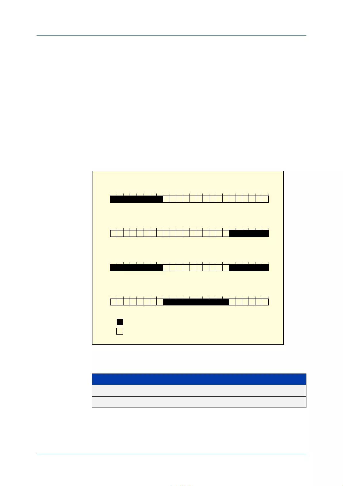
C613-50228-01 Rev A Command Reference for AR2050V 2769
AlliedWare Plus™ Operating System - Version 5.4.8-0.x
TRIGGER COMMANDS
TIME (TRIGGER)
time (trigger)
Overview This command specifies the time of day when the trigger is permitted to activate.
The after parameter specifies the start of a time period that extends to midnight
during which trigger may activate. By default the value of this parameter is
00:00:00 (am); that is, the trigger may activate at any time. The before parameter
specifies the end of a time period beginning at midnight during which the trigger
may activate. By default the value of this parameter is 23:59:59; that is, the trigger
may activate at any time. If the value specified for before is later than the value
specified for after, a time period from “ after ” to “ before ” is defined, during which
the trigger may activate. This command is not applicable to time triggers ( type
time).
The following figure illustrates how the before and after parameters operate.
Syntax time {[after <hh:mm:ss>] [before <hh:mm:ss>]}
Mode Trigger Configuration
ää\ää äÈ\ää £Ó\ää £n\ää ää\ää
ää\ää äÈ\ää £Ó\ää £n\ää ää\ää
ää\ää äÈ\ää £Ó\ää £n\ää ää\ää
ää\ää äÈ\ää £Ó\ää £n\ää ää\ää
"%&/2%
!&4%2
!&4%2"%&/2%
!&4%2"%&/2%
*iÀ`ÊÜiÊÌÀ}}iÀÊ>ÞÊ>VÌÛ>Ìi°iÞ\
*iÀ`ÊÜiÊÌÀ}}iÀÊ>ÞÊÌÊ>VÌÛ>Ìi°
/,ÚäÓ
Parameter Description
after<hh:mm:ss>The earliest time of day when the trigger may be activated.
before<hh:mm:ss>The latest time of day when the trigger may be activated.

C613-50228-01 Rev A Command Reference for AR2050V 2770
AlliedWare Plus™ Operating System - Version 5.4.8-0.x
TRIGGER COMMANDS
TIME (TRIGGER)
Usage For example trigger configurations that use the time (trigger) command, see
“Restrict Internet Access” and “Turn off Power to Port LEDs” in the Triggers Feature
Overview and Configuration Guide.
Examples To allow trigger 63 to activate between midnight and 10:30am, use the
commands:
awplus# configure terminal
awplus(config)# trigger 63
awplus(config-trigger)# time before 10:30:00
To allow trigger 64 to activate between 3:45pm and midnight, use the commands:
awplus# configure terminal
awplus(config)# trigger 64
awplus(config-trigger)# time after 15:45:00
To allow trigger 65 to activate between 10:30am and 8:15pm, use the commands:
awplus# configure terminal
awplus(config)# trigger 65
awplus(config-trigger)# time after 10:30:00 before 20:15:00
Related
Commands
show trigger
trigger

C613-50228-01 Rev A Command Reference for AR2050V 2771
AlliedWare Plus™ Operating System - Version 5.4.8-0.x
TRIGGER COMMANDS
TRAP
trap
Overview This command enables the specified trigger to send SNMP traps.
Use the no variant of this command to disable the sending of SNMP traps from the
specified trigger.
Syntax trap
no trap
Default SNMP traps are enabled by default for all defined triggers.
Mode Trigger Configuration
Usage You must configure SNMP before using traps with triggers. For more information,
see:
•Support for Allied Telesis Enterprise_MIBs_in_AlliedWare Plus, for
information about which MIB objects are supported.
•the SNMP Feature Overview and Configuration_Guide.
•the SNMP Commands chapter.
Since SNMP traps are enabled by default for all defined triggers, a common usage
will be for the no variant of this command to disable SNMP traps from a specified
trap if the trap is only periodic. Refer in particular to AT-TRIGGER-MIB in the
Support for Allied Telesis Enterprise_MIBs_in AlliedWare Plus for further
information about the relevant SNMP MIB.
Examples To enable SNMP traps to be sent from trigger 5, use the commands:
awplus# configure terminal
awplus(config)# trigger 5
awplus(config-trigger)# trap
To disable SNMP traps being sent from trigger 205, use the commands:
awplus# configure terminal
awplus(config)# trigger 205
awplus(config-trigger)# no trap
Related
Commands
trigger
show trigger

C613-50228-01 Rev A Command Reference for AR2050V 2772
AlliedWare Plus™ Operating System - Version 5.4.8-0.x
TRIGGER COMMANDS
TRIGGER
trigger
Overview This command is used to access the Trigger Configuration mode for the specified
trigger. Once Trigger Configuration mode has been entered the trigger type
information can be configured and the trigger scripts and other operational
parameters can be specified. At a minimum the trigger type information must be
specified before the trigger can become active.
The no variant of this command removes a specified trigger and all configuration
associated with it.
Syntax trigger <1-250>
no trigger <1-250>
Mode Global Configuration
Examples To enter trigger configuration mode for trigger 12 use the command:
awplus# trigger 12
To completely remove all configuration associated with trigger 12, use the
command:
awplus# no trigger 12
Related
Commands
show trigger
trigger activate
Parameter Description
<1-250>A trigger ID.

C613-50228-01 Rev A Command Reference for AR2050V 2773
AlliedWare Plus™ Operating System - Version 5.4.8-0.x
TRIGGER COMMANDS
TRIGGER ACTIVATE
trigger activate
Overview This command is used to manually activate a specified trigger from the Privileged
Exec mode, which has been configured with the trigger command from the Global
Configuration mode.
Syntax trigger activate <1-250>
Mode Privileged Exec
Usage This command manually activates a trigger without the normal trigger conditions
being met.
The trigger is activated even if it is configured as inactive. The scripts associated
with the trigger will be executed even if the trigger is in the diagnostic test mode.
Triggers activated manually do not have their repeat counts decremented or their
'last triggered' time updated, and do not result in updates to the '[type] triggers
today' counters.
Example To manually activate trigger 12 use the command:
awplus# trigger activate 12
Related
Commands
show trigger
trigger
Parameter Description
<1-250>A trigger ID.

C613-50228-01 Rev A Command Reference for AR2050V 2774
AlliedWare Plus™ Operating System - Version 5.4.8-0.x
TRIGGER COMMANDS
TYPE ATMF NODE
type atmf node
Overview This command configures a trigger to be activated at an AMF node join event or
leave event.
Syntax type atmf node {join|leave}
Mode Trigger Configuration
CAUTION: Only configure this trigger on one device because it is a network wide
event.
Example 1 To configure trigger 5 to activate at an AMF node leave event, use the following
commands. In this example the command is entered on node-1:
node1(config)# trigger 5
node1(config-trigger) type atmf node leave
Example 2 The following commands will configure trigger 5 to activate if an AMF node join
event occurs on any node within the working set:
node1# atmf working-set group all
This command returns the following display:
Note that the running the above command changes the prompt from the name of
the local node, to the name of the AMF-Network followed, in square brackets, by
the number of member nodes in the working set.
AMF-Net[3]# conf t
AMF-Net[3](config)# trigger 5
AMF-Net[3](config-trigger)# type atmf node leave
AMF-Net[3](config-trigger)# description “E-mail on AMF Exit”
AMF-Net[3](config-trigger)# active
Parameter Description
join AMF node join event.
leave AMF node leave event.
====================
node1, node2, node3:
====================
Working set join

C613-50228-01 Rev A Command Reference for AR2050V 2775
AlliedWare Plus™ Operating System - Version 5.4.8-0.x
TRIGGER COMMANDS
TYPE ATMF NODE
Enter the name of the script to run at the trigger event.
AMF-Net[3](config-trigger)# script 1 email_me.scp
AMF-Net[3](config-trigger)# end
Display the trigger configurations
AMF-Net[3]# show trigger
This command returns the following display:
Display the triggers configured on each of the nodes in the AMF Network.
AMF-Net[3]# show running-config trigger
This command returns the following display:
=======
node1:
=======
TR# Type & Details Description Ac Te Tr Repeat #Scr Days/Date
-------------------------------------------------------------------------------
001 Periodic (2 min) Periodic Status Chk Y N Y Continuous 1 smtwtfs
005 ATMF node (leave) E-mail on ATMF Exit Y N Y Continuous 1 smtwtfs
-------------------------------------------------------------------------------
==============
Node2, Node3,
==============
TR# Type & Details Description Ac Te Tr Repeat #Scr Days/Date
-------------------------------------------------------------------------------
005 ATMF node (leave) E-mail on ATMF Exit Y N Y Continuous 1 smtwtfs
-------------------------------------------------------------------------------

C613-50228-01 Rev A Command Reference for AR2050V 2776
AlliedWare Plus™ Operating System - Version 5.4.8-0.x
TRIGGER COMMANDS
TYPE ATMF NODE
Related
Commands
show trigger
========
Node1:
========
trigger 1
type periodic 2
script 1 atmf.scp
trigger 5
type atmf node leave
description “E-mail on ATMF Exit”
script 1 email_me.scp
!
============
Node2, Node3:
============
trigger 5
type atmf node leave
description “E-mail on ATMF Exit”
script 1 email_me.scp
!

C613-50228-01 Rev A Command Reference for AR2050V 2777
AlliedWare Plus™ Operating System - Version 5.4.8-0.x
TRIGGER COMMANDS
TYPE CPU
type cpu
Overview This command configures a trigger to activate based on CPU usage level. Selecting
the up option causes the trigger to activate when the CPU usage exceeds the
specified usage level. Selecting the down option causes the trigger to activate
when CPU usage drops below the specified usage level. Selecting any causes the
trigger to activate in both situations. The default is any.
Syntax type cpu <1-100> [up|down|any]
Mode Trigger Configuration
Usage For an example trigger configuration that uses the type cpu command, see
“Capture Unusual CPU and RAM Activity” in the Triggers Feature Overview and
Configuration Guide.
Examples To configure trigger 28 to be a CPU trigger that activates when CPU usage exceeds
80% use the following commands:
awplus# configure terminal
awplus(config)# trigger 28
awplus(config-trigger)# type cpu 80 up
To configure trigger 5 to be a CPU trigger that activates when CPU usage either
rises above or drops below 65%, use the following commands:
awplus# configure terminal
awplus(config)# trigger 5
awplus(config-trigger)# type cpu 65
or
awplus# configure terminal
awplus(config)# trigger 5
awplus(config-trigger)# type cpu 65 any
Related
Commands
show trigger
trigger
Parameter Description
<1-100> The percentage of CPU usage at which to trigger.
up Activate when CPU usage exceeds the specified level.
down Activate when CPU usage drops below the specified level
any Activate when CPU usage passes the specified level in either
direction

C613-50228-01 Rev A Command Reference for AR2050V 2778
AlliedWare Plus™ Operating System - Version 5.4.8-0.x
TRIGGER COMMANDS
TYPE INTERFACE
type interface
Overview This command configures a trigger to activate based on the link status of an
interface. The trigger can be activated when the interface becomes operational by
using the up option, or when the interface closes by using the down option. The
trigger can also be configured to activate when either one of these events occurs
by using the any option.
Syntax type interface <interface> [up|down|any]
Mode Trigger Configuration
Example To configure trigger 19 to be an interface trigger that activates when port1.0.2
becomes operational, use the following commands:
awplus# configure terminal
awplus(config)# trigger 19
awplus(config-trigger)# type interface port1.0.2 up
Related
Commands
show trigger
trigger
Parameter Description
<interface>Interface name. This can be the name of a device port, an
eth-management port, or a VLAN.
up Activate when interface becomes operational.
down Activate when the interface closes.
any Activate when any interface link status event occurs.

C613-50228-01 Rev A Command Reference for AR2050V 2779
AlliedWare Plus™ Operating System - Version 5.4.8-0.x
TRIGGER COMMANDS
TYPE LOG
type log
Overview Use this command to configure a trigger to activate based on the content of log
messages matching a string or regular expression.
Syntax type log <log-message-string>
Default There is no type or log message string set by default.
Mode Trigger Configuration
Usage Log type triggers fully support regular expressions using PCRE (Perl-Compatible
Regular Expression) syntax.
Only log messages of severity level notice or higher can activate a trigger.
Note that any command executed by the script will generate a log message with
level notice, and will include ‘[SCRIPT]’ before the command string. Therefore, if
something in the script matches the configured log message trigger string, it will
retrigger indefinitely.
Example To configure trigger 6 to activate when a log message of level notice or higher
indicates that any port has ‘failed’, use the commands:
awplus# configure terminal
awplus(config)# trigger 6
awplus(config-trigger)# type log port.+ failed
Related
Commands
show trigger
trigger
Command
changes
Version 5.4.7-2.1: command added
Parameter Description
<log-message-string> A string or a regular expression (PCRE) to match a log
message or part of a log message.

C613-50228-01 Rev A Command Reference for AR2050V 2780
AlliedWare Plus™ Operating System - Version 5.4.8-0.x
TRIGGER COMMANDS
TYPE MEMORY
type memory
Overview This command configures a trigger to activate based on RAM usage level. Selecting
the up option causes the trigger to activate when memory usage exceeds the
specified level. Selecting the down option causes the trigger to activate when
memory usage drops below the specified level. Selecting any causes the trigger to
activate in both situations. The default is any.
Syntax type memory <1-100> [up|down|any]
Mode Trigger Configuration
Examples To configure trigger 12 to be a memory trigger that activates when memory usage
exceeds 50% use the following commands:
awplus# configure terminal
awplus(config)# trigger 12
awplus(config-trigger)# type memory 50 up
To configure trigger 40 to be a memory trigger that activates when memory usage
either rises above or drops below 65%, use the following commands:
awplus# configure terminal
awplus(config)# trigger 40
awplus(config-trigger)# type memory 65
or
awplus# configure terminal
awplus(config)# trigger 40
awplus(config-trigger)# type memory 65 any
Related
Commands
show trigger
trigger
Parameter Description
<1-100>The percentage of memory usage at which to trigger.
up Activate when memory usage exceeds the specified level.
down Activate when memory usage drops below the specified level.
any Activate when memory usage passes the specified level in either
direction.

C613-50228-01 Rev A Command Reference for AR2050V 2781
AlliedWare Plus™ Operating System - Version 5.4.8-0.x
TRIGGER COMMANDS
TYPE PERIODIC
type periodic
Overview This command configures a trigger to be activated at regular intervals. The time
period between activations is specified in minutes.
Syntax type periodic <1-1440>
Mode Trigger Configuration
Usage A combined limit of 10 triggers of the type periodic and time can be configured. If
you attempt to add more than 10 triggers the following error message is displayed:
For an example trigger configuration that uses the type periodic command, see
“See Daily Statistics” in the Triggers Feature Overview and Configuration Guide.
Example To configure trigger 44 to activate periodically at 10 minute intervals use the
following commands:
awplus# configure terminal
awplus(config)# trigger 44
awplus(config-trigger)# type periodic 10
Related
Commands
show trigger
trigger
Parameter Description
<1-1440>The number of minutes between activations.
% Cannot configure more than 10 triggers with the type time or
periodic

C613-50228-01 Rev A Command Reference for AR2050V 2782
AlliedWare Plus™ Operating System - Version 5.4.8-0.x
TRIGGER COMMANDS
TYPE PING-POLL
type ping-poll
Overview This command configures a trigger that activates when Ping Polling identifies that
a target device’s status has changed. This allows you to run a configuration script
when a device becomes reachable or unreachable.
Syntax type ping-poll <1-100> {up|down}
Mode Trigger Configuration
Example To configure trigger 106 to activate when ping poll 12 detects that its target
device is now unreachable, use the following commands:
awplus# configure terminal
awplus(config)# trigger 106
awplus(config-trigger)# type ping-poll 12 down
Related
Commands
show trigger
trigger
Parameter Description
<1-100>The ping poll ID.
up The trigger activates when ping polling detects that the target is
reachable.
down The trigger activates when ping polling detects that the target is
unreachable.

C613-50228-01 Rev A Command Reference for AR2050V 2783
AlliedWare Plus™ Operating System - Version 5.4.8-0.x
TRIGGER COMMANDS
TYPE REBOOT
type reboot
Overview This command configures a trigger that activates when your device is rebooted.
Syntax type reboot
Mode Trigger Configuration
Example To configure trigger 32 to activate when your device reboots, use the following
commands:
awplus# configure terminal
awplus(config)# trigger 32
awplus(config-trigger)# type reboot
Related
Commands
show trigger
trigger

C613-50228-01 Rev A Command Reference for AR2050V 2784
AlliedWare Plus™ Operating System - Version 5.4.8-0.x
TRIGGER COMMANDS
TYPE TIME
type time
Overview This command configures a trigger that activates at a specified time of day.
Syntax type time <hh:mm>
Mode Trigger Configuration
Usage A combined limit of 10 triggers of the type time and type periodic can be
configured. If you attempt to add more than 10 triggers the following error
message is displayed:
Example To configure trigger 86 to activate at 15:53, use the following commands:
awplus# configure terminal
awplus(config)# trigger 86
awplus(config-trigger)# type time 15:53
Related
Commands
show trigger
trigger
Parameter Description
<hh:mm>The time to activate the trigger.
% Cannot configure more than 10 triggers with the type time or
periodic
C613-50228-01 Rev A Command Reference for AR2050V 2785
AlliedWare Plus™ Operating System - Version 5.4.8-0.x
TRIGGER COMMANDS
TYPE USB
type usb
Overview Use this command to configure a trigger that activates on either the removal or the
insertion of a USB storage device.
Syntax type usb {in|out}
Mode Trigger Configuration
Usage USB triggers cannot execute script files from a USB storage device.
Examples To configure trigger 1 to activate on the insertion of a USB storage device, use the
commands:
awplus# configure terminal
awplus(config)# trigger 1
awplus(config-trigger)# type usb in
Related
Commands
trigger
show running-config trigger
show trigger
Parameter Description
in Trigger activates on insertion of a USB storage device.
out Trigger activates on removal of a USB storage device.


56
C613-50228-01 Rev A Command Reference for AR2050V 2787
AlliedWare Plus™ Operating System - Version 5.4.8-0.x
Ping-Polling
Commands
Introduction
Overview This chapter provides an alphabetical reference for commands used to configure
Ping Polling. For more information, see the Ping Polling Feature Overview and
Configuration Guide.
For information on filtering and saving command output, see the “Getting Started
with AlliedWare Plus” Feature Overview and Configuration Guide.
Command List •“active (ping-polling)” on page 2789
•“clear ping-poll” on page 2790
•“critical-interval” on page 2791
•“debug ping-poll” on page 2792
Table 56-1: The following table lists the default values when configuring a ping
poll
Default Value
Critical-interval 1 second
Description No description
Fail-count 5
Length 32 bytes
Normal-interval 30 seconds
Sample-size 5
Source-ip The IP address of the interface from which the ping packets are
transmitted
Time-out 1 second
Up-count 30

C613-50228-01 Rev A Command Reference for AR2050V 2788
AlliedWare Plus™ Operating System - Version 5.4.8-0.x
PING-POLLING COMMANDS
•“description (ping-polling)” on page 2793
•“fail-count” on page 2794
•“ip (ping-polling)” on page 2795
•“length (ping-poll data)” on page 2796
•“normal-interval” on page 2797
•“ping-poll” on page 2798
•“sample-size” on page 2799
•“show counter ping-poll” on page 2801
•“show ping-poll” on page 2803
•“source-ip” on page 2807
•“timeout (ping polling)” on page 2809
•“up-count” on page 2810
•“undebug ping-poll” on page 2811

C613-50228-01 Rev A Command Reference for AR2050V 2789
AlliedWare Plus™ Operating System - Version 5.4.8-0.x
PING-POLLING COMMANDS
ACTIVE (PING-POLLING)
active (ping-polling)
Overview This command enables a ping-poll instance. The polling instance sends ICMP echo
requests to the device with the IP address specified by the ip (ping-polling)
command.
By default, polling instances are disabled. When a polling instance is enabled, it
assumes that the device it is polling is unreachable.
The no variant of this command disables a ping-poll instance. The polling instance
no longer sends ICMP echo requests to the polled device. This also resets all
counters for this polling instance.
Syntax active
no active
Mode Ping-Polling Configuration
Examples To activate the ping-poll instance 43, use the commands:
awplus# configure terminal
awplus(config)# ping-poll 43
awplus(config-ping-poll)# active
To disable the ping-poll instance 43 and reset its counters, use the commands:
awplus# configure terminal
awplus(config)# ping-poll 43
awplus(config-ping-poll)# no active
Related
Commands
debug ping-poll
ip (ping-polling)
ping-poll
show ping-poll

C613-50228-01 Rev A Command Reference for AR2050V 2790
AlliedWare Plus™ Operating System - Version 5.4.8-0.x
PING-POLLING COMMANDS
CLEAR PING-POLL
clear ping-poll
Overview This command resets the specified ping poll, or all ping poll instances. This clears
the ping counters, and changes the status of polled devices to unreachable. The
polling instance changes to the polling frequency specified with the
critical-interval command. The device status changes to reachable once the device
responses have reached the up-count.
Syntax clear ping-poll {<1-100>|all}
Mode Privileged Exec
Examples To reset the ping poll instance 12, use the command:
awplus# clear ping-poll 12
To reset all ping poll instances, use the command:
awplus# clear ping-poll all
Related
Commands
active (ping-polling)
ping-poll
show ping-poll
Parameter Description
<1-100>A ping poll ID number. The specified ping poll instance has its
counters cleared, and the status of the device it polls is
changed to unreachable.
all Clears the counters and changes the device status of all polling
instances.

C613-50228-01 Rev A Command Reference for AR2050V 2791
AlliedWare Plus™ Operating System - Version 5.4.8-0.x
PING-POLLING COMMANDS
CRITICAL-INTERVAL
critical-interval
Overview This command specifies the time period in seconds between pings when the
polling instance has not received a reply to at least one ping, and when the device
is unreachable.
This command enables the device to quickly observe changes in state, and should
be set to a much lower value than the normal-interval command.
The no variant of this command sets the critical interval to the default of one
second.
Syntax critical-interval <1-65536>
no critical-interval
Default The default is 1 second.
Mode Ping-Polling Configuration
Examples To set the critical interval to 2 seconds for the ping-polling instance 99, use the
commands:
awplus# configure terminal
awplus(config)# ping-poll 99
awplus(config-ping-poll)# critical-interval 2
To reset the critical interval to the default of one second for the ping-polling
instance 99, use the commands:
awplus# configure terminal
awplus(config)# ping-poll 99
awplus(config-ping-poll)# no critical-interval
Related
Commands
fail-count
normal-interval
sample-size
show ping-poll
timeout (ping polling)
up-count
Parameter Description
<1-65536>Time in seconds between pings, when the device has failed to
a ping, or the device is unreachable.

C613-50228-01 Rev A Command Reference for AR2050V 2792
AlliedWare Plus™ Operating System - Version 5.4.8-0.x
PING-POLLING COMMANDS
DEBUG PING-POLL
debug ping-poll
Overview This command enables ping poll debugging for the specified ping-poll instance.
This generates detailed messages about ping execution.
The no variant of this command disables ping-poll debugging for the specified
ping-poll.
Syntax debug ping-poll <1-100>
no debug ping-poll {<1-100>|all}
Mode Privileged Exec
Examples To enable debugging for ping-poll instance 88, use the command:
awplus# debug ping-poll 88
To disable all ping poll debugging, use the command:
awplus# no debug ping-poll all
To disable debugging for ping-poll instance 88, use the command:
awplus# no debug ping-poll 88
Related
Commands
active (ping-polling)
clear ping-poll
ping-poll
show ping-poll
undebug ping-poll
Parameter Description
<1-100>A unique ping poll ID number.
all Turn off all ping-poll debugging.

C613-50228-01 Rev A Command Reference for AR2050V 2793
AlliedWare Plus™ Operating System - Version 5.4.8-0.x
PING-POLLING COMMANDS
DESCRIPTION (PING-POLLING)
description (ping-polling)
Overview This command specifies a string to describe the ping-polling instance. This allows
the ping-polling instance to be recognized easily in show commands. Setting this
command is optional.
By default ping-poll instances do not have a description.
Use the no variant of this command to delete the description set.
Syntax description <description>
no description
Mode Ping-Polling Configuration
Examples To add the text “Primary Gateway” to describe the ping-poll instance 45, use the
commands:
awplus# configure terminal
awplus(config)# ping-poll 45
awplus(config-ping-poll)# description Primary Gateway
To delete the description set for the ping-poll instance 45, use the commands:
awplus# configure terminal
awplus(config)# ping-poll 45
awplus(config-ping-poll)# no description
Related
Commands
ping-poll
show ping-poll
Parameter Description
<description> The description of the target. Valid characters are any printable
character and spaces. There is no maximum character length.

C613-50228-01 Rev A Command Reference for AR2050V 2794
AlliedWare Plus™ Operating System - Version 5.4.8-0.x
PING-POLLING COMMANDS
FAIL-COUNT
fail-count
Overview This command specifies the number of pings that must be unanswered, within the
total number of pings specified by the sample-size command, for the ping-polling
instance to consider the device unreachable.
If the number set by the sample-size command and the fail-count commands are
the same, then the unanswered pings must be consecutive. If the number set by
the sample-size command is greater than the number set by the fail-count
command, then a device that does not always reply to pings may be declared
unreachable.
The no variant of this command resets the fail count to the default.
Syntax fail-count <1-100>
no fail-count
Default The default is 5.
Mode Ping-Polling Configuration
Examples To specify the number of pings that must fail within the sample size to determine
that a device is unreachable for ping-polling instance 45, use the commands:
awplus# configure terminal
awplus(config)# ping-poll 45
awplus(config-ping-poll)# fail-count 5
To reset the fail-count to its default of 5 for ping-polling instance 45, use the
commands:
awplus# configure terminal
awplus(config)# ping-poll 45
awplus(config-ping-poll)# no fail-count
Related
Commands
critical-interval
normal-interval
ping-poll
sample-size
show ping-poll
timeout (ping polling)
up-count
Parameter Description
<1-100>The number of pings within the sample size that a reachable device
must fail to respond to before it is classified as unreachable.

C613-50228-01 Rev A Command Reference for AR2050V 2795
AlliedWare Plus™ Operating System - Version 5.4.8-0.x
PING-POLLING COMMANDS
IP (PING-POLLING)
ip (ping-polling)
Overview This command specifies the IPv4 address of the device you are polling.
Syntax ip {<ip-address>|<ipv6-address>}
Mode Ping-Polling Configuration
Examples To set ping-poll instance 5 to poll the device with the IP address 192.168.0.1,
use the commands:
awplus# configure terminal
awplus(config)# ping-poll 5
awplus(config-ping-poll)# ip 192.168.0.1
To set ping-poll instance 10 to poll the device with the IPv6 address 2001:db8::,
use the commands:
awplus# configure terminal
awplus(config)# ping-poll 10
awplus(config-ping-poll)# ip 2001:db8::
Related
Commands
ping-poll
source-ip
show ping-poll
Parameter Description
<ip-address>An IPv4 address in dotted decimal notation A.B.C.D
<ipv6-address> An IPv6 address in hexadecimal notation X:X::X:X

C613-50228-01 Rev A Command Reference for AR2050V 2796
AlliedWare Plus™ Operating System - Version 5.4.8-0.x
PING-POLLING COMMANDS
LENGTH (PING-POLL DATA)
length (ping-poll data)
Overview This command specifies the number of data bytes to include in the data portion of
the ping packet. This allows you to set the ping packets to a larger size if you find
that larger packet types in your network are not reaching the polled device, while
smaller packets are getting through. This encourages the polling instance to
change the device’s status to unreachable when the network is dropping packets
of the size you are interested in.
The no variant of this command resets the data bytes to the default of 32 bytes.
Syntax length <4-1500>
no length
Default The default is 32.
Mode Ping-Polling Configuration
Examples To specify that ping-poll instance 12 sends ping packet with a data portion of 56
bytes, use the commands:
awplus# configure terminal
awplus(config)# ping-poll 12
awplus(config-ping-poll)# length 56
To reset the number of data bytes in the ping packet to the default of 32 bytes for
ping- poll instance 3, use the commands:
awplus# configure terminal
awplus(config)# ping-poll 12
awplus(config-ping-poll)# length
Related
Commands
ping-poll
show ping-poll
Parameter Description
<4-1500>The number of data bytes to include in the data portion of the ping
packet.

C613-50228-01 Rev A Command Reference for AR2050V 2797
AlliedWare Plus™ Operating System - Version 5.4.8-0.x
PING-POLLING COMMANDS
NORMAL-INTERVAL
normal-interval
Overview This command specifies the time period between pings when the device is
reachable.
The no variant of this command resets the time period to the default of 30 seconds.
Syntax normal-interval <1-65536>
no normal-interval
Default The default is 30 seconds.
Mode Ping-Polling Configuration
Examples To specify a time period of 60 seconds between pings when the device is reachable
for ping-poll instance 45, use the commands:
awplus# configure terminal
awplus(config)# ping-poll 45
awplus(config-ping-poll)# normal-interval 60
To reset the interval to the default of 30 seconds for ping-poll instance 45, use the
commands:
awplus# configure terminal
awplus(config)# ping-poll 45
awplus(config-ping-poll)# no normal-interval
Related
Commands
critical-interval
fail-count
ping-poll
sample-size
show ping-poll
timeout (ping polling)
up-count
Parameter Description
<1-65536>Time in seconds between pings when the target is reachable.

C613-50228-01 Rev A Command Reference for AR2050V 2798
AlliedWare Plus™ Operating System - Version 5.4.8-0.x
PING-POLLING COMMANDS
PING-POLL
ping-poll
Overview This command enters the ping-poll configuration mode. If a ping-poll exists with
the specified number, then this command enters its configuration mode. If
no-ping poll exists with the specified number, then this command creates a new
ping poll with this ID number.
To configure a ping-poll, create a ping poll using this command, and use the ip
(ping-polling) command to specify the device you want the polling instance to
poll. It is not necessary to specify any further commands unless you want to
change a command’s default.
The no variant of this command deletes the specified ping poll.
Syntax ping-poll <1-100>
no ping-poll <1-100>
Mode Global Configuration
Examples To create ping-poll instance 3 and enter ping-poll configuration mode, use the
commands:
awplus# configure terminal
awplus(config)# ping-poll 3
awplus(config-ping-poll)#
To delete ping-poll instance 3, use the commands:
awplus# configure terminal
awplus(config)# no ping-poll 3
Related
Commands
active (ping-polling)
clear ping-poll
debug ping-poll
description (ping-polling)
ip (ping-polling)
length (ping-poll data)
show ping-poll
source-ip
Parameter Description
<1-100>A unique ping poll ID number.

C613-50228-01 Rev A Command Reference for AR2050V 2799
AlliedWare Plus™ Operating System - Version 5.4.8-0.x
PING-POLLING COMMANDS
SAMPLE-SIZE
sample-size
Overview This command sets the total number of pings that the polling instance inspects
when determining whether a device is unreachable. If the number of pings
specified by the fail-count command go unanswered within the inspected
sample, then the device is declared unreachable.
If the numbers set in this command and fail-count command are the same, the
unanswered pings must be consecutive. If the number set by this command is
greater than that set with the fail-count command, a device that does not always
reply to pings may be declared unreachable.
You cannot set this command’s value lower than the fail-count value.
The polling instance uses the number of pings specified by the up-count
command to determine when a device is reachable.
The no variant of this command resets this command to the default.
Syntax sample-size <1-100>
no sample size
Default The default is 5.
Mode Ping-Polling Configuration
Examples To set the sample-size to 50 for ping-poll instance 43, use the commands:
awplus# configure terminal
awplus(config)# ping-poll 43
awplus(config-ping-poll)# sample-size 50
To reset sample-size to the default of 5 for ping-poll instance 43, use the
commands:
awplus# configure terminal
awplus(config)# ping-poll 43
awplus(config-ping-poll)# no sample-size
Parameter Description
<1-100>Number of pings that determines critical and up counts.


C613-50228-01 Rev A Command Reference for AR2050V 2801
AlliedWare Plus™ Operating System - Version 5.4.8-0.x
PING-POLLING COMMANDS
SHOW COUNTER PING-POLL
show counter ping-poll
Overview This command displays the counters for ping polling.
Syntax show counter ping-poll [<1-100>]
Mode User Exec and Privileged Exec
Output Figure 56-1: Example output from the show counter ping-poll command
Parameter Description
<1-100>A unique ping poll ID number. This displays the counters for the specified
ping poll only. If you do not specify a ping poll, then this command
displays counters for all ping polls.
Ping-polling counters
Ping-poll: 1
PingsSent ......... 15
PingsFailedUpState ......... 0
PingsFailedDownState ......... 0
ErrorSendingPing ......... 2
CurrentUpCount ......... 13
CurrentFailCount ......... 0
UpStateEntered ......... 0
DownStateEntered ......... 0
Ping-poll: 2
PingsSent ......... 15
PingsFailedUpState ......... 0
PingsFailedDownState ......... 0
ErrorSendingPing ......... 2
CurrentUpCount ......... 13
CurrentFailCount ......... 0
UpStateEntered ......... 0
DownStateEntered ......... 0
Ping-poll: 5
PingsSent ......... 13
PingsFailedUpState ......... 0
PingsFailedDownState ......... 2
ErrorSendingPing ......... 2
CurrentUpCount ......... 9
CurrentFailCount ......... 0
UpStateEntered ......... 0
DownStateEntered ......... 0

C613-50228-01 Rev A Command Reference for AR2050V 2802
AlliedWare Plus™ Operating System - Version 5.4.8-0.x
PING-POLLING COMMANDS
SHOW COUNTER PING-POLL
Example To display counters for the polling instances, use the command:
awplus# show counter ping-poll
Related
Commands
debug ping-poll
ping-poll
show ping-poll
Table 57: Parameters in output of the show counter ping-poll command
Parameter Description
Ping-poll The ID number of the polling instance.
PingsSent The total number of pings generated by the polling
instance.
PingsFailedUpState The number of unanswered pings while the target
device is in the Up state. This is a cumulative counter
for multiple occurrences of the Up state.
PingsFailedDownState Number of unanswered pings while the target device
is in the Down state. This is a cumulative counter for
multiple occurrences of the Down state.
ErrorSendingPing The number of pings that were not successfully sent to
the target device.
This error can occur when your device does not have a
route to the destination.
CurrentUpCount The current number of sequential ping replies.
CurrentFailCount The number of ping requests that have not received a
ping reply in the current sample-size window.
UpStateEntered Number of times the target device has entered the Up
state.
DownStateEntered Number of times the target device has entered the
Down state.
C613-50228-01 Rev A Command Reference for AR2050V 2803
AlliedWare Plus™ Operating System - Version 5.4.8-0.x
PING-POLLING COMMANDS
SHOW PING-POLL
show ping-poll
Overview This command displays the settings and status of ping polls.
Syntax show ping-poll [<1-100>|state {up|down}] [brief]
Mode User Exec and Privileged Exec
Output Figure 56-2: Example output from the show ping-poll brief command
Parameter Description
<1-100>Displays settings and status for the specified polling instance.
state Displays polling instances based on whether the device they are
polling is currently reachable or unreachable.
up Displays polling instance where the device state is
reachable.
down Displays polling instances where the device state is
unreachable.
brief Displays a summary of the state of ping polls, and the devices they
are polling.
Ping Poll Configuration
----------------------------------------------------------
Id Enabled State Destination
----------------------------------------------------------
1 Yes Down 192.168.0.1
2 Yes Up 192.168.0.100
Table 58: Parameters in output of the show ping-poll brief command
Parameter Meaning
Id The ID number of the polling instance, set when creating the polling
instance with the ping-poll command.
Enabled Whether the polling instance is enabled or disabled.

C613-50228-01 Rev A Command Reference for AR2050V 2804
AlliedWare Plus™ Operating System - Version 5.4.8-0.x
PING-POLLING COMMANDS
SHOW PING-POLL
Figure 56-3: Example output from the show ping-poll command
State The current status of the device being polled:
Up The device is reachable.
Down The device is unreachable.
Critical
Up
The device is reachable but recently the polling
instance has not received some ping replies, so the
polled device may be going down.
Critical
Down
The device is unreachable but the polling instance
received a reply to the last ping packet, so the
polled device may be coming back up.
Destinatio
n
The IP address of the polled device, set with the ip (ping-polling)
command.
Ping Poll Configuration
----------------------------------------------------------
Poll 1:
Description : Primary Gateway
Destination IP address : 192.168.0.1
Status : Down
Enabled : Yes
Source IP address : 192.168.0.10
Critical interval : 1
Normal interval : 30
Fail count : 10
Up count : 5
Sample size : 50
Length : 32
Timeout : 1
Debugging : Enabled
Table 58: Parameters in output of the show ping-poll brief command (cont.)
Parameter Meaning

C613-50228-01 Rev A Command Reference for AR2050V 2805
AlliedWare Plus™ Operating System - Version 5.4.8-0.x
PING-POLLING COMMANDS
SHOW PING-POLL
Poll 2:
Description : Secondary Gateway
Destination IP address : 192.168.0.100
Status : Up
Enabled : Yes
Source IP address : Default
Critical interval : 5
Normal interval : 60
Fail count : 20
Up count : 30
Sample size : 100
Length : 56
Timeout : 2
Debugging : Enabled
Table 59: Parameters in output of the show ping-poll command
Parameter Description
Description Optional description set for the polling instance with the
description (ping-polling) command.
Destination
IP address
The IP address of the polled device, set with the ip (ping-polling)
command.
Status The current status of the device being polled:
Up The device is reachable.
Down The device is unreachable.
Critic
a l Up
The device is reachable but recently the polling
instance has not received some ping replies, so the
polled device may be going down.
Critic
a l
Down
The device is unreachable but the polling instance
received a reply to the last ping packet, so the
polled device may be coming back up.
Enabled Whether the polling instance is enabled or disabled. The active
(ping-polling) and active (ping-polling) commands enable and
disable a polling instance.
Source IP
address
The source IP address sent in the ping packets. This is set using
the source-ip command.
Critical
interval
The time period in seconds between pings when the polling
instance has not received a reply to at least one ping, and when
the device is unreachable. This is set with the critical-interval
command.
Normal
interval
The time period between pings when the device is reachable.
This is set with the normal-interval command.

C613-50228-01 Rev A Command Reference for AR2050V 2806
AlliedWare Plus™ Operating System - Version 5.4.8-0.x
PING-POLLING COMMANDS
SHOW PING-POLL
Examples To display the ping poll settings and the status of all the polls, use the command:
awplus# show ping-poll
To display a summary of the ping poll settings, use the command:
awplus# show ping-poll brief
To display the settings for ping poll 6, use the command:
awplus# show ping-poll 6
To display a summary of the state of ping poll 6, use the command:
awplus# show ping-poll 6 brief
To display the settings of ping polls that have reachable devices, use the
command:
awplus# show ping-poll state up
To display a summary of ping polls that have unreachable devices, use the
command:
awplus# show ping-poll 6 state down brief
Related
Commands
debug ping-poll
ping-poll
Fail count The number of pings that must be unanswered, within the total
number of pings specified by the sample-size command, for the
polling instance to consider the device unreachable. This is set
using the fail-count command.
Up count The number of consecutive pings that the polling instance must
receive a reply to before classifying the device reachable again.
This is set using the up-count command.
Sample size The total number of pings that the polling instance inspects
when determining whether a device is unreachable. This is set
using the sample-size command.
Length The number of data bytes to include in the data portion of the
ping packet. This is set using the length (ping-poll data)
command.
Timeout The time in seconds that the polling instance waits for a
response to a ping packet. This is set using the timeout (ping
polling) command.
Debugging Indicates whether ping polling debugging is Enabled or
Disabled.
This is set using the debug ping-poll command.
Table 59: Parameters in output of the show ping-poll command (cont.)
Parameter Description

C613-50228-01 Rev A Command Reference for AR2050V 2807
AlliedWare Plus™ Operating System - Version 5.4.8-0.x
PING-POLLING COMMANDS
SOURCE-IP
source-ip
Overview This command specifies the source IP address to use in ping packets.
By default, the polling instance uses the address of the interface through which it
transmits the ping packets. It uses the device’s local interface IP address when it is
set. Otherwise, the IP address of the interface through which it transmits the ping
packets is used.
The no variant of this command resets the source IP in the packets to the device’s
local interface IP address.
Syntax source-ip {<ip-address>|<ipv6-address>}
no source-ip
Mode Ping-Polling Configuration
Examples To configure the ping-polling instance 43 to use the source IP address
192.168.0.1 in ping packets, use the commands:
awplus# configure terminal
awplus(config)# ping-poll 43
awplus(config-ping-poll)# source-ip 192.168.0.1
To configure the ping-polling instance 43 to use the source IPv6 address
2001:db8:: in ping packets, use the commands:
awplus# configure terminal
awplus(config)# ping-poll 43
awplus(config-ping-poll)# source-ip 2001:db8::
To reset the source IP address to the device’s local interface IP address for ping-poll
instance 43, use the commands:
awplus# configure terminal
awplus(config)# ping-poll 43
awplus(config-ping-poll)# no source-ip
Parameter Description
<ip-address>An IPv4 address in dotted decimal notation A.B.C.D
<ipv6-address> An IPv6 address in hexadecimal notation X:X::X:X


C613-50228-01 Rev A Command Reference for AR2050V 2809
AlliedWare Plus™ Operating System - Version 5.4.8-0.x
PING-POLLING COMMANDS
TIMEOUT (PING POLLING)
timeout (ping polling)
Overview This command specifies the time in seconds that the polling instance waits for a
response to a ping packet. You may find a higher time-out useful in networks
where ping packets have a low priority.
The no variant of this command resets the set time out to the default of one
second.
Syntax timeout <1-30>
no timeout
Default The default is 1 second.
Mode Ping-Polling Configuration
Examples To specify the timeout as 5 seconds for ping-poll instance 43, use the commands:
awplus# configure terminal
awplus(config)# ping-poll 43
awplus(config-ping-poll)# timeout 5
To reset the timeout to its default of 1 second for ping-poll instance 43, use the
commands:
awplus# configure terminal
awplus(config)# ping-poll 43
awplus(config-ping-poll)# no timeout
Related
Commands
critical-interval
fail-count
normal-interval
ping-poll
sample-size
show ping-poll
up-count
Parameter Description
<1-30>Length of time, in seconds, that the polling instance waits for a
response from the polled device.

C613-50228-01 Rev A Command Reference for AR2050V 2810
AlliedWare Plus™ Operating System - Version 5.4.8-0.x
PING-POLLING COMMANDS
UP-COUNT
up-count
Overview This command sets the number of consecutive pings that the polling instance
must receive a reply to before classifying the device reachable again.
The no variant of this command resets the up count to the default of 30.
Syntax up-count <1-100>
no up-count
Default The default is 30.
Mode Ping-Polling Configuration
Examples To set the upcount to 5 consecutive pings for ping-polling instance 45, use the
commands:
awplus# configure terminal
awplus(config)# ping-poll 45
awplus(config-ping-poll)# up-count 5
To reset the upcount to the default value of 30 consecutive pings for ping-polling
instance 45, use the commands:
awplus# configure terminal
awplus(config)# ping-poll 45
awplus(config-ping-poll)# no up-count
Related
Commands
critical-interval
fail-count
normal-interval
ping-poll
sample-size
show ping-poll
timeout (ping polling)
Parameter Description
<1-100>Number of replied pings before an unreachable device is classified as
reachable.


C613-50228-01 Rev A Command Reference for AR2050V 2812
AlliedWare Plus™ Operating System - Version 5.4.8-0.x
Part 8: Firewall and Network
Address Translation (NAT)

57
C613-50228-01 Rev A Command Reference for AR2050V 2813
AlliedWare Plus™ Operating System - Version 5.4.8-0.x
Firewall Commands
Introduction
Overview This chapter provides an alphabetical reference of commands used to configure
AlliedWare Plus Firewall. For more information see the Firewall_and Network
Address Translation (NAT) Feature Overview and Configuration_Guide.
The table below lists the firewall commands and their applicable modes.
Figure 57-1: Firewall commands and applicable modes
Command List •“clear firewall connections” on page 2815
•“connection-limit (Firewall)” on page 2816
•“connection-log events” on page 2817
Mode Command
Privileged Exec clear firewall connections
debug firewall
show debugging firewall
show firewall
show firewall connections
show firewall rule
show firewall rule config-check
show running-config firewall
Global Configuration firewall
Firewall Configuration protect (Firewall)
rule (Firewall)
move rule (Firewall)

C613-50228-01 Rev A Command Reference for AR2050V 2814
AlliedWare Plus™ Operating System - Version 5.4.8-0.x
FIREWALL COMMANDS
•“firewall” on page 2818
•“debug firewall” on page 2819
•“ip tcp timeout established” on page 2820
•“move rule (Firewall)” on page 2821
•“protect (Firewall)” on page 2822
•“rule (Firewall)” on page 2823
•“show connection-log events” on page 2825
•“show firewall” on page 2826
•“show firewall connections” on page 2827
•“show firewall connections limits” on page 2828
•“show firewall connections limits config-check” on page 2829
•“show firewall rule” on page 2830
•“show firewall rule config-check” on page 2832
•“show debugging firewall” on page 2833
•“show running-config firewall” on page 2834

C613-50228-01 Rev A Command Reference for AR2050V 2815
AlliedWare Plus™ Operating System - Version 5.4.8-0.x
FIREWALL COMMANDS
CLEAR FIREWALL CONNECTIONS
clear firewall connections
Overview Use this command to clear firewall connections.
Syntax clear firewall connections
Mode Privileged Exec
Usage Removing the Network Address Translation (NAT) rule by using the no nat rule
command for an actively translated flow does not stop translating immediately.
This means subsequent packets in the flow are continued to be translated.
The continued translation after associated NAT rule is removed will only stop
when:
• You use the clear firewall connections command to manually stop
translations immediately, when the associated rule has been deleted
regardless whether the firewall feature is actually configured with NAT or
not.
• The traffic flow ends naturally, for example, when it is stopped from the
source. If the flow is re-initiated from a host, it will not be translated by the
firewall, as the rule is deleted after the first flow stopped.
Examples To clear firewall connections, use the command:
awplus# clear firewall connections
Validation
commands
show firewall connections
Related
commands
rule (NAT)

C613-50228-01 Rev A Command Reference for AR2050V 2816
AlliedWare Plus™ Operating System - Version 5.4.8-0.x
FIREWALL COMMANDS
CONNECTION-LIMIT (FIREWALL)
connection-limit (Firewall)
Overview Use this command to limit firewall connections for an entity.
Use the no variant of this command to remove the limit.
Syntax connection-limit [<1-65535>] from <entity_name> with limit
<0-100000>
no connection-limit {<1-65535>|all}
Default The limiting is disabled by default and the number of connections will not be
limited. However, the number is up to the maximum total number of allowed
connections.
Mode Firewall Configuration
Usage This command allows you to limit the number of firewall sessions associated with
a specific entity. The limit will be applied to each host on that entity. This means
connection limits applied to an entity with multiple addresses will apply the limit
to individual hosts, not the total connections for the entity. The limit applies to
both IPv4 and IPv6.
If a connection limit rule is removed, any running connections are not stopped.
Changes to limits only affect new connections. Adding a lower limit will not affect
existing connections.
Examples To set a connection limit for entity DMZ, use the following command:
awplus(config-firewall)# connection-limit
1 from DMZ with limit 10000
To remove the connection limit, use the following command:
awplus(config-firewall)# no connection-limit
1
Validation
commands
show firewall connections
show firewall connections limits
Parameter Description
<1-65535>Unique numeric identifier for the limit.
<entity_name> An entity represents a logical grouping of
subnets, hosts or interfaces. For more
information about entity, see the Application
and Entity Commands.
<0-100000> The maximum number of permitted
connections for the entity.
all Delete all limits.

C613-50228-01 Rev A Command Reference for AR2050V 2817
AlliedWare Plus™ Operating System - Version 5.4.8-0.x
FIREWALL COMMANDS
CONNECTION-LOG EVENTS
connection-log events
Overview Use this command to enable extra logging for indicating the start and the end of
connections passing through the firewall.
Use the no variant of this command to turn off the extra logging of connections
passing through the firewall.
Syntax connection-log events [new|end|all]
no connection-log events [new|end|all]
Default Connection logging is not enabled by default.
Mode Global Configuration.
Usage There are two types of messages you can log: new connections and connections
that ended. You can control the amount of messages you log by choosing to log
either type of message or all of the message types.
Messages contain the following information:
•time
• source and destination addresses (NATed and unNATed)
•protocol
• source and destination ports (NATed and unNATed)
• bytes and packets passed (found in the connection end message)
Example To log all of the new connections and all of the closed connections, use the
commands:
awplus# configure terminal
awplus(config)# connection-log events all
Related
Commands
show connection-log events
Command
changes
Version 5.4.7-1.1: command added.
Parameter Description
new New connection
end Connections closed
all All new connections and connections closed. Default.

C613-50228-01 Rev A Command Reference for AR2050V 2818
AlliedWare Plus™ Operating System - Version 5.4.8-0.x
FIREWALL COMMANDS
FIREWALL
firewall
Overview Use this command to configure the firewall.
Use the no variant of this command to remove all firewall configuration.
Syntax firewall
no firewall
Mode Global Configuration
Usage This command allows you to enter the Firewall Configuration mode. The
command prompt for this mode is awplus(config-firewall)#
In the Firewall Configuration mode, you can:
• Enable or disable firewall protection, see the protect (Firewall) command.
• Create, move, or delete rules for the firewall, see the rule (Firewall) command
and the move rule (Firewall) command.
Examples To configure the firewall, use the commands:
awplus# configure terminal
awplus(config)# firewall
awplus(config-firewall)#
To remove all firewall configuration, use the commands:
awplus# configure terminal
awplus(config)# no firewall
Validation
commands
show firewall
show running-config firewall

C613-50228-01 Rev A Command Reference for AR2050V 2819
AlliedWare Plus™ Operating System - Version 5.4.8-0.x
FIREWALL COMMANDS
DEBUG FIREWALL
debug firewall
Overview Use this command to enable firewall debugging and Network Address Translation
(NAT) debugging. This will cause additional detailed debugging information to be
logged at the “informational” and “debugging” levels.
Use the no variant of this command to disable firewall debugging and NAT
debugging.
For more information about NAT, see the Firewall_and Network Address
Translation (NAT) Feature Overview and Configuration_Guide.
Syntax debug firewall
no debug firewall
Default Firewall debugging and NAT debugging are disabled by default.
Mode Privileged Exec
Examples To enable firewall debugging and NAT debugging, use the command:
awplus# debug firewall
To disable firewall debugging and NAT debugging, use the command:
awplus# no debug firewall
Validation
commands
show debugging firewall

C613-50228-01 Rev A Command Reference for AR2050V 2820
AlliedWare Plus™ Operating System - Version 5.4.8-0.x
FIREWALL COMMANDS
IP TCP TIMEOUT ESTABLISHED
ip tcp timeout established
Overview Use this command to set the idle timeout for all established TCP connections.
Use the no variant of this command to set the idle timeout back to the default of
3600 seconds.
Syntax ip tcp timeout established <1-31536000>
no ip tcp timeout established
Default 3600 seconds (1 hour)
Mode Global Configuration
Usage By default, when a TCP session is successfully established through the firewall,
when the session goes idle, it automatically times out of the firewall connection
tracking table after 3600 seconds. In some situations it may be beneficial to time
out unused established TCP sessions earlier.
For example, in a busy environment where there is an excessive number of
sessions being established, the firewall connection tracking table could become
oversubscribed, with new connections being blocked until older sessions are
timed out.
Example To set a non-default TCP session timeout for established idle sessions of 1800
seconds (30 minutes), use the commands:
awplus# configure terminal
awplus(config)# ip tcp timeout established 1800
Example To set the TCP session timeout for established idle sessions back to the default
setting of 3600 seconds, use the commands:
awplus# configure terminal
awplus(config)# no ip tcp timeout established
Related
Commands
show running-config
Command
changes
Version 5.4.6-1.1: command added
Parameter Description
<1-31536000> Idle timeout for established TCP connections in seconds from 1 to
3153600.

C613-50228-01 Rev A Command Reference for AR2050V 2821
AlliedWare Plus™ Operating System - Version 5.4.8-0.x
FIREWALL COMMANDS
MOVE RULE (FIREWALL)
move rule (Firewall)
Overview Use this command to change the order of firewall rules.
Firewall rules are applied in rule ID order. When rules match the same application,
source entity and destination entity, only the rule with the lowest ID is applied.
Note that you can move an existing rule ID only to an ID that is not assigned to any
rule; otherwise you will be given an error message. Also note that a change to the
rule order may change the rule results.
Syntax move rule <1-65535> to <1-65535>
Mode Firewall Configuration
Examples To change the rule ID from 20 to 10, use the commands:
awplus# configure terminal
awplus(config)# firewall
awplus(config-firewall)# move rule 20 to 10
Validation
commands
show firewall rule
show running-config firewall
Related
commands
rule (Firewall)
Parameter Description
move rule
<1-65535>
Move the ID of a given rule. The rule ID of the given rule
must exist.
Each rule has an ID which is either designated by the user or
automatically generated when the rule is created. The rule
ID is an integer from 1 to 65535.
to <1-65535> New rule ID to assign. The new rule ID must not be used by
any existing rule.

C613-50228-01 Rev A Command Reference for AR2050V 2822
AlliedWare Plus™ Operating System - Version 5.4.8-0.x
FIREWALL COMMANDS
PROTECT (FIREWALL)
protect (Firewall)
Overview Use this command to enable firewall protection.
Use the no variant of this command to disable firewall protection without losing
the existing firewall configuration.
Syntax protect
no protect
Default Firewall protection is disabled by default.
Mode Firewall Configuration
Usage Firewall protection is disabled by default and all traffic can pass through the
firewall. When the firewall is enabled and no rules are added, all traffic will be
blocked by default. You can use the rule (Firewall) command to configure rules to
allow traffic to pass through the firewall.
Examples To enable firewall protection, use the commands:
awplus# configure terminal
awplus(config)# firewall
awplus(config-firewall)# protect
To disable firewall protection, use the commands:
awplus# configure terminal
awplus(config)# firewall
awplus(config-firewall)# no protect
Validation
commands
show firewall
show running-config firewall

C613-50228-01 Rev A Command Reference for AR2050V 2823
AlliedWare Plus™ Operating System - Version 5.4.8-0.x
FIREWALL COMMANDS
RULE (FIREWALL)
rule (Firewall)
Overview Use this command to create a rule for the firewall. Firewall security policy is
specified in the form of firewall rules. Each rule defines the appropriate processing
of a type of traffic passing through the firewall.
Use the no variant of this command to remove a rule.
Syntax rule [<1-65535>] {permit|deny|reject|log} <application-name>
from <source-entity> to <destination-entity>
[no-state-enforcement] [log]
no rule {<1-65535>|all}
Parameter Description
<1-65535>Rule ID is an integer in the range <1-65535>. If
you don’t designate a rule ID, a rule ID will be
automatically generated and it will be greater
than the current highest rule ID.
permit Permit connections that match the
application, source entity and destination
entity specified with this command.
deny Drop connections that match the application,
source entity and destination entity specified
with this command. No error message is sent
back to the source host.
reject Reject connections that match the application,
source entity and destination entity specified
with this command. An error message (for
instance, a TCP reset for a rejected TCP
connection, or a destination unreachable
message for an ICMP connection, etc.) is sent
back to the source host.
log When ‘log’ is the action for the rule, log an
event each time the rule is hit. The traffic will
also be processed by subsequent firewall rules
which may permit, deny or reject the
connection.
<application-name> Application name. You can either specify an
application name or use the word any, which
stands for all applications. For more
information about applications, see
Application and Entity Commands.
<source-entity> Source entity name. An entity represents a
logical grouping of subnets, hosts or
interfaces. For more information about
entities, see Application and Entity
Commands.
<destination-entity> Destination entity name.

C613-50228-01 Rev A Command Reference for AR2050V 2824
AlliedWare Plus™ Operating System - Version 5.4.8-0.x
FIREWALL COMMANDS
RULE (FIREWALL)
Mode Firewall Configuration
Usage When the firewall is enabled and no rules are added, all traffic is blocked by default,
you can use this command to create rules for permitting packets between entities.
The rule is not valid and cannot be hit if either the application, source entity or
destination entity the rule applies to is not properly configured, for example, the
application does not exist or does not have a protocol configured or the entity
does not exist. To configure applications and entities, see Application and Entity
Commands. You can also use the show firewall rule config-check command to
check rule configuration validity.
You can change the rule order by using the move rule (Firewall) command.
Examples To create a rule for permitting application ping between ‘public’ and ‘private’, use
the command:
awplus(config-firewall)# rule 10 permit
ping from public to private
To create a rule for denying application http between ‘public.wan’ and
‘private.lan’, use the command:
awplus(config-firewall)# rule 20 deny
http from public.wan to private.lan
To create a firewall rule to permit application ‘ping’ between ‘public’ and ‘dmz’
entities and to log the results, use the commands:
awplus(config-firewall)# rule 30 permit
ping from public to dmz log
Related
commands
move rule (Firewall)
show firewall rule
show firewall rule config-check
Command
changes
Version 5.4.7-0.1: no-state-enforcement option added.
no-state-enforcement Optionally disable state enforcement for this
rule. Use this option with caution as it will
allow reverse path connection initiation. It
should be used only when the traffic forward
and reverse paths must be different and there
is no alternative approach available.
This option is disabled by default.
log When ‘log’ is appended to a rule, the action is
applied and a log message is also generated
each time the rule is hit.
all Delete all rules.
Parameter Description

C613-50228-01 Rev A Command Reference for AR2050V 2825
AlliedWare Plus™ Operating System - Version 5.4.8-0.x
FIREWALL COMMANDS
SHOW CONNECTION-LOG EVENTS
show connection-log events
Overview This command displays the configuration state (enabled or disabled) for the
logging of connections passing through the firewall, as configured by the
connection-log events command.
Syntax show connection-log events
Mode User Exec
Example To show the logging configuration state for the connections passing through the
firewall, use the command:
awplus# show connection-log events
Output Figure 57-2: Example output from show connection-log events
Related
Commands
connection-log events
Command
changes
Version 5.4.7-1.1: command added.
awplus#show connection-log events
Log new connection events: Disabled
Log connection end events: Enabled

C613-50228-01 Rev A Command Reference for AR2050V 2826
AlliedWare Plus™ Operating System - Version 5.4.8-0.x
FIREWALL COMMANDS
SHOW FIREWALL
show firewall
Overview Use this command to show the protection state of the firewall and the number of
active connections being handled by the firewall.
You can use the protect (Firewall) command to enable firewall protection.
Syntax show firewall
Mode Privileged Exec
Examples To show the state of the firewall, use the command:
awplus# show firewall
Output Figure 57-3: Example output from the show firewall command
Related
commands
protect (Firewall)
awplus#show firewall
Firewall protection is enabled
Active connections: 9

C613-50228-01 Rev A Command Reference for AR2050V 2827
AlliedWare Plus™ Operating System - Version 5.4.8-0.x
FIREWALL COMMANDS
SHOW FIREWALL CONNECTIONS
show firewall connections
Overview Use this command to show the connections currently being tracked by the firewall.
Syntax show firewall connections
Mode Privileged Exec
Examples To show the connections currently being tracked by the firewall, use the
command:
awplus# show firewall connections
Output Figure 57-4: Example output from the show firewall connections command
Related
commands
clear firewall connections
awplus#show firewall connections
tcp ESTABLISHED src=192.168.1.2 dst=172.16.1.2 sport=58616
dport=23 packets=16
bytes=867 src=172.16.1.2 dst=172.16.1.1 sport=23 dport=58616
packets=11 bytes=636
[ASSURED]
icmpv6 src=2001:db8::2 dst=2001:db8::1 type=128 code=0 id=1416
packets=34
bytes=3536 src=2001:db8::1 dst=2001:db8::2 type=129 code=0 id=1416
packets=34
bytes=3536
tcp TIME_WAIT src=2001:db8:1::2 dst=2001:db8:2::2 sport=42532
dport=80 packets=7
bytes=597 src=2001:db8:2::2 dst=2001:db8:1::2 sport=80 dport=42532
packets=5
bytes=651 [ASSURED]
tcp TIME_WAIT src=2001:db8:1::2 dst=2001:db8:2::2 sport=48740
dport=80 packets=5
bytes=564 src=2001:db8:2::2 dst=2001:db8:1::2 sport=80 dport=48740
packets=5
bytes=594 [ASSURED]

C613-50228-01 Rev A Command Reference for AR2050V 2828
AlliedWare Plus™ Operating System - Version 5.4.8-0.x
FIREWALL COMMANDS
SHOW FIREWALL CONNECTIONS LIMITS
show firewall connections limits
Overview Use this command to show the configured firewall connection-limits for a given
entity.
Syntax show firewall connections limits
Mode Privileged Exec
Examples To show the information about all the firewall connection limits, use the
command:
awplus# show firewall connections limits
Output Figure 57-5: Example output from the show firewall connections limits
command
Related
commands
show firewall connections limits config-check
awplus#show firewall connections limits
ID Entity Limit Hit Count
---------------------------------------------------
10 DMZ 100 42

C613-50228-01 Rev A Command Reference for AR2050V 2829
AlliedWare Plus™ Operating System - Version 5.4.8-0.x
FIREWALL COMMANDS
SHOW FIREWALL CONNECTIONS LIMITS CONFIG-CHECK
show firewall connections limits
config-check
Overview Use this command to check configuration validity of firewall connection limits.
An invalid rule will not be active and cannot be hit. This command also shows the
reasons why a limit configuration is not valid.
Syntax show firewall connections limits config-check
Mode Privileged Exec
Usage Firewall limits are applied to entities only. A limit is not valid if the source entity
(zone) is not configured properly. This command checks if the entity exists at all,
and if it does it also checks if the entity (zone) has a valid subnet.
Examples To check configuration validity of connection-limit rules, use the command:
awplus# show firewall connections limits
config-check
Output Figure 57-6: Example output from the show firewall connections limits
config-check command on the console if rule configuration errors
are detected. Connection-limit 10 uses an entity that exists;
however no subnet has been specified. Connection-limit 20 uses an
entity that doesn't exist.
Output Figure 57-7: Example output from the show firewall connections limits
config-check command if all limit rules are valid
Related
commands
show firewall connections limits
awplus#show firewall connections limits config-check
Connection-limit 10:
"From" entity has no subnet or host addresses
Connection-limit 20:
"From" entity does not exist
awplus#show firewall connection limits config-check
All rules are valid

C613-50228-01 Rev A Command Reference for AR2050V 2830
AlliedWare Plus™ Operating System - Version 5.4.8-0.x
FIREWALL COMMANDS
SHOW FIREWALL RULE
show firewall rule
Overview Use this command to show information about firewall rules.
Syntax show firewall rule [<1-65535>]
Mode Privileged Exec
Examples To show information about all firewall rules, use the command:
awplus# show firewall rule
Output Figure 57-8: Example output from the show firewall rule command
To show information about a specific firewall rule, use the command:
awplus# show firewall rule 10
Output Figure 57-9: Example output from the show firewall rule command
Parameter Description
<1-65535>Rule ID
awplus#show firewall rule
[* = Rule is not valid - see "show firewall rule config-check"]
ID Action App From To
Hits
------------------------------------------------------------------
----------------
10 permit ping public private
0
20 permit ping public dmz
0
40 permit ping private dmz
0
* 50 permit voice public private
0
awplus#show firewall rule 10
[* = Rule is not valid - see "show firewall rule config-check"]
ID Action App From To
Hits
------------------------------------------------------------------
----------------
10 permit ping public private
0

C613-50228-01 Rev A Command Reference for AR2050V 2831
AlliedWare Plus™ Operating System - Version 5.4.8-0.x
FIREWALL COMMANDS
SHOW FIREWALL RULE
Related
commands
rule (Firewall)
Output Parameter Description
*Indicates the rule is not valid and cannot be
hit, see the show firewall rule config-check
command.
Action The rule action set by the rule (Firewall)
command.
App Application name.
From Source entity.
To Destination entity.
Hits The number of times the firewall rule has been
hit.

C613-50228-01 Rev A Command Reference for AR2050V 2832
AlliedWare Plus™ Operating System - Version 5.4.8-0.x
FIREWALL COMMANDS
SHOW FIREWALL RULE CONFIG-CHECK
show firewall rule config-check
Overview Use this command to check configuration validity of firewall rules.
An invalid rule will not be active and cannot be hit. This command also shows the
reasons why a rule is not valid.
Syntax show firewall rule config-check
Mode Privileged Exec
Usage Firewall rules are applied to applications and entities. A rule is not valid if either the
application, source entity or destination entity the rule applies to is not configured
properly.
To configure applications and entities, see Application and Entity Commands.
Examples To check configuration validity of firewall rules, use the command:
awplus# show firewall rule config-check
Output Figure 57-10: Example output from the show firewall rule config-check
command if rule configuration errors are detected
Output Figure 57-11: Example output from the show firewall rule config-check
command if all rules are valid
Related
commands
rule (Firewall)
show firewall rule
awplus#show firewall rule config-check
Rule 10:
Application does not have a protocol configured
"From" entity does not exist
"To" entity has no subnet or host addresses
awplus#show firewall rule config-check
All rules are valid

C613-50228-01 Rev A Command Reference for AR2050V 2833
AlliedWare Plus™ Operating System - Version 5.4.8-0.x
FIREWALL COMMANDS
SHOW DEBUGGING FIREWALL
show debugging firewall
Overview Use this command to show the firewall and Network Address Translation (NAT)
debugging status.
You can use the debug firewall command to enable firewall and NAT debugging.
For more information about NAT, see the Firewall_and Network Address
Translation (NAT) Feature Overview and Configuration_Guide.
Syntax show debugging firewall
Mode Privileged Exec
Examples To show the firewall and NAT debugging status, use the command:
awplus# show debugging firewall
Output Figure 57-12: Example output from the show debugging firewall command
Related
commands
debug firewall
awplus#show debugging firewall
Firewall Debugging Status: on

C613-50228-01 Rev A Command Reference for AR2050V 2834
AlliedWare Plus™ Operating System - Version 5.4.8-0.x
FIREWALL COMMANDS
SHOW RUNNING-CONFIG FIREWALL
show running-config firewall
Overview Use this command to show the configuration commands that have been used to
configure the firewall.
Syntax show running-config firewall
Mode Privileged Exec
Examples To show the configuration commands that have been used to configure the
firewall, use the command:
awplus# show running-config firewall
Output Figure 57-13: Example output from the show running-config firewall command
awplus#show running-config firewall
firewall
rule 10 permit ping from public to private
protect
!
58
C613-50228-01 Rev A Command Reference for AR2050V 2835
AlliedWare Plus™ Operating System - Version 5.4.8-0.x
Application and
Entity Commands
Introduction
This chapter provides an alphabetical reference of commands used to configure
application and entity. For more information, see the Firewall_and Network
Address Translation (NAT) Feature Overview and Configuration_Guide.
The table below lists the application commands and their applicable modes.
Figure 58-1: Application commands and applicable modes
The table below lists the entity commands and their applicable modes.
Figure 58-2: Entity commands
Mode Command
Privileged Exec show application
show application detail
Global Configuration application
Application Mode protocol
icmp-type
icmp-code
sport
dport
Mode Command
Privileged Exec show entity
Global Configuration zone
Zone Mode network (Entity)

C613-50228-01 Rev A Command Reference for AR2050V 2836
AlliedWare Plus™ Operating System - Version 5.4.8-0.x
APPLICATION AND ENTITY COMMANDS
Command List •“application” on page 2837
•“dport” on page 2839
•“dscp” on page 2841
•“host (Entity)” on page 2843
•“icmp-code” on page 2845
•“icmp-type” on page 2847
•“ip address (Entity)” on page 2849
•“ip subnet” on page 2851
•“ipv6 address (Entity)” on page 2853
•“ipv6 subnet” on page 2855
•“network (Entity)” on page 2857
•“protocol” on page 2859
•“show application” on page 2861
•“show application detail” on page 2862
•“show entity” on page 2865
•“sport” on page 2867
•“zone” on page 2869
Network Mode ip subnet
ipv6 subnet
host (Entity)
Host Mode ip address (Entity)
ipv6 address (Entity)
Mode Command
C613-50228-01 Rev A Command Reference for AR2050V 2837
AlliedWare Plus™ Operating System - Version 5.4.8-0.x
APPLICATION AND ENTITY COMMANDS
APPLICATION
application
Overview Use this command to create or modify a custom application.
An application is a high level abstraction of application packets being transported
by network traffic. Traffic matching for applications can be achieved by using
several techniques, for example, matching packets to port numbers or searching
for application signatures in flows of packets.
Use the no variant of this command to delete a custom application.
Syntax application <application-name>
no application <application-name>
Mode Global Configuration
Usage Use this command to enter the Application Configuration mode. In this mode you
can then create a custom application or configure an existing application. You can
configure the source port, destination port, protocol, ICMP code and ICMP type for
the application. An application is invalid if its protocol, source or destination are
not properly configured, for example, if the application has no protocol
configured, or source and destination ports are applied to protocols that are not
TCP, UDP or SCTP.
There are 40 predefined applications with protocols, source and destinations
ports.
You can change the protocol, source and destination ports of the predefined
applications. You can only delete the predefined application when you change
either its protocol, source or destination port.
Use the show application command to show all the custom and predefined
applications.
Examples To create a custom application named ‘openVPN’, use the commands:
awplus# configure terminal
awplus(config)# application openVPN
awplus(config-application)#
Parameter Description
<application-name>Application name.
You can use all alphanumeric ASCII characters, and
the dash (-) and underscore (_) characters. The name
can be 1 to 64 characters long. The application name
is case-sensitive. If you create two application names
with the same spelling but one in upper case and the
other one in lower case, the last overwrites the first
entry.

C613-50228-01 Rev A Command Reference for AR2050V 2838
AlliedWare Plus™ Operating System - Version 5.4.8-0.x
APPLICATION AND ENTITY COMMANDS
APPLICATION
To delete custom application ‘openVPN’, use the commands:
awplus# configure terminal
awplus(config)# no application openVPN
Related
commands
dport
icmp-code
icmp-type
protocol
show application
sport

C613-50228-01 Rev A Command Reference for AR2050V 2839
AlliedWare Plus™ Operating System - Version 5.4.8-0.x
APPLICATION AND ENTITY COMMANDS
DPORT
dport
Overview Use this command to specify a destination port or port range for an application.
A port number is part of the addressing information used to identify a specific
process to which a network message is to be forwarded between a sender and a
receiver. For the full list of port numbers and their assignment, you can visit the
Internet Assigned Numbers Authority (IANA) Web site: www.iana.org.
Use the no variant of this command to delete a port or a port range from an
application. Note that
NOTE:
The port or port range that you want to delete must match exactly the existing port
or port range. You cannot remove a port range that is part of an existing port
range.
Syntax dport {<destination-port>|any|<start-range> to <end-range>}
no dport {<destination-port>|any|<start-range> to <end-range>}
Mode Application Mode
Usage You can create more than one destination port number or port range for an
application.
Examples To specify destination port 13 for application openVPN, use the commands:
awplus# configure terminal
awplus(config)# application openVPN
awplus(config-application)# dport 13
To specify destination port 15 and port ranges for application openVPN, use the
commands:
awplus# configure terminal
awplus(config)# application openVPN
awplus(config-application)# dport 15
awplus(config-application)# dport 30 to 37
awplus(config-application)# dport 50 to max
Parameter Description
<destination-port>The destination port number, either TCP or UDP, specified
as an integer in the range <1-65535>.
any Any port number in the range <1-65535>. This equals to a
range of 1 to 65535.
<start-range>Starting port number in the range <1-65535>.
to <end-range>Ending port number in the range <1-65535> or max.

C613-50228-01 Rev A Command Reference for AR2050V 2840
AlliedWare Plus™ Operating System - Version 5.4.8-0.x
APPLICATION AND ENTITY COMMANDS
DPORT
To specify destination port any, that is a port number range of <1-65535>, for
application openVPN, use the commands:
awplus# configure terminal
awplus(config)# application openVPN
awplus(config-application)# dport any
To remove destination port 15 from application openVPN, use the commands:
awplus# configure terminal
awplus(config)# application openVPN
awplus(config-application)# no dport 15
To remove port any from application openVPN, use the commands:
awplus# configure terminal
awplus(config)# application openVPN
awplus(config-application)# no dport 1 to 65535
Validation
commands
show application
Related
commands
application
sport

C613-50228-01 Rev A Command Reference for AR2050V 2841
AlliedWare Plus™ Operating System - Version 5.4.8-0.x
APPLICATION AND ENTITY COMMANDS
DSCP
dscp
Overview Use this command to specify one or more DSCP values used by an application.
Use the no variant of this command to remove one or more DSCP values from an
application.
Syntax dscp <dscp-list>
dscp {af11|af12|af13|af21|af22|af23|af31|af32|af33|af41|af42|
af43|ef|be}
dscp {cs0|cs1|cs2|cs3|cs4|cs5|cs6|cs7}
no dscp
no dscp <dscp-list>
no dscp {af11|af12|af13|af21|af22|af23|af31|af32|af33|af41|
af42|af43|ef|be}
no dscp {cs0|cs1|cs2|cs3|cs4|cs5|cs6|cs7}
Mode Application Mode
Parameter Description
<dscp-list> One or more DSCP values, in the range 0-63. Use spaces to
separate values.
af11 ... be One or more DSCP values specified according to the Assured
Forwarding group, as defined in RFC 2597 and RFC 3260. See the
table below for values. “ef” means expedited forwarding (DSCP
46) and “be” means best effort (DSCP 0). Voice traffic is typically
given a value of ef.
cs0 ... cs7 One or more DSCP values specified according to the Class
Selector group. This is equivalent to TOS IP precedence values, so
that CS0 is equivalent to an IP precedence value of 0, CS1 is
equivalent to an IP precedence value of 1, and so on.
Table 58-1: Assured Forwarding (AF) behavior group
Class 1 Class 2 Class 3 Class 4
Low drop probability AF11
(DSCP 10)
AF21
(DSCP 18)
AF31
(DSCP 26)
AF41
(DSCP 34)
Medium drop probability AF12
(DSCP 12)
AF22
(DSCP 20)
AF32
(DSCP 28)
AF42
(DSCP 36)
High drop probability AF13
(DSCP 14)
AF23
(DSCP 22)
AF33
(DSCP 30)
AF43
(DSCP 38)

C613-50228-01 Rev A Command Reference for AR2050V 2842
AlliedWare Plus™ Operating System - Version 5.4.8-0.x
APPLICATION AND ENTITY COMMANDS
DSCP
Usage You can specify only one set of DSCP values for an application. The newly specified
list will replace the existing one; it will not be added to the existing one.
Example To specify a DSCP of ef for the application named voice, use the commands:
awplus# configure terminal
awplus(config)# application voice
awplus(config-application)# dscp ef
To specify DSCPs of 12 and 13 for the application named test, use the commands:
awplus# configure terminal
awplus(config)# application test
awplus(config-application)# dscp 12 13
To remove DSCP12 from the application named test, use the commands:
awplus# configure terminal
awplus(config)# application test
awplus(config-application)# no dscp 12
To stop the application named test from using DSCP values, use the commands:
awplus# configure terminal
awplus(config)# application test
awplus(config-application)# no dscp
Related
Commands
application
show application
show application detail
C613-50228-01 Rev A Command Reference for AR2050V 2843
AlliedWare Plus™ Operating System - Version 5.4.8-0.x
APPLICATION AND ENTITY COMMANDS
HOST (ENTITY)
host (Entity)
Overview Use this command to add a host to a network entity or to configure an existing
host.
Host is a high level abstraction of a single node in a network. This is commonly
used if a particular device, for example a server, has a static IP address that needs
to be specified in a firewall policy.
Use the no variant of this command to remove a host from a network entity.
Syntax host <host-name>
no host <host-name>
Mode Network Mode
Usage You can create multiple hosts for a network. A host entity is identified by its parent
network using the dot notation, for example,
ZoneName.NetworkName.HostName.
This commands allows you to enter the Host Mode with the prompt
awplus(config- host)#. The Host Mode enables you to configure IPv4 address and
IPv6 address for the host. For more information about host IPv4 address and IPv6
address, see ip address (Entity) command and ipv6 address (Entity) command
respectively.
Example To create a host entity named ftp under network entity servers, use the
commands:
awplus# configure terminal
awplus(config)# zone dmz
awplus(config-zone)# network servers
awplus(config-network)# host ftp
awplus(config-host)#
To remove host entity ftp and its IP address configuration from network entity
servers, use the commands:
awplus# configure terminal
awplus(config)# zone dmz
awplus(config-zone)# network servers
awplus(config-network)# no host ftp
Parameter Description
<host-name>Host name.
You can use all alphanumeric ASCII characters, and the dash (-) and
underscore (_) characters. The name can be 1 to 64 characters in
long.


C613-50228-01 Rev A Command Reference for AR2050V 2845
AlliedWare Plus™ Operating System - Version 5.4.8-0.x
APPLICATION AND ENTITY COMMANDS
ICMP-CODE
icmp-code
Overview Use this command to configure an ICMP message code for an application.
ICMP has many messages that are identified by a “type” field and many of these
ICMP types have a “code” field. Use the icmp-type command to specify the ICMP
type. For the full list of the ICMP code assignments, you can visit the Internet
Assigned Numbers Authority (IANA) Web site: www.iana.org.
Use the no variant of this command to restore the ICMP message code to its
default, which is any.
Syntax icmp-code {<code-number>|any}
no icmp-code
Default The default ICMP code number is any.
Mode Application Mode
Usage You should configure the ICMP code only for applications that use protocol ICMP.
To configure the application protocol, see the protocol command.
You can specify only one ICMP message code for an application. The newly
specified code will replace the previous one.
Examples To specify ICMP code 5 (redirect) for application openVPN, use the commands:
awplus# configure terminal
awplus(config)# application openVPN
awplus(config-application)# icmp-code 5
To specify ICMP code as any code for application openVPN, use the commands: To
restore the ICMP message code to its default for application openVPN, use the
commands:
awplus# configure terminal
awplus(config)# application openVPN
awplus(config-application)# icmp-code any
awplus# configure terminal
awplus(config)# application openVPN
awplus(config-application)# no icmp-code
Validation
commands
show application
Parameter Description
<code-number>Specify an ICMP message code number in the range of 0 to 255.
any Any ICMP message code in the range of 0 to 255.


C613-50228-01 Rev A Command Reference for AR2050V 2847
AlliedWare Plus™ Operating System - Version 5.4.8-0.x
APPLICATION AND ENTITY COMMANDS
ICMP-TYPE
icmp-type
Overview Use this command to configure an ICMP message type for an application.
The ICMP protocol has many messages that are identified by a “type” field. For the
full list of the ICMP type assignments, you can visit the Internet Assigned Numbers
Authority (IANA) Web site: www.iana.org.
Use the no variant of this command to restore the ICMP message type its default,
which is deny.
Syntax icmp-type {<type-number>|any}
no icmp-type
Default The default ICMP type is any.
Mode Application Mode
Usage You should configure the ICMP type only for applications that use protocol ICMP.
To configure the application protocol, see the protocol command.
You can specify only one ICMP message type for an application. The newly
specified type will replace the previous one.
Examples To specify ICMP message type 8 (echo) for application openVPN, use the
commands:
awplus# configure terminal
awplus(config)# application openVPN
awplus(config-application)# icmp-type 8
To specify ICMP message type as any type for application openVPN, use the
commands:
awplus# configure terminal
awplus(config)# application openVPN
awplus(config-application)# icmp-type any
To restore the ICMP message type to its default for application openVPN, use the
commands:
awplus# configure terminal
awplus(config)# application openVPN
awplus(config-application)# no icmp-type
Parameter Description
<type-number>Specify an ICMP message type number in the range of 0 to 255.
any Any ICMP message type in the range of 0 to 255.


C613-50228-01 Rev A Command Reference for AR2050V 2849
AlliedWare Plus™ Operating System - Version 5.4.8-0.x
APPLICATION AND ENTITY COMMANDS
IP ADDRESS (ENTITY)
ip address (Entity)
Overview Use this command to assign an IPv4 address to a host entity.
Use the no variant of this command to remove an IPv4 address from the host.
Syntax ip address <ipv4-address>
ip address dynamic interface <interface_name>
no ip address <ipv4-address>
no ip address dynamic interface <interface_name>
Mode Host Mode
Usage You can add multiple IP addresses to a host entity. If the IP address is not in the
scope of any of its parent network’s IPv4 subnets, a warning message will be given.
Such an IP address is still acceptable because in the future the user may assign a
network subnet that contains the host’s IP address. Firewall policy rules will not
apply to an IP address that is not in at least one of the network’s subnets.
Examples To add an IP address to host ftp, use the commands:
awplus# configure terminal
awplus(config)# zone dmz
awplus(config-zone)# network servers
awplus(config-network)# ip subnet 192.168.1.0/24
awplus(config-network)# host ftp
awplus(config-host)# ip address 192.168.1.5
To add multiple IP addresses to host ftp, use the commands:
awplus# configure terminal
awplus(config)# zone dmz
awplus(config-zone)# network servers
awplus(config-network)# ip subnet 192.168.1.0/24
awplus(config-network)# host ftp
awplus(config-host)# ip address 192.168.1.8
awplus(config-host)# ip address 192.168.1.9
awplus(config-host)# ip address 192.168.1.10
Parameter Description
<ipv4-address>The IPv4 address uses the format A.B.C.D.
dynamic Dynamic IP address, for example, obtained from a DHCP
server.
<interface_name> Interface to acquire IP addresses from.

C613-50228-01 Rev A Command Reference for AR2050V 2850
AlliedWare Plus™ Operating System - Version 5.4.8-0.x
APPLICATION AND ENTITY COMMANDS
IP ADDRESS (ENTITY)
To remove an IP address from host ftp, use the commands:
awplus# configure terminal
awplus(config)# zone dmz
awplus(config-zone)# network servers
awplus(config-network)# host ftp
awplus(config-host)# no ip address 192.168.1.5
Validation
commands
show entity
Related
commands
host (Entity)
C613-50228-01 Rev A Command Reference for AR2050V 2851
AlliedWare Plus™ Operating System - Version 5.4.8-0.x
APPLICATION AND ENTITY COMMANDS
IP SUBNET
ip subnet
Overview Use this command to add an IPv4 subnet to a network entity.
Use the no variant of this command to remove a subnet from a network entity.
Syntax ip subnet <ip-network/m> [interface <interface-name>]
no ip subnet <ip-network/m> [interface <interface-name>]
Mode Network Mode
Usage You can create multiple subnets to a network entity.
Examples To add a subnet to network servers, use the commands:
awplus# configure terminal
awplus(config)# zone dmz
awplus(config-zone)# network servers
awplus(config-network)# ip subnet 192.168.2.0/24
To add a subnet and an interface to network servers, use the commands:
awplus# configure terminal
awplus(config)# zone dmz
awplus(config-zone)# network servers
awplus(config-network)# ip subnet 192.168.2.0/24 interface eth1
Parameter Description
<ip-network/m>IP address of the network, entered in the form
A.B.C.D/M. Dotted decimal notation followed
by a forward slash, and then the subnet mask
length.
interface Specify an interface name. An interface may
be specified to add a further restriction on
the subnet. No interface configured indicates
that any matching address from any interface
is a member of this network.
<interface-name> Interface name. Any AlliedWare Plus interface
type (eth, vlan, ppp, tunnel, lo and so on).
A warning message is given if the interface
does not match an existing interface on the
device.

C613-50228-01 Rev A Command Reference for AR2050V 2852
AlliedWare Plus™ Operating System - Version 5.4.8-0.x
APPLICATION AND ENTITY COMMANDS
IP SUBNET
To add multiple subnets to network servers, use the commands:
awplus# configure terminal
awplus(config)# zone dmz
awplus(config-zone)# network servers
awplus(config-network)# ip subnet 192.168.2.0/24 interface eth1
awplus(config-network)# ip subnet 10.1.0.0/16 interface eth1
To remove a subnet from network servers, use the commands:
awplus# configure terminal
awplus(config)# zone dmz
awplus(config-zone)# network servers
awplus(config-network)# no ip subnet 192.168.2.0/24
Validation
commands
show entity
Related
commands
network (Entity)

C613-50228-01 Rev A Command Reference for AR2050V 2853
AlliedWare Plus™ Operating System - Version 5.4.8-0.x
APPLICATION AND ENTITY COMMANDS
IPV6 ADDRESS (ENTITY)
ipv6 address (Entity)
Overview Use this command to assign an IPv6 address to a host entity.
Use the no variant of this command to remove an IPv6 address from an host entity.
Syntax ipv6 address <ipv6-address>
ipv6 address dynamic interface <interface_name>
no ipv6 address <ipv6-address>
no ipv6 address dynamic interface <interface_name>
Mode Host Mode
Usage You can add multiple IPv6 addresses to a host entity. If the IPv6 address is not in
the scope of any of its parent network’s IPv6 subnets, a warning message will be
given. Such an IP address is still acceptable because in the future the user may
assign a network subnet that contains the host’s IPv6 address. Firewall policy rules
will not apply to an IPv6 address that is not in at least one of the network’s subnets.
Examples To add an IPv6 address to host web-server, use the commands:
awplus# configure terminal
awplus(config)# zone dmz
awplus(config-zone)# network servers
awplus(config-network)# ipv6 subnet 2001:db8:24:100::/64
awplus(config-network)# host web-server
awplus(config-host)# ipv6 address 2001:db8:24:100::1
To add multiple IP addresses to host web-server, use the commands:
awplus# configure terminal
awplus(config)# zone dmz
awplus(config-zone)# network servers
awplus(config-network)# ipv6 subnet 2001:db8:24:100::/64
awplus(config-network)# host web-server
awplus(config-host)# ipv6 address 2001:db8:24:100::2
awplus(config-host)# ipv6 address 2001:db8:24:100::3
awplus(config-host)# ipv6 address 2001:db8:24:100::4
Parameter Description
<ipv6-address>The IPv6 address in the format x:x::x:x.
dynamic Dynamic IPv6 address, for example, obtained from a DHCP
server.
<interface_name> Interface to acquire IP addresses from.

C613-50228-01 Rev A Command Reference for AR2050V 2854
AlliedWare Plus™ Operating System - Version 5.4.8-0.x
APPLICATION AND ENTITY COMMANDS
IPV6 ADDRESS (ENTITY)
To remove an IPv6 address from host web-server, use the commands:
awplus# configure terminal
awplus(config)# zone dmz
awplus(config-zone)# network servers
awplus(config-network)# host web-server
awplus(config-host)# no ipv6 address 2001:db8:24:100::2
Validation
commands
show entity
Related
commands
host (Entity)

C613-50228-01 Rev A Command Reference for AR2050V 2855
AlliedWare Plus™ Operating System - Version 5.4.8-0.x
APPLICATION AND ENTITY COMMANDS
IPV6 SUBNET
ipv6 subnet
Overview Use this command to assign an IPv6 subnet to a network entity.
Use the no variant of this command to remove a IPv6 subnet from a network entity.
Syntax ipv6 subnet <ip-network/m> [interface <interface-name>]
no ipv6 subnet <ip-network/m> [interface <interface-name>]
Mode Network Mode
Usage You can create multiple subnets for a network entity.
Examples To add a subnet to network servers, use the commands:
awplus# configure terminal
awplus(config)# zone dmz
awplus(config-zone)# network servers
awplus(config-network)# ipv6 subnet 2001:db8::/32
To add a subnet and an interface to network servers, use the commands:
awplus# configure terminal
awplus(config)# zone dmz
awplus(config-zone)# network servers
awplus(config-network)# ipv6 subnet 2001:db8::/32 interface
eth1
Parameter Description
<ip-network/m>IPv6 address of the network, entered in the
form X:X::X:X/M, followed by the prefix length
in slash notation.
interface Specify an interface name. An interface may
be specified to add a further restriction on the
subnet. No interface configured indicates that
any matching address from any interface is a
member of this network.
<interface-name> Interface name. Any AlliedWare Plus interface
type (eth, vlan, ppp, tunnel, lo and so on.)
followed by any character.
A warning message is given if the interface
does not match an existing interface on the
device.

C613-50228-01 Rev A Command Reference for AR2050V 2856
AlliedWare Plus™ Operating System - Version 5.4.8-0.x
APPLICATION AND ENTITY COMMANDS
IPV6 SUBNET
To add multiple subnets to network servers, use the commands:
awplus# configure terminal
awplus(config)# zone dmz
awplus(config-zone)# network servers
awplus(config-network)# ipv6 subnet 2001:db8::7/32 interface
eth1
awplus(config-network)# ipv6 subnet 2001:db8::8/32 interface
eth1
To remove a subnet from network servers, use the commands:
awplus# configure terminal
awplus(config)# zone dmz
awplus(config-zone)# network servers
awplus(config-network)# no ipv6 subnet 2001:db8::/32
Validation
commands
show entity
Related
commands
network (Entity)

C613-50228-01 Rev A Command Reference for AR2050V 2857
AlliedWare Plus™ Operating System - Version 5.4.8-0.x
APPLICATION AND ENTITY COMMANDS
NETWORK (ENTITY)
network (Entity)
Overview Use this command to add a network to a zone entity or configure an existing
network.
A network is a high level abstraction of a logical network in a zone. This consists of
the IP subnets and interfaces over which it is reachable. Subnets are grouped into
networks to apply a common set of rules among the subnets.
Use the no variant of this command to destroy a network entity.
Syntax network <network-name>
no network <network-name>
Mode Zone Mode
Usage A network is a member of a zone. You can create multiple networks in a zone. A
network entity is identified with its parent zone using the dot notation, for
example, ZoneName.NetworkName.
This commands allows you to enter the Network Mode with the prompt
awplus(config- network)#. In the Network Mode, you can:
• Configure subnets and interfaces for the network entity
• Create and delete host entities in the network
A network must have at least one valid network address for it to result in
functioning rules using that network entity. For more information about how to
add network address, see the ip subnet command and the ipv6 subnet command.
Note that if the network entity is destroyed, the subnets and hosts in the network
entity will be destroyed as well.
Example To create a network entity named servers, use the commands:
awplus# configure terminal
awplus(config)# zone dmz
awplus(config-zone)# network servers
awplus(config-network)#
Parameter Description
<network-name>Network name.
You can use all alphanumeric ASCII characters, and the dash (-)
and underscore (_) characters. The name can be 1 to 64
characters in long.

C613-50228-01 Rev A Command Reference for AR2050V 2858
AlliedWare Plus™ Operating System - Version 5.4.8-0.x
APPLICATION AND ENTITY COMMANDS
NETWORK (ENTITY)
To destroy a network entity named servers, use the commands:
awplus# configure terminal
awplus(config)# zone dmz
awplus(config-zone)# no network servers
Validation
commands
show entity
Related
commands
host (Entity)
ip subnet
ipv6 subnet
zone

C613-50228-01 Rev A Command Reference for AR2050V 2859
AlliedWare Plus™ Operating System - Version 5.4.8-0.x
APPLICATION AND ENTITY COMMANDS
PROTOCOL
protocol
Overview Use this command to specify a protocol used by an application.
Protocol numbers are used to configure firewalls, routers, and proxy servers. The
protocol number is in the protocol field of the IPv4 header and the next header
field of IPv6 header. For the full list of the IP Protocol assignments, you can visit the
Internet Assigned Numbers Authority (IANA) Web site: www.iana.org.
Use the no variant of this command to unset the protocol in an application.
Syntax protocol {tcp|udp|icmp|ipv6-icmp|<protocol-number>}
no protocol
Mode Application Mode
Usage You can specify only one protocol for an application. The newly specified protocol
will replace the previous one.
Examples To specify protocol tcp for application openVPN, use the commands:
awplus# configure terminal
awplus(config)# application openVPN
awplus(config-application)# protocol tcp
To specify protocol udp for application openVPN, use the commands:
awplus# configure terminal
awplus(config)# application openVPN
awplus(config-application)# protocol udp
To specify protocol icmp for application openVPN, use the commands:
awplus# configure terminal
awplus(config)# application openVPN
awplus(config-application)# protocol icmp
Parameter Description
tcp Transmission Control Protocol. The protocol number is 6.
udp User Datagram Protocol. The protocol number is 17.
icmp Internet Control Message Protocol for Internet Protocol
version 4. The protocol number is 1.
ipv6-icmp Internet Control Message Protocol for Internet Protocol
version 6. The protocol number is 58.
<protocol-number>Protocol number in the range of 0 to 255.

C613-50228-01 Rev A Command Reference for AR2050V 2860
AlliedWare Plus™ Operating System - Version 5.4.8-0.x
APPLICATION AND ENTITY COMMANDS
PROTOCOL
To specify protocol 41 (IPv6) for application openVPN, use the commands:
awplus# configure terminal
awplus(config)# application openVPN
awplus(config-application)# protocol 41
To unset the protocol in application openVPN, use the commands:
awplus# configure terminal
awplus(config)# application openVPN
awplus(config-application)# no protocol
Validation
commands
show application
Related
commands
application

C613-50228-01 Rev A Command Reference for AR2050V 2861
AlliedWare Plus™ Operating System - Version 5.4.8-0.x
APPLICATION AND ENTITY COMMANDS
SHOW APPLICATION
show application
Overview Use this command to show the custom and predefined applications currently
configured.
You can use the show application detail command to show detailed information of
the applications.
Syntax show application
Mode Privileged Exec
Examples To show all applications currently configured, use the command:
awplus# show application
Output Figure 58-3: Example output from show application
Related
commands
show application detail
awplus#show application
aim cvs dns ftp http https icq
ident
imap imaps irc jabber l2tp ldap lisa
msn
mysql news nfs-tcp nfs-udp ntp openvpn
pcanywhere-tcp
pcanywhere
-
udp
ping pop3 pop3s pptp rdp rsync
samba-tcp
samba-udp
smtp socks ssh syslog telnet traceroute
vnc
whois

C613-50228-01 Rev A Command Reference for AR2050V 2862
AlliedWare Plus™ Operating System - Version 5.4.8-0.x
APPLICATION AND ENTITY COMMANDS
SHOW APPLICATION DETAIL
show application detail
Overview Use this command to show detailed information about applications that the
device is aware of. For custom and predefined applications, the protocol,
destination port, source port, ICMP code, ICMP type, DSCP and the name of the
applications will be displayed. For applications defined by DPI, a description of the
application is displayed.
Syntax show application detail [<name>|custom|dpi]
Mode Privileged Exec
Examples To show the information about all applications, use the command:
awplus# show application detail
Parameter Description
<name>The name of a specific application.
custom User-defined application.
dpi DPI applications. For DPI applications to be displayed by this
command, you must first enable DPI by using the enable (DPI)
command and the provider command.

C613-50228-01 Rev A Command Reference for AR2050V 2863
AlliedWare Plus™ Operating System - Version 5.4.8-0.x
APPLICATION AND ENTITY COMMANDS
SHOW APPLICATION DETAIL
Output Figure 58-4: Example output from show application detail
To show the information about the application ping, use the command:
awplus# show application detail ping
awplus#sh application detail Name Mark Detail
-----------------------------------------------------------------a
im - proto=TCP sport=1024-65535 dport=9898
awc - proto=TCP sport=1024-65535
dport=65437-65438
cvs - proto=TCP sport=1024-65535 dport=2401
dns - proto=UDP sport=1024-65535 dport=53
ftp - proto=TCP sport=1024-65535 dport=21
http - proto=TCP sport=1024-65535 dport=80
https - proto=TCP sport=1024-65535 dport=443
icq - proto=TCP sport=1024-65535 dport=5190
ident - proto=TCP sport=1024-65535 dport=113
imap - proto=TCP sport=1024-65535 dport=143
imaps - proto=TCP sport=1024-65535 dport=993
irc - proto=TCP sport=1024-65535 dport=6667
jabber - proto=TCP sport=1024-65535 dport=5222-5223
l2tp - proto=UDP sport=1701 dport=1701
ldap - proto=TCP sport=1024-65535 dport=389
lisa - proto=TCP sport=1024-65535 dport=7741
msn - proto=TCP sport=1024-65535 dport=1863
mysql - proto=TCP sport=1024-65535 dport=3306
news - proto=TCP sport=1024-65535 dport=119
nfs-tcp - proto=TCP sport=1024-65535 dport=2049
nfs-udp - proto=UDP sport=1024-65535 dport=2049
ntp - proto=UDP sport=123,1024-65535 dport=123
openvpn - proto=UDP sport=1024-65535 dport=1194
pcanywhere-tcp - proto=TCP sport=1024-65535 dport=5631
pcanywhere-udp - proto=UDP sport=1024-65535 dport=5631-5632
ping - proto=ICMP type=8 code=0
pop3 - proto=TCP sport=1024-65535 dport=110
pop3s - proto=TCP sport=1024-65535 dport=995
pptp - proto=TCP sport=1024-65535 dport=1723
rdp - proto=TCP sport=1024-65535 dport=3389
rsync - proto=TCP sport=1024-65535 dport=873
samba-tcp - proto=TCP sport=1024-65535 dport=139,445
samba-udp - proto=UDP sport=137-138,1024-65535
dport=137-138
smtp - proto=TCP sport=1024-65535 dport=25
smtp-submission - proto=TCP sport=1024-65535 dport=587
socks - proto=TCP sport=1024-65535 dport=1080
ssh - proto=TCP sport=1024-65535 dport=22
syslog - proto=UDP sport=1024-65535 dport=514
telnet - proto=TCP sport=1024-65535 dport=23
traceroute - proto=UDP sport=1024-65535
dport=33434-33523
vnc - proto=TCP sport=1024-65535 dport=5900
whois - proto=TCP sport=1024-65535 dport=43

C613-50228-01 Rev A Command Reference for AR2050V 2864
AlliedWare Plus™ Operating System - Version 5.4.8-0.x
APPLICATION AND ENTITY COMMANDS
SHOW APPLICATION DETAIL
Figure 58-5: Example output from show application detail for a particular
application
Figure 58-6: Example output from show application detail dpi with provider
built-in
Related
Commands
show application
Command
changes
Version 5.4.7-2.1: More detail added to the output for DPI commands.
awplus#show application detail ping
Name Mark Detail
-----------------------------------------------------------------
ping - proto=ICMP type=8 code=0
awplus#show application detail
Name Mark Detail
------------------------------------------------------------------
1kxun 0xD6 DPI: A Chinese online video streaming platform
afp 0x6A DPI: Apple Filing Protocol, formerly AppleTalk
aimini 0x6C DPI: Aimini P2P real-time communicatings
amazon 0xBB DPI: Amazon online shopping
amqp 0xC9 DPI: Advanced Message Queuing Protocol
apple 0x95 DPI: Apple Inc website
appleicloud 0x98 DPI: A cloud storage and cloud computing
service from Apple Inc
appleitunes 0x9A DPI: A media streaming, broadcasting, and
device management application from Apple Inc
applejuice 0x21 DPI: A defunct file sharing protocol
applestore 0xE9 DPI: Online store for applications that run
on Apple's operating systems
Table 58-2: Parameters in the output from show application detail
Parameter Description
Name Application name—the short name used when
referenced from application-aware features (for instance
firewall).
Mark Application mark—the hexadecimal DPI application index
representing each protocol or application. This value
appears in Firewall log messages, indicating which
application the packet or flow was identified as by DPI.
Detail For custom and pre-defined applications—the IP protocol
and port numbers associated with the application.
For DPI applications— a longer description of the
application.

C613-50228-01 Rev A Command Reference for AR2050V 2865
AlliedWare Plus™ Operating System - Version 5.4.8-0.x
APPLICATION AND ENTITY COMMANDS
SHOW ENTITY
show entity
Overview Use this command to show entity information.
Entity is a high level abstraction of a network device, a group of networks or
subnets. It is the instance that firewall policy can be applied to. There are three
types of entity:
•zone
•network
•host
Syntax show entity [<entity>]
Mode Privileged Exec
Examples To show the information about all entities, use the command:
awplus# show entity
Output Figure 58-7: Example output from the show entity command
To show information associated with the network entity zone1.network1, use
the command:
awplus# show entity zone1.network1
Parameter Description
<entity>Specific entity in dot notation.
awplus#show entity
Zone: zone1
Network: zone1.network1
Subnet: 1:db8:24:100::/64
Subnet: 2001:db8:24:100::/64
Host: zone1.network1.host1
Address: 2001:db8:24:100::1
Zone: zone2
Network: zone2.network2
Host: zone2.network2.host1

C613-50228-01 Rev A Command Reference for AR2050V 2866
AlliedWare Plus™ Operating System - Version 5.4.8-0.x
APPLICATION AND ENTITY COMMANDS
SHOW ENTITY
Output Figure 58-8: Example output from the show entity command
To show information associated with the host entity zone1.network1.host1,
use the command:
awplus# show entity zone1.network1.host1
Output Figure 58-9: Example output from the show entity command
awplus#show entity zone1.network1
Network: zone1.network1
Subnet: 1:db8:24:100::/64
Subnet: 2001:db8:24:100::/64
Host: zone1.network1.host1
Address: 2001:db8:24:100::1
awplus#show entity zone1.network1.host1
Host: zone1.network1.host1
Address: 192.168.1.5

C613-50228-01 Rev A Command Reference for AR2050V 2867
AlliedWare Plus™ Operating System - Version 5.4.8-0.x
APPLICATION AND ENTITY COMMANDS
SPORT
sport
Overview Use this command to specify a source port or a port range used for an application.
A port number is part of the addressing information used to identify a specific
process to which a network message is to be forwarded between a sender and a
receiver. For the full list of port numbers and their assignment, you can visit the
Internet Assigned Numbers Authority (IANA) Web site: www.iana.org.
Use the no variant of this command to delete ports or port ranges from an
application.
NOTE:
The port or port range that you want to delete must match exactly the existing port
or port range. You cannot remove a port range that is part of an existing port
range.
Syntax sport {<source-port>|any|<start-range> to <end-range>}
no sport {<source-port>|any|<start-range> to <end-range>}
Mode Application Mode
Usage You can create more than one source port number or port range for an application.
Examples To specify source port 13 for application openVPN, use the commands:
awplus# configure terminal
awplus(config)# application openVPN
awplus(config-application)# sport 13
To specify source port 15 and port ranges for application openVPN, use the
commands:
awplus# configure terminal
awplus(config)# application openVPN
awplus(config-application)# sport 15
awplus(config-application)# sport 30 to 37
awplus(config-application)# sport 50 to 80
Parameter Description
<source-port>The source port number, either TCP or UDP, specified as an integer
between 1 and 65535.
any Any port number in the range <1-65535>. This equals to a range
of 1 to 65535.
<start-range>Starting port number in the range <1-65535>.
to
<end-range>
Ending port number in the range <1-65535> or max.

C613-50228-01 Rev A Command Reference for AR2050V 2868
AlliedWare Plus™ Operating System - Version 5.4.8-0.x
APPLICATION AND ENTITY COMMANDS
SPORT
To specify source port any, that is a port number range of <1-65535>, for
application openVPN, use the commands:
awplus# configure terminal
awplus(config)# application openVPN
awplus(config-application)# sport any
To remove source port 15 from application openVPN, use the commands:
awplus# configure terminal
awplus(config)# application openVPN
awplus(config-application)# no sport 15
To remove port any from application openVPN, use the commands:
awplus# configure terminal
awplus(config)# application openVPN
awplus(config-application)# no sport 1 to 65535
Validation
commands
show application
Related
commands
application
dport
C613-50228-01 Rev A Command Reference for AR2050V 2869
AlliedWare Plus™ Operating System - Version 5.4.8-0.x
APPLICATION AND ENTITY COMMANDS
ZONE
zone
Overview Use this command to create a zone entity or configure an existing zone.
Zone is a high level abstraction for a logical grouping or segmentation of physical
networks. This is the highest level of partitioning that firewall policy can be applied
to. Zone establishes the security border of your networks. A zone defines a
boundary where traffic is subjected to policy restrictions as it crosses to another
region of your networks. The minimum zones normally implemented would be a
trusted zone for the private network behind the firewall and a untrusted zone for
the Internet. Other common zones are a Demilitarized Zone (DMZ) for publicly
visible web servers and a Virtual Private Network (VPN) zone for remote access
users or tunnels to other networks.
Use the no variant of this command to destroy a zone entity.
Syntax zone <zone-name>
no zone <zone-name>
Mode Global Configuration
Usage This command allows you to enter the Zone Mode with the prompt
awplus(config- category)#. The Zone Mode enables you to create, configure and
delete network entities. For more information about network entity, see the
network (Entity) command.
A zone entity must have at least one network entity for it to result in functioning
rules using that zone entity. Fore more information about how to add network
entities, see the network (Entity) command.
Note that if the zone entity is destroyed, the networks and hosts of this zone will
be destroyed as well.
Examples To create a zone named private, use the commands:
awplus# configure terminal
awplus(config)# zone private
awplus(config-zone)#
To destroy zone private and all its networks, subnets and hosts, use the
commands:
awplus# configure terminal
awplus(config)# no zone private
Parameter Description
<zone-name>Zone name.
You can use all alphanumeric ASCII characters, and the dash (-) and
underscore (_) characters. The name can be 1 to 64 characters long.


59
C613-50228-01 Rev A Command Reference for AR2050V 2871
AlliedWare Plus™ Operating System - Version 5.4.8-0.x
NAT Commands
Introduction
This chapter provides an alphabetical reference of commands used to configure
Network Address Translation (NAT). For more information about NAT introduction
and configuration example, see the Firewall_and Network Address Translation
(NAT) Feature Overview and Configuration_Guide.
The following figure lists the NAT commands and their applicable modes.
Figure 59-1: NAT commands and applicable modes
Command List •“enable (NAT)” on page 2873
•“ip limited-local-proxy-arp” on page 2874
•“local-proxy-arp” on page 2876
•“move rule (NAT)” on page 2877
•“nat” on page 2878
•“rule (NAT)” on page 2879
Mode Command
Privileged Exec show nat
show nat rule
show nat rule config-check
show running-config nat
Global Configuration nat
NAT Configuration enable (NAT)
move rule (NAT)
rule (NAT)


C613-50228-01 Rev A Command Reference for AR2050V 2873
AlliedWare Plus™ Operating System - Version 5.4.8-0.x
NAT COMMANDS
ENABLE (NAT)
enable (NAT)
Overview Use this command to enable NAT .
Use the no variant of this command to disable NAT without losing existing NAT
configuration.
Syntax enable
no enable
Default NAT is disabled by default.
Mode NAT Configuration
Examples To enable NAT, use the commands:
awplus# configure terminal
awplus(config)# nat
awplus(config-nat)# enable
To disable NAT, use the commands:
awplus# configure terminal
awplus(config)# nat
awplus(config-nat)# no enable
Validation
commands
show nat
show running-config nat

C613-50228-01 Rev A Command Reference for AR2050V 2874
AlliedWare Plus™ Operating System - Version 5.4.8-0.x
NAT COMMANDS
IP LIMITED-LOCAL-PROXY-ARP
ip limited-local-proxy-arp
Overview Use this command to enable local proxy ARP, but only for a specified set of IP
addresses. This makes the device respond to ARP requests for those IP addresses
when the addresses are reachable via the interface you are configuring.
To specify the IP addresses, use the command local-proxy-arp.
Use the no variant of this command to disable limited local proxy ARP. This stops
your device from intercepting and responding to ARP requests for the specified
hosts. This allows the hosts to use MAC address resolution to communicate directly
with one another.
Syntax ip limited-local-proxy-arp
no ip limited-local-proxy-arp
Default Limited local proxy ARP is disabled by default.
Mode Interface Configuration
Usage Limited local proxy ARP supports Static NAT configurations in which the NAT
configuration’s public address is different to the ethernet interface’s address.
On such ethernet interfaces, the device needs to respond to ARP requests for the
public address so that it will receive packets targeted at that address.
Limited local proxy ARP makes this possible. It is especially useful when you have
a number of 1-1 NAT configurations and each public address falls within the public
interface’s subnet. If you enable limited local proxy ARP on the public interface and
specify suitable addresses, the device will respond to ARP requests for those
addresses, as long as the addresses are routed out the interface the ARP requests
are received on. The device responds with its own MAC address.
Example The following configuration snippet shows how to use limited local proxy ARP, if
you are using NAT for an HTTP server with an address of 172.22.0.3 connected via
eth1, and eth1 has an address of 172.22.0.1:

C613-50228-01 Rev A Command Reference for AR2050V 2875
AlliedWare Plus™ Operating System - Version 5.4.8-0.x
NAT COMMANDS
IP LIMITED-LOCAL-PROXY-ARP
Related
Commands
ip local-proxy-arp
local-proxy-arp
! Create a private zone for the HTTP server with address 172.22.200.3:
zone private
network vlan1
ip subnet 172.22.200.0/24
host http_server
ip address 172.22.200.3
!
! Create a public zone for the HTTP server with address 172.22.0.3:
zone public
network eth1
ip subnet 0.0.0.0/0 interface eth1
host http_server
ip address 172.22.0.3
!
! Create a NAT rule to map from the public to the private zone:
nat
rule 10 portfwd http from public.eth1 to public.eth1.http_server with dst
private.vlan1.http_server
enable
!
! Configure eth1. It has a different public address than the HTTP server:
interface eth1
ip limited local-proxy-arp
ip address 172.22.0.1/24
!
! Configure vlan1:
interface vlan1
ip address 172.22.200.5/24
!
! Tell the device to respond to ARPs for the HTTP server public address:
local-proxy-arp 172.22.0.3/32

C613-50228-01 Rev A Command Reference for AR2050V 2876
AlliedWare Plus™ Operating System - Version 5.4.8-0.x
NAT COMMANDS
LOCAL-PROXY-ARP
local-proxy-arp
Overview Use this command to specify an IP subnet for use with limited local proxy ARP.
When limited local proxy ARP is enabled with the command ip
limited-local-proxy-arp, the device will respond to ARP requests for addresses in
that subnet.
Use the no variant of this command to stop specifying a subnet for use with limited
local proxy ARP.
Syntax local-proxy-arp [<ip-add/mask>]
no local-proxy-arp [<ip-add/mask>]
Default No subnets are specified for use with limited local proxy ARP.
Mode Global Configuration
Example To specify limited local proxy ARP for the address 172.22.0.3, use the following
commands:
awplus# configure terminal
awplus(config)# local-proxy-arp 172.22.0.3/32
This is part of a configuration snippet that shows how to use limited local proxy
ARP with static NAT. See the command ip limited-local-proxy-arp for the whole
example.
Related
Commands
ip limited-local-proxy-arp
Parameter Description
<ip-add/mask> The IP subnet to use with limited local proxy ARP, in dotted
decimal format (A.B.C.D/M). To specify a single IP address, use a
32-bit mask.

C613-50228-01 Rev A Command Reference for AR2050V 2877
AlliedWare Plus™ Operating System - Version 5.4.8-0.x
NAT COMMANDS
MOVE RULE (NAT)
move rule (NAT)
Overview Use this command to change the order of a NAT rule.
You can move an existing rule ID only to an ID that is not assigned to any rule,
otherwise you will receive an error message.
Syntax move rule <1-65535> to <1-65535>
Mode NAT Configuration
Examples To change the ID of a rule from 10 to 30, use the commands:
awplus# configure terminal
awplus(config)# nat
awplus(config-nat)# move rule 10 to 30
Validation
commands
show nat rule
show running-config nat
Related
commands
rule (NAT)
Parameter Description
move rule
<1-65535>
Move the order of a given rule. The rule ID of the given rule
must exist.
Each rule has an ID which is either designated by the user or
automatically generated when the rule is created. The rule
ID is an integer from 1 to 65535.
to <1-65535> New rule ID to assign. The new rule ID must not be used by
any existing rule.

C613-50228-01 Rev A Command Reference for AR2050V 2878
AlliedWare Plus™ Operating System - Version 5.4.8-0.x
NAT COMMANDS
NAT
nat
Overview Use this command to configure NAT.
Use the no variant of this command to remove all NAT configuration.
Syntax nat
no nat
Mode Global Configuration
Usage This command allows you to enter the NAT Configuration mode. The command
prompt for this mode is awplus(config-nat)#.
In the NAT Configuration mode, you can:
• Enable NAT, see the enable (NAT) command.
• Create NAT rules or change the order of NAT rules, see the rule (NAT)
command and the move rule (NAT) command.
Examples To configure NAT, use the commands:
awplus# configure terminal
awplus(config)# nat
awplus(config-nat)#
To remove all NAT configuration, use the commands:
awplus# configure terminal
awplus(config)# no nat
Validation
commands
show nat
C613-50228-01 Rev A Command Reference for AR2050V 2879
AlliedWare Plus™ Operating System - Version 5.4.8-0.x
NAT COMMANDS
RULE (NAT)
rule (NAT)
Overview Use this command to create a NAT rule.
Use the no variant of this command to remove a specified rule or all rules.
Syntax rule [<1-65535>] masq <application-name> from <source-entity>
to <destination-entity> [with src <source-host-entity>]
rule [<1-65535>] portfw <application-name> from <source-entity>
[to <destination-entity>] with dst <destination-host-entity>
[dport <1-65535>]
rule [<1-65535>] netmap <application-name> from
<source-subnet-entity> to <destination-subnet-entity> with
{src|dst} <translated-subnet-entity>
no rule {<1-65535>|all}
Parameter Description
<1-65535>Rule ID is an integer in the range 1 to 65535. If
you do not designate a rule ID, a rule ID will be
automatically generated and it will be greater
than the current highest rule ID.
masq The type of NAT rule. NAT with IP Masquerade
is a case where all or a range of addresses are
mapped to a single address with source port
translation to identify the association. This
single address masquerades as the public
source address for the private addresses.
portfw The type of NAT rule. Port forwarding allows
remote hosts to connect to a specific host or
service within a private LAN. This will forward
IPv4 packets on to another device, for
example, forward HTTP traffic to an internal
web server.
netmap The type of NAT rule. Use subnet-based NAT to
translate the subnet portion of IP addresses
while leaving the host portion unchanged.
<application-name> In all NAT rules, the application name, either
one of the predefined applications or an
application defined by using the application
command.

C613-50228-01 Rev A Command Reference for AR2050V 2880
AlliedWare Plus™ Operating System - Version 5.4.8-0.x
NAT COMMANDS
RULE (NAT)
<source-entity>Source entity name. An entity represents a
logical grouping of subnets, hosts or
interfaces, created by the zone, network
(Entity), or host (Entity) commands.
In a masq rule, the source entity defines the
private side of the router. You assign private IP
addresses (RFC 1918) to hosts on the private
side of the router. When those hosts send
traffic, the router translates the private
addresses to one or more publicly valid
addresses before routing the traffic. When the
router receives traffic that is destined for those
hosts, it translates the public addresses back
to the appropriate private addresses.
In a portfw rule, the source entity may be an
entity outside your private network.
<destination-entity> The destination entity name.
The destination entity defines the pool of
public-valid IP addresses. It can be a zone
(created by the zone command), network
(network (Entity) command) or host (host
(Entity) command).
<source-host-entity>In a masq rule, the specific source host
address that the traffic will masquerade as.The
source -host-entity must be a host with one IP
address, created by using the host (Entity)
command.
<destination-host-entity>In a portfw rule, the target entity name of the
specific destination host that the traffic will be
port-forwarded to. The target entity must be a
host with one IP address, created by using the
host (Entity) command.
dport <1-65535> In a portfw rule, modify the destination port
to the specified port. (Only for protocols that
have ports.)
<source-subnet-entity>The source entity that the netmap rule will
apply to, for instance a network created by the
network (Entity) command. When the with
src parameter is used, this
source-subnet-entity is translated to the
<translated-subnet-entity> specified.
<destination-subnet-entity>The destination entity that the netmap rule
applies to, for instance a network created by
the network (Entity) command. When the
with dst parameter is used, this destination
subnet is translated to the
<translated-subnet-entity> specified.
Parameter Description

C613-50228-01 Rev A Command Reference for AR2050V 2881
AlliedWare Plus™ Operating System - Version 5.4.8-0.x
NAT COMMANDS
RULE (NAT)
Mode NAT Configuration
Usage You can change the rule order by using the move rule (NAT) command.
Firewall is used in conjunction with NAT. Port forwarding (portfw) and
masquerade (masq) rules do not implicitly permit packets. Portfw rules (actions)
are applied before any other firewall and masq rules (actions) are applied after any
other firewall rules. When firewall protection is enabled, all traffic is blocked by
default. Use the rule (Firewall) command to configure firewall rules which allow the
same application, source and destination entities you configure for the NAT rules.
Netmap dst rules are applied to traffic before it reaches the firewall rules, and
netmap src rules are applied after the firewall has permitted the traffic. Firewall
rules must be written to permit the traffic after it has been translated by the
netmap dst rules.
Entities should have valid interfaces on which inbound and outbound traffic can
be properly translated. You can use the ip subnet command and the ipv6 subnet
command to configure the interfaces.
Removing a NAT rule for an actively translated flow does not stop it translating
immediately. This means subsequent packets in the flow continue to be translated.
The continued translation after the associated NAT rule is removed will only stop
when:
•The clear firewall connections command is executed or the flow stops.
• One of the following actions occurs:
– You can use the clear firewall connections command to manually stop
translations immediately, when the associated rule has been deleted
regardless whether the firewall feature is actually configured with NAT
or not.
– The NAT rule is cleared when the traffic flow ends naturally, for
example, stopped from the source. If the flow is re-initiated from a
host, it will not be translated by the firewall, as the rule is deleted after
the first flow stopped.
<translated-subnet-entity>In a netmap rule:
with src: Modify the source-subnet-entity to
the specified translated-subnet-entity, for
instance a network created by the network
(Entity) command. Both network entities
must contain one subnet with a matching
subnet mask.
with dst: Modify the
destination-subnet-entity to the specified
translated-subnet-entity, for instance a
network created by the network (Entity)
command. Both network entities must contain
one subnet with a matching subnet mask.
all Remove all rules.
Parameter Description

C613-50228-01 Rev A Command Reference for AR2050V 2882
AlliedWare Plus™ Operating System - Version 5.4.8-0.x
NAT COMMANDS
RULE (NAT)
Examples To perform network address translation and port forward application ‘http’ from
entity ‘public’ to any with target destination dmz.servers.web_server, use the
commands:
awplus# configure terminal
awplus(config)# nat
awplus(config-nat)# rule 10 portfw
http from public with dst dmz.servers.web_server
To perform network address translation and masquerade application ‘http’ from
entity ‘private’ to ‘public’, use the commands:
awplus# configure terminal
awplus(config)# nat
awplus(config-nat)# rule 20 masq
http from private to public
To use subnet-based NAT to translate the source address of all traffic from
‘private.lan’ going to ‘remote.lan’ with the new subnet specified in ‘private.global’,
use the commands:
awplus# configure terminal
awplus(config)# nat
awplus(config-nat)# rule 30 netmap all from private.lan to
remote.lan with src private.global
To remove NAT rule 10, use the command:
awplus(config-nat)# no rule 10
Related
commands
application
clear firewall connections
host (Entity)
move rule (NAT)
nat
network (Entity)
show nat rule
show nat rule config-check
show running-config nat
zone
Command
changes
Version 5.4.7-0.1: netmap option added.

C613-50228-01 Rev A Command Reference for AR2050V 2883
AlliedWare Plus™ Operating System - Version 5.4.8-0.x
NAT COMMANDS
SHOW NAT
show nat
Overview Use this command to show the configuration state of NAT.
Syntax show nat
Mode Privileged Exec
Examples To show the configuration state of NAT, use the commands:
awplus# show nat
Output Figure 59-2: Example output from the show nat command
Related
commands
enable (NAT)
awplus#show nat
NAT is enabled
C613-50228-01 Rev A Command Reference for AR2050V 2884
AlliedWare Plus™ Operating System - Version 5.4.8-0.x
NAT COMMANDS
SHOW NAT RULE
show nat rule
Overview Use this command to show information about NAT rules.
Syntax show nat rule [<1-65535>]
Mode Privileged Exec
Examples To show information about all NAT rules, use the command:
awplus# show nat rule
Output Figure 59-3: Example output from the show nat rule command
To show information about a specific NAT rule, use the command:
awplus# show nat rule 10
Output Figure 59-4: Example output from the show nat rule command
Parameter Description
<1-65535>Rule ID
awplus#show nat rule
[* = Rule is not valid - see "show nat rule config-check"]
ID Action App From To With Hits
---------------------------------------------------------------
* 30 masq any private public - 0
10 portfw http public - dmz.a.b 0
awplus#show nat rule 10
[* = Rule is not valid - see "show nat rule config-check"]
ID Action App From To With Hits
---------------------------------------------------------------
10 portfw http public - dmz.a.b 0
Output Parameter Description
*Indicates the rule is not valid and cannot be
hit, see the show nat rule config-check
command.
App Application name.
From Source entity.

C613-50228-01 Rev A Command Reference for AR2050V 2885
AlliedWare Plus™ Operating System - Version 5.4.8-0.x
NAT COMMANDS
SHOW NAT RULE
Related
commands
rule (NAT)
show nat rule config-check
with Target entity name.
To Destination entity.
Hits The number of times the NAT rule has been hit.
Output Parameter Description

C613-50228-01 Rev A Command Reference for AR2050V 2886
AlliedWare Plus™ Operating System - Version 5.4.8-0.x
NAT COMMANDS
SHOW NAT RULE CONFIG-CHECK
show nat rule config-check
Overview Use this command to check configuration validity of NAT rules.
An invalid rule will not be active and cannot be hit.
This command also shows the reasons why a rule is not valid.
Syntax show nat rule config-check
Mode Privileged Exec
Usage NAT rules are applied to applications and entities. A rule is not valid if either the
application, source entity or destination entity the rule applies to is not configured
properly.
To configure applications and entities, see Application and Entity Commands.
Examples To check configuration validity of NAT rules, use the command:
awplus# show nat rule config-check
Output Figure 59-5: Example output from the show nat rule config-check command if
rule configuration errors are detected
Output Figure 59-6: Example output from the show nat rule config-check command if
all rules are valid
awplus#show nat rule config-check
Rule 10:
Application does not have a protocol configured
"From" entity does not exist
"To" entity has no subnet or host addresses
awplus#show nat rule config-check
All rules are valid

C613-50228-01 Rev A Command Reference for AR2050V 2887
AlliedWare Plus™ Operating System - Version 5.4.8-0.x
NAT COMMANDS
SHOW RUNNING-CONFIG NAT
show running-config nat
Overview Use this command to show the configuration commands that have been used to
configure NAT.
Syntax show running-config nat
Mode Privileged Exec
Examples To show the configuration commands that have been used to configure NAT, use
the commands:
awplus# show running-config nat
Output Figure 59-7: Example output from the show running-config nat command
awplus#show running-config nat
nat
rule 10 masq http from private to public
rule 20 portfw http from public with dst dmz.servers.wb
enable
!

C613-50228-01 Rev A Command Reference for AR2050V 2888
AlliedWare Plus™ Operating System - Version 5.4.8-0.x
Part 9: Advanced Network
Protection

60
C613-50228-01 Rev A Command Reference for AR2050V 2889
AlliedWare Plus™ Operating System - Version 5.4.8-0.x
IPS Commands
Introduction
This chapter provides an alphabetical reference of commands used to configure
Intrusion Prevention System (IPS). For more information, see the IPS Feature
Overview and Configuration_Guide.
The table below lists the IPS commands and their applicable modes.
Figure 60-1: IPS Commands and Applicable Modes
Command List •“category action (IPS)” on page 2890
•“ips” on page 2891
•“protect (IPS)” on page 2892
•“show ips” on page 2893
•“show ips categories” on page 2894
•“show running-config ips” on page 2896
Mode Command
Privileged Exec show ips
show ips categories
show running-config ips
Global Configuration ips
IPS Mode category action (IPS)
protect (IPS)

C613-50228-01 Rev A Command Reference for AR2050V 2890
AlliedWare Plus™ Operating System - Version 5.4.8-0.x
IPS COMMANDS
CATEGORY ACTION (IPS)
category action (IPS)
Overview Use this command to configure an action for a specified category.
Use the no variant of this command to set the default action of alert for a specified
category.
Syntax category <category-name> action {alert|deny|disable}
no category <category-name> action
Default The default action is alert.
Mode IPS Mode
Examples To drop packet categorized as checksum, use the commands:
awplus# configure terminal
awplus(config)# ips
awplus(config-ips)# category checksum action deny
To set the default action for category checksum, use the commands:
awplus# configure terminal
awplus(config)# ips
awplus(config-ips)# no category checksum action
Validation
Commands
show ips categories
show running-config ips
Parameter Description
<category-name> Category name. A category is a label that helps to classify the
nature of traffic, for example, whether it is spammer, spot or
spyware and so on. Once IPS protection is enabled, traffic will
be categorized according to the available IPS categories. You
can use the show ips categories command to view the
categories and their actions.
alert Generate a log message. This is the default action.
deny Drop the matching packets. No error message is sent back to
the source host.
disable Ignore a specified category. Ignored categories will not be
used to categorize traffic.

C613-50228-01 Rev A Command Reference for AR2050V 2891
AlliedWare Plus™ Operating System - Version 5.4.8-0.x
IPS COMMANDS
IPS
ips
Overview Use this command to configure IPS.
Use the no variant of this command to remove all IPS configuration.
Syntax ips
no ips
Mode Global Configuration
Usage This command allows you to enter the IPS mode. The command prompt for this
mode is awplus(config-ips)#.
In the IPS mode, you can:
• Enable or disable IPS protection, see the protect (IPS) command.
• Configure an action for specified categories, see the category action (IPS)
command.
Examples To configure IPS, use the commands:
awplus# configure terminal
awplus(config)# ips
awplus(config-ips)#
To remove all IPS configuration, use the commands:
awplus# configure terminal
awplus(config)# no ips

C613-50228-01 Rev A Command Reference for AR2050V 2892
AlliedWare Plus™ Operating System - Version 5.4.8-0.x
IPS COMMANDS
PROTECT (IPS)
protect (IPS)
Overview Use this command to enable IPS protection .
Use the no variant of this command to disable IPS protection.
Syntax protect
no protect
Usage Once IPS protection is enabled, traffic will be categorized according to the
available IPS categories. See the show ips categories command for the list of
available IPS categories.
Default IPS is disabled by default.
Mode IPS Mode
Examples To enable IPS protection, use the commands:
awplus# configure terminal
awplus(config)# ips
awplus(config-ips)# protect
To disable IPS protection, use the commands:
awplus# configure terminal
awplus(config)# ips
awplus(config-ips)# no protect
Validation
Commands
show ips
show running-config ips

C613-50228-01 Rev A Command Reference for AR2050V 2893
AlliedWare Plus™ Operating System - Version 5.4.8-0.x
IPS COMMANDS
SHOW IPS
show ips
Overview Use this command to show the IPS configuration state and event count for the
Intrusion Prevention System (IPS).
Syntax show ips
Mode Privileged Exec
Examples To display information about IPS, use the command:
awplus# show ips
Output Figure 60-2: Example output from the show ips command
Command
changes
Version 5.4.7-0.1: Event count added to the command output.
awplus#show ips
Status: Enabled (Active)
Events: 4

C613-50228-01 Rev A Command Reference for AR2050V 2894
AlliedWare Plus™ Operating System - Version 5.4.8-0.x
IPS COMMANDS
SHOW IPS CATEGORIES
show ips categories
Overview Use this command to show the IPS categories and their actions.
Note that if the IPS database provider is configured, this commands shows only the
provider’s categories.
Syntax show ips categories
Mode Privileged Exec
Examples To show the IPS categories and their actions, use the command:
awplus# show ips categories
Output Figure 60-3: Example output of built-in categories from the show ips
categories command
awplus#show ips categories
Category (* = invalid) Action
---------------------------------------
checksum alert
ftp-bounce alert
gre-decoder-events alert
http-events alert
icmp-decoder-events alert
ip-decoder-events alert
ppp-decoder-events alert
smtp-events alert
stream-events alert
udp-decoder-events alert
Parameter Description
checksum Invalid checksums, e.g. IPv4, TCPv4, UDPv4, ICMPv4,TCPv6,
UDPv6, ICMPv6.
ftp-bounce GPL FTP PORT bounce attempt.
gre-decoder
events
GRE anomalies, e.g. GRE packet too small, GRE wrong version,
GRE v0 recursion control, GRE v0 flags, GRE v0 header too big,
GRE v1 checksum present, GRE v1 routing present, GRE v1 strict
source route, GRE v1 recursion control.
http-events HTTP anomalies, e.g. HTTP unknown error, HTTP gzip
decompression failed, HTTP request field missing colon, HTTP
response field missing colon, HTTP invalid request chunk len,
HTTP invalid response chunk len, HTTP status 100-Continue
already seen, HTTP unable to match response to request, HTTP
invalid server port in request.
C613-50228-01 Rev A Command Reference for AR2050V 2895
AlliedWare Plus™ Operating System - Version 5.4.8-0.x
IPS COMMANDS
SHOW IPS CATEGORIES
icmp-decoder-
events
ICMP anomalies, e.g. IPv6 with ICMPv4 header, ICMPv4 packet
too small, ICMPv4 unknown type, ICMPv6 truncated packet,
ICMPv6 unknown version.
ip-decoder-
events
IPv4 & IPv6 anomalies, e.g. IPv4 packet too small, IPv4 header
size too small, IPv4 wrong IP version, IPv6 packet too small, IPv6
duplicated Routing extension header, IPv6 duplicated Hop-By-
Hop Options extension header, IPv6 DSTOPTS only padding, SLL
packet too small, Ethernet packet too small, VLAN header too
small, FRAG IPv4 Fragmentation overlap, FRAG IPv6 Packet size
too large, IPv4-in-IPv6 invalid protocol, IPv6-in-IPv6 packet too
short.
ppp-decoder-
events
PPP anomalies, e.g. PPP packet too small, PPP IPv6 too small,
PPP wrong type, PPPoE wrong code, PPPoE malformed tags.
smtp-events SMTP anomalies, e.g. SMTP invalid reply, SMTP max reply line
len exceeded, SMTP tls rejected, SMTP data command rejected.
stream-events TCP anomalies, e.g. 3way handshake with ack in wrong dir, 3way
handshake async wrong sequence, 3way handshake right seq
wrong ack evasion, 4way handshake SYNACK with wrong ACK,
STREAM CLOSEWAIT FIN out of window, STREAM ESTABLISHED
SYNACK resend, STREAM FIN invalid ack, STREAM FIN1 ack with
wrong seq, STREAM TIMEWAIT ACK with wrong seq,
stream-events TCP packet too small, stream-events TCP
duplicated option)
udp-decoder-
events
UDP anomalies, e.g. UDP packet too small, UDP header length
too small, UDP invalid header length
Parameter Description

C613-50228-01 Rev A Command Reference for AR2050V 2896
AlliedWare Plus™ Operating System - Version 5.4.8-0.x
IPS COMMANDS
SHOW RUNNING-CONFIG IPS
show running-config ips
Overview Use this command to show the configuration commands that have been used to
configure IPS.
Syntax show running-config dpi
Mode Privileged Exec
Examples To show the commands that have been used to configure IPS, use the command:
awplus# show running-config ips
Output Figure 60-4: Example output from the show running-config ips command
awplus#show running-config ips
ips
protect
!

61
C613-50228-01 Rev A Command Reference for AR2050V 2897
AlliedWare Plus™ Operating System - Version 5.4.8-0.x
URL Filtering
Commands
Introduction
This chapter provides an alphabetical reference of commands used to configure
URL filtering.
URL filtering blocks all HTTP and HTTPS access to a list of websites. You can specify
a short list of websites (up to 1000 blacklist and 1000 whitelist rules) using custom
blacklists to block URLs and custom whitelists to allow access to URLs.
For more information, see the URL Filtering Feature Overview_and Configuration
Guide.
The following table lists the URL filtering commands and their applicable modes.
Figure 61-1: URL filtering commands and applicable modes
Command List •“blacklist” on page 2899
•“log url-requests” on page 2900
•“protect (URL filtering)” on page 2901
•“show running-config url-filter” on page 2902
•“show url-filter” on page 2903
Mode Command
Privileged Exec show running-config url-filter
show url-filter
url-filter reload custom-lists
Global Configuration url-filter
URL Filter
Configuration
blacklist
protect (URL filtering)
whitelist


C613-50228-01 Rev A Command Reference for AR2050V 2899
AlliedWare Plus™ Operating System - Version 5.4.8-0.x
URL FILTERING COMMANDS
BLACKLIST
blacklist
Overview Use this command to add a custom blacklist file to the URL filtering configuration.
Use the no variant of this command to remove a blacklist from the URL filtering
configuration.
Syntax blacklist <location_of_blacklist_file>
no blacklist <location_of_blacklist_file>
Mode URL Filter Configuration
Usage You can use custom blacklists to specify URLs to be blocked.
For information about blacklist rule format, see the URL Filtering Feature Overview
and Configuration Guide.
You can use the whitelist command to add a whitelist that will override any
corresponding blacklist entries.
Examples To add a blacklist that uses a custom file that is stored on a USB device, and then
enable URL filtering, use the commands:
awplus# configure terminal
awplus(config)# url-filter
awplus(config-url-filter)# blacklist usb:/my_blacklist.txt
awplus(config-url-filter)# protect
To remove that blacklist file from the URL filtering configuration, use the
commands:
awplus# configure terminal
awplus(config)# url-filter
awplus(config-url-filter)# no blacklist usb:/my_blacklist.txt
Related
commands
protect (URL filtering)
show url-filter
url-filter reload custom-lists
whitelist
Parameter Description
<location_of_blacklist_
file>
Location of the blacklist file.
The blacklist file can be located in flash or on a USB
device.

C613-50228-01 Rev A Command Reference for AR2050V 2900
AlliedWare Plus™ Operating System - Version 5.4.8-0.x
URL FILTERING COMMANDS
LOG URL-REQUESTS
log url-requests
Overview If URL Filtering is enabled, then by default, black list hits and issues with match
criteria and list files are logged.
Use this command to enable logging of all HTTP and HTTPS URL requests (both
permitted and denied) passing through the firewall.
Use the no variant of this command to disable extra logging of HTTP and HTTPS
URL requests passing through the firewall.
Syntax log url-requests
no log url-requests
Default Disabled by default.
Mode URL Filter Configuration
Usage When enabled, additional log messages for HTTP and HTTPS URL requests passing
through the firewall contain the:
• URL being accessed
• IP address of the user that requested the URL
Example To configure logging of all HTTP and HTTPS URL requests passing through the
firewall (permitted as well as denied), use the following commands:
awplus# configure terminal
awplus(config)# url-filter
awplus(config-url-filter)# log url-requests
Related
Commands
url-filter
Command
changes
Version 5.4.7-1.1: command added

C613-50228-01 Rev A Command Reference for AR2050V 2901
AlliedWare Plus™ Operating System - Version 5.4.8-0.x
URL FILTERING COMMANDS
PROTECT (URL FILTERING)
protect (URL filtering)
Overview Use this command to enable URL filter protection.
Use the no variant of this command to disable URL filter protection without losing
the existing URL filter configuration.
Syntax protect
no protect
Default URL filter protection is disabled by default and all HTTP and HTTPS traffic is
allowed.
Mode URL Filter Configuration
Examples To enable URL filter protection, use the commands:
awplus# configure terminal
awplus(config)# url-filter
awplus(config-url-filter)# protect
To disable URL filter protection, use the commands:
awplus# configure terminal
awplus(config)# url-filter
awplus(config-url-filter)# no protect
Related
commands
show url-filter
Command
changes
Version 5.4.7-1.1: HTTPS support added.

C613-50228-01 Rev A Command Reference for AR2050V 2902
AlliedWare Plus™ Operating System - Version 5.4.8-0.x
URL FILTERING COMMANDS
SHOW RUNNING-CONFIG URL-FILTER
show running-config url-filter
Overview Use this command to show the running configuration information for URL filtering
Syntax show running-config url-filter
Mode Privileged Exec
Examples To show the running configuration of URL filtering, use the command:
awplus# show running-config url-filter

C613-50228-01 Rev A Command Reference for AR2050V 2903
AlliedWare Plus™ Operating System - Version 5.4.8-0.x
URL FILTERING COMMANDS
SHOW URL-FILTER
show url-filter
Overview Use this command to show information about the configuration state of URL
filtering.
Syntax show url-filter
Mode Privileged Exec
Examples To show information about the configuration state of URL filtering, use the
command:
awplus# show url-filter
Output Figure 61-2: Example output from show url-filter
Command
changes
Version 5.4.7-0.1: Event count added to the command output.
awplus#show url-filter
Status: Enabled (Active)
Events: 104
Custom blacklists Entries
blacklist-example.txt 365
Custom whitelists Entries
whitelist-example.txt 4

C613-50228-01 Rev A Command Reference for AR2050V 2904
AlliedWare Plus™ Operating System - Version 5.4.8-0.x
URL FILTERING COMMANDS
URL-FILTER RELOAD CUSTOM-LISTS
url-filter reload custom-lists
Overview Use this command to reload all custom blacklists and whitelists after editing one
or more of them.
Syntax url-filter reload custom-lists
Mode Privileged Exec
Examples To reload all custom blacklists and whitelists, use the following command:
awplus# url-filter reload custom-lists
Related
commands
blacklist
whitelist

C613-50228-01 Rev A Command Reference for AR2050V 2905
AlliedWare Plus™ Operating System - Version 5.4.8-0.x
URL FILTERING COMMANDS
URL-FILTER
url-filter
Overview Use this command to enter URL Filter Configuration mode and configure URL
filtering functionality.
Use the no variant of this command to remove all URL filtering configuration.
Syntax url-filter
no url-filter
Mode Global Configuration
Usage This command allows you to enter the URL Filter Configuration mode and changes
the command prompt to awplus(config-url-filter)#.
The URL Filter Configuration mode enables you to:
• Enable URL filtering protection; see the protect (URL filtering) command.
• Configure custom blacklists; see the blacklist command.
• Configure custom whitelists; see the whitelist command.
Examples To enter the URL Filter Configuration mode, use the commands:
awplus# configure terminal
awplus(config)# url-filter
awplus(config-url-filter)#
To remove all URL filter configuration, use the commands:
awplus# configure terminal
awplus(config)# no url-filter
Related
commands
blacklist
protect (URL filtering)
show running-config
show url-filter
whitelist

C613-50228-01 Rev A Command Reference for AR2050V 2906
AlliedWare Plus™ Operating System - Version 5.4.8-0.x
URL FILTERING COMMANDS
WHITELIST
whitelist
Overview Use this command to add a custom whitelist file to the URL filtering configuration.
Use the no variant of this command to remove a whitelist from the URL filter
configuration.
Syntax whitelist <url_of_whitelist_file>
no whitelist <location_of_whitelist_file>
Mode URL Filter Configuration
Usage Whitelist matching precedes blacklist matching. You can use custom whitelists to
override any corresponding blacklist entries. An HTTP or HTTPS request that
includes a URL that matches an entry in a whitelist will be permitted.
For information about whitelist rule format, see the URL Filtering Feature Overview
and_Configuration Guide.
Examples To add a whitelist that uses a custom file that is stored on a USB device, and then
enable URL filtering, use the commands:
awplus# configure terminal
awplus(config)# url-filter
awplus(config-url-filter)# whitelist usb:/my_whitelist.txt
awplus(config-url-filter)# protect
To remove that whitelist file from the URL filtering configuration, use the
commands:
awplus# configure terminal
awplus(config)# url-filter
awplus(config-url-filter)# no whitelist usb:/my_whitelist.txt
Related
commands
blacklist
protect (URL filtering)
show url-filter
url-filter reload custom-lists
Command
changes
Version 5.4.7-1.1: HTTPS support added.
Parameter Description
<location_of_whitelist_
file>
Location of the whitelist file.
The whitelist file can be located in flash or on a USB
device.

62
C613-50228-01 Rev A Command Reference for AR2050V 2907
AlliedWare Plus™ Operating System - Version 5.4.8-0.x
Application
Awareness
Commands
Introduction
This chapter provides an alphabetical reference of commands used to configure
application awareness, which uses Deep Packet Inspection (DPI). For more
information about application awareness and a configuration example, see the
Application Awareness Feature Overview and Configuration_Guide.
Command List •“dpi” on page 2908
•“enable (DPI)” on page 2909
•“provider” on page 2911
•“show dpi” on page 2912
•“show dpi statistics” on page 2913
•“show running-config dpi” on page 2914

C613-50228-01 Rev A Command Reference for AR2050V 2908
AlliedWare Plus™ Operating System - Version 5.4.8-0.x
APPLICATION AWARENESS COMMANDS
DPI
dpi
Overview Use this command to enter DPI Configuration mode to configure DPI for
application awareness.
Use the no variant of this command to remove all DPI configuration.
Syntax dpi
no dpi
Mode Global Configuration
Usage In DPI Configuration mode, you can:
• Set the DPI provider, using the provider command.
• Enable DPI, using the enable (DPI) command.
Examples To begin configuring DPI, use the commands:
awplus# configure terminal
awplus(config)# dpi
awplus(config-dpi)#
To remove all DPI configuration, use the commands:
awplus# configure terminal
awplus(config)# no dpi
Command
changes
Version 5.4.7-2.1: command added

C613-50228-01 Rev A Command Reference for AR2050V 2909
AlliedWare Plus™ Operating System - Version 5.4.8-0.x
APPLICATION AWARENESS COMMANDS
ENABLE (DPI)
enable (DPI)
Overview Use this command to enable DPI for application awareness.
Use the no variant of this command to disable DPI without losing existing DPI
configuration.
Syntax enable
no enable
Default DPI is disabled by default.
Mode DPI Configuration
Usage Use the provider command to configure the DPI provider before enabling DPI.
When DPI is enabled, it can classify network traffic and identify today’s most
common applications.
DPI itself does not control or apply rules to the traffic. You can use the application
awareness provided by DPI for:
• Network visibility
• Application Control, using the rule (Firewall) command to enforce security
policy and apply rules to the DPI applications
• Traffic Control, using the traffic control rules
•Policy-based Routing (PBR), using the PBR rules.
You can use the show dpi statistics command to show statistics for the applications
being inspected by DPI.
For more information about configuring and using DPI, see the Application
Awareness Feature_Overview_and_Configuration_Guide .
Examples To enable DPI to use the built-in library, use the commands:
awplus# configure terminal
awplus(configt)# dpi
awplus(config-dpi)# provider built-in
awplus(config-dpi)# enable
To disable DPI, use the commands:
awplus# configure terminal
awplus(config)# dpi
awplus(config-dpi)# no enable
Related
Commands
provider
show dpi
show running-config dpi

C613-50228-01 Rev A Command Reference for AR2050V 2910
AlliedWare Plus™ Operating System - Version 5.4.8-0.x
APPLICATION AWARENESS COMMANDS
ENABLE (DPI)
Command
changes
Version 5.4.7-2.1: command added

C613-50228-01 Rev A Command Reference for AR2050V 2911
AlliedWare Plus™ Operating System - Version 5.4.8-0.x
APPLICATION AWARENESS COMMANDS
PROVIDER
provider
Overview Use this command to set the DPI provider for the library of applications used for
DPI to the built-in library predefined in device’s operating system. Application
awareness uses DPI, if enabled, to identify applications by matching packets to a
library of application signatures.
Syntax provider built-in
Default No provider is set by default.
Mode DPI Configuration
Usage You can use the show application command and the show application detail
command to view all applications that the device recognizes. If DPI is enabled, the
show commands can include the commands in the library specified with this
provider command.
Note that custom applications override DPI applications, which override
AlliedWare Plus predefined applications. For more information about applications,
see the application command.
Note that you need to use this command before using the enable (DPI) command
to enable DPI.
Examples To set the DPI provider to the built-in library of application signatures, use the
commands:
awplus# configure terminal
awplus(config)# dpi
awplus(config-dpi)# provider built-in
awplus(config-dpi)# enable
Related
Commands
enable (DPI)
show application detail
show dpi
show running-config dpi
Command
changes
Version 5.4.7-2.1: command added

C613-50228-01 Rev A Command Reference for AR2050V 2912
AlliedWare Plus™ Operating System - Version 5.4.8-0.x
APPLICATION AWARENESS COMMANDS
SHOW DPI
show dpi
Overview Use this command to show the DPI configuration state.
Syntax show dpi
Mode Privileged Exec
Examples To show information about the DPI configuration and provider’s library, use the
command:
awplus# show dpi
Output Figure 62-1: Example output from show dpi with DPI enabled and the provider
set to built-in
Related
Commands
enable (DPI)
provider
Command
changes
Version 5.4.7-2.1: command added
awplus#show dpi
Status: running
Provider: built-in
Table 62-1: Parameters in the output from show dpi
Parameter Description
Status The status of DPI:
• running—DPI is running — DPI is enabled, and the
provided library is available
• disabled—DPI is disabled
Provider The provider for the library of application signatures used
to identify applications.

C613-50228-01 Rev A Command Reference for AR2050V 2913
AlliedWare Plus™ Operating System - Version 5.4.8-0.x
APPLICATION AWARENESS COMMANDS
SHOW DPI STATISTICS
show dpi statistics
Overview Use this command to display statistics for each application being inspected by DPI.
This command gives you counts of the total number of packets and bytes of the
applications being inspected by DPI. You can use the rule (Firewall) command,
traffic control rules or PBR rules to apply rules to the DPI applications.
Syntax show dpi statistics
Mode Privileged Exec
Examples To display the statistics for each application being inspected by DPI, use the
command:
awplus# show dpi statistics
Output Figure 62-2: Example output from the show dpi statistics command on the
console.
Command
changes
Version 5.4.7-2.1: command added
awplus#show dpi statistics
Application Packets Bytes
-------------------------------------------------
http 30 2020
icmp 348 29232
telnet 45 2553

C613-50228-01 Rev A Command Reference for AR2050V 2914
AlliedWare Plus™ Operating System - Version 5.4.8-0.x
APPLICATION AWARENESS COMMANDS
SHOW RUNNING-CONFIG DPI
show running-config dpi
Overview Use this command to show the configuration commands that have been used to
configure DPI.
Syntax show running-config dpi
Mode Privileged Exec
Examples To show the configuration commands that have been used to configure DPI, use
the command:
awplus# show running-config dpi
Output Figure 62-3: Example output from the show running-config dpi command
Command
changes
Version 5.4.7-2.1: command added
awplus#show running-config dpi
dpi
provider built-in
enable
!

C613-50228-01 Rev A Command Reference for AR2050V 2915
AlliedWare Plus™ Operating System - Version 5.4.8-0.x
Part 10: Virtual Private Networks
(VPNs)

63
C613-50228-01 Rev A Command Reference for AR2050V 2916
AlliedWare Plus™ Operating System - Version 5.4.8-0.x
IPsec Commands
Introduction
This chapter provides an alphabetical reference of commands used to configure
Internet Protocol Security (IPsec) tunnel.
For introductory information about IPsec tunnel in AlliedWare Plus, including
overview and configuration information, see the Internet ProtocolSecurity (IPsec)
Feature Overview and_Configuration Guide.
Command List •“clear isakmp sa” on page 2918
•“crypto ipsec profile” on page 2919
•“crypto isakmp key” on page 2921
•“crypto isakmp peer” on page 2923
•“crypto isakmp profile” on page 2925
•“debug isakmp” on page 2927
•“dpd-interval” on page 2929
•“dpd-timeout” on page 2930
•“interface tunnel” on page 2931
•“lifetime (IPsec Profile)” on page 2932
•“lifetime (ISAKMP Profile)” on page 2933
•“no debug isakmp” on page 2934
•“pfs” on page 2935
•“show debugging isakmp” on page 2937
•“show interface tunnel (IPsec)” on page 2938
•“show ipsec counters” on page 2939
•“show ipsec peer” on page 2940
•“show ipsec policy” on page 2941

C613-50228-01 Rev A Command Reference for AR2050V 2917
AlliedWare Plus™ Operating System - Version 5.4.8-0.x
IPSEC COMMANDS
•“show ipsec profile” on page 2942
•“show ipsec sa” on page 2944
•“show isakmp counters” on page 2945
•“show isakmp key (IPsec)” on page 2946
•“show isakmp peer” on page 2947
•“show isakmp profile” on page 2948
•“show isakmp sa” on page 2950
•“transform (IPsec Profile)” on page 2951
•“transform (ISAKMP Profile)” on page 2952
•“tunnel destination (IPsec)” on page 2954
•“tunnel local name (IPsec)” on page 2956
•“tunnel local selector” on page 2957
•“tunnel mode ipsec” on page 2959
•“tunnel protection ipsec (IPsec)” on page 2960
•“tunnel remote name (IPsec)” on page 2961
•“tunnel remote selector” on page 2962
•“tunnel security-reprocessing” on page 2964
•“tunnel source (IPsec)” on page 2965
•“undebug isakmp” on page 2967
•“version (ISAKMP)” on page 2968
C613-50228-01 Rev A Command Reference for AR2050V 2918
AlliedWare Plus™ Operating System - Version 5.4.8-0.x
IPSEC COMMANDS
CLEAR ISAKMP SA
clear isakmp sa
Overview Use this command to delete Internet Security Association Key Management
Protocol (ISAKMP) Security Associations (SAs). SAs specify the Security Parameter
Index (SPI), protocols, algorithms and keys for protecting a single flow of traffic
between two IPSec peers. For more information about SA, see the Internet
Protocol Security (IPSec) Feature Overview and Configuration Guide.
Syntax clear [crypto] isakmp sa [peer <ipv4-addr>|<ipv6-addr>|
<hostname>] [force]
Mode Privileged Exec
Examples To delete the ISAKMP security associations at the peer for an IPv6 address, use the
command:
awplus# clear isakmp sa peer 2001:0db8::1
To delete the ISAKMP security associations at the peer for an IPv4 address, use the
command:
awplus# clear isakmp sa peer 192.168.2.1
To delete the ISAKMP security associations at the peer for a host name, use the
command:
awplus# clear isakmp sa peer remote.example.com
Related
Commands
crypto isakmp key
show isakmp sa
Command
Changes
Version 5.4.7-0.1: Parameter <hostname> added for DDNS feature.
Parameter Description
<ipv4-addr>Destination IPv4 address. The IPv4 address uses the
format A.B.C.D.
<ipv6-addr>Destination IPv6 address. The IPv4 address uses the
format X:X::X:X.
<hostname>Destination host name.
force Force to clear ISAKMP SAs without negotiating with the peer.
C613-50228-01 Rev A Command Reference for AR2050V 2919
AlliedWare Plus™ Operating System - Version 5.4.8-0.x
IPSEC COMMANDS
CRYPTO IPSEC PROFILE
crypto ipsec profile
Overview Use this command to configure a custom IPsec profile.
An IPsec profile comprises one or more transforms that can be configured by using
the transform (IPsec Profile) command.
Use the no variant to delete a previously created profile.
Syntax crypto ipsec profile <profile_name>
no crypto ipsec profile <profile_name>
Default The default IPsec profile with transforms in order of preference is listed in the
following table. Which IPsec profile will actually be used depends on how the
negotiation between the peers is carried out when establishing the connection.
Note that you cannot delete or edit the default profile. Expiry time of 8 hours
applies to the default IPsec profile.
Mode Global Configuration
Examples To configure a custom IPsec profile for establishing IPSec SAs with a remote peer,
use the following commands:
awplus# configure terminal
awplus(config)# crypto ipsec profile my_profile
awplus(config-ipsec-profile)# transform 2 protocol esp
integrity sha1 encryption 3des
To delete a custom profile, use the following commands:
awplus# configure terminal
awplus(config)# no crypto ipsec profile my_profile
Parameter Description
<profile_name>Profile name. Profile names are case insensitive and can be up to
64 characters long composed of printable ASCII characters.
Profile names can have only letters from a to z and A to Z,
numbers from 0 to 9, - (dash), or _ (underscore).
Table 63-1: IPsec default profile
Attribute Transform 1 Transform 2 Transform 3 Transform 4 Transform 5 Transform 6
Protocol ESP ESP ESP ESP ESP ESP
Encryption
(all CBC)
AES256 AES256 AES128 AES128 3DES 3DES
Integrity
(all HMAC)
SHA256 SHA1 SHA256 SHA1 SHA256 SHA1


C613-50228-01 Rev A Command Reference for AR2050V 2921
AlliedWare Plus™ Operating System - Version 5.4.8-0.x
IPSEC COMMANDS
CRYPTO ISAKMP KEY
crypto isakmp key
Overview Use this command to configure a pre-shared authentication key.
Pre-shared key authentication uses optionally encrypted shared keys identified by
hostname, IPv4 or IPv6 address. Pre-shared keys are not viewable and stored
encrypted in the running-configuration.
You must configure this key whenever you specify pre-shared keys in an (Internet
Key Exchange) IKE policy and at both peers.
To use the no variant to remove a previously created pre-shared key.
Syntax crypto isakmp key [8] <key> {hostname <hostname>|address
{<ipv4-addr>|<ipv6-addr>}}
no crypto isakmp key [8] <key> {hostname <hostname>|address
{<ipv4-addr>|<ipv6-addr>}
Default ISAKMP keys do not exist.
Mode Global Configuration
Examples To configure a pre-shared authentication key for a destination host, use the
commands below:
awplus# configure terminal
awplus(config)# crypto isakmp key friend hostname
mypeer@my.domain.com
Parameter Description
crypto Security specific command.
isakmp Internet Security Association Key Management Protocol provides a
common framework for key management implementations.
key Pre-shared key.
<key>Specify the pre-shared key. Us any combination of alphanumeric
characters up to 128 bytes.
8Specifies that an encrypted key follows.
<hostname>Destination hostname.
<ipv4-addr>Destination IPv4 address. The IPv4 address uses the
format A.B.C.D.
<ipv6-addr>Destination IPv6 address. The IPv6 address uses the
format X:X::X:X.

C613-50228-01 Rev A Command Reference for AR2050V 2922
AlliedWare Plus™ Operating System - Version 5.4.8-0.x
IPSEC COMMANDS
CRYPTO ISAKMP KEY
To configure a pre-shared authentication key at a peer with IPv4 address, use the
commands below:
awplus# configure terminal
awplus(config)# crypto isakmp key friend address
192.168.1.1
To configure a pre-shared encrypted authentication key at a peer with IPv4
address, use the commands below:
awplus# configure terminal
awplus(config)# crypto isakmp
key 8 Nhe6ioQmzbysQaJr6Du+cA== address 192.168.1.2
To remove a pre-shared key at a peer, use the commands below:
awplus# configure terminal
awplus(config)# no crypto isakmp key friend hostname
mypeer@my.domain.com
Related
Commands
show isakmp key (IPsec)

C613-50228-01 Rev A Command Reference for AR2050V 2923
AlliedWare Plus™ Operating System - Version 5.4.8-0.x
IPSEC COMMANDS
CRYPTO ISAKMP PEER
crypto isakmp peer
Overview Use this command to configure a peer to use a specific ISAKMP profile.
Use the no variant to set the peer back to using the default profile.
Syntax crypto isakmp peer address {<ipv4-addr>|<ipv6-addr>} hostname
<hostname> profile <profile-name>
crypto isakmp peer dynamic profile <profile-name>
no crypto isakmp peer address {<ipv4-addr>|<ipv6-addr>}
hostname <hostname> profile
no crypto isakmp peer dynamic profile
Default By default, all peers use the default profile.
Mode Global Configuration
Examples To configure a profile for a peer with a dynamic IP address, use the following
commands:
awplus# configure terminal
awplus(config)# crypto isakmp peer dynamic profile peer_profile
To configure a profile for a peer with IPv4 address, use the following commands:
awplus# configure terminal
awplus(config)# crypto isakmp peer address 192.168.1.2 profile
peer_profile
To set the profile for the peer back to default, use the following commands:
awplus# configure terminal
awplus(config)# no crypto isakmp peer dynamic profile
awplus# configure terminal
Parameter Description
<ipv4-addr>Destination IPv4 address. The IPv4 address uses the format
A.B.C.D.
<ipv6-addr>Destination IPv6 address. The IPv6 address uses the format
X:X::X:X.
<hostname>Remote endpoint with a host name as the destination.
dynamic Remote endpoint with a dynamic IP address.
<profile-name>Profile name.

C613-50228-01 Rev A Command Reference for AR2050V 2924
AlliedWare Plus™ Operating System - Version 5.4.8-0.x
IPSEC COMMANDS
CRYPTO ISAKMP PEER
To configure a profile for a peer with a host name, use the following commands:
awplus(config)# crypto isakmp peer hostname user.domain.com
profile peer_profile
awplus# configure terminal
To set the profile for the peer back to the default, use the following commands:
awplus(config)# no crypto isakmp peer hostname user.domain.com
profile peer_profile
Related
Commands
show isakmp peer
Command
Changes
Version 5.4.7-0.1: Parameter <hostname> added for DDNS feature.

C613-50228-01 Rev A Command Reference for AR2050V 2925
AlliedWare Plus™ Operating System - Version 5.4.8-0.x
IPSEC COMMANDS
CRYPTO ISAKMP PROFILE
crypto isakmp profile
Overview Use this command to configure a custom ISAKMP profile.
An ISAKMP profile comprises one or more transforms that can be configured by
using the transform (ISAKMP Profile) command.
Use the no variant to delete a previously created profile.
Syntax crypto isakmp profile <profile_name>
no crypto isakmp profile <profile_name>
Default Which ISAKMP profile transform will actually be used depends on how the
negotiation between the peers is carried out when establishing the connection.
For more information about default ISAKMP profiles, see the following table. Note
that you cannot delete or edit the default profile. Expiry time of 24 hours applies to
the default profile.
Mode Global Configuration
Parameter Description
<profile_name>Profile name. Profile names are case insensitive and can be up to
64 characters long composed of printable ASCII characters.
Profile names can have only letters from a to z and A to Z,
numbers from 0 to 9, - (dash), or _ (underscore).
Table 63-2: ISAKMP default profile
Attribute Encryption Integrity Group Authentication
Transform 1 AES256 SHA256 14 Pre-shared
Transform 2 AES256 SHA256 16 Pre-shared
Transform 3 AES256 SHA1 14 Pre-shared
Transform 4 AES256 SHA1 16 Pre-shared
Transform 5 AES128 SHA256 14 Pre-shared
Transform 6 AES128 SHA256 16 Pre-shared
Transform 7 AES128 SHA1 14 Pre-shared
Transform 8 AES128 SHA1 16 Pre-shared
Transform 9 3DES SHA256 14 Pre-shared
Transform 10 3DES SHA256 16 Pre-shared
Transform 11 3DES SHA1 14 Pre-shared
Transform 12 3DES SHA1 16 Pre-shared

C613-50228-01 Rev A Command Reference for AR2050V 2926
AlliedWare Plus™ Operating System - Version 5.4.8-0.x
IPSEC COMMANDS
CRYPTO ISAKMP PROFILE
Examples To configure a custom ISAKMP profile for establishing ISAKMP SAs with a remote
peer, use the following commands:
awplus# configure terminal
awplus(config)# crypto isakmp profile my_profile
awplus(config-isakmp-profile)# transform 2 integrity sha1
encryption 3des group 5
To delete a custom profile, use the following commands:
awplus# configure terminal
awplus(config)# no crypto isakmp profile my_profile
Related
Commands
dpd-interval
dpd-timeout
lifetime (ISAKMP Profile)
transform (ISAKMP Profile)
version (ISAKMP)
Validation
Commands
show isakmp profile

C613-50228-01 Rev A Command Reference for AR2050V 2927
AlliedWare Plus™ Operating System - Version 5.4.8-0.x
IPSEC COMMANDS
DEBUG ISAKMP
debug isakmp
Overview Use this command to enable debugging ISAKMP.
To disable debugging ISAKMP, see no debug isakmp or undebug isakmp.
Syntax debug [crypto] isakmp [info|trace|all]
Mode Privileged Exec
Parameter Description
debug Debugging function.
crypto Security specific command.
isakmp Internet Security Association Key Management Protocol provides
a common framework for key management implementations.
info Informational debug messages such as protocol events.
trace Verbose debug messages including protocol events and
message traces.
all All debug enabled.

C613-50228-01 Rev A Command Reference for AR2050V 2928
AlliedWare Plus™ Operating System - Version 5.4.8-0.x
IPSEC COMMANDS
DEBUG ISAKMP
Examples Figure 63-1: Example output from the debug isakmp command on the console.
Related
Commands
no debug isakmp
undebug isakmp
awplus#debug isakmp info
awplus#terminal monitor
% Warning: Console logging enabled
awplus#show ipsec peer
21:03:42 awplus IMISH[30349]: show ipsec peer
10.2.0.10
IPSEC
Selector: 0.0.0.0/0 0.0.0.0/0 tunnel1
Profile: default
ISAKMP
LocalID: 10.1.0.10
RemoteID: 10.2.0.10
awplus#ping 192.168.1.2
PING 192.168.1.2 (192.168.1.2) 56(84) bytes of data.
21:04:13 awplus iked: [DEBUG]: ike_pfkey.c:622:sadb_acquire_callback():
sadb_acquire_callback: seq=6 reqid=409
6 satype=96 sa_src=10.1.0.10[0] sa_dst=10.2.0.10[0] samode=229 selid=1
21:04:13 awplus iked: [DEBUG]: isakmp.c:918:isakmp_initiate(): new request (seq:6
spid:1 reqid:4096)
21:04:13 awplus iked: [DEBUG]: ikev2.c:758:ikev2_initiate(): creating new ike_sa
21:04:13 awplus iked: [DEBUG]: ike_sa.c:431:ikev2_allocate_sa():
ikev2_create_sa((nil), 10.1.0.10[500], 10.2.0
.10[500], 0x810b678)
21:04:13 awplus iked: [DEBUG]: ike_sa.c:434:ikev2_allocate_sa(): sa: 0x810d3a0
21:04:13 awplus iked: [DEBUG]: ikev2.c:800:ikev2_initiate(): child_sa: 0x810dd60
21:04:13 awplus iked: [DEBUG]: ikev2_child.c:139:ikev2_child_state_set(): child_sa
0x810dd60 state IDLING -> G
ETSPI
21:04:13 awplus iked: [DEBUG]: ike_pfkey.c:269:sadb_getspi(): sadb_getspi: seq=6,
satype=96
21:04:13 awplus iked: [DEBUG]: ike_pfkey.c:622:sadb_acquire_callback():
sadb_acquire_callback: seq=7 reqid=409
6 satype=96 sa_src=10.1.0.10[0] sa_dst=10.2.0.10[0] samode=229 selid=1
21:04:13 awplus iked: [DEBUG]: isakmp.c:918:isakmp_initiate(): new request (seq:7
spid:1 reqid:4096)
21:04:13 awplus iked: [DEBUG]: ikev2.c:800:ikev2_initiate(): child_sa: 0x810ec68
21:04:13 awplus iked: [DEBUG]: ikev2_child.c:139:ikev2_child_state_set(): child_sa
0x810ec68 state IDLING -> G
ETSPI
awplus#no debug isakmp
awplus#show debugging isakmp
ISAKMP Debugging status:
ISAKMP Informational debugging is disabled
ISAKMP Trace debugging is disabled

C613-50228-01 Rev A Command Reference for AR2050V 2929
AlliedWare Plus™ Operating System - Version 5.4.8-0.x
IPSEC COMMANDS
DPD-INTERVAL
dpd-interval
Overview Use this command to specify the Dead Peer Detection (DPD) interval for an ISAKMP
profile.
DPD is an IKE mechanism using a form of keep-alive to determine if a tunnel peer
is still active.
The interval parameter specifies the amount of time the device waits for traffic
from its peer before sending a DPD acknowledgment message.
Use the no variant to set the interval to its default (30 seconds).
Syntax dpd-interval <10-86400>
no dpd-interval
Default If you do not specify an interval, the default interval of 30 seconds applies.
Mode ISAKMP Profile Configuration
Examples To specify a DPD interval, use the following commands:
awplus(config)# crypto isakmp profile my_profile
awplus(config-isakmp-profile)# dpd-interval 20
To set the interval to its default, use the following commands:
awplus(config-isakmp-profile)# no dpd-interval
Related
Commands
crypto isakmp profile
Validation
Commands
show isakmp profile
Parameter Description
<10-86400>Interval expressed in seconds.

C613-50228-01 Rev A Command Reference for AR2050V 2930
AlliedWare Plus™ Operating System - Version 5.4.8-0.x
IPSEC COMMANDS
DPD-TIMEOUT
dpd-timeout
Overview Use this command to specify a Dead Peer Detection (DPD) timeout for IKEv1.
DPD is an IKE mechanism using a form of keep-alive to determine if a tunnel peer
is still active.
DPD timeout defines the timeout interval after which all connections to a peer are
deleted in case of inactivity. This only applies to IKEv1, in IKEv2 the default
retransmission timeout applies as every exchange is used to detect dead peers.
Use the no variant to set the timeout to its default (150 seconds).
Syntax dpd-timeout <10-86400>
no dpd-timeout
Default If you do not specify a timeout, the default timeout of 150 seconds applies.
Mode ISAKMP Profile Configuration
Examples To specify a DPD timeout for IKEv1, use the following commands:
awplus(config)# crypto isakmp profile my_profile
awplus(config-isakmp-profile)# dpd-timeout 200
To set the timeout to its default, use the following command:
awplus(config-isakmp-profile)# no dpd-timeout
Related
Commands
crypto isakmp profile
Related
Commands
show isakmp profile
Parameter Description
<10-86400>Timeout in seconds.

C613-50228-01 Rev A Command Reference for AR2050V 2931
AlliedWare Plus™ Operating System - Version 5.4.8-0.x
IPSEC COMMANDS
INTERFACE TUNNEL
interface tunnel
Overview Use this command to create a tunnel interface. Tunnel interfaces are identified by
an index identifier that is an integer in the range from 0 through 65535. Note that
the tunnel mode command is needed to enable the tunnel.
Use the no variant of this command to remove a previously created tunnel
interface.
Syntax interface tunnel<0-65535>
no interface tunnel<tunnel-index>
Default Tunnel interfaces do not exist.
Mode Global Configuration
Usage This command creates a new tunnel interface to configure in Global Configuration
mode.
This command is also used to enter Interface Configuration mode for existing
tunnel interfaces.
Usage Note that you need to designate a tunnel mode, tunnel source address, tunnel
destination address, IP address of tunnel interface and use tunnel protection ipsec
(IPsec) command to encrypt and authenticate the packets travelling though the
tunnel.
Examples To configure an IPSec tunnel interface with index 100, enter the commands below:
awplus# configure terminal
awplus(config)# interface tunnel100
awplus(config-if)# tunnel mode ipsec ipv4
To remove the IPSec tunnel interface tunnel100, enter the commands below:
awplus# configure terminal
awplus(config)# no interface tunnel100
Command
changes
Version 5.4.7-2.1: increased range for tunnel index identifier.
Parameter Description
<0-65535> Specify a tunnel interface index identifier in the range from 0 to
65535.

C613-50228-01 Rev A Command Reference for AR2050V 2932
AlliedWare Plus™ Operating System - Version 5.4.8-0.x
IPSEC COMMANDS
LIFETIME (IPSEC PROFILE)
lifetime (IPsec Profile)
Overview Use this command to specify a lifetime for an IPsec SA.
Lifetime measures how long the IPsec SA can be maintained before it expires.
Lifetime prevents a connection from being used too long.
Use the no variant to set the lifetime to default (28800 seconds).
Syntax lifetime seconds <300-31449600>
no lifetime seconds
Default If you do not specify a lifetime, the default lifetime of 28800 seconds (8 hours)
applies.
Mode IPsec Profile Configuration
Examples To specify a lifetime for an IPsec SA, use the following commands:
awplus(config)# crypto ipsec profile my_profile
awplus(config-ipsec-profile)# lifetime seconds 400
To set the lifetime to its default, use the following commands:
awplus(config)# crypto ipsec profile my_profile
awplus(config-ipsec-profile)# no lifetime seconds
Related
Commands
crypto ipsec profile
Parameter Description
<300-31449600>Lifetime in seconds.

C613-50228-01 Rev A Command Reference for AR2050V 2933
AlliedWare Plus™ Operating System - Version 5.4.8-0.x
IPSEC COMMANDS
LIFETIME (ISAKMP PROFILE)
lifetime (ISAKMP Profile)
Overview Use this command to specify a lifetime for an ISAKMP SA.
Lifetime measures how long the ISAKMP SA can be maintained before it expires.
Lifetime prevents a connection from being used too long.
Use the no variant to set the lifetime to default (86400 seconds).
Syntax lifetime <600-31449600>
no lifetime
Default If you do not specify a lifetime, the default lifetime of 86400 seconds (8 hours)
applies.
Mode ISAKMP Profile Configuration
Examples To specify a lifetime for an ISAKMP SA, use the following commands:
awplus(config)# configure isakmp profile my_profile
awplus(config-isakmp-profile)# lifetime 700
To set the lifetime to its default, use the following commands:
awplus(config-isakmp-profile)# no lifetime
Related
Commands
crypto isakmp profile
Parameter Description
<600-31449600>Lifetime in seconds.

C613-50228-01 Rev A Command Reference for AR2050V 2934
AlliedWare Plus™ Operating System - Version 5.4.8-0.x
IPSEC COMMANDS
NO DEBUG ISAKMP
no debug isakmp
Overview Use this command to disable debugging ISAKMP.
To enable debugging ISAKMP, see debug isakmp.
Syntax no [crypto] isakmp [info|trace|all]
Mode Privileged Exec
Related
Commands
debug isakmp
undebug isakmp
Parameter Description
no Disable debugging function.
crypto Security specific.
isakmp Internet Security Association Key Management Protocol provides a
common framework for key management implementations.
info Informational debug messages such as protocol events.
trace Verbose debug messages including protocol events and message
traces.
all All debug enabled.

C613-50228-01 Rev A Command Reference for AR2050V 2935
AlliedWare Plus™ Operating System - Version 5.4.8-0.x
IPSEC COMMANDS
PFS
pfs
Overview Use this command to enable PFS and set a Diffie-Hellman group for PFS in an IPsec
profile.
Use the no variant to disable PFS.
Syntax pfs {2|5|14|15|16|18}
no pfs
Default PFS is disabled.
Mode IPsec Profile Configuration
Usage Perfect Forward Secrecy (PFS) ensures generated keys, for example IPsec SA keys
are not compromised if any other keys, for example, ISAKMP SA keys are
compromised.
The specified PFS group must match the PFS group setting on the peer - especially
when IKEv2 is used for ISAKMP SA negotiation. With IKEv2, if there is a PFS group
mismatch an IPsec SA will be established and the tunnel will come up because PFS
is not required for the initial child SA negotiation. However, when the IPsec SA
rekeys it will fail due to the PFS group mismatch, and upon IPsec SA expiry the
tunnel will no longer be able to carry traffic.
Examples To enable PFS and set a Diffie-Hellman group for PFS, use the following
commands:
awplus(config)# crypto ipsec profile my_profile
awplus(config-ipsec-profile)# pfs 15
To disable PFS, use the following command:
awplus(config-ipsec-profile)# no pfs
Related
Commands
crypto ipsec profile
Parameter Description
21024-bit MODP Group
51536-bit MODP Group
14 2048-bit MODP Group
15 3072-bit MODP Group
16 4096-bit MODP Group
18 8192-bit MODP Group


C613-50228-01 Rev A Command Reference for AR2050V 2937
AlliedWare Plus™ Operating System - Version 5.4.8-0.x
IPSEC COMMANDS
SHOW DEBUGGING ISAKMP
show debugging isakmp
Overview Use this command to show if debugging ISAKMP is enabled.
Syntax show debugging [crypto] isakmp
Mode Privileged Exec
Examples To show if debugging ISAKMP is enabled, enter the command below:
awplus# show debugging isakmp
Output Figure 63-2: Example output from the show debugging isakmp command
Parameter Description
debugging Debugging information.
crypto Security specific command.
isakmp Internet Security Association Key Management Protocol provides a
common framework for key management implementations.
awplus#show debugging isakmp
ISAKMP Debugging status:
ISAKMP Informational debugging is enabled
ISAKMP Trace debugging is disabled
C613-50228-01 Rev A Command Reference for AR2050V 2938
AlliedWare Plus™ Operating System - Version 5.4.8-0.x
IPSEC COMMANDS
SHOW INTERFACE TUNNEL (IPSEC)
show interface tunnel (IPsec)
Overview Use this command to display status information of tunnels.
The tunnel remains inactive if no valid tunnel source or tunnel destination is
configured.
Syntax show interface tunnel<tunnel-index>
Mode Privileged Exec
Examples To display status information for IPsec tunnel “tunnel2”, use the command:
awplus# show interface tunnel2
Output Figure 63-3: Example output from the show interface tunnel command
Related
Commands
interface tunnel
Parameter Description
tunnel Specify this parameter to display tunnel status information of a
given tunnel identified by the <tunnel-index> parameter.
<tunnel-index>Specify a tunnel index in the range from 0 through 65535.
awplus#show interface tunnel2
Interface tunnel2
Link is UP, administrative state is UP
Hardware is Tunnel
IPv4 address 192.168.1.1/24 point-to-point 192.168.1.255
index 21 metric 1 mtu 1438
<UP,POINT-TO-POINT,RUNNING,MULTICAST>
SNMP link-status traps: Disabled
Tunnel source 10.1.0.10, destination 10.2.0.10
Tunnel name local 10.1.0.10, remote 10.2.0.10
Tunnel traffic selectors (ID, local, remote)
1 192.168.2.0/24 192.168.3.0/24
2 0.0.0.0/0 192.168.10.0/24
Tunnel protocol/transport ipsec ipv4, key disabled, sequencing disabled
Checksumming of packets disabled, path MTU discovery disabled
Tunnel protection via IPsec (profile "default")
input packets 11, bytes 924, dropped 0, multicast packets 0
output packets 0, bytes 0, multicast packets 0 broadcast packets 0
Time since last state change: 0 days 03:23:10

C613-50228-01 Rev A Command Reference for AR2050V 2939
AlliedWare Plus™ Operating System - Version 5.4.8-0.x
IPSEC COMMANDS
SHOW IPSEC COUNTERS
show ipsec counters
Overview Use this command to show IPSec counters.
Syntax show [crypto] ipsec counters
Mode Privileged Exec
Examples To show IPSec counters, enter the command below:
awplus# show ipsec counters
Output Figure 63-4: Example output from the show ipsec counters command
Parameter Description
crypto Security specific command.
ipsec Internet Protocol Security defines the protection of IP packets using
encryption and authentication.
counters Show IPSec transformation statistic.
awplus#show ipsec counters
Name Value
-------------------------------------
InError 0
InBufferError 0
InHdrError 0
InNoStates 0
InStateProtoError 0
InStateModeError 0
InStateSeqError 0
InStateExpired 0
InStateMismatch 0
InStateInvalid 0
InTmplMismatch 0
InNoPols 0
InPolBlock 0
InPolError 0
OutError 0
OutBundleGenError 0
OutBundleCheckError 0
OutNoStates 0
OutStateProtoError 0
OutStateModeError 0
OutStateSeqError 0
OutStateExpired 0
OutPolBlock 0
OutPolDead 0
OutPolError 0
FwdHdrError 0

C613-50228-01 Rev A Command Reference for AR2050V 2940
AlliedWare Plus™ Operating System - Version 5.4.8-0.x
IPSEC COMMANDS
SHOW IPSEC PEER
show ipsec peer
Overview Use this command to show IPSec information on a per peer basis.
Syntax show [crypto] ipsec peer [<hostname>|<ipv4-addr>|<ipv6-addr>]
Mode Privileged Exec
Examples To show IPSec information on a per peer basis, enter the command below:
awplus# show ipsec peer 172.16.0.1
Output Figure 63-5: Example output from the show ipsec peer command
Parameter Description
crypto Security specific command.
peer Remote endpoint.
<hostname>Destination hostname.
<ipv4-addr>Destination IPv4 address. The IPv4 address uses the
format A.B.C.D.
<ipv6-addr>Destination IPv6 address. The IPv6 address uses the
format X:X::X:X.
awplus#show ipsec peer 172.16.0.1
172.16.0.2
IPsec
Selectors (local:remote)
Address: 0.0.0.0/0 : 0.0.0.0/0
Protocol: any:any
Port: any:any
Mark: 1:1
Profile: default
SAs:
SPI (In:Out): ca865389:c9c7e3d3
Selectors: 192.168.1.0/24 : 192.168.2.0/24
Proto: ESP
Mode: tunnel
Encryption: AES256
Integrity: SHA256
Expires: 28796s
ISAKMP
LocalID: 172.16.0.1
RemoteID: 172.16.0.2
SAs:
Cookies (Initiator:Responder) 03071749781e5992:93f8457816d3d40d
Ver: 2 Lifetime: 84569s State: Established
Authentication: PSK Group: 14
Encryption: AES256 NATT: no
Integrity: SHA256 DPD: yes
C613-50228-01 Rev A Command Reference for AR2050V 2941
AlliedWare Plus™ Operating System - Version 5.4.8-0.x
IPSEC COMMANDS
SHOW IPSEC POLICY
show ipsec policy
Overview Use this command to show IPSec policies.
Syntax show [crypto] ipsec policy
Mode Privileged Exec
Examples To show IPSec policies, enter the command below:
awplus# show ipsec policy
Output Figure 63-6: Example output from the show ipsec policy command
Parameter Description
crypto Security specific command.
ipsec Internet Protocol Security defines the protection of IP packets
using encryption and authentication.
policy Policy.
awplus#show ipsec policy
Traffic Selector (addresses protocol ports interface)
Profile Peer
0.0.0.0/0 0.0.0.0/0 tunnel1
default 10.2.0.10

C613-50228-01 Rev A Command Reference for AR2050V 2942
AlliedWare Plus™ Operating System - Version 5.4.8-0.x
IPSEC COMMANDS
SHOW IPSEC PROFILE
show ipsec profile
Overview Use this command to show IPsec default and custom profiles.
An IPsec profile consists of a set of parameters that are used by IPsec when
establishing IPsec SAs with a remote peer. AlliedWare Plus provides default
ISAKMP and IPsec profiles that contain a priority ordered set of transforms that are
considered secure by the security community.
Syntax show [crypto] ipsec pofile [<profile_name>]
Mode Privileged Exec
Examples To show all IPsec profiles, including the default profile, use the following
command:
awplus# show ipsec profile
Output Figure 63-7: Example output from the show ipsec profile command
Parameter Description
crypto Security specific.
ipsec Internet Protocol Security defines the protection of IP packets
using encryption and authentication.
profile An IPsec profile consists of a set of parameters that are used by
IPsec SAs with a remote peer.
<profile_name> Custom profile name.
awplus#show ipsec profile
IPsec Profile: default
Replay-window: 32
Expiry: 8h
PFS group: disabled
Transforms:
Protocol Integrity Encryption
1 ESP SHA256 AES256
2 ESP SHA1 AES256
3 ESP SHA256 AES128
4 ESP SHA1 AES128
5 ESP SHA256 3DES
6 ESP SHA1 3DES
IPsec Profile: my_profile
Replay-window: 32
Expiry: 8h
PFS group: disabled
Transforms:
Protocol Integrity Encryption
2 ESP SHA1 3DES

C613-50228-01 Rev A Command Reference for AR2050V 2943
AlliedWare Plus™ Operating System - Version 5.4.8-0.x
IPSEC COMMANDS
SHOW IPSEC PROFILE
Examples To show IPsec profile “my_profile”, use the command:
awplus# show ipsec profile my_profile
Output Figure 63-8: Example output from the show ipsec profile command
Related
Commands
crypto ipsec profile
awplus#show ipsec profile my_profile
IPsec Profile: my_profile
Replay-window: 32
Expiry: 8h
PFS group: disabled
Transforms:
Protocol Integrity Encryption
2 ESP SHA1 3DES

C613-50228-01 Rev A Command Reference for AR2050V 2944
AlliedWare Plus™ Operating System - Version 5.4.8-0.x
IPSEC COMMANDS
SHOW IPSEC SA
show ipsec sa
Overview Use this command to view the settings used by current security associations. SAs
specify the Security Parameter Index (SPI), protocols, algorithms and keys for
protecting a single flow of traffic between two IPSec peers. For more information
about SA, see the Internet Protocol Security (IPSec) Feature Overview and
Configuration Guide.
Syntax show [crypto] ipsec sa
Mode Privileged Exec
Examples To view the settings used by current security associations, enter the command
below:
awplus# show ipsec sa
Output Figure 63-9: Example output from the show ipsec sa command
Parameter Description
crypto Security specific command.
ipsec Internet Protocol Security defines the protection of IP packets
using encryption and authentication.
sa Security Association.
awplus#show ipsec sa
-----------------------------------------------------------------------------
Peer SPI (in:out) Mode Proto Expires
Encryption Integrity PFS
-----------------------------------------------------------------------------
10.0.0.20 c2d8c150:7b24d3f5 tunnel ESP 28786s
AES256 SHA256 -
10.0.0.22 c6c2ad0d:0d008e3d tunnel ESP 3582s
3DES SHA1 -
10.0.0.25 cb36f9dd:cd87a834 tunnel ESP 28778s
AES128 SHA1 2

C613-50228-01 Rev A Command Reference for AR2050V 2945
AlliedWare Plus™ Operating System - Version 5.4.8-0.x
IPSEC COMMANDS
SHOW ISAKMP COUNTERS
show isakmp counters
Overview Use this command to show ISAKMP counters.
Syntax show [crypto] isakmp counters
Mode Privileged Exec
Examples To show ISAKMP counters, enter the command below:
awplus# show isakmp counters
Output Figure 63-10: Example output from the show isakmp counters command
Parameter Description
crypto Security specific command.
isakmp Internet Security Association Key Management Protocol provides
a common framework for key management implementations.
counters Show ISAKMP counters.
awplus#show isakmp counters
Name Value
-------------------------------------
ikeInitRekey 0
ikeRspRekey 0
ikeChildSaRekey 0
ikeInInvalid 0
ikeInInvalidSpi 0
ikeInInitReq 0
ikeInInitRsp 0
ikeOutInitReq 0
ikeOutInitRsp 0
ikeInAuthReq 0
ikeInAuthRsp 0
ikeOutAuthReq 0
ikeOutAuthRsp 0
ikeInCrChildReq 0
ikeInCrChildRsp 0
ikeOutCrChildReq 0
ikeOutCrChildRsp 0
ikeInInfoReq 0
ikeInInfoRsp 0
ikeOutInfoReq 0
ikeOutInfoRsp 0

C613-50228-01 Rev A Command Reference for AR2050V 2946
AlliedWare Plus™ Operating System - Version 5.4.8-0.x
IPSEC COMMANDS
SHOW ISAKMP KEY (IPSEC)
show isakmp key (IPsec)
Overview Use this command to show the ISAKMP pre-shared key. Pre-shared key
authentication using optionally encrypted shared keys identified by hostname,
IPv4 or IPv6 address. Pre-shared keys are not viewable and stored encrypted in the
running-configuration.
Syntax show [crypto] isakmp key
Mode Privileged Exec
Examples To show ISAKMP pre-shared key, enter the command below:
awplus# show isakmp key
Output Figure 63-11: Example output from the show isakmp key command
Parameter Description
crypto Security specific command.
isakmp Internet Security Association Key Management Protocol provides
a common framework for key management implementations.
key Pre-shared key.
awplus#show isakmp key
Hostname/IP address Key
10.2.0.10 mytunnelkey

C613-50228-01 Rev A Command Reference for AR2050V 2947
AlliedWare Plus™ Operating System - Version 5.4.8-0.x
IPSEC COMMANDS
SHOW ISAKMP PEER
show isakmp peer
Overview Use this command to show ISAKMP profile and key status for ISAKMP peers.
Syntax show isakmp peer [<hostname>|<ipv4-addr>|<ipv6-addr>]
Mode Privileged Exec
Examples To show ISAKMP profile and key status for ISAKMP peers, use the following
command:
awplus# show isakmp peer
Output Figure 63-12: Example output from the show isakmp peer command
Related
Commands
crypto isakmp peer
Command
changes
Version 5.4.7-0.1: Parameter <hostname> added for DDNS feature.
Parameter Description
<hostname>Destination hostname.
<ipv4-addr>Destination IPv4 address. The IPv4 address uses the
format A.B.C.D.
<ipv6-addr>Destination IPv6 address. The IPv6 address uses the
format X:X::X:X.
awplus#show isakmp peer
Peer Profile (* incomplete) Key
--------------------------------------------------------------------------------
example.com LEGACY Not Found
2.2.2.2 default PSK
1.1.1.1 SECURE PSK

C613-50228-01 Rev A Command Reference for AR2050V 2948
AlliedWare Plus™ Operating System - Version 5.4.8-0.x
IPSEC COMMANDS
SHOW ISAKMP PROFILE
show isakmp profile
Overview Use this command to show ISAKMP default and custom profiles.
Syntax show [crypto] isakmp profile [<profile_name>]
Mode Privileged Exec
Examples To show ISAKMP profiles, including the default profile, use the command:
awplus# show isakmp profile
Output Figure 63-13: Example output from the show isakmp profile command
Examples To show ISAKMP profile “my_profile”, use the command:
awplus# show isakmp profile my_profile
Parameter Description
<profile_name> Custom profile name.
awplus#show isakmp profile
ISAKMP Profile: default
Version: IKEv2
Authentication: PSK
Expiry: 24h
DPD Interval: 30s
Transforms:
Integrity Encryption DH Group
1 SHA256 AES256 14
2 SHA256 AES256 16
3 SHA1 AES256 14
4 SHA1 AES256 16
5 SHA256 AES128 14
6 SHA256 AES128 16
7 SHA1 AES128 14
8 SHA1 AES128 16
9 SHA256 3DES 14
10 SHA256 3DES 16
11 SHA1 3DES 14
12 SHA1 3DES 16
ISAKMP Profile: my_profile
Version: IKEv2
Authentication: PSK
Expiry: 24h
DPD Interval: 30s
Transforms:
Integrity Encryption DH Group
2 SHA1 3DES 5

C613-50228-01 Rev A Command Reference for AR2050V 2949
AlliedWare Plus™ Operating System - Version 5.4.8-0.x
IPSEC COMMANDS
SHOW ISAKMP PROFILE
Output Figure 63-14: Example output from the show isakmp profile command
Related
Commands
crypto isakmp profile
awplus#show isakmp profile my_profile
ISAKMP Profile: my_profile
Version: IKEv2
Authentication: PSK
Expiry: 24h
DPD Interval: 30s
Transforms:
Integrity Encryption DH Group
2 SHA1 3DES 5
C613-50228-01 Rev A Command Reference for AR2050V 2950
AlliedWare Plus™ Operating System - Version 5.4.8-0.x
IPSEC COMMANDS
SHOW ISAKMP SA
show isakmp sa
Overview Use this command to show current IKE security associations at a peer.
Syntax show [crypto] isakmp sa
Mode Privileged Exec
Examples To show current IKE security associations at a peer, enter the command below:
awplus# show isakmp sa
Output Figure 63-15: Example output from the show isakmp sa command
Parameter Description
crypto Security specific command.
isakmp Internet Security Association Key Management Protocol provides
a common framework for key management implementations.
sa Security Association.
awplus#show isakmp sa
--------------------------------------------------------------------------------
Peer Cookies (initiator:responder) Auth Ver Expires
Encryption Integrity Group DPD NATT State
--------------------------------------------------------------------------------
10.0.0.20 f93c2717a1ece407:972bc0c77344d7a4 PSK 1 78340s
AES256 SHA256 2 yes no Established
10.0.0.22 ccb7f90b54945375:2642525bd20f3428 PSK 1 3334s
3DES SHA1 2 yes no Established
10.0.0.25 bd0efef134c86656:d46d0b1b72b46444 PSK 1 819s
AES128 SHA1 2 yes no Established

C613-50228-01 Rev A Command Reference for AR2050V 2951
AlliedWare Plus™ Operating System - Version 5.4.8-0.x
IPSEC COMMANDS
TRANSFORM (IPSEC PROFILE)
transform (IPsec Profile)
Overview Use this command to create an IPsec profile transform, which specifies the
encryption and authentication algorithms used to protect data.
Use the no variant to delete a previously created transform.
Syntax transform <1-255> protocol esp integrity {sha1|sha256|sha512}
encryption {3des|aes128|aes192|aes256|null}
no transform <1-255>
Default By default, an IPsec profile has no transforms and so will not be active.
Mode IPsec Profile Configuration
Examples To configure an IPsec profile transform, use the following commands:
awplus(config)# crypto ipsec profile my_profile
awplus(config-ipsec-profile)# transform 2 protocol esp
integrity sha1 encryption 3des
To delete a created transform, use the following command:
awplus(config-ipsec-profile)# no transform 2
Related
Commands
crypto ipsec profile
Validation
Commands
show ipsec profile
Parameter Description
<1-255>Transform priority (1 is the highest)
sha1 Secure Hash Standard with 160-bit digest size
sha256 Secure Hash Standard with 256-bit digest size
sha512 Secure Hash Standard with 512 bit digest size
3des Triple DES symmetric key block cipher with a 168-bit key
aes128 Advanced Encryption Standard symmetric key block cipher with a
128-bit key
aes192 Advanced Encryption Standard symmetric key block cipher with a
192-bit key
aes256 Advanced Encryption Standard symmetric key block cipher with a
256-bit key
null No encryption. This option is not intended for use in a live network.
It should only be used for testing purposes.

C613-50228-01 Rev A Command Reference for AR2050V 2952
AlliedWare Plus™ Operating System - Version 5.4.8-0.x
IPSEC COMMANDS
TRANSFORM (ISAKMP PROFILE)
transform (ISAKMP Profile)
Overview Use this command to create an ISAKMP profile transform which specifies the
encryption and authentication algorithms used to protect data in the tunnel.
Use the no variant to delete a previously created transform.
Syntax transform <1-255> integrity {sha1|sha256|sha512} encryption
{3des|aes128|aes192|aes256} group {2|5|14|15|16|18}
no transform <1-255>
Default By default, an ISASMP profile has no transforms and so will not be active.
Mode ISAKMP Profile Configuration
Examples To create an ISAKMP profile transform, use the following commands:
awplus(config)# crypto isakmp profile my_profile
awplus(config-isakmp-profile)# transform 2 integrity sha1
encryption 3des group 5
Parameter Description
<1-255>Transform priority (1 is the highest)
sha1 Secure Hash Standard with 160-bit digest size
sha256 Secure Hash Standard with 256-bit digest size
sha512 Secure Hash Standard with 512 bit digest size
3des Triple DES symmetric key block cipher with a 168-bit key
aes128 Advanced Encryption Standard symmetric key block cipher with a
128-bit key
aes192 Advanced Encryption Standard symmetric key block cipher with a
192-bit key
aes256 Advanced Encryption Standard symmetric key block cipher with a
256-bit key
group Diffie-Hellman group
21024-bit MODP Group
51536-bit MODP Group
14 2048-bit MODP Group
15 3072-bit MODP Group
16 4096-bit MODP Group
18 8192-bit MODP Group


C613-50228-01 Rev A Command Reference for AR2050V 2954
AlliedWare Plus™ Operating System - Version 5.4.8-0.x
IPSEC COMMANDS
TUNNEL DESTINATION (IPSEC)
tunnel destination (IPsec)
Overview Use this command to specify a destination IPv4 or IPv6 address or destination
network name for the remote end of the tunnel.
Use the no variant of this command to remove a configured tunnel destination
address.
Syntax tunnel destination {<WORD>|<ipv4-address>|<ipv6-address>}
no tunnel destination {<WORD>|<ipv4-address>|<ipv6-address>}
Mode Interface Configuration
Examples To configure a destination IPv4 address for IPsec tunnel145, use the commands
below:
awplus# configure terminal
awplus(config)# interface tunnel145
awplus(config-if)# tunnel mode ipsec ipv4
awplus(config-if# tunnel destination 192.0.3.1
To configure a destination IPv6 address for IPsec tunnel145, use the commands
below:
awplus# configure terminal
awplus(config)# interface tunnel145
awplus(config-if)# tunnel mode ipsec ipv6
awplus(config-if# tunnel destination 2001:0db8::
To configure a destination network name for IPsec tunnel145, use the commands
below:
awplus# configure terminal
awplus(config)# interface tunnel145
awplus(config-if)# tunnel mode ipsec ipv4
awplus(config-if# tunnel destination www.z.com
Parameter Description
<WORD>Destination network name or “dynamic”. The “dynamic”
parameter allows you to specify a dynamic IP address for the
remote endpoint. The dynamic IP address can be obtained,
for example, via DHCP.
<ipv4-address>Destination IPv4 address. The IPv4 address uses the
format A.B.C.D.
<ipv6-address>Destination IPv6 address. The IPv4 address uses the
format X:X::X:X.

C613-50228-01 Rev A Command Reference for AR2050V 2955
AlliedWare Plus™ Operating System - Version 5.4.8-0.x
IPSEC COMMANDS
TUNNEL DESTINATION (IPSEC)
To configure a dynamic IP address for the tunnel destination, use the commands
below:
awplus# configure terminal
awplus(config)# interface tunnel145
awplus(config-if)# tunnel mode ipsec ipv4
awplus(config-if# tunnel destination dynamic
To remove the destination address of IPSec tunnel145, use the commands below:
awplus# configure terminal
awplus(config)# interface tunnel145
awplus(config-if)# no tunnel destination 192.0.3.1
Related
Commands
tunnel source (IPsec)

C613-50228-01 Rev A Command Reference for AR2050V 2956
AlliedWare Plus™ Operating System - Version 5.4.8-0.x
IPSEC COMMANDS
TUNNEL LOCAL NAME (IPSEC)
tunnel local name (IPsec)
Overview Use this command to specify an IPSec tunnel hostname to send to the peer for
authentication when you apply tunnel protection ipsec (IPsec) to encrypt the
packets and configure an ISAKMP key.
Use the no variant of this command to remove a previously configured IPSec
tunnel hostname.
Syntax tunnel local name <local-name>
no tunnel local name
Default The default tunnel local name is the IP address of tunnel source.
Mode Interface Configuration
Examples To configure the tunnel local name office1 for tunnel6, use the commands
below:
awplus# configure terminal
awplus(config)# interface tunnel6
awplus(config-if)# tunnel local name office1
To remove a configured tunnel local name for tunnel6, use the commands
below:
awplus# configure terminal
awplus(config)# interface tunnel6
awplus(config-if)# no tunnel local name
Related
Commands
tunnel remote name (IPsec)
Parameter Description
<local-name>Source tunnel hostname.
C613-50228-01 Rev A Command Reference for AR2050V 2957
AlliedWare Plus™ Operating System - Version 5.4.8-0.x
IPSEC COMMANDS
TUNNEL LOCAL SELECTOR
tunnel local selector
Overview Use this command to specify a local subnet for a traffic selector pair.
Use the no variant of this command to unset the local subnet for the traffic selector
pair so that it matches all sources, i.e. 0.0.0.0/0 or ::/0 for IPv4 and IPv6, respectively.
When local and remote subnets for a traffic selector pair are both unset, the traffic
selector pair is removed.
Syntax tunnel local selector [<traffic-selector-ID>]
{<ipv4-subnet>|<ipv6-subnet>}
no tunnel local selector [<traffic-selector-ID>]
Default When no traffic selector pairs are configured there is an implicit traffic selector pair,
where the local and remote subnets are 0.0.0.0/0 or ::/0 depending on the tunnel
IPsec mode.
Mode Interface configuration
Usage A traffic selector pair is an agreement between IKE peers to permit traffic through
a tunnel if the traffic matches a specified pair of local and remote subnets. When
the local selector is specified but the remote selector is not, the selector pair
implicitly matches all destinations.
Examples To specify an IPv4 destination address as the traffic selector for the traffic to match
for tunnel0, use the commands below:
awplus# configure terminal
awplus(config)# interface tunnel0
awplus(config-if)# tunnel source eth1
awplus(config-if)# tunnel destination 10.0.0.2
awplus(config-if)# tunnel local name office
awplus(config-if)# tunnel mode ipsec ipv4
awplus(config-if)# tunnel local selector 192.168.1.0/24
awplus(config-if)# tunnel remote selector 192.168.2.0/24
Parameter
Descript
ion
<traffic-selector
-ID>
Optional traffic selector ID from 1 through 65535. The
default is 1.
<ipv4-subnet> IPv4 subnet in the format A.B.C.D/M.
<ipv6-subnet> IPv6 subnet in the format of X:X::X:X/M

C613-50228-01 Rev A Command Reference for AR2050V 2958
AlliedWare Plus™ Operating System - Version 5.4.8-0.x
IPSEC COMMANDS
TUNNEL LOCAL SELECTOR
To configure an additional source and destination traffic selector pair for the traffic
to match for tunnel0, use the commands:
awplus(config-if)# tunnel local selector 5 192.168.1.0/24
awplus(config-if)# tunnel remote selector 5 192.168.2.0/24
To specify an IPv6 source address as the traffic selector for the traffic to match for
tunnel0, use the commands below:
awplus# configure terminal
awplus(config)# interface tunnel0
awplus(config-if)# tunnel source eth1
awplus(config-if)# tunnel destination 2001:db8:10::1
awplus(config-if)# tunnel local name office
awplus(config-if)# tunnel mode ipsec ipv6
awplus(config-if)# tunnel local selector 2001:db8:1::/64
awplus(config-if)# tunnel remote selector 2001:db8:2::/64
To configure an additional source and destination traffic selector pair for the traffic
to match for tunnel0, use the commands:
awplus(config-if)# tunnel local selector 5 2001:db8:1::/64
awplus(config-if)# tunnel remote selector 5 2001:db8:2::/64
To unset the destination traffic selector for the traffic selector pair with ID 1, for
tunnel 6, use the commands:
awplus# configure terminal
awplus(config)# interface tunnel6
awplus(config-if)# no tunnel remote selector
or
awplus(config-if)# no tunnel remote selector 1
Related
Commands
tunnel remote selector
show interface tunnel (IPsec)

C613-50228-01 Rev A Command Reference for AR2050V 2959
AlliedWare Plus™ Operating System - Version 5.4.8-0.x
IPSEC COMMANDS
TUNNEL MODE IPSEC
tunnel mode ipsec
Overview Use this command to configure the encapsulation tunneling mode to use.
Use the no variant of this command to remove an established tunnel.
Syntax tunnel mode ipsec {ipv4|ipv6}
no tunnel mode
Default Virtual tunnel interfaces have no mode set.
Mode Interface Configuration
Usage A tunnel will not become operational until it is configured with this command.
Examples To configure IPSec in IPv4 tunnel mode, use the commands:
awplus# configure terminal
awplus(config)# interface tunnel6
awplus(config-if)# tunnel mode ipsec ipv4
To remove the configured IPSec tunnel mode for tunnel6, use the commands:
awplus# configure terminal
awplus(config)# interface tunnel6
awplus(config-if)# no tunnel mode
Parameter Description
ipsec ipv4 IPv4 IPsec tunnel
ipsec ipv6 IPv6 IPsec tunnel

C613-50228-01 Rev A Command Reference for AR2050V 2960
AlliedWare Plus™ Operating System - Version 5.4.8-0.x
IPSEC COMMANDS
TUNNEL PROTECTION IPSEC (IPSEC)
tunnel protection ipsec (IPsec)
Overview Use this command to enable IPsec protection for packets encapsulated by this
tunnel.
Use the no variant to disable IPsec protection.
Syntax tunnel protection ipsec [profile <profile_name>]
no tunnel protection ipsec
Default IPsec protection for packets encapsulated by tunnel is disabled. If no custom
profile is specified, the default profile is used.
Mode Interface Configuration
Usage IPsec mode tunnels (IPv4 and IPv6) require this command for them to work. GRE
IPv6 and L2TPv3 IPv6 tunnel have IPsec protection as an option.
Examples To enable IPsec protection by using default profile, use the following commands:
awplus# configure terminal
awplus(config)# interface tunnel14
awplus(config-if)# tunnel protection ipsec
To enable IPsec protection by using a custom profile, use the following commands:
awplus(config)# interface tunnel14
awplus(config-if)# tunnel protection ipsec profile
my_profile
To disable IPsec protection for packets encapsulated by tunnel14, use the
following commands:
awplus# configure terminal
awplus(config)# interface tunnel14
awplus(config-if)# no tunnel protection ipsec
Related
Commands
crypto ipsec profile
Parameter Description
<profile_name>Custom profile name. You can use the crypto ipsec profile
command to create custom profiles.

C613-50228-01 Rev A Command Reference for AR2050V 2961
AlliedWare Plus™ Operating System - Version 5.4.8-0.x
IPSEC COMMANDS
TUNNEL REMOTE NAME (IPSEC)
tunnel remote name (IPsec)
Overview Use this command to specify a tunnel remote name to authenticate the tunnel’s
remote peer device when you apply tunnel protection ipsec (IPsec) to encrypt the
packets and configure an ISAKMP key.
Use the no variant of this command to remove a previously configured tunnel
remote name.
Syntax tunnel remote name <remote-name>
no tunnel local name
Default The default tunnel remote name is the IP address of tunnel destination.
Mode Interface Configuration
Examples To configure tunnel remote name office2 for tunnel6, use the commands below:
awplus# configure terminal
awplus(config)# interface tunnel6
awplus(config-if)# tunnel remote name office2
To remove a configured tunnel local name for tunnel6, use the commands below:
awplus# configure terminal
awplus(config)# interface tunnel6
awplus(config-if)# no tunnel remote name
Related
Commands
tunnel local name (IPsec)
Parameter Description
<remote-name>Destination tunnel hostname

C613-50228-01 Rev A Command Reference for AR2050V 2962
AlliedWare Plus™ Operating System - Version 5.4.8-0.x
IPSEC COMMANDS
TUNNEL REMOTE SELECTOR
tunnel remote selector
Overview Use this command to specify a destination subnet for a traffic selector pair.
Use the no variant of this command to unset the remote subnet for a traffic
selector pair so that it matches all destinations, i.e. 0.0.0.0/0 or ::/0 for IPv4 and IPv6,
respectively. When local and remote subnets for a traffic selector pair are both
unset, the traffic selector pair is removed.
Syntax tunnel remote selector [<traffic-selector-ID>]
{<IPv4-subnet>|<IPv6-subnet>}
no tunnel remote selector [<traffic-selector-ID>]
Default When no traffic selector pairs are configured there is an implicit traffic selector pair,
where the local and remote subnets are 0.0.0.0/0 or ::/0 depending on the tunnel
IPsec mode.
Mode Interface configuration
Usage A traffic selector pair is an agreement between IKE peers to permit trafic through a
tunnel if the traffic matches a specified pair of local and remote subnets. When the
remote selector is specified but the local selector is not, the selector pair implicitly
matches all sources.
Examples To specify an IPv4 destination address as the traffic selector for the traffic to match
for tunnel0, use the commands below:
awplus# configure terminal
awplus(config)# interface tunnel0
awplus(config-if)# tunnel source eth1
awplus(config-if)# tunnel destination 10.0.0.2
awplus(config-if)# tunnel local name office
awplus(config-if)# tunnel mode ipsec ipv4
awplus(config-if)# tunnel local selector 192.168.1.0/24
awplus(config-if)# tunnel remote selector 192.168.2.0/24
When no traffic selector ID is specified the default ID value is used. By specifying a
traffic selector ID, additional selector pairs can be configured.
Parameter Description
<traffic-selector-ID> Traffic selector ID from 1 through 65535. If not specified the default value 1 is
used.
<ipv4-subnet> IPv4 subnet in the format A.B.C.D/M.
<ipv6-subnet> IPv6 subnet in the format of X:X::X:X/M

C613-50228-01 Rev A Command Reference for AR2050V 2963
AlliedWare Plus™ Operating System - Version 5.4.8-0.x
IPSEC COMMANDS
TUNNEL REMOTE SELECTOR
To configure an additional source and destination traffic selector pair for the traffic
to match for tunnel0, use the commands:
awplus(config-if)# tunnel local selector 5 192.168.1.0/24
awplus(config-if)# tunnel remote selector 5 192.168.2.0/24
To specify an IPv6 source address as the traffic selector for the traffic to match for
tunnel0, use the commands below:
awplus# configure terminal
awplus(config)# interface tunnel0
awplus(config-if)# tunnel source eth1
awplus(config-if)# tunnel destination 2001:db8:10::1
awplus(config-if)# tunnel local name office
awplus(config-if)# tunnel mode ipsec ipv6
awplus(config-if)# tunnel local selector 2001:db8:1::/64
awplus(config-if)# tunnel remote selector 2001:db8:2::/64
To configure an additional source and destination traffic selector pair for the traffic
to match for tunnel0, use the commands:
awplus(config-if)# tunnel local selector 5 2001:db8:1::/64
awplus(config-if)# tunnel remote selector 5 2001:db8:2::/64
To unset the destination traffic selector for the traffic selector pair with ID 1, for
tunnel6, use the commands:
awplus# configure terminal
awplus(config)# interface tunnel6
awplus(config-if)# no tunnel remote selector
or
awplus(config-if)# no tunnel remote selector 5
Related
Commands
tunnel local selector
show interface tunnel (IPsec)

C613-50228-01 Rev A Command Reference for AR2050V 2964
AlliedWare Plus™ Operating System - Version 5.4.8-0.x
IPSEC COMMANDS
TUNNEL SECURITY-REPROCESSING
tunnel security-reprocessing
Overview Use this command to enable stream security reprocessing on all tunnel interfaces.
Use the no variant of this command to disable security reprocessing on all tunnel
interfaces.
Note that tunnel security reprocessing increases the load on your device and
reduces throughput. This is because traffic is processed twice through the DPI
engine. Therefore, it should only be enabled if your solution requires it.
Syntax tunnel security-reprocessing
no tunnel security-reprocessing
Default Security reprocessing is disabled by default.
Mode Global Configuration
Usage Use this command when you need to reinspect the traffic in a tunnel terminating
on the device using stream UTM features after tunnel headers and encryption have
been removed. For a configuration example using this command, see the Internet
Protocol Security (IPsec) Feature Overview and_Configuration Guide.
Example To enable security reprocessing, use the commands:
awplus# configure terminal
awplus(config)# tunnel security-reprocessing
To disable security reprocessing, use the commands:
awplus# configure terminal
awplus(config)# no tunnel security-reprocessing
Related
Commands
show interface tunnel (GRE)
show interface tunnel (IPsec)
show interface tunnel (L2TPv3)
show interface tunnel (OpenVPN)
Command
changes
Version 5.4.8-0.2: command added

C613-50228-01 Rev A Command Reference for AR2050V 2965
AlliedWare Plus™ Operating System - Version 5.4.8-0.x
IPSEC COMMANDS
TUNNEL SOURCE (IPSEC)
tunnel source (IPsec)
Overview Use this command to specify an IPv4 or IPv6 source address or interface name for
packets being encapsulated in the IPsec tunnel. The source address should be an
existing IPv4 address or IPv6 address or interface name configured for an interface.
Note that if the tunnel source interface has multiple IP addresses, for example, one
primary and one or more secondary IP addresses, the lowest IP address on the
interface is used for transporting the tunnel encapsulated traffic.
Use the no variant of this command to remove a tunnel source address for a tunnel
interface.
Syntax tunnel source {<interface-name>|<ipv4-address>|<ipv6-address>}
no tunnel source
{<interface-name>|<ipv4-address>|<ipv6-address>}
Mode Interface Configuration
Examples To configure a source IPv4 address for IPsec tunnel145, use the commands
below:
awplus# configure terminal
awplus(config)# interface tunnel145
awplus(config-if)# tunnel mode ipsec ipv4
awplus(config-if)# tunnel source 192.168.1.1
To configure a source IPv6 address for IPsec tunnel145, use the commands
below:
awplus# configure terminal
awplus(config)# interface tunnel145
awplus(config-if)# tunnel mode ipsec ipv6
awplus(config-if)# tunnel source 2001:db8::
To configure a source interface for IPsec tunnel145, use the commands below:
awplus# configure terminal
awplus(config)# interface tunnel145
awplus(config-if)# tunnel mode ipsec ipv4
awplus(config-if)# tunnel source eth1
Parameter Description
<interface>Interface name.
<ipv4-address>The IPv4 address uses the format A.B.C.D.
<ipv6-address>The IPv6 address uses the format X:X::X:X.

C613-50228-01 Rev A Command Reference for AR2050V 2966
AlliedWare Plus™ Operating System - Version 5.4.8-0.x
IPSEC COMMANDS
TUNNEL SOURCE (IPSEC)
To remove the source address of IPsec tunnel145, use the commands below:
awplus# configure terminal
awplus(config)# interface tunnel145
awplus(config-if)# no tunnel source 192.168.1.1
Related
Commands
tunnel destination (IPsec)

C613-50228-01 Rev A Command Reference for AR2050V 2967
AlliedWare Plus™ Operating System - Version 5.4.8-0.x
IPSEC COMMANDS
UNDEBUG ISAKMP
undebug isakmp
Overview Use this command to disable debugging ISAKMP.
To enable debugging ISAKMP, see debug isakmp.
Syntax undebug [crypto] isakmp [info|trace|all]
Mode Privileged Exec
Related
Commands
debug isakmp
no debug isakmp
Parameter Description
undebug Disable debugging function.
crypto Security specific command.
isakmp Internet Security Association Key Management Protocol provides a
common framework for key management implementations.
info Informational debug messages such as protocol events.
trace Verbose debug messages including protocol events and message
traces.
all All debug enabled.

C613-50228-01 Rev A Command Reference for AR2050V 2968
AlliedWare Plus™ Operating System - Version 5.4.8-0.x
IPSEC COMMANDS
VERSION (ISAKMP)
version (ISAKMP)
Overview Use this command to set the ISAKMP protocol version.
Use the no variant to set the protocol version to default (IKEv2).
Syntax version {1 mode {aggressive|main}|2}
no version
Default If you do not specify the version, the default version is IKEv2
Mode IPsec ISAKMP Configuration
Examples To set the ISAKMP protocol version of profile “my_profile” to IKEv1 main mode, use
the following commands:
awplus(config)# configure isakmp profile my_profile
awplus(config-isakmp-profile)# version 1 mode main
To set the version to its default, use the following command:
awplus# no version
Related
Commands
crypto isakmp profile
Validation
Commands
show isakmp profile
Parameter Description
1IKEv1
main IKEv1 Main mode. An IKE session begins with the initiator and
recipient sending three two-way exchanges to define what
encryption and authentication protocols are acceptable, how
long keys should remain active, and whether perfect forward
secrecy should be enforced. Main mode uses more packets for
the process than Aggressive mode, but Main mode is considered
more secure.
aggressive IKEv1 Aggressive mode. The initiator and recipient accomplish
the same objectives, but in only two exchanges.
2IKEv2

64
C613-50228-01 Rev A Command Reference for AR2050V 2969
AlliedWare Plus™ Operating System - Version 5.4.8-0.x
GRE Tunneling
Commands
Introduction
Overview This chapter provides an alphabetical reference of commands used to configure
IPv6 tunnels. For more information about IPv6 tunnels, see the Generic Routing
Encapsulation (GRE) Feature Overview and_Configuration Guide.
Command List •“interface tunnel” on page 2970
•“show interface tunnel (GRE)” on page 2971
•“tunnel checksum” on page 2972
•“tunnel dscp” on page 2973
•“tunnel destination (GRE)” on page 2974
•“tunnel local name (GRE)” on page 2976
•“tunnel mode gre” on page 2977
•“tunnel protection ipsec (GRE)” on page 2978
•“tunnel remote name (GRE)” on page 2979
•“tunnel security-reprocessing” on page 2980
•“tunnel source (GRE)” on page 2981
•“tunnel ttl” on page 2983

C613-50228-01 Rev A Command Reference for AR2050V 2970
AlliedWare Plus™ Operating System - Version 5.4.8-0.x
GRE TUNNELING COMMANDS
INTERFACE TUNNEL
interface tunnel
Overview Use this command to create a tunnel interface. Tunnel interfaces are identified by
an index identifier that is an integer in the range from 0 through 65535. Note that
the tunnel mode command is needed to enable the tunnel.
Use the no variant of this command to remove a previously created tunnel
interface.
Syntax interface tunnel<0-65535>
no interface tunnel<tunnel-index>
Default Tunnel interfaces do not exist.
Mode Global Configuration
Usage This command creates a new tunnel interface to configure in Global Configuration
mode.
This command is also used to enter Interface Configuration mode for existing
tunnel interfaces.
Examples To configure a tunnel interface with index 30 and enable GRE, use the commands:
awplus# configure terminal
awplus(config)# interface tunnel30
awplus(config-if)# tunnel mode gre
To remove the GRE tunnel interface tunnel30, use the commands:
awplus# configure terminal
awplus(config)# no interface tunnel30
Command
changes
Version 5.4.7-2.1: increased range for tunnel index identifiers.
Parameter Description
<0-65535> Specify a tunnel interface index identifier in the range
from 0 through 65535.
C613-50228-01 Rev A Command Reference for AR2050V 2971
AlliedWare Plus™ Operating System - Version 5.4.8-0.x
GRE TUNNELING COMMANDS
SHOW INTERFACE TUNNEL (GRE)
show interface tunnel (GRE)
Overview Use this command to display status information of tunnels.
The tunnel remains inactive if no valid tunnel source or tunnel destination is
configured.
Syntax show interface tunnel<tunnel-index>
Mode Privileged Exec
Example To display status information for GRE tunnel tunnel20, use the command:
awplus# show interface tunnel20
Figure 64-1: Example output from the show interface tunnel command
Parameter Description
tunnel Specify this parameter to display tunnel status information of a
given tunnel identified by the <0-65535> parameter.
<0-65535>Specify a tunnel index in the range from 0 through 65535.
awplus#show interface tunnel20
Interface tunnel20
Link is UP, administrative state is UP
Hardware is Tunnel
IPv4 address 172.16.1.1/24 pointopoint 172.16.1.255
index 4750 metric 1 mtu 1480
arp ageing timeout 300
<UP,POINTOPOINT,RUNNING,MULTICAST>
SNMP link-status traps: Disabled
Tunnel source 192.168.1.1, destination 192.168.2.1
Tunnel local 192.168.1.1, remote 192.168.2.1
Tunnel protocol/transport gre, key disabled, sequencing disabled
Tunnel TTL inherit
Checksumming of packets disabled, path MTU discovery disabled
input packets 0, bytes 0, dropped 0, multicast packets 0
output packets 0, bytes 0, multicast packets 0 broadcast
packets 0
Time since last state change: 0 days 00:05:25

C613-50228-01 Rev A Command Reference for AR2050V 2972
AlliedWare Plus™ Operating System - Version 5.4.8-0.x
GRE TUNNELING COMMANDS
TUNNEL CHECKSUM
tunnel checksum
Overview Use this command to enable GRE tunnel checksum insertion and checking. This
results in the first two bytes after the protocol field in the IPv4 header containing
the checksum. The tunnel checksum is used to detect packet corruption.
Use the no variant of this command to disable checksum insertion and checking.
Syntax tunnel checksum
no tunnel checksum
Default Checksum insertion and checking is disabled.
Mode Interface Configuration
Examples To enable checksum insertion and checking, use the commands:
awplus# configure terminal
awplus(config)# interface tunnel2
awplus(config-if)# tunnel mode gre
awplus(config-if)# tunnel checksum
To disable checksum insertion and checking, use the commands:
awplus# configure terminal
awplus(config)# interface tunnel2
awplus(config-if)# no tunnel checksum

C613-50228-01 Rev A Command Reference for AR2050V 2973
AlliedWare Plus™ Operating System - Version 5.4.8-0.x
GRE TUNNELING COMMANDS
TUNNEL DSCP
tunnel dscp
Overview Use this command to configure the Differentiated Services Code Point (DSCP)
value for the DSCP field in the packet header that encapsulates the tunneled
packets.
Use the no variant of this command to reset the DSCP field to its default value.
Syntax tunnel dscp <0-63>
no tunnel dscp
Default The IPv4 DSCP field value is inherited from the inner header to the outer header.
Mode Interface Configuration
Examples To configure the DSCP value to 10 for tunnel2, use the commands:
awplus# configure terminal
awplus(config)# interface tunnel2
awplus(config-if)# tunnel mode gre
awplus(config-if)# tunnel dscp 10
To remove a configured DSCP value for tunnel2, use the commands:
awplus# configure terminal
awplus(config)# interface tunnel2
awplus(config-if)# no tunnel dscp
Related
commands
interface tunnel
tunnel mode gre
Parameter Description
<0-63> Specify the DSCP value in the range from 0 through 63 for the
DSCP field in the packet header that encapsulates the tunneled
packets.

C613-50228-01 Rev A Command Reference for AR2050V 2974
AlliedWare Plus™ Operating System - Version 5.4.8-0.x
GRE TUNNELING COMMANDS
TUNNEL DESTINATION (GRE)
tunnel destination (GRE)
Overview Use this command to specify a tunnel destination for the remote end of the tunnel.
Tunnel destination can be specified by using a destination network name or an
IPv4 address.
Use the no variant of this command to remove a configured tunnel destination.
Syntax tunnel source {<ipv4-addr>|<destination-network-name>}
no tunnel destination
Mode Interface Configuration
Examples To configure an IPv4 tunnel destination by using an IPv4 address, use the
commands:
awplus# configure terminal
awplus(config)# interface tunnel40
awplus(config-if)# tunnel mode gre
awplus(config-if)# tunnel destination 2.2.2.2
To configure a GRE tunnel destination by using a destination network name, use
the commands:
awplus# configure terminal
awplus(config)# interface tunnel40
awplus(config-if)# tunnel mode gre
awplus(config-if)# tunnel destination
corporate_lan.example.com
To remove a GRE tunnel destination, use the commands:
awplus# configure terminal
awplus(config)# interface tunnel40
awplus(config-if)# no tunnel destination
Parameter Description
<ipv4-addr> Specify the tunnel destination IPv4 address in the dotted decimal format A.B.C.D.
The endpoints of the tunnel must be configured by mirroring IP addresses, that is, the
tunnel source on one endpoint must be specified as the tunnel destination on the other
endpoint.
<destination-
network-name>
Destination network name.
If the destination network name cannot be resolved, then the GRE tunnel remains
inactive.


C613-50228-01 Rev A Command Reference for AR2050V 2976
AlliedWare Plus™ Operating System - Version 5.4.8-0.x
GRE TUNNELING COMMANDS
TUNNEL LOCAL NAME (GRE)
tunnel local name (GRE)
Overview Use this command to specify an IPsec tunnel hostname to send to the peer for
authentication when you apply tunnel protection ipsec (GRE) to encrypt the
packets and configure an ISAKMP key.
Use the no variant of this command to remove a previously configured IPsec
tunnel hostname.
Syntax tunnel local name <local-name>
no tunnel local name
Default The default tunnel local name is the IP address of tunnel source.
Mode Interface Configuration
Examples To configure the tunnel local name office1 for tunnel6, use the commands
below:
awplus# configure terminal
awplus(config)# interface tunnel6
awplus(config-if)# tunnel local name office1
To remove a configured tunnel local name for tunnel6, use the commands
below:
awplus# configure terminal
awplus(config)# interface tunnel6
awplus(config-if)# no tunnel local name
Related
Commands
tunnel remote name (GRE)
Parameter Description
<local-name>Source tunnel hostname.

C613-50228-01 Rev A Command Reference for AR2050V 2977
AlliedWare Plus™ Operating System - Version 5.4.8-0.x
GRE TUNNELING COMMANDS
TUNNEL MODE GRE
tunnel mode gre
Overview Use this command to configure the encapsulation tunneling mode to use. This
command sets GRE IPv4 or IPv6 as the payload over IPv4 or IPv6 tunneling.
Use the no variant of this command to remove an established tunnel.
Syntax tunnel mode gre [ipv6]
no tunnel mode
Default Virtual tunnel interfaces have no mode set by default. If you specify a mode of gre,
the delivery protocol is IPv4 unless you specify IPv6.
Mode Interface Configuration
Usage A tunnel will not become operational until it is configured with this command.
Examples To configure GRE as the encapsulation mode for tunnel2, use the commands:
awplus# configure terminal
awplus(config)# interface tunnel2
awplus(config-if)# tunnel mode gre
To remove a configured GRE tunnel mode for tunnel2, use the commands:
awplus# configure terminal
awplus(config)# interface tunnel2
awplus(config-if)# no tunnel mode
Related
commands
interface tunnel
Parameter Description
gre ipv6 Specify GRE IPv4 or IPv6 as the payload over IPv6 tunneling. IPv6
is the delivery protocol.

C613-50228-01 Rev A Command Reference for AR2050V 2978
AlliedWare Plus™ Operating System - Version 5.4.8-0.x
GRE TUNNELING COMMANDS
TUNNEL PROTECTION IPSEC (GRE)
tunnel protection ipsec (GRE)
Overview Use this command to optionally enable IPsec protection for packets encapsulated
by this tunnel.
Use the no variant to disable IPsec protection.
Syntax tunnel protection ipsec [profile <ipsec-profile>]
no tunnel protection ipsec
Default IPsec protection for packets encapsulated by tunnel is disabled.
Mode Interface Configuration
Usage You also need to configure a pre-shared key in conjunction with this command.
See the crypto isakmp key command for more information about configuring the
pre-shared key.
Examples To enable IPsec protection for packets encapsulated by tunnel14, use the
commands below:
awplus# configure terminal
awplus(config)# interface tunnel14
awplus(config-if)# tunnel protection ipsec
To disable IPsec protection for packets encapsulated by tunnel14, use the
commands below:
awplus# configure terminal
awplus(config)# interface tunnel14
awplus(config-if)# no tunnel protection ipsec
Related
commands
crypto ipsec profile
crypto isakmp key
show isakmp key (IPsec)
Parameter Description
<ipsec-profile> The name of an optional custom IPsec profile (crypto ipsec
profile command) to use to protect this tunnel.

C613-50228-01 Rev A Command Reference for AR2050V 2979
AlliedWare Plus™ Operating System - Version 5.4.8-0.x
GRE TUNNELING COMMANDS
TUNNEL REMOTE NAME (GRE)
tunnel remote name (GRE)
Overview Use this command to specify a tunnel remote name to authenticate the tunnel’s
remote peer device when you apply tunnel protection ipsec (GRE) to encrypt the
packets and configure an ISAKMP key.
Use the no variant of this command to remove a previously configured tunnel
remote name.
Syntax tunnel remote name <remote-name>
no tunnel local name
Default The default tunnel remote name is the IP address of tunnel destination.
Mode Interface Configuration
Examples To configure tunnel remote name office2 for tunnel6, use the commands
below:
awplus# configure terminal
awplus(config)# interface tunnel6
awplus(config-if)# tunnel remote name office2
To remove a configured tunnel local name for tunnel6, use the commands
below:
awplus# configure terminal
awplus(config)# interface tunnel6
awplus(config-if)# no tunnel remote name
Related
Commands
tunnel local name (GRE)
Parameter Description
<remote-name>Destination tunnel hostname

C613-50228-01 Rev A Command Reference for AR2050V 2980
AlliedWare Plus™ Operating System - Version 5.4.8-0.x
GRE TUNNELING COMMANDS
TUNNEL SECURITY-REPROCESSING
tunnel security-reprocessing
Overview Use this command to enable stream security reprocessing on all tunnel interfaces.
Use the no variant of this command to disable security reprocessing on all tunnel
interfaces.
Note that tunnel security reprocessing increases the load on your device and
reduces throughput. This is because traffic is processed twice through the DPI
engine. Therefore, it should only be enabled if your solution requires it.
Syntax tunnel security-reprocessing
no tunnel security-reprocessing
Default Security reprocessing is disabled by default.
Mode Global Configuration
Usage Use this command when you need to reinspect the traffic in a tunnel terminating
on the device using stream UTM features after tunnel headers and encryption have
been removed. For a configuration example using this command, see the Internet
Protocol Security (IPsec) Feature Overview and_Configuration Guide.
Example To enable security reprocessing, use the commands:
awplus# configure terminal
awplus(config)# tunnel security-reprocessing
To disable security reprocessing, use the commands:
awplus# configure terminal
awplus(config)# no tunnel security-reprocessing
Related
Commands
show interface tunnel (GRE)
show interface tunnel (IPsec)
show interface tunnel (L2TPv3)
show interface tunnel (OpenVPN)
Command
changes
Version 5.4.8-0.2: command added

C613-50228-01 Rev A Command Reference for AR2050V 2981
AlliedWare Plus™ Operating System - Version 5.4.8-0.x
GRE TUNNELING COMMANDS
TUNNEL SOURCE (GRE)
tunnel source (GRE)
Overview Use this command to specify a tunnel source for the tunnel interface. Tunnel
source can be specified by using an interface name or an IPv4 address. The source
address must be an existing IPv4 address configured for an interface.
Use the no variant of this command to remove a tunnel source for a tunnel
interface.
Syntax tunnel source {<ipv4-addr>|<interface-name>}
no tunnel source
Mode Interface Configuration
Examples To configure a GRE tunnel source IPv4 address, use the commands:
awplus# configure terminal
awplus# interface eth1
awplus(config-if)# ip address 1.1.1.1/24
awplus(config-if)# interface tunnel1
awplus(config-if)# tunnel mode gre
awplus(config-if)# tunnel source 1.1.1.1
To use an interface name as the tunnel source, use the commands:
awplus# configure terminal
awplus(config)# interface tunnel2
awplus(config-if)# tunnel mode gre
awplus(config-if)# tunnel source eth2
To remove a GRE tunnel source, use the commands:
awplus# configure terminal
awplus(config)# interface tunnel1
awplus(config-if)# no tunnel source
Parameter Description
<ipv4-addr> Specify the tunnel source IPv4 address for the GRE tunnel
interface in the dotted decimal format A.B.C.D.
The endpoints of the tunnel must be configured by mirroring IP
addresses, that is, the tunnel source on one endpoint must be
specified as the tunnel destination on the other endpoint.
<interface-
name>
Available interface name. Any AlliedWare Plus interface type (eth,
vlan, ppp, tunnel, lo and so on).
Using interface name can minimize the number of user-
configured IP addresses and allow the tunnel source IP address to
be dynamically issued via, for example, DHCP.


C613-50228-01 Rev A Command Reference for AR2050V 2983
AlliedWare Plus™ Operating System - Version 5.4.8-0.x
GRE TUNNELING COMMANDS
TUNNEL TTL
tunnel ttl
Overview Use this command to configure the value to use for the Time to Live (TTL) field in
the IPv4 header that encapsulates the tunneled IPv4 or IPv6 packets.
Use the no variant of this command to set the TTL value to its default.
Syntax tunnel ttl <1-255>
no tunnel ttl
Default The default TTL value is inherited from the encapsulated packet.
Mode Interface Configuration
Example To set the TTL value of the packet to 255, use the commands:
awplus# configure terminal
awplus(config)# interface tunnel20
awplus(config-if)# tunnel ttl 255
To remove the configured TTL value of the packet, use the commands:
awplus# configure terminal
awplus(config)# interface tunnel20
awplus(config-if)# no tunnel ttl
Related
commands
interface tunnel
Parameter Description
<1-255> TTL value from 1 through 255.

65
C613-50228-01 Rev A Command Reference for AR2050V 2984
AlliedWare Plus™ Operating System - Version 5.4.8-0.x
OpenVPN
Commands
Introduction
This chapter provides an alphabetical reference of commands used to configure
AlliedWare Plus OpenVPN.
For introductory information about AlliedWare Plus OpenVPN, including overview
and configuration information, see the OpenVPN Feature Overview and
Configuration_Guide.
The table below lists the OpenVPN commands and their applicable modes.
Figure 65-1: OpenVPN commands and applicable modes
Command List •“ip tcp adjust-mss” on page 2986
•“ipv6 tcp adjust-mss” on page 2988
•“show interface tunnel (OpenVPN)” on page 2990
•“show openvpn connections” on page 2991
•“show openvpn connections detail” on page 2992
•“tunnel openvpn authentication” on page 2993
•“tunnel openvpn cipher” on page 2994
Mode Command
Privileged Exec show openvpn connections
show openvpn connections detail
Interface
Configuration
tunnel mode openvpn tap
tunnel mode openvpn tun
tunnel openvpn port
tunnel openvpn tagging

C613-50228-01 Rev A Command Reference for AR2050V 2985
AlliedWare Plus™ Operating System - Version 5.4.8-0.x
OPENVPN COMMANDS
•“tunnel mode openvpn tap” on page 2996
•“tunnel mode openvpn tun” on page 2997
•“tunnel openvpn expiry-bytes” on page 2998
•“tunnel openvpn expiry-seconds” on page 2999
•“tunnel openvpn port” on page 3000
•“tunnel openvpn tagging” on page 3001
•“tunnel security-reprocessing” on page 3002

C613-50228-01 Rev A Command Reference for AR2050V 2986
AlliedWare Plus™ Operating System - Version 5.4.8-0.x
OPENVPN COMMANDS
IP TCP ADJUST-MSS
ip tcp adjust-mss
Overview Use this command to set the Maximum Segment Size (MSS) size for an interface,
where MSS is the maximum TCP data packet size that the interface can transmit
before fragmentation.
Use the no variant of this command to remove a previously specified MSS size for
a PPP interface, and restore the default MSS size.
Syntax ip tcp adjust-mss {<mss-size>|pmtu}
no ip tcp adjust-mss
Default The default setting allows a TCP server or a TCP client to set the MSS value for itself.
Mode Interface Configuration
Usage When a host initiates a TCP session with a server it negotiates the IP segment size
by using the MSS option field in the TCP packet. The value of the MSS option field
is determined by the Maximum Transmission Unit (MTU) configuration on the host.
You can set a feasible MSS value on the following interfaces:
•PPP
• Ethernet
• VTI Tunnels (IPsec, GRE, IPv6, L2TP, OpenVPN)
•VLAN
• DS-Lite (see the command ds-lite adjust-mss)
Examples To configure an MSS size of 1452 bytes on PPP interface ppp0, use the commands:
awplus# configure terminal
awplus(config)# interface ppp0
awplus(config-if)# ip tcp adjust-mss 1452
To configure an MSS size of 1452 bytes on Ethernet interface eth1, use the
commands:
awplus# configure terminal
awplus(config)# interface eth1
awplus(config-if)# ip tcp adjust-mss 1452
Parameter Description
<mss-size><64-1460> Specifies the MSS size in bytes.
pmtu Adjust TCP MSS automatically with respect to the MTU on the
interface.

C613-50228-01 Rev A Command Reference for AR2050V 2987
AlliedWare Plus™ Operating System - Version 5.4.8-0.x
OPENVPN COMMANDS
IP TCP ADJUST-MSS
To restore the MSS size to the default size on PPP interface ppp0, use the
commands:
awplus# configure terminal
awplus(config)# interface ppp0
awplus(config-if)# no ip tcp adjust-mss
Related
Commands
mtu (PPP)
show interface
show interface (PPP)
show interface tunnel (GRE)

C613-50228-01 Rev A Command Reference for AR2050V 2988
AlliedWare Plus™ Operating System - Version 5.4.8-0.x
OPENVPN COMMANDS
IPV6 TCP ADJUST-MSS
ipv6 tcp adjust-mss
Overview Use this command to set the IPv6 Maximum Segment Size (MSS) size for an
interface, where MSS is the maximum TCP data packet size that the interface can
transmit before fragmentation.
Use the no variant of this command to remove a previously specified MSS size for
a PPP interface, and restore the default MSS size.
Syntax ip tcp adjust-mss {<mss-size>|pmtu}
no ip tcp adjust-mss
Default The default setting allows a TCP server or a TCP client to set the MSS value for itself.
Mode Interface Configuration
Usage When a host initiates a TCP session with a server it negotiates the IP segment size
by using the MSS option field in the TCP packet. The value of the MSS option field
is determined by the Maximum Transmission Unit (MTU) configuration on the host.
You can set a feasible MSS value on the following interfaces:
•PPP
• Ethernet
• VTI Tunnels (IPsec, GRE, IPv6, L2TP, OpenVPN)
•VLAN
• DS-Lite (see the command ds-lite adjust-mss)
Examples To configure an IPv6 MSS size of 1452 bytes on PPP interface ppp0, use the
commands:
awplus# configure terminal
awplus(config)# interface ppp0
awplus(config-if)# ipv6 tcp adjust-mss 1452
To configure an IPv6 MSS size of 1452 bytes on Ethernet interface eth1, use the
commands:
awplus# configure terminal
awplus(config)# interface eth1
awplus(config-if)# ip tcp adjust-mss 1452
Parameter Description
<mss-size><64-1460> Specifies the MSS size in bytes.
pmtu Adjust TCP MSS automatically with respect to the MTU on the
interface.

C613-50228-01 Rev A Command Reference for AR2050V 2989
AlliedWare Plus™ Operating System - Version 5.4.8-0.x
OPENVPN COMMANDS
IPV6 TCP ADJUST-MSS
To restore the MSS size to the default size on PPP interface ppp0, use the
commands:
awplus# configure terminal
awplus(config)# interface ppp0
awplus(config-if)# no ip tcp adjust-mss
Related
Commands
mtu (PPP)
show interface
show interface (PPP)
show interface tunnel (GRE)

C613-50228-01 Rev A Command Reference for AR2050V 2990
AlliedWare Plus™ Operating System - Version 5.4.8-0.x
OPENVPN COMMANDS
SHOW INTERFACE TUNNEL (OPENVPN)
show interface tunnel (OpenVPN)
Overview Use this command to display status information of a tunnel.
The tunnel remains inactive if no valid tunnel source or tunnel destination is
configured.
Syntax show interface tunnel<tunnel-index>
Mode Privileged Exec
Examples To display brief status information for OpenVPN tunnel0, enter the command
below:
awplus# show interface tunnel0
Output Figure 65-2: Example output from the show interface tunnel command
Parameter Description
<tunnel-index>The tunnel index in the range from 0 to 65535.
awplus#show interface tunnel0
Interface tunnel0
Link is UP, administrative state is UP
Hardware is Tunnel
IPv4 address 192.168.1.1/24 pointopoint 192.168.1.255
IPv6 address 2001:db8:1::1/64
IPv6 address fe80::200:cdff:fe38:111/64
index 12 metric 1 mtu 1500
<UP,POINTOPOINT,RUNNING,MULTICAST>
SNMP link-status traps: Disabled
Tunnel source UNKNOWN, destination UNKNOWN
Tunnel name local AR3050S, remote UNKNOWN
Tunnel ID local (not set), remote (not set)
Tunnel protocol/transport openvpn tun, key disabled, sequencing disabled
Tunnel TTL -
Checksumming of packets disabled, path MTU discovery disabled
input packets 0, bytes 0, dropped 0, multicast packets 0
output packets 8, bytes 488, multicast packets 0 broadcast packets 0
Time since last state change: 0 days 00:00:36

C613-50228-01 Rev A Command Reference for AR2050V 2991
AlliedWare Plus™ Operating System - Version 5.4.8-0.x
OPENVPN COMMANDS
SHOW OPENVPN CONNECTIONS
show openvpn connections
Overview Use this command to show information about connected OpenVPN users.
Syntax show openvpn connections
Mode Privileged Exec
Examples To show information about connected OpenVPN users, use the command:
awplus# show openvpn connections
Output Figure 65-3: Example output from the show openvpn connections command
Related
Commands
show openvpn connections detail
awplus#show openvpn connections
Maximum connections: 100
Interface: tunnel0
Rx Tx
Username Real Address Bytes Bytes Connected Since
--------------------------------------------------------------------------------
foo ::ffff:192.168.1.2 3553 3906 Wed Aug 13 01:09:07 2014

C613-50228-01 Rev A Command Reference for AR2050V 2992
AlliedWare Plus™ Operating System - Version 5.4.8-0.x
OPENVPN COMMANDS
SHOW OPENVPN CONNECTIONS DETAIL
show openvpn connections detail
Overview Use this command to show detailed information about connected OpenVPN users.
Note that in the output parameters (such as Route, Address, DNS Server) for a
specific user may vary because the parameters depend on the configuration
information of the RADIUS server associated with the user.
Syntax show openvpn connections detail
Mode Privileged Exec
Examples To show detailed information about connected OpenVPN users, use the
command:
awplus# show openvpn connections detail
Output Figure 65-4: Example output from the show openvpn connections detail
command
Related
Commands
show openvpn connections
awplus#show openvpn connections detail
Interface: tunnel0
Username: user1
Route: 192.168.20.0 255.255.255.0 192.168.10.2
Address: 192.168.10.3 255.255.255.0
DNS Server: 192.168.10.253
DNS Server: 192.168.10.254
VID: 20
Username: user2
Route: 192.168.20.0 255.255.255.0 192.168.10.2
Address: 192.168.10.4 255.255.255.0
DNS Server: 192.168.10.253
DNS Server: 192.168.10.254
VID: 20

C613-50228-01 Rev A Command Reference for AR2050V 2993
AlliedWare Plus™ Operating System - Version 5.4.8-0.x
OPENVPN COMMANDS
TUNNEL OPENVPN AUTHENTICATION
tunnel openvpn authentication
Overview Use this command to configure the data channel authentication digest for an
OpenVPN tunnel.
Use the no variant of this command to set the data channel authentication digest
for an OpenVPN tunnel to its default value of SHA1.
Syntax tunnel openvpn authentication {sha1|sha256}
no tunnel openvpn authentication
Default SHA1
Mode Interface configuration
Usage You need to configure the client to use the same setting as the server. To do this,
include one of the following lines in your client’s OpenVPN configuration (.ovpn)
file:
Example To configure tunnel 5, which is an OpenVPN tunnel, to use SHA256 data channel
authentication, use the commands:
awplus# configure terminal
awplus(config)# interface tunnel5
awplus(config-if)# tunnel openvpn authentication SHA256
Related
Commands
tunnel openvpn cipher
Command
changes
Version 5.4.7-0.1: command added
Parameter Description
aes128 Use Secure Hash Standard with 160-bit digest size as the data
channel authentication digest.
aes256 Use Secure Hash Standard with 256-bit digest size as the data
channel authentication digest.
Setting Line
SHA1 auth SHA1
SHA256 auth SHA256

C613-50228-01 Rev A Command Reference for AR2050V 2994
AlliedWare Plus™ Operating System - Version 5.4.8-0.x
OPENVPN COMMANDS
TUNNEL OPENVPN CIPHER
tunnel openvpn cipher
Overview Use this command to configure the data channel encryption cipher for an
OpenVPN tunnel.
Use the no variant of this command to set the data channel encryption cipher for
an OpenVPN tunnel to its default value of AES-128.
Syntax tunnel openvpn cipher {aes128|aes256}
no tunnel openvpn cipher
Default AES-128
Mode Interface configuration
Usage You need to configure the client to use the same setting as the server. To do this,
include one of the following lines in your client’s OpenVPN configuration (.ovpn)
file:
For example, consider a client file tun.ovpn that has the following settings:
To change the client to AES-256, replace the line “cipher AES-128-CBC” with
“cipher AES-256-CBC”.
Parameter Description
aes128 Use Advanced Encryption Standard symmetric key block cipher
with a 128-bit key as the data channel encryption cipher.
aes256 Use Advanced Encryption Standard symmetric key block cipher
with a 256-bit key as the data channel encryption cipher.
Setting Line
AES-128 cipher AES-128-CBC
AES-256 cipher AES-256-CBC
# tun.ovpn
client
auth-user-pass
cipher AES-128-CBC
dev tap
proto udp
remote 192.168.1.1
ca c:/users/support/cacert.pem
verb 7

C613-50228-01 Rev A Command Reference for AR2050V 2995
AlliedWare Plus™ Operating System - Version 5.4.8-0.x
OPENVPN COMMANDS
TUNNEL OPENVPN CIPHER
Example To configure tunnel 5, which is an OpenVPN tunnel, to use AES-256 data channel
encryption, use the commands:
awplus# configure terminal
awplus(config)# interface tunnel5
awplus(config-if)# tunnel openvpn cipher aes256
Related
Commands
tunnel openvpn authentication
Command
changes
Version 5.4.7-0.1: command added

C613-50228-01 Rev A Command Reference for AR2050V 2996
AlliedWare Plus™ Operating System - Version 5.4.8-0.x
OPENVPN COMMANDS
TUNNEL MODE OPENVPN TAP
tunnel mode openvpn tap
Overview Use this command to set the tunnel mode to OpenVPN TAP for a tunnel interface.
Use the no variant of this command to remove the mode.
TAP is a virtual network device. TAP creates a Virtual Tunnel Interface (VTI) that
carries layer 2 frames. You may want to use TAP in the following scenarios:
• You want to use bridges to transport Ethernet frames
• You want to transport any network protocol, such as IPv4, IPv6, IPX
Note that TAP will cause broadcast overhead on the VPN tunnel and add the
overhead of Ethernet headers on all packets transported over the VPN tunnel.
Note that the distribution of client IP addresses through DHCP is only supported in
TAP mode.
Syntax tunnel mode openvpn tap
no tunnel mode
Mode Interface Configuration
Examples To set tunnel5 to be an OpenVPN tunnel in TAP mode, use the commands:
awplus# configure terminal
awplus(config)# interface tunnel5
awplus(config-if)# tunnel mode openvpn tap
To remove the configured mode for tunnel5, use the commands:
awplus# configure terminal
awplus(config)# interface tunnel5
awplus(config-if)# no tunnel mode
Related
Commands
tunnel mode openvpn tun

C613-50228-01 Rev A Command Reference for AR2050V 2997
AlliedWare Plus™ Operating System - Version 5.4.8-0.x
OPENVPN COMMANDS
TUNNEL MODE OPENVPN TUN
tunnel mode openvpn tun
Overview Use this command to set the tunnel mode to OpenVPN TUN for a tunnel interface.
Use the no variant of this command to remove the mode.
TUN is a virtual network device. TUN creates a Virtual Tunnel Interface (VTI) that
carries layer 3 packets. You may want to use TUN in the following scenarios:
• You want to transport traffic that is destined for the VPN client
• You want to transport only layer 3 packets
• You want to support VPN on mobile devices
Note that TUN cannot be used in bridges and broadcast traffic is not transported
in TUN mode.
Syntax tunnel mode openvpn tun
no tunnel mode
Mode Interface Configuration
Examples To set tunnel5 to be an OpenVPN tunnel in TUN mode, use the commands:
awplus# configure terminal
awplus(config)# interface tunnel5
awplus(config-if)# tunnel mode openvpn tun
To remove the configured mode for tunnel5, use the commands:
awplus# configure terminal
awplus(config)# interface tunnel5
awplus(config-if)# no tunnel mode
Related
Commands
tunnel mode openvpn tap

C613-50228-01 Rev A Command Reference for AR2050V 2998
AlliedWare Plus™ Operating System - Version 5.4.8-0.x
OPENVPN COMMANDS
TUNNEL OPENVPN EXPIRY-BYTES
tunnel openvpn expiry-bytes
Overview Use this command to change how the firewall decides when to renegotiate client
keys. By default, client keys are renegotiated after an hour; you can use this
command to base rekeying on data usage instead of time.
Use the no variant of this command to return to time-based rekeying instead.
Syntax tunnel openvpn expiry-bytes <0-4294967295>
no tunnel openvpn expiry-bytes
Default Not configured - the firewall renegotiates keys every hour instead.
Mode Interface mode for a tunnel
Example To configure tunnel2 to rekey after 1Gbyte of traffic, use the following commands:
awplus# configure terminal
awplus(config)# interface tunnel2
awplus(config-if)# tunnel openvpn expiry-bytes 1000000000
To return tunnel2 to the default of rekeying hourly, use the following commands:
awplus# configure terminal
awplus(config)# interface tunnel2
awplus(config-if)# no tunnel openvpn expiry-bytes
Related
Commands
tunnel openvpn expiry-seconds
Command
changes
Version 5.4.7-0.1: command added
Parameter Description
expiry-bytes
<0-4294967295>
The number of bytes of traffic after which the firewall
renegotiates client keys. A value of 0 bytes means that keys
are not renegotiated after the VPN is formed. Otherwise,
setting the expiry-bytes to a non-zero value will cause a rekey
when the firewall has received that many bytes of traffic.

C613-50228-01 Rev A Command Reference for AR2050V 2999
AlliedWare Plus™ Operating System - Version 5.4.8-0.x
OPENVPN COMMANDS
TUNNEL OPENVPN EXPIRY-SECONDS
tunnel openvpn expiry-seconds
Overview Use this command to change when client keys are renegotiated. By default, client
keys are renegotiated after an hour; you can use this command to turn off
renegotiation or to change that time period.
Use the no variant of this command to return to the default of 1 hour.
Syntax tunnel openvpn expiry-seconds <0-4294967295>
no tunnel openvpn expiry-seconds
Default 3600 seconds (1 hour).
Mode Interface mode for a tunnel
Example To configure tunnel2 to rekey every 30 minutes, use the following commands:
awplus# configure terminal
awplus(config)# interface tunnel2
awplus(config-if)# tunnel openvpn expiry-seconds 1800
To return tunnel2 to the default of rekeying hourly, use the following commands:
awplus# configure terminal
awplus(config)# interface tunnel2
awplus(config-if)# no tunnel openvpn expiry-seconds
Related
Commands
tunnel openvpn expiry-bytes
Command
changes
Version 5.4.7-0.1: command added
Parameter Description
expiry-seconds
<0-4294967295>
The length of time after which the firewall renegotiates client
keys. A value of 0 seconds means that keys are not
renegotiated after the VPN is formed. Otherwise, setting the
expiry-seconds to a non-zero timer value will cause a rekey
when that time is exceeded.

C613-50228-01 Rev A Command Reference for AR2050V 3000
AlliedWare Plus™ Operating System - Version 5.4.8-0.x
OPENVPN COMMANDS
TUNNEL OPENVPN PORT
tunnel openvpn port
Overview Use this command to specify the UDP listening port that is used to receive
OpenVPN tunnel connections.
Use the no variant to set the port number to its default value which is 1194.
Syntax tunnel openvpn port <1-65535>
no tunnel openvpn port
Default The default UDP port number is 1194.
Mode Interface Configuration
Usage If firewall protection is enabled, you need to create a firewall rule that allows the
OpenVPN application traffic to traverse the firewall. OpenVPN is a pre-defined
application with destination port number 1194. You can use the show application
detail command to see the application details. If you specify a UDP number that is
different to the default port number, you need to create an application with the
same specified UDP port number for OpenVPN, and then create a firewall rule to
allow the application to traverse the firewall. For more information about firewall
rules, see the rule (Firewall) command.
Examples To configure tunnel tunnel5 to receive incoming tunnel connections on UDP port
4567, use the commands:
awplus(config)# interface tunnel5
awplus(config-if)# tunnel openvpn port 4567
To remove the specified UDP port for tunnel tunnel5 and set the UDP port to its
default value, use the commands:
awplus# configure terminal
awplus(config)# interface tunnel5
awplus(config-if)# no tunnel openvpn port
Parameter Description
<1-65535> Port number from 1 through 65535.

C613-50228-01 Rev A Command Reference for AR2050V 3001
AlliedWare Plus™ Operating System - Version 5.4.8-0.x
OPENVPN COMMANDS
TUNNEL OPENVPN TAGGING
tunnel openvpn tagging
Overview This command configures an OpenVPN tunnel to add an 802.1Q tag (a VLAN ID) to
traffic received over the tunnel. VLAN ID (VID) is a VLAN identifier that is used to
determine which VLAN the traffic belongs to. The VID is determined from
information received from the RADIUS server during the authentication process. If
no VID information is received from the RADIUS server, the value specified in this
command is used.
Use the no variant of this command to remove the VID over the tunnel.
Note that you can add an 802.1Q tag in the TAP mode only.
Syntax tunnel openvpn tagging <1-4094>
no tunnel openvpn tagging
Mode Interface Configuration
Examples To add a 802.1Q tag to packets received over tunnel tunnel5, use the commands:
awplus# configure terminal
awplus(config)# interface tunnel5
awplus(config-if)# tunnel openvpn tagging 1
To remove the 802.1Q tag over tunnel tunnel5, use the commands:
awplus# configure terminal
awplus(config)# interface tunnel5
awplus(config-if)# no tunnel openvpn tagging
Parameter Description
<1-4094> VLAN ID from 1 through 4094

C613-50228-01 Rev A Command Reference for AR2050V 3002
AlliedWare Plus™ Operating System - Version 5.4.8-0.x
OPENVPN COMMANDS
TUNNEL SECURITY-REPROCESSING
tunnel security-reprocessing
Overview Use this command to enable stream security reprocessing on all tunnel interfaces.
Use the no variant of this command to disable security reprocessing on all tunnel
interfaces.
Note that tunnel security reprocessing increases the load on your device and
reduces throughput. This is because traffic is processed twice through the DPI
engine. Therefore, it should only be enabled if your solution requires it.
Syntax tunnel security-reprocessing
no tunnel security-reprocessing
Default Security reprocessing is disabled by default.
Mode Global Configuration
Usage Use this command when you need to reinspect the traffic in a tunnel terminating
on the device using stream UTM features after tunnel headers and encryption have
been removed. For a configuration example using this command, see the Internet
Protocol Security (IPsec) Feature Overview and_Configuration Guide.
Example To enable security reprocessing, use the commands:
awplus# configure terminal
awplus(config)# tunnel security-reprocessing
To disable security reprocessing, use the commands:
awplus# configure terminal
awplus(config)# no tunnel security-reprocessing
Related
Commands
show interface tunnel (GRE)
show interface tunnel (IPsec)
show interface tunnel (L2TPv3)
show interface tunnel (OpenVPN)
Command
changes
Version 5.4.8-0.2: command added

66
C613-50228-01 Rev A Command Reference for AR2050V 3003
AlliedWare Plus™ Operating System - Version 5.4.8-0.x
L2TPv2 PPP
Commands
Introduction
This chapter provides an alphabetical reference of commands used to configure
L2TPv2 tunnels.
For introductory information about tunneling of PPP over L2TPv2 in AlliedWare
Plus, including overview and configuration information, see the L2TPv2 Feature
Overview and Configuration Guide
Command List •“debug l2tp” on page 3005
•“destination” on page 3006
•“encapsulation ppp” on page 3007
•“ip-version” on page 3009
•“l2tp tunnel” on page 3010
•“l2tp unmanaged port” on page 3012
•“l2tp-profile” on page 3013
•“local-subaddress” on page 3014
•“protection ipsec” on page 3015
•“protection local-name” on page 3016
•“protection profile” on page 3018
•“protection remote-name” on page 3019
•“remote-subaddress” on page 3021
•“shared-secret” on page 3022
•“show debugging l2tp” on page 3023
•“show l2tp session” on page 3024
•“show l2tp tunnel” on page 3026
•“show l2tp tunnel config-check” on page 3030


C613-50228-01 Rev A Command Reference for AR2050V 3005
AlliedWare Plus™ Operating System - Version 5.4.8-0.x
L2TPV2 PPP COMMANDS
DEBUG L2TP
debug l2tp
Overview Use this command to enable debugging of L2TPv2 tunnels.
Use the no variant of this command to disable debugging of L2TPv2 tunnels.
Syntax debug l2tp
no debug l2tp
undebug l2tp
Default Debugging of L2TPv2 tunnels is disabled by default.
Mode Privileged Exec
Example To enable debugging for L2TPv2 tunnels, use the commands:
awplus# debug l2tp
awplus# terminal monitor
% Warning: Console logging enabled
To disable debugging of L2TPv2 tunnels, use the command:
awplus# no debug l2tp
or the command:
awplus# undebug l2tp
Related
Commands
debug pppoe-ac
show debugging l2tp

C613-50228-01 Rev A Command Reference for AR2050V 3006
AlliedWare Plus™ Operating System - Version 5.4.8-0.x
L2TPV2 PPP COMMANDS
DESTINATION
destination
Overview Use this command to set the destination of an L2TP tunnel.
Use the no variant of this command to remove the destination from the L2TP
tunnel.
Syntax destination [<ipv4-addr>|<ipv6-addr>|<domain-name>]
no destination
Default No destination is set by default.
Mode L2TP Tunnel Configuration
Example To set the destination IP address for tunnel1 to 10.1.1.1, use the commands:
awplus# configure terminal
awplus(config)# l2tp tunnel tunnel1
awplus(config-l2tp-tunnel)# destination 10.1.1.1
To remove the destination IP address from tunnel1, use the commands:
awplus# configure terminal
awplus(config)# l2tp tunnel tunnel1
awplus(config-l2tp-tunnel)# no destination
Related
Commands
encapsulation ppp
ip-version
l2tp tunnel
show l2tp tunnel config-check
show running-config l2tp-tunnel
source
version
Parameter Description
<ipv4-addr> The destination of the L2TP tunnel as an IPv4 address.
<ipv6-addr> The destination of the L2TP tunnel as an IPv6 address.
<domain-name> The destination of the L2TP tunnel as a fully-qualified domain
name.

C613-50228-01 Rev A Command Reference for AR2050V 3007
AlliedWare Plus™ Operating System - Version 5.4.8-0.x
L2TPV2 PPP COMMANDS
ENCAPSULATION PPP
encapsulation ppp
Overview Use this command to enable PPP encapsulation and create one or more PPP
interfaces over Ethernet, a cellular interface, or a L2TPv2 managed VPN.
Use the no variant of this command to disable PPP encapsulation and remove the
specified PPP interface.
Syntax encapsulation ppp <index>
no encapsulation ppp <index>
Default No PPP encapsulation or interfaces are configured by default.
Mode Interface Configuration mode for an Ethernet interface (e.g. interface eth1), or an
Ethernet sub-interface (e.g. interface eth1.1), or a cellular interface (e.g. interface
cellular0).
L2TP Tunnel Configuration mode for an L2TP tunnel (e.g. l2tp tunnel tunnel0).
Examples To configure a PPP interface with index 0 for Ethernet interface eth1, use the
commands:
awplus# configure terminal
awplus(config)# interface eth1
awplus(config-if)# encapsulation ppp 0
To shut down the ppp0 interface and remove it from Ethernet interface eth1, use
the commands:
awplus# configure terminal
awplus(config)# interface ppp0
awplus(config-if)# shutdown
awplus(config-if)# interface eth1
awplus(config-if)# no encapsulation ppp 0
To set the L2TP tunnel tunnel1 to encapsulate the PPP interface with index 1, use
the commands:
awplus# configure terminal
awplus(config)# l2tp tunnel tunnel1
awplus(config-l2tp-tunnel)# encapsulation ppp 1
Parameter Description
<index>The PPP interface index number in the range from 0 to 255.

C613-50228-01 Rev A Command Reference for AR2050V 3008
AlliedWare Plus™ Operating System - Version 5.4.8-0.x
L2TPV2 PPP COMMANDS
ENCAPSULATION PPP
To remove the PPP interface with index 1 from L2TP tunnel tunnel1, use the
commands:
awplus# configure terminal
awplus(config)# l2tp tunnel tunnel1
awplus(config-l2tp-tunnel)# no encapsulation ppp 1
Related
Commands
l2tp tunnel
ppp service-name (PPPoE)
show interface (PPP)

C613-50228-01 Rev A Command Reference for AR2050V 3009
AlliedWare Plus™ Operating System - Version 5.4.8-0.x
L2TPV2 PPP COMMANDS
IP-VERSION
ip-version
Overview Use this command to set the IP version for the L2TP tunnel.
The IP version must be set to the same value at both ends of the tunnel.
Syntax ip-version [4|6]
Default The IP version is set to IPv4 by default.
Mode L2TP Tunnel Configuration
Example To set the IP version for tunnel1 to IPv6, use the commands:
awplus# configure terminal
awplus(config)# l2tp tunnel tunnel1
awplus(config-l2tp-tunnel)# ip-version 6
To set the IP version for tunnel1 to the default (IPv4), use the commands:
awplus# configure terminal
awplus(config)# l2tp tunnel tunnel1
awplus(config-l2tp-tunnel)# ip-version 4
Related
Commands
encapsulation ppp
ip-version
l2tp tunnel
show running-config l2tp-tunnel
show l2tp tunnel config-check
source
version
Parameter Description
4IPv4
6IPv6

C613-50228-01 Rev A Command Reference for AR2050V 3010
AlliedWare Plus™ Operating System - Version 5.4.8-0.x
L2TPV2 PPP COMMANDS
L2TP TUNNEL
l2tp tunnel
Overview Use this command to create a named L2TP tunnel, and to enter L2TP Tunnel
Configuration mode to configure it.
Use the no variant of this command to remove the named tunnel and all of its
configuration.
Syntax l2tp tunnel <tunnel-name>
no l2tp tunnel <tunnel-name>
Default No L2TP tunnel is configured by default.
Mode Global Configuration
Example To create and begin configuring a new L2TP tunnel named 'tunnel1', use the
commands:
awplus# configure terminal
awplus(config)# l2tp tunnel tunnel1
awplus(config-l2tp-tunnel)#
To remove the tunnel ‘tunnel1’ and its configuration, use the commands:
awplus# configure terminal
awplus(config)# no l2tp tunnel tunnel1
Related
Commands
destination
encapsulation ppp
ip-version
local-subaddress
protection ipsec
protection local-name
protection profile
protection remote-name
remote-subaddress
shared-secret
show l2tp session
show l2tp tunnel
Parameter Description
<tunnel-name> The name of the tunnel to create, change or delete.


C613-50228-01 Rev A Command Reference for AR2050V 3012
AlliedWare Plus™ Operating System - Version 5.4.8-0.x
L2TPV2 PPP COMMANDS
L2TP UNMANAGED PORT
l2tp unmanaged port
Overview Use this command to set the UDP port for an (IPv4 and IPv6) unmanaged L2TP
tunnel (L2TPv3 Ethernet Pseudowires).
This command can only change the UDP port when there is no unmanaged L2TP
tunnel (L2TPv3 Ethernet Pseudowires) configured.
Use the no variant of this command to reset the UDP port to the default (1701).
Syntax l2tp unmanaged port [<1-65535>]
no l2tp unmanaged port
Default The UDP port is 1701 by default.
Mode Global Configuration
Usage The default UDP port for both unmanaged and managed L2TP tunnels is 1701. If
both kinds of tunnel will be configured, the UDP port for the unmanaged tunnel
must be changed to a different port by using the l2tp unmanaged port
command.
Be aware of potential clashes with other UDP port users. Unless it is likely to be
used for other purposes, we recommend configuring UDP port 1702 as a suitable
alternative.
Example To set the UDP port for an L2TP unmanaged tunnel (L2TPv3 Ethernet Pseudowires)
to 1702, use the following commands:
awplus# configure terminal
awplus(config)# l2tp unmanaged port 1702
Related
Commands
tunnel mode l2tp v3
show running-config
Parameter Description
<1-65535> The number of the UDP port to use for an unmanaged L2TP
tunnel (L2TPv3 Ethernet Pseudowires).

C613-50228-01 Rev A Command Reference for AR2050V 3013
AlliedWare Plus™ Operating System - Version 5.4.8-0.x
L2TPV2 PPP COMMANDS
L2TP-PROFILE
l2tp-profile
Overview Use this command to create an L2TP profile and to enter the L2TP Profile
Configuration mode.
Use the no variant of this command to remove the L2TP profile and all its
configuration.
Syntax l2tp-profile <name>
no l2tp-profile <name>
Default No L2TP profile is configured by default. This command is not configured by
default.
Mode Global Configuration
Example To create a L2TP profile named "public", use the commands:
awplus# configure terminal
awplus(config)# l2tp-profile public
awplus(config-l2tp-profile)#
To remove all configuration of this L2TP profile, use the commands:
awplus# configure terminal
awplus(config)# no l2tp-profile public
Related
Commands
l2tp profile
pppoe-ac
shared-secret
show running-config l2tp-profile
version
Parameter Description
<name> The name of the L2TP profile being created or configured.

C613-50228-01 Rev A Command Reference for AR2050V 3014
AlliedWare Plus™ Operating System - Version 5.4.8-0.x
L2TPV2 PPP COMMANDS
LOCAL-SUBADDRESS
local-subaddress
Overview Use this command to set the local sub-address for L2TPv2 tunnel authentication.
Use the no variant of this command to remove the configured local sub-address.
Syntax local-subaddress [<sub-address>]
no local-subaddress
Default The local sub-address is not set by default; by default, the received L2TPv2
sub-address AVP will not be checked before establishing the tunnel.
Mode L2TP Tunnel Configuration
Usage If a local sub-address is set, this is checked against incoming the sub-address AVP
as a requirement for tunnel establishment. The received sub-address AVP content
must match the configured local sub-address.
Example To set the local-sub address of tunnel1 to ‘office1’, use the commands:
awplus# configure terminal
awplus(config)# l2tp tunnel tunnel1
awplus(config-l2tp-tunnel)# local-subaddress office1
To remove the local sub-address configuration from tunnel1, use the commands:
awplus# configure terminal
awplus(config)# l2tp tunnel tunnel1
awplus(config-l2tp-tunnel)# no local-subaddress
Related
Commands
l2tp tunnel
remote-subaddress
show l2tp tunnel config-check
show running-config l2tp-tunnel
Parameter Description
<sub-address> The local sub-address for the tunnel.

C613-50228-01 Rev A Command Reference for AR2050V 3015
AlliedWare Plus™ Operating System - Version 5.4.8-0.x
L2TPV2 PPP COMMANDS
PROTECTION IPSEC
protection ipsec
Overview Use this command to enable IPsec protection on the L2TP tunnel.
Use the no variant of this command to disable IPsec on the tunnel.
Syntax protection ipsec
no protection ipsec
Default IPsec protection is disabled by default.
Mode L2TP Tunnel Configuration
Example To protect tunnel1 with IPsec, use the commands:
awplus# configure terminal
awplus(config)# l2tp tunnel tunnel1
awplus(config-l2tp-tunnel)# protection ipsec
To disable IPsec protection for tunnel1, use the commands:
awplus# configure terminal
awplus(config)# l2tp tunnel tunnel1
awplus(config-l2tp-tunnel)# no protection ipsec
Related
Commands
l2tp tunnel
protection ipsec
protection local-name
protection profile
protection remote-name
show l2tp tunnel config-check
show running-config l2tp-tunnel

C613-50228-01 Rev A Command Reference for AR2050V 3016
AlliedWare Plus™ Operating System - Version 5.4.8-0.x
L2TPV2 PPP COMMANDS
PROTECTION LOCAL-NAME
protection local-name
Overview Use this command to set the IPsec local name for the L2TP tunnel. This is the local
identifier for IKE.
Use the no variant of this command to reset the local name to the default—the
source IP address of the L2TP tunnel.
Syntax protection local-name [<ipsec-local-name>]
no protection local-name
Default By default, the IPsec local name is set to the source IP address of the L2TP tunnel.
Mode L2TP Tunnel Configuration
Usage If no local name is configured with this command, the source IP address of the
tunnel is used. If a local name is configured with this command, the crypto isakmp
key command is required to configure a preshared authentication key using this
local name as the hostname.
Example To set the IPsec local name for tunnel1 to office1 and set the key to ‘friend’, use the
commands:
awplus# configure terminal
awplus(config)# l2tp tunnel tunnel1
awplus(config-l2tp-tunnel)# protection ipsec
awplus(config-l2tp-tunnel)# protection local-name office1
awplus(config)# crypto isakmp key friend hostname office1
To remove the IPsec local name for tunnel1, use the commands:
awplus# configure terminal
awplus(config)# l2tp tunnel tunnel1
awplus(config-l2tp-tunnel)# no protection local-name
Related
Commands
crypto isakmp key
l2tp tunnel
protection ipsec
protection profile
protection remote-name
show l2tp tunnel config-check
Parameter Description
<ipsec-local-name> The IPsec local name for the tunnel.


C613-50228-01 Rev A Command Reference for AR2050V 3018
AlliedWare Plus™ Operating System - Version 5.4.8-0.x
L2TPV2 PPP COMMANDS
PROTECTION PROFILE
protection profile
Overview Use this command to set the IPsec profile to use for this L2TP tunnel.
Use the no variant of this command to set it back to the default IPsec profile: the
profile named ‘default’.
Syntax protection profile [<profile-name>]
no protection profile
Default The L2TP tunnel protection profile is set to the IPsec profile named ‘default’ by
default.
Mode L2TP Tunnel Configuration
Example To set up tunnel1 with IPsec protection using IPsec profile ‘profile1’, use the
commands:
awplus# configure terminal
awplus(config)# l2tp tunnel tunnel1
awplus(config-l2tp-tunnel)# protection ipsec
awplus(config-l2tp-tunnel)# protection profile profile1
To reset tunnel1 to use IPsec protection with IPsec profile ‘default’, use the
commands:
awplus# configure terminal
awplus(config)# l2tp tunnel tunnel1
awplus(config-l2tp-tunnel)# no protection profile
Related
Commands
crypto ipsec profile
l2tp tunnel
protection ipsec
protection local-name
protection remote-name
show l2tp tunnel config-check
show running-config l2tp-tunnel
Parameter Description
<profile-name> The name of the IPsec profile to use. This is the profile created by
the crypto ipsec profile command.

C613-50228-01 Rev A Command Reference for AR2050V 3019
AlliedWare Plus™ Operating System - Version 5.4.8-0.x
L2TPV2 PPP COMMANDS
PROTECTION REMOTE-NAME
protection remote-name
Overview Use this command to set the L2TP tunnel IPsec remote name. This is the remote
identifier for IKE.
Use the no variant of this command to reset the remote name to the default—the
destination IP address of the tunnel.
Syntax protection remote-name [<ipsec-remote-name>]
no protection remote-name
Default By default, the IPsec remote name is set to the destination IP address of the tunnel.
Mode L2TP Tunnel Configuration
Usage In order to set the IPsec remote name for the tunnel and add a corresponding
ISAKMP key for the tunnel, set the IPsec remote name with this command
(protection remote-name) and set the key for this by using the crypto isakmp
key command with this remote name as the hostname.
Example To set the IPsec remote name for tunnel1 to ‘office2’ and set the key to ‘friend’, use
the commands:
awplus# configure terminal
awplus(config)# l2tp tunnel tunnel1
awplus(config-l2tp-tunnel)# protection ipsec
awplus(config-l2tp-tunnel)# protection remote-name office2
awplus(config)# crypto isakmp key friend hostname office2
To reset the IPsec remote name for tunnel1 to default (destination IP address of the
tunnel), use the commands:
awplus# configure terminal
awplus(config)# l2tp tunnel tunnel1
awplus(config-l2tp-tunnel)# no protection remote-name
Related
Commands
crypto isakmp key
l2tp tunnel
protection ipsec
protection local-name
protection profile
show l2tp tunnel config-check
Parameter Description
<ipsec-remote-name> The IPsec remote name for the tunnel.


C613-50228-01 Rev A Command Reference for AR2050V 3021
AlliedWare Plus™ Operating System - Version 5.4.8-0.x
L2TPV2 PPP COMMANDS
REMOTE-SUBADDRESS
remote-subaddress
Overview Use this command to set the remote sub-address for L2TPv2 tunnel
authentication.
Use the no variant of this command to remove the sub-address from the tunnel
configuration.
Syntax remote-subaddress [<sub-address>]
no remote-subaddress
Default The remote sub-address is not set by default; the outgoing L2TP sub-address AVP
for the tunnel will not be populated.
Mode L2TP Tunnel Configuration
Usage If the L2TP peer is also an AR-Series firewall, the remote-subaddress must match
the local sub-address configured at the other end of the tunnel.
If a remote sub-address is configured for the tunnel, this value is placed in the
outgoing sub-address AVP. The other tunnel end point can check this value
against its configured local sub-address for the tunnel before establishing the
tunnel.
Example To set the remote sub-address of tunnel1 to ‘office1’, use the commands:
awplus# configure terminal
awplus(config)# l2tp tunnel tunnel1
awplus(config-l2tp-tunnel)# remote-subaddress office1
To remove the remote sub-address configuration from tunnel1, use the
commands:
awplus# configure terminal
awplus(config)# l2tp tunnel tunnel1
awplus(config-l2tp-tunnel)# no remote-subaddress
Related
Commands
l2tp tunnel
local-subaddress
show l2tp tunnel config-check
show running-config l2tp-tunnel
Parameter Description
<sub-address> The remote sub-address for the tunnel.

C613-50228-01 Rev A Command Reference for AR2050V 3022
AlliedWare Plus™ Operating System - Version 5.4.8-0.x
L2TPV2 PPP COMMANDS
SHARED-SECRET
shared-secret
Overview Use this command to set the secret password that is shared with L2TP tunnel peers.
Use the no variant of this command to remove the shared secret.
Syntax shared-secret <secret>
no shared-secret
Default No shared secret is configured by default.
Mode L2TP Profile Configuration and L2TP Tunnel Configuration
Example To set tunnel secret to "my_password" for tunnel profile "public", use the
commands:
awplus# configure terminal
awplus(config)# l2tp-profile public
awplus(config-l2tp-profile)# shared-secret my_password
To set tunnel secret to "my_password" for tunnel "tunnelone", use the commands:
awplus# configure terminal
awplus(config)# l2tp tunnel tunnelone
awplus(config-l2tp-tunnel)# shared-secret my_password
To remove the tunnel secret for the tunnel profile, use the commands:
awplus# configure terminal
awplus(config)# l2tp-profile public
awplus(config-l2tp-profile)# no shared-secret
To remove the tunnel secret for the tunnel ‘tunnelone’, use the commands:
awplus# configure terminal
awplus(config)# l2tp tunnel tunnelone
awplus(config-l2tp-tunnel)# no shared-secret
Related
Commands
l2tp tunnel
l2tp-profile
show running-config l2tp-profile
version
Parameter Description
<secret> The password shared with the tunnel peer.

C613-50228-01 Rev A Command Reference for AR2050V 3023
AlliedWare Plus™ Operating System - Version 5.4.8-0.x
L2TPV2 PPP COMMANDS
SHOW DEBUGGING L2TP
show debugging l2tp
Overview Use this command to display whether debugging of L2TP tunnels is on or off.
Syntax show debugging l2tp
Mode Privileged Exec
Example To display whether debugging of L2TP tunnels is on or off, use the command:
awplus# show debugging l2tp
Output Figure 66-1: Example output from show debugging l2tp
Related
Commands
debug l2tp
awplus#show debugging l2tp
L2TP Tunnel Debugging is on

C613-50228-01 Rev A Command Reference for AR2050V 3024
AlliedWare Plus™ Operating System - Version 5.4.8-0.x
L2TPV2 PPP COMMANDS
SHOW L2TP SESSION
show l2tp session
Overview Use this command to display a summary or detailed list of information about L2TP
sessions.
Syntax show l2tp session [detail]
Mode Privileged Exec
Example To display summary information about all L2TPv2 sessions, use the command:
awplus# show l2tp session
Output Figure 66-2: Example output from show l2tp session
Parameter Description
detail Displays more detailed information about L2TP sessions.
awplus#show l2tp session
L2TP Session Information
------------------------------------------------------------------
Session ID: 59400
Tunnel ID: 25351
State: RETRY
Type: LAIC
Created At: May 31 20:03:04 2016
Interface Name: ppp1
Remote Session ID: 61156
Establish Timeout: 120
Table 66-1: Parameters in the output from show l2tp session
Parameter Description
Session ID L2TP session ID.
Tunnel ID The ID of the L2TP tunnel for this session.

C613-50228-01 Rev A Command Reference for AR2050V 3025
AlliedWare Plus™ Operating System - Version 5.4.8-0.x
L2TPV2 PPP COMMANDS
SHOW L2TP SESSION
Related
Commands
l2tp tunnel
show l2tp tunnel
State The current state of the L2TP session:
•idle—Idle
• wait-tunnel—Await tunnel
• wait-reply—Await reply
• wait-connect—Await connect
• wait-cs-answer—Await circuit switched answer
• established—Successful connection
• retry—Retrying connection
Type The type of the L2TP session:
• LAIC—LAC incoming call
• LAOC—LAC outgoing call
• LNIC—LNS incoming call
• LNOC—LNS outgoing call
• UNSPEC—unspecified call type
Created At The date and time when the session was created.
Interface Name The name of the interface for this session.
Remote Session ID The ID of the session on the peer.
Establish Timeout The time (in seconds) that a session will wait for the peer
to complete the session setup message exchange.
Table 66-1: Parameters in the output from show l2tp session (cont.)
Parameter Description

C613-50228-01 Rev A Command Reference for AR2050V 3026
AlliedWare Plus™ Operating System - Version 5.4.8-0.x
L2TPV2 PPP COMMANDS
SHOW L2TP TUNNEL
show l2tp tunnel
Overview Use this command to display information about all the current L2TP tunnels.
Syntax show l2tp tunnel [detail]
Mode Privileged Exec
Usage The output from this command depends on whether it won the tiebreaker and
took the LAC role for the tunnel, or lost the tiebreaker and took the LNS role. In the
latter case, a corresponding idle LAC tunnel is also displayed.
Example To display information about all L2TPv2 tunnels, use the command:
awplus# show l2tp tunnel
Output Figure 66-3: Example output from show l2tp tunnel
Parameter Description
detail Display additional detailed information about the tunnels.
AWP-2#show l2tp tunnel
L2TP Tunnel Information
------------------------------------------------------------------
Tunnel ID: 25351
Tunnel Name: tunnel1
Local IP Address: 10.1.1.2
Remote IP Address: 10.1.1.1
State: ESTABLISHED
Created At: May 31 20:03:04 2016
Tunnel Mode: LAC
Remote Tunnel ID: 43832
Remote Host Name: AWP-1
Remote Vendor Name: Allied Telesis International
Local UDP Port: 1701
Remote UDP Port: 1701
Hello Timeout: 60
Retry Timeout: 1
Idle Timeout: 0
Establish Timeout: 60

C613-50228-01 Rev A Command Reference for AR2050V 3027
AlliedWare Plus™ Operating System - Version 5.4.8-0.x
L2TPV2 PPP COMMANDS
SHOW L2TP TUNNEL
Figure 66-4: Example output from show l2tp tunnel detail
awplus#show l2tp tunnel detail
L2TP Tunnel Information details
Tunnel 25351, from 10.1.1.2 to 10.1.1.1:-
state: ESTABLISHED
created at: May 31 20:03:04 2016
administrative name: 'tunnel1'
created by admin: YES, tunnel mode: LAC, persist: YES
peer tunnel id: 43832, host name: AWP-1
UDP ports: local 1701, peer 1701
authorization mode: CHALLENGE, hide AVPs: OFF
digest type: md5
tunnel secret: 'hello'
session limit: 0, session count: 1
tunnel profile: tunnel_profile_tunnel1, session profile:
session_profile_tunnel1, peer profile: peer_profile_tunnel1
hello timeout: 60, retry timeout: 1, idle timeout: 0
establish timeout: 60
persist pend timeout: 60
rx window size: 10, tx window size: 10, max retries: 5
use udp checksums: ON
do pmtu discovery: OFF, mtu: 1460
tos: inherit
framing capability: SYNC ASYNC, bearer capability: DIGITAL
ANALOG
use tiebreaker: ON
tiebreaker: f6 5e 50 9c 02 99 45 83
interopability flags: 128
trace flags: PROTOCOL FSM API AVP FUNC XPRT DATA PPP SYSTEM
Status:-
peer vendor name: Allied Telesis International
peer protocol version: 1.0, firmware 385
peer framing capability: SYNC ASYNC
peer bearer capability: DIGITAL ANALOG
peer rx window size: 10
Transport status:-
ns/nr: 8/9, peer 8/8
cwnd: 9, ssthresh: 10, congpkt_acc: 0
Transport statistics:-
out-of-sequence control/data discards: 0/0
zlbs tx/txfail/rx: 6/0/5
retransmits: 0, duplicate pkt discards: 0, data pkt discards:
0
hellos tx/txfail/rx: 1/0/5
control rx packets: 14, rx bytes: 413
control tx packets: 14, tx bytes: 542
data rx packets: 4, rx bytes: 100, rx errors: 0
data tx packets: 14, tx bytes: 512, tx errors: 0
memory usage: 2111 bytes
Events:-
20:03:04 OPEN_REQ in state IDLE, new state WAITCTLREPLY
20:03:04 SCCRP_ACCEPT in state WAITCTLREPLY, new state
ESTABLISHED

C613-50228-01 Rev A Command Reference for AR2050V 3028
AlliedWare Plus™ Operating System - Version 5.4.8-0.x
L2TPV2 PPP COMMANDS
SHOW L2TP TUNNEL
Table 67: Parameters in the output from show l2tp tunnel .
Parameter Description
Tunnel ID The L2TP tunnel ID, (assigned automatically by the device.
Tunnel Name The name of the L2TP tunnel as specified by the l2tp
tunnel command.
Local IP Address The IPv4 or IPv6 address of the tunnel on this device. This is
either specified by the configuration if the device is in LAC
mode, or assigned automatically by the device if it is in LNS
mode.This may be specified directly by the source
command, or derived from the interface set by that
command.
Remote IP Address The IPv4 or IPv6 address of the device at the remote end of
the tunnel. This may be specified directly by the
destination command, or derived from a domain name set
by that command.
State The current state of the tunnel:
•idle—Idle
• wait-ctl-reply—Await control reply
• wait-ctl-conn—Await connect reply
• established—Successful connection
• closing—Closing connection
• retry—Tie breaker lost, retrying connection
Created at The date and time when the tunnel was created.
Tunnel Mode The tunnel mode:
• LAC—L2TP Access Concentrator—the initiating end of
the tunnel
• LNS—L2TP Network Server—the other end of the tunnel,
authenticates the user and starts the PPP negotiation.
Remote Tunnel ID The tunnel ID on the L2TP peer.
Remote Host Name The host name of the L2TP peer.
Remote Vendor
Name
The name of the vendor for the L2TP peer device. E.g. Allied
Telesis International.
Local UDP Port By default the local UDP port used for both L2TPv2
managed tunnels and L2TPv3 unmanaged tunnels
(Ethernet Pseudowires) is 1701. If both are configured,
change the UDP port for the unmanaged tunnel (l2tp
unmanaged port command).
Remote UDP Port The UPD port used by the remote device for this L2TP
tunnel.

C613-50228-01 Rev A Command Reference for AR2050V 3029
AlliedWare Plus™ Operating System - Version 5.4.8-0.x
L2TPV2 PPP COMMANDS
SHOW L2TP TUNNEL
Related
Commands
l2tp tunnel
Hello Timeout The period between sending L2TP Hello messages (in
seconds).
Retry Timeout The delay (in seconds) before sending the first retry of
unacknowledged control frames.
Idle Timeout The time (in seconds) that a tunnel will remain after its last
session has been torn down.
Establish Timeout The time (in seconds) that a tunnel will wait for the peer to
complete the tunnel setup message exchange.
Table 67: Parameters in the output from show l2tp tunnel . (cont.)
Parameter Description

C613-50228-01 Rev A Command Reference for AR2050V 3030
AlliedWare Plus™ Operating System - Version 5.4.8-0.x
L2TPV2 PPP COMMANDS
SHOW L2TP TUNNEL CONFIG-CHECK
show l2tp tunnel config-check
Overview Use this command to check the configuration of the specified L2TP tunnel or all
L2TP tunnels for errors or missing required configuration.
Syntax show l2tp tunnel [<tunnel-name>] config-check
Mode Privileged Exec
Usage Only tunnels that have a complete configuration may appear in the show l2tp
tunnel commands. For details of the configuration in the system, use the show
running-config l2tp-tunnel command.
Example To check for missing L2TP tunnel configuration for the tunnel ‘tunnel1’, use the
command:
awplus# show l2tp tunnel config-check
Output Figure 66-5: Example output from show l2tp tunnel config-check
Parameter Description
<tunnel-name> The name of the L2TP tunnel to check. If not specified, all tunnels
are checked.
awplus#show l2tp tunnel config-check
L2TP Tunnel tunnel1:
Complete Configuration
L2TP Tunnel tunnel2:
Incomplete Configuration
Missing tunnel name or tunnel name mismatch
Required: PPP interface
Required: destination
Source IP address required when IPSec protection on

C613-50228-01 Rev A Command Reference for AR2050V 3031
AlliedWare Plus™ Operating System - Version 5.4.8-0.x
L2TPV2 PPP COMMANDS
SHOW L2TP TUNNEL CONFIG-CHECK
Related
Commands
show running-config l2tp-tunnel
Table 66-1: Parameters in the output from show l2tp tunnel config-check
Parameter Description
Complete
configuration
The tunnel has a complete and valid configuration.
Incomplete
configuration
There is configuration still required or invalid for this
tunnel, as specified.
Examples of possible messages indicating missing or
invalid configuration include:
• Missing tunnel name or tunnel name mismatch
• Required: PPP interface
• Required: destination
• Required: IP version
• Destination IP address does not match the configured
IP version
• Source IP address does not match the configured IP
version
• Source IP address required when IPSec protection on

C613-50228-01 Rev A Command Reference for AR2050V 3032
AlliedWare Plus™ Operating System - Version 5.4.8-0.x
L2TPV2 PPP COMMANDS
SHOW RUNNING-CONFIG L2TP-PROFILE
show running-config l2tp-profile
Overview Use this command to display the running configuration for L2Tp profiles.
Syntax show running-config l2tp-profile
Mode Privileged Exec
Example To display the running configuration of L2TP profiles, use the command:
awplus# show running-config l2tp-profile
Output Figure 66-6: Example output from show running-config l2tp-profile
Related
Commands
l2tp-profile
shared-secret
version
awplus#show running-config l2tp-profile
l2tp-profile public
version 2
secret "my_password"

C613-50228-01 Rev A Command Reference for AR2050V 3033
AlliedWare Plus™ Operating System - Version 5.4.8-0.x
L2TPV2 PPP COMMANDS
SHOW RUNNING-CONFIG L2TP-TUNNEL
show running-config l2tp-tunnel
Overview Use this command to display the current details for L2TP tunnel configuration.
Syntax show running-config l2tp-tunnel
Mode Privileged Exec
Example To display the L2TP tunnel running configuration, use the command:
awplus# show running-config l2tp-tunnel
Output Figure 66-7: Example output from show running-config l2tp-tunnel
Related
Commands
destination
encapsulation ppp
ip-version
l2tp tunnel
local-subaddress
protection ipsec
protection local-name
protection profile
protection remote-name
remote-subaddress
shared-secret
show l2tp tunnel config-check
source
version
awplus#show running-config l2tp-tunnel
l2tp tunnel example
version 2
ip-version 4
encapsulation ppp 0
source 1.0.0.2
destination 1.0.0.1
local-subaddress TUNNEL2
remote-subaddress TUNNEL1
!

C613-50228-01 Rev A Command Reference for AR2050V 3034
AlliedWare Plus™ Operating System - Version 5.4.8-0.x
L2TPV2 PPP COMMANDS
SOURCE
source
Overview Use this command to set the source address or interface for an L2TP tunnel.
Use the no variant of this command to remove the source address or interface from
an L2TP tunnel.
Syntax source [<interface-name>|<ipv4-addr>|<ipv6-addr>
no source
Default If no source address or interface is configured, the source address used will be
calculated based on the route to the tunnel destination.
Mode L2TP Tunnel Configuration
Example To configure IP address 10.1.1.2 as the source address for the tunnel named
‘tunnel1’, use the commands:
awplus# configure terminal
awplus(config)# l2tp tunnel tunnel1
awplus(config-l2tp-tunnel)# source 10.1.1.2
To remove the configured source address from ‘tunnel1’, so that it uses the default
source, use the commands:
awplus# configure terminal
awplus(config)# l2tp tunnel tunnel1
awplus(config-l2tp-tunnel)# no source
Related
Commands
destination
l2tp tunnel
show l2tp tunnel
Parameter Description
<interface-name> The name of the interface to be used as the tunnel starting
point.
<ipv4-addr> The IPv4 address to be used as the tunnel starting point.
<ipv6-addr> The IPv6 address to be used as the tunnel starting point.

C613-50228-01 Rev A Command Reference for AR2050V 3035
AlliedWare Plus™ Operating System - Version 5.4.8-0.x
L2TPV2 PPP COMMANDS
VERSION
version
Overview Use this command to specify the protocol version of a L2TP tunnel.
Syntax version [<version>]
Default The L2TP version is 2 by default.
Mode L2TP Profile Configuration and L2TP Tunnel Configuration
Example To use L2TPv2 for L2TP tunnel profile ‘public’, use the commands:
awplus# configure terminal
awplus(config)# l2tp-profile public
awplus(config-l2tp-profile)# version 2
To use L2TPv2 for L2TP tunnel ‘tunnelone’, use the commands:
awplus# configure terminal
awplus(config)# l2tp tunnel tunnelone
awplus(config-l2tp-tunnel)# version 2
Related
Commands
l2tp tunnel
l2tp-profile
shared-secret
show running-config l2tp-profile
Parameter Description
<version> The protocol version of the L2TP tunnel. Version 2 is supported.

67
C613-50228-01 Rev A Command Reference for AR2050V 3036
AlliedWare Plus™ Operating System - Version 5.4.8-0.x
L2TPv3 Ethernet
Pseudowire
Commands
Introduction
Overview This chapter provides an alphabetical reference of commands used to configure
L2TPv3 Ethernet pseudowires.
For introductory information about L2TPV3 in AlliedWare Plus, including overview
and configuration information, see the L2TPv3 Ethernet Pseudowire Feature
Overview and Configuration Guide.
Command List •“interface tunnel” on page 3037
•“l2tp unmanaged port” on page 3038
•“show interface tunnel (L2TPv3)” on page 3039
•“tunnel destination (L2TPv3)” on page 3040
•“tunnel local id” on page 3042
•“tunnel mode l2tp v3” on page 3043
•“tunnel protection ipsec” on page 3044
•“tunnel remote id” on page 3045
•“tunnel security-reprocessing” on page 3046
•“tunnel source (L2TPv3)” on page 3047

C613-50228-01 Rev A Command Reference for AR2050V 3037
AlliedWare Plus™ Operating System - Version 5.4.8-0.x
L2TPV3 ETHERNET PSEUDOWIRE COMMANDS
INTERFACE TUNNEL
interface tunnel
Overview Use this command to create a tunnel interface. Tunnel interfaces are identified by
an index identifier that is an integer in the range from 0 through 65535. Note that
the tunnel mode command is needed to enable the tunnel.
Use the no variant of this command to remove a previously created tunnel
interface.
Syntax interface tunnel<0-65535>
no interface tunnel<tunnel-index>
Default Tunnel interfaces do not exist.
Mode Global Configuration
Usage This command creates a new tunnel interface to configure in Global Configuration
mode.
This command is also used to enter Interface Configuration mode for existing
tunnel interfaces.
Examples To configure a tunnel interface with index 30 and enable L2TPv3 mode, use the
commands:
awplus# configure terminal
awplus(config)# interface tunnel30
awplus(config-if)# tunnel mode l2tp v3
To remove the tunnel interface ‘tunnel30’, use the commands:
awplus# configure terminal
awplus(config)# no interface tunnel30
Related
commands
show interface tunnel (L2TPv3)
tunnel mode l2tp v3
Command
changes
Version 5.4.7-2.1: increased range for tunnel index identifiers.
Parameter Description
<0-65535>Specify a tunnel interface index identifier in the range from 0
through 65535.

C613-50228-01 Rev A Command Reference for AR2050V 3038
AlliedWare Plus™ Operating System - Version 5.4.8-0.x
L2TPV3 ETHERNET PSEUDOWIRE COMMANDS
L2TP UNMANAGED PORT
l2tp unmanaged port
Overview Use this command to set the UDP port for an (IPv4 and IPv6) unmanaged L2TP
tunnel (L2TPv3 Ethernet Pseudowires).
This command can only change the UDP port when there is no unmanaged L2TP
tunnel (L2TPv3 Ethernet Pseudowires) configured.
Use the no variant of this command to reset the UDP port to the default (1701).
Syntax l2tp unmanaged port [<1-65535>]
no l2tp unmanaged port
Default The UDP port is 1701 by default.
Mode Global Configuration
Usage The default UDP port for both unmanaged and managed L2TP tunnels is 1701. If
both kinds of tunnel will be configured, the UDP port for the unmanaged tunnel
must be changed to a different port by using the l2tp unmanaged port
command.
Be aware of potential clashes with other UDP port users. Unless it is likely to be
used for other purposes, we recommend configuring UDP port 1702 as a suitable
alternative.
Example To set the UDP port for an L2TP unmanaged tunnel (L2TPv3 Ethernet Pseudowires)
to 1702, use the following commands:
awplus# configure terminal
awplus(config)# l2tp unmanaged port 1702
Related
Commands
tunnel mode l2tp v3
show running-config
Parameter Description
<1-65535> The number of the UDP port to use for an unmanaged L2TP
tunnel (L2TPv3 Ethernet Pseudowires).

C613-50228-01 Rev A Command Reference for AR2050V 3039
AlliedWare Plus™ Operating System - Version 5.4.8-0.x
L2TPV3 ETHERNET PSEUDOWIRE COMMANDS
SHOW INTERFACE TUNNEL (L2TPV3)
show interface tunnel (L2TPv3)
Overview Use this command to display status information of a tunnel.
Syntax show interface tunnel<0-65535>
Mode Privileged Exec
Examples To display status information for L2TPv3 tunnel tunnel20, use the command.
awplus#show interface tunnel20
Output Figure 67-1: Example output from show tunnel interface on the console.
Related
commands
interface tunnel
Parameter Description
<0-65535>Specify a tunnel index in the range from 0 through 65535.
awplus#show interface tunnel20
Interface tunnel20
Link is UP, administrative state is UP
Hardware is Tunnel
IPv4 address 192.168.10.1/24 broadcast 192.168.10.255
IPv6 address 2001:db8:10::1/64
IPv6 address fe80::5054:d4ff:fe84:d1aa/64
index 16795714 metric 1 mtu 1480
arp ageing timeout 300
<UP,BROADCAST,RUNNING,MULTICAST>
SNMP link-status traps: Disabled
Tunnel source 192.168.1.1, destination 192.168.1.2
Tunnel name local 192.168.1.1, remote 192.168.1.2
Tunnel ID local 66, remote 77
Tunnel protocol/transport l2tp v3, key disabled, sequencing
disabled
Tunnel TTL inherit
Checksumming of packets disabled, path MTU discovery disabled
input packets 0, bytes 0, dropped 0, multicast packets 0
output packets 5, bytes 366, multicast packets 0 broadcast
packets 0
Time since last state change: 0 days 00:00:24

C613-50228-01 Rev A Command Reference for AR2050V 3040
AlliedWare Plus™ Operating System - Version 5.4.8-0.x
L2TPV3 ETHERNET PSEUDOWIRE COMMANDS
TUNNEL DESTINATION (L2TPV3)
tunnel destination (L2TPv3)
Overview Use this command to specify a tunnel destination for the remote end of the tunnel.
Tunnel destination can be specified by using a destination network name or an
IPv4 address.
Use the no variant of this command to remove a configured tunnel destination.
Syntax tunnel destination {<ipv4-addr>|<destination-network-name>}
no tunnel destination
Mode Interface Configuration
Examples To configure an IPv4 tunnel destination by using an IPv4 address, use the
commands:
awplus# configure terminal
awplus(config)# interface tunnel40
awplus(config-if)# tunnel mode l2tp v3
awplus(config-if)# tunnel destination 2.2.2.2
To configure an L2TPv3 tunnel destination by using a destination network name,
use the commands:
awplus# configure terminal
awplus(config)# interface tunnel40
awplus(config-if)# tunnel mode l2tp v3
awplus(config-if)# tunnel destination
corporate_lan.example.com
To remove a tunnel destination, use the commands:
awplus# configure terminal
awplus(config)# interface tunnel40
awplus(config-if)# no tunnel destination
Parameter Description
<ipv4-addr> Specify the tunnel destination IPv4 address in the dotted
decimal format A.B.C.D.
The endpoints of the tunnel must be configured by mirroring
IP addresses, that is, the tunnel source on one endpoint must
be specified as the tunnel destination on the other endpoint.
<destination-
network-name>
Destination network name.
If the destination network name cannot be resolved, then the
L2TPv3 tunnel remains inactive.


C613-50228-01 Rev A Command Reference for AR2050V 3042
AlliedWare Plus™ Operating System - Version 5.4.8-0.x
L2TPV3 ETHERNET PSEUDOWIRE COMMANDS
TUNNEL LOCAL ID
tunnel local id
Overview This command specifies a tunnel local identifier sent to the peer to match.
Use the no variant of this command to remove the tunnel local ID.
Syntax tunnel local id <1-2147483647>
no tunnel local id
Default No tunnel local ID is set.
Mode Interface Configuration
Usage The endpoints of the tunnel must be configured by mirroring tunnel IDs, that is,
the tunnel local ID on one endpoint must be specified as the tunnel remote ID on
the other endpoint.
The local session ID defaults to the tunnel local ID and the local session ID is not
configurable. A session provides the data channel in L2TPv3. There is a single
pseudowire per L2TP session.
Examples To specify a tunnel local ID, use the commands:
awplus#configure terminal
awplus(config)#interface tunnel20
awplus(config-if)#tunnel mode l2tp v3
awplus(config-if)#tunnel local id 22
To remove the tunnel local ID, use the commands:
awplus#configure terminal
awplus(config)#interface tunnel20
awplus(config-if)#no tunnel local id
Related
Commands
tunnel remote id
Validation
Commands
show interface tunnel (L2TPv3)
Parameter Description
<1-2147483647>Tunnel ID from 1 through 2147483647

C613-50228-01 Rev A Command Reference for AR2050V 3043
AlliedWare Plus™ Operating System - Version 5.4.8-0.x
L2TPV3 ETHERNET PSEUDOWIRE COMMANDS
TUNNEL MODE L2TP V3
tunnel mode l2tp v3
Overview Use this command to configure the encapsulation tunneling mode.
Use the no variant of this command to remove an established tunnel.
Syntax tunnel mode l2tp v3 [ipv6]
no tunnel mode
Default Virtual tunnel interfaces have no mode set by default. If you specify a mode of l2tp
v3, the delivery protocol is IPv4 unless you specify IPv6.
Mode Interface Configuration
Usage A tunnel will not become operational until it is configured with this command.
Examples To configure L2TPv3 as the encapsulation tunneling mode for tunnel20, use the
commands:
awplus#configure terminal
awplus(config)#interface tunnel20
awplus(config-if)#tunnel mode l2tp v3
To remove the established tunnel20, use the commands:
awplus#configure terminal
awplus(config)#interface tunnel20
awlus(config-if)#no tunnel mode
Related
Commands
interface tunnel
show interface tunnel (L2TPv3)
Parameter Description
ipv6 Specify IPv6 as the delivery protocol.

C613-50228-01 Rev A Command Reference for AR2050V 3044
AlliedWare Plus™ Operating System - Version 5.4.8-0.x
L2TPV3 ETHERNET PSEUDOWIRE COMMANDS
TUNNEL PROTECTION IPSEC
tunnel protection ipsec
Overview Use this command to optionally enable IPsec protection for packets encapsulated
by this tunnel.
Use the no variant of this command to disable IPsec protection.
Syntax tunnel protection ipsec [profile <ipsec-profile>]
no tunnel protection ipsec
Default IPsec protection for packets encapsulated by tunnel is disabled.
Mode Interface Configuration
Usage You also need to configure a pre-shared key in conjunction with this command.
See the crypto isakmp key command for more information about configuring the
pre-shared key.
Examples To enable IPsec protection for packets encapsulated by tunnel114, use the
commands:
awplus#configure terminal
awplus(config)#interface tunnel114
awplus(config-if)#tunnel protection ipsec
To disable IPsec protection for packets encapsulated by tunnel114, use the
commands:
awplus#configure terminal
awplus(config)#interface tunnel114
awplus(config-if)#no tunnel protection ipsec
Related
commands
crypto ipsec profile
crypto isakmp key
show isakmp key (IPsec)
Parameter Description
<ipsec-profile> The name of an optional custom IPsec profile (crypto ipsec
profile command) to use to protect this tunnel.

C613-50228-01 Rev A Command Reference for AR2050V 3045
AlliedWare Plus™ Operating System - Version 5.4.8-0.x
L2TPV3 ETHERNET PSEUDOWIRE COMMANDS
TUNNEL REMOTE ID
tunnel remote id
Overview This command specifies a tunnel remote identifier sent to the peer for match.
Use the no variant of this command to remove the tunnel remote ID.
Syntax tunnel remote id <1-2147483647>
no tunnel remote id
Default No tunnel remote ID is set.
Mode Interface Configuration
Usage The endpoints of the tunnel must be configured by mirroring tunnel IDs, that is,
the tunnel remote ID on one endpoint must be specified as the tunnel local ID on
the other endpoint.
The remote session ID defaults to the tunnel remote ID and the remote session ID
is not configurable. A session provides the data channel in L2TPv3. There is a single
pseudowire per L2TP session.
Examples To specify a tunnel remote ID, use the commands:
awplus#configure terminal
awplus(config)#interface tunnel20
awplus(config-if)#tunnel mode l2tp v3
awplus(config-if)#tunnel remote id 22
To remove the tunnel remote ID, use the commands:
awplus#configure terminal
awplus(config)#interface tunnel20
awplus(config-if)#no tunnel remote id
Related
Commands
tunnel local id
Validation
Commands
show interface tunnel (L2TPv3)
Parameter Description
<1-2147483647>Tunnel ID from 1 through 2147483647

C613-50228-01 Rev A Command Reference for AR2050V 3046
AlliedWare Plus™ Operating System - Version 5.4.8-0.x
L2TPV3 ETHERNET PSEUDOWIRE COMMANDS
TUNNEL SECURITY-REPROCESSING
tunnel security-reprocessing
Overview Use this command to enable stream security reprocessing on all tunnel interfaces.
Use the no variant of this command to disable security reprocessing on all tunnel
interfaces.
Note that tunnel security reprocessing increases the load on your device and
reduces throughput. This is because traffic is processed twice through the DPI
engine. Therefore, it should only be enabled if your solution requires it.
Syntax tunnel security-reprocessing
no tunnel security-reprocessing
Default Security reprocessing is disabled by default.
Mode Global Configuration
Usage Use this command when you need to reinspect the traffic in a tunnel terminating
on the device using stream UTM features after tunnel headers and encryption have
been removed. For a configuration example using this command, see the Internet
Protocol Security (IPsec) Feature Overview and_Configuration Guide.
Example To enable security reprocessing, use the commands:
awplus# configure terminal
awplus(config)# tunnel security-reprocessing
To disable security reprocessing, use the commands:
awplus# configure terminal
awplus(config)# no tunnel security-reprocessing
Related
Commands
show interface tunnel (GRE)
show interface tunnel (IPsec)
show interface tunnel (L2TPv3)
show interface tunnel (OpenVPN)
Command
changes
Version 5.4.8-0.2: command added

C613-50228-01 Rev A Command Reference for AR2050V 3047
AlliedWare Plus™ Operating System - Version 5.4.8-0.x
L2TPV3 ETHERNET PSEUDOWIRE COMMANDS
TUNNEL SOURCE (L2TPV3)
tunnel source (L2TPv3)
Overview Use this command to specify a tunnel source for the tunnel interface. The tunnel
source can be specified by using an interface name or an IPv4 address. The source
address must be an existing IPv4 address configured for an interface.
Use the no variant of this command to remove a tunnel source for a tunnel
interface.
Syntax tunnel source {<ipv4-addr>|<interface-name>}
no tunnel source
Mode Interface Configuration
Examples To configure an L2TPv3 tunnel source IPv4 address, use the commands:
awplus# configure terminal
awplus# interface eth1
awplus(config-if)# ip address 1.1.1.1/24
awplus(config-if)# interface tunnel1
awplus(config-if)# tunnel mode l2tp v3
awplus(config-if)# tunnel source 1.1.1.1
To use an interface name as the tunnel source, use the commands:
awplus# configure terminal
awplus(config)# interface tunnel2
awplus(config-if)# tunnel mode l2tp v3
awplus(config-if)# tunnel source eth2
To remove a tunnel source, use the commands:
awplus# configure terminal
awplus(config)# interface tunnel1
awplus(config-if)# no tunnel source
Parameter Description
<ipv4-addr> Specify the tunnel source IPv4 address for the tunnel interface in
the dotted decimal format A.B.C.D.
The endpoints of the tunnel must be configured by mirroring IP
addresses, that is, the tunnel source on one endpoint must be
specified as the tunnel destination on the other endpoint.
<interface-
name>
Available interface name. Any AlliedWare Plus interface type (eth,
vlan, ppp, tunnel, lo and so on).
Using interface name can minimize the number of user-
configured IP addresses and allow the tunnel source IP address to
be dynamically issued via, for example, DHCP.


68
C613-50228-01 Rev A Command Reference for AR2050V 3049
AlliedWare Plus™ Operating System - Version 5.4.8-0.x
Dual Stack Lite
(DS-Lite)
Commands
Introduction
Overview This chapter provides an alphabetical reference of commands used to configure
Dual Stack Lite (DS-Lite).
DS-Lite allows islands of IPv4 networks (such as within a subscriber’s home) to be
connected to the IPv4 network via an IPv6 only access line. This line is provided by
the service provider. The IPv4 connections from the subscriber’s private network
are tunneled using IPv6 Network Address Translation in the service provider’s
domain before reaching the IPv4 network.
The traffic coming back uses Network Address Translation back at the service
provider before being tunneled back to the subscriber’s private IPv4 network. IPv6
connections to remote IPv6 networks are transported across the same line
seamlessly.
For more information, see the Dual Stack Lite (DS-Lite) Feature Overview and
Configuration Guide.
Command List •“ds-lite adjust-mss” on page 3050
•“ds-lite default-route distance” on page 3052
•“ds-lite enable” on page 3053
•“ds-lite mtu” on page 3054
•“ds-lite static-aftr-name” on page 3055
•“ds-lite upstream-interface” on page 3056
•“show ds-lite” on page 3057
•“show running-config ds-lite” on page 3058
•“tunnel security-reprocessing” on page 3059

C613-50228-01 Rev A Command Reference for AR2050V 3050
AlliedWare Plus™ Operating System - Version 5.4.8-0.x
DUAL STACK LITE (DS-LITE) COMMANDS
DS-LITE ADJUST-MSS
ds-lite adjust-mss
Overview Use this command to apply MSS clamping by either setting a Maximum Segment
Size (MSS) adjustment value or using path MTU discovery.
Use the no variant of this command to disable clamping. MSS clamping is disabled
by default.
Syntax ds-lite adjust-mss {<64-1460>|pmtu}
no ds-lite adjust-mss
Default MSS clamping is disabled by default (no clamping).
Mode Global Configuration
Usage Use this command to apply MSS clamping to IPv4 TCP traffic transported within
the DS-Lite VPN to resolve fragmentation issues.
Examples To set the MSS on the DS-Lite tunnel to 1400, use the commands:
awplus# configure terminal
awplus(config)# ds-lite adjust-mss 1400
To set MSS based on PMTU discovery on the DS-Lite tunnel, use the commands:
awplus# configure terminal
awplus(config)# ds-lite adjust-mss pmtu
To disable the MSS on the DS-Lite tunnel, use the commands:
awplus# configure terminal
awplus(config)# no ds-lite adjust-mss
Related
Commands
ds-lite default-route distance
ds-lite enable
ds-lite mtu
ds-lite static-aftr-name
ds-lite upstream-interface
show ds-lite
show running-config ds-lite
Parameter Description
<64-1460> TCP Maximum Segment Size (MSS)
pmtu MSS calculated and applied based on Path Maximum
Transmission Unit (PMTU) discovery.

C613-50228-01 Rev A Command Reference for AR2050V 3051
AlliedWare Plus™ Operating System - Version 5.4.8-0.x
DUAL STACK LITE (DS-LITE) COMMANDS
DS-LITE ADJUST-MSS
Command
changes
Version 5.4.8-0.2: command added

C613-50228-01 Rev A Command Reference for AR2050V 3052
AlliedWare Plus™ Operating System - Version 5.4.8-0.x
DUAL STACK LITE (DS-LITE) COMMANDS
DS-LITE DEFAULT-ROUTE DISTANCE
ds-lite default-route distance
Overview Use this command to change the Administrative Distance (AD) for the IPv4 default
route dynamically created by DS-Lite.
Use the no variant of this command to return the AD value to the default value of 1.
Syntax ds-lite default-route distance <1-255>
no ds-lite default-route distance
Default AD is set to 1 by default.
Mode Global Configuration
Usage Only use this command if the default AD is not suitable. This command can be
useful if you need to control default route path selection when there are additional
default routes via other interfaces.
Examples To configure the AD to 100, use the commands:
awplus# configure terminal
awplus(config)# ds-lite default-route distance 100
To configure the AD back to the default value of 1, use the commands:
awplus# configure terminal
awplus(config)# no ds-lite default-route distance
Related
Commands
ds-lite adjust-mss
ds-lite enable
ds-lite mtu
ds-lite static-aftr-name
ds-lite upstream-interface
show ds-lite
show ip route
show running-config ds-lite
Command
changes
Version 5.4.8-0.2: command added
Parameter Description
<1-255> The AD to apply to the default route ranging from 1 to 255

C613-50228-01 Rev A Command Reference for AR2050V 3053
AlliedWare Plus™ Operating System - Version 5.4.8-0.x
DUAL STACK LITE (DS-LITE) COMMANDS
DS-LITE ENABLE
ds-lite enable
Overview Use this command to enable DS-Lite.
Use the no variant of this command to disable DS-Lite.
Syntax ds-lite enable
no ds-lite enable
Default DS-Lite is disabled by default.
Mode Global Configuration
Examples To enable DS-Lite, use the commands:
awplus# configure terminal
awplus(config)# ds-lite enable
To disable DS-Lite, use the commands:
awplus# configure terminal
awplus(config)# no ds-lite enable
Related
Commands
ds-lite adjust-mss
ds-lite default-route distance
ds-lite static-aftr-name
ds-lite mtu
ds-lite upstream-interface
show ds-lite
show running-config ds-lite
Command
changes
Version 5.4.8-0.2: command added

C613-50228-01 Rev A Command Reference for AR2050V 3054
AlliedWare Plus™ Operating System - Version 5.4.8-0.x
DUAL STACK LITE (DS-LITE) COMMANDS
DS-LITE MTU
ds-lite mtu
Overview Use this command to set the Maximum Transmit Unit (MTU) on the DS-Lite IPv6
tunnel interface.
Use the no variant of this command to return the MTU value to the default value of
1460.
Syntax ds-lite mtu <1280-1582>
no ds-lite mtu
Default MTU value is set to1460 by default
Mode Global Configuration
Usage Normally the default settings do not need to be changed. You can optionally
configure the MTU if the default setting of the IPv4 VTI dynamically created by
DS-Lite is not suitable.
Examples To set the MTU value to 1400, use the commands:
awplus# configure terminal
awplus(config)# ds-lite mtu 1400
To set the MTU value back to the default value of 1460, use the commands:
awplus# configure terminal
awplus(config)# no ds-lite mtu
Related
Commands
ds-lite adjust-mss
ds-lite default-route distance
ds-lite enable
ds-lite static-aftr-name
ds-lite upstream-interface
show ds-lite
show running-config ds-lite
Command
changes
Version 5.4.8-0.2: command added
Parameter Description
<1280-1582> MTU value range from 1280-1582

C613-50228-01 Rev A Command Reference for AR2050V 3055
AlliedWare Plus™ Operating System - Version 5.4.8-0.x
DUAL STACK LITE (DS-LITE) COMMANDS
DS-LITE STATIC-AFTR-NAME
ds-lite static-aftr-name
Overview Use this command to configure the static IPv6 Address Family Transition Router
(AFTR) name FQDN.
Use the no variant of this command to remove the AFTR name.
Syntax ds-lite static-aftr-name <fqdn>
no ds-lite static-aftr-name
Default No AFTR name is set by default
Mode Global Configuration
Usage The Fully Qualified Domain Name (FQDN) or IPv6 address of the AFTR must be
known if statically configured.
Alternatively, the domain name of the AFTR can also be learned automatically from
a DHCPv6 server. To configure the WAN interface as a DHCPv6 client, use the ipv6
address dhcp command. When the AFTR is learned dynamically via DHCPv6, you
do not need to use the ds-lite static-aftr-name command.
Examples To configure the static AFTR name “example.com”, use the commands:
awplus# configure terminal
awplus(config)# ds-lite static-aftr-name example.com
To remove the static AFTR name, use the commands:
awplus# configure terminal
awplus(config)# no ds-lite static-aftr-name
Related
Commands
ds-lite adjust-mss
ds-lite default-route distance
ds-lite enable
ds-lite mtu
ds-lite upstream-interface
ipv6 address dhcp
show ds-lite
show running-config ds-lite
Command
changes
Version 5.4.8-0.2: command added
Parameter Description
<fqdn> Fully Qualified Domain Name of the service provider

C613-50228-01 Rev A Command Reference for AR2050V 3056
AlliedWare Plus™ Operating System - Version 5.4.8-0.x
DUAL STACK LITE (DS-LITE) COMMANDS
DS-LITE UPSTREAM-INTERFACE
ds-lite upstream-interface
Overview Use this command to specify the upstream “source” interface of the IPv6 DS-Lite
VPN.
Use the no variant of this command to remove an upstream interface from DS-Lite.
Syntax ds-lite upstream-interface <interface-name>
no ds-lite upstream-interface
Default No upstream interface is configured by default.
Mode Global Configuration
Usage The upstream interface must be pre-configured with a globally scoped IPv6
address. The interface must either be a VLAN or eth interface. The IPv6 address
configured on this interface is used as the IPv6 DS-Lite tunnel source. This means
all IPv4 traffic matching the dynamically created default route will be routed and
encapsulated within the DS-Lite IPv6 tunnel.
Examples To configure an upstream interface as ‘vlan1’ for DS-Lite, use the commands:
awplus# configure terminal
awplus(config)# ds-lite upstream-interface vlan1
To remove the upstream interface ‘vlan1’ for DS-Lite, use the commands:
awplus# configure terminal
awplus(config)# no ds-lite upstream-interface
Related
Commands
ds-lite adjust-mss
ds-lite default-route distance
ds-lite static-aftr-name
ds-lite mtu
show ds-lite
show running-config ds-lite
Command
changes
Version 5.4.8-0.2: command added
Parameter Description
<interface-name> The interface to be used as the upstream tunnel for DS-Lite.

C613-50228-01 Rev A Command Reference for AR2050V 3057
AlliedWare Plus™ Operating System - Version 5.4.8-0.x
DUAL STACK LITE (DS-LITE) COMMANDS
SHOW DS-LITE
show ds-lite
Overview Use this command to display the current state and configuration of DS-Lite
running on your device.
Syntax show ds-lite
Mode Privileged Exec
Example To display the current state and configuration of DS-Lite running on your device,
use the command:
awplus# show ds-lite
Output Figure 68-1: Example output from show ds-lite where the AFTR name is
statically configured to example.com and ‘vlan1’ is configured as
the upstream interface:
Figure 68-2: Example output from show ds-lite where DS-Lite is enabled and
non default settings are configured:
Related
Commands
ds-lite adjust-mss
ds-lite default-route distance
ds-lite enable
ds-lite mtu
ds-lite static-aftr-name
ds-lite upstream-interface
show running-config ds-lite
Command
changes
Version 5.4.8-0.2: command added
awplus# show ds-lite
DS-Lite feature is enabled
AFTR name is example.com (static)
Upstream interface vlan1
Tunnel is configured
awplus# show ds-lite
DS-Lite feature is enabled
AFTR name is example.com (static)
Upstream interface vlan1
Tunnel MTU is 1300
Tunnel MSS is 1260
Default Route Administrative Distance is 10
Tunnel is configured

C613-50228-01 Rev A Command Reference for AR2050V 3058
AlliedWare Plus™ Operating System - Version 5.4.8-0.x
DUAL STACK LITE (DS-LITE) COMMANDS
SHOW RUNNING-CONFIG DS-LITE
show running-config ds-lite
Overview Use this command to display the running system configuration specific to DS-Lite.
Syntax show running-config ds-lite
Mode Privileged Exec
Example To display the running system configuration specific to DS-Lite, use the command:
awplus# show running-config ds-lite
Output Figure 68-3: Example output from show running-config ds-lite where the
AFTR name is statically configured to eg.example.com and ‘vlan1’ is
configured as the upstream interface:
Figure 68-4: Example output from show running-config ds-lite where DS-Lite
is enabled and all non-default settings have been configured:
Related
Commands
ds-lite adjust-mss
ds-lite default-route distance
ds-lite enable
ds-lite mtu
ds-lite static-aftr-name
ds-lite upstream-interface
show ds-lite
Command
changes
Version 5.4.8-0.2: command added
awplus# show running-config ds-lite
ds-lite enable
ds-lite static-aftr-name example.com
ds-lite upstream-interface vlan1
awplus# show running-config ds-lite
ds-lite enable
ds-lite static-aftr-name example.com
ds-lite upstream-interface vlan1
ds-lite mtu 1300
ds-lite adjust-mss 1260
ds-lite default-route distance 10

C613-50228-01 Rev A Command Reference for AR2050V 3059
AlliedWare Plus™ Operating System - Version 5.4.8-0.x
DUAL STACK LITE (DS-LITE) COMMANDS
TUNNEL SECURITY-REPROCESSING
tunnel security-reprocessing
Overview Use this command to enable stream security reprocessing on all tunnel interfaces.
Use the no variant of this command to disable security reprocessing on all tunnel
interfaces.
Note that tunnel security reprocessing increases the load on your device and
reduces throughput. This is because traffic is processed twice through the DPI
engine. Therefore, it should only be enabled if your solution requires it.
Syntax tunnel security-reprocessing
no tunnel security-reprocessing
Default Security reprocessing is disabled by default.
Mode Global Configuration
Usage Use this command when you need to reinspect the traffic in a tunnel terminating
on the device using stream UTM features after tunnel headers and encryption have
been removed. For a configuration example using this command, see the Internet
Protocol Security (IPsec) Feature Overview and_Configuration Guide.
Example To enable security reprocessing, use the commands:
awplus# configure terminal
awplus(config)# tunnel security-reprocessing
To disable security reprocessing, use the commands:
awplus# configure terminal
awplus(config)# no tunnel security-reprocessing
Related
Commands
show interface tunnel (GRE)
show interface tunnel (IPsec)
show interface tunnel (L2TPv3)
show interface tunnel (OpenVPN)
Command
changes
Version 5.4.8-0.2: command added